WO2021059697A1 - Dispenser - Google Patents
Dispenser Download PDFInfo
- Publication number
- WO2021059697A1 WO2021059697A1 PCT/JP2020/027976 JP2020027976W WO2021059697A1 WO 2021059697 A1 WO2021059697 A1 WO 2021059697A1 JP 2020027976 W JP2020027976 W JP 2020027976W WO 2021059697 A1 WO2021059697 A1 WO 2021059697A1
- Authority
- WO
- WIPO (PCT)
- Prior art keywords
- lid
- dispenser
- pump chamber
- discharge
- discharge operation
- Prior art date
Links
Images


Classifications
-
- B—PERFORMING OPERATIONS; TRANSPORTING
- B05—SPRAYING OR ATOMISING IN GENERAL; APPLYING FLUENT MATERIALS TO SURFACES, IN GENERAL
- B05B—SPRAYING APPARATUS; ATOMISING APPARATUS; NOZZLES
- B05B11/00—Single-unit hand-held apparatus in which flow of contents is produced by the muscular force of the operator at the moment of use
- B05B11/01—Single-unit hand-held apparatus in which flow of contents is produced by the muscular force of the operator at the moment of use characterised by the means producing the flow
- B05B11/10—Pump arrangements for transferring the contents from the container to a pump chamber by a sucking effect and forcing the contents out through the dispensing nozzle
- B05B11/1028—Pumps having a pumping chamber with a deformable wall
- B05B11/1032—Pumps having a pumping chamber with a deformable wall actuated without substantial movement of the nozzle in the direction of the pressure stroke
-
- F—MECHANICAL ENGINEERING; LIGHTING; HEATING; WEAPONS; BLASTING
- F04—POSITIVE - DISPLACEMENT MACHINES FOR LIQUIDS; PUMPS FOR LIQUIDS OR ELASTIC FLUIDS
- F04B—POSITIVE-DISPLACEMENT MACHINES FOR LIQUIDS; PUMPS
- F04B43/00—Machines, pumps, or pumping installations having flexible working members
- F04B43/02—Machines, pumps, or pumping installations having flexible working members having plate-like flexible members, e.g. diaphragms
-
- B—PERFORMING OPERATIONS; TRANSPORTING
- B05—SPRAYING OR ATOMISING IN GENERAL; APPLYING FLUENT MATERIALS TO SURFACES, IN GENERAL
- B05B—SPRAYING APPARATUS; ATOMISING APPARATUS; NOZZLES
- B05B11/00—Single-unit hand-held apparatus in which flow of contents is produced by the muscular force of the operator at the moment of use
- B05B11/0005—Components or details
- B05B11/0062—Outlet valves actuated by the pressure of the fluid to be sprayed
- B05B11/0064—Lift valves
-
- B—PERFORMING OPERATIONS; TRANSPORTING
- B05—SPRAYING OR ATOMISING IN GENERAL; APPLYING FLUENT MATERIALS TO SURFACES, IN GENERAL
- B05B—SPRAYING APPARATUS; ATOMISING APPARATUS; NOZZLES
- B05B11/00—Single-unit hand-held apparatus in which flow of contents is produced by the muscular force of the operator at the moment of use
- B05B11/01—Single-unit hand-held apparatus in which flow of contents is produced by the muscular force of the operator at the moment of use characterised by the means producing the flow
- B05B11/10—Pump arrangements for transferring the contents from the container to a pump chamber by a sucking effect and forcing the contents out through the dispensing nozzle
- B05B11/1042—Components or details
-
- F—MECHANICAL ENGINEERING; LIGHTING; HEATING; WEAPONS; BLASTING
- F04—POSITIVE - DISPLACEMENT MACHINES FOR LIQUIDS; PUMPS FOR LIQUIDS OR ELASTIC FLUIDS
- F04B—POSITIVE-DISPLACEMENT MACHINES FOR LIQUIDS; PUMPS
- F04B9/00—Piston machines or pumps characterised by the driving or driven means to or from their working members
- F04B9/14—Pumps characterised by muscle-power operation
-
- B—PERFORMING OPERATIONS; TRANSPORTING
- B05—SPRAYING OR ATOMISING IN GENERAL; APPLYING FLUENT MATERIALS TO SURFACES, IN GENERAL
- B05B—SPRAYING APPARATUS; ATOMISING APPARATUS; NOZZLES
- B05B11/00—Single-unit hand-held apparatus in which flow of contents is produced by the muscular force of the operator at the moment of use
- B05B11/0005—Components or details
- B05B11/0062—Outlet valves actuated by the pressure of the fluid to be sprayed
- B05B11/007—Outlet valves actuated by the pressure of the fluid to be sprayed being opened by deformation of a sealing element made of resiliently deformable material, e.g. flaps, skirts, duck-bill valves
-
- B—PERFORMING OPERATIONS; TRANSPORTING
- B05—SPRAYING OR ATOMISING IN GENERAL; APPLYING FLUENT MATERIALS TO SURFACES, IN GENERAL
- B05B—SPRAYING APPARATUS; ATOMISING APPARATUS; NOZZLES
- B05B11/00—Single-unit hand-held apparatus in which flow of contents is produced by the muscular force of the operator at the moment of use
- B05B11/01—Single-unit hand-held apparatus in which flow of contents is produced by the muscular force of the operator at the moment of use characterised by the means producing the flow
- B05B11/10—Pump arrangements for transferring the contents from the container to a pump chamber by a sucking effect and forcing the contents out through the dispensing nozzle
- B05B11/1042—Components or details
- B05B11/1043—Sealing or attachment arrangements between pump and container
- B05B11/1045—Sealing or attachment arrangements between pump and container the pump being preassembled as an independent unit before being mounted on the container
-
- B—PERFORMING OPERATIONS; TRANSPORTING
- B05—SPRAYING OR ATOMISING IN GENERAL; APPLYING FLUENT MATERIALS TO SURFACES, IN GENERAL
- B05B—SPRAYING APPARATUS; ATOMISING APPARATUS; NOZZLES
- B05B11/00—Single-unit hand-held apparatus in which flow of contents is produced by the muscular force of the operator at the moment of use
- B05B11/01—Single-unit hand-held apparatus in which flow of contents is produced by the muscular force of the operator at the moment of use characterised by the means producing the flow
- B05B11/10—Pump arrangements for transferring the contents from the container to a pump chamber by a sucking effect and forcing the contents out through the dispensing nozzle
- B05B11/1042—Components or details
- B05B11/1066—Pump inlet valves
- B05B11/1067—Pump inlet valves actuated by pressure
- B05B11/1069—Pump inlet valves actuated by pressure the valve being made of a resiliently deformable material or being urged in a closed position by a spring
-
- B—PERFORMING OPERATIONS; TRANSPORTING
- B05—SPRAYING OR ATOMISING IN GENERAL; APPLYING FLUENT MATERIALS TO SURFACES, IN GENERAL
- B05B—SPRAYING APPARATUS; ATOMISING APPARATUS; NOZZLES
- B05B15/00—Details of spraying plant or spraying apparatus not otherwise provided for; Accessories
- B05B15/60—Arrangements for mounting, supporting or holding spraying apparatus
- B05B15/62—Arrangements for supporting spraying apparatus, e.g. suction cups
Definitions
- the present invention relates to a dispenser.
- a pump chamber is formed inside a wall body that can be contracted and restored, and by performing a discharge operation of crushing the wall body toward the pump chamber and contracting the wall body, the pump chamber is passed through a discharge valve.
- a pump that ejects a discharge from a nozzle connected to is described.
- a pump chamber is formed by a main body having a recess and a lid covering an opening of the main body, and the pump is operated by pressing the lid toward the pump chamber to deform the pump.
- the present invention relates to a dispenser that discharges a liquid in a chamber from a nozzle portion and releases the discharge operation to allow the liquid to flow into the pump chamber.
- the dispenser of the present invention includes a pressing support portion arranged to face the lid body, and the top portion of the lid body and the pressing support portion are picked up by fingers from the side side of the main body to perform a discharge operation. It has been done.
- FIG. 9A illustrating a configuration of a dispenser according to a second embodiment of the present invention and a state before a discharge operation. It is a perspective view explaining the structure of the dispenser which concerns on 2nd Embodiment. It is a figure explaining the use form of the dispenser which concerns on 2nd Embodiment.
- the cross-sectional view which shows the state of the discharge valve side after the discharge operation of the dispenser which concerns on 2nd Embodiment.
- the cross-sectional view which shows the state of the suction valve side after the discharge operation of the dispenser which concerns on 2nd Embodiment.
- Patent Document 1 when a spherical wall portion is crushed and contracted, it is assumed that the wall portion is wrapped with the entire palm and crushed, or the wall portion is pinched and crushed with fingers. However, when the finger is pinched and crushed, the position of the finger may shift depending on the deformation direction of the wall portion, and the ejection operation may not be sufficiently performed.
- the present invention relates to a dispenser capable of eliminating the above-mentioned drawbacks of the prior art.
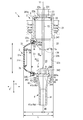
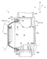
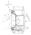
- the dispenser 1 As shown in FIGS. 1 to 3, the dispenser 1 according to the first embodiment of the present invention includes a cap portion 2, a pump portion 3, and a nozzle portion 4. 1 and 2 show a state of the dispenser 1 before the discharge operation. 5 and 6 show a state after the start of the discharge operation of the dispenser 1, FIG. 5 shows a state immediately after the start of the operation, and FIG. 6 shows a state after the discharge operation.
- the state before the discharge operation is a state before the discharge operation is performed on the dispenser 1
- the state after the discharge operation is a state after the discharge operation is performed on the dispenser 1.
- FIG. 3 is an exploded view illustrating the configuration of the dispenser 1.
- the pump unit 3 includes a lid 31 and a casing 32 having a recess 39 inside and serving as a main body to which the lid 31 is mounted.
- the pump portion 3 is formed as a pump chamber 30 by the lid 31 and the casing 32.
- the casing 32 is made of resin and has a substantially bottomed cylindrical shape.
- the casing 32 has an opening 33 formed on one end surface 32a in the axial direction X.
- the axial direction X coincides with the pressurizing direction when the discharge operation is performed
- the diametrical direction Y is the lid 31 and the pump portion 3 when the pump portion 3 is viewed from the lid 31 side. Corresponds to the radial direction.
- the casing 32 is formed with a flow path having a circular cross section that penetrates the pump portion 3 in the radial direction Y, which is a direction orthogonal to the axial direction X.
- One end side of the flow path forms a suction path 341, and the other end side of the flow path forms a discharge path 342.
- the suction passage 341 and the discharge passage 342 each communicate with the pump chamber 30.
- a cap portion 2 is attached to the outer periphery of the suction path 341.
- the cap portion 2 includes three cylindrical portions 21, 22, and 23 having the same center and different diameters.
- the cylindrical portion 21 has a screw formed on the inner peripheral side thereof, and as shown in FIG.
- the cylindrical portion 21 is rotated with respect to the mouth neck 101 of the liquid storage container 100 formed of the film material, thereby causing the mouth neck 101. It constitutes a mounting portion for mounting the dispenser 1 on the liquid storage container 100 by screwing into.
- the cylindrical portion 22 has a cap portion 2 and a pump portion 3 integrated by inserting the outer periphery of the suction path 341 into the cylindrical portion 22 and welding the suction path 341 by a laser or the like.
- the liquid storage container 100 is an inverted type used by being suspended from a towel hanger 160, for example, by a hook 150.
- the nozzle portion 4 is located downward, and the liquid G1 stored in the container is sucked from the inside of the liquid storage container 100 located above the pump. There is.
- the dispenser 1 is subjected to a discharge operation of picking with the fingers 170 of the user's hand [for example, thumb 171 and index finger 172], a constant amount of liquid G in the pump chamber 30 is discharged from the nozzle portion 4, and when the discharge operation is released, the liquid is discharged.
- the liquid G1 is sucked into the pump chamber 30 from the storage container 100.
- the end surface 32b constitutes a pressing support portion arranged to face the lid body 31, and the top portion and the end surface 32b of the lid body 31 are pressed from the side of the casing 32 with fingers 171 and 172. It can be picked up with and discharged.
- the end surface 32b serving as the pressing support portion is formed as a flat surface.
- the cylindrical portion 23 is a portion that is inserted into the mouth neck 101 and is located in the liquid storage container 100 when the dispenser 1 is attached to the liquid storage container 100, and as shown in FIGS. 1 and 3, the cylindrical portion 23 is a portion that is inserted into the mouth and neck portion 101.
- the inside thereof is a liquid inflow path 231.
- the wall portion 22a formed at the boundary between the cylindrical portion 22 and the cylindrical portion 23 is formed with a suction port 232 that communicates with the liquid inflow passage 231 and the suction passage 341.
- a suction valve 5 is provided inside the cylindrical portion 22.
- the suction valve 5 includes a valve body that opens and closes the suction port 232 and a support portion that supports the valve body at intervals in the circumferential direction, and is formed between the inner end surface 22b of the wall portion 22a and the end surface 341a of the suction path 341. It is installed in the space. That is, the suction valve 5 is held in a state of being sandwiched from both sides by the cap portion 2 and the pump portion 3.
- the suction valve 5 is a resin molded product.
- the suction valve 5 is formed so as to close when the internal pressure of the pump chamber 30 becomes high, shield the suction port 232, and stop the flow of liquid from the liquid storage container 100 into the pump chamber 30.
- the suction valve 5 is formed so as to open the suction port 232 when the internal pressure of the pump chamber 30 becomes low and suck the liquid G1 from the inside of the liquid storage container 100.
- the discharge path 342 located on the opposite side of the suction path 341 is formed so as to communicate with the tubular nozzle mounting portion 343.
- the nozzle portion 4 is mounted on the nozzle mounting portion 343.
- the nozzle portion 4 includes an in-nozzle flow path 41 formed so as to penetrate the inside of the nozzle portion, and a mounting flange 42 for mounting on the nozzle mounting portion 343.
- a discharge port 46 is formed at one end 41a [nozzle tip 4a] of the flow path 41 in the nozzle.
- the other end 41b of the in-nozzle flow path 41 is formed so as to communicate with the discharge port 344 formed at the end of the discharge path 342.
- the mounting flange 42 is formed with an annular groove 43 having a stepped portion 44 inside.
- a tubular nozzle mounting portion 343 is inserted into the groove 43.
- a convex portion 45 that engages with the step portion 44 is formed on the outer peripheral surface of the nozzle mounting portion 343.
- the dispenser 1 is formed so that the nozzle mounting portion 343 is inserted into the groove 43 and the stepped portion 44 and the convex portion 45 are engaged with each other to prevent the nozzle portion 4 from coming off.
- a discharge valve 6 is arranged inside the nozzle mounting portion 343.
- the discharge valve 6 includes a valve body that opens and closes the discharge port 344 and a support portion that supports the valve body at intervals in the circumferential direction, and is between the end portion 4b of the nozzle portion 4 and the inner end surface 343a of the nozzle mounting portion 343. It is arranged in the space formed in. That is, the discharge valve 6 is held in a state of being sandwiched from both sides by the nozzle portion 4 and the pump portion 3.
- the discharge valve 6 is a resin molded product.
- the discharge valve 6 opens when the internal pressure of the pump chamber 30 increases to open the discharge port 344, and discharges the liquid in the pump chamber 30 from the discharge port 46 to the outside via the flow path 41 in the nozzle.
- the discharge valve 6 is formed so as to close the valve when the internal pressure of the pump chamber 30 becomes low to close the discharge port 344 and stop the flow of liquid from the inside of the pump chamber 30 to the flow path 41 in the nozzle.
- the liquid inflow path 231 and the suction port 232, the suction path 341, the discharge path 342, the discharge port 344, and the in-nozzle flow path 41 [nozzle portion 4] are in series so that their centers are located on the same straight line. It is arranged in. In the present embodiment, this straight line is the center line Y1 of the nozzle orthogonal to the discharge operation direction Xb to the lid 31. That is, as shown in FIG. 1, the suction passage 341 and the discharge passage 342 are arranged to face each other via the pump chamber 30.
- the lid 31 is attached to the casing 32 so as to cover the opening 33 of the casing 32.
- the lid 31 is made of a material that can be elastically deformed.
- the lid 31 has a top surface 31a located on the opposite side of the end face 32b and is formed in a substantially flat prefix conical shape, and has a top surface 31a as a flat surface at the top.
- the top surface 31a and the end surface 32b of the lid 31 are formed as planes parallel to each other.
- the lid 31 is inflated in a direction (hereinafter referred to as “restoration direction Xa”) protruding outward from the casing 32 indicated by an arrow Xa.
- the lid 31 presses and deforms the liquid G in the pump chamber 30 toward the inside of the pump chamber 30, for example, with a human finger 170 (see FIG. 4), thereby causing the liquid G in the pump chamber 30 to be deformed. Discharge from the discharge port 46.
- the direction indicated by the arrow Xb pressed during the discharge operation is hereinafter referred to as "discharge operation direction Xb". Then, when the discharge operation is released, the lid 31 is restored in the restoration direction Xa, and the liquid G is sucked into the pump chamber 30 from the liquid storage container 100.
- an annular flange portion 31c protruding in the radial direction Y is formed on the opening side 31b of the lid 31 located on the opposite side of the top surface 31a.
- the flange portion 31c is inserted from the opening 33 side into a circular mounting groove 345 formed on the end surface 32a of the casing 32 concentrically with the opening 33.
- the flange portion 3c is formed with a lip portion 36 that can be inserted into the slit portion 346 formed in the bottom portion 345c of the mounting groove 345.
- the flange portion 31c and the mounting groove 345 are formed so that the lip portion 36 is inserted into the slit portion 346 when the flange portion 31c is mounted in the mounting groove 345. Therefore, as shown in FIG. 1, the dispenser 1 is configured such that the lip portion 36 occupies the engaged state due to insertion into the slit portion 346 to prevent the lid 31 from rotating in the circumferential direction. ing.
- a ring shape is formed between the annular outer inner wall 345a of the mounting groove 345 and the outer surface 31d of the lid 31 facing the outer inner wall 345a when mounted in the mounting groove 345.
- the stopper member 37 of the above is mounted so as to be in the fitted state.
- the flange portion 31c of the lid 31c is pressed against the outer inner wall 345a, the inner inner wall 345b, and the bottom portion 345c of the mounting groove 345. Therefore, the lid 31 is mounted on the casing 32 so as not to come off from the annular mounting groove 345 even when pressed in the discharge operation direction Xb.
- the dispenser 1 includes a coil spring 7 in the pump portion 3 (pump chamber 30) that urges the lid 31 toward the restoration direction Xa, which is the outside of the casing 32. ..
- the coil spring 7 is a compression coil spring, and as shown in FIG. 1, one end 7a side thereof is mounted on the bottom surface 32e of the casing 32, and the other end 7b side is mounted on a spring receiving portion 38 formed on the inner surface 31e of the lid 31.
- the spring receiving portion 38 includes an annular rib 38a protruding from the inner surface 31e of the lid 31 toward the inside of the pump chamber 30.
- the bottom surface 32e with which the coil spring 7 is in contact and the end surface 32b serving as the pressing support portion are in a positional relationship opposite to each other. Therefore, when the top portion 31a and the end surface 32b of the lid 31 are picked up by the fingers 170 from the side side of the casing 32 and discharged, the force of the fingers is surely transmitted to the coil spring 7.
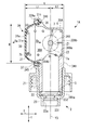
- the length L of the dispenser 1 from the lid 31 to the end face 32b serving as the pressing support portion is defined. That is, when the virtual plane Y2 that passes through the center line Y1 of the nozzle orthogonal to the discharge operation direction Xb and is perpendicular to the discharge operation direction Xb is used as a reference, the top surface of the lid 31 before deformation is obtained from this virtual plane Y2.
- the length to 31a is L1 and the distance from the virtual plane Y2 to the end face 32b is L2
- the distance L from the top surface 31a to the end face 32b is L1 + L2.
- the distance L is a distance at which it is easy to pinch the top portion 31a and the end surface 32b of the lid 31 with two or three fingers 170 of one hand.
- the distance L1 is set longer than the distance L2. This is to secure a stroke amount in which the lid 31 sufficiently enters the pump chamber 30 and deforms when the lid 31 is discharged. Further, it is preferable that the distance L1 is not too large with respect to the distance L2 from the viewpoint of enabling more stable discharge operation.
- the distance L1 is preferably 3 times or less of the distance L2, and the distance is preferably 3 times or less. It is more preferably 2.5 times or less of L2.
- the material used for the casing 32 is a material having a higher rigidity than the material used for the lid 31, and the casing 32 bends before the lid 31 when the discharge operation is performed on the lid 31. It is formed so that it never happens.
- the virtual plane Y2 is described with an exaggerated angle in consideration of legibility.
- the dispenser 1 according to the present embodiment can perform a discharge operation by pinching the top surface 31a and the end surface 32b of the lid 31 with fingers. More specifically, in the dispenser 1 according to the present embodiment, as shown in FIG. 4, after mounting on the liquid storage container 100, as shown in FIG. 5, for example, the thumb 171 is attached to the top surface 31a of the lid 31. The abdomen is applied, the abdomen of the index finger 172 or the middle finger is applied to the end surface 32b of the casing 32, and the pump portion 3 is pinched and held from the lateral axial direction X. From this state, the user presses and pushes the lid 31 in the discharge operation direction Xb against the repulsive force of the coil spring 7.
- the lid 31 begins to be partially deformed toward the inside of the pump chamber 30 by applying a pressing force to the top surface 31a of the lid 31. Therefore, the user can firmly hold the top surface 31a and the end surface 32b with his / her fingers at the initial stage of the discharge operation.
- the lid 31 When the lid 31 is further pushed in the discharge operation direction Xb while being held, the lid 31 is greatly bent into the pump chamber 30 as shown in FIG. Then, the volume of the pump chamber 30 is reduced, the chamber pressure is increased, the flow of the liquid from the suction port 232 is stopped by the suction valve 5, the discharge valve 6 is opened, the discharge port 344 is opened, and the pump chamber is opened.
- the liquid G in 30 is quantitatively discharged from the discharge port 46 via the flow path 41 in the nozzle.
- the lid body 31 moves toward the restoration direction Xa due to the repulsive force of the coil spring 7, and before deformation. It changes to restore the original shape of. Therefore, since the internal pressure of the pump unit 3 becomes low, the discharge valve 6 is closed to close the discharge port 344, and the suction valve 5 is opened to open the suction port 232 to enter the liquid storage container 100. A certain amount of the liquid G1 is sucked into the pump unit 3 through the suction port 232 and the suction path 341.
- the pressing support portion arranged to face the lid body 31 is provided, and the top portion (top surface 31a) of the lid body 31 and the end surface 32b serving as the pressing support portion are lateral to the casing 32.
- the discharge operation can be performed by picking it with a finger 170 from the side. Therefore, the position of the finger 170 is less likely to shift during the discharge operation, and the discharge operation of pushing the lid 31 into the pump chamber 30 can be easily and stably performed.
- the two fingers of one hand may be moved from the direction intersecting the axial direction X so as to face each of the top surface (top surface 31a) of the lid 31 and the end surface 32b serving as the pressing support portion. It is possible.
- the direction in which pressure is applied to the top portion (top surface 31a) of the lid 31 and the end surface 32b serving as the pressing support portion by pinching with two fingers is the direction along the above-mentioned axial direction X, which is the lateral side of the casing 32.
- the top (top surface 31a) of the lid 31 and the end surface 32b serving as the pressing support portion face each other in the horizontal direction when the dispenser 1 is mounted on the liquid storage container 100 in an upright or inverted state. It is preferable to be arranged in.
- the dispenser 1 is a small dispenser assuming that the amount of liquid discharged by one discharge operation is about several milliliters.
- the diameter R of the lid 31 is 23.27 mm
- L1 is 14.85 mm
- L2 is 7.85 mm.
- the diameter R of the lid 31 is the distance between the outer surfaces 31d of the opposing portions of the lid 31 when mounted on the casing 32.
- the material used for the lid 31 include elastomer, silicon, and NBR.
- Examples of the material used for the casing 32 include resin materials such as PP (polypropylene) and PE (polyethylene).
- the distance L is preferably 5 mm or more, more preferably 10 mm or more, and preferably 40 mm or less, more preferably 30 mm. It is less than or equal to, preferably 5 mm or more and 40 mm or less, and more preferably 10 mm or more and 30 mm or less.
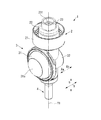
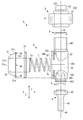
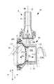
- the dispenser 1A according to the second embodiment of the present invention will be described with reference to FIGS. 7 to 11.
- the dispenser 1A according to the second embodiment includes a cap portion 2, a pump portion 3A, and a nozzle portion 4 as shown in FIGS. 7, 8 and 9.
- these members are mounted on a casing 32A in which the cap portion 2 and the nozzle portion 4 are arranged in a direction orthogonal to the pump portion 3A and constitute the pump portion 3A. As shown in FIG.
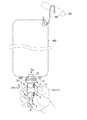
- the dispenser 1A is screwed into the mouth and neck 101 by rotating the cylindrical portion 21 of the cap 2 with respect to the mouth and neck 101 formed on the upper part of the self-supporting liquid storage container 100A. Then, it is attached to the upper part of the liquid storage container 100A and used.
- the dispenser 1A has a lid 31 mounted so as to cover the opening 33 formed in the upper part of the casing 32A.
- the pump portion 3A forms a space surrounded by the lid 31 and the casing 32A as the pump chamber 30A.
- the dispenser 1A picks the lid 31 and the end surface 32Ab serving as the pressing support portion of the casing 32A with fingers 170 (see FIG.
- the dispenser 1A is a so-called pump dispenser in which a liquid is sucked into the pump chamber 30A from the liquid storage container 100A by releasing the pinched finger 170 to release the discharge operation, as shown in FIG.
- the discharge operation is an operation in which the user picks the lid 31 and the end surface 32Ab of the pump portion 3A with the fingers 170 of the hand and pushes the lid 31 to the left.
- the difference between the pump unit 3 and the pump unit 3A is the shape of the casing 32A.
- a suction path 341 is formed below the tubular casing 32A with the end surface 341a facing downward.
- the casing 32A is formed so that the discharge path 342 extends in the discharge direction Z orthogonal to the discharge operation direction X. That is, the casing 32A has an L-shaped cross section.
- the cap portion 2 is integrated with the pump portion 3A by inserting the suction path 341 into the cylindrical portion 22.
- a pumping pipe 180 inserted into the liquid storage container 100A is connected to the cylindrical portion 23, and when the dispenser 1A is mounted on the liquid storage container 100A, the liquid in the container is discharged from below the container. It is said that it can be pumped up.
- the suction port 232 formed in the wall portion 22a at the boundary between the cylindrical portion 22 and the cylindrical portion 23 communicates with the liquid inflow passage 231 extending in the radial direction Y and the suction passage 341, and is cylindrical. It is opened and closed by a suction valve 5 arranged between the portion 22 and the suction passage 341.
- the discharge path 342 extending in the discharge direction Z is formed so as to communicate with the in-nozzle flow path 41 of the nozzle portion 4 mounted on the nozzle mounting portion 343 via the discharge port 344.
- a discharge valve 6 for opening and closing the discharge port 344 is arranged between the discharge path 342 and the nozzle portion 4.
- the dispenser 1A is arranged so that the liquid inflow path 231, the suction port 232, the suction valve 5, and the suction path 341 are located on the center line Y3 extending in the radial direction Y and passing through the pump chamber 30A. ing.
- the dispenser 1A is arranged such that the discharge path 342, the discharge valve 6, and the flow path 41 in the nozzle are located on the center line Z1 of the nozzle extending in the discharge direction Z.
- the end surface 32Ab is formed as a flat surface.
- the center line Y3 and the center line Z1 are arranged so as to face the lid body 31, and together with the lid body 31, an end face constituting a pressing support portion that can be picked up from the side of the casing 32A with a finger 170 and discharged. It is orthogonal to 32Ab.
- the center line Y3 and the center line Z1 pass through the pump chamber 30A and have the same distance from the end face 32Ab.
- the lid 31 is made of an elastically deformable material as in the first embodiment, and is inflated from the casing 32A in the restoration direction Xa before the discharge operation (before deformation). As shown in FIGS. 10 and 11, the lid 31 is subjected to a discharge operation in which the liquid in the pump chamber 30A is deformed by pressing with a human finger 170 toward the discharge operation direction Xb, so that the liquid in the pump chamber 30A is discharged from the nozzle portion 4. It is discharged from the discharge port 46 to the outside. When the pinching finger 170 is released and the discharge operation is released, the lid 31 pumps the liquid G1 from the liquid storage container 100A into the pump chamber 30A and flows it into the pump chamber 30A, as shown in FIGS. 9 and 11.
- the flange portion 31c formed on the opening side 31b of the lid 31 is inserted from the opening 33 side into a circular mounting groove 345 formed in the casing 32A concentrically with the opening 33.
- the lid 31 has an annular mounting groove even when pressed in the discharge operation direction Xb by mounting the ring-shaped stopping member 37 on the mounting groove 345 with the flange portion 31c inserted in the mounting groove 345. It is fixed to the casing 32A so as not to come off from the 345.
- a lip portion 36 and a slit portion 346 are formed in the flange portion 3c and the mounting groove 345, respectively, as in the first embodiment.
- the dispenser 1A includes a coil spring 7 that urges the lid 31 in the pump portion 3A (pump chamber 30A) toward the restoration direction Xa, which is the outside of the casing 32A.
- One end 7a side of the coil spring 7 is mounted on the bottom surface 32Ae of the casing 32A, and the other end 7b side is engaged with a spring receiving portion 38 formed on the inner surface 31e of the lid 31.
- the length La from the lid 31 to the end face 32Ab serving as the pressing support portion is specified. That is, when the virtual plane Z2 passing through the center line Z1 of the nozzle orthogonal to the discharge operation direction Xb and perpendicular to the discharge operation direction Xb is used as a reference, the top surface 31a which is the top of the lid 31 before deformation from the virtual plane Z2.
- the distance La from the top surface 31a to the end face 32Ab is L1 + L2.
- the distance La is a distance at which the top surface 31a and the end surface 32Ab of the lid 31 can be pinched with two or three fingers 170 of one hand.
- the distance L1 is set longer than the distance L2. This is to secure a stroke amount in which the lid 31 sufficiently enters the pump chamber 30A and deforms when the lid 31 is discharged.
- the material used for the casing 32A is a material having a higher rigidity than the material used for the lid 31, and the casing 32A bends before the lid 31 when the discharge operation is performed on the lid 31. It is formed so that it never happens.
- the virtual plane Z2 is shown with an exaggerated angle in consideration of legibility.
- the belly of the thumb 171 is placed on the top surface 31a of the lid 31, and the index finger 172 or the middle finger is placed.
- the antinode of the casing 32A is brought into contact with the end surface 32Ab of the casing 32A, and the pump portion 3A is pinched and held from the axial direction X. From this state, the user presses and pushes the lid 31 in the discharge operation direction Xb against the repulsive force of the coil spring 7.
- the lid 31 begins to be partially deformed toward the inside of the pump chamber 30A by applying a pressing force to the top surface 31a. Therefore, the user can firmly hold the top surface 31a and the end surface 32Ab with his / her fingers at the initial stage of the discharge operation.
- the lid 31 When the lid 31 is further pushed in the discharge operation direction Xb while being held, the lid 31 is greatly bent into the pump chamber 30A. Then, the volume of the pump chamber 30A is reduced, the chamber pressure is increased, the flow of the liquid from the suction port 232 is stopped by the suction valve 5, the discharge valve 6 is opened, the discharge port 344 is opened, and the pump chamber is opened.
- the liquid G in 30A is quantitatively discharged from the discharge port 46 via the flow path 41 in the nozzle.
- the dispenser 1A is provided with an end surface 32Ab which is arranged to face the lid 31 and serves as a pressing support portion which can be pinched with fingers from the side of the casing 32A together with the lid 31 to perform a discharge operation. Therefore, the lid 31 and the end surface 32Ab can be pinched together with fingers 170 from the side side of the casing 32A (the axial direction X intersecting in the same plane as the radial direction Y) to enable the discharge operation. Therefore, since the position shift of the finger 170 during the discharge operation is eliminated, the discharge operation of deforming the lid 31 into the pump chamber 30A is stable, and the dispenser 1A capable of performing a good discharge operation can be provided.
- the length from the virtual plane Z2 to the top surface 31a of the lid 31 is L1 and the length from the virtual plane Z2 to the pressing support portion with reference to the virtual plane Z2 passing through the center line Z1 of the nozzle orthogonal to the discharge operation direction Xb to the lid 31.
- L1 the distance to the end surface 32Ab
- L1> L2 it is easy to secure the stroke amount (deformation amount) of the lid 31 into the pump chamber 30A, and the liquid is discharged at the target discharge amount. It is possible to provide a dispenser 1A capable of performing a good discharge operation.
- the diameter R, the distance L1 and the distance L2 of the lid 31 are set as in the dispenser 1, and the material used for the lid 31 is the same.
- the dispenser 1A is a small dispenser assuming that the amount of liquid discharged by one discharge operation is about several milliliters.
- the diameter R of the lid 31 is 23.27 mm
- L1 is 14.85 mm
- L2 is 7.85 mm.
- the diameter R of the lid 31 is the distance between the outer surfaces 31d of the opposing portions of the lid 31 when mounted on the casing 32A. According to the configuration of the dispenser 1A provided with the lid 31 of such dimensions and materials, when the lid 31 is sandwiched between fingers and pressed in the discharge operation direction Xb, there is no misalignment of the fingers and the lid 31 is satisfactorily used. Was able to perform the discharge operation.
- the dispensers 1 and 1A the end surfaces 32b and 32Ab of the casing located on the opposite side of the lid 31 are used as flat surfaces to form the pressing support portion, but the dispensers 1 and 1A may be substantially flat surfaces. That is, it may have a curved surface as long as it is larger than the radius of curvature of the discharge port 344. Further, in the dispensers 1 and 1A, an uneven portion extending in the diameter direction Y may be formed on the end faces 32b and 32Ab to serve as a pressing support portion.
- the end faces 32b and 32Ab may be used as a pressing support portion as a curved surface recessed toward the pump chambers 30 and 30A. It is preferable to form the pressing support portion as such a concavo-convex portion or a curved surface because it is difficult to slip when picked with a finger 170 and can be firmly held.
- a pump chamber is formed by a main body having a recess and a lid covering an opening of the main body, and a discharge operation of pressing the lid toward the pump chamber to deform it causes liquid in the pump chamber to be discharged.
- a dispenser that discharges liquid from the nozzle portion and releases the discharge operation to allow liquid to flow into the pump chamber.
- a dispenser having a pressing support portion arranged to face the lid body, and the top portion of the lid body and the pressing support portion are picked up from the side of the main body by a finger to perform a discharge operation.
- ⁇ 2> The dispenser according to ⁇ 1>, wherein the distance from the pressing support portion to the top of the lid is 5 mm or more and less than 30 mm.
- the distance from the virtual plane to the top of the lid is L1 with reference to a virtual plane that passes through the center line of the nozzle and is perpendicular to the discharge operation direction, which is the pressing direction of the lid when the discharge operation is performed.
- ⁇ 4> The dispenser according to any one of ⁇ 1> to ⁇ 3>, wherein the lid body is inflated on the side opposite to the main body and has a substantially flat top surface.
- ⁇ 5> The dispenser according to any one of ⁇ 1> to ⁇ 4>, wherein the pressing support portion has a substantially flat surface.
- ⁇ 6> The dispenser according to any one of ⁇ 1> to ⁇ 4>, wherein the top surface of the lid and the end surface serving as the pressing support portion are arranged so as to face each other in the horizontal direction.
- a coil spring for urging the lid body outward is provided in the pump chamber.
- ⁇ 8> The dispenser according to ⁇ 7>, wherein one end side of the coil spring is placed on the bottom surface of the recess and the other end side is in contact with the inner surface 31e of the lid body.
- ⁇ 9> The dispenser according to ⁇ 8>, wherein the bottom surface with which the coil spring is in contact and the pressing support portion face each other.
- the main body has a suction path as a flow path for the liquid flowing into the pump chamber and a discharge path as a flow path for the liquid discharged from the nozzle portion, and each of the suction path and the discharge path has the pump chamber.
- ⁇ 11> The dispenser according to ⁇ 10>, wherein the suction passage and the centers of the discharge passages are arranged in series so as to be located on the same straight line.
- ⁇ 12> The dispenser according to ⁇ 10>, wherein the suction passage and the discharge passage are arranged so as to face each other via the pump chamber.
- the position of the finger is less likely to shift during the discharge operation, and the discharge operation of pushing the lid into the pump chamber can be easily and stably performed.
Landscapes
- Engineering & Computer Science (AREA)
- Mechanical Engineering (AREA)
- General Engineering & Computer Science (AREA)
- Closures For Containers (AREA)
- Containers And Packaging Bodies Having A Special Means To Remove Contents (AREA)
Abstract
A dispenser (1) according to the present invention forms a pump room (30) with a body (32) having a recessed part (39) and a lid body (31) covering an opening part (33) of the body, performs an ejecting operation to press and deform the lid body toward the inside of the pump room to eject a liquid inside the pump room from a nozzle part (4), and cancels the ejecting operation to cause the liquid to flow in the pump room (30). The dispenser (1) is provided with a press supporting part (32b) that is arranged facing the lid body (31). The ejecting operation is performed in such a manner that a top part (31a) of the lid body and the press supporting part (32b) are picked up by fingers from a lateral side of the body (32).
Description
本発明は、ディスペンサーに関する。
The present invention relates to a dispenser.
特許文献1には、収縮、復元可能な壁体の内部にポンプ室が形成されていて、壁体をポンプ室に向かってつぶして収縮させる吐出操作をすることで、吐出弁を介してポンプ室に接続されたノズルから吐出を噴出するポンプが記載されている。
In Patent Document 1, a pump chamber is formed inside a wall body that can be contracted and restored, and by performing a discharge operation of crushing the wall body toward the pump chamber and contracting the wall body, the pump chamber is passed through a discharge valve. A pump that ejects a discharge from a nozzle connected to is described.
本発明は、凹部を有する本体と、前記本体の開口部を覆う蓋体とでポンプ室が形成され、前記蓋体を該ポンプ室内に向かって押圧して変形させる吐出操作をすることで前記ポンプ室内の液体をノズル部から吐出させ、前記吐出操作を解除することで前記ポンプ室内に液体を流入させるディスペンサーに関する。本発明のディスペンサーは、前記蓋体と対向配置された押圧支持部を備え、前記蓋体の頂部と前記押圧支持部とを、前記本体の側方側から指で摘まんで吐出操作を行うようになされている。
In the present invention, a pump chamber is formed by a main body having a recess and a lid covering an opening of the main body, and the pump is operated by pressing the lid toward the pump chamber to deform the pump. The present invention relates to a dispenser that discharges a liquid in a chamber from a nozzle portion and releases the discharge operation to allow the liquid to flow into the pump chamber. The dispenser of the present invention includes a pressing support portion arranged to face the lid body, and the top portion of the lid body and the pressing support portion are picked up by fingers from the side side of the main body to perform a discharge operation. It has been done.
特許文献1では、球状の壁部をつぶして収縮させる吐出操作する際に、手のひら全体で壁部を包み込んでつぶす場合や、指でつまんでつぶす場合が想定される。しかし、指でつまんでつぶす場合、壁部の変形方向によっては指の位置の位置がずれてしまい十分に吐出操作が出来ない場合がある。
本発明は、前述した従来技術が有する欠点を解消し得るディスペンサーに関する。 InPatent Document 1, when a spherical wall portion is crushed and contracted, it is assumed that the wall portion is wrapped with the entire palm and crushed, or the wall portion is pinched and crushed with fingers. However, when the finger is pinched and crushed, the position of the finger may shift depending on the deformation direction of the wall portion, and the ejection operation may not be sufficiently performed.
The present invention relates to a dispenser capable of eliminating the above-mentioned drawbacks of the prior art.
本発明は、前述した従来技術が有する欠点を解消し得るディスペンサーに関する。 In
The present invention relates to a dispenser capable of eliminating the above-mentioned drawbacks of the prior art.
以下に本発明を、その好ましい実施形態に基づき図面を参照しながら説明する。
〔第1の実施形態〕
本発明の第1の実施形態に係るディスペンサー1は、図1~図3に示すように、キャップ部2、ポンプ部3、ノズル部4を備えている。図1,図2は、ディスペンサー1の吐出操作前の状態を示す。図5,図6は、ディスペンサー1の吐出操作開始後の状態を示し、図5は操作開始直後、図6は吐出操作後の状態を示す。吐出操作前とはディスペンサー1に対して吐出操作を行う前の状態であり、吐出操作後とはディスペンサー1に対して吐出操作を行った後の状態を示す。図3はディスペンサー1の構成を説明する分解図である。 Hereinafter, the present invention will be described based on the preferred embodiment with reference to the drawings.
[First Embodiment]
As shown in FIGS. 1 to 3, thedispenser 1 according to the first embodiment of the present invention includes a cap portion 2, a pump portion 3, and a nozzle portion 4. 1 and 2 show a state of the dispenser 1 before the discharge operation. 5 and 6 show a state after the start of the discharge operation of the dispenser 1, FIG. 5 shows a state immediately after the start of the operation, and FIG. 6 shows a state after the discharge operation. The state before the discharge operation is a state before the discharge operation is performed on the dispenser 1, and the state after the discharge operation is a state after the discharge operation is performed on the dispenser 1. FIG. 3 is an exploded view illustrating the configuration of the dispenser 1.
〔第1の実施形態〕
本発明の第1の実施形態に係るディスペンサー1は、図1~図3に示すように、キャップ部2、ポンプ部3、ノズル部4を備えている。図1,図2は、ディスペンサー1の吐出操作前の状態を示す。図5,図6は、ディスペンサー1の吐出操作開始後の状態を示し、図5は操作開始直後、図6は吐出操作後の状態を示す。吐出操作前とはディスペンサー1に対して吐出操作を行う前の状態であり、吐出操作後とはディスペンサー1に対して吐出操作を行った後の状態を示す。図3はディスペンサー1の構成を説明する分解図である。 Hereinafter, the present invention will be described based on the preferred embodiment with reference to the drawings.
[First Embodiment]
As shown in FIGS. 1 to 3, the
ポンプ部3は、蓋体31と、内部に凹部39を有し、蓋体31が装着される本体としてのケーシング32とを備えている。ポンプ部3は、蓋体31とケーシング32とでポンプ室30として形成している。ケーシング32は樹脂製で、略有底円筒形状を成している。ケーシング32は、軸線方向Xの一方の端面32aに開口部33が形成されている。本実施形態において、軸線方向Xは、吐出操作を行う際の加圧方向に一致し、直径方向Yは、ポンプ部3を蓋体31側から見たときの、蓋体31及びポンプ部3の直径方向に相当する。
ケーシング32には、ポンプ部3を、軸線方向Xと直交とする方向である直径方向Yに貫通する断面円形の流路が形成されている。流路の一端側は吸入路341を形成し、流路の他端側は吐出路342を形成している。吸入路341及び吐出路342は、それぞれがポンプ室30と連通している。吸入路341の外周には、キャップ部2が装着されている。キャップ部2は、同一中心を持つ径の異なる3つの円筒部21,22,23を備えている。円筒部21は、その内周側にねじが形成されていて、図4に示すように、フィルム材で形成された液体収納容器100の口頸部101に対して回転させることで口頸部101に螺合してディスペンサー1を液体収納容器100に装着させる装着部を構成している。円筒部22は、図1,図3に示すように、その内部に吸入路341の外周が挿入され、レーザなどによって溶着されることでキャップ部2とポンプ部3とを一体化している。 Thepump unit 3 includes a lid 31 and a casing 32 having a recess 39 inside and serving as a main body to which the lid 31 is mounted. The pump portion 3 is formed as a pump chamber 30 by the lid 31 and the casing 32. The casing 32 is made of resin and has a substantially bottomed cylindrical shape. The casing 32 has an opening 33 formed on one end surface 32a in the axial direction X. In the present embodiment, the axial direction X coincides with the pressurizing direction when the discharge operation is performed, and the diametrical direction Y is the lid 31 and the pump portion 3 when the pump portion 3 is viewed from the lid 31 side. Corresponds to the radial direction.
Thecasing 32 is formed with a flow path having a circular cross section that penetrates the pump portion 3 in the radial direction Y, which is a direction orthogonal to the axial direction X. One end side of the flow path forms a suction path 341, and the other end side of the flow path forms a discharge path 342. The suction passage 341 and the discharge passage 342 each communicate with the pump chamber 30. A cap portion 2 is attached to the outer periphery of the suction path 341. The cap portion 2 includes three cylindrical portions 21, 22, and 23 having the same center and different diameters. The cylindrical portion 21 has a screw formed on the inner peripheral side thereof, and as shown in FIG. 4, the cylindrical portion 21 is rotated with respect to the mouth neck 101 of the liquid storage container 100 formed of the film material, thereby causing the mouth neck 101. It constitutes a mounting portion for mounting the dispenser 1 on the liquid storage container 100 by screwing into. As shown in FIGS. 1 and 3, the cylindrical portion 22 has a cap portion 2 and a pump portion 3 integrated by inserting the outer periphery of the suction path 341 into the cylindrical portion 22 and welding the suction path 341 by a laser or the like.
ケーシング32には、ポンプ部3を、軸線方向Xと直交とする方向である直径方向Yに貫通する断面円形の流路が形成されている。流路の一端側は吸入路341を形成し、流路の他端側は吐出路342を形成している。吸入路341及び吐出路342は、それぞれがポンプ室30と連通している。吸入路341の外周には、キャップ部2が装着されている。キャップ部2は、同一中心を持つ径の異なる3つの円筒部21,22,23を備えている。円筒部21は、その内周側にねじが形成されていて、図4に示すように、フィルム材で形成された液体収納容器100の口頸部101に対して回転させることで口頸部101に螺合してディスペンサー1を液体収納容器100に装着させる装着部を構成している。円筒部22は、図1,図3に示すように、その内部に吸入路341の外周が挿入され、レーザなどによって溶着されることでキャップ部2とポンプ部3とを一体化している。 The
The
図4に示すように、液体収納容器100は、フック150によって例えばタオルハンガー160に吊り下げられて使用する倒立タイプのものである。液体収納容器100に装着されたディスペンサー1は、ノズル部4が下方に向かって位置し、ポンプ上方に位置する液体収納容器100内から容器内に収容されている液体G1を吸引するようになっている。ディスペンサー1は、使用者の手の指170〔例えば親指171と人差し指172〕で摘まむ吐出操作をすると、ポンプ室30内の液体Gが一定量ノズル部4から吐出され、吐出操作を解除すると液体収納容器100内から液体G1がポンプ室30内に吸入されるものである。
すなわち、本実施形態において、端面32bは、蓋体31と対向配置された押圧支持部を構成しており、蓋体31の頂部と端面32bとを、ケーシング32の側方側から指171,172で摘まんで吐出操作可能である。押圧支持部となる端面32bは、平坦面として形成されている。 As shown in FIG. 4, theliquid storage container 100 is an inverted type used by being suspended from a towel hanger 160, for example, by a hook 150. In the dispenser 1 mounted on the liquid storage container 100, the nozzle portion 4 is located downward, and the liquid G1 stored in the container is sucked from the inside of the liquid storage container 100 located above the pump. There is. When the dispenser 1 is subjected to a discharge operation of picking with the fingers 170 of the user's hand [for example, thumb 171 and index finger 172], a constant amount of liquid G in the pump chamber 30 is discharged from the nozzle portion 4, and when the discharge operation is released, the liquid is discharged. The liquid G1 is sucked into the pump chamber 30 from the storage container 100.
That is, in the present embodiment, theend surface 32b constitutes a pressing support portion arranged to face the lid body 31, and the top portion and the end surface 32b of the lid body 31 are pressed from the side of the casing 32 with fingers 171 and 172. It can be picked up with and discharged. The end surface 32b serving as the pressing support portion is formed as a flat surface.
すなわち、本実施形態において、端面32bは、蓋体31と対向配置された押圧支持部を構成しており、蓋体31の頂部と端面32bとを、ケーシング32の側方側から指171,172で摘まんで吐出操作可能である。押圧支持部となる端面32bは、平坦面として形成されている。 As shown in FIG. 4, the
That is, in the present embodiment, the
円筒部23は、ディスペンサー1が液体収納容器100に装着された際に、口頸部101内に挿入されて液体収納容器100内に位置する部位であり、図1,図3に示すように、その内部が液体流入路231とされている。円筒部22と円筒部23との境目に形成された壁部22aは、液体流入路231と吸入路341とに連通する吸入口232が形成されている。
円筒部22の内部には、図1に示すように、吸入弁5が設けられている。吸入弁5は、吸入口232を開閉する弁体と、周方向に間隔をもって弁体を支持する支持部とを備え、壁部22aの内端面22bと吸入路341の端面341aの間に形成される空間内に装着されている。つまり、吸入弁5は、キャップ部2とポンプ部3によって両側から挟まれた状態で保持されている。吸入弁5は樹脂成型品である。吸入弁5は、ポンプ室30の内圧が高くなると閉弁し、吸入口232を遮蔽して液体収納容器100からポンプ室30内への液体の流れを止めるように形成されている。吸入弁5は、ポンプ室30の内圧が低くなると開弁して吸入口232を開放し、液体収納容器100内から液体G1を吸引するように形成されている。 Thecylindrical portion 23 is a portion that is inserted into the mouth neck 101 and is located in the liquid storage container 100 when the dispenser 1 is attached to the liquid storage container 100, and as shown in FIGS. 1 and 3, the cylindrical portion 23 is a portion that is inserted into the mouth and neck portion 101. The inside thereof is a liquid inflow path 231. The wall portion 22a formed at the boundary between the cylindrical portion 22 and the cylindrical portion 23 is formed with a suction port 232 that communicates with the liquid inflow passage 231 and the suction passage 341.
As shown in FIG. 1, asuction valve 5 is provided inside the cylindrical portion 22. The suction valve 5 includes a valve body that opens and closes the suction port 232 and a support portion that supports the valve body at intervals in the circumferential direction, and is formed between the inner end surface 22b of the wall portion 22a and the end surface 341a of the suction path 341. It is installed in the space. That is, the suction valve 5 is held in a state of being sandwiched from both sides by the cap portion 2 and the pump portion 3. The suction valve 5 is a resin molded product. The suction valve 5 is formed so as to close when the internal pressure of the pump chamber 30 becomes high, shield the suction port 232, and stop the flow of liquid from the liquid storage container 100 into the pump chamber 30. The suction valve 5 is formed so as to open the suction port 232 when the internal pressure of the pump chamber 30 becomes low and suck the liquid G1 from the inside of the liquid storage container 100.
円筒部22の内部には、図1に示すように、吸入弁5が設けられている。吸入弁5は、吸入口232を開閉する弁体と、周方向に間隔をもって弁体を支持する支持部とを備え、壁部22aの内端面22bと吸入路341の端面341aの間に形成される空間内に装着されている。つまり、吸入弁5は、キャップ部2とポンプ部3によって両側から挟まれた状態で保持されている。吸入弁5は樹脂成型品である。吸入弁5は、ポンプ室30の内圧が高くなると閉弁し、吸入口232を遮蔽して液体収納容器100からポンプ室30内への液体の流れを止めるように形成されている。吸入弁5は、ポンプ室30の内圧が低くなると開弁して吸入口232を開放し、液体収納容器100内から液体G1を吸引するように形成されている。 The
As shown in FIG. 1, a
図1,図3に示すように、吸入路341と反対側に位置する吐出路342は、筒状のノズル装着部343と連通するように形成されている。ノズル装着部343にはノズル部4が装着される。ノズル部4は、ノズル部内を貫通するように形成されたノズル内流路41と、ノズル装着部343に装着するための装着フランジ42とを備えている。ノズル内流路41の一方の端部41a〔ノズル先端4a〕には吐出口46が形成されている。ノズル内流路41の他方の端部41bは吐出路342の端部に形成された排出口344と連通するように形成されている。装着フランジ42には、内部に段差部44を備えた環状の溝43が形成されている。溝43には筒状のノズル装着部343が挿入される。ノズル装着部343の外周面には、段差部44と係合する凸部45が形成されている。ディスペンサー1は、ノズル装着部343が溝43内に挿入されて段差部44と凸部45とが係合することで、ノズル部4の抜け止めがなされるように形成されている。
As shown in FIGS. 1 and 3, the discharge path 342 located on the opposite side of the suction path 341 is formed so as to communicate with the tubular nozzle mounting portion 343. The nozzle portion 4 is mounted on the nozzle mounting portion 343. The nozzle portion 4 includes an in-nozzle flow path 41 formed so as to penetrate the inside of the nozzle portion, and a mounting flange 42 for mounting on the nozzle mounting portion 343. A discharge port 46 is formed at one end 41a [nozzle tip 4a] of the flow path 41 in the nozzle. The other end 41b of the in-nozzle flow path 41 is formed so as to communicate with the discharge port 344 formed at the end of the discharge path 342. The mounting flange 42 is formed with an annular groove 43 having a stepped portion 44 inside. A tubular nozzle mounting portion 343 is inserted into the groove 43. A convex portion 45 that engages with the step portion 44 is formed on the outer peripheral surface of the nozzle mounting portion 343. The dispenser 1 is formed so that the nozzle mounting portion 343 is inserted into the groove 43 and the stepped portion 44 and the convex portion 45 are engaged with each other to prevent the nozzle portion 4 from coming off.
ノズル装着部343の内部には、吐出弁6が配されている。吐出弁6は、排出口344を開閉する弁体と、周方向に間隔をもって弁体を支持する支持部とを備え、ノズル部4の端部4bとノズル装着部343の内端面343aとの間に形成される空間内に配されている。つまり、吐出弁6は、ノズル部4とポンプ部3によって両側から挟まれた状態で保持されている。吐出弁6は樹脂成型品である。吐出弁6は、ポンプ室30の内圧が高まると開弁して排出口344を開放し、ポンプ室30内の液体を、ノズル内流路41を介して吐出口46から外部へと吐出とするように形成されている。吐出弁6はポンプ室30の内圧が低くなると閉弁して排出口344を閉塞し、ポンプ室30内からノズル内流路41への液体の流れを止めるように形成されている。
ディスペンサー1において、液体流入路231、吸入口232、吸入路341、吐出路342、排出口344及びノズル内流路41〔ノズル部4〕は、各中心が同一の直線上に位置するように直列に配されている。本実施形態において、この直線は蓋体31への吐出操作方向Xbと直交するノズルの中心線Y1とする。すなわち、図1に示すように、吸入路341と吐出路342とがポンプ室30を介して対向配置されている。 Adischarge valve 6 is arranged inside the nozzle mounting portion 343. The discharge valve 6 includes a valve body that opens and closes the discharge port 344 and a support portion that supports the valve body at intervals in the circumferential direction, and is between the end portion 4b of the nozzle portion 4 and the inner end surface 343a of the nozzle mounting portion 343. It is arranged in the space formed in. That is, the discharge valve 6 is held in a state of being sandwiched from both sides by the nozzle portion 4 and the pump portion 3. The discharge valve 6 is a resin molded product. The discharge valve 6 opens when the internal pressure of the pump chamber 30 increases to open the discharge port 344, and discharges the liquid in the pump chamber 30 from the discharge port 46 to the outside via the flow path 41 in the nozzle. It is formed like this. The discharge valve 6 is formed so as to close the valve when the internal pressure of the pump chamber 30 becomes low to close the discharge port 344 and stop the flow of liquid from the inside of the pump chamber 30 to the flow path 41 in the nozzle.
In thedispenser 1, the liquid inflow path 231 and the suction port 232, the suction path 341, the discharge path 342, the discharge port 344, and the in-nozzle flow path 41 [nozzle portion 4] are in series so that their centers are located on the same straight line. It is arranged in. In the present embodiment, this straight line is the center line Y1 of the nozzle orthogonal to the discharge operation direction Xb to the lid 31. That is, as shown in FIG. 1, the suction passage 341 and the discharge passage 342 are arranged to face each other via the pump chamber 30.
ディスペンサー1において、液体流入路231、吸入口232、吸入路341、吐出路342、排出口344及びノズル内流路41〔ノズル部4〕は、各中心が同一の直線上に位置するように直列に配されている。本実施形態において、この直線は蓋体31への吐出操作方向Xbと直交するノズルの中心線Y1とする。すなわち、図1に示すように、吸入路341と吐出路342とがポンプ室30を介して対向配置されている。 A
In the
蓋体31は、ケーシング32の開口部33を覆うように、ケーシング32に装着されている。蓋体31は、弾性変形可能な材質で形成されている。蓋体31は、端面32bと反対側に位置する頂面31aが略平らな接頭円錐形状に形成されており、頂部に平坦面としての頂面31aを有している。蓋体31の頂面31aと端面32bとは、互いに平行な平面として形成されている。蓋体31は、吐出操作前(変形前)においてはケーシング32から矢印Xaで示す外方に突出する方向(以下「復元方向Xa」と記す)に膨設されている。蓋体31は、矢印Xbで示すようにポンプ室30内に向かって、例えば人の指170(図4参照)で押圧して変形させる吐出操作をすることで、ポンプ室30内の液体Gを吐出口46から吐出させる。吐出操作時に押圧する前記矢印Xbで示す方向を、以下「吐出操作方向Xb」という。そして、吐出操作が解除されると、蓋体31は復元方向Xaに向かって復元するとともに、ポンプ室30内に液体Gを液体収納容器100から吸引する。
The lid 31 is attached to the casing 32 so as to cover the opening 33 of the casing 32. The lid 31 is made of a material that can be elastically deformed. The lid 31 has a top surface 31a located on the opposite side of the end face 32b and is formed in a substantially flat prefix conical shape, and has a top surface 31a as a flat surface at the top. The top surface 31a and the end surface 32b of the lid 31 are formed as planes parallel to each other. Before the discharge operation (before deformation), the lid 31 is inflated in a direction (hereinafter referred to as “restoration direction Xa”) protruding outward from the casing 32 indicated by an arrow Xa. As shown by the arrow Xb, the lid 31 presses and deforms the liquid G in the pump chamber 30 toward the inside of the pump chamber 30, for example, with a human finger 170 (see FIG. 4), thereby causing the liquid G in the pump chamber 30 to be deformed. Discharge from the discharge port 46. The direction indicated by the arrow Xb pressed during the discharge operation is hereinafter referred to as "discharge operation direction Xb". Then, when the discharge operation is released, the lid 31 is restored in the restoration direction Xa, and the liquid G is sucked into the pump chamber 30 from the liquid storage container 100.
図3に示すように、頂面31aと逆側に位置する蓋体31の開口側31bには、直径方向Yに突出した環状のフランジ部31cが形成されている。フランジ部31cは、開口部33と同心円状にケーシング32の端面32aに形成された円形の装着溝345内に開口部33側から挿入される。フランジ部3cには、図5に示すように、装着溝345の底部345cに形成されたスリット部346内に挿入可能なリップ部36が形成されている。フランジ部31cと装着溝345とは、フランジ部31cを装着溝345内に装着した際にリップ部36がスリット部346内に挿入されるように形成されている。このため、図1に示すように、ディスペンサー1は、リップ部36がスリット部346への挿入による係合状態を占めることで、蓋体31の周方向への回り止めがなされるように構成されている。
As shown in FIG. 3, an annular flange portion 31c protruding in the radial direction Y is formed on the opening side 31b of the lid 31 located on the opposite side of the top surface 31a. The flange portion 31c is inserted from the opening 33 side into a circular mounting groove 345 formed on the end surface 32a of the casing 32 concentrically with the opening 33. As shown in FIG. 5, the flange portion 3c is formed with a lip portion 36 that can be inserted into the slit portion 346 formed in the bottom portion 345c of the mounting groove 345. The flange portion 31c and the mounting groove 345 are formed so that the lip portion 36 is inserted into the slit portion 346 when the flange portion 31c is mounted in the mounting groove 345. Therefore, as shown in FIG. 1, the dispenser 1 is configured such that the lip portion 36 occupies the engaged state due to insertion into the slit portion 346 to prevent the lid 31 from rotating in the circumferential direction. ing.
装着溝345の環状の外側内壁345aと、装着溝345に装着された状態における、外側内壁345aと対向する蓋体31の外面31dとの間には、図1、図3に示すようにリング状の止め部材37が嵌入状態となるように装着される。この止め部材37が装着溝345に装着されることで、図1に示すように、蓋体31はフランジ部31cが装着溝345の外側内壁345a、内側内壁345b及び底部345cに押し付けられる。このため、蓋体31は、吐出操作方向Xbに押圧された場合でも環状の装着溝345から外れないようにケーシング32に装着されている。
As shown in FIGS. 1 and 3, a ring shape is formed between the annular outer inner wall 345a of the mounting groove 345 and the outer surface 31d of the lid 31 facing the outer inner wall 345a when mounted in the mounting groove 345. The stopper member 37 of the above is mounted so as to be in the fitted state. When the stopper 37 is mounted in the mounting groove 345, as shown in FIG. 1, the flange portion 31c of the lid 31c is pressed against the outer inner wall 345a, the inner inner wall 345b, and the bottom portion 345c of the mounting groove 345. Therefore, the lid 31 is mounted on the casing 32 so as not to come off from the annular mounting groove 345 even when pressed in the discharge operation direction Xb.
ディスペンサー1は、図1,図3に示すように、蓋体31をケーシング32の外側である復元方向Xaに向かって付勢するコイルばね7をポンプ部3(ポンプ室30)内に備えている。コイルばね7は、圧縮コイルばねであって、図1に示すように、その一端7a側がケーシング32の底面32eに載せられ、他端7b側が蓋体31の内面31eに形成されたばね受け部38に係合されている。ばね受け部38は、蓋体31の内面31eからポンプ室30内に向かって突出した環状リブ38aを備えている。すなわち、コイルばね7が当接している底面32eと、押圧支持部となる端面32bとは相対する位置関係にある。このため、蓋体31の頂部31aと端面32bとを、ケーシング32の側方側から指170で摘まんで吐出操作する際に、指の力が確実にコイルばね7に伝わる。
As shown in FIGS. 1 and 3, the dispenser 1 includes a coil spring 7 in the pump portion 3 (pump chamber 30) that urges the lid 31 toward the restoration direction Xa, which is the outside of the casing 32. .. The coil spring 7 is a compression coil spring, and as shown in FIG. 1, one end 7a side thereof is mounted on the bottom surface 32e of the casing 32, and the other end 7b side is mounted on a spring receiving portion 38 formed on the inner surface 31e of the lid 31. Engaged. The spring receiving portion 38 includes an annular rib 38a protruding from the inner surface 31e of the lid 31 toward the inside of the pump chamber 30. That is, the bottom surface 32e with which the coil spring 7 is in contact and the end surface 32b serving as the pressing support portion are in a positional relationship opposite to each other. Therefore, when the top portion 31a and the end surface 32b of the lid 31 are picked up by the fingers 170 from the side side of the casing 32 and discharged, the force of the fingers is surely transmitted to the coil spring 7.
図1に示すように、ディスペンサー1は、蓋体31から押圧支持部となる端面32bまでの長さLが規定されている。すなわち、吐出操作方向Xbと直交するノズルの中心線Y1を通り、吐出操作方向Xbと垂直な仮想平面Y2を基準としたとき、この仮想平面Y2から変形前の蓋体31の頂部となる頂面31aまでの長さをL1、仮想平面Y2から端面32bまでの距離をL2としたときに、頂面31aから端面32bまでの距離Lは、L1+L2とされている。距離Lは、片方の手の二本又は三本の指170で、蓋体31の頂部31aと端面32bとを摘まむことが容易な距離である。ディスペンサー1は、距離L1が距離L2よりも長く設定されている。これは蓋体31に対して吐出操作をした際に、蓋体31がポンプ室30内に十分に入り込んで変形するストローク量を確保するためである。また、距離L1は、距離L2に対する倍率が大き過ぎないことが、吐出操作を一層安定して行えるようにする観点から好ましく、例えば距離L1は、距離L2の3倍以下であることが好ましく、距離L2の2.5倍以下であることがより好ましい。ケーシング32に用いる材質は、蓋体31に用いる材質よりも剛性の高い材質が用いられていて、蓋体31に対して吐出操作を行う際に、蓋体31よりもケーシング32が先に撓むことがないように形成されている。なお、図1において仮想平面Y2は見やすさを考慮して角度を誇張して記載している。
As shown in FIG. 1, the length L of the dispenser 1 from the lid 31 to the end face 32b serving as the pressing support portion is defined. That is, when the virtual plane Y2 that passes through the center line Y1 of the nozzle orthogonal to the discharge operation direction Xb and is perpendicular to the discharge operation direction Xb is used as a reference, the top surface of the lid 31 before deformation is obtained from this virtual plane Y2. When the length to 31a is L1 and the distance from the virtual plane Y2 to the end face 32b is L2, the distance L from the top surface 31a to the end face 32b is L1 + L2. The distance L is a distance at which it is easy to pinch the top portion 31a and the end surface 32b of the lid 31 with two or three fingers 170 of one hand. In the dispenser 1, the distance L1 is set longer than the distance L2. This is to secure a stroke amount in which the lid 31 sufficiently enters the pump chamber 30 and deforms when the lid 31 is discharged. Further, it is preferable that the distance L1 is not too large with respect to the distance L2 from the viewpoint of enabling more stable discharge operation. For example, the distance L1 is preferably 3 times or less of the distance L2, and the distance is preferably 3 times or less. It is more preferably 2.5 times or less of L2. The material used for the casing 32 is a material having a higher rigidity than the material used for the lid 31, and the casing 32 bends before the lid 31 when the discharge operation is performed on the lid 31. It is formed so that it never happens. In FIG. 1, the virtual plane Y2 is described with an exaggerated angle in consideration of legibility.
本実施形態に係るディスペンサー1は、前述したとおり、蓋体31の頂面31aと端面32bとを、指で摘まんで吐出操作可能である。より具体的に説明すると、本実施形態に係るディスペンサー1では、図4に示すように、液体収納容器100へ装着後、図5に示すように、蓋体31の頂面31aに例えば親指171の腹を当て、人差し指172又は中指の腹をケーシング32の端面32bに当てて、ポンプ部3を側方側となる軸線方向Xから摘まんで保持する。この状態から、使用者がコイルばね7の反発力に抗して吐出操作方向Xbに蓋体31を押圧して押し込む。すると、ケーシング32の剛性が蓋体31の剛性よりも高いので、蓋体31の頂面31aに押圧力が加わることでポンプ室30内に向かって蓋体31が部分的に変形し始める。このため、使用者は、吐出操作の初期段階において、頂面31aと端面32bをしっかり指で保持することができる。
As described above, the dispenser 1 according to the present embodiment can perform a discharge operation by pinching the top surface 31a and the end surface 32b of the lid 31 with fingers. More specifically, in the dispenser 1 according to the present embodiment, as shown in FIG. 4, after mounting on the liquid storage container 100, as shown in FIG. 5, for example, the thumb 171 is attached to the top surface 31a of the lid 31. The abdomen is applied, the abdomen of the index finger 172 or the middle finger is applied to the end surface 32b of the casing 32, and the pump portion 3 is pinched and held from the lateral axial direction X. From this state, the user presses and pushes the lid 31 in the discharge operation direction Xb against the repulsive force of the coil spring 7. Then, since the rigidity of the casing 32 is higher than the rigidity of the lid 31, the lid 31 begins to be partially deformed toward the inside of the pump chamber 30 by applying a pressing force to the top surface 31a of the lid 31. Therefore, the user can firmly hold the top surface 31a and the end surface 32b with his / her fingers at the initial stage of the discharge operation.
保持した状態で蓋体31を吐出操作方向Xbにさらに押し込むと、図6に示すように、蓋体31は、ポンプ室30内に大きく撓む。すると、ポンプ室30の容積が減少して室内圧力が高まって吸入弁5で吸入口232からの液体の流れが止められるとともに、吐出弁6が開弁して排出口344が開口され、ポンプ室30内の液体Gがノズル内流路41を介して吐出口46から定量吐出される。
When the lid 31 is further pushed in the discharge operation direction Xb while being held, the lid 31 is greatly bent into the pump chamber 30 as shown in FIG. Then, the volume of the pump chamber 30 is reduced, the chamber pressure is increased, the flow of the liquid from the suction port 232 is stopped by the suction valve 5, the discharge valve 6 is opened, the discharge port 344 is opened, and the pump chamber is opened. The liquid G in 30 is quantitatively discharged from the discharge port 46 via the flow path 41 in the nozzle.
一方、使用者が蓋体31の頂面31aと端面32bから指170を離して吐出操作を解除すると、コイルばね7の反発力によって蓋体31は復元方向Xaに向かって移動して、変形前の元の形状に復元しようと変化する。このため、ポンプ部3の内圧が低くなるので、吐出弁6は閉弁して排出口344が閉塞されるとともに、吸入弁5が開弁して吸入口232が開放されて液体収納容器100内の液体G1が一定量、吸入口232、吸入路341を介してポンプ部3内へと吸引される。
On the other hand, when the user releases the discharge operation by separating the finger 170 from the top surface 31a and the end surface 32b of the lid body 31, the lid body 31 moves toward the restoration direction Xa due to the repulsive force of the coil spring 7, and before deformation. It changes to restore the original shape of. Therefore, since the internal pressure of the pump unit 3 becomes low, the discharge valve 6 is closed to close the discharge port 344, and the suction valve 5 is opened to open the suction port 232 to enter the liquid storage container 100. A certain amount of the liquid G1 is sucked into the pump unit 3 through the suction port 232 and the suction path 341.
このように、ディスペンサー1によれば、蓋体31と対向配置された押圧支持部を備え、蓋体31の頂部(頂面31a)と押圧支持部となる端面32bとを、ケーシング32の側方側から指170で摘まんで吐出操作が可能である。このため、吐出操作時の指170の位置ずれが生じにくく、蓋体31をポンプ室30内に押し込む吐出操作を、容易に且つ安定して行うことができる。ディスペンサー1においては、軸線方向Xと交差する方向から移動させて、片手の2本の指を、蓋体31の頂部(頂面31a)と押圧支持部となる端面32bのそれぞれに対向させることが可能である。2本の指で摘まんで、蓋体31の頂部(頂面31a)と押圧支持部となる端面32bとに圧力を加える方向は、前述した軸線方向Xに沿う方向である
ケーシング32の側方側から指で摘まむには、ディスペンサー1を正立又は倒立状態の液体収納容器100に装着した状態において、蓋体31の頂部(頂面31a)と押圧支持部となる端面32bが水平方向において対向するように配置されることが好ましい。 As described above, according to thedispenser 1, the pressing support portion arranged to face the lid body 31 is provided, and the top portion (top surface 31a) of the lid body 31 and the end surface 32b serving as the pressing support portion are lateral to the casing 32. The discharge operation can be performed by picking it with a finger 170 from the side. Therefore, the position of the finger 170 is less likely to shift during the discharge operation, and the discharge operation of pushing the lid 31 into the pump chamber 30 can be easily and stably performed. In the dispenser 1, the two fingers of one hand may be moved from the direction intersecting the axial direction X so as to face each of the top surface (top surface 31a) of the lid 31 and the end surface 32b serving as the pressing support portion. It is possible. The direction in which pressure is applied to the top portion (top surface 31a) of the lid 31 and the end surface 32b serving as the pressing support portion by pinching with two fingers is the direction along the above-mentioned axial direction X, which is the lateral side of the casing 32. In order to pick the lid with fingers, the top (top surface 31a) of the lid 31 and the end surface 32b serving as the pressing support portion face each other in the horizontal direction when the dispenser 1 is mounted on the liquid storage container 100 in an upright or inverted state. It is preferable to be arranged in.
ケーシング32の側方側から指で摘まむには、ディスペンサー1を正立又は倒立状態の液体収納容器100に装着した状態において、蓋体31の頂部(頂面31a)と押圧支持部となる端面32bが水平方向において対向するように配置されることが好ましい。 As described above, according to the
また蓋体31への吐出操作方向Xbと直交する方向である直径方向Yに延びていて、ポンプ室30内を通る中心線Y1を基準として、中心線Y1から蓋体31の頂面31aまでの長さをL1、中心線Y1から押圧支持部となる端面32bまでの距離をL2としたとき、L1>L2としているので、ポンプ室30内への蓋体31のストローク量(変形量)が確保しやすく、狙った吐出量で液体を吐出することができ、良好な吐出操作を行えるディスペンサーを提供することができる。
Further, from the center line Y1 to the top surface 31a of the lid 31 with reference to the center line Y1 extending in the diameter direction Y which is orthogonal to the discharge operation direction Xb to the lid 31 and passing through the pump chamber 30. When the length is L1 and the distance from the center line Y1 to the end face 32b which is the pressing support portion is L2, L1> L2, so that the stroke amount (deformation amount) of the lid 31 into the pump chamber 30 is secured. It is possible to provide a dispenser that is easy to use, can discharge a liquid with a target discharge amount, and can perform a good discharge operation.
ディスペンサー1は、一度の吐出操作によって吐出される液体の吐出量が数ミリリットル程度を想定した小型のディスペンサーである。具体的な寸法を一例として示すと、蓋体31の直径Rが23.27mm、L1が14.85mm、L2が7.85mmである。蓋体31の直径Rは、ケーシング32に装着された状態における、蓋体31の相対向する部位の外面31d間の距離である。蓋体31に用いる材料としては、例えば、エラストマー、シリコン、NBRが挙げられる。ケーシング32に用いる材料としては、PP(ポリプロピレン)、PE(ポリエチレン)などの樹脂材が挙げられる。このような寸法と材質のディスペンサー1の構成によると、指で挟んで蓋体31を吐出操作方向Xbに押圧する際に指の位置ずれがなく、良好に蓋体31に対する吐出操作を行えた。
蓋体31の頂面31aと押圧支持部32bとの摘まみ易さの観点から、距離Lは、好ましくは5mm以上、より好ましくは10mm以上であり、また、好ましくは40mm以下、より好ましくは30mm以下であり、また好ましくは5mm以上40mm以下、より好ましくは10mm以上30mm以下である。 Thedispenser 1 is a small dispenser assuming that the amount of liquid discharged by one discharge operation is about several milliliters. As an example, the diameter R of the lid 31 is 23.27 mm, L1 is 14.85 mm, and L2 is 7.85 mm. The diameter R of the lid 31 is the distance between the outer surfaces 31d of the opposing portions of the lid 31 when mounted on the casing 32. Examples of the material used for the lid 31 include elastomer, silicon, and NBR. Examples of the material used for the casing 32 include resin materials such as PP (polypropylene) and PE (polyethylene). According to the configuration of the dispenser 1 having such dimensions and materials, there was no misalignment of the fingers when the lid 31 was pressed with the fingers in the discharge operation direction Xb, and the discharge operation with respect to the lid 31 could be performed satisfactorily.
From the viewpoint of easy pinching between thetop surface 31a of the lid 31 and the pressing support portion 32b, the distance L is preferably 5 mm or more, more preferably 10 mm or more, and preferably 40 mm or less, more preferably 30 mm. It is less than or equal to, preferably 5 mm or more and 40 mm or less, and more preferably 10 mm or more and 30 mm or less.
蓋体31の頂面31aと押圧支持部32bとの摘まみ易さの観点から、距離Lは、好ましくは5mm以上、より好ましくは10mm以上であり、また、好ましくは40mm以下、より好ましくは30mm以下であり、また好ましくは5mm以上40mm以下、より好ましくは10mm以上30mm以下である。 The
From the viewpoint of easy pinching between the
〔第2の実施形態〕
図7~図11を用いて本発明の第2の実施形態に係るディスペンサー1Aについて説明する。なお、以降、第1の実施形態と同一機能や同一の部材には同一の符号を付し、適宜それら部材の説明を省略あるいは簡素化して説明する。
第2の実施形態に係るディスペンサー1Aは、図7,図8,図9に示すようにキャップ部2、ポンプ部3A、ノズル部4を備えている。これら部材は、ディスペンサー1Aにおいては、キャップ部2とノズル部4とがポンプ部3Aに対して直交する方向に配されてポンプ部3Aを構成するケーシング32Aに装着されている。ディスペンサー1Aは、図9に示すように、自立型の液体収納容器100Aの上部に形成された口頸部101に対してキャップ部2の円筒部21を回転させることで口頸部101に螺合して液体収納容器100Aの上部に装着されて使用される。
ディスペンサー1Aは、図7に示すように、ケーシング32Aの上部に形成された開口部33を覆うように蓋体31が装着されている。ポンプ部3Aは、蓋体31とケーシング32Aとで囲まれた空間をポンプ室30Aとして形成している。ディスペンサー1Aは、蓋体31とケーシング32Aの押圧支持部となる端面32Abを指170で摘まんで(図9参照)、蓋体31を図中左方から右方に向かう吐出操作方向Xbに押圧する吐出操作をすることで、ポンプ室30Aの液体が一定量、ノズル部4(図8参照)から吐出される。ディスペンサー1Aは、つまんだ指170を離して吐出操作を解除することで図9に示すように、液体収納容器100A内から液体がポンプ室30Aに吸入される所謂ポンプディスペンサーである。ここでは、ポンプ部3Aの蓋体31と端面32Abを使用者が手の指170で摘まんで蓋体31を左方へと押込む操作を吐出操作とする。 [Second Embodiment]
Thedispenser 1A according to the second embodiment of the present invention will be described with reference to FIGS. 7 to 11. Hereinafter, the same functions and the same members as those in the first embodiment are designated by the same reference numerals, and the description of these members will be omitted or simplified as appropriate.
Thedispenser 1A according to the second embodiment includes a cap portion 2, a pump portion 3A, and a nozzle portion 4 as shown in FIGS. 7, 8 and 9. In the dispenser 1A, these members are mounted on a casing 32A in which the cap portion 2 and the nozzle portion 4 are arranged in a direction orthogonal to the pump portion 3A and constitute the pump portion 3A. As shown in FIG. 9, the dispenser 1A is screwed into the mouth and neck 101 by rotating the cylindrical portion 21 of the cap 2 with respect to the mouth and neck 101 formed on the upper part of the self-supporting liquid storage container 100A. Then, it is attached to the upper part of the liquid storage container 100A and used.
As shown in FIG. 7, thedispenser 1A has a lid 31 mounted so as to cover the opening 33 formed in the upper part of the casing 32A. The pump portion 3A forms a space surrounded by the lid 31 and the casing 32A as the pump chamber 30A. The dispenser 1A picks the lid 31 and the end surface 32Ab serving as the pressing support portion of the casing 32A with fingers 170 (see FIG. 9), and presses the lid 31 in the discharge operation direction Xb from the left side to the right side in the drawing. By performing the discharge operation, a constant amount of the liquid in the pump chamber 30A is discharged from the nozzle portion 4 (see FIG. 8). The dispenser 1A is a so-called pump dispenser in which a liquid is sucked into the pump chamber 30A from the liquid storage container 100A by releasing the pinched finger 170 to release the discharge operation, as shown in FIG. Here, the discharge operation is an operation in which the user picks the lid 31 and the end surface 32Ab of the pump portion 3A with the fingers 170 of the hand and pushes the lid 31 to the left.
図7~図11を用いて本発明の第2の実施形態に係るディスペンサー1Aについて説明する。なお、以降、第1の実施形態と同一機能や同一の部材には同一の符号を付し、適宜それら部材の説明を省略あるいは簡素化して説明する。
第2の実施形態に係るディスペンサー1Aは、図7,図8,図9に示すようにキャップ部2、ポンプ部3A、ノズル部4を備えている。これら部材は、ディスペンサー1Aにおいては、キャップ部2とノズル部4とがポンプ部3Aに対して直交する方向に配されてポンプ部3Aを構成するケーシング32Aに装着されている。ディスペンサー1Aは、図9に示すように、自立型の液体収納容器100Aの上部に形成された口頸部101に対してキャップ部2の円筒部21を回転させることで口頸部101に螺合して液体収納容器100Aの上部に装着されて使用される。
ディスペンサー1Aは、図7に示すように、ケーシング32Aの上部に形成された開口部33を覆うように蓋体31が装着されている。ポンプ部3Aは、蓋体31とケーシング32Aとで囲まれた空間をポンプ室30Aとして形成している。ディスペンサー1Aは、蓋体31とケーシング32Aの押圧支持部となる端面32Abを指170で摘まんで(図9参照)、蓋体31を図中左方から右方に向かう吐出操作方向Xbに押圧する吐出操作をすることで、ポンプ室30Aの液体が一定量、ノズル部4(図8参照)から吐出される。ディスペンサー1Aは、つまんだ指170を離して吐出操作を解除することで図9に示すように、液体収納容器100A内から液体がポンプ室30Aに吸入される所謂ポンプディスペンサーである。ここでは、ポンプ部3Aの蓋体31と端面32Abを使用者が手の指170で摘まんで蓋体31を左方へと押込む操作を吐出操作とする。 [Second Embodiment]
The
The
As shown in FIG. 7, the
ポンプ部3とポンプ部3Aの違いは、ケーシング32Aの形状である。図7に示すように、筒状のケーシング32Aは、その下部に吸入路341が端面341aを下向きにして形成されている。ケーシング32Aは、図8に示すように、吐出操作方向Xと直交する吐出方向Zに吐出路342が延びるように形成されている。つまり、ケーシング32Aは断面L字形状を成している。キャップ部2は、円筒部22内に吸入路341を挿入することで、ポンプ部3Aと一体化されている。円筒部23には、図9に示すように液体収納容器100A内に挿入される揚液管180が接続され、ディスペンサー1Aが液体収納容器100Aに装着された際に容器下方から容器内の液体を汲み上げる可能とされている。
The difference between the pump unit 3 and the pump unit 3A is the shape of the casing 32A. As shown in FIG. 7, in the tubular casing 32A, a suction path 341 is formed below the tubular casing 32A with the end surface 341a facing downward. As shown in FIG. 8, the casing 32A is formed so that the discharge path 342 extends in the discharge direction Z orthogonal to the discharge operation direction X. That is, the casing 32A has an L-shaped cross section. The cap portion 2 is integrated with the pump portion 3A by inserting the suction path 341 into the cylindrical portion 22. As shown in FIG. 9, a pumping pipe 180 inserted into the liquid storage container 100A is connected to the cylindrical portion 23, and when the dispenser 1A is mounted on the liquid storage container 100A, the liquid in the container is discharged from below the container. It is said that it can be pumped up.
図7に示すように、円筒部22と円筒部23との境目の壁部22aに形成された吸入口232は、直径方向Yに延びる液体流入路231と吸入路341とに連通するとともに、円筒部22と吸入路341の間に配された吸入弁5によって開閉される。吐出方向Zに延びる吐出路342は、ノズル装着部343に装着されるノズル部4のノズル内流路41と排出口344を介して連通するように形成されている。吐出路342とノズル部4との間には、排出口344を開閉する吐出弁6が配されている。
As shown in FIG. 7, the suction port 232 formed in the wall portion 22a at the boundary between the cylindrical portion 22 and the cylindrical portion 23 communicates with the liquid inflow passage 231 extending in the radial direction Y and the suction passage 341, and is cylindrical. It is opened and closed by a suction valve 5 arranged between the portion 22 and the suction passage 341. The discharge path 342 extending in the discharge direction Z is formed so as to communicate with the in-nozzle flow path 41 of the nozzle portion 4 mounted on the nozzle mounting portion 343 via the discharge port 344. A discharge valve 6 for opening and closing the discharge port 344 is arranged between the discharge path 342 and the nozzle portion 4.
ディスペンサー1Aは、直径方向Yに延びていてポンプ室30A内を通過する中心線Y3上に、液体流入路231、吸入口232、吸入弁5、吸入路341がその中心が位置するように配されている。ディスペンサー1Aは、吐出方向Zに延びるノズルの中心線Z1上に、吐出路342、吐出弁6、ノズル内流路41がその中心が位置するように配されている。端面32Abは平坦面として形成されている。また、中心線Y3と中心線Z1とは、蓋体31と対向配置され、蓋体31と一緒にケーシング32Aの側方側から指170で摘まんで吐出操作が可能な押圧支持部を構成する端面32Abに対して直交している。中心線Y3と中心線Z1とは、ポンプ室30A内を通過し、端面32Abからの距離が同一とされている。
The dispenser 1A is arranged so that the liquid inflow path 231, the suction port 232, the suction valve 5, and the suction path 341 are located on the center line Y3 extending in the radial direction Y and passing through the pump chamber 30A. ing. The dispenser 1A is arranged such that the discharge path 342, the discharge valve 6, and the flow path 41 in the nozzle are located on the center line Z1 of the nozzle extending in the discharge direction Z. The end surface 32Ab is formed as a flat surface. Further, the center line Y3 and the center line Z1 are arranged so as to face the lid body 31, and together with the lid body 31, an end face constituting a pressing support portion that can be picked up from the side of the casing 32A with a finger 170 and discharged. It is orthogonal to 32Ab. The center line Y3 and the center line Z1 pass through the pump chamber 30A and have the same distance from the end face 32Ab.
蓋体31は、第1の実施形態同様、弾性変形可能な材質で形成されていて、吐出操作前(変形前)においてはケーシング32Aから復元方向Xaに膨設されている。蓋体31は、図10、図11に示すように、吐出操作方向Xbに向かって人の指170で押圧して変形させる吐出操作をすることで、ポンプ室30A内の液体をノズル部4の吐出口46から外部へと吐出させる。蓋体31は、摘まんでいる指170が離されて吐出操作が解除されると、図9,図11に示すように、ポンプ室30A内に液体収納容器100Aから液体G1を汲み上げて流入させる。
The lid 31 is made of an elastically deformable material as in the first embodiment, and is inflated from the casing 32A in the restoration direction Xa before the discharge operation (before deformation). As shown in FIGS. 10 and 11, the lid 31 is subjected to a discharge operation in which the liquid in the pump chamber 30A is deformed by pressing with a human finger 170 toward the discharge operation direction Xb, so that the liquid in the pump chamber 30A is discharged from the nozzle portion 4. It is discharged from the discharge port 46 to the outside. When the pinching finger 170 is released and the discharge operation is released, the lid 31 pumps the liquid G1 from the liquid storage container 100A into the pump chamber 30A and flows it into the pump chamber 30A, as shown in FIGS. 9 and 11.
蓋体31の開口側31bに形成されたフランジ部31cは、開口部33と同心円状にケーシング32Aに形成された円形の装着溝345内に開口部33側から挿入される。蓋体31は、装着溝345にフランジ部31cが挿入された状態で、リング状の止め部材37が装着溝345に装着されることで、吐出操作方向Xbに押圧された場合でも環状の装着溝345から外れないようにケーシング32Aに固定されている。
フランジ部3cと装着溝345には、第1の実施形態同様、図7に示すようにリップ部36とスリット部346とがそれぞれ形成されている。そして、フランジ部3cを装着溝345内に装着した際にリップ部36がスリット部346内に挿入されることで、蓋体31の周方向への回り止めがなされている。 Theflange portion 31c formed on the opening side 31b of the lid 31 is inserted from the opening 33 side into a circular mounting groove 345 formed in the casing 32A concentrically with the opening 33. The lid 31 has an annular mounting groove even when pressed in the discharge operation direction Xb by mounting the ring-shaped stopping member 37 on the mounting groove 345 with the flange portion 31c inserted in the mounting groove 345. It is fixed to the casing 32A so as not to come off from the 345.
As shown in FIG. 7, alip portion 36 and a slit portion 346 are formed in the flange portion 3c and the mounting groove 345, respectively, as in the first embodiment. When the flange portion 3c is mounted in the mounting groove 345, the lip portion 36 is inserted into the slit portion 346 to prevent the lid 31 from rotating in the circumferential direction.
フランジ部3cと装着溝345には、第1の実施形態同様、図7に示すようにリップ部36とスリット部346とがそれぞれ形成されている。そして、フランジ部3cを装着溝345内に装着した際にリップ部36がスリット部346内に挿入されることで、蓋体31の周方向への回り止めがなされている。 The
As shown in FIG. 7, a
ディスペンサー1Aは、ポンプ部3A(ポンプ室30A)内に蓋体31をケーシング32Aの外側である復元方向Xaに向かって付勢するコイルばね7を備えている。コイルばね7は、その一端7a側がケーシング32Aの底面32Aeに載せられ、他端7b側が蓋体31の内面31eに形成されたばね受け部38に係合されている。
The dispenser 1A includes a coil spring 7 that urges the lid 31 in the pump portion 3A (pump chamber 30A) toward the restoration direction Xa, which is the outside of the casing 32A. One end 7a side of the coil spring 7 is mounted on the bottom surface 32Ae of the casing 32A, and the other end 7b side is engaged with a spring receiving portion 38 formed on the inner surface 31e of the lid 31.
ディスペンサー1Aにおいても、蓋体31から押圧支持部となる端面32Abまでの長さLaが規定されている。すなわち、吐出操作方向Xbと直交するノズルの中心線Z1を通り、吐出操作方向Xbと垂直な仮想平面Z2を基準としたとき、仮想平面Z2から変形前の蓋体31の頂部となる頂面31aまでの長さL1、仮想平面Z2から端面32Abまでの距離をL2としたとき、頂面31aから端面32Abまでの距離Laは、L1+L2とされている。距離Laは、片方の手の二本又は三本の指170で蓋体31の頂面31aと端面32Abとを摘まむことが可能な距離である。ディスペンサー1Aは、距離L1が距離L2よりも長く設定されている。これは蓋体31に対して吐出操作をした際に、蓋体31がポンプ室30A内に十分に入り込んで変形するストローク量を確保するためである。ケーシング32Aに用いる材質は、蓋体31に用いる材質よりも剛性の高い材質が用いられていて、蓋体31に対して吐出操作を行う際に、蓋体31よりもケーシング32Aが先に撓むことがないように形成されている。なお、図7において仮想平面Z2は見やすさを考慮して角度を誇張して記載している。
Also in the dispenser 1A, the length La from the lid 31 to the end face 32Ab serving as the pressing support portion is specified. That is, when the virtual plane Z2 passing through the center line Z1 of the nozzle orthogonal to the discharge operation direction Xb and perpendicular to the discharge operation direction Xb is used as a reference, the top surface 31a which is the top of the lid 31 before deformation from the virtual plane Z2. When the length L1 and the distance from the virtual plane Z2 to the end face 32Ab are L2, the distance La from the top surface 31a to the end face 32Ab is L1 + L2. The distance La is a distance at which the top surface 31a and the end surface 32Ab of the lid 31 can be pinched with two or three fingers 170 of one hand. In the dispenser 1A, the distance L1 is set longer than the distance L2. This is to secure a stroke amount in which the lid 31 sufficiently enters the pump chamber 30A and deforms when the lid 31 is discharged. The material used for the casing 32A is a material having a higher rigidity than the material used for the lid 31, and the casing 32A bends before the lid 31 when the discharge operation is performed on the lid 31. It is formed so that it never happens. In FIG. 7, the virtual plane Z2 is shown with an exaggerated angle in consideration of legibility.
本実施形態に係るディスペンサー1Aでは、図9に示すように、液体収納容器100Aへ装着後、図10に示すように、蓋体31の頂面31aに親指171の腹を当て、人差し指172又は中指の腹をケーシング32Aの端面32Abに当てて、ポンプ部3Aを軸線方向Xから摘まんで保持する。この状態から、使用者がコイルばね7の反発力に抗して吐出操作方向Xbに蓋体31を押圧して押し込む。すると、ケーシング32Aの剛性が蓋体31の剛性よりも強く形成されているので、頂面31aに押圧力が加わることでポンプ室30A内に向かって蓋体31が部分的に変形し始める。このため、使用者は、吐出操作の初期段階において、頂面31aと端面32Abをしっかり指で保持することができる。
In the dispenser 1A according to the present embodiment, as shown in FIG. 9, after mounting on the liquid storage container 100A, as shown in FIG. 10, the belly of the thumb 171 is placed on the top surface 31a of the lid 31, and the index finger 172 or the middle finger is placed. The antinode of the casing 32A is brought into contact with the end surface 32Ab of the casing 32A, and the pump portion 3A is pinched and held from the axial direction X. From this state, the user presses and pushes the lid 31 in the discharge operation direction Xb against the repulsive force of the coil spring 7. Then, since the rigidity of the casing 32A is formed stronger than the rigidity of the lid 31, the lid 31 begins to be partially deformed toward the inside of the pump chamber 30A by applying a pressing force to the top surface 31a. Therefore, the user can firmly hold the top surface 31a and the end surface 32Ab with his / her fingers at the initial stage of the discharge operation.
保持した状態で蓋体31を吐出操作方向Xbにさらに押し込むと、蓋体31は、ポンプ室30A内に大きく撓む。すると、ポンプ室30Aの容積が減少して室内圧力が高まって吸入弁5で吸入口232からの液体の流れが止められるとともに、吐出弁6が開弁して排出口344が開口され、ポンプ室30A内の液体Gがノズル内流路41を介して吐出口46から定量吐出される。
When the lid 31 is further pushed in the discharge operation direction Xb while being held, the lid 31 is greatly bent into the pump chamber 30A. Then, the volume of the pump chamber 30A is reduced, the chamber pressure is increased, the flow of the liquid from the suction port 232 is stopped by the suction valve 5, the discharge valve 6 is opened, the discharge port 344 is opened, and the pump chamber is opened. The liquid G in 30A is quantitatively discharged from the discharge port 46 via the flow path 41 in the nozzle.
一方、使用者が蓋体31と端面32bから指を離して吐出操作を解除すると、コイルばね7の反発力によって蓋体31は復元方向Xaに向かって移動して、変形前の元の形状に復元しようと変化する。このため、ポンプ部3Aの内圧が低くなるので、吐出弁6は閉弁して排出口344が閉塞されるとともに、図11に示すように吸入弁5が開弁して吸入口232が開放されて液体収納容器100内の液体G1が一定量、吸入口232、吸入路341を介してポンプ部3A内へと吸引される。
On the other hand, when the user releases the discharge operation by releasing the finger from the lid 31 and the end surface 32b, the lid 31 moves toward the restoration direction Xa due to the repulsive force of the coil spring 7 and returns to the original shape before deformation. Change to try to restore. Therefore, since the internal pressure of the pump portion 3A becomes low, the discharge valve 6 is closed to close the discharge port 344, and the suction valve 5 is opened to open the suction port 232 as shown in FIG. A certain amount of the liquid G1 in the liquid storage container 100 is sucked into the pump section 3A through the suction port 232 and the suction path 341.
このように、ディスペンサー1Aによれば、蓋体31と対向配置され、蓋体31と一緒にケーシング32Aの側方側から指でつまんで吐出操作が可能な押圧支持部となる端面32Abを備えているので、蓋体31と端面32Abをケーシング32Aの側方側(直径方向Yと同一平面において交差する軸線方向X)から指170で一緒につまんで吐出操作が可能となる。このため、吐出操作時の指170の位置ずれがなくなるので、蓋体31をポンプ室30A内に変形する吐出操作が安定し、良好な吐出操作を行えるディスペンサー1Aを提供することができる。
蓋体31への吐出操作方向Xbと直交するノズルの中心線Z1を通る仮想平面Z2を基準として仮想平面Z2から蓋体31の頂面31aまでの長さをL1、仮想平面Z2から押圧支持部となる端面32Abまでの距離をL2としたとき、L1>L2としているので、ポンプ室30A内への蓋体31のストローク量(変形量)が確保しやすく、狙った吐出量で液体を吐出することができ、良好な吐出操作を行えるディスペンサー1Aを提供することができる。 As described above, according to thedispenser 1A, the dispenser 1A is provided with an end surface 32Ab which is arranged to face the lid 31 and serves as a pressing support portion which can be pinched with fingers from the side of the casing 32A together with the lid 31 to perform a discharge operation. Therefore, the lid 31 and the end surface 32Ab can be pinched together with fingers 170 from the side side of the casing 32A (the axial direction X intersecting in the same plane as the radial direction Y) to enable the discharge operation. Therefore, since the position shift of the finger 170 during the discharge operation is eliminated, the discharge operation of deforming the lid 31 into the pump chamber 30A is stable, and the dispenser 1A capable of performing a good discharge operation can be provided.
The length from the virtual plane Z2 to thetop surface 31a of the lid 31 is L1 and the length from the virtual plane Z2 to the pressing support portion with reference to the virtual plane Z2 passing through the center line Z1 of the nozzle orthogonal to the discharge operation direction Xb to the lid 31. When the distance to the end surface 32Ab is L2, since L1> L2, it is easy to secure the stroke amount (deformation amount) of the lid 31 into the pump chamber 30A, and the liquid is discharged at the target discharge amount. It is possible to provide a dispenser 1A capable of performing a good discharge operation.
蓋体31への吐出操作方向Xbと直交するノズルの中心線Z1を通る仮想平面Z2を基準として仮想平面Z2から蓋体31の頂面31aまでの長さをL1、仮想平面Z2から押圧支持部となる端面32Abまでの距離をL2としたとき、L1>L2としているので、ポンプ室30A内への蓋体31のストローク量(変形量)が確保しやすく、狙った吐出量で液体を吐出することができ、良好な吐出操作を行えるディスペンサー1Aを提供することができる。 As described above, according to the
The length from the virtual plane Z2 to the
ディスペンサー1Aにおいても、ディスペンサー1と同様に、蓋体31の直径R、距離L1、距離L2を設定するとともに、蓋体31に用いる材料も同一としたところ、指で挟んで蓋体31を吐出操作方向Xbに押圧する際に、指の位置ずれがなく、良好に蓋体31に対する吐出操作を行えた。
In the dispenser 1A as well, the diameter R, the distance L1 and the distance L2 of the lid 31 are set as in the dispenser 1, and the material used for the lid 31 is the same. When pressing in the direction Xb, there was no misalignment of the fingers, and the ejection operation to the lid 31 could be performed satisfactorily.
ディスペンサー1Aは、一度の吐出操作によって吐出される液体の吐出量が数ミリリットル程度を想定した小型のディスペンサーである。具体的な寸法を一例として示すと、蓋体31の直径Rが23.27mm、L1が14.85mm、L2が7.85mmである。蓋体31の直径Rは、ケーシング32Aに装着された状態における、蓋体31の相対向する部位の外面31d間の距離である。
このような寸法と材質の蓋体31を備えたディスペンサー1Aの構成によると、指で挟んで蓋体31を吐出操作方向Xbに押圧する際に、指の位置ずれがなく、良好に蓋体31に対する吐出操作を行えた。 Thedispenser 1A is a small dispenser assuming that the amount of liquid discharged by one discharge operation is about several milliliters. As an example, the diameter R of the lid 31 is 23.27 mm, L1 is 14.85 mm, and L2 is 7.85 mm. The diameter R of the lid 31 is the distance between the outer surfaces 31d of the opposing portions of the lid 31 when mounted on the casing 32A.
According to the configuration of thedispenser 1A provided with the lid 31 of such dimensions and materials, when the lid 31 is sandwiched between fingers and pressed in the discharge operation direction Xb, there is no misalignment of the fingers and the lid 31 is satisfactorily used. Was able to perform the discharge operation.
このような寸法と材質の蓋体31を備えたディスペンサー1Aの構成によると、指で挟んで蓋体31を吐出操作方向Xbに押圧する際に、指の位置ずれがなく、良好に蓋体31に対する吐出操作を行えた。 The
According to the configuration of the
以上、本発明の好ましい実施形態について説明したが、本発明は係る特定の実施形態に限定されるものではなく、上述の説明で特に限定していない限り、請求の範囲に記載された本発明の趣旨の範囲内において、種々の変形・変更が可能である。
ディスペンサー1,1Aでは、蓋体31と反対側に位置するケーシングの端面32b、32Abを平坦面として押圧支持部としたが、略平坦面であってもよい。すなわち、排出口344の曲率半径よりも大きければ、曲面を有していてよい。また、ディスペンサー1,1Aでは、端面32b,32Abに直径方向Yに延びる凹凸部を形成して押圧支持部としてもよい。あるいは端面32b,32Abをポンプ室30,30Aに向かって窪んだ曲面として押圧支持部としてもよい。このような凹凸部や曲面として押圧支持部を形成すると、指170で摘まんだ際に、滑り難くなってしっかり保持することができるので好ましい。 Although the preferred embodiment of the present invention has been described above, the present invention is not limited to the specific embodiment, and unless otherwise specified in the above description, the present invention described in the claims. Various modifications and changes are possible within the scope of the purpose.
In the dispensers 1 and 1A, the end surfaces 32b and 32Ab of the casing located on the opposite side of the lid 31 are used as flat surfaces to form the pressing support portion, but the dispensers 1 and 1A may be substantially flat surfaces. That is, it may have a curved surface as long as it is larger than the radius of curvature of the discharge port 344. Further, in the dispensers 1 and 1A, an uneven portion extending in the diameter direction Y may be formed on the end faces 32b and 32Ab to serve as a pressing support portion. Alternatively, the end faces 32b and 32Ab may be used as a pressing support portion as a curved surface recessed toward the pump chambers 30 and 30A. It is preferable to form the pressing support portion as such a concavo-convex portion or a curved surface because it is difficult to slip when picked with a finger 170 and can be firmly held.
ディスペンサー1,1Aでは、蓋体31と反対側に位置するケーシングの端面32b、32Abを平坦面として押圧支持部としたが、略平坦面であってもよい。すなわち、排出口344の曲率半径よりも大きければ、曲面を有していてよい。また、ディスペンサー1,1Aでは、端面32b,32Abに直径方向Yに延びる凹凸部を形成して押圧支持部としてもよい。あるいは端面32b,32Abをポンプ室30,30Aに向かって窪んだ曲面として押圧支持部としてもよい。このような凹凸部や曲面として押圧支持部を形成すると、指170で摘まんだ際に、滑り難くなってしっかり保持することができるので好ましい。 Although the preferred embodiment of the present invention has been described above, the present invention is not limited to the specific embodiment, and unless otherwise specified in the above description, the present invention described in the claims. Various modifications and changes are possible within the scope of the purpose.
In the
上述した実施形態に関し、本発明はさらに以下のディスペンサーを開示する。
<1>
凹部を有する本体と、前記本体の開口部を覆う蓋体とでポンプ室が形成され、前記蓋体を該ポンプ室内に向かって押圧して変形させる吐出操作をすることで前記ポンプ室内の液体をノズル部から吐出させ、前記吐出操作を解除することで前記ポンプ室内に液体を流入させるディスペンサーであって、
前記蓋体と対向配置された押圧支持部を備え、前記蓋体の頂部と前記押圧支持部とを、前記本体の側方側から指で摘まんで吐出操作を行うようになされている、ディスペンサー。
<2>
前記押圧支持部から前記蓋体の頂部までの距離が、5mm以上30mm未満である、前記<1>に記載のディスペンサー。
<3>
前記ノズル部の中心線を通り、前記吐出操作を行う際の前記蓋体の押圧方向である吐出操作方向と垂直な仮想平面を基準として、前記仮想平面から前記蓋体の頂部までの距離をL1、前記仮想平面から前記押圧支持部までの距離をL2としたときに、L1>L2である、前記<1>に記載のディスペンサー。
<4>
前記蓋体は、前記本体とは反対側に膨設されるとともに、略平らな頂面を有している、前記<1>~<3>の何れか1に記載のディスペンサー。
<5>
前記押圧支持部が略平坦面である、前記<1>~<4>の何れか1に記載のディスペンサー。
<6>
前記蓋体の頂面と押圧支持部となる端面が水平方向において対向するように配されている、前記<1>~<4>の何れか1に記載のディスペンサー。
<7>
前記蓋体を外側に向かって付勢するコイルばねを前記ポンプ室内に備える、前記<1>~<6>の何れか1に記載のディスペンサー。
<8>
前記コイルばねは、その一端側が前記凹部の底面に載せられ、他端側が前記蓋体の内面31eに当接している、前記<7>に記載のディスペンサー。
<9>
前記コイルばねが当接している底面と、前記押圧支持部とが相対する位置にある、前記<8>に記載のディスペンサー。
<10>
前記本体は、前記ポンプ室内に流入する液体の流路としての吸入路と、前記ノズル部から吐出する液体の流路としての吐出路を有し、該吸入路及び該吐出路それぞれが前記ポンプ室に連通している、前記<1>~<9>の何れか1に記載のディスペンサー。
<11>
前記吸入路及び前記吐出路の各中心が同一の直線上に位置するように直列に配されている、前記<10>に記載のディスペンサー。
<12>
前記吸入路と前記吐出路とが前記ポンプ室を介して対向配置されている、前記<10>に記載のディスペンサー。 With respect to the embodiments described above, the present invention further discloses the following dispensers.
<1>
A pump chamber is formed by a main body having a recess and a lid covering an opening of the main body, and a discharge operation of pressing the lid toward the pump chamber to deform it causes liquid in the pump chamber to be discharged. A dispenser that discharges liquid from the nozzle portion and releases the discharge operation to allow liquid to flow into the pump chamber.
A dispenser having a pressing support portion arranged to face the lid body, and the top portion of the lid body and the pressing support portion are picked up from the side of the main body by a finger to perform a discharge operation.
<2>
The dispenser according to <1>, wherein the distance from the pressing support portion to the top of the lid is 5 mm or more and less than 30 mm.
<3>
The distance from the virtual plane to the top of the lid is L1 with reference to a virtual plane that passes through the center line of the nozzle and is perpendicular to the discharge operation direction, which is the pressing direction of the lid when the discharge operation is performed. The dispenser according to <1>, wherein L1> L2 when the distance from the virtual plane to the pressing support portion is L2.
<4>
The dispenser according to any one of <1> to <3>, wherein the lid body is inflated on the side opposite to the main body and has a substantially flat top surface.
<5>
The dispenser according to any one of <1> to <4>, wherein the pressing support portion has a substantially flat surface.
<6>
The dispenser according to any one of <1> to <4>, wherein the top surface of the lid and the end surface serving as the pressing support portion are arranged so as to face each other in the horizontal direction.
<7>
The dispenser according to any one of <1> to <6>, wherein a coil spring for urging the lid body outward is provided in the pump chamber.
<8>
The dispenser according to <7>, wherein one end side of the coil spring is placed on the bottom surface of the recess and the other end side is in contact with theinner surface 31e of the lid body.
<9>
The dispenser according to <8>, wherein the bottom surface with which the coil spring is in contact and the pressing support portion face each other.
<10>
The main body has a suction path as a flow path for the liquid flowing into the pump chamber and a discharge path as a flow path for the liquid discharged from the nozzle portion, and each of the suction path and the discharge path has the pump chamber. The dispenser according to any one of <1> to <9>, which communicates with the above.
<11>
The dispenser according to <10>, wherein the suction passage and the centers of the discharge passages are arranged in series so as to be located on the same straight line.
<12>
The dispenser according to <10>, wherein the suction passage and the discharge passage are arranged so as to face each other via the pump chamber.
<1>
凹部を有する本体と、前記本体の開口部を覆う蓋体とでポンプ室が形成され、前記蓋体を該ポンプ室内に向かって押圧して変形させる吐出操作をすることで前記ポンプ室内の液体をノズル部から吐出させ、前記吐出操作を解除することで前記ポンプ室内に液体を流入させるディスペンサーであって、
前記蓋体と対向配置された押圧支持部を備え、前記蓋体の頂部と前記押圧支持部とを、前記本体の側方側から指で摘まんで吐出操作を行うようになされている、ディスペンサー。
<2>
前記押圧支持部から前記蓋体の頂部までの距離が、5mm以上30mm未満である、前記<1>に記載のディスペンサー。
<3>
前記ノズル部の中心線を通り、前記吐出操作を行う際の前記蓋体の押圧方向である吐出操作方向と垂直な仮想平面を基準として、前記仮想平面から前記蓋体の頂部までの距離をL1、前記仮想平面から前記押圧支持部までの距離をL2としたときに、L1>L2である、前記<1>に記載のディスペンサー。
<4>
前記蓋体は、前記本体とは反対側に膨設されるとともに、略平らな頂面を有している、前記<1>~<3>の何れか1に記載のディスペンサー。
<5>
前記押圧支持部が略平坦面である、前記<1>~<4>の何れか1に記載のディスペンサー。
<6>
前記蓋体の頂面と押圧支持部となる端面が水平方向において対向するように配されている、前記<1>~<4>の何れか1に記載のディスペンサー。
<7>
前記蓋体を外側に向かって付勢するコイルばねを前記ポンプ室内に備える、前記<1>~<6>の何れか1に記載のディスペンサー。
<8>
前記コイルばねは、その一端側が前記凹部の底面に載せられ、他端側が前記蓋体の内面31eに当接している、前記<7>に記載のディスペンサー。
<9>
前記コイルばねが当接している底面と、前記押圧支持部とが相対する位置にある、前記<8>に記載のディスペンサー。
<10>
前記本体は、前記ポンプ室内に流入する液体の流路としての吸入路と、前記ノズル部から吐出する液体の流路としての吐出路を有し、該吸入路及び該吐出路それぞれが前記ポンプ室に連通している、前記<1>~<9>の何れか1に記載のディスペンサー。
<11>
前記吸入路及び前記吐出路の各中心が同一の直線上に位置するように直列に配されている、前記<10>に記載のディスペンサー。
<12>
前記吸入路と前記吐出路とが前記ポンプ室を介して対向配置されている、前記<10>に記載のディスペンサー。 With respect to the embodiments described above, the present invention further discloses the following dispensers.
<1>
A pump chamber is formed by a main body having a recess and a lid covering an opening of the main body, and a discharge operation of pressing the lid toward the pump chamber to deform it causes liquid in the pump chamber to be discharged. A dispenser that discharges liquid from the nozzle portion and releases the discharge operation to allow liquid to flow into the pump chamber.
A dispenser having a pressing support portion arranged to face the lid body, and the top portion of the lid body and the pressing support portion are picked up from the side of the main body by a finger to perform a discharge operation.
<2>
The dispenser according to <1>, wherein the distance from the pressing support portion to the top of the lid is 5 mm or more and less than 30 mm.
<3>
The distance from the virtual plane to the top of the lid is L1 with reference to a virtual plane that passes through the center line of the nozzle and is perpendicular to the discharge operation direction, which is the pressing direction of the lid when the discharge operation is performed. The dispenser according to <1>, wherein L1> L2 when the distance from the virtual plane to the pressing support portion is L2.
<4>
The dispenser according to any one of <1> to <3>, wherein the lid body is inflated on the side opposite to the main body and has a substantially flat top surface.
<5>
The dispenser according to any one of <1> to <4>, wherein the pressing support portion has a substantially flat surface.
<6>
The dispenser according to any one of <1> to <4>, wherein the top surface of the lid and the end surface serving as the pressing support portion are arranged so as to face each other in the horizontal direction.
<7>
The dispenser according to any one of <1> to <6>, wherein a coil spring for urging the lid body outward is provided in the pump chamber.
<8>
The dispenser according to <7>, wherein one end side of the coil spring is placed on the bottom surface of the recess and the other end side is in contact with the
<9>
The dispenser according to <8>, wherein the bottom surface with which the coil spring is in contact and the pressing support portion face each other.
<10>
The main body has a suction path as a flow path for the liquid flowing into the pump chamber and a discharge path as a flow path for the liquid discharged from the nozzle portion, and each of the suction path and the discharge path has the pump chamber. The dispenser according to any one of <1> to <9>, which communicates with the above.
<11>
The dispenser according to <10>, wherein the suction passage and the centers of the discharge passages are arranged in series so as to be located on the same straight line.
<12>
The dispenser according to <10>, wherein the suction passage and the discharge passage are arranged so as to face each other via the pump chamber.
本発明のディスペンサーによれば、吐出操作時に指の位置ずれが生じにくく、蓋体をポンプ室内に押し込む吐出操作を、容易に且つ安定して行うことができる。
According to the dispenser of the present invention, the position of the finger is less likely to shift during the discharge operation, and the discharge operation of pushing the lid into the pump chamber can be easily and stably performed.
Claims (12)
- 凹部を有する本体と、前記本体の開口部を覆う蓋体とでポンプ室が形成され、前記蓋体を該ポンプ室内に向かって押圧して変形させる吐出操作をすることで前記ポンプ室内の液体をノズル部から吐出させ、前記吐出操作を解除することで前記ポンプ室内に液体を流入させるディスペンサーであって、
前記蓋体と対向配置された押圧支持部を備え、前記蓋体の頂部と前記押圧支持部とを、前記本体の側方側から指で摘まんで吐出操作を行うようになされている、ディスペンサー。 A pump chamber is formed by a main body having a recess and a lid covering an opening of the main body, and a discharge operation of pressing the lid toward the pump chamber to deform it causes liquid in the pump chamber to be discharged. A dispenser that discharges liquid from the nozzle portion and releases the discharge operation to allow liquid to flow into the pump chamber.
A dispenser having a pressing support portion arranged to face the lid body, and the top portion of the lid body and the pressing support portion are picked up from the side of the main body by a finger to perform a discharge operation. - 前記押圧支持部から前記蓋体の頂部までの距離が、5mm以上30mm未満である、請求項1に記載のディスペンサー。 The dispenser according to claim 1, wherein the distance from the pressing support portion to the top of the lid is 5 mm or more and less than 30 mm.
- 前記ノズル部の中心線を通り、前記吐出操作を行う際の前記蓋体の押圧方向である吐出操作方向と垂直な仮想平面を基準として、前記仮想平面から前記蓋体の頂部までの距離をL1、前記仮想平面から前記押圧支持部までの距離をL2としたときに、L1>L2である、請求項1に記載のディスペンサー。 The distance from the virtual plane to the top of the lid is L1 with reference to a virtual plane that passes through the center line of the nozzle and is perpendicular to the discharge operation direction, which is the pressing direction of the lid when the discharge operation is performed. The dispenser according to claim 1, wherein L1> L2, where L2 is the distance from the virtual plane to the pressing support portion.
- 前記蓋体は、前記本体とは反対側に膨設されるとともに、略平らな頂面を有している、請求項1~3の何れか1項に記載のディスペンサー。 The dispenser according to any one of claims 1 to 3, wherein the lid body is inflated on the side opposite to the main body and has a substantially flat top surface.
- 前記押圧支持部が略平坦面である、請求項1~4の何れか1項に記載のディスペンサー。 The dispenser according to any one of claims 1 to 4, wherein the pressing support portion has a substantially flat surface.
- 前記蓋体の頂面と押圧支持部となる端面が水平方向において対向するように配されている、請求項1~4の何れか1項に記載のディスペンサー。 The dispenser according to any one of claims 1 to 4, wherein the top surface of the lid and the end surface serving as the pressing support portion are arranged so as to face each other in the horizontal direction.
- 前記蓋体を外側に向かって付勢するコイルばねを前記ポンプ室内に備える、請求項1~6の何れか1項に記載のディスペンサー。 The dispenser according to any one of claims 1 to 6, wherein a coil spring for urging the lid body outward is provided in the pump chamber.
- 前記コイルばねは、その一端側が前記凹部の底面に載せられ、他端側が前記蓋体の内面31eに当接している、請求項7に記載のディスペンサー。 The dispenser according to claim 7, wherein one end side of the coil spring is placed on the bottom surface of the recess and the other end side is in contact with the inner surface 31e of the lid body.
- 前記コイルばねが当接している底面と、前記押圧支持部とが相対する位置にある、請求項8に記載のディスペンサー。 The dispenser according to claim 8, wherein the bottom surface with which the coil spring is in contact and the pressing support portion are located at opposite positions.
- 前記本体は、前記ポンプ室内に流入する液体の流路としての吸入路と、前記ノズル部から吐出する液体の流路としての吐出路を有し、該吸入路及び該吐出路それぞれが前記ポンプ室に連通している、請求項1~9の何れか1項に記載のディスペンサー。 The main body has a suction path as a flow path for the liquid flowing into the pump chamber and a discharge path as a flow path for the liquid discharged from the nozzle portion, and each of the suction path and the discharge path has the pump chamber. The dispenser according to any one of claims 1 to 9, which communicates with the above.
- 前記吸入路及び前記吐出路の各中心が同一の直線上に位置するように直列に配されている、請求項10に記載のディスペンサー。 The dispenser according to claim 10, wherein the suction passage and each center of the discharge passage are arranged in series so as to be located on the same straight line.
- 前記吸入路と前記吐出路とが前記ポンプ室を介して対向配置されている、請求項10に記載のディスペンサー。
The dispenser according to claim 10, wherein the suction passage and the discharge passage are arranged so as to face each other via the pump chamber.
Priority Applications (4)
| Application Number | Priority Date | Filing Date | Title |
|---|---|---|---|
| CN202080067012.XA CN114521187A (en) | 2019-09-25 | 2020-07-17 | Dispenser |
| JP2021548374A JPWO2021059697A1 (en) | 2019-09-25 | 2020-07-17 | |
| EP20867276.6A EP4036032A4 (en) | 2019-09-25 | 2020-07-17 | Dispenser |
| US17/762,660 US20220331823A1 (en) | 2019-09-25 | 2020-07-17 | Dispenser |
Applications Claiming Priority (2)
| Application Number | Priority Date | Filing Date | Title |
|---|---|---|---|
| JP2019174810 | 2019-09-25 | ||
| JP2019-174810 | 2019-09-25 |
Publications (1)
| Publication Number | Publication Date |
|---|---|
| WO2021059697A1 true WO2021059697A1 (en) | 2021-04-01 |
Family
ID=75166546
Family Applications (1)
| Application Number | Title | Priority Date | Filing Date |
|---|---|---|---|
| PCT/JP2020/027976 WO2021059697A1 (en) | 2019-09-25 | 2020-07-17 | Dispenser |
Country Status (6)
| Country | Link |
|---|---|
| US (1) | US20220331823A1 (en) |
| EP (1) | EP4036032A4 (en) |
| JP (1) | JPWO2021059697A1 (en) |
| CN (1) | CN114521187A (en) |
| TW (1) | TW202124228A (en) |
| WO (1) | WO2021059697A1 (en) |
Families Citing this family (1)
| Publication number | Priority date | Publication date | Assignee | Title |
|---|---|---|---|---|
| USD1037007S1 (en) * | 2019-09-25 | 2024-07-30 | Kao Corporation | Pump dispenser |
Citations (6)
| Publication number | Priority date | Publication date | Assignee | Title |
|---|---|---|---|---|
| US2071977A (en) | 1935-10-10 | 1937-02-23 | Fairbanks Morse & Co | Coil winding for dynamo-electric machines |
| JPH0692383A (en) * | 1992-07-10 | 1994-04-05 | Hayakawa Sanki Kk | Flxible container with bellows serving as both entrance and liquid/powder quantitavely extracting dispenser for pump operating mechanism with bellows serving as both entrance and exit |
| JP2001180728A (en) * | 1999-12-27 | 2001-07-03 | Kiyota Engineering:Kk | Pour device for beverage container |
| US20060049208A1 (en) * | 2004-09-09 | 2006-03-09 | Daansen Warren S | Slit valves and dispensing nozzles employing same |
| JP2007509827A (en) * | 2003-10-28 | 2007-04-19 | シークイスト クロージャーズ フォーリン、 インコーポレイテッド | Fluid dispensing member |
| JP2012522184A (en) * | 2009-03-30 | 2012-09-20 | ミードウエストベコ・カルマー・ネザーランド・べー・ヴェー | Pump device and manufacturing method thereof |
Family Cites Families (67)
| Publication number | Priority date | Publication date | Assignee | Title |
|---|---|---|---|---|
| FR439045A (en) * | 1912-01-16 | 1912-06-04 | Massard Soc | Liquid soap dispenser-dispenser |
| US2275666A (en) * | 1938-12-01 | 1942-03-10 | Ralph W Wilson | Atomizer closure |
| GB705302A (en) * | 1951-07-28 | 1954-03-10 | Tamworth Plastics Ltd | Improvements in powder sprayers |
| US2772817A (en) * | 1952-03-01 | 1956-12-04 | Robert J Jauch | Dispensing pumps |
| US2709025A (en) * | 1953-03-30 | 1955-05-24 | Scott Thomas Willard | Dispenser for measured quantity of paste |
| US2814419A (en) * | 1954-08-04 | 1957-11-26 | Lipman Elmer | Liquid dispenser |
| US2888034A (en) * | 1956-08-02 | 1959-05-26 | Glegg Douglas | One-piece double check valve |
| US3162333A (en) * | 1959-07-30 | 1964-12-22 | Guild Molders | Multiple-part plastic pump for liquids |
| US3160329A (en) * | 1963-02-26 | 1964-12-08 | Radic Frank | Dispensing device |
| US3220611A (en) * | 1964-08-14 | 1965-11-30 | Waldo H Zander | Wall mounted bracket and dispenser for collapsible tube |
| US3485419A (en) * | 1968-01-30 | 1969-12-23 | Wilfred V Taylor | Fluent material dispenser |
| US3952924A (en) * | 1968-11-08 | 1976-04-27 | Gustav Eric Valdemar Benson | Dispenser for dispensing a liquid or pasty product from a container |
| US3602387A (en) * | 1969-01-27 | 1971-08-31 | Edmond T Patnaude | Pump and closure assembly |
| SE333624B (en) * | 1969-07-28 | 1971-03-22 | Perpedos Ab | |
| US3907206A (en) * | 1974-09-09 | 1975-09-23 | Hirosi Kondo | Spray device |
| US3987938A (en) * | 1975-09-18 | 1976-10-26 | Diamond International Corporation | Dispensing pump |
| GB2033470B (en) * | 1978-11-06 | 1982-11-10 | Berelson R | Hand or foot pump for liquids |
| GB2062771B (en) * | 1979-10-15 | 1983-06-29 | Tranas Rostfria Ab | Dispensing device |
| US4561571A (en) * | 1983-08-29 | 1985-12-31 | Chen Jason K S | Washing liquid supplier |
| EP0196737B2 (en) * | 1985-01-28 | 1991-11-06 | Earl Wright Company | Foam dispensing device |
| US5076322A (en) * | 1990-10-15 | 1991-12-31 | Pradip Choksi | Vacuum limiting, regulating device |
| US6092695A (en) * | 1992-05-11 | 2000-07-25 | Cytologix Corporation | Interchangeable liquid dispensing cartridge pump |
| US5356038A (en) * | 1993-01-21 | 1994-10-18 | Sprintvest Corporation N.V. | Wall mountable cream tube dispenser |
| AU679722B2 (en) * | 1993-02-10 | 1997-07-10 | Daniel Joseph O'reilly | A bag for dispensing fluid material |
| US5390822A (en) * | 1993-07-26 | 1995-02-21 | Merck & Co., Inc. | Packaging vial for a liquid product in particular medicinal or cosmetic |
| US5388572A (en) * | 1993-10-26 | 1995-02-14 | Tenax Corporation (A Connecticut Corp.) | Dry powder medicament inhalator having an inhalation-activated piston to aerosolize dose and deliver same |
| DE19544693C2 (en) * | 1995-11-30 | 1998-11-19 | Dental Kosmetik Gmbh Dresden | Closure for portioned delivery of liquid contents from containers |
| US6158620A (en) * | 1999-02-11 | 2000-12-12 | Chester Labs, Inc. | Collapsible container |
| US6216916B1 (en) * | 1999-09-16 | 2001-04-17 | Joseph S. Kanfer | Compact fluid pump |
| JP3937279B2 (en) * | 1999-11-30 | 2007-06-27 | 株式会社吉野工業所 | Liquid container |
| EP1215167B1 (en) * | 2000-12-15 | 2007-12-12 | Medisize Schweiz AG | Dispensing pourer for flowable media |
| JP3951045B2 (en) * | 2001-03-30 | 2007-08-01 | 株式会社ダイゾー | Small pressure vessel |
| US6789354B2 (en) * | 2002-04-17 | 2004-09-14 | Timothy Wells | Dispensing capsule for injecting plants with pesticides and nutrients |
| US7501283B2 (en) * | 2003-08-11 | 2009-03-10 | Sakura Finetek U.S.A., Inc. | Fluid dispensing apparatus |
| KR200347812Y1 (en) * | 2003-12-08 | 2004-04-17 | 강성일 | A structure of cosmetic case which is possible for discharge standard capacity of cosmetic |
| US7278554B2 (en) * | 2004-05-10 | 2007-10-09 | Chester Labs, Inc. | Hinged dispenser housing and adaptor |
| US7806301B1 (en) * | 2004-05-19 | 2010-10-05 | Joseph S Kanfer | Dome pump |
| US8899449B2 (en) * | 2004-09-09 | 2014-12-02 | Warren S. Daansen | Nozzle tip with slit valve for fluid dispenser |
| US7434710B2 (en) * | 2005-11-23 | 2008-10-14 | Joseph S. Kanfer | Bellows pump mechanism |
| US8459509B2 (en) * | 2006-05-25 | 2013-06-11 | Sakura Finetek U.S.A., Inc. | Fluid dispensing apparatus |
| DE102006027042A1 (en) * | 2006-06-08 | 2007-12-13 | Seaquist Perfect Dispensing Gmbh | dispenser |
| CN2937092Y (en) * | 2006-08-02 | 2007-08-22 | 袁建军 | Liquid dispenser |
| CA2663130C (en) * | 2006-09-08 | 2014-12-09 | Medical Instill Technologies, Inc. | Apparatus and method for dispensing fluids |
| US20080156829A1 (en) * | 2006-12-28 | 2008-07-03 | Jan-Sun Chen | Structure for controlling soap discharging quantity of soap dispensing apparatus |
| US8579159B2 (en) * | 2008-01-18 | 2013-11-12 | Gojo Industries, Inc. | Squeeze action foam pump |
| DE602009000456D1 (en) * | 2008-05-28 | 2011-02-03 | Gojo Ind Inc | Foam pump with elastic pumping chambers |
| DE102008030203B4 (en) * | 2008-06-25 | 2016-12-08 | Mahle International Gmbh | Pressure control valve |
| US10226783B2 (en) * | 2009-03-30 | 2019-03-12 | Silgan Dispensing Systems R&D Netherlands B.V. | Pump device and methods for making the same |
| US9283582B2 (en) * | 2009-03-30 | 2016-03-15 | Meadwestvaco Calmar Netherlands B.V. | Pouch and pump dispensing system |
| US8353428B2 (en) * | 2009-07-21 | 2013-01-15 | Fres-Co System Usa, Inc. | Volumetric metering fitment and package including the same |
| JP5302176B2 (en) * | 2009-12-16 | 2013-10-02 | 多田プラスチック工業株式会社 | Diaphragm pump for fluid |
| JP2012066849A (en) * | 2010-09-24 | 2012-04-05 | Nissin Seal Industry Co Ltd | Liquid pouring container |
| US8640926B2 (en) * | 2010-11-04 | 2014-02-04 | Gojo Industries, Inc. | Dispenser with flexible cover |
| US8991648B2 (en) * | 2011-07-12 | 2015-03-31 | Gojo Industries, Inc. | Shut-off system for a dispenser |
| US8814005B2 (en) * | 2012-04-27 | 2014-08-26 | Pibed Limited | Foam dispenser |
| US20150260179A1 (en) * | 2012-12-04 | 2015-09-17 | Aptargroup, Inc. | Fluent Product Dispensing Package and Diaphragm Pump For Use Therein |
| US9072411B2 (en) * | 2013-03-14 | 2015-07-07 | Gojo Industries, Inc. | Air-vented liquid dispensers and refill units therefor |
| EP3380247B1 (en) * | 2015-11-25 | 2020-10-28 | Iwanejko Electronics, Zdzislaw Iwanejko | A dispensing device for dispensing liquids from flexible packaging for liquids |
| ITUB20159355A1 (en) * | 2015-12-23 | 2017-06-23 | Taplast Srl | DEVICE FOR DELIVERY OF FLUIDS OR MIXTURES |
| DE102016013009A1 (en) * | 2016-11-02 | 2018-05-03 | Mann + Hummel Gmbh | Unit for regulating or controlling a fluid pressure |
| DE102016013008A1 (en) * | 2016-11-02 | 2018-05-03 | Mann + Hummel Gmbh | Unit for regulating or controlling a fluid pressure |
| DE102017010020A1 (en) * | 2016-11-02 | 2018-05-03 | Mann + Hummel Gmbh | Unit for regulating or controlling a fluid pressure |
| DE102017010071A1 (en) * | 2016-11-02 | 2018-05-03 | Mann+Hummel Gmbh | Unit for regulating or controlling a fluid pressure |
| DE102017010019A1 (en) * | 2016-11-02 | 2018-05-03 | Mann + Hummel Gmbh | Unit for regulating or controlling a fluid pressure |
| JP2020128234A (en) * | 2019-02-08 | 2020-08-27 | 花王株式会社 | Dispenser |
| EP3922360A1 (en) * | 2019-02-08 | 2021-12-15 | Kao Corporation | Dispenser and dispensing container |
| JP7539396B2 (en) * | 2019-09-25 | 2024-08-23 | 花王株式会社 | dispenser |
-
2020
- 2020-07-17 WO PCT/JP2020/027976 patent/WO2021059697A1/en unknown
- 2020-07-17 EP EP20867276.6A patent/EP4036032A4/en active Pending
- 2020-07-17 JP JP2021548374A patent/JPWO2021059697A1/ja active Pending
- 2020-07-17 CN CN202080067012.XA patent/CN114521187A/en active Pending
- 2020-07-17 US US17/762,660 patent/US20220331823A1/en active Pending
- 2020-07-30 TW TW109125771A patent/TW202124228A/en unknown
Patent Citations (6)
| Publication number | Priority date | Publication date | Assignee | Title |
|---|---|---|---|---|
| US2071977A (en) | 1935-10-10 | 1937-02-23 | Fairbanks Morse & Co | Coil winding for dynamo-electric machines |
| JPH0692383A (en) * | 1992-07-10 | 1994-04-05 | Hayakawa Sanki Kk | Flxible container with bellows serving as both entrance and liquid/powder quantitavely extracting dispenser for pump operating mechanism with bellows serving as both entrance and exit |
| JP2001180728A (en) * | 1999-12-27 | 2001-07-03 | Kiyota Engineering:Kk | Pour device for beverage container |
| JP2007509827A (en) * | 2003-10-28 | 2007-04-19 | シークイスト クロージャーズ フォーリン、 インコーポレイテッド | Fluid dispensing member |
| US20060049208A1 (en) * | 2004-09-09 | 2006-03-09 | Daansen Warren S | Slit valves and dispensing nozzles employing same |
| JP2012522184A (en) * | 2009-03-30 | 2012-09-20 | ミードウエストベコ・カルマー・ネザーランド・べー・ヴェー | Pump device and manufacturing method thereof |
Also Published As
| Publication number | Publication date |
|---|---|
| TW202124228A (en) | 2021-07-01 |
| JPWO2021059697A1 (en) | 2021-04-01 |
| CN114521187A (en) | 2022-05-20 |
| EP4036032A1 (en) | 2022-08-03 |
| EP4036032A4 (en) | 2023-10-18 |
| US20220331823A1 (en) | 2022-10-20 |
Similar Documents
| Publication | Publication Date | Title |
|---|---|---|
| US11773840B2 (en) | Elastic member and pump assembly including the same | |
| JPH03148484A (en) | Distributor | |
| CN107114900A (en) | Pump for the container of the bottle of in particular cosmetics and the distributor including the pump | |
| JP6258128B2 (en) | Trigger type liquid ejector | |
| US11051660B2 (en) | Plastomer spring with captive valve | |
| WO2021059696A1 (en) | Dispenser | |
| WO2021059697A1 (en) | Dispenser | |
| US20160052662A1 (en) | Application system for small dose liquid, gel, serum or cream | |
| US20220097088A1 (en) | Dispenser and dispensing container | |
| US9833800B2 (en) | Vented pump | |
| EP3012029B1 (en) | Device for containing a fluid substance | |
| JPWO2021059697A5 (en) | ||
| JP5820690B2 (en) | Discharge pump | |
| WO2021210620A1 (en) | Cap | |
| US11154879B2 (en) | Orifice and spray container including the same | |
| JP7266962B2 (en) | discharge container | |
| KR20210146619A (en) | Lquid sealed container with improved sensitivity | |
| CN113747978A (en) | Discharge head and liquid dispenser having the same | |
| JP4573119B2 (en) | Small discharge container | |
| EP2904931A9 (en) | Cream type cosmetic container | |
| JP6422411B2 (en) | Nozzle head | |
| JP6660830B2 (en) | Dispenser | |
| JP5554160B2 (en) | Dispenser with applicator | |
| JP3217698U (en) | Dropper | |
| KR101713048B1 (en) | The container controlling the quantity of its content |
Legal Events
| Date | Code | Title | Description |
|---|---|---|---|
| 121 | Ep: the epo has been informed by wipo that ep was designated in this application |
Ref document number: 20867276 Country of ref document: EP Kind code of ref document: A1 |
|
| ENP | Entry into the national phase |
Ref document number: 2021548374 Country of ref document: JP Kind code of ref document: A |
|
| NENP | Non-entry into the national phase |
Ref country code: DE |
|
| ENP | Entry into the national phase |
Ref document number: 2020867276 Country of ref document: EP Effective date: 20220425 |