WO2021048580A1 - Procédé de commande de véhicule à distance et dispositif de commande de véhicule à distance - Google Patents
Procédé de commande de véhicule à distance et dispositif de commande de véhicule à distance Download PDFInfo
- Publication number
- WO2021048580A1 WO2021048580A1 PCT/IB2019/001028 IB2019001028W WO2021048580A1 WO 2021048580 A1 WO2021048580 A1 WO 2021048580A1 IB 2019001028 W IB2019001028 W IB 2019001028W WO 2021048580 A1 WO2021048580 A1 WO 2021048580A1
- Authority
- WO
- WIPO (PCT)
- Prior art keywords
- vehicle
- gesture
- information
- remote controller
- detected
- Prior art date
Links
- 238000000034 method Methods 0.000 title claims description 43
- 230000008859 change Effects 0.000 claims abstract description 87
- 230000007704 transition Effects 0.000 claims abstract description 66
- 230000002123 temporal effect Effects 0.000 claims abstract description 17
- 238000001514 detection method Methods 0.000 claims description 46
- 230000006870 function Effects 0.000 claims description 46
- 238000012545 processing Methods 0.000 claims description 3
- 230000001276 controlling effect Effects 0.000 claims 2
- 230000002596 correlated effect Effects 0.000 claims 1
- 238000004891 communication Methods 0.000 description 18
- 230000008569 process Effects 0.000 description 12
- 239000002131 composite material Substances 0.000 description 6
- 238000010586 diagram Methods 0.000 description 5
- 230000005540 biological transmission Effects 0.000 description 4
- 230000001133 acceleration Effects 0.000 description 3
- 238000013459 approach Methods 0.000 description 3
- 206010034719 Personality change Diseases 0.000 description 2
- 230000004913 activation Effects 0.000 description 2
- 150000001875 compounds Chemical class 0.000 description 2
- 239000000284 extract Substances 0.000 description 2
- 230000035772 mutation Effects 0.000 description 2
- 230000003213 activating effect Effects 0.000 description 1
- 238000002485 combustion reaction Methods 0.000 description 1
- 238000007796 conventional method Methods 0.000 description 1
- 230000003247 decreasing effect Effects 0.000 description 1
- 230000003111 delayed effect Effects 0.000 description 1
- 238000005070 sampling Methods 0.000 description 1
- 210000003813 thumb Anatomy 0.000 description 1
Images


Classifications
-
- G—PHYSICS
- G05—CONTROLLING; REGULATING
- G05D—SYSTEMS FOR CONTROLLING OR REGULATING NON-ELECTRIC VARIABLES
- G05D1/00—Control of position, course, altitude or attitude of land, water, air or space vehicles, e.g. using automatic pilots
- G05D1/0011—Control of position, course, altitude or attitude of land, water, air or space vehicles, e.g. using automatic pilots associated with a remote control arrangement
- G05D1/0016—Control of position, course, altitude or attitude of land, water, air or space vehicles, e.g. using automatic pilots associated with a remote control arrangement characterised by the operator's input device
-
- B—PERFORMING OPERATIONS; TRANSPORTING
- B60—VEHICLES IN GENERAL
- B60W—CONJOINT CONTROL OF VEHICLE SUB-UNITS OF DIFFERENT TYPE OR DIFFERENT FUNCTION; CONTROL SYSTEMS SPECIALLY ADAPTED FOR HYBRID VEHICLES; ROAD VEHICLE DRIVE CONTROL SYSTEMS FOR PURPOSES NOT RELATED TO THE CONTROL OF A PARTICULAR SUB-UNIT
- B60W30/00—Purposes of road vehicle drive control systems not related to the control of a particular sub-unit, e.g. of systems using conjoint control of vehicle sub-units
- B60W30/06—Automatic manoeuvring for parking
-
- G—PHYSICS
- G06—COMPUTING; CALCULATING OR COUNTING
- G06F—ELECTRIC DIGITAL DATA PROCESSING
- G06F3/00—Input arrangements for transferring data to be processed into a form capable of being handled by the computer; Output arrangements for transferring data from processing unit to output unit, e.g. interface arrangements
- G06F3/01—Input arrangements or combined input and output arrangements for interaction between user and computer
- G06F3/017—Gesture based interaction, e.g. based on a set of recognized hand gestures
-
- G—PHYSICS
- G06—COMPUTING; CALCULATING OR COUNTING
- G06F—ELECTRIC DIGITAL DATA PROCESSING
- G06F3/00—Input arrangements for transferring data to be processed into a form capable of being handled by the computer; Output arrangements for transferring data from processing unit to output unit, e.g. interface arrangements
- G06F3/01—Input arrangements or combined input and output arrangements for interaction between user and computer
- G06F3/048—Interaction techniques based on graphical user interfaces [GUI]
- G06F3/0487—Interaction techniques based on graphical user interfaces [GUI] using specific features provided by the input device, e.g. functions controlled by the rotation of a mouse with dual sensing arrangements, or of the nature of the input device, e.g. tap gestures based on pressure sensed by a digitiser
- G06F3/0488—Interaction techniques based on graphical user interfaces [GUI] using specific features provided by the input device, e.g. functions controlled by the rotation of a mouse with dual sensing arrangements, or of the nature of the input device, e.g. tap gestures based on pressure sensed by a digitiser using a touch-screen or digitiser, e.g. input of commands through traced gestures
-
- G—PHYSICS
- G06—COMPUTING; CALCULATING OR COUNTING
- G06F—ELECTRIC DIGITAL DATA PROCESSING
- G06F2203/00—Indexing scheme relating to G06F3/00 - G06F3/048
- G06F2203/038—Indexing scheme relating to G06F3/038
- G06F2203/0381—Multimodal input, i.e. interface arrangements enabling the user to issue commands by simultaneous use of input devices of different nature, e.g. voice plus gesture on digitizer
Definitions
- the present invention relates to a vehicle remote control method and a vehicle remote control device for autonomously traveling a vehicle having an autonomous travel control function by remote control.
- An object to be solved by the present invention is to provide a vehicle remote control method and a vehicle remote control device capable of determining whether or not a gesture is input by an operator.
- the detection coordinate information indicating the temporal transition of the gesture detection coordinates detected by the touch panel of the remote controller is acquired and remotely controlled.
- the amount of change in the physical change that occurs in the actuator is detected, and the operator transition information indicating the temporal transition of this amount of change is acquired.
- the frequency characteristic of the detected coordinate information is compared with the frequency characteristic of the actuator transition information to determine the presence or absence of a correlation, and if there is a correlation, the vehicle is made to execute autonomous traveling control.
- the physical change occurring in the remote controller is caused by the gesture input to the touch panel. Can be judged. Therefore, it can be determined whether or not the input gesture is input by the operator.
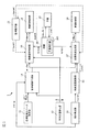
- FIG. 1 is a block diagram showing a remote parking system 1 to which the vehicle remote control method and the vehicle remote control device of the present invention are applied.
- the "autonomous driving control” means that the vehicle is driven by the automatic control of the on-board driving control device without depending on the driving operation of the driver.
- “Autonomous parking control” is a kind of autonomous driving control, and means that a vehicle is parked (entered or exited) by automatic control of an on-board driving control device without depending on a driver's driving operation.
- “parking” means to continuously park the vehicle in the parking space, but in the case of “traveling route”, not only the parking route when entering the garage into the parking space, but also from the parking space. It shall also include the garage exit route.
- the "vehicle travel control method and vehicle travel control device during parking” includes both vehicle travel control when the vehicle is put into the parking space and vehicle travel control when the vehicle is taken out of the parking space. Is done.
- putting in the garage is also called warehousing, and taking out the garage is also called warehousing.
- the remote parking system 1 of the present embodiment performs autonomous driving control in an assist mode in which an operator such as a driver can get on the vehicle and perform an intervention operation of the operator. After that, the operator gets off the vehicle and performs autonomous driving control from the outside of the vehicle in a remote control mode using a remote controller.
- the remote parking system 1 of the present embodiment is a system that puts in or takes out the garage by autonomous driving control when putting in the garage in the parking space or taking out the garage from the parking space. More specifically, the driver disembarks in the middle of entering the garage, and while confirming safety, the vehicle continues autonomous parking control by continuously transmitting an execution command signal to the vehicle by a remote controller. Then, when the vehicle may collide with an obstacle, the autonomous parking control is stopped by stopping the transmission of the execution command signal by the remote controller.
- the autonomous driving control mode in which an operator such as a driver can get on the vehicle and perform an intervention operation by the operator is an assist mode, and an autonomous driving control mode in which the operator gets off and enters or leaves the garage together with remote control. Is called remote control mode.
- a remote control mode combined with remote control can be used.
- the driver When entering the garage in the remote control mode, the driver carries the remote controller and disembarks when the remote control mode is activated, the entry route to the selected parking space is calculated, and the autonomous parking control is started. .. The driver who got off the vehicle completes the garage entry by continuously transmitting the execution command signal to the vehicle by the remote controller.
- the remote parking system 1 of the present embodiment is a system including a remote control mode in which such remote control is used in combination.
- the backward autonomous parking control shown in FIG. 2 is illustrated as an example of the autonomous parking control, the present invention can also be applied to garage parking, columnar autonomous parking, and other autonomous parking.
- the remote parking system 1 of the present embodiment includes a target parking space setting device 11, a vehicle position detector 12, an object detector 13, a parking route generation unit 14, an object deceleration calculation unit 15, a route tracking control unit 16, and a target vehicle speed generation unit. 17.
- the steering angle control unit 18, the vehicle speed control unit 19, the master unit 20, the remote controller 21, and the slave unit 22 are provided.
- the unit 19 and the master unit 20 are mounted on the vehicle.
- the remote controller 21 and the slave unit 22 are possessed by an operator such as a driver. Each configuration will be described below.
- the target parking space setting device 11 searches for parking spaces existing around the own vehicle in the remote control mode, and causes the operator to select a desired parking space from the parking spaces that can be parked. Further, the target parking space setting device 11 outputs the position information of the selected parking space (relative position coordinates from the current position of the own vehicle, latitude / longitude, etc.) to the parking route generation unit 14.
- the target parking space setting device 11 is provided with an input switch, a plurality of cameras, a parking space detection unit, and a touch panel type display (none of which are shown) in order to exert the above-mentioned functions.
- the input switch alternately selects the remote control mode or the assist mode. Multiple cameras capture the surroundings of the vehicle.
- the camera of the target parking space setting device 11 may also be used as the camera of the object detector 13 described later.
- the parking space detection unit is a computer on which a software program for detecting a parking space that can be parked from image data taken by a plurality of cameras is installed.
- the touch panel type display is used for displaying the detected parking space and selecting the parking space.
- the target parking space setting device 11 acquires image data around the own vehicle by a plurality of cameras, analyzes the image data, and allows parking. Detect spaces. Further, the target parking space setting device 11 displays an image including a parking space that can be parked on the touch panel display, and prompts the operator to select a parking space in which the vehicle is to be parked. When the operator selects a desired parking space from the displayed parking spaces, the target parking space setting device 11 outputs the position information of the parking space to the parking route generation unit 14. When searching for a parking space that can be parked, if the map information of the navigation device includes parking lot information having detailed position information, the parking lot information may be used.
- the vehicle position detector 12 is composed of a GPS unit, a gyro sensor, a vehicle speed sensor, and the like.
- the GPS unit detects radio waves transmitted from a plurality of satellite communications and periodically acquires the position information of the own vehicle.
- the vehicle position detector 12 detects the current position of the own vehicle based on the position information of the own vehicle acquired by the GPS unit, the angle change information acquired from the gyro sensor, and the vehicle speed acquired from the vehicle speed sensor.
- the position information of the own vehicle detected by the vehicle position detector 12 is output to the parking route generation unit 14 and the route tracking control unit 16 at predetermined time intervals.
- the object detector 13 searches for an object such as an obstacle in the vicinity of the own vehicle, and includes a camera, a radar (millimeter wave radar, laser radar, ultrasonic radar, etc.), a sonar, or the like. Alternatively, a combination of these is provided. These cameras, radars or sonars, or a combination thereof, are mounted on the outer skin around the vehicle.
- the mounting position of the object detector 13 is not particularly limited, but is, for example, all or a part of the center and both sides of the front bumper, the center and both sides of the rear bumper, the sill outer under the left and right center pillars, and the like. Can be attached to.
- the object detector 13 includes a computer in which a software program for identifying the position of an object detected by a camera, radar, or the like is installed.
- This computer uses the parking route generation unit 14 and the object deceleration calculation unit to obtain the specified object information (target information) and its position information (relative position coordinates from the current position of the own vehicle, latitude / longitude, etc.). Output to 15.
- These object information and position information are used by the parking route generation unit 14 to generate a parking route before the start of autonomous parking control. Further, the object information and the position information are used for the control of decelerating or stopping the own vehicle by the object deceleration calculation unit 15 when an object such as an unexpected obstacle is detected during the autonomous parking control.
- the parking route generation unit 14 calculates a parking route that is a parking route from the current position of the own vehicle to the target parking position (in the case of the remote control mode, it means a warehousing route; the same applies hereinafter) and does not collide with or interfere with an object. To do.
- the size of the own vehicle vehicle width, vehicle length, minimum turning radius, etc.
- the position information of the space are used.
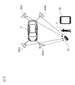
- FIG. 2 is a plan view showing an example of the remote control mode.
- the target parking space setting device 11 sets one parking space TPS. Search for and display an image containing this on the display.
- the parking route generation unit 14 determines the parking route R1 from the current position P1 to the turning position P3 and the parking route from the turning position P3 to the target parking space TPS. Calculate with R2. Then, the series of parking routes R1 and R2 are output to the route tracking control unit 16 and the target vehicle speed generation unit 17.
- the object deceleration calculation unit 15 inputs the position information of an obstacle or other object from the object detector 13, and based on the distance to the object and the vehicle speed, the time until the object collides with the object (TTC: Time to Collection). ) Is calculated, and the deceleration start timing of the own vehicle is calculated.
- TTC Time to Collection
- the object deceleration calculation unit 15 sets the vehicle speed as the initial setting value, and at the timing when the time TTC until the own vehicle V collides with the obstacle becomes equal to or less than the predetermined value. , Decelerate the vehicle speed of the own vehicle V. Further, when an unexpected obstacle is detected in the parking paths R1 and R2 during the series of autonomous parking control shown in FIG. 2, the time until the own vehicle V collides with the obstacle TTC is also obtained. Decelerates or stops the vehicle speed of the own vehicle V at the timing when becomes equal to or less than a predetermined value. This deceleration start timing is output to the target vehicle speed generation unit 17.
- the route tracking control unit 16 tracks the own vehicle along the parking route at predetermined time intervals based on the parking route from the parking route generation unit 14 and the current position of the own vehicle from the vehicle position detector 12. Calculate the target steering angle of. Regarding the parking paths R1 and R2 in FIG. 2, the route tracking control unit 16 sets the target steering angle of the parking path R1 that goes straight and turns right from the current position P1 to the turning position P3 for each current position of the own vehicle V. Calculate at predetermined time intervals. Similarly, the path tracking control unit 16 calculates the target steering angle of the parking path R2 that turns left and goes straight from the turning position P3 to the target parking space TPS at predetermined time intervals for each current position of the own vehicle V. The path tracking control unit 16 outputs the calculated target steering angle to the steering angle control unit 18.
- the target vehicle speed generation unit 17 is a target for following the own vehicle along the parking route at predetermined time intervals based on the parking route from the parking route generation unit 14 and the deceleration start timing from the object deceleration calculation unit 15. Calculate the vehicle speed. Regarding the parking routes R1 and R2 in FIG. 2, the target vehicle speed at the time of starting from the current position P1, going straight and turning right, and stopping at the turning position P3 is calculated at predetermined time intervals for each current position of the own vehicle V. Then, it is output to the vehicle speed control unit 19. Similarly, the target vehicle speed generation unit 17 starts (backward) again from the turning position P3 and stops close to the target vehicle speed when turning left to the middle of the target parking space TPS and the target parking space TPS.
- the target vehicle speed at the time of the operation is calculated for each current position of the own vehicle V at predetermined time intervals and output to the vehicle speed control unit 19. Further, when an unexpected obstacle is detected in the parking paths R1 and R2 during the series of autonomous parking control shown in FIG. 2, the object deceleration calculation unit 15 outputs the deceleration or stop timing. The target vehicle speed corresponding to this is output to the vehicle speed control unit 19.
- the steering angle control unit 18 generates a control signal for operating the steering actuator provided in the steering system of the own vehicle V based on the target steering angle from the path tracking control unit 16. Further, the vehicle speed control unit 19 generates a control signal for operating the accelerator actuator provided in the drive system of the own vehicle V based on the target vehicle speed from the target vehicle speed generation unit 17. By simultaneously controlling the steering angle control unit 18 and the vehicle speed control unit 19, autonomous parking control is executed.
- the international standard for autonomous driving control of a vehicle stipulates that the distance between the vehicle and the operator is within a predetermined remote control distance (for example, within 6 m) as a condition for allowing remote control of the vehicle. Therefore, in the remote parking system 1 of the present embodiment, the slave unit 22 possessed by the operator U and the master unit 20 mounted on the own vehicle V are used, and the relative position of the slave unit 22 with respect to the own vehicle V, that is, , Detects the relative position of the operator U who owns the slave unit 22 with respect to the own vehicle V.
- the slave unit 22 and the master unit 20 form a so-called keyless entry system.
- antennas 202a to 202d connected to the master unit 20 are installed at predetermined locations around the own vehicle V.
- the master unit 20 transmits a slave unit search signal from the antennas 202a to 202d.
- the slave unit 22 receives the slave unit search signal transmitted from each of the antennas 202a to 202d, and measures the radio field strength of the slave unit search signal of each antenna 202a to 202d. ..
- the radio field strength of the slave unit search signal changes depending on the distance between the slave unit 22 and the antennas 202a to 202d.
- the radio wave strength of the slave unit search signal received from the antenna 202b is the strongest, but is received from the antenna 202c near the right side of the rear bumper.
- the signal strength of the slave unit search signal is the weakest.
- the slave unit 22 transmits the radio wave strength of the slave unit search signal of each of the measured antennas 202a to 202d to the master unit 20.
- the position detector 201 of the master unit 20 is, for example, a computer in which a software program for calculating the position of the slave unit 22 from the radio wave strengths of the antennas 202a to 202d received from the slave unit 22 by using a triangulation method or the like is installed. Is.
- the position detector 201 is the relative position of the slave unit 22 with respect to the own vehicle V, that is, the operator U who owns the slave unit 22, based on the radio wave strength of the antennas 202a to 202d received from the slave unit 22.
- the position relative to the vehicle V is detected.
- the position detector 201 outputs the detected relative position of the slave unit 22 to the path tracking control unit 16 and the target vehicle speed generation unit 17 (or instead, the steering angle control unit 18 and the vehicle speed control unit 19 may be used). , Transmit to the remote controller 21.
- the remote controller 21 is a device for the operator U to command from outside the vehicle whether to continue or stop the execution of the autonomous parking control set by the target parking space setting device 11. Therefore, the remote controller 21 wirelessly communicates to transmit an execution command signal to the route tracking control unit 16 and the target vehicle speed generation unit 17 (or instead, the steering angle control unit 18 and the vehicle speed control unit 19 may be used). It has a function and communicates with the wireless communication function provided in the own vehicle V.
- the international standard for autonomous driving control of a vehicle stipulates that the vehicle should execute autonomous driving control only while the operator continuously operates the remote controller. Therefore, in the remote parking system 1 of the present embodiment, the execution command signal is continuously transmitted from the remote controller 21 to the own vehicle V only while a predetermined gesture is continuously input to the touch panel of the remote controller 21. Further, the own vehicle V executes the autonomous parking control only while receiving the execution command signal transmitted from the remote controller 21. That is, when the gesture is no longer detected by the remote controller 21 and the execution command signal is no longer transmitted, the execution of the autonomous parking control is interrupted or stopped.
- the remote controller 21 includes, for example, a mobile information terminal such as a smartphone on which application software for remote control (hereinafter referred to as an application) is installed.
- the smartphone on which the application is installed functions as the remote controller 21 of the remote parking system 1 by activating the application.
- some mobile information terminals such as smartphones are equipped with an operation automation function that records a touch operation on the touch panel 211 and repeatedly plays it back as standard, or those that can obtain an operation automation function by installing application software. is there.
- the remote control device 21 uses a mobile information terminal such as a smartphone, by inputting a gesture by the operation automation function, the operator does not actually input the gesture. Instead, there is a possibility that the autonomous parking control of the own vehicle V will be executed.
- the operator U places the slave unit 22 in the vicinity of the own vehicle V or on the roof of the own vehicle V, and remotely controls the slave unit 22 without possessing the slave unit 22.
- the own vehicle V When the operation automation function of the device 21 is activated and a gesture is input, the own vehicle V performs autonomous parking control at a position away from the operator U without the operation of the operator U.
- the remote parking system 1 of the present embodiment whether or not the gesture input to the remote controller 21 is input by the touch operation of the operator U in order to suppress the input of the gesture using the operation automation function. Is determined. Then, when the gesture is not input by the touch operation of the operator U, the execution of the autonomous parking control of the own vehicle V is interrupted or prohibited.
- the remote controller 21 includes a touch panel 211, a sensor 212, an information generation unit 213, a storage unit 214, a determination unit 215, a command unit 216, and a communication unit 217.
- the touch panel 211 detects the gesture input by the touch operation of the operator U.
- the sensor 212 detects the amount of change in the physical change that occurs in the remote controller 21.
- the information generation unit 213 generates the detection coordinate information based on the detection coordinates of the gesture detected by the touch panel 211.
- the information generation unit 213 generates operator transition information indicating a temporal transition of the change amount of the physical change of the remote controller 21 (a set or profile of the change amount of the change amount with respect to the time axis direction).
- the storage unit 214 stores the detection coordinate information, the command gesture information related to the preset command gesture, and the actuator transition information.
- the determination unit 215 compares the detected coordinate information with the command gesture information, and determines whether or not the gesture detected by the touch panel 211 is a command gesture. Further, the determination unit 215 compares the frequency characteristic of the detected coordinate information with the frequency characteristic of the actuator transition information to determine whether or not there is a correlation.
- the command unit 216 generates an execution command signal when the detected gesture is a command gesture and there is a correlation between the frequency characteristic of the detected coordinate information and the frequency characteristic of the operator transition information.
- the communication unit 217 transmits the execution command signal generated by the command unit 216 to the own vehicle V.
- the touch panel 211 a touch panel display of a smartphone that functions as a remote controller 21 is used.
- the touch panel 211 detects the gesture input by the touch operation of the operator U in the remote control mode.
- the gesture input to the touch panel 211 is a preset command gesture.
- a ring-shaped figure in which the start end at which one input of a gesture is started and the end at which one input of a gesture ends overlaps and is closed is set as a predetermined command gesture.
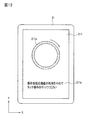
- an input guide 211a indicating the shape of a command gesture of a specified size is displayed on the touch panel 211 at the start of gesture input.
- a message such as "Please touch the displayed input guide along the direction of the arrow" is displayed.
- the input guide 211a may be hidden after it is determined that the input gesture is a command gesture.
- the sensor 212 is a so-called motion sensor such as an acceleration sensor, a gyro sensor, or an orientation sensor, which is provided in advance in a mobile information terminal that functions as a remote controller 21. Since the acceleration sensor, gyro sensor, and azimuth sensor are known sensors, detailed description thereof will be omitted.
- the amount of change in the posture of the remote controller 21 is detected as the amount of change in the physical change that occurs in the remote controller 21. For example, when the operator U inputs a gesture to the remote controller 21, one hand holds the remote controller 21 and the other hand inputs a gesture, or one hand holds the remote controller 21. Then enter the gesture with the thumb on the holding side.
- the posture of the remote controller 21 changes with the input of the gesture.
- the sensor 212 detects the amount of change in the posture of the remote controller 21 when the remote controller 21 remotely controls the own vehicle V.
- the information generation unit 213 functions by operating the CPU (Central Processing Unit) of the mobile information terminal that functions as the remote controller 21 according to the application.
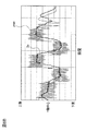
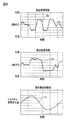
- the graphs shown in FIGS. 6A and 6B show an example of the detection value of the touch operation detected by the touch panel 211 when the operator U inputs a gesture to the touch panel 211.
- the horizontal axis represents time and the vertical axis represents the detected value xraw of the touch operation in the X-axis direction.
- the positive side of the vertical axis of the graph of FIG. 6A indicates the right side of the center line of the X axis of the touch panel 211, and the negative side indicates the left side of the center line of the X axis. Further, in the graph of FIG.
- the horizontal axis shows time and the vertical axis shows the detection value yraw of the touch operation in the Y-axis direction.
- the positive side of the vertical axis of the graph of FIG. 6B indicates the upper side of the touch panel 211 above the center line of the Y axis, and the negative side indicates the lower side of the center line of the Y axis. That is, the detected values xraw and yraw indicate the detection coordinates of the touch operation detected by the touch panel 211.
- the information generation unit 213 calculates the moving average values of the detected values xraw and yraw output from the touch panel 211, and uses the calculated moving average values as a set of changes in the detected coordinates over time (a set of changes in the detected coordinates with respect to the time axis direction).
- the detection coordinate information Dx and Dy indicating the profile) are stored in the storage unit 214.
- the information generation unit 213 generates the operator transition information indicating the temporal transition of the amount of change in the attitude of the remote controller 21 detected by the acceleration sensor, the gyro sensor, and the azimuth sensor of the sensor 212.
- the horizontal axis shows time
- the vertical axis shows the amount and direction of change in attitude of the remote controller 21 detected by the sensor 212.
- the information generation unit 213 extracts the posture change amount (hereinafter referred to as the gesture posture change amount) generated by the gesture input to the touch panel 211 from the composite posture change amount detected by the sensor 212, and the extracted gesture posture change amount.
- the amount is stored in the storage unit 214 as the operator transition information.
- the information generation unit 213 has a portion having frequency characteristics close to the frequency characteristics of the above-mentioned detection coordinate information Dx and Dy from the composite posture change amount P, for example, reference numeral E in FIG. 7A.
- the amount of change in posture indicated by is extracted as the amount of change in gesture posture.
- the extracted gesture posture change amount is stored in the storage unit 214 as the actuator transition information S.
- the method of extracting the gesture posture change amount from the compound posture change amount is not limited to the above method.
- the composite posture change amount is decomposed into a plurality of posture change amounts according to the frequency characteristics, and the posture change amount having a frequency characteristic close to the frequency characteristics of the detected coordinate information Dx and Dy from the decomposed plurality of posture change amounts. May be used as the operator transition information.
- the average posture change amount of the remote controller 21 generated by the gesture input is stored in the storage unit 214 as a sample in advance, and the gesture posture change amount is extracted from the composite posture change amount based on this sample. You may.
- the storage unit 214 is a storage such as a memory provided in advance in a mobile information terminal that functions as a remote controller 21.
- the storage unit 214 stores the above-mentioned detection coordinate information Dx and Dy and the actuator transition information S.
- the storage unit 214 stores command gesture information regarding the form, size, and the like of preset command gestures.
- the storage constituting the storage unit 214 stores operation automation information indicating the contents of the touch operation recorded by the operation automation function. This operation automation information corresponds to the detected coordinate information because it is information indicating the temporal transition of the input coordinates of the gesture detected by the touch panel 211 of the remote controller 21 at the time of recording the touch operation by the operation automation function.
- the determination unit 215 functions when the CPU of the smartphone, which functions as the remote controller 21, operates according to the application.
- the determination unit 215 acquires the detection coordinate information indicating the temporal transition of the detection coordinates of the gesture detected by the touch panel 211 from the storage unit 214. That is, when the operator U inputs a gesture to the touch panel 211, the determination unit 215 acquires the detection coordinate information Dx and Dy generated by the information generation unit 213, and inputs the gesture by the operation automation function. If so, the operation automation information is acquired as the detection coordinate information.
- the determination unit 215 compares the acquired detection coordinate information Dx and Dy with the command gesture information, and determines whether the gesture detected by the touch panel 211 is the command gesture or the input speed of the gesture is within a predetermined range. ..
- the input speed of the gesture is used for determining the command gesture in order to distinguish the gesture input when some object comes into contact with the touch panel 211 from the gesture of the operator U. Further, when the determination unit 215 acquires the operation automation information as the detection coordinate information, the operation automation information and the command gesture information are compared.
- the determination unit 215 determines whether or not the gesture input to the remote controller 21 is input by the touch operation of the operator U, in order to determine whether or not the gesture is input by the touch operation of the operator U.
- the presence or absence of correlation is determined by comparing with the frequency characteristics of the actuator transition information S.
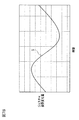
- FIG. 8 is a diagram comparing the above-mentioned detected coordinate information Dx and Dy with the actuator transition information S.
- the detected coordinate information Dx and the actuator transition information S have at least the same frequency characteristics such as period and wavelength. Therefore, the determination unit 215 determines that the detected coordinate information Dx and the actuator transition information S have a correlation. In this way, when the frequency characteristic of the detected coordinate information Dx and the frequency characteristic of the controller transition information S have a correlation, the touch panel 211 is gestured while the remote controller 21 is held by the operator U. Can be determined to have been entered.
- the determination unit 215 acquires the operation automation information from the storage unit 214 as the detection coordinate information. Further, when the gesture is input by the operation automation function, the posture change caused by the gesture input does not occur in the remote controller 21, so that the operator change information generated by the information generation unit 213 is the posture generated by the gesture input. Does not include the amount of change. Therefore, even if the determination unit 215 compares the frequency characteristics of the operation automation information with the frequency characteristics of the actuator transition information, no correlation is found. As a result, it is determined that the gesture has not been input by the operator U, and the execution command signal is not transmitted to the own vehicle V, so that the gesture input by the operation automation function can be suppressed.
- the command unit 216 functions when the CPU of the smartphone, which functions as the remote controller 21, operates according to the application.
- the command unit 216 uses the autonomous travel control function for the own vehicle V. Generates an execution command signal to execute autonomous parking control.
- the command unit 217 outputs the generated execution command signal to the communication unit 216.
- the communication unit 217 uses the communication function provided in advance by the smartphone that functions as the remote controller 21.
- the communication unit 217 is, for example, a wireless communication unit such as Bluetooth (registered trademark), and is connected to a wireless communication unit (not shown) mounted on the own vehicle V in the remote control mode.
- the communication unit 217 transmits the execution command signal generated by the command unit 216 to the own vehicle V.
- a wireless LAN Local Area Network
- Wi-Fi registered trademark
- a mobile phone line or the like may be used as the communication unit 217.
- the execution command signal transmitted to the own vehicle V is input to the route tracking control unit 16 and the target vehicle speed generation unit 17. Further, as described above, the relative positions of the own vehicle V and the slave unit 22 are input from the position detector 201 to the route tracking control unit 16 and the target vehicle speed generation unit 17.
- the route tracking control unit 16 sends the steering angle control unit 18 to the steering angle control unit 18. Output the target steering angle.
- the target vehicle speed generation unit 17 is a vehicle speed control unit when the distance between the own vehicle V and the slave unit 22 is within the remote control distance and the execution command signal from the remote controller 21 is input.
- the target vehicle speed is output to 19.
- the steering angle control unit 18 generates a control signal for operating the steering actuator provided in the steering system of the own vehicle V based on the target steering angle from the path tracking control unit 16. Further, the vehicle speed control unit 19 generates a control signal for operating the accelerator actuator provided in the drive system of the own vehicle V based on the target vehicle speed from the target vehicle speed generation unit 17.
- the route tracking control unit 16 is in the case where the execution command signal from the remote controller 21 is input.
- the target steering angle is not output to the steering angle control unit 18.
- the target vehicle speed generation unit 17 is a place where an execution command signal from the remote controller 21 is input when the distance between the own vehicle V and the slave unit 22 is longer than the remote control distance.
- the target vehicle speed is not output to the vehicle speed control unit 19. That is, when the distance between the own vehicle V and the slave unit 22 is farther than the remote control distance, the autonomous parking control is not executed even if the command gesture is input from the remote control device 21.
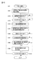
- FIG. 9 is a flowchart showing a control procedure executed by the remote parking system 1 of the present embodiment.
- FIG. 10 is a flowchart showing a procedure of detecting and determining a gesture in the remote controller 21 and transmitting an execution command signal.
- step S1 when the own vehicle V arrives at the position P1 near the target parking space TPS, in step S1 shown in FIG. 9, the operator U such as the driver performs the remote parking of the on-board target parking space setting device 11. Turn on the start switch and select the remote warehousing mode.
- the target parking space setting device 11 searches for a parking space in which the own vehicle V can park using a plurality of on-board cameras, and whether or not there is a parking space in step S3. To judge. If there is a parking space that can be parked, the process proceeds to step S4, and if there is no parking space that can be parked, the process returns to step S1. If the parking space that can be parked is not detected in step S2, the operator may be notified by a language display such as "There is no parking space" or by voice, and this process may be terminated.
- step S4 the target parking space setting device 11 displays the parking space that can be parked on the in-vehicle display, prompts the operator U to select the desired parking space, and the operator U selects a specific parking space TPS. Then, the target parking position information is output to the parking route generation unit 14.
- step S5 the parking route generation unit 14 generates the parking routes R1 and R2 shown in FIG. 2 from the current position P1 of the own vehicle V and the parking space TPS which is the target parking position.
- the object deceleration calculation unit 15 calculates the deceleration start timing at the time of autonomous parking control based on the object information detected by the object detector 13.
- the parking routes R1 and R2 generated by the parking route generation unit 14 are output to the route tracking control unit 16, and the deceleration start timing calculated by the object deceleration calculation unit 15 is output to the target vehicle speed generation unit 17.
- step S6 the operator is urged to consent to the start of the autonomous parking control, and when the operator approves the start, the autonomous driving control by the assist mode is started.
- the vehicle moves forward from the current position P1 by turning right once, and when it reaches the turning position P3, it reverses by turning left to the intermediate stop position P4.
- step S7 since the position of the own vehicle V has reached the intermediate stop position P4, the own vehicle V is stopped and the operator U is urged to disembark.
- the operator U activates the remote controller 21 in step S8.
- the start input of the remote control by the remote controller 21 includes the activation of the application installed on the remote controller 21, the door unlocking operation, the door locking and unlocking operation, and the combination of these and the application activation. Can be exemplified.
- step S9 the own vehicle V is in a stopped state.
- step S9 the pairing process of the remote controller 21 and the own vehicle V is performed.
- the own vehicle V authenticates the remote controller 21 and can accept the command by the pairing process in step S9
- the remote operation is started in step S10.
- the detection of the relative position of the slave unit 22 with respect to the own vehicle V that is, the relative position of the operator U who owns the slave unit 22 is started in step S101 of FIG.
- the slave unit 22 receives the slave unit search signals transmitted from the antennas 202a to 202d of the own vehicle V, and measures the radio wave intensity of the slave unit search signals of the antennas 202a to 202d.
- the slave unit 22 transmits the measured radio field strength of the slave unit search signal to the master unit 20.
- the position detector 201 of the master unit 20 detects the relative position of the slave unit 22 with respect to the own vehicle V based on the radio wave strength of the antennas 202a to 202d received from the slave unit 22.
- the relative position of the operator U with respect to the own vehicle V can be detected.
- the position detector 201 outputs the detected relative position to the route tracking control unit 16 and the target vehicle speed generation unit 17 (or, instead, the steering angle control unit 18 and the vehicle speed control unit 19 may be used), and the remote controller 201. Send to 21.
- step S102 the remote controller 21 proceeds to step S103 to confirm the gesture input when the distance between the own vehicle V and the slave unit 22 is within the predetermined remote control distance. .. If the distance between the own vehicle V and the slave unit 22 is not within the predetermined remote control distance in step S102, a message such as "Please approach within 6 m of the vehicle" is sent to the touch panel 211. Is displayed.
- the determination unit 215 receives the detection coordinate information indicating the temporal transition of the gesture detection coordinates detected by the touch panel 211 from the storage unit 214 in the next step S104. get. That is, when the operator U is inputting a gesture on the touch panel 211, the detection coordinate information Dx and Dy generated by the information generation unit 213 are acquired, and when the gesture is input by the operation automation function. , Acquire operation automation information as detection coordinate information.
- the information generation unit 213 extracts the posture change amount generated by the gesture input to the touch panel 211 from the composite posture change amount detected by the sensor 212, and uses the extracted posture change amount as the controller. It is stored in the storage unit 214 as the transition information S.
- step S106 the determination unit 215 compares the detection coordinate information Dx and Dy acquired from the storage unit 214 with the command gesture information, and determines whether or not the gesture detected by the touch panel 211 is the command gesture. Further, when the input gesture is a command gesture, the determination unit 215 determines in the next step S107 whether or not the input speed of the gesture is within a predetermined range. The determination unit 215 determines that the command gesture has been input when the input gesture is a command gesture and the input speed is within a predetermined range. When the determination unit 215 acquires the operation automation information as the detection coordinate information, the determination unit 215 compares the operation automation information with the command gesture information. Since the operation automation information records the touch operation of an appropriate gesture determined to be a command gesture for the automatic input of the gesture, the determination unit 215 determines that the gesture is a command gesture.
- the process proceeds to the next step S108, and the determination unit 215 compares the frequency characteristic of the detected coordinate information with the frequency characteristic of the operator transition information S to determine whether or not there is a correlation. judge.
- the detection coordinate information acquired by the determination unit 215 is the detection coordinate information Dx and Dy generated by the operator U inputting a gesture on the touch panel 211, for example, as shown in FIG. 8, the detection coordinates The information Dx and the operator transition information S have at least the same frequency characteristics such as period and wavelength. Therefore, the determination unit 215 determines that the detected coordinate information Dx and the actuator transition information S have a correlation.
- the command unit 216 issues an execution command in the next step S109.
- a signal is generated, and an execution command signal is transmitted from the communication unit 217 to the own vehicle V.
- the process returns to step S104 to repeat the gesture determination and the transmission of the execution command signal.
- the determination unit 215 acquires the operation automation information from the storage unit 214 instead of the detection coordinate information Dx and Dy. .. Further, since the remote controller 21 does not generate the attitude change caused by the gesture input, the operator change information generated by the information generation unit 213 does not include the frequency characteristic indicating the amount of the attitude change caused by the gesture input. .. Therefore, in step S108, the determination unit 215 compares the operation automation information with the actuator transition information S and determines that there is no correlation, so that the execution command signal is not transmitted to the own vehicle V.
- the route tracking control unit 16 receives an execution command signal from the remote controller 21 while the distance between the own vehicle V and the slave unit 22 is within the remote control distance. If so, the target steering angle is output to the steering angle control unit 18.
- the target vehicle speed generation unit 17 controls the vehicle speed when the distance between the own vehicle V and the slave unit 22 is within the remote control distance and the execution command signal from the remote controller 21 is input.
- the target vehicle speed is output to the unit 19.
- the steering angle control unit 18 generates a control signal for operating the steering actuator provided in the steering system of the own vehicle V based on the target steering angle from the path tracking control unit 16.
- the vehicle speed control unit 19 generates a control signal for operating the accelerator actuator provided in the drive system of the own vehicle V based on the target vehicle speed from the target vehicle speed generation unit 17.
- autonomous parking control is executed in the next step S12.
- step S10 The processes from step S10 to step S13, which will be described later, are executed at predetermined time intervals until the own vehicle V arrives at the target parking space TPS in step S13.
- step S13 it is determined whether or not the own vehicle V has arrived at the target parking space TPS, and if it has not arrived, the process returns to step S10, and when the own vehicle V arrives at the target parking space TPS. Stops the own vehicle V and ends the process.
- the travel route from the current position P1 of the own vehicle V to the intermediate stop position P4 executes autonomous travel control in the assist mode, and the travel route from the intermediate stop position P4 to the target parking space TPS is in the remote control mode. Executes autonomous driving control by.
- the remote parking system 1 when the own vehicle V having the autonomous traveling control function is remotely controlled by the remote controller 21, it is remote.
- the detection coordinate information Dx and Dy indicating the temporal transition of the detection coordinates of the gesture detected by the touch panel 211 of the controller 21 are acquired, and the amount of change in the physical change occurring in the remote controller 21 is detected to determine the amount of change.
- the operator transition information S indicating the temporal transition is generated.
- the frequency characteristics of the detected coordinate information Dx and Dy are compared with the frequency characteristics of the controller transition information S to determine whether or not there is a correlation, and if there is a correlation, autonomous driving control is executed on the own vehicle V. Let me.
- the operation automation information is acquired as the detection coordinate information, it is detected that the detection coordinates of the gesture detected by the touch panel 211 are changed by the operation automation information, but the remote controller Since the physical change of 21 does not occur, the frequency characteristic of the operation automation information and the frequency characteristic of the actuator transition information S have no correlation, and the gesture is input by the touch operation of the operator U. It can be judged that there is no such thing.
- the execution command signal is not transmitted to the own vehicle V, so that the gesture input by the operation automation function can be suppressed.
- the change in posture that occurs in the remote controller 21 is used as the physical change that occurs in the remote controller 21, it is determined whether or not the operator U is inputting the gesture while holding the remote controller 21. It is possible to suppress the input of gestures by the operation automation function.
- the gesture is a preset command gesture
- the frequency characteristic of the detected coordinate information is compared with the frequency characteristic of the operator transition information to determine the correlation. Determine the presence or absence.
- the own vehicle V is made to execute the autonomous traveling control. As a result, it is possible to urge the operator U to input a predetermined command gesture by a touch operation, and it is possible to suppress the input of the gesture by the operation automation function.
- the remote control device 21 a mobile information terminal that functions as the remote control device 21 by processing the installed application software is used, and a physical change that occurs in the remote control device 21 is detected by a sensor provided in advance in the mobile information terminal. doing. As a result, it is not necessary to newly provide a sensor in the remote controller 21, which is low cost.
- the own vehicle V when the gesture is no longer detected, the own vehicle V is stopped from the autonomous parking control. Therefore, the operation for causing the own vehicle V to stop the autonomous parking control becomes unnecessary, and the remote control of the own vehicle V becomes easy.
- Second Embodiment a second embodiment of the remote parking system to which the vehicle remote control method and the vehicle remote control device of the present invention are applied will be described.
- the same reference numerals as those of the first embodiment will be used for the same configurations as those of the first embodiment, and detailed description thereof will be omitted.
- the change in pressure applied to the touch panel 211 is used as the physical change that occurs in the remote controller 21.
- the sensor 212 includes a pressure sensor that detects the pressure of the touch panel 211
- the change in the pressure applied to the touch panel 211 uses the detection value of the pressure sensor.
- the touch panel 211 is a pressure-sensitive touch panel, or when the touch panel 211 is provided with a pressure sensor, the detected value detected by the touch panel 211 may be used.
- the pressure of the touch operation is not constant, and the pressure may be high at a position where the touch operation is easy and low at a position where the touch operation is difficult. ..
- the pressure may be unconsciously increased in order to reliably perform the touch operation, and in a position where touch operation is easy, the pressure may be decreased.
- the pressure of the touch operation at the time of gesture input varies depending on the method of holding the remote controller 21 of the operator U, the habit of the touch operation, and the like.
- steps S101 to S104 proceed in the same procedure as in the first embodiment, but in step S105a, the amount of change in pressure applied to the touch panel 211 is detected.
- the information generation unit 213 generates actuator transition information indicating the temporal transition of the amount of change.
- the determination unit 215 compares the frequency characteristics of the detected coordinate information with the frequency characteristics of the actuator transition information to determine whether or not there is a correlation. ..
- the command unit 216 when there is a correlation between the frequency characteristic of the detected coordinate information and the frequency characteristic of the actuator transition information, in step S109, the command unit 216 generates an execution command signal, and the communication unit 217 generates the own vehicle. Send to V. Further, if there is no correlation between the frequency characteristic of the detected coordinate information and the frequency characteristic of the operator transition information, the execution command signal is not transmitted to the own vehicle V.
- the first embodiment and the second embodiment it is necessary to input gestures a plurality of times in order to generate the actuator transition information. That is, in order to accurately generate the actuator transition information, it is necessary to increase the sampling number of the change amount of the physical change of the remote controller 21, so that the start of the autonomous parking control of the own vehicle V is delayed. In the present embodiment, such a problem is solved so that the autonomous parking control of the own vehicle V can be started quickly.
- steps S121 to S124 are the same processes as steps S101 to S104 of the first embodiment shown in FIG. Further, steps S125 to S127 are the same processes as steps S106, S107 and S109 of the first embodiment. That is, in the present embodiment, the determination unit 215 first determines whether or not the input gesture is a command gesture, and if the input gesture is a command gesture, the command unit 216 determines whether or not the input gesture is a command gesture. A signal is generated and transmitted to the own vehicle V by the communication unit 217.
- the information generation unit 213 may generate the operator mutation information from the amount of change in the posture of the remote controller 21, or FIG. 11
- the actuator mutation information may be generated from the change in the pressure applied to the touch panel 211.
- step S129 similarly to step S108 of the first embodiment shown in FIG. 10, the determination unit 215 compares the frequency characteristic of the detected coordinate information with the frequency characteristic of the actuator transition information and has a correlation. To judge. Then, when there is a correlation between the frequency characteristic of the detected coordinate information and the frequency characteristic of the actuator transition information, the generation and transmission of the execution command signal are continued in step S130. If there is no correlation between the frequency characteristic of the detected coordinate information and the frequency characteristic of the actuator transition information, the generation and transmission of the execution command signal are stopped in step S131.
- the gesture is a preset command gesture
- the own vehicle V is made to execute autonomous driving control. Then, after the autonomous travel control is executed by the own vehicle V, the frequency characteristic of the detected coordinate information is compared with the frequency characteristic of the operator transition information to determine whether or not there is a correlation. The vehicle V is allowed to continue the autonomous driving control, and if there is no correlation, the autonomous driving control is stopped. As a result, the autonomous parking control of the own vehicle V can be started quickly.
- the gesture input is not performed by the touch operation of the operator U but is performed by the operation automation function after the start of the autonomous parking control of the own vehicle V, the autonomous parking control of the own vehicle V is performed. Since it is canceled, it is possible to suppress the input of gestures by the operation automation function.
- the autonomous driving control of the own vehicle V is not executed.
- the operator U may be instructed to input a gesture by a touch operation.
- guidance information 211b such as "Please stop using the operation automation function and perform a touch operation" is displayed on the touch panel 211 of the remote controller 21.
- the guidance information 211b may be presented by voice, or the voice and the display by the touch panel 211 may be used in combination.
Landscapes
- Engineering & Computer Science (AREA)
- Physics & Mathematics (AREA)
- Theoretical Computer Science (AREA)
- General Physics & Mathematics (AREA)
- General Engineering & Computer Science (AREA)
- Automation & Control Theory (AREA)
- Computing Systems (AREA)
- Mathematical Physics (AREA)
- Aviation & Aerospace Engineering (AREA)
- Radar, Positioning & Navigation (AREA)
- Remote Sensing (AREA)
- Human Computer Interaction (AREA)
- Mechanical Engineering (AREA)
- Transportation (AREA)
- Control Of Position, Course, Altitude, Or Attitude Of Moving Bodies (AREA)
- Selective Calling Equipment (AREA)
Abstract
L'invention concerne, lorsqu'un véhicule hôte (V) ayant une fonction de commande de déplacement autonome est commandé à distance par un dispositif de commande à distance (21), des informations de coordonnées détectées (Dx, Dy) indiquant une transition temporelle dans des coordonnées détectées d'un geste détecté par un panneau tactile (211) du dispositif de commande à distance (21) étant obtenues, une quantité de changement d'un changement physique survenant dans le dispositif de commande à distance (21) étant détectée, et des informations de transition de dispositif de commande (S) indiquant un changement temporel dans la quantité de changement étant obtenues. Ensuite, des caractéristiques de fréquence des informations de coordonnées détectées (Dx, Dy) et des caractéristiques de fréquence des informations de transition de dispositif de commande (S) sont comparées pour déterminer s'il existe ou non une corrélation, et lorsqu'il y a une corrélation, le véhicule hôte (V) est amené à exécuter une commande de déplacement autonome.
Priority Applications (5)
| Application Number | Priority Date | Filing Date | Title |
|---|---|---|---|
| PCT/IB2019/001028 WO2021048580A1 (fr) | 2019-09-09 | 2019-09-09 | Procédé de commande de véhicule à distance et dispositif de commande de véhicule à distance |
| EP19944650.1A EP4029748B1 (fr) | 2019-09-09 | 2019-09-09 | Procédé de commande de véhicule à distance et dispositif de commande de véhicule à distance |
| JP2021544946A JP7276471B2 (ja) | 2019-09-09 | 2019-09-09 | 車両遠隔制御方法及び車両遠隔制御装置 |
| US17/641,282 US11619934B2 (en) | 2019-09-09 | 2019-09-09 | Vehicle remote control method and vehicle remote control device |
| CN201980100163.8A CN114630774B (zh) | 2019-09-09 | 2019-09-09 | 车辆远程控制方法及车辆远程控制装置 |
Applications Claiming Priority (1)
| Application Number | Priority Date | Filing Date | Title |
|---|---|---|---|
| PCT/IB2019/001028 WO2021048580A1 (fr) | 2019-09-09 | 2019-09-09 | Procédé de commande de véhicule à distance et dispositif de commande de véhicule à distance |
Publications (1)
| Publication Number | Publication Date |
|---|---|
| WO2021048580A1 true WO2021048580A1 (fr) | 2021-03-18 |
Family
ID=74865688
Family Applications (1)
| Application Number | Title | Priority Date | Filing Date |
|---|---|---|---|
| PCT/IB2019/001028 WO2021048580A1 (fr) | 2019-09-09 | 2019-09-09 | Procédé de commande de véhicule à distance et dispositif de commande de véhicule à distance |
Country Status (5)
| Country | Link |
|---|---|
| US (1) | US11619934B2 (fr) |
| EP (1) | EP4029748B1 (fr) |
| JP (1) | JP7276471B2 (fr) |
| CN (1) | CN114630774B (fr) |
| WO (1) | WO2021048580A1 (fr) |
Families Citing this family (5)
| Publication number | Priority date | Publication date | Assignee | Title |
|---|---|---|---|---|
| FI128506B (en) * | 2019-01-28 | 2020-06-30 | Elisa Oyj | Automatic network deployment |
| DE102020110909A1 (de) * | 2020-04-22 | 2021-10-28 | HELLA GmbH & Co. KGaA | Fernbedienungssystem für ein Fahrzeug und Verfahren zu dessen Betrieb |
| JP7287346B2 (ja) * | 2020-05-21 | 2023-06-06 | トヨタ自動車株式会社 | 自動バレー駐車システム |
| US20220379882A1 (en) * | 2021-05-28 | 2022-12-01 | Jaguar Land Rover Limited | Apparatus and method for controlling vehicle movement |
| JP2023005105A (ja) * | 2021-06-28 | 2023-01-18 | トヨタ自動車株式会社 | リモート駐車装置 |
Citations (3)
| Publication number | Priority date | Publication date | Assignee | Title |
|---|---|---|---|---|
| JP2016074285A (ja) * | 2014-10-03 | 2016-05-12 | 本田技研工業株式会社 | 車両遠隔操作システム |
| US20160170494A1 (en) | 2013-07-26 | 2016-06-16 | Daimler Ag | Method and device for remote control of a function of a vehicle |
| JP2019061686A (ja) * | 2017-09-22 | 2019-04-18 | 株式会社パークランド | 駐車場管理方法 |
Family Cites Families (14)
| Publication number | Priority date | Publication date | Assignee | Title |
|---|---|---|---|---|
| US7999797B2 (en) * | 2006-12-26 | 2011-08-16 | Sony Ericsson Mobile Communications Ab | Detecting and locating a touch or a tap on an input surface |
| US8677287B2 (en) * | 2008-12-04 | 2014-03-18 | Mitsubishi Electric Corporation | Display input device and navigation device |
| US8633901B2 (en) * | 2009-01-30 | 2014-01-21 | Blackberry Limited | Handheld electronic device having a touchscreen and a method of using a touchscreen of a handheld electronic device |
| US20100201615A1 (en) * | 2009-02-12 | 2010-08-12 | David John Tupman | Touch and Bump Input Control |
| US8866735B2 (en) * | 2010-12-16 | 2014-10-21 | Motorla Mobility LLC | Method and apparatus for activating a function of an electronic device |
| US8982045B2 (en) * | 2010-12-17 | 2015-03-17 | Microsoft Corporation | Using movement of a computing device to enhance interpretation of input events produced when interacting with the computing device |
| JP6221265B2 (ja) * | 2013-03-04 | 2017-11-01 | 株式会社デンソー | タッチパネル操作装置及びタッチパネル操作装置における操作イベント判定方法 |
| KR20150001130A (ko) * | 2013-06-26 | 2015-01-06 | 삼성전자주식회사 | 사용자 입력 처리 방법 및 상기 방법이 적용된 장치 |
| GB2521467A (en) * | 2013-12-20 | 2015-06-24 | Univ Newcastle | Enhanced user interaction with a device |
| US9440660B2 (en) * | 2014-07-22 | 2016-09-13 | Toyota Motor Engineering & Manufacturing North America, Inc. | Method for remote communication with and through a vehicle |
| CN105242870A (zh) * | 2015-10-30 | 2016-01-13 | 小米科技有限责任公司 | 具有触摸屏的终端的防误触方法及装置 |
| JP6543185B2 (ja) * | 2015-12-22 | 2019-07-10 | クラリオン株式会社 | 車載装置 |
| JP2018127066A (ja) | 2017-02-07 | 2018-08-16 | 三菱自動車工業株式会社 | 駐車支援装置 |
| JP7298699B2 (ja) * | 2019-09-09 | 2023-06-27 | 日産自動車株式会社 | 車両遠隔制御方法及び車両遠隔制御装置 |
-
2019
- 2019-09-09 EP EP19944650.1A patent/EP4029748B1/fr active Active
- 2019-09-09 US US17/641,282 patent/US11619934B2/en active Active
- 2019-09-09 CN CN201980100163.8A patent/CN114630774B/zh active Active
- 2019-09-09 JP JP2021544946A patent/JP7276471B2/ja active Active
- 2019-09-09 WO PCT/IB2019/001028 patent/WO2021048580A1/fr unknown
Patent Citations (4)
| Publication number | Priority date | Publication date | Assignee | Title |
|---|---|---|---|---|
| US20160170494A1 (en) | 2013-07-26 | 2016-06-16 | Daimler Ag | Method and device for remote control of a function of a vehicle |
| JP2016538780A (ja) * | 2013-07-26 | 2016-12-08 | ダイムラー・アクチェンゲゼルシャフトDaimler AG | 車両の機能を遠隔制御する方法及び装置 |
| JP2016074285A (ja) * | 2014-10-03 | 2016-05-12 | 本田技研工業株式会社 | 車両遠隔操作システム |
| JP2019061686A (ja) * | 2017-09-22 | 2019-04-18 | 株式会社パークランド | 駐車場管理方法 |
Non-Patent Citations (1)
| Title |
|---|
| See also references of EP4029748A4 |
Also Published As
| Publication number | Publication date |
|---|---|
| EP4029748B1 (fr) | 2024-01-10 |
| US11619934B2 (en) | 2023-04-04 |
| EP4029748A1 (fr) | 2022-07-20 |
| US20220365527A1 (en) | 2022-11-17 |
| CN114630774B (zh) | 2023-06-02 |
| JPWO2021048580A1 (fr) | 2021-03-18 |
| JP7276471B2 (ja) | 2023-05-18 |
| EP4029748A4 (fr) | 2022-10-12 |
| CN114630774A (zh) | 2022-06-14 |
Similar Documents
| Publication | Publication Date | Title |
|---|---|---|
| WO2021048580A1 (fr) | Procédé de commande de véhicule à distance et dispositif de commande de véhicule à distance | |
| US20140244073A1 (en) | Vehicle including automatic steering portion | |
| US12093033B2 (en) | Vehicle remote control method and vehicle remote control device | |
| US11305757B2 (en) | Vehicle travel control method and vehicle travel control device | |
| CN113815604A (zh) | 车载装置及控制方法 | |
| CN111527010A (zh) | 驻车控制方法以及驻车控制装置 | |
| US20230012530A1 (en) | Remote parking system and parking assistance control apparatus used therein | |
| EP4105108B1 (fr) | Procédé et système de contrôle d'une commande de fonctionnement de véhicule initiée par l'utilisateur | |
| WO2021048586A1 (fr) | Procédé de commande à distance de véhicule et dispositif de commande à distance de véhicule | |
| JPWO2020115517A1 (ja) | 駐車時の車両走行制御方法及び車両走行制御装置 | |
| RU2795171C1 (ru) | Способ и устройство дистанционного управления транспортным средством | |
| JP7206103B2 (ja) | 車両走行制御方法及び車両走行制御装置 | |
| WO2021048891A1 (fr) | Corps mobile et procédé de commande de corps mobile | |
| RU2795181C1 (ru) | Способ дистанционного управления транспортным средством и устройство дистанционного управления транспортным средством | |
| JP2020091506A (ja) | 駐車時の車両走行制御方法及び車両走行制御装置 | |
| JP2020144791A (ja) | 車両制御システム、車両制御方法、及びプログラム | |
| US11420620B1 (en) | Vehicle parking assistance systems and methods | |
| CN117565897A (zh) | 一种泊车出库方法、装置、电子设备及存储介质 |
Legal Events
| Date | Code | Title | Description |
|---|---|---|---|
| 121 | Ep: the epo has been informed by wipo that ep was designated in this application |
Ref document number: 19944650 Country of ref document: EP Kind code of ref document: A1 |
|
| ENP | Entry into the national phase |
Ref document number: 2021544946 Country of ref document: JP Kind code of ref document: A |
|
| NENP | Non-entry into the national phase |
Ref country code: DE |
|
| ENP | Entry into the national phase |
Ref document number: 2019944650 Country of ref document: EP Effective date: 20220411 |