WO2021048580A1 - Vehicle remote control method and vehicle remote control device - Google Patents
Vehicle remote control method and vehicle remote control device Download PDFInfo
- Publication number
- WO2021048580A1 WO2021048580A1 PCT/IB2019/001028 IB2019001028W WO2021048580A1 WO 2021048580 A1 WO2021048580 A1 WO 2021048580A1 IB 2019001028 W IB2019001028 W IB 2019001028W WO 2021048580 A1 WO2021048580 A1 WO 2021048580A1
- Authority
- WO
- WIPO (PCT)
- Prior art keywords
- vehicle
- gesture
- information
- remote controller
- detected
- Prior art date
Links
- 238000000034 method Methods 0.000 title claims description 43
- 230000008859 change Effects 0.000 claims abstract description 87
- 230000007704 transition Effects 0.000 claims abstract description 66
- 230000002123 temporal effect Effects 0.000 claims abstract description 17
- 238000001514 detection method Methods 0.000 claims description 46
- 230000006870 function Effects 0.000 claims description 46
- 238000012545 processing Methods 0.000 claims description 3
- 230000001276 controlling effect Effects 0.000 claims 2
- 230000002596 correlated effect Effects 0.000 claims 1
- 238000004891 communication Methods 0.000 description 18
- 230000008569 process Effects 0.000 description 12
- 239000002131 composite material Substances 0.000 description 6
- 238000010586 diagram Methods 0.000 description 5
- 230000005540 biological transmission Effects 0.000 description 4
- 230000001133 acceleration Effects 0.000 description 3
- 238000013459 approach Methods 0.000 description 3
- 206010034719 Personality change Diseases 0.000 description 2
- 230000004913 activation Effects 0.000 description 2
- 150000001875 compounds Chemical class 0.000 description 2
- 239000000284 extract Substances 0.000 description 2
- 230000035772 mutation Effects 0.000 description 2
- 230000003213 activating effect Effects 0.000 description 1
- 238000002485 combustion reaction Methods 0.000 description 1
- 238000007796 conventional method Methods 0.000 description 1
- 230000003247 decreasing effect Effects 0.000 description 1
- 230000003111 delayed effect Effects 0.000 description 1
- 238000005070 sampling Methods 0.000 description 1
- 210000003813 thumb Anatomy 0.000 description 1
Images


Classifications
-
- G—PHYSICS
- G05—CONTROLLING; REGULATING
- G05D—SYSTEMS FOR CONTROLLING OR REGULATING NON-ELECTRIC VARIABLES
- G05D1/00—Control of position, course or altitude of land, water, air, or space vehicles, e.g. automatic pilot
- G05D1/0011—Control of position, course or altitude of land, water, air, or space vehicles, e.g. automatic pilot associated with a remote control arrangement
- G05D1/0016—Control of position, course or altitude of land, water, air, or space vehicles, e.g. automatic pilot associated with a remote control arrangement characterised by the operator's input device
-
- B—PERFORMING OPERATIONS; TRANSPORTING
- B60—VEHICLES IN GENERAL
- B60W—CONJOINT CONTROL OF VEHICLE SUB-UNITS OF DIFFERENT TYPE OR DIFFERENT FUNCTION; CONTROL SYSTEMS SPECIALLY ADAPTED FOR HYBRID VEHICLES; ROAD VEHICLE DRIVE CONTROL SYSTEMS FOR PURPOSES NOT RELATED TO THE CONTROL OF A PARTICULAR SUB-UNIT
- B60W30/00—Purposes of road vehicle drive control systems not related to the control of a particular sub-unit, e.g. of systems using conjoint control of vehicle sub-units, or advanced driver assistance systems for ensuring comfort, stability and safety or drive control systems for propelling or retarding the vehicle
- B60W30/06—Automatic manoeuvring for parking
-
- G—PHYSICS
- G06—COMPUTING; CALCULATING OR COUNTING
- G06F—ELECTRIC DIGITAL DATA PROCESSING
- G06F3/00—Input arrangements for transferring data to be processed into a form capable of being handled by the computer; Output arrangements for transferring data from processing unit to output unit, e.g. interface arrangements
- G06F3/01—Input arrangements or combined input and output arrangements for interaction between user and computer
- G06F3/017—Gesture based interaction, e.g. based on a set of recognized hand gestures
-
- G—PHYSICS
- G06—COMPUTING; CALCULATING OR COUNTING
- G06F—ELECTRIC DIGITAL DATA PROCESSING
- G06F3/00—Input arrangements for transferring data to be processed into a form capable of being handled by the computer; Output arrangements for transferring data from processing unit to output unit, e.g. interface arrangements
- G06F3/01—Input arrangements or combined input and output arrangements for interaction between user and computer
- G06F3/048—Interaction techniques based on graphical user interfaces [GUI]
- G06F3/0487—Interaction techniques based on graphical user interfaces [GUI] using specific features provided by the input device, e.g. functions controlled by the rotation of a mouse with dual sensing arrangements, or of the nature of the input device, e.g. tap gestures based on pressure sensed by a digitiser
- G06F3/0488—Interaction techniques based on graphical user interfaces [GUI] using specific features provided by the input device, e.g. functions controlled by the rotation of a mouse with dual sensing arrangements, or of the nature of the input device, e.g. tap gestures based on pressure sensed by a digitiser using a touch-screen or digitiser, e.g. input of commands through traced gestures
-
- G—PHYSICS
- G06—COMPUTING; CALCULATING OR COUNTING
- G06F—ELECTRIC DIGITAL DATA PROCESSING
- G06F2203/00—Indexing scheme relating to G06F3/00 - G06F3/048
- G06F2203/038—Indexing scheme relating to G06F3/038
- G06F2203/0381—Multimodal input, i.e. interface arrangements enabling the user to issue commands by simultaneous use of input devices of different nature, e.g. voice plus gesture on digitizer
Definitions
- the present invention relates to a vehicle remote control method and a vehicle remote control device for autonomously traveling a vehicle having an autonomous travel control function by remote control.
- An object to be solved by the present invention is to provide a vehicle remote control method and a vehicle remote control device capable of determining whether or not a gesture is input by an operator.
- the detection coordinate information indicating the temporal transition of the gesture detection coordinates detected by the touch panel of the remote controller is acquired and remotely controlled.
- the amount of change in the physical change that occurs in the actuator is detected, and the operator transition information indicating the temporal transition of this amount of change is acquired.
- the frequency characteristic of the detected coordinate information is compared with the frequency characteristic of the actuator transition information to determine the presence or absence of a correlation, and if there is a correlation, the vehicle is made to execute autonomous traveling control.
- the physical change occurring in the remote controller is caused by the gesture input to the touch panel. Can be judged. Therefore, it can be determined whether or not the input gesture is input by the operator.
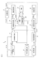
- FIG. 1 is a block diagram showing a remote parking system 1 to which the vehicle remote control method and the vehicle remote control device of the present invention are applied.
- the "autonomous driving control” means that the vehicle is driven by the automatic control of the on-board driving control device without depending on the driving operation of the driver.
- “Autonomous parking control” is a kind of autonomous driving control, and means that a vehicle is parked (entered or exited) by automatic control of an on-board driving control device without depending on a driver's driving operation.
- “parking” means to continuously park the vehicle in the parking space, but in the case of “traveling route”, not only the parking route when entering the garage into the parking space, but also from the parking space. It shall also include the garage exit route.
- the "vehicle travel control method and vehicle travel control device during parking” includes both vehicle travel control when the vehicle is put into the parking space and vehicle travel control when the vehicle is taken out of the parking space. Is done.
- putting in the garage is also called warehousing, and taking out the garage is also called warehousing.
- the remote parking system 1 of the present embodiment performs autonomous driving control in an assist mode in which an operator such as a driver can get on the vehicle and perform an intervention operation of the operator. After that, the operator gets off the vehicle and performs autonomous driving control from the outside of the vehicle in a remote control mode using a remote controller.
- the remote parking system 1 of the present embodiment is a system that puts in or takes out the garage by autonomous driving control when putting in the garage in the parking space or taking out the garage from the parking space. More specifically, the driver disembarks in the middle of entering the garage, and while confirming safety, the vehicle continues autonomous parking control by continuously transmitting an execution command signal to the vehicle by a remote controller. Then, when the vehicle may collide with an obstacle, the autonomous parking control is stopped by stopping the transmission of the execution command signal by the remote controller.
- the autonomous driving control mode in which an operator such as a driver can get on the vehicle and perform an intervention operation by the operator is an assist mode, and an autonomous driving control mode in which the operator gets off and enters or leaves the garage together with remote control. Is called remote control mode.
- a remote control mode combined with remote control can be used.
- the driver When entering the garage in the remote control mode, the driver carries the remote controller and disembarks when the remote control mode is activated, the entry route to the selected parking space is calculated, and the autonomous parking control is started. .. The driver who got off the vehicle completes the garage entry by continuously transmitting the execution command signal to the vehicle by the remote controller.
- the remote parking system 1 of the present embodiment is a system including a remote control mode in which such remote control is used in combination.
- the backward autonomous parking control shown in FIG. 2 is illustrated as an example of the autonomous parking control, the present invention can also be applied to garage parking, columnar autonomous parking, and other autonomous parking.
- the remote parking system 1 of the present embodiment includes a target parking space setting device 11, a vehicle position detector 12, an object detector 13, a parking route generation unit 14, an object deceleration calculation unit 15, a route tracking control unit 16, and a target vehicle speed generation unit. 17.
- the steering angle control unit 18, the vehicle speed control unit 19, the master unit 20, the remote controller 21, and the slave unit 22 are provided.
- the unit 19 and the master unit 20 are mounted on the vehicle.
- the remote controller 21 and the slave unit 22 are possessed by an operator such as a driver. Each configuration will be described below.
- the target parking space setting device 11 searches for parking spaces existing around the own vehicle in the remote control mode, and causes the operator to select a desired parking space from the parking spaces that can be parked. Further, the target parking space setting device 11 outputs the position information of the selected parking space (relative position coordinates from the current position of the own vehicle, latitude / longitude, etc.) to the parking route generation unit 14.
- the target parking space setting device 11 is provided with an input switch, a plurality of cameras, a parking space detection unit, and a touch panel type display (none of which are shown) in order to exert the above-mentioned functions.
- the input switch alternately selects the remote control mode or the assist mode. Multiple cameras capture the surroundings of the vehicle.
- the camera of the target parking space setting device 11 may also be used as the camera of the object detector 13 described later.
- the parking space detection unit is a computer on which a software program for detecting a parking space that can be parked from image data taken by a plurality of cameras is installed.
- the touch panel type display is used for displaying the detected parking space and selecting the parking space.
- the target parking space setting device 11 acquires image data around the own vehicle by a plurality of cameras, analyzes the image data, and allows parking. Detect spaces. Further, the target parking space setting device 11 displays an image including a parking space that can be parked on the touch panel display, and prompts the operator to select a parking space in which the vehicle is to be parked. When the operator selects a desired parking space from the displayed parking spaces, the target parking space setting device 11 outputs the position information of the parking space to the parking route generation unit 14. When searching for a parking space that can be parked, if the map information of the navigation device includes parking lot information having detailed position information, the parking lot information may be used.
- the vehicle position detector 12 is composed of a GPS unit, a gyro sensor, a vehicle speed sensor, and the like.
- the GPS unit detects radio waves transmitted from a plurality of satellite communications and periodically acquires the position information of the own vehicle.
- the vehicle position detector 12 detects the current position of the own vehicle based on the position information of the own vehicle acquired by the GPS unit, the angle change information acquired from the gyro sensor, and the vehicle speed acquired from the vehicle speed sensor.
- the position information of the own vehicle detected by the vehicle position detector 12 is output to the parking route generation unit 14 and the route tracking control unit 16 at predetermined time intervals.
- the object detector 13 searches for an object such as an obstacle in the vicinity of the own vehicle, and includes a camera, a radar (millimeter wave radar, laser radar, ultrasonic radar, etc.), a sonar, or the like. Alternatively, a combination of these is provided. These cameras, radars or sonars, or a combination thereof, are mounted on the outer skin around the vehicle.
- the mounting position of the object detector 13 is not particularly limited, but is, for example, all or a part of the center and both sides of the front bumper, the center and both sides of the rear bumper, the sill outer under the left and right center pillars, and the like. Can be attached to.
- the object detector 13 includes a computer in which a software program for identifying the position of an object detected by a camera, radar, or the like is installed.
- This computer uses the parking route generation unit 14 and the object deceleration calculation unit to obtain the specified object information (target information) and its position information (relative position coordinates from the current position of the own vehicle, latitude / longitude, etc.). Output to 15.
- These object information and position information are used by the parking route generation unit 14 to generate a parking route before the start of autonomous parking control. Further, the object information and the position information are used for the control of decelerating or stopping the own vehicle by the object deceleration calculation unit 15 when an object such as an unexpected obstacle is detected during the autonomous parking control.
- the parking route generation unit 14 calculates a parking route that is a parking route from the current position of the own vehicle to the target parking position (in the case of the remote control mode, it means a warehousing route; the same applies hereinafter) and does not collide with or interfere with an object. To do.
- the size of the own vehicle vehicle width, vehicle length, minimum turning radius, etc.
- the position information of the space are used.
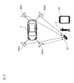
- FIG. 2 is a plan view showing an example of the remote control mode.
- the target parking space setting device 11 sets one parking space TPS. Search for and display an image containing this on the display.
- the parking route generation unit 14 determines the parking route R1 from the current position P1 to the turning position P3 and the parking route from the turning position P3 to the target parking space TPS. Calculate with R2. Then, the series of parking routes R1 and R2 are output to the route tracking control unit 16 and the target vehicle speed generation unit 17.
- the object deceleration calculation unit 15 inputs the position information of an obstacle or other object from the object detector 13, and based on the distance to the object and the vehicle speed, the time until the object collides with the object (TTC: Time to Collection). ) Is calculated, and the deceleration start timing of the own vehicle is calculated.
- TTC Time to Collection
- the object deceleration calculation unit 15 sets the vehicle speed as the initial setting value, and at the timing when the time TTC until the own vehicle V collides with the obstacle becomes equal to or less than the predetermined value. , Decelerate the vehicle speed of the own vehicle V. Further, when an unexpected obstacle is detected in the parking paths R1 and R2 during the series of autonomous parking control shown in FIG. 2, the time until the own vehicle V collides with the obstacle TTC is also obtained. Decelerates or stops the vehicle speed of the own vehicle V at the timing when becomes equal to or less than a predetermined value. This deceleration start timing is output to the target vehicle speed generation unit 17.
- the route tracking control unit 16 tracks the own vehicle along the parking route at predetermined time intervals based on the parking route from the parking route generation unit 14 and the current position of the own vehicle from the vehicle position detector 12. Calculate the target steering angle of. Regarding the parking paths R1 and R2 in FIG. 2, the route tracking control unit 16 sets the target steering angle of the parking path R1 that goes straight and turns right from the current position P1 to the turning position P3 for each current position of the own vehicle V. Calculate at predetermined time intervals. Similarly, the path tracking control unit 16 calculates the target steering angle of the parking path R2 that turns left and goes straight from the turning position P3 to the target parking space TPS at predetermined time intervals for each current position of the own vehicle V. The path tracking control unit 16 outputs the calculated target steering angle to the steering angle control unit 18.
- the target vehicle speed generation unit 17 is a target for following the own vehicle along the parking route at predetermined time intervals based on the parking route from the parking route generation unit 14 and the deceleration start timing from the object deceleration calculation unit 15. Calculate the vehicle speed. Regarding the parking routes R1 and R2 in FIG. 2, the target vehicle speed at the time of starting from the current position P1, going straight and turning right, and stopping at the turning position P3 is calculated at predetermined time intervals for each current position of the own vehicle V. Then, it is output to the vehicle speed control unit 19. Similarly, the target vehicle speed generation unit 17 starts (backward) again from the turning position P3 and stops close to the target vehicle speed when turning left to the middle of the target parking space TPS and the target parking space TPS.
- the target vehicle speed at the time of the operation is calculated for each current position of the own vehicle V at predetermined time intervals and output to the vehicle speed control unit 19. Further, when an unexpected obstacle is detected in the parking paths R1 and R2 during the series of autonomous parking control shown in FIG. 2, the object deceleration calculation unit 15 outputs the deceleration or stop timing. The target vehicle speed corresponding to this is output to the vehicle speed control unit 19.
- the steering angle control unit 18 generates a control signal for operating the steering actuator provided in the steering system of the own vehicle V based on the target steering angle from the path tracking control unit 16. Further, the vehicle speed control unit 19 generates a control signal for operating the accelerator actuator provided in the drive system of the own vehicle V based on the target vehicle speed from the target vehicle speed generation unit 17. By simultaneously controlling the steering angle control unit 18 and the vehicle speed control unit 19, autonomous parking control is executed.
- the international standard for autonomous driving control of a vehicle stipulates that the distance between the vehicle and the operator is within a predetermined remote control distance (for example, within 6 m) as a condition for allowing remote control of the vehicle. Therefore, in the remote parking system 1 of the present embodiment, the slave unit 22 possessed by the operator U and the master unit 20 mounted on the own vehicle V are used, and the relative position of the slave unit 22 with respect to the own vehicle V, that is, , Detects the relative position of the operator U who owns the slave unit 22 with respect to the own vehicle V.
- the slave unit 22 and the master unit 20 form a so-called keyless entry system.
- antennas 202a to 202d connected to the master unit 20 are installed at predetermined locations around the own vehicle V.
- the master unit 20 transmits a slave unit search signal from the antennas 202a to 202d.
- the slave unit 22 receives the slave unit search signal transmitted from each of the antennas 202a to 202d, and measures the radio field strength of the slave unit search signal of each antenna 202a to 202d. ..
- the radio field strength of the slave unit search signal changes depending on the distance between the slave unit 22 and the antennas 202a to 202d.
- the radio wave strength of the slave unit search signal received from the antenna 202b is the strongest, but is received from the antenna 202c near the right side of the rear bumper.
- the signal strength of the slave unit search signal is the weakest.
- the slave unit 22 transmits the radio wave strength of the slave unit search signal of each of the measured antennas 202a to 202d to the master unit 20.
- the position detector 201 of the master unit 20 is, for example, a computer in which a software program for calculating the position of the slave unit 22 from the radio wave strengths of the antennas 202a to 202d received from the slave unit 22 by using a triangulation method or the like is installed. Is.
- the position detector 201 is the relative position of the slave unit 22 with respect to the own vehicle V, that is, the operator U who owns the slave unit 22, based on the radio wave strength of the antennas 202a to 202d received from the slave unit 22.
- the position relative to the vehicle V is detected.
- the position detector 201 outputs the detected relative position of the slave unit 22 to the path tracking control unit 16 and the target vehicle speed generation unit 17 (or instead, the steering angle control unit 18 and the vehicle speed control unit 19 may be used). , Transmit to the remote controller 21.
- the remote controller 21 is a device for the operator U to command from outside the vehicle whether to continue or stop the execution of the autonomous parking control set by the target parking space setting device 11. Therefore, the remote controller 21 wirelessly communicates to transmit an execution command signal to the route tracking control unit 16 and the target vehicle speed generation unit 17 (or instead, the steering angle control unit 18 and the vehicle speed control unit 19 may be used). It has a function and communicates with the wireless communication function provided in the own vehicle V.
- the international standard for autonomous driving control of a vehicle stipulates that the vehicle should execute autonomous driving control only while the operator continuously operates the remote controller. Therefore, in the remote parking system 1 of the present embodiment, the execution command signal is continuously transmitted from the remote controller 21 to the own vehicle V only while a predetermined gesture is continuously input to the touch panel of the remote controller 21. Further, the own vehicle V executes the autonomous parking control only while receiving the execution command signal transmitted from the remote controller 21. That is, when the gesture is no longer detected by the remote controller 21 and the execution command signal is no longer transmitted, the execution of the autonomous parking control is interrupted or stopped.
- the remote controller 21 includes, for example, a mobile information terminal such as a smartphone on which application software for remote control (hereinafter referred to as an application) is installed.
- the smartphone on which the application is installed functions as the remote controller 21 of the remote parking system 1 by activating the application.
- some mobile information terminals such as smartphones are equipped with an operation automation function that records a touch operation on the touch panel 211 and repeatedly plays it back as standard, or those that can obtain an operation automation function by installing application software. is there.
- the remote control device 21 uses a mobile information terminal such as a smartphone, by inputting a gesture by the operation automation function, the operator does not actually input the gesture. Instead, there is a possibility that the autonomous parking control of the own vehicle V will be executed.
- the operator U places the slave unit 22 in the vicinity of the own vehicle V or on the roof of the own vehicle V, and remotely controls the slave unit 22 without possessing the slave unit 22.
- the own vehicle V When the operation automation function of the device 21 is activated and a gesture is input, the own vehicle V performs autonomous parking control at a position away from the operator U without the operation of the operator U.
- the remote parking system 1 of the present embodiment whether or not the gesture input to the remote controller 21 is input by the touch operation of the operator U in order to suppress the input of the gesture using the operation automation function. Is determined. Then, when the gesture is not input by the touch operation of the operator U, the execution of the autonomous parking control of the own vehicle V is interrupted or prohibited.
- the remote controller 21 includes a touch panel 211, a sensor 212, an information generation unit 213, a storage unit 214, a determination unit 215, a command unit 216, and a communication unit 217.
- the touch panel 211 detects the gesture input by the touch operation of the operator U.
- the sensor 212 detects the amount of change in the physical change that occurs in the remote controller 21.
- the information generation unit 213 generates the detection coordinate information based on the detection coordinates of the gesture detected by the touch panel 211.
- the information generation unit 213 generates operator transition information indicating a temporal transition of the change amount of the physical change of the remote controller 21 (a set or profile of the change amount of the change amount with respect to the time axis direction).
- the storage unit 214 stores the detection coordinate information, the command gesture information related to the preset command gesture, and the actuator transition information.
- the determination unit 215 compares the detected coordinate information with the command gesture information, and determines whether or not the gesture detected by the touch panel 211 is a command gesture. Further, the determination unit 215 compares the frequency characteristic of the detected coordinate information with the frequency characteristic of the actuator transition information to determine whether or not there is a correlation.
- the command unit 216 generates an execution command signal when the detected gesture is a command gesture and there is a correlation between the frequency characteristic of the detected coordinate information and the frequency characteristic of the operator transition information.
- the communication unit 217 transmits the execution command signal generated by the command unit 216 to the own vehicle V.
- the touch panel 211 a touch panel display of a smartphone that functions as a remote controller 21 is used.
- the touch panel 211 detects the gesture input by the touch operation of the operator U in the remote control mode.
- the gesture input to the touch panel 211 is a preset command gesture.
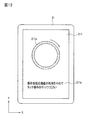
- a ring-shaped figure in which the start end at which one input of a gesture is started and the end at which one input of a gesture ends overlaps and is closed is set as a predetermined command gesture.
- an input guide 211a indicating the shape of a command gesture of a specified size is displayed on the touch panel 211 at the start of gesture input.
- a message such as "Please touch the displayed input guide along the direction of the arrow" is displayed.
- the input guide 211a may be hidden after it is determined that the input gesture is a command gesture.
- the sensor 212 is a so-called motion sensor such as an acceleration sensor, a gyro sensor, or an orientation sensor, which is provided in advance in a mobile information terminal that functions as a remote controller 21. Since the acceleration sensor, gyro sensor, and azimuth sensor are known sensors, detailed description thereof will be omitted.
- the amount of change in the posture of the remote controller 21 is detected as the amount of change in the physical change that occurs in the remote controller 21. For example, when the operator U inputs a gesture to the remote controller 21, one hand holds the remote controller 21 and the other hand inputs a gesture, or one hand holds the remote controller 21. Then enter the gesture with the thumb on the holding side.
- the posture of the remote controller 21 changes with the input of the gesture.
- the sensor 212 detects the amount of change in the posture of the remote controller 21 when the remote controller 21 remotely controls the own vehicle V.
- the information generation unit 213 functions by operating the CPU (Central Processing Unit) of the mobile information terminal that functions as the remote controller 21 according to the application.
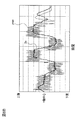
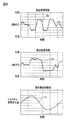
- the graphs shown in FIGS. 6A and 6B show an example of the detection value of the touch operation detected by the touch panel 211 when the operator U inputs a gesture to the touch panel 211.
- the horizontal axis represents time and the vertical axis represents the detected value xraw of the touch operation in the X-axis direction.
- the positive side of the vertical axis of the graph of FIG. 6A indicates the right side of the center line of the X axis of the touch panel 211, and the negative side indicates the left side of the center line of the X axis. Further, in the graph of FIG.
- the horizontal axis shows time and the vertical axis shows the detection value yraw of the touch operation in the Y-axis direction.
- the positive side of the vertical axis of the graph of FIG. 6B indicates the upper side of the touch panel 211 above the center line of the Y axis, and the negative side indicates the lower side of the center line of the Y axis. That is, the detected values xraw and yraw indicate the detection coordinates of the touch operation detected by the touch panel 211.
- the information generation unit 213 calculates the moving average values of the detected values xraw and yraw output from the touch panel 211, and uses the calculated moving average values as a set of changes in the detected coordinates over time (a set of changes in the detected coordinates with respect to the time axis direction).
- the detection coordinate information Dx and Dy indicating the profile) are stored in the storage unit 214.
- the information generation unit 213 generates the operator transition information indicating the temporal transition of the amount of change in the attitude of the remote controller 21 detected by the acceleration sensor, the gyro sensor, and the azimuth sensor of the sensor 212.
- the horizontal axis shows time
- the vertical axis shows the amount and direction of change in attitude of the remote controller 21 detected by the sensor 212.
- the information generation unit 213 extracts the posture change amount (hereinafter referred to as the gesture posture change amount) generated by the gesture input to the touch panel 211 from the composite posture change amount detected by the sensor 212, and the extracted gesture posture change amount.
- the amount is stored in the storage unit 214 as the operator transition information.
- the information generation unit 213 has a portion having frequency characteristics close to the frequency characteristics of the above-mentioned detection coordinate information Dx and Dy from the composite posture change amount P, for example, reference numeral E in FIG. 7A.
- the amount of change in posture indicated by is extracted as the amount of change in gesture posture.
- the extracted gesture posture change amount is stored in the storage unit 214 as the actuator transition information S.
- the method of extracting the gesture posture change amount from the compound posture change amount is not limited to the above method.
- the composite posture change amount is decomposed into a plurality of posture change amounts according to the frequency characteristics, and the posture change amount having a frequency characteristic close to the frequency characteristics of the detected coordinate information Dx and Dy from the decomposed plurality of posture change amounts. May be used as the operator transition information.
- the average posture change amount of the remote controller 21 generated by the gesture input is stored in the storage unit 214 as a sample in advance, and the gesture posture change amount is extracted from the composite posture change amount based on this sample. You may.
- the storage unit 214 is a storage such as a memory provided in advance in a mobile information terminal that functions as a remote controller 21.
- the storage unit 214 stores the above-mentioned detection coordinate information Dx and Dy and the actuator transition information S.
- the storage unit 214 stores command gesture information regarding the form, size, and the like of preset command gestures.
- the storage constituting the storage unit 214 stores operation automation information indicating the contents of the touch operation recorded by the operation automation function. This operation automation information corresponds to the detected coordinate information because it is information indicating the temporal transition of the input coordinates of the gesture detected by the touch panel 211 of the remote controller 21 at the time of recording the touch operation by the operation automation function.
- the determination unit 215 functions when the CPU of the smartphone, which functions as the remote controller 21, operates according to the application.
- the determination unit 215 acquires the detection coordinate information indicating the temporal transition of the detection coordinates of the gesture detected by the touch panel 211 from the storage unit 214. That is, when the operator U inputs a gesture to the touch panel 211, the determination unit 215 acquires the detection coordinate information Dx and Dy generated by the information generation unit 213, and inputs the gesture by the operation automation function. If so, the operation automation information is acquired as the detection coordinate information.
- the determination unit 215 compares the acquired detection coordinate information Dx and Dy with the command gesture information, and determines whether the gesture detected by the touch panel 211 is the command gesture or the input speed of the gesture is within a predetermined range. ..
- the input speed of the gesture is used for determining the command gesture in order to distinguish the gesture input when some object comes into contact with the touch panel 211 from the gesture of the operator U. Further, when the determination unit 215 acquires the operation automation information as the detection coordinate information, the operation automation information and the command gesture information are compared.
- the determination unit 215 determines whether or not the gesture input to the remote controller 21 is input by the touch operation of the operator U, in order to determine whether or not the gesture is input by the touch operation of the operator U.
- the presence or absence of correlation is determined by comparing with the frequency characteristics of the actuator transition information S.
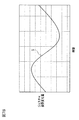
- FIG. 8 is a diagram comparing the above-mentioned detected coordinate information Dx and Dy with the actuator transition information S.
- the detected coordinate information Dx and the actuator transition information S have at least the same frequency characteristics such as period and wavelength. Therefore, the determination unit 215 determines that the detected coordinate information Dx and the actuator transition information S have a correlation. In this way, when the frequency characteristic of the detected coordinate information Dx and the frequency characteristic of the controller transition information S have a correlation, the touch panel 211 is gestured while the remote controller 21 is held by the operator U. Can be determined to have been entered.
- the determination unit 215 acquires the operation automation information from the storage unit 214 as the detection coordinate information. Further, when the gesture is input by the operation automation function, the posture change caused by the gesture input does not occur in the remote controller 21, so that the operator change information generated by the information generation unit 213 is the posture generated by the gesture input. Does not include the amount of change. Therefore, even if the determination unit 215 compares the frequency characteristics of the operation automation information with the frequency characteristics of the actuator transition information, no correlation is found. As a result, it is determined that the gesture has not been input by the operator U, and the execution command signal is not transmitted to the own vehicle V, so that the gesture input by the operation automation function can be suppressed.
- the command unit 216 functions when the CPU of the smartphone, which functions as the remote controller 21, operates according to the application.
- the command unit 216 uses the autonomous travel control function for the own vehicle V. Generates an execution command signal to execute autonomous parking control.
- the command unit 217 outputs the generated execution command signal to the communication unit 216.
- the communication unit 217 uses the communication function provided in advance by the smartphone that functions as the remote controller 21.
- the communication unit 217 is, for example, a wireless communication unit such as Bluetooth (registered trademark), and is connected to a wireless communication unit (not shown) mounted on the own vehicle V in the remote control mode.
- the communication unit 217 transmits the execution command signal generated by the command unit 216 to the own vehicle V.
- a wireless LAN Local Area Network
- Wi-Fi registered trademark
- a mobile phone line or the like may be used as the communication unit 217.
- the execution command signal transmitted to the own vehicle V is input to the route tracking control unit 16 and the target vehicle speed generation unit 17. Further, as described above, the relative positions of the own vehicle V and the slave unit 22 are input from the position detector 201 to the route tracking control unit 16 and the target vehicle speed generation unit 17.
- the route tracking control unit 16 sends the steering angle control unit 18 to the steering angle control unit 18. Output the target steering angle.
- the target vehicle speed generation unit 17 is a vehicle speed control unit when the distance between the own vehicle V and the slave unit 22 is within the remote control distance and the execution command signal from the remote controller 21 is input.
- the target vehicle speed is output to 19.
- the steering angle control unit 18 generates a control signal for operating the steering actuator provided in the steering system of the own vehicle V based on the target steering angle from the path tracking control unit 16. Further, the vehicle speed control unit 19 generates a control signal for operating the accelerator actuator provided in the drive system of the own vehicle V based on the target vehicle speed from the target vehicle speed generation unit 17.
- the route tracking control unit 16 is in the case where the execution command signal from the remote controller 21 is input.
- the target steering angle is not output to the steering angle control unit 18.
- the target vehicle speed generation unit 17 is a place where an execution command signal from the remote controller 21 is input when the distance between the own vehicle V and the slave unit 22 is longer than the remote control distance.
- the target vehicle speed is not output to the vehicle speed control unit 19. That is, when the distance between the own vehicle V and the slave unit 22 is farther than the remote control distance, the autonomous parking control is not executed even if the command gesture is input from the remote control device 21.
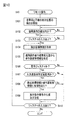
- FIG. 9 is a flowchart showing a control procedure executed by the remote parking system 1 of the present embodiment.
- FIG. 10 is a flowchart showing a procedure of detecting and determining a gesture in the remote controller 21 and transmitting an execution command signal.
- step S1 when the own vehicle V arrives at the position P1 near the target parking space TPS, in step S1 shown in FIG. 9, the operator U such as the driver performs the remote parking of the on-board target parking space setting device 11. Turn on the start switch and select the remote warehousing mode.
- the target parking space setting device 11 searches for a parking space in which the own vehicle V can park using a plurality of on-board cameras, and whether or not there is a parking space in step S3. To judge. If there is a parking space that can be parked, the process proceeds to step S4, and if there is no parking space that can be parked, the process returns to step S1. If the parking space that can be parked is not detected in step S2, the operator may be notified by a language display such as "There is no parking space" or by voice, and this process may be terminated.
- step S4 the target parking space setting device 11 displays the parking space that can be parked on the in-vehicle display, prompts the operator U to select the desired parking space, and the operator U selects a specific parking space TPS. Then, the target parking position information is output to the parking route generation unit 14.
- step S5 the parking route generation unit 14 generates the parking routes R1 and R2 shown in FIG. 2 from the current position P1 of the own vehicle V and the parking space TPS which is the target parking position.
- the object deceleration calculation unit 15 calculates the deceleration start timing at the time of autonomous parking control based on the object information detected by the object detector 13.
- the parking routes R1 and R2 generated by the parking route generation unit 14 are output to the route tracking control unit 16, and the deceleration start timing calculated by the object deceleration calculation unit 15 is output to the target vehicle speed generation unit 17.
- step S6 the operator is urged to consent to the start of the autonomous parking control, and when the operator approves the start, the autonomous driving control by the assist mode is started.
- the vehicle moves forward from the current position P1 by turning right once, and when it reaches the turning position P3, it reverses by turning left to the intermediate stop position P4.
- step S7 since the position of the own vehicle V has reached the intermediate stop position P4, the own vehicle V is stopped and the operator U is urged to disembark.
- the operator U activates the remote controller 21 in step S8.
- the start input of the remote control by the remote controller 21 includes the activation of the application installed on the remote controller 21, the door unlocking operation, the door locking and unlocking operation, and the combination of these and the application activation. Can be exemplified.
- step S9 the own vehicle V is in a stopped state.
- step S9 the pairing process of the remote controller 21 and the own vehicle V is performed.
- the own vehicle V authenticates the remote controller 21 and can accept the command by the pairing process in step S9
- the remote operation is started in step S10.
- the detection of the relative position of the slave unit 22 with respect to the own vehicle V that is, the relative position of the operator U who owns the slave unit 22 is started in step S101 of FIG.
- the slave unit 22 receives the slave unit search signals transmitted from the antennas 202a to 202d of the own vehicle V, and measures the radio wave intensity of the slave unit search signals of the antennas 202a to 202d.
- the slave unit 22 transmits the measured radio field strength of the slave unit search signal to the master unit 20.
- the position detector 201 of the master unit 20 detects the relative position of the slave unit 22 with respect to the own vehicle V based on the radio wave strength of the antennas 202a to 202d received from the slave unit 22.
- the relative position of the operator U with respect to the own vehicle V can be detected.
- the position detector 201 outputs the detected relative position to the route tracking control unit 16 and the target vehicle speed generation unit 17 (or, instead, the steering angle control unit 18 and the vehicle speed control unit 19 may be used), and the remote controller 201. Send to 21.
- step S102 the remote controller 21 proceeds to step S103 to confirm the gesture input when the distance between the own vehicle V and the slave unit 22 is within the predetermined remote control distance. .. If the distance between the own vehicle V and the slave unit 22 is not within the predetermined remote control distance in step S102, a message such as "Please approach within 6 m of the vehicle" is sent to the touch panel 211. Is displayed.
- the determination unit 215 receives the detection coordinate information indicating the temporal transition of the gesture detection coordinates detected by the touch panel 211 from the storage unit 214 in the next step S104. get. That is, when the operator U is inputting a gesture on the touch panel 211, the detection coordinate information Dx and Dy generated by the information generation unit 213 are acquired, and when the gesture is input by the operation automation function. , Acquire operation automation information as detection coordinate information.
- the information generation unit 213 extracts the posture change amount generated by the gesture input to the touch panel 211 from the composite posture change amount detected by the sensor 212, and uses the extracted posture change amount as the controller. It is stored in the storage unit 214 as the transition information S.
- step S106 the determination unit 215 compares the detection coordinate information Dx and Dy acquired from the storage unit 214 with the command gesture information, and determines whether or not the gesture detected by the touch panel 211 is the command gesture. Further, when the input gesture is a command gesture, the determination unit 215 determines in the next step S107 whether or not the input speed of the gesture is within a predetermined range. The determination unit 215 determines that the command gesture has been input when the input gesture is a command gesture and the input speed is within a predetermined range. When the determination unit 215 acquires the operation automation information as the detection coordinate information, the determination unit 215 compares the operation automation information with the command gesture information. Since the operation automation information records the touch operation of an appropriate gesture determined to be a command gesture for the automatic input of the gesture, the determination unit 215 determines that the gesture is a command gesture.
- the process proceeds to the next step S108, and the determination unit 215 compares the frequency characteristic of the detected coordinate information with the frequency characteristic of the operator transition information S to determine whether or not there is a correlation. judge.
- the detection coordinate information acquired by the determination unit 215 is the detection coordinate information Dx and Dy generated by the operator U inputting a gesture on the touch panel 211, for example, as shown in FIG. 8, the detection coordinates The information Dx and the operator transition information S have at least the same frequency characteristics such as period and wavelength. Therefore, the determination unit 215 determines that the detected coordinate information Dx and the actuator transition information S have a correlation.
- the command unit 216 issues an execution command in the next step S109.
- a signal is generated, and an execution command signal is transmitted from the communication unit 217 to the own vehicle V.
- the process returns to step S104 to repeat the gesture determination and the transmission of the execution command signal.
- the determination unit 215 acquires the operation automation information from the storage unit 214 instead of the detection coordinate information Dx and Dy. .. Further, since the remote controller 21 does not generate the attitude change caused by the gesture input, the operator change information generated by the information generation unit 213 does not include the frequency characteristic indicating the amount of the attitude change caused by the gesture input. .. Therefore, in step S108, the determination unit 215 compares the operation automation information with the actuator transition information S and determines that there is no correlation, so that the execution command signal is not transmitted to the own vehicle V.
- the route tracking control unit 16 receives an execution command signal from the remote controller 21 while the distance between the own vehicle V and the slave unit 22 is within the remote control distance. If so, the target steering angle is output to the steering angle control unit 18.
- the target vehicle speed generation unit 17 controls the vehicle speed when the distance between the own vehicle V and the slave unit 22 is within the remote control distance and the execution command signal from the remote controller 21 is input.
- the target vehicle speed is output to the unit 19.
- the steering angle control unit 18 generates a control signal for operating the steering actuator provided in the steering system of the own vehicle V based on the target steering angle from the path tracking control unit 16.
- the vehicle speed control unit 19 generates a control signal for operating the accelerator actuator provided in the drive system of the own vehicle V based on the target vehicle speed from the target vehicle speed generation unit 17.
- autonomous parking control is executed in the next step S12.
- step S10 The processes from step S10 to step S13, which will be described later, are executed at predetermined time intervals until the own vehicle V arrives at the target parking space TPS in step S13.
- step S13 it is determined whether or not the own vehicle V has arrived at the target parking space TPS, and if it has not arrived, the process returns to step S10, and when the own vehicle V arrives at the target parking space TPS. Stops the own vehicle V and ends the process.
- the travel route from the current position P1 of the own vehicle V to the intermediate stop position P4 executes autonomous travel control in the assist mode, and the travel route from the intermediate stop position P4 to the target parking space TPS is in the remote control mode. Executes autonomous driving control by.
- the remote parking system 1 when the own vehicle V having the autonomous traveling control function is remotely controlled by the remote controller 21, it is remote.
- the detection coordinate information Dx and Dy indicating the temporal transition of the detection coordinates of the gesture detected by the touch panel 211 of the controller 21 are acquired, and the amount of change in the physical change occurring in the remote controller 21 is detected to determine the amount of change.
- the operator transition information S indicating the temporal transition is generated.
- the frequency characteristics of the detected coordinate information Dx and Dy are compared with the frequency characteristics of the controller transition information S to determine whether or not there is a correlation, and if there is a correlation, autonomous driving control is executed on the own vehicle V. Let me.
- the operation automation information is acquired as the detection coordinate information, it is detected that the detection coordinates of the gesture detected by the touch panel 211 are changed by the operation automation information, but the remote controller Since the physical change of 21 does not occur, the frequency characteristic of the operation automation information and the frequency characteristic of the actuator transition information S have no correlation, and the gesture is input by the touch operation of the operator U. It can be judged that there is no such thing.
- the execution command signal is not transmitted to the own vehicle V, so that the gesture input by the operation automation function can be suppressed.
- the change in posture that occurs in the remote controller 21 is used as the physical change that occurs in the remote controller 21, it is determined whether or not the operator U is inputting the gesture while holding the remote controller 21. It is possible to suppress the input of gestures by the operation automation function.
- the gesture is a preset command gesture
- the frequency characteristic of the detected coordinate information is compared with the frequency characteristic of the operator transition information to determine the correlation. Determine the presence or absence.
- the own vehicle V is made to execute the autonomous traveling control. As a result, it is possible to urge the operator U to input a predetermined command gesture by a touch operation, and it is possible to suppress the input of the gesture by the operation automation function.
- the remote control device 21 a mobile information terminal that functions as the remote control device 21 by processing the installed application software is used, and a physical change that occurs in the remote control device 21 is detected by a sensor provided in advance in the mobile information terminal. doing. As a result, it is not necessary to newly provide a sensor in the remote controller 21, which is low cost.
- the own vehicle V when the gesture is no longer detected, the own vehicle V is stopped from the autonomous parking control. Therefore, the operation for causing the own vehicle V to stop the autonomous parking control becomes unnecessary, and the remote control of the own vehicle V becomes easy.
- Second Embodiment a second embodiment of the remote parking system to which the vehicle remote control method and the vehicle remote control device of the present invention are applied will be described.
- the same reference numerals as those of the first embodiment will be used for the same configurations as those of the first embodiment, and detailed description thereof will be omitted.
- the change in pressure applied to the touch panel 211 is used as the physical change that occurs in the remote controller 21.
- the sensor 212 includes a pressure sensor that detects the pressure of the touch panel 211
- the change in the pressure applied to the touch panel 211 uses the detection value of the pressure sensor.
- the touch panel 211 is a pressure-sensitive touch panel, or when the touch panel 211 is provided with a pressure sensor, the detected value detected by the touch panel 211 may be used.
- the pressure of the touch operation is not constant, and the pressure may be high at a position where the touch operation is easy and low at a position where the touch operation is difficult. ..
- the pressure may be unconsciously increased in order to reliably perform the touch operation, and in a position where touch operation is easy, the pressure may be decreased.
- the pressure of the touch operation at the time of gesture input varies depending on the method of holding the remote controller 21 of the operator U, the habit of the touch operation, and the like.
- steps S101 to S104 proceed in the same procedure as in the first embodiment, but in step S105a, the amount of change in pressure applied to the touch panel 211 is detected.
- the information generation unit 213 generates actuator transition information indicating the temporal transition of the amount of change.
- the determination unit 215 compares the frequency characteristics of the detected coordinate information with the frequency characteristics of the actuator transition information to determine whether or not there is a correlation. ..
- the command unit 216 when there is a correlation between the frequency characteristic of the detected coordinate information and the frequency characteristic of the actuator transition information, in step S109, the command unit 216 generates an execution command signal, and the communication unit 217 generates the own vehicle. Send to V. Further, if there is no correlation between the frequency characteristic of the detected coordinate information and the frequency characteristic of the operator transition information, the execution command signal is not transmitted to the own vehicle V.
- the first embodiment and the second embodiment it is necessary to input gestures a plurality of times in order to generate the actuator transition information. That is, in order to accurately generate the actuator transition information, it is necessary to increase the sampling number of the change amount of the physical change of the remote controller 21, so that the start of the autonomous parking control of the own vehicle V is delayed. In the present embodiment, such a problem is solved so that the autonomous parking control of the own vehicle V can be started quickly.
- steps S121 to S124 are the same processes as steps S101 to S104 of the first embodiment shown in FIG. Further, steps S125 to S127 are the same processes as steps S106, S107 and S109 of the first embodiment. That is, in the present embodiment, the determination unit 215 first determines whether or not the input gesture is a command gesture, and if the input gesture is a command gesture, the command unit 216 determines whether or not the input gesture is a command gesture. A signal is generated and transmitted to the own vehicle V by the communication unit 217.
- the information generation unit 213 may generate the operator mutation information from the amount of change in the posture of the remote controller 21, or FIG. 11
- the actuator mutation information may be generated from the change in the pressure applied to the touch panel 211.
- step S129 similarly to step S108 of the first embodiment shown in FIG. 10, the determination unit 215 compares the frequency characteristic of the detected coordinate information with the frequency characteristic of the actuator transition information and has a correlation. To judge. Then, when there is a correlation between the frequency characteristic of the detected coordinate information and the frequency characteristic of the actuator transition information, the generation and transmission of the execution command signal are continued in step S130. If there is no correlation between the frequency characteristic of the detected coordinate information and the frequency characteristic of the actuator transition information, the generation and transmission of the execution command signal are stopped in step S131.
- the gesture is a preset command gesture
- the own vehicle V is made to execute autonomous driving control. Then, after the autonomous travel control is executed by the own vehicle V, the frequency characteristic of the detected coordinate information is compared with the frequency characteristic of the operator transition information to determine whether or not there is a correlation. The vehicle V is allowed to continue the autonomous driving control, and if there is no correlation, the autonomous driving control is stopped. As a result, the autonomous parking control of the own vehicle V can be started quickly.
- the gesture input is not performed by the touch operation of the operator U but is performed by the operation automation function after the start of the autonomous parking control of the own vehicle V, the autonomous parking control of the own vehicle V is performed. Since it is canceled, it is possible to suppress the input of gestures by the operation automation function.
- the autonomous driving control of the own vehicle V is not executed.
- the operator U may be instructed to input a gesture by a touch operation.
- guidance information 211b such as "Please stop using the operation automation function and perform a touch operation" is displayed on the touch panel 211 of the remote controller 21.
- the guidance information 211b may be presented by voice, or the voice and the display by the touch panel 211 may be used in combination.
Abstract
When a host vehicle (V) having an autonomous travel control function is remotely controlled by a remote controller (21), detected coordinate information (Dx, Dy) indicating a temporal transition in detected coordinates of a gesture detected by a touch panel (211) of the remote controller (21) is obtained, a change amount of a physical change arising in the remote controller (21) is detected, and controller transition information (S) indicating a temporal change in the change amount is obtained. Next, frequency characteristics of the detected coordinate information (Dx, Dy) and frequency characteristics of the controller transition information (S) are compared to determine whether or not there is correlation, and when there is correlation, the host vehicle (V) is caused to execute autonomous travel control.
Description
本発明は、自律走行制御機能を備えた車両を遠隔操作により自律走行させる車両遠隔制御方法及び車両遠隔制御装置に関するものである。
The present invention relates to a vehicle remote control method and a vehicle remote control device for autonomously traveling a vehicle having an autonomous travel control function by remote control.
車両の遠隔操作装置のタッチパネルに入力されたジェスチャが、予め決められたジェスチャと一致するか否かを判定し、一致した場合に当該ジェスチャに割り当てられた所定の機能を車両に実行させる車両の遠隔制御方法が知られている(特許文献1参照)。
It is determined whether or not the gesture input to the touch panel of the remote control device of the vehicle matches a predetermined gesture, and if they match, the vehicle remotely causes the vehicle to perform a predetermined function assigned to the gesture. A control method is known (see Patent Document 1).
上記従来技術では、タッチパネルに入力されているジェスチャが、実際に操作者によって入力されているのか否かを判定することはできなかった。
With the above-mentioned conventional technique, it was not possible to determine whether or not the gesture input to the touch panel was actually input by the operator.
本発明が解決しようとする課題は、操作者によってジェスチャが入力されているのか否かを判定することができる車両遠隔制御方法及び車両遠隔制御装置を提供することである。
An object to be solved by the present invention is to provide a vehicle remote control method and a vehicle remote control device capable of determining whether or not a gesture is input by an operator.
本発明は、自律走行制御機能を備えた車両を遠隔操作器により遠隔操作する際に、遠隔操作器のタッチパネルにより検出されたジェスチャの検出座標の時間的変移を示す検出座標情報を取得し、遠隔操作器に生じる物理的変化の変化量を検出して、この変化量の時間的変移を示す操作器変移情報を取得する。そして、検出座標情報の周波数特性と、操作器変移情報の周波数特性とを比較して相関性の有無を判定し、相関性がある場合に、車両に自律走行制御を実行させる。
According to the present invention, when a vehicle equipped with an autonomous travel control function is remotely controlled by a remote controller, the detection coordinate information indicating the temporal transition of the gesture detection coordinates detected by the touch panel of the remote controller is acquired and remotely controlled. The amount of change in the physical change that occurs in the actuator is detected, and the operator transition information indicating the temporal transition of this amount of change is acquired. Then, the frequency characteristic of the detected coordinate information is compared with the frequency characteristic of the actuator transition information to determine the presence or absence of a correlation, and if there is a correlation, the vehicle is made to execute autonomous traveling control.
本発明によれば、検出座標情報の周波数特性と、操作器変移情報の周波数特性とに相関性がある場合、遠隔操作器に生じている物理的変化が、タッチパネルに対するジェスチャの入力によって生じていると判断することができる。したがって、入力されたジェスチャが操作者によって入力されているのか否かを判定することができる。
According to the present invention, when there is a correlation between the frequency characteristic of the detected coordinate information and the frequency characteristic of the controller transition information, the physical change occurring in the remote controller is caused by the gesture input to the touch panel. Can be judged. Therefore, it can be determined whether or not the input gesture is input by the operator.
《第1実施形態》
以下、本発明の実施形態を図面に基づいて説明する。図1は、本発明の車両遠隔制御方法及び車両遠隔制御装置を適用したリモート駐車システム1を示すブロック図である。本明細書において「自律走行制御」とは、ドライバの運転操作に依ることなく、車載された走行制御装置の自動制御により、車両を走行させることをいう。「自律駐車制御」とは、自律走行制御の一種であって、ドライバの運転操作に依ることなく、車載された走行制御装置の自動制御により、車両を駐車(入庫又は出庫)させることをいう。また、「駐車」とは、駐車スペースへ車両を継続的に止めておくことをいうが、「走行経路」という場合には、駐車スペースへ車庫入れする場合の駐車経路のみならず、駐車スペースからの車庫出し経路をも含むものとする。その意味で、「駐車時の車両走行制御方法及び車両走行制御装置」は、駐車スペースへの車庫入れ時の車両の走行制御と、駐車スペースからの車庫出し時の車両走行制御との両方が含まれる。なお、車庫入れを入庫とも言い、車庫出しを出庫とも言う。以下の実施形態においては、本発明に係る遠隔制御方法及び遠隔制御装置を、遠隔制御された車両を自律走行制御により駐車するリモート駐車システムに適用した一例を挙げて、本発明の具体例を説明する。本実施形態のリモート駐車システム1は、ドライバなどの操作者が車両に乗車して当該操作者の介入操作が可能なアシストモードにより自律走行制御を行う。その後、操作者が車両から降車し、車両の外部から遠隔操作器を用いたリモートコントロールモードにより自律走行制御を行う。 << First Embodiment >>
Hereinafter, embodiments of the present invention will be described with reference to the drawings. FIG. 1 is a block diagram showing aremote parking system 1 to which the vehicle remote control method and the vehicle remote control device of the present invention are applied. In the present specification, the "autonomous driving control" means that the vehicle is driven by the automatic control of the on-board driving control device without depending on the driving operation of the driver. "Autonomous parking control" is a kind of autonomous driving control, and means that a vehicle is parked (entered or exited) by automatic control of an on-board driving control device without depending on a driver's driving operation. In addition, "parking" means to continuously park the vehicle in the parking space, but in the case of "traveling route", not only the parking route when entering the garage into the parking space, but also from the parking space. It shall also include the garage exit route. In that sense, the "vehicle travel control method and vehicle travel control device during parking" includes both vehicle travel control when the vehicle is put into the parking space and vehicle travel control when the vehicle is taken out of the parking space. Is done. In addition, putting in the garage is also called warehousing, and taking out the garage is also called warehousing. In the following embodiments, a specific example of the present invention will be described with reference to an example in which the remote control method and the remote control device according to the present invention are applied to a remote parking system for parking a remotely controlled vehicle by autonomous driving control. To do. The remote parking system 1 of the present embodiment performs autonomous driving control in an assist mode in which an operator such as a driver can get on the vehicle and perform an intervention operation of the operator. After that, the operator gets off the vehicle and performs autonomous driving control from the outside of the vehicle in a remote control mode using a remote controller.
以下、本発明の実施形態を図面に基づいて説明する。図1は、本発明の車両遠隔制御方法及び車両遠隔制御装置を適用したリモート駐車システム1を示すブロック図である。本明細書において「自律走行制御」とは、ドライバの運転操作に依ることなく、車載された走行制御装置の自動制御により、車両を走行させることをいう。「自律駐車制御」とは、自律走行制御の一種であって、ドライバの運転操作に依ることなく、車載された走行制御装置の自動制御により、車両を駐車(入庫又は出庫)させることをいう。また、「駐車」とは、駐車スペースへ車両を継続的に止めておくことをいうが、「走行経路」という場合には、駐車スペースへ車庫入れする場合の駐車経路のみならず、駐車スペースからの車庫出し経路をも含むものとする。その意味で、「駐車時の車両走行制御方法及び車両走行制御装置」は、駐車スペースへの車庫入れ時の車両の走行制御と、駐車スペースからの車庫出し時の車両走行制御との両方が含まれる。なお、車庫入れを入庫とも言い、車庫出しを出庫とも言う。以下の実施形態においては、本発明に係る遠隔制御方法及び遠隔制御装置を、遠隔制御された車両を自律走行制御により駐車するリモート駐車システムに適用した一例を挙げて、本発明の具体例を説明する。本実施形態のリモート駐車システム1は、ドライバなどの操作者が車両に乗車して当該操作者の介入操作が可能なアシストモードにより自律走行制御を行う。その後、操作者が車両から降車し、車両の外部から遠隔操作器を用いたリモートコントロールモードにより自律走行制御を行う。 << First Embodiment >>
Hereinafter, embodiments of the present invention will be described with reference to the drawings. FIG. 1 is a block diagram showing a
本実施形態のリモート駐車システム1は、駐車スペースへの車庫入れ又は駐車スペースからの車庫出しをする場合に、自律走行制御により車庫入れ又は車庫出しを行うシステムである。より具体的には、車庫入れの途中でドライバが降車し、安全を確認しながら、遠隔操作器により実行指令信号を車両に送信し続けることで、車両は自律駐車制御を継続する。そして、車両が障害物と衝突するおそれがある場合には、遠隔操作器による実行指令信号の送信を中止することで、自律駐車制御を停止するものである。以下、ドライバなどの操作者が乗車して当該操作者の介入操作が可能な自律走行制御モードをアシストモード、操作者が降車して遠隔操作を併用した車庫入れ又は車庫出しを行う自律走行制御モードをリモートコントロールモードという。
The remote parking system 1 of the present embodiment is a system that puts in or takes out the garage by autonomous driving control when putting in the garage in the parking space or taking out the garage from the parking space. More specifically, the driver disembarks in the middle of entering the garage, and while confirming safety, the vehicle continues autonomous parking control by continuously transmitting an execution command signal to the vehicle by a remote controller. Then, when the vehicle may collide with an obstacle, the autonomous parking control is stopped by stopping the transmission of the execution command signal by the remote controller. Hereinafter, the autonomous driving control mode in which an operator such as a driver can get on the vehicle and perform an intervention operation by the operator is an assist mode, and an autonomous driving control mode in which the operator gets off and enters or leaves the garage together with remote control. Is called remote control mode.
たとえば、幅狭の車庫や両隣に他車両が駐車している駐車場など、サイドドアが充分に開くほど余裕がない幅狭の駐車スペースでは、ドライバの乗降が困難となる。このような場合でも駐車を可能とするため、遠隔操作を併用したリモートコントロールモードを利用することができる。リモートコントロールモードで車庫入れを行う場合には、リモートコントロールモードを起動し、選択した駐車スペースへの入庫経路を演算して自律駐車制御が開始されたら、ドライバは遠隔操作器を所持して降車する。降車したドライバは、遠隔操作器により車両に実行指令信号を送信し続けることで車庫入れを完了する。
For example, in a narrow parking space where there is not enough room for the side doors to open, such as a narrow garage or a parking lot where other vehicles are parked on both sides, it is difficult for the driver to get on and off. Since parking is possible even in such a case, a remote control mode combined with remote control can be used. When entering the garage in the remote control mode, the driver carries the remote controller and disembarks when the remote control mode is activated, the entry route to the selected parking space is calculated, and the autonomous parking control is started. .. The driver who got off the vehicle completes the garage entry by continuously transmitting the execution command signal to the vehicle by the remote controller.
また、当該駐車スペースからの車庫出しする場合には、ドライバは所持した遠隔操作器を用いて車両の内燃機関又は駆動用モータをONし、さらにリモート出庫モードを起動し、選択した車庫出し位置への出庫経路を演算して自律出庫制御が開始されたら、ドライバは遠隔操作器により実行指令を送信し続けることで車庫出しを完了し、その後に乗車する。本実施形態のリモート駐車システム1は、このような遠隔操作を併用したリモートコントロールモードを備えるシステムである。なお、自律駐車制御の一例として、図2に示す後退自律駐車制御を例示するが、車庫出し、縦列自律駐車その他の自律駐車にも本発明を適用することができる。
In addition, when taking out the garage from the parking space, the driver turns on the internal combustion engine or the drive motor of the vehicle using the remote controller possessed, further activates the remote leaving mode, and moves to the selected garage leaving position. When the autonomous warehousing control is started by calculating the garage delivery route, the driver completes the garage unloading by continuing to transmit the execution command by the remote controller, and then gets on the vehicle. The remote parking system 1 of the present embodiment is a system including a remote control mode in which such remote control is used in combination. Although the backward autonomous parking control shown in FIG. 2 is illustrated as an example of the autonomous parking control, the present invention can also be applied to garage parking, columnar autonomous parking, and other autonomous parking.
本実施形態のリモート駐車システム1は、目標駐車スペース設定器11、車両位置検出器12、物体検出器13、駐車経路生成部14、物体減速演算部15、経路追従制御部16、目標車速生成部17、操舵角制御部18、車速制御部19、親機20、遠隔操作器21及び子機22を備える。目標駐車スペース設定器11、車両位置検出器12、物体検出器13、駐車経路生成部14、物体減速演算部15、経路追従制御部16、目標車速生成部17、操舵角制御部18、車速制御部19及び親機20は、車両に搭載されている。遠隔操作器21及び子機22は、ドライバなどの操作者により所持される。以下、各構成を説明する。
The remote parking system 1 of the present embodiment includes a target parking space setting device 11, a vehicle position detector 12, an object detector 13, a parking route generation unit 14, an object deceleration calculation unit 15, a route tracking control unit 16, and a target vehicle speed generation unit. 17. The steering angle control unit 18, the vehicle speed control unit 19, the master unit 20, the remote controller 21, and the slave unit 22 are provided. Target parking space setting device 11, vehicle position detector 12, object detector 13, parking route generation unit 14, object deceleration calculation unit 15, route tracking control unit 16, target vehicle speed generation unit 17, steering angle control unit 18, vehicle speed control The unit 19 and the master unit 20 are mounted on the vehicle. The remote controller 21 and the slave unit 22 are possessed by an operator such as a driver. Each configuration will be described below.
目標駐車スペース設定器11は、リモートコントロールモードにおいて、自車両の周辺に存在する駐車スペースを探索し、駐車可能な駐車スペースの中から操作者に所望の駐車スペースを選択させる。また、目標駐車スペース設定器11は、選択された駐車スペースの位置情報(自車両の現在位置からの相対的位置座標や、緯度・経度など)を駐車経路生成部14に出力する。
The target parking space setting device 11 searches for parking spaces existing around the own vehicle in the remote control mode, and causes the operator to select a desired parking space from the parking spaces that can be parked. Further, the target parking space setting device 11 outputs the position information of the selected parking space (relative position coordinates from the current position of the own vehicle, latitude / longitude, etc.) to the parking route generation unit 14.
目標駐車スペース設定器11は、上述した機能を発揮するために、入力スイッチ、複数のカメラ、駐車スペース検出部及びタッチパネル型ディスプレイ(いずれも図示せず)を備える。入力スイッチは、リモートコントロールモードと、アシストモードを択一的に選択する。複数のカメラは、車両の周囲を撮影する。なお、目標駐車スペース設定器11のカメラは、後述する物体検出器13のカメラと兼用してもよい。駐車スペース検出部は、複数のカメラで撮影された画像データから駐車可能な駐車スペースを検出するソフトウェアプログラムがインストールされたコンピュータである。タッチパネル型ディスプレイは、検出された駐車スペースの表示と、駐車スペースの選択に用いる。
The target parking space setting device 11 is provided with an input switch, a plurality of cameras, a parking space detection unit, and a touch panel type display (none of which are shown) in order to exert the above-mentioned functions. The input switch alternately selects the remote control mode or the assist mode. Multiple cameras capture the surroundings of the vehicle. The camera of the target parking space setting device 11 may also be used as the camera of the object detector 13 described later. The parking space detection unit is a computer on which a software program for detecting a parking space that can be parked from image data taken by a plurality of cameras is installed. The touch panel type display is used for displaying the detected parking space and selecting the parking space.
目標駐車スペース設定器11は、ドライバなどの操作者が、入力スイッチによりリモートコントロールモードを選択すると、複数のカメラにより自車両の周囲の画像データを取得し、画像データを解析して駐車可能な駐車スペースを検出する。また、目標駐車スペース設定器11は、駐車可能な駐車スペースを含む画像をタッチパネル型ディスプレイに表示し、操作者に車両を駐車したい駐車スペースの選択を促す。操作者が、表示された駐車スペースから所望の駐車スペースを選択すると、目標駐車スペース設定器11は、この駐車スペースの位置情報を駐車経路生成部14に出力する。なお、駐車可能な駐車スペースを探索する場合に、ナビゲーション装置の地図情報に詳細な位置情報を有する駐車場情報が含まれるときは、当該駐車場情報を用いてもよい。
When an operator such as a driver selects a remote control mode with an input switch, the target parking space setting device 11 acquires image data around the own vehicle by a plurality of cameras, analyzes the image data, and allows parking. Detect spaces. Further, the target parking space setting device 11 displays an image including a parking space that can be parked on the touch panel display, and prompts the operator to select a parking space in which the vehicle is to be parked. When the operator selects a desired parking space from the displayed parking spaces, the target parking space setting device 11 outputs the position information of the parking space to the parking route generation unit 14. When searching for a parking space that can be parked, if the map information of the navigation device includes parking lot information having detailed position information, the parking lot information may be used.
車両位置検出器12は、GPSユニット、ジャイロセンサ、および車速センサなどから構成されている。GPSユニットは、複数の衛星通信から送信される電波を検出し、自車両の位置情報を周期的に取得する。車両位置検出器12は、GPSユニットにより取得した自車両の位置情報と、ジャイロセンサから取得した角度変化情報と、車速センサから取得した車速とに基づいて、自車両の現在位置を検出する。車両位置検出器12により検出された自車両の位置情報は、所定時間間隔で駐車経路生成部14及び経路追従制御部16に出力される。
The vehicle position detector 12 is composed of a GPS unit, a gyro sensor, a vehicle speed sensor, and the like. The GPS unit detects radio waves transmitted from a plurality of satellite communications and periodically acquires the position information of the own vehicle. The vehicle position detector 12 detects the current position of the own vehicle based on the position information of the own vehicle acquired by the GPS unit, the angle change information acquired from the gyro sensor, and the vehicle speed acquired from the vehicle speed sensor. The position information of the own vehicle detected by the vehicle position detector 12 is output to the parking route generation unit 14 and the route tracking control unit 16 at predetermined time intervals.
物体検出器13は、自車両の周辺に、障害物などの物体が存在するか否かを探索するものであり、カメラ、レーダー(ミリ波レーダー、レーザーレーダー、超音波レーダーなど)若しくはソナーなど、又はこれらを組み合わせたものを備える。これらのカメラ、レーダー若しくはソナー又はこれらを組み合わせたものは、自車両の周囲の外板部に装着されている。物体検出器13の装着位置としては、特に限定はされないが、たとえば、フロントバンパの中央及び両サイド、リヤバンパの中央及び両サイド、左右のセンターピラー下部のシルアウタなどの全箇所又はこれらの一部箇所に装着することができる。
The object detector 13 searches for an object such as an obstacle in the vicinity of the own vehicle, and includes a camera, a radar (millimeter wave radar, laser radar, ultrasonic radar, etc.), a sonar, or the like. Alternatively, a combination of these is provided. These cameras, radars or sonars, or a combination thereof, are mounted on the outer skin around the vehicle. The mounting position of the object detector 13 is not particularly limited, but is, for example, all or a part of the center and both sides of the front bumper, the center and both sides of the rear bumper, the sill outer under the left and right center pillars, and the like. Can be attached to.
また、物体検出器13は、カメラやレーダーなどで検出された物体の位置を特定するためのソフトウェアプログラムがインストールされたコンピュータを備える。このコンピュータは、特定された物体情報(物標情報)とその位置情報(自車両の現在位置からの相対的位置座標や、緯度・経度など)を、駐車経路生成部14と、物体減速演算部15へ出力する。これらの物体情報及び位置情報は、自律駐車制御の開始前においては、駐車経路生成部14による駐車経路の生成に利用される。また、物体情報及び位置情報は、自律駐車制御中においては、不意な障害物などの物体を検出した場合に、物体減速演算部15により自車両を減速又は停車させる制御に利用される。
Further, the object detector 13 includes a computer in which a software program for identifying the position of an object detected by a camera, radar, or the like is installed. This computer uses the parking route generation unit 14 and the object deceleration calculation unit to obtain the specified object information (target information) and its position information (relative position coordinates from the current position of the own vehicle, latitude / longitude, etc.). Output to 15. These object information and position information are used by the parking route generation unit 14 to generate a parking route before the start of autonomous parking control. Further, the object information and the position information are used for the control of decelerating or stopping the own vehicle by the object deceleration calculation unit 15 when an object such as an unexpected obstacle is detected during the autonomous parking control.
駐車経路生成部14は、自車両の現在位置から目標駐車位置に向かう駐車経路(リモートコントロールモードの場合は入庫経路をいう。以下同じ。)であって、物体に衝突又は干渉しない駐車経路を演算する。駐車経路の演算には、予め記憶している自車両の大きさ(車幅、車長及び最小回転半径など)と、目標駐車スペース設定器11からの目標駐車位置(リモートコントロールモードの場合は駐車スペースの位置情報をいう。以下同じ)と、車両位置検出器12からの自車両の現在位置情報と、物体検出器13からの物体(障害物)の位置情報とを用いる。
The parking route generation unit 14 calculates a parking route that is a parking route from the current position of the own vehicle to the target parking position (in the case of the remote control mode, it means a warehousing route; the same applies hereinafter) and does not collide with or interfere with an object. To do. To calculate the parking route, the size of the own vehicle (vehicle width, vehicle length, minimum turning radius, etc.) stored in advance and the target parking position from the target parking space setting device 11 (parking in the remote control mode) The position information of the space; the same applies hereinafter), the current position information of the own vehicle from the vehicle position detector 12, and the position information of the object (obstacle) from the object detector 13 are used.
図2は、リモートコントロールモードの一例を示す平面図である。図2に示す自車両Vの現在位置P1において、ドライバなどの操作者Uが車内の入力スイッチを操作してリモートコントロールモードを選択すると、目標駐車スペース設定器11は1つの駐車可能な駐車スペースTPSを探索してこれを含む画像をディスプレイに表示する。これに対して操作者Uが駐車スペースTPSを選択すると、駐車経路生成部14は、現在位置P1から切り返し位置P3に至る駐車経路R1と、切り返し位置P3から目標とする駐車スペースTPSに至る駐車経路R2とを演算する。そして、この一連の駐車経路R1、R2を経路追従制御部16及び目標車速生成部17に出力する。
FIG. 2 is a plan view showing an example of the remote control mode. At the current position P1 of the own vehicle V shown in FIG. 2, when an operator U such as a driver operates an input switch in the vehicle to select the remote control mode, the target parking space setting device 11 sets one parking space TPS. Search for and display an image containing this on the display. On the other hand, when the operator U selects the parking space TPS, the parking route generation unit 14 determines the parking route R1 from the current position P1 to the turning position P3 and the parking route from the turning position P3 to the target parking space TPS. Calculate with R2. Then, the series of parking routes R1 and R2 are output to the route tracking control unit 16 and the target vehicle speed generation unit 17.
物体減速演算部15は、物体検出器13からの障害物その他の物体の位置情報を入力し、物体との距離と、車速とに基づいて、物体と衝突するまでの時間(TTC:Time to Collision)を演算し、自車両の減速開始タイミングを演算する。たとえば、図2に示すリモートコントロールモードでは、切り返し位置P3における道路の右側の壁W、目標とする駐車スペースTPSに至る駐車経路R2の左右両側の家屋H1、H2及び植木WDなどが障害物としての物体となる。物体減速演算部15は、これらの障害物との距離が所定以上である場合は、車速を初期設定値とし、自車両Vが障害物に衝突するまでの時間TTCが所定値以下になるタイミングで、自車両Vの車速を減速する。また、図2に示す一連の自律駐車制御を実行中に、駐車経路R1、R2の中に不意な障害物を検出した場合も同様に、自車両Vがその障害物に衝突するまでの時間TTCが所定値以下になるタイミングで、自車両Vの車速を減速又は停車させる。この減速開始タイミングは、目標車速生成部17に出力する。
The object deceleration calculation unit 15 inputs the position information of an obstacle or other object from the object detector 13, and based on the distance to the object and the vehicle speed, the time until the object collides with the object (TTC: Time to Collection). ) Is calculated, and the deceleration start timing of the own vehicle is calculated. For example, in the remote control mode shown in FIG. 2, the wall W on the right side of the road at the turning position P3, the houses H1, H2 and the planting WD on both the left and right sides of the parking route R2 leading to the target parking space TPS are obstacles. It becomes an object. When the distance to these obstacles is equal to or greater than the predetermined value, the object deceleration calculation unit 15 sets the vehicle speed as the initial setting value, and at the timing when the time TTC until the own vehicle V collides with the obstacle becomes equal to or less than the predetermined value. , Decelerate the vehicle speed of the own vehicle V. Further, when an unexpected obstacle is detected in the parking paths R1 and R2 during the series of autonomous parking control shown in FIG. 2, the time until the own vehicle V collides with the obstacle TTC is also obtained. Decelerates or stops the vehicle speed of the own vehicle V at the timing when becomes equal to or less than a predetermined value. This deceleration start timing is output to the target vehicle speed generation unit 17.
経路追従制御部16は、駐車経路生成部14からの駐車経路と、車両位置検出器12からの自車両の現在位置とに基づいて、所定時間間隔で自車両を駐車経路に沿って追従するための目標操舵角を演算する。図2の駐車経路R1、R2についていえば、経路追従制御部16は、現在位置P1から切り返し位置P3まで直進及び右旋回する駐車経路R1の目標操舵角を、自車両Vの現在位置ごとに所定時間間隔で演算する。同様に、経路追従制御部16は、切り返し位置P3から目標とする駐車スペースTPSまで左旋回及び直進する駐車経路R2の目標操舵角を、自車両Vの現在位置ごとに所定時間間隔で演算する。経路追従制御部16は、算出した目標操舵角を操舵角制御部18に出力する。
The route tracking control unit 16 tracks the own vehicle along the parking route at predetermined time intervals based on the parking route from the parking route generation unit 14 and the current position of the own vehicle from the vehicle position detector 12. Calculate the target steering angle of. Regarding the parking paths R1 and R2 in FIG. 2, the route tracking control unit 16 sets the target steering angle of the parking path R1 that goes straight and turns right from the current position P1 to the turning position P3 for each current position of the own vehicle V. Calculate at predetermined time intervals. Similarly, the path tracking control unit 16 calculates the target steering angle of the parking path R2 that turns left and goes straight from the turning position P3 to the target parking space TPS at predetermined time intervals for each current position of the own vehicle V. The path tracking control unit 16 outputs the calculated target steering angle to the steering angle control unit 18.
目標車速生成部17は、駐車経路生成部14からの駐車経路と、物体減速演算部15からの減速開始タイミングとに基づいて、所定時間間隔で自車両を駐車経路に沿って追従する際の目標車速を演算する。図2の駐車経路R1、R2についていえば、現在位置P1から発進し、直進及び右旋回して切り返し位置P3で停止する際の目標車速を、自車両Vの現在位置ごとに所定時間間隔で演算し、車速制御部19に出力する。同様に、目標車速生成部17は、切り返し位置P3から再度発進(後退)し、目標とする駐車スペースTPSの途中まで左旋回する際の目標車速と、目標とする駐車スペースTPSに接近して停車する際の目標車速とを、自車両Vの現在位置ごとに所定時間間隔で演算し、車速制御部19に出力する。また、図2に示す一連の自律駐車制御を実行中に、駐車経路R1、R2の中に不意な障害物を検出した場合は、物体減速演算部15から減速又は停車タイミングが出力されるので、これに応じた目標車速を車速制御部19に出力する。
The target vehicle speed generation unit 17 is a target for following the own vehicle along the parking route at predetermined time intervals based on the parking route from the parking route generation unit 14 and the deceleration start timing from the object deceleration calculation unit 15. Calculate the vehicle speed. Regarding the parking routes R1 and R2 in FIG. 2, the target vehicle speed at the time of starting from the current position P1, going straight and turning right, and stopping at the turning position P3 is calculated at predetermined time intervals for each current position of the own vehicle V. Then, it is output to the vehicle speed control unit 19. Similarly, the target vehicle speed generation unit 17 starts (backward) again from the turning position P3 and stops close to the target vehicle speed when turning left to the middle of the target parking space TPS and the target parking space TPS. The target vehicle speed at the time of the operation is calculated for each current position of the own vehicle V at predetermined time intervals and output to the vehicle speed control unit 19. Further, when an unexpected obstacle is detected in the parking paths R1 and R2 during the series of autonomous parking control shown in FIG. 2, the object deceleration calculation unit 15 outputs the deceleration or stop timing. The target vehicle speed corresponding to this is output to the vehicle speed control unit 19.
操舵角制御部18は、経路追従制御部16からの目標操舵角に基づいて、自車両Vの操舵系システムに設けられた操舵アクチュエータを動作する制御信号を生成する。また、車速制御部19は、目標車速生成部17からの目標車速に基づいて、自車両Vの駆動系システムに設けられたアクセルアクチュエータを動作する制御信号を生成する。これら操舵角制御部18と車速制御部19とを同時に制御することで、自律駐車制御が実行される。
The steering angle control unit 18 generates a control signal for operating the steering actuator provided in the steering system of the own vehicle V based on the target steering angle from the path tracking control unit 16. Further, the vehicle speed control unit 19 generates a control signal for operating the accelerator actuator provided in the drive system of the own vehicle V based on the target vehicle speed from the target vehicle speed generation unit 17. By simultaneously controlling the steering angle control unit 18 and the vehicle speed control unit 19, autonomous parking control is executed.
次に、子機22と、親機20について説明する。車両の自律走行制御に関する国際規格では、車両の遠隔操作を許容する条件として、車両と操作者との距離が所定の遠隔操作距離以内(たとえば、6m以内)であることが規定されている。そのため、本実施形態のリモート駐車システム1では、操作者Uが所持する子機22と、自車両Vに搭載した親機20とを利用して、自車両Vに対する子機22の相対位置、すなわち、子機22を所持している操作者Uの自車両Vに対する相対位置を検出する。子機22及び親機20は、いわゆるキーレスエントリシステムを構成する。キーレスエントリシステムは、ドライバなどの操作者Uが子機22を所持した状態で自車両Vの所定距離以内に接近すると、自車両Vに設置した親機20と子機22との間で無線通信を行い、ドアロックの自動解除などを行うシステムである。
Next, the slave unit 22 and the master unit 20 will be described. The international standard for autonomous driving control of a vehicle stipulates that the distance between the vehicle and the operator is within a predetermined remote control distance (for example, within 6 m) as a condition for allowing remote control of the vehicle. Therefore, in the remote parking system 1 of the present embodiment, the slave unit 22 possessed by the operator U and the master unit 20 mounted on the own vehicle V are used, and the relative position of the slave unit 22 with respect to the own vehicle V, that is, , Detects the relative position of the operator U who owns the slave unit 22 with respect to the own vehicle V. The slave unit 22 and the master unit 20 form a so-called keyless entry system. In the keyless entry system, when an operator U such as a driver approaches the slave unit 22 within a predetermined distance while holding the slave unit 22, wireless communication is performed between the master unit 20 installed in the own vehicle V and the slave unit 22. It is a system that automatically unlocks the door lock.
本実施形態では、たとえば、図3に示すように、自車両Vの周囲の所定箇所に、親機20に接続されたアンテナ202a~202dを設置している。親機20は、アンテナ202a~202dから子機探索信号を送信する。子機22は、自車両Vの所定距離内に接近すると、各アンテナ202a~202dから送信されている子機探索信号を受信し、各アンテナ202a~202dの子機探索信号の電波強度を測定する。子機探索信号の電波強度は、子機22と、各アンテナ202a~202dとの距離によって変化する。すなわち、子機22がフロントバンパの左サイド近傍のアンテナ202bの近傍に存在する場合、アンテナ202bから受信した子機探索信号の電波強度が最も強くなるが、リヤバンパの右サイド近傍のアンテナ202cから受信した子機探索信号の電波強度は最も弱くなる。
In the present embodiment, for example, as shown in FIG. 3, antennas 202a to 202d connected to the master unit 20 are installed at predetermined locations around the own vehicle V. The master unit 20 transmits a slave unit search signal from the antennas 202a to 202d. When the slave unit 22 approaches within a predetermined distance of the own vehicle V, the slave unit 22 receives the slave unit search signal transmitted from each of the antennas 202a to 202d, and measures the radio field strength of the slave unit search signal of each antenna 202a to 202d. .. The radio field strength of the slave unit search signal changes depending on the distance between the slave unit 22 and the antennas 202a to 202d. That is, when the slave unit 22 exists in the vicinity of the antenna 202b near the left side of the front bumper, the radio wave strength of the slave unit search signal received from the antenna 202b is the strongest, but is received from the antenna 202c near the right side of the rear bumper. The signal strength of the slave unit search signal is the weakest.
子機22は、測定した各アンテナ202a~202dの子機探索信号の電波強度を親機20に送信する。親機20の位置検出器201は、たとえば、子機22から受信した各アンテナ202a~202dの電波強度から、三角測量法などを用いて子機22の位置を演算するソフトウェアプログラムがインストールされたコンピュータである。位置検出器201は、子機22から受信した各アンテナ202a~202dの電波強度に基づいて、自車両Vに対する子機22の相対位置、すなわち、子機22を所持している操作者Uの自車両Vに対する相対位置を検出する。位置検出器201は、検出した子機22の相対位置を、経路追従制御部16及び目標車速生成部17(又はこれに代えて、操舵角制御部18及び車速制御部19でもよい)に出力し、遠隔操作器21に送信する。
The slave unit 22 transmits the radio wave strength of the slave unit search signal of each of the measured antennas 202a to 202d to the master unit 20. The position detector 201 of the master unit 20 is, for example, a computer in which a software program for calculating the position of the slave unit 22 from the radio wave strengths of the antennas 202a to 202d received from the slave unit 22 by using a triangulation method or the like is installed. Is. The position detector 201 is the relative position of the slave unit 22 with respect to the own vehicle V, that is, the operator U who owns the slave unit 22, based on the radio wave strength of the antennas 202a to 202d received from the slave unit 22. The position relative to the vehicle V is detected. The position detector 201 outputs the detected relative position of the slave unit 22 to the path tracking control unit 16 and the target vehicle speed generation unit 17 (or instead, the steering angle control unit 18 and the vehicle speed control unit 19 may be used). , Transmit to the remote controller 21.
遠隔操作器21は、目標駐車スペース設定器11にて設定した自律駐車制御の実行を継続するか又は停止するかを、操作者Uが車外から指令するための装置である。そのため、遠隔操作器21は、経路追従制御部16及び目標車速生成部17(又はこれに代えて、操舵角制御部18及び車速制御部19でもよい)に実行指令信号を送信するための無線通信機能を備え、自車両Vに設けられた無線通信機能との間で通信を行う。
The remote controller 21 is a device for the operator U to command from outside the vehicle whether to continue or stop the execution of the autonomous parking control set by the target parking space setting device 11. Therefore, the remote controller 21 wirelessly communicates to transmit an execution command signal to the route tracking control unit 16 and the target vehicle speed generation unit 17 (or instead, the steering angle control unit 18 and the vehicle speed control unit 19 may be used). It has a function and communicates with the wireless communication function provided in the own vehicle V.
車両の自律走行制御に関する国際規格では、操作者が遠隔操作器の操作を連続して行っている間だけ、車両に自律走行制御を実行させることが規定されている。そのため、本実施形態のリモート駐車システム1では、遠隔操作器21のタッチパネルに所定のジェスチャが連続して入力されている間だけ、遠隔操作器21から自車両Vに実行指令信号を送信し続ける。また、自車両Vは、遠隔操作器21から送信された実行指令信号を受信している間のみ、自律駐車制御を実行する。すなわち、遠隔操作器21でジェスチャが検出されなくなり、実行指令信号が送信されなくなった場合には、自律駐車制御の実行を中断又は中止する。
The international standard for autonomous driving control of a vehicle stipulates that the vehicle should execute autonomous driving control only while the operator continuously operates the remote controller. Therefore, in the remote parking system 1 of the present embodiment, the execution command signal is continuously transmitted from the remote controller 21 to the own vehicle V only while a predetermined gesture is continuously input to the touch panel of the remote controller 21. Further, the own vehicle V executes the autonomous parking control only while receiving the execution command signal transmitted from the remote controller 21. That is, when the gesture is no longer detected by the remote controller 21 and the execution command signal is no longer transmitted, the execution of the autonomous parking control is interrupted or stopped.
遠隔操作器21は、たとえば、リモートコントロール用のアプリケーションソフトウェア(以下、アプリケーションという。)がインストールされたスマートフォンなどの携帯情報端末からなる。アプリケーションがインストールされたスマートフォンは、当該アプリケーションを起動することにより、リモート駐車システム1の遠隔操作器21として機能する。
The remote controller 21 includes, for example, a mobile information terminal such as a smartphone on which application software for remote control (hereinafter referred to as an application) is installed. The smartphone on which the application is installed functions as the remote controller 21 of the remote parking system 1 by activating the application.
ところで、スマートフォンなどの携帯情報端末には、タッチパネル211に対するタッチ操作を記録して繰り返し再生する操作自動化機能を標準で備えたものや、アプリケーションソフトウェアをインストールすることによって、操作自動化機能が得られるものがある。上述したように、遠隔操作器21は、スマートフォンなどの携帯情報端末を利用しているため、操作自動化機能によってジェスチャを入力することで、実際には操作者がジェスチャを入力していないにも関わらず、自車両Vの自律駐車制御が実行される可能性がある。特に、自車両Vの遠隔操作距離を延ばすために、操作者Uが、自車両Vの近傍や、自車両Vの屋根の上に子機22を置き、子機22を所持しない状態で遠隔操作装器21の操作自動化機能を作動させてジェスチャを入力した場合、自車両Vは、操作者Uから離れた位置で、操作者Uの操作によらずに自律駐車制御を行うことになる。本実施形態のリモート駐車システム1では、操作自動化機能を利用したジェスチャの入力を抑制するために、遠隔操作器21に入力されているジェスチャが、操作者Uのタッチ操作によって入力されているのか否かを判定する。そして、操作者Uのタッチ操作によってジェスチャが入力されていない場合には、自車両Vの自律駐車制御の実行を中断又は禁止する。
By the way, some mobile information terminals such as smartphones are equipped with an operation automation function that records a touch operation on the touch panel 211 and repeatedly plays it back as standard, or those that can obtain an operation automation function by installing application software. is there. As described above, since the remote control device 21 uses a mobile information terminal such as a smartphone, by inputting a gesture by the operation automation function, the operator does not actually input the gesture. Instead, there is a possibility that the autonomous parking control of the own vehicle V will be executed. In particular, in order to extend the remote control distance of the own vehicle V, the operator U places the slave unit 22 in the vicinity of the own vehicle V or on the roof of the own vehicle V, and remotely controls the slave unit 22 without possessing the slave unit 22. When the operation automation function of the device 21 is activated and a gesture is input, the own vehicle V performs autonomous parking control at a position away from the operator U without the operation of the operator U. In the remote parking system 1 of the present embodiment, whether or not the gesture input to the remote controller 21 is input by the touch operation of the operator U in order to suppress the input of the gesture using the operation automation function. Is determined. Then, when the gesture is not input by the touch operation of the operator U, the execution of the autonomous parking control of the own vehicle V is interrupted or prohibited.
遠隔操作器21は、図4に示すように、タッチパネル211、センサ212、情報生成部213、記憶部214、判定部215、指令部216及び通信部217を備える。タッチパネル211は、操作者Uのタッチ操作により入力されたジェスチャを検出する。センサ212は、遠隔操作器21に生じる物理的変化の変化量を検出する。情報生成部213は、タッチパネル211により検出されたジェスチャの検出座標に基づいて、検出座標情報を生成する。また、情報生成部213は、遠隔操作器21の物理的変化の変化量の時間的変移(時間軸方向に対する変化量の移り変わりの集合又はプロファイル)を示す操作器変移情報を生成する。記憶部214は、検出座標情報と、予め設定された指令ジェスチャに関する指令ジェスチャ情報と、操作器変移情報とを記憶する。判定部215は、検出座標情報と指令ジェスチャ情報とを比較して、タッチパネル211で検出したジェスチャが指令ジェスチャであるか否かを判定する。また、判定部215は、検出座標情報の周波数特性と、操作器変移情報の周波数特性とを比較して相関性の有無を判定する。指令部216は、検出したジェスチャが指令ジェスチャであって、検出座標情報の周波数特性と、操作器変移情報の周波数特性とに相関性がある場合に、実行指令信号を生成する。通信部217は、指令部216で生成された実行指令信号を自車両Vに送信する。
As shown in FIG. 4, the remote controller 21 includes a touch panel 211, a sensor 212, an information generation unit 213, a storage unit 214, a determination unit 215, a command unit 216, and a communication unit 217. The touch panel 211 detects the gesture input by the touch operation of the operator U. The sensor 212 detects the amount of change in the physical change that occurs in the remote controller 21. The information generation unit 213 generates the detection coordinate information based on the detection coordinates of the gesture detected by the touch panel 211. In addition, the information generation unit 213 generates operator transition information indicating a temporal transition of the change amount of the physical change of the remote controller 21 (a set or profile of the change amount of the change amount with respect to the time axis direction). The storage unit 214 stores the detection coordinate information, the command gesture information related to the preset command gesture, and the actuator transition information. The determination unit 215 compares the detected coordinate information with the command gesture information, and determines whether or not the gesture detected by the touch panel 211 is a command gesture. Further, the determination unit 215 compares the frequency characteristic of the detected coordinate information with the frequency characteristic of the actuator transition information to determine whether or not there is a correlation. The command unit 216 generates an execution command signal when the detected gesture is a command gesture and there is a correlation between the frequency characteristic of the detected coordinate information and the frequency characteristic of the operator transition information. The communication unit 217 transmits the execution command signal generated by the command unit 216 to the own vehicle V.
以下、遠隔操作器21の各部について、さらに詳しく説明する。タッチパネル211には、遠隔操作器21として機能するスマートフォンのタッチパネルディスプレイが用いられる。タッチパネル211は、リモートコントロールモードにおいて、操作者Uのタッチ操作により入力されたジェスチャを検出する。タッチパネル211に入力されるジェスチャは、予め設定された規定の指令ジェスチャである。本実施形態では、たとえば、ジェスチャの1回の入力が開始される始端と、ジェスチャの1回の入力が終わる終端とが重なって閉じられた円環形状の図形を規定の指令ジェスチャとして設定している。図5に示すように、ジェスチャの入力開始時のタッチパネル211には、規定サイズの指令ジェスチャの形状を示す入力ガイド211aが表示される。また、入力ガイド211aの近傍には、「表示されている入力ガイドを矢印の方向に沿ってタッチ操作して下さい」などのメッセージが表示される。なお、入力ガイド211aは、入力されたジェスチャが指令ジェスチャであると判定された後で非表示にしてもよい。
Hereinafter, each part of the remote controller 21 will be described in more detail. As the touch panel 211, a touch panel display of a smartphone that functions as a remote controller 21 is used. The touch panel 211 detects the gesture input by the touch operation of the operator U in the remote control mode. The gesture input to the touch panel 211 is a preset command gesture. In the present embodiment, for example, a ring-shaped figure in which the start end at which one input of a gesture is started and the end at which one input of a gesture ends overlaps and is closed is set as a predetermined command gesture. There is. As shown in FIG. 5, an input guide 211a indicating the shape of a command gesture of a specified size is displayed on the touch panel 211 at the start of gesture input. Further, in the vicinity of the input guide 211a, a message such as "Please touch the displayed input guide along the direction of the arrow" is displayed. The input guide 211a may be hidden after it is determined that the input gesture is a command gesture.
センサ212は、遠隔操作器21として機能する携帯情報端末が予め備える加速度センサ、ジャイロセンサ、方位センサなどのいわゆるモーションセンサである。加速度センサ、ジャイロセンサ及び方位センサは、公知のセンサであるため詳しい説明は省略する。本実施形態では、遠隔操作器21に生じる物理的変化の変化量として、遠隔操作器21の姿勢の変化の変化量を検出する。たとえば、操作者Uが遠隔操作器21にジェスチャを入力する場合に、片方の手で遠隔操作器21を保持して、反対側の手でジェスチャを入力し、あるいは片手で遠隔操作器21を保持し、その保持している側の親指でジェスチャを入力する。このように、操作者Uが遠隔操作器21を保持してジェスチャを入力すると、そのジェスチャの入力に伴い、遠隔操作器21の姿勢に変化が生じる。センサ212は、遠隔操作器21で自車両Vをリモートコントロールする際に、遠隔操作器21の姿勢の変化の変化量を検出する。
The sensor 212 is a so-called motion sensor such as an acceleration sensor, a gyro sensor, or an orientation sensor, which is provided in advance in a mobile information terminal that functions as a remote controller 21. Since the acceleration sensor, gyro sensor, and azimuth sensor are known sensors, detailed description thereof will be omitted. In the present embodiment, the amount of change in the posture of the remote controller 21 is detected as the amount of change in the physical change that occurs in the remote controller 21. For example, when the operator U inputs a gesture to the remote controller 21, one hand holds the remote controller 21 and the other hand inputs a gesture, or one hand holds the remote controller 21. Then enter the gesture with the thumb on the holding side. In this way, when the operator U holds the remote controller 21 and inputs a gesture, the posture of the remote controller 21 changes with the input of the gesture. The sensor 212 detects the amount of change in the posture of the remote controller 21 when the remote controller 21 remotely controls the own vehicle V.
情報生成部213は、遠隔操作器21として機能する携帯情報端末のCPU(Central Processing Unit)が、アプリケーションにしたがって動作することで機能する。図6A及び図6Bに示すグラフは、操作者Uがタッチパネル211にジェスチャを入力したときに、タッチパネル211で検出されるタッチ操作の検出値の一例を示している。図6Aのグラフは、横軸が時間、縦軸がX軸方向におけるタッチ操作の検出値xrawを示す。図6Aのグラフの縦軸のプラス側は、タッチパネル211のX軸の中心線より右側を示し、マイナス側は、X軸の中心線より左側を示す。また、図6Bのグラフは、横軸が時間、縦軸がY軸方向におけるタッチ操作の検出値yrawを示す。図6Bのグラフの縦軸のプラス側は、タッチパネル211のY軸の中心線より上側を示し、マイナス側は、Y軸の中心線より下側を示す。すなわち、検出値xraw、yrawは、タッチパネル211で検出したタッチ操作の検出座標を示す。情報生成部213は、タッチパネル211から出力された検出値xraw、yrawの移動平均値を演算し、演算した移動平均値を、検出座標の時間的変移(時間軸方向に対する検出座標の移り変わりの集合又はプロファイル)を示す検出座標情報Dx、Dyとして、記憶部214に記憶する。
The information generation unit 213 functions by operating the CPU (Central Processing Unit) of the mobile information terminal that functions as the remote controller 21 according to the application. The graphs shown in FIGS. 6A and 6B show an example of the detection value of the touch operation detected by the touch panel 211 when the operator U inputs a gesture to the touch panel 211. In the graph of FIG. 6A, the horizontal axis represents time and the vertical axis represents the detected value xraw of the touch operation in the X-axis direction. The positive side of the vertical axis of the graph of FIG. 6A indicates the right side of the center line of the X axis of the touch panel 211, and the negative side indicates the left side of the center line of the X axis. Further, in the graph of FIG. 6B, the horizontal axis shows time and the vertical axis shows the detection value yraw of the touch operation in the Y-axis direction. The positive side of the vertical axis of the graph of FIG. 6B indicates the upper side of the touch panel 211 above the center line of the Y axis, and the negative side indicates the lower side of the center line of the Y axis. That is, the detected values xraw and yraw indicate the detection coordinates of the touch operation detected by the touch panel 211. The information generation unit 213 calculates the moving average values of the detected values xraw and yraw output from the touch panel 211, and uses the calculated moving average values as a set of changes in the detected coordinates over time (a set of changes in the detected coordinates with respect to the time axis direction). The detection coordinate information Dx and Dy indicating the profile) are stored in the storage unit 214.
また、情報生成部213は、センサ212の加速度センサ、ジャイロセンサ、方位センサによって検出された、遠隔操作器21の姿勢の変化量の時間的変移を示す操作器変移情報を生成する。図7Aに示すグラフは、横軸が時間、縦軸がセンサ212で検出された遠隔操作器21の姿勢変化量及び変化方向を示している。遠隔操作器21は、操作者Uが保持した状態でジェスチャを入力する際に、ジェスチャの入力に伴う姿勢変化だけでなく、その他の様々な要因によって姿勢変化を生じる。たとえば、操作者Uは、タッチパネル211にジェスチャを入力しながら遠隔操作器21を上下左右に動かすことがある。また、操作者Uが歩きながらジェスチャを入力した場合、その歩行振動による姿勢変化も発生する。図7Aに示すグラフは、このような様々な要因によって遠隔操作器21生じる複合姿勢変化量Pを示している。
Further, the information generation unit 213 generates the operator transition information indicating the temporal transition of the amount of change in the attitude of the remote controller 21 detected by the acceleration sensor, the gyro sensor, and the azimuth sensor of the sensor 212. In the graph shown in FIG. 7A, the horizontal axis shows time, and the vertical axis shows the amount and direction of change in attitude of the remote controller 21 detected by the sensor 212. When the remote controller 21 inputs a gesture while being held by the operator U, the remote controller 21 causes a posture change not only due to the posture change accompanying the gesture input but also due to various other factors. For example, the operator U may move the remote controller 21 up / down / left / right while inputting a gesture on the touch panel 211. Further, when the operator U inputs a gesture while walking, a posture change due to the walking vibration also occurs. The graph shown in FIG. 7A shows the combined posture change amount P caused by the remote controller 21 due to such various factors.
情報生成部213は、センサ212で検出された複合姿勢変化量から、タッチパネル211へのジェスチャの入力によって生じている姿勢変化量(以下、ジェスチャ姿勢変化量という)を抽出し、抽出したジェスチャ姿勢変化量を操作器変移情報として記憶部214に記憶する。たとえば、図7Aに示す例であれば、情報生成部213は、複合姿勢変化量Pから、上述した検出座標情報Dx、Dyの周波数特性に近い周波数特性を有する部分、たとえば、図7Aの符号Eで示す姿勢変化量を、ジェスチャ姿勢変化量として抽出する。そして、抽出したジェスチャ姿勢変化量を、図7Bに示すように、操作器変移情報Sとして記憶部214に記憶する。
The information generation unit 213 extracts the posture change amount (hereinafter referred to as the gesture posture change amount) generated by the gesture input to the touch panel 211 from the composite posture change amount detected by the sensor 212, and the extracted gesture posture change amount. The amount is stored in the storage unit 214 as the operator transition information. For example, in the example shown in FIG. 7A, the information generation unit 213 has a portion having frequency characteristics close to the frequency characteristics of the above-mentioned detection coordinate information Dx and Dy from the composite posture change amount P, for example, reference numeral E in FIG. 7A. The amount of change in posture indicated by is extracted as the amount of change in gesture posture. Then, as shown in FIG. 7B, the extracted gesture posture change amount is stored in the storage unit 214 as the actuator transition information S.
なお、複合姿勢変化量から、ジェスチャ姿勢変化量を抽出する手法は、上記の手法に限定されない。たとえば、複合姿勢変化量を周波数特性に応じて複数の姿勢変化量に分解し、分解した複数の姿勢変化量のなかから、検出座標情報Dx、Dyの周波数特性に近い周波数特性を有する姿勢変化量を操作器変移情報としてもよい。また、予め、ジェスチャの入力によって生じる遠隔操作器21の平均的な姿勢変化量をサンプルとして記憶部214に記憶しておき、このサンプルに基づいて、複合姿勢変化量からジェスチャ姿勢変化量を抽出してもよい。
The method of extracting the gesture posture change amount from the compound posture change amount is not limited to the above method. For example, the composite posture change amount is decomposed into a plurality of posture change amounts according to the frequency characteristics, and the posture change amount having a frequency characteristic close to the frequency characteristics of the detected coordinate information Dx and Dy from the decomposed plurality of posture change amounts. May be used as the operator transition information. Further, the average posture change amount of the remote controller 21 generated by the gesture input is stored in the storage unit 214 as a sample in advance, and the gesture posture change amount is extracted from the composite posture change amount based on this sample. You may.
記憶部214は、遠隔操作器21として機能する携帯情報端末が予め備えるメモリなどのストレージである。記憶部214は、上述した検出座標情報Dx、Dyと、操作器変移情報Sを記憶する。また、記憶部214は、予め設定された指令ジェスチャの形態、サイズなどに関する指令ジェスチャ情報を記憶する。さらに、記憶部214を構成するストレージには、操作自動化機能によって記録されたタッチ操作の内容を示す操作自動化情報が記憶される。この操作自動化情報は、操作自動化機能によるタッチ操作の記録時に、遠隔操作器21のタッチパネル211により検出されたジェスチャの入力座標の時間的変移を示す情報であるため、検出座標情報に相当する。
The storage unit 214 is a storage such as a memory provided in advance in a mobile information terminal that functions as a remote controller 21. The storage unit 214 stores the above-mentioned detection coordinate information Dx and Dy and the actuator transition information S. In addition, the storage unit 214 stores command gesture information regarding the form, size, and the like of preset command gestures. Further, the storage constituting the storage unit 214 stores operation automation information indicating the contents of the touch operation recorded by the operation automation function. This operation automation information corresponds to the detected coordinate information because it is information indicating the temporal transition of the input coordinates of the gesture detected by the touch panel 211 of the remote controller 21 at the time of recording the touch operation by the operation automation function.
判定部215は、遠隔操作器21として機能するスマートフォンのCPUが、アプリケーションにしたがって動作することで機能する。判定部215は、記憶部214から、タッチパネル211により検出されたジェスチャの検出座標の時間的変移を示す検出座標情報を取得する。すなわち、判定部215は、操作者Uがタッチパネル211にジェスチャを入力している場合には、情報生成部213で生成された検出座標情報Dx、Dyを取得し、操作自動化機能によってジェスチャを入力している場合には、検出座標情報として、操作自動化情報を取得する。
The determination unit 215 functions when the CPU of the smartphone, which functions as the remote controller 21, operates according to the application. The determination unit 215 acquires the detection coordinate information indicating the temporal transition of the detection coordinates of the gesture detected by the touch panel 211 from the storage unit 214. That is, when the operator U inputs a gesture to the touch panel 211, the determination unit 215 acquires the detection coordinate information Dx and Dy generated by the information generation unit 213, and inputs the gesture by the operation automation function. If so, the operation automation information is acquired as the detection coordinate information.
判定部215は、取得した検出座標情報Dx、Dyと、指令ジェスチャ情報を比較して、タッチパネル211で検出したジェスチャが指令ジェスチャであるか、ジェスチャの入力速度が所定範囲内であるかを判定する。なお、ジェスチャの入力速度を指令ジェスチャの判定に用いるのは、何らかの物体がタッチパネル211に接触して入力されたジェスチャを、操作者Uのジェスチャと区別するためである。また、判定部215が、検出座標情報として操作自動化情報を取得した場合には、操作自動化情報と、指令ジェスチャ情報とが比較される。
The determination unit 215 compares the acquired detection coordinate information Dx and Dy with the command gesture information, and determines whether the gesture detected by the touch panel 211 is the command gesture or the input speed of the gesture is within a predetermined range. .. The input speed of the gesture is used for determining the command gesture in order to distinguish the gesture input when some object comes into contact with the touch panel 211 from the gesture of the operator U. Further, when the determination unit 215 acquires the operation automation information as the detection coordinate information, the operation automation information and the command gesture information are compared.
また、判定部215は、遠隔操作器21に入力されているジェスチャが、操作者Uのタッチ操作によって入力されているのか否かを判定するために、検出座標情報Dx、Dyの周波数特性と、操作器変移情報Sの周波数特性とを比較して、相関性の有無を判定する。たとえば、図8は、上述した検出座標情報Dx、Dyと、操作器変移情報Sを比較した図である。この図から分かるように、検出座標情報Dxと操作器変移情報Sは、少なくとも周期、波長などの周波数特性が一致している。したがって、判定部215は、検出座標情報Dxと操作器変移情報Sは、相関性を有していると判定する。このように、検出座標情報Dxの周波数特性と、操作器変移情報Sの周波数特性とが相関性を有している場合、操作者Uによって遠隔操作器21が保持された状態でタッチパネル211にジェスチャが入力されていると判断することができる。
Further, the determination unit 215 determines whether or not the gesture input to the remote controller 21 is input by the touch operation of the operator U, in order to determine whether or not the gesture is input by the touch operation of the operator U. The presence or absence of correlation is determined by comparing with the frequency characteristics of the actuator transition information S. For example, FIG. 8 is a diagram comparing the above-mentioned detected coordinate information Dx and Dy with the actuator transition information S. As can be seen from this figure, the detected coordinate information Dx and the actuator transition information S have at least the same frequency characteristics such as period and wavelength. Therefore, the determination unit 215 determines that the detected coordinate information Dx and the actuator transition information S have a correlation. In this way, when the frequency characteristic of the detected coordinate information Dx and the frequency characteristic of the controller transition information S have a correlation, the touch panel 211 is gestured while the remote controller 21 is held by the operator U. Can be determined to have been entered.
これに対し、遠隔操作器21で操作自動化機能によってジェスチャの入力が行われている場合には、判定部215は、検出座標情報として、記憶部214から操作自動化情報を取得している。また、操作自動化機能によるジェスチャの入力時には、遠隔操作器21には、ジェスチャの入力によって生じる姿勢変化は発生しないので、情報生成部213で生成される操作器変移情報は、ジェスチャの入力によって生じる姿勢変化量を含まない。したがって、判定部215により、操作自動化情報の周波数特性と、操作器変移情報の周波数特性とを比較しても相関性は認められない。これにより、操作者Uによってジェスチャが入力されていないと判断され、自車両Vに実行指令信号は送信されないので、操作自動化機能によるジェスチャの入力を抑制することができる。
On the other hand, when the gesture is input by the operation automation function in the remote controller 21, the determination unit 215 acquires the operation automation information from the storage unit 214 as the detection coordinate information. Further, when the gesture is input by the operation automation function, the posture change caused by the gesture input does not occur in the remote controller 21, so that the operator change information generated by the information generation unit 213 is the posture generated by the gesture input. Does not include the amount of change. Therefore, even if the determination unit 215 compares the frequency characteristics of the operation automation information with the frequency characteristics of the actuator transition information, no correlation is found. As a result, it is determined that the gesture has not been input by the operator U, and the execution command signal is not transmitted to the own vehicle V, so that the gesture input by the operation automation function can be suppressed.
次に、遠隔操作器21の指令部216及び通信部217について説明する。指令部216は、遠隔操作器21として機能するスマートフォンのCPUが、アプリケーションにしたがって動作することで機能する。指令部216は、タッチパネル211で検出されたジェスチャが、判定部215で指令ジェスチャであると判定され、ジェスチャが操作者Uによって入力されたと判定された場合に、自車両Vに自律走行制御機能による自律駐車制御を実行させるための実行指令信号を生成する。指令部217は、生成した実行指令信号を通信部216に出力する。
Next, the command unit 216 and the communication unit 217 of the remote controller 21 will be described. The command unit 216 functions when the CPU of the smartphone, which functions as the remote controller 21, operates according to the application. When the gesture detected by the touch panel 211 is determined by the determination unit 215 to be a command gesture and the gesture is determined to have been input by the operator U, the command unit 216 uses the autonomous travel control function for the own vehicle V. Generates an execution command signal to execute autonomous parking control. The command unit 217 outputs the generated execution command signal to the communication unit 216.
通信部217には、遠隔操作器21として機能するスマートフォンが予め備えている通信機能を利用する。通信部217は、たとえば、Bluetooth(登録商標)などの無線通信部であり、リモートコントロールモードにおいて、自車両Vに搭載された無線通信部(図示せず)と接続する。通信部217は、指令部216で生成された実行指令信号を自車両Vに送信する。なお、通信部217として、Wi−Fi(登録商標)などの無線LAN(Local Area Network)や、携帯電話回線などを用いてもよい。
The communication unit 217 uses the communication function provided in advance by the smartphone that functions as the remote controller 21. The communication unit 217 is, for example, a wireless communication unit such as Bluetooth (registered trademark), and is connected to a wireless communication unit (not shown) mounted on the own vehicle V in the remote control mode. The communication unit 217 transmits the execution command signal generated by the command unit 216 to the own vehicle V. As the communication unit 217, a wireless LAN (Local Area Network) such as Wi-Fi (registered trademark), a mobile phone line, or the like may be used.
図1に示すように、自車両Vに送信された実行指令信号は、経路追従制御部16と、目標車速生成部17とに入力される。また、上述したように、自車両Vと子機22との相対位置は、位置検出器201から、経路追従制御部16と目標車速生成部17とに入力されている。経路追従制御部16は、自車両Vと子機22との距離が遠隔操作距離以内であって、かつ、遠隔操作器21からの実行指令信号が入力された場合に、操舵角制御部18に目標操舵角を出力する。同様に、目標車速生成部17は、自車両Vと子機22との距離が遠隔操作距離以内であって、かつ、遠隔操作器21からの実行指令信号が入力された場合に、車速制御部19に目標車速を出力する。操舵角制御部18は、経路追従制御部16からの目標操舵角に基づいて、自車両Vの操舵系システムに設けられた操舵アクチュエータを動作する制御信号を生成する。また、車速制御部19は、目標車速生成部17からの目標車速に基づいて、自車両Vの駆動系システムに設けられたアクセルアクチュエータを動作する制御信号を生成する。
As shown in FIG. 1, the execution command signal transmitted to the own vehicle V is input to the route tracking control unit 16 and the target vehicle speed generation unit 17. Further, as described above, the relative positions of the own vehicle V and the slave unit 22 are input from the position detector 201 to the route tracking control unit 16 and the target vehicle speed generation unit 17. When the distance between the own vehicle V and the slave unit 22 is within the remote control distance and the execution command signal from the remote control device 21 is input, the route tracking control unit 16 sends the steering angle control unit 18 to the steering angle control unit 18. Output the target steering angle. Similarly, the target vehicle speed generation unit 17 is a vehicle speed control unit when the distance between the own vehicle V and the slave unit 22 is within the remote control distance and the execution command signal from the remote controller 21 is input. The target vehicle speed is output to 19. The steering angle control unit 18 generates a control signal for operating the steering actuator provided in the steering system of the own vehicle V based on the target steering angle from the path tracking control unit 16. Further, the vehicle speed control unit 19 generates a control signal for operating the accelerator actuator provided in the drive system of the own vehicle V based on the target vehicle speed from the target vehicle speed generation unit 17.
また、経路追従制御部16は、自車両Vと子機22との距離が遠隔操作距離よりも離れている場合には、遠隔操作器21からの実行指令信号が入力されている場合であっても、操舵角制御部18に目標操舵角を出力しない。同様に、目標車速生成部17は、自車両Vと子機22との距離が遠隔操作距離よりも離れている場合には、遠隔操作器21からの実行指令信号が入力されている場であっても、車速制御部19に目標車速を出力しない。すなわち、自車両Vと子機22との距離が遠隔操作距離よりも離れている場合には、遠隔操作器21から指令ジェスチャが入力されていても自律駐車制御は実行されない。
Further, when the distance between the own vehicle V and the slave unit 22 is farther than the remote control distance, the route tracking control unit 16 is in the case where the execution command signal from the remote controller 21 is input. However, the target steering angle is not output to the steering angle control unit 18. Similarly, the target vehicle speed generation unit 17 is a place where an execution command signal from the remote controller 21 is input when the distance between the own vehicle V and the slave unit 22 is longer than the remote control distance. However, the target vehicle speed is not output to the vehicle speed control unit 19. That is, when the distance between the own vehicle V and the slave unit 22 is farther than the remote control distance, the autonomous parking control is not executed even if the command gesture is input from the remote control device 21.
次に図9及び図10を参照して、本実施形態のリモート駐車システム1の制御フローを説明する。ここでは、図2に示す後退駐車を自律駐車制御により実行するシーンを説明する。図9は、本実施形態のリモート駐車システム1で実行される制御手順を示すフローチャートである。図10は、遠隔操作器21におけるジェスチャの検出、判定及び実行指令信号の送信までの手順を示すフローチャートである。
Next, the control flow of the remote parking system 1 of the present embodiment will be described with reference to FIGS. 9 and 10. Here, a scene in which the backward parking shown in FIG. 2 is executed by autonomous parking control will be described. FIG. 9 is a flowchart showing a control procedure executed by the remote parking system 1 of the present embodiment. FIG. 10 is a flowchart showing a procedure of detecting and determining a gesture in the remote controller 21 and transmitting an execution command signal.
まず、自車両Vが目標とする駐車スペースTPSの近傍の位置P1に到着すると、図9に示すステップS1において、ドライバなどの操作者Uは、車載された目標駐車スペース設定器11のリモート駐車の開始スイッチをONしてリモート入庫モードを選択する。目標駐車スペース設定器11は、ステップS2にて、車載された複数のカメラなどを用いて自車両Vが駐車可能な駐車スペースを探索し、ステップS3にて駐車可能な駐車スペースがあるか否かを判定する。駐車可能な駐車スペースがある場合はステップS4へ進み、駐車可能な駐車スペースがない場合はステップS1へ戻る。ステップS2により駐車可能な駐車スペースが検出されない場合は、「駐車スペースがありません」といった言語表示または音声にて操作者に報知し、本処理を終了してもよい。
First, when the own vehicle V arrives at the position P1 near the target parking space TPS, in step S1 shown in FIG. 9, the operator U such as the driver performs the remote parking of the on-board target parking space setting device 11. Turn on the start switch and select the remote warehousing mode. In step S2, the target parking space setting device 11 searches for a parking space in which the own vehicle V can park using a plurality of on-board cameras, and whether or not there is a parking space in step S3. To judge. If there is a parking space that can be parked, the process proceeds to step S4, and if there is no parking space that can be parked, the process returns to step S1. If the parking space that can be parked is not detected in step S2, the operator may be notified by a language display such as "There is no parking space" or by voice, and this process may be terminated.
目標駐車スペース設定器11は、ステップS4にて、駐車可能な駐車スペースを車載のディスプレイに表示し、操作者Uに希望する駐車スペースの選択を促し、操作者Uが特定の駐車スペースTPSを選択したら、その目標駐車位置情報を駐車経路生成部14へ出力する。駐車経路生成部14は、ステップS5において、自車両Vの現在位置P1と目標駐車位置である駐車スペースTPSとから、図2に示す駐車経路R1,R2を生成する。物体減速演算部15は、物体検出器13により検出された物体情報に基づいて、自律駐車制御時の減速開始タイミングを演算する。駐車経路生成部14により生成された駐車経路R1,R2は経路追従制御部16へ出力され、物体減速演算部15により演算された減速開始タイミングは、目標車速生成部17へ出力される。
In step S4, the target parking space setting device 11 displays the parking space that can be parked on the in-vehicle display, prompts the operator U to select the desired parking space, and the operator U selects a specific parking space TPS. Then, the target parking position information is output to the parking route generation unit 14. In step S5, the parking route generation unit 14 generates the parking routes R1 and R2 shown in FIG. 2 from the current position P1 of the own vehicle V and the parking space TPS which is the target parking position. The object deceleration calculation unit 15 calculates the deceleration start timing at the time of autonomous parking control based on the object information detected by the object detector 13. The parking routes R1 and R2 generated by the parking route generation unit 14 are output to the route tracking control unit 16, and the deceleration start timing calculated by the object deceleration calculation unit 15 is output to the target vehicle speed generation unit 17.
以上により自律駐車制御がスタンバイ状態となるので、ステップS6にて、操作者に自律駐車制御の開始の承諾を促し、操作者が開始を承諾すると、アシストモードによる自律走行制御が開始される。図2に示す後退駐車においては、現在位置P1から一旦右旋回で前進し、切り返し位置P3に到着したら、左旋回で中間停車位置P4まで後退する。
Since the autonomous parking control is in the standby state as described above, in step S6, the operator is urged to consent to the start of the autonomous parking control, and when the operator approves the start, the autonomous driving control by the assist mode is started. In the backward parking shown in FIG. 2, the vehicle moves forward from the current position P1 by turning right once, and when it reaches the turning position P3, it reverses by turning left to the intermediate stop position P4.
ステップS7では、自車両Vの位置が中間停車位置P4に到達したので、自車両Vを停車し、操作者Uに降車を促す。ステップS7にて降車が促され、操作者が遠隔操作器21を持って降車すると、ステップS8にて、操作者Uは遠隔操作器21を起動する。これにより遠隔操作が開始される。なお、遠隔操作器21による遠隔操作の開始入力は、遠隔操作器21にインストールされたアプリケーションの起動のほか、ドアの開錠操作、ドアの施錠及び開錠操作、これらとアプリケーションの起動の組み合わせなどを例示することができる。なお、ステップS7からステップS9までの間は、自車両Vは停車状態とされる。
In step S7, since the position of the own vehicle V has reached the intermediate stop position P4, the own vehicle V is stopped and the operator U is urged to disembark. When the operator is prompted to disembark in step S7 and the operator disembarks with the remote controller 21, the operator U activates the remote controller 21 in step S8. As a result, remote control is started. The start input of the remote control by the remote controller 21 includes the activation of the application installed on the remote controller 21, the door unlocking operation, the door locking and unlocking operation, and the combination of these and the application activation. Can be exemplified. From step S7 to step S9, the own vehicle V is in a stopped state.
ステップS9においては、遠隔操作器21と自車両Vとのペアリング処理が行われる。ステップS9のペアリング処理により、自車両Vが遠隔操作器21を認証して指令の受け付けが可能になると、ステップS10にてリモート操作が開始される。
In step S9, the pairing process of the remote controller 21 and the own vehicle V is performed. When the own vehicle V authenticates the remote controller 21 and can accept the command by the pairing process in step S9, the remote operation is started in step S10.
遠隔操作器21によるリモート操作では、図10のステップS101にて、自車両Vに対する子機22の相対位置、すなわち子機22を所持する操作者Uの相対位置の検出を開始する。子機22は、自車両Vの各アンテナ202a~202dから送信されている子機探索信号を受信し、各アンテナ202a~202dの子機探索信号の電波強度を測定する。子機22は、測定した子機探索信号の電波強度を親機20に送信する。親機20の位置検出器201は、子機22から受信した各アンテナ202a~202dの電波強度に基づいて、自車両Vに対する子機22の相対位置を検出する。これにより、操作者Uが子機22を所持している場合には、自車両Vに対する操作者Uの相対位置を検出することができる。位置検出器201は、検出した相対位置を、経路追従制御部16及び目標車速生成部17(又はこれに代えて、操舵角制御部18及び車速制御部19でもよい)に出力し、遠隔操作器21に送信する。
In the remote control by the remote controller 21, the detection of the relative position of the slave unit 22 with respect to the own vehicle V, that is, the relative position of the operator U who owns the slave unit 22 is started in step S101 of FIG. The slave unit 22 receives the slave unit search signals transmitted from the antennas 202a to 202d of the own vehicle V, and measures the radio wave intensity of the slave unit search signals of the antennas 202a to 202d. The slave unit 22 transmits the measured radio field strength of the slave unit search signal to the master unit 20. The position detector 201 of the master unit 20 detects the relative position of the slave unit 22 with respect to the own vehicle V based on the radio wave strength of the antennas 202a to 202d received from the slave unit 22. As a result, when the operator U possesses the slave unit 22, the relative position of the operator U with respect to the own vehicle V can be detected. The position detector 201 outputs the detected relative position to the route tracking control unit 16 and the target vehicle speed generation unit 17 (or, instead, the steering angle control unit 18 and the vehicle speed control unit 19 may be used), and the remote controller 201. Send to 21.
遠隔操作器21は、次のステップS102にて、自車両Vと子機22との間の距離が、所定の遠隔操作距離以内である場合には、ステップS103に進んでジェスチャの入力を確認する。なお、ステップS102にて、自車両Vと子機22との間の距離が所定の遠隔操作距離以内でない場合には、タッチパネル211に対し、たとえば「車両の6m以内に近づいてください」などのメッセージを表示する。
In the next step S102, the remote controller 21 proceeds to step S103 to confirm the gesture input when the distance between the own vehicle V and the slave unit 22 is within the predetermined remote control distance. .. If the distance between the own vehicle V and the slave unit 22 is not within the predetermined remote control distance in step S102, a message such as "Please approach within 6 m of the vehicle" is sent to the touch panel 211. Is displayed.
ステップS103でジェスチャの入力が行われている場合、判定部215は、次のステップS104にて、記憶部214から、タッチパネル211により検出されたジェスチャの検出座標の時間的変移を示す検出座標情報を取得する。すなわち、操作者Uがタッチパネル211にジェスチャを入力している場合には、情報生成部213で生成された検出座標情報Dx、Dyを取得し、操作自動化機能によってジェスチャを入力している場合には、検出座標情報として、操作自動化情報を取得する。
When the gesture is input in step S103, the determination unit 215 receives the detection coordinate information indicating the temporal transition of the gesture detection coordinates detected by the touch panel 211 from the storage unit 214 in the next step S104. get. That is, when the operator U is inputting a gesture on the touch panel 211, the detection coordinate information Dx and Dy generated by the information generation unit 213 are acquired, and when the gesture is input by the operation automation function. , Acquire operation automation information as detection coordinate information.
次のステップS105では、情報生成部213は、センサ212で検出された複合姿勢変化量から、タッチパネル211へのジェスチャの入力によって生じている姿勢変化量を抽出し、抽出した姿勢変化量を操作器変移情報Sとして記憶部214に記憶する。
In the next step S105, the information generation unit 213 extracts the posture change amount generated by the gesture input to the touch panel 211 from the composite posture change amount detected by the sensor 212, and uses the extracted posture change amount as the controller. It is stored in the storage unit 214 as the transition information S.
判定部215は、ステップS106にて、記憶部214から取得した検出座標情報Dx、Dyと、指令ジェスチャ情報を比較し、タッチパネル211で検出したジェスチャが指令ジェスチャであるか否かを判定する。また、判定部215は、入力されたジェスチャが指令ジェスチャであった場合、次のステップS107にて、ジェスチャの入力速度が所定範囲内であるか否かを判定する。判定部215は、入力されたジェスチャが指令ジェスチャであり、かつ、入力速度が所定範囲内である場合に、指令ジェスチャが入力されたと判定する。なお、判定部215は、検出座標情報として、操作自動化情報を取得した場合には、操作自動化情報と、指令ジェスチャ情報とを比較する。なお、操作自動化情報は、ジェスチャの自動入力のために、指令ジェスチャと判定される適正なジェスチャのタッチ操作を記録したものであるから、判定部215によって、指令ジェスチャであると判定される。
In step S106, the determination unit 215 compares the detection coordinate information Dx and Dy acquired from the storage unit 214 with the command gesture information, and determines whether or not the gesture detected by the touch panel 211 is the command gesture. Further, when the input gesture is a command gesture, the determination unit 215 determines in the next step S107 whether or not the input speed of the gesture is within a predetermined range. The determination unit 215 determines that the command gesture has been input when the input gesture is a command gesture and the input speed is within a predetermined range. When the determination unit 215 acquires the operation automation information as the detection coordinate information, the determination unit 215 compares the operation automation information with the command gesture information. Since the operation automation information records the touch operation of an appropriate gesture determined to be a command gesture for the automatic input of the gesture, the determination unit 215 determines that the gesture is a command gesture.
検出したジェスチャが指令ジェスチャであった場合、次のステップS108に進み、判定部215は、検出座標情報の周波数特性と、操作器変移情報Sの周波数特性とを比較して、相関性の有無を判定する。判定部215が取得した検出座標情報が、操作者Uがタッチパネル211にジェスチャを入力することにより生成された検出座標情報Dx、Dyである場合には、たとえば、図8に示すように、検出座標情報Dxと操作器変移情報Sは、少なくとも周期、波長などの周波数特性が一致することになる。そのため、判定部215は、検出座標情報Dxと操作器変移情報Sは、相関性を有していると判定する。
If the detected gesture is a command gesture, the process proceeds to the next step S108, and the determination unit 215 compares the frequency characteristic of the detected coordinate information with the frequency characteristic of the operator transition information S to determine whether or not there is a correlation. judge. When the detection coordinate information acquired by the determination unit 215 is the detection coordinate information Dx and Dy generated by the operator U inputting a gesture on the touch panel 211, for example, as shown in FIG. 8, the detection coordinates The information Dx and the operator transition information S have at least the same frequency characteristics such as period and wavelength. Therefore, the determination unit 215 determines that the detected coordinate information Dx and the actuator transition information S have a correlation.
判定部215において、検出座標情報Dxの周波数特性と、操作器変移情報Sの周波数特性とが相関性を有していると判定された場合、次のステップS109にて、指令部216は実行指令信号を生成し、通信部217から自車両Vへ実行指令信号を送信する。次のステップS110において、ジェスチャの入力が継続されている場合には、ステップS104に戻ってジェスチャの判定と、実行指令信号の送信とを繰り返す。
When the determination unit 215 determines that the frequency characteristic of the detected coordinate information Dx and the frequency characteristic of the actuator transition information S have a correlation, the command unit 216 issues an execution command in the next step S109. A signal is generated, and an execution command signal is transmitted from the communication unit 217 to the own vehicle V. In the next step S110, if the gesture input is continued, the process returns to step S104 to repeat the gesture determination and the transmission of the execution command signal.
一方、遠隔操作器21で操作自動化機能によってジェスチャの入力が行われている場合には、判定部215は、検出座標情報Dx、Dyの代わりに、記憶部214から操作自動化情報を取得している。また、遠隔操作器21には、ジェスチャの入力によって生じる姿勢変化は発生しないため、情報生成部213で生成される操作器変移情報は、ジェスチャの入力によって生じる姿勢変化量を示す周波数特性を含まない。そのため、ステップS108では、判定部215は、操作自動化情報と操作器変移情報Sとを比較して、相関性がないと判定するので、自車両Vに実行指令信号は送信されない。
On the other hand, when the gesture is input by the operation automation function in the remote controller 21, the determination unit 215 acquires the operation automation information from the storage unit 214 instead of the detection coordinate information Dx and Dy. .. Further, since the remote controller 21 does not generate the attitude change caused by the gesture input, the operator change information generated by the information generation unit 213 does not include the frequency characteristic indicating the amount of the attitude change caused by the gesture input. .. Therefore, in step S108, the determination unit 215 compares the operation automation information with the actuator transition information S and determines that there is no correlation, so that the execution command signal is not transmitted to the own vehicle V.
図7に戻り、ステップS11では、経路追従制御部16は、自車両Vと子機22との距離が遠隔操作距離以内であって、かつ、遠隔操作器21からの実行指令信号が入力されている場合に、操舵角制御部18に目標操舵角を出力する。同様に、目標車速生成部17は、自車両Vと子機22との距離が遠隔操作距離以内であって、かつ、遠隔操作器21からの実行指令信号が入力されている場合に、車速制御部19に目標車速を出力する。操舵角制御部18は、経路追従制御部16からの目標操舵角に基づいて、自車両Vの操舵系システムに設けられた操舵アクチュエータを動作する制御信号を生成する。また、車速制御部19は、目標車速生成部17からの目標車速に基づいて、自車両Vの駆動系システムに設けられたアクセルアクチュエータを動作する制御信号を生成する。これにより、次のステップS12で自律駐車制御が実行される。
Returning to FIG. 7, in step S11, the route tracking control unit 16 receives an execution command signal from the remote controller 21 while the distance between the own vehicle V and the slave unit 22 is within the remote control distance. If so, the target steering angle is output to the steering angle control unit 18. Similarly, the target vehicle speed generation unit 17 controls the vehicle speed when the distance between the own vehicle V and the slave unit 22 is within the remote control distance and the execution command signal from the remote controller 21 is input. The target vehicle speed is output to the unit 19. The steering angle control unit 18 generates a control signal for operating the steering actuator provided in the steering system of the own vehicle V based on the target steering angle from the path tracking control unit 16. Further, the vehicle speed control unit 19 generates a control signal for operating the accelerator actuator provided in the drive system of the own vehicle V based on the target vehicle speed from the target vehicle speed generation unit 17. As a result, autonomous parking control is executed in the next step S12.
なお、ステップS10から後述するステップS13までの処理は、ステップS13にて自車両Vが目標とする駐車スペースTPSに到着するまでの間、所定時間間隔で実行される。ステップS13にて、自車両Vが目標とする駐車スペースTPSに到着したか否かを判断し、到着していない場合はステップS10へ戻り、自車両Vが目標とする駐車スペースTPSに到着した場合は、自車両Vを停車して処理を終了する。以上により、自車両Vの現在位置P1から中間停車位置P4までの走行経路は、アシストモードによる自律走行制御を実行し、中間停車位置P4から目標とする駐車スペースTPSまでの走行経路はリモートコントロールモードによる自律走行制御を実行する。
The processes from step S10 to step S13, which will be described later, are executed at predetermined time intervals until the own vehicle V arrives at the target parking space TPS in step S13. In step S13, it is determined whether or not the own vehicle V has arrived at the target parking space TPS, and if it has not arrived, the process returns to step S10, and when the own vehicle V arrives at the target parking space TPS. Stops the own vehicle V and ends the process. As described above, the travel route from the current position P1 of the own vehicle V to the intermediate stop position P4 executes autonomous travel control in the assist mode, and the travel route from the intermediate stop position P4 to the target parking space TPS is in the remote control mode. Executes autonomous driving control by.
以上のとおり、本発明の車両の遠隔制御方法及び遠隔制御装置を適用したリモート駐車システム1によれば、自律走行制御機能を備えた自車両Vを遠隔操作器21により遠隔操作する際に、遠隔操作器21のタッチパネル211により検出されたジェスチャの検出座標の時間的変移を示す検出座標情報Dx、Dyを取得し、遠隔操作器21に生じる物理的変化の変化量を検出して、変化量の時間的変移を示す操作器変移情報Sを生成する。次いで、検出座標情報Dx、Dyの周波数特性と、操作器変移情報Sの周波数特性とを比較して相関性の有無を判定し、相関性がある場合に、自車両Vに自律走行制御を実行させる。すなわち、検出座標情報Dx、Dyの周波数特性と、操作器変移情報Sの周波数特性とが相関性を有する場合には、操作者Uのタッチ操作によってジェスチャが入力されていると判断することができる。これに対し、検出座標情報として、操作自動化情報を取得していた場合には、操作自動化情報によりタッチパネル211により検出されるジェスチャの検出座標は変化していることが検出されるが、遠隔操作器21の物理的変化は生じないため、操作自動化情報の周波数特性と、操作器変移情報Sの周波数特性とは相関性を有さないことになり、操作者Uのタッチ操作によってジェスチャが入力されていないと判断することができる。操作者Uのタッチ操作によってジェスチャが入力されていない場合、自車両Vに実行指令信号は送信されないので、操作自動化機能によるジェスチャの入力を抑制することができる。
As described above, according to the remote parking system 1 to which the remote control method of the vehicle and the remote control device of the present invention are applied, when the own vehicle V having the autonomous traveling control function is remotely controlled by the remote controller 21, it is remote. The detection coordinate information Dx and Dy indicating the temporal transition of the detection coordinates of the gesture detected by the touch panel 211 of the controller 21 are acquired, and the amount of change in the physical change occurring in the remote controller 21 is detected to determine the amount of change. The operator transition information S indicating the temporal transition is generated. Next, the frequency characteristics of the detected coordinate information Dx and Dy are compared with the frequency characteristics of the controller transition information S to determine whether or not there is a correlation, and if there is a correlation, autonomous driving control is executed on the own vehicle V. Let me. That is, when the frequency characteristics of the detected coordinate information Dx and Dy and the frequency characteristics of the actuator transition information S have a correlation, it can be determined that the gesture is input by the touch operation of the operator U. .. On the other hand, when the operation automation information is acquired as the detection coordinate information, it is detected that the detection coordinates of the gesture detected by the touch panel 211 are changed by the operation automation information, but the remote controller Since the physical change of 21 does not occur, the frequency characteristic of the operation automation information and the frequency characteristic of the actuator transition information S have no correlation, and the gesture is input by the touch operation of the operator U. It can be judged that there is no such thing. When the gesture is not input by the touch operation of the operator U, the execution command signal is not transmitted to the own vehicle V, so that the gesture input by the operation automation function can be suppressed.
また、遠隔操作器21に生じる物理的変化として、遠隔操作器に生じる姿勢の変化を用いるので、操作者Uが遠隔操作器21を保持した状態でジェスチャを入力しているか否かを判定することができ、操作自動化機能によるジェスチャの入力を抑制することができる。
Further, since the change in posture that occurs in the remote controller 21 is used as the physical change that occurs in the remote controller 21, it is determined whether or not the operator U is inputting the gesture while holding the remote controller 21. It is possible to suppress the input of gestures by the operation automation function.
また、ジェスチャが予め設定した指令ジェスチャであるか否かを判定し、ジェスチャが指令ジェスチャである場合に、検出座標情報の周波数特性と、操作器変移情報の周波数特性とを比較して相関性の有無を判定する。そして、検出座標情報の周波数特性と、操作器変移情報の周波数特性とに相関性がある場合に、自車両Vに自律走行制御を実行させている。これにより、操作者Uに対し、規定の指令ジェスチャをタッチ操作によって入力することを促すことができ、操作自動化機能によるジェスチャの入力を抑制することができる。
In addition, it is determined whether or not the gesture is a preset command gesture, and when the gesture is a command gesture, the frequency characteristic of the detected coordinate information is compared with the frequency characteristic of the operator transition information to determine the correlation. Determine the presence or absence. Then, when there is a correlation between the frequency characteristic of the detected coordinate information and the frequency characteristic of the actuator transition information, the own vehicle V is made to execute the autonomous traveling control. As a result, it is possible to urge the operator U to input a predetermined command gesture by a touch operation, and it is possible to suppress the input of the gesture by the operation automation function.
また、遠隔操作器21として、インストールされたアプリケーションソフトウェアの処理によって遠隔操作器21として機能する携帯情報端末を利用し、遠隔操作器21に生じる物理的変化は、携帯情報端末が予め備えるセンサによって検出している。これにより、遠隔操作器21にセンサを新たに設ける必要がないため、ローコストである。
Further, as the remote control device 21, a mobile information terminal that functions as the remote control device 21 by processing the installed application software is used, and a physical change that occurs in the remote control device 21 is detected by a sensor provided in advance in the mobile information terminal. doing. As a result, it is not necessary to newly provide a sensor in the remote controller 21, which is low cost.
また、本実施形態では、ジェスチャが検出されなくなった場合に、自車両Vに自律駐車制御を中止させている。そのため、自車両Vに自律駐車制御を中止させるための操作は不要となるので、自車両Vの遠隔操作が容易になる。
Further, in the present embodiment, when the gesture is no longer detected, the own vehicle V is stopped from the autonomous parking control. Therefore, the operation for causing the own vehicle V to stop the autonomous parking control becomes unnecessary, and the remote control of the own vehicle V becomes easy.
《第2実施形態》
次に、本発明の車両遠隔制御方法及び車両遠隔制御装置を適用したリモート駐車システムの第2実施形態について説明する。なお、第1実施形態と同様の構成については、第1実施形態と同符号を用いて詳しい説明は省略する。 << Second Embodiment >>
Next, a second embodiment of the remote parking system to which the vehicle remote control method and the vehicle remote control device of the present invention are applied will be described. The same reference numerals as those of the first embodiment will be used for the same configurations as those of the first embodiment, and detailed description thereof will be omitted.
本実施形態では、遠隔操作器21に生じる物理的変化として、タッチパネル211に加わる圧力の変化を利用する。なお、タッチパネル211に加わる圧力の変化は、センサ212として、タッチパネル211の圧力を検出する圧力センサを備えている場合には、この圧力センサの検出値を利用する。また、タッチパネル211が感圧式タッチパネルである場合、あるいは圧力センサを備えている場合には、タッチパネル211で検出された検出値を利用してもよい。
In the present embodiment, the change in pressure applied to the touch panel 211 is used as the physical change that occurs in the remote controller 21. When the sensor 212 includes a pressure sensor that detects the pressure of the touch panel 211, the change in the pressure applied to the touch panel 211 uses the detection value of the pressure sensor. Further, when the touch panel 211 is a pressure-sensitive touch panel, or when the touch panel 211 is provided with a pressure sensor, the detected value detected by the touch panel 211 may be used.
遠隔操作器21のタッチパネル211にタッチ操作によってジェスチャを入力する場合、タッチ操作の圧力は一定ではなく、タッチ操作しやすい位置では圧力が高くなり、タッチ操作しにくい位置では圧力が低くなることがある。また、これとは逆に、タッチ操作しにくい位置では、タッチ操作を確実に行うために無意識に圧力が高くなり、タッチ操作しやすい位置では圧力が低くなることがある。このように、操作者Uの遠隔操作器21の保持の仕方や、タッチ操作の癖などによって、ジェスチャ入力時のタッチ操作の圧力は変動する。
When a gesture is input to the touch panel 211 of the remote controller 21 by touch operation, the pressure of the touch operation is not constant, and the pressure may be high at a position where the touch operation is easy and low at a position where the touch operation is difficult. .. On the contrary, in a position where touch operation is difficult, the pressure may be unconsciously increased in order to reliably perform the touch operation, and in a position where touch operation is easy, the pressure may be decreased. In this way, the pressure of the touch operation at the time of gesture input varies depending on the method of holding the remote controller 21 of the operator U, the habit of the touch operation, and the like.
本実施形態では、図11に示すように、ステップS101からステップS104までは、第1実施形態と同じ手順で処理を進めるが、ステップS105aでは、タッチパネル211に加わる圧力の変化量を検出して、情報生成部213により、変化量の時間的変移を示す操作器変移情報を生成する。そして、ステップS106~ステップS108では、第1実施形態と同様に、判定部215にて、検出座標情報の周波数特性と、操作器変移情報の周波数特性とを比較して相関性の有無を判定する。そして、検出座標情報の周波数特性と、操作器変移情報の周波数特性とに相関性があった場合には、ステップS109にて、指令部216で実行指令信号を生成し、通信部217で自車両Vに送信する。また、検出座標情報の周波数特性と、操作器変移情報の周波数特性とに相関性がない場合には、自車両Vに実行指令信号を送信しない。
In the present embodiment, as shown in FIG. 11, steps S101 to S104 proceed in the same procedure as in the first embodiment, but in step S105a, the amount of change in pressure applied to the touch panel 211 is detected. The information generation unit 213 generates actuator transition information indicating the temporal transition of the amount of change. Then, in steps S106 to S108, as in the first embodiment, the determination unit 215 compares the frequency characteristics of the detected coordinate information with the frequency characteristics of the actuator transition information to determine whether or not there is a correlation. .. Then, when there is a correlation between the frequency characteristic of the detected coordinate information and the frequency characteristic of the actuator transition information, in step S109, the command unit 216 generates an execution command signal, and the communication unit 217 generates the own vehicle. Send to V. Further, if there is no correlation between the frequency characteristic of the detected coordinate information and the frequency characteristic of the operator transition information, the execution command signal is not transmitted to the own vehicle V.
このように、遠隔操作器21に生じる物理的変化として、タッチパネル211に加わる圧力の変化を用いるので、操作者Uが実際にタッチパネル211にタッチ操作してジェスチャを入力しているか否かを判定することができ、操作自動化機能によるジェスチャの入力を抑制することができる。
In this way, since the change in the pressure applied to the touch panel 211 is used as the physical change that occurs in the remote controller 21, it is determined whether or not the operator U actually touches the touch panel 211 to input a gesture. It is possible to suppress the input of gestures by the operation automation function.
《第3実施形態》
次に、本発明の車両遠隔制御方法及び車両遠隔制御装置を適用したリモート駐車システムの第3実施形態について説明する。なお、第1実施形態と同様の構成については、第1実施形態と同符号を用いて詳しい説明は省略する。 << Third Embodiment >>
Next, a third embodiment of the remote parking system to which the vehicle remote control method and the vehicle remote control device of the present invention are applied will be described. The same reference numerals as those of the first embodiment will be used for the same configurations as those of the first embodiment, and detailed description thereof will be omitted.
第1実施形態及び第2実施形態では、操作器変移情報を生成するために、複数回のジェスチャの入力を必要とする。つまり、操作器変移情報を精度よく生成するには、遠隔操作器21の物理的変化の変化量のサンプリング数を増やす必要があるため、自車両Vの自律駐車制御の開始が遅くなる。本実施形態では、このような課題を解決し、自車両Vの自律駐車制御の開始が迅速に行われるようにするものである。
In the first embodiment and the second embodiment, it is necessary to input gestures a plurality of times in order to generate the actuator transition information. That is, in order to accurately generate the actuator transition information, it is necessary to increase the sampling number of the change amount of the physical change of the remote controller 21, so that the start of the autonomous parking control of the own vehicle V is delayed. In the present embodiment, such a problem is solved so that the autonomous parking control of the own vehicle V can be started quickly.
本実施形態では、図12に示すように、ステップS121~ステップS124は、図10に示す第1実施形態のステップS101~ステップS104と同様の処理である。また、ステップS125~ステップS127は、第1実施形態のステップS106、ステップS107及びステップS109と同様の処理である。すなわち、本実施形態では、判定部215において、入力されたジェスチャが指令ジェスチャであるか否かを先に判定し、入力されたジェスチャが指令ジェスチャであった場合には、指令部216で実行指令信号を生成し、通信部217で自車両Vに送信する。
In the present embodiment, as shown in FIG. 12, steps S121 to S124 are the same processes as steps S101 to S104 of the first embodiment shown in FIG. Further, steps S125 to S127 are the same processes as steps S106, S107 and S109 of the first embodiment. That is, in the present embodiment, the determination unit 215 first determines whether or not the input gesture is a command gesture, and if the input gesture is a command gesture, the command unit 216 determines whether or not the input gesture is a command gesture. A signal is generated and transmitted to the own vehicle V by the communication unit 217.
次のステップS128では、図10に示す第1実施形態のステップS105のように、情報生成部213により、遠隔操作器21の姿勢変化量から操作器変異情報を生成してもよいし、図11に示す第2実施形態のステップS105aのように、タッチパネル211に加わる圧力の変化から操作器変異情報を生成してもよい。
In the next step S128, as in step S105 of the first embodiment shown in FIG. 10, the information generation unit 213 may generate the operator mutation information from the amount of change in the posture of the remote controller 21, or FIG. 11 As in step S105a of the second embodiment shown in the above, the actuator mutation information may be generated from the change in the pressure applied to the touch panel 211.
次のステップS129では、図10に示す第1実施形態のステップS108と同様に、判定部215によって、検出座標情報の周波数特性と、操作器変移情報の周波数特性とを比較して相関性の有無を判定する。そして、検出座標情報の周波数特性と、操作器変移情報の周波数特性とに相関性がある場合には、ステップS130にて、実行指令信号の生成と送信とを継続する。また、検出座標情報の周波数特性と、操作器変移情報の周波数特性とに相関性がない場合には、ステップS131にて、実行指令信号の生成と送信とを中止する。
In the next step S129, similarly to step S108 of the first embodiment shown in FIG. 10, the determination unit 215 compares the frequency characteristic of the detected coordinate information with the frequency characteristic of the actuator transition information and has a correlation. To judge. Then, when there is a correlation between the frequency characteristic of the detected coordinate information and the frequency characteristic of the actuator transition information, the generation and transmission of the execution command signal are continued in step S130. If there is no correlation between the frequency characteristic of the detected coordinate information and the frequency characteristic of the actuator transition information, the generation and transmission of the execution command signal are stopped in step S131.
以上で、説明したように、本実施形態では、ジェスチャが、予め設定した指令ジェスチャであるか否かを判定し、ジェスチャが指令ジェスチャである場合に、自車両Vに自律走行制御を実行させる。そして自車両Vによる自律走行制御の実行後に、検出座標情報の周波数特性と、前記操作器変移情報の周波数特性とを比較して相関性の有無を判定し、相関性がある場合には、自車両Vに自律走行制御を継続させ、相関性がない場合には、自律走行制御を中止させる。これにより、自車両Vの自律駐車制御の開始が迅速に行われるようになる。また、自車両Vの自律駐車制御の開始後に、ジェスチャの入力が操作者Uのタッチ操作によって行われておらず、操作自動化機能によって行われている場合には、自車両Vの自律駐車制御を中止するので、操作自動化機能によるジェスチャの入力を抑制することができる。
As described above, in the present embodiment, it is determined whether or not the gesture is a preset command gesture, and if the gesture is a command gesture, the own vehicle V is made to execute autonomous driving control. Then, after the autonomous travel control is executed by the own vehicle V, the frequency characteristic of the detected coordinate information is compared with the frequency characteristic of the operator transition information to determine whether or not there is a correlation. The vehicle V is allowed to continue the autonomous driving control, and if there is no correlation, the autonomous driving control is stopped. As a result, the autonomous parking control of the own vehicle V can be started quickly. Further, if the gesture input is not performed by the touch operation of the operator U but is performed by the operation automation function after the start of the autonomous parking control of the own vehicle V, the autonomous parking control of the own vehicle V is performed. Since it is canceled, it is possible to suppress the input of gestures by the operation automation function.
上記の第1~第3実施形態では、操作者Uが携帯情報端末の操作自動化機能を利用してジェスチャを入力している場合に、自車両Vの自律走行制御を実行しないようにしたが、それと同時に、操作者Uに対し、タッチ操作によってジェスチャを入力するように案内を行うようにしてもよい。図13に示す例では、遠隔操作器21のタッチパネル211に、たとえば、「操作自動化機能の利用をやめて、タッチ操作を行ってください」などの案内情報211bを表示している。これにより、操作者Uに操作自動化機能は利用できないこと、及びタッチ操作によってジェスチャを入力する必要があることを報知することができる。なお、案内情報211bは、音声で提示してもよいし、音声とタッチパネル211による表示とを併用してもよい。
In the first to third embodiments described above, when the operator U uses the operation automation function of the mobile information terminal to input a gesture, the autonomous driving control of the own vehicle V is not executed. At the same time, the operator U may be instructed to input a gesture by a touch operation. In the example shown in FIG. 13, guidance information 211b such as "Please stop using the operation automation function and perform a touch operation" is displayed on the touch panel 211 of the remote controller 21. As a result, it is possible to notify the operator U that the operation automation function cannot be used and that the gesture needs to be input by the touch operation. The guidance information 211b may be presented by voice, or the voice and the display by the touch panel 211 may be used in combination.
1…リモート駐車システム
11…目標駐車スペース設定器
12…車両位置検出器
13…物体検出器
14…駐車経路生成部
15…物体減速演算部
16…経路追従制御部
17…目標車速生成部
18…操舵角制御部
19…車速制御部
20…親機
22…子機
21…遠隔操作器
211…タッチパネル
212…センサ
213…情報生成部
214…記憶部
215…判定部
216…指令部
217…通信部
V…自車両
TPS…目標とする駐車スペース
R1,R2…駐車経路
W…壁(障害物)
H1,H2…家屋(障害物)
WD…植木(障害物) 1 ...Remote parking system 11 ... Target parking space setting device 12 ... Vehicle position detector 13 ... Object detector 14 ... Parking route generation unit 15 ... Object deceleration calculation unit 16 ... Path tracking control unit 17 ... Target vehicle speed generation unit 18 ... Steering Angle control unit 19 ... Vehicle speed control unit 20 ... Master unit 22 ... Slave unit 21 ... Remote controller 211 ... Touch panel 212 ... Sensor 213 ... Information generation unit 214 ... Storage unit 215 ... Judgment unit 216 ... Command unit 217 ... Communication unit V ... Own vehicle TPS ... Target parking space R1, R2 ... Parking route W ... Wall (obstacle)
H1, H2 ... House (obstacle)
WD ... Planting (obstacle)
11…目標駐車スペース設定器
12…車両位置検出器
13…物体検出器
14…駐車経路生成部
15…物体減速演算部
16…経路追従制御部
17…目標車速生成部
18…操舵角制御部
19…車速制御部
20…親機
22…子機
21…遠隔操作器
211…タッチパネル
212…センサ
213…情報生成部
214…記憶部
215…判定部
216…指令部
217…通信部
V…自車両
TPS…目標とする駐車スペース
R1,R2…駐車経路
W…壁(障害物)
H1,H2…家屋(障害物)
WD…植木(障害物) 1 ...
H1, H2 ... House (obstacle)
WD ... Planting (obstacle)
Claims (9)
- 自律走行制御機能を備えた車両を遠隔操作器により遠隔操作する際に、
前記遠隔操作器のタッチパネルにより検出されたジェスチャの検出座標の時間的変移を示す検出座標情報を取得し、
前記遠隔操作器に生じる物理的変化の変化量を検出して、前記変化量の時間的変移を示す操作器変移情報を取得し、
前記検出座標情報の周波数特性と、前記操作器変移情報の周波数特性とを比較して相関性の有無を判定し、
前記検出座標情報の周波数特性と、前記操作器変移情報の周波数特性とに相関性がある場合に、前記車両に自律走行制御を実行させる車両遠隔制御方法。 When remotely controlling a vehicle equipped with an autonomous driving control function with a remote controller,
The detection coordinate information indicating the temporal transition of the detection coordinates of the gesture detected by the touch panel of the remote controller is acquired.
By detecting the amount of change in the physical change that occurs in the remote controller, the actuator transition information indicating the temporal transition of the amount of change is acquired.
The presence or absence of correlation is determined by comparing the frequency characteristics of the detected coordinate information with the frequency characteristics of the actuator transition information.
A vehicle remote control method for causing the vehicle to execute autonomous travel control when there is a correlation between the frequency characteristic of the detected coordinate information and the frequency characteristic of the actuator transition information. - 前記遠隔操作器に生じる物理的変化とは、前記遠隔操作器に生じる姿勢の変化である請求項1に記載の車両遠隔制御方法。 The vehicle remote control method according to claim 1, wherein the physical change that occurs in the remote controller is a change in posture that occurs in the remote controller.
- 前記遠隔操作器に生じる物理的変化とは、前記タッチパネルに加わる圧力の変化である請求項1に記載の車両遠隔制御方法。 The vehicle remote control method according to claim 1, wherein the physical change that occurs in the remote controller is a change in pressure applied to the touch panel.
- 前記ジェスチャが、予め設定した指令ジェスチャであるか否かを判定し、
前記ジェスチャが前記指令ジェスチャである場合に、前記検出座標情報の周波数特性と、前記操作器変移情報の周波数特性とを比較して相関性の有無を判定し、
前記検出座標情報の周波数特性と、前記操作器変移情報の周波数特性とに相関性がある場合に、前記車両に自律走行制御を実行させる請求項1~3のいずれか1項に記載の車両遠隔制御方法。 It is determined whether or not the gesture is a preset command gesture, and the gesture is determined.
When the gesture is the command gesture, the presence or absence of correlation is determined by comparing the frequency characteristics of the detected coordinate information with the frequency characteristics of the controller transition information.
The vehicle remote according to any one of claims 1 to 3, wherein the vehicle is made to execute autonomous traveling control when there is a correlation between the frequency characteristic of the detected coordinate information and the frequency characteristic of the controller transition information. Control method. - 前記ジェスチャが、予め設定した指令ジェスチャであるか否かを判定し、
前記ジェスチャが前記指令ジェスチャである場合に、前記車両に自律走行制御を実行させ、
前記車両による自律走行制御の実行開始後に、前記検出座標情報の周波数特性と、前記操作器変移情報の周波数特性とを比較して相関性の有無を判定し、
前記検出座標情報の周波数特性と、前記操作器変移情報の周波数特性とに相関性がある場合に、前記車両に自律走行制御を継続させ、
前記検出座標情報の周波数特性と、前記操作器変移情報の周波数特性とに相関性がない場合に、前記車両に自律走行制御を中止させる請求項1~3のいずれか1項に記載の車両遠隔制御方法。 It is determined whether or not the gesture is a preset command gesture, and the gesture is determined.
When the gesture is the command gesture, the vehicle is made to execute autonomous driving control.
After the execution of the autonomous travel control by the vehicle is started, the presence or absence of correlation is determined by comparing the frequency characteristics of the detected coordinate information with the frequency characteristics of the actuator transition information.
When there is a correlation between the frequency characteristic of the detected coordinate information and the frequency characteristic of the actuator transition information, the vehicle is allowed to continue autonomous traveling control.
The vehicle remote according to any one of claims 1 to 3, wherein when the frequency characteristic of the detected coordinate information and the frequency characteristic of the actuator transition information do not correlate, the vehicle causes the vehicle to stop autonomous traveling control. Control method. - 前記遠隔操作器は、インストールされたアプリケーションソフトウェアの処理によって前記遠隔操作器として機能する携帯情報端末であり、
前記遠隔操作器に生じる物理的変化は、前記携帯情報端末が予め備えるセンサによって検出する請求項1~5のいずれか1項に記載の車両遠隔制御方法。 The remote controller is a mobile information terminal that functions as the remote controller by processing the installed application software.
The vehicle remote control method according to any one of claims 1 to 5, wherein the physical change that occurs in the remote controller is detected by a sensor provided in advance in the mobile information terminal. - 前記ジェスチャが検出されなくなった場合、前記車両の自律走行制御を中止する請求項1~6のいずれか1項に記載の車両遠隔制御方法。 The vehicle remote control method according to any one of claims 1 to 6, wherein when the gesture is no longer detected, the autonomous driving control of the vehicle is stopped.
- 前記遠隔操作器のタッチパネルにより検出されたジェスチャの検出座標の時間的変移を示す検出座標情報を検出し、前記遠隔操作器に生じる物理的変化の変化量を検出できない場合、
前記遠隔操作器は、操作者に対し、操作者のタッチ操作によってジェスチャを入力するように案内情報を提示する請求項1~7のいずれか1項に記載の車両遠隔制御方法。 When the detection coordinate information indicating the temporal change of the detection coordinates of the gesture detected by the touch panel of the remote controller is detected and the amount of change in the physical change occurring in the remote controller cannot be detected.
The vehicle remote control method according to any one of claims 1 to 7, wherein the remote controller presents guidance information to the operator so as to input a gesture by a touch operation of the operator. - 自律走行制御機能を備えた車両を遠隔操作器により遠隔操作する際に、
前記遠隔操作器に生じる物理的変化の変化量をセンサによって検出し、前記変化量の時間的変移を示す操作器変移情報を生成する情報生成部と、
前記遠隔操作器のタッチパネルにより検出されたジェスチャの検出座標の時間的変移を示す検出座標情報を取得し、前記検出座標情報の周波数特性と、前記操作器変移情報の周波数特性とを比較して相関性の有無を判定する判定部と、
前記検出座標情報の周波数特性と、前記操作器変移情報の周波数特性とに相関性がある場合に、前記車両に自律走行制御を実行させる指令部と、を備える車両遠隔制御方法。 When remotely controlling a vehicle equipped with an autonomous driving control function with a remote controller,
An information generator that detects the amount of change in the physical change that occurs in the remote controller with a sensor and generates information on the change in the controller that indicates the temporal change in the amount of change.
The detection coordinate information indicating the temporal transition of the detection coordinates of the gesture detected by the touch panel of the remote controller is acquired, and the frequency characteristic of the detection coordinate information is compared with the frequency characteristic of the controller transition information and correlated. A judgment unit that determines the presence or absence of sex,
A vehicle remote control method including a command unit for causing the vehicle to execute autonomous travel control when there is a correlation between the frequency characteristic of the detected coordinate information and the frequency characteristic of the actuator transition information.
Priority Applications (5)
| Application Number | Priority Date | Filing Date | Title |
|---|---|---|---|
| PCT/IB2019/001028 WO2021048580A1 (en) | 2019-09-09 | 2019-09-09 | Vehicle remote control method and vehicle remote control device |
| EP19944650.1A EP4029748B1 (en) | 2019-09-09 | 2019-09-09 | Vehicle remote control method and vehicle remote control device |
| JP2021544946A JP7276471B2 (en) | 2019-09-09 | 2019-09-09 | Vehicle remote control method and vehicle remote control device |
| CN201980100163.8A CN114630774B (en) | 2019-09-09 | 2019-09-09 | Vehicle remote control method and vehicle remote control device |
| US17/641,282 US11619934B2 (en) | 2019-09-09 | 2019-09-09 | Vehicle remote control method and vehicle remote control device |
Applications Claiming Priority (1)
| Application Number | Priority Date | Filing Date | Title |
|---|---|---|---|
| PCT/IB2019/001028 WO2021048580A1 (en) | 2019-09-09 | 2019-09-09 | Vehicle remote control method and vehicle remote control device |
Publications (1)
| Publication Number | Publication Date |
|---|---|
| WO2021048580A1 true WO2021048580A1 (en) | 2021-03-18 |
Family
ID=74865688
Family Applications (1)
| Application Number | Title | Priority Date | Filing Date |
|---|---|---|---|
| PCT/IB2019/001028 WO2021048580A1 (en) | 2019-09-09 | 2019-09-09 | Vehicle remote control method and vehicle remote control device |
Country Status (5)
| Country | Link |
|---|---|
| US (1) | US11619934B2 (en) |
| EP (1) | EP4029748B1 (en) |
| JP (1) | JP7276471B2 (en) |
| CN (1) | CN114630774B (en) |
| WO (1) | WO2021048580A1 (en) |
Families Citing this family (3)
| Publication number | Priority date | Publication date | Assignee | Title |
|---|---|---|---|---|
| FI128506B (en) * | 2019-01-28 | 2020-06-30 | Elisa Oyj | Automated deployment in network |
| US20220379882A1 (en) * | 2021-05-28 | 2022-12-01 | Jaguar Land Rover Limited | Apparatus and method for controlling vehicle movement |
| JP2023005105A (en) * | 2021-06-28 | 2023-01-18 | トヨタ自動車株式会社 | remote parking device |
Citations (3)
| Publication number | Priority date | Publication date | Assignee | Title |
|---|---|---|---|---|
| JP2016074285A (en) * | 2014-10-03 | 2016-05-12 | 本田技研工業株式会社 | Vehicle remote control system |
| US20160170494A1 (en) | 2013-07-26 | 2016-06-16 | Daimler Ag | Method and device for remote control of a function of a vehicle |
| JP2019061686A (en) * | 2017-09-22 | 2019-04-18 | 株式会社パークランド | Parking lot management method |
Family Cites Families (14)
| Publication number | Priority date | Publication date | Assignee | Title |
|---|---|---|---|---|
| US7999797B2 (en) * | 2006-12-26 | 2011-08-16 | Sony Ericsson Mobile Communications Ab | Detecting and locating a touch or a tap on an input surface |
| US8677287B2 (en) * | 2008-12-04 | 2014-03-18 | Mitsubishi Electric Corporation | Display input device and navigation device |
| US8633901B2 (en) * | 2009-01-30 | 2014-01-21 | Blackberry Limited | Handheld electronic device having a touchscreen and a method of using a touchscreen of a handheld electronic device |
| US20100201615A1 (en) * | 2009-02-12 | 2010-08-12 | David John Tupman | Touch and Bump Input Control |
| US8866735B2 (en) * | 2010-12-16 | 2014-10-21 | Motorla Mobility LLC | Method and apparatus for activating a function of an electronic device |
| US8982045B2 (en) * | 2010-12-17 | 2015-03-17 | Microsoft Corporation | Using movement of a computing device to enhance interpretation of input events produced when interacting with the computing device |
| JP6221265B2 (en) * | 2013-03-04 | 2017-11-01 | 株式会社デンソー | Touch panel operation device and operation event determination method in touch panel operation device |
| KR20150001130A (en) * | 2013-06-26 | 2015-01-06 | 삼성전자주식회사 | Method for processing user input and apparatus for the same |
| GB2521467A (en) * | 2013-12-20 | 2015-06-24 | Univ Newcastle | Enhanced user interaction with a device |
| US9440660B2 (en) * | 2014-07-22 | 2016-09-13 | Toyota Motor Engineering & Manufacturing North America, Inc. | Method for remote communication with and through a vehicle |
| CN105242870A (en) | 2015-10-30 | 2016-01-13 | 小米科技有限责任公司 | False touch method and device of terminal with touch screen |
| JP6543185B2 (en) * | 2015-12-22 | 2019-07-10 | クラリオン株式会社 | In-vehicle device |
| JP2018127066A (en) | 2017-02-07 | 2018-08-16 | 三菱自動車工業株式会社 | Parking support device |
| CN114616835A (en) * | 2019-09-09 | 2022-06-10 | 日产自动车株式会社 | Vehicle remote control method and vehicle remote control device |
-
2019
- 2019-09-09 US US17/641,282 patent/US11619934B2/en active Active
- 2019-09-09 JP JP2021544946A patent/JP7276471B2/en active Active
- 2019-09-09 CN CN201980100163.8A patent/CN114630774B/en active Active
- 2019-09-09 EP EP19944650.1A patent/EP4029748B1/en active Active
- 2019-09-09 WO PCT/IB2019/001028 patent/WO2021048580A1/en unknown
Patent Citations (4)
| Publication number | Priority date | Publication date | Assignee | Title |
|---|---|---|---|---|
| US20160170494A1 (en) | 2013-07-26 | 2016-06-16 | Daimler Ag | Method and device for remote control of a function of a vehicle |
| JP2016538780A (en) * | 2013-07-26 | 2016-12-08 | ダイムラー・アクチェンゲゼルシャフトDaimler AG | Method and apparatus for remotely controlling vehicle functions |
| JP2016074285A (en) * | 2014-10-03 | 2016-05-12 | 本田技研工業株式会社 | Vehicle remote control system |
| JP2019061686A (en) * | 2017-09-22 | 2019-04-18 | 株式会社パークランド | Parking lot management method |
Non-Patent Citations (1)
| Title |
|---|
| See also references of EP4029748A4 |
Also Published As
| Publication number | Publication date |
|---|---|
| US11619934B2 (en) | 2023-04-04 |
| CN114630774B (en) | 2023-06-02 |
| EP4029748B1 (en) | 2024-01-10 |
| EP4029748A4 (en) | 2022-10-12 |
| JPWO2021048580A1 (en) | 2021-03-18 |
| US20220365527A1 (en) | 2022-11-17 |
| EP4029748A1 (en) | 2022-07-20 |
| JP7276471B2 (en) | 2023-05-18 |
| CN114630774A (en) | 2022-06-14 |
Similar Documents
| Publication | Publication Date | Title |
|---|---|---|
| WO2021048580A1 (en) | Vehicle remote control method and vehicle remote control device | |
| US11305757B2 (en) | Vehicle travel control method and vehicle travel control device | |
| CN111527010A (en) | Parking control method and parking control device | |
| CN113815604A (en) | Vehicle-mounted device and control method | |
| US20220342415A1 (en) | Vehicle Remote Control Method and Vehicle Remote Control Device | |
| US20230012530A1 (en) | Remote parking system and parking assistance control apparatus used therein | |
| US11383700B2 (en) | Vehicle travel control device and vehicle travel control method for parking | |
| WO2021048586A1 (en) | Vehicle remote control method and vehicle remote control device | |
| RU2795171C1 (en) | Method and device for remote control of vehicle | |
| US20200282978A1 (en) | Vehicle control system, vehicle control method, and storage medium | |
| JP7206103B2 (en) | VEHICLE DRIVING CONTROL METHOD AND VEHICLE DRIVING CONTROL DEVICE | |
| WO2021048891A1 (en) | Mobile body and control method for mobile body | |
| RU2795181C1 (en) | Vehicle remote control method and vehicle remote control device | |
| JP2020091506A (en) | Vehicle drive control method and vehicle drive control device when parking | |
| EP4105108A1 (en) | A method and system for controlling a user-initiated vehicle-operation-command | |
| WO2021186529A1 (en) | Parking assistance method and parking assistance system | |
| CN115158218A (en) | Vehicle parking assist system and method | |
| CN117565897A (en) | Parking and exiting method and device, electronic equipment and storage medium |
Legal Events
| Date | Code | Title | Description |
|---|---|---|---|
| 121 | Ep: the epo has been informed by wipo that ep was designated in this application |
Ref document number: 19944650 Country of ref document: EP Kind code of ref document: A1 |
|
| ENP | Entry into the national phase |
Ref document number: 2021544946 Country of ref document: JP Kind code of ref document: A |
|
| NENP | Non-entry into the national phase |
Ref country code: DE |
|
| ENP | Entry into the national phase |
Ref document number: 2019944650 Country of ref document: EP Effective date: 20220411 |