WO2021044919A1 - 1,3-ブタジエンの製造方法 - Google Patents
1,3-ブタジエンの製造方法 Download PDFInfo
- Publication number
- WO2021044919A1 WO2021044919A1 PCT/JP2020/032167 JP2020032167W WO2021044919A1 WO 2021044919 A1 WO2021044919 A1 WO 2021044919A1 JP 2020032167 W JP2020032167 W JP 2020032167W WO 2021044919 A1 WO2021044919 A1 WO 2021044919A1
- Authority
- WO
- WIPO (PCT)
- Prior art keywords
- gas
- butadiene
- tower
- solvent
- volume
- Prior art date
Links
Images


Classifications
-
- C—CHEMISTRY; METALLURGY
- C07—ORGANIC CHEMISTRY
- C07C—ACYCLIC OR CARBOCYCLIC COMPOUNDS
- C07C5/00—Preparation of hydrocarbons from hydrocarbons containing the same number of carbon atoms
- C07C5/42—Preparation of hydrocarbons from hydrocarbons containing the same number of carbon atoms by dehydrogenation with a hydrogen acceptor
- C07C5/48—Preparation of hydrocarbons from hydrocarbons containing the same number of carbon atoms by dehydrogenation with a hydrogen acceptor with oxygen as an acceptor
-
- C—CHEMISTRY; METALLURGY
- C07—ORGANIC CHEMISTRY
- C07B—GENERAL METHODS OF ORGANIC CHEMISTRY; APPARATUS THEREFOR
- C07B61/00—Other general methods
-
- C—CHEMISTRY; METALLURGY
- C07—ORGANIC CHEMISTRY
- C07C—ACYCLIC OR CARBOCYCLIC COMPOUNDS
- C07C7/00—Purification; Separation; Use of additives
- C07C7/005—Processes comprising at least two steps in series
-
- C—CHEMISTRY; METALLURGY
- C07—ORGANIC CHEMISTRY
- C07C—ACYCLIC OR CARBOCYCLIC COMPOUNDS
- C07C7/00—Purification; Separation; Use of additives
- C07C7/11—Purification; Separation; Use of additives by absorption, i.e. purification or separation of gaseous hydrocarbons with the aid of liquids
-
- C—CHEMISTRY; METALLURGY
- C07—ORGANIC CHEMISTRY
- C07C—ACYCLIC OR CARBOCYCLIC COMPOUNDS
- C07C2523/00—Catalysts comprising metals or metal oxides or hydroxides, not provided for in group C07C2521/00
- C07C2523/02—Catalysts comprising metals or metal oxides or hydroxides, not provided for in group C07C2521/00 of the alkali- or alkaline earth metals or beryllium
- C07C2523/04—Alkali metals
-
- C—CHEMISTRY; METALLURGY
- C07—ORGANIC CHEMISTRY
- C07C—ACYCLIC OR CARBOCYCLIC COMPOUNDS
- C07C2523/00—Catalysts comprising metals or metal oxides or hydroxides, not provided for in group C07C2521/00
- C07C2523/16—Catalysts comprising metals or metal oxides or hydroxides, not provided for in group C07C2521/00 of arsenic, antimony, bismuth, vanadium, niobium, tantalum, polonium, chromium, molybdenum, tungsten, manganese, technetium or rhenium
- C07C2523/18—Arsenic, antimony or bismuth
-
- C—CHEMISTRY; METALLURGY
- C07—ORGANIC CHEMISTRY
- C07C—ACYCLIC OR CARBOCYCLIC COMPOUNDS
- C07C2523/00—Catalysts comprising metals or metal oxides or hydroxides, not provided for in group C07C2521/00
- C07C2523/16—Catalysts comprising metals or metal oxides or hydroxides, not provided for in group C07C2521/00 of arsenic, antimony, bismuth, vanadium, niobium, tantalum, polonium, chromium, molybdenum, tungsten, manganese, technetium or rhenium
- C07C2523/24—Chromium, molybdenum or tungsten
- C07C2523/28—Molybdenum
-
- C—CHEMISTRY; METALLURGY
- C07—ORGANIC CHEMISTRY
- C07C—ACYCLIC OR CARBOCYCLIC COMPOUNDS
- C07C2523/00—Catalysts comprising metals or metal oxides or hydroxides, not provided for in group C07C2521/00
- C07C2523/16—Catalysts comprising metals or metal oxides or hydroxides, not provided for in group C07C2521/00 of arsenic, antimony, bismuth, vanadium, niobium, tantalum, polonium, chromium, molybdenum, tungsten, manganese, technetium or rhenium
- C07C2523/24—Chromium, molybdenum or tungsten
- C07C2523/31—Chromium, molybdenum or tungsten combined with bismuth
-
- C—CHEMISTRY; METALLURGY
- C07—ORGANIC CHEMISTRY
- C07C—ACYCLIC OR CARBOCYCLIC COMPOUNDS
- C07C2523/00—Catalysts comprising metals or metal oxides or hydroxides, not provided for in group C07C2521/00
- C07C2523/70—Catalysts comprising metals or metal oxides or hydroxides, not provided for in group C07C2521/00 of the iron group metals or copper
- C07C2523/74—Iron group metals
- C07C2523/745—Iron
-
- C—CHEMISTRY; METALLURGY
- C07—ORGANIC CHEMISTRY
- C07C—ACYCLIC OR CARBOCYCLIC COMPOUNDS
- C07C2523/00—Catalysts comprising metals or metal oxides or hydroxides, not provided for in group C07C2521/00
- C07C2523/70—Catalysts comprising metals or metal oxides or hydroxides, not provided for in group C07C2521/00 of the iron group metals or copper
- C07C2523/74—Iron group metals
- C07C2523/75—Cobalt
-
- C—CHEMISTRY; METALLURGY
- C07—ORGANIC CHEMISTRY
- C07C—ACYCLIC OR CARBOCYCLIC COMPOUNDS
- C07C2523/00—Catalysts comprising metals or metal oxides or hydroxides, not provided for in group C07C2521/00
- C07C2523/70—Catalysts comprising metals or metal oxides or hydroxides, not provided for in group C07C2521/00 of the iron group metals or copper
- C07C2523/74—Iron group metals
- C07C2523/755—Nickel
-
- C—CHEMISTRY; METALLURGY
- C07—ORGANIC CHEMISTRY
- C07C—ACYCLIC OR CARBOCYCLIC COMPOUNDS
- C07C2523/00—Catalysts comprising metals or metal oxides or hydroxides, not provided for in group C07C2521/00
- C07C2523/70—Catalysts comprising metals or metal oxides or hydroxides, not provided for in group C07C2521/00 of the iron group metals or copper
- C07C2523/76—Catalysts comprising metals or metal oxides or hydroxides, not provided for in group C07C2521/00 of the iron group metals or copper combined with metals, oxides or hydroxides provided for in groups C07C2523/02 - C07C2523/36
- C07C2523/84—Catalysts comprising metals or metal oxides or hydroxides, not provided for in group C07C2521/00 of the iron group metals or copper combined with metals, oxides or hydroxides provided for in groups C07C2523/02 - C07C2523/36 with arsenic, antimony, bismuth, vanadium, niobium, tantalum, polonium, chromium, molybdenum, tungsten, manganese, technetium or rhenium
- C07C2523/85—Chromium, molybdenum or tungsten
- C07C2523/88—Molybdenum
- C07C2523/887—Molybdenum containing in addition other metals, oxides or hydroxides provided for in groups C07C2523/02 - C07C2523/36
Definitions
- the present invention relates to a method for producing 1,3-butadiene, and more particularly to a method for producing 1,3-butadiene using an oxidative dehydrogenation reaction.
- C4 fraction a fraction having 4 carbon atoms obtained by cracking naphtha
- a method is adopted in which components other than butadiene are separated by distillation.
- Demand for butadiene is increasing as a raw material for synthetic rubber, etc., but the supply of C4 fraction is decreasing due to the shift of ethylene production method from naphtha cracking method to ethane thermal decomposition method. Therefore, there is a demand for the production of butadiene using the C4 fraction as a raw material.
- This production method includes an oxidative dehydrogenation reaction step in which a raw material gas containing n-butene and a molecular oxygen-containing gas containing molecular oxygen (specifically, for example, air) is subjected to an oxidative dehydrogenation reaction. It has a cooling step of cooling the produced gas obtained by the step, and a produced gas separating step of separating butadiene from the produced gas cooled by this step.
- a quenching tower including, for example, a filling tower or a shelf column, which quenches the generated gas by making it come into direct flow contact with the cooling medium, is used.
- reaction by-products such as carbonyl compounds such as acetaldehyde and methyl vinyl ketone and organic acids such as carboxylic acid are generated.
- reaction by-products are precipitated by, for example, quenching the product gas in the cooling step, and the solid component adheres to the solid packing or the shelf board (tray) in the quenching tower used. If the amount of the solid component adhered increases with time, a differential pressure is generated in the quenching tower, which makes it impossible to continue the cooling process. Therefore, it is necessary to decompose the quenching tower to remove the adhered solid component, and therefore, it is difficult to stably cool the produced gas for a long period of time.
- the present invention has been made based on the above circumstances, and an object of the present invention is to prevent or suppress the generation of solid components in the step of cooling the produced gas, and to cool the produced gas for a long period of time. It is an object of the present invention to provide a method for producing 1,3-butadiene that can be stably carried out over a period of time.
- the method for producing 1,3-butadiene of the present invention is a production gas containing 1,3-butadiene by oxidatively dehydrogenating oxygen with a raw material gas containing n-butene in the presence of a metal oxide catalyst.
- the step (C) of cooling the produced gas washed in the step (B) by contacting with a cooling medium, and the step (C) of cooling the produced gas cooled in the step (C) are selectively used as an absorption solvent.
- It has a step (D) of separating molecular oxygen and inert gases into other gases including 1,3-butadiene by absorption.
- the step (B) is characterized in that the generated gas is sprayed onto the surface of the cleaning liquid and brought into contact with the cleaning liquid to carry out the cleaning treatment.
- the step (B) is carried out in the cleaning unit, and the mass ratio of the cleaning liquid to the produced gas in the cleaning unit is 1.1 to 8. It is preferably 9.9.
- the cleaning unit has one or more stages of scrubbing portions for cleaning the produced gas.
- the pH of the cleaning liquid is in the range of 6 to 10 in the step (B).
- the cleaning liquid after the cleaning treatment of the produced gas in the step (B) is used as a cooling medium for cooling the produced gas in the step (C). Is preferable.
- the precipitated solid component is removed by cleaning the produced gas in the step (B) before subjecting the produced gas to the step (C) for cooling. Therefore, it is possible to prevent or suppress a large amount of solid components precipitated by cooling in the step (C) from adhering to the solid filling material, the shelf board, etc., and as a result, the cooling of the produced gas is stabilized for a long period of time. Can be executed.
- the method for producing butadiene (1,3-butadiene) of the present invention has the steps shown in (1) to (4) below, and by going through the steps (1) to (4) below.
- Butadiene is produced from a raw material gas containing n-butene.
- FIG. 1 is a flow chart showing an example of a specific method for carrying out the method for producing butadiene of the present invention.
- the butadiene production method of the example shown in FIG. 1 has the above steps (1) to (4) and absorbs other gases containing 1,3-butadiene obtained in the step (D).
- the absorption solvent used in the step (D) is circulated and used.
- a product gas containing butadiene (1,3-butadiene) is obtained by oxidatively dehydrogenating the raw material gas and the molecular oxygen-containing gas in the presence of a metal oxide catalyst.
- the oxidative dehydrogenation reaction between the raw material gas and the molecular oxygen-containing gas is carried out by the reactor 1 as shown in FIG.
- the reactor 1 is a tower-like structure in which a gas inlet and a gas outlet are provided in the upper part and a catalyst layer (not shown) is formed by filling the inside with a metal oxide catalyst. is there.
- the pipe 100 and the pipe 113 are connected to the gas introduction port via the pipe 116, and the pipe 101 is connected to the gas outlet of the cleaning unit 2.
- the step (A) will be specifically described.
- the reactor 1 is connected to the raw material gas and the molecular oxygen-containing gas via the pipe 100 communicating with the pipe 116, and if necessary, the inert gas and water (if necessary).
- Water vapor) (hereinafter collectively referred to as "new supply gas") is supplied.
- the new supply gas Before being introduced into the reactor 1, the new supply gas is heated to about 200 ° C. or higher and 400 ° C. or lower by a preheater (not shown) arranged between the reactor 1 and the pipe 100. Further, the reflux gas from the circulation step is supplied to the reactor 1 after being heated by the preheater via the pipe 113 communicating with the pipe 116 together with the new supply gas supplied through the pipe 100. Will be done.
- a mixed gas of the newly supplied gas and the reflux gas is supplied to the reactor 1 after being heated by the preheater.
- the new supply gas and the reflux gas may be directly supplied to the reactor 1 from separate pipes, but are supplied in a mixed state from the common pipe 116 as shown in FIG. It is preferable to be done.
- the common pipe 116 the mixed gas containing various components can be supplied to the reactor 1 in a state of being uniformly mixed in advance, so that the non-uniform mixed gas is partially contained in the reactor 1. It is possible to prevent the formation of explosive gas.
- butadiene (1,3-butadiene) is generated by the oxidative dehydrogenation reaction between the raw material gas and the molecular oxygen-containing gas, and the produced gas containing the butadiene is obtained. Be done.
- the obtained generated gas flows out to the pipe 101 from the gas outlet of the reactor 1.
- n-butene As the raw material gas, a gaseous substance obtained by gasifying n-butene, which is a monoolefin having 4 carbon atoms, with a vaporizer (not shown) is used. This raw material gas is a flammable gas.
- n-butene means linear butene, and specifically, 1-butene, cis-2-butene and trans-2-butene are included in n-butene.
- the raw material gas may contain arbitrary impurities. Specific examples of this impurity include branched monoolefins such as i-butene and saturated hydrocarbons such as propane, n-butane and i-butane.
- the raw material gas may contain 1,3-butadiene, which is a production target, as an impurity.
- the amount of impurities in the raw material gas is usually 60% by volume or less, preferably 40% by volume or less, more preferably 25% by volume or less, and particularly preferably 5% by volume or less in 100% by volume of the raw material gas.
- the reaction rate tends to be slowed down or the amount of by-products tends to increase due to the decrease in the concentration of linear butene in the raw material gas.
- a fraction containing linear butene as a main component obtained by separating butadiene and i-butene from a C4 fraction (fraction having 4 carbon atoms) produced as a by-product of naphtha decomposition.
- raffinate 2 a fraction containing linear butene as a main component
- C4 fraction fraction having 4 carbon atoms
- the butene fraction produced by the dehydrogenation reaction of n-butane or the oxidative dehydrogenation reaction can be used.
- Gases containing high-purity 1-butene, cis-2-butene and trans-2-butene, and mixtures thereof, obtained by dimerizing ethylene can also be used.
- Fluid Catalytic decomposes the heavy oil fraction obtained when crude oil is distilled in an oil refining plant or the like using a powdery solid catalyst in a fluidized bed state and converts it into hydrocarbons having a low boiling point.
- a gas containing a large amount of hydrocarbons having 4 carbon atoms obtained from Cracking) (hereinafter, may be abbreviated as “FCC-C4”) can be used as a raw material gas as it is, or from FCC-C4 to phosphorus or the like. It is also possible to use a raw material gas from which the impurities of the above have been removed.
- the molecular oxygen-containing gas is usually a gas containing 10% by volume or more of molecular oxygen (O 2). In this molecular oxygen-containing gas, the concentration of molecular oxygen is preferably 15% by volume or more, more preferably 20% by volume or more.
- the molecular oxygen-containing gas includes molecular oxygen (N 2 ), argon (Ar), neon (Ne), helium (He), carbon monoxide (CO), and carbon dioxide (CO 2 ). And may contain any gas such as water (water vapor).
- the amount of any gas in the molecular oxygen-containing gas is usually 90% by volume or less, preferably 85% by volume or less, and more preferably 80% by volume or less when the arbitrary gas is molecular nitrogen.
- any gas is a gas other than molecular nitrogen, it is usually 10% by volume or less, preferably 1% by volume or less. If the amount of the arbitrary gas is excessive, the required amount of molecular oxygen may not coexist with the raw material gas in the reaction system (inside the reactor 1). In the step (A), air is mentioned as a preferable specific example of the molecular oxygen-containing gas.
- the inert gases are preferably supplied to the reactor 1 together with the raw material gas and the molecular oxygen-containing gas.
- concentration (relative concentration) of the raw material gas and the molecular oxygen is adjusted so that the mixed gas does not form a roar in the reactor 1. can do.
- the inert gas include molecular nitrogen (N 2 ), argon (Ar) and carbon dioxide (CO 2 ). These can be used alone or in combination of two or more. Of these, molecular nitrogen is preferable from an economic point of view.
- Water is preferably supplied to the reactor 1 together with the raw material gas and the molecular oxygen-containing gas.
- the raw material gas and the molecular oxygen are used so that the mixed gas does not form a roar in the reactor 1 as in the case of the above-mentioned inert gases.
- the concentration (relative concentration) can be adjusted.
- the mixed gas contains a flammable raw material gas and molecular oxygen, its composition is adjusted so that the concentration of the raw material gas does not fall within the explosive range. Specifically, each gas constituting the mixed gas (specifically, a raw material gas, a molecular oxygen-containing gas (air), and an inert gas and water (water vapor) used as needed) is used.
- the gas of the reactor 1 is monitored by a flow meter (not shown) installed in a pipe (specifically, a pipe (not shown) communicating with the pipe 100 and a pipe 113) supplied to the reactor 1. Control the composition of the mixed gas at the inlet.
- the composition of the new supply gas supplied to the reactor 1 via the pipe 100 is controlled according to the molecular oxygen concentration of the reflux gas supplied to the reactor 1 via the pipe 113.
- the “explosion range” refers to a range in which the mixed gas has a composition that ignites in the presence of some ignition source.
- the concentration of flammable gas is lower than a certain value, it does not ignite even if an ignition source exists, and this concentration is called the lower explosive limit.
- the lower explosive limit is the lower limit of the explosion range.
- the explosive limit is the upper limit of the explosive range.
- the total concentration of 1-butene and 2-butene is 2% by volume or more and 30% by volume in 100% by volume of the mixed gas from the viewpoint of butadiene productivity and suppression of the burden on the metal oxide catalyst. It is preferably 5% by volume or less, more preferably 3% by volume or more and 25% by volume or less, and particularly preferably 5% by volume or more and 20% by volume or less. If the total concentration of 1-butene and 2-butene is too small, the productivity of butadiene may decrease. On the other hand, if the total concentration of 1-butene and 2-butene is excessive, the burden on the metal oxide catalyst may increase.
- the concentration (relative concentration) of molecular oxygen with respect to the raw material gas is preferably 50 parts by volume or more and 170 parts by volume or less, more preferably 70 parts by volume or more, with respect to 100 parts by volume of the raw material gas. It is 160 parts by volume or less.
- concentration of molecular oxygen in the mixed gas deviates from the above range, it tends to be difficult to adjust the concentration of molecular oxygen in the gas outlet of the reactor 1 by adjusting the reaction temperature. If the concentration of molecular oxygen in the gas outlet of the reactor 1 cannot be controlled by the reaction temperature, it becomes impossible to suppress the decomposition of the target product and the occurrence of side reactions inside the reactor 1. There is a risk.
- the concentration (relative concentration) of molecular nitrogen with respect to the raw material gas is preferably 400 parts by volume or more and 1800 parts by volume or less, more preferably 500 parts by volume or more, with respect to 100 parts by volume of the raw material gas. It is 1700 parts by volume or less.
- the concentration (relative concentration) of water (water vapor) with respect to the raw material gas is preferably 0 parts by volume or more and 900 parts by volume or less, more preferably 80 parts by volume or more and 300 parts by volume with respect to 100 parts by volume of the raw material gas. It is as follows.
- Metal oxide catalyst As the metal oxide catalyst, a composite oxide catalyst containing molybdenum and bismuth is used. As such a composite oxide catalyst, for example, one containing at least molybdenum (Mo), bismuth (Bi) and iron (Fe) can be used, and specific examples thereof include the following composition formula (1). Examples thereof include those containing a composite metal oxide represented by.
- Composition formula (1) Mo a Bi b F c X d Y e Z f O g
- X is at least one selected from the group consisting of Ni and Co.
- Y is at least one selected from the group consisting of Li, Na, K, Rb, Cs and Tl.
- Z is at least one selected from the group consisting of Mg, Ca, Ce, Zn, Cr, Sb, As, B, P and W.
- a, b, c, d, e, f and g each independently indicate the atomic ratio of each element, and when a is 12, b is 0.1 to 8 and c is 0.1 to 0.1. 20, d is 0 to 20, e is 0 to 4, f is 0 to 2, and g is the number of atoms of the oxygen element required to satisfy the valence of each of the above components. ..
- the composite oxide catalyst containing the composite metal oxide represented by the above composition formula (1) has high activity and high selectivity in a method for producing butadiene using an oxidative dehydrogenation reaction, and further has a long life. Excellent stability.
- the method for preparing the composite oxide catalyst is not particularly limited, and is an evaporative drying method, a spray-drying method, or oxidation using the raw material of each element related to the composite metal oxide constituting the composite oxide catalyst to be prepared.
- a known method such as a product mixing method can be adopted.
- the raw material of each of the above elements is not particularly limited, and for example, oxides, nitrates, carbonates, ammonium salts, hydroxides, carboxylates, ammonium carboxylates, ammonium halides, and hydrogen acids of the constituent elements. , Alkoxide and the like.
- the composite oxide catalyst may be used by supporting it on an inert carrier.
- the carrier type include silica, alumina, and silicon carbide.
- the supply amount of the mixed gas may be kept constant by reducing the supply amount of water (water vapor).
- the gas residence time in the piping and the reactor 1 can be kept constant, and fluctuations in the pressure of the reactor 1 can be suppressed.
- the pressure of the reactor 1 (specifically, the pressure at the gas inlet of the reactor 1), that is, the pressure in the step (A) is preferably 0.1 MPaG or more and 0.4 MPaG or less, and more preferably 0. It is 15 MPaG or more and 0.35 MPaG or less, and more preferably 0.2 MPaG or more and 0.3 MPaG or less.
- the gas hourly space velocity obtained by the following equation (1) is preferably at 500h -1 or more 5000h -1 or less, more preferably 800h -1 or more 3500H -1 or less, and more preferably not more than 1000h -1 or 3000h -1.
- the "catalyst layer volume” indicates the volume (apparent volume) of the entire catalyst layer including voids.
- the real volume gas spatiotemporal velocity (real volume GHSV) obtained by the following mathematical formula (2) is preferably 500 h -1 or more and 2300 h -1 or less, more preferably 600 h -1. above 2000h -1 or less, and more preferably not more than 700 h -1 or more 1500h -1.
- the reaction efficiency in the oxidative dehydrogenation reaction can be further improved.
- the "catalyst layer volume” indicates the volume (apparent volume) of the entire catalyst layer including voids, as in the above formula (1).
- the temperature of the reaction system rises, and a plurality of types of by-products can be produced.
- unsaturated carbonyl compounds having 3 to 4 carbon atoms such as acrolein, acrylic acid, methacrolein, methacrolein, maleic acid, fumaric acid, maleic anhydride, methyl vinyl ketone, crotonaldehyde and crotonic acid are used. When it is produced and the concentration in the produced gas is increased, various harmful effects occur.
- the unsaturated carbonyl compound dissolves in the absorbing solvent or the like that is circulated in the step (D), impurities are accumulated in the absorbing solvent or the like, and the precipitation of deposits on each member is likely to be induced. Become.
- the reaction temperature is preferably 300 ° C. or higher and 400 ° C. or lower, more preferably 320 ° C. or higher and lower than 380 ° C.
- the reaction temperature By setting the reaction temperature within the above range, caulking (precipitation of solid carbon) in the metal oxide catalyst can be suppressed, and the concentration of the unsaturated carbonyl compound in the produced gas can be kept within a certain range. It will be possible. Further, the concentration of molecular oxygen at the gas outlet of the reactor 1 can be kept within a certain range. On the other hand, if the reaction temperature is too low, the conversion rate of n-butene may decrease. Further, when the reaction temperature is excessive, the concentration of the unsaturated carbonyl compound becomes high, and impurities tend to accumulate in an absorption solvent or the like, or caulking in a metal oxide catalyst tends to occur.
- the reactor 1 is appropriately cooled by, for example, removing heat with a heat medium (specifically, dibenzyltoluene, nitrite, etc.).
- a heat medium specifically, dibenzyltoluene, nitrite, etc.
- the produced gas includes 1,3-butadiene, which is the target product of the oxidative dehydrogenation reaction between the raw material gas and the molecular oxygen-containing gas, as well as a reaction by-product, an unreacted raw material gas, and unreacted molecular oxygen. And gas for concentration adjustment etc. are included.
- Reaction by-products include carbonyl compounds and heterocyclic compounds.
- the carbonyl compound includes ketones, aldehydes and organic acids. Ketones include methyl vinyl ketone, acetophenone, benzophenone, anthraquinone and fluorenone.
- aldehydes include acetaldehyde, acrolein, methacrolein, crotonaldehyde, benzaldehyde and the like.
- organic acids include maleic acid, fumaric acid, acrylic acid, phthalic acid, benzoic acid, crotonic acid, tetrahydrophthalic acid, isophthalic acid, terephthalic acid, methacrylic acid, phenol and the like.
- a heterocyclic compound furan and the like can be mentioned.
- Step (B) the generated gas obtained in the step (A) is sprayed onto the surface of the cleaning liquid to bring it into contact with the cleaning liquid, thereby performing the cleaning treatment.
- the step (B) is preferably carried out in the cleaning unit 2 having one or more stages of scrubbing portions for cleaning the generated gas.
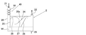
- FIG. 2 is an explanatory diagram showing a configuration of an example of a cleaning unit that can be used in the step (B).
- a scrubbing portion 20a is provided in a chamber 20 having a gas introduction port 21 for introducing the generated gas from the step (A) and a gas outlet 22 for leading out the generated gas that has been cleaned.
- the cleaning liquid W is stored in the bottom of the chamber 20, and the cleaning liquid outlet 29 for leading the cleaning liquid W to the outside is formed on the bottom wall of the chamber 20.
- the cleaning liquid outlet 29 is connected to the pipe 103.
- a flow path forming member 24 for forming a flow path for the generated gas is provided.
- the flow path forming member 24 is a vertical plate 25 provided so as to face the side wall of the chamber 20 and a first curved plate provided on the back surface of the vertical plate 25 and curved in a partially elliptical shape. It is composed of 26, a second curved plate 27 provided on the back surface of the first curved plate 26, and an auxiliary guide plate 28 provided so as to face the second curved plate 27.
- the lower end of the vertical plate 26 is provided so as to be immersed in the stored cleaning liquid W.
- a flow path is formed between the side wall of the chamber 20 and the vertical plate 25 to guide the generated gas introduced from the gas introduction port 21 to the stored cleaning liquid W. Further, between the second curved plate 27 and the auxiliary guide plate 28, a flow path is formed in which the road width becomes smaller from the upstream side to the downstream side.
- the gas generated from the step (a) is introduced into the scrubbing portion 20a from the gas introduction port 21.
- the introduced generated gas flows downward along the flow path between the vertical plate 25 and the side wall of the chamber 20 together with the cleaning liquid W sprayed from the cleaning liquid spraying unit 40. Then, when the generated gas is sprayed onto the liquid surface of the stored cleaning liquid W and comes into contact with the liquid surface, a part of the by-products in the produced gas is precipitated in the cleaning liquid W as a solid component.
- the flow speed of the generated gas is rapidly decelerated. And by slow reversal, droplets due to the cleaning liquid W are separated from the generated gas.
- the scrubbing unit 20a is subjected to the cleaning treatment of the generated gas, and then the gas is led out from the gas outlet 22 to the outside. Further, a part of the stored cleaning liquid W is led out from the cleaning liquid outlet 29 to the outside.
- water or alkaline water can be used as the cleaning liquid W.
- the temperature of the cleaning liquid W is preferably 5 ° C. or higher and 50 ° C. or lower, more preferably 5 ° C. or higher and 30 ° C. or lower.
- the cleaning liquid W led out from the cleaning liquid outlet 29 may be discarded, but it is preferably used as all or part of the cooling medium in the step (C) described later.
- the cleaning liquid W led out from the cleaning liquid outlet 29 is reused as a cooling medium in the step (C) by being supplied to the cooling medium supply mechanism 38 in the quenching tower 3 via the pipe 103. ..
- the mass ratio (cleaning liquid / generated gas) of the cleaning liquid W and the produced gas in the cleaning unit 2 is preferably 1.1 to 8.9. If this mass ratio is less than 1.1, the gas cleaning will be insufficient, and there is a risk that dirt will accumulate on the gas-liquid contact member 37 inside the quenching tower 3 in step () C described later. On the other hand, when this mass ratio exceeds 8.9, the balance between the cleaning liquid and the generated gas is lost, the cleaning mechanism due to the Venturi effect cannot be maintained, and the controllability of the cleaning unit 2 deteriorates. Dirt may also accumulate on the gas-liquid contact member 37 inside the quenching tower 3 in C).
- the pH of the cleaning liquid W is in the range of 6 to 10. If the pH of the cleaning liquid W is less than 6, the dirt cleaning effect of the cleaning liquid will not be exhibited, and there is a risk that dirt will accumulate on the gas-liquid contact member 37 inside the quenching tower 3 in step C described later. .. On the other hand, when the pH of the cleaning liquid W exceeds 10, there is a concern that alkaline corrosion may affect the equipment.
- the product gas washed in the step (B) is cooled.
- the cooling of the generated gas from the step (B) is performed by the quenching tower 3 and the cooling heat exchanger 4.
- the gas generated from the step (B) is supplied to the quenching tower 3 via the pipe 102, cooled in the quenching tower 3, and then cooled by the cooling heat exchanger 4 via the pipe 105. Is further cooled in the cooling heat exchanger 4.
- the produced gas from the step (A) is purified. Specifically, a part of the by-products contained in the produced gas from the step (A) is condensed or precipitated and removed by cooling.
- FIG. 3 is an explanatory diagram showing a configuration of an example of a quenching tower that can be used in the step (C).
- the quenching tower 3 is configured to quench the produced gas to a temperature of, for example, about 30 ° C. or higher and 90 ° C. or lower by bringing a cooling medium into countercurrent contact with the generated gas, and extends in the vertical direction at both ends. It has a closed cylindrical tower body 30.
- a gas introduction port 34 for introducing the gas generated from the step (B) into the inside of the tower main body 30 is provided at a position on the lower side of the peripheral wall portion 31 of the tower main body 30. Further, the tower top portion 32 of the tower body 30 is provided with a gas outlet 35 for leading out the cooled generated gas from the inside of the tower body 30. Further, the bottom 33 of the tower body 30 is provided with a cooling medium outlet 36 for leading out the cooling medium supplied to the inside.
- a gas-liquid contact member 37 is provided at a position between the gas introduction port 34 and the gas outlet 35 in the tower main body 30.
- a plurality of gas-liquid contact members 37 are arranged so as to be vertically overlapped with each other via a space.
- a cooling medium supply mechanism 38 for supplying a cooling medium for cooling the generated gas is provided above the gas-liquid contact member 37 on the uppermost stage.
- the quenching tower 3 when the quenching tower 3 is composed of a filling tower, an irregular filling can be used. Specific examples of irregular fillings include Raschig rings, pole rings, cascade mini rings, and the like. Further, when the quenching tower 3 is composed of a shelf column, a shelf board is used as the gas-liquid contact member 37.
- the cooling medium supply mechanism 38 has a spray head 39 for spraying the cooling medium.
- the spray head 39 is arranged above the gas-liquid contact member 37 at the uppermost stage in the tower body 30 so as to face downward.
- Water or alkaline water can be used as the cooling medium supplied from the cooling medium supply mechanism 38.
- the temperature of the cooling medium is appropriately determined according to the cooling temperature of the produced gas, but is preferably 10 ° C. or higher and 90 ° C. or lower, more preferably 20 ° C. or higher and 70 ° C. or lower, and particularly preferably 20 ° C. or higher. It is 40 ° C. or lower.
- a pipe 102 whose one end is connected to the gas outlet 22 of the reactor 1 is connected to the gas inlet 34 of the quenching tower 3, and a pipe 105 is connected to the gas outlet 35 of the quenching tower 3. .. Further, a pipe 103 is connected to the spray head 39 of the cooling medium supply mechanism 38 in the quenching tower 3, and a pipe 104 is connected to the cooling medium outlet 36 of the quenching tower 3.
- the internal temperature is preferably 10 ° C. or higher and 100 ° C. or lower, and more preferably 20 ° C. or higher and 90 ° C. or lower.
- the pressure of the quenching tower 3 during operation (specifically, the pressure of the gas outlet of the quenching tower 3), that is, the pressure of the step (C) is equal to the pressure of the step (A) or the pressure of the step (A). It is preferably less than the pressure.
- the difference between the pressure of the step (C) and the pressure of the step (A), that is, the value obtained by subtracting the pressure of the step (C) from the pressure of the step (A) is 0 MPaG or more and 0.05 MPaG or less. It is preferably 0.01 MPaG or more, and more preferably 0.04 MPaG or less.
- the reaction by-products in the gas produced from the step (A) can be condensed and dissolved in the cooling medium in the quenching tower 3. It can be promoted, and as a result, the concentration of the reaction by-product in the product gas flowing out from the quenching tower 3 can be further reduced.
- the generated gas is introduced into the tower body 30 from the gas introduction port 34 and is led out from the gas outlet 35.
- the generated gas is circulated from the lower part of the tower main body 30 to the upper part via the gas-liquid contact member 37 inside the tower main body 30.
- the cooling medium by the cooling water supply mechanism 38 is sprayed downward from the spray head 39.
- the supplied cooling medium is led out from the cooling medium outlet 36 to the outside of the tower body 30.
- the derived cooling medium may be discarded, but it may be used as the cleaning liquid W in the step (B).
- the cooling medium led out from the cooling medium outlet 36 is reused as the cleaning liquid W in the step (B) by being supplied to the cleaning liquid spraying unit 40 in the cleaning unit 2 via the pipe 104. ..
- a heat exchanger 4 capable of cooling the generated gas flowing out of the quenching tower 3 to room temperature (10 ° C. or higher and 30 ° C. or lower) is appropriately used.
- the cooling heat exchanger 4 is connected to the gas inlet with a pipe 105 having one end connected to the gas outlet 35 of the quenching tower 3, and is connected to the gas outlet of the heat exchanger 4.
- Piping 106 is connected.
- the pressure of the cooling heat exchanger 4 during operation is the pressure of the quenching tower 3 during operation (specifically, the pressure of the gas outlet of the quenching tower 3). Pressure) is preferably equal to.
- the concentration of molecular nitrogen is preferably 60% by volume or more and 94% by volume or less, more preferably. Is 70% by volume or more and 85% by volume or less.
- the concentration of butadiene is preferably 2% by volume or more and 15% by volume or less, more preferably 3% by volume or more and 10% by volume or less.
- the concentration of water (water vapor) is preferably 1% by volume or more and 30% by volume or less, and more preferably 1% by volume or more and 3% by volume or less.
- the concentration of ketones and aldehydes is preferably 0% by volume or more and 0.3% by volume or less, and more preferably 0.05% by volume or more and 0.25% by volume or less.
- the produced gas obtained through the step (C) is separated (coarse) into molecular oxygen and inert gases and other gases containing 1,3-butadiene by selective absorption into the absorbing solvent.
- the "other gas containing 1,3-butadiene” refers to at least butadiene and 1-butene and 2-butene (unreacted 1-butene and 2-butene) absorbed by the absorbing solvent. Indicates the gas contained.
- the separation of the produced gas through the step (C) is performed by the absorption tower 5 as shown in FIG.
- the absorption tower 5 is provided with a gas introduction port for introducing the gas produced through the step (C) at the lower part, a solvent introduction port for introducing the absorption solvent at the upper part, and the bottom of the tower is provided with a solvent introduction port.
- a solvent outlet is provided to derive an absorption solvent that has absorbed the gas (specifically, other gas containing 1,3-butadiene), and a gas that has not been absorbed by the absorption solvent (specifically) is provided at the top of the column.
- a pipe 106 having one end connected to the gas outlet of the heat exchanger 4 is connected to the gas inlet, a pipe 107 is connected to the solvent inlet, and a pipe 114 is connected to the solvent outlet.
- a pipe 108 is connected to the gas outlet of the absorption tower 5.
- the generated gas that has passed through the step (C), that is, the generated gas that has flowed out from the heat exchanger 4, is sent to the absorption tower 5 via the pipe 106, and is synchronously supplied to the absorption tower 5.
- the absorption solvent is supplied to the absorption tower 5 via the pipe 107.
- the absorbing solvent is countercurrently contacted with the produced gas that has undergone the step (C), and the other gas containing 1,3-butadiene in the produced gas that has undergone the step (C) is selectively absorbed by the absorbing solvent.
- the other gas containing 1,3-butadiene and the molecular oxygen and the inert gas are roughly separated.
- the absorption solvent that absorbed the other gas containing 1,3-butadiene flows out from the absorption tower 5 to the pipe 114, while the molecular oxygen and the inert gas that were not absorbed by the absorption solvent are absorbed. It flows out from the tower 5 to the pipe 108.
- the temperature inside the absorption tower 5 is not particularly limited, but as the temperature inside the absorption tower 5 increases, molecular oxygen and inert gases are less likely to be absorbed by the absorption solvent.
- the absorption efficiency of hydrocarbons such as butadiene (other gases containing 1,3-butadiene) into the absorption solvent increases, so that the productivity of butadiene increases.
- it is preferably 0 ° C. or higher and 60 ° C. or lower, and more preferably 10 ° C. or higher and 50 ° C. or lower.
- the pressure of the absorption tower 5 during operation (specifically, the pressure of the gas outlet of the absorption tower 5), that is, the pressure of the step (D) is equal to the pressure of the step (C) or the pressure of the step (C). It is preferably less than the pressure.
- the difference between the pressure of the step (D) and the pressure of the step (C), that is, the value obtained by subtracting the pressure of the step (D) from the pressure of the step (C) is 0 MPaG or more and 0.05 MPaG or less. It is preferably 0.01 MPaG or more, and more preferably 0.04 MPaG or less.
- the pressure difference between the step (C) and the step (D) within the above range, the absorption of butadiene (other gas containing 1,3-butadiene) into the absorption solvent in the absorption tower 5 can be promoted. As a result, the amount of the absorbing solvent used can be reduced, and the energy consumption can be reduced.
- the absorption solvent examples include those containing an organic solvent as a main component.
- “having an organic solvent as a main component” means that the content ratio of the organic solvent in the absorption solvent is 50% by mass or more.
- the organic solvent constituting the absorption solvent include aromatic compounds such as toluene, xylene and benzene, amide compounds such as dimethylformamide and N-methyl-2-pyrrolidone, sulfur compounds such as dimethyl sulfoxide and sulfolane, acetonitrile and butyronitrile and the like. Examples thereof include nitrile compounds, and ketone compounds such as cyclohexanone and acetophenone.
- the amount of the absorbing solvent used is not particularly limited, but is 10 times by mass with respect to the total flow rate (mass flow rate) of butadiene, 1-butene and 2-butene in the product gas produced through the step (C). It is preferably 100 times by mass or less, and more preferably 17 times by mass or more and 35 times by mass or less.
- the amount of the absorbing solvent used in the above range the absorption efficiency of other gases containing 1,3-butadiene can be improved.
- the amount of the absorbing solvent used is excessive, the amount of energy consumed for purification for circulating use of the absorbing solvent tends to increase. Further, when the amount of the absorbing solvent used is too small, the absorption efficiency of other gases containing 1,3-butadiene tends to decrease.
- the temperature of the absorbing solvent (temperature at the solvent inlet) is preferably 0 ° C. or higher and 60 ° C. or lower, and more preferably 0 ° C. or higher and 40 ° C. or lower.
- the molecular oxygen and the inert gas obtained in the step (D) are fed to the step (A) as a reflux gas.
- the molecular oxygen and the inert gas from the step (D) are processed by the solvent recovery column 6 and the compressor 7. Specifically, the molecular oxygen and the inert gas from the step (D), that is, the molecular oxygen and the inert gas flowing out from the absorption tower 5, are sent to the solvent recovery tower 6 via the pipe 108. After being fed and subjected to solvent removal treatment, it is fed to the compressor 7 via the pipe 111, and is pressure-adjusted if necessary.
- the molecular oxygen and the inert gas from the step (D) which has been subjected to the solvent removal treatment and the pressure adjustment treatment in this manner flow out from the compressor 7 toward the reaction tower 1 into the pipe 113.
- the molecular oxygen and the inert gas discharged from the solvent recovery tower 6 are partly transferred to the pipe 111 in the process of flowing through the pipe 111. It is discarded via the communicating pipe 112.
- the supply amount of the reflux gas for the step (A) is adjusted by providing the pipe 112 for discarding a part of the molecular oxygen and the inert gas flowing out from the solvent recovery tower 6. Can be done.
- the solvent recovery tower 6 is configured to remove the molecular oxygen and the inert gas from the solvent by washing the molecular oxygen and the inert gas from the step (D) with water or a solvent.
- a gas introduction port for introducing the molecular oxygen and the inert gas from the step (D) is provided in the central portion of the solvent recovery tower 6.
- a cleaning liquid inlet for introducing water or solvent is provided in the upper part of the solvent recovery tower 6.
- a pipe 108 whose one end is connected to the gas outlet of the absorption tower 5 is connected to the gas introduction port, and a pipe 109 is connected to the cleaning liquid introduction port.
- the solvent recovery tower 6 is provided at the top of the tower with a gas outlet for leading out molecular oxygen and inert gases washed with water or a solvent. Further, the bottom of the solvent recovery tower 6 is provided with a cleaning liquid outlet for leading out the water or solvent used for cleaning the molecular oxygen and the inert gas from the step (D).
- a pipe 111 is connected to the gas outlet of the solvent recovery tower 6, and a pipe 110 is connected to the cleaning liquid outlet.
- the absorption solvent contained in the molecular oxygen and the inert gas from the step (D) is removed, and the removed absorption solvent is washed together with the water or solvent used for washing.
- the liquid flows out from the liquid outlet to the pipe 110 and is collected through the pipe 110. Further, the molecular oxygen and the inert gas from the step (D) that have been subjected to the solvent removal treatment flow out to the pipe 111 from the gas outlet of the solvent recovery tower 6.
- the temperature inside the solvent recovery tower 6 is not particularly limited, but is preferably 0 ° C. or higher and 80 ° C. or lower, and more preferably 10 ° C. or higher and 60 ° C. or lower. ..
- compressor 7 a compressor capable of boosting the molecular oxygen and the inert gas from the solvent recovery column 6 as necessary to obtain the pressure required in the step (A) is appropriately used.
- the compressor 7 is connected to the gas inlet with a pipe 111 having one end connected to the gas outlet of the solvent recovery tower 6, and the compressor 7 has a pipe 113 connected to the gas outlet. It is connected.
- the pressure difference is increased according to the pressure difference between the step (D) and the step (A).
- the boosting is usually small, so that the electric energy consumption of the compressor remains small.
- the concentration of molecular nitrogen in the molecular oxygen and the inert gas discharged from the compressor 7, that is, the reflux gas is preferably 87% by volume or more and 97% by volume or less, and more preferably 90% by volume or more and 95% by volume or more. It is less than or equal to the volume.
- the concentration of molecular oxygen is preferably 1% by volume or more and 6% by volume or less, more preferably 2% by volume or more and 5% by volume or less.
- the absorption solvent obtained in the step (D) that has absorbed other gas containing 1,3-butadiene is subjected to solvent separation treatment. That is, by separating the absorption solvent from the absorption solvent from the step (D), a gas flow of another gas containing 1,3-butadiene, that is, a gas containing 1,3-butadiene is obtained.
- the thawing column 8 separates the other gas containing 1,3-butadiene from the absorbing solvent.
- the absorption solvent from the step (D), that is, the absorption solvent that has absorbed the other gas containing 1,3-butadiene that has flowed out from the absorption tower 5, is desorbed through the pipe 114. Is fed to and subjected to solvent separation treatment. Then, in the demelting tower 8, the other gas containing 1,3-butadiene and the absorbing solvent are distilled and separated.
- the demelting column 8 has a structure in which the solvent separation treatment is performed by distilling and separating the absorbing solvent from the step (D).
- a solvent introduction port for introducing the absorption solvent from the step (D) is provided in the central portion of the demelting tower 8.
- a gas outlet for deriving a gas containing 1,3-butadiene separated from the absorption solvent from the step (D) is provided at the top of the demelting column 8.
- the bottom of the demelting column 8 is provided with a solvent outlet for deriving the absorbing solvent separated from the absorbing solvent from the step (D).
- a pipe 114 whose one end is connected to the solvent outlet of the absorption tower 5 is connected to the solvent introduction port, and a pipe 117 is connected to the gas outlet of the demelting tower 8 to the solvent outlet. Is connected to the pipe 115.
- the gas containing 1,3-butadiene and the absorption solvent separated from the absorption solvent from the step (D) are separated from each other, and the gas containing 1,3-butadiene is discharged from the gas outlet. It flows out to the pipe 117, and the absorbing solvent flows out to the pipe 115 from the solvent outlet.
- the pressure inside the demelting tower 8 is not particularly limited, but is preferably 0.03 MPaG or more and 1.0 MPaG or less, and more preferably 0.2 MPaG or more and 0.6 MPaG or less.
- the temperature of the bottom of the thawing tower 8 is preferably 80 ° C. or higher and 190 ° C. or lower, and more preferably 100 ° C. or higher and 180 ° C. or lower.
- the precipitated solid component is removed by cleaning the produced gas in the step (B) before subjecting the produced gas to the step (C) for cooling. Therefore, it is possible to prevent or suppress a large amount of solid components precipitated by cooling in the step (C) from adhering to the solid filler, shelf board, etc. in the quenching tower 3, and as a result, the cooling of the produced gas is prolonged. It can be executed stably over a period of time.
- Example 1 According to the flow chart of FIG. 1, by going through the following steps (A), step (C), step (D), desolubilization step and circulation step, 1, 3 from the raw material gas containing 1-butene and 2-butene -Butadiene was produced continuously for 72 hours. Further, as the raw material gas, a gas containing 1-butene and 2-butene and having a ratio of 2-butene to 87% by volume with respect to a total of 100% by volume of 1-butene and 2-butene was used.
- Step (A) A reactor 1 (inner diameter 21.2 mm, outer diameter 25.4 mm) filled with a metal oxide catalyst so that the catalyst layer length is 1500 mm is filled with a volume ratio (1-butene and 2-butene / O 2 / N 2).
- a mixed gas having a / H 2 O) of 1 / 1.5 / 16.3 / 1.2 is supplied at a GHSV of 2000 h -1 , and a raw material gas and molecular oxygen are supplied depending on the conditions of a reaction temperature of 320 to 350 ° C.
- a produced gas containing 1,3-butadiene was obtained by subjecting the contained gas to an oxidative dehydrogenation reaction.
- the pressure in this first step was 0.1 MPaG.
- the actual volume GHSV of the mixed gas was 2150 h -1 .
- an oxide represented by the composition formula Mo 12 Bi 5 Fe 0.5 Ni 2 Co 3 K 0.1 Cs 0.1 Sb 0.2 is added to spherical silica at a ratio of 20% of the total catalyst volume.
- the one supported by was used.
- the mixed gas is a mixture of a raw material gas and a reflux gas (molecular oxygen and inert gases), and if necessary, air as a molecular oxygen-containing gas, molecular nitrogen as an inert gas, and the like.
- the composition is adjusted by further mixing water (steam).
- Step (B) Using the cleaning unit shown in FIG. 2, the generated gas was cleaned under the following conditions. Mass ratio of cleaning liquid W and generated gas in the cleaning unit 2: 1.1 Cleaning solution W pH: 3-5
- Step (C) As the quenching tower 3, the one having the following specifications was used.
- Overall length of tower body 20 0.4 cm Inner diameter of tower body 20: 0.026 cm
- Gas-liquid contact member 37 Irregular filling (Raschig ring) Number of irregular fillings filled in the gas-liquid contact member 37: 270
- the generated gas flowing out of the reactor 1 was brought into countercurrent contact with the cooling medium in the quenching tower 3 to be rapidly cooled, cooled to 76 ° C., and then cooled to 30 ° C. in the cooling heat exchanger 4.
- the pressure in this step (C) that is, the pressure at the gas outlet of the quenching tower 3 was 0.1 MPaG, and the pressure at the gas outlet of the cooling heat exchanger 4 was also 0.1 MPaG.
- Step (D) The generated gas flowing out from the heat exchanger 4 (hereinafter, also referred to as “cooling generated gas”) is collected from the absorption tower 5 (outer diameter 152.4 mm, height 7800 mm, material SUS304) in which a regular filling is arranged. It was supplied from the lower gas inlet, and an absorption solvent containing 95% by mass or more of toluene was supplied at 10 ° C. from the upper solvent inlet of the absorption tower 5. The amount of the absorbing solvent supplied was 33 times by mass with respect to the total flow rate (mass flow rate) of butadiene, 1-butene and 2-butene in the cooling product gas.
- a gas containing 1,3-butadiene was obtained by supplying the liquid flowing out from the absorption tower 5 to the thawing tower 8 and cooling the gas flowing out from the thawing tower main body with a condenser.
- an effluent that is, an absorption solvent (hereinafter, also referred to as “circulation absorption solvent”), in which a part of the effluent from the main body of the demelting tower was heated in a reboiler was obtained.
- the gas containing 1,3-butadiene and the circulating absorption solvent were distilled and separated in the demelting tower 8.
- step (B) 1-butene and 1-butene and the same as in Example 1 except that the mass ratio of the cleaning liquid W and the produced gas in the cleaning unit 2 was changed to 8.9 and the pH of the cleaning liquid W was changed to 6 to 8. 1,3-butadiene was continuously produced from the raw material gas containing 2-butene for 72 hours.
- Example 1 In Examples 1 and 2 and Comparative Example 1, after the production of 1,3-butadiene was completed, the gas-liquid contact member 37 in the lowermost stage of the quenching tower 3 was examined. However, in Comparative Example 1, it was confirmed that a large amount of solid components were attached. Further, in each of the cleaning unit 2 and the quenching tower 3, the mass of the solid components precipitated per hour is measured, and in the cleaning unit 2 with respect to the total mass of the solid components precipitated in each of the cleaning unit 2 and the quenching tower 3. The ratio of the mass of the precipitated solid component was determined as the removal rate of the solid component by the cleaning unit 2. As a result, the removal rate of the solid component in Example 1 was 59.4%, and the removal rate of the solid component in Example 2 was 72.9%.
Landscapes
- Chemical & Material Sciences (AREA)
- Organic Chemistry (AREA)
- Engineering & Computer Science (AREA)
- Analytical Chemistry (AREA)
- Oil, Petroleum & Natural Gas (AREA)
- Water Supply & Treatment (AREA)
- Organic Low-Molecular-Weight Compounds And Preparation Thereof (AREA)
Abstract
生成ガスの冷却工程において、固形成分の発生が防止または抑制され、生成ガスの冷却が長期間にわたって安定して実行される1,3-ブタジエンの製造方法の提供。 金属酸化物触媒の存在下において、n-ブテンを含む原料ガスと酸素とを酸化脱水素反応することにより、1, 3-ブタジエンを含む生成ガスを得る工程(A)、前記工程(A)において得られた前記生成ガスを洗浄処理する工程(B)、前記工程(B)において洗浄処理された前記生成ガスを、冷却媒体に接触することによって冷却する工程(C)、および前記工程(C)において冷却された前記生成ガスを、吸収溶媒への選択的吸収により、分子状酸素および不活性ガス類と1,3-ブタジエンを含むその他のガスとに分離する工程(D)を有し、前記工程(B)においては、前記生成ガスを洗浄液の液面に吹き付けて接触させることによって洗浄処理することを特徴とする。
Description
本発明は、1,3-ブタジエンの製造方法に関し、更に詳しくは、酸化脱水素反応を利用する1,3-ブタジエンの製造方法に関する。
従来、1,3-ブタジエン(以下、単に「ブタジエン」ともいう。)を製造する方法としては、ナフサのクラッキングにより得られた炭素数4の留分(以下、「C4留分」ともいう。)からブタジエン以外の成分を蒸留によって分離する方法が採用されている。
ブタジエンは合成ゴムなどの原料として需要が増加しているが、エチレンの製法がナフサのクラッキングによる方法からエタンの熱分解による方法に移行している等の事情により、C4留分の供給量が減少しており、C4留分を原料としないブタジエンの製造が求められている。
ブタジエンは合成ゴムなどの原料として需要が増加しているが、エチレンの製法がナフサのクラッキングによる方法からエタンの熱分解による方法に移行している等の事情により、C4留分の供給量が減少しており、C4留分を原料としないブタジエンの製造が求められている。
そこで、ブタジエンの製造方法として、n-ブテンを酸化脱水素させて得られる生成ガスからブタジエンを分離して得る方法が注目されている(例えば特許文献1乃至特許文献4参照。)。この製造方法は、n-ブテンと、分子状酸素を含有する分子状酸素含有ガス(具体的には、例えば空気)とを含む原料ガスを、酸化脱水素反応させる酸化脱水素反応工程と、この工程によって得られた生成ガスを冷却する冷却工程と、この工程によって冷却された生成ガスからブタジエンを分離する生成ガス分離工程とを有する。冷却工程においては、生成ガスを冷却媒体に向流接触させることによって急冷する、例えば充填塔または棚段塔からなる急冷塔が用いられている。
しかしながら、上記のブタジエンの製造方法においては、アセトアルデヒド、メチルビニルケトン等のカルボニル化合物や、カルボン酸等の有機酸類などの反応副生成物が発生する。このような反応副生成物は、例えば冷却工程において生成ガスが急冷されることにより析出し、用いられる急冷塔内における固体充填物または棚板(トレイ)に固形成分が付着する。この固形成分の付着量が経時的に多くなると、急冷塔内に差圧が生じることにより、冷却工程の続行が不能となる。このため、急冷塔を分解して付着した固形成分を除去することが必要となり、従って、生成ガスの冷却を長期間にわたって安定して実行することが困難である。
本発明は、以上のような事情に基づいてなされたものであり、その目的は、生成ガスを冷却する工程において、固形成分の発生を防止または抑制することができ、生成ガスの冷却を長期間にわたって安定して実行することができる1,3-ブタジエンの製造方法を提供することにある。
本発明の1,3-ブタジエンの製造方法は、金属酸化物触媒の存在下において、n-ブテンを含む原料ガスと酸素とを酸化脱水素反応することにより、1, 3-ブタジエンを含む生成ガスを得る工程(A)、
前記工程(A)において得られた前記生成ガスを洗浄処理する工程(B)、
前記工程(B)において洗浄処理された前記生成ガスを、冷却媒体に接触することによって冷却する工程(C)、および
前記工程(C)において冷却された前記生成ガスを、吸収溶媒への選択的吸収により、分子状酸素および不活性ガス類と1,3-ブタジエンを含むその他のガスとに分離する工程(D)を有し、
前記工程(B)においては、前記生成ガスを洗浄液の液面に吹き付けて接触させることによって洗浄処理することを特徴とする。
前記工程(A)において得られた前記生成ガスを洗浄処理する工程(B)、
前記工程(B)において洗浄処理された前記生成ガスを、冷却媒体に接触することによって冷却する工程(C)、および
前記工程(C)において冷却された前記生成ガスを、吸収溶媒への選択的吸収により、分子状酸素および不活性ガス類と1,3-ブタジエンを含むその他のガスとに分離する工程(D)を有し、
前記工程(B)においては、前記生成ガスを洗浄液の液面に吹き付けて接触させることによって洗浄処理することを特徴とする。
本発明の1,3-ブタジエンの製造方法においては、前記工程(B)は、洗浄ユニット内において実行され、当該洗浄ユニット内における前記洗浄液と前記生成ガスとの質量比が、1.1~8.9であることが好ましい。
また、本発明の1,3-ブタジエンの製造方法においては、前記洗浄ユニットは、前記生成ガスを洗浄処理するスクラビング部を1段以上有することが好ましい。
また、本発明の1,3-ブタジエンの製造方法においては、前記工程(B)において、前記洗浄液のpHが6~10の範囲にあることが好ましい。
また、本発明の1,3-ブタジエンの製造方法においては、前記工程(B)における前記生成ガスの洗浄処理後の洗浄液を、前記工程(C)において前記生成ガスを冷却する冷却媒体として用いることが好ましい。
本発明の1,3-ブタジエンの製造方法によれば、生成ガスを冷却する工程(C)に供する前に、工程(B)において生成ガスを洗浄処理することにより、析出する固形成分が除去されるため、工程(C)において冷却によって析出する固形成分が固体充填物や棚板などに多量に付着することを防止または抑制することができ、その結果、生成ガスの冷却を長期間にわたって安定して実行することができる。
以下、本発明の実施の形態について説明する。
本発明のブタジエン(1,3-ブタジエン)の製造方法は、下記の(1)~(4)に示す工程を有するものであり、当該下記の(1)~(4)の工程を経ることにより、n-ブテンを含む原料ガスからブタジエンを製造するものである。
(1)金属酸化物触媒の存在下において、n-ブテンを含む原料ガスと酸素とを酸化脱水素反応することにより、1,3-ブタジエンを含む生成ガスを得る工程(A)
(2)工程(A)において得られた生成ガスを洗浄処理する工程(B)
(3)工程(B)において洗浄処理された生成ガスを、冷却媒体に接触することによって冷却する工程(C)
(4)工程(C)において冷却された生成ガスを、吸収溶媒への選択的吸収により、分子状酸素および不活性ガス類と1,3-ブタジエンを含むその他のガスとに分離する工程(D)
図1は、本発明のブタジエンの製造方法を実施するための具体的な手法の一例を示すフロー図である。以下、図1を用いて、本発明のブタジエンの製造方法の具体的な一例を詳細に説明する。
図1に示す例のブタジエンの製造方法は、上記の(1)~(4)の工程を有すると共に、工程(D)において得られた、1,3-ブタジエンを含むその他のガスを吸収した吸収溶媒を、溶媒分離処理する脱溶工程と、工程(D)において得られた、分子状酸素および不活性ガス類を、工程(A)に還流する、すなわち還流ガスとして送給する循環工程とを有するものである。
また、図1に示す例のブタジエンの製造方法においては、工程(D)に供される吸収溶媒が循環使用される。
図1に示す例のブタジエンの製造方法は、上記の(1)~(4)の工程を有すると共に、工程(D)において得られた、1,3-ブタジエンを含むその他のガスを吸収した吸収溶媒を、溶媒分離処理する脱溶工程と、工程(D)において得られた、分子状酸素および不活性ガス類を、工程(A)に還流する、すなわち還流ガスとして送給する循環工程とを有するものである。
また、図1に示す例のブタジエンの製造方法においては、工程(D)に供される吸収溶媒が循環使用される。
<工程(A)>
工程(A)においては、金属酸化物触媒の存在下において、原料ガスと分子状酸素含有ガスとを酸化脱水素反応させることにより、ブタジエン(1,3-ブタジエン)を含む生成ガスを得る。この工程(A)において、原料ガスと分子状酸素含有ガスとの酸化脱水素反応は、図1に示されているように、反応器1によって行われる。ここに、反応器1は、上部にガス導入口、下部にガス導出口が設けられ、内部に金属酸化物触媒が充填されることによって触媒層(図示省略)が形成された塔状のものである。この反応器1において、ガス導入口には配管116を介して配管100と配管113とが接続されており、また、洗浄ユニット2のガス導出口には、配管101が接続されている。
工程(A)においては、金属酸化物触媒の存在下において、原料ガスと分子状酸素含有ガスとを酸化脱水素反応させることにより、ブタジエン(1,3-ブタジエン)を含む生成ガスを得る。この工程(A)において、原料ガスと分子状酸素含有ガスとの酸化脱水素反応は、図1に示されているように、反応器1によって行われる。ここに、反応器1は、上部にガス導入口、下部にガス導出口が設けられ、内部に金属酸化物触媒が充填されることによって触媒層(図示省略)が形成された塔状のものである。この反応器1において、ガス導入口には配管116を介して配管100と配管113とが接続されており、また、洗浄ユニット2のガス導出口には、配管101が接続されている。
工程(A)について具体的に説明すると、反応器1に、配管116に連通する配管100を介して、原料ガスおよび分子状酸素含有ガス、並びに、必要に応じて、不活性ガス類および水(水蒸気)(以下、これらをまとめて「新規供給ガス」ともいう。)を供給する。新規供給ガスは、反応器1に導入される前に、当該反応器1と配管100との間に配設された予熱器(図示省略)によって200℃以上400℃以下程度に加熱される。また、反応器1には、配管100を介して供給される新規供給ガスと共に、循環工程からの還流ガスが、配管116に連通する配管113を介して、前記予熱器によって加熱された後、供給される。すなわち、反応器1には、新規供給ガスと還流ガスとの混合ガスが、予熱器によって加熱された後、供給される。ここに、新規供給ガスと還流ガスとは、別個の配管から反応器1に直接供給されてもよいが、図1に示されているように、共通の配管116から、混合された状態で供給されることが好ましい。共通の配管116を設けることにより、種々の成分を含む混合ガスを、予め均一に混合した状態で反応器1に供給することができるため、当該反応器1内において不均一な混合ガスが部分的に爆鳴気を形成する事態を防止することなどができる。
そして、混合ガスが供給された反応器1においては、原料ガスと分子状酸素含有ガスとの酸化脱水素反応によってブタジエン(1,3-ブタジエン)が生成されて、そのブタジエンを含む生成ガスが得られる。得られた生成ガスは、反応器1のガス導出口から配管101に流出する。
そして、混合ガスが供給された反応器1においては、原料ガスと分子状酸素含有ガスとの酸化脱水素反応によってブタジエン(1,3-ブタジエン)が生成されて、そのブタジエンを含む生成ガスが得られる。得られた生成ガスは、反応器1のガス導出口から配管101に流出する。
(原料ガス)
原料ガスとしては、炭素数4のモノオレフィンであるn-ブテンを気化器(図示省略)でガス化したガス状物が用いられる。この原料ガスは、可燃性ガスである。本発明において、「n-ブテン」とは、直鎖状ブテンを意味し、具体的には、1-ブテン、シス-2-ブテンおよびトランス-2-ブテンがn-ブテンに含まれる。
また、原料ガスには、任意の不純物が含まれていてもよい。この不純物の具体例としては、i-ブテン等の分岐型モノオレフィン、プロパン、n-ブタンおよびi-ブタン等の飽和炭化水素などが挙げられる。また、原料ガスには、不純物として、製造目的物である1,3-ブタジエンが含まれていてもよい。原料ガスにおける不純物量は、通常、原料ガス100体積%において、60体積%以下であり、好ましくは40体積%以下、より好ましくは25体積%以下、特に好ましくは5体積%以下である。不純物量が過大である場合には、原料ガスにおける直鎖状ブテンの濃度が低下することに起因して反応速度が遅くなったり、副生成物量が増加したりする傾向にある。
原料ガスとしては、例えば、ナフサ分解で副生するC4留分(炭素数4の留分)からブタジエンおよびi-ブテンを分離して得られる直鎖状ブテンを主成分とする留分(ラフィネート2)や、n-ブタンの脱水素反応または酸化脱水素反応により生成するブテン留分を使用することができる。また、エチレンの2量化により得られる、高純度の、1-ブテン、シス-2-ブテンおよびトランス-2-ブテン、並びに、これらの混合物を含有するガスを使用することもできる。さらには、石油精製プラントなどで原油を蒸留した際に得られる重油留分を、流動層状態で粉末状の固体触媒を使って分解し、低沸点の炭化水素に変換する流動接触分解(Fluid Catalytic Cracking)から得られる炭素数4の炭化水素類を多く含むガス(以下、「FCC-C4」と略記することもある。)をそのまま原料ガスとすることもでき、また、FCC-C4からリンなどの不純物を除去したものを原料ガスとして使用することもできる。
(分子状酸素含有ガス)
分子状酸素含有ガスは、通常、分子状酸素(O2)を10体積%以上含むガスである。この分子状酸素含有ガスにおいて、分子状酸素の濃度は、15体積%以上であることが好ましく、より好ましくは20体積%以上である。
また、分子状酸素含有ガスは、分子状酸素と共に、分子状窒素(N2)、アルゴン(Ar)、ネオン(Ne)、ヘリウム(He)、一酸化炭素(CO)、二酸化炭素(CO2)および水(水蒸気)などの任意のガスを含むものであってもよい。分子状酸素含有ガスにおける任意のガスの量は、任意のガスが分子状窒素である場合には、通常、90体積%以下であり、好ましくは85体積%以下、より好ましくは80体積%以下であり、また、任意のガスが分子状窒素以外のガスである場合には、通常、10体積%以下であり、好ましくは1体積%以下である。任意のガスの量が過大である場合には、反応系(反応器1の内部)において、必要とされる量の分子状酸素を原料ガスと共存させることができなくなるおそれがある。
工程(A)において、分子状酸素含有ガスの好ましい具体例としては、空気が挙げられる。
(不活性ガス類)
不活性ガス類は、原料ガスおよび分子状酸素含有ガスと共に反応器1に供給されることが好ましい。
反応器1に不活性ガス類を供給することにより、当該反応器1内において、混合ガスが爆鳴気を形成することがないように、原料ガスおよび分子状酸素の濃度(相対濃度)を調整することができる。
不活性ガス類としては、分子状窒素(N2)、アルゴン(Ar)および二酸化炭素(CO2)などが挙げられる。これらは、単独でまたは二種以上を組み合わせて用いることができる。これらの中では、経済的観点から、分子状窒素が好ましい。
不活性ガス類は、原料ガスおよび分子状酸素含有ガスと共に反応器1に供給されることが好ましい。
反応器1に不活性ガス類を供給することにより、当該反応器1内において、混合ガスが爆鳴気を形成することがないように、原料ガスおよび分子状酸素の濃度(相対濃度)を調整することができる。
不活性ガス類としては、分子状窒素(N2)、アルゴン(Ar)および二酸化炭素(CO2)などが挙げられる。これらは、単独でまたは二種以上を組み合わせて用いることができる。これらの中では、経済的観点から、分子状窒素が好ましい。
(水(水蒸気))
水は、原料ガスと分子状酸素含有ガスと共に反応器1に供給されることが好ましい。
反応器1に水を供給することにより、前述の不活性ガス類と同様に、当該反応器1内において、混合ガスが爆鳴気を形成することがないように、原料ガスおよび分子状酸素の濃度(相対濃度)を調整することができる。
水は、原料ガスと分子状酸素含有ガスと共に反応器1に供給されることが好ましい。
反応器1に水を供給することにより、前述の不活性ガス類と同様に、当該反応器1内において、混合ガスが爆鳴気を形成することがないように、原料ガスおよび分子状酸素の濃度(相対濃度)を調整することができる。
(混合ガス)
混合ガスは、可燃性の原料ガスと分子状酸素とを含むものであることから、原料ガスの濃度が爆発範囲とならないように、その組成が調整される。
具体的には、混合ガスを構成する各々のガス(具体的には、原料ガス、分子状酸素含有ガス(空気)、並びに、必要に応じて用いられる不活性ガス類および水(水蒸気))を反応器1に供給する配管(具体的には、配管100に連通する配管(図示省略)および配管113)に設置された流量計(図示省略)にて流量を監視しながら、反応器1のガス導入口における混合ガスの組成を制御する。例えば、配管113を介して反応器1に供給される還流ガスの分子状酸素濃度に応じて、配管100を介して反応器1に供給する新規供給ガスの組成を制御する。
なお、本明細書中において、「爆発範囲」とは、混合ガスが何らかの着火源の存在下で着火するような組成を有する範囲を示す。ここに、可燃性ガスの濃度が或る値より低い場合には着火源が存在しても着火しないことが知られており、この濃度を爆発下限界という。爆発下限界は、爆発範囲の下限値である。また、可燃性のガスの濃度が或る値より高い場合にはやはり着火源が存在しても着火しないことが知られており、この濃度を爆発上限界という。爆発上限界は、爆発範囲の上限値である。そして、これらの値は分子状酸素の濃度に依存しており、一般に、分子状酸素の濃度が低いほど両者の値が近づき、分子状酸素の濃度が或る値になったとき両者が一致する。このときの分子状酸素の濃度を限界酸素濃度という。而して、混合ガスにおいては、分子状酸素の濃度が限界酸素濃度よりも低ければ原料ガスの濃度によらず混合ガスは着火しない。
具体的に、混合ガスにおいて、1-ブテンと2-ブテンとの合計の濃度は、ブタジエンの生産性および金属酸化物触媒の負担抑制の観点から、混合ガス100体積%において、2体積%以上30体積%以下であることが好ましく、より好ましくは3体積%以上25体積%以下であり、特に好ましくは5体積%以上20体積%以下である。1-ブテンと2-ブテンとの合計の濃度が過小である場合には、ブタジエンの生産性が低下するおそれがある。一方、1-ブテンと2-ブテンとの合計の濃度が過大である場合には、金属酸化物触媒の負担が大きくなるおそれがある。
また、混合ガスにおいて、原料ガスに対する分子状酸素の濃度(相対濃度)は、原料ガス100体積部に対して、50体積部以上170体積部以下であることが好ましく、より好ましくは70体積部以上160体積部以下である。混合ガスにおける分子状酸素の濃度が上記の範囲を逸脱する場合には、反応温度を調整することによって反応器1のガス導出口における分子状酸素の濃度を調整しづらくなる傾向がある。そして、反応温度によって反応器1のガス導出口における分子状酸素の濃度を制御できなくなることによれば、反応器1の内部における目的生成物の分解および副反応の発生を抑止することができなくなるおそれがある。
また、混合ガスにおいて、原料ガスに対する分子状窒素の濃度(相対濃度)は、原料ガス100体積部に対して、400体積部以上1800体積部以下であることが好ましく、より好ましくは500体積部以上1700体積部以下である。また、原料ガスに対する水(水蒸気)の濃度(相対濃度)は、原料ガス100体積部に対して、0体積部以上900体積部以下であることが好ましく、より好ましくは80体積部以上300体積部以下である。分子状窒素の濃度や水の濃度が過大である場合には、いずれの場合においても、その値が大きくなるほど、原料ガスの濃度が小さくなることからブタジエンの生産効率が低下する傾向がある。一方、分子状窒素の濃度や水の濃度が過小である場合には、いずれの場合においても、その値が小さくなるほど、原料ガスの濃度が爆発範囲となったり、後述する、反応系の除熱が困難となったりする傾向がある。
(金属酸化物触媒)
金属酸化物触媒としては、モリブデンおよびビスマスを含有する複合酸化物触媒が用いられる。このような複合酸化物触媒としては、例えば、モリブデン(Mo)、ビスマス(Bi)および鉄(Fe)を少なくとも含有するものを用いることができ、その具体例としては、下記の組成式(1)で表される複合金属酸化物を含有するものが挙げられる。
金属酸化物触媒としては、モリブデンおよびビスマスを含有する複合酸化物触媒が用いられる。このような複合酸化物触媒としては、例えば、モリブデン(Mo)、ビスマス(Bi)および鉄(Fe)を少なくとも含有するものを用いることができ、その具体例としては、下記の組成式(1)で表される複合金属酸化物を含有するものが挙げられる。
組成式(1):
MoaBibFecXdYeZfOg
MoaBibFecXdYeZfOg
上記の組成式(1)中、Xは、NiおよびCoよりなる群から選ばれる少なくとも一種である。Yは、Li、Na、K、Rb、CsおよびTlよりなる群から選ばれる少なくとも一種である。Zは、Mg、Ca、Ce、Zn、Cr、Sb、As、B、PおよびWよりなる群から選ばれる少なくとも一種である。a、b、c、d、e、fおよびgは、それぞれ独立して、各元素の原子比率を示し、aが12のとき、bは0.1~8であり、cは0.1~20であり、dは0~20であり、eは0~4であり、fは0~2であり、gは上記各成分の原子価を満足するのに必要な酸素元素の原子数である。
上記の組成式(1)で表される複合金属酸化物を含有する複合酸化物触媒は、酸化脱水素反応を使用してブタジエンを製造する方法において、高活性かつ高選択性であり、さらに寿命安定性に優れている。
複合酸化物触媒の調製法としては、特に限定されず、調製すべき複合酸化物触媒を構成する複合金属酸化物に係る各元素の原料物質を用いた、蒸発乾固法、スプレードライ法、酸化物混合法などの公知の方法を採用することができる。
上記各元素の原料物質としては、特に限定されず、例えば、成分元素の酸化物、硝酸塩、炭酸塩、アンモニウム塩、水酸化物、カルボン酸塩、カルボン酸アンモニウム塩、ハロゲン化アンモニウム塩、水素酸、アルコキシドなどが挙げられる。
上記各元素の原料物質としては、特に限定されず、例えば、成分元素の酸化物、硝酸塩、炭酸塩、アンモニウム塩、水酸化物、カルボン酸塩、カルボン酸アンモニウム塩、ハロゲン化アンモニウム塩、水素酸、アルコキシドなどが挙げられる。
また、複合酸化物触媒は、不活性な担体に担持させて使用してもよい。担体種としてはシリカ、アルミナ、シリコンカーバイドなどが挙げられる。
(酸素脱水素反応)
工程(A)において、酸化脱水素反応を開始させるときには、先ずは反応器1に対する、分子状酸素含有ガス、不活性ガス類および水(水蒸気)の供給を開始し、それらの供給量を調整することによって、反応器1のガス導入口における分子状酸素の濃度が限界酸素濃度以下となるように調整し、次いで、原料ガスの供給を開始し、反応器1のガス導入口における原料ガスの濃度が爆発上限界を超えるように、原料ガスの供給量と分子状酸素含有ガスの供給量とを増加していくことが好ましい。
また、原料ガスおよび分子状酸素含有ガスの供給量を増やしていくときには、水(水蒸気)の供給量を減らすことにより、混合ガスの供給量を一定となるようにしてもよい。このようにすることにより、配管や反応器1におけるガス滞留時間が一定に保たれ、反応器1の圧力の変動を抑えることができる。
反応器1の圧力(具体的には、反応器1のガス導入口における圧力)、すなわち工程(A)の圧力は、0.1MPaG以上0.4MPaG以下であることが好ましく、より好ましくは0.15MPaG以上0.35MPaG以下であり、さらに好ましくは0.2MPaG以上0.3MPaG以下である。
工程(A)の圧力を上記範囲とすることにより、酸化脱水素反応における反応効率が向上する。工程(A)の圧力が過小である場合には、酸化脱水素反応における反応効率が低下する傾向にある。一方、工程(A)の圧力が過大である場合には、酸化脱水素反応における収率が低下する傾向にある。
工程(A)の圧力を上記範囲とすることにより、酸化脱水素反応における反応効率が向上する。工程(A)の圧力が過小である場合には、酸化脱水素反応における反応効率が低下する傾向にある。一方、工程(A)の圧力が過大である場合には、酸化脱水素反応における収率が低下する傾向にある。
また、酸化脱水素反応において、下記の数式(1)により求められる気体時空間速度(GHSV)は、500h-1以上5000h-1以下であることが好ましく、より好ましくは800h-1以上3500h-1以下であり、さらに好ましくは1000h-1以上3000h-1以下である。
GHSVを上記範囲とすることにより、酸化脱水素反応における反応効率をより向上させることができる。
GHSVを上記範囲とすることにより、酸化脱水素反応における反応効率をより向上させることができる。
数式(1):
GHSV[h-1]=大気圧換算ガス流量[Nm3 /h]÷触媒層体積[m3 ]
GHSV[h-1]=大気圧換算ガス流量[Nm3 /h]÷触媒層体積[m3 ]
上記の数式(1)中、「触媒層体積」とは、空隙を含む触媒層全体の体積(見かけ体積)を示す。
また、酸化脱水素反応において、下記の数式(2)により求められる実体積気体時空間速度(実体積GHSV)は、500h-1以上2300h-1以下であることが好ましく、より好ましくは600h-1以上2000h-1以下であり、さらに好ましくは700h-1以上1500h-1以下である。
実体積GHSVを上記範囲とすることにより、酸化脱水素反応における反応効率をより向上させることができる。
実体積GHSVを上記範囲とすることにより、酸化脱水素反応における反応効率をより向上させることができる。
数式(2):
実体積GHSV[h-1]=実ガス流量[m3 /h]÷触媒層体積[m3 ]
実体積GHSV[h-1]=実ガス流量[m3 /h]÷触媒層体積[m3 ]
上記の数式(2)中、「触媒層体積」とは、上記数式(1)と同様に、空隙を含む触媒層全体の体積(見かけ体積)を示す。
また、酸化脱水素反応においては、当該酸化脱水素反応が発熱反応であることから、反応系の温度が上昇し、また、複数種類の副生成物が生成し得る。そして、副生成物として、アクロレイン、アクリル酸、メタクロレイン、メタクリル酸、マレイン酸、フマル酸、無水マレイン酸、メチルビニルケトン、クロトンアルデヒドおよびクロトン酸などの炭素数3~4の不飽和カルボニル化合物が生成し、生成ガスにおける濃度が高くなることによれば、種々の弊害が生じる。具体的には、上記不飽和カルボニル化合物が、工程(D)にて循環使用する吸収溶媒などに溶解することから、吸収溶媒などにおいて不純物が蓄積し、各部材における付着物の析出が誘発されやすくなる。
而して、酸化脱水素反応において、上記不飽和カルボニル化合物の濃度を一定の範囲内とする手法としては、酸化脱水素反応の反応温度を調整する方法が挙げられる。また、反応温度を調整することにより、反応器1のガス導出口における分子状酸素の濃度を、一定範囲内とすることもできる。
具体的に、反応温度は、300℃以上400℃以下であることが好ましく、より好ましくは320℃以上380℃未満である。
反応温度を上記範囲とすることにより、金属酸化物触媒におけるコーキング(固体炭素の析出)を抑制することができると共に、生成ガスにおける、上記不飽和カルボニル化合物の濃度を、一定範囲内とすることが可能となる。また、反応器1のガス導出口における分子状酸素の濃度を、一定範囲内とすることも可能となる。
一方、反応温度が過小である場合には、n-ブテンの転化率が低下するおそれがある。また、反応温度が過大である場合には、上記不飽和カルボニル化合物の濃度が高くなり、吸収溶媒などにおいて不純物が蓄積したり、金属酸化物触媒におけるコーキングが生じたりする傾向がある。
ここに、反応温度を調整する方法の好ましい具体例としては、例えば熱媒体(具体的には、ジベンジルトルエン、亜硝酸塩など)による除熱を行うことにより、反応器1を適宜冷却して、触媒層の温度を一定に制御する手法が挙げられる。
(生成ガス)
生成ガスには、原料ガスと分子状酸素含有ガスとの酸化脱水素反応の目的生成物である1,3-ブタジエンと共に、反応副生成物、未反応の原料ガス、未反応の分子状酸素、および濃度調整用ガスなどが含まれている。反応副生成物としては、カルボニル化合物および複素環式化合物が挙げられる。ここに、カルボニル化合物には、ケトン類、アルデヒド類、有機酸類が含まれる。
ケトン類としては、メチルビニルケトン、アセトフェノン、ベンゾフェノン、アントラキノンおよびフルオレノンが挙げられる。
アルデヒド類としては、アセトアルデヒド、アクロレイン、メタクロレイン、クロトンアルデヒド、ベンズアルデヒドなどが挙げられる。
有機酸類としては、マレイン酸、フマル酸、アクリル酸、フタル酸、安息香酸、クロトン酸、テトラヒドロフタル酸、イソフタル酸、テレフタル酸、メタクリル酸、フェノールなどが挙げられる。
また、複素環式化合物としては、フランなどが挙げられる。
<工程(B)>
工程(B)においては、工程(A)において得られた生成ガスを、洗浄液の液面に吹き付けて接触させることによって洗浄処理する。工程(B)は、生成ガスを洗浄処理するスクラビング部を1段以上有する洗浄ユニット2内において実行することが好ましい。
工程(B)においては、工程(A)において得られた生成ガスを、洗浄液の液面に吹き付けて接触させることによって洗浄処理する。工程(B)は、生成ガスを洗浄処理するスクラビング部を1段以上有する洗浄ユニット2内において実行することが好ましい。
図2は、工程(B)に用いることができる洗浄ユニットの一例の構成を示す説明図である。この洗浄ユニット2においては、工程(A)からの生成ガスを導入するガス導入口21および洗浄処理された生成ガスを導出するガス導出口22を有するチャンバー20内に、スクラビング部20aが設けられている。また、チャンバー20の底部には、洗浄液Wが貯留されており、チャンバー20の底壁には、洗浄液Wを外部に導出する洗浄液導出口29が形成されている。この洗浄液導出口29は、配管103に接続されている。
スクラビング部20aにおいては、生成ガスの流路を形成する流路形成部材24が設けられている。
スクラビング部20aにおいて、流路形成部材24は、チャンバー20の側壁に対向するよう設けられた垂直板25と、この垂直板25の裏面に設けられた、部分楕円状に湾曲する第1の湾曲板26と、この第1の湾曲板26の裏面に設けられた第2の湾曲板27と、この第2の湾曲板27に対向するよう設けられた補助案内板28とにより構成されている。垂直板26は、その下端が、貯留された洗浄液Wに浸るよう設けられている。チャンバー20の側壁と垂直板25との間には、ガス導入口21から導入された生成ガスを、貯留された洗浄液Wまで導く流路が形成されている。また、第2の湾曲板27と補助案内板28との間には、上流側から下流側に向かうに従って路幅が小さくなる流路が形成されている。
スクラビング部20aにおいて、流路形成部材24は、チャンバー20の側壁に対向するよう設けられた垂直板25と、この垂直板25の裏面に設けられた、部分楕円状に湾曲する第1の湾曲板26と、この第1の湾曲板26の裏面に設けられた第2の湾曲板27と、この第2の湾曲板27に対向するよう設けられた補助案内板28とにより構成されている。垂直板26は、その下端が、貯留された洗浄液Wに浸るよう設けられている。チャンバー20の側壁と垂直板25との間には、ガス導入口21から導入された生成ガスを、貯留された洗浄液Wまで導く流路が形成されている。また、第2の湾曲板27と補助案内板28との間には、上流側から下流側に向かうに従って路幅が小さくなる流路が形成されている。
上記の洗浄ユニット2においては、工程(a)からの生成ガスがガス導入口21からスクラビング部20aに導入される。導入された生成ガスは、洗浄液噴霧部40から噴霧された洗浄液Wと共に、垂直板25とチャンバー20の側壁との間の流路を下方に向かって流通する。そして、貯留された洗浄液Wの液面に生成ガスが吹き付けられて接触することにより、当該生成ガス中の副生成物の一部が固体成分として洗浄液W中に析出する。また、貯留された洗浄液Wの液面に生成ガスが吹き付けられると、当該洗浄液Wの液面が押し下げられることにより、垂直板25の下端と洗浄液Wの液面との間に、僅かな間隙が形成される。この間隙を生成ガスが通過すると、ベンチュリー効果によって洗浄液Wによる液滴が噴き上げられる。このとき、第1の湾曲板26内が、負圧となって渦流が生じることにより、析出した固形成分は、洗浄液Wによる微細な液滴と共に巻き込まれ捕集される。また、生成ガスが、比較的粒径の大きい洗浄液Wによる液滴と共に、第2の湾曲板27と補助案内板28との間の流路を流過すると、生成ガスの流通速度の急激な減速および緩速反転により、生成ガスから洗浄液Wによる液滴が分離する。このようにして、スクラビング部20aにおいて生成ガスの洗浄処理が行われ、その後、ガス導出口22から外部に導出される。また、貯留された洗浄液Wの一部は、洗浄液導出口29から外部に導出される。
このような工程(B)において、洗浄液Wとしては、水、アルカリ水を用いることができる。洗浄液Wの温度は、5℃以上50℃以下であることが好ましく、より好ましくは5℃以上30℃以下である。
洗浄液導出口29から導出された洗浄液Wは廃棄されてもよいが、後述する工程(C)における冷却媒体の全部または一部として用いられることが好ましい。図示の例では、洗浄液導出口29から導出された洗浄液Wは、配管103を介して急冷塔3における冷却媒体供給機構38に供給されることにより、工程(C)における冷却媒体として再利用される。
洗浄液導出口29から導出された洗浄液Wは廃棄されてもよいが、後述する工程(C)における冷却媒体の全部または一部として用いられることが好ましい。図示の例では、洗浄液導出口29から導出された洗浄液Wは、配管103を介して急冷塔3における冷却媒体供給機構38に供給されることにより、工程(C)における冷却媒体として再利用される。
また、洗浄ユニット2内における洗浄液Wと生成ガスとの質量比(洗浄液/生成ガス)は、1.1~8.9であることが好ましい。この質量比が1.1未満である場合には、ガスの洗浄不足となり、後述の工程()Cにおける急冷塔3の内部の気液接触用部材37に汚れが蓄積してしまう恐れがある。一方、この質量比が8.9を超える場合には、洗浄液と生成ガスとのバランスが崩れ、ベンチュリー効果による洗浄機構を維持できなくなり、洗浄ユニット2の制御性が低下し、同じく後述の工程(C)における急冷塔3の内部の気液接触用部材37にも汚れが蓄積してしまう恐れがある。
また、工程(B)においては、洗浄液WのpHが6~10の範囲にあることが好ましい。洗浄液WのpHが6未満である場合には、洗浄液の汚れ洗浄効果が発揮されなくなり、後述の工程Cにおける急冷塔3の内部の気液接触用部材37に汚れが蓄積してしまう恐れがある。一方、洗浄液WのpHが10を超える場合には、アルカリ腐食による機器への影響が懸念される。
<工程(C)>
工程(C)においては、工程(B)において洗浄処理された生成ガスを冷却する。図示の例の工程(C)において、工程(B)からの生成ガスの冷却は、急冷塔3および冷却用熱交換器4によって行われる。
具体的に説明すると、工程(B)からの生成ガスは、配管102を介して急冷塔3に送給され、当該急冷塔3において冷却された後、配管105を介して冷却用熱交換器4に送給されて、当該冷却用熱交換器4においてさらに冷却される。このようにして急冷塔3および冷却用熱交換器4によって冷却された工程(A)からの生成ガスは、冷却用熱交換器4から配管106に流出する。
この工程(C)を経ることにより、工程(A)からの生成ガスが精製される。具体的には、工程(A)からの生成ガスに含まれている副生成物の一部が冷却によって凝縮または析出して除去される。
(急冷塔)
図3は、工程(C)に用いることができる急冷塔の一例の構成を示す説明図である。この急冷塔3は、生成ガスに冷却媒体を向流接触させることによって、当該生成ガスを例えば30℃以上90℃以下程度の温度に急冷する構成のものであって、上下方向に伸びる、両端が閉塞された円筒状の塔本体30を有する。
図3は、工程(C)に用いることができる急冷塔の一例の構成を示す説明図である。この急冷塔3は、生成ガスに冷却媒体を向流接触させることによって、当該生成ガスを例えば30℃以上90℃以下程度の温度に急冷する構成のものであって、上下方向に伸びる、両端が閉塞された円筒状の塔本体30を有する。
塔本体30の周壁部31における下部側位置には、工程(B)からの生成ガスを塔本体30の内部に導入するガス導入口34が設けられている。また、塔本体30の塔頂部32には、冷却された生成ガスを塔本体30の内部から導出するガス導出口35が設けられている。また、塔本体30の塔底部33には、内部に供給された冷却媒体を導出する冷却媒体導出口36が設けられている。
塔本体30内には、ガス導入口34とガス導出口35との間の位置に、気液接触用部材37が設けられている。図示の例では、複数の気液接触用部材37が、互いに空間を介して上下に重なるよう配設されている。最上段の気液接触用部材37の上方位置には、生成ガスを冷却する冷却媒体を供給する冷却媒体供給機構38が設けられている。
気液接触用部材37としては、急冷塔3を充填塔により構成する場合には、不規則充填物を利用することができる。不規則充填物の具体例としては、ラシヒリング、ポールリング、カスケードミニリングなどが挙げられる。また、急冷塔3を棚段塔により構成する場合には、気液接触用部材37として棚板が用いられる。
冷却媒体供給機構38は、冷却媒体を噴霧する噴霧ヘッド39を有する。この噴霧ヘッド39は、塔本体30内の最上段の気液接触用部材37の上方において、下方を向くよう配置されている。冷却媒体供給機構38から供給される冷却媒体としては、水、アルカリ水を用いることができる。冷却媒体の温度は、生成ガスの冷却温度に応じて適宜に定められるが、10℃以上90℃以下であることが好ましく、より好ましくは20℃以上70℃以下であり、特に好ましくは20℃以上40℃以下である。
急冷塔3のガス導入口34には、一端が反応器1のガス導出口22に接続された配管102が接続されており、急冷塔3のガス導出口35には配管105が接続されている。また、急冷塔3における冷却媒体供給機構38の噴霧ヘッド39には、配管103が接続され、急冷塔3の冷却媒体導出口36には配管104が接続されている。
また、動作中の急冷塔3において、内部の温度は、10℃以上100℃以下であることが好ましく、より好ましくは20℃以上90℃以下である。
また、動作中の急冷塔3の圧力(具体的には、急冷塔3のガス導出口の圧力)、すなわち工程(C)の圧力は、工程(A)の圧力と同等または工程(A)の圧力未満であることが好ましい。
具体的には、工程(C)の圧力の、工程(A)の圧力との差、すなわち工程(A)の圧力から工程(C)の圧力を減じた値は、0MPaG以上0. 05MPaG以下であることが好ましく、より好ましくは0. 01MPaG以上0. 04MPaG以下である。
工程(A)と工程(C)との圧力差を上記範囲とすることにより、急冷塔3において、工程(A)からの生成ガス中の反応副生成物の、凝縮および冷却媒体への溶解を促進することができ、その結果、急冷塔3から流出する生成ガスにおける反応副生成物の濃度をより低減することができる。
具体的には、工程(C)の圧力の、工程(A)の圧力との差、すなわち工程(A)の圧力から工程(C)の圧力を減じた値は、0MPaG以上0. 05MPaG以下であることが好ましく、より好ましくは0. 01MPaG以上0. 04MPaG以下である。
工程(A)と工程(C)との圧力差を上記範囲とすることにより、急冷塔3において、工程(A)からの生成ガス中の反応副生成物の、凝縮および冷却媒体への溶解を促進することができ、その結果、急冷塔3から流出する生成ガスにおける反応副生成物の濃度をより低減することができる。
上記の急冷塔3においては、生成ガスが、ガス導入口34から塔本体30の内部に導入され、ガス導出口35から導出される。これにより、生成ガスは、塔本体30の内部において、当該塔本体30の下部から気液接触用部材37を介して上部に流通される。一方、冷却水供給機構38による冷却媒体は、噴霧ヘッド39から下方に向かって噴霧される。これにより、塔本体30の内部において、上方に向かって流通する生成ガスに対して冷却媒体が向流接触する結果、生成ガスが急冷される。供給された冷却媒体は、冷却媒体導出口36から塔本体30の外部に導出される。導出された冷却媒体は廃棄されてもよいが、工程(B)における洗浄液Wとして用いられてもよい。図示の例では、冷却媒体導出口36から導出された冷却媒体は、配管104を介して洗浄ユニット2における洗浄液噴霧部40に供給されることにより、工程(B)における洗浄液Wとして再利用される。
(冷却用熱交換器)
冷却用熱交換器4としては、急冷塔3から流出された生成ガスを、室温(10℃以上30℃以下)に冷却することのできるものが適宜用いられる。
この図の例において、冷却用熱交換器4には、ガス導入口に、一端が急冷塔3のガス導出口35に接続された配管105が接続され、熱交換器4のガス導出口には、配管106が接続されている。
冷却用熱交換器4としては、急冷塔3から流出された生成ガスを、室温(10℃以上30℃以下)に冷却することのできるものが適宜用いられる。
この図の例において、冷却用熱交換器4には、ガス導入口に、一端が急冷塔3のガス導出口35に接続された配管105が接続され、熱交換器4のガス導出口には、配管106が接続されている。
また、動作中の冷却用熱交換器4の圧力(具体的には、冷却用熱交換器4のガス導出口の圧力)は、動作中の急冷塔3の圧力(急冷塔3のガス導出口の圧力)と同等であることが好ましい。
冷却用熱交換器4から流出された冷却生成ガス、すなわち工程(C)によって冷却された生成ガスにおいて、分子状窒素の濃度は、60体積%以上94体積%以下であることが好ましく、より好ましくは70体積%以上85体積%以下である。また、ブタジエンの濃度は、2体積%以上15体積%以下であることが好ましく、より好ましくは3体積%以上10体積%以下である。また、水(水蒸気)の濃度は、1体積%以上30体積%以下であることが好ましく、より好ましくは1体積%以上3体積%以下である。ケトン・アルデヒド類の濃度は、0体積%以上0.3体積%以下であることが好ましく、より好ましくは0.05体積%以上0.25体積%以下である。
工程(C)において冷却された生成ガスにおける各成分の濃度が上記の範囲であることにより、次工程以降におけるブタジエン精製の効率を向上させ、かつ、脱溶工程で生じる副反応を抑制することができ、これにより、ブタジエンを製造する際のエネルギー消費量をより低減することができる。
工程(C)において冷却された生成ガスにおける各成分の濃度が上記の範囲であることにより、次工程以降におけるブタジエン精製の効率を向上させ、かつ、脱溶工程で生じる副反応を抑制することができ、これにより、ブタジエンを製造する際のエネルギー消費量をより低減することができる。
<工程(D)>
工程(D)においては、工程(C)を経た生成ガスを、吸収溶媒への選択的吸収により、分子状酸素および不活性ガス類と1,3-ブタジエンを含むその他のガスとに分離(粗分離)する。ここに、「1,3-ブタジエンを含むその他のガス」とは、吸収溶媒に吸収される、少なくとも、ブタジエンと1-ブテンおよび2-ブテン(未反応の1-ブテンおよび2-ブテン)とを含むガスを示す。
この工程(D)において、工程(C)を経た生成ガスの分離は、図1に示されているように、吸収塔5によって行われる。ここに、吸収塔5は、下部に工程(C)を経た生成ガスを導入するガス導入口が設けられ、上部に吸収溶媒を導入する溶媒導入口が設けられていると共に、塔底には、ガス(具体的には、1,3-ブタジエンを含むその他のガス)を吸収した吸収溶媒を導出する溶媒導出口が設けられ、塔頂には、吸収溶媒に吸収されなかったガス(具体的には、分子状酸素および不活性ガス類)を導出するガス導出口35が設けられたものである。ガス導入口には一端が熱交換器4のガス導出口に接続された配管106が接続され、溶媒導入口には配管107が接続されており、また溶媒導出口には配管114が接続され、吸収塔5のガス導出口には配管108が接続されている。
工程(D)について具体的に説明すると、工程(C)を経た生成ガス、すなわち熱交換器4から流出された生成ガスは、配管106を介して吸収塔5に送給され、それと同期して当該吸収塔5には配管107を介して吸収溶媒を供給する。このようにして、工程(C)を経た生成ガスに吸収溶媒を向流接触し、工程(C)を経た生成ガス中の1,3-ブタジエンを含むその他のガスを吸収溶媒に選択的に吸収させることにより、1,3-ブタジエンを含むその他のガスと分子状酸素および不活性ガス類とを粗分離する。そして、1,3-ブタジエンを含むその他のガスを吸収した吸収溶媒は、吸収塔5から配管114に流出し、一方、吸収溶媒に吸収されなかった、分子状酸素および不活性ガス類は、吸収塔5から配管108に流出する。
動作中の吸収塔5において、当該吸収塔5の内部の温度は、特に限定はされないが、吸収塔5の内部の温度が高くなるに従って分子状酸素および不活性ガス類が吸収溶媒に吸収されにくくなり、その一方、吸収塔5の内部の温度が低くなるに従ってブタジエン等の炭化水素(1,3-ブタジエンを含むその他のガス)の吸収溶媒への吸収効率が高くなることから、ブタジエンの生産性を考慮して、0℃以上60℃以下であることが好ましく、より好ましくは10℃以上50℃以下である。
また、動作中の吸収塔5の圧力(具体的には、吸収塔5のガス導出口の圧力)、すなわち工程(D)の圧力は、工程(C)の圧力と同等または工程(C)の圧力未満であることが好ましい。
具体的には、工程(D)の圧力の、工程(C)の圧力との差、すなわち工程(C)の圧力から工程(D)の圧力を減じた値は、0MPaG以上0. 05MPaG以下であることが好ましく、より好ましくは0. 01MPaG以上0. 04MPaG以下である。
工程(C)と工程(D)との圧力差を上記範囲とすることにより、吸収塔5における吸収溶媒へのブタジエン(1,3-ブタジエンを含むその他のガス)の吸収を促進することができ、その結果、吸収溶媒の使用量を低減することができ、エネルギー消費を低減させることができる。
具体的には、工程(D)の圧力の、工程(C)の圧力との差、すなわち工程(C)の圧力から工程(D)の圧力を減じた値は、0MPaG以上0. 05MPaG以下であることが好ましく、より好ましくは0. 01MPaG以上0. 04MPaG以下である。
工程(C)と工程(D)との圧力差を上記範囲とすることにより、吸収塔5における吸収溶媒へのブタジエン(1,3-ブタジエンを含むその他のガス)の吸収を促進することができ、その結果、吸収溶媒の使用量を低減することができ、エネルギー消費を低減させることができる。
(吸収溶媒)
吸収溶媒としては、例えば、有機溶媒を主成分とするものが挙げられる。ここに「有機溶媒を主成分とする」とは、吸収溶媒における有機溶媒の含有割合が50質量%以上であることを示す。
吸収溶媒を構成する有機溶媒としては、例えばトルエン、キシレンおよびベンゼン等の芳香族化合物、ジメチルホルムアミドおよびN-メチル-2-ピロリドン等のアミド化合物、ジメチルスルホキシドおよびスルホラン等の硫黄化合物、アセトニトリルおよびブチロニトリル等のニトリル化合物、シクロヘキサノンおよびアセトフェノン等のケトン化合物などが挙げられる。
吸収溶媒としては、例えば、有機溶媒を主成分とするものが挙げられる。ここに「有機溶媒を主成分とする」とは、吸収溶媒における有機溶媒の含有割合が50質量%以上であることを示す。
吸収溶媒を構成する有機溶媒としては、例えばトルエン、キシレンおよびベンゼン等の芳香族化合物、ジメチルホルムアミドおよびN-メチル-2-ピロリドン等のアミド化合物、ジメチルスルホキシドおよびスルホラン等の硫黄化合物、アセトニトリルおよびブチロニトリル等のニトリル化合物、シクロヘキサノンおよびアセトフェノン等のケトン化合物などが挙げられる。
吸収溶媒の使用量(供給量)は、特に限定されないが、工程(C)を経た生成ガスにおけるブタジエンと1-ブテンと2- ブテンとの合計の流量(質量流量)に対して、10質量倍以上100質量倍以下であることが好ましく、より好ましくは17質量倍以上35質量倍以下である。
吸収溶媒の使用量を上記範囲とすることにより、1,3-ブタジエンを含むその他のガスの吸収効率を向上させることができる。
一方、吸収溶媒の使用量が過大である場合には、吸収溶媒を循環使用するための精製に用いるエネルギー消費量が増大する傾向がある。また、吸収溶媒の使用量が過小である場合には、1,3-ブタジエンを含むその他のガスの吸収効率が低下する傾向にある。
吸収溶媒の使用量を上記範囲とすることにより、1,3-ブタジエンを含むその他のガスの吸収効率を向上させることができる。
一方、吸収溶媒の使用量が過大である場合には、吸収溶媒を循環使用するための精製に用いるエネルギー消費量が増大する傾向がある。また、吸収溶媒の使用量が過小である場合には、1,3-ブタジエンを含むその他のガスの吸収効率が低下する傾向にある。
吸収溶媒の温度(溶媒導入口における温度)は、0℃以上60℃以下であることが好ましく、より好ましくは0℃以上40℃以下である。
吸収溶媒の温度を上記範囲とすることにより、1,3-ブタジエンを含むその他のガスの吸収効率をより向上させることができる。
吸収溶媒の温度を上記範囲とすることにより、1,3-ブタジエンを含むその他のガスの吸収効率をより向上させることができる。
<循環工程>
循環工程においては、工程(D)において得られた、分子状酸素および不活性ガス類を、工程(A)に対して還流ガスとして送給する。この循環工程において、工程(D)からの分子状酸素および不活性ガス類は、溶剤回収塔6および圧縮機7によって処理される。
具体的に説明すると、工程(D)からの分子状酸素および不活性ガス類、すなわち吸収塔5から流出された分子状酸素および不活性ガス類は、配管108を介して溶剤回収塔6に送給されて溶媒除去処理された後、配管111を介して圧縮機7に送給され、必要に応じて圧力調整処理される。このようにして溶媒除去処理および圧力調整処理された工程(D)からの分子状酸素および不活性ガス類は、圧縮機7から反応塔1に向かって配管113に流出する。
この図の例において、溶剤回収塔6から流出された、分子状酸素および不活性ガス類は、配管111を流通する過程において、当該分子状酸素および不活性ガス類の一部が、配管111に連通する配管112を介して廃棄される。このように、溶剤回収塔6から流出された、分子状酸素および不活性ガス類の一部を廃棄するための配管112を設けることにより、工程(A)に対する還流ガスの供給量を調整することができる。
(溶剤回収塔)
溶剤回収塔6は、工程(D)からの分子状酸素および不活性ガス類を水または溶剤によって洗浄することにより、当該分子状酸素および不活性ガス類を溶媒除去処理する構成のものである。溶剤回収塔6における中央部には工程(D)からの分子状酸素および不活性ガス類を導入するガス導入口が設けられている。溶剤回収塔6における上部には水または溶剤を導入する洗浄用液体導入口が設けられている。ガス導入口には、一端が吸収塔5のガス導出口に接続された配管108が接続されており、また洗浄用液体導入口には配管109が接続されている。また、溶剤回収塔6には、塔頂に、水または溶剤によって洗浄された、分子状酸素および不活性ガス類を導出するガス導出口が設けられている。また、溶剤回収塔6における塔底には、工程(D)からの分子状酸素および不活性ガス類の洗浄に用いた水または溶剤を導出する洗浄用液体導出口が設けられている。溶剤回収塔6のガス導出口には、配管111が接続されており、洗浄用液体導出口には配管110が接続されている。
溶剤回収塔6は、工程(D)からの分子状酸素および不活性ガス類を水または溶剤によって洗浄することにより、当該分子状酸素および不活性ガス類を溶媒除去処理する構成のものである。溶剤回収塔6における中央部には工程(D)からの分子状酸素および不活性ガス類を導入するガス導入口が設けられている。溶剤回収塔6における上部には水または溶剤を導入する洗浄用液体導入口が設けられている。ガス導入口には、一端が吸収塔5のガス導出口に接続された配管108が接続されており、また洗浄用液体導入口には配管109が接続されている。また、溶剤回収塔6には、塔頂に、水または溶剤によって洗浄された、分子状酸素および不活性ガス類を導出するガス導出口が設けられている。また、溶剤回収塔6における塔底には、工程(D)からの分子状酸素および不活性ガス類の洗浄に用いた水または溶剤を導出する洗浄用液体導出口が設けられている。溶剤回収塔6のガス導出口には、配管111が接続されており、洗浄用液体導出口には配管110が接続されている。
この溶剤回収塔6においては、工程(D)からの分子状酸素および不活性ガス類に含まれていた吸収溶媒が除去され、除去された吸収溶媒が、洗浄に用いられた水または溶剤と共に洗浄用液体導出口から配管110に流出し、この配管110を介して回収される。また、溶剤除去処理された、工程(D)からの分子状酸素および不活性ガス類は、溶剤回収塔6のガス導出口から配管111に流出する。
また、動作中の溶剤回収塔6において、当該溶剤回収塔6の内部の温度は、特に限定されないが、0℃以上80℃以下であることが好ましく、より好ましくは10℃以上60℃以下である。
(圧縮機)
圧縮機7としては、溶剤回収塔6からの分子状酸素および不活性ガス類を、必要に応じて昇圧し、工程(A)において必要とされる圧力にすることのできるものが適宜用いられる。
この図の例において、圧縮機7には、ガス導入口に、一端が溶剤回収塔6のガス導出口に接続された配管111が接続され、圧縮機7のガス導出口には、配管113が接続されている。
圧縮機7としては、溶剤回収塔6からの分子状酸素および不活性ガス類を、必要に応じて昇圧し、工程(A)において必要とされる圧力にすることのできるものが適宜用いられる。
この図の例において、圧縮機7には、ガス導入口に、一端が溶剤回収塔6のガス導出口に接続された配管111が接続され、圧縮機7のガス導出口には、配管113が接続されている。
この圧縮機7においては、工程(D)の圧力が工程(A)の圧力未満である場合において、工程(D)と工程(A)との圧力差に応じ、当該圧力差分の昇圧を行う。
この圧縮機7において昇圧が行われる場合において、その昇圧は、通常、小さいものであるため、圧縮機の電気エネルギー消費量は小さなものに留まる。
この圧縮機7において昇圧が行われる場合において、その昇圧は、通常、小さいものであるため、圧縮機の電気エネルギー消費量は小さなものに留まる。
圧縮機7から流出された分子状酸素および不活性ガス類、すなわち還流ガスにおいて、分子状窒素の濃度は、87体積%以上97体積%以下であることが好ましく、より好ましくは90体積%以上95体積%以下である。また、分子状酸素の濃度は、1体積%以上6体積%以下であることが好ましく、より好ましくは2体積%以上5体積%以下である。
<脱溶工程>
脱溶工程においては、工程(D)において得られた、1,3-ブタジエンを含むその他のガスを吸収した吸収溶媒を溶媒分離処理する。すなわち、工程(D)からの吸収溶媒から吸収溶媒を分離することにより、1,3-ブタジエンを含むその他のガス、すなわち1,3-ブタジエンを含むガスのガス流を得る。この脱溶工程においては、図1に示されているように、1,3-ブタジエンを含むその他のガスと吸収溶媒との分離が脱溶塔8によって行われる。
具体的に説明すると、工程(D)からの吸収溶媒、すなわち吸収塔5から流出された、1,3-ブタジエンを含むその他のガスを吸収した吸収溶媒は、配管114を介して脱溶塔8に送給されて溶媒分離処理される。そして、脱溶塔8においては、1,3-ブタジエンを含むその他のガスと吸収溶媒とを蒸留分離する。
(脱溶塔)
脱溶塔8は、工程(D)からの吸収溶媒を蒸留分離することによって溶媒分離処理する構成のものである。脱溶塔8における中央部には工程(D)からの吸収溶媒を導入する溶媒導入口が設けられている。また、脱溶塔8における塔頂には、工程(D)からの吸収溶媒から分離された1,3-ブタジエンを含むガスを導出するガス導出口が設けられている。脱溶塔8における塔底には、工程(D)からの吸収溶媒から分離された吸収溶媒を導出する溶媒導出口が設けられている。溶媒導入口には、一端が吸収塔5の溶媒導出口に接続された配管114が接続されており、また、脱溶塔8のガス導出口には、配管117が接続され、溶媒導出口には配管115が接続されている。
脱溶塔8は、工程(D)からの吸収溶媒を蒸留分離することによって溶媒分離処理する構成のものである。脱溶塔8における中央部には工程(D)からの吸収溶媒を導入する溶媒導入口が設けられている。また、脱溶塔8における塔頂には、工程(D)からの吸収溶媒から分離された1,3-ブタジエンを含むガスを導出するガス導出口が設けられている。脱溶塔8における塔底には、工程(D)からの吸収溶媒から分離された吸収溶媒を導出する溶媒導出口が設けられている。溶媒導入口には、一端が吸収塔5の溶媒導出口に接続された配管114が接続されており、また、脱溶塔8のガス導出口には、配管117が接続され、溶媒導出口には配管115が接続されている。
この脱溶塔8においては、工程(D)からの吸収溶媒から分離された、1,3-ブタジエンを含むガスと吸収溶媒とが、それぞれ、1,3-ブタジエンを含むガスがガス導出口から配管117に流出し、吸収溶媒が溶媒導出口から配管115に流出する。
脱溶塔8の内部の圧力は、特に限定されないが、0.03MPaG以上1.0MPaG以下であることが好ましく、より好ましくは0.2MPaG以上0.6MPaG以下である。
また、動作中の脱溶塔8において、当該脱溶塔8の塔底の温度は、80℃以上190℃以下であることが好ましく、より好ましくは100℃以上180℃以下である。
このような1,3-ブタジエンの製造方法によれば、生成ガスを冷却する工程(C)に供する前に、工程(B)において生成ガスを洗浄処理することにより、析出する固形成分が除去されるため、工程(C)において冷却によって析出する固形成分が急冷塔3における固体充填物や棚板などに多量に付着することを防止または抑制することができ、その結果、生成ガスの冷却を長期間にわたって安定して実行することができる。
以下、本発明の具体的な実施例について説明するが、本発明はこれらの実施例に限定されるものではない。
[実施例1]
図1のフロー図に従って、下記の工程(A)、工程(C)、工程(D)、脱溶工程および循環工程を経ることにより、1-ブテンおよび2-ブテンを含む原料ガスから1,3-ブタジエンを、72時間連続して製造した。
また、原料ガスとしては、1-ブテンおよび2-ブテンを含み、1-ブテンと2-ブテンとの合計100体積%に対する2-ブテンの割合が87体積%のものを用いた。
図1のフロー図に従って、下記の工程(A)、工程(C)、工程(D)、脱溶工程および循環工程を経ることにより、1-ブテンおよび2-ブテンを含む原料ガスから1,3-ブタジエンを、72時間連続して製造した。
また、原料ガスとしては、1-ブテンおよび2-ブテンを含み、1-ブテンと2-ブテンとの合計100体積%に対する2-ブテンの割合が87体積%のものを用いた。
(工程(A))
金属酸化物触媒を、触媒層長が1500mmとなるように充填した反応器1(内径21.2mm、外径25.4mm)に、体積比(1-ブテンおよび2-ブテン/O2/N2/H2O)が1/1.5/16.3/1.2である混合ガスを2000h-1のGHSVにて供給し、反応温度320~350℃の条件によって、原料ガスと分子状酸素含有ガスとを酸化脱水素反応させることにより、1,3-ブタジエンを含む生成ガスを得た。この第1工程の圧力、すなわち反応器1のガス導入口における圧力は、0.1MPaGであった。ここに、混合ガスの実体積GHSVは2150h-1であった。
この第1工程において、金属酸化物触媒としては、組成式Mo12Bi5Fe0.5Ni2Co3K0.1Cs0.1Sb0.2で表される酸化物を球状のシリカに触媒総体積の20%の割合で担持したものを用いた。
また、混合ガスは、原料ガスと還流ガス(分子状酸素および不活性ガス類)とが混合され、必要に応じて、分子状酸素含有ガスとしての空気、不活性ガス類としての分子状窒素および水(水蒸気)がさらに混合されることにより、組成が調整されたものである。
(工程(B))
図2に示す洗浄ユニットを用い、下記の条件で生成ガスの洗浄処理を行った。
洗浄ユニット2内における洗浄液Wと生成ガスとの質量比:1.1
洗浄液WのpH:3~5
図2に示す洗浄ユニットを用い、下記の条件で生成ガスの洗浄処理を行った。
洗浄ユニット2内における洗浄液Wと生成ガスとの質量比:1.1
洗浄液WのpH:3~5
(工程(C))
急冷塔3としては、下記の仕様のものを用いた。
塔本体20の全長:0.4cm
塔本体20の内径:0.026cm
気液接触用部材37:不規則充填物(ラシヒリング)
気液接触用部材37中に充填された不規則充填物の数:270個
急冷塔3としては、下記の仕様のものを用いた。
塔本体20の全長:0.4cm
塔本体20の内径:0.026cm
気液接触用部材37:不規則充填物(ラシヒリング)
気液接触用部材37中に充填された不規則充填物の数:270個
反応器1から流出された生成ガスを、急冷塔3において、冷却媒体と向流接触させて急冷し、76℃まで冷却した後、冷却用熱交換器4において30℃まで冷却した。この工程(C)の圧力、すなわち急冷塔3のガス導出口における圧力は、0.1MPaGであり、また冷却用熱交換器4のガス導出口における圧力も0.1MPaGであった。
(工程(D))
熱交換器4から流出された生成ガス(以下、「冷却生成ガス」ともいう。)を、内部に規則充填物を配置した吸収塔5(外径152.4mm、高さ7800mm、材質SUS304)の下部のガス導入口から供給し、当該吸収塔5の上部の溶媒導入口からは、トルエンを95質量%以上含む吸収溶媒を10℃で供給した。吸収溶媒の供給量は、冷却生成ガスにおけるブタジエンと1-ブテンと2-ブテンとの合計の流量(質量流量)に対して33質量倍であった。この工程(D)の圧力、すなわち吸収塔5のガス導出口における圧力は、0.1MPaGであった。
熱交換器4から流出された生成ガス(以下、「冷却生成ガス」ともいう。)を、内部に規則充填物を配置した吸収塔5(外径152.4mm、高さ7800mm、材質SUS304)の下部のガス導入口から供給し、当該吸収塔5の上部の溶媒導入口からは、トルエンを95質量%以上含む吸収溶媒を10℃で供給した。吸収溶媒の供給量は、冷却生成ガスにおけるブタジエンと1-ブテンと2-ブテンとの合計の流量(質量流量)に対して33質量倍であった。この工程(D)の圧力、すなわち吸収塔5のガス導出口における圧力は、0.1MPaGであった。
(循環工程)
吸収塔5から流出されたガスを、溶剤回収塔6において、水または溶剤によって洗浄することにより、当該ガスに含まれていた少量の吸収溶媒を除去した。このようにして吸収溶媒が除去されたガスは、溶剤回収塔6から流出し、一部が廃棄され、残りの大部分が圧縮機7に送給された。そして、圧縮機7においては、溶剤回収塔6からのガスが、圧力調整処理によって昇圧された。このようにして吸収溶媒が除去され、昇圧されたガスは、圧縮機7から流出し、反応器1に還流された。
吸収塔5から流出されたガスを、溶剤回収塔6において、水または溶剤によって洗浄することにより、当該ガスに含まれていた少量の吸収溶媒を除去した。このようにして吸収溶媒が除去されたガスは、溶剤回収塔6から流出し、一部が廃棄され、残りの大部分が圧縮機7に送給された。そして、圧縮機7においては、溶剤回収塔6からのガスが、圧力調整処理によって昇圧された。このようにして吸収溶媒が除去され、昇圧されたガスは、圧縮機7から流出し、反応器1に還流された。
(脱溶工程)
吸収塔5から流出された液体を脱溶塔8に供給し、脱溶塔本体から流出されたガスをコンデンサーにおいて冷却することにより、1,3-ブタジエンを含むガスを得た。また、脱溶塔本体から流出された液の一部をリボイラーにおいて加熱した流出液、すなわち吸収溶媒(以下、「循環吸収溶媒」ともいう。)も得た。このようにして、脱溶塔8において1,3-ブタジエンを含むガスと循環吸収溶媒とを蒸留分離した。
吸収塔5から流出された液体を脱溶塔8に供給し、脱溶塔本体から流出されたガスをコンデンサーにおいて冷却することにより、1,3-ブタジエンを含むガスを得た。また、脱溶塔本体から流出された液の一部をリボイラーにおいて加熱した流出液、すなわち吸収溶媒(以下、「循環吸収溶媒」ともいう。)も得た。このようにして、脱溶塔8において1,3-ブタジエンを含むガスと循環吸収溶媒とを蒸留分離した。
[実施例2]
工程(B)において、洗浄ユニット2内における洗浄液Wと生成ガスとの質量比を8.9、洗浄液WのpHを6~8変更したこと以外は実施例1と同様にして、1-ブテンおよび2-ブテンを含む原料ガスから1,3-ブタジエンを、72時間連続して製造した。
工程(B)において、洗浄ユニット2内における洗浄液Wと生成ガスとの質量比を8.9、洗浄液WのpHを6~8変更したこと以外は実施例1と同様にして、1-ブテンおよび2-ブテンを含む原料ガスから1,3-ブタジエンを、72時間連続して製造した。
[比較例1]
工程(B)を行わなかったこと以外は実施例1と同様にして、1-ブテンおよび2-ブテンを含む原料ガスから1,3-ブタジエンを、72時間連続して製造した。
工程(B)を行わなかったこと以外は実施例1と同様にして、1-ブテンおよび2-ブテンを含む原料ガスから1,3-ブタジエンを、72時間連続して製造した。
実施例1~2および比較例1において、1,3-ブタジエンの製造が終了した後、急冷塔3における最下段の気液接触用部材37を調べたところ、実施例1においては少量の固形成分が付着しているのに対し、比較例1においては多量に固形成分が付着していることが確認された。
また、洗浄ユニット2および急冷塔3の各々において、1時間当りに析出した固形成分の質量を測定し、洗浄ユニット2および急冷塔3の各々において析出した固形成分の合計の質量に対する洗浄ユニット2において析出した固形成分の質量の比率を、洗浄ユニット2による固形成分の除去率として求めた。その結果、実施例1における固形成分の除去率は59.4%、実施例2における固形成分の除去率は72.9%であった。
以上のことから、実施例1~2によれば、冷却によって析出する固形成分が気液接触用部材37に多量に付着することが防止または抑制され、その結果、生成ガスの冷却を長期間にわたって安定して実行することが可能であることが理解される。
1 反応器
2 洗浄ユニット
3 急冷塔
4 熱交換器
5 吸収塔
6 溶剤回収塔
7 圧縮機
8 脱溶塔
20 チャンバー
20a スクラビング部
21 ガス導入口
22 ガス導出口
24 流路形成部材
25 垂直板
26 第1の湾曲板
27 第2の湾曲板
28 補助案内板
29 洗浄液導出口
30 塔本体
31 周壁部
32 塔頂部
33 塔底部
34 ガス導入口
35 ガス導出口
36 冷却媒体導出口
37 気液接触用部材
38 冷却媒体供給機構
39 噴霧ヘッド
40 洗浄液噴霧部
100~117 配管
W 洗浄液
2 洗浄ユニット
3 急冷塔
4 熱交換器
5 吸収塔
6 溶剤回収塔
7 圧縮機
8 脱溶塔
20 チャンバー
20a スクラビング部
21 ガス導入口
22 ガス導出口
24 流路形成部材
25 垂直板
26 第1の湾曲板
27 第2の湾曲板
28 補助案内板
29 洗浄液導出口
30 塔本体
31 周壁部
32 塔頂部
33 塔底部
34 ガス導入口
35 ガス導出口
36 冷却媒体導出口
37 気液接触用部材
38 冷却媒体供給機構
39 噴霧ヘッド
40 洗浄液噴霧部
100~117 配管
W 洗浄液
Claims (5)
- 金属酸化物触媒の存在下において、n-ブテンを含む原料ガスと酸素とを酸化脱水素反応することにより、1, 3-ブタジエンを含む生成ガスを得る工程(A)、
前記工程(A)において得られた前記生成ガスを洗浄処理する工程(B)、
前記工程(B)において洗浄処理された前記生成ガスを、冷却媒体に接触することによって冷却する工程(C)、および
前記工程(C)において冷却された前記生成ガスを、吸収溶媒への選択的吸収により、分子状酸素および不活性ガス類と1,3-ブタジエンを含むその他のガスとに分離する工程(D)を有し、
前記工程(B)においては、前記生成ガスを洗浄液の液面に吹き付けて接触させることによって洗浄処理することを特徴とする1,3-ブタジエンの製造方法。 - 前記工程(B)は、洗浄ユニット内において実行され、当該洗浄ユニット内における前記洗浄液と前記生成ガスとの質量比が、1.1~8.9であることを特徴とする請求項1に記載の1, 3-ブタジエンの製造方法。
- 前記洗浄ユニットは、前記生成ガスを洗浄処理するスクラビング部を1段以上有することを特徴とする請求項1または請求項2に記載の1,3-ブタジエンの製造方法。
- 前記工程(B)において、前記洗浄液のpHが6~10の範囲にあることを特徴とする請求項1乃至請求項3のいずれかに記載の1,3-ブタジエンの製造方法。
- 前記工程(B)における前記生成ガスの洗浄処理後の洗浄液を、前記工程(C)において前記生成ガスを冷却する冷却媒体として用いることを特徴とする請求項1乃至請求項4のいずれかに記載の1,3-ブタジエンの製造方法。
Priority Applications (2)
| Application Number | Priority Date | Filing Date | Title |
|---|---|---|---|
| JP2021543715A JPWO2021044919A1 (ja) | 2019-09-02 | 2020-08-26 | |
| US17/653,167 US20220185746A1 (en) | 2019-09-02 | 2022-03-02 | Method for producing 1,3-butadiene |
Applications Claiming Priority (2)
| Application Number | Priority Date | Filing Date | Title |
|---|---|---|---|
| JP2019159593 | 2019-09-02 | ||
| JP2019-159593 | 2019-09-02 |
Related Child Applications (1)
| Application Number | Title | Priority Date | Filing Date |
|---|---|---|---|
| US17/653,167 Continuation US20220185746A1 (en) | 2019-09-02 | 2022-03-02 | Method for producing 1,3-butadiene |
Publications (1)
| Publication Number | Publication Date |
|---|---|
| WO2021044919A1 true WO2021044919A1 (ja) | 2021-03-11 |
Family
ID=74852349
Family Applications (1)
| Application Number | Title | Priority Date | Filing Date |
|---|---|---|---|
| PCT/JP2020/032167 WO2021044919A1 (ja) | 2019-09-02 | 2020-08-26 | 1,3-ブタジエンの製造方法 |
Country Status (3)
| Country | Link |
|---|---|
| US (1) | US20220185746A1 (ja) |
| JP (1) | JPWO2021044919A1 (ja) |
| WO (1) | WO2021044919A1 (ja) |
Citations (6)
| Publication number | Priority date | Publication date | Assignee | Title |
|---|---|---|---|---|
| JPS60126235A (ja) * | 1983-12-14 | 1985-07-05 | Nippon Zeon Co Ltd | ブタジエンの製造方法 |
| JP2012111751A (ja) * | 2010-11-04 | 2012-06-14 | Mitsubishi Chemicals Corp | 共役ジエンの製造方法 |
| JP2013177380A (ja) * | 2012-02-08 | 2013-09-09 | Mitsubishi Chemicals Corp | 共役ジエンの製造方法 |
| JP2016500372A (ja) * | 2012-12-06 | 2016-01-12 | ビーエーエスエフ ソシエタス・ヨーロピアBasf Se | n−ブテン類からブタジエンへの酸化的脱水素化法 |
| JP2018016566A (ja) * | 2016-07-26 | 2018-02-01 | 旭化成株式会社 | ブタジエンの製造方法 |
| JP2019508401A (ja) * | 2016-02-04 | 2019-03-28 | ビーエーエスエフ ソシエタス・ヨーロピアBasf Se | 酸化的脱水素化によるn−ブテンからの1,3−ブタジエンの製造方法 |
Family Cites Families (2)
| Publication number | Priority date | Publication date | Assignee | Title |
|---|---|---|---|---|
| HU200708B (en) * | 1985-05-14 | 1990-08-28 | Fuetoeber Epueletgep Termekek | Apparatus for washing respectively absorbing gas |
| DE102004059356A1 (de) * | 2004-12-09 | 2006-06-14 | Basf Ag | Verfahren zur Herstellung von Butadien aus n-Butan |
-
2020
- 2020-08-26 JP JP2021543715A patent/JPWO2021044919A1/ja active Pending
- 2020-08-26 WO PCT/JP2020/032167 patent/WO2021044919A1/ja active Application Filing
-
2022
- 2022-03-02 US US17/653,167 patent/US20220185746A1/en active Pending
Patent Citations (6)
| Publication number | Priority date | Publication date | Assignee | Title |
|---|---|---|---|---|
| JPS60126235A (ja) * | 1983-12-14 | 1985-07-05 | Nippon Zeon Co Ltd | ブタジエンの製造方法 |
| JP2012111751A (ja) * | 2010-11-04 | 2012-06-14 | Mitsubishi Chemicals Corp | 共役ジエンの製造方法 |
| JP2013177380A (ja) * | 2012-02-08 | 2013-09-09 | Mitsubishi Chemicals Corp | 共役ジエンの製造方法 |
| JP2016500372A (ja) * | 2012-12-06 | 2016-01-12 | ビーエーエスエフ ソシエタス・ヨーロピアBasf Se | n−ブテン類からブタジエンへの酸化的脱水素化法 |
| JP2019508401A (ja) * | 2016-02-04 | 2019-03-28 | ビーエーエスエフ ソシエタス・ヨーロピアBasf Se | 酸化的脱水素化によるn−ブテンからの1,3−ブタジエンの製造方法 |
| JP2018016566A (ja) * | 2016-07-26 | 2018-02-01 | 旭化成株式会社 | ブタジエンの製造方法 |
Also Published As
| Publication number | Publication date |
|---|---|
| JPWO2021044919A1 (ja) | 2021-03-11 |
| US20220185746A1 (en) | 2022-06-16 |
Similar Documents
| Publication | Publication Date | Title |
|---|---|---|
| JP4235545B2 (ja) | 少なくとも1種のオレフィン系炭化水素の部分酸化生成物および/または部分アンモ酸化生成物の製造方法 | |
| JP4588631B2 (ja) | プロピレンの部分酸化−及び/又はアンモ酸化生成物少なくとも1種を製造する方法 | |
| TWI344953B (en) | Preparation of acrolein or acrylic acid or a mixture thereof from propane | |
| EP2831022B1 (en) | Low emissions oxidative dehydrogenation process for producing butadiene | |
| US10308569B2 (en) | Process for preparing 1,3-butadiene from n-butenes by oxidative dehydrogenation | |
| JP6625634B2 (ja) | 酸化的脱水素化によりn−ブテン類から1,3−ブタジエンを製造するための方法 | |
| WO2015087668A1 (ja) | 1,3-ブタジエンの製造方法 | |
| JP6070825B2 (ja) | 1,3−ブタジエンの製造方法 | |
| CN107207386A (zh) | 由正丁烯通过氧化脱氢制备1,3‑丁二烯的方法 | |
| JP5717393B2 (ja) | ブタジエンの製造プロセス | |
| CN107667084A (zh) | 由正丁烯通过氧化脱氢生产1,3‑丁二烯 | |
| JP2018509456A (ja) | 酸化的脱水素化によりn−ブテン類から1,3−ブタジエンを製造するための方法 | |
| KR20080015104A (ko) | 프로필렌의 부분 산화 반응 및/또는 가암모니아 산화반응에 의한 1종 이상의 최종 생성물의 제조 방법 | |
| KR20190132677A (ko) | n-부텐의 산화성 탈수소화를 위한 반응기의 러닝 다운 및 재생 방법 | |
| WO2021044919A1 (ja) | 1,3-ブタジエンの製造方法 | |
| JP2018016566A (ja) | ブタジエンの製造方法 | |
| US10647639B2 (en) | Method for preparing 1,3-butadiene from N-butenes by oxidative dehydrogeneation | |
| WO2021044918A1 (ja) | 1,3-ブタジエンの製造方法 | |
| WO2014168051A1 (ja) | 1,3-ブタジエンの製造方法 | |
| JP7421288B2 (ja) | クエンチ塔およびガスの冷却方法 | |
| JP2019151604A (ja) | 1,3−ブタジエンの製造方法 | |
| WO2021172239A1 (ja) | 1,3-ブタジエンの製造方法 | |
| WO2021059834A1 (ja) | 1,3-ブタジエンの製造方法 | |
| JP7196155B2 (ja) | 1,3-ブタジエンの製造方法 | |
| CN109071381A (zh) | 由n-丁烯通过氧化脱氢生产1,3-丁二烯的方法 |
Legal Events
| Date | Code | Title | Description |
|---|---|---|---|
| 121 | Ep: the epo has been informed by wipo that ep was designated in this application |
Ref document number: 20860023 Country of ref document: EP Kind code of ref document: A1 |
|
| ENP | Entry into the national phase |
Ref document number: 2021543715 Country of ref document: JP Kind code of ref document: A |
|
| NENP | Non-entry into the national phase |
Ref country code: DE |
|
| 122 | Ep: pct application non-entry in european phase |
Ref document number: 20860023 Country of ref document: EP Kind code of ref document: A1 |