WO2021044505A1 - 移動体装置及び加工システム - Google Patents
移動体装置及び加工システム Download PDFInfo
- Publication number
- WO2021044505A1 WO2021044505A1 PCT/JP2019/034507 JP2019034507W WO2021044505A1 WO 2021044505 A1 WO2021044505 A1 WO 2021044505A1 JP 2019034507 W JP2019034507 W JP 2019034507W WO 2021044505 A1 WO2021044505 A1 WO 2021044505A1
- Authority
- WO
- WIPO (PCT)
- Prior art keywords
- stage
- moving
- work
- processing
- axis direction
- Prior art date
- Legal status (The legal status is an assumption and is not a legal conclusion. Google has not performed a legal analysis and makes no representation as to the accuracy of the status listed.)
- Ceased
Links
Images















Classifications
-
- B—PERFORMING OPERATIONS; TRANSPORTING
- B23—MACHINE TOOLS; METAL-WORKING NOT OTHERWISE PROVIDED FOR
- B23K—SOLDERING OR UNSOLDERING; WELDING; CLADDING OR PLATING BY SOLDERING OR WELDING; CUTTING BY APPLYING HEAT LOCALLY, e.g. FLAME CUTTING; WORKING BY LASER BEAM
- B23K26/00—Working by laser beam, e.g. welding, cutting or boring
- B23K26/08—Devices involving relative movement between laser beam and workpiece
-
- B—PERFORMING OPERATIONS; TRANSPORTING
- B23—MACHINE TOOLS; METAL-WORKING NOT OTHERWISE PROVIDED FOR
- B23Q—DETAILS, COMPONENTS, OR ACCESSORIES FOR MACHINE TOOLS, e.g. ARRANGEMENTS FOR COPYING OR CONTROLLING; MACHINE TOOLS IN GENERAL CHARACTERISED BY THE CONSTRUCTION OF PARTICULAR DETAILS OR COMPONENTS; COMBINATIONS OR ASSOCIATIONS OF METAL-WORKING MACHINES, NOT DIRECTED TO A PARTICULAR RESULT
- B23Q1/00—Members which are comprised in the general build-up of a form of machine, particularly relatively large fixed members
- B23Q1/25—Movable or adjustable work or tool supports
- B23Q1/26—Movable or adjustable work or tool supports characterised by constructional features relating to the co-operation of relatively movable members; Means for preventing relative movement of such members
- B23Q1/38—Movable or adjustable work or tool supports characterised by constructional features relating to the co-operation of relatively movable members; Means for preventing relative movement of such members using fluid bearings or fluid cushion supports
-
- B—PERFORMING OPERATIONS; TRANSPORTING
- B23—MACHINE TOOLS; METAL-WORKING NOT OTHERWISE PROVIDED FOR
- B23Q—DETAILS, COMPONENTS, OR ACCESSORIES FOR MACHINE TOOLS, e.g. ARRANGEMENTS FOR COPYING OR CONTROLLING; MACHINE TOOLS IN GENERAL CHARACTERISED BY THE CONSTRUCTION OF PARTICULAR DETAILS OR COMPONENTS; COMBINATIONS OR ASSOCIATIONS OF METAL-WORKING MACHINES, NOT DIRECTED TO A PARTICULAR RESULT
- B23Q1/00—Members which are comprised in the general build-up of a form of machine, particularly relatively large fixed members
- B23Q1/25—Movable or adjustable work or tool supports
- B23Q1/44—Movable or adjustable work or tool supports using particular mechanisms
- B23Q1/56—Movable or adjustable work or tool supports using particular mechanisms with sliding pairs only, the sliding pairs being the first two elements of the mechanism
- B23Q1/60—Movable or adjustable work or tool supports using particular mechanisms with sliding pairs only, the sliding pairs being the first two elements of the mechanism two sliding pairs only, the sliding pairs being the first two elements of the mechanism
- B23Q1/62—Movable or adjustable work or tool supports using particular mechanisms with sliding pairs only, the sliding pairs being the first two elements of the mechanism two sliding pairs only, the sliding pairs being the first two elements of the mechanism with perpendicular axes, e.g. cross-slides
Definitions
- the present invention relates to, for example, the technical fields of a moving body device for moving an object and a processing system for processing an object.
- Patent Document 1 describes a processing device that processes an object by irradiating the object with a laser beam. In the technical field related to the processing of such an object, it is desired to improve the processing accuracy of the object.
- the first member having the first surface, the second member movably provided in the second surface separated from the first surface in the first direction, and the second member are provided.
- a mobile device is provided that includes a connecting member to be connected, and the rigidity of the connecting member in the first direction is lower than the rigidity in the direction parallel to the second surface.
- the mounting device on which the object is placed, the processing device for processing the object mounted on the pre-described mounting device, and the object mounted on the pre-described mounting device are measured.
- a measuring device is provided, and the above-described device is provided on a second member movably provided in a second surface separated from the first surface of the first member in a first direction, and the second member.
- a processing system including a levitation member for levitation of the second member on the first surface is provided.
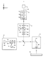
- FIG. 1 is a cross-sectional view showing the overall structure of the processing system of the first embodiment.
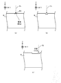
- FIGS. 2 (a) to 2 (c) is a cross-sectional view showing a state of removal processing performed on the work.
- FIGS. 3 (a) to 3 (c) is a cross-sectional view showing a state of a work machined by non-thermal processing.
- FIG. 4 is a cross-sectional view showing the structure of the processing apparatus.
- FIG. 5 is a perspective view showing the structure of the optical system included in the processing apparatus.
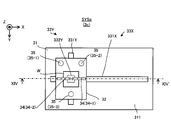
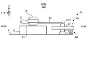
- FIG. 6 is a top view showing the stage device of the first embodiment.
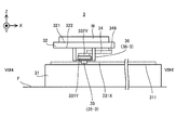
- FIG. 7 is a sectional view taken along line VI # 1-VI # 1'of the stage apparatus shown in FIG. FIG.
- FIG. 8 is a sectional view taken along line VI # 2-VI # 2'of the stage apparatus shown in FIG.
- FIG. 9 is a sectional view taken along line VI # 3-VI # 3'of the stage apparatus shown in FIG.
- FIG. 10 is a sectional view taken along line VI # 4-VI # 4'of the stage apparatus shown in FIG.
- FIG. 11 is a cross-sectional view showing how the Y slide member is displaced to the + Z side.
- FIG. 12 is a cross-sectional view showing how the Y slide member is displaced to the ⁇ Z side.
- FIG. 13 is a top view showing the stage device of the second embodiment.
- FIG. 14 is a top view showing the stage device of the third embodiment.
- FIG. 15 is a cross-sectional view of the stage device shown in FIG.
- FIG. 16 is a top view showing the stage device of the fourth embodiment.
- FIG. 17 is a cross-sectional view showing the stage apparatus of the fifth embodiment.
- FIG. 18 is a cross-sectional view showing the stage apparatus of the fifth embodiment.
- FIG. 19 is a cross-sectional view showing the stage apparatus of the sixth embodiment.
- FIG. 20 is a cross-sectional view showing the stage apparatus of the sixth embodiment.
- FIG. 21 is a top view showing the stage apparatus of the seventh embodiment.
- FIG. 22 is a cross-sectional view showing the stage apparatus of the seventh embodiment.
- FIG. 23 is a cross-sectional view showing the stage apparatus of the eighth embodiment.
- FIG. 24 is a cross-sectional view showing how the Y slide member is displaced to the + Z side in the eighth embodiment.
- FIG. 25 is a cross-sectional view showing how the Y slide member is displaced to the ⁇ Z side in the eighth embodiment.
- FIG. 26 is a cross-sectional view showing the stage apparatus of the ninth embodiment.
- FIG. 27 is a cross-sectional view showing how the Y slide member is displaced to the + Z side in the ninth embodiment.
- FIG. 28 is a cross-sectional view showing how the Y slide member is displaced to the ⁇ Z side in the ninth embodiment.
- FIG. 29 is a cross-sectional view showing the stage apparatus of the tenth embodiment.
- FIG. 30 is a cross-sectional view showing how the Y slide member is displaced to the + Z side in the tenth embodiment.
- FIG. 31 is a cross-sectional view showing how the Y slide member is displaced to the ⁇ Z side in the tenth embodiment.
- FIG. 32 is a top view showing the stage apparatus of the eleventh embodiment.
- FIG. 33 is a cross-sectional view of the stage device shown in FIG. 32 in XXXXII-XXXII'.
- FIG. 34 is a top view showing the stage apparatus of the twelfth embodiment.
- FIG. 35 is a cross-sectional view taken along the line XXXIV-XXXIV'of the stage apparatus shown in FIG. 34.
- each of the X-axis direction and the Y-axis direction is a horizontal direction (that is, a predetermined direction in the horizontal plane), and the Z-axis direction is a vertical direction (that is, a direction orthogonal to the horizontal plane). Yes, it is assumed that it is substantially in the vertical direction or the gravity direction).
- the rotation directions (in other words, the inclination direction) around the X-axis, the Y-axis, and the Z-axis are referred to as the ⁇ X direction, the ⁇ Y direction, and the ⁇ Z direction, respectively.
- the Z-axis direction may be the direction of gravity.
- the XY plane may be horizontal.
- machining system SYSa Processing system SYS of the first embodiment
- FIG. 1 is a cross-sectional view showing the overall structure of the processing system SYSA of the first embodiment.
- FIG. 1 does not show a cross section of some of the components of the processing system SYS.
- the processing system SYSa includes a processing device 1, a measuring device 2, a stage device 3, a housing 4, a drive system 5, a drive system 6, and a control device 7.
- the processing device 1 can process the work W under the control of the control device 7.
- the work W may be, for example, a metal, an alloy (for example, duralumin, etc.), a semiconductor (for example, silicon), or a resin (for example, acrylic or PET (polyethylene)). It may be terephthalate), it may be a composite material such as CFRP (Carbon Fiber Reinforced Plastic), it may be glass, or it may be an object composed of any other material. May be good.
- the processing device 1 irradiates the work W with processing light EL in order to process the work W.
- the processing light EL may be any kind of light as long as the work W can be processed by being irradiated with the work W.
- the description will be made using an example in which the processing light EL is a laser light, but the processing light EL may be a type of light different from the laser light.
- the wavelength of the processing light EL may be any wavelength as long as the work W can be processed by irradiating the work W.
- the processed light EL may be visible light or invisible light (for example, at least one of infrared light and ultraviolet light).
- the processing apparatus 1 irradiates the work W with processing light EL to perform removal processing for removing a part of the work W.
- the processing apparatus 1 may perform processing different from the removal processing (for example, additional processing or marking processing).
- the removal process includes flat surface processing that removes a part of the work W to form a flat surface, curved surface processing that removes a part of the work W to form a curved surface, and drilling process that removes a part of the work to form a hole.
- Pocket processing to remove a part of the work to form a pocket, cutting processing to cut the work, and engraving processing to form (in other words, engrave) any character or any pattern (in other words, engraving) May contain at least one of.
- FIGS. 2 (a) to 2 (c) are cross-sectional views showing a state of removal processing performed on the work W.
- the processing apparatus 1 irradiates the irradiation region EA set (in other words, formed) on the surface of the work W with the processing light EL.
- the irradiation region EA is irradiated with the processing light EL, the energy of the processing light EL is transmitted to the portion of the work W that is close to the irradiation region EA.
- the material constituting the portion of the work W close to the irradiation region EA is melted by the heat generated by the energy of the processing light EL.
- the molten material becomes droplets and scatters.
- the molten material evaporates due to the heat generated by the energy of the processing light EL.
- the portion of the work W that is close to the irradiation region EA is removed. That is, as shown in FIG. 2B, a concave portion (groove portion as an example) is formed on the surface of the work W.
- the processing apparatus 1 processes the work W by utilizing the so-called thermal processing principle.
- the processing apparatus 1 appropriately removes the portion of the work W to be removed by causing the processing light EL to scan the surface of the work W along a desired scanning locus corresponding to the region to be removed. be able to.
- the processing apparatus 1 can also process the work W by using the principle of non-thermal processing (for example, ablation processing). That is, the processing apparatus 1 may perform non-thermal processing (for example, ablation processing) on the work W.
- non-thermal processing for example, ablation processing
- the processing apparatus 1 may perform non-thermal processing (for example, ablation processing) on the work W.
- pulsed light having a light emission time of picoseconds or less or, in some cases, nanoseconds or femtoseconds or less
- the material constituting the portion of the work W that is close to the irradiation region EA Instantly evaporates and scatters.
- FIGS. 3 (a) to 3 (c), which are cross-sectional views showing the state of the work W processed by non-thermal processing the processing system SYSa has heat generated by the energy of the processing optical EL.
- a recess in other words, a groove
- the measuring device 2 can measure the object to be measured under the control of the control device 7.
- the object to be measured includes, for example, a work W.
- the measuring device 2 may be a device capable of measuring the state of the work W.
- the state of the work W may include the position of the work W.
- the position of the work W may include the position of the surface of the work W.
- the position of the surface of the work W may include a position in at least one of the X-axis direction, the Y-axis direction, and the Z-axis direction of each portion of the surface of the work W.
- the state of the work W may include the shape of the work W (for example, a three-dimensional shape).
- the shape of the work W may include the shape of the surface of the work W.
- the shape of the surface of the work W is, in addition to or in place of, the position of the surface of the work W described above, the orientation of each part of the surface of the work W (for example, the direction of the normal of each part, and the X-axis. , Substantially equivalent to the amount of inclination of each part with respect to at least one of the Y-axis and the Z-axis).
- the state of the work W may include the size of the work W (for example, the size in at least one of the X-axis direction, the Y-axis direction, and the Z-axis direction).
- the measurement information regarding the measurement result of the measuring device 2 is output from the measuring device 2 to the control device 7.
- the measuring device 2 there is a measuring device that measures the work W by projecting slit light on the surface of the work W and using an optical cutting method that measures the shape of the projected slit light.
- Another example of the measuring device 2 is a measuring device that measures the work W by using a white interferometry method that measures an interference pattern between white light that passes through the work W and white light that does not pass through the work W.
- the white light referred to here may mean light having a wavelength width (spectral width) with respect to monochromatic light.
- the measuring device 2 may measure the work W by using another method different from the optical cutting method and the white interferometry method.
- a pattern projection method in which a light pattern is projected on the surface of the work W and the shape of the projected pattern is measured, light is projected on the surface of the work W and the projected light is returned.
- Time-of-flight method moiretopography method (specifically, lattice irradiation method or lattice projection method), holographic interferometry, in which the operation of measuring the distance from the time to the work W is performed at multiple positions on the work W.
- At least one of a method, an autocollimation method, a stereo method, a non-point aberration method, a critical angle method, and a knife edge method can be mentioned.
- the measuring device 2 receives the light source that emits the measurement light (for example, slit light or white light) and the light from the work W irradiated with the measurement light (for example, the reflected light of the measurement light). It may be provided with a light receiver.
- the receiver may include a single photodetector, may include a plurality of photodetectors arranged in a one-dimensional direction, or may include a plurality of photodetectors arranged in a two-dimensional direction. ..
- the stage device 3 is arranged (that is, provided) below the processing device 1 and the measuring device 2 (that is, on the ⁇ Z side).
- the stage device 3 includes a surface plate 31 and a stage 32.
- the surface plate 31 is arranged on the bottom surface F of the housing 4 (or on a supporting surface such as a floor on which the housing 4 is placed).
- a stage 32 is arranged on the surface plate 31.
- the stage 32 is arranged on the surface plate 31 so that the lower surface of the stage 32 (that is, the surface facing the ⁇ Z side) 322 faces the upper surface of the surface plate 31 (that is, the surface facing the + Z side) 311.
- the stage 32 is arranged on the surface plate 31 so that the lower surface 322 of the stage 32 is separated from the upper surface 311 of the surface plate 31 along the Z-axis direction.
- the prevention (not shown) for reducing the transmission of the vibration of the surface plate 31 to the stage 32.
- a shaking device may be installed.
- a support frame 8 for supporting the processing device 1 and the measuring device 2 may be arranged on the surface plate 31 (particularly on the upper surface 311 of the surface plate 31).
- the processing device 1 and the measuring device 2 (further, the stage 32) may be supported by the same surface plate 31.
- the processing apparatus 1 may not be arranged on the surface plate 31.
- At least a part of the measuring device 2 may not be arranged on the surface plate 31.
- At least a part of the processing device 1 and at least a part of the measuring device 2 may be arranged on different surface plates (or other support surfaces).
- the stage device 3 may include a surface plate 31. In this case, the stage 32 may be arranged on the structure of the housing 4.
- the stage 32 may be made of quartz glass or other materials (for example, metal, ceramics, etc.).
- the work W is placed on the stage 32.
- the upper surface of the stage 32 includes a mounting surface 321 on which the work W can be mounted.
- the mounting surface 321 is a surface parallel to the XY plane.
- the mounting surface 321 is a surface opposite to the lower surface 322.
- the work W is placed on the mounting surface 321. Therefore, the stage 32 is used as a mounting member on which the work W is mounted. At this time, the stage 32 does not have to hold the mounted work W.
- the stage 32 does not have to apply an external force for holding the work W to the mounted work W.
- the work W may be placed on the stage 32 without applying an external force. Alternatively, the stage 32 may hold the mounted work W.
- the stage 32 may apply an external force for holding the work W to the mounted work W.
- the work W may be placed on the stage 32 in a state where an external force is applied.
- the stage 32 may be used as a holding member for holding the work W.
- the stage 32 may hold the work W by vacuum-adsorbing and / or electrostatically adsorbing the work W. Since the stage device 3 includes the stage 32 on which the work W is mounted, the stage device 3 may be referred to as a mounting device.
- the stage 32 can move on the surface plate 31 (particularly on the upper surface 311 of the surface plate 31) while the work W is placed under the control of the control device 7. At this time, the upper surface 311 of the surface plate 31 may be used as a guide surface for the movement of the stage 32.
- the stage 32 is movable with respect to at least one of the surface plate 31, the processing device 1, and the measuring device 2.
- the stage 32 can move along the X-axis direction and the Y-axis direction, respectively. In this case, the stage 32 can move along the stage running surface parallel to the XY plane.
- the stage 32 may be movable along at least one of the Z-axis direction, the ⁇ X direction, the ⁇ Y direction, and the ⁇ Z direction in addition to or in place of at least one of the X-axis direction and the Y-axis direction. .. Since the stage device 3 includes a movable (that is, a moving body) stage 32, the stage device 3 may be referred to as a mobile device.
- stage device 3 capable of moving the stage 32 will be described in detail later with reference to FIG. 6 and the like, and thus detailed description thereof will be omitted here.
- the housing 4 accommodates the processing device 1, the measuring device 2, and the stage device 3 in the internal storage space SP separated from the space outside the housing 4. That is, in the first embodiment, the processing device 1, the measuring device 2, and the stage device 3 are arranged in the same housing 4. The processing device 1, the measuring device 2, and the stage device 3 are arranged in the same accommodation space SP.
- the housing 4 accommodates the work W in the accommodation space SP inside the work W. That is, the processing device 1, the measuring device 2, and the work W are arranged in the same accommodation space SP.
- at least a part of the processing apparatus 1 may not be arranged in the accommodation space SP. At least a part of the processing apparatus 1 may not be arranged outside the housing 4.
- At least a part of the measuring device 2 may not be arranged in the accommodation space SP. At least a part of the measuring device 2 may not be arranged outside the housing 4. At least a part of the stage device 3 may not be arranged in the accommodation space SP. At least a part of the stage device 3 may not be arranged outside the housing 4.
- the drive system 5 moves the processing device 1 under the control of the control device 7.
- the drive system 5 moves the processing device 1 with respect to at least one of the surface plate 31, the stage 32, and the work W mounted on the stage 32.
- the drive system 5 may move the processing device 1 with respect to the measuring device 2.
- the drive system 5 moves the processing apparatus 1 along at least one of the X-axis direction, the Y-axis direction, the Z-axis direction, the ⁇ X direction, the ⁇ Y direction, and the ⁇ Z direction.
- the drive system 5 includes, for example, a motor and the like.
- the processing system SYSa includes a position measuring instrument 51 capable of measuring the position of the processing device 1 moved by the drive system 5.
- the position measuring instrument 51 may include, for example, at least one of an encoder and a laser interferometer.
- the drive system 5 moves the processing device 1, the irradiation region EA moves on the work W. Further, when the drive system 5 moves the machining apparatus 1, the machining shot region PSA (see FIG. 5 described later) also moves on the work W. Therefore, the drive system 5 can change the positional relationship between the work W and the irradiation region EA and the machining shot region PSA by moving the machining apparatus 1.
- the "machining shot region PSA" in the first embodiment is machined by the machining apparatus 1 in a state where the positional relationship between the machining apparatus 1 and the object to be machined (for example, the work W) is fixed (that is, without changing). Indicates the area where is performed (in other words, the range). Typically, as shown in FIG.
- the machining shot region PSA is the machining light deflected by the galvano mirror 141 included in the machining device 1 in a state where the positional relationship between the machining device 1 and the object to be machined is fixed. It is set so that the area matches the scanning range of the EL or is narrower than the scanning range.
- the machining shot region PSA is a region in which the irradiation region EA irradiated with the machining light EL with the positional relationship between the machining apparatus 1 and the machining object fixed is equal to or narrower than the movable range. Is set to be. Therefore, the machining shot region PSA is a region determined with reference to the machining apparatus 1 (that is, a region having a predetermined positional relationship with the machining apparatus 1).
- the processing apparatus 1 does not have to be movable.
- the processing system SYSa does not have to include the drive system 5. If the processing apparatus 1 does not move, the processing system SYS may not include the position measuring instrument 51.
- the processing apparatus 1 since the stage 32 is movable in the X-axis direction and the Y-axis direction, the processing apparatus 1 may be movable in the Z-axis direction. At this time, the focus position of the processing light EL may be controlled by the movement of the processing apparatus 1 in the Z-axis direction. The focus position of the observation device 16 may be controlled by the movement of the processing device 1 to the Z axis.
- the drive system 6 moves the measuring device 2 under the control of the control device 7.
- the drive system 6 moves the measuring device 2 with respect to at least one of the surface plate 31, the stage 32, and the work W mounted on the stage 32.
- the drive system 6 may move the measuring device 2 with respect to the processing device 1.
- the drive system 6 moves the measuring device 2 along at least one of the X-axis direction, the Y-axis direction, the Z-axis direction, the ⁇ X direction, the ⁇ Y direction, and the ⁇ Z direction.
- the drive system 6 includes, for example, a motor and the like.
- the processing system SYSa includes a position measuring instrument 61 capable of measuring the position of the measuring device 2 moved by the drive system 6.
- the position measuring instrument 61 may include, for example, at least one of an encoder and a laser interferometer.
- the drive system 6 moves the measuring device 2
- the measurement shot area MSA moves on the work W. Therefore, the drive system 6 can change the positional relationship between the work W and the measurement shot area MSA by moving the measurement device 2.
- the "measurement shot area MSA" in the first embodiment is measured by the measuring device 2 in a state where the positional relationship between the measuring device 2 and the measurement target (for example, the work W) is fixed (that is, without changing). Indicates the area where is performed (in other words, the range).
- the measuring device 2 is a measuring device using the optical cutting method
- the measurement shot area MSA is subjected to the optical cutting method in a state where the positional relationship between the measuring device 2 and the measurement object is fixed.
- the measuring device 2 is a measuring device using the white interferometry
- the measurement shot area MSA is typically subjected to the white interferometry with the positional relationship between the measuring device 2 and the object to be measured fixed. It may be set so as to coincide with or narrower than the range in which the white light to be used can be irradiated (for example, the scanning range of the white light).
- the measurement shot area MSA is a light receiving surface (for example, simply) of a receiver that receives light from a work W irradiated with slit light and / or white light in a state where the positional relationship between the measuring device 2 and the measurement object is fixed. It may be set so as to correspond to one photodetector or a light receiving surface of a plurality of photo detectors arranged in a one-dimensional direction or a two-dimensional direction). Therefore, the measurement shot area MSA is an area determined with reference to the measurement device 2 (that is, an area having a predetermined positional relationship with the measurement device 2). Such a measurement shot area MSA may be referred to as a measurable range or a measurable field of the measuring device 2.
- the stage 32 is movable, the positional relationship between the work W and the measurement shot area MSA can be changed even if the measuring device 2 is not movable. Therefore, the measuring device 2 does not have to be movable. In this case, the processing system SYSa does not have to include the drive system 6. If the measuring device 2 does not move, the machining system SYS may not include the position measuring device 61.
- the measuring device 2 since the stage 32 is movable in the X-axis direction and the Y-axis direction, the measuring device 2 may be movable in the Z-axis direction. At this time, the focus position of the measuring device 2 may be controlled by the movement of the measuring device 2 in the Z-axis direction.
- the control device 7 controls the operation of the processing system SYS.
- the control device 7 may include, for example, an arithmetic unit and a storage device.
- the arithmetic unit may include, for example, at least one of a CPU (Central Processing Unit) and a GPU (Graphics Processing Unit).
- the control device 7 functions as a device that controls the operation of the processing system SYS by executing a computer program by the arithmetic unit.
- This computer program is a computer program for causing the control device 7 (for example, an arithmetic unit) to perform (that is, execute) an operation described later to be performed by the control device 7. That is, this computer program is a computer program for causing the control device 7 to function so that the processing system SYSa performs an operation described later.
- the computer program executed by the arithmetic unit may be recorded in a storage device (that is, a recording medium) included in the control device 7, or any storage built in the control device 7 or externally attached to the control device 7. It may be recorded on a medium (for example, a hard disk or a semiconductor memory). Alternatively, the arithmetic unit may download the computer program to be executed from an external device of the control device 7 via the network interface.
- a storage device that is, a recording medium included in the control device 7, or any storage built in the control device 7 or externally attached to the control device 7. It may be recorded on a medium (for example, a hard disk or a semiconductor memory).
- the arithmetic unit may download the computer program to be executed from an external device of the control device 7 via the network interface.
- the control device 7 does not have to be provided inside the processing system SYS, and may be provided as a server or the like outside the processing system SYS, for example.
- the control device 7 and the processing system SYSA may be connected by a wired and / or wireless network (or a data bus and / or a communication line).
- a wired network for example, a network using a serial bus type interface represented by at least one of IEEE1394, RS-232x, RS-422, RS-423, RS-485 and USB may be used.
- a network using a parallel bus interface may be used.
- a network using an Ethernet (registered trademark) compliant interface represented by at least one of 10BASE-T, 100BASE-TX and 1000BASE-T may be used.
- a network using radio waves may be used.
- An example of a network using radio waves is a network conforming to IEEE802.1x (for example, at least one of wireless LAN and Bluetooth®).
- a network using infrared rays may be used.
- a network using optical communication may be used.
- the control device 7 and the processing system SYSA may be configured so that various types of information can be transmitted and received via the network.
- control device 7 may be able to transmit information such as commands and control parameters to the processing system SYSA via the network.
- the processing system SYSa may include a receiving device that receives information such as commands and control parameters from the control device 7 via the network.
- the first control device that performs a part of the processing performed by the control device 7 is provided inside the processing system SYS
- the second control device that performs the other part of the processing performed by the control device 7 is provided.
- the control device may be provided outside the processing system SYS.
- the recording medium for recording the computer program executed by the arithmetic unit includes CD-ROM, CD-R, CD-RW, flexible disc, MO, DVD-ROM, DVD-RAM, DVD-R, DVD + R, and DVD-. At least one of optical disks such as RW, DVD + RW and Blu-ray (registered trademark), magnetic media such as magnetic tape, magneto-optical disks, semiconductor memories such as USB memory, and any other medium capable of storing a program is used. You may.
- the recording medium may include a device capable of recording a computer program (for example, a general-purpose device or a dedicated device in which the computer program is implemented in a state in which it can be executed in at least one form such as software and firmware).
- each process or function included in the computer program may be realized by a logical processing block realized in the control device 7 by the control device 7 (typically a computer) executing the computer program.
- the control device 7 typically a computer
- it may be realized by hardware such as a predetermined gate array (FPGA, ASIC) included in the control device 7, or a logical processing block and a partial hardware module that realizes a part of the hardware. May be realized in a mixed format.
- FIG. 4 is a cross-sectional view showing the structure of the processing apparatus 1.
- the processing apparatus 1 returns the light source 11, the optical system 12, the dichroic mirror 13, the optical system 14, and so on, as shown in FIG. 4, which is a cross-sectional view showing the structure of the processing apparatus 1. It includes a light protection device 15 and an observation device 16.
- the structure of the processing apparatus 1 shown in FIG. 4 is merely an example. Therefore, the processing apparatus 1 may have any structure as long as the work W can be processed by using the processing optical EL. That is, the processing device 1 does not necessarily have to include at least one of a light source 11, an optical system 12, a dichroic mirror 13, an optical system 14, a return light prevention device 15, and an observation device 16.
- the light source 11 can generate a processed light EL.
- the processing light EL is a laser light
- the light source 11 may be, for example, a laser diode.
- the light source 11 may be a light source capable of pulse oscillation.
- the light source 11 can generate pulsed light (for example, pulsed light having a light emission time of picoseconds or less) as processed light EL.
- the light source 11 emits the generated processed light EL toward the optical system 12.
- the light source 11 may emit processed light EL in a linearly polarized state.
- the optical system 12 is an optical system in which the processed light EL emitted from the light source 11 is incident.
- the optical system 12 is an optical system that emits the processed light EL incident on the optical system 12 toward the return light prevention device 15. That is, the optical system 12 is an optical system that guides the processed light EL emitted from the light source 11 to the return light prevention device 15.
- the optical system 12 may control the state of the processed light EL emitted from the light source 11, and may emit the processed light EL whose state is controlled toward the return light prevention device 15.
- the optical system 12 may control the beam diameter of the processing light EL (that is, the size of the processing light EL in the plane intersecting the traveling direction of the processing light EL).
- the optical system 12 may control the beam diameter (that is, the spot diameter) of the processing light EL on the surface of the work W by controlling the beam diameter of the processing light EL.
- the optical system 12 may include a beam expander 121.
- the optical system 12 may control the degree of convergence or the degree of divergence of the processing light emitted from the optical system 12.
- the optical system 12 may include a focus lens 122.
- the focus lens 122 is composed of one or more lenses, and by adjusting the position of at least a part of the lenses along the optical axis direction, the degree of convergence or the degree of divergence of the processed light EL is changed to change the degree of convergence or divergence of the processed light EL. It is an optical element for adjusting the focus position.
- the focus lens 122 may be integrated with the beam expander 121 or may be separate from the beam expander 121.
- the optical system 12 may control the intensity distribution of the processing light EL in the plane intersecting the traveling direction of the processing light EL.
- the optical system 12 may include an intensity distribution control member 123 capable of controlling the intensity distribution of the processing light EL.
- the state of the processing light EL controlled by the optical system 12 includes the focus position of the processing light EL, the beam diameter of the processing light EL, the convergence degree of the processing light EL, the divergence degree of the processing light EL, and the intensity distribution of the processing light EL.
- at least one of the pulse length of the processing light EL, the number of pulses of the processing light EL, the intensity of the processing light EL, the traveling direction of the processing light EL, and the polarization state of the processing light EL may be included. ..
- the dichroic mirror 13 guides the processed light EL incident on the dichroic mirror 13 from the optical system 12 via the return light prevention device 15 to the optical system 14.
- the dichroic mirror 13 reflects one of the processed light EL and the observation light (illumination light IL and the reflected light ILr) having a wavelength different from that of the processed light EL and transmits the other.
- the dichroic mirror 13 guides the processing light EL to the optical system 14 by reflecting the processing light EL toward the optical system 14.
- the dichroic mirror 13 may guide the processing light EL to the optical system 14 by passing the processing light EL.
- the optical system 14 is an optical system for irradiating the work W with the processed light EL from the dichroic mirror 13 (that is, guiding the work W).
- the optical system 14 includes a galvano mirror 141 and an f ⁇ lens 142.
- the galvano mirror 141 deflects the processed light EL so that the processed light EL from the f ⁇ lens 142 scans the work W (that is, the irradiation region EA irradiated with the processed light EL moves on the surface of the work W). ..
- the optical system 14 may deflect the processing light EL by using a polygon mirror in addition to or in place of the galvano mirror 141.
- the galvano mirror 141 includes an X scanning mirror 141X and a Y scanning mirror 141Y, as shown in FIG. 5, which is a perspective view showing the structure of the optical system 14.
- the X scanning mirror 141X reflects the processed light EL toward the Y scanning mirror 141Y.
- the X scanning mirror 141X can swing or rotate about the ⁇ Y direction (that is, the rotation direction around the Y axis). Due to the swing or rotation of the X scanning mirror 141X, the processing light EL scans the surface of the work W along the X-axis direction. Due to the swing or rotation of the X scanning mirror 141X, the irradiation region EA moves on the surface of the work W along the X-axis direction.
- the Y scanning mirror 141Y reflects the processed light EL toward the f ⁇ lens 142.
- the Y scanning mirror 141Y can swing or rotate about the ⁇ X direction (that is, the rotation direction around the X axis).
- the processing light EL scans the surface of the work W along the Y-axis direction.
- the irradiation region EA moves on the surface of the work W along the Y-axis direction.
- the f ⁇ lens 142 is an optical element for condensing the processed light EL from the galvano mirror 141 on the work W.
- the X scanning mirror 141X may swing or rotate about a direction slightly inclined from the ⁇ Y direction (that is, the rotation direction around the Y axis).
- the Y scanning mirror 141Y may swing or rotate about a direction slightly inclined from the ⁇ X direction (that is, the rotation direction around the X axis).
- the f ⁇ lens 142 is a telecentric optical system on the injection surface side (work W side), but the f ⁇ lens 142 does not have to be a telecentric optical system.
- the f ⁇ lens 142 is a telecentric optical system on the ejection surface side (work W side)
- the irradiation position does not change in the XY plane of the processed light EL even if the thickness of the work W (size in the Z axis direction) changes.
- the return light prevention device 15 prevents the return light ELr, which is the processed light EL reflected by the work W, from returning to the optical system 12 and the light source 11.
- the return light prevention device 15 guides the processed light EL emitted by the optical system 12 to the dichroic mirror 13 (that is, leads to the work W).
- the return light prevention device 15 may utilize polarized light, for example.
- the light source 11 may emit, for example, the processed light EL in the linearly polarized state.
- the return light prevention device 15 includes, for example, a 1/2 wave plate 151, a polarization beam splitter 152, a 1/4 wave plate 153, a 1/2 wave plate 154, and a beam diffuser 155.
- the 1/2 wave plate 151 changes the polarization direction of the processed light EL from the optical system 12.
- the 1/2 wavelength plate 151 changes the polarization direction of the processed light EL from the optical system 12 so that it can pass through the polarization beam splitter 152.
- the processed light EL that has passed through the 1/2 wavelength plate 151 passes through the polarizing beam splitter 152.
- the description will proceed with reference to an example in which the polarizing beam splitter 152 passes p-polarized light through the polarization splitting surface of the polarizing beam splitter 152 while reflecting s-polarized light. That is, the description will proceed with reference to an example in which the processed light EL passing through the polarization beam splitter 152 is p-polarized light.
- the processed light EL that has passed through the polarization beam splitter 152 passes through the quarter wave plate 153 and becomes circularly polarized.
- the processed light EL that has passed through the 1/4 wave plate 153 passes through the 1/2 wave plate 154, and the ellipticity of its polarization is adjusted.
- the circularly polarized processed light EL is incident on the dichroic mirror 13.
- the return light prevention device 15 can guide the processed light EL to the dichroic mirror 13.
- the return light ELr incident on the return light prevention device 15 is incident on the 1/4 wave plate 153 via the 1/2 wavelength plate 154.
- the rotation direction of the return light ELr is reversed with respect to the rotation direction of the processed light EL. Therefore, the return light ELr that has passed through the 1/2 wave plate 154 and the 1/4 wave plate 153 becomes s-polarized light.
- the return light ELr that has passed through the quarter wave plate 153 is reflected by the polarization beam splitter 152.
- the 1/4 wave plate may be arranged in the optical path between the 1/4 wave plate 154 and the work W. Further, the 1/4 wave plate 153 may be removed from the optical path, and the work W may be processed with the processing light in the linearly polarized state.
- the observation device 16 can optically observe the state of the surface of the work W.
- FIG. 4 shows an example in which the observation device 16 can optically image the state of the surface of the work W.
- the observation device 16 may include a light source 161, a beam splitter 162, a notch filter 163, and an image pickup device 164.
- the light source 161 generates an illumination light IL.
- the illumination light IL is visible light, but may be invisible light.
- the wavelength of the illumination light IL is different from the wavelength of the processing light EL.
- the wavelength of the illumination light IL is set to a wavelength that can pass through the dichroic mirror 13.
- the light source 161 emits the generated illumination light IL toward the beam splitter 162.
- the beam splitter 162 reflects at least a part of the illumination light IL from the light source 161 toward the notch filter 163.
- the notch filter 163 is a filter that attenuates only light in a part of the wavelength band of the incident illumination light IL.
- a bandpass filter that transmits only light in a part of the wavelength band of the incident illumination light IL may be used in addition to or in place of the notch filter 163.
- the notch filter 163 limits the wavelength band of the illumination light IL passing through the notch filter 163 to a wavelength band that can pass through the dichroic mirror 13.
- the illumination light IL reflected by the beam splitter 162 enters the dichroic mirror 13 via the notch filter 163.
- the illumination light IL incident on the dichroic mirror 13 passes through the dichroic mirror 13.
- the illumination light IL irradiates the surface of the work W via the optical system 14. That is, the illumination light IL irradiates the surface of the work W through an optical path that at least partially overlaps the optical path of the processed light EL.
- the illumination light IL irradiates the surface of the work W through a part of the optical system (in the example shown in FIG. 4, the dichroic mirror 13 and the optical system 14) that guides the processed light EL from the light source 11 to the work W. Therefore, in the example shown in FIG.
- a part of the optical system that guides the processed light EL from the light source 11 to the work W is shared as a part of the optical system that guides the illumination light IL from the light source 161 to the work W. ..
- the optical system that guides the processing light EL from the light source 11 to the work W and the optical system that guides the illumination light IL from the light source 161 to the work W may be optically separated. At least a part of the illumination light IL applied to the surface of the work W is reflected by the surface of the work W. As a result, the illumination light IL reflected by the work W is incident on the optical system 14 as the reflected light ILr. The reflected light ILr is incident on the observation device 16 via the optical system 14.
- the reflected light ILr incident on the observation device 16 is incident on the beam splitter 162 through the notch filter 163.
- the illumination light IL and the reflected light ILr may be referred to as observation light.
- the notch filter 163 may be used as a light-shielding member for preventing the processed light EL having a wavelength different from that of the observation light from entering the inside of the observation device 16 (particularly, the image pickup device 164). At least a part of the reflected light ILr incident on the beam splitter 162 passes through the beam splitter 162 and is incident on the image sensor 164. As a result, the observation device 16 can optically image the state of the surface of the work W.
- the observation result (specifically, the imaging result) of the observation device 16 includes information that can identify the state of the work W. Therefore, the observation device 16 may be used as a measuring device for measuring the work W.
- the observation result (specifically, the imaging result) of the observation device 16 includes information that can identify the shape of the work W (for example, the shape of the surface of the work W). Therefore, the observation device 16 may be used as a measuring device for measuring the shape of the work W.
- a part of the processing device 1 is shared with at least a part of the measuring device (observation device 16 in the example shown in FIG. 4) for measuring the work W.
- FIG. 6 is a top view showing the stage device 3 of the first embodiment.
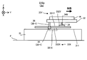
- FIG. 7 is a sectional view taken along line VI # 1-VI # 1'of the stage device 3 shown in FIG.
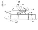
- FIG. 8 is a sectional view taken along line VI # 2-VI # 2'of the stage device 3 shown in FIG.
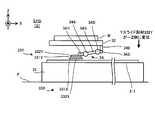
- FIG. 9 is a sectional view taken along line VI # 3-VI # 3'of the stage device 3 shown in FIG.
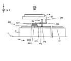
- FIG. 10 is a sectional view taken along line VI # 4-VI # 4'of the stage device 3 shown in FIG.
- the stage device 3 includes a stage drive system 33, a connecting member 34, and an air bearing 35 in addition to the surface plate 31 and the stage 32 described above.
- the stage drive system 33 is a device for moving the stage 32 along the X-axis direction and the Y-axis direction, respectively. In this case, the stage drive system 33 does not have to control the position of the stage 32 in the Z-axis direction.
- the stage drive system 33 mainly includes an X stage drive system 33X for moving the stage 32 along the X-axis direction, and a Y stage drive system 33Y for mainly moving the stage 32 along the Y-axis direction.
- the X stage drive system 33X and the Y stage drive system 33Y are arranged between the surface plate 31 and the stage 32. Specifically, the X stage drive system 33X and the Y stage drive system 33Y are arranged between the upper surface 311 of the surface plate 31 and the lower surface 322 of the stage 32.
- the X stage drive system 33X includes an X rail member (X guide member) 331X and an X slide member 332X.
- the X rail member 331X is arranged on the surface plate 31.
- the X rail member 331X is a member extending along the X-axis direction.
- the X rail member 331X is a member having a longitudinal direction in the X-axis direction.
- the X slide member 332X is attached to the X rail member 331X.
- the X slide member 332X is a moving member that can move along the X rail member 331X. That is, the X slide member 332X is attached to the X rail member 331X so that the X slide member 332X can move along the X rail member 331X.
- the X slide member 332X may be referred to as an X block member. Since the X rail member 331X is a member extending along the X axis direction, the X slide member 332X can move along the X axis direction. The X slide member 332X can be moved by using the power of a motor (for example, a linear motor) (not shown) included in the X stage drive system 33X. That is, the X stage drive system 33X is a drive system including a so-called linear motion guide.
- the X stage drive system 33X may be referred to as a mobile device.
- the Y stage drive system 33Y is located on the X stage drive system 33X.
- the Y stage drive system 33Y includes a Y rail member (Y guide member) 331Y and a Y slide member 332Y.
- the Y rail member 331Y is arranged on the X slide member 332X.
- the Y rail member 331Y is connected to the X slide member 332X.
- the Y rail member 331Y is a member extending along the Y-axis direction.
- the Y rail member 331Y is a member having a longitudinal direction in the Y-axis direction.
- the Y slide member 332Y is attached to the Y rail member 331Y.
- the Y slide member 332Y is a moving member that can move along the Y rail member 331Y. That is, the Y slide member 332Y is attached to the Y rail member 331Y so that the Y slide member 332Y can move along the Y rail member 331Y.
- the Y slide member 332Y may be referred to as a Y block member. Since the Y rail member 331Y is a member extending along the Y axis direction, the Y slide member 332Y can move along the Y axis direction.
- the Y rail member can be moved by using the power of a motor (for example, a linear motor) (not shown) included in the Y stage drive system 33Y. That is, the Y stage drive system 33Y is a drive system including a so-called linear motion guide.
- the Y stage drive system 33Y may be referred to as a mobile device.
- the Y rail member 331Y Since the Y rail member 331Y is arranged on the X slide member 332X, the Y rail member 331Y can also move along the X axis direction as the X slide member 332X moves in the X axis direction.
- the Y slide member 332Y attached to the Y rail member 331Y also moves along the X-axis direction. Therefore, the Y slide member 332Y is a moving member that can move along the X-axis direction and the Y-axis direction, respectively.
- the connecting member 34 is a member that extends (that is, extends) from the Y slide member 332Y toward the stage 32.
- the connecting member 34 is a member that extends from a position where the Y slide member 332Y and the connecting member 34 are connected toward a position where the stage 32 and the connecting member 34 are connected.
- the connecting member 34 moves from the connecting portion 3321Y (FIG. 7) connected to the connecting member 34 of the Y slide member 332Y toward the connecting portion 323 (FIG. 7) connected to the connecting member 34 of the stage 32. It is a member that extends.
- the connecting member 34 connects the Y slide member 332Y and the stage 32. Specifically, the connecting member 34 is connected to the Y slide member 332Y (particularly, the connecting portion 3321Y) via the connecting portion 341 (FIG. 7) of the connecting member 34. In the example shown in FIGS. 6 to 10, the connecting portion 341 of the connecting member 34 is connected to the upper surface of the Y slide member 332Y (that is, the surface facing the + Z side), but is an arbitrary portion of the Y slide member 332Y. May be linked to.
- the connecting member 34 is connected to the stage 32 (particularly, the connecting portion 323) via the connecting portion 342 (FIG. 7) of the connecting member 34. In the example shown in FIGS. 6 to 10, the connecting portion 342 of the connecting member 34 is connected to the lower surface 322 of the stage 32, but may be connected to any portion of the stage 32.
- the connecting member 34 is a Y-slide member via at least a part of the space below the stage 32 (for example, the space between the lower surface 322 of the stage 32 and the upper surface 311 of the surface plate 31).
- the 332Y and the stage 32 are connected.
- the connecting member 34 extends from the Y slide member 332Y toward the stage 32 in the space below the stage 32.
- the connecting member 34 is arranged in the space below the stage 32.
- the connecting member 34 is arranged between the lower surface 322 of the stage 32 and the upper surface 311 of the surface plate 31.
- the connecting portion 342 is connected to the stage 32 via the spacer 349 so that the portion of the connecting member 34 other than the connecting portion 342 does not come into contact with the stage 32 (particularly, the lower surface 322).
- the spacer 349 has a size capable of forming a predetermined gap between the connecting member 34 and the stage 32 in the Z-axis direction.
- the connecting portion 342 may be connected to the stage 32 without passing through the spacer 349.
- the connecting portion 342 or the spacer 349 is connected to the stage 32 at the peripheral portion of the stage 32, but may be connected at another place. For example, they may be connected in the vicinity of the center position or the center of gravity of the stage 32.
- the vicinity of the center position (center of gravity position) of the stage 32 is a position closer to the center (center of gravity) than the position of 1/2 of the line segment connecting the center (center of gravity) of the stage 32 and the end of the stage 32. be able to.
- At least a part of the Y slide member 332Y and at least a part of the stage 32 are in the Z-axis direction. They may be adjacent along. At least a part of the Y slide member 332Y and at least a part of the stage 32 may overlap along the Z-axis direction. At least a part of the Y slide member 332Y and at least a part of the stage 32 may face each other along the Z-axis direction. The position of the Y slide member 332Y in the Z-axis direction may be different from the position of the stage 32 in the Z-axis direction.
- the position of the Y slide member 332Y in the direction along at least a part of the XY plane may be the same as the position of the stage 32 in the direction along the at least a part of the XY plane. More specifically, at least a part of the Y slide member 332Y may be arranged in a space below at least a part of the stage 32. At least a part of the stage 32 may be arranged in a space above at least a part of the Y slide member 332Y.
- the stage connected to the Y slide member 332Y via the connecting member 34 also moves along the X-axis direction.
- the stage 32 connected to the Y-slide member 332Y via the connecting member 34 also moves along the Y-axis direction. That is, the stage 32 can move along the X-axis direction and the Y-axis direction as the Y slide member 332Y moves. That is, the stage 32 can move in the stage running plane along the XY plane.
- the connecting member 34 may function as a spring that absorbs the displacement in the X-axis direction.
- the stage 32 may not move along the X-axis direction.
- the amount of movement of the stage 32 along the X-axis direction may be less than the amount of movement expected from the amount of movement of the Y slide member 332Y along the X-axis direction.
- the rigidity of the connecting member 34 in the X-axis direction is the stage 32 in the movement mode assumed from the movement mode of the Y-slide member 332Y in the X-axis direction as the Y-slide member 332Y moves along the X-axis direction. May be set to a value high enough to satisfy the movement condition #X that the movement is along the X-axis direction.
- the movement mode may include the direction of movement. That is, the movement condition #X may include a condition relating to the movement direction of the Y slide member 332Y and the stage 32 in the X-axis direction.
- the movement condition # X may include the movement condition # X1 that the direction of movement of the stage 32 in the X-axis direction is the same as the direction of movement of the Y slide member 332Y in the X-axis direction. More specifically, the movement condition #X includes the movement condition # X11 that the stage 32 moves toward the + X side when the Y slide member 332Y moves toward the + X side, and the Y slide member 332Y. It may include at least one of the movement conditions # X12 that the stage 32 moves toward the ⁇ X side when it moves toward the ⁇ X side.
- the movement mode may include a movement amount in addition to or in place of the movement direction.
- the movement condition #X may include a condition relating to the movement amount of the Y slide member 332Y and the stage 32 in the X-axis direction.
- the movement condition # X may include the movement condition # X2 in which the movement amount of the stage 32 along the X-axis direction is proportional to the movement amount of the Y slide member 332Y along the X-axis direction.
- the movement mode may include a movement speed (ie, movement amount per unit time) in addition to or in place of at least one of the movement direction and the movement amount.
- the movement condition #X may include a condition relating to the movement speed of the Y slide member 332Y and the stage 32 in the X-axis direction.
- the movement condition # X may include the movement condition # X3 in which the movement speed of the stage 32 along the X-axis direction is proportional to the movement speed of the Y slide member 332Y along the X-axis direction.
- the connecting member 34 may function as a spring that absorbs the displacement in the Y-axis direction.
- the stage 32 may not move along the Y-axis direction.
- the amount of movement of the stage 32 along the Y-axis direction may be less than the amount of movement expected from the amount of movement of the Y slide member 332Y along the Y-axis direction.
- the rigidity of the connecting member 34 in the Y-axis direction is the movement mode assumed from the movement mode of the Y-slide member 332Y in the Y-axis direction as the Y-slide member 332Y moves along the Y-axis direction. May be set to a value high enough to satisfy the movement condition # Y that moves along the Y-axis direction.
- the movement mode may include at least one of the movement direction, the movement amount, and the movement speed.
- the movement condition #Y is a condition relating to the direction of movement of the Y slide member 332Y and the stage 32 in the Y axis direction, a condition relating to the amount of movement of the Y slide member 332Y and the stage 32 in the Y axis direction, and the Y slide member 332Y and It may include at least one of the conditions relating to the moving speed of the stage 32 in the Y-axis direction.
- the movement condition # Y may include the movement condition # Y1 that the direction of movement of the stage 32 in the Y-axis direction is the same as the direction of movement of the Y slide member 332Y in the Y-axis direction.
- the movement condition #Y includes the movement condition # Y11 that the stage 32 moves toward the + Y side when the Y slide member 332Y moves toward the + Y side, and the Y slide member 332Y. It may include at least one of the movement conditions # Y12 that the stage 32 moves toward the ⁇ Y side when it moves toward the ⁇ Y side.
- the movement condition # Y may include the movement condition # Y2 that the movement amount of the stage 32 along the Y-axis direction is proportional to the movement amount of the Y slide member 332Y along the Y-axis direction.
- the moving condition # Y may include the moving condition # Y3 that the moving speed of the stage 32 along the Y-axis direction is proportional to the moving speed of the Y slide member 332Y along the Y-axis direction.
- the rigidity of the connecting member 34 connecting the Y slide member 332Y and the stage 32 in the Z axis direction is too high, the displacement of the Y slide member 332Y along the Z axis direction is caused by the connecting member 34 via the connecting member 34. Will be transmitted to. Such displacement of the stage 32 along the Z-axis direction may lead to deterioration of machining accuracy of the work W placed on the stage 32. Therefore, the rigidity of the connecting member 34 in the Z-axis direction is deformed (for example, distorted, bent, or bent) in the Z-axis direction so as to absorb the displacement of the Y slide member 332Y along the Z-axis direction. The value may be set as low as possible to satisfy the absorption condition.
- the connecting member 34 is typically displaced in the Z-axis direction.
- the connecting member 34 is displaced in the Z-axis direction when the stage 32 moves along the running surface of the stage.
- the stage 32 can be appropriately moved along the running surface of the stage without being affected by the displacement of the Y slide member 332Y along the Z-axis direction.
- the "absorption of displacement of Y slide member 332Y" in the first embodiment is only for canceling the displacement of Y slide member 332Y with the connecting member 34 so that the displacement of Y slide member 332Y is not transmitted to the stage 32.
- the displacement of the Y slide member 332Y is also reduced by the connecting member 34 so that the displacement transmitted from the Y slide member 332Y to the stage 32 becomes small enough to have almost no effect on the machining accuracy of the work W.
- the connecting member 34 is typically a member whose rigidity in each of the X-axis direction and the Y-axis direction is higher than the rigidity in the Z-axis direction.
- the connecting member 34 is typically a member whose rigidity in the Z-axis direction is lower than the rigidity in each of the X-axis direction and the Y-axis direction.
- the connecting member 34 may be a flexible member whose rigidity in one direction is higher than that in another direction.
- the rigidity of the connecting member 34 is higher than that of the connecting member in the comparative example in which the rigidity in each of the X-axis direction and the Y-axis direction is not higher than the rigidity in the Z-axis direction.
- Condition # Y and displacement absorption condition can be easily satisfied.
- the connecting member 34 may be, for example, a member extending along the X-axis direction or the Y-axis direction (or any direction along the XY plane).
- the connecting member 34 may be a member having a longitudinal shape.
- the connecting member 34 may be a member having at least one length in the X-axis direction and the Y-axis direction sufficiently larger than the thickness in the Z-axis direction.
- the connecting member 34 may be a member having a relatively high aspect ratio, which is a ratio of length to thickness.
- the connecting member 34 is a member extending along the X-axis direction (that is, a member whose longitudinal direction is the X-axis direction). In this case, the rigidity of the connecting member 34 tends to satisfy the above-mentioned movement condition # X, movement condition # Y, and displacement absorption condition.
- the connecting portions 341 and 342 of the connecting member 34 are the connecting members 34, respectively. It may be one end and the other end.
- the connecting portion 3321Y of the Y slide member 332Y to which the connecting portion 341 is connected and the connecting portion 323 of the stage 32 to which the connecting portion 342 is connected are separated from each other along the direction in which the connecting member 34 extends.
- the connecting member 34 is different from the connecting portion 3321Y of the Y slide member 332Y in the position along the X-axis direction or the Y-axis direction (or any direction along the XY plane) of the stage 32. It connects with the connecting portion 323.
- the connecting member 34 may include an elastic body.
- the connecting member 34 may include an elastic member which is an elastic body.
- the connecting member 34 may include a spring, which is an example of an elastic body.
- springs include at least one of a wire spring (in other words, a coil spring), a leaf spring, a bar spring (in other words, a torsion bar), and a spiral spring.
- the connecting member 34 includes a leaf spring
- the leaf spring may have a plate-like shape along a plane parallel to the XY plane or the XY plane.
- the leaf spring may have a plate-like shape along the stage running surface or a surface parallel to the stage running surface.
- the connecting member 34 may include, in addition to or in place of the spring, rubber, which is another example of an elastic body.
- the connecting member 34 contains an elastic body as described above, the rigidity of the connecting member 34 is particularly likely to satisfy the displacement absorption condition as compared with the case where the connecting member 34 does not contain the elastic body.
- the connecting member 34 including the elastic body may be referred to as an elastic member.
- the connecting member 34 is a member extending along the X-axis direction or the Y-axis direction (or any direction along the XY plane)
- the rigidity of the connecting member 34 is the movement condition # X
- the connecting member 34 includes a spring
- the spring included in the connecting member 34 is a spring having a shape extending along the X-axis direction or the Y-axis direction (or any direction along the XY plane).
- An example of such a spring is a spring having a plate-like shape (so-called leaf spring).
- the air bearing 35 is a member that supports the stage 32. Specifically, the air bearing 35 supports the stage 32 in the Z-axis direction.
- the air bearing 35 supports the stage 32 in the Z-axis direction so as to maintain a relative position in the Z-axis direction between the surface plate 31 (for example, the upper surface 311 of the surface plate 31) and the stage 32.
- the air bearing 35 supports the stage 32 in the Z-axis direction so that the positional relationship between the surface plate 31 (for example, the upper surface 311 of the surface plate 31) and the stage 32 in the Z-axis direction becomes a desired positional relationship. ..
- the air bearing 35 is provided in the Z-axis direction so that the stage 32 does not unintentionally move along the Z-axis direction with respect to the surface plate 31 (that is, the stage 32 is not displaced in the Z-axis direction). Supports stage 32.
- the stage device 3 includes a plurality of air bearings 35.
- the stage device 3 includes three air bearings 35 (specifically, air bearings 35-1 to 35-3).
- the stage device 3 may include a single air bearing 35, may include two air bearings 35, or may include four or more air bearings 35.
- the air bearing 35 is arranged on the stage 32. Typically, the air bearing 35 is fixed to the stage 32. In particular, the air bearing 35 is arranged on the lower surface 322 of the stage 32. Specifically, the air bearing 35 is provided on the stage 32 via the mounting member 36. However, the air bearing 35 may be provided directly on the stage 32 without the intervention of the mounting member 36. In the example shown in FIGS. 6 to 10, the air bearing 35-1 is attached to the stage 32 via the mounting member 36-1, and the air bearing 35-2 is attached to the stage 32 via the leg member 36-2. The air bearing 35-3 is attached to the stage 32 via the attachment member 36-3. The air bearing 35 may be fixed to the mounting member 36 and may be 3, or may be simply fitted.
- the mounting member 36 is a member extending from the lower surface 322 of the stage 32 toward the air bearing 35 arranged below the stage 32.
- the mounting member 36 may have any structure as long as the air bearing 35 can be mounted on the stage 32.
- another member specifically, Y rail member 331Y as shown in FIG. 10 is arranged between the air bearing 35-3 and the stage 32. ..
- the air bearing 35-3 is arranged at a position where it overlaps with the Y rail member 331Y in the Z-axis direction. Therefore, the mounting member 36-3 for mounting the air bearing 35-3 on the stage 32 is another member (specifically, FIG. 10) arranged between the air bearing 35-3 and the stage 32.
- the mounting member 36-3 is a member extending downward from the lower surface 322 of the stage 32 through one of the left and right sides of the Y rail member 331Y, and the left and right members of the Y rail member 331Y from the lower surface 322 of the stage 32. It includes a member that passes through the other side and extends downward, and a member that connects these two members and arranges an air bearing 35.
- the air bearing 35 is arranged so as to face the surface plate 31 (particularly, its upper surface 311).
- the air bearing 35 supports the stage 32 in a non-contact state with respect to the surface plate 31.
- the air bearing 35 ejects gas from the gas outlet of the air bearing 35 to form a thin gas film between the air bearing 35 and the surface plate 31 (particularly, the upper surface 311 thereof).
- the formed gas film can function as a gas bearing.
- the air bearing 35 is in a floating state with respect to the surface plate 31. Therefore, the stage 32 on which the air bearing 35 is arranged is also in a floating state with respect to the surface plate 31.
- the air bearing 35 can function as a levitation member that levitates the stage 32 on the surface plate 31 (particularly, its upper surface 311).
- the gas ejected from the gas outlet of the air bearing 35 may be air, CDA (clean dry air), or another type of gas.
- an inert gas such as nitrogen gas
- an inert gas such as nitrogen gas may be ejected from the gas outlet of the air bearing 35. That is, the same type of gas as the surrounding atmosphere in which the air bearing 35 is provided may be ejected from the gas outlet of the air bearing 35.
- the stage 32 moves along the X-axis direction and the Y-axis direction as the X-slide member 332X and the Y-slide member 332Y move while being supported by the air bearing 35.
- the air bearing 35 since the air bearing 35 is arranged on the stage 32, the air bearing 35 also moves along the X-axis direction and the Y-axis direction as the stage 32 moves. That is, the air bearing 35 moves along the X-axis direction and the Y-axis direction in a state of facing the surface plate 31 and forming a gas film between the air bearing 35 and the surface plate 31.
- the X rail member 331X is arranged on the surface plate 31 on which the air bearing 35 faces.
- the X rail member 331X may be an obstacle to the movement of the air bearing 35.
- the air bearing 35 becomes the X rail member 331X.
- the air bearing 35 is arranged at an appropriate position so as not to come into contact with the X rail member 331X even when the stage 32 moves.
- the air bearing 35 does not come into contact with the X rail member 331X even when the stage 32 moves to the + Y side to the maximum, and the stage 32 moves to the ⁇ Y side to the maximum. Even if it is, it is arranged at an appropriate position so as not to come into contact with the X rail member 331X. More specifically, the air bearing 35 does not overlap at least a part of the X rail member 331X in the Z-axis direction even when the stage 32 moves to the + Y side to the maximum, and the stage 32 is ⁇ . It is arranged at an appropriate position that does not overlap with at least a part of the X rail member 331X in the Z-axis direction even when it is moved to the Y side to the maximum extent.
- the air bearings 35-1 and 35-2 and the air bearing 35-3 are sandwiched between the X rail member 331X along the Y-axis direction. It is arranged so as to sandwich it.
- the air bearing 35-1 and the air bearing 35-2 sandwich the Y rail member 331Y in the Y-axis direction. Is located in.
- the plurality of airs 35 are present. Not all of the bearings 35 are aligned in a straight line. As a result, since the stage 32 is supported at three or more points, the stability of the stage 32 supported by the three air bearings 35-1 to 35-3 is improved.
- the positional relationship between the stage 32 (furthermore, the work W mounted on the stage 32), the processing device 1, and the measuring device 2 changes. That is, when the stage 32 moves, the position of the stage 32 (furthermore, the work W mounted on the stage 32) with respect to the processing device 1 and the measuring device 2 changes. Therefore, moving the stage 32 can be regarded as equivalent to changing the positional relationship between the stage 32 (furthermore, the work W mounted on the stage 32), the processing device 1, and the measuring device 2. Good.
- the stage 32 may be moved so that at least a part of the work W is located in the machining shot region PSA during at least a part of the machining period in which the machining apparatus 1 processes the work W.
- the stage 32 may be moved so that the machining shot region PSA is located on the work W for at least a portion of the machining period.
- the machining apparatus 1 is a machine W of the work W located in the machining shot area PSA. At least a part of the processing light EL can be irradiated.
- the processing apparatus 1 is used at a plurality of positions of the work W (for example, a plurality of locations in the plane along the XY plane).
- the processing according to 1 may be performed in order. Specifically, first, the stage drive system 33 moves the stage 32 along the running surface of the stage so that the first portion of the work W is included in the machining shot region PSA (furthermore, if necessary).
- the processing apparatus 1 may be moved by the drive system 5 described later, the same shall apply hereinafter in this paragraph). After that, with the stage 32 stationary, the processing apparatus 1 processes the first portion by irradiating the processing light EL so that the irradiation region EA moves in the processing shot region PSA including the first portion. After that, the stage drive system 33 moves the stage 32 along the stage running surface so that the second portion of the work W, which is different from the first portion, is included in the machining shot region PSA. After that, with the stage 32 stationary, the processing apparatus 1 processes the second portion by irradiating the processing light EL so that the irradiation region EA moves in the processing shot region PSA including the second portion. After that, the same operation may be repeated until the machining of the work W is completed.
- the stage 32 may be moved so that at least a part of the work W is located in the measurement shot area MSA during at least a part of the measurement period in which the measuring device 2 measures the work W.
- the stage 32 may be moved so that the measurement shot region MSA is located on the work W during at least a part of the measurement period.
- the measuring device 2 is a device of the work W located in the measurement shot area MSA. At least a part can be measured. That is, at least a part of the work W is measured by the measuring device 2 in a state of being placed on the stage 32 (or being held by the stage 32).
- the measuring device is used at a plurality of locations of the work W (for example, a plurality of locations in the plane along the XY plane).
- the measurement according to 2 may be performed in order. Specifically, first, the stage drive system 33 moves the stage 32 along the running surface of the stage so that the first portion of the work W is included in the measurement shot area MSA (furthermore, if necessary).
- the measuring device 2 may be moved by the drive system 6 described later, the same shall apply hereinafter in this paragraph). After that, with the stage 32 stationary, the measuring device 2 measures the first portion by measuring the measurement shot area MSA including the first portion.
- the stage drive system 33 moves the stage 32 along the stage running surface so that the second portion of the work W, which is different from the first portion, is included in the measurement shot area MSA.
- the measuring device 2 measures the second portion by measuring the measurement shot area MSA including the second portion. After that, the same operation may be repeated until the measurement of the work W is completed.
- the measuring device 2 using the optical cutting method since the measurement shot region MSA typically has a slit shape extending in a predetermined direction, the work W is moved by the stage 32 along the direction intersecting the longitudinal direction of the slit. The work W may be measured while moving.
- the stage 32 may move between the machining shot area PSA and the measurement shot area MSA with the work W placed on the stage 32.
- the stage 32 may be moved so that the work W moves between the machining shot area PSA and the measurement shot area MSA while the work W is placed on the stage 32. That is, in the work W, in addition to the processing period in which the processing device 1 processes the work W and the measurement period in which the measuring device 2 measures the work W, the work W moves between the processing shot area PSA and the measurement shot area MSA. It may also remain mounted on the stage 32 during the moving period.
- the work W may remain mounted on the stage 32 between the processing of the work W by the processing device 1 and the measurement of the work W by the measuring device 2.
- the work W may remain mounted on the stage 32 between the processing of the work W by the processing device 1 and the measurement of the work W by the measuring device 2.
- the work W may remain mounted on the stage 32 between the measurement of the work W by the measuring device 2 and the processing of the work W by the processing device 1.
- the machining device 1 is used between the completion of machining of the work W by the processing device 1 and the start of measurement of the work W by the measuring device 2, or after the measurement of the work W by the measuring device 2 is completed.
- the work W does not have to be removed from the stage 32 until the machining of the work W is started.
- the stage 32 may be moved from the machining shot region PSA to the measurement shot region MSA after the machining of the work W by the machining apparatus 1 is completed.
- the measuring device 2 may measure the work W after the processing device 1 has machined the work W.
- the processing device 1 may process the work W before the measuring device 2 measures the work W.
- the measurement result of the measuring device 2 may be used to evaluate the processing quality of the work W by the processing device 1.
- the stage 32 may move from the measurement shot area MSA to the processing shot area PSA after the measuring device 2 completes the measurement of the work W.
- the measuring device 2 may measure the work W before the processing device 1 processes the work W.
- the processing device 1 may process the work W after the measuring device 2 measures the work W.
- the measurement result of the measuring device 2 may be used to control the machining operation of the work W by the machining device 1.
- a holding mode in which the stage 32 holds the work W for at least a part of the machining period and a holding mode in which the stage 32 holds the work W for at least a part of the measurement period May be the same.
- the force with which the stage 32 holds the work W can be mentioned.
- the holding mode in which the stage 32 holds the work W in at least a part of the machining period and the holding mode in which the stage 32 holds the work W in at least a part of the measurement period may be different.
- a weight may be placed on the work W. In particular, when the work W is lightweight and / or small, the weight is effective.
- the stage device 3 may include a position measuring instrument 39 (see FIG. 1) for measuring the position of the stage 32.
- the position measuring instrument 39 may include, for example, at least one of an encoder and a laser interferometer.
- the processing system SYSA of the first embodiment includes both the processing device 1 and the measuring device 2.
- the processing system SYSa includes a processing device 1 and a measuring device 2 in a housing 4 in which the stage device 3 is housed (that is, the work W is housed). Therefore, it is not necessary to remove the work W from the stage 32 between the time when the processing device 1 processes the work W and the time when the measuring device 2 measures the processed work W. Similarly, it is not necessary to remove the work W from the stage 32 between the time when the measuring device 2 measures the work W and the time when the processing device 1 processes the measured work W.
- the work W measured between the time when the processing device 1 processes the work W and the time when the processed work W is measured by the measuring device 2 and / or after the measuring device 2 measures the work W is measured.
- the work W needs to be removed from the stage 32 before the processing apparatus 1 is processed only the amount that does not require the work W to be removed from the stage 32 and the work W to be remounted on the stage 32.
- the throughput related to the processing of the work W is improved.
- the work W is also correspondingly.
- Throughput related to processing is improved. Further, the influence of processing error and measurement error due to the placement and removal of the work W can be reduced.
- the machining system SYSa since the machining system SYSa includes both the machining device 1 and the measuring device 2, the machining system SYSa measures the work W while measuring the state of the work W machined by the machining device 1 with the measuring device 2. Can be processed. As a result, when the state of the work W deviates from the desired state (for example, the machining amount of the work W is not appropriate and / or the machining position of the work W is not appropriate), the machining system SYSa has the work W.
- the processing apparatus 1 can be immediately controlled so that the state of the above approaches or matches the desired state.
- the machining system SYS when the machining amount of the work W is not appropriate and / or the machining position of the work W is not appropriate, the machining amount of the work W is appropriate and / or the machining position of the work W is set.
- the processing apparatus 1 can be controlled immediately so as to be appropriate. Therefore, the machining system SYSa can machine the work W with higher accuracy than the case where the work W is machined without measuring the state of the work W machined by the machining device 1 with the measuring device 2. ..
- the processing apparatus 1 processes the work W by using the processing optical EL, cutting chips of the work W are less likely to be generated as compared with the case where the work W is processed by using a cutting member or the like. Therefore, even if the processing device 1 and the measuring device 2 are arranged in the same housing 4, the cutting chips hardly hinder the proper operation of the measuring device 2.
- the processing apparatus 1 processes the work W by using the processing optical EL
- a relatively large external force acts on the work W as compared with the case where the work W is processed by using a cutting member or the like.
- the stage 32 does not have to hold the work W with a relatively large holding force.
- the work W can be placed on the stage 32 in substantially the same state both when the processing device 1 processes the work W and when the measuring device 2 measures the work W. Therefore, the measuring device 2 can measure the work W mounted on the stage 32 in the same state as when the processing device 1 is processing the work W.
- the measuring device 2 is caused by a relatively strong force as compared with the case where the work W is held by the stage 32 with a relatively strong holding force when the processing device 1 is processing the work W.
- the work W can be measured with relatively high accuracy without being affected by the minute distortion of the work W that may occur.
- the processing apparatus 1 can process the work W with high accuracy while reducing the influence of the distortion of the work W.
- the stage 32 connects the connecting member 34 to the stage drive system 33 (specifically, the X stage drive system 33X and the Y stage drive system 33Y, particularly the Y slide member 332Y). It is connected via.
- the stage 32 can be appropriately moved along the X-axis direction in accordance with the movement of the Y slide member 332Y along the X-axis direction.
- the stage 32 can be appropriately moved along the Y-axis direction in accordance with the movement of the Y-slide member 332Y along the Y-axis direction.
- the stage 32 can be accurately moved along the X-axis direction and the Y-axis direction under the control of the control device 7. Therefore, even when the stage 32 and the stage drive system 33 are connected via the connecting member 34, the machining accuracy of the work W does not deteriorate.
- FIG. 11 is a cross-sectional view showing how the Y slide member 332Y is displaced to the + Z side.
- FIG. 12 is a cross-sectional view showing how the Y slide member 332Y is displaced to the ⁇ Z side.
- the connecting portion 341 connected to the Y slide member 332Y of the connecting members 34 also displaces to the + Z side.
- the "displacement of the Y slide member 332Y" referred to here means a state in which the position of the Y slide member 332Y is deviated from the reference position of the Y slide member 332Y. Even in this case, if the rigidity of the connecting member 34 satisfies the displacement absorption condition, the force transmitted from the Y slide member 332Y to the connecting portion 341 so as to displace the connecting portion 341 to the + Z side is generated.
- the connecting member 34 it is not transmitted as it is to the connecting portion 342 connected to the stage 32. That is, the connecting member 34 satisfying the displacement absorption condition suppresses the force transmitted from the Y slide member 332Y to the connecting portion 341 so as to displace the connecting portion 341 to the + Z side to the connecting portion 342. It will be possible. As a result, the connecting portion 342 is not displaced to the + Z side like the connecting portion 341. Specifically, the connecting portion 342 does not displace toward the + Z side (that is, does not move along the Z-axis direction).
- the moving amount is smaller than the moving amount of the connecting portion 341.
- the connecting portion 342 is displaced to the + Z side only to the extent that it hardly affects the machining accuracy of the work W.
- the connecting portion 341 is also displaced to the ⁇ Z side. Even in this case, if the rigidity of the connecting member 34 satisfies the displacement absorption condition, the force transmitted from the Y slide member 332Y to the connecting portion 341 so as to displace the connecting portion 341 to the ⁇ Z side is applied. , It is not transmitted as it is to the connecting portion 342. That is, in the connecting member 34 satisfying the displacement absorption condition, the force transmitted from the Y slide member 332Y to the connecting portion 341 so as to displace the connecting portion 341 to the ⁇ Z side is transmitted to the connecting portion 342.
- the connecting portion 342 is not displaced to the ⁇ Z side like the connecting portion 341. Specifically, the connecting portion 342 does not displace toward the ⁇ Z side (that is, does not move along the Z-axis direction). Alternatively, even if the connecting portion 342 is displaced to the ⁇ Z side, the amount of movement thereof is smaller than the amount of movement of the connecting portion 341. Typically, the connecting portion 342 is displaced to the ⁇ Z side only to the extent that it has little effect on the machining accuracy of the work W.
- the connecting portion 342 and the connecting portion 341 can be moved separately in the Z-axis direction. It can be said that there is.
- the displacement of the stage drive system 33 in the Z-axis direction is absorbed by the connecting member 34. Therefore, the stage 32 does not unintentionally move along the Z-axis direction to the extent that the machining accuracy of the work W is affected due to the displacement of the stage drive system 33 in the Z-axis direction. Therefore, the machining accuracy of the work W is improved as compared with the case where the displacement of the stage drive system 33 in the Z-axis direction is not absorbed by the connecting member 34.
- the stage 32 has an air bearing 35 in the Z-axis direction. Supported by. Therefore, even when the rigidity of the connecting member 34 connecting the stage 32 and the stage drive system 33 in the Z-axis direction is relatively low, since the air bearing 35 supports the stage 32, the work W The stage 32 does not unintentionally move along the Z-axis direction to the extent that it affects the machining accuracy.
- the positional relationship between the stage 32 and the surface plate 31 (for example, the positional relationship between the stage 32 and the upper surface 311 of the surface plate 31) due to the connecting member 34 and the air bearing 35 (particularly, the gas film formed by the air bearing 35). ) Is maintained, so that the machining accuracy of the work W is improved.
- the position of the stage 32 in the Z-axis direction is positioned with reference to the surface plate 31 (upper surface 311 of the surface plate 31), and the adverse effect of the Z displacement given to the stage 32 by the stage drive system 33 is affected by the connecting member. Since it is reduced by 34, the machining accuracy of the work W, particularly the machining accuracy in the Z direction, is improved.
- the adverse effect on the Z displacement given to the stage 32 does not have to be caused by the stage drive system 33. Further, the adverse effect on the Z displacement given to the stage 32 may be vibration.
- the processing system SYSb of the second embodiment (hereinafter, the machining system SYS of the second embodiment will be referred to as "machining system SYSb") will be described.
- the processing system SYSb of the second embodiment is different from the processing system SYSa of the first embodiment described above in that it includes a stage device 3b instead of the stage device 3.
- Other features of the machining system SYSb may be the same as other features of the machining system SYS. Therefore, in the following, the stage device 3b of the second embodiment will be described with reference to FIG.
- FIG. 13 is a top view showing the stage device 3b of the second embodiment.
- the constituent requirements already explained will be designated by the same reference numerals, and detailed description thereof will be omitted.
- the stage device 3b has no other member (for example, Y rail member 331Y) arranged between the air bearing 35-3 and the stage 32 as compared with the stage device 3.
- the mounting member 36-3 for mounting the air bearing 35-3 on the stage 32 is arranged between the air bearing 35-3 and the stage 32.
- the difference is that it does not have to have a shape extending from the lower surface 322 of the stage 32 toward the air bearing 35-3 while avoiding the members.
- all the air bearings 35 are arranged at positions that do not overlap with the Y rail member 331Y in the Z-axis direction.
- Other features of the stage device 3b may be the same as the other features of the stage device 3.
- Such a processing system SYSb of the second embodiment can enjoy the same effect as the effect that can be enjoyed by the processing system SYSa of the first embodiment described above.
- the stage device 3b further includes an air bearing 35-4 that is attached to the stage 32 via the attachment member 36-4.
- the air bearings 35-4 are mainly arranged for the purpose of balancing the forces for supporting the stage 32.
- the stage device 3b does not have to include the air bearing 35-4.
- machining system SYSc (3) Machining system SYSc of the third embodiment
- the processing system SYSc of the third embodiment is different from the processing system SYSa of the first embodiment described above in that it includes a stage device 3c instead of the stage device 3.
- Other features of the machining system SYSc may be identical to other features of the machining system SYS. Therefore, in the following, the stage device 3c of the third embodiment will be described with reference to FIGS. 14 and 15.
- FIG. 14 is a top view showing the stage device 3c of the third embodiment.
- FIG. 15 is a cross-sectional view showing the stage device 3c of the third embodiment.
- the stage device 3c may not include the plurality of connecting members 34 in that it includes the plurality of connecting members 34 (for example, a single connecting member 34). It is different from the stage device 3 (provided).
- the stage device 3c includes two connecting members 34 (specifically, connecting members 34-1 and 34-2), but includes three or more connecting members 34. You may have.
- Other features of the stage device 3c may be the same as the other features of the stage device 3.
- Such a processing system SYSc of the third embodiment can enjoy the same effect as the effect that can be enjoyed by the processing system SYSa of the first embodiment described above.
- Y rail member 331Y are not arranged between the constituent requirements described in the second embodiment (for example, the air bearing 35-3 and the stage 32). Configuration requirements) may be adopted.
- FIG. 16 is a top view showing the stage device 3d of the fourth embodiment.
- the stage device 3d is different from the stage device 3 described above in that it includes a connecting member 34d instead of the connecting member 34.
- Other features of the stage device 3d may be the same as the other features of the stage device 3.
- the connecting member 34d is different from the connecting member 34 in that it is a member that spreads along both the X-axis direction and the Y-axis direction (that is, spreads along the XY plane).
- the connecting member 34d may be a member in which both the aspect ratio, which is the ratio of the length in the X-axis direction to the thickness, and the aspect ratio, which is the ratio of the length in the Y-axis direction to the thickness, are relatively high.
- the rigidity of the connecting member 34d tends to satisfy both the movement condition # X and the movement condition # Y described above. Further, even in this case, if the connecting member 34 is a member whose lengths in the X-axis direction and the Y-axis direction are sufficiently large with respect to the thickness in the Z-axis direction, the rigidity of the connecting member 34d is high. There is no change in that the above-mentioned displacement absorption condition can be satisfied. Other features of the connecting member 34d may be the same as other features of the connecting member 34.
- the connecting member 34d may be a leaf spring. At this time, the connecting member 34d may have a plate-like shape along a plane parallel to the XY plane or the XY plane. The connecting member 34d may have a plate-like shape along a stage running surface or a surface parallel to the stage running surface.
- Such a processing system SYSd of the fourth embodiment can enjoy the same effect as the effect that can be enjoyed by the processing system SYSa of the first embodiment described above.
- At least one of the constituent requirements described in the second embodiment and the constituent requirements described in the third embodiment may be adopted.
- machining system SYS The processing system SYSTEM of the fifth embodiment Subsequently, the machining system SYS of the fifth embodiment (hereinafter, the machining system SYS of the fifth embodiment will be referred to as "machining system SYS") will be described.
- the processing system SYS of the fifth embodiment is different from the processing system SYSa of the first embodiment described above in that it includes the stage device 3e instead of the stage device 3.
- Other features of the machining system SYS may be the same as other features of the machining system SYS. Therefore, in the following, the stage apparatus 3e of the fifth embodiment will be described with reference to FIGS. 17 and 18. 17 and 18 are cross-sectional views showing the stage apparatus 3e of the fifth embodiment.
- the stage device 3e is different from the stage device 3 described above in that the X rail member 331X is embedded in the surface plate 31.
- Other features of the stage device 3e may be the same as the other features of the stage device 3.
- the X rail member 331X is embedded in the surface plate 31 so that the upper surface of the X rail member 331X is not located on the + Z side (that is, not above) the upper surface 311 of the surface plate 31.
- the X rail member 331X is embedded in the surface plate 31 so that the upper surface of the X rail member 331X does not protrude toward the + Z side of the upper surface 311 of the surface plate 31.
- the position of the upper surface of the X rail member 331X in the Z-axis direction may be the same as the position of the upper surface 311 of the surface plate 31 in the Z-axis direction.
- the upper surface of the X rail member 331X may be arranged at the same height as the upper surface 311 of the surface plate 31.
- the position of the upper surface of the X rail member 331X in the Z-axis direction may be located on the ⁇ Z side (that is, downward) of the position of the upper surface 311 of the surface plate 31 in the Z-axis direction. That is, the upper surface of the X rail member 331X may be arranged at a position lower than the upper surface 311 of the surface plate 31.
- the X rail member 331X When the X rail member 331X is embedded in the surface plate 31 in this way, the X rail member 331X does not become an obstacle to the movement of the air bearing 35. Specifically, as shown in FIG. 18, even if the stage 32 (furthermore, the air bearing 35) moves along the Y-axis direction with the movement of the Y slide member 332Y, the air bearing 35 is an X rail member. It will not come into contact with 331X. That is, in the fifth embodiment, the stage drive system 33 including the X rail member 331X is arranged at a position that does not interfere with the movement of the air bearing 35 (that is, does not interfere with the movement of the air bearing 35).
- the air bearing 35 can be arranged at a limited position on the lower surface 322 of the stage 32 (for example, a position where the air bearing 35 can be arranged so as not to overlap the X rail member 331X in the Z-axis direction even when the stage 32 moves). It is not necessary to arrange the air bearing 35. That is, the air bearing 35 can be arranged at a position where the X rail member 331X and the air bearing 35 overlap in the Z-axis direction when the stage 32 moves. The air bearing 35 can be arranged so as to overlap the X rail member 331X in the Z-axis direction when the stage 32 moves. Therefore, the degree of freedom in the arrangement position of the air bearing 35 is increased.
- Such a processing system SYS of the fifth embodiment can enjoy the same effect as the effect that can be enjoyed by the processing system SYS Sa of the first embodiment described above, and also has a degree of freedom in the arrangement position of the air bearing 35. Can be increased. Further, it is possible to prevent the size of the stage 32 from becoming excessively large due to the increased degree of freedom in the arrangement position of the air bearing 35.
- the movement stroke of the stage 32 in the Y-axis direction In order to secure the amount, it is desired to make the distance between the air bearing 35 and the X rail member 331X in the Y-axis direction relatively large (see FIG. 6). In this case, the larger the size (that is, the length) of the stage 32 in which the air bearing 35 is arranged in the Y-axis direction, the larger the distance between the air bearing 35 and the X rail member 331X in the Y-axis direction.
- the size of the stage 32 in the Y-axis direction may be considerably larger than the size of the work W in the Y-axis direction. That is, in exchange for the merit of securing the amount of movement stroke of the stage 32 in the Y-axis direction, the demerit that the size of the stage 32 increases becomes apparent.
- the stage since the degree of freedom in arranging the air bearing 35 is increased, the stage does not need to be relatively large in the distance between the air bearing 35 and the X rail member 331X in the Y-axis direction. It is possible to secure the amount of movement stroke of 32 in the Y-axis direction.
- the X slide member 332X does not have to be embedded in the surface plate 31.
- the X slide member 332X may be embedded in the surface plate 31.
- the X slide member 332X may be embedded in the surface plate 31 so that the upper surface of the X slide member 332X is not located on the + Z side of the upper surface 311 of the surface plate 31.
- the position of the upper surface of the X slide member 332X in the Z-axis direction may be the same as the position of the upper surface 311 of the surface plate 31 in the Z-axis direction.
- the X slide member 332X When the upper surface of the X slide member 332X is not located on the + Z side of the upper surface 311 of the surface plate 31, the X slide member 332X does not hinder the movement of the air bearing 35.
- the case where the X slide member 332X hinders the movement of the air bearing 35 is the case where the air bearing 35 is arranged at a position where it overlaps with the Y rail member 331Y arranged on the X slide member 332X in the Z axis direction. .. That is, the X slide member 332X may be an obstacle to the movement of the air bearing 35 arranged at a position overlapping the Y rail member 331Y in the Z axis direction in the Y axis direction.
- the X slide member 332X does not hinder the movement of the air bearing 35 arranged at a position where it does not overlap the Y rail member 331Y in the Z axis direction in the Y axis direction.
- the X slide member 332X may hinder the movement of the air bearing 35-3 in the Y-axis direction.
- the X slide member 332X does not hinder the movement of the air bearings 35-1 and 35-2 in the Y-axis direction, respectively.
- At least one of the constituent requirements described in the second to third embodiments and the constituent requirements described in the fourth embodiment is adopted. May be good.
- machining system SYSf The processing system SYSf of the sixth embodiment Subsequently, the machining system SYS of the sixth embodiment (hereinafter, the machining system SYS of the sixth embodiment will be referred to as "machining system SYSf") will be described.
- the processing system SYSf of the sixth embodiment is different from the processing system SYSa of the first embodiment described above in that it includes the stage device 3f instead of the stage device 3.
- Other features of the machining system SYSf may be the same as other features of the machining system SYS. Therefore, in the following, the stage device 3f of the sixth embodiment will be described with reference to FIGS. 19 and 20.
- 19 and 20 are cross-sectional views showing the stage device 3f of the sixth embodiment.
- the stage device 3f differs from the stage device 3 described above in that the X rail member 331X is arranged at a position distant from the surface plate 31 upward.
- the stage device 3f includes a support member 37f.
- the stage device 3f includes two support members 37f, but the number of support members 37f is not limited to two.
- the support member 37f is arranged on the surface plate 31 (for example, the upper surface 311 of the surface plate 31).
- the support member 37f is a member extending upward from the surface plate 31.
- the support member 37f supports the X rail member 331X from below.
- the two support members 37f support the X rail member 331X from below at or near both ends of the X rail member 331X.
- the X rail member 331X is arranged at a position separated upward from the surface plate 31.
- the stage device 3f is further different from the above-mentioned stage device 3 in that the stage device 3f is provided with the stage 32f instead of the stage 32.
- Other features of the stage device 3f may be the same as the other features of the stage device 3.
- the stage 32f includes a ceiling member 324f, a bottom member 325f, and a side wall member 326f.
- the ceiling member 324f is a plate-shaped member parallel to the XY plane.
- the work W is placed on the upper surface of the ceiling member 324f.
- the connecting member 34 is connected to the lower surface of the ceiling member 324f via the spacer 349. Therefore, the stage 32f can move along the X-axis direction and the Y-axis direction as the Y slide member 332Y moves, similarly to the stage 32 described above.
- the bottom member 325f is a plate-shaped member parallel to the XY plane.
- the bottom member 325f is arranged below the ceiling member 324f.
- the side wall member 326f is a plate-shaped member parallel to the XZ plane.
- the side wall member 326f is a member that connects the ceiling member 324f and the bottom member 325f.
- the stage 32f has a side wall member 326f-1 that connects the outer edge of the ceiling member 324f on the + Y side and the outer edge of the bottom member 325f on the + Y side, and the outer edge of the ceiling member 324f on the ⁇ Y side and the bottom member 325f.
- the stage 32f including the ceiling member 324f, the bottom member 325f, and the side wall member 326f has a tubular shape.
- the internal space 327f surrounded by the ceiling member 324f, the bottom member 325f, and the side wall member 326f is used as an accommodation space for accommodating (that is, arranging) at least a part of the stage drive system 33.
- a part of the X rail member 331X, a part of the X slide member 332X, a part of the Y rail member 331Y, and a Y slide member 332Y are housed in the internal space 327f. Therefore, in the sixth embodiment, the X slide member 332X moves along the X-axis direction while being housed in the internal space 327f.
- the Y slide member 332Y moves along the Y-axis direction while being housed in the internal space 327f. Further, the connecting member 34 is housed in the internal space 327f. Therefore, in the sixth embodiment, the connecting member 34 connects the Y slide member 332Y and the stage 32f (particularly, the ceiling member 324f) in the internal space 327f.
- the internal space 327f is connected to the space outside the stage 32f through the opening 3281f which is the end of the internal space 327f.
- the internal space 327f is connected to the space outside the stage 32f via the opening 3281f-1, which is the end of the internal space 327f on the + X side.
- the internal space 327f is connected to the space outside the stage 32f via an opening 3281f-2 which is an end portion of the internal space 327f on the ⁇ X side.
- the X rail member 331X extends from the internal space 327f to the space outside the stage 32f through the openings 3281f-1 and 3281f-2.
- the axis connecting the opening 3281f-1 and the opening 3281f-2 is the X rail member 331X. Is parallel to the extending direction (that is, the X-axis direction). As a result, even if the X rail member 331X is a member extending in the X-axis direction (particularly, a relatively long member), the X rail member 331X does not hinder the movement of the stage 32f.
- the stage 32f can move along the X-axis direction while maintaining a state in which the X rail member 331X extends from the internal space 327f to the space outside the stage 32f via the openings 3281f-1 and 3281f-2. ..
- the stage 32f can move along the X-axis direction while maintaining a state in which the X rail member 331X does not contact the stage 32f.
- An opening 328f is formed in the side wall member 326f.
- the side wall member 326f-1 is formed with an opening 3382f-1
- the side wall member 326f-2 is formed with an opening 3382f-2.
- the Y rail member 331Y extends from the internal space 327f to the space outside the stage 32f through the openings 3282f-1 and 3382f-2. Since the Y rail member 331Y extends from the internal space 327f to the space outside the stage 32f via the openings 3382f-1 and 3382f-2, the axis connecting the opening 3382f-1 and the opening 3382f-2 is the Y rail member 331Y. Is parallel to the extending direction (that is, the Y-axis direction).
- the Y rail member 331Y does not hinder the movement of the stage 32f. That is, the stage 32f can move along the Y-axis direction while maintaining a state in which the Y rail member 331Y extends from the internal space 327f to the space outside the stage 32f via the openings 3382f-1 and 328f-2. .. The stage 32f can move along the Y-axis direction while maintaining a state in which the Y rail member 331Y does not contact the stage 32f (particularly, does not contact the side wall member 326f).
- the X rail member 331X is arranged at a position upward away from the surface plate 31, and the air bearing 35 is attached to the bottom member 325f of the stage 32f (specifically, a member located below the stage drive system 33).
- the X rail member 331X does not interfere with the movement of the air bearing 35.
- the stage 32 furthermore, the air bearing 35
- the X rail member 331X is not arranged on the surface plate 31. Therefore, the air bearing 35 that moves with a thin gas film formed between the surface plate 31 and the surface plate 31 does not come into contact with the X rail member 331X.
- the stage drive system 33 including the X rail member 331X is arranged at a position that does not interfere with the movement of the air bearing 35 (that is, does not interfere with the movement of the air bearing 35). Therefore, in the fifth embodiment as well, the degree of freedom of the arrangement position of the air bearing 35 is increased as in the sixth embodiment.
- Such a processing system SYSf of the sixth embodiment can enjoy the same effect as the effect that can be enjoyed by the processing system SYSa of the first embodiment described above, and also has a degree of freedom in the arrangement position of the air bearing 35. Can be increased.
- the constituent requirements described in the second to fourth embodiments and the constituent requirements described in the fifth embodiment (for example, the constituent requirements for burying the X rail member 331X in the surface plate 31). ) May be adopted.
- FIG. 21 is a top view showing the stage device 3g of the seventh embodiment.
- FIG. 22 is a cross-sectional view taken along the line XXI-XXI'of the stage device 3g shown in FIG.
- the stage device 3g is different from the stage device 3 described above in that it includes a protective member 38g.
- Other features of the stage device 3g may be the same as the other features of the stage device 3.
- the protective member 38g is arranged on the X slide member 332X. Therefore, the protective member 38g moves along the X-axis direction together with the Y stage drive system 33Y arranged on the X slide member 332X as the X slide member 332X moves.
- the protective member 38g is arranged around the Y stage drive system 33Y. Specifically, the protective member 38g is arranged so as to surround at least a part of the Y stage drive system 33Y. The protective member 38g is arranged so as to surround at least a part of the Y rail member 331Y and the Y slide member 332Y. That is, at least a part of the Y rail member 331Y and the Y slide member 332Y is arranged in the space 38SP surrounded by the protective member 38g. In this case, the possibility that a substance from the space outside the space 38SP (specifically, the accommodation space SP inside the housing 4) invades the space 38SP surrounded by the protective member 38g is relatively small. ..
- the accommodation space SP there may be a product generated by processing the work W.
- a product is a substance (eg, a fume containing a molten or evaporated work W material) produced by irradiation with processing light EL.
- a necessary material supplied to the accommodation space SP for processing on the work W As an example of such a necessary item, a material (that is, a material for additional processing) supplied to the accommodation space SP when the processing system SYSg performs additional processing as described later can be mentioned.
- the possibility that a substance containing such a product and / or a necessary substance invades the space 38SP from the accommodation space SP is relatively small.
- the protective member 38g can function as a member for reducing the invasion of invading substances into the space 38SP.
- the protective member 38g may function as a member for reducing adhesion of invading substances to at least a part of the Y rail member 331Y and the Y slide member 332Y.
- the proper movement of the Y slide member 332Y along the Y rail member 331Y may be hindered.
- the protective member 38g since the protective member 38g is arranged, the proper movement of the Y slide member 332Y along the Y rail member 331Y is hindered as compared with the case where the protective member 38g is not arranged. The chances of being sick are small. Therefore, the Y-slide member 332Y (furthermore, the stage 32 connected to the Y-slide member 332Y) can be appropriately moved along the Y-axis direction.
- An opening 38AP may be formed in the protective member 38g.
- the opening 38AP may be used as a space through which the connecting member 34 passes. That is, the connecting member 34 may extend from the Y slide member 332Y arranged in the space 38SP toward the stage 32 located outside the space 38SP through the opening 38AP.
- the protective member 38g includes a protective member 381g, a protective member 382g, and a protective member 383g.
- the protective member 381g is arranged on the X slide member 332X.
- the protective member 381g is a member extending from the X slide member 332X toward the + Z side (that is, upward).
- the protective member 381g is arranged on one of the left and right sides of the Y rail member 331Y (in the example shown in FIG. 22, the ⁇ X side).
- the protective member 381g extends along the Y rail member 331Y while ensuring a gap between the protective member 381g and the Y rail member 331Y. That is, the protective member 381g is a member extending along the Y-axis direction.
- Such a protective member 381g is used as a side wall member that defines the space 38SP.
- the protective member 382g is a member extending from the + Z side end (that is, the outer edge) of the protective member 381g toward the side (+ X side in the example shown in FIG. 22).
- the protective member 382g is arranged above at least a part of the Y rail member 331Y and the Y slide member 332Y.
- the protective member 382g extends along the Y rail member 331Y while ensuring a gap between the Y rail member 331Y and the Y slide member 332Y. That is, the protective member 382g is a member extending along the Y-axis direction.
- Such a protective member 382g is used as a ceiling member that defines the space 38SP.
- the protective member 383 g is a member extending from the X slide member 332X toward the + Z side (that is, upward).
- the protective member 383g is arranged on the left and right opposite sides (+ X side in the example shown in FIG. 22) of the Y rail member 331Y.
- the protective member 383g is arranged so as to sandwich at least a part of the Y rail member 331Y between the protective member 383g and the protective member 381g.
- the protective member 383g extends along the Y rail member 331Y while ensuring a gap between the protective member 383g and the Y rail member 331Y. That is, the protective member 383g is a member extending along the Y-axis direction.
- Such a protective member 383 g is used as a side wall member that defines the space 38SP.
- the gap between the protective member 382 g and the protective member 383 g is used as an opening 38AP through which the connecting member 34 passes. Since each of the protective members 382g and 383g is a member extending along the Y-axis direction, the opening 38AP is an opening having a longitudinal shape in which the Y-axis direction is the longitudinal direction. As a result, even if the Y slide member 332Y moves along the Y rail member 331Y, the connecting member 34 that moves with the Y slide member 332Y as the Y slide member 332Y moves does not come into contact with the protective members 382g and 383g. Absent.
- Such a processing system SYSg of the seventh embodiment can enjoy the same effect as the effect that can be enjoyed by the processing system SYSa of the first embodiment described above, and the Y slide member 332Y (further, stage 32). ) Can be moved relatively smoothly and / or with high accuracy.
- the stage device 3g may include, in addition to or in place of the protective member 38g, a member that reduces the adhesion of invading substances to at least a part of the X rail member 331X and the X slide member 332X.
- the stage device 3g is a member that reduces the invasion of invading substances into the space in which the constituent requirements for reducing the adhesion of invading substances (for example, at least a part of the stage drive system 33, the drive system 5 and the drive system 6) are arranged. May be provided.
- the constituent requirements described in the second to fifth embodiments and the constituent requirements described in the sixth embodiment (for example, the X rail member 331X arranged at a position away from the surface plate 31). At least one of the configuration requirements) may be adopted.
- FIG. 23 is a top view showing the stage device 3h of the eighth embodiment.
- the stage device 3h is different from the stage device 3 described above in that the connecting member 34h is provided instead of the connecting member 34.
- Other features of the stage device 3h may be the same as the other features of the stage device 3.
- the connecting member 34h is different from the connecting member 34 in that it has a structure capable of functioning as an elastic hinge. Other features of the connecting member 34h may be the same as other features of the connecting member 34.
- the connecting member 34h includes a connecting portion 341h, a connecting portion 342h, an intermediate portion 343h, a notch portion 344h, and a notch portion 345h.
- the connecting portion 341h is a portion of the connecting member 34h that is connected to the Y slide member 332Y, similarly to the connecting portion 341 described above.
- the connecting portion 342h is a portion of the connecting member 34h that is connected to the stage 32, similarly to the connecting portion 342 described above.
- the intermediate portion 343h is a portion of the connecting member 34h located between the connecting portion 341h and the connecting portion 342h.
- the notch portion 344h is a portion of the connecting member 34h that connects the connecting portion 341h and the intermediate portion 343h.
- the notch portion 345h is a portion of the connecting member 34h that connects the connecting portion 342h and the intermediate portion 343h. Notches are formed in each of the notch portions 344h and 345h.
- the connecting member 34h that can function as such an elastic hinge also has rigidity that satisfies the displacement absorption condition, like the connecting member 34 described above. That is, the displacement of the stage drive system 33 in the Z-axis direction (particularly, the displacement of the Y slide member 332Y in the Z-axis direction) is absorbed by the connecting member 34h.
- the absorption of the displacement of the stage drive system 33 by the connecting member 34h will be described with reference to FIGS. 24 and 25.
- FIG. 24 is a cross-sectional view showing how the Y slide member 332Y is displaced to the + Z side in the eighth embodiment.
- FIG. 25 is a cross-sectional view showing how the Y slide member 332Y is displaced to the ⁇ Z side in the eighth embodiment.
- the connecting portion 341h connected to the Y slide member 332Y among the connecting members 34h also displaces to the + Z side.
- the connecting member 34h which can function as an elastic hinge, is deformed (specifically, elastic) due to the force transmitted from the Y slide member 332Y to the connecting portion 341h so as to displace the connecting portion 341h to the + Z side. Deform.
- the connecting portion 342h is displaced to the + Z side only to the extent that the connecting portion 342h connected to the stage 32 is not displaced to the + Z side or the machining accuracy of the work W is hardly affected. Transform so that it does not.
- the connecting portion 341h is also displaced to the ⁇ Z side.
- the connecting member 34h is arranged so that the connecting portion 342h is not displaced to the ⁇ Z side or the connecting portion 342h is displaced to the ⁇ Z side only to the extent that the machining accuracy of the work W is hardly affected. Deform. Therefore, also in the eighth embodiment, as in the first embodiment, the stage 32 is moved in the Z-axis direction so as to affect the machining accuracy of the work W due to the displacement of the stage drive system 33 in the Z-axis direction. It does not move unintentionally along it. Therefore, the machining accuracy of the work W is improved as compared with the case where the displacement of the stage drive system 33 in the Z-axis direction is not absorbed by the connecting member 34h.
- Such a processing system SYS of the eighth embodiment can enjoy the same effect as the effect that can be enjoyed by the processing system SYS of the first embodiment described above.
- At least one of the constituent requirements described in the second to sixth embodiments and the constituent requirements described in the seventh embodiment (for example, the constituent requirements relating to the protective member 38 g) is adopted. May be good.
- FIG. 26 is a top view showing the stage device 3i of the ninth embodiment.
- the stage device 3i is different from the stage device 3 described above in that the connecting member 34i is provided instead of the connecting member 34.
- Other features of the stage device 3i may be the same as the other features of the stage device 3.
- the connecting member 34i is different from the connecting member 34 in that it constitutes a link mechanism. Other features of the connecting member 34i may be the same as other features of the connecting member 34.
- the connecting member 34i includes a connecting portion 341i, a connecting portion 342i, and an intermediate portion 343i.
- the connecting portion 341i is a portion of the connecting member 34i that is connected to the Y slide member 332Y, similarly to the connecting portion 341 described above.
- the connecting portion 342i is a portion of the connecting member 34i that is connected to the stage 32, similarly to the connecting portion 342 described above.
- the intermediate portion 343i is a portion of the connecting member 34i located between the connecting portion 341i and the connecting portion 342i.
- Each of the connecting portion 341i, the connecting portion 342i and the intermediate portion 343i corresponds to a link in the link mechanism.
- the connecting portion 341i and the intermediate portion 343i are connected via a joint 344i.
- the connecting portion 341i is rotatable about a rotation axis defined by the joint 344i (particularly, a rotation axis parallel to the XY plane, and in the example shown in FIG. 26, the Y axis).
- the intermediate portion 343i is rotatable about the axis of rotation defined by the joint 344i.
- the connecting portion 341i and the intermediate portion 343i are rotatable (ie, movable) separately from each other.
- the connecting portion 342i and the intermediate portion 343i are connected via a joint 345i.
- the connecting portion 342i is rotatable around a rotation axis defined by the joint 345i (particularly, a rotation axis parallel to the XY plane, and in the example shown in FIG. 26, the Y axis).
- the intermediate portion 343i is rotatable about the axis of rotation defined by the joint 344i.
- the connecting portion 342i and the intermediate portion 343i are rotatable (ie, movable) separately from each other.
- the connecting member 34i constituting such a link mechanism absorbs the displacement of the Y slide member 332Y along the Z-axis direction regardless of whether or not it has the rigidity satisfying the above-mentioned displacement absorption condition. Can be done. That is, the displacement of the stage drive system 33 in the Z-axis direction (particularly, the displacement of the Y slide member 332Y in the Z-axis direction) is absorbed by the connecting member 34i.
- the absorption of the displacement of the stage drive system 33 by the connecting member 34i will be described with reference to FIGS. 27 and 28.
- FIG. 27 is a cross-sectional view showing how the Y slide member 332Y is displaced to the + Z side in the ninth embodiment.
- FIG. 28 is a cross-sectional view showing how the Y slide member 332Y is displaced to the ⁇ Z side in the ninth embodiment.
- the connecting portion 341i connected to the Y slide member 332Y of the connecting members 34i also displaces to the + Z side.
- the joint 344i connecting the connecting portion 341i and the intermediate portion 343i is also displaced to the + Z side.
- the connecting portion 341i, the intermediate portion 343i, and the connecting portion 342i can move separately from each other, even if the joint 344i formed at one end of the intermediate portion 343i is displaced to the + Z side, it is intermediate.
- the joint 345i formed at the other end of the portion 343i does not displace to the + Z side.
- the connecting portion 342i (that is, the connecting portion 342i connected to the stage 32) connected to the other end of the intermediate portion 343i via the joint 345i is not displaced to the + Z side or has almost no machining accuracy of the work W.
- the connecting portion 342h is displaced to the + Z side only to the extent that it does not affect it.
- the joint 345i formed at the other end of the intermediate portion 343i is similarly shown in FIG. Does not displace to the -Z side.
- the connecting portion 342i connected to the stage 32 is not displaced to the ⁇ Z side, or the connecting portion 342h is displaced to the + Z side only to the extent that it hardly affects the machining accuracy of the work W.
- the stage 32 is moved in the Z-axis direction so as to affect the machining accuracy of the work W due to the displacement of the stage drive system 33 in the Z-axis direction. It does not move unintentionally along it. Therefore, the machining accuracy of the work W is improved as compared with the case where the displacement of the stage drive system 33 in the Z-axis direction is not absorbed by the connecting member 34i.
- Such a processing system SYSi of the ninth embodiment can enjoy the same effect as the effect that can be enjoyed by the processing system SYSa of the first embodiment described above.
- At least one of the constituent requirements described in the second to seventh embodiments and the constituent requirements described in the eighth embodiment is adopted. May be good.
- FIG. 29 is a top view showing the stage device 3j of the tenth embodiment.
- the stage device 3j is different from the stage device 3 described above in that the connecting member 34j is provided instead of the connecting member 34.
- Other features of the stage device 3j may be the same as the other features of the stage device 3.
- the connecting member 34j is different from the connecting member 34 in that it uses a linear motion guide to absorb the displacement of the Y slide member 332Y along the Z-axis direction.
- Other features of the connecting member 34j may be the same as other features of the connecting member 34.
- the connecting member 34j includes a connecting portion 341j, a connecting portion 342j, a slide portion 343j, and a rail portion 344j.
- the connecting portion 341j is a portion of the connecting member 34j that is connected to the Y slide member 332Y, similarly to the connecting portion 341 described above.
- the connecting portion 342j is a portion of the connecting member 34j that is connected to the stage 32, similarly to the connecting portion 342 described above.
- the slide portion 343j is connected to the connecting portion 341j.
- the rail portion 344j is connected to the connecting portion 342j.
- the rail portion 344j is a member extending along the Z-axis direction.
- the slide portion 343j is attached to the rail portion 344j so as to be movable along the rail portion 344j. Therefore, the slide portion 343j can move along the Z-axis direction.
- the connecting member 34j includes a linear motion guide including the slide portion 343j and the rail portion 344j.
- the connecting member 34j including such a linear motion guide absorbs the displacement of the Y slide member 332Y along the Z-axis direction regardless of whether or not it has the rigidity satisfying the above-mentioned displacement absorption condition. Can be done. That is, the displacement of the stage drive system 33 in the Z-axis direction (particularly, the displacement of the Y slide member 332Y in the Z-axis direction) is absorbed by the connecting member 34j.
- the absorption of the displacement of the stage drive system 33 by the connecting member 34j will be described with reference to FIGS. 30 and 31.
- FIG. 30 is a cross-sectional view showing how the Y slide member 332Y is displaced to the + Z side in the tenth embodiment.
- FIG. 31 is a cross-sectional view showing how the Y slide member 332Y is displaced to the ⁇ Z side in the tenth embodiment.
- the stage 32 is moved in the Z-axis direction so as to affect the machining accuracy of the work W due to the displacement of the stage drive system 33 in the Z-axis direction. It does not move unintentionally along it. Therefore, the machining accuracy of the work W is improved as compared with the case where the displacement of the stage drive system 33 in the Z-axis direction is not absorbed by the connecting member 34j.
- Such a processing system SYSj of the tenth embodiment can enjoy the same effect as the effect that can be enjoyed by the processing system SYSa of the first embodiment described above.
- At least one of the constituent requirements described in the second to eighth embodiments and the constituent requirements described in the ninth embodiment (for example, the constituent requirements related to the connecting member 34i) is adopted. May be good.
- FIG. 32 is a top view showing the stage device 3k of the eleventh embodiment.
- FIG. 33 is a cross-sectional view taken along the line XXXII-XXXII'of the stage device 3k shown in FIG.
- the stage device 3k is different from the stage device 3 described above in that the positional relationship between the connecting member 34, the stage 32, and the stage drive system 33 is different.
- the connecting member 34 connects the Y slide member 332Y and the stage 32 via at least a part of the space below the stage 32. That is, the stage drive system 33 is arranged below the stage 32, and the connecting member 34 extends from the Y slide member 332Y toward the stage 32 in the space below the stage 32.
- the connecting member 34 connects the Y slide member 332Y and the stage 32 via at least a part of the space on the side of the stage 32.
- the stage drive system 33 is arranged on the side of the stage 32 (that is, the position of the stage 32 and the position of the stage drive system 33 in the direction along the XY plane).
- the connecting member 34 extends from the Y slide member 332Y toward the stage 32 via a space lateral to the stage 32.
- Other features of the stage device 3k may be the same as the other features of the stage device 3.
- Such a processing system SYSk of the eleventh embodiment can enjoy the same effect as the effect that can be enjoyed by the processing system SYSa of the first embodiment described above.
- the connecting member 34 is connected to the stage 32 without the spacer 349, but may be connected to the stage 32 via the spacer 349.
- the air bearing 35 is attached to the stage 32 without the attachment member 36, but may be attached to the stage 32 via the attachment member 36.
- At least one of the constituent requirements described in the second to ninth embodiments and the constituent requirements described in the tenth embodiment may be adopted. ..
- FIG. 34 is a top view showing the stage device 3l of the twelfth embodiment.
- FIG. 35 is a cross-sectional view taken along the line XXXIV-XXXIV'of the stage device 3l shown in FIG. 34.
- the stage device 3l is different from the above-mentioned stage device 3k in that it includes a plurality of stage drive systems 33.
- the stage device 3l has a stage drive system 33 arranged on one left and right side (for example, + Y side) of the stage 32 and the left and right other side (for example, ⁇ Y side) of the stage 32. It is provided with a stage drive system 33 arranged in.
- "-1" is added to the end of the reference code of the configuration requirement for the stage drive system 33 arranged on the left and right sides of the stage 32, and the stage drive arranged on the left and right sides of the stage 32.
- the two are distinguished by adding "-2" to the end of the reference code of the constituent requirements relating to the system 33.
- the stage device 3l includes a plurality of connecting members 34 for connecting the plurality of Y slide members 332Y and the stage 32, which are each provided by the plurality of stage drive systems 33, as compared with the stage device 3k described above.
- the stage device 3l is referred to as a connecting member 34 (hereinafter referred to as “connecting member 34-1”) for connecting the Y slide member 332Y-1 included in the stage drive system 33-1 and the stage 32. ), And a connecting member 34 (hereinafter, referred to as “connecting member 34-2”) that connects the Y slide member 332Y-2 included in the stage drive system 33-2 and the stage 32.
- stage device 3l may be the same as other features of the stage device 3l.
- Such a processing system SYSl of the twelfth embodiment can enjoy the same effect as the effect that can be enjoyed by the processing system SYSk of the eleventh embodiment described above.
- the stage device 3l may include a single connecting member 34 while the stage device 3l includes a plurality of stage drive systems 33. While the stage device 3l includes a single stage drive system 33, it may include a plurality of connecting members 34 (see the third embodiment).
- Each of the stage devices 3 to the tenth embodiment described above may also be provided with a plurality of stage drive systems 33, similarly to the stage device 3l of the twelfth embodiment.
- Each of the stage apparatus 3 of the first embodiment to the stage apparatus j of the tenth embodiment described above also has a plurality of connecting members corresponding to the plurality of stage drive systems 33, similarly to the stage apparatus 3l of the twelfth embodiment. 34 may be provided.
- At least one of the constituent requirements described in the first to tenth embodiments may be adopted.
- the stage drive system 33 is a stage drive system including a linear motion guide.
- the stage drive system 33 may be any drive system as long as the stage 32 can be moved along the X-axis direction and the Y-axis direction, respectively. Even in this case, as long as the moving member that moves along the X-axis direction and / or the Y-axis direction of the stage drive system 33 and the stage 32 are connected via the connecting member 34 described above, the above is described. The effect can be enjoyed.
- the stage device 3 includes an air bearing 35 as a support member for supporting the stage 32 in the Z-axis direction.
- the stage device 3 may include a support member different from the air bearing 35 as a support member for supporting the stage 32 in the Z-axis direction.
- This support member may be a support member that supports the stage 32 in a non-contact state with respect to the surface plate 31 (or in a non-contact state with respect to the stage 32).
- the processing apparatus 1 irradiates the work W with the processing light EL to perform removal processing for removing a part of the work W.
- the processing apparatus 1 may perform processing different from the removal processing by irradiating the work W with the processing light EL in addition to or instead of the removal processing.
- the processing apparatus 1 may irradiate the work W with the processing light EL to perform additional processing on the work W.
- the processing apparatus 1 changes at least a part of the characteristics of the surface of the work W by irradiation with the processing light EL to form a desired pattern (for example, a character pattern, a graphic pattern, or an arbitrary pattern) on the surface of the work W. Marking processing may be performed.
- the processing system SYS includes the measuring device 2, but the measuring device 2 may not be provided.
- the processing apparatus 1 processes the work W by irradiating the work W with a processing light EL which is an example of an energy beam.
- the processing apparatus 1 may process the work W by irradiating the work W with an arbitrary energy beam different from light.
- the processing device 1 may include a beam irradiating device capable of irradiating an arbitrary energy beam in addition to or in place of the light source 11.
- Any energy beam may include, but is not limited to, a charged particle beam such as an electron beam or an ion beam, or an electromagnetic wave.
- the processing system SYS that processes the work W is provided with the stage device 3.
- any device that performs some operation or processing using the work W (or any object) can use the stage device 3 described above as a mounting device on which the work W (or any object) is placed. You may have.
- the work W is placed on the stage device 3.
- the processing device 1 and / or the measuring device 2 may be provided on the stage device 3.
- Appendix 2 The description in Appendix 1 in which the second portion moves only a second movement amount smaller than the first movement amount in the support direction during the period in which the first portion moves by the first movement amount in the support direction. Placement device.
- Appendix 3 The mounting device according to Appendix 1 or 2, wherein the second portion does not move in the support direction during the period in which the first portion moves in the support direction.
- Appendix 4 From Appendix 1, the connecting member suppresses the force applied from the moving member to the connecting member due to the movement of the moving member in the supporting direction to be transmitted to the above-mentioned mounting member via the connecting member.
- the mounting device according to any one of 3.
- Appendix 5 The mounting member on which the object is mounted and the mounting member A support member that supports the above-mentioned mounting member in the support direction, A moving device including a moving member that can move along a moving direction that intersects the supporting direction, A connecting member for connecting the moving member and the previously described placing member is provided.
- the connecting member is a mounting device that suppresses the force applied from the moving member to the connecting member due to the movement of the moving member in the supporting direction to be transmitted to the above-mentioned mounting member via the connecting member. ..
- Appendix 6 The object mounting device according to any one of Appendix 1 to 5, wherein the connecting member is a member having a rigidity in the moving direction higher than the rigidity in the supporting direction.
- the mounting member on which the object is mounted and the mounting member A support member that supports the above-mentioned mounting member in the support direction, A moving device including a moving member that can move along a moving direction that intersects the supporting direction, A connecting member for connecting the moving member and the previously described placing member is provided.
- the connecting member is an object mounting device whose rigidity in the moving direction is higher than the rigidity in the supporting direction.
- the above-mentioned placing member can move along the moving direction with the movement of the moving member connected to the above-mentioned placing member via the connecting member.
- the rigidity of the connecting member in the moving direction is such that as the moving member moves along the moving direction, the previously described member has a desired moving mode assumed from the moving mode of the moving member in the moving direction.
- the object mounting device according to Appendix 8 wherein the moving mode includes at least one of a moving direction, a moving amount, and a moving speed.
- the movement conditions are as follows: (i) the direction of movement of the moving member in the moving direction coincides with the direction of movement of the previously described placing member in the moving direction, and (ii) the moving member in the moving direction.
- the condition that the amount of movement is proportional to the amount of movement of the previously described member in the direction of movement, and (iii) the speed of movement of the member in the direction of movement is the same as the speed of movement of the member in the direction of movement.
- the rigidity of the connecting member in the supporting direction satisfies the displacement absorption condition that the moving member is deformed in the supporting direction so as to absorb the displacement of the moving member along the supporting direction.
- Appendix 12 The mounting device according to any one of Appendix 1 to 11, wherein the connecting member includes an elastic body.
- [Appendix 13] The mounting member on which the object is mounted and the mounting member A support member that supports the above-mentioned mounting member in the support direction, A moving device including a moving member that can move along a moving direction that intersects the supporting direction, A mounting device that connects the moving member and the above-mentioned mounting member and includes a connecting member including an elastic body.
- the spring includes a leaf spring.
- the connecting member is connected to the first portion via a first joint, a first portion connected to the moving member, a second portion connected to the above-mentioned mounting member, and via the second joint. Including the third part connected to the second part The first and third portions can be moved separately around the axis intersecting the support direction via the joint.
- the mounting device according to any one of Supplementary note 1 to 15, wherein the second and third portions can be separately moved around an axis intersecting the support direction via the second joint.
- the first and third portions can rotate separately around an axis intersecting the support direction with the first link mechanism as the center of rotation.
- the mounting device according to Appendix 16 wherein the second and third portions can rotate separately around an axis intersecting the support direction with the second link mechanism as a rotation center.
- the connecting member has a first portion connected to the moving member, a second portion connected to the above-mentioned placing member, and a third portion extending along the support direction and connected to the second portion. Includes parts, The mounting device according to any one of Appendix 1 to 15, wherein the first portion is movable with respect to the third portion along the third portion.
- the connecting member is any one of Supplementary notes 1 to 26 that connects one part of the moving member and another part of the above-described placing member whose position with respect to the direction intersecting the supporting direction is different from the one part.
- the support direction is the vertical direction.
- Appendix 29 The mounting device according to Appendix 28, wherein the connecting member connects the moving member and the previously described mounting member through a space below at least a part of the previously described mounting member.
- Appendix 30 The mounting device according to Appendix 28 or 29, wherein at least a part of the connecting member is arranged in a space below at least a part of the mounting member described above.
- Appendix 31 The mounting device according to Appendix 1 to 30, wherein the mounting member described above and the moving member are arranged at different positions with respect to a direction intersecting the supporting direction.
- Appendix 32 The support direction is the vertical direction.
- Appendix 33 The mounting device according to Appendix 32, wherein the connecting member connects the moving member and the previously described mounting member via a space on the side of at least a part of the previously described mounting member.
- [Appendix 34] The mounting device according to Appendix 32 or 33, wherein at least a part of the connecting member is arranged in a space on the side of at least a part of the mounting member described above.
- Appendix 35 The item according to any one of Supplementary note 1 to 34, wherein the above-mentioned placing member can move along the moving direction with the movement of the moving member connected to the above-mentioned placing member via the connecting member.
- the support member that supports the above-mentioned placing member can move along the moving direction with the movement of the moving member connected to the above-mentioned placing member via the connecting member.
- the mounting device according to Appendix 36 wherein the moving device is arranged at a position that does not interfere with the movement of the support member.
- the support member moves in a state of facing the facing member, The mounting device according to Appendix 37, wherein at least a part of the moving device is embedded in the facing member so as not to protrude from the surface of the facing member along a direction intersecting the moving direction.
- the moving device includes a first extending member extending along a first moving direction intersecting the supporting direction, a first moving member movable along the first extending member, and the like.
- a second extending member that extends along a second moving direction that intersects the first moving direction and is connected to the first moving member, and moves along the second extending member.
- the support member moves in a state of facing the facing member,
- the mounting device according to Appendix 37 wherein at least a part of the moving device is arranged at a position separated from the surface of the facing member along a direction intersecting the moving direction.
- An internal space is formed in the above-mentioned placing member, and the internal space is formed.
- the moving device includes a first extending member extending along a first moving direction intersecting the supporting direction, a first moving member movable along the first extending member, and the like.
- a second extending member that extends along a second moving direction that intersects the first moving direction and is connected to the first moving member, and moves along the second extending member.
- At least a part of the first and second extending members is arranged in the internal space.
- the above-mentioned placing member is formed with an opening connected to the internal space.
- the mounting device according to Appendix 43, wherein at least one of the first and second extending members can extend from the internal space to a space outside the previously described placing member through the opening.
- the above-mentioned placing member includes a first outer surface that can face the surface of the facing member and a second outer surface that is different from the first outer surface.
- the support member is arranged on the first outer surface.
- the peripheral member reduces adhesion of a substance to at least a part of the moving device.
- the mounting device according to Appendix 46 or 47, wherein the peripheral member reduces the intrusion of a substance into at least a part of the space in which the moving member moves.
- the moving device includes an extending member extending along the moving direction and the moving member movable along the extending member.
- the mounting device according to any one of Supplementary note 46 to 48, wherein the peripheral member surrounds at least a part of the extending member.
- the moving device includes an extending member extending along the moving direction and the moving member movable along the extending member.
- the mounting device according to any one of Appendix 1 to 49, further comprising a peripheral member that surrounds at least a part of the extending member.
- Appendix 51 The mounting device according to Appendix 49 or 50, wherein the peripheral member reduces adhesion of a substance to at least a part of the extending member.
- Appendix 52 The mounting device according to any one of Appendix 49 to 51, wherein the peripheral member reduces the invasion of a substance into at least a part of the space in which the extending member exists.
- Appendix 53 The mounting device according to Appendix 47, 48, 51 or 52, wherein the substance contains a substance generated by processing the object.
- Appendix 54 The mounting device according to any one of Appendix 46 to 53, wherein an opening is formed in the peripheral member.
- Appendix 59 The mounting according to Appendix 57 or 58, wherein the support member supports the pre-described placement member by forming a gas film between the support member and the reference surface and floating the pre-described placement member with respect to the reference surface. apparatus.
- Appendix 60 The support member faces the facing member and The mounting device according to any one of Appendix 56 to 59, wherein the reference surface includes the surface of the facing member.
- Appendix 61 The object mounting device according to any one of claims 1 to 60, further comprising a plurality of the connecting members.
- Appendix 62 The mounting device according to any one of Appendix 1 to 61, wherein the support member includes an air bearing.
- Appendix 63 The mounting device according to any one of Appendix 1 to 62, which comprises a plurality of the connecting members.
- Appendix 64 The mounting device according to any one of Supplementary notes 1 to 63, wherein the support direction is a vertical direction.
- Appendix 65 The mounting device according to any one of Appendix 1 to 64, wherein the moving direction is a direction along a horizontal plane.
- Appendix 66 The mounting device according to any one of Appendix 1 to 65, and A processing system including a processing apparatus for processing the object.
- Appendix 67 A processing method for processing the object mounted on the mounting device according to any one of Appendix 1 to 65.
- the first member having the first surface and A mounting device having a second member separated from the first surface in the first direction, A moving device that moves the second member on the first surface, and A processing device that processes an object by irradiating the object with an energy beam, Equipped with a measuring device for measuring the object
- the above-described device is provided on the second member and has a levitation member that levitates the second member on the first surface.
- the moving device moves the second member, which has been levitated on the first surface by the levitation member, in a direction intersecting the first direction.
- At least one of the processing device and the measuring device is a processing system provided on the second member.
- Appendix 70 The processing system according to Appendix 68 or 69, further comprising a measuring device for measuring a portion of the object processed by the processing device.
- Appendix 71 The processing system according to Appendix 70, wherein the measuring device measures the position of the surface of the object with respect to the first direction.
- the moving device has a moving member and has a moving member.
- the second member and the moving member are connected by a connecting member, and the second member and the moving member are connected by a connecting member.
- the moving device according to any one of Supplementary note 68 to 72, wherein the moving device moves the second member on the first surface in a direction intersecting with the first direction by moving the moving member.
- Processing system. [Appendix 74] The second member moves in a direction intersecting the first direction on the first surface with the first surface as a guide surface. The processing system according to Appendix 73, wherein the moving member moves on a guide member different from that of the first member.
- Appendix 75 The processing system according to Appendix 73 or 74, wherein the moving device does not control the position of the moving member in the first direction.
- the present invention is not limited to the above-described embodiment, and can be appropriately modified within the scope of claims and within the scope not contrary to the gist or idea of the invention that can be read from the entire specification, and the mobile device accompanied by such modification.
- the mounting device, the processing system and the processing method are also included in the technical scope of the present invention.
- SYSTEM processing system 1 Processing equipment 2 Measuring equipment 3 Stage equipment 32 Stage 31 Fixed plate 32 Stage 33 Stage drive system 33X X Stage drive system 331X X Rail member 332X X Slide member 33Y Y Stage drive system 331Y Y Rail member 332Y Y Slide member 34 Connecting member 35 Air bearing 36 Mounting member 4 Housing 7 Control device W work EL processing light
Landscapes
- Engineering & Computer Science (AREA)
- Mechanical Engineering (AREA)
- Physics & Mathematics (AREA)
- Optics & Photonics (AREA)
- Plasma & Fusion (AREA)
- Laser Beam Processing (AREA)
- Machine Tool Units (AREA)
Priority Applications (2)
| Application Number | Priority Date | Filing Date | Title |
|---|---|---|---|
| PCT/JP2019/034507 WO2021044505A1 (ja) | 2019-09-03 | 2019-09-03 | 移動体装置及び加工システム |
| JP2021543829A JP7435613B2 (ja) | 2019-09-03 | 2019-09-03 | 移動体装置及び加工システム |
Applications Claiming Priority (1)
| Application Number | Priority Date | Filing Date | Title |
|---|---|---|---|
| PCT/JP2019/034507 WO2021044505A1 (ja) | 2019-09-03 | 2019-09-03 | 移動体装置及び加工システム |
Publications (1)
| Publication Number | Publication Date |
|---|---|
| WO2021044505A1 true WO2021044505A1 (ja) | 2021-03-11 |
Family
ID=74851984
Family Applications (1)
| Application Number | Title | Priority Date | Filing Date |
|---|---|---|---|
| PCT/JP2019/034507 Ceased WO2021044505A1 (ja) | 2019-09-03 | 2019-09-03 | 移動体装置及び加工システム |
Country Status (2)
| Country | Link |
|---|---|
| JP (1) | JP7435613B2 (https=) |
| WO (1) | WO2021044505A1 (https=) |
Families Citing this family (1)
| Publication number | Priority date | Publication date | Assignee | Title |
|---|---|---|---|---|
| JP7582028B2 (ja) * | 2021-03-31 | 2024-11-13 | 日本精工株式会社 | テーブル装置 |
Citations (5)
| Publication number | Priority date | Publication date | Assignee | Title |
|---|---|---|---|---|
| JP2007266585A (ja) * | 2006-03-02 | 2007-10-11 | Sumitomo Heavy Ind Ltd | ステージ装置 |
| JP2015196222A (ja) * | 2014-04-01 | 2015-11-09 | 日本精工株式会社 | テーブル装置、及び搬送装置 |
| JP2016002610A (ja) * | 2014-06-16 | 2016-01-12 | トヨタ自動車株式会社 | ステージ装置 |
| JP2016026881A (ja) * | 2014-06-23 | 2016-02-18 | 三菱電機株式会社 | レーザ加工装置 |
| JP2016166924A (ja) * | 2015-03-09 | 2016-09-15 | 株式会社ニューフレアテクノロジー | ステージ装置 |
Family Cites Families (3)
| Publication number | Priority date | Publication date | Assignee | Title |
|---|---|---|---|---|
| US20110042874A1 (en) * | 2009-08-20 | 2011-02-24 | Nikon Corporation | Object processing apparatus, exposure apparatus and exposure method, and device manufacturing method |
| JP6379612B2 (ja) * | 2014-04-11 | 2018-08-29 | 株式会社ニコン | 移動体装置及び露光装置、並びにデバイス製造方法 |
| WO2017099087A1 (ja) * | 2015-12-07 | 2017-06-15 | 株式会社ニコン | 露光装置及び露光装置の制御方法、並びにデバイス製造方法 |
-
2019
- 2019-09-03 WO PCT/JP2019/034507 patent/WO2021044505A1/ja not_active Ceased
- 2019-09-03 JP JP2021543829A patent/JP7435613B2/ja active Active
Patent Citations (5)
| Publication number | Priority date | Publication date | Assignee | Title |
|---|---|---|---|---|
| JP2007266585A (ja) * | 2006-03-02 | 2007-10-11 | Sumitomo Heavy Ind Ltd | ステージ装置 |
| JP2015196222A (ja) * | 2014-04-01 | 2015-11-09 | 日本精工株式会社 | テーブル装置、及び搬送装置 |
| JP2016002610A (ja) * | 2014-06-16 | 2016-01-12 | トヨタ自動車株式会社 | ステージ装置 |
| JP2016026881A (ja) * | 2014-06-23 | 2016-02-18 | 三菱電機株式会社 | レーザ加工装置 |
| JP2016166924A (ja) * | 2015-03-09 | 2016-09-15 | 株式会社ニューフレアテクノロジー | ステージ装置 |
Also Published As
| Publication number | Publication date |
|---|---|
| JP7435613B2 (ja) | 2024-02-21 |
| JPWO2021044505A1 (https=) | 2021-03-11 |
Similar Documents
| Publication | Publication Date | Title |
|---|---|---|
| JP7666576B2 (ja) | 加工装置 | |
| JP7485014B2 (ja) | 加工システム及び計測部材 | |
| JP7464055B2 (ja) | 処理システム及びロボットシステム | |
| JP7736112B2 (ja) | 加工システム | |
| JP7601100B2 (ja) | 加工システム | |
| JP7435613B2 (ja) | 移動体装置及び加工システム | |
| JP2025179168A (ja) | 加工システム | |
| WO2021245861A1 (ja) | 加工装置 | |
| WO2023228401A1 (ja) | 加工システム | |
| JP3080690B2 (ja) | 光学ヘッド | |
| US6798819B1 (en) | Optical pickup apparatus and method of manufacturing the same | |
| JP7747047B2 (ja) | 加工システム | |
| US20070097835A1 (en) | Optical pick-up having a rotary arm actuator | |
| JP2004206760A (ja) | 光ヘッド装置 | |
| JP2707123B2 (ja) | 光学ヘッド | |
| JP4470042B2 (ja) | 光ピックアップ装置 | |
| JP2004348854A (ja) | 光ヘッド装置 | |
| US7711020B2 (en) | Optical pick-up apparatus and optical disk apparatus | |
| JP3548694B2 (ja) | 光ピックアップ装置およびその製造方法 | |
| KR20060048933A (ko) | 광학 픽업 장치, 광 기록 및 재생 장치 및 광 기록 및 재생방법 | |
| JP2007157220A (ja) | 光ピックアップ装置 | |
| JPH06309726A (ja) | 光磁気ディスクドライブ装置 | |
| JPH02278523A (ja) | 光ディスク装置 |
Legal Events
| Date | Code | Title | Description |
|---|---|---|---|
| 121 | Ep: the epo has been informed by wipo that ep was designated in this application |
Ref document number: 19944155 Country of ref document: EP Kind code of ref document: A1 |
|
| ENP | Entry into the national phase |
Ref document number: 2021543829 Country of ref document: JP Kind code of ref document: A |
|
| NENP | Non-entry into the national phase |
Ref country code: DE |
|
| 122 | Ep: pct application non-entry in european phase |
Ref document number: 19944155 Country of ref document: EP Kind code of ref document: A1 |