WO2021044505A1 - Object transfer apparatus and processing system - Google Patents
Object transfer apparatus and processing system Download PDFInfo
- Publication number
- WO2021044505A1 WO2021044505A1 PCT/JP2019/034507 JP2019034507W WO2021044505A1 WO 2021044505 A1 WO2021044505 A1 WO 2021044505A1 JP 2019034507 W JP2019034507 W JP 2019034507W WO 2021044505 A1 WO2021044505 A1 WO 2021044505A1
- Authority
- WO
- WIPO (PCT)
- Prior art keywords
- stage
- moving
- work
- processing
- axis direction
- Prior art date
Links
Images


Classifications
-
- B—PERFORMING OPERATIONS; TRANSPORTING
- B23—MACHINE TOOLS; METAL-WORKING NOT OTHERWISE PROVIDED FOR
- B23K—SOLDERING OR UNSOLDERING; WELDING; CLADDING OR PLATING BY SOLDERING OR WELDING; CUTTING BY APPLYING HEAT LOCALLY, e.g. FLAME CUTTING; WORKING BY LASER BEAM
- B23K26/00—Working by laser beam, e.g. welding, cutting or boring
- B23K26/08—Devices involving relative movement between laser beam and workpiece
-
- B—PERFORMING OPERATIONS; TRANSPORTING
- B23—MACHINE TOOLS; METAL-WORKING NOT OTHERWISE PROVIDED FOR
- B23Q—DETAILS, COMPONENTS, OR ACCESSORIES FOR MACHINE TOOLS, e.g. ARRANGEMENTS FOR COPYING OR CONTROLLING; MACHINE TOOLS IN GENERAL CHARACTERISED BY THE CONSTRUCTION OF PARTICULAR DETAILS OR COMPONENTS; COMBINATIONS OR ASSOCIATIONS OF METAL-WORKING MACHINES, NOT DIRECTED TO A PARTICULAR RESULT
- B23Q1/00—Members which are comprised in the general build-up of a form of machine, particularly relatively large fixed members
- B23Q1/25—Movable or adjustable work or tool supports
- B23Q1/26—Movable or adjustable work or tool supports characterised by constructional features relating to the co-operation of relatively movable members; Means for preventing relative movement of such members
- B23Q1/38—Movable or adjustable work or tool supports characterised by constructional features relating to the co-operation of relatively movable members; Means for preventing relative movement of such members using fluid bearings or fluid cushion supports
-
- B—PERFORMING OPERATIONS; TRANSPORTING
- B23—MACHINE TOOLS; METAL-WORKING NOT OTHERWISE PROVIDED FOR
- B23Q—DETAILS, COMPONENTS, OR ACCESSORIES FOR MACHINE TOOLS, e.g. ARRANGEMENTS FOR COPYING OR CONTROLLING; MACHINE TOOLS IN GENERAL CHARACTERISED BY THE CONSTRUCTION OF PARTICULAR DETAILS OR COMPONENTS; COMBINATIONS OR ASSOCIATIONS OF METAL-WORKING MACHINES, NOT DIRECTED TO A PARTICULAR RESULT
- B23Q1/00—Members which are comprised in the general build-up of a form of machine, particularly relatively large fixed members
- B23Q1/25—Movable or adjustable work or tool supports
- B23Q1/44—Movable or adjustable work or tool supports using particular mechanisms
- B23Q1/56—Movable or adjustable work or tool supports using particular mechanisms with sliding pairs only, the sliding pairs being the first two elements of the mechanism
- B23Q1/60—Movable or adjustable work or tool supports using particular mechanisms with sliding pairs only, the sliding pairs being the first two elements of the mechanism two sliding pairs only, the sliding pairs being the first two elements of the mechanism
- B23Q1/62—Movable or adjustable work or tool supports using particular mechanisms with sliding pairs only, the sliding pairs being the first two elements of the mechanism two sliding pairs only, the sliding pairs being the first two elements of the mechanism with perpendicular axes, e.g. cross-slides
Definitions
- the present invention relates to, for example, the technical fields of a moving body device for moving an object and a processing system for processing an object.
- Patent Document 1 describes a processing device that processes an object by irradiating the object with a laser beam. In the technical field related to the processing of such an object, it is desired to improve the processing accuracy of the object.
- the first member having the first surface, the second member movably provided in the second surface separated from the first surface in the first direction, and the second member are provided.
- a mobile device is provided that includes a connecting member to be connected, and the rigidity of the connecting member in the first direction is lower than the rigidity in the direction parallel to the second surface.
- the mounting device on which the object is placed, the processing device for processing the object mounted on the pre-described mounting device, and the object mounted on the pre-described mounting device are measured.
- a measuring device is provided, and the above-described device is provided on a second member movably provided in a second surface separated from the first surface of the first member in a first direction, and the second member.
- a processing system including a levitation member for levitation of the second member on the first surface is provided.
- FIG. 1 is a cross-sectional view showing the overall structure of the processing system of the first embodiment.
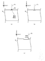
- FIGS. 2 (a) to 2 (c) is a cross-sectional view showing a state of removal processing performed on the work.
- FIGS. 3 (a) to 3 (c) is a cross-sectional view showing a state of a work machined by non-thermal processing.
- FIG. 4 is a cross-sectional view showing the structure of the processing apparatus.
- FIG. 5 is a perspective view showing the structure of the optical system included in the processing apparatus.
- FIG. 6 is a top view showing the stage device of the first embodiment.
- FIG. 7 is a sectional view taken along line VI # 1-VI # 1'of the stage apparatus shown in FIG. FIG.
- FIG. 8 is a sectional view taken along line VI # 2-VI # 2'of the stage apparatus shown in FIG.
- FIG. 9 is a sectional view taken along line VI # 3-VI # 3'of the stage apparatus shown in FIG.
- FIG. 10 is a sectional view taken along line VI # 4-VI # 4'of the stage apparatus shown in FIG.
- FIG. 11 is a cross-sectional view showing how the Y slide member is displaced to the + Z side.
- FIG. 12 is a cross-sectional view showing how the Y slide member is displaced to the ⁇ Z side.
- FIG. 13 is a top view showing the stage device of the second embodiment.
- FIG. 14 is a top view showing the stage device of the third embodiment.
- FIG. 15 is a cross-sectional view of the stage device shown in FIG.
- FIG. 16 is a top view showing the stage device of the fourth embodiment.
- FIG. 17 is a cross-sectional view showing the stage apparatus of the fifth embodiment.
- FIG. 18 is a cross-sectional view showing the stage apparatus of the fifth embodiment.
- FIG. 19 is a cross-sectional view showing the stage apparatus of the sixth embodiment.
- FIG. 20 is a cross-sectional view showing the stage apparatus of the sixth embodiment.
- FIG. 21 is a top view showing the stage apparatus of the seventh embodiment.
- FIG. 22 is a cross-sectional view showing the stage apparatus of the seventh embodiment.
- FIG. 23 is a cross-sectional view showing the stage apparatus of the eighth embodiment.
- FIG. 24 is a cross-sectional view showing how the Y slide member is displaced to the + Z side in the eighth embodiment.
- FIG. 25 is a cross-sectional view showing how the Y slide member is displaced to the ⁇ Z side in the eighth embodiment.
- FIG. 26 is a cross-sectional view showing the stage apparatus of the ninth embodiment.
- FIG. 27 is a cross-sectional view showing how the Y slide member is displaced to the + Z side in the ninth embodiment.
- FIG. 28 is a cross-sectional view showing how the Y slide member is displaced to the ⁇ Z side in the ninth embodiment.
- FIG. 29 is a cross-sectional view showing the stage apparatus of the tenth embodiment.
- FIG. 30 is a cross-sectional view showing how the Y slide member is displaced to the + Z side in the tenth embodiment.
- FIG. 31 is a cross-sectional view showing how the Y slide member is displaced to the ⁇ Z side in the tenth embodiment.
- FIG. 32 is a top view showing the stage apparatus of the eleventh embodiment.
- FIG. 33 is a cross-sectional view of the stage device shown in FIG. 32 in XXXXII-XXXII'.
- FIG. 34 is a top view showing the stage apparatus of the twelfth embodiment.
- FIG. 35 is a cross-sectional view taken along the line XXXIV-XXXIV'of the stage apparatus shown in FIG. 34.
- each of the X-axis direction and the Y-axis direction is a horizontal direction (that is, a predetermined direction in the horizontal plane), and the Z-axis direction is a vertical direction (that is, a direction orthogonal to the horizontal plane). Yes, it is assumed that it is substantially in the vertical direction or the gravity direction).
- the rotation directions (in other words, the inclination direction) around the X-axis, the Y-axis, and the Z-axis are referred to as the ⁇ X direction, the ⁇ Y direction, and the ⁇ Z direction, respectively.
- the Z-axis direction may be the direction of gravity.
- the XY plane may be horizontal.
- machining system SYSa Processing system SYS of the first embodiment
- FIG. 1 is a cross-sectional view showing the overall structure of the processing system SYSA of the first embodiment.
- FIG. 1 does not show a cross section of some of the components of the processing system SYS.
- the processing system SYSa includes a processing device 1, a measuring device 2, a stage device 3, a housing 4, a drive system 5, a drive system 6, and a control device 7.
- the processing device 1 can process the work W under the control of the control device 7.
- the work W may be, for example, a metal, an alloy (for example, duralumin, etc.), a semiconductor (for example, silicon), or a resin (for example, acrylic or PET (polyethylene)). It may be terephthalate), it may be a composite material such as CFRP (Carbon Fiber Reinforced Plastic), it may be glass, or it may be an object composed of any other material. May be good.
- the processing device 1 irradiates the work W with processing light EL in order to process the work W.
- the processing light EL may be any kind of light as long as the work W can be processed by being irradiated with the work W.
- the description will be made using an example in which the processing light EL is a laser light, but the processing light EL may be a type of light different from the laser light.
- the wavelength of the processing light EL may be any wavelength as long as the work W can be processed by irradiating the work W.
- the processed light EL may be visible light or invisible light (for example, at least one of infrared light and ultraviolet light).
- the processing apparatus 1 irradiates the work W with processing light EL to perform removal processing for removing a part of the work W.
- the processing apparatus 1 may perform processing different from the removal processing (for example, additional processing or marking processing).
- the removal process includes flat surface processing that removes a part of the work W to form a flat surface, curved surface processing that removes a part of the work W to form a curved surface, and drilling process that removes a part of the work to form a hole.
- Pocket processing to remove a part of the work to form a pocket, cutting processing to cut the work, and engraving processing to form (in other words, engrave) any character or any pattern (in other words, engraving) May contain at least one of.
- FIGS. 2 (a) to 2 (c) are cross-sectional views showing a state of removal processing performed on the work W.
- the processing apparatus 1 irradiates the irradiation region EA set (in other words, formed) on the surface of the work W with the processing light EL.
- the irradiation region EA is irradiated with the processing light EL, the energy of the processing light EL is transmitted to the portion of the work W that is close to the irradiation region EA.
- the material constituting the portion of the work W close to the irradiation region EA is melted by the heat generated by the energy of the processing light EL.
- the molten material becomes droplets and scatters.
- the molten material evaporates due to the heat generated by the energy of the processing light EL.
- the portion of the work W that is close to the irradiation region EA is removed. That is, as shown in FIG. 2B, a concave portion (groove portion as an example) is formed on the surface of the work W.
- the processing apparatus 1 processes the work W by utilizing the so-called thermal processing principle.
- the processing apparatus 1 appropriately removes the portion of the work W to be removed by causing the processing light EL to scan the surface of the work W along a desired scanning locus corresponding to the region to be removed. be able to.
- the processing apparatus 1 can also process the work W by using the principle of non-thermal processing (for example, ablation processing). That is, the processing apparatus 1 may perform non-thermal processing (for example, ablation processing) on the work W.
- non-thermal processing for example, ablation processing
- the processing apparatus 1 may perform non-thermal processing (for example, ablation processing) on the work W.
- pulsed light having a light emission time of picoseconds or less or, in some cases, nanoseconds or femtoseconds or less
- the material constituting the portion of the work W that is close to the irradiation region EA Instantly evaporates and scatters.
- FIGS. 3 (a) to 3 (c), which are cross-sectional views showing the state of the work W processed by non-thermal processing the processing system SYSa has heat generated by the energy of the processing optical EL.
- a recess in other words, a groove
- the measuring device 2 can measure the object to be measured under the control of the control device 7.
- the object to be measured includes, for example, a work W.
- the measuring device 2 may be a device capable of measuring the state of the work W.
- the state of the work W may include the position of the work W.
- the position of the work W may include the position of the surface of the work W.
- the position of the surface of the work W may include a position in at least one of the X-axis direction, the Y-axis direction, and the Z-axis direction of each portion of the surface of the work W.
- the state of the work W may include the shape of the work W (for example, a three-dimensional shape).
- the shape of the work W may include the shape of the surface of the work W.
- the shape of the surface of the work W is, in addition to or in place of, the position of the surface of the work W described above, the orientation of each part of the surface of the work W (for example, the direction of the normal of each part, and the X-axis. , Substantially equivalent to the amount of inclination of each part with respect to at least one of the Y-axis and the Z-axis).
- the state of the work W may include the size of the work W (for example, the size in at least one of the X-axis direction, the Y-axis direction, and the Z-axis direction).
- the measurement information regarding the measurement result of the measuring device 2 is output from the measuring device 2 to the control device 7.
- the measuring device 2 there is a measuring device that measures the work W by projecting slit light on the surface of the work W and using an optical cutting method that measures the shape of the projected slit light.
- Another example of the measuring device 2 is a measuring device that measures the work W by using a white interferometry method that measures an interference pattern between white light that passes through the work W and white light that does not pass through the work W.
- the white light referred to here may mean light having a wavelength width (spectral width) with respect to monochromatic light.
- the measuring device 2 may measure the work W by using another method different from the optical cutting method and the white interferometry method.
- a pattern projection method in which a light pattern is projected on the surface of the work W and the shape of the projected pattern is measured, light is projected on the surface of the work W and the projected light is returned.
- Time-of-flight method moiretopography method (specifically, lattice irradiation method or lattice projection method), holographic interferometry, in which the operation of measuring the distance from the time to the work W is performed at multiple positions on the work W.
- At least one of a method, an autocollimation method, a stereo method, a non-point aberration method, a critical angle method, and a knife edge method can be mentioned.
- the measuring device 2 receives the light source that emits the measurement light (for example, slit light or white light) and the light from the work W irradiated with the measurement light (for example, the reflected light of the measurement light). It may be provided with a light receiver.
- the receiver may include a single photodetector, may include a plurality of photodetectors arranged in a one-dimensional direction, or may include a plurality of photodetectors arranged in a two-dimensional direction. ..
- the stage device 3 is arranged (that is, provided) below the processing device 1 and the measuring device 2 (that is, on the ⁇ Z side).
- the stage device 3 includes a surface plate 31 and a stage 32.
- the surface plate 31 is arranged on the bottom surface F of the housing 4 (or on a supporting surface such as a floor on which the housing 4 is placed).
- a stage 32 is arranged on the surface plate 31.
- the stage 32 is arranged on the surface plate 31 so that the lower surface of the stage 32 (that is, the surface facing the ⁇ Z side) 322 faces the upper surface of the surface plate 31 (that is, the surface facing the + Z side) 311.
- the stage 32 is arranged on the surface plate 31 so that the lower surface 322 of the stage 32 is separated from the upper surface 311 of the surface plate 31 along the Z-axis direction.
- the prevention (not shown) for reducing the transmission of the vibration of the surface plate 31 to the stage 32.
- a shaking device may be installed.
- a support frame 8 for supporting the processing device 1 and the measuring device 2 may be arranged on the surface plate 31 (particularly on the upper surface 311 of the surface plate 31).
- the processing device 1 and the measuring device 2 (further, the stage 32) may be supported by the same surface plate 31.
- the processing apparatus 1 may not be arranged on the surface plate 31.
- At least a part of the measuring device 2 may not be arranged on the surface plate 31.
- At least a part of the processing device 1 and at least a part of the measuring device 2 may be arranged on different surface plates (or other support surfaces).
- the stage device 3 may include a surface plate 31. In this case, the stage 32 may be arranged on the structure of the housing 4.
- the stage 32 may be made of quartz glass or other materials (for example, metal, ceramics, etc.).
- the work W is placed on the stage 32.
- the upper surface of the stage 32 includes a mounting surface 321 on which the work W can be mounted.
- the mounting surface 321 is a surface parallel to the XY plane.
- the mounting surface 321 is a surface opposite to the lower surface 322.
- the work W is placed on the mounting surface 321. Therefore, the stage 32 is used as a mounting member on which the work W is mounted. At this time, the stage 32 does not have to hold the mounted work W.
- the stage 32 does not have to apply an external force for holding the work W to the mounted work W.
- the work W may be placed on the stage 32 without applying an external force. Alternatively, the stage 32 may hold the mounted work W.
- the stage 32 may apply an external force for holding the work W to the mounted work W.
- the work W may be placed on the stage 32 in a state where an external force is applied.
- the stage 32 may be used as a holding member for holding the work W.
- the stage 32 may hold the work W by vacuum-adsorbing and / or electrostatically adsorbing the work W. Since the stage device 3 includes the stage 32 on which the work W is mounted, the stage device 3 may be referred to as a mounting device.
- the stage 32 can move on the surface plate 31 (particularly on the upper surface 311 of the surface plate 31) while the work W is placed under the control of the control device 7. At this time, the upper surface 311 of the surface plate 31 may be used as a guide surface for the movement of the stage 32.
- the stage 32 is movable with respect to at least one of the surface plate 31, the processing device 1, and the measuring device 2.
- the stage 32 can move along the X-axis direction and the Y-axis direction, respectively. In this case, the stage 32 can move along the stage running surface parallel to the XY plane.
- the stage 32 may be movable along at least one of the Z-axis direction, the ⁇ X direction, the ⁇ Y direction, and the ⁇ Z direction in addition to or in place of at least one of the X-axis direction and the Y-axis direction. .. Since the stage device 3 includes a movable (that is, a moving body) stage 32, the stage device 3 may be referred to as a mobile device.
- stage device 3 capable of moving the stage 32 will be described in detail later with reference to FIG. 6 and the like, and thus detailed description thereof will be omitted here.
- the housing 4 accommodates the processing device 1, the measuring device 2, and the stage device 3 in the internal storage space SP separated from the space outside the housing 4. That is, in the first embodiment, the processing device 1, the measuring device 2, and the stage device 3 are arranged in the same housing 4. The processing device 1, the measuring device 2, and the stage device 3 are arranged in the same accommodation space SP.
- the housing 4 accommodates the work W in the accommodation space SP inside the work W. That is, the processing device 1, the measuring device 2, and the work W are arranged in the same accommodation space SP.
- at least a part of the processing apparatus 1 may not be arranged in the accommodation space SP. At least a part of the processing apparatus 1 may not be arranged outside the housing 4.
- At least a part of the measuring device 2 may not be arranged in the accommodation space SP. At least a part of the measuring device 2 may not be arranged outside the housing 4. At least a part of the stage device 3 may not be arranged in the accommodation space SP. At least a part of the stage device 3 may not be arranged outside the housing 4.
- the drive system 5 moves the processing device 1 under the control of the control device 7.
- the drive system 5 moves the processing device 1 with respect to at least one of the surface plate 31, the stage 32, and the work W mounted on the stage 32.
- the drive system 5 may move the processing device 1 with respect to the measuring device 2.
- the drive system 5 moves the processing apparatus 1 along at least one of the X-axis direction, the Y-axis direction, the Z-axis direction, the ⁇ X direction, the ⁇ Y direction, and the ⁇ Z direction.
- the drive system 5 includes, for example, a motor and the like.
- the processing system SYSa includes a position measuring instrument 51 capable of measuring the position of the processing device 1 moved by the drive system 5.
- the position measuring instrument 51 may include, for example, at least one of an encoder and a laser interferometer.
- the drive system 5 moves the processing device 1, the irradiation region EA moves on the work W. Further, when the drive system 5 moves the machining apparatus 1, the machining shot region PSA (see FIG. 5 described later) also moves on the work W. Therefore, the drive system 5 can change the positional relationship between the work W and the irradiation region EA and the machining shot region PSA by moving the machining apparatus 1.
- the "machining shot region PSA" in the first embodiment is machined by the machining apparatus 1 in a state where the positional relationship between the machining apparatus 1 and the object to be machined (for example, the work W) is fixed (that is, without changing). Indicates the area where is performed (in other words, the range). Typically, as shown in FIG.
- the machining shot region PSA is the machining light deflected by the galvano mirror 141 included in the machining device 1 in a state where the positional relationship between the machining device 1 and the object to be machined is fixed. It is set so that the area matches the scanning range of the EL or is narrower than the scanning range.
- the machining shot region PSA is a region in which the irradiation region EA irradiated with the machining light EL with the positional relationship between the machining apparatus 1 and the machining object fixed is equal to or narrower than the movable range. Is set to be. Therefore, the machining shot region PSA is a region determined with reference to the machining apparatus 1 (that is, a region having a predetermined positional relationship with the machining apparatus 1).
- the processing apparatus 1 does not have to be movable.
- the processing system SYSa does not have to include the drive system 5. If the processing apparatus 1 does not move, the processing system SYS may not include the position measuring instrument 51.
- the processing apparatus 1 since the stage 32 is movable in the X-axis direction and the Y-axis direction, the processing apparatus 1 may be movable in the Z-axis direction. At this time, the focus position of the processing light EL may be controlled by the movement of the processing apparatus 1 in the Z-axis direction. The focus position of the observation device 16 may be controlled by the movement of the processing device 1 to the Z axis.
- the drive system 6 moves the measuring device 2 under the control of the control device 7.
- the drive system 6 moves the measuring device 2 with respect to at least one of the surface plate 31, the stage 32, and the work W mounted on the stage 32.
- the drive system 6 may move the measuring device 2 with respect to the processing device 1.
- the drive system 6 moves the measuring device 2 along at least one of the X-axis direction, the Y-axis direction, the Z-axis direction, the ⁇ X direction, the ⁇ Y direction, and the ⁇ Z direction.
- the drive system 6 includes, for example, a motor and the like.
- the processing system SYSa includes a position measuring instrument 61 capable of measuring the position of the measuring device 2 moved by the drive system 6.
- the position measuring instrument 61 may include, for example, at least one of an encoder and a laser interferometer.
- the drive system 6 moves the measuring device 2
- the measurement shot area MSA moves on the work W. Therefore, the drive system 6 can change the positional relationship between the work W and the measurement shot area MSA by moving the measurement device 2.
- the "measurement shot area MSA" in the first embodiment is measured by the measuring device 2 in a state where the positional relationship between the measuring device 2 and the measurement target (for example, the work W) is fixed (that is, without changing). Indicates the area where is performed (in other words, the range).
- the measuring device 2 is a measuring device using the optical cutting method
- the measurement shot area MSA is subjected to the optical cutting method in a state where the positional relationship between the measuring device 2 and the measurement object is fixed.
- the measuring device 2 is a measuring device using the white interferometry
- the measurement shot area MSA is typically subjected to the white interferometry with the positional relationship between the measuring device 2 and the object to be measured fixed. It may be set so as to coincide with or narrower than the range in which the white light to be used can be irradiated (for example, the scanning range of the white light).
- the measurement shot area MSA is a light receiving surface (for example, simply) of a receiver that receives light from a work W irradiated with slit light and / or white light in a state where the positional relationship between the measuring device 2 and the measurement object is fixed. It may be set so as to correspond to one photodetector or a light receiving surface of a plurality of photo detectors arranged in a one-dimensional direction or a two-dimensional direction). Therefore, the measurement shot area MSA is an area determined with reference to the measurement device 2 (that is, an area having a predetermined positional relationship with the measurement device 2). Such a measurement shot area MSA may be referred to as a measurable range or a measurable field of the measuring device 2.
- the stage 32 is movable, the positional relationship between the work W and the measurement shot area MSA can be changed even if the measuring device 2 is not movable. Therefore, the measuring device 2 does not have to be movable. In this case, the processing system SYSa does not have to include the drive system 6. If the measuring device 2 does not move, the machining system SYS may not include the position measuring device 61.
- the measuring device 2 since the stage 32 is movable in the X-axis direction and the Y-axis direction, the measuring device 2 may be movable in the Z-axis direction. At this time, the focus position of the measuring device 2 may be controlled by the movement of the measuring device 2 in the Z-axis direction.
- the control device 7 controls the operation of the processing system SYS.
- the control device 7 may include, for example, an arithmetic unit and a storage device.
- the arithmetic unit may include, for example, at least one of a CPU (Central Processing Unit) and a GPU (Graphics Processing Unit).
- the control device 7 functions as a device that controls the operation of the processing system SYS by executing a computer program by the arithmetic unit.
- This computer program is a computer program for causing the control device 7 (for example, an arithmetic unit) to perform (that is, execute) an operation described later to be performed by the control device 7. That is, this computer program is a computer program for causing the control device 7 to function so that the processing system SYSa performs an operation described later.
- the computer program executed by the arithmetic unit may be recorded in a storage device (that is, a recording medium) included in the control device 7, or any storage built in the control device 7 or externally attached to the control device 7. It may be recorded on a medium (for example, a hard disk or a semiconductor memory). Alternatively, the arithmetic unit may download the computer program to be executed from an external device of the control device 7 via the network interface.
- a storage device that is, a recording medium included in the control device 7, or any storage built in the control device 7 or externally attached to the control device 7. It may be recorded on a medium (for example, a hard disk or a semiconductor memory).
- the arithmetic unit may download the computer program to be executed from an external device of the control device 7 via the network interface.
- the control device 7 does not have to be provided inside the processing system SYS, and may be provided as a server or the like outside the processing system SYS, for example.
- the control device 7 and the processing system SYSA may be connected by a wired and / or wireless network (or a data bus and / or a communication line).
- a wired network for example, a network using a serial bus type interface represented by at least one of IEEE1394, RS-232x, RS-422, RS-423, RS-485 and USB may be used.
- a network using a parallel bus interface may be used.
- a network using an Ethernet (registered trademark) compliant interface represented by at least one of 10BASE-T, 100BASE-TX and 1000BASE-T may be used.
- a network using radio waves may be used.
- An example of a network using radio waves is a network conforming to IEEE802.1x (for example, at least one of wireless LAN and Bluetooth®).
- a network using infrared rays may be used.
- a network using optical communication may be used.
- the control device 7 and the processing system SYSA may be configured so that various types of information can be transmitted and received via the network.
- control device 7 may be able to transmit information such as commands and control parameters to the processing system SYSA via the network.
- the processing system SYSa may include a receiving device that receives information such as commands and control parameters from the control device 7 via the network.
- the first control device that performs a part of the processing performed by the control device 7 is provided inside the processing system SYS
- the second control device that performs the other part of the processing performed by the control device 7 is provided.
- the control device may be provided outside the processing system SYS.
- the recording medium for recording the computer program executed by the arithmetic unit includes CD-ROM, CD-R, CD-RW, flexible disc, MO, DVD-ROM, DVD-RAM, DVD-R, DVD + R, and DVD-. At least one of optical disks such as RW, DVD + RW and Blu-ray (registered trademark), magnetic media such as magnetic tape, magneto-optical disks, semiconductor memories such as USB memory, and any other medium capable of storing a program is used. You may.
- the recording medium may include a device capable of recording a computer program (for example, a general-purpose device or a dedicated device in which the computer program is implemented in a state in which it can be executed in at least one form such as software and firmware).
- each process or function included in the computer program may be realized by a logical processing block realized in the control device 7 by the control device 7 (typically a computer) executing the computer program.
- the control device 7 typically a computer
- it may be realized by hardware such as a predetermined gate array (FPGA, ASIC) included in the control device 7, or a logical processing block and a partial hardware module that realizes a part of the hardware. May be realized in a mixed format.
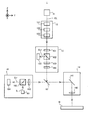
- FIG. 4 is a cross-sectional view showing the structure of the processing apparatus 1.
- the processing apparatus 1 returns the light source 11, the optical system 12, the dichroic mirror 13, the optical system 14, and so on, as shown in FIG. 4, which is a cross-sectional view showing the structure of the processing apparatus 1. It includes a light protection device 15 and an observation device 16.
- the structure of the processing apparatus 1 shown in FIG. 4 is merely an example. Therefore, the processing apparatus 1 may have any structure as long as the work W can be processed by using the processing optical EL. That is, the processing device 1 does not necessarily have to include at least one of a light source 11, an optical system 12, a dichroic mirror 13, an optical system 14, a return light prevention device 15, and an observation device 16.
- the light source 11 can generate a processed light EL.
- the processing light EL is a laser light
- the light source 11 may be, for example, a laser diode.
- the light source 11 may be a light source capable of pulse oscillation.
- the light source 11 can generate pulsed light (for example, pulsed light having a light emission time of picoseconds or less) as processed light EL.
- the light source 11 emits the generated processed light EL toward the optical system 12.
- the light source 11 may emit processed light EL in a linearly polarized state.
- the optical system 12 is an optical system in which the processed light EL emitted from the light source 11 is incident.
- the optical system 12 is an optical system that emits the processed light EL incident on the optical system 12 toward the return light prevention device 15. That is, the optical system 12 is an optical system that guides the processed light EL emitted from the light source 11 to the return light prevention device 15.
- the optical system 12 may control the state of the processed light EL emitted from the light source 11, and may emit the processed light EL whose state is controlled toward the return light prevention device 15.
- the optical system 12 may control the beam diameter of the processing light EL (that is, the size of the processing light EL in the plane intersecting the traveling direction of the processing light EL).
- the optical system 12 may control the beam diameter (that is, the spot diameter) of the processing light EL on the surface of the work W by controlling the beam diameter of the processing light EL.
- the optical system 12 may include a beam expander 121.
- the optical system 12 may control the degree of convergence or the degree of divergence of the processing light emitted from the optical system 12.
- the optical system 12 may include a focus lens 122.
- the focus lens 122 is composed of one or more lenses, and by adjusting the position of at least a part of the lenses along the optical axis direction, the degree of convergence or the degree of divergence of the processed light EL is changed to change the degree of convergence or divergence of the processed light EL. It is an optical element for adjusting the focus position.
- the focus lens 122 may be integrated with the beam expander 121 or may be separate from the beam expander 121.
- the optical system 12 may control the intensity distribution of the processing light EL in the plane intersecting the traveling direction of the processing light EL.
- the optical system 12 may include an intensity distribution control member 123 capable of controlling the intensity distribution of the processing light EL.
- the state of the processing light EL controlled by the optical system 12 includes the focus position of the processing light EL, the beam diameter of the processing light EL, the convergence degree of the processing light EL, the divergence degree of the processing light EL, and the intensity distribution of the processing light EL.
- at least one of the pulse length of the processing light EL, the number of pulses of the processing light EL, the intensity of the processing light EL, the traveling direction of the processing light EL, and the polarization state of the processing light EL may be included. ..
- the dichroic mirror 13 guides the processed light EL incident on the dichroic mirror 13 from the optical system 12 via the return light prevention device 15 to the optical system 14.
- the dichroic mirror 13 reflects one of the processed light EL and the observation light (illumination light IL and the reflected light ILr) having a wavelength different from that of the processed light EL and transmits the other.
- the dichroic mirror 13 guides the processing light EL to the optical system 14 by reflecting the processing light EL toward the optical system 14.
- the dichroic mirror 13 may guide the processing light EL to the optical system 14 by passing the processing light EL.
- the optical system 14 is an optical system for irradiating the work W with the processed light EL from the dichroic mirror 13 (that is, guiding the work W).
- the optical system 14 includes a galvano mirror 141 and an f ⁇ lens 142.
- the galvano mirror 141 deflects the processed light EL so that the processed light EL from the f ⁇ lens 142 scans the work W (that is, the irradiation region EA irradiated with the processed light EL moves on the surface of the work W). ..
- the optical system 14 may deflect the processing light EL by using a polygon mirror in addition to or in place of the galvano mirror 141.
- the galvano mirror 141 includes an X scanning mirror 141X and a Y scanning mirror 141Y, as shown in FIG. 5, which is a perspective view showing the structure of the optical system 14.
- the X scanning mirror 141X reflects the processed light EL toward the Y scanning mirror 141Y.
- the X scanning mirror 141X can swing or rotate about the ⁇ Y direction (that is, the rotation direction around the Y axis). Due to the swing or rotation of the X scanning mirror 141X, the processing light EL scans the surface of the work W along the X-axis direction. Due to the swing or rotation of the X scanning mirror 141X, the irradiation region EA moves on the surface of the work W along the X-axis direction.
- the Y scanning mirror 141Y reflects the processed light EL toward the f ⁇ lens 142.
- the Y scanning mirror 141Y can swing or rotate about the ⁇ X direction (that is, the rotation direction around the X axis).
- the processing light EL scans the surface of the work W along the Y-axis direction.
- the irradiation region EA moves on the surface of the work W along the Y-axis direction.
- the f ⁇ lens 142 is an optical element for condensing the processed light EL from the galvano mirror 141 on the work W.
- the X scanning mirror 141X may swing or rotate about a direction slightly inclined from the ⁇ Y direction (that is, the rotation direction around the Y axis).
- the Y scanning mirror 141Y may swing or rotate about a direction slightly inclined from the ⁇ X direction (that is, the rotation direction around the X axis).
- the f ⁇ lens 142 is a telecentric optical system on the injection surface side (work W side), but the f ⁇ lens 142 does not have to be a telecentric optical system.
- the f ⁇ lens 142 is a telecentric optical system on the ejection surface side (work W side)
- the irradiation position does not change in the XY plane of the processed light EL even if the thickness of the work W (size in the Z axis direction) changes.
- the return light prevention device 15 prevents the return light ELr, which is the processed light EL reflected by the work W, from returning to the optical system 12 and the light source 11.
- the return light prevention device 15 guides the processed light EL emitted by the optical system 12 to the dichroic mirror 13 (that is, leads to the work W).
- the return light prevention device 15 may utilize polarized light, for example.
- the light source 11 may emit, for example, the processed light EL in the linearly polarized state.
- the return light prevention device 15 includes, for example, a 1/2 wave plate 151, a polarization beam splitter 152, a 1/4 wave plate 153, a 1/2 wave plate 154, and a beam diffuser 155.
- the 1/2 wave plate 151 changes the polarization direction of the processed light EL from the optical system 12.
- the 1/2 wavelength plate 151 changes the polarization direction of the processed light EL from the optical system 12 so that it can pass through the polarization beam splitter 152.
- the processed light EL that has passed through the 1/2 wavelength plate 151 passes through the polarizing beam splitter 152.
- the description will proceed with reference to an example in which the polarizing beam splitter 152 passes p-polarized light through the polarization splitting surface of the polarizing beam splitter 152 while reflecting s-polarized light. That is, the description will proceed with reference to an example in which the processed light EL passing through the polarization beam splitter 152 is p-polarized light.
- the processed light EL that has passed through the polarization beam splitter 152 passes through the quarter wave plate 153 and becomes circularly polarized.
- the processed light EL that has passed through the 1/4 wave plate 153 passes through the 1/2 wave plate 154, and the ellipticity of its polarization is adjusted.
- the circularly polarized processed light EL is incident on the dichroic mirror 13.
- the return light prevention device 15 can guide the processed light EL to the dichroic mirror 13.
- the return light ELr incident on the return light prevention device 15 is incident on the 1/4 wave plate 153 via the 1/2 wavelength plate 154.
- the rotation direction of the return light ELr is reversed with respect to the rotation direction of the processed light EL. Therefore, the return light ELr that has passed through the 1/2 wave plate 154 and the 1/4 wave plate 153 becomes s-polarized light.
- the return light ELr that has passed through the quarter wave plate 153 is reflected by the polarization beam splitter 152.
- the 1/4 wave plate may be arranged in the optical path between the 1/4 wave plate 154 and the work W. Further, the 1/4 wave plate 153 may be removed from the optical path, and the work W may be processed with the processing light in the linearly polarized state.
- the observation device 16 can optically observe the state of the surface of the work W.
- FIG. 4 shows an example in which the observation device 16 can optically image the state of the surface of the work W.
- the observation device 16 may include a light source 161, a beam splitter 162, a notch filter 163, and an image pickup device 164.
- the light source 161 generates an illumination light IL.
- the illumination light IL is visible light, but may be invisible light.
- the wavelength of the illumination light IL is different from the wavelength of the processing light EL.
- the wavelength of the illumination light IL is set to a wavelength that can pass through the dichroic mirror 13.
- the light source 161 emits the generated illumination light IL toward the beam splitter 162.
- the beam splitter 162 reflects at least a part of the illumination light IL from the light source 161 toward the notch filter 163.
- the notch filter 163 is a filter that attenuates only light in a part of the wavelength band of the incident illumination light IL.
- a bandpass filter that transmits only light in a part of the wavelength band of the incident illumination light IL may be used in addition to or in place of the notch filter 163.
- the notch filter 163 limits the wavelength band of the illumination light IL passing through the notch filter 163 to a wavelength band that can pass through the dichroic mirror 13.
- the illumination light IL reflected by the beam splitter 162 enters the dichroic mirror 13 via the notch filter 163.
- the illumination light IL incident on the dichroic mirror 13 passes through the dichroic mirror 13.
- the illumination light IL irradiates the surface of the work W via the optical system 14. That is, the illumination light IL irradiates the surface of the work W through an optical path that at least partially overlaps the optical path of the processed light EL.
- the illumination light IL irradiates the surface of the work W through a part of the optical system (in the example shown in FIG. 4, the dichroic mirror 13 and the optical system 14) that guides the processed light EL from the light source 11 to the work W. Therefore, in the example shown in FIG.
- a part of the optical system that guides the processed light EL from the light source 11 to the work W is shared as a part of the optical system that guides the illumination light IL from the light source 161 to the work W. ..
- the optical system that guides the processing light EL from the light source 11 to the work W and the optical system that guides the illumination light IL from the light source 161 to the work W may be optically separated. At least a part of the illumination light IL applied to the surface of the work W is reflected by the surface of the work W. As a result, the illumination light IL reflected by the work W is incident on the optical system 14 as the reflected light ILr. The reflected light ILr is incident on the observation device 16 via the optical system 14.
- the reflected light ILr incident on the observation device 16 is incident on the beam splitter 162 through the notch filter 163.
- the illumination light IL and the reflected light ILr may be referred to as observation light.
- the notch filter 163 may be used as a light-shielding member for preventing the processed light EL having a wavelength different from that of the observation light from entering the inside of the observation device 16 (particularly, the image pickup device 164). At least a part of the reflected light ILr incident on the beam splitter 162 passes through the beam splitter 162 and is incident on the image sensor 164. As a result, the observation device 16 can optically image the state of the surface of the work W.
- the observation result (specifically, the imaging result) of the observation device 16 includes information that can identify the state of the work W. Therefore, the observation device 16 may be used as a measuring device for measuring the work W.
- the observation result (specifically, the imaging result) of the observation device 16 includes information that can identify the shape of the work W (for example, the shape of the surface of the work W). Therefore, the observation device 16 may be used as a measuring device for measuring the shape of the work W.
- a part of the processing device 1 is shared with at least a part of the measuring device (observation device 16 in the example shown in FIG. 4) for measuring the work W.
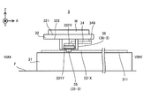
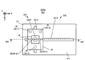
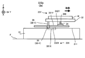
- FIG. 6 is a top view showing the stage device 3 of the first embodiment.
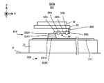
- FIG. 7 is a sectional view taken along line VI # 1-VI # 1'of the stage device 3 shown in FIG.
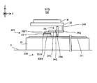
- FIG. 8 is a sectional view taken along line VI # 2-VI # 2'of the stage device 3 shown in FIG.
- FIG. 9 is a sectional view taken along line VI # 3-VI # 3'of the stage device 3 shown in FIG.
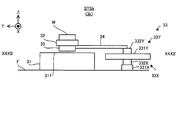
- FIG. 10 is a sectional view taken along line VI # 4-VI # 4'of the stage device 3 shown in FIG.
- the stage device 3 includes a stage drive system 33, a connecting member 34, and an air bearing 35 in addition to the surface plate 31 and the stage 32 described above.
- the stage drive system 33 is a device for moving the stage 32 along the X-axis direction and the Y-axis direction, respectively. In this case, the stage drive system 33 does not have to control the position of the stage 32 in the Z-axis direction.
- the stage drive system 33 mainly includes an X stage drive system 33X for moving the stage 32 along the X-axis direction, and a Y stage drive system 33Y for mainly moving the stage 32 along the Y-axis direction.
- the X stage drive system 33X and the Y stage drive system 33Y are arranged between the surface plate 31 and the stage 32. Specifically, the X stage drive system 33X and the Y stage drive system 33Y are arranged between the upper surface 311 of the surface plate 31 and the lower surface 322 of the stage 32.
- the X stage drive system 33X includes an X rail member (X guide member) 331X and an X slide member 332X.
- the X rail member 331X is arranged on the surface plate 31.
- the X rail member 331X is a member extending along the X-axis direction.
- the X rail member 331X is a member having a longitudinal direction in the X-axis direction.
- the X slide member 332X is attached to the X rail member 331X.
- the X slide member 332X is a moving member that can move along the X rail member 331X. That is, the X slide member 332X is attached to the X rail member 331X so that the X slide member 332X can move along the X rail member 331X.
- the X slide member 332X may be referred to as an X block member. Since the X rail member 331X is a member extending along the X axis direction, the X slide member 332X can move along the X axis direction. The X slide member 332X can be moved by using the power of a motor (for example, a linear motor) (not shown) included in the X stage drive system 33X. That is, the X stage drive system 33X is a drive system including a so-called linear motion guide.
- the X stage drive system 33X may be referred to as a mobile device.
- the Y stage drive system 33Y is located on the X stage drive system 33X.
- the Y stage drive system 33Y includes a Y rail member (Y guide member) 331Y and a Y slide member 332Y.
- the Y rail member 331Y is arranged on the X slide member 332X.
- the Y rail member 331Y is connected to the X slide member 332X.
- the Y rail member 331Y is a member extending along the Y-axis direction.
- the Y rail member 331Y is a member having a longitudinal direction in the Y-axis direction.
- the Y slide member 332Y is attached to the Y rail member 331Y.
- the Y slide member 332Y is a moving member that can move along the Y rail member 331Y. That is, the Y slide member 332Y is attached to the Y rail member 331Y so that the Y slide member 332Y can move along the Y rail member 331Y.
- the Y slide member 332Y may be referred to as a Y block member. Since the Y rail member 331Y is a member extending along the Y axis direction, the Y slide member 332Y can move along the Y axis direction.
- the Y rail member can be moved by using the power of a motor (for example, a linear motor) (not shown) included in the Y stage drive system 33Y. That is, the Y stage drive system 33Y is a drive system including a so-called linear motion guide.
- the Y stage drive system 33Y may be referred to as a mobile device.
- the Y rail member 331Y Since the Y rail member 331Y is arranged on the X slide member 332X, the Y rail member 331Y can also move along the X axis direction as the X slide member 332X moves in the X axis direction.
- the Y slide member 332Y attached to the Y rail member 331Y also moves along the X-axis direction. Therefore, the Y slide member 332Y is a moving member that can move along the X-axis direction and the Y-axis direction, respectively.
- the connecting member 34 is a member that extends (that is, extends) from the Y slide member 332Y toward the stage 32.
- the connecting member 34 is a member that extends from a position where the Y slide member 332Y and the connecting member 34 are connected toward a position where the stage 32 and the connecting member 34 are connected.
- the connecting member 34 moves from the connecting portion 3321Y (FIG. 7) connected to the connecting member 34 of the Y slide member 332Y toward the connecting portion 323 (FIG. 7) connected to the connecting member 34 of the stage 32. It is a member that extends.
- the connecting member 34 connects the Y slide member 332Y and the stage 32. Specifically, the connecting member 34 is connected to the Y slide member 332Y (particularly, the connecting portion 3321Y) via the connecting portion 341 (FIG. 7) of the connecting member 34. In the example shown in FIGS. 6 to 10, the connecting portion 341 of the connecting member 34 is connected to the upper surface of the Y slide member 332Y (that is, the surface facing the + Z side), but is an arbitrary portion of the Y slide member 332Y. May be linked to.
- the connecting member 34 is connected to the stage 32 (particularly, the connecting portion 323) via the connecting portion 342 (FIG. 7) of the connecting member 34. In the example shown in FIGS. 6 to 10, the connecting portion 342 of the connecting member 34 is connected to the lower surface 322 of the stage 32, but may be connected to any portion of the stage 32.
- the connecting member 34 is a Y-slide member via at least a part of the space below the stage 32 (for example, the space between the lower surface 322 of the stage 32 and the upper surface 311 of the surface plate 31).
- the 332Y and the stage 32 are connected.
- the connecting member 34 extends from the Y slide member 332Y toward the stage 32 in the space below the stage 32.
- the connecting member 34 is arranged in the space below the stage 32.
- the connecting member 34 is arranged between the lower surface 322 of the stage 32 and the upper surface 311 of the surface plate 31.
- the connecting portion 342 is connected to the stage 32 via the spacer 349 so that the portion of the connecting member 34 other than the connecting portion 342 does not come into contact with the stage 32 (particularly, the lower surface 322).
- the spacer 349 has a size capable of forming a predetermined gap between the connecting member 34 and the stage 32 in the Z-axis direction.
- the connecting portion 342 may be connected to the stage 32 without passing through the spacer 349.
- the connecting portion 342 or the spacer 349 is connected to the stage 32 at the peripheral portion of the stage 32, but may be connected at another place. For example, they may be connected in the vicinity of the center position or the center of gravity of the stage 32.
- the vicinity of the center position (center of gravity position) of the stage 32 is a position closer to the center (center of gravity) than the position of 1/2 of the line segment connecting the center (center of gravity) of the stage 32 and the end of the stage 32. be able to.
- At least a part of the Y slide member 332Y and at least a part of the stage 32 are in the Z-axis direction. They may be adjacent along. At least a part of the Y slide member 332Y and at least a part of the stage 32 may overlap along the Z-axis direction. At least a part of the Y slide member 332Y and at least a part of the stage 32 may face each other along the Z-axis direction. The position of the Y slide member 332Y in the Z-axis direction may be different from the position of the stage 32 in the Z-axis direction.
- the position of the Y slide member 332Y in the direction along at least a part of the XY plane may be the same as the position of the stage 32 in the direction along the at least a part of the XY plane. More specifically, at least a part of the Y slide member 332Y may be arranged in a space below at least a part of the stage 32. At least a part of the stage 32 may be arranged in a space above at least a part of the Y slide member 332Y.
- the stage connected to the Y slide member 332Y via the connecting member 34 also moves along the X-axis direction.
- the stage 32 connected to the Y-slide member 332Y via the connecting member 34 also moves along the Y-axis direction. That is, the stage 32 can move along the X-axis direction and the Y-axis direction as the Y slide member 332Y moves. That is, the stage 32 can move in the stage running plane along the XY plane.
- the connecting member 34 may function as a spring that absorbs the displacement in the X-axis direction.
- the stage 32 may not move along the X-axis direction.
- the amount of movement of the stage 32 along the X-axis direction may be less than the amount of movement expected from the amount of movement of the Y slide member 332Y along the X-axis direction.
- the rigidity of the connecting member 34 in the X-axis direction is the stage 32 in the movement mode assumed from the movement mode of the Y-slide member 332Y in the X-axis direction as the Y-slide member 332Y moves along the X-axis direction. May be set to a value high enough to satisfy the movement condition #X that the movement is along the X-axis direction.
- the movement mode may include the direction of movement. That is, the movement condition #X may include a condition relating to the movement direction of the Y slide member 332Y and the stage 32 in the X-axis direction.
- the movement condition # X may include the movement condition # X1 that the direction of movement of the stage 32 in the X-axis direction is the same as the direction of movement of the Y slide member 332Y in the X-axis direction. More specifically, the movement condition #X includes the movement condition # X11 that the stage 32 moves toward the + X side when the Y slide member 332Y moves toward the + X side, and the Y slide member 332Y. It may include at least one of the movement conditions # X12 that the stage 32 moves toward the ⁇ X side when it moves toward the ⁇ X side.
- the movement mode may include a movement amount in addition to or in place of the movement direction.
- the movement condition #X may include a condition relating to the movement amount of the Y slide member 332Y and the stage 32 in the X-axis direction.
- the movement condition # X may include the movement condition # X2 in which the movement amount of the stage 32 along the X-axis direction is proportional to the movement amount of the Y slide member 332Y along the X-axis direction.
- the movement mode may include a movement speed (ie, movement amount per unit time) in addition to or in place of at least one of the movement direction and the movement amount.
- the movement condition #X may include a condition relating to the movement speed of the Y slide member 332Y and the stage 32 in the X-axis direction.
- the movement condition # X may include the movement condition # X3 in which the movement speed of the stage 32 along the X-axis direction is proportional to the movement speed of the Y slide member 332Y along the X-axis direction.
- the connecting member 34 may function as a spring that absorbs the displacement in the Y-axis direction.
- the stage 32 may not move along the Y-axis direction.
- the amount of movement of the stage 32 along the Y-axis direction may be less than the amount of movement expected from the amount of movement of the Y slide member 332Y along the Y-axis direction.
- the rigidity of the connecting member 34 in the Y-axis direction is the movement mode assumed from the movement mode of the Y-slide member 332Y in the Y-axis direction as the Y-slide member 332Y moves along the Y-axis direction. May be set to a value high enough to satisfy the movement condition # Y that moves along the Y-axis direction.
- the movement mode may include at least one of the movement direction, the movement amount, and the movement speed.
- the movement condition #Y is a condition relating to the direction of movement of the Y slide member 332Y and the stage 32 in the Y axis direction, a condition relating to the amount of movement of the Y slide member 332Y and the stage 32 in the Y axis direction, and the Y slide member 332Y and It may include at least one of the conditions relating to the moving speed of the stage 32 in the Y-axis direction.
- the movement condition # Y may include the movement condition # Y1 that the direction of movement of the stage 32 in the Y-axis direction is the same as the direction of movement of the Y slide member 332Y in the Y-axis direction.
- the movement condition #Y includes the movement condition # Y11 that the stage 32 moves toward the + Y side when the Y slide member 332Y moves toward the + Y side, and the Y slide member 332Y. It may include at least one of the movement conditions # Y12 that the stage 32 moves toward the ⁇ Y side when it moves toward the ⁇ Y side.
- the movement condition # Y may include the movement condition # Y2 that the movement amount of the stage 32 along the Y-axis direction is proportional to the movement amount of the Y slide member 332Y along the Y-axis direction.
- the moving condition # Y may include the moving condition # Y3 that the moving speed of the stage 32 along the Y-axis direction is proportional to the moving speed of the Y slide member 332Y along the Y-axis direction.
- the rigidity of the connecting member 34 connecting the Y slide member 332Y and the stage 32 in the Z axis direction is too high, the displacement of the Y slide member 332Y along the Z axis direction is caused by the connecting member 34 via the connecting member 34. Will be transmitted to. Such displacement of the stage 32 along the Z-axis direction may lead to deterioration of machining accuracy of the work W placed on the stage 32. Therefore, the rigidity of the connecting member 34 in the Z-axis direction is deformed (for example, distorted, bent, or bent) in the Z-axis direction so as to absorb the displacement of the Y slide member 332Y along the Z-axis direction. The value may be set as low as possible to satisfy the absorption condition.
- the connecting member 34 is typically displaced in the Z-axis direction.
- the connecting member 34 is displaced in the Z-axis direction when the stage 32 moves along the running surface of the stage.
- the stage 32 can be appropriately moved along the running surface of the stage without being affected by the displacement of the Y slide member 332Y along the Z-axis direction.
- the "absorption of displacement of Y slide member 332Y" in the first embodiment is only for canceling the displacement of Y slide member 332Y with the connecting member 34 so that the displacement of Y slide member 332Y is not transmitted to the stage 32.
- the displacement of the Y slide member 332Y is also reduced by the connecting member 34 so that the displacement transmitted from the Y slide member 332Y to the stage 32 becomes small enough to have almost no effect on the machining accuracy of the work W.
- the connecting member 34 is typically a member whose rigidity in each of the X-axis direction and the Y-axis direction is higher than the rigidity in the Z-axis direction.
- the connecting member 34 is typically a member whose rigidity in the Z-axis direction is lower than the rigidity in each of the X-axis direction and the Y-axis direction.
- the connecting member 34 may be a flexible member whose rigidity in one direction is higher than that in another direction.
- the rigidity of the connecting member 34 is higher than that of the connecting member in the comparative example in which the rigidity in each of the X-axis direction and the Y-axis direction is not higher than the rigidity in the Z-axis direction.
- Condition # Y and displacement absorption condition can be easily satisfied.
- the connecting member 34 may be, for example, a member extending along the X-axis direction or the Y-axis direction (or any direction along the XY plane).
- the connecting member 34 may be a member having a longitudinal shape.
- the connecting member 34 may be a member having at least one length in the X-axis direction and the Y-axis direction sufficiently larger than the thickness in the Z-axis direction.
- the connecting member 34 may be a member having a relatively high aspect ratio, which is a ratio of length to thickness.
- the connecting member 34 is a member extending along the X-axis direction (that is, a member whose longitudinal direction is the X-axis direction). In this case, the rigidity of the connecting member 34 tends to satisfy the above-mentioned movement condition # X, movement condition # Y, and displacement absorption condition.
- the connecting portions 341 and 342 of the connecting member 34 are the connecting members 34, respectively. It may be one end and the other end.
- the connecting portion 3321Y of the Y slide member 332Y to which the connecting portion 341 is connected and the connecting portion 323 of the stage 32 to which the connecting portion 342 is connected are separated from each other along the direction in which the connecting member 34 extends.
- the connecting member 34 is different from the connecting portion 3321Y of the Y slide member 332Y in the position along the X-axis direction or the Y-axis direction (or any direction along the XY plane) of the stage 32. It connects with the connecting portion 323.
- the connecting member 34 may include an elastic body.
- the connecting member 34 may include an elastic member which is an elastic body.
- the connecting member 34 may include a spring, which is an example of an elastic body.
- springs include at least one of a wire spring (in other words, a coil spring), a leaf spring, a bar spring (in other words, a torsion bar), and a spiral spring.
- the connecting member 34 includes a leaf spring
- the leaf spring may have a plate-like shape along a plane parallel to the XY plane or the XY plane.
- the leaf spring may have a plate-like shape along the stage running surface or a surface parallel to the stage running surface.
- the connecting member 34 may include, in addition to or in place of the spring, rubber, which is another example of an elastic body.
- the connecting member 34 contains an elastic body as described above, the rigidity of the connecting member 34 is particularly likely to satisfy the displacement absorption condition as compared with the case where the connecting member 34 does not contain the elastic body.
- the connecting member 34 including the elastic body may be referred to as an elastic member.
- the connecting member 34 is a member extending along the X-axis direction or the Y-axis direction (or any direction along the XY plane)
- the rigidity of the connecting member 34 is the movement condition # X
- the connecting member 34 includes a spring
- the spring included in the connecting member 34 is a spring having a shape extending along the X-axis direction or the Y-axis direction (or any direction along the XY plane).
- An example of such a spring is a spring having a plate-like shape (so-called leaf spring).
- the air bearing 35 is a member that supports the stage 32. Specifically, the air bearing 35 supports the stage 32 in the Z-axis direction.
- the air bearing 35 supports the stage 32 in the Z-axis direction so as to maintain a relative position in the Z-axis direction between the surface plate 31 (for example, the upper surface 311 of the surface plate 31) and the stage 32.
- the air bearing 35 supports the stage 32 in the Z-axis direction so that the positional relationship between the surface plate 31 (for example, the upper surface 311 of the surface plate 31) and the stage 32 in the Z-axis direction becomes a desired positional relationship. ..
- the air bearing 35 is provided in the Z-axis direction so that the stage 32 does not unintentionally move along the Z-axis direction with respect to the surface plate 31 (that is, the stage 32 is not displaced in the Z-axis direction). Supports stage 32.
- the stage device 3 includes a plurality of air bearings 35.
- the stage device 3 includes three air bearings 35 (specifically, air bearings 35-1 to 35-3).
- the stage device 3 may include a single air bearing 35, may include two air bearings 35, or may include four or more air bearings 35.
- the air bearing 35 is arranged on the stage 32. Typically, the air bearing 35 is fixed to the stage 32. In particular, the air bearing 35 is arranged on the lower surface 322 of the stage 32. Specifically, the air bearing 35 is provided on the stage 32 via the mounting member 36. However, the air bearing 35 may be provided directly on the stage 32 without the intervention of the mounting member 36. In the example shown in FIGS. 6 to 10, the air bearing 35-1 is attached to the stage 32 via the mounting member 36-1, and the air bearing 35-2 is attached to the stage 32 via the leg member 36-2. The air bearing 35-3 is attached to the stage 32 via the attachment member 36-3. The air bearing 35 may be fixed to the mounting member 36 and may be 3, or may be simply fitted.
- the mounting member 36 is a member extending from the lower surface 322 of the stage 32 toward the air bearing 35 arranged below the stage 32.
- the mounting member 36 may have any structure as long as the air bearing 35 can be mounted on the stage 32.
- another member specifically, Y rail member 331Y as shown in FIG. 10 is arranged between the air bearing 35-3 and the stage 32. ..
- the air bearing 35-3 is arranged at a position where it overlaps with the Y rail member 331Y in the Z-axis direction. Therefore, the mounting member 36-3 for mounting the air bearing 35-3 on the stage 32 is another member (specifically, FIG. 10) arranged between the air bearing 35-3 and the stage 32.
- the mounting member 36-3 is a member extending downward from the lower surface 322 of the stage 32 through one of the left and right sides of the Y rail member 331Y, and the left and right members of the Y rail member 331Y from the lower surface 322 of the stage 32. It includes a member that passes through the other side and extends downward, and a member that connects these two members and arranges an air bearing 35.
- the air bearing 35 is arranged so as to face the surface plate 31 (particularly, its upper surface 311).
- the air bearing 35 supports the stage 32 in a non-contact state with respect to the surface plate 31.
- the air bearing 35 ejects gas from the gas outlet of the air bearing 35 to form a thin gas film between the air bearing 35 and the surface plate 31 (particularly, the upper surface 311 thereof).
- the formed gas film can function as a gas bearing.
- the air bearing 35 is in a floating state with respect to the surface plate 31. Therefore, the stage 32 on which the air bearing 35 is arranged is also in a floating state with respect to the surface plate 31.
- the air bearing 35 can function as a levitation member that levitates the stage 32 on the surface plate 31 (particularly, its upper surface 311).
- the gas ejected from the gas outlet of the air bearing 35 may be air, CDA (clean dry air), or another type of gas.
- an inert gas such as nitrogen gas
- an inert gas such as nitrogen gas may be ejected from the gas outlet of the air bearing 35. That is, the same type of gas as the surrounding atmosphere in which the air bearing 35 is provided may be ejected from the gas outlet of the air bearing 35.
- the stage 32 moves along the X-axis direction and the Y-axis direction as the X-slide member 332X and the Y-slide member 332Y move while being supported by the air bearing 35.
- the air bearing 35 since the air bearing 35 is arranged on the stage 32, the air bearing 35 also moves along the X-axis direction and the Y-axis direction as the stage 32 moves. That is, the air bearing 35 moves along the X-axis direction and the Y-axis direction in a state of facing the surface plate 31 and forming a gas film between the air bearing 35 and the surface plate 31.
- the X rail member 331X is arranged on the surface plate 31 on which the air bearing 35 faces.
- the X rail member 331X may be an obstacle to the movement of the air bearing 35.
- the air bearing 35 becomes the X rail member 331X.
- the air bearing 35 is arranged at an appropriate position so as not to come into contact with the X rail member 331X even when the stage 32 moves.
- the air bearing 35 does not come into contact with the X rail member 331X even when the stage 32 moves to the + Y side to the maximum, and the stage 32 moves to the ⁇ Y side to the maximum. Even if it is, it is arranged at an appropriate position so as not to come into contact with the X rail member 331X. More specifically, the air bearing 35 does not overlap at least a part of the X rail member 331X in the Z-axis direction even when the stage 32 moves to the + Y side to the maximum, and the stage 32 is ⁇ . It is arranged at an appropriate position that does not overlap with at least a part of the X rail member 331X in the Z-axis direction even when it is moved to the Y side to the maximum extent.
- the air bearings 35-1 and 35-2 and the air bearing 35-3 are sandwiched between the X rail member 331X along the Y-axis direction. It is arranged so as to sandwich it.
- the air bearing 35-1 and the air bearing 35-2 sandwich the Y rail member 331Y in the Y-axis direction. Is located in.
- the plurality of airs 35 are present. Not all of the bearings 35 are aligned in a straight line. As a result, since the stage 32 is supported at three or more points, the stability of the stage 32 supported by the three air bearings 35-1 to 35-3 is improved.
- the positional relationship between the stage 32 (furthermore, the work W mounted on the stage 32), the processing device 1, and the measuring device 2 changes. That is, when the stage 32 moves, the position of the stage 32 (furthermore, the work W mounted on the stage 32) with respect to the processing device 1 and the measuring device 2 changes. Therefore, moving the stage 32 can be regarded as equivalent to changing the positional relationship between the stage 32 (furthermore, the work W mounted on the stage 32), the processing device 1, and the measuring device 2. Good.
- the stage 32 may be moved so that at least a part of the work W is located in the machining shot region PSA during at least a part of the machining period in which the machining apparatus 1 processes the work W.
- the stage 32 may be moved so that the machining shot region PSA is located on the work W for at least a portion of the machining period.
- the machining apparatus 1 is a machine W of the work W located in the machining shot area PSA. At least a part of the processing light EL can be irradiated.
- the processing apparatus 1 is used at a plurality of positions of the work W (for example, a plurality of locations in the plane along the XY plane).
- the processing according to 1 may be performed in order. Specifically, first, the stage drive system 33 moves the stage 32 along the running surface of the stage so that the first portion of the work W is included in the machining shot region PSA (furthermore, if necessary).
- the processing apparatus 1 may be moved by the drive system 5 described later, the same shall apply hereinafter in this paragraph). After that, with the stage 32 stationary, the processing apparatus 1 processes the first portion by irradiating the processing light EL so that the irradiation region EA moves in the processing shot region PSA including the first portion. After that, the stage drive system 33 moves the stage 32 along the stage running surface so that the second portion of the work W, which is different from the first portion, is included in the machining shot region PSA. After that, with the stage 32 stationary, the processing apparatus 1 processes the second portion by irradiating the processing light EL so that the irradiation region EA moves in the processing shot region PSA including the second portion. After that, the same operation may be repeated until the machining of the work W is completed.
- the stage 32 may be moved so that at least a part of the work W is located in the measurement shot area MSA during at least a part of the measurement period in which the measuring device 2 measures the work W.
- the stage 32 may be moved so that the measurement shot region MSA is located on the work W during at least a part of the measurement period.
- the measuring device 2 is a device of the work W located in the measurement shot area MSA. At least a part can be measured. That is, at least a part of the work W is measured by the measuring device 2 in a state of being placed on the stage 32 (or being held by the stage 32).
- the measuring device is used at a plurality of locations of the work W (for example, a plurality of locations in the plane along the XY plane).
- the measurement according to 2 may be performed in order. Specifically, first, the stage drive system 33 moves the stage 32 along the running surface of the stage so that the first portion of the work W is included in the measurement shot area MSA (furthermore, if necessary).
- the measuring device 2 may be moved by the drive system 6 described later, the same shall apply hereinafter in this paragraph). After that, with the stage 32 stationary, the measuring device 2 measures the first portion by measuring the measurement shot area MSA including the first portion.
- the stage drive system 33 moves the stage 32 along the stage running surface so that the second portion of the work W, which is different from the first portion, is included in the measurement shot area MSA.
- the measuring device 2 measures the second portion by measuring the measurement shot area MSA including the second portion. After that, the same operation may be repeated until the measurement of the work W is completed.
- the measuring device 2 using the optical cutting method since the measurement shot region MSA typically has a slit shape extending in a predetermined direction, the work W is moved by the stage 32 along the direction intersecting the longitudinal direction of the slit. The work W may be measured while moving.
- the stage 32 may move between the machining shot area PSA and the measurement shot area MSA with the work W placed on the stage 32.
- the stage 32 may be moved so that the work W moves between the machining shot area PSA and the measurement shot area MSA while the work W is placed on the stage 32. That is, in the work W, in addition to the processing period in which the processing device 1 processes the work W and the measurement period in which the measuring device 2 measures the work W, the work W moves between the processing shot area PSA and the measurement shot area MSA. It may also remain mounted on the stage 32 during the moving period.
- the work W may remain mounted on the stage 32 between the processing of the work W by the processing device 1 and the measurement of the work W by the measuring device 2.
- the work W may remain mounted on the stage 32 between the processing of the work W by the processing device 1 and the measurement of the work W by the measuring device 2.
- the work W may remain mounted on the stage 32 between the measurement of the work W by the measuring device 2 and the processing of the work W by the processing device 1.
- the machining device 1 is used between the completion of machining of the work W by the processing device 1 and the start of measurement of the work W by the measuring device 2, or after the measurement of the work W by the measuring device 2 is completed.
- the work W does not have to be removed from the stage 32 until the machining of the work W is started.
- the stage 32 may be moved from the machining shot region PSA to the measurement shot region MSA after the machining of the work W by the machining apparatus 1 is completed.
- the measuring device 2 may measure the work W after the processing device 1 has machined the work W.
- the processing device 1 may process the work W before the measuring device 2 measures the work W.
- the measurement result of the measuring device 2 may be used to evaluate the processing quality of the work W by the processing device 1.
- the stage 32 may move from the measurement shot area MSA to the processing shot area PSA after the measuring device 2 completes the measurement of the work W.
- the measuring device 2 may measure the work W before the processing device 1 processes the work W.
- the processing device 1 may process the work W after the measuring device 2 measures the work W.
- the measurement result of the measuring device 2 may be used to control the machining operation of the work W by the machining device 1.
- a holding mode in which the stage 32 holds the work W for at least a part of the machining period and a holding mode in which the stage 32 holds the work W for at least a part of the measurement period May be the same.
- the force with which the stage 32 holds the work W can be mentioned.
- the holding mode in which the stage 32 holds the work W in at least a part of the machining period and the holding mode in which the stage 32 holds the work W in at least a part of the measurement period may be different.
- a weight may be placed on the work W. In particular, when the work W is lightweight and / or small, the weight is effective.
- the stage device 3 may include a position measuring instrument 39 (see FIG. 1) for measuring the position of the stage 32.
- the position measuring instrument 39 may include, for example, at least one of an encoder and a laser interferometer.
- the processing system SYSA of the first embodiment includes both the processing device 1 and the measuring device 2.
- the processing system SYSa includes a processing device 1 and a measuring device 2 in a housing 4 in which the stage device 3 is housed (that is, the work W is housed). Therefore, it is not necessary to remove the work W from the stage 32 between the time when the processing device 1 processes the work W and the time when the measuring device 2 measures the processed work W. Similarly, it is not necessary to remove the work W from the stage 32 between the time when the measuring device 2 measures the work W and the time when the processing device 1 processes the measured work W.
- the work W measured between the time when the processing device 1 processes the work W and the time when the processed work W is measured by the measuring device 2 and / or after the measuring device 2 measures the work W is measured.
- the work W needs to be removed from the stage 32 before the processing apparatus 1 is processed only the amount that does not require the work W to be removed from the stage 32 and the work W to be remounted on the stage 32.
- the throughput related to the processing of the work W is improved.
- the work W is also correspondingly.
- Throughput related to processing is improved. Further, the influence of processing error and measurement error due to the placement and removal of the work W can be reduced.
- the machining system SYSa since the machining system SYSa includes both the machining device 1 and the measuring device 2, the machining system SYSa measures the work W while measuring the state of the work W machined by the machining device 1 with the measuring device 2. Can be processed. As a result, when the state of the work W deviates from the desired state (for example, the machining amount of the work W is not appropriate and / or the machining position of the work W is not appropriate), the machining system SYSa has the work W.
- the processing apparatus 1 can be immediately controlled so that the state of the above approaches or matches the desired state.
- the machining system SYS when the machining amount of the work W is not appropriate and / or the machining position of the work W is not appropriate, the machining amount of the work W is appropriate and / or the machining position of the work W is set.
- the processing apparatus 1 can be controlled immediately so as to be appropriate. Therefore, the machining system SYSa can machine the work W with higher accuracy than the case where the work W is machined without measuring the state of the work W machined by the machining device 1 with the measuring device 2. ..
- the processing apparatus 1 processes the work W by using the processing optical EL, cutting chips of the work W are less likely to be generated as compared with the case where the work W is processed by using a cutting member or the like. Therefore, even if the processing device 1 and the measuring device 2 are arranged in the same housing 4, the cutting chips hardly hinder the proper operation of the measuring device 2.
- the processing apparatus 1 processes the work W by using the processing optical EL
- a relatively large external force acts on the work W as compared with the case where the work W is processed by using a cutting member or the like.
- the stage 32 does not have to hold the work W with a relatively large holding force.
- the work W can be placed on the stage 32 in substantially the same state both when the processing device 1 processes the work W and when the measuring device 2 measures the work W. Therefore, the measuring device 2 can measure the work W mounted on the stage 32 in the same state as when the processing device 1 is processing the work W.
- the measuring device 2 is caused by a relatively strong force as compared with the case where the work W is held by the stage 32 with a relatively strong holding force when the processing device 1 is processing the work W.
- the work W can be measured with relatively high accuracy without being affected by the minute distortion of the work W that may occur.
- the processing apparatus 1 can process the work W with high accuracy while reducing the influence of the distortion of the work W.
- the stage 32 connects the connecting member 34 to the stage drive system 33 (specifically, the X stage drive system 33X and the Y stage drive system 33Y, particularly the Y slide member 332Y). It is connected via.
- the stage 32 can be appropriately moved along the X-axis direction in accordance with the movement of the Y slide member 332Y along the X-axis direction.
- the stage 32 can be appropriately moved along the Y-axis direction in accordance with the movement of the Y-slide member 332Y along the Y-axis direction.
- the stage 32 can be accurately moved along the X-axis direction and the Y-axis direction under the control of the control device 7. Therefore, even when the stage 32 and the stage drive system 33 are connected via the connecting member 34, the machining accuracy of the work W does not deteriorate.
- FIG. 11 is a cross-sectional view showing how the Y slide member 332Y is displaced to the + Z side.
- FIG. 12 is a cross-sectional view showing how the Y slide member 332Y is displaced to the ⁇ Z side.
- the connecting portion 341 connected to the Y slide member 332Y of the connecting members 34 also displaces to the + Z side.
- the "displacement of the Y slide member 332Y" referred to here means a state in which the position of the Y slide member 332Y is deviated from the reference position of the Y slide member 332Y. Even in this case, if the rigidity of the connecting member 34 satisfies the displacement absorption condition, the force transmitted from the Y slide member 332Y to the connecting portion 341 so as to displace the connecting portion 341 to the + Z side is generated.
- the connecting member 34 it is not transmitted as it is to the connecting portion 342 connected to the stage 32. That is, the connecting member 34 satisfying the displacement absorption condition suppresses the force transmitted from the Y slide member 332Y to the connecting portion 341 so as to displace the connecting portion 341 to the + Z side to the connecting portion 342. It will be possible. As a result, the connecting portion 342 is not displaced to the + Z side like the connecting portion 341. Specifically, the connecting portion 342 does not displace toward the + Z side (that is, does not move along the Z-axis direction).
- the moving amount is smaller than the moving amount of the connecting portion 341.
- the connecting portion 342 is displaced to the + Z side only to the extent that it hardly affects the machining accuracy of the work W.
- the connecting portion 341 is also displaced to the ⁇ Z side. Even in this case, if the rigidity of the connecting member 34 satisfies the displacement absorption condition, the force transmitted from the Y slide member 332Y to the connecting portion 341 so as to displace the connecting portion 341 to the ⁇ Z side is applied. , It is not transmitted as it is to the connecting portion 342. That is, in the connecting member 34 satisfying the displacement absorption condition, the force transmitted from the Y slide member 332Y to the connecting portion 341 so as to displace the connecting portion 341 to the ⁇ Z side is transmitted to the connecting portion 342.
- the connecting portion 342 is not displaced to the ⁇ Z side like the connecting portion 341. Specifically, the connecting portion 342 does not displace toward the ⁇ Z side (that is, does not move along the Z-axis direction). Alternatively, even if the connecting portion 342 is displaced to the ⁇ Z side, the amount of movement thereof is smaller than the amount of movement of the connecting portion 341. Typically, the connecting portion 342 is displaced to the ⁇ Z side only to the extent that it has little effect on the machining accuracy of the work W.
- the connecting portion 342 and the connecting portion 341 can be moved separately in the Z-axis direction. It can be said that there is.
- the displacement of the stage drive system 33 in the Z-axis direction is absorbed by the connecting member 34. Therefore, the stage 32 does not unintentionally move along the Z-axis direction to the extent that the machining accuracy of the work W is affected due to the displacement of the stage drive system 33 in the Z-axis direction. Therefore, the machining accuracy of the work W is improved as compared with the case where the displacement of the stage drive system 33 in the Z-axis direction is not absorbed by the connecting member 34.
- the stage 32 has an air bearing 35 in the Z-axis direction. Supported by. Therefore, even when the rigidity of the connecting member 34 connecting the stage 32 and the stage drive system 33 in the Z-axis direction is relatively low, since the air bearing 35 supports the stage 32, the work W The stage 32 does not unintentionally move along the Z-axis direction to the extent that it affects the machining accuracy.
- the positional relationship between the stage 32 and the surface plate 31 (for example, the positional relationship between the stage 32 and the upper surface 311 of the surface plate 31) due to the connecting member 34 and the air bearing 35 (particularly, the gas film formed by the air bearing 35). ) Is maintained, so that the machining accuracy of the work W is improved.
- the position of the stage 32 in the Z-axis direction is positioned with reference to the surface plate 31 (upper surface 311 of the surface plate 31), and the adverse effect of the Z displacement given to the stage 32 by the stage drive system 33 is affected by the connecting member. Since it is reduced by 34, the machining accuracy of the work W, particularly the machining accuracy in the Z direction, is improved.
- the adverse effect on the Z displacement given to the stage 32 does not have to be caused by the stage drive system 33. Further, the adverse effect on the Z displacement given to the stage 32 may be vibration.
- the processing system SYSb of the second embodiment (hereinafter, the machining system SYS of the second embodiment will be referred to as "machining system SYSb") will be described.
- the processing system SYSb of the second embodiment is different from the processing system SYSa of the first embodiment described above in that it includes a stage device 3b instead of the stage device 3.
- Other features of the machining system SYSb may be the same as other features of the machining system SYS. Therefore, in the following, the stage device 3b of the second embodiment will be described with reference to FIG.
- FIG. 13 is a top view showing the stage device 3b of the second embodiment.
- the constituent requirements already explained will be designated by the same reference numerals, and detailed description thereof will be omitted.
- the stage device 3b has no other member (for example, Y rail member 331Y) arranged between the air bearing 35-3 and the stage 32 as compared with the stage device 3.
- the mounting member 36-3 for mounting the air bearing 35-3 on the stage 32 is arranged between the air bearing 35-3 and the stage 32.
- the difference is that it does not have to have a shape extending from the lower surface 322 of the stage 32 toward the air bearing 35-3 while avoiding the members.
- all the air bearings 35 are arranged at positions that do not overlap with the Y rail member 331Y in the Z-axis direction.
- Other features of the stage device 3b may be the same as the other features of the stage device 3.
- Such a processing system SYSb of the second embodiment can enjoy the same effect as the effect that can be enjoyed by the processing system SYSa of the first embodiment described above.
- the stage device 3b further includes an air bearing 35-4 that is attached to the stage 32 via the attachment member 36-4.
- the air bearings 35-4 are mainly arranged for the purpose of balancing the forces for supporting the stage 32.
- the stage device 3b does not have to include the air bearing 35-4.
- machining system SYSc (3) Machining system SYSc of the third embodiment
- the processing system SYSc of the third embodiment is different from the processing system SYSa of the first embodiment described above in that it includes a stage device 3c instead of the stage device 3.
- Other features of the machining system SYSc may be identical to other features of the machining system SYS. Therefore, in the following, the stage device 3c of the third embodiment will be described with reference to FIGS. 14 and 15.
- FIG. 14 is a top view showing the stage device 3c of the third embodiment.
- FIG. 15 is a cross-sectional view showing the stage device 3c of the third embodiment.
- the stage device 3c may not include the plurality of connecting members 34 in that it includes the plurality of connecting members 34 (for example, a single connecting member 34). It is different from the stage device 3 (provided).
- the stage device 3c includes two connecting members 34 (specifically, connecting members 34-1 and 34-2), but includes three or more connecting members 34. You may have.
- Other features of the stage device 3c may be the same as the other features of the stage device 3.
- Such a processing system SYSc of the third embodiment can enjoy the same effect as the effect that can be enjoyed by the processing system SYSa of the first embodiment described above.
- Y rail member 331Y are not arranged between the constituent requirements described in the second embodiment (for example, the air bearing 35-3 and the stage 32). Configuration requirements) may be adopted.
- FIG. 16 is a top view showing the stage device 3d of the fourth embodiment.
- the stage device 3d is different from the stage device 3 described above in that it includes a connecting member 34d instead of the connecting member 34.
- Other features of the stage device 3d may be the same as the other features of the stage device 3.
- the connecting member 34d is different from the connecting member 34 in that it is a member that spreads along both the X-axis direction and the Y-axis direction (that is, spreads along the XY plane).
- the connecting member 34d may be a member in which both the aspect ratio, which is the ratio of the length in the X-axis direction to the thickness, and the aspect ratio, which is the ratio of the length in the Y-axis direction to the thickness, are relatively high.
- the rigidity of the connecting member 34d tends to satisfy both the movement condition # X and the movement condition # Y described above. Further, even in this case, if the connecting member 34 is a member whose lengths in the X-axis direction and the Y-axis direction are sufficiently large with respect to the thickness in the Z-axis direction, the rigidity of the connecting member 34d is high. There is no change in that the above-mentioned displacement absorption condition can be satisfied. Other features of the connecting member 34d may be the same as other features of the connecting member 34.
- the connecting member 34d may be a leaf spring. At this time, the connecting member 34d may have a plate-like shape along a plane parallel to the XY plane or the XY plane. The connecting member 34d may have a plate-like shape along a stage running surface or a surface parallel to the stage running surface.
- Such a processing system SYSd of the fourth embodiment can enjoy the same effect as the effect that can be enjoyed by the processing system SYSa of the first embodiment described above.
- At least one of the constituent requirements described in the second embodiment and the constituent requirements described in the third embodiment may be adopted.
- machining system SYS The processing system SYSTEM of the fifth embodiment Subsequently, the machining system SYS of the fifth embodiment (hereinafter, the machining system SYS of the fifth embodiment will be referred to as "machining system SYS") will be described.
- the processing system SYS of the fifth embodiment is different from the processing system SYSa of the first embodiment described above in that it includes the stage device 3e instead of the stage device 3.
- Other features of the machining system SYS may be the same as other features of the machining system SYS. Therefore, in the following, the stage apparatus 3e of the fifth embodiment will be described with reference to FIGS. 17 and 18. 17 and 18 are cross-sectional views showing the stage apparatus 3e of the fifth embodiment.
- the stage device 3e is different from the stage device 3 described above in that the X rail member 331X is embedded in the surface plate 31.
- Other features of the stage device 3e may be the same as the other features of the stage device 3.
- the X rail member 331X is embedded in the surface plate 31 so that the upper surface of the X rail member 331X is not located on the + Z side (that is, not above) the upper surface 311 of the surface plate 31.
- the X rail member 331X is embedded in the surface plate 31 so that the upper surface of the X rail member 331X does not protrude toward the + Z side of the upper surface 311 of the surface plate 31.
- the position of the upper surface of the X rail member 331X in the Z-axis direction may be the same as the position of the upper surface 311 of the surface plate 31 in the Z-axis direction.
- the upper surface of the X rail member 331X may be arranged at the same height as the upper surface 311 of the surface plate 31.
- the position of the upper surface of the X rail member 331X in the Z-axis direction may be located on the ⁇ Z side (that is, downward) of the position of the upper surface 311 of the surface plate 31 in the Z-axis direction. That is, the upper surface of the X rail member 331X may be arranged at a position lower than the upper surface 311 of the surface plate 31.
- the X rail member 331X When the X rail member 331X is embedded in the surface plate 31 in this way, the X rail member 331X does not become an obstacle to the movement of the air bearing 35. Specifically, as shown in FIG. 18, even if the stage 32 (furthermore, the air bearing 35) moves along the Y-axis direction with the movement of the Y slide member 332Y, the air bearing 35 is an X rail member. It will not come into contact with 331X. That is, in the fifth embodiment, the stage drive system 33 including the X rail member 331X is arranged at a position that does not interfere with the movement of the air bearing 35 (that is, does not interfere with the movement of the air bearing 35).
- the air bearing 35 can be arranged at a limited position on the lower surface 322 of the stage 32 (for example, a position where the air bearing 35 can be arranged so as not to overlap the X rail member 331X in the Z-axis direction even when the stage 32 moves). It is not necessary to arrange the air bearing 35. That is, the air bearing 35 can be arranged at a position where the X rail member 331X and the air bearing 35 overlap in the Z-axis direction when the stage 32 moves. The air bearing 35 can be arranged so as to overlap the X rail member 331X in the Z-axis direction when the stage 32 moves. Therefore, the degree of freedom in the arrangement position of the air bearing 35 is increased.
- Such a processing system SYS of the fifth embodiment can enjoy the same effect as the effect that can be enjoyed by the processing system SYS Sa of the first embodiment described above, and also has a degree of freedom in the arrangement position of the air bearing 35. Can be increased. Further, it is possible to prevent the size of the stage 32 from becoming excessively large due to the increased degree of freedom in the arrangement position of the air bearing 35.
- the movement stroke of the stage 32 in the Y-axis direction In order to secure the amount, it is desired to make the distance between the air bearing 35 and the X rail member 331X in the Y-axis direction relatively large (see FIG. 6). In this case, the larger the size (that is, the length) of the stage 32 in which the air bearing 35 is arranged in the Y-axis direction, the larger the distance between the air bearing 35 and the X rail member 331X in the Y-axis direction.
- the size of the stage 32 in the Y-axis direction may be considerably larger than the size of the work W in the Y-axis direction. That is, in exchange for the merit of securing the amount of movement stroke of the stage 32 in the Y-axis direction, the demerit that the size of the stage 32 increases becomes apparent.
- the stage since the degree of freedom in arranging the air bearing 35 is increased, the stage does not need to be relatively large in the distance between the air bearing 35 and the X rail member 331X in the Y-axis direction. It is possible to secure the amount of movement stroke of 32 in the Y-axis direction.
- the X slide member 332X does not have to be embedded in the surface plate 31.
- the X slide member 332X may be embedded in the surface plate 31.
- the X slide member 332X may be embedded in the surface plate 31 so that the upper surface of the X slide member 332X is not located on the + Z side of the upper surface 311 of the surface plate 31.
- the position of the upper surface of the X slide member 332X in the Z-axis direction may be the same as the position of the upper surface 311 of the surface plate 31 in the Z-axis direction.
- the X slide member 332X When the upper surface of the X slide member 332X is not located on the + Z side of the upper surface 311 of the surface plate 31, the X slide member 332X does not hinder the movement of the air bearing 35.
- the case where the X slide member 332X hinders the movement of the air bearing 35 is the case where the air bearing 35 is arranged at a position where it overlaps with the Y rail member 331Y arranged on the X slide member 332X in the Z axis direction. .. That is, the X slide member 332X may be an obstacle to the movement of the air bearing 35 arranged at a position overlapping the Y rail member 331Y in the Z axis direction in the Y axis direction.
- the X slide member 332X does not hinder the movement of the air bearing 35 arranged at a position where it does not overlap the Y rail member 331Y in the Z axis direction in the Y axis direction.
- the X slide member 332X may hinder the movement of the air bearing 35-3 in the Y-axis direction.
- the X slide member 332X does not hinder the movement of the air bearings 35-1 and 35-2 in the Y-axis direction, respectively.
- At least one of the constituent requirements described in the second to third embodiments and the constituent requirements described in the fourth embodiment is adopted. May be good.
- machining system SYSf The processing system SYSf of the sixth embodiment Subsequently, the machining system SYS of the sixth embodiment (hereinafter, the machining system SYS of the sixth embodiment will be referred to as "machining system SYSf") will be described.
- the processing system SYSf of the sixth embodiment is different from the processing system SYSa of the first embodiment described above in that it includes the stage device 3f instead of the stage device 3.
- Other features of the machining system SYSf may be the same as other features of the machining system SYS. Therefore, in the following, the stage device 3f of the sixth embodiment will be described with reference to FIGS. 19 and 20.
- 19 and 20 are cross-sectional views showing the stage device 3f of the sixth embodiment.
- the stage device 3f differs from the stage device 3 described above in that the X rail member 331X is arranged at a position distant from the surface plate 31 upward.
- the stage device 3f includes a support member 37f.
- the stage device 3f includes two support members 37f, but the number of support members 37f is not limited to two.
- the support member 37f is arranged on the surface plate 31 (for example, the upper surface 311 of the surface plate 31).
- the support member 37f is a member extending upward from the surface plate 31.
- the support member 37f supports the X rail member 331X from below.
- the two support members 37f support the X rail member 331X from below at or near both ends of the X rail member 331X.
- the X rail member 331X is arranged at a position separated upward from the surface plate 31.
- the stage device 3f is further different from the above-mentioned stage device 3 in that the stage device 3f is provided with the stage 32f instead of the stage 32.
- Other features of the stage device 3f may be the same as the other features of the stage device 3.
- the stage 32f includes a ceiling member 324f, a bottom member 325f, and a side wall member 326f.
- the ceiling member 324f is a plate-shaped member parallel to the XY plane.
- the work W is placed on the upper surface of the ceiling member 324f.
- the connecting member 34 is connected to the lower surface of the ceiling member 324f via the spacer 349. Therefore, the stage 32f can move along the X-axis direction and the Y-axis direction as the Y slide member 332Y moves, similarly to the stage 32 described above.
- the bottom member 325f is a plate-shaped member parallel to the XY plane.
- the bottom member 325f is arranged below the ceiling member 324f.
- the side wall member 326f is a plate-shaped member parallel to the XZ plane.
- the side wall member 326f is a member that connects the ceiling member 324f and the bottom member 325f.
- the stage 32f has a side wall member 326f-1 that connects the outer edge of the ceiling member 324f on the + Y side and the outer edge of the bottom member 325f on the + Y side, and the outer edge of the ceiling member 324f on the ⁇ Y side and the bottom member 325f.
- the stage 32f including the ceiling member 324f, the bottom member 325f, and the side wall member 326f has a tubular shape.
- the internal space 327f surrounded by the ceiling member 324f, the bottom member 325f, and the side wall member 326f is used as an accommodation space for accommodating (that is, arranging) at least a part of the stage drive system 33.
- a part of the X rail member 331X, a part of the X slide member 332X, a part of the Y rail member 331Y, and a Y slide member 332Y are housed in the internal space 327f. Therefore, in the sixth embodiment, the X slide member 332X moves along the X-axis direction while being housed in the internal space 327f.
- the Y slide member 332Y moves along the Y-axis direction while being housed in the internal space 327f. Further, the connecting member 34 is housed in the internal space 327f. Therefore, in the sixth embodiment, the connecting member 34 connects the Y slide member 332Y and the stage 32f (particularly, the ceiling member 324f) in the internal space 327f.
- the internal space 327f is connected to the space outside the stage 32f through the opening 3281f which is the end of the internal space 327f.
- the internal space 327f is connected to the space outside the stage 32f via the opening 3281f-1, which is the end of the internal space 327f on the + X side.
- the internal space 327f is connected to the space outside the stage 32f via an opening 3281f-2 which is an end portion of the internal space 327f on the ⁇ X side.
- the X rail member 331X extends from the internal space 327f to the space outside the stage 32f through the openings 3281f-1 and 3281f-2.
- the axis connecting the opening 3281f-1 and the opening 3281f-2 is the X rail member 331X. Is parallel to the extending direction (that is, the X-axis direction). As a result, even if the X rail member 331X is a member extending in the X-axis direction (particularly, a relatively long member), the X rail member 331X does not hinder the movement of the stage 32f.
- the stage 32f can move along the X-axis direction while maintaining a state in which the X rail member 331X extends from the internal space 327f to the space outside the stage 32f via the openings 3281f-1 and 3281f-2. ..
- the stage 32f can move along the X-axis direction while maintaining a state in which the X rail member 331X does not contact the stage 32f.
- An opening 328f is formed in the side wall member 326f.
- the side wall member 326f-1 is formed with an opening 3382f-1
- the side wall member 326f-2 is formed with an opening 3382f-2.
- the Y rail member 331Y extends from the internal space 327f to the space outside the stage 32f through the openings 3282f-1 and 3382f-2. Since the Y rail member 331Y extends from the internal space 327f to the space outside the stage 32f via the openings 3382f-1 and 3382f-2, the axis connecting the opening 3382f-1 and the opening 3382f-2 is the Y rail member 331Y. Is parallel to the extending direction (that is, the Y-axis direction).
- the Y rail member 331Y does not hinder the movement of the stage 32f. That is, the stage 32f can move along the Y-axis direction while maintaining a state in which the Y rail member 331Y extends from the internal space 327f to the space outside the stage 32f via the openings 3382f-1 and 328f-2. .. The stage 32f can move along the Y-axis direction while maintaining a state in which the Y rail member 331Y does not contact the stage 32f (particularly, does not contact the side wall member 326f).
- the X rail member 331X is arranged at a position upward away from the surface plate 31, and the air bearing 35 is attached to the bottom member 325f of the stage 32f (specifically, a member located below the stage drive system 33).
- the X rail member 331X does not interfere with the movement of the air bearing 35.
- the stage 32 furthermore, the air bearing 35
- the X rail member 331X is not arranged on the surface plate 31. Therefore, the air bearing 35 that moves with a thin gas film formed between the surface plate 31 and the surface plate 31 does not come into contact with the X rail member 331X.
- the stage drive system 33 including the X rail member 331X is arranged at a position that does not interfere with the movement of the air bearing 35 (that is, does not interfere with the movement of the air bearing 35). Therefore, in the fifth embodiment as well, the degree of freedom of the arrangement position of the air bearing 35 is increased as in the sixth embodiment.
- Such a processing system SYSf of the sixth embodiment can enjoy the same effect as the effect that can be enjoyed by the processing system SYSa of the first embodiment described above, and also has a degree of freedom in the arrangement position of the air bearing 35. Can be increased.
- the constituent requirements described in the second to fourth embodiments and the constituent requirements described in the fifth embodiment (for example, the constituent requirements for burying the X rail member 331X in the surface plate 31). ) May be adopted.
- FIG. 21 is a top view showing the stage device 3g of the seventh embodiment.
- FIG. 22 is a cross-sectional view taken along the line XXI-XXI'of the stage device 3g shown in FIG.
- the stage device 3g is different from the stage device 3 described above in that it includes a protective member 38g.
- Other features of the stage device 3g may be the same as the other features of the stage device 3.
- the protective member 38g is arranged on the X slide member 332X. Therefore, the protective member 38g moves along the X-axis direction together with the Y stage drive system 33Y arranged on the X slide member 332X as the X slide member 332X moves.
- the protective member 38g is arranged around the Y stage drive system 33Y. Specifically, the protective member 38g is arranged so as to surround at least a part of the Y stage drive system 33Y. The protective member 38g is arranged so as to surround at least a part of the Y rail member 331Y and the Y slide member 332Y. That is, at least a part of the Y rail member 331Y and the Y slide member 332Y is arranged in the space 38SP surrounded by the protective member 38g. In this case, the possibility that a substance from the space outside the space 38SP (specifically, the accommodation space SP inside the housing 4) invades the space 38SP surrounded by the protective member 38g is relatively small. ..
- the accommodation space SP there may be a product generated by processing the work W.
- a product is a substance (eg, a fume containing a molten or evaporated work W material) produced by irradiation with processing light EL.
- a necessary material supplied to the accommodation space SP for processing on the work W As an example of such a necessary item, a material (that is, a material for additional processing) supplied to the accommodation space SP when the processing system SYSg performs additional processing as described later can be mentioned.
- the possibility that a substance containing such a product and / or a necessary substance invades the space 38SP from the accommodation space SP is relatively small.
- the protective member 38g can function as a member for reducing the invasion of invading substances into the space 38SP.
- the protective member 38g may function as a member for reducing adhesion of invading substances to at least a part of the Y rail member 331Y and the Y slide member 332Y.
- the proper movement of the Y slide member 332Y along the Y rail member 331Y may be hindered.
- the protective member 38g since the protective member 38g is arranged, the proper movement of the Y slide member 332Y along the Y rail member 331Y is hindered as compared with the case where the protective member 38g is not arranged. The chances of being sick are small. Therefore, the Y-slide member 332Y (furthermore, the stage 32 connected to the Y-slide member 332Y) can be appropriately moved along the Y-axis direction.
- An opening 38AP may be formed in the protective member 38g.
- the opening 38AP may be used as a space through which the connecting member 34 passes. That is, the connecting member 34 may extend from the Y slide member 332Y arranged in the space 38SP toward the stage 32 located outside the space 38SP through the opening 38AP.
- the protective member 38g includes a protective member 381g, a protective member 382g, and a protective member 383g.
- the protective member 381g is arranged on the X slide member 332X.
- the protective member 381g is a member extending from the X slide member 332X toward the + Z side (that is, upward).
- the protective member 381g is arranged on one of the left and right sides of the Y rail member 331Y (in the example shown in FIG. 22, the ⁇ X side).
- the protective member 381g extends along the Y rail member 331Y while ensuring a gap between the protective member 381g and the Y rail member 331Y. That is, the protective member 381g is a member extending along the Y-axis direction.
- Such a protective member 381g is used as a side wall member that defines the space 38SP.
- the protective member 382g is a member extending from the + Z side end (that is, the outer edge) of the protective member 381g toward the side (+ X side in the example shown in FIG. 22).
- the protective member 382g is arranged above at least a part of the Y rail member 331Y and the Y slide member 332Y.
- the protective member 382g extends along the Y rail member 331Y while ensuring a gap between the Y rail member 331Y and the Y slide member 332Y. That is, the protective member 382g is a member extending along the Y-axis direction.
- Such a protective member 382g is used as a ceiling member that defines the space 38SP.
- the protective member 383 g is a member extending from the X slide member 332X toward the + Z side (that is, upward).
- the protective member 383g is arranged on the left and right opposite sides (+ X side in the example shown in FIG. 22) of the Y rail member 331Y.
- the protective member 383g is arranged so as to sandwich at least a part of the Y rail member 331Y between the protective member 383g and the protective member 381g.
- the protective member 383g extends along the Y rail member 331Y while ensuring a gap between the protective member 383g and the Y rail member 331Y. That is, the protective member 383g is a member extending along the Y-axis direction.
- Such a protective member 383 g is used as a side wall member that defines the space 38SP.
- the gap between the protective member 382 g and the protective member 383 g is used as an opening 38AP through which the connecting member 34 passes. Since each of the protective members 382g and 383g is a member extending along the Y-axis direction, the opening 38AP is an opening having a longitudinal shape in which the Y-axis direction is the longitudinal direction. As a result, even if the Y slide member 332Y moves along the Y rail member 331Y, the connecting member 34 that moves with the Y slide member 332Y as the Y slide member 332Y moves does not come into contact with the protective members 382g and 383g. Absent.
- Such a processing system SYSg of the seventh embodiment can enjoy the same effect as the effect that can be enjoyed by the processing system SYSa of the first embodiment described above, and the Y slide member 332Y (further, stage 32). ) Can be moved relatively smoothly and / or with high accuracy.
- the stage device 3g may include, in addition to or in place of the protective member 38g, a member that reduces the adhesion of invading substances to at least a part of the X rail member 331X and the X slide member 332X.
- the stage device 3g is a member that reduces the invasion of invading substances into the space in which the constituent requirements for reducing the adhesion of invading substances (for example, at least a part of the stage drive system 33, the drive system 5 and the drive system 6) are arranged. May be provided.
- the constituent requirements described in the second to fifth embodiments and the constituent requirements described in the sixth embodiment (for example, the X rail member 331X arranged at a position away from the surface plate 31). At least one of the configuration requirements) may be adopted.
- FIG. 23 is a top view showing the stage device 3h of the eighth embodiment.
- the stage device 3h is different from the stage device 3 described above in that the connecting member 34h is provided instead of the connecting member 34.
- Other features of the stage device 3h may be the same as the other features of the stage device 3.
- the connecting member 34h is different from the connecting member 34 in that it has a structure capable of functioning as an elastic hinge. Other features of the connecting member 34h may be the same as other features of the connecting member 34.
- the connecting member 34h includes a connecting portion 341h, a connecting portion 342h, an intermediate portion 343h, a notch portion 344h, and a notch portion 345h.
- the connecting portion 341h is a portion of the connecting member 34h that is connected to the Y slide member 332Y, similarly to the connecting portion 341 described above.
- the connecting portion 342h is a portion of the connecting member 34h that is connected to the stage 32, similarly to the connecting portion 342 described above.
- the intermediate portion 343h is a portion of the connecting member 34h located between the connecting portion 341h and the connecting portion 342h.
- the notch portion 344h is a portion of the connecting member 34h that connects the connecting portion 341h and the intermediate portion 343h.
- the notch portion 345h is a portion of the connecting member 34h that connects the connecting portion 342h and the intermediate portion 343h. Notches are formed in each of the notch portions 344h and 345h.
- the connecting member 34h that can function as such an elastic hinge also has rigidity that satisfies the displacement absorption condition, like the connecting member 34 described above. That is, the displacement of the stage drive system 33 in the Z-axis direction (particularly, the displacement of the Y slide member 332Y in the Z-axis direction) is absorbed by the connecting member 34h.
- the absorption of the displacement of the stage drive system 33 by the connecting member 34h will be described with reference to FIGS. 24 and 25.
- FIG. 24 is a cross-sectional view showing how the Y slide member 332Y is displaced to the + Z side in the eighth embodiment.
- FIG. 25 is a cross-sectional view showing how the Y slide member 332Y is displaced to the ⁇ Z side in the eighth embodiment.
- the connecting portion 341h connected to the Y slide member 332Y among the connecting members 34h also displaces to the + Z side.
- the connecting member 34h which can function as an elastic hinge, is deformed (specifically, elastic) due to the force transmitted from the Y slide member 332Y to the connecting portion 341h so as to displace the connecting portion 341h to the + Z side. Deform.
- the connecting portion 342h is displaced to the + Z side only to the extent that the connecting portion 342h connected to the stage 32 is not displaced to the + Z side or the machining accuracy of the work W is hardly affected. Transform so that it does not.
- the connecting portion 341h is also displaced to the ⁇ Z side.
- the connecting member 34h is arranged so that the connecting portion 342h is not displaced to the ⁇ Z side or the connecting portion 342h is displaced to the ⁇ Z side only to the extent that the machining accuracy of the work W is hardly affected. Deform. Therefore, also in the eighth embodiment, as in the first embodiment, the stage 32 is moved in the Z-axis direction so as to affect the machining accuracy of the work W due to the displacement of the stage drive system 33 in the Z-axis direction. It does not move unintentionally along it. Therefore, the machining accuracy of the work W is improved as compared with the case where the displacement of the stage drive system 33 in the Z-axis direction is not absorbed by the connecting member 34h.
- Such a processing system SYS of the eighth embodiment can enjoy the same effect as the effect that can be enjoyed by the processing system SYS of the first embodiment described above.
- At least one of the constituent requirements described in the second to sixth embodiments and the constituent requirements described in the seventh embodiment (for example, the constituent requirements relating to the protective member 38 g) is adopted. May be good.
- FIG. 26 is a top view showing the stage device 3i of the ninth embodiment.
- the stage device 3i is different from the stage device 3 described above in that the connecting member 34i is provided instead of the connecting member 34.
- Other features of the stage device 3i may be the same as the other features of the stage device 3.
- the connecting member 34i is different from the connecting member 34 in that it constitutes a link mechanism. Other features of the connecting member 34i may be the same as other features of the connecting member 34.
- the connecting member 34i includes a connecting portion 341i, a connecting portion 342i, and an intermediate portion 343i.
- the connecting portion 341i is a portion of the connecting member 34i that is connected to the Y slide member 332Y, similarly to the connecting portion 341 described above.
- the connecting portion 342i is a portion of the connecting member 34i that is connected to the stage 32, similarly to the connecting portion 342 described above.
- the intermediate portion 343i is a portion of the connecting member 34i located between the connecting portion 341i and the connecting portion 342i.
- Each of the connecting portion 341i, the connecting portion 342i and the intermediate portion 343i corresponds to a link in the link mechanism.
- the connecting portion 341i and the intermediate portion 343i are connected via a joint 344i.
- the connecting portion 341i is rotatable about a rotation axis defined by the joint 344i (particularly, a rotation axis parallel to the XY plane, and in the example shown in FIG. 26, the Y axis).
- the intermediate portion 343i is rotatable about the axis of rotation defined by the joint 344i.
- the connecting portion 341i and the intermediate portion 343i are rotatable (ie, movable) separately from each other.
- the connecting portion 342i and the intermediate portion 343i are connected via a joint 345i.
- the connecting portion 342i is rotatable around a rotation axis defined by the joint 345i (particularly, a rotation axis parallel to the XY plane, and in the example shown in FIG. 26, the Y axis).
- the intermediate portion 343i is rotatable about the axis of rotation defined by the joint 344i.
- the connecting portion 342i and the intermediate portion 343i are rotatable (ie, movable) separately from each other.
- the connecting member 34i constituting such a link mechanism absorbs the displacement of the Y slide member 332Y along the Z-axis direction regardless of whether or not it has the rigidity satisfying the above-mentioned displacement absorption condition. Can be done. That is, the displacement of the stage drive system 33 in the Z-axis direction (particularly, the displacement of the Y slide member 332Y in the Z-axis direction) is absorbed by the connecting member 34i.
- the absorption of the displacement of the stage drive system 33 by the connecting member 34i will be described with reference to FIGS. 27 and 28.
- FIG. 27 is a cross-sectional view showing how the Y slide member 332Y is displaced to the + Z side in the ninth embodiment.
- FIG. 28 is a cross-sectional view showing how the Y slide member 332Y is displaced to the ⁇ Z side in the ninth embodiment.
- the connecting portion 341i connected to the Y slide member 332Y of the connecting members 34i also displaces to the + Z side.
- the joint 344i connecting the connecting portion 341i and the intermediate portion 343i is also displaced to the + Z side.
- the connecting portion 341i, the intermediate portion 343i, and the connecting portion 342i can move separately from each other, even if the joint 344i formed at one end of the intermediate portion 343i is displaced to the + Z side, it is intermediate.
- the joint 345i formed at the other end of the portion 343i does not displace to the + Z side.
- the connecting portion 342i (that is, the connecting portion 342i connected to the stage 32) connected to the other end of the intermediate portion 343i via the joint 345i is not displaced to the + Z side or has almost no machining accuracy of the work W.
- the connecting portion 342h is displaced to the + Z side only to the extent that it does not affect it.
- the joint 345i formed at the other end of the intermediate portion 343i is similarly shown in FIG. Does not displace to the -Z side.
- the connecting portion 342i connected to the stage 32 is not displaced to the ⁇ Z side, or the connecting portion 342h is displaced to the + Z side only to the extent that it hardly affects the machining accuracy of the work W.
- the stage 32 is moved in the Z-axis direction so as to affect the machining accuracy of the work W due to the displacement of the stage drive system 33 in the Z-axis direction. It does not move unintentionally along it. Therefore, the machining accuracy of the work W is improved as compared with the case where the displacement of the stage drive system 33 in the Z-axis direction is not absorbed by the connecting member 34i.
- Such a processing system SYSi of the ninth embodiment can enjoy the same effect as the effect that can be enjoyed by the processing system SYSa of the first embodiment described above.
- At least one of the constituent requirements described in the second to seventh embodiments and the constituent requirements described in the eighth embodiment is adopted. May be good.
- FIG. 29 is a top view showing the stage device 3j of the tenth embodiment.
- the stage device 3j is different from the stage device 3 described above in that the connecting member 34j is provided instead of the connecting member 34.
- Other features of the stage device 3j may be the same as the other features of the stage device 3.
- the connecting member 34j is different from the connecting member 34 in that it uses a linear motion guide to absorb the displacement of the Y slide member 332Y along the Z-axis direction.
- Other features of the connecting member 34j may be the same as other features of the connecting member 34.
- the connecting member 34j includes a connecting portion 341j, a connecting portion 342j, a slide portion 343j, and a rail portion 344j.
- the connecting portion 341j is a portion of the connecting member 34j that is connected to the Y slide member 332Y, similarly to the connecting portion 341 described above.
- the connecting portion 342j is a portion of the connecting member 34j that is connected to the stage 32, similarly to the connecting portion 342 described above.
- the slide portion 343j is connected to the connecting portion 341j.
- the rail portion 344j is connected to the connecting portion 342j.
- the rail portion 344j is a member extending along the Z-axis direction.
- the slide portion 343j is attached to the rail portion 344j so as to be movable along the rail portion 344j. Therefore, the slide portion 343j can move along the Z-axis direction.
- the connecting member 34j includes a linear motion guide including the slide portion 343j and the rail portion 344j.
- the connecting member 34j including such a linear motion guide absorbs the displacement of the Y slide member 332Y along the Z-axis direction regardless of whether or not it has the rigidity satisfying the above-mentioned displacement absorption condition. Can be done. That is, the displacement of the stage drive system 33 in the Z-axis direction (particularly, the displacement of the Y slide member 332Y in the Z-axis direction) is absorbed by the connecting member 34j.
- the absorption of the displacement of the stage drive system 33 by the connecting member 34j will be described with reference to FIGS. 30 and 31.
- FIG. 30 is a cross-sectional view showing how the Y slide member 332Y is displaced to the + Z side in the tenth embodiment.
- FIG. 31 is a cross-sectional view showing how the Y slide member 332Y is displaced to the ⁇ Z side in the tenth embodiment.
- the stage 32 is moved in the Z-axis direction so as to affect the machining accuracy of the work W due to the displacement of the stage drive system 33 in the Z-axis direction. It does not move unintentionally along it. Therefore, the machining accuracy of the work W is improved as compared with the case where the displacement of the stage drive system 33 in the Z-axis direction is not absorbed by the connecting member 34j.
- Such a processing system SYSj of the tenth embodiment can enjoy the same effect as the effect that can be enjoyed by the processing system SYSa of the first embodiment described above.
- At least one of the constituent requirements described in the second to eighth embodiments and the constituent requirements described in the ninth embodiment (for example, the constituent requirements related to the connecting member 34i) is adopted. May be good.
- FIG. 32 is a top view showing the stage device 3k of the eleventh embodiment.
- FIG. 33 is a cross-sectional view taken along the line XXXII-XXXII'of the stage device 3k shown in FIG.
- the stage device 3k is different from the stage device 3 described above in that the positional relationship between the connecting member 34, the stage 32, and the stage drive system 33 is different.
- the connecting member 34 connects the Y slide member 332Y and the stage 32 via at least a part of the space below the stage 32. That is, the stage drive system 33 is arranged below the stage 32, and the connecting member 34 extends from the Y slide member 332Y toward the stage 32 in the space below the stage 32.
- the connecting member 34 connects the Y slide member 332Y and the stage 32 via at least a part of the space on the side of the stage 32.
- the stage drive system 33 is arranged on the side of the stage 32 (that is, the position of the stage 32 and the position of the stage drive system 33 in the direction along the XY plane).
- the connecting member 34 extends from the Y slide member 332Y toward the stage 32 via a space lateral to the stage 32.
- Other features of the stage device 3k may be the same as the other features of the stage device 3.
- Such a processing system SYSk of the eleventh embodiment can enjoy the same effect as the effect that can be enjoyed by the processing system SYSa of the first embodiment described above.
- the connecting member 34 is connected to the stage 32 without the spacer 349, but may be connected to the stage 32 via the spacer 349.
- the air bearing 35 is attached to the stage 32 without the attachment member 36, but may be attached to the stage 32 via the attachment member 36.
- At least one of the constituent requirements described in the second to ninth embodiments and the constituent requirements described in the tenth embodiment may be adopted. ..
- FIG. 34 is a top view showing the stage device 3l of the twelfth embodiment.
- FIG. 35 is a cross-sectional view taken along the line XXXIV-XXXIV'of the stage device 3l shown in FIG. 34.
- the stage device 3l is different from the above-mentioned stage device 3k in that it includes a plurality of stage drive systems 33.
- the stage device 3l has a stage drive system 33 arranged on one left and right side (for example, + Y side) of the stage 32 and the left and right other side (for example, ⁇ Y side) of the stage 32. It is provided with a stage drive system 33 arranged in.
- "-1" is added to the end of the reference code of the configuration requirement for the stage drive system 33 arranged on the left and right sides of the stage 32, and the stage drive arranged on the left and right sides of the stage 32.
- the two are distinguished by adding "-2" to the end of the reference code of the constituent requirements relating to the system 33.
- the stage device 3l includes a plurality of connecting members 34 for connecting the plurality of Y slide members 332Y and the stage 32, which are each provided by the plurality of stage drive systems 33, as compared with the stage device 3k described above.
- the stage device 3l is referred to as a connecting member 34 (hereinafter referred to as “connecting member 34-1”) for connecting the Y slide member 332Y-1 included in the stage drive system 33-1 and the stage 32. ), And a connecting member 34 (hereinafter, referred to as “connecting member 34-2”) that connects the Y slide member 332Y-2 included in the stage drive system 33-2 and the stage 32.
- stage device 3l may be the same as other features of the stage device 3l.
- Such a processing system SYSl of the twelfth embodiment can enjoy the same effect as the effect that can be enjoyed by the processing system SYSk of the eleventh embodiment described above.
- the stage device 3l may include a single connecting member 34 while the stage device 3l includes a plurality of stage drive systems 33. While the stage device 3l includes a single stage drive system 33, it may include a plurality of connecting members 34 (see the third embodiment).
- Each of the stage devices 3 to the tenth embodiment described above may also be provided with a plurality of stage drive systems 33, similarly to the stage device 3l of the twelfth embodiment.
- Each of the stage apparatus 3 of the first embodiment to the stage apparatus j of the tenth embodiment described above also has a plurality of connecting members corresponding to the plurality of stage drive systems 33, similarly to the stage apparatus 3l of the twelfth embodiment. 34 may be provided.
- At least one of the constituent requirements described in the first to tenth embodiments may be adopted.
- the stage drive system 33 is a stage drive system including a linear motion guide.
- the stage drive system 33 may be any drive system as long as the stage 32 can be moved along the X-axis direction and the Y-axis direction, respectively. Even in this case, as long as the moving member that moves along the X-axis direction and / or the Y-axis direction of the stage drive system 33 and the stage 32 are connected via the connecting member 34 described above, the above is described. The effect can be enjoyed.
- the stage device 3 includes an air bearing 35 as a support member for supporting the stage 32 in the Z-axis direction.
- the stage device 3 may include a support member different from the air bearing 35 as a support member for supporting the stage 32 in the Z-axis direction.
- This support member may be a support member that supports the stage 32 in a non-contact state with respect to the surface plate 31 (or in a non-contact state with respect to the stage 32).
- the processing apparatus 1 irradiates the work W with the processing light EL to perform removal processing for removing a part of the work W.
- the processing apparatus 1 may perform processing different from the removal processing by irradiating the work W with the processing light EL in addition to or instead of the removal processing.
- the processing apparatus 1 may irradiate the work W with the processing light EL to perform additional processing on the work W.
- the processing apparatus 1 changes at least a part of the characteristics of the surface of the work W by irradiation with the processing light EL to form a desired pattern (for example, a character pattern, a graphic pattern, or an arbitrary pattern) on the surface of the work W. Marking processing may be performed.
- the processing system SYS includes the measuring device 2, but the measuring device 2 may not be provided.
- the processing apparatus 1 processes the work W by irradiating the work W with a processing light EL which is an example of an energy beam.
- the processing apparatus 1 may process the work W by irradiating the work W with an arbitrary energy beam different from light.
- the processing device 1 may include a beam irradiating device capable of irradiating an arbitrary energy beam in addition to or in place of the light source 11.
- Any energy beam may include, but is not limited to, a charged particle beam such as an electron beam or an ion beam, or an electromagnetic wave.
- the processing system SYS that processes the work W is provided with the stage device 3.
- any device that performs some operation or processing using the work W (or any object) can use the stage device 3 described above as a mounting device on which the work W (or any object) is placed. You may have.
- the work W is placed on the stage device 3.
- the processing device 1 and / or the measuring device 2 may be provided on the stage device 3.
- Appendix 2 The description in Appendix 1 in which the second portion moves only a second movement amount smaller than the first movement amount in the support direction during the period in which the first portion moves by the first movement amount in the support direction. Placement device.
- Appendix 3 The mounting device according to Appendix 1 or 2, wherein the second portion does not move in the support direction during the period in which the first portion moves in the support direction.
- Appendix 4 From Appendix 1, the connecting member suppresses the force applied from the moving member to the connecting member due to the movement of the moving member in the supporting direction to be transmitted to the above-mentioned mounting member via the connecting member.
- the mounting device according to any one of 3.
- Appendix 5 The mounting member on which the object is mounted and the mounting member A support member that supports the above-mentioned mounting member in the support direction, A moving device including a moving member that can move along a moving direction that intersects the supporting direction, A connecting member for connecting the moving member and the previously described placing member is provided.
- the connecting member is a mounting device that suppresses the force applied from the moving member to the connecting member due to the movement of the moving member in the supporting direction to be transmitted to the above-mentioned mounting member via the connecting member. ..
- Appendix 6 The object mounting device according to any one of Appendix 1 to 5, wherein the connecting member is a member having a rigidity in the moving direction higher than the rigidity in the supporting direction.
- the mounting member on which the object is mounted and the mounting member A support member that supports the above-mentioned mounting member in the support direction, A moving device including a moving member that can move along a moving direction that intersects the supporting direction, A connecting member for connecting the moving member and the previously described placing member is provided.
- the connecting member is an object mounting device whose rigidity in the moving direction is higher than the rigidity in the supporting direction.
- the above-mentioned placing member can move along the moving direction with the movement of the moving member connected to the above-mentioned placing member via the connecting member.
- the rigidity of the connecting member in the moving direction is such that as the moving member moves along the moving direction, the previously described member has a desired moving mode assumed from the moving mode of the moving member in the moving direction.
- the object mounting device according to Appendix 8 wherein the moving mode includes at least one of a moving direction, a moving amount, and a moving speed.
- the movement conditions are as follows: (i) the direction of movement of the moving member in the moving direction coincides with the direction of movement of the previously described placing member in the moving direction, and (ii) the moving member in the moving direction.
- the condition that the amount of movement is proportional to the amount of movement of the previously described member in the direction of movement, and (iii) the speed of movement of the member in the direction of movement is the same as the speed of movement of the member in the direction of movement.
- the rigidity of the connecting member in the supporting direction satisfies the displacement absorption condition that the moving member is deformed in the supporting direction so as to absorb the displacement of the moving member along the supporting direction.
- Appendix 12 The mounting device according to any one of Appendix 1 to 11, wherein the connecting member includes an elastic body.
- [Appendix 13] The mounting member on which the object is mounted and the mounting member A support member that supports the above-mentioned mounting member in the support direction, A moving device including a moving member that can move along a moving direction that intersects the supporting direction, A mounting device that connects the moving member and the above-mentioned mounting member and includes a connecting member including an elastic body.
- the spring includes a leaf spring.
- the connecting member is connected to the first portion via a first joint, a first portion connected to the moving member, a second portion connected to the above-mentioned mounting member, and via the second joint. Including the third part connected to the second part The first and third portions can be moved separately around the axis intersecting the support direction via the joint.
- the mounting device according to any one of Supplementary note 1 to 15, wherein the second and third portions can be separately moved around an axis intersecting the support direction via the second joint.
- the first and third portions can rotate separately around an axis intersecting the support direction with the first link mechanism as the center of rotation.
- the mounting device according to Appendix 16 wherein the second and third portions can rotate separately around an axis intersecting the support direction with the second link mechanism as a rotation center.
- the connecting member has a first portion connected to the moving member, a second portion connected to the above-mentioned placing member, and a third portion extending along the support direction and connected to the second portion. Includes parts, The mounting device according to any one of Appendix 1 to 15, wherein the first portion is movable with respect to the third portion along the third portion.
- the connecting member is any one of Supplementary notes 1 to 26 that connects one part of the moving member and another part of the above-described placing member whose position with respect to the direction intersecting the supporting direction is different from the one part.
- the support direction is the vertical direction.
- Appendix 29 The mounting device according to Appendix 28, wherein the connecting member connects the moving member and the previously described mounting member through a space below at least a part of the previously described mounting member.
- Appendix 30 The mounting device according to Appendix 28 or 29, wherein at least a part of the connecting member is arranged in a space below at least a part of the mounting member described above.
- Appendix 31 The mounting device according to Appendix 1 to 30, wherein the mounting member described above and the moving member are arranged at different positions with respect to a direction intersecting the supporting direction.
- Appendix 32 The support direction is the vertical direction.
- Appendix 33 The mounting device according to Appendix 32, wherein the connecting member connects the moving member and the previously described mounting member via a space on the side of at least a part of the previously described mounting member.
- [Appendix 34] The mounting device according to Appendix 32 or 33, wherein at least a part of the connecting member is arranged in a space on the side of at least a part of the mounting member described above.
- Appendix 35 The item according to any one of Supplementary note 1 to 34, wherein the above-mentioned placing member can move along the moving direction with the movement of the moving member connected to the above-mentioned placing member via the connecting member.
- the support member that supports the above-mentioned placing member can move along the moving direction with the movement of the moving member connected to the above-mentioned placing member via the connecting member.
- the mounting device according to Appendix 36 wherein the moving device is arranged at a position that does not interfere with the movement of the support member.
- the support member moves in a state of facing the facing member, The mounting device according to Appendix 37, wherein at least a part of the moving device is embedded in the facing member so as not to protrude from the surface of the facing member along a direction intersecting the moving direction.
- the moving device includes a first extending member extending along a first moving direction intersecting the supporting direction, a first moving member movable along the first extending member, and the like.
- a second extending member that extends along a second moving direction that intersects the first moving direction and is connected to the first moving member, and moves along the second extending member.
- the support member moves in a state of facing the facing member,
- the mounting device according to Appendix 37 wherein at least a part of the moving device is arranged at a position separated from the surface of the facing member along a direction intersecting the moving direction.
- An internal space is formed in the above-mentioned placing member, and the internal space is formed.
- the moving device includes a first extending member extending along a first moving direction intersecting the supporting direction, a first moving member movable along the first extending member, and the like.
- a second extending member that extends along a second moving direction that intersects the first moving direction and is connected to the first moving member, and moves along the second extending member.
- At least a part of the first and second extending members is arranged in the internal space.
- the above-mentioned placing member is formed with an opening connected to the internal space.
- the mounting device according to Appendix 43, wherein at least one of the first and second extending members can extend from the internal space to a space outside the previously described placing member through the opening.
- the above-mentioned placing member includes a first outer surface that can face the surface of the facing member and a second outer surface that is different from the first outer surface.
- the support member is arranged on the first outer surface.
- the peripheral member reduces adhesion of a substance to at least a part of the moving device.
- the mounting device according to Appendix 46 or 47, wherein the peripheral member reduces the intrusion of a substance into at least a part of the space in which the moving member moves.
- the moving device includes an extending member extending along the moving direction and the moving member movable along the extending member.
- the mounting device according to any one of Supplementary note 46 to 48, wherein the peripheral member surrounds at least a part of the extending member.
- the moving device includes an extending member extending along the moving direction and the moving member movable along the extending member.
- the mounting device according to any one of Appendix 1 to 49, further comprising a peripheral member that surrounds at least a part of the extending member.
- Appendix 51 The mounting device according to Appendix 49 or 50, wherein the peripheral member reduces adhesion of a substance to at least a part of the extending member.
- Appendix 52 The mounting device according to any one of Appendix 49 to 51, wherein the peripheral member reduces the invasion of a substance into at least a part of the space in which the extending member exists.
- Appendix 53 The mounting device according to Appendix 47, 48, 51 or 52, wherein the substance contains a substance generated by processing the object.
- Appendix 54 The mounting device according to any one of Appendix 46 to 53, wherein an opening is formed in the peripheral member.
- Appendix 59 The mounting according to Appendix 57 or 58, wherein the support member supports the pre-described placement member by forming a gas film between the support member and the reference surface and floating the pre-described placement member with respect to the reference surface. apparatus.
- Appendix 60 The support member faces the facing member and The mounting device according to any one of Appendix 56 to 59, wherein the reference surface includes the surface of the facing member.
- Appendix 61 The object mounting device according to any one of claims 1 to 60, further comprising a plurality of the connecting members.
- Appendix 62 The mounting device according to any one of Appendix 1 to 61, wherein the support member includes an air bearing.
- Appendix 63 The mounting device according to any one of Appendix 1 to 62, which comprises a plurality of the connecting members.
- Appendix 64 The mounting device according to any one of Supplementary notes 1 to 63, wherein the support direction is a vertical direction.
- Appendix 65 The mounting device according to any one of Appendix 1 to 64, wherein the moving direction is a direction along a horizontal plane.
- Appendix 66 The mounting device according to any one of Appendix 1 to 65, and A processing system including a processing apparatus for processing the object.
- Appendix 67 A processing method for processing the object mounted on the mounting device according to any one of Appendix 1 to 65.
- the first member having the first surface and A mounting device having a second member separated from the first surface in the first direction, A moving device that moves the second member on the first surface, and A processing device that processes an object by irradiating the object with an energy beam, Equipped with a measuring device for measuring the object
- the above-described device is provided on the second member and has a levitation member that levitates the second member on the first surface.
- the moving device moves the second member, which has been levitated on the first surface by the levitation member, in a direction intersecting the first direction.
- At least one of the processing device and the measuring device is a processing system provided on the second member.
- Appendix 70 The processing system according to Appendix 68 or 69, further comprising a measuring device for measuring a portion of the object processed by the processing device.
- Appendix 71 The processing system according to Appendix 70, wherein the measuring device measures the position of the surface of the object with respect to the first direction.
- the moving device has a moving member and has a moving member.
- the second member and the moving member are connected by a connecting member, and the second member and the moving member are connected by a connecting member.
- the moving device according to any one of Supplementary note 68 to 72, wherein the moving device moves the second member on the first surface in a direction intersecting with the first direction by moving the moving member.
- Processing system. [Appendix 74] The second member moves in a direction intersecting the first direction on the first surface with the first surface as a guide surface. The processing system according to Appendix 73, wherein the moving member moves on a guide member different from that of the first member.
- Appendix 75 The processing system according to Appendix 73 or 74, wherein the moving device does not control the position of the moving member in the first direction.
- the present invention is not limited to the above-described embodiment, and can be appropriately modified within the scope of claims and within the scope not contrary to the gist or idea of the invention that can be read from the entire specification, and the mobile device accompanied by such modification.
- the mounting device, the processing system and the processing method are also included in the technical scope of the present invention.
- SYSTEM processing system 1 Processing equipment 2 Measuring equipment 3 Stage equipment 32 Stage 31 Fixed plate 32 Stage 33 Stage drive system 33X X Stage drive system 331X X Rail member 332X X Slide member 33Y Y Stage drive system 331Y Y Rail member 332Y Y Slide member 34 Connecting member 35 Air bearing 36 Mounting member 4 Housing 7 Control device W work EL processing light
Abstract
This object transfer apparatus is provided with: a first member having a first surface; a second member which is provided so as to be able to move within a second surface that is spaced away from the first surface in a first direction; a levitation member which is provided to the second member and which causes the second member to levitate above the first surface; a movement device which has a movement member capable of moving in a second direction that intersects with the first direction; and a coupling member which couples the movement member and the second member, wherein the rigidity of the coupling member in the first direction is less than that in a direction parallel to the second surface.
Description
本発明は、例えば、物体を移動させる移動体装置及び物体を加工する加工システムの技術分野に関する。
The present invention relates to, for example, the technical fields of a moving body device for moving an object and a processing system for processing an object.
特許文献1には、レーザ光を物体に照射して物体を加工する加工装置が記載されている。このような物体の加工に関する技術分野では、物体の加工精度の向上が望まれている。
Patent Document 1 describes a processing device that processes an object by irradiating the object with a laser beam. In the technical field related to the processing of such an object, it is desired to improve the processing accuracy of the object.
第1の態様によれば、第1面を有する第1部材と、前記第1面から第1方向に離れた第2面内で移動可能に設けられる第2部材と、前記第2部材に設けられ、前記第2部材を前記第1面上に浮上させる浮上部材と、前記第1方向と交差する第2方向に移動する移動部材を有する移動装置と、前記移動部材と前記第2部材とを連結する連結部材とを備え、前記連結部材の前記第1方向に関する剛性は、前記第2面と平行な方向に関する剛性よりも低い移動体装置が提供される。
According to the first aspect, the first member having the first surface, the second member movably provided in the second surface separated from the first surface in the first direction, and the second member are provided. A levitation member that floats the second member on the first surface, a moving device having a moving member that moves in a second direction intersecting the first direction, and the moving member and the second member. A mobile device is provided that includes a connecting member to be connected, and the rigidity of the connecting member in the first direction is lower than the rigidity in the direction parallel to the second surface.
第2の態様によれば、物体を載置する載置装置と、前記載置装置に載置された前記物体を加工する加工装置と、前記載置装置に載置された前記物体を計測する計測装置とを備え、前記載置装置は、第1部材の第1面から第1方向に離れた第2面内で移動可能に設けられる第2部材と、前記第2部材に設けられ、前記第2部材を前記第1面上に浮上させる浮上部材とを備える加工システムが提供される。
According to the second aspect, the mounting device on which the object is placed, the processing device for processing the object mounted on the pre-described mounting device, and the object mounted on the pre-described mounting device are measured. A measuring device is provided, and the above-described device is provided on a second member movably provided in a second surface separated from the first surface of the first member in a first direction, and the second member. A processing system including a levitation member for levitation of the second member on the first surface is provided.
本発明の作用及び他の利得は次に説明する実施するための形態から明らかにされる。
The actions and other gains of the present invention will be clarified from the embodiments described below.
以下、図面を参照して移動体装置、載置装置、加工システム及び加工方法の実施形態について説明する。以下では、ワークWを加工する加工システムSYSを一例として用いて、移動体装置、載置装置、加工システム及び加工方法の実施形態を説明する。
Hereinafter, embodiments of the moving body device, the mounting device, the processing system, and the processing method will be described with reference to the drawings. Hereinafter, embodiments of a mobile device, a mounting device, a machining system, and a machining method will be described using the machining system SYS for machining the work W as an example.
また、以下の説明では、互いに直交するX軸、Y軸及びZ軸から定義されるXYZ直交座標系を用いて、加工システムSYSを構成する各種構成要素の位置関係について説明する。尚、以下の説明では、説明の便宜上、X軸方向及びY軸方向のそれぞれが水平方向(つまり、水平面内の所定方向)であり、Z軸方向が鉛直方向(つまり、水平面に直交する方向であり、実質的には上下方向或いは重力方向)であるものとする。また、X軸、Y軸及びZ軸周りの回転方向(言い換えれば、傾斜方向)を、それぞれ、θX方向、θY方向及びθZ方向と称する。ここで、Z軸方向を重力方向としてもよい。また、XY平面を水平方向としてもよい。
Further, in the following description, the positional relationship of various components constituting the machining system SYS will be described using the XYZ Cartesian coordinate system defined from the X-axis, the Y-axis, and the Z-axis which are orthogonal to each other. In the following description, for convenience of explanation, each of the X-axis direction and the Y-axis direction is a horizontal direction (that is, a predetermined direction in the horizontal plane), and the Z-axis direction is a vertical direction (that is, a direction orthogonal to the horizontal plane). Yes, it is assumed that it is substantially in the vertical direction or the gravity direction). Further, the rotation directions (in other words, the inclination direction) around the X-axis, the Y-axis, and the Z-axis are referred to as the θX direction, the θY direction, and the θZ direction, respectively. Here, the Z-axis direction may be the direction of gravity. Further, the XY plane may be horizontal.
(1)第1実施形態の加工システムSYS
初めに、第1実施形態の加工システムSYS(以降、第1実施形態の加工システムSYSを、“加工システムSYSa”と称する)について説明する。 (1) Processing system SYS of the first embodiment
First, the machining system SYS of the first embodiment (hereinafter, the machining system SYS of the first embodiment will be referred to as "machining system SYSa") will be described.
(1-1)第1実施形態の加工システムSYSaの全体構造
初めに、図1を参照しながら、第1実施形態の加工システムSYSaの全体構造について説明する。図1は、第1実施形態の加工システムSYSaの全体構造を示す断面図である。尚、図面の簡略化のために、図1は、加工システムSYSaの一部の構成要素については、その断面を示していない。 (1-1) Overall Structure of the Machining System SYS Sa of the First Embodiment First, the overall structure of the machining system SYS Sa of the first embodiment will be described with reference to FIG. FIG. 1 is a cross-sectional view showing the overall structure of the processing system SYSA of the first embodiment. For the sake of simplification of the drawings, FIG. 1 does not show a cross section of some of the components of the processing system SYS.
初めに、図1を参照しながら、第1実施形態の加工システムSYSaの全体構造について説明する。図1は、第1実施形態の加工システムSYSaの全体構造を示す断面図である。尚、図面の簡略化のために、図1は、加工システムSYSaの一部の構成要素については、その断面を示していない。 (1-1) Overall Structure of the Machining System SYS Sa of the First Embodiment First, the overall structure of the machining system SYS Sa of the first embodiment will be described with reference to FIG. FIG. 1 is a cross-sectional view showing the overall structure of the processing system SYSA of the first embodiment. For the sake of simplification of the drawings, FIG. 1 does not show a cross section of some of the components of the processing system SYS.
図1に示すように、加工システムSYSaは、加工装置1と、計測装置2と、ステージ装置3と、筐体4と、駆動系5と、駆動系6と、制御装置7とを備える。
As shown in FIG. 1, the processing system SYSa includes a processing device 1, a measuring device 2, a stage device 3, a housing 4, a drive system 5, a drive system 6, and a control device 7.
加工装置1は、制御装置7の制御下で、ワークWを加工可能である。ワークWは、例えば、金属であってもよいし、合金(例えば、ジュラルミン等)であってもよいし、半導体(例えば、シリコン)であってもよいし、樹脂(例えば、アクリルやPET(ポリエチレンテレフタラート)であってもよいし、CFRP(Carbon Fiber Reinforced Plastic)等の複合材料であってもよいし、ガラスであってもよいし、それ以外の任意の材料から構成される物体であってもよい。
The processing device 1 can process the work W under the control of the control device 7. The work W may be, for example, a metal, an alloy (for example, duralumin, etc.), a semiconductor (for example, silicon), or a resin (for example, acrylic or PET (polyethylene)). It may be terephthalate), it may be a composite material such as CFRP (Carbon Fiber Reinforced Plastic), it may be glass, or it may be an object composed of any other material. May be good.
加工装置1は、ワークWを加工するために、ワークWに対して加工光ELを照射する。加工光ELは、ワークWに照射されることでワークWを加工可能である限りは、どのような種類の光であってもよい。第1実施形態では、加工光ELがレーザ光である例を用いて説明を進めるが、加工光ELは、レーザ光とは異なる種類の光であってもよい。更に、加工光ELの波長は、ワークWに照射されることでワークWを加工可能である限りは、どのような波長であってもよい。例えば、加工光ELは、可視光であってもよいし、不可視光(例えば、赤外光及び紫外光の少なくとも一方等)であってもよい。
The processing device 1 irradiates the work W with processing light EL in order to process the work W. The processing light EL may be any kind of light as long as the work W can be processed by being irradiated with the work W. In the first embodiment, the description will be made using an example in which the processing light EL is a laser light, but the processing light EL may be a type of light different from the laser light. Further, the wavelength of the processing light EL may be any wavelength as long as the work W can be processed by irradiating the work W. For example, the processed light EL may be visible light or invisible light (for example, at least one of infrared light and ultraviolet light).
第1実施形態では、加工装置1は、ワークWに加工光ELを照射して、ワークWの一部を除去する除去加工を行うものとする。但し、後述するように、加工装置1は、除去加工とは異なる加工(例えば、付加加工又はマーキング加工)を行ってもよい。除去加工は、ワークWの一部を除去して平面を形成する平面加工、ワークWの一部を除去して曲面を形成する曲面加工、ワークの一部を除去して穴を形成する穴あけ加工、ワークの一部を除去してポケットを形成するポケット加工、ワークを切断する切断加工、及び、任意の文字若しくは任意のパターンを形成する(言い換えれば、刻む)彫刻加工(言い換えれば、刻印加工)の少なくとも一つを含んでいてもよい。
In the first embodiment, the processing apparatus 1 irradiates the work W with processing light EL to perform removal processing for removing a part of the work W. However, as will be described later, the processing apparatus 1 may perform processing different from the removal processing (for example, additional processing or marking processing). The removal process includes flat surface processing that removes a part of the work W to form a flat surface, curved surface processing that removes a part of the work W to form a curved surface, and drilling process that removes a part of the work to form a hole. , Pocket processing to remove a part of the work to form a pocket, cutting processing to cut the work, and engraving processing to form (in other words, engrave) any character or any pattern (in other words, engraving) May contain at least one of.
ここで、図2(a)から図2(c)のそれぞれを参照しながら、加工光ELを用いた除去加工の一例について説明する。図2(a)から図2(c)のそれぞれは、ワークWに対して行われる除去加工の様子を示す断面図である。図2(a)に示すように、加工装置1は、ワークWの表面に設定(言い換えれば、形成)される照射領域EAに対して加工光ELを照射する。照射領域EAに加工光ELが照射されると、ワークWのうち照射領域EAに近接する部分に、加工光ELのエネルギが伝達される。加工光ELのエネルギに起因した熱が伝達されると、加工光ELのエネルギに起因した熱によって、ワークWのうち照射領域EAに近接する部分を構成する材料が溶融する。溶融した材料は、液滴となって飛散する。或いは、溶融した材料は、加工光ELのエネルギに起因した熱によって蒸発する。その結果、ワークWのうち照射領域EAに近接する部分が除去される。つまり、図2(b)に示すように、ワークWの表面に凹部(一例として溝部)が形成される。この場合、加工装置1は、いわゆる熱加工の原理を利用して、ワークWを加工しているといえる。更に、加工光ELがワークWの表面を走査すると、ワークWの表面上で照射領域EAが移動する。その結果、図2(c)に示すように、加工光ELの走査軌跡(つまり、照射領域EAの移動軌跡)に沿って、ワークWの表面が少なくとも部分的に除去される。つまり、加工光ELの走査軌跡(つまり、照射領域EAの移動軌跡)に沿って、ワークWの表面が実質的に削り取られる。このため、加工装置1は、除去加工したい領域に対応する所望の走査軌跡に沿って加工光ELにワークWの表面上を走査させることで、ワークWのうち除去加工したい部分を適切に除去することができる。
Here, an example of removal processing using the processing optical EL will be described with reference to each of FIGS. 2 (a) to 2 (c). Each of FIGS. 2 (a) to 2 (c) is a cross-sectional view showing a state of removal processing performed on the work W. As shown in FIG. 2A, the processing apparatus 1 irradiates the irradiation region EA set (in other words, formed) on the surface of the work W with the processing light EL. When the irradiation region EA is irradiated with the processing light EL, the energy of the processing light EL is transmitted to the portion of the work W that is close to the irradiation region EA. When the heat generated by the energy of the processing light EL is transferred, the material constituting the portion of the work W close to the irradiation region EA is melted by the heat generated by the energy of the processing light EL. The molten material becomes droplets and scatters. Alternatively, the molten material evaporates due to the heat generated by the energy of the processing light EL. As a result, the portion of the work W that is close to the irradiation region EA is removed. That is, as shown in FIG. 2B, a concave portion (groove portion as an example) is formed on the surface of the work W. In this case, it can be said that the processing apparatus 1 processes the work W by utilizing the so-called thermal processing principle. Further, when the processing light EL scans the surface of the work W, the irradiation region EA moves on the surface of the work W. As a result, as shown in FIG. 2C, the surface of the work W is at least partially removed along the scanning locus of the processed light EL (that is, the moving locus of the irradiation region EA). That is, the surface of the work W is substantially scraped along the scanning locus of the processing light EL (that is, the moving locus of the irradiation region EA). Therefore, the processing apparatus 1 appropriately removes the portion of the work W to be removed by causing the processing light EL to scan the surface of the work W along a desired scanning locus corresponding to the region to be removed. be able to.
一方で、加工光ELの特性によっては、加工装置1は、非熱加工(例えば、アブレーション加工)の原理を利用して、ワークWを加工することも可能である。つまり、加工装置1は、ワークWに対して非熱加工(例えば、アブレーション加工)を行ってもよい。例えば、発光時間がピコ秒以下(或いは、場合によっては、ナノ秒又はフェムト秒以下)のパルス光が加工光ELとして用いられると、ワークWのうち照射領域EAに近接する部分を構成する材料は、瞬時に蒸発及び飛散する。尚、発光時間がピコ秒以下(或いは、場合によっては、ナノ秒又はフェムト秒以下)のパルス光が加工光ELとして用いられる場合、ワークWのうち照射領域EAに近接する部分を構成する材料は、溶融状態を経ずに昇華することもある。このため、非熱加工によって加工されるワークWの様子を示す断面図である図3(a)から図3(c)に示すように、加工システムSYSaは、加工光ELのエネルギに起因した熱によるワークWへの影響を極力抑制しながら、ワークWの表面に凹部(言い換えれば、溝部)が形成可能となる。
On the other hand, depending on the characteristics of the processing optical EL, the processing apparatus 1 can also process the work W by using the principle of non-thermal processing (for example, ablation processing). That is, the processing apparatus 1 may perform non-thermal processing (for example, ablation processing) on the work W. For example, when pulsed light having a light emission time of picoseconds or less (or, in some cases, nanoseconds or femtoseconds or less) is used as the processing light EL, the material constituting the portion of the work W that is close to the irradiation region EA , Instantly evaporates and scatters. When pulsed light with a light emission time of picoseconds or less (or, in some cases, nanoseconds or femtoseconds or less) is used as the processing light EL, the material constituting the portion of the work W that is close to the irradiation region EA is , It may sublimate without going through the molten state. Therefore, as shown in FIGS. 3 (a) to 3 (c), which are cross-sectional views showing the state of the work W processed by non-thermal processing, the processing system SYSa has heat generated by the energy of the processing optical EL. A recess (in other words, a groove) can be formed on the surface of the work W while suppressing the influence of the above on the work W as much as possible.
尚、このような除去加工を行う加工装置1の構造については、後に図4等を参照しながら詳述するため、ここでの詳細な説明は省略する。
Since the structure of the processing apparatus 1 that performs such removal processing will be described in detail later with reference to FIG. 4 and the like, detailed description here will be omitted.
再び図1において、計測装置2は、制御装置7の制御下で、計測対象物を計測可能である。計測対象物は、例えばワークWを含む。例えば、計測装置2は、ワークWの状態を計測可能な装置であってもよい。ワークWの状態は、ワークWの位置を含んでいてもよい。ワークWの位置は、ワークWの表面の位置を含んでいてもよい。ワークWの表面の位置は、ワークWの表面を細分化した各部位のX軸方向、Y軸方向及びZ軸方向の少なくとも一つにおける位置を含んでいてもよい。ワークWの状態は、ワークWの形状(例えば、3次元形状)を含んでいてもよい。ワークWの形状は、ワークWの表面の形状を含んでいてもよい。ワークWの表面の形状は、上述したワークWの表面の位置に加えて又は代えて、ワークWの表面を細分化した各部位の向き(例えば、各部位の法線の向きであり、X軸、Y軸及びZ軸の少なくとも一つに対する各部位の傾斜量と実質的に等価)を含んでいてもよい。ワークWの状態は、ワークWのサイズ(例えば、X軸方向、Y軸方向及びZ軸方向の少なくとも一つにおけるサイズ)を含んでいてもよい。計測装置2の計測結果に関する計測情報は、計測装置2から制御装置7に出力される。
Again, in FIG. 1, the measuring device 2 can measure the object to be measured under the control of the control device 7. The object to be measured includes, for example, a work W. For example, the measuring device 2 may be a device capable of measuring the state of the work W. The state of the work W may include the position of the work W. The position of the work W may include the position of the surface of the work W. The position of the surface of the work W may include a position in at least one of the X-axis direction, the Y-axis direction, and the Z-axis direction of each portion of the surface of the work W. The state of the work W may include the shape of the work W (for example, a three-dimensional shape). The shape of the work W may include the shape of the surface of the work W. The shape of the surface of the work W is, in addition to or in place of, the position of the surface of the work W described above, the orientation of each part of the surface of the work W (for example, the direction of the normal of each part, and the X-axis. , Substantially equivalent to the amount of inclination of each part with respect to at least one of the Y-axis and the Z-axis). The state of the work W may include the size of the work W (for example, the size in at least one of the X-axis direction, the Y-axis direction, and the Z-axis direction). The measurement information regarding the measurement result of the measuring device 2 is output from the measuring device 2 to the control device 7.
計測装置2の一例として、ワークWの表面にスリット光を投影すると共に投影されたスリット光の形状を計測する光切断法を用いてワークWを計測する計測装置があげられる。計測装置2の他の一例として、ワークWを介した白色光とワークWを介していない白色光との干渉パターンを計測する白色干渉法を用いてワークWを計測する計測装置があげられる。尚、ここで言う白色光は、単色光に対して波長幅(スペクトル幅)を持つ光を意味していてもよい。但し、計測装置2は、光切断法及び白色干渉法とは異なるその他の方法を用いて、ワークWを計測してもよい。その他の方法の一例として、ワークWの表面に光パターンを投影し、投影されたパターンの形状を計測するパターン投影法、ワークWの表面に光を投射し且つ投射された光が戻ってくるまでの時間からワークWまでの距離を測定する動作をワークW上の複数の位置で行うタイム・オブ・フライト法、モアレトポグラフィ法(具体的には、格子照射法若しくは格子投影法)、ホログラフィック干渉法、オートコリメーション法、ステレオ法、非点収差法、臨界角法、及び、ナイフエッジ法の少なくとも一つがあげられる。いずれの場合においても、計測装置2は、計測光(例えば、スリット光又は白色光)を射出する光源と、計測光が照射されたワークWからの光(例えば、計測光の反射光)を受光する受光器とを備えていてもよい。受光器は、単一のフォトディテクタを含んでいてもよいし、一次元方向に配列された複数のフォトディテクタを含んでいてもよいし、二次元方向に配列された複数のフォトディテクタを含んでいてもよい。
As an example of the measuring device 2, there is a measuring device that measures the work W by projecting slit light on the surface of the work W and using an optical cutting method that measures the shape of the projected slit light. Another example of the measuring device 2 is a measuring device that measures the work W by using a white interferometry method that measures an interference pattern between white light that passes through the work W and white light that does not pass through the work W. The white light referred to here may mean light having a wavelength width (spectral width) with respect to monochromatic light. However, the measuring device 2 may measure the work W by using another method different from the optical cutting method and the white interferometry method. As an example of other methods, a pattern projection method in which a light pattern is projected on the surface of the work W and the shape of the projected pattern is measured, light is projected on the surface of the work W and the projected light is returned. Time-of-flight method, moiretopography method (specifically, lattice irradiation method or lattice projection method), holographic interferometry, in which the operation of measuring the distance from the time to the work W is performed at multiple positions on the work W. At least one of a method, an autocollimation method, a stereo method, a non-point aberration method, a critical angle method, and a knife edge method can be mentioned. In either case, the measuring device 2 receives the light source that emits the measurement light (for example, slit light or white light) and the light from the work W irradiated with the measurement light (for example, the reflected light of the measurement light). It may be provided with a light receiver. The receiver may include a single photodetector, may include a plurality of photodetectors arranged in a one-dimensional direction, or may include a plurality of photodetectors arranged in a two-dimensional direction. ..
ステージ装置3は、加工装置1及び計測装置2の下方(つまり、-Z側)に配置される(つまり、設けられる)。ステージ装置3は、定盤31と、ステージ32とを備える。定盤31は、筐体4の底面F上(或いは、筐体4が載置される床面等の支持面上)に配置される。定盤31上には、ステージ32が配置される。ステージ32は、ステージ32の下面(つまり、-Z側を向いた面)322が定盤31の上面(つまり、+Z側を向いた面)311に対向するように、定盤31上に配置される。特に、後に詳述するように、ステージ32は、ステージ32の下面322が定盤31の上面311からZ軸方向に沿って離れるように、定盤31上に配置される。筐体4の底面或いは筐体4が載置される床面等の支持面と定盤31との間には、定盤31の振動のステージ32への伝達を低減するための不図示の防振装置が設置されていてもよい。更に、定盤31上には(特に、定盤31の上面311上には)、加工装置1及び計測装置2を支持する支持フレーム8が配置されていてもよい。加工装置1及び計測装置2(更には、ステージ32)は、同じ定盤31によって支持されていてもよい。但し、加工装置1の少なくとも一部が、定盤31上に配置されていなくてもよい。計測装置2の少なくとも一部が、定盤31上に配置されていなくてもよい。加工装置1の少なくとも一部と、計測装置2の少なくとも一部とが、それぞれ異なる定盤(或いは、その他の支持面)上に配置されていてもよい。尚、ステージ装置3は、定盤31を備えていてもよい。この場合、筐体4の構造体上に、ステージ32が配置されていてもよい。
The stage device 3 is arranged (that is, provided) below the processing device 1 and the measuring device 2 (that is, on the −Z side). The stage device 3 includes a surface plate 31 and a stage 32. The surface plate 31 is arranged on the bottom surface F of the housing 4 (or on a supporting surface such as a floor on which the housing 4 is placed). A stage 32 is arranged on the surface plate 31. The stage 32 is arranged on the surface plate 31 so that the lower surface of the stage 32 (that is, the surface facing the −Z side) 322 faces the upper surface of the surface plate 31 (that is, the surface facing the + Z side) 311. To. In particular, as will be described in detail later, the stage 32 is arranged on the surface plate 31 so that the lower surface 322 of the stage 32 is separated from the upper surface 311 of the surface plate 31 along the Z-axis direction. Between the bottom surface of the housing 4 or the support surface such as the floor on which the housing 4 is placed and the surface plate 31, the prevention (not shown) for reducing the transmission of the vibration of the surface plate 31 to the stage 32. A shaking device may be installed. Further, a support frame 8 for supporting the processing device 1 and the measuring device 2 may be arranged on the surface plate 31 (particularly on the upper surface 311 of the surface plate 31). The processing device 1 and the measuring device 2 (further, the stage 32) may be supported by the same surface plate 31. However, at least a part of the processing apparatus 1 may not be arranged on the surface plate 31. At least a part of the measuring device 2 may not be arranged on the surface plate 31. At least a part of the processing device 1 and at least a part of the measuring device 2 may be arranged on different surface plates (or other support surfaces). The stage device 3 may include a surface plate 31. In this case, the stage 32 may be arranged on the structure of the housing 4.
ステージ32は、石英ガラスから構成されていてもよいし、その他の材料(例えば、金属、セラミックス等)から構成されていてもよい。ステージ32上には、ワークWが載置される。具体的には、ステージ32の上面は、ワークWを載置可能な載置面321を含む。載置面321は、XY平面に平行な面である。載置面321は、下面322とは逆側の面である。ワークWは、載置面321上に載置される。このため、ステージ32は、ワークWが載置される載置部材として用いられる。この際、ステージ32は、載置されたワークWを保持しなくてもよい。ステージ32は、載置されたワークWに、ワークWを保持するための外力を加えなくてもよい。ワークWは、外力を加えられることなくステージ32上に載置されてもよい。或いは、ステージ32は、載置されたワークWを保持してもよい。ステージ32は、載置されたワークWに、ワークWを保持するための外力を加えてもよい。ワークWは、外力を加えられた状態でステージ32上に載置されてもよい。この場合、ステージ32は、ワークWを保持する保持部材として用いられてもよい。例えば、ステージ32は、ワークWを真空吸着及び/又は静電吸着することで、ワークWを保持してもよい。尚、ワークWが載置されるステージ32をステージ装置3が備えているがゆえに、ステージ装置3は、載置装置と称されてもよい。
The stage 32 may be made of quartz glass or other materials (for example, metal, ceramics, etc.). The work W is placed on the stage 32. Specifically, the upper surface of the stage 32 includes a mounting surface 321 on which the work W can be mounted. The mounting surface 321 is a surface parallel to the XY plane. The mounting surface 321 is a surface opposite to the lower surface 322. The work W is placed on the mounting surface 321. Therefore, the stage 32 is used as a mounting member on which the work W is mounted. At this time, the stage 32 does not have to hold the mounted work W. The stage 32 does not have to apply an external force for holding the work W to the mounted work W. The work W may be placed on the stage 32 without applying an external force. Alternatively, the stage 32 may hold the mounted work W. The stage 32 may apply an external force for holding the work W to the mounted work W. The work W may be placed on the stage 32 in a state where an external force is applied. In this case, the stage 32 may be used as a holding member for holding the work W. For example, the stage 32 may hold the work W by vacuum-adsorbing and / or electrostatically adsorbing the work W. Since the stage device 3 includes the stage 32 on which the work W is mounted, the stage device 3 may be referred to as a mounting device.
ステージ32は、制御装置7の制御下で、ワークWが載置されたまま定盤31上(特に、定盤31の上面311上)を移動可能である。この際、定盤31の上面311は、ステージ32の移動に関するガイド面として用いられてもよい。ステージ32は、定盤31、加工装置1及び計測装置2の少なくとも一つに対して移動可能である。ステージ32は、X軸方向及びY軸方向のそれぞれに沿って移動可能である。この場合、ステージ32は、XY平面に平行なステージ走り面に沿って移動可能である。尚、ステージ32は、X軸方向及びY軸方向の少なくとも一つに加えて又は代えて、Z軸方向、θX方向、θY方向及びθZ方向の少なくとも一つに沿って移動可能であってもよい。尚、移動可能な(つまり、移動体である)ステージ32をステージ装置3が備えているがゆえに、ステージ装置3は、移動体装置と称されてもよい。
The stage 32 can move on the surface plate 31 (particularly on the upper surface 311 of the surface plate 31) while the work W is placed under the control of the control device 7. At this time, the upper surface 311 of the surface plate 31 may be used as a guide surface for the movement of the stage 32. The stage 32 is movable with respect to at least one of the surface plate 31, the processing device 1, and the measuring device 2. The stage 32 can move along the X-axis direction and the Y-axis direction, respectively. In this case, the stage 32 can move along the stage running surface parallel to the XY plane. The stage 32 may be movable along at least one of the Z-axis direction, the θX direction, the θY direction, and the θZ direction in addition to or in place of at least one of the X-axis direction and the Y-axis direction. .. Since the stage device 3 includes a movable (that is, a moving body) stage 32, the stage device 3 may be referred to as a mobile device.
尚、このようなステージ32を移動させることが可能なステージ装置3の構造については、後に図6等を参照しながら詳述するため、ここでの詳細な説明は省略する。
The structure of the stage device 3 capable of moving the stage 32 will be described in detail later with reference to FIG. 6 and the like, and thus detailed description thereof will be omitted here.
筐体4は、筐体4の外部の空間に対して隔てられた内部の収容空間SPに、加工装置1、計測装置2及びステージ装置3を収容する。つまり、第1実施形態では、加工装置1、計測装置2及びステージ装置3は、同じ筐体4に配置されている。加工装置1、計測装置2及びステージ装置3は、同じ収容空間SPに配置されている。ステージ装置3のステージ32にワークWが載置されている場合には、筐体4は、その内部の収容空間SPにワークWを収容する。つまり、加工装置1、計測装置2及びワークWは、同じ収容空間SPに配置されている。但し、加工装置1の少なくとも一部が収容空間SPに配置されていなくてもよい。加工装置1の少なくとも一部が、筐体4の外部に配置されていなくてもよい。計測装置2の少なくとも一部が収容空間SPに配置されていなくてもよい。計測装置2の少なくとも一部が、筐体4の外部に配置されていなくてもよい。ステージ装置3の少なくとも一部が収容空間SPに配置されていなくてもよい。ステージ装置3の少なくとも一部が、筐体4の外部に配置されていなくてもよい。
The housing 4 accommodates the processing device 1, the measuring device 2, and the stage device 3 in the internal storage space SP separated from the space outside the housing 4. That is, in the first embodiment, the processing device 1, the measuring device 2, and the stage device 3 are arranged in the same housing 4. The processing device 1, the measuring device 2, and the stage device 3 are arranged in the same accommodation space SP. When the work W is placed on the stage 32 of the stage device 3, the housing 4 accommodates the work W in the accommodation space SP inside the work W. That is, the processing device 1, the measuring device 2, and the work W are arranged in the same accommodation space SP. However, at least a part of the processing apparatus 1 may not be arranged in the accommodation space SP. At least a part of the processing apparatus 1 may not be arranged outside the housing 4. At least a part of the measuring device 2 may not be arranged in the accommodation space SP. At least a part of the measuring device 2 may not be arranged outside the housing 4. At least a part of the stage device 3 may not be arranged in the accommodation space SP. At least a part of the stage device 3 may not be arranged outside the housing 4.
駆動系5は、制御装置7の制御下で、加工装置1を移動させる。駆動系5は、定盤31、ステージ32及びステージ32に載置されたワークWの少なくとも一つに対して加工装置1を移動させる。駆動系5は、計測装置2に対して加工装置1を移動させてもよい。駆動系5は、加工装置1を、X軸方向、Y軸方向、Z軸方向、θX方向、θY方向及びθZ方向の少なくとも一つに沿って移動させる。駆動系5は、例えば、モータ等を含む。更に、加工システムSYSaは、駆動系5が移動させる加工装置1の位置を計測可能な位置計測器51を備えている。位置計測器51は、例えば、エンコーダ及びレーザ干渉計のうちの少なくとも一方を含んでいてもよい。
The drive system 5 moves the processing device 1 under the control of the control device 7. The drive system 5 moves the processing device 1 with respect to at least one of the surface plate 31, the stage 32, and the work W mounted on the stage 32. The drive system 5 may move the processing device 1 with respect to the measuring device 2. The drive system 5 moves the processing apparatus 1 along at least one of the X-axis direction, the Y-axis direction, the Z-axis direction, the θX direction, the θY direction, and the θZ direction. The drive system 5 includes, for example, a motor and the like. Further, the processing system SYSa includes a position measuring instrument 51 capable of measuring the position of the processing device 1 moved by the drive system 5. The position measuring instrument 51 may include, for example, at least one of an encoder and a laser interferometer.
駆動系5が加工装置1を移動させると、ワークW上において、照射領域EAが移動する。更に、駆動系5が加工装置1を移動させると、ワークW上において、加工ショット領域PSA(後述する図5参照))もまた移動する。従って、駆動系5は、加工装置1を移動させることで、ワークWと照射領域EA及び加工ショット領域PSAのそれぞれとの位置関係を変更可能である。尚、第1実施形態における「加工ショット領域PSA」は、加工装置1と加工対象物(例えば、ワークW)との位置関係を固定した状態で(つまり、変更することなく)加工装置1による加工が行われる領域(言い換えれば、範囲)を示す。典型的には、加工ショット領域PSAは、後述する図5に示すように、加工装置1と加工対象物との位置関係を固定した状態で加工装置1が備えるガルバノミラー141によって偏向される加工光ELの走査範囲と一致する又は当該走査範囲よりも狭い領域になるように設定される。言い換えれば、加工ショット領域PSAは、加工装置1と加工対象物との位置関係を固定した状態で加工光ELが照射される照射領域EAが移動可能な範囲と一致する又は当該範囲よりも狭い領域になるように設定される。このため、加工ショット領域PSAは、加工装置1を基準に定まる領域(つまり、加工装置1と所定の位置関係を有する領域)になる。
When the drive system 5 moves the processing device 1, the irradiation region EA moves on the work W. Further, when the drive system 5 moves the machining apparatus 1, the machining shot region PSA (see FIG. 5 described later) also moves on the work W. Therefore, the drive system 5 can change the positional relationship between the work W and the irradiation region EA and the machining shot region PSA by moving the machining apparatus 1. The "machining shot region PSA" in the first embodiment is machined by the machining apparatus 1 in a state where the positional relationship between the machining apparatus 1 and the object to be machined (for example, the work W) is fixed (that is, without changing). Indicates the area where is performed (in other words, the range). Typically, as shown in FIG. 5 described later, the machining shot region PSA is the machining light deflected by the galvano mirror 141 included in the machining device 1 in a state where the positional relationship between the machining device 1 and the object to be machined is fixed. It is set so that the area matches the scanning range of the EL or is narrower than the scanning range. In other words, the machining shot region PSA is a region in which the irradiation region EA irradiated with the machining light EL with the positional relationship between the machining apparatus 1 and the machining object fixed is equal to or narrower than the movable range. Is set to be. Therefore, the machining shot region PSA is a region determined with reference to the machining apparatus 1 (that is, a region having a predetermined positional relationship with the machining apparatus 1).
但し、ステージ32が移動可能であるがゆえに、加工装置1が移動可能でなくても、ワークWと照射領域EA及び加工ショット領域PSAのそれぞれとの位置関係を変更可能である。このため、加工装置1が移動可能でなくてもよい。この場合、加工システムSYSaは、駆動系5を備えていなくてもよい。加工装置1が移動しない場合には、加工システムSYSは、位置計測器51を備えていなくてもよい。
However, since the stage 32 is movable, the positional relationship between the work W and the irradiation area EA and the processing shot area PSA can be changed even if the processing device 1 is not movable. Therefore, the processing apparatus 1 does not have to be movable. In this case, the processing system SYSa does not have to include the drive system 5. If the processing apparatus 1 does not move, the processing system SYS may not include the position measuring instrument 51.
また、第1実施形態においては、ステージ32がX軸方向及びY軸方向のそれぞれに移動可能であるため、加工装置1はZ軸方向に移動可能であってもよい。このとき、加工装置1のZ軸方向への移動によって、加工光ELのフォーカス位置が制御されてもよい。加工装置1のZ軸への移動によって、観察装置16のピント位置が制御されてもよい。
Further, in the first embodiment, since the stage 32 is movable in the X-axis direction and the Y-axis direction, the processing apparatus 1 may be movable in the Z-axis direction. At this time, the focus position of the processing light EL may be controlled by the movement of the processing apparatus 1 in the Z-axis direction. The focus position of the observation device 16 may be controlled by the movement of the processing device 1 to the Z axis.
駆動系6は、制御装置7の制御下で、計測装置2を移動させる。駆動系6は、定盤31、ステージ32及びステージ32に載置されたワークWの少なくとも一つに対して計測装置2を移動させる。駆動系6は、加工装置1に対して計測装置2を移動させてもよい。駆動系6は、計測装置2を、X軸方向、Y軸方向、Z軸方向、θX方向、θY方向及びθZ方向の少なくとも一つに沿って移動させる。駆動系6は、例えば、モータ等を含む。更に、加工システムSYSaは、駆動系6が移動させる計測装置2の位置を計測可能な位置計測器61を備えている。位置計測器61は、例えば、エンコーダ及びレーザ干渉計のうちの少なくとも一方を含んでいてもよい。
The drive system 6 moves the measuring device 2 under the control of the control device 7. The drive system 6 moves the measuring device 2 with respect to at least one of the surface plate 31, the stage 32, and the work W mounted on the stage 32. The drive system 6 may move the measuring device 2 with respect to the processing device 1. The drive system 6 moves the measuring device 2 along at least one of the X-axis direction, the Y-axis direction, the Z-axis direction, the θX direction, the θY direction, and the θZ direction. The drive system 6 includes, for example, a motor and the like. Further, the processing system SYSa includes a position measuring instrument 61 capable of measuring the position of the measuring device 2 moved by the drive system 6. The position measuring instrument 61 may include, for example, at least one of an encoder and a laser interferometer.
駆動系6が計測装置2を移動させると、ワークW上において、計測ショット領域MSAが移動する。従って、駆動系6は、計測装置2を移動させることで、ワークWと計測ショット領域MSAとの位置関係を変更可能である。尚、第1実施形態における「計測ショット領域MSA」は、計測装置2と計測対象物(例えば、ワークW)との位置関係を固定した状態で(つまり、変更することなく)計測装置2による計測が行われる領域(言い換えれば、範囲)を示す。例えば、計測装置2が光切断法を用いる計測装置である場合には、典型的には、計測ショット領域MSAは、計測装置2と計測対象物との位置関係を固定した状態で光切断法に用いられるスリット光を照射可能な範囲(例えば、スリット光の走査範囲)と一致するように又は当該範囲よりも狭い範囲になるように設定されてもよい。例えば、計測装置2が白色干渉法を用いる計測装置である場合には、典型的には、計測ショット領域MSAは、計測装置2と計測対象物との位置関係を固定した状態で白色干渉法に用いられる白色光を照射可能な範囲(例えば、白色光の走査範囲)と一致するように又は当該範囲よりも狭い範囲になるように設定されてもよい。計測ショット領域MSAは、計測装置2と計測対象物との位置関係を固定した状態でスリット光及び/又は白色光が照射されたワークWからの光を受光する受光器の受光面(例えば、単一のフォトディテクタ、又は、一次元方向若しくは二次元方向に配列された複数のフォトディテクタの受光面)に対応する範囲になるように設定されてもよい。このため、計測ショット領域MSAは、計測装置2を基準に定まる領域(つまり、計測装置2と所定の位置関係を有する領域)になる。このような計測ショット領域MSAを、計測装置2の計測可能範囲又は計測可能フィールドと称してもよい。
When the drive system 6 moves the measuring device 2, the measurement shot area MSA moves on the work W. Therefore, the drive system 6 can change the positional relationship between the work W and the measurement shot area MSA by moving the measurement device 2. The "measurement shot area MSA" in the first embodiment is measured by the measuring device 2 in a state where the positional relationship between the measuring device 2 and the measurement target (for example, the work W) is fixed (that is, without changing). Indicates the area where is performed (in other words, the range). For example, when the measuring device 2 is a measuring device using the optical cutting method, typically, the measurement shot area MSA is subjected to the optical cutting method in a state where the positional relationship between the measuring device 2 and the measurement object is fixed. It may be set so as to coincide with or narrower than the range in which the slit light used can be irradiated (for example, the scanning range of the slit light). For example, when the measuring device 2 is a measuring device using the white interferometry, the measurement shot area MSA is typically subjected to the white interferometry with the positional relationship between the measuring device 2 and the object to be measured fixed. It may be set so as to coincide with or narrower than the range in which the white light to be used can be irradiated (for example, the scanning range of the white light). The measurement shot area MSA is a light receiving surface (for example, simply) of a receiver that receives light from a work W irradiated with slit light and / or white light in a state where the positional relationship between the measuring device 2 and the measurement object is fixed. It may be set so as to correspond to one photodetector or a light receiving surface of a plurality of photo detectors arranged in a one-dimensional direction or a two-dimensional direction). Therefore, the measurement shot area MSA is an area determined with reference to the measurement device 2 (that is, an area having a predetermined positional relationship with the measurement device 2). Such a measurement shot area MSA may be referred to as a measurable range or a measurable field of the measuring device 2.
但し、ステージ32が移動可能であるがゆえに、計測装置2が移動可能でなくても、ワークWと計測ショット領域MSAとの位置関係を変更可能である。このため、計測装置2が移動可能でなくてもよい。この場合、加工システムSYSaは、駆動系6を備えていなくてもよい。計測装置2が移動しない場合には、加工システムSYSは、位置計測器61を備えていなくてもよい。
However, since the stage 32 is movable, the positional relationship between the work W and the measurement shot area MSA can be changed even if the measuring device 2 is not movable. Therefore, the measuring device 2 does not have to be movable. In this case, the processing system SYSa does not have to include the drive system 6. If the measuring device 2 does not move, the machining system SYS may not include the position measuring device 61.
また、第1実施形態においては、ステージ32がX軸方向及びY軸方向のそれぞれに移動可能であるため、計測装置2はZ軸方向に移動可能であってもよい。このとき、計測装置2のZ軸方向への移動によって、計測装置2のピント位置が制御されてもよい。
Further, in the first embodiment, since the stage 32 is movable in the X-axis direction and the Y-axis direction, the measuring device 2 may be movable in the Z-axis direction. At this time, the focus position of the measuring device 2 may be controlled by the movement of the measuring device 2 in the Z-axis direction.
制御装置7は、加工システムSYSaの動作を制御する。制御装置7は、例えば、演算装置と記憶装置とを含んでいてもよい。演算装置は、例えば、CPU(Central Processing Unit)及びGPU(Graphics Processing Unit))の少なくとも一方を含んでいてもよい。制御装置7は、演算装置がコンピュータプログラムを実行することで、加工システムSYSaの動作を制御する装置として機能する。このコンピュータプログラムは、制御装置7が行うべき後述する動作を制御装置7(例えば、演算装置)に行わせる(つまり、実行させる)ためのコンピュータプログラムである。つまり、このコンピュータプログラムは、加工システムSYSaに後述する動作を行わせるように制御装置7を機能させるためのコンピュータプログラムである。演算装置が実行するコンピュータプログラムは、制御装置7が備える記憶装置(つまり、記録媒体)に記録されていてもよいし、制御装置7に内蔵された又は制御装置7に外付け可能な任意の記憶媒体(例えば、ハードディスクや半導体メモリ)に記録されていてもよい。或いは、演算装置は、実行するべきコンピュータプログラムを、ネットワークインタフェースを介して、制御装置7の外部の装置からダウンロードしてもよい。
The control device 7 controls the operation of the processing system SYS. The control device 7 may include, for example, an arithmetic unit and a storage device. The arithmetic unit may include, for example, at least one of a CPU (Central Processing Unit) and a GPU (Graphics Processing Unit). The control device 7 functions as a device that controls the operation of the processing system SYS by executing a computer program by the arithmetic unit. This computer program is a computer program for causing the control device 7 (for example, an arithmetic unit) to perform (that is, execute) an operation described later to be performed by the control device 7. That is, this computer program is a computer program for causing the control device 7 to function so that the processing system SYSa performs an operation described later. The computer program executed by the arithmetic unit may be recorded in a storage device (that is, a recording medium) included in the control device 7, or any storage built in the control device 7 or externally attached to the control device 7. It may be recorded on a medium (for example, a hard disk or a semiconductor memory). Alternatively, the arithmetic unit may download the computer program to be executed from an external device of the control device 7 via the network interface.
制御装置7は、加工システムSYSaの内部に設けられていなくてもよく、例えば、加工システムSYSa外にサーバ等として設けられていてもよい。この場合、制御装置7と加工システムSYSaとは、有線及び/又は無線のネットワーク(或いは、データバス及び/又は通信回線)で接続されていてもよい。有線のネットワークとして、例えばIEEE1394、RS-232x、RS-422、RS-423、RS-485及びUSBの少なくとも一つに代表されるシリアルバス方式のインタフェースを用いるネットワークが用いられてもよい。有線のネットワークとして、パラレルバス方式のインタフェースを用いるネットワークが用いられてもよい。有線のネットワークとして、10BASE-T、100BASE-TX及び1000BASE-Tの少なくとも一つに代表されるイーサネット(登録商標)に準拠したインタフェースを用いるネットワークが用いられてもよい。無線のネットワークとして、電波を用いたネットワークが用いられてもよい。電波を用いたネットワークの一例として、IEEE802.1xに準拠したネットワーク(例えば、無線LAN及びBluetooth(登録商標)の少なくとも一方)があげられる。無線のネットワークとして、赤外線を用いたネットワークが用いられてもよい。無線のネットワークとして、光通信を用いたネットワークが用いられてもよい。この場合、制御装置7と加工システムSYSaとはネットワークを介して各種の情報の送受信が可能となるように構成されていてもよい。また、制御装置7は、ネットワークを介して加工システムSYSaにコマンドや制御パラメータ等の情報を送信可能であってもよい。加工システムSYSaは、制御装置7からのコマンドや制御パラメータ等の情報を、上記ネットワークを介して受信する受信装置を備えていてもよい。或いは、制御装置7が行う処理のうちの一部を行う第1制御装置が加工システムSYSaの内部に設けられている一方で、制御装置7が行う処理のうちの他の一部を行う第2制御装置が加工システムSYSaの外部に設けられていてもよい。
The control device 7 does not have to be provided inside the processing system SYS, and may be provided as a server or the like outside the processing system SYS, for example. In this case, the control device 7 and the processing system SYSA may be connected by a wired and / or wireless network (or a data bus and / or a communication line). As the wired network, for example, a network using a serial bus type interface represented by at least one of IEEE1394, RS-232x, RS-422, RS-423, RS-485 and USB may be used. As the wired network, a network using a parallel bus interface may be used. As a wired network, a network using an Ethernet (registered trademark) compliant interface represented by at least one of 10BASE-T, 100BASE-TX and 1000BASE-T may be used. As the wireless network, a network using radio waves may be used. An example of a network using radio waves is a network conforming to IEEE802.1x (for example, at least one of wireless LAN and Bluetooth®). As the wireless network, a network using infrared rays may be used. As the wireless network, a network using optical communication may be used. In this case, the control device 7 and the processing system SYSA may be configured so that various types of information can be transmitted and received via the network. Further, the control device 7 may be able to transmit information such as commands and control parameters to the processing system SYSA via the network. The processing system SYSa may include a receiving device that receives information such as commands and control parameters from the control device 7 via the network. Alternatively, while the first control device that performs a part of the processing performed by the control device 7 is provided inside the processing system SYS, the second control device that performs the other part of the processing performed by the control device 7 is provided. The control device may be provided outside the processing system SYS.
尚、演算装置が実行するコンピュータプログラムを記録する記録媒体としては、CD-ROM、CD-R、CD-RWやフレキシブルディスク、MO、DVD-ROM、DVD-RAM、DVD-R、DVD+R、DVD-RW、DVD+RW及びBlu-ray(登録商標)等の光ディスク、磁気テープ等の磁気媒体、光磁気ディスク、USBメモリ等の半導体メモリ、及び、その他プログラムを格納可能な任意の媒体の少なくとも一つが用いられてもよい。記録媒体には、コンピュータプログラムを記録可能な機器(例えば、コンピュータプログラムがソフトウェア及びファームウェア等の少なくとも一方の形態で実行可能な状態に実装された汎用機器又は専用機器)が含まれていてもよい。更に、コンピュータプログラムに含まれる各処理や機能は、制御装置7(典型的にはコンピュータ)がコンピュータプログラムを実行することで制御装置7内に実現される論理的な処理ブロックによって実現されてもよいし、制御装置7が備える所定のゲートアレイ(FPGA、ASIC)等のハードウェアによって実現されてもよいし、論理的な処理ブロックとハードウェアの一部の要素を実現する部分的ハードウェアモジュールとが混在する形式で実現してもよい。
The recording medium for recording the computer program executed by the arithmetic unit includes CD-ROM, CD-R, CD-RW, flexible disc, MO, DVD-ROM, DVD-RAM, DVD-R, DVD + R, and DVD-. At least one of optical disks such as RW, DVD + RW and Blu-ray (registered trademark), magnetic media such as magnetic tape, magneto-optical disks, semiconductor memories such as USB memory, and any other medium capable of storing a program is used. You may. The recording medium may include a device capable of recording a computer program (for example, a general-purpose device or a dedicated device in which the computer program is implemented in a state in which it can be executed in at least one form such as software and firmware). Further, each process or function included in the computer program may be realized by a logical processing block realized in the control device 7 by the control device 7 (typically a computer) executing the computer program. However, it may be realized by hardware such as a predetermined gate array (FPGA, ASIC) included in the control device 7, or a logical processing block and a partial hardware module that realizes a part of the hardware. May be realized in a mixed format.
(1-2)加工装置1の構造
続いて、図4を参照しながら、加工装置1の構造について説明する。図4は、加工装置1の構造を示す断面図である。 (1-2) Structure ofProcessing Device 1 Subsequently, the structure of the processing device 1 will be described with reference to FIG. FIG. 4 is a cross-sectional view showing the structure of the processing apparatus 1.
続いて、図4を参照しながら、加工装置1の構造について説明する。図4は、加工装置1の構造を示す断面図である。 (1-2) Structure of
図4に示すように、加工装置1は、加工装置1の構造を示す断面図である図4に示すように、光源11と、光学系12と、ダイクロイックミラー13と、光学系14と、戻り光防止装置15と、観察装置16とを備えている。尚、図4に示す加工装置1の構造はあくまで一例である。このため、加工装置1は、加工光ELを用いてワークWを加工可能である限りは、どのような構造を有していてもよい。つまり、加工装置1は、光源11と、光学系12と、ダイクロイックミラー13と、光学系14と、戻り光防止装置15と、観察装置16との少なくとも一つを必ずしも備えていなくてもよい。
As shown in FIG. 4, the processing apparatus 1 returns the light source 11, the optical system 12, the dichroic mirror 13, the optical system 14, and so on, as shown in FIG. 4, which is a cross-sectional view showing the structure of the processing apparatus 1. It includes a light protection device 15 and an observation device 16. The structure of the processing apparatus 1 shown in FIG. 4 is merely an example. Therefore, the processing apparatus 1 may have any structure as long as the work W can be processed by using the processing optical EL. That is, the processing device 1 does not necessarily have to include at least one of a light source 11, an optical system 12, a dichroic mirror 13, an optical system 14, a return light prevention device 15, and an observation device 16.
光源11は、加工光ELを生成可能である。加工光ELがレーザ光である場合には、光源11は、例えば、レーザダイオードであってもよい。更に、光源11は、パルス発振可能な光源であってもよい。この場合、光源11は、パルス光(例えば、発光時間がピコ秒以下のパルス光)を加工光ELとして生成可能である。光源11は、生成した加工光ELを、光学系12に向けて射出する。尚、光源11は直線偏光状態の加工光ELを射出してもよい。
The light source 11 can generate a processed light EL. When the processing light EL is a laser light, the light source 11 may be, for example, a laser diode. Further, the light source 11 may be a light source capable of pulse oscillation. In this case, the light source 11 can generate pulsed light (for example, pulsed light having a light emission time of picoseconds or less) as processed light EL. The light source 11 emits the generated processed light EL toward the optical system 12. The light source 11 may emit processed light EL in a linearly polarized state.
光学系12は、光源11から射出された加工光ELが入射する光学系である。光学系12は、光学系12に入射した加工光ELを、戻り光防止装置15に向けて射出する光学系である。つまり、光学系12は、光源11から射出された加工光ELを、戻り光防止装置15に導く光学系である。
The optical system 12 is an optical system in which the processed light EL emitted from the light source 11 is incident. The optical system 12 is an optical system that emits the processed light EL incident on the optical system 12 toward the return light prevention device 15. That is, the optical system 12 is an optical system that guides the processed light EL emitted from the light source 11 to the return light prevention device 15.
光学系12は、光源11から射出された加工光ELの状態を制御すると共に、状態が制御された加工光ELを、戻り光防止装置15に向けて射出してもよい。例えば、光学系12は、加工光ELのビーム径(つまり、加工光ELの進行方向に交差する面内における加工光ELのサイズ)を制御してもよい。光学系12は、加工光ELのビーム径を制御することで、ワークWの表面における加工光ELのビーム径(つまり、スポット径)を制御してもよい。この場合、光学系12は、ビームエキスパンダ121を備えていてもよい。例えば、光学系12は、光学系12から射出される加工光の収斂度或いは発散度を制御してもよい。これにより、加工光ELのフォーカス位置(例えば、いわゆるベストフォーカス位置)が制御される。この場合、光学系12は、フォーカスレンズ122を備えていてもよい。フォーカスレンズ122は、1以上のレンズで構成され、その少なくとも一部のレンズの光軸方向に沿った位置を調整することで、加工光ELの収斂度又は発散度を変更して加工光ELのフォーカス位置を調整するための光学素子である。尚、フォーカスレンズ122は、ビームエキスパンダ121と一体化されていてもよいし、ビームエキスパンダ121と別体であってもよい。例えば、光学系12は、加工光ELの進行方向に交差する面内における加工光ELの強度分布を制御してもよい。この場合、光学系12は、加工光ELの強度分布を制御可能な強度分布制御部材123を備えていてもよい。尚、光学系12によって制御される加工光ELの状態は、加工光ELのフォーカス位置、加工光ELのビーム径、加工光ELの収斂度、加工光ELの発散度及び加工光ELの強度分布に加えて又は代えて、加工光ELのパルス長、加工光ELのパルス数、加工光ELの強度、加工光ELの進行方向及び加工光ELの偏光状態の少なくとも一つを含んでいてもよい。
The optical system 12 may control the state of the processed light EL emitted from the light source 11, and may emit the processed light EL whose state is controlled toward the return light prevention device 15. For example, the optical system 12 may control the beam diameter of the processing light EL (that is, the size of the processing light EL in the plane intersecting the traveling direction of the processing light EL). The optical system 12 may control the beam diameter (that is, the spot diameter) of the processing light EL on the surface of the work W by controlling the beam diameter of the processing light EL. In this case, the optical system 12 may include a beam expander 121. For example, the optical system 12 may control the degree of convergence or the degree of divergence of the processing light emitted from the optical system 12. As a result, the focus position of the processed light EL (for example, the so-called best focus position) is controlled. In this case, the optical system 12 may include a focus lens 122. The focus lens 122 is composed of one or more lenses, and by adjusting the position of at least a part of the lenses along the optical axis direction, the degree of convergence or the degree of divergence of the processed light EL is changed to change the degree of convergence or divergence of the processed light EL. It is an optical element for adjusting the focus position. The focus lens 122 may be integrated with the beam expander 121 or may be separate from the beam expander 121. For example, the optical system 12 may control the intensity distribution of the processing light EL in the plane intersecting the traveling direction of the processing light EL. In this case, the optical system 12 may include an intensity distribution control member 123 capable of controlling the intensity distribution of the processing light EL. The state of the processing light EL controlled by the optical system 12 includes the focus position of the processing light EL, the beam diameter of the processing light EL, the convergence degree of the processing light EL, the divergence degree of the processing light EL, and the intensity distribution of the processing light EL. In addition to or instead, at least one of the pulse length of the processing light EL, the number of pulses of the processing light EL, the intensity of the processing light EL, the traveling direction of the processing light EL, and the polarization state of the processing light EL may be included. ..
ダイクロイックミラー13は、光学系12から戻り光防止装置15を介してダイクロイックミラー13に入射する加工光ELを、光学系14に導く。ダイクロイックミラー13は、加工光EL及び当該加工光ELと異なる波長の観察光(照明光IL及び反射光ILr)のうち一方を反射し他方を透過する。図4に示す例では、ダイクロイックミラー13は、加工光ELを光学系14に向けて反射することで加工光ELを光学系14に導いている。但し、ダイクロイックミラー13は、加工光ELを通過させることで加工光ELを光学系14に導いてもよい。
The dichroic mirror 13 guides the processed light EL incident on the dichroic mirror 13 from the optical system 12 via the return light prevention device 15 to the optical system 14. The dichroic mirror 13 reflects one of the processed light EL and the observation light (illumination light IL and the reflected light ILr) having a wavelength different from that of the processed light EL and transmits the other. In the example shown in FIG. 4, the dichroic mirror 13 guides the processing light EL to the optical system 14 by reflecting the processing light EL toward the optical system 14. However, the dichroic mirror 13 may guide the processing light EL to the optical system 14 by passing the processing light EL.
光学系14は、ダイクロイックミラー13からの加工光ELを、ワークWに照射する(つまり、ワークWに導く)ための光学系である。加工光ELをワークWに照射するために、光学系14は、ガルバノミラー141と、fθレンズ142とを備える。ガルバノミラー141は、fθレンズ142からの加工光ELがワークWを走査する(つまり、加工光ELが照射される照射領域EAがワークWの表面を移動する)ように、加工光ELを偏向する。尚、光学系14は、ガルバノミラー141に加えて又は代えて、ポリゴンミラーを用いて加工光ELを偏向してもよい。ガルバノミラー141は、光学系14の構造を示す斜視図である図5に示すように、X走査ミラー141Xと、Y走査ミラー141Yとを備える。X走査ミラー141Xは、加工光ELをY走査ミラー141Yに向けて反射する。X走査ミラー141Xは、θY方向(つまり、Y軸周りの回転方向)を軸として揺動又は回転可能である。X走査ミラー141Xの揺動又は回転により、加工光ELは、ワークWの表面をX軸方向に沿って走査する。X走査ミラー141Xの揺動又は回転により、照射領域EAは、ワークWの表面上をX軸方向に沿って移動する。Y走査ミラー141Yは、加工光ELをfθレンズ142に向けて反射する。Y走査ミラー141Yは、θX方向(つまり、X軸周りの回転方向)を軸として揺動又は回転可能である。Y走査ミラー141Yの揺動又は回転により、加工光ELは、ワークWの表面をY軸方向に沿って走査する。Y走査ミラー141Yの揺動又は回転により、照射領域EAは、ワークWの表面上をY軸方向に沿って移動する。fθレンズ142は、ガルバノミラー141からの加工光ELをワークW上に集光するための光学素子である。尚、X走査ミラー141Xは、θY方向(つまり、Y軸周りの回転方向)から若干傾いた方向を軸として揺動又は回転可能であってもよい。Y走査ミラー141Yは、θX方向(つまり、X軸周りの回転方向)から若干傾いた方向を軸として揺動又は回転可能であってもよい。尚、第1実施形態では、fθレンズ142が射出面側(ワークW側)テレセントリックな光学系であるが、fθレンズ142としては、テレセントリックな光学系でなくてもよい。fθレンズ142が射出面側(ワークW側)テレセントリックな光学系である場合には、ワークWの厚み(Z軸方向のサイズ)が変わっても加工光ELのXY面内で照射位置が変わらないという利点がある。
The optical system 14 is an optical system for irradiating the work W with the processed light EL from the dichroic mirror 13 (that is, guiding the work W). In order to irradiate the work W with the processed light EL, the optical system 14 includes a galvano mirror 141 and an fθ lens 142. The galvano mirror 141 deflects the processed light EL so that the processed light EL from the fθ lens 142 scans the work W (that is, the irradiation region EA irradiated with the processed light EL moves on the surface of the work W). .. The optical system 14 may deflect the processing light EL by using a polygon mirror in addition to or in place of the galvano mirror 141. The galvano mirror 141 includes an X scanning mirror 141X and a Y scanning mirror 141Y, as shown in FIG. 5, which is a perspective view showing the structure of the optical system 14. The X scanning mirror 141X reflects the processed light EL toward the Y scanning mirror 141Y. The X scanning mirror 141X can swing or rotate about the θY direction (that is, the rotation direction around the Y axis). Due to the swing or rotation of the X scanning mirror 141X, the processing light EL scans the surface of the work W along the X-axis direction. Due to the swing or rotation of the X scanning mirror 141X, the irradiation region EA moves on the surface of the work W along the X-axis direction. The Y scanning mirror 141Y reflects the processed light EL toward the fθ lens 142. The Y scanning mirror 141Y can swing or rotate about the θX direction (that is, the rotation direction around the X axis). By swinging or rotating the Y scanning mirror 141Y, the processing light EL scans the surface of the work W along the Y-axis direction. Due to the swing or rotation of the Y scanning mirror 141Y, the irradiation region EA moves on the surface of the work W along the Y-axis direction. The fθ lens 142 is an optical element for condensing the processed light EL from the galvano mirror 141 on the work W. The X scanning mirror 141X may swing or rotate about a direction slightly inclined from the θY direction (that is, the rotation direction around the Y axis). The Y scanning mirror 141Y may swing or rotate about a direction slightly inclined from the θX direction (that is, the rotation direction around the X axis). In the first embodiment, the fθ lens 142 is a telecentric optical system on the injection surface side (work W side), but the fθ lens 142 does not have to be a telecentric optical system. When the fθ lens 142 is a telecentric optical system on the ejection surface side (work W side), the irradiation position does not change in the XY plane of the processed light EL even if the thickness of the work W (size in the Z axis direction) changes. There is an advantage.
再び図4において、戻り光防止装置15は、ワークWによって反射した加工光ELである戻り光ELrが光学系12及び光源11へと戻ることを防止する。一方で、戻り光防止装置15は、光学系12が射出した加工光ELをダイクロイックミラー13へと導く(つまり、ワークWへと導く)。戻り光ELrが光学系12及び光源11へと戻ることを防止しながら加工光ELをダイクロイックミラー13へと導くために、戻り光防止装置15は、例えば、偏光を利用してもよい。このような偏光を利用する戻り光防止装置15を用いる場合には、光源11は、例えば、直線偏光状態の加工光ELを射出してもよい。戻り光防止装置15は、例えば、1/2波長板151と、偏光ビームスプリッタ152と、1/4波長板153と、1/2波長板154と、ビームディフューザー155とを備えている。1/2波長板151は、光学系12からの加工光ELの偏光方向を変更する。例えば、1/2波長板151は、光学系12からの加工光ELの偏光方向を、偏光ビームスプリッタ152を通過可能な方向に変更する。1/2波長板151を通過した加工光ELは、偏光ビームスプリッタ152を通過する。ここでは、説明の便宜上、偏光ビームスプリッタ152が、偏光ビームスプリッタ152の偏光分離面に対してp偏光を通過させる一方でs偏光を反射させる例を用いて説明を進める。つまり、偏光ビームスプリッタ152を通過した加工光ELがp偏光である例を用いて説明を進める。偏光ビームスプリッタ152を通過した加工光ELは、1/4波長板153を通過して円偏光になる。1/4波長板153を通過した加工光ELは、1/2波長板154を通過してその偏光の楕円度が調整される。円偏光になった加工光ELは、ダイクロイックミラー13に入射する。このため、戻り光防止装置15は、加工光ELをダイクロイックミラー13へと導くことができる。一方で、戻り光防止装置15に入射した戻り光ELrは、1/2波長板154を介して1/4波長板153に入射する。このとき、戻り光ELrは、ワークWの表面で反射された加工光ELであるため、戻り光ELrの回転方向は、加工光ELの回転方向に対して反転している。このため、1/2波長板154及び1/4波長板153を通過した戻り光ELrは、s偏光になる。その結果、1/4波長板153を通過した戻り光ELrは、偏光ビームスプリッタ152によって反射される。偏光ビームスプリッタ152が反射した戻り光ELrは、ビームディフューザー155によって吸収される。このため、戻り光防止装置15は、戻り光ELrが光学系12及び光源11へと戻ることを防止することができる。尚、直線偏光状態の加工光でワークWを加工する場合には、1/4波長板154とワークWとの間の光路中に1/4波長板を配置してもよい。また、1/4波長板153を光路から外して、直線偏光状態の加工光でワークWを加工してもよい。
Again in FIG. 4, the return light prevention device 15 prevents the return light ELr, which is the processed light EL reflected by the work W, from returning to the optical system 12 and the light source 11. On the other hand, the return light prevention device 15 guides the processed light EL emitted by the optical system 12 to the dichroic mirror 13 (that is, leads to the work W). In order to guide the processed light EL to the dichroic mirror 13 while preventing the return light ELr from returning to the optical system 12 and the light source 11, the return light prevention device 15 may utilize polarized light, for example. When the return light prevention device 15 utilizing such polarized light is used, the light source 11 may emit, for example, the processed light EL in the linearly polarized state. The return light prevention device 15 includes, for example, a 1/2 wave plate 151, a polarization beam splitter 152, a 1/4 wave plate 153, a 1/2 wave plate 154, and a beam diffuser 155. The 1/2 wave plate 151 changes the polarization direction of the processed light EL from the optical system 12. For example, the 1/2 wavelength plate 151 changes the polarization direction of the processed light EL from the optical system 12 so that it can pass through the polarization beam splitter 152. The processed light EL that has passed through the 1/2 wavelength plate 151 passes through the polarizing beam splitter 152. Here, for convenience of explanation, the description will proceed with reference to an example in which the polarizing beam splitter 152 passes p-polarized light through the polarization splitting surface of the polarizing beam splitter 152 while reflecting s-polarized light. That is, the description will proceed with reference to an example in which the processed light EL passing through the polarization beam splitter 152 is p-polarized light. The processed light EL that has passed through the polarization beam splitter 152 passes through the quarter wave plate 153 and becomes circularly polarized. The processed light EL that has passed through the 1/4 wave plate 153 passes through the 1/2 wave plate 154, and the ellipticity of its polarization is adjusted. The circularly polarized processed light EL is incident on the dichroic mirror 13. Therefore, the return light prevention device 15 can guide the processed light EL to the dichroic mirror 13. On the other hand, the return light ELr incident on the return light prevention device 15 is incident on the 1/4 wave plate 153 via the 1/2 wavelength plate 154. At this time, since the return light ELr is the processed light EL reflected on the surface of the work W, the rotation direction of the return light ELr is reversed with respect to the rotation direction of the processed light EL. Therefore, the return light ELr that has passed through the 1/2 wave plate 154 and the 1/4 wave plate 153 becomes s-polarized light. As a result, the return light ELr that has passed through the quarter wave plate 153 is reflected by the polarization beam splitter 152. The return light ELr reflected by the polarization beam splitter 152 is absorbed by the beam diffuser 155. Therefore, the return light prevention device 15 can prevent the return light ELr from returning to the optical system 12 and the light source 11. When processing the work W with the processing light in the linearly polarized state, the 1/4 wave plate may be arranged in the optical path between the 1/4 wave plate 154 and the work W. Further, the 1/4 wave plate 153 may be removed from the optical path, and the work W may be processed with the processing light in the linearly polarized state.
観察装置16は、ワークWの表面の状態を光学的に観察可能である。例えば、図4は、観察装置16がワークWの表面の状態を光学的に撮像可能な例を示している。この場合、観察装置16は、光源161と、ビームスプリッタ162と、ノッチフィルタ163と、撮像素子164とを備えていてもよい。光源161は、照明光ILを生成する。照明光ILは、可視光であるが、不可視光であってもよい。但し、照明光ILの波長は、加工光ELの波長とは異なる。特に、照明光ILの波長は、ダイクロイックミラー13を通過可能な波長に設定される。光源161は、生成した照明光ILを、ビームスプリッタ162に向けて射出する。ビームスプリッタ162は、光源161からの照明光ILの少なくとも一部を、ノッチフィルタ163に向けて反射する。ノッチフィルタ163は、入射する照明光ILのうち一部の波長帯域の光のみを減衰させるフィルタである。尚、入射する照明光ILのうち一部の波長帯域の光のみを透過させるバンドパスフィルタを、ノッチフィルタ163に加えて又は代えて用いてもよい。このノッチフィルタ163は、ノッチフィルタ163を通過する照明光ILの波長帯域を、ダイクロイックミラー13を透過できる波長帯域に制限する。ビームスプリッタ162が反射した照明光ILは、ノッチフィルタ163を介してダイクロイックミラー13に入射する。ダイクロイックミラー13に入射した照明光ILは、ダイクロイックミラー13を通過する。その結果、照明光ILは、光学系14を介してワークWの表面に照射される。つまり、照明光ILは、加工光ELの光路と少なくとも部分的に重複する光路を介してワークWの表面に照射される。照明光ILは、光源11からの加工光ELをワークWに導く光学系の一部(図4に示す例では、ダイクロイックミラー13及び光学系14)を介してワークWの表面に照射される。従って、図4に示す例では、光源11からの加工光ELをワークWに導く光学系の一部が、光源161からの照明光ILをワークWに導く光学系の一部として共用されている。但し、光源11からの加工光ELをワークWに導く光学系と、光源161からの照明光ILをワークWに導く光学系とが、光学的に分離されていてもよい。ワークWの表面に照射された照明光ILの少なくとも一部は、ワークWの表面で反射される。その結果、ワークWによって反射した照明光ILは、反射光ILrとして光学系14に入射する。反射光ILrは、光学系14を介して観察装置16に入射する。観察装置16に入射した反射光ILrは、ノッチフィルタ163を介してビームスプリッタ162に入射する。尚、照明光ILと反射光ILrとを観察光と称してもよい。尚、ノッチフィルタ163は、観察光と波長が異なる加工光ELが観察装置16の内部(特に、撮像素子164)に入射することを防止するための遮光部材として用いられてもよい。ビームスプリッタ162に入射した反射光ILrの少なくとも一部は、ビームスプリッタ162を通過して撮像素子164に入射する。その結果、観察装置16は、ワークWの表面の状態を光学的に撮像することができる。
The observation device 16 can optically observe the state of the surface of the work W. For example, FIG. 4 shows an example in which the observation device 16 can optically image the state of the surface of the work W. In this case, the observation device 16 may include a light source 161, a beam splitter 162, a notch filter 163, and an image pickup device 164. The light source 161 generates an illumination light IL. The illumination light IL is visible light, but may be invisible light. However, the wavelength of the illumination light IL is different from the wavelength of the processing light EL. In particular, the wavelength of the illumination light IL is set to a wavelength that can pass through the dichroic mirror 13. The light source 161 emits the generated illumination light IL toward the beam splitter 162. The beam splitter 162 reflects at least a part of the illumination light IL from the light source 161 toward the notch filter 163. The notch filter 163 is a filter that attenuates only light in a part of the wavelength band of the incident illumination light IL. A bandpass filter that transmits only light in a part of the wavelength band of the incident illumination light IL may be used in addition to or in place of the notch filter 163. The notch filter 163 limits the wavelength band of the illumination light IL passing through the notch filter 163 to a wavelength band that can pass through the dichroic mirror 13. The illumination light IL reflected by the beam splitter 162 enters the dichroic mirror 13 via the notch filter 163. The illumination light IL incident on the dichroic mirror 13 passes through the dichroic mirror 13. As a result, the illumination light IL irradiates the surface of the work W via the optical system 14. That is, the illumination light IL irradiates the surface of the work W through an optical path that at least partially overlaps the optical path of the processed light EL. The illumination light IL irradiates the surface of the work W through a part of the optical system (in the example shown in FIG. 4, the dichroic mirror 13 and the optical system 14) that guides the processed light EL from the light source 11 to the work W. Therefore, in the example shown in FIG. 4, a part of the optical system that guides the processed light EL from the light source 11 to the work W is shared as a part of the optical system that guides the illumination light IL from the light source 161 to the work W. .. However, the optical system that guides the processing light EL from the light source 11 to the work W and the optical system that guides the illumination light IL from the light source 161 to the work W may be optically separated. At least a part of the illumination light IL applied to the surface of the work W is reflected by the surface of the work W. As a result, the illumination light IL reflected by the work W is incident on the optical system 14 as the reflected light ILr. The reflected light ILr is incident on the observation device 16 via the optical system 14. The reflected light ILr incident on the observation device 16 is incident on the beam splitter 162 through the notch filter 163. The illumination light IL and the reflected light ILr may be referred to as observation light. The notch filter 163 may be used as a light-shielding member for preventing the processed light EL having a wavelength different from that of the observation light from entering the inside of the observation device 16 (particularly, the image pickup device 164). At least a part of the reflected light ILr incident on the beam splitter 162 passes through the beam splitter 162 and is incident on the image sensor 164. As a result, the observation device 16 can optically image the state of the surface of the work W.
観察装置16の観察結果(具体的には、撮像結果)は、ワークWの状態を特定可能な情報を含んでいる。従って、観察装置16は、ワークWを計測するための計測装置として用いられてもよい。特に、観察装置16の観察結果(具体的には、撮像結果)は、ワークWの形状(例えば、ワークWの表面の形状)を特定可能な情報を含んでいる。従って、観察装置16は、ワークWの形状を計測するための計測装置として用いられてもよい。この場合、加工装置1の一部が、ワークWを計測するための計測装置(図4に示す例では、観察装置16)の少なくとも一部と共用されていると言える。
The observation result (specifically, the imaging result) of the observation device 16 includes information that can identify the state of the work W. Therefore, the observation device 16 may be used as a measuring device for measuring the work W. In particular, the observation result (specifically, the imaging result) of the observation device 16 includes information that can identify the shape of the work W (for example, the shape of the surface of the work W). Therefore, the observation device 16 may be used as a measuring device for measuring the shape of the work W. In this case, it can be said that a part of the processing device 1 is shared with at least a part of the measuring device (observation device 16 in the example shown in FIG. 4) for measuring the work W.
(1-3)ステージ装置3の構造
続いて、図6から図10を参照しながら、第1実施形態のステージ装置3の構造について説明する。図6は、第1実施形態のステージ装置3を示す上面図である。図7は、図6に示すステージ装置3のVI#1-VI#1’断面図である。図8は、図6に示すステージ装置3のVI#2-VI#2’断面図である。図9は、図6に示すステージ装置3のVI#3-VI#3’断面図である。図10は、図6に示すステージ装置3のVI#4-VI#4’断面図である。 (1-3) Structure ofStage Device 3 Subsequently, the structure of the stage device 3 of the first embodiment will be described with reference to FIGS. 6 to 10. FIG. 6 is a top view showing the stage device 3 of the first embodiment. FIG. 7 is a sectional view taken along line VI # 1-VI # 1'of the stage device 3 shown in FIG. FIG. 8 is a sectional view taken along line VI # 2-VI # 2'of the stage device 3 shown in FIG. FIG. 9 is a sectional view taken along line VI # 3-VI # 3'of the stage device 3 shown in FIG. FIG. 10 is a sectional view taken along line VI # 4-VI # 4'of the stage device 3 shown in FIG.
続いて、図6から図10を参照しながら、第1実施形態のステージ装置3の構造について説明する。図6は、第1実施形態のステージ装置3を示す上面図である。図7は、図6に示すステージ装置3のVI#1-VI#1’断面図である。図8は、図6に示すステージ装置3のVI#2-VI#2’断面図である。図9は、図6に示すステージ装置3のVI#3-VI#3’断面図である。図10は、図6に示すステージ装置3のVI#4-VI#4’断面図である。 (1-3) Structure of
図6から図10に示すように、ステージ装置3は、上述した定盤31及びステージ32に加えて、ステージ駆動系33と、連結部材34と、エアベアリング35とを備えている。
As shown in FIGS. 6 to 10, the stage device 3 includes a stage drive system 33, a connecting member 34, and an air bearing 35 in addition to the surface plate 31 and the stage 32 described above.
ステージ駆動系33は、ステージ32をX軸方向及びY軸方向のそれぞれに沿って移動させるための装置である。この場合、ステージ駆動系33は、ステージ32のZ軸方向の位置を制御しなくてもよい。ステージ駆動系33は、主としてステージ32をX軸方向に沿って移動させるためのXステージ駆動系33Xと、主としてステージ32をY軸方向に沿って移動させるためのYステージ駆動系33Yとを備える。Xステージ駆動系33X及びYステージ駆動系33Yは、定盤31とステージ32との間に配置される。具体的には、Xステージ駆動系33X及びYステージ駆動系33Yは、定盤31の上面311とステージ32の下面322との間に配置される。
The stage drive system 33 is a device for moving the stage 32 along the X-axis direction and the Y-axis direction, respectively. In this case, the stage drive system 33 does not have to control the position of the stage 32 in the Z-axis direction. The stage drive system 33 mainly includes an X stage drive system 33X for moving the stage 32 along the X-axis direction, and a Y stage drive system 33Y for mainly moving the stage 32 along the Y-axis direction. The X stage drive system 33X and the Y stage drive system 33Y are arranged between the surface plate 31 and the stage 32. Specifically, the X stage drive system 33X and the Y stage drive system 33Y are arranged between the upper surface 311 of the surface plate 31 and the lower surface 322 of the stage 32.
Xステージ駆動系33Xは、Xレール部材(Xガイド部材)331Xと、Xスライド部材332Xとを備える。Xレール部材331Xは、定盤31上に配置される。Xレール部材331Xは、X軸方向に沿って延びる部材である。Xレール部材331Xは、X軸方向に長手方向を有する部材である。Xスライド部材332Xは、Xレール部材331Xに取り付けられている。Xスライド部材332Xは、Xレール部材331Xに沿って移動可能な移動部材である。つまり、Xスライド部材332Xは、Xスライド部材332XがXレール部材331Xに沿って移動可能となるように、Xレール部材331Xに取り付けられている。この場合、Xスライド部材332Xは、Xブロック部材と称してもよい。Xレール部材331XがX軸方向に沿って延びる部材であるため、Xスライド部材332Xは、X軸方向に沿って移動可能である。Xスライド部材332Xは、Xステージ駆動系33Xが備える不図示のモータ(例えば、リニアモータ)の動力を用いて移動可能である。つまり、Xステージ駆動系33Xは、いわゆる直動ガイドを含む駆動系である。尚、Xステージ駆動系33Xは、移動装置と称されてもよい。
The X stage drive system 33X includes an X rail member (X guide member) 331X and an X slide member 332X. The X rail member 331X is arranged on the surface plate 31. The X rail member 331X is a member extending along the X-axis direction. The X rail member 331X is a member having a longitudinal direction in the X-axis direction. The X slide member 332X is attached to the X rail member 331X. The X slide member 332X is a moving member that can move along the X rail member 331X. That is, the X slide member 332X is attached to the X rail member 331X so that the X slide member 332X can move along the X rail member 331X. In this case, the X slide member 332X may be referred to as an X block member. Since the X rail member 331X is a member extending along the X axis direction, the X slide member 332X can move along the X axis direction. The X slide member 332X can be moved by using the power of a motor (for example, a linear motor) (not shown) included in the X stage drive system 33X. That is, the X stage drive system 33X is a drive system including a so-called linear motion guide. The X stage drive system 33X may be referred to as a mobile device.
Yステージ駆動系33Yは、Xステージ駆動系33X上に位置する。具体的には、Yステージ駆動系33Yは、Yレール部材(Yガイド部材)331Yと、Yスライド部材332Yとを備える。Yレール部材331Yは、Xスライド部材332X上に配置される。Yレール部材331Yは、Xスライド部材332Xと連結される。Yレール部材331Yは、Y軸方向に沿って延びる部材である。Yレール部材331Yは、Y軸方向に長手方向を有する部材である。Yスライド部材332Yは、Yレール部材331Yに取り付けられている。Yスライド部材332Yは、Yレール部材331Yに沿って移動可能な移動部材である。つまり、Yスライド部材332Yは、Yスライド部材332YがYレール部材331Yに沿って移動可能となるように、Yレール部材331Yに取り付けられている。この場合、Yスライド部材332Yは、Yブロック部材と称してもよい。Yレール部材331YがY軸方向に沿って延びる部材であるため、Yスライド部材332Yは、Y軸方向に沿って移動可能である。Yレール部材は、Yステージ駆動系33Yが備える不図示のモータ(例えば、リニアモータ)の動力を用いて移動可能である。つまり、Yステージ駆動系33Yは、いわゆる直動ガイドを含む駆動系である。尚、Yステージ駆動系33Yは、移動装置と称されてもよい。
The Y stage drive system 33Y is located on the X stage drive system 33X. Specifically, the Y stage drive system 33Y includes a Y rail member (Y guide member) 331Y and a Y slide member 332Y. The Y rail member 331Y is arranged on the X slide member 332X. The Y rail member 331Y is connected to the X slide member 332X. The Y rail member 331Y is a member extending along the Y-axis direction. The Y rail member 331Y is a member having a longitudinal direction in the Y-axis direction. The Y slide member 332Y is attached to the Y rail member 331Y. The Y slide member 332Y is a moving member that can move along the Y rail member 331Y. That is, the Y slide member 332Y is attached to the Y rail member 331Y so that the Y slide member 332Y can move along the Y rail member 331Y. In this case, the Y slide member 332Y may be referred to as a Y block member. Since the Y rail member 331Y is a member extending along the Y axis direction, the Y slide member 332Y can move along the Y axis direction. The Y rail member can be moved by using the power of a motor (for example, a linear motor) (not shown) included in the Y stage drive system 33Y. That is, the Y stage drive system 33Y is a drive system including a so-called linear motion guide. The Y stage drive system 33Y may be referred to as a mobile device.
Yレール部材331YがXスライド部材332X上に配置されているため、Xスライド部材332XのX軸方向の移動に伴って、Yレール部材331Yもまた、X軸方向に沿って移動可能である。Yレール部材331YがX軸方向に沿って移動すると、Yレール部材331Yに取り付けられているYスライド部材332Yもまた、X軸方向に沿って移動する。このため、Yスライド部材332Yは、X軸方向及びY軸方向のそれぞれに沿って移動可能な移動部材である。
Since the Y rail member 331Y is arranged on the X slide member 332X, the Y rail member 331Y can also move along the X axis direction as the X slide member 332X moves in the X axis direction. When the Y rail member 331Y moves along the X-axis direction, the Y slide member 332Y attached to the Y rail member 331Y also moves along the X-axis direction. Therefore, the Y slide member 332Y is a moving member that can move along the X-axis direction and the Y-axis direction, respectively.
連結部材34は、Yスライド部材332Yからステージ32に向かって延びる(つまり、延在する)部材である。連結部材34は、Yスライド部材332Yと連結部材34とが連結される位置から、ステージ32と連結部材34とが連結される位置に向かって延びる部材である。連結部材34は、Yスライド部材332Yのうちの連結部材34と連結される連結部分3321Y(図7)から、ステージ32のうちの連結部材34と連結される連結部分323(図7)に向かって延びる部材である。
The connecting member 34 is a member that extends (that is, extends) from the Y slide member 332Y toward the stage 32. The connecting member 34 is a member that extends from a position where the Y slide member 332Y and the connecting member 34 are connected toward a position where the stage 32 and the connecting member 34 are connected. The connecting member 34 moves from the connecting portion 3321Y (FIG. 7) connected to the connecting member 34 of the Y slide member 332Y toward the connecting portion 323 (FIG. 7) connected to the connecting member 34 of the stage 32. It is a member that extends.
連結部材34は、Yスライド部材332Yとステージ32とを連結する。具体的には、連結部材34は、連結部材34のうちの連結部分341(図7)を介してYスライド部材332Y(特に、その連結部分3321Y)に連結される。図6から図10に示す例では、連結部材34の連結部分341は、Yスライド部材332Yの上面(つまり、+Z側を向いた面)に連結されているが、Yスライド部材332Yの任意の部分に連結されてもよい。連結部材34は、連結部材34の連結部分342(図7)を介してステージ32(特に、その連結部分323)に連結される。図6から図10に示す例では、連結部材34の連結部分342は、ステージ32の下面322に連結されているが、ステージ32の任意の部分に連結されてもよい。
The connecting member 34 connects the Y slide member 332Y and the stage 32. Specifically, the connecting member 34 is connected to the Y slide member 332Y (particularly, the connecting portion 3321Y) via the connecting portion 341 (FIG. 7) of the connecting member 34. In the example shown in FIGS. 6 to 10, the connecting portion 341 of the connecting member 34 is connected to the upper surface of the Y slide member 332Y (that is, the surface facing the + Z side), but is an arbitrary portion of the Y slide member 332Y. May be linked to. The connecting member 34 is connected to the stage 32 (particularly, the connecting portion 323) via the connecting portion 342 (FIG. 7) of the connecting member 34. In the example shown in FIGS. 6 to 10, the connecting portion 342 of the connecting member 34 is connected to the lower surface 322 of the stage 32, but may be connected to any portion of the stage 32.
第1実施形態では、連結部材34は、ステージ32の下方の空間(一例として、ステージ32の下面322と定盤31の上面311との間の空間)の少なくとも一部を介して、Yスライド部材332Yとステージ32とを連結する。連結部材34は、ステージ32の下方の空間においてYスライド部材332Yからステージ32に向かって延びる。連結部材34は、ステージ32の下方の空間に配置される。連結部材34は、ステージ32の下面322と定盤31の上面311との間に配置される。この場合、連結部材34のうちの連結部分342以外の部分がステージ32(特に、下面322)と接触しないように、連結部分342は、スペーサ349を介してステージ32に連結されている。スペーサ349は、Z軸方向において連結部材34とステージ32との間に所定の間隙を形成可能なサイズを有している。但し、連結部分342は、スペーサ349を介することなくステージ32に連結されていてもよい。尚、連結部分342又はスペーサ349は、ステージ32の周辺部でステージ32と連結されているが、他の場所で連結されていてもよい。例えば、ステージ32の中心位置近傍或いは重心位置近傍で連結されていてもよい。ここで、ステージ32の中心位置(重心位置)近傍は、ステージ32の中心(重心)とステージ32の端部とを結ぶ線分の1/2の位置よりも中心(重心)側の位置とすることができる。
In the first embodiment, the connecting member 34 is a Y-slide member via at least a part of the space below the stage 32 (for example, the space between the lower surface 322 of the stage 32 and the upper surface 311 of the surface plate 31). The 332Y and the stage 32 are connected. The connecting member 34 extends from the Y slide member 332Y toward the stage 32 in the space below the stage 32. The connecting member 34 is arranged in the space below the stage 32. The connecting member 34 is arranged between the lower surface 322 of the stage 32 and the upper surface 311 of the surface plate 31. In this case, the connecting portion 342 is connected to the stage 32 via the spacer 349 so that the portion of the connecting member 34 other than the connecting portion 342 does not come into contact with the stage 32 (particularly, the lower surface 322). The spacer 349 has a size capable of forming a predetermined gap between the connecting member 34 and the stage 32 in the Z-axis direction. However, the connecting portion 342 may be connected to the stage 32 without passing through the spacer 349. The connecting portion 342 or the spacer 349 is connected to the stage 32 at the peripheral portion of the stage 32, but may be connected at another place. For example, they may be connected in the vicinity of the center position or the center of gravity of the stage 32. Here, the vicinity of the center position (center of gravity position) of the stage 32 is a position closer to the center (center of gravity) than the position of 1/2 of the line segment connecting the center (center of gravity) of the stage 32 and the end of the stage 32. be able to.
ステージ32の下方の空間の少なくとも一部において連結部材34がYスライド部材332Yとステージ32とを連結する場合、Yスライド部材332Yの少なくとも一部とステージ32の少なくとも一部とは、Z軸方向に沿って隣接していてもよい。Yスライド部材332Yの少なくとも一部とステージ32の少なくとも一部とは、Z軸方向に沿って重複していてもよい。Yスライド部材332Yの少なくとも一部とステージ32の少なくとも一部とは、Z軸方向に沿って対向していてもよい。Yスライド部材332YのZ軸方向における位置は、ステージ32のZ軸方向における位置とは異なっていてもよい。Yスライド部材332Yの少なくとも一部のXY平面に沿った方向における位置は、ステージ32の少なくとも一部のXY平面に沿った方向における位置と同じになっていてもよい。より具体的には、Yスライド部材332Yの少なくとも一部は、ステージ32の少なくとも一部の下方の空間に配置されていてもよい。ステージ32の少なくとも一部は、Yスライド部材332Yの少なくとも一部の上方の空間に配置されていてもよい。
When the connecting member 34 connects the Y slide member 332Y and the stage 32 in at least a part of the space below the stage 32, at least a part of the Y slide member 332Y and at least a part of the stage 32 are in the Z-axis direction. They may be adjacent along. At least a part of the Y slide member 332Y and at least a part of the stage 32 may overlap along the Z-axis direction. At least a part of the Y slide member 332Y and at least a part of the stage 32 may face each other along the Z-axis direction. The position of the Y slide member 332Y in the Z-axis direction may be different from the position of the stage 32 in the Z-axis direction. The position of the Y slide member 332Y in the direction along at least a part of the XY plane may be the same as the position of the stage 32 in the direction along the at least a part of the XY plane. More specifically, at least a part of the Y slide member 332Y may be arranged in a space below at least a part of the stage 32. At least a part of the stage 32 may be arranged in a space above at least a part of the Y slide member 332Y.
Yスライド部材332Yとステージ32とが連結部材34によって連結されているため、Yスライド部材332YがX軸方向に沿って移動すると、Yスライド部材332Yに対して連結部材34を介して連結されたステージ32もまた、X軸方向に沿って移動する。Yスライド部材332YがY軸方向に沿って移動すると、Yスライド部材332Yに対して連結部材34を介して連結されたステージ32もまた、Y軸方向に沿って移動する。つまり、ステージ32は、Yスライド部材332Yの移動に伴ってX軸方向及びY軸方向のそれぞれに沿って移動可能となる。つまり、ステージ32は、XY平面に沿ったステージ走り面内で移動可能となる。
Since the Y slide member 332Y and the stage 32 are connected by the connecting member 34, when the Y slide member 332Y moves along the X-axis direction, the stage connected to the Y slide member 332Y via the connecting member 34. 32 also moves along the X-axis direction. When the Y-slide member 332Y moves along the Y-axis direction, the stage 32 connected to the Y-slide member 332Y via the connecting member 34 also moves along the Y-axis direction. That is, the stage 32 can move along the X-axis direction and the Y-axis direction as the Y slide member 332Y moves. That is, the stage 32 can move in the stage running plane along the XY plane.
但し、Yスライド部材332Yとステージ32とを連結する連結部材34のX軸方向における剛性が低すぎると、連結部材34がX軸方向における変位を吸収するばねとして機能してしまいかねない。その結果、Yスライド部材332YがX軸方向に沿った移動した場合であっても、ステージ32がX軸方向に沿って移動しない可能性がある。或いは、ステージ32のX軸方向に沿った移動量が、Yスライド部材332YのX軸方向に沿った移動量から想定される移動量よりも少なくなってしまう可能性がある。このため、連結部材34のX軸方向における剛性は、Yスライド部材332YのX軸方向に沿った移動に伴って、Yスライド部材332YのX軸方向における移動態様から想定される移動態様でステージ32がX軸方向に沿って移動するという移動条件#Xを満たすことが可能な程度に高い値に設定されていてもよい。移動態様は、移動の向きを含んでいてもよい。つまり、移動条件#Xは、Yスライド部材332Y及びステージ32のX軸方向における移動の向きに関する条件を含んでいてもよい。例えば、移動条件#Xは、ステージ32のX軸方向における移動の向きが、Yスライド部材332YのX軸方向における移動の向きと同じになるという移動条件#X1を含んでいてもよい。より具体的には、移動条件#Xは、Yスライド部材332Yが+X側に向かって移動した場合に、ステージ32が+X側に向かって移動するという移動条件#X11、及び、Yスライド部材332Yが-X側に向かって移動した場合に、ステージ32が-X側に向かって移動するという移動条件#X12の少なくとも一つを含んでいてもよい。移動態様は、移動の向きに加えて又は代えて、移動量を含んでいてもよい。つまり、移動条件#Xは、Yスライド部材332Y及びステージ32のX軸方向における移動量に関する条件を含んでいてもよい。例えば、移動条件#Xは、ステージ32のX軸方向に沿った移動量が、Yスライド部材332YのX軸方向に沿った移動量に比例するという移動条件#X2を含んでいてもよい。移動態様は、移動の向き及び移動量の少なくとも一方に加えて又は代えて、移動速度(つまり、単位時間当たりの移動量)を含んでいてもよい。つまり、移動条件#Xは、Yスライド部材332Y及びステージ32のX軸方向における移動速度に関する条件を含んでいてもよい。例えば、移動条件#Xは、ステージ32のX軸方向に沿った移動速度が、Yスライド部材332YのX軸方向に沿った移動速度に比例するという移動条件#X3を含んでいてもよい。
However, if the rigidity of the connecting member 34 connecting the Y slide member 332Y and the stage 32 in the X-axis direction is too low, the connecting member 34 may function as a spring that absorbs the displacement in the X-axis direction. As a result, even if the Y slide member 332Y moves along the X-axis direction, the stage 32 may not move along the X-axis direction. Alternatively, the amount of movement of the stage 32 along the X-axis direction may be less than the amount of movement expected from the amount of movement of the Y slide member 332Y along the X-axis direction. Therefore, the rigidity of the connecting member 34 in the X-axis direction is the stage 32 in the movement mode assumed from the movement mode of the Y-slide member 332Y in the X-axis direction as the Y-slide member 332Y moves along the X-axis direction. May be set to a value high enough to satisfy the movement condition #X that the movement is along the X-axis direction. The movement mode may include the direction of movement. That is, the movement condition #X may include a condition relating to the movement direction of the Y slide member 332Y and the stage 32 in the X-axis direction. For example, the movement condition # X may include the movement condition # X1 that the direction of movement of the stage 32 in the X-axis direction is the same as the direction of movement of the Y slide member 332Y in the X-axis direction. More specifically, the movement condition #X includes the movement condition # X11 that the stage 32 moves toward the + X side when the Y slide member 332Y moves toward the + X side, and the Y slide member 332Y. It may include at least one of the movement conditions # X12 that the stage 32 moves toward the −X side when it moves toward the −X side. The movement mode may include a movement amount in addition to or in place of the movement direction. That is, the movement condition #X may include a condition relating to the movement amount of the Y slide member 332Y and the stage 32 in the X-axis direction. For example, the movement condition # X may include the movement condition # X2 in which the movement amount of the stage 32 along the X-axis direction is proportional to the movement amount of the Y slide member 332Y along the X-axis direction. The movement mode may include a movement speed (ie, movement amount per unit time) in addition to or in place of at least one of the movement direction and the movement amount. That is, the movement condition #X may include a condition relating to the movement speed of the Y slide member 332Y and the stage 32 in the X-axis direction. For example, the movement condition # X may include the movement condition # X3 in which the movement speed of the stage 32 along the X-axis direction is proportional to the movement speed of the Y slide member 332Y along the X-axis direction.
同様に、Yスライド部材332Yとステージ32とを連結する連結部材34のY軸方向における剛性が低すぎると、連結部材34がY軸方向における変位を吸収するばねとして機能してしまいかねない。その結果、Yスライド部材332YがY軸方向に沿って移動した場合であっても、ステージ32がY軸方向に沿って移動しない可能性がある。或いは、ステージ32のY軸方向に沿った移動量が、Yスライド部材332YのY軸方向に沿った移動量から想定される移動量よりも少なくなってしまう可能性がある。このため、連結部材34のY軸方向における剛性は、Yスライド部材332YのY軸方向に沿った移動に伴って、Yスライド部材332YのY軸方向における移動態様から想定される移動態様でステージ32がY軸方向に沿って移動するという移動条件#Yを満たすことが可能な程度に高い値に設定されていてもよい。移動態様は、上述したように、移動の向き、移動量及び移動速度の少なくとも一つを含んでいてもよい。つまり、移動条件#Yは、Yスライド部材332Y及びステージ32のY軸方向における移動の向きに関する条件、Yスライド部材332Y及びステージ32のY軸方向における移動量に関する条件、及び、Yスライド部材332Y及びステージ32のY軸方向における移動速度に関する条件の少なくともひとつを含んでいてもよい。例えば、移動条件#Yは、ステージ32のY軸方向における移動の向きが、Yスライド部材332YのY軸方向における移動の向きと同じになるという移動条件#Y1を含んでいてもよい。より具体的には、移動条件#Yは、Yスライド部材332Yが+Y側に向かって移動した場合に、ステージ32が+Y側に向かって移動するという移動条件#Y11、及び、Yスライド部材332Yが-Y側に向かって移動した場合に、ステージ32が-Y側に向かって移動するという移動条件#Y12の少なくとも一つを含んでいてもよい。例えば、移動条件#Yは、ステージ32のY軸方向に沿った移動量が、Yスライド部材332YのY軸方向に沿った移動量に比例するという移動条件#Y2を含んでいてもよい。例えば、移動条件#Yは、ステージ32のY軸方向に沿った移動速度が、Yスライド部材332YのY軸方向に沿った移動速度に比例するという移動条件#Y3を含んでいてもよい。
Similarly, if the rigidity of the connecting member 34 connecting the Y slide member 332Y and the stage 32 in the Y-axis direction is too low, the connecting member 34 may function as a spring that absorbs the displacement in the Y-axis direction. As a result, even if the Y slide member 332Y moves along the Y-axis direction, the stage 32 may not move along the Y-axis direction. Alternatively, the amount of movement of the stage 32 along the Y-axis direction may be less than the amount of movement expected from the amount of movement of the Y slide member 332Y along the Y-axis direction. Therefore, the rigidity of the connecting member 34 in the Y-axis direction is the movement mode assumed from the movement mode of the Y-slide member 332Y in the Y-axis direction as the Y-slide member 332Y moves along the Y-axis direction. May be set to a value high enough to satisfy the movement condition # Y that moves along the Y-axis direction. As described above, the movement mode may include at least one of the movement direction, the movement amount, and the movement speed. That is, the movement condition #Y is a condition relating to the direction of movement of the Y slide member 332Y and the stage 32 in the Y axis direction, a condition relating to the amount of movement of the Y slide member 332Y and the stage 32 in the Y axis direction, and the Y slide member 332Y and It may include at least one of the conditions relating to the moving speed of the stage 32 in the Y-axis direction. For example, the movement condition # Y may include the movement condition # Y1 that the direction of movement of the stage 32 in the Y-axis direction is the same as the direction of movement of the Y slide member 332Y in the Y-axis direction. More specifically, the movement condition #Y includes the movement condition # Y11 that the stage 32 moves toward the + Y side when the Y slide member 332Y moves toward the + Y side, and the Y slide member 332Y. It may include at least one of the movement conditions # Y12 that the stage 32 moves toward the −Y side when it moves toward the −Y side. For example, the movement condition # Y may include the movement condition # Y2 that the movement amount of the stage 32 along the Y-axis direction is proportional to the movement amount of the Y slide member 332Y along the Y-axis direction. For example, the moving condition # Y may include the moving condition # Y3 that the moving speed of the stage 32 along the Y-axis direction is proportional to the moving speed of the Y slide member 332Y along the Y-axis direction.
一方で、Yスライド部材332Yとステージ32とを連結する連結部材34のZ軸方向における剛性が高すぎると、Yスライド部材332YのZ軸方向に沿った変位が、連結部材34を介してステージ32に伝達されてしまう。このようなステージ32のZ軸方向に沿った変位は、ステージ32に載置されたワークWの加工精度の悪化につながりかねない。このため、連結部材34のZ軸方向における剛性は、Yスライド部材332YのZ軸方向に沿った変位を吸収するようにZ軸方向において変形する(例えば、歪む、たわむ、又は、曲がる)という変位吸収条件を満たすことが可能な程度に低い値に設定されていてもよい。この場合、連結部材34は、典型的には、Z軸方向において変位する。特に、連結部材34は、ステージ32がステージ走り面に沿って移動するときにZ軸方向において変位する。その結果、ステージ32は、Yスライド部材332YのZ軸方向に沿った変位による影響を受けることなく、ステージ走り面に沿って適切に移動可能となる。尚、第1実施形態における「Yスライド部材332Yの変位の吸収」は、Yスライド部材332Yの変位がステージ32に伝達しなくなるように、Yスライド部材332Yの変位を連結部材34で打ち消すことのみならず、Yスライド部材332Yからステージ32に伝達された変位がワークWの加工精度に殆ど影響を与えないほどに小さくなるように、Yスライド部材332Yの変位を連結部材34で低減することも含む。
On the other hand, if the rigidity of the connecting member 34 connecting the Y slide member 332Y and the stage 32 in the Z axis direction is too high, the displacement of the Y slide member 332Y along the Z axis direction is caused by the connecting member 34 via the connecting member 34. Will be transmitted to. Such displacement of the stage 32 along the Z-axis direction may lead to deterioration of machining accuracy of the work W placed on the stage 32. Therefore, the rigidity of the connecting member 34 in the Z-axis direction is deformed (for example, distorted, bent, or bent) in the Z-axis direction so as to absorb the displacement of the Y slide member 332Y along the Z-axis direction. The value may be set as low as possible to satisfy the absorption condition. In this case, the connecting member 34 is typically displaced in the Z-axis direction. In particular, the connecting member 34 is displaced in the Z-axis direction when the stage 32 moves along the running surface of the stage. As a result, the stage 32 can be appropriately moved along the running surface of the stage without being affected by the displacement of the Y slide member 332Y along the Z-axis direction. The "absorption of displacement of Y slide member 332Y" in the first embodiment is only for canceling the displacement of Y slide member 332Y with the connecting member 34 so that the displacement of Y slide member 332Y is not transmitted to the stage 32. However, the displacement of the Y slide member 332Y is also reduced by the connecting member 34 so that the displacement transmitted from the Y slide member 332Y to the stage 32 becomes small enough to have almost no effect on the machining accuracy of the work W.
連結部材34は、典型的には、X軸方向及びY軸方向のそれぞれにおける剛性が、Z軸方向における剛性よりも高い部材となる。連結部材34は、典型的には、Z軸方向における剛性が、X軸方向及びY軸方向のそれぞれにおける剛性よりも低い部材となる。言い換えると、連結部材34は、ある方向における剛性が別の方向における剛性よりも高くなるフレクシャな部材であってもよい。この場合、X軸方向及びY軸方向のそれぞれにおける剛性が、Z軸方向における剛性よりも高くない比較例の連結部材と比較して、連結部材34の剛性は、上述した移動条件#X、移動条件#Y及び変位吸収条件を満たしやすくなる。
The connecting member 34 is typically a member whose rigidity in each of the X-axis direction and the Y-axis direction is higher than the rigidity in the Z-axis direction. The connecting member 34 is typically a member whose rigidity in the Z-axis direction is lower than the rigidity in each of the X-axis direction and the Y-axis direction. In other words, the connecting member 34 may be a flexible member whose rigidity in one direction is higher than that in another direction. In this case, the rigidity of the connecting member 34 is higher than that of the connecting member in the comparative example in which the rigidity in each of the X-axis direction and the Y-axis direction is not higher than the rigidity in the Z-axis direction. Condition # Y and displacement absorption condition can be easily satisfied.
連結部材34は、例えば、X軸方向又はY軸方向(或いは、XY平面に沿った任意の方向)に沿って延びる部材であってもよい。連結部材34は、長手形状を有する部材であってもよい。連結部材34は、Z軸方向の厚みに対してX軸方向及びY軸方向の少なくとも一方の長さが十分に大きい部材であってもよい。連結部材34は、厚みに対する長さの比であるアスペクト比が相対的に高い部材であってもよい。図6から図10に示す例では、連結部材34は、X軸方向に沿って延びる部材(つまり、X軸方向が長手方向となる部材)である。この場合、連結部材34の剛性は、上述した移動条件#X、移動条件#Y及び変位吸収条件を満たしやすくなる。
The connecting member 34 may be, for example, a member extending along the X-axis direction or the Y-axis direction (or any direction along the XY plane). The connecting member 34 may be a member having a longitudinal shape. The connecting member 34 may be a member having at least one length in the X-axis direction and the Y-axis direction sufficiently larger than the thickness in the Z-axis direction. The connecting member 34 may be a member having a relatively high aspect ratio, which is a ratio of length to thickness. In the example shown in FIGS. 6 to 10, the connecting member 34 is a member extending along the X-axis direction (that is, a member whose longitudinal direction is the X-axis direction). In this case, the rigidity of the connecting member 34 tends to satisfy the above-mentioned movement condition # X, movement condition # Y, and displacement absorption condition.
連結部材34がX軸方向又はY軸方向(或いは、XY平面に沿った任意の方向)に沿って延びる部材である場合には、連結部材34の連結部分341及び342は、それぞれ、連結部材34の一方の端部及び他方の端部であってもよい。この場合、連結部分341が連結されるYスライド部材332Yの連結部分3321Yと、連結部分342が連結されるステージ32の連結部分323とは、連結部材34が延びる方向に沿って離れる。つまり、連結部材34は、Yスライド部材332Yの連結部分3321Yと、X軸方向又はY軸方向(或いは、XY平面に沿った任意の方向)に沿った位置が連結部分3321Yとは異なるステージ32の連結部分323とを連結する。
When the connecting member 34 is a member extending along the X-axis direction or the Y-axis direction (or any direction along the XY plane), the connecting portions 341 and 342 of the connecting member 34 are the connecting members 34, respectively. It may be one end and the other end. In this case, the connecting portion 3321Y of the Y slide member 332Y to which the connecting portion 341 is connected and the connecting portion 323 of the stage 32 to which the connecting portion 342 is connected are separated from each other along the direction in which the connecting member 34 extends. That is, the connecting member 34 is different from the connecting portion 3321Y of the Y slide member 332Y in the position along the X-axis direction or the Y-axis direction (or any direction along the XY plane) of the stage 32. It connects with the connecting portion 323.
連結部材34は、弾性体を含んでいてもよい。連結部材34は、弾性体である弾性部材を含んでいてもよい。例えば、連結部材34は、弾性体の一例であるバネを含んでいてもよい。バネの一例として、線バネ(言い換えれば、コイルバネ)、板バネ、棒バネ(言い換えれば、トーションバー)及び渦巻きバネの少なくとも一つがあげられる。連結部材34が板バネを含む場合には、当該板バネは、XY平面又はXY平面と平行な面に沿った板状の形状を有していてもよい。板バネは、ステージ走り面又はステージ走り面と平行な面に沿った板状の形状を有していてもよい。或いは、例えば、連結部材34は、バネに加えて又は代えて、弾性体の他の一例であるゴムを含んでいてもよい。このように連結部材34が弾性体を含んでいる場合、連結部材34が弾性体を含んでいない場合と比較して、連結部材34の剛性が特に変位吸収条件を満たしやすくなる。尚、弾性体を含む連結部材34は、弾性部材と称されてもよい。
The connecting member 34 may include an elastic body. The connecting member 34 may include an elastic member which is an elastic body. For example, the connecting member 34 may include a spring, which is an example of an elastic body. Examples of springs include at least one of a wire spring (in other words, a coil spring), a leaf spring, a bar spring (in other words, a torsion bar), and a spiral spring. When the connecting member 34 includes a leaf spring, the leaf spring may have a plate-like shape along a plane parallel to the XY plane or the XY plane. The leaf spring may have a plate-like shape along the stage running surface or a surface parallel to the stage running surface. Alternatively, for example, the connecting member 34 may include, in addition to or in place of the spring, rubber, which is another example of an elastic body. When the connecting member 34 contains an elastic body as described above, the rigidity of the connecting member 34 is particularly likely to satisfy the displacement absorption condition as compared with the case where the connecting member 34 does not contain the elastic body. The connecting member 34 including the elastic body may be referred to as an elastic member.
但し、上述したように、連結部材34がX軸方向又はY軸方向(或いは、XY平面に沿った任意の方向)に沿って延びる部材であれば、連結部材34の剛性が移動条件#X、移動条件#Y及び変位吸収条件を満たしやすくなる。このため、連結部材34がバネを含む場合には、連結部材34が含むバネは、X軸方向又はY軸方向(或いは、XY平面に沿った任意の方向)に沿って延びる形状を有するバネであってもよい。このようなバネの一例として、板状の形状を有するバネ(いわゆる、板バネ)があげられる。
However, as described above, if the connecting member 34 is a member extending along the X-axis direction or the Y-axis direction (or any direction along the XY plane), the rigidity of the connecting member 34 is the movement condition # X, It becomes easier to satisfy the movement condition #Y and the displacement absorption condition. Therefore, when the connecting member 34 includes a spring, the spring included in the connecting member 34 is a spring having a shape extending along the X-axis direction or the Y-axis direction (or any direction along the XY plane). There may be. An example of such a spring is a spring having a plate-like shape (so-called leaf spring).
エアベアリング35は、ステージ32を支持する部材である。具体的には、エアベアリング35は、Z軸方向においてステージ32を支持する。エアベアリング35は、定盤31(例えば、定盤31の上面311)とステージ32との間のZ軸方向における相対位置を維持するように、Z軸方向においてステージ32を支持する。エアベアリング35は、定盤31(例えば、定盤31の上面311)とステージ32との間のZ軸方向における位置関係が所望の位置関係となるように、Z軸方向においてステージ32を支持する。エアベアリング35は、定盤31に対してステージ32が意図せずZ軸方向に沿って移動しないように(つまり、Z軸方向におけるステージ32の位置ずれが生じないように)、Z軸方向においてステージ32を支持する。
The air bearing 35 is a member that supports the stage 32. Specifically, the air bearing 35 supports the stage 32 in the Z-axis direction. The air bearing 35 supports the stage 32 in the Z-axis direction so as to maintain a relative position in the Z-axis direction between the surface plate 31 (for example, the upper surface 311 of the surface plate 31) and the stage 32. The air bearing 35 supports the stage 32 in the Z-axis direction so that the positional relationship between the surface plate 31 (for example, the upper surface 311 of the surface plate 31) and the stage 32 in the Z-axis direction becomes a desired positional relationship. .. The air bearing 35 is provided in the Z-axis direction so that the stage 32 does not unintentionally move along the Z-axis direction with respect to the surface plate 31 (that is, the stage 32 is not displaced in the Z-axis direction). Supports stage 32.
第1実施形態では、ステージ装置3は、複数のエアベアリング35を備えている。図6から図10に示す例では、ステージ装置3は、3つのエアベアリング35(具体的には、エアベアリング35-1から35-3)を備えている。但し、ステージ装置3は、単一のエアベアリング35を備えていてもよいし、2つのエアベアリング35を備えていてもよいし、4つ以上のエアベアリング35を備えていてもよい。
In the first embodiment, the stage device 3 includes a plurality of air bearings 35. In the example shown in FIGS. 6 to 10, the stage device 3 includes three air bearings 35 (specifically, air bearings 35-1 to 35-3). However, the stage device 3 may include a single air bearing 35, may include two air bearings 35, or may include four or more air bearings 35.
エアベアリング35は、ステージ32に配置されている。典型的には、エアベアリング35は、ステージ32に固定されている。特に、エアベアリング35は、ステージ32の下面322に配置されている。具体的には、エアベアリング35は、取付部材36を介してステージ32に設けられている。但し、エアベアリング35は、取付部材36を介することなく、ステージ32に直接的に設けられていてもよい。図6から図10に示す例では、エアベアリング35-1は、取付部材36-1を介してステージ32に取り付けられており、エアベアリング35-2は、脚部材36-2を介してステージ32に取り付けられており、エアベアリング35-3は、取付部材36-3を介してステージ32に取り付けられている。尚、エアベアリング35は取付部材36に固定されていて3もよいし、単にはめ込まれていてもよい。
The air bearing 35 is arranged on the stage 32. Typically, the air bearing 35 is fixed to the stage 32. In particular, the air bearing 35 is arranged on the lower surface 322 of the stage 32. Specifically, the air bearing 35 is provided on the stage 32 via the mounting member 36. However, the air bearing 35 may be provided directly on the stage 32 without the intervention of the mounting member 36. In the example shown in FIGS. 6 to 10, the air bearing 35-1 is attached to the stage 32 via the mounting member 36-1, and the air bearing 35-2 is attached to the stage 32 via the leg member 36-2. The air bearing 35-3 is attached to the stage 32 via the attachment member 36-3. The air bearing 35 may be fixed to the mounting member 36 and may be 3, or may be simply fitted.
取付部材36は、ステージ32の下面322からステージ32の下方に配置されるエアベアリング35に向かって延びる部材である。但し、取付部材36は、エアベアリング35をステージ32に取り付けられる限りは、どのような構造を有していてもよい。尚、図6から図10に示す例では、エアベアリング35-3とステージ32との間に他の部材(具体的には、図10に示すように、Yレール部材331Y)が配置されている。言い換えれば、エアベアリング35-3は、Yレール部材331YとZ軸方向において重なる位置に配置されている。このため、エアベアリング35-3をステージ32に取り付けるための取付部材36-3は、エアベアリング35-3とステージ32との間に配置されている他の部材(具体的には、図10に示すように、Yレール部材331Y)を避けながら、ステージ32の下面322からエアベアリング35-3に向かって延びる形状を有している。図10に示す例では、取付部材36-3は、ステージ32の下面322からYレール部材331Yの左右一方側を通過して下方に延びる部材と、ステージ32の下面322からYレール部材331Yの左右他方側を通過して下方に延びる部材と、これら2つの部材を連結すると共にエアベアリング35が配置される部材とを含んでいる。
The mounting member 36 is a member extending from the lower surface 322 of the stage 32 toward the air bearing 35 arranged below the stage 32. However, the mounting member 36 may have any structure as long as the air bearing 35 can be mounted on the stage 32. In the example shown in FIGS. 6 to 10, another member (specifically, Y rail member 331Y as shown in FIG. 10) is arranged between the air bearing 35-3 and the stage 32. .. In other words, the air bearing 35-3 is arranged at a position where it overlaps with the Y rail member 331Y in the Z-axis direction. Therefore, the mounting member 36-3 for mounting the air bearing 35-3 on the stage 32 is another member (specifically, FIG. 10) arranged between the air bearing 35-3 and the stage 32. As shown, it has a shape extending from the lower surface 322 of the stage 32 toward the air bearing 35-3 while avoiding the Y rail member 331Y). In the example shown in FIG. 10, the mounting member 36-3 is a member extending downward from the lower surface 322 of the stage 32 through one of the left and right sides of the Y rail member 331Y, and the left and right members of the Y rail member 331Y from the lower surface 322 of the stage 32. It includes a member that passes through the other side and extends downward, and a member that connects these two members and arranges an air bearing 35.
エアベアリング35は、定盤31(特に、その上面311)に対向するように配置される。エアベアリング35は、定盤31に対して非接触な状態でステージ32を支持する。具体的には、エアベアリング35は、エアベアリング35の気体噴出口から気体を噴出することで、定盤31(特に、その上面311)との間に薄い気体膜を形成する。形成された気体膜は、ガスベアリングとして機能可能である。その結果、エアベアリング35は、定盤31に対して浮上した状態になる。このため、エアベアリング35が配置されているステージ32もまた、定盤31に対して浮上した状態になる。つまり、エアベアリング35は、ステージ32を定盤31(特に、その上面311)上に浮上させる浮上部材として機能可能である。尚、エアベアリング35の気体噴出口から噴出される気体は、空気であってもよいし、CDA(クリーン・ドライ・エア)であってもよいし、別の種類の気体であってもよい。例えば、筐体4の内部が窒素ガス等の不活性ガスで満たされる場合には、エアベアリング35の気体噴出口から窒素ガス等の不活性ガスを噴出してもよい。つまり、エアベアリング35が設けられる周囲の雰囲気と同じ種類のガスを、エアベアリング35の気体噴出口から噴出してもよい。
The air bearing 35 is arranged so as to face the surface plate 31 (particularly, its upper surface 311). The air bearing 35 supports the stage 32 in a non-contact state with respect to the surface plate 31. Specifically, the air bearing 35 ejects gas from the gas outlet of the air bearing 35 to form a thin gas film between the air bearing 35 and the surface plate 31 (particularly, the upper surface 311 thereof). The formed gas film can function as a gas bearing. As a result, the air bearing 35 is in a floating state with respect to the surface plate 31. Therefore, the stage 32 on which the air bearing 35 is arranged is also in a floating state with respect to the surface plate 31. That is, the air bearing 35 can function as a levitation member that levitates the stage 32 on the surface plate 31 (particularly, its upper surface 311). The gas ejected from the gas outlet of the air bearing 35 may be air, CDA (clean dry air), or another type of gas. For example, when the inside of the housing 4 is filled with an inert gas such as nitrogen gas, an inert gas such as nitrogen gas may be ejected from the gas outlet of the air bearing 35. That is, the same type of gas as the surrounding atmosphere in which the air bearing 35 is provided may be ejected from the gas outlet of the air bearing 35.
ステージ32は、エアベアリング35によって支持された状態で、Xスライド部材332X及びYスライド部材332Yの移動に伴ってX軸方向及びY軸方向のそれぞれに沿って移動する。この際、エアベアリング35がステージ32に配置されているため、エアベアリング35もまた、ステージ32の移動に伴ってX軸方向及びY軸方向のそれぞれに沿って移動する。つまり、エアベアリング35は、定盤31に対向し且つ定盤31との間に気体膜を形成した状態で、X軸方向及びY軸方向のそれぞれに沿って移動する。
The stage 32 moves along the X-axis direction and the Y-axis direction as the X-slide member 332X and the Y-slide member 332Y move while being supported by the air bearing 35. At this time, since the air bearing 35 is arranged on the stage 32, the air bearing 35 also moves along the X-axis direction and the Y-axis direction as the stage 32 moves. That is, the air bearing 35 moves along the X-axis direction and the Y-axis direction in a state of facing the surface plate 31 and forming a gas film between the air bearing 35 and the surface plate 31.
但し、上述したように、エアベアリング35が対向する定盤31には、Xレール部材331Xが配置されている。この場合、Xレール部材331Xがエアベアリング35の移動にとって障害になる可能性がある。具体的には、図6に示すように、Yスライド部材332Yの移動に伴ってステージ32(更には、エアベアリング35)がY軸方向に沿って移動すると、エアベアリング35がXレール部材331Xに接触する可能性がある。そこで、エアベアリング35は、ステージ32が移動した場合であってもXレール部材331Xに接触することがない適切な位置に配置される。具体的には、エアベアリング35は、ステージ32が+Y側に最大限移動した場合であってもXレール部材331Xに接触することがなく、且つ、ステージ32が-Y側に最大限移動した場合であってもXレール部材331Xに接触することがない適切な位置に配置される。より具体的には、エアベアリング35は、ステージ32が+Y側に最大限移動した場合であってもZ軸方向においてXレール部材331Xの少なくとも一部を重なることがなく、且つ、ステージ32が-Y側に最大限移動した場合であってもZ軸方向においてXレール部材331Xの少なくとも一部と重なることがない適切な位置に配置される。図6に示す例では、3つのエアベアリング35-1から35-3は、Y軸方向に沿ってエアベアリング35-1及び35-2とエアベアリング35-3とがXレール部材331Xを間に挟み込むように配置されている。
However, as described above, the X rail member 331X is arranged on the surface plate 31 on which the air bearing 35 faces. In this case, the X rail member 331X may be an obstacle to the movement of the air bearing 35. Specifically, as shown in FIG. 6, when the stage 32 (further, the air bearing 35) moves along the Y-axis direction with the movement of the Y slide member 332Y, the air bearing 35 becomes the X rail member 331X. There is a possibility of contact. Therefore, the air bearing 35 is arranged at an appropriate position so as not to come into contact with the X rail member 331X even when the stage 32 moves. Specifically, the air bearing 35 does not come into contact with the X rail member 331X even when the stage 32 moves to the + Y side to the maximum, and the stage 32 moves to the −Y side to the maximum. Even if it is, it is arranged at an appropriate position so as not to come into contact with the X rail member 331X. More specifically, the air bearing 35 does not overlap at least a part of the X rail member 331X in the Z-axis direction even when the stage 32 moves to the + Y side to the maximum, and the stage 32 is −. It is arranged at an appropriate position that does not overlap with at least a part of the X rail member 331X in the Z-axis direction even when it is moved to the Y side to the maximum extent. In the example shown in FIG. 6, in the three air bearings 35-1 to 35-3, the air bearings 35-1 and 35-2 and the air bearing 35-3 are sandwiched between the X rail member 331X along the Y-axis direction. It is arranged so as to sandwich it.
更に、図6に示す例では、3つのエアベアリング35-1から35-3は、Y軸方向に沿ってエアベアリング35-1とエアベアリング35-2とがYレール部材331Yを間に挟み込むように配置されている。このように少なくとも二つのエアベアリング35がYレール部材331Yを間に挟み込み且つ少なくとも二つのエアベアリング35がXレール部材331Xを間に挟み込むように複数のエアベアリング35が配置される場合、複数のエアベアリング35の全てが直線状に並ぶことはない。その結果、ステージ32が三点以上で支持されるがゆえに、3つのエアベアリング35-1から35-3が支持するステージ32の安定性が向上する。
Further, in the example shown in FIG. 6, in the three air bearings 35-1 to 35-3, the air bearing 35-1 and the air bearing 35-2 sandwich the Y rail member 331Y in the Y-axis direction. Is located in. When a plurality of air bearings 35 are arranged so that at least two air bearings 35 sandwich the Y rail member 331Y and at least two air bearings 35 sandwich the X rail member 331X in between, the plurality of airs are present. Not all of the bearings 35 are aligned in a straight line. As a result, since the stage 32 is supported at three or more points, the stability of the stage 32 supported by the three air bearings 35-1 to 35-3 is improved.
ステージ32が移動すると、ステージ32(更には、ステージ32に載置されたワークW)と加工装置1と計測装置2との位置関係が変わる。つまり、ステージ32が移動すると、加工装置1及び計測装置2に対するステージ32(更には、ステージ32に載置されたワークW)の位置が変わる。従って、ステージ32を移動させることは、ステージ32(更には、ステージ32に載置されたワークW)と加工装置1と計測装置2との位置関係を変更することと等価であるとみなしてもよい。
When the stage 32 moves, the positional relationship between the stage 32 (furthermore, the work W mounted on the stage 32), the processing device 1, and the measuring device 2 changes. That is, when the stage 32 moves, the position of the stage 32 (furthermore, the work W mounted on the stage 32) with respect to the processing device 1 and the measuring device 2 changes. Therefore, moving the stage 32 can be regarded as equivalent to changing the positional relationship between the stage 32 (furthermore, the work W mounted on the stage 32), the processing device 1, and the measuring device 2. Good.
ステージ32は、加工装置1がワークWを加工する加工期間の少なくとも一部において加工ショット領域PSA内にワークWの少なくとも一部が位置するように、移動してもよい。ステージ32は、加工期間の少なくとも一部においてワークW上に加工ショット領域PSAが位置するように、移動してもよい。加工ショット領域PSA内にワークWの少なくとも一部が位置する(つまり、ワークW上に加工ショット領域PSAが位置する)場合には、加工装置1は、加工ショット領域PSA内に位置するワークWの少なくとも一部に加工光ELを照射することができる。その結果、ワークWの少なくとも一部は、ステージ32上に載置された状態(或いは、ステージ32に保持された状態)で、加工装置1が照射する加工光ELによって加工される。尚、ワークWの全体が加工ショット領域PSA内に位置することができない程度にワークWが大きい場合には、ワークWの複数個所(例えば、XY平面に沿った面内における複数個所)で加工装置1による加工が順に行われてもよい。具体的には、まず、ステージ駆動系33により、ワークWのうちの第1部分が加工ショット領域PSAに含まれるように、ステージ32がステージ走り面に沿って移動する(更には、必要に応じて、後述する駆動系5によって加工装置1が移動してもよい、以下この段落において同じ)。その後、ステージ32が静止した状態で、加工装置1は、第1部分を含む加工ショット領域PSA内を照射領域EAが移動するように加工光ELを照射することで、第1部分を加工する。その後、ステージ駆動系33により、ワークWのうちの第1部分とは異なる第2部分が加工ショット領域PSAに含まれるように、ステージ32がステージ走り面に沿って移動する。その後、ステージ32が静止した状態で、加工装置1は、第2部分を含む加工ショット領域PSA内を照射領域EAが移動するように加工光ELを照射することで、第2部分を加工する。以降、ワークWの加工が完了するまで同様の動作が繰り返されてもよい。
The stage 32 may be moved so that at least a part of the work W is located in the machining shot region PSA during at least a part of the machining period in which the machining apparatus 1 processes the work W. The stage 32 may be moved so that the machining shot region PSA is located on the work W for at least a portion of the machining period. When at least a part of the work W is located in the machining shot area PSA (that is, the machining shot area PSA is located on the work W), the machining apparatus 1 is a machine W of the work W located in the machining shot area PSA. At least a part of the processing light EL can be irradiated. As a result, at least a part of the work W is processed by the processing light EL irradiated by the processing apparatus 1 in a state of being placed on the stage 32 (or being held by the stage 32). If the work W is so large that the entire work W cannot be located in the machining shot region PSA, the machining apparatus is used at a plurality of positions of the work W (for example, a plurality of locations in the plane along the XY plane). The processing according to 1 may be performed in order. Specifically, first, the stage drive system 33 moves the stage 32 along the running surface of the stage so that the first portion of the work W is included in the machining shot region PSA (furthermore, if necessary). The processing apparatus 1 may be moved by the drive system 5 described later, the same shall apply hereinafter in this paragraph). After that, with the stage 32 stationary, the processing apparatus 1 processes the first portion by irradiating the processing light EL so that the irradiation region EA moves in the processing shot region PSA including the first portion. After that, the stage drive system 33 moves the stage 32 along the stage running surface so that the second portion of the work W, which is different from the first portion, is included in the machining shot region PSA. After that, with the stage 32 stationary, the processing apparatus 1 processes the second portion by irradiating the processing light EL so that the irradiation region EA moves in the processing shot region PSA including the second portion. After that, the same operation may be repeated until the machining of the work W is completed.
ステージ32は、計測装置2がワークWを計測する計測期間の少なくとも一部において計測ショット領域MSA内にワークWの少なくとも一部が位置するように、移動してもよい。ステージ32は、計測期間の少なくとも一部においてワークW上に計測ショット領域MSAが位置するように、移動してもよい。計測ショット領域MSA内にワークWの少なくとも一部が位置する(つまり、ワークW上に計測ショット領域MSAが位置する)場合には、計測装置2は、計測ショット領域MSA内に位置するワークWの少なくとも一部を計測することができる。つまり、ワークWの少なくとも一部は、ステージ32上に載置された状態(或いは、ステージ32に保持された状態)で、計測装置2によって計測される。尚、ワークWの全体が計測ショット領域MSA内に位置することができない程度にワークWが大きい場合には、ワークWの複数個所(例えば、XY平面に沿った面内における複数個所)で計測装置2による計測が順に行われてもよい。具体的には、まず、ステージ駆動系33により、ワークWのうちの第1部分が計測ショット領域MSAに含まれるように、ステージ32がステージ走り面に沿って移動する(更には、必要に応じて、後述する駆動系6によって計測装置2が移動してもよい、以下この段落において同じ)。その後、ステージ32が静止した状態で、計測装置2は、第1部分を含む計測ショット領域MSAを計測することで、第1部分を計測する。その後、ステージ駆動系33により、ワークWのうちの第1部分とは異なる第2部分が計測ショット領域MSAに含まれるように、ステージ32がステージ走り面に沿って移動する。その後、ステージ32が静止した状態で、計測装置2は、第2部分を含む計測ショット領域MSAを計測することで、第2部分を計測する。以降、ワークWの計測が完了するまで同様の動作が繰り返されてもよい。尚、光切断法を用いる計測装置2では、計測ショット領域MSAは典型的には所定方向に伸びたスリット形状であるため、当該スリットの長手方向と交差する方向に沿ってワークWをステージ32によって移動させつつワークWの計測が行われてもよい。
The stage 32 may be moved so that at least a part of the work W is located in the measurement shot area MSA during at least a part of the measurement period in which the measuring device 2 measures the work W. The stage 32 may be moved so that the measurement shot region MSA is located on the work W during at least a part of the measurement period. When at least a part of the work W is located in the measurement shot area MSA (that is, the measurement shot area MSA is located on the work W), the measuring device 2 is a device of the work W located in the measurement shot area MSA. At least a part can be measured. That is, at least a part of the work W is measured by the measuring device 2 in a state of being placed on the stage 32 (or being held by the stage 32). If the work W is so large that the entire work W cannot be located in the measurement shot area MSA, the measuring device is used at a plurality of locations of the work W (for example, a plurality of locations in the plane along the XY plane). The measurement according to 2 may be performed in order. Specifically, first, the stage drive system 33 moves the stage 32 along the running surface of the stage so that the first portion of the work W is included in the measurement shot area MSA (furthermore, if necessary). The measuring device 2 may be moved by the drive system 6 described later, the same shall apply hereinafter in this paragraph). After that, with the stage 32 stationary, the measuring device 2 measures the first portion by measuring the measurement shot area MSA including the first portion. After that, the stage drive system 33 moves the stage 32 along the stage running surface so that the second portion of the work W, which is different from the first portion, is included in the measurement shot area MSA. After that, with the stage 32 stationary, the measuring device 2 measures the second portion by measuring the measurement shot area MSA including the second portion. After that, the same operation may be repeated until the measurement of the work W is completed. In the measuring device 2 using the optical cutting method, since the measurement shot region MSA typically has a slit shape extending in a predetermined direction, the work W is moved by the stage 32 along the direction intersecting the longitudinal direction of the slit. The work W may be measured while moving.
ステージ32は、ステージ32上にワークWが載置された状態で、加工ショット領域PSAと計測ショット領域MSAとの間で移動してもよい。ステージ32は、ステージ32上にワークWが載置された状態で、ワークWが加工ショット領域PSAと計測ショット領域MSAとの間で移動するように移動してもよい。つまり、ワークWは、加工装置1がワークWを加工する加工期間及び計測装置2がワークWを計測する計測期間に加えて、ワークWが加工ショット領域PSAと計測ショット領域MSAとの間を移動する移動期間中もまた、ステージ32に載置されたままであってもよい。ワークWは、加工装置1によるワークWの加工と計測装置2によるワークWの計測との間で、ステージ32に載置されたままであってもよい。ワークWは、加工装置1によるワークWの加工から計測装置2によるワークWの計測までの間で、ステージ32に載置されたままであってもよい。ワークWは、計測装置2によるワークWの計測から加工装置1によるワークWの加工までの間で、ステージ32に載置されたままであってもよい。言い換えれば、加工装置1によるワークWの加工が完了してから計測装置2によるワークWの計測が開始されるまでの間に又は計測装置2によるワークWの計測が完了してから加工装置1によるワークWの加工が開始されるまでの間に、ステージ32からワークWが取り外されなくてもよい。
The stage 32 may move between the machining shot area PSA and the measurement shot area MSA with the work W placed on the stage 32. The stage 32 may be moved so that the work W moves between the machining shot area PSA and the measurement shot area MSA while the work W is placed on the stage 32. That is, in the work W, in addition to the processing period in which the processing device 1 processes the work W and the measurement period in which the measuring device 2 measures the work W, the work W moves between the processing shot area PSA and the measurement shot area MSA. It may also remain mounted on the stage 32 during the moving period. The work W may remain mounted on the stage 32 between the processing of the work W by the processing device 1 and the measurement of the work W by the measuring device 2. The work W may remain mounted on the stage 32 between the processing of the work W by the processing device 1 and the measurement of the work W by the measuring device 2. The work W may remain mounted on the stage 32 between the measurement of the work W by the measuring device 2 and the processing of the work W by the processing device 1. In other words, between the completion of machining of the work W by the processing device 1 and the start of measurement of the work W by the measuring device 2, or after the measurement of the work W by the measuring device 2 is completed, the machining device 1 is used. The work W does not have to be removed from the stage 32 until the machining of the work W is started.
尚、ステージ32は、加工装置1によるワークWの加工が完了した後に、加工ショット領域PSAから計測ショット領域MSAへと移動してもよい。この場合、計測装置2は、加工装置1がワークWを加工した後に、ワークWを計測してもよい。加工装置1は、計測装置2がワークWを計測する前に、ワークWを加工してもよい。計測装置2の計測結果は、加工装置1によるワークWの加工品質を評価するために用いられてもよい。
The stage 32 may be moved from the machining shot region PSA to the measurement shot region MSA after the machining of the work W by the machining apparatus 1 is completed. In this case, the measuring device 2 may measure the work W after the processing device 1 has machined the work W. The processing device 1 may process the work W before the measuring device 2 measures the work W. The measurement result of the measuring device 2 may be used to evaluate the processing quality of the work W by the processing device 1.
また、ステージ32は、計測装置2がワークWの計測を完了した後に、計測ショット領域MSAから加工ショット領域PSAへと移動してもよい。この場合、計測装置2は、加工装置1がワークWを加工する前に、ワークWを計測してもよい。加工装置1は、計測装置2がワークWを計測した後に、ワークWを加工してもよい。計測装置2の計測結果は、加工装置1によるワークWの加工動作を制御するために用いられてもよい。
Further, the stage 32 may move from the measurement shot area MSA to the processing shot area PSA after the measuring device 2 completes the measurement of the work W. In this case, the measuring device 2 may measure the work W before the processing device 1 processes the work W. The processing device 1 may process the work W after the measuring device 2 measures the work W. The measurement result of the measuring device 2 may be used to control the machining operation of the work W by the machining device 1.
ステージ32がワークWを保持している場合は、加工期間の少なくとも一部においてステージ32がワークWを保持する保持態様と、計測期間の少なくとも一部においてステージ32がワークWを保持する保持態様とが同じであってもよい。保持態様の一例として、ステージ32がワークWを保持する力があげられる。但し、加工期間の少なくとも一部においてステージ32がワークWを保持する保持態様と、計測期間の少なくとも一部においてステージ32がワークWを保持する保持態様とが異なっていてもよい。また、ステージ32がワークWを保持することに加えて又は代えて、ワークWに重り(ウエイト)を載せてもよい。特に、ワークWが軽量である場合及び/又は小型である場合には、重りが有効である。
When the stage 32 holds the work W, a holding mode in which the stage 32 holds the work W for at least a part of the machining period and a holding mode in which the stage 32 holds the work W for at least a part of the measurement period. May be the same. As an example of the holding mode, the force with which the stage 32 holds the work W can be mentioned. However, the holding mode in which the stage 32 holds the work W in at least a part of the machining period and the holding mode in which the stage 32 holds the work W in at least a part of the measurement period may be different. Further, in addition to or in place of the stage 32 holding the work W, a weight may be placed on the work W. In particular, when the work W is lightweight and / or small, the weight is effective.
ステージ32が移動する場合には、ステージ装置3は、ステージ32の位置を計測するため位置計測器39(図1参照)を備えていてもよい。位置計測器39は、例えば、エンコーダ及びレーザ干渉計のうちの少なくとも一方を含んでいてもよい。
When the stage 32 moves, the stage device 3 may include a position measuring instrument 39 (see FIG. 1) for measuring the position of the stage 32. The position measuring instrument 39 may include, for example, at least one of an encoder and a laser interferometer.
(1-4)技術的効果
以上説明したように、第1実施形態の加工システムSYSaは、加工装置1と計測装置2との双方を備えている。特に、加工システムSYSaは、加工装置1と計測装置2とを、ステージ装置3が収容される(つまり、ワークWが収容される)筐体4内に備えている。このため、加工装置1がワークWを加工してから加工されたワークWを計測装置2が計測するまでの間に、ステージ32からワークWを取り外さなくてもよい。同様に、計測装置2がワークWを計測してから計測されたワークWを加工装置1が加工するまでの間に、ステージ32からワークWを取り外さなくてもよい。このため、加工装置1がワークWを加工してから加工されたワークWを計測装置2が計測するまでの間に及び/又は計測装置2がワークWを計測してから計測されたワークWを加工装置1が加工するまでの間にステージ32からワークWを取り外す必要がある場合と比較して、ワークWのステージ32からの取り外し及びワークWのステージ32への再載置が不要な分だけワークWの加工に関するスループットが向上する。更には、ワークWのステージ32への再載置に伴って必要になりかねないアライメント動作(例えば、ステージ32に対するワークWの位置合わせ動作)を行わなくてもよいがゆえに、その分もワークWの加工に関するスループットが向上する。更には、ワークWの載置や取り外しに起因する加工誤差や計測誤差の影響が低減可能となる。 (1-4) Technical Effects As described above, the processing system SYSA of the first embodiment includes both theprocessing device 1 and the measuring device 2. In particular, the processing system SYSa includes a processing device 1 and a measuring device 2 in a housing 4 in which the stage device 3 is housed (that is, the work W is housed). Therefore, it is not necessary to remove the work W from the stage 32 between the time when the processing device 1 processes the work W and the time when the measuring device 2 measures the processed work W. Similarly, it is not necessary to remove the work W from the stage 32 between the time when the measuring device 2 measures the work W and the time when the processing device 1 processes the measured work W. Therefore, the work W measured between the time when the processing device 1 processes the work W and the time when the processed work W is measured by the measuring device 2 and / or after the measuring device 2 measures the work W is measured. Compared to the case where the work W needs to be removed from the stage 32 before the processing apparatus 1 is processed, only the amount that does not require the work W to be removed from the stage 32 and the work W to be remounted on the stage 32. The throughput related to the processing of the work W is improved. Furthermore, since it is not necessary to perform an alignment operation (for example, an alignment operation of the work W with respect to the stage 32) that may be required when the work W is relocated to the stage 32, the work W is also correspondingly. Throughput related to processing is improved. Further, the influence of processing error and measurement error due to the placement and removal of the work W can be reduced.
以上説明したように、第1実施形態の加工システムSYSaは、加工装置1と計測装置2との双方を備えている。特に、加工システムSYSaは、加工装置1と計測装置2とを、ステージ装置3が収容される(つまり、ワークWが収容される)筐体4内に備えている。このため、加工装置1がワークWを加工してから加工されたワークWを計測装置2が計測するまでの間に、ステージ32からワークWを取り外さなくてもよい。同様に、計測装置2がワークWを計測してから計測されたワークWを加工装置1が加工するまでの間に、ステージ32からワークWを取り外さなくてもよい。このため、加工装置1がワークWを加工してから加工されたワークWを計測装置2が計測するまでの間に及び/又は計測装置2がワークWを計測してから計測されたワークWを加工装置1が加工するまでの間にステージ32からワークWを取り外す必要がある場合と比較して、ワークWのステージ32からの取り外し及びワークWのステージ32への再載置が不要な分だけワークWの加工に関するスループットが向上する。更には、ワークWのステージ32への再載置に伴って必要になりかねないアライメント動作(例えば、ステージ32に対するワークWの位置合わせ動作)を行わなくてもよいがゆえに、その分もワークWの加工に関するスループットが向上する。更には、ワークWの載置や取り外しに起因する加工誤差や計測誤差の影響が低減可能となる。 (1-4) Technical Effects As described above, the processing system SYSA of the first embodiment includes both the
また、加工システムSYSaが加工装置1と計測装置2との双方を備えているがゆえに、加工システムSYSaは、加工装置1が加工したワークWの状態を計測装置2で計測しながら、ワークWを加工することができる。その結果、加工システムSYSaは、ワークWの状態が所望の状態から乖離している(例えば、ワークWの加工量が適切でない及び/又はワークWの加工位置が適切でない)場合には、ワークWの状態が所望の状態に近づくように又は一致するように、加工装置1を即座に制御することができる。例えば、加工システムSYSaは、ワークWの加工量が適切でない及び/又はワークWの加工位置が適切でない場合には、ワークWの加工量が適切になるように及び/又はワークWの加工位置が適切になるように、加工装置1を即座に制御することができる。このため、加工装置1が加工したワークWの状態を計測装置2で計測することなくワークWを加工する場合と比較して、加工システムSYSaは、ワークWをより高精度に加工することができる。
Further, since the machining system SYSa includes both the machining device 1 and the measuring device 2, the machining system SYSa measures the work W while measuring the state of the work W machined by the machining device 1 with the measuring device 2. Can be processed. As a result, when the state of the work W deviates from the desired state (for example, the machining amount of the work W is not appropriate and / or the machining position of the work W is not appropriate), the machining system SYSa has the work W. The processing apparatus 1 can be immediately controlled so that the state of the above approaches or matches the desired state. For example, in the machining system SYS, when the machining amount of the work W is not appropriate and / or the machining position of the work W is not appropriate, the machining amount of the work W is appropriate and / or the machining position of the work W is set. The processing apparatus 1 can be controlled immediately so as to be appropriate. Therefore, the machining system SYSa can machine the work W with higher accuracy than the case where the work W is machined without measuring the state of the work W machined by the machining device 1 with the measuring device 2. ..
また、加工装置1が加工光ELを用いてワークWを加工するがゆえに、ワークWが切削部材等を用いて加工される場合と比較して、ワークWの切削くずが発生しにくい。このため、加工装置1と計測装置2とを同じ筐体4内に配置したとしても、切削くずによって計測装置2の適切な動作が妨げられることは殆どない。
Further, since the processing apparatus 1 processes the work W by using the processing optical EL, cutting chips of the work W are less likely to be generated as compared with the case where the work W is processed by using a cutting member or the like. Therefore, even if the processing device 1 and the measuring device 2 are arranged in the same housing 4, the cutting chips hardly hinder the proper operation of the measuring device 2.
また、加工装置1が加工光ELを用いてワークWを加工するがゆえに、ワークWが切削部材等を用いて加工される場合と比較して、ワークWに相対的に大きな外力が作用することはない。このため、ステージ32は、ワークWを相対的に大きな保持力で保持しなくてもよくなる。その結果、ステージ32には、加工装置1がワークWを加工する場合及び計測装置2がワークWを計測する場合の双方において実質的に同じ状態でワークWが載置可能となる。このため、計測装置2は、加工装置1がワークWを加工している場合と同様の状態でステージ32に載置されているワークWを計測することができる。つまり、計測装置2は、加工装置1がワークWを加工している場合に相対的に強い保持力でワークWがステージ32によって保持されている場合と比較して、相対的に強い力に起因して生じ得るワークWの微小な歪みの影響を受けることなく、ワークWを相対的に高精度に計測することができる。また、加工装置1は、ワークWの歪みの影響を低減した状態でワークWを高精度に加工することができる。
Further, since the processing apparatus 1 processes the work W by using the processing optical EL, a relatively large external force acts on the work W as compared with the case where the work W is processed by using a cutting member or the like. There is no. Therefore, the stage 32 does not have to hold the work W with a relatively large holding force. As a result, the work W can be placed on the stage 32 in substantially the same state both when the processing device 1 processes the work W and when the measuring device 2 measures the work W. Therefore, the measuring device 2 can measure the work W mounted on the stage 32 in the same state as when the processing device 1 is processing the work W. That is, the measuring device 2 is caused by a relatively strong force as compared with the case where the work W is held by the stage 32 with a relatively strong holding force when the processing device 1 is processing the work W. The work W can be measured with relatively high accuracy without being affected by the minute distortion of the work W that may occur. Further, the processing apparatus 1 can process the work W with high accuracy while reducing the influence of the distortion of the work W.
また、第1実施形態では、ステージ32は、ステージ駆動系33(具体的には、Xステージ駆動系33X及びYステージ駆動系33Yであり、特に、Yスライド部材332Y)に対して連結部材34を介して連結されている。連結部材34の剛性が移動条件#Xを満たす場合には、ステージ32は、Yスライド部材332YのX軸方向に沿った移動に合わせて、X軸方向に沿って適切に移動可能となる。連結部材34の剛性が移動条件#Yを満たす場合には、ステージ32は、Yスライド部材332YのY軸方向に沿った移動に合わせて、Y軸方向に沿って適切に移動可能となる。このため、ステージ32は、制御装置7の制御下で、X軸方向及びY軸方向のそれぞれに沿って精度よく移動可能となる。このため、ステージ32とステージ駆動系33とが連結部材34を介して連結されている場合においても、ワークWの加工精度が悪化することはない。
Further, in the first embodiment, the stage 32 connects the connecting member 34 to the stage drive system 33 (specifically, the X stage drive system 33X and the Y stage drive system 33Y, particularly the Y slide member 332Y). It is connected via. When the rigidity of the connecting member 34 satisfies the movement condition # X, the stage 32 can be appropriately moved along the X-axis direction in accordance with the movement of the Y slide member 332Y along the X-axis direction. When the rigidity of the connecting member 34 satisfies the movement condition # Y, the stage 32 can be appropriately moved along the Y-axis direction in accordance with the movement of the Y-slide member 332Y along the Y-axis direction. Therefore, the stage 32 can be accurately moved along the X-axis direction and the Y-axis direction under the control of the control device 7. Therefore, even when the stage 32 and the stage drive system 33 are connected via the connecting member 34, the machining accuracy of the work W does not deteriorate.
また、連結部材34の剛性が変位吸収条件を満たしている場合には、ステージ駆動系33のZ軸方向の変位(特に、Yスライド部材332YのZ軸方向の変位)が、連結部材34によって吸収される。つまり、ステージ駆動系33のZ軸方向の変位がステージ32に伝達しなくなるか、又は、ステージ駆動系33からステージ32に伝達された変位がワークWの加工精度に殆ど影響を与えないほどに小さくなる。このステージ駆動系33の変位の吸収について、図11及び図12を参照しながら説明する。図11は、Yスライド部材332Yが+Z側に変位する様子を示す断面図である。図12は、Yスライド部材332Yが-Z側に変位する様子を示す断面図である。
When the rigidity of the connecting member 34 satisfies the displacement absorption condition, the displacement of the stage drive system 33 in the Z-axis direction (particularly, the displacement of the Y slide member 332Y in the Z-axis direction) is absorbed by the connecting member 34. Will be done. That is, the displacement of the stage drive system 33 in the Z-axis direction is not transmitted to the stage 32, or the displacement transmitted from the stage drive system 33 to the stage 32 is so small that it hardly affects the machining accuracy of the work W. Become. The absorption of the displacement of the stage drive system 33 will be described with reference to FIGS. 11 and 12. FIG. 11 is a cross-sectional view showing how the Y slide member 332Y is displaced to the + Z side. FIG. 12 is a cross-sectional view showing how the Y slide member 332Y is displaced to the −Z side.
図11に示すように、ステージ32がステージ走り面に沿って移動しているときにYスライド部材332Yが+Z側に変位すると、連結部材34のうちYスライド部材332Yに連結されている連結部分341もまた、+Z側に変位する。尚、ここで言う「Yスライド部材332Yの変位」とは、Yスライド部材332Yの基準位置に対してYスライド部材332Yの位置がずれている状態を意味する。この場合であっても、連結部材34の剛性が変位吸収条件を満たしている場合には、連結部分341を+Z側に変位させるようにYスライド部材332Yから連結部分341に伝達された力は、連結部材34のうちステージ32に連結されている連結部分342に対してそのまま伝達されることはない。つまり、変位吸収条件を満たす連結部材34は、連結部分341を+Z側に変位させるようにYスライド部材332Yから連結部分341に伝達された力が、連結部分342に対して伝達されることを抑制可能となる。その結果、連結部分342が連結部分341と同じように+Z側に変位することはない。具体的には、連結部分342は、+Z側に変位しない(つまり、Z軸方向に沿って移動しない)。或いは、連結部分342が+Z側に変位したとしても(つまり、Z軸方向に沿って移動したとしても)、その移動量は、連結部分341の移動量よりも小さくなる。典型的には、連結部分342は、ワークWの加工精度に殆ど影響を与えない程度しか+Z側に変位することはない。
As shown in FIG. 11, when the Y slide member 332Y is displaced to the + Z side while the stage 32 is moving along the stage running surface, the connecting portion 341 connected to the Y slide member 332Y of the connecting members 34 Also displaces to the + Z side. The "displacement of the Y slide member 332Y" referred to here means a state in which the position of the Y slide member 332Y is deviated from the reference position of the Y slide member 332Y. Even in this case, if the rigidity of the connecting member 34 satisfies the displacement absorption condition, the force transmitted from the Y slide member 332Y to the connecting portion 341 so as to displace the connecting portion 341 to the + Z side is generated. Of the connecting members 34, it is not transmitted as it is to the connecting portion 342 connected to the stage 32. That is, the connecting member 34 satisfying the displacement absorption condition suppresses the force transmitted from the Y slide member 332Y to the connecting portion 341 so as to displace the connecting portion 341 to the + Z side to the connecting portion 342. It will be possible. As a result, the connecting portion 342 is not displaced to the + Z side like the connecting portion 341. Specifically, the connecting portion 342 does not displace toward the + Z side (that is, does not move along the Z-axis direction). Alternatively, even if the connecting portion 342 is displaced to the + Z side (that is, even if it moves along the Z-axis direction), the moving amount is smaller than the moving amount of the connecting portion 341. Typically, the connecting portion 342 is displaced to the + Z side only to the extent that it hardly affects the machining accuracy of the work W.
同様に、図12に示すように、ステージ32がステージ走り面に沿って移動しているときにYスライド部材332Yが-Z側に変位すると、連結部分341もまた、-Z側に変位する。この場合であっても、連結部材34の剛性が変位吸収条件を満たしている場合には、連結部分341を-Z側に変位させるようにYスライド部材332Yから連結部分341に伝達された力は、連結部分342に対してそのまま伝達されることはない。つまり、変位吸収条件を満たす連結部材34は、連結部分341を-Z側に変位させるようにYスライド部材332Yから連結部分341に伝達された力が、連結部分342に対して伝達されることを抑制可能となる。その結果、連結部分342が連結部分341と同じように-Z側に変位することはない。具体的には、連結部分342は、-Z側に変位しない(つまり、Z軸方向に沿って移動しない)。或いは、連結部分342が-Z側に変位したとしても、その移動量は、連結部分341の移動量よりも小さくなる。典型的には、連結部分342は、ワークWの加工精度に殆ど影響を与えない程度しか-Z側に変位することはない。
Similarly, as shown in FIG. 12, when the Y slide member 332Y is displaced to the −Z side while the stage 32 is moving along the stage running surface, the connecting portion 341 is also displaced to the −Z side. Even in this case, if the rigidity of the connecting member 34 satisfies the displacement absorption condition, the force transmitted from the Y slide member 332Y to the connecting portion 341 so as to displace the connecting portion 341 to the −Z side is applied. , It is not transmitted as it is to the connecting portion 342. That is, in the connecting member 34 satisfying the displacement absorption condition, the force transmitted from the Y slide member 332Y to the connecting portion 341 so as to displace the connecting portion 341 to the −Z side is transmitted to the connecting portion 342. It can be suppressed. As a result, the connecting portion 342 is not displaced to the −Z side like the connecting portion 341. Specifically, the connecting portion 342 does not displace toward the −Z side (that is, does not move along the Z-axis direction). Alternatively, even if the connecting portion 342 is displaced to the −Z side, the amount of movement thereof is smaller than the amount of movement of the connecting portion 341. Typically, the connecting portion 342 is displaced to the −Z side only to the extent that it has little effect on the machining accuracy of the work W.
尚、連結部分342が連結部分341と同じようにZ軸方向において変位することはない状態は、実質的には、Z軸方向において連結部分342と連結部分341とが別々に移動可能な状態であるとも言える。
In the state where the connecting portion 342 is not displaced in the Z-axis direction like the connecting portion 341, the connecting portion 342 and the connecting portion 341 can be moved separately in the Z-axis direction. It can be said that there is.
このように、第1実施形態では、ステージ駆動系33のZ軸方向の変位が、連結部材34によって吸収される。従って、ステージ駆動系33のZ軸方向の変位に起因して、ワークWの加工精度に影響を与えるほどにステージ32がZ軸方向に沿って意図せず移動することはない。このため、ステージ駆動系33のZ軸方向の変位が連結部材34によって吸収されない場合と比較して、ワークWの加工精度が向上する。
As described above, in the first embodiment, the displacement of the stage drive system 33 in the Z-axis direction is absorbed by the connecting member 34. Therefore, the stage 32 does not unintentionally move along the Z-axis direction to the extent that the machining accuracy of the work W is affected due to the displacement of the stage drive system 33 in the Z-axis direction. Therefore, the machining accuracy of the work W is improved as compared with the case where the displacement of the stage drive system 33 in the Z-axis direction is not absorbed by the connecting member 34.
また、ステージ駆動系33のZ軸方向の変位が連結部材34によって吸収されるほどに連結部材34のZ軸方向の剛性が低い場合であっても、ステージ32は、Z軸方向においてエアベアリング35によって支持されている。従って、ステージ32とステージ駆動系33とを連結する連結部材34のZ軸方向の剛性が相対的に低い場合であっても、エアベアリング35がステージ32を支持しているがゆえに、ワークWの加工精度に影響を与えるほどにステージ32がZ軸方向に沿って意図せず移動することはない。つまり、連結部材34とエアベアリング35(特に、エアベアリング35が形成する気体膜)とによって、ステージ32と定盤31との位置関係(例えば、ステージ32と定盤31の上面311との位置関係)が維持されるため、ワークWの加工精度が向上する。
Further, even when the rigidity of the connecting member 34 in the Z-axis direction is so low that the displacement of the stage drive system 33 in the Z-axis direction is absorbed by the connecting member 34, the stage 32 has an air bearing 35 in the Z-axis direction. Supported by. Therefore, even when the rigidity of the connecting member 34 connecting the stage 32 and the stage drive system 33 in the Z-axis direction is relatively low, since the air bearing 35 supports the stage 32, the work W The stage 32 does not unintentionally move along the Z-axis direction to the extent that it affects the machining accuracy. That is, the positional relationship between the stage 32 and the surface plate 31 (for example, the positional relationship between the stage 32 and the upper surface 311 of the surface plate 31) due to the connecting member 34 and the air bearing 35 (particularly, the gas film formed by the air bearing 35). ) Is maintained, so that the machining accuracy of the work W is improved.
第1実施形態では、ステージ32のZ軸方向における位置を定盤31(定盤31の上面311)基準で位置決めしており、ステージ駆動系33によってステージ32に与えられるZ変位に関する悪影響を連結部材34によって低減しているため、ワークWの加工精度、特にZ方向における加工精度が向上する。
In the first embodiment, the position of the stage 32 in the Z-axis direction is positioned with reference to the surface plate 31 (upper surface 311 of the surface plate 31), and the adverse effect of the Z displacement given to the stage 32 by the stage drive system 33 is affected by the connecting member. Since it is reduced by 34, the machining accuracy of the work W, particularly the machining accuracy in the Z direction, is improved.
尚、ステージ32に与えられるZ変位に関する悪影響は、ステージ駆動系33起因のものでなくてもよい。また、ステージ32に与えられるZ変位に関する悪影響は、振動であってもよい。
The adverse effect on the Z displacement given to the stage 32 does not have to be caused by the stage drive system 33. Further, the adverse effect on the Z displacement given to the stage 32 may be vibration.
(2)第2実施形態の加工システムSYSb
続いて、第2実施形態の加工システムSYS(以降、第2実施形態の加工システムSYSを、“加工システムSYSb”と称する)について説明する。第2実施形態の加工システムSYSbは、上述した第1実施形態の加工システムSYSaと比較して、ステージ装置3に代えてステージ装置3bを備えているという点で異なる。加工システムSYSbのその他の特徴は、加工システムSYSaのその他の特徴と同一であってもよい。従って、以下では、図13を参照しながら、第2実施形態のステージ装置3bについて説明する。図13は、第2実施形態のステージ装置3bを示す上面図である。尚、以降の説明では、既に説明済みの構成要件については、同一の参照符号を付してその詳細な説明については省略する。 (2) The processing system SYSb of the second embodiment
Subsequently, the machining system SYS of the second embodiment (hereinafter, the machining system SYS of the second embodiment will be referred to as "machining system SYSb") will be described. The processing system SYSb of the second embodiment is different from the processing system SYSa of the first embodiment described above in that it includes astage device 3b instead of the stage device 3. Other features of the machining system SYSb may be the same as other features of the machining system SYS. Therefore, in the following, the stage device 3b of the second embodiment will be described with reference to FIG. FIG. 13 is a top view showing the stage device 3b of the second embodiment. In the following description, the constituent requirements already explained will be designated by the same reference numerals, and detailed description thereof will be omitted.
続いて、第2実施形態の加工システムSYS(以降、第2実施形態の加工システムSYSを、“加工システムSYSb”と称する)について説明する。第2実施形態の加工システムSYSbは、上述した第1実施形態の加工システムSYSaと比較して、ステージ装置3に代えてステージ装置3bを備えているという点で異なる。加工システムSYSbのその他の特徴は、加工システムSYSaのその他の特徴と同一であってもよい。従って、以下では、図13を参照しながら、第2実施形態のステージ装置3bについて説明する。図13は、第2実施形態のステージ装置3bを示す上面図である。尚、以降の説明では、既に説明済みの構成要件については、同一の参照符号を付してその詳細な説明については省略する。 (2) The processing system SYSb of the second embodiment
Subsequently, the machining system SYS of the second embodiment (hereinafter, the machining system SYS of the second embodiment will be referred to as "machining system SYSb") will be described. The processing system SYSb of the second embodiment is different from the processing system SYSa of the first embodiment described above in that it includes a
図13に示すように、ステージ装置3bは、ステージ装置3と比較して、エアベアリング35-3とステージ32との間に他の部材(例えば、Yレール部材331Y)が配置されていないという点において異なる。つまり、第2実施形態では、ステージ装置3bは、エアベアリング35-3をステージ32に取り付けるための取付部材36-3が、エアベアリング35-3とステージ32との間に配置されている他の部材を避けながらステージ32の下面322からエアベアリング35-3に向かって延びる形状を有していなくてもよいという点で異なる。言い換えれば、第2実施形態では、全てのエアベアリング35が、Yレール部材331YとZ軸方向において重ならない位置に配置されている。ステージ装置3bのその他の特徴は、ステージ装置3のその他の特徴と同一であってもよい。
As shown in FIG. 13, the stage device 3b has no other member (for example, Y rail member 331Y) arranged between the air bearing 35-3 and the stage 32 as compared with the stage device 3. Is different. That is, in the second embodiment, in the stage device 3b, the mounting member 36-3 for mounting the air bearing 35-3 on the stage 32 is arranged between the air bearing 35-3 and the stage 32. The difference is that it does not have to have a shape extending from the lower surface 322 of the stage 32 toward the air bearing 35-3 while avoiding the members. In other words, in the second embodiment, all the air bearings 35 are arranged at positions that do not overlap with the Y rail member 331Y in the Z-axis direction. Other features of the stage device 3b may be the same as the other features of the stage device 3.
このような第2実施形態の加工システムSYSbは、上述した第1実施形態の加工システムSYSaが享受可能な効果と同様の効果を享受することができる。
Such a processing system SYSb of the second embodiment can enjoy the same effect as the effect that can be enjoyed by the processing system SYSa of the first embodiment described above.
尚、図13に示す例では、ステージ装置3bは、取付部材36-4を介してステージ32に取り付けられるエアベアリング35-4を更に備えている。エアベアリング35-4は、主として、ステージ32を支持するための力のバランスをとる趣旨で配置されている。但し、ステージ装置3bは、エアベアリング35-4を備えていなくてもよい。
In the example shown in FIG. 13, the stage device 3b further includes an air bearing 35-4 that is attached to the stage 32 via the attachment member 36-4. The air bearings 35-4 are mainly arranged for the purpose of balancing the forces for supporting the stage 32. However, the stage device 3b does not have to include the air bearing 35-4.
(3)第3実施形態の加工システムSYSc
続いて、第3実施形態の加工システムSYS(以降、第3実施形態の加工システムSYSを、“加工システムSYSc”と称する)について説明する。第3実施形態の加工システムSYScは、上述した第1実施形態の加工システムSYSaと比較して、ステージ装置3に代えてステージ装置3cを備えているという点で異なる。加工システムSYScのその他の特徴は、加工システムSYSaのその他の特徴と同一であってもよい。従って、以下では、図14及び図15を参照しながら、第3実施形態のステージ装置3cについて説明する。図14は、第3実施形態のステージ装置3cを示す上面図である。図15は、第3実施形態のステージ装置3cを示す断面図である。 (3) Machining system SYSc of the third embodiment
Subsequently, the machining system SYS of the third embodiment (hereinafter, the machining system SYS of the third embodiment will be referred to as "machining system SYSc") will be described. The processing system SYSc of the third embodiment is different from the processing system SYSa of the first embodiment described above in that it includes astage device 3c instead of the stage device 3. Other features of the machining system SYSc may be identical to other features of the machining system SYS. Therefore, in the following, the stage device 3c of the third embodiment will be described with reference to FIGS. 14 and 15. FIG. 14 is a top view showing the stage device 3c of the third embodiment. FIG. 15 is a cross-sectional view showing the stage device 3c of the third embodiment.
続いて、第3実施形態の加工システムSYS(以降、第3実施形態の加工システムSYSを、“加工システムSYSc”と称する)について説明する。第3実施形態の加工システムSYScは、上述した第1実施形態の加工システムSYSaと比較して、ステージ装置3に代えてステージ装置3cを備えているという点で異なる。加工システムSYScのその他の特徴は、加工システムSYSaのその他の特徴と同一であってもよい。従って、以下では、図14及び図15を参照しながら、第3実施形態のステージ装置3cについて説明する。図14は、第3実施形態のステージ装置3cを示す上面図である。図15は、第3実施形態のステージ装置3cを示す断面図である。 (3) Machining system SYSc of the third embodiment
Subsequently, the machining system SYS of the third embodiment (hereinafter, the machining system SYS of the third embodiment will be referred to as "machining system SYSc") will be described. The processing system SYSc of the third embodiment is different from the processing system SYSa of the first embodiment described above in that it includes a
図14及び図15に示すように、ステージ装置3cは、複数の連結部材34を備えているという点において、複数の連結部材34を備えていなくてもよい(例えば、単一の連結部材34を備えている)ステージ装置3とは異なる。図14及び図15に示す例では、ステージ装置3cは、2つの連結部材34(具体的には、連結部材34-1及び34-2)を備えているが、3つ以上の連結部材34を備えていてもよい。ステージ装置3cのその他の特徴は、ステージ装置3のその他の特徴と同一であってもよい。
As shown in FIGS. 14 and 15, the stage device 3c may not include the plurality of connecting members 34 in that it includes the plurality of connecting members 34 (for example, a single connecting member 34). It is different from the stage device 3 (provided). In the example shown in FIGS. 14 and 15, the stage device 3c includes two connecting members 34 (specifically, connecting members 34-1 and 34-2), but includes three or more connecting members 34. You may have. Other features of the stage device 3c may be the same as the other features of the stage device 3.
このような第3実施形態の加工システムSYScは、上述した第1実施形態の加工システムSYSaが享受可能な効果と同様の効果を享受することができる。
Such a processing system SYSc of the third embodiment can enjoy the same effect as the effect that can be enjoyed by the processing system SYSa of the first embodiment described above.
尚、第3実施形態においても、第2実施形態で説明した構成要件(例えば、エアベアリング35-3とステージ32との間に他の部材(例えば、Yレール部材331Y)が配置されていないという構成要件)が採用されてもよい。
Also in the third embodiment, it is said that other members (for example, Y rail member 331Y) are not arranged between the constituent requirements described in the second embodiment (for example, the air bearing 35-3 and the stage 32). Configuration requirements) may be adopted.
(4)第4実施形態の加工システムSYSd
続いて、第4実施形態の加工システムSYS(以降、第4実施形態の加工システムSYSを、“加工システムSYSd”と称する)について説明する。第4実施形態の加工システムSYSdは、上述した第1実施形態の加工システムSYSaと比較して、ステージ装置3に代えてステージ装置3dを備えているという点で異なる。加工システムSYSdのその他の特徴は、加工システムSYSaのその他の特徴と同一であってもよい。従って、以下では、図16を参照しながら、第4実施形態のステージ装置3dについて説明する。図16は、第4実施形態のステージ装置3dを示す上面図である。 (4) Machining system SYSd of the fourth embodiment
Subsequently, the machining system SYS of the fourth embodiment (hereinafter, the machining system SYS of the fourth embodiment will be referred to as "machining system SYSd") will be described. The processing system SYSd of the fourth embodiment is different from the processing system SYSa of the first embodiment described above in that it includes thestage device 3d instead of the stage device 3. Other features of the machining system SYSd may be the same as the other features of the machining system SYS. Therefore, in the following, the stage device 3d of the fourth embodiment will be described with reference to FIG. FIG. 16 is a top view showing the stage device 3d of the fourth embodiment.
続いて、第4実施形態の加工システムSYS(以降、第4実施形態の加工システムSYSを、“加工システムSYSd”と称する)について説明する。第4実施形態の加工システムSYSdは、上述した第1実施形態の加工システムSYSaと比較して、ステージ装置3に代えてステージ装置3dを備えているという点で異なる。加工システムSYSdのその他の特徴は、加工システムSYSaのその他の特徴と同一であってもよい。従って、以下では、図16を参照しながら、第4実施形態のステージ装置3dについて説明する。図16は、第4実施形態のステージ装置3dを示す上面図である。 (4) Machining system SYSd of the fourth embodiment
Subsequently, the machining system SYS of the fourth embodiment (hereinafter, the machining system SYS of the fourth embodiment will be referred to as "machining system SYSd") will be described. The processing system SYSd of the fourth embodiment is different from the processing system SYSa of the first embodiment described above in that it includes the
図16に示すように、ステージ装置3dは、上述したステージ装置3と比較して、連結部材34に代えて、連結部材34dを備えているという点で異なる。ステージ装置3dのその他の特徴は、ステージ装置3のその他の特徴と同一であってもよい。連結部材34dは、連結部材34と比較して、X軸方向及びY軸方向の双方に沿って広がる(つまり、XY平面に沿って広がる)部材であるという点で異なる。連結部材34dは、厚みに対するX軸方向の長さの比であるアスペクト比と厚みに対するY軸方向の長さの比であるアスペクト比の双方が相対的に高い部材であってもよい。この場合、連結部材34dの剛性は、上述した移動条件#X及び移動条件#Yの双方を満たしやすくなる。更に、この場合であっても、連結部材34は、Z軸方向の厚みに対してX軸方向及びY軸方向それぞれの長さが十分に大きい部材である場合には、連結部材34dの剛性は、上述した変位吸収条件を満たすことができる点に変わりはない。連結部材34dのその他の特徴は、連結部材34のその他の特徴と同一であってもよい。
As shown in FIG. 16, the stage device 3d is different from the stage device 3 described above in that it includes a connecting member 34d instead of the connecting member 34. Other features of the stage device 3d may be the same as the other features of the stage device 3. The connecting member 34d is different from the connecting member 34 in that it is a member that spreads along both the X-axis direction and the Y-axis direction (that is, spreads along the XY plane). The connecting member 34d may be a member in which both the aspect ratio, which is the ratio of the length in the X-axis direction to the thickness, and the aspect ratio, which is the ratio of the length in the Y-axis direction to the thickness, are relatively high. In this case, the rigidity of the connecting member 34d tends to satisfy both the movement condition # X and the movement condition # Y described above. Further, even in this case, if the connecting member 34 is a member whose lengths in the X-axis direction and the Y-axis direction are sufficiently large with respect to the thickness in the Z-axis direction, the rigidity of the connecting member 34d is high. There is no change in that the above-mentioned displacement absorption condition can be satisfied. Other features of the connecting member 34d may be the same as other features of the connecting member 34.
連結部材34dは、板バネであってもよい。このとき、連結部材34dは、XY平面又はXY平面と平行な面に沿った板状の形状を有していてもよい。連結部材34dは、ステージ走り面又はステージ走り面と平行な面に沿った板状の形状を有していてもよい。
The connecting member 34d may be a leaf spring. At this time, the connecting member 34d may have a plate-like shape along a plane parallel to the XY plane or the XY plane. The connecting member 34d may have a plate-like shape along a stage running surface or a surface parallel to the stage running surface.
このような第4実施形態の加工システムSYSdは、上述した第1実施形態の加工システムSYSaが享受可能な効果と同様の効果を享受することができる。
Such a processing system SYSd of the fourth embodiment can enjoy the same effect as the effect that can be enjoyed by the processing system SYSa of the first embodiment described above.
尚、第4実施形態においても、第2実施形態で説明した構成要件及び第3実施形態で説明した構成要件(例えば、複数の連結部材34に関する構成要件)の少なくとも一つが採用されてもよい。
Also in the fourth embodiment, at least one of the constituent requirements described in the second embodiment and the constituent requirements described in the third embodiment (for example, the constituent requirements relating to the plurality of connecting members 34) may be adopted.
(5)第5実施形態の加工システムSYSe
続いて、第5実施形態の加工システムSYS(以降、第5実施形態の加工システムSYSを、“加工システムSYSe”と称する)について説明する。第5実施形態の加工システムSYSeは、上述した第1実施形態の加工システムSYSaと比較して、ステージ装置3に代えてステージ装置3eを備えているという点で異なる。加工システムSYSeのその他の特徴は、加工システムSYSaのその他の特徴と同一であってもよい。従って、以下では、図17及び図18を参照しながら、第5実施形態のステージ装置3eについて説明する。図17及び図18のそれぞれは、第5実施形態のステージ装置3eを示す断面図である。 (5) The processing system SYSTEM of the fifth embodiment
Subsequently, the machining system SYS of the fifth embodiment (hereinafter, the machining system SYS of the fifth embodiment will be referred to as "machining system SYS") will be described. The processing system SYS of the fifth embodiment is different from the processing system SYSa of the first embodiment described above in that it includes thestage device 3e instead of the stage device 3. Other features of the machining system SYS may be the same as other features of the machining system SYS. Therefore, in the following, the stage apparatus 3e of the fifth embodiment will be described with reference to FIGS. 17 and 18. 17 and 18 are cross-sectional views showing the stage apparatus 3e of the fifth embodiment.
続いて、第5実施形態の加工システムSYS(以降、第5実施形態の加工システムSYSを、“加工システムSYSe”と称する)について説明する。第5実施形態の加工システムSYSeは、上述した第1実施形態の加工システムSYSaと比較して、ステージ装置3に代えてステージ装置3eを備えているという点で異なる。加工システムSYSeのその他の特徴は、加工システムSYSaのその他の特徴と同一であってもよい。従って、以下では、図17及び図18を参照しながら、第5実施形態のステージ装置3eについて説明する。図17及び図18のそれぞれは、第5実施形態のステージ装置3eを示す断面図である。 (5) The processing system SYSTEM of the fifth embodiment
Subsequently, the machining system SYS of the fifth embodiment (hereinafter, the machining system SYS of the fifth embodiment will be referred to as "machining system SYS") will be described. The processing system SYS of the fifth embodiment is different from the processing system SYSa of the first embodiment described above in that it includes the
図17及び図18に示すように、ステージ装置3eは、上述したステージ装置3と比較して、Xレール部材331Xが定盤31に埋設されているという点で異なる。ステージ装置3eのその他の特徴は、ステージ装置3のその他の特徴と同一であってもよい。
As shown in FIGS. 17 and 18, the stage device 3e is different from the stage device 3 described above in that the X rail member 331X is embedded in the surface plate 31. Other features of the stage device 3e may be the same as the other features of the stage device 3.
Xレール部材331Xは、Xレール部材331Xの上面が定盤31の上面311よりも+Z側に位置しない(つまり、上方に位置しない)ように、定盤31に埋設されている。Xレール部材331Xは、Xレール部材331Xの上面が定盤31の上面311よりも+Z側に突き出ないように、定盤31に埋設されている。この際、Xレール部材331Xの上面のZ軸方向における位置は、定盤31の上面311のZ軸方向における位置と同じであってもよい。つまり、Xレール部材331Xの上面は、定盤31の上面311と同じ高さに配置されていてもよい。或いは、Xレール部材331Xの上面のZ軸方向における位置は、定盤31の上面311のZ軸方向における位置よりも-Z側に(つまり、下方に)位置していてもよい。つまり、Xレール部材331Xの上面は、定盤31の上面311よりも低い位置に配置されていてもよい。
The X rail member 331X is embedded in the surface plate 31 so that the upper surface of the X rail member 331X is not located on the + Z side (that is, not above) the upper surface 311 of the surface plate 31. The X rail member 331X is embedded in the surface plate 31 so that the upper surface of the X rail member 331X does not protrude toward the + Z side of the upper surface 311 of the surface plate 31. At this time, the position of the upper surface of the X rail member 331X in the Z-axis direction may be the same as the position of the upper surface 311 of the surface plate 31 in the Z-axis direction. That is, the upper surface of the X rail member 331X may be arranged at the same height as the upper surface 311 of the surface plate 31. Alternatively, the position of the upper surface of the X rail member 331X in the Z-axis direction may be located on the −Z side (that is, downward) of the position of the upper surface 311 of the surface plate 31 in the Z-axis direction. That is, the upper surface of the X rail member 331X may be arranged at a position lower than the upper surface 311 of the surface plate 31.
このようにXレール部材331Xが定盤31に埋設されると、Xレール部材331Xがエアベアリング35の移動にとって障害になることがなくなる。具体的には、図18に示すように、Yスライド部材332Yの移動に伴ってステージ32(更には、エアベアリング35)がY軸方向に沿って移動したとしても、エアベアリング35がXレール部材331Xに接触することがなくなる。つまり、第5実施形態では、Xレール部材331Xを含むステージ駆動系33は、エアベアリング35の移動に干渉しない(つまり、エアベアリング35の移動にとって障害とならない)位置に配置される。
When the X rail member 331X is embedded in the surface plate 31 in this way, the X rail member 331X does not become an obstacle to the movement of the air bearing 35. Specifically, as shown in FIG. 18, even if the stage 32 (furthermore, the air bearing 35) moves along the Y-axis direction with the movement of the Y slide member 332Y, the air bearing 35 is an X rail member. It will not come into contact with 331X. That is, in the fifth embodiment, the stage drive system 33 including the X rail member 331X is arranged at a position that does not interfere with the movement of the air bearing 35 (that is, does not interfere with the movement of the air bearing 35).
このため、ステージ32の下面322上の限定的な位置(例えば、ステージ32が移動した場合であってもZ軸方向においてXレール部材331Xと重ならないようにエアベアリング35を配置可能な位置)にエアベアリング35を配置しなくてもよくなる。つまり、ステージ32が移動した場合にZ軸方向においてXレール部材331Xとエアベアリング35とが重なるような位置に、エアベアリング35を配置することができる。ステージ32が移動した場合にZ軸方向においてXレール部材331Xと重なるように、エアベアリング35を配置することができる。このため、エアベアリング35の配置位置の自由度が増加する。
Therefore, at a limited position on the lower surface 322 of the stage 32 (for example, a position where the air bearing 35 can be arranged so as not to overlap the X rail member 331X in the Z-axis direction even when the stage 32 moves). It is not necessary to arrange the air bearing 35. That is, the air bearing 35 can be arranged at a position where the X rail member 331X and the air bearing 35 overlap in the Z-axis direction when the stage 32 moves. The air bearing 35 can be arranged so as to overlap the X rail member 331X in the Z-axis direction when the stage 32 moves. Therefore, the degree of freedom in the arrangement position of the air bearing 35 is increased.
このような第5実施形態の加工システムSYSeは、上述した第1実施形態の加工システムSYSaが享受可能な効果と同様の効果を享受することができると共に、エアベアリング35の配置位置の自由度を増加させることができる。更には、エアベアリング35の配置位置の自由度が増加したことにより、ステージ32のサイズが過度に大きくなることを防止することも可能となる。一例として、上述したようにXレール部材331Xがエアベアリング35のY軸方向における移動(つまり、ステージ32のY軸方向における移動)にとって障害となる場合には、ステージ32のY軸方向の移動ストローク量を確保するために、Y軸方向におけるエアベアリング35とXレール部材331Xとの間の距離を相対的に大きくすることが望まれる(図6参照)。この場合、エアベアリング35が配置されるステージ32のY軸方向のサイズ(つまり、長さ)が大きくなるほど、Y軸方向におけるエアベアリング35とXレール部材331Xとの間の距離が大きくなる。しかしながら、この場合には、ワークWのY軸方向のサイズと比較してステージ32のY軸方向のサイズがかなり大きくなってしまう可能性がある。つまり、ステージ32のY軸方向の移動ストローク量を確保するというメリットと引き換えに、ステージ32のサイズが増大してしまうというデメリットが顕在化する。しかるに、第5実施形態では、エアベアリング35の配置の自由度が増加するがゆえに、Y軸方向におけるエアベアリング35とXレール部材331Xとの間の距離を相対的に大きくしなくても、ステージ32のY軸方向の移動ストローク量を確保することができる。
Such a processing system SYS of the fifth embodiment can enjoy the same effect as the effect that can be enjoyed by the processing system SYS Sa of the first embodiment described above, and also has a degree of freedom in the arrangement position of the air bearing 35. Can be increased. Further, it is possible to prevent the size of the stage 32 from becoming excessively large due to the increased degree of freedom in the arrangement position of the air bearing 35. As an example, when the X rail member 331X becomes an obstacle to the movement of the air bearing 35 in the Y-axis direction (that is, the movement of the stage 32 in the Y-axis direction) as described above, the movement stroke of the stage 32 in the Y-axis direction In order to secure the amount, it is desired to make the distance between the air bearing 35 and the X rail member 331X in the Y-axis direction relatively large (see FIG. 6). In this case, the larger the size (that is, the length) of the stage 32 in which the air bearing 35 is arranged in the Y-axis direction, the larger the distance between the air bearing 35 and the X rail member 331X in the Y-axis direction. However, in this case, the size of the stage 32 in the Y-axis direction may be considerably larger than the size of the work W in the Y-axis direction. That is, in exchange for the merit of securing the amount of movement stroke of the stage 32 in the Y-axis direction, the demerit that the size of the stage 32 increases becomes apparent. However, in the fifth embodiment, since the degree of freedom in arranging the air bearing 35 is increased, the stage does not need to be relatively large in the distance between the air bearing 35 and the X rail member 331X in the Y-axis direction. It is possible to secure the amount of movement stroke of 32 in the Y-axis direction.
尚、Xスライド部材332Xは、定盤31に埋設されていなくてもよい。或いは、Xスライド部材332Xは、定盤31に埋設されていてもよい。例えば、Xスライド部材332Xの上面が定盤31の上面311よりも+Z側に位置しないように、Xスライド部材332Xが定盤31に埋設されていてもよい。この際、Xスライド部材332Xの上面のZ軸方向における位置は、定盤31の上面311のZ軸方向における位置と同じであってもよい。Xスライド部材332Xの上面が定盤31の上面311よりも+Z側に位置しない場合には、Xスライド部材332Xがエアベアリング35の移動にとって障害になることがなくなる。尚、Xスライド部材332Xがエアベアリング35の移動にとって障害になるケースは、Xスライド部材332Xに配置されているYレール部材331YとZ軸方向において重なる位置にエアベアリング35が配置されるケースである。つまり、Xスライド部材332Xは、Yレール部材331YとZ軸方向において重なる位置に配置されているエアベアリング35のY軸方向における移動にとって障害になる可能性がある。一方で、Xスライド部材332Xは、Yレール部材331YとZ軸方向において重ならない位置に配置されているエアベアリング35のY軸方向における移動にとっては、障害になることはない。図6に示す例で言えば、Xスライド部材332Xは、エアベアリング35-3のY軸方向における移動にとって障害となる可能性はある。一方で、図6に示す例で言えば、Xスライド部材332Xは、エアベアリング35-1及び35-2のそれぞれのY軸方向における移動にとって障害となることはない。
The X slide member 332X does not have to be embedded in the surface plate 31. Alternatively, the X slide member 332X may be embedded in the surface plate 31. For example, the X slide member 332X may be embedded in the surface plate 31 so that the upper surface of the X slide member 332X is not located on the + Z side of the upper surface 311 of the surface plate 31. At this time, the position of the upper surface of the X slide member 332X in the Z-axis direction may be the same as the position of the upper surface 311 of the surface plate 31 in the Z-axis direction. When the upper surface of the X slide member 332X is not located on the + Z side of the upper surface 311 of the surface plate 31, the X slide member 332X does not hinder the movement of the air bearing 35. The case where the X slide member 332X hinders the movement of the air bearing 35 is the case where the air bearing 35 is arranged at a position where it overlaps with the Y rail member 331Y arranged on the X slide member 332X in the Z axis direction. .. That is, the X slide member 332X may be an obstacle to the movement of the air bearing 35 arranged at a position overlapping the Y rail member 331Y in the Z axis direction in the Y axis direction. On the other hand, the X slide member 332X does not hinder the movement of the air bearing 35 arranged at a position where it does not overlap the Y rail member 331Y in the Z axis direction in the Y axis direction. In the example shown in FIG. 6, the X slide member 332X may hinder the movement of the air bearing 35-3 in the Y-axis direction. On the other hand, in the example shown in FIG. 6, the X slide member 332X does not hinder the movement of the air bearings 35-1 and 35-2 in the Y-axis direction, respectively.
尚、第5実施形態においても、第2実施形態から第3実施形態で説明した構成要件及び第4実施形態で説明した構成要件(例えば、連結部材34dに関する構成要件)の少なくとも一つが採用されてもよい。
Also in the fifth embodiment, at least one of the constituent requirements described in the second to third embodiments and the constituent requirements described in the fourth embodiment (for example, the constituent requirements related to the connecting member 34d) is adopted. May be good.
(6)第6実施形態の加工システムSYSf
続いて、第6実施形態の加工システムSYS(以降、第6実施形態の加工システムSYSを、“加工システムSYSf”と称する)について説明する。第6実施形態の加工システムSYSfは、上述した第1実施形態の加工システムSYSaと比較して、ステージ装置3に代えてステージ装置3fを備えているという点で異なる。加工システムSYSfのその他の特徴は、加工システムSYSaのその他の特徴と同一であってもよい。従って、以下では、図19及び図20を参照しながら、第6実施形態のステージ装置3fについて説明する。図19及び図20のそれぞれは、第6実施形態のステージ装置3fを示す断面図である。 (6) The processing system SYSf of the sixth embodiment
Subsequently, the machining system SYS of the sixth embodiment (hereinafter, the machining system SYS of the sixth embodiment will be referred to as "machining system SYSf") will be described. The processing system SYSf of the sixth embodiment is different from the processing system SYSa of the first embodiment described above in that it includes thestage device 3f instead of the stage device 3. Other features of the machining system SYSf may be the same as other features of the machining system SYS. Therefore, in the following, the stage device 3f of the sixth embodiment will be described with reference to FIGS. 19 and 20. 19 and 20 are cross-sectional views showing the stage device 3f of the sixth embodiment.
続いて、第6実施形態の加工システムSYS(以降、第6実施形態の加工システムSYSを、“加工システムSYSf”と称する)について説明する。第6実施形態の加工システムSYSfは、上述した第1実施形態の加工システムSYSaと比較して、ステージ装置3に代えてステージ装置3fを備えているという点で異なる。加工システムSYSfのその他の特徴は、加工システムSYSaのその他の特徴と同一であってもよい。従って、以下では、図19及び図20を参照しながら、第6実施形態のステージ装置3fについて説明する。図19及び図20のそれぞれは、第6実施形態のステージ装置3fを示す断面図である。 (6) The processing system SYSf of the sixth embodiment
Subsequently, the machining system SYS of the sixth embodiment (hereinafter, the machining system SYS of the sixth embodiment will be referred to as "machining system SYSf") will be described. The processing system SYSf of the sixth embodiment is different from the processing system SYSa of the first embodiment described above in that it includes the
図19及び図20に示すように、ステージ装置3fは、上述したステージ装置3と比較して、Xレール部材331Xが定盤31から上方に離れた位置に配置されているという点で異なる。具体的には、ステージ装置3fは、支持部材37fを備えている。図19に示す例では、ステージ装置3fは、2つの支持部材37fを備えているが、支持部材37fの数が2つに限定されることはない。支持部材37fは、定盤31(例えば、定盤31の上面311)に配置されている。支持部材37fは、定盤31から上方に向かって延びる部材である。支持部材37fは、Xレール部材331Xを下方から支持する。図19に示す例では、2つの支持部材37fは、Xレール部材331Xの両端部又はその近傍においてXレール部材331Xを下方から支持する。その結果、Xレール部材331Xは、定盤31から上方に離れた位置に配置される。
As shown in FIGS. 19 and 20, the stage device 3f differs from the stage device 3 described above in that the X rail member 331X is arranged at a position distant from the surface plate 31 upward. Specifically, the stage device 3f includes a support member 37f. In the example shown in FIG. 19, the stage device 3f includes two support members 37f, but the number of support members 37f is not limited to two. The support member 37f is arranged on the surface plate 31 (for example, the upper surface 311 of the surface plate 31). The support member 37f is a member extending upward from the surface plate 31. The support member 37f supports the X rail member 331X from below. In the example shown in FIG. 19, the two support members 37f support the X rail member 331X from below at or near both ends of the X rail member 331X. As a result, the X rail member 331X is arranged at a position separated upward from the surface plate 31.
ステージ装置3fは更に、上述したステージ装置3と比較して、ステージ32に代えてステージ32fを備えているという点で異なる。ステージ装置3fのその他の特徴は、ステージ装置3のその他の特徴と同一であってもよい。
The stage device 3f is further different from the above-mentioned stage device 3 in that the stage device 3f is provided with the stage 32f instead of the stage 32. Other features of the stage device 3f may be the same as the other features of the stage device 3.
ステージ32fは、天井部材324fと、底部材325fと、側壁部材326fとを備えている。天井部材324fは、XY平面に平行な板状の部材である。天井部材324fの上面にワークWが載置される。天井部材324fの下面に、スペーサ349を介して連結部材34が連結される。このため、ステージ32fは、上述したステージ32と同様に、Yスライド部材332Yの移動に伴ってX軸方向及びY軸方向のそれぞれにそって移動可能である。底部材325fは、XY平面に平行な板状の部材である。底部材325fは、天井部材324fの下方に配置される。底部材325fの下面には、取付部材36を介してエアベアリング35が配置される。このため、ステージ32fは、ステージ32と同様に、Z軸方向においてエアベアリング35によって支持される。側壁部材326fは、XZ平面に平行な板状の部材である。側壁部材326fは、天井部材324fと底部材325fとを連結する部材である。具体的には、ステージ32fは、天井部材324fの+Y側の外縁と底部材325fの+Y側の外縁とを連結する側壁部材326f-1と、天井部材324fの-Y側の外縁と底部材325fの-Y側の外縁とを連結する側壁部材326f-2とを備えている。その結果、天井部材324fと底部材325fと側壁部材326fとを備えるステージ32fは、筒状の形状を有する。
The stage 32f includes a ceiling member 324f, a bottom member 325f, and a side wall member 326f. The ceiling member 324f is a plate-shaped member parallel to the XY plane. The work W is placed on the upper surface of the ceiling member 324f. The connecting member 34 is connected to the lower surface of the ceiling member 324f via the spacer 349. Therefore, the stage 32f can move along the X-axis direction and the Y-axis direction as the Y slide member 332Y moves, similarly to the stage 32 described above. The bottom member 325f is a plate-shaped member parallel to the XY plane. The bottom member 325f is arranged below the ceiling member 324f. An air bearing 35 is arranged on the lower surface of the bottom member 325f via a mounting member 36. Therefore, the stage 32f is supported by the air bearing 35 in the Z-axis direction, similarly to the stage 32. The side wall member 326f is a plate-shaped member parallel to the XZ plane. The side wall member 326f is a member that connects the ceiling member 324f and the bottom member 325f. Specifically, the stage 32f has a side wall member 326f-1 that connects the outer edge of the ceiling member 324f on the + Y side and the outer edge of the bottom member 325f on the + Y side, and the outer edge of the ceiling member 324f on the −Y side and the bottom member 325f. It is provided with a side wall member 326f-2 that connects to the outer edge on the −Y side of the above. As a result, the stage 32f including the ceiling member 324f, the bottom member 325f, and the side wall member 326f has a tubular shape.
天井部材324fと底部材325fと側壁部材326fとによって囲まれた内部空間327fは、ステージ駆動系33の少なくとも一部を収容する(つまり、配置する)ための収容空間として用いられる。図19及び図20に示す例では、内部空間327fには、Xレール部材331Xの一部、Xスライド部材332X、Yレール部材331Yの一部、及び、Yスライド部材332Yが収容されている。このため、第6実施形態では、Xスライド部材332Xは、内部空間327fに収容された状態でX軸方向に沿って移動する。Yスライド部材332Yは、内部空間327fに収容された状態でY軸方向に沿って移動する。更に、内部空間327fには、連結部材34が収容されている。従って、第6実施形態では、連結部材34は、内部空間327fにおいてYスライド部材332Yとステージ32f(特に、天井部材324f)とを連結する。
The internal space 327f surrounded by the ceiling member 324f, the bottom member 325f, and the side wall member 326f is used as an accommodation space for accommodating (that is, arranging) at least a part of the stage drive system 33. In the example shown in FIGS. 19 and 20, a part of the X rail member 331X, a part of the X slide member 332X, a part of the Y rail member 331Y, and a Y slide member 332Y are housed in the internal space 327f. Therefore, in the sixth embodiment, the X slide member 332X moves along the X-axis direction while being housed in the internal space 327f. The Y slide member 332Y moves along the Y-axis direction while being housed in the internal space 327f. Further, the connecting member 34 is housed in the internal space 327f. Therefore, in the sixth embodiment, the connecting member 34 connects the Y slide member 332Y and the stage 32f (particularly, the ceiling member 324f) in the internal space 327f.
上述したようにステージ32fが筒状の形状を有しているため、内部空間327fは、内部空間327fの端部たる開口3281fを介してステージ32fの外部の空間に繋がっている。具体的には、内部空間327fは、内部空間327fの+X側の端部たる開口3281f-1を介してステージ32fの外部の空間に繋がっている。内部空間327fは、内部空間327fの-X側の端部たる開口3281f-2を介してステージ32fの外部の空間に繋がっている。Xレール部材331Xは、この開口3281f-1及び3281f-2を介して内部空間327fからステージ32fの外部の空間に延びる。Xレール部材331Xが開口3281f-1及び3281f-2を介して内部空間327fからステージ32fの外部の空間に延びるために、開口3281f-1と開口3281f-2とを結ぶ軸は、Xレール部材331Xが延びる方向(つまり、X軸方向)に平行になる。その結果、Xレール部材331XがX軸方向に延びる部材(特に、相対的に長い部材)であったとしても、Xレール部材331Xがステージ32fの移動にとって障害となることはない。つまり、ステージ32fは、Xレール部材331Xが開口3281f-1及び3281f-2を介して内部空間327fからステージ32fの外部の空間に延びる状態を維持しながら、X軸方向に沿って移動可能となる。ステージ32fは、Xレール部材331Xがステージ32fに接触しない状態を維持しながら、X軸方向に沿って移動可能となる。
Since the stage 32f has a tubular shape as described above, the internal space 327f is connected to the space outside the stage 32f through the opening 3281f which is the end of the internal space 327f. Specifically, the internal space 327f is connected to the space outside the stage 32f via the opening 3281f-1, which is the end of the internal space 327f on the + X side. The internal space 327f is connected to the space outside the stage 32f via an opening 3281f-2 which is an end portion of the internal space 327f on the −X side. The X rail member 331X extends from the internal space 327f to the space outside the stage 32f through the openings 3281f-1 and 3281f-2. Since the X rail member 331X extends from the internal space 327f to the space outside the stage 32f via the openings 3281f-1 and 3281f-2, the axis connecting the opening 3281f-1 and the opening 3281f-2 is the X rail member 331X. Is parallel to the extending direction (that is, the X-axis direction). As a result, even if the X rail member 331X is a member extending in the X-axis direction (particularly, a relatively long member), the X rail member 331X does not hinder the movement of the stage 32f. That is, the stage 32f can move along the X-axis direction while maintaining a state in which the X rail member 331X extends from the internal space 327f to the space outside the stage 32f via the openings 3281f-1 and 3281f-2. .. The stage 32f can move along the X-axis direction while maintaining a state in which the X rail member 331X does not contact the stage 32f.
側壁部材326fには、開口3282fが形成されている。具体的には、側壁部材326f-1には、開口3282f-1が形成されており、側壁部材326f-2には、開口3282f-2が形成されている。Yレール部材331Yは、この開口3282f-1及び3282f-2を介して内部空間327fからステージ32fの外部の空間に延びる。Yレール部材331Yが開口3282f-1及び3282f-2を介して内部空間327fからステージ32fの外部の空間に延びるために、開口3282f-1と開口3282f-2とを結ぶ軸は、Yレール部材331Yが延びる方向(つまり、Y軸方向)に平行になる。その結果、Yレール部材331YがY軸方向に延びる部材(特に、相対的に長い部材)であったとしても、Yレール部材331Yがステージ32fの移動にとって障害となることはない。つまり、ステージ32fは、Yレール部材331Yが開口3282f-1及び3282f-2を介して内部空間327fからステージ32fの外部の空間に延びる状態を維持しながら、Y軸方向に沿って移動可能となる。ステージ32fは、Yレール部材331Yがステージ32fに接触しない(特に、側壁部材326fに接触しない)状態を維持しながら、Y軸方向に沿って移動可能となる。
An opening 328f is formed in the side wall member 326f. Specifically, the side wall member 326f-1 is formed with an opening 3382f-1, and the side wall member 326f-2 is formed with an opening 3382f-2. The Y rail member 331Y extends from the internal space 327f to the space outside the stage 32f through the openings 3282f-1 and 3382f-2. Since the Y rail member 331Y extends from the internal space 327f to the space outside the stage 32f via the openings 3382f-1 and 3382f-2, the axis connecting the opening 3382f-1 and the opening 3382f-2 is the Y rail member 331Y. Is parallel to the extending direction (that is, the Y-axis direction). As a result, even if the Y rail member 331Y is a member extending in the Y axis direction (particularly, a relatively long member), the Y rail member 331Y does not hinder the movement of the stage 32f. That is, the stage 32f can move along the Y-axis direction while maintaining a state in which the Y rail member 331Y extends from the internal space 327f to the space outside the stage 32f via the openings 3382f-1 and 328f-2. .. The stage 32f can move along the Y-axis direction while maintaining a state in which the Y rail member 331Y does not contact the stage 32f (particularly, does not contact the side wall member 326f).
このようにXレール部材331Xが定盤31から上方に離れた位置に配置され且つステージ32fの底部材325f(具体的には、ステージ駆動系33よりも下方に位置する部材)にエアベアリング35が配置されると、Xレール部材331Xがエアベアリング35の移動にとって障害になることがなくなる。具体的には、Yスライド部材332Yの移動に伴ってステージ32(更には、エアベアリング35)がY軸方向に沿って移動したとしても、Xレール部材331Xが定盤31上に配置されていないがゆえに、定盤31との間に薄い気体膜を形成した状態で移動するエアベアリング35がXレール部材331Xに接触することがなくなる。つまり、第6実施形態では、Xレール部材331Xを含むステージ駆動系33は、エアベアリング35の移動に干渉しない(つまり、エアベアリング35の移動にとって障害とならない)位置に配置される。このため、第5実施形態においても、第6実施形態と同様に、エアベアリング35の配置位置の自由度が増加する。
In this way, the X rail member 331X is arranged at a position upward away from the surface plate 31, and the air bearing 35 is attached to the bottom member 325f of the stage 32f (specifically, a member located below the stage drive system 33). Once arranged, the X rail member 331X does not interfere with the movement of the air bearing 35. Specifically, even if the stage 32 (furthermore, the air bearing 35) moves along the Y-axis direction with the movement of the Y slide member 332Y, the X rail member 331X is not arranged on the surface plate 31. Therefore, the air bearing 35 that moves with a thin gas film formed between the surface plate 31 and the surface plate 31 does not come into contact with the X rail member 331X. That is, in the sixth embodiment, the stage drive system 33 including the X rail member 331X is arranged at a position that does not interfere with the movement of the air bearing 35 (that is, does not interfere with the movement of the air bearing 35). Therefore, in the fifth embodiment as well, the degree of freedom of the arrangement position of the air bearing 35 is increased as in the sixth embodiment.
このような第6実施形態の加工システムSYSfは、上述した第1実施形態の加工システムSYSaが享受可能な効果と同様の効果を享受することができると共に、エアベアリング35の配置位置の自由度を増加させることができる。
Such a processing system SYSf of the sixth embodiment can enjoy the same effect as the effect that can be enjoyed by the processing system SYSa of the first embodiment described above, and also has a degree of freedom in the arrangement position of the air bearing 35. Can be increased.
尚、第6実施形態においても、第2実施形態から第4実施形態で説明した構成要件及び第5実施形態で説明した構成要件(例えば、Xレール部材331Xの定盤31への埋設に関する構成要件)の少なくとも一つが採用されてもよい。
Also in the sixth embodiment, the constituent requirements described in the second to fourth embodiments and the constituent requirements described in the fifth embodiment (for example, the constituent requirements for burying the X rail member 331X in the surface plate 31). ) May be adopted.
(7)第7実施形態の加工システムSYSg
続いて、第7実施形態の加工システムSYS(以降、第7実施形態の加工システムSYSを、“加工システムSYSg”と称する)について説明する。第7実施形態の加工システムSYSgは、上述した第1実施形態の加工システムSYSaと比較して、ステージ装置3に代えてステージ装置3gを備えているという点で異なる。加工システムSYSgのその他の特徴は、加工システムSYSaのその他の特徴と同一であってもよい。従って、以下では、図21及び図22を参照しながら、第7実施形態のステージ装置3gについて説明する。図21は、第7実施形態のステージ装置3gを示す上面図である。図22は、図21に示すステージ装置3gのXXI-XXI’断面図である。 (7) Processing system SYSg of the 7th embodiment
Subsequently, the machining system SYS of the seventh embodiment (hereinafter, the machining system SYS of the seventh embodiment will be referred to as "machining system SYSg") will be described. The processing system SYSg of the seventh embodiment is different from the processing system SYSa of the first embodiment described above in that it includes astage device 3g instead of the stage device 3. Other features of the machining system SYSg may be identical to other features of the machining system SYS. Therefore, in the following, the stage device 3g of the seventh embodiment will be described with reference to FIGS. 21 and 22. FIG. 21 is a top view showing the stage device 3g of the seventh embodiment. FIG. 22 is a cross-sectional view taken along the line XXI-XXI'of the stage device 3g shown in FIG.
続いて、第7実施形態の加工システムSYS(以降、第7実施形態の加工システムSYSを、“加工システムSYSg”と称する)について説明する。第7実施形態の加工システムSYSgは、上述した第1実施形態の加工システムSYSaと比較して、ステージ装置3に代えてステージ装置3gを備えているという点で異なる。加工システムSYSgのその他の特徴は、加工システムSYSaのその他の特徴と同一であってもよい。従って、以下では、図21及び図22を参照しながら、第7実施形態のステージ装置3gについて説明する。図21は、第7実施形態のステージ装置3gを示す上面図である。図22は、図21に示すステージ装置3gのXXI-XXI’断面図である。 (7) Processing system SYSg of the 7th embodiment
Subsequently, the machining system SYS of the seventh embodiment (hereinafter, the machining system SYS of the seventh embodiment will be referred to as "machining system SYSg") will be described. The processing system SYSg of the seventh embodiment is different from the processing system SYSa of the first embodiment described above in that it includes a
図21及び図22に示すように、ステージ装置3gは、上述したステージ装置3と比較して、保護部材38gを備えているという点で異なる。ステージ装置3gのその他の特徴は、ステージ装置3のその他の特徴と同一であってもよい。
As shown in FIGS. 21 and 22, the stage device 3g is different from the stage device 3 described above in that it includes a protective member 38g. Other features of the stage device 3g may be the same as the other features of the stage device 3.
保護部材38gは、Xスライド部材332X上に配置されている。このため、保護部材38gは、Xスライド部材332Xの移動に伴って、Xスライド部材332Xに配置されているYステージ駆動系33Yと共にX軸方向に沿って移動する。
The protective member 38g is arranged on the X slide member 332X. Therefore, the protective member 38g moves along the X-axis direction together with the Y stage drive system 33Y arranged on the X slide member 332X as the X slide member 332X moves.
保護部材38gは、Yステージ駆動系33Yの周辺に配置される。具体的には、保護部材38gは、Yステージ駆動系33Yの少なくとも一部を取り囲むように配置される。保護部材38gは、Yレール部材331Y及びYスライド部材332Yの少なくとも一部を取り囲むように配置される。つまり、Yレール部材331Y及びYスライド部材332Yの少なくとも一部は、保護部材38gが取り囲む空間38SPに配置される。この場合、保護部材38gが取り囲む空間38SPには、当該空間38SPの外部の空間(具体的には、筐体4の内部の収容空間SP)からの物質が侵入する可能性が相対的に小さくなる。例えば、収容空間SPには、ワークWに対する加工に伴って生ずる生成物が存在する可能性がある。このような生成物の一例として、加工光ELの照射によって生ずる物質(例えば、溶融又は蒸発したワークWの材料を含むヒューム)があげられる。例えば、収容空間SPには、ワークWに対する加工のために収容空間SPに供給される必要物が存在する可能性がある。このような必要物の一例として、後述するように加工システムSYSgが付加加工を行う場合において収容空間SPに供給される材料(つまり、付加加工用の材料)があげられる。第7実施形態では、このような生成物及び/又は必要物を含む物質(以降、説明の便宜上、“侵入物質”と称する)が収容空間SPから空間38SPに侵入する可能性が相対的に小さくなる。このため、保護部材38gは、空間38SPに対する侵入物質の侵入を低減する部材として機能可能である。
The protective member 38g is arranged around the Y stage drive system 33Y. Specifically, the protective member 38g is arranged so as to surround at least a part of the Y stage drive system 33Y. The protective member 38g is arranged so as to surround at least a part of the Y rail member 331Y and the Y slide member 332Y. That is, at least a part of the Y rail member 331Y and the Y slide member 332Y is arranged in the space 38SP surrounded by the protective member 38g. In this case, the possibility that a substance from the space outside the space 38SP (specifically, the accommodation space SP inside the housing 4) invades the space 38SP surrounded by the protective member 38g is relatively small. .. For example, in the accommodation space SP, there may be a product generated by processing the work W. An example of such a product is a substance (eg, a fume containing a molten or evaporated work W material) produced by irradiation with processing light EL. For example, in the accommodation space SP, there may be a necessary material supplied to the accommodation space SP for processing on the work W. As an example of such a necessary item, a material (that is, a material for additional processing) supplied to the accommodation space SP when the processing system SYSg performs additional processing as described later can be mentioned. In the seventh embodiment, the possibility that a substance containing such a product and / or a necessary substance (hereinafter referred to as “invading substance” for convenience of description) invades the space 38SP from the accommodation space SP is relatively small. Become. Therefore, the protective member 38g can function as a member for reducing the invasion of invading substances into the space 38SP.
上述したように、空間38SPには、Yレール部材331Y及びYスライド部材332Yの少なくとも一部が配置されている。このため、Yレール部材331Y及びYスライド部材332Yが配置されている空間の少なくとも一部に侵入物質が侵入する可能性が相対的に小さくなる。その結果、侵入物質がYレール部材331Y及びYスライド部材332Yの少なくとも一部に付着する可能性が相対的に小さくなる。このため、保護部材38gは、Yレール部材331Y及びYスライド部材332Yの少なくとも一部に対する侵入物質の付着を低減する部材として機能してもよい。仮にYレール部材331Y及び/又はYスライド部材332Yに侵入物質が付着すると、Yレール部材331Yに沿ったYスライド部材332Yの適切な移動が妨げられる可能性がある。しかるに、第7実施形態では、保護部材38gが配置されているがゆえに、保護部材38gが配置されていない場合と比較して、Yレール部材331Yに沿ったYスライド部材332Yの適切な移動が妨げられる可能性は小さくなる。このため、Yスライド部材332Y(更には、Yスライド部材332Yに連結されているステージ32)は、Y軸方向に沿って適切に移動可能となる。
As described above, at least a part of the Y rail member 331Y and the Y slide member 332Y is arranged in the space 38SP. Therefore, the possibility that the invading substance invades at least a part of the space in which the Y rail member 331Y and the Y slide member 332Y are arranged is relatively small. As a result, the possibility that the invading substance adheres to at least a part of the Y rail member 331Y and the Y slide member 332Y is relatively reduced. Therefore, the protective member 38g may function as a member for reducing adhesion of invading substances to at least a part of the Y rail member 331Y and the Y slide member 332Y. If an invading substance adheres to the Y rail member 331Y and / or the Y slide member 332Y, the proper movement of the Y slide member 332Y along the Y rail member 331Y may be hindered. However, in the seventh embodiment, since the protective member 38g is arranged, the proper movement of the Y slide member 332Y along the Y rail member 331Y is hindered as compared with the case where the protective member 38g is not arranged. The chances of being sick are small. Therefore, the Y-slide member 332Y (furthermore, the stage 32 connected to the Y-slide member 332Y) can be appropriately moved along the Y-axis direction.
尚、保護部材38gには、開口38APが形成されていてもよい。開口38APは、連結部材34が通過する空間として用いられてもよい。つまり、連結部材34は、開口38APを介して、空間38SPに配置されているYスライド部材332Yから、空間38SPの外部に位置するステージ32に向かって延びていてもよい。
An opening 38AP may be formed in the protective member 38g. The opening 38AP may be used as a space through which the connecting member 34 passes. That is, the connecting member 34 may extend from the Y slide member 332Y arranged in the space 38SP toward the stage 32 located outside the space 38SP through the opening 38AP.
図21及び図22は、上述したように機能する保護部材38gの構造の一具体例が記載されている。図21及び図22に示す例では、保護部材38gは、保護部材381gと、保護部材382gと、保護部材383gとを備えている。
21 and 22 show a specific example of the structure of the protective member 38 g that functions as described above. In the example shown in FIGS. 21 and 22, the protective member 38g includes a protective member 381g, a protective member 382g, and a protective member 383g.
保護部材381gは、Xスライド部材332X上に配置されている。保護部材381gは、Xスライド部材332Xから+Z側に(つまり、上方に)向かって延びる部材である。保護部材381gは、Yレール部材331Yの左右一方側(図22に示す例では、-X側)に配置される。保護部材381gは、Yレール部材331Yとの間に間隙を確保しながらYレール部材331Yに沿って延びる。つまり、保護部材381gは、Y軸方向に沿って延びる部材である。このような保護部材381gは、空間38SPを規定する側壁部材として用いられる。
The protective member 381g is arranged on the X slide member 332X. The protective member 381g is a member extending from the X slide member 332X toward the + Z side (that is, upward). The protective member 381g is arranged on one of the left and right sides of the Y rail member 331Y (in the example shown in FIG. 22, the −X side). The protective member 381g extends along the Y rail member 331Y while ensuring a gap between the protective member 381g and the Y rail member 331Y. That is, the protective member 381g is a member extending along the Y-axis direction. Such a protective member 381g is used as a side wall member that defines the space 38SP.
保護部材382gは、保護部材381gの+Z側の端部(つまり、外縁)から側方(図22に示す例では、+X側)に向かって延びる部材である。保護部材382gは、Yレール部材331Y及びYスライド部材332Yの少なくとも一部の上方に配置される。保護部材382gは、Yレール部材331Y及びYスライド部材332Yとの間に間隙を確保しながらYレール部材331Yに沿って延びる。つまり、保護部材382gは、Y軸方向に沿って延びる部材である。このような保護部材382gは、空間38SPを規定する天井部材として用いられる。
The protective member 382g is a member extending from the + Z side end (that is, the outer edge) of the protective member 381g toward the side (+ X side in the example shown in FIG. 22). The protective member 382g is arranged above at least a part of the Y rail member 331Y and the Y slide member 332Y. The protective member 382g extends along the Y rail member 331Y while ensuring a gap between the Y rail member 331Y and the Y slide member 332Y. That is, the protective member 382g is a member extending along the Y-axis direction. Such a protective member 382g is used as a ceiling member that defines the space 38SP.
保護部材383gは、Xスライド部材332Xから+Z側に(つまり、上方に)向かって延びる部材である。保護部材383gは、Yレール部材331Yの左右他方側(図22に示す例では、+X側)に配置される。保護部材383gは、保護部材381gとの間にYレール部材331Yの少なくとも一部を挟み込むように配置される。保護部材383gは、Yレール部材331Yとの間に間隙を確保しながらYレール部材331Yに沿って延びる。つまり、保護部材383gは、Y軸方向に沿って延びる部材である。このような保護部材383gは、空間38SPを規定する側壁部材として用いられる。
The protective member 383 g is a member extending from the X slide member 332X toward the + Z side (that is, upward). The protective member 383g is arranged on the left and right opposite sides (+ X side in the example shown in FIG. 22) of the Y rail member 331Y. The protective member 383g is arranged so as to sandwich at least a part of the Y rail member 331Y between the protective member 383g and the protective member 381g. The protective member 383g extends along the Y rail member 331Y while ensuring a gap between the protective member 383g and the Y rail member 331Y. That is, the protective member 383g is a member extending along the Y-axis direction. Such a protective member 383 g is used as a side wall member that defines the space 38SP.
保護部材382gと保護部材383gとの間の間隙は、連結部材34が通過する開口38APとして用いられる。保護部材382g及び383gのそれぞれがY軸方向に沿って延びる部材であるため、開口38APは、Y軸方向が長手方向となる長手形状を有する開口となる。その結果、Yレール部材331Yに沿ってYスライド部材332Yが移動したとしても、Yスライド部材332Yの移動に伴ってYスライド部材332Yと移動する連結部材34が保護部材382g及び383gに接触することはない。
The gap between the protective member 382 g and the protective member 383 g is used as an opening 38AP through which the connecting member 34 passes. Since each of the protective members 382g and 383g is a member extending along the Y-axis direction, the opening 38AP is an opening having a longitudinal shape in which the Y-axis direction is the longitudinal direction. As a result, even if the Y slide member 332Y moves along the Y rail member 331Y, the connecting member 34 that moves with the Y slide member 332Y as the Y slide member 332Y moves does not come into contact with the protective members 382g and 383g. Absent.
このような第7実施形態の加工システムSYSgは、上述した第1実施形態の加工システムSYSaが享受可能な効果と同様の効果を享受することができると共に、Yスライド部材332Y(更には、ステージ32)を相対的にスムーズに及び/又は精度よく移動させることができる。
Such a processing system SYSg of the seventh embodiment can enjoy the same effect as the effect that can be enjoyed by the processing system SYSa of the first embodiment described above, and the Y slide member 332Y (further, stage 32). ) Can be moved relatively smoothly and / or with high accuracy.
尚、ステージ装置3gは、保護部材38gに加えて又は代えて、Xレール部材331X及びXスライド部材332Xの少なくとも一部に対する侵入物質の付着を低減する部材を備えていてもよい。ステージ装置3gは、侵入物質の付着を低減したい構成要件(例えば、ステージ駆動系33、駆動系5及び駆動系6の少なくとも一部)が配置されている空間への侵入物質の侵入を低減する部材を備えていてもよい。
The stage device 3g may include, in addition to or in place of the protective member 38g, a member that reduces the adhesion of invading substances to at least a part of the X rail member 331X and the X slide member 332X. The stage device 3g is a member that reduces the invasion of invading substances into the space in which the constituent requirements for reducing the adhesion of invading substances (for example, at least a part of the stage drive system 33, the drive system 5 and the drive system 6) are arranged. May be provided.
第7実施形態においても、第2実施形態から第5実施形態で説明した構成要件及び第6実施形態で説明した構成要件(例えば、定盤31から離れた位置に配置されるXレール部材331Xに関する構成要件)の少なくとも一つが採用されてもよい。
Also in the seventh embodiment, the constituent requirements described in the second to fifth embodiments and the constituent requirements described in the sixth embodiment (for example, the X rail member 331X arranged at a position away from the surface plate 31). At least one of the configuration requirements) may be adopted.
(8)第8実施形態の加工システムSYSh
続いて、第8実施形態の加工システムSYS(以降、第8実施形態の加工システムSYSを、“加工システムSYSh”と称する)について説明する。第8実施形態の加工システムSYShは、上述した第1実施形態の加工システムSYSaと比較して、ステージ装置3に代えてステージ装置3hを備えているという点で異なる。加工システムSYShのその他の特徴は、加工システムSYSaのその他の特徴と同一であってもよい。従って、以下では、図23を参照しながら、第8実施形態のステージ装置3hについて説明する。図23は、第8実施形態のステージ装置3hを示す上面図である。 (8) The processing system SYS of the eighth embodiment
Subsequently, the machining system SYS of the eighth embodiment (hereinafter, the machining system SYS of the eighth embodiment will be referred to as "machining system SYS") will be described. The processing system SYS of the eighth embodiment is different from the processing system SYS of the first embodiment described above in that it includes astage device 3h instead of the stage device 3. Other features of the machining system SYS may be the same as other features of the machining system SYS. Therefore, in the following, the stage apparatus 3h of the eighth embodiment will be described with reference to FIG. 23. FIG. 23 is a top view showing the stage device 3h of the eighth embodiment.
続いて、第8実施形態の加工システムSYS(以降、第8実施形態の加工システムSYSを、“加工システムSYSh”と称する)について説明する。第8実施形態の加工システムSYShは、上述した第1実施形態の加工システムSYSaと比較して、ステージ装置3に代えてステージ装置3hを備えているという点で異なる。加工システムSYShのその他の特徴は、加工システムSYSaのその他の特徴と同一であってもよい。従って、以下では、図23を参照しながら、第8実施形態のステージ装置3hについて説明する。図23は、第8実施形態のステージ装置3hを示す上面図である。 (8) The processing system SYS of the eighth embodiment
Subsequently, the machining system SYS of the eighth embodiment (hereinafter, the machining system SYS of the eighth embodiment will be referred to as "machining system SYS") will be described. The processing system SYS of the eighth embodiment is different from the processing system SYS of the first embodiment described above in that it includes a
図23に示すように、ステージ装置3hは、上述したステージ装置3と比較して、連結部材34に代えて連結部材34hを備えているという点で異なる。ステージ装置3hのその他の特徴は、ステージ装置3のその他の特徴と同一であってもよい。
As shown in FIG. 23, the stage device 3h is different from the stage device 3 described above in that the connecting member 34h is provided instead of the connecting member 34. Other features of the stage device 3h may be the same as the other features of the stage device 3.
連結部材34hは、連結部材34と比較して、弾性ヒンジとして機能可能な構造を有しているという点で異なる。連結部材34hのその他の特徴は、連結部材34のその他の特徴と同一であってもよい。
The connecting member 34h is different from the connecting member 34 in that it has a structure capable of functioning as an elastic hinge. Other features of the connecting member 34h may be the same as other features of the connecting member 34.
弾性ヒンジとして機能するために、連結部材34hは、連結部分341hと、連結部分342hと、中間部分343hと、切れ欠き部分344hと、切れ欠き部分345hとを含む。連結部分341hは、上述した連結部分341と同様に、連結部材34hのうちYスライド部材332Yに連結される部分である。連結部分342hは、上述した連結部分342と同様に、連結部材34hのうちステージ32に連結される部分である。中間部分343hは、連結部材34hのうち連結部分341hと連結部分342hとの間に位置する部分である。切れ欠き部分344hは、連結部材34hのうち連結部分341hと中間部分343hとをつなぐ部分である。切れ欠き部分345hは、連結部材34hのうち連結部分342hと中間部分343hとをつなぐ部分である。切れ欠き部分344h及び345hのそれぞれには、切れ欠きが形成されている。
In order to function as an elastic hinge, the connecting member 34h includes a connecting portion 341h, a connecting portion 342h, an intermediate portion 343h, a notch portion 344h, and a notch portion 345h. The connecting portion 341h is a portion of the connecting member 34h that is connected to the Y slide member 332Y, similarly to the connecting portion 341 described above. The connecting portion 342h is a portion of the connecting member 34h that is connected to the stage 32, similarly to the connecting portion 342 described above. The intermediate portion 343h is a portion of the connecting member 34h located between the connecting portion 341h and the connecting portion 342h. The notch portion 344h is a portion of the connecting member 34h that connects the connecting portion 341h and the intermediate portion 343h. The notch portion 345h is a portion of the connecting member 34h that connects the connecting portion 342h and the intermediate portion 343h. Notches are formed in each of the notch portions 344h and 345h.
このような弾性ヒンジとして機能可能な連結部材34hもまた、上述した連結部材34と同様に、変位吸収条件を満たす剛性を有することになる。つまり、ステージ駆動系33のZ軸方向の変位(特に、Yスライド部材332YのZ軸方向の変位)が、連結部材34hによって吸収される。この連結部材34hによるステージ駆動系33の変位の吸収について、図24及び図25を参照しながら説明する。図24は、第8実施形態においてYスライド部材332Yが+Z側に変位する様子を示す断面図である。図25は、第8実施形態においてYスライド部材332Yが-Z側に変位する様子を示す断面図である。
The connecting member 34h that can function as such an elastic hinge also has rigidity that satisfies the displacement absorption condition, like the connecting member 34 described above. That is, the displacement of the stage drive system 33 in the Z-axis direction (particularly, the displacement of the Y slide member 332Y in the Z-axis direction) is absorbed by the connecting member 34h. The absorption of the displacement of the stage drive system 33 by the connecting member 34h will be described with reference to FIGS. 24 and 25. FIG. 24 is a cross-sectional view showing how the Y slide member 332Y is displaced to the + Z side in the eighth embodiment. FIG. 25 is a cross-sectional view showing how the Y slide member 332Y is displaced to the −Z side in the eighth embodiment.
図24に示すように、ステージ32がステージ走り面に沿って移動しているときにYスライド部材332Yが+Z側に変位すると、連結部材34hのうちYスライド部材332Yに連結されている連結部分341hもまた、+Z側に変位する。この場合、連結部分341hを+Z側に変位させるようにYスライド部材332Yから連結部分341hに伝達された力に起因して、弾性ヒンジとして機能可能な連結部材34hが変形(具体的には、弾性変形)する。具体的には、連結部材34hは、ステージ32に連結されている連結部分342hが+Z側に変位しないように又はワークWの加工精度に殆ど影響を与えない程度しか連結部分342hが+Z側に変位しないように変形する。同様に、図25に示すように、ステージ32がステージ走り面に沿って移動しているときにYスライド部材332Yが-Z側に変位すると、連結部分341hもまた、-Z側に変位する。この場合であっても、連結部材34hは、連結部分342hが-Z側に変位しないように又はワークWの加工精度に殆ど影響を与えない程度しか連結部分342hが-Z側に変位しないように変形する。従って、第8実施形態においても、第1実施形態と同様に、ステージ駆動系33のZ軸方向の変位に起因して、ワークWの加工精度に影響を与えるほどにステージ32がZ軸方向に沿って意図せず移動することはない。このため、ステージ駆動系33のZ軸方向の変位が連結部材34hによって吸収されない場合と比較して、ワークWの加工精度が向上する。
As shown in FIG. 24, when the Y slide member 332Y is displaced to the + Z side while the stage 32 is moving along the stage running surface, the connecting portion 341h connected to the Y slide member 332Y among the connecting members 34h Also displaces to the + Z side. In this case, the connecting member 34h, which can function as an elastic hinge, is deformed (specifically, elastic) due to the force transmitted from the Y slide member 332Y to the connecting portion 341h so as to displace the connecting portion 341h to the + Z side. Deform. Specifically, in the connecting member 34h, the connecting portion 342h is displaced to the + Z side only to the extent that the connecting portion 342h connected to the stage 32 is not displaced to the + Z side or the machining accuracy of the work W is hardly affected. Transform so that it does not. Similarly, as shown in FIG. 25, if the Y slide member 332Y is displaced to the −Z side while the stage 32 is moving along the stage running surface, the connecting portion 341h is also displaced to the −Z side. Even in this case, the connecting member 34h is arranged so that the connecting portion 342h is not displaced to the −Z side or the connecting portion 342h is displaced to the −Z side only to the extent that the machining accuracy of the work W is hardly affected. Deform. Therefore, also in the eighth embodiment, as in the first embodiment, the stage 32 is moved in the Z-axis direction so as to affect the machining accuracy of the work W due to the displacement of the stage drive system 33 in the Z-axis direction. It does not move unintentionally along it. Therefore, the machining accuracy of the work W is improved as compared with the case where the displacement of the stage drive system 33 in the Z-axis direction is not absorbed by the connecting member 34h.
このような第8実施形態の加工システムSYShは、上述した第1実施形態の加工システムSYSaが享受可能な効果と同様の効果を享受することができる。
Such a processing system SYS of the eighth embodiment can enjoy the same effect as the effect that can be enjoyed by the processing system SYS of the first embodiment described above.
尚、第8実施形態においても、第2実施形態から第6実施形態で説明した構成要件及び第7実施形態で説明した構成要件(例えば、保護部材38gに関する構成要件)の少なくとも一つが採用されてもよい。
Also in the eighth embodiment, at least one of the constituent requirements described in the second to sixth embodiments and the constituent requirements described in the seventh embodiment (for example, the constituent requirements relating to the protective member 38 g) is adopted. May be good.
(9)第9実施形態の加工システムSYSi
続いて、第9実施形態の加工システムSYS(以降、第9実施形態の加工システムSYSを、“加工システムSYSi”と称する)について説明する。第9実施形態の加工システムSYSiは、上述した第1実施形態の加工システムSYSaと比較して、ステージ装置3に代えてステージ装置3iを備えているという点で異なる。加工システムSYSiのその他の特徴は、加工システムSYSaのその他の特徴と同一であってもよい。従って、以下では、図26を参照しながら、第9実施形態のステージ装置3iについて説明する。図26は、第9実施形態のステージ装置3iを示す上面図である。 (9) Processing system SYSSi of the ninth embodiment
Subsequently, the machining system SYS of the ninth embodiment (hereinafter, the machining system SYS of the ninth embodiment will be referred to as "machining system SYSi") will be described. The processing system SYSi of the ninth embodiment is different from the processing system SYSa of the first embodiment described above in that it includes astage device 3i instead of the stage device 3. Other features of the machining system SYSi may be the same as those of the machining system SYSa. Therefore, in the following, the stage apparatus 3i of the ninth embodiment will be described with reference to FIG. 26. FIG. 26 is a top view showing the stage device 3i of the ninth embodiment.
続いて、第9実施形態の加工システムSYS(以降、第9実施形態の加工システムSYSを、“加工システムSYSi”と称する)について説明する。第9実施形態の加工システムSYSiは、上述した第1実施形態の加工システムSYSaと比較して、ステージ装置3に代えてステージ装置3iを備えているという点で異なる。加工システムSYSiのその他の特徴は、加工システムSYSaのその他の特徴と同一であってもよい。従って、以下では、図26を参照しながら、第9実施形態のステージ装置3iについて説明する。図26は、第9実施形態のステージ装置3iを示す上面図である。 (9) Processing system SYSSi of the ninth embodiment
Subsequently, the machining system SYS of the ninth embodiment (hereinafter, the machining system SYS of the ninth embodiment will be referred to as "machining system SYSi") will be described. The processing system SYSi of the ninth embodiment is different from the processing system SYSa of the first embodiment described above in that it includes a
図26に示すように、ステージ装置3iは、上述したステージ装置3と比較して、連結部材34に代えて連結部材34iを備えているという点で異なる。ステージ装置3iのその他の特徴は、ステージ装置3のその他の特徴と同一であってもよい。
As shown in FIG. 26, the stage device 3i is different from the stage device 3 described above in that the connecting member 34i is provided instead of the connecting member 34. Other features of the stage device 3i may be the same as the other features of the stage device 3.
連結部材34iは、連結部材34と比較して、リンク機構を構成しているという点で異なる。連結部材34iのその他の特徴は、連結部材34のその他の特徴と同一であってもよい。
The connecting member 34i is different from the connecting member 34 in that it constitutes a link mechanism. Other features of the connecting member 34i may be the same as other features of the connecting member 34.
リンク機構を構成するために、連結部材34iは、連結部分341iと、連結部分342iと、中間部分343iとを含む。連結部分341iは、上述した連結部分341と同様に、連結部材34iのうちYスライド部材332Yに連結される部分である。連結部分342iは、上述した連結部分342と同様に、連結部材34iのうちステージ32に連結される部分である。中間部分343iは、連結部材34iのうち連結部分341iと連結部分342iとの間に位置する部分である。連結部分341i、連結部分342i及び中間部分343iのそれぞれは、リンク機構におけるリンクに相当する。連結部分341iと中間部分343iとは、ジョイント344iを介して接続されている。連結部分341iは、ジョイント344iによって規定される回転軸(特に、XY平面に平行な回転軸であり、図26に示す例ではY軸)周りに回転可能である。中間部分343iは、ジョイント344iによって規定される回転軸周りに回転可能である。連結部分341iと中間部分343iとは、互いに別々に回転可能(つまり、移動可能)である。連結部分342iと中間部分343iとは、ジョイント345iを介して接続されている。連結部分342iは、ジョイント345iによって規定される回転軸(特に、XY平面に平行な回転軸であり、図26に示す例ではY軸)周りに回転可能である。中間部分343iは、ジョイント344iによって規定される回転軸周りに回転可能である。連結部分342iと中間部分343iとは、互いに別々に回転可能(つまり、移動可能)である。
In order to form a link mechanism, the connecting member 34i includes a connecting portion 341i, a connecting portion 342i, and an intermediate portion 343i. The connecting portion 341i is a portion of the connecting member 34i that is connected to the Y slide member 332Y, similarly to the connecting portion 341 described above. The connecting portion 342i is a portion of the connecting member 34i that is connected to the stage 32, similarly to the connecting portion 342 described above. The intermediate portion 343i is a portion of the connecting member 34i located between the connecting portion 341i and the connecting portion 342i. Each of the connecting portion 341i, the connecting portion 342i and the intermediate portion 343i corresponds to a link in the link mechanism. The connecting portion 341i and the intermediate portion 343i are connected via a joint 344i. The connecting portion 341i is rotatable about a rotation axis defined by the joint 344i (particularly, a rotation axis parallel to the XY plane, and in the example shown in FIG. 26, the Y axis). The intermediate portion 343i is rotatable about the axis of rotation defined by the joint 344i. The connecting portion 341i and the intermediate portion 343i are rotatable (ie, movable) separately from each other. The connecting portion 342i and the intermediate portion 343i are connected via a joint 345i. The connecting portion 342i is rotatable around a rotation axis defined by the joint 345i (particularly, a rotation axis parallel to the XY plane, and in the example shown in FIG. 26, the Y axis). The intermediate portion 343i is rotatable about the axis of rotation defined by the joint 344i. The connecting portion 342i and the intermediate portion 343i are rotatable (ie, movable) separately from each other.
このようなリンク機構を構成する連結部材34iは、上述した変位吸収条件を満たす剛性を有していようが有していなかろうが、Yスライド部材332YのZ軸方向に沿った変位を吸収することができる。つまり、ステージ駆動系33のZ軸方向の変位(特に、Yスライド部材332YのZ軸方向の変位)が、連結部材34iによって吸収される。この連結部材34iによるステージ駆動系33の変位の吸収について、図27及び図28を参照しながら説明する。図27は、第9実施形態においてYスライド部材332Yが+Z側に変位する様子を示す断面図である。図28は、第9実施形態においてYスライド部材332Yが-Z側に変位する様子を示す断面図である。
The connecting member 34i constituting such a link mechanism absorbs the displacement of the Y slide member 332Y along the Z-axis direction regardless of whether or not it has the rigidity satisfying the above-mentioned displacement absorption condition. Can be done. That is, the displacement of the stage drive system 33 in the Z-axis direction (particularly, the displacement of the Y slide member 332Y in the Z-axis direction) is absorbed by the connecting member 34i. The absorption of the displacement of the stage drive system 33 by the connecting member 34i will be described with reference to FIGS. 27 and 28. FIG. 27 is a cross-sectional view showing how the Y slide member 332Y is displaced to the + Z side in the ninth embodiment. FIG. 28 is a cross-sectional view showing how the Y slide member 332Y is displaced to the −Z side in the ninth embodiment.
図27に示すように、ステージ32がステージ走り面に沿って移動しているときにYスライド部材332Yが+Z側に変位すると、連結部材34iのうちYスライド部材332Yに連結されている連結部分341iもまた、+Z側に変位する。この場合、連結部分341iと中間部分343iとを接続するジョイント344iもまた、+Z側に変位する。一方で、連結部分341iと中間部分343iと連結部分342iとが互いに別々に移動可能であるがゆえに、中間部分343iの一端に形成されたジョイント344iが+Z側に変位した場合であっても、中間部分343iの他端に形成されたジョイント345iは、+Z側に変位しない。或いは、ジョイント345iが仮に+Z側に変位したとしても、その変位量は極めて小さい。なぜならば、中間部分343iの一端を+Z側に変位させるように中間部分343iに伝達された力は、中間部分343iをジョイント345iが規定する回転軸周りに回転させるための力として利用されるからである。その結果、ジョイント345iを介して中間部分343iの他端に接続された連結部分342i(つまり、ステージ32に連結された連結部分342i)は、+Z側に変位しないか又はワークWの加工精度に殆ど影響を与えない程度しか連結部分342hが+Z側に変位しない。ステージ32がステージ走り面に沿って移動しているときにYスライド部材332Yが-Z側に変位する場合も同様に、図28に示すように、中間部分343iの他端に形成されたジョイント345iは、-Z側に変位しない。或いは、ジョイント345iが仮に-Z側に変位したとしても、その変位量は極めて小さい。その結果、ステージ32に連結された連結部分342iは、-Z側に変位しないか又はワークWの加工精度に殆ど影響を与えない程度しか連結部分342hが+Z側に変位しない。従って、第9実施形態においても、第1実施形態と同様に、ステージ駆動系33のZ軸方向の変位に起因して、ワークWの加工精度に影響を与えるほどにステージ32がZ軸方向に沿って意図せず移動することはない。このため、ステージ駆動系33のZ軸方向の変位が連結部材34iによって吸収されない場合と比較して、ワークWの加工精度が向上する。
As shown in FIG. 27, when the Y slide member 332Y is displaced to the + Z side while the stage 32 is moving along the stage running surface, the connecting portion 341i connected to the Y slide member 332Y of the connecting members 34i Also displaces to the + Z side. In this case, the joint 344i connecting the connecting portion 341i and the intermediate portion 343i is also displaced to the + Z side. On the other hand, since the connecting portion 341i, the intermediate portion 343i, and the connecting portion 342i can move separately from each other, even if the joint 344i formed at one end of the intermediate portion 343i is displaced to the + Z side, it is intermediate. The joint 345i formed at the other end of the portion 343i does not displace to the + Z side. Alternatively, even if the joint 345i is displaced to the + Z side, the amount of displacement is extremely small. This is because the force transmitted to the intermediate portion 343i so as to displace one end of the intermediate portion 343i to the + Z side is used as a force for rotating the intermediate portion 343i around the rotation axis defined by the joint 345i. is there. As a result, the connecting portion 342i (that is, the connecting portion 342i connected to the stage 32) connected to the other end of the intermediate portion 343i via the joint 345i is not displaced to the + Z side or has almost no machining accuracy of the work W. The connecting portion 342h is displaced to the + Z side only to the extent that it does not affect it. Similarly, when the Y slide member 332Y is displaced to the −Z side when the stage 32 is moving along the running surface of the stage, the joint 345i formed at the other end of the intermediate portion 343i is similarly shown in FIG. Does not displace to the -Z side. Alternatively, even if the joint 345i is displaced to the −Z side, the amount of displacement is extremely small. As a result, the connecting portion 342i connected to the stage 32 is not displaced to the −Z side, or the connecting portion 342h is displaced to the + Z side only to the extent that it hardly affects the machining accuracy of the work W. Therefore, also in the ninth embodiment, as in the first embodiment, the stage 32 is moved in the Z-axis direction so as to affect the machining accuracy of the work W due to the displacement of the stage drive system 33 in the Z-axis direction. It does not move unintentionally along it. Therefore, the machining accuracy of the work W is improved as compared with the case where the displacement of the stage drive system 33 in the Z-axis direction is not absorbed by the connecting member 34i.
このような第9実施形態の加工システムSYSiは、上述した第1実施形態の加工システムSYSaが享受可能な効果と同様の効果を享受することができる。
Such a processing system SYSi of the ninth embodiment can enjoy the same effect as the effect that can be enjoyed by the processing system SYSa of the first embodiment described above.
尚、第9実施形態においても、第2実施形態から第7実施形態で説明した構成要件及び第8実施形態で説明した構成要件(例えば、連結部材34hに関する構成要件)の少なくとも一つが採用されてもよい。
Also in the ninth embodiment, at least one of the constituent requirements described in the second to seventh embodiments and the constituent requirements described in the eighth embodiment (for example, the constituent requirements related to the connecting member 34h) is adopted. May be good.
(10)第10実施形態の加工システムSYSj
続いて、第10実施形態の加工システムSYS(以降、第10実施形態の加工システムSYSを、“加工システムSYSj”と称する)について説明する。第10実施形態の加工システムSYSjは、上述した第1実施形態の加工システムSYSaと比較して、ステージ装置3に代えてステージ装置3jを備えているという点で異なる。加工システムSYSjのその他の特徴は、加工システムSYSaのその他の特徴と同一であってもよい。従って、以下では、図29を参照しながら、第10実施形態のステージ装置3jについて説明する。図29は、第10実施形態のステージ装置3jを示す上面図である。 (10) Processing system SYSj of the tenth embodiment
Subsequently, the machining system SYS of the tenth embodiment (hereinafter, the machining system SYS of the tenth embodiment will be referred to as "machining system SYSj") will be described. The machining system SYSj of the tenth embodiment is different from the machining system SYSa of the first embodiment described above in that it includes a stage device 3j instead of thestage device 3. Other features of the machining system SYSj may be the same as other features of the machining system SYSa. Therefore, in the following, the stage apparatus 3j of the tenth embodiment will be described with reference to FIG. 29. FIG. 29 is a top view showing the stage device 3j of the tenth embodiment.
続いて、第10実施形態の加工システムSYS(以降、第10実施形態の加工システムSYSを、“加工システムSYSj”と称する)について説明する。第10実施形態の加工システムSYSjは、上述した第1実施形態の加工システムSYSaと比較して、ステージ装置3に代えてステージ装置3jを備えているという点で異なる。加工システムSYSjのその他の特徴は、加工システムSYSaのその他の特徴と同一であってもよい。従って、以下では、図29を参照しながら、第10実施形態のステージ装置3jについて説明する。図29は、第10実施形態のステージ装置3jを示す上面図である。 (10) Processing system SYSj of the tenth embodiment
Subsequently, the machining system SYS of the tenth embodiment (hereinafter, the machining system SYS of the tenth embodiment will be referred to as "machining system SYSj") will be described. The machining system SYSj of the tenth embodiment is different from the machining system SYSa of the first embodiment described above in that it includes a stage device 3j instead of the
図29に示すように、ステージ装置3jは、上述したステージ装置3と比較して、連結部材34に代えて連結部材34jを備えているという点で異なる。ステージ装置3jのその他の特徴は、ステージ装置3のその他の特徴と同一であってもよい。
As shown in FIG. 29, the stage device 3j is different from the stage device 3 described above in that the connecting member 34j is provided instead of the connecting member 34. Other features of the stage device 3j may be the same as the other features of the stage device 3.
連結部材34jは、連結部材34と比較して、直動ガイドを利用してYスライド部材332YのZ軸方向に沿った変位を吸収するという点で異なる。連結部材34jのその他の特徴は、連結部材34のその他の特徴と同一であってもよい。
The connecting member 34j is different from the connecting member 34 in that it uses a linear motion guide to absorb the displacement of the Y slide member 332Y along the Z-axis direction. Other features of the connecting member 34j may be the same as other features of the connecting member 34.
連結部材34jは、連結部分341jと、連結部分342jと、スライド部分343jと、レール部分344jとを含む。連結部分341jは、上述した連結部分341と同様に、連結部材34jのうちYスライド部材332Yに連結される部分である。連結部分342jは、上述した連結部分342と同様に、連結部材34jのうちステージ32に連結される部分である。スライド部分343jは、連結部分341jに連結されている。レール部分344jは、連結部分342jに連結されている。レール部分344jは、Z軸方向に沿って延びる部材である。スライド部分343jは、レール部分344jに沿って移動可能となるように、レール部分344jに取り付けられている。このため、スライド部分343jは、Z軸方向に沿って移動可能となる。このように、連結部材34jは、スライド部分343j及びレール部分344jを含む直動ガイドを含んでいる。
The connecting member 34j includes a connecting portion 341j, a connecting portion 342j, a slide portion 343j, and a rail portion 344j. The connecting portion 341j is a portion of the connecting member 34j that is connected to the Y slide member 332Y, similarly to the connecting portion 341 described above. The connecting portion 342j is a portion of the connecting member 34j that is connected to the stage 32, similarly to the connecting portion 342 described above. The slide portion 343j is connected to the connecting portion 341j. The rail portion 344j is connected to the connecting portion 342j. The rail portion 344j is a member extending along the Z-axis direction. The slide portion 343j is attached to the rail portion 344j so as to be movable along the rail portion 344j. Therefore, the slide portion 343j can move along the Z-axis direction. As described above, the connecting member 34j includes a linear motion guide including the slide portion 343j and the rail portion 344j.
このような直動ガイドを含む連結部材34jは、上述した変位吸収条件を満たす剛性を有していようが有していなかろうが、Yスライド部材332YのZ軸方向に沿った変位を吸収することができる。つまり、ステージ駆動系33のZ軸方向の変位(特に、Yスライド部材332YのZ軸方向の変位)が、連結部材34jによって吸収される。この連結部材34jによるステージ駆動系33の変位の吸収について、図30及び図31を参照しながら説明する。図30は、第10実施形態においてYスライド部材332Yが+Z側に変位する様子を示す断面図である。図31は、第10実施形態においてYスライド部材332Yが-Z側に変位する様子を示す断面図である。
The connecting member 34j including such a linear motion guide absorbs the displacement of the Y slide member 332Y along the Z-axis direction regardless of whether or not it has the rigidity satisfying the above-mentioned displacement absorption condition. Can be done. That is, the displacement of the stage drive system 33 in the Z-axis direction (particularly, the displacement of the Y slide member 332Y in the Z-axis direction) is absorbed by the connecting member 34j. The absorption of the displacement of the stage drive system 33 by the connecting member 34j will be described with reference to FIGS. 30 and 31. FIG. 30 is a cross-sectional view showing how the Y slide member 332Y is displaced to the + Z side in the tenth embodiment. FIG. 31 is a cross-sectional view showing how the Y slide member 332Y is displaced to the −Z side in the tenth embodiment.
図30に示すように、ステージ32がステージ走り面に沿って移動しているときにYスライド部材332Yが+Z側に変位すると、連結部材34jのうちYスライド部材332Yに連結されている連結部分341jもまた、+Z側に変位する。その結果、連結部分341jに連結されているスライド部分343jもまた、+Z側に変位する。一方で、スライド部分343jが+Z側に変位したとしても、スライド部分343jが取り付けられているレール部分344jが+Z側に変位することはない。このため、レール部分344jに連結された連結部分342j(つまり、ステージ32に連結された連結部分342j)もまた、+Z側に変位することはない。ステージ32がステージ走り面に沿って移動しているときにYスライド部材332Yが-Z側に変位する場合も同様に、図31に示すように、連結部分341j及びスライド部分343jが-Z側に変位する一方で、レール部分344j及び連結部分342jが-Z側に変位することはない。従って、第10実施形態においても、第1実施形態と同様に、ステージ駆動系33のZ軸方向の変位に起因して、ワークWの加工精度に影響を与えるほどにステージ32がZ軸方向に沿って意図せず移動することはない。このため、ステージ駆動系33のZ軸方向の変位が連結部材34jによって吸収されない場合と比較して、ワークWの加工精度が向上する。
As shown in FIG. 30, when the Y slide member 332Y is displaced to the + Z side while the stage 32 is moving along the stage running surface, the connecting portion 341j connected to the Y slide member 332Y among the connecting members 34j. Also displaces to the + Z side. As a result, the slide portion 343j connected to the connecting portion 341j is also displaced to the + Z side. On the other hand, even if the slide portion 343j is displaced to the + Z side, the rail portion 344j to which the slide portion 343j is attached is not displaced to the + Z side. Therefore, the connecting portion 342j connected to the rail portion 344j (that is, the connecting portion 342j connected to the stage 32) is also not displaced to the + Z side. Similarly, when the Y slide member 332Y is displaced to the −Z side when the stage 32 is moving along the running surface of the stage, the connecting portion 341j and the slide portion 343j are moved to the −Z side as shown in FIG. 31. On the other hand, the rail portion 344j and the connecting portion 342j are not displaced to the −Z side. Therefore, also in the tenth embodiment, as in the first embodiment, the stage 32 is moved in the Z-axis direction so as to affect the machining accuracy of the work W due to the displacement of the stage drive system 33 in the Z-axis direction. It does not move unintentionally along it. Therefore, the machining accuracy of the work W is improved as compared with the case where the displacement of the stage drive system 33 in the Z-axis direction is not absorbed by the connecting member 34j.
このような第10実施形態の加工システムSYSjは、上述した第1実施形態の加工システムSYSaが享受可能な効果と同様の効果を享受することができる。
Such a processing system SYSj of the tenth embodiment can enjoy the same effect as the effect that can be enjoyed by the processing system SYSa of the first embodiment described above.
尚、第10実施形態においても、第2実施形態から第8実施形態で説明した構成要件及び第9実施形態で説明した構成要件(例えば、連結部材34iに関する構成要件)の少なくとも一つが採用されてもよい。
Also in the tenth embodiment, at least one of the constituent requirements described in the second to eighth embodiments and the constituent requirements described in the ninth embodiment (for example, the constituent requirements related to the connecting member 34i) is adopted. May be good.
(11)第11実施形態の加工システムSYSk
続いて、第11実施形態の加工システムSYS(以降、第11実施形態の加工システムSYSを、“加工システムSYSk”と称する)について説明する。第11実施形態の加工システムSYSkは、上述した第1実施形態の加工システムSYSaと比較して、ステージ装置3に代えてステージ装置3kを備えているという点で異なる。加工システムSYSkのその他の特徴は、加工システムSYSaのその他の特徴と同一であってもよい。従って、以下では、図32及び図33を参照しながら、第11実施形態のステージ装置3kについて説明する。図32は、第11実施形態のステージ装置3kを示す上面図である。図33は、図32に示すステージ装置3kのXXXII-XXXII’断面図である。 (11) Machining system SYSk of the eleventh embodiment
Subsequently, the machining system SYS of the eleventh embodiment (hereinafter, the machining system SYS of the eleventh embodiment will be referred to as "machining system SYSK") will be described. The processing system SYSk of the eleventh embodiment is different from the processing system SYSa of the first embodiment described above in that it includes astage device 3k instead of the stage device 3. Other features of the machining system SYSk may be the same as those of the machining system SYS. Therefore, in the following, the stage device 3k of the eleventh embodiment will be described with reference to FIGS. 32 and 33. FIG. 32 is a top view showing the stage device 3k of the eleventh embodiment. FIG. 33 is a cross-sectional view taken along the line XXXII-XXXII'of the stage device 3k shown in FIG.
続いて、第11実施形態の加工システムSYS(以降、第11実施形態の加工システムSYSを、“加工システムSYSk”と称する)について説明する。第11実施形態の加工システムSYSkは、上述した第1実施形態の加工システムSYSaと比較して、ステージ装置3に代えてステージ装置3kを備えているという点で異なる。加工システムSYSkのその他の特徴は、加工システムSYSaのその他の特徴と同一であってもよい。従って、以下では、図32及び図33を参照しながら、第11実施形態のステージ装置3kについて説明する。図32は、第11実施形態のステージ装置3kを示す上面図である。図33は、図32に示すステージ装置3kのXXXII-XXXII’断面図である。 (11) Machining system SYSk of the eleventh embodiment
Subsequently, the machining system SYS of the eleventh embodiment (hereinafter, the machining system SYS of the eleventh embodiment will be referred to as "machining system SYSK") will be described. The processing system SYSk of the eleventh embodiment is different from the processing system SYSa of the first embodiment described above in that it includes a
図32及び図33に示すように、ステージ装置3kは、上述したステージ装置3と比較して、連結部材34とステージ32とステージ駆動系33との位置関係が異なるという点で異なる。具体的には、上述したステージ装置3では、連結部材34は、ステージ32の下方の空間の少なくとも一部を介して、Yスライド部材332Yとステージ32とを連結する。つまり、ステージ32の下方にステージ駆動系33が配置されており、且つ、連結部材34は、ステージ32の下方の空間においてYスライド部材332Yからステージ32に向かって延びる。一方で、第11実施形態のステージ装置3kでは、連結部材34は、ステージ32の側方の空間の少なくとも一部を介して、Yスライド部材332Yとステージ32とを連結する。つまり、第11実施形態のステージ装置3kでは、ステージ32の側方にステージ駆動系33が配置されており(つまり、XY平面に沿った方向においてステージ32の位置とステージ駆動系33の位置とが異なり)、連結部材34は、ステージ32の側方の空間を介してYスライド部材332Yからステージ32に向かって延びる。ステージ装置3kのその他の特徴は、ステージ装置3のその他の特徴と同一であってもよい。
As shown in FIGS. 32 and 33, the stage device 3k is different from the stage device 3 described above in that the positional relationship between the connecting member 34, the stage 32, and the stage drive system 33 is different. Specifically, in the stage device 3 described above, the connecting member 34 connects the Y slide member 332Y and the stage 32 via at least a part of the space below the stage 32. That is, the stage drive system 33 is arranged below the stage 32, and the connecting member 34 extends from the Y slide member 332Y toward the stage 32 in the space below the stage 32. On the other hand, in the stage device 3k of the eleventh embodiment, the connecting member 34 connects the Y slide member 332Y and the stage 32 via at least a part of the space on the side of the stage 32. That is, in the stage device 3k of the eleventh embodiment, the stage drive system 33 is arranged on the side of the stage 32 (that is, the position of the stage 32 and the position of the stage drive system 33 in the direction along the XY plane). The connecting member 34 extends from the Y slide member 332Y toward the stage 32 via a space lateral to the stage 32. Other features of the stage device 3k may be the same as the other features of the stage device 3.
このような第11実施形態の加工システムSYSkは、上述した第1実施形態の加工システムSYSaが享受可能な効果と同様の効果を享受することができる。
Such a processing system SYSk of the eleventh embodiment can enjoy the same effect as the effect that can be enjoyed by the processing system SYSa of the first embodiment described above.
尚、図32及び図33に示す例では、連結部材34は、スペーサ349を介することなくステージ32に連結されているが、スペーサ349を介してステージ32に連結されていてもよい。エアベアリング35は、取付部材36を介することなくステージ32に取り付けられているが、取付部材36を介してステージ32に取り付けられていてもよい。
In the examples shown in FIGS. 32 and 33, the connecting member 34 is connected to the stage 32 without the spacer 349, but may be connected to the stage 32 via the spacer 349. The air bearing 35 is attached to the stage 32 without the attachment member 36, but may be attached to the stage 32 via the attachment member 36.
第11実施形態においても、第2実施形態から第9実施形態で説明した構成要件及び第10実施形態で説明した構成要件(例えば、連結部材34jに関する構成要件)の少なくとも一つが採用されてもよい。
Also in the eleventh embodiment, at least one of the constituent requirements described in the second to ninth embodiments and the constituent requirements described in the tenth embodiment (for example, the constituent requirements related to the connecting member 34j) may be adopted. ..
(12)第12実施形態の加工システムSYSl
続いて、第12実施形態の加工システムSYS(以降、第12実施形態の加工システムSYSを、“加工システムSYSl”と称する)について説明する。第12実施形態の加工システムSYSlは、上述した第11実施形態の加工システムSYSkと比較して、ステージ装置3kに代えてステージ装置3lを備えているという点で異なる。加工システムSYSlのその他の特徴は、加工システムSYSkのその他の特徴と同一であってもよい。従って、以下では、図34及び図35を参照しながら、第12実施形態のステージ装置3lについて説明する。図34は、第12実施形態のステージ装置3lを示す上面図である。図35は、図34に示すステージ装置3lのXXXIV-XXXIV’断面図である。 (12) Machining system SYSTEM of the twelfth embodiment
Subsequently, the machining system SYS of the twelfth embodiment (hereinafter, the machining system SYS of the twelfth embodiment will be referred to as "machining system SYS") will be described. The processing system SYSl of the twelfth embodiment is different from the processing system SYSk of the eleventh embodiment described above in that it includes a stage device 3l instead of thestage device 3k. Other features of the machining system SYSl may be the same as those of the machining system SYSk. Therefore, in the following, the stage apparatus 3l of the twelfth embodiment will be described with reference to FIGS. 34 and 35. FIG. 34 is a top view showing the stage device 3l of the twelfth embodiment. FIG. 35 is a cross-sectional view taken along the line XXXIV-XXXIV'of the stage device 3l shown in FIG. 34.
続いて、第12実施形態の加工システムSYS(以降、第12実施形態の加工システムSYSを、“加工システムSYSl”と称する)について説明する。第12実施形態の加工システムSYSlは、上述した第11実施形態の加工システムSYSkと比較して、ステージ装置3kに代えてステージ装置3lを備えているという点で異なる。加工システムSYSlのその他の特徴は、加工システムSYSkのその他の特徴と同一であってもよい。従って、以下では、図34及び図35を参照しながら、第12実施形態のステージ装置3lについて説明する。図34は、第12実施形態のステージ装置3lを示す上面図である。図35は、図34に示すステージ装置3lのXXXIV-XXXIV’断面図である。 (12) Machining system SYSTEM of the twelfth embodiment
Subsequently, the machining system SYS of the twelfth embodiment (hereinafter, the machining system SYS of the twelfth embodiment will be referred to as "machining system SYS") will be described. The processing system SYSl of the twelfth embodiment is different from the processing system SYSk of the eleventh embodiment described above in that it includes a stage device 3l instead of the
図34及び図35に示すように、ステージ装置3lは、上述したステージ装置3kと比較して、ステージ駆動系33を複数備えているという点で異なっている。図34及び図35に示す例では、ステージ装置3lは、ステージ32の左右一方側(例えば、+Y側)に配置されるステージ駆動系33と、ステージ32の左右他方側(例えば、-Y側)に配置されるステージ駆動系33とを備えている。尚、以下の説明では、ステージ32の左右一方側に配置されるステージ駆動系33に関する構成要件の参照符号の末尾に「-1」を付与すると共にステージ32の左右他方側に配置されるステージ駆動系33に関する構成要件の参照符号の末尾に「-2」を付与することで、この両者を区別する。
As shown in FIGS. 34 and 35, the stage device 3l is different from the above-mentioned stage device 3k in that it includes a plurality of stage drive systems 33. In the examples shown in FIGS. 34 and 35, the stage device 3l has a stage drive system 33 arranged on one left and right side (for example, + Y side) of the stage 32 and the left and right other side (for example, −Y side) of the stage 32. It is provided with a stage drive system 33 arranged in. In the following description, "-1" is added to the end of the reference code of the configuration requirement for the stage drive system 33 arranged on the left and right sides of the stage 32, and the stage drive arranged on the left and right sides of the stage 32. The two are distinguished by adding "-2" to the end of the reference code of the constituent requirements relating to the system 33.
更に、ステージ装置3lは、上述したステージ装置3kと比較して、複数のステージ駆動系33がそれぞれ備える複数のYスライド部材332Yとステージ32とをそれぞれ連結する複数の連結部材34を備えている。図34及び図35に示す例では、ステージ装置3lは、ステージ駆動系33-1が備えるYスライド部材332Y-1とステージ32とを連結する連結部材34(以降、“連結部材34-1”と称する)と、ステージ駆動系33-2が備えるYスライド部材332Y-2とステージ32とを連結する連結部材34(以降、“連結部材34-2”と称する)とを備える。
Further, the stage device 3l includes a plurality of connecting members 34 for connecting the plurality of Y slide members 332Y and the stage 32, which are each provided by the plurality of stage drive systems 33, as compared with the stage device 3k described above. In the example shown in FIGS. 34 and 35, the stage device 3l is referred to as a connecting member 34 (hereinafter referred to as “connecting member 34-1”) for connecting the Y slide member 332Y-1 included in the stage drive system 33-1 and the stage 32. ), And a connecting member 34 (hereinafter, referred to as “connecting member 34-2”) that connects the Y slide member 332Y-2 included in the stage drive system 33-2 and the stage 32.
ステージ装置3lのその他の特徴は、ステージ装置3lのその他の特徴と同一であってもよい。
Other features of the stage device 3l may be the same as other features of the stage device 3l.
このような第12実施形態の加工システムSYSlは、上述した第11実施形態の加工システムSYSkが享受可能な効果と同様の効果を享受することができる。
Such a processing system SYSl of the twelfth embodiment can enjoy the same effect as the effect that can be enjoyed by the processing system SYSk of the eleventh embodiment described above.
尚、ステージ装置3lは、ステージ駆動系33を複数備える一方で、単一の連結部材34を備えていてもよい。ステージ装置3lは、単一のステージ駆動系33を備える一方で、複数の連結部材34を備えていてもよい(第3実施形態参照)。
The stage device 3l may include a single connecting member 34 while the stage device 3l includes a plurality of stage drive systems 33. While the stage device 3l includes a single stage drive system 33, it may include a plurality of connecting members 34 (see the third embodiment).
上述した第1実施形態のステージ装置3から第10実施形態のステージ装置jのそれぞれもまた、第12実施形態のステージ装置3lと同様に、複数のステージ駆動系33を備えていてもよい。上述した第1実施形態のステージ装置3から第10実施形態のステージ装置jのそれぞれもまた、第12実施形態のステージ装置3lと同様に、複数のステージ駆動系33にそれぞれ対応する複数の連結部材34を備えていてもよい。
Each of the stage devices 3 to the tenth embodiment described above may also be provided with a plurality of stage drive systems 33, similarly to the stage device 3l of the twelfth embodiment. Each of the stage apparatus 3 of the first embodiment to the stage apparatus j of the tenth embodiment described above also has a plurality of connecting members corresponding to the plurality of stage drive systems 33, similarly to the stage apparatus 3l of the twelfth embodiment. 34 may be provided.
第12実施形態においても、第1実施形態から第10実施形態で説明した構成要件の少なくとも一つが採用されてもよい。
Also in the twelfth embodiment, at least one of the constituent requirements described in the first to tenth embodiments may be adopted.
(13)その他の変形例
上述した説明では、ステージ駆動系33が、直動ガイドを含むステージ駆動系である。しかしながら、ステージ駆動系33は、ステージ32をX軸方向及びY軸方向のそれぞれに沿って移動させることができる限りは、どのような駆動系であってもよい。この場合であっても、ステージ駆動系33が備えるX軸方向及び/又はY軸方向に沿って移動する移動部材とステージ32とが上述した連結部材34を介して連結される限りは、上述した効果が享受可能となる。 (13) Other Modified Examples In the above description, thestage drive system 33 is a stage drive system including a linear motion guide. However, the stage drive system 33 may be any drive system as long as the stage 32 can be moved along the X-axis direction and the Y-axis direction, respectively. Even in this case, as long as the moving member that moves along the X-axis direction and / or the Y-axis direction of the stage drive system 33 and the stage 32 are connected via the connecting member 34 described above, the above is described. The effect can be enjoyed.
上述した説明では、ステージ駆動系33が、直動ガイドを含むステージ駆動系である。しかしながら、ステージ駆動系33は、ステージ32をX軸方向及びY軸方向のそれぞれに沿って移動させることができる限りは、どのような駆動系であってもよい。この場合であっても、ステージ駆動系33が備えるX軸方向及び/又はY軸方向に沿って移動する移動部材とステージ32とが上述した連結部材34を介して連結される限りは、上述した効果が享受可能となる。 (13) Other Modified Examples In the above description, the
上述した説明では、ステージ装置3は、Z軸方向においてステージ32を支持するための支持部材として、エアベアリング35を備えている。しかしながら、ステージ装置3は、Z軸方向においてステージ32を支持するための支持部材として、エアベアリング35とは異なる支持部材を備えていてもよい。この支持部材は、定盤31に対して非接触な状態で(或いは、ステージ32に対して非接触な状態で)ステージ32を支持する支持部材であってもよい。
In the above description, the stage device 3 includes an air bearing 35 as a support member for supporting the stage 32 in the Z-axis direction. However, the stage device 3 may include a support member different from the air bearing 35 as a support member for supporting the stage 32 in the Z-axis direction. This support member may be a support member that supports the stage 32 in a non-contact state with respect to the surface plate 31 (or in a non-contact state with respect to the stage 32).
上述した説明では、加工装置1は、ワークWに加工光ELを照射して、ワークWの一部を除去する除去加工を行っている。しかしながら、加工装置1は、除去加工に加えて又は代えて、ワークWに加工光ELを照射して、除去加工とは異なる加工を行ってもよい。例えば、加工装置1は、ワークWに加工光ELを照射して、ワークWに付加加工を行ってもよい。例えば、加工装置1は、ワークWの表面の少なくとも一部の特性を加工光ELの照射によって変えて、ワークWの表面に所望のパターン(例えば、文字パターン、図形パターン又は任意のパターン)を形成するマーキング加工を行ってもよい。
In the above description, the processing apparatus 1 irradiates the work W with the processing light EL to perform removal processing for removing a part of the work W. However, the processing apparatus 1 may perform processing different from the removal processing by irradiating the work W with the processing light EL in addition to or instead of the removal processing. For example, the processing apparatus 1 may irradiate the work W with the processing light EL to perform additional processing on the work W. For example, the processing apparatus 1 changes at least a part of the characteristics of the surface of the work W by irradiation with the processing light EL to form a desired pattern (for example, a character pattern, a graphic pattern, or an arbitrary pattern) on the surface of the work W. Marking processing may be performed.
上述した説明では、加工システムSYSは、計測装置2を備えているが、計測装置2を備えていなくてもよい。
In the above description, the processing system SYS includes the measuring device 2, but the measuring device 2 may not be provided.
上述した説明では、加工装置1は、エネルギビームの一例である加工光ELをワークWに照射することで、ワークWを加工している。しかしながら、加工装置1は、光とは異なる任意のエネルギビームをワークWに照射して、ワークWを加工してもよい。この場合、加工装置1は、光源11に加えて又は代えて、任意のエネルギビームを照射可能なビーム照射装置を備えていてもよい。任意のエネルギビームは、限定されないが、電子ビーム、イオンビーム等の荷電粒子ビーム又は電磁波を含んでいてもよい。
In the above description, the processing apparatus 1 processes the work W by irradiating the work W with a processing light EL which is an example of an energy beam. However, the processing apparatus 1 may process the work W by irradiating the work W with an arbitrary energy beam different from light. In this case, the processing device 1 may include a beam irradiating device capable of irradiating an arbitrary energy beam in addition to or in place of the light source 11. Any energy beam may include, but is not limited to, a charged particle beam such as an electron beam or an ion beam, or an electromagnetic wave.
上述した説明では、ワークWを加工する加工システムSYSがステージ装置3を備えている。しかしながら、ワークW(或いは、任意の物体)を用いて何らかの動作又は処理を行う任意の装置が、ワークW(或いは、任意の物体)が載置される載置装置として、上述したステージ装置3を備えていてもよい。
In the above description, the processing system SYS that processes the work W is provided with the stage device 3. However, any device that performs some operation or processing using the work W (or any object) can use the stage device 3 described above as a mounting device on which the work W (or any object) is placed. You may have.
上述した説明では、ステージ装置3にワークWが載置されている。しかしながら、ステージ装置3上に加工装置1及び/又は計測装置2を設けてもよい。
In the above description, the work W is placed on the stage device 3. However, the processing device 1 and / or the measuring device 2 may be provided on the stage device 3.
(14)付記
以上説明した実施形態に関して、更に以下の付記を開示する。
[付記1]
物体が載置される載置部材と、
支持方向において前記載置部材を支持する支持部材と、
前記支持方向に交差する移動方向に沿って移動可能な移動部材を含む移動装置と、
前記移動部材と前記載置部材とを連結する連結部材と
を備え、
前記連結部材のうち前記移動部材に連結される第1部分と前記連結部材のうち前記載置部材に連結される第2部分とは、前記支持方向に関して別々に移動可能である
載置装置。
[付記2]
前記支持方向に関して前記第1部分が第1移動量だけ移動する期間中に、前記支持方向に関して前記第2部分が前記第1移動量よりも少ない第2移動量しか移動しない
付記1に記載の載置装置。
[付記3]
前記支持方向に関して前記第1部分が移動する期間中に、前記支持方向に関して前記第2部分が移動しない
付記1又は2に記載の載置装置。
[付記4]
前記連結部材は、前記支持方向における前記移動部材の移動に起因して前記移動部材から前記連結部材に加わる力が、前記連結部材を介して前記載置部材へ伝達することを抑制する
付記1から3のいずれか一項に記載の載置装置。
[付記5]
物体が載置される載置部材と、
支持方向において前記載置部材を支持する支持部材と、
前記支持方向に交差する移動方向に沿って移動可能な移動部材を含む移動装置と、
前記移動部材と前記載置部材とを連結する連結部材と
を備え、
前記連結部材は、前記支持方向における前記移動部材の移動に起因して前記移動部材から前記連結部材に加わる力が、前記連結部材を介して前記載置部材へ伝達することを抑制する
載置装置。
[付記6]
前記連結部材は、前記移動方向における剛性が前記支持方向における剛性よりも高い部材である
付記1から5のいずれか一項に記載の物体載置装置。
[付記7]
物体が載置される載置部材と、
支持方向において前記載置部材を支持する支持部材と、
前記支持方向に交差する移動方向に沿って移動可能な移動部材を含む移動装置と、
前記移動部材と前記載置部材とを連結する連結部材と
を備え、
前記連結部材は、前記移動方向における剛性が前記支持方向における剛性よりも高い部材である
物体載置装置。
[付記8]
前記載置部材は、前記連結部材を介して前記載置部材に連結される前記移動部材の移動に伴って前記移動方向に沿って移動可能であり、
前記連結部材の前記移動方向における剛性は、前記移動部材の前記移動方向に沿った移動に伴って、前記移動部材の前記移動方向における移動態様から想定される所望の移動態様で前記載置部材が前記移動方向に沿って移動するという移動条件を満たす
付記1から7のいずれか一項に記載の物体載置装置。
[付記9]
前記移動態様は、移動の向き、移動量及び移動速度の少なくとも一つを含む
付記8に記載の物体載置装置。
[付記10]
前記移動条件は、(i)前記移動部材の前記移動方向における移動の向きが、前記載置部材の前記移動方向における移動の向きと一致するという条件、(ii)前記移動部材の前記移動方向における移動量が、前記載置部材の前記移動方向における移動量と比例するという条件、及び、(iii)前記移動部材の前記移動方向における移動速度が、前記載置部材の前記移動方向における移動速度と一致するという条件の少なくとも一つを含む
付記8又は9に記載の物体載置装置。
[付記11]
前記連結部材の前記支持方向における剛性は、前記移動部材の前記支持方向に沿った変位を吸収するように前記支持方向において変形するという変位吸収条件を満たす
付記1から10のいずれか一項に記載の物体載置装置。
[付記12]
前記連結部材は、弾性体を含む
付記1から11のいずれか一項に記載の載置装置。
[付記13]
物体が載置される載置部材と、
支持方向において前記載置部材を支持する支持部材と、
前記支持方向に交差する移動方向に沿って移動可能な移動部材を含む移動装置と、
前記移動部材と前記載置部材とを連結し且つ弾性体を含む連結部材と
を備える載置装置。
[付記14]
前記弾性体は、バネ及び弾性ヒンジの少なくとも一つを含む
付記12又は13に記載の載置装置。
[付記15]
前記バネは、板バネを含む
付記14に記載の載置装置。
[付記16]
前記連結部材は、前記移動部材に連結される第1部分と、前記載置部材に連結される第2部分と、第1ジョイントを介して前記第1部分と連結され且つ前記第2ジョイントを介して前記第2部分と連結される第3部分とを含み、
前記第1及び第3部分は、前記ジョイントを介して、前記支持方向に交差する軸周りに別々に移動可能であり、
前記第2及び第3部分は、前記第2ジョイントを介して、前記支持方向に交差する軸周りに別々に移動可能である
付記1から15のいずれか一項に記載の載置装置。
[付記17]
前記第1及び第3部分は、前記第1リンク機構を回転中心として、前記支持方向に交差する軸周りに別々に回転可能であり、
前記第2及び第3部分は、前記第2リンク機構を回転中心として、前記支持方向に交差する軸周りに別々に回転可能である
付記16に記載の載置装置。
[付記18]
前記連結部材は、前記移動部材に連結される第1部分と、前記載置部材に連結される第2部分と、前記支持方向に沿って延在すると共に前記第2部分と連結される第3部分を含んでおり、
前記第1部分は、前記第3部分に沿って前記第3部分に対して移動可能である
付記1から15のいずれか一項に記載の載置装置。
[付記19]
前記連結部材は、前記移動部材から前記載置部材に向かって延在する
付記1から18のいずれか一項に記載の載置装置。
[付記20]
前記連結部材は、前記移動部材の一の部分から前記載置部材の他の部分に向かって延在する
付記1から19のいずれか一項に記載の載置装置。
[付記21]
前記連結部材は、前記支持方向に交差する方向に沿って延在する
付記1から20のいずれか一項に記載の載置装置。
[付記22]
前記連結部材は、板状の形状又は長手形状の部材を含む
付記1から21のいずれか一項に記載の載置装置。
[付記23]
前記載置部材の少なくとも一部と前記移動部材の少なくとも一部とは、前記支持方向に沿って隣接する
付記1から22のいずれか一項に記載の載置装置。
[付記24]
前記載置部材と前記移動部材とは、前記支持方向に関して異なる位置に配置される
付記1から23のいずれか一項に記載の載置装置。
[付記25]
前記載置部材の少なくとも一部と前記移動部材の少なくとも一部とは、前記支持方向に交差する方向に関して同じ位置に配置される
付記1から24のいずれか一項に記載の載置装置。
[付記26]
前記載置部材の少なくとも一部は、前記支持方向に沿って前記移動部材の少なくとも一部に対向する
付記1から25のいずれか一項に記載の載置装置。
[付記27]
前記連結部材は、前記移動部材の一の部分と、前記支持方向に交差する方向に関する位置が前記一の部分とは異なる前記載置部材の他の部分とを連結する
付記1から26のいずれか一項に記載の載置装置。
[付記28]
前記支持方向は、鉛直方向であり、
前記載置部材の少なくとも一部は、前記移動部材の少なくとも一部の上方に位置する
付記1から27のいずれか一項に記載の載置装置。
[付記29]
前記連結部材は、前記載置部材の少なくとも一部の下方の空間を介して前記移動部材と前記載置部材とを連結する
付記28に記載の載置装置。
[付記30]
前記連結部材の少なくとも一部は、前記載置部材の少なくとも一部の下方の空間に配置される
付記28又は29に記載の載置装置。
[付記31]
前記載置部材と前記移動部材とは、前記支持方向に交差する方向に関して異なる位置に配置される
付記1から30に記載の載置装置。
[付記32]
前記支持方向は、鉛直方向であり、
前記載置部材は、前記移動部材の側方に位置する
付記1から31のいずれか一項に記載の載置装置。
[付記33]
前記連結部材は、前記載置部材の少なくとも一部の側方の空間を介して前記移動部材と前記載置部材とを連結する
付記32に記載の載置装置。
[付記34]
前記連結部材の少なくとも一部は、前記載置部材の少なくとも一部の側方の空間に配置される
付記32又は33に記載の載置装置。
[付記35]
前記載置部材は、前記連結部材を介して前記載置部材に連結される前記移動部材の移動に伴って前記移動方向に沿って移動可能である
付記1から34のいずれか一項に記載の載置装置。
[付記36]
前記載置部材を支持する前記支持部材は、前記連結部材を介して前記載置部材に連結される前記移動部材の移動に伴って前記移動方向に沿って移動可能である
付記1から35のいずれか一項に記載の載置装置。
[付記37]
前記移動装置は、前記支持部材の移動に干渉しない位置に配置される
付記36に記載の載置装置。
[付記38]
前記支持部材は、対向部材に対向した状態で移動し、
前記移動装置の少なくとも一部は、前記対向部材の表面から前記移動方向に交差する方向に沿って突き出ないように、前記対向部材に埋設される
付記37に記載の載置装置。
[付記39]
前記移動装置は、前記支持方向に交差する第1の移動方向に沿って延在する第1の延在部材と、前記第1の延在部材に沿って移動可能な第1の移動部材と、前記第1の移動方向に交差する第2の移動方向に沿って延在し且つ前記第1の移動部材に接続される第2の延在部材と、前記第2の延在部材に沿って移動可能であって且つ前記連結部材によって前記載置部材に連結される第2の移動部材とを含み、
前記第1の延在部材が、前記対向部材の表面から前記移動方向に交差する方向に沿って突き出ないように前記対向部材に埋設される
付記38に記載の載置装置。
[付記40]
前記支持部材は、対向部材に対向した状態で移動し、
前記移動装置の少なくとも一部は、前記対向部材の表面から前記移動方向に交差する方向に沿って離れた位置に配置される
付記37に記載の載置装置。
[付記41]
前記載置部材には、内部空間が形成されており、
前記移動装置の少なくとも一部は、前記内部空間に配置される
付記40に記載の載置装置。
[付記42]
前記載置部材には、内部空間が形成されており、
前記移動部材は、前記内部空間を移動可能である
付記40又は41に記載の物体載置装置。
[付記43]
前記移動装置は、前記支持方向に交差する第1の移動方向に沿って延在する第1の延在部材と、前記第1の延在部材に沿って移動可能な第1の移動部材と、前記第1の移動方向に交差する第2の移動方向に沿って延在し且つ前記第1の移動部材に接続される第2の延在部材と、前記第2の延在部材に沿って移動可能であって且つ前記連結部材によって前記載置部材に連結される第2の移動部材とを含み、
前記第1及び第2の延在部材の少なくとも一部が、前記内部空間に配置され、
前記第1及び第2の移動部材の少なくとも一部が、前記内部空間を移動可能である
付記40から42のいずれか一項に記載の載置装置。
[付記44]
前記載置部材には、前記内部空間につながる開口が形成されており、
前記第1及び第2の延在部材の少なくとも一方は、前記開口を介して、前記内部空間から前記載置部材の外部の空間に延在可能である
付記43に記載の載置装置。
[付記45]
前記載置部材は、前記対向部材の表面に対向可能な第1の外面と、前記第1の外面とは異なる第2の外面とを備え、
前記第1の外面に、前記支持部材が配置され、
前記第2の外面に、前記物体が載置される
付記40から44のいずれか一項に記載の載置装置。
[付記46]
前記移動装置の少なくとも一部を取り囲む周辺部材を更に備える
付記1から45のいずれか一項に記載の載置装置。
[付記47]
前記周辺部材は、前記移動装置の少なくとも一部に対する物質の付着を低減する
付記46に記載の載置装置。
[付記48]
前記周辺部材は、前記移動部材が移動する空間の少なくとも一部への物質の侵入を低減する
付記46又は47に記載の載置装置。
[付記49]
前記移動装置は、前記移動方向に沿って延在する延在部材と、前記延在部材に沿って移動可能な前記移動部材とを備え、
前記周辺部材は、前記延在部材の少なくとも一部を取り囲む
付記46から48のいずれか一項に記載の載置装置。
[付記50]
前記移動装置は、前記移動方向に沿って延在する延在部材と、前記延在部材に沿って移動可能な前記移動部材とを備え、
前記延在部材の少なくとも一部を取り囲む周辺部材を更に備える
付記1から49のいずれか一項に記載の載置装置。
[付記51]
前記周辺部材は、前記延在部材の少なくとも一部に対する物質の付着を低減する
付記49又は50に記載の載置装置。
[付記52]
前記周辺部材は、前記延在部材が存在する空間の少なくとも一部への物質の侵入を低減する
付記49から51のいずれか一項に記載の載置装置。
[付記53]
前記物質は、前記物体の加工に伴って生ずる物質を含む
付記47、48、51又は52に記載の載置装置。
[付記54]
前記周辺部材には、開口が形成されている
付記46から53のいずれか一項に記載の載置装置。
[付記55]
前記連結部材は、前記開口を介して、前記周辺部材が取り囲む空間から前記周辺部材の外部の空間に向かって延在する
付記54に記載の載置装置。
[付記56]
前記支持部材は、前記支持方向における基準面と前記載置部材との間の相対位置を維持するように前記載置部材を支持する
付記1から55のいずれか一項に記載の載置装置。
[付記57]
前記支持部材は、前記基準面に対して非接触な状態で前記載置部材を支持する
付記1から56のいずれか一項に記載の載置装置。
[付記58]
前記支持部材は、前記載置部材に配置されている
付記57に記載の載置装置。
[付記59]
前記支持部材は、前記基準面との間に気体膜を形成して前記基準面に対して前記載置部材を浮上させることで、前記載置部材を支持する
付記57又は58に記載の載置装置。
[付記60]
前記支持部材は、対向部材に対向し、
前記基準面は、前記対向部材の表面を含む
付記56から59のいずれか一項に記載の載置装置。
[付記61]
前記連結部材を複数備える
請求項1から60のいずれか一項に記載の物体載置装置。
[付記62]
前記支持部材は、エアベアリングを含む
付記1から61のいずれか一項に記載の載置装置。
[付記63]
前記連結部材を複数備える
付記1から62のいずれか一項に記載の載置装置。
[付記64]
前記支持方向は、鉛直方向である
付記1から63のいずれか一項に記載の載置装置。
[付記65]
前記移動方向は、水平面に沿った方向である
付記1から64のいずれか一項に記載の載置装置。
[付記66]
付記1から65のいずれか一項に記載の載置装置と、
前記物体を加工する加工装置と
を備える加工システム。
[付記67]
付記1から65のいずれか一項に記載の載置装置に載置された前記物体を加工する加工方法。
[付記68]
第1面を有する第1部材と、
前記第1面から第1方向に離れた第2部材を有する載置装置と、
前記第2部材を前記第1面上で移動する移動装置と、
物体にエネルギビームを照射することにより前記物体を加工する加工装置と、
前記物体を計測する計測装置と
を備え、
前記載置装置は、前記第2部材に設けられ、前記第2部材を前記第1面上に浮上させる浮上部材を有し、
前記移動装置は、前記浮上部材により前記第1面上で浮上された前記第2部材を、前記第1方向と交差する方向に移動し、
前記加工装置と前記計測装置とのうち少なくとも1つは前記第2部材に設けられる
加工システム。
[付記69]
前記加工装置は、前記物体に前記エネルギビームを照射する照射光学装置を備える
付記68に記載の加工システム。
[付記70]
前記加工装置によって加工される前記物体の部位を計測する計測装置を更に備える
付記68又は69に記載の加工システム。
[付記71]
前記計測装置は、前記第1方向に関する前記物体の表面の位置を計測する
付記70に記載の加工システム。
[付記72]
前記計測装置は、前記第1面と平行な面内において複数箇所で計測する
付記71に記載の加工システム。
[付記73]
前記移動装置は、移動部材を有し、
前記第2部材と前記移動部材は、連結部材で連結され、
前記移動装置は、前記移動部材を移動することにより、前記第2部材を、前記第1面上で、前記第1方向と交差する方向に移動する
付記68から72のいずれか一項に記載の加工システム。
[付記74]
前記第2部材は、前記第1面をガイド面として、前記第1面上で、前記第1方向と交差する方向に移動し、
前記移動部材は、前記第1部材とは異なるガイド部材上で移動する
付記73に記載の加工システム。
[付記75]
前記移動装置は、前記移動部材の前記第1方向の位置を制御しない
付記73又は74に記載の加工システム。
[付記76]
前記連結部材の前記第1方向に関する剛性は、前記第1方向と交差する方向に関する剛性よりも低い
付記73から75のいずれか一項に記載の加工システム。
[付記77]
前記浮上部材は、前記浮上部材と前記第1面との間にガスベアリングを形成し、
前記連結部材と前記ガスベアリングにより、前記第2部材と前記第1面との位置関係を維持する
付記73から76のいずれか一項に記載の加工システム。 (14) Additional Notes The following additional notes will be further disclosed with respect to the embodiments described above.
[Appendix 1]
The mounting member on which the object is mounted and the mounting member
A support member that supports the above-mentioned mounting member in the support direction,
A moving device including a moving member that can move along a moving direction that intersects the supporting direction,
A connecting member for connecting the moving member and the previously described placing member is provided.
A mounting device in which the first portion of the connecting member connected to the moving member and the second portion of the connecting member connected to the above-mentioned mounting member can be moved separately in the supporting direction.
[Appendix 2]
The description inAppendix 1 in which the second portion moves only a second movement amount smaller than the first movement amount in the support direction during the period in which the first portion moves by the first movement amount in the support direction. Placement device.
[Appendix 3]
The mounting device according to Appendix 1 or 2, wherein the second portion does not move in the support direction during the period in which the first portion moves in the support direction.
[Appendix 4]
FromAppendix 1, the connecting member suppresses the force applied from the moving member to the connecting member due to the movement of the moving member in the supporting direction to be transmitted to the above-mentioned mounting member via the connecting member. The mounting device according to any one of 3.
[Appendix 5]
The mounting member on which the object is mounted and the mounting member
A support member that supports the above-mentioned mounting member in the support direction,
A moving device including a moving member that can move along a moving direction that intersects the supporting direction,
A connecting member for connecting the moving member and the previously described placing member is provided.
The connecting member is a mounting device that suppresses the force applied from the moving member to the connecting member due to the movement of the moving member in the supporting direction to be transmitted to the above-mentioned mounting member via the connecting member. ..
[Appendix 6]
The object mounting device according to any one ofAppendix 1 to 5, wherein the connecting member is a member having a rigidity in the moving direction higher than the rigidity in the supporting direction.
[Appendix 7]
The mounting member on which the object is mounted and the mounting member
A support member that supports the above-mentioned mounting member in the support direction,
A moving device including a moving member that can move along a moving direction that intersects the supporting direction,
A connecting member for connecting the moving member and the previously described placing member is provided.
The connecting member is an object mounting device whose rigidity in the moving direction is higher than the rigidity in the supporting direction.
[Appendix 8]
The above-mentioned placing member can move along the moving direction with the movement of the moving member connected to the above-mentioned placing member via the connecting member.
The rigidity of the connecting member in the moving direction is such that as the moving member moves along the moving direction, the previously described member has a desired moving mode assumed from the moving mode of the moving member in the moving direction. The object mounting device according to any one ofAppendix 1 to 7, which satisfies the movement condition of moving along the movement direction.
[Appendix 9]
The object mounting device according toAppendix 8, wherein the moving mode includes at least one of a moving direction, a moving amount, and a moving speed.
[Appendix 10]
The movement conditions are as follows: (i) the direction of movement of the moving member in the moving direction coincides with the direction of movement of the previously described placing member in the moving direction, and (ii) the moving member in the moving direction. The condition that the amount of movement is proportional to the amount of movement of the previously described member in the direction of movement, and (iii) the speed of movement of the member in the direction of movement is the same as the speed of movement of the member in the direction of movement. The object mounting device according toAppendix 8 or 9, which comprises at least one of the conditions of matching.
[Appendix 11]
The rigidity of the connecting member in the supporting direction satisfies the displacement absorption condition that the moving member is deformed in the supporting direction so as to absorb the displacement of the moving member along the supporting direction. Object mounting device.
[Appendix 12]
The mounting device according to any one ofAppendix 1 to 11, wherein the connecting member includes an elastic body.
[Appendix 13]
The mounting member on which the object is mounted and the mounting member
A support member that supports the above-mentioned mounting member in the support direction,
A moving device including a moving member that can move along a moving direction that intersects the supporting direction,
A mounting device that connects the moving member and the above-mentioned mounting member and includes a connecting member including an elastic body.
[Appendix 14]
The mounting device according to Appendix 12 or 13, wherein the elastic body includes at least one of a spring and an elastic hinge.
[Appendix 15]
The mounting device according toAppendix 14, wherein the spring includes a leaf spring.
[Appendix 16]
The connecting member is connected to the first portion via a first joint, a first portion connected to the moving member, a second portion connected to the above-mentioned mounting member, and via the second joint. Including the third part connected to the second part
The first and third portions can be moved separately around the axis intersecting the support direction via the joint.
The mounting device according to any one ofSupplementary note 1 to 15, wherein the second and third portions can be separately moved around an axis intersecting the support direction via the second joint.
[Appendix 17]
The first and third portions can rotate separately around an axis intersecting the support direction with the first link mechanism as the center of rotation.
The mounting device according toAppendix 16, wherein the second and third portions can rotate separately around an axis intersecting the support direction with the second link mechanism as a rotation center.
[Appendix 18]
The connecting member has a first portion connected to the moving member, a second portion connected to the above-mentioned placing member, and a third portion extending along the support direction and connected to the second portion. Includes parts,
The mounting device according to any one ofAppendix 1 to 15, wherein the first portion is movable with respect to the third portion along the third portion.
[Appendix 19]
The mounting device according to any one ofAppendix 1 to 18, wherein the connecting member extends from the moving member toward the previously described mounting member.
[Appendix 20]
The mounting device according to any one ofSupplementary note 1 to 19, wherein the connecting member extends from one part of the moving member toward another part of the above-mentioned mounting member.
[Appendix 21]
The mounting device according to any one ofSupplementary note 1 to 20, wherein the connecting member extends along a direction intersecting the support direction.
[Appendix 22]
The mounting device according to any one ofAppendix 1 to 21, wherein the connecting member includes a plate-shaped member or a longitudinal-shaped member.
[Appendix 23]
The mounting device according to any one ofSupplementary note 1 to 22, wherein at least a part of the above-mentioned placing member and at least a part of the moving member are adjacent to each other along the supporting direction.
[Appendix 24]
The mounting device according to any one ofAppendix 1 to 23, wherein the mounting member described above and the moving member are arranged at different positions with respect to the supporting direction.
[Appendix 25]
The mounting device according to any one ofSupplementary note 1 to 24, wherein at least a part of the above-mentioned placing member and at least a part of the moving member are arranged at the same position with respect to a direction intersecting the supporting direction.
[Appendix 26]
The mounting device according to any one ofSupplementary note 1 to 25, wherein at least a part of the above-mentioned placing member faces at least a part of the moving member along the supporting direction.
[Appendix 27]
The connecting member is any one ofSupplementary notes 1 to 26 that connects one part of the moving member and another part of the above-described placing member whose position with respect to the direction intersecting the supporting direction is different from the one part. The mounting device according to paragraph 1.
[Appendix 28]
The support direction is the vertical direction.
The mounting device according to any one ofAppendix 1 to 27, wherein at least a part of the above-mentioned mounting member is located above at least a part of the moving member.
[Appendix 29]
The mounting device according to Appendix 28, wherein the connecting member connects the moving member and the previously described mounting member through a space below at least a part of the previously described mounting member.
[Appendix 30]
The mounting device according to Appendix 28 or 29, wherein at least a part of the connecting member is arranged in a space below at least a part of the mounting member described above.
[Appendix 31]
The mounting device according toAppendix 1 to 30, wherein the mounting member described above and the moving member are arranged at different positions with respect to a direction intersecting the supporting direction.
[Appendix 32]
The support direction is the vertical direction.
The mounting member according to any one ofAppendix 1 to 31, which is located on the side of the moving member.
[Appendix 33]
The mounting device according toAppendix 32, wherein the connecting member connects the moving member and the previously described mounting member via a space on the side of at least a part of the previously described mounting member.
[Appendix 34]
The mounting device according to Appendix 32 or 33, wherein at least a part of the connecting member is arranged in a space on the side of at least a part of the mounting member described above.
[Appendix 35]
The item according to any one ofSupplementary note 1 to 34, wherein the above-mentioned placing member can move along the moving direction with the movement of the moving member connected to the above-mentioned placing member via the connecting member. Mounting device.
[Appendix 36]
The support member that supports the above-mentioned placing member can move along the moving direction with the movement of the moving member connected to the above-mentioned placing member via the connecting member. The mounting device according toitem 1.
[Appendix 37]
The mounting device according toAppendix 36, wherein the moving device is arranged at a position that does not interfere with the movement of the support member.
[Appendix 38]
The support member moves in a state of facing the facing member,
The mounting device according to Appendix 37, wherein at least a part of the moving device is embedded in the facing member so as not to protrude from the surface of the facing member along a direction intersecting the moving direction.
[Appendix 39]
The moving device includes a first extending member extending along a first moving direction intersecting the supporting direction, a first moving member movable along the first extending member, and the like. A second extending member that extends along a second moving direction that intersects the first moving direction and is connected to the first moving member, and moves along the second extending member. Including a second moving member that is possible and is connected to the previously described placement member by the connecting member.
The mounting device according to Appendix 38, wherein the first extending member is embedded in the facing member so as not to protrude from the surface of the facing member along a direction intersecting the moving direction.
[Appendix 40]
The support member moves in a state of facing the facing member,
The mounting device according to Appendix 37, wherein at least a part of the moving device is arranged at a position separated from the surface of the facing member along a direction intersecting the moving direction.
[Appendix 41]
An internal space is formed in the above-mentioned placing member, and the internal space is formed.
The mounting device according to Appendix 40, wherein at least a part of the moving device is arranged in the internal space.
[Appendix 42]
An internal space is formed in the above-mentioned placing member, and the internal space is formed.
The object mounting device according to Appendix 40 or 41, wherein the moving member is movable in the internal space.
[Appendix 43]
The moving device includes a first extending member extending along a first moving direction intersecting the supporting direction, a first moving member movable along the first extending member, and the like. A second extending member that extends along a second moving direction that intersects the first moving direction and is connected to the first moving member, and moves along the second extending member. Including a second moving member that is possible and is connected to the previously described placement member by the connecting member.
At least a part of the first and second extending members is arranged in the internal space,
The mounting device according to any one of Appendix 40 to 42, wherein at least a part of the first and second moving members can move in the internal space.
[Appendix 44]
The above-mentioned placing member is formed with an opening connected to the internal space.
The mounting device according to Appendix 43, wherein at least one of the first and second extending members can extend from the internal space to a space outside the previously described placing member through the opening.
[Appendix 45]
The above-mentioned placing member includes a first outer surface that can face the surface of the facing member and a second outer surface that is different from the first outer surface.
The support member is arranged on the first outer surface.
The mounting device according to any one of Appendix 40 to 44, wherein the object is mounted on the second outer surface.
[Appendix 46]
The mounting device according to any one ofAppendix 1 to 45, further comprising a peripheral member that surrounds at least a part of the moving device.
[Appendix 47]
The mounting device according to Appendix 46, wherein the peripheral member reduces adhesion of a substance to at least a part of the moving device.
[Appendix 48]
The mounting device according to Appendix 46 or 47, wherein the peripheral member reduces the intrusion of a substance into at least a part of the space in which the moving member moves.
[Appendix 49]
The moving device includes an extending member extending along the moving direction and the moving member movable along the extending member.
The mounting device according to any one of Supplementary note 46 to 48, wherein the peripheral member surrounds at least a part of the extending member.
[Appendix 50]
The moving device includes an extending member extending along the moving direction and the moving member movable along the extending member.
The mounting device according to any one ofAppendix 1 to 49, further comprising a peripheral member that surrounds at least a part of the extending member.
[Appendix 51]
The mounting device according to Appendix 49 or 50, wherein the peripheral member reduces adhesion of a substance to at least a part of the extending member.
[Appendix 52]
The mounting device according to any one of Appendix 49 to 51, wherein the peripheral member reduces the invasion of a substance into at least a part of the space in which the extending member exists.
[Appendix 53]
The mounting device according toAppendix 47, 48, 51 or 52, wherein the substance contains a substance generated by processing the object.
[Appendix 54]
The mounting device according to any one of Appendix 46 to 53, wherein an opening is formed in the peripheral member.
[Appendix 55]
The mounting device according to Appendix 54, wherein the connecting member extends from a space surrounded by the peripheral member toward a space outside the peripheral member through the opening.
[Appendix 56]
The mounting device according to any one ofSupplementary note 1 to 55, wherein the support member supports the preambled place member so as to maintain a relative position between the reference plane and the previously described place member in the support direction.
[Appendix 57]
The mounting device according to any one ofAppendix 1 to 56, wherein the support member supports the above-described mounting member in a state of non-contact with the reference surface.
[Appendix 58]
The mounting device according to Appendix 57, wherein the support member is arranged on the mounting member described above.
[Appendix 59]
The mounting according to Appendix 57 or 58, wherein the support member supports the pre-described placement member by forming a gas film between the support member and the reference surface and floating the pre-described placement member with respect to the reference surface. apparatus.
[Appendix 60]
The support member faces the facing member and
The mounting device according to any one of Appendix 56 to 59, wherein the reference surface includes the surface of the facing member.
[Appendix 61]
The object mounting device according to any one ofclaims 1 to 60, further comprising a plurality of the connecting members.
[Appendix 62]
The mounting device according to any one ofAppendix 1 to 61, wherein the support member includes an air bearing.
[Appendix 63]
The mounting device according to any one ofAppendix 1 to 62, which comprises a plurality of the connecting members.
[Appendix 64]
The mounting device according to any one ofSupplementary notes 1 to 63, wherein the support direction is a vertical direction.
[Appendix 65]
The mounting device according to any one ofAppendix 1 to 64, wherein the moving direction is a direction along a horizontal plane.
[Appendix 66]
The mounting device according to any one ofAppendix 1 to 65, and
A processing system including a processing apparatus for processing the object.
[Appendix 67]
A processing method for processing the object mounted on the mounting device according to any one ofAppendix 1 to 65.
[Appendix 68]
The first member having the first surface and
A mounting device having a second member separated from the first surface in the first direction,
A moving device that moves the second member on the first surface, and
A processing device that processes an object by irradiating the object with an energy beam,
Equipped with a measuring device for measuring the object
The above-described device is provided on the second member and has a levitation member that levitates the second member on the first surface.
The moving device moves the second member, which has been levitated on the first surface by the levitation member, in a direction intersecting the first direction.
At least one of the processing device and the measuring device is a processing system provided on the second member.
[Appendix 69]
The processing system according to Appendix 68, wherein the processing apparatus includes an irradiation optical apparatus for irradiating the object with the energy beam.
[Appendix 70]
The processing system according to Appendix 68 or 69, further comprising a measuring device for measuring a portion of the object processed by the processing device.
[Appendix 71]
The processing system according to Appendix 70, wherein the measuring device measures the position of the surface of the object with respect to the first direction.
[Appendix 72]
The processing system according to Appendix 71, wherein the measuring device measures at a plurality of points in a plane parallel to the first plane.
[Appendix 73]
The moving device has a moving member and has a moving member.
The second member and the moving member are connected by a connecting member, and the second member and the moving member are connected by a connecting member.
The moving device according to any one of Supplementary note 68 to 72, wherein the moving device moves the second member on the first surface in a direction intersecting with the first direction by moving the moving member. Processing system.
[Appendix 74]
The second member moves in a direction intersecting the first direction on the first surface with the first surface as a guide surface.
The processing system according to Appendix 73, wherein the moving member moves on a guide member different from that of the first member.
[Appendix 75]
The processing system according to Appendix 73 or 74, wherein the moving device does not control the position of the moving member in the first direction.
[Appendix 76]
The processing system according to any one of Supplementary note 73 to 75, wherein the rigidity of the connecting member in the first direction is lower than the rigidity in the direction intersecting with the first direction.
[Appendix 77]
The levitation member forms a gas bearing between the levitation member and the first surface.
The processing system according to any one of Appendix 73 to 76, wherein the connecting member and the gas bearing maintain the positional relationship between the second member and the first surface.
以上説明した実施形態に関して、更に以下の付記を開示する。
[付記1]
物体が載置される載置部材と、
支持方向において前記載置部材を支持する支持部材と、
前記支持方向に交差する移動方向に沿って移動可能な移動部材を含む移動装置と、
前記移動部材と前記載置部材とを連結する連結部材と
を備え、
前記連結部材のうち前記移動部材に連結される第1部分と前記連結部材のうち前記載置部材に連結される第2部分とは、前記支持方向に関して別々に移動可能である
載置装置。
[付記2]
前記支持方向に関して前記第1部分が第1移動量だけ移動する期間中に、前記支持方向に関して前記第2部分が前記第1移動量よりも少ない第2移動量しか移動しない
付記1に記載の載置装置。
[付記3]
前記支持方向に関して前記第1部分が移動する期間中に、前記支持方向に関して前記第2部分が移動しない
付記1又は2に記載の載置装置。
[付記4]
前記連結部材は、前記支持方向における前記移動部材の移動に起因して前記移動部材から前記連結部材に加わる力が、前記連結部材を介して前記載置部材へ伝達することを抑制する
付記1から3のいずれか一項に記載の載置装置。
[付記5]
物体が載置される載置部材と、
支持方向において前記載置部材を支持する支持部材と、
前記支持方向に交差する移動方向に沿って移動可能な移動部材を含む移動装置と、
前記移動部材と前記載置部材とを連結する連結部材と
を備え、
前記連結部材は、前記支持方向における前記移動部材の移動に起因して前記移動部材から前記連結部材に加わる力が、前記連結部材を介して前記載置部材へ伝達することを抑制する
載置装置。
[付記6]
前記連結部材は、前記移動方向における剛性が前記支持方向における剛性よりも高い部材である
付記1から5のいずれか一項に記載の物体載置装置。
[付記7]
物体が載置される載置部材と、
支持方向において前記載置部材を支持する支持部材と、
前記支持方向に交差する移動方向に沿って移動可能な移動部材を含む移動装置と、
前記移動部材と前記載置部材とを連結する連結部材と
を備え、
前記連結部材は、前記移動方向における剛性が前記支持方向における剛性よりも高い部材である
物体載置装置。
[付記8]
前記載置部材は、前記連結部材を介して前記載置部材に連結される前記移動部材の移動に伴って前記移動方向に沿って移動可能であり、
前記連結部材の前記移動方向における剛性は、前記移動部材の前記移動方向に沿った移動に伴って、前記移動部材の前記移動方向における移動態様から想定される所望の移動態様で前記載置部材が前記移動方向に沿って移動するという移動条件を満たす
付記1から7のいずれか一項に記載の物体載置装置。
[付記9]
前記移動態様は、移動の向き、移動量及び移動速度の少なくとも一つを含む
付記8に記載の物体載置装置。
[付記10]
前記移動条件は、(i)前記移動部材の前記移動方向における移動の向きが、前記載置部材の前記移動方向における移動の向きと一致するという条件、(ii)前記移動部材の前記移動方向における移動量が、前記載置部材の前記移動方向における移動量と比例するという条件、及び、(iii)前記移動部材の前記移動方向における移動速度が、前記載置部材の前記移動方向における移動速度と一致するという条件の少なくとも一つを含む
付記8又は9に記載の物体載置装置。
[付記11]
前記連結部材の前記支持方向における剛性は、前記移動部材の前記支持方向に沿った変位を吸収するように前記支持方向において変形するという変位吸収条件を満たす
付記1から10のいずれか一項に記載の物体載置装置。
[付記12]
前記連結部材は、弾性体を含む
付記1から11のいずれか一項に記載の載置装置。
[付記13]
物体が載置される載置部材と、
支持方向において前記載置部材を支持する支持部材と、
前記支持方向に交差する移動方向に沿って移動可能な移動部材を含む移動装置と、
前記移動部材と前記載置部材とを連結し且つ弾性体を含む連結部材と
を備える載置装置。
[付記14]
前記弾性体は、バネ及び弾性ヒンジの少なくとも一つを含む
付記12又は13に記載の載置装置。
[付記15]
前記バネは、板バネを含む
付記14に記載の載置装置。
[付記16]
前記連結部材は、前記移動部材に連結される第1部分と、前記載置部材に連結される第2部分と、第1ジョイントを介して前記第1部分と連結され且つ前記第2ジョイントを介して前記第2部分と連結される第3部分とを含み、
前記第1及び第3部分は、前記ジョイントを介して、前記支持方向に交差する軸周りに別々に移動可能であり、
前記第2及び第3部分は、前記第2ジョイントを介して、前記支持方向に交差する軸周りに別々に移動可能である
付記1から15のいずれか一項に記載の載置装置。
[付記17]
前記第1及び第3部分は、前記第1リンク機構を回転中心として、前記支持方向に交差する軸周りに別々に回転可能であり、
前記第2及び第3部分は、前記第2リンク機構を回転中心として、前記支持方向に交差する軸周りに別々に回転可能である
付記16に記載の載置装置。
[付記18]
前記連結部材は、前記移動部材に連結される第1部分と、前記載置部材に連結される第2部分と、前記支持方向に沿って延在すると共に前記第2部分と連結される第3部分を含んでおり、
前記第1部分は、前記第3部分に沿って前記第3部分に対して移動可能である
付記1から15のいずれか一項に記載の載置装置。
[付記19]
前記連結部材は、前記移動部材から前記載置部材に向かって延在する
付記1から18のいずれか一項に記載の載置装置。
[付記20]
前記連結部材は、前記移動部材の一の部分から前記載置部材の他の部分に向かって延在する
付記1から19のいずれか一項に記載の載置装置。
[付記21]
前記連結部材は、前記支持方向に交差する方向に沿って延在する
付記1から20のいずれか一項に記載の載置装置。
[付記22]
前記連結部材は、板状の形状又は長手形状の部材を含む
付記1から21のいずれか一項に記載の載置装置。
[付記23]
前記載置部材の少なくとも一部と前記移動部材の少なくとも一部とは、前記支持方向に沿って隣接する
付記1から22のいずれか一項に記載の載置装置。
[付記24]
前記載置部材と前記移動部材とは、前記支持方向に関して異なる位置に配置される
付記1から23のいずれか一項に記載の載置装置。
[付記25]
前記載置部材の少なくとも一部と前記移動部材の少なくとも一部とは、前記支持方向に交差する方向に関して同じ位置に配置される
付記1から24のいずれか一項に記載の載置装置。
[付記26]
前記載置部材の少なくとも一部は、前記支持方向に沿って前記移動部材の少なくとも一部に対向する
付記1から25のいずれか一項に記載の載置装置。
[付記27]
前記連結部材は、前記移動部材の一の部分と、前記支持方向に交差する方向に関する位置が前記一の部分とは異なる前記載置部材の他の部分とを連結する
付記1から26のいずれか一項に記載の載置装置。
[付記28]
前記支持方向は、鉛直方向であり、
前記載置部材の少なくとも一部は、前記移動部材の少なくとも一部の上方に位置する
付記1から27のいずれか一項に記載の載置装置。
[付記29]
前記連結部材は、前記載置部材の少なくとも一部の下方の空間を介して前記移動部材と前記載置部材とを連結する
付記28に記載の載置装置。
[付記30]
前記連結部材の少なくとも一部は、前記載置部材の少なくとも一部の下方の空間に配置される
付記28又は29に記載の載置装置。
[付記31]
前記載置部材と前記移動部材とは、前記支持方向に交差する方向に関して異なる位置に配置される
付記1から30に記載の載置装置。
[付記32]
前記支持方向は、鉛直方向であり、
前記載置部材は、前記移動部材の側方に位置する
付記1から31のいずれか一項に記載の載置装置。
[付記33]
前記連結部材は、前記載置部材の少なくとも一部の側方の空間を介して前記移動部材と前記載置部材とを連結する
付記32に記載の載置装置。
[付記34]
前記連結部材の少なくとも一部は、前記載置部材の少なくとも一部の側方の空間に配置される
付記32又は33に記載の載置装置。
[付記35]
前記載置部材は、前記連結部材を介して前記載置部材に連結される前記移動部材の移動に伴って前記移動方向に沿って移動可能である
付記1から34のいずれか一項に記載の載置装置。
[付記36]
前記載置部材を支持する前記支持部材は、前記連結部材を介して前記載置部材に連結される前記移動部材の移動に伴って前記移動方向に沿って移動可能である
付記1から35のいずれか一項に記載の載置装置。
[付記37]
前記移動装置は、前記支持部材の移動に干渉しない位置に配置される
付記36に記載の載置装置。
[付記38]
前記支持部材は、対向部材に対向した状態で移動し、
前記移動装置の少なくとも一部は、前記対向部材の表面から前記移動方向に交差する方向に沿って突き出ないように、前記対向部材に埋設される
付記37に記載の載置装置。
[付記39]
前記移動装置は、前記支持方向に交差する第1の移動方向に沿って延在する第1の延在部材と、前記第1の延在部材に沿って移動可能な第1の移動部材と、前記第1の移動方向に交差する第2の移動方向に沿って延在し且つ前記第1の移動部材に接続される第2の延在部材と、前記第2の延在部材に沿って移動可能であって且つ前記連結部材によって前記載置部材に連結される第2の移動部材とを含み、
前記第1の延在部材が、前記対向部材の表面から前記移動方向に交差する方向に沿って突き出ないように前記対向部材に埋設される
付記38に記載の載置装置。
[付記40]
前記支持部材は、対向部材に対向した状態で移動し、
前記移動装置の少なくとも一部は、前記対向部材の表面から前記移動方向に交差する方向に沿って離れた位置に配置される
付記37に記載の載置装置。
[付記41]
前記載置部材には、内部空間が形成されており、
前記移動装置の少なくとも一部は、前記内部空間に配置される
付記40に記載の載置装置。
[付記42]
前記載置部材には、内部空間が形成されており、
前記移動部材は、前記内部空間を移動可能である
付記40又は41に記載の物体載置装置。
[付記43]
前記移動装置は、前記支持方向に交差する第1の移動方向に沿って延在する第1の延在部材と、前記第1の延在部材に沿って移動可能な第1の移動部材と、前記第1の移動方向に交差する第2の移動方向に沿って延在し且つ前記第1の移動部材に接続される第2の延在部材と、前記第2の延在部材に沿って移動可能であって且つ前記連結部材によって前記載置部材に連結される第2の移動部材とを含み、
前記第1及び第2の延在部材の少なくとも一部が、前記内部空間に配置され、
前記第1及び第2の移動部材の少なくとも一部が、前記内部空間を移動可能である
付記40から42のいずれか一項に記載の載置装置。
[付記44]
前記載置部材には、前記内部空間につながる開口が形成されており、
前記第1及び第2の延在部材の少なくとも一方は、前記開口を介して、前記内部空間から前記載置部材の外部の空間に延在可能である
付記43に記載の載置装置。
[付記45]
前記載置部材は、前記対向部材の表面に対向可能な第1の外面と、前記第1の外面とは異なる第2の外面とを備え、
前記第1の外面に、前記支持部材が配置され、
前記第2の外面に、前記物体が載置される
付記40から44のいずれか一項に記載の載置装置。
[付記46]
前記移動装置の少なくとも一部を取り囲む周辺部材を更に備える
付記1から45のいずれか一項に記載の載置装置。
[付記47]
前記周辺部材は、前記移動装置の少なくとも一部に対する物質の付着を低減する
付記46に記載の載置装置。
[付記48]
前記周辺部材は、前記移動部材が移動する空間の少なくとも一部への物質の侵入を低減する
付記46又は47に記載の載置装置。
[付記49]
前記移動装置は、前記移動方向に沿って延在する延在部材と、前記延在部材に沿って移動可能な前記移動部材とを備え、
前記周辺部材は、前記延在部材の少なくとも一部を取り囲む
付記46から48のいずれか一項に記載の載置装置。
[付記50]
前記移動装置は、前記移動方向に沿って延在する延在部材と、前記延在部材に沿って移動可能な前記移動部材とを備え、
前記延在部材の少なくとも一部を取り囲む周辺部材を更に備える
付記1から49のいずれか一項に記載の載置装置。
[付記51]
前記周辺部材は、前記延在部材の少なくとも一部に対する物質の付着を低減する
付記49又は50に記載の載置装置。
[付記52]
前記周辺部材は、前記延在部材が存在する空間の少なくとも一部への物質の侵入を低減する
付記49から51のいずれか一項に記載の載置装置。
[付記53]
前記物質は、前記物体の加工に伴って生ずる物質を含む
付記47、48、51又は52に記載の載置装置。
[付記54]
前記周辺部材には、開口が形成されている
付記46から53のいずれか一項に記載の載置装置。
[付記55]
前記連結部材は、前記開口を介して、前記周辺部材が取り囲む空間から前記周辺部材の外部の空間に向かって延在する
付記54に記載の載置装置。
[付記56]
前記支持部材は、前記支持方向における基準面と前記載置部材との間の相対位置を維持するように前記載置部材を支持する
付記1から55のいずれか一項に記載の載置装置。
[付記57]
前記支持部材は、前記基準面に対して非接触な状態で前記載置部材を支持する
付記1から56のいずれか一項に記載の載置装置。
[付記58]
前記支持部材は、前記載置部材に配置されている
付記57に記載の載置装置。
[付記59]
前記支持部材は、前記基準面との間に気体膜を形成して前記基準面に対して前記載置部材を浮上させることで、前記載置部材を支持する
付記57又は58に記載の載置装置。
[付記60]
前記支持部材は、対向部材に対向し、
前記基準面は、前記対向部材の表面を含む
付記56から59のいずれか一項に記載の載置装置。
[付記61]
前記連結部材を複数備える
請求項1から60のいずれか一項に記載の物体載置装置。
[付記62]
前記支持部材は、エアベアリングを含む
付記1から61のいずれか一項に記載の載置装置。
[付記63]
前記連結部材を複数備える
付記1から62のいずれか一項に記載の載置装置。
[付記64]
前記支持方向は、鉛直方向である
付記1から63のいずれか一項に記載の載置装置。
[付記65]
前記移動方向は、水平面に沿った方向である
付記1から64のいずれか一項に記載の載置装置。
[付記66]
付記1から65のいずれか一項に記載の載置装置と、
前記物体を加工する加工装置と
を備える加工システム。
[付記67]
付記1から65のいずれか一項に記載の載置装置に載置された前記物体を加工する加工方法。
[付記68]
第1面を有する第1部材と、
前記第1面から第1方向に離れた第2部材を有する載置装置と、
前記第2部材を前記第1面上で移動する移動装置と、
物体にエネルギビームを照射することにより前記物体を加工する加工装置と、
前記物体を計測する計測装置と
を備え、
前記載置装置は、前記第2部材に設けられ、前記第2部材を前記第1面上に浮上させる浮上部材を有し、
前記移動装置は、前記浮上部材により前記第1面上で浮上された前記第2部材を、前記第1方向と交差する方向に移動し、
前記加工装置と前記計測装置とのうち少なくとも1つは前記第2部材に設けられる
加工システム。
[付記69]
前記加工装置は、前記物体に前記エネルギビームを照射する照射光学装置を備える
付記68に記載の加工システム。
[付記70]
前記加工装置によって加工される前記物体の部位を計測する計測装置を更に備える
付記68又は69に記載の加工システム。
[付記71]
前記計測装置は、前記第1方向に関する前記物体の表面の位置を計測する
付記70に記載の加工システム。
[付記72]
前記計測装置は、前記第1面と平行な面内において複数箇所で計測する
付記71に記載の加工システム。
[付記73]
前記移動装置は、移動部材を有し、
前記第2部材と前記移動部材は、連結部材で連結され、
前記移動装置は、前記移動部材を移動することにより、前記第2部材を、前記第1面上で、前記第1方向と交差する方向に移動する
付記68から72のいずれか一項に記載の加工システム。
[付記74]
前記第2部材は、前記第1面をガイド面として、前記第1面上で、前記第1方向と交差する方向に移動し、
前記移動部材は、前記第1部材とは異なるガイド部材上で移動する
付記73に記載の加工システム。
[付記75]
前記移動装置は、前記移動部材の前記第1方向の位置を制御しない
付記73又は74に記載の加工システム。
[付記76]
前記連結部材の前記第1方向に関する剛性は、前記第1方向と交差する方向に関する剛性よりも低い
付記73から75のいずれか一項に記載の加工システム。
[付記77]
前記浮上部材は、前記浮上部材と前記第1面との間にガスベアリングを形成し、
前記連結部材と前記ガスベアリングにより、前記第2部材と前記第1面との位置関係を維持する
付記73から76のいずれか一項に記載の加工システム。 (14) Additional Notes The following additional notes will be further disclosed with respect to the embodiments described above.
[Appendix 1]
The mounting member on which the object is mounted and the mounting member
A support member that supports the above-mentioned mounting member in the support direction,
A moving device including a moving member that can move along a moving direction that intersects the supporting direction,
A connecting member for connecting the moving member and the previously described placing member is provided.
A mounting device in which the first portion of the connecting member connected to the moving member and the second portion of the connecting member connected to the above-mentioned mounting member can be moved separately in the supporting direction.
[Appendix 2]
The description in
[Appendix 3]
The mounting device according to
[Appendix 4]
From
[Appendix 5]
The mounting member on which the object is mounted and the mounting member
A support member that supports the above-mentioned mounting member in the support direction,
A moving device including a moving member that can move along a moving direction that intersects the supporting direction,
A connecting member for connecting the moving member and the previously described placing member is provided.
The connecting member is a mounting device that suppresses the force applied from the moving member to the connecting member due to the movement of the moving member in the supporting direction to be transmitted to the above-mentioned mounting member via the connecting member. ..
[Appendix 6]
The object mounting device according to any one of
[Appendix 7]
The mounting member on which the object is mounted and the mounting member
A support member that supports the above-mentioned mounting member in the support direction,
A moving device including a moving member that can move along a moving direction that intersects the supporting direction,
A connecting member for connecting the moving member and the previously described placing member is provided.
The connecting member is an object mounting device whose rigidity in the moving direction is higher than the rigidity in the supporting direction.
[Appendix 8]
The above-mentioned placing member can move along the moving direction with the movement of the moving member connected to the above-mentioned placing member via the connecting member.
The rigidity of the connecting member in the moving direction is such that as the moving member moves along the moving direction, the previously described member has a desired moving mode assumed from the moving mode of the moving member in the moving direction. The object mounting device according to any one of
[Appendix 9]
The object mounting device according to
[Appendix 10]
The movement conditions are as follows: (i) the direction of movement of the moving member in the moving direction coincides with the direction of movement of the previously described placing member in the moving direction, and (ii) the moving member in the moving direction. The condition that the amount of movement is proportional to the amount of movement of the previously described member in the direction of movement, and (iii) the speed of movement of the member in the direction of movement is the same as the speed of movement of the member in the direction of movement. The object mounting device according to
[Appendix 11]
The rigidity of the connecting member in the supporting direction satisfies the displacement absorption condition that the moving member is deformed in the supporting direction so as to absorb the displacement of the moving member along the supporting direction. Object mounting device.
[Appendix 12]
The mounting device according to any one of
[Appendix 13]
The mounting member on which the object is mounted and the mounting member
A support member that supports the above-mentioned mounting member in the support direction,
A moving device including a moving member that can move along a moving direction that intersects the supporting direction,
A mounting device that connects the moving member and the above-mentioned mounting member and includes a connecting member including an elastic body.
[Appendix 14]
The mounting device according to
[Appendix 15]
The mounting device according to
[Appendix 16]
The connecting member is connected to the first portion via a first joint, a first portion connected to the moving member, a second portion connected to the above-mentioned mounting member, and via the second joint. Including the third part connected to the second part
The first and third portions can be moved separately around the axis intersecting the support direction via the joint.
The mounting device according to any one of
[Appendix 17]
The first and third portions can rotate separately around an axis intersecting the support direction with the first link mechanism as the center of rotation.
The mounting device according to
[Appendix 18]
The connecting member has a first portion connected to the moving member, a second portion connected to the above-mentioned placing member, and a third portion extending along the support direction and connected to the second portion. Includes parts,
The mounting device according to any one of
[Appendix 19]
The mounting device according to any one of
[Appendix 20]
The mounting device according to any one of
[Appendix 21]
The mounting device according to any one of
[Appendix 22]
The mounting device according to any one of
[Appendix 23]
The mounting device according to any one of
[Appendix 24]
The mounting device according to any one of
[Appendix 25]
The mounting device according to any one of
[Appendix 26]
The mounting device according to any one of
[Appendix 27]
The connecting member is any one of
[Appendix 28]
The support direction is the vertical direction.
The mounting device according to any one of
[Appendix 29]
The mounting device according to Appendix 28, wherein the connecting member connects the moving member and the previously described mounting member through a space below at least a part of the previously described mounting member.
[Appendix 30]
The mounting device according to Appendix 28 or 29, wherein at least a part of the connecting member is arranged in a space below at least a part of the mounting member described above.
[Appendix 31]
The mounting device according to
[Appendix 32]
The support direction is the vertical direction.
The mounting member according to any one of
[Appendix 33]
The mounting device according to
[Appendix 34]
The mounting device according to
[Appendix 35]
The item according to any one of
[Appendix 36]
The support member that supports the above-mentioned placing member can move along the moving direction with the movement of the moving member connected to the above-mentioned placing member via the connecting member. The mounting device according to
[Appendix 37]
The mounting device according to
[Appendix 38]
The support member moves in a state of facing the facing member,
The mounting device according to Appendix 37, wherein at least a part of the moving device is embedded in the facing member so as not to protrude from the surface of the facing member along a direction intersecting the moving direction.
[Appendix 39]
The moving device includes a first extending member extending along a first moving direction intersecting the supporting direction, a first moving member movable along the first extending member, and the like. A second extending member that extends along a second moving direction that intersects the first moving direction and is connected to the first moving member, and moves along the second extending member. Including a second moving member that is possible and is connected to the previously described placement member by the connecting member.
The mounting device according to Appendix 38, wherein the first extending member is embedded in the facing member so as not to protrude from the surface of the facing member along a direction intersecting the moving direction.
[Appendix 40]
The support member moves in a state of facing the facing member,
The mounting device according to Appendix 37, wherein at least a part of the moving device is arranged at a position separated from the surface of the facing member along a direction intersecting the moving direction.
[Appendix 41]
An internal space is formed in the above-mentioned placing member, and the internal space is formed.
The mounting device according to Appendix 40, wherein at least a part of the moving device is arranged in the internal space.
[Appendix 42]
An internal space is formed in the above-mentioned placing member, and the internal space is formed.
The object mounting device according to Appendix 40 or 41, wherein the moving member is movable in the internal space.
[Appendix 43]
The moving device includes a first extending member extending along a first moving direction intersecting the supporting direction, a first moving member movable along the first extending member, and the like. A second extending member that extends along a second moving direction that intersects the first moving direction and is connected to the first moving member, and moves along the second extending member. Including a second moving member that is possible and is connected to the previously described placement member by the connecting member.
At least a part of the first and second extending members is arranged in the internal space,
The mounting device according to any one of Appendix 40 to 42, wherein at least a part of the first and second moving members can move in the internal space.
[Appendix 44]
The above-mentioned placing member is formed with an opening connected to the internal space.
The mounting device according to Appendix 43, wherein at least one of the first and second extending members can extend from the internal space to a space outside the previously described placing member through the opening.
[Appendix 45]
The above-mentioned placing member includes a first outer surface that can face the surface of the facing member and a second outer surface that is different from the first outer surface.
The support member is arranged on the first outer surface.
The mounting device according to any one of Appendix 40 to 44, wherein the object is mounted on the second outer surface.
[Appendix 46]
The mounting device according to any one of
[Appendix 47]
The mounting device according to Appendix 46, wherein the peripheral member reduces adhesion of a substance to at least a part of the moving device.
[Appendix 48]
The mounting device according to Appendix 46 or 47, wherein the peripheral member reduces the intrusion of a substance into at least a part of the space in which the moving member moves.
[Appendix 49]
The moving device includes an extending member extending along the moving direction and the moving member movable along the extending member.
The mounting device according to any one of Supplementary note 46 to 48, wherein the peripheral member surrounds at least a part of the extending member.
[Appendix 50]
The moving device includes an extending member extending along the moving direction and the moving member movable along the extending member.
The mounting device according to any one of
[Appendix 51]
The mounting device according to Appendix 49 or 50, wherein the peripheral member reduces adhesion of a substance to at least a part of the extending member.
[Appendix 52]
The mounting device according to any one of Appendix 49 to 51, wherein the peripheral member reduces the invasion of a substance into at least a part of the space in which the extending member exists.
[Appendix 53]
The mounting device according to
[Appendix 54]
The mounting device according to any one of Appendix 46 to 53, wherein an opening is formed in the peripheral member.
[Appendix 55]
The mounting device according to Appendix 54, wherein the connecting member extends from a space surrounded by the peripheral member toward a space outside the peripheral member through the opening.
[Appendix 56]
The mounting device according to any one of
[Appendix 57]
The mounting device according to any one of
[Appendix 58]
The mounting device according to Appendix 57, wherein the support member is arranged on the mounting member described above.
[Appendix 59]
The mounting according to Appendix 57 or 58, wherein the support member supports the pre-described placement member by forming a gas film between the support member and the reference surface and floating the pre-described placement member with respect to the reference surface. apparatus.
[Appendix 60]
The support member faces the facing member and
The mounting device according to any one of Appendix 56 to 59, wherein the reference surface includes the surface of the facing member.
[Appendix 61]
The object mounting device according to any one of
[Appendix 62]
The mounting device according to any one of
[Appendix 63]
The mounting device according to any one of
[Appendix 64]
The mounting device according to any one of
[Appendix 65]
The mounting device according to any one of
[Appendix 66]
The mounting device according to any one of
A processing system including a processing apparatus for processing the object.
[Appendix 67]
A processing method for processing the object mounted on the mounting device according to any one of
[Appendix 68]
The first member having the first surface and
A mounting device having a second member separated from the first surface in the first direction,
A moving device that moves the second member on the first surface, and
A processing device that processes an object by irradiating the object with an energy beam,
Equipped with a measuring device for measuring the object
The above-described device is provided on the second member and has a levitation member that levitates the second member on the first surface.
The moving device moves the second member, which has been levitated on the first surface by the levitation member, in a direction intersecting the first direction.
At least one of the processing device and the measuring device is a processing system provided on the second member.
[Appendix 69]
The processing system according to Appendix 68, wherein the processing apparatus includes an irradiation optical apparatus for irradiating the object with the energy beam.
[Appendix 70]
The processing system according to Appendix 68 or 69, further comprising a measuring device for measuring a portion of the object processed by the processing device.
[Appendix 71]
The processing system according to Appendix 70, wherein the measuring device measures the position of the surface of the object with respect to the first direction.
[Appendix 72]
The processing system according to Appendix 71, wherein the measuring device measures at a plurality of points in a plane parallel to the first plane.
[Appendix 73]
The moving device has a moving member and has a moving member.
The second member and the moving member are connected by a connecting member, and the second member and the moving member are connected by a connecting member.
The moving device according to any one of Supplementary note 68 to 72, wherein the moving device moves the second member on the first surface in a direction intersecting with the first direction by moving the moving member. Processing system.
[Appendix 74]
The second member moves in a direction intersecting the first direction on the first surface with the first surface as a guide surface.
The processing system according to Appendix 73, wherein the moving member moves on a guide member different from that of the first member.
[Appendix 75]
The processing system according to Appendix 73 or 74, wherein the moving device does not control the position of the moving member in the first direction.
[Appendix 76]
The processing system according to any one of Supplementary note 73 to 75, wherein the rigidity of the connecting member in the first direction is lower than the rigidity in the direction intersecting with the first direction.
[Appendix 77]
The levitation member forms a gas bearing between the levitation member and the first surface.
The processing system according to any one of Appendix 73 to 76, wherein the connecting member and the gas bearing maintain the positional relationship between the second member and the first surface.
上述の各実施形態の構成要件の少なくとも一部は、上述の各実施形態の構成要件の少なくとも他の一部と適宜組み合わせることができる。上述の各実施形態の構成要件のうちの一部が用いられなくてもよい。また、法令で許容される限りにおいて、上述の各実施形態で引用した全ての公開公報及び米国特許の開示を援用して本文の記載の一部とする。
At least a part of the constituent elements of each of the above-described embodiments can be appropriately combined with at least another part of the constituent requirements of each of the above-described embodiments. Some of the constituent requirements of each of the above embodiments may not be used. In addition, to the extent permitted by law, the disclosures of all published gazettes and US patents cited in each of the above embodiments shall be incorporated as part of the text.
本発明は、上述した実施例に限られるものではなく、特許請求の範囲及び明細書全体から読み取れる発明の要旨或いは思想に反しない範囲で適宜変更可能であり、そのような変更を伴う移動体装置、載置装置、加工システム及び加工方法もまた本発明の技術的範囲に含まれるものである。
The present invention is not limited to the above-described embodiment, and can be appropriately modified within the scope of claims and within the scope not contrary to the gist or idea of the invention that can be read from the entire specification, and the mobile device accompanied by such modification. , The mounting device, the processing system and the processing method are also included in the technical scope of the present invention.
SYS 加工システム
1 加工装置
2 計測装置
3 ステージ装置
32 ステージ
31 定盤
32 ステージ
33 ステージ駆動系
33X Xステージ駆動系
331X Xレール部材
332X Xスライド部材
33Y Yステージ駆動系
331Y Yレール部材
332Y Yスライド部材
34 連結部材
35 エアベアリング
36 取付部材
4 筐体
7 制御装置
W ワーク
EL 加工光SYSTEM processing system 1 Processing equipment 2 Measuring equipment 3 Stage equipment 32 Stage 31 Fixed plate 32 Stage 33 Stage drive system 33X X Stage drive system 331X X Rail member 332X X Slide member 33Y Y Stage drive system 331Y Y Rail member 332Y Y Slide member 34 Connecting member 35 Air bearing 36 Mounting member 4 Housing 7 Control device W work EL processing light
1 加工装置
2 計測装置
3 ステージ装置
32 ステージ
31 定盤
32 ステージ
33 ステージ駆動系
33X Xステージ駆動系
331X Xレール部材
332X Xスライド部材
33Y Yステージ駆動系
331Y Yレール部材
332Y Yスライド部材
34 連結部材
35 エアベアリング
36 取付部材
4 筐体
7 制御装置
W ワーク
EL 加工光
Claims (31)
- 第1面を有する第1部材と、
前記第1面から第1方向に離れた第2面内で移動可能に設けられる第2部材と、
前記第2部材に設けられ、前記第2部材を前記第1面上に浮上させる浮上部材と、
前記第1方向と交差する第2方向に移動する移動部材を有する移動装置と、
前記移動部材と前記第2部材とを連結する連結部材と
を備え、
前記連結部材の前記第1方向に関する剛性は、前記第2面と平行な方向に関する剛性よりも低い
移動体装置。 The first member having the first surface and
A second member movably provided in the second surface separated from the first surface in the first direction, and
A levitation member provided on the second member and causing the second member to levitate on the first surface.
A moving device having a moving member that moves in the second direction intersecting the first direction, and
A connecting member for connecting the moving member and the second member is provided.
A mobile device in which the rigidity of the connecting member in the first direction is lower than the rigidity in the direction parallel to the second surface. - 前記連結部材のうち前記第2部材に連結される第1部分と前記連結部材のうち前記移動部材に連結される第2部分とは、前記第1方向に関して別々に移動可能である
請求項1に記載の移動体装置。 According to claim 1, the first portion of the connecting member connected to the second member and the second portion of the connecting member connected to the moving member can be moved separately in the first direction. The mobile device described. - 前記移動部材は、前記第2方向に移動するときに前記第1方向に変位する
請求項1又は2に記載の移動体装置。 The moving body device according to claim 1 or 2, wherein the moving member is displaced in the first direction when moving in the second direction. - 前記連結部材は、前記第2面又は前記第2面と平行な面に沿った板状部材を有する
請求項1から3のいずれか一項に記載の移動体装置。 The mobile device according to any one of claims 1 to 3, wherein the connecting member has a plate-shaped member along the second surface or a surface parallel to the second surface. - 前記連結部材は、弾性体である弾性部材を有する
請求項1から4のいずれか一項に記載の移動体装置。 The mobile device according to any one of claims 1 to 4, wherein the connecting member has an elastic member that is an elastic body. - 前記移動装置は、第1移動装置であり、
前記移動部材は、第1移動部材であり、
前記第1及び第2方向と交差する第3方向に移動する第2移動部材を有する第2移動装置を更に備え、
前記第2移動部材は前記第1移動装置と連結される
請求項1から5のいずれか一項に記載の移動体装置。 The moving device is a first moving device.
The moving member is a first moving member.
Further comprising a second moving device having a second moving member moving in a third direction intersecting the first and second directions.
The mobile device according to any one of claims 1 to 5, wherein the second moving member is connected to the first moving device. - 前記第1移動装置は、前記第2方向に長手方向を有し、
前記第2移動装置は、前記第3方向に長手方向を有する
請求項6に記載の移動体装置。 The first moving device has a longitudinal direction in the second direction and has a longitudinal direction.
The mobile device according to claim 6, wherein the second mobile device has a longitudinal direction in the third direction. - 前記第2移動装置上に前記第1移動装置が位置する
請求項6又は7に記載の移動体装置。 The mobile device according to claim 6 or 7, wherein the first mobile device is located on the second mobile device. - 前記第2移動装置は、前記第1部材上に配置される
請求項6から8のいずれか一項に記載の移動体装置。 The mobile device according to any one of claims 6 to 8, wherein the second mobile device is arranged on the first member. - 前記第1及び第2移動装置は、前記第1及び第2部材の間に配置される
請求項6から9のいずれか一項に記載の移動体装置。 The mobile device according to any one of claims 6 to 9, wherein the first and second mobile devices are arranged between the first and second members. - 前記第2部材は、前記第1部材の前記第1面側に向けられ且つ前記第1面から離れた部位を備え、
前記第1及び第2移動装置は、前記第2部材の前記部位と前記第1面との間に配置される
請求項6から10のいずれか一項に記載の移動体装置。 The second member includes a portion of the first member that is directed toward the first surface and away from the first surface.
The mobile device according to any one of claims 6 to 10, wherein the first and second mobile devices are arranged between the portion of the second member and the first surface. - 前記浮上部材は、第1浮上部材と第2浮上部材とを備え、
前記第2移動装置は、前記第1および第2浮上部材の間に配置される
請求項6から11のいずれか一項に記載の移動体装置。 The levitation member includes a first levitation member and a second levitation member.
The mobile device according to any one of claims 6 to 11, wherein the second mobile device is arranged between the first and second levitation members. - 前記浮上部材は、第3浮上部材を更に備え、
前記第1移動装置は、前記第1及び第3浮上部材の間に配置される
請求項6から12のいずれか一項に記載の移動体装置。 The levitation member further includes a third levitation member.
The mobile device according to any one of claims 6 to 12, wherein the first mobile device is arranged between the first and third levitation members. - 前記連結部材は、前記第2部材と前記第1面との間に配置される
請求項1から13のいずれか一項に記載の移動体装置。 The mobile device according to any one of claims 1 to 13, wherein the connecting member is arranged between the second member and the first surface. - 前記移動装置は、前記第1及び第2部材の間に配置される
請求項1から14のいずれか一項に記載の移動体装置。 The mobile device according to any one of claims 1 to 14, wherein the mobile device is arranged between the first and second members. - 前記第2部材は、前記第1部材の前記第1面側に向けられ且つ前記第1面から離れた部位を備え、
前記移動装置は、前記第2部材の前記部位と前記第1面との間に配置される
請求項1から15のいずれか一項に記載の移動体装置。 The second member includes a portion of the first member that is directed toward the first surface and away from the first surface.
The mobile device according to any one of claims 1 to 15, wherein the moving device is arranged between the portion of the second member and the first surface. - 前記浮上部材は、第1浮上部材と第2浮上部材とを備え、
前記移動装置は、前記第1および第2浮上部材の間に配置される
請求項1から16のいずれか一項に記載の移動体装置。 The levitation member includes a first levitation member and a second levitation member.
The mobile device according to any one of claims 1 to 16, wherein the moving device is arranged between the first and second levitation members. - 請求項1から17のいずれか一項に記載の移動体装置と、
前記移動体装置の前記第2部材上に載置される物体を加工する加工装置と
を備える加工システム。 The mobile device according to any one of claims 1 to 17.
A processing system including a processing device for processing an object placed on the second member of the moving body device. - 第1面を有する第1部材と、
前記第1面から第1方向に離れ且つ物体を載置する第2部材を有する載置装置と、
前記第2部材を前記第1面上で移動する移動装置と、
前記第2部材に載置された前記物体にエネルギビームを照射することにより前記物体を加工する加工装置と、
前記第2部材に載置された前記物体を計測する計測装置と
を備え、
前記載置装置は、前記第2部材に設けられ、前記第2部材を前記第1面上に浮上させる浮上部材を有し、
前記移動装置は、前記浮上部材により前記第1面上で浮上された前記第2部材を、前記第1方向と交差する方向に移動する
加工システム。 The first member having the first surface and
A mounting device having a second member that is separated from the first surface in the first direction and mounts an object.
A moving device that moves the second member on the first surface, and
A processing device for processing the object by irradiating the object mounted on the second member with an energy beam,
A measuring device for measuring the object mounted on the second member is provided.
The above-described device is provided on the second member and has a levitation member that levitates the second member on the first surface.
The moving device is a processing system that moves the second member floated on the first surface by the floating member in a direction intersecting the first direction. - 前記加工装置は、前記物体に前記エネルギビームを照射する照射光学装置を備える
請求項18又は19に記載の加工システム。 The processing system according to claim 18 or 19, wherein the processing apparatus includes an irradiation optical apparatus for irradiating the object with the energy beam. - 前記物体は、外力を加えられることなく前記第2部材上に載置される
請求項18から20のいずれか一項に記載の加工システム。 The processing system according to any one of claims 18 to 20, wherein the object is placed on the second member without applying an external force. - 前記加工装置によって加工される前記物体の部位を計測する計測装置を更に備える
請求項18から21のいずれか一項に記載の加工システム。 The processing system according to any one of claims 18 to 21, further comprising a measuring device for measuring a portion of the object processed by the processing device. - 前記計測装置は、前記第1方向に関する前記物体の表面の位置を計測する
請求項22に記載の加工システム。 The processing system according to claim 22, wherein the measuring device measures the position of the surface of the object with respect to the first direction. - 前記計測装置は、前記第1面と平行な面内において複数箇所で計測する
請求項23に記載の加工システム。 The processing system according to claim 23, wherein the measuring device measures at a plurality of points in a plane parallel to the first plane. - 前記移動装置は、移動部材を有し、
前記第2部材と前記移動部材は、連結部材で連結され、
前記移動装置は、前記移動部材を移動することにより、前記第2部材を、前記第1面上で、前記第1方向と交差する方向に移動する
請求項19から24のいずれか一項に記載の加工システム。 The moving device has a moving member and has a moving member.
The second member and the moving member are connected by a connecting member, and the second member and the moving member are connected by a connecting member.
The moving device according to any one of claims 19 to 24, wherein the moving device moves the second member on the first surface in a direction intersecting with the first direction by moving the moving member. Processing system. - 前記移動部材を静止させた状態で、前記第2部材に載置された前記物体上で前記エネルギビームの照射位置を移動することにより前記物体上の第1領域を加工し、
前記第1領域の加工完了後、前記移動部材の移動により前記第2部材を前記第1面上で前記第1方向と交差する方向に移動し、
前記移動部材の移動後に、前記移動部材を静止させた状態で、前記第2部材に載置された前記物体上で前記エネルギビームの照射位置を移動することにより前記物体上の第2領域を加工する
請求項25に記載の加工システム。 With the moving member stationary, the first region on the object is processed by moving the irradiation position of the energy beam on the object placed on the second member.
After the processing of the first region is completed, the moving member moves the second member in a direction intersecting the first direction on the first surface.
After the moving member is moved, the second region on the object is processed by moving the irradiation position of the energy beam on the object placed on the second member while the moving member is stationary. 25. The processing system according to claim 25. - 前記第2部材に載置された前記物体を前記計測装置で計測し、
前記物体の計測後、前記移動部材の移動により前記第2部材を前記第1面上で、前記第1方向と交差する方向に移動し、
前記移動部材の移動後に、前記計測装置の計測結果に基づいて、前記加工装置で前記物体を加工する
請求項25又は26に記載の加工システム。 The object placed on the second member is measured by the measuring device, and the object is measured.
After measuring the object, the moving member moves the second member on the first surface in a direction intersecting the first direction.
The processing system according to claim 25 or 26, wherein after the moving member is moved, the object is processed by the processing apparatus based on the measurement result of the measuring apparatus. - 前記第2部材は、前記第1面をガイド面として、前記第1面上で、前記第1方向と交差する方向に移動し、
前記移動部材は、前記第1部材とは異なるガイド部材上で移動する
請求項25から27のいずれか一項に記載の加工システム。 The second member moves in a direction intersecting the first direction on the first surface with the first surface as a guide surface.
The processing system according to any one of claims 25 to 27, wherein the moving member moves on a guide member different from the first member. - 前記移動装置は、前記移動部材の前記第1方向の位置を制御しない
請求項25から28のいずれか一項に記載の加工システム。 The processing system according to any one of claims 25 to 28, wherein the moving device does not control the position of the moving member in the first direction. - 前記連結部材の前記第1方向に関する剛性は、前記第1方向と交差する方向に関する剛性よりも低い
請求項25から29のいずれか一項に記載の加工システム。 The processing system according to any one of claims 25 to 29, wherein the rigidity of the connecting member in the first direction is lower than the rigidity in the direction intersecting with the first direction. - 前記浮上部材は、前記浮上部材と前記第1面との間にガスベアリングを形成し、
前記連結部材と前記ガスベアリングにより、前記第2部材と前記第1面との位置関係を維持する
請求項25から30のいずれか一項に記載の加工システム。 The levitation member forms a gas bearing between the levitation member and the first surface.
The processing system according to any one of claims 25 to 30, wherein the connecting member and the gas bearing maintain the positional relationship between the second member and the first surface.
Priority Applications (2)
| Application Number | Priority Date | Filing Date | Title |
|---|---|---|---|
| PCT/JP2019/034507 WO2021044505A1 (en) | 2019-09-03 | 2019-09-03 | Object transfer apparatus and processing system |
| JP2021543829A JP7435613B2 (en) | 2019-09-03 | 2019-09-03 | Mobile equipment and processing systems |
Applications Claiming Priority (1)
| Application Number | Priority Date | Filing Date | Title |
|---|---|---|---|
| PCT/JP2019/034507 WO2021044505A1 (en) | 2019-09-03 | 2019-09-03 | Object transfer apparatus and processing system |
Publications (1)
| Publication Number | Publication Date |
|---|---|
| WO2021044505A1 true WO2021044505A1 (en) | 2021-03-11 |
Family
ID=74851984
Family Applications (1)
| Application Number | Title | Priority Date | Filing Date |
|---|---|---|---|
| PCT/JP2019/034507 WO2021044505A1 (en) | 2019-09-03 | 2019-09-03 | Object transfer apparatus and processing system |
Country Status (2)
| Country | Link |
|---|---|
| JP (1) | JP7435613B2 (en) |
| WO (1) | WO2021044505A1 (en) |
Citations (5)
| Publication number | Priority date | Publication date | Assignee | Title |
|---|---|---|---|---|
| JP2007266585A (en) * | 2006-03-02 | 2007-10-11 | Sumitomo Heavy Ind Ltd | Stage apparatus |
| JP2015196222A (en) * | 2014-04-01 | 2015-11-09 | 日本精工株式会社 | Table device, and carrying device |
| JP2016002610A (en) * | 2014-06-16 | 2016-01-12 | トヨタ自動車株式会社 | Stage device |
| JP2016026881A (en) * | 2014-06-23 | 2016-02-18 | 三菱電機株式会社 | Laser beam machining device |
| JP2016166924A (en) * | 2015-03-09 | 2016-09-15 | 株式会社ニューフレアテクノロジー | Stage equipment |
Family Cites Families (3)
| Publication number | Priority date | Publication date | Assignee | Title |
|---|---|---|---|---|
| US20110042874A1 (en) | 2009-08-20 | 2011-02-24 | Nikon Corporation | Object processing apparatus, exposure apparatus and exposure method, and device manufacturing method |
| JP6379612B2 (en) | 2014-04-11 | 2018-08-29 | 株式会社ニコン | MOBILE DEVICE, EXPOSURE APPARATUS, AND DEVICE MANUFACTURING METHOD |
| KR20180090860A (en) | 2015-12-07 | 2018-08-13 | 가부시키가이샤 니콘 | EXPOSURE APPARATUS AND METHOD OF CONTROLLING EXPOSURE APPARATUS |
-
2019
- 2019-09-03 JP JP2021543829A patent/JP7435613B2/en active Active
- 2019-09-03 WO PCT/JP2019/034507 patent/WO2021044505A1/en active Application Filing
Patent Citations (5)
| Publication number | Priority date | Publication date | Assignee | Title |
|---|---|---|---|---|
| JP2007266585A (en) * | 2006-03-02 | 2007-10-11 | Sumitomo Heavy Ind Ltd | Stage apparatus |
| JP2015196222A (en) * | 2014-04-01 | 2015-11-09 | 日本精工株式会社 | Table device, and carrying device |
| JP2016002610A (en) * | 2014-06-16 | 2016-01-12 | トヨタ自動車株式会社 | Stage device |
| JP2016026881A (en) * | 2014-06-23 | 2016-02-18 | 三菱電機株式会社 | Laser beam machining device |
| JP2016166924A (en) * | 2015-03-09 | 2016-09-15 | 株式会社ニューフレアテクノロジー | Stage equipment |
Also Published As
| Publication number | Publication date |
|---|---|
| JPWO2021044505A1 (en) | 2021-03-11 |
| JP7435613B2 (en) | 2024-02-21 |
Similar Documents
| Publication | Publication Date | Title |
|---|---|---|
| WO2021025119A1 (en) | Processing device | |
| WO2021039881A1 (en) | Processing system | |
| WO2021044505A1 (en) | Object transfer apparatus and processing system | |
| WO2022024246A1 (en) | Processing system | |
| WO2021245861A1 (en) | Processing apparatus | |
| JP7468614B2 (en) | Processing System | |
| JPH08221776A (en) | Lens driving device | |
| US7113459B2 (en) | Optical device, information recording/reproducing apparatus using the optical device | |
| WO2021130962A1 (en) | Beam processing device | |
| JPH01162235A (en) | Optical head | |
| JP3080690B2 (en) | Optical head | |
| WO2021220477A1 (en) | Processing system | |
| WO2021210104A1 (en) | Processing system and measurement member | |
| US6798819B1 (en) | Optical pickup apparatus and method of manufacturing the same | |
| WO2023228401A1 (en) | Machining system | |
| US20070097835A1 (en) | Optical pick-up having a rotary arm actuator | |
| US8064318B2 (en) | Optical pickup apparatus with protected collimator lens | |
| JP2004206760A (en) | Optical head | |
| JP2005262251A (en) | Laser beam machining apparatus | |
| JPH05250698A (en) | Optical head device | |
| JP2707123B2 (en) | Optical head | |
| JP4470042B2 (en) | Optical pickup device | |
| JP2004348854A (en) | Optical head device | |
| JP3548694B2 (en) | Optical pickup device and method of manufacturing the same | |
| JP2010032221A (en) | Beam irradiation apparatus |
Legal Events
| Date | Code | Title | Description |
|---|---|---|---|
| 121 | Ep: the epo has been informed by wipo that ep was designated in this application |
Ref document number: 19944155 Country of ref document: EP Kind code of ref document: A1 |
|
| ENP | Entry into the national phase |
Ref document number: 2021543829 Country of ref document: JP Kind code of ref document: A |
|
| NENP | Non-entry into the national phase |
Ref country code: DE |
|
| 122 | Ep: pct application non-entry in european phase |
Ref document number: 19944155 Country of ref document: EP Kind code of ref document: A1 |