WO2023228401A1 - Machining system - Google Patents
Machining system Download PDFInfo
- Publication number
- WO2023228401A1 WO2023228401A1 PCT/JP2022/021729 JP2022021729W WO2023228401A1 WO 2023228401 A1 WO2023228401 A1 WO 2023228401A1 JP 2022021729 W JP2022021729 W JP 2022021729W WO 2023228401 A1 WO2023228401 A1 WO 2023228401A1
- Authority
- WO
- WIPO (PCT)
- Prior art keywords
- processing
- optical system
- light
- irradiation
- measurement
- Prior art date
Links
- 238000003754 machining Methods 0.000 title abstract description 45
- 230000003287 optical effect Effects 0.000 claims abstract description 1303
- 230000001678 irradiating effect Effects 0.000 claims abstract description 61
- 238000012545 processing Methods 0.000 claims description 1575
- 238000005259 measurement Methods 0.000 claims description 1134
- 230000008859 change Effects 0.000 claims description 84
- 230000004308 accommodation Effects 0.000 claims description 28
- 230000001276 controlling effect Effects 0.000 claims description 28
- 238000003860 storage Methods 0.000 claims description 25
- 238000002347 injection Methods 0.000 claims description 9
- 239000007924 injection Substances 0.000 claims description 9
- 230000001105 regulatory effect Effects 0.000 claims description 4
- 239000007789 gas Substances 0.000 description 100
- 238000010926 purge Methods 0.000 description 46
- 238000000034 method Methods 0.000 description 34
- 230000032258 transport Effects 0.000 description 34
- 230000008569 process Effects 0.000 description 32
- 230000035945 sensitivity Effects 0.000 description 20
- 238000013459 approach Methods 0.000 description 19
- 230000006870 function Effects 0.000 description 18
- 238000001514 detection method Methods 0.000 description 15
- 230000010287 polarization Effects 0.000 description 15
- 238000004590 computer program Methods 0.000 description 13
- 239000000126 substance Substances 0.000 description 13
- 230000000694 effects Effects 0.000 description 12
- 238000004364 calculation method Methods 0.000 description 11
- 230000002265 prevention Effects 0.000 description 10
- 238000000926 separation method Methods 0.000 description 10
- 230000007246 mechanism Effects 0.000 description 8
- 238000003672 processing method Methods 0.000 description 8
- 230000015572 biosynthetic process Effects 0.000 description 7
- 230000001681 protective effect Effects 0.000 description 7
- 238000003786 synthesis reaction Methods 0.000 description 7
- 239000012530 fluid Substances 0.000 description 6
- 238000010248 power generation Methods 0.000 description 6
- 241000953555 Theama Species 0.000 description 5
- 230000002238 attenuated effect Effects 0.000 description 5
- 230000004075 alteration Effects 0.000 description 4
- 239000000470 constituent Substances 0.000 description 4
- 238000010586 diagram Methods 0.000 description 4
- 230000006872 improvement Effects 0.000 description 4
- 238000010801 machine learning Methods 0.000 description 4
- 239000000463 material Substances 0.000 description 4
- 239000004065 semiconductor Substances 0.000 description 4
- 230000009471 action Effects 0.000 description 3
- 238000005520 cutting process Methods 0.000 description 3
- 238000013016 damping Methods 0.000 description 3
- 230000007423 decrease Effects 0.000 description 3
- 239000011521 glass Substances 0.000 description 3
- 230000015654 memory Effects 0.000 description 3
- 230000010355 oscillation Effects 0.000 description 3
- IJGRMHOSHXDMSA-UHFFFAOYSA-N Atomic nitrogen Chemical compound N#N IJGRMHOSHXDMSA-UHFFFAOYSA-N 0.000 description 2
- 229910000530 Gallium indium arsenide Inorganic materials 0.000 description 2
- 238000013528 artificial neural network Methods 0.000 description 2
- 230000005540 biological transmission Effects 0.000 description 2
- 230000000903 blocking effect Effects 0.000 description 2
- 239000004918 carbon fiber reinforced polymer Substances 0.000 description 2
- 238000004891 communication Methods 0.000 description 2
- 229910001873 dinitrogen Inorganic materials 0.000 description 2
- 238000005286 illumination Methods 0.000 description 2
- 239000011159 matrix material Substances 0.000 description 2
- 239000013307 optical fiber Substances 0.000 description 2
- 239000003973 paint Substances 0.000 description 2
- 239000002245 particle Substances 0.000 description 2
- 239000000758 substrate Substances 0.000 description 2
- 230000008685 targeting Effects 0.000 description 2
- VYZAMTAEIAYCRO-UHFFFAOYSA-N Chromium Chemical compound [Cr] VYZAMTAEIAYCRO-UHFFFAOYSA-N 0.000 description 1
- 229910000737 Duralumin Inorganic materials 0.000 description 1
- WGLPBDUCMAPZCE-UHFFFAOYSA-N Trioxochromium Chemical compound O=[Cr](=O)=O WGLPBDUCMAPZCE-UHFFFAOYSA-N 0.000 description 1
- KXNLCSXBJCPWGL-UHFFFAOYSA-N [Ga].[As].[In] Chemical compound [Ga].[As].[In] KXNLCSXBJCPWGL-UHFFFAOYSA-N 0.000 description 1
- 229910045601 alloy Inorganic materials 0.000 description 1
- 239000000956 alloy Substances 0.000 description 1
- 238000013473 artificial intelligence Methods 0.000 description 1
- 230000008901 benefit Effects 0.000 description 1
- 229910052804 chromium Inorganic materials 0.000 description 1
- 239000011651 chromium Substances 0.000 description 1
- 229910000423 chromium oxide Inorganic materials 0.000 description 1
- 230000001427 coherent effect Effects 0.000 description 1
- 230000000295 complement effect Effects 0.000 description 1
- 239000002131 composite material Substances 0.000 description 1
- 238000005094 computer simulation Methods 0.000 description 1
- 238000009833 condensation Methods 0.000 description 1
- 230000005494 condensation Effects 0.000 description 1
- 230000006866 deterioration Effects 0.000 description 1
- 230000002542 deteriorative effect Effects 0.000 description 1
- 238000011161 development Methods 0.000 description 1
- 238000010894 electron beam technology Methods 0.000 description 1
- 239000000446 fuel Substances 0.000 description 1
- 239000003517 fume Substances 0.000 description 1
- 230000005484 gravity Effects 0.000 description 1
- 239000005431 greenhouse gas Substances 0.000 description 1
- 238000010884 ion-beam technique Methods 0.000 description 1
- 239000007788 liquid Substances 0.000 description 1
- 238000004519 manufacturing process Methods 0.000 description 1
- 238000002844 melting Methods 0.000 description 1
- 230000008018 melting Effects 0.000 description 1
- 229910052751 metal Inorganic materials 0.000 description 1
- 239000002184 metal Substances 0.000 description 1
- 229910044991 metal oxide Inorganic materials 0.000 description 1
- 150000004706 metal oxides Chemical class 0.000 description 1
- 238000012986 modification Methods 0.000 description 1
- 230000004048 modification Effects 0.000 description 1
- 230000009467 reduction Effects 0.000 description 1
- 239000011347 resin Substances 0.000 description 1
- 229920005989 resin Polymers 0.000 description 1
- 229910052710 silicon Inorganic materials 0.000 description 1
- 239000010703 silicon Substances 0.000 description 1
- 230000003746 surface roughness Effects 0.000 description 1
- 238000002834 transmittance Methods 0.000 description 1
- 229910052721 tungsten Inorganic materials 0.000 description 1
- 238000003466 welding Methods 0.000 description 1
Images


Classifications
-
- B—PERFORMING OPERATIONS; TRANSPORTING
- B23—MACHINE TOOLS; METAL-WORKING NOT OTHERWISE PROVIDED FOR
- B23K—SOLDERING OR UNSOLDERING; WELDING; CLADDING OR PLATING BY SOLDERING OR WELDING; CUTTING BY APPLYING HEAT LOCALLY, e.g. FLAME CUTTING; WORKING BY LASER BEAM
- B23K26/00—Working by laser beam, e.g. welding, cutting or boring
- B23K26/08—Devices involving relative movement between laser beam and workpiece
- B23K26/082—Scanning systems, i.e. devices involving movement of the laser beam relative to the laser head
-
- B—PERFORMING OPERATIONS; TRANSPORTING
- B23—MACHINE TOOLS; METAL-WORKING NOT OTHERWISE PROVIDED FOR
- B23K—SOLDERING OR UNSOLDERING; WELDING; CLADDING OR PLATING BY SOLDERING OR WELDING; CUTTING BY APPLYING HEAT LOCALLY, e.g. FLAME CUTTING; WORKING BY LASER BEAM
- B23K26/00—Working by laser beam, e.g. welding, cutting or boring
- B23K26/70—Auxiliary operations or equipment
Definitions
- the present invention relates, for example, to the technical field of processing systems capable of processing objects.
- Patent Document 1 describes a processing system that processes an object by irradiating the object with laser light. This type of processing system is required to process objects appropriately.
- an irradiation optical system capable of irradiating the object with an energy beam for processing the object
- a mounting device capable of mounting the object on a mounting surface, and the mounting device.
- a first changing device capable of changing at least one of a positional relationship and a posture relationship between the placed object and the irradiation optical system; and a light receiving device capable of receiving the energy beam emitted from the irradiation optical system.
- a second changing device capable of changing the positional relationship between the light receiving device and the irradiation optical system, and a control device, and under the control of the control device, the second changing device changes the light receiving device.
- a processing system is provided that is repositioned from a second position different from the first position to a first position capable of receiving the energy beam.
- the object it is possible to irradiate the object with a processing beam for processing the object, and to irradiate the object with a measurement beam for measuring the object, and at least an irradiation optical system including an objective optical system; a light receiving device capable of receiving the processing beam and the measurement beam emitted from the irradiation optical system; a position changing device capable of changing at least one of the irradiation position of the measurement beam; and a control device, the control device configured to change the reception result of the processed beam by the light receiving device and the reception of the measurement beam by the light receiving device.
- a processing system is provided that controls the position changing device based on the results.
- a deflection optical system capable of deflecting an energy beam for processing or measuring an object to change the irradiation position of the energy beam on the object;
- the light receiving device capable of receiving the energy beam emitted from the irradiation optical system, and the deflection optical system
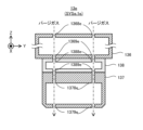
- the light receiving device includes a position changing device that can change the irradiation position of the energy beam on the top, and a control device that controls the position changing device based on the result of reception of the energy beam by the light receiving device, the light receiving device a beam passing member formed with a plurality of passing regions through which the energy beam emitted from the irradiation optical system can pass; and a light receiving section capable of receiving each of the energy beams that have passed through each of the plurality of passing regions.
- the deflection optical system deflects the energy beam so that the energy beam scans the plurality of passing regions along one direction along the surface of the beam passing member;
- a processing system is provided that controls the position changing device based on a result of reception of the energy beam by a light receiving device.
- an exit optical system including a position adjustment optical system; the exit optical system is capable of irradiating the object with the energy beam emitted from the exit optical system; and the exit optical system is removable from the exit optical system; identifying a plurality of irradiation optical systems including an objective optical system, an exchange device capable of replacing the irradiation optical system attached to the emission optical system, and the type of the irradiation optical system attached to the emission optical system; One of the plurality of light collection position adjustment optical systems is selected based on the identified type, and the selected one light collection position adjustment optical system is positioned in the optical path of the energy beam.
- a processing system is provided, comprising: a control device that moves the first focusing position adjusting optical system so as to move the first focusing position adjusting optical system.
- an irradiation optical system capable of irradiating an energy beam onto an object; a first changing device capable of changing at least one of a positional relationship and an attitude relationship between the object and the irradiation optical system; A light receiving device capable of receiving the energy beam emitted from the irradiation optical system, a second changing device capable of changing a positional relationship between the light receiving device and the irradiation optical system, and a control device, the control device A processing system is provided in which, under the control of the second changing device, the light receiving device is changed in position from a second position different from the first position to a first position where the light receiving device can receive the energy beam.
- an irradiation optical system capable of irradiating an object with a first beam and a second beam different from the first beam; a light receiving device capable of receiving the first beam and the second beam; and changing at least one of the irradiation position of the first beam on the object and the irradiation position of the second beam on the object. and a control device, the control device controlling the position change device based on the light reception result of the first beam by the light receiving device and the light reception result of the second beam by the light receiving device.
- a processing system is provided for controlling.
- a deflection optical system capable of deflecting an energy beam to change the irradiation position of the energy beam on an object; and a deflection optical system capable of irradiating the object with the energy beam emitted from the deflection optical system.
- the control device includes a beam passing member formed with a plurality of passing regions through which the energy beam can pass, and a light receiving section capable of receiving each of the energy beams that have passed through each of the plurality of passing regions, and the control device A processing system is provided that controls the position changing device based on a result of reception of the energy beam by the device.
- the injection optical system includes a plurality of focusing position adjusting optical systems capable of emitting an energy beam, adjusting a focusing position of the energy beam, and having different focal lengths.
- a plurality of irradiation systems capable of irradiating the object with the energy beam emitted from the emission optical system, detachable from the emission optical system, and including at least an objective optical system;
- One of the plurality of light focusing position adjusting optical systems is selected, and the one light focusing position is adjusted so that the selected one light focusing position adjusting optical system is located in the optical path of the energy beam.
- a processing system is provided that includes a control device that moves a position adjustment optical system.
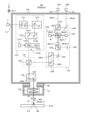
- FIG. 1 is a cross-sectional view schematically showing an example of the configuration of a processing system according to the first embodiment.
- FIG. 2 is a block diagram showing an example of the configuration of the processing system in the first embodiment.
- FIG. 3 is a sectional view showing the configuration of the processing head in the first embodiment.
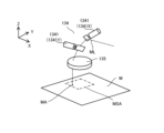
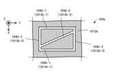
- FIG. 4 is a perspective view showing a processing shot area.
- FIG. 5 is a perspective view showing the measurement shot area.
- FIG. 6 is a sectional view showing an example of the configuration of a mounting adapter used to attach the irradiation optical system to the exit optical system.
- FIGS. 7(a) to 7(c) is a cross-sectional view showing the process of attaching the irradiation optical system to the exit optical system.
- FIG. 7(a) to 7(c) is a cross-sectional view showing the process of attaching the irradiation optical system to the exit optical system.
- FIG. 8 is a cross-sectional view conceptually showing an example of the configuration of the head exchange device.
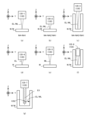
- FIGS. 9(a) to 9(g) is a cross-sectional view showing an example of an irradiation optical system.
- FIG. 10 is a block diagram showing an example of the configuration of a processing system in the second embodiment.
- FIG. 11(a) is a sectional view showing the calibration position where the optical measurement device is located when the calibration operation is performed
- FIG. 11(b) is a sectional view showing the calibration position where the optical measurement device is located when the calibration operation is not performed.
- FIG. 3 is a cross-sectional view showing a non-calibration position where is located.
- FIG. 12 is a sectional view showing the configuration of the optical measurement device.
- FIG. 13 is a plan view showing a search mark formed by a light passage area.
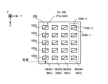
- FIG. 14 is a plan view showing a beam passing member on which a plurality of search marks are formed.
- FIG. 15 is a plan view showing a beam passing member on which a plurality of search marks are formed.
- FIG. 16 is a plan view showing a plurality of search marks irradiated with processing light.
- FIG. 17 shows light reception information output by the light receiving element.
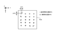
- FIG. 18 is a plan view showing the reference irradiation position of the processing light and the actual irradiation position of the processing light within the processing shot area.
- FIGS. 19(a) to 19(c) shows light reception information output by the light receiving element.
- FIG. 19(a) to 19(c) shows light reception information output by the light receiving element.
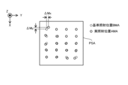
- FIG. 20 is a plan view showing the reference irradiation position of the measurement light and the actual irradiation position of the measurement light within the measurement shot area.
- FIG. 21 is a plan view showing the actual irradiation position of the processing light and the actual irradiation position of the measurement light in the processing shot area and the measurement shot area.
- FIGS. 22(a) to 22(c) shows light reception information output by the light receiving element.
- FIG. 23 is a sectional view showing the configuration of a processing head in the third embodiment.
- FIG. 24 is a sectional view showing the configuration of a processing head in the fourth embodiment.
- FIG. 25 is a sectional view showing the configuration of a processing head in the fifth embodiment.
- FIG. 26 is a cross-sectional view showing the configuration of a processing head in the fifth embodiment.
- each of the X-axis direction and the Y-axis direction is a horizontal direction (that is, a predetermined direction within a horizontal plane), and the Z-axis direction is a vertical direction (that is, a direction perpendicular to the horizontal plane). (and substantially in the vertical direction).
- the rotation directions (in other words, the tilt directions) around the X-axis, Y-axis, and Z-axis are referred to as the ⁇ X direction, the ⁇ Y direction, and the ⁇ Z direction, respectively.
- the Z-axis direction may be the direction of gravity.
- the XY plane may be set in the horizontal direction.
- processing system SYS Processing system SYS of the first embodiment
- processing system SYSa Processing system SYS in the first embodiment
- processing system SYSa the processing system SYS in the first embodiment
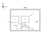
- FIG. 1 is a cross-sectional view schematically showing an example of the configuration of the processing system SYSa in the first embodiment.
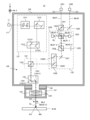
- FIG. 2 is a block diagram showing an example of the configuration of the processing system SYSa in the first embodiment.
- the processing system SYSa includes a processing unit 1 and a control unit 2.
- the processing unit 1 may be called a processing device, and the control unit 2 may be called a control device.
- At least a portion of the processing unit 1 may be accommodated in the internal space SP of the housing 3.
- the internal space SP of the housing 3 may be purged with a purge gas (that is, gas) such as nitrogen gas, or may not be purged with a purge gas.
- the internal space SP of the housing 3 may or may not be evacuated.
- the processing unit 1 may not be housed in the internal space SP of the housing 3.
- a local space surrounding only a part of the processing unit 1 may be purged with a purge gas or may be evacuated.
- the processing unit 1 is capable of processing a workpiece W, which is a workpiece (which may also be referred to as a base material), under the control of the control unit 2.
- the workpiece W may be made of metal, an alloy (such as duralumin), a semiconductor (such as silicon), a resin, or a CFRP. It may be a composite material such as (Carbon Fiber Reinforced Plastic), a paint (as an example, a paint layer applied to a base material), a glass, or any other material. It may also be an object made of material.
- the processing unit 1 irradiates the workpiece W with processing light EL in order to process the workpiece W.
- the processing light EL may be any type of light as long as the workpiece W can be processed by being irradiated onto the workpiece W. In the first embodiment, the description will be given using an example in which the processing light EL is a laser beam, but the processing light EL may be a different type of light from the laser beam.
- the wavelength of the processing light EL may be any wavelength as long as the workpiece W can be processed by being irradiated with the processing light EL.
- the processing light EL may be visible light or invisible light (for example, at least one of infrared light, ultraviolet light, extreme ultraviolet light, etc.).
- the processing light EL may include pulsed light. Alternatively, the processing light EL may not include pulsed light. In other words, the processing light EL may be continuous light. Note that since the light is an example of an energy beam, the processing light EL may also be referred to as a processing beam.
- the processing unit 1 may perform additional processing on the workpiece W. That is, the processing unit 1 may perform additional processing to form a shaped object on the workpiece W.
- the processing unit 1 may perform removal processing on the workpiece W. That is, the processing unit 1 may perform removal processing to remove a part of the workpiece W.
- the processing unit 1 may perform marking processing to form a desired mark on the surface of the workpiece W.
- the processing unit 1 may perform peening processing to change the surface characteristics of the workpiece W.
- the processing unit 1 may perform a peeling process to peel off the surface of the workpiece W.
- the processing unit 1 may perform welding processing to join one work W and another work W.
- the processing unit 1 may perform cutting processing to cut the workpiece W.
- the processing unit 1 may perform planar processing (in other words, remelting processing) for making the surface of the workpiece W close to a flat surface by melting the surface of the workpiece W and solidifying the melted surface.
- the processing unit 1 may form a desired structure on the surface of the workpiece W by processing the workpiece W. However, the processing unit 1 may perform processing different from the processing for forming a desired structure on the surface of the workpiece W.
- the riblet structure may include a structure capable of reducing resistance (particularly, at least one of frictional resistance and turbulent flow frictional resistance) on the surface of the work W against fluid. For this reason, the riblet structure may be formed on the workpiece W having a member installed (in other words, located) in the fluid.
- the term "fluid” used herein means a medium (for example, at least one of gas and liquid) flowing toward the surface of the workpiece W. For example, if the surface of the workpiece W moves relative to the medium while the medium itself is stationary, this medium may be referred to as a fluid.
- the state in which the medium is stationary may mean a state in which the medium is not moving relative to a predetermined reference object (for example, the ground surface).
- An example of the workpiece W on which the riblet structure is formed is at least one of an aircraft, a windmill, an engine turbine, and a power generation turbine.
- the workpiece W becomes easier to move relative to the fluid. Therefore, the resistance that prevents movement of the workpiece W relative to the fluid is reduced, leading to energy savings.
- the resistance that impedes movement (typically, rotation) of the windmill is reduced, so that the efficiency of the windmill can be improved.
- the workpiece W is an engine turbine (for example, at least a part of the engine turbine)
- the resistance that prevents movement (typically, rotation) of the engine turbine is reduced; This leads to higher efficiency or energy saving of engine turbines.
- the workpiece W is a power generation turbine (for example, at least a part of the power generation turbine)
- the resistance that prevents movement (typically, rotation) of the power generation turbine is reduced; This leads to higher efficiency of power generation turbines (in other words, improved power generation efficiency).
- Processing Unit 1 is committed to achieving Goal 13 of the Sustainable Development Goals (SDGs) led by the United Nations: ⁇ Take urgent action to combat climate change and its impacts.'' It has the potential to contribute to ⁇ 13.2.2 Reduction of Total Greenhouse Gas Emissions per Year'', which is one of the goals set forth in ⁇ and its impact''.
- SDGs Sustainable Development Goals
- the processing unit 1 is further capable of measuring the measurement object M under the control of the control unit 2.
- the processing unit 1 irradiates the measurement object M with measurement light ML for measuring the measurement object M, in order to measure the measurement object M.
- the processing unit 1 irradiates the measurement object M with the measurement light ML, and detects at least a portion of the return light RL that returns from the measurement object M irradiated with the measurement light ML ( In other words, the object M to be measured is measured by receiving light.
- the light that returns from the measurement object M that has been irradiated with the measurement light ML is light from the measurement object M that is generated by the irradiation of the measurement light ML.
- the measurement light ML may be any type of light as long as the measurement target M can be measured by being irradiated onto the measurement target M.
- the measurement light ML is a laser light.
- the measurement light ML may be a different type of light from laser light.
- the wavelength of the measurement light ML may be any wavelength as long as the measurement target M can be measured by being irradiated onto the measurement target M.
- the measurement light ML may be visible light or invisible light (for example, at least one of infrared light, ultraviolet light, extreme ultraviolet light, etc.).
- the measurement light ML may include pulsed light (for example, pulsed light whose emission time is picoseconds or less). Alternatively, the measurement light ML does not need to include pulsed light. In other words, the measurement light ML may be continuous light. Note that since light is an example of an energy beam, the measurement light ML may also be referred to as a measurement beam.
- the processing unit 1 may be able to measure the characteristics of the measurement target M using the measurement light ML.
- the characteristics of the measurement target M include, for example, the position of the measurement target M, the shape of the measurement target M, the reflectance of the measurement target M, the transmittance of the measurement target M, the temperature of the measurement target M, and the measurement It may include at least one of the surface roughness of the object M.
- the processing unit 1 measures at least the position of the measurement target object M.
- the position of the measurement target M may include the position of the surface of the measurement target M.
- the position of the surface of the measurement target M may include the position of at least a portion of the surface of the measurement target M.
- the position of the measurement object M may mean the position (that is, relative position) of the measurement object M with respect to the processing head 13. That is, the position of the measurement object M may mean the position of the measurement object M in the measurement coordinate system with the processing head 13 as a reference.
- the operation of measuring the position of the measurement object M may include the operation of measuring the shape of the measurement object M. This is because the shape of the measurement target M can be calculated from the position of the measurement target M.
- the measurement object M may include, for example, a workpiece W that is processed by the processing unit 1.
- the measurement object M may include, for example, any object placed on a stage 15, which will be described later.
- the measurement object M may include a stage 15, for example.
- the measurement object M may include, for example, an optical measurement device 18b used in a calibration operation described later in the second embodiment.
- the processing unit 1 includes a processing light source 11, a measurement light source 12, a processing head 13, a head drive system 141, a position measuring device 142, and a stage 15. , a stage drive system 161 , a position measurement device 162 , and a head exchange device 17 .
- the processing light source 11 generates processing light EL.
- the processing light source 11 may include, for example, a laser diode.
- the processing light source 11 may be a light source capable of pulse oscillation. In this case, the processing light source 11 can generate pulsed light as the processing light EL.
- the processing light source 11 may be a CW light source that generates CW (continuous wave).
- the measurement light source 12 generates measurement light ML.
- the measurement light source 12 may include, for example, a laser diode.
- the measurement light source 12 may be a light source capable of pulse oscillation.
- the measurement light source 12 can generate pulsed light as the processing light EL.
- the measurement light source 12 may be a CW light source that generates CW (continuous wave).
- the processing head 13 irradiates the workpiece W with the processing light EL generated by the processing light source 11 and irradiates the measurement object M with the measurement light ML generated by the measurement light source 12.
- the machining head 13 includes a machining optical system 131, a measurement optical system 132, a combining optical system 133, and a deflection optical system. 134 and an irradiation optical system 135.
- the processing head 13 irradiates the workpiece W with processing light EL via a processing optical system 131, a combining optical system 133, a deflection optical system 134, and an irradiation optical system 135.
- the processing head 13 irradiates the measurement object M with the measurement light ML via the measurement optical system 132, the synthesis optical system 133, the deflection optical system 134, and the irradiation optical system 135. Note that the details of the configuration of the processing head 13 will be described in detail later with reference to FIG. 3.
- the head drive system 141 moves the processing head 13. That is, the head drive system 141 moves the position of the processing head 13. For this reason, the head drive system 141 may be referred to as a moving device.
- the head drive system 141 may move the processing head 13 (that is, linearly move) along a movement axis along at least one of the X-axis direction, the Y-axis direction, and the Z-axis direction, for example.
- the head drive system 141 moves the processing head 13 along at least one of the ⁇ X direction, the ⁇ Y direction, and the ⁇ Z direction, in addition to or instead of at least one of the X-axis direction, Y-axis direction, and Z-axis direction. may be moved.
- the head drive system 141 has a rotation axis along the X-axis direction (namely, the A-axis), a rotation axis along the Y-axis direction (namely, the B-axis), and a rotation axis along the Z-axis direction (namely, the C-axis).
- the processing head 13 may be rotated (that is, rotationally moved) around at least one of the axes).
- the processing unit 1 may process the workpiece W while moving the processing head 13. Specifically, the processing unit 1 may set the processing shot area PSA at a desired position of the workpiece W by moving the processing head 13, and may process the desired position of the workpiece W.
- the head drive system 141 moves the processing head 13
- the relative positional relationship between the measurement shot area MSA (see FIG. 5 described later) where the processing head 13 performs measurement and the measurement target M changes. That is, the measurement shot area MSA moves with respect to the measurement object M.
- the processing unit 1 may measure the measurement object M while moving the processing head 13. Specifically, the processing unit 1 may set the measurement shot area MSA at a desired position of the measurement target M by moving the processing head 13, and measure the desired position of the measurement target M.
- the positional relationship between the processing head 13 (in particular, the irradiation optical system 135 included in the processing head 13) and the workpiece W placed on the stage 15 changes.
- the positional relationship between the processing head 13 (in particular, the irradiation optical system 135) and the workpiece W along at least one of the X-axis direction, the Y-axis direction, and the Z-axis direction may change.
- the positional relationship between the processing head 13 (in particular, the irradiation optical system 135) and the workpiece W along at least one of the ⁇ X direction, the ⁇ Y direction, and the ⁇ Z direction may change.
- the head drive system 141 may be considered to function as a changing device that can change at least one of the positional relationship and posture relationship between the processing head 13 (particularly the irradiation optical system 135) and the workpiece W.
- the position measuring device 142 can measure the position of the processing head 13.
- the position measuring device 142 may include, for example, an interferometer (eg, a laser interferometer).
- the position measuring device 142 may include, for example, an encoder (for example, at least one of a linear encoder and a rotary encoder).
- Position measuring device 142 may include, for example, a potentiometer.
- the position measuring device 142 may include, for example, an open-loop control type position detecting device.
- the open-loop control type position detection device is a position detection device that measures the position of the processing head 13 by estimating the amount of movement of the processing head 13 from the integrated value of the number of pulses for driving the stepping motor.
- the operation of measuring the position of the processing head 13 is considered to be equivalent to the operation of measuring the position of the irradiation optical system 135 that the processing head 13 is equipped with.
- the position measuring device 142 may be considered to be measuring the position of the irradiation optical system 135 included in the processing head 13.
- the stage 15 may be referred to as a mounting device. Specifically, the workpiece W is placed on a placement surface 151 that is at least a portion of the upper surface of the stage 15 .
- the stage 15 can support the work W placed on the stage 15.
- the stage 15 may be able to hold the work W placed on the stage 15.
- the stage 15 may include at least one of a mechanical chuck, an electrostatic chuck, a vacuum chuck, etc. to hold the workpiece W.
- a jig for holding the work W may hold the work W, and the stage 15 may hold the jig holding the work W.
- the stage 15 does not need to hold the work W placed on the stage 15. In this case, the workpiece W may be placed on the stage 15 without a clamp.
- stage drive system 161 moves the stage 15.
- stage drive system 161 moves the position of the stage 15.
- stage drive system 161 may be referred to as a moving device.
- the stage drive system 161 may move the stage 15 (that is, linearly move) along a movement axis along at least one of the X-axis direction, the Y-axis direction, and the Z-axis direction, for example.
- the stage drive system 161 moves the stage 15 along at least one of the ⁇ X direction, the ⁇ Y direction, and the ⁇ Z direction, in addition to or instead of at least one of the X-axis direction, Y-axis direction, and Z-axis direction. You may move it.
- the stage drive system 161 has a rotation axis along the X-axis direction (namely, the A-axis), a rotation axis along the Y-axis direction (namely, the B-axis), and a rotation axis along the Z-axis direction (namely, the C-axis).
- the stage 15 may be rotated (that is, rotated) around at least one of the following axes.
- the processing unit 1 may process the work W while moving the stage 15. Specifically, the processing unit 1 may set the processing shot area PSA at a desired position of the workpiece W by moving the stage 15, and may process the desired position of the workpiece W.
- the processing unit 1 may measure the measurement object M while moving the stage 15. Specifically, the processing unit 1 may set the measurement shot area MSA at a desired position of the measurement target M by moving the stage 15, and measure the desired position of the measurement target M.
- the positional relationship between the processing head 13 (in particular, the irradiation optical system 135 included in the processing head 13) and the workpiece W placed on the stage 15 changes.
- the positional relationship between the processing head 13 (in particular, the irradiation optical system 135) and the workpiece W along at least one of the X-axis direction, the Y-axis direction, and the Z-axis direction may change.
- the positional relationship between the processing head 13 (in particular, the irradiation optical system 135) and the workpiece W along at least one of the ⁇ X direction, the ⁇ Y direction, and the ⁇ Z direction may change.
- the stage drive system 161 may be considered to function as a changing device that can change at least one of the positional relationship and posture relationship between the processing head 13 (particularly the irradiation optical system 135) and the workpiece W.
- Position measuring device 162 can measure the position of the stage 15.
- Position measurement device 162 may include, for example, an interferometer (eg, a laser interferometer).
- the position measuring device 162 may include, for example, an encoder (for example, at least one of a linear encoder and a rotary encoder).
- Position measuring device 162 may include, for example, a potentiometer.
- the position measuring device 162 may include, for example, a position detecting device using an open loop control method.
- the open-loop control type position detection device is a position detection device that measures the position of the stage 15 by estimating the amount of movement of the stage 15 from the integrated value of the number of pulses for driving the stepping motor.
- the head exchange device 17 is a device that can replace the irradiation optical system 135 included in the processing head 13.
- the head exchange device 17 may remove the irradiation optical system 135 attached to the processing head 13.
- the head exchange device 17 may attach the irradiation optical system 135 to the processing head 13 to which the irradiation optical system 135 is not attached.
- the head exchange device 17 removes the first irradiation optical system 135 attached to the processing head 13, and then installs a second irradiation optical system different from the first irradiation optical system 135 on the processing head 13. 135 may be attached.
- the head exchange device 17 may replace the first irradiation optical system 135 attached to the processing head 13 with the second irradiation optical system 135. For this reason, the irradiation optical system 135 may be detachable from the processing head 13. Note that the configuration of the irradiation optical system 135 that is detachable from the processing head 13 and the configuration of the head exchange device 17 will be described in detail later with reference to FIGS. 6 to 9.
- the control unit 2 controls the operation of the processing unit 1.
- the control unit 2 may control the operation of the processing head 13 included in the processing unit 1.
- the control unit 2 may control the operation of at least one of the processing optical system 131, the measurement optical system 132, the combining optical system 133, the deflection optical system 134, and the irradiation optical system 135 included in the processing head 13.
- the control unit 2 may control the operation of the head drive system 141 included in the processing unit 1 (for example, movement of the processing head 13).
- the control unit 2 may control the operation of the stage drive system 161 included in the processing unit 1 (for example, movement of the stage 15).
- the control unit 2 may control the operation of the head exchange device 17 included in the processing unit 1.
- the control unit 2 may control the operation of the processing unit 1 based on the measurement results of the measurement target M by the processing unit 1. Specifically, the control unit 2 generates measurement data of the measurement object M (for example, data regarding at least one of the position and shape of the measurement object M) based on the measurement results of the measurement object M, and The operation of the processing unit 1 may be controlled based on the measured data. For example, the control unit 2 generates measurement data for at least a portion of the workpiece W based on the measurement results of the workpiece W, which is an example of the measurement target M (for example, the position and shape of at least a portion of the workpiece W). (at least one of them may be calculated), and the operation of the processing unit 1 may be controlled to process the workpiece W based on the measurement data.
- the control unit 2 generates measurement data for at least a portion of the workpiece W based on the measurement results of the workpiece W, which is an example of the measurement target M (for example, the position and shape of at least a portion of the workpiece W).
- the control unit 2 may include, for example, a calculation device and a storage device.
- the arithmetic device may include, for example, at least one of a CPU (Central Processing Unit) and a GPU (Graphics Processing Unit).
- the storage device may include, for example, memory.
- the control unit 2 functions as a device that controls the operation of the processing unit 1 by a calculation device executing a computer program.
- This computer program is a computer program for causing the arithmetic device to perform (that is, execute) the operation to be performed by the control unit 2, which will be described later. That is, this computer program is a computer program for causing the control unit 2 to function so as to cause the processing unit 1 to perform the operations described below.
- the computer program executed by the arithmetic device may be recorded in a storage device (that is, a recording medium) provided in the control unit 2, or may be stored in any storage device built into the control unit 2 or externally attachable to the control unit 2. It may be recorded on a medium (for example, a hard disk or a semiconductor memory). Alternatively, the computing device may download the computer program to be executed from a device external to the control unit 2 via the network interface.
- a storage device that is, a recording medium
- the computing device may download the computer program to be executed from a device external to the control unit 2 via the network interface.
- the control unit 2 does not need to be provided inside the processing unit 1.
- the control unit 2 may be provided outside the processing unit 1 as a server or the like.
- the control unit 2 and the processing unit 1 may be connected via a wired and/or wireless network (or a data bus and/or a communication line).
- a wired network for example, a network using a serial bus type interface represented by at least one of IEEE1394, RS-232x, RS-422, RS-423, RS-485, and USB may be used.
- a network using a parallel bus interface may be used.
- a network using an interface compliant with Ethernet typified by at least one of 10BASE-T, 100BASE-TX, and 1000BASE-T may be used.
- a network using radio waves may be used.
- An example of a network using radio waves is a network compliant with IEEE802.1x (for example, at least one of a wireless LAN and Bluetooth (registered trademark)).
- a network using infrared rays may be used.
- a network using optical communication may be used as the wireless network.
- the control unit 2 and the processing unit 1 may be configured to be able to transmit and receive various information via a network.
- control unit 2 may be able to transmit information such as commands and control parameters to the processing unit 1 via a network.
- the processing unit 1 may include a receiving device that receives information such as commands and control parameters from the control unit 2 via the network.
- the processing unit 1 may include a transmitting device (that is, an output device outputting information to the control unit 2) that transmits information such as commands and control parameters to the control unit 2 via the network. good.
- a first control device that performs some of the processing performed by the control unit 2 is provided inside the processing unit 1, while a second control device that performs another part of the processing performed by the control unit 2 is provided inside the processing unit 1.
- the control device may be provided outside the processing unit 1.
- a calculation model that can be constructed by machine learning may be implemented by a calculation device executing a computer program.
- An example of a calculation model that can be constructed by machine learning is a calculation model that includes a neural network (so-called artificial intelligence (AI)).
- learning the computational model may include learning parameters (eg, at least one of weights and biases) of the neural network.
- the control unit 2 may control the operation of the processing unit 1 using the calculation model. That is, the operation of controlling the operation of the processing unit 1 may include the operation of controlling the operation of the processing unit 1 using a calculation model.
- the control unit 2 may be equipped with an arithmetic model that has been constructed by offline machine learning using teacher data.
- the calculation model installed in the control unit 2 may be updated by online machine learning on the control unit 2.
- the control unit 2 may use a calculation model installed in a device external to the control unit 2 (that is, a device provided outside the processing unit 1) in addition to or in place of the calculation model installed in the control unit 2. may be used to control the operation of the processing unit 1.
- the recording medium for recording the computer program executed by the control unit 2 includes CD-ROM, CD-R, CD-RW, flexible disk, MO, DVD-ROM, DVD-RAM, DVD-R, DVD+R, and DVD.
- At least one of optical disks such as RW, DVD+RW and Blu-ray (registered trademark), magnetic media such as magnetic tape, magneto-optical disks, semiconductor memories such as USB memory, and any other arbitrary medium capable of storing programs is used. It's okay to be hit.
- the recording medium may include a device capable of recording a computer program (for example, a general-purpose device or a dedicated device in which a computer program is implemented in an executable state in the form of at least one of software and firmware).
- each process or function included in the computer program may be realized by a logical processing block that is realized within the control unit 2 when the control unit 2 (that is, the computer) executes the computer program, or It may be realized by hardware such as a predetermined gate array (FPGA (Field Programmable Gate Array), ASIC (Application Specific Integrated Cricut)) included in the control unit 2, or it may be realized by a logical processing block. some of the hardware It may also be realized in a mixed format with partial hardware modules that realize the elements.
- FPGA Field Programmable Gate Array
- ASIC Application Specific Integrated Cricut
- FIG. 3 is a cross-sectional view showing an example of the configuration of the processing head 13.
- processing light EL generated by the processing light source 11 is incident on the processing head 13 via a light transmission member 111 such as an optical fiber.
- the processing light source 11 may be placed outside the processing head 13.
- the processing light source 11 may be arranged inside the processing head 13.
- the processing head 13 includes a processing optical system 131, a measurement optical system 132, a combining optical system 133, a deflection optical system 134, and an irradiation optical system 135.
- the processing optical system 131 is an optical system into which the processing light EL from the processing light source 11 is incident.
- the processing optical system 131 is an optical system that emits the processing light EL that has entered the processing optical system 131 toward the combining optical system 133.
- the processing light EL emitted by the processing optical system 131 is irradiated onto the workpiece W via the combining optical system 133, the deflection optical system 134, and the irradiation optical system 135.
- the processing optical system 131 may include, for example, a position adjustment optical system 1311, an angle adjustment optical system 1312, and a galvanometer mirror 1313. However, the processing optical system 131 does not need to include at least one of the position adjustment optical system 1311, the angle adjustment optical system 1312, and the galvanometer mirror 1313.
- the position adjustment optical system 1311 can adjust the emission position of the processing light EL from the processing optical system 131.
- the position adjustment optical system 1311 may include, for example, a parallel plane plate that can be tilted with respect to the traveling direction of the processing light EL, and change the emission position of the processing light EL by changing the inclination angle of the parallel plane plate.
- the angle adjustment optical system 1312 can adjust the emission angle (that is, the emission direction) of the processing light EL from the processing optical system 131.
- the angle adjustment optical system 1312 may include, for example, a mirror that can be tilted with respect to the traveling direction of the processing light EL, and the emission angle of the processing light EL may be changed by changing the inclination angle of this mirror.
- the galvanometer mirror 1313 deflects the processing light EL (that is, changes the emission angle of the processing light EL).
- the galvanometer mirror 1313 changes the focusing position of the processing light EL in a plane intersecting the optical axis EX of the irradiation optical system 135 (that is, in a plane along the XY plane) by deflecting the processing light EL.
- the processing head 13 irradiates the workpiece W with the processing light EL in a state where the optical axis EX and the surface of the workpiece W intersect.
- the irradiation position PA of the processing light EL on the surface of the workpiece W is changed in the direction along the surface of the workpiece W. (i.e. move). That is, the irradiation position PA of the processing light EL is changed along at least one of the X-axis direction and the Y-axis direction.
- the galvano mirror 1341 can change the irradiation position PA of the processing light EL, it may be called a position changing optical system or a position changing device.
- the galvanometer mirror 1313 includes an X scanning mirror 1313X and a Y scanning mirror 1313Y.
- Each of the X scanning mirror 1313X and the Y scanning mirror 1313Y is a variable tilt angle mirror whose angle with respect to the optical path of the processing light EL incident on the galvanometer mirror 1313 is changed.
- the X scanning mirror 1313X deflects the processing light EL so as to change the irradiation position PA of the processing light EL on the workpiece W along the X-axis direction.
- the X scanning mirror 1313X may be rotatable or swingable around the Y axis.
- the galvanometer mirror 1313 changes the irradiation position PA of the processing light EL on the workpiece W along the X-axis direction by changing the position of the X-scanning mirror 1313X in the ⁇ Y direction (or the posture around the Y-axis). It may be changeable.
- the Y scanning mirror 1313Y deflects the processing light EL so as to change the irradiation position PA of the processing light EL on the workpiece W along the Y-axis direction.
- the Y scanning mirror 1313Y may be rotatable or swingable around the X axis.
- the galvanometer mirror 1313 changes the irradiation position PA of the processing light EL on the workpiece W along the Y-axis direction by changing the position of the Y-scanning mirror 1313Y in the ⁇ X direction (or the posture around the X-axis). It may be changeable.
- the processing light EL emitted from the processing optical system 131 enters the combining optical system 133.
- the combining optical system 133 includes a beam splitter (eg, a polarizing beam splitter) 1331.
- the beam splitter 1331 emits the processing light EL that has entered the beam splitter 1331 toward the deflection optical system 134 .
- the processing light EL incident on the beam splitter 1331 is emitted toward the deflection optical system 134 by passing through the polarization separation surface of the beam splitter 1331. Therefore, in the example shown in FIG.
- the processing light EL is polarized by the beam splitter 1331 in a state where it has a polarization direction that can pass through the polarization separation surface (for example, a polarization direction that is p-polarized light with respect to the polarization separation surface). incident on the surface.
- a polarization direction that can pass through the polarization separation surface for example, a polarization direction that is p-polarized light with respect to the polarization separation surface.
- the processing light EL emitted from the synthesis optical system 133 enters the deflection optical system 134.
- the deflection optical system 134 emits the processing light EL that has entered the deflection optical system 134 toward the irradiation optical system 135 .
- the deflection optical system 134 includes a galvanometer mirror 1341.
- the processing light EL that has entered the deflection optical system 134 enters the galvano mirror 1341.
- the galvanometer mirror 1341 deflects the processing light EL (that is, changes the emission angle of the processing light EL).
- the galvanometer mirror 1341 changes the focusing position of the processing light EL in a plane intersecting the optical axis EX of the irradiation optical system 135 (that is, in a plane along the XY plane) by deflecting the processing light EL.
- the processing head 13 irradiates the workpiece W with the processing light EL in a state where the optical axis EX and the surface of the workpiece W intersect.
- the galvanometer mirror 1341 can change the irradiation position PA of the processing light EL, and therefore may be referred to as a position changing device.
- the galvanometer mirror 1341 includes an X scanning mirror 1341X and a Y scanning mirror 1341Y.
- Each of the X scanning mirror 1341X and the Y scanning mirror 1341Y is a variable tilt angle mirror whose angle with respect to the optical path of the processing light EL incident on the galvanometer mirror 1341 is changed.
- the X scanning mirror 1341X deflects the processing light EL so as to change the irradiation position PA of the processing light EL on the workpiece W along the X-axis direction.
- the X scanning mirror 1341X may be rotatable or swingable around the Y axis.
- the galvanometer mirror 1341 changes the irradiation position PA of the processing light EL on the workpiece W along the X-axis direction by changing the position of the X-scanning mirror 1341X in the ⁇ Y direction (or the posture around the Y-axis). It may be changeable.
- the Y scanning mirror 1341Y deflects the processing light EL so as to change the irradiation position PA of the processing light EL on the workpiece W along the Y-axis direction.
- the Y scanning mirror 1341Y may be rotatable or swingable around the X axis.
- the galvanometer mirror 1341 changes the irradiation position PA of the processing light EL on the workpiece W along the Y-axis direction by changing the position in the ⁇ X direction (or the posture around the X-axis) of the Y-scanning mirror 1341Y. It may be changeable.
- At least one of the galvano mirrors 1341 and 1313 allows the processing light EL to scan the processing shot area PSA determined with the processing head 13 as a reference. That is, at least one of the galvanometer mirrors 1341 and 1313 allows the irradiation position PA to move within the processing shot area PSA determined with the processing head 13 as a reference.
- An example of the processing shot area PSA is shown in FIG. 4.
- the machining shot area PSA is an area (in other words, an area) where machining is performed by the machining head 13 while the positional relationship between the machining head 13 and the workpiece W is fixed (that is, without changing). ) is shown.
- the processing shot area PSA coincides with the scanning range of the processing light EL deflected by at least one of the galvanometer mirrors 1341 and 1313 with the positional relationship between the processing head 13 and the workpiece W being fixed, or the processing shot area PSA coincides with the scanning range of the processing light EL deflected by at least one of the galvano mirrors 1341 and 1313.
- the area is set to be narrower than the range.
- the processing shot area PSA irradiation position PA
- the scanning range of the processing light EL mentioned above may be the maximum range among the ranges scanned by the processing light EL.
- each of the galvano mirrors 1341 and 1313 may be considered to function as a position changing device that can change the incident position of the processing light EL into the irradiation optical system 135 by deflecting the processing light EL. .
- the incident angle typically The angle of incidence of the optical system 135 with respect to the optical axis EX may be changed.
- the irradiation optical system 135 is an optical system that can irradiate the workpiece W with the processing light EL.
- the irradiation optical system 135 includes an f ⁇ lens 1351 that can function as an objective optical system. Processing light EL emitted from the deflection optical system 134 enters the f ⁇ lens 1351 .
- the f ⁇ lens 1351 irradiates the work W with the processing light EL emitted from the deflection optical system 134. Specifically, the f ⁇ lens 1351 emits the processing light EL in a direction along the optical axis EX of the irradiation optical system 135.
- the processing light EL emitted by the f ⁇ lens 1351 enters the workpiece W by traveling along the direction along the optical axis EX.
- the optical axis EX of the irradiation optical system 135 may be the optical axis of the f ⁇ lens 1351.
- the f ⁇ lens 1351 may focus the processing light EL from the galvano mirror 1341 onto the workpiece W.
- the processing light EL emitted from the f ⁇ lens 1351 may be irradiated onto the work W without passing through another optical element (in other words, an optical member, such as a lens) having power.
- the f ⁇ lens 1351 is the optical element having the final stage power (that is, the optical element closest to the workpiece W) among the plurality of optical elements arranged on the optical path of the processing light EL, so the f ⁇ lens 1351 is the final optical element. It may also be called an element.
- the power of the optical element may be the reciprocal of the focal length of the optical element.
- the processing light EL from the galvanometer mirror 1341 may be a parallel light beam.
- the irradiation optical system 135 may include an objective optical system having a projection characteristic different from f ⁇ .
- At least one of the X scanning mirror 1341X and Y scanning mirror 1341Y that constitute the galvano mirror 1341, and the X scanning mirror 1313X and Y scanning mirror 1313Y that constitute the galvano mirror 1313 is an f ⁇ lens as an irradiation optical system. 1351 and/or its conjugate position.
- a relay optical system for making each scanning mirror optically conjugate with each other may be arranged between the scanning mirrors.
- the measurement light ML generated by the measurement light source 12 is incident on the processing head 13 via an optical transmission member 121 such as an optical fiber.
- the measurement light source 12 may be placed outside the processing head 13.
- the measurement light source 12 may be placed inside the processing head 13.
- the measurement light source 12 may include an optical comb light source.
- An optical comb light source is a light source that can generate pulsed light containing frequency components arranged at equal intervals on a frequency axis (hereinafter referred to as "optical frequency comb").
- the measurement light source 12 emits pulsed light including frequency components arranged at equal intervals on the frequency axis as the measurement light ML.
- the measurement light source 12 may include a light source different from the optical comb light source.
- the processing system SYSa includes a plurality of measurement light sources 12.
- the processing system SYSa may include a measurement light source 12#1 and a measurement light source 12#2.
- the plurality of measurement light sources 12 may each emit a plurality of measurement lights ML that are phase-synchronized and coherent with each other.
- the plurality of measurement light sources 12 may have different oscillation frequencies. Therefore, the plurality of measurement lights ML emitted by the plurality of measurement light sources 12 are different from each other in pulse frequency (for example, the number of pulsed lights per unit time, which is the reciprocal of the pulsed light emission period). It may be .
- the processing system SYSa may include a single measurement light source 12.
- the measurement light ML emitted from the measurement light source 12 enters the measurement optical system 132.
- the measurement optical system 132 is an optical system that emits the measurement light ML that has entered the measurement optical system 132 toward the synthesis optical system 133.
- the measurement light ML emitted by the measurement optical system 132 is irradiated onto the measurement object M via the synthesis optical system 133, the deflection optical system 134, and the irradiation optical system 135.
- the measurement optical system 132 includes, for example, a mirror 1320, a beam splitter 1321, a beam splitter 1322, a detector 1323, a beam splitter 1324, a mirror 1325, a detector 1326, a mirror 1327, and a galvano mirror 1328. Be prepared.
- the measurement light ML emitted from the measurement light source 12 enters the beam splitter 1321.
- measurement light ML emitted from measurement light source 12 #1 (hereinafter referred to as “measurement light ML #1”) enters beam splitter 1321.
- Measurement light ML emitted from measurement light source 12#2 (hereinafter referred to as “measurement light ML#2”) enters beam splitter 1321 via mirror 1320.
- Beam splitter 1321 emits measurement lights ML#1 and ML#2 that have entered beam splitter 1321 toward beam splitter 1322. In other words, the beam splitter 1321 emits the measurement lights ML#1 and ML#2, which are incident on the beam splitter 1321 from different directions, in the same direction (that is, the direction in which the beam splitter 1322 is arranged).
- Beam splitter 1322 reflects measurement light ML#1-1, which is a part of measurement light ML#1 incident on beam splitter 1322, toward detector 1323. Beam splitter 1322 emits measurement light ML#1-2, which is another part of measurement light ML#1 that has entered beam splitter 1322, toward beam splitter 1324. Beam splitter 1322 reflects measurement light ML#2-1, which is part of measurement light ML#2 that has entered beam splitter 1322, toward detector 1323. Beam splitter 1322 emits measurement light ML#2-2, which is another part of measurement light ML#2 that has entered beam splitter 1322, toward beam splitter 1324.
- the detector 1323 receives (that is, detects) measurement light ML#1-1 and measurement light ML#2-1.
- the detector 1323 receives interference light generated by interference between measurement light ML#1-1 and measurement light ML#2-1.
- the operation of receiving interference light generated by interference between measurement light ML#1-1 and measurement light ML#2-1 is performed by measurement light ML#1-1 and measurement light ML#2-1. may be considered to be equivalent to the operation of receiving light.
- the detection result of the detector 1323 is output to the control unit 2.
- Beam splitter 1324 emits at least a portion of measurement light ML#1-2 that has entered beam splitter 1324 toward mirror 1325.
- Beam splitter 1324 emits at least a portion of measurement light ML#2-2 that has entered beam splitter 1324 toward mirror 1327.
- Measurement light ML#1-2 emitted from beam splitter 1324 enters mirror 1325.
- Measurement light ML#1-2 incident on mirror 1325 is reflected by a reflective surface of mirror 1325 (the reflective surface may be referred to as a reference surface).
- the mirror 1325 reflects the measurement light ML#1-2 that has entered the mirror 1325 toward the beam splitter 1324. That is, the mirror 1325 emits the measurement light ML#1-2 that has entered the mirror 1325 toward the beam splitter 1324 as the measurement light ML#1-3 that is reflected light.
- measurement lights ML#1-3 may be referred to as reference lights.
- Measurement light ML#1-3 emitted from mirror 1325 enters beam splitter 1324.
- the beam splitter 1324 emits the measurement lights ML#1-3 that have entered the beam splitter 1324 toward the beam splitter 1322. Measurement light ML#1-3 emitted from beam splitter 1324 enters beam splitter 1322. Beam splitter 1322 emits measurement light ML#1-3 that has entered beam splitter 1322 toward detector 1326.
- measurement light ML#2-2 emitted from beam splitter 1324 enters mirror 1327.
- Mirror 1327 reflects measurement light ML#2-2 that has entered mirror 1327 toward galvano mirror 1328.
- the mirror 1327 emits the measurement light ML#2-2 that has entered the mirror 1327 toward the galvanometer mirror 1328.
- the galvanometer mirror 1328 deflects the measurement light ML#2-2 (that is, changes the emission angle of the measurement light ML#2-2).
- the galvanometer mirror 1328 deflects the measurement light ML#2-2 in a plane intersecting the optical axis EX of the irradiation optical system 135 (that is, in a plane along the XY plane). Change the light focusing position.
- the processing head 13 directs the measurement beam ML to the measurement object M in a state where the optical axis EX intersects the surface of the measurement object M (workpiece W in the example shown in FIG. 3). Irradiate #2-2.
- the irradiation position MA of measurement light ML#2-2 on the surface of measurement target M changes It is changed (that is, moved) in the direction along the surface of the object M. That is, the irradiation position MA of the measurement light ML#2-2 is changed along at least one of the X-axis direction and the Y-axis direction.
- the galvano mirror 1328 can change the irradiation position MA of the measurement light ML#2-2, and therefore may be referred to as a position changing optical system or a position changing device.
- the galvanometer mirror 1328 includes an X scanning mirror 1328X and a Y scanning mirror 1328Y.
- Each of the X scanning mirror 1328X and the Y scanning mirror 1328Y is a variable tilt angle mirror whose angle with respect to the optical path of the measurement light ML#2-2 incident on the galvanometer mirror 1328 is changed.
- the X scanning mirror 1328X deflects the measurement light ML#2-2 so as to change the irradiation position MA of the measurement light ML#2-2 on the measurement target M along the X-axis direction.
- the X scanning mirror 1328X may be rotatable or swingable around the Y axis.
- the galvanometer mirror 1328 changes the irradiation position MA of the measurement light ML#2-2 on the measurement object M by changing the position of the X scanning mirror 1328X in the ⁇ Y direction (or the posture around the Y axis). It may be changeable along the X-axis direction.
- the Y scanning mirror 1328Y deflects the processing light EL so as to change the irradiation position MA of the measurement light ML#2-2 on the measurement object M along the Y-axis direction.
- the Y scanning mirror 1328Y may be rotatable or swingable around the X axis.
- the galvanometer mirror 1328 changes the irradiation position MA of the measurement light ML#2-2 on the measurement target M by changing the position in the ⁇ X direction (or the posture around the X axis) of the Y scanning mirror 1328Y. It may be changeable along the Y-axis direction.
- Measurement light ML#2-2 emitted from the measurement optical system 132 enters the synthesis optical system 133.
- the beam splitter 1331 of the combining optical system 133 emits the measurement light ML#2-2 that has entered the beam splitter 1331 toward the deflection optical system 134.
- the measurement light ML#2-2 that has entered the combining optical system 133 is reflected by the polarization separation surface and is emitted toward the deflection optical system 134. Therefore, in the example shown in FIG.
- the measurement light ML#2-2 is sent to the beam splitter in a state where it has a polarization direction that can be reflected by the polarization separation surface (for example, a polarization direction that becomes s-polarized light with respect to the polarization separation surface).
- the light is incident on the polarization separation surface of 1331.
- the processing light EL enters the beam splitter 1331 in addition to the measurement light ML#2-2. That is, both the measurement light ML#2-2 and the processing light EL pass through the beam splitter 1331.
- the beam splitter 1331 directs the processing light EL and the measurement light ML#2-2, which have entered the beam splitter 1331 from different directions, in the same direction (that is, toward the same deflection optical system 134). Therefore, the beam splitter 1331 substantially functions as a combining optical member that combines the processing light EL and the measurement light ML#2-2.
- the combining optical system 133 may include a dichroic mirror instead of the beam splitter 1331 as a combining optical member. Even in this case, the combining optical system 133 uses a dichroic mirror to combine the processing light EL and the measurement light ML#2-2 (that is, the optical path of the processing light EL and the measurement light ML#2-2). can be combined with the optical path).
- Measurement light ML#2-2 emitted from the combining optical system 133 enters the deflection optical system 134.
- the deflection optical system 134 emits the measurement light ML#2-2 that has entered the deflection optical system 134 toward the irradiation optical system 135.
- the measurement light ML#2-2 that entered the deflection optical system 134 enters the galvanometer mirror 1341.
- the galvanometer mirror 1341 deflects the measurement light ML#2-2 in the same way as when deflecting the processing light EL. Therefore, the galvanometer mirror 1341 can change the irradiation position MA of the measurement light ML#2-2 on the surface of the measurement object M in the direction along the surface of the measurement object M. In other words, the galvanometer mirror 1341 changes the irradiation position MA of the measurement light ML#2-2 on the measurement target M by changing the position of the X scanning mirror 1341X in the ⁇ Y direction (or the posture around the Y axis). It may be changeable along the X-axis direction.
- the galvanometer mirror 1341 changes the irradiation position MA of the measurement light ML#2-2 on the measurement target M on the Y axis by changing the position in the ⁇ X direction (or the posture around the X axis) of the Y scanning mirror 1341Y. It may be changeable along the direction. In this way, the galvano mirror 1341 can change the irradiation position MA of the measurement light ML#2-2, and therefore may be referred to as a position changing optical system or a position changing device.
- the processing light EL is incident on the galvanometer mirror 1341 in addition to the measurement light ML#2-2. That is, the processing light EL and measurement light ML#2-2 combined by the beam splitter 1331 are incident on the galvanometer mirror 1341. Therefore, both the measurement light ML#2-2 and the processing light EL pass through the same galvanometer mirror 1341. Therefore, the galvanometer mirror 1341 can synchronize and change the irradiation position PA of the processing light EL and the irradiation position MA of the measurement light ML#2-2. In other words, the galvanometer mirror 1341 can change the irradiation position PA of the processing light EL and the irradiation position MA of the measurement light ML#2-2 in conjunction with each other.
- the processing system SYSa can use the galvano mirror 1328 to move the irradiation position MA of the measurement light ML#2-2 independently with respect to the irradiation position PA of the processing light EL. That is, the processing system SYSa can use the galvanometer mirror 1328 to change the relative positional relationship between the irradiation position PA of the processing light EL and the irradiation position MA of the measurement light ML#2-2.
- the processing system SYSa uses the galvanometer mirror 1328 to determine the relative positional relationship between the irradiation position PA of the processing light EL and the irradiation position MA of the measurement light ML#2-2. It can be changed along the direction intersecting the irradiation direction (in the example shown in FIG. 3, at least one of the X-axis direction and the Y-axis direction).
- the processing system SYSa can independently move the irradiation position PA of the processing light EL with respect to the irradiation position MA of the measurement light ML#2-2 using the galvanometer mirror 1313. That is, the processing system SYSa can use the galvanometer mirror 1313 to change the relative positional relationship between the irradiation position PA of the processing light EL and the irradiation position MA of the measurement light ML#2-2.
- the processing system SYSa uses a galvanometer mirror 1328 to adjust the relative positional relationship between the irradiation position PA of the processing light EL and the irradiation position MA of the measurement light ML#2-2, such that the direction intersects the irradiation direction of the processing light EL. (in the example shown in FIG. 3, at least one of the X-axis direction and the Y-axis direction).
- At least one of the galvanometer mirrors 1341 and 1328 allows the measurement light ML#2-2 to scan the measurement shot area MSA determined with the processing head 13 as a reference. That is, at least one of the galvanometer mirrors 1341 and 1328 allows the irradiation position MA to be moved within the measurement shot area MSA determined with the processing head 13 as a reference.
- An example of the measurement shot area MSA is shown in FIG. As shown in FIG. 5, the measurement shot area MSA is an area where the processing head 13 performs measurement while the positional relationship between the processing head 13 and the measurement target M is fixed (that is, without changing). , range).
- the measurement shot area MSA coincides with the scanning range of the measurement light ML deflected by at least one of the galvano mirrors 1341 and 1328 while the positional relationship between the processing head 13 and the measurement target M is fixed.
- the area is set to be narrower than the scanning range.
- the measurement shot area MSA irradiation position MA
- the scanning range of the measurement light ML mentioned above may be the maximum range among the ranges scanned by the measurement light ML.
- measurement light ML#2-2 emitted from the deflection optical system 134 enters the irradiation optical system 135.
- the irradiation optical system 135 of the measurement light ML#2-2 The incident position changes. Therefore, each of the galvano mirrors 1341 and 1328 functions as a position changing device that can change the incident position of the measurement light ML#2-2 onto the irradiation optical system 135 by deflecting the measurement light ML#2-2. It may be assumed that
- the irradiation optical system 135 is an optical system that can irradiate the measurement target M (in the example shown in FIG. 3, the workpiece W) with the measurement light ML#2-2.
- the f ⁇ lens 1351 irradiates the measurement object M with the measurement light ML#2-2 emitted from the deflection optical system 134.
- the f ⁇ lens 1351 emits the measurement light ML#2-2 in the direction along the optical axis EX of the irradiation optical system 135.
- the measurement light ML#2-2 emitted by the f ⁇ lens 1351 travels in the direction along the optical axis EX and enters the measurement target M.
- the f ⁇ lens 1351 may focus the measurement light ML#2-2 emitted from the deflection optical system 134 onto the measurement target M.
- the measurement light ML#2-2 emitted from the f ⁇ lens 1351 reaches the measurement target M without passing through another optical element having power (in other words, an optical member such as a lens). It may be irradiated.
- the f ⁇ lens 1351 is the optical element having the power of the final stage (that is, the optical element closest to the workpiece W) among the plurality of optical elements arranged on the optical path of the measurement light ML#2-2. Therefore, it may also be referred to as the final optical element.
- the measurement light ML#2-2 that is emitted from the deflection optical system 134 and enters the f ⁇ lens 1351 may be a parallel light beam.
- the measurement object M When the measurement object M is irradiated with the measurement light ML#2-2, light resulting from the irradiation of the measurement light ML#2-2 is generated from the measurement object M. That is, when the measurement object M is irradiated with the measurement light ML#2-2, light resulting from the irradiation of the measurement light ML#2-2 is emitted from the measurement object M.
- the light caused by the irradiation of the measurement light ML#2-2 (in other words, the light emitted from the measurement object M due to the irradiation of the measurement light ML#2-2) is reflected by the measurement object M.
- Measurement light ML#2-2 (that is, reflected light), measurement light ML#2-2 scattered by measurement object M (that is, scattered light), measurement light ML#2-2 that was diffracted by measurement object M 2 (that is, diffracted light), and measurement light ML#2-2 that has passed through the measurement object M (that is, transmitted light).
- the optical path of the measurement light ML#2-2 that is emitted from the irradiation optical system 135 and enters the measurement object M, and the optical path of the return light RL that is emitted from the measurement object M and enters the irradiation optical system 135. may be the same.
- the return light RL that has entered the irradiation optical system 135 enters the deflection optical system 134 via the f ⁇ lens 1351.
- the return light RL that has entered the deflection optical system 134 enters the combining optical system 133 via the galvano mirror 1341.
- the beam splitter 1331 of the combining optical system 133 emits the return light RL that has entered the beam splitter 1331 toward the measurement optical system 132.
- the return light RL that has entered the beam splitter 1331 is reflected on the polarization separation surface and is emitted toward the measurement optical system 132. Therefore, in the example shown in FIG. 3, the returned light RL enters the polarization separation surface of the beam splitter 1331 in a state where it has a polarization direction that can be reflected by the polarization separation surface.
- the return light RL emitted from the beam splitter 1331 enters the galvanometer mirror 1328 of the measurement optical system 132.
- the galvano mirror 1328 emits the return light RL that has entered the galvano mirror 1328 toward the mirror 1327 .
- Mirror 1327 reflects the return light RL that has entered mirror 1327 toward beam splitter 1324 .
- Beam splitter 1324 emits at least a portion of the return light RL that has entered beam splitter 1324 toward beam splitter 1322 .
- Beam splitter 1322 emits at least a portion of the return light RL that has entered beam splitter 1322 toward detector 1326.
- the measurement light ML#1-3 enters the detector 1326 in addition to the return light RL. That is, the return light RL directed toward the detector 1326 via the measurement target M and the measurement light ML#1-3 directed toward the detector 1326 without passing through the measurement target M enter the detector 1326.
- the detector 1326 receives (that is, detects) the measurement light ML#1-3 and the return light RL.
- the detector 1326 receives interference light generated by interference between measurement light ML#1-3 and return light RL.
- the operation of receiving interference light generated by interference between measurement light ML#1-3 and return light RL is equivalent to the operation of receiving measurement light ML#1-3 and return light RL. It may be considered as
- the detection result of the detector 1326 is output to the control unit 2.
- the control unit 2 acquires the detection results of the detector 1323 and the detection results of the detector 1326.
- the control unit 2 generates measurement data of the measurement target M (for example, measurement data regarding at least one of the position and shape of the measurement target M) based on the detection results of the detector 1323 and the detection result of the detector 1326. You can.
- the pulse frequency of measurement light ML#1 and the pulse frequency of measurement light ML#2 are different, the pulse frequency of measurement light ML#1-1 and the pulse frequency of measurement light ML#2-1 are different. different. Therefore, the interference light between measurement light ML#1-1 and measurement light ML#2-1 is such that the pulsed light forming measurement light ML#1-1 and the pulsed light forming measurement light ML#2-1 are different from each other. At the same time, pulsed light appears in synchronization with the timing of incidence on the detector 1323, resulting in interference light. Similarly, the pulse frequency of the measurement lights ML#1-3 and the pulse frequency of the return light RL are different.
- the interference light between the measurement light ML#1-3 and the return light RL is generated at the timing when the pulsed light forming the measurement light ML#1-3 and the pulsed light forming the return light RL simultaneously enter the detector 1326.
- the result is interference light in which pulsed light appears in synchronization with .
- the position (position on the time axis) of the pulsed interference light detected by the detector 1326 varies depending on the positional relationship between the processing head 13 and the measurement target M. This is because the interference light detected by the detector 1326 includes the return light RL that goes to the detector 1326 via the measurement object M, and the measurement light ML#1-3 that goes to the detector 1326 without going through the measurement object M.
- the position (position on the time axis) of the pulsed interference light detected by the detector 1323 is determined by the positional relationship between the processing head 13 and the measurement target M (that is, the position between the processing head 13 and the measurement object M). It does not change depending on the positional relationship with the object M). Therefore, the time difference between the pulsed interference light detected by the detector 1326 and the pulsed interference light detected by the detector 1323 indirectly indicates the positional relationship between the processing head 13 and the measurement target M. I can say that.
- the time difference between the pulsed interference light detected by the detector 1326 and the pulsed interference light detected by the detector 1323 is determined by the time difference in the direction along the optical path of the measurement light ML (that is, the direction along the optical path of the measurement light ML). It can be said that the distance between the processing head 13 and the measurement object M in the direction (along the direction) is indirectly indicated. Therefore, the control unit 2 controls the direction along the optical path of the measurement light ML (for example, based on the time difference between the pulsed interference light detected by the detector 1326 and the pulsed interference light detected by the detector 1323 The distance between the processing head 13 and the object to be measured M in the Z-axis direction can be calculated.
- the control unit 2 can calculate the position of the measurement target object M in the direction (for example, the Z-axis direction) along the optical path of the measurement light ML. More specifically, the control unit 2 can calculate the distance between the processing head 13 and the irradiated portion of the measurement target M that is irradiated with the measurement light ML#2-2. The control unit 2 can calculate the position of the irradiated portion in the direction along the optical path of the measurement light ML (for example, the Z-axis direction). Furthermore, since the irradiation position of the measurement light ML#2-2 on the measurement target M is determined by the driving states of the galvano mirrors 1341 and 1328, the control unit 2 controls the driving states of the galvano mirrors 1341 and 1328.
- the control unit 2 can generate measurement data indicating the position of the irradiated portion in the measurement coordinate system based on the processing head 13 (for example, the position in a three-dimensional coordinate space).
- the processing head 13 may irradiate measurement light ML#2-2 onto multiple parts of the measurement target M.
- at least one of the galvanometer mirrors 1341 and 1328 is configured to irradiate the measurement light ML#2 on the measurement target M so that the processing head 13 irradiates the measurement light ML#2-2 onto multiple parts of the measurement target M.
- -2 irradiation position may be changed.
- at least one of the processing head 13 and the stage 15 may be moved so that the processing head 13 irradiates the measurement light ML#2-2 onto a plurality of parts of the measurement target M.
- the control unit 2 can generate measurement data indicating the positions of the plurality of parts of the measurement object M.
- the control unit 2 can generate measurement data indicating the shape of the measurement target M based on measurement data indicating the positions of the plurality of parts. For example, the control unit 2 calculates, as the shape of the measurement object M, a three-dimensional shape composed of a virtual plane (or curved surface) connecting a plurality of parts whose positions have been specified. Measurement data indicating the shape of M can be generated.
- FIG. 1 (1-3) Structure of processing head 13 with replaceable irradiation optical system 135
- the processing light EL is irradiated onto the workpiece W
- the measurement light ML is irradiated onto the measurement target M.
- the irradiation optical system 135 is replaceable.
- the configuration of the processing head 13 in which the irradiation optical system 135 is replaceable will be further described below with reference to FIG.
- the processing optical system 131, the measurement optical system 132, the combining optical system 133, and the deflection optical system 134 may be housed in a head housing 136 of the processing head 13.
- the irradiation optical system 135 may be housed in a head housing 137 of the processing head 13 that is different from the head housing 136. Note that at least one of the head housings 136 and 137 may be referred to as a lens barrel.
- the processing light EL is transmitted to the irradiation optical system 135 housed in the head housing 137 via the processing optical system 131, measurement optical system 132, synthesis optical system 133, and deflection optical system 134 housed in the head housing 136. and measurement light ML are incident. That is, the optical system including the processing optical system 131, the measurement optical system 132, the combining optical system 133, and the deflection optical system 134 housed in the head housing 136 emits the processing light EL and the measurement light ML to the irradiation optical system 135. .
- an optical system including a processing optical system 131, a measurement optical system 132, a combining optical system 133, and a deflection optical system 134 will be described, and a processing light EL and a measurement light ML will be used in an irradiation optical system 135. It is called an exit optical system 130 for emitting light.
- the head housing 137 can be attached to the head housing 136.
- the head housing 137 attached to the head housing 136 is removable from the head housing 136. That is, the head housing 137 is removable from the head housing 136.
- the irradiation optical system 135 housed in the head housing 137 can be attached to the emission optical system 130 housed in the head housing 136.
- Illumination optics 135 attached to exit optics 130 may be considered removable from exit optics 130 .
- the irradiation optical system 135 may be considered to be detachable from the emission optical system 130.
- the head housing 137 may be removably attached to the head housing 136 via the mounting adapter 138. That is, the irradiation optical system 135 may be detachable from the injection optical system 130 via the mounting adapter 138. However, the head housing 137 may be detachable from the head housing 136 without using the attachment adapter 138. That is, the irradiation optical system 135 may be detachable from the injection optical system 130 without using the attachment adapter 138.
- FIG. 6 An example of the mounting adapter 138 is shown in FIG. As shown in FIG. 6, the mounting adapter 138 may be attached to the head housing 136.
- the mounting adapter 138 has a top surface (specifically, the surface facing the +Z side) of the mounting adapter 138 that is connected to a bottom surface of the head housing 136 (specifically, the surface facing the -Z side).
- the head casing 136 may be attached to the head housing 136 so as to face the head casing 136 .
- the lower surface of the mounting adapter 138 (specifically, the surface facing the -Z side) may be used as the mounting surface 1380 to which the head housing 137 is attached. That is, the head housing 137 may be attached to the attachment adapter 138 such that the attachment surface 1370, which is the upper surface of the head housing 137, faces the attachment surface 1380 of the attachment adapter 138. As a result, head housing 137 is attached to head housing 136 via attachment adapter 138.
- At least one attachment pin 1381 may be formed on the attachment surface 1380 of the attachment adapter 138.
- At least one attachment pin 1382 may be formed on the side surface of each attachment pin 1381. As shown in the enlarged view of the mounting pin 1381 on the right side of FIG. 1381) and a state in which each mounting pin 1382 is not housed inside the mounting pin 1381 (as a result, each mounting pin 1382 protrudes from the side of the mounting pin 1381). It may be switchable.
- each mounting pin 1382 is such that each mounting pin 1382 is accommodated inside the mounting pin 1381 using the force that moves the mounting pin 1382, and the state where each mounting pin 1382 is accommodated inside the mounting pin 1381. It is possible to switch between the state where it is not
- the force that moves the attachment pin 1382 may be a force applied to the attachment pin 1382 from the head housing 137.
- the attachment pin 1382 may come into contact with the surface of the head housing 137 (for example, the surface forming the attachment hole 1371 described later). In this case, a force is applied to the mounting pin 1382 that pushes out the mounting pin 1382 from the surface of the head housing 137.
- the attachment pin 1382 may be moved by a force that pushes out the attachment pin 1382 from the surface of the head housing 137.
- the mounting pin 1382 may be accommodated inside the mounting pin 1381 by a force that pushes out the mounting pin 1382 from the surface of the head housing 137.
- the curvature of at least a portion of the surface of the mounting pin 1382 may be set to an appropriate curvature so that force is appropriately applied to the mounting pin 1382 from the surface of the head housing 137.
- At least a portion of the surface of the attachment pin 1382 may be a curved surface.
- the force that moves the attachment pin 1382 may be, for example, a force caused by gas (for example, air).
- the force that moves the attachment pin 1382 may be, for example, a force due to gas (eg, air) pressure.
- a pneumatic device supplying gas may move the mounting pin 1382.
- a purge gas may be used as the gas for moving the attachment pin 1382, or a gas different from the purge gas may be used.
- the two mounting pins 1381 are arranged on a straight line intersecting the optical axis EX of the irradiation optical system 135.
- the number of attachment pins 1381 is not limited to two.
- a single mounting pin 1381 may be formed.
- Three or more attachment pins 1381 may be formed.
- a mounting hole 1371 may be formed in the mounting surface 1370 of the head housing 137 into which a mounting pin 1381 of the mounting adapter 138 can be inserted.
- the number of attachment holes 1371 formed in the head housing 137 may be the same as the number of attachment pins 1381 formed in the attachment adapter 138.
- the mounting hole 1371 may be connected to a mounting hole 1372 into which a mounting pin 1382 of the mounting adapter 138 can be inserted.
- the number of attachment holes 1372 connected to each attachment hole 1371 may be the same as the number of attachment pins 1382 formed in each attachment pin 1381.
- each attachment pin 1382 in order to attach the head housing 137 to the attachment adapter 138, the state of each attachment pin 1382 is changed to a state in which each attachment pin 1382 is housed inside the attachment pin 1381, as shown in FIG. 7(a). may be switched to Thereafter, the head housing 137 may be aligned with the mounting adapter 138 so that each mounting pin 1381 is inserted into each mounting hole 1371, as shown in FIG. 7(b). Thereafter, as shown in FIG. 7C, the state of each mounting pin 1382 may be switched to a state in which each mounting pin 1382 is not housed inside the mounting pin 1381. As a result, as shown in FIG.
- the mounting pin 1382 is inserted into the mounting hole 1372, and the head housing 137 is fixed to the mounting adapter 138. That is, the head housing 137 is attached to the head housing 136. In other words, the irradiation optical system 135 is attached to the exit optical system 130.
- each mounting pin 1381 may be removed from each mounting hole 1371, as shown in FIG. 7(a).
- the head housing 137 is removed from the mounting adapter 138, as shown in FIG. 7(a). That is, the head housing 137 is removed from the head housing 136.
- the irradiation optical system 135 is removed from the exit optical system 130.
- a groove may be formed in at least one of the mounting surface 1380 of the mounting adapter 138 and the mounting surface 1370 of the head housing 137.
- the groove may be evacuated.
- the control unit 2 may determine whether the head housing 137 is properly attached to the attachment adapter 138 based on the air pressure of the evacuated groove.
- the force that moves the attachment pin 1382 may include a force caused by a spring (or any elastic body) in addition to the force caused by the gas described above.
- the state of the mounting pin 1382 may be set such that the mounting pin 1382 protrudes from the side surface of the mounting pin 1381 due to a force applied to the mounting pin 1382 from a spring. In this state, the state of the mounting pin 1382 may be switched to a state in which the mounting pin 1382 is housed inside the mounting pin 1381 by the force caused by the gas.
- the mounting pin 1382 protrudes from the side surface of the mounting pin 1381, while when the pneumatic device is in the ON state, the mounting pin 1382 protrudes from the side surface of the mounting pin 1381.
- 1382 may be housed inside the mounting pin 1381. In this case, even if the pneumatic device breaks down due to an unexpected situation (that is, even if the pneumatic device is turned off), the head housing 137 can be attached to the mounting adapter 138. It will never come off. Therefore, damage to the irradiation optical system 135 due to falling can be prevented.
- the mounting pin 1381 and the mounting hole 1371 can function as a fall prevention mechanism that prevents the head housing 137 from falling from the mounting adapter 138.
- the mounting pin 1381 and the mounting hole 1371 can function as a drop-off prevention mechanism that prevents the head housing 137 from falling off the mounting adapter 138.
- the processing head 13 may include other fall prevention mechanisms (fall prevention mechanisms) in addition to the fall prevention mechanisms (fall prevention mechanisms) including the mounting pins 1381 and the attachment holes 1371.
- the mounting adapter 138 is attached to the head housing 136.
- the attachment adapter 138 may be attached to the head housing 137.
- a plurality of head housings 137 are selectively attached to the head housing 136, as described later.
- a mounting adapter 138 may be attached to each of the plurality of head housings 137.
- FIG. 8 is a cross-sectional view conceptually showing an example of the configuration of the head exchanging device 17. As shown in FIG.
- the head exchange device 17 includes a storage device 171, a transport device 172, and a housing 173.
- the housing device 171 can house the irradiation optical system 135 that can be attached to the processing head 13.
- the housing device 171 may be capable of housing a plurality of irradiation optical systems 135, each of which can be attached to the processing head 13.
- the housing device 171 includes N (N is a variable representing an integer of 2 or more) irradiation optical systems 135 (specifically, irradiation optical systems 135#1 to 135). #N) is accommodated.
- the housing device 171 may be capable of housing the irradiation optical system 135 housed in the head housing 137.
- the housing device 171 may be capable of housing the head housing 137 in which the irradiation optical system 135 is housed.
- the housing device 171 may house a plurality of irradiation optical systems 135 having mutually different optical characteristics. Examples of a plurality of irradiation optical systems 135 having different optical characteristics are shown in FIGS. 9(a) to 9(g). FIGS. 9(a) to 9(g) each show seven irradiation optical systems 135 having different optical characteristics.
- the housing device 171 may house a plurality of irradiation optical systems 135 having different numerical apertures NA (Numerial Apertures).
- NA numerical aperture
- NA numerical aperture
- the numerical aperture NA of the irradiation optical system 135 increases, processing accuracy and measurement accuracy become higher, but the possibility that the irradiation optical system 135 collides with the workpiece W (or the object to be measured M) increases.
- the storage device 171 has the effect of improving processing accuracy and measurement accuracy (hereinafter referred to as accuracy improvement effect), and the effect of preventing collision between the irradiation optical system 135 and the workpiece W (or measurement target M). (hereinafter referred to as collision prevention effect), a plurality of irradiation optical systems 135 having different numerical apertures NA may be accommodated.
- the working distance may be the distance along the optical axis EX from the final optical element of the irradiation optical system 135 to the focusing position of the processing light EL.
- the working distance may be the distance along the optical axis EX from the optical element disposed closest to the exit side among the one or more optical elements constituting the irradiation optical system 135 to the condensing position of the processing light EL. .
- the working distance may be the distance along the direction parallel to the optical axis EX from the part of the head housing 137 that accommodates the irradiation optical system 135 located closest to the work W to the condensing position of the processing light EL. good.
- the focusing position of the processing light EL may be the rear focal position of the irradiation optical system 135.
- the housing device 171 may house an irradiation optical system 135-1 in which the numerical aperture NA is set to the first numerical aperture NA1 in order to achieve both an accuracy improvement effect and a collision prevention effect.
- the housing device 171 in addition to or in place of the irradiation optical system 135-1, the housing device 171 has a numerical aperture NA larger than the first numerical aperture NA1 in order to give priority to the accuracy improvement effect over the collision prevention effect.
- An irradiation optical system 135-2 set to a second numerical aperture NA2 may be accommodated.
- the housing device 171 may have a first numerical aperture NA in order to prioritize the collision prevention effect over the accuracy improvement effect.
- An irradiation optical system 135-3 may be accommodated, which is set to a third numerical aperture NA3 smaller than the numerical aperture NA1.
- the processing system SYSa when the irradiation optical system 135-1 is attached to the processing head 13, the processing system SYSa reduces the possibility of collision between the irradiation optical system 135 and the workpiece W (or the measurement object M). It is possible to process the workpiece W with the first processing accuracy and measure the measurement object M with the first measurement accuracy. Further, when the irradiation optical system 135-2 is attached to the processing head 13, the processing system SYSa processes the workpiece W with a second processing accuracy higher than the first processing accuracy, and The measurement target M can be measured with a second measurement accuracy higher than the measurement accuracy of .
- the processing system SYSa when the irradiation optical system 135-3 is attached to the processing head 13, compared to the case where the irradiation optical system 135-1 is attached to the processing head 13, the processing system SYSa is Collision between the workpiece 135 and the workpiece W (or the measurement object M) can be further prevented. Furthermore, since the working distance becomes longer, the processing system SYSa appropriately processes the workpiece W so as to form a deep hole in the workpiece W, as shown in FIG. It is possible to properly measure the inside of a deep hole formed in a hole.
- the housing device 171 may house an irradiation optical system 135-4 specialized for processing the workpiece W using the processing light EL.
- the housing device 171 may house an irradiation optical system 135-4 that prioritizes improving processing accuracy over improving measurement accuracy.
- the housing device 171 may house the irradiation optical system 135-4 designed only to improve processing accuracy without giving any consideration to improving measurement accuracy. In this case, when the irradiation optical system 135-4 is attached to the processing head 13, the processing system SYSa can process the workpiece W more appropriately.
- the housing device 171 may house an irradiation optical system 135-5 specialized for measuring the measurement target M using the measurement light ML.
- the housing device 171 may house an irradiation optical system 135-5 that prioritizes improving measurement accuracy over improving processing accuracy.
- the accommodating device 171 may house the irradiation optical system 135-5 designed only to improve measurement accuracy without giving any consideration to improving processing accuracy. In this case, if the irradiation optical system 135-5 is attached to the processing head 13, the processing system SYSa can measure the measurement object M more appropriately.
- the accommodation device 171 includes an irradiation optical system whose size (so-called width) in a direction intersecting the irradiation direction of the processing light EL and the measurement light ML is limited to a certain size or less.
- 135-6 may be accommodated. Since the irradiation optical system 135-6 is housed in the head housing 137, the accommodating device 171 has a size (so-called width) in a direction intersecting the irradiation direction of the processing light EL and the measurement light ML that is below a certain size. An irradiation optical system 135-6 may be housed in a restricted head housing 137.
- the processing system SYSa can insert the Irradiation optics 135-6 can be advanced. Therefore, the processing system SYSa can appropriately process the workpiece W so as to form a deep hole in the workpiece W, and can appropriately measure the inside of the deep hole formed in the measurement target M.
- the processing light EL and the measurement light ML are provided in the accommodation device 171 in a direction intersecting the optical axis EX of the irradiation optical system 135 (for example, the optical axis of the f ⁇ lens 1351).
- An irradiation optical system 135-7 capable of emitting at least one of the above may be housed.
- the irradiation optical system 135-7 changes the traveling direction of at least one of the processing light EL and measurement light ML emitted from the f ⁇ lens 1351.
- a mirror 1352 that can reflect at least one of the MLs may be provided.
- the mirror 1352 may be rotatable around the optical axis EX of the irradiation optical system 135 (for example, the optical axis of the f ⁇ lens 1351).
- the processing system SYSa emits processing light onto the surface of the workpiece W or measurement target M along the optical axis EX of the irradiation optical system 135.
- EL or measurement light ML can be irradiated.
- the transport device 172 can transport the irradiation optical system 135 between the head exchange device 17 and the processing head 13. Specifically, the transport device 172 may take out the irradiation optical system 135 housed in the housing device 171 from the housing device 171 . Thereafter, the transport device 172 may transport the irradiation optical system 135 taken out from the storage device 171 from the storage device 171 to the processing head 13. Thereafter, the transport device 172 may attach the irradiation optical system 135 transported to the processing head 13 to the processing head 13. Furthermore, the transport device 172 may remove the irradiation optical system 135 attached to the processing head 13 from the processing head 13.
- the transport device 172 may transport the irradiation optical system 135 removed from the processing head 13 from the processing head 13 to the storage device 171. Thereafter, the transport device 172 may store the irradiation optical system 135 transported to the storage device 171 in the storage device 171.
- the control unit 2 controls which one of the irradiation optical systems 135 to be attached to the processing head 13. may be selected as the irradiation optical system 135.
- the control unit 2 selects any one of the plurality of irradiation optical systems 135 as the one irradiation optical system 135 to be attached to the processing head 13 based on instructions from the user of the processing system SYSa. You may choose.
- the control unit 2 selects any one of the plurality of irradiation optical systems 135 as the one irradiation optical system 135 to be attached to the processing head 13 based on the processing mode performed by the processing system SYSa. You may choose.
- control unit 2 selects any one of the plurality of irradiation optical systems 135 as the one irradiation optical system 135 to be attached to the processing head 13 based on the measurement mode performed by the processing system SYSa. You may choose. Thereafter, the transport device 172 may transport the one irradiation optical system 135 selected by the control unit 2 from the storage device 171 to the processing head 13.
- the transport device 172 may include a transport arm 1721 that can grasp or temporarily hold the irradiation optical system 135 in order to transport the irradiation optical system 135. In this case, the transport device 172 may transport the irradiation optical system 135 between the head exchange device 17 and the processing head 13 using the transport arm 1721.
- a magazine-type auto tool changer used in machine tools may be used as the head exchange device 17. good.
- the storage device 171 may be referred to as a magazine.
- a magazine of an auto tool changer may be used as the storage device 171.
- the cutting tools that are normally housed in the magazine may not be housed in the magazine that functions as the housing device 171 for housing the plurality of irradiation optical systems 135.
- a turret-type auto tool changer used in machine tools may be used as the head changing device 17.
- the storage device 171 may function as a tool pot having a drum shape.
- a tool pot of an auto tool changer may be used as the storage device 171.
- the cutting tool that is normally housed in the tool pot may not be housed in the tool pot that functions as the housing device 171 for housing the plurality of irradiation optical systems 135.
- the transport device 172 directly rotates the tool pot used as the storage device 171 so that the desired irradiation optical system 135 is located at the position closest to the transport device 172, and The irradiation optical system 135 located at the irradiation optical system 135 may be held or temporarily held.
- the tool pot used as the storage device 171 may be rotated so that the desired irradiation optical system 135 is located at the desired position without using the force of the transport device 172.
- the tool pot used as the storage device 171 may be rotated so that the desired irradiation optical system 135 to be attached to the processing head 13 is located closest to the +Y side.
- the desired irradiation optical system 135 moves so as to protrude from the transport port 1731 toward the +Y side, and the processing head 13 is moved so that the irradiation optical system 135 that has protruded from the transport port 1731 can be attached to the processing head 13.
- the irradiation optical system 135 that protrudes from the transport port 1731 may be approached.
- the machining system SYSa may be manufactured using the machine tool.
- the machining system SYSa may be manufactured using a machine tool by attaching the machining head 13 to the main shaft of the machine tool.
- a device inside the housing of a machine tool that has already been designed, developed, or mass-produced may be used as a component of the processing system SYSa.
- a stage of a machine tool may be used as the stage 15 of the processing system SYSa.
- a guide mechanism of a machine tool may be used as at least one of the head drive system 141 and the stage drive system 161 of the processing system SYSa.
- the device inside the housing of the machine tool may be at least partially improved, and the partially improved device may be used as a component of the machining system SYSa.
- the cost of the processing system SYSa can be reduced compared to the case where the components of the processing system SYSa are newly designed from scratch.
- the machining system SYS may use devices inside the housing of a machine tool that have already been designed, developed, or mass-produced (for example, an auto tool changer, a stage, and a guide mechanism for the head) as components of the machining system SYS.
- the housing 173 accommodates at least a portion of the storage device 171 and the transport device 172. Specifically, at least a portion of the storage device 171 and the transport device 172 are stored in a storage space 1730 inside the housing 173.
- a transport port 1731 may be formed in the casing 173.
- the transport device 172 may transport the irradiation optical system 135 between the head exchange device 17 and the processing head 13 via the transport port 1731.
- a gas supply port 1732 may be formed in the housing 173.
- a purge gas that is, gas
- nitrogen gas may be supplied to the accommodation space 1730 inside the housing 173 through a gas supply port 1732. That is, the processing system SYS may supply purge gas to the accommodation space 1730 inside the housing 173 via the gas supply port 1732 using a gas supply device (not shown).
- the atmospheric pressure of the housing space 1730 is supplied to the housing space 1730 through the gas supply port 1732 to the space outside the housing 173 (specifically, the internal space SP inside the housing 3 housing the processing unit 1).
- the purge gas may be supplied so that the pressure is higher than that of the air pressure. That is, purge gas is supplied to the accommodation space 1730 through the gas supply port 1732 so that the air pressure in the accommodation space 1730 is higher than the air pressure in the internal space SP in which the workpiece W is placed on the stage 15. Good too.
- purge gas may be supplied to the accommodation space 1730 via the gas supply port 1732 so that the air pressure in the accommodation space 1730 is higher than the air pressure in the internal space SP in which the workpiece W is processed.
- the head exchange device 17 can prevent unnecessary substances from adhering to the irradiation optical system 135 housed in the housing space 1730.
- unnecessary substances is fume generated during processing of the workpiece W.
- the purge gas may be supplied toward the irradiation optical system 135 housed in the accommodation space 1730 via the gas supply port 1732.
- the purge gas may be supplied through the gas supply port 1732 toward at least one of the plurality of irradiation optical systems 135 accommodated in the accommodation space 1730.
- the purge gas supplied toward the irradiation optical system 135 will cause the substances to adhere to the irradiation optical system 135. unnecessary substances are removed. Therefore, the head exchange device 17 can prevent unnecessary substances from adhering to the irradiation optical system 135 housed in the housing space 1730.
- purge gas may be supplied to the mounting surface 1380 of the mounting adapter 138 during at least part of the period when the head housing 137 is removed from the mounting adapter 138 (head housing 136). In this case, it is possible to prevent unnecessary substances from adhering to the mounting surface 1380.
- the period during which the purge gas is supplied to the mounting surface 1380 of the mounting adapter 138 may be the entire period during which the head housing 137 is removed from the mounting adapter 138 (head housing 136).
- the irradiation optical system 135 attached to the processing head 13 can be replaced. Therefore, compared to the case where the irradiation optical system 135 attached to the processing head 13 cannot be replaced, the processing system SYSa uses one irradiation optical system 135 that matches the processing purpose to more appropriately target the workpiece W. It can be processed into Furthermore, compared to the case where the irradiation optical system 135 attached to the processing head 13 cannot be replaced, the processing system SYSa uses one irradiation optical system 135 that matches the measurement purpose to more easily measure the measurement target M. Can be measured appropriately.
- processing system SYS in the second embodiment will be explained.
- the processing system SYS in the second embodiment will be referred to as a "processing system SYSb.”
- FIG. 10 is a block diagram showing an example of the configuration of the processing system SYSb in the second embodiment.
- the same reference numerals are given to the same components as already explained components, and detailed explanation thereof will be omitted.
- the processing system SYSb in the second embodiment differs from the processing system SYSa in the first embodiment in that it includes a processing unit 1b instead of the processing unit 1 described above. It's different.
- Other characteristics of the processing system SYSb may be the same as other characteristics of the processing system SYSa.
- the processing unit 1b differs from the processing unit 1 in that it further includes an optical measurement device 18b, a measurement drive system 191b, and a position measurement device 192b. Other features of the processing unit 1b may be the same as other features of the processing unit 1.
- the optical measurement device 18b is a member used for calibration operation.
- the calibration operation is an operation for calibrating (in other words, controlling or adjusting) at least one of the irradiation position PA of the processing light EL and the irradiation position MA of the measurement light ML.
- the calibration operation is performed under the control of the control unit 2. That is, the processing system SYSb performs a calibration operation under the control of the control unit 2.
- the details of the calibration operation and the optical measurement device 18b will be described in detail later, but the outline thereof will be briefly described below.
- the processing head 13 irradiates the optical measurement device 18b with at least one of the processing light EL and the measurement light ML under the control of the control unit 2. That is, the processing head 13 emits at least one of the processing light EL and the measurement light ML toward the optical measurement device 18b via the irradiation optical system 135.
- the optical measurement device 18b measures at least one of the processing light EL and the measurement light ML irradiated onto the optical measurement device 18b under the control of the control unit 2. That is, the optical measurement device 18b measures at least one of the processing light EL and the measurement light ML emitted from the irradiation optical system 135.
- the optical measurement device 18b receives at least one of the processing light EL and the measurement light ML irradiated onto the optical measurement device 18b. That is, the optical measurement device 18b receives at least one of the processing light EL and the measurement light ML emitted from the irradiation optical system 135. For this reason, the optical measurement device 18b may be called a light receiving device. Light reception information indicating the result of reception of at least one of the processing light EL and the measurement light ML by the optical measurement device 18b is output from the optical measurement device 18b to the control unit 2.
- the control unit 2 calibrates at least one of the irradiation position PA of the processing light EL and the irradiation position MA of the measurement light ML based on the light reception information. Specifically, the control unit 2 calculates (in other words, acquires) at least one of the irradiation position PA of the processing light EL and the irradiation position MA of the measurement light ML based on the light reception information. That is, the control unit 2 acquires irradiation position information regarding at least one of the irradiation position PA of the processing light EL and the irradiation position MA of the measurement light ML, based on the light reception information. After that, the control unit 2 calibrates at least one of the irradiation position PA of the processing light EL and the irradiation position MA of the measurement light ML based on the irradiation position information.
- the measurement drive system 191b moves the optical measurement device 18b under the control of the control unit 2. That is, the measurement drive system 191b moves the position of the optical measurement device 18b. Therefore, the measurement drive system 191b may be referred to as a moving device.
- the measurement drive system 191b may move the optical measurement device 18b (that is, linearly move) along a movement axis along at least one of the X-axis direction, the Y-axis direction, and the Z-axis direction, for example.
- the measurement drive system 191b operates an optical measurement device along at least one of the ⁇ X direction, the ⁇ Y direction, and the ⁇ Z direction, in addition to or instead of at least one of the X-axis direction, Y-axis direction, and Z-axis direction. 18b may be moved.
- the measurement drive system 191b has a rotation axis along the X-axis direction (that is, the A-axis), a rotation axis along the Y-axis direction (that is, the B-axis), and a rotation axis along the Z-axis direction (that is, the C-axis).
- the optical measurement device 18b may be rotated (that is, rotationally moved) around at least one of the axes).
- the positional relationship between the processing head 13 (in particular, the irradiation optical system 135 included in the processing head 13) and the optical measurement device 18b changes.
- the positional relationship between the processing head 13 (in particular, the irradiation optical system 135) and the optical measurement device 18b along at least one of the X-axis direction, the Y-axis direction, and the Z-axis direction may be changed.
- the positional relationship between the processing head 13 (in particular, the irradiation optical system 135) and the optical measurement device 18b along at least one of the ⁇ X direction, the ⁇ Y direction, and the ⁇ Z direction may be changed.
- the positional relationship between the processing head 13 (especially the irradiation optical system 135) and the optical measuring device 18b along at least one of the ⁇ X direction, ⁇ Y direction, and ⁇ Z direction is determined by the positional relationship between the processing head 13 (especially the irradiation optical system 135) and the optical measurement device 18b. It may be considered that this is the attitude relationship between the optical measuring device 18b and the optical measuring device 18b. Therefore, the measurement drive system 191b may be regarded as functioning as a changing device capable of changing at least one of the positional relationship and posture relationship between the processing head 13 (in particular, the irradiation optical system 135) and the optical measurement device 18b. good.
- the measurement drive system 191b moves the optical measurement device 18b so that the optical measurement device 18b is located at the calibration position CP1, as shown in FIG. may be moved.
- the calibration position CP1 is a position where the optical measurement device 18b can receive at least one of the processing light EL and the measurement light ML.
- the measurement drive system 191b is configured such that the optical measurement device 18b is located at the non-calibration position CP2 as shown in FIG. Alternatively, the optical measuring device 18b may be moved.
- the non-calibration position CP2 is a position where the optical measurement device 18b cannot receive at least one of the processing light EL and the measurement light ML.
- the measurement drive system 191b moves the optical measurement device 18b so that the optical measurement device 18b is located at the non-calibration position CP2 during at least part of the measurement period during which the processing unit 1 measures the measurement target M. You may let them.
- the measurement drive system 191b moves the optical measurement device 18b so that the optical measurement device 18b is located at the non-calibration position CP2, which is different from the calibration position CP1, during at least part of the processing period and the measurement period. You can. That is, the measurement drive system 191b may move the optical measurement device 18b between the calibration position CP1 and the non-calibration position CP2.
- the optical measurement device 18b located at the non-calibration position CP2 does not receive the processing light EL. Therefore, the processing light EL emitted toward the workpiece W in order to process the workpiece W is not blocked by the optical measurement device 18b. Therefore, even if the processing unit 1b includes the optical measurement device 18b, the processing unit 1b can appropriately process the workpiece W.
- the optical measurement device 18b located at the non-calibration position CP2 does not receive the measurement light ML. The measurement light ML emitted toward the measurement object M to measure the measurement object M is not blocked by the optical measurement device 18b.
- the processing unit 1b can appropriately measure the measurement target M. Further, typically, the light intensity of the processing light EL received by the optical measurement device 18b is lower than the light intensity of the processing light EL when processing the workpiece W. Since the processing light EL with high light intensity is not irradiated to the optical measurement device 18b during the processing period, deterioration and damage of the optical measurement device 18b can be prevented.
- the optical measurement device 18b located at the calibration position CP1 can receive at least one of the processing light EL and the measurement light ML. That is, the processing unit 1b can irradiate the optical measurement device 18b with at least one of the processing light EL and the measurement light ML. Therefore, during the calibration period, the processing system SYSb can appropriately perform the calibration operation.
- the measurement drive system 191b moves the optical measurement device 18b along a direction intersecting the direction in which at least one of the processing light EL and the measurement light ML is irradiated, thereby moving the optical measurement device 18b to a position different from the calibration position CP1. It may be moved between the calibration position CP2 and the calibration position CP2. In other words, the measurement drive system 191b moves the optical measurement device 18b and the processing head 13 (in particular, the irradiation optical system 135) relative to each other along the direction intersecting the direction in which at least one of the processing light EL and the measurement light ML is irradiated. By changing the positional relationship, the optical measuring device 18b may be moved between the calibration position CP1 and the non-calibration position CP2.
- the direction in which at least one of the processing light EL and the measurement light ML is irradiated is the Z-axis direction. Therefore, the measurement drive system 191b may move the optical measurement device 18b along the direction intersecting the Z-axis direction. In this case, the calibration position CP1 and the non-calibration position CP2 may be separated from each other along the direction intersecting the direction in which at least one of the processing light EL and the measurement light ML is irradiated.
- the calibration position CP1 may be a position on the optical path of at least one of the processing light EL and the measurement light ML.
- the calibration position CP1 may be a position where the processing head 13 (in particular, the irradiation optical system 135) can irradiate at least one of the processing light EL and the measurement light ML.
- the non-calibration position CP2 may be a position away from the respective optical paths of the processing light EL and the measurement light ML.
- the non-calibration position CP2 may be a position where the processing head 13 (in particular, the irradiation optical system 135) cannot irradiate each of the processing light EL and the measurement light ML.
- the non-calibration position CP2 may be a position where the processing head 13 (in particular, the irradiation optical system 135) is prohibited from irradiating each of the processing light EL and the measurement light ML.
- the non-calibration position CP2 may be a position outside the area that can be processed by the processing unit 1b (for example, the above-mentioned processing shot area PSA).
- the non-calibration position CP2 may be a position outside the area (for example, the above-mentioned measurement shot area MSA) that can be measured by the processing unit 1b.
- the calibration position CP1 may be a position on the stage 15.
- the optical measurement device 18b located at the calibration position CP1 may be placed on the stage 15.
- the stage 15 may hold an optical measurement device 18b.
- the stage 15 does not need to hold the optical measurement device 18b.
- the non-calibration position CP2 may be a position away from the stage 15.
- the non-calibration position CP2 may be a position away from the stage 15 along the direction intersecting the direction in which at least one of the processing light EL and the measurement light ML is irradiated.
- the non-calibration position CP2 may be a position in the accommodation device 171 of the head exchange device 17 described above. That is, the non-calibration position CP2 may be a position within the housing 173 that houses the housing device 171 (that is, a position within the housing space 1730). In this case, the optical measurement device 18b located at the non-calibration position CP2 may be accommodated in the accommodation device 171. The optical measurement device 18b located at the non-calibration position CP2 may be accommodated in the accommodation space 1730. The optical measurement device 18b located at the non-calibration position CP2 may be housed in a housing space different from the housing space 1730.
- the calibration position CP1 may be a position outside the accommodation device 171. That is, the calibration position CP1 may be a position outside the housing 173 (that is, a position outside the accommodation space 1730).
- the head drive system 141 may be considered to function as a changing device capable of changing at least one of the positional relationship and posture relationship between the processing head 13 (in particular, the irradiation optical system 135) and the optical measurement device 18b. good.
- the processing system SYSb moves the processing head 13 using the head drive system 141 in addition to or instead of moving the optical measurement device 18b using the measurement drive system 191b. may be relatively moved between the calibration position CP1 and the non-calibration position CP2.
- the position measuring device 192b can measure the position of the optical measuring device 18b under the control of the control unit 2.
- the position measuring device 192b may include, for example, an interferometer (eg, a laser interferometer).
- the position measuring device 192b may include, for example, an encoder (for example, at least one of a linear encoder and a rotary encoder).
- the position measuring device 192b may include, for example, a potentiometer.
- the position measurement device 192b may include, for example, a position detection device using an open loop control method.
- the open-loop control type position detection device measures the position of the optical measurement device 18b by estimating the amount of movement of the optical measurement device 18b from the integrated value of the number of pulses for driving the stepping motor. be.
- FIG. 12 is a cross-sectional view showing the configuration of the optical measurement device 18b.
- the optical measurement device 18b includes a beam passing member 181b, a light receiving element 182b, and a light receiving optical system 183b.
- the beam passing member 181b is a member in which a light passing region 184b through which at least one of the processing light EL and the measurement light ML can pass is formed.
- the light receiving element 182b can receive at least one of the processing light EL and the measurement light ML that have passed through the light passing region 184b of the beam passing member 181b.
- the light receiving element 182b is a sensor that corresponds to the wavelength of the processing light EL and the wavelength of the measurement light ML.
- the light receiving element 182b examples include a photodetector, a CCD (Charge Coupled Device) sensor, a CMOS (Complementary Metal Oxide Semiconductor) sensor, and an InGaAs (Indium Gallium Arsenide) element. At least one of the sensors used is mentioned.
- the light receiving element 182b may be able to receive at least one of the processing light EL and the measurement light ML that have passed through the light passing region 184b of the beam passing member 181b via the light receiving optical system 183b. . Therefore, the beam passing member 181b may be arranged above the light receiving optical system 183b, and the light receiving optical system 183b may be arranged above the light receiving element 182b.
- the beam passing member 181b may be arranged between the processing head 13 and the light receiving optical system 183b, and the light receiving optical system 183b may be arranged between the beam passing member 181b and the light receiving element 182b.
- the beam passing member 181b, the light receiving element 182b, and the light receiving optical system 183b may be arranged inside a recess 1801b (that is, a recess) formed in the base member 180b of the optical measurement device 18b. However, at least one of the beam passing member 181b, the light receiving element 182b, and the light receiving optical system 183b may be arranged at an arbitrary position different from the recess 1801b.
- the beam passing member 181b includes a glass substrate 1811b and an attenuation film 1812b formed on at least a portion of the surface of the glass substrate 1811b.
- the attenuation film 1812b is a member capable of attenuating the processing light EL and measurement light ML that are incident on the attenuation film 1812b.
- Attenuation film 1812b may include, for example, a chromium film or a chromium oxide film.
- Attenuation of the processing light EL by the attenuation film 1812b does not mean only making the intensity of the processing light EL that has passed through the attenuation film 1812b smaller than the intensity of the processing light EL that has entered the attenuation film 1812b.
- it may include blocking (that is, shielding) the processing light EL incident on the attenuation film 1812b.
- attenuation of the measurement light ML by the attenuation film 1812b" in the second embodiment only means making the intensity of the measurement light ML that has passed through the attenuation film 1812b smaller than the intensity of the measurement light ML that has entered the attenuation film 1812b.
- the processing light EL may include blocking (that is, shielding) the measurement light ML that has entered the attenuation film 1812b. Therefore, when the processing light EL enters the attenuation film 1812b, the processing light EL attenuated by the attenuation film 1812b may enter the light receiving element 182b via the attenuation film 1812b, or the processing light EL may enter the light receiving element 182b through the attenuation film 1812b. Since the processing light EL is blocked by the light receiving element 1812b, the processing light EL does not have to enter the light receiving element 182b.
- the measurement light ML attenuated by the attenuation film 1812b may be incident on the light receiving element 182b via the attenuation film 1812b, or the measurement light ML may be attenuated.
- the measurement light ML does not need to enter the light receiving element 182b because it is blocked by the film 1812b. Therefore, the attenuation film 1812b may be referred to as a light shielding film.
- At least one opening 1813b is formed in the damping film 1812b.
- a plurality of openings 1813b are formed in the damping film 1812b.
- the opening 1813b is a through hole that penetrates the damping film 1812b in the Z-axis direction. Therefore, when the processing light EL enters the opening 1813b formed in the attenuation film 1812b, the processing light EL passes through the beam passing member 181b via the opening 1813b. That is, the processing light EL enters the light receiving element 182b through the opening 1813b without being attenuated or blocked by the attenuation film 1812b.
- the measurement light ML when the measurement light ML enters the aperture 1813b formed in the attenuation film 1812b, the measurement light ML passes through the beam passing member 181b via the aperture 1813b. That is, the measurement light ML enters the light receiving element 182b through the opening 1813b without being attenuated or blocked by the attenuation film 1812b.
- the portion of the beam passing member 181b where the attenuation film 1812b is not formed serves as the light passing region 184b through which the processing light EL and the measurement light ML pass. Function. Therefore, a light passing region 184b is formed in the beam passing member 181b by the opening 1813b.
- a plurality of apertures 1813b are formed, a plurality of light passage regions 184b may be respectively formed in the beam passage member 181b by the plurality of apertures 1813b.
- the light passing region 184b may have a predetermined shape in a plane (typically, an XY plane) along the surface of the beam passing member 181b. That is, the opening 1813b forming the light passing region 184b may have a predetermined shape in a plane (typically, an XY plane) along the surface of the beam passing member 181b.
- the light passing region 184b is a mark (i.e., a pattern) having a predetermined shape corresponding to the shape of the light passing region 184b within a plane (typically an XY plane) along the surface of the beam passing member 181b. ) may be formed.
- a mark (that is, a pattern) having a predetermined shape may be formed on the beam passing member 181b by the light passing region 184b formed by the aperture 1813b having a predetermined shape.
- a light passing region 184b forming a search mark 185b which is an example of a mark, may be formed in the beam passing member 181b.
- the light passage area 184b forming the search mark 185b may include two first linear light passage areas 184b-1 and one second linear light passage area 184b-2. Each of the two first linear light passing regions 184b-1 may extend along the first direction.
- the two first linear light passing regions 184b-1 may be separated along a third direction orthogonal to the first direction.
- One second linear light passing region 184b-2 may be located between two first linear light passing regions 184b-1.
- One second linear light passage region 184b-2 may extend along a second direction that is inclined (that is, diagonally intersects) with respect to the first direction.
- the light passing region 184b forming the search mark 185b is formed by two first linear openings each extending along the first direction and separated along the third direction orthogonal to the first direction.
- 1813b-1 and a second linear opening 1813b-1 located between the two first linear openings 1813b-1 and extending along a second direction that is inclined (that is, diagonally intersects) with respect to the first direction. It may be formed by a linear opening 1813b-2.
- the light passing region 184b forming the search mark 185b is formed by two first linear regions each extending along the Y-axis direction and spaced apart along the X-axis direction orthogonal to the Y-axis direction. , and a second linear light passing region 184b-2 extending along a direction inclined (that is, obliquely intersecting) with respect to the X-axis direction. That is, in the example shown in FIG. 13, the light passing regions 184b forming the search mark 185b are divided into two first regions each extending along the Y-axis direction and separated along the X-axis direction orthogonal to the Y-axis direction. It is formed by a linear opening 1813b-1 and a second linear opening 1813b-2 extending along a direction inclined (that is, obliquely intersecting) with respect to the X-axis direction.
- an example of the angle between the second linear opening 1813b-2 and the X-axis is at least one of 75 degrees, 60 degrees, 45 degrees, 30 degrees, and 15 degrees.
- the angle between the second linear opening 1813b-2 and the X-axis may be different from the angle illustrated here.
- the second linear opening 1813b-2 extending along a direction that is inclined (that is, diagonally intersects) with respect to the X-axis direction is also inclined with respect to the Y-axis direction.
- An example of the angle between the second linear opening 1813b-2 and the Y axis is at least one of 75 degrees, 60 degrees, 45 degrees, 30 degrees, and 15 degrees.
- the angle between the second linear opening 1813b-2 and the Y-axis may be different from the angle illustrated here.
- the angle between the second linear opening 1813b-2 and the Y-axis may be the same as the angle between the second linear opening 1813b-2 and the X-axis.
- the angle between the second linear opening 1813b-2 and the Y-axis may be different from the angle between the second linear opening 1813b-2 and the X-axis.
- the light passing region 184b forming the search mark 185b further includes two third linear light passing regions 184b arranged in a direction that intersects the direction in which the two first linear light passing regions 184b-1 are arranged. -3 may be included. That is, the light passing region 184b may further include two linear openings 1813b-3 forming two third linear light passing regions 184b-3. Each of the two third linear light passing regions 184b-3 may extend along a direction intersecting the direction in which the first linear light passing region 184b-1 extends. The two third linear light passing regions 184b-3 may be separated along the direction in which the first linear light passing region 184b-1 extends. The second linear light passing region 184b-2 may be located between the two third linear light passing regions 184b-3.
- the length (that is, the size in the longitudinal direction) of the first linear light passing region 184b-1 forming the search mark 185b is, for example, from 0.1 mm to 1.0 mm, but may be any other length. Good too.
- the width of the first linear light passing region 184b-1 forming the search mark 185b (that is, the size in the lateral direction) is, for example, several ⁇ m, but it may be any other width.
- the width of the second linear light passing region 184b-1 forming the search mark 185b (that is, the size in the lateral direction) is, for example, several ⁇ m, but it may be any other width.
- the size of the search mark 185b (for example, the size in at least one of the X-axis direction and the Y-axis direction) is, for example, from 0.1 mm to several mm, but may be other sizes.
- the distance between the two first linear light passing regions 184b-1 forming the search mark 185b is, for example, from 0.1 mm to several mm, but may be any other distance.
- the angle between the first linear light passing region 184b-1 and the second linear light passing region 184b-2 that is inclined with respect to the first linear light passing region 184b-1 is 10 degree to 20 degrees (for example, 15 degrees), but other angles may be used.
- a plurality of search marks 185b may be formed on the beam passing member 181b. That is, a plurality of light passage regions 184b forming a plurality of search marks 185b (or a plurality of arbitrary marks) may be formed in the beam passage member 181b. For example, as shown in FIG. 14, a plurality of search marks 185b distributed in a matrix may be formed on the beam passing member 181b. In the example shown in FIG. 14, a plurality of search marks 185b are formed on the beam passing member 181b, which are regularly arranged along each of the X-axis direction and the Y-axis direction.
- the plurality of search marks 185b may include at least two search marks 185b whose angles between the second linear opening 1813b-2 and the X-axis are different.
- the plurality of search marks 185b may include at least two search marks 185b whose angles between the second linear opening 1813b-2 and the Y-axis are different.
- the plurality of search marks 185b may include at least two search marks 185b in which the second linear opening 1813b-2 and the X-axis form the same angle.
- the plurality of search marks 185b may include at least two search marks 185b in which the second linear opening 1813b-2 and the Y-axis form the same angle.
- the processing unit 1b sequentially searches at least two different search marks 185b during the calibration period. Processing light EL may be irradiated. Similarly, during the calibration period, the processing unit 1b may sequentially irradiate at least two different search marks 185b with the measurement light ML.
- the size of the mark forming area 186b where the plurality of search marks 185b are formed on the beam passing member 181b is smaller than or the same as the size of at least one of the processing shot area PSA and the measurement shot area MSA.
- the processing unit 1b uses at least one of the galvanometer mirrors 1313 and 1341 to generate multiple search marks 185b while keeping the positional relationship between the processing head 13 (in particular, the irradiation optical system 135) and the optical measurement device 18b fixed.
- the processing light EL can be sequentially irradiated with the processing light EL.
- the processing unit 1b changes the irradiation position PA of the processing light EL within the processing shot area PSA set on the beam passing member 181b, and uses at least one of the galvanometer mirrors 1313 and 1341 to control the processing light EL.
- the processing light EL can be sequentially irradiated onto a plurality of search marks 185b distributed in the mark forming area 186b where the irradiation position PA can be set.
- the processing unit 1b uses at least one of the galvanometer mirrors 1328 and 1341 to form a plurality of search marks 185b while fixing the positional relationship between the processing head 13 (in particular, the irradiation optical system 135) and the optical measurement device 18b.
- the measurement light ML can be sequentially irradiated with the measurement light ML.
- the processing unit 1b changes the irradiation position MA of the measurement light ML within the measurement shot area MSA set on the beam passing member 181b, and uses at least one of the galvano mirrors 1328 and 1341 to irradiate the measurement light ML.
- the measurement light ML can be sequentially irradiated onto a plurality of search marks 185b distributed in the mark forming area 186b where the irradiation position MA can be set.
- the size of the mark forming area 186b where the plurality of search marks 185b are formed on the beam passing member 181b may be larger than the size of at least one of the processing shot area PSA and the measurement shot area MSA.
- the position of the optical measuring device 18b when at least one of the processing shot area PSA and the measurement shot area MSA and the mark forming area 186b overlap at least partially may be referred to as a calibration position CP1.
- the position of the optical measurement device 18b when the processing shot area PSA and the measurement shot area MSA do not overlap with the mark forming area 186b may be referred to as a non-calibration position CP2.
- the light receiving element 182b may receive the processing light EL that has passed through each of the at least two search marks 185b.
- FIG. 15 is a cross-sectional view taken along the line AA' in FIG. ) is a cross-sectional view showing the.
- the light receiving element 182b receives the processed light EL that has passed through the search mark 185b#1, the processed light EL that has passed through the search mark 185b#2, and the processed light EL that has passed through the search mark 185b#3.
- the processing light EL may be received, the processing light EL that has passed through the search mark 185b#4 may be received, and the processing light EL that has passed through the search mark 185b#5 may be received.
- the processing unit 1b sequentially irradiates the measurement light ML to at least two search marks 185b, the light receiving element 182b 185b may be received.
- the light-receiving optical system 183b performs at least two search marks so that the processing light EL that has passed through each of the at least two search marks 185b formed at different positions on the beam passing member 181b is directed to the same light-receiving element 182b.
- the traveling direction of the processing light EL that has passed through each of the marks 185b may be changed.
- the light receiving optical system 183b emits the processed light EL that has passed through the search mark 185b#1 from the first emission portion RP#1 of the light receiving optical system 183b toward the light receiving element 182b. Good too.
- the processed light EL emitted from the first emission portion RP#1 of the light receiving optical system 183b passes through the optical path from the first emission portion RP#1 toward the light receiving element 182b and enters the light receiving element 182b. good. Further, the light receiving optical system 183b directs the processed light EL that has passed through the search mark 185b#2 from a second exit portion RP#2 of the light receiving optical system 183b, which is different from the first exit portion RP#1, toward the light receiving element 182b. May be ejected.
- the processed light EL emitted from the second emission portion RP#2 of the light receiving optical system 183b passes through the optical path from the second emission portion RP#2 toward the light receiving element 182b and enters the light receiving element 182b. good. Further, the light receiving optical system 183b transfers the processed light EL that has passed through the search mark 185b#3 from the first emitting portion RP#1 to the third emitting portion RP# of the light receiving optical system 183b which is different from the second emitting portion RP#2. 3 may be emitted toward the light receiving element 182b.
- the processed light EL emitted from the third emission portion RP#3 of the light receiving optical system 183b passes through the optical path from the third emission portion RP#3 toward the light receiving element 182b and enters the light receiving element 182b. good. Further, the light receiving optical system 183b transfers the processed light EL that has passed through the search mark 185b#4 to a fourth emitting portion RP# of the light receiving optical system 183b which is different from the first emitting portion RP#1 to the third emitting portion RP#3. 4 may be emitted toward the light receiving element 182b.
- the light receiving optical system 183b transfers the processed light EL that has passed through the search mark 185b#5 to a fifth emitting portion RP# of the light receiving optical system 183b which is different from the first emitting portion RP#1 to the fourth emitting portion RP#4. 5 may be emitted toward the light receiving element 182b.
- the optical measuring device 18b does not need to include at least two light receiving elements 182b for respectively receiving the processed light EL that has passed through the at least two search marks 185b.
- the optical measuring device 18b only needs to include a single light receiving element 182b for receiving the processing light EL that has passed through each of the at least two search marks 185b.
- the light receiving optical system 183b may be considered to function as a focusing optical system that focuses the processing light EL that has passed through the beam passing member 181b onto the light receiving element 182b.
- the light (processing light EL, measurement light ML) from a plurality of search marks 185b at different spatial positions is guided to the same position on the light receiving element 182b by the light receiving optical system 183b, This makes it less susceptible to in-plane differences in sensitivity, etc.
- the processing unit 1b sequentially irradiates the measurement light ML onto at least two search marks 185b
- the light receiving optical system 183b The traveling direction of the measurement light ML that has passed through each of the at least two search marks 185b such that the measurement light ML that has passed through each of the at least two search marks 185b, which are respectively formed at different positions above, heads toward the same light receiving element 182b. may be changed.
- the optical measurement device 18b may include an optical member for reducing the influence of chromatic aberration.
- An achromatic lens is an example of an optical member for reducing the influence of chromatic aberration.
- a dichroic mirror is an example of an optical member for reducing the influence of chromatic aberration. When a dichroic mirror is used, the dichroic mirror may separate the processing light EL that has passed through the light receiving optical system 183b and the measurement light ML that has passed through the light receiving optical system 183b. The processing light EL and measurement light ML separated by the dichroic mirror may be received by two different light receiving elements 182b, respectively.
- the optical measurement device 18b does not need to include a single light receiving element as the light receiving element 182b.
- the optical measuring device 18b can be equipped with any type of light receiving element 182b as long as one search mark 185b irradiated with each of the processing light EL and the measurement light ML can be specified from the light reception result by the light receiving element 182b.
- the optical measurement device 18b may include a two-dimensional sensor as the light receiving element 182b.
- the optical measurement device 18b may include a two-dimensional sensor in which a plurality of light receiving elements are arranged in a matrix as the light receiving element 182b.
- the optical measurement device 18b may include a two-dimensional sensor including a light-receiving surface that extends two-dimensionally as the light-receiving element 182b.
- the control unit 2 controls the intensity of the processing light EL irradiated onto the optical measuring device 18b (for example, the amount of energy per unit area on the light receiving surface of the light receiving element 182b) to be applied to the workpiece W in order to process the workpiece W.
- the intensity of the processing light EL (for example, within a plane intersecting the traveling direction of the processing light EL) is set so that the intensity of the processing light EL to be irradiated is smaller than the intensity of the processing light EL (for example, the amount of energy per unit area on the surface of the workpiece W).
- the amount of energy per unit area may also be controlled.
- the control unit 2 may control the processing light source 11 itself to control the intensity of the processing light EL.
- the control unit 2 may control the intensity of the processing light EL by controlling a light attenuation member (not shown) arranged on the emission side of the processing light source 11. As a result, the possibility that the optical measurement device 18b will be destroyed by irradiation with the processing light EL is reduced or eliminated.
- the calibration position CP1 may be set at or near the processing surface that is the surface of the workpiece W that is irradiated with the processing light EL in order to process the workpiece W.
- the processing surface of the workpiece W is It is located above (that is, on the +Z side). Therefore, the calibration position CP1 where the optical measurement device 18b is located may be a position above the mounting surface 151 of the stage 15. That is, the calibration position CP1 may be a position between the mounting surface 151 of the stage 15 and the processing head 13 (in particular, the irradiation optical system 135).
- the calibration position CP1 may be the same position as the mounting surface 151 of the stage 15.
- the calibration position CP1 may be a position lower than the mounting surface 151 of the stage 15 (that is, on the ⁇ Z side).
- the processing system SYSb rotates around at least one of the rotation axis along the X-axis direction (i.e., the A-axis) and the rotation axis along the Y-axis direction (i.e., the B-axis). By rotating the stage 15, the calibration position CP1 where the optical measurement device 18b is located can be changed along the Z-axis direction.
- the processing system SYSb can change the calibration position CP1 where the optical measurement device 18b is located along the Z-axis direction by moving the stage 15 along the Z-axis direction. Therefore, the processing system SYSb can bring the calibration position CP1 close to the processing surface of the workpiece W during at least part of the calibration period.
- the calibration position CP1 may be the same position as the reference position of the stage 15 in at least one of the X-axis direction and the Y-axis direction.
- the calibration position CP1 may be a position different from the reference position of the stage 15.
- the reference position of the stage 15 may be the center position of the movement stroke of the stage 15.
- the reference position of the stage 15 may be a position on the C-axis.
- the reference position of the stage 15 may be the position of the processing origin of the processing head 13.
- the processing light EL when the irradiation optical system 135 emits the processing light EL by reflecting the processing light EL using a mirror, the processing light EL emitted from the irradiation optical system 135 via at least one of the galvanometer mirrors 1313 and 1341
- the irradiation position PA of the light EL may vary depending on the positional relationship between the processing head 13 (particularly the irradiation optical system 135) and the workpiece W.
- the irradiation optical system 135 when the irradiation optical system 135 emits the measurement light ML by reflecting the measurement light ML using a mirror, the irradiation optical system 135 emits the measurement light ML via at least one of the galvanometer mirrors 1328 and 1341.
- the irradiation position MA of the measurement light ML may vary depending on the positional relationship between the processing head 13 (particularly the irradiation optical system 135) and the workpiece W.
- the calibration position CP1 may be the same position as the reference position of the stage 15 in at least one of the X-axis direction and the Y-axis direction.
- the irradiation position PA of the processing light EL and the irradiation position MA of the measurement light ML may vary depending on the positional relationship between the processing head 13 (in particular, the irradiation optical system 135) and the workpiece W. Even in this case, the processing system SYSb can appropriately perform the calibration operation.
- the processing system SYSb may include a regulating member 4b that regulates the optical measuring device 18b so that the optical measuring device 18b is located at the calibration position CP1.
- An example of the regulating member 4b is a stopper that restricts the movement of the optical measuring device 18b by coming into contact with the optical measuring device 18b located at the calibration position CP1.
- the measurement drive system 191b can appropriately move the optical measurement device 18b so that the optical measurement device 18b is located at the calibration position CP1.
- the head drive system 141 moves the processing head so that the processing head 13 is located at a position where the processing head 13 can irradiate the processing light EL to the optical measurement device 18b located at the calibration position CP1. Move 13.
- the control unit 2 calculates the position of the optical measuring device 18b based on the measurement result of the position measuring device 192b, and the processing head 13 irradiates the processing light EL to the optical measuring device 18b located at the calculated position.
- the head drive system 141 may be controlled so that the processing head 13 moves toward a position where it can be moved.
- the optical measurement device 18b may be moved to the space below the stage 15.
- the optical measurement device 18b may be placed in a space below the stage 15.
- the stage 15 may move at the timing when the processing head 13 irradiates the optical measurement device 18b with at least one of the processing light EL and the measurement light ML.
- the stage 15 may be moved from a position above the optical measurement device 18b to another position.
- the stage 15 may move from a position above the optical measurement device 18b to another position by moving along at least one of the X-axis direction and the Y-axis direction.
- the stage 15 may move from a position above the optical measurement device 18b to another position by rotating around a rotation axis along at least one of the X-axis direction and the Y-axis direction.
- the optical measuring device 18b hidden in the stage 15 is exposed. Therefore, the processing head 13 can irradiate the optical measurement device 18b with at least one of the processing light EL and the measurement light ML.
- the processing head 13 may irradiate the processing light EL to the optical measurement device 18b under the control of the control unit 2. . Specifically, the processing head 13 may irradiate the processing light EL to at least one search mark 185b formed on the optical measurement device 18b.
- the processing head 13 applies the processing light EL to at least one search mark 185b while the positional relationship between the processing head 13 (in particular, the irradiation optical system 135) and the optical measurement device 18b is fixed. It may be irradiated.
- the processing head 13 irradiates the desired search mark 185b with the processing light EL by moving the irradiation position PA of the processing light EL on the beam passing member 181b using at least one of the galvanometer mirrors 1313 and 1341. You can.
- control unit 2 may generate a galvano control signal for controlling at least one of the galvano mirrors 1313 and 1341 so as to irradiate the desired search mark 185b with the processing light EL. Thereafter, the processing head 13 may irradiate the desired search mark 185b with the processing light EL by controlling at least one of the galvano mirrors 1313 and 1341 based on the galvano control signal.
- the processing head 13 has a first linear light passing region 184b-1 and a second linear light passing region 184b-2 forming a search mark 185b.
- the search mark 185b may be irradiated with the processing light EL along the first scanning direction. That is, the processing head 13 may irradiate the search mark 185b with the processing light EL along the first scanning direction by moving the irradiation position PA of the processing light EL along the first scanning direction.
- the first scanning direction is the X-axis direction. Therefore, the processing head 13 may irradiate the search mark 185b with the processing light EL by moving the irradiation position PA of the processing light EL along the X-axis direction.
- the processing head 13 moves along a second scanning direction in which two third linear light passing regions 184b-3 and one second linear light passing region 184b-2 forming the search mark 185b are lined up.
- the processing light EL may be irradiated onto the search mark 185b. That is, the processing head 13 may irradiate the search mark 185b with the processing light EL along the second scanning direction by moving the irradiation position PA of the processing light EL along the second scanning direction.
- the second scanning direction is the Y-axis direction. Therefore, the processing head 13 may irradiate the search mark 185b with the processing light EL by moving the irradiation position PA of the processing light EL along the Y-axis direction.
- the processing head 13 While the irradiation position PA is moved along either one of the scanning directions, it is not necessary to move the irradiation position PA along the other of the first and second scanning directions.
- the irradiation position information (described below) generated when the irradiation position PA is moved along either the first or second scanning direction is related to the irradiation position PA moving along the first scanning direction. It may be used as information, or as information regarding the irradiation position PA moving along the second scanning direction.
- the angle between the second linear opening 1813b-2 and the Y-axis is 45 degrees. May be smaller than .
- the angle between the second linear opening 1813b-2 and the X-axis is less than 45 degrees. It can be small.
- the processing head 13 may move along each direction.
- irradiation position information which will be described later, generated when moving the irradiation position PA along the first scanning direction may be used as information regarding the irradiation position PA moving along the first scanning direction.
- it may not be used as information regarding the irradiation position PA moving along the second scanning direction.
- Irradiation position information generated when moving the irradiation position PA along the second scanning direction may be used as information regarding the irradiation position PA moving along the second scanning direction. It does not have to be used as information regarding the irradiation position PA moving along one scanning direction.
- the second linear opening 1813b- 2 and the Y-axis may be the same as the angle between the second linear opening 1813b-2 and the X-axis.
- the angle between the second linear opening 1813b-2 and the Y-axis and the angle between the second linear opening 1813b-2 and the X-axis may be 45 degrees.
- the processing head 13 moves the irradiation position PA along either the first or second scanning direction. While PA is moved, it is not necessary to move irradiation position PA along either the other of the first and second scanning directions.
- the irradiation position information (described below) generated when the irradiation position PA is moved along either the first or second scanning direction is related to the irradiation position PA moving along the first scanning direction. It may be used as information, or as information regarding the irradiation position PA moving along the second scanning direction.
- the control unit 2 may use at least one of the galvano mirrors 1313 and 1341 to move the irradiation position PA along one scanning direction, while moving the optical measuring device 18b along the same scanning direction.
- the control unit 2 may move the irradiation position PA in one moving direction using at least one of the galvanometer mirrors 1313 and 1341, and move the optical measuring device 18b in the same moving direction.
- the control unit 2 determines that the moving speed of the irradiation position PA on the beam passing member 181b by at least one of the galvano mirrors 1313 and 1341 is higher than that of the irradiation position PA on the beam passing member 181b due to the movement of the optical measuring device 18b.
- At least one of the galvanometer mirrors 1313 and 1341 and the optical measuring device 18b may be controlled so that the moving speed is faster than the moving speed.
- the light receiving time during which the light receiving element 182b can receive the processing light EL becomes longer. Therefore, the SN ratio of the light receiving element 182b can be improved.
- the processing system SYSb can extend the light reception time by moving the optical measurement device 18b. Therefore, the SN ratio of the light receiving element 182b can be improved.
- the control unit 2 may control the moving speed of the irradiation position PA on the beam passing member 181b (that is, the scanning speed of the processing light EL). For example, the control unit 2 sets the moving speed of the irradiation position PA on the beam passing member 181b to a first speed faster than the second speed, thereby setting the moving speed of the irradiation position PA to the second speed.
- the time required to measure the processing light EL may be shortened compared to the case where the processing light EL is used.
- the control unit 2 sets the moving speed of the irradiation position PA on the beam passing member 181b to a second speed that is slower than the first speed, so that the moving speed of the irradiation position PA is set to the first speed.
- the measurement accuracy of the processing light EL may be improved compared to the case where the processing light EL is used.
- the processing head 13 may sequentially irradiate the processing light EL to the plurality of search marks 185b. That is, the processing head 13 may sequentially irradiate the plurality of search marks 185b with the processing light EL along the direction along the surface of the beam passing member 181b on which the plurality of search marks 185b are formed. In other words, the processing head 13 may sequentially scan the plurality of search marks 185b with the processing light EL. That is, the processing head 13 may sequentially scan the plurality of search marks 185b with the processing light EL along the direction along the surface of the beam passing member 181b on which the plurality of search marks 185b are formed.
- the processing head 13 may sequentially irradiate the plurality of search marks 185b with the processing light EL along the scanning direction. That is, the processing head 13 may sequentially irradiate the plurality of search marks 185b with the processing light EL along the scanning direction by moving the irradiation position PA of the processing light EL along the scanning direction.
- the scanning direction is the X-axis direction. Therefore, the processing head 13 may sequentially irradiate the plurality of search marks 185b with the processing light EL by moving the irradiation position PA of the processing light EL along the X-axis direction.
- a plurality of mark groups MG including a plurality of search marks 185b arranged along the scanning direction (for example, the X-axis direction) are formed along a direction intersecting the scanning direction (for example, the Y-axis direction).
- the processing head 13 may repeat the operation of sequentially irradiating the processing light EL to the plurality of search marks 185b included in each mark group MG, targeting the plurality of mark groups MG.
- the processing head 13 sequentially irradiates the plurality of search marks 185b included in the first mark group MG#1 with the processing light EL, and processes the plurality of search marks 185b included in the second mark group MG#2.
- the processing light EL is sequentially irradiated to the plurality of search marks 185b included in the third mark group MG#3, and processed into the plurality of search marks 185b included in the fourth mark group MG#4.
- the light EL may be irradiated sequentially.
- the light receiving element 182b When the search mark 185b is irradiated with the processing light EL, the light receiving element 182b receives the processing light EL that has passed through the light passing region 184b forming the search mark 185b. That is, the light receiving element 182b receives the processing light EL via the search mark 185b. The light receiving element 182b receives the processing light EL that has passed through the search mark 185b. As a result, the light receiving element 182b receives the processed light EL that has passed through one of the two first linear light passing regions 184b-1 that constitute the search mark 185b, and then receives the processed light EL that has passed through one of the two first linear light passing regions 184b-1 that constitute the search mark 185b.
- the processing light EL that has passed through the linear light passage area 184b-2 is received, and then the processing light EL that has passed through the other of the two first linear light passage areas 184b-1 that constitute the search mark 185b. receives light. Therefore, as shown in FIG. 17, which is a graph showing the reception results of processed light EL by the light receiving element 182b, the light receiving element 182b detects processed light that has passed through one of the two first linear light passing regions 184b-1.
- the light receiving element 182b When the plurality of search marks 185b are sequentially irradiated with the processing light EL, the light receiving element 182b outputs light reception information indicating a light reception signal including a plurality of pulse signals in which pulse waveforms P1 to P3 appear in order as a light reception result.
- the processing head 13 may irradiate the optical measurement device 18b with the measurement light ML in addition to or instead of irradiating the optical measurement device 18b with the processing light EL. Specifically, the processing head 13 may irradiate the measurement light ML onto at least one search mark 185b formed on the optical measurement device 18b.
- the processing head 13 applies the measurement light ML to at least one search mark 185b while the positional relationship between the processing head 13 (in particular, the irradiation optical system 135) and the optical measurement device 18b is fixed. It may be irradiated.
- the processing head 13 irradiates the desired search mark 185b with the measurement light ML by moving the irradiation position PA of the measurement light ML on the beam passing member 181b using at least one of the galvanometer mirrors 1328 and 1341. You can.
- control unit 2 may generate a galvano control signal for controlling at least one of the galvano mirrors 1328 and 1341 so as to irradiate the desired search mark 185b with the measurement light ML. Thereafter, the processing head 13 may irradiate the desired search mark 185b with the measurement light ML by controlling at least one of the galvano mirrors 1328 and 1341 based on the galvano control signal.
- the processing head 13 has a first linear light passing region 184b-1 and a second linear light passing region 184b-2 forming a search mark 185b.
- the search mark 185b may be irradiated with the measurement light ML along the first scanning direction. That is, the processing head 13 may irradiate the search mark 185b with the measurement light ML along the first scanning direction by moving the irradiation position MA of the measurement light ML along the first scanning direction.
- the first scanning direction is the X-axis direction. Therefore, the processing head 13 may irradiate the search mark 185b with the measurement light ML by moving the irradiation position MA of the measurement light ML along the first X-axis direction.
- the processing head 13 moves along a second scanning direction in which two third linear light passing regions 184b-3 and one second linear light passing region 184b-2 forming the search mark 185b are lined up.
- the search mark 185b may be irradiated with the measurement light ML. That is, the processing head 13 may irradiate the search mark 185b with the measurement light ML along the second scanning direction by moving the irradiation position MA of the measurement light ML along the second scanning direction.
- the third scanning direction is the Y-axis direction. Therefore, the processing head 13 may irradiate the search mark 185b with the measurement light ML by moving the irradiation position MA of the measurement light ML along the Y-axis direction.
- the processing head 13 While the irradiation position MA is moved along either one of the scanning directions, it is not necessary to move the irradiation position MA along the other of the first and second scanning directions.
- the irradiation position information (described below) generated when the irradiation position MA is moved along either the first or second scanning direction is related to the irradiation position MA moving along the first scanning direction. It may be used as information, or as information regarding the irradiation position MA moving along the second scanning direction.
- the processing head 13 moves the irradiation position MA along the first scanning direction (X-axis direction), the angle between the second linear opening 1813b-2 and the Y-axis is 45 degrees. May be smaller than .
- the angle between the second linear opening 1813b-2 and the X-axis is less than 45 degrees. It can be small.
- the processing head 13 may be moved along each of the directions.
- irradiation position information which will be described later, generated when moving the irradiation position MA along the first scanning direction may be used as information regarding the irradiation position MA moving along the first scanning direction.
- it may not be used as information regarding the irradiation position MA moving along the second scanning direction.
- Irradiation position information generated when moving the irradiation position MA along the second scanning direction may be used as information regarding the irradiation position MA moving along the second scanning direction. It does not have to be used as information regarding the irradiation position MA moving along one scanning direction.
- the second linear opening 1813b- 2 and the Y-axis may be the same as the angle between the second linear opening 1813b-2 and the X-axis.
- the angle between the second linear opening 1813b-2 and the Y-axis and the angle between the second linear opening 1813b-2 and the X-axis may be 45 degrees.
- the movement accuracy of the irradiation position MA in the first scanning direction is Even if the difference between the movement accuracy of the irradiation position MA in the second scanning direction and the movement accuracy of the irradiation position MA in the second scanning direction exceeds the allowable amount, the processing head 13 moves the irradiation position MA along either the first or second scanning direction. While moving MA, it is not necessary to move irradiation position MA along either the other of the first and second scanning directions.
- the irradiation position information (described below) generated when the irradiation position MA is moved along either the first or second scanning direction is related to the irradiation position MA moving along the first scanning direction. It may be used as information, or as information regarding the irradiation position MA moving along the second scanning direction.
- the control unit 2 may move the irradiation position MA along one scanning direction using at least one of the galvano mirrors 1328 and 1341, and move the optical measuring device 18b along the same scanning direction.
- the control unit 2 may use at least one of the galvanometer mirrors 1313 and 1341 to move the irradiation position MA in one moving direction, while moving the optical measurement device 18b in the same moving direction. In this case, the control unit 2 determines that the moving speed of the irradiation position MA on the beam passing member 181b by at least one of the galvano mirrors 1328 and 1341 is higher than that of the irradiation position MA on the beam passing member 181b due to the movement of the optical measuring device 18b.
- At least one of the galvanometer mirrors 1313 and 1341 and the optical measuring device 18b may be controlled so that the moving speed is faster than the moving speed.
- the light receiving time during which the light receiving element 182b can receive the measurement light ML becomes longer. Therefore, the SN ratio of the light receiving element 182b can be improved.
- the processing system SYSb can extend the light reception time by moving the optical measurement device 18b. Therefore, the SN ratio of the light receiving element 182b can be improved.
- the control unit 2 may control the moving speed of the irradiation position MA on the beam passing member 181b (that is, the scanning speed of the processing light EL). For example, the control unit 2 sets the moving speed of the irradiation position MA on the beam passing member 181b to a first speed faster than the second speed, thereby setting the moving speed of the irradiation position MA to the second speed.
- the time required for measurement with the measurement light ML may be shortened compared to the case where the measurement light ML is used.
- the control unit 2 sets the moving speed of the irradiation position MA on the beam passing member 181b to a second speed that is slower than the first speed, so that the moving speed of the irradiation position MA is set to the first speed.
- the measurement accuracy of the measurement light ML may be improved compared to the case where the measurement light ML is used.
- the processing head 13 may sequentially irradiate the plurality of search marks 185b with the measurement light ML. That is, the processing head 13 may sequentially irradiate the plurality of search marks 185b with the measurement light ML along the direction along the surface of the beam passing member 181b on which the plurality of search marks 185b are formed. In other words, the processing head 13 may sequentially scan the plurality of search marks 185b with the measurement light ML. That is, the processing head 13 may sequentially scan the plurality of search marks 185b with the measurement light ML along the direction along the surface of the beam passing member 181b on which the plurality of search marks 185b are formed.
- the processing head 13 may sequentially irradiate the plurality of search marks 185b with the measurement light ML along the scanning direction. That is, the processing head 13 may sequentially irradiate the plurality of search marks 185b with the measurement light ML along the scanning direction by moving the irradiation position MA of the measurement light ML along the scanning direction.
- the scanning direction is the X-axis direction. Therefore, the processing head 13 may sequentially irradiate the plurality of search marks 185b with the measurement light ML by moving the irradiation position MA of the measurement light ML along the X-axis direction.
- a plurality of mark groups MG including a plurality of search marks 185b arranged along the scanning direction (for example, the X-axis direction) are formed along a direction intersecting the scanning direction (for example, the Y-axis direction).
- the processing head 13 may repeat the operation of sequentially irradiating the plurality of search marks 185b included in each mark group MG with the measurement light ML, targeting the plurality of mark groups MG. For example, the processing head 13 sequentially irradiates the plurality of search marks 185b included in the first mark group MG#1 with the measurement light ML, and measures the plurality of search marks 185b included in the second mark group MG#2.
- Measurement light ML is sequentially irradiated onto a plurality of search marks 185b included in the third mark group MG#3, and measurement is performed on a plurality of search marks 185b included in a fourth mark group MG#4.
- the light ML may be irradiated sequentially.
- the light receiving element 182b When the search mark 185b is irradiated with the measurement light ML, the light receiving element 182b receives the measurement light ML that has passed through the light passing region 184b forming the search mark 185b. That is, the light receiving element 182b receives the measurement light ML via the search mark 185b. The light receiving element 182b receives the measurement light ML that has passed through the search mark 185b.
- the light receiving element 182b receives the measurement light ML that has passed through one of the two first linear light passing regions 184b-1 that make up the search mark 185b, and then the second The measurement light ML that has passed through the linear light passage area 184b-2 is received, and then the measurement light ML that has passed through the other of the two first linear light passage areas 184b-1 that constitute the search mark 185b. receives light. Therefore, as shown in FIG. 17, which is a graph showing the results of the measurement light ML received by the light receiving element 182b, the light receiving element 182b detects the measurement light that has passed through one of the two first linear light passing regions 184b-1.
- the light-receiving element 182b When the plurality of search marks 185b are sequentially irradiated with the measurement light ML, the light-receiving element 182b outputs light-receiving information indicating, as a light-receiving result, a light-receiving signal including a plurality of pulse signals in which pulse waveforms P1 to P3 appear in sequence.
- FIG. 17 shows an example in which the horizontal axis of the graph indicates the reception timing (that is, time) of each of the processing light EL and the measurement light ML. may be considered to indicate the respective positions of That is, it is also possible to develop the above explanation on the premise that the horizontal axis of the graph shown in FIG. 17 indicates the respective positions of the processing light EL and the measurement light ML.
- the processing head 13 does not irradiate the optical measurement device 18b with the processing light EL and the measurement light ML at the same time. In this case, the processing head 13 does not need to irradiate the optical measurement device 18b with the measurement light ML during the period in which the optical measurement device 18b is irradiated with the processing light EL. The processing head 13 does not need to irradiate the optical measurement device 18b with the processing light EL during the period in which the optical measurement device 18b is irradiated with the measurement light ML.
- the light receiving element 182b is capable of handling processing light EL that has passed through the search mark 185b and measurement light ML that has passed through the search mark 185b. can be properly received.
- the light receiving element 182b outputs light receiving information indicating the light receiving result of the processed light EL that has passed through the search mark 185b and light receiving information that indicates the light receiving result of the measurement light ML that has passed through the search mark 185b, in an output mode that allows them to be distinguished from each other. It can be output with .
- the processing head 13 may irradiate the optical measurement device 18b with the processing light EL and the measurement light ML at the same time.
- the processing head 13 may irradiate the same search mark 185b with the measurement light ML during at least part of the period in which the same search mark 185b is irradiated with the processing light EL.
- the processing head 13 may irradiate the measurement light ML to another search mark 185b different from the one search mark 185b during at least part of the period in which the processing light EL is irradiated to the one search mark 185b. good.
- the optical measurement device 18b may include a plurality of light receiving elements 182b.
- the optical measurement device 18b separately includes a light receiving element 182b for receiving the processing light EL that has passed through the search mark 185b, and a light receiving element 182b for receiving the measurement light ML that has passed through the search mark 185b. You can leave it there.
- the optical measurement device 18b shows the reception result of the processing light EL that has passed through the search mark 185b.
- the light reception information and the light reception information indicating the light reception result of the measurement light ML that has passed through the search mark 185b can be output in an output manner that can be distinguished from each other.
- the processing head 13 can receive the processing light EL and the measurement light ML.
- the optical measuring device 18b may be irradiated with both at the same time.
- the processing head 13 does not need to irradiate the optical measurement device 18b with the processing light EL and the measurement light ML at the same time.
- the control unit 2 calculates (in other words, acquires) at least one of the irradiation position PA of the processing light EL and the irradiation position MA of the measurement light ML based on the light reception information output from the light reception element 182b. That is, the control unit 2 generates (acquires) irradiation position information regarding at least one of the irradiation position PA of the processing light EL and the irradiation position MA of the measurement light ML, based on the light reception information.
- the control unit 2 uses the reference irradiation position BPA of processing light EL and the actual irradiation position PA (hereinafter "actual") of processing light EL as irradiation position information.
- Information regarding the relative positional relationship with the irradiation position APA" may also be generated.
- the processing head 13 controls at least one of the galvanometer mirrors 1313 and 1341 so as to irradiate the processing light EL to one search mark 185b. Based on the galvano control signal, the processing light EL is irradiated to the one search mark 185b.
- the reference irradiation position BPA is the ideal processing light EL when the processing head 13 irradiates the processing light EL to one search mark 185b based on the galvano control signal for irradiating the processing light EL to the one search mark 185b. It may be a typical irradiation position PA (in other words, a designed or targeted irradiation position PA).
- the actual irradiation position APA is the actual irradiation position APA when the processing head 13 irradiates the processing light EL to the same search mark 185b based on the same galvano control signal for irradiating the processing light EL to the same search mark 185b.
- the control unit 2 may calculate the actual irradiation position APA based on the light reception information.
- the information regarding the reference irradiation position BPA may be information known to the control unit 2.
- the control unit 2 can generate irradiation position information including information regarding the relative positional relationship between the reference irradiation position BPA and the actual irradiation position APA based on the light reception information and the information regarding the reference irradiation position BPA. can.
- the control unit 2 uses the search marks 185b distributed within the processing shot area PSA as irradiation position information.
- Information regarding the relative positional relationship between the reference irradiation position BPA and the actual irradiation position APA at each of a plurality of different positions may be generated.
- the control unit 2 uses, as irradiation position information, information regarding the relative positional relationship between the reference irradiation position BPA and the actual irradiation position APA at each position of the plurality of search marks 185b distributed within the processing shot area PSA. Information may be generated.
- the information regarding the reference irradiation position BPA is generated in advance based on light reception information obtained by the processing unit 1b in the initial processing state irradiating the optical measurement device 18b with the processing light EL. You can. Therefore, the processing system SYSb may perform an initial operation to generate information regarding the reference irradiation position BPA before performing the calibration operation.
- the state of the processing unit 1b is set to the initial processing state.
- a galvano control signal is input to the galvano mirrors 1313 and 1341 to control the galvano mirrors 1313 and 1341 so as to irradiate the machining light EL to one position in the machining shot area PSA.
- the processing unit 1b may be in a state where it can actually irradiate the processing light EL to one position within the processing shot area PSA.
- the initial machining state of the machining unit 1b is the ideal irradiation position PA of the machining light EL indicated by the galvano control signal and the actual irradiation position of the machining light EL emitted by the machining unit 1b operating based on the galvano control signal. It may be in a state where the PA and PA match.
- the control unit 2 may adjust the sensitivity (drive amount) of at least one of the galvano mirrors 1313 and 1341 to the galvano control signal. Note that when the irradiation optical system 135 is replaceable as described above, the control unit 2 may adjust the sensitivity of at least one of the galvano mirrors 1313 and 1341 to the galvano control signal for each irradiation optical system 135. good.
- the control unit 2 adjusts the sensitivity of at least one of the galvanometer mirrors 1313 and 1341 to the first irradiation optical system 135 corresponding to the first irradiation optical system 135.
- the sensitivity may be set to 1.
- the control unit 2 controls the sensitivity of at least one of the galvano mirrors 1313 and 1341 to The sensitivity may be set to a second sensitivity corresponding to the second irradiation optical system 135.
- control unit 2 may set the sensitivity of at least one of the galvano mirrors 1313 and 1341 to the galvano control signal to be common to the plurality of irradiation optical systems 135.
- the sensitivity may be adjusted to a predetermined value.
- the measurement drive system 191b moves the optical measurement device 18b to the calibration position CP1 under the control of the control unit 2.
- the head drive system 141 moves the processing head 13 under the control of the control unit 2 to a position where the processing head 13 can irradiate the processing light EL to the optical measurement device 18b located at the calibration position CP1. move it to In this case, the control unit 2 may acquire initial position information regarding the relative positional relationship between at least one of the processing head 13 and the stage 15 and the optical measurement device 18b.
- control unit 2 controls at least one of the processing head 13 and the stage 15 and the optical measurement device 18b based on the measurement result of at least one of the position measurement devices 142 and 162 and the measurement result of the position measurement device 192b.
- the relative positional relationship between the two may be calculated. For example, based on the measurement results of the position measuring device 142 and the position measuring device 192b, the control unit 2 selects the optical measuring device 18b located at the calibration position CP1 and the optical measuring device 18b located at the calibration position CP1.
- the relative positional relationship with the processing head 13 located at a position where the processing head 13 can irradiate the processing light EL with respect to the measuring device 18b may be calculated.
- the control unit 2 calculates the relative positional relationship between the optical measuring device 18b located at the calibration position CP1 and the stage 15 based on the measurement results of the position measuring device 162 and the position measuring device 192b. You can.
- the initial position information acquired here may be used in the calibration operation to move the optical measurement device 18b to the calibration position CP1.
- the initial position information is used in the calibration operation to move the processing head 13b to a position where the processing head 13 can irradiate the processing light EL with respect to the optical measurement device 18b located at the calibration position CP1.
- the initial position information may be used to move the stage 15 in a calibration operation. That is, the processing system SYSb may perform a calibration operation based on the initial position information acquired in the initial operation.
- the processing unit 1b irradiates the optical measurement device 18b with the processing light EL. Specifically, the processing unit 1b irradiates the desired search mark 185b formed on the optical measurement device 18b with the processing light EL. As a result, the optical measurement device 18b outputs light reception information indicating the reception result of the processing light EL that has passed through the desired search mark 185b.
- This light reception information includes information regarding the actual irradiation position PA of the processing light EL at the desired position where the desired search mark 185b is located within the processing shot area PSA. As described above, in the processing unit 1b in the initial processing state, the actual irradiation position PA of the processing light EL matches the ideal irradiation position PA of the processing light EL.
- the light reception information includes information regarding the ideal irradiation position PA (that is, the reference irradiation position BPA) of the processing light EL at the desired position where the desired search mark 185b is located within the processing shot area PSA. I'm here. Therefore, the control unit 2 can generate information regarding the reference irradiation position BPA based on the light reception information acquired by the initial operation. Alternatively, the control unit 2 may use the light reception information acquired by the initial operation as information regarding the reference irradiation position BPA.
- the processing unit 1b may irradiate the processing light EL to the plurality of search marks 185b formed on the optical measurement device 18b.
- the control unit 2 controls the processing light EL at the plurality of positions where the plurality of search marks 185b distributed within the processing shot area PSA are located, based on the light reception information acquired by the initial operation.
- Information regarding the ideal irradiation position PA that is, the reference irradiation position BPA
- the control unit 2 determines the distance between the reference irradiation position BPA and the actual irradiation position APA in the direction along the surface of the beam passing member 181b (in other words, the relative positional relationship between the reference irradiation position BPA and the actual irradiation position APA). positional deviation) may also be calculated. In particular, the control unit 2 may calculate the distance between the reference irradiation position BPA and the actual irradiation position APA at each of a plurality of positions within the processed shot area PSA. For example, FIG. 18 shows the relative positional relationship between the reference irradiation position BPA and the actual irradiation position APA at each of a plurality of positions within the processing shot area PSA.
- the control unit 2 calculates the distance ⁇ Px between the reference irradiation position BPA and the actual irradiation position APA in the X-axis direction, as shown in FIG. , it may be calculated as a relative positional relationship between the reference irradiation position BPA and the actual irradiation position APA. In particular, the control unit 2 may calculate the distance ⁇ Px at each of a plurality of positions within the processing shot area PSA.
- control unit 2 may calculate the distance ⁇ Py between the reference irradiation position BPA and the actual irradiation position APA in the Y-axis direction as the relative positional relationship between the reference irradiation position BPA and the actual irradiation position APA.
- control unit 2 may calculate the distance ⁇ Py at each of a plurality of positions within the processed shot area PSA.
- control unit 2 may calculate the distances ⁇ Px and ⁇ Py by performing an operation different from the operation shown below.
- FIG. 19(a) shows light reception information (in particular, a pulse signal in which pulse waveforms P1 to P3 appear in order) when the actual irradiation position APA and the reference irradiation position BPA match.
- the upper drawing in FIG. 19(a) shows the light reception information acquired when the desired search mark 185b is irradiated with the processing light EL in the initial operation
- the lower drawing in FIG. The drawing shows light reception information acquired when the same desired search mark 185b is irradiated with the processing light EL in the calibration operation.
- the timing at which pulse waveforms P1 to P3 appear in the initial operation coincides with the timing at which pulse waveforms P1 to P3 appear in the calibration operation, respectively.
- FIG. 19(b) shows light reception information (in particular, a pulse signal in which pulse waveforms P1 to P3 appear in order) when the actual irradiation position APA and the reference irradiation position BPA are separated along the X-axis direction.
- the upper drawing in FIG. 19(b) shows the light reception information acquired when the desired search mark 185b is irradiated with the processing light EL in the initial operation
- the lower drawing in FIG. The drawing shows light reception information acquired when the same desired search mark 185b is irradiated with the processing light EL in the calibration operation.
- the timing at which pulse waveforms P1 to P3 appear in the initial operation is the same as the timing at which pulse waveforms P1 to P3 appear in the calibration operation, respectively.
- the timing advances or lags by a time ⁇ tx corresponding to the distance ⁇ Px.
- FIG. 19(c) shows light reception information (in particular, a pulse signal in which pulse waveforms P1 to P3 appear in order) when the actual irradiation position APA and the reference irradiation position BPA are separated along the Y-axis direction.
- the upper drawing in FIG. 19(c) shows the light reception information acquired when the desired search mark 185b is irradiated with the processing light EL in the initial operation
- the lower drawing in FIG. The drawing shows light reception information acquired when the same desired search mark 185b is irradiated with the processing light EL in the calibration operation.
- the timing at which pulse waveform P2 appears in the initial operation and the timing at which pulse waveform P2 appears in the calibration operation is Compared to the difference between the timing at which the pulse waveforms P1 and P3 appear in the operation and the timing at which the pulse waveforms P1 and P3 appear in the calibration operation, the timing advances or lags by a time ⁇ ty corresponding to the distance ⁇ Py.
- the control unit 2 calculates the distance ⁇ Px based on the time ⁇ tx corresponding to the difference between the timing at which pulse waveforms P1 to P3 appear in the initial operation and the timing at which pulse waveforms P1 to P3 appear in the calibration operation. Good too.
- the control unit 2 determines the difference between the timing at which the pulse waveform P2 appears in the initial operation and the timing at which the pulse waveform P2 appears in the calibration operation, the timing at which the pulse waveforms P1 and P3 appear in the initial operation, and the timing at which the pulse waveforms P1 and P2 appear in the calibration operation.
- the distance ⁇ Py may be calculated based on the time ⁇ ty corresponding to the difference between the timing at which P3 appears and the difference.
- FIG. 19 shows an example in which the horizontal axis of the graph indicates the reception timing (that is, time) of each of the processing light EL and the measurement light ML. may be considered to indicate the respective positions of That is, it is also possible to develop the above explanation on the premise that the horizontal axis of the graph shown in FIG. 19 indicates the respective positions of the processing light EL and the measurement light ML.
- the control unit 2 uses the reference irradiation position BMA of the measurement light ML and the actual irradiation position MA (hereinafter "actual") of the measurement light ML as the irradiation position information.
- Information regarding the relative positional relationship with the irradiation position AMA" may also be generated.
- the processing head 13 controls at least one of the galvano mirrors 1328 and 1341 so as to irradiate the measurement light ML onto one search mark 185b. Based on the galvano control signal, measurement light ML is irradiated to the one search mark 185b.
- the reference irradiation position BMA is the ideal measurement light ML when the processing head 13 irradiates the measurement light ML onto one search mark 185b based on the galvano control signal for irradiating the measurement light ML onto the one search mark 185b.
- the irradiation position MA may be a standard irradiation position MA (in other words, a designed or targeted irradiation position MA).
- the actual irradiation position AMA is the actual irradiation position AMA when the processing head 13 irradiates the measurement light ML to the same search mark 185b based on the same galvano control signal for irradiating the measurement light ML to the same search mark 185b.
- the control unit 2 may calculate the actual irradiation position AMA based on the light reception information.
- the information regarding the reference irradiation position BMA may be information known to the control unit 2.
- the control unit 2 can generate irradiation position information including information regarding the relative positional relationship between the reference irradiation position BMA and the actual irradiation position AMA, based on the light reception information and the information regarding the reference irradiation position BMA. can.
- the control unit 2 uses the irradiation position information as the irradiation position information.
- Information regarding the relative positional relationship between the reference irradiation position BMA and the actual irradiation position AMA at each of a plurality of different positions may be generated.
- the control unit 2 uses, as irradiation position information, information regarding the relative positional relationship between the reference irradiation position BMA and the actual irradiation position AMA at each position of the plurality of search marks 185b distributed within the measurement shot area MSA. Information may be generated.
- the information regarding the reference irradiation position BMA is generated in advance based on light reception information obtained by the processing unit 1b in the initial measurement state irradiating the optical measurement device 18b with the measurement light ML. You can. Therefore, the processing system SYSb may perform an initial operation to generate information regarding the reference irradiation position BMA before performing the calibration operation.
- the state of the processing unit 1b is set to the initial measurement state.
- a galvano control signal for controlling the galvano mirrors 1328 and 1341 is input to the galvano mirrors 1328 and 1341 so as to irradiate the measurement light ML to one position within the measurement shot area MSA.
- the processing unit 1b may be in a state where it can actually irradiate the measurement light ML to one position within the measurement shot area MSA.
- the initial measurement state of the processing unit 1b is the ideal irradiation position MA of the measurement light ML indicated by the galvano control signal, and the actual irradiation position MA of the measurement light ML emitted by the processing unit 1b that operates based on the galvano control signal. It may be in a state where the MA and MA match.
- the control unit 2 may adjust the sensitivity (drive amount) of at least one of the galvano mirrors 1328 and 1341 to the galvano control signal. Note that when the irradiation optical system 135 is replaceable as described above, the control unit 2 may adjust the sensitivity of at least one of the galvano mirrors 1328 and 1341 to the galvano control signal for each irradiation optical system 135. good.
- the control unit 2 adjusts the sensitivity of at least one of the galvanometer mirrors 1328 and 1341 to the first irradiation optical system 135 corresponding to the first irradiation optical system 135.
- the sensitivity may be set to 3.
- the control unit 2 controls the sensitivity of at least one of the galvanometer mirrors 1328 and 1341 to The sensitivity may be set to a fourth sensitivity corresponding to the second irradiation optical system 135.
- control unit 2 may set the sensitivity of at least one of the galvano mirrors 1328 and 1341 to the galvano control signal to be common to the plurality of irradiation optical systems 135.
- the sensitivity may be adjusted to a predetermined sensitivity.
- the measurement drive system 191b moves the optical measurement device 18b to the calibration position CP1 under the control of the control unit 2.
- the head drive system 141 moves the processing head 13 under the control of the control unit 2 to a position where the processing head 13 can irradiate the measurement light ML to the optical measurement device 18b located at the calibration position CP1. move it to In this case, the control unit 2 may acquire initial position information regarding the relative positional relationship between at least one of the processing head 13 and the stage 15 and the optical measurement device 18b.
- control unit 2 controls at least one of the processing head 13 and the stage 15 and the optical measurement device 18b based on the measurement result of at least one of the position measurement devices 142 and 162 and the measurement result of the position measurement device 192b.
- the relative positional relationship between the two may be calculated. For example, based on the measurement results of the position measuring device 142 and the position measuring device 192b, the control unit 2 selects the optical measuring device 18b located at the calibration position CP1 and the optical measuring device 18b located at the calibration position CP1.
- the relative positional relationship with the processing head 13 located at a position where the processing head 13 can irradiate the measurement light ML with respect to the measurement device 18b may be calculated.
- the control unit 2 calculates the relative positional relationship between the optical measuring device 18b located at the calibration position CP1 and the stage 15 based on the measurement results of the position measuring device 162 and the position measuring device 192b. You can.
- the initial position information acquired here may be used in the calibration operation to move the optical measurement device 18b to the calibration position CP1.
- the initial position information is used in the calibration operation to move the processing head 13b to a position where the processing head 13 can irradiate the measurement light ML with respect to the optical measurement device 18b located at the calibration position CP1.
- the initial position information may be used to move the stage 15 in a calibration operation. That is, the processing system SYSb may perform a calibration operation based on the initial position information acquired in the initial operation.
- the processing unit 1b irradiates the optical measurement device 18b with the measurement light ML. Specifically, the processing unit 1b irradiates the desired search mark 185b formed on the optical measurement device 18b with the measurement light ML. As a result, the optical measurement device 18b outputs light reception information indicating the light reception result of the measurement light ML that has passed through the desired search mark 185b.
- This light reception information includes information regarding the actual irradiation position MA of the measurement light ML at the desired position where the desired search mark 185b is located within the measurement shot area MSA.
- the actual irradiation position MA of the measurement light ML matches the ideal irradiation position MA of the measurement light ML. Therefore, the light reception information includes information regarding the ideal irradiation position MA (that is, the reference irradiation position BMA) of the measurement light ML at the desired position where the desired search mark 185b is located within the measurement shot area MSA. I'm here. Therefore, the control unit 2 can generate information regarding the reference irradiation position BMA based on the light reception information acquired by the initial operation. Alternatively, the control unit 2 may use the light reception information acquired by the initial operation as information regarding the reference irradiation position BMA.
- the processing unit 1b may irradiate the plurality of search marks 185b formed on the optical measurement device 18b with the measurement light ML.
- the control unit 2 controls the measurement light ML at the plurality of positions where the plurality of search marks 185b distributed within the measurement shot area MSA are located, based on the light reception information acquired by the initial operation.
- Information regarding the ideal irradiation position MA that is, the reference irradiation position BMA
- the control unit 2 determines the distance between the reference irradiation position BMA and the actual irradiation position AMA in the direction along the surface of the beam passing member 181b (in other words, the relative positional relationship between the reference irradiation position BMA and the actual irradiation position AMA). positional deviation) may also be calculated. In particular, the control unit 2 may calculate the distance between the reference irradiation position BMA and the actual irradiation position AMA at each of a plurality of positions within the measurement shot area MSA. For example, FIG. 20 shows the relative positional relationship between the reference irradiation position BMA and the actual irradiation position AMA at each of a plurality of positions within the measurement shot area MSA.
- the control unit 2 calculates the distance ⁇ Mx between the reference irradiation position BMA and the actual irradiation position AMA in the X-axis direction, as shown in FIG. , it may be calculated as a relative positional relationship between the reference irradiation position BMA and the actual irradiation position AMA. In particular, the control unit 2 may calculate the distance ⁇ Mx at each of a plurality of positions within the measurement shot area MSA.
- control unit 2 may calculate the distance ⁇ My between the reference irradiation position BMA and the actual irradiation position AMA in the Y-axis direction as the relative positional relationship between the reference irradiation position BMA and the actual irradiation position AMA.
- control unit 2 may calculate the distance ⁇ My at each of a plurality of positions within the measurement shot area MSA.
- the control unit 2 calculates the distance ⁇ Mx based on the light reception information indicating the light reception result of the measurement light ML by performing the same operation as the operation of calculating the distances ⁇ Px and ⁇ Py based on the light reception information indicating the light reception result of the processing light EL. and ⁇ My may be calculated.
- an example of the operation of calculating the distances ⁇ Px and ⁇ Py based on the light reception information indicating the reception result of the processing light EL described above is as follows: "Actual irradiation position APA”, “Reference irradiation position BPA”, “Processing light EL” , by replacing the words “distance ⁇ Px” and “distance ⁇ Py” with the words “actual irradiation position AMA”, “reference irradiation position BMA”, “measurement light ML”, “distance ⁇ Mx” and “distance ⁇ My", respectively.
- the control unit 2 As the irradiation position information, Information regarding the relative positional relationship between the actual irradiation position APA of the processing light EL and the actual irradiation position AMA of the measurement light ML may be generated.
- the light reception information obtained by the processing head 13 irradiating one search mark 185b with the processing light EL includes information regarding the actual irradiation position APA of the processing light EL irradiated on the one search mark 185b. I'm here.
- the light reception information obtained by irradiating the measurement light ML onto one search mark 185b of the processing head 13 includes information regarding the actual irradiation position AMA of the measurement light ML irradiated onto the one search mark 185b. . Therefore, the control unit 2 can generate irradiation position information including information regarding the relative positional relationship between the actual irradiation position APA and the actual irradiation position AMA based on the light reception information.
- the control unit 2 determines that the irradiation position information is based on the processing shot area PSA and the measurement shot area.
- Information regarding the relative positional relationship between the actual irradiation position APA and the actual irradiation position AMA at each of a plurality of different positions in at least one of the MSAs may be generated.
- control unit 2 uses, as the irradiation position information, the actual irradiation position APA and the actual irradiation position at each position of the plurality of search marks 185b distributed in at least one of the processing shot area PSA and the measurement shot area MSA. It may also include information regarding the relative positional relationship with the AMA.
- the control unit 2 determines the distance between the actual irradiation position APA and the actual irradiation position APA in the direction along the surface of the beam passing member 181b (in other words, the relative positional relationship between the actual irradiation position APA and the actual irradiation position AMA). positional deviation) may also be calculated. In particular, the control unit 2 may calculate the distance between the actual irradiation position APA and the actual irradiation position AMA at each of a plurality of positions in at least one of the processing shot area PSA and the measurement shot area MSA. For example, FIG.
- the control unit 2 calculates the distance ⁇ PMx between the actual irradiation position APA and the actual irradiation position AMA in the X-axis direction, as shown in FIG. , may be calculated as a relative positional relationship between the actual irradiation position APA and the actual irradiation position AMA.
- control unit 2 may calculate the distance ⁇ PMx at each of a plurality of positions in at least one of the processing shot area PSA and the measurement shot area MSA. Furthermore, the control unit 2 may calculate the distance ⁇ PMy between the actual irradiation position APA and the actual irradiation position AMA in the Y-axis direction as a relative positional relationship between the actual irradiation position APA and the actual irradiation position AMA. In particular, the control unit 2 may calculate the distance ⁇ PMy at each of a plurality of positions in at least one of the processing shot area PSA and the measurement shot area MSA.
- the distances ⁇ PMx and ⁇ PMy are determined based on the light reception information indicating the reception results of the processing light EL and the measurement light ML irradiated onto the desired search mark 185b.
- FIG. 22(a) shows light reception information (in particular, a pulse signal in which pulse waveforms P1 to P3 appear in order) when the actual irradiation position APA and the actual irradiation position AMA match.
- the upper drawing in FIG. 22(a) shows the light reception information acquired when the desired search mark 185b is irradiated with the processing light EL
- the lower drawing in FIG. It shows light reception information acquired when the same desired search mark 185b is irradiated with the measurement light ML.
- the timing at which pulse waveforms P1 to P3 appear in the reception result of the processing light EL is the same as the timing at which pulse waveforms P1 to P3 appear in the reception result of the measurement light ML, respectively. Match the timing.
- FIG. 22(b) shows light reception information (in particular, a pulse signal in which pulse waveforms P1 to P3 appear in order) when the actual irradiation position APA and the actual irradiation position AMA are separated along the X-axis direction.
- the upper drawing in FIG. 22(b) shows the light reception information acquired when the desired search mark 185b is irradiated with the processing light EL
- the lower drawing in FIG. 22(b) shows the received light information. It shows light reception information acquired when the same desired search mark 185b is irradiated with the measurement light ML.
- the timing at which pulse waveforms P1 to P3 appear in the reception result of the processing light EL is determined by the reception result of the measurement light ML.
- the time ⁇ tx corresponding to the distance ⁇ PMx advances or lags behind the timing at which the pulse waveforms P1 to P3 appear.
- FIG. 22(c) shows light reception information (in particular, a pulse signal in which pulse waveforms P1 to P3 appear in order) when the actual irradiation position APA and the actual irradiation position AMA are separated along the Y-axis direction.
- the upper drawing in FIG. 22(c) shows the light reception information acquired when the desired search mark 185b is irradiated with the processing light EL
- the lower drawing in FIG. 22(c) shows It shows light reception information acquired when the same desired search mark 185b is irradiated with the measurement light ML.
- the pulse waveform P2 appears at the timing when the pulse waveform P2 appears in the reception result of the processing light EL, and the pulse waveform P2 appears in the reception result of the measurement light ML.
- the difference with the timing is determined according to the distance ⁇ PMy by comparing the timing at which pulse waveforms P1 and P3 appear in the reception result of the processing light EL and the timing at which pulse waveforms P1 and P3 appear in the reception result of the measurement light ML. Advance or lag by time ⁇ ty.
- the control unit 2 calculates the time ⁇ tx corresponding to the difference between the timing at which pulse waveforms P1 to P3 appear in the reception result of the processing light EL and the timing at which pulse waveforms P1 to P3 appear in the reception result of the measurement light ML.
- the distance ⁇ PMx may be calculated.
- the control unit 2 determines the difference between the timing at which the pulse waveform P2 appears as a result of receiving the processed light EL and the timing at which the pulse waveform P2 appears as the result of receiving the measuring light ML, and the difference between the timing when the pulse waveform P2 appears as the result of receiving the processed light EL, and the pulse waveforms P1 and P3 as the result of receiving the processed light EL.
- the distance ⁇ PMy may be calculated based on the time ⁇ ty corresponding to the difference between the timing at which the pulse waveforms P1 and P3 appear in the reception result of the measurement light ML.
- the control unit 2 includes a position change device capable of changing the irradiation position PA of the processing light EL based on the irradiation position information so that the irradiation position PA of the processing light EL becomes a desired first irradiation position. may be controlled.
- a position changing device that can change the irradiation position PA of the processing light EL is at least one of the galvanometer mirrors 1313 and 1341 that can change the irradiation position PA of the processing light EL. Therefore, the control unit 2 may control at least one of the galvanometer mirrors 1313 and 1341 based on the irradiation position information so that the irradiation position PA of the processing light EL becomes the desired first irradiation position. good.
- control unit 2 may calibrate the irradiation position PA of the processing light EL so that the actual irradiation position APA approaches the reference irradiation position BPA compared to before calibrating the irradiation position PA of the processing light EL. good. That is, the control unit 2 controls at least one of the galvanometer mirrors 1313 and 1341 so that the actual irradiation position APA approaches the reference irradiation position BPA compared to before calibrating the irradiation position PA of the processing light EL. You may.
- the control unit 2 controls whether the processing light EL is actually irradiated based on a galvano control signal for controlling at least one of the galvanometer mirrors 1313 and 1341 so as to irradiate the processing light EL to the reference irradiation position BPA.
- the irradiation position PA of the processing light EL may be calibrated so that the actual irradiation position APA approaches the reference irradiation position BPA.
- the control unit 2 controls the actual irradiation in which the processing light EL is actually irradiated based on the galvano control signal for controlling at least one of the galvanometer mirrors 1313 and 1341 so as to irradiate the processing light EL to a desired position.
- the irradiation position PA of the processing light EL may be calibrated so that the position APA approaches a desired position.
- control unit 2 controls the plurality of positions in the processing shot area PSA based on the information regarding the relative positional relationship between the reference irradiation position BPA and the actual irradiation position APA at each of the plurality of positions in the processing shot area PSA.
- the irradiation position PA of the processing light EL at each of the plurality of positions within the processing shot area PSA may be calibrated so that the actual irradiation position APA approaches the reference irradiation position BPA at each position.
- control unit 2 performs the actual irradiation at one position within the processing shot area PSA based on information regarding the relative positional relationship between the reference irradiation position BPA and the actual irradiation position APA at one position within the processing shot area PSA.
- the irradiation position PA of the processing light EL at one position within the processing shot area PSA may be calibrated so that the irradiation position APA approaches the reference irradiation position BPA.
- control unit 2 may calibrate the irradiation position PA of the processing light EL so that the actual irradiation position APA matches the reference irradiation position BPA. That is, the control unit 2 may control at least one of the galvanometer mirrors 1313 and 1341 so that the actual irradiation position APA matches the reference irradiation position BPA. Specifically, the control unit 2 applies the processing light to the reference irradiation position BPA based on a galvano control signal for controlling at least one of the galvano mirrors 1313 and 1341 so as to irradiate the processing light EL to the reference irradiation position BPA.
- the irradiation position PA of the processing light EL may be calibrated so that the EL is actually irradiated.
- the control unit 2 controls whether the processing light EL is actually applied to the desired position based on a galvano control signal for controlling at least one of the galvanometer mirrors 1313 and 1341 so as to irradiate the processing light EL to the desired position.
- the irradiation position PA of the processing light EL may be calibrated so that the irradiation position PA is irradiated with the processing light EL.
- control unit 2 controls the plurality of positions in the processing shot area PSA based on the information regarding the relative positional relationship between the reference irradiation position BPA and the actual irradiation position APA at each of the plurality of positions in the processing shot area PSA.
- the irradiation position PA of the processing light EL at each of a plurality of positions within the processing shot area PSA may be calibrated so that the actual irradiation position APA matches the reference irradiation position BPA at each position.
- control unit 2 performs the actual irradiation at one position within the processing shot area PSA based on information regarding the relative positional relationship between the reference irradiation position BPA and the actual irradiation position APA at one position within the processing shot area PSA.
- the irradiation position PA of the processing light EL at one position within the processing shot area PSA may be calibrated so that the irradiation position APA matches the reference irradiation position BPA.
- the control unit 2 includes a position change device capable of changing the irradiation position MA of the measurement light ML based on the irradiation position information so that the irradiation position MA of the measurement light ML becomes a desired second irradiation position. may be controlled.
- a position changing device that can change the irradiation position MA of the measurement light ML is at least one of the galvanometer mirrors 1328 and 1341 that can change the irradiation position MA of the measurement light ML. Therefore, the control unit 2 may control at least one of the galvanometer mirrors 1328 and 1341 based on the irradiation position information so that the irradiation position MA of the measurement light ML becomes the desired second irradiation position. good.
- control unit 2 may calibrate the irradiation position MA of the measurement light ML so that the actual irradiation position AMA approaches the reference irradiation position BMA compared to before calibrating the irradiation position MA of the measurement light ML. good. That is, the control unit 2 controls at least one of the galvanometer mirrors 1328 and 1341 so that the actual irradiation position AMA approaches the reference irradiation position BMA compared to before calibrating the irradiation position MA of the measurement light ML. You may.
- the control unit 2 controls whether the measurement light ML is actually irradiated based on a galvano control signal for controlling at least one of the galvanometer mirrors 1328 and 1341 so as to irradiate the reference irradiation position BMA with the measurement light ML.
- the irradiation position MA of the measurement light ML may be calibrated so that the actual irradiation position AMA approaches the reference irradiation position BMA.
- the control unit 2 controls the actual irradiation in which the measurement light ML is actually irradiated based on the galvano control signal for controlling at least one of the galvanometer mirrors 1328 and 1341 so as to irradiate the measurement light ML to a desired position.
- the irradiation position MA of the measurement light ML may be calibrated so that the position AMA approaches a desired position.
- control unit 2 controls the plurality of positions in the measurement shot area MSA based on the information regarding the relative positional relationship between the reference irradiation position BMA and the actual irradiation position AMA at each of the plurality of positions in the measurement shot area MSA.
- the irradiation position MA of the measurement light ML at each of the plurality of positions within the measurement shot area MSA may be calibrated so that the actual irradiation position AMA approaches the reference irradiation position BMA at each of the positions.
- control unit 2 performs the actual irradiation at one position within the measurement shot area MSA based on information regarding the relative positional relationship between the reference irradiation position BMA and the actual irradiation position AMA at one position within the measurement shot area MSA.
- the irradiation position MA of the measurement light ML at one position within the measurement shot area MSA may be calibrated so that the irradiation position AMA approaches the reference irradiation position BMA.
- control unit 2 may calibrate the irradiation position MA of the measurement light ML so that the actual irradiation position AMA matches the reference irradiation position BMA. That is, the control unit 2 may control at least one of the galvanometer mirrors 1328 and 1341 so that the actual irradiation position AMA matches the reference irradiation position BMA. Specifically, the control unit 2 irradiates the reference irradiation position BMA with the measurement light ML based on a galvano control signal for controlling at least one of the galvanometer mirrors 1328 and 1341 to irradiate the measurement light ML onto the reference irradiation position BMA.
- the irradiation position MA of the measurement light ML may be calibrated so that the ML is actually irradiated.
- the control unit 2 controls whether the measurement light ML is actually applied to the desired position based on the galvano control signal for controlling at least one of the galvanometer mirrors 1328 and 1341 so as to irradiate the measurement light ML to the desired position.
- the irradiation position MA of the measurement light ML may be calibrated so that the irradiation position MA is irradiated with the measurement light ML.
- control unit 2 controls the plurality of positions in the measurement shot area MSA based on the information regarding the relative positional relationship between the reference irradiation position BMA and the actual irradiation position AMA at each of the plurality of positions in the measurement shot area MSA.
- the irradiation position PA of the measurement light ML at each of the plurality of positions within the measurement shot area MSA may be calibrated so that the actual irradiation position AMA matches the reference irradiation position BMA at each of the positions.
- control unit 2 performs the actual irradiation at one position within the measurement shot area MSA based on information regarding the relative positional relationship between the reference irradiation position BMA and the actual irradiation position AMA at one position within the measurement shot area MSA.
- the irradiation position MA of the measurement light ML at one position within the measurement shot area MSA may be calibrated so that the irradiation position AMA matches the reference irradiation position BMA.
- irradiation position information includes information regarding the relative positional relationship between the actual irradiation position APA of the processing light EL and the actual irradiation position AMA of the measurement light ML
- the control unit 2 may calibrate at least one of the irradiation position PA of the processing light EL and the irradiation position MA of the measurement light ML based on the irradiation position information.
- control unit 2 performs processing so that the relative positional relationship between the irradiation position PA of the processing light EL and the irradiation position MA of the measurement light ML is a predetermined positional relationship based on the irradiation position information.
- a position changing device that can change at least one of the irradiation position PA of the light EL and the irradiation position MA of the measurement light ML may be controlled.
- the control unit 2 controls the galvanometer mirror 1313, At least one of 1328 and 1341 may be controlled.
- control unit 2 may determine that the actual irradiation position APA of the processing light EL is different from the actual irradiation position APA of the measurement light ML compared to before calibrating at least one of the irradiation position PA of the processing light EL and the irradiation position MA of the measurement light ML. At least one of the irradiation position PA of the processing light EL and the irradiation position MA of the measurement light ML may be calibrated so as to approach the position AMA.
- the control unit 2 determines that the actual irradiation position APA of the processing light EL is the actual irradiation position of the measurement light ML compared to before calibrating at least one of the irradiation position PA of the processing light EL and the irradiation position MA of the measurement light ML.
- At least one of the galvano mirrors 1313, 1328, and 1341 may be controlled so as to approach the AMA.
- the control unit 2 actually irradiates the processing light EL based on a galvano control signal for controlling at least one of the galvanometer mirrors 1313 and 1341 so as to irradiate the processing light EL to a desired position.
- the actual irradiation position APA is the actual irradiation position where the measurement light ML is actually irradiated based on a galvano control signal for controlling at least one of the galvanometer mirrors 1328 and 1341 so that the measurement light ML is irradiated to the same desired position.
- At least one of the irradiation position PA of the processing light EL and the irradiation position MA of the measurement light ML may be calibrated so as to approach the AMA.
- control unit 2 controls the processing shot area based on the information regarding the relative positional relationship between the actual irradiation position APA and the actual irradiation position AMA at each of the plurality of positions within the processing shot area PSA and the measurement shot area MSA.
- the irradiation position PA and measurement shot of the processing light EL are set at each of the plurality of positions in the processing shot area PSA so that the actual irradiation position APA approaches the actual irradiation position AMA at each of the plurality of positions in the PSA and measurement shot area MSA.
- At least one of the irradiation positions MA of the measurement light ML at each of a plurality of positions within the area MSA may be calibrated.
- control unit 2 controls the processing shot area PSA and the measurement shot area based on the information regarding the relative positional relationship between the actual irradiation position APA and the actual irradiation position AMA at one position within the processing shot area PSA and the measurement shot area MSA.
- the irradiation position PA of the processing light EL at one position within the processing shot area PSA and one position within the measurement shot area MSA are set so that the actual irradiation position APA approaches the actual irradiation position AMA at one position within the shot area MSA.
- control unit 2 controls at least the irradiation position PA of the processing light EL and the irradiation position MA of the measurement light ML so that the actual irradiation position APA of the processing light EL matches the actual irradiation position AMA of the measurement light ML.
- One may be calibrated. That is, the control unit 2 may control at least one of the galvanometer mirrors 1313, 1328, and 1341 so that the actual irradiation position APA of the processing light EL matches the actual irradiation position AMA of the measurement light ML.
- the control unit 2 actually irradiates the processing light EL based on a galvano control signal for controlling at least one of the galvanometer mirrors 1313 and 1341 so as to irradiate the processing light EL to a desired position.
- the actual irradiation position APA is the actual irradiation position where the measurement light ML is actually irradiated based on a galvano control signal for controlling at least one of the galvanometer mirrors 1328 and 1341 so that the measurement light ML is irradiated to the same desired position.
- At least one of the irradiation position PA of the processing light EL and the irradiation position MA of the measurement light ML may be calibrated so as to match the AMA.
- control unit 2 controls the processing shot area based on the information regarding the relative positional relationship between the actual irradiation position APA and the actual irradiation position AMA at each of the plurality of positions within the processing shot area PSA and the measurement shot area MSA.
- PSA and measurement The irradiation position PA and measurement of the processing light EL at each of the plurality of positions in the processing shot area PSA are set so that the actual irradiation position APA matches the actual irradiation position AMA at each of the plurality of positions in the processing shot area MSA.
- At least one of the irradiation positions MA of the measurement light ML at each of a plurality of positions within the shot area MSA may be calibrated.
- control unit 2 controls the processing shot area PSA and the measurement shot area based on the information regarding the relative positional relationship between the actual irradiation position APA and the actual irradiation position AMA at one position within the processing shot area PSA and the measurement shot area MSA.
- the irradiation position PA of the processing light EL at one position within the processing shot area PSA and the one position within the measurement shot area MSA are set so that the actual irradiation position APA coincides with the actual irradiation position AMA at one position within the shot area MSA.
- At least one of the irradiation positions MA of the measurement light ML may be calibrated.
- the machining system SYSb may perform a calibration operation before starting machining of the workpiece W.
- the processing system SYSb may perform a calibration operation before starting measurement of the measurement object M.
- the machining system SYSb may perform a calibration operation after completing machining of the workpiece W.
- the processing system SYSb may perform a calibration operation after completing the measurement of the measurement object M.
- the machining system SYSb may perform a calibration operation after starting machining of the workpiece W and before completing machining of the workpiece W. That is, the machining system SYSb may perform the calibration operation during at least part of the machining period in which the workpiece W is being machined.
- the processing system SYSb may perform a calibration operation after starting the measurement of the measurement object M and before completing the measurement of the measurement object M. That is, the processing system SYSb may perform the calibration operation during at least part of the measurement period in which the measurement target M is being measured.
- the processing system SYSb may perform a calibration operation to calibrate the irradiation position PA of the processing light EL when it is assumed that the irradiation position PA of the processing light EL has changed.
- the irradiation position PA of the processing light EL may change over time.
- the optical system included in the processing system SYSb specifically, the processing optical system 131 used for irradiating the workpiece W with the processing light EL.
- the temperature of at least one of the combining optical system 133, the deflection optical system 134, and the irradiation optical system 135 changes.
- the irradiation position PA of the processing light EL may change due to a change in the temperature of the optical system of the processing system SYSb.
- the processing system SYSb performs a calibration function to calibrate the irradiation position PA of the processing light EL when a predetermined period of time or more has passed since the last calibration operation for calibrating the irradiation position PA of the processing light EL. tion action may also be performed.
- the processing system SYSb detects the temperature of the optical system of the processing system SYSb (in particular, the optical system used to irradiate the measurement target M with the processing light EL), and detects the amount of variation in the detected temperature. exceeds a predetermined temperature threshold, a calibration operation may be performed to calibrate the irradiation position PA of the processing light EL.
- the processing system SYSb may include a temperature sensor for detecting the temperature of the optical system of the processing system SYSb. Note that if the irradiation optical system 135 is replaceable, a temperature sensor that detects the temperature of the irradiation optical system 135 may be placed in the head housing 137 that houses the irradiation optical system 135.
- the detection result of the temperature sensor may be output to the control unit 2 via a signal contact formed in the head housing 137.
- the detection result of the temperature sensor is detected by a first signal contact formed on the head housing 137 and a second signal formed on the mounting adapter 138 and electrically in contact with the first signal contact. It may be outputted to the control unit 2 via an output signal line formed by the contacts.
- the irradiation position of the processing light EL may change as the irradiation optical system 135 is replaced. This is because the optical characteristics of the irradiation optical system 135 that was removed from the processing head 13 due to the replacement of the irradiation optical system 135 (that is, the irradiation optical system 135 before replacement) and the new This is because the optical characteristics of the attached irradiation optical system 135 (that is, the irradiation optical system 135 after replacement) are not necessarily the same. For this reason, the processing system SYSb may perform a calibration operation to calibrate the irradiation position PA of the processing light EL when the irradiation optical system 135 is replaced.
- the actual irradiation position APA of the processing light EL before the irradiation optical system 135 is replaced is used as the reference irradiation position BPA of the processing light EL.
- the control unit 2 uses, as the irradiation position information, the actual irradiation position APA of the processed light EL before the irradiation optical system 135 is replaced, and the actual irradiation position APA of the processed light EL after the irradiation optical system 135 is replaced.
- Information regarding the relative positional relationship with the APA may be generated.
- the control unit 2 adjusts the processing light so that the actual irradiation position APA of the processing light EL after the irradiation optical system 135 is replaced approaches the actual irradiation position APA of the processing light EL before the irradiation optical system 135 is replaced.
- the EL irradiation position PA may be calibrated.
- the control unit 2 performs processing so that the actual irradiation position APA of the processing light EL after the irradiation optical system 135 is replaced matches the actual irradiation position APA of the processing light EL before the irradiation optical system 135 is replaced.
- the irradiation position PA of the light EL may be calibrated.
- the irradiation position information regarding the relative positional relationship between the reference irradiation position BPA and the actual irradiation position APA may be considered to be equivalent to the information regarding the change in the actual irradiation position APA with respect to the reference irradiation position BPA.
- the control unit 2 may be considered to be calculating (obtaining) information regarding a change in the irradiation position PA of the processing light EL as the irradiation position information regarding the irradiation position PA of the processing light EL.
- the processing system SYSb may perform a calibration operation to calibrate the irradiation position MA of the measurement light ML when it is assumed that the irradiation position MA of the measurement light ML has changed.
- the irradiation position MA of the measurement light ML may change over time.
- the optical system provided in the processing system SYSb specifically, the measurement optical system used to irradiate the measurement target M with the measurement light ML
- the irradiation position MA of the measurement light ML may change due to variations in the temperature of the optical system of the processing system SYSb.
- the processing system SYSb performs a calibration operation to calibrate the irradiation position MA of the measurement light ML when a predetermined period of time or more has passed since the last calibration operation for calibrating the irradiation position MA of the measurement light ML. tion action may also be performed.
- the processing system SYSb detects the temperature of the optical system of the processing system SYSb (in particular, the optical system used to irradiate the measurement object M with the measurement light ML), and detects the amount of variation in the detected temperature. exceeds a predetermined temperature threshold, a calibration operation may be performed to calibrate the irradiation position MA of the measurement light ML.
- the processing system SYSb may include a temperature sensor for detecting the temperature of the optical system of the processing system SYSb.
- the irradiation position of the measurement light ML may change as the irradiation optical system 135 is replaced. This is because the optical characteristics of the irradiation optical system 135 that was removed from the processing head 13 due to the replacement of the irradiation optical system 135 (that is, the irradiation optical system 135 before replacement) and the new This is because the optical characteristics of the attached irradiation optical system 135 (that is, the irradiation optical system 135 after replacement) are not necessarily the same. For this reason, the processing system SYSb may perform a calibration operation to calibrate the irradiation position MA of the measurement light ML when the irradiation optical system 135 is replaced.
- the actual irradiation position AMA of the measurement light ML before the irradiation optical system 135 is replaced is used as the reference irradiation position BMA of the measurement light ML.
- the control unit 2 uses, as the irradiation position information, the actual irradiation position AMA of the measurement light ML before the irradiation optical system 135 is replaced, and the actual irradiation position AMA of the measurement light ML after the irradiation optical system 135 is replaced.
- Information regarding the relative positional relationship with the AMA may be generated.
- control unit 2 causes the actual irradiation position AMA of the measurement light ML after the irradiation optical system 135 is replaced to approach the actual irradiation position AMA of the measurement light ML before the irradiation optical system 135 is replaced.
- the irradiation position MA of the measurement light ML may be calibrated.
- the control unit 2 performs measurement so that the actual irradiation position AMA of the measurement light ML after the irradiation optical system 135 is replaced matches the actual irradiation position AMA of the measurement light ML before the irradiation optical system 135 is replaced.
- the irradiation position MA of the light ML may be calibrated.
- the irradiation position information regarding the relative positional relationship between the reference irradiation position BMA and the actual irradiation position AMA may be considered to be equivalent to the information regarding the change in the actual irradiation position AMA with respect to the reference irradiation position BMA.
- the control unit 2 may be considered to be calculating (obtaining) information regarding a change in the irradiation position MA of the measurement light ML as the irradiation position information regarding the irradiation position MA of the measurement light ML.
- the processing system SYSb of the second embodiment can perform a calibration operation using the optical measurement device 18b. That is, the processing system SYSb can calibrate at least one of the irradiation position PA of the processing light EL and the irradiation position MA of the measurement light ML. Therefore, the processing system SYSb can appropriately irradiate the processing light EL to an appropriate position. As a result, the processing system SYSb can appropriately process the workpiece W. Furthermore, the processing system SYSb can appropriately irradiate the measurement light ML to an appropriate position. As a result, the processing system SYSb can appropriately measure the measurement object M.
- FIG. 23 is a sectional view showing the configuration of a processing head 13c in the third embodiment.
- the processing head 13c differs from the processing head 13 in that it includes a processing optical system 131c instead of the processing optical system 131.
- Other features of the processing head 13c may be the same as other features of the processing head 13.
- the processing optical system 131c differs from the processing optical system 131 in that it further includes a focus control optical system 1314c. Other features of the processing optical system 131c may be the same as other features of the processing optical system 131.
- the focus control optical system 1314c is an optical system that can adjust (in other words, change) the focusing position of the processing light EL. It is a system. Specifically, the focus control optical system 1314c is an optical system that can adjust the focusing position of the processing light EL along the irradiation direction (for example, the Z-axis direction) of the processing light EL. For this reason, the focus control optical system 1314c includes a focus lens 1315c that can change the focusing position of the processing light EL. Note that the focus lens 1315c may also be referred to as a focusing position adjustment optical system.
- the irradiation optical system 135 is replaceable, similar to the first or second embodiment described above.
- the relative positional relationship between the focusing position of the processing light EL and the focusing position of the measurement light ML may change.
- the focusing position of the processing light EL and the focusing position of the measurement light ML in the Z-axis direction which is the irradiation direction of the processing light EL (or the irradiation direction of the measurement light ML)
- the relative positional relationship between the two may change.
- the relative positional relationship between the focal position of the processing light EL and the focal position of the measurement light ML may be different from the desired positional relationship.
- the relative positional relationship between the focusing position of the processing light EL and the focusing position of the measurement light ML was a desired positional relationship, but the irradiation optical system After 135 is replaced, there is a possibility that the relative positional relationship between the condensing position of the processing light EL and the condensing position of the measurement light ML will be different from the desired positional relationship.
- An example of a desired positional relationship is a positional relationship in which the focusing position of the processing light EL and the focusing position of the measuring light ML match in the Z-axis direction. That is, an example of a desired positional relationship is a positional relationship in which the focusing position of the processing light EL and the focusing position of the measuring light ML are located at the same position in the Z-axis direction.
- the machining system SYSc may be configured such that the condensing position is located on the surface of the workpiece W. While processing the workpiece W using the processing light EL, it is possible to measure the workpiece W using the measurement light ML whose focusing position is not located on the surface of the workpiece W (that is, the measurement light ML in a defocused state). There is sex. As a result, the processing system SYSc has a technical problem in that it cannot appropriately measure the workpiece W (or any measurement target M). As an example, the processing system SYSc has a technical problem of poor measurement accuracy.
- the processing system SYSc may process the workpiece W using processing light EL whose focusing position is not located on the surface of the workpiece W (that is, processing light EL in a defocused state). There is a possibility that the workpiece W may be measured using the processing light EL located on the surface of the workpiece W. As a result, the processing system SYSc has a technical problem in that it cannot properly process the workpiece W. As an example, the processing system SYSc has a technical problem of deteriorating processing accuracy.
- the focus control optical system 1314c includes a plurality of focus lenses 1315c.
- the focus control optical system 1314c includes a plurality of focus lenses 1315c having different focal lengths.
- the first focus lens 1315c of the plurality of focus lenses 1315c is used when the first irradiation optical system 135 of the plurality of irradiation optical systems 135 that can be attached to the processing head 13 is attached to the processing head 13. , is used as one focus lens 1315c for actually adjusting the focusing position of the processing light EL. Therefore, when the first irradiation optical system 135 is attached to the processing head 13, the first focus lens 1315c is located on the optical path of the processing light EL. On the other hand, other focus lenses 1315c different from the first focus lens 1315c among the plurality of focus lenses 1315c are not located on the optical path of the processing light EL. In other words, the other focus lens 1315c retreats from the optical path of the processing light EL.
- the first focus lens 1315c has a relative positional relationship with the focusing position of the processing light EL and the focusing position of the measurement light ML under the condition that the first irradiation optical system 135 is attached to the processing head 13.
- the focusing position of the processing light EL may be adjustable so as to achieve a desired positional relationship.
- the desired positional relationship is such that the condensing position of the processing light EL and the condensing position of the measurement light ML match in the Z-axis direction
- the first focus lens 1315c Z under the situation where the first irradiation optical system 135 is attached to the processing head 13 compared to the case where another focus lens 1315c different from the focus lens 1315c is located on the optical path of the processing light EL.
- the focusing position of the processing light EL may be adjustable so that the distance (that is, positional deviation) between the focusing position of the processing light EL and the measuring light ML in the axial direction becomes small.
- the first focus lens 1315c adjusts the focus position of the processing light EL and the focus position of the measurement light ML in the Z-axis direction under the condition that the first irradiation optical system 135 is attached to the processing head 13. It may be possible to adjust the focusing position of the processing light EL so that the processing light EL matches the processing light EL.
- the second focus lens 1315c which is different from the first focus lens 1315c among the plurality of focus lenses 1315c, is the first irradiation optical system among the plurality of irradiation optical systems 135 that can be attached to the processing head 13.
- a second irradiation optical system 135 different from 135 is attached to the processing head 13, it is used as one focus lens 1315c for actually adjusting the focusing position of the processing light EL. Therefore, when the second irradiation optical system 135 is attached to the processing head 13, the second focus lens 1315c is located on the optical path of the processing light EL.
- other focus lenses 1315c different from the second focus lens 1315c among the plurality of focus lenses 1315c are not located on the optical path of the processing light EL. In other words, the other focus lens 1315c retreats from the optical path of the processing light EL.
- the second focus lens 1315c has a relative positional relationship with the focusing position of the processing light EL and the focusing position of the measurement light ML under the condition that the second irradiation optical system 135 is attached to the processing head 13.
- the focusing position of the processing light EL may be adjustable so as to achieve a desired positional relationship.
- the second focus lens 1315c Z in a situation where the second irradiation optical system 135 is attached to the processing head 13 compared to a case where another focus lens 1315c different from the focus lens 1315c is located on the optical path of the processing light EL.
- the focusing position of the processing light EL may be adjustable so that the distance (that is, positional deviation) between the focusing position of the processing light EL and the measuring light ML in the axial direction becomes small.
- the second focus lens 1315c is configured such that the focusing position of the processing light EL and the focusing position of the measurement light ML match in the Z-axis direction under the condition that the second irradiation optical system 135 is attached to the processing head 13.
- the focusing position of the processing light EL may be adjustable so that the processing light EL can be focused.
- the plurality of focus lenses 1315c may correspond to the plurality of irradiation optical systems 135 that can be attached to the processing head 13, respectively. That is, the plurality of focus lenses 1315c and the plurality of irradiation optical systems 135 that can be attached to the processing head 13 may have a one-to-one correspondence. In other words, the number of focus lenses 1315c included in the focus control optical system 1314c may be the same as the number of irradiation optical systems 135 that can be attached to the processing head 13. However, the number of focus lenses 1315c included in the focus control optical system 1314c does not have to be the same as the number of irradiation optical systems 135 that can be attached to the processing head 13.
- the control unit 2 specifies the type of irradiation optical system 135 attached to the processing head 13, and actually adjusts the focusing position of the processing light EL from among the plurality of focus lenses 1315c based on the specified type.
- one focus lens 1315c may be selected for the purpose.
- the control unit 2 specifies that the type of the irradiation optical system 135 attached to the processing head 13 is the first irradiation optical system 135, the control unit 2 selects the first irradiation optical system 135 from among the plurality of focus lenses 1315c.
- the first focus lens 1315c corresponding to the irradiation optical system 135 may be selected as one focus lens 1315c for actually adjusting the focusing position of the processing light EL.
- control unit 2 when the control unit 2 specifies that the type of the irradiation optical system 135 attached to the processing head 13 is the second irradiation optical system 135, the control unit 2 selects the second irradiation optical system 135 from among the plurality of focus lenses 1315c.
- the second focus lens 1315c corresponding to the irradiation optical system 135 may be selected as the one focus lens 1315c for actually adjusting the focusing position of the processing light EL.
- the control unit 2 performs focus control so that the selected one focus lens 1315c is located on the optical path of the processing light EL, while the other focus lenses 1315c that are not selected are retreated from the optical path of the processing light EL.
- Optical system 1314 may also be controlled.
- the irradiation optical system 135 sends information (for example, information such as model number) that can identify the type of the irradiation optical system 135 to the control unit 2. You can also output it. As an example, the irradiation optical system 135 may output information that can identify the type of the irradiation optical system 135 to the control unit 2 via a signal contact formed in the head housing 137.
- the irradiation optical system 135 transmits information that can identify the type of the irradiation optical system 135 to a first signal contact formed on the head housing 137 and to a first signal contact formed on the mounting adapter 138 and to the first signal contact point formed on the head housing 137. It may be outputted to the control unit 2 via an output signal line formed by the signal contact and a second signal contact in electrical contact. In this case, the control unit 2 may specify the type of the irradiation optical system 135 based on information that allows the type of the irradiation optical system 135 to be specified.
- the focus control optical system 1314c may include a lens holder 1316c and an actuator 1317c.
- the lens holder 1316c is a holding member that can hold a plurality of focus lenses 1315c.
- the lens holder 1316c may hold a plurality of focus lenses 1315c so that the plurality of focus lenses 1315c are lined up along the direction intersecting the optical path of the processing light EL.
- the actuator 1317c is a moving device that can move the lens holder 1316c under the control of the control unit 2. In particular, the actuator 1317c may move the lens holder 1316c along a direction intersecting the optical path of the processing light EL.
- control unit 2 uses the actuator 1317c to position one focus lens 1315c corresponding to one irradiation optical system 135 attached to the processing head 13 on the optical path of the processing light EL, while the other The lens holder 1316c may be moved so that the focus lens 1315c is retracted from the optical path of the processing light EL.
- the processing system SYSc of the third embodiment replaces the focus lens 1315c that adjusts the focusing position of the processing light EL in accordance with the replacement of the irradiation optical system 135 attached to the processing head 13. be able to. Therefore, even if the irradiation optical system 135 is replaceable, the processing system SYSc adjusts the relative positional relationship between the focusing position of the processing light EL and the focusing position of the measurement light ML to a desired position. You can maintain the relationship. Therefore, compared to the case where the focus lens 1315c is not replaced, the processing system SYSc can appropriately process the workpiece W. Moreover, compared to the case where the focus lens 1315c is not replaced, the processing system SYSc can appropriately measure the measurement object M.
- the processing optical system 131 includes the focus control optical system 1314c.
- the measurement optical system 132 may include a focus control optical system 1314c.
- the processing system SYSc may replace the focus lens 1315c that adjusts the focusing position of the measurement light ML in conjunction with the replacement of the irradiation optical system 135 attached to the processing head 13.
- the processing optical system 131 includes a focus variable beam expander that can change the focusing position of the processing light EL, the processing optical system 131 does not need to include the focus control optical system 1314c.
- the processing system SYSc controls the variable focus beam expander so that the focusing position of the processing light EL is located at a desired position in accordance with the replacement of the irradiation optical system 135 attached to the processing head 13. You can.
- the measurement optical system 132 includes a focus variable beam expander that can change the focusing position of the processing light EL, the measurement optical system 132 does not need to include a focus control optical system.
- the processing system SYSc controls the variable focus beam expander so that the focusing position of the measurement light ML is located at a desired position in accordance with the replacement of the irradiation optical system 135 attached to the processing head 13. You can.
- the focus control optical system 1314c includes a plurality of focus lenses 1315c having mutually different focal lengths.
- the focus control optical system 1314c may be a variable focal length optical system (typically a zoom optical system) whose focal length can be continuously changed.
- the focal length of the focus control optical system 1314c may be changed in accordance with the replacement of the irradiation optical system 135 attached to the processing head 13.
- the processing system SYSd in the fourth embodiment is different from the processing system SYSa in the first embodiment to the processing system SYSc in the third embodiment. It differs in that it includes a unit 1d. Other characteristics of the processing system SYSd may be the same as other characteristics of each of the processing systems SYSa to SYSc.
- the processing unit 1d differs from the processing units 1, 1b, or 1c in that it includes a processing head 13d instead of the processing head 13 or 13c.
- FIG. 24 is a sectional view showing the configuration of a processing head 13d in the fourth embodiment.
- the processing head 13d differs from the processing head 13 or 13c in that a contact sensor 1370d is attached to the head housing 137 instead of the processing optical system 131.
- Other features of the processing head 13d may be the same as other features of the processing head 13 or 13c.
- the contact sensor 1370d is a detection device for detecting contact between the contact sensor 1370d and another object. Since the contact sensor 1370d is attached to the head housing 137, the contact sensor 1370d may be considered to be detecting contact between the head housing 137 and another object. Since the head housing 137 is a part of the processing head 13, the contact sensor 1370d may be considered to be detecting contact between the processing head 13 and another object. Note that examples of other objects that the contact sensor 1370d comes into contact with include at least one of the workpiece W, the measurement target M, and the stage 15.
- the control unit 2 may control the head drive system 141 so that the head housing 137 (or the processing head 13) moves away from other objects.
- the contact sensor 1370d may have any configuration as long as it can detect contact between the contact sensor 1370d and another object.
- FIG. 24 shows an example of the configuration of the contact sensor 1370d.
- the contact sensor 1370d includes a support member 1371d and a protective bumper 1372d.
- the support member 1371d is attached to the head housing 137.
- the support member 1371d is a pressurized conductive member (for example, pressurized conductive rubber).
- the support member 1371d supports the protective bumper 1372d.
- the protective bumper 1372d is a member for protecting the head housing 137. Note that the protective bumper 1372d may be formed with an opening 1373d through which each of the processing light EL and the measurement light ML can pass.
- the support member 1371d is pressurized by the force applied to the protective bumper 1372d from the other object. As a result, a conductive path is formed in the support member 1371d.
- the contact sensor 1370d detects contact between the contact sensor 1370d and another object using the presence or absence of the conductive path of the support member 1371d. In this case, the control unit 2 may determine whether the contact sensor 1370d is in contact with another object by determining whether a conductive path is formed in the support member 1371d.
- the control unit 2 may obtain information regarding the presence or absence of the conduction path of the support member 1371d via a signal contact formed on the head housing 137. Specifically, the control unit 2 transmits information regarding the presence or absence of the conduction path of the support member 1371d to the first signal contact formed on the head housing 137 and the first signal contact formed on the mounting adapter 138. and a second signal contact in electrical contact with the output signal line.
- the processing system SYSd of the fourth embodiment includes the contact sensor 1370d. Therefore, the processing system SYSd can determine whether or not the head housing 137 (or the processing head 13) is in contact with another object. Alternatively, the processing system SYSd can determine whether the head housing 137 (or the processing head 13) is too close to another object. Therefore, the processing system SYSd can prevent damage to the processing head 13 due to contact between the head housing 137 (or the processing head 13) and another object.
- the processing system SYS may include a non-contact sensor such as a proximity sensor in addition to or in place of the contact sensor 1370d.
- a non-contact sensor such as a proximity sensor in addition to or in place of the contact sensor 1370d.
- the control unit 2 may control the head drive system 141 so that the head housing 137 (or the processing head 13) moves away from other objects.
- processing system SYS in the fifth embodiment will be explained.
- the processing system SYS in the fifth embodiment will be referred to as a "processing system SYSe.”
- the machining system SYSd in the fifth embodiment is different from the machining system SYSa in the first embodiment to the machining system SYSd in the fourth embodiment, in that the machining system SYSd in the fifth embodiment is replaced with the machining unit 1, 1b, 1c or 1d described above. , is different in that it includes a processing unit 1e.
- Other characteristics of the processing system SYSe may be the same as other characteristics of each of the processing systems SYSa to SYSd.
- the processing unit 1e differs from the processing units 1, 1b, 1c, or 1d in that it includes a processing head 13e instead of the processing head 13, 13c, or 13d.
- Other features of processing unit 1e may be the same as other features of processing unit 1, 1b, 1c, or 1d. Therefore, in the following description, the configuration of the processing head 13e in the fifth embodiment will be described with reference to FIG. 25.
- FIG. 25 is a sectional view showing the configuration of a processing head 13e in the fifth embodiment.
- the processing head 13e differs from the processing heads 13, 13c, or 13d in that purge gas is supplied to the internal spaces of the head housings 136 and 137, respectively.
- Other features of the processing head 13e may be the same as other features of the processing head 13, 13c, or 13d.
- the head housing 136 may be formed with a gas supply port 1368e and a gas supply port 1369e.
- the gas supply port 1368e may be formed on the top surface of the head housing 136.
- the gas supply port 1369e may be formed on the lower surface of the head housing 136.
- the purge gas may be supplied to the internal space of the head housing 136 from at least one of the gas supply ports 1368e and 1369e.
- the internal space of the head housing 136 (that is, the space in which the processing optical system 131, the measurement optical system 132, the combining optical system 133, and the deflection optical system 134 are accommodated) is purged with the purge gas.
- the purge gas may be used to cool at least one of the processing optical system 131, the measurement optical system 132, the combining optical system 133, and the deflection optical system 134.
- the purge gas may be used to prevent unnecessary substances from entering the internal space of the head housing 136.
- the purge gas supplied to the inside of the head housing 136 may flow out of the head housing 136 from at least one of the gas supply ports 1368e and 1369e.
- the head housing 136 is formed with an opening (not shown) through which each of the processing light EL and the measurement light ML can pass.
- this opening may be used as at least one of gas supply ports 1368e and 1369e.
- the head housing 137 may be formed with a gas supply port 1378e and a gas supply port 1379e.
- the gas supply port 1378e may be formed on the top surface of the head housing 137.
- the gas supply port 1379e may be formed on the lower surface of the head housing 137.
- the purge gas may be supplied to the internal space of the head housing 137 from at least one of the gas supply ports 1378e and 1379e.
- the purge gas may be used to cool the illumination optics 135.
- the purge gas may be used to prevent unnecessary substances from entering the internal space of the head housing 137.
- the purge gas supplied to the inside of the head housing 137 may flow out of the head housing 137 from at least one of the gas supply ports 1378e and 1379e.
- the head housing 137 has an opening (not shown) through which each of the processing light EL and the measurement light ML can pass.
- this opening may be used as at least one of gas supply ports 1368e and 1369e.
- the purge gas is supplied to the internal space of the head housing 136 via the gas supply port 1368e.
- the purge gas supplied to the inside of the head housing 136 flows out of the head housing 136 through the gas supply port 1369e.
- the purge gas supplied to the interior of the head housing 136 is supplied to the internal space of the head housing 137 via gas supply ports 1369e and 1378e. Therefore, the head housings 136 and 137 may be aligned with each other so that a purge gas flow path is formed through the gas supply ports 1369e and 1378e.
- the purge gas supplied to the internal space of the head housing 137 flows out of the head housing 137 through the gas supply port 1379e. In this way, a purge gas path from the head housing 136 to the head housing 137 may be formed.
- the purge gas flowing out of the head housing 137 through the gas supply port 1379e may be used to prevent unnecessary substances generated during processing of the workpiece W from adhering to the processing head 13.
- the purge gas flowing out of the head housing 137 through the gas supply port 1379e may be used to form an air curtain that prevents unnecessary substances from adhering to the processing head 13.
- the attachment adapter 138 has a path for purge gas from the head housing 136 to the head housing 137.
- the mounting adapter 138 may be formed with a gas supply port 1388e and a gas supply port 1388e.
- the purge gas supplied to the inside of the head housing 136 may be supplied to the internal space of the mounting adapter 138 via the gas supply ports 1369e and 1388e.
- the purge gas supplied to the inside of the mounting adapter 138 may be supplied to the internal space of the head housing 137 via the gas supply ports 1389e and 1378e.
- purge gas may be supplied.
- the purge gas may be supplied to the internal space of the head housing 136 via the gas supply port 1368e.
- the purge gas supplied to the inside of the head housing 136 flows out of the head housing 136 through the gas supply port 1369e.
- the purge gas supplied to the inside of the head housing 136 may be supplied to the internal space of the mounting adapter 138 via the gas supply ports 1369e and 1388e.
- the purge gas supplied to the internal space of the mounting adapter 138 may flow out of the mounting adapter 138 via the gas supply port 1389e.
- the purge gas is used to remove unnecessary substances generated during processing of the workpiece W from the processing head 13. It may also be used to prevent adhesion.
- the processing unit 1 includes the head drive system 141. However, the processing unit 1 may not include the head drive system 141. That is, the processing head 13 does not need to be movable. Furthermore, in the above description, the processing unit 1 includes the stage drive system 161. However, the processing unit 1 may not include the stage drive system 161. That is, the stage 15 does not need to be movable.
- the processing system SYS processes the workpiece W by irradiating the workpiece W with the processing light EL.
- the processing system SYS processes the workpiece W by irradiating the workpiece W with an energy beam in the form of light.
- the processing system SYS may process the workpiece W by irradiating the workpiece W with an arbitrary energy beam different from light.
- arbitrary energy beams include at least one of charged particle beams and electromagnetic waves.
- An example of a charged particle beam is at least one of an electron beam and an ion beam.
- the processing system SYS processes the workpiece W by irradiating the workpiece W with the measurement light ML.
- the processing system SYS may measure the workpiece W by irradiating the workpiece W with an arbitrary energy beam different from light.
- an irradiation optical system capable of irradiating the object with an energy beam for processing the object; a mounting device capable of placing the object on a mounting surface; a first changing device capable of changing at least one of a positional relationship and a posture relationship between the object placed on the mounting device and the irradiation optical system; a light receiving device capable of receiving the energy beam emitted from the irradiation optical system; a second changing device capable of changing the positional relationship between the light receiving device and the irradiation optical system; Equipped with a control device and Under the control of the control device, the second changing device changes the position of the light receiving device from a second position different from the first position to a first position where the energy beam can be received.
- the processing system includes a housing device capable of housing the light receiving device, the first position is a position outside the accommodation device; The processing system according to any one of Supplementary Notes 1 to 4, wherein the second position is a position within the storage device.
- the irradiation optical system is a first irradiation optical system, The first irradiation optical system is replaceable with a second irradiation optical system different from the first irradiation optical system, The second changing device changes the positional relationship between the light receiving device and the irradiation optical system when the first irradiation optical system is replaced with the second irradiation optical system.
- the irradiation optical system is a first irradiation optical system, The first irradiation optical system is replaceable with a second irradiation optical system different from the first irradiation optical system,
- the processing system according to appendix 5 wherein the second changing device changes the positional relationship between the light receiving device and the irradiation optical system when the first irradiation optical system is replaced with the second irradiation optical system.
- the accommodation device can accommodate the first irradiation optical system and the second irradiation optical system.
- the processing system includes an exchange device capable of replacing the first irradiation optical system with the second irradiation optical system,
- the exchange device includes a housing in which a housing space is formed in which the housing device is arranged,
- the processing system according to any one of Supplementary Notes 7 and 8, wherein the housing is formed with a gas supply port that can supply gas to the accommodation space.
- the processing system according to appendix 9, wherein the gas is supplied from the gas supply port toward at least one of the first and second irradiation optical systems accommodated in the accommodation device.
- the processing system according to appendix 9 or 10, wherein the gas supplied from the gas supply port to the accommodation space causes the air pressure in the accommodation space to be higher than the air pressure in the space in which the object is placed.
- the processing system includes an ejection optical system that ejects the energy beam to the irradiation optical system, The processing system according to any one of Supplementary Notes 9 to 11, wherein the exchanging device replaces the irradiation optical system by removing the irradiation optical system attached to the exit optical system from the exit optical system.
- the energy beam is a processing beam
- the irradiation optical system is capable of irradiating the object with a measurement beam different from the processing beam and for measuring the object
- the processing system according to any one of Supplementary Notes 1 to 14, wherein the light receiving device disposed at the first position is capable of receiving the measurement beam emitted from the irradiation optical system.
- the processing system according to appendix 15, wherein the control device acquires information regarding the irradiation position of the measurement beam based on the light reception result of the light receiving device.
- the processing system includes a position changing device capable of changing the incident position of the energy beam on the irradiation optical system, The processing system according to any one of Supplementary Notes 1 to 14, wherein the control device controls the position changing device based on the light reception result of the light receiving device.
- the position changing device includes a first position changing optical system capable of deflecting the energy beam and changing the irradiation position of the energy beam on the object.
- the processing system includes a position changing device capable of changing the incident position of the energy beam on the irradiation optical system, The processing system according to any one of Supplementary Notes 15 to 17, wherein the control device controls the position changing device based on the light reception result of the light receiving device.
- the control device is configured to reduce a deviation between the irradiation position of the processing beam on the object and the irradiation position of the measurement beam on the object, compared to before controlling the position change device.
- the processing system according to attachment 21, which controls the position changing device.
- the light receiving device is a beam passing member formed with a passage area through which each of the processing beam and the measurement beam emitted from the irradiation optical system can pass; and a light receiving unit capable of receiving each of the processing beam and the measurement beam that have passed through the passage area, From Appendix 21, the control device controls the position changing device based on the light reception result of the processing beam and the light reception result of the measurement beam by the light receiving section of the light receiving device arranged at the first position. 26.
- the processing system according to any one of 25.
- the beam passage member has a plurality of passage areas, The processing system according to appendix 26, wherein the light receiving unit receives the processing beam that has passed through each of the plurality of passing regions, and receives the measurement beam that has passed through each of the plurality of passing regions.
- the position changing device is capable of deflecting the processing beam to change the irradiation position of the processing beam on the object, and deflecting the measurement beam to irradiate the measurement beam on the object. Furthermore, it is equipped with a deflection optical system whose position can be changed.
- the deflection optical system deflects each of the processing beam and the measurement beam so that each of the processing beam and the measurement beam scans the plurality of passing regions
- the control device is configured to control the reception result of the processing beam by the light receiving device during a period in which the processing beam scans the plurality of passing regions, and the light receiving result during a period in which the measurement beam scans the plurality of passing regions.
- Each of the plurality of passing regions includes a linear first region extending in a first direction intersecting the direction in which the plurality of passing regions are lined up and through which each of the processing beam and the measurement beam can pass; a linear second region extending in a second direction diagonally intersecting the direction and through which each of the processing beam and the measurement beam can pass;
- the control device includes: Calculating a first timing when the processing beam passes through the first region and a second timing when the processing beam passes through the second region based on the reception result of the processing beam by the light receiving device; Based on the result of reception of the measurement beam by the light receiving device, calculate a third timing when the measurement beam passes through the first area and a fourth timing when the measurement beam passes through the second area,
- the position changing device changes the relative positional relationship between the irradiation position of the processing beam on the object and the irradiation position of the measurement beam on the object in a first direction intersecting the irradiation direction of the measurement beam.
- the processing system according to any one of appendices 21 to 29, which can be changed to.
- the first changing device changes at least one of the positional relationship and posture relationship between the object and the irradiation optical system by moving the position of the placement device. Processing system described.
- an irradiation optical system capable of irradiating the object with a processing beam for processing the object, and irradiating the object with a measurement beam for measuring the object, and including at least an objective optical system; and, a light receiving device capable of receiving the processing beam and the measurement beam emitted from the irradiation optical system; a position changing device capable of changing at least one of the irradiation position of the processing beam on the object and the irradiation position of the measurement beam on the object; Equipped with a control device and The control device controls the position changing device based on a result of reception of the processing beam by the light reception device and a reception result of the measurement beam by the light reception device.
- the control device acquires the irradiation position of the processing beam and the irradiation position of the measurement beam based on the light reception result by the light receiving device, The processing system according to attachment 41, wherein the control device controls the position changing device based on the acquired irradiation position of the processing beam and the irradiation position of the measurement beam.
- the control device is configured to reduce a deviation between the irradiation position of the processing beam on the object and the irradiation position of the measurement beam on the object, compared to before controlling the position change device.
- the processing system according to attachment 41 or 42 which controls the position changing device.
- the control device controls the position changing device so that the irradiation position of the processing beam on the object matches the irradiation position of the measurement beam on the object.
- the position change device includes a first position change optical system capable of deflecting the processing beam and changing the irradiation position of the processing beam on the object.
- the position changing device includes a second position changing optical system capable of deflecting the measurement beam and changing the irradiation position of the measurement beam on the object.
- the light receiving device is a beam passing member formed with a passage area through which each of the processing beam and the measurement beam emitted from the irradiation optical system can pass; and a light receiving unit capable of receiving each of the processing beam and the measurement beam that have passed through the passage area, The control device controls the position changing device based on the reception result of the processing beam by the light reception unit and the reception result of the measurement beam by the light reception unit. processing system.
- the beam passage member has a plurality of passage areas, The processing system according to appendix 47, wherein the light receiving unit receives the processing beam that has passed through each of the plurality of passing regions, and receives the measurement beam that has passed through each of the plurality of passing regions.
- the processing system is capable of deflecting the processing beam to change the irradiation position of the processing beam on the object, and deflecting the measurement beam to change the irradiation position of the measurement beam on the object. Furthermore, it is equipped with a deflection optical system that can change the The deflection optical system controls the processing beam and the measurement beam so that each of the processing beam and the measurement beam scans the plurality of passing regions along one direction along the surface of the beam passing member. Deflect each, The control device is configured to control the reception result of the processing beam by the light receiving device during a period in which the processing beam scans the plurality of passing regions, and the light receiving result during a period in which the measurement beam scans the plurality of passing regions. 49.
- Each of the plurality of passing regions includes a linear first region extending in a first direction intersecting the direction in which the plurality of passing regions are lined up and through which each of the processing beam and the measurement beam can pass; a linear second region extending in a second direction diagonally intersecting the direction and through which each of the processing beam and the measurement beam can pass;
- the control device includes: Calculating a first timing when the processing beam passes through the first region and a second timing when the processing beam passes through the second region based on the reception result of the processing beam by the light receiving device; Based on the result of reception of the measurement beam by the light receiving device, calculate a third timing when the measurement beam passes through the first area and a fourth timing when the measurement beam passes through the second area,
- the processing system according to attachment 49 wherein the position changing device is controlled based on at least one of a difference between the first timing and the third timing and a difference between the second timing
- the irradiation optical system is a first irradiation optical system,
- the first irradiation optical system is replaceable with a second irradiation optical system different from the first irradiation optical system, From appendix 41, when the first irradiation optical system is replaced with the second irradiation optical system, the light receiving device receives each of the processing beam and the measurement beam emitted from the second irradiation optical system.
- the processing system according to any one of 50.
- the light receiving device is located on an optical path of at least one of the processing beam and the measurement beam during at least a part of the period in which the light receiving device receives the processing beam and the measurement beam, and the object is located on the optical path of at least one of the processing beam and the measurement beam.
- the object is located at a position away from the respective optical paths of the processing beam and the measurement beam during at least part of each of the period during which the object is processed and the period during which the object is measured by the measurement beam.
- the position changing device changes the relative positional relationship between the irradiation position of the processing beam on the object and the irradiation position of the measurement beam on the object in a first direction intersecting the irradiation direction of the measurement beam.
- the processing system according to any one of appendices 41 to 52, which can be changed to.
- the position changing device is capable of changing the relative positional relationship between the irradiation position of the processing beam on the object and the irradiation position of the measurement beam on the object. Processing system described in.
- a deflection optical system capable of deflecting an energy beam for processing or measuring an object to change the irradiation position of the energy beam on the object; an irradiation optical system capable of irradiating the object with the energy beam emitted from the deflection optical system; a light receiving device capable of receiving the energy beam emitted from the irradiation optical system; a position changing device capable of changing the irradiation position of the energy beam on the object by changing the position or attitude of the deflection optical system; a control device that controls the position changing device based on a result of reception of the energy beam by the light receiving device;
- the light receiving device is a beam passing member formed with a plurality of passing regions through which the energy beam emitted from the irradiation optical system can pass; and a light receiving section capable of receiving each of the energy beams that have passed through each of the plurality of passing regions, The deflection optical system deflects the energy beam so that the energy beam scans the plurality of
- the plurality of passing regions are arranged such that the beam passing region is distributed within a scanning region on the surface of the beam passing member in which the irradiation position of the energy beam can be set by the deflection optical system deflecting the energy beam.
- the processing system according to any one of appendices 55 to 58, which is formed in a passage member.
- the deflection optical system directs the energy beam so that the energy beam scans the plurality of passage areas along the one direction while the positional relationship between the light receiving device and the irradiation optical system is fixed.
- the processing system according to any one of appendices 55 to 59, which deflects.
- Each of the plurality of passage areas extends in a first direction that intersects the direction in which the plurality of passage areas are lined up, and intersects diagonally with the first direction with a linear first area through which the energy beam can pass. 61.
- the processing system according to any one of appendices 55 to 60, including a linear second region extending in a second direction and through which the energy beam can pass.
- the control device determines a first timing when the energy beam passes through the first region and a second timing when the energy beam passes through the second region, based on a result of reception of the energy beam by the light receiving device.
- the processing system according to attachment 61, wherein the position changing device is controlled based on the first and second timings.
- the processing system according to any one of appendices 55 to 62, wherein the position changing device includes a position changing optical system capable of deflecting the energy beam and changing the irradiation position of the energy beam on the object.
- the irradiation optical system is a first irradiation optical system, The first irradiation optical system is replaceable with a second irradiation optical system different from the first irradiation optical system, Any one of appendices 55 to 63, wherein when the first irradiation optical system is replaced with the second irradiation optical system, the light receiving device receives the energy beam emitted from the second irradiation optical system.
- the light receiving device is located on at least one optical path of the energy beam during at least a part of the period during which the light receiving device receives the energy beam, and at least during the period during which the object is processed or measured by the energy beam.
- the processing system according to any one of appendices 55 to 64, in which a portion of the processing system is located at a position away from the optical path of the energy beam.
- An injection optical system capable of emitting an energy beam for processing or measuring an object, capable of adjusting a focusing position of the energy beam, and including a plurality of focusing position adjusting optical systems having mutually different focal lengths.
- a control device that moves the selected one focusing position adjusting optical system so that the one focusing position adjusting optical system is located on the optical path of the energy beam.
- a first light collection position adjustment optical system as the first light collection position adjustment optical system
- a second exchange optical system that can be used as the irradiation optical system and is different from the first exchange optical system is attached to the exit optical system as the irradiation optical system
- the control device a second focusing position adjusting optical system different from the first focusing position adjusting optical system among the plurality of focusing position adjusting optical systems is selected as the first focusing position adjusting optical system
- the exchange device replaces the irradiation optical system by attaching one of a plurality of exchange optical systems, each of which can be used as the irradiation optical system, to the exit optical system as the irradiation optical system,
- the processing system according to appendix 66 or 67, wherein the plurality of focusing position adjustment optical systems and the plurality of exchange optical systems have a one-to-one correspondence.
- the emission optical system is capable of emitting a processing beam for processing the object and a measurement beam for measuring the object as the energy beam
- the control device controls the irradiation optical system in comparison with a case where another light focusing position adjusting optical system different from the one light focusing position adjusting optical system among the plurality of light focusing position adjusting optical systems is selected. Adjusting the focusing position of one of the plurality of focusing position adjusting optical systems so that the deviation between the focusing position of the processing beam and the focusing position of the measurement beam is reduced in the direction along the optical axis of the processing beam. Selecting an optical system The processing system according to any one of appendices 66 to 68.
- the emission optical system is capable of emitting a processing beam for processing the object and a measurement beam for measuring the object as the energy beam
- the control device controls one of the plurality of focusing position adjusting optical systems so that the focusing position of the processing beam and the focusing position of the measurement beam coincide in the direction along the optical axis of the irradiation optical system.
- the processing system according to any one of appendices 66 to 69, wherein one of the focusing position adjustment optical systems is selected.
- Supplementary note 69 or 70 The processing system according to 70.
- an irradiation optical system capable of irradiating an object with an energy beam; a first changing device capable of changing at least one of a positional relationship and a posture relationship between the object and the irradiation optical system; a light receiving device capable of receiving the energy beam emitted from the irradiation optical system; a second changing device capable of changing the positional relationship between the light receiving device and the irradiation optical system; Equipped with a control device and Under the control of the control device, the second changing device changes the position of the light receiving device from a second position different from the first position to a first position where the energy beam can be received.
- an irradiation optical system capable of irradiating an object with a first beam and irradiating the object with a second beam different from the first beam; a light receiving device capable of receiving the first beam and the second beam emitted from the irradiation optical system; a position changing device capable of changing at least one of the irradiation position of the first beam on the object and the irradiation position of the second beam on the object; Equipped with a control device and The control device controls the position changing device based on a result of receiving the first beam by the light receiving device and a result of receiving the second beam by the light receiving device.
- a deflection optical system capable of deflecting an energy beam to change the irradiation position of the energy beam on an object; an irradiation optical system capable of irradiating the object with the energy beam emitted from the deflection optical system; a light receiving device capable of receiving the energy beam emitted from the irradiation optical system; a position changing device capable of changing the irradiation position of the energy beam on the object by changing the position or attitude of the deflection optical system; a control device that controls the position changing device based on a result of reception of the energy beam by the light receiving device;
- the light receiving device is a beam passing member formed with a plurality of passing regions through which the energy beam emitted from the irradiation optical system can pass; and a light receiving section capable of receiving each of the energy beams that have passed through each of the plurality of passing regions, The control device controls the position changing device based on a result of reception of the energy beam by the light receiving device.
- an exit optical system that is capable of emitting an energy beam and that includes a plurality of focusing position adjustment optical systems that are capable of adjusting a focusing position of the energy beam and that have different focal lengths; a plurality of irradiation optical systems capable of irradiating the object with the energy beam emitted from the emission optical system, detachable from the emission optical system, and including at least an objective optical system; , an exchange device capable of replacing the irradiation optical system attached to the emission optical system; identifying the type of the irradiation optical system attached to the exit optical system, and selecting one of the plurality of light focusing position adjusting optical systems based on the identified type; and a control device that moves the selected one focusing position adjusting optical system so that the one focusing position adjusting optical system is located on the optical path of the energy beam.
- a processing method comprising changing at least one of an irradiation position of a processing beam and an irradiation position of the measurement beam.
- Changing the irradiation position of the energy beam means changing the position or attitude of the deflection optical system based on the reception result of the energy beam by the light receiving device, thereby changing the irradiation position of the energy beam on the object.
- the light receiving device is a beam passing member formed with a plurality of passing regions through which the energy beam emitted from the irradiation optical system can pass; and a light receiving section capable of receiving each of the energy beams that have passed through each of the plurality of passing regions, Changing the irradiation position of the energy beam includes using the deflection optical system so that the energy beam scans the plurality of passing regions along one direction along the surface of the beam passing member.
- a processing method that involves deflecting an energy beam.
- An injection optical system capable of emitting an energy beam for processing or measuring an object, capable of adjusting a focusing position of the energy beam, and including a plurality of focusing position adjusting optical systems having mutually different focal lengths.
- a plurality of irradiation optical systems capable of irradiating the object with the energy beam emitted from the emission optical system, detachable from the emission optical system, and including at least an objective optical system. irradiating the object with the energy beam emitted from the emission optical system using exchanging the irradiation optical system attached to the exit optical system; identifying the type of the irradiation optical system attached to the exit optical system, and selecting one of the plurality of light focusing position adjusting optical systems based on the identified type; A processing method comprising: moving the one selected focusing position adjusting optical system so that the selected one focusing position adjusting optical system is located in the optical path of the energy beam.
- Changing the positional relationship between the light receiving device and the irradiation optical system means changing the position of the light receiving device from a second position different from the first position to a first position where the energy beam can be received.
- irradiating the object with the first beam using an irradiation optical system irradiating the object with a second beam different from the first beam using the irradiation optical system; receiving the first beam and the second beam emitted from the irradiation optical system using a light receiving device; changing at least one of the irradiation position of the first beam on the object and the irradiation position of the second beam on the object, Changing at least one of the irradiation position of the first beam and the irradiation position of the second beam may change the result of reception of the first beam by the light receiving device and the result of reception of the second beam by the light receiving device.
- the processing method includes changing at least one of the irradiation position of the first beam and the irradiation position of the second beam based on the irradiation position of the first beam.
- Changing the irradiation position of the energy beam means changing the position or attitude of the deflection optical system based on the reception result of the energy beam by the light receiving device, thereby changing the irradiation position of the energy beam on the object.
- the light receiving device is a beam passing member formed with a plurality of passing regions through which the energy beam emitted from the irradiation optical system can pass;
- a processing method comprising: a light receiving section capable of receiving each of the energy beams that have passed through each of the plurality of passing regions.
- the energy beam is emitted from an exit optical system including a plurality of focusing position adjustment optical systems capable of emitting an energy beam, and capable of adjusting a focusing position of the energy beam, and having different focal lengths.
- a plurality of irradiation optical systems capable of irradiating the object with the energy beam emitted from the emission optical system, detachable from the emission optical system, and including at least an objective optical system. irradiating the object with the energy beam emitted from the emission optical system using exchanging the irradiation optical system attached to the exit optical system; identifying the type of the irradiation optical system attached to the exit optical system, and selecting one of the plurality of light focusing position adjusting optical systems based on the identified type; A processing method comprising: moving the one selected focusing position adjusting optical system so that the selected one focusing position adjusting optical system is located in the optical path of the energy beam.
Abstract
This machining system comprises: an irradiation optical system capable of irradiating an object with an energy beam for machining the object; a mounting device that allows the object to be mounted on a mounting surface; a first changing device capable of changing at least one of a positional relationship and a posture relationship between the object mounted on the mounting device and the irradiation optical system; a light receiving device capable of receiving the energy beam emitted from the irradiation optical system; a second changing device capable of changing a positional relationship between the light receiving device and the irradiation optical system; and a control device. Under control of the control device, the position of the light receiving device is changed to a first position capable receiving the energy beam, from a second position different from the first position, by the second changing device.
Description
本発明は、例えば、物体を加工可能な加工システムの技術分野に関する。
The present invention relates, for example, to the technical field of processing systems capable of processing objects.
特許文献1には、レーザ光を物体に照射することで物体を加工する加工システムが記載されている。この種の加工システムでは、物体を適切に加工することが要求されている。
Patent Document 1 describes a processing system that processes an object by irradiating the object with laser light. This type of processing system is required to process objects appropriately.
第1の態様によれば、物体を加工するためのエネルギビームを前記物体に照射可能な照射光学系と、前記物体を載置面上に載置可能な載置装置と、前記載置装置に載置された前記物体と前記照射光学系との位置関係及び姿勢関係のうちの少なくとも一方を変更可能な第1変更装置と、前記照射光学系から射出される前記エネルギビームを受光可能な受光装置と、前記受光装置と前記照射光学系との位置関係を変更可能な第2変更装置と、制御装置とを備え、前記制御装置の制御の下で、前記第2変更装置により、前記受光装置は、前記エネルギビームを受光可能な第1位置に、前記第1位置とは異なる第2位置から位置変更される加工システムが提供される。
According to the first aspect, there is provided an irradiation optical system capable of irradiating the object with an energy beam for processing the object, a mounting device capable of mounting the object on a mounting surface, and the mounting device. a first changing device capable of changing at least one of a positional relationship and a posture relationship between the placed object and the irradiation optical system; and a light receiving device capable of receiving the energy beam emitted from the irradiation optical system. and a second changing device capable of changing the positional relationship between the light receiving device and the irradiation optical system, and a control device, and under the control of the control device, the second changing device changes the light receiving device. , a processing system is provided that is repositioned from a second position different from the first position to a first position capable of receiving the energy beam.
第2の態様によれば、物体を加工するための加工ビームを前記物体に照射可能であって、且つ、前記物体を計測するための計測ビームを前記物体に照射可能であって、且つ、少なくとも対物光学系を含む照射光学系と、前記照射光学系から射出される前記加工ビーム及び前記計測ビームを受光可能な受光装置と、前記物体上での前記加工ビームの照射位置と前記物体上での前記計測ビームの照射位置との少なくとも一方を変更可能な位置変更装置と、制御装置とを備え、前記制御装置は、前記受光装置による前記加工ビームの受光結果と前記受光装置による前記計測ビームの受光結果とに基づいて、前記位置変更装置を制御する加工システムが提供される。
According to the second aspect, it is possible to irradiate the object with a processing beam for processing the object, and to irradiate the object with a measurement beam for measuring the object, and at least an irradiation optical system including an objective optical system; a light receiving device capable of receiving the processing beam and the measurement beam emitted from the irradiation optical system; a position changing device capable of changing at least one of the irradiation position of the measurement beam; and a control device, the control device configured to change the reception result of the processed beam by the light receiving device and the reception of the measurement beam by the light receiving device. A processing system is provided that controls the position changing device based on the results.
第3の態様によれば、物体を加工又は計測するためのエネルギビームを偏向して前記物体上での前記エネルギビームの照射位置を変更可能な偏向光学系と、前記偏向光学系から射出される前記エネルギビームを前記物体に照射可能な照射光学系と、前記照射光学系から射出される前記エネルギビームを受光可能な受光装置と、前記偏向光学系の位置又は姿勢を変更することにより、前記物体上での前記エネルギビームの照射位置を変更可能な位置変更装置と、前記受光装置による前記エネルギビームの受光結果に基づいて、前記位置変更装置を制御する制御装置とを備え、前記受光装置は、前記照射光学系から射出される前記エネルギビームが通過可能な通過領域が複数形成されたビーム通過部材と、前記複数の通過領域のそれぞれを通過した前記エネルギビームのそれぞれを受光可能な受光部とを備え、前記偏向光学系は、前記ビーム通過部材の表面に沿った一の方向に沿って前記エネルギビームが前記複数の通過領域を走査するように前記エネルギビームを偏向し、前記制御装置は、前記受光装置による前記エネルギビームの受光結果に基づいて、前記位置変更装置を制御する加工システムが提供される。
According to a third aspect, there is provided a deflection optical system capable of deflecting an energy beam for processing or measuring an object to change the irradiation position of the energy beam on the object; By changing the position or attitude of the irradiation optical system capable of irradiating the energy beam onto the object, the light receiving device capable of receiving the energy beam emitted from the irradiation optical system, and the deflection optical system, The light receiving device includes a position changing device that can change the irradiation position of the energy beam on the top, and a control device that controls the position changing device based on the result of reception of the energy beam by the light receiving device, the light receiving device a beam passing member formed with a plurality of passing regions through which the energy beam emitted from the irradiation optical system can pass; and a light receiving section capable of receiving each of the energy beams that have passed through each of the plurality of passing regions. the deflection optical system deflects the energy beam so that the energy beam scans the plurality of passing regions along one direction along the surface of the beam passing member; A processing system is provided that controls the position changing device based on a result of reception of the energy beam by a light receiving device.
第4の態様によれば、物体を加工又は計測するためのエネルギビームを射出可能であって、且つ、前記エネルギビームの集光位置を調整可能であって且つ焦点距離が互いに異なる複数の集光位置調整光学系を含む射出光学系と、前記射出光学系から射出される前記エネルギビームを前記物体に照射可能であって、且つ、前記射出光学系に対して着脱可能であって、且つ、少なくとも対物光学系を含む複数の照射光学系と、前記射出光学系に取り付けられる前記照射光学系を交換可能な交換装置と、前記射出光学系に取り付けられている前記照射光学系の種類を特定し、前記特定した種類に基づいて、複数の集光位置調整光学系のうちの一の集光位置調整光学系を選択し、前記選択した一の集光位置調整光学系が前記エネルギビームの光路に位置するように前記一の集光位置調整光学系を移動させる制御装置とを備える加工システムが提供される。
According to the fourth aspect, it is possible to emit an energy beam for processing or measuring an object, and the focusing position of the energy beam can be adjusted, and the plurality of focusing beams have different focal lengths. an exit optical system including a position adjustment optical system; the exit optical system is capable of irradiating the object with the energy beam emitted from the exit optical system; and the exit optical system is removable from the exit optical system; identifying a plurality of irradiation optical systems including an objective optical system, an exchange device capable of replacing the irradiation optical system attached to the emission optical system, and the type of the irradiation optical system attached to the emission optical system; One of the plurality of light collection position adjustment optical systems is selected based on the identified type, and the selected one light collection position adjustment optical system is positioned in the optical path of the energy beam. A processing system is provided, comprising: a control device that moves the first focusing position adjusting optical system so as to move the first focusing position adjusting optical system.
第5の態様によれば、エネルギビームを物体に照射可能な照射光学系と、前記物体と前記照射光学系との位置関係及び姿勢関係のうちの少なくとも一方を変更可能な第1変更装置と、前記照射光学系から射出される前記エネルギビームを受光可能な受光装置と、前記受光装置と前記照射光学系との位置関係を変更可能な第2変更装置と、制御装置とを備え、前記制御装置の制御の下で、前記第2変更装置により、前記受光装置は、前記エネルギビームを受光可能な第1位置に、前記第1位置とは異なる第2位置から位置変更される加工システムが提供される。
According to a fifth aspect, an irradiation optical system capable of irradiating an energy beam onto an object; a first changing device capable of changing at least one of a positional relationship and an attitude relationship between the object and the irradiation optical system; A light receiving device capable of receiving the energy beam emitted from the irradiation optical system, a second changing device capable of changing a positional relationship between the light receiving device and the irradiation optical system, and a control device, the control device A processing system is provided in which, under the control of the second changing device, the light receiving device is changed in position from a second position different from the first position to a first position where the light receiving device can receive the energy beam. Ru.
第6の態様によれば、第1ビームを物体に照射可能であって、且つ、前記第1ビームとは異なる第2ビームを前記物体に照射可能な照射光学系と、前記照射光学系から射出される前記第1ビーム及び前記第2ビームを受光可能な受光装置と、前記物体上での前記第1ビームの照射位置と前記物体上での前記第2ビームの照射位置との少なくとも一方を変更可能な位置変更装置と、制御装置とを備え、前記制御装置は、前記受光装置による前記第1ビームの受光結果と前記受光装置による前記第2ビームの受光結果とに基づいて、前記位置変更装置を制御する加工システムが提供される。
According to the sixth aspect, an irradiation optical system capable of irradiating an object with a first beam and a second beam different from the first beam; a light receiving device capable of receiving the first beam and the second beam; and changing at least one of the irradiation position of the first beam on the object and the irradiation position of the second beam on the object. and a control device, the control device controlling the position change device based on the light reception result of the first beam by the light receiving device and the light reception result of the second beam by the light receiving device. A processing system is provided for controlling.
第7の態様によれば、エネルギビームを偏向して物体上での前記エネルギビームの照射位置を変更可能な偏向光学系と、前記偏向光学系から射出される前記エネルギビームを前記物体に照射可能な照射光学系と、前記照射光学系から射出される前記エネルギビームを受光可能な受光装置と、前記偏向光学系の位置又は姿勢を変更することにより、前記物体上での前記エネルギビームの照射位置を変更可能な位置変更装置と、前記受光装置による前記エネルギビームの受光結果に基づいて、前記位置変更装置を制御する制御装置とを備え、前記受光装置は、前記照射光学系から射出される前記エネルギビームが通過可能な通過領域が複数形成されたビーム通過部材と、前記複数の通過領域のそれぞれを通過した前記エネルギビームのそれぞれを受光可能な受光部とを備え、前記制御装置は、前記受光装置による前記エネルギビームの受光結果に基づいて、前記位置変更装置を制御する加工システムが提供される。
According to the seventh aspect, there is provided a deflection optical system capable of deflecting an energy beam to change the irradiation position of the energy beam on an object; and a deflection optical system capable of irradiating the object with the energy beam emitted from the deflection optical system. By changing the position or attitude of an irradiation optical system, a light receiving device capable of receiving the energy beam emitted from the irradiation optical system, and the deflection optical system, the irradiation position of the energy beam on the object can be adjusted. and a control device that controls the position changing device based on a result of reception of the energy beam by the light receiving device, the light receiving device is configured to change the position of the energy beam emitted from the irradiation optical system. The control device includes a beam passing member formed with a plurality of passing regions through which the energy beam can pass, and a light receiving section capable of receiving each of the energy beams that have passed through each of the plurality of passing regions, and the control device A processing system is provided that controls the position changing device based on a result of reception of the energy beam by the device.
第8の態様によれば、エネルギビームを射出可能であって、且つ、前記エネルギビームの集光位置を調整可能であって且つ焦点距離が互いに異なる複数の集光位置調整光学系を含む射出光学系と、前記射出光学系から射出される前記エネルギビームを前記物体に照射可能であって、且つ、前記射出光学系に対して着脱可能であって、且つ、少なくとも対物光学系を含む複数の照射光学系と、前記射出光学系に取り付けられる前記照射光学系を交換可能な交換装置と、前記射出光学系に取り付けられている前記照射光学系の種類を特定し、前記特定した種類に基づいて、複数の集光位置調整光学系のうちの一の集光位置調整光学系を選択し、前記選択した一の集光位置調整光学系が前記エネルギビームの光路に位置するように前記一の集光位置調整光学系を移動させる制御装置とを備える加工システムが提供される。
According to the eighth aspect, the injection optical system includes a plurality of focusing position adjusting optical systems capable of emitting an energy beam, adjusting a focusing position of the energy beam, and having different focal lengths. a plurality of irradiation systems capable of irradiating the object with the energy beam emitted from the emission optical system, detachable from the emission optical system, and including at least an objective optical system; An optical system, an exchange device capable of replacing the irradiation optical system attached to the exit optical system, and a type of the irradiation optical system attached to the exit optical system, and based on the identified type, One of the plurality of light focusing position adjusting optical systems is selected, and the one light focusing position is adjusted so that the selected one light focusing position adjusting optical system is located in the optical path of the energy beam. A processing system is provided that includes a control device that moves a position adjustment optical system.
本発明の作用及び他の利得は次に説明する実施するための形態から明らかにされる。
The operation and other advantages of the present invention will become clear from the following detailed description.
以下、図面を参照しながら、加工システムの実施形態について説明する。以下では、物体の一例であるワークWを加工可能な加工システムSYSを用いて、加工システムの実施形態を説明する。但し、本発明が以下に説明する実施形態に限定されることはない。
Hereinafter, embodiments of the processing system will be described with reference to the drawings. In the following, an embodiment of a processing system will be described using a processing system SYS that can process a workpiece W, which is an example of an object. However, the present invention is not limited to the embodiments described below.
また、以下の説明では、互いに直交するX軸、Y軸及びZ軸から定義されるXYZ直交座標系を用いて、加工システムSYSを構成する各種構成要素の位置関係について説明する。尚、以下の説明では、説明の便宜上、X軸方向及びY軸方向のそれぞれが水平方向(つまり、水平面内の所定方向)であり、Z軸方向が鉛直方向(つまり、水平面に直交する方向であり、実質的には上下方向)であるものとする。また、X軸、Y軸及びZ軸周りの回転方向(言い換えれば、傾斜方向)を、それぞれ、θX方向、θY方向及びθZ方向と称する。ここで、Z軸方向を重力方向としてもよい。また、XY平面を水平方向としてもよい。
Furthermore, in the following description, the positional relationships of various components constituting the processing system SYS will be explained using an XYZ orthogonal coordinate system defined by mutually orthogonal X, Y, and Z axes. In the following explanation, for convenience of explanation, each of the X-axis direction and the Y-axis direction is a horizontal direction (that is, a predetermined direction within a horizontal plane), and the Z-axis direction is a vertical direction (that is, a direction perpendicular to the horizontal plane). (and substantially in the vertical direction). Further, the rotation directions (in other words, the tilt directions) around the X-axis, Y-axis, and Z-axis are referred to as the θX direction, the θY direction, and the θZ direction, respectively. Here, the Z-axis direction may be the direction of gravity. Further, the XY plane may be set in the horizontal direction.
(1)第1実施形態の加工システムSYS
初めに、第1実施形態における加工システムSYSについて説明する。尚、以下の説明では、第1実施形態における加工システムSYSを、“加工システムSYSa”と称する。 (1) Processing system SYS of the first embodiment
First, the processing system SYS in the first embodiment will be explained. In the following description, the processing system SYS in the first embodiment will be referred to as the "processing system SYSa."
(1-1)加工システムSYSaの全体構成
初めに、図1及び図2を参照しながら、第1実施形態における加工システムSYSaの構成について説明する。図1は、第1実施形態における加工システムSYSaの構成の一例を模式的に示す断面図である。図2は、第1実施形態における加工システムSYSaの構成の一例を示すブロック図である。 (1-1) Overall configuration of machining system SYSa First, the configuration of machining system SYSa in the first embodiment will be described with reference to FIGS. 1 and 2. FIG. 1 is a cross-sectional view schematically showing an example of the configuration of the processing system SYSa in the first embodiment. FIG. 2 is a block diagram showing an example of the configuration of the processing system SYSa in the first embodiment.
初めに、図1及び図2を参照しながら、第1実施形態における加工システムSYSaの構成について説明する。図1は、第1実施形態における加工システムSYSaの構成の一例を模式的に示す断面図である。図2は、第1実施形態における加工システムSYSaの構成の一例を示すブロック図である。 (1-1) Overall configuration of machining system SYSa First, the configuration of machining system SYSa in the first embodiment will be described with reference to FIGS. 1 and 2. FIG. 1 is a cross-sectional view schematically showing an example of the configuration of the processing system SYSa in the first embodiment. FIG. 2 is a block diagram showing an example of the configuration of the processing system SYSa in the first embodiment.
図1及び図2に示すように、加工システムSYSaは、加工ユニット1と、制御ユニット2とを備えている。尚、加工ユニット1は、加工装置と称されてもよいし、制御ユニット2は、制御装置と称されてもよい。加工ユニット1の少なくとも一部は、筐体3の内部空間SPに収容されていてもよい。筐体3の内部空間SPは、窒素ガス等のパージガス(つまり、気体)でパージされていてもよいし、パージガスでパージされていなくてもよい。筐体3の内部空間SPは、真空引きされてもよいし、真空引きされていなくてもよい。但し、加工ユニット1は、筐体3の内部空間SPに収容されていなくてもよい。加工ユニット1の一部のみを囲う局所空間が、パージガスでパージされていてもよいし、真空引きされていてもよい。
As shown in FIGS. 1 and 2, the processing system SYSa includes a processing unit 1 and a control unit 2. Note that the processing unit 1 may be called a processing device, and the control unit 2 may be called a control device. At least a portion of the processing unit 1 may be accommodated in the internal space SP of the housing 3. The internal space SP of the housing 3 may be purged with a purge gas (that is, gas) such as nitrogen gas, or may not be purged with a purge gas. The internal space SP of the housing 3 may or may not be evacuated. However, the processing unit 1 may not be housed in the internal space SP of the housing 3. A local space surrounding only a part of the processing unit 1 may be purged with a purge gas or may be evacuated.
加工ユニット1は、制御ユニット2の制御下で、加工対象物(母材と称されてもよい)であるワークWを加工可能である。ワークWは、例えば、金属であってもよいし、合金(例えば、ジュラルミン等)であってもよいし、半導体(例えば、シリコン)であってもよいし、樹脂であってもよいし、CFRP(Carbon Fiber Reinforced Plastic)等の複合材料であってもよいし、塗料(一例として基材に塗布された塗料層)であってもよいし、ガラスであってもよいし、それ以外の任意の材料から構成される物体であってもよい。
The processing unit 1 is capable of processing a workpiece W, which is a workpiece (which may also be referred to as a base material), under the control of the control unit 2. The workpiece W may be made of metal, an alloy (such as duralumin), a semiconductor (such as silicon), a resin, or a CFRP. It may be a composite material such as (Carbon Fiber Reinforced Plastic), a paint (as an example, a paint layer applied to a base material), a glass, or any other material. It may also be an object made of material.
加工ユニット1は、ワークWを加工するために、ワークWに対して加工光ELを照射する。加工光ELは、ワークWに照射されることでワークWを加工可能である限りは、どのような種類の光であってもよい。第1実施形態では、加工光ELがレーザ光である例を用いて説明を進めるが、加工光ELは、レーザ光とは異なる種類の光であってもよい。更に、加工光ELの波長は、ワークWに照射されることでワークWを加工可能である限りは、どのような波長であってもよい。例えば、加工光ELは、可視光であってもよいし、不可視光(例えば、赤外光、紫外光及び極端紫外光等の少なくとも一つ)であってもよい。加工光ELは、パルス光を含んでいてもよい。或いは、加工光ELは、パルス光を含んでいなくてもよい。言い換えると、加工光ELは、連続光であってもよい。尚、光は、エネルギビームの一例であるがゆえに、加工光ELは、加工ビームと称されてもよい。
The processing unit 1 irradiates the workpiece W with processing light EL in order to process the workpiece W. The processing light EL may be any type of light as long as the workpiece W can be processed by being irradiated onto the workpiece W. In the first embodiment, the description will be given using an example in which the processing light EL is a laser beam, but the processing light EL may be a different type of light from the laser beam. Further, the wavelength of the processing light EL may be any wavelength as long as the workpiece W can be processed by being irradiated with the processing light EL. For example, the processing light EL may be visible light or invisible light (for example, at least one of infrared light, ultraviolet light, extreme ultraviolet light, etc.). The processing light EL may include pulsed light. Alternatively, the processing light EL may not include pulsed light. In other words, the processing light EL may be continuous light. Note that since the light is an example of an energy beam, the processing light EL may also be referred to as a processing beam.
加工ユニット1は、ワークWに対して付加加工を行ってもよい。つまり、加工ユニット1は、ワークWに造形物を造形する付加加工を行ってもよい。加工ユニット1は、ワークWに対して除去加工を行ってもよい。つまり、加工ユニット1は、ワークWの一部を除去する除去加工を行ってもよい。加工ユニット1は、ワークWの表面に所望のマークを形成するマーキング加工を行ってもよい。加工ユニット1は、ワークWの表面の特性を変更するピーニング加工を行ってもよい。加工ユニット1は、ワークWの表面を剥離する剥離加工を行ってもよい。加工ユニット1は、一のワークWと他のワークWとを接合する溶接加工を行ってもよい。加工ユニット1は、ワークWを切断する切断加工を行ってもよい。加工ユニット1は、ワークWの表面を溶融する共に溶融させた表面を固化させることで表面を平面に近づけるための平面加工(言い換えれば、リメルト加工)を行ってもよい。
The processing unit 1 may perform additional processing on the workpiece W. That is, the processing unit 1 may perform additional processing to form a shaped object on the workpiece W. The processing unit 1 may perform removal processing on the workpiece W. That is, the processing unit 1 may perform removal processing to remove a part of the workpiece W. The processing unit 1 may perform marking processing to form a desired mark on the surface of the workpiece W. The processing unit 1 may perform peening processing to change the surface characteristics of the workpiece W. The processing unit 1 may perform a peeling process to peel off the surface of the workpiece W. The processing unit 1 may perform welding processing to join one work W and another work W. The processing unit 1 may perform cutting processing to cut the workpiece W. The processing unit 1 may perform planar processing (in other words, remelting processing) for making the surface of the workpiece W close to a flat surface by melting the surface of the workpiece W and solidifying the melted surface.
加工ユニット1は、ワークWを加工することで、ワークWの表面に所望構造を形成してもよい。但し、加工ユニット1は、ワークWの表面に所望構造を形成するための加工とは異なる加工を行ってもよい。
The processing unit 1 may form a desired structure on the surface of the workpiece W by processing the workpiece W. However, the processing unit 1 may perform processing different from the processing for forming a desired structure on the surface of the workpiece W.
所望構造の一例として、リブレット構造があげられる。リブレット構造は、ワークWの表面の流体に対する抵抗(特に、摩擦抵抗及び乱流摩擦抵抗の少なくとも一方)を低減可能な構造を含んでいてもよい。このため、リブレット構造は、流体中に設置される(言い換えれば、位置する)部材を有するワークWに形成されてもよい。尚、ここでいう「流体」とは、ワークWの表面に対して流れている媒質(例えば、気体及び液体の少なくとも一方)を意味する。例えば、媒質自体が静止している状況下でワークWの表面が媒質に対して移動する場合には、この媒質を流体と称してもよい。尚、媒質が静止している状態は、所定の基準物(例えば、地表面)に対して媒質が移動していない状態を意味していてもよい。
An example of a desired structure is a riblet structure. The riblet structure may include a structure capable of reducing resistance (particularly, at least one of frictional resistance and turbulent flow frictional resistance) on the surface of the work W against fluid. For this reason, the riblet structure may be formed on the workpiece W having a member installed (in other words, located) in the fluid. Note that the term "fluid" used herein means a medium (for example, at least one of gas and liquid) flowing toward the surface of the workpiece W. For example, if the surface of the workpiece W moves relative to the medium while the medium itself is stationary, this medium may be referred to as a fluid. Note that the state in which the medium is stationary may mean a state in which the medium is not moving relative to a predetermined reference object (for example, the ground surface).
リブレット構造が形成されるワークWの一例として、航空機、風車、エンジン用タービン、及び、発電用タービンのうちの少なくとも一つがあげられる。このようなリブレット構造がワークWに形成される場合には、ワークWは、流体に対して相対的に移動しやすくなる。このため、流体に対するワークWの移動を妨げる抵抗が低減されるがゆえに、省エネルギー化につながる。つまり、環境にやさしいワークWの製造が可能となる。例えば、ワークWが、航空機の機体表面に露出する部材である(例えば、航空機の少なくとも一部である)場合には、航空機の移動を妨げる抵抗が低減されるがゆえに、航空機の省燃費化につながる。例えば、ワークWが風車である(例えば、風車の少なくとも一部である)場合には、風車の移動(典型的には、回転)を妨げる抵抗が低減されるがゆえに、風車の高効率化につながる。例えば、ワークWがエンジン用タービンである(例えば、エンジン用タービンの少なくとも一部である)場合には、エンジン用タービンの移動(典型的には、回転)を妨げる抵抗が低減されるがゆえに、エンジン用タービンの高効率化又は省エネルギー化につながる。例えば、ワークWが発電用タービンである(例えば、発電用タービンの少なくとも一部である)場合には、発電用タービンの移動(典型的には、回転)を妨げる抵抗が低減されるがゆえに、発電用タービンの高効率化(つまり、発電効率の向上)につながる。このため、加工ユニット1は、国連が主導する持続可能な開発目標(SDGs)の目標13(Goal 13)「気候変動及びその影響を軽減するための緊急対策を講じる(Take urgent action to conbat climate chnage and its impact)」に掲げられている目標の中の「13.2.2 年間温室効果ガス総排出量(Total Greenhouse gas emissions per year)の削減」に貢献できる可能性がある。
An example of the workpiece W on which the riblet structure is formed is at least one of an aircraft, a windmill, an engine turbine, and a power generation turbine. When such a riblet structure is formed on the workpiece W, the workpiece W becomes easier to move relative to the fluid. Therefore, the resistance that prevents movement of the workpiece W relative to the fluid is reduced, leading to energy savings. In other words, it is possible to manufacture an environmentally friendly workpiece W. For example, if the workpiece W is a member exposed on the surface of the aircraft body (for example, at least a part of the aircraft), the resistance that impedes the movement of the aircraft is reduced, which contributes to the fuel efficiency of the aircraft. Connect. For example, when the workpiece W is a windmill (for example, at least a part of the windmill), the resistance that impedes movement (typically, rotation) of the windmill is reduced, so that the efficiency of the windmill can be improved. Connect. For example, when the workpiece W is an engine turbine (for example, at least a part of the engine turbine), the resistance that prevents movement (typically, rotation) of the engine turbine is reduced; This leads to higher efficiency or energy saving of engine turbines. For example, when the workpiece W is a power generation turbine (for example, at least a part of the power generation turbine), the resistance that prevents movement (typically, rotation) of the power generation turbine is reduced; This leads to higher efficiency of power generation turbines (in other words, improved power generation efficiency). For this reason, Processing Unit 1 is committed to achieving Goal 13 of the Sustainable Development Goals (SDGs) led by the United Nations: ``Take urgent action to combat climate change and its impacts.'' It has the potential to contribute to ``13.2.2 Reduction of Total Greenhouse Gas Emissions per Year'', which is one of the goals set forth in ``and its impact''.
加工ユニット1は更に、制御ユニット2の制御下で、計測対象物Mを計測可能である。加工ユニット1は、計測対象物Mを計測するために、計測対象物Mに対して、計測対象物Mを計測するための計測光MLを照射する。具体的には、加工ユニット1は、計測光MLを計測対象物Mに照射し、且つ、計測光MLが照射された計測対象物Mから戻ってくる戻り光RLの少なくとも一部を検出する(つまり、受光する)ことで、計測対象物Mを計測する。計測光MLが照射された計測対象物Mから戻ってくる光は、計測光MLの照射によって生じる計測対象物Mからの光である。
The processing unit 1 is further capable of measuring the measurement object M under the control of the control unit 2. The processing unit 1 irradiates the measurement object M with measurement light ML for measuring the measurement object M, in order to measure the measurement object M. Specifically, the processing unit 1 irradiates the measurement object M with the measurement light ML, and detects at least a portion of the return light RL that returns from the measurement object M irradiated with the measurement light ML ( In other words, the object M to be measured is measured by receiving light. The light that returns from the measurement object M that has been irradiated with the measurement light ML is light from the measurement object M that is generated by the irradiation of the measurement light ML.
計測光MLは、計測対象物Mに照射されることで計測対象物Mを計測可能である限りは、どのような種類の光であってもよい。第1実施形態では、計測光MLがレーザ光である例を用いて説明を進める。但し、計測光MLは、レーザ光とは異なる種類の光であってもよい。更に、計測光MLの波長は、計測対象物Mに照射されることで計測対象物Mを計測可能である限りは、どのような波長であってもよい。例えば、計測光MLは、可視光であってもよいし、不可視光(例えば、赤外光、紫外光及び極端紫外光等の少なくとも一つ)であってもよい。計測光MLは、パルス光(例えば、発光時間がピコ秒以下のパルス光)を含んでいてもよい。或いは、計測光MLは、パルス光を含んでいなくてもよい。言い換えると、計測光MLは、連続光であってもよい。尚、光は、エネルギビームの一例であるがゆえに、計測光MLは、計測ビームと称されてもよい。
The measurement light ML may be any type of light as long as the measurement target M can be measured by being irradiated onto the measurement target M. In the first embodiment, the description will proceed using an example in which the measurement light ML is a laser light. However, the measurement light ML may be a different type of light from laser light. Furthermore, the wavelength of the measurement light ML may be any wavelength as long as the measurement target M can be measured by being irradiated onto the measurement target M. For example, the measurement light ML may be visible light or invisible light (for example, at least one of infrared light, ultraviolet light, extreme ultraviolet light, etc.). The measurement light ML may include pulsed light (for example, pulsed light whose emission time is picoseconds or less). Alternatively, the measurement light ML does not need to include pulsed light. In other words, the measurement light ML may be continuous light. Note that since light is an example of an energy beam, the measurement light ML may also be referred to as a measurement beam.
加工ユニット1は、計測光MLを用いて、計測対象物Mの特性を計測可能であってもよい。計測対象物Mの特性は、例えば、計測対象物Mの位置、計測対象物Mの形状、計測対象物Mの反射率、計測対象物Mの透過率、計測対象物Mの温度、及び、計測対象物Mの表面粗さの少なくとも一つを含んでいてもよい。
The processing unit 1 may be able to measure the characteristics of the measurement target M using the measurement light ML. The characteristics of the measurement target M include, for example, the position of the measurement target M, the shape of the measurement target M, the reflectance of the measurement target M, the transmittance of the measurement target M, the temperature of the measurement target M, and the measurement It may include at least one of the surface roughness of the object M.
以下の説明では、加工ユニット1が計測対象物Mの位置を少なくとも計測する例について説明する。計測対象物Mの位置は、計測対象物Mの表面の位置を含んでいてもよい。計測対象物Mの表面の位置は、計測対象物Mの表面の少なくとも一部の位置を含んでいてもよい。また、計測対象物Mの位置は、加工ヘッド13に対する計測対象物Mの位置(つまり、相対位置)を意味していてもよい。つまり、計測対象物Mの位置は、加工ヘッド13を基準とする計測座標系における計測対象物Mの位置を意味していてもよい。また、後述するように、計測対象物Mの位置を計測する動作は、計測対象物Mの形状を計測する動作を含んでいてもよい。なぜならば、計測対象物Mの位置から、計測対象物Mの形状を算出可能であるからである。
In the following description, an example will be described in which the processing unit 1 measures at least the position of the measurement target object M. The position of the measurement target M may include the position of the surface of the measurement target M. The position of the surface of the measurement target M may include the position of at least a portion of the surface of the measurement target M. Furthermore, the position of the measurement object M may mean the position (that is, relative position) of the measurement object M with respect to the processing head 13. That is, the position of the measurement object M may mean the position of the measurement object M in the measurement coordinate system with the processing head 13 as a reference. Furthermore, as will be described later, the operation of measuring the position of the measurement object M may include the operation of measuring the shape of the measurement object M. This is because the shape of the measurement target M can be calculated from the position of the measurement target M.
計測対象物Mは、例えば、加工ユニット1が加工するワークWを含んでいてもよい。計測対象物Mは、例えば、後述するステージ15に載置される任意の物体を含んでいてもよい。計測対象物Mは、例えば、ステージ15を含んでいてもよい。計測対象物Mは、例えば、第2実施形態で後述するキャリブレーション動作に用いられる光計測装置18bを含んでいてもよい。
The measurement object M may include, for example, a workpiece W that is processed by the processing unit 1. The measurement object M may include, for example, any object placed on a stage 15, which will be described later. The measurement object M may include a stage 15, for example. The measurement object M may include, for example, an optical measurement device 18b used in a calibration operation described later in the second embodiment.
ワークWを加工し且つ計測対象物Mを計測するために、加工ユニット1は、加工光源11と、計測光源12と、加工ヘッド13と、ヘッド駆動系141と、位置計測装置142と、ステージ15と、ステージ駆動系161と、位置計測装置162と、ヘッド交換装置17とを備える。
In order to process the workpiece W and measure the measurement target M, the processing unit 1 includes a processing light source 11, a measurement light source 12, a processing head 13, a head drive system 141, a position measuring device 142, and a stage 15. , a stage drive system 161 , a position measurement device 162 , and a head exchange device 17 .
加工光源11は、加工光ELを生成する。加工光ELがレーザ光である場合には、加工光源11は、例えば、レーザダイオードを含んでいてもよい。更に、加工光源11は、パルス発振可能な光源であってもよい。この場合、加工光源11は、パルス光を加工光ELとして生成可能である。尚、加工光源11は、CW(連続波)を生成するCW光源であってもよい。
The processing light source 11 generates processing light EL. When the processing light EL is a laser beam, the processing light source 11 may include, for example, a laser diode. Furthermore, the processing light source 11 may be a light source capable of pulse oscillation. In this case, the processing light source 11 can generate pulsed light as the processing light EL. Note that the processing light source 11 may be a CW light source that generates CW (continuous wave).
計測光源12は、計測光MLを生成する。計測光MLがレーザ光である場合には、計測光源12は、例えば、レーザダイオードを含んでいてもよい。更に、計測光源12は、パルス発振可能な光源であってもよい。この場合、計測光源12は、パルス光を加工光ELとして生成可能である。尚、計測光源12は、CW(連続波)を生成するCW光源であってもよい。
The measurement light source 12 generates measurement light ML. When the measurement light ML is a laser beam, the measurement light source 12 may include, for example, a laser diode. Furthermore, the measurement light source 12 may be a light source capable of pulse oscillation. In this case, the measurement light source 12 can generate pulsed light as the processing light EL. Note that the measurement light source 12 may be a CW light source that generates CW (continuous wave).
加工ヘッド13は、加工光源11が生成した加工光ELをワークWに照射し且つ計測光源12が生成した計測光MLを計測対象物Mに照射する。加工光ELをワークWに照射し且つ計測光MLを計測対象物Mに照射するために、加工ヘッド13は、加工光学系131と、計測光学系132と、合成光学系133と、偏向光学系134と、照射光学系135とを備える。加工ヘッド13は、加工光学系131、合成光学系133、偏向光学系134及び照射光学系135を介して、加工光ELをワークWに照射する。また、加工ヘッド13は、計測光学系132、合成光学系133、偏向光学系134及び照射光学系135を介して、計測光MLを計測対象物Mに照射する。尚、加工ヘッド13の構成の詳細については、図3を参照しながら、後に詳述する。
The processing head 13 irradiates the workpiece W with the processing light EL generated by the processing light source 11 and irradiates the measurement object M with the measurement light ML generated by the measurement light source 12. In order to irradiate the work W with the machining light EL and the measurement target M with the measurement light ML, the machining head 13 includes a machining optical system 131, a measurement optical system 132, a combining optical system 133, and a deflection optical system. 134 and an irradiation optical system 135. The processing head 13 irradiates the workpiece W with processing light EL via a processing optical system 131, a combining optical system 133, a deflection optical system 134, and an irradiation optical system 135. Further, the processing head 13 irradiates the measurement object M with the measurement light ML via the measurement optical system 132, the synthesis optical system 133, the deflection optical system 134, and the irradiation optical system 135. Note that the details of the configuration of the processing head 13 will be described in detail later with reference to FIG. 3.
ヘッド駆動系141は、加工ヘッド13を移動させる。つまり、ヘッド駆動系141は、加工ヘッド13の位置を動かす。このため、ヘッド駆動系141は、移動装置と称されてもよい。ヘッド駆動系141は、例えば、X軸方向、Y軸方向、Z軸方向のうちの少なくとも一つに沿った移動軸に沿って加工ヘッド13を移動(つまり、直線移動)させてもよい。ヘッド駆動系141は、例えば、X軸方向、Y軸方向及びZ軸方向のうちの少なくとも一つに加えて又は代えて、θX方向、θY方向及びθZ方向の少なくとも一つに沿って加工ヘッド13を移動させてもよい。つまり、ヘッド駆動系141は、X軸方向に沿った回転軸(つまり、A軸)、Y軸方向に沿った回転軸(つまり、B軸)及びZ軸方向に沿った回転軸(つまり、C軸)のうちの少なくとも一つの軸の周りに加工ヘッド13を回転(つまり、回転移動)させてもよい。
The head drive system 141 moves the processing head 13. That is, the head drive system 141 moves the position of the processing head 13. For this reason, the head drive system 141 may be referred to as a moving device. The head drive system 141 may move the processing head 13 (that is, linearly move) along a movement axis along at least one of the X-axis direction, the Y-axis direction, and the Z-axis direction, for example. For example, the head drive system 141 moves the processing head 13 along at least one of the θX direction, the θY direction, and the θZ direction, in addition to or instead of at least one of the X-axis direction, Y-axis direction, and Z-axis direction. may be moved. That is, the head drive system 141 has a rotation axis along the X-axis direction (namely, the A-axis), a rotation axis along the Y-axis direction (namely, the B-axis), and a rotation axis along the Z-axis direction (namely, the C-axis). The processing head 13 may be rotated (that is, rotationally moved) around at least one of the axes).
ヘッド駆動系141が加工ヘッド13を移動させると、加工ヘッド13とステージ15(更には、ステージ15に載置されるワークW)との相対的な位置関係が変わる。このため、加工ヘッド13が加工を行う加工ショット領域PSA(後述する図4参照)とワークWとの相対的な位置関係が変わる。つまり、ワークWに対して加工ショット領域PSAが移動する。加工ユニット1は、加工ヘッド13を移動させつつワークWを加工してもよい。具体的には、加工ユニット1は、加工ヘッド13を移動させることでワークWの所望位置に加工ショット領域PSAを設定し、ワークWの所望位置を加工してもよい。
When the head drive system 141 moves the processing head 13, the relative positional relationship between the processing head 13 and the stage 15 (furthermore, the workpiece W placed on the stage 15) changes. Therefore, the relative positional relationship between the workpiece W and the processing shot area PSA (see FIG. 4, which will be described later), which is processed by the processing head 13, changes. That is, the processing shot area PSA moves with respect to the workpiece W. The processing unit 1 may process the workpiece W while moving the processing head 13. Specifically, the processing unit 1 may set the processing shot area PSA at a desired position of the workpiece W by moving the processing head 13, and may process the desired position of the workpiece W.
更に、ヘッド駆動系141が加工ヘッド13を移動させると、加工ヘッド13が計測を行う計測ショット領域MSA(後述する図5参照)と計測対象物Mとの相対的な位置関係が変わる。つまり、計測対象物Mに対して計測ショット領域MSAが移動する。加工ユニット1は、加工ヘッド13を移動させつつ計測対象物Mを計測してもよい。具体的には、加工ユニット1は、加工ヘッド13を移動させることで計測対象物Mの所望位置に計測ショット領域MSAを設定し、計測対象物Mの所望位置を計測してもよい。
Further, when the head drive system 141 moves the processing head 13, the relative positional relationship between the measurement shot area MSA (see FIG. 5 described later) where the processing head 13 performs measurement and the measurement target M changes. That is, the measurement shot area MSA moves with respect to the measurement object M. The processing unit 1 may measure the measurement object M while moving the processing head 13. Specifically, the processing unit 1 may set the measurement shot area MSA at a desired position of the measurement target M by moving the processing head 13, and measure the desired position of the measurement target M.
更に、ヘッド駆動系141が加工ヘッド13を移動させると、加工ヘッド13(特に、加工ヘッド13が備える照射光学系135)とステージ15に載置されたワークWとの位置関係が変わる。例えば、X軸方向、Y軸方向及びZ軸方向の少なくとも一つに沿った加工ヘッド13(特に、照射光学系135)とワークWとの位置関係が変わってもよい。例えば、θX方向、θY方向及びθZ方向の少なくとも一つに沿った加工ヘッド13(特に、照射光学系135)とワークWとの位置関係が変わってもよい。尚、θX方向、θY方向及びθZ方向の少なくとも一つに沿った加工ヘッド13(特に、照射光学系135)とワークWとの位置関係は、加工ヘッド13(特に、照射光学系135)とワークWとの姿勢関係であるとみなしてもよい。このため、ヘッド駆動系141は、加工ヘッド13(特に、照射光学系135)とワークWとの位置関係及び姿勢関係の少なくとも一方を変更可能な変更装置として機能しているとみなしてもよい。
Furthermore, when the head drive system 141 moves the processing head 13, the positional relationship between the processing head 13 (in particular, the irradiation optical system 135 included in the processing head 13) and the workpiece W placed on the stage 15 changes. For example, the positional relationship between the processing head 13 (in particular, the irradiation optical system 135) and the workpiece W along at least one of the X-axis direction, the Y-axis direction, and the Z-axis direction may change. For example, the positional relationship between the processing head 13 (in particular, the irradiation optical system 135) and the workpiece W along at least one of the θX direction, the θY direction, and the θZ direction may change. Note that the positional relationship between the processing head 13 (especially the irradiation optical system 135) and the workpiece W along at least one of the θX direction, the θY direction, and the θZ direction is such that the processing head 13 (especially the irradiation optical system 135) and the workpiece It may be considered that there is a posture relationship with W. Therefore, the head drive system 141 may be considered to function as a changing device that can change at least one of the positional relationship and posture relationship between the processing head 13 (particularly the irradiation optical system 135) and the workpiece W.
位置計測装置142は、加工ヘッド13の位置を計測可能である。位置計測装置142は、例えば、干渉計(例えば、レーザ干渉計)を含んでいてもよい。位置計測装置142は、例えば、エンコーダ(一例として、リニアエンコーダ及びロータリエンコーダの少なくとも一つ)を含んでいてもよい。位置計測装置142は、例えば、ポテンショメータを含んでいてもよい。ヘッド駆動系141がステッピングモータを駆動源として用いている場合には、位置計測装置142は、例えば、オープンループ制御方式の位置検出装置を含んでいてもよい。オープンループ制御方式の位置検出装置は、ステッピングモータを駆動するためのパルス数の積算値から、加工ヘッド13の移動量を推定することで、加工ヘッド13の位置を計測する位置検出装置である。
The position measuring device 142 can measure the position of the processing head 13. The position measuring device 142 may include, for example, an interferometer (eg, a laser interferometer). The position measuring device 142 may include, for example, an encoder (for example, at least one of a linear encoder and a rotary encoder). Position measuring device 142 may include, for example, a potentiometer. When the head drive system 141 uses a stepping motor as a drive source, the position measuring device 142 may include, for example, an open-loop control type position detecting device. The open-loop control type position detection device is a position detection device that measures the position of the processing head 13 by estimating the amount of movement of the processing head 13 from the integrated value of the number of pulses for driving the stepping motor.
尚、加工ヘッド13が照射光学系135を備えているがゆえに、加工ヘッド13の位置を計測する動作は、加工ヘッド13が備える照射光学系135の位置を計測する動作と等価であるとみなしてもよい。つまり、位置計測装置142は、加工ヘッド13が備える照射光学系135の位置を計測しているとみなしてもよい。
Note that since the processing head 13 is equipped with the irradiation optical system 135, the operation of measuring the position of the processing head 13 is considered to be equivalent to the operation of measuring the position of the irradiation optical system 135 that the processing head 13 is equipped with. Good too. In other words, the position measuring device 142 may be considered to be measuring the position of the irradiation optical system 135 included in the processing head 13.
ステージ15には、ワークWが載置される。このため、ステージ15は、載置装置と称されてもよい。具体的には、ステージ15の上面の少なくとも一部である載置面151に、ワークWが載置される。ステージ15は、ステージ15に載置されたワークWを支持可能である。ステージ15は、ステージ15に載置されたワークWを保持可能であってもよい。この場合、ステージ15は、ワークWを保持するために、機械的なチャック、静電チャック及び真空吸着チャック等の少なくとも一つを備えていてもよい。或いは、ワークWを保持するための治具がワークWを保持し、ステージ15は、ワークWを保持した治具を保持してもよい。或いは、ステージ15は、ステージ15に載置されたワークWを保持しなくてもよい。この場合、ワークWは、クランプレスでステージ15に載置されていてもよい。
A workpiece W is placed on the stage 15. For this reason, the stage 15 may be referred to as a mounting device. Specifically, the workpiece W is placed on a placement surface 151 that is at least a portion of the upper surface of the stage 15 . The stage 15 can support the work W placed on the stage 15. The stage 15 may be able to hold the work W placed on the stage 15. In this case, the stage 15 may include at least one of a mechanical chuck, an electrostatic chuck, a vacuum chuck, etc. to hold the workpiece W. Alternatively, a jig for holding the work W may hold the work W, and the stage 15 may hold the jig holding the work W. Alternatively, the stage 15 does not need to hold the work W placed on the stage 15. In this case, the workpiece W may be placed on the stage 15 without a clamp.
ステージ駆動系161は、ステージ15を移動させる。つまり、ステージ駆動系161は、ステージ15の位置を動かす。このため、ステージ駆動系161は、移動装置と称されてもよい。ステージ駆動系161は、例えば、X軸方向、Y軸方向、Z軸方向のうちの少なくとも一つに沿った移動軸に沿ってステージ15を移動(つまり、直線移動)させてもよい。ステージ駆動系161は、例えば、X軸方向、Y軸方向及びZ軸方向のうちの少なくとも一つに加えて又は代えて、θX方向、θY方向及びθZ方向の少なくとも一つに沿ってステージ15を移動させてもよい。つまり、ステージ駆動系161は、X軸方向に沿った回転軸(つまり、A軸)、Y軸方向に沿った回転軸(つまり、B軸)及びZ軸方向に沿った回転軸(つまり、C軸)のうちの少なくとも一つの軸の周りにステージ15を回転(つまり、回転移動)させてもよい。
The stage drive system 161 moves the stage 15. In other words, the stage drive system 161 moves the position of the stage 15. For this reason, stage drive system 161 may be referred to as a moving device. The stage drive system 161 may move the stage 15 (that is, linearly move) along a movement axis along at least one of the X-axis direction, the Y-axis direction, and the Z-axis direction, for example. For example, the stage drive system 161 moves the stage 15 along at least one of the θX direction, the θY direction, and the θZ direction, in addition to or instead of at least one of the X-axis direction, Y-axis direction, and Z-axis direction. You may move it. In other words, the stage drive system 161 has a rotation axis along the X-axis direction (namely, the A-axis), a rotation axis along the Y-axis direction (namely, the B-axis), and a rotation axis along the Z-axis direction (namely, the C-axis). The stage 15 may be rotated (that is, rotated) around at least one of the following axes.
ステージ駆動系161がステージ15を移動させると、加工ヘッド13とステージ15(更には、ステージ15に載置されるワークW)との相対的な位置関係が変わる。このため、加工ヘッド13が加工を行う加工ショット領域PSA(後述する図4参照)とワークWとの相対的な位置関係が変わる。つまり、ワークWに対して加工ショット領域PSAが移動する。加工ユニット1は、ステージ15を移動させつつワークWを加工してもよい。具体的には、加工ユニット1は、ステージ15を移動させることでワークWの所望位置に加工ショット領域PSAを設定し、ワークWの所望位置を加工してもよい。
When the stage drive system 161 moves the stage 15, the relative positional relationship between the processing head 13 and the stage 15 (furthermore, the workpiece W placed on the stage 15) changes. Therefore, the relative positional relationship between the workpiece W and the processing shot area PSA (see FIG. 4, which will be described later), which is processed by the processing head 13, changes. That is, the processing shot area PSA moves with respect to the workpiece W. The processing unit 1 may process the work W while moving the stage 15. Specifically, the processing unit 1 may set the processing shot area PSA at a desired position of the workpiece W by moving the stage 15, and may process the desired position of the workpiece W.
更に、ステージ駆動系161がステージ15を移動させると、加工ヘッド13が計測を行う計測ショット領域MSA(後述する図5参照)と計測対象物Mとの相対的な位置関係が変わる。つまり、計測対象物Mに対して計測ショット領域MSAが移動する。加工ユニット1は、ステージ15を移動させつつ計測対象物Mを計測してもよい。具体的には、加工ユニット1は、ステージ15を移動させることで計測対象物Mの所望位置に計測ショット領域MSAを設定し、計測対象物Mの所望位置を計測してもよい。
Further, when the stage drive system 161 moves the stage 15, the relative positional relationship between the measurement shot area MSA (see FIG. 5 described later) where the processing head 13 performs measurement and the measurement target M changes. That is, the measurement shot area MSA moves with respect to the measurement object M. The processing unit 1 may measure the measurement object M while moving the stage 15. Specifically, the processing unit 1 may set the measurement shot area MSA at a desired position of the measurement target M by moving the stage 15, and measure the desired position of the measurement target M.
更に、ステージ駆動系161がステージ15を移動させると、加工ヘッド13(特に、加工ヘッド13が備える照射光学系135)とステージ15に載置されたワークWとの位置関係が変わる。例えば、X軸方向、Y軸方向及びZ軸方向の少なくとも一つに沿った加工ヘッド13(特に、照射光学系135)とワークWとの位置関係が変わってもよい。例えば、θX方向、θY方向及びθZ方向の少なくとも一つに沿った加工ヘッド13(特に、照射光学系135)とワークWとの位置関係が変わってもよい。尚、上述したように、θX方向、θY方向及びθZ方向の少なくとも一つに沿った加工ヘッド13(特に、照射光学系135)とワークWとの位置関係は、加工ヘッド13(特に、照射光学系135)とワークWとの姿勢関係であるとみなしてもよい。このため、ステージ駆動系161は、加工ヘッド13(特に、照射光学系135)とワークWとの位置関係及び姿勢関係の少なくとも一方を変更可能な変更装置として機能しているとみなしてもよい。
Further, when the stage drive system 161 moves the stage 15, the positional relationship between the processing head 13 (in particular, the irradiation optical system 135 included in the processing head 13) and the workpiece W placed on the stage 15 changes. For example, the positional relationship between the processing head 13 (in particular, the irradiation optical system 135) and the workpiece W along at least one of the X-axis direction, the Y-axis direction, and the Z-axis direction may change. For example, the positional relationship between the processing head 13 (in particular, the irradiation optical system 135) and the workpiece W along at least one of the θX direction, the θY direction, and the θZ direction may change. As described above, the positional relationship between the processing head 13 (in particular, the irradiation optical system 135) and the workpiece W along at least one of the θX direction, θY direction, and θZ direction is It may be considered that this is the posture relationship between the system 135) and the workpiece W. Therefore, the stage drive system 161 may be considered to function as a changing device that can change at least one of the positional relationship and posture relationship between the processing head 13 (particularly the irradiation optical system 135) and the workpiece W.
位置計測装置162は、ステージ15の位置を計測可能である。位置計測装置162は、例えば、干渉計(例えば、レーザ干渉計)を含んでいてもよい。位置計測装置162は、例えば、エンコーダ(一例として、リニアエンコーダ及びロータリエンコーダの少なくとも一つ)を含んでいてもよい。位置計測装置162は、例えば、ポテンショメータを含んでいてもよい。ステージ駆動系161がステッピングモータを駆動源として用いている場合には、位置計測装置162は、例えば、オープンループ制御方式の位置検出装置を含んでいてもよい。オープンループ制御方式の位置検出装置は、ステッピングモータを駆動するためのパルス数の積算値から、ステージ15の移動量を推定することで、ステージ15の位置を計測する位置検出装置である。
The position measuring device 162 can measure the position of the stage 15. Position measurement device 162 may include, for example, an interferometer (eg, a laser interferometer). The position measuring device 162 may include, for example, an encoder (for example, at least one of a linear encoder and a rotary encoder). Position measuring device 162 may include, for example, a potentiometer. When the stage drive system 161 uses a stepping motor as a drive source, the position measuring device 162 may include, for example, a position detecting device using an open loop control method. The open-loop control type position detection device is a position detection device that measures the position of the stage 15 by estimating the amount of movement of the stage 15 from the integrated value of the number of pulses for driving the stepping motor.
ヘッド交換装置17は、加工ヘッド13が備える照射光学系135を交換可能な装置である。例えば、ヘッド交換装置17は、加工ヘッド13に取り付けられている照射光学系135を取り外してもよい。例えば、ヘッド交換装置17は、照射光学系135が取り付けられていない加工ヘッド13に、照射光学系135を取り付けてもよい。一例として、ヘッド交換装置17は、加工ヘッド13に取り付けられている第1の照射光学系135を取り外し、その後、加工ヘッド13に、第1の照射光学系135とは異なる第2の照射光学系135を取り付けてもよい。つまり、ヘッド交換装置17は、加工ヘッド13に取り付けられている第1の照射光学系135を、第2の照射光学系135に交換してもよい。このため、照射光学系135は、加工ヘッド13に対して着脱可能であってもよい。尚、加工ヘッド13に対して着脱可能な照射光学系135の構成及びヘッド交換装置17の構成については、後に図6から図9を参照しながら詳述する。
The head exchange device 17 is a device that can replace the irradiation optical system 135 included in the processing head 13. For example, the head exchange device 17 may remove the irradiation optical system 135 attached to the processing head 13. For example, the head exchange device 17 may attach the irradiation optical system 135 to the processing head 13 to which the irradiation optical system 135 is not attached. As an example, the head exchange device 17 removes the first irradiation optical system 135 attached to the processing head 13, and then installs a second irradiation optical system different from the first irradiation optical system 135 on the processing head 13. 135 may be attached. That is, the head exchange device 17 may replace the first irradiation optical system 135 attached to the processing head 13 with the second irradiation optical system 135. For this reason, the irradiation optical system 135 may be detachable from the processing head 13. Note that the configuration of the irradiation optical system 135 that is detachable from the processing head 13 and the configuration of the head exchange device 17 will be described in detail later with reference to FIGS. 6 to 9.
制御ユニット2は、加工ユニット1の動作を制御する。例えば、制御ユニット2は、加工ユニット1が備える加工ヘッド13の動作を制御してもよい。例えば、制御ユニット2は、加工ヘッド13が備える加工光学系131、計測光学系132、合成光学系133、偏向光学系134及び照射光学系135の少なくとも一つの動作を制御してもよい。例えば、制御ユニット2は、加工ユニット1が備えるヘッド駆動系141の動作(例えば、加工ヘッド13の移動)を制御してもよい。例えば、制御ユニット2は、加工ユニット1が備えるステージ駆動系161の動作(例えば、ステージ15の移動)を制御してもよい。例えば、制御ユニット2は、加工ユニット1が備えるヘッド交換装置17の動作を制御してもよい。
The control unit 2 controls the operation of the processing unit 1. For example, the control unit 2 may control the operation of the processing head 13 included in the processing unit 1. For example, the control unit 2 may control the operation of at least one of the processing optical system 131, the measurement optical system 132, the combining optical system 133, the deflection optical system 134, and the irradiation optical system 135 included in the processing head 13. For example, the control unit 2 may control the operation of the head drive system 141 included in the processing unit 1 (for example, movement of the processing head 13). For example, the control unit 2 may control the operation of the stage drive system 161 included in the processing unit 1 (for example, movement of the stage 15). For example, the control unit 2 may control the operation of the head exchange device 17 included in the processing unit 1.
制御ユニット2は、加工ユニット1による計測対象物Mの計測結果に基づいて、加工ユニット1の動作を制御してもよい。具体的には、制御ユニット2は、計測対象物Mの計測結果に基づいて、計測対象物Mの計測データ(例えば、計測対象物Mの位置及び形状の少なくとも一方に関するデータ)を生成し、生成した計測データに基づいて、加工ユニット1の動作を制御してもよい。例えば、制御ユニット2は、計測対象物Mの一例であるワークWの計測結果に基づいて、ワークWの少なくとも一部の計測データを生成し(例えば、ワークWの少なくとも一部の位置及び形状の少なくとも一方を算出し)、計測データに基づいて、ワークWを加工するように加工ユニット1の動作を制御してもよい。
The control unit 2 may control the operation of the processing unit 1 based on the measurement results of the measurement target M by the processing unit 1. Specifically, the control unit 2 generates measurement data of the measurement object M (for example, data regarding at least one of the position and shape of the measurement object M) based on the measurement results of the measurement object M, and The operation of the processing unit 1 may be controlled based on the measured data. For example, the control unit 2 generates measurement data for at least a portion of the workpiece W based on the measurement results of the workpiece W, which is an example of the measurement target M (for example, the position and shape of at least a portion of the workpiece W). (at least one of them may be calculated), and the operation of the processing unit 1 may be controlled to process the workpiece W based on the measurement data.
制御ユニット2は、例えば、演算装置と、記憶装置とを備えていてもよい。演算装置は、例えば、CPU(Central Processing Unit)及びGPU(Graphics Processing Unit)の少なくとも一方を含んでいてもよい。記憶装置は、例えば、メモリを含んでいてもよい。制御ユニット2は、演算装置がコンピュータプログラムを実行することで、加工ユニット1の動作を制御する装置として機能する。このコンピュータプログラムは、制御ユニット2が行うべき後述する動作を演算装置に行わせる(つまり、実行させる)ためのコンピュータプログラムである。つまり、このコンピュータプログラムは、加工ユニット1に後述する動作を行わせるように制御ユニット2を機能させるためのコンピュータプログラムである。演算装置が実行するコンピュータプログラムは、制御ユニット2が備える記憶装置(つまり、記録媒体)に記録されていてもよいし、制御ユニット2に内蔵された又は制御ユニット2に外付け可能な任意の記憶媒体(例えば、ハードディスクや半導体メモリ)に記録されていてもよい。或いは、演算装置は、実行するべきコンピュータプログラムを、ネットワークインタフェースを介して、制御ユニット2の外部の装置からダウンロードしてもよい。
The control unit 2 may include, for example, a calculation device and a storage device. The arithmetic device may include, for example, at least one of a CPU (Central Processing Unit) and a GPU (Graphics Processing Unit). The storage device may include, for example, memory. The control unit 2 functions as a device that controls the operation of the processing unit 1 by a calculation device executing a computer program. This computer program is a computer program for causing the arithmetic device to perform (that is, execute) the operation to be performed by the control unit 2, which will be described later. That is, this computer program is a computer program for causing the control unit 2 to function so as to cause the processing unit 1 to perform the operations described below. The computer program executed by the arithmetic device may be recorded in a storage device (that is, a recording medium) provided in the control unit 2, or may be stored in any storage device built into the control unit 2 or externally attachable to the control unit 2. It may be recorded on a medium (for example, a hard disk or a semiconductor memory). Alternatively, the computing device may download the computer program to be executed from a device external to the control unit 2 via the network interface.
制御ユニット2は、加工ユニット1の内部に設けられていなくてもよい。例えば、制御ユニット2は、加工ユニット1外にサーバ等として設けられていてもよい。この場合、制御ユニット2と加工ユニット1とは、有線及び/又は無線のネットワーク(或いは、データバス及び/又は通信回線)で接続されていてもよい。有線のネットワークとして、例えばIEEE1394、RS-232x、RS-422、RS-423、RS-485及びUSBの少なくとも一つに代表されるシリアルバス方式のインタフェースを用いるネットワークが用いられてもよい。有線のネットワークとして、パラレルバス方式のインタフェースを用いるネットワークが用いられてもよい。有線のネットワークとして、10BASE-T、100BASE-TX及び1000BASE-Tの少なくとも一つに代表されるイーサネット(登録商標)に準拠したインタフェースを用いるネットワークが用いられてもよい。無線のネットワークとして、電波を用いたネットワークが用いられてもよい。電波を用いたネットワークの一例として、IEEE802.1xに準拠したネットワーク(例えば、無線LAN及びBluetooth(登録商標)の少なくとも一方)があげられる。無線のネットワークとして、赤外線を用いたネットワークが用いられてもよい。無線のネットワークとして、光通信を用いたネットワークが用いられてもよい。この場合、制御ユニット2と加工ユニット1とはネットワークを介して各種の情報の送受信が可能となるように構成されていてもよい。また、制御ユニット2は、ネットワークを介して加工ユニット1にコマンドや制御パラメータ等の情報を送信可能であってもよい。加工ユニット1は、制御ユニット2からのコマンドや制御パラメータ等の情報を、上記ネットワークを介して受信する受信装置を備えていてもよい。加工ユニット1は、制御ユニット2に対してコマンドや制御パラメータ等の情報を、上記ネットワークを介して送信する送信装置(つまり、制御ユニット2に対して情報を出力する出力装置)を備えていてもよい。或いは、制御ユニット2が行う処理のうちの一部を行う第1制御装置が加工ユニット1の内部に設けられている一方で、制御ユニット2が行う処理のうちの他の一部を行う第2制御装置が加工ユニット1の外部に設けられていてもよい。
The control unit 2 does not need to be provided inside the processing unit 1. For example, the control unit 2 may be provided outside the processing unit 1 as a server or the like. In this case, the control unit 2 and the processing unit 1 may be connected via a wired and/or wireless network (or a data bus and/or a communication line). As the wired network, for example, a network using a serial bus type interface represented by at least one of IEEE1394, RS-232x, RS-422, RS-423, RS-485, and USB may be used. As the wired network, a network using a parallel bus interface may be used. As the wired network, a network using an interface compliant with Ethernet (registered trademark) typified by at least one of 10BASE-T, 100BASE-TX, and 1000BASE-T may be used. As the wireless network, a network using radio waves may be used. An example of a network using radio waves is a network compliant with IEEE802.1x (for example, at least one of a wireless LAN and Bluetooth (registered trademark)). As the wireless network, a network using infrared rays may be used. A network using optical communication may be used as the wireless network. In this case, the control unit 2 and the processing unit 1 may be configured to be able to transmit and receive various information via a network. Furthermore, the control unit 2 may be able to transmit information such as commands and control parameters to the processing unit 1 via a network. The processing unit 1 may include a receiving device that receives information such as commands and control parameters from the control unit 2 via the network. The processing unit 1 may include a transmitting device (that is, an output device outputting information to the control unit 2) that transmits information such as commands and control parameters to the control unit 2 via the network. good. Alternatively, a first control device that performs some of the processing performed by the control unit 2 is provided inside the processing unit 1, while a second control device that performs another part of the processing performed by the control unit 2 is provided inside the processing unit 1. The control device may be provided outside the processing unit 1.
制御ユニット2内には、演算装置がコンピュータプログラムを実行することで、機械学習によって構築可能な演算モデルが実装されてもよい。機械学習によって構築可能な演算モデルの一例として、例えば、ニューラルネットワークを含む演算モデル(いわゆる、人工知能(AI:Artificial Intelligence))があげられる。この場合、演算モデルの学習は、ニューラルネットワークのパラメータ(例えば、重み及びバイアスの少なくとも一つ)の学習を含んでいてもよい。制御ユニット2は、演算モデルを用いて、加工ユニット1の動作を制御してもよい。つまり、加工ユニット1の動作を制御する動作は、演算モデルを用いて加工ユニット1の動作を制御する動作を含んでいてもよい。尚、制御ユニット2には、教師データを用いたオフラインでの機械学習により構築済みの演算モデルが実装されてもよい。また、制御ユニット2に実装された演算モデルは、制御ユニット2上においてオンラインでの機械学習によって更新されてもよい。或いは、制御ユニット2は、制御ユニット2に実装されている演算モデルに加えて又は代えて、制御ユニット2の外部の装置(つまり、加工ユニット1の外部に設けられる装置)に実装された演算モデルを用いて、加工ユニット1の動作を制御してもよい。
In the control unit 2, a calculation model that can be constructed by machine learning may be implemented by a calculation device executing a computer program. An example of a calculation model that can be constructed by machine learning is a calculation model that includes a neural network (so-called artificial intelligence (AI)). In this case, learning the computational model may include learning parameters (eg, at least one of weights and biases) of the neural network. The control unit 2 may control the operation of the processing unit 1 using the calculation model. That is, the operation of controlling the operation of the processing unit 1 may include the operation of controlling the operation of the processing unit 1 using a calculation model. Note that the control unit 2 may be equipped with an arithmetic model that has been constructed by offline machine learning using teacher data. Further, the calculation model installed in the control unit 2 may be updated by online machine learning on the control unit 2. Alternatively, the control unit 2 may use a calculation model installed in a device external to the control unit 2 (that is, a device provided outside the processing unit 1) in addition to or in place of the calculation model installed in the control unit 2. may be used to control the operation of the processing unit 1.
尚、制御ユニット2が実行するコンピュータプログラムを記録する記録媒体としては、CD-ROM、CD-R、CD-RWやフレキシブルディスク、MO、DVD-ROM、DVD-RAM、DVD-R、DVD+R、DVD-RW、DVD+RW及びBlu-ray(登録商標)等の光ディスク、磁気テープ等の磁気媒体、光磁気ディスク、USBメモリ等の半導体メモリ、及び、その他プログラムを格納可能な任意の媒体の少なくとも一つが用いられてもよい。記録媒体には、コンピュータプログラムを記録可能な機器(例えば、コンピュータプログラムがソフトウェア及びファームウェア等の少なくとも一方の形態で実行可能な状態に実装された汎用機器又は専用機器)が含まれていてもよい。更に、コンピュータプログラムに含まれる各処理や機能は、制御ユニット2(つまり、コンピュータ)がコンピュータプログラムを実行することで制御ユニット2内に実現される論理的な処理ブロックによって実現されてもよいし、制御ユニット2が備える所定のゲートアレイ(FPGA(Field Programmable Gate Array)、ASIC(Application Specific Integrated Cricuit))等のハードウェアによって実現されてもよいし、論理的な処理ブロックとハードウェアの一部の要素を実現する部分的ハードウェアモジュールとが混在する形式で実現してもよい。
The recording medium for recording the computer program executed by the control unit 2 includes CD-ROM, CD-R, CD-RW, flexible disk, MO, DVD-ROM, DVD-RAM, DVD-R, DVD+R, and DVD. - At least one of optical disks such as RW, DVD+RW and Blu-ray (registered trademark), magnetic media such as magnetic tape, magneto-optical disks, semiconductor memories such as USB memory, and any other arbitrary medium capable of storing programs is used. It's okay to be hit. The recording medium may include a device capable of recording a computer program (for example, a general-purpose device or a dedicated device in which a computer program is implemented in an executable state in the form of at least one of software and firmware). Furthermore, each process or function included in the computer program may be realized by a logical processing block that is realized within the control unit 2 when the control unit 2 (that is, the computer) executes the computer program, or It may be realized by hardware such as a predetermined gate array (FPGA (Field Programmable Gate Array), ASIC (Application Specific Integrated Cricut)) included in the control unit 2, or it may be realized by a logical processing block. some of the hardware It may also be realized in a mixed format with partial hardware modules that realize the elements.
(1-2)加工ヘッド13の構成
続いて、図3を参照しながら、加工ヘッド13の構成の一例について説明する。図3は、加工ヘッド13の構成の一例を示す断面図である。 (1-2) Structure ofProcessing Head 13 Next, an example of the structure of the processing head 13 will be described with reference to FIG. FIG. 3 is a cross-sectional view showing an example of the configuration of the processing head 13.
続いて、図3を参照しながら、加工ヘッド13の構成の一例について説明する。図3は、加工ヘッド13の構成の一例を示す断面図である。 (1-2) Structure of
図3に示すように、加工ヘッド13には、光ファイバ等の光伝送部材111を介して、加工光源11が生成した加工光ELが入射する。加工光源11は、加工ヘッド13の外部に配置されていてもよい。加工光源11は、加工ヘッド13の内部に配置されていてもよい。
As shown in FIG. 3, processing light EL generated by the processing light source 11 is incident on the processing head 13 via a light transmission member 111 such as an optical fiber. The processing light source 11 may be placed outside the processing head 13. The processing light source 11 may be arranged inside the processing head 13.
加工ヘッド13は、上述したように、加工光学系131と、計測光学系132と、合成光学系133と、偏向光学系134と、照射光学系135とを備える。
As described above, the processing head 13 includes a processing optical system 131, a measurement optical system 132, a combining optical system 133, a deflection optical system 134, and an irradiation optical system 135.
加工光学系131は、加工光源11からの加工光ELが入射する光学系である。加工光学系131は、加工光学系131に入射した加工光ELを、合成光学系133に向けて射出する光学系である。加工光学系131が射出した加工光ELは、合成光学系133、偏向光学系134及び照射光学系135を介してワークWに照射される。
The processing optical system 131 is an optical system into which the processing light EL from the processing light source 11 is incident. The processing optical system 131 is an optical system that emits the processing light EL that has entered the processing optical system 131 toward the combining optical system 133. The processing light EL emitted by the processing optical system 131 is irradiated onto the workpiece W via the combining optical system 133, the deflection optical system 134, and the irradiation optical system 135.
加工光学系131は、例えば、位置調整光学系1311と、角度調整光学系1312と、ガルバノミラー1313とを含んでいてもよい。但し、加工光学系131は、位置調整光学系1311、角度調整光学系1312及びガルバノミラー1313の少なくとも一つを含んでいなくてもよい。
The processing optical system 131 may include, for example, a position adjustment optical system 1311, an angle adjustment optical system 1312, and a galvanometer mirror 1313. However, the processing optical system 131 does not need to include at least one of the position adjustment optical system 1311, the angle adjustment optical system 1312, and the galvanometer mirror 1313.
位置調整光学系1311は、加工光学系131からの加工光ELの射出位置を調整可能である。位置調整光学系1311は、例えば、加工光ELの進行方向に対して傾斜可能な平行平面板を備え、平行平面板の傾斜角を変えることで加工光ELの射出位置を変更してもよい。
The position adjustment optical system 1311 can adjust the emission position of the processing light EL from the processing optical system 131. The position adjustment optical system 1311 may include, for example, a parallel plane plate that can be tilted with respect to the traveling direction of the processing light EL, and change the emission position of the processing light EL by changing the inclination angle of the parallel plane plate.
角度調整光学系1312は、加工光学系131からの加工光ELの射出角度(つまり、射出方向)を調整可能である。角度調整光学系1312は、例えば、加工光ELの進行方向に対して傾斜可能なミラーを備え、このミラーの傾斜角を変えることで加工光ELの射出角度を変更してもよい。
The angle adjustment optical system 1312 can adjust the emission angle (that is, the emission direction) of the processing light EL from the processing optical system 131. The angle adjustment optical system 1312 may include, for example, a mirror that can be tilted with respect to the traveling direction of the processing light EL, and the emission angle of the processing light EL may be changed by changing the inclination angle of this mirror.
ガルバノミラー1313は、加工光ELを偏向する(つまり、加工光ELの射出角度を変更する)。ガルバノミラー1313は、加工光ELを偏向することで、照射光学系135の光軸EXに交差する面内(つまり、XY平面に沿った面内)における加工光ELの集光位置を変更する。通常、図3に示すように、加工ヘッド13は、光軸EXとワークWの表面とが交差する状態で、ワークWに加工光ELを照射する。このため、光軸EXに交差する面内における加工光ELの集光位置が変更されると、ワークWの表面における加工光ELの照射位置PAが、ワークWの表面に沿った方向において変更される(つまり、移動する)。つまり、X軸方向及びY軸方向の少なくとも一方に沿って、加工光ELの照射位置PAが変更される。このように、ガルバノミラー1341は、加工光ELの照射位置PAを変更可能であるがゆえに、位置変更光学系又は位置変更装置と称されてもよい。
The galvanometer mirror 1313 deflects the processing light EL (that is, changes the emission angle of the processing light EL). The galvanometer mirror 1313 changes the focusing position of the processing light EL in a plane intersecting the optical axis EX of the irradiation optical system 135 (that is, in a plane along the XY plane) by deflecting the processing light EL. Normally, as shown in FIG. 3, the processing head 13 irradiates the workpiece W with the processing light EL in a state where the optical axis EX and the surface of the workpiece W intersect. Therefore, when the focusing position of the processing light EL in the plane intersecting the optical axis EX is changed, the irradiation position PA of the processing light EL on the surface of the workpiece W is changed in the direction along the surface of the workpiece W. (i.e. move). That is, the irradiation position PA of the processing light EL is changed along at least one of the X-axis direction and the Y-axis direction. In this way, since the galvano mirror 1341 can change the irradiation position PA of the processing light EL, it may be called a position changing optical system or a position changing device.
ガルバノミラー1313は、X走査ミラー1313Xと、Y走査ミラー1313Yとを含む。X走査ミラー1313X及びY走査ミラー1313Yのそれぞれは、ガルバノミラー1313に入射する加工光ELの光路に対する角度が変更される傾斜角可変ミラーである。X走査ミラー1313Xは、ワークW上での加工光ELの照射位置PAをX軸方向に沿って変更するよう、加工光ELを偏向する。この場合、X走査ミラー1313Xは、Y軸廻りに回転又は揺動可能であってもよい。つまり、ガルバノミラー1313は、X走査ミラー1313XのθY方向の位置(或いは、Y軸周りの姿勢)を変更することで、ワークW上での加工光ELの照射位置PAをX軸方向に沿って変更可能であってもよい。Y走査ミラー1313Yは、ワークW上での加工光ELの照射位置PAをY軸方向に沿って変更するよう、加工光ELを偏向する。この場合、Y走査ミラー1313Yは、X軸廻りに回転又は揺動可能であってもよい。つまり、ガルバノミラー1313は、Y走査ミラー1313YのθX方向の位置(或いは、X軸周りの姿勢)を変更することで、ワークW上での加工光ELの照射位置PAをY軸方向に沿って変更可能であってもよい。
The galvanometer mirror 1313 includes an X scanning mirror 1313X and a Y scanning mirror 1313Y. Each of the X scanning mirror 1313X and the Y scanning mirror 1313Y is a variable tilt angle mirror whose angle with respect to the optical path of the processing light EL incident on the galvanometer mirror 1313 is changed. The X scanning mirror 1313X deflects the processing light EL so as to change the irradiation position PA of the processing light EL on the workpiece W along the X-axis direction. In this case, the X scanning mirror 1313X may be rotatable or swingable around the Y axis. In other words, the galvanometer mirror 1313 changes the irradiation position PA of the processing light EL on the workpiece W along the X-axis direction by changing the position of the X-scanning mirror 1313X in the θY direction (or the posture around the Y-axis). It may be changeable. The Y scanning mirror 1313Y deflects the processing light EL so as to change the irradiation position PA of the processing light EL on the workpiece W along the Y-axis direction. In this case, the Y scanning mirror 1313Y may be rotatable or swingable around the X axis. In other words, the galvanometer mirror 1313 changes the irradiation position PA of the processing light EL on the workpiece W along the Y-axis direction by changing the position of the Y-scanning mirror 1313Y in the θX direction (or the posture around the X-axis). It may be changeable.
加工光学系131から射出された加工光EL(この場合、ガルバノミラー1313から射出された加工光EL)は、合成光学系133に入射する。合成光学系133は、ビームスプリッタ(例えば、偏光ビームスプリッタ)1331を含む。ビームスプリッタ1331は、ビームスプリッタ1331に入射した加工光ELを、偏向光学系134に向けて射出する。図3に示す例では、ビームスプリッタ1331に入射した加工光ELは、ビームスプリッタ1331の偏光分離面を通過することで偏向光学系134に向けて射出される。このため、図3に示す例では、加工光ELは、偏光分離面を通過可能な偏光方向(例えば、偏光分離面に対してp偏光となる偏光方向)を有する状態でビームスプリッタ1331の偏光分離面に入射する。
The processing light EL emitted from the processing optical system 131 (in this case, the processing light EL emitted from the galvano mirror 1313) enters the combining optical system 133. The combining optical system 133 includes a beam splitter (eg, a polarizing beam splitter) 1331. The beam splitter 1331 emits the processing light EL that has entered the beam splitter 1331 toward the deflection optical system 134 . In the example shown in FIG. 3, the processing light EL incident on the beam splitter 1331 is emitted toward the deflection optical system 134 by passing through the polarization separation surface of the beam splitter 1331. Therefore, in the example shown in FIG. 3, the processing light EL is polarized by the beam splitter 1331 in a state where it has a polarization direction that can pass through the polarization separation surface (for example, a polarization direction that is p-polarized light with respect to the polarization separation surface). incident on the surface.
合成光学系133から射出された加工光ELは、偏向光学系134に入射する。偏向光学系134は、偏向光学系134に入射した加工光ELを、照射光学系135に向けて射出する。
The processing light EL emitted from the synthesis optical system 133 enters the deflection optical system 134. The deflection optical system 134 emits the processing light EL that has entered the deflection optical system 134 toward the irradiation optical system 135 .
偏向光学系134は、ガルバノミラー1341を備える。偏向光学系134に入射した加工光ELは、ガルバノミラー1341に入射する。ガルバノミラー1341は、加工光ELを偏向する(つまり、加工光ELの射出角度を変更する)。ガルバノミラー1341は、加工光ELを偏向することで、照射光学系135の光軸EXに交差する面内(つまり、XY平面に沿った面内)における加工光ELの集光位置を変更する。通常、図3に示すように、加工ヘッド13は、光軸EXとワークWの表面とが交差する状態で、ワークWに加工光ELを照射する。このため、光軸EXに交差する面内における加工光ELの集光位置が変更されると、ワークWの表面における加工光ELの照射位置PAが、ワークWの表面に沿った方向において変更される(つまり、移動する)。つまり、X軸方向及びY軸方向の少なくとも一方に沿って、加工光ELの照射位置PAが変更される。このように、ガルバノミラー1341は、加工光ELの照射位置PAを変更可能であるがゆえに、位置変更装置と称されてもよい。
The deflection optical system 134 includes a galvanometer mirror 1341. The processing light EL that has entered the deflection optical system 134 enters the galvano mirror 1341. The galvanometer mirror 1341 deflects the processing light EL (that is, changes the emission angle of the processing light EL). The galvanometer mirror 1341 changes the focusing position of the processing light EL in a plane intersecting the optical axis EX of the irradiation optical system 135 (that is, in a plane along the XY plane) by deflecting the processing light EL. Normally, as shown in FIG. 3, the processing head 13 irradiates the workpiece W with the processing light EL in a state where the optical axis EX and the surface of the workpiece W intersect. Therefore, when the focusing position of the processing light EL in the plane intersecting the optical axis EX is changed, the irradiation position PA of the processing light EL on the surface of the workpiece W is changed in the direction along the surface of the workpiece W. (i.e. move). That is, the irradiation position PA of the processing light EL is changed along at least one of the X-axis direction and the Y-axis direction. In this way, the galvanometer mirror 1341 can change the irradiation position PA of the processing light EL, and therefore may be referred to as a position changing device.
ガルバノミラー1341は、X走査ミラー1341Xと、Y走査ミラー1341Yとを含む。X走査ミラー1341X及びY走査ミラー1341Yのそれぞれは、ガルバノミラー1341に入射する加工光ELの光路に対する角度が変更される傾斜角可変ミラーである。X走査ミラー1341Xは、ワークW上での加工光ELの照射位置PAをX軸方向に沿って変更するよう、加工光ELを偏向する。この場合、X走査ミラー1341Xは、Y軸廻りに回転又は揺動可能であってもよい。つまり、ガルバノミラー1341は、X走査ミラー1341XのθY方向の位置(或いは、Y軸周りの姿勢)を変更することで、ワークW上での加工光ELの照射位置PAをX軸方向に沿って変更可能であってもよい。Y走査ミラー1341Yは、ワークW上での加工光ELの照射位置PAをY軸方向に沿って変更するよう、加工光ELを偏向する。この場合、Y走査ミラー1341Yは、X軸廻りに回転又は揺動可能であってもよい。つまり、ガルバノミラー1341は、Y走査ミラー1341YのθX方向の位置(或いは、X軸周りの姿勢)を変更することで、ワークW上での加工光ELの照射位置PAをY軸方向に沿って変更可能であってもよい。
The galvanometer mirror 1341 includes an X scanning mirror 1341X and a Y scanning mirror 1341Y. Each of the X scanning mirror 1341X and the Y scanning mirror 1341Y is a variable tilt angle mirror whose angle with respect to the optical path of the processing light EL incident on the galvanometer mirror 1341 is changed. The X scanning mirror 1341X deflects the processing light EL so as to change the irradiation position PA of the processing light EL on the workpiece W along the X-axis direction. In this case, the X scanning mirror 1341X may be rotatable or swingable around the Y axis. In other words, the galvanometer mirror 1341 changes the irradiation position PA of the processing light EL on the workpiece W along the X-axis direction by changing the position of the X-scanning mirror 1341X in the θY direction (or the posture around the Y-axis). It may be changeable. The Y scanning mirror 1341Y deflects the processing light EL so as to change the irradiation position PA of the processing light EL on the workpiece W along the Y-axis direction. In this case, the Y scanning mirror 1341Y may be rotatable or swingable around the X axis. In other words, the galvanometer mirror 1341 changes the irradiation position PA of the processing light EL on the workpiece W along the Y-axis direction by changing the position in the θX direction (or the posture around the X-axis) of the Y-scanning mirror 1341Y. It may be changeable.
このようなガルバノミラー1341及び1313の少なくとも一方により、加工光ELは、加工ヘッド13を基準に定まる加工ショット領域PSAを走査可能となる。つまり、ガルバノミラー1341及び1313の少なくとも一方により、照射位置PAは、加工ヘッド13を基準に定まる加工ショット領域PSA内で移動可能となる。加工ショット領域PSAの一例が、図4に示されている。図4に示すように、加工ショット領域PSAは、加工ヘッド13とワークWとの位置関係を固定した状態で(つまり、変更することなく)加工ヘッド13による加工が行われる領域(言い換えれば、範囲)を示す。典型的には、加工ショット領域PSAは、加工ヘッド13とワークWとの位置関係を固定した状態でガルバノミラー1341及び1313の少なくとも一方によって偏向される加工光ELの走査範囲と一致する又は当該走査範囲よりも狭い領域になるように設定される。更に、上述したヘッド駆動系141により加工ヘッド13が移動することで及び/又はステージ駆動系161によりステージ15が移動することで、加工ショット領域PSA(照射位置PA)がワークWの表面上を相対的に移動可能である。尚、上述した加工光ELの走査範囲は、加工光ELが走査される範囲のうち最大範囲であってもよい。
At least one of the galvano mirrors 1341 and 1313 allows the processing light EL to scan the processing shot area PSA determined with the processing head 13 as a reference. That is, at least one of the galvanometer mirrors 1341 and 1313 allows the irradiation position PA to move within the processing shot area PSA determined with the processing head 13 as a reference. An example of the processing shot area PSA is shown in FIG. 4. As shown in FIG. 4, the machining shot area PSA is an area (in other words, an area) where machining is performed by the machining head 13 while the positional relationship between the machining head 13 and the workpiece W is fixed (that is, without changing). ) is shown. Typically, the processing shot area PSA coincides with the scanning range of the processing light EL deflected by at least one of the galvanometer mirrors 1341 and 1313 with the positional relationship between the processing head 13 and the workpiece W being fixed, or the processing shot area PSA coincides with the scanning range of the processing light EL deflected by at least one of the galvano mirrors 1341 and 1313. The area is set to be narrower than the range. Further, by moving the processing head 13 by the above-mentioned head drive system 141 and/or by moving the stage 15 by the stage drive system 161, the processing shot area PSA (irradiation position PA) is moved relative to the surface of the workpiece W. It is movable. In addition, the scanning range of the processing light EL mentioned above may be the maximum range among the ranges scanned by the processing light EL.
再び図3において、偏向光学系134から射出された加工光ELは、照射光学系135に入射する。上述したように偏向光学系134が備えるガルバノミラー1341及び加工光学系131が備えるガルバノミラー1313の少なくとも一方が加工光ELを偏向すると、加工光ELの照射光学系135への入射位置が変わる。このため、ガルバノミラー1341及び1313のそれぞれは、加工光ELを偏向することで、加工光ELの照射光学系135への入射位置を変更可能な位置変更装置として機能しているとみなしてもよい。
Referring again to FIG. 3, the processing light EL emitted from the deflection optical system 134 enters the irradiation optical system 135. As described above, when at least one of the galvano mirror 1341 included in the deflection optical system 134 and the galvano mirror 1313 included in the processing optical system 131 deflects the processing light EL, the incident position of the processing light EL on the irradiation optical system 135 changes. Therefore, each of the galvano mirrors 1341 and 1313 may be considered to function as a position changing device that can change the incident position of the processing light EL into the irradiation optical system 135 by deflecting the processing light EL. .
尚、偏向光学系134のガルバノミラー1341及び加工光学系131のガルバノミラー1313のうち少なくとも一方による加工光ELの偏向によって変わる加工光ELの照射光学系135への入射位置は、照射光学系135を構成する光学部材のうち最も偏向光学系134側(最も入射側)の光学部材に入射する加工光ELの入射位置であってもよい。また、偏向光学系134のガルバノミラー1341及び加工光学系131のガルバノミラー1313のうち少なくとも一方による加工光ELの偏向によって、照射光学系135へ入射する加工光ELの入射角度(典型的には照射光学系135の光軸EXに対する入射角度)が変わってもよい。
Note that the incident position of the processing light EL on the irradiation optical system 135, which changes depending on the deflection of the processing light EL by at least one of the galvano mirror 1341 of the deflection optical system 134 and the galvano mirror 1313 of the processing optical system 131, It may be the incident position of the processing light EL that is incident on the optical member closest to the deflection optical system 134 (the closest to the incident side) among the constituent optical members. Further, by deflecting the processing light EL by at least one of the galvano mirror 1341 of the deflection optical system 134 and the galvano mirror 1313 of the processing optical system 131, the incident angle (typically The angle of incidence of the optical system 135 with respect to the optical axis EX may be changed.
照射光学系135は、加工光ELをワークWに照射可能な光学系である。加工光ELをワークWに照射するために、照射光学系135は、対物光学系として機能可能なfθレンズ1351を備えている。fθレンズ1351には、偏向光学系134から射出された加工光ELが入射する。fθレンズ1351は、偏向光学系134から射出された加工光ELを、ワークWに照射する。具体的には、fθレンズ1351は、照射光学系135の光軸EXに沿った方向に向けて加工光ELを射出する。その結果、fθレンズ1351が射出した加工光ELは、光軸EXに沿った方向に沿って進行することでワークWに入射する。尚、照射光学系135の光軸EXは、fθレンズ1351の光軸であってもよい。
The irradiation optical system 135 is an optical system that can irradiate the workpiece W with the processing light EL. In order to irradiate the workpiece W with the processing light EL, the irradiation optical system 135 includes an fθ lens 1351 that can function as an objective optical system. Processing light EL emitted from the deflection optical system 134 enters the fθ lens 1351 . The fθ lens 1351 irradiates the work W with the processing light EL emitted from the deflection optical system 134. Specifically, the fθ lens 1351 emits the processing light EL in a direction along the optical axis EX of the irradiation optical system 135. As a result, the processing light EL emitted by the fθ lens 1351 enters the workpiece W by traveling along the direction along the optical axis EX. Note that the optical axis EX of the irradiation optical system 135 may be the optical axis of the fθ lens 1351.
fθレンズ1351は、ガルバノミラー1341からの加工光ELを、ワークW上に集光してもよい。この場合、fθレンズ1351から射出された加工光ELは、パワーを有する他の光学要素(言い換えれば、光学部材であって、例えばレンズ等)を介することなく、ワークWに照射されてもよい。この場合、fθレンズ1351は、加工光ELの光路上に配置される複数の光学要素のうちの最終段のパワーを有する光学要素(つまり、最もワークWに近い光学要素)であるため、最終光学要素と称されてもよい。尚、光学要素のパワーは、光学要素の焦点距離の逆数であってもよい。また、この場合、ガルバノミラー1341からの加工光ELは、平行光束であってもよい。尚、照射光学系135は、fθとは異なる射影特性を有する対物光学系を備えていてもよい。
The fθ lens 1351 may focus the processing light EL from the galvano mirror 1341 onto the workpiece W. In this case, the processing light EL emitted from the fθ lens 1351 may be irradiated onto the work W without passing through another optical element (in other words, an optical member, such as a lens) having power. In this case, the fθ lens 1351 is the optical element having the final stage power (that is, the optical element closest to the workpiece W) among the plurality of optical elements arranged on the optical path of the processing light EL, so the fθ lens 1351 is the final optical element. It may also be called an element. Note that the power of the optical element may be the reciprocal of the focal length of the optical element. Further, in this case, the processing light EL from the galvanometer mirror 1341 may be a parallel light beam. Note that the irradiation optical system 135 may include an objective optical system having a projection characteristic different from fθ.
尚、ガルバノミラー1341を構成するX走査ミラー1341X及びY走査ミラー1341Y、並びに、ガルバノミラー1313を構成するX走査ミラー1313X及びY走査ミラー1313Yのうちの少なくとも一つは、照射光学系としてのfθレンズ1351の入射瞳位置及び/又はその共役位置に配置されていてもよい。ガルバノミラー1341及び1313を構成する走査ミラーが複数の場合、各走査ミラーを互いに光学的に共役にするためのリレー光学系が走査ミラー間に配置されていてもよい。
Note that at least one of the X scanning mirror 1341X and Y scanning mirror 1341Y that constitute the galvano mirror 1341, and the X scanning mirror 1313X and Y scanning mirror 1313Y that constitute the galvano mirror 1313 is an fθ lens as an irradiation optical system. 1351 and/or its conjugate position. When there are a plurality of scanning mirrors constituting the galvano mirrors 1341 and 1313, a relay optical system for making each scanning mirror optically conjugate with each other may be arranged between the scanning mirrors.
加工ヘッド13には更に、光ファイバ等の光伝送部材121を介して、計測光源12が生成した計測光MLが入射する。計測光源12は、加工ヘッド13の外部に配置されていてもよい。計測光源12は、加工ヘッド13の内部に配置されていてもよい。
Further, the measurement light ML generated by the measurement light source 12 is incident on the processing head 13 via an optical transmission member 121 such as an optical fiber. The measurement light source 12 may be placed outside the processing head 13. The measurement light source 12 may be placed inside the processing head 13.
計測光源12は、光コム光源を含んでいてもよい。光コム光源は、周波数軸上で等間隔に並んだ周波数成分を含む光(以降、“光周波数コム”と称する)をパルス光として生成可能な光源である。この場合、計測光源12は、周波数軸上で等間隔に並んだ周波数成分を含むパルス光を、計測光MLとして射出する。但し、計測光源12は、光コム光源とは異なる光源を含んでいてもよい。
The measurement light source 12 may include an optical comb light source. An optical comb light source is a light source that can generate pulsed light containing frequency components arranged at equal intervals on a frequency axis (hereinafter referred to as "optical frequency comb"). In this case, the measurement light source 12 emits pulsed light including frequency components arranged at equal intervals on the frequency axis as the measurement light ML. However, the measurement light source 12 may include a light source different from the optical comb light source.
図3に示す例では、加工システムSYSaは、複数の計測光源12を備えている。例えば、加工システムSYSaは、計測光源12#1と、計測光源12#2とを備えていてもよい。複数の計測光源12は、互いに位相同期され且つ干渉性のある複数の計測光MLをそれぞれ射出してもよい。例えば、複数の計測光源12は、発振周波数が異なっていてもよい。このため、複数の計測光源12がそれぞれ射出する複数の計測光MLは、パルス周波数(例えば、単位時間当たりのパルス光の数であり、パルス光の発光周期の逆数)が異なる複数の計測光MLとなっていてもよい。但し、加工システムSYSaは、単一の計測光源12を備えていてもよい。
In the example shown in FIG. 3, the processing system SYSa includes a plurality of measurement light sources 12. For example, the processing system SYSa may include a measurement light source 12#1 and a measurement light source 12#2. The plurality of measurement light sources 12 may each emit a plurality of measurement lights ML that are phase-synchronized and coherent with each other. For example, the plurality of measurement light sources 12 may have different oscillation frequencies. Therefore, the plurality of measurement lights ML emitted by the plurality of measurement light sources 12 are different from each other in pulse frequency (for example, the number of pulsed lights per unit time, which is the reciprocal of the pulsed light emission period). It may be . However, the processing system SYSa may include a single measurement light source 12.
計測光源12から射出された計測光MLは、計測光学系132に入射する。計測光学系132は、計測光学系132に入射した計測光MLを、合成光学系133に向けて射出する光学系である。計測光学系132が射出した計測光MLは、合成光学系133、偏向光学系134及び照射光学系135を介して計測対象物Mに照射される。
The measurement light ML emitted from the measurement light source 12 enters the measurement optical system 132. The measurement optical system 132 is an optical system that emits the measurement light ML that has entered the measurement optical system 132 toward the synthesis optical system 133. The measurement light ML emitted by the measurement optical system 132 is irradiated onto the measurement object M via the synthesis optical system 133, the deflection optical system 134, and the irradiation optical system 135.
計測光学系132は、例えば、ミラー1320と、ビームスプリッタ1321と、ビームスプリッタ1322と、検出器1323と、ビームスプリッタ1324と、ミラー1325と、検出器1326と、ミラー1327と、ガルバノミラー1328とを備える。
The measurement optical system 132 includes, for example, a mirror 1320, a beam splitter 1321, a beam splitter 1322, a detector 1323, a beam splitter 1324, a mirror 1325, a detector 1326, a mirror 1327, and a galvano mirror 1328. Be prepared.
計測光源12から射出された計測光MLは、ビームスプリッタ1321に入射する。具体的には、計測光源12#1から射出された計測光ML(以降、“計測光ML#1”と称する)は、ビームスプリッタ1321に入射する。計測光源12#2から射出された計測光ML(以降、“計測光ML#2”と称する)は、ミラー1320を介して、ビームスプリッタ1321に入射する。ビームスプリッタ1321は、ビームスプリッタ1321に入射した計測光ML#1及びML#2を、ビームスプリッタ1322に向けて射出する。つまり、ビームスプリッタ1321は、それぞれ異なる方向からビームスプリッタ1321に入射した計測光ML#1及びML#2を、同じ方向(つまり、ビームスプリッタ1322が配置されている方向)に向けて射出する。
The measurement light ML emitted from the measurement light source 12 enters the beam splitter 1321. Specifically, measurement light ML emitted from measurement light source 12 #1 (hereinafter referred to as “measurement light ML # 1”) enters beam splitter 1321. Measurement light ML emitted from measurement light source 12#2 (hereinafter referred to as "measurement light ML# 2") enters beam splitter 1321 via mirror 1320. Beam splitter 1321 emits measurement lights ML# 1 and ML# 2 that have entered beam splitter 1321 toward beam splitter 1322. In other words, the beam splitter 1321 emits the measurement lights ML# 1 and ML# 2, which are incident on the beam splitter 1321 from different directions, in the same direction (that is, the direction in which the beam splitter 1322 is arranged).
ビームスプリッタ1322は、ビームスプリッタ1322に入射した計測光ML#1の一部である計測光ML#1-1を、検出器1323に向けて反射する。ビームスプリッタ1322は、ビームスプリッタ1322に入射した計測光ML#1の他の一部である計測光ML#1-2を、ビームスプリッタ1324に向けて射出する。ビームスプリッタ1322は、ビームスプリッタ1322に入射した計測光ML#2の一部である計測光ML#2-1を、検出器1323に向けて反射する。ビームスプリッタ1322は、ビームスプリッタ1322に入射した計測光ML#2の他の一部である計測光ML#2-2を、ビームスプリッタ1324に向けて射出する。
Beam splitter 1322 reflects measurement light ML#1-1, which is a part of measurement light ML# 1 incident on beam splitter 1322, toward detector 1323. Beam splitter 1322 emits measurement light ML#1-2, which is another part of measurement light ML# 1 that has entered beam splitter 1322, toward beam splitter 1324. Beam splitter 1322 reflects measurement light ML#2-1, which is part of measurement light ML# 2 that has entered beam splitter 1322, toward detector 1323. Beam splitter 1322 emits measurement light ML#2-2, which is another part of measurement light ML# 2 that has entered beam splitter 1322, toward beam splitter 1324.
ビームスプリッタ1322から射出された計測光ML#1-1及びML#2-1は、検出器1323に入射する。検出器1323は、計測光ML#1-1と計測光ML#2-1とを受光する(つまり、検出する)。特に、検出器1323は、計測光ML#1-1と計測光ML#2-1とが干渉することで生成される干渉光を受光する。尚、計測光ML#1-1と計測光ML#2-1とが干渉することで生成される干渉光を受光する動作は、計測光ML#1-1と計測光ML#2-1とを受光する動作と等価であるとみなしてもよい。検出器1323の検出結果は、制御ユニット2に出力される。
The measurement lights ML#1-1 and ML#2-1 emitted from the beam splitter 1322 enter the detector 1323. The detector 1323 receives (that is, detects) measurement light ML#1-1 and measurement light ML#2-1. In particular, the detector 1323 receives interference light generated by interference between measurement light ML#1-1 and measurement light ML#2-1. Note that the operation of receiving interference light generated by interference between measurement light ML#1-1 and measurement light ML#2-1 is performed by measurement light ML#1-1 and measurement light ML#2-1. may be considered to be equivalent to the operation of receiving light. The detection result of the detector 1323 is output to the control unit 2.
ビームスプリッタ1322から射出された計測光ML#1-2及びML#2-2は、ビームスプリッタ1324に入射する。ビームスプリッタ1324は、ビームスプリッタ1324に入射した計測光ML#1-2の少なくとも一部を、ミラー1325に向けて射出する。ビームスプリッタ1324は、ビームスプリッタ1324に入射した計測光ML#2-2の少なくとも一部を、ミラー1327に向けて射出する。
The measurement lights ML#1-2 and ML#2-2 emitted from the beam splitter 1322 enter the beam splitter 1324. Beam splitter 1324 emits at least a portion of measurement light ML#1-2 that has entered beam splitter 1324 toward mirror 1325. Beam splitter 1324 emits at least a portion of measurement light ML#2-2 that has entered beam splitter 1324 toward mirror 1327.
ビームスプリッタ1324から射出された計測光ML#1-2は、ミラー1325に入射する。ミラー1325に入射した計測光ML#1-2は、ミラー1325の反射面(反射面は、参照面と称されてもよい)によって反射される。具体的には、ミラー1325は、ミラー1325に入射した計測光ML#1-2をビームスプリッタ1324に向けて反射する。つまり、ミラー1325は、ミラー1325に入射した計測光ML#1-2を、その反射光である計測光ML#1-3としてビームスプリッタ1324に向けて射出する。この場合、計測光ML#1-3は、参照光と称されてもよい。ミラー1325から射出された計測光ML#1-3は、ビームスプリッタ1324に入射する。ビームスプリッタ1324は、ビームスプリッタ1324に入射した計測光ML#1-3をビームスプリッタ1322に向けて射出する。ビームスプリッタ1324から射出された計測光ML#1-3は、ビームスプリッタ1322に入射する。ビームスプリッタ1322は、ビームスプリッタ1322に入射した計測光ML#1-3を、検出器1326に向けて射出する。
Measurement light ML#1-2 emitted from beam splitter 1324 enters mirror 1325. Measurement light ML#1-2 incident on mirror 1325 is reflected by a reflective surface of mirror 1325 (the reflective surface may be referred to as a reference surface). Specifically, the mirror 1325 reflects the measurement light ML#1-2 that has entered the mirror 1325 toward the beam splitter 1324. That is, the mirror 1325 emits the measurement light ML#1-2 that has entered the mirror 1325 toward the beam splitter 1324 as the measurement light ML#1-3 that is reflected light. In this case, measurement lights ML#1-3 may be referred to as reference lights. Measurement light ML#1-3 emitted from mirror 1325 enters beam splitter 1324. The beam splitter 1324 emits the measurement lights ML#1-3 that have entered the beam splitter 1324 toward the beam splitter 1322. Measurement light ML#1-3 emitted from beam splitter 1324 enters beam splitter 1322. Beam splitter 1322 emits measurement light ML#1-3 that has entered beam splitter 1322 toward detector 1326.
一方で、ビームスプリッタ1324から射出された計測光ML#2-2は、ミラー1327に入射する。ミラー1327は、ミラー1327に入射した計測光ML#2-2をガルバノミラー1328に向けて反射する。つまり、ミラー1327は、ミラー1327に入射した計測光ML#2-2をガルバノミラー1328に向けて射出する。
On the other hand, measurement light ML#2-2 emitted from beam splitter 1324 enters mirror 1327. Mirror 1327 reflects measurement light ML#2-2 that has entered mirror 1327 toward galvano mirror 1328. In other words, the mirror 1327 emits the measurement light ML#2-2 that has entered the mirror 1327 toward the galvanometer mirror 1328.
ガルバノミラー1328は、計測光ML#2-2を偏向する(つまり、計測光ML#2-2の射出角度を変更する)。ガルバノミラー1328は、計測光ML#2-2を偏向することで、照射光学系135の光軸EXに交差する面内(つまり、XY平面に沿った面内)における計測光ML#2-2の集光位置を変更する。通常、図3に示すように、加工ヘッド13は、光軸EXと計測対象物M(図3に示す例では、ワークW)の表面とが交差する状態で、計測対象物Mに計測光ML#2-2を照射する。このため、光軸EXに交差する面内における計測光ML#2-2の集光位置が変更されると、計測対象物Mの表面における計測光ML#2-2の照射位置MAが、計測対象物Mの表面に沿った方向において変更される(つまり、移動する)。つまり、X軸方向及びY軸方向の少なくとも一方に沿って、計測光ML#2-2の照射位置MAが変更される。このように、ガルバノミラー1328は、計測光ML#2-2の照射位置MAを変更可能であるがゆえに、位置変更光学系又は位置変更装置と称されてもよい。
The galvanometer mirror 1328 deflects the measurement light ML#2-2 (that is, changes the emission angle of the measurement light ML#2-2). The galvanometer mirror 1328 deflects the measurement light ML#2-2 in a plane intersecting the optical axis EX of the irradiation optical system 135 (that is, in a plane along the XY plane). Change the light focusing position. Normally, as shown in FIG. 3, the processing head 13 directs the measurement beam ML to the measurement object M in a state where the optical axis EX intersects the surface of the measurement object M (workpiece W in the example shown in FIG. 3). Irradiate #2-2. Therefore, when the focusing position of measurement light ML#2-2 in a plane intersecting the optical axis EX is changed, the irradiation position MA of measurement light ML#2-2 on the surface of measurement target M changes It is changed (that is, moved) in the direction along the surface of the object M. That is, the irradiation position MA of the measurement light ML#2-2 is changed along at least one of the X-axis direction and the Y-axis direction. In this way, the galvano mirror 1328 can change the irradiation position MA of the measurement light ML#2-2, and therefore may be referred to as a position changing optical system or a position changing device.
ガルバノミラー1328は、X走査ミラー1328Xと、Y走査ミラー1328Yとを含む。X走査ミラー1328X及びY走査ミラー1328Yのそれぞれは、ガルバノミラー1328に入射する計測光ML#2-2の光路に対する角度が変更される傾斜角可変ミラーである。X走査ミラー1328Xは、計測対象物M上での計測光ML#2-2の照射位置MAをX軸方向に沿って変更するよう、計測光ML#2-2を偏向する。この場合、X走査ミラー1328Xは、Y軸廻りに回転又は揺動可能であってもよい。つまり、ガルバノミラー1328は、X走査ミラー1328XのθY方向の位置(或いは、Y軸周りの姿勢)を変更することで、計測対象物M上での計測光ML#2-2の照射位置MAをX軸方向に沿って変更可能であってもよい。Y走査ミラー1328Yは、計測対象物M上での計測光ML#2-2の照射位置MAをY軸方向に沿って変更するよう、加工光ELを偏向する。この場合、Y走査ミラー1328Yは、X軸廻りに回転又は揺動可能であってもよい。つまり、ガルバノミラー1328は、Y走査ミラー1328YのθX方向の位置(或いは、X軸周りの姿勢)を変更することで、計測対象物M上での計測光ML#2-2の照射位置MAをY軸方向に沿って変更可能であってもよい。
The galvanometer mirror 1328 includes an X scanning mirror 1328X and a Y scanning mirror 1328Y. Each of the X scanning mirror 1328X and the Y scanning mirror 1328Y is a variable tilt angle mirror whose angle with respect to the optical path of the measurement light ML#2-2 incident on the galvanometer mirror 1328 is changed. The X scanning mirror 1328X deflects the measurement light ML#2-2 so as to change the irradiation position MA of the measurement light ML#2-2 on the measurement target M along the X-axis direction. In this case, the X scanning mirror 1328X may be rotatable or swingable around the Y axis. In other words, the galvanometer mirror 1328 changes the irradiation position MA of the measurement light ML#2-2 on the measurement object M by changing the position of the X scanning mirror 1328X in the θY direction (or the posture around the Y axis). It may be changeable along the X-axis direction. The Y scanning mirror 1328Y deflects the processing light EL so as to change the irradiation position MA of the measurement light ML#2-2 on the measurement object M along the Y-axis direction. In this case, the Y scanning mirror 1328Y may be rotatable or swingable around the X axis. In other words, the galvanometer mirror 1328 changes the irradiation position MA of the measurement light ML#2-2 on the measurement target M by changing the position in the θX direction (or the posture around the X axis) of the Y scanning mirror 1328Y. It may be changeable along the Y-axis direction.
計測光学系132から射出された計測光ML#2-2(この場合、ガルバノミラー1328から射出された計測光ML#2-2)は、合成光学系133に入射する。合成光学系133のビームスプリッタ1331は、ビームスプリッタ1331に入射した計測光ML#2-2を、偏向光学系134に向けて射出する。図3に示す例では、合成光学系133に入射した計測光ML#2-2は、偏光分離面において反射されることで偏向光学系134に向けて射出される。このため、図3に示す例では、計測光ML#2-2は、偏光分離面で反射可能な偏光方向(例えば、偏光分離面に対してs偏光となる偏光方向)を有する状態でビームスプリッタ1331の偏光分離面に入射する。
Measurement light ML#2-2 emitted from the measurement optical system 132 (in this case, measurement light ML#2-2 emitted from the galvanometer mirror 1328) enters the synthesis optical system 133. The beam splitter 1331 of the combining optical system 133 emits the measurement light ML#2-2 that has entered the beam splitter 1331 toward the deflection optical system 134. In the example shown in FIG. 3, the measurement light ML#2-2 that has entered the combining optical system 133 is reflected by the polarization separation surface and is emitted toward the deflection optical system 134. Therefore, in the example shown in FIG. 3, the measurement light ML#2-2 is sent to the beam splitter in a state where it has a polarization direction that can be reflected by the polarization separation surface (for example, a polarization direction that becomes s-polarized light with respect to the polarization separation surface). The light is incident on the polarization separation surface of 1331.
ここで、上述したように、ビームスプリッタ1331には、計測光ML#2-2に加えて加工光ELが入射する。つまり、計測光ML#2-2及び加工光ELの双方がビームスプリッタ1331を通過する。ビームスプリッタ1331は、ビームスプリッタ1331に異なる方向からそれぞれ入射してきた加工光EL及び計測光ML#2-2を、同じ方向に向けて(つまり、同じ偏向光学系134に向けて)射出する。従って、ビームスプリッタ1331は、実質的には、加工光EL及び計測光ML#2-2を合成する合成光学部材として機能する。
Here, as described above, the processing light EL enters the beam splitter 1331 in addition to the measurement light ML#2-2. That is, both the measurement light ML#2-2 and the processing light EL pass through the beam splitter 1331. The beam splitter 1331 directs the processing light EL and the measurement light ML#2-2, which have entered the beam splitter 1331 from different directions, in the same direction (that is, toward the same deflection optical system 134). Therefore, the beam splitter 1331 substantially functions as a combining optical member that combines the processing light EL and the measurement light ML#2-2.
尚、加工光ELの波長と計測光MLの波長とが異なる場合には、合成光学系133は、合成光学部材として、ビームスプリッタ1331に代えて、ダイクロイックミラーを備えていてもよい。この場合であっても、合成光学系133は、ダイクロイックミラーを用いて、加工光EL及び計測光ML#2-2を合成する(つまり、加工光ELの光路と計測光ML#2-2の光路とを合成する)ことができる。
Note that if the wavelength of the processing light EL and the wavelength of the measurement light ML are different, the combining optical system 133 may include a dichroic mirror instead of the beam splitter 1331 as a combining optical member. Even in this case, the combining optical system 133 uses a dichroic mirror to combine the processing light EL and the measurement light ML#2-2 (that is, the optical path of the processing light EL and the measurement light ML#2-2). can be combined with the optical path).
合成光学系133から射出された計測光ML#2-2は、偏向光学系134に入射する。偏向光学系134は、偏向光学系134に入射した計測光ML#2-2を、照射光学系135に向けて射出する。
Measurement light ML#2-2 emitted from the combining optical system 133 enters the deflection optical system 134. The deflection optical system 134 emits the measurement light ML#2-2 that has entered the deflection optical system 134 toward the irradiation optical system 135.
偏向光学系134に入射した計測光ML#2-2は、ガルバノミラー1341に入射する。ガルバノミラー1341は、加工光ELを偏向する場合と同様に、計測光ML#2-2を偏向する。このため、ガルバノミラー1341は、計測対象物Mの表面における計測光ML#2-2の照射位置MAを、計測対象物Mの表面に沿った方向において変更可能である。つまり、ガルバノミラー1341は、X走査ミラー1341XのθY方向の位置(或いは、Y軸周りの姿勢)を変更することで、計測対象物M上での計測光ML#2-2の照射位置MAをX軸方向に沿って変更可能であってもよい。ガルバノミラー1341は、Y走査ミラー1341YのθX方向の位置(或いは、X軸周りの姿勢)を変更することで、計測対象物M上での計測光ML#2-2の照射位置MAをY軸方向に沿って変更可能であってもよい。このように、ガルバノミラー1341は、計測光ML#2-2の照射位置MAを変更可能であるがゆえに、位置変更光学系又は位置変更装置と称されてもよい。
The measurement light ML#2-2 that entered the deflection optical system 134 enters the galvanometer mirror 1341. The galvanometer mirror 1341 deflects the measurement light ML#2-2 in the same way as when deflecting the processing light EL. Therefore, the galvanometer mirror 1341 can change the irradiation position MA of the measurement light ML#2-2 on the surface of the measurement object M in the direction along the surface of the measurement object M. In other words, the galvanometer mirror 1341 changes the irradiation position MA of the measurement light ML#2-2 on the measurement target M by changing the position of the X scanning mirror 1341X in the θY direction (or the posture around the Y axis). It may be changeable along the X-axis direction. The galvanometer mirror 1341 changes the irradiation position MA of the measurement light ML#2-2 on the measurement target M on the Y axis by changing the position in the θX direction (or the posture around the X axis) of the Y scanning mirror 1341Y. It may be changeable along the direction. In this way, the galvano mirror 1341 can change the irradiation position MA of the measurement light ML#2-2, and therefore may be referred to as a position changing optical system or a position changing device.
上述したように、ガルバノミラー1341には、計測光ML#2-2に加えて加工光ELが入射する。つまり、ガルバノミラー1341には、ビームスプリッタ1331が合成した加工光EL及び計測光ML#2-2が入射する。従って、計測光ML#2-2及び加工光ELの双方が同じガルバノミラー1341を通過する。このため、ガルバノミラー1341は、加工光ELの照射位置PAと計測光ML#2-2の照射位置MAとを同期して変更可能である。つまり、ガルバノミラー1341は、加工光ELの照射位置PAと計測光ML#2-2の照射位置MAとを連動して変更可能である。
As described above, the processing light EL is incident on the galvanometer mirror 1341 in addition to the measurement light ML#2-2. That is, the processing light EL and measurement light ML#2-2 combined by the beam splitter 1331 are incident on the galvanometer mirror 1341. Therefore, both the measurement light ML#2-2 and the processing light EL pass through the same galvanometer mirror 1341. Therefore, the galvanometer mirror 1341 can synchronize and change the irradiation position PA of the processing light EL and the irradiation position MA of the measurement light ML#2-2. In other words, the galvanometer mirror 1341 can change the irradiation position PA of the processing light EL and the irradiation position MA of the measurement light ML#2-2 in conjunction with each other.
一方で、上述したように、計測光ML#2-2は、ガルバノミラー1328を介して計測対象物Mに照射される一方で、加工光ELは、ガルバノミラー1328を介することなくワークWに照射される。このため、加工システムSYSaは、ガルバノミラー1328を用いて、加工光ELの照射位置PAに対して、計測光ML#2-2の照射位置MAを独立して移動させることができる。つまり、加工システムSYSaは、ガルバノミラー1328を用いて、加工光ELの照射位置PAと計測光ML#2-2の照射位置MAとの相対的な位置関係を変更することができる。特に、加工システムSYSaは、ガルバノミラー1328を用いて、加工光ELの照射位置PAと計測光ML#2-2の照射位置MAとの相対的な位置関係を、計測光ML#2-2の照射方向と交差する方向(図3に示す例では、X軸方向及びY軸方向の少なくとも一方)に沿って変更することができる。
On the other hand, as described above, the measurement light ML#2-2 is irradiated onto the measurement target M via the galvano mirror 1328, while the processing light EL is irradiated onto the workpiece W without passing through the galvano mirror 1328. be done. Therefore, the processing system SYSa can use the galvano mirror 1328 to move the irradiation position MA of the measurement light ML#2-2 independently with respect to the irradiation position PA of the processing light EL. That is, the processing system SYSa can use the galvanometer mirror 1328 to change the relative positional relationship between the irradiation position PA of the processing light EL and the irradiation position MA of the measurement light ML#2-2. In particular, the processing system SYSa uses the galvanometer mirror 1328 to determine the relative positional relationship between the irradiation position PA of the processing light EL and the irradiation position MA of the measurement light ML#2-2. It can be changed along the direction intersecting the irradiation direction (in the example shown in FIG. 3, at least one of the X-axis direction and the Y-axis direction).
同様に、上述したように、加工光ELは、ガルバノミラー1313を介して計測対象物Mに照射される一方で、計測光ML#2-2は、ガルバノミラー1313を介することなくワークWに照射される。このため、加工システムSYSaは、ガルバノミラー1313を用いて、計測光ML#2-2の照射位置MAに対して、加工光ELの照射位置PAを独立して移動させることができる。つまり、加工システムSYSaは、ガルバノミラー1313を用いて、加工光ELの照射位置PAと計測光ML#2-2の照射位置MAとの相対的な位置関係を変更することができる。特に、加工システムSYSaは、ガルバノミラー1328を用いて、加工光ELの照射位置PAと計測光ML#2-2の照射位置MAとの相対的な位置関係を、加工光ELの照射方向と交差する方向(図3に示す例では、X軸方向及びY軸方向の少なくとも一方)に沿って変更することができる。
Similarly, as described above, the processing light EL is irradiated onto the measurement target M via the galvano mirror 1313, while the measurement light ML#2-2 is irradiated onto the workpiece W without passing through the galvano mirror 1313. be done. Therefore, the processing system SYSa can independently move the irradiation position PA of the processing light EL with respect to the irradiation position MA of the measurement light ML#2-2 using the galvanometer mirror 1313. That is, the processing system SYSa can use the galvanometer mirror 1313 to change the relative positional relationship between the irradiation position PA of the processing light EL and the irradiation position MA of the measurement light ML#2-2. In particular, the processing system SYSa uses a galvanometer mirror 1328 to adjust the relative positional relationship between the irradiation position PA of the processing light EL and the irradiation position MA of the measurement light ML#2-2, such that the direction intersects the irradiation direction of the processing light EL. (in the example shown in FIG. 3, at least one of the X-axis direction and the Y-axis direction).
このようなガルバノミラー1341及び1328の少なくとも一方により、計測光ML#2-2は、加工ヘッド13を基準に定まる計測ショット領域MSAを走査可能となる。つまり、ガルバノミラー1341及び1328の少なくとも一方により、照射位置MAは、加工ヘッド13を基準に定まる計測ショット領域MSA内で移動可能となる。計測ショット領域MSAの一例が、図5に示されている。図5に示すように、計測ショット領域MSAは、加工ヘッド13と計測対象物Mとの位置関係を固定した状態で(つまり、変更することなく)加工ヘッド13による計測が行われる領域(言い換えれば、範囲)を示す。典型的には、計測ショット領域MSAは、加工ヘッド13と計測対象物Mとの位置関係を固定した状態でガルバノミラー1341及び1328の少なくとも一方によって偏向される計測光MLの走査範囲と一致する又は当該走査範囲よりも狭い領域になるように設定される。更に、上述したヘッド駆動系141により加工ヘッド13が移動することで及び/又はステージ駆動系161によりステージ15が移動することで、計測ショット領域MSA(照射位置MA)が計測対象物Mの表面上を相対的に移動可能である。尚、上述した計測光MLの走査範囲は、計測光MLが走査される範囲のうち最大範囲であってもよい。
At least one of the galvanometer mirrors 1341 and 1328 allows the measurement light ML#2-2 to scan the measurement shot area MSA determined with the processing head 13 as a reference. That is, at least one of the galvanometer mirrors 1341 and 1328 allows the irradiation position MA to be moved within the measurement shot area MSA determined with the processing head 13 as a reference. An example of the measurement shot area MSA is shown in FIG. As shown in FIG. 5, the measurement shot area MSA is an area where the processing head 13 performs measurement while the positional relationship between the processing head 13 and the measurement target M is fixed (that is, without changing). , range). Typically, the measurement shot area MSA coincides with the scanning range of the measurement light ML deflected by at least one of the galvano mirrors 1341 and 1328 while the positional relationship between the processing head 13 and the measurement target M is fixed. The area is set to be narrower than the scanning range. Furthermore, by moving the processing head 13 by the above-mentioned head drive system 141 and/or by moving the stage 15 by the stage drive system 161, the measurement shot area MSA (irradiation position MA) is moved onto the surface of the measurement target M. can be moved relatively. In addition, the scanning range of the measurement light ML mentioned above may be the maximum range among the ranges scanned by the measurement light ML.
再び図3において、偏向光学系134から射出された計測光ML#2-2は、照射光学系135に入射する。上述したように偏向光学系134が備えるガルバノミラー1341及び計測光学系132が備えるガルバノミラー1328の少なくとも一方が計測光ML#2-2を偏向すると、計測光ML#2-2の照射光学系135への入射位置が変わる。このため、ガルバノミラー1341及び1328のそれぞれは、計測光ML#2-2を偏向することで、計測光ML#2-2の照射光学系135への入射位置を変更可能な位置変更装置として機能しているとみなしてもよい。
Referring again to FIG. 3, measurement light ML#2-2 emitted from the deflection optical system 134 enters the irradiation optical system 135. As described above, when at least one of the galvano mirror 1341 included in the deflection optical system 134 and the galvano mirror 1328 included in the measurement optical system 132 deflects the measurement light ML#2-2, the irradiation optical system 135 of the measurement light ML#2-2 The incident position changes. Therefore, each of the galvano mirrors 1341 and 1328 functions as a position changing device that can change the incident position of the measurement light ML#2-2 onto the irradiation optical system 135 by deflecting the measurement light ML#2-2. It may be assumed that
照射光学系135は、計測光ML#2-2を計測対象物M(図3に示す例では、ワークW)に照射可能な光学系である。具体的には、fθレンズ1351は、偏向光学系134から射出された計測光ML#2-2を、計測対象物Mに照射する。具体的には、fθレンズ1351は、照射光学系135の光軸EXに沿った方向に向けて計測光ML#2-2を射出する。その結果、fθレンズ1351が射出した計測光ML#2-2は、光軸EXに沿った方向に沿って進行することで計測対象物Mに入射する。
The irradiation optical system 135 is an optical system that can irradiate the measurement target M (in the example shown in FIG. 3, the workpiece W) with the measurement light ML#2-2. Specifically, the fθ lens 1351 irradiates the measurement object M with the measurement light ML#2-2 emitted from the deflection optical system 134. Specifically, the fθ lens 1351 emits the measurement light ML#2-2 in the direction along the optical axis EX of the irradiation optical system 135. As a result, the measurement light ML#2-2 emitted by the fθ lens 1351 travels in the direction along the optical axis EX and enters the measurement target M.
fθレンズ1351は、偏向光学系134から射出された計測光ML#2-2を、計測対象物M上に集光してもよい。この場合、fθレンズ1351から射出された計測光ML#2-2は、パワーを有する他の光学要素(言い換えれば、光学部材であって、例えばレンズ等)を介することなく、計測対象物Mに照射されてもよい。この場合、fθレンズ1351は、計測光ML#2-2の光路上に配置される複数の光学要素のうちの最終段のパワーを有する光学要素(つまり、最もワークWに近い光学要素)であるため、最終光学要素と称されてもよい。この場合、偏向光学系134から射出されてfθレンズ1351に入射する計測光ML#2-2は、平行光束であってもよい。
The fθ lens 1351 may focus the measurement light ML#2-2 emitted from the deflection optical system 134 onto the measurement target M. In this case, the measurement light ML#2-2 emitted from the fθ lens 1351 reaches the measurement target M without passing through another optical element having power (in other words, an optical member such as a lens). It may be irradiated. In this case, the fθ lens 1351 is the optical element having the power of the final stage (that is, the optical element closest to the workpiece W) among the plurality of optical elements arranged on the optical path of the measurement light ML#2-2. Therefore, it may also be referred to as the final optical element. In this case, the measurement light ML#2-2 that is emitted from the deflection optical system 134 and enters the fθ lens 1351 may be a parallel light beam.
計測対象物Mに計測光ML#2-2が照射されると、計測光ML#2-2の照射に起因した光が計測対象物Mから発生する。つまり、計測対象物Mに計測光ML#2-2が照射されると、計測光ML#2-2の照射に起因した光が計測対象物Mから射出される。計測光ML#2-2の照射に起因した光(言い換えれば、計測光ML#2-2の照射に起因して計測対象物Mから射出される光)は、計測対象物Mで反射された計測光ML#2-2(つまり、反射光)、計測対象物Mで散乱された計測光ML#2-2(つまり、散乱光)、計測対象物Mで回折された計測光ML#2-2(つまり、回折光)、及び計測対象物Mを透過した計測光ML#2-2(つまり、透過光)のうちの少なくとも一つを含んでいてもよい。
When the measurement object M is irradiated with the measurement light ML#2-2, light resulting from the irradiation of the measurement light ML#2-2 is generated from the measurement object M. That is, when the measurement object M is irradiated with the measurement light ML#2-2, light resulting from the irradiation of the measurement light ML#2-2 is emitted from the measurement object M. The light caused by the irradiation of the measurement light ML#2-2 (in other words, the light emitted from the measurement object M due to the irradiation of the measurement light ML#2-2) is reflected by the measurement object M. Measurement light ML#2-2 (that is, reflected light), measurement light ML#2-2 scattered by measurement object M (that is, scattered light), measurement light ML#2-2 that was diffracted by measurement object M 2 (that is, diffracted light), and measurement light ML#2-2 that has passed through the measurement object M (that is, transmitted light).
計測光ML#2-2の照射に起因して計測対象物Mから射出される光の少なくとも一部は、戻り光RLとして照射光学系135に入射する。具体的には、計測光ML#2-2の照射に起因して計測対象物Mから射出される光のうちの、計測対象物Mに入射する計測光ML#2-2の光路に沿って進行する光が、戻り光RLとして照射光学系135に入射する。この場合、照射光学系135から射出されて計測対象物Mに入射する計測光ML#2-2の光路と、計測対象物Mから射出されて照射光学系135に入射する戻り光RLの光路とは同じであってもよい。照射光学系135に入射した戻り光RLは、fθレンズ1351を介して、偏向光学系134に入射する。偏向光学系134に入射した戻り光RLは、ガルバノミラー1341を介して、合成光学系133に入射する。合成光学系133のビームスプリッタ1331は、ビームスプリッタ1331に入射した戻り光RLを、計測光学系132に向けて射出する。図3に示す例では、ビームスプリッタ1331に入射した戻り光RLは、偏光分離面において反射されることで計測光学系132に向けて射出される。このため、図3に示す例では、戻り光RLは、偏光分離面で反射可能な偏光方向を有する状態でビームスプリッタ1331の偏光分離面に入射する。
At least a portion of the light emitted from the measurement object M due to the irradiation with the measurement light ML#2-2 enters the irradiation optical system 135 as return light RL. Specifically, along the optical path of the measurement light ML#2-2 that is incident on the measurement target M among the light emitted from the measurement target M due to the irradiation of the measurement light ML#2-2. The traveling light enters the irradiation optical system 135 as return light RL. In this case, the optical path of the measurement light ML#2-2 that is emitted from the irradiation optical system 135 and enters the measurement object M, and the optical path of the return light RL that is emitted from the measurement object M and enters the irradiation optical system 135. may be the same. The return light RL that has entered the irradiation optical system 135 enters the deflection optical system 134 via the fθ lens 1351. The return light RL that has entered the deflection optical system 134 enters the combining optical system 133 via the galvano mirror 1341. The beam splitter 1331 of the combining optical system 133 emits the return light RL that has entered the beam splitter 1331 toward the measurement optical system 132. In the example shown in FIG. 3, the return light RL that has entered the beam splitter 1331 is reflected on the polarization separation surface and is emitted toward the measurement optical system 132. Therefore, in the example shown in FIG. 3, the returned light RL enters the polarization separation surface of the beam splitter 1331 in a state where it has a polarization direction that can be reflected by the polarization separation surface.
ビームスプリッタ1331から射出された戻り光RLは、計測光学系132のガルバノミラー1328に入射する。ガルバノミラー1328は、ガルバノミラー1328に入射した戻り光RLをミラー1327に向けて射出する。ミラー1327は、ミラー1327に入射した戻り光RLをビームスプリッタ1324に向けて反射する。ビームスプリッタ1324は、ビームスプリッタ1324に入射した戻り光RLの少なくとも一部をビームスプリッタ1322に向けて射出する。ビームスプリッタ1322は、ビームスプリッタ1322に入射した戻り光RLの少なくとも一部を検出器1326に向けて射出する。
The return light RL emitted from the beam splitter 1331 enters the galvanometer mirror 1328 of the measurement optical system 132. The galvano mirror 1328 emits the return light RL that has entered the galvano mirror 1328 toward the mirror 1327 . Mirror 1327 reflects the return light RL that has entered mirror 1327 toward beam splitter 1324 . Beam splitter 1324 emits at least a portion of the return light RL that has entered beam splitter 1324 toward beam splitter 1322 . Beam splitter 1322 emits at least a portion of the return light RL that has entered beam splitter 1322 toward detector 1326.
上述したように、検出器1326には、戻り光RLに加えて、計測光ML#1-3が入射する。つまり、検出器1326には、計測対象物Mを介して検出器1326に向かう戻り光RLと、計測対象物Mを介することなく検出器1326に向かう計測光ML#1-3とが入射する。検出器1326は、計測光ML#1-3と戻り光RLとを受光する(つまり、検出する)。特に、検出器1326は、計測光ML#1-3と戻り光RLとが干渉することで生成される干渉光を受光する。尚、計測光ML#1-3と戻り光RLとが干渉することで生成される干渉光を受光する動作は、計測光ML#1-3と戻り光RLとを受光する動作と等価であるとみなしてもよい。検出器1326の検出結果は、制御ユニット2に出力される。
As described above, the measurement light ML#1-3 enters the detector 1326 in addition to the return light RL. That is, the return light RL directed toward the detector 1326 via the measurement target M and the measurement light ML#1-3 directed toward the detector 1326 without passing through the measurement target M enter the detector 1326. The detector 1326 receives (that is, detects) the measurement light ML#1-3 and the return light RL. In particular, the detector 1326 receives interference light generated by interference between measurement light ML#1-3 and return light RL. Note that the operation of receiving interference light generated by interference between measurement light ML#1-3 and return light RL is equivalent to the operation of receiving measurement light ML#1-3 and return light RL. It may be considered as The detection result of the detector 1326 is output to the control unit 2.
制御ユニット2は、検出器1323の検出結果及び検出器1326の検出結果を取得する。制御ユニット2は、検出器1323の検出結果及び検出器1326の検出結果に基づいて、計測対象物Mの計測データ(例えば、計測対象物Mの位置及び形状の少なくとも一方に関する計測データ)を生成してもよい。
The control unit 2 acquires the detection results of the detector 1323 and the detection results of the detector 1326. The control unit 2 generates measurement data of the measurement target M (for example, measurement data regarding at least one of the position and shape of the measurement target M) based on the detection results of the detector 1323 and the detection result of the detector 1326. You can.
具体的には、計測光ML#1のパルス周波数と計測光ML#2のパルス周波数とが異なるため、計測光ML#1-1のパルス周波数と計測光ML#2-1のパルス周波数とが異なる。従って、計測光ML#1-1と計測光ML#2-1との干渉光は、計測光ML#1-1を構成するパルス光と計測光ML#2-1を構成するパルス光とが同時に検出器1323に入射したタイミングに同期してパルス光が現れる干渉光となる。同様に、計測光ML#1-3のパルス周波数と戻り光RLのパルス周波数とが異なる。従って、計測光ML#1-3と戻り光RLとの干渉光は、計測光ML#1-3を構成するパルス光と戻り光RLを構成するパルス光とが同時に検出器1326に入射したタイミングに同期してパルス光が現れる干渉光となる。ここで、検出器1326が検出する干渉光のパルス光の位置(時間軸上の位置)は、加工ヘッド13と計測対象物Mとの位置関係に応じて変動する。なぜならば、検出器1326が検出する干渉光は、計測対象物Mを介して検出器1326に向かう戻り光RLと、計測対象物Mを介することなく検出器1326に向かう計測光ML#1-3との干渉光であるからである。一方で、検出器1323が検出する干渉光のパルス光の位置(時間軸上の位置)は、加工ヘッド13と計測対象物Mとの位置関係(つまり、実質的には、加工ヘッド13と計測対象物Mとの位置関係)に応じて変動することはない。このため、検出器1326が検出する干渉光のパルス光と検出器1323が検出する干渉光のパルス光との時間差は、加工ヘッド13と計測対象物Mとの位置関係を間接的に示していると言える。具体的には、検出器1326が検出する干渉光のパルス光と検出器1323が検出する干渉光のパルス光との時間差は、計測光MLの光路に沿った方向(つまり、計測光MLの進行方向に沿った方向)における加工ヘッド13と計測対象物Mとの間の距離を間接的に示していると言える。このため、制御ユニット2は、検出器1326が検出する干渉光のパルス光と検出器1323が検出する干渉光のパルス光との時間差に基づいて、計測光MLの光路に沿った方向(例えば、Z軸方向)における加工ヘッド13と計測対象物Mとの間の距離を算出することができる。言い換えれば、制御ユニット2は、計測光MLの光路に沿った方向(例えば、Z軸方向)における計測対象物Mの位置を算出することができる。より具体的には、制御ユニット2は、計測対象物Mのうち計測光ML#2-2が照射された被照射部分と加工ヘッド13との間の距離を算出することができる。制御ユニット2は、計測光MLの光路に沿った方向(例えば、Z軸方向)における被照射部分の位置を算出することができる。更には、計測対象物M上での計測光ML#2-2の照射位置がガルバノミラー1341及び1328の駆動状態によって決定されるがゆえに、制御ユニット2は、ガルバノミラー1341及び1328の駆動状態に基づいて、計測光MLの光路に交差する方向(例えば、X軸方向及びY軸方向の少なくとも一つ)における被照射部分の位置を算出することができる。その結果、制御ユニット2は、加工ヘッド13を基準とする計測座標系における被照射部分の位置(例えば、三次元座標空間内での位置)を示す計測データを生成することができる。
Specifically, since the pulse frequency of measurement light ML# 1 and the pulse frequency of measurement light ML# 2 are different, the pulse frequency of measurement light ML#1-1 and the pulse frequency of measurement light ML#2-1 are different. different. Therefore, the interference light between measurement light ML#1-1 and measurement light ML#2-1 is such that the pulsed light forming measurement light ML#1-1 and the pulsed light forming measurement light ML#2-1 are different from each other. At the same time, pulsed light appears in synchronization with the timing of incidence on the detector 1323, resulting in interference light. Similarly, the pulse frequency of the measurement lights ML#1-3 and the pulse frequency of the return light RL are different. Therefore, the interference light between the measurement light ML#1-3 and the return light RL is generated at the timing when the pulsed light forming the measurement light ML#1-3 and the pulsed light forming the return light RL simultaneously enter the detector 1326. The result is interference light in which pulsed light appears in synchronization with . Here, the position (position on the time axis) of the pulsed interference light detected by the detector 1326 varies depending on the positional relationship between the processing head 13 and the measurement target M. This is because the interference light detected by the detector 1326 includes the return light RL that goes to the detector 1326 via the measurement object M, and the measurement light ML#1-3 that goes to the detector 1326 without going through the measurement object M. This is because the light interferes with the On the other hand, the position (position on the time axis) of the pulsed interference light detected by the detector 1323 is determined by the positional relationship between the processing head 13 and the measurement target M (that is, the position between the processing head 13 and the measurement object M). It does not change depending on the positional relationship with the object M). Therefore, the time difference between the pulsed interference light detected by the detector 1326 and the pulsed interference light detected by the detector 1323 indirectly indicates the positional relationship between the processing head 13 and the measurement target M. I can say that. Specifically, the time difference between the pulsed interference light detected by the detector 1326 and the pulsed interference light detected by the detector 1323 is determined by the time difference in the direction along the optical path of the measurement light ML (that is, the direction along the optical path of the measurement light ML). It can be said that the distance between the processing head 13 and the measurement object M in the direction (along the direction) is indirectly indicated. Therefore, the control unit 2 controls the direction along the optical path of the measurement light ML (for example, based on the time difference between the pulsed interference light detected by the detector 1326 and the pulsed interference light detected by the detector 1323 The distance between the processing head 13 and the object to be measured M in the Z-axis direction can be calculated. In other words, the control unit 2 can calculate the position of the measurement target object M in the direction (for example, the Z-axis direction) along the optical path of the measurement light ML. More specifically, the control unit 2 can calculate the distance between the processing head 13 and the irradiated portion of the measurement target M that is irradiated with the measurement light ML#2-2. The control unit 2 can calculate the position of the irradiated portion in the direction along the optical path of the measurement light ML (for example, the Z-axis direction). Furthermore, since the irradiation position of the measurement light ML#2-2 on the measurement target M is determined by the driving states of the galvano mirrors 1341 and 1328, the control unit 2 controls the driving states of the galvano mirrors 1341 and 1328. Based on this, the position of the irradiated portion in a direction (for example, at least one of the X-axis direction and the Y-axis direction) intersecting the optical path of the measurement light ML can be calculated. As a result, the control unit 2 can generate measurement data indicating the position of the irradiated portion in the measurement coordinate system based on the processing head 13 (for example, the position in a three-dimensional coordinate space).
加工ヘッド13は、計測対象物Mの複数の部位に計測光ML#2-2を照射してもよい。例えば、加工ヘッド13が計測対象物Mの複数の部位に計測光ML#2-2を照射するように、ガルバノミラー1341及び1328の少なくとも一方は、計測対象物M上での計測光ML#2-2の照射位置を変更してもよい。例えば、加工ヘッド13が計測対象物Mの複数の部位に計測光ML#2-2を照射するように、加工ヘッド13及びステージ15の少なくとも一方が移動してもよい。計測光ML#2-2が計測対象物Mの複数の部位に照射されると、制御ユニット2は、計測対象物Mの複数の部位の位置を示す計測データを生成することができる。その結果、制御ユニット2は、複数の部位の位置を示す計測データに基づいて、計測対象物Mの形状を示す計測データを生成することができる。例えば、制御ユニット2は、位置が特定された複数の部位を結ぶ仮想的な平面(或いは、曲面)から構成される三次元形状を、計測対象物Mの形状として算出することで、計測対象物Mの形状を示す計測データを生成することができる。
The processing head 13 may irradiate measurement light ML#2-2 onto multiple parts of the measurement target M. For example, at least one of the galvanometer mirrors 1341 and 1328 is configured to irradiate the measurement light ML# 2 on the measurement target M so that the processing head 13 irradiates the measurement light ML#2-2 onto multiple parts of the measurement target M. -2 irradiation position may be changed. For example, at least one of the processing head 13 and the stage 15 may be moved so that the processing head 13 irradiates the measurement light ML#2-2 onto a plurality of parts of the measurement target M. When the measurement light ML#2-2 is irradiated onto a plurality of parts of the measurement object M, the control unit 2 can generate measurement data indicating the positions of the plurality of parts of the measurement object M. As a result, the control unit 2 can generate measurement data indicating the shape of the measurement target M based on measurement data indicating the positions of the plurality of parts. For example, the control unit 2 calculates, as the shape of the measurement object M, a three-dimensional shape composed of a virtual plane (or curved surface) connecting a plurality of parts whose positions have been specified. Measurement data indicating the shape of M can be generated.
(1-3)照射光学系135が交換可能な加工ヘッド13の構成
第1実施形態では、上述したように、加工光ELをワークWに照射し且つ計測光MLを計測対象物Mに照射する照射光学系135は交換可能である。以下、図3を参照しながら、照射光学系135が交換可能な加工ヘッド13の構成について更に説明する。 (1-3) Structure ofprocessing head 13 with replaceable irradiation optical system 135 In the first embodiment, as described above, the processing light EL is irradiated onto the workpiece W, and the measurement light ML is irradiated onto the measurement target M. The irradiation optical system 135 is replaceable. The configuration of the processing head 13 in which the irradiation optical system 135 is replaceable will be further described below with reference to FIG.
第1実施形態では、上述したように、加工光ELをワークWに照射し且つ計測光MLを計測対象物Mに照射する照射光学系135は交換可能である。以下、図3を参照しながら、照射光学系135が交換可能な加工ヘッド13の構成について更に説明する。 (1-3) Structure of
図3に示すように、加工光学系131、計測光学系132、合成光学系133及び偏向光学系134は、加工ヘッド13のヘッド筐体136に収容されていてもよい。一方で、照射光学系135は、ヘッド筐体136とは異なる加工ヘッド13のヘッド筐体137に収容されていてもよい。尚、ヘッド筐体136及び137の少なくとも一方は、鏡筒と称されてもよい。
As shown in FIG. 3, the processing optical system 131, the measurement optical system 132, the combining optical system 133, and the deflection optical system 134 may be housed in a head housing 136 of the processing head 13. On the other hand, the irradiation optical system 135 may be housed in a head housing 137 of the processing head 13 that is different from the head housing 136. Note that at least one of the head housings 136 and 137 may be referred to as a lens barrel.
この場合、ヘッド筐体136に収容される加工光学系131、計測光学系132、合成光学系133及び偏向光学系134を介して、ヘッド筐体137に収容される照射光学系135に加工光EL及び計測光MLのそれぞれが入射する。つまり、ヘッド筐体136に収容される加工光学系131、計測光学系132、合成光学系133及び偏向光学系134を含む光学系は、照射光学系135に加工光EL及び計測光MLを射出する。このため、以下の説明では、説明の便宜上、加工光学系131、計測光学系132、合成光学系133及び偏向光学系134を含む光学系を、照射光学系135に加工光EL及び計測光MLを射出する射出光学系130と称する。
In this case, the processing light EL is transmitted to the irradiation optical system 135 housed in the head housing 137 via the processing optical system 131, measurement optical system 132, synthesis optical system 133, and deflection optical system 134 housed in the head housing 136. and measurement light ML are incident. That is, the optical system including the processing optical system 131, the measurement optical system 132, the combining optical system 133, and the deflection optical system 134 housed in the head housing 136 emits the processing light EL and the measurement light ML to the irradiation optical system 135. . Therefore, in the following description, for convenience of explanation, an optical system including a processing optical system 131, a measurement optical system 132, a combining optical system 133, and a deflection optical system 134 will be described, and a processing light EL and a measurement light ML will be used in an irradiation optical system 135. It is called an exit optical system 130 for emitting light.
ヘッド筐体137は、ヘッド筐体136に取り付け可能である。ヘッド筐体136に取り付けられたヘッド筐体137は、ヘッド筐体136から取り外し可能である。つまり、ヘッド筐体137は、ヘッド筐体136に対して着脱可能である。この場合、ヘッド筐体137に収容されている照射光学系135は、ヘッド筐体136に収容されている射出光学系130に取り付け可能であるとみなしてもよい。射出光学系130に取り付けられた照射光学系135は、射出光学系130から取り外し可能であるとみなしてもよい。つまり、照射光学系135は、射出光学系130に対して着脱可能であるとみなしてもよい。
The head housing 137 can be attached to the head housing 136. The head housing 137 attached to the head housing 136 is removable from the head housing 136. That is, the head housing 137 is removable from the head housing 136. In this case, it may be assumed that the irradiation optical system 135 housed in the head housing 137 can be attached to the emission optical system 130 housed in the head housing 136. Illumination optics 135 attached to exit optics 130 may be considered removable from exit optics 130 . In other words, the irradiation optical system 135 may be considered to be detachable from the emission optical system 130.
第1実施形態では、ヘッド筐体137は、取付アダプタ138を介して、ヘッド筐体136に対して着脱可能であってもよい。つまり、照射光学系135は、取付アダプタ138を介して、射出光学系130に対して着脱可能であってもよい。但し、ヘッド筐体137は、取付アダプタ138を用いることなく、ヘッド筐体136に対して着脱可能であってもよい。つまり、照射光学系135は、取付アダプタ138を用いることなく、射出光学系130に対して着脱可能であってもよい。
In the first embodiment, the head housing 137 may be removably attached to the head housing 136 via the mounting adapter 138. That is, the irradiation optical system 135 may be detachable from the injection optical system 130 via the mounting adapter 138. However, the head housing 137 may be detachable from the head housing 136 without using the attachment adapter 138. That is, the irradiation optical system 135 may be detachable from the injection optical system 130 without using the attachment adapter 138.
取付アダプタ138の一例が、図6に示されている。図6に示すように、取付アダプタ138は、ヘッド筐体136に取り付けられていてもよい。図6に示す例では、取付アダプタ138は、取付アダプタ138の上面(具体的には、+Z側を向いた面)が、ヘッド筐体136の下面(具体的には、-Z側を向いた面)に対向するように、ヘッド筐体136に取り付けられていてもよい。
An example of the mounting adapter 138 is shown in FIG. As shown in FIG. 6, the mounting adapter 138 may be attached to the head housing 136. In the example shown in FIG. 6, the mounting adapter 138 has a top surface (specifically, the surface facing the +Z side) of the mounting adapter 138 that is connected to a bottom surface of the head housing 136 (specifically, the surface facing the -Z side). The head casing 136 may be attached to the head housing 136 so as to face the head casing 136 .
取付アダプタ138の下面(具体的には、-Z側を向いた面)は、ヘッド筐体137が取り付けられる取付面1380として用いられてもよい。つまり、ヘッド筐体137は、ヘッド筐体137の上面である取付面1370が取付アダプタ138の取付面1380に対向するように、取付アダプタ138に取り付けられてもよい。その結果、ヘッド筐体137が、取付アダプタ138を介してヘッド筐体136に取り付けられる。
The lower surface of the mounting adapter 138 (specifically, the surface facing the -Z side) may be used as the mounting surface 1380 to which the head housing 137 is attached. That is, the head housing 137 may be attached to the attachment adapter 138 such that the attachment surface 1370, which is the upper surface of the head housing 137, faces the attachment surface 1380 of the attachment adapter 138. As a result, head housing 137 is attached to head housing 136 via attachment adapter 138.
ヘッド筐体137を取付アダプタ138に取り付けるために、取付アダプタ138の取付面1380には、少なくとも一つの取付ピン1381が形成されていてもよい。各取付ピン1381の側面には、少なくとも一つの取付ピン1382が形成されていてもよい。各取付ピン1382の状態は、図6の右側における取付ピン1381の拡大図に示すように、各取付ピン1382が取付ピン1381の内部に収容されている(その結果、各取付ピン1382が取付ピン1381の側面から突き出ていない)状態と、各取付ピン1382が取付ピン1381の内部に収容されていない(その結果、各取付ピン1382が取付ピン1381の側面から突き出ている)状態との間で切り替え可能であってもよい。例えば、各取付ピン1382の状態は、取付ピン1382を動かす力を用いて、各取付ピン1382が取付ピン1381の内部に収容されている状態と、各取付ピン1382が取付ピン1381の内部に収容されていない状態との間で切り替え可能である。
In order to attach the head housing 137 to the attachment adapter 138, at least one attachment pin 1381 may be formed on the attachment surface 1380 of the attachment adapter 138. At least one attachment pin 1382 may be formed on the side surface of each attachment pin 1381. As shown in the enlarged view of the mounting pin 1381 on the right side of FIG. 1381) and a state in which each mounting pin 1382 is not housed inside the mounting pin 1381 (as a result, each mounting pin 1382 protrudes from the side of the mounting pin 1381). It may be switchable. For example, the state of each mounting pin 1382 is such that each mounting pin 1382 is accommodated inside the mounting pin 1381 using the force that moves the mounting pin 1382, and the state where each mounting pin 1382 is accommodated inside the mounting pin 1381. It is possible to switch between the state where it is not
取付ピン1382を動かす力は、ヘッド筐体137から取付ピン1382に加わる力であってもよい。例えば、ヘッド筐体137が取付アダプタ138に取り付けられる過程で、取付ピン1382がヘッド筐体137の表面(例えば、後述する取付穴1371を形成する面)に接触する可能性がある。この場合、ヘッド筐体137の表面から取付ピン1382を押し出す力が取付ピン1382に加わる。取付ピン1382は、ヘッド筐体137の表面からの取付ピン1382を押し出す力によって動いてもよい。つまり、取付ピン1382は、ヘッド筐体137の表面からの取付ピン1382を押し出す力によって取付ピン1381の内部に収容されてもよい。尚、この場合、ヘッド筐体137の表面から取付ピン1382に力が適切に加わるように、取付ピン1382の表面の少なくとも一部の曲率が、適切な曲率に設定されていてもい。取付ピン1382の表面の少なくとも一部が曲面になっていてもよい。
The force that moves the attachment pin 1382 may be a force applied to the attachment pin 1382 from the head housing 137. For example, in the process of attaching the head housing 137 to the attachment adapter 138, the attachment pin 1382 may come into contact with the surface of the head housing 137 (for example, the surface forming the attachment hole 1371 described later). In this case, a force is applied to the mounting pin 1382 that pushes out the mounting pin 1382 from the surface of the head housing 137. The attachment pin 1382 may be moved by a force that pushes out the attachment pin 1382 from the surface of the head housing 137. That is, the mounting pin 1382 may be accommodated inside the mounting pin 1381 by a force that pushes out the mounting pin 1382 from the surface of the head housing 137. In this case, the curvature of at least a portion of the surface of the mounting pin 1382 may be set to an appropriate curvature so that force is appropriately applied to the mounting pin 1382 from the surface of the head housing 137. At least a portion of the surface of the attachment pin 1382 may be a curved surface.
取付ピン1382を動かす力は、例えば、気体(例えば、空気)に起因した力であってもよい。取付ピン1382を動かす力は、例えば、気体(例えば、空気)の圧力に起因した力であってもよい。この場合、気体を供給する空圧装置が、取付ピン1382を動かしてもよい。取付ピン1382を動かすための気体として、パージガスが用いられてもよいし、パージガスとは異なる気体が用いられてもよい。
The force that moves the attachment pin 1382 may be, for example, a force caused by gas (for example, air). The force that moves the attachment pin 1382 may be, for example, a force due to gas (eg, air) pressure. In this case, a pneumatic device supplying gas may move the mounting pin 1382. A purge gas may be used as the gas for moving the attachment pin 1382, or a gas different from the purge gas may be used.
尚、図6及び図7に示した例では、2つの取付ピン1381が照射光学系135の光軸EXと交差する直線上に配置されている。しかしながら、取付ピン1381の数は二つには限定されない。単一の取付ピン1381が形成されていてもよい。三つ以上の取付ピン1381が形成されていてもよい。
In the example shown in FIGS. 6 and 7, the two mounting pins 1381 are arranged on a straight line intersecting the optical axis EX of the irradiation optical system 135. However, the number of attachment pins 1381 is not limited to two. A single mounting pin 1381 may be formed. Three or more attachment pins 1381 may be formed.
更に、ヘッド筐体137を取付アダプタ138に取り付けるために、ヘッド筐体137の取付面1370には、取付アダプタ138の取付ピン1381が挿入可能な取付穴1371が形成されていてもよい。ヘッド筐体137に形成される取付穴1371の数は、取付アダプタ138に形成される取付ピン1381の数と同一であってもよい。更に、取付穴1371には、取付アダプタ138の取付ピン1382が挿入可能な取付穴1372がつながっていてもよい。各取付穴1371につながる取付穴1372の数は、各取付ピン1381に形成される取付ピン1382の数と同一であってもよい。
Further, in order to attach the head housing 137 to the mounting adapter 138, a mounting hole 1371 may be formed in the mounting surface 1370 of the head housing 137 into which a mounting pin 1381 of the mounting adapter 138 can be inserted. The number of attachment holes 1371 formed in the head housing 137 may be the same as the number of attachment pins 1381 formed in the attachment adapter 138. Further, the mounting hole 1371 may be connected to a mounting hole 1372 into which a mounting pin 1382 of the mounting adapter 138 can be inserted. The number of attachment holes 1372 connected to each attachment hole 1371 may be the same as the number of attachment pins 1382 formed in each attachment pin 1381.
この場合、取付アダプタ138にヘッド筐体137を取り付けるために、図7(a)に示すように、各取付ピン1382の状態が、各取付ピン1382が取付ピン1381の内部に収容されている状態に切り替えられてもよい。その後、図7(b)に示すように、各取付ピン1381が各取付穴1371に挿入されるように、ヘッド筐体137が取付アダプタ138に対して位置合わせされてもよい。その後、図7(c)に示すように、各取付ピン1382の状態が、各取付ピン1382が取付ピン1381の内部に収容されていない状態に切り替えられてもよい。その結果、図7(c)に示すように、取付ピン1382が取付穴1372に挿入され、ヘッド筐体137が取付アダプタ138に固定される。つまり、ヘッド筐体137がヘッド筐体136に取り付けられる。言い換えれば、照射光学系135が射出光学系130に取り付けられる。
In this case, in order to attach the head housing 137 to the attachment adapter 138, the state of each attachment pin 1382 is changed to a state in which each attachment pin 1382 is housed inside the attachment pin 1381, as shown in FIG. 7(a). may be switched to Thereafter, the head housing 137 may be aligned with the mounting adapter 138 so that each mounting pin 1381 is inserted into each mounting hole 1371, as shown in FIG. 7(b). Thereafter, as shown in FIG. 7C, the state of each mounting pin 1382 may be switched to a state in which each mounting pin 1382 is not housed inside the mounting pin 1381. As a result, as shown in FIG. 7(c), the mounting pin 1382 is inserted into the mounting hole 1372, and the head housing 137 is fixed to the mounting adapter 138. That is, the head housing 137 is attached to the head housing 136. In other words, the irradiation optical system 135 is attached to the exit optical system 130.
一方で、取付アダプタ138に取り付けられたヘッド筐体137を取り外すために、図7(b)に示すように、各取付ピン1382の状態が、各取付ピン1382が取付ピン1381の内部に収容されている状態に切り替えられてもよい。その後、図7(a)に示すように、各取付ピン1381が各取付穴1371から取り外されてもよい。その結果、図7(a)に示すように、ヘッド筐体137が取付アダプタ138から取り外される。つまり、ヘッド筐体137がヘッド筐体136から取り外される。言い換えれば、照射光学系135が射出光学系130から取り外される。
On the other hand, in order to remove the head housing 137 attached to the attachment adapter 138, as shown in FIG. It may be possible to switch to a state where Thereafter, each mounting pin 1381 may be removed from each mounting hole 1371, as shown in FIG. 7(a). As a result, the head housing 137 is removed from the mounting adapter 138, as shown in FIG. 7(a). That is, the head housing 137 is removed from the head housing 136. In other words, the irradiation optical system 135 is removed from the exit optical system 130.
取付アダプタ138の取付面1380及びヘッド筐体137の取付面1370の少なくとも一方には、溝が形成されていてもよい。ヘッド筐体137が取付アダプタ138に取り付けられた後、溝が真空引きされてもよい。この場合、ヘッド筐体137が取付アダプタ138に適切に取り付けられている場合には、取付面1370が取付面1380に適切に密着しているがゆえに、溝の気圧が一定値以下にまで低くなると想定される。一方で、ヘッド筐体137が取付アダプタ138に適切に取り付けられていない場合には、取付面1370が取付面1380に適切に密着していないがゆえに、溝の気圧が一定値以下にまで低くならないと想定される。このため、制御ユニット2は、真空引きされた溝の気圧に基づいて、ヘッド筐体137が取付アダプタ138に適切に取り付けられているか否かを判定してもよい。
A groove may be formed in at least one of the mounting surface 1380 of the mounting adapter 138 and the mounting surface 1370 of the head housing 137. After the head housing 137 is attached to the mounting adapter 138, the groove may be evacuated. In this case, when the head housing 137 is properly attached to the mounting adapter 138, the mounting surface 1370 is in proper contact with the mounting surface 1380, so that when the air pressure in the groove drops below a certain value, is assumed. On the other hand, if the head housing 137 is not properly attached to the mounting adapter 138, the air pressure in the groove will not drop below a certain value because the mounting surface 1370 is not in proper contact with the mounting surface 1380. It is assumed that Therefore, the control unit 2 may determine whether the head housing 137 is properly attached to the attachment adapter 138 based on the air pressure of the evacuated groove.
取付ピン1382を動かす力は、上述した気体に起因した力に加えて、バネ(或いは、任意の弾性体)に起因した力を含んでいてもよい。例えば、取付ピン1382の状態は、バネから取付ピン1382に加わる力によって、取付ピン1382が取付ピン1381の側面から突き出ている状態に設定されていてもよい。この状態において気体に起因した力によって、取付ピン1382の状態が、取付ピン1382が取付ピン1381の内部に収容されている状態に切り替えられてもよい。つまり、空圧装置の状態がオフ状態となっている場合に、取付ピン1382が取付ピン1381の側面から突き出ている一方で、空圧装置の状態がオン状態となっている場合に、取付ピン1382が取付ピン1381の内部に収容されていてもよい。この場合、不測の事態によって空圧装置が故障してしまった場合であっても(つまり、空圧装置がオフ状態になってしまった場合であっても)、ヘッド筐体137が取付アダプタ138から外れることはない。従って、落下に起因した照射光学系135の破損が防止可能となる。このため、取付ピン1381及び取付穴1371は、ヘッド筐体137が取付アダプタ138から落下することを防止する落下防止機構として機能可能である。取付ピン1381及び取付穴1371は、ヘッド筐体137が取付アダプタ138から脱落することを防止する脱落防止機構として機能可能である。但し、加工ヘッド13は、取付ピン1381及び取付穴1371を含む落下防止機構(脱落防止機構)に加えて、その他の落下防止機構(脱落防止機構)を備えていてもよい。
The force that moves the attachment pin 1382 may include a force caused by a spring (or any elastic body) in addition to the force caused by the gas described above. For example, the state of the mounting pin 1382 may be set such that the mounting pin 1382 protrudes from the side surface of the mounting pin 1381 due to a force applied to the mounting pin 1382 from a spring. In this state, the state of the mounting pin 1382 may be switched to a state in which the mounting pin 1382 is housed inside the mounting pin 1381 by the force caused by the gas. In other words, when the pneumatic device is in the OFF state, the mounting pin 1382 protrudes from the side surface of the mounting pin 1381, while when the pneumatic device is in the ON state, the mounting pin 1382 protrudes from the side surface of the mounting pin 1381. 1382 may be housed inside the mounting pin 1381. In this case, even if the pneumatic device breaks down due to an unexpected situation (that is, even if the pneumatic device is turned off), the head housing 137 can be attached to the mounting adapter 138. It will never come off. Therefore, damage to the irradiation optical system 135 due to falling can be prevented. Therefore, the mounting pin 1381 and the mounting hole 1371 can function as a fall prevention mechanism that prevents the head housing 137 from falling from the mounting adapter 138. The mounting pin 1381 and the mounting hole 1371 can function as a drop-off prevention mechanism that prevents the head housing 137 from falling off the mounting adapter 138. However, the processing head 13 may include other fall prevention mechanisms (fall prevention mechanisms) in addition to the fall prevention mechanisms (fall prevention mechanisms) including the mounting pins 1381 and the attachment holes 1371.
また、上述の例では、取付アダプタ138がヘッド筐体136に取り付けられている。しかしながら、取付アダプタ138は、ヘッド筐体137に取り付けられていてもよい。照射光学系135が交換可能である場合には、後述するように、複数のヘッド筐体137が選択的にヘッド筐体136に取り付けられる。この場合、複数のヘッド筐体137のそれぞれに取付アダプタ138が取り付けられていてもよい。
Furthermore, in the above example, the mounting adapter 138 is attached to the head housing 136. However, the attachment adapter 138 may be attached to the head housing 137. When the irradiation optical system 135 is replaceable, a plurality of head housings 137 are selectively attached to the head housing 136, as described later. In this case, a mounting adapter 138 may be attached to each of the plurality of head housings 137.
(1-4)ヘッド交換装置17の構成
続いて、図8を参照しながら、照射光学系135を交換するヘッド交換装置17の構成について説明する。図8は、ヘッド交換装置17の構成の一例を概念的に示す断面図である。 (1-4) Configuration ofHead Exchange Device 17 Next, the configuration of the head exchange device 17 for exchanging the irradiation optical system 135 will be described with reference to FIG. FIG. 8 is a cross-sectional view conceptually showing an example of the configuration of the head exchanging device 17. As shown in FIG.
続いて、図8を参照しながら、照射光学系135を交換するヘッド交換装置17の構成について説明する。図8は、ヘッド交換装置17の構成の一例を概念的に示す断面図である。 (1-4) Configuration of
図8に示すように、ヘッド交換装置17は、収容装置171と、搬送装置172と、筐体173とを備えている。
As shown in FIG. 8, the head exchange device 17 includes a storage device 171, a transport device 172, and a housing 173.
収容装置171は、加工ヘッド13に取り付け可能な照射光学系135を収容可能である。典型的には、収容装置171は、それぞれが加工ヘッド13に取り付け可能な複数の照射光学系135を収容可能であってもよい。図8に示す例では、収容装置171は、N(尚、Nは、2以上の整数を示す変数)個の照射光学系135(具体的には、照射光学系135#1から照射光学系135#N)を収容している。
The housing device 171 can house the irradiation optical system 135 that can be attached to the processing head 13. Typically, the housing device 171 may be capable of housing a plurality of irradiation optical systems 135, each of which can be attached to the processing head 13. In the example shown in FIG. 8, the housing device 171 includes N (N is a variable representing an integer of 2 or more) irradiation optical systems 135 (specifically, irradiation optical systems 135#1 to 135). #N) is accommodated.
上述したように、照射光学系135は、照射光学系135がヘッド筐体137に収容された状態で、加工ヘッド13(特に、射出光学系130)に取り付けられる。このため、収容装置171は、ヘッド筐体137に収容された照射光学系135を収容可能であってもよい。言い換えれば、収容装置171は、照射光学系135が収容されたヘッド筐体137を収容可能であってもよい。
As described above, the irradiation optical system 135 is attached to the processing head 13 (particularly the injection optical system 130) with the irradiation optical system 135 housed in the head housing 137. Therefore, the housing device 171 may be capable of housing the irradiation optical system 135 housed in the head housing 137. In other words, the housing device 171 may be capable of housing the head housing 137 in which the irradiation optical system 135 is housed.
収容装置171には、光学特性が互いに異なる複数の照射光学系135が収容されていてもよい。光学特性が互いに異なる複数の照射光学系135の一例が、図9(a)から図9(g)に示されている。図9(a)から図9(g)は、それぞれ、光学特性が互いに異なる七つの照射光学系135を示している。
The housing device 171 may house a plurality of irradiation optical systems 135 having mutually different optical characteristics. Examples of a plurality of irradiation optical systems 135 having different optical characteristics are shown in FIGS. 9(a) to 9(g). FIGS. 9(a) to 9(g) each show seven irradiation optical systems 135 having different optical characteristics.
例えば、図9(a)から図9(c)に示すように、収容装置171には、開口数NA(Numerial Aperture)が互いに異なる複数の照射光学系135が収容されていてもよい。具体的には、照射光学系135の開口数NAが大きくなるほど、加工精度及び計測精度が高くなるものの、照射光学系135とワークW(或いは、計測対象物M)との間のワーキングディスタンスが短くなる。このため、照射光学系135の開口数NAが大きくなるほど、加工精度及び計測精度が高くなるものの、照射光学系135がワークW(或いは、計測対象物M)に衝突する可能性が高くなる。一方で、照射光学系135の開口数NAが小さくなるほど、照射光学系135とワークW(或いは、計測対象物M)との間のワーキングディスタンスが長くなるものの、加工精度及び計測精度が低下する。このため、照射光学系135の開口数NAが小さくなるほど、照射光学系135がワークW(或いは、計測対象物M)に衝突する可能性が低くなるものの、加工精度及び計測精度が低下する。従って、収容装置171には、加工精度及び計測精度の向上という効果(以下、精度向上効果と称する)と、照射光学系135とワークW(或いは、計測対象物M)との衝突の防止という効果(以下、衝突防止効果と称する)との間のトレードオフを考慮した上で、開口数NAが互いに異なる複数の照射光学系135が収容されていてもよい。
For example, as shown in FIGS. 9A to 9C, the housing device 171 may house a plurality of irradiation optical systems 135 having different numerical apertures NA (Numerial Apertures). Specifically, the larger the numerical aperture NA of the irradiation optical system 135, the higher the processing accuracy and measurement accuracy, but the shorter the working distance between the irradiation optical system 135 and the workpiece W (or the measurement target M). Become. Therefore, as the numerical aperture NA of the irradiation optical system 135 increases, processing accuracy and measurement accuracy become higher, but the possibility that the irradiation optical system 135 collides with the workpiece W (or the object to be measured M) increases. On the other hand, as the numerical aperture NA of the irradiation optical system 135 becomes smaller, the working distance between the irradiation optical system 135 and the workpiece W (or the measurement target M) becomes longer, but the processing accuracy and measurement accuracy decrease. Therefore, as the numerical aperture NA of the irradiation optical system 135 becomes smaller, the possibility that the irradiation optical system 135 collides with the workpiece W (or the object to be measured M) decreases, but the processing accuracy and measurement accuracy decrease. Therefore, the storage device 171 has the effect of improving processing accuracy and measurement accuracy (hereinafter referred to as accuracy improvement effect), and the effect of preventing collision between the irradiation optical system 135 and the workpiece W (or measurement target M). (hereinafter referred to as collision prevention effect), a plurality of irradiation optical systems 135 having different numerical apertures NA may be accommodated.
別の言い方をすると、ワーキングディスタンス(作動距離)が互いに異なる複数の照射光学系135が収容されていてもよい。ここで、ワーキングディスタンスは、照射光学系135の最終光学要素から加工光ELの集光位置までの光軸EXに沿った距離であってもよい。ワーキングディスタンスは、照射光学系135を構成する一つ以上の光学要素のうち最も射出側に配置される光学要素から加工光ELの集光位置までの光軸EXに沿った距離であってもよい。ワーキングディスタンスは、照射光学系135を収容するヘッド筐体137のうち最もワークW側に位置する箇所から加工光ELの集光位置までの光軸EXと平行な方向に沿った距離であってもよい。ここで、加工光ELの集光位置は、照射光学系135の後側焦点位置であってもよい。
In other words, a plurality of irradiation optical systems 135 having different working distances may be accommodated. Here, the working distance may be the distance along the optical axis EX from the final optical element of the irradiation optical system 135 to the focusing position of the processing light EL. The working distance may be the distance along the optical axis EX from the optical element disposed closest to the exit side among the one or more optical elements constituting the irradiation optical system 135 to the condensing position of the processing light EL. . The working distance may be the distance along the direction parallel to the optical axis EX from the part of the head housing 137 that accommodates the irradiation optical system 135 located closest to the work W to the condensing position of the processing light EL. good. Here, the focusing position of the processing light EL may be the rear focal position of the irradiation optical system 135.
一例として、収容装置171には、精度向上効果と衝突防止効果との両立を図るために開口数NAが第1の開口数NA1に設定された照射光学系135-1が収容されていてもよい。他の一例として、収容装置171には、照射光学系135-1に加えて又は代えて、衝突防止効果よりも精度向上効果を優先するために開口数NAが第1の開口数NA1よりも大きい第2の開口数NA2に設定された照射光学系135-2が収容されていてもよい。他の一例として、収容装置171には、照射光学系135-1及び135-2の少なくとも一方に加えて又は代えて、精度向上効果よりも衝突防止効果を優先するために開口数NAが第1の開口数NA1よりも小さい第3の開口数NA3に設定された照射光学系135-3が収容されていてもよい。
As an example, the housing device 171 may house an irradiation optical system 135-1 in which the numerical aperture NA is set to the first numerical aperture NA1 in order to achieve both an accuracy improvement effect and a collision prevention effect. . As another example, in addition to or in place of the irradiation optical system 135-1, the housing device 171 has a numerical aperture NA larger than the first numerical aperture NA1 in order to give priority to the accuracy improvement effect over the collision prevention effect. An irradiation optical system 135-2 set to a second numerical aperture NA2 may be accommodated. As another example, in addition to or in place of at least one of the irradiation optical systems 135-1 and 135-2, the housing device 171 may have a first numerical aperture NA in order to prioritize the collision prevention effect over the accuracy improvement effect. An irradiation optical system 135-3 may be accommodated, which is set to a third numerical aperture NA3 smaller than the numerical aperture NA1.
この場合、照射光学系135-1が加工ヘッド13に取り付けられている場合には、加工システムSYSaは、照射光学系135とワークW(或いは、計測対象物M)との衝突の可能性を低減させつつ、第1の加工精度でワークWを加工し且つ第1の計測精度で計測対象物Mを計測することができる。また、照射光学系135-2が加工ヘッド13に取り付けられている場合には、加工システムSYSaは、第1の加工精度よりも高い第2の加工精度でワークWを加工し、且つ、第1の計測精度よりも高い第2の計測精度で計測対象物Mを計測することができる。また、照射光学系135-3が加工ヘッド13に取り付けられている場合には、照射光学系135-1が加工ヘッド13に取り付けられている場合と比較して、加工システムSYSaは、照射光学系135とワークW(或いは、計測対象物M)との衝突をより一層防止することができる。更には、ワーキングディスタンスが長くなるがゆえに、図9(c)に示すように、加工システムSYSaは、ワークWに深い穴を形成するようにワークWを適切に加工し、且つ、計測対象物Mに形成されている深い穴の内部を適切に計測することができる。
In this case, when the irradiation optical system 135-1 is attached to the processing head 13, the processing system SYSa reduces the possibility of collision between the irradiation optical system 135 and the workpiece W (or the measurement object M). It is possible to process the workpiece W with the first processing accuracy and measure the measurement object M with the first measurement accuracy. Further, when the irradiation optical system 135-2 is attached to the processing head 13, the processing system SYSa processes the workpiece W with a second processing accuracy higher than the first processing accuracy, and The measurement target M can be measured with a second measurement accuracy higher than the measurement accuracy of . Furthermore, when the irradiation optical system 135-3 is attached to the processing head 13, compared to the case where the irradiation optical system 135-1 is attached to the processing head 13, the processing system SYSa is Collision between the workpiece 135 and the workpiece W (or the measurement object M) can be further prevented. Furthermore, since the working distance becomes longer, the processing system SYSa appropriately processes the workpiece W so as to form a deep hole in the workpiece W, as shown in FIG. It is possible to properly measure the inside of a deep hole formed in a hole.
例えば、図9(d)に示すように、収容装置171には、加工光ELを用いたワークWの加工に特化した照射光学系135-4が収容されていてもよい。例えば、収容装置171には、計測精度の向上よりも加工精度の向上を優先した照射光学系135-4が収容されていてもよい。例えば、収容装置171には、計測精度の向上を何ら考慮することなく、加工精度の向上のみを目指して設計された照射光学系135-4が収容されていてもよい。この場合、照射光学系135-4が加工ヘッド13に取り付けられている場合には、加工システムSYSaは、ワークWをより適切に加工することができる。
For example, as shown in FIG. 9(d), the housing device 171 may house an irradiation optical system 135-4 specialized for processing the workpiece W using the processing light EL. For example, the housing device 171 may house an irradiation optical system 135-4 that prioritizes improving processing accuracy over improving measurement accuracy. For example, the housing device 171 may house the irradiation optical system 135-4 designed only to improve processing accuracy without giving any consideration to improving measurement accuracy. In this case, when the irradiation optical system 135-4 is attached to the processing head 13, the processing system SYSa can process the workpiece W more appropriately.
例えば、図9(e)に示すように、収容装置171には、計測光MLを用いた計測対象物Mの計測に特化した照射光学系135-5が収容されていてもよい。例えば、収容装置171には、加工精度の向上よりも計測精度の向上を優先した照射光学系135-5が収容されていてもよい。例えば、収容装置171には、加工精度の向上を何ら考慮することなく、計測精度の向上のみを目指して設計された照射光学系135-5が収容されていてもよい。この場合、照射光学系135-5が加工ヘッド13に取り付けられている場合には、加工システムSYSaは、計測対象物Mをより適切に計測することができる。
For example, as shown in FIG. 9(e), the housing device 171 may house an irradiation optical system 135-5 specialized for measuring the measurement target M using the measurement light ML. For example, the housing device 171 may house an irradiation optical system 135-5 that prioritizes improving measurement accuracy over improving processing accuracy. For example, the accommodating device 171 may house the irradiation optical system 135-5 designed only to improve measurement accuracy without giving any consideration to improving processing accuracy. In this case, if the irradiation optical system 135-5 is attached to the processing head 13, the processing system SYSa can measure the measurement object M more appropriately.
例えば、図9(f)に示すように、収容装置171には、加工光EL及び計測光MLの照射方向に交差する方向におけるサイズ(いわゆる、幅)が一定サイズ以下に制限された照射光学系135-6が収容されていてもよい。照射光学系135-6がヘッド筐体137に収容されているため、収容装置171には、加工光EL及び計測光MLの照射方向に交差する方向におけるサイズ(いわゆる、幅)が一定サイズ以下に制限されたヘッド筐体137に収容された照射光学系135-6が収容されていてもよい。この場合、照射光学系135-6が加工ヘッド13に取り付けられている場合には、加工システムSYSaは、ワークW又は計測対象物Mに形成された一定サイズ以下の幅を有する穴の内部に、照射光学系135-6を進入させることができる。このため、加工システムSYSaは、ワークWに深い穴を形成するようにワークWを適切に加工し、且つ、計測対象物Mに形成されている深い穴の内部を適切に計測することができる。
For example, as shown in FIG. 9F, the accommodation device 171 includes an irradiation optical system whose size (so-called width) in a direction intersecting the irradiation direction of the processing light EL and the measurement light ML is limited to a certain size or less. 135-6 may be accommodated. Since the irradiation optical system 135-6 is housed in the head housing 137, the accommodating device 171 has a size (so-called width) in a direction intersecting the irradiation direction of the processing light EL and the measurement light ML that is below a certain size. An irradiation optical system 135-6 may be housed in a restricted head housing 137. In this case, when the irradiation optical system 135-6 is attached to the processing head 13, the processing system SYSa can insert the Irradiation optics 135-6 can be advanced. Therefore, the processing system SYSa can appropriately process the workpiece W so as to form a deep hole in the workpiece W, and can appropriately measure the inside of the deep hole formed in the measurement target M.
例えば、図9(g)に示すように、収容装置171には、照射光学系135の光軸EX(例えば、fθレンズ1351の光軸)に交差する方向に向けて加工光EL及び計測光MLの少なくとも一方を射出可能な照射光学系135-7が収容されていてもよい。この場合、照射光学系135-7は、fθレンズ1351から射出される加工光EL及び計測光MLの少なくとも一方の進行方向を変更するように、fθレンズ1351から射出される加工光EL及び計測光MLの少なくとも一方を反射可能なミラー1352を備えていてもよい。更に、ミラー1352は、照射光学系135の光軸EX(例えば、fθレンズ1351の光軸)の周りに回転可能であってもよい。このような照射光学系135-7が加工ヘッド13に取り付けられている場合には、加工システムSYSaは、照射光学系135の光軸EXに沿ったワークW又は計測対象物Mの表面に加工光EL又は計測光MLを照射することができる。
For example, as shown in FIG. 9(g), the processing light EL and the measurement light ML are provided in the accommodation device 171 in a direction intersecting the optical axis EX of the irradiation optical system 135 (for example, the optical axis of the fθ lens 1351). An irradiation optical system 135-7 capable of emitting at least one of the above may be housed. In this case, the irradiation optical system 135-7 changes the traveling direction of at least one of the processing light EL and measurement light ML emitted from the fθ lens 1351. A mirror 1352 that can reflect at least one of the MLs may be provided. Furthermore, the mirror 1352 may be rotatable around the optical axis EX of the irradiation optical system 135 (for example, the optical axis of the fθ lens 1351). When such an irradiation optical system 135-7 is attached to the processing head 13, the processing system SYSa emits processing light onto the surface of the workpiece W or measurement target M along the optical axis EX of the irradiation optical system 135. EL or measurement light ML can be irradiated.
再び図8において、搬送装置172は、照射光学系135をヘッド交換装置17と加工ヘッド13との間で搬送可能である。具体的には、搬送装置172は、収容装置171に収容された照射光学系135を収容装置171から取り出してもよい。その後、搬送装置172は、収容装置171から取り出した照射光学系135を、収容装置171から加工ヘッド13に搬送してもよい。その後、搬送装置172は、加工ヘッド13に搬送した照射光学系135を、加工ヘッド13に取り付けてもよい。更に、搬送装置172は、加工ヘッド13に取り付けられた照射光学系135を、加工ヘッド13から取り外してもよい。その後、搬送装置172は、加工ヘッド13から取り外した照射光学系135を、加工ヘッド13から収容装置171に搬送してもよい。その後、搬送装置172は、収容装置171に搬送した照射光学系135を、収容装置171に収容してもよい。
Referring again to FIG. 8, the transport device 172 can transport the irradiation optical system 135 between the head exchange device 17 and the processing head 13. Specifically, the transport device 172 may take out the irradiation optical system 135 housed in the housing device 171 from the housing device 171 . Thereafter, the transport device 172 may transport the irradiation optical system 135 taken out from the storage device 171 from the storage device 171 to the processing head 13. Thereafter, the transport device 172 may attach the irradiation optical system 135 transported to the processing head 13 to the processing head 13. Furthermore, the transport device 172 may remove the irradiation optical system 135 attached to the processing head 13 from the processing head 13. Thereafter, the transport device 172 may transport the irradiation optical system 135 removed from the processing head 13 from the processing head 13 to the storage device 171. Thereafter, the transport device 172 may store the irradiation optical system 135 transported to the storage device 171 in the storage device 171.
収容装置171に複数の照射光学系135が収容されている場合には、制御ユニット2は、複数の照射光学系135のうちのいずれか一つの照射光学系135を、加工ヘッド13に取り付けるべき一の照射光学系135として選択してもよい。例えば、制御ユニット2は、加工システムSYSaのユーザの指示に基づいて、複数の照射光学系135のうちのいずれか一つの照射光学系135を、加工ヘッド13に取り付けるべき一の照射光学系135として選択してもよい。例えば、制御ユニット2は、加工システムSYSaが行う加工態様に基づいて、複数の照射光学系135のうちのいずれか一つの照射光学系135を、加工ヘッド13に取り付けるべき一の照射光学系135として選択してもよい。例えば、制御ユニット2は、加工システムSYSaが行う計測態様に基づいて、複数の照射光学系135のうちのいずれか一つの照射光学系135を、加工ヘッド13に取り付けるべき一の照射光学系135として選択してもよい。その後、搬送装置172は、制御ユニット2が選択した一の照射光学系135を、収容装置171から加工ヘッド13に搬送してもよい。
When a plurality of irradiation optical systems 135 are housed in the housing device 171, the control unit 2 controls which one of the irradiation optical systems 135 to be attached to the processing head 13. may be selected as the irradiation optical system 135. For example, the control unit 2 selects any one of the plurality of irradiation optical systems 135 as the one irradiation optical system 135 to be attached to the processing head 13 based on instructions from the user of the processing system SYSa. You may choose. For example, the control unit 2 selects any one of the plurality of irradiation optical systems 135 as the one irradiation optical system 135 to be attached to the processing head 13 based on the processing mode performed by the processing system SYSa. You may choose. For example, the control unit 2 selects any one of the plurality of irradiation optical systems 135 as the one irradiation optical system 135 to be attached to the processing head 13 based on the measurement mode performed by the processing system SYSa. You may choose. Thereafter, the transport device 172 may transport the one irradiation optical system 135 selected by the control unit 2 from the storage device 171 to the processing head 13.
搬送装置172は、照射光学系135を搬送するために、照射光学系135を掴む又は一時的に保持することが可能な搬送アーム1721を備えていてもよい。この場合、搬送装置172は、搬送アーム1721を用いて、照射光学系135をヘッド交換装置17と加工ヘッド13との間で搬送してもよい。
The transport device 172 may include a transport arm 1721 that can grasp or temporarily hold the irradiation optical system 135 in order to transport the irradiation optical system 135. In this case, the transport device 172 may transport the irradiation optical system 135 between the head exchange device 17 and the processing head 13 using the transport arm 1721.
搬送装置172が搬送アーム1721を用いて照射光学系135を搬送する場合には、工作機械で用いられるマガジン式のオートツールチェンジャー(ATC:Auto Tool Changer)が、ヘッド交換装置17として用いられてもよい。この場合、収容装置171は、マガジンと称されてもよい。言い換えれば、オートツールチェンジャーのマガジンが、収容装置171として用いられてもよい。この場合、通常はマガジンに収容されている切削工具は、複数の照射光学系135を収容するための収容装置171として機能するマガジンには収容されていなくてもよい。
When the transport device 172 transports the irradiation optical system 135 using the transport arm 1721, a magazine-type auto tool changer (ATC: Auto Tool Changer) used in machine tools may be used as the head exchange device 17. good. In this case, the storage device 171 may be referred to as a magazine. In other words, a magazine of an auto tool changer may be used as the storage device 171. In this case, the cutting tools that are normally housed in the magazine may not be housed in the magazine that functions as the housing device 171 for housing the plurality of irradiation optical systems 135.
或いは、工作機械で用いられるタレット式のオートツールチェンジャーが、ヘッド交換装置17として用いられてもよい。この場合、収容装置171は、ドラム形状を有するツールポットとして機能してもよい。言い換えれば、オートツールチェンジャーのツールポットが、収容装置171として用いられてもよい。この場合、通常はツールポットに収容されている切削工具は、複数の照射光学系135を収容するための収容装置171として機能するツールポットには収容されていなくてもよい。この場合、搬送装置172は、所望の照射光学系135が搬送装置172に最も近い位置に位置するように、収容装置171として用いられるツールポットを直接的に回転させ、搬送装置172に最も近い位置に位置している照射光学系135を把持又は一時的に保持してもよい。或いは、収容装置171として用いられるツールポットが、搬送装置172の力を用いることなく、所望の照射光学系135が所望位置に位置するように、回転してもよい。一例として、図8に示す例において、収容装置171として用いられるツールポットは、加工ヘッド13に取り付けられるべき所望の照射光学系135が、最も+Y側に位置するように、回転してもよい。その後、所望の照射光学系135が搬送口1731から+Y側に向かって飛び出すように移動し、搬送口1731から飛び出した照射光学系135が加工ヘッド13に取り付け可能となるように、加工ヘッド13が搬送口1731から飛び出した照射光学系135に近づいてもよい。
Alternatively, a turret-type auto tool changer used in machine tools may be used as the head changing device 17. In this case, the storage device 171 may function as a tool pot having a drum shape. In other words, a tool pot of an auto tool changer may be used as the storage device 171. In this case, the cutting tool that is normally housed in the tool pot may not be housed in the tool pot that functions as the housing device 171 for housing the plurality of irradiation optical systems 135. In this case, the transport device 172 directly rotates the tool pot used as the storage device 171 so that the desired irradiation optical system 135 is located at the position closest to the transport device 172, and The irradiation optical system 135 located at the irradiation optical system 135 may be held or temporarily held. Alternatively, the tool pot used as the storage device 171 may be rotated so that the desired irradiation optical system 135 is located at the desired position without using the force of the transport device 172. As an example, in the example shown in FIG. 8, the tool pot used as the storage device 171 may be rotated so that the desired irradiation optical system 135 to be attached to the processing head 13 is located closest to the +Y side. After that, the desired irradiation optical system 135 moves so as to protrude from the transport port 1731 toward the +Y side, and the processing head 13 is moved so that the irradiation optical system 135 that has protruded from the transport port 1731 can be attached to the processing head 13. The irradiation optical system 135 that protrudes from the transport port 1731 may be approached.
工作機械のオートツールチェンジャーがヘッド交換装置17として用いられる場合には、当該工作機械を用いて加工システムSYSaが製造されてもよい。例えば、工作機械の主軸に加工ヘッド13が取り付けられることで、工作機械を用いて加工システムSYSaが製造されてもよい。この場合、既に設計、開発又は量産済みの工作機械の筐体の内部の装置が、加工システムSYSaの構成要素として用いられてもよい。例えば、工作機械のステージが、加工システムSYSaのステージ15として用いられてもよい。例えば、工作機械のガイド機構が、加工システムSYSaのヘッド駆動系141及びステージ駆動系161の少なくとも一方として用いられてもよい。或いは、工作機械の筐体の内部の装置が少なくとも部分的に改良され、部分的に改良された装置が加工システムSYSaの構成要素として用いられてもよい。その結果、加工システムSYSaの構成要素を一から新たに設計する場合と比較して、加工システムSYaのコストが低減可能となる。
加工システムSYSは、既に設計、開発又は量産済みの工作機械の筐体の内部の装置(例えば、オートツールチェンジャー、ステージ及びヘッドのガイド機構)を、加工システムSYSの構成要素として用いてもよい。 When an auto tool changer of a machine tool is used as thehead changing device 17, the machining system SYSa may be manufactured using the machine tool. For example, the machining system SYSa may be manufactured using a machine tool by attaching the machining head 13 to the main shaft of the machine tool. In this case, a device inside the housing of a machine tool that has already been designed, developed, or mass-produced may be used as a component of the processing system SYSa. For example, a stage of a machine tool may be used as the stage 15 of the processing system SYSa. For example, a guide mechanism of a machine tool may be used as at least one of the head drive system 141 and the stage drive system 161 of the processing system SYSa. Alternatively, the device inside the housing of the machine tool may be at least partially improved, and the partially improved device may be used as a component of the machining system SYSa. As a result, the cost of the processing system SYSa can be reduced compared to the case where the components of the processing system SYSa are newly designed from scratch.
The machining system SYS may use devices inside the housing of a machine tool that have already been designed, developed, or mass-produced (for example, an auto tool changer, a stage, and a guide mechanism for the head) as components of the machining system SYS.
加工システムSYSは、既に設計、開発又は量産済みの工作機械の筐体の内部の装置(例えば、オートツールチェンジャー、ステージ及びヘッドのガイド機構)を、加工システムSYSの構成要素として用いてもよい。 When an auto tool changer of a machine tool is used as the
The machining system SYS may use devices inside the housing of a machine tool that have already been designed, developed, or mass-produced (for example, an auto tool changer, a stage, and a guide mechanism for the head) as components of the machining system SYS.
筐体173は、収容装置171及び搬送装置172の少なくとも一部を収容する。具体的には、収容装置171及び搬送装置172の少なくとも一部は、筐体173の内部の収容空間1730に収容される。
The housing 173 accommodates at least a portion of the storage device 171 and the transport device 172. Specifically, at least a portion of the storage device 171 and the transport device 172 are stored in a storage space 1730 inside the housing 173.
筐体173には、搬送口1731が形成されていてもよい。この場合、搬送装置172は、搬送口1731を介して、照射光学系135をヘッド交換装置17と加工ヘッド13との間で搬送してもよい。
A transport port 1731 may be formed in the casing 173. In this case, the transport device 172 may transport the irradiation optical system 135 between the head exchange device 17 and the processing head 13 via the transport port 1731.
筐体173には、気体供給口1732が形成されていてもよい。筐体173の内部の収容空間1730には、気体供給口1732を介して、窒素ガス等のパージガス(つまり、気体)が供給されてもよい。つまり、加工システムSYSは、不図示の気体供給装置を用いて、気体供給口1732を介して、筐体173の内部の収容空間1730にパージガスを供給してもよい。
A gas supply port 1732 may be formed in the housing 173. A purge gas (that is, gas) such as nitrogen gas may be supplied to the accommodation space 1730 inside the housing 173 through a gas supply port 1732. That is, the processing system SYS may supply purge gas to the accommodation space 1730 inside the housing 173 via the gas supply port 1732 using a gas supply device (not shown).
収容空間1730には、気体供給口1732を介して、収容空間1730の気圧が、筐体173の外部の空間(具体的には、加工ユニット1を収容する筐体3の内部の内部空間SP)の気圧よりも高くなるように、パージガスが供給されてもよい。つまり、収容空間1730には、気体供給口1732を介して、収容空間1730の気圧が、ワークWがステージ15に載置される内部空間SPの気圧よりも高くなるように、パージガスが供給されてもよい。言い換えれば、収容空間1730には、気体供給口1732を介して、収容空間1730の気圧が、ワークWが加工される内部空間SPの気圧よりも高くなるように、パージガスが供給されてもよい。その結果、ワークWの加工に伴って発生する不要物質が、ワークWが存在する内部空間SPから、ヘッド交換装置17の収容空間1730に進入する可能性が低くなる。このため、ヘッド交換装置17は、収容空間1730に収容されている照射光学系135に不要物質が付着することを防止することができる。尚、不要物質の一例として、ワークWの加工に伴って発生するヒュームがあげられる。
The atmospheric pressure of the housing space 1730 is supplied to the housing space 1730 through the gas supply port 1732 to the space outside the housing 173 (specifically, the internal space SP inside the housing 3 housing the processing unit 1). The purge gas may be supplied so that the pressure is higher than that of the air pressure. That is, purge gas is supplied to the accommodation space 1730 through the gas supply port 1732 so that the air pressure in the accommodation space 1730 is higher than the air pressure in the internal space SP in which the workpiece W is placed on the stage 15. Good too. In other words, purge gas may be supplied to the accommodation space 1730 via the gas supply port 1732 so that the air pressure in the accommodation space 1730 is higher than the air pressure in the internal space SP in which the workpiece W is processed. As a result, the possibility that unnecessary substances generated during processing of the workpiece W will enter the accommodation space 1730 of the head exchange device 17 from the internal space SP where the workpiece W exists is reduced. Therefore, the head exchange device 17 can prevent unnecessary substances from adhering to the irradiation optical system 135 housed in the housing space 1730. Incidentally, an example of unnecessary substances is fume generated during processing of the workpiece W.
パージガスは、気体供給口1732を介して、収容空間1730に収容されている照射光学系135に向けて供給されてもよい。例えば、パージガスは、気体供給口1732を介して、収容空間1730に収容されている複数の照射光学系135のうちの少なくとも一つに向けて供給されてもよい。この場合、仮に収容空間1730に収容されている照射光学系135に不要物質が付着してしまった場合であっても、照射光学系135に向けて供給されたパージガスによって、照射光学系135に付着した不要物質が除去される。このため、ヘッド交換装置17は、収容空間1730に収容されている照射光学系135に不要物質が付着することを防止することができる。
The purge gas may be supplied toward the irradiation optical system 135 housed in the accommodation space 1730 via the gas supply port 1732. For example, the purge gas may be supplied through the gas supply port 1732 toward at least one of the plurality of irradiation optical systems 135 accommodated in the accommodation space 1730. In this case, even if unnecessary substances adhere to the irradiation optical system 135 housed in the accommodation space 1730, the purge gas supplied toward the irradiation optical system 135 will cause the substances to adhere to the irradiation optical system 135. unnecessary substances are removed. Therefore, the head exchange device 17 can prevent unnecessary substances from adhering to the irradiation optical system 135 housed in the housing space 1730.
尚、ヘッド筐体137が取付アダプタ138(ヘッド筐体136)から取り外されている期間の少なくとも一部において、取付アダプタ138の取付面1380にパージガスが供給されていてもよい。この場合、取付面1380に不要物質が付着することを防止することができる。ここで、取付アダプタ138の取付面1380にパージガスが供給される期間は、ヘッド筐体137が取付アダプタ138(ヘッド筐体136)から外されている全期間であってもよい。
Note that purge gas may be supplied to the mounting surface 1380 of the mounting adapter 138 during at least part of the period when the head housing 137 is removed from the mounting adapter 138 (head housing 136). In this case, it is possible to prevent unnecessary substances from adhering to the mounting surface 1380. Here, the period during which the purge gas is supplied to the mounting surface 1380 of the mounting adapter 138 may be the entire period during which the head housing 137 is removed from the mounting adapter 138 (head housing 136).
(1-5)加工システムSYSaの技術的効果
以上説明したように、第1実施形態の加工システムSYSaは、加工ヘッド13に取り付けられる照射光学系135を交換することができる。このため、加工ヘッド13に取り付けられる照射光学系135を交換することができない場合と比較して、加工システムSYSaは、加工目的に合致した一の照射光学系135を用いて、ワークWをより適切に加工することができる。更に、加工ヘッド13に取り付けられる照射光学系135を交換することができない場合と比較して、加工システムSYSaは、計測目的に合致した一の照射光学系135を用いて、計測対象物Mをより適切に計測することができる。 (1-5) Technical Effects of Processing System SYSa As explained above, in the processing system SYSa of the first embodiment, the irradiationoptical system 135 attached to the processing head 13 can be replaced. Therefore, compared to the case where the irradiation optical system 135 attached to the processing head 13 cannot be replaced, the processing system SYSa uses one irradiation optical system 135 that matches the processing purpose to more appropriately target the workpiece W. It can be processed into Furthermore, compared to the case where the irradiation optical system 135 attached to the processing head 13 cannot be replaced, the processing system SYSa uses one irradiation optical system 135 that matches the measurement purpose to more easily measure the measurement target M. Can be measured appropriately.
以上説明したように、第1実施形態の加工システムSYSaは、加工ヘッド13に取り付けられる照射光学系135を交換することができる。このため、加工ヘッド13に取り付けられる照射光学系135を交換することができない場合と比較して、加工システムSYSaは、加工目的に合致した一の照射光学系135を用いて、ワークWをより適切に加工することができる。更に、加工ヘッド13に取り付けられる照射光学系135を交換することができない場合と比較して、加工システムSYSaは、計測目的に合致した一の照射光学系135を用いて、計測対象物Mをより適切に計測することができる。 (1-5) Technical Effects of Processing System SYSa As explained above, in the processing system SYSa of the first embodiment, the irradiation
(2)第2実施形態の加工システムSYSb
続いて、第2実施形態における加工システムSYSについて説明する。尚、以下の説明では、第2実施形態における加工システムSYSを、“加工システムSYSb”と称する。 (2) Processing system SYSb of the second embodiment
Next, the processing system SYS in the second embodiment will be explained. In the following description, the processing system SYS in the second embodiment will be referred to as a "processing system SYSb."
(2-1)加工システムSYSbの構成
初めに、図10を参照しながら、第2実施形態における加工システムSYSbの構成について説明する。図10は、第2実施形態における加工システムSYSbの構成の一例を示すブロック図である。尚、以下の説明では、既に説明済みの構成要素と同一の構成要素については、同一の参照符号を付することで、その詳細な説明を省略する。 (2-1) Configuration of processing system SYSb First, the configuration of the processing system SYSb in the second embodiment will be described with reference to FIG. FIG. 10 is a block diagram showing an example of the configuration of the processing system SYSb in the second embodiment. In the following description, the same reference numerals are given to the same components as already explained components, and detailed explanation thereof will be omitted.
初めに、図10を参照しながら、第2実施形態における加工システムSYSbの構成について説明する。図10は、第2実施形態における加工システムSYSbの構成の一例を示すブロック図である。尚、以下の説明では、既に説明済みの構成要素と同一の構成要素については、同一の参照符号を付することで、その詳細な説明を省略する。 (2-1) Configuration of processing system SYSb First, the configuration of the processing system SYSb in the second embodiment will be described with reference to FIG. FIG. 10 is a block diagram showing an example of the configuration of the processing system SYSb in the second embodiment. In the following description, the same reference numerals are given to the same components as already explained components, and detailed explanation thereof will be omitted.
図10に示すように、第2実施形態における加工システムSYSbは、上述した第1実施形態における加工システムSYSaと比較して、上述した加工ユニット1に代えて、加工ユニット1bを備えているという点で異なる。加工システムSYSbのその他の特徴は、加工システムSYSaのその他の特徴と同一であってもよい。
As shown in FIG. 10, the processing system SYSb in the second embodiment differs from the processing system SYSa in the first embodiment in that it includes a processing unit 1b instead of the processing unit 1 described above. It's different. Other characteristics of the processing system SYSb may be the same as other characteristics of the processing system SYSa.
加工ユニット1bは、加工ユニット1と比較して、光計測装置18bと、計測駆動系191bと、位置計測装置192bとを更に備えているという点で異なる。加工ユニット1bのその他の特徴は、加工ユニット1のその他の特徴と同一であってもよい。
The processing unit 1b differs from the processing unit 1 in that it further includes an optical measurement device 18b, a measurement drive system 191b, and a position measurement device 192b. Other features of the processing unit 1b may be the same as other features of the processing unit 1.
光計測装置18bは、キャリブレーション動作に用いられる部材である。キャリブレーション動作は、加工光ELの照射位置PA及び計測光MLの照射位置MAの少なくとも一方を較正する(言い換えれば、制御する又は調整する)ための動作である。キャリブレーション動作は、制御ユニット2の制御下で行われる。つまり、加工システムSYSbは、制御ユニット2の制御下でキャリブレーション動作を行う。尚、キャリブレーション動作の詳細及び光計測装置18bの詳細については後に詳述するが、以下にその概要について簡単に説明する。
The optical measurement device 18b is a member used for calibration operation. The calibration operation is an operation for calibrating (in other words, controlling or adjusting) at least one of the irradiation position PA of the processing light EL and the irradiation position MA of the measurement light ML. The calibration operation is performed under the control of the control unit 2. That is, the processing system SYSb performs a calibration operation under the control of the control unit 2. The details of the calibration operation and the optical measurement device 18b will be described in detail later, but the outline thereof will be briefly described below.
キャリブレーション動作を行うために、加工ヘッド13は、制御ユニット2の制御下で、加工光EL及び計測光MLの少なくとも一方を光計測装置18bに照射する。つまり、加工ヘッド13は、照射光学系135を介して、加工光EL及び計測光MLの少なくとも一方を光計測装置18bに向けて射出する。光計測装置18bは、制御ユニット2の制御下で、光計測装置18bに照射された加工光EL及び計測光MLの少なくとも一方を計測する。つまり、光計測装置18bは、照射光学系135から射出された加工光EL及び計測光MLの少なくとも一方を計測する。具体的には、光計測装置18bは、光計測装置18bに照射された加工光EL及び計測光MLの少なくとも一方を受光する。つまり、光計測装置18bは、照射光学系135から射出された加工光EL及び計測光MLの少なくとも一方を受光する。このため、光計測装置18bは、受光装置と称されてもよい。光計測装置18bによる加工光EL及び計測光MLの少なくとも一方の受光結果を示す受光情報は、光計測装置18bから制御ユニット2に出力される。
In order to perform the calibration operation, the processing head 13 irradiates the optical measurement device 18b with at least one of the processing light EL and the measurement light ML under the control of the control unit 2. That is, the processing head 13 emits at least one of the processing light EL and the measurement light ML toward the optical measurement device 18b via the irradiation optical system 135. The optical measurement device 18b measures at least one of the processing light EL and the measurement light ML irradiated onto the optical measurement device 18b under the control of the control unit 2. That is, the optical measurement device 18b measures at least one of the processing light EL and the measurement light ML emitted from the irradiation optical system 135. Specifically, the optical measurement device 18b receives at least one of the processing light EL and the measurement light ML irradiated onto the optical measurement device 18b. That is, the optical measurement device 18b receives at least one of the processing light EL and the measurement light ML emitted from the irradiation optical system 135. For this reason, the optical measurement device 18b may be called a light receiving device. Light reception information indicating the result of reception of at least one of the processing light EL and the measurement light ML by the optical measurement device 18b is output from the optical measurement device 18b to the control unit 2.
制御ユニット2は、受光情報に基づいて、加工光ELの照射位置PAと計測光MLの照射位置MAとの少なくとも一方を較正する。具体的には、制御ユニット2は、受光情報に基づいて、加工光ELの照射位置PA及び計測光MLの照射位置MAの少なくとも一方を算出(言い換えれば、取得)する。つまり、制御ユニット2は、受光情報に基づいて、加工光ELの照射位置PA及び計測光MLの照射位置MAの少なくとも一方に関する照射位置情報を取得する。その後、制御ユニット2は、照射位置情報に基づいて、加工光ELの照射位置PAと計測光MLの照射位置MAとの少なくとも一方を較正する。
The control unit 2 calibrates at least one of the irradiation position PA of the processing light EL and the irradiation position MA of the measurement light ML based on the light reception information. Specifically, the control unit 2 calculates (in other words, acquires) at least one of the irradiation position PA of the processing light EL and the irradiation position MA of the measurement light ML based on the light reception information. That is, the control unit 2 acquires irradiation position information regarding at least one of the irradiation position PA of the processing light EL and the irradiation position MA of the measurement light ML, based on the light reception information. After that, the control unit 2 calibrates at least one of the irradiation position PA of the processing light EL and the irradiation position MA of the measurement light ML based on the irradiation position information.
計測駆動系191bは、制御ユニット2の制御下で、光計測装置18bを移動させる。つまり、計測駆動系191bは、光計測装置18bの位置を動かす。このため、計測駆動系191bは、移動装置と称されてもよい。計測駆動系191bは、例えば、X軸方向、Y軸方向、Z軸方向のうちの少なくとも一つに沿った移動軸に沿って光計測装置18bを移動(つまり、直線移動)させてもよい。計測駆動系191bは、例えば、X軸方向、Y軸方向及びZ軸方向のうちの少なくとも一つに加えて又は代えて、θX方向、θY方向及びθZ方向の少なくとも一つに沿って光計測装置18bを移動させてもよい。つまり、計測駆動系191bは、X軸方向に沿った回転軸(つまり、A軸)、Y軸方向に沿った回転軸(つまり、B軸)及びZ軸方向に沿った回転軸(つまり、C軸)のうちの少なくとも一つの軸の周りに光計測装置18bを回転(つまり、回転移動)させてもよい。
The measurement drive system 191b moves the optical measurement device 18b under the control of the control unit 2. That is, the measurement drive system 191b moves the position of the optical measurement device 18b. Therefore, the measurement drive system 191b may be referred to as a moving device. The measurement drive system 191b may move the optical measurement device 18b (that is, linearly move) along a movement axis along at least one of the X-axis direction, the Y-axis direction, and the Z-axis direction, for example. The measurement drive system 191b, for example, operates an optical measurement device along at least one of the θX direction, the θY direction, and the θZ direction, in addition to or instead of at least one of the X-axis direction, Y-axis direction, and Z-axis direction. 18b may be moved. In other words, the measurement drive system 191b has a rotation axis along the X-axis direction (that is, the A-axis), a rotation axis along the Y-axis direction (that is, the B-axis), and a rotation axis along the Z-axis direction (that is, the C-axis). The optical measurement device 18b may be rotated (that is, rotationally moved) around at least one of the axes).
計測駆動系191bが光計測装置18bを移動させると、加工ヘッド13(特に、加工ヘッド13が備える照射光学系135)と光計測装置18bとの位置関係が変わる。例えば、X軸方向、Y軸方向及びZ軸方向の少なくとも一つに沿った加工ヘッド13(特に、照射光学系135)と光計測装置18bとの位置関係が変わってもよい。例えば、θX方向、θY方向及びθZ方向の少なくとも一つに沿った加工ヘッド13(特に、照射光学系135)と光計測装置18bとの位置関係が変わってもよい。尚、θX方向、θY方向及びθZ方向の少なくとも一つに沿った加工ヘッド13(特に、照射光学系135)と光計測装置18bとの位置関係は、加工ヘッド13(特に、照射光学系135)と光計測装置18bとの姿勢関係であるとみなしてもよい。このため、計測駆動系191bは、加工ヘッド13(特に、照射光学系135)と光計測装置18bとの位置関係及び姿勢関係の少なくとも一方を変更可能な変更装置として機能しているとみなしてもよい。
When the measurement drive system 191b moves the optical measurement device 18b, the positional relationship between the processing head 13 (in particular, the irradiation optical system 135 included in the processing head 13) and the optical measurement device 18b changes. For example, the positional relationship between the processing head 13 (in particular, the irradiation optical system 135) and the optical measurement device 18b along at least one of the X-axis direction, the Y-axis direction, and the Z-axis direction may be changed. For example, the positional relationship between the processing head 13 (in particular, the irradiation optical system 135) and the optical measurement device 18b along at least one of the θX direction, the θY direction, and the θZ direction may be changed. The positional relationship between the processing head 13 (especially the irradiation optical system 135) and the optical measuring device 18b along at least one of the θX direction, θY direction, and θZ direction is determined by the positional relationship between the processing head 13 (especially the irradiation optical system 135) and the optical measurement device 18b. It may be considered that this is the attitude relationship between the optical measuring device 18b and the optical measuring device 18b. Therefore, the measurement drive system 191b may be regarded as functioning as a changing device capable of changing at least one of the positional relationship and posture relationship between the processing head 13 (in particular, the irradiation optical system 135) and the optical measurement device 18b. good.
計測駆動系191bは、キャリブレーション動作が行われるキャリブレーション期間の少なくとも一部において、図11(a)に示すように、光計測装置18bがキャリブレーション位置CP1に位置するように、光計測装置18bを移動させてもよい。キャリブレーション位置CP1は、光計測装置18bが加工光EL及び計測光MLの少なくとも一方を受光可能な位置である。一方で、計測駆動系191bは、加工ユニット1がワークWを加工する加工期間の少なくとも一部において、図11(b)に示すように、光計測装置18bが非キャリブレーション位置CP2に位置するように、光計測装置18bを移動させてもよい。非キャリブレーション位置CP2は、光計測装置18bが加工光EL及び計測光MLの少なくとも一方を受光可能でない位置である。同様に、計測駆動系191bは、加工ユニット1が計測対象物Mを計測する計測期間の少なくとも一部において、光計測装置18bが非キャリブレーション位置CP2に位置するように、光計測装置18bを移動させてもよい。つまり、計測駆動系191bは、加工期間及び計測期間の少なくとも一部において、光計測装置18bが、キャリブレーション位置CP1とは異なる非キャリブレーション位置CP2に位置するように、光計測装置18bを移動させてもよい。つまり、計測駆動系191bは、光計測装置18bを、キャリブレーション位置CP1と非キャリブレーション位置CP2との間で移動させてもよい。
The measurement drive system 191b moves the optical measurement device 18b so that the optical measurement device 18b is located at the calibration position CP1, as shown in FIG. may be moved. The calibration position CP1 is a position where the optical measurement device 18b can receive at least one of the processing light EL and the measurement light ML. On the other hand, the measurement drive system 191b is configured such that the optical measurement device 18b is located at the non-calibration position CP2 as shown in FIG. Alternatively, the optical measuring device 18b may be moved. The non-calibration position CP2 is a position where the optical measurement device 18b cannot receive at least one of the processing light EL and the measurement light ML. Similarly, the measurement drive system 191b moves the optical measurement device 18b so that the optical measurement device 18b is located at the non-calibration position CP2 during at least part of the measurement period during which the processing unit 1 measures the measurement target M. You may let them. In other words, the measurement drive system 191b moves the optical measurement device 18b so that the optical measurement device 18b is located at the non-calibration position CP2, which is different from the calibration position CP1, during at least part of the processing period and the measurement period. You can. That is, the measurement drive system 191b may move the optical measurement device 18b between the calibration position CP1 and the non-calibration position CP2.
この場合、加工期間中において、非キャリブレーション位置CP2に位置している光計測装置18bが加工光ELを受光することはない。このため、ワークWを加工するためにワークWに向けて射出された加工光ELが、光計測装置18bによって遮られることがない。このため、加工ユニット1bが光計測装置18bを備える場合であっても、加工ユニット1bは、ワークWを適切に加工することができる。同様に、計測期間中において、非キャリブレーション位置CP2に位置している光計測装置18bが計測光MLを受光することはない。計測対象物Mを計測するために計測対象物Mに向けて射出された計測光MLが、光計測装置18bによって遮られることがない。このため、加工ユニット1bが光計測装置18bを備える場合であっても、加工ユニット1bは、計測対象物Mを適切に計測することができる。また、典型的には、光計測装置18bが受光する加工光ELの光強度は、ワークWを加工する際の加工光ELの光強度よりも低くなる。加工期間中において高い光強度の加工光ELが光計測装置18bに照射されないため、光計測装置18bの劣化や破損を防止することができる。一方で、キャリブレーション期間において、キャリブレーション位置CP1に位置している光計測装置18bは、加工光EL及び計測光MLの少なくとも一方を受光可能である。つまり、加工ユニット1bは、光計測装置18bに加工光EL及び計測光MLの少なくとも一方を照射することができる。このため、キャリブレーション期間において、加工システムSYSbは、キャリブレーション動作を適切に行うことができる。
In this case, during the processing period, the optical measurement device 18b located at the non-calibration position CP2 does not receive the processing light EL. Therefore, the processing light EL emitted toward the workpiece W in order to process the workpiece W is not blocked by the optical measurement device 18b. Therefore, even if the processing unit 1b includes the optical measurement device 18b, the processing unit 1b can appropriately process the workpiece W. Similarly, during the measurement period, the optical measurement device 18b located at the non-calibration position CP2 does not receive the measurement light ML. The measurement light ML emitted toward the measurement object M to measure the measurement object M is not blocked by the optical measurement device 18b. Therefore, even if the processing unit 1b includes the optical measurement device 18b, the processing unit 1b can appropriately measure the measurement target M. Further, typically, the light intensity of the processing light EL received by the optical measurement device 18b is lower than the light intensity of the processing light EL when processing the workpiece W. Since the processing light EL with high light intensity is not irradiated to the optical measurement device 18b during the processing period, deterioration and damage of the optical measurement device 18b can be prevented. On the other hand, during the calibration period, the optical measurement device 18b located at the calibration position CP1 can receive at least one of the processing light EL and the measurement light ML. That is, the processing unit 1b can irradiate the optical measurement device 18b with at least one of the processing light EL and the measurement light ML. Therefore, during the calibration period, the processing system SYSb can appropriately perform the calibration operation.
計測駆動系191bは、加工光EL及び計測光MLの少なくとも一方が照射される方向と交差する方向に沿って光計測装置18bを移動させることで、光計測装置18bを、キャリブレーション位置CP1と非キャリブレーション位置CP2との間で移動させてもよい。つまり、計測駆動系191bは、加工光EL及び計測光MLの少なくとも一方が照射される方向と交差する方向に沿って光計測装置18bと加工ヘッド13(特に、照射光学系135)との相対的な位置関係を変更することで、光計測装置18bを、キャリブレーション位置CP1と非キャリブレーション位置CP2との間で移動させてもよい。尚、図11(a)に示す例では、加工光EL及び計測光MLの少なくとも一方が照射される方向は、Z軸方向である。このため、計測駆動系191bは、Z軸方向と交差する方向に沿って光計測装置18bを移動させてもよい。この場合、キャリブレーション位置CP1と非キャリブレーション位置CP2とは、加工光EL及び計測光MLの少なくとも一方が照射される方向と交差する方向に沿って互いに離れていてもよい。
The measurement drive system 191b moves the optical measurement device 18b along a direction intersecting the direction in which at least one of the processing light EL and the measurement light ML is irradiated, thereby moving the optical measurement device 18b to a position different from the calibration position CP1. It may be moved between the calibration position CP2 and the calibration position CP2. In other words, the measurement drive system 191b moves the optical measurement device 18b and the processing head 13 (in particular, the irradiation optical system 135) relative to each other along the direction intersecting the direction in which at least one of the processing light EL and the measurement light ML is irradiated. By changing the positional relationship, the optical measuring device 18b may be moved between the calibration position CP1 and the non-calibration position CP2. In the example shown in FIG. 11A, the direction in which at least one of the processing light EL and the measurement light ML is irradiated is the Z-axis direction. Therefore, the measurement drive system 191b may move the optical measurement device 18b along the direction intersecting the Z-axis direction. In this case, the calibration position CP1 and the non-calibration position CP2 may be separated from each other along the direction intersecting the direction in which at least one of the processing light EL and the measurement light ML is irradiated.
図11(a)に示すように、キャリブレーション位置CP1は、加工光EL及び計測光MLの少なくとも一方の光路上の位置であってもよい。キャリブレーション位置CP1は、加工ヘッド13(特に、照射光学系135)が加工光EL及び計測光MLの少なくとも一方を照射可能な位置であってもよい。一方で、図11(b)に示すように、非キャリブレーション位置CP2は、加工光EL及び計測光MLのそれぞれの光路から離れた位置であってもよい。非キャリブレーション位置CP2は、加工ヘッド13(特に、照射光学系135)が加工光EL及び計測光MLのそれぞれを照射できない位置であってもよい。非キャリブレーション位置CP2は、加工ヘッド13(特に、照射光学系135)が加工光EL及び計測光MLのそれぞれを照射することが禁止されている位置であってもよい。非キャリブレーション位置CP2は、加工ユニット1bが加工可能な領域(例えば、上述した加工ショット領域PSA)の外の位置であってもよい。非キャリブレーション位置CP2は、加工ユニット1bが計測可能な領域(例えば、上述した計測ショット領域MSA)の外の位置であってもよい。
As shown in FIG. 11(a), the calibration position CP1 may be a position on the optical path of at least one of the processing light EL and the measurement light ML. The calibration position CP1 may be a position where the processing head 13 (in particular, the irradiation optical system 135) can irradiate at least one of the processing light EL and the measurement light ML. On the other hand, as shown in FIG. 11(b), the non-calibration position CP2 may be a position away from the respective optical paths of the processing light EL and the measurement light ML. The non-calibration position CP2 may be a position where the processing head 13 (in particular, the irradiation optical system 135) cannot irradiate each of the processing light EL and the measurement light ML. The non-calibration position CP2 may be a position where the processing head 13 (in particular, the irradiation optical system 135) is prohibited from irradiating each of the processing light EL and the measurement light ML. The non-calibration position CP2 may be a position outside the area that can be processed by the processing unit 1b (for example, the above-mentioned processing shot area PSA). The non-calibration position CP2 may be a position outside the area (for example, the above-mentioned measurement shot area MSA) that can be measured by the processing unit 1b.
キャリブレーション位置CP1は、ステージ15上の位置であってもよい。この場合に、キャリブレーション位置CP1に位置する光計測装置18bは、ステージ15上に載置されていてもよい。ステージ15は、光計測装置18bを保持してもよい。或いは、ステージ15は、光計測装置18bを保持しなくてもよい。一方で、非キャリブレーション位置CP2は、ステージ15から離れた位置であってもよい。特に、非キャリブレーション位置CP2は、ステージ15から、加工光EL及び計測光MLの少なくとも一方が照射される方向と交差する方向に沿って離れた位置であってもよい。
The calibration position CP1 may be a position on the stage 15. In this case, the optical measurement device 18b located at the calibration position CP1 may be placed on the stage 15. The stage 15 may hold an optical measurement device 18b. Alternatively, the stage 15 does not need to hold the optical measurement device 18b. On the other hand, the non-calibration position CP2 may be a position away from the stage 15. In particular, the non-calibration position CP2 may be a position away from the stage 15 along the direction intersecting the direction in which at least one of the processing light EL and the measurement light ML is irradiated.
非キャリブレーション位置CP2は、上述したヘッド交換装置17の収容装置171の中の位置であってもよい。つまり、非キャリブレーション位置CP2は、収容装置171を収容する筐体173の中の位置(つまり、収容空間1730内の位置)であってもよい。この場合、非キャリブレーション位置CP2に位置する光計測装置18bは、収容装置171に収容されていてもよい。非キャリブレーション位置CP2に位置する光計測装置18bは、収容空間1730に収容されていてもよい。非キャリブレーション位置CP2に位置する光計測装置18bは、収容空間1730とは異なる収容空間に収容されていてもよい。一方で、キャリブレーション位置CP1は、収容装置171の外の位置であってもよい。つまり、キャリブレーション位置CP1は、筐体173の外の位置(つまり、収容空間1730の外の位置)であってもよい。
The non-calibration position CP2 may be a position in the accommodation device 171 of the head exchange device 17 described above. That is, the non-calibration position CP2 may be a position within the housing 173 that houses the housing device 171 (that is, a position within the housing space 1730). In this case, the optical measurement device 18b located at the non-calibration position CP2 may be accommodated in the accommodation device 171. The optical measurement device 18b located at the non-calibration position CP2 may be accommodated in the accommodation space 1730. The optical measurement device 18b located at the non-calibration position CP2 may be housed in a housing space different from the housing space 1730. On the other hand, the calibration position CP1 may be a position outside the accommodation device 171. That is, the calibration position CP1 may be a position outside the housing 173 (that is, a position outside the accommodation space 1730).
尚、上述したヘッド駆動系141が加工ヘッド13を移動させた場合においても、加工ヘッド13(特に、加工ヘッド13が備える照射光学系135)と光計測装置18bとの位置関係が変わる。このため、ヘッド駆動系141は、加工ヘッド13(特に、照射光学系135)と光計測装置18bとの位置関係及び姿勢関係の少なくとも一方を変更可能な変更装置として機能しているとみなしてもよい。この場合、加工システムSYSbは、計測駆動系191bを用いて光計測装置18bを移動させることに加えて又は代えて、ヘッド駆動系141を用いて加工ヘッド13を移動させることで、光計測装置18bを、キャリブレーション位置CP1と非キャリブレーション位置CP2との間で相対的に移動させてもよい。
Note that even when the above-described head drive system 141 moves the processing head 13, the positional relationship between the processing head 13 (especially the irradiation optical system 135 included in the processing head 13) and the optical measurement device 18b changes. Therefore, the head drive system 141 may be considered to function as a changing device capable of changing at least one of the positional relationship and posture relationship between the processing head 13 (in particular, the irradiation optical system 135) and the optical measurement device 18b. good. In this case, the processing system SYSb moves the processing head 13 using the head drive system 141 in addition to or instead of moving the optical measurement device 18b using the measurement drive system 191b. may be relatively moved between the calibration position CP1 and the non-calibration position CP2.
再び図10において、位置計測装置192bは、制御ユニット2の制御下で、光計測装置18bの位置を計測可能である。位置計測装置192bは、例えば、干渉計(例えば、レーザ干渉計)を含んでいてもよい。位置計測装置192bは、例えば、エンコーダ(一例として、リニアエンコーダ及びロータリエンコーダの少なくとも一つ)を含んでいてもよい。位置計測装置192bは、例えば、ポテンショメータを含んでいてもよい。計測駆動系191bがステッピングモータを駆動源として用いている場合には、位置計測装置192bは、例えば、オープンループ制御方式の位置検出装置を含んでいてもよい。オープンループ制御方式の位置検出装置は、ステッピングモータを駆動するためのパルス数の積算値から、光計測装置18bの移動量を推定することで、光計測装置18bの位置を計測する位置検出装置である。
Referring again to FIG. 10, the position measuring device 192b can measure the position of the optical measuring device 18b under the control of the control unit 2. The position measuring device 192b may include, for example, an interferometer (eg, a laser interferometer). The position measuring device 192b may include, for example, an encoder (for example, at least one of a linear encoder and a rotary encoder). The position measuring device 192b may include, for example, a potentiometer. When the measurement drive system 191b uses a stepping motor as a drive source, the position measurement device 192b may include, for example, a position detection device using an open loop control method. The open-loop control type position detection device measures the position of the optical measurement device 18b by estimating the amount of movement of the optical measurement device 18b from the integrated value of the number of pulses for driving the stepping motor. be.
(2-2)光計測装置18bの構成
続いて、図12を参照しながら、光計測装置18bの構成について説明する。図12は、光計測装置18bの構成を示す断面図である。 (2-2) Configuration of theoptical measurement device 18b Next, the configuration of the optical measurement device 18b will be described with reference to FIG. 12. FIG. 12 is a cross-sectional view showing the configuration of the optical measurement device 18b.
続いて、図12を参照しながら、光計測装置18bの構成について説明する。図12は、光計測装置18bの構成を示す断面図である。 (2-2) Configuration of the
図12に示すように、光計測装置18bは、ビーム通過部材181bと、受光素子182bと、受光光学系183bとを備える。ビーム通過部材181bは、加工光EL及び計測光MLの少なくとも一方が通過可能な光通過領域184bが形成された部材である。受光素子182bは、ビーム通過部材181bの光通過領域184bを通過した加工光EL及び計測光MLの少なくとも一方を受光可能である。受光素子182bは、加工光ELの波長と計測光MLの波長とに対応したセンサである。受光素子182bの一例として、フォトディテクタ、CCD(Charge Coupled Device)センサ及びCMOS(Complementary Metal Oxide Semiconductor)センサ、InGaAs(インジウム・ガリウム・ヒ素)素子を使用したせンサのうちの少なくとも一つがあげられる。第2実施形態では特に、受光素子182bは、ビーム通過部材181bの光通過領域184bを通過した加工光EL及び計測光MLの少なくとも一方を、受光光学系183bを介して受光可能であってもよい。このため、ビーム通過部材181bは、受光光学系183bの上方に配置され、受光光学系183bは、受光素子182bの上方に配置されていてもよい。ビーム通過部材181bは、加工ヘッド13と受光光学系183bとの間に配置され、受光光学系183bは、ビーム通過部材181bと受光素子182bとの間に配置されていてもよい。
As shown in FIG. 12, the optical measurement device 18b includes a beam passing member 181b, a light receiving element 182b, and a light receiving optical system 183b. The beam passing member 181b is a member in which a light passing region 184b through which at least one of the processing light EL and the measurement light ML can pass is formed. The light receiving element 182b can receive at least one of the processing light EL and the measurement light ML that have passed through the light passing region 184b of the beam passing member 181b. The light receiving element 182b is a sensor that corresponds to the wavelength of the processing light EL and the wavelength of the measurement light ML. Examples of the light receiving element 182b include a photodetector, a CCD (Charge Coupled Device) sensor, a CMOS (Complementary Metal Oxide Semiconductor) sensor, and an InGaAs (Indium Gallium Arsenide) element. At least one of the sensors used is mentioned. In particular, in the second embodiment, the light receiving element 182b may be able to receive at least one of the processing light EL and the measurement light ML that have passed through the light passing region 184b of the beam passing member 181b via the light receiving optical system 183b. . Therefore, the beam passing member 181b may be arranged above the light receiving optical system 183b, and the light receiving optical system 183b may be arranged above the light receiving element 182b. The beam passing member 181b may be arranged between the processing head 13 and the light receiving optical system 183b, and the light receiving optical system 183b may be arranged between the beam passing member 181b and the light receiving element 182b.
ビーム通過部材181b、受光素子182b及び受光光学系183bは、光計測装置18bのベース部材180bに形成された窪み1801b(つまり、凹部)の内部に配置されていてもよい。但し、ビーム通過部材181b、受光素子182b及び受光光学系183bの少なくとも一つは、窪み1801bとは異なる任意の位置に配置されていてもよい。
The beam passing member 181b, the light receiving element 182b, and the light receiving optical system 183b may be arranged inside a recess 1801b (that is, a recess) formed in the base member 180b of the optical measurement device 18b. However, at least one of the beam passing member 181b, the light receiving element 182b, and the light receiving optical system 183b may be arranged at an arbitrary position different from the recess 1801b.
ビーム通過部材181bは、ガラス基板1811bと、ガラス基板1811bの表面の少なくとも一部に形成された減衰膜1812bとを含む。減衰膜1812bは、減衰膜1812bに入射する加工光EL及び計測光MLを減衰可能な部材である。減衰膜1812bは、例えば、クロム膜又は酸化クロム膜を含んでいてもよい。尚、第2実施形態における「減衰膜1812bによる加工光ELの減衰」は、減衰膜1812bを通過した加工光ELの強度を減衰膜1812bに入射した加工光ELの強度よりも小さくすることのみならず、減衰膜1812bに入射した加工光ELを遮光する(つまり、遮蔽する)ことを含んでいてもよい。同様に、第2実施形態における「減衰膜1812bによる計測光MLの減衰」は、減衰膜1812bを通過した計測光MLの強度を減衰膜1812bに入射した計測光MLの強度よりも小さくすることのみならず、減衰膜1812bに入射した計測光MLを遮光する(つまり、遮蔽する)ことを含んでいてもよい。従って、加工光ELが減衰膜1812bに入射した場合には、減衰膜1812bによって減衰された加工光ELが減衰膜1812bを介して受光素子182bに入射してもよいし、加工光ELが減衰膜1812bによって遮光されることで加工光ELが受光素子182bに入射しなくてもよい。同様に、計測光MLが減衰膜1812bに入射した場合には、減衰膜1812bによって減衰された計測光MLが減衰膜1812bを介して受光素子182bに入射してもよいし、計測光MLが減衰膜1812bによって遮光されることで計測光MLが受光素子182bに入射しなくてもよい。このため、減衰膜1812bは、遮光膜と称されてもよい。
The beam passing member 181b includes a glass substrate 1811b and an attenuation film 1812b formed on at least a portion of the surface of the glass substrate 1811b. The attenuation film 1812b is a member capable of attenuating the processing light EL and measurement light ML that are incident on the attenuation film 1812b. Attenuation film 1812b may include, for example, a chromium film or a chromium oxide film. Note that "attenuation of the processing light EL by the attenuation film 1812b" in the second embodiment does not mean only making the intensity of the processing light EL that has passed through the attenuation film 1812b smaller than the intensity of the processing light EL that has entered the attenuation film 1812b. First, it may include blocking (that is, shielding) the processing light EL incident on the attenuation film 1812b. Similarly, "attenuation of the measurement light ML by the attenuation film 1812b" in the second embodiment only means making the intensity of the measurement light ML that has passed through the attenuation film 1812b smaller than the intensity of the measurement light ML that has entered the attenuation film 1812b. Instead, it may include blocking (that is, shielding) the measurement light ML that has entered the attenuation film 1812b. Therefore, when the processing light EL enters the attenuation film 1812b, the processing light EL attenuated by the attenuation film 1812b may enter the light receiving element 182b via the attenuation film 1812b, or the processing light EL may enter the light receiving element 182b through the attenuation film 1812b. Since the processing light EL is blocked by the light receiving element 1812b, the processing light EL does not have to enter the light receiving element 182b. Similarly, when the measurement light ML is incident on the attenuation film 1812b, the measurement light ML attenuated by the attenuation film 1812b may be incident on the light receiving element 182b via the attenuation film 1812b, or the measurement light ML may be attenuated. The measurement light ML does not need to enter the light receiving element 182b because it is blocked by the film 1812b. Therefore, the attenuation film 1812b may be referred to as a light shielding film.
減衰膜1812bには、少なくとも一つの開口1813bが形成されている。図12に示す例では、減衰膜1812bには、複数の開口1813bが形成されている。開口1813bは、減衰膜1812bをZ軸方向において貫通する貫通孔である。このため、加工光ELが減衰膜1812bに形成された開口1813bに入射した場合には、加工光ELは、開口1813bを介してビーム通過部材181bを通過する。つまり、加工光ELは、減衰膜1812bによって減衰又は遮光されることなく、開口1813bを介して受光素子182bに入射する。同様に、計測光MLが減衰膜1812bに形成された開口1813bに入射した場合には、計測光MLは、開口1813bを介してビーム通過部材181bを通過する。つまり、計測光MLは、減衰膜1812bによって減衰又は遮光されることなく、開口1813bを介して受光素子182bに入射する。
At least one opening 1813b is formed in the damping film 1812b. In the example shown in FIG. 12, a plurality of openings 1813b are formed in the damping film 1812b. The opening 1813b is a through hole that penetrates the damping film 1812b in the Z-axis direction. Therefore, when the processing light EL enters the opening 1813b formed in the attenuation film 1812b, the processing light EL passes through the beam passing member 181b via the opening 1813b. That is, the processing light EL enters the light receiving element 182b through the opening 1813b without being attenuated or blocked by the attenuation film 1812b. Similarly, when the measurement light ML enters the aperture 1813b formed in the attenuation film 1812b, the measurement light ML passes through the beam passing member 181b via the aperture 1813b. That is, the measurement light ML enters the light receiving element 182b through the opening 1813b without being attenuated or blocked by the attenuation film 1812b.
このように、ビーム通過部材181bのうち減衰膜1812bが形成されていない部分(つまり、開口1813bが形成されている部分)は、加工光EL及び計測光MLのそれぞれを通過させる光通過領域184bとして機能する。このため、ビーム通過部材181bには、開口1813bによって光通過領域184bが形成される。開口1813bが複数形成されている場合には、ビーム通過部材181bには、複数の開口1813bによって複数の光通過領域184bがそれぞれ形成されていてもよい。
In this way, the portion of the beam passing member 181b where the attenuation film 1812b is not formed (that is, the portion where the opening 1813b is formed) serves as the light passing region 184b through which the processing light EL and the measurement light ML pass. Function. Therefore, a light passing region 184b is formed in the beam passing member 181b by the opening 1813b. When a plurality of apertures 1813b are formed, a plurality of light passage regions 184b may be respectively formed in the beam passage member 181b by the plurality of apertures 1813b.
光通過領域184bは、ビーム通過部材181bの表面に沿った平面(典型的には、XY平面)内において、所定形状を有していてもよい。つまり、光通過領域184bを形成する開口1813bは、ビーム通過部材181bの表面に沿った平面(典型的には、XY平面)内において、所定形状を有していてもよい。この場合、光通過領域184bは、ビーム通過部材181bの表面に沿った平面(典型的には、XY平面)内において、光通過領域184bの形状に対応する所定の形状を有するマーク(つまり、パターン)を形成していてもよい。つまり、ビーム通過部材181bには、所定形状の開口1813bによって形成される光通過領域184bによって、所定の形状を有するマーク(つまり、パターン)が形成されていてもよい。例えば、図13に示すように、ビーム通過部材181bには、マークの一例であるサーチマーク185bを形成する光通過領域184bが形成されていてもよい。サーチマーク185bを形成する光通過領域184bは、二つの第1の線状の光通過領域184b-1と、一つの第2の線状の光通過領域184b-2とを含んでいてもよい。二つの第1の線状の光通過領域184b-1のそれぞれは、第1の方向に沿って延びていてもよい。二つの第1の線状の光通過領域184b-1は、第1の方向に直交する第3の方向に沿って離れていてもよい。一つの第2の線状の光通過領域184b-2は、二つの第1の線状の光通過領域184b-1の間に位置していてもよい。一つの第2の線状の光通過領域184b-2は、第1の方向に対して傾斜した(つまり、斜めに交差する)第2の方向に沿って延びていてもよい。つまり、サーチマーク185bを形成する光通過領域184bは、それぞれが第1の方向に沿って延び且つ第1の方向に直交する第3の方向に沿って離れた二つの第1の線状の開口1813b-1と、二つの第1の線状の開口1813b-1の間に位置し且つ第1の方向に対して傾斜した(つまり、斜めに交差する)第2の方向に沿って延びる第2の線状の開口1813b-2とによって形成されていてもよい。図13に示す例では、サーチマーク185bを形成する光通過領域184bは、それぞれがY軸方向に沿って延び且つY軸方向に直交するX軸方向に沿って離れた二つの第1の線状の光通過領域184b-1と、X軸方向に対して傾斜した(つまり、斜めに交差する)方向に沿って延びる第2の線状の光通過領域184b-2とを含んでいる。つまり、図13に示す例では、サーチマーク185bを形成する光通過領域184bは、それぞれがY軸方向に沿って延び且つY軸方向に直交するX軸方向に沿って離れた二つの第1の線状の開口1813b-1と、X軸方向に対して傾斜した(つまり、斜めに交差する)方向に沿って延びる第2の線状の開口1813b-2とによって形成されている。
The light passing region 184b may have a predetermined shape in a plane (typically, an XY plane) along the surface of the beam passing member 181b. That is, the opening 1813b forming the light passing region 184b may have a predetermined shape in a plane (typically, an XY plane) along the surface of the beam passing member 181b. In this case, the light passing region 184b is a mark (i.e., a pattern) having a predetermined shape corresponding to the shape of the light passing region 184b within a plane (typically an XY plane) along the surface of the beam passing member 181b. ) may be formed. That is, a mark (that is, a pattern) having a predetermined shape may be formed on the beam passing member 181b by the light passing region 184b formed by the aperture 1813b having a predetermined shape. For example, as shown in FIG. 13, a light passing region 184b forming a search mark 185b, which is an example of a mark, may be formed in the beam passing member 181b. The light passage area 184b forming the search mark 185b may include two first linear light passage areas 184b-1 and one second linear light passage area 184b-2. Each of the two first linear light passing regions 184b-1 may extend along the first direction. The two first linear light passing regions 184b-1 may be separated along a third direction orthogonal to the first direction. One second linear light passing region 184b-2 may be located between two first linear light passing regions 184b-1. One second linear light passage region 184b-2 may extend along a second direction that is inclined (that is, diagonally intersects) with respect to the first direction. In other words, the light passing region 184b forming the search mark 185b is formed by two first linear openings each extending along the first direction and separated along the third direction orthogonal to the first direction. 1813b-1 and a second linear opening 1813b-1 located between the two first linear openings 1813b-1 and extending along a second direction that is inclined (that is, diagonally intersects) with respect to the first direction. It may be formed by a linear opening 1813b-2. In the example shown in FIG. 13, the light passing region 184b forming the search mark 185b is formed by two first linear regions each extending along the Y-axis direction and spaced apart along the X-axis direction orthogonal to the Y-axis direction. , and a second linear light passing region 184b-2 extending along a direction inclined (that is, obliquely intersecting) with respect to the X-axis direction. That is, in the example shown in FIG. 13, the light passing regions 184b forming the search mark 185b are divided into two first regions each extending along the Y-axis direction and separated along the X-axis direction orthogonal to the Y-axis direction. It is formed by a linear opening 1813b-1 and a second linear opening 1813b-2 extending along a direction inclined (that is, obliquely intersecting) with respect to the X-axis direction.
尚、第2の線状の開口1813b-2とX軸とがなす角度の一例として、75度、60度、45度、30度及び15度の少なくとも一つがあげられる。第2の線状の開口1813b-2とX軸とがなす角度は、ここで例示した角度とは異なる角度であってもよい。更に、X軸方向に対して傾斜した(つまり、斜めに交差する)方向に沿って延びる第2の線状の開口1813b-2は、Y軸方向に対しても傾斜している。
Note that an example of the angle between the second linear opening 1813b-2 and the X-axis is at least one of 75 degrees, 60 degrees, 45 degrees, 30 degrees, and 15 degrees. The angle between the second linear opening 1813b-2 and the X-axis may be different from the angle illustrated here. Furthermore, the second linear opening 1813b-2 extending along a direction that is inclined (that is, diagonally intersects) with respect to the X-axis direction is also inclined with respect to the Y-axis direction.
第2の線状の開口1813b-2とY軸とがなす角度の一例として、75度、60度、45度、30度及び15度の少なくとも一つがあげられる。第2の線状の開口1813b-2とY軸とがなす角度は、ここで例示した角度とは異なる角度であってもよい。第2の線状の開口1813b-2とY軸とがなす角度は、第2の線状の開口1813b-2とX軸とがなす角度と同一であってもよい。第2の線状の開口1813b-2とY軸とがなす角度は、第2の線状の開口1813b-2とX軸とがなす角度と異なっていてもよい。
An example of the angle between the second linear opening 1813b-2 and the Y axis is at least one of 75 degrees, 60 degrees, 45 degrees, 30 degrees, and 15 degrees. The angle between the second linear opening 1813b-2 and the Y-axis may be different from the angle illustrated here. The angle between the second linear opening 1813b-2 and the Y-axis may be the same as the angle between the second linear opening 1813b-2 and the X-axis. The angle between the second linear opening 1813b-2 and the Y-axis may be different from the angle between the second linear opening 1813b-2 and the X-axis.
サーチマーク185bを形成する光通過領域184bは更に、二つの第1の線状の光通過領域184b-1が並ぶ方向と交差する方向に沿って並ぶ二つの第3の線状の光通過領域184b-3を含んでいてもよい。つまり、光通過領域184bは更に、二つの第3の線状の光通過領域184b-3を形成する二つの線状の開口1813b-3を含んでいてもよい。二つの第3の線状の光通過領域184b-3のそれぞれは、第1の線状の光通過領域184b-1が延びる方向に交差する方向に沿って延びていてもよい。二つの第3の線状の光通過領域184b-3は、第1の線状の光通過領域184b-1が延びる方向に沿って離れていてもよい。第2の線状の光通過領域184b-2は、二つの第3の線状の光通過領域184b-3の間に位置していてもよい。
The light passing region 184b forming the search mark 185b further includes two third linear light passing regions 184b arranged in a direction that intersects the direction in which the two first linear light passing regions 184b-1 are arranged. -3 may be included. That is, the light passing region 184b may further include two linear openings 1813b-3 forming two third linear light passing regions 184b-3. Each of the two third linear light passing regions 184b-3 may extend along a direction intersecting the direction in which the first linear light passing region 184b-1 extends. The two third linear light passing regions 184b-3 may be separated along the direction in which the first linear light passing region 184b-1 extends. The second linear light passing region 184b-2 may be located between the two third linear light passing regions 184b-3.
サーチマーク185bを形成する第1の線状の光通過領域184b-1の長さ(つまり、長手方向のサイズ)は、例えば0.1mmから1.0mmであるが、その他の長さであってもよい。サーチマーク185bを形成する第1の線状の光通過領域184b-1の幅(つまり、短手方向のサイズ)は、例えば数μmであるが、その他の幅であってもよい。サーチマーク185bを形成する第2の線状の光通過領域184b-1の幅(つまり、短手方向のサイズ)は、例えば数μmであるが、その他の幅であってもよい。サーチマーク185bのサイズ(例えば、X軸方向及びY軸方向の少なくとも一方におけるサイズ)は、例えば、0.1mmから数mmであるが、その他のサイズであってもよい。サーチマーク185bを形成する二つの第1の線状の光通過領域184b-1の間の距離は、例えば0.1mmから数mmであるが、その他の距離であってもよい。第1の線状の光通過領域184b-1と当該第1の線状の光通過領域184b-1に対して傾斜する第2の線状の光通過領域184b-2とがなす角度は、10度から20度(例えば、15度)であるが、その他の角度であってもよい。
The length (that is, the size in the longitudinal direction) of the first linear light passing region 184b-1 forming the search mark 185b is, for example, from 0.1 mm to 1.0 mm, but may be any other length. Good too. The width of the first linear light passing region 184b-1 forming the search mark 185b (that is, the size in the lateral direction) is, for example, several μm, but it may be any other width. The width of the second linear light passing region 184b-1 forming the search mark 185b (that is, the size in the lateral direction) is, for example, several μm, but it may be any other width. The size of the search mark 185b (for example, the size in at least one of the X-axis direction and the Y-axis direction) is, for example, from 0.1 mm to several mm, but may be other sizes. The distance between the two first linear light passing regions 184b-1 forming the search mark 185b is, for example, from 0.1 mm to several mm, but may be any other distance. The angle between the first linear light passing region 184b-1 and the second linear light passing region 184b-2 that is inclined with respect to the first linear light passing region 184b-1 is 10 degree to 20 degrees (for example, 15 degrees), but other angles may be used.
ビーム通過部材181bには、複数のサーチマーク185b(或いは、複数の任意のマーク、以下同じ)が形成されていてもよい。つまり、ビーム通過部材181bには、複数のサーチマーク185b(或いは、複数の任意のマーク)を形成する複数の光通過領域184bが形成されていてもよい。例えば、図14に示すように、ビーム通過部材181bには、マトリクス状に分布する複数のサーチマーク185bが形成されていてもよい。図14に示す例では、ビーム通過部材181bには、X軸方向及びY軸方向のそれぞれに沿って規則的に並ぶ複数のサーチマーク185bが形成されている。
A plurality of search marks 185b (or a plurality of arbitrary marks, the same applies hereinafter) may be formed on the beam passing member 181b. That is, a plurality of light passage regions 184b forming a plurality of search marks 185b (or a plurality of arbitrary marks) may be formed in the beam passage member 181b. For example, as shown in FIG. 14, a plurality of search marks 185b distributed in a matrix may be formed on the beam passing member 181b. In the example shown in FIG. 14, a plurality of search marks 185b are formed on the beam passing member 181b, which are regularly arranged along each of the X-axis direction and the Y-axis direction.
複数のサーチマーク185bは、第2の線状の開口1813b-2とX軸とがなす角度が異なる少なくとも二つのサーチマーク185bを含んでいてもよい。複数のサーチマーク185bは、第2の線状の開口1813b-2とY軸とがなす角度が異なる少なくとも二つのサーチマーク185bを含んでいてもよい。複数のサーチマーク185bは、第2の線状の開口1813b-2とX軸とがなす角度が同じになる少なくとも二つのサーチマーク185bを含んでいてもよい。複数のサーチマーク185bは、第2の線状の開口1813b-2とY軸とがなす角度が同じになる少なくとも二つのサーチマーク185bを含んでいてもよい。
The plurality of search marks 185b may include at least two search marks 185b whose angles between the second linear opening 1813b-2 and the X-axis are different. The plurality of search marks 185b may include at least two search marks 185b whose angles between the second linear opening 1813b-2 and the Y-axis are different. The plurality of search marks 185b may include at least two search marks 185b in which the second linear opening 1813b-2 and the X-axis form the same angle. The plurality of search marks 185b may include at least two search marks 185b in which the second linear opening 1813b-2 and the Y-axis form the same angle.
ビーム通過部材181bに複数の(つまり、二つ又は三つ以上)サーチマーク185bが形成されている場合には、キャリブレーション期間中に、加工ユニット1bは、互いに異なる少なくとも二つのサーチマーク185bに順に加工光ELを照射してもよい。同様に、キャリブレーション期間中に、加工ユニット1bは、互いに異なる少なくとも二つのサーチマーク185bに順に計測光MLを照射してもよい。
When a plurality of (that is, two or more) search marks 185b are formed on the beam passing member 181b, the processing unit 1b sequentially searches at least two different search marks 185b during the calibration period. Processing light EL may be irradiated. Similarly, during the calibration period, the processing unit 1b may sequentially irradiate at least two different search marks 185b with the measurement light ML.
ビーム通過部材181b上で複数のサーチマーク185bが形成されるマーク形成領域186bのサイズは、加工ショット領域PSA及び計測ショット領域MSAの少なくとも一方のサイズよりも小さい又は同一である。その結果、加工ユニット1bは、加工ヘッド13(特に、照射光学系135)と光計測装置18bとの位置関係を固定したまま、ガルバノミラー1313及び1341の少なくとも一方を用いて、複数のサーチマーク185bに順に加工光ELを照射することができる。つまり、加工ユニット1bは、ビーム通過部材181b上に設定された加工ショット領域PSA内で加工光ELの照射位置PAを変更することで、ガルバノミラー1313及び1341の少なくとも一方を用いて加工光ELの照射位置PAが設定可能なマーク形成領域186bに分布する複数のサーチマーク185bに順に加工光ELを照射することができる。同様に、加工ユニット1bは、加工ヘッド13(特に、照射光学系135)と光計測装置18bとの位置関係を固定したまま、ガルバノミラー1328及び1341の少なくとも一方を用いて、複数のサーチマーク185bに順に計測光MLを照射することができる。つまり、加工ユニット1bは、ビーム通過部材181b上に設定された計測ショット領域MSA内で計測光MLの照射位置MAを変更することで、ガルバノミラー1328及び1341の少なくとも一方を用いて計測光MLの照射位置MAが設定可能なマーク形成領域186bに分布する複数のサーチマーク185bに順に計測光MLを照射することができる。但し、ビーム通過部材181b上で複数のサーチマーク185bが形成されるマーク形成領域186bのサイズは、加工ショット領域PSA及び計測ショット領域MSAの少なくとも一方のサイズよりも大きくてもよい。
The size of the mark forming area 186b where the plurality of search marks 185b are formed on the beam passing member 181b is smaller than or the same as the size of at least one of the processing shot area PSA and the measurement shot area MSA. As a result, the processing unit 1b uses at least one of the galvanometer mirrors 1313 and 1341 to generate multiple search marks 185b while keeping the positional relationship between the processing head 13 (in particular, the irradiation optical system 135) and the optical measurement device 18b fixed. The processing light EL can be sequentially irradiated with the processing light EL. That is, the processing unit 1b changes the irradiation position PA of the processing light EL within the processing shot area PSA set on the beam passing member 181b, and uses at least one of the galvanometer mirrors 1313 and 1341 to control the processing light EL. The processing light EL can be sequentially irradiated onto a plurality of search marks 185b distributed in the mark forming area 186b where the irradiation position PA can be set. Similarly, the processing unit 1b uses at least one of the galvanometer mirrors 1328 and 1341 to form a plurality of search marks 185b while fixing the positional relationship between the processing head 13 (in particular, the irradiation optical system 135) and the optical measurement device 18b. The measurement light ML can be sequentially irradiated with the measurement light ML. In other words, the processing unit 1b changes the irradiation position MA of the measurement light ML within the measurement shot area MSA set on the beam passing member 181b, and uses at least one of the galvano mirrors 1328 and 1341 to irradiate the measurement light ML. The measurement light ML can be sequentially irradiated onto a plurality of search marks 185b distributed in the mark forming area 186b where the irradiation position MA can be set. However, the size of the mark forming area 186b where the plurality of search marks 185b are formed on the beam passing member 181b may be larger than the size of at least one of the processing shot area PSA and the measurement shot area MSA.
尚、加工ショット領域PSA及び計測ショット領域MSAの少なくとも一方とマーク形成領域186bとの少なくとも一部同士が重なる場合の光計測装置18bの位置を、キャリブレーション位置CP1と称してもよい。加工ショット領域PSA及び計測ショット領域MSAとマーク形成領域186bとが重ならない場合の光計測装置18bの位置を、非キャリブレーション位置CP2と称してもよい。
Note that the position of the optical measuring device 18b when at least one of the processing shot area PSA and the measurement shot area MSA and the mark forming area 186b overlap at least partially may be referred to as a calibration position CP1. The position of the optical measurement device 18b when the processing shot area PSA and the measurement shot area MSA do not overlap with the mark forming area 186b may be referred to as a non-calibration position CP2.
加工ユニット1bが少なくとも二つのサーチマーク185bに順に加工光ELを照射する場合には、受光素子182bは、少なくとも二つのサーチマーク185bのそれぞれを通過した加工光ELを受光してもよい。例えば、図15は、図14のA-A’断面図であって、加工ユニット1bが加工光ELを順に照射する五つのサーチマーク185b(具体的には、サーチマーク185b#1から185b#5)を示す断面図である。図15に示すように、受光素子182bは、サーチマーク185b#1を通過した加工光ELを受光し、サーチマーク185b#2を通過した加工光ELを受光し、サーチマーク185b#3を通過した加工光ELを受光し、サーチマーク185b#4を通過した加工光ELを受光し、サーチマーク185b#5を通過した加工光ELを受光してもよい。
When the processing unit 1b sequentially irradiates the processing light EL to at least two search marks 185b, the light receiving element 182b may receive the processing light EL that has passed through each of the at least two search marks 185b. For example, FIG. 15 is a cross-sectional view taken along the line AA' in FIG. ) is a cross-sectional view showing the. As shown in FIG. 15, the light receiving element 182b receives the processed light EL that has passed through the search mark 185b# 1, the processed light EL that has passed through the search mark 185b# 2, and the processed light EL that has passed through the search mark 185b# 3. The processing light EL may be received, the processing light EL that has passed through the search mark 185b# 4 may be received, and the processing light EL that has passed through the search mark 185b# 5 may be received.
重複する説明を省略するために詳細な説明は省略するが、加工ユニット1bが少なくとも二つのサーチマーク185bに順に計測光MLを照射する場合においても同様に、受光素子182bは、少なくとも二つのサーチマーク185bのそれぞれを通過した計測光MLを受光してもよい。
Although a detailed description will be omitted to avoid redundant explanation, similarly, even when the processing unit 1b sequentially irradiates the measurement light ML to at least two search marks 185b, the light receiving element 182b 185b may be received.
この場合、受光光学系183bは、ビーム通過部材181b上で異なる位置にそれぞれ形成された少なくとも二つのサーチマーク185bのそれぞれを通過した加工光ELが同じ受光素子182bに向かうように、少なくとも二つのサーチマーク185bのそれぞれを通過した加工光ELの進行方向を変更してもよい。例えば、図15に示すように、受光光学系183bは、サーチマーク185b#1を通過した加工光ELを、受光光学系183bの第1射出部分RP#1から受光素子182bに向けて射出してもよい。その結果、受光光学系183bの第1射出部分RP#1から射出された加工光ELは、第1射出部分RP#1から受光素子182bに向かう光路を通過して受光素子182bに入射してもよい。また、受光光学系183bは、サーチマーク185b#2を通過した加工光ELを、第1射出部分RP#1とは異なる受光光学系183bの第2射出部分RP#2から受光素子182bに向けて射出してもよい。その結果、受光光学系183bの第2射出部分RP#2から射出された加工光ELは、第2射出部分RP#2から受光素子182bに向かう光路を通過して受光素子182bに入射してもよい。また、受光光学系183bは、サーチマーク185b#3を通過した加工光ELを、第1射出部分RP#1から第2射出部分RP#2とは異なる受光光学系183bの第3射出部分RP#3から受光素子182bに向けて射出してもよい。その結果、受光光学系183bの第3射出部分RP#3から射出された加工光ELは、第3射出部分RP#3から受光素子182bに向かう光路を通過して受光素子182bに入射してもよい。また、受光光学系183bは、サーチマーク185b#4を通過した加工光ELを、第1射出部分RP#1から第3射出部分RP#3とは異なる受光光学系183bの第4射出部分RP#4から受光素子182bに向けて射出してもよい。その結果、受光光学系183bの第4射出部分RP#4から射出された加工光ELは、第4射出部分RP#4から受光素子182bに向かう光路を通過して受光素子182bに入射してもよい。また、受光光学系183bは、サーチマーク185b#5を通過した加工光ELを、第1射出部分RP#1から第4射出部分RP#4とは異なる受光光学系183bの第5射出部分RP#5から受光素子182bに向けて射出してもよい。その結果、受光光学系183bの第5射出部分RP#5から射出された加工光ELは、第5射出部分RP#5から受光素子182bに向かう光路を通過して受光素子182bに入射してもよい。その結果、受光素子182bは、少なくとも二つのサーチマーク185bのそれぞれを通過した加工光ELを、受光光学系183bを介して適切に受光することができる。このため、光計測装置18bは、少なくとも二つのサーチマーク185bを通過した加工光ELをそれぞれ受光するための少なくとも二つの受光素子182bを備えていなくてもよくなる。つまり、光計測装置18bは、少なくとも二つのサーチマーク185bそれぞれを通過した加工光ELを受光するための単一の受光素子182bを備えていればよい。尚、この場合には、受光光学系183bは、ビーム通過部材181bを通過した加工光ELを受光素子182bに集光する集光光学系として機能しているとみなしてもよい。このように、空間的な位置が異なる複数のサーチマーク185bからの光(加工光EL、計測光ML)を受光光学系183bで受光素子182b上の同じ位置に導いているため、受光素子182bの感度の面内差等の影響を受けにくくなる。
In this case, the light-receiving optical system 183b performs at least two search marks so that the processing light EL that has passed through each of the at least two search marks 185b formed at different positions on the beam passing member 181b is directed to the same light-receiving element 182b. The traveling direction of the processing light EL that has passed through each of the marks 185b may be changed. For example, as shown in FIG. 15, the light receiving optical system 183b emits the processed light EL that has passed through the search mark 185b# 1 from the first emission portion RP# 1 of the light receiving optical system 183b toward the light receiving element 182b. Good too. As a result, the processed light EL emitted from the first emission portion RP# 1 of the light receiving optical system 183b passes through the optical path from the first emission portion RP# 1 toward the light receiving element 182b and enters the light receiving element 182b. good. Further, the light receiving optical system 183b directs the processed light EL that has passed through the search mark 185b# 2 from a second exit portion RP# 2 of the light receiving optical system 183b, which is different from the first exit portion RP# 1, toward the light receiving element 182b. May be ejected. As a result, the processed light EL emitted from the second emission portion RP# 2 of the light receiving optical system 183b passes through the optical path from the second emission portion RP# 2 toward the light receiving element 182b and enters the light receiving element 182b. good. Further, the light receiving optical system 183b transfers the processed light EL that has passed through the search mark 185b# 3 from the first emitting portion RP# 1 to the third emitting portion RP# of the light receiving optical system 183b which is different from the second emitting portion RP# 2. 3 may be emitted toward the light receiving element 182b. As a result, the processed light EL emitted from the third emission portion RP# 3 of the light receiving optical system 183b passes through the optical path from the third emission portion RP# 3 toward the light receiving element 182b and enters the light receiving element 182b. good. Further, the light receiving optical system 183b transfers the processed light EL that has passed through the search mark 185b# 4 to a fourth emitting portion RP# of the light receiving optical system 183b which is different from the first emitting portion RP# 1 to the third emitting portion RP# 3. 4 may be emitted toward the light receiving element 182b. As a result, even if the processed light EL emitted from the fourth emission part RP# 4 of the light receiving optical system 183b passes through the optical path from the fourth emission part RP# 4 to the light receiving element 182b and enters the light receiving element 182b, good. Further, the light receiving optical system 183b transfers the processed light EL that has passed through the search mark 185b# 5 to a fifth emitting portion RP# of the light receiving optical system 183b which is different from the first emitting portion RP# 1 to the fourth emitting portion RP# 4. 5 may be emitted toward the light receiving element 182b. As a result, even if the processed light EL emitted from the fifth emission part RP# 5 of the light receiving optical system 183b passes through the optical path from the fifth emission part RP# 5 to the light receiving element 182b and enters the light receiving element 182b, good. As a result, the light receiving element 182b can appropriately receive the processing light EL that has passed through each of the at least two search marks 185b via the light receiving optical system 183b. Therefore, the optical measuring device 18b does not need to include at least two light receiving elements 182b for respectively receiving the processed light EL that has passed through the at least two search marks 185b. In other words, the optical measuring device 18b only needs to include a single light receiving element 182b for receiving the processing light EL that has passed through each of the at least two search marks 185b. In this case, the light receiving optical system 183b may be considered to function as a focusing optical system that focuses the processing light EL that has passed through the beam passing member 181b onto the light receiving element 182b. In this way, since the light (processing light EL, measurement light ML) from a plurality of search marks 185b at different spatial positions is guided to the same position on the light receiving element 182b by the light receiving optical system 183b, This makes it less susceptible to in-plane differences in sensitivity, etc.
重複する説明を省略するために詳細な説明は省略するが、加工ユニット1bが少なくとも二つのサーチマーク185bに順に計測光MLを照射する場合においても同様に、受光光学系183bは、ビーム通過部材181b上で異なる位置にそれぞれ形成された少なくとも二つのサーチマーク185bのそれぞれを通過した計測光MLが同じ受光素子182bに向かうように、少なくとも二つのサーチマーク185bのそれぞれを通過した計測光MLの進行方向を変更してもよい。
Although a detailed description will be omitted to avoid redundant description, similarly, when the processing unit 1b sequentially irradiates the measurement light ML onto at least two search marks 185b, the light receiving optical system 183b The traveling direction of the measurement light ML that has passed through each of the at least two search marks 185b such that the measurement light ML that has passed through each of the at least two search marks 185b, which are respectively formed at different positions above, heads toward the same light receiving element 182b. may be changed.
加工光EL及び計測光MLの双方が受光光学系183bを介して受光素子182bに入射する場合には、色収差の影響が生ずる可能性がある。このため、光計測装置18bは、色収差の影響を低減するための光学部材を備えていてもよい。色収差の影響を低減するための光学部材の一例として、色消しレンズがあげられる。色収差の影響を低減するための光学部材の一例として、ダイクロイックミラーがあげられる。ダイクロイックミラーが用いられる場合には、ダイクロイックミラーは、受光光学系183bを通過した加工光ELと、受光光学系183bを通過した計測光MLとを分離してもよい。ダイクロイックミラーが分離した加工光EL及び計測光MLは、異なる二つの受光素子182bによってそれぞれ受光されてもよい。
When both the processing light EL and the measurement light ML enter the light receiving element 182b via the light receiving optical system 183b, the influence of chromatic aberration may occur. Therefore, the optical measurement device 18b may include an optical member for reducing the influence of chromatic aberration. An achromatic lens is an example of an optical member for reducing the influence of chromatic aberration. A dichroic mirror is an example of an optical member for reducing the influence of chromatic aberration. When a dichroic mirror is used, the dichroic mirror may separate the processing light EL that has passed through the light receiving optical system 183b and the measurement light ML that has passed through the light receiving optical system 183b. The processing light EL and measurement light ML separated by the dichroic mirror may be received by two different light receiving elements 182b, respectively.
尚、光計測装置18bは、受光素子182bとして、単一の受光素子を備えていてなくてもよい。光計測装置18bは、加工光EL及び計測光MLのそれぞれが照射された一のサーチマーク185bを、受光素子182bによる受光結果から特定することができる限りは、どのような受光素子182bを備えていてもよい。例えば、光計測装置18bは、二次元センサを受光素子182bとして備えていてもよい。例えば、光計測装置18bは、複数の受光素子がマトリクス状に配置された二次元センサを受光素子182bとして備えていてもよい。例えば、光計測装置18bは、二次元状に広がる受光面を含む二次元センサを受光素子182bとして備えていてもよい。
Note that the optical measurement device 18b does not need to include a single light receiving element as the light receiving element 182b. The optical measuring device 18b can be equipped with any type of light receiving element 182b as long as one search mark 185b irradiated with each of the processing light EL and the measurement light ML can be specified from the light reception result by the light receiving element 182b. You can. For example, the optical measurement device 18b may include a two-dimensional sensor as the light receiving element 182b. For example, the optical measurement device 18b may include a two-dimensional sensor in which a plurality of light receiving elements are arranged in a matrix as the light receiving element 182b. For example, the optical measurement device 18b may include a two-dimensional sensor including a light-receiving surface that extends two-dimensionally as the light-receiving element 182b.
加工光ELの照射によってワークWが加工されることを考慮すれば、加工光ELの照射によって光計測装置18bの少なくとも一部もまた加工(実質的には、破壊)されてしまう可能性がある。このため、制御ユニット2は、光計測装置18bに照射される加工光ELの強度(例えば、受光素子182bの受光面における単位面積あたりのエネルギー量)が、ワークWを加工するためにワークWに照射される加工光ELの強度(例えば、ワークWの表面における単位面積当たりのエネルギー量)よりも小さくなるように、加工光ELの強度(例えば、加工光ELの進行方向に交差する面内で単位面積当たりのエネルギー量)を制御してもよい。このとき、制御ユニット2は、加工光源11自体を制御して、加工光ELの強度を制御してもよい。或いは、制御ユニット2は、加工光源11の射出側に配置される減光部材(不図示)を制御して、加工光ELの強度を制御してもよい。その結果、加工光ELの照射によって光計測装置18bが破壊される可能性が低くなる又はなくなる。
Considering that the work W is processed by irradiation with the processing light EL, there is a possibility that at least a part of the optical measuring device 18b will also be processed (substantially destroyed) by the irradiation with the processing light EL. . Therefore, the control unit 2 controls the intensity of the processing light EL irradiated onto the optical measuring device 18b (for example, the amount of energy per unit area on the light receiving surface of the light receiving element 182b) to be applied to the workpiece W in order to process the workpiece W. The intensity of the processing light EL (for example, within a plane intersecting the traveling direction of the processing light EL) is set so that the intensity of the processing light EL to be irradiated is smaller than the intensity of the processing light EL (for example, the amount of energy per unit area on the surface of the workpiece W). The amount of energy per unit area) may also be controlled. At this time, the control unit 2 may control the processing light source 11 itself to control the intensity of the processing light EL. Alternatively, the control unit 2 may control the intensity of the processing light EL by controlling a light attenuation member (not shown) arranged on the emission side of the processing light source 11. As a result, the possibility that the optical measurement device 18b will be destroyed by irradiation with the processing light EL is reduced or eliminated.
(2-3)光計測装置18bを用いて行われるキャリブレーション動作
続いて、光計測装置18bを用いて行われるキャリブレーション動作について説明する。特に、以下では、キャリブレーション動作の流れについて説明する。 (2-3) Calibration operation performed using theoptical measurement device 18b Next , the calibration operation performed using the optical measurement device 18b will be described. In particular, the flow of the calibration operation will be described below.
続いて、光計測装置18bを用いて行われるキャリブレーション動作について説明する。特に、以下では、キャリブレーション動作の流れについて説明する。 (2-3) Calibration operation performed using the
(2-3-1)光計測装置18bの移動
まず、上述した図11(a)に示すように、計測駆動系191bは、光計測装置18bが、加工光EL及び計測光MLの少なくとも一方を光計測装置18bが受光可能なキャリブレーション位置CP1に位置するように、光計測装置18bを移動させる。つまり、計測駆動系191bは、光計測装置18bが、非キャリブレーション位置CP2からキャリブレーション位置CP1に位置変更されるように、光計測装置18bを移動させる。 (2-3-1) Movement of theoptical measurement device 18b First, as shown in FIG. The optical measuring device 18b is moved so that the optical measuring device 18b is located at a calibration position CP1 where it can receive light. That is, the measurement drive system 191b moves the optical measurement device 18b so that the optical measurement device 18b is changed in position from the non-calibration position CP2 to the calibration position CP1.
まず、上述した図11(a)に示すように、計測駆動系191bは、光計測装置18bが、加工光EL及び計測光MLの少なくとも一方を光計測装置18bが受光可能なキャリブレーション位置CP1に位置するように、光計測装置18bを移動させる。つまり、計測駆動系191bは、光計測装置18bが、非キャリブレーション位置CP2からキャリブレーション位置CP1に位置変更されるように、光計測装置18bを移動させる。 (2-3-1) Movement of the
ここで、Z軸方向において、キャリブレーション位置CP1は、ワークWを加工するために加工光ELが照射されるワークWの表面である加工面又はその近傍に設定されていてもよい。例えば、ステージ15の載置面151上に載置されたワークWに加工光ELが照射されることでワークWが加工されることを考慮すれば、ワークWの加工面は、載置面151よりも上方(つまり、+Z側)に位置する。このため、光計測装置18bが位置するキャリブレーション位置CP1は、ステージ15の載置面151よりも上方の位置であってもよい。つまり、キャリブレーション位置CP1は、ステージ15の載置面151と加工ヘッド13(特に、照射光学系135)との間の位置であってもよい。
Here, in the Z-axis direction, the calibration position CP1 may be set at or near the processing surface that is the surface of the workpiece W that is irradiated with the processing light EL in order to process the workpiece W. For example, considering that the workpiece W placed on the mounting surface 151 of the stage 15 is processed by being irradiated with the processing light EL, the processing surface of the workpiece W is It is located above (that is, on the +Z side). Therefore, the calibration position CP1 where the optical measurement device 18b is located may be a position above the mounting surface 151 of the stage 15. That is, the calibration position CP1 may be a position between the mounting surface 151 of the stage 15 and the processing head 13 (in particular, the irradiation optical system 135).
但し、Z軸方向において、キャリブレーション位置CP1は、ステージ15の載置面151と同じ位置であってもよい。或いは、Z軸方向において、キャリブレーション位置CP1は、ステージ15の載置面151よりも下方(つまり、-Z側)の位置であってもよい。この場合であっても、加工システムSYSbは、X軸方向に沿った回転軸(つまり、A軸)及びY軸方向に沿った回転軸(つまり、B軸)のうちの少なくとも一つの軸の周りにステージ15を回転させることで、光計測装置18bが位置するキャリブレーション位置CP1を、Z軸方向に沿って変更することができる。或いは、加工システムSYSbは、Z軸方向に沿ってステージ15を移動させることで、光計測装置18bが位置するキャリブレーション位置CP1を、Z軸方向に沿って変更することができる。このため、加工システムSYSbは、キャリブレーション期間の少なくとも一部において、キャリブレーション位置CP1をワークWの加工面に近づけることができる。
However, in the Z-axis direction, the calibration position CP1 may be the same position as the mounting surface 151 of the stage 15. Alternatively, in the Z-axis direction, the calibration position CP1 may be a position lower than the mounting surface 151 of the stage 15 (that is, on the −Z side). Even in this case, the processing system SYSb rotates around at least one of the rotation axis along the X-axis direction (i.e., the A-axis) and the rotation axis along the Y-axis direction (i.e., the B-axis). By rotating the stage 15, the calibration position CP1 where the optical measurement device 18b is located can be changed along the Z-axis direction. Alternatively, the processing system SYSb can change the calibration position CP1 where the optical measurement device 18b is located along the Z-axis direction by moving the stage 15 along the Z-axis direction. Therefore, the processing system SYSb can bring the calibration position CP1 close to the processing surface of the workpiece W during at least part of the calibration period.
尚、X軸方向及びY軸方向の少なくとも一方において、キャリブレーション位置CP1は、ステージ15の基準位置と同じ位置であってもよい。或いは、キャリブレーション位置CP1は、ステージ15の基準位置と異なる位置であってもよい。ステージ15の基準位置は、ステージ15の移動ストロークの中心位置であってもよい。ステージ15がZ軸方向に沿った回転軸(つまり、C軸)周りに回転する場合には、ステージ15の基準位置は、C軸上の位置であってもよい。ステージ15の基準位置は、加工ヘッド13の加工原点の位置であってもよい。
Note that the calibration position CP1 may be the same position as the reference position of the stage 15 in at least one of the X-axis direction and the Y-axis direction. Alternatively, the calibration position CP1 may be a position different from the reference position of the stage 15. The reference position of the stage 15 may be the center position of the movement stroke of the stage 15. When the stage 15 rotates around a rotation axis along the Z-axis direction (that is, the C-axis), the reference position of the stage 15 may be a position on the C-axis. The reference position of the stage 15 may be the position of the processing origin of the processing head 13.
但し、照射光学系135がミラーを用いて加工光ELを反射することで加工光ELを射出する場合には、ガルバノミラー1313及び1341の少なくとも一つを介して照射光学系135から射出された加工光ELの照射位置PAが、加工ヘッド13(特に、照射光学系135)とワークWとの間の位置関係に依存して変動する可能性がある。同様に、照射光学系135がミラーを用いて計測光MLを反射することで計測光MLを射出する場合には、ガルバノミラー1328及び1341の少なくとも一つを介して照射光学系135から射出された計測光MLの照射位置MAが、加工ヘッド13(特に、照射光学系135)とワークWとの間の位置関係に依存して変動する可能性がある。この場合には、X軸方向及びY軸方向の少なくとも一方において、キャリブレーション位置CP1は、ステージ15の基準位置と同じ位置であってもよい。その結果、加工ヘッド13(特に、照射光学系135)とワークWとの間の位置関係に依存して加工光ELの照射位置PA及び計測光MLの照射位置MAが変動する可能性がある場合であっても、加工システムSYSbは、適切にキャリブレーション動作を行うことができる。
However, when the irradiation optical system 135 emits the processing light EL by reflecting the processing light EL using a mirror, the processing light EL emitted from the irradiation optical system 135 via at least one of the galvanometer mirrors 1313 and 1341 The irradiation position PA of the light EL may vary depending on the positional relationship between the processing head 13 (particularly the irradiation optical system 135) and the workpiece W. Similarly, when the irradiation optical system 135 emits the measurement light ML by reflecting the measurement light ML using a mirror, the irradiation optical system 135 emits the measurement light ML via at least one of the galvanometer mirrors 1328 and 1341. The irradiation position MA of the measurement light ML may vary depending on the positional relationship between the processing head 13 (particularly the irradiation optical system 135) and the workpiece W. In this case, the calibration position CP1 may be the same position as the reference position of the stage 15 in at least one of the X-axis direction and the Y-axis direction. As a result, the irradiation position PA of the processing light EL and the irradiation position MA of the measurement light ML may vary depending on the positional relationship between the processing head 13 (in particular, the irradiation optical system 135) and the workpiece W. Even in this case, the processing system SYSb can appropriately perform the calibration operation.
尚、加工システムSYSbは、図11に示すように、光計測装置18bがキャリブレーション位置CP1に位置するように光計測装置18bを規制する規制部材4bを備えていてもよい。規制部材4bの一例として、キャリブレーション位置CP1に位置する光計測装置18bに接触することで光計測装置18bの移動を制限するストッパがあげられる。この場合、計測駆動系191bは、光計測装置18bがキャリブレーション位置CP1に位置するように、光計測装置18bを適切に移動させることができる。
Note that, as shown in FIG. 11, the processing system SYSb may include a regulating member 4b that regulates the optical measuring device 18b so that the optical measuring device 18b is located at the calibration position CP1. An example of the regulating member 4b is a stopper that restricts the movement of the optical measuring device 18b by coming into contact with the optical measuring device 18b located at the calibration position CP1. In this case, the measurement drive system 191b can appropriately move the optical measurement device 18b so that the optical measurement device 18b is located at the calibration position CP1.
更に、ヘッド駆動系141は、加工ヘッド13が、キャリブレーション位置CP1に位置する光計測装置18bに対して加工ヘッド13が加工光ELを照射することが可能な位置に位置するように、加工ヘッド13を移動させる。この場合、制御ユニット2は、位置計測装置192bの計測結果に基づいて光計測装置18bの位置を算出し、算出した位置に位置する光計測装置18bに対して加工ヘッド13が加工光ELを照射することが可能な位置に向かって加工ヘッド13が移動するように、ヘッド駆動系141を制御してもよい。
Further, the head drive system 141 moves the processing head so that the processing head 13 is located at a position where the processing head 13 can irradiate the processing light EL to the optical measurement device 18b located at the calibration position CP1. Move 13. In this case, the control unit 2 calculates the position of the optical measuring device 18b based on the measurement result of the position measuring device 192b, and the processing head 13 irradiates the processing light EL to the optical measuring device 18b located at the calculated position. The head drive system 141 may be controlled so that the processing head 13 moves toward a position where it can be moved.
光計測装置18bは、ステージ15の下方の空間に移動してもよい。光計測装置18bは、ステージ15の下方の空間に配置されていてもよい。この場合、加工ヘッド13が光計測装置18bに加工光EL及び計測光MLの少なくとも一方を照射するタイミングで、ステージ15が移動してもよい。具体的には、ステージ15は、光計測装置18bの上方の位置から、別の位置へと移動してもよい。例えば、ステージ15は、X軸方向及びY軸方向の少なくとも一方に沿って移動することで、光計測装置18bの上方の位置から、別の位置へと移動してもよい。例えば、ステージ15は、X軸方向及びY軸方向の少なくとも一方に沿った回転軸周りに回転することで、光計測装置18bの上方の位置から、別の位置へと移動してもよい。その結果、ステージ15に隠れていた光計測装置18bが露出する。このため、加工ヘッド13は、光計測装置18bに加工光EL及び計測光MLの少なくとも一方を照射することができる。
The optical measurement device 18b may be moved to the space below the stage 15. The optical measurement device 18b may be placed in a space below the stage 15. In this case, the stage 15 may move at the timing when the processing head 13 irradiates the optical measurement device 18b with at least one of the processing light EL and the measurement light ML. Specifically, the stage 15 may be moved from a position above the optical measurement device 18b to another position. For example, the stage 15 may move from a position above the optical measurement device 18b to another position by moving along at least one of the X-axis direction and the Y-axis direction. For example, the stage 15 may move from a position above the optical measurement device 18b to another position by rotating around a rotation axis along at least one of the X-axis direction and the Y-axis direction. As a result, the optical measuring device 18b hidden in the stage 15 is exposed. Therefore, the processing head 13 can irradiate the optical measurement device 18b with at least one of the processing light EL and the measurement light ML.
(2-3-2)光計測装置18bに対する加工光EL及び計測光MLの照射
その後、加工ヘッド13は、制御ユニット2の制御下で、光計測装置18bに加工光ELを照射してもよい。具体的には、加工ヘッド13は、光計測装置18bに形成された少なくとも一つのサーチマーク185bに加工光ELを照射してもよい。 (2-3-2) Irradiation of the processing light EL and measurement light ML to theoptical measurement device 18b After that, the processing head 13 may irradiate the processing light EL to the optical measurement device 18b under the control of the control unit 2. . Specifically, the processing head 13 may irradiate the processing light EL to at least one search mark 185b formed on the optical measurement device 18b.
その後、加工ヘッド13は、制御ユニット2の制御下で、光計測装置18bに加工光ELを照射してもよい。具体的には、加工ヘッド13は、光計測装置18bに形成された少なくとも一つのサーチマーク185bに加工光ELを照射してもよい。 (2-3-2) Irradiation of the processing light EL and measurement light ML to the
第2実施形態では特に、加工ヘッド13は、加工ヘッド13(特に、照射光学系135)と光計測装置18bとの位置関係が固定された状態で、少なくとも一つのサーチマーク185bに加工光ELを照射してもよい。この場合、加工ヘッド13は、ガルバノミラー1313及び1341の少なくとも一方を用いて加工光ELの照射位置PAをビーム通過部材181b上で移動させることで、所望のサーチマーク185bに加工光ELを照射してもよい。具体的には、制御ユニット2は、所望のサーチマーク185bに加工光ELを照射するようにガルバノミラー1313及び1341の少なくとも一方を制御するためのガルバノ制御信号を生成してもよい。その後、加工ヘッド13は、ガルバノ制御信号に基づいてガルバノミラー1313及び1341の少なくとも一方を制御することで、所望のサーチマーク185bに加工光ELを照射してもよい。
Particularly in the second embodiment, the processing head 13 applies the processing light EL to at least one search mark 185b while the positional relationship between the processing head 13 (in particular, the irradiation optical system 135) and the optical measurement device 18b is fixed. It may be irradiated. In this case, the processing head 13 irradiates the desired search mark 185b with the processing light EL by moving the irradiation position PA of the processing light EL on the beam passing member 181b using at least one of the galvanometer mirrors 1313 and 1341. You can. Specifically, the control unit 2 may generate a galvano control signal for controlling at least one of the galvano mirrors 1313 and 1341 so as to irradiate the desired search mark 185b with the processing light EL. Thereafter, the processing head 13 may irradiate the desired search mark 185b with the processing light EL by controlling at least one of the galvano mirrors 1313 and 1341 based on the galvano control signal.
加工ヘッド13は、図16に示すように、サーチマーク185bを構成する二つの第1の線状の光通過領域184b-1及び一つの第2の線状の光通過領域184b-2が並ぶ第1の走査方向に沿って、サーチマーク185bに加工光ELを照射してもよい。つまり、加工ヘッド13は、第1の走査方向に沿って加工光ELの照射位置PAを移動させることで、第1の走査方向に沿ってサーチマーク185bに加工光ELを照射してもよい。図16に示す例では、第1の走査方向は、X軸方向である。このため、加工ヘッド13は、X軸方向に沿って加工光ELの照射位置PAを移動させることで、サーチマーク185bに加工光ELを照射してもよい。
As shown in FIG. 16, the processing head 13 has a first linear light passing region 184b-1 and a second linear light passing region 184b-2 forming a search mark 185b. The search mark 185b may be irradiated with the processing light EL along the first scanning direction. That is, the processing head 13 may irradiate the search mark 185b with the processing light EL along the first scanning direction by moving the irradiation position PA of the processing light EL along the first scanning direction. In the example shown in FIG. 16, the first scanning direction is the X-axis direction. Therefore, the processing head 13 may irradiate the search mark 185b with the processing light EL by moving the irradiation position PA of the processing light EL along the X-axis direction.
加工ヘッド13は、サーチマーク185bを構成する二つの第3の線状の光通過領域184b-3及び一つの第2の線状の光通過領域184b-2が並ぶ第2の走査方向に沿って、サーチマーク185bに加工光ELを照射してもよい。つまり、加工ヘッド13は、第2の走査方向に沿って加工光ELの照射位置PAを移動させることで、第2の走査方向に沿ってサーチマーク185bに加工光ELを照射してもよい。図16に示す例では、第2の走査方向は、Y軸方向である。このため、加工ヘッド13は、Y軸方向に沿って加工光ELの照射位置PAを移動させることで、サーチマーク185bに加工光ELを照射してもよい。
The processing head 13 moves along a second scanning direction in which two third linear light passing regions 184b-3 and one second linear light passing region 184b-2 forming the search mark 185b are lined up. , the processing light EL may be irradiated onto the search mark 185b. That is, the processing head 13 may irradiate the search mark 185b with the processing light EL along the second scanning direction by moving the irradiation position PA of the processing light EL along the second scanning direction. In the example shown in FIG. 16, the second scanning direction is the Y-axis direction. Therefore, the processing head 13 may irradiate the search mark 185b with the processing light EL by moving the irradiation position PA of the processing light EL along the Y-axis direction.
第1の走査方向における照射位置PAの移動精度と、第2の走査方向における照射位置PAの移動精度との違いが許容量未満である場合には、加工ヘッド13は、第1及び第2の走査方向のいずれか一方に沿って照射位置PAを移動させる一方で、第1及び第2の走査方向のいずれか他方に沿って照射位置PAを移動させなくてもよい。この場合、第1及び第2の走査方向のいずれか一方に沿って照射位置PAを移動させる場合に生成される後述の照射位置情報は、第1の走査方向に沿って移動する照射位置PAに関する情報として利用されてもよいし、第2の走査方向に沿って移動する照射位置PAに関する情報として利用されてもよい。尚、加工ヘッド13が第1の走査方向(X軸方向)に沿って照射位置PAを移動させる場合には、第2の線状の開口1813b-2とY軸とがなす角度は、45度よりも小さくてもよい。加工ヘッド13が第2の走査方向(Y軸方向)に沿って照射位置PAを移動させる場合には、第2の線状の開口1813b-2とX軸とがなす角度は、45度よりも小さくてもよい。
If the difference between the movement accuracy of the irradiation position PA in the first scanning direction and the movement accuracy of the irradiation position PA in the second scanning direction is less than the allowable amount, the processing head 13 While the irradiation position PA is moved along either one of the scanning directions, it is not necessary to move the irradiation position PA along the other of the first and second scanning directions. In this case, the irradiation position information (described below) generated when the irradiation position PA is moved along either the first or second scanning direction is related to the irradiation position PA moving along the first scanning direction. It may be used as information, or as information regarding the irradiation position PA moving along the second scanning direction. Note that when the processing head 13 moves the irradiation position PA along the first scanning direction (X-axis direction), the angle between the second linear opening 1813b-2 and the Y-axis is 45 degrees. May be smaller than . When the processing head 13 moves the irradiation position PA along the second scanning direction (Y-axis direction), the angle between the second linear opening 1813b-2 and the X-axis is less than 45 degrees. It can be small.
第1の走査方向における照射位置PAの移動精度と、第2の走査方向における照射位置PAの移動精度との違いが許容量を超える場合には、加工ヘッド13は、第1及び第2の走査方向のそれぞれに沿って照射位置PAを移動させてもよい。この場合、第1の走査方向に沿って照射位置PAを移動させる場合に生成される後述の照射位置情報は、第1の走査方向に沿って移動する照射位置PAに関する情報として利用されてもよいが、第2の走査方向に沿って移動する照射位置PAに関する情報として利用されなくてもよい。第2の走査方向に沿って照射位置PAを移動させる場合に生成される後述の照射位置情報は、第2の走査方向に沿って移動する照射位置PAに関する情報として利用されてもよいが、第1の走査方向に沿って移動する照射位置PAに関する情報として利用されなくてもよい。尚、第1の走査方向における照射位置PAの移動精度と、第2の走査方向における照射位置PAの移動精度との違いが許容量未満である場合には、第2の線状の開口1813b-2とY軸とがなす角度は、第2の線状の開口1813b-2とX軸とがなす角度と同じであってもよい。例えば、第2の線状の開口1813b-2とY軸とがなす角度と、第2の線状の開口1813b-2とX軸とがなす角度とは、45度であってもよい。
If the difference between the movement accuracy of the irradiation position PA in the first scanning direction and the movement accuracy of the irradiation position PA in the second scanning direction exceeds the allowable amount, the processing head 13 The irradiation position PA may be moved along each direction. In this case, irradiation position information, which will be described later, generated when moving the irradiation position PA along the first scanning direction may be used as information regarding the irradiation position PA moving along the first scanning direction. However, it may not be used as information regarding the irradiation position PA moving along the second scanning direction. Irradiation position information, which will be described later, generated when moving the irradiation position PA along the second scanning direction may be used as information regarding the irradiation position PA moving along the second scanning direction. It does not have to be used as information regarding the irradiation position PA moving along one scanning direction. Note that if the difference between the movement accuracy of the irradiation position PA in the first scanning direction and the movement accuracy of the irradiation position PA in the second scanning direction is less than the allowable amount, the second linear opening 1813b- 2 and the Y-axis may be the same as the angle between the second linear opening 1813b-2 and the X-axis. For example, the angle between the second linear opening 1813b-2 and the Y-axis and the angle between the second linear opening 1813b-2 and the X-axis may be 45 degrees.
上述したように第2の線状の開口1813b-2とX軸とがなす角度が異なる少なくとも二つのサーチマーク185bが形成されている場合には、第1の走査方向における照射位置PAの移動精度と、第2の走査方向における照射位置PAの移動精度との違いが許容量を超える場合であっても、加工ヘッド13は、第1及び第2の走査方向のいずれか一方に沿って照射位置PAを移動させる一方で、第1及び第2の走査方向のいずれか他方に沿って照射位置PAを移動させなくてもよい。この場合、第1及び第2の走査方向のいずれか一方に沿って照射位置PAを移動させる場合に生成される後述の照射位置情報は、第1の走査方向に沿って移動する照射位置PAに関する情報として利用されてもよいし、第2の走査方向に沿って移動する照射位置PAに関する情報として利用されてもよい。
As described above, when at least two search marks 185b are formed with different angles between the second linear opening 1813b-2 and the X-axis, the accuracy of movement of the irradiation position PA in the first scanning direction Even if the difference between the movement accuracy of the irradiation position PA in the second scanning direction and the movement accuracy of the irradiation position PA in the second scanning direction exceeds the allowable amount, the processing head 13 moves the irradiation position PA along either the first or second scanning direction. While PA is moved, it is not necessary to move irradiation position PA along either the other of the first and second scanning directions. In this case, the irradiation position information (described below) generated when the irradiation position PA is moved along either the first or second scanning direction is related to the irradiation position PA moving along the first scanning direction. It may be used as information, or as information regarding the irradiation position PA moving along the second scanning direction.
制御ユニット2は、ガルバノミラー1313及び1341の少なくとも一方を用いて照射位置PAを一の走査方向に沿って移動させつつ、光計測装置18bを同じ一の走査方向に沿って移動させてもよい。制御ユニット2は、ガルバノミラー1313及び1341の少なくとも一方を用いて照射位置PAを一の移動方向に向かって移動させつつ、光計測装置18bを同じ一の移動方向に向かって移動させてもよい。この場合、制御ユニット2は、ガルバノミラー1313及び1341の少なくとも一方によるビーム通過部材181b上での照射位置PAの移動速度が、光計測装置18bの移動によるビーム通過部材181b上での照射位置PAの移動速度よりも速くなるように、ガルバノミラー1313及び1341の少なくとも一方と光計測装置18bとを制御してもよい。その結果、光計測装置18bが移動しない場合と比較して、受光素子182bが加工光ELを受光可能な受光時間が長くなる。このため、受光素子182bのSN比が改善可能となる。例えば、ガルバノミラー1313及び1341の少なくとも一方に速度依存性があることに起因してガルバノミラー1313及び1341の少なくとも一方が備える走査ミラーを相対的に高速に回転させる必要がある場合には、受光時間が短くなってしまう。このような場合であっても、加工システムSYSbは、光計測装置18bを移動させることで、受光時間を長くすることができる。このため、受光素子182bのSN比が改善可能となる。
The control unit 2 may use at least one of the galvano mirrors 1313 and 1341 to move the irradiation position PA along one scanning direction, while moving the optical measuring device 18b along the same scanning direction. The control unit 2 may move the irradiation position PA in one moving direction using at least one of the galvanometer mirrors 1313 and 1341, and move the optical measuring device 18b in the same moving direction. In this case, the control unit 2 determines that the moving speed of the irradiation position PA on the beam passing member 181b by at least one of the galvano mirrors 1313 and 1341 is higher than that of the irradiation position PA on the beam passing member 181b due to the movement of the optical measuring device 18b. At least one of the galvanometer mirrors 1313 and 1341 and the optical measuring device 18b may be controlled so that the moving speed is faster than the moving speed. As a result, compared to the case where the optical measuring device 18b does not move, the light receiving time during which the light receiving element 182b can receive the processing light EL becomes longer. Therefore, the SN ratio of the light receiving element 182b can be improved. For example, if at least one of the galvano mirrors 1313 and 1341 has speed dependence and it is necessary to rotate the scanning mirror of at least one of the galvano mirrors 1313 and 1341 at a relatively high speed, the light reception time becomes shorter. Even in such a case, the processing system SYSb can extend the light reception time by moving the optical measurement device 18b. Therefore, the SN ratio of the light receiving element 182b can be improved.
制御ユニット2は、ビーム通過部材181b上での照射位置PAの移動速度(つまり、加工光ELの走査速度)を制御してもよい。例えば、制御ユニット2は、ビーム通過部材181b上での照射位置PAの移動速度を第2速度よりも速い第1速度に設定することで、照射位置PAの移動速度が第2速度に設定されている場合と比較して、加工光ELの計測に要する時間を短くしてもよい。例えば、制御ユニット2は、ビーム通過部材181b上での照射位置PAの移動速度を第1速度よりも遅い第2速度に設定することで、照射位置PAの移動速度が第1速度に設定されている場合と比較して、加工光ELの計測精度を向上させてもよい。
The control unit 2 may control the moving speed of the irradiation position PA on the beam passing member 181b (that is, the scanning speed of the processing light EL). For example, the control unit 2 sets the moving speed of the irradiation position PA on the beam passing member 181b to a first speed faster than the second speed, thereby setting the moving speed of the irradiation position PA to the second speed. The time required to measure the processing light EL may be shortened compared to the case where the processing light EL is used. For example, the control unit 2 sets the moving speed of the irradiation position PA on the beam passing member 181b to a second speed that is slower than the first speed, so that the moving speed of the irradiation position PA is set to the first speed. The measurement accuracy of the processing light EL may be improved compared to the case where the processing light EL is used.
上述したように光計測装置18bに複数のサーチマーク185bが形成されている場合には、加工ヘッド13は、複数のサーチマーク185bに加工光ELを順に照射してもよい。つまり、加工ヘッド13は、複数のサーチマーク185bが形成されたビーム通過部材181bの表面に沿った方向に沿って、複数のサーチマーク185bに加工光ELを順に照射してもよい。言い換えれば、加工ヘッド13は、複数のサーチマーク185bを加工光ELで順に走査してもよい。つまり、加工ヘッド13は、複数のサーチマーク185bが形成されたビーム通過部材181bの表面に沿った方向に沿って、複数のサーチマーク185bを加工光ELで順に走査してもよい。
As described above, when a plurality of search marks 185b are formed on the optical measurement device 18b, the processing head 13 may sequentially irradiate the processing light EL to the plurality of search marks 185b. That is, the processing head 13 may sequentially irradiate the plurality of search marks 185b with the processing light EL along the direction along the surface of the beam passing member 181b on which the plurality of search marks 185b are formed. In other words, the processing head 13 may sequentially scan the plurality of search marks 185b with the processing light EL. That is, the processing head 13 may sequentially scan the plurality of search marks 185b with the processing light EL along the direction along the surface of the beam passing member 181b on which the plurality of search marks 185b are formed.
加工ヘッド13は、図16に示すように、走査方向に沿って、複数のサーチマーク185bに加工光ELを順に照射してもよい。つまり、加工ヘッド13は、走査方向に沿って加工光ELの照射位置PAを移動させることで、走査方向に沿って複数のサーチマーク185bに加工光ELを順に照射してもよい。図16に示す例では、走査方向は、X軸方向である。このため、加工ヘッド13は、X軸方向に沿って加工光ELの照射位置PAを移動させることで、複数のサーチマーク185bに加工光ELを順に照射してもよい。
As shown in FIG. 16, the processing head 13 may sequentially irradiate the plurality of search marks 185b with the processing light EL along the scanning direction. That is, the processing head 13 may sequentially irradiate the plurality of search marks 185b with the processing light EL along the scanning direction by moving the irradiation position PA of the processing light EL along the scanning direction. In the example shown in FIG. 16, the scanning direction is the X-axis direction. Therefore, the processing head 13 may sequentially irradiate the plurality of search marks 185b with the processing light EL by moving the irradiation position PA of the processing light EL along the X-axis direction.
図16に示すように、走査方向(例えば、X軸方向)に沿って並ぶ複数のサーチマーク185bを含むマーク群MGが、走査方向に交差する方向(例えば、Y軸方向)に沿って複数形成されている場合には、加工ヘッド13は、各マーク群MGに含まれる複数のサーチマーク185bに加工光ELを順に照射する動作を、複数のマーク群MGを対象に繰り返してもよい。例えば、加工ヘッド13は、第1のマーク群MG#1に含まれる複数のサーチマーク185bに加工光ELを順に照射し、第2のマーク群MG#2に含まれる複数のサーチマーク185bに加工光ELを順に照射し、第3のマーク群MG#3に含まれる複数のサーチマーク185bに加工光ELを順に照射し、第4のマーク群MG#4に含まれる複数のサーチマーク185bに加工光ELを順に照射してもよい。
As shown in FIG. 16, a plurality of mark groups MG including a plurality of search marks 185b arranged along the scanning direction (for example, the X-axis direction) are formed along a direction intersecting the scanning direction (for example, the Y-axis direction). In this case, the processing head 13 may repeat the operation of sequentially irradiating the processing light EL to the plurality of search marks 185b included in each mark group MG, targeting the plurality of mark groups MG. For example, the processing head 13 sequentially irradiates the plurality of search marks 185b included in the first mark group MG# 1 with the processing light EL, and processes the plurality of search marks 185b included in the second mark group MG# 2. The processing light EL is sequentially irradiated to the plurality of search marks 185b included in the third mark group MG# 3, and processed into the plurality of search marks 185b included in the fourth mark group MG# 4. The light EL may be irradiated sequentially.
加工光ELがサーチマーク185bに照射されると、受光素子182bは、サーチマーク185bを形成する光通過領域184bを通過した加工光ELを受光する。つまり、受光素子182bは、サーチマーク185bを介した加工光ELを受光する。受光素子182bは、サーチマーク185bを通過した加工光ELを受光する。その結果、受光素子182bは、サーチマーク185bを構成する二つの第1の線状の光通過領域184b-1の一方を通過した加工光ELを受光し、その後、サーチマーク185bを構成する第2の線状の光通過領域184b-2を通過した加工光ELを受光し、その後、サーチマーク185bを構成する二つの第1の線状の光通過領域184b-1の他方を通過した加工光ELを受光する。このため、受光素子182bによる加工光ELの受光結果を示すグラフである図17に示すように、受光素子182bは、二つの第1の線状の光通過領域184b-1の一方を通過した加工光ELに対応するパルス波形P1と、第2の線状の光通過領域184b-2を通過した加工光ELに対応するパルス波形P2と、二つの第1の線状の光通過領域184b-1の他方を通過した加工光ELに対応するパルス波形P3とが順に現れるパルス信号を含む受光信号を受光結果として示す受光情報を出力する。加工光ELが複数のサーチマーク185bに順に照射された場合には、受光素子182bは、パルス波形P1からP3が順に現れるパルス信号を複数含む受光信号を受光結果として示す受光情報を出力する。
When the search mark 185b is irradiated with the processing light EL, the light receiving element 182b receives the processing light EL that has passed through the light passing region 184b forming the search mark 185b. That is, the light receiving element 182b receives the processing light EL via the search mark 185b. The light receiving element 182b receives the processing light EL that has passed through the search mark 185b. As a result, the light receiving element 182b receives the processed light EL that has passed through one of the two first linear light passing regions 184b-1 that constitute the search mark 185b, and then receives the processed light EL that has passed through one of the two first linear light passing regions 184b-1 that constitute the search mark 185b. The processing light EL that has passed through the linear light passage area 184b-2 is received, and then the processing light EL that has passed through the other of the two first linear light passage areas 184b-1 that constitute the search mark 185b. receives light. Therefore, as shown in FIG. 17, which is a graph showing the reception results of processed light EL by the light receiving element 182b, the light receiving element 182b detects processed light that has passed through one of the two first linear light passing regions 184b-1. A pulse waveform P1 corresponding to the light EL, a pulse waveform P2 corresponding to the processing light EL that has passed through the second linear light passing region 184b-2, and two first linear light passing regions 184b-1. It outputs light reception information indicating, as a light reception result, a light reception signal including a pulse signal in which a pulse waveform P3 corresponding to the processed light EL that has passed through the other side appears in order. When the plurality of search marks 185b are sequentially irradiated with the processing light EL, the light receiving element 182b outputs light reception information indicating a light reception signal including a plurality of pulse signals in which pulse waveforms P1 to P3 appear in order as a light reception result.
更に、加工ヘッド13は、制御ユニット2の制御下で、光計測装置18bに加工光ELを照射することに加えて又は代えて、光計測装置18bに計測光MLを照射してもよい。具体的には、加工ヘッド13は、光計測装置18bに形成された少なくとも一つのサーチマーク185bに計測光MLを照射してもよい。
Further, under the control of the control unit 2, the processing head 13 may irradiate the optical measurement device 18b with the measurement light ML in addition to or instead of irradiating the optical measurement device 18b with the processing light EL. Specifically, the processing head 13 may irradiate the measurement light ML onto at least one search mark 185b formed on the optical measurement device 18b.
第2実施形態では特に、加工ヘッド13は、加工ヘッド13(特に、照射光学系135)と光計測装置18bとの位置関係が固定された状態で、少なくとも一つのサーチマーク185bに計測光MLを照射してもよい。この場合、加工ヘッド13は、ガルバノミラー1328及び1341の少なくとも一方を用いて計測光MLの照射位置PAをビーム通過部材181b上で移動させることで、所望のサーチマーク185bに計測光MLを照射してもよい。具体的には、制御ユニット2は、所望のサーチマーク185bに計測光MLを照射するようにガルバノミラー1328及び1341の少なくとも一方を制御するためのガルバノ制御信号を生成してもよい。その後、加工ヘッド13は、ガルバノ制御信号に基づいてガルバノミラー1328及び1341の少なくとも一方を制御することで、所望のサーチマーク185bに計測光MLを照射してもよい。
In particular, in the second embodiment, the processing head 13 applies the measurement light ML to at least one search mark 185b while the positional relationship between the processing head 13 (in particular, the irradiation optical system 135) and the optical measurement device 18b is fixed. It may be irradiated. In this case, the processing head 13 irradiates the desired search mark 185b with the measurement light ML by moving the irradiation position PA of the measurement light ML on the beam passing member 181b using at least one of the galvanometer mirrors 1328 and 1341. You can. Specifically, the control unit 2 may generate a galvano control signal for controlling at least one of the galvano mirrors 1328 and 1341 so as to irradiate the desired search mark 185b with the measurement light ML. Thereafter, the processing head 13 may irradiate the desired search mark 185b with the measurement light ML by controlling at least one of the galvano mirrors 1328 and 1341 based on the galvano control signal.
加工ヘッド13は、図16に示すように、サーチマーク185bを構成する二つの第1の線状の光通過領域184b-1及び一つの第2の線状の光通過領域184b-2が並ぶ第1の走査方向に沿って、サーチマーク185bに計測光MLを照射してもよい。つまり、加工ヘッド13は、第1の走査方向に沿って計測光MLの照射位置MAを移動させることで、第1の走査方向に沿ってサーチマーク185bに計測光MLを照射してもよい。図16に示す例では、第1の走査方向は、X軸方向である。このため、加工ヘッド13は、第1のX軸方向に沿って計測光MLの照射位置MAを移動させることで、サーチマーク185bに計測光MLを照射してもよい。
As shown in FIG. 16, the processing head 13 has a first linear light passing region 184b-1 and a second linear light passing region 184b-2 forming a search mark 185b. The search mark 185b may be irradiated with the measurement light ML along the first scanning direction. That is, the processing head 13 may irradiate the search mark 185b with the measurement light ML along the first scanning direction by moving the irradiation position MA of the measurement light ML along the first scanning direction. In the example shown in FIG. 16, the first scanning direction is the X-axis direction. Therefore, the processing head 13 may irradiate the search mark 185b with the measurement light ML by moving the irradiation position MA of the measurement light ML along the first X-axis direction.
加工ヘッド13は、サーチマーク185bを構成する二つの第3の線状の光通過領域184b-3及び一つの第2の線状の光通過領域184b-2が並ぶ第2の走査方向に沿って、サーチマーク185bに計測光MLを照射してもよい。つまり、加工ヘッド13は、第2の走査方向に沿って計測光MLの照射位置MAを移動させることで、第2の走査方向に沿ってサーチマーク185bに計測光MLを照射してもよい。図16に示す例では、第3の走査方向は、Y軸方向である。このため、加工ヘッド13は、Y軸方向に沿って計測光MLの照射位置MAを移動させることで、サーチマーク185bに計測光MLを照射してもよい。
The processing head 13 moves along a second scanning direction in which two third linear light passing regions 184b-3 and one second linear light passing region 184b-2 forming the search mark 185b are lined up. , the search mark 185b may be irradiated with the measurement light ML. That is, the processing head 13 may irradiate the search mark 185b with the measurement light ML along the second scanning direction by moving the irradiation position MA of the measurement light ML along the second scanning direction. In the example shown in FIG. 16, the third scanning direction is the Y-axis direction. Therefore, the processing head 13 may irradiate the search mark 185b with the measurement light ML by moving the irradiation position MA of the measurement light ML along the Y-axis direction.
第1の走査方向における照射位置MAの移動精度と、第2の走査方向における照射位置MAの移動精度との違いが許容量未満である場合には、加工ヘッド13は、第1及び第2の走査方向のいずれか一方に沿って照射位置MAを移動させる一方で、第1及び第2の走査方向のいずれか他方に沿って照射位置MAを移動させなくてもよい。この場合、第1及び第2の走査方向のいずれか一方に沿って照射位置MAを移動させる場合に生成される後述の照射位置情報は、第1の走査方向に沿って移動する照射位置MAに関する情報として利用されてもよいし、第2の走査方向に沿って移動する照射位置MAに関する情報として利用されてもよい。尚、加工ヘッド13が第1の走査方向(X軸方向)に沿って照射位置MAを移動させる場合には、第2の線状の開口1813b-2とY軸とがなす角度は、45度よりも小さくてもよい。加工ヘッド13が第2の走査方向(Y軸方向)に沿って照射位置MAを移動させる場合には、第2の線状の開口1813b-2とX軸とがなす角度は、45度よりも小さくてもよい。
If the difference between the movement accuracy of the irradiation position MA in the first scanning direction and the movement accuracy of the irradiation position MA in the second scanning direction is less than the allowable amount, the processing head 13 While the irradiation position MA is moved along either one of the scanning directions, it is not necessary to move the irradiation position MA along the other of the first and second scanning directions. In this case, the irradiation position information (described below) generated when the irradiation position MA is moved along either the first or second scanning direction is related to the irradiation position MA moving along the first scanning direction. It may be used as information, or as information regarding the irradiation position MA moving along the second scanning direction. Note that when the processing head 13 moves the irradiation position MA along the first scanning direction (X-axis direction), the angle between the second linear opening 1813b-2 and the Y-axis is 45 degrees. May be smaller than . When the processing head 13 moves the irradiation position MA along the second scanning direction (Y-axis direction), the angle between the second linear opening 1813b-2 and the X-axis is less than 45 degrees. It can be small.
第1の走査方向における照射位置MAの移動精度と、第2の走査方向における照射位置MAの移動精度との違いが許容量を超える場合には、加工ヘッド13は、第1及び第2の走査方向のそれぞれに沿って照射位置MAを移動させてもよい。この場合、第1の走査方向に沿って照射位置MAを移動させる場合に生成される後述の照射位置情報は、第1の走査方向に沿って移動する照射位置MAに関する情報として利用されてもよいが、第2の走査方向に沿って移動する照射位置MAに関する情報として利用されなくてもよい。第2の走査方向に沿って照射位置MAを移動させる場合に生成される後述の照射位置情報は、第2の走査方向に沿って移動する照射位置MAに関する情報として利用されてもよいが、第1の走査方向に沿って移動する照射位置MAに関する情報として利用されなくてもよい。尚、第1の走査方向における照射位置MAの移動精度と、第2の走査方向における照射位置MAの移動精度との違いが許容量未満である場合には、第2の線状の開口1813b-2とY軸とがなす角度は、第2の線状の開口1813b-2とX軸とがなす角度と同じであってもよい。例えば、第2の線状の開口1813b-2とY軸とがなす角度と、第2の線状の開口1813b-2とX軸とがなす角度とは、45度であってもよい。
If the difference between the movement accuracy of the irradiation position MA in the first scanning direction and the movement accuracy of the irradiation position MA in the second scanning direction exceeds the allowable amount, the processing head 13 The irradiation position MA may be moved along each of the directions. In this case, irradiation position information, which will be described later, generated when moving the irradiation position MA along the first scanning direction may be used as information regarding the irradiation position MA moving along the first scanning direction. However, it may not be used as information regarding the irradiation position MA moving along the second scanning direction. Irradiation position information, which will be described later, generated when moving the irradiation position MA along the second scanning direction may be used as information regarding the irradiation position MA moving along the second scanning direction. It does not have to be used as information regarding the irradiation position MA moving along one scanning direction. Note that if the difference between the movement accuracy of the irradiation position MA in the first scanning direction and the movement accuracy of the irradiation position MA in the second scanning direction is less than the allowable amount, the second linear opening 1813b- 2 and the Y-axis may be the same as the angle between the second linear opening 1813b-2 and the X-axis. For example, the angle between the second linear opening 1813b-2 and the Y-axis and the angle between the second linear opening 1813b-2 and the X-axis may be 45 degrees.
上述したように第2の線状の開口1813b-2とX軸とがなす角度が異なる少なくとも二つのサーチマーク185bが形成されている場合には、第1の走査方向における照射位置MAの移動精度と、第2の走査方向における照射位置MAの移動精度との違いが許容量を超える場合であっても、加工ヘッド13は、第1及び第2の走査方向のいずれか一方に沿って照射位置MAを移動させる一方で、第1及び第2の走査方向のいずれか他方に沿って照射位置MAを移動させなくてもよい。この場合、第1及び第2の走査方向のいずれか一方に沿って照射位置MAを移動させる場合に生成される後述の照射位置情報は、第1の走査方向に沿って移動する照射位置MAに関する情報として利用されてもよいし、第2の走査方向に沿って移動する照射位置MAに関する情報として利用されてもよい。
As described above, when at least two search marks 185b are formed with different angles between the second linear opening 1813b-2 and the X-axis, the movement accuracy of the irradiation position MA in the first scanning direction is Even if the difference between the movement accuracy of the irradiation position MA in the second scanning direction and the movement accuracy of the irradiation position MA in the second scanning direction exceeds the allowable amount, the processing head 13 moves the irradiation position MA along either the first or second scanning direction. While moving MA, it is not necessary to move irradiation position MA along either the other of the first and second scanning directions. In this case, the irradiation position information (described below) generated when the irradiation position MA is moved along either the first or second scanning direction is related to the irradiation position MA moving along the first scanning direction. It may be used as information, or as information regarding the irradiation position MA moving along the second scanning direction.
制御ユニット2は、ガルバノミラー1328及び1341の少なくとも一方を用いて照射位置MAを一の走査方向に沿って移動させつつ、光計測装置18bを同じ一の走査方向に沿って移動させてもよい。制御ユニット2は、ガルバノミラー1313及び1341の少なくとも一方を用いて照射位置MAを一の移動方向に向かって移動させつつ、光計測装置18bを同じ一の移動方向に向かって移動させてもよい。この場合、制御ユニット2は、ガルバノミラー1328及び1341の少なくとも一方によるビーム通過部材181b上での照射位置MAの移動速度が、光計測装置18bの移動によるビーム通過部材181b上での照射位置MAの移動速度よりも速くなるように、ガルバノミラー1313及び1341の少なくとも一方と光計測装置18bとを制御してもよい。その結果、光計測装置18bが移動しない場合と比較して、受光素子182bが計測光MLを受光可能な受光時間が長くなる。このため、受光素子182bのSN比が改善可能となる。例えば、ガルバノミラー1328及び1341の少なくとも一方に速度依存性があることに起因してガルバノミラー1328及び1341の少なくとも一方が備える走査ミラーを相対的に高速に回転させる必要がある場合には、受光時間が短くなってしまう。このような場合であっても、加工システムSYSbは、光計測装置18bを移動させることで、受光時間を長くすることができる。このため、受光素子182bのSN比が改善可能となる。
The control unit 2 may move the irradiation position MA along one scanning direction using at least one of the galvano mirrors 1328 and 1341, and move the optical measuring device 18b along the same scanning direction. The control unit 2 may use at least one of the galvanometer mirrors 1313 and 1341 to move the irradiation position MA in one moving direction, while moving the optical measurement device 18b in the same moving direction. In this case, the control unit 2 determines that the moving speed of the irradiation position MA on the beam passing member 181b by at least one of the galvano mirrors 1328 and 1341 is higher than that of the irradiation position MA on the beam passing member 181b due to the movement of the optical measuring device 18b. At least one of the galvanometer mirrors 1313 and 1341 and the optical measuring device 18b may be controlled so that the moving speed is faster than the moving speed. As a result, compared to the case where the optical measuring device 18b does not move, the light receiving time during which the light receiving element 182b can receive the measurement light ML becomes longer. Therefore, the SN ratio of the light receiving element 182b can be improved. For example, if at least one of the galvano mirrors 1328 and 1341 has speed dependence and it is necessary to rotate the scanning mirror of at least one of the galvano mirrors 1328 and 1341 at a relatively high speed, the light reception time becomes shorter. Even in such a case, the processing system SYSb can extend the light reception time by moving the optical measurement device 18b. Therefore, the SN ratio of the light receiving element 182b can be improved.
制御ユニット2は、ビーム通過部材181b上での照射位置MAの移動速度(つまり、加工光ELの走査速度)を制御してもよい。例えば、制御ユニット2は、ビーム通過部材181b上での照射位置MAの移動速度を第2速度よりも速い第1速度に設定することで、照射位置MAの移動速度が第2速度に設定されている場合と比較して、計測光MLの計測に要する時間を短くしてもよい。例えば、制御ユニット2は、ビーム通過部材181b上での照射位置MAの移動速度を第1速度よりも遅い第2速度に設定することで、照射位置MAの移動速度が第1速度に設定されている場合と比較して、計測光MLの計測精度を向上させてもよい。
The control unit 2 may control the moving speed of the irradiation position MA on the beam passing member 181b (that is, the scanning speed of the processing light EL). For example, the control unit 2 sets the moving speed of the irradiation position MA on the beam passing member 181b to a first speed faster than the second speed, thereby setting the moving speed of the irradiation position MA to the second speed. The time required for measurement with the measurement light ML may be shortened compared to the case where the measurement light ML is used. For example, the control unit 2 sets the moving speed of the irradiation position MA on the beam passing member 181b to a second speed that is slower than the first speed, so that the moving speed of the irradiation position MA is set to the first speed. The measurement accuracy of the measurement light ML may be improved compared to the case where the measurement light ML is used.
上述したように光計測装置18bに複数のサーチマーク185bが形成されている場合には、加工ヘッド13は、複数のサーチマーク185bに計測光MLを順に照射してもよい。つまり、加工ヘッド13は、複数のサーチマーク185bが形成されたビーム通過部材181bの表面に沿った方向に沿って、複数のサーチマーク185bに計測光MLを順に照射してもよい。言い換えれば、加工ヘッド13は、複数のサーチマーク185bを計測光MLで順に走査してもよい。つまり、加工ヘッド13は、複数のサーチマーク185bが形成されたビーム通過部材181bの表面に沿った方向に沿って、複数のサーチマーク185bを計測光MLで順に走査してもよい。
As described above, when a plurality of search marks 185b are formed on the optical measuring device 18b, the processing head 13 may sequentially irradiate the plurality of search marks 185b with the measurement light ML. That is, the processing head 13 may sequentially irradiate the plurality of search marks 185b with the measurement light ML along the direction along the surface of the beam passing member 181b on which the plurality of search marks 185b are formed. In other words, the processing head 13 may sequentially scan the plurality of search marks 185b with the measurement light ML. That is, the processing head 13 may sequentially scan the plurality of search marks 185b with the measurement light ML along the direction along the surface of the beam passing member 181b on which the plurality of search marks 185b are formed.
加工ヘッド13は、図16に示すように、走査方向に沿って、複数のサーチマーク185bに計測光MLを順に照射してもよい。つまり、加工ヘッド13は、走査方向に沿って計測光MLの照射位置MAを移動させることで、走査方向に沿って複数のサーチマーク185bに計測光MLを順に照射してもよい。図16に示す例では、走査方向は、X軸方向である。このため、加工ヘッド13は、X軸方向に沿って計測光MLの照射位置MAを移動させることで、複数のサーチマーク185bに計測光MLを順に照射してもよい。
As shown in FIG. 16, the processing head 13 may sequentially irradiate the plurality of search marks 185b with the measurement light ML along the scanning direction. That is, the processing head 13 may sequentially irradiate the plurality of search marks 185b with the measurement light ML along the scanning direction by moving the irradiation position MA of the measurement light ML along the scanning direction. In the example shown in FIG. 16, the scanning direction is the X-axis direction. Therefore, the processing head 13 may sequentially irradiate the plurality of search marks 185b with the measurement light ML by moving the irradiation position MA of the measurement light ML along the X-axis direction.
図16に示すように、走査方向(例えば、X軸方向)に沿って並ぶ複数のサーチマーク185bを含むマーク群MGが、走査方向に交差する方向(例えば、Y軸方向)に沿って複数形成されている場合には、加工ヘッド13は、各マーク群MGに含まれる複数のサーチマーク185bに計測光MLを順に照射する動作を、複数のマーク群MGを対象に繰り返してもよい。例えば、加工ヘッド13は、第1のマーク群MG#1に含まれる複数のサーチマーク185bに計測光MLを順に照射し、第2のマーク群MG#2に含まれる複数のサーチマーク185bに計測光MLを順に照射し、第3のマーク群MG#3に含まれる複数のサーチマーク185bに計測光MLを順に照射し、第4のマーク群MG#4に含まれる複数のサーチマーク185bに計測光MLを順に照射してもよい。
As shown in FIG. 16, a plurality of mark groups MG including a plurality of search marks 185b arranged along the scanning direction (for example, the X-axis direction) are formed along a direction intersecting the scanning direction (for example, the Y-axis direction). In this case, the processing head 13 may repeat the operation of sequentially irradiating the plurality of search marks 185b included in each mark group MG with the measurement light ML, targeting the plurality of mark groups MG. For example, the processing head 13 sequentially irradiates the plurality of search marks 185b included in the first mark group MG# 1 with the measurement light ML, and measures the plurality of search marks 185b included in the second mark group MG# 2. Measurement light ML is sequentially irradiated onto a plurality of search marks 185b included in the third mark group MG# 3, and measurement is performed on a plurality of search marks 185b included in a fourth mark group MG# 4. The light ML may be irradiated sequentially.
計測光MLがサーチマーク185bに照射されると、受光素子182bは、サーチマーク185bを形成する光通過領域184bを通過した計測光MLを受光する。つまり、受光素子182bは、サーチマーク185bを介した計測光MLを受光する。受光素子182bは、サーチマーク185bを通過した計測光MLを受光する。その結果、受光素子182bは、サーチマーク185bを構成する二つの第1の線状の光通過領域184b-1の一方を通過した計測光MLを受光し、その後、サーチマーク185bを構成する第2の線状の光通過領域184b-2を通過した計測光MLを受光し、その後、サーチマーク185bを構成する二つの第1の線状の光通過領域184b-1の他方を通過した計測光MLを受光する。このため、受光素子182bによる計測光MLの受光結果を示すグラフである図17に示すように、受光素子182bは、二つの第1の線状の光通過領域184b-1の一方を通過した計測光MLに対応するパルス波形P1と、第2の線状の光通過領域184b-2を通過した計測光MLに対応するパルス波形P2と、二つの第1の線状の光通過領域184b-1の他方を通過した計測光MLに対応するパルス波形P3とが順に現れるパルス信号を含む受光信号を受光結果として示す受光情報を出力する。計測光MLが複数のサーチマーク185bに順に照射された場合には、受光素子182bは、パルス波形P1からP3が順に現れるパルス信号を複数含む受光信号を受光結果として示す受光情報を出力する。
When the search mark 185b is irradiated with the measurement light ML, the light receiving element 182b receives the measurement light ML that has passed through the light passing region 184b forming the search mark 185b. That is, the light receiving element 182b receives the measurement light ML via the search mark 185b. The light receiving element 182b receives the measurement light ML that has passed through the search mark 185b. As a result, the light receiving element 182b receives the measurement light ML that has passed through one of the two first linear light passing regions 184b-1 that make up the search mark 185b, and then the second The measurement light ML that has passed through the linear light passage area 184b-2 is received, and then the measurement light ML that has passed through the other of the two first linear light passage areas 184b-1 that constitute the search mark 185b. receives light. Therefore, as shown in FIG. 17, which is a graph showing the results of the measurement light ML received by the light receiving element 182b, the light receiving element 182b detects the measurement light that has passed through one of the two first linear light passing regions 184b-1. A pulse waveform P1 corresponding to the light ML, a pulse waveform P2 corresponding to the measurement light ML that has passed through the second linear light passing region 184b-2, and two first linear light passing regions 184b-1. It outputs light reception information indicating, as a light reception result, a light reception signal including a pulse signal in which a pulse waveform P3 corresponding to the measurement light ML that has passed through the other side appears in order. When the plurality of search marks 185b are sequentially irradiated with the measurement light ML, the light-receiving element 182b outputs light-receiving information indicating, as a light-receiving result, a light-receiving signal including a plurality of pulse signals in which pulse waveforms P1 to P3 appear in sequence.
尚、図17は、グラフの横軸が加工光EL及び計測光MLのそれぞれの受光タイミング(つまり、時間)を示す例を示しているが、グラフの横軸は、加工光EL及び計測光MLのそれぞれの位置を示しているとみなしてもよい。つまり、図17に示すグラフの横軸が加工光EL及び計測光MLのそれぞれの位置を示しているという前提で、上述した説明を展開することも可能である。
Note that FIG. 17 shows an example in which the horizontal axis of the graph indicates the reception timing (that is, time) of each of the processing light EL and the measurement light ML. may be considered to indicate the respective positions of That is, it is also possible to develop the above explanation on the premise that the horizontal axis of the graph shown in FIG. 17 indicates the respective positions of the processing light EL and the measurement light ML.
加工ヘッド13は、加工光ELと計測光MLとを同時に光計測装置18bに照射しない。この場合、加工ヘッド13は、光計測装置18bに加工光ELが照射されている期間において、光計測装置18bに計測光MLを照射しなくてもよい。加工ヘッド13は、光計測装置18bに計測光MLが照射されている期間において、光計測装置18bに加工光ELを照射しなくてもよい。この場合、光計測装置18bが単一の受光素子182bを備えている場合であっても、受光素子182bは、サーチマーク185bを通過した加工光ELと、サーチマーク185bを通過した計測光MLとを適切に受光することができる。つまり、受光素子182bは、サーチマーク185bを通過した加工光ELの受光結果を示す受光情報と、サーチマーク185bを通過した計測光MLの受光結果を示す受光情報とを、互いに区別可能な出力態様で出力することができる。
The processing head 13 does not irradiate the optical measurement device 18b with the processing light EL and the measurement light ML at the same time. In this case, the processing head 13 does not need to irradiate the optical measurement device 18b with the measurement light ML during the period in which the optical measurement device 18b is irradiated with the processing light EL. The processing head 13 does not need to irradiate the optical measurement device 18b with the processing light EL during the period in which the optical measurement device 18b is irradiated with the measurement light ML. In this case, even if the optical measuring device 18b is equipped with a single light receiving element 182b, the light receiving element 182b is capable of handling processing light EL that has passed through the search mark 185b and measurement light ML that has passed through the search mark 185b. can be properly received. In other words, the light receiving element 182b outputs light receiving information indicating the light receiving result of the processed light EL that has passed through the search mark 185b and light receiving information that indicates the light receiving result of the measurement light ML that has passed through the search mark 185b, in an output mode that allows them to be distinguished from each other. It can be output with .
但し、加工ヘッド13は、加工光ELと計測光MLとを同時に光計測装置18bに照射してもよい。この場合、加工ヘッド13は、一のサーチマーク185bに加工光ELが照射されている期間の少なくとも一部において、同じ一のサーチマーク185bに計測光MLを照射してもよい。或いは、加工ヘッド13は、一のサーチマーク185bに加工光ELが照射されている期間の少なくとも一部において、一のサーチマーク185bとは異なる他のサーチマーク185bに計測光MLを照射してもよい。
However, the processing head 13 may irradiate the optical measurement device 18b with the processing light EL and the measurement light ML at the same time. In this case, the processing head 13 may irradiate the same search mark 185b with the measurement light ML during at least part of the period in which the same search mark 185b is irradiated with the processing light EL. Alternatively, the processing head 13 may irradiate the measurement light ML to another search mark 185b different from the one search mark 185b during at least part of the period in which the processing light EL is irradiated to the one search mark 185b. good.
加工ヘッド13が加工光ELと計測光MLとを同時に光計測装置18bに照射する場合には、光計測装置18bは、複数の受光素子182bを備えていてもよい。例えば、光計測装置18bは、サーチマーク185bを通過した加工光ELを受光するための受光素子182bと、サーチマーク185bを通過した計測光MLを受光するための受光素子182bとを、別々に備えていてもよい。その結果、加工ヘッド13が加工光ELと計測光MLとを同時に光計測装置18bに照射する場合であっても、光計測装置18bは、サーチマーク185bを通過した加工光ELの受光結果を示す受光情報と、サーチマーク185bを通過した計測光MLの受光結果を示す受光情報とを、互いに区別可能な出力態様で出力することができる。
When the processing head 13 simultaneously irradiates the optical measurement device 18b with the processing light EL and the measurement light ML, the optical measurement device 18b may include a plurality of light receiving elements 182b. For example, the optical measurement device 18b separately includes a light receiving element 182b for receiving the processing light EL that has passed through the search mark 185b, and a light receiving element 182b for receiving the measurement light ML that has passed through the search mark 185b. You can leave it there. As a result, even if the processing head 13 simultaneously irradiates the processing light EL and the measurement light ML onto the optical measurement device 18b, the optical measurement device 18b shows the reception result of the processing light EL that has passed through the search mark 185b. The light reception information and the light reception information indicating the light reception result of the measurement light ML that has passed through the search mark 185b can be output in an output manner that can be distinguished from each other.
光計測装置18bが加工光ELを受光するための受光素子182bと計測光MLを受光するための受光素子182bとを別々に備えている場合において、加工ヘッド13は、加工光ELと計測光MLとを同時に光計測装置18bに照射してもよい。或いは、加工ヘッド13は、加工光ELと計測光MLとを同時に光計測装置18bに照射しなくてもよい。
In the case where the optical measuring device 18b separately includes a light receiving element 182b for receiving the processing light EL and a light receiving element 182b for receiving the measurement light ML, the processing head 13 can receive the processing light EL and the measurement light ML. The optical measuring device 18b may be irradiated with both at the same time. Alternatively, the processing head 13 does not need to irradiate the optical measurement device 18b with the processing light EL and the measurement light ML at the same time.
(2-3-3)照射位置情報の生成(取得)
その後、制御ユニット2は、受光素子182bから出力される受光情報に基づいて、加工光ELの照射位置PA及び計測光MLの照射位置MAの少なくとも一方を算出(言い換えれば、取得)する。つまり、制御ユニット2は、受光情報に基づいて、加工光ELの照射位置PA及び計測光MLの照射位置MAの少なくとも一方に関する照射位置情報を生成(取得)する。 (2-3-3) Generation (acquisition) of irradiation position information
Thereafter, thecontrol unit 2 calculates (in other words, acquires) at least one of the irradiation position PA of the processing light EL and the irradiation position MA of the measurement light ML based on the light reception information output from the light reception element 182b. That is, the control unit 2 generates (acquires) irradiation position information regarding at least one of the irradiation position PA of the processing light EL and the irradiation position MA of the measurement light ML, based on the light reception information.
その後、制御ユニット2は、受光素子182bから出力される受光情報に基づいて、加工光ELの照射位置PA及び計測光MLの照射位置MAの少なくとも一方を算出(言い換えれば、取得)する。つまり、制御ユニット2は、受光情報に基づいて、加工光ELの照射位置PA及び計測光MLの照射位置MAの少なくとも一方に関する照射位置情報を生成(取得)する。 (2-3-3) Generation (acquisition) of irradiation position information
Thereafter, the
(2-3-3-1)照射位置情報の第1具体例
制御ユニット2は、照射位置情報として、加工光ELの基準照射位置BPAと加工光ELの実際の照射位置PA(以降、“実照射位置APA”と称する)との相対的な位置関係に関する情報を生成してもよい。具体的には、上述したように、キャリブレーション動作を行うために、加工ヘッド13は、一のサーチマーク185bに加工光ELを照射するようにガルバノミラー1313及び1341の少なくとも一方を制御するためのガルバノ制御信号に基づいて、当該一のサーチマーク185bに加工光ELを照射する。基準照射位置BPAは、一のサーチマーク185bに加工光ELを照射するためのガルバノ制御信号に基づいて加工ヘッド13が一のサーチマーク185bに加工光ELを照射した場合の、加工光ELの理想的な照射位置PA(言い換えれば、設計上の又は目標とする照射位置PA)であってもよい。一方で、実照射位置APAは、同じ一のサーチマーク185bに加工光ELを照射するための同じガルバノ制御信号に基づいて加工ヘッド13が同じ一のサーチマーク185bに加工光ELを照射した場合の、加工光ELの実際の照射位置PAであってもよい。キャリブレーション動作によって得られる受光情報は、この実照射位置APAに関する情報を含んでいる。このため、制御ユニット2は、受光情報に基づいて、実照射位置APAを算出してもよい。一方で、基準照射位置BPAに関する情報は、制御ユニット2にとって既知の情報であってもよい。その結果、制御ユニット2は、受光情報と基準照射位置BPAに関する情報とに基づいて、基準照射位置BPAと実照射位置APAとの相対的な位置関係に関する情報を含む照射位置情報を生成することができる。 (2-3-3-1) First specific example of irradiation position information Thecontrol unit 2 uses the reference irradiation position BPA of processing light EL and the actual irradiation position PA (hereinafter "actual") of processing light EL as irradiation position information. Information regarding the relative positional relationship with the irradiation position APA" may also be generated. Specifically, as described above, in order to perform the calibration operation, the processing head 13 controls at least one of the galvanometer mirrors 1313 and 1341 so as to irradiate the processing light EL to one search mark 185b. Based on the galvano control signal, the processing light EL is irradiated to the one search mark 185b. The reference irradiation position BPA is the ideal processing light EL when the processing head 13 irradiates the processing light EL to one search mark 185b based on the galvano control signal for irradiating the processing light EL to the one search mark 185b. It may be a typical irradiation position PA (in other words, a designed or targeted irradiation position PA). On the other hand, the actual irradiation position APA is the actual irradiation position APA when the processing head 13 irradiates the processing light EL to the same search mark 185b based on the same galvano control signal for irradiating the processing light EL to the same search mark 185b. , may be the actual irradiation position PA of the processing light EL. The light reception information obtained by the calibration operation includes information regarding this actual irradiation position APA. Therefore, the control unit 2 may calculate the actual irradiation position APA based on the light reception information. On the other hand, the information regarding the reference irradiation position BPA may be information known to the control unit 2. As a result, the control unit 2 can generate irradiation position information including information regarding the relative positional relationship between the reference irradiation position BPA and the actual irradiation position APA based on the light reception information and the information regarding the reference irradiation position BPA. can.
制御ユニット2は、照射位置情報として、加工光ELの基準照射位置BPAと加工光ELの実際の照射位置PA(以降、“実照射位置APA”と称する)との相対的な位置関係に関する情報を生成してもよい。具体的には、上述したように、キャリブレーション動作を行うために、加工ヘッド13は、一のサーチマーク185bに加工光ELを照射するようにガルバノミラー1313及び1341の少なくとも一方を制御するためのガルバノ制御信号に基づいて、当該一のサーチマーク185bに加工光ELを照射する。基準照射位置BPAは、一のサーチマーク185bに加工光ELを照射するためのガルバノ制御信号に基づいて加工ヘッド13が一のサーチマーク185bに加工光ELを照射した場合の、加工光ELの理想的な照射位置PA(言い換えれば、設計上の又は目標とする照射位置PA)であってもよい。一方で、実照射位置APAは、同じ一のサーチマーク185bに加工光ELを照射するための同じガルバノ制御信号に基づいて加工ヘッド13が同じ一のサーチマーク185bに加工光ELを照射した場合の、加工光ELの実際の照射位置PAであってもよい。キャリブレーション動作によって得られる受光情報は、この実照射位置APAに関する情報を含んでいる。このため、制御ユニット2は、受光情報に基づいて、実照射位置APAを算出してもよい。一方で、基準照射位置BPAに関する情報は、制御ユニット2にとって既知の情報であってもよい。その結果、制御ユニット2は、受光情報と基準照射位置BPAに関する情報とに基づいて、基準照射位置BPAと実照射位置APAとの相対的な位置関係に関する情報を含む照射位置情報を生成することができる。 (2-3-3-1) First specific example of irradiation position information The
上述したようにキャリブレーション動作によって加工ショット領域PSA内に分布する複数のサーチマーク185bに加工光ELが順に照射される場合には、制御ユニット2は、照射位置情報として、加工ショット領域PSA内の複数の異なる位置のそれぞれにおける基準照射位置BPAと実照射位置APAとの相対的な位置関係に関する情報を生成してもよい。具体的には、制御ユニット2は、照射位置情報として、加工ショット領域PSA内に分布する複数のサーチマーク185bのそれぞれの位置における基準照射位置BPAと実照射位置APAとの相対的な位置関係に関する情報を生成してもよい。
As described above, when the plurality of search marks 185b distributed within the processing shot area PSA are sequentially irradiated with the processing light EL by the calibration operation, the control unit 2 uses the search marks 185b distributed within the processing shot area PSA as irradiation position information. Information regarding the relative positional relationship between the reference irradiation position BPA and the actual irradiation position APA at each of a plurality of different positions may be generated. Specifically, the control unit 2 uses, as irradiation position information, information regarding the relative positional relationship between the reference irradiation position BPA and the actual irradiation position APA at each position of the plurality of search marks 185b distributed within the processing shot area PSA. Information may be generated.
基準照射位置BPAに関する情報は、キャリブレーション動作が行われる前に、初期加工状態にある加工ユニット1bが光計測装置18bに加工光ELを照射することで得られる受光情報に基づいて予め生成されていてもよい。このため、加工システムSYSbは、キャリブレーション動作を行う前に、基準照射位置BPAに関する情報を生成するための初期動作を行ってもよい。
Before the calibration operation is performed, the information regarding the reference irradiation position BPA is generated in advance based on light reception information obtained by the processing unit 1b in the initial processing state irradiating the optical measurement device 18b with the processing light EL. You can. Therefore, the processing system SYSb may perform an initial operation to generate information regarding the reference irradiation position BPA before performing the calibration operation.
具体的には、まず、加工ユニット1bの状態が初期加工状態に設定される。加工ユニット1bの初期加工状態は、加工ショット領域PSA内の一の位置に加工光ELを照射するようにガルバノミラー1313及び1341を制御するためのガルバノ制御信号がガルバノミラー1313及び1341に入力された場合に、加工ユニット1bが、加工ショット領域PSA内の一の位置に加工光ELを実際に照射することができる状態であってもよい。つまり、加工ユニット1bの初期加工状態は、ガルバノ制御信号が示す加工光ELの理想的な照射位置PAと、ガルバノ制御信号に基づいて動作する加工ユニット1bが射出した加工光ELの実際の照射位置PAとが一致する状態であってもよい。
Specifically, first, the state of the processing unit 1b is set to the initial processing state. In the initial machining state of the machining unit 1b, a galvano control signal is input to the galvano mirrors 1313 and 1341 to control the galvano mirrors 1313 and 1341 so as to irradiate the machining light EL to one position in the machining shot area PSA. In this case, the processing unit 1b may be in a state where it can actually irradiate the processing light EL to one position within the processing shot area PSA. In other words, the initial machining state of the machining unit 1b is the ideal irradiation position PA of the machining light EL indicated by the galvano control signal and the actual irradiation position of the machining light EL emitted by the machining unit 1b operating based on the galvano control signal. It may be in a state where the PA and PA match.
この場合、加工ユニット1bの状態を初期加工状態に設定するために、制御ユニット2は、ガルバノ制御信号に対するガルバノミラー1313及び1341の少なくとも一方の感度(駆動量)を調整してもよい。尚、上述したように照射光学系135が交換可能である場合には、制御ユニット2は、照射光学系135毎に、ガルバノ制御信号に対するガルバノミラー1313及び1341の少なくとも一方の感度を調整してもよい。例えば、第1の照射光学系135が加工ヘッド13に取り付けられている場合には、制御ユニット2は、ガルバノミラー1313及び1341の少なくとも一方の感度を、第1の照射光学系135に対応する第1の感度に設定してもよい。例えば、第1の照射光学系135とは異なる第2の照射光学系135が加工ヘッド13に取り付けられている場合には、制御ユニット2は、ガルバノミラー1313及び1341の少なくとも一方の感度を、第2の照射光学系135に対応する第2の感度に設定してもよい。或いは、上述したように照射光学系135が交換可能である場合であっても、制御ユニット2は、ガルバノ制御信号に対するガルバノミラー1313及び1341の少なくとも一方の感度を、複数の照射光学系135に共通する所定感度に調整してもよい。
In this case, in order to set the state of the processing unit 1b to the initial processing state, the control unit 2 may adjust the sensitivity (drive amount) of at least one of the galvano mirrors 1313 and 1341 to the galvano control signal. Note that when the irradiation optical system 135 is replaceable as described above, the control unit 2 may adjust the sensitivity of at least one of the galvano mirrors 1313 and 1341 to the galvano control signal for each irradiation optical system 135. good. For example, when the first irradiation optical system 135 is attached to the processing head 13, the control unit 2 adjusts the sensitivity of at least one of the galvanometer mirrors 1313 and 1341 to the first irradiation optical system 135 corresponding to the first irradiation optical system 135. The sensitivity may be set to 1. For example, when a second irradiation optical system 135 different from the first irradiation optical system 135 is attached to the processing head 13, the control unit 2 controls the sensitivity of at least one of the galvano mirrors 1313 and 1341 to The sensitivity may be set to a second sensitivity corresponding to the second irradiation optical system 135. Alternatively, even if the irradiation optical system 135 is replaceable as described above, the control unit 2 may set the sensitivity of at least one of the galvano mirrors 1313 and 1341 to the galvano control signal to be common to the plurality of irradiation optical systems 135. The sensitivity may be adjusted to a predetermined value.
合わせて、計測駆動系191bは、制御ユニット2の制御下で、光計測装置18bをキャリブレーション位置CP1に移動させる。更に、ヘッド駆動系141は、制御ユニット2の制御下で、加工ヘッド13を、キャリブレーション位置CP1に位置する光計測装置18bに対して加工ヘッド13が加工光ELを照射することが可能な位置に移動させる。この場合、制御ユニット2は、加工ヘッド13及びステージ15の少なくとも一方と光計測装置18bとの相対的な位置関係に関する初期位置情報を取得してもよい。具体的には、制御ユニット2は、位置計測装置142及び162の少なくとも一方の計測結果と位置計測装置192bの計測結果とに基づいて、加工ヘッド13及びステージ15の少なくとも一方と光計測装置18bとの相対的な位置関係を算出してもよい。例えば、制御ユニット2は、位置計測装置142及び位置計測装置192bのそれぞれの計測結果に基づいて、キャリブレーション位置CP1に位置している光計測装置18bと、キャリブレーション位置CP1に位置している光計測装置18bに対して加工ヘッド13が加工光ELを照射可能な位置に位置している加工ヘッド13との相対的な位置関係を算出してもよい。制御ユニット2は、位置計測装置162及び位置計測装置192bのそれぞれの計測結果に基づいて、キャリブレーション位置CP1に位置している光計測装置18bと、ステージ15との相対的な位置関係を算出してもよい。ここで取得された初期位置情報は、キャリブレーション動作において光計測装置18bをキャリブレーション位置CP1に移動させるために用いられてもよい。初期位置情報は、キャリブレーション動作において加工ヘッド13bを、キャリブレーション位置CP1に位置している光計測装置18bに対して加工ヘッド13が加工光ELを照射可能な位置に移動させるために用いられてもよい。初期位置情報は、キャリブレーション動作においてステージ15を移動させるために用いられてもよい。つまり、加工システムSYSbは、初期動作において取得された初期位置情報に基づいて、キャリブレーション動作を行ってもよい。
At the same time, the measurement drive system 191b moves the optical measurement device 18b to the calibration position CP1 under the control of the control unit 2. Further, the head drive system 141 moves the processing head 13 under the control of the control unit 2 to a position where the processing head 13 can irradiate the processing light EL to the optical measurement device 18b located at the calibration position CP1. move it to In this case, the control unit 2 may acquire initial position information regarding the relative positional relationship between at least one of the processing head 13 and the stage 15 and the optical measurement device 18b. Specifically, the control unit 2 controls at least one of the processing head 13 and the stage 15 and the optical measurement device 18b based on the measurement result of at least one of the position measurement devices 142 and 162 and the measurement result of the position measurement device 192b. The relative positional relationship between the two may be calculated. For example, based on the measurement results of the position measuring device 142 and the position measuring device 192b, the control unit 2 selects the optical measuring device 18b located at the calibration position CP1 and the optical measuring device 18b located at the calibration position CP1. The relative positional relationship with the processing head 13 located at a position where the processing head 13 can irradiate the processing light EL with respect to the measuring device 18b may be calculated. The control unit 2 calculates the relative positional relationship between the optical measuring device 18b located at the calibration position CP1 and the stage 15 based on the measurement results of the position measuring device 162 and the position measuring device 192b. You can. The initial position information acquired here may be used in the calibration operation to move the optical measurement device 18b to the calibration position CP1. The initial position information is used in the calibration operation to move the processing head 13b to a position where the processing head 13 can irradiate the processing light EL with respect to the optical measurement device 18b located at the calibration position CP1. Good too. The initial position information may be used to move the stage 15 in a calibration operation. That is, the processing system SYSb may perform a calibration operation based on the initial position information acquired in the initial operation.
その後、加工ユニット1bは、光計測装置18bに加工光ELを照射する。具体的には、加工ユニット1bは、光計測装置18bに形成された所望のサーチマーク185bに加工光ELを照射する。その結果、光計測装置18bから、所望のサーチマーク185bを通過した加工光ELの受光結果を示す受光情報が出力される。この受光情報は、加工ショット領域PSA内で所望のサーチマーク185bが位置している所望の位置での加工光ELの実際の照射位置PAに関する情報を含んでいる。初期加工状態の加工ユニット1bでは加工光ELの実際の照射位置PAと加工光ELの理想的な照射位置PAとが一致することは、上述したとおりである。このため、受光情報は、加工ショット領域PSA内で所望のサーチマーク185bが位置している所望の位置での加工光ELの理想的な照射位置PA(つまり、基準照射位置BPA)に関する情報を含んでいる。従って、制御ユニット2は、初期動作によって取得された受光情報に基づいて、基準照射位置BPAに関する情報を生成することができる。或いは、制御ユニット2は、初期動作によって取得された受光情報を、基準照射位置BPAに関する情報として用いてもよい。
After that, the processing unit 1b irradiates the optical measurement device 18b with the processing light EL. Specifically, the processing unit 1b irradiates the desired search mark 185b formed on the optical measurement device 18b with the processing light EL. As a result, the optical measurement device 18b outputs light reception information indicating the reception result of the processing light EL that has passed through the desired search mark 185b. This light reception information includes information regarding the actual irradiation position PA of the processing light EL at the desired position where the desired search mark 185b is located within the processing shot area PSA. As described above, in the processing unit 1b in the initial processing state, the actual irradiation position PA of the processing light EL matches the ideal irradiation position PA of the processing light EL. Therefore, the light reception information includes information regarding the ideal irradiation position PA (that is, the reference irradiation position BPA) of the processing light EL at the desired position where the desired search mark 185b is located within the processing shot area PSA. I'm here. Therefore, the control unit 2 can generate information regarding the reference irradiation position BPA based on the light reception information acquired by the initial operation. Alternatively, the control unit 2 may use the light reception information acquired by the initial operation as information regarding the reference irradiation position BPA.
初期動作においても、加工ユニット1bは、光計測装置18bに形成された複数のサーチマーク185bに加工光ELを照射してもよい。この場合、制御ユニット2は、初期動作によって取得された受光情報に基づいて、加工ショット領域PSA内に分布している複数のサーチマーク185bがそれぞれ位置している複数の位置での加工光ELの理想的な照射位置PA(つまり、基準照射位置BPA)に関する情報を生成することができる。
Even in the initial operation, the processing unit 1b may irradiate the processing light EL to the plurality of search marks 185b formed on the optical measurement device 18b. In this case, the control unit 2 controls the processing light EL at the plurality of positions where the plurality of search marks 185b distributed within the processing shot area PSA are located, based on the light reception information acquired by the initial operation. Information regarding the ideal irradiation position PA (that is, the reference irradiation position BPA) can be generated.
制御ユニット2は、基準照射位置BPAと実照射位置APAとの相対的な位置関係として、ビーム通過部材181bの表面に沿った方向における基準照射位置BPAと実照射位置APAとの距離(言い換えれば、位置ズレ)を算出してもよい。特に、制御ユニット2は、加工ショット領域PSA内の複数の位置のそれぞれにおける基準照射位置BPAと実照射位置APAとの距離を算出してもよい。例えば、図18は、加工ショット領域PSA内の複数の位置のそれぞれにおける基準照射位置BPAと実照射位置APAとの相対的な位置関係を示している。ビーム通過部材181bの表面がXY平面に沿った面であることを考慮すると、図18に示すように、制御ユニット2は、X軸方向における基準照射位置BPAと実照射位置APAとの距離ΔPxを、基準照射位置BPAと実照射位置APAとの相対的な位置関係として算出してもよい。特に、制御ユニット2は、加工ショット領域PSA内の複数の位置のそれぞれにおける距離ΔPxを算出してもよい。更に、制御ユニット2は、Y軸方向における基準照射位置BPAと実照射位置APAとの距離ΔPyを、基準照射位置BPAと実照射位置APAとの相対的な位置関係として算出してもよい。特に、制御ユニット2は、加工ショット領域PSA内の複数の位置のそれぞれにおける距離ΔPyを算出してもよい。
The control unit 2 determines the distance between the reference irradiation position BPA and the actual irradiation position APA in the direction along the surface of the beam passing member 181b (in other words, the relative positional relationship between the reference irradiation position BPA and the actual irradiation position APA). positional deviation) may also be calculated. In particular, the control unit 2 may calculate the distance between the reference irradiation position BPA and the actual irradiation position APA at each of a plurality of positions within the processed shot area PSA. For example, FIG. 18 shows the relative positional relationship between the reference irradiation position BPA and the actual irradiation position APA at each of a plurality of positions within the processing shot area PSA. Considering that the surface of the beam passing member 181b is along the XY plane, the control unit 2 calculates the distance ΔPx between the reference irradiation position BPA and the actual irradiation position APA in the X-axis direction, as shown in FIG. , it may be calculated as a relative positional relationship between the reference irradiation position BPA and the actual irradiation position APA. In particular, the control unit 2 may calculate the distance ΔPx at each of a plurality of positions within the processing shot area PSA. Furthermore, the control unit 2 may calculate the distance ΔPy between the reference irradiation position BPA and the actual irradiation position APA in the Y-axis direction as the relative positional relationship between the reference irradiation position BPA and the actual irradiation position APA. In particular, the control unit 2 may calculate the distance ΔPy at each of a plurality of positions within the processed shot area PSA.
以下、図19(a)から図19(b)を参照しながら、所望のサーチマーク185bに照射された加工光ELの受光結果を示す受光情報に基づいて距離ΔPx及びΔPyを算出するための動作の一例について説明する。但し、制御ユニット2は、以下に示す動作とは異なる動作を行うことで、距離ΔPx及びΔPyを算出してもよい。
Hereinafter, with reference to FIGS. 19(a) to 19(b), operations for calculating the distances ΔPx and ΔPy based on light reception information indicating the reception result of the processing light EL irradiated onto the desired search mark 185b will be described. An example will be explained. However, the control unit 2 may calculate the distances ΔPx and ΔPy by performing an operation different from the operation shown below.
図19(a)は、実照射位置APAと基準照射位置BPAとが一致する場合における受光情報(特に、パルス波形P1からP3が順に現れるパルス信号)を示している。特に、図19(a)の上側の図面は、初期動作で所望のサーチマーク185bに加工光ELが照射された場合に取得された受光情報を示しており、図19(a)の下側の図面は、キャリブレーション動作で同じ所望のサーチマーク185bに加工光ELが照射された場合に取得された受光情報を示している。実照射位置APAと基準照射位置BPAとが一致する場合には、初期動作でパルス波形P1からP3が現れるタイミングは、それぞれ、キャリブレーション動作でパルス波形P1からP3が現れるタイミングと一致する。
FIG. 19(a) shows light reception information (in particular, a pulse signal in which pulse waveforms P1 to P3 appear in order) when the actual irradiation position APA and the reference irradiation position BPA match. In particular, the upper drawing in FIG. 19(a) shows the light reception information acquired when the desired search mark 185b is irradiated with the processing light EL in the initial operation, and the lower drawing in FIG. The drawing shows light reception information acquired when the same desired search mark 185b is irradiated with the processing light EL in the calibration operation. When the actual irradiation position APA and the reference irradiation position BPA match, the timing at which pulse waveforms P1 to P3 appear in the initial operation coincides with the timing at which pulse waveforms P1 to P3 appear in the calibration operation, respectively.
図19(b)は、実照射位置APAと基準照射位置BPAとがX軸方向に沿って離れている場合における受光情報(特に、パルス波形P1からP3が順に現れるパルス信号)を示している。特に、図19(b)の上側の図面は、初期動作で所望のサーチマーク185bに加工光ELが照射された場合に取得された受光情報を示しており、図19(b)の下側の図面は、キャリブレーション動作で同じ所望のサーチマーク185bに加工光ELが照射された場合に取得された受光情報を示している。実照射位置APAと基準照射位置BPAとがX軸方向に沿って離れている場合には、初期動作でパルス波形P1からP3が現れるタイミングは、それぞれ、キャリブレーション動作でパルス波形P1からP3が現れるタイミングから、距離ΔPxに応じた時間Δtxだけ進む又は遅れる。
FIG. 19(b) shows light reception information (in particular, a pulse signal in which pulse waveforms P1 to P3 appear in order) when the actual irradiation position APA and the reference irradiation position BPA are separated along the X-axis direction. In particular, the upper drawing in FIG. 19(b) shows the light reception information acquired when the desired search mark 185b is irradiated with the processing light EL in the initial operation, and the lower drawing in FIG. The drawing shows light reception information acquired when the same desired search mark 185b is irradiated with the processing light EL in the calibration operation. When the actual irradiation position APA and the reference irradiation position BPA are apart along the X-axis direction, the timing at which pulse waveforms P1 to P3 appear in the initial operation is the same as the timing at which pulse waveforms P1 to P3 appear in the calibration operation, respectively. The timing advances or lags by a time Δtx corresponding to the distance ΔPx.
図19(c)は、実照射位置APAと基準照射位置BPAとがY軸方向に沿って離れている場合における受光情報(特に、パルス波形P1からP3が順に現れるパルス信号)を示している。特に、図19(c)の上側の図面は、初期動作で所望のサーチマーク185bに加工光ELが照射された場合に取得された受光情報を示しており、図19(c)の下側の図面は、キャリブレーション動作で同じ所望のサーチマーク185bに加工光ELが照射された場合に取得された受光情報を示している。実照射位置APAと基準照射位置BPAとがY軸方向に沿って離れている場合には、初期動作でパルス波形P2が現れるタイミングとキャリブレーション動作でパルス波形P2が現れるタイミングとの差分は、初期動作でパルス波形P1及びP3が現れるタイミングとキャリブレーション動作でパルス波形P1及びP3が現れるタイミングとの差分と比較して、距離ΔPyに応じた時間Δtyだけ進む又は遅れる。
FIG. 19(c) shows light reception information (in particular, a pulse signal in which pulse waveforms P1 to P3 appear in order) when the actual irradiation position APA and the reference irradiation position BPA are separated along the Y-axis direction. In particular, the upper drawing in FIG. 19(c) shows the light reception information acquired when the desired search mark 185b is irradiated with the processing light EL in the initial operation, and the lower drawing in FIG. The drawing shows light reception information acquired when the same desired search mark 185b is irradiated with the processing light EL in the calibration operation. If the actual irradiation position APA and the reference irradiation position BPA are apart along the Y-axis direction, the difference between the timing at which pulse waveform P2 appears in the initial operation and the timing at which pulse waveform P2 appears in the calibration operation is Compared to the difference between the timing at which the pulse waveforms P1 and P3 appear in the operation and the timing at which the pulse waveforms P1 and P3 appear in the calibration operation, the timing advances or lags by a time Δty corresponding to the distance ΔPy.
このため、制御ユニット2は、初期動作でパルス波形P1からP3が現れるタイミングとキャリブレーション動作でパルス波形P1からP3が現れるタイミングとの違いに相当する時間Δtxに基づいて、距離ΔPxを算出してもよい。制御ユニット2は、初期動作でパルス波形P2が現れるタイミングとキャリブレーション動作でパルス波形P2が現れるタイミングとの差分と、初期動作でパルス波形P1及びP3が現れるタイミングとキャリブレーション動作でパルス波形P1及びP3が現れるタイミングとの差分との違いに相当する時間Δtyに基づいて、距離ΔPyを算出してもよい。
Therefore, the control unit 2 calculates the distance ΔPx based on the time Δtx corresponding to the difference between the timing at which pulse waveforms P1 to P3 appear in the initial operation and the timing at which pulse waveforms P1 to P3 appear in the calibration operation. Good too. The control unit 2 determines the difference between the timing at which the pulse waveform P2 appears in the initial operation and the timing at which the pulse waveform P2 appears in the calibration operation, the timing at which the pulse waveforms P1 and P3 appear in the initial operation, and the timing at which the pulse waveforms P1 and P2 appear in the calibration operation. The distance ΔPy may be calculated based on the time Δty corresponding to the difference between the timing at which P3 appears and the difference.
尚、図19は、グラフの横軸が加工光EL及び計測光MLのそれぞれの受光タイミング(つまり、時間)を示す例を示しているが、グラフの横軸は、加工光EL及び計測光MLのそれぞれの位置を示しているとみなしてもよい。つまり、図19に示すグラフの横軸が加工光EL及び計測光MLのそれぞれの位置を示しているという前提で、上述した説明を展開することも可能である。
Note that FIG. 19 shows an example in which the horizontal axis of the graph indicates the reception timing (that is, time) of each of the processing light EL and the measurement light ML. may be considered to indicate the respective positions of That is, it is also possible to develop the above explanation on the premise that the horizontal axis of the graph shown in FIG. 19 indicates the respective positions of the processing light EL and the measurement light ML.
Note that FIG. 19 shows an example in which the horizontal axis of the graph indicates the reception timing (that is, time) of each of the processing light EL and the measurement light ML. may be considered to indicate the respective positions of That is, it is also possible to develop the above explanation on the premise that the horizontal axis of the graph shown in FIG. 19 indicates the respective positions of the processing light EL and the measurement light ML.
(2-3-3-2)照射位置情報の第2具体例
制御ユニット2は、照射位置情報として、計測光MLの基準照射位置BMAと計測光MLの実際の照射位置MA(以降、“実照射位置AMA”と称する)との相対的な位置関係に関する情報を生成してもよい。具体的には、上述したように、キャリブレーション動作を行うために、加工ヘッド13は、一のサーチマーク185bに計測光MLを照射するようにガルバノミラー1328及び1341の少なくとも一方を制御するためのガルバノ制御信号に基づいて、当該一のサーチマーク185bに計測光MLを照射する。基準照射位置BMAは、一のサーチマーク185bに計測光MLを照射するためのガルバノ制御信号に基づいて加工ヘッド13が一のサーチマーク185bに計測光MLを照射した場合の、計測光MLの理想的な照射位置MA(言い換えれば、設計上の又は目標とする照射位置MA)であってもよい。一方で、実照射位置AMAは、同じ一のサーチマーク185bに計測光MLを照射するための同じガルバノ制御信号に基づいて加工ヘッド13が同じ一のサーチマーク185bに計測光MLを照射した場合の、計測光MLの実際の照射位置MAであってもよい。キャリブレーション動作によって得られる受光情報は、この実照射位置AMAに関する情報を含んでいる。このため、制御ユニット2は、受光情報に基づいて、実照射位置AMAを算出してもよい。一方で、基準照射位置BMAに関する情報は、制御ユニット2にとって既知の情報であってもよい。その結果、制御ユニット2は、受光情報と基準照射位置BMAに関する情報とに基づいて、基準照射位置BMAと実照射位置AMAとの相対的な位置関係に関する情報を含む照射位置情報を生成することができる。 (2-3-3-2) Second specific example of irradiation position information Thecontrol unit 2 uses the reference irradiation position BMA of the measurement light ML and the actual irradiation position MA (hereinafter "actual") of the measurement light ML as the irradiation position information. Information regarding the relative positional relationship with the irradiation position AMA" may also be generated. Specifically, as described above, in order to perform the calibration operation, the processing head 13 controls at least one of the galvano mirrors 1328 and 1341 so as to irradiate the measurement light ML onto one search mark 185b. Based on the galvano control signal, measurement light ML is irradiated to the one search mark 185b. The reference irradiation position BMA is the ideal measurement light ML when the processing head 13 irradiates the measurement light ML onto one search mark 185b based on the galvano control signal for irradiating the measurement light ML onto the one search mark 185b. The irradiation position MA may be a standard irradiation position MA (in other words, a designed or targeted irradiation position MA). On the other hand, the actual irradiation position AMA is the actual irradiation position AMA when the processing head 13 irradiates the measurement light ML to the same search mark 185b based on the same galvano control signal for irradiating the measurement light ML to the same search mark 185b. , may be the actual irradiation position MA of the measurement light ML. The light reception information obtained by the calibration operation includes information regarding this actual irradiation position AMA. Therefore, the control unit 2 may calculate the actual irradiation position AMA based on the light reception information. On the other hand, the information regarding the reference irradiation position BMA may be information known to the control unit 2. As a result, the control unit 2 can generate irradiation position information including information regarding the relative positional relationship between the reference irradiation position BMA and the actual irradiation position AMA, based on the light reception information and the information regarding the reference irradiation position BMA. can.
制御ユニット2は、照射位置情報として、計測光MLの基準照射位置BMAと計測光MLの実際の照射位置MA(以降、“実照射位置AMA”と称する)との相対的な位置関係に関する情報を生成してもよい。具体的には、上述したように、キャリブレーション動作を行うために、加工ヘッド13は、一のサーチマーク185bに計測光MLを照射するようにガルバノミラー1328及び1341の少なくとも一方を制御するためのガルバノ制御信号に基づいて、当該一のサーチマーク185bに計測光MLを照射する。基準照射位置BMAは、一のサーチマーク185bに計測光MLを照射するためのガルバノ制御信号に基づいて加工ヘッド13が一のサーチマーク185bに計測光MLを照射した場合の、計測光MLの理想的な照射位置MA(言い換えれば、設計上の又は目標とする照射位置MA)であってもよい。一方で、実照射位置AMAは、同じ一のサーチマーク185bに計測光MLを照射するための同じガルバノ制御信号に基づいて加工ヘッド13が同じ一のサーチマーク185bに計測光MLを照射した場合の、計測光MLの実際の照射位置MAであってもよい。キャリブレーション動作によって得られる受光情報は、この実照射位置AMAに関する情報を含んでいる。このため、制御ユニット2は、受光情報に基づいて、実照射位置AMAを算出してもよい。一方で、基準照射位置BMAに関する情報は、制御ユニット2にとって既知の情報であってもよい。その結果、制御ユニット2は、受光情報と基準照射位置BMAに関する情報とに基づいて、基準照射位置BMAと実照射位置AMAとの相対的な位置関係に関する情報を含む照射位置情報を生成することができる。 (2-3-3-2) Second specific example of irradiation position information The
上述したようにキャリブレーション動作によって計測ショット領域MSA内に分布する複数のサーチマーク185bに計測光MLが順に照射される場合には、制御ユニット2は、照射位置情報として、計測ショット領域MSA内の複数の異なる位置のそれぞれにおける基準照射位置BMAと実照射位置AMAとの相対的な位置関係に関する情報を生成してもよい。具体的には、制御ユニット2は、照射位置情報として、計測ショット領域MSA内に分布する複数のサーチマーク185bのそれぞれの位置における基準照射位置BMAと実照射位置AMAとの相対的な位置関係に関する情報を生成してもよい。
As described above, when the plurality of search marks 185b distributed within the measurement shot area MSA are sequentially irradiated with the measurement light ML by the calibration operation, the control unit 2 uses the irradiation position information as the irradiation position information. Information regarding the relative positional relationship between the reference irradiation position BMA and the actual irradiation position AMA at each of a plurality of different positions may be generated. Specifically, the control unit 2 uses, as irradiation position information, information regarding the relative positional relationship between the reference irradiation position BMA and the actual irradiation position AMA at each position of the plurality of search marks 185b distributed within the measurement shot area MSA. Information may be generated.
基準照射位置BMAに関する情報は、キャリブレーション動作が行われる前に、初期計測状態にある加工ユニット1bが光計測装置18bに計測光MLを照射することで得られる受光情報に基づいて予め生成されていてもよい。このため、加工システムSYSbは、キャリブレーション動作を行う前に、基準照射位置BMAに関する情報を生成するための初期動作を行ってもよい。
Before the calibration operation is performed, the information regarding the reference irradiation position BMA is generated in advance based on light reception information obtained by the processing unit 1b in the initial measurement state irradiating the optical measurement device 18b with the measurement light ML. You can. Therefore, the processing system SYSb may perform an initial operation to generate information regarding the reference irradiation position BMA before performing the calibration operation.
具体的には、まず、加工ユニット1bの状態が初期計測状態に設定される。加工ユニット1bの初期計測状態は、計測ショット領域MSA内の一の位置に計測光MLを照射するようにガルバノミラー1328及び1341を制御するためのガルバノ制御信号がガルバノミラー1328及び1341に入力された場合に、加工ユニット1bが、計測ショット領域MSA内の一の位置に計測光MLを実際に照射することができる状態であってもよい。つまり、加工ユニット1bの初期計測状態は、ガルバノ制御信号が示す計測光MLの理想的な照射位置MAと、ガルバノ制御信号に基づいて動作する加工ユニット1bが射出した計測光MLの実際の照射位置MAとが一致する状態であってもよい。
Specifically, first, the state of the processing unit 1b is set to the initial measurement state. In the initial measurement state of the processing unit 1b, a galvano control signal for controlling the galvano mirrors 1328 and 1341 is input to the galvano mirrors 1328 and 1341 so as to irradiate the measurement light ML to one position within the measurement shot area MSA. In this case, the processing unit 1b may be in a state where it can actually irradiate the measurement light ML to one position within the measurement shot area MSA. In other words, the initial measurement state of the processing unit 1b is the ideal irradiation position MA of the measurement light ML indicated by the galvano control signal, and the actual irradiation position MA of the measurement light ML emitted by the processing unit 1b that operates based on the galvano control signal. It may be in a state where the MA and MA match.
この場合、加工ユニット1bの状態を初期計測状態に設定するために、制御ユニット2は、ガルバノ制御信号に対するガルバノミラー1328及び1341の少なくとも一方の感度(駆動量)を調整してもよい。尚、上述したように照射光学系135が交換可能である場合には、制御ユニット2は、照射光学系135毎に、ガルバノ制御信号に対するガルバノミラー1328及び1341の少なくとも一方の感度を調整してもよい。例えば、第1の照射光学系135が加工ヘッド13に取り付けられている場合には、制御ユニット2は、ガルバノミラー1328及び1341の少なくとも一方の感度を、第1の照射光学系135に対応する第3の感度に設定してもよい。例えば、第1の照射光学系135とは異なる第2の照射光学系135が加工ヘッド13に取り付けられている場合には、制御ユニット2は、ガルバノミラー1328及び1341の少なくとも一方の感度を、第2の照射光学系135に対応する第4の感度に設定してもよい。或いは、上述したように照射光学系135が交換可能である場合であっても、制御ユニット2は、ガルバノ制御信号に対するガルバノミラー1328及び1341の少なくとも一方の感度を、複数の照射光学系135に共通する所定感度に調整してもよい。
In this case, in order to set the state of the processing unit 1b to the initial measurement state, the control unit 2 may adjust the sensitivity (drive amount) of at least one of the galvano mirrors 1328 and 1341 to the galvano control signal. Note that when the irradiation optical system 135 is replaceable as described above, the control unit 2 may adjust the sensitivity of at least one of the galvano mirrors 1328 and 1341 to the galvano control signal for each irradiation optical system 135. good. For example, when the first irradiation optical system 135 is attached to the processing head 13, the control unit 2 adjusts the sensitivity of at least one of the galvanometer mirrors 1328 and 1341 to the first irradiation optical system 135 corresponding to the first irradiation optical system 135. The sensitivity may be set to 3. For example, when a second irradiation optical system 135 different from the first irradiation optical system 135 is attached to the processing head 13, the control unit 2 controls the sensitivity of at least one of the galvanometer mirrors 1328 and 1341 to The sensitivity may be set to a fourth sensitivity corresponding to the second irradiation optical system 135. Alternatively, even if the irradiation optical system 135 is replaceable as described above, the control unit 2 may set the sensitivity of at least one of the galvano mirrors 1328 and 1341 to the galvano control signal to be common to the plurality of irradiation optical systems 135. The sensitivity may be adjusted to a predetermined sensitivity.
合わせて、計測駆動系191bは、制御ユニット2の制御下で、光計測装置18bをキャリブレーション位置CP1に移動させる。更に、ヘッド駆動系141は、制御ユニット2の制御下で、加工ヘッド13を、キャリブレーション位置CP1に位置する光計測装置18bに対して加工ヘッド13が計測光MLを照射することが可能な位置に移動させる。この場合、制御ユニット2は、加工ヘッド13及びステージ15の少なくとも一方と光計測装置18bとの相対的な位置関係に関する初期位置情報を取得してもよい。具体的には、制御ユニット2は、位置計測装置142及び162の少なくとも一方の計測結果と位置計測装置192bの計測結果とに基づいて、加工ヘッド13及びステージ15の少なくとも一方と光計測装置18bとの相対的な位置関係を算出してもよい。例えば、制御ユニット2は、位置計測装置142及び位置計測装置192bのそれぞれの計測結果に基づいて、キャリブレーション位置CP1に位置している光計測装置18bと、キャリブレーション位置CP1に位置している光計測装置18bに対して加工ヘッド13が計測光MLを照射可能な位置に位置している加工ヘッド13との相対的な位置関係を算出してもよい。制御ユニット2は、位置計測装置162及び位置計測装置192bのそれぞれの計測結果に基づいて、キャリブレーション位置CP1に位置している光計測装置18bと、ステージ15との相対的な位置関係を算出してもよい。ここで取得された初期位置情報は、キャリブレーション動作において光計測装置18bをキャリブレーション位置CP1に移動させるために用いられてもよい。初期位置情報は、キャリブレーション動作において加工ヘッド13bを、キャリブレーション位置CP1に位置している光計測装置18bに対して加工ヘッド13が計測光MLを照射可能な位置に移動させるために用いられてもよい。初期位置情報は、キャリブレーション動作においてステージ15を移動させるために用いられてもよい。つまり、加工システムSYSbは、初期動作において取得された初期位置情報に基づいて、キャリブレーション動作を行ってもよい。
At the same time, the measurement drive system 191b moves the optical measurement device 18b to the calibration position CP1 under the control of the control unit 2. Further, the head drive system 141 moves the processing head 13 under the control of the control unit 2 to a position where the processing head 13 can irradiate the measurement light ML to the optical measurement device 18b located at the calibration position CP1. move it to In this case, the control unit 2 may acquire initial position information regarding the relative positional relationship between at least one of the processing head 13 and the stage 15 and the optical measurement device 18b. Specifically, the control unit 2 controls at least one of the processing head 13 and the stage 15 and the optical measurement device 18b based on the measurement result of at least one of the position measurement devices 142 and 162 and the measurement result of the position measurement device 192b. The relative positional relationship between the two may be calculated. For example, based on the measurement results of the position measuring device 142 and the position measuring device 192b, the control unit 2 selects the optical measuring device 18b located at the calibration position CP1 and the optical measuring device 18b located at the calibration position CP1. The relative positional relationship with the processing head 13 located at a position where the processing head 13 can irradiate the measurement light ML with respect to the measurement device 18b may be calculated. The control unit 2 calculates the relative positional relationship between the optical measuring device 18b located at the calibration position CP1 and the stage 15 based on the measurement results of the position measuring device 162 and the position measuring device 192b. You can. The initial position information acquired here may be used in the calibration operation to move the optical measurement device 18b to the calibration position CP1. The initial position information is used in the calibration operation to move the processing head 13b to a position where the processing head 13 can irradiate the measurement light ML with respect to the optical measurement device 18b located at the calibration position CP1. Good too. The initial position information may be used to move the stage 15 in a calibration operation. That is, the processing system SYSb may perform a calibration operation based on the initial position information acquired in the initial operation.
その後、加工ユニット1bは、光計測装置18bに計測光MLを照射する。具体的には、加工ユニット1bは、光計測装置18bに形成された所望のサーチマーク185bに計測光MLを照射する。その結果、光計測装置18bから、所望のサーチマーク185bを通過した計測光MLの受光結果を示す受光情報が出力される。この受光情報は、計測ショット領域MSA内で所望のサーチマーク185bが位置している所望の位置での計測光MLの実際の照射位置MAに関する情報を含んでいる。初期計測状態の加工ユニット1bでは計測光MLの実際の照射位置MAと計測光MLの理想的な照射位置MAとが一致することは、上述したとおりである。このため、受光情報は、計測ショット領域MSA内で所望のサーチマーク185bが位置している所望の位置での計測光MLの理想的な照射位置MA(つまり、基準照射位置BMA)に関する情報を含んでいる。従って、制御ユニット2は、初期動作によって取得された受光情報に基づいて、基準照射位置BMAに関する情報を生成することができる。或いは、制御ユニット2は、初期動作によって取得された受光情報を、基準照射位置BMAに関する情報として用いてもよい。
After that, the processing unit 1b irradiates the optical measurement device 18b with the measurement light ML. Specifically, the processing unit 1b irradiates the desired search mark 185b formed on the optical measurement device 18b with the measurement light ML. As a result, the optical measurement device 18b outputs light reception information indicating the light reception result of the measurement light ML that has passed through the desired search mark 185b. This light reception information includes information regarding the actual irradiation position MA of the measurement light ML at the desired position where the desired search mark 185b is located within the measurement shot area MSA. As described above, in the processing unit 1b in the initial measurement state, the actual irradiation position MA of the measurement light ML matches the ideal irradiation position MA of the measurement light ML. Therefore, the light reception information includes information regarding the ideal irradiation position MA (that is, the reference irradiation position BMA) of the measurement light ML at the desired position where the desired search mark 185b is located within the measurement shot area MSA. I'm here. Therefore, the control unit 2 can generate information regarding the reference irradiation position BMA based on the light reception information acquired by the initial operation. Alternatively, the control unit 2 may use the light reception information acquired by the initial operation as information regarding the reference irradiation position BMA.
初期動作においても、加工ユニット1bは、光計測装置18bに形成された複数のサーチマーク185bに計測光MLを照射してもよい。この場合、制御ユニット2は、初期動作によって取得された受光情報に基づいて、計測ショット領域MSA内に分布している複数のサーチマーク185bがそれぞれ位置している複数の位置での計測光MLの理想的な照射位置MA(つまり、基準照射位置BMA)に関する情報を生成することができる。
Even in the initial operation, the processing unit 1b may irradiate the plurality of search marks 185b formed on the optical measurement device 18b with the measurement light ML. In this case, the control unit 2 controls the measurement light ML at the plurality of positions where the plurality of search marks 185b distributed within the measurement shot area MSA are located, based on the light reception information acquired by the initial operation. Information regarding the ideal irradiation position MA (that is, the reference irradiation position BMA) can be generated.
制御ユニット2は、基準照射位置BMAと実照射位置AMAとの相対的な位置関係として、ビーム通過部材181bの表面に沿った方向における基準照射位置BMAと実照射位置AMAとの距離(言い換えれば、位置ズレ)を算出してもよい。特に、制御ユニット2は、計測ショット領域MSA内の複数の位置のそれぞれにおける基準照射位置BMAと実照射位置AMAとの距離を算出してもよい。例えば、図20は、計測ショット領域MSA内の複数の位置のそれぞれにおける基準照射位置BMAと実照射位置AMAとの相対的な位置関係を示している。ビーム通過部材181bの表面がXY平面に沿った面であることを考慮すると、図20に示すように、制御ユニット2は、X軸方向における基準照射位置BMAと実照射位置AMAとの距離ΔMxを、基準照射位置BMAと実照射位置AMAとの相対的な位置関係として算出してもよい。特に、制御ユニット2は、計測ショット領域MSA内の複数の位置のそれぞれにおける距離ΔMxを算出してもよい。更に、制御ユニット2は、Y軸方向における基準照射位置BMAと実照射位置AMAとの距離ΔMyを、基準照射位置BMAと実照射位置AMAとの相対的な位置関係として算出してもよい。特に、制御ユニット2は、計測ショット領域MSA内の複数の位置のそれぞれにおける距離ΔMyを算出してもよい。
The control unit 2 determines the distance between the reference irradiation position BMA and the actual irradiation position AMA in the direction along the surface of the beam passing member 181b (in other words, the relative positional relationship between the reference irradiation position BMA and the actual irradiation position AMA). positional deviation) may also be calculated. In particular, the control unit 2 may calculate the distance between the reference irradiation position BMA and the actual irradiation position AMA at each of a plurality of positions within the measurement shot area MSA. For example, FIG. 20 shows the relative positional relationship between the reference irradiation position BMA and the actual irradiation position AMA at each of a plurality of positions within the measurement shot area MSA. Considering that the surface of the beam passing member 181b is along the XY plane, the control unit 2 calculates the distance ΔMx between the reference irradiation position BMA and the actual irradiation position AMA in the X-axis direction, as shown in FIG. , it may be calculated as a relative positional relationship between the reference irradiation position BMA and the actual irradiation position AMA. In particular, the control unit 2 may calculate the distance ΔMx at each of a plurality of positions within the measurement shot area MSA. Furthermore, the control unit 2 may calculate the distance ΔMy between the reference irradiation position BMA and the actual irradiation position AMA in the Y-axis direction as the relative positional relationship between the reference irradiation position BMA and the actual irradiation position AMA. In particular, the control unit 2 may calculate the distance ΔMy at each of a plurality of positions within the measurement shot area MSA.
制御ユニット2は、加工光ELの受光結果を示す受光情報に基づいて距離ΔPx及びΔPyを算出する動作と同様の動作を行うことで、計測光MLの受光結果を示す受光情報に基づいて距離ΔMx及びΔMyを算出してもよい。つまり、上述した加工光ELの受光結果を示す受光情報に基づいて距離ΔPx及びΔPyを算出する動作の一例の説明は、「実照射位置APA」、「基準照射位置BPA」、「加工光EL」、「距離ΔPx」及び「距離ΔPy」という文言を、「実照射位置AMA」、「基準照射位置BMA」、「計測光ML」、「距離ΔMx」及び「距離ΔMy」という文言にそれぞれ置き換えることで、計測光MLの受光結果を示す受光情報に基づいて距離ΔMx及びΔMyを算出する動作の一例の説明として流用可能である。このため、計測光MLの受光結果を示す受光情報に基づいて距離ΔMx及びΔMyを算出する動作の一例の説明は省略する。
The control unit 2 calculates the distance ΔMx based on the light reception information indicating the light reception result of the measurement light ML by performing the same operation as the operation of calculating the distances ΔPx and ΔPy based on the light reception information indicating the light reception result of the processing light EL. and ΔMy may be calculated. In other words, an example of the operation of calculating the distances ΔPx and ΔPy based on the light reception information indicating the reception result of the processing light EL described above is as follows: "Actual irradiation position APA", "Reference irradiation position BPA", "Processing light EL" , by replacing the words "distance ΔPx" and "distance ΔPy" with the words "actual irradiation position AMA", "reference irradiation position BMA", "measurement light ML", "distance ΔMx" and "distance ΔMy", respectively. , can be used as an explanation of an example of the operation of calculating the distances ΔMx and ΔMy based on the light reception information indicating the light reception result of the measurement light ML. Therefore, a description of an example of the operation of calculating the distances ΔMx and ΔMy based on light reception information indicating the result of reception of the measurement light ML will be omitted.
(2-3-3-3)照射位置情報の第3具体例
加工ヘッド13が同じサーチマーク185bに加工光EL及び計測光MLを照射する場合には、制御ユニット2は、照射位置情報として、加工光ELの実照射位置APAと計測光MLの実照射位置AMAとの相対的な位置関係に関する情報を生成してもよい。具体的には、加工ヘッド13が一のサーチマーク185bに加工光ELを照射することで得られる受光情報は、一のサーチマーク185bに照射された加工光ELの実照射位置APAに関する情報を含んでいる。同様に、加工ヘッド13が一のサーチマーク185bに計測光MLを照射することで得られる受光情報は、一のサーチマーク185bに照射された計測光MLの実照射位置AMAに関する情報を含んでいる。このため、制御ユニット2は、受光情報に基づいて、実照射位置APAと実照射位置AMAとの相対的な位置関係に関する情報を含む照射位置情報を生成することができる。 (2-3-3-3) Third specific example of irradiation position information When theprocessing head 13 irradiates the same search mark 185b with the processing light EL and measurement light ML, the control unit 2, as the irradiation position information, Information regarding the relative positional relationship between the actual irradiation position APA of the processing light EL and the actual irradiation position AMA of the measurement light ML may be generated. Specifically, the light reception information obtained by the processing head 13 irradiating one search mark 185b with the processing light EL includes information regarding the actual irradiation position APA of the processing light EL irradiated on the one search mark 185b. I'm here. Similarly, the light reception information obtained by irradiating the measurement light ML onto one search mark 185b of the processing head 13 includes information regarding the actual irradiation position AMA of the measurement light ML irradiated onto the one search mark 185b. . Therefore, the control unit 2 can generate irradiation position information including information regarding the relative positional relationship between the actual irradiation position APA and the actual irradiation position AMA based on the light reception information.
加工ヘッド13が同じサーチマーク185bに加工光EL及び計測光MLを照射する場合には、制御ユニット2は、照射位置情報として、加工光ELの実照射位置APAと計測光MLの実照射位置AMAとの相対的な位置関係に関する情報を生成してもよい。具体的には、加工ヘッド13が一のサーチマーク185bに加工光ELを照射することで得られる受光情報は、一のサーチマーク185bに照射された加工光ELの実照射位置APAに関する情報を含んでいる。同様に、加工ヘッド13が一のサーチマーク185bに計測光MLを照射することで得られる受光情報は、一のサーチマーク185bに照射された計測光MLの実照射位置AMAに関する情報を含んでいる。このため、制御ユニット2は、受光情報に基づいて、実照射位置APAと実照射位置AMAとの相対的な位置関係に関する情報を含む照射位置情報を生成することができる。 (2-3-3-3) Third specific example of irradiation position information When the
上述したようにキャリブレーション動作によって複数のサーチマーク185bに加工光EL及び計測光MLのそれぞれが順に照射される場合には、制御ユニット2は、照射位置情報は、加工ショット領域PSA及び計測ショット領域MSAの少なくとも一方の中の複数の異なる位置のそれぞれにおける実照射位置APAと実照射位置AMAとの相対的な位置関係に関する情報を生成してもよい。具体的には、制御ユニット2は、照射位置情報として、加工ショット領域PSA及び計測ショット領域MSAの少なくとも一方の中に分布する複数のサーチマーク185bのそれぞれの位置における実照射位置APAと実照射位置AMAとの相対的な位置関係に関する情報を含んでいてもよい。
As described above, when the plurality of search marks 185b are sequentially irradiated with the processing light EL and the measurement light ML by the calibration operation, the control unit 2 determines that the irradiation position information is based on the processing shot area PSA and the measurement shot area. Information regarding the relative positional relationship between the actual irradiation position APA and the actual irradiation position AMA at each of a plurality of different positions in at least one of the MSAs may be generated. Specifically, the control unit 2 uses, as the irradiation position information, the actual irradiation position APA and the actual irradiation position at each position of the plurality of search marks 185b distributed in at least one of the processing shot area PSA and the measurement shot area MSA. It may also include information regarding the relative positional relationship with the AMA.
制御ユニット2は、実照射位置APAと実照射位置AMAとの相対的な位置関係として、ビーム通過部材181bの表面に沿った方向における実照射位置APAと実照射位置APAとの距離(言い換えれば、位置ズレ)を算出してもよい。特に、制御ユニット2は、加工ショット領域PSA及び計測ショット領域MSAの少なくとも一方の中の複数の位置のそれぞれにおける実照射位置APAと実照射位置AMAとの距離を算出してもよい。例えば、図21は、加工ショット領域PSA及び計測ショット領域MSAの少なくとも一方の中の複数の位置のそれぞれにおける実照射位置APAと実照射位置AMAとの相対的な位置関係を示している。ビーム通過部材181bの表面がXY平面に沿った面であることを考慮すると、図21に示すように、制御ユニット2は、X軸方向における実照射位置APAと実照射位置AMAとの距離ΔPMxを、実照射位置APAと実照射位置AMAとの相対的な位置関係として算出してもよい。特に、制御ユニット2は、加工ショット領域PSA及び計測ショット領域MSAの少なくとも一方の中の複数の位置のそれぞれにおける距離ΔPMxを算出してもよい。更に、制御ユニット2は、Y軸方向における実照射位置APAと実照射位置AMAとの距離ΔPMyを、実照射位置APAと実照射位置AMAとの相対的な位置関係として算出してもよい。特に、制御ユニット2は、加工ショット領域PSA及び計測ショット領域MSAの少なくとも一方の中の複数の位置のそれぞれにおける距離ΔPMyを算出してもよい。
The control unit 2 determines the distance between the actual irradiation position APA and the actual irradiation position APA in the direction along the surface of the beam passing member 181b (in other words, the relative positional relationship between the actual irradiation position APA and the actual irradiation position AMA). positional deviation) may also be calculated. In particular, the control unit 2 may calculate the distance between the actual irradiation position APA and the actual irradiation position AMA at each of a plurality of positions in at least one of the processing shot area PSA and the measurement shot area MSA. For example, FIG. 21 shows the relative positional relationship between the actual irradiation position APA and the actual irradiation position AMA at each of a plurality of positions in at least one of the processing shot area PSA and the measurement shot area MSA. Considering that the surface of the beam passing member 181b is along the XY plane, the control unit 2 calculates the distance ΔPMx between the actual irradiation position APA and the actual irradiation position AMA in the X-axis direction, as shown in FIG. , may be calculated as a relative positional relationship between the actual irradiation position APA and the actual irradiation position AMA. In particular, the control unit 2 may calculate the distance ΔPMx at each of a plurality of positions in at least one of the processing shot area PSA and the measurement shot area MSA. Furthermore, the control unit 2 may calculate the distance ΔPMy between the actual irradiation position APA and the actual irradiation position AMA in the Y-axis direction as a relative positional relationship between the actual irradiation position APA and the actual irradiation position AMA. In particular, the control unit 2 may calculate the distance ΔPMy at each of a plurality of positions in at least one of the processing shot area PSA and the measurement shot area MSA.
以下、図22(a)から図22(b)を参照しながら、所望のサーチマーク185bに照射された加工光EL及び計測光MLのそれぞれの受光結果を示す受光情報に基づいて距離ΔPMx及びΔPMyを算出するための動作の一例について説明する。
Hereinafter, with reference to FIGS. 22(a) to 22(b), the distances ΔPMx and ΔPMy are determined based on the light reception information indicating the reception results of the processing light EL and the measurement light ML irradiated onto the desired search mark 185b. An example of the operation for calculating .
図22(a)は、実照射位置APAと実照射位置AMAとが一致する場合における受光情報(特に、パルス波形P1からP3が順に現れるパルス信号)を示している。特に、図22(a)の上側の図面は、所望のサーチマーク185bに加工光ELが照射された場合に取得された受光情報を示しており、図22(a)の下側の図面は、同じ所望のサーチマーク185bに計測光MLが照射された場合に取得された受光情報を示している。実照射位置APAと実照射位置AMAとが一致する場合には、加工光ELの受光結果でパルス波形P1からP3が現れるタイミングは、それぞれ、計測光MLの受光結果でパルス波形P1からP3が現れるタイミングと一致する。
FIG. 22(a) shows light reception information (in particular, a pulse signal in which pulse waveforms P1 to P3 appear in order) when the actual irradiation position APA and the actual irradiation position AMA match. In particular, the upper drawing in FIG. 22(a) shows the light reception information acquired when the desired search mark 185b is irradiated with the processing light EL, and the lower drawing in FIG. It shows light reception information acquired when the same desired search mark 185b is irradiated with the measurement light ML. When the actual irradiation position APA and the actual irradiation position AMA match, the timing at which pulse waveforms P1 to P3 appear in the reception result of the processing light EL is the same as the timing at which pulse waveforms P1 to P3 appear in the reception result of the measurement light ML, respectively. Match the timing.
図22(b)は、実照射位置APAと実照射位置AMAとがX軸方向に沿って離れている場合における受光情報(特に、パルス波形P1からP3が順に現れるパルス信号)を示している。特に、図22(b)の上側の図面は、所望のサーチマーク185bに加工光ELが照射された場合に取得された受光情報を示しており、図22(b)の下側の図面は、同じ所望のサーチマーク185bに計測光MLが照射された場合に取得された受光情報を示している。実照射位置APAと実照射位置AMAとがX軸方向に沿って離れている場合には、加工光ELの受光結果でパルス波形P1からP3が現れるタイミングは、それぞれ、計測光MLの受光結果でパルス波形P1からP3が現れるタイミングから、距離ΔPMxに応じた時間Δtxだけ進む又は遅れる。
FIG. 22(b) shows light reception information (in particular, a pulse signal in which pulse waveforms P1 to P3 appear in order) when the actual irradiation position APA and the actual irradiation position AMA are separated along the X-axis direction. In particular, the upper drawing in FIG. 22(b) shows the light reception information acquired when the desired search mark 185b is irradiated with the processing light EL, and the lower drawing in FIG. 22(b) shows the received light information. It shows light reception information acquired when the same desired search mark 185b is irradiated with the measurement light ML. When the actual irradiation position APA and the actual irradiation position AMA are separated along the X-axis direction, the timing at which pulse waveforms P1 to P3 appear in the reception result of the processing light EL is determined by the reception result of the measurement light ML. The time Δtx corresponding to the distance ΔPMx advances or lags behind the timing at which the pulse waveforms P1 to P3 appear.
図22(c)は、実照射位置APAと実照射位置AMAとがY軸方向に沿って離れている場合における受光情報(特に、パルス波形P1からP3が順に現れるパルス信号)を示している。特に、図22(c)の上側の図面は、所望のサーチマーク185bに加工光ELが照射された場合に取得された受光情報を示しており、図22(c)の下側の図面は、同じ所望のサーチマーク185bに計測光MLが照射された場合に取得された受光情報を示している。実照射位置APAと実照射位置AMAとがY軸方向に沿って離れている場合には、加工光ELの受光結果でパルス波形P2が現れるタイミングと計測光MLの受光結果でパルス波形P2が現れるタイミングとの差分は、加工光ELの受光結果でパルス波形P1及びP3が現れるタイミングと計測光MLの受光結果でパルス波形P1及びP3が現れるタイミングとの差分と比較して、距離ΔPMyに応じた時間Δtyだけ進む又は遅れる。
FIG. 22(c) shows light reception information (in particular, a pulse signal in which pulse waveforms P1 to P3 appear in order) when the actual irradiation position APA and the actual irradiation position AMA are separated along the Y-axis direction. In particular, the upper drawing in FIG. 22(c) shows the light reception information acquired when the desired search mark 185b is irradiated with the processing light EL, and the lower drawing in FIG. 22(c) shows It shows light reception information acquired when the same desired search mark 185b is irradiated with the measurement light ML. When the actual irradiation position APA and the actual irradiation position AMA are separated along the Y-axis direction, the pulse waveform P2 appears at the timing when the pulse waveform P2 appears in the reception result of the processing light EL, and the pulse waveform P2 appears in the reception result of the measurement light ML. The difference with the timing is determined according to the distance ΔPMy by comparing the timing at which pulse waveforms P1 and P3 appear in the reception result of the processing light EL and the timing at which pulse waveforms P1 and P3 appear in the reception result of the measurement light ML. Advance or lag by time Δty.
このため、制御ユニット2は、加工光ELの受光結果でパルス波形P1からP3が現れるタイミングと計測光MLの受光結果でパルス波形P1からP3が現れるタイミングとの違いに相当する時間Δtxに基づいて、距離ΔPMxを算出してもよい。制御ユニット2は、加工光ELの受光結果でパルス波形P2が現れるタイミングと計測光MLの受光結果でパルス波形P2が現れるタイミングとの差分と、加工光ELの受光結果でパルス波形P1及びP3が現れるタイミングと計測光MLの受光結果でパルス波形P1及びP3が現れるタイミングとの差分との違いに相当する時間Δtyに基づいて、距離ΔPMyを算出してもよい。
Therefore, the control unit 2 calculates the time Δtx corresponding to the difference between the timing at which pulse waveforms P1 to P3 appear in the reception result of the processing light EL and the timing at which pulse waveforms P1 to P3 appear in the reception result of the measurement light ML. , the distance ΔPMx may be calculated. The control unit 2 determines the difference between the timing at which the pulse waveform P2 appears as a result of receiving the processed light EL and the timing at which the pulse waveform P2 appears as the result of receiving the measuring light ML, and the difference between the timing when the pulse waveform P2 appears as the result of receiving the processed light EL, and the pulse waveforms P1 and P3 as the result of receiving the processed light EL. The distance ΔPMy may be calculated based on the time Δty corresponding to the difference between the timing at which the pulse waveforms P1 and P3 appear in the reception result of the measurement light ML.
(2-3-4)照射位置情報に基づく加工光ELの照射位置PA及び計測光MLの照射位置の較正
その後、制御ユニット2は、照射位置情報に基づいて、加工光ELの照射位置PAと計測光MLの照射位置MAとの少なくとも一方を較正する(言い換えれば、制御又は調整する)。 (2-3-4) Calibration of the irradiation position PA of the processing light EL and the irradiation position of the measurement light ML based on the irradiation position information After that, thecontrol unit 2 calibrates the irradiation position PA of the processing light EL and the irradiation position PA of the processing light EL based on the irradiation position information. At least one of the measurement light ML and the irradiation position MA is calibrated (in other words, controlled or adjusted).
その後、制御ユニット2は、照射位置情報に基づいて、加工光ELの照射位置PAと計測光MLの照射位置MAとの少なくとも一方を較正する(言い換えれば、制御又は調整する)。 (2-3-4) Calibration of the irradiation position PA of the processing light EL and the irradiation position of the measurement light ML based on the irradiation position information After that, the
(2-3-4-1)加工光ELの基準照射位置BPAと加工光ELの実照射位置APAとの相対的な位置関係に関する照射位置情報に基づく加工光ELの照射位置PAの較正
例えば、照射位置情報が、加工光ELの基準照射位置BPAと加工光ELの実照射位置APAとの相対的な位置関係に関する情報を含んでいる場合には、制御ユニット2は、照射位置情報に基づいて、加工光ELの照射位置PAを較正してもよい。具体的には、制御ユニット2は、照射位置情報に基づいて、加工光ELの照射位置PAが所望の第1照射位置となるように、加工光ELの照射位置PAを変更可能な位置変更装置を制御してもよい。尚、加工光ELの照射位置PAを変更可能な位置変更装置の一例として、加工光ELの照射位置PAを変更可能なガルバノミラー1313及び1341のうちの少なくとも一つがあげられる。このため、制御ユニット2は、照射位置情報に基づいて、加工光ELの照射位置PAが所望の第1照射位置となるように、ガルバノミラー1313及び1341のうちの少なくとも一つを制御してもよい。 (2-3-4-1) Calibration of the irradiation position PA of the processing light EL based on irradiation position information regarding the relative positional relationship between the reference irradiation position BPA of the processing light EL and the actual irradiation position APA of the processing light EL.For example, When the irradiation position information includes information regarding the relative positional relationship between the reference irradiation position BPA of the processing light EL and the actual irradiation position APA of the processing light EL, thecontrol unit 2 , the irradiation position PA of the processing light EL may be calibrated. Specifically, the control unit 2 includes a position change device capable of changing the irradiation position PA of the processing light EL based on the irradiation position information so that the irradiation position PA of the processing light EL becomes a desired first irradiation position. may be controlled. An example of a position changing device that can change the irradiation position PA of the processing light EL is at least one of the galvanometer mirrors 1313 and 1341 that can change the irradiation position PA of the processing light EL. Therefore, the control unit 2 may control at least one of the galvanometer mirrors 1313 and 1341 based on the irradiation position information so that the irradiation position PA of the processing light EL becomes the desired first irradiation position. good.
例えば、照射位置情報が、加工光ELの基準照射位置BPAと加工光ELの実照射位置APAとの相対的な位置関係に関する情報を含んでいる場合には、制御ユニット2は、照射位置情報に基づいて、加工光ELの照射位置PAを較正してもよい。具体的には、制御ユニット2は、照射位置情報に基づいて、加工光ELの照射位置PAが所望の第1照射位置となるように、加工光ELの照射位置PAを変更可能な位置変更装置を制御してもよい。尚、加工光ELの照射位置PAを変更可能な位置変更装置の一例として、加工光ELの照射位置PAを変更可能なガルバノミラー1313及び1341のうちの少なくとも一つがあげられる。このため、制御ユニット2は、照射位置情報に基づいて、加工光ELの照射位置PAが所望の第1照射位置となるように、ガルバノミラー1313及び1341のうちの少なくとも一つを制御してもよい。 (2-3-4-1) Calibration of the irradiation position PA of the processing light EL based on irradiation position information regarding the relative positional relationship between the reference irradiation position BPA of the processing light EL and the actual irradiation position APA of the processing light EL.For example, When the irradiation position information includes information regarding the relative positional relationship between the reference irradiation position BPA of the processing light EL and the actual irradiation position APA of the processing light EL, the
一例として、制御ユニット2は、加工光ELの照射位置PAを較正する前と比較して、実照射位置APAが基準照射位置BPAに近づくように、加工光ELの照射位置PAを較正してもよい。つまり、制御ユニット2は、加工光ELの照射位置PAを較正する前と比較して、実照射位置APAが基準照射位置BPAに近づくように、ガルバノミラー1313及び1341のうちの少なくとも一つを制御してもよい。具体的には、制御ユニット2は、基準照射位置BPAに加工光ELを照射するようにガルバノミラー1313及び1341の少なくとも一方を制御するためのガルバノ制御信号に基づいて加工光ELが実際に照射される実照射位置APAが、基準照射位置BPAに近づくように、加工光ELの照射位置PAを較正してもよい。言い換えれば、制御ユニット2は、所望の位置に加工光ELを照射するようにガルバノミラー1313及び1341の少なくとも一方を制御するためのガルバノ制御信号に基づいて加工光ELが実際に照射される実照射位置APAが、所望の位置に近づくように、加工光ELの照射位置PAを較正してもよい。
As an example, the control unit 2 may calibrate the irradiation position PA of the processing light EL so that the actual irradiation position APA approaches the reference irradiation position BPA compared to before calibrating the irradiation position PA of the processing light EL. good. That is, the control unit 2 controls at least one of the galvanometer mirrors 1313 and 1341 so that the actual irradiation position APA approaches the reference irradiation position BPA compared to before calibrating the irradiation position PA of the processing light EL. You may. Specifically, the control unit 2 controls whether the processing light EL is actually irradiated based on a galvano control signal for controlling at least one of the galvanometer mirrors 1313 and 1341 so as to irradiate the processing light EL to the reference irradiation position BPA. The irradiation position PA of the processing light EL may be calibrated so that the actual irradiation position APA approaches the reference irradiation position BPA. In other words, the control unit 2 controls the actual irradiation in which the processing light EL is actually irradiated based on the galvano control signal for controlling at least one of the galvanometer mirrors 1313 and 1341 so as to irradiate the processing light EL to a desired position. The irradiation position PA of the processing light EL may be calibrated so that the position APA approaches a desired position.
この場合、制御ユニット2は、加工ショット領域PSA内の複数の位置のそれぞれにおける基準照射位置BPAと実照射位置APAとの相対的な位置関係に関する情報に基づいて、加工ショット領域PSA内の複数の位置のそれぞれにおいて実照射位置APAが基準照射位置BPAに近づくように、加工ショット領域PSA内の複数の位置のそれぞれにおける加工光ELの照射位置PAを較正してもよい。つまり、制御ユニット2は、加工ショット領域PSA内の一の位置における基準照射位置BPAと実照射位置APAとの相対的な位置関係に関する情報に基づいて、加工ショット領域PSA内の一の位置において実照射位置APAが基準照射位置BPAに近づくように、加工ショット領域PSA内の一の位置における加工光ELの照射位置PAを較正してもよい。
In this case, the control unit 2 controls the plurality of positions in the processing shot area PSA based on the information regarding the relative positional relationship between the reference irradiation position BPA and the actual irradiation position APA at each of the plurality of positions in the processing shot area PSA. The irradiation position PA of the processing light EL at each of the plurality of positions within the processing shot area PSA may be calibrated so that the actual irradiation position APA approaches the reference irradiation position BPA at each position. That is, the control unit 2 performs the actual irradiation at one position within the processing shot area PSA based on information regarding the relative positional relationship between the reference irradiation position BPA and the actual irradiation position APA at one position within the processing shot area PSA. The irradiation position PA of the processing light EL at one position within the processing shot area PSA may be calibrated so that the irradiation position APA approaches the reference irradiation position BPA.
他の一例として、制御ユニット2は、実照射位置APAが基準照射位置BPAに一致するように、加工光ELの照射位置PAを較正してもよい。つまり、制御ユニット2は、実照射位置APAが基準照射位置BPAに一致するように、ガルバノミラー1313及び1341のうちの少なくとも一つを制御してもよい。具体的には、制御ユニット2は、基準照射位置BPAに加工光ELを照射するようにガルバノミラー1313及び1341の少なくとも一方を制御するためのガルバノ制御信号に基づいて、基準照射位置BPAに加工光ELが実際に照射されるように、加工光ELの照射位置PAを較正してもよい。言い換えれば、制御ユニット2は、所望の位置に加工光ELを照射するようにガルバノミラー1313及び1341の少なくとも一方を制御するためのガルバノ制御信号に基づいて、当該所望の位置に加工光ELが実際に照射されるように、加工光ELの照射位置PAを較正してもよい。
As another example, the control unit 2 may calibrate the irradiation position PA of the processing light EL so that the actual irradiation position APA matches the reference irradiation position BPA. That is, the control unit 2 may control at least one of the galvanometer mirrors 1313 and 1341 so that the actual irradiation position APA matches the reference irradiation position BPA. Specifically, the control unit 2 applies the processing light to the reference irradiation position BPA based on a galvano control signal for controlling at least one of the galvano mirrors 1313 and 1341 so as to irradiate the processing light EL to the reference irradiation position BPA. The irradiation position PA of the processing light EL may be calibrated so that the EL is actually irradiated. In other words, the control unit 2 controls whether the processing light EL is actually applied to the desired position based on a galvano control signal for controlling at least one of the galvanometer mirrors 1313 and 1341 so as to irradiate the processing light EL to the desired position. The irradiation position PA of the processing light EL may be calibrated so that the irradiation position PA is irradiated with the processing light EL.
この場合、制御ユニット2は、加工ショット領域PSA内の複数の位置のそれぞれにおける基準照射位置BPAと実照射位置APAとの相対的な位置関係に関する情報に基づいて、加工ショット領域PSA内の複数の位置のそれぞれにおいて実照射位置APAが基準照射位置BPAに一致するように、加工ショット領域PSA内の複数の位置のそれぞれにおける加工光ELの照射位置PAを較正してもよい。つまり、制御ユニット2は、加工ショット領域PSA内の一の位置における基準照射位置BPAと実照射位置APAとの相対的な位置関係に関する情報に基づいて、加工ショット領域PSA内の一の位置において実照射位置APAが基準照射位置BPAに一致するように、加工ショット領域PSA内の一の位置における加工光ELの照射位置PAを較正してもよい。
In this case, the control unit 2 controls the plurality of positions in the processing shot area PSA based on the information regarding the relative positional relationship between the reference irradiation position BPA and the actual irradiation position APA at each of the plurality of positions in the processing shot area PSA. The irradiation position PA of the processing light EL at each of a plurality of positions within the processing shot area PSA may be calibrated so that the actual irradiation position APA matches the reference irradiation position BPA at each position. That is, the control unit 2 performs the actual irradiation at one position within the processing shot area PSA based on information regarding the relative positional relationship between the reference irradiation position BPA and the actual irradiation position APA at one position within the processing shot area PSA. The irradiation position PA of the processing light EL at one position within the processing shot area PSA may be calibrated so that the irradiation position APA matches the reference irradiation position BPA.
(2-3-4-2)計測光MLの基準照射位置BMAと計測光MLの実照射位置AMAとの相対的な位置関係に関する照射位置情報に基づく計測光MLの照射位置MAの較正
例えば、照射位置情報が、計測光MLの基準照射位置BMAと計測光MLの実照射位置AMAとの相対的な位置関係に関する情報を含んでいる場合には、制御ユニット2は、照射位置情報に基づいて、計測光MLの照射位置MAを較正してもよい。具体的には、制御ユニット2は、照射位置情報に基づいて、計測光MLの照射位置MAが所望の第2照射位置となるように、計測光MLの照射位置MAを変更可能な位置変更装置を制御してもよい。尚、計測光MLの照射位置MAを変更可能な位置変更装置の一例として、計測光MLの照射位置MAを変更可能なガルバノミラー1328及び1341のうちの少なくとも一つがあげられる。このため、制御ユニット2は、照射位置情報に基づいて、計測光MLの照射位置MAが所望の第2照射位置となるように、ガルバノミラー1328及び1341のうちの少なくとも一つを制御してもよい。 (2-3-4-2) Calibration of the irradiation position MA of the measurement light ML based on irradiation position information regarding the relative positional relationship between the reference irradiation position BMA of the measurement light ML and the actual irradiation position AMA of the measurement light ML For example, When the irradiation position information includes information regarding the relative positional relationship between the reference irradiation position BMA of the measurement light ML and the actual irradiation position AMA of the measurement light ML, thecontrol unit 2 , the irradiation position MA of the measurement light ML may be calibrated. Specifically, the control unit 2 includes a position change device capable of changing the irradiation position MA of the measurement light ML based on the irradiation position information so that the irradiation position MA of the measurement light ML becomes a desired second irradiation position. may be controlled. An example of a position changing device that can change the irradiation position MA of the measurement light ML is at least one of the galvanometer mirrors 1328 and 1341 that can change the irradiation position MA of the measurement light ML. Therefore, the control unit 2 may control at least one of the galvanometer mirrors 1328 and 1341 based on the irradiation position information so that the irradiation position MA of the measurement light ML becomes the desired second irradiation position. good.
例えば、照射位置情報が、計測光MLの基準照射位置BMAと計測光MLの実照射位置AMAとの相対的な位置関係に関する情報を含んでいる場合には、制御ユニット2は、照射位置情報に基づいて、計測光MLの照射位置MAを較正してもよい。具体的には、制御ユニット2は、照射位置情報に基づいて、計測光MLの照射位置MAが所望の第2照射位置となるように、計測光MLの照射位置MAを変更可能な位置変更装置を制御してもよい。尚、計測光MLの照射位置MAを変更可能な位置変更装置の一例として、計測光MLの照射位置MAを変更可能なガルバノミラー1328及び1341のうちの少なくとも一つがあげられる。このため、制御ユニット2は、照射位置情報に基づいて、計測光MLの照射位置MAが所望の第2照射位置となるように、ガルバノミラー1328及び1341のうちの少なくとも一つを制御してもよい。 (2-3-4-2) Calibration of the irradiation position MA of the measurement light ML based on irradiation position information regarding the relative positional relationship between the reference irradiation position BMA of the measurement light ML and the actual irradiation position AMA of the measurement light ML For example, When the irradiation position information includes information regarding the relative positional relationship between the reference irradiation position BMA of the measurement light ML and the actual irradiation position AMA of the measurement light ML, the
一例として、制御ユニット2は、計測光MLの照射位置MAを較正する前と比較して、実照射位置AMAが基準照射位置BMAに近づくように、計測光MLの照射位置MAを較正してもよい。つまり、制御ユニット2は、計測光MLの照射位置MAを較正する前と比較して、実照射位置AMAが基準照射位置BMAに近づくように、ガルバノミラー1328及び1341のうちの少なくとも一つを制御してもよい。具体的には、制御ユニット2は、基準照射位置BMAに計測光MLを照射するようにガルバノミラー1328及び1341の少なくとも一方を制御するためのガルバノ制御信号に基づいて計測光MLが実際に照射される実照射位置AMAが、基準照射位置BMAに近づくように、計測光MLの照射位置MAを較正してもよい。言い換えれば、制御ユニット2は、所望の位置に計測光MLを照射するようにガルバノミラー1328及び1341の少なくとも一方を制御するためのガルバノ制御信号に基づいて計測光MLが実際に照射される実照射位置AMAが、所望の位置に近づくように、計測光MLの照射位置MAを較正してもよい。
As an example, the control unit 2 may calibrate the irradiation position MA of the measurement light ML so that the actual irradiation position AMA approaches the reference irradiation position BMA compared to before calibrating the irradiation position MA of the measurement light ML. good. That is, the control unit 2 controls at least one of the galvanometer mirrors 1328 and 1341 so that the actual irradiation position AMA approaches the reference irradiation position BMA compared to before calibrating the irradiation position MA of the measurement light ML. You may. Specifically, the control unit 2 controls whether the measurement light ML is actually irradiated based on a galvano control signal for controlling at least one of the galvanometer mirrors 1328 and 1341 so as to irradiate the reference irradiation position BMA with the measurement light ML. The irradiation position MA of the measurement light ML may be calibrated so that the actual irradiation position AMA approaches the reference irradiation position BMA. In other words, the control unit 2 controls the actual irradiation in which the measurement light ML is actually irradiated based on the galvano control signal for controlling at least one of the galvanometer mirrors 1328 and 1341 so as to irradiate the measurement light ML to a desired position. The irradiation position MA of the measurement light ML may be calibrated so that the position AMA approaches a desired position.
この場合、制御ユニット2は、計測ショット領域MSA内の複数の位置のそれぞれにおける基準照射位置BMAと実照射位置AMAとの相対的な位置関係に関する情報に基づいて、計測ショット領域MSA内の複数の位置のそれぞれにおいて実照射位置AMAが基準照射位置BMAに近づくように、計測ショット領域MSA内の複数の位置のそれぞれにおける計測光MLの照射位置MAを較正してもよい。つまり、制御ユニット2は、計測ショット領域MSA内の一の位置における基準照射位置BMAと実照射位置AMAとの相対的な位置関係に関する情報に基づいて、計測ショット領域MSA内の一の位置において実照射位置AMAが基準照射位置BMAに近づくように、計測ショット領域MSA内の一の位置における計測光MLの照射位置MAを較正してもよい。
In this case, the control unit 2 controls the plurality of positions in the measurement shot area MSA based on the information regarding the relative positional relationship between the reference irradiation position BMA and the actual irradiation position AMA at each of the plurality of positions in the measurement shot area MSA. The irradiation position MA of the measurement light ML at each of the plurality of positions within the measurement shot area MSA may be calibrated so that the actual irradiation position AMA approaches the reference irradiation position BMA at each of the positions. That is, the control unit 2 performs the actual irradiation at one position within the measurement shot area MSA based on information regarding the relative positional relationship between the reference irradiation position BMA and the actual irradiation position AMA at one position within the measurement shot area MSA. The irradiation position MA of the measurement light ML at one position within the measurement shot area MSA may be calibrated so that the irradiation position AMA approaches the reference irradiation position BMA.
他の一例として、制御ユニット2は、実照射位置AMAが基準照射位置BMAに一致するように、計測光MLの照射位置MAを較正してもよい。つまり、制御ユニット2は、実照射位置AMAが基準照射位置BMAに一致するように、ガルバノミラー1328及び1341のうちの少なくとも一つを制御してもよい。具体的には、制御ユニット2は、基準照射位置BMAに計測光MLを照射するようにガルバノミラー1328及び1341の少なくとも一方を制御するためのガルバノ制御信号に基づいて、基準照射位置BMAに計測光MLが実際に照射されるように、計測光MLの照射位置MAを較正してもよい。言い換えれば、制御ユニット2は、所望の位置に計測光MLを照射するようにガルバノミラー1328及び1341の少なくとも一方を制御するためのガルバノ制御信号に基づいて、当該所望の位置に計測光MLが実際に照射されるように、計測光MLの照射位置MAを較正してもよい。
As another example, the control unit 2 may calibrate the irradiation position MA of the measurement light ML so that the actual irradiation position AMA matches the reference irradiation position BMA. That is, the control unit 2 may control at least one of the galvanometer mirrors 1328 and 1341 so that the actual irradiation position AMA matches the reference irradiation position BMA. Specifically, the control unit 2 irradiates the reference irradiation position BMA with the measurement light ML based on a galvano control signal for controlling at least one of the galvanometer mirrors 1328 and 1341 to irradiate the measurement light ML onto the reference irradiation position BMA. The irradiation position MA of the measurement light ML may be calibrated so that the ML is actually irradiated. In other words, the control unit 2 controls whether the measurement light ML is actually applied to the desired position based on the galvano control signal for controlling at least one of the galvanometer mirrors 1328 and 1341 so as to irradiate the measurement light ML to the desired position. The irradiation position MA of the measurement light ML may be calibrated so that the irradiation position MA is irradiated with the measurement light ML.
この場合、制御ユニット2は、計測ショット領域MSA内の複数の位置のそれぞれにおける基準照射位置BMAと実照射位置AMAとの相対的な位置関係に関する情報に基づいて、計測ショット領域MSA内の複数の位置のそれぞれにおいて実照射位置AMAが基準照射位置BMAに一致するように、計測ショット領域MSA内の複数の位置のそれぞれにおける計測光MLの照射位置PAを較正してもよい。つまり、制御ユニット2は、計測ショット領域MSA内の一の位置における基準照射位置BMAと実照射位置AMAとの相対的な位置関係に関する情報に基づいて、計測ショット領域MSA内の一の位置において実照射位置AMAが基準照射位置BMAに一致するように、計測ショット領域MSA内の一の位置における計測光MLの照射位置MAを較正してもよい。
In this case, the control unit 2 controls the plurality of positions in the measurement shot area MSA based on the information regarding the relative positional relationship between the reference irradiation position BMA and the actual irradiation position AMA at each of the plurality of positions in the measurement shot area MSA. The irradiation position PA of the measurement light ML at each of the plurality of positions within the measurement shot area MSA may be calibrated so that the actual irradiation position AMA matches the reference irradiation position BMA at each of the positions. That is, the control unit 2 performs the actual irradiation at one position within the measurement shot area MSA based on information regarding the relative positional relationship between the reference irradiation position BMA and the actual irradiation position AMA at one position within the measurement shot area MSA. The irradiation position MA of the measurement light ML at one position within the measurement shot area MSA may be calibrated so that the irradiation position AMA matches the reference irradiation position BMA.
(2-3-4-3)加工光ELの実照射位置APAと計測光MLの実照射位置AMAとの相対的な位置関係に関する照射位置情報に基づく加工光ELの照射位置PA及び計測光MLの照射位置MAの少なくとも一方の較正
例えば、照射位置情報が、加工光ELの実照射位置APAと計測光MLの実照射位置AMAとの相対的な位置関係に関する情報を含んでいる場合には、制御ユニット2は、照射位置情報に基づいて、加工光ELの照射位置PA及び計測光MLの照射位置MAの少なくとも一方を較正してもよい。具体的には、制御ユニット2は、照射位置情報に基づいて、加工光ELの照射位置PAと計測光MLの照射位置MAとの相対的な位置関係が所定の位置関係となるように、加工光ELの照射位置PA及び計測光MLの照射位置MAの少なくとも一方を変更可能な位置変更装置を制御してもよい。例えば、制御ユニット2は、照射位置情報に基づいて、加工光ELの照射位置PAと計測光MLの照射位置MAとの相対的な位置関係が所定の位置関係となるように、ガルバノミラー1313、1328及び1341のうちの少なくとも一つを制御してもよい。 (2-3-4-3) Irradiation position PA of processing light EL and measurement light ML based on irradiation position information regarding the relative positional relationship between actual irradiation position APA of processing light EL and actual irradiation position AMA of measurement light ML For example, when the irradiation position information includes information regarding the relative positional relationship between the actual irradiation position APA of the processing light EL and the actual irradiation position AMA of the measurement light ML, Thecontrol unit 2 may calibrate at least one of the irradiation position PA of the processing light EL and the irradiation position MA of the measurement light ML based on the irradiation position information. Specifically, the control unit 2 performs processing so that the relative positional relationship between the irradiation position PA of the processing light EL and the irradiation position MA of the measurement light ML is a predetermined positional relationship based on the irradiation position information. A position changing device that can change at least one of the irradiation position PA of the light EL and the irradiation position MA of the measurement light ML may be controlled. For example, based on the irradiation position information, the control unit 2 controls the galvanometer mirror 1313, At least one of 1328 and 1341 may be controlled.
例えば、照射位置情報が、加工光ELの実照射位置APAと計測光MLの実照射位置AMAとの相対的な位置関係に関する情報を含んでいる場合には、制御ユニット2は、照射位置情報に基づいて、加工光ELの照射位置PA及び計測光MLの照射位置MAの少なくとも一方を較正してもよい。具体的には、制御ユニット2は、照射位置情報に基づいて、加工光ELの照射位置PAと計測光MLの照射位置MAとの相対的な位置関係が所定の位置関係となるように、加工光ELの照射位置PA及び計測光MLの照射位置MAの少なくとも一方を変更可能な位置変更装置を制御してもよい。例えば、制御ユニット2は、照射位置情報に基づいて、加工光ELの照射位置PAと計測光MLの照射位置MAとの相対的な位置関係が所定の位置関係となるように、ガルバノミラー1313、1328及び1341のうちの少なくとも一つを制御してもよい。 (2-3-4-3) Irradiation position PA of processing light EL and measurement light ML based on irradiation position information regarding the relative positional relationship between actual irradiation position APA of processing light EL and actual irradiation position AMA of measurement light ML For example, when the irradiation position information includes information regarding the relative positional relationship between the actual irradiation position APA of the processing light EL and the actual irradiation position AMA of the measurement light ML, The
一例として、制御ユニット2は、加工光ELの照射位置PA及び計測光MLの照射位置MAの少なくとも一方を較正する前と比較して、加工光ELの実照射位置APAが計測光MLの実照射位置AMAに近づくように、加工光ELの照射位置PA及び計測光MLの照射位置MAの少なくとも一方を較正してもよい。つまり、制御ユニット2は、加工光ELの照射位置PA及び計測光MLの照射位置MAの少なくとも一方を較正する前と比較して、加工光ELの実照射位置APAが計測光MLの実照射位置AMAに近づくように、ガルバノミラー1313、1328及び1341のうちの少なくとも一つを制御してもよい。具体的には、制御ユニット2は、所望の位置に加工光ELを照射するようにガルバノミラー1313及び1341の少なくとも一方を制御するためのガルバノ制御信号に基づいて加工光ELが実際に照射される実照射位置APAが、同じ所望の位置に計測光MLを照射するようにガルバノミラー1328及び1341の少なくとも一方を制御するためのガルバノ制御信号に基づいて計測光MLが実際に照射される実照射位置AMAに近づくように、加工光ELの照射位置PA及び計測光MLの照射位置MAの少なくとも一方を較正してもよい。
As an example, the control unit 2 may determine that the actual irradiation position APA of the processing light EL is different from the actual irradiation position APA of the measurement light ML compared to before calibrating at least one of the irradiation position PA of the processing light EL and the irradiation position MA of the measurement light ML. At least one of the irradiation position PA of the processing light EL and the irradiation position MA of the measurement light ML may be calibrated so as to approach the position AMA. In other words, the control unit 2 determines that the actual irradiation position APA of the processing light EL is the actual irradiation position of the measurement light ML compared to before calibrating at least one of the irradiation position PA of the processing light EL and the irradiation position MA of the measurement light ML. At least one of the galvano mirrors 1313, 1328, and 1341 may be controlled so as to approach the AMA. Specifically, the control unit 2 actually irradiates the processing light EL based on a galvano control signal for controlling at least one of the galvanometer mirrors 1313 and 1341 so as to irradiate the processing light EL to a desired position. The actual irradiation position APA is the actual irradiation position where the measurement light ML is actually irradiated based on a galvano control signal for controlling at least one of the galvanometer mirrors 1328 and 1341 so that the measurement light ML is irradiated to the same desired position. At least one of the irradiation position PA of the processing light EL and the irradiation position MA of the measurement light ML may be calibrated so as to approach the AMA.
この場合、制御ユニット2は、加工ショット領域PSA及び計測ショット領域MSA内の複数の位置のそれぞれにおける実照射位置APAと実照射位置AMAとの相対的な位置関係に関する情報に基づいて、加工ショット領域PSA及び計測ショット領域MSA内の複数の位置のそれぞれにおいて実照射位置APAが実照射位置AMAに近づくように、加工ショット領域PSA内の複数の位置のそれぞれにおける加工光ELの照射位置PA及び計測ショット領域MSA内の複数の位置のそれぞれにおける計測光MLの照射位置MAの少なくとも一方を較正してもよい。つまり、制御ユニット2は、加工ショット領域PSA及び計測ショット領域MSA内の一の位置における実照射位置APAと実照射位置AMAとの相対的な位置関係に関する情報に基づいて、加工ショット領域PSA及び計測ショット領域MSA内の一の位置において実照射位置APAが実照射位置AMAに近づくように、加工ショット領域PSA内の一の位置における加工光ELの照射位置PA及び計測ショット領域MSA内の一の位置における計測光MLの照射位置MAの少なくとも一方を較正してもよい。
In this case, the control unit 2 controls the processing shot area based on the information regarding the relative positional relationship between the actual irradiation position APA and the actual irradiation position AMA at each of the plurality of positions within the processing shot area PSA and the measurement shot area MSA. The irradiation position PA and measurement shot of the processing light EL are set at each of the plurality of positions in the processing shot area PSA so that the actual irradiation position APA approaches the actual irradiation position AMA at each of the plurality of positions in the PSA and measurement shot area MSA. At least one of the irradiation positions MA of the measurement light ML at each of a plurality of positions within the area MSA may be calibrated. That is, the control unit 2 controls the processing shot area PSA and the measurement shot area based on the information regarding the relative positional relationship between the actual irradiation position APA and the actual irradiation position AMA at one position within the processing shot area PSA and the measurement shot area MSA. The irradiation position PA of the processing light EL at one position within the processing shot area PSA and one position within the measurement shot area MSA are set so that the actual irradiation position APA approaches the actual irradiation position AMA at one position within the shot area MSA. You may calibrate at least one of the irradiation positions MA of the measurement light ML in .
他の一例として、制御ユニット2は、加工光ELの実照射位置APAが計測光MLの実照射位置AMAに一致するように、加工光ELの照射位置PA及び計測光MLの照射位置MAの少なくとも一方を較正してもよい。つまり、制御ユニット2は、加工光ELの実照射位置APAが計測光MLの実照射位置AMAと一致するように、ガルバノミラー1313、1328及び1341のうちの少なくとも一つを制御してもよい。具体的には、制御ユニット2は、所望の位置に加工光ELを照射するようにガルバノミラー1313及び1341の少なくとも一方を制御するためのガルバノ制御信号に基づいて加工光ELが実際に照射される実照射位置APAが、同じ所望の位置に計測光MLを照射するようにガルバノミラー1328及び1341の少なくとも一方を制御するためのガルバノ制御信号に基づいて計測光MLが実際に照射される実照射位置AMAと一致するように、加工光ELの照射位置PA及び計測光MLの照射位置MAの少なくとも一方を較正してもよい。
As another example, the control unit 2 controls at least the irradiation position PA of the processing light EL and the irradiation position MA of the measurement light ML so that the actual irradiation position APA of the processing light EL matches the actual irradiation position AMA of the measurement light ML. One may be calibrated. That is, the control unit 2 may control at least one of the galvanometer mirrors 1313, 1328, and 1341 so that the actual irradiation position APA of the processing light EL matches the actual irradiation position AMA of the measurement light ML. Specifically, the control unit 2 actually irradiates the processing light EL based on a galvano control signal for controlling at least one of the galvanometer mirrors 1313 and 1341 so as to irradiate the processing light EL to a desired position. The actual irradiation position APA is the actual irradiation position where the measurement light ML is actually irradiated based on a galvano control signal for controlling at least one of the galvanometer mirrors 1328 and 1341 so that the measurement light ML is irradiated to the same desired position. At least one of the irradiation position PA of the processing light EL and the irradiation position MA of the measurement light ML may be calibrated so as to match the AMA.
この場合、制御ユニット2は、加工ショット領域PSA及び計測ショット領域MSA内の複数の位置のそれぞれにおける実照射位置APAと実照射位置AMAとの相対的な位置関係に関する情報に基づいて、加工ショット領域PSA及び計測ショット領域MSA内の複数の位置のそれぞれにおいて実照射位置APAが実照射位置AMAに一致するように、加工ショット領域PSA内の複数の位置のそれぞれにおける加工光ELの照射位置PA及び計測ショット領域MSA内の複数の位置のそれぞれにおける計測光MLの照射位置MAの少なくとも一方を較正してもよい。つまり、制御ユニット2は、加工ショット領域PSA及び計測ショット領域MSA内の一の位置における実照射位置APAと実照射位置AMAとの相対的な位置関係に関する情報に基づいて、加工ショット領域PSA及び計測ショット領域MSA内の一の位置において実照射位置APAが実照射位置AMAに一致するように、加工ショット領域PSA内の一の位置における加工光ELの照射位置PA及び計測ショット領域MSA内の一の位置における計測光MLの照射位置MAの少なくとも一方を較正してもよい。
In this case, the control unit 2 controls the processing shot area based on the information regarding the relative positional relationship between the actual irradiation position APA and the actual irradiation position AMA at each of the plurality of positions within the processing shot area PSA and the measurement shot area MSA. PSA and measurement The irradiation position PA and measurement of the processing light EL at each of the plurality of positions in the processing shot area PSA are set so that the actual irradiation position APA matches the actual irradiation position AMA at each of the plurality of positions in the processing shot area MSA. At least one of the irradiation positions MA of the measurement light ML at each of a plurality of positions within the shot area MSA may be calibrated. That is, the control unit 2 controls the processing shot area PSA and the measurement shot area based on the information regarding the relative positional relationship between the actual irradiation position APA and the actual irradiation position AMA at one position within the processing shot area PSA and the measurement shot area MSA. The irradiation position PA of the processing light EL at one position within the processing shot area PSA and the one position within the measurement shot area MSA are set so that the actual irradiation position APA coincides with the actual irradiation position AMA at one position within the shot area MSA. At least one of the irradiation positions MA of the measurement light ML may be calibrated.
(2-3-5)キャリブレーション動作を行うタイミング
加工システムSYSbは、ワークWの加工を開始する前に、キャリブレーション動作を行ってもよい。加工システムSYSbは、計測対象物Mの計測を開始する前に、キャリブレーション動作を行ってもよい。加工システムSYSbは、ワークWの加工を完了した後に、キャリブレーション動作を行ってもよい。加工システムSYSbは、計測対象物Mの計測を完了した後に、キャリブレーション動作を行ってもよい。加工システムSYSbは、ワークWの加工を開始した後であって、且つ、ワークWの加工を完了する前に、キャリブレーション動作を行ってもよい。つまり、加工システムSYSbは、ワークWが加工されている加工期間の少なくとも一部において、キャリブレーション動作を行ってもよい。加工システムSYSbは、計測対象物Mの計測を開始した後であって、且つ、計測対象物Mの計測を完了する前に、キャリブレーション動作を行ってもよい。つまり、加工システムSYSbは、計測対象物Mが計測されている計測期間の少なくとも一部において、キャリブレーション動作を行ってもよい。 (2-3-5) Timing for performing calibration operation The machining system SYSb may perform a calibration operation before starting machining of the workpiece W. The processing system SYSb may perform a calibration operation before starting measurement of the measurement object M. The machining system SYSb may perform a calibration operation after completing machining of the workpiece W. The processing system SYSb may perform a calibration operation after completing the measurement of the measurement object M. The machining system SYSb may perform a calibration operation after starting machining of the workpiece W and before completing machining of the workpiece W. That is, the machining system SYSb may perform the calibration operation during at least part of the machining period in which the workpiece W is being machined. The processing system SYSb may perform a calibration operation after starting the measurement of the measurement object M and before completing the measurement of the measurement object M. That is, the processing system SYSb may perform the calibration operation during at least part of the measurement period in which the measurement target M is being measured.
加工システムSYSbは、ワークWの加工を開始する前に、キャリブレーション動作を行ってもよい。加工システムSYSbは、計測対象物Mの計測を開始する前に、キャリブレーション動作を行ってもよい。加工システムSYSbは、ワークWの加工を完了した後に、キャリブレーション動作を行ってもよい。加工システムSYSbは、計測対象物Mの計測を完了した後に、キャリブレーション動作を行ってもよい。加工システムSYSbは、ワークWの加工を開始した後であって、且つ、ワークWの加工を完了する前に、キャリブレーション動作を行ってもよい。つまり、加工システムSYSbは、ワークWが加工されている加工期間の少なくとも一部において、キャリブレーション動作を行ってもよい。加工システムSYSbは、計測対象物Mの計測を開始した後であって、且つ、計測対象物Mの計測を完了する前に、キャリブレーション動作を行ってもよい。つまり、加工システムSYSbは、計測対象物Mが計測されている計測期間の少なくとも一部において、キャリブレーション動作を行ってもよい。 (2-3-5) Timing for performing calibration operation The machining system SYSb may perform a calibration operation before starting machining of the workpiece W. The processing system SYSb may perform a calibration operation before starting measurement of the measurement object M. The machining system SYSb may perform a calibration operation after completing machining of the workpiece W. The processing system SYSb may perform a calibration operation after completing the measurement of the measurement object M. The machining system SYSb may perform a calibration operation after starting machining of the workpiece W and before completing machining of the workpiece W. That is, the machining system SYSb may perform the calibration operation during at least part of the machining period in which the workpiece W is being machined. The processing system SYSb may perform a calibration operation after starting the measurement of the measurement object M and before completing the measurement of the measurement object M. That is, the processing system SYSb may perform the calibration operation during at least part of the measurement period in which the measurement target M is being measured.
加工光ELの照射位置PAが変化していなければ、加工光ELの照射位置PAを較正するために上述したキャリブレーション動作を行う必要性は必ずしも高くない。一方で、加工光ELの照射位置PAが変化している場合には、加工光ELの照射位置PAを較正するために上述したキャリブレーション動作を行う必要性は高い。このため、加工システムSYSbは、加工光ELの照射位置PAが変化したと想定される場合に、加工光ELの照射位置PAを較正するためのキャリブレーション動作を行ってもよい。
If the irradiation position PA of the processing light EL has not changed, it is not necessarily necessary to perform the above-described calibration operation to calibrate the irradiation position PA of the processing light EL. On the other hand, if the irradiation position PA of the processing light EL is changing, it is highly necessary to perform the above-described calibration operation to calibrate the irradiation position PA of the processing light EL. For this reason, the processing system SYSb may perform a calibration operation to calibrate the irradiation position PA of the processing light EL when it is assumed that the irradiation position PA of the processing light EL has changed.
一例として、加工光ELの照射位置PAは、時間の経過に伴って変化する可能性がある。例えば、加工システムSYSbが動作を開始すると、時間の経過に伴って、加工システムSYSbが備える光学系(具体的には、加工光ELをワークWに照射するために用いられる、加工光学系131、合成光学系133、偏向光学系134及び照射光学系135の少なくとも一つ)の温度が変動する可能性がある。その結果、加工システムSYSbの光学系の温度の変動に起因して、加工光ELの照射位置PAが変化する可能性がある。このため、加工システムSYSbは、加工光ELの照射位置PAを較正するためのキャリブレーション動作が前回行われてから所定時間以上経過した場合に、加工光ELの照射位置PAを較正するためのキャリブレーション動作を行ってもよい。
As an example, the irradiation position PA of the processing light EL may change over time. For example, when the processing system SYSb starts operating, the optical system included in the processing system SYSb (specifically, the processing optical system 131 used for irradiating the workpiece W with the processing light EL, There is a possibility that the temperature of at least one of the combining optical system 133, the deflection optical system 134, and the irradiation optical system 135 changes. As a result, the irradiation position PA of the processing light EL may change due to a change in the temperature of the optical system of the processing system SYSb. For this reason, the processing system SYSb performs a calibration function to calibrate the irradiation position PA of the processing light EL when a predetermined period of time or more has passed since the last calibration operation for calibrating the irradiation position PA of the processing light EL. tion action may also be performed.
他の一例として、加工システムSYSbは、加工システムSYSbの光学系(特に、加工光ELを計測対象物Mに照射するために用いられる光学系)の温度を検出し、当該検出した温度の変動量が所定の温度閾値を超えた場合に、加工光ELの照射位置PAを較正するためのキャリブレーション動作を行ってもよい。この場合、加工システムSYSbは、加工システムSYSbの光学系の温度を検出するための温度センサを備えていてもよい。尚、照射光学系135が交換可能である場合には、照射光学系135の温度を検出する温度センサは、照射光学系135を収容するヘッド筐体137に配置されていてもよい。この場合、温度センサの検出結果は、ヘッド筐体137に形成される信号接点を介して、制御ユニット2に出力されてもよい。具体的には、温度センサの検出結果は、ヘッド筐体137に形成される第1の信号接点と、取付アダプタ138に形成され且つ当該第1の信号接点と電気的に接触する第2の信号接点とによって形成される出力信号ラインを介して、制御ユニット2に出力されてもよい。
As another example, the processing system SYSb detects the temperature of the optical system of the processing system SYSb (in particular, the optical system used to irradiate the measurement target M with the processing light EL), and detects the amount of variation in the detected temperature. exceeds a predetermined temperature threshold, a calibration operation may be performed to calibrate the irradiation position PA of the processing light EL. In this case, the processing system SYSb may include a temperature sensor for detecting the temperature of the optical system of the processing system SYSb. Note that if the irradiation optical system 135 is replaceable, a temperature sensor that detects the temperature of the irradiation optical system 135 may be placed in the head housing 137 that houses the irradiation optical system 135. In this case, the detection result of the temperature sensor may be output to the control unit 2 via a signal contact formed in the head housing 137. Specifically, the detection result of the temperature sensor is detected by a first signal contact formed on the head housing 137 and a second signal formed on the mounting adapter 138 and electrically in contact with the first signal contact. It may be outputted to the control unit 2 via an output signal line formed by the contacts.
他の一例として、照射光学系135が交換可能である場合には、加工光ELの照射位置は、照射光学系135の交換に伴って変化する可能性がある。なぜならば、照射光学系135の交換によって加工ヘッド13から取り外された照射光学系135(つまり、交換前の照射光学系135)の光学特性と、照射光学系135の交換によって加工ヘッド13に新たに取り付けられた照射光学系135(つまり、交換後の照射光学系135)の光学特性とが同一であるとは限らないからである。このため、加工システムSYSbは、照射光学系135が交換された場合に、加工光ELの照射位置PAを較正するためのキャリブレーション動作を行ってもよい。
As another example, if the irradiation optical system 135 is replaceable, the irradiation position of the processing light EL may change as the irradiation optical system 135 is replaced. This is because the optical characteristics of the irradiation optical system 135 that was removed from the processing head 13 due to the replacement of the irradiation optical system 135 (that is, the irradiation optical system 135 before replacement) and the new This is because the optical characteristics of the attached irradiation optical system 135 (that is, the irradiation optical system 135 after replacement) are not necessarily the same. For this reason, the processing system SYSb may perform a calibration operation to calibrate the irradiation position PA of the processing light EL when the irradiation optical system 135 is replaced.
尚、照射光学系135が交換された場合に行われるキャリブレーション動作では、加工光ELの基準照射位置BPAとして、照射光学系135が交換される前における加工光ELの実照射位置APAが用いられてもよい。この場合、制御ユニット2は、照射位置情報として、照射光学系135が交換される前における加工光ELの実照射位置APAと、照射光学系135が交換された後における加工光ELの実照射位置APAとの相対的な位置関係に関する情報を生成してもよい。制御ユニット2は、照射光学系135が交換された後における加工光ELの実照射位置APAが、照射光学系135が交換される前における加工光ELの実照射位置APAに近づくように、加工光ELの照射位置PAを較正してもよい。制御ユニット2は、照射光学系135が交換された後における加工光ELの実照射位置APAが、照射光学系135が交換される前における加工光ELの実照射位置APAと一致するように、加工光ELの照射位置PAを較正してもよい。
Note that in the calibration operation performed when the irradiation optical system 135 is replaced, the actual irradiation position APA of the processing light EL before the irradiation optical system 135 is replaced is used as the reference irradiation position BPA of the processing light EL. You can. In this case, the control unit 2 uses, as the irradiation position information, the actual irradiation position APA of the processed light EL before the irradiation optical system 135 is replaced, and the actual irradiation position APA of the processed light EL after the irradiation optical system 135 is replaced. Information regarding the relative positional relationship with the APA may be generated. The control unit 2 adjusts the processing light so that the actual irradiation position APA of the processing light EL after the irradiation optical system 135 is replaced approaches the actual irradiation position APA of the processing light EL before the irradiation optical system 135 is replaced. The EL irradiation position PA may be calibrated. The control unit 2 performs processing so that the actual irradiation position APA of the processing light EL after the irradiation optical system 135 is replaced matches the actual irradiation position APA of the processing light EL before the irradiation optical system 135 is replaced. The irradiation position PA of the light EL may be calibrated.
尚、基準照射位置BPAと実照射位置APAとの相対的な位置関係に関する照射位置情報は、基準照射位置BPAに対する実照射位置APAの変化に関する情報と等価であるとみなしてもよい。この場合、制御ユニット2は、加工光ELの照射位置PAに関する照射位置情報として、加工光ELの照射位置PAの変化に関する情報を算出(取得)しているとみなしてもよい。
Incidentally, the irradiation position information regarding the relative positional relationship between the reference irradiation position BPA and the actual irradiation position APA may be considered to be equivalent to the information regarding the change in the actual irradiation position APA with respect to the reference irradiation position BPA. In this case, the control unit 2 may be considered to be calculating (obtaining) information regarding a change in the irradiation position PA of the processing light EL as the irradiation position information regarding the irradiation position PA of the processing light EL.
同様に、計測光MLの照射位置MAが変化していなければ、計測光MLの照射位置MAを較正するために上述したキャリブレーション動作を行う必要性は必ずしも高くない。一方で、計測光MLの照射位置MAが変化している場合には、計測光MLの照射位置MAを較正するために上述したキャリブレーション動作を行う必要性は高い。このため、加工システムSYSbは、計測光MLの照射位置MAが変化したと想定される場合に、計測光MLの照射位置MAを較正するためのキャリブレーション動作を行ってもよい。
Similarly, if the irradiation position MA of the measurement light ML has not changed, it is not necessarily necessary to perform the above-described calibration operation to calibrate the irradiation position MA of the measurement light ML. On the other hand, when the irradiation position MA of the measurement light ML is changing, it is highly necessary to perform the above-described calibration operation in order to calibrate the irradiation position MA of the measurement light ML. For this reason, the processing system SYSb may perform a calibration operation to calibrate the irradiation position MA of the measurement light ML when it is assumed that the irradiation position MA of the measurement light ML has changed.
一例として、計測光MLの照射位置MAは、時間の経過に伴って変化する可能性がある。例えば、加工システムSYSbが動作を開始すると、時間の経過に伴って、加工システムSYSbが備える光学系(具体的には、計測光MLを計測対象物Mに照射するために用いられる、計測光学系132、合成光学系133、偏向光学系134及び照射光学系135の少なくとも一つ)の温度が変動する可能性がある。その結果、加工システムSYSbの光学系の温度の変動に起因して、計測光MLの照射位置MAが変化する可能性がある。このため、加工システムSYSbは、計測光MLの照射位置MAを較正するためのキャリブレーション動作が前回行われてから所定時間以上経過した場合に、計測光MLの照射位置MAを較正するためのキャリブレーション動作を行ってもよい。
As an example, the irradiation position MA of the measurement light ML may change over time. For example, when the processing system SYSb starts operating, the optical system provided in the processing system SYSb (specifically, the measurement optical system used to irradiate the measurement target M with the measurement light ML) 132, the combining optical system 133, the deflection optical system 134, and the irradiation optical system 135). As a result, the irradiation position MA of the measurement light ML may change due to variations in the temperature of the optical system of the processing system SYSb. For this reason, the processing system SYSb performs a calibration operation to calibrate the irradiation position MA of the measurement light ML when a predetermined period of time or more has passed since the last calibration operation for calibrating the irradiation position MA of the measurement light ML. tion action may also be performed.
他の一例として、加工システムSYSbは、加工システムSYSbの光学系(特に、計測光MLを計測対象物Mに照射するために用いられる光学系)の温度を検出し、当該検出した温度の変動量が所定の温度閾値を超えた場合に、計測光MLの照射位置MAを較正するためのキャリブレーション動作を行ってもよい。この場合、加工システムSYSbは、加工システムSYSbの光学系の温度を検出するための温度センサを備えていてもよい。
As another example, the processing system SYSb detects the temperature of the optical system of the processing system SYSb (in particular, the optical system used to irradiate the measurement object M with the measurement light ML), and detects the amount of variation in the detected temperature. exceeds a predetermined temperature threshold, a calibration operation may be performed to calibrate the irradiation position MA of the measurement light ML. In this case, the processing system SYSb may include a temperature sensor for detecting the temperature of the optical system of the processing system SYSb.
他の一例として、照射光学系135が交換可能である場合には、計測光MLの照射位置は、照射光学系135の交換に伴って変化する可能性がある。なぜならば、照射光学系135の交換によって加工ヘッド13から取り外された照射光学系135(つまり、交換前の照射光学系135)の光学特性と、照射光学系135の交換によって加工ヘッド13に新たに取り付けられた照射光学系135(つまり、交換後の照射光学系135)の光学特性とが同一であるとは限らないからである。このため、加工システムSYSbは、照射光学系135が交換された場合に、計測光MLの照射位置MAを較正するためのキャリブレーション動作を行ってもよい。
As another example, if the irradiation optical system 135 is replaceable, the irradiation position of the measurement light ML may change as the irradiation optical system 135 is replaced. This is because the optical characteristics of the irradiation optical system 135 that was removed from the processing head 13 due to the replacement of the irradiation optical system 135 (that is, the irradiation optical system 135 before replacement) and the new This is because the optical characteristics of the attached irradiation optical system 135 (that is, the irradiation optical system 135 after replacement) are not necessarily the same. For this reason, the processing system SYSb may perform a calibration operation to calibrate the irradiation position MA of the measurement light ML when the irradiation optical system 135 is replaced.
尚、照射光学系135が交換された場合に行われるキャリブレーション動作では、計測光MLの基準照射位置BMAとして、照射光学系135が交換される前における計測光MLの実照射位置AMAが用いられてもよい。この場合、制御ユニット2は、照射位置情報として、照射光学系135が交換される前における計測光MLの実照射位置AMAと、照射光学系135が交換された後における計測光MLの実照射位置AMAとの相対的な位置関係に関する情報を生成してもよい。更に、制御ユニット2は、照射光学系135が交換された後における計測光MLの実照射位置AMAが、照射光学系135が交換される前における計測光MLの実照射位置AMAに近づくように、計測光MLの照射位置MAを較正してもよい。制御ユニット2は、照射光学系135が交換された後における計測光MLの実照射位置AMAが、照射光学系135が交換される前における計測光MLの実照射位置AMAと一致するように、計測光MLの照射位置MAを較正してもよい。
Note that in the calibration operation performed when the irradiation optical system 135 is replaced, the actual irradiation position AMA of the measurement light ML before the irradiation optical system 135 is replaced is used as the reference irradiation position BMA of the measurement light ML. You can. In this case, the control unit 2 uses, as the irradiation position information, the actual irradiation position AMA of the measurement light ML before the irradiation optical system 135 is replaced, and the actual irradiation position AMA of the measurement light ML after the irradiation optical system 135 is replaced. Information regarding the relative positional relationship with the AMA may be generated. Furthermore, the control unit 2 causes the actual irradiation position AMA of the measurement light ML after the irradiation optical system 135 is replaced to approach the actual irradiation position AMA of the measurement light ML before the irradiation optical system 135 is replaced. The irradiation position MA of the measurement light ML may be calibrated. The control unit 2 performs measurement so that the actual irradiation position AMA of the measurement light ML after the irradiation optical system 135 is replaced matches the actual irradiation position AMA of the measurement light ML before the irradiation optical system 135 is replaced. The irradiation position MA of the light ML may be calibrated.
尚、基準照射位置BMAと実照射位置AMAとの相対的な位置関係に関する照射位置情報は、基準照射位置BMAに対する実照射位置AMAの変化に関する情報と等価であるとみなしてもよい。この場合、制御ユニット2は、計測光MLの照射位置MAに関する照射位置情報として、計測光MLの照射位置MAの変化に関する情報を算出(取得)しているとみなしてもよい。
Incidentally, the irradiation position information regarding the relative positional relationship between the reference irradiation position BMA and the actual irradiation position AMA may be considered to be equivalent to the information regarding the change in the actual irradiation position AMA with respect to the reference irradiation position BMA. In this case, the control unit 2 may be considered to be calculating (obtaining) information regarding a change in the irradiation position MA of the measurement light ML as the irradiation position information regarding the irradiation position MA of the measurement light ML.
(2-4)加工システムSYSbの技術的効果
以上説明したように、第2実施形態の加工システムSYSbは、光計測装置18bを用いて、キャリブレーション動作を行うことができる。つまり、加工システムSYSbは、加工光ELの照射位置PA及び計測光MLの照射位置MAの少なくとも一方を較正することができる。このため、加工システムSYSbは、適切な位置に加工光ELを適切に照射することができる。その結果、加工システムSYSbは、ワークWを適切に加工することができる。また、加工システムSYSbは、適切な位置に計測光MLを適切に照射することができる。その結果、加工システムSYSbは、計測対象物Mを適切に計測することができる。 (2-4) Technical Effects of Processing System SYSb As explained above, the processing system SYSb of the second embodiment can perform a calibration operation using theoptical measurement device 18b. That is, the processing system SYSb can calibrate at least one of the irradiation position PA of the processing light EL and the irradiation position MA of the measurement light ML. Therefore, the processing system SYSb can appropriately irradiate the processing light EL to an appropriate position. As a result, the processing system SYSb can appropriately process the workpiece W. Furthermore, the processing system SYSb can appropriately irradiate the measurement light ML to an appropriate position. As a result, the processing system SYSb can appropriately measure the measurement object M.
以上説明したように、第2実施形態の加工システムSYSbは、光計測装置18bを用いて、キャリブレーション動作を行うことができる。つまり、加工システムSYSbは、加工光ELの照射位置PA及び計測光MLの照射位置MAの少なくとも一方を較正することができる。このため、加工システムSYSbは、適切な位置に加工光ELを適切に照射することができる。その結果、加工システムSYSbは、ワークWを適切に加工することができる。また、加工システムSYSbは、適切な位置に計測光MLを適切に照射することができる。その結果、加工システムSYSbは、計測対象物Mを適切に計測することができる。 (2-4) Technical Effects of Processing System SYSb As explained above, the processing system SYSb of the second embodiment can perform a calibration operation using the
(3)第3実施形態の加工システムSYSc
続いて、第3実施形態における加工システムSYSについて説明する。尚、以下の説明では、第3実施形態における加工システムSYSを、“加工システムSYSc”と称する。第3実施形態における加工システムSYScは、上述した第1実施形態における加工システムSYSaから第2実施形態における加工システムSYSbのそれぞれと比較して、上述した加工ユニット1又は1bに代えて、加工ユニット1cを備えているという点で異なる。加工システムSYScのその他の特徴は、加工システムSYSaからSYSbのそれぞれのその他の特徴と同一であってもよい。加工ユニット1cは、加工ユニット1又は1bと比較して、加工ヘッド13に代えて、加工ヘッド13cを備えているという点で異なる。加工ユニット1cのその他の特徴は、加工ユニット1又は1bのその他の特徴と同一であってもよい。このため、以下の説明では、図23を参照しながら、第3実施形態における加工ヘッド13cの構成について説明する。図23は、第3実施形態における加工ヘッド13cの構成を示す断面図である。 (3) Processing system SYSc of third embodiment
Next, the processing system SYS in the third embodiment will be explained. In the following description, the processing system SYS in the third embodiment will be referred to as a "processing system SYSc." The machining system SYSc in the third embodiment is different from the machining system SYSa in the first embodiment to the machining system SYSb in the second embodiment. It is different in that it is equipped with Other characteristics of the processing system SYSc may be the same as other characteristics of each of the processing systems SYSa to SYSb. The processing unit 1c differs from the processing unit 1 or 1b in that it includes a processing head 13c instead of the processing head 13. Other features of processing unit 1c may be the same as other features of processing unit 1 or 1b. Therefore, in the following description, the configuration of the processing head 13c in the third embodiment will be described with reference to FIG. 23. FIG. 23 is a sectional view showing the configuration of a processing head 13c in the third embodiment.
続いて、第3実施形態における加工システムSYSについて説明する。尚、以下の説明では、第3実施形態における加工システムSYSを、“加工システムSYSc”と称する。第3実施形態における加工システムSYScは、上述した第1実施形態における加工システムSYSaから第2実施形態における加工システムSYSbのそれぞれと比較して、上述した加工ユニット1又は1bに代えて、加工ユニット1cを備えているという点で異なる。加工システムSYScのその他の特徴は、加工システムSYSaからSYSbのそれぞれのその他の特徴と同一であってもよい。加工ユニット1cは、加工ユニット1又は1bと比較して、加工ヘッド13に代えて、加工ヘッド13cを備えているという点で異なる。加工ユニット1cのその他の特徴は、加工ユニット1又は1bのその他の特徴と同一であってもよい。このため、以下の説明では、図23を参照しながら、第3実施形態における加工ヘッド13cの構成について説明する。図23は、第3実施形態における加工ヘッド13cの構成を示す断面図である。 (3) Processing system SYSc of third embodiment
Next, the processing system SYS in the third embodiment will be explained. In the following description, the processing system SYS in the third embodiment will be referred to as a "processing system SYSc." The machining system SYSc in the third embodiment is different from the machining system SYSa in the first embodiment to the machining system SYSb in the second embodiment. It is different in that it is equipped with Other characteristics of the processing system SYSc may be the same as other characteristics of each of the processing systems SYSa to SYSb. The processing unit 1c differs from the
図23に示すように、加工ヘッド13cは、加工ヘッド13と比較して、加工光学系131に代えて、加工光学系131cを備えているという点で異なる。加工ヘッド13cのその他の特徴は、加工ヘッド13のその他の特徴と同一であってもよい。
As shown in FIG. 23, the processing head 13c differs from the processing head 13 in that it includes a processing optical system 131c instead of the processing optical system 131. Other features of the processing head 13c may be the same as other features of the processing head 13.
加工光学系131cは、加工光学系131と比較して、フォーカス制御光学系1314cを更に備えているという点で異なる。加工光学系131cのその他の特徴は、加工光学系131のその他の特徴と同一であってもよい
フォーカス制御光学系1314cは、加工光ELの集光位置を調整(言い換えれば、変更)可能な光学系である。具体的には、フォーカス制御光学系1314cは、加工光ELの照射方向(例えば、Z軸方向)に沿って加工光ELの集光位置を調整可能な光学系である。このため、フォーカス制御光学系1314cは、加工光ELの集光位置を変更可能なフォーカスレンズ1315cを備えている。尚、フォーカスレンズ1315cは、集光位置調整光学系と称されてもよい。 The processingoptical system 131c differs from the processing optical system 131 in that it further includes a focus control optical system 1314c. Other features of the processing optical system 131c may be the same as other features of the processing optical system 131.The focus control optical system 1314c is an optical system that can adjust (in other words, change) the focusing position of the processing light EL. It is a system. Specifically, the focus control optical system 1314c is an optical system that can adjust the focusing position of the processing light EL along the irradiation direction (for example, the Z-axis direction) of the processing light EL. For this reason, the focus control optical system 1314c includes a focus lens 1315c that can change the focusing position of the processing light EL. Note that the focus lens 1315c may also be referred to as a focusing position adjustment optical system.
フォーカス制御光学系1314cは、加工光ELの集光位置を調整(言い換えれば、変更)可能な光学系である。具体的には、フォーカス制御光学系1314cは、加工光ELの照射方向(例えば、Z軸方向)に沿って加工光ELの集光位置を調整可能な光学系である。このため、フォーカス制御光学系1314cは、加工光ELの集光位置を変更可能なフォーカスレンズ1315cを備えている。尚、フォーカスレンズ1315cは、集光位置調整光学系と称されてもよい。 The processing
ここで、第3実施形態では、上述した第1又は第2実施形態と同様に、照射光学系135が交換可能である。この場合、照射光学系135の交換に伴って、加工光ELの集光位置と計測光MLの集光位置との相対的な位置関係が変動してしまう可能性がある。特に、照射光学系135の交換に伴って、加工光ELの照射方向(或いは、計測光MLの照射方向)であるZ軸方向における加工光ELの集光位置と計測光MLの集光位置との相対的な位置関係が変動してしまう可能性がある。その結果、加工光ELの集光位置と計測光MLの集光位置との相対的な位置関係が、所望の位置関係とは異なる位置関係になる可能性がある。例えば、照射光学系135が交換される前は、加工光ELの集光位置と計測光MLの集光位置との相対的な位置関係が所望の位置関係になっていた一方で、照射光学系135が交換された後は、加工光ELの集光位置と計測光MLの集光位置との相対的な位置関係が所望の位置関係とは異なる位置関係になる可能性がある。つまり、加工ヘッド13に取り付けられている照射光学系135が第1の照射光学系135から第2の照射光学系135に交換された場合には、第1の照射光学系135から射出された加工光EL及び計測光MLの集光位置の相対的な位置関係が所望の位置関係になっていた一方で、第2の照射光学系135から射出された加工光EL及び計測光MLの集光位置の相対的な位置関係が所望の位置関係とは異なる位置関係になる可能性がある。尚、所望の位置関係の一例として、Z軸方向において加工光ELの集光位置と計測光MLの集光位置とが一致する位置関係があげられる。つまり、所望の位置関係の一例として、Z軸方向において加工光ELの集光位置と計測光MLの集光位置とが同じ位置に位置する位置関係があげられる。
Here, in the third embodiment, the irradiation optical system 135 is replaceable, similar to the first or second embodiment described above. In this case, as the irradiation optical system 135 is replaced, the relative positional relationship between the focusing position of the processing light EL and the focusing position of the measurement light ML may change. In particular, as the irradiation optical system 135 is replaced, the focusing position of the processing light EL and the focusing position of the measurement light ML in the Z-axis direction, which is the irradiation direction of the processing light EL (or the irradiation direction of the measurement light ML), There is a possibility that the relative positional relationship between the two may change. As a result, the relative positional relationship between the focal position of the processing light EL and the focal position of the measurement light ML may be different from the desired positional relationship. For example, before the irradiation optical system 135 was replaced, the relative positional relationship between the focusing position of the processing light EL and the focusing position of the measurement light ML was a desired positional relationship, but the irradiation optical system After 135 is replaced, there is a possibility that the relative positional relationship between the condensing position of the processing light EL and the condensing position of the measurement light ML will be different from the desired positional relationship. In other words, when the irradiation optical system 135 attached to the processing head 13 is replaced from the first irradiation optical system 135 to the second irradiation optical system 135, the processing emitted from the first irradiation optical system 135 While the relative positional relationship between the condensing positions of the light EL and the measurement light ML was the desired positional relationship, the condensation positions of the processing light EL and the measurement light ML emitted from the second irradiation optical system 135 There is a possibility that the relative positional relationship between the two positions will be different from the desired positional relationship. An example of a desired positional relationship is a positional relationship in which the focusing position of the processing light EL and the focusing position of the measuring light ML match in the Z-axis direction. That is, an example of a desired positional relationship is a positional relationship in which the focusing position of the processing light EL and the focusing position of the measuring light ML are located at the same position in the Z-axis direction.
加工光EL及び計測光MLの集光位置の相対的な位置関係が所望の位置関係とは異なる位置関係になっている場合、例えば、加工システムSYScは、集光位置がワークWの表面に位置する加工光ELを用いてワークWを加工しつつ、集光位置がワークWの表面に位置していない計測光ML(つまり、デフォーカス状態の計測光ML)を用いてワークWを計測する可能性がある。その結果、加工システムSYScは、ワークW(或いは、任意の計測対象物M)を適切に計測することができないという技術的問題を有する。一例として、加工システムSYScは、計測精度が悪化するという技術的問題を有する。或いは、例えば、加工システムSYScは、集光位置がワークWの表面に位置していない加工光EL(つまり、デフォーカス状態の加工光EL)を用いてワークWを加工しつつ、集光位置がワークWの表面に位置している加工光ELを用いてワークWを計測する可能性がある。その結果、加工システムSYScは、ワークWを適切に加工することができないという技術的問題を有する。一例として、加工システムSYScは、加工精度が悪化するという技術的問題を有する。
If the relative positional relationship between the condensing positions of the processing light EL and the measurement light ML is different from the desired positional relationship, for example, the machining system SYSc may be configured such that the condensing position is located on the surface of the workpiece W. While processing the workpiece W using the processing light EL, it is possible to measure the workpiece W using the measurement light ML whose focusing position is not located on the surface of the workpiece W (that is, the measurement light ML in a defocused state). There is sex. As a result, the processing system SYSc has a technical problem in that it cannot appropriately measure the workpiece W (or any measurement target M). As an example, the processing system SYSc has a technical problem of poor measurement accuracy. Alternatively, for example, the processing system SYSc may process the workpiece W using processing light EL whose focusing position is not located on the surface of the workpiece W (that is, processing light EL in a defocused state). There is a possibility that the workpiece W may be measured using the processing light EL located on the surface of the workpiece W. As a result, the processing system SYSc has a technical problem in that it cannot properly process the workpiece W. As an example, the processing system SYSc has a technical problem of deteriorating processing accuracy.
そこで、第3実施形態では、このような技術的問題を解決するために、フォーカス制御光学系1314cは、フォーカスレンズ1315cを複数備える。特に、フォーカス制御光学系1314cは、焦点距離が互いに異なる複数のフォーカスレンズ1315cを備える。
Therefore, in the third embodiment, in order to solve such a technical problem, the focus control optical system 1314c includes a plurality of focus lenses 1315c. In particular, the focus control optical system 1314c includes a plurality of focus lenses 1315c having different focal lengths.
複数のフォーカスレンズ1315cのうちの第1のフォーカスレンズ1315cは、加工ヘッド13に取り付け可能な複数の照射光学系135のうちの第1の照射光学系135が加工ヘッド13に取り付けられている場合に、加工光ELの集光位置を実際に調整するための一のフォーカスレンズ1315cとして用いられる。このため、第1の照射光学系135が加工ヘッド13に取り付けられている場合に、第1のフォーカスレンズ1315cは、加工光ELの光路上に位置する。一方で、複数のフォーカスレンズ1315cのうちの第1のフォーカスレンズ1315cとは異なる他のフォーカスレンズ1315cは、加工光ELの光路上に位置しない。つまり、他のフォーカスレンズ1315cは、加工光ELの光路から退避する。
The first focus lens 1315c of the plurality of focus lenses 1315c is used when the first irradiation optical system 135 of the plurality of irradiation optical systems 135 that can be attached to the processing head 13 is attached to the processing head 13. , is used as one focus lens 1315c for actually adjusting the focusing position of the processing light EL. Therefore, when the first irradiation optical system 135 is attached to the processing head 13, the first focus lens 1315c is located on the optical path of the processing light EL. On the other hand, other focus lenses 1315c different from the first focus lens 1315c among the plurality of focus lenses 1315c are not located on the optical path of the processing light EL. In other words, the other focus lens 1315c retreats from the optical path of the processing light EL.
第1のフォーカスレンズ1315cは、第1の照射光学系135が加工ヘッド13に取り付けられている状況下での加工光ELの集光位置と計測光MLの集光位置と相対的な位置関係が所望の位置関係となるように、加工光ELの集光位置を調整可能であってもよい。上述したように所望の位置関係がZ軸方向において加工光ELの集光位置と計測光MLの集光位置とが一致する位置関係である場合に、第1のフォーカスレンズ1315cは、第1のフォーカスレンズ1315cとは異なる他のフォーカスレンズ1315cが加工光ELの光路上に位置している場合と比較して、第1の照射光学系135が加工ヘッド13に取り付けられている状況下でのZ軸方向における加工光ELの集光位置と計測光MLの集光位置との距離(つまり、位置ずれ)が小さくなるように、加工光ELの集光位置を調整可能であってもよい。或いは、第1のフォーカスレンズ1315cは、第1の照射光学系135が加工ヘッド13に取り付けられている状況下で、Z軸方向において加工光ELの集光位置と計測光MLの集光位置とが一致するように、加工光ELの集光位置を調整可能であってもよい。
The first focus lens 1315c has a relative positional relationship with the focusing position of the processing light EL and the focusing position of the measurement light ML under the condition that the first irradiation optical system 135 is attached to the processing head 13. The focusing position of the processing light EL may be adjustable so as to achieve a desired positional relationship. As described above, when the desired positional relationship is such that the condensing position of the processing light EL and the condensing position of the measurement light ML match in the Z-axis direction, the first focus lens 1315c Z under the situation where the first irradiation optical system 135 is attached to the processing head 13 compared to the case where another focus lens 1315c different from the focus lens 1315c is located on the optical path of the processing light EL. The focusing position of the processing light EL may be adjustable so that the distance (that is, positional deviation) between the focusing position of the processing light EL and the measuring light ML in the axial direction becomes small. Alternatively, the first focus lens 1315c adjusts the focus position of the processing light EL and the focus position of the measurement light ML in the Z-axis direction under the condition that the first irradiation optical system 135 is attached to the processing head 13. It may be possible to adjust the focusing position of the processing light EL so that the processing light EL matches the processing light EL.
一方で、複数のフォーカスレンズ1315cのうちの第1のフォーカスレンズ1315cとは異なる第2のフォーカスレンズ1315cは、加工ヘッド13に取り付け可能な複数の照射光学系135のうちの第1の照射光学系135とは異なる第2の照射光学系135が加工ヘッド13に取り付けられている場合に、加工光ELの集光位置を実際に調整するための一のフォーカスレンズ1315cとして用いられる。このため、第2の照射光学系135が加工ヘッド13に取り付けられている場合に、第2のフォーカスレンズ1315cは、加工光ELの光路上に位置する。一方で、複数のフォーカスレンズ1315cのうちの第2のフォーカスレンズ1315cとは異なる他のフォーカスレンズ1315cは、加工光ELの光路上に位置しない。つまり、他のフォーカスレンズ1315cは、加工光ELの光路から退避する。
On the other hand, the second focus lens 1315c, which is different from the first focus lens 1315c among the plurality of focus lenses 1315c, is the first irradiation optical system among the plurality of irradiation optical systems 135 that can be attached to the processing head 13. When a second irradiation optical system 135 different from 135 is attached to the processing head 13, it is used as one focus lens 1315c for actually adjusting the focusing position of the processing light EL. Therefore, when the second irradiation optical system 135 is attached to the processing head 13, the second focus lens 1315c is located on the optical path of the processing light EL. On the other hand, other focus lenses 1315c different from the second focus lens 1315c among the plurality of focus lenses 1315c are not located on the optical path of the processing light EL. In other words, the other focus lens 1315c retreats from the optical path of the processing light EL.
第2のフォーカスレンズ1315cは、第2の照射光学系135が加工ヘッド13に取り付けられている状況下での加工光ELの集光位置と計測光MLの集光位置と相対的な位置関係が所望の位置関係となるように、加工光ELの集光位置を調整可能であってもよい。上述したように所望の位置関係がZ軸方向において加工光ELの集光位置と計測光MLの集光位置とが一致する位置関係である場合に、第2のフォーカスレンズ1315cは、第2のフォーカスレンズ1315cとは異なる他のフォーカスレンズ1315cが加工光ELの光路上に位置している場合と比較して、第2の照射光学系135が加工ヘッド13に取り付けられている状況下でのZ軸方向における加工光ELの集光位置と計測光MLの集光位置との距離(つまり、位置ずれ)が小さくなるように、加工光ELの集光位置を調整可能であってもよい。第2のフォーカスレンズ1315cは、第2の照射光学系135が加工ヘッド13に取り付けられている状況下で、Z軸方向において加工光ELの集光位置と計測光MLの集光位置とが一致するように、加工光ELの集光位置を調整可能であってもよい。
The second focus lens 1315c has a relative positional relationship with the focusing position of the processing light EL and the focusing position of the measurement light ML under the condition that the second irradiation optical system 135 is attached to the processing head 13. The focusing position of the processing light EL may be adjustable so as to achieve a desired positional relationship. As described above, when the desired positional relationship is such that the condensing position of the processing light EL and the condensing position of the measurement light ML match in the Z-axis direction, the second focus lens 1315c Z in a situation where the second irradiation optical system 135 is attached to the processing head 13 compared to a case where another focus lens 1315c different from the focus lens 1315c is located on the optical path of the processing light EL. The focusing position of the processing light EL may be adjustable so that the distance (that is, positional deviation) between the focusing position of the processing light EL and the measuring light ML in the axial direction becomes small. The second focus lens 1315c is configured such that the focusing position of the processing light EL and the focusing position of the measurement light ML match in the Z-axis direction under the condition that the second irradiation optical system 135 is attached to the processing head 13. The focusing position of the processing light EL may be adjustable so that the processing light EL can be focused.
複数のフォーカスレンズ1315cは、加工ヘッド13に取り付け可能な複数の照射光学系135にそれぞれ対応していてもよい。つまり、複数のフォーカスレンズ1315cと、加工ヘッド13に取り付け可能な複数の照射光学系135とは、1対1で対応していてもよい。言い換えれば、フォーカス制御光学系1314cが備えるフォーカスレンズ1315cの数は、加工ヘッド13に取り付け可能な照射光学系135の数と同一であってもよい。但し、フォーカス制御光学系1314cが備えるフォーカスレンズ1315cの数は、加工ヘッド13に取り付け可能な照射光学系135の数と同一でなくてもよい。
The plurality of focus lenses 1315c may correspond to the plurality of irradiation optical systems 135 that can be attached to the processing head 13, respectively. That is, the plurality of focus lenses 1315c and the plurality of irradiation optical systems 135 that can be attached to the processing head 13 may have a one-to-one correspondence. In other words, the number of focus lenses 1315c included in the focus control optical system 1314c may be the same as the number of irradiation optical systems 135 that can be attached to the processing head 13. However, the number of focus lenses 1315c included in the focus control optical system 1314c does not have to be the same as the number of irradiation optical systems 135 that can be attached to the processing head 13.
制御ユニット2は、加工ヘッド13に取り付けられている照射光学系135の種類を特定し、特定した種類に基づいて、複数のフォーカスレンズ1315cの中から、加工光ELの集光位置を実際に調整するための一のフォーカスレンズ1315cを選択してもよい。例えば、制御ユニット2は、加工ヘッド13に取り付けられている照射光学系135の種類が第1の照射光学系135であると特定した場合には、複数のフォーカスレンズ1315cの中から、第1の照射光学系135に対応する第1のフォーカスレンズ1315cを、加工光ELの集光位置を実際に調整するための一のフォーカスレンズ1315cとして選択してもよい。例えば、制御ユニット2は、加工ヘッド13に取り付けられている照射光学系135の種類が第2の照射光学系135であると特定した場合には、複数のフォーカスレンズ1315cの中から、第2の照射光学系135に対応する第2のフォーカスレンズ1315cを、加工光ELの集光位置を実際に調整するための一のフォーカスレンズ1315cとして選択してもよい。その後、制御ユニット2は、選択した一のフォーカスレンズ1315cが加工光ELの光路上に位置する一方で、選択しなかった他のフォーカスレンズ1315cが加工光ELの光路から退避するように、フォーカス制御光学系1314を制御してもよい。
The control unit 2 specifies the type of irradiation optical system 135 attached to the processing head 13, and actually adjusts the focusing position of the processing light EL from among the plurality of focus lenses 1315c based on the specified type. Alternatively, one focus lens 1315c may be selected for the purpose. For example, when the control unit 2 specifies that the type of the irradiation optical system 135 attached to the processing head 13 is the first irradiation optical system 135, the control unit 2 selects the first irradiation optical system 135 from among the plurality of focus lenses 1315c. The first focus lens 1315c corresponding to the irradiation optical system 135 may be selected as one focus lens 1315c for actually adjusting the focusing position of the processing light EL. For example, when the control unit 2 specifies that the type of the irradiation optical system 135 attached to the processing head 13 is the second irradiation optical system 135, the control unit 2 selects the second irradiation optical system 135 from among the plurality of focus lenses 1315c. The second focus lens 1315c corresponding to the irradiation optical system 135 may be selected as the one focus lens 1315c for actually adjusting the focusing position of the processing light EL. After that, the control unit 2 performs focus control so that the selected one focus lens 1315c is located on the optical path of the processing light EL, while the other focus lenses 1315c that are not selected are retreated from the optical path of the processing light EL. Optical system 1314 may also be controlled.
加工ヘッド13に取り付けられている照射光学系135の種類を特定するために、照射光学系135は、照射光学系135の種類を特定可能な情報(例えば、型番等の情報)を制御ユニット2に出力してもよい。一例として、照射光学系135は、照射光学系135の種類を特定可能な情報を、ヘッド筐体137に形成される信号接点を介して、制御ユニット2に出力してもよい。具体的には、照射光学系135は、照射光学系135の種類を特定可能な情報を、ヘッド筐体137に形成される第1の信号接点と、取付アダプタ138に形成され且つ当該第1の信号接点と電気的に接触する第2の信号接点とによって形成される出力信号ラインを介して、制御ユニット2に出力してもよい。この場合、制御ユニット2は、照射光学系135の種類を特定可能な情報に基づいて、照射光学系135の種類を特定してもよい。
In order to specify the type of the irradiation optical system 135 attached to the processing head 13, the irradiation optical system 135 sends information (for example, information such as model number) that can identify the type of the irradiation optical system 135 to the control unit 2. You can also output it. As an example, the irradiation optical system 135 may output information that can identify the type of the irradiation optical system 135 to the control unit 2 via a signal contact formed in the head housing 137. Specifically, the irradiation optical system 135 transmits information that can identify the type of the irradiation optical system 135 to a first signal contact formed on the head housing 137 and to a first signal contact formed on the mounting adapter 138 and to the first signal contact point formed on the head housing 137. It may be outputted to the control unit 2 via an output signal line formed by the signal contact and a second signal contact in electrical contact. In this case, the control unit 2 may specify the type of the irradiation optical system 135 based on information that allows the type of the irradiation optical system 135 to be specified.
複数のフォーカスレンズ1315cのうちの一のフォーカスレンズ1315cを加工光ELの光路上に位置させるために、フォーカス制御光学系1314cは、レンズホルダ1316cと、アクチュエータ1317cとを備えていてもよい。レンズホルダ1316cは、複数のフォーカスレンズ1315cを保持可能な保持部材である。特に、レンズホルダ1316cは、加工光ELの光路に交差する方向に沿って複数のフォーカスレンズ1315cが並ぶように、複数のフォーカスレンズ1315cを保持してもよい。アクチュエータ1317cは、制御ユニット2の制御下で、レンズホルダ1316cを移動させることが可能な移動装置である。特に、アクチュエータ1317cは、加工光ELの光路に交差する方向に沿ってレンズホルダ1316cを移動させてもよい。この場合、制御ユニット2は、アクチュエータ1317cを用いて、加工ヘッド13に取り付けられている一の照射光学系135に対応する一のフォーカスレンズ1315cが加工光ELの光路上に位置する一方で、他のフォーカスレンズ1315cが加工光ELの光路から退避するように、レンズホルダ1316cを移動させてもよい。
In order to position one of the plurality of focus lenses 1315c on the optical path of the processing light EL, the focus control optical system 1314c may include a lens holder 1316c and an actuator 1317c. The lens holder 1316c is a holding member that can hold a plurality of focus lenses 1315c. In particular, the lens holder 1316c may hold a plurality of focus lenses 1315c so that the plurality of focus lenses 1315c are lined up along the direction intersecting the optical path of the processing light EL. The actuator 1317c is a moving device that can move the lens holder 1316c under the control of the control unit 2. In particular, the actuator 1317c may move the lens holder 1316c along a direction intersecting the optical path of the processing light EL. In this case, the control unit 2 uses the actuator 1317c to position one focus lens 1315c corresponding to one irradiation optical system 135 attached to the processing head 13 on the optical path of the processing light EL, while the other The lens holder 1316c may be moved so that the focus lens 1315c is retracted from the optical path of the processing light EL.
以上説明したように、第3実施形態の加工システムSYScは、加工ヘッド13に取り付けられている照射光学系135の交換に合わせて、加工光ELの集光位置を調整するフォーカスレンズ1315cを交換することができる。このため、加工システムSYScは、照射光学系135が交換可能である場合であっても、加工光ELの集光位置と計測光MLの集光位置との相対的な位置関係を、所望の位置関係のまま維持することができる。このため、フォーカスレンズ1315cが交換されない場合と比較して、加工システムSYScは、ワークWを適切に加工することができる。また、フォーカスレンズ1315cが交換されない場合と比較して、加工システムSYScは、計測対象物Mを適切に計測することができる。
As described above, the processing system SYSc of the third embodiment replaces the focus lens 1315c that adjusts the focusing position of the processing light EL in accordance with the replacement of the irradiation optical system 135 attached to the processing head 13. be able to. Therefore, even if the irradiation optical system 135 is replaceable, the processing system SYSc adjusts the relative positional relationship between the focusing position of the processing light EL and the focusing position of the measurement light ML to a desired position. You can maintain the relationship. Therefore, compared to the case where the focus lens 1315c is not replaced, the processing system SYSc can appropriately process the workpiece W. Moreover, compared to the case where the focus lens 1315c is not replaced, the processing system SYSc can appropriately measure the measurement object M.
尚、上述した説明では、加工光学系131がフォーカス制御光学系1314cを備えている。しかしながら、加工光学系131に加えて又は代えて、計測光学系132がフォーカス制御光学系1314cを備えていてもよい。この場合、加工システムSYScは、加工ヘッド13に取り付けられている照射光学系135の交換に合わせて、計測光MLの集光位置を調整するフォーカスレンズ1315cを交換してもよい。
Note that in the above description, the processing optical system 131 includes the focus control optical system 1314c. However, in addition to or in place of the processing optical system 131, the measurement optical system 132 may include a focus control optical system 1314c. In this case, the processing system SYSc may replace the focus lens 1315c that adjusts the focusing position of the measurement light ML in conjunction with the replacement of the irradiation optical system 135 attached to the processing head 13.
加工光学系131が加工光ELの集光位置を変更可能なフォーカス可変ビームエキスパンダを備えている場合には、加工光学系131は、フォーカス制御光学系1314cを備えていなくてもよい。この場合、加工システムSYScは、加工ヘッド13に取り付けられている照射光学系135の交換に合わせて、加工光ELの集光位置が所望位置に位置するように、フォーカス可変ビームエキスパンダを制御してもよい。
If the processing optical system 131 includes a focus variable beam expander that can change the focusing position of the processing light EL, the processing optical system 131 does not need to include the focus control optical system 1314c. In this case, the processing system SYSc controls the variable focus beam expander so that the focusing position of the processing light EL is located at a desired position in accordance with the replacement of the irradiation optical system 135 attached to the processing head 13. You can.
計測光学系132が加工光ELの集光位置を変更可能なフォーカス可変ビームエキスパンダを備えている場合には、計測光学系132は、フォーカス制御光学系を備えていなくてもよい。この場合、加工システムSYScは、加工ヘッド13に取り付けられている照射光学系135の交換に合わせて、計測光MLの集光位置が所望位置に位置するように、フォーカス可変ビームエキスパンダを制御してもよい。
If the measurement optical system 132 includes a focus variable beam expander that can change the focusing position of the processing light EL, the measurement optical system 132 does not need to include a focus control optical system. In this case, the processing system SYSc controls the variable focus beam expander so that the focusing position of the measurement light ML is located at a desired position in accordance with the replacement of the irradiation optical system 135 attached to the processing head 13. You can.
また、上述した説明では、フォーカス制御光学系1314cが互いに異なる焦点距離を有する複数のフォーカスレンズ1315cを備えている。しかしながら、フォーカス制御光学系1314cは、その焦点距離を連続的に変更することができる可変焦点距離光学系(典型的にはズーム光学系)であってもよい。この場合には、加工ヘッド13に取り付けられている照射光学系135の交換に合わせて、フォーカス制御光学系1314cの焦点距離が変更されてもよい。
Furthermore, in the above description, the focus control optical system 1314c includes a plurality of focus lenses 1315c having mutually different focal lengths. However, the focus control optical system 1314c may be a variable focal length optical system (typically a zoom optical system) whose focal length can be continuously changed. In this case, the focal length of the focus control optical system 1314c may be changed in accordance with the replacement of the irradiation optical system 135 attached to the processing head 13.
(4)第4実施形態の加工システムSYSd
続いて、第4実施形態における加工システムSYSについて説明する。尚、以下の説明では、第4実施形態における加工システムSYSを、“加工システムSYSd”と称する。第4実施形態における加工システムSYSdは、上述した第1実施形態における加工システムSYSaから第3実施形態における加工システムSYScのそれぞれと比較して、上述した加工ユニット1、1b又は1cに代えて、加工ユニット1dを備えているという点で異なる。加工システムSYSdのその他の特徴は、加工システムSYSaからSYScのそれぞれのその他の特徴と同一であってもよい。加工ユニット1dは、加工ユニット1、1b又は1cと比較して、加工ヘッド13又は13cに代えて、加工ヘッド13dを備えているという点で異なる。加工ユニット1dのその他の特徴は、加工ユニット1、1b又は1cのその他の特徴と同一であってもよい。このため、以下の説明では、図24を参照しながら、第4実施形態における加工ヘッド13dの構成について説明する。図24は、第4実施形態における加工ヘッド13dの構成を示す断面図である。 (4) Processing system SYSd of the fourth embodiment
Next, the processing system SYS in the fourth embodiment will be explained. In the following description, the processing system SYS in the fourth embodiment will be referred to as a "processing system SYSd." The processing system SYSd in the fourth embodiment is different from the processing system SYSa in the first embodiment to the processing system SYSc in the third embodiment. It differs in that it includes a unit 1d. Other characteristics of the processing system SYSd may be the same as other characteristics of each of the processing systems SYSa to SYSc. The processing unit 1d differs from the processing units 1, 1b, or 1c in that it includes a processing head 13d instead of the processing head 13 or 13c. Other features of processing unit 1d may be the same as other features of processing unit 1, 1b, or 1c. Therefore, in the following description, the configuration of the processing head 13d in the fourth embodiment will be described with reference to FIG. 24. FIG. 24 is a sectional view showing the configuration of a processing head 13d in the fourth embodiment.
続いて、第4実施形態における加工システムSYSについて説明する。尚、以下の説明では、第4実施形態における加工システムSYSを、“加工システムSYSd”と称する。第4実施形態における加工システムSYSdは、上述した第1実施形態における加工システムSYSaから第3実施形態における加工システムSYScのそれぞれと比較して、上述した加工ユニット1、1b又は1cに代えて、加工ユニット1dを備えているという点で異なる。加工システムSYSdのその他の特徴は、加工システムSYSaからSYScのそれぞれのその他の特徴と同一であってもよい。加工ユニット1dは、加工ユニット1、1b又は1cと比較して、加工ヘッド13又は13cに代えて、加工ヘッド13dを備えているという点で異なる。加工ユニット1dのその他の特徴は、加工ユニット1、1b又は1cのその他の特徴と同一であってもよい。このため、以下の説明では、図24を参照しながら、第4実施形態における加工ヘッド13dの構成について説明する。図24は、第4実施形態における加工ヘッド13dの構成を示す断面図である。 (4) Processing system SYSd of the fourth embodiment
Next, the processing system SYS in the fourth embodiment will be explained. In the following description, the processing system SYS in the fourth embodiment will be referred to as a "processing system SYSd." The processing system SYSd in the fourth embodiment is different from the processing system SYSa in the first embodiment to the processing system SYSc in the third embodiment. It differs in that it includes a unit 1d. Other characteristics of the processing system SYSd may be the same as other characteristics of each of the processing systems SYSa to SYSc. The processing unit 1d differs from the
図24に示すように、加工ヘッド13dは、加工ヘッド13又は13cと比較して、加工光学系131に代えて、ヘッド筐体137に接触センサ1370dが取り付けられているという点で異なる。加工ヘッド13dのその他の特徴は、加工ヘッド13又は13cのその他の特徴と同一であってもよい。
As shown in FIG. 24, the processing head 13d differs from the processing head 13 or 13c in that a contact sensor 1370d is attached to the head housing 137 instead of the processing optical system 131. Other features of the processing head 13d may be the same as other features of the processing head 13 or 13c.
接触センサ1370dは、接触センサ1370dと他の物体との接触を検出するための検出装置である。接触センサ1370dがヘッド筐体137に取り付けられているため、接触センサ1370dは、ヘッド筐体137と他の物体との接触を検出しているとみなしてもよい。ヘッド筐体137が加工ヘッド13の一部であるため、接触センサ1370dは、加工ヘッド13と他の物体との接触を検出しているとみなしてもよい。尚、接触センサ1370dが接触する他の物体の一例として、ワークW、計測対象物M及びステージ15の少なくとも一つがあげられる。
The contact sensor 1370d is a detection device for detecting contact between the contact sensor 1370d and another object. Since the contact sensor 1370d is attached to the head housing 137, the contact sensor 1370d may be considered to be detecting contact between the head housing 137 and another object. Since the head housing 137 is a part of the processing head 13, the contact sensor 1370d may be considered to be detecting contact between the processing head 13 and another object. Note that examples of other objects that the contact sensor 1370d comes into contact with include at least one of the workpiece W, the measurement target M, and the stage 15.
接触センサ1370dが接触センサ1370dと他の物体との接触を検出した場合には、ヘッド筐体137(或いは、加工ヘッド13)が他の物体と接触している可能性がある。或いは、ヘッド筐体137(或いは、加工ヘッド13)が他の物体に近接しすぎている可能性がある。このため、この場合には、制御ユニット2は、ヘッド筐体137(或いは、加工ヘッド13)が他の物体から離れるように、ヘッド駆動系141を制御してもよい。
If the contact sensor 1370d detects contact between the contact sensor 1370d and another object, there is a possibility that the head housing 137 (or the processing head 13) is in contact with another object. Alternatively, the head housing 137 (or the processing head 13) may be too close to another object. Therefore, in this case, the control unit 2 may control the head drive system 141 so that the head housing 137 (or the processing head 13) moves away from other objects.
接触センサ1370dは、接触センサ1370dと他の物体との接触を検出することができる限りは、どのような構成を有していてもよい。図24は、接触センサ1370dの構成の一例を示している。図24に示す例では、接触センサ1370dは、支持部材1371dと、保護バンパー1372dとを備えている。支持部材1371dは、ヘッド筐体137に取り付けられている。支持部材1371dは、加圧導電性部材(例えば、加圧導電性ゴム)である。支持部材1371dは、保護バンパー1372dを支持する。保護バンパー1372dは、ヘッド筐体137を保護するための部材である。尚、保護バンパー1372dには、加工光EL及び計測光MLのそれぞれが通過可能な開口1373dが形成されていてもよい。
The contact sensor 1370d may have any configuration as long as it can detect contact between the contact sensor 1370d and another object. FIG. 24 shows an example of the configuration of the contact sensor 1370d. In the example shown in FIG. 24, the contact sensor 1370d includes a support member 1371d and a protective bumper 1372d. The support member 1371d is attached to the head housing 137. The support member 1371d is a pressurized conductive member (for example, pressurized conductive rubber). The support member 1371d supports the protective bumper 1372d. The protective bumper 1372d is a member for protecting the head housing 137. Note that the protective bumper 1372d may be formed with an opening 1373d through which each of the processing light EL and the measurement light ML can pass.
この場合、保護バンパー1372dが他の物体に接触すると、他の物体から保護バンパー1372dに加わる力によって、支持部材1371dが加圧される。その結果、支持部材1371dに導通経路が形成される。一方で、保護バンパー1372dが他の物体に接触していない場合には、支持部材1371dに導通経路が形成されることはない。このため、接触センサ1370dは、支持部材1371dの導通経路の有無を用いて、接触センサ1370dと他の物体との接触を検出する。この場合、制御ユニット2は、支持部材1371dに導通経路が形成されているか否かを判定することで、接触センサ1370dと他の物体とが接触しているか否かを判定してもよい。
In this case, when the protective bumper 1372d comes into contact with another object, the support member 1371d is pressurized by the force applied to the protective bumper 1372d from the other object. As a result, a conductive path is formed in the support member 1371d. On the other hand, when the protective bumper 1372d is not in contact with another object, no conductive path is formed in the support member 1371d. Therefore, the contact sensor 1370d detects contact between the contact sensor 1370d and another object using the presence or absence of the conductive path of the support member 1371d. In this case, the control unit 2 may determine whether the contact sensor 1370d is in contact with another object by determining whether a conductive path is formed in the support member 1371d.
制御ユニット2は、ヘッド筐体137に形成される信号接点を介して、支持部材1371dの導通経路の有無に関する情報を取得してもよい。具体的には、制御ユニット2は、支持部材1371dの導通経路の有無に関する情報を、ヘッド筐体137に形成される第1の信号接点と、取付アダプタ138に形成され且つ当該第1の信号接点と電気的に接触する第2の信号接点とによって形成される出力信号ラインを介して取得してもよい。
The control unit 2 may obtain information regarding the presence or absence of the conduction path of the support member 1371d via a signal contact formed on the head housing 137. Specifically, the control unit 2 transmits information regarding the presence or absence of the conduction path of the support member 1371d to the first signal contact formed on the head housing 137 and the first signal contact formed on the mounting adapter 138. and a second signal contact in electrical contact with the output signal line.
以上説明したように、第4実施形態の加工システムSYSdは、接触センサ1370dを備えている。このため、加工システムSYSdは、ヘッド筐体137(或いは、加工ヘッド13)が他の物体と接触しているか否かを判定することができる。或いは、加工システムSYSdは、ヘッド筐体137(或いは、加工ヘッド13)が他の物体に近接しすぎているか否かを判定することができる。このため、加工システムSYSdは、ヘッド筐体137(或いは、加工ヘッド13)と他の物体との接触に起因した加工ヘッド13の損傷を防止することができる。
As explained above, the processing system SYSd of the fourth embodiment includes the contact sensor 1370d. Therefore, the processing system SYSd can determine whether or not the head housing 137 (or the processing head 13) is in contact with another object. Alternatively, the processing system SYSd can determine whether the head housing 137 (or the processing head 13) is too close to another object. Therefore, the processing system SYSd can prevent damage to the processing head 13 due to contact between the head housing 137 (or the processing head 13) and another object.
尚、加工システムSYSは、接触センサ1370dに加えて又は代えて、近接センサ等の非接触センサを備えていてもよい。この場合、非接触センサが非接触センサと他の物体との近接を検出した場合には、ヘッド筐体137(或いは、加工ヘッド13)が他の物体と接触する可能性がある。或いは、ヘッド筐体137(或いは、加工ヘッド13)が他の物体に近接しすぎている可能性がある。このため、この場合には、制御ユニット2は、ヘッド筐体137(或いは、加工ヘッド13)が他の物体から離れるように、ヘッド駆動系141を制御してもよい。
Note that the processing system SYS may include a non-contact sensor such as a proximity sensor in addition to or in place of the contact sensor 1370d. In this case, if the non-contact sensor detects the proximity of the non-contact sensor to another object, there is a possibility that the head housing 137 (or processing head 13) will come into contact with the other object. Alternatively, the head housing 137 (or the processing head 13) may be too close to another object. Therefore, in this case, the control unit 2 may control the head drive system 141 so that the head housing 137 (or the processing head 13) moves away from other objects.
(5)第5実施形態の加工システムSYSe
続いて、第5実施形態における加工システムSYSについて説明する。尚、以下の説明では、第5実施形態における加工システムSYSを、“加工システムSYSe”と称する。第5実施形態における加工システムSYSdは、上述した第1実施形態における加工システムSYSaから第4実施形態における加工システムSYSdのそれぞれと比較して、上述した加工ユニット1、1b、1c又は1dに代えて、加工ユニット1eを備えているという点で異なる。加工システムSYSeのその他の特徴は、加工システムSYSaからSYSdのそれぞれのその他の特徴と同一であってもよい。加工ユニット1eは、加工ユニット1、1b、1c又は1dと比較して、加工ヘッド13、13c又は13dに代えて、加工ヘッド13eを備えているという点で異なる。加工ユニット1eのその他の特徴は、加工ユニット1、1b、1c又は1dのその他の特徴と同一であってもよい。このため、以下の説明では、図25を参照しながら、第5実施形態における加工ヘッド13eの構成について説明する。図25は、第5実施形態における加工ヘッド13eの構成を示す断面図である。 (5) Processing system SYSe of the fifth embodiment
Next, the processing system SYS in the fifth embodiment will be explained. In the following description, the processing system SYS in the fifth embodiment will be referred to as a "processing system SYSe." The machining system SYSd in the fifth embodiment is different from the machining system SYSa in the first embodiment to the machining system SYSd in the fourth embodiment, in that the machining system SYSd in the fifth embodiment is replaced with the machining unit 1, 1b, 1c or 1d described above. , is different in that it includes a processing unit 1e. Other characteristics of the processing system SYSe may be the same as other characteristics of each of the processing systems SYSa to SYSd. The processing unit 1e differs from the processing units 1, 1b, 1c, or 1d in that it includes a processing head 13e instead of the processing head 13, 13c, or 13d. Other features of processing unit 1e may be the same as other features of processing unit 1, 1b, 1c, or 1d. Therefore, in the following description, the configuration of the processing head 13e in the fifth embodiment will be described with reference to FIG. 25. FIG. 25 is a sectional view showing the configuration of a processing head 13e in the fifth embodiment.
続いて、第5実施形態における加工システムSYSについて説明する。尚、以下の説明では、第5実施形態における加工システムSYSを、“加工システムSYSe”と称する。第5実施形態における加工システムSYSdは、上述した第1実施形態における加工システムSYSaから第4実施形態における加工システムSYSdのそれぞれと比較して、上述した加工ユニット1、1b、1c又は1dに代えて、加工ユニット1eを備えているという点で異なる。加工システムSYSeのその他の特徴は、加工システムSYSaからSYSdのそれぞれのその他の特徴と同一であってもよい。加工ユニット1eは、加工ユニット1、1b、1c又は1dと比較して、加工ヘッド13、13c又は13dに代えて、加工ヘッド13eを備えているという点で異なる。加工ユニット1eのその他の特徴は、加工ユニット1、1b、1c又は1dのその他の特徴と同一であってもよい。このため、以下の説明では、図25を参照しながら、第5実施形態における加工ヘッド13eの構成について説明する。図25は、第5実施形態における加工ヘッド13eの構成を示す断面図である。 (5) Processing system SYSe of the fifth embodiment
Next, the processing system SYS in the fifth embodiment will be explained. In the following description, the processing system SYS in the fifth embodiment will be referred to as a "processing system SYSe." The machining system SYSd in the fifth embodiment is different from the machining system SYSa in the first embodiment to the machining system SYSd in the fourth embodiment, in that the machining system SYSd in the fifth embodiment is replaced with the
図25に示すように、加工ヘッド13eは、加工ヘッド13、13c又は13dと比較して、パージガスがヘッド筐体136及び137のそれぞれの内部空間に供給されるという点で異なる。加工ヘッド13eのその他の特徴は、加工ヘッド13、13c又は13dのその他の特徴と同一であってもよい。
As shown in FIG. 25, the processing head 13e differs from the processing heads 13, 13c, or 13d in that purge gas is supplied to the internal spaces of the head housings 136 and 137, respectively. Other features of the processing head 13e may be the same as other features of the processing head 13, 13c, or 13d.
具体的には、ヘッド筐体136には、ガス供給口1368eと、ガス供給口1369eとが形成されていてもよい。ガス供給口1368eは、ヘッド筐体136の上面に形成されていてもよい。ガス供給口1369eは、ヘッド筐体136の下面に形成されていてもよい。パージガスは、ガス供給口1368e及び1369eの少なくとも一方から、ヘッド筐体136の内部空間に供給されてもよい。その結果、ヘッド筐体136の内部空間(つまり、加工光学系131、計測光学系132、合成光学系133及び偏向光学系134が収容されている空間)が、パージガスによってパージされる。この場合、パージガスは、加工光学系131、計測光学系132、合成光学系133及び偏向光学系134の少なくとも一つを冷却するために用いられてもよい。パージガスは、ヘッド筐体136の内部空間への不要物質の進入を防ぐために用いられてもよい。ヘッド筐体136の内部に供給されたパージガスは、ガス供給口1368e及び1369eの少なくとも一方から、ヘッド筐体136の外部に流出してもよい。
Specifically, the head housing 136 may be formed with a gas supply port 1368e and a gas supply port 1369e. The gas supply port 1368e may be formed on the top surface of the head housing 136. The gas supply port 1369e may be formed on the lower surface of the head housing 136. The purge gas may be supplied to the internal space of the head housing 136 from at least one of the gas supply ports 1368e and 1369e. As a result, the internal space of the head housing 136 (that is, the space in which the processing optical system 131, the measurement optical system 132, the combining optical system 133, and the deflection optical system 134 are accommodated) is purged with the purge gas. In this case, the purge gas may be used to cool at least one of the processing optical system 131, the measurement optical system 132, the combining optical system 133, and the deflection optical system 134. The purge gas may be used to prevent unnecessary substances from entering the internal space of the head housing 136. The purge gas supplied to the inside of the head housing 136 may flow out of the head housing 136 from at least one of the gas supply ports 1368e and 1369e.
尚、ヘッド筐体136には、加工光EL及び計測光MLのそれぞれが通過可能な不図示の開口が形成されている。この場合、この開口が、ガス供給口1368e及び1369eの少なくとも一方として用いられてもよい。
Note that the head housing 136 is formed with an opening (not shown) through which each of the processing light EL and the measurement light ML can pass. In this case, this opening may be used as at least one of gas supply ports 1368e and 1369e.
更に、ヘッド筐体137には、ガス供給口1378eと、ガス供給口1379eとが形成されていてもよい。ガス供給口1378eは、ヘッド筐体137の上面に形成されていてもよい。ガス供給口1379eは、ヘッド筐体137の下面に形成されていてもよい。パージガスは、ガス供給口1378e及び1379eの少なくとも一方から、ヘッド筐体137の内部空間に供給されてもよい。その結果、ヘッド筐体137の内部空間(つまり、照射光学系135が収容されている空間)が、パージガスによってパージされる。この場合、パージガスは、照射光学系135を冷却するために用いられてもよい。パージガスは、ヘッド筐体137の内部空間への不要物質の進入を防ぐために用いられてもよい。ヘッド筐体137の内部に供給されたパージガスは、ガス供給口1378e及び1379eの少なくとも一方から、ヘッド筐体137の外部に流出してもよい。
Further, the head housing 137 may be formed with a gas supply port 1378e and a gas supply port 1379e. The gas supply port 1378e may be formed on the top surface of the head housing 137. The gas supply port 1379e may be formed on the lower surface of the head housing 137. The purge gas may be supplied to the internal space of the head housing 137 from at least one of the gas supply ports 1378e and 1379e. As a result, the internal space of the head housing 137 (that is, the space in which the irradiation optical system 135 is accommodated) is purged with the purge gas. In this case, the purge gas may be used to cool the illumination optics 135. The purge gas may be used to prevent unnecessary substances from entering the internal space of the head housing 137. The purge gas supplied to the inside of the head housing 137 may flow out of the head housing 137 from at least one of the gas supply ports 1378e and 1379e.
尚、ヘッド筐体137には、加工光EL及び計測光MLのそれぞれが通過可能な不図示の開口が形成されている。この場合、この開口が、ガス供給口1368e及び1369eの少なくとも一方として用いられてもよい。
Note that the head housing 137 has an opening (not shown) through which each of the processing light EL and the measurement light ML can pass. In this case, this opening may be used as at least one of gas supply ports 1368e and 1369e.
図25に示す例では、パージガスは、ガス供給口1368eを介して、ヘッド筐体136の内部空間に供給されている。ヘッド筐体136の内部に供給されたパージガスは、ガス供給口1369eを介して、ヘッド筐体136の外部に流出する。より具体的には、ヘッド筐体136の内部に供給されたパージガスは、ガス供給口1369e及び1378eを介して、ヘッド筐体137の内部空間に供給されている。このため、ヘッド筐体136及び137は、ガス供給口1369e及び1378eを介したパージガスの流路が形成されるように、互いに位置合わせされていてもよい。ヘッド筐体137の内部空間に供給されたパージガスは、ガス供給口1379eを介してヘッド筐体137の外部に流出する。このように、ヘッド筐体136からヘッド筐体137に至るパージガスの経路が形成されていてもよい。
In the example shown in FIG. 25, the purge gas is supplied to the internal space of the head housing 136 via the gas supply port 1368e. The purge gas supplied to the inside of the head housing 136 flows out of the head housing 136 through the gas supply port 1369e. More specifically, the purge gas supplied to the interior of the head housing 136 is supplied to the internal space of the head housing 137 via gas supply ports 1369e and 1378e. Therefore, the head housings 136 and 137 may be aligned with each other so that a purge gas flow path is formed through the gas supply ports 1369e and 1378e. The purge gas supplied to the internal space of the head housing 137 flows out of the head housing 137 through the gas supply port 1379e. In this way, a purge gas path from the head housing 136 to the head housing 137 may be formed.
ガス供給口1379eを介してヘッド筐体137の外部に流出したパージガスは、ワークWの加工に伴って発生する不要物質が加工ヘッド13に付着することを防止するために用いられてもよい。例えば、ガス供給口1379eを介してヘッド筐体137の外部に流出したパージガスは、不要物質が加工ヘッド13に付着することを防止するエアカーテンを形成するために用いられてもよい。
The purge gas flowing out of the head housing 137 through the gas supply port 1379e may be used to prevent unnecessary substances generated during processing of the workpiece W from adhering to the processing head 13. For example, the purge gas flowing out of the head housing 137 through the gas supply port 1379e may be used to form an air curtain that prevents unnecessary substances from adhering to the processing head 13.
上述したようにヘッド筐体137が取付アダプタ138を介してヘッド筐体136に取り付けられている場合には、取付アダプタ138には、ヘッド筐体136からヘッド筐体137へと向かうパージガスの経路が形成されていてもよい。例えば、取付アダプタ138には、ガス供給口1388eとガス供給口1388eとが形成されていてもよい。この場合、ヘッド筐体136の内部に供給されたパージガスは、ガス供給口1369e及び1388eを介して、取付アダプタ138の内部空間に供給されてもよい。取付アダプタ138の内部に供給されたパージガスは、ガス供給口1389e及び1378eを介して、ヘッド筐体137の内部空間に供給されてもよい。その結果、ヘッド筐体137が取付アダプタ138を介してヘッド筐体136に取り付けられている場合であっても、ヘッド筐体136からヘッド筐体137に至るパージガスの経路が形成可能となる。
When the head housing 137 is attached to the head housing 136 via the attachment adapter 138 as described above, the attachment adapter 138 has a path for purge gas from the head housing 136 to the head housing 137. may be formed. For example, the mounting adapter 138 may be formed with a gas supply port 1388e and a gas supply port 1388e. In this case, the purge gas supplied to the inside of the head housing 136 may be supplied to the internal space of the mounting adapter 138 via the gas supply ports 1369e and 1388e. The purge gas supplied to the inside of the mounting adapter 138 may be supplied to the internal space of the head housing 137 via the gas supply ports 1389e and 1378e. As a result, even when the head housing 137 is attached to the head housing 136 via the attachment adapter 138, a purge gas path from the head housing 136 to the head housing 137 can be formed.
上述したように照射光学系135が交換可能である場合には、図26に示すように、加工ヘッド13から照射光学系135が取り外された(つまり、ヘッド筐体137が取り外された)場合においても、パージガスが供給されてもよい。例えば、図26に示すように、パージガスは、ガス供給口1368eを介して、ヘッド筐体136の内部空間に供給されてもよい。ヘッド筐体136の内部に供給されたパージガスは、ガス供給口1369eを介して、ヘッド筐体136の外部に流出する。より具体的には、ヘッド筐体136の内部に供給されたパージガスは、ガス供給口1369e及び1388eを介して、取付アダプタ138の内部空間に供給されてもよい。取付アダプタ138の内部空間に供給されたパージガスは、ガス供給口1389eを介して取付アダプタ138の外部に流出してもよい。この場合、加工ヘッド13から照射光学系135が取り外された(つまり、ヘッド筐体137が取り外された)場合においても、パージガスは、ワークWの加工に伴って発生する不要物質が加工ヘッド13に付着することを防止するために用いられてもよい。
When the irradiation optical system 135 is replaceable as described above, as shown in FIG. 26, when the irradiation optical system 135 is removed from the processing head 13 (that is, the head housing 137 is removed), Also, purge gas may be supplied. For example, as shown in FIG. 26, the purge gas may be supplied to the internal space of the head housing 136 via the gas supply port 1368e. The purge gas supplied to the inside of the head housing 136 flows out of the head housing 136 through the gas supply port 1369e. More specifically, the purge gas supplied to the inside of the head housing 136 may be supplied to the internal space of the mounting adapter 138 via the gas supply ports 1369e and 1388e. The purge gas supplied to the internal space of the mounting adapter 138 may flow out of the mounting adapter 138 via the gas supply port 1389e. In this case, even when the irradiation optical system 135 is removed from the processing head 13 (that is, the head housing 137 is removed), the purge gas is used to remove unnecessary substances generated during processing of the workpiece W from the processing head 13. It may also be used to prevent adhesion.
図25及び図26では、図示を簡単にするためパージガスの経路を直線的に描いたが、パージガスの経路は直線的なものでなくてもよい。
In FIGS. 25 and 26, the path of the purge gas is drawn linearly to simplify the illustration, but the path of the purge gas does not have to be linear.
(6)その他の変形例
上述した説明では、加工ユニット1は、ヘッド駆動系141を備えている。しかしながら、加工ユニット1は、ヘッド駆動系141を備えていなくてもよい。つまり、加工ヘッド13は、移動可能でなくてもよい。また、上述した説明では、加工ユニット1は、ステージ駆動系161を備えている。しかしながら、加工ユニット1は、ステージ駆動系161を備えていなくてもよい。つまり、ステージ15は、移動可能でなくてもよい。 (6) Other Modifications In the above description, theprocessing unit 1 includes the head drive system 141. However, the processing unit 1 may not include the head drive system 141. That is, the processing head 13 does not need to be movable. Furthermore, in the above description, the processing unit 1 includes the stage drive system 161. However, the processing unit 1 may not include the stage drive system 161. That is, the stage 15 does not need to be movable.
上述した説明では、加工ユニット1は、ヘッド駆動系141を備えている。しかしながら、加工ユニット1は、ヘッド駆動系141を備えていなくてもよい。つまり、加工ヘッド13は、移動可能でなくてもよい。また、上述した説明では、加工ユニット1は、ステージ駆動系161を備えている。しかしながら、加工ユニット1は、ステージ駆動系161を備えていなくてもよい。つまり、ステージ15は、移動可能でなくてもよい。 (6) Other Modifications In the above description, the
上述した説明では、加工システムSYSは、ワークWに加工光ELを照射することで、ワークWを加工している。つまり、加工システムSYSは、光という形態のエネルギビームをワークWに照射することで、ワークWを加工している。しかしながら、加工システムSYSは、光とは異なる任意のエネルギビームをワークWに照射して、ワークWを加工させてもよい。任意のエネルギビームの一例として、荷電粒子ビーム及び電磁波の少なくとも一方があげられる。荷電粒子ビームの一例として、電子ビーム及びイオンビームの少なくとも一方があげられる。また、上述した説明では、加工システムSYSは、ワークWに計測光MLを照射することで、ワークWを加工している。しかしながら、加工システムSYSは、光とは異なる任意のエネルギビームをワークWに照射して、ワークWを計測させてもよい。
In the above description, the processing system SYS processes the workpiece W by irradiating the workpiece W with the processing light EL. In other words, the processing system SYS processes the workpiece W by irradiating the workpiece W with an energy beam in the form of light. However, the processing system SYS may process the workpiece W by irradiating the workpiece W with an arbitrary energy beam different from light. Examples of arbitrary energy beams include at least one of charged particle beams and electromagnetic waves. An example of a charged particle beam is at least one of an electron beam and an ion beam. Furthermore, in the above description, the processing system SYS processes the workpiece W by irradiating the workpiece W with the measurement light ML. However, the processing system SYS may measure the workpiece W by irradiating the workpiece W with an arbitrary energy beam different from light.
(7)付記
以上説明した実施形態に関して、更に以下の付記を開示する。
[付記1]
物体を加工するためのエネルギビームを前記物体に照射可能な照射光学系と、
前記物体を載置面上に載置可能な載置装置と、
前記載置装置に載置された前記物体と前記照射光学系との位置関係及び姿勢関係のうちの少なくとも一方を変更可能な第1変更装置と、
前記照射光学系から射出される前記エネルギビームを受光可能な受光装置と、
前記受光装置と前記照射光学系との位置関係を変更可能な第2変更装置と、
制御装置と
を備え、
前記制御装置の制御の下で、前記第2変更装置により、前記受光装置は、前記エネルギビームを受光可能な第1位置に、前記第1位置とは異なる第2位置から位置変更される
加工システム。
[付記2]
前記第2位置は、前記加工システムが加工可能な領域の外の位置である
付記1に記載の加工システム。
[付記3]
前記第1位置は、前記エネルギビームが照射可能な位置であり、
前記第2位置は、前記エネルギビームの照射が禁止されている位置である
付記1又は2に記載の加工システム。
[付記4]
前記第2変更装置は、前記エネルギビームが照射される方向と交差する方向に前記受光装置と前記照射光学系との位置関係を変更可能である
付記1から3のいずれか一項に記載の加工システム。
[付記5]
前記加工システムは、前記受光装置を収容可能な収容装置を備え、
前記第1位置は、前記収容装置の外の位置であり、
前記第2位置は、前記収容装置の中の位置である
付記1から4のいずれか一項に記載の加工システム。
[付記6]
前記照射光学系は、第1照射光学系であり、
前記第1照射光学系は、前記第1照射光学系とは異なる第2照射光学系に交換可能であり、
前記第2変更装置は、前記第1照射光学系が前記第2照射光学系に交換された場合に、前記受光装置と前記照射光学系との位置関係を変更する
付記1から4のいずれか一項に記載の加工システム。
[付記7]
前記照射光学系は、第1照射光学系であり、
前記第1照射光学系は、前記第1照射光学系とは異なる第2照射光学系に交換可能であり、
前記第2変更装置は、前記第1照射光学系が前記第2照射光学系に交換された場合に、前記受光装置と前記照射光学系との位置関係を変更する
付記5に記載の加工システム。
[付記8]
前記収容装置は、前記第1照射光学系、及び、前記第2照射光学系を収容可能である
付記7に記載の加工システム。
[付記9]
前記加工システムは、前記第1照射光学系を前記第2照射光学系と交換可能な交換装置を備え、
前記交換装置は、前記収容装置が配置される収容空間が形成された筐体を備えており、
前記筐体には、前記収容空間に気体を供給可能な気体供給口が形成されている
付記7又は8のいずれか一項に記載の加工システム。
[付記10]
前記気体供給口から、前記収容装置に収容されている前記第1及び第2照射光学系の少なくとも一つに向けて、前記気体が供給される
付記9に記載の加工システム。
[付記11]
前記気体供給口から前記収容空間に供給される前記気体により、前記収容空間の気圧が、前記物体が載置されている空間の気圧よりも高くなる
付記9又は10に記載の加工システム。
[付記12]
前記加工システムは、前記照射光学系に前記エネルギビームを射出する射出光学系を備え、
前記交換装置は、前記射出光学系に取り付けられている前記照射光学系を前記射出光学系から取り外すことで、前記照射光学系を交換する
付記9から11のいずれか一項に記載の加工システム。
[付記13]
前記制御装置は、前記受光装置による受光結果に基づいて、前記エネルギビームの照射位置に関する情報を取得する
付記1から12のいずれか一項に記載の加工システム。
[付記14]
前記照射位置に関する情報は、前記エネルギビームの照射位置の変化に関する情報を含む
付記13記載の加工システム。
[付記15]
前記エネルギビームは、加工ビームであり、
前記照射光学系は、前記加工ビームとは異なり且つ前記物体を計測するための計測ビームを前記物体に照射可能であり、
前記第1位置に配置された前記受光装置は、前記照射光学系から射出される前記計測ビームを受光可能である
付記1から14のいずれか一項に記載の加工システム。
[付記16]
前記制御装置は、前記受光装置の受光結果に基づいて、前記計測ビームの照射位置に関する情報を取得する
付記15に記載の加工システム。
[付記17]
前記計測ビームの照射位置に関する情報は、前記計測ビームの照射位置の変化に関する情報を含む
付記16に記載の加工システム。
[付記18]
前記受光装置は、前記受光装置が前記加工ビーム及び前記計測ビームを受光する期間の少なくとも一部において、前記加工ビーム及び前記計測ビームの少なくとも一方の光路上に位置し、前記物体が前記加工ビームによって加工される期間及び前記物体が前記計測ビームによって計測される期間のそれぞれの少なくとも一部において、前記加工ビーム及び前記計測ビームのそれぞれの光路から離れた位置に位置する
付記15から17のいずれか一項に記載の加工システム。
[付記19]
前記加工システムは、前記エネルギビームの前記照射光学系への入射位置を変更可能な位置変更装置を備え、
前記制御装置は、前記受光装置の受光結果に基づいて、前記位置変更装置を制御する
付記1から14のいずれか一項に記載の加工システム。
[付記20]
前記位置変更装置は、前記エネルギビームを偏向して前記物体上での前記エネルギビームの照射位置を変更可能な第1位置変更光学系を備える
付記19に記載の加工システム。
[付記21]
前記加工システムは、前記エネルギビームの前記照射光学系への入射位置を変更可能な位置変更装置を備え、
前記制御装置は、前記受光装置の受光結果に基づいて、前記位置変更装置を制御する
付記15から17のいずれか一項に記載の加工システム。
[付記22]
前記制御装置は、前記位置変更装置を制御する前と比較して、前記物体上での前記加工ビームの照射位置と前記物体上での前記計測ビームの照射位置とのずれが小さくなるように、前記位置変更装置を制御する
付記21に記載の加工システム。
[付記23]
前記制御装置は、前記物体上での前記加工ビームの照射位置と前記物体上での前記計測ビームの照射位置とが一致するように、前記位置変更装置を制御する
付記21又は22に記載の加工システム。
[付記24]
前記位置変更装置は、前記エネルギビームを偏向して前記物体上での前記エネルギビームの照射位置を変更可能な第1位置変更光学系を備える
付記21から23のいずれか一項に記載の加工システム。
[付記25]
前記位置変更装置は、前記計測ビームを偏向して前記物体上での前記計測ビームの照射位置を変更可能な第2位置変更光学系を備える
付記21から24のいずれか一項に記載の加工システム。
[付記26]
前記受光装置は、
前記照射光学系から射出される前記加工ビーム及び前記計測ビームのそれぞれが通過可能な通過領域が形成されたビーム通過部材と、
前記通過領域を通過した前記加工ビーム及び前記計測ビームのそれぞれを受光可能な受光部と
を備え、
前記制御装置は、前記第1位置に配置された前記受光装置の前記受光部による、前記加工ビームの受光結果と前記計測ビームの受光結果とに基づいて、前記位置変更装置を制御する
付記21から25のいずれか一項に記載の加工システム。
[付記27]
前記ビーム通過部材には、前記通過領域が複数されており、
前記受光部は、前記複数の通過領域のそれぞれを通過した前記加工ビームを受光し、且つ、前記複数の通過領域のそれぞれを通過した前記計測ビームを受光する
付記26に記載の加工システム。
[付記28]
前記位置変更装置は、前記加工ビームを偏向して前記物体上での前記加工ビームの照射位置を変更可能であって、且つ、前記計測ビームを偏向して前記物体上での前記計測ビームの照射位置を変更可能な偏向光学系を更に備え、
前記偏向光学系は、前記加工ビーム及び前記計測ビームのそれぞれが前記複数の通過領域を走査するように、前記加工ビーム及び前記計測ビームのそれぞれを偏向し、
前記制御装置は、前記加工ビームが前記複数の通過領域を走査する期間中の前記受光装置による前記加工ビームの受光結果と、前記計測ビームが前記複数の通過領域を走査する期間中の前記受光装置による前記計測ビームの受光結果とに基づいて、前記位置変更装置を制御する
付記27に記載の加工システム。
[付記29]
前記複数の通過領域のそれぞれは、前記複数の通過領域が並ぶ方向と交差する第1方向に延び且つ前記加工ビーム及び前記計測ビームのそれぞれが通過可能な線状の第1領域と、前記第1方向と斜めに交差する第2方向に延び且つ前記加工ビーム及び前記計測ビームのそれぞれが通過可能な線状の第2領域とを含み、
前記制御装置は、
前記受光装置による前記加工ビームの受光結果に基づいて、前記加工ビームが前記第1領域を通過した第1タイミングと、前記加工ビームが前記第2領域を通過した第2タイミングとを算出し、
前記受光装置による前記計測ビームの受光結果に基づいて、前記計測ビームが前記第1領域を通過した第3タイミングと、前記計測ビームが前記第2領域を通過した第4タイミングとを算出し、
前記第1タイミングと前記第3タイミングとの差分及び前記第2タイミングと前記第4タイミングとの差分の少なくとも一方に基づいて、前記位置変更装置を制御する
付記28に記載の加工システム。
[付記30]
前記位置変更装置は、前記物体上での前記加工ビームの照射位置と前記物体上での前記計測ビームの照射位置との相対的な位置関係を、前記計測ビームの照射方向と交差する第1方向に変更可能である
付記21から29のいずれか一項に記載の加工システム。
[付記31]
前記第1変更装置は、前記載置装置の位置を動かすことにより、前記物体と前記照射光学系との位置関係及び姿勢関係のうちの少なくとも一方を変更する
付記1から30のいずれか一項に記載の加工システム。
[付記32]
前記第2変更装置は、前記受光装置の位置を動かすことにより、前記受光装置と前記照射光学系との位置関係を変更可能である
付記1から31のいずれか一項に記載の加工システム。
[付記33]
前記制御装置の制御の下で、前記第2変更装置により、前記受光装置は、前記載置面と前記照射光学系との間の前記第1位置に、前記第2位置から位置変更される
付記1から32のいずれか一項に記載の加工システム。
[付記34]
前記加工システムは、前記第2変更装置によって前記受光装置が所定位置に位置するように規制する規制部材を備える
付記1から33のいずれか一項に記載の加工システム。
[付記35]
前記加工システムは、前記第2変更装置によって変更された前記受光装置の位置を計測する位置計測装置を備える
付記1から34のいずれか一項に記載の加工システム。
[付記36]
前記位置計測装置は、第1位置計測装置であって、
前記加工システムは、前記照射光学系の位置を計測する第2位置計測装置を備える
付記35に記載の加工システム。
[付記37]
前記制御装置は、前記位置計測装置の計測結果に基づいて前記エネルギビームが照射される位置を制御する
付記35又は36に記載の加工システム。
[付記38]
前記位置計測装置は、エンコーダ、干渉計測装置、及び、ポテンショメータの少なくとも一つを含む
付記35から37のいずれか一項に記載の加工システム。
[付記39]
前記制御装置は、前記載置装置と前記受光装置との位置関係に関する情報を取得可能である
付記1から38のいずれか一項に記載の加工システム。
[付記40]
前記制御装置は、前記載置装置と前記受光装置との位置関係に関する情報に基づいて前記エネルギビームが照射される位置を制御する
付記39に記載の加工システム。
[付記41]
物体を加工するための加工ビームを前記物体に照射可能であって、且つ、前記物体を計測するための計測ビームを前記物体に照射可能であって、且つ、少なくとも対物光学系を含む照射光学系と、
前記照射光学系から射出される前記加工ビーム及び前記計測ビームを受光可能な受光装置と、
前記物体上での前記加工ビームの照射位置と前記物体上での前記計測ビームの照射位置との少なくとも一方を変更可能な位置変更装置と、
制御装置と
を備え、
前記制御装置は、前記受光装置による前記加工ビームの受光結果と前記受光装置による前記計測ビームの受光結果とに基づいて、前記位置変更装置を制御する
加工システム。
[付記42]
前記制御装置は、前記受光装置による受光結果に基づいて、前記加工ビームの照射位置、及び、前記計測ビームの照射位置を取得し、
前記制御装置は、取得された前記加工ビームの照射位置、及び、前記計測ビームの照射位置に基づいて、前記位置変更装置を制御する
付記41に記載の加工システム。
[付記43]
前記制御装置は、前記位置変更装置を制御する前と比較して、前記物体上での前記加工ビームの照射位置と前記物体上での前記計測ビームの照射位置とのずれが小さくなるように、前記位置変更装置を制御する
付記41又は42に記載の加工システム。
[付記44]
前記制御装置は、前記物体上での前記加工ビームの照射位置と前記物体上での前記計測ビームの照射位置とが一致するように、前記位置変更装置を制御する
付記41から43のいずれか一項に記載の加工システム。
[付記45]
前記位置変更装置は、前記加工ビームを偏向して前記物体上での前記加工ビームの照射位置を変更可能な第1位置変更光学系を備える
付記41から44のいずれか一項に記載の加工システム。
[付記46]
前記位置変更装置は、前記計測ビームを偏向して前記物体上での前記計測ビームの照射位置を変更可能な第2位置変更光学系を備える
付記41から45のいずれか一項に記載の加工システム。
[付記47]
前記受光装置は、
前記照射光学系から射出される前記加工ビーム及び前記計測ビームのそれぞれが通過可能な通過領域が形成されたビーム通過部材と、
前記通過領域を通過した前記加工ビーム及び前記計測ビームのそれぞれを受光可能な受光部と
を備え、
前記制御装置は、前記受光部による前記加工ビームの受光結果と前記受光部による前記計測ビームの受光結果とに基づいて、前記位置変更装置を制御する
付記41から46のいずれか一項に記載の加工システム。
[付記48]
前記ビーム通過部材には、前記通過領域が複数されており、
前記受光部は、前記複数の通過領域のそれぞれを通過した前記加工ビームを受光し、且つ、前記複数の通過領域のそれぞれを通過した前記計測ビームを受光する
付記47に記載の加工システム。
[付記49]
前記加工システムは、前記加工ビームを偏向して前記物体上での前記加工ビームの照射位置を変更可能であって、且つ、前記計測ビームを偏向して前記物体上での前記計測ビームの照射位置を変更可能な偏向光学系を更に備え、
前記偏向光学系は、前記ビーム通過部材の表面に沿った一の方向に沿って前記加工ビーム及び前記計測ビームのそれぞれが前記複数の通過領域を走査するように、前記加工ビーム及び前記計測ビームのそれぞれを偏向し、
前記制御装置は、前記加工ビームが前記複数の通過領域を走査する期間中の前記受光装置による前記加工ビームの受光結果と、前記計測ビームが前記複数の通過領域を走査する期間中の前記受光装置による前記計測ビームの受光結果とに基づいて、前記位置変更装置を制御する
付記48に記載の加工システム。
[付記50]
前記複数の通過領域のそれぞれは、前記複数の通過領域が並ぶ方向と交差する第1方向に延び且つ前記加工ビーム及び前記計測ビームのそれぞれが通過可能な線状の第1領域と、前記第1方向と斜めに交差する第2方向に延び且つ前記加工ビーム及び前記計測ビームのそれぞれが通過可能な線状の第2領域とを含み、
前記制御装置は、
前記受光装置による前記加工ビームの受光結果に基づいて、前記加工ビームが前記第1領域を通過した第1タイミングと、前記加工ビームが前記第2領域を通過した第2タイミングとを算出し、
前記受光装置による前記計測ビームの受光結果に基づいて、前記計測ビームが前記第1領域を通過した第3タイミングと、前記計測ビームが前記第2領域を通過した第4タイミングとを算出し、
前記第1タイミングと前記第3タイミングとの差分及び前記第2タイミングと前記第4タイミングとの差分の少なくとも一方に基づいて、前記位置変更装置を制御する
付記49に記載の加工システム。
[付記51]
前記照射光学系は、第1照射光学系であり、
前記第1照射光学系は、前記第1照射光学系とは異なる第2照射光学系に交換可能であり、
前記第1照射光学系が前記第2照射光学系に交換された場合に、前記受光装置は、前記第2照射光学系から射出される前記加工ビーム及び前記計測ビームのそれぞれを受光する
付記41から50のいずれか一項に記載の加工システム。
[付記52]
前記受光装置は、前記受光装置が前記加工ビーム及び前記計測ビームを受光する期間の少なくとも一部において、前記加工ビーム及び前記計測ビームの少なくとも一方の光路上に位置し、前記物体が前記加工ビームによって加工される期間及び前記物体が前記計測ビームによって計測される期間のそれぞれの少なくとも一部において、前記加工ビーム及び前記計測ビームのそれぞれの光路から離れた位置に位置する
付記41から51のいずれか一項に記載の加工システム。
[付記53]
前記位置変更装置は、前記物体上での前記加工ビームの照射位置と前記物体上での前記計測ビームの照射位置との相対的な位置関係を、前記計測ビームの照射方向と交差する第1方向に変更可能である
付記41から52のいずれか一項に記載の加工システム。
[付記54]
前記位置変更装置は、前記物体上での前記加工ビームの照射位置と前記物体上での前記計測ビームの照射位置との相対的な位置関係を変更可能である
付記41から53のいずれか一項に記載の加工システム。
[付記55]
物体を加工又は計測するためのエネルギビームを偏向して前記物体上での前記エネルギビームの照射位置を変更可能な偏向光学系と、
前記偏向光学系から射出される前記エネルギビームを前記物体に照射可能な照射光学系と、
前記照射光学系から射出される前記エネルギビームを受光可能な受光装置と、
前記偏向光学系の位置又は姿勢を変更することにより、前記物体上での前記エネルギビームの照射位置を変更可能な位置変更装置と、
前記受光装置による前記エネルギビームの受光結果に基づいて、前記位置変更装置を制御する制御装置と
を備え、
前記受光装置は、
前記照射光学系から射出される前記エネルギビームが通過可能な通過領域が複数形成されたビーム通過部材と、
前記複数の通過領域のそれぞれを通過した前記エネルギビームのそれぞれを受光可能な受光部と
を備え、
前記偏向光学系は、前記ビーム通過部材の表面に沿った一の方向に沿って前記エネルギビームが前記複数の通過領域を走査するように前記エネルギビームを偏向し、
前記制御装置は、前記受光装置による前記エネルギビームの受光結果に基づいて、前記位置変更装置を制御する
加工システム。
[付記56]
前記受光部は、受光光学系を介して、前記複数の通過領域のそれぞれを通過した前記エネルギビームを受光する
付記55に記載の加工システム。
[付記57]
前記受光光学系は、前記複数の通過領域のうちの第1の通過領域を通過した前記エネルギビームを、前記受光光学系の第1部分から射出し、
前記受光光学系は、前記複数の通過領域のうちの前記第1の通過領域とは異なる第2の通過領域を通過した前記エネルギビームを、前記第1部分と異なる前記受光光学系の第2部分から射出し、
前記第1部分から射出された前記エネルギビームは、前記第1部分から前記受光部に向かう第1光路を通過して、前記受光部に入射し、
前記第2部分から射出された前記エネルギビームは、前記第1部分から前記受光部に向かい且つ前記第1光路とは異なる第2光路を通過して、前記受光部に入射する
付記56に記載の加工システム。
[付記58]
前記受光装置は、前記受光部を一つ備える
付記55から57のいずれか一項に記載の加工システム。
[付記59]
前記複数の通過領域は、前記ビーム通過部材の表面上において、前記偏向光学系が前記エネルギビームを偏向することで前記エネルギビームの照射位置が設定可能な走査領域内に分布するように、前記ビーム通過部材に形成されている
付記55から58のいずれか一項に記載の加工システム。
[付記60]
前記偏向光学系は、前記受光装置と前記照射光学系との位置関係が固定された状態で、前記一の方向に沿って前記エネルギビームが前記複数の通過領域を走査するように前記エネルギビームを偏向する
付記55から59のいずれか一項に記載の加工システム。
[付記61]
前記複数の通過領域のそれぞれは、前記複数の通過領域が並ぶ方向と交差する第1方向に延び且つ前記エネルギビームが通過可能な線状の第1領域と、前記第1方向と斜めに交差する第2方向に延び且つ前記エネルギビームが通過可能な線状の第2領域とを含む
付記55から60のいずれか一項に記載の加工システム。
[付記62]
前記制御装置は、前記受光装置による前記エネルギビームの受光結果に基づいて、前記エネルギビームが前記第1領域を通過した第1タイミングと、前記エネルギビームが前記第2領域を通過した第2タイミングとを算出し、前記第1及び第2タイミングに基づいて、前記位置変更装置を制御する
付記61に記載の加工システム。
[付記63]
前記位置変更装置は、前記エネルギビームを偏向して前記物体上での前記エネルギビームの照射位置を変更可能な位置変更光学系を備える
付記55から62のいずれか一項に記載の加工システム。
[付記64]
前記照射光学系は、第1照射光学系であり、
前記第1照射光学系は、前記第1照射光学系とは異なる第2照射光学系に交換可能であり、
前記第1照射光学系が前記第2照射光学系に交換された場合に、前記受光装置は、前記第2照射光学系から射出される前記エネルギビームを受光する
付記55から63のいずれか一項に記載の加工システム。
[付記65]
前記受光装置は、前記受光装置が前記エネルギビームを受光する期間の少なくとも一部において、前記エネルギビームの少なくとも一方の光路上に位置し、前記物体が前記エネルギビームによって加工又は計測される期間の少なくとも一部において、前記エネルギビームの光路から離れた位置に位置する
付記55から64のいずれか一項に記載の加工システム。
[付記66]
物体を加工又は計測するためのエネルギビームを射出可能であって、且つ、前記エネルギビームの集光位置を調整可能であって且つ焦点距離が互いに異なる複数の集光位置調整光学系を含む射出光学系と、
前記射出光学系から射出される前記エネルギビームを前記物体に照射可能であって、且つ、前記射出光学系に対して着脱可能であって、且つ、少なくとも対物光学系を含む複数の照射光学系と、
前記射出光学系に取り付けられる前記照射光学系を交換可能な交換装置と、
前記射出光学系に取り付けられている前記照射光学系の種類を特定し、前記特定した種類に基づいて、複数の集光位置調整光学系のうちの一の集光位置調整光学系を選択し、前記選択した一の集光位置調整光学系が前記エネルギビームの光路に位置するように前記一の集光位置調整光学系を移動させる制御装置と
を備える加工システム。
[付記67]
前記照射光学系として利用可能な第1の交換光学系が前記照射光学系として前記射出光学系に取り付けられている場合には、前記制御装置は、前記複数の集光位置調整光学系のうちの第1の集光位置調整光学系を前記一の集光位置調整光学系として選択し、
前記照射光学系として利用可能であって且つ前記第1の交換光学系とは異なる第2の交換光学系が前記照射光学系として前記射出光学系に取り付けられている場合には、前記制御装置は、前記複数の集光位置調整光学系のうちの前記第1の集光位置調整光学系とは異なる第2の集光位置調整光学系を前記一の集光位置調整光学系として選択する
付記66に記載の加工システム。
[付記68]
前記交換装置は、それぞれが前記照射光学系として利用可能な複数の交換光学系のうちの一つを前記照射光学系として前記射出光学系に取り付けることで、前記照射光学系を交換し、
前記複数の集光位置調整光学系と、前記複数の交換光学系とは、1対1で対応する
付記66又は67に記載の加工システム。
[付記69]
前記射出光学系は、前記エネルギビームとして、前記物体を加工するための加工ビームと、前記物体を計測するための計測ビームとを射出可能であり、
前記制御装置は、複数の集光位置調整光学系のうちの前記一の集光位置調整光学系とは異なる他の集光位置調整光学系が選択された場合と比較して、前記照射光学系の光軸に沿った方向において、前記加工ビームの集光位置と前記計測ビームの集光位置とのずれが小さくなるように、複数の集光位置調整光学系のうちの一の集光位置調整光学系を選択する
付記66から68のいずれか一項に記載の加工システム。
[付記70]
前記射出光学系は、前記エネルギビームとして、前記物体を加工するための加工ビームと、前記物体を計測するための計測ビームとを射出可能であり、
前記制御装置は、前記照射光学系の光軸に沿った方向において、前記加工ビームの集光位置と前記計測ビームの集光位置とが一致するように、複数の集光位置調整光学系のうちの一の集光位置調整光学系を選択する
付記66から69のいずれか一項に記載の加工システム。
[付記71]
前記制御装置は、前記選択した一の集光位置調整光学系が前記加工ビーム及び前記計測ビームのいずれか一方の光路に位置するように前記一の集光位置調整光学系を移動させる
付記69又は70に記載の加工システム。
[付記72]
エネルギビームを物体に照射可能な照射光学系と、
前記物体と前記照射光学系との位置関係及び姿勢関係のうちの少なくとも一方を変更可能な第1変更装置と、
前記照射光学系から射出される前記エネルギビームを受光可能な受光装置と、
前記受光装置と前記照射光学系との位置関係を変更可能な第2変更装置と、
制御装置と
を備え、
前記制御装置の制御の下で、前記第2変更装置により、前記受光装置は、前記エネルギビームを受光可能な第1位置に、前記第1位置とは異なる第2位置から位置変更される
加工システム。
[付記73]
第1ビームを物体に照射可能であって、且つ、前記第1ビームとは異なる第2ビームを前記物体に照射可能な照射光学系と、
前記照射光学系から射出される前記第1ビーム及び前記第2ビームを受光可能な受光装置と、
前記物体上での前記第1ビームの照射位置と前記物体上での前記第2ビームの照射位置との少なくとも一方を変更可能な位置変更装置と、
制御装置と
を備え、
前記制御装置は、前記受光装置による前記第1ビームの受光結果と前記受光装置による前記第2ビームの受光結果とに基づいて、前記位置変更装置を制御する
加工システム。
[付記74]
エネルギビームを偏向して物体上での前記エネルギビームの照射位置を変更可能な偏向光学系と、
前記偏向光学系から射出される前記エネルギビームを前記物体に照射可能な照射光学系と、
前記照射光学系から射出される前記エネルギビームを受光可能な受光装置と、
前記偏向光学系の位置又は姿勢を変更することにより、前記物体上での前記エネルギビームの照射位置を変更可能な位置変更装置と、
前記受光装置による前記エネルギビームの受光結果に基づいて、前記位置変更装置を制御する制御装置と
を備え、
前記受光装置は、
前記照射光学系から射出される前記エネルギビームが通過可能な通過領域が複数形成されたビーム通過部材と、
前記複数の通過領域のそれぞれを通過した前記エネルギビームのそれぞれを受光可能な受光部と
を備え、
前記制御装置は、前記受光装置による前記エネルギビームの受光結果に基づいて、前記位置変更装置を制御する
加工システム。
[付記75]
エネルギビームを射出可能であって、且つ、前記エネルギビームの集光位置を調整可能であって且つ焦点距離が互いに異なる複数の集光位置調整光学系を含む射出光学系と、
前記射出光学系から射出される前記エネルギビームを前記物体に照射可能であって、且つ、前記射出光学系に対して着脱可能であって、且つ、少なくとも対物光学系を含む複数の照射光学系と、
前記射出光学系に取り付けられる前記照射光学系を交換可能な交換装置と、
前記射出光学系に取り付けられている前記照射光学系の種類を特定し、前記特定した種類に基づいて、複数の集光位置調整光学系のうちの一の集光位置調整光学系を選択し、前記選択した一の集光位置調整光学系が前記エネルギビームの光路に位置するように前記一の集光位置調整光学系を移動させる制御装置と
を備える加工システム。
[付記76]
照射光学系を用いて、載置装置の載置面上に載置された物体を加工するためのエネルギビームを前記物体に照射することと
前記載置装置に載置された前記物体と前記照射光学系との位置関係及び姿勢関係のうちの少なくとも一方を変更することと、
受光装置を用いて、前記照射光学系から射出される前記エネルギビームを受光することと、
前記受光装置と前記照射光学系との位置関係を変更することと
を含み、
前記受光装置と前記照射光学系との位置関係を変更することは、前記受光装置を、前記エネルギビームを受光可能な第1位置に、前記第1位置とは異なる第2位置から位置変更することを含む
加工方法。
[付記77]
照射光学系を用いて、物体を加工するための加工ビームを前記物体に照射することと、
前記照射光学系を用いて、前記物体を計測するための計測ビームを前記物体に照射することと、
受光装置を用いて、前記照射光学系から射出される前記加工ビーム及び前記計測ビームを受光することと、
前記物体上での前記加工ビームの照射位置と前記物体上での前記計測ビームの照射位置との少なくとも一方を変更することと
を含み、
前記加工ビームの照射位置と前記計測ビームの照射位置との少なくとも一方を変更することは、前記受光装置による前記加工ビームの受光結果と前記受光装置による前記計測ビームの受光結果とに基づいて、前記加工ビームの照射位置と前記計測ビームの照射位置との少なくとも一方を変更することを含む
加工方法。
[付記78]
物体を加工又は計測するためのエネルギビームを偏向可能な偏向光学系を用いて、前記物体上での前記エネルギビームの照射位置を変更することと、
前記偏向光学系から射出される前記エネルギビームを、照射光学系を介して前記物体に照射することと、
受光装置を用いて、前記照射光学系から射出される前記エネルギビームを受光することと
を含み、
前記エネルギビームの照射位置を変更することは、前記受光装置による前記エネルギビームの受光結果に基づいて、前記偏向光学系の位置又は姿勢を変更することにより、前記物体上での前記エネルギビームの照射位置を変更することを含み、
前記受光装置は、
前記照射光学系から射出される前記エネルギビームが通過可能な通過領域が複数形成されたビーム通過部材と、
前記複数の通過領域のそれぞれを通過した前記エネルギビームのそれぞれを受光可能な受光部と
を備え、
前記エネルギビームの照射位置を変更することは、前記偏向光学系を用いて、前記ビーム通過部材の表面に沿った一の方向に沿って前記エネルギビームが前記複数の通過領域を走査するように前記エネルギビームを偏向することを含む
加工方法。
[付記79]
物体を加工又は計測するためのエネルギビームを射出可能であって、且つ、前記エネルギビームの集光位置を調整可能であって且つ焦点距離が互いに異なる複数の集光位置調整光学系を含む射出光学系から、前記エネルギビームを射出することと、
前記射出光学系から射出される前記エネルギビームを前記物体に照射可能であって、且つ、前記射出光学系に対して着脱可能であって、且つ、少なくとも対物光学系を含む複数の照射光学系を用いて、前記射出光学系から射出される前記エネルギビームを前記物体に照射することと、
前記射出光学系に取り付けられる前記照射光学系を交換することと、
前記射出光学系に取り付けられている前記照射光学系の種類を特定し、前記特定した種類に基づいて、複数の集光位置調整光学系のうちの一の集光位置調整光学系を選択し、前記選択した一の集光位置調整光学系が前記エネルギビームの光路に位置するように前記一の集光位置調整光学系を移動させることと
を含む加工方法。
[付記80]
照射光学系を用いて、エネルギビームを物体に照射することと、
前記物体と前記照射光学系との位置関係及び姿勢関係のうちの少なくとも一方を変更することと、
受光装置を用いて、前記照射光学系から射出される前記エネルギビームを受光することと
前記受光装置と前記照射光学系との位置関係を変更することと
を含み、
前記受光装置と前記照射光学系との位置関係を変更することは、前記受光装置を、前記エネルギビームを受光可能な第1位置に、前記第1位置とは異なる第2位置から位置変更することを含む
加工方法。
[付記81]
照射光学系を用いて、第1ビームを物体に照射することと、
前記照射光学系を用いて、前記第1ビームとは異なる第2ビームを前記物体に照射することと、
受光装置を用いて、前記照射光学系から射出される前記第1ビーム及び前記第2ビームを受光することと、
前記物体上での前記第1ビームの照射位置と前記物体上での前記第2ビームの照射位置との少なくとも一方を変更することと
を含み、
前記第1ビームの照射位置と前記第2ビームの照射位置との少なくとも一方を変更することは、前記受光装置による前記第1ビームの受光結果と前記受光装置による前記第2ビームの受光結果とに基づいて、前記第1ビームの照射位置と前記第2ビームの照射位置との少なくとも一方を変更することを含む
加工方法。
[付記82]
エネルギビームを偏向可能な偏向光学系を用いて、物体上での前記エネルギビームの照射位置を変更することと、
前記偏向光学系から射出される前記エネルギビームを、照射光学系を介して前記物体に照射することと、
受光装置を用いて、前記照射光学系から射出される前記エネルギビームを受光することと
を含み、
前記エネルギビームの照射位置を変更することは、前記受光装置による前記エネルギビームの受光結果に基づいて、前記偏向光学系の位置又は姿勢を変更することにより、前記物体上での前記エネルギビームの照射位置を変更することを含み、
前記受光装置は、
前記照射光学系から射出される前記エネルギビームが通過可能な通過領域が複数形成されたビーム通過部材と、
前記複数の通過領域のそれぞれを通過した前記エネルギビームのそれぞれを受光可能な受光部と
を備える
加工方法。
[付記83]
エネルギビームを射出可能であって、且つ、前記エネルギビームの集光位置を調整可能であって且つ焦点距離が互いに異なる複数の集光位置調整光学系を含む射出光学系から、前記エネルギビームを射出することと、
前記射出光学系から射出される前記エネルギビームを前記物体に照射可能であって、且つ、前記射出光学系に対して着脱可能であって、且つ、少なくとも対物光学系を含む複数の照射光学系を用いて、前記射出光学系から射出される前記エネルギビームを前記物体に照射することと、
前記射出光学系に取り付けられる前記照射光学系を交換することと、
前記射出光学系に取り付けられている前記照射光学系の種類を特定し、前記特定した種類に基づいて、複数の集光位置調整光学系のうちの一の集光位置調整光学系を選択し、前記選択した一の集光位置調整光学系が前記エネルギビームの光路に位置するように前記一の集光位置調整光学系を移動させることと
を含む加工方法。 (7) Additional Notes Regarding the embodiments described above, the following additional notes are further disclosed.
[Additional note 1]
an irradiation optical system capable of irradiating the object with an energy beam for processing the object;
a mounting device capable of placing the object on a mounting surface;
a first changing device capable of changing at least one of a positional relationship and a posture relationship between the object placed on the mounting device and the irradiation optical system;
a light receiving device capable of receiving the energy beam emitted from the irradiation optical system;
a second changing device capable of changing the positional relationship between the light receiving device and the irradiation optical system;
Equipped with a control device and
Under the control of the control device, the second changing device changes the position of the light receiving device from a second position different from the first position to a first position where the energy beam can be received. .
[Additional note 2]
The processing system according tosupplementary note 1, wherein the second position is a position outside a region that can be processed by the processing system.
[Additional note 3]
The first position is a position where the energy beam can be irradiated,
The processing system according to appendix 1 or 2, wherein the second position is a position where irradiation with the energy beam is prohibited.
[Additional note 4]
The processing according to any one ofSupplementary Notes 1 to 3, wherein the second changing device is capable of changing the positional relationship between the light receiving device and the irradiation optical system in a direction intersecting the direction in which the energy beam is irradiated. system.
[Additional note 5]
The processing system includes a housing device capable of housing the light receiving device,
the first position is a position outside the accommodation device;
The processing system according to any one ofSupplementary Notes 1 to 4, wherein the second position is a position within the storage device.
[Additional note 6]
The irradiation optical system is a first irradiation optical system,
The first irradiation optical system is replaceable with a second irradiation optical system different from the first irradiation optical system,
The second changing device changes the positional relationship between the light receiving device and the irradiation optical system when the first irradiation optical system is replaced with the second irradiation optical system. The processing system described in section.
[Additional note 7]
The irradiation optical system is a first irradiation optical system,
The first irradiation optical system is replaceable with a second irradiation optical system different from the first irradiation optical system,
The processing system according toappendix 5, wherein the second changing device changes the positional relationship between the light receiving device and the irradiation optical system when the first irradiation optical system is replaced with the second irradiation optical system.
[Additional note 8]
The processing system according to appendix 7, wherein the accommodation device can accommodate the first irradiation optical system and the second irradiation optical system.
[Additional note 9]
The processing system includes an exchange device capable of replacing the first irradiation optical system with the second irradiation optical system,
The exchange device includes a housing in which a housing space is formed in which the housing device is arranged,
The processing system according to any one of Supplementary Notes 7 and 8, wherein the housing is formed with a gas supply port that can supply gas to the accommodation space.
[Additional note 10]
The processing system according toappendix 9, wherein the gas is supplied from the gas supply port toward at least one of the first and second irradiation optical systems accommodated in the accommodation device.
[Additional note 11]
The processing system according toappendix 9 or 10, wherein the gas supplied from the gas supply port to the accommodation space causes the air pressure in the accommodation space to be higher than the air pressure in the space in which the object is placed.
[Additional note 12]
The processing system includes an ejection optical system that ejects the energy beam to the irradiation optical system,
The processing system according to any one ofSupplementary Notes 9 to 11, wherein the exchanging device replaces the irradiation optical system by removing the irradiation optical system attached to the exit optical system from the exit optical system.
[Additional note 13]
The processing system according to any one ofSupplementary Notes 1 to 12, wherein the control device acquires information regarding the irradiation position of the energy beam based on the light reception result by the light receiving device.
[Additional note 14]
The processing system according toappendix 13, wherein the information regarding the irradiation position includes information regarding a change in the irradiation position of the energy beam.
[Additional note 15]
The energy beam is a processing beam,
The irradiation optical system is capable of irradiating the object with a measurement beam different from the processing beam and for measuring the object,
The processing system according to any one ofSupplementary Notes 1 to 14, wherein the light receiving device disposed at the first position is capable of receiving the measurement beam emitted from the irradiation optical system.
[Additional note 16]
The processing system according toappendix 15, wherein the control device acquires information regarding the irradiation position of the measurement beam based on the light reception result of the light receiving device.
[Additional note 17]
The processing system according to appendix 16, wherein the information regarding the irradiation position of the measurement beam includes information regarding a change in the irradiation position of the measurement beam.
[Additional note 18]
The light receiving device is located on an optical path of at least one of the processing beam and the measurement beam during at least a part of the period in which the light receiving device receives the processing beam and the measurement beam, and the object is located on the optical path of at least one of the processing beam and the measurement beam. Any one ofSupplementary Notes 15 to 17, wherein the object is located at a position away from the respective optical paths of the processing beam and the measurement beam during at least part of each of the period during which the object is processed and the period during which the object is measured by the measurement beam. The processing system described in section.
[Additional note 19]
The processing system includes a position changing device capable of changing the incident position of the energy beam on the irradiation optical system,
The processing system according to any one ofSupplementary Notes 1 to 14, wherein the control device controls the position changing device based on the light reception result of the light receiving device.
[Additional note 20]
The processing system according to appendix 19, wherein the position changing device includes a first position changing optical system capable of deflecting the energy beam and changing the irradiation position of the energy beam on the object.
[Additional note 21]
The processing system includes a position changing device capable of changing the incident position of the energy beam on the irradiation optical system,
The processing system according to any one ofSupplementary Notes 15 to 17, wherein the control device controls the position changing device based on the light reception result of the light receiving device.
[Additional note 22]
The control device is configured to reduce a deviation between the irradiation position of the processing beam on the object and the irradiation position of the measurement beam on the object, compared to before controlling the position change device. The processing system according to attachment 21, which controls the position changing device.
[Additional note 23]
The processing according to appendix 21 or 22, wherein the control device controls the position changing device so that the irradiation position of the processing beam on the object matches the irradiation position of the measurement beam on the object. system.
[Additional note 24]
The processing system according to any one of Supplementary Notes 21 to 23, wherein the position changing device includes a first position changing optical system capable of deflecting the energy beam and changing the irradiation position of the energy beam on the object. .
[Additional note 25]
The processing system according to any one of appendices 21 to 24, wherein the position change device includes a second position change optical system that can deflect the measurement beam and change the irradiation position of the measurement beam on the object. .
[Additional note 26]
The light receiving device is
a beam passing member formed with a passage area through which each of the processing beam and the measurement beam emitted from the irradiation optical system can pass;
and a light receiving unit capable of receiving each of the processing beam and the measurement beam that have passed through the passage area,
From Appendix 21, the control device controls the position changing device based on the light reception result of the processing beam and the light reception result of the measurement beam by the light receiving section of the light receiving device arranged at the first position. 26. The processing system according to any one of 25.
[Additional note 27]
The beam passage member has a plurality of passage areas,
The processing system according to appendix 26, wherein the light receiving unit receives the processing beam that has passed through each of the plurality of passing regions, and receives the measurement beam that has passed through each of the plurality of passing regions.
[Additional note 28]
The position changing device is capable of deflecting the processing beam to change the irradiation position of the processing beam on the object, and deflecting the measurement beam to irradiate the measurement beam on the object. Furthermore, it is equipped with a deflection optical system whose position can be changed.
The deflection optical system deflects each of the processing beam and the measurement beam so that each of the processing beam and the measurement beam scans the plurality of passing regions,
The control device is configured to control the reception result of the processing beam by the light receiving device during a period in which the processing beam scans the plurality of passing regions, and the light receiving result during a period in which the measurement beam scans the plurality of passing regions. 28. The processing system according to attachment 27, wherein the position changing device is controlled based on the reception result of the measurement beam.
[Additional note 29]
Each of the plurality of passing regions includes a linear first region extending in a first direction intersecting the direction in which the plurality of passing regions are lined up and through which each of the processing beam and the measurement beam can pass; a linear second region extending in a second direction diagonally intersecting the direction and through which each of the processing beam and the measurement beam can pass;
The control device includes:
Calculating a first timing when the processing beam passes through the first region and a second timing when the processing beam passes through the second region based on the reception result of the processing beam by the light receiving device;
Based on the result of reception of the measurement beam by the light receiving device, calculate a third timing when the measurement beam passes through the first area and a fourth timing when the measurement beam passes through the second area,
The processing system according to attachment 28, wherein the position changing device is controlled based on at least one of a difference between the first timing and the third timing and a difference between the second timing and the fourth timing.
[Additional note 30]
The position changing device changes the relative positional relationship between the irradiation position of the processing beam on the object and the irradiation position of the measurement beam on the object in a first direction intersecting the irradiation direction of the measurement beam. The processing system according to any one of appendices 21 to 29, which can be changed to.
[Additional note 31]
The first changing device changes at least one of the positional relationship and posture relationship between the object and the irradiation optical system by moving the position of the placement device. Processing system described.
[Additional note 32]
The processing system according to any one ofSupplementary Notes 1 to 31, wherein the second changing device is capable of changing the positional relationship between the light receiving device and the irradiation optical system by moving the position of the light receiving device.
[Additional note 33]
Under the control of the control device, the second changing device changes the position of the light receiving device from the second position to the first position between the placement surface and the irradiation optical system. 33. The processing system according to any one of 1 to 32.
[Additional note 34]
The processing system according to any one ofSupplementary Notes 1 to 33, wherein the processing system includes a regulating member that regulates the light receiving device to be located at a predetermined position by the second changing device.
[Additional note 35]
The processing system according to any one ofSupplementary Notes 1 to 34, wherein the processing system includes a position measuring device that measures the position of the light receiving device changed by the second changing device.
[Appendix 36]
The position measuring device is a first position measuring device,
The processing system according to attachment 35, wherein the processing system includes a second position measuring device that measures the position of the irradiation optical system.
[Additional note 37]
The processing system according to appendix 35 or 36, wherein the control device controls the position to which the energy beam is irradiated based on the measurement result of the position measurement device.
[Appendix 38]
The processing system according to any one of appendices 35 to 37, wherein the position measurement device includes at least one of an encoder, an interference measurement device, and a potentiometer.
[Additional note 39]
39. The processing system according to any one ofSupplementary Notes 1 to 38, wherein the control device is capable of acquiring information regarding the positional relationship between the placement device and the light receiving device.
[Additional note 40]
The processing system according to attachment 39, wherein the control device controls a position where the energy beam is irradiated based on information regarding a positional relationship between the placement device and the light receiving device.
[Additional note 41]
an irradiation optical system capable of irradiating the object with a processing beam for processing the object, and irradiating the object with a measurement beam for measuring the object, and including at least an objective optical system; and,
a light receiving device capable of receiving the processing beam and the measurement beam emitted from the irradiation optical system;
a position changing device capable of changing at least one of the irradiation position of the processing beam on the object and the irradiation position of the measurement beam on the object;
Equipped with a control device and
The control device controls the position changing device based on a result of reception of the processing beam by the light reception device and a reception result of the measurement beam by the light reception device.
[Additional note 42]
The control device acquires the irradiation position of the processing beam and the irradiation position of the measurement beam based on the light reception result by the light receiving device,
The processing system according to attachment 41, wherein the control device controls the position changing device based on the acquired irradiation position of the processing beam and the irradiation position of the measurement beam.
[Additional note 43]
The control device is configured to reduce a deviation between the irradiation position of the processing beam on the object and the irradiation position of the measurement beam on the object, compared to before controlling the position change device. The processing system according to attachment 41 or 42, which controls the position changing device.
[Additional note 44]
The control device controls the position changing device so that the irradiation position of the processing beam on the object matches the irradiation position of the measurement beam on the object. The processing system described in section.
[Additional note 45]
The processing system according to any one of appendices 41 to 44, wherein the position change device includes a first position change optical system capable of deflecting the processing beam and changing the irradiation position of the processing beam on the object. .
[Additional note 46]
The processing system according to any one of appendices 41 to 45, wherein the position changing device includes a second position changing optical system capable of deflecting the measurement beam and changing the irradiation position of the measurement beam on the object. .
[Additional note 47]
The light receiving device is
a beam passing member formed with a passage area through which each of the processing beam and the measurement beam emitted from the irradiation optical system can pass;
and a light receiving unit capable of receiving each of the processing beam and the measurement beam that have passed through the passage area,
The control device controls the position changing device based on the reception result of the processing beam by the light reception unit and the reception result of the measurement beam by the light reception unit. processing system.
[Additional note 48]
The beam passage member has a plurality of passage areas,
The processing system according to appendix 47, wherein the light receiving unit receives the processing beam that has passed through each of the plurality of passing regions, and receives the measurement beam that has passed through each of the plurality of passing regions.
[Additional note 49]
The processing system is capable of deflecting the processing beam to change the irradiation position of the processing beam on the object, and deflecting the measurement beam to change the irradiation position of the measurement beam on the object. Furthermore, it is equipped with a deflection optical system that can change the
The deflection optical system controls the processing beam and the measurement beam so that each of the processing beam and the measurement beam scans the plurality of passing regions along one direction along the surface of the beam passing member. Deflect each,
The control device is configured to control the reception result of the processing beam by the light receiving device during a period in which the processing beam scans the plurality of passing regions, and the light receiving result during a period in which the measurement beam scans the plurality of passing regions. 49. The processing system according to appendix 48, wherein the position changing device is controlled based on the measurement beam reception result.
[Additional note 50]
Each of the plurality of passing regions includes a linear first region extending in a first direction intersecting the direction in which the plurality of passing regions are lined up and through which each of the processing beam and the measurement beam can pass; a linear second region extending in a second direction diagonally intersecting the direction and through which each of the processing beam and the measurement beam can pass;
The control device includes:
Calculating a first timing when the processing beam passes through the first region and a second timing when the processing beam passes through the second region based on the reception result of the processing beam by the light receiving device;
Based on the result of reception of the measurement beam by the light receiving device, calculate a third timing when the measurement beam passes through the first area and a fourth timing when the measurement beam passes through the second area,
The processing system according to attachment 49, wherein the position changing device is controlled based on at least one of a difference between the first timing and the third timing and a difference between the second timing and the fourth timing.
[Additional note 51]
The irradiation optical system is a first irradiation optical system,
The first irradiation optical system is replaceable with a second irradiation optical system different from the first irradiation optical system,
From appendix 41, when the first irradiation optical system is replaced with the second irradiation optical system, the light receiving device receives each of the processing beam and the measurement beam emitted from the second irradiation optical system. 50. The processing system according to any one of 50.
[Additional note 52]
The light receiving device is located on an optical path of at least one of the processing beam and the measurement beam during at least a part of the period in which the light receiving device receives the processing beam and the measurement beam, and the object is located on the optical path of at least one of the processing beam and the measurement beam. Any one of Supplementary Notes 41 to 51, wherein the object is located at a position away from the respective optical paths of the processing beam and the measurement beam during at least part of each of the period during which the object is processed and the period during which the object is measured by the measurement beam. The processing system described in section.
[Additional note 53]
The position changing device changes the relative positional relationship between the irradiation position of the processing beam on the object and the irradiation position of the measurement beam on the object in a first direction intersecting the irradiation direction of the measurement beam. The processing system according to any one of appendices 41 to 52, which can be changed to.
[Additional note 54]
The position changing device is capable of changing the relative positional relationship between the irradiation position of the processing beam on the object and the irradiation position of the measurement beam on the object. Processing system described in.
[Additional note 55]
a deflection optical system capable of deflecting an energy beam for processing or measuring an object to change the irradiation position of the energy beam on the object;
an irradiation optical system capable of irradiating the object with the energy beam emitted from the deflection optical system;
a light receiving device capable of receiving the energy beam emitted from the irradiation optical system;
a position changing device capable of changing the irradiation position of the energy beam on the object by changing the position or attitude of the deflection optical system;
a control device that controls the position changing device based on a result of reception of the energy beam by the light receiving device;
The light receiving device is
a beam passing member formed with a plurality of passing regions through which the energy beam emitted from the irradiation optical system can pass;
and a light receiving section capable of receiving each of the energy beams that have passed through each of the plurality of passing regions,
The deflection optical system deflects the energy beam so that the energy beam scans the plurality of passing regions along one direction along the surface of the beam passing member,
The control device controls the position changing device based on a result of reception of the energy beam by the light receiving device.A processing system.
[Additional note 56]
The processing system according to appendix 55, wherein the light receiving unit receives the energy beam that has passed through each of the plurality of passing regions via a light receiving optical system.
[Additional note 57]
The light receiving optical system emits the energy beam that has passed through a first passing region of the plurality of passing regions from a first portion of the light receiving optical system,
The light receiving optical system transmits the energy beam that has passed through a second passing region different from the first passing region among the plurality of passing regions to a second portion of the light receiving optical system different from the first portion. Injection from
The energy beam emitted from the first part passes through a first optical path from the first part to the light receiving part, and enters the light receiving part,
According to appendix 56, the energy beam emitted from the second portion goes from the first portion to the light receiving portion, passes through a second optical path different from the first optical path, and enters the light receiving portion. processing system.
[Additional note 58]
The processing system according to any one of appendices 55 to 57, wherein the light receiving device includes one of the light receiving sections.
[Additional note 59]
The plurality of passing regions are arranged such that the beam passing region is distributed within a scanning region on the surface of the beam passing member in which the irradiation position of the energy beam can be set by the deflection optical system deflecting the energy beam. The processing system according to any one of appendices 55 to 58, which is formed in a passage member.
[Additional note 60]
The deflection optical system directs the energy beam so that the energy beam scans the plurality of passage areas along the one direction while the positional relationship between the light receiving device and the irradiation optical system is fixed. The processing system according to any one of appendices 55 to 59, which deflects.
[Additional note 61]
Each of the plurality of passage areas extends in a first direction that intersects the direction in which the plurality of passage areas are lined up, and intersects diagonally with the first direction with a linear first area through which the energy beam can pass. 61. The processing system according to any one of appendices 55 to 60, including a linear second region extending in a second direction and through which the energy beam can pass.
[Additional note 62]
The control device determines a first timing when the energy beam passes through the first region and a second timing when the energy beam passes through the second region, based on a result of reception of the energy beam by the light receiving device. The processing system according to attachment 61, wherein the position changing device is controlled based on the first and second timings.
[Additional note 63]
63. The processing system according to any one of appendices 55 to 62, wherein the position changing device includes a position changing optical system capable of deflecting the energy beam and changing the irradiation position of the energy beam on the object.
[Additional note 64]
The irradiation optical system is a first irradiation optical system,
The first irradiation optical system is replaceable with a second irradiation optical system different from the first irradiation optical system,
Any one of appendices 55 to 63, wherein when the first irradiation optical system is replaced with the second irradiation optical system, the light receiving device receives the energy beam emitted from the second irradiation optical system. Processing system described in.
[Additional note 65]
The light receiving device is located on at least one optical path of the energy beam during at least a part of the period during which the light receiving device receives the energy beam, and at least during the period during which the object is processed or measured by the energy beam. 65. The processing system according to any one of appendices 55 to 64, in which a portion of the processing system is located at a position away from the optical path of the energy beam.
[Additional note 66]
An injection optical system capable of emitting an energy beam for processing or measuring an object, capable of adjusting a focusing position of the energy beam, and including a plurality of focusing position adjusting optical systems having mutually different focal lengths. system and
a plurality of irradiation optical systems capable of irradiating the object with the energy beam emitted from the emission optical system, detachable from the emission optical system, and including at least an objective optical system; ,
an exchange device capable of replacing the irradiation optical system attached to the emission optical system;
identifying the type of the irradiation optical system attached to the exit optical system, and selecting one of the plurality of light focusing position adjusting optical systems based on the identified type; and a control device that moves the selected one focusing position adjusting optical system so that the one focusing position adjusting optical system is located on the optical path of the energy beam.
[Additional note 67]
When a first exchange optical system that can be used as the irradiation optical system is attached to the exit optical system as the irradiation optical system, the control device controls the first exchange optical system that can be used as the irradiation optical system. selecting a first light collection position adjustment optical system as the first light collection position adjustment optical system;
When a second exchange optical system that can be used as the irradiation optical system and is different from the first exchange optical system is attached to the exit optical system as the irradiation optical system, the control device , a second focusing position adjusting optical system different from the first focusing position adjusting optical system among the plurality of focusing position adjusting optical systems is selected as the first focusing position adjusting optical system; Supplementary note 66 Processing system described in.
[Additional note 68]
The exchange device replaces the irradiation optical system by attaching one of a plurality of exchange optical systems, each of which can be used as the irradiation optical system, to the exit optical system as the irradiation optical system,
The processing system according to appendix 66 or 67, wherein the plurality of focusing position adjustment optical systems and the plurality of exchange optical systems have a one-to-one correspondence.
[Additional note 69]
The emission optical system is capable of emitting a processing beam for processing the object and a measurement beam for measuring the object as the energy beam,
The control device controls the irradiation optical system in comparison with a case where another light focusing position adjusting optical system different from the one light focusing position adjusting optical system among the plurality of light focusing position adjusting optical systems is selected. Adjusting the focusing position of one of the plurality of focusing position adjusting optical systems so that the deviation between the focusing position of the processing beam and the focusing position of the measurement beam is reduced in the direction along the optical axis of the processing beam. Selecting an optical system The processing system according to any one of appendices 66 to 68.
[Additional note 70]
The emission optical system is capable of emitting a processing beam for processing the object and a measurement beam for measuring the object as the energy beam,
The control device controls one of the plurality of focusing position adjusting optical systems so that the focusing position of the processing beam and the focusing position of the measurement beam coincide in the direction along the optical axis of the irradiation optical system. 69. The processing system according to any one of appendices 66 to 69, wherein one of the focusing position adjustment optical systems is selected.
[Additional note 71]
Supplementary note 69 or 70. The processing system according to 70.
[Additional note 72]
an irradiation optical system capable of irradiating an object with an energy beam;
a first changing device capable of changing at least one of a positional relationship and a posture relationship between the object and the irradiation optical system;
a light receiving device capable of receiving the energy beam emitted from the irradiation optical system;
a second changing device capable of changing the positional relationship between the light receiving device and the irradiation optical system;
Equipped with a control device and
Under the control of the control device, the second changing device changes the position of the light receiving device from a second position different from the first position to a first position where the energy beam can be received. .
[Additional note 73]
an irradiation optical system capable of irradiating an object with a first beam and irradiating the object with a second beam different from the first beam;
a light receiving device capable of receiving the first beam and the second beam emitted from the irradiation optical system;
a position changing device capable of changing at least one of the irradiation position of the first beam on the object and the irradiation position of the second beam on the object;
Equipped with a control device and
The control device controls the position changing device based on a result of receiving the first beam by the light receiving device and a result of receiving the second beam by the light receiving device.
[Additional note 74]
a deflection optical system capable of deflecting an energy beam to change the irradiation position of the energy beam on an object;
an irradiation optical system capable of irradiating the object with the energy beam emitted from the deflection optical system;
a light receiving device capable of receiving the energy beam emitted from the irradiation optical system;
a position changing device capable of changing the irradiation position of the energy beam on the object by changing the position or attitude of the deflection optical system;
a control device that controls the position changing device based on a result of reception of the energy beam by the light receiving device;
The light receiving device is
a beam passing member formed with a plurality of passing regions through which the energy beam emitted from the irradiation optical system can pass;
and a light receiving section capable of receiving each of the energy beams that have passed through each of the plurality of passing regions,
The control device controls the position changing device based on a result of reception of the energy beam by the light receiving device.A processing system.
[Additional note 75]
an exit optical system that is capable of emitting an energy beam and that includes a plurality of focusing position adjustment optical systems that are capable of adjusting a focusing position of the energy beam and that have different focal lengths;
a plurality of irradiation optical systems capable of irradiating the object with the energy beam emitted from the emission optical system, detachable from the emission optical system, and including at least an objective optical system; ,
an exchange device capable of replacing the irradiation optical system attached to the emission optical system;
identifying the type of the irradiation optical system attached to the exit optical system, and selecting one of the plurality of light focusing position adjusting optical systems based on the identified type; and a control device that moves the selected one focusing position adjusting optical system so that the one focusing position adjusting optical system is located on the optical path of the energy beam.
[Additional note 76]
irradiating the object with an energy beam for processing the object placed on the mounting surface of the mounting device using an irradiation optical system; changing at least one of the positional relationship and posture relationship with the optical system;
receiving the energy beam emitted from the irradiation optical system using a light receiving device;
changing the positional relationship between the light receiving device and the irradiation optical system,
Changing the positional relationship between the light receiving device and the irradiation optical system means changing the position of the light receiving device from a second position different from the first position to a first position where the energy beam can be received. Including processing methods.
[Additional note 77]
irradiating the object with a processing beam for processing the object using an irradiation optical system;
irradiating the object with a measurement beam for measuring the object using the irradiation optical system;
receiving the processing beam and the measurement beam emitted from the irradiation optical system using a light receiving device;
changing at least one of the irradiation position of the processing beam on the object and the irradiation position of the measurement beam on the object,
Changing at least one of the irradiation position of the processing beam and the irradiation position of the measurement beam is based on the reception result of the processing beam by the light reception device and the reception result of the measurement beam by the light reception device. A processing method comprising changing at least one of an irradiation position of a processing beam and an irradiation position of the measurement beam.
[Additional note 78]
Changing the irradiation position of the energy beam on the object using a deflection optical system capable of deflecting an energy beam for processing or measuring the object;
irradiating the object with the energy beam emitted from the deflection optical system via an irradiation optical system;
receiving the energy beam emitted from the irradiation optical system using a light receiving device;
Changing the irradiation position of the energy beam means changing the position or attitude of the deflection optical system based on the reception result of the energy beam by the light receiving device, thereby changing the irradiation position of the energy beam on the object. including changing position;
The light receiving device is
a beam passing member formed with a plurality of passing regions through which the energy beam emitted from the irradiation optical system can pass;
and a light receiving section capable of receiving each of the energy beams that have passed through each of the plurality of passing regions,
Changing the irradiation position of the energy beam includes using the deflection optical system so that the energy beam scans the plurality of passing regions along one direction along the surface of the beam passing member. A processing method that involves deflecting an energy beam.
[Additional note 79]
An injection optical system capable of emitting an energy beam for processing or measuring an object, capable of adjusting a focusing position of the energy beam, and including a plurality of focusing position adjusting optical systems having mutually different focal lengths. emitting the energy beam from the system;
A plurality of irradiation optical systems capable of irradiating the object with the energy beam emitted from the emission optical system, detachable from the emission optical system, and including at least an objective optical system. irradiating the object with the energy beam emitted from the emission optical system using
exchanging the irradiation optical system attached to the exit optical system;
identifying the type of the irradiation optical system attached to the exit optical system, and selecting one of the plurality of light focusing position adjusting optical systems based on the identified type; A processing method comprising: moving the one selected focusing position adjusting optical system so that the selected one focusing position adjusting optical system is located in the optical path of the energy beam.
[Additional note 80]
irradiating an object with an energy beam using an irradiation optical system;
changing at least one of the positional relationship and posture relationship between the object and the irradiation optical system;
receiving the energy beam emitted from the irradiation optical system using a light receiving device; and changing the positional relationship between the light receiving device and the irradiation optical system,
Changing the positional relationship between the light receiving device and the irradiation optical system means changing the position of the light receiving device from a second position different from the first position to a first position where the energy beam can be received. Including processing methods.
[Additional note 81]
irradiating the object with the first beam using an irradiation optical system;
irradiating the object with a second beam different from the first beam using the irradiation optical system;
receiving the first beam and the second beam emitted from the irradiation optical system using a light receiving device;
changing at least one of the irradiation position of the first beam on the object and the irradiation position of the second beam on the object,
Changing at least one of the irradiation position of the first beam and the irradiation position of the second beam may change the result of reception of the first beam by the light receiving device and the result of reception of the second beam by the light receiving device. The processing method includes changing at least one of the irradiation position of the first beam and the irradiation position of the second beam based on the irradiation position of the first beam.
[Additional note 82]
Changing the irradiation position of the energy beam on the object using a deflection optical system capable of deflecting the energy beam;
irradiating the object with the energy beam emitted from the deflection optical system via an irradiation optical system;
receiving the energy beam emitted from the irradiation optical system using a light receiving device;
Changing the irradiation position of the energy beam means changing the position or attitude of the deflection optical system based on the reception result of the energy beam by the light receiving device, thereby changing the irradiation position of the energy beam on the object. including changing position;
The light receiving device is
a beam passing member formed with a plurality of passing regions through which the energy beam emitted from the irradiation optical system can pass;
A processing method, comprising: a light receiving section capable of receiving each of the energy beams that have passed through each of the plurality of passing regions.
[Additional note 83]
The energy beam is emitted from an exit optical system including a plurality of focusing position adjustment optical systems capable of emitting an energy beam, and capable of adjusting a focusing position of the energy beam, and having different focal lengths. to do and
A plurality of irradiation optical systems capable of irradiating the object with the energy beam emitted from the emission optical system, detachable from the emission optical system, and including at least an objective optical system. irradiating the object with the energy beam emitted from the emission optical system using
exchanging the irradiation optical system attached to the exit optical system;
identifying the type of the irradiation optical system attached to the exit optical system, and selecting one of the plurality of light focusing position adjusting optical systems based on the identified type; A processing method comprising: moving the one selected focusing position adjusting optical system so that the selected one focusing position adjusting optical system is located in the optical path of the energy beam.
以上説明した実施形態に関して、更に以下の付記を開示する。
[付記1]
物体を加工するためのエネルギビームを前記物体に照射可能な照射光学系と、
前記物体を載置面上に載置可能な載置装置と、
前記載置装置に載置された前記物体と前記照射光学系との位置関係及び姿勢関係のうちの少なくとも一方を変更可能な第1変更装置と、
前記照射光学系から射出される前記エネルギビームを受光可能な受光装置と、
前記受光装置と前記照射光学系との位置関係を変更可能な第2変更装置と、
制御装置と
を備え、
前記制御装置の制御の下で、前記第2変更装置により、前記受光装置は、前記エネルギビームを受光可能な第1位置に、前記第1位置とは異なる第2位置から位置変更される
加工システム。
[付記2]
前記第2位置は、前記加工システムが加工可能な領域の外の位置である
付記1に記載の加工システム。
[付記3]
前記第1位置は、前記エネルギビームが照射可能な位置であり、
前記第2位置は、前記エネルギビームの照射が禁止されている位置である
付記1又は2に記載の加工システム。
[付記4]
前記第2変更装置は、前記エネルギビームが照射される方向と交差する方向に前記受光装置と前記照射光学系との位置関係を変更可能である
付記1から3のいずれか一項に記載の加工システム。
[付記5]
前記加工システムは、前記受光装置を収容可能な収容装置を備え、
前記第1位置は、前記収容装置の外の位置であり、
前記第2位置は、前記収容装置の中の位置である
付記1から4のいずれか一項に記載の加工システム。
[付記6]
前記照射光学系は、第1照射光学系であり、
前記第1照射光学系は、前記第1照射光学系とは異なる第2照射光学系に交換可能であり、
前記第2変更装置は、前記第1照射光学系が前記第2照射光学系に交換された場合に、前記受光装置と前記照射光学系との位置関係を変更する
付記1から4のいずれか一項に記載の加工システム。
[付記7]
前記照射光学系は、第1照射光学系であり、
前記第1照射光学系は、前記第1照射光学系とは異なる第2照射光学系に交換可能であり、
前記第2変更装置は、前記第1照射光学系が前記第2照射光学系に交換された場合に、前記受光装置と前記照射光学系との位置関係を変更する
付記5に記載の加工システム。
[付記8]
前記収容装置は、前記第1照射光学系、及び、前記第2照射光学系を収容可能である
付記7に記載の加工システム。
[付記9]
前記加工システムは、前記第1照射光学系を前記第2照射光学系と交換可能な交換装置を備え、
前記交換装置は、前記収容装置が配置される収容空間が形成された筐体を備えており、
前記筐体には、前記収容空間に気体を供給可能な気体供給口が形成されている
付記7又は8のいずれか一項に記載の加工システム。
[付記10]
前記気体供給口から、前記収容装置に収容されている前記第1及び第2照射光学系の少なくとも一つに向けて、前記気体が供給される
付記9に記載の加工システム。
[付記11]
前記気体供給口から前記収容空間に供給される前記気体により、前記収容空間の気圧が、前記物体が載置されている空間の気圧よりも高くなる
付記9又は10に記載の加工システム。
[付記12]
前記加工システムは、前記照射光学系に前記エネルギビームを射出する射出光学系を備え、
前記交換装置は、前記射出光学系に取り付けられている前記照射光学系を前記射出光学系から取り外すことで、前記照射光学系を交換する
付記9から11のいずれか一項に記載の加工システム。
[付記13]
前記制御装置は、前記受光装置による受光結果に基づいて、前記エネルギビームの照射位置に関する情報を取得する
付記1から12のいずれか一項に記載の加工システム。
[付記14]
前記照射位置に関する情報は、前記エネルギビームの照射位置の変化に関する情報を含む
付記13記載の加工システム。
[付記15]
前記エネルギビームは、加工ビームであり、
前記照射光学系は、前記加工ビームとは異なり且つ前記物体を計測するための計測ビームを前記物体に照射可能であり、
前記第1位置に配置された前記受光装置は、前記照射光学系から射出される前記計測ビームを受光可能である
付記1から14のいずれか一項に記載の加工システム。
[付記16]
前記制御装置は、前記受光装置の受光結果に基づいて、前記計測ビームの照射位置に関する情報を取得する
付記15に記載の加工システム。
[付記17]
前記計測ビームの照射位置に関する情報は、前記計測ビームの照射位置の変化に関する情報を含む
付記16に記載の加工システム。
[付記18]
前記受光装置は、前記受光装置が前記加工ビーム及び前記計測ビームを受光する期間の少なくとも一部において、前記加工ビーム及び前記計測ビームの少なくとも一方の光路上に位置し、前記物体が前記加工ビームによって加工される期間及び前記物体が前記計測ビームによって計測される期間のそれぞれの少なくとも一部において、前記加工ビーム及び前記計測ビームのそれぞれの光路から離れた位置に位置する
付記15から17のいずれか一項に記載の加工システム。
[付記19]
前記加工システムは、前記エネルギビームの前記照射光学系への入射位置を変更可能な位置変更装置を備え、
前記制御装置は、前記受光装置の受光結果に基づいて、前記位置変更装置を制御する
付記1から14のいずれか一項に記載の加工システム。
[付記20]
前記位置変更装置は、前記エネルギビームを偏向して前記物体上での前記エネルギビームの照射位置を変更可能な第1位置変更光学系を備える
付記19に記載の加工システム。
[付記21]
前記加工システムは、前記エネルギビームの前記照射光学系への入射位置を変更可能な位置変更装置を備え、
前記制御装置は、前記受光装置の受光結果に基づいて、前記位置変更装置を制御する
付記15から17のいずれか一項に記載の加工システム。
[付記22]
前記制御装置は、前記位置変更装置を制御する前と比較して、前記物体上での前記加工ビームの照射位置と前記物体上での前記計測ビームの照射位置とのずれが小さくなるように、前記位置変更装置を制御する
付記21に記載の加工システム。
[付記23]
前記制御装置は、前記物体上での前記加工ビームの照射位置と前記物体上での前記計測ビームの照射位置とが一致するように、前記位置変更装置を制御する
付記21又は22に記載の加工システム。
[付記24]
前記位置変更装置は、前記エネルギビームを偏向して前記物体上での前記エネルギビームの照射位置を変更可能な第1位置変更光学系を備える
付記21から23のいずれか一項に記載の加工システム。
[付記25]
前記位置変更装置は、前記計測ビームを偏向して前記物体上での前記計測ビームの照射位置を変更可能な第2位置変更光学系を備える
付記21から24のいずれか一項に記載の加工システム。
[付記26]
前記受光装置は、
前記照射光学系から射出される前記加工ビーム及び前記計測ビームのそれぞれが通過可能な通過領域が形成されたビーム通過部材と、
前記通過領域を通過した前記加工ビーム及び前記計測ビームのそれぞれを受光可能な受光部と
を備え、
前記制御装置は、前記第1位置に配置された前記受光装置の前記受光部による、前記加工ビームの受光結果と前記計測ビームの受光結果とに基づいて、前記位置変更装置を制御する
付記21から25のいずれか一項に記載の加工システム。
[付記27]
前記ビーム通過部材には、前記通過領域が複数されており、
前記受光部は、前記複数の通過領域のそれぞれを通過した前記加工ビームを受光し、且つ、前記複数の通過領域のそれぞれを通過した前記計測ビームを受光する
付記26に記載の加工システム。
[付記28]
前記位置変更装置は、前記加工ビームを偏向して前記物体上での前記加工ビームの照射位置を変更可能であって、且つ、前記計測ビームを偏向して前記物体上での前記計測ビームの照射位置を変更可能な偏向光学系を更に備え、
前記偏向光学系は、前記加工ビーム及び前記計測ビームのそれぞれが前記複数の通過領域を走査するように、前記加工ビーム及び前記計測ビームのそれぞれを偏向し、
前記制御装置は、前記加工ビームが前記複数の通過領域を走査する期間中の前記受光装置による前記加工ビームの受光結果と、前記計測ビームが前記複数の通過領域を走査する期間中の前記受光装置による前記計測ビームの受光結果とに基づいて、前記位置変更装置を制御する
付記27に記載の加工システム。
[付記29]
前記複数の通過領域のそれぞれは、前記複数の通過領域が並ぶ方向と交差する第1方向に延び且つ前記加工ビーム及び前記計測ビームのそれぞれが通過可能な線状の第1領域と、前記第1方向と斜めに交差する第2方向に延び且つ前記加工ビーム及び前記計測ビームのそれぞれが通過可能な線状の第2領域とを含み、
前記制御装置は、
前記受光装置による前記加工ビームの受光結果に基づいて、前記加工ビームが前記第1領域を通過した第1タイミングと、前記加工ビームが前記第2領域を通過した第2タイミングとを算出し、
前記受光装置による前記計測ビームの受光結果に基づいて、前記計測ビームが前記第1領域を通過した第3タイミングと、前記計測ビームが前記第2領域を通過した第4タイミングとを算出し、
前記第1タイミングと前記第3タイミングとの差分及び前記第2タイミングと前記第4タイミングとの差分の少なくとも一方に基づいて、前記位置変更装置を制御する
付記28に記載の加工システム。
[付記30]
前記位置変更装置は、前記物体上での前記加工ビームの照射位置と前記物体上での前記計測ビームの照射位置との相対的な位置関係を、前記計測ビームの照射方向と交差する第1方向に変更可能である
付記21から29のいずれか一項に記載の加工システム。
[付記31]
前記第1変更装置は、前記載置装置の位置を動かすことにより、前記物体と前記照射光学系との位置関係及び姿勢関係のうちの少なくとも一方を変更する
付記1から30のいずれか一項に記載の加工システム。
[付記32]
前記第2変更装置は、前記受光装置の位置を動かすことにより、前記受光装置と前記照射光学系との位置関係を変更可能である
付記1から31のいずれか一項に記載の加工システム。
[付記33]
前記制御装置の制御の下で、前記第2変更装置により、前記受光装置は、前記載置面と前記照射光学系との間の前記第1位置に、前記第2位置から位置変更される
付記1から32のいずれか一項に記載の加工システム。
[付記34]
前記加工システムは、前記第2変更装置によって前記受光装置が所定位置に位置するように規制する規制部材を備える
付記1から33のいずれか一項に記載の加工システム。
[付記35]
前記加工システムは、前記第2変更装置によって変更された前記受光装置の位置を計測する位置計測装置を備える
付記1から34のいずれか一項に記載の加工システム。
[付記36]
前記位置計測装置は、第1位置計測装置であって、
前記加工システムは、前記照射光学系の位置を計測する第2位置計測装置を備える
付記35に記載の加工システム。
[付記37]
前記制御装置は、前記位置計測装置の計測結果に基づいて前記エネルギビームが照射される位置を制御する
付記35又は36に記載の加工システム。
[付記38]
前記位置計測装置は、エンコーダ、干渉計測装置、及び、ポテンショメータの少なくとも一つを含む
付記35から37のいずれか一項に記載の加工システム。
[付記39]
前記制御装置は、前記載置装置と前記受光装置との位置関係に関する情報を取得可能である
付記1から38のいずれか一項に記載の加工システム。
[付記40]
前記制御装置は、前記載置装置と前記受光装置との位置関係に関する情報に基づいて前記エネルギビームが照射される位置を制御する
付記39に記載の加工システム。
[付記41]
物体を加工するための加工ビームを前記物体に照射可能であって、且つ、前記物体を計測するための計測ビームを前記物体に照射可能であって、且つ、少なくとも対物光学系を含む照射光学系と、
前記照射光学系から射出される前記加工ビーム及び前記計測ビームを受光可能な受光装置と、
前記物体上での前記加工ビームの照射位置と前記物体上での前記計測ビームの照射位置との少なくとも一方を変更可能な位置変更装置と、
制御装置と
を備え、
前記制御装置は、前記受光装置による前記加工ビームの受光結果と前記受光装置による前記計測ビームの受光結果とに基づいて、前記位置変更装置を制御する
加工システム。
[付記42]
前記制御装置は、前記受光装置による受光結果に基づいて、前記加工ビームの照射位置、及び、前記計測ビームの照射位置を取得し、
前記制御装置は、取得された前記加工ビームの照射位置、及び、前記計測ビームの照射位置に基づいて、前記位置変更装置を制御する
付記41に記載の加工システム。
[付記43]
前記制御装置は、前記位置変更装置を制御する前と比較して、前記物体上での前記加工ビームの照射位置と前記物体上での前記計測ビームの照射位置とのずれが小さくなるように、前記位置変更装置を制御する
付記41又は42に記載の加工システム。
[付記44]
前記制御装置は、前記物体上での前記加工ビームの照射位置と前記物体上での前記計測ビームの照射位置とが一致するように、前記位置変更装置を制御する
付記41から43のいずれか一項に記載の加工システム。
[付記45]
前記位置変更装置は、前記加工ビームを偏向して前記物体上での前記加工ビームの照射位置を変更可能な第1位置変更光学系を備える
付記41から44のいずれか一項に記載の加工システム。
[付記46]
前記位置変更装置は、前記計測ビームを偏向して前記物体上での前記計測ビームの照射位置を変更可能な第2位置変更光学系を備える
付記41から45のいずれか一項に記載の加工システム。
[付記47]
前記受光装置は、
前記照射光学系から射出される前記加工ビーム及び前記計測ビームのそれぞれが通過可能な通過領域が形成されたビーム通過部材と、
前記通過領域を通過した前記加工ビーム及び前記計測ビームのそれぞれを受光可能な受光部と
を備え、
前記制御装置は、前記受光部による前記加工ビームの受光結果と前記受光部による前記計測ビームの受光結果とに基づいて、前記位置変更装置を制御する
付記41から46のいずれか一項に記載の加工システム。
[付記48]
前記ビーム通過部材には、前記通過領域が複数されており、
前記受光部は、前記複数の通過領域のそれぞれを通過した前記加工ビームを受光し、且つ、前記複数の通過領域のそれぞれを通過した前記計測ビームを受光する
付記47に記載の加工システム。
[付記49]
前記加工システムは、前記加工ビームを偏向して前記物体上での前記加工ビームの照射位置を変更可能であって、且つ、前記計測ビームを偏向して前記物体上での前記計測ビームの照射位置を変更可能な偏向光学系を更に備え、
前記偏向光学系は、前記ビーム通過部材の表面に沿った一の方向に沿って前記加工ビーム及び前記計測ビームのそれぞれが前記複数の通過領域を走査するように、前記加工ビーム及び前記計測ビームのそれぞれを偏向し、
前記制御装置は、前記加工ビームが前記複数の通過領域を走査する期間中の前記受光装置による前記加工ビームの受光結果と、前記計測ビームが前記複数の通過領域を走査する期間中の前記受光装置による前記計測ビームの受光結果とに基づいて、前記位置変更装置を制御する
付記48に記載の加工システム。
[付記50]
前記複数の通過領域のそれぞれは、前記複数の通過領域が並ぶ方向と交差する第1方向に延び且つ前記加工ビーム及び前記計測ビームのそれぞれが通過可能な線状の第1領域と、前記第1方向と斜めに交差する第2方向に延び且つ前記加工ビーム及び前記計測ビームのそれぞれが通過可能な線状の第2領域とを含み、
前記制御装置は、
前記受光装置による前記加工ビームの受光結果に基づいて、前記加工ビームが前記第1領域を通過した第1タイミングと、前記加工ビームが前記第2領域を通過した第2タイミングとを算出し、
前記受光装置による前記計測ビームの受光結果に基づいて、前記計測ビームが前記第1領域を通過した第3タイミングと、前記計測ビームが前記第2領域を通過した第4タイミングとを算出し、
前記第1タイミングと前記第3タイミングとの差分及び前記第2タイミングと前記第4タイミングとの差分の少なくとも一方に基づいて、前記位置変更装置を制御する
付記49に記載の加工システム。
[付記51]
前記照射光学系は、第1照射光学系であり、
前記第1照射光学系は、前記第1照射光学系とは異なる第2照射光学系に交換可能であり、
前記第1照射光学系が前記第2照射光学系に交換された場合に、前記受光装置は、前記第2照射光学系から射出される前記加工ビーム及び前記計測ビームのそれぞれを受光する
付記41から50のいずれか一項に記載の加工システム。
[付記52]
前記受光装置は、前記受光装置が前記加工ビーム及び前記計測ビームを受光する期間の少なくとも一部において、前記加工ビーム及び前記計測ビームの少なくとも一方の光路上に位置し、前記物体が前記加工ビームによって加工される期間及び前記物体が前記計測ビームによって計測される期間のそれぞれの少なくとも一部において、前記加工ビーム及び前記計測ビームのそれぞれの光路から離れた位置に位置する
付記41から51のいずれか一項に記載の加工システム。
[付記53]
前記位置変更装置は、前記物体上での前記加工ビームの照射位置と前記物体上での前記計測ビームの照射位置との相対的な位置関係を、前記計測ビームの照射方向と交差する第1方向に変更可能である
付記41から52のいずれか一項に記載の加工システム。
[付記54]
前記位置変更装置は、前記物体上での前記加工ビームの照射位置と前記物体上での前記計測ビームの照射位置との相対的な位置関係を変更可能である
付記41から53のいずれか一項に記載の加工システム。
[付記55]
物体を加工又は計測するためのエネルギビームを偏向して前記物体上での前記エネルギビームの照射位置を変更可能な偏向光学系と、
前記偏向光学系から射出される前記エネルギビームを前記物体に照射可能な照射光学系と、
前記照射光学系から射出される前記エネルギビームを受光可能な受光装置と、
前記偏向光学系の位置又は姿勢を変更することにより、前記物体上での前記エネルギビームの照射位置を変更可能な位置変更装置と、
前記受光装置による前記エネルギビームの受光結果に基づいて、前記位置変更装置を制御する制御装置と
を備え、
前記受光装置は、
前記照射光学系から射出される前記エネルギビームが通過可能な通過領域が複数形成されたビーム通過部材と、
前記複数の通過領域のそれぞれを通過した前記エネルギビームのそれぞれを受光可能な受光部と
を備え、
前記偏向光学系は、前記ビーム通過部材の表面に沿った一の方向に沿って前記エネルギビームが前記複数の通過領域を走査するように前記エネルギビームを偏向し、
前記制御装置は、前記受光装置による前記エネルギビームの受光結果に基づいて、前記位置変更装置を制御する
加工システム。
[付記56]
前記受光部は、受光光学系を介して、前記複数の通過領域のそれぞれを通過した前記エネルギビームを受光する
付記55に記載の加工システム。
[付記57]
前記受光光学系は、前記複数の通過領域のうちの第1の通過領域を通過した前記エネルギビームを、前記受光光学系の第1部分から射出し、
前記受光光学系は、前記複数の通過領域のうちの前記第1の通過領域とは異なる第2の通過領域を通過した前記エネルギビームを、前記第1部分と異なる前記受光光学系の第2部分から射出し、
前記第1部分から射出された前記エネルギビームは、前記第1部分から前記受光部に向かう第1光路を通過して、前記受光部に入射し、
前記第2部分から射出された前記エネルギビームは、前記第1部分から前記受光部に向かい且つ前記第1光路とは異なる第2光路を通過して、前記受光部に入射する
付記56に記載の加工システム。
[付記58]
前記受光装置は、前記受光部を一つ備える
付記55から57のいずれか一項に記載の加工システム。
[付記59]
前記複数の通過領域は、前記ビーム通過部材の表面上において、前記偏向光学系が前記エネルギビームを偏向することで前記エネルギビームの照射位置が設定可能な走査領域内に分布するように、前記ビーム通過部材に形成されている
付記55から58のいずれか一項に記載の加工システム。
[付記60]
前記偏向光学系は、前記受光装置と前記照射光学系との位置関係が固定された状態で、前記一の方向に沿って前記エネルギビームが前記複数の通過領域を走査するように前記エネルギビームを偏向する
付記55から59のいずれか一項に記載の加工システム。
[付記61]
前記複数の通過領域のそれぞれは、前記複数の通過領域が並ぶ方向と交差する第1方向に延び且つ前記エネルギビームが通過可能な線状の第1領域と、前記第1方向と斜めに交差する第2方向に延び且つ前記エネルギビームが通過可能な線状の第2領域とを含む
付記55から60のいずれか一項に記載の加工システム。
[付記62]
前記制御装置は、前記受光装置による前記エネルギビームの受光結果に基づいて、前記エネルギビームが前記第1領域を通過した第1タイミングと、前記エネルギビームが前記第2領域を通過した第2タイミングとを算出し、前記第1及び第2タイミングに基づいて、前記位置変更装置を制御する
付記61に記載の加工システム。
[付記63]
前記位置変更装置は、前記エネルギビームを偏向して前記物体上での前記エネルギビームの照射位置を変更可能な位置変更光学系を備える
付記55から62のいずれか一項に記載の加工システム。
[付記64]
前記照射光学系は、第1照射光学系であり、
前記第1照射光学系は、前記第1照射光学系とは異なる第2照射光学系に交換可能であり、
前記第1照射光学系が前記第2照射光学系に交換された場合に、前記受光装置は、前記第2照射光学系から射出される前記エネルギビームを受光する
付記55から63のいずれか一項に記載の加工システム。
[付記65]
前記受光装置は、前記受光装置が前記エネルギビームを受光する期間の少なくとも一部において、前記エネルギビームの少なくとも一方の光路上に位置し、前記物体が前記エネルギビームによって加工又は計測される期間の少なくとも一部において、前記エネルギビームの光路から離れた位置に位置する
付記55から64のいずれか一項に記載の加工システム。
[付記66]
物体を加工又は計測するためのエネルギビームを射出可能であって、且つ、前記エネルギビームの集光位置を調整可能であって且つ焦点距離が互いに異なる複数の集光位置調整光学系を含む射出光学系と、
前記射出光学系から射出される前記エネルギビームを前記物体に照射可能であって、且つ、前記射出光学系に対して着脱可能であって、且つ、少なくとも対物光学系を含む複数の照射光学系と、
前記射出光学系に取り付けられる前記照射光学系を交換可能な交換装置と、
前記射出光学系に取り付けられている前記照射光学系の種類を特定し、前記特定した種類に基づいて、複数の集光位置調整光学系のうちの一の集光位置調整光学系を選択し、前記選択した一の集光位置調整光学系が前記エネルギビームの光路に位置するように前記一の集光位置調整光学系を移動させる制御装置と
を備える加工システム。
[付記67]
前記照射光学系として利用可能な第1の交換光学系が前記照射光学系として前記射出光学系に取り付けられている場合には、前記制御装置は、前記複数の集光位置調整光学系のうちの第1の集光位置調整光学系を前記一の集光位置調整光学系として選択し、
前記照射光学系として利用可能であって且つ前記第1の交換光学系とは異なる第2の交換光学系が前記照射光学系として前記射出光学系に取り付けられている場合には、前記制御装置は、前記複数の集光位置調整光学系のうちの前記第1の集光位置調整光学系とは異なる第2の集光位置調整光学系を前記一の集光位置調整光学系として選択する
付記66に記載の加工システム。
[付記68]
前記交換装置は、それぞれが前記照射光学系として利用可能な複数の交換光学系のうちの一つを前記照射光学系として前記射出光学系に取り付けることで、前記照射光学系を交換し、
前記複数の集光位置調整光学系と、前記複数の交換光学系とは、1対1で対応する
付記66又は67に記載の加工システム。
[付記69]
前記射出光学系は、前記エネルギビームとして、前記物体を加工するための加工ビームと、前記物体を計測するための計測ビームとを射出可能であり、
前記制御装置は、複数の集光位置調整光学系のうちの前記一の集光位置調整光学系とは異なる他の集光位置調整光学系が選択された場合と比較して、前記照射光学系の光軸に沿った方向において、前記加工ビームの集光位置と前記計測ビームの集光位置とのずれが小さくなるように、複数の集光位置調整光学系のうちの一の集光位置調整光学系を選択する
付記66から68のいずれか一項に記載の加工システム。
[付記70]
前記射出光学系は、前記エネルギビームとして、前記物体を加工するための加工ビームと、前記物体を計測するための計測ビームとを射出可能であり、
前記制御装置は、前記照射光学系の光軸に沿った方向において、前記加工ビームの集光位置と前記計測ビームの集光位置とが一致するように、複数の集光位置調整光学系のうちの一の集光位置調整光学系を選択する
付記66から69のいずれか一項に記載の加工システム。
[付記71]
前記制御装置は、前記選択した一の集光位置調整光学系が前記加工ビーム及び前記計測ビームのいずれか一方の光路に位置するように前記一の集光位置調整光学系を移動させる
付記69又は70に記載の加工システム。
[付記72]
エネルギビームを物体に照射可能な照射光学系と、
前記物体と前記照射光学系との位置関係及び姿勢関係のうちの少なくとも一方を変更可能な第1変更装置と、
前記照射光学系から射出される前記エネルギビームを受光可能な受光装置と、
前記受光装置と前記照射光学系との位置関係を変更可能な第2変更装置と、
制御装置と
を備え、
前記制御装置の制御の下で、前記第2変更装置により、前記受光装置は、前記エネルギビームを受光可能な第1位置に、前記第1位置とは異なる第2位置から位置変更される
加工システム。
[付記73]
第1ビームを物体に照射可能であって、且つ、前記第1ビームとは異なる第2ビームを前記物体に照射可能な照射光学系と、
前記照射光学系から射出される前記第1ビーム及び前記第2ビームを受光可能な受光装置と、
前記物体上での前記第1ビームの照射位置と前記物体上での前記第2ビームの照射位置との少なくとも一方を変更可能な位置変更装置と、
制御装置と
を備え、
前記制御装置は、前記受光装置による前記第1ビームの受光結果と前記受光装置による前記第2ビームの受光結果とに基づいて、前記位置変更装置を制御する
加工システム。
[付記74]
エネルギビームを偏向して物体上での前記エネルギビームの照射位置を変更可能な偏向光学系と、
前記偏向光学系から射出される前記エネルギビームを前記物体に照射可能な照射光学系と、
前記照射光学系から射出される前記エネルギビームを受光可能な受光装置と、
前記偏向光学系の位置又は姿勢を変更することにより、前記物体上での前記エネルギビームの照射位置を変更可能な位置変更装置と、
前記受光装置による前記エネルギビームの受光結果に基づいて、前記位置変更装置を制御する制御装置と
を備え、
前記受光装置は、
前記照射光学系から射出される前記エネルギビームが通過可能な通過領域が複数形成されたビーム通過部材と、
前記複数の通過領域のそれぞれを通過した前記エネルギビームのそれぞれを受光可能な受光部と
を備え、
前記制御装置は、前記受光装置による前記エネルギビームの受光結果に基づいて、前記位置変更装置を制御する
加工システム。
[付記75]
エネルギビームを射出可能であって、且つ、前記エネルギビームの集光位置を調整可能であって且つ焦点距離が互いに異なる複数の集光位置調整光学系を含む射出光学系と、
前記射出光学系から射出される前記エネルギビームを前記物体に照射可能であって、且つ、前記射出光学系に対して着脱可能であって、且つ、少なくとも対物光学系を含む複数の照射光学系と、
前記射出光学系に取り付けられる前記照射光学系を交換可能な交換装置と、
前記射出光学系に取り付けられている前記照射光学系の種類を特定し、前記特定した種類に基づいて、複数の集光位置調整光学系のうちの一の集光位置調整光学系を選択し、前記選択した一の集光位置調整光学系が前記エネルギビームの光路に位置するように前記一の集光位置調整光学系を移動させる制御装置と
を備える加工システム。
[付記76]
照射光学系を用いて、載置装置の載置面上に載置された物体を加工するためのエネルギビームを前記物体に照射することと
前記載置装置に載置された前記物体と前記照射光学系との位置関係及び姿勢関係のうちの少なくとも一方を変更することと、
受光装置を用いて、前記照射光学系から射出される前記エネルギビームを受光することと、
前記受光装置と前記照射光学系との位置関係を変更することと
を含み、
前記受光装置と前記照射光学系との位置関係を変更することは、前記受光装置を、前記エネルギビームを受光可能な第1位置に、前記第1位置とは異なる第2位置から位置変更することを含む
加工方法。
[付記77]
照射光学系を用いて、物体を加工するための加工ビームを前記物体に照射することと、
前記照射光学系を用いて、前記物体を計測するための計測ビームを前記物体に照射することと、
受光装置を用いて、前記照射光学系から射出される前記加工ビーム及び前記計測ビームを受光することと、
前記物体上での前記加工ビームの照射位置と前記物体上での前記計測ビームの照射位置との少なくとも一方を変更することと
を含み、
前記加工ビームの照射位置と前記計測ビームの照射位置との少なくとも一方を変更することは、前記受光装置による前記加工ビームの受光結果と前記受光装置による前記計測ビームの受光結果とに基づいて、前記加工ビームの照射位置と前記計測ビームの照射位置との少なくとも一方を変更することを含む
加工方法。
[付記78]
物体を加工又は計測するためのエネルギビームを偏向可能な偏向光学系を用いて、前記物体上での前記エネルギビームの照射位置を変更することと、
前記偏向光学系から射出される前記エネルギビームを、照射光学系を介して前記物体に照射することと、
受光装置を用いて、前記照射光学系から射出される前記エネルギビームを受光することと
を含み、
前記エネルギビームの照射位置を変更することは、前記受光装置による前記エネルギビームの受光結果に基づいて、前記偏向光学系の位置又は姿勢を変更することにより、前記物体上での前記エネルギビームの照射位置を変更することを含み、
前記受光装置は、
前記照射光学系から射出される前記エネルギビームが通過可能な通過領域が複数形成されたビーム通過部材と、
前記複数の通過領域のそれぞれを通過した前記エネルギビームのそれぞれを受光可能な受光部と
を備え、
前記エネルギビームの照射位置を変更することは、前記偏向光学系を用いて、前記ビーム通過部材の表面に沿った一の方向に沿って前記エネルギビームが前記複数の通過領域を走査するように前記エネルギビームを偏向することを含む
加工方法。
[付記79]
物体を加工又は計測するためのエネルギビームを射出可能であって、且つ、前記エネルギビームの集光位置を調整可能であって且つ焦点距離が互いに異なる複数の集光位置調整光学系を含む射出光学系から、前記エネルギビームを射出することと、
前記射出光学系から射出される前記エネルギビームを前記物体に照射可能であって、且つ、前記射出光学系に対して着脱可能であって、且つ、少なくとも対物光学系を含む複数の照射光学系を用いて、前記射出光学系から射出される前記エネルギビームを前記物体に照射することと、
前記射出光学系に取り付けられる前記照射光学系を交換することと、
前記射出光学系に取り付けられている前記照射光学系の種類を特定し、前記特定した種類に基づいて、複数の集光位置調整光学系のうちの一の集光位置調整光学系を選択し、前記選択した一の集光位置調整光学系が前記エネルギビームの光路に位置するように前記一の集光位置調整光学系を移動させることと
を含む加工方法。
[付記80]
照射光学系を用いて、エネルギビームを物体に照射することと、
前記物体と前記照射光学系との位置関係及び姿勢関係のうちの少なくとも一方を変更することと、
受光装置を用いて、前記照射光学系から射出される前記エネルギビームを受光することと
前記受光装置と前記照射光学系との位置関係を変更することと
を含み、
前記受光装置と前記照射光学系との位置関係を変更することは、前記受光装置を、前記エネルギビームを受光可能な第1位置に、前記第1位置とは異なる第2位置から位置変更することを含む
加工方法。
[付記81]
照射光学系を用いて、第1ビームを物体に照射することと、
前記照射光学系を用いて、前記第1ビームとは異なる第2ビームを前記物体に照射することと、
受光装置を用いて、前記照射光学系から射出される前記第1ビーム及び前記第2ビームを受光することと、
前記物体上での前記第1ビームの照射位置と前記物体上での前記第2ビームの照射位置との少なくとも一方を変更することと
を含み、
前記第1ビームの照射位置と前記第2ビームの照射位置との少なくとも一方を変更することは、前記受光装置による前記第1ビームの受光結果と前記受光装置による前記第2ビームの受光結果とに基づいて、前記第1ビームの照射位置と前記第2ビームの照射位置との少なくとも一方を変更することを含む
加工方法。
[付記82]
エネルギビームを偏向可能な偏向光学系を用いて、物体上での前記エネルギビームの照射位置を変更することと、
前記偏向光学系から射出される前記エネルギビームを、照射光学系を介して前記物体に照射することと、
受光装置を用いて、前記照射光学系から射出される前記エネルギビームを受光することと
を含み、
前記エネルギビームの照射位置を変更することは、前記受光装置による前記エネルギビームの受光結果に基づいて、前記偏向光学系の位置又は姿勢を変更することにより、前記物体上での前記エネルギビームの照射位置を変更することを含み、
前記受光装置は、
前記照射光学系から射出される前記エネルギビームが通過可能な通過領域が複数形成されたビーム通過部材と、
前記複数の通過領域のそれぞれを通過した前記エネルギビームのそれぞれを受光可能な受光部と
を備える
加工方法。
[付記83]
エネルギビームを射出可能であって、且つ、前記エネルギビームの集光位置を調整可能であって且つ焦点距離が互いに異なる複数の集光位置調整光学系を含む射出光学系から、前記エネルギビームを射出することと、
前記射出光学系から射出される前記エネルギビームを前記物体に照射可能であって、且つ、前記射出光学系に対して着脱可能であって、且つ、少なくとも対物光学系を含む複数の照射光学系を用いて、前記射出光学系から射出される前記エネルギビームを前記物体に照射することと、
前記射出光学系に取り付けられる前記照射光学系を交換することと、
前記射出光学系に取り付けられている前記照射光学系の種類を特定し、前記特定した種類に基づいて、複数の集光位置調整光学系のうちの一の集光位置調整光学系を選択し、前記選択した一の集光位置調整光学系が前記エネルギビームの光路に位置するように前記一の集光位置調整光学系を移動させることと
を含む加工方法。 (7) Additional Notes Regarding the embodiments described above, the following additional notes are further disclosed.
[Additional note 1]
an irradiation optical system capable of irradiating the object with an energy beam for processing the object;
a mounting device capable of placing the object on a mounting surface;
a first changing device capable of changing at least one of a positional relationship and a posture relationship between the object placed on the mounting device and the irradiation optical system;
a light receiving device capable of receiving the energy beam emitted from the irradiation optical system;
a second changing device capable of changing the positional relationship between the light receiving device and the irradiation optical system;
Equipped with a control device and
Under the control of the control device, the second changing device changes the position of the light receiving device from a second position different from the first position to a first position where the energy beam can be received. .
[Additional note 2]
The processing system according to
[Additional note 3]
The first position is a position where the energy beam can be irradiated,
The processing system according to
[Additional note 4]
The processing according to any one of
[Additional note 5]
The processing system includes a housing device capable of housing the light receiving device,
the first position is a position outside the accommodation device;
The processing system according to any one of
[Additional note 6]
The irradiation optical system is a first irradiation optical system,
The first irradiation optical system is replaceable with a second irradiation optical system different from the first irradiation optical system,
The second changing device changes the positional relationship between the light receiving device and the irradiation optical system when the first irradiation optical system is replaced with the second irradiation optical system. The processing system described in section.
[Additional note 7]
The irradiation optical system is a first irradiation optical system,
The first irradiation optical system is replaceable with a second irradiation optical system different from the first irradiation optical system,
The processing system according to
[Additional note 8]
The processing system according to appendix 7, wherein the accommodation device can accommodate the first irradiation optical system and the second irradiation optical system.
[Additional note 9]
The processing system includes an exchange device capable of replacing the first irradiation optical system with the second irradiation optical system,
The exchange device includes a housing in which a housing space is formed in which the housing device is arranged,
The processing system according to any one of Supplementary Notes 7 and 8, wherein the housing is formed with a gas supply port that can supply gas to the accommodation space.
[Additional note 10]
The processing system according to
[Additional note 11]
The processing system according to
[Additional note 12]
The processing system includes an ejection optical system that ejects the energy beam to the irradiation optical system,
The processing system according to any one of
[Additional note 13]
The processing system according to any one of
[Additional note 14]
The processing system according to
[Additional note 15]
The energy beam is a processing beam,
The irradiation optical system is capable of irradiating the object with a measurement beam different from the processing beam and for measuring the object,
The processing system according to any one of
[Additional note 16]
The processing system according to
[Additional note 17]
The processing system according to appendix 16, wherein the information regarding the irradiation position of the measurement beam includes information regarding a change in the irradiation position of the measurement beam.
[Additional note 18]
The light receiving device is located on an optical path of at least one of the processing beam and the measurement beam during at least a part of the period in which the light receiving device receives the processing beam and the measurement beam, and the object is located on the optical path of at least one of the processing beam and the measurement beam. Any one of
[Additional note 19]
The processing system includes a position changing device capable of changing the incident position of the energy beam on the irradiation optical system,
The processing system according to any one of
[Additional note 20]
The processing system according to appendix 19, wherein the position changing device includes a first position changing optical system capable of deflecting the energy beam and changing the irradiation position of the energy beam on the object.
[Additional note 21]
The processing system includes a position changing device capable of changing the incident position of the energy beam on the irradiation optical system,
The processing system according to any one of
[Additional note 22]
The control device is configured to reduce a deviation between the irradiation position of the processing beam on the object and the irradiation position of the measurement beam on the object, compared to before controlling the position change device. The processing system according to attachment 21, which controls the position changing device.
[Additional note 23]
The processing according to appendix 21 or 22, wherein the control device controls the position changing device so that the irradiation position of the processing beam on the object matches the irradiation position of the measurement beam on the object. system.
[Additional note 24]
The processing system according to any one of Supplementary Notes 21 to 23, wherein the position changing device includes a first position changing optical system capable of deflecting the energy beam and changing the irradiation position of the energy beam on the object. .
[Additional note 25]
The processing system according to any one of appendices 21 to 24, wherein the position change device includes a second position change optical system that can deflect the measurement beam and change the irradiation position of the measurement beam on the object. .
[Additional note 26]
The light receiving device is
a beam passing member formed with a passage area through which each of the processing beam and the measurement beam emitted from the irradiation optical system can pass;
and a light receiving unit capable of receiving each of the processing beam and the measurement beam that have passed through the passage area,
From Appendix 21, the control device controls the position changing device based on the light reception result of the processing beam and the light reception result of the measurement beam by the light receiving section of the light receiving device arranged at the first position. 26. The processing system according to any one of 25.
[Additional note 27]
The beam passage member has a plurality of passage areas,
The processing system according to appendix 26, wherein the light receiving unit receives the processing beam that has passed through each of the plurality of passing regions, and receives the measurement beam that has passed through each of the plurality of passing regions.
[Additional note 28]
The position changing device is capable of deflecting the processing beam to change the irradiation position of the processing beam on the object, and deflecting the measurement beam to irradiate the measurement beam on the object. Furthermore, it is equipped with a deflection optical system whose position can be changed.
The deflection optical system deflects each of the processing beam and the measurement beam so that each of the processing beam and the measurement beam scans the plurality of passing regions,
The control device is configured to control the reception result of the processing beam by the light receiving device during a period in which the processing beam scans the plurality of passing regions, and the light receiving result during a period in which the measurement beam scans the plurality of passing regions. 28. The processing system according to attachment 27, wherein the position changing device is controlled based on the reception result of the measurement beam.
[Additional note 29]
Each of the plurality of passing regions includes a linear first region extending in a first direction intersecting the direction in which the plurality of passing regions are lined up and through which each of the processing beam and the measurement beam can pass; a linear second region extending in a second direction diagonally intersecting the direction and through which each of the processing beam and the measurement beam can pass;
The control device includes:
Calculating a first timing when the processing beam passes through the first region and a second timing when the processing beam passes through the second region based on the reception result of the processing beam by the light receiving device;
Based on the result of reception of the measurement beam by the light receiving device, calculate a third timing when the measurement beam passes through the first area and a fourth timing when the measurement beam passes through the second area,
The processing system according to attachment 28, wherein the position changing device is controlled based on at least one of a difference between the first timing and the third timing and a difference between the second timing and the fourth timing.
[Additional note 30]
The position changing device changes the relative positional relationship between the irradiation position of the processing beam on the object and the irradiation position of the measurement beam on the object in a first direction intersecting the irradiation direction of the measurement beam. The processing system according to any one of appendices 21 to 29, which can be changed to.
[Additional note 31]
The first changing device changes at least one of the positional relationship and posture relationship between the object and the irradiation optical system by moving the position of the placement device. Processing system described.
[Additional note 32]
The processing system according to any one of
[Additional note 33]
Under the control of the control device, the second changing device changes the position of the light receiving device from the second position to the first position between the placement surface and the irradiation optical system. 33. The processing system according to any one of 1 to 32.
[Additional note 34]
The processing system according to any one of
[Additional note 35]
The processing system according to any one of
[Appendix 36]
The position measuring device is a first position measuring device,
The processing system according to attachment 35, wherein the processing system includes a second position measuring device that measures the position of the irradiation optical system.
[Additional note 37]
The processing system according to appendix 35 or 36, wherein the control device controls the position to which the energy beam is irradiated based on the measurement result of the position measurement device.
[Appendix 38]
The processing system according to any one of appendices 35 to 37, wherein the position measurement device includes at least one of an encoder, an interference measurement device, and a potentiometer.
[Additional note 39]
39. The processing system according to any one of
[Additional note 40]
The processing system according to attachment 39, wherein the control device controls a position where the energy beam is irradiated based on information regarding a positional relationship between the placement device and the light receiving device.
[Additional note 41]
an irradiation optical system capable of irradiating the object with a processing beam for processing the object, and irradiating the object with a measurement beam for measuring the object, and including at least an objective optical system; and,
a light receiving device capable of receiving the processing beam and the measurement beam emitted from the irradiation optical system;
a position changing device capable of changing at least one of the irradiation position of the processing beam on the object and the irradiation position of the measurement beam on the object;
Equipped with a control device and
The control device controls the position changing device based on a result of reception of the processing beam by the light reception device and a reception result of the measurement beam by the light reception device.
[Additional note 42]
The control device acquires the irradiation position of the processing beam and the irradiation position of the measurement beam based on the light reception result by the light receiving device,
The processing system according to attachment 41, wherein the control device controls the position changing device based on the acquired irradiation position of the processing beam and the irradiation position of the measurement beam.
[Additional note 43]
The control device is configured to reduce a deviation between the irradiation position of the processing beam on the object and the irradiation position of the measurement beam on the object, compared to before controlling the position change device. The processing system according to attachment 41 or 42, which controls the position changing device.
[Additional note 44]
The control device controls the position changing device so that the irradiation position of the processing beam on the object matches the irradiation position of the measurement beam on the object. The processing system described in section.
[Additional note 45]
The processing system according to any one of appendices 41 to 44, wherein the position change device includes a first position change optical system capable of deflecting the processing beam and changing the irradiation position of the processing beam on the object. .
[Additional note 46]
The processing system according to any one of appendices 41 to 45, wherein the position changing device includes a second position changing optical system capable of deflecting the measurement beam and changing the irradiation position of the measurement beam on the object. .
[Additional note 47]
The light receiving device is
a beam passing member formed with a passage area through which each of the processing beam and the measurement beam emitted from the irradiation optical system can pass;
and a light receiving unit capable of receiving each of the processing beam and the measurement beam that have passed through the passage area,
The control device controls the position changing device based on the reception result of the processing beam by the light reception unit and the reception result of the measurement beam by the light reception unit. processing system.
[Additional note 48]
The beam passage member has a plurality of passage areas,
The processing system according to appendix 47, wherein the light receiving unit receives the processing beam that has passed through each of the plurality of passing regions, and receives the measurement beam that has passed through each of the plurality of passing regions.
[Additional note 49]
The processing system is capable of deflecting the processing beam to change the irradiation position of the processing beam on the object, and deflecting the measurement beam to change the irradiation position of the measurement beam on the object. Furthermore, it is equipped with a deflection optical system that can change the
The deflection optical system controls the processing beam and the measurement beam so that each of the processing beam and the measurement beam scans the plurality of passing regions along one direction along the surface of the beam passing member. Deflect each,
The control device is configured to control the reception result of the processing beam by the light receiving device during a period in which the processing beam scans the plurality of passing regions, and the light receiving result during a period in which the measurement beam scans the plurality of passing regions. 49. The processing system according to appendix 48, wherein the position changing device is controlled based on the measurement beam reception result.
[Additional note 50]
Each of the plurality of passing regions includes a linear first region extending in a first direction intersecting the direction in which the plurality of passing regions are lined up and through which each of the processing beam and the measurement beam can pass; a linear second region extending in a second direction diagonally intersecting the direction and through which each of the processing beam and the measurement beam can pass;
The control device includes:
Calculating a first timing when the processing beam passes through the first region and a second timing when the processing beam passes through the second region based on the reception result of the processing beam by the light receiving device;
Based on the result of reception of the measurement beam by the light receiving device, calculate a third timing when the measurement beam passes through the first area and a fourth timing when the measurement beam passes through the second area,
The processing system according to attachment 49, wherein the position changing device is controlled based on at least one of a difference between the first timing and the third timing and a difference between the second timing and the fourth timing.
[Additional note 51]
The irradiation optical system is a first irradiation optical system,
The first irradiation optical system is replaceable with a second irradiation optical system different from the first irradiation optical system,
From appendix 41, when the first irradiation optical system is replaced with the second irradiation optical system, the light receiving device receives each of the processing beam and the measurement beam emitted from the second irradiation optical system. 50. The processing system according to any one of 50.
[Additional note 52]
The light receiving device is located on an optical path of at least one of the processing beam and the measurement beam during at least a part of the period in which the light receiving device receives the processing beam and the measurement beam, and the object is located on the optical path of at least one of the processing beam and the measurement beam. Any one of Supplementary Notes 41 to 51, wherein the object is located at a position away from the respective optical paths of the processing beam and the measurement beam during at least part of each of the period during which the object is processed and the period during which the object is measured by the measurement beam. The processing system described in section.
[Additional note 53]
The position changing device changes the relative positional relationship between the irradiation position of the processing beam on the object and the irradiation position of the measurement beam on the object in a first direction intersecting the irradiation direction of the measurement beam. The processing system according to any one of appendices 41 to 52, which can be changed to.
[Additional note 54]
The position changing device is capable of changing the relative positional relationship between the irradiation position of the processing beam on the object and the irradiation position of the measurement beam on the object. Processing system described in.
[Additional note 55]
a deflection optical system capable of deflecting an energy beam for processing or measuring an object to change the irradiation position of the energy beam on the object;
an irradiation optical system capable of irradiating the object with the energy beam emitted from the deflection optical system;
a light receiving device capable of receiving the energy beam emitted from the irradiation optical system;
a position changing device capable of changing the irradiation position of the energy beam on the object by changing the position or attitude of the deflection optical system;
a control device that controls the position changing device based on a result of reception of the energy beam by the light receiving device;
The light receiving device is
a beam passing member formed with a plurality of passing regions through which the energy beam emitted from the irradiation optical system can pass;
and a light receiving section capable of receiving each of the energy beams that have passed through each of the plurality of passing regions,
The deflection optical system deflects the energy beam so that the energy beam scans the plurality of passing regions along one direction along the surface of the beam passing member,
The control device controls the position changing device based on a result of reception of the energy beam by the light receiving device.A processing system.
[Additional note 56]
The processing system according to appendix 55, wherein the light receiving unit receives the energy beam that has passed through each of the plurality of passing regions via a light receiving optical system.
[Additional note 57]
The light receiving optical system emits the energy beam that has passed through a first passing region of the plurality of passing regions from a first portion of the light receiving optical system,
The light receiving optical system transmits the energy beam that has passed through a second passing region different from the first passing region among the plurality of passing regions to a second portion of the light receiving optical system different from the first portion. Injection from
The energy beam emitted from the first part passes through a first optical path from the first part to the light receiving part, and enters the light receiving part,
According to appendix 56, the energy beam emitted from the second portion goes from the first portion to the light receiving portion, passes through a second optical path different from the first optical path, and enters the light receiving portion. processing system.
[Additional note 58]
The processing system according to any one of appendices 55 to 57, wherein the light receiving device includes one of the light receiving sections.
[Additional note 59]
The plurality of passing regions are arranged such that the beam passing region is distributed within a scanning region on the surface of the beam passing member in which the irradiation position of the energy beam can be set by the deflection optical system deflecting the energy beam. The processing system according to any one of appendices 55 to 58, which is formed in a passage member.
[Additional note 60]
The deflection optical system directs the energy beam so that the energy beam scans the plurality of passage areas along the one direction while the positional relationship between the light receiving device and the irradiation optical system is fixed. The processing system according to any one of appendices 55 to 59, which deflects.
[Additional note 61]
Each of the plurality of passage areas extends in a first direction that intersects the direction in which the plurality of passage areas are lined up, and intersects diagonally with the first direction with a linear first area through which the energy beam can pass. 61. The processing system according to any one of appendices 55 to 60, including a linear second region extending in a second direction and through which the energy beam can pass.
[Additional note 62]
The control device determines a first timing when the energy beam passes through the first region and a second timing when the energy beam passes through the second region, based on a result of reception of the energy beam by the light receiving device. The processing system according to attachment 61, wherein the position changing device is controlled based on the first and second timings.
[Additional note 63]
63. The processing system according to any one of appendices 55 to 62, wherein the position changing device includes a position changing optical system capable of deflecting the energy beam and changing the irradiation position of the energy beam on the object.
[Additional note 64]
The irradiation optical system is a first irradiation optical system,
The first irradiation optical system is replaceable with a second irradiation optical system different from the first irradiation optical system,
Any one of appendices 55 to 63, wherein when the first irradiation optical system is replaced with the second irradiation optical system, the light receiving device receives the energy beam emitted from the second irradiation optical system. Processing system described in.
[Additional note 65]
The light receiving device is located on at least one optical path of the energy beam during at least a part of the period during which the light receiving device receives the energy beam, and at least during the period during which the object is processed or measured by the energy beam. 65. The processing system according to any one of appendices 55 to 64, in which a portion of the processing system is located at a position away from the optical path of the energy beam.
[Additional note 66]
An injection optical system capable of emitting an energy beam for processing or measuring an object, capable of adjusting a focusing position of the energy beam, and including a plurality of focusing position adjusting optical systems having mutually different focal lengths. system and
a plurality of irradiation optical systems capable of irradiating the object with the energy beam emitted from the emission optical system, detachable from the emission optical system, and including at least an objective optical system; ,
an exchange device capable of replacing the irradiation optical system attached to the emission optical system;
identifying the type of the irradiation optical system attached to the exit optical system, and selecting one of the plurality of light focusing position adjusting optical systems based on the identified type; and a control device that moves the selected one focusing position adjusting optical system so that the one focusing position adjusting optical system is located on the optical path of the energy beam.
[Additional note 67]
When a first exchange optical system that can be used as the irradiation optical system is attached to the exit optical system as the irradiation optical system, the control device controls the first exchange optical system that can be used as the irradiation optical system. selecting a first light collection position adjustment optical system as the first light collection position adjustment optical system;
When a second exchange optical system that can be used as the irradiation optical system and is different from the first exchange optical system is attached to the exit optical system as the irradiation optical system, the control device , a second focusing position adjusting optical system different from the first focusing position adjusting optical system among the plurality of focusing position adjusting optical systems is selected as the first focusing position adjusting optical system; Supplementary note 66 Processing system described in.
[Additional note 68]
The exchange device replaces the irradiation optical system by attaching one of a plurality of exchange optical systems, each of which can be used as the irradiation optical system, to the exit optical system as the irradiation optical system,
The processing system according to appendix 66 or 67, wherein the plurality of focusing position adjustment optical systems and the plurality of exchange optical systems have a one-to-one correspondence.
[Additional note 69]
The emission optical system is capable of emitting a processing beam for processing the object and a measurement beam for measuring the object as the energy beam,
The control device controls the irradiation optical system in comparison with a case where another light focusing position adjusting optical system different from the one light focusing position adjusting optical system among the plurality of light focusing position adjusting optical systems is selected. Adjusting the focusing position of one of the plurality of focusing position adjusting optical systems so that the deviation between the focusing position of the processing beam and the focusing position of the measurement beam is reduced in the direction along the optical axis of the processing beam. Selecting an optical system The processing system according to any one of appendices 66 to 68.
[Additional note 70]
The emission optical system is capable of emitting a processing beam for processing the object and a measurement beam for measuring the object as the energy beam,
The control device controls one of the plurality of focusing position adjusting optical systems so that the focusing position of the processing beam and the focusing position of the measurement beam coincide in the direction along the optical axis of the irradiation optical system. 69. The processing system according to any one of appendices 66 to 69, wherein one of the focusing position adjustment optical systems is selected.
[Additional note 71]
Supplementary note 69 or 70. The processing system according to 70.
[Additional note 72]
an irradiation optical system capable of irradiating an object with an energy beam;
a first changing device capable of changing at least one of a positional relationship and a posture relationship between the object and the irradiation optical system;
a light receiving device capable of receiving the energy beam emitted from the irradiation optical system;
a second changing device capable of changing the positional relationship between the light receiving device and the irradiation optical system;
Equipped with a control device and
Under the control of the control device, the second changing device changes the position of the light receiving device from a second position different from the first position to a first position where the energy beam can be received. .
[Additional note 73]
an irradiation optical system capable of irradiating an object with a first beam and irradiating the object with a second beam different from the first beam;
a light receiving device capable of receiving the first beam and the second beam emitted from the irradiation optical system;
a position changing device capable of changing at least one of the irradiation position of the first beam on the object and the irradiation position of the second beam on the object;
Equipped with a control device and
The control device controls the position changing device based on a result of receiving the first beam by the light receiving device and a result of receiving the second beam by the light receiving device.
[Additional note 74]
a deflection optical system capable of deflecting an energy beam to change the irradiation position of the energy beam on an object;
an irradiation optical system capable of irradiating the object with the energy beam emitted from the deflection optical system;
a light receiving device capable of receiving the energy beam emitted from the irradiation optical system;
a position changing device capable of changing the irradiation position of the energy beam on the object by changing the position or attitude of the deflection optical system;
a control device that controls the position changing device based on a result of reception of the energy beam by the light receiving device;
The light receiving device is
a beam passing member formed with a plurality of passing regions through which the energy beam emitted from the irradiation optical system can pass;
and a light receiving section capable of receiving each of the energy beams that have passed through each of the plurality of passing regions,
The control device controls the position changing device based on a result of reception of the energy beam by the light receiving device.A processing system.
[Additional note 75]
an exit optical system that is capable of emitting an energy beam and that includes a plurality of focusing position adjustment optical systems that are capable of adjusting a focusing position of the energy beam and that have different focal lengths;
a plurality of irradiation optical systems capable of irradiating the object with the energy beam emitted from the emission optical system, detachable from the emission optical system, and including at least an objective optical system; ,
an exchange device capable of replacing the irradiation optical system attached to the emission optical system;
identifying the type of the irradiation optical system attached to the exit optical system, and selecting one of the plurality of light focusing position adjusting optical systems based on the identified type; and a control device that moves the selected one focusing position adjusting optical system so that the one focusing position adjusting optical system is located on the optical path of the energy beam.
[Additional note 76]
irradiating the object with an energy beam for processing the object placed on the mounting surface of the mounting device using an irradiation optical system; changing at least one of the positional relationship and posture relationship with the optical system;
receiving the energy beam emitted from the irradiation optical system using a light receiving device;
changing the positional relationship between the light receiving device and the irradiation optical system,
Changing the positional relationship between the light receiving device and the irradiation optical system means changing the position of the light receiving device from a second position different from the first position to a first position where the energy beam can be received. Including processing methods.
[Additional note 77]
irradiating the object with a processing beam for processing the object using an irradiation optical system;
irradiating the object with a measurement beam for measuring the object using the irradiation optical system;
receiving the processing beam and the measurement beam emitted from the irradiation optical system using a light receiving device;
changing at least one of the irradiation position of the processing beam on the object and the irradiation position of the measurement beam on the object,
Changing at least one of the irradiation position of the processing beam and the irradiation position of the measurement beam is based on the reception result of the processing beam by the light reception device and the reception result of the measurement beam by the light reception device. A processing method comprising changing at least one of an irradiation position of a processing beam and an irradiation position of the measurement beam.
[Additional note 78]
Changing the irradiation position of the energy beam on the object using a deflection optical system capable of deflecting an energy beam for processing or measuring the object;
irradiating the object with the energy beam emitted from the deflection optical system via an irradiation optical system;
receiving the energy beam emitted from the irradiation optical system using a light receiving device;
Changing the irradiation position of the energy beam means changing the position or attitude of the deflection optical system based on the reception result of the energy beam by the light receiving device, thereby changing the irradiation position of the energy beam on the object. including changing position;
The light receiving device is
a beam passing member formed with a plurality of passing regions through which the energy beam emitted from the irradiation optical system can pass;
and a light receiving section capable of receiving each of the energy beams that have passed through each of the plurality of passing regions,
Changing the irradiation position of the energy beam includes using the deflection optical system so that the energy beam scans the plurality of passing regions along one direction along the surface of the beam passing member. A processing method that involves deflecting an energy beam.
[Additional note 79]
An injection optical system capable of emitting an energy beam for processing or measuring an object, capable of adjusting a focusing position of the energy beam, and including a plurality of focusing position adjusting optical systems having mutually different focal lengths. emitting the energy beam from the system;
A plurality of irradiation optical systems capable of irradiating the object with the energy beam emitted from the emission optical system, detachable from the emission optical system, and including at least an objective optical system. irradiating the object with the energy beam emitted from the emission optical system using
exchanging the irradiation optical system attached to the exit optical system;
identifying the type of the irradiation optical system attached to the exit optical system, and selecting one of the plurality of light focusing position adjusting optical systems based on the identified type; A processing method comprising: moving the one selected focusing position adjusting optical system so that the selected one focusing position adjusting optical system is located in the optical path of the energy beam.
[Additional note 80]
irradiating an object with an energy beam using an irradiation optical system;
changing at least one of the positional relationship and posture relationship between the object and the irradiation optical system;
receiving the energy beam emitted from the irradiation optical system using a light receiving device; and changing the positional relationship between the light receiving device and the irradiation optical system,
Changing the positional relationship between the light receiving device and the irradiation optical system means changing the position of the light receiving device from a second position different from the first position to a first position where the energy beam can be received. Including processing methods.
[Additional note 81]
irradiating the object with the first beam using an irradiation optical system;
irradiating the object with a second beam different from the first beam using the irradiation optical system;
receiving the first beam and the second beam emitted from the irradiation optical system using a light receiving device;
changing at least one of the irradiation position of the first beam on the object and the irradiation position of the second beam on the object,
Changing at least one of the irradiation position of the first beam and the irradiation position of the second beam may change the result of reception of the first beam by the light receiving device and the result of reception of the second beam by the light receiving device. The processing method includes changing at least one of the irradiation position of the first beam and the irradiation position of the second beam based on the irradiation position of the first beam.
[Additional note 82]
Changing the irradiation position of the energy beam on the object using a deflection optical system capable of deflecting the energy beam;
irradiating the object with the energy beam emitted from the deflection optical system via an irradiation optical system;
receiving the energy beam emitted from the irradiation optical system using a light receiving device;
Changing the irradiation position of the energy beam means changing the position or attitude of the deflection optical system based on the reception result of the energy beam by the light receiving device, thereby changing the irradiation position of the energy beam on the object. including changing position;
The light receiving device is
a beam passing member formed with a plurality of passing regions through which the energy beam emitted from the irradiation optical system can pass;
A processing method, comprising: a light receiving section capable of receiving each of the energy beams that have passed through each of the plurality of passing regions.
[Additional note 83]
The energy beam is emitted from an exit optical system including a plurality of focusing position adjustment optical systems capable of emitting an energy beam, and capable of adjusting a focusing position of the energy beam, and having different focal lengths. to do and
A plurality of irradiation optical systems capable of irradiating the object with the energy beam emitted from the emission optical system, detachable from the emission optical system, and including at least an objective optical system. irradiating the object with the energy beam emitted from the emission optical system using
exchanging the irradiation optical system attached to the exit optical system;
identifying the type of the irradiation optical system attached to the exit optical system, and selecting one of the plurality of light focusing position adjusting optical systems based on the identified type; A processing method comprising: moving the one selected focusing position adjusting optical system so that the selected one focusing position adjusting optical system is located in the optical path of the energy beam.
上述の各実施形態の構成要件の少なくとも一部は、上述の各実施形態の構成要件の少なくとも他の一部と適宜組み合わせることができる。上述の各実施形態の構成要件のうちの一部が用いられなくてもよい。また、法令で許容される限りにおいて、上述の各実施形態で引用した全ての公開公報及び米国特許の開示を援用して本文の記載の一部とする。
At least some of the constituent features of each of the above-described embodiments can be combined as appropriate with at least some of the other constituent features of each of the above-described embodiments. Some of the constituent elements of each embodiment described above may not be used. In addition, to the extent permitted by law, the disclosures of all publications and US patents cited in each of the above-mentioned embodiments are incorporated into the description of the main text.
本発明は、上述した実施形態に限られるものではなく、特許請求の範囲及び明細書全体から読み取れる発明の要旨或いは思想に反しない範囲で適宜変更可能であり、そのような変更を伴う加工システムもまた本発明の技術的範囲に含まれるものである。
The present invention is not limited to the embodiments described above, and can be modified as appropriate within the scope of the invention that does not contradict the gist or idea of the invention that can be read from the claims and the entire specification. It is also included within the technical scope of the present invention.
SYS 加工システム
1 加工ユニット
13 加工ヘッド
131 加工光学系
1313 ガルバノミラー
132 計測光学系
1328 ガルバノミラー
133 合成光学系
134 偏向光学系
1341 ガルバノミラー
135 照射光学系
1351 fθレンズ
17 ヘッド交換装置
18b 光計測装置
181b ビーム通過部材
182b 受光素子
183b 受光光学系
184b 光通過領域
2 制御ユニット
W ワーク
M 計測対象物
EL 加工光
ML 計測光
PA、MA 照射位置
PSA 加工ショット領域
MSA 計測ショット領域SYS Processing system 1 Processing unit 13 Processing head 131 Processing optical system 1313 Galvano mirror 132 Measurement optical system 1328 Galvano mirror 133 Synthesis optical system 134 Deflection optical system 1341 Galvano mirror 135 Irradiation optical system 1351 fθ lens 17 Head exchange device 18b Optical measurement device 181b Beam passing member 182b Light receiving element 183b Light receiving optical system 184b Light passing area 2 Control unit W Work M Measurement object EL Processing light ML Measurement light PA, MA Irradiation position PSA Processing shot area MSA Measurement shot area
1 加工ユニット
13 加工ヘッド
131 加工光学系
1313 ガルバノミラー
132 計測光学系
1328 ガルバノミラー
133 合成光学系
134 偏向光学系
1341 ガルバノミラー
135 照射光学系
1351 fθレンズ
17 ヘッド交換装置
18b 光計測装置
181b ビーム通過部材
182b 受光素子
183b 受光光学系
184b 光通過領域
2 制御ユニット
W ワーク
M 計測対象物
EL 加工光
ML 計測光
PA、MA 照射位置
PSA 加工ショット領域
MSA 計測ショット領域
Claims (75)
- 物体を加工するためのエネルギビームを前記物体に照射可能な照射光学系と、
前記物体を載置面上に載置可能な載置装置と、
前記載置装置に載置された前記物体と前記照射光学系との位置関係及び姿勢関係のうちの少なくとも一方を変更可能な第1変更装置と、
前記照射光学系から射出される前記エネルギビームを受光可能な受光装置と、
前記受光装置と前記照射光学系との位置関係を変更可能な第2変更装置と、
制御装置と
を備え、
前記制御装置の制御の下で、前記第2変更装置により、前記受光装置は、前記エネルギビームを受光可能な第1位置に、前記第1位置とは異なる第2位置から位置変更される
加工システム。 an irradiation optical system capable of irradiating the object with an energy beam for processing the object;
a mounting device capable of placing the object on a mounting surface;
a first changing device capable of changing at least one of a positional relationship and a posture relationship between the object placed on the mounting device and the irradiation optical system;
a light receiving device capable of receiving the energy beam emitted from the irradiation optical system;
a second changing device capable of changing the positional relationship between the light receiving device and the irradiation optical system;
Equipped with a control device and
Under the control of the control device, the second changing device changes the position of the light receiving device from a second position different from the first position to a first position where the energy beam can be received. . - 前記第2位置は、前記加工システムが加工可能な領域の外の位置である
請求項1に記載の加工システム。 The processing system according to claim 1, wherein the second position is a position outside a region that can be processed by the processing system. - 前記第1位置は、前記エネルギビームが照射可能な位置であり、
前記第2位置は、前記エネルギビームの照射が禁止されている位置である
請求項1又は2に記載の加工システム。 The first position is a position where the energy beam can be irradiated,
The processing system according to claim 1 or 2, wherein the second position is a position where irradiation with the energy beam is prohibited. - 前記第2変更装置は、前記エネルギビームが照射される方向と交差する方向に前記受光装置と前記照射光学系との位置関係を変更可能である
請求項1から3のいずれか一項に記載の加工システム。 The second changing device is capable of changing the positional relationship between the light receiving device and the irradiation optical system in a direction intersecting a direction in which the energy beam is irradiated. processing system. - 前記加工システムは、前記受光装置を収容可能な収容装置を備え、
前記第1位置は、前記収容装置の外の位置であり、
前記第2位置は、前記収容装置の中の位置である
請求項1から4のいずれか一項に記載の加工システム。 The processing system includes a housing device capable of housing the light receiving device,
The first position is a position outside the storage device,
The processing system according to any one of claims 1 to 4, wherein the second position is a position within the storage device. - 前記照射光学系は、第1照射光学系であり、
前記第1照射光学系は、前記第1照射光学系とは異なる第2照射光学系に交換可能であり、
前記第2変更装置は、前記第1照射光学系が前記第2照射光学系に交換された場合に、前記受光装置と前記照射光学系との位置関係を変更する
請求項1から4のいずれか一項に記載の加工システム。 The irradiation optical system is a first irradiation optical system,
The first irradiation optical system is replaceable with a second irradiation optical system different from the first irradiation optical system,
Any one of claims 1 to 4, wherein the second changing device changes the positional relationship between the light receiving device and the irradiation optical system when the first irradiation optical system is replaced with the second irradiation optical system. The processing system described in item 1. - 前記照射光学系は、第1照射光学系であり、
前記第1照射光学系は、前記第1照射光学系とは異なる第2照射光学系に交換可能であり、
前記第2変更装置は、前記第1照射光学系が前記第2照射光学系に交換された場合に、前記受光装置と前記照射光学系との位置関係を変更する
請求項5に記載の加工システム。 The irradiation optical system is a first irradiation optical system,
The first irradiation optical system is replaceable with a second irradiation optical system different from the first irradiation optical system,
The processing system according to claim 5, wherein the second changing device changes the positional relationship between the light receiving device and the irradiation optical system when the first irradiation optical system is replaced with the second irradiation optical system. . - 前記収容装置は、前記第1照射光学系、及び、前記第2照射光学系を収容可能である
請求項7に記載の加工システム。 The processing system according to claim 7, wherein the accommodation device is capable of accommodating the first irradiation optical system and the second irradiation optical system. - 前記加工システムは、前記第1照射光学系を前記第2照射光学系と交換可能な交換装置を備え、
前記交換装置は、前記収容装置が配置される収容空間が形成された筐体を備えており、
前記筐体には、前記収容空間に気体を供給可能な気体供給口が形成されている
請求項7又は8のいずれか一項に記載の加工システム。 The processing system includes an exchange device capable of exchanging the first irradiation optical system with the second irradiation optical system,
The exchange device includes a housing in which a housing space is formed in which the housing device is arranged,
The processing system according to claim 7 , wherein the housing has a gas supply port that can supply gas to the accommodation space. - 前記気体供給口から、前記収容装置に収容されている前記第1及び第2照射光学系の少なくとも一つに向けて、前記気体が供給される
請求項9に記載の加工システム。 The processing system according to claim 9, wherein the gas is supplied from the gas supply port toward at least one of the first and second irradiation optical systems accommodated in the accommodation device. - 前記気体供給口から前記収容空間に供給される前記気体により、前記収容空間の気圧が、前記物体が載置されている空間の気圧よりも高くなる
請求項9又は10に記載の加工システム。 The processing system according to claim 9 or 10, wherein the gas supplied from the gas supply port to the accommodation space makes the air pressure in the accommodation space higher than the air pressure in the space in which the object is placed. - 前記加工システムは、前記照射光学系に前記エネルギビームを射出する射出光学系を備え、
前記交換装置は、前記射出光学系に取り付けられている前記照射光学系を前記射出光学系から取り外すことで、前記照射光学系を交換する
請求項9から11のいずれか一項に記載の加工システム。 The processing system includes an ejection optical system that ejects the energy beam to the irradiation optical system,
The processing system according to any one of claims 9 to 11, wherein the exchanging device replaces the irradiation optical system by removing the irradiation optical system attached to the exit optical system from the exit optical system. . - 前記制御装置は、前記受光装置による受光結果に基づいて、前記エネルギビームの照射位置に関する情報を取得する
請求項1から12のいずれか一項に記載の加工システム。 The processing system according to any one of claims 1 to 12, wherein the control device acquires information regarding the irradiation position of the energy beam based on a light reception result by the light receiving device. - 前記照射位置に関する情報は、前記エネルギビームの照射位置の変化に関する情報を含む
請求項13記載の加工システム。 The processing system according to claim 13, wherein the information regarding the irradiation position includes information regarding a change in the irradiation position of the energy beam. - 前記エネルギビームは、加工ビームであり、
前記照射光学系は、前記加工ビームとは異なり且つ前記物体を計測するための計測ビームを前記物体に照射可能であり、
前記第1位置に配置された前記受光装置は、前記照射光学系から射出される前記計測ビームを受光可能である
請求項1から14のいずれか一項に記載の加工システム。 The energy beam is a processing beam,
The irradiation optical system is capable of irradiating the object with a measurement beam different from the processing beam and for measuring the object,
The processing system according to any one of claims 1 to 14, wherein the light receiving device placed at the first position is capable of receiving the measurement beam emitted from the irradiation optical system. - 前記制御装置は、前記受光装置の受光結果に基づいて、前記計測ビームの照射位置に関する情報を取得する
請求項15に記載の加工システム。 The processing system according to claim 15, wherein the control device acquires information regarding the irradiation position of the measurement beam based on the light reception result of the light receiving device. - 前記計測ビームの照射位置に関する情報は、前記計測ビームの照射位置の変化に関する情報を含む
請求項16に記載の加工システム。 The processing system according to claim 16, wherein the information regarding the irradiation position of the measurement beam includes information regarding a change in the irradiation position of the measurement beam. - 前記受光装置は、前記受光装置が前記加工ビーム及び前記計測ビームを受光する期間の少なくとも一部において、前記加工ビーム及び前記計測ビームの少なくとも一方の光路上に位置し、前記物体が前記加工ビームによって加工される期間及び前記物体が前記計測ビームによって計測される期間のそれぞれの少なくとも一部において、前記加工ビーム及び前記計測ビームのそれぞれの光路から離れた位置に位置する
請求項15から17のいずれか一項に記載の加工システム。 The light receiving device is located on an optical path of at least one of the processing beam and the measurement beam during at least a part of the period in which the light receiving device receives the processing beam and the measurement beam, and the object is located on the optical path of at least one of the processing beam and the measurement beam. Any one of claims 15 to 17, wherein the object is located at a position away from the respective optical paths of the processing beam and the measurement beam during at least part of each of the period during which the object is processed and the period during which the object is measured by the measurement beam. The processing system described in item 1. - 前記加工システムは、前記エネルギビームの前記照射光学系への入射位置を変更可能な位置変更装置を備え、
前記制御装置は、前記受光装置の受光結果に基づいて、前記位置変更装置を制御する
請求項1から14のいずれか一項に記載の加工システム。 The processing system includes a position changing device capable of changing the incident position of the energy beam on the irradiation optical system,
The processing system according to any one of claims 1 to 14, wherein the control device controls the position changing device based on a light reception result of the light receiving device. - 前記位置変更装置は、前記エネルギビームを偏向して前記物体上での前記エネルギビームの照射位置を変更可能な第1位置変更光学系を備える
請求項19に記載の加工システム。 The processing system according to claim 19, wherein the position changing device includes a first position changing optical system capable of deflecting the energy beam and changing the irradiation position of the energy beam on the object. - 前記加工システムは、前記エネルギビームの前記照射光学系への入射位置を変更可能な位置変更装置を備え、
前記制御装置は、前記受光装置の受光結果に基づいて、前記位置変更装置を制御する
請求項15から17のいずれか一項に記載の加工システム。 The processing system includes a position changing device capable of changing the incident position of the energy beam on the irradiation optical system,
The processing system according to any one of claims 15 to 17, wherein the control device controls the position changing device based on a light reception result of the light receiving device. - 前記制御装置は、前記位置変更装置を制御する前と比較して、前記物体上での前記加工ビームの照射位置と前記物体上での前記計測ビームの照射位置とのずれが小さくなるように、前記位置変更装置を制御する
請求項21に記載の加工システム。 The control device controls the position changing device so that the deviation between the irradiation position of the processing beam on the object and the irradiation position of the measurement beam on the object becomes smaller compared to before controlling the position change device. The processing system according to claim 21, further comprising controlling the position changing device. - 前記制御装置は、前記物体上での前記加工ビームの照射位置と前記物体上での前記計測ビームの照射位置とが一致するように、前記位置変更装置を制御する
請求項21又は22に記載の加工システム。 The control device controls the position changing device so that the irradiation position of the processing beam on the object matches the irradiation position of the measurement beam on the object. processing system. - 前記位置変更装置は、前記エネルギビームを偏向して前記物体上での前記エネルギビームの照射位置を変更可能な第1位置変更光学系を備える
請求項21から23のいずれか一項に記載の加工システム。 The processing according to any one of claims 21 to 23, wherein the position changing device includes a first position changing optical system capable of deflecting the energy beam and changing the irradiation position of the energy beam on the object. system. - 前記位置変更装置は、前記計測ビームを偏向して前記物体上での前記計測ビームの照射位置を変更可能な第2位置変更光学系を備える
請求項21から24のいずれか一項に記載の加工システム。 The processing according to any one of claims 21 to 24, wherein the position changing device includes a second position changing optical system capable of deflecting the measurement beam and changing the irradiation position of the measurement beam on the object. system. - 前記受光装置は、
前記照射光学系から射出される前記加工ビーム及び前記計測ビームのそれぞれが通過可能な通過領域が形成されたビーム通過部材と、
前記通過領域を通過した前記加工ビーム及び前記計測ビームのそれぞれを受光可能な受光部と
を備え、
前記制御装置は、前記第1位置に配置された前記受光装置の前記受光部による、前記加工ビームの受光結果と前記計測ビームの受光結果とに基づいて、前記位置変更装置を制御する
請求項21から25のいずれか一項に記載の加工システム。 The light receiving device is
a beam passing member formed with a passage area through which each of the processing beam and the measurement beam emitted from the irradiation optical system can pass;
a light receiving section capable of receiving each of the processing beam and the measurement beam that have passed through the passage area;
The control device controls the position changing device based on the light reception result of the processing beam and the light reception result of the measurement beam by the light receiving section of the light receiving device arranged at the first position. 26. The processing system according to any one of 25 to 25. - 前記ビーム通過部材には、前記通過領域が複数されており、
前記受光部は、前記複数の通過領域のそれぞれを通過した前記加工ビームを受光し、且つ、前記複数の通過領域のそれぞれを通過した前記計測ビームを受光する
請求項26に記載の加工システム。 The beam passing member has a plurality of passing regions,
The processing system according to claim 26, wherein the light receiving unit receives the processing beam that has passed through each of the plurality of passing regions, and receives the measurement beam that has passed through each of the plurality of passing regions. - 前記位置変更装置は、前記加工ビームを偏向して前記物体上での前記加工ビームの照射位置を変更可能であって、且つ、前記計測ビームを偏向して前記物体上での前記計測ビームの照射位置を変更可能な偏向光学系を更に備え、
前記偏向光学系は、前記加工ビーム及び前記計測ビームのそれぞれが前記複数の通過領域を走査するように、前記加工ビーム及び前記計測ビームのそれぞれを偏向し、
前記制御装置は、前記加工ビームが前記複数の通過領域を走査する期間中の前記受光装置による前記加工ビームの受光結果と、前記計測ビームが前記複数の通過領域を走査する期間中の前記受光装置による前記計測ビームの受光結果とに基づいて、前記位置変更装置を制御する
請求項27に記載の加工システム。 The position changing device is capable of deflecting the processing beam to change the irradiation position of the processing beam on the object, and deflecting the measurement beam to irradiate the measurement beam on the object. Furthermore, it is equipped with a deflection optical system whose position can be changed.
The deflection optical system deflects each of the processing beam and the measurement beam so that each of the processing beam and the measurement beam scans the plurality of passing regions,
The control device is configured to control the light receiving result of the processing beam by the light receiving device during a period in which the processing beam scans the plurality of passing regions, and the light receiving result during a period in which the measurement beam scans the plurality of passing regions. The processing system according to claim 27, wherein the position changing device is controlled based on a result of reception of the measurement beam by. - 前記複数の通過領域のそれぞれは、前記複数の通過領域が並ぶ方向と交差する第1方向に延び且つ前記加工ビーム及び前記計測ビームのそれぞれが通過可能な線状の第1領域と、前記第1方向と斜めに交差する第2方向に延び且つ前記加工ビーム及び前記計測ビームのそれぞれが通過可能な線状の第2領域とを含み、
前記制御装置は、
前記受光装置による前記加工ビームの受光結果に基づいて、前記加工ビームが前記第1領域を通過した第1タイミングと、前記加工ビームが前記第2領域を通過した第2タイミングとを算出し、
前記受光装置による前記計測ビームの受光結果に基づいて、前記計測ビームが前記第1領域を通過した第3タイミングと、前記計測ビームが前記第2領域を通過した第4タイミングとを算出し、
前記第1タイミングと前記第3タイミングとの差分及び前記第2タイミングと前記第4タイミングとの差分の少なくとも一方に基づいて、前記位置変更装置を制御する
請求項28に記載の加工システム。 Each of the plurality of passing regions includes a linear first region extending in a first direction intersecting the direction in which the plurality of passing regions are lined up and through which each of the processing beam and the measurement beam can pass; a linear second region extending in a second direction diagonally intersecting the direction and through which each of the processing beam and the measurement beam can pass;
The control device includes:
Calculating a first timing when the processing beam passes through the first region and a second timing when the processing beam passes through the second region based on the reception result of the processing beam by the light receiving device;
Based on the result of reception of the measurement beam by the light receiving device, calculate a third timing when the measurement beam passes through the first area and a fourth timing when the measurement beam passes through the second area,
The processing system according to claim 28, wherein the position changing device is controlled based on at least one of a difference between the first timing and the third timing and a difference between the second timing and the fourth timing. - 前記位置変更装置は、前記物体上での前記加工ビームの照射位置と前記物体上での前記計測ビームの照射位置との相対的な位置関係を、前記計測ビームの照射方向と交差する第1方向に変更可能である
請求項21から29のいずれか一項に記載の加工システム。 The position changing device changes the relative positional relationship between the irradiation position of the processing beam on the object and the irradiation position of the measurement beam on the object in a first direction intersecting the irradiation direction of the measurement beam. The processing system according to any one of claims 21 to 29, which can be changed to. - 前記第1変更装置は、前記載置装置の位置を動かすことにより、前記物体と前記照射光学系との位置関係及び姿勢関係のうちの少なくとも一方を変更する
請求項1から30のいずれか一項に記載の加工システム。 31. The first changing device changes at least one of a positional relationship and a posture relationship between the object and the irradiation optical system by moving the position of the mounting device. Processing system described in. - 前記第2変更装置は、前記受光装置の位置を動かすことにより、前記受光装置と前記照射光学系との位置関係を変更可能である
請求項1から31のいずれか一項に記載の加工システム。 The processing system according to any one of claims 1 to 31, wherein the second changing device is capable of changing the positional relationship between the light receiving device and the irradiation optical system by moving the position of the light receiving device. - 前記制御装置の制御の下で、前記第2変更装置により、前記受光装置は、前記載置面と前記照射光学系との間の前記第1位置に、前記第2位置から位置変更される
請求項1から32のいずれか一項に記載の加工システム。 Under the control of the control device, the second changing device changes the position of the light receiving device from the second position to the first position between the placing surface and the irradiation optical system. The processing system according to any one of Items 1 to 32. - 前記加工システムは、前記第2変更装置によって前記受光装置が所定位置に位置するように規制する規制部材を備える
請求項1から33のいずれか一項に記載の加工システム。 The processing system according to any one of claims 1 to 33, wherein the processing system includes a regulating member that regulates the light receiving device to be located at a predetermined position by the second changing device. - 前記加工システムは、前記第2変更装置によって変更された前記受光装置の位置を計測する位置計測装置を備える
請求項1から34のいずれか一項に記載の加工システム。 The processing system according to any one of claims 1 to 34, wherein the processing system includes a position measuring device that measures the position of the light receiving device changed by the second changing device. - 前記位置計測装置は、第1位置計測装置であって、
前記加工システムは、前記照射光学系の位置を計測する第2位置計測装置を備える
請求項35に記載の加工システム。 The position measuring device is a first position measuring device,
The processing system according to claim 35, wherein the processing system includes a second position measuring device that measures the position of the irradiation optical system. - 前記制御装置は、前記位置計測装置の計測結果に基づいて前記エネルギビームが照射される位置を制御する
請求項35又は36に記載の加工システム。 The processing system according to claim 35 or 36, wherein the control device controls a position to be irradiated with the energy beam based on a measurement result of the position measurement device. - 前記位置計測装置は、エンコーダ、干渉計測装置、及び、ポテンショメータの少なくとも一つを含む
請求項35から37のいずれか一項に記載の加工システム。 The processing system according to any one of claims 35 to 37, wherein the position measurement device includes at least one of an encoder, an interference measurement device, and a potentiometer. - 前記制御装置は、前記載置装置と前記受光装置との位置関係に関する情報を取得可能である
請求項1から38のいずれか一項に記載の加工システム。 The processing system according to any one of claims 1 to 38, wherein the control device is capable of acquiring information regarding a positional relationship between the placement device and the light receiving device. - 前記制御装置は、前記載置装置と前記受光装置との位置関係に関する情報に基づいて前記エネルギビームが照射される位置を制御する
請求項39に記載の加工システム。 The processing system according to claim 39, wherein the control device controls a position to which the energy beam is irradiated based on information regarding a positional relationship between the placement device and the light receiving device. - 物体を加工するための加工ビームを前記物体に照射可能であって、且つ、前記物体を計測するための計測ビームを前記物体に照射可能であって、且つ、少なくとも対物光学系を含む照射光学系と、
前記照射光学系から射出される前記加工ビーム及び前記計測ビームを受光可能な受光装置と、
前記物体上での前記加工ビームの照射位置と前記物体上での前記計測ビームの照射位置との少なくとも一方を変更可能な位置変更装置と、
制御装置と
を備え、
前記制御装置は、前記受光装置による前記加工ビームの受光結果と前記受光装置による前記計測ビームの受光結果とに基づいて、前記位置変更装置を制御する
加工システム。 an irradiation optical system capable of irradiating the object with a processing beam for processing the object, and irradiating the object with a measurement beam for measuring the object, and including at least an objective optical system; and,
a light receiving device capable of receiving the processing beam and the measurement beam emitted from the irradiation optical system;
a position changing device capable of changing at least one of the irradiation position of the processing beam on the object and the irradiation position of the measurement beam on the object;
Equipped with a control device and
The processing system, wherein the control device controls the position changing device based on a result of reception of the processing beam by the light reception device and a reception result of the measurement beam by the light reception device. - 前記制御装置は、前記受光装置による受光結果に基づいて、前記加工ビームの照射位置、及び、前記計測ビームの照射位置を取得し、
前記制御装置は、取得された前記加工ビームの照射位置、及び、前記計測ビームの照射位置に基づいて、前記位置変更装置を制御する
請求項41に記載の加工システム。 The control device acquires the irradiation position of the processing beam and the irradiation position of the measurement beam based on the light reception result by the light receiving device,
The processing system according to claim 41, wherein the control device controls the position changing device based on the obtained irradiation position of the processing beam and the obtained irradiation position of the measurement beam. - 前記制御装置は、前記位置変更装置を制御する前と比較して、前記物体上での前記加工ビームの照射位置と前記物体上での前記計測ビームの照射位置とのずれが小さくなるように、前記位置変更装置を制御する
請求項41又は42に記載の加工システム。 The control device controls the position changing device so that the deviation between the irradiation position of the processing beam on the object and the irradiation position of the measurement beam on the object becomes smaller compared to before controlling the position change device. The processing system according to claim 41 or 42, wherein the processing system controls the position changing device. - 前記制御装置は、前記物体上での前記加工ビームの照射位置と前記物体上での前記計測ビームの照射位置とが一致するように、前記位置変更装置を制御する
請求項41から43のいずれか一項に記載の加工システム。 The control device controls the position changing device so that the irradiation position of the processing beam on the object matches the irradiation position of the measurement beam on the object. The processing system described in item 1. - 前記位置変更装置は、前記加工ビームを偏向して前記物体上での前記加工ビームの照射位置を変更可能な第1位置変更光学系を備える
請求項41から44のいずれか一項に記載の加工システム。 The processing according to any one of claims 41 to 44, wherein the position changing device includes a first position changing optical system capable of deflecting the processing beam and changing the irradiation position of the processing beam on the object. system. - 前記位置変更装置は、前記計測ビームを偏向して前記物体上での前記計測ビームの照射位置を変更可能な第2位置変更光学系を備える
請求項41から45のいずれか一項に記載の加工システム。 The processing according to any one of claims 41 to 45, wherein the position changing device includes a second position changing optical system capable of deflecting the measurement beam and changing the irradiation position of the measurement beam on the object. system. - 前記受光装置は、
前記照射光学系から射出される前記加工ビーム及び前記計測ビームのそれぞれが通過可能な通過領域が形成されたビーム通過部材と、
前記通過領域を通過した前記加工ビーム及び前記計測ビームのそれぞれを受光可能な受光部と
を備え、
前記制御装置は、前記受光部による前記加工ビームの受光結果と前記受光部による前記計測ビームの受光結果とに基づいて、前記位置変更装置を制御する
請求項41から46のいずれか一項に記載の加工システム。 The light receiving device is
a beam passing member formed with a passage area through which each of the processing beam and the measurement beam emitted from the irradiation optical system can pass;
a light receiving section capable of receiving each of the processing beam and the measurement beam that have passed through the passage area;
The control device controls the position changing device based on a result of reception of the processing beam by the light receiver and a result of reception of the measurement beam by the light receiver. processing system. - 前記ビーム通過部材には、前記通過領域が複数されており、
前記受光部は、前記複数の通過領域のそれぞれを通過した前記加工ビームを受光し、且つ、前記複数の通過領域のそれぞれを通過した前記計測ビームを受光する
請求項47に記載の加工システム。 The beam passing member has a plurality of passing regions,
The processing system according to claim 47, wherein the light receiving unit receives the processing beam that has passed through each of the plurality of passing regions, and receives the measurement beam that has passed through each of the plurality of passing regions. - 前記加工システムは、前記加工ビームを偏向して前記物体上での前記加工ビームの照射位置を変更可能であって、且つ、前記計測ビームを偏向して前記物体上での前記計測ビームの照射位置を変更可能な偏向光学系を更に備え、
前記偏向光学系は、前記ビーム通過部材の表面に沿った一の方向に沿って前記加工ビーム及び前記計測ビームのそれぞれが前記複数の通過領域を走査するように、前記加工ビーム及び前記計測ビームのそれぞれを偏向し、
前記制御装置は、前記加工ビームが前記複数の通過領域を走査する期間中の前記受光装置による前記加工ビームの受光結果と、前記計測ビームが前記複数の通過領域を走査する期間中の前記受光装置による前記計測ビームの受光結果とに基づいて、前記位置変更装置を制御する
請求項48に記載の加工システム。 The processing system is capable of deflecting the processing beam to change the irradiation position of the processing beam on the object, and deflecting the measurement beam to change the irradiation position of the measurement beam on the object. Furthermore, it is equipped with a deflection optical system that can change the
The deflection optical system controls the processing beam and the measurement beam so that each of the processing beam and the measurement beam scans the plurality of passing regions along one direction along the surface of the beam passing member. Deflect each,
The control device is configured to control the reception result of the processing beam by the light receiving device during a period in which the processing beam scans the plurality of passing regions, and the light receiving result during a period in which the measurement beam scans the plurality of passing regions. The processing system according to claim 48, wherein the position changing device is controlled based on a result of reception of the measurement beam by. - 前記複数の通過領域のそれぞれは、前記複数の通過領域が並ぶ方向と交差する第1方向に延び且つ前記加工ビーム及び前記計測ビームのそれぞれが通過可能な線状の第1領域と、前記第1方向と斜めに交差する第2方向に延び且つ前記加工ビーム及び前記計測ビームのそれぞれが通過可能な線状の第2領域とを含み、
前記制御装置は、
前記受光装置による前記加工ビームの受光結果に基づいて、前記加工ビームが前記第1領域を通過した第1タイミングと、前記加工ビームが前記第2領域を通過した第2タイミングとを算出し、
前記受光装置による前記計測ビームの受光結果に基づいて、前記計測ビームが前記第1領域を通過した第3タイミングと、前記計測ビームが前記第2領域を通過した第4タイミングとを算出し、
前記第1タイミングと前記第3タイミングとの差分及び前記第2タイミングと前記第4タイミングとの差分の少なくとも一方に基づいて、前記位置変更装置を制御する
請求項49に記載の加工システム。 Each of the plurality of passing regions includes a linear first region extending in a first direction intersecting the direction in which the plurality of passing regions are lined up and through which each of the processing beam and the measurement beam can pass; a linear second region extending in a second direction diagonally intersecting the direction and through which each of the processing beam and the measurement beam can pass;
The control device includes:
Calculating a first timing when the processing beam passes through the first region and a second timing when the processing beam passes through the second region based on the reception result of the processing beam by the light receiving device;
Based on the result of reception of the measurement beam by the light receiving device, calculate a third timing when the measurement beam passes through the first area and a fourth timing when the measurement beam passes through the second area,
The processing system according to claim 49, wherein the position changing device is controlled based on at least one of a difference between the first timing and the third timing and a difference between the second timing and the fourth timing. - 前記照射光学系は、第1照射光学系であり、
前記第1照射光学系は、前記第1照射光学系とは異なる第2照射光学系に交換可能であり、
前記第1照射光学系が前記第2照射光学系に交換された場合に、前記受光装置は、前記第2照射光学系から射出される前記加工ビーム及び前記計測ビームのそれぞれを受光する
請求項41から50のいずれか一項に記載の加工システム。 The irradiation optical system is a first irradiation optical system,
The first irradiation optical system is replaceable with a second irradiation optical system different from the first irradiation optical system,
41. When the first irradiation optical system is replaced with the second irradiation optical system, the light receiving device receives each of the processing beam and the measurement beam emitted from the second irradiation optical system. 50. The processing system according to any one of 50 to 50. - 前記受光装置は、前記受光装置が前記加工ビーム及び前記計測ビームを受光する期間の少なくとも一部において、前記加工ビーム及び前記計測ビームの少なくとも一方の光路上に位置し、前記物体が前記加工ビームによって加工される期間及び前記物体が前記計測ビームによって計測される期間のそれぞれの少なくとも一部において、前記加工ビーム及び前記計測ビームのそれぞれの光路から離れた位置に位置する
請求項41から51のいずれか一項に記載の加工システム。 The light receiving device is located on an optical path of at least one of the processing beam and the measurement beam during at least a part of the period in which the light receiving device receives the processing beam and the measurement beam, and the object is located on the optical path of at least one of the processing beam and the measurement beam. 52. Any one of claims 41 to 51, wherein the object is located at a position away from the respective optical paths of the processing beam and the measurement beam during at least part of each of the period during which the object is processed and the period during which the object is measured by the measurement beam. The processing system described in item 1. - 前記位置変更装置は、前記物体上での前記加工ビームの照射位置と前記物体上での前記計測ビームの照射位置との相対的な位置関係を、前記計測ビームの照射方向と交差する第1方向に変更可能である
請求項41から52のいずれか一項に記載の加工システム。 The position changing device changes the relative positional relationship between the irradiation position of the processing beam on the object and the irradiation position of the measurement beam on the object in a first direction intersecting the irradiation direction of the measurement beam. The processing system according to any one of claims 41 to 52, which can be changed to. - 前記位置変更装置は、前記物体上での前記加工ビームの照射位置と前記物体上での前記計測ビームの照射位置との相対的な位置関係を変更可能である
請求項41から53のいずれか一項に記載の加工システム。 54. The position changing device is capable of changing the relative positional relationship between the irradiation position of the processing beam on the object and the irradiation position of the measurement beam on the object. The processing system described in Section. - 物体を加工又は計測するためのエネルギビームを偏向して前記物体上での前記エネルギビームの照射位置を変更可能な偏向光学系と、
前記偏向光学系から射出される前記エネルギビームを前記物体に照射可能な照射光学系と、
前記照射光学系から射出される前記エネルギビームを受光可能な受光装置と、
前記偏向光学系の位置又は姿勢を変更することにより、前記物体上での前記エネルギビームの照射位置を変更可能な位置変更装置と、
前記受光装置による前記エネルギビームの受光結果に基づいて、前記位置変更装置を制御する制御装置と
を備え、
前記受光装置は、
前記照射光学系から射出される前記エネルギビームが通過可能な通過領域が複数形成されたビーム通過部材と、
前記複数の通過領域のそれぞれを通過した前記エネルギビームのそれぞれを受光可能な受光部と
を備え、
前記偏向光学系は、前記ビーム通過部材の表面に沿った一の方向に沿って前記エネルギビームが前記複数の通過領域を走査するように前記エネルギビームを偏向し、
前記制御装置は、前記受光装置による前記エネルギビームの受光結果に基づいて、前記位置変更装置を制御する
加工システム。 a deflection optical system capable of deflecting an energy beam for processing or measuring an object to change the irradiation position of the energy beam on the object;
an irradiation optical system capable of irradiating the object with the energy beam emitted from the deflection optical system;
a light receiving device capable of receiving the energy beam emitted from the irradiation optical system;
a position changing device capable of changing the irradiation position of the energy beam on the object by changing the position or attitude of the deflection optical system;
a control device that controls the position changing device based on a result of reception of the energy beam by the light receiving device;
The light receiving device is
a beam passing member formed with a plurality of passing regions through which the energy beam emitted from the irradiation optical system can pass;
and a light receiving section capable of receiving each of the energy beams that have passed through each of the plurality of passing regions,
The deflection optical system deflects the energy beam so that the energy beam scans the plurality of passing regions along one direction along the surface of the beam passing member,
The control device controls the position changing device based on a result of reception of the energy beam by the light receiving device.A processing system. - 前記受光部は、受光光学系を介して、前記複数の通過領域のそれぞれを通過した前記エネルギビームを受光する
請求項55に記載の加工システム。 The processing system according to claim 55, wherein the light receiving unit receives the energy beam that has passed through each of the plurality of passing regions via a light receiving optical system. - 前記受光光学系は、前記複数の通過領域のうちの第1の通過領域を通過した前記エネルギビームを、前記受光光学系の第1部分から射出し、
前記受光光学系は、前記複数の通過領域のうちの前記第1の通過領域とは異なる第2の通過領域を通過した前記エネルギビームを、前記第1部分と異なる前記受光光学系の第2部分から射出し、
前記第1部分から射出された前記エネルギビームは、前記第1部分から前記受光部に向かう第1光路を通過して、前記受光部に入射し、
前記第2部分から射出された前記エネルギビームは、前記第1部分から前記受光部に向かい且つ前記第1光路とは異なる第2光路を通過して、前記受光部に入射する
請求項56に記載の加工システム。 The light receiving optical system emits the energy beam that has passed through a first passing region of the plurality of passing regions from a first portion of the light receiving optical system,
The light receiving optical system transmits the energy beam that has passed through a second passing region different from the first passing region among the plurality of passing regions to a second portion of the light receiving optical system different from the first portion. Injection from
The energy beam emitted from the first part passes through a first optical path from the first part to the light receiving part, and enters the light receiving part,
57. The energy beam emitted from the second portion travels from the first portion toward the light receiving portion, passes through a second optical path different from the first optical path, and enters the light receiving portion. processing system. - 前記受光装置は、前記受光部を一つ備える
請求項55から57のいずれか一項に記載の加工システム。 The processing system according to any one of claims 55 to 57, wherein the light receiving device includes one light receiving section. - 前記複数の通過領域は、前記ビーム通過部材の表面上において、前記偏向光学系が前記エネルギビームを偏向することで前記エネルギビームの照射位置が設定可能な走査領域内に分布するように、前記ビーム通過部材に形成されている
請求項55から58のいずれか一項に記載の加工システム。 The plurality of passing regions are arranged such that the beam passing region is distributed within a scanning region on the surface of the beam passing member in which the irradiation position of the energy beam can be set by the deflection optical system deflecting the energy beam. The processing system according to any one of claims 55 to 58, wherein the processing system is formed in a passage member. - 前記偏向光学系は、前記受光装置と前記照射光学系との位置関係が固定された状態で、前記一の方向に沿って前記エネルギビームが前記複数の通過領域を走査するように前記エネルギビームを偏向する
請求項55から59のいずれか一項に記載の加工システム。 The deflection optical system directs the energy beam so that the energy beam scans the plurality of passage areas along the one direction while the positional relationship between the light receiving device and the irradiation optical system is fixed. The processing system according to any one of claims 55 to 59, wherein the processing system is deflected. - 前記複数の通過領域のそれぞれは、前記複数の通過領域が並ぶ方向と交差する第1方向に延び且つ前記エネルギビームが通過可能な線状の第1領域と、前記第1方向と斜めに交差する第2方向に延び且つ前記エネルギビームが通過可能な線状の第2領域とを含む
請求項55から60のいずれか一項に記載の加工システム。 Each of the plurality of passage areas extends in a first direction that intersects the direction in which the plurality of passage areas are lined up, and diagonally intersects the first direction with a linear first area through which the energy beam can pass. 61. The processing system according to claim 55, further comprising a linear second region extending in a second direction and through which the energy beam can pass. - 前記制御装置は、前記受光装置による前記エネルギビームの受光結果に基づいて、前記エネルギビームが前記第1領域を通過した第1タイミングと、前記エネルギビームが前記第2領域を通過した第2タイミングとを算出し、前記第1及び第2タイミングに基づいて、前記位置変更装置を制御する
請求項61に記載の加工システム。 The control device determines a first timing when the energy beam passes through the first region and a second timing when the energy beam passes through the second region, based on a result of reception of the energy beam by the light receiving device. The processing system according to claim 61, wherein the position changing device is controlled based on the first and second timings. - 前記位置変更装置は、前記エネルギビームを偏向して前記物体上での前記エネルギビームの照射位置を変更可能な位置変更光学系を備える
請求項55から62のいずれか一項に記載の加工システム。 The processing system according to any one of claims 55 to 62, wherein the position changing device includes a position changing optical system capable of deflecting the energy beam and changing the irradiation position of the energy beam on the object. - 前記照射光学系は、第1照射光学系であり、
前記第1照射光学系は、前記第1照射光学系とは異なる第2照射光学系に交換可能であり、
前記第1照射光学系が前記第2照射光学系に交換された場合に、前記受光装置は、前記第2照射光学系から射出される前記エネルギビームを受光する
請求項55から63のいずれか一項に記載の加工システム。 The irradiation optical system is a first irradiation optical system,
The first irradiation optical system is replaceable with a second irradiation optical system different from the first irradiation optical system,
Any one of claims 55 to 63, wherein when the first irradiation optical system is replaced with the second irradiation optical system, the light receiving device receives the energy beam emitted from the second irradiation optical system. The processing system described in section. - 前記受光装置は、前記受光装置が前記エネルギビームを受光する期間の少なくとも一部において、前記エネルギビームの少なくとも一方の光路上に位置し、前記物体が前記エネルギビームによって加工又は計測される期間の少なくとも一部において、前記エネルギビームの光路から離れた位置に位置する
請求項55から64のいずれか一項に記載の加工システム。 The light receiving device is located on at least one optical path of the energy beam during at least a part of the period during which the light receiving device receives the energy beam, and at least during the period during which the object is processed or measured by the energy beam. 65. The processing system according to any one of claims 55 to 64, wherein a portion is located at a position remote from the optical path of the energy beam. - 物体を加工又は計測するためのエネルギビームを射出可能であって、且つ、前記エネルギビームの集光位置を調整可能であって且つ焦点距離が互いに異なる複数の集光位置調整光学系を含む射出光学系と、
前記射出光学系から射出される前記エネルギビームを前記物体に照射可能であって、且つ、前記射出光学系に対して着脱可能であって、且つ、少なくとも対物光学系を含む複数の照射光学系と、
前記射出光学系に取り付けられる前記照射光学系を交換可能な交換装置と、
前記射出光学系に取り付けられている前記照射光学系の種類を特定し、前記特定した種類に基づいて、複数の集光位置調整光学系のうちの一の集光位置調整光学系を選択し、前記選択した一の集光位置調整光学系が前記エネルギビームの光路に位置するように前記一の集光位置調整光学系を移動させる制御装置と
を備える加工システム。 An injection optical system capable of emitting an energy beam for processing or measuring an object, capable of adjusting a focusing position of the energy beam, and including a plurality of focusing position adjustment optical systems having different focal lengths. system and
a plurality of irradiation optical systems capable of irradiating the object with the energy beam emitted from the emission optical system, detachable from the emission optical system, and including at least an objective optical system; ,
an exchange device capable of replacing the irradiation optical system attached to the emission optical system;
identifying the type of the irradiation optical system attached to the exit optical system, and selecting one of the plurality of light focusing position adjusting optical systems based on the identified type; and a control device that moves the selected one focusing position adjusting optical system so that the selected one focusing position adjusting optical system is located in the optical path of the energy beam. - 前記照射光学系として利用可能な第1の交換光学系が前記照射光学系として前記射出光学系に取り付けられている場合には、前記制御装置は、前記複数の集光位置調整光学系のうちの第1の集光位置調整光学系を前記一の集光位置調整光学系として選択し、
前記照射光学系として利用可能であって且つ前記第1の交換光学系とは異なる第2の交換光学系が前記照射光学系として前記射出光学系に取り付けられている場合には、前記制御装置は、前記複数の集光位置調整光学系のうちの前記第1の集光位置調整光学系とは異なる第2の集光位置調整光学系を前記一の集光位置調整光学系として選択する
請求項66に記載の加工システム。 When a first exchange optical system that can be used as the irradiation optical system is attached to the exit optical system as the irradiation optical system, the control device controls the first exchange optical system that can be used as the irradiation optical system. selecting a first light collection position adjustment optical system as the first light collection position adjustment optical system;
When a second exchange optical system that can be used as the irradiation optical system and is different from the first exchange optical system is attached to the exit optical system as the irradiation optical system, the control device , a second focusing position adjusting optical system different from the first focusing position adjusting optical system among the plurality of focusing position adjusting optical systems is selected as the first focusing position adjusting optical system. 66. The processing system described in 66. - 前記交換装置は、それぞれが前記照射光学系として利用可能な複数の交換光学系のうちの一つを前記照射光学系として前記射出光学系に取り付けることで、前記照射光学系を交換し、
前記複数の集光位置調整光学系と、前記複数の交換光学系とは、1対1で対応する
請求項66又は67に記載の加工システム。 The exchange device replaces the irradiation optical system by attaching one of a plurality of exchange optical systems, each of which can be used as the irradiation optical system, to the exit optical system as the irradiation optical system,
The processing system according to claim 66 or 67, wherein the plurality of focusing position adjustment optical systems and the plurality of exchange optical systems have a one-to-one correspondence. - 前記射出光学系は、前記エネルギビームとして、前記物体を加工するための加工ビームと、前記物体を計測するための計測ビームとを射出可能であり、
前記制御装置は、複数の集光位置調整光学系のうちの前記一の集光位置調整光学系とは異なる他の集光位置調整光学系が選択された場合と比較して、前記照射光学系の光軸に沿った方向において、前記加工ビームの集光位置と前記計測ビームの集光位置とのずれが小さくなるように、複数の集光位置調整光学系のうちの一の集光位置調整光学系を選択する
請求項66から68のいずれか一項に記載の加工システム。 The emission optical system is capable of emitting a processing beam for processing the object and a measurement beam for measuring the object as the energy beam,
The control device controls the irradiation optical system in comparison with a case where another light focusing position adjusting optical system different from the one light focusing position adjusting optical system among the plurality of light focusing position adjusting optical systems is selected. Adjusting the focusing position of one of the plurality of focusing position adjusting optical systems so that the deviation between the focusing position of the processing beam and the focusing position of the measurement beam is reduced in the direction along the optical axis of the processing beam. 69. The processing system according to any one of claims 66 to 68, wherein an optical system is selected. - 前記射出光学系は、前記エネルギビームとして、前記物体を加工するための加工ビームと、前記物体を計測するための計測ビームとを射出可能であり、
前記制御装置は、前記照射光学系の光軸に沿った方向において、前記加工ビームの集光位置と前記計測ビームの集光位置とが一致するように、複数の集光位置調整光学系のうちの一の集光位置調整光学系を選択する
請求項66から69のいずれか一項に記載の加工システム。 The emission optical system is capable of emitting a processing beam for processing the object and a measurement beam for measuring the object as the energy beam,
The control device controls one of the plurality of focusing position adjusting optical systems so that the focusing position of the processing beam and the focusing position of the measurement beam match in the direction along the optical axis of the irradiation optical system. 70. The processing system according to claim 66, wherein one of the focusing position adjustment optical systems is selected. - 前記制御装置は、前記選択した一の集光位置調整光学系が前記加工ビーム及び前記計測ビームのいずれか一方の光路に位置するように前記一の集光位置調整光学系を移動させる
請求項69又は70に記載の加工システム。 69. The control device moves the selected one focusing position adjusting optical system so that the selected one focusing position adjusting optical system is located on the optical path of either the processing beam or the measurement beam. Or the processing system according to 70. - エネルギビームを物体に照射可能な照射光学系と、
前記物体と前記照射光学系との位置関係及び姿勢関係のうちの少なくとも一方を変更可能な第1変更装置と、
前記照射光学系から射出される前記エネルギビームを受光可能な受光装置と、
前記受光装置と前記照射光学系との位置関係を変更可能な第2変更装置と、
制御装置と
を備え、
前記制御装置の制御の下で、前記第2変更装置により、前記受光装置は、前記エネルギビームを受光可能な第1位置に、前記第1位置とは異なる第2位置から位置変更される
加工システム。 an irradiation optical system capable of irradiating an object with an energy beam;
a first changing device capable of changing at least one of a positional relationship and a posture relationship between the object and the irradiation optical system;
a light receiving device capable of receiving the energy beam emitted from the irradiation optical system;
a second changing device capable of changing the positional relationship between the light receiving device and the irradiation optical system;
Equipped with a control device and
Under the control of the control device, the second changing device changes the position of the light receiving device from a second position different from the first position to a first position where the energy beam can be received. . - 第1ビームを物体に照射可能であって、且つ、前記第1ビームとは異なる第2ビームを前記物体に照射可能な照射光学系と、
前記照射光学系から射出される前記第1ビーム及び前記第2ビームを受光可能な受光装置と、
前記物体上での前記第1ビームの照射位置と前記物体上での前記第2ビームの照射位置との少なくとも一方を変更可能な位置変更装置と、
制御装置と
を備え、
前記制御装置は、前記受光装置による前記第1ビームの受光結果と前記受光装置による前記第2ビームの受光結果とに基づいて、前記位置変更装置を制御する
加工システム。 an irradiation optical system capable of irradiating an object with a first beam and irradiating the object with a second beam different from the first beam;
a light receiving device capable of receiving the first beam and the second beam emitted from the irradiation optical system;
a position changing device capable of changing at least one of the irradiation position of the first beam on the object and the irradiation position of the second beam on the object;
Equipped with a control device and
The control device controls the position changing device based on a result of receiving the first beam by the light receiving device and a result of receiving the second beam by the light receiving device. - エネルギビームを偏向して物体上での前記エネルギビームの照射位置を変更可能な偏向光学系と、
前記偏向光学系から射出される前記エネルギビームを前記物体に照射可能な照射光学系と、
前記照射光学系から射出される前記エネルギビームを受光可能な受光装置と、
前記偏向光学系の位置又は姿勢を変更することにより、前記物体上での前記エネルギビームの照射位置を変更可能な位置変更装置と、
前記受光装置による前記エネルギビームの受光結果に基づいて、前記位置変更装置を制御する制御装置と
を備え、
前記受光装置は、
前記照射光学系から射出される前記エネルギビームが通過可能な通過領域が複数形成されたビーム通過部材と、
前記複数の通過領域のそれぞれを通過した前記エネルギビームのそれぞれを受光可能な受光部と
を備え、
前記制御装置は、前記受光装置による前記エネルギビームの受光結果に基づいて、前記位置変更装置を制御する
加工システム。 a deflection optical system capable of deflecting an energy beam and changing the irradiation position of the energy beam on an object;
an irradiation optical system capable of irradiating the object with the energy beam emitted from the deflection optical system;
a light receiving device capable of receiving the energy beam emitted from the irradiation optical system;
a position changing device capable of changing the irradiation position of the energy beam on the object by changing the position or attitude of the deflection optical system;
a control device that controls the position changing device based on a result of reception of the energy beam by the light receiving device;
The light receiving device is
a beam passing member formed with a plurality of passing regions through which the energy beam emitted from the irradiation optical system can pass;
and a light receiving unit capable of receiving each of the energy beams that have passed through each of the plurality of passing regions,
The control device controls the position changing device based on a result of reception of the energy beam by the light receiving device.A processing system. - エネルギビームを射出可能であって、且つ、前記エネルギビームの集光位置を調整可能であって且つ焦点距離が互いに異なる複数の集光位置調整光学系を含む射出光学系と、
前記射出光学系から射出される前記エネルギビームを前記物体に照射可能であって、且つ、前記射出光学系に対して着脱可能であって、且つ、少なくとも対物光学系を含む複数の照射光学系と、
前記射出光学系に取り付けられる前記照射光学系を交換可能な交換装置と、
前記射出光学系に取り付けられている前記照射光学系の種類を特定し、前記特定した種類に基づいて、複数の集光位置調整光学系のうちの一の集光位置調整光学系を選択し、前記選択した一の集光位置調整光学系が前記エネルギビームの光路に位置するように前記一の集光位置調整光学系を移動させる制御装置と
を備える加工システム。 an exit optical system that is capable of emitting an energy beam and that includes a plurality of focusing position adjustment optical systems that are capable of adjusting a focusing position of the energy beam and that have different focal lengths;
a plurality of irradiation optical systems capable of irradiating the object with the energy beam emitted from the emission optical system, detachable from the emission optical system, and including at least an objective optical system; ,
an exchange device capable of replacing the irradiation optical system attached to the emission optical system;
identifying the type of the irradiation optical system attached to the exit optical system, and selecting one of the plurality of light focusing position adjusting optical systems based on the identified type; and a control device that moves the selected one focusing position adjusting optical system so that the selected one focusing position adjusting optical system is located in the optical path of the energy beam.
Priority Applications (1)
| Application Number | Priority Date | Filing Date | Title |
|---|---|---|---|
| PCT/JP2022/021729 WO2023228401A1 (en) | 2022-05-27 | 2022-05-27 | Machining system |
Applications Claiming Priority (1)
| Application Number | Priority Date | Filing Date | Title |
|---|---|---|---|
| PCT/JP2022/021729 WO2023228401A1 (en) | 2022-05-27 | 2022-05-27 | Machining system |
Publications (1)
| Publication Number | Publication Date |
|---|---|
| WO2023228401A1 true WO2023228401A1 (en) | 2023-11-30 |
Family
ID=88918830
Family Applications (1)
| Application Number | Title | Priority Date | Filing Date |
|---|---|---|---|
| PCT/JP2022/021729 WO2023228401A1 (en) | 2022-05-27 | 2022-05-27 | Machining system |
Country Status (1)
| Country | Link |
|---|---|
| WO (1) | WO2023228401A1 (en) |
Citations (7)
| Publication number | Priority date | Publication date | Assignee | Title |
|---|---|---|---|---|
| JPH0455082A (en) * | 1990-06-25 | 1992-02-21 | Amada Co Ltd | Laser beam machine |
| JPH106061A (en) * | 1996-06-18 | 1998-01-13 | Amada Co Ltd | Laser beam machining head provided with electrostatic capacity sensor head |
| JP2003181671A (en) * | 2001-12-17 | 2003-07-02 | Amada Co Ltd | Lens automatic replacing apparatus for laser processing machine |
| JP2008119716A (en) * | 2006-11-10 | 2008-05-29 | Marubun Corp | Laser beam machining apparatus, and focus maintaining method therein |
| JP2010082663A (en) * | 2008-09-30 | 2010-04-15 | Sunx Ltd | Laser beam machine |
| JP2016203232A (en) * | 2015-04-28 | 2016-12-08 | パナソニックIpマネジメント株式会社 | Laser processing device, and laser processing method |
| WO2016203823A1 (en) * | 2015-06-15 | 2016-12-22 | Dmg森精機株式会社 | Processing machine |
-
2022
- 2022-05-27 WO PCT/JP2022/021729 patent/WO2023228401A1/en unknown
Patent Citations (7)
| Publication number | Priority date | Publication date | Assignee | Title |
|---|---|---|---|---|
| JPH0455082A (en) * | 1990-06-25 | 1992-02-21 | Amada Co Ltd | Laser beam machine |
| JPH106061A (en) * | 1996-06-18 | 1998-01-13 | Amada Co Ltd | Laser beam machining head provided with electrostatic capacity sensor head |
| JP2003181671A (en) * | 2001-12-17 | 2003-07-02 | Amada Co Ltd | Lens automatic replacing apparatus for laser processing machine |
| JP2008119716A (en) * | 2006-11-10 | 2008-05-29 | Marubun Corp | Laser beam machining apparatus, and focus maintaining method therein |
| JP2010082663A (en) * | 2008-09-30 | 2010-04-15 | Sunx Ltd | Laser beam machine |
| JP2016203232A (en) * | 2015-04-28 | 2016-12-08 | パナソニックIpマネジメント株式会社 | Laser processing device, and laser processing method |
| WO2016203823A1 (en) * | 2015-06-15 | 2016-12-22 | Dmg森精機株式会社 | Processing machine |
Similar Documents
| Publication | Publication Date | Title |
|---|---|---|
| US6720567B2 (en) | Apparatus and method for focal point control for laser machining | |
| ES2535683T3 (en) | Laser machining head and procedure for machining a workpiece using a laser beam | |
| JP6629369B2 (en) | System and method for improving focus tracking using a hybrid mode light source | |
| US20050161445A1 (en) | Laser machining apparatus | |
| CN109414790A (en) | Method and apparatus for determining the reference focus orientation of the beam of the lathe based on beam by a sequence for executing test cutting on workpiece | |
| JPWO2020090075A1 (en) | Processing system and processing method | |
| JP2005532544A (en) | Laser calibration device | |
| US20220355412A1 (en) | Processing apparatus | |
| WO2023228401A1 (en) | Machining system | |
| JP7464055B2 (en) | Processing system and robot system | |
| EP4190477A1 (en) | Processing system | |
| WO2021245861A1 (en) | Processing apparatus | |
| JPWO2020090074A1 (en) | Processing system and processing method | |
| WO2024042681A1 (en) | Machining system | |
| US20210060695A1 (en) | Laser processing apparatus and optical adjustment method | |
| WO2021171371A1 (en) | Processing system | |
| WO2022162893A1 (en) | Machine tool, optical systems, and measuring device | |
| WO2024013930A1 (en) | Modeling system, processing system, modeling method, and processing method | |
| WO2023032054A1 (en) | Movement error calculating system, machine tool, calculating device, calibration method, and optical measuring device | |
| CN117940735A (en) | Movement error calculation system, machine tool, calculation device, calibration method, and optical measurement device | |
| US20230133779A1 (en) | Processing system and measurement member | |
| WO2021220477A1 (en) | Processing system | |
| WO2024047750A1 (en) | Processing system | |
| WO2021044505A1 (en) | Object transfer apparatus and processing system | |
| WO2023032053A1 (en) | Machining system |
Legal Events
| Date | Code | Title | Description |
|---|---|---|---|
| 121 | Ep: the epo has been informed by wipo that ep was designated in this application |
Ref document number: 22943801 Country of ref document: EP Kind code of ref document: A1 |