WO2021220477A1 - Processing system - Google Patents
Processing system Download PDFInfo
- Publication number
- WO2021220477A1 WO2021220477A1 PCT/JP2020/018298 JP2020018298W WO2021220477A1 WO 2021220477 A1 WO2021220477 A1 WO 2021220477A1 JP 2020018298 W JP2020018298 W JP 2020018298W WO 2021220477 A1 WO2021220477 A1 WO 2021220477A1
- Authority
- WO
- WIPO (PCT)
- Prior art keywords
- irradiation
- processing system
- energy beam
- rotating
- measurement
- Prior art date
Links
- 238000012545 processing Methods 0.000 title claims abstract description 829
- 238000005259 measurement Methods 0.000 claims abstract description 334
- 230000001678 irradiating effect Effects 0.000 claims abstract description 132
- 238000003754 machining Methods 0.000 claims description 304
- 230000003287 optical effect Effects 0.000 claims description 149
- 238000000034 method Methods 0.000 claims description 70
- 238000009826 distribution Methods 0.000 claims description 42
- 230000008569 process Effects 0.000 claims description 41
- 230000008859 change Effects 0.000 claims description 22
- 238000012986 modification Methods 0.000 claims description 18
- 230000004048 modification Effects 0.000 claims description 18
- 208000036829 Device dislocation Diseases 0.000 claims description 8
- 230000005484 gravity Effects 0.000 claims description 7
- 210000001747 pupil Anatomy 0.000 claims description 5
- 230000001154 acute effect Effects 0.000 claims description 2
- 238000001514 detection method Methods 0.000 claims description 2
- 230000026676 system process Effects 0.000 abstract 1
- 210000003128 head Anatomy 0.000 description 137
- 238000012360 testing method Methods 0.000 description 115
- 230000006870 function Effects 0.000 description 19
- RFHAOTPXVQNOHP-UHFFFAOYSA-N fluconazole Chemical compound C1=NC=NN1CC(C=1C(=CC(F)=CC=1)F)(O)CN1C=NC=N1 RFHAOTPXVQNOHP-UHFFFAOYSA-N 0.000 description 17
- 238000004590 computer program Methods 0.000 description 12
- 238000013016 damping Methods 0.000 description 9
- 230000010287 polarization Effects 0.000 description 7
- 239000011521 glass Substances 0.000 description 5
- 238000010586 diagram Methods 0.000 description 4
- 239000012530 fluid Substances 0.000 description 4
- 238000002347 injection Methods 0.000 description 4
- 239000007924 injection Substances 0.000 description 4
- 239000007788 liquid Substances 0.000 description 4
- 239000000463 material Substances 0.000 description 4
- 239000004065 semiconductor Substances 0.000 description 4
- 238000003860 storage Methods 0.000 description 4
- 239000000758 substrate Substances 0.000 description 4
- 238000006243 chemical reaction Methods 0.000 description 3
- 230000015654 memory Effects 0.000 description 3
- 238000012935 Averaging Methods 0.000 description 2
- 240000002853 Nelumbo nucifera Species 0.000 description 2
- 235000006508 Nelumbo nucifera Nutrition 0.000 description 2
- 235000006510 Nelumbo pentapetala Nutrition 0.000 description 2
- 238000002679 ablation Methods 0.000 description 2
- 230000002238 attenuated effect Effects 0.000 description 2
- 230000005540 biological transmission Effects 0.000 description 2
- 239000004918 carbon fiber reinforced polymer Substances 0.000 description 2
- 210000000078 claw Anatomy 0.000 description 2
- 238000004891 communication Methods 0.000 description 2
- 238000005520 cutting process Methods 0.000 description 2
- 230000000694 effects Effects 0.000 description 2
- 238000005286 illumination Methods 0.000 description 2
- 239000003550 marker Substances 0.000 description 2
- 239000012768 molten material Substances 0.000 description 2
- 239000002245 particle Substances 0.000 description 2
- 230000009467 reduction Effects 0.000 description 2
- 230000002940 repellent Effects 0.000 description 2
- 239000005871 repellent Substances 0.000 description 2
- 238000000926 separation method Methods 0.000 description 2
- 238000000638 solvent extraction Methods 0.000 description 2
- 241000251730 Chondrichthyes Species 0.000 description 1
- VYZAMTAEIAYCRO-UHFFFAOYSA-N Chromium Chemical compound [Cr] VYZAMTAEIAYCRO-UHFFFAOYSA-N 0.000 description 1
- WGLPBDUCMAPZCE-UHFFFAOYSA-N Trioxochromium Chemical compound O=[Cr](=O)=O WGLPBDUCMAPZCE-UHFFFAOYSA-N 0.000 description 1
- 238000005411 Van der Waals force Methods 0.000 description 1
- 239000000853 adhesive Substances 0.000 description 1
- 230000001070 adhesive effect Effects 0.000 description 1
- 239000000956 alloy Substances 0.000 description 1
- 229910045601 alloy Inorganic materials 0.000 description 1
- 230000004075 alteration Effects 0.000 description 1
- 230000003373 anti-fouling effect Effects 0.000 description 1
- 238000013459 approach Methods 0.000 description 1
- 239000000919 ceramic Substances 0.000 description 1
- 229910052804 chromium Inorganic materials 0.000 description 1
- 239000011651 chromium Substances 0.000 description 1
- 229910000423 chromium oxide Inorganic materials 0.000 description 1
- 238000004140 cleaning Methods 0.000 description 1
- 239000003086 colorant Substances 0.000 description 1
- 239000002131 composite material Substances 0.000 description 1
- 239000000470 constituent Substances 0.000 description 1
- 238000006073 displacement reaction Methods 0.000 description 1
- 238000005553 drilling Methods 0.000 description 1
- 238000010894 electron beam technology Methods 0.000 description 1
- 239000000835 fiber Substances 0.000 description 1
- 238000009499 grossing Methods 0.000 description 1
- 238000003384 imaging method Methods 0.000 description 1
- 238000005305 interferometry Methods 0.000 description 1
- 238000010884 ion-beam technique Methods 0.000 description 1
- 238000000691 measurement method Methods 0.000 description 1
- 229910052751 metal Inorganic materials 0.000 description 1
- 239000002184 metal Substances 0.000 description 1
- 239000011347 resin Substances 0.000 description 1
- 229920005989 resin Polymers 0.000 description 1
- 229910052710 silicon Inorganic materials 0.000 description 1
- 239000010703 silicon Substances 0.000 description 1
- 238000002366 time-of-flight method Methods 0.000 description 1
Images


Classifications
-
- B—PERFORMING OPERATIONS; TRANSPORTING
- B23—MACHINE TOOLS; METAL-WORKING NOT OTHERWISE PROVIDED FOR
- B23K—SOLDERING OR UNSOLDERING; WELDING; CLADDING OR PLATING BY SOLDERING OR WELDING; CUTTING BY APPLYING HEAT LOCALLY, e.g. FLAME CUTTING; WORKING BY LASER BEAM
- B23K26/00—Working by laser beam, e.g. welding, cutting or boring
- B23K26/50—Working by transmitting the laser beam through or within the workpiece
-
- B—PERFORMING OPERATIONS; TRANSPORTING
- B23—MACHINE TOOLS; METAL-WORKING NOT OTHERWISE PROVIDED FOR
- B23K—SOLDERING OR UNSOLDERING; WELDING; CLADDING OR PLATING BY SOLDERING OR WELDING; CUTTING BY APPLYING HEAT LOCALLY, e.g. FLAME CUTTING; WORKING BY LASER BEAM
- B23K26/00—Working by laser beam, e.g. welding, cutting or boring
- B23K26/02—Positioning or observing the workpiece, e.g. with respect to the point of impact; Aligning, aiming or focusing the laser beam
- B23K26/03—Observing, e.g. monitoring, the workpiece
- B23K26/032—Observing, e.g. monitoring, the workpiece using optical means
-
- B—PERFORMING OPERATIONS; TRANSPORTING
- B23—MACHINE TOOLS; METAL-WORKING NOT OTHERWISE PROVIDED FOR
- B23K—SOLDERING OR UNSOLDERING; WELDING; CLADDING OR PLATING BY SOLDERING OR WELDING; CUTTING BY APPLYING HEAT LOCALLY, e.g. FLAME CUTTING; WORKING BY LASER BEAM
- B23K26/00—Working by laser beam, e.g. welding, cutting or boring
- B23K26/02—Positioning or observing the workpiece, e.g. with respect to the point of impact; Aligning, aiming or focusing the laser beam
- B23K26/06—Shaping the laser beam, e.g. by masks or multi-focusing
- B23K26/062—Shaping the laser beam, e.g. by masks or multi-focusing by direct control of the laser beam
- B23K26/0622—Shaping the laser beam, e.g. by masks or multi-focusing by direct control of the laser beam by shaping pulses
- B23K26/0624—Shaping the laser beam, e.g. by masks or multi-focusing by direct control of the laser beam by shaping pulses using ultrashort pulses, i.e. pulses of 1ns or less
-
- B—PERFORMING OPERATIONS; TRANSPORTING
- B23—MACHINE TOOLS; METAL-WORKING NOT OTHERWISE PROVIDED FOR
- B23K—SOLDERING OR UNSOLDERING; WELDING; CLADDING OR PLATING BY SOLDERING OR WELDING; CUTTING BY APPLYING HEAT LOCALLY, e.g. FLAME CUTTING; WORKING BY LASER BEAM
- B23K26/00—Working by laser beam, e.g. welding, cutting or boring
- B23K26/08—Devices involving relative movement between laser beam and workpiece
- B23K26/082—Scanning systems, i.e. devices involving movement of the laser beam relative to the laser head
-
- B—PERFORMING OPERATIONS; TRANSPORTING
- B23—MACHINE TOOLS; METAL-WORKING NOT OTHERWISE PROVIDED FOR
- B23K—SOLDERING OR UNSOLDERING; WELDING; CLADDING OR PLATING BY SOLDERING OR WELDING; CUTTING BY APPLYING HEAT LOCALLY, e.g. FLAME CUTTING; WORKING BY LASER BEAM
- B23K26/00—Working by laser beam, e.g. welding, cutting or boring
- B23K26/08—Devices involving relative movement between laser beam and workpiece
- B23K26/0823—Devices involving rotation of the workpiece
-
- B—PERFORMING OPERATIONS; TRANSPORTING
- B23—MACHINE TOOLS; METAL-WORKING NOT OTHERWISE PROVIDED FOR
- B23K—SOLDERING OR UNSOLDERING; WELDING; CLADDING OR PLATING BY SOLDERING OR WELDING; CUTTING BY APPLYING HEAT LOCALLY, e.g. FLAME CUTTING; WORKING BY LASER BEAM
- B23K26/00—Working by laser beam, e.g. welding, cutting or boring
- B23K26/08—Devices involving relative movement between laser beam and workpiece
- B23K26/083—Devices involving movement of the workpiece in at least one axial direction
- B23K26/0853—Devices involving movement of the workpiece in at least in two axial directions, e.g. in a plane
- B23K26/0861—Devices involving movement of the workpiece in at least in two axial directions, e.g. in a plane in at least in three axial directions
-
- B—PERFORMING OPERATIONS; TRANSPORTING
- B23—MACHINE TOOLS; METAL-WORKING NOT OTHERWISE PROVIDED FOR
- B23K—SOLDERING OR UNSOLDERING; WELDING; CLADDING OR PLATING BY SOLDERING OR WELDING; CUTTING BY APPLYING HEAT LOCALLY, e.g. FLAME CUTTING; WORKING BY LASER BEAM
- B23K26/00—Working by laser beam, e.g. welding, cutting or boring
- B23K26/36—Removing material
Definitions
- the present invention relates to a technical field of a processing system capable of processing an object with an energy beam.
- Patent Document 1 describes a processing system for processing an object by irradiating the object with a laser beam. In this type of processing system, it is required to process an object appropriately.
- a holding device that rotatably holds an object, a rotating device that rotates the holding device, a beam irradiating device that irradiates the object held by the holding device with an energy beam, and the object.
- the object measuring device that measures the object
- the information about the object measured by the object measuring device and the information on the rotation axis of the rotating device
- at least one of the beam irradiation device and the rotating device is controlled.
- a processing system including a control device and processing an object by irradiating the object held by the holding device with an energy beam from the beam irradiating device is provided.
- a holding device that rotatably holds an object, a rotating device that rotates the holding device, a beam irradiating device that irradiates the object held by the holding device with an energy beam, and the object.
- a control device that controls at least one of the beam irradiation device and the rotating device based on the deviation between the object measuring device that measures the object, the object measured by the object measuring device, and the rotation axis of the rotating device.
- a processing system for processing the object by irradiating the object held by the holding device with an energy beam from the beam irradiating device.
- a holding device that rotatably holds an object, a rotating device that rotates the holding device, a beam irradiating device that irradiates the object held by the holding device with an energy beam, and the object.
- the object measuring device that measures the object
- the information about the object measured by the object measuring device and the information of at least one of the position and the orientation of the rotating device, at least one of the beam irradiating device and the rotating device.
- a processing system for processing an object by irradiating the object held by the holding device with an energy beam from the beam irradiating device is provided with a control device for controlling one of them.
- a holding device that rotatably holds an object
- a rotating device that rotates the holding device
- a beam irradiating device that irradiates the object held by the holding device with an energy beam
- the beam A beam measuring device for measuring the energy beam from the irradiating device and a control device for controlling the beam irradiating device based on the information about the energy beam measured by the beam measuring device are provided from the beam irradiating device.
- a processing system for processing an object by irradiating the object held by the holding device with the energy beam of the above is provided.
- a holding device that rotatably holds an object, a rotating device that rotates the holding device, a beam irradiating device that irradiates the object held by the holding device with an energy beam, and the object.
- An object measuring device for measuring, a beam measuring device for measuring the energy beam from the beam irradiating device, a moving device for moving at least one of the beam irradiating device and the beam measuring device, and at least the moving device.
- the control device includes a control device for controlling, and the control device is at least one of the beam irradiation device and the beam measurement device so that the beam measurement device is at a position where the energy beam from the beam irradiation device can be measured.
- a processing system is provided for moving at least one of the beam irradiating device and the beam measuring device so that the object measuring device can measure at least a part of the beam measuring device.
- a holding device that rotatably holds an object, a rotating device that rotates the holding device, a beam irradiating device that irradiates the object held by the holding device with an energy beam, and the object.
- An object measuring device for measuring, a beam measuring device for measuring the energy beam from the beam irradiating device, a moving device for moving at least one of the beam irradiating device and the beam measuring device, and the beam irradiating device.
- the control device includes an acquisition device that acquires information about a position and at least one of the positions of the beam measurement device, and a control device that controls at least the moving device.
- the control device includes at least the beam irradiation device of the beam measurement device.
- At least one of the beam irradiator and the beam measuring device is moved to an irradiable position where the energy beam can be partially irradiated, and the position of the beam irradiator and the beam measuring device moved to the irradiable position.
- a processing system that acquires irradiation position information regarding at least one of the positions using the acquisition device and controls at least one of the position of the beam irradiation device and the position of the beam measurement device based on the irradiation position information. Provided.
- a holding device that rotatably holds an object, a rotating device that rotates the holding device, a beam irradiating device that irradiates the object held by the holding device with an energy beam, and the object.
- An object measuring device for measuring, a beam measuring device for measuring the energy beam from the beam irradiating device, a moving device for moving at least one of the beam irradiating device and the beam measuring device, and the beam irradiating device.
- the control device includes an acquisition device that acquires information about a position and at least one of the positions of the beam measurement device, and a control device that controls at least the moving device.
- the control device includes at least one of the beam measurement devices.
- At least one of the beam irradiation device and the beam measurement device is moved to a measurable position where the unit can be measured, and at least one of the position of the beam irradiation device and the position of the beam measurement device moved to the measurable position.
- a processing system that acquires measurement position information with respect to the above using the acquisition device and controls at least one of the position of the beam irradiation device and the position of the beam measurement device based on the measurement position information.
- a holding device that rotatably holds an object, a rotating device that rotates the holding device, a beam irradiating device that irradiates the object held by the holding device with an energy beam, and the object.
- the beam irradiation device includes an object measurement device that measures the three-dimensional shape of the surface of the object, and a control device that controls at least one of the beam irradiation device and the rotation device based on the measurement result of the object measurement device.
- a processing system for processing an object by irradiating the object held by the holding device with an energy beam from the above is provided.
- the holding device for holding an object the rotating device for rotating the holding device, the beam irradiating device for irradiating the object held by the holding device with an energy beam, and the object are measured.
- An object measuring device and a control device that controls the beam irradiating device based on the measurement result of the object by the object measuring device are provided.
- the control device determines the measurement result of the object including the processing mark by the energy beam. Based on this, a processing system for controlling the beam irradiation device is provided.
- a holding device for holding an object a rotating device for rotating the holding device, a beam irradiating device for irradiating the object held by the holding device with an energy beam, and the object are measured.
- the object measuring device a control device for controlling at least one of the beam irradiating device and the rotating device based on the measurement result of the object by the object measuring device, and a moving device for moving the rotating device are provided.
- the object measuring device measures the object each time the moving device moves the rotating device along one direction, and the control device measures the irradiation period during which the beam irradiating device irradiates the object with the energy beam.
- a processing system that controls at least one of the beam irradiation device and the moving device based on the measurement result of the object by the object measuring device is provided.
- the holding device for holding an object the rotating device for rotating the holding device, the beam irradiating device for irradiating the object held by the holding device with an energy beam, and the object are measured.
- the object measuring device includes a control device that controls at least one of the beam irradiating device and the rotating device based on the measurement result of the object by the object measuring device.
- a processing system is provided in which the object is measured each time the object is rotated by a predetermined rotation angle, and the control device controls the beam irradiation device based on the measurement result of the object by the object measurement device.
- the holding device for holding an object the rotating device for rotating the holding device, the beam irradiating device for irradiating the object held by the holding device with an energy beam, and the object are measured.
- An object measuring device a control device that controls at least one of the beam irradiating device and the rotating device based on the measurement result of the object by the object measuring device, and a control device provided in the rotating device from the beam irradiating device.
- a processing system including a beam measuring device for measuring the energy beam is provided.
- a holding device that rotatably holds an object, a rotating device that rotates the holding device, a beam irradiating device that irradiates the object held by the holding device with an energy beam, and the object.
- a control device including an object measuring device for measuring an object, a changing device for changing the irradiation position of the energy beam irradiated on the object, and a control device for controlling at least one of the rotating device and the changing device. The device controls the rotating device and the changing device so as to rotate the holding device and change the irradiation position based on the information about the object measured by the object measuring device, and from the beam irradiation device.
- a processing system for processing an object by irradiating the object held by the holding device with the energy beam of the above is provided.
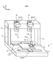
- FIG. 1 is a perspective view schematically showing the appearance of the processing system of the present embodiment.
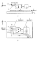
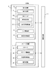
- FIG. 2 is a system configuration diagram showing a system configuration of the processing system of the present embodiment.
- FIGS. 3 (a) to 3 (c) is a cross-sectional view showing a state of removal processing performed on the work.
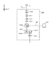
- FIG. 4 is a cross-sectional view showing the configuration of the irradiation optical system.
- FIG. 5 is a cross-sectional view showing the configuration of the rotating device.
- FIG. 6 is a plan view showing the structure of the measuring device.
- FIG. 7 is a cross-sectional view showing the structure of the measuring device.
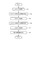
- FIG. 8 is a flowchart showing the flow of the machining operation.
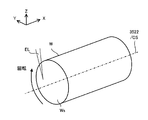
- FIG. 9 is a perspective view showing the work being machined.
- FIG. 9 is a perspective view showing the work being machined.
- FIG. 10 is a cross-sectional view showing the processing light applied to the work.
- FIG. 11 is a cross-sectional view showing another example of the processing light applied to the work.
- FIG. 12 is a perspective view showing another example of the processing light applied to the work.
- FIG. 13 is a cross-sectional view showing an example of a beam damper.
- FIG. 14 is a flowchart showing the flow of the first axis information generation operation.
- FIG. 15 is a plan view showing a height image of the test work, which is an example of the measurement result of the test work.
- FIG. 16 is a top view showing the test work.
- FIG. 15 is a plan view showing a height image of the test work, which is an example of the measurement result of the test work.
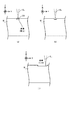
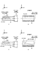
- FIG. 17 (a) is a top view showing an ideal test work in which the direction in which the rotation axis extends and the direction in which the stage moves are parallel (or coincident)
- FIG. 17 (b) is a top view showing FIG. 17 (b).
- It is a plan view which shows the height image corresponding to the measurement result of the test work shown in a)
- FIG. 17 (d) is a plan view which shows the height image corresponding to the measurement result of the test work shown in FIG. 17 (c).
- FIG. 18 is a flowchart showing the flow of another example of the first axis information generation operation.
- FIG. 18 is a flowchart showing the flow of another example of the first axis information generation operation.
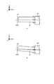
- 19A is a plan view showing a height image corresponding to the measurement result of an ideal test work in which the direction in which the rotation axis extends and the direction in which the stage moves are parallel (or coincident).
- 19 (b) is a plan view showing a height image corresponding to the measurement result of the test work in which the direction in which the rotation axis extends and the direction in which the stage moves are not parallel (or do not match).
- FIG. 20 is a flowchart showing the flow of the second axis information generation operation.
- 21 (a) is a top view showing an ideal test work in which the direction in which the rotation axis extends and the scanning direction of the processing light are parallel (or coincident)
- FIG. 21 (b) is FIG. 21.
- FIG. 21 (d) is a plan view showing a height image corresponding to the measurement result of the test work shown in FIG. 21 (c).
- FIGS. 22 (a) and 22 (b) are a top view showing a workpiece in which a chucking error has occurred.
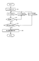
- FIG. 23 is a flowchart showing the flow of the third axis information generation operation (particularly, the operation of generating eccentric error information).
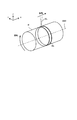
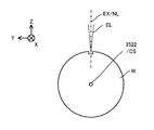
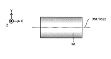
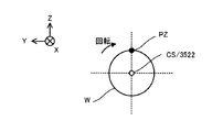
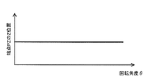
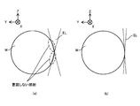
- FIG. 24 is a cross-sectional view showing how an ideal workpiece whose central axis coincides with the rotation axis rotates.
- FIG. 25 is a graph showing the relationship between the position of the end point of the work shown in FIG. 24 in the Z-axis direction and the rotation angle of the work.
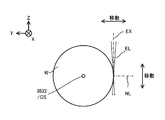
- FIG. 26 is a cross-sectional view showing how a workpiece whose central axis is parallel to the rotation axis but does not match is rotating.
- FIG. 27 is a graph showing the relationship between the position of the end point of the work shown in FIG. 26 in the Z-axis direction and the rotation angle of the work.
- FIG. 28 is a cross-sectional view showing how a workpiece whose central axis is parallel to the rotation axis but does not match is rotating.
- FIG. 29 is a graph showing the relationship between the position of the end point of the work shown in FIG.
- FIG. 30 is a cross-sectional view showing an example of the irradiation position of the processing light EL controlled based on the eccentricity error information.
- FIG. 31 is a flowchart showing the flow of the third axis information generation operation (particularly, the operation of generating the declination error information).
- FIG. 32 is a top view showing a work in which an argument error occurs.
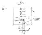
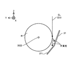
- FIG. 33 (a) is a cross-sectional view showing how the machining head irradiates the measuring device with the machining light
- FIG. 33 (b) is a plan view showing how the machining head irradiates the measuring device with the machining light.
- FIG. 33 (c) is a graph showing the result of receiving the processed light by the light receiving element included in the measuring device.
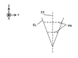
- FIG. 34 is a cross-sectional view showing the processing light.
- FIG. 35 (a) is a cross-sectional view showing the machining light applied to the work from the direction of twisting with respect to the rotation axis, and
- FIG. 35 (b) is a cross-sectional view showing the machining light with a controlled opening angle. be.
- FIG. 36 is a cross-sectional view showing a measuring device for measuring processing light.
- FIG. 37 is a cross-sectional view showing a measuring device for measuring processing light.
- FIG. 38 is a cross-sectional view showing a measuring device for measuring processing light.
- FIG. 36 is a cross-sectional view showing a measuring device for measuring processing light.
- FIG. 39 is a cross-sectional view showing a measuring device for measuring processing light.
- FIG. 40 (a) is a cross-sectional view showing an example of a relative baseline, a machining baseline and a measurement baseline
- FIG. 40 (b) is a plane showing an example of the relative baseline, the machining baseline and the measurement baseline. It is a figure.
- FIG. 41 is a perspective view schematically showing the appearance of the processing system of the first modification.
- FIG. 42 is a perspective view schematically showing the appearance of the processing system of the second modification.
- FIG. 43 is a system configuration diagram showing the system configuration of the processing system of the second modification.
- FIG. 44 is a cross-sectional view showing the configuration of the irradiation optical system of the second modification.
- FIG. 45 is a perspective view schematically showing the appearance of the processing system of the third modification.
- each of the X-axis direction and the Y-axis direction is a horizontal direction (that is, a predetermined direction in the horizontal plane), and the Z-axis direction is a vertical direction (that is, a direction orthogonal to the horizontal plane). Yes, it is assumed that it is substantially in the vertical direction).
- the rotation directions (in other words, the inclination direction) around the X-axis, the Y-axis, and the Z-axis are referred to as the ⁇ X direction, the ⁇ Y direction, and the ⁇ Z direction, respectively.
- the Z-axis direction may be the direction of gravity.
- the XY plane may be horizontal.
- FIG. 1 is a perspective view schematically showing the appearance of the processing system SYS of the present embodiment.
- FIG. 2 is a system configuration diagram showing a system configuration of the processing system SYS of the present embodiment.
- the processing system SYS includes a processing device 1, a measuring device 2, a stage device 3, and a control device 4.
- the processing device 1, the measuring device 2, and the stage device 3 are housed in the housing 5.
- the processing device 1, the measuring device 2, and the stage device 3 do not have to be housed in the housing 5. That is, the processing system SYS does not have to include the housing 5 that houses the processing device 1, the measuring device 2, and the stage device 3.
- the measuring device 2 is provided on the rotating device 35 side as compared with the processing device 1 in the X-axis direction, but the arrangement may be reversed.
- the processing device 1 can process the work W under the control of the control device 4.
- the work W is an object processed by the processing apparatus 1.
- the work W may be, for example, a metal, an alloy (for example, duralmine, etc.), a semiconductor (for example, silicon), a resin, or CFRP. It may be a composite material such as (Carbon Fiber Reinforced Plastic), glass, ceramics, or an object composed of any other material.
- the processing apparatus 1 may irradiate the work W with processing light EL to perform removal processing for removing a part of the work W.
- the removal process is at least one of flat surface processing, cylindrical processing, drilling processing, smoothing processing, cutting processing, and engraving processing (in other words, engraving processing) for forming (in other words, engraving) an arbitrary character or an arbitrary pattern. May include one.
- FIGS. 3 (a) to 3 (c) is a cross-sectional view showing a state of removal processing performed on the work W.
- the processing apparatus 1 irradiates the target irradiation region EA set (in other words, formed) on the surface of the work W with the processing light EL.
- the target irradiation region EA is irradiated with the processing light EL, the energy of the processing light EL is transmitted to the portion of the work W that is close to the target irradiation region EA and the target irradiation region EA.
- the material constituting the target irradiation region EA and the portion of the work W close to the target irradiation region EA is melted by the heat generated by the energy of the processing light EL. ..
- the molten material becomes droplets and scatters.
- the molten material evaporates due to the heat generated by the energy of the processing light EL.
- the portion of the work W that is close to the target irradiation region EA and the target irradiation region EA is removed. That is, as shown in FIG. 3B, a recess (in other words, a groove) is formed on the surface of the work W.
- the processing apparatus 1 processes the work W by utilizing the so-called thermal processing principle. Further, the processing apparatus 1 moves the target irradiation region EA on the surface of the work W by using the galvanometer mirror 1214 described later. That is, the processing apparatus 1 scans the surface of the work W with the processing light EL. As a result, as shown in FIG. 3C, the surface of the work W is at least partially removed along the scanning locus of the processed light EL (that is, the moving locus of the target irradiation region EA). Therefore, the processing apparatus 1 appropriately removes the portion of the work W to be removed by causing the processing light EL to scan the surface of the work W along a desired scanning locus corresponding to the region to be removed. be able to.
- the processing apparatus 1 can also process the work W by using the principle of non-thermal processing (for example, ablation processing). That is, the processing apparatus 1 may perform non-thermal processing (for example, ablation processing) on the work W.
- non-thermal processing for example, ablation processing
- pulsed light having a light emission time of picoseconds or less or, in some cases, nanoseconds or femtoseconds or less
- it is close to the target irradiation region EA and the target irradiation region EA in the work W.
- the materials that make up the part instantly evaporate and scatter.
- pulsed light having a light emission time of picoseconds or less (or, in some cases, nanoseconds or femtoseconds or less) is used as the processing light EL, it is close to the target irradiation region EA and the target irradiation region EA in the work W.
- the material constituting the part may sublimate without going through a molten state. Therefore, a recess (in other words, a groove) can be formed on the surface of the work W while suppressing the influence of heat caused by the energy of the processing light EL on the work W as much as possible.
- the processing apparatus 1 may form a riblet structure on the work W.
- the riblet structure may be a structure capable of reducing the resistance of the surface of the work W to the fluid (particularly, at least one of frictional resistance and turbulent frictional resistance).
- the riblet structure may include a structure capable of reducing noise generated when the fluid and the surface of the work W move relative to each other.
- the riblet structure is, for example, a second direction in which a groove extending along a first direction (for example, the Y-axis direction) along the surface of the work W is along the surface of the work W and intersects in the first direction. It may include a plurality of structures arranged along (for example, the X-axis direction).
- the processing apparatus 1 may form an arbitrary structure having an arbitrary shape on the surface of the work W.
- an arbitrary structure there is a structure that generates a vortex with respect to the flow of fluid on the surface of the work W.
- a structure for imparting hydrophobicity to the surface of the work W is a regularly or irregularly formed micro-nanometer-order fine texture structure (typically a concavo-convex structure).
- Such a fine texture structure may include at least one of a shark skin structure and a dimple structure having a function of reducing resistance due to a fluid (gas and / or liquid).
- the fine textured structure may include a leaf surface structure of a lotus having at least one of a liquid repellent function and a self-cleaning function (for example, having a lotus effect).
- the fine texture structure includes a fine protrusion structure having a liquid transport function (see US Patent Publication No. 2017/0044002), a concavo-convex structure having a lipophilic function, a concavo-convex structure having an antifouling function, a reflectance reducing function and a repellent structure.
- a moth-eye structure that has at least one of the liquid functions, a concavo-convex structure that intensifies only light of a specific wavelength by interference to exhibit a structural color, a pillar array structure that has an adhesive function that utilizes van der Waals force, a concavo-convex structure that has an aerodynamic noise reduction function, It may include at least one of a honeycomb structure having a droplet collecting function and an uneven structure for improving adhesion to a layer formed on the surface.
- the processing device 1 in order to process the work W, includes a processing light source 11, a processing head 12, a head drive system 13, and a position measuring device 14.
- the processing light source 11 emits at least one of infrared light, visible light, ultraviolet light, and extreme ultraviolet light, for example, as processing light EL. However, other types of light may be used as the processing light EL.
- the processed light EL may include pulsed light (that is, a plurality of pulse beams).
- the processing light EL may be laser light.
- the processing light source 11 may include a laser light source (for example, a semiconductor laser such as a laser diode (LD: Laser Diode)).
- the laser light source may include at least one such as a fiber laser, a CO 2 laser, a YAG laser and an excimer laser.
- the processing light EL does not have to be laser light.
- the processing light source 11 may include an arbitrary light source (for example, at least one such as an LED (Light Emitting Diode) and a discharge lamp).
- the processing head 12 irradiates the work W with the processing light EL from the processing light source 11. Therefore, the processing head 12 may be referred to as a beam irradiation device.
- a stage 32 on which the work W can be placed is arranged below the processing head 12. Therefore, the processing head 12 irradiates the work W with the processing light EL by injecting the processing light EL downward from the processing head 12.
- the processing head 12 includes an irradiation optical system 121 in order to irradiate the work W with the processing light EL.
- FIG. 4 is a cross-sectional view schematically showing the structure of the irradiation optical system 121.
- the irradiation optical system 121 includes, for example, a condensing position changing optical system 1210, an opening angle changing optical system 1211, an ellipticity changing optical system 1212, an optical rotation optical system 1213, and a galvanometer mirror 1214. And an f ⁇ lens 1215.
- the irradiation optical system 121 may not include at least one of the focusing position changing optical system 1210, the opening angle changing optical system 1211, the ellipticity changing optical system 1212, and the optical rotation optical system 1213.
- the condensing position changing optical system 1210 is an optical member capable of changing the condensing position of the processing light EL (that is, the converging position of the processing light EL) along the traveling direction of the processing light EL.
- the focusing position changing optical system 1210 may include, for example, a plurality of lenses arranged along the traveling direction of the processed light EL. In this case, the focusing position of the processed light EL may be changed by moving at least one of the plurality of lenses along the optical axis direction.
- the opening angle changing optical system 1211 is an optical member capable of changing the opening angle of the processing light EL emitted from the processing head 12.
- the "opening angle of the processing light EL" in the present embodiment may mean the angle formed by the outermost light beam of the processing light EL.
- the "opening angle of the processing light EL” in the present embodiment may mean the angle formed by the outermost light beam of the processing light EL and the main light ray of the processing light EL.
- the opening angle changing optical system 1211 may be regarded as substantially changing the numerical aperture of the irradiation optical system 121.
- the opening angle changing optical system 1211 may be referred to as an opening angle changing device.
- the ellipticity changing optical system 1212 is an optical member capable of changing the ellipticity of the processing light EL emitted from the processing head 12. Specifically, the ellipticity changing optical system 1212 changes the ellipticity of the spot of the processing light EL in the plane intersecting the irradiation axis EX along the traveling direction of the processing light EL.
- the ellipticity changing optical system 1212 includes an optical member (for example, at least one such as a toric lens and a cylindrical lens) having different refractive powers in two orthogonal directions, and the optical member is used around the optical axis or with the optical axis. The ellipticity may be changed by rotating it around a parallel axis.
- the ellipticity changing optical system 1212 may include a plurality of optical members, and the ellipticity may be changed by changing the distance between the plurality of optical members in the optical axis direction.
- at least one of the plurality of optical members may be an optical member having an asymmetric refractive power with respect to the optical axis.
- the irradiation axis EX is typically an axis extending along the main light beam of the processing light EL.
- the main light rays of the processed light EL are the center of light in the first cross section that intersects the traveling direction of the processed light EL and the center of light in the second cross section that intersects the traveling direction and is different from the first cross section. It may be a line connecting.
- the irradiation axis EX is parallel to the optical axis AX of the f ⁇ lens 1215, but the irradiation axis EX may be tilted with respect to the optical axis AX of the f ⁇ lens 1215.
- the irradiation axis EX is parallel to the Z axis, but the irradiation axis EX may be inclined with respect to the Z axis.
- Changing the ellipticity means changing the opening angle of the processed light EL in the first surface including the irradiation axis EX and the processing light EL in the second surface including the irradiation axis EX and intersecting the first surface. It may be considered to be substantially equivalent to changing at least one of the opening angles of. Therefore, the ellipticity changing optical system 1212 may be referred to as an opening angle changing optical system or an opening angle changing device. In this case, the opening angle changing optical system 1211 described above may function as at least a part of the ellipticity changing optical system 1212.
- the optical rotation optical system 1213 is an optical member capable of rotating a spot of the processed light EL around the optical axis AX (particularly around the irradiation axis EX) in a plane intersecting the irradiation axis EX.
- the optical rotation optical system 1213 sets the direction in which the maximum value of the diameters of the spots of the processed light EL (that is, the cross section of the processed light EL) on the entrance pupil surface of the f ⁇ lens 1215 is taken around the optical axis AX. Rotate (especially around the irradiation axis EX).
- the direction in which the diameter of the spot of the processed light EL (that is, the cross section of the processed light EL) on the entrance pupil surface of the f ⁇ lens 1215 is maximized is around the optical axis AX (particularly, the irradiation axis).
- Rotate (around EX) In this case, the optical rotation optical system 1213 rotates the direction of the long axis or the minor axis of the spot of the processed light EL on the entrance pupil surface of the f ⁇ lens 1215 around the optical axis AX (particularly around the irradiation axis EX). It may be regarded as letting.
- the optical rotation optical system 1213 may include an optical member that can rotate around the optical axis, and the spot of the processed light EL may be rotated by rotating the optical member around the optical axis.
- Such an optical member may be referred to as a beam rotator. Therefore, the optical rotation optical system 1213 may be referred to as a beam rotation member.
- the ellipticity changing optical system 1212 and the optical rotation optical system 1213 may be used in combination.
- the processed optical EL that has passed through the condensing position changing optical system 1210, the opening angle changing optical system 1211, the ellipticity changing optical system 1212, and the optical rotation optical system 1213 is incident on the galvano mirror 1214.
- the galvano mirror 1214 changes the injection direction of the processing light EL from the galvano mirror 1214 by deflecting the processing light EL (that is, changing the injection angle of the processing light EL). For this reason, the galvanometer mirror 1214 may be referred to as a beam deflector.
- FIG. 4 shows an example in which the emission direction of the processed light EL from the galvano mirror 1214 is changed in the YZ plane.
- the galvano mirror 1214 changes the injection direction of the processing light EL from the galvano mirror 1214 to change the irradiation position of the processing light EL on the processing head 12 (for example, the irradiation position of the processing light EL on the surface of the work W). You may change it. That is, the galvano mirror 1214 may change (that is, move) the irradiation position of the processing light EL by deflecting the processing light EL. Therefore, the galvano mirror 1214 may be referred to as a beam irradiation position changing device. Note that FIG. 4 shows an example in which the irradiation position of the processing light EL is changed in the Y-axis direction.
- the galvano mirror 1214 may change the traveling direction of the processing light EL from the processing head 12 (that is, the direction in which the irradiation axis EX extends) by changing the injection direction of the processing light EL from the galvano mirror 1214. good. That is, the galvano mirror 1214 may change at least one of the irradiation position and the traveling direction of the processing light EL. Therefore, the galvanometer mirror 1214 may be referred to as a beam irradiation state changing device capable of changing the irradiation state of the processing light EL including at least one of the irradiation position and the traveling direction.
- the galvano mirror 1214 includes, for example, an X scanning mirror 1214X and a Y scanning mirror 1214Y.
- Each of the X scanning mirror 1214X and the Y scanning mirror 1214Y is a tilt angle variable mirror in which the angle of the processed light EL incident on each mirror with respect to the optical path can be changed.
- the X scanning mirror 1214X reflects the processed light EL toward the Y scanning mirror 1214Y.
- the X scanning mirror 1214X is swingable or rotatable about a rotation axis along the Y axis. Due to the swing or rotation of the X scanning mirror 1214X, the processing light EL scans the surface of the work W along the X-axis direction.
- the target irradiation region EA moves on the surface of the work W along the X-axis direction.
- the Y scanning mirror 1214Y reflects the processed light EL toward the f ⁇ lens 1215.
- the Y scanning mirror 1214Y is swingable or rotatable about a rotation axis along the X axis. By swinging or rotating the Y scanning mirror 1214Y, the processing light EL scans the surface of the work W along the Y-axis direction. Due to the swing or rotation of the Y scanning mirror 1214Y, the target irradiation region EA moves on the surface of the work W along the Y-axis direction.
- the machining optical EL can scan the machining shot region PSA determined based on the machining head 12. That is, the galvano mirror 1214 makes it possible for the target irradiation region EA to move within the machining shot region PSA determined with reference to the machining head 12.
- the machining shot region PSA indicates a region (in other words, a range) in which machining is performed by the machining apparatus 1 in a state where the positional relationship between the machining head 12 and the work W is fixed (that is, without changing).
- the machining shot region PSA coincides with or exceeds the maximum scannable range of the machining light EL deflected by the galvano mirror 1214 with the positional relationship between the machining head 12 and the work W fixed. It is set to be a small area.
- the machining shot area PSA is smaller than the part of the work W to be machined, the machining shot area PSA set in the machining shot area PSA on the work W is scanned by the machining optical EL to scan a certain part on the work W.
- the operation of processing and the operation of changing the position of the processing shot region PSA on the work W by changing the relative positional relationship between the processing head 12 and the work W are repeated.
- the irradiation optical system 121 may, in addition to or in place of the galvano mirror 1214, an arbitrary optical member capable of deflecting the processed light EL (that is, at least one of the emission direction and the irradiation position of the processed light EL can be changed). You may have.
- An example of such an optical member is a polygon mirror having a plurality of reflecting surfaces having different angles. The polygon mirror changes the incident angle of the processing light EL with respect to the one reflecting surface during the period in which the processing light EL is irradiated to the one reflecting surface, and makes the reflecting surface irradiated with the processing light EL a plurality of reflecting surfaces. It is rotatable to switch between.
- the irradiation optical system 121 may include a return light reduction optical system having a polarizing optical member.
- the f ⁇ lens 1215 is an optical system for emitting the processed light EL from the galvano mirror 1214 toward the work W.
- the f ⁇ lens 1215 is an optical element capable of condensing the processed light EL from the galvano mirror 1214 on a condensing surface intersecting the optical axis AX of the f ⁇ lens 1215. Therefore, the f ⁇ lens 1215 may be referred to as a condensing optical system.
- the condensing surface of the f ⁇ lens 1215 may be set on the ejection side of the f ⁇ lens 1215.
- the condensing surface of the f ⁇ lens 1215 may be set on the surface of the work W, for example. In this case, the f ⁇ lens 1215 can collect the processed light EL from the galvano mirror 1214 on the surface of the work W.
- the head drive system 13 sets the processing head 12, and thus the irradiation optical system 121, under the control of the control device 4, in the X-axis direction, the Y-axis direction, the Z-axis direction, the ⁇ X direction, and the ⁇ Y direction. And move along at least one in the ⁇ Z direction. Therefore, the head drive system 13 may be referred to as a mobile device.
- FIG. 1 shows an example in which the head drive system 13 moves the machining head 12 along the Z-axis direction.
- the head drive system 13 may include, for example, a Z slider member 131 extending along the Z axis direction.
- the Z slider member 131 is arranged on the support frame 6 arranged on the surface plate 31 described later via the vibration isolator.
- the support frame 6 is, for example, a pair of leg members 61 arranged on the surface plate 31 via a vibration isolator and extending along the Z-axis direction, and a pair of leg members 61 so as to connect the upper ends of the pair of leg members 61.
- a beam member 62 arranged on the leg member 61 and extending along the X-axis direction may be provided.
- the Z slider member 131 is arranged on the beam member 62 via, for example, a support member 63 extending along the Z axis direction.
- the processing head 12 is connected to the Z slider member 131 so as to be movable along the Z slider member 131.
- the positional relationship between the processing head 12 and the stage 32 which will be described later, changes. Further, when the processing head 12 moves, the positional relationship between the processing head 12 and the rotating device 35, which will be described later, arranged on the stage 32 changes. Further, when the machining head 12 moves, the positional relationship between the machining head 12 and the work W held by the rotating device 35 changes. Therefore, moving the machining head 12 may be regarded as equivalent to changing the positional relationship between the machining head 12 and the stage 32, the rotating device 35, and the work W. Further, when the processing head 12 moves, the irradiation position of the processing light EL on the surface of the work W moves with respect to the surface of the work W.
- moving the processing head 12 may be regarded as equivalent to changing the irradiation position of the processing light EL on the surface of the work W.
- the position measuring device 14 can measure (in other words, detect) the position of the processing head 12. That is, the position measuring device 14 is a device capable of acquiring information regarding the position of the processing head 12.
- the position measuring device 14 may include, for example, at least one of an encoder and a laser interferometer.
- the measuring device 2 can measure the work W under the control of the control device 4. Since the measuring device 2 measures an object called a work W, it may be referred to as an object measuring device or a work measuring device. In order to measure the work W, the measuring device 2 includes a measuring head 21, a head drive system 22, and a position measuring device 23.
- the measurement head 21 can measure the work W under the control of the control device 4.
- the measuring head 21 measures the surface of the work W three-dimensionally. That is, the measuring head 21 measures the three-dimensional shape of the surface of the work W. Therefore, the measuring head 21 may be provided with a three-dimensional measuring device 211 capable of measuring the three-dimensional shape of the surface of the work W.
- Work measurement information regarding the measurement result of the work W by the measurement head 21 (that is, the measurement result of the work W by the three-dimensional measuring device 211) is output from the measurement head 21 to the control device 4.
- the control device 4 controls the operation of the machining system SYS based on the work measurement information.
- control device 4 is a machining system SYS (for example, a machining device 1, a measuring device 2, and a stage device 3) so that the machining system SYS can appropriately machine the work W based on the work measurement information. At least one of) is controlled.
- the measuring device 2, the measuring head 21, or the three-dimensional shape measuring device 211 may be referred to as an object information acquisition device or a work information acquisition device in order to acquire work measurement information regarding the three-dimensional shape of the surface of the work W. ..
- the three-dimensional measuring device 211 may measure the work W in a non-contact manner.
- the three-dimensional measuring device 211 may optically measure the work W. That is, the three-dimensional measuring device 211 may measure the work W using an arbitrary measuring beam such as a measuring light.
- the three-dimensional measuring device 211 may measure the work W by projecting the slit light on the surface of the work W and using an optical cutting method for measuring the shape of the projected slit light.
- the three-dimensional measuring device 211 may measure the work W by using a white interferometry method for measuring an interference pattern between white light passing through the work W and white light not passing through the work W.
- the three-dimensional measuring device 211 projects a light pattern on the surface of the work W and measures the shape of the projected pattern.
- the three-dimensional measuring device 211 projects light on the surface of the work W and returns the projected light.
- Time-of-flight method moiretopography method (specifically, lattice irradiation method or lattice projection method), in which the operation of measuring the distance from the time until arrival to the work W is performed at multiple positions on the work W.
- the work W may be measured using at least one of a holographic interference method, an autocollimation method, a stereo method, a non-point aberration method, a critical angle method, a knife edge method, an interference measurement method, and a cofocal method. ..
- the three-dimensional measuring device 211 may measure the work W by imaging the work W illuminated by the illumination light.
- the three-dimensional measuring device 211 includes a light source that emits measurement light ML (for example, slit light, white light, or illumination light) and light from the work W irradiated with the measurement light ML (for example, measurement). It may be provided with a light receiver that receives light (reflected light).
- the three-dimensional measuring instrument 211 may measure the work W by contact.
- the measurement head 21 measures the work W in units of the measurement shot area MSA.
- the measurement shot area MSA indicates an area (in other words, a range) in which measurement is performed by the measurement head 21 in a state where the positional relationship between the measurement head 21 and the work W is fixed (that is, without changing).
- the measurement shot area MSA coincides with the maximum range in which the measurement head 21 can irradiate the measurement light ML with the positional relationship between the measurement head 21 and the work W fixed (that is, without changing).
- the area is set to be narrower than the relevant range.
- the measurement shot area MSA may be referred to as a measurable range or measurable field of the measurement head 21.
- the measurement head 21 is aligned with respect to the processing head 12 so that the measurement axis MX of the measurement head 21 does not coincide with the irradiation axis EX along the traveling direction of the processing light EL. ..
- the measurement axis MX is parallel to the irradiation axis EX.
- the measurement axis MX may be, for example, an axis extending along the optical axis of the optical system included in the measurement head 21.
- the measurement axis MX may be, for example, an axis extending along the main ray of the measurement light ML from the measurement head 21.
- the measurement axis MX does not have to be parallel to the irradiation axis EX.
- the head drive system 22 moves the measurement head 21 along at least one of the X-axis direction, the Y-axis direction, the Z-axis direction, the ⁇ X direction, the ⁇ Y direction, and the ⁇ Z direction under the control of the control device 4. Therefore, the head drive system 22 may be referred to as a mobile device.
- FIG. 1 shows an example in which the head drive system 22 moves the measurement head 21 along the Z-axis direction.
- the head drive system 22 may include, for example, a Z slider member 221 extending along the Z axis direction.
- the Z slider member 221 may be arranged on the beam member 62 via a support member 64 extending in the Z axis direction.
- the measurement head 21 is connected to the Z slider member 221 so as to be movable along the Z slider member 221.
- moving the measuring head 21 may be regarded as equivalent to changing the positional relationship between the measuring head 21 and the stage 32, the rotating device 35, and the work W.
- the position measuring device 23 can measure (in other words, detect) the position of the measuring head 21. That is, the position measuring device 23 is a device capable of acquiring information regarding the position of the measuring head 21.
- the position measuring device 23 may include, for example, at least one of an encoder and a laser interferometer.
- the stage device 3 includes a surface plate 31, a stage 32, a stage drive system 33, a position measuring device 34, a rotating device 35, and a measuring device 36.
- the surface plate 31 is arranged on the bottom surface of the housing 5 (or on a supporting surface such as a floor on which the housing 5 is placed).
- a stage 32 is arranged on the surface plate 31.
- a shaking device may be installed. Further, the support frame 6 described above may be arranged on the surface plate 31.
- the stage 32 is a mounting device on which the work W can be mounted.
- the stage 32 may be able to hold the work W placed on the stage 32.
- the stage 32 may not be able to hold the work W placed on the stage 32.
- the work W may be mounted on the stage 32 without being clamped.
- the rotating device 35 is arranged on the stage 32.
- the rotating device 35 is a device that rotates the chuck 353, which is a holding device that rotatably holds the work W, as will be described in detail later. Therefore, in the present embodiment, the work W may be placed on the stage 32 or may be held by the rotating device 35 via the chuck 353.
- the processing head 12 may irradiate the work W placed on the stage 32 with the processing light EL, or may irradiate the work W held by the rotating device 35 with the processing light EL.
- the measuring head 21 may measure the work W mounted on the stage 32, or may measure the work W held by the rotating device 35. In the following, unless otherwise specified, the work W is assumed to be held by the rotating device 35. Since the rotating device 35 rotates the chuck 353 that holds the work W, the rotating device 35 may be regarded as a device that rotates the work W.
- the stage drive system 33 moves the stage 32 under the control of the control device 4. Therefore, the stage drive system 33 may be referred to as a mobile device.
- the rotating device 35 arranged on the stage 32 also moves together with the stage 32.
- the work W mounted on the stage 32 or held by the rotating device 35 on the stage 32 also moves together with the stage 32.
- the stage drive system 33 moves the stage 32 along at least one of the X-axis, the Y-axis, the Z-axis, the ⁇ X direction, the ⁇ Y direction, and the ⁇ Z direction, for example. In the example shown in FIG. 1, the stage drive system 33 moves the stage 32 along the X-axis and the Y-axis, respectively.
- the stage drive system 33 moves the stage 32 along the direction along the XY plane that intersects the traveling directions of the processing light EL and the measurement light ML, respectively.
- the stage drive system 33 includes, for example, an X slide member 331 extending along the X-axis direction (in the example shown in FIG. 1, two X-slide members 331 provided parallel to each other) and along the Y-axis direction.
- a Y-slide member 332 (one Y-slide member 332 in the example shown in FIG. 1) may be provided.
- the two X slide members 331 are arranged on the surface plate 31 so as to be arranged along the Y-axis direction.
- the Y slide member 332 is connected to the two X slide members 331 so as to be movable along the two X slide members 331.
- the stage 32 is connected to the Y slide member 332 so as to be movable along the Y slide member 332.
- a plurality of X slide members 331 are provided, but the number of X slide members may be one.
- the stage 32 may be configured to be floated and supported by an air bearing on the surface plate 31.
- moving the stage 32 may be regarded as equivalent to changing the positional relationship between each of the stage 32, the rotating device 35, and the work W and each of the processing head 12 and the measuring head 21.
- the stage 32 moves, the irradiation position of the processing light EL on the surface of the work W moves with respect to the surface of the work W. That is, the irradiation position of the processing light EL on the surface of the work W changes on the surface of the work W. Therefore, moving the stage 32 may be regarded as equivalent to changing the irradiation position of the processing light EL on the surface of the work W.
- the position measuring device 34 can measure the position of the stage 32 (in other words, it can detect it). That is, the position measuring device 34 is a device capable of acquiring information regarding the position of the stage 32.
- the position measuring device 34 may include, for example, at least one of an encoder and a laser interferometer. Since the position measuring device 34 can acquire information regarding the position of the stage 32, the position measuring device 34 may be referred to as a stage position information acquiring device.
- the rotating device 35 is a device that rotates the chuck 353, which is a holding device that holds the work W rotatably.
- the configuration of the rotating device 35 will be described with reference to FIG.
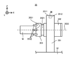
- FIG. 5 is a cross-sectional view showing the configuration of the rotating device 35.
- the rotating device 35 includes a support frame 351 and a rotating motor 352.
- the support frame 351 is arranged on the stage 32.
- the rotary motor 352 is supported by a support frame 351.
- the rotary motor 352 operates to rotate the rotary shaft 3521.
- the rotating shaft 3521 may be a member extending along a direction intersecting the direction of gravity (in the example shown in FIG. 5, the X-axis direction). That is, in the example shown in FIG. 5, the rotary motor 352 rotates the rotary shaft 3521 extending along the X-axis direction around the rotary shaft 3522 extending along the X-axis direction.
- the rotary shaft 3522 is a shaft that passes through the center of rotation of the rotary shaft 3521 and extends along the rotary shaft 3521. However, the rotating shaft 3521 may extend along a direction different from the X-axis direction.
- the rotary motor 352 may rotate the rotary shaft 3521 extending in a direction different from the X-axis direction around the rotary shaft 3522 extending in a direction different from the X-axis direction.
- the rotating shaft 3521 may be provided so that the angle of the rotating shaft 3522 with respect to the X axis (for example, an angle in the XZ plane and an angle in the XY plane) can be changed.
- the rotating shaft 3521 may be movable in at least one of the ⁇ z direction and the ⁇ y direction.
- the rotating device 35 includes a rotary encoder for detecting the rotation angle of the rotation motor 352 or the rotation angle of the rotation shaft 3521, and the output thereof is output to the control device 4.
- This rotary encoder may be referred to as a rotation detection device capable of detecting the rotation angle of the rotation device.
- a chuck 353 is connected to the rotating shaft 3521.
- the chuck 353 is a holding device capable of holding the work W.
- the chuck 353 holds the work W by sandwiching the work W in contact with the holding surface 3531 of the chuck 353 with a plurality of claws 3532 included in the chuck 353.
- the chuck 353 moves the work W in contact with the holding surface 3531 along the YZ plane intersecting the X-axis in the X-axis direction.
- the work W is held by sandwiching the work W with a plurality of claws 3532 extending along the line.
- the method of holding the work W by the chuck 353 is not limited to the method shown in FIG.
- the rotary motor 352 rotates the rotary shaft 3521 to rotate the chuck 353 connected to the rotary shaft 3521 around the rotary shaft 3522.
- the rotating device 35 can function as a spindle capable of rotating the work W held by the chuck 353.
- the rotating device 35 rotates the work W around the X axis.
- the measuring device 36 is a device capable of measuring the machining optical EL from the machining head 12. Therefore, the measuring device 36 may be referred to as a beam measuring device. Further, at least a part of the measuring device 36 can be measured by the measuring head 21. In this case, at least a part of the measuring device 36 may be regarded as functioning as a mark (or an index) that can be measured by the measuring head 21.
- the processing light measurement information regarding the measurement result of the processing light EL by the measuring device 36 and the mark measurement information regarding the measurement result of the measuring device 36 by the measuring head 21 are output from the measuring head 21 to the control device 4.
- the control device 4 controls the operation of the machining system SYS based on at least one of the machining light measurement information and the marker measurement information. Specifically, the control device 4 controls the machining system SYS (for example, the machining device 1) so that the machining system SYS can appropriately machine the work W based on at least one of the machining light measurement information and the marker measurement information. , At least one of the measuring device 2 and the stage device 3).
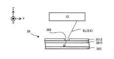
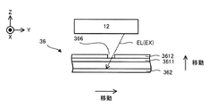
- FIG. 6 is a plan view showing the structure of the measuring device 36.
- FIG. 7 is a cross-sectional view showing the structure of the measuring device 36. Note that FIG. 7 corresponds to the VI-VI'cross-sectional view of FIG.
- the measuring device 36 is arranged (that is, provided) in the rotating device 35.
- the measuring device 36 is arranged on the support frame 351 of the rotating device 35. Since the measuring device 36 measures the machining optical EL and the measuring head 21 measures at least a part of the measuring device 36, the measuring device 36 faces the upper surface 3511 of the support frame 351 (that is, the machining head 12 and the measuring head 21). It may be arranged on the surface where it was. However, the measuring device 36 may be arranged on a surface different from the upper surface of the support frame 351. The measuring device 36 may be arranged on a member different from the support frame 351.
- the measuring device 36 may be arranged on the stage 32. At least a portion of the measuring device 36 may be removable from the support frame 351. Alternatively, the measuring device 36 may be integrated with the support frame 351. Further, a plurality of measuring devices 36 may be arranged on the support frame 351. The measuring device 36 may be arranged on the chuck 353. A plurality of measuring devices 36 may be arranged on the chuck 353.
- the measuring device 36 includes a beam passing member 361 and a light receiving element 362.
- the beam passing member 361 is a plate-shaped member along the XY plane.
- the shape of the beam passing member 361 in the XY plane is rectangular, but it may be any other shape (for example, circular or elliptical).
- the beam passing member 361 has a flat plate shape, it may have a curved shape.
- the size of one side of the beam passing member 361 is, for example, several mm to a dozen mm, but other sizes may be used.
- the light receiving element 362 includes a light receiving surface 3621 extending along the XY plane.
- the shape of the light receiving surface 3621 in the XY plane is rectangular, but it may be any other shape (for example, circular or elliptical).
- the size of one side of the light receiving surface 3621 may be the same as the size of one side of the beam passing member 361, may be smaller than the size of one side of the beam passing member 361, or the size of one side of the beam passing member 361. May be larger than.
- the beam passing member 361 and the light receiving element 362 are arranged inside a recess 3512 (that is, a recess) formed in the support frame 351. That is, the beam passing member 361 and the light receiving element 362 are arranged in the recess 3512 recessed from the upper surface 3511 of the support frame 351 to the ⁇ Z side. However, at least one of the beam passing member 361 and the light receiving element 362 may be arranged at a position different from that of the recess 3512.
- the beam passing member 361 is arranged above the light receiving element 362. That is, the beam passing member 361 is arranged at a position closer to the processing head 12 and the measuring head 21 than the light receiving element 362.
- the surface of the beam passing member 361 (specifically, the surface facing the processing head 12 and the measuring head 21 side, and the surface on the + Z side) is below the upper surface 3511. It may be located.
- the measuring device 36 does not protrude from the surface of the support frame 351, the possibility that the work W or the like accidentally comes into contact with the measuring device 36 (particularly, the beam passing member 361) is reduced.
- the surface of the beam passing member 361 may be located at the same height as the upper surface 3511 or may be located above the upper surface 3511.
- the beam passing member 361 includes a glass substrate 3611 and an attenuation film 3612 formed on at least a part of the surface of the glass substrate 3611.
- the attenuation film 3612 is a member capable of attenuating the processed light EL incident on the attenuation film 3612.
- the "attenuation of the processing light EL by the attenuation film 3612" in the present embodiment not only makes the intensity of the processing light EL passing through the attenuation film 3612 smaller than the intensity of the processing light EL incident on the attenuation film 3612. ,
- the processing light EL incident on the attenuation film 3612 may be shielded (that is, shielded).
- the processing light EL when the processing light EL is incident on the attenuation film 3612, the processing light EL attenuated by the attenuation film 3612 is incident on the light receiving element 362 via the attenuation film 3612, or the processing light EL is incident on the attenuation film 3612.
- the processed light EL does not enter the light receiving element 362 because it is shielded from light.
- the attenuation film 3612 may be formed of a chromium film or a chromium oxide film.
- At least one opening 363 is formed in the damping film 3612.
- a plurality of openings 363 are formed in the damping film 3612.
- the opening 363 is a through hole that penetrates the damping film 3612 in the Z-axis direction. Therefore, when the processing light EL is incident on the opening 363 formed in the attenuation film 3612, the processing light EL passes through the beam passing member 361 through the opening 363. That is, the processed light EL is incident on the light receiving element 362 through the opening 363 without being attenuated or shaded by the attenuation film 3612.
- the portion of the glass substrate 3611 on which the attenuation film 3612 is formed functions as an attenuation region 364 for attenuating the processed light EL.
- the portion of the glass substrate 3611 in which the attenuation film 3612 is not formed functions as a passage region 365 through which the processing light EL is passed.
- the passing region 365 does not attenuate the processed light EL passing through the passing region 365.
- the passing region 365 may attenuate the processed light EL passing through the passing region 365.
- the passing region 365 does not have to be a region through which all (that is, 100%) of the processed light EL incident on the passing region 365 passes, and a part of the processed light EL incident on the passing region 365 passes through. It may be. However, the attenuation rate of the processed light EL in the passing region 365 is smaller than the attenuation rate of the processed light EL in the attenuation region 364.
- the attenuation region 364 is typically arranged adjacent to the passage region 365. That is, the passage region 365 is arranged in the attenuation region 364.
- the measuring device 36 is arranged on the support frame 3511 (that is, arranged on the rotating device 35), the positional relationship between each of the damping area 364 and the passing area 365 and the rotating device 35 is fixed. That is, the positional relationship between each of the damping region 364 and the passing region 365 and the rotating device 35 is a predetermined relationship known to the control device 4.
- the passage region 365 formed by the opening 363 may form a mark (ie, pattern) 366 having a predetermined shape in a plane (typically an XY plane) along the surface of the damping film 3612. ..
- the mark 366 can function as a mark that can be measured by the measuring head 21.
- a mark 366 having a slit shape (this mark 366 may be referred to as a slit mark) may be formed on the beam passing member 361.
- the slit-shaped mark 366 is a mark formed by a passage region 365 having a single linear (for example, slit-shaped) shape in a plane along the surface of the damping film 3612.
- a plurality of marks 366 having different angles with respect to the X-axis and the Y-axis are formed on the beam passing member 361.
- the beam passing member 361 may be formed with a mark 366 having another shape.
- the beam passing member 361 has a mark 366 formed by a plurality of linear passing regions 365, each extending along one direction and arranged along another direction intersecting in one direction.
- the mark 366 may be referred to as a fine mark).
- the beam passing member 361 has a mark 366 formed by a passing region 365 having a rectangular shape in a plane along the surface of the damping film 3612 (this mark 366 may be referred to as a rectangular mark). ..
- the beam passing member 361 has a plurality of linear passing regions 365, each of which extends along a first direction and is arranged along a second direction intersecting the first direction.
- the beam passing member 361 has two first linear passing regions 365, each extending along a fifth direction and separated along a sixth direction orthogonal to the fifth direction.
- the light receiving element 362 is a light receiving unit capable of receiving (for example, detecting) the processed light EL incident on the light receiving element 362 through the passing region 365 (that is, the opening 363) on the light receiving surface 3621.
- the light receiving element 362 is a light receiving unit capable of receiving the processed light EL that has passed through the passing region 365 (that is, the opening 363) on the light receiving surface 3621.
- the light receiving element 362 receives the processed light EL incident on the light receiving element 362 via each of the plurality of passing regions 365 on the light receiving surface 3621. It may be possible.
- the light receiving surface 3621 may be formed by one photoelectric conversion surface of the photoelectric conversion element.
- the light receiving element 362 may be capable of receiving the processed light EL incident on the light receiving element 362 via the first passing region 365 at the first portion of the light receiving surface 3621.
- the light receiving element 362 may be capable of receiving the processed light EL incident on the light receiving element 362 via the second passing region 365 at the second portion of the light receiving surface 3621.
- the measuring device 36 does not have to include the plurality of light receiving elements 362 corresponding to the plurality of passing regions 365, respectively.
- the measuring device 36 may include a light receiving element 362 common to the plurality of passing regions 365.
- the measuring device 36 may include a plurality of light receiving elements 362 corresponding to the plurality of passing regions 365, respectively.
- the focusing position of the processing light EL may be set to or near the passing region 365 of the beam passing member 361.
- the control device 4 may set the focusing position of the processing light EL to an appropriate position by controlling the focus changing optical system 1210.
- the intensity of the processing light EL applied to the measuring device 36 (for example, the amount of energy per unit area on the light receiving surface 3621 of the light receiving element 362) is the processing light applied to the work W to process the work W.
- the intensity of the processing light EL (for example, the energy per unit area in the plane intersecting the traveling direction of the processing light EL) so as to be smaller than the intensity of the EL (for example, the amount of energy per unit area on the surface of the work W). Amount) may be controlled.
- control device 4 may reduce the intensity of the processing light EL by controlling the processing light source 11.
- control device 4 may reduce the intensity of the processing light EL by controlling a dimming member (not shown) arranged on the emission side of the processing light source 11.
- the light receiving result of the light receiving element 362 includes information regarding the state of the processed light EL incident on the light receiving element 362.
- the light receiving result of the light receiving element 362 includes information on the intensity of the processed light EL incident on the light receiving element 362 (specifically, the intensity in the plane intersecting the XY plane). More specifically, the light receiving result of the light receiving element 362 includes information on the intensity distribution of the processed light EL in the plane along the XY plane.
- the light receiving result of the light receiving element 362 is output to the control device 4 as the above-mentioned processing light measurement information.
- the measurement result of the mark 366 by the measurement head 21 is output to the control device 4 as the mark measurement information described above.
- control device 4 controls the operation of the machining system SYS.
- the control device 4 may set the machining conditions of the work W and control at least one of the machining device 1, the measuring device 2, and the stage device 3 so that the work W is machined according to the set machining conditions. good.
- the control device 4 controls the operation of the processing system SYS.
- the control device 4 may include, for example, an arithmetic unit and a storage device.
- the arithmetic unit may include, for example, at least one of a CPU (Central Processing Unit) and a GPU (Graphics Processing Unit).
- the storage device may include, for example, a memory.
- the control device 4 functions as a device that controls the operation of the processing system SYS by executing a computer program by the arithmetic unit.
- This computer program is a computer program for causing the arithmetic unit to perform (that is, execute) the operation described later to be performed by the control device 4.
- this computer program is a computer program for causing the control device 4 to function so that the processing system SYS performs the operation described later.
- the computer program executed by the arithmetic unit may be recorded in a storage device (that is, a recording medium) included in the control device 4, or any storage built in the control device 4 or externally attached to the control device 4. It may be recorded on a medium (for example, a hard disk or a semiconductor memory). Alternatively, the arithmetic unit may download the computer program to be executed from an external device of the control device 4 via the network interface.
- the control device 4 does not have to be provided inside the processing system SYS.
- the control device 4 may be provided as a server or the like outside the processing system SYS.
- the control device 4 and the processing system SYS may be connected by a wired and / or wireless network (or a data bus and / or a communication line).
- a wired network for example, a network using a serial bus type interface represented by at least one of IEEE1394, RS-232x, RS-422, RS-423, RS-485 and USB may be used.
- a network using a parallel bus interface may be used.
- a network using an Ethernet (registered trademark) compliant interface represented by at least one of 10BASE-T, 100BASE-TX and 1000BASE-T may be used.
- a network using radio waves may be used.
- An example of a network using radio waves is a network conforming to IEEE802.1x (for example, at least one of wireless LAN and Bluetooth®).
- a network using infrared rays may be used.
- a network using optical communication may be used.
- the control device 4 and the processing system SYS may be configured so that various types of information can be transmitted and received via the network.
- control device 4 may be able to transmit information such as commands and control parameters to the processing system SYS via the network.
- the processing system SYS may include a receiving device that receives information such as commands and control parameters from the control device 4 via the network. Even if the processing system SYS is provided with a transmission device (that is, an output device that outputs information to the control device 4) that transmits information such as commands and control parameters to the control device 4 via the network. good.
- the first control device that performs a part of the processing performed by the control device 4 is provided inside the processing system SYS, the second control device that performs the other part of the processing performed by the control device 4 is provided.
- the control device may be provided outside the processing system SYS.
- the recording medium for recording the computer program executed by the control device 4 includes a CD-ROM, a CD-R, a CD-RW, a flexible disk, an MO, a DVD-ROM, a DVD-RAM, a DVD-R, a DVD + R, and a DVD.
- -Used by at least one of optical disks such as RW, DVD + RW and Blu-ray (registered trademark), magnetic media such as magnetic tape, magneto-optical disks, semiconductor memories such as USB memory, and other media capable of storing programs. May be done.
- the recording medium may include a device capable of recording a computer program (for example, a general-purpose device or a dedicated device in which the computer program is implemented in a state in which it can be executed in at least one form such as software and firmware).
- each process or function included in the computer program may be realized by a logical processing block realized in the control device 4 by the control device 4 (that is, a computer) executing the computer program. It may be realized by hardware such as a predetermined gate array (FPGA, ASIC) included in the control device 4, or a logical processing block and a partial hardware module that realizes a part of the hardware are mixed. It may be realized in the form of.
- the processing system SYS performs a processing operation for processing at least a part of the surface of the work W using the processing optical EL. Further, the machining system SYS uses the measuring device 2 to rotate the rotating device 35 with respect to the rotation shaft 3522 before the machining operation is performed (or after the machining operation is completed or during the machining operation). The axis information generation operation for generating the axis information is performed. Further, the machining system SYS uses the measuring device 36 to provide optical state information regarding the state of the machining light EL before the machining operation is performed (or after the machining operation is completed or during the machining operation). The light state information generation operation for generating is performed.
- the machining system SYS measures the machining origin PO of the machining device 1 by using the measuring device 36 before the machining operation is performed (or after the machining operation is completed or during the machining operation).
- the origin information operation for generating the origin information related to the measurement origin MO of the device 2 is performed. Therefore, in the following, the machining operation, the axis information generation operation, the optical state information generation operation, and the origin information generation operation will be described in order.
- the machining operation, the axis information generation operation, the optical state information generation operation, and the origin information generation operation performed when processing the work W having a cylindrical shape held by the chuck 353 will be described.
- a machining operation, an axis information generation operation, a light state information generation operation, and an origin information generation operation may be performed on the work W having a shape different from the cylindrical shape.
- a machining operation, a light state information generation operation, and an origin information generation operation may be performed on the work W that is not held by the chuck 353 (that is, mounted on the stage 32).
- FIG. 8 is a flowchart showing the flow of the machining operation.
- the measuring head 21 measures the work W held by the chuck 353 (step S11).
- the measuring head 21 may measure the work W rotating by the rotating device 35. That is, the measuring head 21 may measure the work W during at least a part of the period during which the rotating device 35 rotates the work W.
- the measuring head 21 may measure the stationary work W.
- the rotating device 35 measures the work target portion of the surface of the work W where the measurement shot area MSA is set each time.
- the work W may be rotated by a predetermined angle so that the measurement shot area MSA includes a new measurement target portion on the surface of the W that has not yet been measured by the measurement head 21.
- the processing system SYS may alternately measure the work W by the measuring head 21 and rotate the work W by the rotating device 35.
- the measurement head 21 measures the first measurement target portion on the surface of the work W in a state where the measurement shot area MSA is set on the first measurement target portion on the surface of the work W.
- the rotating device 35 sets the work W so that the measurement shot area MSA is set in the second measurement target portion different from the first measurement target portion on the surface of the work W under the control of the control device 4. Rotate by a predetermined angle.
- the measurement head 21 measures the second measurement target portion on the surface of the work W in a state where the measurement shot area MSA is set on the second measurement target portion on the surface of the work W. After that, the same operation is repeated.
- the measurement head 21 can sequentially measure a plurality of measurement target portions obtained by subdividing (partitioning or segmenting) the surface of the work W.
- the measurement target portion in which the measurement shot area MSA is set after the rotating device 35 rotates the work W is the measurement target in which the measurement shot area MSA is set before the rotating device 35 rotates the work W. It may partially overlap with the part. That is, the measurement target portion to be measured by the measurement head 21 after the rotating device 35 rotates the work W is the measurement target portion already measured by the measurement head 21 before the rotating device 35 rotates the work W. May overlap.
- the measurement target portion in which the measurement shot area MSA is set after the rotating device 35 rotates the work W is the measurement target portion in which the measurement shot area MSA is set before the rotating device 35 rotates the work W. It does not have to overlap with. That is, the measurement target portion to be measured by the measurement head 21 after the rotating device 35 rotates the work W overlaps with the measurement target portion already measured by the measurement head 21 before the rotating device 35 rotates the work W. It does not have to be.
- the stage 32 measures each time the measurement head 21 measures the measurement target portion of the surface of the work W in which the measurement shot area MSA is set.
- the work W may be moved by a predetermined movement amount so that the measurement shot area MSA includes a new measurement target portion on the surface of the work W that has not yet been measured by the measurement head 21.
- the moving direction of the work W at this time may be a direction parallel to the rotating shaft 3522 of the rotating device 35.
- the moving direction of the work W may be a direction intersecting the rotation shaft 3522. In this way, the processing system SYS may alternately measure the work W by the measuring head 21 and move the work W by the stage 32.
- the control device 4 sets the machining conditions of the work W based on the work measurement information regarding the measurement result of the work W by the measurement head 21 in step S11 (step S12).
- the processing conditions may include, for example, conditions relating to the processing light EL.
- the conditions relating to the processing light EL may include, for example, conditions relating to at least one of the intensity of the processing light EL, the irradiation timing of the processing light EL, and the irradiation time of the processing light EL.
- the processing conditions may include, for example, conditions relating to the movement of the processing head 12.
- the conditions relating to the movement of the machining head 21 may include, for example, conditions relating to at least one of the moving speed of the machining head 12, the moving timing of the machining head 12, and the moving amount of the machining head 12.
- the processing conditions may include, for example, conditions relating to the movement of the stage 32.
- the conditions relating to the movement of the stage 32 may include, for example, conditions relating to at least one of the moving speed of the stage 32, the moving timing of the stage 32, and the moving amount of the stage 32.
- the machining conditions may include, for example, conditions relating to the rotation of the work W by the rotating device 35.
- the conditions relating to the rotation of the work W may include, for example, conditions relating to at least one of the rotation speed of the work W, the rotation timing of the work W, and the rotation amount (that is, the rotation angle) of the work W.
- the machining system SYS machining the work W according to the machining conditions set in step S12 (step S13). That is, the processing head 12 irradiates the work W with the processing light EL and moves according to the processing conditions set in step S12. The stage 32 moves according to the machining conditions set in step S12. The rotating device 35 rotates the work W according to the machining conditions set in step S12.
- the processing head 12 may process the work W by irradiating the work W rotating by the rotating device 35 with the processing light EL. That is, the processing head 12 may process the work W by irradiating the work W with the processing light EL during at least a part of the period during which the rotating device 35 rotates the work W. Alternatively, the processing head 12 may process the work W by irradiating the stationary work W with the processing light EL. When the machining head 12 irradiates the stationary work W with the machining light EL, the rotating device 35 processes the machining target portion of the surface of the work W included in the machining shot region PSA.
- the work W may be rotated by a predetermined angle so that a new processing target portion on the surface of the work W that has not yet been processed by the processing head 12 is included in the processing shot region PSA. That is, the processing system SYS may alternately process the work W by the processing head 12 (that is, irradiate the work W with the processing light EL by the processing head 12) and rotate the work W by the rotating device 35. Specifically, the machining head 12 applies the machining light EL to the first machining target portion on the surface of the work W in a state where the machining shot region PSA is set on the first machining target portion on the surface of the work W. By irradiating, the first processing target portion is processed.
- the rotating device 35 sets the work W so that the machining shot region PSA is set in the second machining target portion different from the first machining target portion on the surface of the work W under the control of the control device 4. Rotate by a predetermined angle. After that, the machining head 12 irradiates the second machining target portion on the surface of the work W with the machining light EL while the machining shot region PSA is set on the second machining target portion on the surface of the work W. Then, the second processing target portion is processed. After that, the same operation is repeated. As a result, the processing head 12 can sequentially process a plurality of processing target portions obtained by subdividing (partitioning, segmenting) the surface of the work W.
- the control device 4 moves the work W by a predetermined movement amount so that the machining shot region PSA is set in the second machining target portion different from the first machining target portion on the surface of the work W. You may let me.
- the moving direction of the work W at this time is typically a direction along the rotating shaft 3522 of the rotating device 35, but may be a direction intersecting the rotating shaft 3522.
- the processing system SYS rotates the work W with the rotating device 35 in order to process the surface of the work W with the processing light EL (more specifically, the chuck 353 holding the work W). Is rotated by the rotating device 35).
- the processing system SYS may be considered to be lathe-processing the surface of the work W with the processing optical EL.
- the processing system SYS may consider that the surface of the work W is laser-lathe-processed by the processing light EL.
- the machining head 12 has a strip-shaped shape extending along the circumferential direction on the surface of the work W.
- the region Wb can be processed.
- the processing system SYS may repeat the operation of processing the band-shaped region Wb while relatively moving the work W and the processing light EL. That is, the processing system SYS may process the surface of the work W with the processing light EL while relatively moving the work W and the processing light EL.
- the processing system SYS may process the band-shaped region Wb on the surface of the work W with the processing light EL while moving the irradiation position of the processing light EL on the surface of the work W with respect to the surface of the work W. Specifically, as shown in FIG. 9, the processing system SYS processes the band-shaped region Wb on the surface of the work W while moving the irradiation position of the processing light EL on the surface of the work W in parallel with the rotation axis 3522. It may be processed by optical EL.
- the processing system SYS in the processing system SYS, the operation of processing the band-shaped region Wb on the surface of the work W by the processing light EL by rotating the work W using the rotating device 35, and the state in which the rotation of the work W by the rotating device 35 is stopped.
- the operation of moving the irradiation position of the processing light EL on the surface of the work W in parallel with the rotation shaft 3522 may be alternately performed.
- the processing system SYS can process the entire work W (or the portion of the surface of the work W that should be processed by the processing light EL).
- the operation of moving the irradiation position of the processing light EL in parallel with the rotation shaft 3522 is not only the operation of making the irradiation position of the processing light EL literally parallel to the rotation shaft 3522, but also the operation of moving the irradiation position of the processing light EL in parallel with the rotation axis 3522. It also includes the operation of moving in a direction that is not strictly parallel, but that can be regarded as substantially parallel.
- the processing head 12 irradiates the work W with processing light EL traveling along the Z-axis direction. That is, the processing head 12 irradiates the work W with the processing light EL whose irradiation axis EX is parallel to the Z axis.
- FIG. 10 which is a cross-sectional view showing the processing light EL applied to the work W
- the processing head 12 intersects the rotation axis 3522 (that is, the central axis CS of the work W) of the rotating device 35.
- the work W may be irradiated with the processing light EL from the direction.
- the processing head 12 may irradiate the work W with the processing light EL at which the irradiation shaft EX intersects the rotation shaft 3522.
- the processing head 12 since the processing head 12 is arranged above the work W, the processing head 12 may irradiate the upper surface of the work W (that is, the surface facing the processing head 12 side) with the processing light EL. .. That is, the processing head 12 may irradiate a certain portion of the surface of the work W with the machining light EL from the direction along the normal NL of the certain portion.
- the processing head 12 is the rotating shaft 3522 of the rotating device 35 (that is, the central axis CS of the work W).
- the work W may be irradiated with the processing light EL from the twisting direction. That is, the processing head 12 may irradiate the work W with processing light EL in which the irradiation shaft EX is twisted with respect to the rotation shaft 3522.
- the twisting direction with respect to the rotating shaft 3522 may be referred to as a direction along the axis at the twisting position with the rotating shaft 3522.
- the machining head 12 typically irradiates a certain portion of the surface of the work W with the machining light EL from a direction intersecting the normal NL of the certain portion.
- the processing head 12 may irradiate a certain portion of the surface of the work W with the processing light EL traveling along the irradiation axis EX whose angle formed with the normal NL of the portion is larger than 0 degrees. ..
- the processing head 12 may irradiate a certain portion of the surface of the work W with the processing light EL traveling along the irradiation axis EX whose angle formed with the normal NL of the portion is larger than 30 degrees. ..
- the processing head 12 may irradiate a certain portion of the surface of the work W with the processing light EL traveling along the irradiation axis EX whose angle formed with the normal NL of the portion is larger than 60 degrees. ..
- the processing head 12 may irradiate a certain portion of the surface of the work W with the processing light EL traveling along the irradiation axis EX whose angle formed with the normal NL of the portion is larger than 70 degrees. ..
- the processing head 12 may irradiate a certain portion of the surface of the work W with the processing light EL traveling along the irradiation axis EX whose angle formed with the normal NL of the portion is larger than 80 degrees. ..
- the processing head 12 may irradiate a certain portion of the surface of the work W with the processing light EL traveling along the irradiation axis EX at an angle of 90 degrees with the normal NL of the portion.
- FIG. 11 shows an example in which the processing head 12 irradiates a certain portion of the surface of the work W with the processing light EL traveling along the irradiation axis EX at an angle of 90 degrees with the normal NL of the portion. Is shown.
- the processing system SYS may change the irradiation position of the processing light EL along the direction intersecting the rotating shaft 3522. good. Since the shape of the work W is cylindrical, the direction intersecting the rotation axis 3522 (that is, the direction intersecting the central axis CS of the work W) corresponds to the radial direction of the work W. Therefore, the processing system SYS may change the irradiation position of the processing light EL along the radial direction of the work W. Even when the work W is irradiated with the processing light EL from the direction intersecting the rotating shaft 3522, the processing system SYS may change the irradiation position of the processing light EL along the direction intersecting the rotating shaft 3522. good.
- the processing system SYS intersects the irradiation position of the processing light EL (in this case, the irradiation position may mean the focusing position, the same applies hereinafter) and intersects the rotation axis 3522. It may be changed along the Y-axis direction intersecting the irradiation axis EX. In this case, the processing system SYS may change the irradiation position of the processing light EL along the Y-axis direction so that the irradiation position of the processing light EL approaches the rotation axis 3522.
- the processing light is set so that the irradiation position of the processing light EL in the second period after the first period is closer to the rotation axis 3522 with respect to the irradiation position of the processing light EL in the first period.
- the irradiation position of the EL may be changed along the Y-axis direction.
- the processing system SYS may change the irradiation position of the processing light EL along the Y-axis direction so that the irradiation position of the processing light EL moves toward the + Y side.
- the processing system SYS may change the irradiation position of the processing light EL along the Z-axis direction intersecting the rotation axis 3522 and along the irradiation axis EX.
- the amount of defocus of the processing light EL irradiated on the surface of the work W changes as the irradiation position is changed.
- the fluence of the processed light EL irradiated on the surface of the work W changes as the irradiation position is changed.
- the machining system SYS changes the irradiation position of the machining light EL so that the surface of the work W is irradiated with the machining light EL having a relatively high fluence. You may. Typically, the fluence is highest when the light collecting position of the processing light EL is located on the surface of the work W. Therefore, in the processing system SYS, the light collecting position of the processing light EL is located on the surface of the work W. The irradiation position of the processing light EL may be changed so as to be performed. As a result, the amount of work W processed by one irradiation of the processing light EL becomes relatively large.
- a processing system is used to finely adjust the processing amount of the work W by relatively reducing the processing amount of the work W by irradiating the work light EL once.
- the SYSTEM may change the irradiation position of the processing light EL so that the processing light EL having a relatively low fluence is irradiated on the surface of the work W.
- the processing system SYS processes the processing light EL so that the condensing position of the processing light EL is away from the surface of the work W (that is, the defocused processing light EL is applied to the surface of the work W).
- the irradiation position of the optical EL may be changed.
- the processing system SYS may reduce the intensity of the processing light EL so that the surface of the work W is irradiated with the processing light EL having a relatively low fluence.
- FIGS. 10 and 11 show an example in which the processing head 12 irradiates the surface of the work W extending along the rotation shaft 3522 with the processing light EL.
- FIG. 10 and 11 show an example in which the processing head 12 irradiates the surface of the work W extending along the rotation shaft 3522 with the processing light EL.
- the processing head 12 has the processing light EL with respect to the surface Ws of the work W intersecting the rotation shaft 3522. May be irradiated.
- the processing light EL may irradiate the surface Ws of the work W from a direction orthogonal to the direction (X direction) of the rotation axis 3522.
- the processing light EL may irradiate the surface Ws of the work W from a direction that is not orthogonal to the direction (X direction) of the rotation axis 3522 but intersects.
- the processing light EL may be applied to the surface Ws of the work W from the direction of the rotating shaft 3522 and the direction at the twisted position. Further, the processing light EL may be applied to the surface Ws of the work W from the direction of the rotation shaft 3522.
- the light generated due to the irradiation of the processing light EL is, for example, the reflected light of the processing light EL from the work W, the scattered light of the processing light EL from the work W, and the passing light of the processing light EL through the work W. It may contain at least one of them. Alternatively, at least a part of the processing light EL traveling toward the work W may proceed beyond the work W as it is without being irradiated to the work W.
- the stage device 3 refers to the light portion of the light generated by the irradiation of the processing light EL and the processing light EL that has not been irradiated to the work W (hereinafter, both of them are collectively referred to as "unnecessary light”. ) May be provided with a beam damper 37 capable of terminating.
- An example of the beam damper 37 is shown in FIG. As shown in FIG. 13, the beam damper 37 is arranged (that is, provided) on the side opposite to the processing head 12 with respect to the irradiation position of the processing light EL on the surface of the work W. In the example shown in FIG.
- the beam damper 37 has a portion arranged on the ⁇ Z side of the irradiation position of the processing light EL on the surface of the work W.
- the beam damper 37 includes an irradiation surface 371 that is irradiated with unnecessary light. Therefore, the irradiation surface 371 is arranged on the optical path of unnecessary light.
- the irradiation surface 371 may absorb unnecessary light or scatter it. At this time, in order to reduce the possibility that the unnecessary light irradiated on the irradiation surface 371 returns to the processing head 12, even if the irradiation surface 371 is arranged so as to be inclined with respect to the irradiation axis EX of the processing light EL. good.
- the irradiation surface 371 may be arranged so that the angle formed by the irradiation surface 371 and the irradiation axis EX is an acute angle. Further, the irradiation surface 371 does not have to be flat.
- the irradiation surface 371 may be a curved surface including at least one such as a convex surface and a concave surface.
- the irradiation surface 371 of the beam damper 37 may be provided at a position away from the condensing position of the processed light EL.
- the beam damper 37 may be mounted on the stage 32, or may be mounted on a member different from the stage 32 (for example, at least one of the surface plate 31 and the housing 5).
- the surface of the work W machined by the machining light EL is measured by the measuring head 21 (step S14).
- the measurement of the work W by the measuring head 21 may be performed in parallel with the processing of the work W by the processing head 12.
- the measuring head 21 is the surface of the work W that has already been machined by the machining light EL during at least a part of the period during which the machining head 12 irradiates the first portion of the surface of the work W with the machining light EL. The second part of the above may be measured.
- the measurement of the work W by the measuring head 21 may be performed in a state where the machining of the work W by the machining head 12 is stopped.
- control device 4 determines whether or not the machining amount of the work W is appropriate based on the work measurement information regarding the measurement result of the work W by the measurement head 21 in step S14 (step S15). That is, the control device 4 determines whether or not the machining amount of the work W based on the machining conditions set in step S12 is an appropriate amount predetermined or assumed.
- step S15: No If it is determined as a result of the determination in step S15 that the machining amount of the work W is not appropriate (step S15: No), the control device 4 determines the work measurement information regarding the measurement result of the work W by the measurement head 21 in step S14. Based on the above, the machining conditions are reset so that the machining amount of the work W becomes appropriate (step S16). On the other hand, if it is determined that the machining amount of the work W is appropriate as a result of the determination in step S15 (step S15: Yes), the control device 4 does not have to reset the machining conditions. After that, the machining system SYS repeats the operations from step S13 to step S16 until the machining of the work W is completed (step S17).
- the machining system SYS pre-measures the work W before machining in step S11, machining the work W based on the pre-measurement result of the work W in step S13, and in step S14.
- the work W after machining is measured after the fact, and in step S16, the machining conditions are reset based on the result of the post-measurement of the work W. Therefore, the processing system SYS can appropriately process the work W.
- the machining system SYS includes both the machining head 12 and the measurement head 21, the operations from step S11 to step S17 can be performed without removing the work W from the chuck 353.
- the machining system SYS may perform at least one of the first axis information generation operation to the third axis information generation operation.
- the first axis information generation operation is an operation for generating assembling error information regarding the deviation between the direction in which the rotation shaft 3522 extends and the movement direction of the stage 32 as rotation axis information.
- the deviation between the direction in which the rotating shaft 3522 extends and the moving direction of the stage 32 is referred to as an “assembly error (that is, an assembly error of the rotating device 35 with respect to the stage 32)”.
- the second axis information generation operation is a scanning error regarding a deviation between the direction in which the rotating shaft 3522 extends and the moving direction of the irradiation position of the processing light EL on the surface of the work W by the galvano mirror 1214 (that is, the scanning direction of the processing light EL).
- This is an operation for generating information as rotation axis information.
- the deviation between the direction in which the rotating shaft 3522 extends and the scanning direction of the processed light EL by the galvanometer mirror 1214 is referred to as “scanning error”.
- the third axis information generation operation is an operation for generating chucking error information regarding the deviation between the rotation shaft 3522 and the work W held by the chuck 353 as rotation axis information.
- the deviation between the rotating shaft 3522 and the work W held by the chuck 353 is referred to as a “chucking error”.
- the first to third axis information generation operations will be described in order.
- the rotation axis information may be regarded as information relating to at least one of the position and orientation of the rotation shaft 3522 (and by extension, at least one of the position and orientation of the rotation device 35).
- the assembly error information may be regarded as information regarding at least one of the position and orientation of the rotating shaft 3522 with respect to the moving direction of the stage 32 (and by extension, at least one of the position and orientation of the rotating device 35).
- the scanning error information may be regarded as information regarding at least one of the position and orientation of the rotating shaft 3522 with respect to the operating direction of the processing light EL (and by extension, at least one of the position and orientation of the rotating device 35).
- the chucking error information may be regarded as information regarding at least one of the position and orientation of the rotating shaft 3522 with respect to the work W (and by extension, at least one of the position and orientation of the rotating device 35).
- the control device 4 processes the work W based on the information regarding at least one of the positions and orientations of the rotating shaft 3522 (and by extension, at least one of the positions and orientations of the rotating device 35). For example, it may be considered that at least one of the processing head 12) and the stage device 3 (for example, the rotating device 35) is controlled.
- the direction in which the rotating shaft 3522 extends is the moving direction of the stage 32 due to the assembling accuracy when the rotating device 35 is arranged on the stage 32 or the assembling accuracy when the chuck 353 is attached to the rotating shaft 352. It may not be parallel (or may not match). Further, due to the moving accuracy of the stage 32, the direction in which the rotation shaft 3522 extends may not be parallel to (or do not match) the moving direction of the stage 32. Therefore, the machining system SYS generates assembly error information regarding the deviation (that is, assembly error) between the direction in which the rotating shaft 3522 extends and the moving direction of the stage 32 by performing the first axis information generation operation. ..
- the first axis information generation operation will be described with reference to FIG.
- FIG. 14 is a flowchart showing the flow of the first axis information generation operation.
- test work Wt a test work (hereinafter, referred to as “test work Wt”) for performing the first axis information generation operation is held by the chuck 353 (step S21). At this time, the test work Wt is held by the chuck 353 so that the central axis CSt of the test work Wt coincides with the rotation axis 3522.
- the test work Wt a work whose roundness and straightness are known can be used.
- the test work Wt is, for example, a work having a shape capable of calculating the central axis CSt of the test work Wt from the measurement result of the test work Wt by the measuring device 2.
- An example of such a test work Wt is a test work Wt having a cylindrical shape.
- FIG. 15 shows a height image of the test work Wt, which is an example of the measurement result of the test work Wt having a cylindrical shape by the measuring device 2.
- shades represent height information and colors.
- the light-colored portion indicates that the height of the portion is high (+ Z-axis side), and the light-colored portion indicates that the height of the portion is low (+ Z-axis side).
- the test work Wt is reflected so that the portion along the central axis CSt is higher than the portion other than the portion along the central axis CSt. It becomes a statue. Since the shape of the test work Wt is an ideal cylindrical shape, the control device 4 can calculate the central axis CSt of the test work Wt from the measurement result of the test work Wt by the measuring device 2. The calculated central axis CSt can be used as the rotation axis 3522.
- test work Wt is held by the chuck 353 so that the central axis CSt of the test work Wt coincides with the rotation axis 3522.
- the work W may be held by the chuck 353 in place of the test work Wt in step S21.
- the processing system SYS measures a part of the test work Wt by measuring a part of the test work Wt using the measuring device 2 (step S22) and moving the stage 32 (step S24). Repeat until the required number of operations are performed. Specifically, for example, as shown in FIG. 16 which is a top view showing the test work Wt, the measuring device 2 sets the measurement shot area MSA in the first measurement target portion Wt 11 on the surface of the test work Wt. The first measurement target portion Wt11 is measured. The machining system SYS then moves the stage 32 along one direction. For example, the machining system SYS moves the stage 32 along one direction parallel to the direction in which the rotating shaft 3522 should originally extend.
- the machining system SYS moves the stage 32 along the X-axis direction of the stage coordinate system.
- the measurement shot area MSA moves on the surface of the test work Wt.
- the processing system SYS moves the stage 32 so that the measurement shot area MSA is set in the second measurement target portion Wt12 adjacent to the first measurement target portion Wt11 on the surface of the test work Wt.
- the measuring device 2 measures the second measurement target portion Wt12. After that, the same operation is repeated until the operation of measuring a part of the test work Wt is performed a required number of times (step S23).
- control device 4 After that, the control device 4 generates assembly error information based on the measurement result of the test work Wt in step S22 (step S25).
- the operation of generating the assembly error information will be described with reference to FIGS. 17 (a) to 17 (d).
- FIG. 17A shows an ideal test work Wt in which the direction in which the rotating shaft 3522 extends (that is, the direction in which the central axis CSt extends) and the moving direction of the stage 32 are parallel (or coincident). ..
- the height image corresponding to the measurement result of this test work Wt is shown in FIG. 17 (b). This height image corresponds to an image generated by connecting a plurality of images corresponding to a plurality of measurement results of the test work Wt along the moving direction of the measurement shot area MSA.
- the control device 4 can calculate the rotation axis 3522 (central axis CSt) based on the test work Wt reflected in the height image.
- the control device 4 can acquire information about the rotating shaft 3522. Further, since the measurement shot area MSA moves with the movement of the stage 32, the height image of the test work Wt becomes an image extending along the moving direction of the stage 32. Therefore, the control device 4 can calculate the moving direction of the stage 32 based on the height image itself. Specifically, the control device 4 calculates the direction in which a plurality of images corresponding to the measurement results of the test work Wt are connected (for example, the longitudinal direction of the height image) as the moving direction of the stage 32. May be good. In the example shown in FIG.
- the direction in which the rotating shaft 3522 extends is parallel to (or coincides with) the moving direction of the stage 32, so that the direction in which the rotating shaft 3522 calculated by the control device 4 extends and the control device The moving direction of the stage 32 calculated by 4 becomes parallel (or coincides with).
- FIG. 17C shows a test work Wt in which the direction in which the rotation axis 3522 extends (that is, the direction in which the central axis CSt extends) and the movement direction of the stage 32 are not parallel (or do not match). ..
- the height image corresponding to the measurement result of this test work Wt is shown in FIG. 17 (d).
- FIG. 17D in this case, the direction in which the rotating shaft 3522 calculated by the control device 4 extends and the moving direction of the stage 32 calculated by the control device 4 are not parallel (or do not match). ..
- control device 4 can calculate the relationship (particularly, deviation) between the direction in which the rotating shaft 3522 extends and the moving direction of the stage 32. As a result, the control device 4 can generate assembly error information regarding the deviation between the direction in which the rotating shaft 3522 extends and the moving direction of the stage 32.
- the control device 4 calculates the rotation axis 3522 (central axis CSt) using the height image corresponding to the measurement result of the test work Wt.
- the control device 4 may additionally or instead calculate the rotation axis 3522 (central axis CSt) using the contour of the test work Wt.
- the control device 4 may calculate the midline of the two sides extending in the X-axis direction of the contour of the test work Wt as the rotation axis 3522 (central axis CSt).
- the machining system SYS has a stage along an operation of measuring a part of the test work Wt and another direction (for example, the Y-axis direction) in which the rotation shaft 3522 intersects in the direction in which it should originally extend.
- the operation of moving the 32 may be repeated.
- the assembly error information also includes information on the assembly error of the chuck 353 with respect to the rotating shaft 352.
- the processing system SYS may perform the procedure of FIG. 14 by rotating the rotating device 35 by a predetermined angle (for example, 60 degrees) after performing the procedure of FIG. 14 described above.
- the control device 4 repeats such a procedure a predetermined number of times (for example, repeats 6 times, in this case, every time the rotation angle of the rotating shaft 352 becomes 0 degrees, 60 degrees, 120 degrees, 180 degrees, 240 degrees, 300 degrees.
- the deviation of the central axis CSt due to the assembly error may be calculated by averaging the results of the procedure of FIG. 14 which has been performed a predetermined number of times.
- the generated assembly error information may be referred to by the control device 4 in order to perform the above-mentioned machining operation. That is, the assembly error information may be referred to by the control device 4 during the machining period in which the work W is machined by irradiating the work W with the machining light EL. Specifically, the control device 4 has the direction in which the rotary shaft 3522 extends and the stage even when the direction in which the rotary shaft 3522 extends and the direction in which the stage 32 moves are deviated from each other based on the assembly error information.
- the machining system SYS may be controlled so that the work W can be machined in the same manner as when there is no deviation from the moving direction of 32.
- the control device 4 even if there is a deviation between the direction in which the rotary shaft 3522 extends and the movement direction of the stage 32 based on the assembly error information, the direction in which the rotary shaft 3522 extends and the movement of the stage 32 occur.
- At least one of the machining head 12 (particularly the galvanometer mirror 1214) and the stage 32 is controlled so that the irradiation position of the machining light EL moves on the surface of the work W as in the case where the deviation from the direction does not occur. May be good.
- the control device 4 determines the machining head 12 (particularly, particularly) so that the irradiation position of the machining light EL on the surface of the work W moves along the direction in which the rotation shaft 3522 extends based on the assembly error information. At least one of the galvanometer mirror 1214) and the stage 32 may be controlled. As a result, the machining system SYS can machine the work W with higher accuracy as compared with the case where the assembly error information is not used. Since the control device 4 refers to the assembly error information during the machining period in which the work W is machined by irradiating the work W with the machining light EL, the first axis information generation operation is performed before the machining operation. It may be broken.
- the rotating device 35 controls the stage 32 based on the assembly error information. It may be reassembled in. Typically, the rotating device 35 may be reassembled to the stage 32 so that the direction in which the rotating shaft 3522 extends is parallel to (or coincides with) the moving direction of the stage 32. In this case, since there is no deviation between the direction in which the rotating shaft 3522 extends and the moving direction of the stage 32, the machining system SYS can machine the work W with higher accuracy.
- the machining system SYS in order to generate the assembly error information, has an operation of measuring a part of the test work Wt and one direction parallel to the direction in which the rotation shaft 3522 should originally extend (described above). In the example, the operation of moving the stage 32 along the X-axis direction) is repeated. However, the machining system SYS has an operation of measuring a part of the test work Wt and an operation of moving the stage 32 along another direction (for example, the Y-axis direction) in which the rotation shaft 3522 intersects in the direction in which it should originally extend. May be repeated. In this case as well, the control device 4 can generate assembly error information regarding the deviation between the direction in which the rotating shaft 3522 extends and the moving direction of the stage 32.
- the test work Wt is held by the chuck 353 so that the central axis CSt of the test work Wt coincides with the rotation axis 3522.
- the chuck 353 may hold the test work Wt again each time the first axis information generation operation shown in FIG. 14 is completed. That is, each time the first axis information generation operation shown in FIG. 14 is completed, the test work Wt may be removed from the chuck 353, and then the test work Wt may be held by the chuck 353 again.
- the machining system SYS may perform the first axis information generation operation shown in FIG. 14 again.
- a plurality of assembly errors are calculated by the first axis information generation operation performed a plurality of times.
- the control device 4 may generate assembly error information based on the plurality of assembly errors calculated in this way. For example, the control device 4 may generate assembly error information regarding an average value of a plurality of assembly errors. As a result, the influence caused by the fact that the central axis CSt of the test work Wt does not match the rotation axis 3522 is reduced.
- the assembly error may be referred to as a stage running error.
- the machining system SYS performs the operation shown in FIG. 18 in addition to or instead of the operation shown in FIG. , Assembly error information (that is, stage running error information regarding stage running error) may be generated.
- the test work Wt is held by the chuck 353 (step S31).
- the work W to be machined is available as the test work Wt, in step S31.
- the work W may be held by the chuck 353 instead of the test work Wt.
- the processing system SYS processes a plurality of parts on the surface of the test work Wt. Specifically, first, the machining system SYS sets a machining shot region PSA in the first machining target portion on the surface of the test work Wt, and machining at least a part of the first machining target portion (step S32). .. The machining system SYS then moves the stage 32 along one direction. For example, the machining system SYS moves the stage 32 along one direction parallel to the direction in which the rotation shaft 3522 should originally extend (step S33). For example, if the rotation axis 3522 should originally extend along the X-axis direction, the machining system SYS moves the stage 32 along the X-axis direction of the stage coordinate system.
- the processing system SYS processes at least a part of the second processing target portion (step S34).
- the irradiation position of the processing light EL in the processing shot area PSA when processing at least a part of the second processing target portion is the processing shot when processing at least a part of the first processing target portion. It is the same as the irradiation position of the processing light EL in the region PSA.
- the machining mark in the second machining target portion is located at a position separated from the machining mark in the first machining target portion by the moving amount of the stage 32 in step S33 along the moving direction of the stage 32 in step S33. exist.
- FIG. 18 shows an example in which two parts on the surface of the test work Wt are processed, three or more parts on the surface of the test work Wt may be processed.
- the measuring device 2 measures the surface of the test work Wt (particularly, the portion processed in steps S32 and S34 and the processing mark) (step S35).
- control device 4 After that, the control device 4 generates assembly error information based on the measurement result of the test work Wt in step S35 (step S36).
- step S36 the operation of generating the assembly error information will be described with reference to FIGS. 19 (a) to 19 (b).
- FIG. 19A shows a height image corresponding to the measurement result of the ideal test work Wt in which the direction in which the rotating shaft 3522 extends and the moving direction of the stage 32 are parallel (or coincident).
- the control device 4 can calculate the rotation axis 3522 based on the test work Wt reflected in the height image.
- the plurality of machining marks are separated along the moving direction of the stage 32. Therefore, the control device 4 can calculate the moving direction of the stage 32 based on the relative positional relationship of the plurality of processing marks reflected in the height image. Specifically, the control device 4 may calculate the direction along the line connecting the plurality of machining marks as the moving direction of the stage 32. In the example shown in FIG.
- the direction in which the rotating shaft 3522 extends is parallel to (or coincides with) the moving direction of the stage 32, so that the direction in which the rotating shaft 3522 calculated by the control device 4 extends and the control device The moving direction of the stage 32 calculated by 4 becomes parallel (or coincides with).
- FIG. 19B shows a height image corresponding to the measurement result of the test work Wt in which the direction in which the rotating shaft 3522 extends and the moving direction of the stage 32 do not become parallel (or do not match).
- the direction in which the rotating shaft 3522 calculated by the control device 4 extends and the moving direction of the stage 32 calculated by the control device 4 are not parallel (or do not match). ..
- control device 4 can calculate the relationship (particularly, deviation) between the direction in which the rotating shaft 3522 extends and the moving direction of the stage 32. As a result, the control device 4 can generate assembly error information regarding the deviation between the direction in which the rotating shaft 3522 extends and the moving direction of the stage 32.
- the direction in which the rotating shaft 3522 extends is the processing light produced by the galvano mirror 1214. It may not be parallel to (or do not match) the scanning direction of the EL. Further, due to the assembly error of the galvano mirror 1214 or the scanning accuracy, the direction in which the rotating shaft 3522 extends may not be parallel to (or do not match) the scanning direction of the processing light EL.
- the machining system SYS generates scanning error information regarding the deviation (that is, scanning error) between the direction in which the rotating shaft 3522 extends and the scanning direction of the machining optical EL by performing the second axis information generation operation. do.
- the second axis information generation operation may be omitted.
- FIG. 20 is a flowchart showing the flow of the second axis information generation operation.
- the test work Wt for performing the second axis information generation operation is held by the chuck 353 (step S41). At this time, the test work Wt is held by the chuck 353 so that the central axis CSt of the test work Wt coincides with the rotation axis 3522.
- the test work Wt for performing the second axis information generation operation may be the same as the test work Wt for performing the first axis information generation operation.
- the work W may be held by the chuck 353 in place of the test work Wt in step S41.
- the processing system SYS forms a linear groove GV (see FIG. 21 (a) and the like) on the surface of the test work Wt by deflecting the processing light EL using the galvano mirror 1214 (step S42).
- the galvano mirror 1214 is such that the irradiation position of the machining light EL moves on the surface of the test work Wt along one direction parallel to the direction in which the rotation shaft 3522 should originally extend.
- a linear groove GV extending in one direction is formed on the surface of the test work Wt.
- the machining system SYS controls the X scanning mirror 1214X to form a linear shape extending along the X-axis direction on the surface of the test work Wt.
- a groove GV is formed.
- the processing head 12 and the stage 32 do not move during the period in which the processing light EL is applied to the test work Wt to form the groove GV.
- the measuring device 2 measures the surface of the test work Wt (particularly, the portion where the linear groove GV is formed in step S42 and the machining mark) (step S43).
- control device 4 After that, the control device 4 generates scanning error information based on the measurement result of the test work Wt in step S42 (step S44).
- scanning error information will be described with reference to FIGS. 21 (a) to 21 (d).
- FIG. 21A shows an ideal test work Wt in which the direction in which the rotating shaft 3522 extends (that is, the direction in which the central axis CSt extends) and the scanning direction of the processing light EL are parallel (or coincident). There is.
- a height image corresponding to the measurement result of this test work Wt is shown in FIG. 21 (b).
- the control device 4 can calculate the rotation axis 3522 (central axis CSt) based on the test work Wt reflected in the height image. Further, the control device 4 can calculate the scanning direction of the processing light EL based on the direction in which the groove GV reflected in the height image extends.
- the groove GV extends along the scanning direction of the processing light EL, so that the direction in which the groove GV extends is the same as the scanning direction of the processing light EL.
- the direction in which the rotating shaft 3522 extends is parallel to (or coincides with) the scanning direction of the processing light EL, so that the direction in which the rotating shaft 3522 calculated by the control device 4 extends is controlled.
- the scanning direction of the processing light EL calculated by the device 4 becomes parallel (or coincides with).
- FIG. 21C shows a test work Wt in which the direction in which the rotating shaft 3522 extends and the scanning direction of the processing light EL are not parallel (or do not match).
- a height image corresponding to the measurement result of this test work Wt is shown in FIG. 21 (d).
- FIG. 21D in this case, the direction in which the rotation shaft 3522 calculated by the control device 4 extends and the scanning direction of the processing light EL calculated by the control device 4 are not parallel (or do not match).
- control device 4 can calculate the relationship (particularly, deviation) between the direction in which the rotating shaft 3522 extends and the scanning direction of the processing light EL. As a result, the control device 4 can generate scanning error information regarding the deviation between the direction in which the rotating shaft 3522 extends and the scanning direction of the processing light EL.
- the control device 4 calculates the rotation axis 3522 (central axis CSt) using the height image corresponding to the measurement result of the test work Wt.
- the control device 4 may additionally / or instead calculate the rotation axis 3522 (central axis CSt) using the contour of the test work Wt.
- the control device 4 may calculate the midline of the two sides extending in the X-axis direction of the contour of the test work Wt as the rotation axis 3522 (central axis CSt).
- the machining system SYS has a stage along an operation of measuring a part of the test work Wt and another direction (for example, the Y-axis direction) in which the rotation shaft 3522 intersects in the direction in which it should originally extend.
- the operation of moving the 32 may be repeated.
- the processing system SYS may perform the procedure of FIG. 20 by rotating the rotating device 35 by a predetermined angle (for example, 60 degrees) after performing the procedure of FIG. 20 described above.
- the control device 4 repeats such a procedure a predetermined number of times (for example, repeats 6 times, in this case, every time the rotation angle of the rotating shaft 352 becomes 0 degrees, 60 degrees, 120 degrees, 180 degrees, 240 degrees, 300 degrees.
- the scanning error information may be calculated by averaging the results of the procedure of FIG. 20 performed a predetermined number of times (performing the procedure of 20).
- the machining system SYS may perform the procedure of FIG. 20 after removing the test work Wt from the chuck 353 and holding it again by the chuck 353 after performing the procedure of FIG. 20 described above.
- the generated scanning error information may be referred to by the control device 4 in order to perform the above-mentioned machining operation. That is, the scanning error information may be referred to by the control device 4 during the machining period in which the work W is machined by irradiating the work W with the machining light EL. Specifically, the control device 4 determines the direction in which the rotating shaft 3522 extends even when there is a deviation between the direction in which the rotating shaft 3522 extends and the scanning direction of the processing light EL based on the scanning error information.
- the processing system SYS may be controlled so that the work W can be processed in the same manner as when the processing light EL does not deviate from the scanning direction.
- the direction in which the rotating shaft 3522 extends and the processing light EL even when the direction in which the rotating shaft 3522 extends and the scanning direction in the processing light EL are deviated based on the scanning error information.
- At least one of the processing head 12 (particularly, the galvano mirror 1214) and the stage 32 is controlled so that the irradiation position of the processing light EL moves on the surface of the work W as in the case where there is no deviation from the scanning direction of. You may.
- the control device 4 determines the machining head 12 (particularly, particularly) so that the irradiation position of the machining light EL on the surface of the work W moves along the direction in which the rotation shaft 3522 extends based on the scanning error information.
- At least one of the galvanometer mirror 1214) and the stage 32 may be controlled. If the stage 32 does not move during machining, the control device 4 may control the machining head 12 (particularly, the galvanometer mirror 1214). As a result, the machining system SYS can machine the work W with higher accuracy as compared with the case where the scanning error information is not used. Since the control device 4 refers to the scanning error information during the machining period in which the work W is machined by irradiating the work W with the machining light EL, the second axis information generation operation is performed before the machining operation. It may be broken.
- the machining system SYS moves the irradiation position of the machining light EL along one direction parallel to the direction in which the rotation shaft 3522 should originally extend. It controls the mirror 1214.
- the machining system SYS may control the galvano mirror 1214 so that the irradiation position of the machining light EL moves along another direction in which the rotation shaft 3522 intersects in the direction in which it should originally extend.
- the processing system SYS may form a linear groove GV extending along the Y-axis direction on the surface of the test work Wt by controlling the Y scanning mirror 1214Y.
- the control device 4 can generate scanning error information regarding the deviation between the direction in which the rotating shaft 3522 extends and the scanning direction of the processing light EL.
- the test work Wt is held by the chuck 353 so that the central axis CSt of the test work Wt coincides with the rotation axis 3522.
- the chuck 353 may not be able to hold the test work Wt so that the central axis CSt of the test work Wt always coincides with the rotation shaft 3522. Therefore, the chuck 353 may re-hold the test work Wt each time the second axis information generation operation shown in FIG. 20 is completed. That is, each time the second axis information generation operation shown in FIG. 20 is completed, the test work Wt may be removed from the chuck 353, and then the test work Wt may be held by the chuck 353 again.
- the machining system SYS may perform the second axis information generation operation shown in FIG. 20 again.
- a plurality of scanning errors are calculated by the second axis information generation operation performed a plurality of times.
- the control device 4 may generate scanning error information based on the plurality of scanning errors calculated in this way. For example, the control device 4 may generate scanning error information regarding the average value of a plurality of scanning errors. As a result, the influence caused by the fact that the central axis CSt of the test work Wt does not match the rotation axis 3522 is reduced.
- the chuck 353 has a chucking error that the rotation axis 3522 is parallel to the central axis CS but does not match. There is a possibility of holding the work W in the generated state.
- FIG. 22B which is a top view showing a work W in which a chucking error has occurred
- the chuck 353 has a chucking error that the rotating shaft 3522 is not parallel to the central axis CS. There is a possibility of holding the work W at.
- a chucking error in which the rotating shaft 3522 is parallel to the central axis CS but does not match is referred to as an "eccentric error”.
- the eccentric error may be regarded as an error relating to the positional relationship between the rotating shaft 3522 and the central shaft CS.
- the chucking error that the rotating shaft 3522 is not parallel to the central axis CS is referred to as “argument error”.
- the declination error may be regarded as an error related to the angular relationship between the rotating shaft 3522 and the central shaft CS. Therefore, the machining system SYS may generate eccentric error information regarding the eccentric error as chucking error information by performing the third axis information generation operation.
- the processing system SYS may generate the declination error information regarding the declination error as chucking error information by performing the third axis information generation operation.
- the operation for generating the eccentric error information and the operation for generating the declination error information will be described in order.
- FIG. 23 is a flowchart showing an operation flow for generating eccentric error information.
- the work W is held by the chuck 353 (step S51).
- the processing system SYS performs an operation of measuring at least a part of the work W using the measuring device 2 (step S52) and an operation of rotating the work W by a predetermined angle using the rotating device 35 (step S54).
- the required angle may be, for example, at least 360 degrees. That is, the machining system SYS performs an operation of measuring at least a part of the work W using the measuring device 2 (step S52) and an operation of rotating the work W using the rotating device 35 (step S54). Repeat until at least one revolution.
- the required angle may be 360 degrees or more, or may be less than 360 degrees.
- the machining head 12 does not have to move during the period from step S52 to step S54.
- control device 4 After that, the control device 4 generates eccentric error information based on the measurement result of the work W in step S52 (step S55).
- step S55 the operation of generating the eccentric error information will be described with reference to FIGS. 24 to 29.
- FIG. 24 is a cross-sectional view showing how an ideal work W whose central axis CS coincides with the rotation axis 3522 rotates.
- the central axis CS coincides with the rotating shaft 3522, even if the work W is rotated by the rotating device 35, the end of the surface of the work W in one direction intersecting the rotating shaft 3522.
- the position of the end point (end portion) located at is not changed in one direction.
- the end point PZ located at the end of the surface of the work W in the Z-axis direction intersecting the rotation axis 3522 will be used as an end point. In this case, assuming that the work W is rotated by the rotating device 35 as shown in FIG.
- FIG. 26 is a cross-sectional view showing how the work W, whose central axis CS is parallel to the rotation axis 3522 but does not match, rotates.
- FIG. 26 when the central axis CS does not coincide with the rotating shaft 3522, when the work W is rotated by the rotating device 35, the end portion of the surface of the work W in one direction intersecting the rotating shaft 3522 is formed.
- the position of the constituent end points in one direction fluctuates according to the rotation of the work W.
- FIG. 27 which is a graph showing the relationship between the position of the end point PZ of the work W shown in FIG.
- the work W is rotated by the rotating device 35.
- the position (that is, the height) of the end point PZ in the Z-axis direction fluctuates in a sinusoidal shape according to the rotation of the work W. That is, the position of the end point PZ in the Z-axis direction is a value that changes in a sinusoidal shape according to the rotation angle ⁇ .
- the amount of fluctuation in the position of the end point PZ in the Z-axis direction (that is, the difference between the maximum value and the minimum value of the position of the end point PZ in the Z-axis direction) is the distance between the central axis CS and the rotation axis 3522. The larger the amount of corresponding eccentricity error, the larger the amount.
- FIG. 28 is also a cross-sectional view showing a state in which a work W whose central axis CS is parallel to the rotation axis 3522 but which does not match rotates, as in FIG. 26.
- the end point PZ is separated from the rotation axis 3522 not only in the Z-axis direction but also in the Y-axis direction where the rotation angle ⁇ is zero degrees.
- FIG. 26 it is different from the example shown in FIG. 26 in which the end point PZ is separated from the rotation axis 3522 only in the Z axis direction under the situation where the rotation angle ⁇ is zero degree. In this case, as shown in FIG.
- FIG. 29 which is a graph showing the relationship between the position of the end point PZ of the work W shown in FIG. 28 in the Z-axis direction and the rotation angle ⁇ of the work W, when the work W is rotated by the rotating device 35.
- the position (that is, height) of the end point PZ in the Z-axis direction fluctuates in a sinusoidal manner according to the rotation of the work W.
- the variation in the position of the end point PZ shown in FIG. 29 in the Z-axis direction is different from the variation in the position of the end point PZ shown in FIG. 29 in the Z-axis direction in that the phase of the variation is different.
- the control device 4 calculates the relationship between the position of the end point PZ of the work W in the Z-axis direction and the rotation angle ⁇ of the work W based on the measurement result of the work W by the measuring device 2, thereby causing an eccentricity error. Can be calculated. Specifically, the control device 4 calculates the amount of change in the position of the end point PZ in the Z-axis direction based on the relationship between the position of the end point PZ in the Z-axis direction and the rotation angle ⁇ , and the central axis is calculated from the amount of change. The distance between the CS and the rotating shaft 3522 (that is, the eccentricity error) can be calculated.
- control device 4 calculates the phase of the fluctuation of the position of the end point PZ in the Z-axis direction based on the relationship between the position of the end point PZ in the Z-axis direction and the rotation angle ⁇ , and rotates the work W from the phase.
- the state of the work W according to the angle ⁇ (specifically, information regarding the direction in which the central axis CS of the work W is located with respect to the rotation axis 3522) can be calculated. That is, the control device 4 can generate eccentric error information regarding the eccentric error, which is the deviation between the central axis CS of the work W and the rotating shaft 3522.
- control device 4 may obtain the rotation shaft 3522 from the contour of the work W and obtain the eccentric error from the obtained displacement of the rotation shaft 3522.
- the generated eccentric error information may be referred to by the control device 4 in order to perform the above-mentioned machining operation. That is, the eccentric error information may be referred to by the control device 4 during the machining period in which the work W is machined by irradiating the work W with the machining light EL. Specifically, the control device 4 can process the work W in the same manner as when the eccentric error does not occur even when the eccentric error occurs based on the eccentric error information.
- the processing system SYS may be controlled. For example, in the control device 4, the processing light EL is applied to the surface of the work W as in the case where the eccentricity error does not occur even when the eccentricity error occurs based on the eccentricity error information.
- the irradiation position of the processing light EL may be controlled. Since the control device 4 refers to the eccentric error information during the machining period in which the work W is machined by irradiating the work W with the machining light EL, the operation of generating the eccentric error information is performed before the machining operation. You may be.
- FIG. 30 shows an example of the irradiation position of the processed light EL controlled based on the eccentric error information.
- FIG. 30 shows an example in which the machining light EL is applied to the end point of the work W (specifically, the end point PY located at the end in the Y-axis direction intersecting the rotation shaft 3522) from the twisting direction with respect to the rotation shaft 3522. Is shown.
- the position of the end point PY in the Y-axis direction fluctuates according to the rotation of the work W.
- the control device 4 may control the irradiation position (in this case, the condensing position) of the processing light EL along the Y-axis direction so that the processing light EL is irradiated to the end point PY.
- the control device 7 may control the irradiation position (in this case, the condensing position) of the processing light EL along the Y-axis direction by controlling the galvano mirror 1214.
- FIG. 31 is a flowchart showing an operation flow for generating declination error information.
- the machining system SYS performs the operations of steps S51 to S54 described above, which are also performed in the operation of generating eccentric error information. However, the machining system SYS performs the operations of steps S51 to S54 described above at a plurality of different positions (for example, two positions) of the work W. Specifically, as shown in FIG. 32, which is a top view showing the work W in which the declination error occurs, the processing system SYS measures the first measurement target portion W21 of the work W using the measuring device 2. The operation of rotating the work W (step S52) and the operation of rotating the work W by a predetermined angle using the rotating device 35 (step S54) are repeated until the work W is rotated by a required angle (step S53).
- the processing system SYS performs the operations of steps S51 to S54 at the first position P1 of the work W in which the first measurement target portion W21 exists.
- the machining system SYS then moves the stage 32 along the rotation axis 3522.
- the processing system SYS moves the stage 32 so that the measuring device 2 can measure the second measurement target portion W22 of the work W (step S62). Since the stage 32 is moving along the rotation axis 3522, the position of the second measurement target portion W22 in the direction along the rotation axis 3522 is the position of the first measurement target portion W21 in the direction along the rotation axis 3522. Different from the position.
- the processing system SYS uses the measuring device 2 to measure the second measurement target portion W22 of the work W (step S52) and the rotating device 35 to rotate the work W by a predetermined angle (step).
- S54) is repeated until the work W rotates by a required angle (step S53). That is, the processing system SYS performs the operations of steps S51 to S54 at the second position P2 of the work W in which the second measurement target portion W22 exists. The above operation is repeated until it is determined that it is not necessary to perform the operation of step S51 to S54 at another position of the work W (step S61).
- the control device 4 After that, the control device 4 generates declination error information based on the measurement result of the work W in step S52 (step S63). Specifically, the control device 4 calculates the eccentricity error at each of a plurality of different positions along the rotation axis 3522 based on the measurement result of the work W in step S52. For example, as shown in FIG. 32, the control device 4 calculates the eccentric error at the first position P1 and the eccentric error at the second position P2. After that, the control device 4 calculates the declination error (for example, the angle formed by the central axis CS and the rotation axis 3522) based on the calculated plurality of eccentricity errors. That is, the control device 4 can generate the declination error information regarding the declination error which is the deviation between the central axis CS of the work W and the rotation axis 3522.
- the declination error for example, the angle formed by the central axis CS and the rotation axis 3522
- the generated declination error information may be referred to by the control device 4 in order to perform the above-mentioned machining operation. Since the control method using the declination error information may be the same as the control method using the declination error information, detailed description thereof will be omitted. As a result, the machining system SYS can machine the work W with higher accuracy as compared with the case where the declination error information is not used. Since the control device 4 refers to the declination error information during the machining period in which the work W is machined by irradiating the work W with the machining light EL, the declination error information generation operation precedes the machining operation. It may have been done.
- assembly error information (particularly, assembly error when the chuck 353 is attached to the rotating shaft 352) may be generated by the same operation as the third axis information generation operation.
- the light state information may include, for example, intensity distribution information regarding the intensity distribution in the angular direction with respect to the irradiation axis EX of the processed light EL.
- the optical state information may include, for example, traveling direction information regarding the traveling direction of the processed light EL.
- the optical state information may include, for example, passing position information regarding a position through which the processing light EL passes in a plane intersecting the traveling direction of the processing light EL. Therefore, in the following, the operation of generating the intensity distribution information, the operation of generating the traveling direction information, and the operation of generating the passing position information will be described in order.
- FIG. 33 (a) is a cross-sectional view showing how the processing head 12 irradiates the measuring device 36 with the processing light EL
- FIG. 33 (b) shows the processing head 12 irradiating the measuring device 36 with the processing light EL
- FIG. 33 (c) is a plan view showing the state, and is a graph showing the light receiving result of the processed light EL by the light receiving element 362 included in the measuring device 36.
- the control device 4 controls the stage drive system 33 so that the processing head 12 is formed on the mark 366 forming the passage region 365 through which the processing light EL can pass.
- Moves the stage 32 to a position where the processing light EL can be irradiated that is, moves the rotating device 35 in which the measuring device 36 is arranged). That is, the control device 4 moves the stage 32 so that the mark 366 is located in the machining shot area PSA.
- the control device 4 may move the processing head 12 in addition to or in place of the stage 32.
- the control device 4 irradiates the processing head 12 so as to irradiate the mark 366 with the processing light EL.
- the processing head 12 deflects the processing light EL by using the galvano mirror 1214 under the control of the control device 4, thereby deflecting the processing light EL.
- the processing head 12 has the processing light so that the processing light EL (more specifically, the target irradiation region EA of the processing light EL) crosses the passing region 365 constituting the mark 366 in the plane along the XY plane.
- the processing light EL may scan at least a part of the surface of the measuring device 36.
- the processing light EL is applied to the mark 366 at a certain timing during the period when the processing light EL is scanning at least a part of the surface of the measuring device 36. That is, the processing light EL is received by the light receiving element 362 at a certain timing during the period when the processing light EL is scanning at least a part of the surface of the measuring device 36.
- the control device 4 compares the intensity of the processing light EL with the intensity of the processing light EL during the period when the processing light EL is not irradiating the passing region 365 constituting the mark 366.
- a light receiving signal indicating that the intensity of the processed light EL is increased during the period when at least a part of the EL is irradiated to the passing region 365 is acquired as the processing light measurement information corresponding to the light receiving result of the processing light EL. .. That is, the control device 4 can acquire the information regarding the intensity distribution of the processing light EL as the processing light measurement information. In this case, it can be said that the measuring device 36 measures the intensity distribution of the processed light EL.
- the time (light receiving timing) on the horizontal axis of FIG. 33C can be read as a relative position along the scanning direction (Y-axis direction) between the processing light EL and the measuring device 36.
- the processing system SYS repeats the operation of measuring the processing light EL while changing the relative positional relationship between the measuring device 36 and the processing head 12 in the direction along the irradiation axis EX along the traveling direction of the processing light EL. .. Specifically, the control device 4 moves at least one of the machining head 12 and the stage 32 so that the position of the measuring device 36 with respect to the machining head 12 is the first position. After that, the measuring device 36 measures the processing light EL. After that, the control device 4 causes at least the machining head 12 and the stage 32 so that the position of the measuring device 36 with respect to the machining head 12 is a second position different from the first position in the direction along the irradiation axis EX. Move one.
- the control device 4 moves at least one of the machining head 12 and the stage 32 along the irradiation axis EX (along the Z-axis direction in the example shown in FIG. 33A).
- the measuring device 36 measures the processing light EL. That is, the measuring device 36 measures the processing light EL at the first position in the direction along the irradiation axis EX (that is, the direction in which the processing light EL travels), and measures the processing light EL in the direction along the irradiation axis EX (that is, the processing light).
- the processing light EL is measured at a second position different from the first position in the direction in which the EL travels).
- the change in the distance between the condensing position of the processed light EL and the measuring device 36 in the direction along the irradiation axis EX may be changed by the condensing position changing optical system 1210.
- the control device 4 After that, the control device 4 generates the intensity distribution information regarding the intensity distribution of the processing light EL based on the processing light measurement information.
- the processing light measurement information shows the intensity distribution of the processing light EL on the surface of the beam passing member 361.
- the operation of measuring the processing light EL is repeated while changing the relative positional relationship between the measuring device 36 and the processing head 12 in the direction along the irradiation axis EX. Therefore, as shown in FIG. 34, which is a cross-sectional view showing the processing light EL, the processing light measurement information is processed on a plurality of surface PNs that intersect the irradiation axis EX and have different positions in the direction along the irradiation axis EX.
- the intensity distribution of optical EL is shown.
- the control device 4 synthesizes the intensity distribution of the processed light EL on a plurality of surface PNs having different positions in the direction along the irradiation axis EX, and from the synthesized three-dimensional intensity distribution, the irradiation axis EX of the processed light EL. Intensity distribution information regarding the intensity distribution in the angular direction with respect to the light may be generated.
- control device 4 estimates the intensity distribution PN of the processed light EL among the plurality of surfaces based on the intensity distribution of the processed light EL on the plurality of surfaces having different positions in the direction along the irradiation axis EX ( In other words, it may be complemented) to generate intensity distribution information regarding the intensity distribution in the angular direction with respect to the irradiation axis EX of the processed light EL.
- the processing system SYS does not have to change the relative positional relationship between the measuring device 36 and the processing head 12 in the direction along the irradiation axis EX when measuring the processing light EL.
- the control device 4 sets the focusing position of the processing light EL and the measuring device 36 so that the focusing position of the processing light EL is separated from the passing region 365 constituting the mark 366 in the direction along the irradiation axis EX. You may control the relative positional relationship with.
- control device 4 is a condensing position of the processing light EL and a measuring device so that the measuring device 36 measures the processing light EL at a position different from the condensing position of the processing light EL in the direction along the irradiation axis EX.
- the relative positional relationship with 36 may be controlled.
- the control device 4 may control the relative positional relationship between the condensing position of the processing light EL and the measuring device 36 so that the defocused processing light EL is irradiated on the mark 366.
- the control device 4 After that, the control device 4 generates the intensity distribution information regarding the intensity distribution of the processing light EL based on the processing light measurement information.
- the processed light measurement information indicates the intensity distribution of the processed light EL on the light receiving surface 3621 of the light receiving element 362.
- the distance (so-called defocus amount) between the condensing position of the processed light EL and the measuring device 36 in the direction along the irradiation axis EX is known information for the control device 4. This is because the control device 4 sets the focusing position of the processing light EL and the measuring device 36 so that the focusing position of the processing light EL is separated from the passing region 365 constituting the mark 366 in the direction along the irradiation axis EX.
- the control device 4 has the intensity of the processing light EL on a plurality of surfaces having different positions in the direction along the irradiation axis EX based on the intensity distribution and the defocus amount of the processing light EL indicated by the processing light measurement information.
- the distribution can be estimated (in other words, complemented). That is, the control device 4 can generate intensity distribution information regarding the intensity distribution in the angular direction with respect to the irradiation axis EX of the processed light EL.
- the generated intensity distribution information may be referred to by the control device 4 in order to perform the above-mentioned machining operation. That is, the intensity distribution information may be referred to by the control device 4 during the processing period in which the work W is processed by irradiating the work W with the processing light EL. Since the control device 4 refers to the strength distribution information during the machining period in which the work W is machined by irradiating the work W with the machining light EL, the strength distribution information generation operation is performed before the machining operation. You may be.
- control device 4 controls at least one of the irradiation position of the processing light EL and the traveling direction of the processing light EL so that the processing light EL is irradiated to a desired position of the work W based on the intensity distribution information. May be good.
- control device 4 may control at least one of the irradiation position of the processing light EL and the traveling direction of the processing light EL by controlling the galvano mirror 1214.
- the control device 4 calculates the opening angle of the processing light EL based on the intensity distribution information, and based on the calculated opening angle, the processing light EL so that the opening angle of the processing light EL becomes a desired angle.
- the opening angle may be controlled.
- the control device 4 may control the opening angle of the processing light EL by controlling the opening angle changing optical system 1211.
- Such control of the opening angle may be performed, for example, when the machining light EL is applied to the work W from the twisting direction with respect to the rotating shaft 3522. For example, as shown in FIG.
- the light EL may unintentionally irradiate not only the portion of the surface of the work W that should be irradiated with the processed light EL but also the portion of the surface of the work W that should not be irradiated with the processed light EL. There is. That is, there is a possibility that the processing light EL is unintentionally irradiated even to a portion of the surface of the work W that should not be irradiated with the processing light EL. Therefore, as shown in FIG.
- the control device 4 may reduce the opening angle of the processing light EL. As a result, the possibility that the processing light EL is irradiated to the portion of the surface of the work W that should not be irradiated with the processing light EL is reduced.
- control device 4 may perform an operation of generating intensity distribution information after performing an operation of changing the opening angle of the processed light EL by the opening angle changing optical system 1211.
- the control device 4 may control the opening angle of the processing light EL based on the intensity distribution information obtained in this generation operation.
- the machining head 12 may irradiate the mark 366 having a plurality of slit shapes having different longitudinal directions under the control of the control device 4.
- the machining head 12 may irradiate a plurality of marks 366 whose longitudinal directions intersect (typically orthogonal) with the machining light EL under the control of the control device 4.
- the control device 4 can calculate the ellipticity of the processing light EL based on the processing light measurement information.
- the control device 4 may control the ellipticity of the processing light EL based on the calculated ellipticity so that the ellipticity of the processing light EL becomes a desired ellipticity.
- the control device 4 may control the ellipticity of the processing light EL by controlling the ellipticity changing optical system 1212. Further, the control device 4 sets the processing light EL so that the direction in which the maximum value of the spot diameters of the processing light EL on the entrance pupil surface of the f ⁇ lens 1215 is taken is the desired direction based on the calculated ellipticity. It may be rotated around the optical axis AX (particularly around the irradiation axis EX). In this case, the control device 4 may rotate the processing light EL around the optical axis AX (particularly around the irradiation axis EX) by controlling the optical rotation optical system 1213.
- the control device 4 may perform an operation of generating intensity distribution information after performing an operation of changing the ellipticity of the processed light by the optical rotation optical system 1213.
- the control device 4 may control the ellipticity of the processing light EL based on the intensity distribution information obtained in this generation operation.
- FIG. 36 which is a cross-sectional view showing a measuring device 36 for measuring the processing light EL
- the control device 4 is a measuring device during a period in which the processing light EL is emitted from the processing head 12.
- the stage 32 is moved (that is, the rotating device 35 in which the measuring device 36 is arranged is moved) so that the 36 can measure the processing light EL (that is, the light receiving element 362 can receive the processing light EL). ..
- the processing head 12 does not have to deflect the processing light EL by using the galvano mirror 1214.
- the control device 4 acquires information regarding the position of the stage 32 (that is, the position of the measuring device 36) when the measuring device 36 measures the processing light EL from the position measuring device 34.
- the control device 4 assumes that the traveling direction of the processing light EL to be measured is the direction along the Z axis (that is, the irradiation axis EX is along the Z axis), and then sets the irradiation axis EX.
- the stage 32 is moved along the direction along the line (that is, the Z-axis direction). That is, the control device 4 moves the measuring device 36 along the direction along the irradiation axis EX (that is, the Z-axis direction).
- the control device 4 may move the processing head 12 in the Z-axis direction instead of or in addition to moving the stage 32 in the Z-axis direction.
- the measuring device 36 measures the processing light EL again from different positions in the position where the processing light EL was measured last time and the direction along the irradiation axis EX (that is, the Z-axis direction). That is, the measuring device 36 measures the processing light EL at the first position in the direction along the irradiation axis EX (that is, the Z-axis direction), and the measurement device 36 measures the processing light EL in the direction along the irradiation axis EX (that is, the Z-axis direction). The processing light EL is measured at a second position different from the first position.
- the measuring device 36 moves along the direction along the irradiation axis EX (that is, the Z axis direction). Even so, the measuring device 36 can measure the processed light EL.
- FIG. 37 which is a cross-sectional view showing the measuring device 36 for measuring the processing light EL
- the traveling direction of the processing light EL to be measured is not actually the direction along the Z axis (that is,).
- the measuring device 36 simply moves along the direction along the irradiation axis EX (that is, the Z axis direction).
- FIG. 38 which is a cross-sectional view showing the measuring device 36 for measuring the processed light EL
- the control device 4 allows the measuring device 36 to measure the processed light EL (that is, the light receiving element 362 is processed).
- the stage 32 may be moved.
- the control device 4 acquires information regarding the position of the stage 32 (that is, the position of the measuring device 36) when the measuring device 36 measures the processing light EL from the position measuring device 34.
- the control device 4 After that, the control device 4 generates travel direction information regarding the traveling direction of the processing light EL based on the information regarding the position of the measuring device 36 when the measuring device 36 measures the processing light EL.
- the control device 4 is a measuring device 36 when the measuring device 36 measures the processing light EL before moving the measuring device 36 along the direction along the irradiation axis EX (that is, the Z-axis direction). After moving the measuring device 36 along the direction (that is, the Z-axis direction) along the irradiation axis EX and the information regarding the position (hereinafter referred to as "first measurement position"), the measuring device 36 performs the processing light EL.
- the traveling direction information is generated based on the information regarding the position of the measuring device 36 (hereinafter, referred to as “second measurement position”) at the time of measuring.
- the control device 4 may generate traveling direction information based on the first and second measurement positions in the direction intersecting the irradiation axis EX (for example, at least one of the X-axis direction and the Y-axis direction).
- the processing light EL The direction of travel is presumed to be along the Z axis.
- the traveling direction of the processing light EL when the first measurement position and the second measurement position are at different positions in the direction intersecting the irradiation axis EX (for example, at least one of the X-axis direction and the Y-axis direction), the traveling direction of the processing light EL. Is presumed to be in a direction inclined with respect to the Z axis.
- the amount of inclination of the processing light EL with respect to the Z-axis in the traveling direction is the distance between the first and second measurement positions in the direction intersecting the irradiation axis EX (for example, at least one of the X-axis direction and the Y-axis direction).
- the distance between the first and second measurement positions in the direction along the irradiation axis EX that is, the Z-axis direction). In this way, the control device 4 generates the traveling direction information.
- the generated traveling direction information may be referred to by the control device 4 in order to perform the above-mentioned machining operation. That is, the traveling direction information may be referred to by the control device 4 during the processing period in which the work W is processed by irradiating the work W with the processing light EL.
- the control device 4 controls at least one of the irradiation position of the processing light EL and the traveling direction of the processing light EL so that the processing light EL is irradiated to a desired position of the work W based on the traveling direction information. May be good.
- the control device 4 may control at least one of the irradiation position of the processing light EL and the traveling direction of the processing light EL by controlling the galvano mirror 1214.
- the apparatus disclosed in US Patent Application Publication No. 2018/0169788 may be used as the galvano mirror 1214.
- the control device 4 refers to the traveling direction information during the processing period in which the work W is processed by irradiating the work W with the processing light EL, the operation of generating the traveling direction information is performed before the processing operation. You may be.
- FIG. 39 which is a cross-sectional view showing a measuring device 36 for measuring the processing light EL
- the control device 4 is set to a plurality of irradiation positions of the processing light EL with respect to the processing head 12.
- the processing head 12 is controlled.
- the control device 4 may change the irradiation position of the processing light EL with respect to the processing head 12 by deflecting the processing light EL using, for example, the galvano mirror 1214.
- the control device 4 may control the machining head 12 so that the irradiation position of the machining light EL with respect to the machining head 12 is set to the first irradiation position IP # 1.
- the measuring device 36 measures the processing light EL during the period when the irradiation position of the processing light EL on the processing head 12 becomes the first irradiation position IP # 1.
- the control device 4 provides information regarding the position of the stage 32 (that is, the position of the measuring device 36) when the measuring device 36 measures the processed light EL irradiated to the first irradiation position IP # 1. Get from. After that, the control device 4 may control the machining head 12 so that the irradiation position of the machining light EL with respect to the machining head 12 is set to the second irradiation position IP # 2.
- the second irradiation position IP # 2 is different from the first irradiation position IP # 1 in, for example, a direction along a surface intersecting the traveling direction of the processed light EL (for example, a surface along the XY plane).
- the measuring device 36 measures the processing light EL during the period when the irradiation position of the processing light EL on the processing head 12 becomes the second irradiation position IP # 2.
- the control device 4 provides information regarding the position of the stage 32 (that is, the position of the measuring device 36) when the measuring device 36 measures the processed light EL irradiated to the second irradiation position IP # 2, the position measuring device 34. Get from.
- the measuring device 36 may measure the processed light EL irradiated to a plurality of irradiation positions via the plurality of marks 366. For example, the measuring device 36 may measure the processed light EL irradiated to the first irradiation position IP # 1 via the first mark 366 (for example, the mark 366 # 1 in FIG. 39). For example, the measuring device 36 may measure the processed light EL irradiated to the second irradiation position IP # 2 via the second mark 366 (for example, the mark 366 # 2 in FIG. 39).
- the measuring device 36 moves in a plane intersecting the traveling direction of the machining light EL (for example, a plane along the XY plane) during the period of measuring the machining light EL irradiated to the plurality of irradiation positions. It does not have to be. However, the measuring device 36 is in a surface intersecting the traveling direction of the processing light EL (for example, a surface along the XY plane) during at least a part of the period for measuring the processing light EL irradiated to the plurality of irradiation positions. You may move.
- the measuring device 36 may measure the processed light EL irradiated to a plurality of irradiation positions via a single mark 366.
- the control device 4 may move the stage 32 (that is, the measuring device 36) to the first stage position so that the mark 366 is located at the first irradiation position IP # 1.
- the measuring device 366 measures the processed light EL irradiated to the first irradiation position IP # 1 via the mark 366.
- the control device 4 moves the stage 32 (that is, the measuring device 36) to a second stage position different from the first stage position so that the mark 366 is located at the second irradiation position IP # 2. You may. During the period in which the mark 366 is located at the second irradiation position IP # 2, the measuring device 366 measures the processed light EL irradiated to the second irradiation position IP # 2 via the mark 366.
- the control device 4 relates to a position where the processing light EL passes in a plane intersecting the traveling direction of the processing light EL based on the information regarding the position of the measuring device 36 when the measuring device 36 measures the processing light EL.
- Generate passing position information may be referred to by the control device 4 in order to perform the above-mentioned machining operation. That is, the passing position information may be referred to by the control device 4 during the processing period in which the work W is processed by irradiating the work W with the processing light EL.
- the control device 4 controls at least one of the irradiation position of the processing light EL and the traveling direction of the processing light EL so that the processing light EL is irradiated to a desired position of the work W based on the passing position information. May be good.
- the control device 4 may control at least one of the irradiation position of the processing light EL and the traveling direction of the processing light EL by controlling the galvano mirror 1214. Since the control device 4 refers to the passing position information during the processing period in which the work W is processed by irradiating the work W with the processing light EL, the operation of generating the passing position information is performed before the processing operation. You may be.
- the positional relationship of the plurality of marks 366 and the rotation shaft 3522 may have a predetermined relationship. That is, the relative positional relationship between the plurality of marks 366 and the rotating shaft 3522 may be information known to the control device 4.
- the control device 4 specifies the relationship between the rotating shaft 3522 and the irradiation position of the processing light EL based on the passing position information and the information regarding the relative positional relationship between the plurality of marks 366 and the rotating shaft 3522. can do.
- the control device 4 can irradiate the desired position of the work W rotating around the rotation shaft 3522 with the processing light EL.
- the stage 32 moves.
- the moving surface of the stage 32 that is, the surface on which the stage 32 moves and intersects the traveling direction of the processing light EL
- the rotation shaft 3522 may have a predetermined relationship. That is, the relative positional relationship between the moving surface of the stage 32 and the rotating shaft 3522 may be information known to the control device 4.
- the control device 4 determines the relationship between the rotating shaft 3522 and the irradiation position of the processing light EL based on the passing position information and the information regarding the relative positional relationship between the moving surface of the stage 32 and the rotating shaft 3522. Can be identified.
- the control device 4 can irradiate the desired position of the work W rotating around the rotation shaft 3522 with the processing light EL.
- the origin information may include information about the distance between the machining origin PO and the measurement origin MO.
- the origin information may include information about the distance between the device origin AO of the machining system SYS (eg, the origin of the stage coordinate system used to control the position of the stage 32) and the machining origin PO.
- the origin information may include information about the distance between the device origin AO and the measurement origin MO.
- the machining origin PO corresponds to the position of the stage 32 when the center of the machining shot region PSA coincides with the reference position (for example, the center) of the stage 32 and the condensing position of the machining light EL coincides with the surface of the stage 32. do.
- the measurement origin MO corresponds to the position of the stage 32 when the center of the measurement shot area MSA and the reference position (for example, the center) of the stage 32 coincide with each other and the condensing position of the measurement light ML coincides with the surface of the stage 32. do.
- the distance between the machining origin PO and the measurement origin MO is referred to as “relative baseline BLrlt”
- the distance between the device origin AO and the machining origin PO is “machining baseline BLprc”.
- the distance between the device origin AO and the measurement origin MO is referred to as “measurement baseline BLmsr”. Examples of relative baseline BLrlt, machining baseline BLprc and measurement baseline BLmsr are shown in FIGS. 40 (a) and 40 (b). As shown in FIGS.
- the relative baseline BLrlt has a component ⁇ Xrlt corresponding to the distance between the machining origin PO and the measurement origin PO in the X-axis direction and machining in the Y-axis direction. It may contain at least one of a component ⁇ Yrlt corresponding to the distance between the origin PO and the measurement origin PO and a component ⁇ Zrlt corresponding to the distance between the processing origin PO and the measurement origin PO in the Z-axis direction. ..
- the machining baseline BLprc is a component ⁇ Xprc corresponding to the distance between the device origin AO and the machining origin PO in the X-axis direction and a component ⁇ Yprc corresponding to the distance between the device origin AO and the machining origin PO in the Y-axis direction. And at least one of the component ⁇ Zprc corresponding to the distance between the device origin AO and the machining origin PO in the Z-axis direction may be included.
- the measurement baseline BLmsr is a component ⁇ Xmsr corresponding to the distance between the device origin AO and the measurement origin MO in the X-axis direction and a component ⁇ Ymsr corresponding to the distance between the device origin AO and the measurement origin MO in the Y-axis direction. And at least one of the component ⁇ Zmsr corresponding to the distance between the device origin AO and the measurement origin MO in the Z-axis direction may be included.
- the control device 4 may set the device origin AO. However, if the origin information does not include information about the device origin AO, the control device 4 does not have to set the device origin AO.
- the control device 4 measures the measurement head to measure a reference mark formed on the rotating device 35 (or other member such as the stage 32) to define the device origin AO. 21 is controlled.
- the device origin AO is set at a position having a predetermined positional relationship with respect to the reference mark.
- the control device 4 acquires information regarding the position of the stage 32 when the measurement head 21 measures the reference mark from the position measurement device 34. After that, the control device 4 may set a position having a predetermined positional relationship with the acquired position of the stage 32 at the device origin AO.
- control device 4 calculates the positions of the machining origin PO and the measurement origin MO.
- the control device 4 acquires the measurement result of the mark 366 by the measurement head 21. Specifically, the control device 4 controls the stage drive system 33 so that the reference (for example, mark 366) of the measurement device 36 is located at the center of the measurement shot area MSA in the X-axis direction and the Y-axis. The stage 32 is moved (that is, the measuring device 36 is moved) along each of the directions. Further, the control device 4 is along the Z-axis direction so that the condensing position of the measurement light ML coincides with the surface of the rotating device 35 (specifically, the surface of the measuring device 36 arranged on the rotating device 35). To move the stage 32.
- the control device 4 controls the stage drive system 33 so that the reference (for example, mark 366) of the measurement device 36 is located at the center of the measurement shot area MSA in the X-axis direction and the Y-axis.
- the stage 32 is moved (that is, the measuring device 36 is moved) along each of the directions. Further, the control device 4 is along the Z-axi
- the control device 4 may or may not move the measurement head 21 by controlling the head drive system 22. After that, the measuring head 21 measures the mark 366. Further, the control device 4 acquires the position of the stage 32 (that is, the position of the measuring device 36) at the time when the measuring head 21 measures the mark 366 from the position measuring device 34. The position of the stage 32 acquired here corresponds to the position of the measurement origin MO. Therefore, the control device 4 calculates the distance between the position of the stage 32 and the device origin AO at the time when the measurement head 21 measures the mark 366, and calculates the measurement baseline BLmsr based on the calculated distance. Can be done.
- the control device 4 calculates the distance between the position of the stage 32 at the time when the measurement head 21 measures the mark 366 and the machining origin PO whose position is calculated by the method described later, and is relative based on the calculated distance.
- the baseline BLrlt can be calculated.
- the control device 4 controls at least one of the relative baseline BLrlt and the measurement baseline BLmsr during the period in which the measurement head 21 measures the work W and the like. At least one of the stage 32 and the measurement head 21 may be moved based on the above. That is, the control device 4 controls the positions of at least one of the stage 32 and the measurement head 21 based on at least one of the relative baseline BLrlt and the measurement baseline BLmsr during the period in which the measurement head 21 measures the work W and the like. You may.
- the measurement shot area MSA can be set at an appropriate position in the stage coordinate system with respect to the device origin AO. That is, the processing system SYSa can appropriately process the work W based on the appropriate measurement result of the work W by the measuring device 2.
- the control device 4 acquires the measurement result (that is, the machining light measurement information) by the machining light EL measuring device 36 via the passing region 365 constituting the mark 366. do. Specifically, the control device 4 controls the stage drive system 33 so that the reference (for example, mark 366) of the measuring device 36 is located at the center of the machining shot region PSA in the X-axis direction and the Y-axis. The stage 32 is moved (that is, the measuring device 36 is moved) along each of the directions.
- control device 4 is along the Z-axis direction so that the condensing position of the processed light EL coincides with the surface of the rotating device 35 (specifically, the surface of the measuring device 36 arranged in the rotating device 35).
- the control device 4 may or may not move the machining head 12 by controlling the head drive system 13.
- the processing head 12 irradiates the mark 366 with the processing light EL.
- the light receiving element 362 receives the processed light EL through the passing region 365 constituting the mark 366.
- the control device 4 acquires the position of the stage 32 (that is, the position of the measuring device 36) at the time when the light receiving element 362 receives the processing light EL from the position measuring device 34.
- the position of the stage 32 acquired here corresponds to the position of the machining origin PO. Therefore, the control device 4 calculates the distance between the position of the stage 32 and the device origin AO at the time when the light receiving element 362 receives the processing light EL via the mark 366, and the processing base is based on the calculated distance.
- the line BLprc can be calculated.
- the control device 4 calculates and calculates the distance between the position of the stage 32 at the time when the light receiving element 362 receives the processed light EL via the mark 366 and the measurement origin MO whose position is calculated by the method described above.
- the relative baseline BLrlt can be calculated based on the distance.
- the control device 4 controls at least one of the relative baseline BLrlt and the machining baseline BLprc during the period in which the machining head 12 processes the work W and the like. At least one of the stage 32 and the processing head 12 may be moved based on the above. That is, the control device 4 controls the positions of at least one of the stage 32 and the machining head 12 based on at least one of the relative baseline BLrlt and the machining baseline BLprc during the period in which the machining head 12 processes the work W and the like. You may. As a result, the machining shot region PSA can be set at an appropriate position in the stage coordinate system with respect to the device origin AO. That is, the processing system SYSa can appropriately process the work W.
- the processing system SYS described above can appropriately process the work W by using the processing optical EL. Further, the processing system SYS can appropriately measure the work W by using the measurement light ML.
- the processing system SYS can generate the above-mentioned rotation axis information using the measurement light ML and process the work W based on the rotation axis information. Therefore, the machining system SYS can appropriately machine the work W held so as to rotate as compared with the case where the work W is machined without using the rotation axis information.
- the processing system SYS can generate the above-mentioned optical state information by using the measuring device 36, and process the work W based on the optical state information. Therefore, the processing system SYS can appropriately process the work W by using the processing light EL as compared with the case where the work W is processed without using the optical state information.
- the processing system SYS can generate the above-mentioned origin information using the measuring device 36 and process the work W based on the origin information. Therefore, the processing system SYS can appropriately process the work W by using the processing light EL as compared with the case where the work W is processed without using the origin information.
- FIG. 41 is a perspective view schematically showing the appearance of the processing system SYSA of the first modification.
- the measurement axis MX irradiates in that the measurement axis MX of the measurement head 21 intersects with the irradiation axis EX along the traveling direction of the processing light EL. It is different from the above-mentioned processing system SYS that is parallel to the axis EX.
- the irradiation axis EX is parallel to the Z axis, but the irradiation axis EX may be inclined with respect to the Z axis.
- the measurement axis MX is inclined with respect to the Z axis, but the measurement axis EX may be parallel to the Z axis.
- Other features of the processing system SYSA may be the same as the processing system SYS.
- FIG. 42 is a perspective view schematically showing the appearance of the processing system SYSb of the second modification.
- the measurement axis MX of the measurement head 21 coincides with the irradiation axis EX along the traveling direction of the processing light EL.
- the machining system SYSb replaces the machining device 1 with the machining device 1b as compared with the machining system SYS. It differs in that it has.
- the processing system SYSb is different from the processing system SYS in that it does not have to be provided with the measuring device 2.
- the processing apparatus 1b is different from the processing apparatus 1 in that the processing head 12b is provided instead of the processing head 12.
- Other features of the processing apparatus 1b may be the same as those of the processing apparatus 1.
- the processing head 12b is different from the processing head 12 in that it includes an irradiation optical system 121b instead of the irradiation optical system 121.
- the processing head 12b is different from the processing head 12 in that it includes a three-dimensional measuring device 211.
- Other features of the machining head 12b may be the same as the machining head 12.
- the structure of the irradiation optical system 121b is shown in FIG. As shown in FIG. 44, the irradiation optical system 121b includes a synthetic optical system 1216b as compared with the irradiation optical system 121. Other features of the irradiation optical system 121b may be the same as those of the irradiation optical system 121.
- the synthetic optical system 1216c includes the processed light EL that has passed through the condensing position changing optical system 1210, the opening angle changing optical system 1211, the ellipticity changing optical system 1212, and the optical rotation optical system 1213, and the measurement light from the three-dimensional measuring device 211. Synthesize ML.
- the compositing optical system 1216b may include a polarization beam splitter. Either one of the processing light EL and the measurement light ML incident on the polarization beam splitter may be reflected by the polarization separation surface of the polarization beam splitter. Either the processing light EL and the measurement light ML incident on the polarization beam splitter may pass through the polarization separation surface of the polarization beam splitter. As a result, the polarizing beam splitter emits the processing light EL and the measurement light ML that are incident on the polarizing beam splitter from different directions in the same direction (specifically, toward the galvanometer mirror 1214).
- the irradiation axis EX of the processing light EL and the measurement axis MX of the measurement light ML coincide with each other.
- the irradiation axis EX of the processing light EL and the measurement axis MX of the measurement light ML do not have to coincide with each other (that is, they may be parallel to each other and slightly laterally displaced).
- the processing light EL and the measurement light ML may be combined and separated by a dichroic mirror instead of a polarizing beam splitter. In this case, the wavelengths of the processing light EL and the measurement light ML may be different from each other.
- the processing system SYSb may be provided with the measuring device 2.
- FIG. 45 is a perspective view schematically showing the appearance of the processing system SYSc of the third modification.
- the rotary shaft 3521 extends along the direction of gravity in that the rotary shaft 3521 extends along the direction of gravity. It is different from the processing system SYS.
- the machining system SYSc differs from the above-mentioned machining system SYS extending along the direction in which the rotary shaft 3522 intersects the gravitational direction in that the rotary shaft 3522 extends along the direction of gravity.
- Other features of the processing system SYSA may be the same as the processing system SYS.
- the processing system SYS processes the work W by irradiating the work W with the processing light EL.
- the processing system SYS may process the work W by irradiating the work W with an arbitrary energy beam.
- the processing system SYS may include a beam source capable of irradiating an arbitrary energy beam in addition to or in place of the processing light source 11.
- an arbitrary energy beam at least one of a charged particle beam and an electromagnetic wave can be mentioned.
- the charged particle beam at least one of an electron beam and an ion beam can be mentioned.
- the present invention can be appropriately modified within a range not contrary to the gist or idea of the invention that can be read from the claims and the entire specification, and a processing system accompanied by such a modification is also included in the technical idea of the present invention. Is done.
Abstract
A processing system according to the present invention includes: a holding device that holds an object in a manner capable of rotation; a rotary device that rotates the holding device; a beam irradiation device that irradiates the object with an energy beam; an object measurement device that measures the object; and a control device that controls at least one of the beam irradiation device and the rotary device on the basis of information about the object measured by the object measurement device and information about the rotation axis of the rotary device. The processing system processes the object by irradiating the object held by the holding device with the energy beam emitted from the beam irradiation device.
Description
本発明は、エネルギビームで物体を加工可能な加工システムの技術分野に関する。
The present invention relates to a technical field of a processing system capable of processing an object with an energy beam.
特許文献1には、レーザ光を物体に照射することで物体を加工する加工システムが記載されている。この種の加工システムでは、物体を適切に加工することが要求されている。
Patent Document 1 describes a processing system for processing an object by irradiating the object with a laser beam. In this type of processing system, it is required to process an object appropriately.
第1の態様によれば、物体を回転可能に保持する保持装置と、前記保持装置を回転させる回転装置と、前記保持装置が保持した前記物体にエネルギビームを照射するビーム照射装置と、前記物体を計測する物体計測装置と、前記物体計測装置によって計測された前記物体に関する情報と、前記回転装置の回転軸の情報とに基づいて、前記ビーム照射装置及び前記回転装置のうち少なくとも一方を制御する制御装置とを備え、前記ビーム照射装置からのエネルギビームを前記保持装置に保持された前記物体に照射することにより前記物体を加工する加工システムが提供される。
According to the first aspect, a holding device that rotatably holds an object, a rotating device that rotates the holding device, a beam irradiating device that irradiates the object held by the holding device with an energy beam, and the object. Based on the object measuring device that measures the object, the information about the object measured by the object measuring device, and the information on the rotation axis of the rotating device, at least one of the beam irradiation device and the rotating device is controlled. A processing system including a control device and processing an object by irradiating the object held by the holding device with an energy beam from the beam irradiating device is provided.
第2の態様によれば、物体を回転可能に保持する保持装置と、前記保持装置を回転させる回転装置と、前記保持装置が保持した前記物体にエネルギビームを照射するビーム照射装置と、前記物体を計測する物体計測装置と、前記物体計測装置によって計測された前記物体と、前記回転装置の回転軸とのずれに基づいて、前記ビーム照射装置及び前記回転装置のうち少なくとも一方を制御する制御装置とを備え、前記ビーム照射装置からのエネルギビームを前記保持装置に保持された前記物体に照射することにより前記物体を加工する加工システムが提供される。
According to the second aspect, a holding device that rotatably holds an object, a rotating device that rotates the holding device, a beam irradiating device that irradiates the object held by the holding device with an energy beam, and the object. A control device that controls at least one of the beam irradiation device and the rotating device based on the deviation between the object measuring device that measures the object, the object measured by the object measuring device, and the rotation axis of the rotating device. Provided is a processing system for processing the object by irradiating the object held by the holding device with an energy beam from the beam irradiating device.
第3の態様によれば、物体を回転可能に保持する保持装置と、前記保持装置を回転させる回転装置と、前記保持装置が保持した前記物体にエネルギビームを照射するビーム照射装置と、前記物体を計測する物体計測装置と、前記物体計測装置によって計測された前記物体に関する情報と、前記回転装置の位置及び姿勢の少なくとも一方の情報とに基づいて、前記ビーム照射装置及び前記回転装置のうち少なくとも一方を制御する制御装置とを備え、前記ビーム照射装置からのエネルギビームを前記保持装置に保持された前記物体に照射することにより前記物体を加工する加工システムが提供される。
According to the third aspect, a holding device that rotatably holds an object, a rotating device that rotates the holding device, a beam irradiating device that irradiates the object held by the holding device with an energy beam, and the object. Based on the object measuring device that measures the object, the information about the object measured by the object measuring device, and the information of at least one of the position and the orientation of the rotating device, at least one of the beam irradiating device and the rotating device. A processing system for processing an object by irradiating the object held by the holding device with an energy beam from the beam irradiating device is provided with a control device for controlling one of them.
第4の態様によれば、物体を回転可能に保持する保持装置と、前記保持装置を回転させる回転装置と、前記保持装置が保持した前記物体にエネルギビームを照射するビーム照射装置と、前記ビーム照射装置からの前記エネルギビームを計測するビーム計測装置と、前記ビーム計測装置によって計測された前記エネルギビームに関する情報に基づいて、前記ビーム照射装置を制御する制御装置とを備え、前記ビーム照射装置からのエネルギビームを前記保持装置に保持された前記物体に照射することにより前記物体を加工する加工システムが提供される。
According to the fourth aspect, a holding device that rotatably holds an object, a rotating device that rotates the holding device, a beam irradiating device that irradiates the object held by the holding device with an energy beam, and the beam. A beam measuring device for measuring the energy beam from the irradiating device and a control device for controlling the beam irradiating device based on the information about the energy beam measured by the beam measuring device are provided from the beam irradiating device. A processing system for processing an object by irradiating the object held by the holding device with the energy beam of the above is provided.
第5の態様によれば、物体を回転可能に保持する保持装置と、前記保持装置を回転させる回転装置と、前記保持装置が保持した前記物体にエネルギビームを照射するビーム照射装置と、前記物体を計測する物体計測装置と、前記ビーム照射装置からの前記エネルギビームを計測するビーム計測装置と、前記ビーム照射装置及び前記ビーム計測装置のうち少なくとも一方を移動させる移動装置と、少なくとも前記移動装置を制御する制御装置とを備え、前記制御装置は、前記ビーム計測装置が前記ビーム照射装置からの前記エネルギビームを計測できる位置となるように、前記ビーム照射装置及び前記ビーム計測装置のうちの少なくとも一方を移動させ、前記物体計測装置によって前記ビーム計測装置の少なくとも一部を計測できる位置となるように、前記ビーム照射装置及び前記ビーム計測装置のうちの少なくとも一方を移動させる加工システムが提供される。
According to a fifth aspect, a holding device that rotatably holds an object, a rotating device that rotates the holding device, a beam irradiating device that irradiates the object held by the holding device with an energy beam, and the object. An object measuring device for measuring, a beam measuring device for measuring the energy beam from the beam irradiating device, a moving device for moving at least one of the beam irradiating device and the beam measuring device, and at least the moving device. The control device includes a control device for controlling, and the control device is at least one of the beam irradiation device and the beam measurement device so that the beam measurement device is at a position where the energy beam from the beam irradiation device can be measured. A processing system is provided for moving at least one of the beam irradiating device and the beam measuring device so that the object measuring device can measure at least a part of the beam measuring device.
第6の態様によれば、物体を回転可能に保持する保持装置と、前記保持装置を回転させる回転装置と、前記保持装置が保持した前記物体にエネルギビームを照射するビーム照射装置と、前記物体を計測する物体計測装置と、前記ビーム照射装置からの前記エネルギビームを計測するビーム計測装置と、前記ビーム照射装置及び前記ビーム計測装置のうち少なくとも一方を移動させる移動装置と、前記ビーム照射装置の位置及び前記ビーム計測装置の位置のうち少なくとも一方に関する情報を取得する取得装置と、少なくとも前記移動装置を制御する制御装置とを備え、前記制御装置は、前記ビーム照射装置が前記ビーム計測装置の少なくとも一部に前記エネルギビームを照射できる照射可能位置に、前記ビーム照射装置及び前記ビーム計測装置のうち少なくとも一方を移動し、前記照射可能位置に移動した前記ビーム照射装置の位置及び前記ビーム計測装置の位置うち少なくとも一方に関する照射位置情報を、前記取得装置を用いて取得し、前記照射位置情報に基づいて、前記ビーム照射装置の位置及び前記ビーム計測装置の位置のうち少なくとも一方を制御する加工システムが提供される。
According to the sixth aspect, a holding device that rotatably holds an object, a rotating device that rotates the holding device, a beam irradiating device that irradiates the object held by the holding device with an energy beam, and the object. An object measuring device for measuring, a beam measuring device for measuring the energy beam from the beam irradiating device, a moving device for moving at least one of the beam irradiating device and the beam measuring device, and the beam irradiating device. The control device includes an acquisition device that acquires information about a position and at least one of the positions of the beam measurement device, and a control device that controls at least the moving device. The control device includes at least the beam irradiation device of the beam measurement device. At least one of the beam irradiator and the beam measuring device is moved to an irradiable position where the energy beam can be partially irradiated, and the position of the beam irradiator and the beam measuring device moved to the irradiable position. A processing system that acquires irradiation position information regarding at least one of the positions using the acquisition device and controls at least one of the position of the beam irradiation device and the position of the beam measurement device based on the irradiation position information. Provided.
第7の態様によれば、物体を回転可能に保持する保持装置と、前記保持装置を回転させる回転装置と、前記保持装置が保持した前記物体にエネルギビームを照射するビーム照射装置と、前記物体を計測する物体計測装置と、前記ビーム照射装置からの前記エネルギビームを計測するビーム計測装置と、前記ビーム照射装置及び前記ビーム計測装置のうち少なくとも一方を移動させる移動装置と、前記ビーム照射装置の位置及び前記ビーム計測装置の位置のうち少なくとも一方に関する情報を取得する取得装置と、少なくとも前記移動装置を制御する制御装置と備え、前記制御装置は、前記物体計測装置が前記ビーム計測装置の少なくとも一部を計測できる計測可能位置に、前記ビーム照射装置及び前記ビーム計測装置のうち少なくとも一方を移動し、前記計測可能位置に移動した前記ビーム照射装置の位置及び前記ビーム計測装置の位置のうち少なくとも一方に関する計測位置情報を、前記取得装置を用いて取得し、前記計測位置情報に基づいて、前記ビーム照射装置の位置及び前記ビーム計測装置の位置のうち少なくとも一方を制御する加工システムが提供される。
According to a seventh aspect, a holding device that rotatably holds an object, a rotating device that rotates the holding device, a beam irradiating device that irradiates the object held by the holding device with an energy beam, and the object. An object measuring device for measuring, a beam measuring device for measuring the energy beam from the beam irradiating device, a moving device for moving at least one of the beam irradiating device and the beam measuring device, and the beam irradiating device. The control device includes an acquisition device that acquires information about a position and at least one of the positions of the beam measurement device, and a control device that controls at least the moving device. The control device includes at least one of the beam measurement devices. At least one of the beam irradiation device and the beam measurement device is moved to a measurable position where the unit can be measured, and at least one of the position of the beam irradiation device and the position of the beam measurement device moved to the measurable position. Provided is a processing system that acquires measurement position information with respect to the above using the acquisition device and controls at least one of the position of the beam irradiation device and the position of the beam measurement device based on the measurement position information.
第8の態様によれば、物体を回転可能に保持する保持装置と、前記保持装置を回転させる回転装置と、前記保持装置が保持した前記物体にエネルギビームを照射するビーム照射装置と、前記物体の表面の3次元形状を計測する物体計測装置と、前記物体計測装置の計測結果に基づいて、前記ビーム照射装置及び前記回転装置のうち少なくとも一方を制御する制御装置とを備え、前記ビーム照射装置からのエネルギビームを前記保持装置に保持された前記物体に照射することにより前記物体を加工する加工システムが提供される。
According to an eighth aspect, a holding device that rotatably holds an object, a rotating device that rotates the holding device, a beam irradiating device that irradiates the object held by the holding device with an energy beam, and the object. The beam irradiation device includes an object measurement device that measures the three-dimensional shape of the surface of the object, and a control device that controls at least one of the beam irradiation device and the rotation device based on the measurement result of the object measurement device. A processing system for processing an object by irradiating the object held by the holding device with an energy beam from the above is provided.
第9の態様によれば、物体を保持する保持装置と、前記保持装置を回転させる回転装置と、前記保持装置が保持した前記物体にエネルギビームを照射するビーム照射装置と、前記物体を計測する物体計測装置と、前記物体計測装置による前記物体の計測結果に基づいて、前記ビーム照射装置を制御する制御装置とを備え、前記ビーム照射装置は、前記ビーム照射装置が前記物体に前記エネルギビームを照射する期間中に、前記物体の表面上での前記エネルギビームの照射位置を、前記物体の表面に沿って変更し、前記制御装置は、前記エネルギビームによる加工跡を含む前記物体の計測結果に基づいて、前記ビーム照射装置を制御する加工システムが提供される。
According to the ninth aspect, the holding device for holding an object, the rotating device for rotating the holding device, the beam irradiating device for irradiating the object held by the holding device with an energy beam, and the object are measured. An object measuring device and a control device that controls the beam irradiating device based on the measurement result of the object by the object measuring device are provided. During the irradiation period, the irradiation position of the energy beam on the surface of the object is changed along the surface of the object, and the control device determines the measurement result of the object including the processing mark by the energy beam. Based on this, a processing system for controlling the beam irradiation device is provided.
第10の態様によれば、物体を保持する保持装置と、前記保持装置を回転させる回転装置と、前記保持装置が保持した前記物体にエネルギビームを照射するビーム照射装置と、前記物体を計測する物体計測装置と、前記物体計測装置による前記物体の計測結果に基づいて、前記ビーム照射装置及び前記回転装置の少なくとも一方を制御する制御装置と、前記回転装置を移動させる移動装置とを備え、前記物体計測装置は、前記移動装置が前記回転装置を一の方向に沿って移動させる都度、前記物体を計測し、前記制御装置は、前記ビーム照射装置が前記物体に前記エネルギビームを照射する照射期間中に、前記物体計測装置による前記物体の計測結果に基づいて、前記ビーム照射装置及び前記移動装置の少なくとも一方を制御する加工システムが提供される。
According to a tenth aspect, a holding device for holding an object, a rotating device for rotating the holding device, a beam irradiating device for irradiating the object held by the holding device with an energy beam, and the object are measured. The object measuring device, a control device for controlling at least one of the beam irradiating device and the rotating device based on the measurement result of the object by the object measuring device, and a moving device for moving the rotating device are provided. The object measuring device measures the object each time the moving device moves the rotating device along one direction, and the control device measures the irradiation period during which the beam irradiating device irradiates the object with the energy beam. A processing system that controls at least one of the beam irradiation device and the moving device based on the measurement result of the object by the object measuring device is provided.
第11の態様によれば、物体を保持する保持装置と、前記保持装置を回転させる回転装置と、前記保持装置が保持した前記物体にエネルギビームを照射するビーム照射装置と、前記物体を計測する物体計測装置と、前記物体計測装置による前記物体の計測結果に基づいて、前記ビーム照射装置及び前記回転装置の少なくとも一方を制御する制御装置とを備え、前記物体計測装置は、前記回転装置が前記物体を所定回転角度だけ回転させる都度、前記物体を計測し、前記制御装置は、前記物体計測装置による前記物体の計測結果に基づいて、前記ビーム照射装置を制御する加工システムが提供される。
According to the eleventh aspect, the holding device for holding an object, the rotating device for rotating the holding device, the beam irradiating device for irradiating the object held by the holding device with an energy beam, and the object are measured. The object measuring device includes a control device that controls at least one of the beam irradiating device and the rotating device based on the measurement result of the object by the object measuring device. A processing system is provided in which the object is measured each time the object is rotated by a predetermined rotation angle, and the control device controls the beam irradiation device based on the measurement result of the object by the object measurement device.
第12の態様によれば、物体を保持する保持装置と、前記保持装置を回転させる回転装置と、前記保持装置が保持した前記物体にエネルギビームを照射するビーム照射装置と、前記物体を計測する物体計測装置と、前記物体計測装置による前記物体の計測結果に基づいて、前記ビーム照射装置及び前記回転装置の少なくとも一方を制御する制御装置と、前記回転装置に設けられ、前記ビーム照射装置からの前記エネルギビームを計測するビーム計測装置とを備える加工システムが提供される。
According to the twelfth aspect, the holding device for holding an object, the rotating device for rotating the holding device, the beam irradiating device for irradiating the object held by the holding device with an energy beam, and the object are measured. An object measuring device, a control device that controls at least one of the beam irradiating device and the rotating device based on the measurement result of the object by the object measuring device, and a control device provided in the rotating device from the beam irradiating device. A processing system including a beam measuring device for measuring the energy beam is provided.
第13の態様によれば、物体を回転可能に保持する保持装置と、前記保持装置を回転させる回転装置と、前記保持装置が保持した前記物体にエネルギビームを照射するビーム照射装置と、前記物体を計測する物体計測装置と、前記物体上に照射される前記エネルギビームの照射位置を変更する変更装置と、前記回転装置及び前記変更装置のうち少なくとも一方を制御する制御装置とを備え、前記制御装置は、前記物体計測装置によって計測された前記物体に関する情報に基づいて、前記保持装置を回転させ且つ前記照射位置を変更するように前記回転装置及び前記変更装置を制御し、前記ビーム照射装置からのエネルギビームを前記保持装置に保持された前記物体に照射することにより前記物体を加工する加工システムが提供される。
According to a thirteenth aspect, a holding device that rotatably holds an object, a rotating device that rotates the holding device, a beam irradiating device that irradiates the object held by the holding device with an energy beam, and the object. A control device including an object measuring device for measuring an object, a changing device for changing the irradiation position of the energy beam irradiated on the object, and a control device for controlling at least one of the rotating device and the changing device. The device controls the rotating device and the changing device so as to rotate the holding device and change the irradiation position based on the information about the object measured by the object measuring device, and from the beam irradiation device. A processing system for processing an object by irradiating the object held by the holding device with the energy beam of the above is provided.
以下、図面を参照しながら、加工システムの実施形態について説明する。以下では、エネルギビームの一具体例である加工光ELを用いてワークWを加工する加工システムSYSを用いて、加工システム及び計測部材の実施形態を説明する。但し、本発明が以下に説明する実施形態に限定されることはない。
Hereinafter, embodiments of the processing system will be described with reference to the drawings. Hereinafter, embodiments of the processing system and the measuring member will be described using the processing system SYS that processes the work W using the processing light EL, which is a specific example of the energy beam. However, the present invention is not limited to the embodiments described below.
また、以下の説明では、互いに直交するX軸、Y軸及びZ軸から定義されるXYZ直交座標系を用いて、加工システムSYSを構成する各種構成要素の位置関係について説明する。尚、以下の説明では、説明の便宜上、X軸方向及びY軸方向のそれぞれが水平方向(つまり、水平面内の所定方向)であり、Z軸方向が鉛直方向(つまり、水平面に直交する方向であり、実質的には上下方向)であるものとする。また、X軸、Y軸及びZ軸周りの回転方向(言い換えれば、傾斜方向)を、それぞれ、θX方向、θY方向及びθZ方向と称する。ここで、Z軸方向を重力方向としてもよい。また、XY平面を水平方向としてもよい。
Further, in the following description, the positional relationship of various components constituting the machining system SYS will be described using the XYZ Cartesian coordinate system defined from the X-axis, the Y-axis, and the Z-axis which are orthogonal to each other. In the following description, for convenience of explanation, each of the X-axis direction and the Y-axis direction is a horizontal direction (that is, a predetermined direction in the horizontal plane), and the Z-axis direction is a vertical direction (that is, a direction orthogonal to the horizontal plane). Yes, it is assumed that it is substantially in the vertical direction). Further, the rotation directions (in other words, the inclination direction) around the X-axis, the Y-axis, and the Z-axis are referred to as the θX direction, the θY direction, and the θZ direction, respectively. Here, the Z-axis direction may be the direction of gravity. Further, the XY plane may be horizontal.
(1)加工システムSYSの構造
初めに、図1及び図2を参照しながら、本実施形態の加工システムSYSの構造について説明する。図1は、本実施形態の加工システムSYSの外観を模式的に示す斜視図である。図2は、本実施形態の加工システムSYSのシステム構成を示すシステム構成図である。 (1) Structure of Processing System SYS First, the structure of the processing system SYS of the present embodiment will be described with reference to FIGS. 1 and 2. FIG. 1 is a perspective view schematically showing the appearance of the processing system SYS of the present embodiment. FIG. 2 is a system configuration diagram showing a system configuration of the processing system SYS of the present embodiment.
初めに、図1及び図2を参照しながら、本実施形態の加工システムSYSの構造について説明する。図1は、本実施形態の加工システムSYSの外観を模式的に示す斜視図である。図2は、本実施形態の加工システムSYSのシステム構成を示すシステム構成図である。 (1) Structure of Processing System SYS First, the structure of the processing system SYS of the present embodiment will be described with reference to FIGS. 1 and 2. FIG. 1 is a perspective view schematically showing the appearance of the processing system SYS of the present embodiment. FIG. 2 is a system configuration diagram showing a system configuration of the processing system SYS of the present embodiment.
図1及び図2に示すように、加工システムSYSは、加工装置1と、計測装置2と、ステージ装置3と、制御装置4とを備えている。加工装置1、計測装置2及びステージ装置3は、筐体5に収容されている。但し、加工装置1、計測装置2及びステージ装置3は、筐体5に収容されていなくてもよい。つまり、加工システムSYSは、加工装置1、計測装置2及びステージ装置3を収容する筐体5を備えていなくてもよい。尚、図1においては、X軸方向に関して加工装置1よりも計測装置2の方が回転装置35側に設けられているが、その逆の配置でもよい。
As shown in FIGS. 1 and 2, the processing system SYS includes a processing device 1, a measuring device 2, a stage device 3, and a control device 4. The processing device 1, the measuring device 2, and the stage device 3 are housed in the housing 5. However, the processing device 1, the measuring device 2, and the stage device 3 do not have to be housed in the housing 5. That is, the processing system SYS does not have to include the housing 5 that houses the processing device 1, the measuring device 2, and the stage device 3. In FIG. 1, the measuring device 2 is provided on the rotating device 35 side as compared with the processing device 1 in the X-axis direction, but the arrangement may be reversed.
加工装置1は、制御装置4の制御下で、ワークWを加工可能である。ワークWは、加工装置1によって加工される物体である。ワークWは、例えば、金属であってもよいし、合金(例えば、ジュラルミン等)であってもよいし、半導体(例えば、シリコン)であってもよいし、樹脂であってもよいし、CFRP(Carbon Fiber Reinforced Plastic)等の複合材料であってもよいし、ガラスであってもよいし、セラミックスであってもよいし、それ以外の任意の材料から構成される物体であってもよい。
The processing device 1 can process the work W under the control of the control device 4. The work W is an object processed by the processing apparatus 1. The work W may be, for example, a metal, an alloy (for example, duralmine, etc.), a semiconductor (for example, silicon), a resin, or CFRP. It may be a composite material such as (Carbon Fiber Reinforced Plastic), glass, ceramics, or an object composed of any other material.
加工装置1は、ワークWに加工光ELを照射して、ワークWの一部を除去する除去加工を行ってもよい。除去加工は、平面加工、円筒加工、穴あけ加工、平滑化加工、切断加工、及び、任意の文字若しくは任意のパターンを形成する(言い換えれば、刻む)彫刻加工(言い換えれば、刻印加工)の少なくとも一つを含んでいてもよい。
The processing apparatus 1 may irradiate the work W with processing light EL to perform removal processing for removing a part of the work W. The removal process is at least one of flat surface processing, cylindrical processing, drilling processing, smoothing processing, cutting processing, and engraving processing (in other words, engraving processing) for forming (in other words, engraving) an arbitrary character or an arbitrary pattern. May include one.
ここで、図3(a)から図3(c)のそれぞれを参照しながら、加工光ELを用いた除去加工の一例について説明する。図3(a)から図3(c)のそれぞれは、ワークWに対して行われる除去加工の様子を示す断面図である。図3(a)に示すように、加工装置1は、ワークWの表面に設定(言い換えれば、形成)される目標照射領域EAに対して加工光ELを照射する。目標照射領域EAに加工光ELが照射されると、ワークWのうち目標照射領域EA及び目標照射領域EAと近接する部分に、加工光ELのエネルギが伝達される。加工光ELのエネルギに起因した熱が伝達されると、加工光ELのエネルギに起因した熱によって、ワークWのうち目標照射領域EA及び目標照射領域EAと近接する部分を構成する材料が溶融する。溶融した材料は、液滴となって飛散する。或いは、溶融した材料は、加工光ELのエネルギに起因した熱によって蒸発する。その結果、ワークWのうち目標照射領域EA及び目標照射領域EAと近接する部分が除去される。つまり、図3(b)に示すように、ワークWの表面に凹部(言い換えれば、溝部)が形成される。この場合、加工装置1は、いわゆる熱加工の原理を利用して、ワークWを加工しているといえる。更に、加工装置1は、後述するガルバノミラー1214を用いて、ワークWの表面上で目標照射領域EAを移動させる。つまり、加工装置1は、加工光ELでワークWの表面を走査する。その結果、図3(c)に示すように、加工光ELの走査軌跡(つまり、目標照射領域EAの移動軌跡)に沿って、ワークWの表面が少なくとも部分的に除去される。このため、加工装置1は、除去加工したい領域に対応する所望の走査軌跡に沿って加工光ELにワークWの表面上を走査させることで、ワークWのうち除去加工したい部分を適切に除去することができる。
Here, an example of removal processing using the processing optical EL will be described with reference to each of FIGS. 3 (a) to 3 (c). Each of FIGS. 3 (a) to 3 (c) is a cross-sectional view showing a state of removal processing performed on the work W. As shown in FIG. 3A, the processing apparatus 1 irradiates the target irradiation region EA set (in other words, formed) on the surface of the work W with the processing light EL. When the target irradiation region EA is irradiated with the processing light EL, the energy of the processing light EL is transmitted to the portion of the work W that is close to the target irradiation region EA and the target irradiation region EA. When the heat generated by the energy of the processing light EL is transferred, the material constituting the target irradiation region EA and the portion of the work W close to the target irradiation region EA is melted by the heat generated by the energy of the processing light EL. .. The molten material becomes droplets and scatters. Alternatively, the molten material evaporates due to the heat generated by the energy of the processing light EL. As a result, the portion of the work W that is close to the target irradiation region EA and the target irradiation region EA is removed. That is, as shown in FIG. 3B, a recess (in other words, a groove) is formed on the surface of the work W. In this case, it can be said that the processing apparatus 1 processes the work W by utilizing the so-called thermal processing principle. Further, the processing apparatus 1 moves the target irradiation region EA on the surface of the work W by using the galvanometer mirror 1214 described later. That is, the processing apparatus 1 scans the surface of the work W with the processing light EL. As a result, as shown in FIG. 3C, the surface of the work W is at least partially removed along the scanning locus of the processed light EL (that is, the moving locus of the target irradiation region EA). Therefore, the processing apparatus 1 appropriately removes the portion of the work W to be removed by causing the processing light EL to scan the surface of the work W along a desired scanning locus corresponding to the region to be removed. be able to.
一方で、加工光ELの特性によっては、加工装置1は、非熱加工(例えば、アブレーション加工)の原理を利用して、ワークWを加工することも可能である。つまり、加工装置1は、ワークWに対して非熱加工(例えば、アブレーション加工)を行ってもよい。例えば、発光時間がピコ秒以下(或いは、場合によっては、ナノ秒又はフェムト秒以下)のパルス光が加工光ELとして用いられると、ワークWのうち目標照射領域EA及び目標照射領域EAと近接する部分を構成する材料は、瞬時に蒸発及び飛散する。尚、発光時間がピコ秒以下(或いは、場合によっては、ナノ秒又はフェムト秒以下)のパルス光が加工光ELとして用いられる場合、ワークWのうち目標照射領域EA及び目標照射領域EAと近接する部分を構成する材料は、溶融状態を経ずに昇華することもある。このため、加工光ELのエネルギに起因した熱によるワークWへの影響を極力抑制しながら、ワークWの表面に凹部(言い換えれば、溝部)が形成可能となる。
On the other hand, depending on the characteristics of the processing optical EL, the processing apparatus 1 can also process the work W by using the principle of non-thermal processing (for example, ablation processing). That is, the processing apparatus 1 may perform non-thermal processing (for example, ablation processing) on the work W. For example, when pulsed light having a light emission time of picoseconds or less (or, in some cases, nanoseconds or femtoseconds or less) is used as the processing light EL, it is close to the target irradiation region EA and the target irradiation region EA in the work W. The materials that make up the part instantly evaporate and scatter. When pulsed light having a light emission time of picoseconds or less (or, in some cases, nanoseconds or femtoseconds or less) is used as the processing light EL, it is close to the target irradiation region EA and the target irradiation region EA in the work W. The material constituting the part may sublimate without going through a molten state. Therefore, a recess (in other words, a groove) can be formed on the surface of the work W while suppressing the influence of heat caused by the energy of the processing light EL on the work W as much as possible.
除去加工を行う場合には、加工装置1は、リブレット構造をワークW上に形成してもよい。リブレット構造は、ワークWの表面の流体に対する抵抗(特に、摩擦抵抗及び乱流摩擦抵抗の少なくとも一方)を低減可能な構造であってもよい。リブレット構造は、流体とワークWの表面とが相対的に移動するときに発生する騒音を低減可能な構造を含んでいてもよい。リブレット構造は、例えば、ワークWの表面に沿った第1の方向(例えば、Y軸方向)に沿って延びる溝が、ワークWの表面に沿っており且つ第1の方向に交差する第2方向(例えば、X軸方向)に沿って複数配列された構造を含んでいてもよい。
When performing the removal processing, the processing apparatus 1 may form a riblet structure on the work W. The riblet structure may be a structure capable of reducing the resistance of the surface of the work W to the fluid (particularly, at least one of frictional resistance and turbulent frictional resistance). The riblet structure may include a structure capable of reducing noise generated when the fluid and the surface of the work W move relative to each other. The riblet structure is, for example, a second direction in which a groove extending along a first direction (for example, the Y-axis direction) along the surface of the work W is along the surface of the work W and intersects in the first direction. It may include a plurality of structures arranged along (for example, the X-axis direction).
除去加工を行う場合には、加工装置1は、ワークWの表面上に、任意の形状を有する任意の構造を形成してもよい。任意の構造の一例として、ワークWの表面上の流体の流れに対して渦を発生させる構造があげられる。任意の構造の他の一例として、ワークWの表面に疎水性を与えるための構造があげられる。任意の構造の他の一例としては、規則的又は不規則的に形成されたマイクロ・ナノメートルオーダの微細テクスチャ構造(典型的には凹凸構造)があげられる。このような微細テクスチャ構造は、流体(気体及び/又は液体)による抵抗を低減させる機能を有するサメ肌構造及びディンプル構造の少なくとも一方を含んでいてもよい。微細なテクスチャ構造は、撥液機能及びセルフクリーニング機能の少なくとも一方を有する(例えば、ロータス効果を有する)ハスの葉表面構造を含んでいてもよい。微細なテクスチャ構造は、液体輸送機能を有する微細突起構造(米国特許公開第2017/0044002号公報参照)、親液性機能を有する凹凸構造、防汚機能を有する凹凸構造、反射率低減機能及び撥液機能の少なくとも一方を有するモスアイ構造、特定波長の光のみを干渉で強めて構造色を呈する凹凸構造、ファンデルワールス力を利用した接着機能を有するピラーアレイ構造、空力騒音低減機能を有する凹凸構造、液滴捕集機能を有するハニカム構造、並びに、表面上に形成される層との密着性を向上させる凹凸構造等の少なくとも一つを含んでいてもよい。
When performing the removal processing, the processing apparatus 1 may form an arbitrary structure having an arbitrary shape on the surface of the work W. As an example of an arbitrary structure, there is a structure that generates a vortex with respect to the flow of fluid on the surface of the work W. Another example of any structure is a structure for imparting hydrophobicity to the surface of the work W. Another example of any structure is a regularly or irregularly formed micro-nanometer-order fine texture structure (typically a concavo-convex structure). Such a fine texture structure may include at least one of a shark skin structure and a dimple structure having a function of reducing resistance due to a fluid (gas and / or liquid). The fine textured structure may include a leaf surface structure of a lotus having at least one of a liquid repellent function and a self-cleaning function (for example, having a lotus effect). The fine texture structure includes a fine protrusion structure having a liquid transport function (see US Patent Publication No. 2017/0044002), a concavo-convex structure having a lipophilic function, a concavo-convex structure having an antifouling function, a reflectance reducing function and a repellent structure. A moth-eye structure that has at least one of the liquid functions, a concavo-convex structure that intensifies only light of a specific wavelength by interference to exhibit a structural color, a pillar array structure that has an adhesive function that utilizes van der Waals force, a concavo-convex structure that has an aerodynamic noise reduction function, It may include at least one of a honeycomb structure having a droplet collecting function and an uneven structure for improving adhesion to a layer formed on the surface.
再び図1及び図2において、ワークWを加工するために、加工装置1は、加工光源11と、加工ヘッド12と、ヘッド駆動系13と、位置計測装置14とを備える。
In FIGS. 1 and 2 again, in order to process the work W, the processing device 1 includes a processing light source 11, a processing head 12, a head drive system 13, and a position measuring device 14.
加工光源11は、例えば、赤外光、可視光、紫外光及び極端紫外光のうちの少なくとも一つを、加工光ELとして射出する。但し、加工光ELとして、その他の種類の光が用いられてもよい。加工光ELは、パルス光(つまり、複数のパルスビーム)を含んでいてもよい。加工光ELは、レーザ光であってもよい。この場合、加工光源11は、レーザ光源(例えば、レーザダイオード(LD:Laser Diode)等の半導体レーザ)を含んでいてもよい。レーザ光源は、ファイバ・レーザ、CO2レーザ、YAGレーザ及びエキシマレーザ等の少なくとも一つを含んでいてもよい。但し、加工光ELはレーザ光でなくてもよい。加工光源11は、任意の光源(例えば、LED(Light Emitting Diode)及び放電ランプ等の少なくとも一つ)を含んでいてもよい。
The processing light source 11 emits at least one of infrared light, visible light, ultraviolet light, and extreme ultraviolet light, for example, as processing light EL. However, other types of light may be used as the processing light EL. The processed light EL may include pulsed light (that is, a plurality of pulse beams). The processing light EL may be laser light. In this case, the processing light source 11 may include a laser light source (for example, a semiconductor laser such as a laser diode (LD: Laser Diode)). The laser light source may include at least one such as a fiber laser, a CO 2 laser, a YAG laser and an excimer laser. However, the processing light EL does not have to be laser light. The processing light source 11 may include an arbitrary light source (for example, at least one such as an LED (Light Emitting Diode) and a discharge lamp).
加工ヘッド12は、加工光源11からの加工光ELを、ワークWに照射する。このため、加工ヘッド12は、ビーム照射装置と称されてもよい。図1に示す例では、加工ヘッド12の下方に、ワークWを載置可能なステージ32が配置される。このため、加工ヘッド12は、加工ヘッド12から下方に向けて加工光ELを射出することで、加工光ELをワークWに照射する。加工光ELをワークWに照射するために、加工ヘッド12は、照射光学系121を備える。以下、図4を参照しながら、照射光学系121について説明する。図4は、照射光学系121の構造を模式的に示す断面図である。
The processing head 12 irradiates the work W with the processing light EL from the processing light source 11. Therefore, the processing head 12 may be referred to as a beam irradiation device. In the example shown in FIG. 1, a stage 32 on which the work W can be placed is arranged below the processing head 12. Therefore, the processing head 12 irradiates the work W with the processing light EL by injecting the processing light EL downward from the processing head 12. The processing head 12 includes an irradiation optical system 121 in order to irradiate the work W with the processing light EL. Hereinafter, the irradiation optical system 121 will be described with reference to FIG. FIG. 4 is a cross-sectional view schematically showing the structure of the irradiation optical system 121.
図4に示すように、照射光学系121は、例えば、集光位置変更光学系1210と、開き角変更光学系1211と、楕円率変更光学系1212と、光回転光学系1213と、ガルバノミラー1214と、fθレンズ1215とを備える。但し、照射光学系121は、集光位置変更光学系1210、開き角変更光学系1211、楕円率変更光学系1212及び光回転光学系1213のうちの少なくとも一つを備えていなくてもよい。
As shown in FIG. 4, the irradiation optical system 121 includes, for example, a condensing position changing optical system 1210, an opening angle changing optical system 1211, an ellipticity changing optical system 1212, an optical rotation optical system 1213, and a galvanometer mirror 1214. And an fθ lens 1215. However, the irradiation optical system 121 may not include at least one of the focusing position changing optical system 1210, the opening angle changing optical system 1211, the ellipticity changing optical system 1212, and the optical rotation optical system 1213.
集光位置変更光学系1210は、加工光ELの集光位置(つまり、加工光ELの収斂位置)を、加工光ELの進行方向に沿って変更可能な光学部材である。集光位置変更光学系1210は、例えば、加工光ELの進行方向に沿って並ぶ複数枚のレンズを含んでいてもよい。この場合、複数枚のレンズのうちの少なくとも一つがその光軸方向に沿って移動することで、加工光ELの集光位置が変更されてもよい。
The condensing position changing optical system 1210 is an optical member capable of changing the condensing position of the processing light EL (that is, the converging position of the processing light EL) along the traveling direction of the processing light EL. The focusing position changing optical system 1210 may include, for example, a plurality of lenses arranged along the traveling direction of the processed light EL. In this case, the focusing position of the processed light EL may be changed by moving at least one of the plurality of lenses along the optical axis direction.
開き角変更光学系1211は、加工ヘッド12から射出される加工光ELの開き角を変更可能な光学部材である。本実施形態における「加工光ELの開き角」は、加工光ELの最も外側の光線がなす角度を意味していてもよい。或いは、本実施形態における「加工光ELの開き角」は、加工光ELの最も外側の光線と、加工光ELの主光線とがなす角度を意味していてもよい。この場合、開き角変更光学系1211は、実質的には、照射光学系121の開口数を変更しているとみなしてもよい。尚、開き角変更光学系1211は、開き角変更装置と称されてもよい。
The opening angle changing optical system 1211 is an optical member capable of changing the opening angle of the processing light EL emitted from the processing head 12. The "opening angle of the processing light EL" in the present embodiment may mean the angle formed by the outermost light beam of the processing light EL. Alternatively, the "opening angle of the processing light EL" in the present embodiment may mean the angle formed by the outermost light beam of the processing light EL and the main light ray of the processing light EL. In this case, the opening angle changing optical system 1211 may be regarded as substantially changing the numerical aperture of the irradiation optical system 121. The opening angle changing optical system 1211 may be referred to as an opening angle changing device.
楕円率変更光学系1212は、加工ヘッド12から射出される加工光ELの楕円率を変更可能な光学部材である。具体的には、楕円率変更光学系1212は、加工光ELの進行方向に沿った照射軸EXに交差する面内における加工光ELのスポットの楕円率を変更する。例えば、楕円率変更光学系1212は、直交する二つの方向で屈折力が異なる光学部材(例えば、トーリックレンズ及びシリンドリカルレンズ等の少なくとも一つ)を備え、当該光学部材を光軸廻り又は光軸と平行な軸廻りに回転させることで楕円率を変更してもよい。例えば、楕円率変更光学系1212は、複数の光学部材を備え、当該複数の光学部材の光軸方向の間隔等を変更することで楕円率を変更してもよい。ここで、複数の光学部材のうち少なくとも一つは、光軸に関して非対称な屈折力を有する光学部材であってもよい。尚、照射軸EXは、典型的には、加工光ELの主光線に沿って延びる軸である。加工光ELの主光線は、加工光ELの進行方向と交差する第1の断面における光量重心と、進行方向と交差する面であって第1の断面とは異なる第2の断面における光量重心とを結ぶ線であってもよい。図4に示す例では、照射軸EXがfθレンズ1215の光軸AXに平行であるが、照射軸EXがfθレンズ1215の光軸AXに対して傾斜していてもよい。図4に示す例では、照射軸EXがZ軸に平行であるが、照射軸EXがZ軸に対して傾斜していてもよい。
The ellipticity changing optical system 1212 is an optical member capable of changing the ellipticity of the processing light EL emitted from the processing head 12. Specifically, the ellipticity changing optical system 1212 changes the ellipticity of the spot of the processing light EL in the plane intersecting the irradiation axis EX along the traveling direction of the processing light EL. For example, the ellipticity changing optical system 1212 includes an optical member (for example, at least one such as a toric lens and a cylindrical lens) having different refractive powers in two orthogonal directions, and the optical member is used around the optical axis or with the optical axis. The ellipticity may be changed by rotating it around a parallel axis. For example, the ellipticity changing optical system 1212 may include a plurality of optical members, and the ellipticity may be changed by changing the distance between the plurality of optical members in the optical axis direction. Here, at least one of the plurality of optical members may be an optical member having an asymmetric refractive power with respect to the optical axis. The irradiation axis EX is typically an axis extending along the main light beam of the processing light EL. The main light rays of the processed light EL are the center of light in the first cross section that intersects the traveling direction of the processed light EL and the center of light in the second cross section that intersects the traveling direction and is different from the first cross section. It may be a line connecting. In the example shown in FIG. 4, the irradiation axis EX is parallel to the optical axis AX of the fθ lens 1215, but the irradiation axis EX may be tilted with respect to the optical axis AX of the fθ lens 1215. In the example shown in FIG. 4, the irradiation axis EX is parallel to the Z axis, but the irradiation axis EX may be inclined with respect to the Z axis.
尚、楕円率を変更することは、照射軸EXを含む第1面内での加工光ELの開き角と、照射軸EXを含み且つ第1面と交差する第2面内での加工光ELの開き角との少なくとも一方を変更することと実質的には等価であるとみなしてもよい。このため、楕円率変更光学系1212は、開き角変更光学系又は開き角変更装置と称されてもよい。この場合、上述した開き角変更光学系1211が、楕円率変更光学系1212の少なくとも一部として機能してもよい。
Changing the ellipticity means changing the opening angle of the processed light EL in the first surface including the irradiation axis EX and the processing light EL in the second surface including the irradiation axis EX and intersecting the first surface. It may be considered to be substantially equivalent to changing at least one of the opening angles of. Therefore, the ellipticity changing optical system 1212 may be referred to as an opening angle changing optical system or an opening angle changing device. In this case, the opening angle changing optical system 1211 described above may function as at least a part of the ellipticity changing optical system 1212.
光回転光学系1213は、照射軸EXに交差する面内において、加工光ELのスポットを、光軸AX廻りに(特に、照射軸EX廻りに)回転可能な光学部材である。本実施形態では、光回転光学系1213は、fθレンズ1215の入射瞳面での加工光ELのスポット(つまり、加工光ELの断面)の直径のうち最大値をとる方向を光軸AX廻りに(特に、照射軸EX廻りに)回転させる。つまり、光回転光学系1213は、fθレンズ1215の入射瞳面での加工光ELのスポット(つまり、加工光ELの断面)の直径が最大になる方向を光軸AX廻りに(特に、照射軸EX廻りに)回転させる。この場合、光回転光学系1213は、fθレンズ1215の入射瞳面での加工光ELのスポットの長軸の方向又は短軸の方向を光軸AX廻りに(特に、照射軸EX廻りに)回転させているとみなしてもよい。例えば、光回転光学系1213は、光軸廻りに回転可能な光学部材を備え、当該光学部材を光軸周りに回転させることで、加工光ELのスポットを回転させてもよい。このような光学部材は、ビームローテータと称されてもよい。このため、光回転光学系1213は、ビーム回転部材と称されてもよい。尚、楕円率変更光学系1212と光回転光学系1213とは兼用されていてもよい。
The optical rotation optical system 1213 is an optical member capable of rotating a spot of the processed light EL around the optical axis AX (particularly around the irradiation axis EX) in a plane intersecting the irradiation axis EX. In the present embodiment, the optical rotation optical system 1213 sets the direction in which the maximum value of the diameters of the spots of the processed light EL (that is, the cross section of the processed light EL) on the entrance pupil surface of the fθ lens 1215 is taken around the optical axis AX. Rotate (especially around the irradiation axis EX). That is, in the optical rotation optical system 1213, the direction in which the diameter of the spot of the processed light EL (that is, the cross section of the processed light EL) on the entrance pupil surface of the fθ lens 1215 is maximized is around the optical axis AX (particularly, the irradiation axis). Rotate (around EX). In this case, the optical rotation optical system 1213 rotates the direction of the long axis or the minor axis of the spot of the processed light EL on the entrance pupil surface of the fθ lens 1215 around the optical axis AX (particularly around the irradiation axis EX). It may be regarded as letting. For example, the optical rotation optical system 1213 may include an optical member that can rotate around the optical axis, and the spot of the processed light EL may be rotated by rotating the optical member around the optical axis. Such an optical member may be referred to as a beam rotator. Therefore, the optical rotation optical system 1213 may be referred to as a beam rotation member. The ellipticity changing optical system 1212 and the optical rotation optical system 1213 may be used in combination.
集光位置変更光学系1210、開き角変更光学系1211、楕円率変更光学系1212及び光回転光学系1213を通過した加工光ELは、ガルバノミラー1214に入射する。ガルバノミラー1214は、加工光ELを偏向する(つまり、加工光ELの射出角度を変更する)ことで、ガルバノミラー1214からの加工光ELの射出方向を変更する。このため、ガルバノミラー1214は、ビーム偏向装置と称されてもよい。尚、図4は、ガルバノミラー1214からの加工光ELの射出方向が、YZ平面内において変更されている例を示している。ガルバノミラー1214は、ガルバノミラー1214からの加工光ELの射出方向を変更することで、加工ヘッド12に対する加工光ELの照射位置(例えば、ワークWの表面上での加工光ELの照射位置)を変更してもよい。つまり、ガルバノミラー1214は、加工光ELを偏向することで、加工光ELの照射位置を変更(つまり、移動)してもよい。このため、ガルバノミラー1214は、ビーム照射位置変更装置と称されてもよい。尚、図4は、加工光ELの照射位置が、Y軸方向において変更されている例を示している。また、ガルバノミラー1214は、ガルバノミラー1214からの加工光ELの射出方向を変更することで、加工ヘッド12からの加工光ELの進行方向(つまり、照射軸EXの延びる方向)を変更してもよい。つまり、ガルバノミラー1214は、加工光ELの照射位置及び進行方向の少なくとも一方を変更してもよい。このため、ガルバノミラー1214は、照射位置及び進行方向の少なくとも一方を含む加工光ELの照射状態を変更可能なビーム照射状態変更装置と称されてもよい。
The processed optical EL that has passed through the condensing position changing optical system 1210, the opening angle changing optical system 1211, the ellipticity changing optical system 1212, and the optical rotation optical system 1213 is incident on the galvano mirror 1214. The galvano mirror 1214 changes the injection direction of the processing light EL from the galvano mirror 1214 by deflecting the processing light EL (that is, changing the injection angle of the processing light EL). For this reason, the galvanometer mirror 1214 may be referred to as a beam deflector. Note that FIG. 4 shows an example in which the emission direction of the processed light EL from the galvano mirror 1214 is changed in the YZ plane. The galvano mirror 1214 changes the injection direction of the processing light EL from the galvano mirror 1214 to change the irradiation position of the processing light EL on the processing head 12 (for example, the irradiation position of the processing light EL on the surface of the work W). You may change it. That is, the galvano mirror 1214 may change (that is, move) the irradiation position of the processing light EL by deflecting the processing light EL. Therefore, the galvano mirror 1214 may be referred to as a beam irradiation position changing device. Note that FIG. 4 shows an example in which the irradiation position of the processing light EL is changed in the Y-axis direction. Further, the galvano mirror 1214 may change the traveling direction of the processing light EL from the processing head 12 (that is, the direction in which the irradiation axis EX extends) by changing the injection direction of the processing light EL from the galvano mirror 1214. good. That is, the galvano mirror 1214 may change at least one of the irradiation position and the traveling direction of the processing light EL. Therefore, the galvanometer mirror 1214 may be referred to as a beam irradiation state changing device capable of changing the irradiation state of the processing light EL including at least one of the irradiation position and the traveling direction.
ガルバノミラー1214は、例えば、X走査ミラー1214Xと、Y走査ミラー1214Yとを含む。X走査ミラー1214X及びY走査ミラー1214Yのそれぞれは、各ミラーに入射する加工光ELの光路に対する角度が変更可能な傾斜角可変ミラーである。X走査ミラー1214Xは、加工光ELをY走査ミラー1214Yに向けて反射する。X走査ミラー1214Xは、Y軸に沿った回転軸周りに揺動又は回転可能である。X走査ミラー1214Xの揺動又は回転により、加工光ELは、ワークWの表面をX軸方向に沿って走査する。X走査ミラー1214Xの揺動又は回転により、目標照射領域EAは、ワークWの表面上をX軸方向に沿って移動する。Y走査ミラー1214Yは、加工光ELをfθレンズ1215に向けて反射する。Y走査ミラー1214Yは、X軸に沿った回転軸周りに揺動又は回転可能である。Y走査ミラー1214Yの揺動又は回転により、加工光ELは、ワークWの表面をY軸方向に沿って走査する。Y走査ミラー1214Yの揺動又は回転により、目標照射領域EAは、ワークWの表面上をY軸方向に沿って移動する。
The galvano mirror 1214 includes, for example, an X scanning mirror 1214X and a Y scanning mirror 1214Y. Each of the X scanning mirror 1214X and the Y scanning mirror 1214Y is a tilt angle variable mirror in which the angle of the processed light EL incident on each mirror with respect to the optical path can be changed. The X scanning mirror 1214X reflects the processed light EL toward the Y scanning mirror 1214Y. The X scanning mirror 1214X is swingable or rotatable about a rotation axis along the Y axis. Due to the swing or rotation of the X scanning mirror 1214X, the processing light EL scans the surface of the work W along the X-axis direction. Due to the swing or rotation of the X scanning mirror 1214X, the target irradiation region EA moves on the surface of the work W along the X-axis direction. The Y scanning mirror 1214Y reflects the processed light EL toward the fθ lens 1215. The Y scanning mirror 1214Y is swingable or rotatable about a rotation axis along the X axis. By swinging or rotating the Y scanning mirror 1214Y, the processing light EL scans the surface of the work W along the Y-axis direction. Due to the swing or rotation of the Y scanning mirror 1214Y, the target irradiation region EA moves on the surface of the work W along the Y-axis direction.
このようなガルバノミラー1214により、加工光ELは、加工ヘッド12を基準に定まる加工ショット領域PSAを走査可能となる。つまり、ガルバノミラー1214により、目標照射領域EAは、加工ヘッド12を基準に定まる加工ショット領域PSA内で移動可能となる。尚、加工ショット領域PSAは、加工ヘッド12とワークWとの位置関係を固定した状態で(つまり、変更することなく)加工装置1による加工が行われる領域(言い換えれば、範囲)を示す。典型的には、加工ショット領域PSAは、加工ヘッド12とワークWとの位置関係を固定した状態でガルバノミラー1214によって偏向される加工光ELが走査可能な最大範囲と一致する又は当該範囲よりも狭い領域になるように設定される。加工ショット領域PSAがワークWのうちの加工したい部分よりも小さい場合には、ワークW上のある部分に設定された加工ショット領域PSAを加工光ELで走査することでワークW上のある部分を加工する動作と、加工ヘッド12とワークWとの相対的な位置関係を変更することでワークW上での加工ショット領域PSAの位置を変更する動作とが繰り返される。
With such a galvano mirror 1214, the machining optical EL can scan the machining shot region PSA determined based on the machining head 12. That is, the galvano mirror 1214 makes it possible for the target irradiation region EA to move within the machining shot region PSA determined with reference to the machining head 12. The machining shot region PSA indicates a region (in other words, a range) in which machining is performed by the machining apparatus 1 in a state where the positional relationship between the machining head 12 and the work W is fixed (that is, without changing). Typically, the machining shot region PSA coincides with or exceeds the maximum scannable range of the machining light EL deflected by the galvano mirror 1214 with the positional relationship between the machining head 12 and the work W fixed. It is set to be a small area. When the machining shot area PSA is smaller than the part of the work W to be machined, the machining shot area PSA set in the machining shot area PSA on the work W is scanned by the machining optical EL to scan a certain part on the work W. The operation of processing and the operation of changing the position of the processing shot region PSA on the work W by changing the relative positional relationship between the processing head 12 and the work W are repeated.
尚、照射光学系121は、ガルバノミラー1214に加えて又は代えて、加工光ELを偏向可能な(つまり、加工光ELの射出方向及び照射位置の少なくとも一方を変更可能な)任意の光学部材を備えていてもよい。このような光学部材の一例として、角度が異なる複数の反射面を有するポリゴンミラーがあげられる。ポリゴンミラーは、加工光ELが一の反射面に照射されている期間中に当該一の反射面に対する加工光ELの入射角度を変更し且つ加工光ELが照射される反射面を複数の反射面の間で切り替えるように回転可能である。また、照射光学系121は、偏光光学部材を有する戻り光低減光学系を備えていてもよい。
The irradiation optical system 121 may, in addition to or in place of the galvano mirror 1214, an arbitrary optical member capable of deflecting the processed light EL (that is, at least one of the emission direction and the irradiation position of the processed light EL can be changed). You may have. An example of such an optical member is a polygon mirror having a plurality of reflecting surfaces having different angles. The polygon mirror changes the incident angle of the processing light EL with respect to the one reflecting surface during the period in which the processing light EL is irradiated to the one reflecting surface, and makes the reflecting surface irradiated with the processing light EL a plurality of reflecting surfaces. It is rotatable to switch between. Further, the irradiation optical system 121 may include a return light reduction optical system having a polarizing optical member.
fθレンズ1215は、ガルバノミラー1214からの加工光ELをワークWに向けて射出するための光学系である。特に、fθレンズ1215は、ガルバノミラー1214からの加工光ELを、fθレンズ1215の光軸AXと交差する集光面に集光可能な光学素子である。このため、fθレンズ1215は、集光光学系と称されてもよい。fθレンズ1215の集光面は、fθレンズ1215の射出側に設定されてもよい。fθレンズ1215の集光面は、例えば、ワークWの表面に設定されてもよい。この場合、fθレンズ1215は、ガルバノミラー1214からの加工光ELを、ワークWの表面に集光可能である。
The fθ lens 1215 is an optical system for emitting the processed light EL from the galvano mirror 1214 toward the work W. In particular, the fθ lens 1215 is an optical element capable of condensing the processed light EL from the galvano mirror 1214 on a condensing surface intersecting the optical axis AX of the fθ lens 1215. Therefore, the fθ lens 1215 may be referred to as a condensing optical system. The condensing surface of the fθ lens 1215 may be set on the ejection side of the fθ lens 1215. The condensing surface of the fθ lens 1215 may be set on the surface of the work W, for example. In this case, the fθ lens 1215 can collect the processed light EL from the galvano mirror 1214 on the surface of the work W.
再び図1及び図2において、ヘッド駆動系13は、制御装置4の制御下で、加工ヘッド12、ひいては照射光学系121を、X軸方向、Y軸方向、Z軸方向、θX方向、θY方向及びθZ方向の少なくとも一つに沿って移動させる。このため、ヘッド駆動系13は、移動装置と称されてもよい。図1は、ヘッド駆動系13が加工ヘッド12をZ軸方向に沿って移動させる例を示している。この場合、ヘッド駆動系13は、例えば、Z軸方向に沿って延びるZスライダ部材131を備えていてもよい。Zスライダ部材131は、防振装置を介して後述する定盤31上に配置される支持フレーム6に配置されている。支持フレーム6は、例えば、防振装置を介して定盤31上に配置され且つZ軸方向に沿って延びる一対の脚部材61と、一対の脚部材61の上端部を連結するように一対の脚部材61上に配置され且つX軸方向に沿って延びる梁部材62とを備えていてもよい。Zスライダ部材131は、例えば、Z軸方向に沿って延びる支持部材63を介して、梁部材62に配置される。Zスライダ部材131には、加工ヘッド12が、Zスライダ部材131に沿って移動可能となるように接続されている。
Again, in FIGS. 1 and 2, the head drive system 13 sets the processing head 12, and thus the irradiation optical system 121, under the control of the control device 4, in the X-axis direction, the Y-axis direction, the Z-axis direction, the θX direction, and the θY direction. And move along at least one in the θZ direction. Therefore, the head drive system 13 may be referred to as a mobile device. FIG. 1 shows an example in which the head drive system 13 moves the machining head 12 along the Z-axis direction. In this case, the head drive system 13 may include, for example, a Z slider member 131 extending along the Z axis direction. The Z slider member 131 is arranged on the support frame 6 arranged on the surface plate 31 described later via the vibration isolator. The support frame 6 is, for example, a pair of leg members 61 arranged on the surface plate 31 via a vibration isolator and extending along the Z-axis direction, and a pair of leg members 61 so as to connect the upper ends of the pair of leg members 61. A beam member 62 arranged on the leg member 61 and extending along the X-axis direction may be provided. The Z slider member 131 is arranged on the beam member 62 via, for example, a support member 63 extending along the Z axis direction. The processing head 12 is connected to the Z slider member 131 so as to be movable along the Z slider member 131.
加工ヘッド12が移動すると、加工ヘッド12と後述するステージ32との位置関係が変わる。更に、加工ヘッド12が移動すると、加工ヘッド12とステージ32上に配置された後述する回転装置35との位置関係が変わる。更に、加工ヘッド12が移動すると、加工ヘッド12と回転装置35が保持するワークWとの位置関係が変わる。従って、加工ヘッド12を移動させることは、加工ヘッド12とステージ32、回転装置35及びワークWのそれぞれとの位置関係を変更することと等価であるとみなしてもよい。また、加工ヘッド12が移動すると、ワークWの表面における加工光ELの照射位置がワークWの表面に対して移動する。つまり、ワークWの表面における加工光ELの照射位置がワークWの表面上で変わる。従って、加工ヘッド12を移動させることは、ワークWの表面における加工光ELの照射位置を変更することと等価であるとみなしてもよい。
When the processing head 12 moves, the positional relationship between the processing head 12 and the stage 32, which will be described later, changes. Further, when the processing head 12 moves, the positional relationship between the processing head 12 and the rotating device 35, which will be described later, arranged on the stage 32 changes. Further, when the machining head 12 moves, the positional relationship between the machining head 12 and the work W held by the rotating device 35 changes. Therefore, moving the machining head 12 may be regarded as equivalent to changing the positional relationship between the machining head 12 and the stage 32, the rotating device 35, and the work W. Further, when the processing head 12 moves, the irradiation position of the processing light EL on the surface of the work W moves with respect to the surface of the work W. That is, the irradiation position of the processing light EL on the surface of the work W changes on the surface of the work W. Therefore, moving the processing head 12 may be regarded as equivalent to changing the irradiation position of the processing light EL on the surface of the work W.
位置計測装置14は、加工ヘッド12の位置を計測可能(言い換えれば、検出可能)である。つまり、位置計測装置14は、加工ヘッド12の位置に関する情報を取得可能な装置である。位置計測装置14は、例えば、エンコーダ及びレーザ干渉計の少なくとも一つを含んでいてもよい。
The position measuring device 14 can measure (in other words, detect) the position of the processing head 12. That is, the position measuring device 14 is a device capable of acquiring information regarding the position of the processing head 12. The position measuring device 14 may include, for example, at least one of an encoder and a laser interferometer.
計測装置2は、制御装置4の制御下で、ワークWを計測可能である。尚、計測装置2は、ワークWという物体を計測するため、物体計測装置又はワーク計測装置と称されてもよい。ワークWを計測するために、計測装置2は、計測ヘッド21と、ヘッド駆動系22と、位置計測装置23とを備える。
The measuring device 2 can measure the work W under the control of the control device 4. Since the measuring device 2 measures an object called a work W, it may be referred to as an object measuring device or a work measuring device. In order to measure the work W, the measuring device 2 includes a measuring head 21, a head drive system 22, and a position measuring device 23.
計測ヘッド21は、制御装置4の制御下で、ワークWを計測可能である。本実施形態では、計測ヘッド21は、ワークWの表面を3次元計測する。つまり、計測ヘッド21は、ワークWの表面の3次元形状を計測する。このため、計測ヘッド21は、ワークWの表面の3次元形状を計測可能な3次元計測装置211を備えていてもよい。計測ヘッド21によるワークWの計測結果(つまり、3次元計測装置211によるワークWの計測結果)に関するワーク計測情報は、計測ヘッド21から制御装置4に出力される。制御装置4は、ワーク計測情報に基づいて、加工システムSYSの動作を制御する。具体的には、制御装置4は、ワーク計測情報に基づいて、加工システムSYSがワークWを適切に加工することができるように加工システムSYS(例えば、加工装置1、計測装置2及びステージ装置3の少なくとも一つ)を制御する。尚、計測装置2、計測ヘッド21又は3次元形状計測装置211は、ワークWの表面の3次元形状に関するワーク計測情報を取得するため、物体情報取得装置又はワーク情報取得装置と称されてもよい。
The measurement head 21 can measure the work W under the control of the control device 4. In the present embodiment, the measuring head 21 measures the surface of the work W three-dimensionally. That is, the measuring head 21 measures the three-dimensional shape of the surface of the work W. Therefore, the measuring head 21 may be provided with a three-dimensional measuring device 211 capable of measuring the three-dimensional shape of the surface of the work W. Work measurement information regarding the measurement result of the work W by the measurement head 21 (that is, the measurement result of the work W by the three-dimensional measuring device 211) is output from the measurement head 21 to the control device 4. The control device 4 controls the operation of the machining system SYS based on the work measurement information. Specifically, the control device 4 is a machining system SYS (for example, a machining device 1, a measuring device 2, and a stage device 3) so that the machining system SYS can appropriately machine the work W based on the work measurement information. At least one of) is controlled. The measuring device 2, the measuring head 21, or the three-dimensional shape measuring device 211 may be referred to as an object information acquisition device or a work information acquisition device in order to acquire work measurement information regarding the three-dimensional shape of the surface of the work W. ..
3次元計測装置211は、ワークWを非接触計測してもよい。例えば、3次元計測装置211は、光学的にワークWを計測してもよい。つまり、3次元計測装置211は、計測光等の任意の計測ビームを用いてワークWを計測してもよい。例えば、3次元計測装置211は、ワークWの表面にスリット光を投影すると共に投影されたスリット光の形状を計測する光切断法を用いて、ワークWを計測してもよい。例えば、3次元計測装置211は、ワークWを介した白色光とワークWを介していない白色光との干渉パターンを計測する白色干渉法を用いて、ワークWを計測してもよい。例えば、3次元計測装置211は、ワークWの表面に光パターンを投影し、投影されたパターンの形状を計測するパターン投影法、ワークWの表面に光を投射し且つ投射された光が戻ってくるまでの時間からワークWまでの距離を測定する動作を、ワークW上の複数の位置で行うタイム・オブ・フライト法、モアレトポグラフィ法(具体的には、格子照射法若しくは格子投影法)、ホログラフィック干渉法、オートコリメーション法、ステレオ法、非点収差法、臨界角法、ナイフエッジ法、干渉計測法、及び、共焦点法の少なくとも一つを用いて、ワークWを計測してもよい。例えば、3次元計測装置211は、照明光で照明されたワークWを撮像することでワークWを計測してもよい。いずれの場合においても、3次元計測装置211は、計測光ML(例えば、スリット光、白色光又は照明光)を射出する光源と、計測光MLが照射されたワークWからの光(例えば、計測光の反射光)を受光する受光器とを備えていてもよい。尚、3次元計測器211は、ワークWを接触計測してもよい。
The three-dimensional measuring device 211 may measure the work W in a non-contact manner. For example, the three-dimensional measuring device 211 may optically measure the work W. That is, the three-dimensional measuring device 211 may measure the work W using an arbitrary measuring beam such as a measuring light. For example, the three-dimensional measuring device 211 may measure the work W by projecting the slit light on the surface of the work W and using an optical cutting method for measuring the shape of the projected slit light. For example, the three-dimensional measuring device 211 may measure the work W by using a white interferometry method for measuring an interference pattern between white light passing through the work W and white light not passing through the work W. For example, the three-dimensional measuring device 211 projects a light pattern on the surface of the work W and measures the shape of the projected pattern. The three-dimensional measuring device 211 projects light on the surface of the work W and returns the projected light. Time-of-flight method, moiretopography method (specifically, lattice irradiation method or lattice projection method), in which the operation of measuring the distance from the time until arrival to the work W is performed at multiple positions on the work W. The work W may be measured using at least one of a holographic interference method, an autocollimation method, a stereo method, a non-point aberration method, a critical angle method, a knife edge method, an interference measurement method, and a cofocal method. .. For example, the three-dimensional measuring device 211 may measure the work W by imaging the work W illuminated by the illumination light. In either case, the three-dimensional measuring device 211 includes a light source that emits measurement light ML (for example, slit light, white light, or illumination light) and light from the work W irradiated with the measurement light ML (for example, measurement). It may be provided with a light receiver that receives light (reflected light). The three-dimensional measuring instrument 211 may measure the work W by contact.
計測ヘッド21は、計測ショット領域MSAを単位としてワークWを計測する。計測ショット領域MSAは、計測ヘッド21とワークWとの位置関係を固定した状態で(つまり、変更することなく)計測ヘッド21による計測が行われる領域(言い換えれば、範囲)を示す。典型的には、計測ショット領域MSAは、計測ヘッド21とワークWとの位置関係を固定した状態で(つまり、変更することなく)計測ヘッド21が計測光MLを照射可能な最大範囲と一致する又は当該範囲よりも狭い領域になるように設定される。尚、計測ショット領域MSAは、計測ヘッド21の計測可能範囲、計測可能フィールドと称されてもよい。
The measurement head 21 measures the work W in units of the measurement shot area MSA. The measurement shot area MSA indicates an area (in other words, a range) in which measurement is performed by the measurement head 21 in a state where the positional relationship between the measurement head 21 and the work W is fixed (that is, without changing). Typically, the measurement shot area MSA coincides with the maximum range in which the measurement head 21 can irradiate the measurement light ML with the positional relationship between the measurement head 21 and the work W fixed (that is, without changing). Alternatively, the area is set to be narrower than the relevant range. The measurement shot area MSA may be referred to as a measurable range or measurable field of the measurement head 21.
図1に示す例では、計測ヘッド21は、計測ヘッド21の計測軸MXが、加工光ELの進行方向に沿った照射軸EXと一致しないように、加工ヘッド12に対して位置合わせされている。図1に示す例では、計測軸MXは、照射軸EXと平行である。尚、計測軸MXは、例えば、計測ヘッド21が備える光学系の光軸に沿って延びる軸であってもよい。計測軸MXは、例えば、計測ヘッド21からの計測光MLの主光線に沿って延びる軸であってもよい。尚、後述する第1変形例で説明するように、計測軸MXは照射軸EXと平行でなくてもよい。
In the example shown in FIG. 1, the measurement head 21 is aligned with respect to the processing head 12 so that the measurement axis MX of the measurement head 21 does not coincide with the irradiation axis EX along the traveling direction of the processing light EL. .. In the example shown in FIG. 1, the measurement axis MX is parallel to the irradiation axis EX. The measurement axis MX may be, for example, an axis extending along the optical axis of the optical system included in the measurement head 21. The measurement axis MX may be, for example, an axis extending along the main ray of the measurement light ML from the measurement head 21. As will be described in the first modification described later, the measurement axis MX does not have to be parallel to the irradiation axis EX.
ヘッド駆動系22は、制御装置4の制御下で、計測ヘッド21を、X軸方向、Y軸方向、Z軸方向、θX方向、θY方向及びθZ方向の少なくとも一つに沿って移動させる。このため、ヘッド駆動系22は、移動装置と称されてもよい。図1は、ヘッド駆動系22が計測ヘッド21をZ軸方向に沿って移動させる例を示している。この場合、ヘッド駆動系22は、例えば、Z軸方向に沿って延びるZスライダ部材221を備えていてもよい。Zスライダ部材221は、Z軸方向に延びる支持部材64を介して、梁部材62に配置されていてもよい。Zスライダ部材221には、計測ヘッド21が、Zスライダ部材221に沿って移動可能となるように接続されている。
The head drive system 22 moves the measurement head 21 along at least one of the X-axis direction, the Y-axis direction, the Z-axis direction, the θX direction, the θY direction, and the θZ direction under the control of the control device 4. Therefore, the head drive system 22 may be referred to as a mobile device. FIG. 1 shows an example in which the head drive system 22 moves the measurement head 21 along the Z-axis direction. In this case, the head drive system 22 may include, for example, a Z slider member 221 extending along the Z axis direction. The Z slider member 221 may be arranged on the beam member 62 via a support member 64 extending in the Z axis direction. The measurement head 21 is connected to the Z slider member 221 so as to be movable along the Z slider member 221.
計測ヘッド21が移動すると、計測ヘッド21とステージ32、回転装置35及びワークWのそれぞれとの位置関係が変わる。従って、計測ヘッド21を移動させることは、計測ヘッド21とステージ32、回転装置35及びワークWのそれぞれとの位置関係を変更することと等価であるとみなしてもよい。
When the measuring head 21 moves, the positional relationship between the measuring head 21 and the stage 32, the rotating device 35, and the work W changes. Therefore, moving the measuring head 21 may be regarded as equivalent to changing the positional relationship between the measuring head 21 and the stage 32, the rotating device 35, and the work W.
位置計測装置23は、計測ヘッド21の位置を計測可能(言い換えれば、検出可能)である。つまり、位置計測装置23は、計測ヘッド21の位置に関する情報を取得可能な装置である。位置計測装置23は、例えば、エンコーダ及びレーザ干渉計の少なくとも一つを含んでいてもよい。
The position measuring device 23 can measure (in other words, detect) the position of the measuring head 21. That is, the position measuring device 23 is a device capable of acquiring information regarding the position of the measuring head 21. The position measuring device 23 may include, for example, at least one of an encoder and a laser interferometer.
ステージ装置3は、定盤31と、ステージ32と、ステージ駆動系33と、位置計測装置34と、回転装置35と、計測装置36とを備える。
The stage device 3 includes a surface plate 31, a stage 32, a stage drive system 33, a position measuring device 34, a rotating device 35, and a measuring device 36.
定盤31は、筐体5の底面上(或いは、筐体5が載置される床面等の支持面上)に配置される。定盤31上には、ステージ32が配置される。筐体5の底面或いは筐体5が載置される床面等の支持面と定盤31との間には、定盤31の振動のステージ32への伝達を低減するための不図示の防振装置が設置されていてもよい。更に、定盤31上には、上述した支持フレーム6が配置されていてもよい。
The surface plate 31 is arranged on the bottom surface of the housing 5 (or on a supporting surface such as a floor on which the housing 5 is placed). A stage 32 is arranged on the surface plate 31. An obstruction (not shown) for reducing the transmission of vibration of the surface plate 31 to the stage 32 between the bottom surface of the housing 5 or the support surface such as the floor on which the housing 5 is placed and the surface plate 31. A shaking device may be installed. Further, the support frame 6 described above may be arranged on the surface plate 31.
ステージ32は、ワークWが載置可能な載置装置である。ステージ32は、ステージ32に載置されたワークWを保持可能であってもよい。或いは、ステージ32は、ステージ32に載置されたワークWを保持可能でなくてもよい。このとき、ワークWは、クランプレスでステージ32に載置されていてもよい。
The stage 32 is a mounting device on which the work W can be mounted. The stage 32 may be able to hold the work W placed on the stage 32. Alternatively, the stage 32 may not be able to hold the work W placed on the stage 32. At this time, the work W may be mounted on the stage 32 without being clamped.
本実施形態では、ステージ32に回転装置35が配置される。回転装置35は、後に詳述するように、ワークWを回転可能に保持する保持装置であるチャック353を回転させる装置である。このため、本実施形態では、ワークWは、ステージ32に載置されてもよいし、チャック353を介して回転装置35によって保持されてもよい。加工ヘッド12は、ステージ32に載置されたワークWに加工光ELを照射してもよいし、回転装置35によって保持されたワークWに加工光ELを照射してもよい。計測ヘッド21は、ステージ32に載置されたワークWを計測してもよいし、回転装置35によって保持されたワークWを計測してもよい。以下では、特段の説明がない場合は、ワークWは、回転装置35によって保持されているものとする。尚、回転装置35がワークWを保持するチャック353を回転させることから、回転装置35はワークWを回転させる装置とみなしてもよい。
In this embodiment, the rotating device 35 is arranged on the stage 32. The rotating device 35 is a device that rotates the chuck 353, which is a holding device that rotatably holds the work W, as will be described in detail later. Therefore, in the present embodiment, the work W may be placed on the stage 32 or may be held by the rotating device 35 via the chuck 353. The processing head 12 may irradiate the work W placed on the stage 32 with the processing light EL, or may irradiate the work W held by the rotating device 35 with the processing light EL. The measuring head 21 may measure the work W mounted on the stage 32, or may measure the work W held by the rotating device 35. In the following, unless otherwise specified, the work W is assumed to be held by the rotating device 35. Since the rotating device 35 rotates the chuck 353 that holds the work W, the rotating device 35 may be regarded as a device that rotates the work W.
ステージ駆動系33は、制御装置4の制御下で、ステージ32を移動させる。このため、ステージ駆動系33は、移動装置と称されてもよい。ステージ32が移動すると、ステージ32に配置された回転装置35もまたステージ32と共に移動する。また、ステージ32が移動すると、ステージ32に載置された又はステージ32上の回転装置35に保持されたワークWもまたステージ32と共に移動する。ステージ駆動系33は、例えば、X軸、Y軸、Z軸、θX方向、θY方向及びθZ方向の少なくとも一つに沿ってステージ32を移動させる。図1に示す例では、ステージ駆動系33は、X軸及びY軸のそれぞれに沿ってステージ32を移動させる。つまり、図1に示す例では、ステージ駆動系33は、加工光EL及び計測光MLの夫々の進行方向に交差するXY平面に沿った方向に沿ってステージ32を移動させる。この場合、ステージ駆動系33は、例えば、X軸方向に沿って延びるXスライド部材331(図1に示す例では、互いに平行に設けられた二つのXスライド部材331)と、Y軸方向に沿って延びるYスライド部材332(図1に示す例では、一つのYスライド部材332)とを備えていてもよい。二つのXスライド部材331は、Y軸方向に沿って並ぶように定盤31上に配置される。Yスライド部材332は、二つのXスライド部材331に沿って移動可能となるように、二つのXスライド部材331に接続される。ステージ32は、Yスライド部材332に沿って移動可能となるようにYスライド部材332に接続される。尚、図1の例ではXスライド部材331が複数設けられているが、Xスライド部材は一つであってもよい。また、ステージ32は、定盤31上にエアベアリングで浮上支持される構成であってもよい。
The stage drive system 33 moves the stage 32 under the control of the control device 4. Therefore, the stage drive system 33 may be referred to as a mobile device. When the stage 32 moves, the rotating device 35 arranged on the stage 32 also moves together with the stage 32. Further, when the stage 32 moves, the work W mounted on the stage 32 or held by the rotating device 35 on the stage 32 also moves together with the stage 32. The stage drive system 33 moves the stage 32 along at least one of the X-axis, the Y-axis, the Z-axis, the θX direction, the θY direction, and the θZ direction, for example. In the example shown in FIG. 1, the stage drive system 33 moves the stage 32 along the X-axis and the Y-axis, respectively. That is, in the example shown in FIG. 1, the stage drive system 33 moves the stage 32 along the direction along the XY plane that intersects the traveling directions of the processing light EL and the measurement light ML, respectively. In this case, the stage drive system 33 includes, for example, an X slide member 331 extending along the X-axis direction (in the example shown in FIG. 1, two X-slide members 331 provided parallel to each other) and along the Y-axis direction. A Y-slide member 332 (one Y-slide member 332 in the example shown in FIG. 1) may be provided. The two X slide members 331 are arranged on the surface plate 31 so as to be arranged along the Y-axis direction. The Y slide member 332 is connected to the two X slide members 331 so as to be movable along the two X slide members 331. The stage 32 is connected to the Y slide member 332 so as to be movable along the Y slide member 332. In the example of FIG. 1, a plurality of X slide members 331 are provided, but the number of X slide members may be one. Further, the stage 32 may be configured to be floated and supported by an air bearing on the surface plate 31.
ステージ32が移動すると、ステージ32、回転装置35及びワークWのそれぞれと加工ヘッド12及び計測ヘッド21のそれぞれとの位置関係が変わる。従って、ステージ32を移動させることは、ステージ32、回転装置35及びワークWのそれぞれと加工ヘッド12及び計測ヘッド21のそれぞれとの位置関係を変更することと等価であるとみなしてもよい。また、ステージ32が移動すると、ワークWの表面における加工光ELの照射位置がワークWの表面に対して移動する。つまり、ワークWの表面における加工光ELの照射位置がワークWの表面上で変わる。従って、ステージ32を移動させることは、ワークWの表面における加工光ELの照射位置を変更することと等価であるとみなしてもよい。
When the stage 32 moves, the positional relationship between the stage 32, the rotating device 35, and the work W and the processing head 12 and the measuring head 21 changes. Therefore, moving the stage 32 may be regarded as equivalent to changing the positional relationship between each of the stage 32, the rotating device 35, and the work W and each of the processing head 12 and the measuring head 21. Further, when the stage 32 moves, the irradiation position of the processing light EL on the surface of the work W moves with respect to the surface of the work W. That is, the irradiation position of the processing light EL on the surface of the work W changes on the surface of the work W. Therefore, moving the stage 32 may be regarded as equivalent to changing the irradiation position of the processing light EL on the surface of the work W.
位置計測装置34は、ステージ32の位置を計測可能(言い換えれば、検出可能)である。つまり、位置計測装置34は、ステージ32の位置に関する情報を取得可能な装置である。位置計測装置34は、例えば、エンコーダ及びレーザ干渉計の少なくとも一つを含んでいてもよい。位置計測装置34がステージ32の位置に関する情報を取得可能であることから、位置計測装置34をステージ位置情報取得装置と称してもよい。
The position measuring device 34 can measure the position of the stage 32 (in other words, it can detect it). That is, the position measuring device 34 is a device capable of acquiring information regarding the position of the stage 32. The position measuring device 34 may include, for example, at least one of an encoder and a laser interferometer. Since the position measuring device 34 can acquire information regarding the position of the stage 32, the position measuring device 34 may be referred to as a stage position information acquiring device.
回転装置35は、上述したように、ワークWを回転可能に保持する保持装置であるチャック353を回転させる装置である。ここで、回転装置35の構成について、図5を参照しながら説明する。図5は、回転装置35の構成を示す断面図である。
As described above, the rotating device 35 is a device that rotates the chuck 353, which is a holding device that holds the work W rotatably. Here, the configuration of the rotating device 35 will be described with reference to FIG. FIG. 5 is a cross-sectional view showing the configuration of the rotating device 35.
図5に示すように、回転装置35は、支持フレーム351と、回転モータ352とを備えている。支持フレーム351は、ステージ32上に配置されている。回転モータ352は、支持フレーム351によって支持されている。回転モータ352は、回転シャフト3521を回転させるように動作する。回転シャフト3521は、重力方向と交差する方向(図5に示す例では、X軸方向)に沿って延びる部材であってもよい。つまり、図5に示す例では、回転モータ352は、X軸方向に沿って延びる回転シャフト3521を、X軸方向に沿って延びる回転軸3522周りに回転させている。尚、回転軸3522は、回転シャフト3521の回転中心を通過し且つ回転シャフト3521に沿って延びる軸である。しかしながら、回転シャフト3521は、X軸方向とは異なる方向に沿って延びていてもよい。回転モータ352は、X軸方向とは異なる方向に沿って延びる回転シャフト3521を、X軸方向とは異なる方向に沿って延びる回転軸3522廻りに回転させてもよい。尚、回転シャフト3521は、その回転軸3522のX軸に対する角度(例えば、XZ平面内の角度、XY平面内の角度)が変更可能となるように設けられてもよい。つまり、回転シャフト3521は、θz方向及びθy方向の少なくとも一方で可動であってもよい。また、図5では不図示ではあるが、回転装置35は、回転モータ352の回転角度或いは回転シャフト3521の回転角度を検出するためのロータリーエンコーダを備えており、その出力は制御装置4に出力される。このロータリーエンコーダを、回転装置の回転角を検出可能な回転検出装置と称してもよい。
As shown in FIG. 5, the rotating device 35 includes a support frame 351 and a rotating motor 352. The support frame 351 is arranged on the stage 32. The rotary motor 352 is supported by a support frame 351. The rotary motor 352 operates to rotate the rotary shaft 3521. The rotating shaft 3521 may be a member extending along a direction intersecting the direction of gravity (in the example shown in FIG. 5, the X-axis direction). That is, in the example shown in FIG. 5, the rotary motor 352 rotates the rotary shaft 3521 extending along the X-axis direction around the rotary shaft 3522 extending along the X-axis direction. The rotary shaft 3522 is a shaft that passes through the center of rotation of the rotary shaft 3521 and extends along the rotary shaft 3521. However, the rotating shaft 3521 may extend along a direction different from the X-axis direction. The rotary motor 352 may rotate the rotary shaft 3521 extending in a direction different from the X-axis direction around the rotary shaft 3522 extending in a direction different from the X-axis direction. The rotating shaft 3521 may be provided so that the angle of the rotating shaft 3522 with respect to the X axis (for example, an angle in the XZ plane and an angle in the XY plane) can be changed. That is, the rotating shaft 3521 may be movable in at least one of the θz direction and the θy direction. Further, although not shown in FIG. 5, the rotating device 35 includes a rotary encoder for detecting the rotation angle of the rotation motor 352 or the rotation angle of the rotation shaft 3521, and the output thereof is output to the control device 4. NS. This rotary encoder may be referred to as a rotation detection device capable of detecting the rotation angle of the rotation device.
回転シャフト3521には、チャック353が連結されている。チャック353は、ワークWを保持可能な保持装置である。図5に示す例では、チャック353は、チャック353の保持面3531に接触したワークWを、チャック353が備える複数の爪3532を用いて挟み込むことで、ワークWを保持している。特に、図5に示す例では、回転シャフト3521がX軸方向に延びているため、チャック353は、X軸に交差するYZ平面に沿った保持面3531に接触したワークWを、X軸方向に沿って延びる複数の爪3532を用いて挟み込むことで、ワークWを保持している。但し、チャック353がワークWを保持する方法が図5に示す方法に限定されることはない。
A chuck 353 is connected to the rotating shaft 3521. The chuck 353 is a holding device capable of holding the work W. In the example shown in FIG. 5, the chuck 353 holds the work W by sandwiching the work W in contact with the holding surface 3531 of the chuck 353 with a plurality of claws 3532 included in the chuck 353. In particular, in the example shown in FIG. 5, since the rotating shaft 3521 extends in the X-axis direction, the chuck 353 moves the work W in contact with the holding surface 3531 along the YZ plane intersecting the X-axis in the X-axis direction. The work W is held by sandwiching the work W with a plurality of claws 3532 extending along the line. However, the method of holding the work W by the chuck 353 is not limited to the method shown in FIG.
回転モータ352は、回転シャフト3521を回転させることで、回転シャフト3521に連結されたチャック353を回転軸3522廻りに回転させる。その結果、チャック353が保持するワークWもまた、回転軸3522廻りに回転する。このため、回転装置35は、チャック353が保持するワークWを回転させることが可能な主軸台として機能可能であるとも言える。図5に示す例では、回転装置35は、ワークWをX軸廻りに回転させる。
The rotary motor 352 rotates the rotary shaft 3521 to rotate the chuck 353 connected to the rotary shaft 3521 around the rotary shaft 3522. As a result, the work W held by the chuck 353 also rotates around the rotation shaft 3522. Therefore, it can be said that the rotating device 35 can function as a spindle capable of rotating the work W held by the chuck 353. In the example shown in FIG. 5, the rotating device 35 rotates the work W around the X axis.
再び図1及び図2において、計測装置36は、加工ヘッド12からの加工光ELを計測可能な装置である。このため、計測装置36は、ビーム計測装置と称されてもよい。更に、計測装置36の少なくとも一部は、計測ヘッド21によって計測可能である。この場合、計測装置36の少なくとも一部は、計測ヘッド21によって計測可能なマーク(或いは指標)として機能しているとみなしてもよい。計測装置36による加工光ELの計測結果に関する加工光計測情報及び計測ヘッド21による計測装置36の計測結果に関するマーク計測情報のそれぞれは、計測ヘッド21から制御装置4に出力される。制御装置4は、加工光計測情報及びマーカ計測情報の少なくとも一方に基づいて、加工システムSYSの動作を制御する。具体的には、制御装置4は、加工光計測情報及びマーカ計測情報の少なくとも一方に基づいて、加工システムSYSがワークWを適切に加工することができるように加工システムSYS(例えば、加工装置1、計測装置2及びステージ装置3の少なくとも一つ)を制御する。
Again, in FIGS. 1 and 2, the measuring device 36 is a device capable of measuring the machining optical EL from the machining head 12. Therefore, the measuring device 36 may be referred to as a beam measuring device. Further, at least a part of the measuring device 36 can be measured by the measuring head 21. In this case, at least a part of the measuring device 36 may be regarded as functioning as a mark (or an index) that can be measured by the measuring head 21. The processing light measurement information regarding the measurement result of the processing light EL by the measuring device 36 and the mark measurement information regarding the measurement result of the measuring device 36 by the measuring head 21 are output from the measuring head 21 to the control device 4. The control device 4 controls the operation of the machining system SYS based on at least one of the machining light measurement information and the marker measurement information. Specifically, the control device 4 controls the machining system SYS (for example, the machining device 1) so that the machining system SYS can appropriately machine the work W based on at least one of the machining light measurement information and the marker measurement information. , At least one of the measuring device 2 and the stage device 3).
ここで、図6から図7を参照しながら、計測装置36の構造について説明する。図6は、計測装置36の構造を示す平面図である。図7は、計測装置36の構造を示す断面図である。尚、図7は、図6のVI-VI’断面図に相当する。
Here, the structure of the measuring device 36 will be described with reference to FIGS. 6 to 7. FIG. 6 is a plan view showing the structure of the measuring device 36. FIG. 7 is a cross-sectional view showing the structure of the measuring device 36. Note that FIG. 7 corresponds to the VI-VI'cross-sectional view of FIG.
図6及び図7に示すように(更には、上述した図5に示すように)、計測装置36は、回転装置35に配置されている(つまり、設けられている)。図5から図7に示す例では、計測装置36は、回転装置35の支持フレーム351に配置されている。計測装置36が加工光ELを計測し且つ計測ヘッド21が計測装置36の少なくとも一部を計測するため、計測装置36は、支持フレーム351の上面3511(つまり、加工ヘッド12及び計測ヘッド21を向いた面)に配置されていてもよい。但し、計測装置36は、支持フレーム351の上面とは異なる面に配置されていてもよい。計測装置36は、支持フレーム351とは異なる部材に配置されていてもよい。例えば、計測装置36は、ステージ32に配置されていてもよい。計測装置36の少なくとも一部は、支持フレーム351から取り外し可能であってもよい。或いは、計測装置36は、支持フレーム351と一体化されていてもよい。また、複数の計測装置36が支持フレーム351に配置されていてもよい。尚、計測装置36は、チャック353に配置されていてもよい。チャック353に複数の計測装置36が配置されていてもよい。
As shown in FIGS. 6 and 7 (furthermore, as shown in FIG. 5 described above), the measuring device 36 is arranged (that is, provided) in the rotating device 35. In the example shown in FIGS. 5 to 7, the measuring device 36 is arranged on the support frame 351 of the rotating device 35. Since the measuring device 36 measures the machining optical EL and the measuring head 21 measures at least a part of the measuring device 36, the measuring device 36 faces the upper surface 3511 of the support frame 351 (that is, the machining head 12 and the measuring head 21). It may be arranged on the surface where it was. However, the measuring device 36 may be arranged on a surface different from the upper surface of the support frame 351. The measuring device 36 may be arranged on a member different from the support frame 351. For example, the measuring device 36 may be arranged on the stage 32. At least a portion of the measuring device 36 may be removable from the support frame 351. Alternatively, the measuring device 36 may be integrated with the support frame 351. Further, a plurality of measuring devices 36 may be arranged on the support frame 351. The measuring device 36 may be arranged on the chuck 353. A plurality of measuring devices 36 may be arranged on the chuck 353.
図6及び図7に示すように、計測装置36は、ビーム通過部材361と、受光素子362とを備える。ビーム通過部材361は、XY平面に沿った板状の部材である。XY平面内でのビーム通過部材361の形状は矩形であるが、その他の任意の形状(例えば、円形又は楕円形)であってもよい。尚、ビーム通過部材361は平板状であるが、曲がった形状であってもよい。ビーム通過部材361の一辺のサイズは、例えば、数mmから十数mmであるが、その他のサイズであってもよい。受光素子362は、XY平面に沿って広がる受光面3621を備える。XY平面内での受光面3621の形状は矩形であるが、その他の任意の形状(例えば、円形又は楕円形)であってもよい。受光面3621の一辺のサイズは、ビーム通過部材361の一辺のサイズと同一であってもよいし、ビーム通過部材361の一辺のサイズよりも小さくてもよいし、ビーム通過部材361の一辺のサイズよりも大きくてもよい。
As shown in FIGS. 6 and 7, the measuring device 36 includes a beam passing member 361 and a light receiving element 362. The beam passing member 361 is a plate-shaped member along the XY plane. The shape of the beam passing member 361 in the XY plane is rectangular, but it may be any other shape (for example, circular or elliptical). Although the beam passing member 361 has a flat plate shape, it may have a curved shape. The size of one side of the beam passing member 361 is, for example, several mm to a dozen mm, but other sizes may be used. The light receiving element 362 includes a light receiving surface 3621 extending along the XY plane. The shape of the light receiving surface 3621 in the XY plane is rectangular, but it may be any other shape (for example, circular or elliptical). The size of one side of the light receiving surface 3621 may be the same as the size of one side of the beam passing member 361, may be smaller than the size of one side of the beam passing member 361, or the size of one side of the beam passing member 361. May be larger than.
ビーム通過部材361と受光素子362とは、支持フレーム351に形成された窪み3512(つまり、凹部)の内部に配置されている。つまり、ビーム通過部材361と受光素子362とは、支持フレーム351の上面3511から-Z側に窪んだ窪み3512に配置されている。但し、ビーム通過部材361及び受光素子362の少なくとも一方は、窪み3512とは異なる位置に配置されていてもよい。
The beam passing member 361 and the light receiving element 362 are arranged inside a recess 3512 (that is, a recess) formed in the support frame 351. That is, the beam passing member 361 and the light receiving element 362 are arranged in the recess 3512 recessed from the upper surface 3511 of the support frame 351 to the −Z side. However, at least one of the beam passing member 361 and the light receiving element 362 may be arranged at a position different from that of the recess 3512.
窪み3512内において、ビーム通過部材361は、受光素子362の上方に配置される。つまり、ビーム通過部材361は、受光素子362よりも加工ヘッド12及び計測ヘッド21により近い位置に配置される。この場合、図7に示すように、ビーム通過部材361の表面(具体的には、加工ヘッド12及び計測ヘッド21側を向いた表面であり、+Z側の表面)は、上面3511よりも下方に位置していてもよい。その結果、計測装置36が支持フレーム351の表面から突き出ることがないがゆえに、ワークW等が計測装置36(特に、ビーム通過部材361)に誤って接触してしまう可能性が小さくなる。その結果、ワークW等がビーム通過部材361に接触することに起因してビーム通過部材361が破損及び/又は汚染する可能性が小さくなる。但し、ビーム通過部材361の表面は、上面3511と同じ高さに位置していてもよいし、上面3511よりも上方に位置していてもよい。
In the recess 3512, the beam passing member 361 is arranged above the light receiving element 362. That is, the beam passing member 361 is arranged at a position closer to the processing head 12 and the measuring head 21 than the light receiving element 362. In this case, as shown in FIG. 7, the surface of the beam passing member 361 (specifically, the surface facing the processing head 12 and the measuring head 21 side, and the surface on the + Z side) is below the upper surface 3511. It may be located. As a result, since the measuring device 36 does not protrude from the surface of the support frame 351, the possibility that the work W or the like accidentally comes into contact with the measuring device 36 (particularly, the beam passing member 361) is reduced. As a result, the possibility that the beam passing member 361 is damaged and / or contaminated due to the work W or the like coming into contact with the beam passing member 361 is reduced. However, the surface of the beam passing member 361 may be located at the same height as the upper surface 3511 or may be located above the upper surface 3511.
ビーム通過部材361は、ガラス基板3611と、ガラス基板3611の表面の少なくとも一部に形成された減衰膜3612とを含む。減衰膜3612は、減衰膜3612に入射する加工光ELを減衰可能な部材である。尚、本実施形態における「減衰膜3612による加工光ELの減衰」は、減衰膜3612を通過した加工光ELの強度を減衰膜3612に入射した加工光ELの強度よりも小さくすることのみならず、減衰膜3612に入射した加工光ELを遮光する(つまり、遮蔽する)ことを含んでいてもよい。従って、加工光ELが減衰膜3612に入射した場合には、減衰膜3612によって減衰された加工光ELが減衰膜3612を介して受光素子362に入射するか、又は、加工光ELが減衰膜3612によって遮光されることで加工光ELが受光素子362に入射することはない。尚、減衰膜3612は、クロム膜又は酸化クロム膜で形成されていてもよい。
The beam passing member 361 includes a glass substrate 3611 and an attenuation film 3612 formed on at least a part of the surface of the glass substrate 3611. The attenuation film 3612 is a member capable of attenuating the processed light EL incident on the attenuation film 3612. The "attenuation of the processing light EL by the attenuation film 3612" in the present embodiment not only makes the intensity of the processing light EL passing through the attenuation film 3612 smaller than the intensity of the processing light EL incident on the attenuation film 3612. , The processing light EL incident on the attenuation film 3612 may be shielded (that is, shielded). Therefore, when the processing light EL is incident on the attenuation film 3612, the processing light EL attenuated by the attenuation film 3612 is incident on the light receiving element 362 via the attenuation film 3612, or the processing light EL is incident on the attenuation film 3612. The processed light EL does not enter the light receiving element 362 because it is shielded from light. The attenuation film 3612 may be formed of a chromium film or a chromium oxide film.
減衰膜3612には、少なくとも一つの開口363が形成されている。図6から図7に示す例では、減衰膜3612には、複数の開口363が形成されている。開口363は、減衰膜3612をZ軸方向において貫通する貫通孔である。このため、加工光ELが減衰膜3612に形成された開口363に入射した場合には、加工光ELは、開口363を介してビーム通過部材361を通過する。つまり、加工光ELは、減衰膜3612によって減衰又は遮光されることなく、開口363を介して受光素子362に入射する。
At least one opening 363 is formed in the damping film 3612. In the example shown in FIGS. 6 to 7, a plurality of openings 363 are formed in the damping film 3612. The opening 363 is a through hole that penetrates the damping film 3612 in the Z-axis direction. Therefore, when the processing light EL is incident on the opening 363 formed in the attenuation film 3612, the processing light EL passes through the beam passing member 361 through the opening 363. That is, the processed light EL is incident on the light receiving element 362 through the opening 363 without being attenuated or shaded by the attenuation film 3612.
このように、ガラス基板3611のうち減衰膜3612が形成された部分(つまり、開口363が形成されていない部分)は、加工光ELを減衰させる減衰領域364として機能する。一方で、ガラス基板3611のうち減衰膜3612が形成されていない部分(つまり、開口363が形成されている部分)は、加工光ELを通過させる通過領域365として機能する。この際、通過領域365は、通過領域365を通過する加工光ELを減衰させない。但し、通過領域365は、通過領域365を通過する加工光ELを減衰させてもよい。つまり、通過領域365は、通過領域365に入射した加工光ELの全て(つまり、100%)が通過する領域でなくてもよく、通過領域365に入射した加工光ELの一部が通過する領域であってもよい。但し、通過領域365による加工光ELの減衰率は、減衰領域364による加工光ELの減衰率よりも小さい。減衰領域364は、典型的には、通過領域365と隣接して配置される。つまり、通過領域365は、減衰領域364の中に配置される。
As described above, the portion of the glass substrate 3611 on which the attenuation film 3612 is formed (that is, the portion where the opening 363 is not formed) functions as an attenuation region 364 for attenuating the processed light EL. On the other hand, the portion of the glass substrate 3611 in which the attenuation film 3612 is not formed (that is, the portion in which the opening 363 is formed) functions as a passage region 365 through which the processing light EL is passed. At this time, the passing region 365 does not attenuate the processed light EL passing through the passing region 365. However, the passing region 365 may attenuate the processed light EL passing through the passing region 365. That is, the passing region 365 does not have to be a region through which all (that is, 100%) of the processed light EL incident on the passing region 365 passes, and a part of the processed light EL incident on the passing region 365 passes through. It may be. However, the attenuation rate of the processed light EL in the passing region 365 is smaller than the attenuation rate of the processed light EL in the attenuation region 364. The attenuation region 364 is typically arranged adjacent to the passage region 365. That is, the passage region 365 is arranged in the attenuation region 364.
計測装置36が支持フレーム3511に配置されている(つまり、回転装置35に配置されている)ため、減衰領域364及び通過領域365のそれぞれと回転装置35との位置関係は、固定される。つまり、減衰領域364及び通過領域365のそれぞれと回転装置35との位置関係は、制御装置4にとって既知である所定の関係となる。
Since the measuring device 36 is arranged on the support frame 3511 (that is, arranged on the rotating device 35), the positional relationship between each of the damping area 364 and the passing area 365 and the rotating device 35 is fixed. That is, the positional relationship between each of the damping region 364 and the passing region 365 and the rotating device 35 is a predetermined relationship known to the control device 4.
開口363によって形成される通過領域365は、減衰膜3612の表面に沿った平面(典型的には、XY平面)内において所定の形状を有するマーク(つまり、パターン)366を形成していてもよい。このマーク366は、計測ヘッド21によって計測可能なマークとして機能可能である。
The passage region 365 formed by the opening 363 may form a mark (ie, pattern) 366 having a predetermined shape in a plane (typically an XY plane) along the surface of the damping film 3612. .. The mark 366 can function as a mark that can be measured by the measuring head 21.
例えば、図6に示すように、ビーム通過部材361には、スリット形状を有するマーク366(このマーク366を、スリットマークと称してもよい)が形成されていてもよい。スリット形状を有するマーク366は、減衰膜3612の表面に沿った平面内において単一の線状(例えば、スリット状)の形状を有する通過領域365によって形成されるマークである。図6に示す例では、ビーム通過部材361には、X軸及びY軸のそれぞれに対する角度が異なる複数のマーク366が形成されている。但し、ビーム通過部材361には、その他の形状を有するマーク366が形成されていてもよい。例えば、ビーム通過部材361には、それぞれが一の方向に沿って延び且つ一の方向に交差する他の方向に沿って配列される複数の線状の通過領域365によって形成されるマーク366(このマーク366を、ファインマークと称してもよい)が形成されていてもよい。例えば、ビーム通過部材361には、減衰膜3612の表面に沿った平面内において矩形の形状を有する通過領域365によって形成されるマーク366(このマーク366を、矩形マークと称してもよい)である。例えば、ビーム通過部材361には、それぞれが第1の方向に沿って延び且つ第1の方向に交差する第2の方向に沿って配列される複数の線状の通過領域365と、それぞれが第1の方向に交差する第3の方向に沿って延び且つ第3の方向に交差する第4の方向に沿って配列される複数の線状の通過領域365とによって形成されるマーク366(このマーク366を、クロスマークと称してもよい)が形成されていてもよい。例えば、ビーム通過部材361には、それぞれが第5の方向に沿って延び且つ第5の方向に直交する第6の方向に沿って離れた二つの第1の線状の通過領域365と、第5の方向に対して傾斜した(つまり、斜めに交差する)第7の方向に沿って延びる第2の線状の通過領域365とによって形成されるマーク(このマーク366を、サーチマークと称してもよい)が形成されていてもよい。
For example, as shown in FIG. 6, a mark 366 having a slit shape (this mark 366 may be referred to as a slit mark) may be formed on the beam passing member 361. The slit-shaped mark 366 is a mark formed by a passage region 365 having a single linear (for example, slit-shaped) shape in a plane along the surface of the damping film 3612. In the example shown in FIG. 6, a plurality of marks 366 having different angles with respect to the X-axis and the Y-axis are formed on the beam passing member 361. However, the beam passing member 361 may be formed with a mark 366 having another shape. For example, the beam passing member 361 has a mark 366 formed by a plurality of linear passing regions 365, each extending along one direction and arranged along another direction intersecting in one direction. The mark 366 may be referred to as a fine mark). For example, the beam passing member 361 has a mark 366 formed by a passing region 365 having a rectangular shape in a plane along the surface of the damping film 3612 (this mark 366 may be referred to as a rectangular mark). .. For example, the beam passing member 361 has a plurality of linear passing regions 365, each of which extends along a first direction and is arranged along a second direction intersecting the first direction. A mark 366 formed by a plurality of linear passage regions 365 extending along a third direction intersecting in one direction and arranged along a fourth direction intersecting the third direction (this mark). 366 may be referred to as a cross mark). For example, the beam passing member 361 has two first linear passing regions 365, each extending along a fifth direction and separated along a sixth direction orthogonal to the fifth direction. A mark formed by a second linear passage region 365 extending along a seventh direction that is inclined (that is, diagonally intersects) with respect to the direction of 5 (this mark 366 is referred to as a search mark). May be formed).
受光素子362は、通過領域365(つまり、開口363)を介して受光素子362に入射してきた加工光ELを受光面3621で受光可能な(例えば、検出可能な)受光部である。受光素子362は、通過領域365(つまり、開口363)を通過した加工光ELを受光面3621で受光可能な受光部である。受光部の一例として、受光した加工光ELを光電変換可能な光電変換器があげられる。
The light receiving element 362 is a light receiving unit capable of receiving (for example, detecting) the processed light EL incident on the light receiving element 362 through the passing region 365 (that is, the opening 363) on the light receiving surface 3621. The light receiving element 362 is a light receiving unit capable of receiving the processed light EL that has passed through the passing region 365 (that is, the opening 363) on the light receiving surface 3621. As an example of the light receiving unit, there is a photoelectric converter capable of photoelectric conversion of the received processed light EL.
ビーム通過部材361に複数の通過領域365が形成されている場合には、受光素子362は、複数の通過領域365のそれぞれを介して受光素子362に入射してきた加工光ELを受光面3621で受光可能であってもよい。尚、受光面3621は、光電変換素子の1つの光電変換面で形成されていてもよい。例えば、受光素子362は、第1の通過領域365を介して受光素子362に入射してきた加工光ELを、受光面3621の第1の部分で受光可能であってもよい。例えば、受光素子362は、第2の通過領域365を介して受光素子362に入射してきた加工光ELを、受光面3621の第2の部分で受光可能であってもよい。このように、本実施形態では、計測装置36は、複数の通過領域365にそれぞれ対応する複数の受光素子362を備えていなくてもよい。計測装置36は、複数の通過領域365に共通の受光素子362を備えていればよい。但し、計測装置36は、複数の通過領域365にそれぞれ対応する複数の受光素子362を備えていてもよい。
When a plurality of passing regions 365 are formed in the beam passing member 361, the light receiving element 362 receives the processed light EL incident on the light receiving element 362 via each of the plurality of passing regions 365 on the light receiving surface 3621. It may be possible. The light receiving surface 3621 may be formed by one photoelectric conversion surface of the photoelectric conversion element. For example, the light receiving element 362 may be capable of receiving the processed light EL incident on the light receiving element 362 via the first passing region 365 at the first portion of the light receiving surface 3621. For example, the light receiving element 362 may be capable of receiving the processed light EL incident on the light receiving element 362 via the second passing region 365 at the second portion of the light receiving surface 3621. As described above, in the present embodiment, the measuring device 36 does not have to include the plurality of light receiving elements 362 corresponding to the plurality of passing regions 365, respectively. The measuring device 36 may include a light receiving element 362 common to the plurality of passing regions 365. However, the measuring device 36 may include a plurality of light receiving elements 362 corresponding to the plurality of passing regions 365, respectively.
通過領域365を介して受光素子362が加工光ELを受光する場合には、加工光ELの集光位置は、ビーム通過部材361の通過領域365に又はその近傍に設定されていてもよい。一方で、加工光ELでワークWが加工される場合には、加工光ELの集光位置は、ワークWの表面又はその近傍に設定されていてもよい。このため、制御装置4は、フォーカス変更光学系1210を制御することで、加工光ELの集光位置を適切な位置に設定してもよい。
When the light receiving element 362 receives the processing light EL through the passing region 365, the focusing position of the processing light EL may be set to or near the passing region 365 of the beam passing member 361. On the other hand, when the work W is processed by the processing light EL, the condensing position of the processing light EL may be set to the surface of the work W or its vicinity. Therefore, the control device 4 may set the focusing position of the processing light EL to an appropriate position by controlling the focus changing optical system 1210.
加工光ELの照射によってワークWが加工されることを考慮すれば、加工光ELの照射によって計測装置36の少なくとも一部もまた加工(実質的には、破壊)されてしまう可能性がある。このため、計測装置36に照射される加工光ELの強度(例えば、受光素子362の受光面3621における単位面積あたりのエネルギ量)が、ワークWを加工するためにワークWに照射される加工光ELの強度(例えば、ワークWの表面における単位面積当たりのエネルギ量)よりも小さくなるように、加工光ELの強度(例えば、加工光ELの進行方向に交差する面内で単位面積当たりのエネルギ量)が制御されてもよい。例えば、制御装置4は、加工光源11を制御することで、加工光ELの強度を小さくしてもよい。例えば、制御装置4は、加工光源11の射出側に配置される減光部材(不図示)を制御することで、加工光ELの強度を小さくしてもよい。
Considering that the work W is processed by the irradiation of the processing light EL, there is a possibility that at least a part of the measuring device 36 is also processed (substantially destroyed) by the irradiation of the processing light EL. Therefore, the intensity of the processing light EL applied to the measuring device 36 (for example, the amount of energy per unit area on the light receiving surface 3621 of the light receiving element 362) is the processing light applied to the work W to process the work W. The intensity of the processing light EL (for example, the energy per unit area in the plane intersecting the traveling direction of the processing light EL) so as to be smaller than the intensity of the EL (for example, the amount of energy per unit area on the surface of the work W). Amount) may be controlled. For example, the control device 4 may reduce the intensity of the processing light EL by controlling the processing light source 11. For example, the control device 4 may reduce the intensity of the processing light EL by controlling a dimming member (not shown) arranged on the emission side of the processing light source 11.
受光素子362の受光結果は、受光素子362に入射した加工光ELの状態に関する情報を含む。例えば、受光素子362の受光結果は、受光素子362に入射した加工光ELの強度(具体的には、XY平面に交差する面内での強度)に関する情報を含む。より具体的には、受光素子362の受光結果は、XY平面に沿った面内における加工光ELの強度分布に関する情報を含む。受光素子362の受光結果は、上述した加工光計測情報として制御装置4に出力される。加えて、上述したように、マーク366が計測ヘッド21によって計測される場合には、計測ヘッド21によるマーク366の計測結果が、上述したマーク計測情報として制御装置4に出力される。
The light receiving result of the light receiving element 362 includes information regarding the state of the processed light EL incident on the light receiving element 362. For example, the light receiving result of the light receiving element 362 includes information on the intensity of the processed light EL incident on the light receiving element 362 (specifically, the intensity in the plane intersecting the XY plane). More specifically, the light receiving result of the light receiving element 362 includes information on the intensity distribution of the processed light EL in the plane along the XY plane. The light receiving result of the light receiving element 362 is output to the control device 4 as the above-mentioned processing light measurement information. In addition, as described above, when the mark 366 is measured by the measurement head 21, the measurement result of the mark 366 by the measurement head 21 is output to the control device 4 as the mark measurement information described above.
再び図1及び図2において、制御装置4は、加工システムSYSの動作を制御する。例えば、制御装置4は、ワークWの加工条件を設定すると共に、設定した加工条件に従ってワークWが加工されるように加工装置1、計測装置2及びステージ装置3の少なくとも一つを制御してもよい。
Again in FIGS. 1 and 2, the control device 4 controls the operation of the machining system SYS. For example, the control device 4 may set the machining conditions of the work W and control at least one of the machining device 1, the measuring device 2, and the stage device 3 so that the work W is machined according to the set machining conditions. good.
制御装置4は、加工システムSYSの動作を制御する。制御装置4は、例えば、演算装置と、記憶装置とを備えていてもよい。演算装置は、例えば、CPU(Central Processing Unit)及びGPU(Graphics Processing Unit)の少なくとも一方を含んでいてもよい。記憶装置は、例えば、メモリを含んでいてもよい。制御装置4は、演算装置がコンピュータプログラムを実行することで、加工システムSYSの動作を制御する装置として機能する。このコンピュータプログラムは、制御装置4が行うべき後述する動作を演算装置に行わせる(つまり、実行させる)ためのコンピュータプログラムである。つまり、このコンピュータプログラムは、加工システムSYSに後述する動作を行わせるように制御装置4を機能させるためのコンピュータプログラムである。演算装置が実行するコンピュータプログラムは、制御装置4が備える記憶装置(つまり、記録媒体)に記録されていてもよいし、制御装置4に内蔵された又は制御装置4に外付け可能な任意の記憶媒体(例えば、ハードディスクや半導体メモリ)に記録されていてもよい。或いは、演算装置は、実行するべきコンピュータプログラムを、ネットワークインタフェースを介して、制御装置4の外部の装置からダウンロードしてもよい。
The control device 4 controls the operation of the processing system SYS. The control device 4 may include, for example, an arithmetic unit and a storage device. The arithmetic unit may include, for example, at least one of a CPU (Central Processing Unit) and a GPU (Graphics Processing Unit). The storage device may include, for example, a memory. The control device 4 functions as a device that controls the operation of the processing system SYS by executing a computer program by the arithmetic unit. This computer program is a computer program for causing the arithmetic unit to perform (that is, execute) the operation described later to be performed by the control device 4. That is, this computer program is a computer program for causing the control device 4 to function so that the processing system SYS performs the operation described later. The computer program executed by the arithmetic unit may be recorded in a storage device (that is, a recording medium) included in the control device 4, or any storage built in the control device 4 or externally attached to the control device 4. It may be recorded on a medium (for example, a hard disk or a semiconductor memory). Alternatively, the arithmetic unit may download the computer program to be executed from an external device of the control device 4 via the network interface.
制御装置4は、加工システムSYSの内部に設けられていなくてもよい。例えば、制御装置4は、加工システムSYS外にサーバ等として設けられていてもよい。この場合、制御装置4と加工システムSYSとは、有線及び/又は無線のネットワーク(或いは、データバス及び/又は通信回線)で接続されていてもよい。有線のネットワークとして、例えばIEEE1394、RS-232x、RS-422、RS-423、RS-485及びUSBの少なくとも一つに代表されるシリアルバス方式のインタフェースを用いるネットワークが用いられてもよい。有線のネットワークとして、パラレルバス方式のインタフェースを用いるネットワークが用いられてもよい。有線のネットワークとして、10BASE-T、100BASE-TX及び1000BASE-Tの少なくとも一つに代表されるイーサネット(登録商標)に準拠したインタフェースを用いるネットワークが用いられてもよい。無線のネットワークとして、電波を用いたネットワークが用いられてもよい。電波を用いたネットワークの一例として、IEEE802.1xに準拠したネットワーク(例えば、無線LAN及びBluetooth(登録商標)の少なくとも一方)があげられる。無線のネットワークとして、赤外線を用いたネットワークが用いられてもよい。無線のネットワークとして、光通信を用いたネットワークが用いられてもよい。この場合、制御装置4と加工システムSYSとはネットワークを介して各種の情報の送受信が可能となるように構成されていてもよい。また、制御装置4は、ネットワークを介して加工システムSYSにコマンドや制御パラメータ等の情報を送信可能であってもよい。加工システムSYSは、制御装置4からのコマンドや制御パラメータ等の情報を、上記ネットワークを介して受信する受信装置を備えていてもよい。加工システムSYSは、制御装置4に対してコマンドや制御パラメータ等の情報を、上記ネットワークを介して送信する送信装置(つまり、制御装置4に対して情報を出力する出力装置)を備えていてもよい。或いは、制御装置4が行う処理のうちの一部を行う第1制御装置が加工システムSYSの内部に設けられている一方で、制御装置4が行う処理のうちの他の一部を行う第2制御装置が加工システムSYSの外部に設けられていてもよい。
The control device 4 does not have to be provided inside the processing system SYS. For example, the control device 4 may be provided as a server or the like outside the processing system SYS. In this case, the control device 4 and the processing system SYS may be connected by a wired and / or wireless network (or a data bus and / or a communication line). As the wired network, for example, a network using a serial bus type interface represented by at least one of IEEE1394, RS-232x, RS-422, RS-423, RS-485 and USB may be used. As the wired network, a network using a parallel bus interface may be used. As a wired network, a network using an Ethernet (registered trademark) compliant interface represented by at least one of 10BASE-T, 100BASE-TX and 1000BASE-T may be used. As the wireless network, a network using radio waves may be used. An example of a network using radio waves is a network conforming to IEEE802.1x (for example, at least one of wireless LAN and Bluetooth®). As the wireless network, a network using infrared rays may be used. As the wireless network, a network using optical communication may be used. In this case, the control device 4 and the processing system SYS may be configured so that various types of information can be transmitted and received via the network. Further, the control device 4 may be able to transmit information such as commands and control parameters to the processing system SYS via the network. The processing system SYS may include a receiving device that receives information such as commands and control parameters from the control device 4 via the network. Even if the processing system SYS is provided with a transmission device (that is, an output device that outputs information to the control device 4) that transmits information such as commands and control parameters to the control device 4 via the network. good. Alternatively, while the first control device that performs a part of the processing performed by the control device 4 is provided inside the processing system SYS, the second control device that performs the other part of the processing performed by the control device 4 is provided. The control device may be provided outside the processing system SYS.
尚、制御装置4が実行するコンピュータプログラムを記録する記録媒体としては、CD-ROM、CD-R、CD-RWやフレキシブルディスク、MO、DVD-ROM、DVD-RAM、DVD-R、DVD+R、DVD-RW、DVD+RW及びBlu-ray(登録商標)等の光ディスク、磁気テープ等の磁気媒体、光磁気ディスク、USBメモリ等の半導体メモリ、及び、その他プログラムを格納可能な任意の媒体の少なくとも一つが用いられてもよい。記録媒体には、コンピュータプログラムを記録可能な機器(例えば、コンピュータプログラムがソフトウェア及びファームウェア等の少なくとも一方の形態で実行可能な状態に実装された汎用機器又は専用機器)が含まれていてもよい。更に、コンピュータプログラムに含まれる各処理や機能は、制御装置4(つまり、コンピュータ)がコンピュータプログラムを実行することで制御装置4内に実現される論理的な処理ブロックによって実現されてもよいし、制御装置4が備える所定のゲートアレイ(FPGA、ASIC)等のハードウェアによって実現されてもよいし、論理的な処理ブロックとハードウェアの一部の要素を実現する部分的ハードウェアモジュールとが混在する形式で実現してもよい。
The recording medium for recording the computer program executed by the control device 4 includes a CD-ROM, a CD-R, a CD-RW, a flexible disk, an MO, a DVD-ROM, a DVD-RAM, a DVD-R, a DVD + R, and a DVD. -Used by at least one of optical disks such as RW, DVD + RW and Blu-ray (registered trademark), magnetic media such as magnetic tape, magneto-optical disks, semiconductor memories such as USB memory, and other media capable of storing programs. May be done. The recording medium may include a device capable of recording a computer program (for example, a general-purpose device or a dedicated device in which the computer program is implemented in a state in which it can be executed in at least one form such as software and firmware). Further, each process or function included in the computer program may be realized by a logical processing block realized in the control device 4 by the control device 4 (that is, a computer) executing the computer program. It may be realized by hardware such as a predetermined gate array (FPGA, ASIC) included in the control device 4, or a logical processing block and a partial hardware module that realizes a part of the hardware are mixed. It may be realized in the form of.
(2)加工システムSYSの動作
続いて、加工システムSYSの動作について説明する。上述したように、加工システムSYSは、加工光ELを用いてワークWの表面の少なくとも一部を加工するための加工動作を行う。更に、加工システムSYSは、加工動作を行う前に(或いは、加工動作を終了した後に又は加工動作を行っている最中に)、計測装置2を用いて、回転装置35の回転軸3522に関する回転軸情報を生成するための軸情報生成動作を行う。更に、加工システムSYSは、加工動作を行う前に(或いは、加工動作を終了した後に又は加工動作を行っている最中に)、計測装置36を用いて、加工光ELの状態に関する光状態情報を生成するための光状態情報生成動作を行う。更に、加工システムSYSは、加工動作を行う前に(或いは、加工動作を終了した後に又は加工動作を行っている最中に)、計測装置36を用いて、加工装置1の加工原点POと計測装置2の計測原点MOとに関する原点情報を生成するための原点情報動作を行う。このため、以下では、加工動作と、軸情報生成動作と、光状態情報生成動作と、原点情報生成動作とについて順に説明する。 (2) Operation of Machining System SYS Next, the operation of the machining system SYS will be described. As described above, the processing system SYS performs a processing operation for processing at least a part of the surface of the work W using the processing optical EL. Further, the machining system SYS uses themeasuring device 2 to rotate the rotating device 35 with respect to the rotation shaft 3522 before the machining operation is performed (or after the machining operation is completed or during the machining operation). The axis information generation operation for generating the axis information is performed. Further, the machining system SYS uses the measuring device 36 to provide optical state information regarding the state of the machining light EL before the machining operation is performed (or after the machining operation is completed or during the machining operation). The light state information generation operation for generating is performed. Further, the machining system SYS measures the machining origin PO of the machining device 1 by using the measuring device 36 before the machining operation is performed (or after the machining operation is completed or during the machining operation). The origin information operation for generating the origin information related to the measurement origin MO of the device 2 is performed. Therefore, in the following, the machining operation, the axis information generation operation, the optical state information generation operation, and the origin information generation operation will be described in order.
続いて、加工システムSYSの動作について説明する。上述したように、加工システムSYSは、加工光ELを用いてワークWの表面の少なくとも一部を加工するための加工動作を行う。更に、加工システムSYSは、加工動作を行う前に(或いは、加工動作を終了した後に又は加工動作を行っている最中に)、計測装置2を用いて、回転装置35の回転軸3522に関する回転軸情報を生成するための軸情報生成動作を行う。更に、加工システムSYSは、加工動作を行う前に(或いは、加工動作を終了した後に又は加工動作を行っている最中に)、計測装置36を用いて、加工光ELの状態に関する光状態情報を生成するための光状態情報生成動作を行う。更に、加工システムSYSは、加工動作を行う前に(或いは、加工動作を終了した後に又は加工動作を行っている最中に)、計測装置36を用いて、加工装置1の加工原点POと計測装置2の計測原点MOとに関する原点情報を生成するための原点情報動作を行う。このため、以下では、加工動作と、軸情報生成動作と、光状態情報生成動作と、原点情報生成動作とについて順に説明する。 (2) Operation of Machining System SYS Next, the operation of the machining system SYS will be described. As described above, the processing system SYS performs a processing operation for processing at least a part of the surface of the work W using the processing optical EL. Further, the machining system SYS uses the
尚、以下では、説明の便宜上、チャック353に保持された円柱形状を有するワークWを加工する場合に行われる加工動作、軸情報生成動作、光状態情報生成動作及び原点情報生成動作について説明する。但し、円柱形状とは異なる形状を有するワークWに対して、加工動作、軸情報生成動作、光状態情報生成動作及び原点情報生成動作が行われてもよい。チャック353に保持されていない(つまり、ステージ32に載置されている)ワークWに対して、加工動作、光状態情報生成動作及び原点情報生成動作が行われてもよい。
In the following, for convenience of explanation, the machining operation, the axis information generation operation, the optical state information generation operation, and the origin information generation operation performed when processing the work W having a cylindrical shape held by the chuck 353 will be described. However, a machining operation, an axis information generation operation, a light state information generation operation, and an origin information generation operation may be performed on the work W having a shape different from the cylindrical shape. A machining operation, a light state information generation operation, and an origin information generation operation may be performed on the work W that is not held by the chuck 353 (that is, mounted on the stage 32).
(2-1)加工動作
はじめに、図8を参照しながら、加工光ELを用いてワークWの表面の少なくとも一部を加工するための加工動作について説明する。図8は、加工動作の流れを示すフローチャートである。 (2-1) Machining Operation First, a machining operation for machining at least a part of the surface of the work W using the machining light EL will be described with reference to FIG. FIG. 8 is a flowchart showing the flow of the machining operation.
はじめに、図8を参照しながら、加工光ELを用いてワークWの表面の少なくとも一部を加工するための加工動作について説明する。図8は、加工動作の流れを示すフローチャートである。 (2-1) Machining Operation First, a machining operation for machining at least a part of the surface of the work W using the machining light EL will be described with reference to FIG. FIG. 8 is a flowchart showing the flow of the machining operation.
図8に示すように、まず、計測ヘッド21は、チャック353に保持されているワークWを計測する(ステップS11)。この場合、計測ヘッド21は、回転装置35によって回転しているワークWを計測してもよい。つまり、計測ヘッド21は、回転装置35がワークWを回転させている期間の少なくとも一部においてワークWを計測してもよい。或いは、計測ヘッド21は、静止しているワークWを計測してもよい。計測ヘッド21が静止しているワークWを計測する場合には、回転装置35は、計測ヘッド21がワークWの表面のうち計測ショット領域MSAが設定されている計測対象部分を計測する都度、ワークWの表面のうちの計測ヘッド21が未だ計測していない新たな計測対象部分が計測ショット領域MSAに含まれるように、ワークWを所定角度だけ回転させてもよい。つまり、加工システムSYSは、計測ヘッド21によるワークWの計測と、回転装置35によるワークWの回転とを交互に行ってもよい。具体的には、計測ヘッド21は、ワークWの表面の第1の計測対象部分に計測ショット領域MSAが設定されている状態で、ワークWの表面の第1の計測対象部分を計測する。その後、回転装置35は、制御装置4の制御下で、ワークWの表面の第1の計測対象部分とは異なる第2の計測対象部分に計測ショット領域MSAが設定されるように、ワークWを所定角度だけ回転させる。その後、計測ヘッド21は、ワークWの表面の第2の計測対象部分に計測ショット領域MSAが設定されている状態で、ワークWの表面の第2の計測対象部分を計測する。以降、同様の動作が繰り返される。その結果、計測ヘッド21は、ワークWの表面を細分化(区画化又はセグメント化)することで得られる複数の計測対象部分を順に計測することができる。この際、回転装置35がワークWを回転させた後に計測ショット領域MSAが設定されている計測対象部分は、回転装置35がワークWを回転させる前に計測ショット領域MSAが設定されていた計測対象部分と、部分的に重複していてもよい。つまり、回転装置35がワークWを回転させた後に計測ヘッド21が計測する予定の計測対象部分は、回転装置35がワークWを回転させる前に計測ヘッド21が既に計測した計測対象部分と、部分的に重複していてもよい。但し、回転装置35がワークWを回転させた後に計測ショット領域MSAが設定されている計測対象部分は、回転装置35がワークWを回転させる前に計測ショット領域MSAが設定されていた計測対象部分と重複していなくてもよい。つまり、回転装置35がワークWを回転させた後に計測ヘッド21が計測する予定の計測対象部分は、回転装置35がワークWを回転させる前に計測ヘッド21が既に計測した計測対象部分と重複していなくてもよい。
As shown in FIG. 8, first, the measuring head 21 measures the work W held by the chuck 353 (step S11). In this case, the measuring head 21 may measure the work W rotating by the rotating device 35. That is, the measuring head 21 may measure the work W during at least a part of the period during which the rotating device 35 rotates the work W. Alternatively, the measuring head 21 may measure the stationary work W. When the measuring head 21 measures the stationary work W, the rotating device 35 measures the work target portion of the surface of the work W where the measurement shot area MSA is set each time. The work W may be rotated by a predetermined angle so that the measurement shot area MSA includes a new measurement target portion on the surface of the W that has not yet been measured by the measurement head 21. That is, the processing system SYS may alternately measure the work W by the measuring head 21 and rotate the work W by the rotating device 35. Specifically, the measurement head 21 measures the first measurement target portion on the surface of the work W in a state where the measurement shot area MSA is set on the first measurement target portion on the surface of the work W. After that, the rotating device 35 sets the work W so that the measurement shot area MSA is set in the second measurement target portion different from the first measurement target portion on the surface of the work W under the control of the control device 4. Rotate by a predetermined angle. After that, the measurement head 21 measures the second measurement target portion on the surface of the work W in a state where the measurement shot area MSA is set on the second measurement target portion on the surface of the work W. After that, the same operation is repeated. As a result, the measurement head 21 can sequentially measure a plurality of measurement target portions obtained by subdividing (partitioning or segmenting) the surface of the work W. At this time, the measurement target portion in which the measurement shot area MSA is set after the rotating device 35 rotates the work W is the measurement target in which the measurement shot area MSA is set before the rotating device 35 rotates the work W. It may partially overlap with the part. That is, the measurement target portion to be measured by the measurement head 21 after the rotating device 35 rotates the work W is the measurement target portion already measured by the measurement head 21 before the rotating device 35 rotates the work W. May overlap. However, the measurement target portion in which the measurement shot area MSA is set after the rotating device 35 rotates the work W is the measurement target portion in which the measurement shot area MSA is set before the rotating device 35 rotates the work W. It does not have to overlap with. That is, the measurement target portion to be measured by the measurement head 21 after the rotating device 35 rotates the work W overlaps with the measurement target portion already measured by the measurement head 21 before the rotating device 35 rotates the work W. It does not have to be.
また、計測ヘッド21が静止しているワークWを計測する場合には、ステージ32は、計測ヘッド21がワークWの表面のうち計測ショット領域MSAが設定されている計測対象部分を計測する都度、ワークWの表面のうちの計測ヘッド21が未だ計測していない新たな計測対象部分が計測ショット領域MSAに含まれるように、ワークWを所定移動量だけ移動させてもよい。このときのワークWの移動方向は、回転装置35の回転軸3522に平行な方向であってもよい。尚、ワークWの移動方向は、回転軸3522と交差する方向であってもよい。このように、加工システムSYSは、計測ヘッド21によるワークWの計測と、ステージ32によるワークWの移動とを交互に行ってもよい。
Further, when measuring the work W in which the measurement head 21 is stationary, the stage 32 measures each time the measurement head 21 measures the measurement target portion of the surface of the work W in which the measurement shot area MSA is set. The work W may be moved by a predetermined movement amount so that the measurement shot area MSA includes a new measurement target portion on the surface of the work W that has not yet been measured by the measurement head 21. The moving direction of the work W at this time may be a direction parallel to the rotating shaft 3522 of the rotating device 35. The moving direction of the work W may be a direction intersecting the rotation shaft 3522. In this way, the processing system SYS may alternately measure the work W by the measuring head 21 and move the work W by the stage 32.
その後、制御装置4は、ステップS11における計測ヘッド21によるワークWの計測結果に関するワーク計測情報に基づいて、ワークWの加工条件を設定する(ステップS12)。加工条件は、例えば、加工光ELに関する条件を含んでいてもよい。加工光ELに関する条件は、例えば、加工光ELの強度、加工光ELの照射タイミング及び加工光ELの照射時間の少なくとも一つに関する条件を含んでいてもよい。加工条件は、例えば、加工ヘッド12の移動に関する条件を含んでいてもよい。加工ヘッド21の移動に関する条件は、例えば、加工ヘッド12の移動速度、加工ヘッド12の移動タイミング及び加工ヘッド12の移動量の少なくとも一つに関する条件を含んでいてもよい。加工条件は、例えば、ステージ32の移動に関する条件を含んでいてもよい。ステージ32の移動に関する条件は、例えば、ステージ32の移動速度、ステージ32の移動タイミング及びステージ32の移動量の少なくとも一つに関する条件を含んでいてもよい。加工条件は、例えば、回転装置35によるワークWの回転に関する条件を含んでいてもよい。ワークWの回転に関する条件は、例えば、ワークWの回転速度、ワークWの回転タイミング及びワークWの回転量(つまり、回転角度)の少なくとも一つに関する条件を含んでいてもよい。
After that, the control device 4 sets the machining conditions of the work W based on the work measurement information regarding the measurement result of the work W by the measurement head 21 in step S11 (step S12). The processing conditions may include, for example, conditions relating to the processing light EL. The conditions relating to the processing light EL may include, for example, conditions relating to at least one of the intensity of the processing light EL, the irradiation timing of the processing light EL, and the irradiation time of the processing light EL. The processing conditions may include, for example, conditions relating to the movement of the processing head 12. The conditions relating to the movement of the machining head 21 may include, for example, conditions relating to at least one of the moving speed of the machining head 12, the moving timing of the machining head 12, and the moving amount of the machining head 12. The processing conditions may include, for example, conditions relating to the movement of the stage 32. The conditions relating to the movement of the stage 32 may include, for example, conditions relating to at least one of the moving speed of the stage 32, the moving timing of the stage 32, and the moving amount of the stage 32. The machining conditions may include, for example, conditions relating to the rotation of the work W by the rotating device 35. The conditions relating to the rotation of the work W may include, for example, conditions relating to at least one of the rotation speed of the work W, the rotation timing of the work W, and the rotation amount (that is, the rotation angle) of the work W.
その後、加工システムSYSは、ステップS12で設定された加工条件に従ってワークWを加工する(ステップS13)。つまり、加工ヘッド12は、ステップS12で設定された加工条件に従って加工光ELをワークWに照射し且つ移動する。ステージ32は、ステップS12で設定された加工条件に従って移動する。回転装置35は、ステップS12で設定された加工条件に従ってワークWを回転させる。
After that, the machining system SYS machining the work W according to the machining conditions set in step S12 (step S13). That is, the processing head 12 irradiates the work W with the processing light EL and moves according to the processing conditions set in step S12. The stage 32 moves according to the machining conditions set in step S12. The rotating device 35 rotates the work W according to the machining conditions set in step S12.
加工ヘッド12は、回転装置35によって回転しているワークWに加工光ELを照射することで、ワークWを加工してもよい。つまり、加工ヘッド12は、回転装置35がワークWを回転させている期間の少なくとも一部においてワークWに加工光ELを照射することで、ワークWを加工してもよい。或いは、加工ヘッド12は、静止しているワークWに加工光ELを照射することで、ワークWを加工してもよい。加工ヘッド12が静止しているワークWに加工光ELを照射する場合には、回転装置35は、加工ヘッド12がワークWの表面のうち加工ショット領域PSAに含まれている加工対象部分を加工する都度、ワークWの表面のうちの加工ヘッド12が未だ加工していない新たな加工対象部分が加工ショット領域PSAに含まれるように、ワークWを所定角度だけ回転させてもよい。つまり、加工システムSYSは、加工ヘッド12によるワークWの加工(つまり、加工ヘッド12による加工光ELのワークWに対する照射)と、回転装置35によるワークWの回転とを交互に行ってもよい。具体的には、加工ヘッド12は、ワークWの表面の第1の加工対象部分に加工ショット領域PSAが設定されている状態で、ワークWの表面の第1の加工対象部分に加工光ELを照射することで、第1の加工対象部分を加工する。その後、回転装置35は、制御装置4の制御下で、ワークWの表面の第1の加工対象部分とは異なる第2の加工対象部分に加工ショット領域PSAが設定されるように、ワークWを所定角度だけ回転させる。その後、加工ヘッド12は、ワークWの表面の第2の加工対象部分に加工ショット領域PSAが設定されている状態で、ワークWの表面の第2の加工対象部分に加工光ELを照射することで、第2の加工対象部分を加工する。以降、同様の動作が繰り返される。その結果、加工ヘッド12は、ワークWの表面を細分化(区画化、セグメント化)することで得られる複数の加工対象部分を順に加工することができる。また、このとき、制御装置4は、ワークWの表面の第1の加工対象部分とは異なる第2の加工対象部分に加工ショット領域PSAが設定されるように、ワークWを所定移動量だけ移動させてもよい。このときのワークWの移動方向は、典型的には回転装置35の回転軸3522に沿った方向であるが、回転軸3522と交差する方向であってもよい。
The processing head 12 may process the work W by irradiating the work W rotating by the rotating device 35 with the processing light EL. That is, the processing head 12 may process the work W by irradiating the work W with the processing light EL during at least a part of the period during which the rotating device 35 rotates the work W. Alternatively, the processing head 12 may process the work W by irradiating the stationary work W with the processing light EL. When the machining head 12 irradiates the stationary work W with the machining light EL, the rotating device 35 processes the machining target portion of the surface of the work W included in the machining shot region PSA. Each time, the work W may be rotated by a predetermined angle so that a new processing target portion on the surface of the work W that has not yet been processed by the processing head 12 is included in the processing shot region PSA. That is, the processing system SYS may alternately process the work W by the processing head 12 (that is, irradiate the work W with the processing light EL by the processing head 12) and rotate the work W by the rotating device 35. Specifically, the machining head 12 applies the machining light EL to the first machining target portion on the surface of the work W in a state where the machining shot region PSA is set on the first machining target portion on the surface of the work W. By irradiating, the first processing target portion is processed. After that, the rotating device 35 sets the work W so that the machining shot region PSA is set in the second machining target portion different from the first machining target portion on the surface of the work W under the control of the control device 4. Rotate by a predetermined angle. After that, the machining head 12 irradiates the second machining target portion on the surface of the work W with the machining light EL while the machining shot region PSA is set on the second machining target portion on the surface of the work W. Then, the second processing target portion is processed. After that, the same operation is repeated. As a result, the processing head 12 can sequentially process a plurality of processing target portions obtained by subdividing (partitioning, segmenting) the surface of the work W. Further, at this time, the control device 4 moves the work W by a predetermined movement amount so that the machining shot region PSA is set in the second machining target portion different from the first machining target portion on the surface of the work W. You may let me. The moving direction of the work W at this time is typically a direction along the rotating shaft 3522 of the rotating device 35, but may be a direction intersecting the rotating shaft 3522.
いずれの場合においても、加工システムSYSは、加工光ELでワークWの表面を加工するために、ワークWを回転装置35で回転させている(より具体的には、ワークWを保持するチャック353を回転装置35で回転させている)。この場合、加工システムSYSは、加工光ELでワークWの表面を旋盤加工しているとみなしてもよい。加工光ELがレーザ光である場合には、加工システムSYSは、加工光ELでワークWの表面をレーザ旋盤加工しているとみなしてもよい。
In any case, the processing system SYS rotates the work W with the rotating device 35 in order to process the surface of the work W with the processing light EL (more specifically, the chuck 353 holding the work W). Is rotated by the rotating device 35). In this case, the processing system SYS may be considered to be lathe-processing the surface of the work W with the processing optical EL. When the processing light EL is a laser beam, the processing system SYS may consider that the surface of the work W is laser-lathe-processed by the processing light EL.
回転装置35がワークWを回転させることで、加工中のワークWを示す斜視図である図9に示すように、加工ヘッド12は、ワークWの表面のうち円周方向に沿って広がる帯状の領域Wbを加工することができる。この場合、加工システムSYSは、帯状の領域Wbを加工する動作を、ワークWと加工光ELとを相対移動させながら繰り返してもよい。つまり、加工システムSYSは、ワークWと加工光ELとを相対移動させながら、ワークWの表面を加工光ELで加工してもよい。加工システムSYSは、ワークWの表面における加工光ELの照射位置をワークWの表面に対して移動させながら、ワークWの表面の帯状領域Wbを加工光ELで加工してもよい。具体的には、図9に示すように、加工システムSYSは、ワークWの表面における加工光ELの照射位置を、回転軸3522と平行に移動させながら、ワークWの表面の帯状領域Wbを加工光ELで加工してもよい。つまり、加工システムSYSは、回転装置35を用いてワークWを回転させることでワークWの表面の帯状領域Wbを加工光ELで加工する動作と、回転装置35によるワークWの回転を停止した状態でワークWの表面における加工光ELの照射位置を回転軸3522と平行に移動させる動作とを交互に行ってもよい。その結果、加工システムSYSは、ワークWの全体(或いは、ワークWの表面のうち加工光ELで加工するべき部分)を加工することができる。尚、加工光ELの照射位置を回転軸3522と平行に移動させる動作は、加工光ELの照射位置を回転軸3522と文字通り平行にさせる動作のみならず、加工光ELの照射位置を回転軸3522と厳密には平行でないものの実質的には平行とみなしても支障がない方向に移動させる動作をも含む。
As shown in FIG. 9, which is a perspective view showing the work W being machined by rotating the work W by the rotating device 35, the machining head 12 has a strip-shaped shape extending along the circumferential direction on the surface of the work W. The region Wb can be processed. In this case, the processing system SYS may repeat the operation of processing the band-shaped region Wb while relatively moving the work W and the processing light EL. That is, the processing system SYS may process the surface of the work W with the processing light EL while relatively moving the work W and the processing light EL. The processing system SYS may process the band-shaped region Wb on the surface of the work W with the processing light EL while moving the irradiation position of the processing light EL on the surface of the work W with respect to the surface of the work W. Specifically, as shown in FIG. 9, the processing system SYS processes the band-shaped region Wb on the surface of the work W while moving the irradiation position of the processing light EL on the surface of the work W in parallel with the rotation axis 3522. It may be processed by optical EL. That is, in the processing system SYS, the operation of processing the band-shaped region Wb on the surface of the work W by the processing light EL by rotating the work W using the rotating device 35, and the state in which the rotation of the work W by the rotating device 35 is stopped. The operation of moving the irradiation position of the processing light EL on the surface of the work W in parallel with the rotation shaft 3522 may be alternately performed. As a result, the processing system SYS can process the entire work W (or the portion of the surface of the work W that should be processed by the processing light EL). The operation of moving the irradiation position of the processing light EL in parallel with the rotation shaft 3522 is not only the operation of making the irradiation position of the processing light EL literally parallel to the rotation shaft 3522, but also the operation of moving the irradiation position of the processing light EL in parallel with the rotation axis 3522. It also includes the operation of moving in a direction that is not strictly parallel, but that can be regarded as substantially parallel.
上述したように、加工ヘッド12は、Z軸方向に沿って進行する加工光ELをワークWに照射している。つまり、加工ヘッド12は、照射軸EXがZ軸に平行になる加工光ELをワークWに照射している。この場合、ワークWに照射される加工光ELを示す断面図である図10に示すように、加工ヘッド12は、回転装置35の回転軸3522(つまり、ワークWの中心軸CS)に交差する方向から、ワークWに加工光ELを照射してもよい。つまり、加工ヘッド12は、照射軸EXが回転軸3522に交差する加工光ELをワークWに照射してもよい。この場合、加工ヘッド12がワークWの上方に配置されているため、加工ヘッド12は、ワークWの上面(つまり、加工ヘッド12側を向いている面)に加工光ELを照射してもよい。つまり、加工ヘッド12は、ワークWの表面のある部分に、当該ある部分の法線NLに沿った方向から加工光ELを照射してもよい。
As described above, the processing head 12 irradiates the work W with processing light EL traveling along the Z-axis direction. That is, the processing head 12 irradiates the work W with the processing light EL whose irradiation axis EX is parallel to the Z axis. In this case, as shown in FIG. 10, which is a cross-sectional view showing the processing light EL applied to the work W, the processing head 12 intersects the rotation axis 3522 (that is, the central axis CS of the work W) of the rotating device 35. The work W may be irradiated with the processing light EL from the direction. That is, the processing head 12 may irradiate the work W with the processing light EL at which the irradiation shaft EX intersects the rotation shaft 3522. In this case, since the processing head 12 is arranged above the work W, the processing head 12 may irradiate the upper surface of the work W (that is, the surface facing the processing head 12 side) with the processing light EL. .. That is, the processing head 12 may irradiate a certain portion of the surface of the work W with the machining light EL from the direction along the normal NL of the certain portion.
或いは、ワークWに照射される加工光ELの他の例を示す断面図である図11に示すように、加工ヘッド12は、回転装置35の回転軸3522(つまり、ワークWの中心軸CS)に対してねじれの方向から、ワークWに加工光ELを照射してもよい。つまり、加工ヘッド12は、照射軸EXが回転軸3522に対してねじれの関係にある加工光ELをワークWに照射してもよい。尚、回転軸3522に対するねじれの方向は、回転軸3522とねじれの位置にある軸に沿った方向と称してもよい。この場合、加工ヘッド12は、典型的には、ワークWの表面のある部分に、当該ある部分の法線NLに交差する方向から加工光ELを照射することになる。例えば、加工ヘッド12は、ワークWの表面のある部分に、当該ある部分の法線NLとなす角度が0度よりも大きくなる照射軸EXに沿って進行する加工光ELを照射してもよい。例えば、加工ヘッド12は、ワークWの表面のある部分に、当該ある部分の法線NLとなす角度が30度よりも大きくなる照射軸EXに沿って進行する加工光ELを照射してもよい。例えば、加工ヘッド12は、ワークWの表面のある部分に、当該ある部分の法線NLとなす角度が60度よりも大きくなる照射軸EXに沿って進行する加工光ELを照射してもよい。例えば、加工ヘッド12は、ワークWの表面のある部分に、当該ある部分の法線NLとなす角度が70度よりも大きくなる照射軸EXに沿って進行する加工光ELを照射してもよい。例えば、加工ヘッド12は、ワークWの表面のある部分に、当該ある部分の法線NLとなす角度が80度よりも大きくなる照射軸EXに沿って進行する加工光ELを照射してもよい。例えば、加工ヘッド12は、ワークWの表面のある部分に、当該ある部分の法線NLとなす角度が90度となる照射軸EXに沿って進行する加工光ELを照射してもよい。尚、図11は、加工ヘッド12が、ワークWの表面のある部分に、当該ある部分の法線NLとなす角度が90度となる照射軸EXに沿って進行する加工光ELを照射する例を示している。
Alternatively, as shown in FIG. 11, which is a cross-sectional view showing another example of the processing light EL applied to the work W, the processing head 12 is the rotating shaft 3522 of the rotating device 35 (that is, the central axis CS of the work W). The work W may be irradiated with the processing light EL from the twisting direction. That is, the processing head 12 may irradiate the work W with processing light EL in which the irradiation shaft EX is twisted with respect to the rotation shaft 3522. The twisting direction with respect to the rotating shaft 3522 may be referred to as a direction along the axis at the twisting position with the rotating shaft 3522. In this case, the machining head 12 typically irradiates a certain portion of the surface of the work W with the machining light EL from a direction intersecting the normal NL of the certain portion. For example, the processing head 12 may irradiate a certain portion of the surface of the work W with the processing light EL traveling along the irradiation axis EX whose angle formed with the normal NL of the portion is larger than 0 degrees. .. For example, the processing head 12 may irradiate a certain portion of the surface of the work W with the processing light EL traveling along the irradiation axis EX whose angle formed with the normal NL of the portion is larger than 30 degrees. .. For example, the processing head 12 may irradiate a certain portion of the surface of the work W with the processing light EL traveling along the irradiation axis EX whose angle formed with the normal NL of the portion is larger than 60 degrees. .. For example, the processing head 12 may irradiate a certain portion of the surface of the work W with the processing light EL traveling along the irradiation axis EX whose angle formed with the normal NL of the portion is larger than 70 degrees. .. For example, the processing head 12 may irradiate a certain portion of the surface of the work W with the processing light EL traveling along the irradiation axis EX whose angle formed with the normal NL of the portion is larger than 80 degrees. .. For example, the processing head 12 may irradiate a certain portion of the surface of the work W with the processing light EL traveling along the irradiation axis EX at an angle of 90 degrees with the normal NL of the portion. FIG. 11 shows an example in which the processing head 12 irradiates a certain portion of the surface of the work W with the processing light EL traveling along the irradiation axis EX at an angle of 90 degrees with the normal NL of the portion. Is shown.
回転軸3522に対してねじれの方向からワークWに加工光ELを照射する場合には、加工システムSYSは、加工光ELの照射位置を、回転軸3522に交差する方向に沿って変更してもよい。ワークWの形状が円柱形状であるため、回転軸3522に交差する方向(つまり、ワークWの中心軸CSに交差する方向)は、ワークWの径方向に相当する。このため、加工システムSYSは、加工光ELの照射位置を、ワークWの径方向に沿って変更してもよい。尚、回転軸3522に交差する方向からワークWに加工光ELを照射する場合においても、加工システムSYSは、加工光ELの照射位置を、回転軸3522に交差する方向に沿って変更してもよい。
When irradiating the work W with the processing light EL from the twisting direction with respect to the rotating shaft 3522, the processing system SYS may change the irradiation position of the processing light EL along the direction intersecting the rotating shaft 3522. good. Since the shape of the work W is cylindrical, the direction intersecting the rotation axis 3522 (that is, the direction intersecting the central axis CS of the work W) corresponds to the radial direction of the work W. Therefore, the processing system SYS may change the irradiation position of the processing light EL along the radial direction of the work W. Even when the work W is irradiated with the processing light EL from the direction intersecting the rotating shaft 3522, the processing system SYS may change the irradiation position of the processing light EL along the direction intersecting the rotating shaft 3522. good.
例えば、図11に示すように、加工システムSYSは、加工光ELの照射位置(この場合、照射位置は集光位置を意味していてもよい、以下同じ)を、回転軸3522に交差し且つ照射軸EXに交差するY軸方向に沿って変更してもよい。この場合、加工システムSYSは、加工光ELの照射位置が回転軸3522に近づくように、加工光ELの照射位置をY軸方向に沿って変更してもよい。例えば、加工システムSYSは、第1期間における加工光ELの照射位置に対して、第1期間よりも後の第2期間における加工光ELの照射位置が回転軸3522に近くなるように、加工光ELの照射位置をY軸方向に沿って変更してもよい。図11に示す例では、加工システムSYSは、加工光ELの照射位置が+Y側に向かって移動するように、加工光ELの照射位置をY軸方向に沿って変更してもよい。
For example, as shown in FIG. 11, the processing system SYS intersects the irradiation position of the processing light EL (in this case, the irradiation position may mean the focusing position, the same applies hereinafter) and intersects the rotation axis 3522. It may be changed along the Y-axis direction intersecting the irradiation axis EX. In this case, the processing system SYS may change the irradiation position of the processing light EL along the Y-axis direction so that the irradiation position of the processing light EL approaches the rotation axis 3522. For example, in the processing system SYS, the processing light is set so that the irradiation position of the processing light EL in the second period after the first period is closer to the rotation axis 3522 with respect to the irradiation position of the processing light EL in the first period. The irradiation position of the EL may be changed along the Y-axis direction. In the example shown in FIG. 11, the processing system SYS may change the irradiation position of the processing light EL along the Y-axis direction so that the irradiation position of the processing light EL moves toward the + Y side.
例えば、図11に示すように、加工システムSYSは、加工光ELの照射位置を、回転軸3522に交差し且つ照射軸EXに沿ったZ軸方向に沿って変更してもよい。この場合、照射位置の変更に伴い、ワークWの表面に照射される加工光ELのデフォーカス量が変わる。その結果、照射位置の変更に伴い、ワークWの表面に照射される加工光ELのフルエンスが変わる。一例として、ワークWの加工を開始したばかりのタイミングでは、加工システムSYSは、フルエンスが相対的に高い加工光ELがワークWの表面に照射されるように、加工光ELの照射位置を変更してもよい。典型的には、加工光ELの集光位置がワークWの表面に位置している場合にフルエンスが最も高くなるため、加工システムSYSは、加工光ELの集光位置がワークWの表面に位置するように、加工光ELの照射位置を変更してもよい。その結果、1回の加工光ELの照射によるワークWの加工量が相対的に多くなる。このため、加工システムSYSは、ワークWの粗加工を相対的に速く行うことができる。一方で、ワークWの仕上げ加工をするタイミングでは、1回の加工光ELの照射によるワークWの加工量を相対的に少なくすることでワークWの加工量を微細に調整するために、加工システムSYSは、フルエンスが相対的に低い加工光ELがワークWの表面に照射されるように、加工光ELの照射位置を変更してもよい。典型的には、加工システムSYSは、加工光ELの集光位置がワークWの表面から離れるように(つまり、デフォーカスされた加工光ELがワークWの表面に照射されるように)、加工光ELの照射位置を変更してもよい。或いは、加工システムSYSは、フルエンスが相対的に低い加工光ELがワークWの表面に照射されるように、加工光ELの強度を低くしてもよい。
For example, as shown in FIG. 11, the processing system SYS may change the irradiation position of the processing light EL along the Z-axis direction intersecting the rotation axis 3522 and along the irradiation axis EX. In this case, the amount of defocus of the processing light EL irradiated on the surface of the work W changes as the irradiation position is changed. As a result, the fluence of the processed light EL irradiated on the surface of the work W changes as the irradiation position is changed. As an example, at the timing when the machining of the work W has just started, the machining system SYS changes the irradiation position of the machining light EL so that the surface of the work W is irradiated with the machining light EL having a relatively high fluence. You may. Typically, the fluence is highest when the light collecting position of the processing light EL is located on the surface of the work W. Therefore, in the processing system SYS, the light collecting position of the processing light EL is located on the surface of the work W. The irradiation position of the processing light EL may be changed so as to be performed. As a result, the amount of work W processed by one irradiation of the processing light EL becomes relatively large. Therefore, the machining system SYS can perform rough machining of the work W relatively quickly. On the other hand, at the timing of finishing the work W, a processing system is used to finely adjust the processing amount of the work W by relatively reducing the processing amount of the work W by irradiating the work light EL once. The SYSTEM may change the irradiation position of the processing light EL so that the processing light EL having a relatively low fluence is irradiated on the surface of the work W. Typically, the processing system SYS processes the processing light EL so that the condensing position of the processing light EL is away from the surface of the work W (that is, the defocused processing light EL is applied to the surface of the work W). The irradiation position of the optical EL may be changed. Alternatively, the processing system SYS may reduce the intensity of the processing light EL so that the surface of the work W is irradiated with the processing light EL having a relatively low fluence.
上述した図10及び図11は、チャック353がワークWを保持する際にワークWが接触するチャック353の保持面3531(YZ平面に沿った面であり、図5参照)と平行な面に交差するワークWの表面(例えば、円柱形上のワークWの側面)に対して加工ヘッド12が加工光ELを照射する例を示している。つまり、図10及び図11は、回転軸3522に沿って延びるワークWの表面に対して加工ヘッド12が加工光ELを照射する例を示している。一方で、ワークWに照射される加工光ELの他の例を示す斜視図である図12に示すように、回転軸3522に交差するワークWの表面Wsに対して加工ヘッド12が加工光ELを照射してもよい。ここで、加工光ELは、回転軸3522の方向(X方向)と直交する方向からワークWの表面Wsに照射されてもよい。加工光ELは、回転軸3522の方向(X方向)と直交はしないが交差する方向からワークWの表面Wsに照射されてもよい。加工光ELは、回転軸3522の方向とねじれの位置にある方向からワークWの表面Wsに照射されてもよい。また、加工光ELは、回転軸3522の方向からワークWの表面Wsに照射されてもよい。
10 and 11 described above intersect a plane parallel to the holding surface 3531 (a plane along the YZ plane, see FIG. 5) of the chuck 353 with which the work W comes into contact when the chuck 353 holds the work W. An example is shown in which the processing head 12 irradiates the surface of the work W to be processed (for example, the side surface of the work W on a cylindrical shape) with the processing light EL. That is, FIGS. 10 and 11 show an example in which the processing head 12 irradiates the surface of the work W extending along the rotation shaft 3522 with the processing light EL. On the other hand, as shown in FIG. 12, which is a perspective view showing another example of the processing light EL applied to the work W, the processing head 12 has the processing light EL with respect to the surface Ws of the work W intersecting the rotation shaft 3522. May be irradiated. Here, the processing light EL may irradiate the surface Ws of the work W from a direction orthogonal to the direction (X direction) of the rotation axis 3522. The processing light EL may irradiate the surface Ws of the work W from a direction that is not orthogonal to the direction (X direction) of the rotation axis 3522 but intersects. The processing light EL may be applied to the surface Ws of the work W from the direction of the rotating shaft 3522 and the direction at the twisted position. Further, the processing light EL may be applied to the surface Ws of the work W from the direction of the rotation shaft 3522.
ワークWに加工光ELが照射された場合には、加工光ELの照射に起因して発生する光がワークWから射出される可能性がある。加工光ELの照射に起因して発生する光は、例えば、ワークWからの加工光ELの反射光、ワークWからの加工光ELの散乱光及びワークWを介した加工光ELの通過光のうちの少なくとも一つを含んでいてもよい。或いは、ワークWに向かって進行する加工光ELの少なくとも一部が、ワークWに照射されることなくそのままワークWを超えて進行する可能性がある。この場合、ステージ装置3は、加工光ELの照射に起因して発生する光及び加工光ELのうちワークWに照射されなかった光部分(以降、この両者をまとめて、“不要光”と称する)を終端可能なビームダンパ37を備えていてもよい。ビームダンパ37の一例が図13に示されている。図13に示すように、ビームダンパ37は、ワークWの表面における加工光ELの照射位置に関して加工ヘッド12とは反対側に配置される(つまり、設けられる)。図13に示す例では、ビームダンパ37は、ワークWの表面における加工光ELの照射位置よりも-Z側に配置される部分を有する。ビームダンパ37は、不要光が照射される照射面371を備える。このため、照射面371は、不要光の光路上に配置される。照射面371は、不要光を吸収してもよいし、散乱させてもよい。この際、照射面371に照射された不要光が加工ヘッド12に戻る可能性を低くするために、照射面371は、加工光ELの照射軸EXに対して傾斜するように配置されていてもよい。例えば、照射面371は、照射面371と照射軸EXとがなす角度が鋭角になるように配置されてもよい。また、照射面371は平面でなくてもよい。例えば、照射面371は、凸面及び凹面等の少なくとも一つを含む曲面であってもよい。尚、ビームダンパ37の照射面371は、加工光ELの集光位置から離れた位置に設けられていてもよい。ビームダンパ37は、ステージ32上に取り付けられていてもよいし、ステージ32とは異なる部材(例えば、定盤31及び筐体5の少なくとも一方)に取り付けられていてもよい。
When the work W is irradiated with the processing light EL, there is a possibility that the light generated due to the irradiation of the processing light EL is emitted from the work W. The light generated due to the irradiation of the processing light EL is, for example, the reflected light of the processing light EL from the work W, the scattered light of the processing light EL from the work W, and the passing light of the processing light EL through the work W. It may contain at least one of them. Alternatively, at least a part of the processing light EL traveling toward the work W may proceed beyond the work W as it is without being irradiated to the work W. In this case, the stage device 3 refers to the light portion of the light generated by the irradiation of the processing light EL and the processing light EL that has not been irradiated to the work W (hereinafter, both of them are collectively referred to as "unnecessary light". ) May be provided with a beam damper 37 capable of terminating. An example of the beam damper 37 is shown in FIG. As shown in FIG. 13, the beam damper 37 is arranged (that is, provided) on the side opposite to the processing head 12 with respect to the irradiation position of the processing light EL on the surface of the work W. In the example shown in FIG. 13, the beam damper 37 has a portion arranged on the −Z side of the irradiation position of the processing light EL on the surface of the work W. The beam damper 37 includes an irradiation surface 371 that is irradiated with unnecessary light. Therefore, the irradiation surface 371 is arranged on the optical path of unnecessary light. The irradiation surface 371 may absorb unnecessary light or scatter it. At this time, in order to reduce the possibility that the unnecessary light irradiated on the irradiation surface 371 returns to the processing head 12, even if the irradiation surface 371 is arranged so as to be inclined with respect to the irradiation axis EX of the processing light EL. good. For example, the irradiation surface 371 may be arranged so that the angle formed by the irradiation surface 371 and the irradiation axis EX is an acute angle. Further, the irradiation surface 371 does not have to be flat. For example, the irradiation surface 371 may be a curved surface including at least one such as a convex surface and a concave surface. The irradiation surface 371 of the beam damper 37 may be provided at a position away from the condensing position of the processed light EL. The beam damper 37 may be mounted on the stage 32, or may be mounted on a member different from the stage 32 (for example, at least one of the surface plate 31 and the housing 5).
再び図8において、加工光ELによって加工されたワークWの表面は、計測ヘッド21によって計測される(ステップS14)。この際、計測ヘッド21によるワークWの計測は、加工ヘッド12によるワークWの加工と並行して行われてもよい。具体的には、計測ヘッド21は、加工ヘッド12がワークWの表面の第1部分に加工光ELを照射している期間の少なくとも一部に、加工光ELによって既に加工されたワークWの表面の第2部分を計測してもよい。或いは、計測ヘッド21によるワークWの計測は、加工ヘッド12によるワークWの加工を停止した状態で行われてもよい。
Again, in FIG. 8, the surface of the work W machined by the machining light EL is measured by the measuring head 21 (step S14). At this time, the measurement of the work W by the measuring head 21 may be performed in parallel with the processing of the work W by the processing head 12. Specifically, the measuring head 21 is the surface of the work W that has already been machined by the machining light EL during at least a part of the period during which the machining head 12 irradiates the first portion of the surface of the work W with the machining light EL. The second part of the above may be measured. Alternatively, the measurement of the work W by the measuring head 21 may be performed in a state where the machining of the work W by the machining head 12 is stopped.
その後、制御装置4は、ステップS14における計測ヘッド21によるワークWの計測結果に関するワーク計測情報に基づいて、ワークWの加工量が適切であるか否かを判定する(ステップS15)。つまり、制御装置4は、ステップS12で設定された加工条件に基づくワークWの加工量が、予め定めた又は想定していた適切な量であるか否かを判定する。
After that, the control device 4 determines whether or not the machining amount of the work W is appropriate based on the work measurement information regarding the measurement result of the work W by the measurement head 21 in step S14 (step S15). That is, the control device 4 determines whether or not the machining amount of the work W based on the machining conditions set in step S12 is an appropriate amount predetermined or assumed.
ステップS15における判定の結果、ワークWの加工量が適切でないと判定された場合には(ステップS15:No)、制御装置4は、ステップS14における計測ヘッド21によるワークWの計測結果に関するワーク計測情報に基づいて、ワークWの加工量が適切になるように、加工条件を再設定する(ステップS16)。他方で、ステップS15における判定の結果、ワークWの加工量が適切であると判定された場合には(ステップS15:Yes)、制御装置4は、加工条件を再設定しなくてもよい。その後、加工システムSYSは、ステップS13からステップS16までの動作を、ワークWの加工が完了するまで繰り返す(ステップS17)。
If it is determined as a result of the determination in step S15 that the machining amount of the work W is not appropriate (step S15: No), the control device 4 determines the work measurement information regarding the measurement result of the work W by the measurement head 21 in step S14. Based on the above, the machining conditions are reset so that the machining amount of the work W becomes appropriate (step S16). On the other hand, if it is determined that the machining amount of the work W is appropriate as a result of the determination in step S15 (step S15: Yes), the control device 4 does not have to reset the machining conditions. After that, the machining system SYS repeats the operations from step S13 to step S16 until the machining of the work W is completed (step S17).
このように、本実施形態では、加工システムSYSは、ステップS11において、加工前のワークWを事前計測し、ステップS13において、ワークWの事前計測結果に基づいてワークWを加工し、ステップS14において、加工後のワークWを事後計測し、ステップS16において、ワークWの事後計測の結果に基づいて加工条件を再設定する。このため、加工システムSYSは、ワークWを適切に加工することができる。特に、加工システムSYSは、加工ヘッド12及び計測ヘッド21の双方を備えているため、ワークWをチャック353から取り外すことなく、ステップS11からステップS17までの動作を行うことができる。
As described above, in the present embodiment, the machining system SYS pre-measures the work W before machining in step S11, machining the work W based on the pre-measurement result of the work W in step S13, and in step S14. , The work W after machining is measured after the fact, and in step S16, the machining conditions are reset based on the result of the post-measurement of the work W. Therefore, the processing system SYS can appropriately process the work W. In particular, since the machining system SYS includes both the machining head 12 and the measurement head 21, the operations from step S11 to step S17 can be performed without removing the work W from the chuck 353.
(2-2)軸情報生成動作
続いて、計測装置2を用いて、回転装置35の回転軸3522に関する回転軸情報を生成するための軸情報生成動作について説明する。本実施形態では、加工システムSYSは、第1の軸情報生成動作から第3の軸情報生成動作のうちの少なくとも一つを行ってもよい。第1の軸情報生成動作は、回転軸3522が延びる方向とステージ32の移動方向とのずれに関する組み付け誤差情報を、回転軸情報として生成するための動作である。以下の説明では、回転軸3522が延びる方向とステージ32の移動方向とのずれを、“組み付け誤差(つまり、ステージ32に対する回転装置35の組み付け誤差)”と称する。第2の軸情報生成動作は、回転軸3522が延びる方向とガルバノミラー1214によるワークWの表面における加工光ELの照射位置の移動方向(つまり、加工光ELの走査方向)とのずれに関する走査誤差情報を、回転軸情報として生成するための動作である。以下の説明では、回転軸3522が延びる方向とガルバノミラー1214による加工光ELの走査方向とのずれを、“走査誤差”と称する。第3の軸情報生成動作は、回転軸3522とチャック353が保持しているワークWとのずれに関するチャッキング誤差情報を、回転軸情報として生成するための動作である。以下の説明では、回転軸3522とチャック353が保持しているワークWとのずれを、“チャッキング誤差”と称する。以下、第1から第3の軸情報生成動作について順に説明する。 (2-2) Axis Information Generation Operation Next, an axis information generation operation for generating rotation axis information regarding therotation axis 3522 of the rotation device 35 will be described using the measuring device 2. In the present embodiment, the machining system SYS may perform at least one of the first axis information generation operation to the third axis information generation operation. The first axis information generation operation is an operation for generating assembling error information regarding the deviation between the direction in which the rotation shaft 3522 extends and the movement direction of the stage 32 as rotation axis information. In the following description, the deviation between the direction in which the rotating shaft 3522 extends and the moving direction of the stage 32 is referred to as an “assembly error (that is, an assembly error of the rotating device 35 with respect to the stage 32)”. The second axis information generation operation is a scanning error regarding a deviation between the direction in which the rotating shaft 3522 extends and the moving direction of the irradiation position of the processing light EL on the surface of the work W by the galvano mirror 1214 (that is, the scanning direction of the processing light EL). This is an operation for generating information as rotation axis information. In the following description, the deviation between the direction in which the rotating shaft 3522 extends and the scanning direction of the processed light EL by the galvanometer mirror 1214 is referred to as “scanning error”. The third axis information generation operation is an operation for generating chucking error information regarding the deviation between the rotation shaft 3522 and the work W held by the chuck 353 as rotation axis information. In the following description, the deviation between the rotating shaft 3522 and the work W held by the chuck 353 is referred to as a “chucking error”. Hereinafter, the first to third axis information generation operations will be described in order.
続いて、計測装置2を用いて、回転装置35の回転軸3522に関する回転軸情報を生成するための軸情報生成動作について説明する。本実施形態では、加工システムSYSは、第1の軸情報生成動作から第3の軸情報生成動作のうちの少なくとも一つを行ってもよい。第1の軸情報生成動作は、回転軸3522が延びる方向とステージ32の移動方向とのずれに関する組み付け誤差情報を、回転軸情報として生成するための動作である。以下の説明では、回転軸3522が延びる方向とステージ32の移動方向とのずれを、“組み付け誤差(つまり、ステージ32に対する回転装置35の組み付け誤差)”と称する。第2の軸情報生成動作は、回転軸3522が延びる方向とガルバノミラー1214によるワークWの表面における加工光ELの照射位置の移動方向(つまり、加工光ELの走査方向)とのずれに関する走査誤差情報を、回転軸情報として生成するための動作である。以下の説明では、回転軸3522が延びる方向とガルバノミラー1214による加工光ELの走査方向とのずれを、“走査誤差”と称する。第3の軸情報生成動作は、回転軸3522とチャック353が保持しているワークWとのずれに関するチャッキング誤差情報を、回転軸情報として生成するための動作である。以下の説明では、回転軸3522とチャック353が保持しているワークWとのずれを、“チャッキング誤差”と称する。以下、第1から第3の軸情報生成動作について順に説明する。 (2-2) Axis Information Generation Operation Next, an axis information generation operation for generating rotation axis information regarding the
尚、回転軸情報は、回転軸3522の位置及び姿勢の少なくとも一方(ひいては、回転装置35の位置及び姿勢の少なくとも一方)に関する情報であるとみなしてもよい。例えば、組み付け誤差情報は、ステージ32の移動方向に対する回転軸3522の位置及び姿勢の少なくとも一方(ひいては、回転装置35の位置及び姿勢の少なくとも一方)に関する情報であるとみなしてもよい。例えば、走査誤差情報は、加工光ELの操作方向に対する回転軸3522の位置及び姿勢の少なくとも一方(ひいては、回転装置35の位置及び姿勢の少なくとも一方)に関する情報であるとみなしてもよい。例えば、チャッキング誤差情報は、ワークWに対する回転軸3522の位置及び姿勢の少なくとも一方(ひいては、回転装置35の位置及び姿勢の少なくとも一方)に関する情報であるとみなしてもよい。この場合、制御装置4は、ワークWを加工するために、回転軸3522の位置及び姿勢の少なくとも一方(ひいては、回転装置35の位置及び姿勢の少なくとも一方)に関する情報に基づいて、加工装置1(例えば、加工ヘッド12)及びステージ装置3(例えば、回転装置35)の少なくとも一方を制御しているとみなしてもよい。
Note that the rotation axis information may be regarded as information relating to at least one of the position and orientation of the rotation shaft 3522 (and by extension, at least one of the position and orientation of the rotation device 35). For example, the assembly error information may be regarded as information regarding at least one of the position and orientation of the rotating shaft 3522 with respect to the moving direction of the stage 32 (and by extension, at least one of the position and orientation of the rotating device 35). For example, the scanning error information may be regarded as information regarding at least one of the position and orientation of the rotating shaft 3522 with respect to the operating direction of the processing light EL (and by extension, at least one of the position and orientation of the rotating device 35). For example, the chucking error information may be regarded as information regarding at least one of the position and orientation of the rotating shaft 3522 with respect to the work W (and by extension, at least one of the position and orientation of the rotating device 35). In this case, the control device 4 processes the work W based on the information regarding at least one of the positions and orientations of the rotating shaft 3522 (and by extension, at least one of the positions and orientations of the rotating device 35). For example, it may be considered that at least one of the processing head 12) and the stage device 3 (for example, the rotating device 35) is controlled.
(2-2-1)第1の軸情報生成動作(組み付け誤差)
はじめに、回転軸3522が延びる方向とステージ32の移動方向とのずれである組み付け誤差に関する組み付け誤差情報を生成するための第1の軸情報生成動作について説明する。理想的には、回転軸3522が延びる方向は、ステージ32の移動方向と平行になる(或いは、一致する)。例えば、本実施形態では、回転軸3522がX軸方向に沿って延びる軸であるため、回転軸3522が延びる方向は、ステージ32の位置を制御するために用いられるステージ座標系におけるX軸と平行になる(或いは、一致する)。しかしながら、実際には、回転装置35をステージ32に配置するときの組み付け精度又はチャック353を回転シャフト352に取り付けるときの組み付け精度に起因して、回転軸3522が延びる方向がステージ32の移動方向と平行にならない(或いは、一致しない)可能性がある。また、ステージ32の移動精度に起因して、回転軸3522が延びる方向がステージ32の移動方向と平行にならない(或いは、一致しない)可能性がある。そこで、加工システムSYSは、第1の軸情報生成動作を行うことで、このような回転軸3522が延びる方向とステージ32の移動方向とのずれ(つまり、組み付け誤差)に関する組み付け誤差情報を生成する。以下、図14を参照しながら、第1の軸情報生成動作について説明する。図14は、第1の軸情報生成動作の流れを示すフローチャートである。 (2-2-1) First axis information generation operation (assembly error)
First, a first axis information generation operation for generating assembly error information regarding an assembly error, which is a deviation between the direction in which therotating shaft 3522 extends and the moving direction of the stage 32, will be described. Ideally, the direction in which the rotation shaft 3522 extends is parallel to (or coincides with) the moving direction of the stage 32. For example, in the present embodiment, since the rotation axis 3522 is an axis extending along the X-axis direction, the direction in which the rotation axis 3522 extends is parallel to the X-axis in the stage coordinate system used to control the position of the stage 32. Becomes (or matches). However, in reality, the direction in which the rotating shaft 3522 extends is the moving direction of the stage 32 due to the assembling accuracy when the rotating device 35 is arranged on the stage 32 or the assembling accuracy when the chuck 353 is attached to the rotating shaft 352. It may not be parallel (or may not match). Further, due to the moving accuracy of the stage 32, the direction in which the rotation shaft 3522 extends may not be parallel to (or do not match) the moving direction of the stage 32. Therefore, the machining system SYS generates assembly error information regarding the deviation (that is, assembly error) between the direction in which the rotating shaft 3522 extends and the moving direction of the stage 32 by performing the first axis information generation operation. .. Hereinafter, the first axis information generation operation will be described with reference to FIG. FIG. 14 is a flowchart showing the flow of the first axis information generation operation.
はじめに、回転軸3522が延びる方向とステージ32の移動方向とのずれである組み付け誤差に関する組み付け誤差情報を生成するための第1の軸情報生成動作について説明する。理想的には、回転軸3522が延びる方向は、ステージ32の移動方向と平行になる(或いは、一致する)。例えば、本実施形態では、回転軸3522がX軸方向に沿って延びる軸であるため、回転軸3522が延びる方向は、ステージ32の位置を制御するために用いられるステージ座標系におけるX軸と平行になる(或いは、一致する)。しかしながら、実際には、回転装置35をステージ32に配置するときの組み付け精度又はチャック353を回転シャフト352に取り付けるときの組み付け精度に起因して、回転軸3522が延びる方向がステージ32の移動方向と平行にならない(或いは、一致しない)可能性がある。また、ステージ32の移動精度に起因して、回転軸3522が延びる方向がステージ32の移動方向と平行にならない(或いは、一致しない)可能性がある。そこで、加工システムSYSは、第1の軸情報生成動作を行うことで、このような回転軸3522が延びる方向とステージ32の移動方向とのずれ(つまり、組み付け誤差)に関する組み付け誤差情報を生成する。以下、図14を参照しながら、第1の軸情報生成動作について説明する。図14は、第1の軸情報生成動作の流れを示すフローチャートである。 (2-2-1) First axis information generation operation (assembly error)
First, a first axis information generation operation for generating assembly error information regarding an assembly error, which is a deviation between the direction in which the
図14に示すように、第1の軸情報生成動作を行うためのテスト用のワーク(以降、“テストワークWt”と称する)がチャック353によって保持される(ステップS21)。このとき、テストワークWtは、テストワークWtの中心軸CStが回転軸3522と一致するように、チャック353によって保持される。尚、テストワークWtとして、真円度及び真直度が既知であるワークを用いることができる。
As shown in FIG. 14, a test work (hereinafter, referred to as “test work Wt”) for performing the first axis information generation operation is held by the chuck 353 (step S21). At this time, the test work Wt is held by the chuck 353 so that the central axis CSt of the test work Wt coincides with the rotation axis 3522. As the test work Wt, a work whose roundness and straightness are known can be used.
テストワークWtは、例えば、計測装置2によるテストワークWtの計測結果からテストワークWtの中心軸CStを算出できる形状を有するワークである。このようなテストワークWtの一例として、円柱形状を有するテストワークWtがあげられる。図15に円柱形状を有するテストワークWtの計測装置2による計測結果の一例であるテストワークWtの高さ像を示す。図15並びに後述する図17(b)、図17(d)、図19、図21(b)、及び図21(d)の高さ像においては、濃淡が高さ情報を表しており、色の薄い部分がその部分の高さが高いこと(+Z軸側)を表しており、色の薄い部分がその部分の高さが低いこと(+Z軸側)を表している。図15に示すように、テストワークWtの高さ像は、中心軸CStに沿った部分が、中心軸CStに沿った部分以外の他の部分よりも高くなるようにテストワークWtが写り込んだ像となる。テストワークWtの形状が理想的な円柱形状であるため、制御装置4は、計測装置2によるテストワークWtの計測結果から、テストワークWtの中心軸CStを算出することができる。算出した中心軸CStは、回転軸3522として利用可能である。なぜならば、上述したように、テストワークWtは、テストワークWtの中心軸CStが回転軸3522と一致するように、チャック353によって保持されるからである。尚、加工対象となるワークWがテストワークWtとして利用可能である場合には、ステップS21において、テストワークWtに代えてワークWがチャック353によって保持されてもよい。
The test work Wt is, for example, a work having a shape capable of calculating the central axis CSt of the test work Wt from the measurement result of the test work Wt by the measuring device 2. An example of such a test work Wt is a test work Wt having a cylindrical shape. FIG. 15 shows a height image of the test work Wt, which is an example of the measurement result of the test work Wt having a cylindrical shape by the measuring device 2. In the height images of FIG. 15 and FIGS. 17 (b), 17 (d), 19, 19, 21 (b), and 21 (d), which will be described later, shades represent height information and colors. The light-colored portion indicates that the height of the portion is high (+ Z-axis side), and the light-colored portion indicates that the height of the portion is low (+ Z-axis side). As shown in FIG. 15, in the height image of the test work Wt, the test work Wt is reflected so that the portion along the central axis CSt is higher than the portion other than the portion along the central axis CSt. It becomes a statue. Since the shape of the test work Wt is an ideal cylindrical shape, the control device 4 can calculate the central axis CSt of the test work Wt from the measurement result of the test work Wt by the measuring device 2. The calculated central axis CSt can be used as the rotation axis 3522. This is because, as described above, the test work Wt is held by the chuck 353 so that the central axis CSt of the test work Wt coincides with the rotation axis 3522. When the work W to be machined can be used as the test work Wt, the work W may be held by the chuck 353 in place of the test work Wt in step S21.
その後、加工システムSYSは、計測装置2を用いてテストワークWtの一部を計測する動作(ステップS22)と、ステージ32を移動させる動作(ステップS24)とを、テストワークWtの一部を計測する動作が必要回数行われるまで繰り返す。具体的には、例えば、テストワークWtを示す上面図である図16に示すように、計測装置2は、テストワークWtの表面の第1の計測対象部分Wt11に計測ショット領域MSAを設定し、第1の計測対象部分Wt11を計測する。その後、加工システムSYSは、一の方向に沿ってステージ32を移動させる。例えば、加工システムSYSは、回転軸3522が本来延びるべき方向に平行な一の方向に沿ってステージ32を移動させる。例えば、回転軸3522が本来X軸方向に沿って延びるべきである場合には、加工システムSYSは、ステージ座標系のX軸方向に沿ってステージ32を移動させる。ステージ32の移動に伴って、計測ショット領域MSAがテストワークWtの表面上を移動する。この際、加工システムSYSは、テストワークWtの表面上で第1の計測対象部分Wt11に隣接する第2の計測対象部分Wt12に計測ショット領域MSAが設定されるように、ステージ32を移動させる。その後、計測装置2は、第2の計測対象部分Wt12を計測する。以降、同様の動作が、テストワークWtの一部を計測する動作が必要回数行われるまで繰り返される(ステップS23)。
After that, the processing system SYS measures a part of the test work Wt by measuring a part of the test work Wt using the measuring device 2 (step S22) and moving the stage 32 (step S24). Repeat until the required number of operations are performed. Specifically, for example, as shown in FIG. 16 which is a top view showing the test work Wt, the measuring device 2 sets the measurement shot area MSA in the first measurement target portion Wt 11 on the surface of the test work Wt. The first measurement target portion Wt11 is measured. The machining system SYS then moves the stage 32 along one direction. For example, the machining system SYS moves the stage 32 along one direction parallel to the direction in which the rotating shaft 3522 should originally extend. For example, if the rotation axis 3522 should originally extend along the X-axis direction, the machining system SYS moves the stage 32 along the X-axis direction of the stage coordinate system. As the stage 32 moves, the measurement shot area MSA moves on the surface of the test work Wt. At this time, the processing system SYS moves the stage 32 so that the measurement shot area MSA is set in the second measurement target portion Wt12 adjacent to the first measurement target portion Wt11 on the surface of the test work Wt. After that, the measuring device 2 measures the second measurement target portion Wt12. After that, the same operation is repeated until the operation of measuring a part of the test work Wt is performed a required number of times (step S23).
その後、制御装置4は、ステップS22におけるテストワークWtの計測結果に基づいて、組み付け誤差情報を生成する(ステップS25)。ここで、図17(a)から図17(d)を参照しながら、組み付け誤差情報を生成する動作について説明する。
After that, the control device 4 generates assembly error information based on the measurement result of the test work Wt in step S22 (step S25). Here, the operation of generating the assembly error information will be described with reference to FIGS. 17 (a) to 17 (d).
図17(a)は、回転軸3522が延びる方向(つまり、中心軸CStが延びる方向)とステージ32の移動方向とが平行になる(或いは、一致する)理想的なテストワークWtを示している。このテストワークWtの計測結果に相当する高さ像は、図17(b)に示されている。この高さ像は、テストワークWtの複数回の計測結果に相当する複数の像を、計測ショット領域MSAの移動方向に沿ってつなげることで生成される像に相当する。図17(b)に示すように、制御装置4は、高さ像に写り込んだテストワークWtに基づいて、回転軸3522(中心軸CSt)を算出することができる。つまり、制御装置4は、回転軸3522に関する情報を取得することができる。更に、計測ショット領域MSAがステージ32の移動に伴って移動しているがゆえに、テストワークWtの高さ像は、ステージ32の移動方向に沿って延びる像となる。従って、制御装置4は、高さ像そのものに基づいて、ステージ32の移動方向を算出することができる。具体的には、制御装置4は、テストワークWtの複数回の計測結果に相当する複数の像をつないだ方向(例えば、高さ像の長手方向)を、ステージ32の移動方向として算出してもよい。図17(b)に示す例では、回転軸3522が延びる方向とステージ32の移動方向とが平行になる(或いは、一致する)ため、制御装置4が算出した回転軸3522が延びる方向と制御装置4が算出したステージ32の移動方向とが平行になる(或いは、一致する)。
FIG. 17A shows an ideal test work Wt in which the direction in which the rotating shaft 3522 extends (that is, the direction in which the central axis CSt extends) and the moving direction of the stage 32 are parallel (or coincident). .. The height image corresponding to the measurement result of this test work Wt is shown in FIG. 17 (b). This height image corresponds to an image generated by connecting a plurality of images corresponding to a plurality of measurement results of the test work Wt along the moving direction of the measurement shot area MSA. As shown in FIG. 17B, the control device 4 can calculate the rotation axis 3522 (central axis CSt) based on the test work Wt reflected in the height image. That is, the control device 4 can acquire information about the rotating shaft 3522. Further, since the measurement shot area MSA moves with the movement of the stage 32, the height image of the test work Wt becomes an image extending along the moving direction of the stage 32. Therefore, the control device 4 can calculate the moving direction of the stage 32 based on the height image itself. Specifically, the control device 4 calculates the direction in which a plurality of images corresponding to the measurement results of the test work Wt are connected (for example, the longitudinal direction of the height image) as the moving direction of the stage 32. May be good. In the example shown in FIG. 17B, the direction in which the rotating shaft 3522 extends is parallel to (or coincides with) the moving direction of the stage 32, so that the direction in which the rotating shaft 3522 calculated by the control device 4 extends and the control device The moving direction of the stage 32 calculated by 4 becomes parallel (or coincides with).
一方で、図17(c)は、回転軸3522が延びる方向(つまり、中心軸CStが延びる方向)とステージ32の移動方向とが平行にならない(或いは、一致しない)テストワークWtを示している。このテストワークWtの計測結果に相当する高さ像は、図17(d)に示されている。図17(d)に示すように、この場合には、制御装置4が算出した回転軸3522が延びる方向と制御装置4が算出したステージ32の移動方向とが平行にならない(或いは、一致しない)。
On the other hand, FIG. 17C shows a test work Wt in which the direction in which the rotation axis 3522 extends (that is, the direction in which the central axis CSt extends) and the movement direction of the stage 32 are not parallel (or do not match). .. The height image corresponding to the measurement result of this test work Wt is shown in FIG. 17 (d). As shown in FIG. 17D, in this case, the direction in which the rotating shaft 3522 calculated by the control device 4 extends and the moving direction of the stage 32 calculated by the control device 4 are not parallel (or do not match). ..
このため、制御装置4は、回転軸3522が延びる方向とステージ32の移動方向との関係(特に、ずれ)を算出することができる。その結果、制御装置4は、回転軸3522が延びる方向とステージ32の移動方向とのずれに関する組み付け誤差情報を生成することができる。
Therefore, the control device 4 can calculate the relationship (particularly, deviation) between the direction in which the rotating shaft 3522 extends and the moving direction of the stage 32. As a result, the control device 4 can generate assembly error information regarding the deviation between the direction in which the rotating shaft 3522 extends and the moving direction of the stage 32.
尚、上述した図17の例では、制御装置4は、テストワークWtの計測結果に相当する高さ像を用いて、回転軸3522(中心軸CSt)を算出している。しかしながら、制御装置4は、それに加えて又は代えて、テストワークWtの輪郭を用いて回転軸3522(中心軸CSt)を算出してもよい。この場合、制御装置4は、テストワークWtの輪郭のうちX軸方向に延びる二辺の中線を、回転軸3522(中心軸CSt)として算出してもよい。このとき、後述するように、加工システムSYSは、テストワークWtの一部を計測する動作と、回転軸3522が本来延びるべき方向に交差する他の方向(例えば、Y軸方向)に沿ってステージ32を移動させる動作とを繰り返してもよい。
In the above-mentioned example of FIG. 17, the control device 4 calculates the rotation axis 3522 (central axis CSt) using the height image corresponding to the measurement result of the test work Wt. However, the control device 4 may additionally or instead calculate the rotation axis 3522 (central axis CSt) using the contour of the test work Wt. In this case, the control device 4 may calculate the midline of the two sides extending in the X-axis direction of the contour of the test work Wt as the rotation axis 3522 (central axis CSt). At this time, as will be described later, the machining system SYS has a stage along an operation of measuring a part of the test work Wt and another direction (for example, the Y-axis direction) in which the rotation shaft 3522 intersects in the direction in which it should originally extend. The operation of moving the 32 may be repeated.
また、組み付け誤差情報は、チャック353の回転シャフト352に対する組付け誤差に関する情報も含んでいる。この場合、加工システムSYSは、上述した図14の手順を実施した後に、所定角度(例えば60度)だけ回転装置35を回転させ、図14の手順を実施してもよい。制御装置4は、このような手順を所定回数繰り返し(例えば6回繰り返し、この場合回転シャフト352の回転角度が0度、60度、120度、180度、240度、300度になるごとに図14の手順を行う)、所定回数行われた図14の手順の結果を平均化することで、組み付け誤差による中心軸CStのずれを算出してもよい。尚、このようテストワークWtを回転させて計測することを複数回繰り返すことにより、テストワークWtの自重たわみによる影響を組み付け誤差と切り分けることができる。
The assembly error information also includes information on the assembly error of the chuck 353 with respect to the rotating shaft 352. In this case, the processing system SYS may perform the procedure of FIG. 14 by rotating the rotating device 35 by a predetermined angle (for example, 60 degrees) after performing the procedure of FIG. 14 described above. The control device 4 repeats such a procedure a predetermined number of times (for example, repeats 6 times, in this case, every time the rotation angle of the rotating shaft 352 becomes 0 degrees, 60 degrees, 120 degrees, 180 degrees, 240 degrees, 300 degrees. The deviation of the central axis CSt due to the assembly error may be calculated by averaging the results of the procedure of FIG. 14 which has been performed a predetermined number of times. By repeating the rotation and measurement of the test work Wt a plurality of times in this way, the influence of the own weight deflection of the test work Wt can be separated from the assembly error.
生成された組み付け誤差情報は、上述した加工動作を行うために制御装置4によって参照されてもよい。つまり、組み付け誤差情報は、加工光ELをワークWに照射することでワークWを加工する加工期間中に、制御装置4によって参照されてもよい。具体的には、制御装置4は、組み付け誤差情報に基づいて、回転軸3522が延びる方向とステージ32の移動方向とのずれが生じている場合であっても、回転軸3522が延びる方向とステージ32の移動方向とのずれが生じていない場合と同様にワークWを加工することができるように、加工システムSYSを制御してもよい。例えば、制御装置4は、組み付け誤差情報に基づいて、回転軸3522が延びる方向とステージ32の移動方向とのずれが生じている場合であっても、回転軸3522が延びる方向とステージ32の移動方向とのずれが生じていない場合と同様に加工光ELの照射位置がワークWの表面上を移動するように、加工ヘッド12(特に、ガルバノミラー1214)及びステージ32の少なくとも一方を制御してもよい。典型的には、制御装置4は、組み付け誤差情報に基づいて、ワークWの表面における加工光ELの照射位置が、回転軸3522が延びる方向に沿って移動するように、加工ヘッド12(特に、ガルバノミラー1214)及びステージ32の少なくとも一方を制御してもよい。その結果、組み付け誤差情報を用いない場合と比較して、加工システムSYSは、ワークWをより高精度に加工することができる。尚、加工光ELをワークWに照射することでワークWを加工する加工期間中に制御装置4が組み付け誤差情報を参照するために、第1の軸情報生成動作は加工動作よりも先に行われていてもよい。
The generated assembly error information may be referred to by the control device 4 in order to perform the above-mentioned machining operation. That is, the assembly error information may be referred to by the control device 4 during the machining period in which the work W is machined by irradiating the work W with the machining light EL. Specifically, the control device 4 has the direction in which the rotary shaft 3522 extends and the stage even when the direction in which the rotary shaft 3522 extends and the direction in which the stage 32 moves are deviated from each other based on the assembly error information. The machining system SYS may be controlled so that the work W can be machined in the same manner as when there is no deviation from the moving direction of 32. For example, in the control device 4, even if there is a deviation between the direction in which the rotary shaft 3522 extends and the movement direction of the stage 32 based on the assembly error information, the direction in which the rotary shaft 3522 extends and the movement of the stage 32 occur. At least one of the machining head 12 (particularly the galvanometer mirror 1214) and the stage 32 is controlled so that the irradiation position of the machining light EL moves on the surface of the work W as in the case where the deviation from the direction does not occur. May be good. Typically, the control device 4 determines the machining head 12 (particularly, particularly) so that the irradiation position of the machining light EL on the surface of the work W moves along the direction in which the rotation shaft 3522 extends based on the assembly error information. At least one of the galvanometer mirror 1214) and the stage 32 may be controlled. As a result, the machining system SYS can machine the work W with higher accuracy as compared with the case where the assembly error information is not used. Since the control device 4 refers to the assembly error information during the machining period in which the work W is machined by irradiating the work W with the machining light EL, the first axis information generation operation is performed before the machining operation. It may be broken.
組み付け誤差情報に基づいて制御装置4が加工ヘッド12(特に、ガルバノミラー1214)及びステージ32の少なくとも一方を制御することに加えて又は代えて、組み付け誤差情報に基づいて、回転装置35がステージ32に組付け直されてもよい。典型的には、回転軸3522が延びる方向とステージ32の移動方向とが平行になる(或いは、一致する)ように、回転装置35がステージ32に組付け直されてもよい。この場合、回転軸3522が延びる方向とステージ32の移動方向とのずれがなくなるため、加工システムSYSは、ワークWをより高精度に加工することができる。
In addition to or in place of the control device 4 controlling at least one of the machining head 12 (particularly the galvano mirror 1214) and the stage 32 based on the assembly error information, the rotating device 35 controls the stage 32 based on the assembly error information. It may be reassembled in. Typically, the rotating device 35 may be reassembled to the stage 32 so that the direction in which the rotating shaft 3522 extends is parallel to (or coincides with) the moving direction of the stage 32. In this case, since there is no deviation between the direction in which the rotating shaft 3522 extends and the moving direction of the stage 32, the machining system SYS can machine the work W with higher accuracy.
尚、上述した説明では、組み付け誤差情報を生成するために、加工システムSYSは、テストワークWtの一部を計測する動作と、回転軸3522が本来延びるべき方向に平行な一の方向(上述の例では、X軸方向)に沿ってステージ32を移動させる動作とを繰り返している。しかしながら、加工システムSYSは、テストワークWtの一部を計測する動作と、回転軸3522が本来延びるべき方向に交差する他の方向(例えば、Y軸方向)に沿ってステージ32を移動させる動作とを繰り返してもよい。この場合も、制御装置4は、回転軸3522が延びる方向とステージ32の移動方向とのずれに関する組み付け誤差情報を生成することができる。
In the above description, in order to generate the assembly error information, the machining system SYS has an operation of measuring a part of the test work Wt and one direction parallel to the direction in which the rotation shaft 3522 should originally extend (described above). In the example, the operation of moving the stage 32 along the X-axis direction) is repeated. However, the machining system SYS has an operation of measuring a part of the test work Wt and an operation of moving the stage 32 along another direction (for example, the Y-axis direction) in which the rotation shaft 3522 intersects in the direction in which it should originally extend. May be repeated. In this case as well, the control device 4 can generate assembly error information regarding the deviation between the direction in which the rotating shaft 3522 extends and the moving direction of the stage 32.
また、上述した説明では、テストワークWtは、テストワークWtの中心軸CStが回転軸3522と一致するように、チャック353によって保持される。しかしながら、現実的には、テストワークWtの中心軸CStが回転軸3522と常に一致するようにチャック353がテストワークWtを保持できない可能性がある。そこで、図14に示す第1の軸情報生成動作が終了する都度、チャック353がテストワークWtを保持し直してもよい。つまり、図14に示す第1の軸情報生成動作が終了する都度、チャック353からテストワークWtが取り外され、その後、テストワークWtがチャック353に再度保持されてもよい。チャック353がテストワークWtを保持し直した後に、加工システムSYSは、図14に示す第1の軸情報生成動作を再度行ってもよい。その結果、複数回行われる第1の軸情報生成動作により、複数の組み付け誤差が算出される。制御装置4は、このように算出される複数の組み付け誤差に基づいて組み付け誤差情報を生成してもよい。例えば、制御装置4は、複数の組み付け誤差の平均値に関する組み付け誤差情報を生成してもよい。その結果、テストワークWtの中心軸CStが回転軸3522と一致しないことで生ずる影響が低減される。
Further, in the above description, the test work Wt is held by the chuck 353 so that the central axis CSt of the test work Wt coincides with the rotation axis 3522. However, in reality, there is a possibility that the chuck 353 cannot hold the test work Wt so that the central axis CSt of the test work Wt always coincides with the rotation shaft 3522. Therefore, the chuck 353 may hold the test work Wt again each time the first axis information generation operation shown in FIG. 14 is completed. That is, each time the first axis information generation operation shown in FIG. 14 is completed, the test work Wt may be removed from the chuck 353, and then the test work Wt may be held by the chuck 353 again. After the chuck 353 holds the test work Wt again, the machining system SYS may perform the first axis information generation operation shown in FIG. 14 again. As a result, a plurality of assembly errors are calculated by the first axis information generation operation performed a plurality of times. The control device 4 may generate assembly error information based on the plurality of assembly errors calculated in this way. For example, the control device 4 may generate assembly error information regarding an average value of a plurality of assembly errors. As a result, the influence caused by the fact that the central axis CSt of the test work Wt does not match the rotation axis 3522 is reduced.
また、回転軸3522が延びる方向とステージ32の移動方向とのずれは、回転軸3522とステージ32の走り面とのずれと等価であるとみなしてもよい。このため、組み付け誤差は、ステージ走り誤差と称されてもよい。このように組み付け誤差がステージ走り誤差と等価であるとみなしてもよいことを考慮すれば、加工システムSYSは、図14に示す動作に加えて又は代えて、図18に示す動作を行うことで、組み付け誤差情報(つまり、ステージ走り誤差に関するステージ走り誤差情報)を生成してもよい。
Further, the deviation between the direction in which the rotating shaft 3522 extends and the moving direction of the stage 32 may be regarded as equivalent to the deviation between the rotating shaft 3522 and the running surface of the stage 32. Therefore, the assembly error may be referred to as a stage running error. Considering that the assembly error may be regarded as equivalent to the stage running error in this way, the machining system SYS performs the operation shown in FIG. 18 in addition to or instead of the operation shown in FIG. , Assembly error information (that is, stage running error information regarding stage running error) may be generated.
具体的には、図18に示すように、テストワークWtがチャック353によって保持される(ステップS31)尚、加工対象となるワークWがテストワークWtとして利用可能である場合には、ステップS31において、テストワークWtに代えてワークWがチャック353によって保持されてもよい。
Specifically, as shown in FIG. 18, the test work Wt is held by the chuck 353 (step S31). When the work W to be machined is available as the test work Wt, in step S31. , The work W may be held by the chuck 353 instead of the test work Wt.
その後、加工システムSYSは、テストワークWtの表面の複数部分を加工する。具体的には、まず、加工システムSYSは、テストワークWtの表面の第1の加工対象部分に加工ショット領域PSAを設定し、第1の加工対象部分の少なくとも一部を加工する(ステップS32)。その後、加工システムSYSは、一の方向に沿ってステージ32を移動させる。例えば、加工システムSYSは、回転軸3522が本来延びるべき方向に平行な一の方向に沿ってステージ32を移動させる(ステップS33)。例えば、回転軸3522が本来X軸方向に沿って延びるべき場合には、加工システムSYSは、ステージ座標系のX軸方向に沿ってステージ32を移動させる。ステージ32の移動に伴って、加工ショット領域PSAがテストワークWtの表面上を移動する。この際、加工システムSYSは、テストワークWtの表面上で第1の加工対象部分とは異なる第2の加工対象部分に加工ショット領域PSAが設定されるように、ステージ32を移動させる。その後、加工システムSYSは、第2の加工対象部分の少なくとも一部を加工する(ステップS34)。この際、第2の加工対象部分の少なくとも一部を加工するときの加工ショット領域PSA内での加工光ELの照射位置は、第1の加工対象部分の少なくとも一部を加工するときの加工ショット領域PSA内での加工光ELの照射位置と同じである。このため、第2の加工対象部分における加工跡は、第1の加工対象部分における加工跡から、ステップS33におけるステージ32の移動方向に沿って、ステップS33におけるステージ32の移動量だけ離れた位置に存在する。尚、図18は、テストワークWtの表面の二つの部分が加工される例を示しているが、テストワークWtの表面の三つ以上の部分が加工されてもよい。
After that, the processing system SYS processes a plurality of parts on the surface of the test work Wt. Specifically, first, the machining system SYS sets a machining shot region PSA in the first machining target portion on the surface of the test work Wt, and machining at least a part of the first machining target portion (step S32). .. The machining system SYS then moves the stage 32 along one direction. For example, the machining system SYS moves the stage 32 along one direction parallel to the direction in which the rotation shaft 3522 should originally extend (step S33). For example, if the rotation axis 3522 should originally extend along the X-axis direction, the machining system SYS moves the stage 32 along the X-axis direction of the stage coordinate system. As the stage 32 moves, the machining shot region PSA moves on the surface of the test work Wt. At this time, the machining system SYS moves the stage 32 so that the machining shot region PSA is set on the surface of the test work Wt in a second machining target portion different from the first machining target portion. After that, the processing system SYS processes at least a part of the second processing target portion (step S34). At this time, the irradiation position of the processing light EL in the processing shot area PSA when processing at least a part of the second processing target portion is the processing shot when processing at least a part of the first processing target portion. It is the same as the irradiation position of the processing light EL in the region PSA. Therefore, the machining mark in the second machining target portion is located at a position separated from the machining mark in the first machining target portion by the moving amount of the stage 32 in step S33 along the moving direction of the stage 32 in step S33. exist. Although FIG. 18 shows an example in which two parts on the surface of the test work Wt are processed, three or more parts on the surface of the test work Wt may be processed.
その後、計測装置2は、テストワークWtの表面(特に、ステップS32及びS34において加工された部分であり、加工跡)を計測する(ステップS35)。
After that, the measuring device 2 measures the surface of the test work Wt (particularly, the portion processed in steps S32 and S34 and the processing mark) (step S35).
その後、制御装置4は、ステップS35におけるテストワークWtの計測結果に基づいて、組み付け誤差情報を生成する(ステップS36)。ここで、図19(a)から図19(b)を参照しながら、組み付け誤差情報を生成する動作について説明する。
After that, the control device 4 generates assembly error information based on the measurement result of the test work Wt in step S35 (step S36). Here, the operation of generating the assembly error information will be described with reference to FIGS. 19 (a) to 19 (b).
図19(a)は、回転軸3522が延びる方向とステージ32の移動方向とが平行になる(或いは、一致する)理想的なテストワークWtの計測結果に相当する高さ像を示す。図19(a)に示すように、制御装置4は、高さ像に写り込んだテストワークWtに基づいて、回転軸3522を算出することができる。更に、上述したように、複数の加工跡は、ステージ32の移動方向に沿って離れている。このため、制御装置4は、高さ像に写り込んでいる複数の加工跡の相対的な位置関係に基づいて、ステージ32の移動方向を算出することができる。具体的には、制御装置4は、複数の加工跡を結ぶ線に沿った方向を、ステージ32の移動方向として算出してもよい。図19(a)に示す例では、回転軸3522が延びる方向とステージ32の移動方向とが平行になる(或いは、一致する)ため、制御装置4が算出した回転軸3522が延びる方向と制御装置4が算出したステージ32の移動方向とが平行になる(或いは、一致する)。
FIG. 19A shows a height image corresponding to the measurement result of the ideal test work Wt in which the direction in which the rotating shaft 3522 extends and the moving direction of the stage 32 are parallel (or coincident). As shown in FIG. 19A, the control device 4 can calculate the rotation axis 3522 based on the test work Wt reflected in the height image. Further, as described above, the plurality of machining marks are separated along the moving direction of the stage 32. Therefore, the control device 4 can calculate the moving direction of the stage 32 based on the relative positional relationship of the plurality of processing marks reflected in the height image. Specifically, the control device 4 may calculate the direction along the line connecting the plurality of machining marks as the moving direction of the stage 32. In the example shown in FIG. 19A, the direction in which the rotating shaft 3522 extends is parallel to (or coincides with) the moving direction of the stage 32, so that the direction in which the rotating shaft 3522 calculated by the control device 4 extends and the control device The moving direction of the stage 32 calculated by 4 becomes parallel (or coincides with).
一方で、図19(b)は、回転軸3522が延びる方向とステージ32の移動方向とが平行にならない(或いは、一致しない)テストワークWtの計測結果に相当する高さ像を示す。図19(b)に示すように、この場合には、制御装置4が算出した回転軸3522が延びる方向と制御装置4が算出したステージ32の移動方向とが平行にならない(或いは、一致しない)。
On the other hand, FIG. 19B shows a height image corresponding to the measurement result of the test work Wt in which the direction in which the rotating shaft 3522 extends and the moving direction of the stage 32 do not become parallel (or do not match). As shown in FIG. 19B, in this case, the direction in which the rotating shaft 3522 calculated by the control device 4 extends and the moving direction of the stage 32 calculated by the control device 4 are not parallel (or do not match). ..
このため、制御装置4は、回転軸3522が延びる方向とステージ32の移動方向との関係(特に、ずれ)を算出することができる。その結果、制御装置4は、回転軸3522が延びる方向とステージ32の移動方向とのずれに関する組み付け誤差情報を生成することができる。
Therefore, the control device 4 can calculate the relationship (particularly, deviation) between the direction in which the rotating shaft 3522 extends and the moving direction of the stage 32. As a result, the control device 4 can generate assembly error information regarding the deviation between the direction in which the rotating shaft 3522 extends and the moving direction of the stage 32.
(2-2-2)第2の軸情報生成動作(走査誤差)
続いて、回転軸3522が延びる方向とガルバノミラー1214による加工光ELの走査方向とのずれである走査誤差に関する走査誤差情報を生成するための第2の軸情報生成動作について説明する。理想的には、回転軸3522が延びる方向は、加工光ELの走査方向と平行になる(或いは、一致する)。例えば、本実施形態では、回転軸3522がX軸方向に沿って延びる軸であるため、回転軸3522が延びる方向は、ガルバノミラー1214が備えるX走査ミラー1214Xによる加工光ELの走査方向と平行になる(或いは、一致する)。しかしながら、実際には、回転装置35をステージ32に配置するときの組み付け精度又はチャック353を回転シャフト352に取り付けるときの組み付け精度に起因して、回転軸3522が延びる方向がガルバノミラー1214による加工光ELの走査方向と平行にならない(或いは、一致しない)可能性がある。また、ガルバノミラー1214の組み付け誤差或いは走査精度に起因して、回転軸3522が延びる方向が加工光ELの走査方向と平行にならない(或いは、一致しない)可能性がある。そこで、加工システムSYSは、第2の軸情報生成動作を行うことで、このような回転軸3522が延びる方向と加工光ELの走査方向とのずれ(つまり、走査誤差)に関する走査誤差情報を生成する。尚、回転軸3522が延びる方向がガルバノミラー1214による加工光ELの走査方向と平行である場合には、第2の軸情報生成動作を省略してもよい。以下、図20を参照しながら、第2の軸情報生成動作について説明する。図20は、第2の軸情報生成動作の流れを示すフローチャートである。 (2-2-2) Second axis information generation operation (scanning error)
Next, a second axis information generation operation for generating scanning error information regarding a scanning error, which is a deviation between the direction in which therotating shaft 3522 extends and the scanning direction of the processed light EL by the galvanometer mirror 1214, will be described. Ideally, the direction in which the rotation shaft 3522 extends is parallel to (or coincides with) the scanning direction of the processing light EL. For example, in the present embodiment, since the rotating shaft 3522 is an axis extending along the X-axis direction, the direction in which the rotating shaft 3522 extends is parallel to the scanning direction of the processing light EL by the X scanning mirror 1214X included in the galvano mirror 1214. Become (or match). However, in reality, due to the assembly accuracy when the rotating device 35 is arranged on the stage 32 or the assembly accuracy when the chuck 353 is attached to the rotating shaft 352, the direction in which the rotating shaft 3522 extends is the processing light produced by the galvano mirror 1214. It may not be parallel to (or do not match) the scanning direction of the EL. Further, due to the assembly error of the galvano mirror 1214 or the scanning accuracy, the direction in which the rotating shaft 3522 extends may not be parallel to (or do not match) the scanning direction of the processing light EL. Therefore, the machining system SYS generates scanning error information regarding the deviation (that is, scanning error) between the direction in which the rotating shaft 3522 extends and the scanning direction of the machining optical EL by performing the second axis information generation operation. do. When the direction in which the rotation shaft 3522 extends is parallel to the scanning direction of the processing light EL by the galvano mirror 1214, the second axis information generation operation may be omitted. Hereinafter, the second axis information generation operation will be described with reference to FIG. 20. FIG. 20 is a flowchart showing the flow of the second axis information generation operation.
続いて、回転軸3522が延びる方向とガルバノミラー1214による加工光ELの走査方向とのずれである走査誤差に関する走査誤差情報を生成するための第2の軸情報生成動作について説明する。理想的には、回転軸3522が延びる方向は、加工光ELの走査方向と平行になる(或いは、一致する)。例えば、本実施形態では、回転軸3522がX軸方向に沿って延びる軸であるため、回転軸3522が延びる方向は、ガルバノミラー1214が備えるX走査ミラー1214Xによる加工光ELの走査方向と平行になる(或いは、一致する)。しかしながら、実際には、回転装置35をステージ32に配置するときの組み付け精度又はチャック353を回転シャフト352に取り付けるときの組み付け精度に起因して、回転軸3522が延びる方向がガルバノミラー1214による加工光ELの走査方向と平行にならない(或いは、一致しない)可能性がある。また、ガルバノミラー1214の組み付け誤差或いは走査精度に起因して、回転軸3522が延びる方向が加工光ELの走査方向と平行にならない(或いは、一致しない)可能性がある。そこで、加工システムSYSは、第2の軸情報生成動作を行うことで、このような回転軸3522が延びる方向と加工光ELの走査方向とのずれ(つまり、走査誤差)に関する走査誤差情報を生成する。尚、回転軸3522が延びる方向がガルバノミラー1214による加工光ELの走査方向と平行である場合には、第2の軸情報生成動作を省略してもよい。以下、図20を参照しながら、第2の軸情報生成動作について説明する。図20は、第2の軸情報生成動作の流れを示すフローチャートである。 (2-2-2) Second axis information generation operation (scanning error)
Next, a second axis information generation operation for generating scanning error information regarding a scanning error, which is a deviation between the direction in which the
図20に示すように、第2の軸情報生成動作を行うためのテストワークWtがチャック353によって保持される(ステップS41)。このとき、テストワークWtは、テストワークWtの中心軸CStが回転軸3522と一致するように、チャック353によって保持される。尚、第2の軸情報生成動作を行うためのテストワークWtは、第1の軸情報生成動作を行うためのテストワークWtと同一であってもよい。加工対象となるワークWがテストワークWtとして利用可能である場合には、ステップS41において、テストワークWtに代えてワークWがチャック353によって保持されてもよい。
As shown in FIG. 20, the test work Wt for performing the second axis information generation operation is held by the chuck 353 (step S41). At this time, the test work Wt is held by the chuck 353 so that the central axis CSt of the test work Wt coincides with the rotation axis 3522. The test work Wt for performing the second axis information generation operation may be the same as the test work Wt for performing the first axis information generation operation. When the work W to be machined is available as the test work Wt, the work W may be held by the chuck 353 in place of the test work Wt in step S41.
その後、加工システムSYSは、ガルバノミラー1214を用いて加工光ELを偏向することで、テストワークWtの表面に直線状の溝GV(図21(a)等参照)を形成する(ステップS42)。具体的には、例えば、加工システムSYSは、回転軸3522が本来延びるべき方向に平行な一の方向に沿って加工光ELの照射位置がテストワークWtの表面上で移動するようにガルバノミラー1214を制御することで、テストワークWtの表面に一の方向に沿って延びる直線状の溝GVを形成する。例えば、回転軸3522が本来X軸方向に沿って延びるべき場合には、加工システムSYSは、X走査ミラー1214Xを制御することで、テストワークWtの表面にX軸方向に沿って延びる直線状の溝GVを形成する。溝GVを形成するためにテストワークWtに加工光ELが照射されている期間中は、加工ヘッド12及びステージ32は移動しない。
After that, the processing system SYS forms a linear groove GV (see FIG. 21 (a) and the like) on the surface of the test work Wt by deflecting the processing light EL using the galvano mirror 1214 (step S42). Specifically, for example, in the machining system SYS, the galvano mirror 1214 is such that the irradiation position of the machining light EL moves on the surface of the test work Wt along one direction parallel to the direction in which the rotation shaft 3522 should originally extend. By controlling the above, a linear groove GV extending in one direction is formed on the surface of the test work Wt. For example, when the rotating shaft 3522 should originally extend along the X-axis direction, the machining system SYS controls the X scanning mirror 1214X to form a linear shape extending along the X-axis direction on the surface of the test work Wt. A groove GV is formed. The processing head 12 and the stage 32 do not move during the period in which the processing light EL is applied to the test work Wt to form the groove GV.
その後、計測装置2は、テストワークWtの表面(特に、ステップS42において直線状の溝GVが形成された部分であり、加工跡)を計測する(ステップS43)。
After that, the measuring device 2 measures the surface of the test work Wt (particularly, the portion where the linear groove GV is formed in step S42 and the machining mark) (step S43).
その後、制御装置4は、ステップS42におけるテストワークWtの計測結果に基づいて、走査誤差情報を生成する(ステップS44)。ここで、図21(a)から図21(d)を参照しながら、走査誤差情報を生成する動作について説明する。
After that, the control device 4 generates scanning error information based on the measurement result of the test work Wt in step S42 (step S44). Here, the operation of generating the scanning error information will be described with reference to FIGS. 21 (a) to 21 (d).
図21(a)は、回転軸3522が延びる方向(つまり、中心軸CStが延びる方向)と加工光ELの走査方向とが平行になる(或いは、一致する)理想的なテストワークWtを示している。このテストワークWtの計測結果に相当する高さ像は、図21(b)に示されている。図21(b)に示すように、制御装置4は、高さ像に写り込んだテストワークWtに基づいて、回転軸3522(中心軸CSt)を算出することができる。更に、制御装置4は、高さ像に写り込んだ溝GVが延びる方向に基づいて、加工光ELの走査方向を算出することができる。なぜならば、溝GVは、加工光ELの走査方向に沿って延びるがゆえに、溝GVが延びる方向は、加工光ELの走査方向と同じになるからである。図21(b)に示す例では、回転軸3522が延びる方向と加工光ELの走査方向とが平行になる(或いは、一致する)ため、制御装置4が算出した回転軸3522が延びる方向と制御装置4が算出した加工光ELの走査方向とが平行になる(或いは、一致する)。
FIG. 21A shows an ideal test work Wt in which the direction in which the rotating shaft 3522 extends (that is, the direction in which the central axis CSt extends) and the scanning direction of the processing light EL are parallel (or coincident). There is. A height image corresponding to the measurement result of this test work Wt is shown in FIG. 21 (b). As shown in FIG. 21B, the control device 4 can calculate the rotation axis 3522 (central axis CSt) based on the test work Wt reflected in the height image. Further, the control device 4 can calculate the scanning direction of the processing light EL based on the direction in which the groove GV reflected in the height image extends. This is because the groove GV extends along the scanning direction of the processing light EL, so that the direction in which the groove GV extends is the same as the scanning direction of the processing light EL. In the example shown in FIG. 21B, the direction in which the rotating shaft 3522 extends is parallel to (or coincides with) the scanning direction of the processing light EL, so that the direction in which the rotating shaft 3522 calculated by the control device 4 extends is controlled. The scanning direction of the processing light EL calculated by the device 4 becomes parallel (or coincides with).
一方で、図21(c)は、回転軸3522が延びる方向と加工光ELの走査方向とが平行にならない(或いは、一致しない)テストワークWtを示している。このテストワークWtの計測結果に相当する高さ像は、図21(d)に示されている。図21(d)に示すように、この場合には、制御装置4が算出した回転軸3522が延びる方向と制御装置4が算出した加工光ELの走査方向とが平行にならない(或いは、一致しない)。
On the other hand, FIG. 21C shows a test work Wt in which the direction in which the rotating shaft 3522 extends and the scanning direction of the processing light EL are not parallel (or do not match). A height image corresponding to the measurement result of this test work Wt is shown in FIG. 21 (d). As shown in FIG. 21D, in this case, the direction in which the rotation shaft 3522 calculated by the control device 4 extends and the scanning direction of the processing light EL calculated by the control device 4 are not parallel (or do not match). ).
このため、制御装置4は、回転軸3522が延びる方向と加工光ELの走査方向との関係(特に、ずれ)を算出することができる。その結果、制御装置4は、回転軸3522が延びる方向と加工光ELの走査方向とのずれに関する走査誤差情報を生成することができる。
Therefore, the control device 4 can calculate the relationship (particularly, deviation) between the direction in which the rotating shaft 3522 extends and the scanning direction of the processing light EL. As a result, the control device 4 can generate scanning error information regarding the deviation between the direction in which the rotating shaft 3522 extends and the scanning direction of the processing light EL.
尚、上述した図21の例では、制御装置4は、テストワークWtの計測結果に相当する高さ像を用いて、回転軸3522(中心軸CSt)を算出している。しかしながら、制御装置4は、それに加えて/或いは代えて、テストワークWtの輪郭を用いて回転軸3522(中心軸CSt)を算出してもよい。この場合、制御装置4は、テストワークWtの輪郭のうちX軸方向に延びる二辺の中線を、回転軸3522(中心軸CSt)として算出してもよい。このとき、後述するように、加工システムSYSは、テストワークWtの一部を計測する動作と、回転軸3522が本来延びるべき方向に交差する他の方向(例えば、Y軸方向)に沿ってステージ32を移動させる動作とを繰り返してもよい。
In the example of FIG. 21 described above, the control device 4 calculates the rotation axis 3522 (central axis CSt) using the height image corresponding to the measurement result of the test work Wt. However, the control device 4 may additionally / or instead calculate the rotation axis 3522 (central axis CSt) using the contour of the test work Wt. In this case, the control device 4 may calculate the midline of the two sides extending in the X-axis direction of the contour of the test work Wt as the rotation axis 3522 (central axis CSt). At this time, as will be described later, the machining system SYS has a stage along an operation of measuring a part of the test work Wt and another direction (for example, the Y-axis direction) in which the rotation shaft 3522 intersects in the direction in which it should originally extend. The operation of moving the 32 may be repeated.
また、加工システムSYSは、上述した図20の手順を実施した後に、所定角度(例えば60度)だけ回転装置35を回転させ、図20の手順を実施してもよい。制御装置4は、このような手順を所定回数繰り返し(例えば6回繰り返し、この場合回転シャフト352の回転角度が0度、60度、120度、180度、240度、300度になるごとに図20の手順を行う)、所定回数行われた図20の手順の結果を平均化することで、走査誤差情報を算出してもよい。
Further, the processing system SYS may perform the procedure of FIG. 20 by rotating the rotating device 35 by a predetermined angle (for example, 60 degrees) after performing the procedure of FIG. 20 described above. The control device 4 repeats such a procedure a predetermined number of times (for example, repeats 6 times, in this case, every time the rotation angle of the rotating shaft 352 becomes 0 degrees, 60 degrees, 120 degrees, 180 degrees, 240 degrees, 300 degrees. The scanning error information may be calculated by averaging the results of the procedure of FIG. 20 performed a predetermined number of times (performing the procedure of 20).
尚、加工システムSYSは、上述した図20の手順を実施した後に、チャック353からテストワークWtを取り外して、再度チャック353によって保持させてから、図20の手順を実施してもよい。
The machining system SYS may perform the procedure of FIG. 20 after removing the test work Wt from the chuck 353 and holding it again by the chuck 353 after performing the procedure of FIG. 20 described above.
生成された走査誤差情報は、上述した加工動作を行うために制御装置4によって参照されてもよい。つまり、走査誤差情報は、加工光ELをワークWに照射することでワークWを加工する加工期間中に、制御装置4によって参照されてもよい。具体的には、制御装置4は、走査誤差情報に基づいて、回転軸3522が延びる方向と加工光ELの走査方向とのずれが生じている場合であっても、回転軸3522が延びる方向と加工光ELの走査方向とのずれが生じていない場合と同様にワークWを加工することができるように、加工システムSYSを制御してもよい。例えば、制御装置4は、走査誤差情報に基づいて、回転軸3522が延びる方向と加工光ELの走査方向とのずれが生じている場合であっても、回転軸3522が延びる方向と加工光ELの走査方向とのずれが生じていない場合と同様に加工光ELの照射位置がワークWの表面上を移動するように、加工ヘッド12(特に、ガルバノミラー1214)及びステージ32の少なくとも一方を制御してもよい。典型的には、制御装置4は、走査誤差情報に基づいて、ワークWの表面における加工光ELの照射位置が、回転軸3522が延びる方向に沿って移動するように、加工ヘッド12(特に、ガルバノミラー1214)及びステージ32の少なくとも一方を制御してもよい。尚、加工中にステージ32が移動しないような場合には、制御装置4は、加工ヘッド12(特に、ガルバノミラー1214)を制御してもよい。その結果、走査誤差情報を用いない場合と比較して、加工システムSYSは、ワークWをより高精度に加工することができる。尚、加工光ELをワークWに照射することでワークWを加工する加工期間中に制御装置4が走査誤差情報を参照するために、第2の軸情報生成動作は加工動作よりも先に行われていてもよい。
The generated scanning error information may be referred to by the control device 4 in order to perform the above-mentioned machining operation. That is, the scanning error information may be referred to by the control device 4 during the machining period in which the work W is machined by irradiating the work W with the machining light EL. Specifically, the control device 4 determines the direction in which the rotating shaft 3522 extends even when there is a deviation between the direction in which the rotating shaft 3522 extends and the scanning direction of the processing light EL based on the scanning error information. The processing system SYS may be controlled so that the work W can be processed in the same manner as when the processing light EL does not deviate from the scanning direction. For example, in the control device 4, the direction in which the rotating shaft 3522 extends and the processing light EL even when the direction in which the rotating shaft 3522 extends and the scanning direction in the processing light EL are deviated based on the scanning error information. At least one of the processing head 12 (particularly, the galvano mirror 1214) and the stage 32 is controlled so that the irradiation position of the processing light EL moves on the surface of the work W as in the case where there is no deviation from the scanning direction of. You may. Typically, the control device 4 determines the machining head 12 (particularly, particularly) so that the irradiation position of the machining light EL on the surface of the work W moves along the direction in which the rotation shaft 3522 extends based on the scanning error information. At least one of the galvanometer mirror 1214) and the stage 32 may be controlled. If the stage 32 does not move during machining, the control device 4 may control the machining head 12 (particularly, the galvanometer mirror 1214). As a result, the machining system SYS can machine the work W with higher accuracy as compared with the case where the scanning error information is not used. Since the control device 4 refers to the scanning error information during the machining period in which the work W is machined by irradiating the work W with the machining light EL, the second axis information generation operation is performed before the machining operation. It may be broken.
尚、上述した説明では、走査誤差情報を生成するために、加工システムSYSは、回転軸3522が本来延びるべき方向に平行な一の方向に沿って加工光ELの照射位置が移動するようにガルバノミラー1214を制御している。しかしながら、加工システムSYSは、回転軸3522が本来延びるべき方向に交差する他の方向に沿って加工光ELの照射位置が移動するように、ガルバノミラー1214を制御してもよい。例えば、加工システムSYSは、Y走査ミラー1214Yを制御することで、テストワークWtの表面にY軸方向に沿って延びる直線状の溝GVを形成してもよい。この場合も、制御装置4は、回転軸3522が延びる方向と加工光ELの走査方向とのずれに関する走査誤差情報を生成することができる。
In the above description, in order to generate scanning error information, the machining system SYS moves the irradiation position of the machining light EL along one direction parallel to the direction in which the rotation shaft 3522 should originally extend. It controls the mirror 1214. However, the machining system SYS may control the galvano mirror 1214 so that the irradiation position of the machining light EL moves along another direction in which the rotation shaft 3522 intersects in the direction in which it should originally extend. For example, the processing system SYS may form a linear groove GV extending along the Y-axis direction on the surface of the test work Wt by controlling the Y scanning mirror 1214Y. In this case as well, the control device 4 can generate scanning error information regarding the deviation between the direction in which the rotating shaft 3522 extends and the scanning direction of the processing light EL.
また、上述した説明では、テストワークWtは、テストワークWtの中心軸CStが回転軸3522と一致するように、チャック353によって保持される。しかしながら、現実的には、テストワークWtの中心軸CStが回転軸3522と常に一致するようにチャック353がテストワークWtを保持できない可能性があることは上述したとおりである。そこで、図20に示す第2の軸情報生成動作が終了する都度、チャック353がテストワークWtを保持し直してもよい。つまり、図20に示す第2の軸情報生成動作が終了する都度、チャック353からテストワークWtが取り外され、その後、テストワークWtがチャック353に再度保持されてもよい。チャック353がテストワークWtを保持し直した後に、加工システムSYSは、図20に示す第2の軸情報生成動作を再度行ってもよい。その結果、複数回行われる第2の軸情報生成動作により、複数の走査誤差が算出される。制御装置4は、このように算出される複数の走査誤差に基づいて走査誤差情報を生成してもよい。例えば、制御装置4は、複数の走査誤差の平均値に関する走査誤差情報を生成してもよい。その結果、テストワークWtの中心軸CStが回転軸3522と一致しないことで生ずる影響が低減される。
Further, in the above description, the test work Wt is held by the chuck 353 so that the central axis CSt of the test work Wt coincides with the rotation axis 3522. However, in reality, as described above, the chuck 353 may not be able to hold the test work Wt so that the central axis CSt of the test work Wt always coincides with the rotation shaft 3522. Therefore, the chuck 353 may re-hold the test work Wt each time the second axis information generation operation shown in FIG. 20 is completed. That is, each time the second axis information generation operation shown in FIG. 20 is completed, the test work Wt may be removed from the chuck 353, and then the test work Wt may be held by the chuck 353 again. After the chuck 353 holds the test work Wt again, the machining system SYS may perform the second axis information generation operation shown in FIG. 20 again. As a result, a plurality of scanning errors are calculated by the second axis information generation operation performed a plurality of times. The control device 4 may generate scanning error information based on the plurality of scanning errors calculated in this way. For example, the control device 4 may generate scanning error information regarding the average value of a plurality of scanning errors. As a result, the influence caused by the fact that the central axis CSt of the test work Wt does not match the rotation axis 3522 is reduced.
(2-2-3)第3の軸情報生成動作(チャッキング誤差)
続いて、回転軸3522とチャック353が保持しているワークWとのずれであるチャッキング誤差に関するチャッキング誤差情報を生成する第3の軸情報生成動作について説明する。理想的には、チャック353は、回転軸3522がワークWの中心軸CSと一致するようにワークWを保持する。しかしながら、チャック353に対するワークWの取り付け精度等に起因して、チャック353は、回転軸3522が中心軸CSと一致するようにワークWを保持することができない可能性がある。例えば、チャッキング誤差が生じているワークWを示す上面図である図22(a)に示すように、チャック353は、回転軸3522が中心軸CSと平行であるものの一致しないというチャッキング誤差が生じている状態でワークWを保持する可能性がある。例えば、チャッキング誤差が生じているワークWを示す上面図である図22(b)に示すように、チャック353は、回転軸3522が中心軸CSと平行でないというチャッキング誤差が生じている状態でワークWを保持する可能性がある。尚、説明の便宜上、回転軸3522が中心軸CSと平行であるものの一致しないというチャッキング誤差を、“偏心誤差”と称する。偏心誤差は、回転軸3522と中心軸CSとの位置関係に関する誤差であるとみなしてもよい。また、回転軸3522が中心軸CSと平行でないというチャッキング誤差を、“偏角誤差”と称する。偏角誤差は、回転軸3522と中心軸CSとの角度関係に関する誤差であるとみなしてもよい。このため、加工システムSYSは、第3の軸情報生成動作を行うことで、偏心誤差に関する偏心誤差情報を、チャッキング誤差情報として生成してもよい。加工システムSYSは、第3の軸情報生成動作を行うことで、偏角誤差に関する偏角誤差情報を、チャッキング誤差情報として生成してもよい。以降、偏心誤差情報を生成するための動作と、偏角誤差情報を生成するための動作とについて順に説明する。 (2-2-3) Third axis information generation operation (chucking error)
Subsequently, a third axis information generation operation for generating chucking error information regarding a chucking error, which is a deviation between therotating shaft 3522 and the work W held by the chuck 353, will be described. Ideally, the chuck 353 holds the work W so that the rotating shaft 3522 coincides with the central axis CS of the work W. However, due to the mounting accuracy of the work W on the chuck 353 and the like, the chuck 353 may not be able to hold the work W so that the rotating shaft 3522 coincides with the central axis CS. For example, as shown in FIG. 22 (a), which is a top view showing a work W in which a chucking error occurs, the chuck 353 has a chucking error that the rotation axis 3522 is parallel to the central axis CS but does not match. There is a possibility of holding the work W in the generated state. For example, as shown in FIG. 22B, which is a top view showing a work W in which a chucking error has occurred, the chuck 353 has a chucking error that the rotating shaft 3522 is not parallel to the central axis CS. There is a possibility of holding the work W at. For convenience of explanation, a chucking error in which the rotating shaft 3522 is parallel to the central axis CS but does not match is referred to as an "eccentric error". The eccentric error may be regarded as an error relating to the positional relationship between the rotating shaft 3522 and the central shaft CS. Further, the chucking error that the rotating shaft 3522 is not parallel to the central axis CS is referred to as “argument error”. The declination error may be regarded as an error related to the angular relationship between the rotating shaft 3522 and the central shaft CS. Therefore, the machining system SYS may generate eccentric error information regarding the eccentric error as chucking error information by performing the third axis information generation operation. The processing system SYS may generate the declination error information regarding the declination error as chucking error information by performing the third axis information generation operation. Hereinafter, the operation for generating the eccentric error information and the operation for generating the declination error information will be described in order.
続いて、回転軸3522とチャック353が保持しているワークWとのずれであるチャッキング誤差に関するチャッキング誤差情報を生成する第3の軸情報生成動作について説明する。理想的には、チャック353は、回転軸3522がワークWの中心軸CSと一致するようにワークWを保持する。しかしながら、チャック353に対するワークWの取り付け精度等に起因して、チャック353は、回転軸3522が中心軸CSと一致するようにワークWを保持することができない可能性がある。例えば、チャッキング誤差が生じているワークWを示す上面図である図22(a)に示すように、チャック353は、回転軸3522が中心軸CSと平行であるものの一致しないというチャッキング誤差が生じている状態でワークWを保持する可能性がある。例えば、チャッキング誤差が生じているワークWを示す上面図である図22(b)に示すように、チャック353は、回転軸3522が中心軸CSと平行でないというチャッキング誤差が生じている状態でワークWを保持する可能性がある。尚、説明の便宜上、回転軸3522が中心軸CSと平行であるものの一致しないというチャッキング誤差を、“偏心誤差”と称する。偏心誤差は、回転軸3522と中心軸CSとの位置関係に関する誤差であるとみなしてもよい。また、回転軸3522が中心軸CSと平行でないというチャッキング誤差を、“偏角誤差”と称する。偏角誤差は、回転軸3522と中心軸CSとの角度関係に関する誤差であるとみなしてもよい。このため、加工システムSYSは、第3の軸情報生成動作を行うことで、偏心誤差に関する偏心誤差情報を、チャッキング誤差情報として生成してもよい。加工システムSYSは、第3の軸情報生成動作を行うことで、偏角誤差に関する偏角誤差情報を、チャッキング誤差情報として生成してもよい。以降、偏心誤差情報を生成するための動作と、偏角誤差情報を生成するための動作とについて順に説明する。 (2-2-3) Third axis information generation operation (chucking error)
Subsequently, a third axis information generation operation for generating chucking error information regarding a chucking error, which is a deviation between the
(2-2-3-1)偏心誤差情報を生成する動作
初めに、図23を参照しながら、偏心誤差情報を生成するための動作について説明する。図23は、偏心誤差情報を生成するための動作の流れを示すフローチャートである。 (2-2-3-1) Operation for generating eccentric error information First, an operation for generating eccentric error information will be described with reference to FIG. 23. FIG. 23 is a flowchart showing an operation flow for generating eccentric error information.
初めに、図23を参照しながら、偏心誤差情報を生成するための動作について説明する。図23は、偏心誤差情報を生成するための動作の流れを示すフローチャートである。 (2-2-3-1) Operation for generating eccentric error information First, an operation for generating eccentric error information will be described with reference to FIG. 23. FIG. 23 is a flowchart showing an operation flow for generating eccentric error information.
図23に示すように、ワークWがチャック353によって保持される(ステップS51)。その後、加工システムSYSは、計測装置2を用いてワークWの少なくとも一部を計測する動作(ステップS52)と、回転装置35を用いてワークWを所定角度だけ回転させる動作(ステップS54)とを、ワークWが所定角度よりも大きい必要角度だけ回転するまで繰り返す。例えば、必要角度は、例えば、少なくとも360度であってもよい。つまり、加工システムSYSは、計測装置2を用いてワークWの少なくとも一部を計測する動作(ステップS52)と、回転装置35を用いてワークWを回転させる動作(ステップS54)とを、ワークWが少なくとも1回転するまで繰り返す。ここで、必要角度は、360度以上であってもよいし、360度未満であってもよい。尚、ステップS52からステップS54までの動作が行われている期間中は、加工ヘッド12は移動しなくてもよい。
As shown in FIG. 23, the work W is held by the chuck 353 (step S51). After that, the processing system SYS performs an operation of measuring at least a part of the work W using the measuring device 2 (step S52) and an operation of rotating the work W by a predetermined angle using the rotating device 35 (step S54). , Repeat until the work W rotates by a required angle larger than a predetermined angle. For example, the required angle may be, for example, at least 360 degrees. That is, the machining system SYS performs an operation of measuring at least a part of the work W using the measuring device 2 (step S52) and an operation of rotating the work W using the rotating device 35 (step S54). Repeat until at least one revolution. Here, the required angle may be 360 degrees or more, or may be less than 360 degrees. The machining head 12 does not have to move during the period from step S52 to step S54.
その後、制御装置4は、ステップS52におけるワークWの計測結果に基づいて、偏心誤差情報を生成する(ステップS55)。ここで、図24から図29を参照しながら、偏心誤差情報を生成する動作について説明する。
After that, the control device 4 generates eccentric error information based on the measurement result of the work W in step S52 (step S55). Here, the operation of generating the eccentric error information will be described with reference to FIGS. 24 to 29.
図24は、中心軸CSが回転軸3522と一致する理想的なワークWが回転する様子を示す断面図である。図24に示すように、中心軸CSが回転軸3522と一致する場合には、回転装置35によってワークWが回転したとしても、ワークWの表面のうち回転軸3522に交差する一の方向における端に位置する端点(端部分)の一の方向における位置が変動することはない。以下では、説明の便宜上、端点として、ワークWの表面のうち回転軸3522に交差するZ軸方向における端に位置する端点PZを用いて説明を進める。この場合、図24に示すワークWの端点PZのZ軸方向における位置とワークWの回転角度θとの関係を示すグラフである図25に示すように、回転装置35によってワークWが回転したとしても、端点PZのZ軸方向における位置(つまり、高さ)が変動することはない。つまり、端点PZのZ軸方向における位置(つまり、高さ)は、回転角度θに関係なく一定の値となる。
FIG. 24 is a cross-sectional view showing how an ideal work W whose central axis CS coincides with the rotation axis 3522 rotates. As shown in FIG. 24, when the central axis CS coincides with the rotating shaft 3522, even if the work W is rotated by the rotating device 35, the end of the surface of the work W in one direction intersecting the rotating shaft 3522. The position of the end point (end portion) located at is not changed in one direction. In the following, for convenience of explanation, the end point PZ located at the end of the surface of the work W in the Z-axis direction intersecting the rotation axis 3522 will be used as an end point. In this case, assuming that the work W is rotated by the rotating device 35 as shown in FIG. 25, which is a graph showing the relationship between the position of the end point PZ of the work W shown in FIG. 24 in the Z-axis direction and the rotation angle θ of the work W. However, the position (that is, height) of the end point PZ in the Z-axis direction does not fluctuate. That is, the position (that is, height) of the end point PZ in the Z-axis direction is a constant value regardless of the rotation angle θ.
一方で、図26は、中心軸CSが回転軸3522と平行であるものの一致しないワークWが回転する様子を示す断面図である。図26に示すように、中心軸CSが回転軸3522と一致しない場合には、回転装置35によってワークWが回転すると、ワークWの表面のうち回転軸3522に交差する一の方向における端部を構成する端点の一の方向における位置が、ワークWの回転に合わせて変動する。具体的には、図26に示すワークWの端点PZのZ軸方向における位置とワークWの回転角度θとの関係を示すグラフである図27に示すように、回転装置35によってワークWが回転すると、端点PZのZ軸方向における位置(つまり、高さ)は、ワークWの回転に合わせて正弦波状に変動する。つまり、端点PZのZ軸方向における位置は、回転角度θに応じて正弦波状に変化する値となる。このとき、端点PZのZ軸方向における位置の変動量(つまり、端点PZのZ軸方向における位置の最大値と最小値との差分)は、中心軸CSと回転軸3522との間の距離に相当する偏心誤差の量が大きくなるほど大きくなる。
On the other hand, FIG. 26 is a cross-sectional view showing how the work W, whose central axis CS is parallel to the rotation axis 3522 but does not match, rotates. As shown in FIG. 26, when the central axis CS does not coincide with the rotating shaft 3522, when the work W is rotated by the rotating device 35, the end portion of the surface of the work W in one direction intersecting the rotating shaft 3522 is formed. The position of the constituent end points in one direction fluctuates according to the rotation of the work W. Specifically, as shown in FIG. 27, which is a graph showing the relationship between the position of the end point PZ of the work W shown in FIG. 26 in the Z-axis direction and the rotation angle θ of the work W, the work W is rotated by the rotating device 35. Then, the position (that is, the height) of the end point PZ in the Z-axis direction fluctuates in a sinusoidal shape according to the rotation of the work W. That is, the position of the end point PZ in the Z-axis direction is a value that changes in a sinusoidal shape according to the rotation angle θ. At this time, the amount of fluctuation in the position of the end point PZ in the Z-axis direction (that is, the difference between the maximum value and the minimum value of the position of the end point PZ in the Z-axis direction) is the distance between the central axis CS and the rotation axis 3522. The larger the amount of corresponding eccentricity error, the larger the amount.
図28もまた、図26と同様に、中心軸CSが回転軸3522と平行であるものの一致しないワークWが回転する様子を示す断面図である。但し、図28に示す例では、回転角度θがゼロ度となっている状況下で端点PZが回転軸3522からZ軸方向のみならずZ軸方向に交差するY軸方向においても離れているという点で、回転角度θがゼロ度となっている状況下で端点PZが回転軸3522からZ軸方向のみに離れている図26に示す例と異なる。この場合、図28に示すワークWの端点PZのZ軸方向における位置とワークWの回転角度θとの関係を示すグラフである図29に示すように、回転装置35によってワークWが回転すると、端点PZのZ軸方向における位置(つまり、高さ)は、ワークWの回転に合わせて正弦波状に変動する。但し、図29に示す端点PZのZ軸方向における位置の変動は、図29に示す端点PZのZ軸方向における位置の変動と比較して、変動の位相が異なるという点で異なっている。
FIG. 28 is also a cross-sectional view showing a state in which a work W whose central axis CS is parallel to the rotation axis 3522 but which does not match rotates, as in FIG. 26. However, in the example shown in FIG. 28, it is said that the end point PZ is separated from the rotation axis 3522 not only in the Z-axis direction but also in the Y-axis direction where the rotation angle θ is zero degrees. At the point, it is different from the example shown in FIG. 26 in which the end point PZ is separated from the rotation axis 3522 only in the Z axis direction under the situation where the rotation angle θ is zero degree. In this case, as shown in FIG. 29, which is a graph showing the relationship between the position of the end point PZ of the work W shown in FIG. 28 in the Z-axis direction and the rotation angle θ of the work W, when the work W is rotated by the rotating device 35, The position (that is, height) of the end point PZ in the Z-axis direction fluctuates in a sinusoidal manner according to the rotation of the work W. However, the variation in the position of the end point PZ shown in FIG. 29 in the Z-axis direction is different from the variation in the position of the end point PZ shown in FIG. 29 in the Z-axis direction in that the phase of the variation is different.
このため、制御装置4は、計測装置2によるワークWの計測結果に基づいて、ワークWの端点PZのZ軸方向における位置とワークWの回転角度θとの関係を算出することで、偏心誤差を算出することができる。具体的には、制御装置4は、端点PZのZ軸方向における位置と回転角度θとの関係に基づいて、端点PZのZ軸方向における位置の変動量を算出し、当該変動量から中心軸CSと回転軸3522との間の距離(つまり、偏心誤差)を算出することができる。更には、制御装置4は、端点PZのZ軸方向における位置と回転角度θとの関係に基づいて、端点PZのZ軸方向における位置の変動の位相を算出し、当該位相からワークWの回転角度θに応じたワークWの状態(具体的には、回転軸3522に対してワークWの中心軸CSが位置している方向に関する情報)を算出することができる。つまり、制御装置4は、ワークWの中心軸CSと回転軸3522とのずれである偏心誤差に関する偏心誤差情報を生成することができる。
Therefore, the control device 4 calculates the relationship between the position of the end point PZ of the work W in the Z-axis direction and the rotation angle θ of the work W based on the measurement result of the work W by the measuring device 2, thereby causing an eccentricity error. Can be calculated. Specifically, the control device 4 calculates the amount of change in the position of the end point PZ in the Z-axis direction based on the relationship between the position of the end point PZ in the Z-axis direction and the rotation angle θ, and the central axis is calculated from the amount of change. The distance between the CS and the rotating shaft 3522 (that is, the eccentricity error) can be calculated. Further, the control device 4 calculates the phase of the fluctuation of the position of the end point PZ in the Z-axis direction based on the relationship between the position of the end point PZ in the Z-axis direction and the rotation angle θ, and rotates the work W from the phase. The state of the work W according to the angle θ (specifically, information regarding the direction in which the central axis CS of the work W is located with respect to the rotation axis 3522) can be calculated. That is, the control device 4 can generate eccentric error information regarding the eccentric error, which is the deviation between the central axis CS of the work W and the rotating shaft 3522.
尚、制御装置4は、ワークWの輪郭から回転軸3522を求め、求められた回転軸3522の変位から偏心誤差を求めてもよい。
Note that the control device 4 may obtain the rotation shaft 3522 from the contour of the work W and obtain the eccentric error from the obtained displacement of the rotation shaft 3522.
生成された偏心誤差情報は、上述した加工動作を行うために制御装置4によって参照されてもよい。つまり、偏心誤差情報は、加工光ELをワークWに照射することでワークWを加工する加工期間中に、制御装置4によって参照されてもよい。具体的には、制御装置4は、偏心誤差情報に基づいて、偏心誤差が生じている場合であっても、偏心誤差が生じていない場合と同様にワークWを加工することができるように、加工システムSYSを制御してもよい。例えば、制御装置4は、偏心誤差情報に基づいて、偏心誤差が生じている場合であっても、偏心誤差が生じていない場合と同様にワークWの表面に加工光ELが照射されるように、加工光ELの照射位置を制御してもよい。尚、加工光ELをワークWに照射することでワークWを加工する加工期間中に制御装置4が偏心誤差情報を参照するために、偏心誤差情報の生成動作は加工動作よりも先に行われていてもよい。
The generated eccentric error information may be referred to by the control device 4 in order to perform the above-mentioned machining operation. That is, the eccentric error information may be referred to by the control device 4 during the machining period in which the work W is machined by irradiating the work W with the machining light EL. Specifically, the control device 4 can process the work W in the same manner as when the eccentric error does not occur even when the eccentric error occurs based on the eccentric error information. The processing system SYS may be controlled. For example, in the control device 4, the processing light EL is applied to the surface of the work W as in the case where the eccentricity error does not occur even when the eccentricity error occurs based on the eccentricity error information. , The irradiation position of the processing light EL may be controlled. Since the control device 4 refers to the eccentric error information during the machining period in which the work W is machined by irradiating the work W with the machining light EL, the operation of generating the eccentric error information is performed before the machining operation. You may be.
偏心誤差情報に基づいて制御される加工光ELの照射位置の一例が図30に示されている。図30は、回転軸3522に対してねじれの方向からワークWの端点(具体的には、回転軸3522に交差するY軸方向における端に位置する端点PY)に加工光ELが照射される例を示している。図30に示すように、偏心誤差が生じている場合には、ワークWの回転に合わせて端点PYのY軸方向における位置が変動する。この場合、制御装置4は、端点PYに加工光ELが照射されるように、Y軸方向に沿って加工光ELの照射位置(この場合、集光位置)を制御してもよい。例えば、制御装置7は、ガルバノミラー1214を制御することで、Y軸方向に沿って加工光ELの照射位置(この場合、集光位置)を制御してもよい。その結果、偏心誤差情報を用いない場合と比較して、加工システムSYSは、ワークWをより高精度に加工することができる。
FIG. 30 shows an example of the irradiation position of the processed light EL controlled based on the eccentric error information. FIG. 30 shows an example in which the machining light EL is applied to the end point of the work W (specifically, the end point PY located at the end in the Y-axis direction intersecting the rotation shaft 3522) from the twisting direction with respect to the rotation shaft 3522. Is shown. As shown in FIG. 30, when an eccentric error occurs, the position of the end point PY in the Y-axis direction fluctuates according to the rotation of the work W. In this case, the control device 4 may control the irradiation position (in this case, the condensing position) of the processing light EL along the Y-axis direction so that the processing light EL is irradiated to the end point PY. For example, the control device 7 may control the irradiation position (in this case, the condensing position) of the processing light EL along the Y-axis direction by controlling the galvano mirror 1214. As a result, the machining system SYS can machine the work W with higher accuracy as compared with the case where the eccentric error information is not used.
(2-2-3-2)偏角誤差情報を生成する動作
続いて、図31を参照しながら、偏角誤差情報を生成するための動作について説明する。図31は、偏角誤差情報を生成するための動作の流れを示すフローチャートである。 (2-2-3-2) Operation for Generating Declination Error Information Subsequently, an operation for generating declination error information will be described with reference to FIG. 31. FIG. 31 is a flowchart showing an operation flow for generating declination error information.
続いて、図31を参照しながら、偏角誤差情報を生成するための動作について説明する。図31は、偏角誤差情報を生成するための動作の流れを示すフローチャートである。 (2-2-3-2) Operation for Generating Declination Error Information Subsequently, an operation for generating declination error information will be described with reference to FIG. 31. FIG. 31 is a flowchart showing an operation flow for generating declination error information.
図31に示すように、加工システムSYSは、偏心誤差情報を生成する動作でも行われる上述したステップS51からステップS54の動作を行う。但し、加工システムSYSは、上述したステップS51からステップS54の動作を、ワークWの異なる複数の位置(例えば、二つの位置)において行う。具体的には、偏角誤差が生じているワークWを示す上面図である図32に示すように、加工システムSYSは、計測装置2を用いてワークWの第1の計測対象部分W21を計測する動作(ステップS52)と、回転装置35を用いてワークWを所定角度だけ回転させる動作(ステップS54)とを、ワークWが必要角度だけ回転するまで繰り返す(ステップS53)。つまり、加工システムSYSは、第1の計測対象部分W21が存在するワークWの第1位置P1において、ステップS51からステップS54の動作を行う。その後、加工システムSYSは、ステージ32を回転軸3522に沿って移動させる。この際、加工システムSYSは、計測装置2がワークWの第2の計測対象部分W22を計測することができるように、ステージ32を移動させる(ステップS62)。ステージ32が回転軸3522に沿って移動しているため、回転軸3522に沿った方向における第2の計測対象部分W22の位置は、回転軸3522に沿った方向における第1の計測対象部分W21の位置とは異なる。その後、加工システムSYSは、計測装置2を用いてワークWの第2の計測対象部分W22を計測する動作(ステップS52)と、回転装置35を用いてワークWを所定角度だけ回転させる動作(ステップS54)とを、ワークWが必要角度だけ回転するまで繰り返す(ステップS53)。つまり、加工システムSYSは、第2の計測対象部分W22が存在するワークWの第2位置P2において、ステップS51からステップS54の動作を行う。以上の動作が、ワークWの他の位置においてステップS51からステップS54の動作を行う必要がないと判定されるまで繰り返される(ステップS61)。
As shown in FIG. 31, the machining system SYS performs the operations of steps S51 to S54 described above, which are also performed in the operation of generating eccentric error information. However, the machining system SYS performs the operations of steps S51 to S54 described above at a plurality of different positions (for example, two positions) of the work W. Specifically, as shown in FIG. 32, which is a top view showing the work W in which the declination error occurs, the processing system SYS measures the first measurement target portion W21 of the work W using the measuring device 2. The operation of rotating the work W (step S52) and the operation of rotating the work W by a predetermined angle using the rotating device 35 (step S54) are repeated until the work W is rotated by a required angle (step S53). That is, the processing system SYS performs the operations of steps S51 to S54 at the first position P1 of the work W in which the first measurement target portion W21 exists. The machining system SYS then moves the stage 32 along the rotation axis 3522. At this time, the processing system SYS moves the stage 32 so that the measuring device 2 can measure the second measurement target portion W22 of the work W (step S62). Since the stage 32 is moving along the rotation axis 3522, the position of the second measurement target portion W22 in the direction along the rotation axis 3522 is the position of the first measurement target portion W21 in the direction along the rotation axis 3522. Different from the position. After that, the processing system SYS uses the measuring device 2 to measure the second measurement target portion W22 of the work W (step S52) and the rotating device 35 to rotate the work W by a predetermined angle (step). S54) is repeated until the work W rotates by a required angle (step S53). That is, the processing system SYS performs the operations of steps S51 to S54 at the second position P2 of the work W in which the second measurement target portion W22 exists. The above operation is repeated until it is determined that it is not necessary to perform the operation of step S51 to S54 at another position of the work W (step S61).
その後、制御装置4は、ステップS52におけるワークWの計測結果に基づいて、偏角誤差情報を生成する(ステップS63)。具体的には、制御装置4は、ステップS52におけるワークWの計測結果に基づいて、回転軸3522に沿って異なる複数の位置のそれぞれにおける偏心誤差を算出する。例えば、図32に示すように、制御装置4は、第1の位置P1における偏心誤差と、第2の位置P2における偏心誤差を算出する。その後、制御装置4は、算出した複数の偏心誤差に基づいて、偏角誤差(例えば、中心軸CSと回転軸3522とがなす角度)を算出する。つまり、制御装置4は、ワークWの中心軸CSと回転軸3522とのずれである偏角誤差に関する偏角誤差情報を生成することができる。
After that, the control device 4 generates declination error information based on the measurement result of the work W in step S52 (step S63). Specifically, the control device 4 calculates the eccentricity error at each of a plurality of different positions along the rotation axis 3522 based on the measurement result of the work W in step S52. For example, as shown in FIG. 32, the control device 4 calculates the eccentric error at the first position P1 and the eccentric error at the second position P2. After that, the control device 4 calculates the declination error (for example, the angle formed by the central axis CS and the rotation axis 3522) based on the calculated plurality of eccentricity errors. That is, the control device 4 can generate the declination error information regarding the declination error which is the deviation between the central axis CS of the work W and the rotation axis 3522.
生成された偏角誤差情報は、上述した加工動作を行うために制御装置4によって参照されてもよい。尚、偏角誤差情報を用いた制御方法は、偏心誤差情報を用いた制御方法と同じであってもよいため、その詳細な説明を省略する。その結果、偏角誤差情報を用いない場合と比較して、加工システムSYSは、ワークWをより高精度に加工することができる。尚、加工光ELをワークWに照射することでワークWを加工する加工期間中に制御装置4が偏角誤差情報を参照するために、偏角誤差情報の生成動作は加工動作よりも先に行われていてもよい。
The generated declination error information may be referred to by the control device 4 in order to perform the above-mentioned machining operation. Since the control method using the declination error information may be the same as the control method using the declination error information, detailed description thereof will be omitted. As a result, the machining system SYS can machine the work W with higher accuracy as compared with the case where the declination error information is not used. Since the control device 4 refers to the declination error information during the machining period in which the work W is machined by irradiating the work W with the machining light EL, the declination error information generation operation precedes the machining operation. It may have been done.
また、第3の軸情報生成動作と同様の動作によって組み付け誤差情報(特に、チャック353を回転シャフト352に取り付けるときの組み付け誤差)が生成されてもよい。
Further, assembly error information (particularly, assembly error when the chuck 353 is attached to the rotating shaft 352) may be generated by the same operation as the third axis information generation operation.
(2-3)光状態情報生成動作
続いて、計測装置36を用いて加工光ELの状態に関する光状態情報を生成するための光状態情報生成動作について説明する。本実施形態では、光状態情報は、例えば、加工光ELの照射軸EXに対する角度方向の強度分布に関する強度分布情報を含んでいてもよい。光状態情報は、例えば、加工光ELの進行方向に関する進行方向情報を含んでいてもよい。光状態情報は、例えば、加工光ELの進行方向と交差する面内で加工光ELが通過する位置に関する通過位置情報を含んでいてもよい。このため、以下では、強度分布情報を生成する動作と、進行方向情報を生成する動作と、通過位置情報を生成する動作とについて順に説明する。 (2-3) Light State Information Generation Operation Next, a light state information generation operation for generating light state information regarding the state of the processed light EL will be described using the measuringdevice 36. In the present embodiment, the light state information may include, for example, intensity distribution information regarding the intensity distribution in the angular direction with respect to the irradiation axis EX of the processed light EL. The optical state information may include, for example, traveling direction information regarding the traveling direction of the processed light EL. The optical state information may include, for example, passing position information regarding a position through which the processing light EL passes in a plane intersecting the traveling direction of the processing light EL. Therefore, in the following, the operation of generating the intensity distribution information, the operation of generating the traveling direction information, and the operation of generating the passing position information will be described in order.
続いて、計測装置36を用いて加工光ELの状態に関する光状態情報を生成するための光状態情報生成動作について説明する。本実施形態では、光状態情報は、例えば、加工光ELの照射軸EXに対する角度方向の強度分布に関する強度分布情報を含んでいてもよい。光状態情報は、例えば、加工光ELの進行方向に関する進行方向情報を含んでいてもよい。光状態情報は、例えば、加工光ELの進行方向と交差する面内で加工光ELが通過する位置に関する通過位置情報を含んでいてもよい。このため、以下では、強度分布情報を生成する動作と、進行方向情報を生成する動作と、通過位置情報を生成する動作とについて順に説明する。 (2-3) Light State Information Generation Operation Next, a light state information generation operation for generating light state information regarding the state of the processed light EL will be described using the measuring
(2-3-1)強度分布情報を生成する動作
はじめに、加工光ELの照射軸EXに対する角度方向の強度分布に関する強度分布情報を生成する動作について説明する。 (2-3-1) Operation for generating intensity distribution information First, an operation for generating intensity distribution information regarding the intensity distribution in the angular direction with respect to the irradiation axis EX of the processed light EL will be described.
はじめに、加工光ELの照射軸EXに対する角度方向の強度分布に関する強度分布情報を生成する動作について説明する。 (2-3-1) Operation for generating intensity distribution information First, an operation for generating intensity distribution information regarding the intensity distribution in the angular direction with respect to the irradiation axis EX of the processed light EL will be described.
強度分布情報を生成するために、加工システムSYSは、計測装置36を用いて加工光ELの強度分布を計測する。以下、図33(a)から図33(c)を参照しながら、計測装置36を用いて加工光ELの強度分布を計測する動作について説明する。図33(a)は、加工ヘッド12が加工光ELを計測装置36に照射する様子を示す断面図であり、図33(b)は、加工ヘッド12が加工光ELを計測装置36に照射する様子を示す平面図であり、図33(c)は、計測装置36が備える受光素子362による加工光ELの受光結果を示すグラフである。
In order to generate the intensity distribution information, the processing system SYS measures the intensity distribution of the processing light EL using the measuring device 36. Hereinafter, an operation of measuring the intensity distribution of the processed light EL using the measuring device 36 will be described with reference to FIGS. 33 (a) to 33 (c). FIG. 33 (a) is a cross-sectional view showing how the processing head 12 irradiates the measuring device 36 with the processing light EL, and FIG. 33 (b) shows the processing head 12 irradiating the measuring device 36 with the processing light EL. FIG. 33 (c) is a plan view showing the state, and is a graph showing the light receiving result of the processed light EL by the light receiving element 362 included in the measuring device 36.
図33(a)及び図33(b)に示すように、制御装置4は、ステージ駆動系33を制御することで、加工光ELが通過可能な通過領域365を構成するマーク366に加工ヘッド12が加工光ELを照射可能となる位置にステージ32を移動させる(つまり、計測装置36が配置されている回転装置35を移動させる)。つまり、制御装置4は、マーク366が加工ショット領域PSA内に位置するように、ステージ32を移動させる。この際、制御装置4は、ステージ32に加えて又は代えて、加工ヘッド12を移動させてもよい。その後、制御装置4は、マーク366に対して加工光ELを照射するように加工ヘッド12を照射する。
As shown in FIGS. 33 (a) and 33 (b), the control device 4 controls the stage drive system 33 so that the processing head 12 is formed on the mark 366 forming the passage region 365 through which the processing light EL can pass. Moves the stage 32 to a position where the processing light EL can be irradiated (that is, moves the rotating device 35 in which the measuring device 36 is arranged). That is, the control device 4 moves the stage 32 so that the mark 366 is located in the machining shot area PSA. At this time, the control device 4 may move the processing head 12 in addition to or in place of the stage 32. After that, the control device 4 irradiates the processing head 12 so as to irradiate the mark 366 with the processing light EL.
この際、図33(a)及び図33(b)に示すように、加工ヘッド12は、制御装置4の制御下で、ガルバノミラー1214を用いて加工光ELを偏向することで、加工光ELに計測装置36の表面の少なくとも一部(具体的には、マーク366が形成されている部分を含む面)を走査させる。特に、加工ヘッド12は、XY平面に沿った面内において加工光EL(より具体的には、加工光ELの目標照射領域EA)がマーク366を構成する通過領域365を横切るように、加工光ELに計測装置36の表面の少なくとも一部を走査させる。尚、制御装置4の制御下でステージ32を移動させることにより、加工光ELに計測装置36の表面の少なくとも一部を走査させてもよい。
At this time, as shown in FIGS. 33 (a) and 33 (b), the processing head 12 deflects the processing light EL by using the galvano mirror 1214 under the control of the control device 4, thereby deflecting the processing light EL. To scan at least a part of the surface of the measuring device 36 (specifically, the surface including the portion where the mark 366 is formed). In particular, the processing head 12 has the processing light so that the processing light EL (more specifically, the target irradiation region EA of the processing light EL) crosses the passing region 365 constituting the mark 366 in the plane along the XY plane. Have the EL scan at least a portion of the surface of the measuring device 36. By moving the stage 32 under the control of the control device 4, the processing light EL may scan at least a part of the surface of the measuring device 36.
その結果、加工光ELが計測装置36の表面の少なくとも一部を走査している期間中のあるタイミングで加工光ELがマーク366に照射されることになる。つまり、加工光ELが計測装置36の表面の少なくとも一部を走査している期間中のあるタイミングで加工光ELが受光素子362によって受光される。その結果、制御装置4は、図33(c)に示すように、加工光ELがマーク366を構成する通過領域365に照射されていない期間中の加工光ELの強度と比較して、加工光ELの少なくとも一部が通過領域365に照射されている期間中の加工光ELの強度が大きくなっていることを示す受光信号を、加工光ELの受光結果に相当する加工光計測情報として取得する。つまり、制御装置4は、加工光ELの強度分布に関する情報を、加工光計測情報として取得することができる。この場合、計測装置36は、加工光ELの強度分布を計測しているとも言える。尚、図33(c)の横軸である時間(受光タイミング)は、加工光ELと計測装置36との走査方向(Y軸方向)に沿った相対的な位置に読み替えることができる。
As a result, the processing light EL is applied to the mark 366 at a certain timing during the period when the processing light EL is scanning at least a part of the surface of the measuring device 36. That is, the processing light EL is received by the light receiving element 362 at a certain timing during the period when the processing light EL is scanning at least a part of the surface of the measuring device 36. As a result, as shown in FIG. 33 (c), the control device 4 compares the intensity of the processing light EL with the intensity of the processing light EL during the period when the processing light EL is not irradiating the passing region 365 constituting the mark 366. A light receiving signal indicating that the intensity of the processed light EL is increased during the period when at least a part of the EL is irradiated to the passing region 365 is acquired as the processing light measurement information corresponding to the light receiving result of the processing light EL. .. That is, the control device 4 can acquire the information regarding the intensity distribution of the processing light EL as the processing light measurement information. In this case, it can be said that the measuring device 36 measures the intensity distribution of the processed light EL. The time (light receiving timing) on the horizontal axis of FIG. 33C can be read as a relative position along the scanning direction (Y-axis direction) between the processing light EL and the measuring device 36.
加工システムSYSは、加工光ELを計測する動作を、加工光ELの進行方向に沿った照射軸EXに沿った方向において計測装置36と加工ヘッド12との相対的な位置関係を変更しながら繰り返す。具体的には、制御装置4は、加工ヘッド12に対する計測装置36の位置が第1の位置となるように、加工ヘッド12及びステージ32の少なくとも一方を移動させる。その後、計測装置36は、加工光ELを計測する。その後、制御装置4は、加工ヘッド12に対する計測装置36の位置が、照射軸EXに沿った方向において第1の位置とは異なる第2の位置となるように、加工ヘッド12及びステージ32の少なくとも一方を移動させる。典型的には、制御装置4は、照射軸EXに沿って(図33(a)に示す例では、Z軸方向に沿って)加工ヘッド12及びステージ32の少なくとも一方を移動させる。その後、計測装置36は、加工光ELを計測する。つまり、計測装置36は、照射軸EXに沿った方向(つまり、加工光ELが進行する方向)における第1の位置で加工光ELを計測し、照射軸EXに沿った方向(つまり、加工光ELが進行する方向)において第1の位置とは異なる第2の位置で加工光ELを計測する。ここで、照射軸EXに沿った方向における加工光ELの集光位置と計測装置36との距離の変更は、集光位置変更光学系1210による変更であってもよい。
The processing system SYS repeats the operation of measuring the processing light EL while changing the relative positional relationship between the measuring device 36 and the processing head 12 in the direction along the irradiation axis EX along the traveling direction of the processing light EL. .. Specifically, the control device 4 moves at least one of the machining head 12 and the stage 32 so that the position of the measuring device 36 with respect to the machining head 12 is the first position. After that, the measuring device 36 measures the processing light EL. After that, the control device 4 causes at least the machining head 12 and the stage 32 so that the position of the measuring device 36 with respect to the machining head 12 is a second position different from the first position in the direction along the irradiation axis EX. Move one. Typically, the control device 4 moves at least one of the machining head 12 and the stage 32 along the irradiation axis EX (along the Z-axis direction in the example shown in FIG. 33A). After that, the measuring device 36 measures the processing light EL. That is, the measuring device 36 measures the processing light EL at the first position in the direction along the irradiation axis EX (that is, the direction in which the processing light EL travels), and measures the processing light EL in the direction along the irradiation axis EX (that is, the processing light). The processing light EL is measured at a second position different from the first position in the direction in which the EL travels). Here, the change in the distance between the condensing position of the processed light EL and the measuring device 36 in the direction along the irradiation axis EX may be changed by the condensing position changing optical system 1210.
その後、制御装置4は、加工光計測情報に基づいて、加工光ELの強度分布に関する強度分布情報を生成する。具体的には、加工光計測情報は、ビーム通過部材361の表面上における加工光ELの強度分布を示している。ここで、加工光ELを計測する動作は、照射軸EXに沿った方向において計測装置36と加工ヘッド12との相対的な位置関係を変更しながら繰り返される。このため、加工光ELを示す断面図である図34に示すように、加工光計測情報は、照射軸EXに交差すると共に照射軸EXに沿った方向における位置が異なる複数の面PN上における加工光ELの強度分布を示している。制御装置4は、照射軸EXに沿った方向における位置が異なる複数の面PN上における加工光ELの強度分布を合成して、合成された3次元的な強度分布から加工光ELの照射軸EXに対する角度方向の強度分布に関する強度分布情報を生成してもよい。或いは、制御装置4は、照射軸EXに沿った方向における位置が異なる複数の面上における加工光ELの強度分布に基づいて、複数の面の間における加工光ELの強度分布PNを推定する(言い換えれば、補完する)して、加工光ELの照射軸EXに対する角度方向の強度分布に関する強度分布情報を生成してもよい。
After that, the control device 4 generates the intensity distribution information regarding the intensity distribution of the processing light EL based on the processing light measurement information. Specifically, the processing light measurement information shows the intensity distribution of the processing light EL on the surface of the beam passing member 361. Here, the operation of measuring the processing light EL is repeated while changing the relative positional relationship between the measuring device 36 and the processing head 12 in the direction along the irradiation axis EX. Therefore, as shown in FIG. 34, which is a cross-sectional view showing the processing light EL, the processing light measurement information is processed on a plurality of surface PNs that intersect the irradiation axis EX and have different positions in the direction along the irradiation axis EX. The intensity distribution of optical EL is shown. The control device 4 synthesizes the intensity distribution of the processed light EL on a plurality of surface PNs having different positions in the direction along the irradiation axis EX, and from the synthesized three-dimensional intensity distribution, the irradiation axis EX of the processed light EL. Intensity distribution information regarding the intensity distribution in the angular direction with respect to the light may be generated. Alternatively, the control device 4 estimates the intensity distribution PN of the processed light EL among the plurality of surfaces based on the intensity distribution of the processed light EL on the plurality of surfaces having different positions in the direction along the irradiation axis EX ( In other words, it may be complemented) to generate intensity distribution information regarding the intensity distribution in the angular direction with respect to the irradiation axis EX of the processed light EL.
或いは、加工システムSYSは、加工光ELを計測する際に、照射軸EXに沿った方向において計測装置36と加工ヘッド12との相対的な位置関係を変更しなくてもよい。具体的には、制御装置4は、照射軸EXに沿った方向において加工光ELの集光位置がマーク366を構成する通過領域365から離れるように、加工光ELの集光位置と計測装置36との相対的な位置関係を制御してもよい。つまり、制御装置4は、照射軸EXに沿った方向において加工光ELの集光位置とは異なる位置において計測装置36が加工光ELを計測するように、加工光ELの集光位置と計測装置36との相対的な位置関係を制御してもよい。言い換えれば、制御装置4は、デフォーカスされた加工光ELがマーク366に照射されるように、加工光ELの集光位置と計測装置36との相対的な位置関係を制御してもよい。
Alternatively, the processing system SYS does not have to change the relative positional relationship between the measuring device 36 and the processing head 12 in the direction along the irradiation axis EX when measuring the processing light EL. Specifically, the control device 4 sets the focusing position of the processing light EL and the measuring device 36 so that the focusing position of the processing light EL is separated from the passing region 365 constituting the mark 366 in the direction along the irradiation axis EX. You may control the relative positional relationship with. That is, the control device 4 is a condensing position of the processing light EL and a measuring device so that the measuring device 36 measures the processing light EL at a position different from the condensing position of the processing light EL in the direction along the irradiation axis EX. The relative positional relationship with 36 may be controlled. In other words, the control device 4 may control the relative positional relationship between the condensing position of the processing light EL and the measuring device 36 so that the defocused processing light EL is irradiated on the mark 366.
その後、制御装置4は、加工光計測情報に基づいて、加工光ELの強度分布に関する強度分布情報を生成する。具体的には、加工光計測情報は、受光素子362の受光面3621上における加工光ELの強度分布を示していることは上述したとおりである。更に、照射軸EXに沿った方向における加工光ELの集光位置と計測装置36との間の距離(いわゆる、デフォーカス量)は、制御装置4にとって既知の情報である。なぜならば、制御装置4は、照射軸EXに沿った方向において加工光ELの集光位置がマーク366を構成する通過領域365から離れるように、加工光ELの集光位置と計測装置36との相対的な位置関係を制御しているからである。その結果、制御装置4は、加工光計測情報が示す加工光ELの強度分布とデフォーカス量とに基づいて、照射軸EXに沿った方向における位置が異なる複数の面上における加工光ELの強度分布を推定する(言い換えれば、補完する)ことができる。つまり、制御装置4は、加工光ELの照射軸EXに対する角度方向の強度分布に関する強度分布情報を生成することができる。
After that, the control device 4 generates the intensity distribution information regarding the intensity distribution of the processing light EL based on the processing light measurement information. Specifically, as described above, the processed light measurement information indicates the intensity distribution of the processed light EL on the light receiving surface 3621 of the light receiving element 362. Further, the distance (so-called defocus amount) between the condensing position of the processed light EL and the measuring device 36 in the direction along the irradiation axis EX is known information for the control device 4. This is because the control device 4 sets the focusing position of the processing light EL and the measuring device 36 so that the focusing position of the processing light EL is separated from the passing region 365 constituting the mark 366 in the direction along the irradiation axis EX. This is because it controls the relative positional relationship. As a result, the control device 4 has the intensity of the processing light EL on a plurality of surfaces having different positions in the direction along the irradiation axis EX based on the intensity distribution and the defocus amount of the processing light EL indicated by the processing light measurement information. The distribution can be estimated (in other words, complemented). That is, the control device 4 can generate intensity distribution information regarding the intensity distribution in the angular direction with respect to the irradiation axis EX of the processed light EL.
生成された強度分布情報は、上述した加工動作を行うために制御装置4によって参照されてもよい。つまり、強度分布情報は、加工光ELをワークWに照射することでワークWを加工する加工期間中に、制御装置4によって参照されてもよい。尚、加工光ELをワークWに照射することでワークWを加工する加工期間中に制御装置4が強度分布情報を参照するために、強度分布情報の生成動作は加工動作よりも先に行われていてもよい。
The generated intensity distribution information may be referred to by the control device 4 in order to perform the above-mentioned machining operation. That is, the intensity distribution information may be referred to by the control device 4 during the processing period in which the work W is processed by irradiating the work W with the processing light EL. Since the control device 4 refers to the strength distribution information during the machining period in which the work W is machined by irradiating the work W with the machining light EL, the strength distribution information generation operation is performed before the machining operation. You may be.
例えば、制御装置4は、強度分布情報に基づいて、ワークWの所望位置に加工光ELが照射されるように、加工光ELの照射位置及び加工光ELの進行方向の少なくとも一方を制御してもよい。この場合、制御装置4は、ガルバノミラー1214を制御することで、加工光ELの照射位置及び加工光ELの進行方向の少なくとも一方を制御してもよい。
For example, the control device 4 controls at least one of the irradiation position of the processing light EL and the traveling direction of the processing light EL so that the processing light EL is irradiated to a desired position of the work W based on the intensity distribution information. May be good. In this case, the control device 4 may control at least one of the irradiation position of the processing light EL and the traveling direction of the processing light EL by controlling the galvano mirror 1214.
例えば、制御装置4は、強度分布情報に基づいて加工光ELの開き角を算出し、算出した開き角に基づいて、加工光ELの開き角が所望の角度となるように、加工光ELの開き角を制御してもよい。この場合、制御装置4は、開き角変更光学系1211を制御することで、加工光ELの開き角を制御してもよい。このような開き角の制御は、例えば、回転軸3522に対してねじれの方向からワークWに加工光ELが照射される場合に行われてもよい。例えば、回転軸3522に対してねじれの方向からワークWに照射される加工光ELを示す断面図である図35(a)に示すように、加工光ELの開き角が大きい場合には、加工光ELは、ワークWの表面のうちの加工光ELを照射するべき部分のみならず、ワークWの表面のうちの加工光ELを照射するべきでない部分にまで意図せず照射されてしまう可能性がある。つまり、ワークWの表面のうちの加工光ELを照射するべきでない部分にまで加工光ELが意図せず照射されてしまう可能性がある。そこで、開き角が制御された加工光ELを示す断面図である図35(b)に示すように、制御装置4は、加工光ELの開き角を小さくしてもよい。その結果、ワークWの表面のうちの加工光ELを照射するべきでない部分に加工光ELが照射される可能性が低減される。
For example, the control device 4 calculates the opening angle of the processing light EL based on the intensity distribution information, and based on the calculated opening angle, the processing light EL so that the opening angle of the processing light EL becomes a desired angle. The opening angle may be controlled. In this case, the control device 4 may control the opening angle of the processing light EL by controlling the opening angle changing optical system 1211. Such control of the opening angle may be performed, for example, when the machining light EL is applied to the work W from the twisting direction with respect to the rotating shaft 3522. For example, as shown in FIG. 35 (a), which is a cross-sectional view showing the processing light EL irradiating the work W from the twisting direction with respect to the rotating shaft 3522, when the opening angle of the processing light EL is large, processing is performed. The light EL may unintentionally irradiate not only the portion of the surface of the work W that should be irradiated with the processed light EL but also the portion of the surface of the work W that should not be irradiated with the processed light EL. There is. That is, there is a possibility that the processing light EL is unintentionally irradiated even to a portion of the surface of the work W that should not be irradiated with the processing light EL. Therefore, as shown in FIG. 35B, which is a cross-sectional view showing the processing light EL whose opening angle is controlled, the control device 4 may reduce the opening angle of the processing light EL. As a result, the possibility that the processing light EL is irradiated to the portion of the surface of the work W that should not be irradiated with the processing light EL is reduced.
また、制御装置4は、開き角変更光学系1211による加工光ELの開き角変更動作を行った後に、強度分布情報の生成動作を行ってもよい。制御装置4は、この生成動作で得られた強度分布情報に基づいて、加工光ELの開き角を制御してもよい。
Further, the control device 4 may perform an operation of generating intensity distribution information after performing an operation of changing the opening angle of the processed light EL by the opening angle changing optical system 1211. The control device 4 may control the opening angle of the processing light EL based on the intensity distribution information obtained in this generation operation.
尚、加工ヘッド12は、制御装置4の制御下で、長手方向が異なる複数のスリット形状を有するマーク366に加工光ELを照射してもよい。例えば、加工ヘッド12は、制御装置4の制御下で、長手方向が交差する(典型的には、直交する)複数のマーク366に加工光ELを照射してもよい。この場合、制御装置4は、加工光計測情報に基づいて、加工光ELの楕円率を算出することができる。制御装置4は、算出した楕円率に基づいて、加工光ELの楕円率が所望の楕円率となるように、加工光ELの楕円率を制御してもよい。この場合、制御装置4は、楕円率変更光学系1212を制御することで、加工光ELの楕円率を制御してもよい。また、制御装置4は、算出した楕円率に基づいて、fθレンズ1215の入射瞳面での加工光ELのスポットの直径のうち最大値をとる方向が所望方向となるように、加工光ELを光軸AX廻りに(特に、照射軸EX廻りに)回転させてもよい。この場合、制御装置4は、光回転光学系1213を制御することで、加工光ELを光軸AX廻りに(特に、照射軸EX廻りに)回転させてもよい。尚、制御装置4は、光回転光学系1213による加工光の楕円率変更動作を行った後に、強度分布情報の生成動作を行ってもよい。制御装置4は、この生成動作で得られた強度分布情報に基づいて、加工光ELの楕円率を制御してもよい。
The machining head 12 may irradiate the mark 366 having a plurality of slit shapes having different longitudinal directions under the control of the control device 4. For example, the machining head 12 may irradiate a plurality of marks 366 whose longitudinal directions intersect (typically orthogonal) with the machining light EL under the control of the control device 4. In this case, the control device 4 can calculate the ellipticity of the processing light EL based on the processing light measurement information. The control device 4 may control the ellipticity of the processing light EL based on the calculated ellipticity so that the ellipticity of the processing light EL becomes a desired ellipticity. In this case, the control device 4 may control the ellipticity of the processing light EL by controlling the ellipticity changing optical system 1212. Further, the control device 4 sets the processing light EL so that the direction in which the maximum value of the spot diameters of the processing light EL on the entrance pupil surface of the fθ lens 1215 is taken is the desired direction based on the calculated ellipticity. It may be rotated around the optical axis AX (particularly around the irradiation axis EX). In this case, the control device 4 may rotate the processing light EL around the optical axis AX (particularly around the irradiation axis EX) by controlling the optical rotation optical system 1213. The control device 4 may perform an operation of generating intensity distribution information after performing an operation of changing the ellipticity of the processed light by the optical rotation optical system 1213. The control device 4 may control the ellipticity of the processing light EL based on the intensity distribution information obtained in this generation operation.
(2-3-2)進行方向情報を生成する動作
続いて、加工光ELの進行方向(つまり、照射軸EXの延びる方向)に関する進行方向情報を生成する動作について説明する。進行方向情報を生成するために、加工システムSYSは、計測装置36を用いて加工光ELを計測する。 (2-3-2) Operation for generating traveling direction information Next, an operation for generating traveling direction information regarding the traveling direction of the processing light EL (that is, the direction in which the irradiation axis EX extends) will be described. In order to generate the traveling direction information, the processing system SYS measures the processing optical EL using the measuringdevice 36.
続いて、加工光ELの進行方向(つまり、照射軸EXの延びる方向)に関する進行方向情報を生成する動作について説明する。進行方向情報を生成するために、加工システムSYSは、計測装置36を用いて加工光ELを計測する。 (2-3-2) Operation for generating traveling direction information Next, an operation for generating traveling direction information regarding the traveling direction of the processing light EL (that is, the direction in which the irradiation axis EX extends) will be described. In order to generate the traveling direction information, the processing system SYS measures the processing optical EL using the measuring
具体的には、加工光ELを計測する計測装置36を示す断面図である図36に示すように、制御装置4は、加工ヘッド12から加工光ELが射出されている期間中に、計測装置36が加工光ELを計測できるように(つまり、受光素子362が加工光ELを受光できるように)、ステージ32を移動させる(つまり、計測装置36が配置されている回転装置35を移動させる)。この際、加工ヘッド12は、ガルバノミラー1214を用いて加工光ELを偏向しなくてもよい。制御装置4は、計測装置36が加工光ELを計測したときのステージ32の位置(つまり、計測装置36の位置)に関する情報を、位置計測装置34から取得する。
Specifically, as shown in FIG. 36, which is a cross-sectional view showing a measuring device 36 for measuring the processing light EL, the control device 4 is a measuring device during a period in which the processing light EL is emitted from the processing head 12. The stage 32 is moved (that is, the rotating device 35 in which the measuring device 36 is arranged is moved) so that the 36 can measure the processing light EL (that is, the light receiving element 362 can receive the processing light EL). .. At this time, the processing head 12 does not have to deflect the processing light EL by using the galvano mirror 1214. The control device 4 acquires information regarding the position of the stage 32 (that is, the position of the measuring device 36) when the measuring device 36 measures the processing light EL from the position measuring device 34.
その後、制御装置4は、計測対象である加工光ELの進行方向がZ軸に沿った方向である(つまり、照射軸EXがZ軸に沿っている)と仮定した上で、照射軸EXに沿った方向(つまり、Z軸方向)に沿ってステージ32を移動させる。つまり、制御装置4は、照射軸EXに沿った方向(つまり、Z軸方向)に沿って計測装置36を移動させる。尚、制御装置4は、ステージ32をZ軸方向に移動させることに代えて又は加えて、加工ヘッド12をZ軸方向に移動させてもよい。その結果、計測装置36は、前回加工光ELを計測した位置と照射軸EXに沿った方向(つまり、Z軸方向)において異なる位置から、加工光ELを再び計測する。つまり、計測装置36は、照射軸EXに沿った方向(つまり、Z軸方向)における第1の位置で加工光ELを計測し、照射軸EXに沿った方向(つまり、Z軸方向)において第1の位置とは異なる第2の位置で加工光ELを計測する。この際、計測対象である加工光ELの進行方向が実際にZ軸に沿った方向である場合には、照射軸EXに沿った方向(つまり、Z軸方向)に沿って計測装置36が移動しても、計測装置36は、加工光ELを計測することができる。一方で、加工光ELを計測する計測装置36を示す断面図である図37に示すように、計測対象である加工光ELの進行方向が実際にはZ軸に沿った方向ではない(つまり、加工光ELの進行方向がZ軸に対して傾斜している)場合には、照射軸EXに沿った方向(つまり、Z軸方向)に沿って計測装置36が移動するだけでは、計測装置36は、加工光ELを計測することができない可能性がある。このため、加工光ELを計測する計測装置36を示す断面図である図38に示すように、制御装置4は、計測装置36が加工光ELを計測できるように(つまり、受光素子362が加工光ELを受光できるように)、照射軸EXに沿った方向(つまり、Z軸方向)に加えて、照射軸EXに交差する方向(例えば、X軸方向及びY軸方向の少なくとも一方)に沿ってステージ32を移動させてもよい。制御装置4は、計測装置36が加工光ELを計測したときのステージ32の位置(つまり、計測装置36の位置)に関する情報を、位置計測装置34から取得する。
After that, the control device 4 assumes that the traveling direction of the processing light EL to be measured is the direction along the Z axis (that is, the irradiation axis EX is along the Z axis), and then sets the irradiation axis EX. The stage 32 is moved along the direction along the line (that is, the Z-axis direction). That is, the control device 4 moves the measuring device 36 along the direction along the irradiation axis EX (that is, the Z-axis direction). The control device 4 may move the processing head 12 in the Z-axis direction instead of or in addition to moving the stage 32 in the Z-axis direction. As a result, the measuring device 36 measures the processing light EL again from different positions in the position where the processing light EL was measured last time and the direction along the irradiation axis EX (that is, the Z-axis direction). That is, the measuring device 36 measures the processing light EL at the first position in the direction along the irradiation axis EX (that is, the Z-axis direction), and the measurement device 36 measures the processing light EL in the direction along the irradiation axis EX (that is, the Z-axis direction). The processing light EL is measured at a second position different from the first position. At this time, when the traveling direction of the processing light EL to be measured is actually the direction along the Z axis, the measuring device 36 moves along the direction along the irradiation axis EX (that is, the Z axis direction). Even so, the measuring device 36 can measure the processed light EL. On the other hand, as shown in FIG. 37, which is a cross-sectional view showing the measuring device 36 for measuring the processing light EL, the traveling direction of the processing light EL to be measured is not actually the direction along the Z axis (that is,). When the traveling direction of the processing light EL is inclined with respect to the Z axis), the measuring device 36 simply moves along the direction along the irradiation axis EX (that is, the Z axis direction). May not be able to measure the processed light EL. Therefore, as shown in FIG. 38, which is a cross-sectional view showing the measuring device 36 for measuring the processed light EL, the control device 4 allows the measuring device 36 to measure the processed light EL (that is, the light receiving element 362 is processed). In addition to the direction along the irradiation axis EX (that is, the Z-axis direction), along the direction intersecting the irradiation axis EX (for example, at least one of the X-axis direction and the Y-axis direction) so that the light EL can be received). The stage 32 may be moved. The control device 4 acquires information regarding the position of the stage 32 (that is, the position of the measuring device 36) when the measuring device 36 measures the processing light EL from the position measuring device 34.
その後、制御装置4は、計測装置36が加工光ELを計測したときの計測装置36の位置に関する情報に基づいて、加工光ELの進行方向に関する進行方向情報を生成する。具体的には、制御装置4は、照射軸EXに沿った方向(つまり、Z軸方向)に沿って計測装置36を移動させる前に計測装置36が加工光ELを計測したときの計測装置36の位置(以下、“第1計測位置”と称する)に関する情報と、照射軸EXに沿った方向(つまり、Z軸方向)に沿って計測装置36を移動させた後に計測装置36が加工光ELを計測したときの計測装置36の位置(以下、“第2計測位置”と称する)に関する情報とに基づいて、進行方向情報を生成する。例えば、制御装置4は、照射軸EXに交差する方向(例えば、X軸方向及びY軸方向の少なくとも一方)における第1及び第2計測位置に基づいて、進行方向情報を生成してもよい。具体的には、照射軸EXに交差する方向(例えば、X軸方向及びY軸方向の少なくとも一方)において第1計測位置と第2計測位置とが同じ位置にある場合には、加工光ELの進行方向は、Z軸に沿った方向であると推定される。一方で、照射軸EXに交差する方向(例えば、X軸方向及びY軸方向の少なくとも一方)において第1計測位置と第2計測位置とが異なる位置にある場合には、加工光ELの進行方向は、Z軸に対して傾斜した方向であると推定される。この場合、加工光ELの進行方向のZ軸に対する傾斜量は、照射軸EXに交差する方向(例えば、X軸方向及びY軸方向の少なくとも一方)における第1及び第2計測位置の間の距離と、照射軸EXに沿った方向(つまり、Z軸方向)における第1及び第2計測位置の間の距離とから算出可能である。このように、制御装置4は、進行方向情報を生成する。
After that, the control device 4 generates travel direction information regarding the traveling direction of the processing light EL based on the information regarding the position of the measuring device 36 when the measuring device 36 measures the processing light EL. Specifically, the control device 4 is a measuring device 36 when the measuring device 36 measures the processing light EL before moving the measuring device 36 along the direction along the irradiation axis EX (that is, the Z-axis direction). After moving the measuring device 36 along the direction (that is, the Z-axis direction) along the irradiation axis EX and the information regarding the position (hereinafter referred to as "first measurement position"), the measuring device 36 performs the processing light EL. The traveling direction information is generated based on the information regarding the position of the measuring device 36 (hereinafter, referred to as “second measurement position”) at the time of measuring. For example, the control device 4 may generate traveling direction information based on the first and second measurement positions in the direction intersecting the irradiation axis EX (for example, at least one of the X-axis direction and the Y-axis direction). Specifically, when the first measurement position and the second measurement position are at the same position in the direction intersecting the irradiation axis EX (for example, at least one of the X-axis direction and the Y-axis direction), the processing light EL The direction of travel is presumed to be along the Z axis. On the other hand, when the first measurement position and the second measurement position are at different positions in the direction intersecting the irradiation axis EX (for example, at least one of the X-axis direction and the Y-axis direction), the traveling direction of the processing light EL. Is presumed to be in a direction inclined with respect to the Z axis. In this case, the amount of inclination of the processing light EL with respect to the Z-axis in the traveling direction is the distance between the first and second measurement positions in the direction intersecting the irradiation axis EX (for example, at least one of the X-axis direction and the Y-axis direction). And the distance between the first and second measurement positions in the direction along the irradiation axis EX (that is, the Z-axis direction). In this way, the control device 4 generates the traveling direction information.
生成された進行方向情報は、上述した加工動作を行うために制御装置4によって参照されてもよい。つまり、進行方向情報は、加工光ELをワークWに照射することでワークWを加工する加工期間中に、制御装置4によって参照されてもよい。例えば、制御装置4は、進行方向情報に基づいて、ワークWの所望位置に加工光ELが照射されるように、加工光ELの照射位置及び加工光ELの進行方向の少なくとも一方を制御してもよい。この場合、制御装置4は、ガルバノミラー1214を制御することで、加工光ELの照射位置及び加工光ELの進行方向の少なくとも一方を制御してもよい。尚、加工光ELの照射位置及び加工光ELの進行方向を制御するために、ガルバノミラー1214として米国特許出願公開第2018/0169788号明細書に開示される装置を用いてもよい。また、加工光ELをワークWに照射することでワークWを加工する加工期間中に制御装置4が進行方向情報を参照するために、進行方向情報の生成動作は加工動作よりも先に行われていてもよい。
The generated traveling direction information may be referred to by the control device 4 in order to perform the above-mentioned machining operation. That is, the traveling direction information may be referred to by the control device 4 during the processing period in which the work W is processed by irradiating the work W with the processing light EL. For example, the control device 4 controls at least one of the irradiation position of the processing light EL and the traveling direction of the processing light EL so that the processing light EL is irradiated to a desired position of the work W based on the traveling direction information. May be good. In this case, the control device 4 may control at least one of the irradiation position of the processing light EL and the traveling direction of the processing light EL by controlling the galvano mirror 1214. In addition, in order to control the irradiation position of the processing light EL and the traveling direction of the processing light EL, the apparatus disclosed in US Patent Application Publication No. 2018/0169788 may be used as the galvano mirror 1214. Further, since the control device 4 refers to the traveling direction information during the processing period in which the work W is processed by irradiating the work W with the processing light EL, the operation of generating the traveling direction information is performed before the processing operation. You may be.
(2-3-3)通過位置情報を生成する動作
続いて、加工光ELの進行方向と交差する面内で加工光ELが通過する位置に関する通過位置情報を生成する動作について説明する。通過位置情報を生成するために、加工システムSYSは、計測装置36を用いて加工光ELを計測する。 (2-3-3) Operation of Generating Passing Position Information Next, an operation of generating passing position information regarding a position through which the processing light EL passes in a plane intersecting the traveling direction of the processing light EL will be described. In order to generate the passing position information, the processing system SYS measures the processing optical EL using the measuringdevice 36.
続いて、加工光ELの進行方向と交差する面内で加工光ELが通過する位置に関する通過位置情報を生成する動作について説明する。通過位置情報を生成するために、加工システムSYSは、計測装置36を用いて加工光ELを計測する。 (2-3-3) Operation of Generating Passing Position Information Next, an operation of generating passing position information regarding a position through which the processing light EL passes in a plane intersecting the traveling direction of the processing light EL will be described. In order to generate the passing position information, the processing system SYS measures the processing optical EL using the measuring
具体的には、加工光ELを計測する計測装置36を示す断面図である図39に示すように、制御装置4は、加工ヘッド12に対する加工光ELの照射位置が複数個所に設定されるように、加工ヘッド12を制御する。この場合、制御装置4は、例えば、ガルバノミラー1214を用いて加工光ELを偏向することで、加工ヘッド12に対する加工光ELの照射位置を変更してもよい。例えば、制御装置4は、加工ヘッド12に対する加工光ELの照射位置を第1の照射位置IP#1に設定するように、加工ヘッド12を制御してもよい。加工ヘッド12に対する加工光ELの照射位置が第1の照射位置IP#1となる期間中に、計測装置36は、加工光ELを計測する。制御装置4は、第1の照射位置IP#1に照射された加工光ELを計測装置36が計測したときのステージ32の位置(つまり、計測装置36の位置)に関する情報を、位置計測装置34から取得する。その後、制御装置4は、加工ヘッド12に対する加工光ELの照射位置を第2の照射位置IP#2に設定するように、加工ヘッド12を制御してもよい。第2の照射位置IP#2は、例えば、加工光ELの進行方向と交差する面(例えば、XY平面に沿った面)に沿った方向において、第1の照射位置IP#1とは異なる。加工ヘッド12に対する加工光ELの照射位置が第2の照射位置IP#2となる期間中に、計測装置36は、加工光ELを計測する。制御装置4は、第2の照射位置IP#2に照射された加工光ELを計測装置36が計測したときのステージ32の位置(つまり、計測装置36の位置)に関する情報を、位置計測装置34から取得する。
Specifically, as shown in FIG. 39, which is a cross-sectional view showing a measuring device 36 for measuring the processing light EL, the control device 4 is set to a plurality of irradiation positions of the processing light EL with respect to the processing head 12. In addition, the processing head 12 is controlled. In this case, the control device 4 may change the irradiation position of the processing light EL with respect to the processing head 12 by deflecting the processing light EL using, for example, the galvano mirror 1214. For example, the control device 4 may control the machining head 12 so that the irradiation position of the machining light EL with respect to the machining head 12 is set to the first irradiation position IP # 1. The measuring device 36 measures the processing light EL during the period when the irradiation position of the processing light EL on the processing head 12 becomes the first irradiation position IP # 1. The control device 4 provides information regarding the position of the stage 32 (that is, the position of the measuring device 36) when the measuring device 36 measures the processed light EL irradiated to the first irradiation position IP # 1. Get from. After that, the control device 4 may control the machining head 12 so that the irradiation position of the machining light EL with respect to the machining head 12 is set to the second irradiation position IP # 2. The second irradiation position IP # 2 is different from the first irradiation position IP # 1 in, for example, a direction along a surface intersecting the traveling direction of the processed light EL (for example, a surface along the XY plane). The measuring device 36 measures the processing light EL during the period when the irradiation position of the processing light EL on the processing head 12 becomes the second irradiation position IP # 2. The control device 4 provides information regarding the position of the stage 32 (that is, the position of the measuring device 36) when the measuring device 36 measures the processed light EL irradiated to the second irradiation position IP # 2, the position measuring device 34. Get from.
計測装置36は、複数のマーク366を介して、複数の照射位置に照射される加工光ELを計測してもよい。例えば、計測装置36は、第1のマーク366(例えば、図39中のマーク366#1)を介して、第1の照射位置IP#1に照射される加工光ELを計測してもよい。例えば、計測装置36は、第2のマーク366(例えば、図39中のマーク366#2)を介して、第2の照射位置IP#2に照射される加工光ELを計測してもよい。この場合、計測装置36は、複数の照射位置に照射される加工光ELを計測する期間中に、加工光ELの進行方向と交差する面(例えば、XY平面に沿った面)内において移動しなくてもよい。但し、計測装置36は、複数の照射位置に照射される加工光ELを計測する期間の少なくとも一部において、加工光ELの進行方向と交差する面(例えば、XY平面に沿った面)内において移動してもよい。
The measuring device 36 may measure the processed light EL irradiated to a plurality of irradiation positions via the plurality of marks 366. For example, the measuring device 36 may measure the processed light EL irradiated to the first irradiation position IP # 1 via the first mark 366 (for example, the mark 366 # 1 in FIG. 39). For example, the measuring device 36 may measure the processed light EL irradiated to the second irradiation position IP # 2 via the second mark 366 (for example, the mark 366 # 2 in FIG. 39). In this case, the measuring device 36 moves in a plane intersecting the traveling direction of the machining light EL (for example, a plane along the XY plane) during the period of measuring the machining light EL irradiated to the plurality of irradiation positions. It does not have to be. However, the measuring device 36 is in a surface intersecting the traveling direction of the processing light EL (for example, a surface along the XY plane) during at least a part of the period for measuring the processing light EL irradiated to the plurality of irradiation positions. You may move.
或いは、計測装置36は、単一のマーク366を介して、複数の照射位置に照射される加工光ELを計測してもよい。例えば、制御装置4は、マーク366が第1の照射位置IP#1に位置するように、ステージ32(つまり、計測装置36)を第1のステージ位置に移動させてもよい。マーク366が第1の照射位置IP#1に位置する期間中に、計測装置366は、マーク366を介して、第1の照射位置IP#1に照射される加工光ELを計測する。その後、制御装置4は、マーク366が第2の照射位置IP#2に位置するように、ステージ32(つまり、計測装置36)を第1のステージ位置とは異なる第2のステージ位置に移動させてもよい。マーク366が第2の照射位置IP#2に位置する期間中に、計測装置366は、マーク366を介して、第2の照射位置IP#2に照射される加工光ELを計測する。
Alternatively, the measuring device 36 may measure the processed light EL irradiated to a plurality of irradiation positions via a single mark 366. For example, the control device 4 may move the stage 32 (that is, the measuring device 36) to the first stage position so that the mark 366 is located at the first irradiation position IP # 1. During the period in which the mark 366 is located at the first irradiation position IP # 1, the measuring device 366 measures the processed light EL irradiated to the first irradiation position IP # 1 via the mark 366. After that, the control device 4 moves the stage 32 (that is, the measuring device 36) to a second stage position different from the first stage position so that the mark 366 is located at the second irradiation position IP # 2. You may. During the period in which the mark 366 is located at the second irradiation position IP # 2, the measuring device 366 measures the processed light EL irradiated to the second irradiation position IP # 2 via the mark 366.
その後、制御装置4は、計測装置36が加工光ELを計測したときの計測装置36の位置に関する情報に基づいて、加工光ELの進行方向と交差する面内で加工光ELが通過する位置に関する通過位置情報を生成する。生成された通過位置情報は、上述した加工動作を行うために制御装置4によって参照されてもよい。つまり、通過位置情報は、加工光ELをワークWに照射することでワークWを加工する加工期間中に、制御装置4によって参照されてもよい。例えば、制御装置4は、通過位置情報に基づいて、ワークWの所望位置に加工光ELが照射されるように、加工光ELの照射位置及び加工光ELの進行方向の少なくとも一方を制御してもよい。この場合、制御装置4は、ガルバノミラー1214を制御することで、加工光ELの照射位置及び加工光ELの進行方向の少なくとも一方を制御してもよい。尚、加工光ELをワークWに照射することでワークWを加工する加工期間中に制御装置4が通過位置情報を参照するために、通過位置情報の生成動作は加工動作よりも先に行われていてもよい。
After that, the control device 4 relates to a position where the processing light EL passes in a plane intersecting the traveling direction of the processing light EL based on the information regarding the position of the measuring device 36 when the measuring device 36 measures the processing light EL. Generate passing position information. The generated passing position information may be referred to by the control device 4 in order to perform the above-mentioned machining operation. That is, the passing position information may be referred to by the control device 4 during the processing period in which the work W is processed by irradiating the work W with the processing light EL. For example, the control device 4 controls at least one of the irradiation position of the processing light EL and the traveling direction of the processing light EL so that the processing light EL is irradiated to a desired position of the work W based on the passing position information. May be good. In this case, the control device 4 may control at least one of the irradiation position of the processing light EL and the traveling direction of the processing light EL by controlling the galvano mirror 1214. Since the control device 4 refers to the passing position information during the processing period in which the work W is processed by irradiating the work W with the processing light EL, the operation of generating the passing position information is performed before the processing operation. You may be.
複数の照射位置に照射される加工光ELを計測するために複数のマーク366が用いられる場合には、複数のマーク366の位置関係と回転軸3522とは、所定の関係にあってもよい。つまり、複数のマーク366と回転軸3522との相対的な位置関係は、制御装置4にとって既知の情報であってもよい。この場合、制御装置4は、通過位置情報と、複数のマーク366と回転軸3522との相対的な位置関係に関する情報とに基づいて、回転軸3522と加工光ELの照射位置との関係を特定することができる。その結果、制御装置4は、回転軸3522廻りに回転するワークWの所望位置に加工光ELを照射することができる。
When a plurality of marks 366 are used to measure the processed light EL irradiated to a plurality of irradiation positions, the positional relationship of the plurality of marks 366 and the rotation shaft 3522 may have a predetermined relationship. That is, the relative positional relationship between the plurality of marks 366 and the rotating shaft 3522 may be information known to the control device 4. In this case, the control device 4 specifies the relationship between the rotating shaft 3522 and the irradiation position of the processing light EL based on the passing position information and the information regarding the relative positional relationship between the plurality of marks 366 and the rotating shaft 3522. can do. As a result, the control device 4 can irradiate the desired position of the work W rotating around the rotation shaft 3522 with the processing light EL.
複数の照射位置に照射される加工光ELを計測するために単一のマーク366が用いられる場合には、ステージ32が移動することは上述したとおりである。この場合、ステージ32の移動面(つまり、ステージ32が移動する、加工光ELの進行方向に交差する面)と回転軸3522とは、所定の関係にあってもよい。つまり、ステージ32の移動面と回転軸3522との相対的な位置関係は、制御装置4にとって既知の情報であってもよい。この場合、制御装置4は、通過位置情報と、ステージ32の移動面と回転軸3522との相対的な位置関係に関する情報とに基づいて、回転軸3522と加工光ELの照射位置との関係を特定することができる。その結果、制御装置4は、回転軸3522廻りに回転するワークWの所望位置に加工光ELを照射することができる。
As described above, when a single mark 366 is used to measure the processed light EL irradiated to a plurality of irradiation positions, the stage 32 moves. In this case, the moving surface of the stage 32 (that is, the surface on which the stage 32 moves and intersects the traveling direction of the processing light EL) and the rotation shaft 3522 may have a predetermined relationship. That is, the relative positional relationship between the moving surface of the stage 32 and the rotating shaft 3522 may be information known to the control device 4. In this case, the control device 4 determines the relationship between the rotating shaft 3522 and the irradiation position of the processing light EL based on the passing position information and the information regarding the relative positional relationship between the moving surface of the stage 32 and the rotating shaft 3522. Can be identified. As a result, the control device 4 can irradiate the desired position of the work W rotating around the rotation shaft 3522 with the processing light EL.
(2-4)原点情報生成動作
続いて、計測装置36を用いて加工装置1の加工原点POと計測装置2の計測原点MOとに関する原点情報を生成するための原点情報動作について説明する。原点情報は、加工原点POと計測原点MOとの間の距離に関する情報を含んでいてもよい。原点情報は、加工システムSYSの装置原点AO(例えば、ステージ32の位置を制御するために用いられるステージ座標系の原点)と加工原点POとの間の距離に関する情報を含んでいてもよい。原点情報は、装置原点AOと計測原点MOとの間の距離に関する情報を含んでいてもよい。加工原点POは、加工ショット領域PSAの中心とステージ32の基準位置(例えば、中心)とが一致し且つ加工光ELの集光位置がステージ32の表面に一致する場合のステージ32の位置に相当する。計測原点MOは、計測ショット領域MSAの中心とステージ32の基準位置(例えば、中心)とが一致し且つ計測光MLの集光位置がステージ32の表面に一致する場合のステージ32の位置に相当する。 (2-4) Origin Information Generation Operation Next, an origin information operation for generating origin information regarding the processing origin PO of theprocessing device 1 and the measurement origin MO of the measuring device 2 will be described using the measuring device 36. The origin information may include information about the distance between the machining origin PO and the measurement origin MO. The origin information may include information about the distance between the device origin AO of the machining system SYS (eg, the origin of the stage coordinate system used to control the position of the stage 32) and the machining origin PO. The origin information may include information about the distance between the device origin AO and the measurement origin MO. The machining origin PO corresponds to the position of the stage 32 when the center of the machining shot region PSA coincides with the reference position (for example, the center) of the stage 32 and the condensing position of the machining light EL coincides with the surface of the stage 32. do. The measurement origin MO corresponds to the position of the stage 32 when the center of the measurement shot area MSA and the reference position (for example, the center) of the stage 32 coincide with each other and the condensing position of the measurement light ML coincides with the surface of the stage 32. do.
続いて、計測装置36を用いて加工装置1の加工原点POと計測装置2の計測原点MOとに関する原点情報を生成するための原点情報動作について説明する。原点情報は、加工原点POと計測原点MOとの間の距離に関する情報を含んでいてもよい。原点情報は、加工システムSYSの装置原点AO(例えば、ステージ32の位置を制御するために用いられるステージ座標系の原点)と加工原点POとの間の距離に関する情報を含んでいてもよい。原点情報は、装置原点AOと計測原点MOとの間の距離に関する情報を含んでいてもよい。加工原点POは、加工ショット領域PSAの中心とステージ32の基準位置(例えば、中心)とが一致し且つ加工光ELの集光位置がステージ32の表面に一致する場合のステージ32の位置に相当する。計測原点MOは、計測ショット領域MSAの中心とステージ32の基準位置(例えば、中心)とが一致し且つ計測光MLの集光位置がステージ32の表面に一致する場合のステージ32の位置に相当する。 (2-4) Origin Information Generation Operation Next, an origin information operation for generating origin information regarding the processing origin PO of the
尚、以下の説明では、加工原点POと計測原点MOとの間の距離は、“相対ベースラインBLrlt”と称し、装置原点AOと加工原点POとの間の距離は、“加工ベースラインBLprc”と称し、装置原点AOと計測原点MOとの間の距離は、“計測ベースラインBLmsr”と称する。相対ベースラインBLrlt、加工ベースラインBLprc及び計測ベースラインBLmsrの一例が、図40(a)及び図40(b)に示されている。図40(a)及び図40(b)に示すように、相対ベースラインBLrltは、X軸方向における加工原点POと計測原点POとの間の距離に相当する成分ΔXrltと、Y軸方向における加工原点POと計測原点POとの間の距離に相当する成分ΔYrltと、Z軸方向における加工原点POと計測原点POとの間の距離に相当する成分ΔZrltとの少なくとも一つを含んでいてもよい。加工ベースラインBLprcは、X軸方向における装置原点AOと加工原点POとの間の距離に相当する成分ΔXprcと、Y軸方向における装置原点AOと加工原点POとの間の距離に相当する成分ΔYprcと、Z軸方向における装置原点AOと加工原点POとの間の距離に相当する成分ΔZprcとの少なくとも一つを含んでいてもよい。計測ベースラインBLmsrは、X軸方向における装置原点AOと計測原点MOとの間の距離に相当する成分ΔXmsrと、Y軸方向における装置原点AOと計測原点MOとの間の距離に相当する成分ΔYmsrと、Z軸方向における装置原点AOと計測原点MOとの間の距離に相当する成分ΔZmsrとの少なくとも一つを含んでいてもよい。
In the following description, the distance between the machining origin PO and the measurement origin MO is referred to as "relative baseline BLrlt", and the distance between the device origin AO and the machining origin PO is "machining baseline BLprc". The distance between the device origin AO and the measurement origin MO is referred to as "measurement baseline BLmsr". Examples of relative baseline BLrlt, machining baseline BLprc and measurement baseline BLmsr are shown in FIGS. 40 (a) and 40 (b). As shown in FIGS. 40 (a) and 40 (b), the relative baseline BLrlt has a component ΔXrlt corresponding to the distance between the machining origin PO and the measurement origin PO in the X-axis direction and machining in the Y-axis direction. It may contain at least one of a component ΔYrlt corresponding to the distance between the origin PO and the measurement origin PO and a component ΔZrlt corresponding to the distance between the processing origin PO and the measurement origin PO in the Z-axis direction. .. The machining baseline BLprc is a component ΔXprc corresponding to the distance between the device origin AO and the machining origin PO in the X-axis direction and a component ΔYprc corresponding to the distance between the device origin AO and the machining origin PO in the Y-axis direction. And at least one of the component ΔZprc corresponding to the distance between the device origin AO and the machining origin PO in the Z-axis direction may be included. The measurement baseline BLmsr is a component ΔXmsr corresponding to the distance between the device origin AO and the measurement origin MO in the X-axis direction and a component ΔYmsr corresponding to the distance between the device origin AO and the measurement origin MO in the Y-axis direction. And at least one of the component ΔZmsr corresponding to the distance between the device origin AO and the measurement origin MO in the Z-axis direction may be included.
原点情報を生成するために、制御装置4は、装置原点AOを設定してもよい。但し、原点情報が装置原点AOに関する情報を含んでいない場合には、制御装置4は、装置原点AOを設定しなくてもよい。装置原点AOを設定するために、制御装置4は、装置原点AOを定義するために回転装置35(或いは、ステージ32等のその他の部材)に形成された基準マークを計測するように、計測ヘッド21を制御する。本実施形態では、装置原点AOは、基準マークに対して所定の位置関係を有する位置に設定される。この場合、制御装置4は、基準マークを計測ヘッド21が計測したときのステージ32の位置に関する情報を位置計測装置34から取得する。その後、制御装置4は、取得したステージ32の位置と所定の位置関係を有する位置を、装置原点AOに設定してもよい。
In order to generate the origin information, the control device 4 may set the device origin AO. However, if the origin information does not include information about the device origin AO, the control device 4 does not have to set the device origin AO. To set the device origin AO, the control device 4 measures the measurement head to measure a reference mark formed on the rotating device 35 (or other member such as the stage 32) to define the device origin AO. 21 is controlled. In the present embodiment, the device origin AO is set at a position having a predetermined positional relationship with respect to the reference mark. In this case, the control device 4 acquires information regarding the position of the stage 32 when the measurement head 21 measures the reference mark from the position measurement device 34. After that, the control device 4 may set a position having a predetermined positional relationship with the acquired position of the stage 32 at the device origin AO.
その後、制御装置4は、加工原点PO及び計測原点MOのそれぞれの位置を算出する。
After that, the control device 4 calculates the positions of the machining origin PO and the measurement origin MO.
計測原点MOの位置を算出するために、制御装置4は、計測ヘッド21によるマーク366の計測結果を取得する。具体的には、制御装置4は、ステージ駆動系33を制御することで、計測装置36の基準(例えば、マーク366)が計測ショット領域MSAの中心に位置するように、X軸方向及びY軸方向のそれぞれに沿ってステージ32を移動させる(つまり、計測装置36を移動させる)。更に、制御装置4は、計測光MLの集光位置が回転装置35の表面(具体的には、回転装置35に配置された計測装置36の表面)に一致するように、Z軸方向に沿ってステージ32を移動させる。この際、制御装置4は、ヘッド駆動系22を制御することで計測ヘッド21を移動させてもよいし、計測ヘッド21を移動させなくてもよい。その後、計測ヘッド21は、マーク366を計測する。更に、制御装置4は、計測ヘッド21がマーク366を計測した時点でのステージ32の位置(つまり、計測装置36の位置)を位置計測装置34から取得する。ここで取得したステージ32の位置は、計測原点MOの位置に対応する。従って、制御装置4は、計測ヘッド21がマーク366を計測した時点でのステージ32の位置と装置原点AOとの間の距離を算出し、算出した距離に基づいて計測ベースラインBLmsrを算出することができる。制御装置4は、計測ヘッド21がマーク366を計測した時点でのステージ32の位置と後述する方法で位置が算出される加工原点POとの間の距離を算出し、算出した距離に基づいて相対ベースラインBLrltを算出することができる。
In order to calculate the position of the measurement origin MO, the control device 4 acquires the measurement result of the mark 366 by the measurement head 21. Specifically, the control device 4 controls the stage drive system 33 so that the reference (for example, mark 366) of the measurement device 36 is located at the center of the measurement shot area MSA in the X-axis direction and the Y-axis. The stage 32 is moved (that is, the measuring device 36 is moved) along each of the directions. Further, the control device 4 is along the Z-axis direction so that the condensing position of the measurement light ML coincides with the surface of the rotating device 35 (specifically, the surface of the measuring device 36 arranged on the rotating device 35). To move the stage 32. At this time, the control device 4 may or may not move the measurement head 21 by controlling the head drive system 22. After that, the measuring head 21 measures the mark 366. Further, the control device 4 acquires the position of the stage 32 (that is, the position of the measuring device 36) at the time when the measuring head 21 measures the mark 366 from the position measuring device 34. The position of the stage 32 acquired here corresponds to the position of the measurement origin MO. Therefore, the control device 4 calculates the distance between the position of the stage 32 and the device origin AO at the time when the measurement head 21 measures the mark 366, and calculates the measurement baseline BLmsr based on the calculated distance. Can be done. The control device 4 calculates the distance between the position of the stage 32 at the time when the measurement head 21 measures the mark 366 and the machining origin PO whose position is calculated by the method described later, and is relative based on the calculated distance. The baseline BLrlt can be calculated.
相対ベースラインBLrlt及び計測ベースラインBLmsrの少なくとも一方が算出された後には、制御装置4は、計測ヘッド21がワークW等を計測する期間中に、相対ベースラインBLrlt及び計測ベースラインBLmsrの少なくとも一方に基づいてステージ32及び計測ヘッド21の少なくとも一方を移動させてもよい。つまり、制御装置4は、計測ヘッド21がワークW等を計測する期間中に、相対ベースラインBLrlt及び計測ベースラインBLmsrの少なくとも一方に基づいてステージ32及び計測ヘッド21の少なくとも一方の位置を制御してもよい。その結果、計測ショット領域MSAは、装置原点AOを基準とするステージ座標系内の適切な位置に設定可能となる。つまり、加工システムSYSaは、計測装置2によるワークWの適切な計測結果に基づいて、ワークWを適切に加工することができる。
After at least one of the relative baseline BLrlt and the measurement baseline BLmsr has been calculated, the control device 4 controls at least one of the relative baseline BLrlt and the measurement baseline BLmsr during the period in which the measurement head 21 measures the work W and the like. At least one of the stage 32 and the measurement head 21 may be moved based on the above. That is, the control device 4 controls the positions of at least one of the stage 32 and the measurement head 21 based on at least one of the relative baseline BLrlt and the measurement baseline BLmsr during the period in which the measurement head 21 measures the work W and the like. You may. As a result, the measurement shot area MSA can be set at an appropriate position in the stage coordinate system with respect to the device origin AO. That is, the processing system SYSa can appropriately process the work W based on the appropriate measurement result of the work W by the measuring device 2.
続いて、加工原点POの位置を算出するために、制御装置4は、マーク366を構成する通過領域365を介した加工光ELの計測装置36による計測結果(つまり、加工光計測情報)を取得する。具体的には、制御装置4は、ステージ駆動系33を制御することで、計測装置36の基準(例えば、マーク366)が加工ショット領域PSAの中心に位置するように、X軸方向及びY軸方向のそれぞれに沿ってステージ32を移動させる(つまり、計測装置36を移動させる)。更に、制御装置4は、加工光ELの集光位置が回転装置35の表面(具体的には、回転装置35に配置された計測装置36の表面)に一致するように、Z軸方向に沿ってステージ32を移動させる。この際、制御装置4は、ヘッド駆動系13を制御することで加工ヘッド12を移動させてもよいし、加工ヘッド12を移動させなくてもよい。その後、加工ヘッド12は、マーク366に加工光ELを照射する。その結果、受光素子362は、マーク366を構成する通過領域365を介した加工光ELを受光する。制御装置4は、受光素子362が加工光ELを受光した時点でのステージ32の位置(つまり、計測装置36の位置)を位置計測装置34から取得する。ここで取得したステージ32の位置は、加工原点POの位置に対応する。従って、制御装置4は、受光素子362がマーク366を介した加工光ELを受光した時点でのステージ32の位置と装置原点AOとの間の距離を算出し、算出した距離に基づいて加工ベースラインBLprcを算出することができる。制御装置4は、受光素子362がマーク366を介した加工光ELを受光した時点でのステージ32の位置と上述した方法で位置が算出される計測原点MOとの間の距離を算出し、算出した距離に基づいて相対ベースラインBLrltを算出することができる。
Subsequently, in order to calculate the position of the machining origin PO, the control device 4 acquires the measurement result (that is, the machining light measurement information) by the machining light EL measuring device 36 via the passing region 365 constituting the mark 366. do. Specifically, the control device 4 controls the stage drive system 33 so that the reference (for example, mark 366) of the measuring device 36 is located at the center of the machining shot region PSA in the X-axis direction and the Y-axis. The stage 32 is moved (that is, the measuring device 36 is moved) along each of the directions. Further, the control device 4 is along the Z-axis direction so that the condensing position of the processed light EL coincides with the surface of the rotating device 35 (specifically, the surface of the measuring device 36 arranged in the rotating device 35). To move the stage 32. At this time, the control device 4 may or may not move the machining head 12 by controlling the head drive system 13. After that, the processing head 12 irradiates the mark 366 with the processing light EL. As a result, the light receiving element 362 receives the processed light EL through the passing region 365 constituting the mark 366. The control device 4 acquires the position of the stage 32 (that is, the position of the measuring device 36) at the time when the light receiving element 362 receives the processing light EL from the position measuring device 34. The position of the stage 32 acquired here corresponds to the position of the machining origin PO. Therefore, the control device 4 calculates the distance between the position of the stage 32 and the device origin AO at the time when the light receiving element 362 receives the processing light EL via the mark 366, and the processing base is based on the calculated distance. The line BLprc can be calculated. The control device 4 calculates and calculates the distance between the position of the stage 32 at the time when the light receiving element 362 receives the processed light EL via the mark 366 and the measurement origin MO whose position is calculated by the method described above. The relative baseline BLrlt can be calculated based on the distance.
相対ベースラインBLrlt及び加工ベースラインBLprcの少なくとも一方が算出された後には、制御装置4は、加工ヘッド12がワークW等を加工する期間中に、相対ベースラインBLrlt及び加工ベースラインBLprcの少なくとも一方に基づいてステージ32及び加工ヘッド12の少なくとも一方を移動させてもよい。つまり、制御装置4は、加工ヘッド12がワークW等を加工する期間中に、相対ベースラインBLrlt及び加工ベースラインBLprcの少なくとも一方に基づいてステージ32及び加工ヘッド12の少なくとも一方の位置を制御してもよい。その結果、加工ショット領域PSAは、装置原点AOを基準とするステージ座標系内の適切な位置に設定可能となる。つまり、加工システムSYSaは、ワークWを適切に加工することができる。
After at least one of the relative baseline BLrlt and the machining baseline BLprc has been calculated, the control device 4 controls at least one of the relative baseline BLrlt and the machining baseline BLprc during the period in which the machining head 12 processes the work W and the like. At least one of the stage 32 and the processing head 12 may be moved based on the above. That is, the control device 4 controls the positions of at least one of the stage 32 and the machining head 12 based on at least one of the relative baseline BLrlt and the machining baseline BLprc during the period in which the machining head 12 processes the work W and the like. You may. As a result, the machining shot region PSA can be set at an appropriate position in the stage coordinate system with respect to the device origin AO. That is, the processing system SYSa can appropriately process the work W.
(3)加工システムSYSの技術的効果
以上説明した加工システムSYSは、加工光ELを用いてワークWを適切に加工することができる。更に、加工システムSYSは、計測光MLを用いてワークWを適切に計測することができる。 (3) Technical Effects of Processing System SYS The processing system SYS described above can appropriately process the work W by using the processing optical EL. Further, the processing system SYS can appropriately measure the work W by using the measurement light ML.
以上説明した加工システムSYSは、加工光ELを用いてワークWを適切に加工することができる。更に、加工システムSYSは、計測光MLを用いてワークWを適切に計測することができる。 (3) Technical Effects of Processing System SYS The processing system SYS described above can appropriately process the work W by using the processing optical EL. Further, the processing system SYS can appropriately measure the work W by using the measurement light ML.
特に、加工システムSYSは、計測光MLを用いて上述した回転軸情報を生成し、回転軸情報に基づいてワークWを加工することができる。このため、加工システムSYSは、回転軸情報を用いることなくワークWを加工する場合と比較して、回転するように保持されたワークWを適切に加工することができる。
In particular, the processing system SYS can generate the above-mentioned rotation axis information using the measurement light ML and process the work W based on the rotation axis information. Therefore, the machining system SYS can appropriately machine the work W held so as to rotate as compared with the case where the work W is machined without using the rotation axis information.
更に、加工システムSYSは、計測装置36を用いて上述した光状態情報を生成し、光状態情報に基づいてワークWを加工することができる。このため、加工システムSYSは、光状態情報を用いることなくワークWを加工する場合と比較して、加工光ELを用いてワークWを適切に加工することができる。
Further, the processing system SYS can generate the above-mentioned optical state information by using the measuring device 36, and process the work W based on the optical state information. Therefore, the processing system SYS can appropriately process the work W by using the processing light EL as compared with the case where the work W is processed without using the optical state information.
更に、加工システムSYSは、計測装置36を用いて上述した原点情報を生成し、原点情報に基づいてワークWを加工することができる。このため、加工システムSYSは、原点情報を用いることなくワークWを加工する場合と比較して、加工光ELを用いてワークWを適切に加工することができる。
Further, the processing system SYS can generate the above-mentioned origin information using the measuring device 36 and process the work W based on the origin information. Therefore, the processing system SYS can appropriately process the work W by using the processing light EL as compared with the case where the work W is processed without using the origin information.
(4)変形例
続いて、加工システムSYSの変形例について説明する。 (4) Modification Example Next, a modification of the machining system SYS will be described.
続いて、加工システムSYSの変形例について説明する。 (4) Modification Example Next, a modification of the machining system SYS will be described.
(4-1)第1変形例
初めに、図41を参照しながら、第1変形例の加工システムSYS(以降、第1変形例の加工システムSYSを、“加工システムSYSa”と称する)について説明する。図41は、第1変形例の加工システムSYSaの外観を模式的に示す斜視図である。 (4-1) First Modified Example First , the machining system SYS of the first modified example (hereinafter, the machining system SYS of the first modified example will be referred to as “machining system SYSa”) will be described with reference to FIG. 41. do. FIG. 41 is a perspective view schematically showing the appearance of the processing system SYSA of the first modification.
初めに、図41を参照しながら、第1変形例の加工システムSYS(以降、第1変形例の加工システムSYSを、“加工システムSYSa”と称する)について説明する。図41は、第1変形例の加工システムSYSaの外観を模式的に示す斜視図である。 (4-1) First Modified Example First , the machining system SYS of the first modified example (hereinafter, the machining system SYS of the first modified example will be referred to as “machining system SYSa”) will be described with reference to FIG. 41. do. FIG. 41 is a perspective view schematically showing the appearance of the processing system SYSA of the first modification.
図41に示すように、第1変形例の加工システムSYSaは、計測ヘッド21の計測軸MXが、加工光ELの進行方向に沿った照射軸EXと交差するという点で、計測軸MXが照射軸EXと平行になる上述した加工システムSYSとは異なる。尚、図41に示す例では、照射軸EXがZ軸に平行であるが、照射軸EXがZ軸に対して傾斜していてもよい。また、図41に示す例では、計測軸MXがZ軸に対して傾斜しているが、計測軸EXがZ軸に平行であってもよい。加工システムSYSaのその他の特徴は、加工システムSYSと同一であってもよい。
As shown in FIG. 41, in the processing system SYSA of the first modification, the measurement axis MX irradiates in that the measurement axis MX of the measurement head 21 intersects with the irradiation axis EX along the traveling direction of the processing light EL. It is different from the above-mentioned processing system SYS that is parallel to the axis EX. In the example shown in FIG. 41, the irradiation axis EX is parallel to the Z axis, but the irradiation axis EX may be inclined with respect to the Z axis. Further, in the example shown in FIG. 41, the measurement axis MX is inclined with respect to the Z axis, but the measurement axis EX may be parallel to the Z axis. Other features of the processing system SYSA may be the same as the processing system SYS.
(4-2)第2変形例
続いて、図42を参照しながら、第2変形例の加工システムSYS(以降、第2変形例の加工システムSYSを、“加工システムSYSb”と称する)について説明する。図42は、第2変形例の加工システムSYSbの外観を模式的に示す斜視図である。 (4-2) Second Modified Example Next, with reference to FIG. 42, the machining system SYS of the second modified example (hereinafter, the machining system SYS of the second modified example will be referred to as “machining system SYSb”) will be described. do. FIG. 42 is a perspective view schematically showing the appearance of the processing system SYSb of the second modification.
続いて、図42を参照しながら、第2変形例の加工システムSYS(以降、第2変形例の加工システムSYSを、“加工システムSYSb”と称する)について説明する。図42は、第2変形例の加工システムSYSbの外観を模式的に示す斜視図である。 (4-2) Second Modified Example Next, with reference to FIG. 42, the machining system SYS of the second modified example (hereinafter, the machining system SYS of the second modified example will be referred to as “machining system SYSb”) will be described. do. FIG. 42 is a perspective view schematically showing the appearance of the processing system SYSb of the second modification.
図42に示すように、第2変形例の加工システムSYSbは、計測ヘッド21の計測軸MXが、加工光ELの進行方向に沿った照射軸EXと一致しているという点で、計測軸MXが照射軸EXと一致しない上述した加工システムSYSとは異なる。この場合、第2変形例の加工システムSYSbのシステム構成を示すシステム構成図である図43に示すように、加工システムSYSbは、加工システムSYSと比較して、加工装置1に代えて加工装置1bを備えているという点で異なる。更に、加工システムSYSbは、加工システムSYSと比較して、計測装置2を備えていなくてもよいという点で異なる。加工システムSYSbのその他の特徴は、加工システムSYSと同一であってもよい。加工装置1bは、加工装置1と比較して、加工ヘッド12に代えて加工ヘッド12bを備えているという点で異なる。加工装置1bのその他の特徴は、加工装置1と同一であってもよい。加工ヘッド12bは、加工ヘッド12と比較して、照射光学系121に代えて照射光学系121bを備えているという点で異なっている。更に、加工ヘッド12bは、加工ヘッド12と比較して、3次元計測装置211を備えているという点で異なっている。加工ヘッド12bのその他の特徴は、加工ヘッド12と同一であってもよい。
As shown in FIG. 42, in the processing system SYSb of the second modification, the measurement axis MX of the measurement head 21 coincides with the irradiation axis EX along the traveling direction of the processing light EL. Is different from the above-mentioned processing system SYS that does not match the irradiation axis EX. In this case, as shown in FIG. 43, which is a system configuration diagram showing the system configuration of the machining system SYSb of the second modification, the machining system SYSb replaces the machining device 1 with the machining device 1b as compared with the machining system SYS. It differs in that it has. Further, the processing system SYSb is different from the processing system SYS in that it does not have to be provided with the measuring device 2. Other features of the processing system SYSb may be the same as the processing system SYS. The processing apparatus 1b is different from the processing apparatus 1 in that the processing head 12b is provided instead of the processing head 12. Other features of the processing apparatus 1b may be the same as those of the processing apparatus 1. The processing head 12b is different from the processing head 12 in that it includes an irradiation optical system 121b instead of the irradiation optical system 121. Further, the processing head 12b is different from the processing head 12 in that it includes a three-dimensional measuring device 211. Other features of the machining head 12b may be the same as the machining head 12.
照射光学系121bの構造が図44に示されている。図44に示すように、照射光学系121bは、照射光学系121と比較して、合成光学系1216bを備えている。照射光学系121bのその他の特徴は、照射光学系121と同一であってもよい。合成光学系1216cは、集光位置変更光学系1210、開き角変更光学系1211、楕円率変更光学系1212及び光回転光学系1213を通過した加工光ELと、3次元計測装置211からの計測光MLを合成する。例えば、加工光ELと計測光MLとを合成するために、合成光学系1216bは、偏光ビームスプリッタを備えていてもよい。偏光ビームスプリッタに入射してくる加工光EL及び計測光MLのいずれか一方は、偏光ビームスプリッタの偏光分離面で反射されてもよい。偏光ビームスプリッタに入射してくる加工光EL及び計測光MLのいずれか他方は、偏光ビームスプリッタの偏光分離面を通過してもよい。その結果、偏光ビームスプリッタは、偏光ビームスプリッタに異なる方向から入射してくる加工光EL及び計測光MLを、同じ方向に向けて(具体的には、ガルバノミラー1214に向けて)射出する。このため、加工光ELの照射軸EXと計測光MLの計測軸MXとが一致する。ここで、加工光ELの照射軸EXと計測光MLの計測軸MXとが一致していなくてもよい(つまり、互いに平行で若干横ずれしている関係であってもよい)。また、加工光ELと計測光MLの合成及び分離を、偏光ビームスプリッタではなく、ダイクロイックミラーで行ってもよい。この場合、加工光ELと計測光MLとの波長は互いに異なっていてもよい。
The structure of the irradiation optical system 121b is shown in FIG. As shown in FIG. 44, the irradiation optical system 121b includes a synthetic optical system 1216b as compared with the irradiation optical system 121. Other features of the irradiation optical system 121b may be the same as those of the irradiation optical system 121. The synthetic optical system 1216c includes the processed light EL that has passed through the condensing position changing optical system 1210, the opening angle changing optical system 1211, the ellipticity changing optical system 1212, and the optical rotation optical system 1213, and the measurement light from the three-dimensional measuring device 211. Synthesize ML. For example, in order to combine the processing light EL and the measurement light ML, the compositing optical system 1216b may include a polarization beam splitter. Either one of the processing light EL and the measurement light ML incident on the polarization beam splitter may be reflected by the polarization separation surface of the polarization beam splitter. Either the processing light EL and the measurement light ML incident on the polarization beam splitter may pass through the polarization separation surface of the polarization beam splitter. As a result, the polarizing beam splitter emits the processing light EL and the measurement light ML that are incident on the polarizing beam splitter from different directions in the same direction (specifically, toward the galvanometer mirror 1214). Therefore, the irradiation axis EX of the processing light EL and the measurement axis MX of the measurement light ML coincide with each other. Here, the irradiation axis EX of the processing light EL and the measurement axis MX of the measurement light ML do not have to coincide with each other (that is, they may be parallel to each other and slightly laterally displaced). Further, the processing light EL and the measurement light ML may be combined and separated by a dichroic mirror instead of a polarizing beam splitter. In this case, the wavelengths of the processing light EL and the measurement light ML may be different from each other.
尚、加工システムSYSbは、計測装置2を備えていてもよい。
The processing system SYSb may be provided with the measuring device 2.
(4-3)第3変形例
続いて、図45を参照しながら、第3変形例の加工システムSYS(以降、第3変形例の加工システムSYSを、“加工システムSYSc”と称する)について説明する。図45は、第3変形例の加工システムSYScの外観を模式的に示す斜視図である。 (4-3) Third Modified Example Next, with reference to FIG. 45, the machining system SYS of the third modified example (hereinafter, the machining system SYS of the third modified example will be referred to as “machining system SYSc”) will be described. do. FIG. 45 is a perspective view schematically showing the appearance of the processing system SYSc of the third modification.
続いて、図45を参照しながら、第3変形例の加工システムSYS(以降、第3変形例の加工システムSYSを、“加工システムSYSc”と称する)について説明する。図45は、第3変形例の加工システムSYScの外観を模式的に示す斜視図である。 (4-3) Third Modified Example Next, with reference to FIG. 45, the machining system SYS of the third modified example (hereinafter, the machining system SYS of the third modified example will be referred to as “machining system SYSc”) will be described. do. FIG. 45 is a perspective view schematically showing the appearance of the processing system SYSc of the third modification.
図45に示すように、第3変形例の加工システムSYScは、回転シャフト3521が重力方向に沿って延びているという点で、回転シャフト3521が重力方向に交差する方向に沿って延びている上述した加工システムSYSとは異なる。加工システムSYScは、回転軸3522が重力方向に沿って延びているという点で、回転軸3522が重力方向に交差する方向に沿って延びている上述した加工システムSYSとは異なる。加工システムSYSaのその他の特徴は、加工システムSYSと同一であってもよい。
As shown in FIG. 45, in the machining system SYSc of the third modification, the rotary shaft 3521 extends along the direction of gravity in that the rotary shaft 3521 extends along the direction of gravity. It is different from the processing system SYS. The machining system SYSc differs from the above-mentioned machining system SYS extending along the direction in which the rotary shaft 3522 intersects the gravitational direction in that the rotary shaft 3522 extends along the direction of gravity. Other features of the processing system SYSA may be the same as the processing system SYS.
(4-4)その他の変形例
上述した説明では、加工システムSYSは、加工光ELをワークWに照射することでワークWを加工している。しかしながら、加工システムSYSは、任意のエネルギビームをワークWに照射することで、ワークWを加工してもよい。この場合、加工システムSYSは、加工光源11に加えて又は代えて、任意のエネルギビームを照射可能なビーム源を備えていてもよい。任意のエネルギビームの一例として、荷電粒子ビーム及び電磁波等の少なくとも一方があげられる。荷電粒子ビームの一例として、電子ビーム及びイオンビーム等の少なくとも一方があげられる。 (4-4) Other Modification Examples In the above description, the processing system SYS processes the work W by irradiating the work W with the processing light EL. However, the processing system SYS may process the work W by irradiating the work W with an arbitrary energy beam. In this case, the processing system SYS may include a beam source capable of irradiating an arbitrary energy beam in addition to or in place of theprocessing light source 11. As an example of an arbitrary energy beam, at least one of a charged particle beam and an electromagnetic wave can be mentioned. As an example of the charged particle beam, at least one of an electron beam and an ion beam can be mentioned.
上述した説明では、加工システムSYSは、加工光ELをワークWに照射することでワークWを加工している。しかしながら、加工システムSYSは、任意のエネルギビームをワークWに照射することで、ワークWを加工してもよい。この場合、加工システムSYSは、加工光源11に加えて又は代えて、任意のエネルギビームを照射可能なビーム源を備えていてもよい。任意のエネルギビームの一例として、荷電粒子ビーム及び電磁波等の少なくとも一方があげられる。荷電粒子ビームの一例として、電子ビーム及びイオンビーム等の少なくとも一方があげられる。 (4-4) Other Modification Examples In the above description, the processing system SYS processes the work W by irradiating the work W with the processing light EL. However, the processing system SYS may process the work W by irradiating the work W with an arbitrary energy beam. In this case, the processing system SYS may include a beam source capable of irradiating an arbitrary energy beam in addition to or in place of the
上述の各実施形態の要件は、適宜組み合わせることができる。上述の各実施形態の要件のうちの一部が用いられなくてもよい。上述の各実施形態の要件は、適宜他の実施形態の要件と置き換えることができる。また、法令で許容される限りにおいて、上述の各実施形態で引用した装置等に関する全ての公開公報及び米国特許の開示を援用して本文の記載の一部とする。
The requirements of each of the above embodiments can be combined as appropriate. Some of the requirements of each of the above embodiments may not be used. The requirements of each of the above embodiments can be replaced with the requirements of other embodiments as appropriate. In addition, to the extent permitted by law, all publications and disclosures of US patents relating to the devices and the like cited in each of the above embodiments shall be incorporated as part of the description of the main text.
また、本発明は、請求の範囲及び明細書全体から読み取るこのできる発明の要旨又は思想に反しない範囲で適宜変更可能であり、そのような変更を伴う加工システムもまた本発明の技術思想に含まれる。
Further, the present invention can be appropriately modified within a range not contrary to the gist or idea of the invention that can be read from the claims and the entire specification, and a processing system accompanied by such a modification is also included in the technical idea of the present invention. Is done.
1 加工装置
11 加工ヘッド
2 計測装置
3 ステージ装置
32 ステージ
35 回転装置
3521 回転シャフト
3522 回転軸
36 計測装置
361 ビーム通過部材
362 受光素子
363 開口
364 減衰領域
365 通過領域
366 マーク
EL 加工光
ML 計測光
W ワーク
SYS 加工システム 1Machining device 11 Machining head 2 Measuring device 3 Stage device 32 Stage 35 Rotating device 3521 Rotating shaft 3522 Rotating shaft 36 Measuring device 361 Beam passing member 362 Light receiving element 363 Opening 364 Damping area 365 Passing area 366 Mark EL processing light ML Work SYSTEM processing system
11 加工ヘッド
2 計測装置
3 ステージ装置
32 ステージ
35 回転装置
3521 回転シャフト
3522 回転軸
36 計測装置
361 ビーム通過部材
362 受光素子
363 開口
364 減衰領域
365 通過領域
366 マーク
EL 加工光
ML 計測光
W ワーク
SYS 加工システム 1
Claims (104)
- 物体を回転可能に保持する保持装置と、
前記保持装置を回転させる回転装置と、
前記保持装置が保持した前記物体にエネルギビームを照射するビーム照射装置と、
前記物体を計測する物体計測装置と、
前記物体計測装置によって計測された前記物体に関する情報と、前記回転装置の回転軸の情報とに基づいて、前記ビーム照射装置及び前記回転装置のうち少なくとも一方を制御する制御装置と
を備え、
前記ビーム照射装置からのエネルギビームを前記保持装置に保持された前記物体に照射することにより前記物体を加工する
加工システム。 A holding device that holds the object rotatably,
A rotating device for rotating the holding device and
A beam irradiating device that irradiates the object held by the holding device with an energy beam,
An object measuring device that measures the object and
A control device for controlling at least one of the beam irradiation device and the rotating device based on the information about the object measured by the object measuring device and the information on the rotation axis of the rotating device is provided.
A processing system for processing an object by irradiating the object held by the holding device with an energy beam from the beam irradiating device. - 前記制御装置は、前記回転軸と前記物体とのずれに基づいて、前記ビーム照射装置及び前記回転装置のうち少なくとも一方を制御する
請求項1に記載の加工システム。 The processing system according to claim 1, wherein the control device controls at least one of the beam irradiation device and the rotation device based on the deviation between the rotation axis and the object. - 物体を回転可能に保持する保持装置と、
前記保持装置を回転させる回転装置と、
前記保持装置が保持した前記物体にエネルギビームを照射するビーム照射装置と、
前記物体を計測する物体計測装置と、
前記物体計測装置によって計測された前記物体と、前記回転装置の回転軸とのずれに基づいて、前記ビーム照射装置及び前記回転装置のうち少なくとも一方を制御する制御装置と
を備え、
前記ビーム照射装置からのエネルギビームを前記保持装置に保持された前記物体に照射することにより前記物体を加工する
加工システム。 A holding device that holds the object rotatably,
A rotating device for rotating the holding device and
A beam irradiating device that irradiates the object held by the holding device with an energy beam,
An object measuring device that measures the object and
A control device for controlling at least one of the beam irradiation device and the rotation device based on the deviation between the object measured by the object measurement device and the rotation axis of the rotation device is provided.
A processing system for processing an object by irradiating the object held by the holding device with an energy beam from the beam irradiating device. - 前記制御装置は、前記回転軸と前記物体の中心軸との角度関係に基づいて、前記ビーム照射装置及び前記回転装置のうち少なくとも一方を制御する
請求項1から3のいずれか一項に記載の加工システム。 The control device according to any one of claims 1 to 3, wherein the control device controls at least one of the beam irradiation device and the rotation device based on the angular relationship between the rotation axis and the central axis of the object. Processing system. - 前記制御装置は、前記回転軸と前記物体の中心軸との位置関係に基づいて、前記ビーム照射装置及び前記回転装置のうち少なくとも一方を制御する
請求項1から4のいずれか一項に記載の加工システム。 The control device according to any one of claims 1 to 4, wherein the control device controls at least one of the beam irradiation device and the rotation device based on the positional relationship between the rotation axis and the central axis of the object. Processing system. - 前記制御装置は、前記回転軸と前記物体とのずれに基づいて、前記ビーム照射装置による前記エネルギビームの照射位置を制御する
請求項1から5のいずれか一項に記載の加工システム。 The processing system according to any one of claims 1 to 5, wherein the control device controls an irradiation position of the energy beam by the beam irradiation device based on a deviation between the rotation axis and the object. - 前記制御装置は、前記回転軸と前記物体とのずれに基づいて、前記ビーム照射装置による前記エネルギビームの照射位置を前記回転軸と交差する方向に変える
請求項6に記載の加工システム。 The processing system according to claim 6, wherein the control device changes the irradiation position of the energy beam by the beam irradiation device in a direction intersecting the rotation axis based on the deviation between the rotation axis and the object. - 前記ビーム照射装置は、前記ビーム照射装置に対する前記エネルギビームの前記照射位置を変えるビーム照射位置変更装置を備える
請求項6又は7に記載の加工システム。 The processing system according to claim 6 or 7, wherein the beam irradiation device includes a beam irradiation position changing device that changes the irradiation position of the energy beam with respect to the beam irradiation device. - 前記ビーム照射装置は、前記物体の表面上の照射位置に、前記表面の前記照射位置での法線と交差する方向から前記エネルギビームを照射する
請求項1から8のいずれか一項に記載の加工システム。 The beam irradiation device according to any one of claims 1 to 8, wherein the beam irradiation device irradiates the irradiation position on the surface of the object with the energy beam from a direction intersecting the normal line at the irradiation position on the surface. Processing system. - 前記照射位置に照射される前記エネルギビームの進行方向に沿った照射軸と前記法線とのなす角度は60度以上である
請求項9に記載の加工システム。 The processing system according to claim 9, wherein the angle formed by the irradiation axis and the normal line along the traveling direction of the energy beam irradiated to the irradiation position is 60 degrees or more. - 前記エネルギビームの前記照射位置は、前記回転軸と交差する方向で変更可能である
請求項9又は10に記載の加工システム。 The processing system according to claim 9 or 10, wherein the irradiation position of the energy beam can be changed in a direction intersecting the rotation axis. - 前記ビーム照射装置が前記物体に前記エネルギビームを照射する第1期間における前記エネルギビームの前記照射位置に対して、前記第1期間よりも後の第2期間における前記照射位置は前記回転軸に近い
請求項1から11のいずれか一項に記載の加工システム。 The irradiation position in the second period after the first period is closer to the rotation axis with respect to the irradiation position of the energy beam in the first period in which the beam irradiation device irradiates the object with the energy beam. The processing system according to any one of claims 1 to 11. - 前記照射位置に関して前記ビーム照射装置とは反対側に設けられて、前記エネルギビームが照射されるビームダンパを備える
請求項1から12のいずれか一項に記載の加工システム。 The processing system according to any one of claims 1 to 12, which is provided on the side opposite to the beam irradiation device with respect to the irradiation position and includes a beam damper on which the energy beam is irradiated. - 前記ビームダンパは、前記エネルギビームが照射される照射面を備え、
前記照射面は、前記エネルギビームの進行方向に沿った照射軸に対して傾斜している
請求項13に記載の加工システム。 The beam damper includes an irradiation surface on which the energy beam is irradiated.
The processing system according to claim 13, wherein the irradiation surface is inclined with respect to an irradiation axis along the traveling direction of the energy beam. - 前記照射面と前記照射軸とのなす角度は鋭角である
請求項14に記載の加工システム。 The processing system according to claim 14, wherein the angle formed by the irradiation surface and the irradiation axis is an acute angle. - 物体を回転可能に保持する保持装置と、
前記保持装置を回転させる回転装置と、
前記保持装置が保持した前記物体にエネルギビームを照射するビーム照射装置と、
前記物体を計測する物体計測装置と、
前記物体計測装置によって計測された前記物体に関する情報と、前記回転装置の位置及び姿勢の少なくとも一方の情報とに基づいて、前記ビーム照射装置及び前記回転装置のうち少なくとも一方を制御する制御装置と
を備え、
前記ビーム照射装置からのエネルギビームを前記保持装置に保持された前記物体に照射することにより前記物体を加工する
加工システム。 A holding device that holds the object rotatably,
A rotating device for rotating the holding device and
A beam irradiating device that irradiates the object held by the holding device with an energy beam,
An object measuring device that measures the object and
A control device that controls at least one of the beam irradiation device and the rotating device based on the information about the object measured by the object measuring device and the information of at least one of the position and the posture of the rotating device. Prepare,
A processing system for processing an object by irradiating the object held by the holding device with an energy beam from the beam irradiating device. - 前記物体計測装置は、前記回転装置の位置及び姿勢の少なくとも一方の情報を得る
請求項16に記載の加工システム。 The processing system according to claim 16, wherein the object measuring device obtains information on at least one of a position and an attitude of the rotating device. - 前記回転装置に設けられ、前記ビーム照射装置からの前記エネルギビームを計測するビーム計測装置をさらに備える
請求項17に記載の加工システム。 The processing system according to claim 17, further comprising a beam measuring device provided in the rotating device and measuring the energy beam from the beam irradiating device. - 前記物体計測装置は、前記ビーム計測装置の位置及び姿勢の少なくとも一方を計測する
請求項18に記載の加工システム。 The processing system according to claim 18, wherein the object measuring device measures at least one of a position and an attitude of the beam measuring device. - 前記ビーム照射装置からの前記エネルギビームを計測するビーム計測装置をさらに備える
請求項1から19のいずれか一項に記載の加工システム。 The processing system according to any one of claims 1 to 19, further comprising a beam measuring device for measuring the energy beam from the beam irradiating device. - 物体を回転可能に保持する保持装置と、
前記保持装置を回転させる回転装置と、
前記保持装置が保持した前記物体にエネルギビームを照射するビーム照射装置と、
前記ビーム照射装置からの前記エネルギビームを計測するビーム計測装置と、
前記ビーム計測装置によって計測された前記エネルギビームに関する情報に基づいて、前記ビーム照射装置を制御する制御装置と
を備え、
前記ビーム照射装置からのエネルギビームを前記保持装置に保持された前記物体に照射することにより前記物体を加工する
加工システム。 A holding device that holds the object rotatably,
A rotating device for rotating the holding device and
A beam irradiating device that irradiates the object held by the holding device with an energy beam,
A beam measuring device that measures the energy beam from the beam irradiating device, and
A control device for controlling the beam irradiation device based on the information about the energy beam measured by the beam measuring device is provided.
A processing system for processing an object by irradiating the object held by the holding device with an energy beam from the beam irradiating device. - 前記ビーム計測装置は、前記エネルギビームが進行する方向に沿った照射軸に対する角度方向の強度分布を計測する
請求項20又は21に記載の加工システム。 The processing system according to claim 20 or 21, wherein the beam measuring device measures an intensity distribution in an angular direction with respect to an irradiation axis along a direction in which the energy beam travels. - 前記制御装置は、前記ビーム計測装置の計測結果に基づいて、前記エネルギビームの照射位置を制御する
請求項22に記載の加工システム。 The processing system according to claim 22, wherein the control device controls the irradiation position of the energy beam based on the measurement result of the beam measuring device. - 前記制御装置は、前記ビーム計測装置の計測結果に基づいて、前記エネルギビームが進行する方向を制御する
請求項22又は23に記載の加工システム。 The processing system according to claim 22 or 23, wherein the control device controls the direction in which the energy beam travels based on the measurement result of the beam measuring device. - 前記ビーム照射装置は、前記ビーム照射装置に対する前記エネルギビームの前記照射位置及び前記ビーム照射装置からの前記エネルギビームの進行方向のうち少なくとも一方を変えるビーム照射状態変更装置を備える
請求項23又は24に記載の加工システム。 23 or 24 of claim 23 or 24, wherein the beam irradiation device includes a beam irradiation state changing device that changes at least one of the irradiation position of the energy beam with respect to the beam irradiation device and the traveling direction of the energy beam from the beam irradiation device. Described processing system. - 前記ビーム照射装置は、前記エネルギビームの開き角を変更する開き角変更装置を備え、
前記制御装置は、前記ビーム計測装置の計測結果に基づいて、前記開き角を制御する
請求項22から25のいずれか一項に記載の加工システム。 The beam irradiation device includes an opening angle changing device that changes the opening angle of the energy beam.
The processing system according to any one of claims 22 to 25, wherein the control device controls the opening angle based on the measurement result of the beam measuring device. - 前記ビーム照射装置は、前記開き角変更装置を第1開き角変更装置とするとき、前記エネルギビームの進行方向に沿った照射軸を含む第1面での前記エネルギビームの第1開き角と、前記照射軸を含み前記第1面と交差する第2面の前記エネルギビームの第2開き角とのうち少なくとも一方を変更する第2開き角変更装置を備え、
前記制御装置は、前記ビーム計測装置の計測結果に基づいて、前記第1開き角及び前記第2開き角のうち少なくとも一方を制御する
請求項23に記載の加工システム。 When the opening angle changing device is used as the first opening angle changing device, the beam irradiation device includes the first opening angle of the energy beam on the first surface including the irradiation axis along the traveling direction of the energy beam. A second opening angle changing device for changing at least one of the second opening angle of the energy beam on the second surface including the irradiation axis and intersecting the first surface is provided.
The processing system according to claim 23, wherein the control device controls at least one of the first opening angle and the second opening angle based on the measurement result of the beam measuring device. - 前記ビーム照射装置は、前記エネルギビームを集光する集光光学系と、前記集光光学系の入射瞳でのビーム断面の直径のうち最大値をとる方向を前記集光光学系の光軸廻りで変更するビーム回転部材とを備える
請求項20から27のいずれか一項に記載の加工システム。 In the beam irradiator, the direction in which the maximum value of the diameters of the focusing optical system for condensing the energy beam and the beam cross section at the incident pupil of the condensing optical system is taken is around the optical axis of the condensing optical system. The processing system according to any one of claims 20 to 27, comprising a beam rotating member changed in. - 前記ビーム計測装置は、前記エネルギビームが進行する方向における第1位置で前記エネルギビームを計測し、前記進行する方向において前記第1位置と異なる第2位置で前記エネルギビームを計測する
請求項20から28のいずれか一項に記載の加工システム。 From claim 20, the beam measuring device measures the energy beam at a first position in the direction in which the energy beam travels, and measures the energy beam at a second position different from the first position in the direction in which the energy beam travels. The processing system according to any one of 28. - 前記ビーム計測装置は、前記エネルギビームが進行する方向における第1位置で前記エネルギビームを計測し、
前記進行する方向において前記第1位置は前記エネルギビームが集光される集光位置と異なる
請求項20から29のいずれか一項に記載の加工システム。 The beam measuring device measures the energy beam at a first position in the direction in which the energy beam travels.
The processing system according to any one of claims 20 to 29, wherein the first position is different from the focusing position where the energy beam is focused in the traveling direction. - 前記ビーム計測装置は、前記エネルギビームが進行する方向を計測する
請求項20から30のいずれか一項に記載の加工システム。 The processing system according to any one of claims 20 to 30, wherein the beam measuring device measures a direction in which the energy beam travels. - 前記ビーム計測装置は、前記エネルギビームが進行する方向における第1位置で前記エネルギビームを計測し、前記進行する方向において前記第1位置と異なる第2位置で前記エネルギビームを計測し、
前記エネルギビームが進行する方向と交差する方向における前記第1及び第2位置に基づいて、前記エネルギビームが進行する方向を計測する
請求項31に記載の加工システム。 The beam measuring device measures the energy beam at a first position in the direction in which the energy beam travels, and measures the energy beam at a second position different from the first position in the traveling direction.
The processing system according to claim 31, wherein the direction in which the energy beam travels is measured based on the first and second positions in a direction intersecting the direction in which the energy beam travels. - 前記ビーム計測装置によって計測された前記エネルギビームが進行する方向に基づいて、前記エネルギビームの照射位置を制御する
請求項31又は32に記載の加工システム。 The processing system according to claim 31 or 32, wherein the irradiation position of the energy beam is controlled based on the traveling direction of the energy beam measured by the beam measuring device. - 前記ビーム計測装置によって計測された前記エネルギビームが進行する方向に基づいて、前記エネルギビームが進行する方向を制御する
請求項31から33のいずれか一項に記載の加工システム。 The processing system according to any one of claims 31 to 33, which controls the traveling direction of the energy beam based on the traveling direction of the energy beam measured by the beam measuring device. - 前記ビーム計測装置は、前記エネルギビームが進行する方向と交差する面内で前記エネルギビームが通過する位置を計測する
請求項20から34のいずれか一項に記載の加工システム。 The processing system according to any one of claims 20 to 34, wherein the beam measuring device measures a position through which the energy beam passes in a plane intersecting a direction in which the energy beam travels. - 前記ビーム計測装置は、前記ビーム照射装置に対する前記エネルギビームの照射位置を第1位置にしたときに前記エネルギビームを計測し、前記ビーム照射装置に対する前記エネルギビームの照射位置を前記第1位置と異なる第2位置にしたときに前記エネルギビームを計測する
請求項20から35のいずれか一項に記載の加工システム。 The beam measuring device measures the energy beam when the irradiation position of the energy beam with respect to the beam irradiating device is set to the first position, and the irradiation position of the energy beam with respect to the beam irradiating device is different from the first position. The processing system according to any one of claims 20 to 35, wherein the energy beam is measured when the energy beam is set to the second position. - 前記ビーム計測装置は、前記エネルギビームを減衰する減衰領域内に設けられた第1ビーム通過部分と、前記減衰領域内に設けられ前記第1ビーム通過部分と異なる第2ビーム通過部分とを備え、
前記第1及び第2ビーム通過部分の位置関係と前記回転軸とは所定の関係にある
請求項36に記載の加工システム。 The beam measuring device includes a first beam passing portion provided in an attenuation region for attenuating the energy beam, and a second beam passing portion provided in the attenuation region and different from the first beam passing portion.
The processing system according to claim 36, wherein the positional relationship between the first and second beam passing portions and the rotation axis have a predetermined relationship. - 前記エネルギビームの照射位置を前記第1の位置にしたとき、前記ビーム計測装置は前記第1ビーム通過部分を通過した前記エネルギビームを受光し、
前記エネルギビームの照射位置を前記第2の位置にしたとき、前記ビーム計測装置は前記第2ビーム通過部分を通過した前記エネルギビームを受光する
請求項37に記載の加工システム。 When the irradiation position of the energy beam is set to the first position, the beam measuring device receives the energy beam that has passed through the first beam passing portion, and receives the energy beam.
The processing system according to claim 37, wherein when the irradiation position of the energy beam is set to the second position, the beam measuring device receives the energy beam that has passed through the second beam passing portion. - 前記回転装置は、前記エネルギビームの進行方向と交差する面に沿って移動可能な移動ステージに設けられる
請求項36又は37に記載の加工システム。 The processing system according to claim 36 or 37, wherein the rotating device is provided on a moving stage that is movable along a surface that intersects the traveling direction of the energy beam. - 前記ビーム計測装置は、前記エネルギビームを減衰する減衰領域内に設けられたビーム通過部分を備え、
前記回転装置の回転軸と、前記移動ステージが移動する前記交差する面との関係は、所定の関係にある
請求項36に記載の加工システム。 The beam measuring device includes a beam passing portion provided in an attenuation region for attenuating the energy beam.
The processing system according to claim 36, wherein the relationship between the rotation axis of the rotating device and the intersecting surface on which the moving stage moves is a predetermined relationship. - 前記移動ステージが第1のステージ位置に位置したときに、前記ビーム計測装置は前記ビーム通過部分を通過した前記エネルギビームを受光し、
前記移動ステージが前記第1のステージ位置と異なる第2のステージ位置に位置したときに、前記ビーム計測装置は前記ビーム通過部分を通過した前記エネルギビームを受光する
請求項40に記載の加工システム。 When the moving stage is located at the first stage position, the beam measuring device receives the energy beam that has passed through the beam passing portion, and receives the energy beam.
The processing system according to claim 40, wherein when the moving stage is positioned at a second stage position different from the first stage position, the beam measuring device receives the energy beam that has passed through the beam passing portion. - 前記ビーム計測装置は、前記エネルギビームを減衰する減衰領域内に設けられたビーム通過部分を備え、
前記ビーム通過部分と前記回転装置との位置関係は所定の関係である
請求項20から41のいずれか一項に記載の加工システム。 The beam measuring device includes a beam passing portion provided in an attenuation region for attenuating the energy beam.
The processing system according to any one of claims 20 to 41, wherein the positional relationship between the beam passing portion and the rotating device is a predetermined relationship. - 前記ビーム照射装置からの前記エネルギビームが進行する方向に沿った照射軸と、前記物体計測装置の計測軸とは一致していない
請求項1から42のいずれか一項に記載の加工システム。 The processing system according to any one of claims 1 to 42, wherein the irradiation axis along the direction in which the energy beam from the beam irradiation device travels does not coincide with the measurement axis of the object measurement device. - 前記照射軸と前記計測軸とは平行である
請求項43に記載の加工システム。 The processing system according to claim 43, wherein the irradiation axis and the measurement axis are parallel to each other. - 前記照射軸と前記計測軸とは交差している
請求項43に記載の加工システム。 The processing system according to claim 43, wherein the irradiation axis and the measurement axis intersect with each other. - 前記ビーム照射装置からの前記エネルギビームが進行する方向に沿った照射軸と、前記物体計測装置の計測軸とは一致している
請求項1から42のいずれか一項に記載の加工システム。 The processing system according to any one of claims 1 to 42, wherein the irradiation axis along the direction in which the energy beam from the beam irradiation device travels coincides with the measurement axis of the object measurement device. - 前記物体計測装置は、前記物体の表面を3次元計測する
請求項1から46のいずれか一項に記載の加工システム。 The processing system according to any one of claims 1 to 46, wherein the object measuring device measures the surface of the object three-dimensionally. - 前記制御装置は、前記物体計測装置によって前記物体が計測された後に前記物体を回転させるように前記回転装置を制御し、
前記物体計測装置は、前記回転装置によって回転された前記物体を計測する
請求項1から47のいずれか一項に記載の加工システム。 The control device controls the rotating device so as to rotate the object after the object is measured by the object measuring device.
The processing system according to any one of claims 1 to 47, wherein the object measuring device measures the object rotated by the rotating device. - 前記回転装置によって回転された前記物体上における計測範囲は、前記回転装置によって回転される前の前記物体上における計測範囲と一部重畳する
請求項48に記載の加工システム。 The processing system according to claim 48, wherein the measurement range on the object rotated by the rotating device partially overlaps with the measuring range on the object before being rotated by the rotating device. - 前記物体計測装置は、前記回転装置によって回転している前記物体を計測する
請求項1から47のいずれか一項に記載の加工システム。 The processing system according to any one of claims 1 to 47, wherein the object measuring device measures the object rotating by the rotating device. - 前記ビーム照射装置からの前記エネルギビームを計測するビーム計測装置と、
前記ビーム照射装置及び前記ビーム計測装置のうち少なくとも一方を移動させる移動装置と
をさらに備え、
前記制御装置は、
前記ビーム計測装置が前記ビーム照射装置からの前記エネルギビームを計測できるように、前記ビーム照射装置及び前記ビーム計測装置のうちの少なくとも一方を移動させ、
前記物体計測装置によって前記ビーム計測装置の少なくとも一部を計測できるように、前記ビーム照射装置及び前記ビーム計測装置のうちの少なくとも一方を移動させる
請求項1から50のいずれか一項に記載の加工システム。 A beam measuring device that measures the energy beam from the beam irradiating device, and
A moving device for moving at least one of the beam irradiating device and the beam measuring device is further provided.
The control device is
At least one of the beam irradiation device and the beam measurement device is moved so that the beam measurement device can measure the energy beam from the beam irradiation device.
The processing according to any one of claims 1 to 50, wherein at least one of the beam irradiation device and the beam measurement device is moved so that at least a part of the beam measurement device can be measured by the object measurement device. system. - 物体を回転可能に保持する保持装置と、
前記保持装置を回転させる回転装置と、
前記保持装置が保持した前記物体にエネルギビームを照射するビーム照射装置と、
前記物体を計測する物体計測装置と、
前記ビーム照射装置からの前記エネルギビームを計測するビーム計測装置と、
前記ビーム照射装置及び前記ビーム計測装置のうち少なくとも一方を移動させる移動装置と、
少なくとも前記移動装置を制御する制御装置と
を備え、
前記制御装置は、
前記ビーム計測装置が前記ビーム照射装置からの前記エネルギビームを計測できる位置となるように、前記ビーム照射装置及び前記ビーム計測装置のうちの少なくとも一方を移動させ、
前記物体計測装置によって前記ビーム計測装置の少なくとも一部を計測できる位置となるように、前記ビーム照射装置及び前記ビーム計測装置のうちの少なくとも一方を移動させる
加工システム。 A holding device that holds the object rotatably,
A rotating device for rotating the holding device and
A beam irradiating device that irradiates the object held by the holding device with an energy beam,
An object measuring device that measures the object and
A beam measuring device that measures the energy beam from the beam irradiating device, and
A moving device that moves at least one of the beam irradiating device and the beam measuring device, and
It is provided with at least a control device for controlling the mobile device.
The control device is
At least one of the beam irradiation device and the beam measurement device is moved so that the beam measurement device can measure the energy beam from the beam irradiation device.
A processing system that moves at least one of the beam irradiation device and the beam measurement device so that the object measurement device can measure at least a part of the beam measurement device. - 前記制御装置は、前記ビーム計測装置が前記ビーム照射装置からの前記エネルギビームを計測するときの、前記ビーム照射装置及び前記ビーム計測装置のうちの少なくとも一方の位置に関する第1情報と、前記物体計測装置によって前記ビーム計測装置の少なくとも一部を計測するときの、前記ビーム照射装置及び前記ビーム計測装置のうちの少なくとも一方の位置に関する第2情報とに基づいて、前記移動装置を制御する
請求項51又は52に記載の加工システム The control device includes first information regarding the position of at least one of the beam irradiation device and the beam measurement device when the beam measurement device measures the energy beam from the beam irradiation device, and the object measurement. 51. Claim 51 that controls the mobile device based on the second information regarding the position of at least one of the beam irradiation device and the beam measurement device when the device measures at least a part of the beam measurement device. Or the processing system according to 52. - 前記ビーム照射装置からの前記エネルギビームを計測するビーム計測装置と、
前記ビーム照射装置の位置及び前記ビーム計測装置の位置のうち少なくとも一方を移動させる移動装置と
前記ビーム照射装置の位置及び前記ビーム計測装置の位置のうち少なくとも一方に関する情報を取得する取得装置と、
をさらに備え、
前記制御装置は、
前記ビーム照射装置が前記ビーム計測装置の少なくとも一部に前記エネルギビームを照射できる照射可能位置に、前記ビーム照射装置及び前記ビーム計測装置のうち少なくとも一方を移動し、
前記照射可能位置に移動した前記ビーム照射装置の位置及び前記ビーム計測装置の位置のうち少なくとも一方に関する照射位置情報を、前記取得装置を用いて取得し、
前記照射位置情報に基づいて、前記ビーム照射装置の位置及び前記ビーム計測装置の位置のうち少なくとも一方を制御する
請求項1から53のいずれか一項に記載の加工システム。 A beam measuring device that measures the energy beam from the beam irradiating device, and
A moving device that moves at least one of the position of the beam irradiating device and the position of the beam measuring device, an acquisition device that acquires information about at least one of the position of the beam irradiating device and the position of the beam measuring device, and the acquisition device.
With more
The control device is
At least one of the beam irradiation device and the beam measurement device is moved to a position where the beam irradiation device can irradiate at least a part of the beam measurement device with the energy beam.
The irradiation position information regarding at least one of the position of the beam irradiation device and the position of the beam measurement device moved to the irradiation possible position is acquired by using the acquisition device.
The processing system according to any one of claims 1 to 53, which controls at least one of the position of the beam irradiation device and the position of the beam measurement device based on the irradiation position information. - 物体を回転可能に保持する保持装置と、
前記保持装置を回転させる回転装置と、
前記保持装置が保持した前記物体にエネルギビームを照射するビーム照射装置と、
前記物体を計測する物体計測装置と、
前記ビーム照射装置からの前記エネルギビームを計測するビーム計測装置と、
前記ビーム照射装置及び前記ビーム計測装置のうち少なくとも一方を移動させる移動装置と、
前記ビーム照射装置の位置及び前記ビーム計測装置の位置のうち少なくとも一方に関する情報を取得する取得装置と、
少なくとも前記移動装置を制御する制御装置と
を備え、
前記制御装置は、
前記ビーム照射装置が前記ビーム計測装置の少なくとも一部に前記エネルギビームを照射できる照射可能位置に、前記ビーム照射装置及び前記ビーム計測装置のうち少なくとも一方を移動し、
前記照射可能位置に移動した前記ビーム照射装置の位置及び前記ビーム計測装置の位置うち少なくとも一方に関する照射位置情報を、前記取得装置を用いて取得し、
前記照射位置情報に基づいて、前記ビーム照射装置の位置及び前記ビーム計測装置の位置のうち少なくとも一方を制御する
加工システム。 A holding device that holds the object rotatably,
A rotating device for rotating the holding device and
A beam irradiating device that irradiates the object held by the holding device with an energy beam,
An object measuring device that measures the object and
A beam measuring device that measures the energy beam from the beam irradiating device, and
A moving device that moves at least one of the beam irradiating device and the beam measuring device, and
An acquisition device that acquires information regarding at least one of the position of the beam irradiation device and the position of the beam measurement device, and
It is provided with at least a control device for controlling the mobile device.
The control device is
At least one of the beam irradiation device and the beam measurement device is moved to a position where the beam irradiation device can irradiate at least a part of the beam measurement device with the energy beam.
The irradiation position information regarding at least one of the position of the beam irradiation device and the position of the beam measuring device moved to the irradiation possible position is acquired by using the acquisition device.
A processing system that controls at least one of the position of the beam irradiation device and the position of the beam measurement device based on the irradiation position information. - 前記ビーム照射装置からの前記エネルギビームを計測するビーム計測装置と、
前記ビーム照射装置及び前記ビーム計測装置のうち少なくとも一方を移動させる移動装置と
前記ビーム照射装置の位置及び前記ビーム計測装置の位置のうち少なくとも一方に関する情報を取得する取得装置と、
をさらに備え、
前記制御装置は、
前記物体計測装置が前記ビーム計測装置の少なくとも一部を計測できる計測可能位置に、前記ビーム照射装置及び前記ビーム計測装置のうち少なくとも一方を移動し、
前記計測可能位置に移動した前記ビーム照射装置の位置及び前記ビーム計測装置の位置のうち少なくとも一方に関する計測位置情報を、前記取得装置を用いて取得し、
前記計測位置情報に基づいて、前記ビーム照射装置の位置及び前記ビーム計測装置の位置のうち少なくとも一方を制御する
請求項1から55のいずれか一項に記載の加工システム。 A beam measuring device that measures the energy beam from the beam irradiating device, and
A moving device for moving at least one of the beam irradiating device and the beam measuring device, an acquisition device for acquiring information on at least one of the position of the beam irradiating device and the position of the beam measuring device, and the acquisition device.
With more
The control device is
At least one of the beam irradiation device and the beam measurement device is moved to a measurable position where the object measurement device can measure at least a part of the beam measurement device.
The measurement position information regarding at least one of the position of the beam irradiation device and the position of the beam measurement device moved to the measurable position is acquired by using the acquisition device.
The processing system according to any one of claims 1 to 55, which controls at least one of the position of the beam irradiation device and the position of the beam measurement device based on the measurement position information. - 物体を回転可能に保持する保持装置と、
前記保持装置を回転させる回転装置と、
前記保持装置が保持した前記物体にエネルギビームを照射するビーム照射装置と、
前記物体を計測する物体計測装置と、
前記ビーム照射装置からの前記エネルギビームを計測するビーム計測装置と、
前記ビーム照射装置及び前記ビーム計測装置のうち少なくとも一方を移動させる移動装置と、
前記ビーム照射装置の位置及び前記ビーム計測装置の位置のうち少なくとも一方に関する情報を取得する取得装置と、
少なくとも前記移動装置を制御する制御装置と
を備え、
前記制御装置は、
前記物体計測装置が前記ビーム計測装置の少なくとも一部を計測できる計測可能位置に、前記ビーム照射装置及び前記ビーム計測装置のうち少なくとも一方を移動し、
前記計測可能位置に移動した前記ビーム照射装置の位置及び前記ビーム計測装置の位置のうち少なくとも一方に関する計測位置情報を、前記取得装置を用いて取得し、
前記計測位置情報に基づいて、前記ビーム照射装置の位置及び前記ビーム計測装置の位置のうち少なくとも一方を制御する
加工システム。 A holding device that holds the object rotatably,
A rotating device for rotating the holding device and
A beam irradiating device that irradiates the object held by the holding device with an energy beam,
An object measuring device that measures the object and
A beam measuring device that measures the energy beam from the beam irradiating device, and
A moving device that moves at least one of the beam irradiating device and the beam measuring device, and
An acquisition device that acquires information regarding at least one of the position of the beam irradiation device and the position of the beam measurement device, and
It is provided with at least a control device for controlling the mobile device.
The control device is
At least one of the beam irradiation device and the beam measurement device is moved to a measurable position where the object measurement device can measure at least a part of the beam measurement device.
The measurement position information regarding at least one of the position of the beam irradiation device and the position of the beam measurement device moved to the measurable position is acquired by using the acquisition device.
A processing system that controls at least one of the position of the beam irradiation device and the position of the beam measurement device based on the measurement position information. - 前記ビーム照射装置は、前記物体計測装置によって計測された前記物体に前記エネルギビームを照射し、
前記物体計測装置は、前記エネルギビームが照射された後の前記物体を計測する
請求項1から57のいずれか一項に記載の加工システム。 The beam irradiating device irradiates the object measured by the object measuring device with the energy beam.
The processing system according to any one of claims 1 to 57, wherein the object measuring device measures the object after being irradiated with the energy beam. - 前記ビーム照射装置は、前記回転装置によって回転している前記物体に前記エネルギビームを照射する
請求項1から58のいずれか一項に記載の加工システム。 The processing system according to any one of claims 1 to 58, wherein the beam irradiating device irradiates the object rotating by the rotating device with the energy beam. - 前記回転装置は、前記ビーム照射装置によって前記エネルギビームが照射された前記物体を回転させ、
前記ビーム照射装置は、前記回転装置によって回転された前記物体に前記エネルギビームを照射する
請求項1から58のいずれか一項に記載の加工システム。 The rotating device rotates the object irradiated with the energy beam by the beam irradiating device.
The processing system according to any one of claims 1 to 58, wherein the beam irradiating device irradiates the object rotated by the rotating device with the energy beam. - 前記ビーム照射装置は、前記回転装置の回転軸と交差する方向から前記エネルギビームを照射する
請求項1から60のいずれか一項に記載の加工システム。 The processing system according to any one of claims 1 to 60, wherein the beam irradiating device irradiates the energy beam from a direction intersecting the rotation axis of the rotating device. - 前記ビーム照射装置は、前記回転装置の回転軸に対してねじれの方向から前記エネルギビームを照射する
請求項1から60のいずれか一項に記載の加工システム。 The processing system according to any one of claims 1 to 60, wherein the beam irradiating device irradiates the energy beam with respect to the rotating shaft of the rotating device from a twisting direction. - 前記ビーム照射装置からの前記エネルギビームが前記物体に照射される照射位置は、前記回転軸と平行な方向に沿って可変である
請求項61又は62に記載の加工システム。 The processing system according to claim 61 or 62, wherein the irradiation position at which the energy beam from the beam irradiation device is applied to the object is variable along a direction parallel to the rotation axis. - 前記保持装置は、前記物体を保持したときに前記物体と接触する保持面を備え、
前記ビーム照射装置は、前記保持面と平行な面と交差する前記物体の表面に前記エネルギビームを照射する
請求項1から63のいずれか一項に記載の加工システム。 The holding device includes a holding surface that comes into contact with the object when it is held.
The processing system according to any one of claims 1 to 63, wherein the beam irradiating device irradiates the surface of the object intersecting with a surface parallel to the holding surface with the energy beam. - 前記ビーム照射装置は、前記回転装置の回転軸と交差する前記物体の表面に前記エネルギビームを照射する
請求項1から64のいずれか一項に記載の加工システム。 The processing system according to any one of claims 1 to 64, wherein the beam irradiating device irradiates the surface of the object intersecting the rotation axis of the rotating device with the energy beam. - 前記ビーム照射装置と前記回転装置との少なくとも一方を移動させる移動装置をさらに備える
請求項1から65のいずれか一項に記載の加工システム。 The processing system according to any one of claims 1 to 65, further comprising a moving device for moving at least one of the beam irradiating device and the rotating device. - 前記ビーム照射装置は、前記ビーム照射装置に対する前記エネルギビームの前記照射位置を変えるビーム照射位置変更装置を備える
請求項1から64のいずれか一項に記載の加工システム。 The processing system according to any one of claims 1 to 64, wherein the beam irradiation device includes a beam irradiation position changing device for changing the irradiation position of the energy beam with respect to the beam irradiation device. - 前記回転装置の回転軸は、重力方向と交差する方向に延びている
請求項1から67のいずれか一項に記載の加工システム。 The processing system according to any one of claims 1 to 67, wherein the rotation axis of the rotating device extends in a direction intersecting the direction of gravity. - 前記回転装置の回転軸は、重力方向に延びている
請求項1から67のいずれか一項に記載の加工システム。 The processing system according to any one of claims 1 to 67, wherein the rotating shaft of the rotating device extends in the direction of gravity. - 前記保持装置を前記回転装置で回転させながら、前記エネルギビームとしてレーザービームで前記物体の表面にレーザー旋盤加工を行う
請求項1から69のいずれか一項に記載の加工システム。 The processing system according to any one of claims 1 to 69, wherein the surface of the object is subjected to laser lathe processing with a laser beam as the energy beam while rotating the holding device with the rotating device. - 物体を回転可能に保持する保持装置と、
前記保持装置を回転させる回転装置と、
前記保持装置が保持した前記物体にエネルギビームを照射するビーム照射装置と、
前記物体の表面の3次元形状を計測する物体計測装置と、
前記物体計測装置の計測結果に基づいて、前記ビーム照射装置及び前記回転装置のうち少なくとも一方を制御する制御装置と
を備え、
前記ビーム照射装置からのエネルギビームを前記保持装置に保持された前記物体に照射することにより前記物体を加工する
加工システム。 A holding device that holds the object rotatably,
A rotating device for rotating the holding device and
A beam irradiating device that irradiates the object held by the holding device with an energy beam,
An object measuring device that measures the three-dimensional shape of the surface of the object,
A control device for controlling at least one of the beam irradiation device and the rotation device based on the measurement result of the object measurement device is provided.
A processing system for processing an object by irradiating the object held by the holding device with an energy beam from the beam irradiating device. - 前記保持装置を前記回転装置で回転させながら、前記エネルギビームとしてのレーザービームで前記物体の表面にレーザー旋盤加工を行う
請求項71に記載の加工システム。 The processing system according to claim 71, wherein the surface of the object is subjected to laser lathe processing with a laser beam as the energy beam while rotating the holding device with the rotating device. - 前記制御装置は、前記物体計測装置の計測結果から得られる、前記物体と前記回転装置の回転軸とのずれに基づいて前記ビーム照射装置及び前記回転装置のうち少なくとも一方を制御する
請求項71又は72に記載の加工システム。 The control device controls at least one of the beam irradiation device and the rotation device based on the deviation between the object and the rotation axis of the rotation device obtained from the measurement result of the object measurement device. 72. The processing system. - 前記回転装置の回転を停止した状態で、前記物体と前記エネルギビームとを相対移動しながら、前記物体の表面を前記エネルギビームで加工可能である
請求項71に記載の加工システム。 The processing system according to claim 71, wherein the surface of the object can be processed by the energy beam while the object and the energy beam are relatively moved in a state where the rotation of the rotating device is stopped. - 前記相対移動は、前記回転装置の回転軸と平行に行われる
請求項74に記載の加工システム。 The processing system according to claim 74, wherein the relative movement is performed in parallel with the rotation axis of the rotating device. - 物体を保持する保持装置と、
前記保持装置を回転させる回転装置と、
前記保持装置が保持した前記物体にエネルギビームを照射するビーム照射装置と、
前記物体を計測する物体計測装置と、
前記物体計測装置による前記物体の計測結果に基づいて、前記ビーム照射装置を制御する制御装置と
を備え、
前記ビーム照射装置は、前記ビーム照射装置が前記物体に前記エネルギビームを照射する期間中に、前記物体の表面上での前記エネルギビームの照射位置を、前記物体の表面に沿って変更し、
前記制御装置は、前記エネルギビームによる加工跡を含む前記物体の計測結果に基づいて、前記ビーム照射装置を制御する
加工システム。 A holding device that holds an object,
A rotating device for rotating the holding device and
A beam irradiating device that irradiates the object held by the holding device with an energy beam,
An object measuring device that measures the object and
A control device for controlling the beam irradiation device based on the measurement result of the object by the object measuring device is provided.
The beam irradiator changes the irradiation position of the energy beam on the surface of the object along the surface of the object while the beam irradiator irradiates the object with the energy beam.
The control device is a processing system that controls the beam irradiation device based on the measurement result of the object including the processing trace by the energy beam. - 前記ビーム照射装置は、前記ビーム照射装置が前記物体としての第1物体を加工するために前記エネルギビームを前記第1物体に照射する第1期間中に、前記第1物体の表面上での前記照射位置を変更し、
前記制御装置は、前記ビーム照射装置が前記物体としての第2物体を加工するために前記エネルギビームを前記第2物体に照射する第2期間中に、前記エネルギビームによる加工跡を含む前記第1物体の計測結果に基づいて前記ビーム照射装置を制御する
請求項76に記載の加工システム。 The beam irradiator is the said on the surface of the first object during the first period in which the beam irradiator irradiates the first object with the energy beam in order to process the first object as the object. Change the irradiation position,
The control device includes the first processing mark by the energy beam during the second period in which the beam irradiating device irradiates the second object with the energy beam in order to process the second object as the object. The processing system according to claim 76, which controls the beam irradiation device based on the measurement result of an object. - 前記制御装置は、前記第1物体の計測結果に基づいて、前記加工跡が延びる方向と前記回転装置の回転軸が延びる方向との関係に関する方向情報を生成し、前記第2期間中に、前記方向情報に基づいて前記ビーム照射装置を制御する
請求項77に記載の加工システム。 Based on the measurement result of the first object, the control device generates directional information regarding the relationship between the direction in which the machining mark extends and the direction in which the rotation axis of the rotating device extends, and during the second period, the control device generates directional information. The processing system according to claim 77, which controls the beam irradiation device based on the direction information. - 前記制御装置は、前記第2期間中に、前記第2物体の表面上での前記エネルギビームの照射位置が、前記回転軸が延びる方向に沿って移動するように、前記ビーム照射装置を制御する
請求項77又は78に記載の加工システム。 The control device controls the beam irradiation device so that the irradiation position of the energy beam on the surface of the second object moves along the direction in which the rotation axis extends during the second period. The processing system according to claim 77 or 78. - 前記ビーム照射装置は、前記エネルギビームを偏向可能なビーム偏向装置を用いて、前記照射位置を変更し、
前記制御装置は、前記第2期間中に、前記第2物体の表面上での前記エネルギビームの照射位置が、前記回転軸が延びる方向に沿って移動するように、前記ビーム偏向装置を制御する
請求項77から79のいずれか一項に記載の加工システム。 The beam irradiation device changes the irradiation position by using a beam deflector capable of deflecting the energy beam.
The control device controls the beam deflector so that the irradiation position of the energy beam on the surface of the second object moves along the direction in which the rotation axis extends during the second period. The processing system according to any one of claims 77 to 79. - 前記回転装置を移動させる移動装置を更に備え、
前記第1期間中に、前記ビーム照射装置が前記第1物体の第1領域を加工し、前記第1領域が加工された後に前記移動装置が前記回転装置を移動させ、前記回転装置が移動した後、前記ビーム照射装置が前記第1物体の第2領域を加工し、
前記制御装置は、前記第2期間中に、前記エネルギビームによる前記第1及び第2領域のそれぞれの加工跡を含む前記第1物体の計測結果に基づいて前記ビーム照射装置及び前記移動装置の少なくとも一方を制御する
請求項77から80のいずれか一項に記載の加工システム。 A moving device for moving the rotating device is further provided.
During the first period, the beam irradiator processed the first region of the first object, and after the first region was processed, the moving device moved the rotating device, and the rotating device moved. Later, the beam irradiator processes the second region of the first object,
During the second period, the control device is at least the beam irradiating device and the moving device based on the measurement results of the first object including the processing marks of the first and second regions by the energy beam. The processing system according to any one of claims 77 to 80, which controls one of them. - 前記制御装置は、前記第1物体の計測結果に基づいて、前記第1領域の加工跡と前記第2領域の加工跡との相対的な位置関係に関する位置関係情報を生成し、前記第2期間中に、前記位置関係情報に基づいて前記ビーム照射装置及び前記移動装置の少なくとも一方を制御する
請求項81に記載の加工システム。 Based on the measurement result of the first object, the control device generates positional relationship information regarding the relative positional relationship between the processing trace of the first region and the processing trace of the second region, and the second period. The processing system according to claim 81, wherein at least one of the beam irradiation device and the moving device is controlled based on the positional relationship information. - 前記位置関係情報は、前記第1領域の加工跡と前記第2領域の加工跡とを結ぶ線に沿った方向に関する情報を含む
請求項81又は82に記載の加工システム。 The processing system according to claim 81 or 82, wherein the positional relationship information includes information regarding a direction along a line connecting the processing traces of the first region and the processing traces of the second region. - 前記制御装置は、前記第2期間中に、前記第2物体の表面上での前記エネルギビームの照射位置が、前記回転軸が延びる方向に沿って移動するように、前記ビーム照射装置及び前記移動装置の少なくとも一方を制御する
請求項83に記載の加工システム。 The control device and the beam irradiating device and the moving so that the irradiation position of the energy beam on the surface of the second object moves along the direction in which the rotation axis extends during the second period. The processing system according to claim 83, which controls at least one of the devices. - 物体を保持する保持装置と、
前記保持装置を回転させる回転装置と、
前記保持装置が保持した前記物体にエネルギビームを照射するビーム照射装置と、
前記物体を計測する物体計測装置と、
前記物体計測装置による前記物体の計測結果に基づいて、前記ビーム照射装置及び前記回転装置の少なくとも一方を制御する制御装置と、
前記回転装置を移動させる移動装置と
を備え、
前記物体計測装置は、前記移動装置が前記回転装置を一の方向に沿って移動させる都度、前記物体を計測し、
前記制御装置は、前記ビーム照射装置が前記物体に前記エネルギビームを照射する照射期間中に、前記物体計測装置による前記物体の計測結果に基づいて、前記ビーム照射装置及び前記移動装置の少なくとも一方を制御する
加工システム。 A holding device that holds an object,
A rotating device for rotating the holding device and
A beam irradiating device that irradiates the object held by the holding device with an energy beam,
An object measuring device that measures the object and
A control device that controls at least one of the beam irradiation device and the rotation device based on the measurement result of the object by the object measurement device.
A moving device for moving the rotating device is provided.
The object measuring device measures the object each time the moving device moves the rotating device in one direction.
The control device performs at least one of the beam irradiating device and the moving device based on the measurement result of the object by the object measuring device during the irradiation period in which the beam irradiating device irradiates the object with the energy beam. Processing system to control. - 前記制御装置は、前記物体の計測結果に基づいて、前記一の方向と前記回転装置の回転軸が延びる方向との関係に関する方向情報を生成し、前記照射期間中に、前記方向情報に基づいて、前記ビーム照射装置及び前記移動装置の少なくとも一方を制御する
請求項85に記載の加工システム。 Based on the measurement result of the object, the control device generates directional information regarding the relationship between the one direction and the direction in which the rotation axis of the rotating device extends, and based on the directional information during the irradiation period. The processing system according to claim 85, which controls at least one of the beam irradiation device and the moving device. - 前記制御装置は、前記照射期間中に、前記物体の表面上での前記エネルギビームの照射位置が、前記回転軸が延びる方向に沿って移動するように、前記ビーム照射装置及び前記移動装置の少なくとも一方を制御する
請求項85又は86に記載の加工システム。 The control device is at least the beam irradiation device and the moving device so that the irradiation position of the energy beam on the surface of the object moves along the direction in which the rotation axis extends during the irradiation period. The processing system according to claim 85 or 86, which controls one of them. - 前記物体計測装置は、前記保持装置が前記物体としての第1物体を保持している期間中に、前記移動装置が前記回転装置を前記一の方向に沿って移動させる都度、前記物体としての第1物体を計測し、
前記制御装置は、前記ビーム照射装置が前記物体としての第2物体に前記エネルギビームを照射する前記照射期間中に、前記物体計測装置による前記第1物体の計測結果に基づいて、前記ビーム照射装置及び前記移動装置の少なくとも一方を制御する
請求項85から87のいずれか一項に記載の加工システム。 The object measuring device is a first object as the object each time the moving device moves the rotating device along the one direction while the holding device holds the first object as the object. Measure one object,
The control device is based on the measurement result of the first object by the object measuring device during the irradiation period in which the beam irradiating device irradiates the second object as the object with the energy beam. The processing system according to any one of claims 85 to 87, which controls at least one of the mobile devices. - 前記制御装置は、前記第1物体の計測結果に基づいて、前記一の方向と前記回転装置の回転軸が延びる方向との関係に関する方向情報を生成し、前記照射期間中に、前記方向情報に基づいて、前記ビーム照射装置及び前記移動装置の少なくとも一方を制御する
請求項88に記載の加工システム。 The control device generates directional information regarding the relationship between the one direction and the direction in which the rotation axis of the rotating device extends, based on the measurement result of the first object, and obtains the directional information during the irradiation period. The processing system according to claim 88, which controls at least one of the beam irradiation device and the moving device based on the above. - 前記制御装置は、前記照射期間中に、前記第2物体の表面上での前記エネルギビームの照射位置が、前記回転軸が延びる方向に沿って移動するように、前記ビーム照射装置及び前記移動装置の少なくとも一方を制御する
請求項88又は89に記載の加工システム。 The control device includes the beam irradiation device and the moving device so that the irradiation position of the energy beam on the surface of the second object moves along the direction in which the rotation axis extends during the irradiation period. 88. The processing system according to claim 88 or 89, which controls at least one of the above. - 物体を保持する保持装置と、
前記保持装置を回転させる回転装置と、
前記保持装置が保持した前記物体にエネルギビームを照射するビーム照射装置と、
前記物体を計測する物体計測装置と、
前記物体計測装置による前記物体の計測結果に基づいて、前記ビーム照射装置及び前記回転装置の少なくとも一方を制御する制御装置と
を備え、
前記物体計測装置は、前記回転装置が前記物体を所定回転角度だけ回転させる都度、前記物体を計測し、
前記制御装置は、前記物体計測装置による前記物体の計測結果に基づいて、前記ビーム照射装置を制御する
加工システム。 A holding device that holds an object,
A rotating device for rotating the holding device and
A beam irradiating device that irradiates the object held by the holding device with an energy beam,
An object measuring device that measures the object and
A control device for controlling at least one of the beam irradiation device and the rotation device based on the measurement result of the object by the object measurement device is provided.
The object measuring device measures the object each time the rotating device rotates the object by a predetermined rotation angle.
The control device is a processing system that controls the beam irradiation device based on the measurement result of the object by the object measurement device. - 前記物体計測装置は、前記回転装置が前記物体を前記所定回転角度だけ回転させる都度、前記回転装置の回転軸に交差する第1交差方向において端に位置する前記物体の端部分を計測し、
前記制御装置は、前記物体の計測結果に基づいて、前記端部分の位置に関する位置情報を生成し、前記位置情報に基づいて、前記ビーム照射装置を制御する
請求項91に記載の加工システム。 Each time the rotating device rotates the object by the predetermined rotation angle, the object measuring device measures the end portion of the object located at the end in the first crossing direction intersecting the rotation axis of the rotating device.
The processing system according to claim 91, wherein the control device generates position information regarding the position of the end portion based on the measurement result of the object, and controls the beam irradiation device based on the position information. - 前記物体計測装置は、前記回転装置が前記物体を前記所定回転角度だけ回転させる都度前記端部分を計測する動作を、前記物体上の第1位置及び前記第1位置とは前記回転軸に沿った方向において異なる前記物体上の第2位置で行う
請求項91又は92に記載の加工システム。 The object measuring device measures the end portion of the object each time the rotating device rotates the object by the predetermined rotation angle, and the first position on the object and the first position are along the rotation axis. The processing system according to claim 91 or 92, which is performed at a second position on the object which is different in direction. - 前記位置情報は、前記第1交差方向における前記端部分の位置と前記回転軸周りにおける前記物体の回転角度との関係に関する情報を含む
請求項92又は93に記載の加工システム。 The processing system according to claim 92 or 93, wherein the position information includes information regarding a relationship between the position of the end portion in the first crossing direction and the rotation angle of the object around the rotation axis. - 前記位置情報は、前記第1交差方向における前記端部分の位置の前記回転角度に対する変化量の位相に関する情報を含む
請求項92から94のいずれか一項に記載の加工システム。 The processing system according to any one of claims 92 to 94, wherein the position information includes information on the phase of the amount of change of the position of the end portion in the first crossing direction with respect to the rotation angle. - 前記制御装置は、前記回転軸に交差する第2交差方向に沿って前記エネルギビームの照射位置を変更するように、前記ビーム照射装置を制御する
請求項92から95のいずれか一項に記載の加工システム。 The control device according to any one of claims 92 to 95, which controls the beam irradiation device so as to change the irradiation position of the energy beam along a second crossing direction intersecting the rotation axis. Processing system. - 物体を保持する保持装置と、
前記保持装置を回転させる回転装置と、
前記保持装置が保持した前記物体にエネルギビームを照射するビーム照射装置と、
前記物体を計測する物体計測装置と、
前記物体計測装置による前記物体の計測結果に基づいて、前記ビーム照射装置及び前記回転装置の少なくとも一方を制御する制御装置と、
前記回転装置に設けられ、前記ビーム照射装置からの前記エネルギビームを計測するビーム計測装置と
を備える加工システム。 A holding device that holds an object,
A rotating device for rotating the holding device and
A beam irradiating device that irradiates the object held by the holding device with an energy beam,
An object measuring device that measures the object and
A control device that controls at least one of the beam irradiation device and the rotation device based on the measurement result of the object by the object measurement device.
A processing system provided in the rotating device and including a beam measuring device for measuring the energy beam from the beam irradiating device. - 前記ビーム計測装置は、前記エネルギビームを減衰させる減衰領域と前記エネルギビームを通過させる通過領域とを持つビーム通過部材と、前記通過領域を通過した前記エネルギビームを検出する検出部とを有する
請求項97に記載の加工システム。 The beam measuring device has a beam passing member having an attenuation region for attenuating the energy beam and a passing region for passing the energy beam, and a detection unit for detecting the energy beam passing through the passing region. The processing system according to 97. - 前記回転装置を移動させる移動装置を更に備え、
前記制御装置は、前記ビーム計測装置が前記エネルギビームを検出したときの前記回転装置の位置に関する情報及び前記物体計測装置が前記ビーム計測装置の少なくとも一部を計測したときの前記回転装置の位置に関する情報に基づいて、前記回転装置の位置を制御する
請求項97又は98に記載の加工システム。 A moving device for moving the rotating device is further provided.
The control device relates to information on the position of the rotating device when the beam measuring device detects the energy beam and the position of the rotating device when the object measuring device measures at least a part of the beam measuring device. The processing system according to claim 97 or 98, which controls the position of the rotating device based on information. - 物体を回転可能に保持する保持装置と、
前記保持装置を回転させる回転装置と、
前記保持装置が保持した前記物体にエネルギビームを照射するビーム照射装置と、
前記物体を計測する物体計測装置と、
前記物体上に照射される前記エネルギビームの照射位置を変更する変更装置と、
前記回転装置及び前記変更装置のうち少なくとも一方を制御する制御装置と
を備え、
前記制御装置は、前記物体計測装置によって計測された前記物体に関する情報に基づいて、前記保持装置を回転させ且つ前記照射位置を変更するように前記回転装置及び前記変更装置を制御し、
前記ビーム照射装置からのエネルギビームを前記保持装置に保持された前記物体に照射することにより前記物体を加工する
加工システム。 A holding device that holds the object rotatably,
A rotating device for rotating the holding device and
A beam irradiating device that irradiates the object held by the holding device with an energy beam,
An object measuring device that measures the object and
A changing device that changes the irradiation position of the energy beam irradiated on the object, and
A control device for controlling at least one of the rotating device and the changing device is provided.
The control device controls the rotating device and the changing device so as to rotate the holding device and change the irradiation position based on the information about the object measured by the object measuring device.
A processing system for processing an object by irradiating the object held by the holding device with an energy beam from the beam irradiating device. - 前記ビーム照射装置は前記変更装置を有している
請求項100に記載の加工システム。 The processing system according to claim 100, wherein the beam irradiation device includes the modification device. - 前記変更装置は、前記ビーム照射装置に対して前記照射位置を変更する
請求項101に記載の加工システム。 The processing system according to claim 101, wherein the changing device changes the irradiation position with respect to the beam irradiation device. - 前記加工装置による前記物体の加工中に、前記保持装置を回転させ且つ前記照射位置を移動させる
請求項100から102のいずれか一項に記載の加工システム。 The processing system according to any one of claims 100 to 102, wherein the holding device is rotated and the irradiation position is moved during processing of the object by the processing device. - 前記回転装置は回転軸周りに前記保持装置を回転させ、
前記変更装置によって前記照射位置を前記回転軸と平行な方向及び前記回転軸と交差する方向に移動させつつ前記物体を加工する
請求項100から103のいずれか一項に記載の加工システム。 The rotating device rotates the holding device around a rotation axis, and the rotating device rotates the holding device.
The processing system according to any one of claims 100 to 103, wherein the object is processed while the irradiation position is moved in a direction parallel to the rotation axis and a direction intersecting the rotation axis by the changing device.
Priority Applications (5)
| Application Number | Priority Date | Filing Date | Title |
|---|---|---|---|
| CN202080100204.6A CN115485093A (en) | 2020-04-30 | 2020-04-30 | Machining system |
| PCT/JP2020/018298 WO2021220477A1 (en) | 2020-04-30 | 2020-04-30 | Processing system |
| EP20932956.4A EP4144473A4 (en) | 2020-04-30 | 2020-04-30 | Processing system |
| JP2022518551A JPWO2021220477A1 (en) | 2020-04-30 | 2020-04-30 | |
| US17/918,432 US20230166359A1 (en) | 2020-04-30 | 2020-04-30 | Processing system |
Applications Claiming Priority (1)
| Application Number | Priority Date | Filing Date | Title |
|---|---|---|---|
| PCT/JP2020/018298 WO2021220477A1 (en) | 2020-04-30 | 2020-04-30 | Processing system |
Publications (1)
| Publication Number | Publication Date |
|---|---|
| WO2021220477A1 true WO2021220477A1 (en) | 2021-11-04 |
Family
ID=78331878
Family Applications (1)
| Application Number | Title | Priority Date | Filing Date |
|---|---|---|---|
| PCT/JP2020/018298 WO2021220477A1 (en) | 2020-04-30 | 2020-04-30 | Processing system |
Country Status (5)
| Country | Link |
|---|---|
| US (1) | US20230166359A1 (en) |
| EP (1) | EP4144473A4 (en) |
| JP (1) | JPWO2021220477A1 (en) |
| CN (1) | CN115485093A (en) |
| WO (1) | WO2021220477A1 (en) |
Citations (10)
| Publication number | Priority date | Publication date | Assignee | Title |
|---|---|---|---|---|
| US4427872A (en) | 1978-09-22 | 1984-01-24 | Coherent, Inc. | Precision machining apparatus and method utilizing a laser |
| JPS59120390A (en) * | 1982-12-27 | 1984-07-11 | Honda Motor Co Ltd | Laser working method |
| JPH11156580A (en) * | 1997-11-28 | 1999-06-15 | Amada Co Ltd | Reflection light preventing scrap box |
| JP2004063406A (en) * | 2002-07-31 | 2004-02-26 | Sanyo Electric Co Ltd | Laser sealing battery, its manufacturing method and laser irradiation apparatus |
| JP2010192570A (en) * | 2009-02-17 | 2010-09-02 | Panasonic Corp | Laser soldering apparatus |
| JP2013202685A (en) * | 2012-03-29 | 2013-10-07 | Mitsuboshi Diamond Industrial Co Ltd | Laser processing apparatus |
| JP2014223672A (en) * | 2013-04-25 | 2014-12-04 | 三菱マテリアル株式会社 | Method of and device for laser-processing rotor |
| US20170044002A1 (en) | 2014-04-23 | 2017-02-16 | Japan Science And Technology Agency | Combined-blade-type open flow path device and joined body thereof |
| US20180169788A1 (en) | 2015-06-22 | 2018-06-21 | Scanlab Gmbh | Scanning Head with Integrated Beam Position Sensor and Adjustment Arrangement for an Off-Line Adjustment |
| JP2019039830A (en) * | 2017-08-25 | 2019-03-14 | 株式会社ディスコ | Laser beam profiler unit and laser processing device |
-
2020
- 2020-04-30 JP JP2022518551A patent/JPWO2021220477A1/ja active Pending
- 2020-04-30 WO PCT/JP2020/018298 patent/WO2021220477A1/en unknown
- 2020-04-30 EP EP20932956.4A patent/EP4144473A4/en active Pending
- 2020-04-30 US US17/918,432 patent/US20230166359A1/en active Pending
- 2020-04-30 CN CN202080100204.6A patent/CN115485093A/en active Pending
Patent Citations (10)
| Publication number | Priority date | Publication date | Assignee | Title |
|---|---|---|---|---|
| US4427872A (en) | 1978-09-22 | 1984-01-24 | Coherent, Inc. | Precision machining apparatus and method utilizing a laser |
| JPS59120390A (en) * | 1982-12-27 | 1984-07-11 | Honda Motor Co Ltd | Laser working method |
| JPH11156580A (en) * | 1997-11-28 | 1999-06-15 | Amada Co Ltd | Reflection light preventing scrap box |
| JP2004063406A (en) * | 2002-07-31 | 2004-02-26 | Sanyo Electric Co Ltd | Laser sealing battery, its manufacturing method and laser irradiation apparatus |
| JP2010192570A (en) * | 2009-02-17 | 2010-09-02 | Panasonic Corp | Laser soldering apparatus |
| JP2013202685A (en) * | 2012-03-29 | 2013-10-07 | Mitsuboshi Diamond Industrial Co Ltd | Laser processing apparatus |
| JP2014223672A (en) * | 2013-04-25 | 2014-12-04 | 三菱マテリアル株式会社 | Method of and device for laser-processing rotor |
| US20170044002A1 (en) | 2014-04-23 | 2017-02-16 | Japan Science And Technology Agency | Combined-blade-type open flow path device and joined body thereof |
| US20180169788A1 (en) | 2015-06-22 | 2018-06-21 | Scanlab Gmbh | Scanning Head with Integrated Beam Position Sensor and Adjustment Arrangement for an Off-Line Adjustment |
| JP2019039830A (en) * | 2017-08-25 | 2019-03-14 | 株式会社ディスコ | Laser beam profiler unit and laser processing device |
Non-Patent Citations (1)
| Title |
|---|
| See also references of EP4144473A4 |
Also Published As
| Publication number | Publication date |
|---|---|
| US20230166359A1 (en) | 2023-06-01 |
| EP4144473A1 (en) | 2023-03-08 |
| JPWO2021220477A1 (en) | 2021-11-04 |
| CN115485093A (en) | 2022-12-16 |
| EP4144473A4 (en) | 2024-04-24 |
Similar Documents
| Publication | Publication Date | Title |
|---|---|---|
| JP7409315B2 (en) | Processing system and processing method | |
| US8294062B2 (en) | Laser beam positioning systems for material processing and methods for using such systems | |
| CN109414790A (en) | Method and apparatus for determining the reference focus orientation of the beam of the lathe based on beam by a sequence for executing test cutting on workpiece | |
| JP5928575B2 (en) | Laser processing machine | |
| JPWO2019082315A1 (en) | Processing equipment and manufacturing method of moving body | |
| WO2021220477A1 (en) | Processing system | |
| WO2020208808A1 (en) | Machining system, machining method, robot system, connecting device, and end effector device | |
| WO2021038821A1 (en) | Processing system and robot system | |
| JPWO2020090961A1 (en) | Processing system and processing method | |
| JP7435626B2 (en) | Beam processing equipment | |
| WO2021245861A1 (en) | Processing apparatus | |
| CN116133783A (en) | Processing system | |
| WO2020217349A1 (en) | Processing method and processing apparatus | |
| WO2021171371A1 (en) | Processing system | |
| WO2021210104A1 (en) | Processing system and measurement member | |
| WO2023233514A1 (en) | Processing system | |
| WO2021044505A1 (en) | Object transfer apparatus and processing system | |
| WO2023228401A1 (en) | Machining system | |
| WO2021220456A1 (en) | Processing system | |
| JP7355103B2 (en) | Processing equipment, processing methods and processing systems | |
| US20230405709A1 (en) | Processing system and display apparatus | |
| WO2022162893A1 (en) | Machine tool, optical systems, and measuring device | |
| JP2001001177A (en) | Method for laser beam machining and device therefor | |
| JP2020063978A (en) | Light projecting device, light receiving device, light projecting and receiving device, light projecting method, light receiving method, program and recording medium |
Legal Events
| Date | Code | Title | Description |
|---|---|---|---|
| 121 | Ep: the epo has been informed by wipo that ep was designated in this application |
Ref document number: 20932956 Country of ref document: EP Kind code of ref document: A1 |
|
| ENP | Entry into the national phase |
Ref document number: 2022518551 Country of ref document: JP Kind code of ref document: A |
|
| NENP | Non-entry into the national phase |
Ref country code: DE |
|
| ENP | Entry into the national phase |
Ref document number: 2020932956 Country of ref document: EP Effective date: 20221130 |