WO2021038821A1 - Processing system and robot system - Google Patents
Processing system and robot system Download PDFInfo
- Publication number
- WO2021038821A1 WO2021038821A1 PCT/JP2019/034089 JP2019034089W WO2021038821A1 WO 2021038821 A1 WO2021038821 A1 WO 2021038821A1 JP 2019034089 W JP2019034089 W JP 2019034089W WO 2021038821 A1 WO2021038821 A1 WO 2021038821A1
- Authority
- WO
- WIPO (PCT)
- Prior art keywords
- light
- processing
- work
- optical system
- positional relationship
- Prior art date
Links
Images


Classifications
-
- B—PERFORMING OPERATIONS; TRANSPORTING
- B23—MACHINE TOOLS; METAL-WORKING NOT OTHERWISE PROVIDED FOR
- B23K—SOLDERING OR UNSOLDERING; WELDING; CLADDING OR PLATING BY SOLDERING OR WELDING; CUTTING BY APPLYING HEAT LOCALLY, e.g. FLAME CUTTING; WORKING BY LASER BEAM
- B23K26/00—Working by laser beam, e.g. welding, cutting or boring
- B23K26/02—Positioning or observing the workpiece, e.g. with respect to the point of impact; Aligning, aiming or focusing the laser beam
- B23K26/03—Observing, e.g. monitoring, the workpiece
- B23K26/032—Observing, e.g. monitoring, the workpiece using optical means
-
- B—PERFORMING OPERATIONS; TRANSPORTING
- B23—MACHINE TOOLS; METAL-WORKING NOT OTHERWISE PROVIDED FOR
- B23K—SOLDERING OR UNSOLDERING; WELDING; CLADDING OR PLATING BY SOLDERING OR WELDING; CUTTING BY APPLYING HEAT LOCALLY, e.g. FLAME CUTTING; WORKING BY LASER BEAM
- B23K26/00—Working by laser beam, e.g. welding, cutting or boring
- B23K26/02—Positioning or observing the workpiece, e.g. with respect to the point of impact; Aligning, aiming or focusing the laser beam
- B23K26/035—Aligning the laser beam
-
- B—PERFORMING OPERATIONS; TRANSPORTING
- B23—MACHINE TOOLS; METAL-WORKING NOT OTHERWISE PROVIDED FOR
- B23K—SOLDERING OR UNSOLDERING; WELDING; CLADDING OR PLATING BY SOLDERING OR WELDING; CUTTING BY APPLYING HEAT LOCALLY, e.g. FLAME CUTTING; WORKING BY LASER BEAM
- B23K26/00—Working by laser beam, e.g. welding, cutting or boring
- B23K26/02—Positioning or observing the workpiece, e.g. with respect to the point of impact; Aligning, aiming or focusing the laser beam
- B23K26/06—Shaping the laser beam, e.g. by masks or multi-focusing
- B23K26/0604—Shaping the laser beam, e.g. by masks or multi-focusing by a combination of beams
-
- B—PERFORMING OPERATIONS; TRANSPORTING
- B23—MACHINE TOOLS; METAL-WORKING NOT OTHERWISE PROVIDED FOR
- B23K—SOLDERING OR UNSOLDERING; WELDING; CLADDING OR PLATING BY SOLDERING OR WELDING; CUTTING BY APPLYING HEAT LOCALLY, e.g. FLAME CUTTING; WORKING BY LASER BEAM
- B23K26/00—Working by laser beam, e.g. welding, cutting or boring
- B23K26/02—Positioning or observing the workpiece, e.g. with respect to the point of impact; Aligning, aiming or focusing the laser beam
- B23K26/06—Shaping the laser beam, e.g. by masks or multi-focusing
- B23K26/062—Shaping the laser beam, e.g. by masks or multi-focusing by direct control of the laser beam
- B23K26/0622—Shaping the laser beam, e.g. by masks or multi-focusing by direct control of the laser beam by shaping pulses
-
- B—PERFORMING OPERATIONS; TRANSPORTING
- B23—MACHINE TOOLS; METAL-WORKING NOT OTHERWISE PROVIDED FOR
- B23K—SOLDERING OR UNSOLDERING; WELDING; CLADDING OR PLATING BY SOLDERING OR WELDING; CUTTING BY APPLYING HEAT LOCALLY, e.g. FLAME CUTTING; WORKING BY LASER BEAM
- B23K26/00—Working by laser beam, e.g. welding, cutting or boring
- B23K26/08—Devices involving relative movement between laser beam and workpiece
- B23K26/082—Scanning systems, i.e. devices involving movement of the laser beam relative to the laser head
-
- B—PERFORMING OPERATIONS; TRANSPORTING
- B23—MACHINE TOOLS; METAL-WORKING NOT OTHERWISE PROVIDED FOR
- B23K—SOLDERING OR UNSOLDERING; WELDING; CLADDING OR PLATING BY SOLDERING OR WELDING; CUTTING BY APPLYING HEAT LOCALLY, e.g. FLAME CUTTING; WORKING BY LASER BEAM
- B23K26/00—Working by laser beam, e.g. welding, cutting or boring
- B23K26/08—Devices involving relative movement between laser beam and workpiece
- B23K26/0823—Devices involving rotation of the workpiece
-
- B—PERFORMING OPERATIONS; TRANSPORTING
- B23—MACHINE TOOLS; METAL-WORKING NOT OTHERWISE PROVIDED FOR
- B23K—SOLDERING OR UNSOLDERING; WELDING; CLADDING OR PLATING BY SOLDERING OR WELDING; CUTTING BY APPLYING HEAT LOCALLY, e.g. FLAME CUTTING; WORKING BY LASER BEAM
- B23K26/00—Working by laser beam, e.g. welding, cutting or boring
- B23K26/08—Devices involving relative movement between laser beam and workpiece
- B23K26/083—Devices involving movement of the workpiece in at least one axial direction
- B23K26/0853—Devices involving movement of the workpiece in at least in two axial directions, e.g. in a plane
- B23K26/0861—Devices involving movement of the workpiece in at least in two axial directions, e.g. in a plane in at least in three axial directions
-
- B—PERFORMING OPERATIONS; TRANSPORTING
- B23—MACHINE TOOLS; METAL-WORKING NOT OTHERWISE PROVIDED FOR
- B23K—SOLDERING OR UNSOLDERING; WELDING; CLADDING OR PLATING BY SOLDERING OR WELDING; CUTTING BY APPLYING HEAT LOCALLY, e.g. FLAME CUTTING; WORKING BY LASER BEAM
- B23K26/00—Working by laser beam, e.g. welding, cutting or boring
- B23K26/08—Devices involving relative movement between laser beam and workpiece
- B23K26/0869—Devices involving movement of the laser head in at least one axial direction
- B23K26/0876—Devices involving movement of the laser head in at least one axial direction in at least two axial directions
- B23K26/0884—Devices involving movement of the laser head in at least one axial direction in at least two axial directions in at least in three axial directions, e.g. manipulators, robots
-
- B—PERFORMING OPERATIONS; TRANSPORTING
- B23—MACHINE TOOLS; METAL-WORKING NOT OTHERWISE PROVIDED FOR
- B23K—SOLDERING OR UNSOLDERING; WELDING; CLADDING OR PLATING BY SOLDERING OR WELDING; CUTTING BY APPLYING HEAT LOCALLY, e.g. FLAME CUTTING; WORKING BY LASER BEAM
- B23K26/00—Working by laser beam, e.g. welding, cutting or boring
- B23K26/36—Removing material
- B23K26/362—Laser etching
-
- B—PERFORMING OPERATIONS; TRANSPORTING
- B23—MACHINE TOOLS; METAL-WORKING NOT OTHERWISE PROVIDED FOR
- B23K—SOLDERING OR UNSOLDERING; WELDING; CLADDING OR PLATING BY SOLDERING OR WELDING; CUTTING BY APPLYING HEAT LOCALLY, e.g. FLAME CUTTING; WORKING BY LASER BEAM
- B23K26/00—Working by laser beam, e.g. welding, cutting or boring
- B23K26/36—Removing material
- B23K26/38—Removing material by boring or cutting
-
- B—PERFORMING OPERATIONS; TRANSPORTING
- B23—MACHINE TOOLS; METAL-WORKING NOT OTHERWISE PROVIDED FOR
- B23K—SOLDERING OR UNSOLDERING; WELDING; CLADDING OR PLATING BY SOLDERING OR WELDING; CUTTING BY APPLYING HEAT LOCALLY, e.g. FLAME CUTTING; WORKING BY LASER BEAM
- B23K26/00—Working by laser beam, e.g. welding, cutting or boring
- B23K26/36—Removing material
- B23K26/40—Removing material taking account of the properties of the material involved
- B23K26/402—Removing material taking account of the properties of the material involved involving non-metallic material, e.g. isolators
-
- B—PERFORMING OPERATIONS; TRANSPORTING
- B23—MACHINE TOOLS; METAL-WORKING NOT OTHERWISE PROVIDED FOR
- B23K—SOLDERING OR UNSOLDERING; WELDING; CLADDING OR PLATING BY SOLDERING OR WELDING; CUTTING BY APPLYING HEAT LOCALLY, e.g. FLAME CUTTING; WORKING BY LASER BEAM
- B23K26/00—Working by laser beam, e.g. welding, cutting or boring
- B23K26/70—Auxiliary operations or equipment
-
- B—PERFORMING OPERATIONS; TRANSPORTING
- B23—MACHINE TOOLS; METAL-WORKING NOT OTHERWISE PROVIDED FOR
- B23K—SOLDERING OR UNSOLDERING; WELDING; CLADDING OR PLATING BY SOLDERING OR WELDING; CUTTING BY APPLYING HEAT LOCALLY, e.g. FLAME CUTTING; WORKING BY LASER BEAM
- B23K37/00—Auxiliary devices or processes, not specially adapted to a procedure covered by only one of the preceding main groups
- B23K37/04—Auxiliary devices or processes, not specially adapted to a procedure covered by only one of the preceding main groups for holding or positioning work
-
- B—PERFORMING OPERATIONS; TRANSPORTING
- B23—MACHINE TOOLS; METAL-WORKING NOT OTHERWISE PROVIDED FOR
- B23K—SOLDERING OR UNSOLDERING; WELDING; CLADDING OR PLATING BY SOLDERING OR WELDING; CUTTING BY APPLYING HEAT LOCALLY, e.g. FLAME CUTTING; WORKING BY LASER BEAM
- B23K2101/00—Articles made by soldering, welding or cutting
- B23K2101/34—Coated articles, e.g. plated or painted; Surface treated articles
-
- B—PERFORMING OPERATIONS; TRANSPORTING
- B23—MACHINE TOOLS; METAL-WORKING NOT OTHERWISE PROVIDED FOR
- B23K—SOLDERING OR UNSOLDERING; WELDING; CLADDING OR PLATING BY SOLDERING OR WELDING; CUTTING BY APPLYING HEAT LOCALLY, e.g. FLAME CUTTING; WORKING BY LASER BEAM
- B23K2101/00—Articles made by soldering, welding or cutting
- B23K2101/36—Electric or electronic devices
- B23K2101/40—Semiconductor devices
-
- B—PERFORMING OPERATIONS; TRANSPORTING
- B23—MACHINE TOOLS; METAL-WORKING NOT OTHERWISE PROVIDED FOR
- B23K—SOLDERING OR UNSOLDERING; WELDING; CLADDING OR PLATING BY SOLDERING OR WELDING; CUTTING BY APPLYING HEAT LOCALLY, e.g. FLAME CUTTING; WORKING BY LASER BEAM
- B23K2103/00—Materials to be soldered, welded or cut
- B23K2103/16—Composite materials, e.g. fibre reinforced
- B23K2103/166—Multilayered materials
- B23K2103/172—Multilayered materials wherein at least one of the layers is non-metallic
-
- B—PERFORMING OPERATIONS; TRANSPORTING
- B23—MACHINE TOOLS; METAL-WORKING NOT OTHERWISE PROVIDED FOR
- B23K—SOLDERING OR UNSOLDERING; WELDING; CLADDING OR PLATING BY SOLDERING OR WELDING; CUTTING BY APPLYING HEAT LOCALLY, e.g. FLAME CUTTING; WORKING BY LASER BEAM
- B23K2103/00—Materials to be soldered, welded or cut
- B23K2103/30—Organic material
- B23K2103/42—Plastics
-
- B—PERFORMING OPERATIONS; TRANSPORTING
- B23—MACHINE TOOLS; METAL-WORKING NOT OTHERWISE PROVIDED FOR
- B23K—SOLDERING OR UNSOLDERING; WELDING; CLADDING OR PLATING BY SOLDERING OR WELDING; CUTTING BY APPLYING HEAT LOCALLY, e.g. FLAME CUTTING; WORKING BY LASER BEAM
- B23K2103/00—Materials to be soldered, welded or cut
- B23K2103/50—Inorganic material, e.g. metals, not provided for in B23K2103/02 – B23K2103/26
- B23K2103/56—Inorganic material, e.g. metals, not provided for in B23K2103/02 – B23K2103/26 semiconducting
Definitions
- the present invention relates to a technical field of a processing system and a robot system that process an object.
- Patent Document 1 describes a processing system that forms a structure by irradiating the surface of an object with processing light. In this kind of processing system, it is required to appropriately control the relative positional relationship between the member and the object used to perform the processing for the object.
- the processing system irradiates at least a part of the object with the processing light from the processing light source to process the object, and the measurement light from the measurement light source travels through the first optical path.
- a branching optical system that branches into a first light and a second light traveling in a second optical path, and an irradiation optical system that irradiates the surface of the object with the processed light and irradiates the surface of the object with the second light.
- a position changing device that changes the relative positional relationship between the object and the irradiation optical system, and a third light path that travels in the third light path of the light generated by the second light that irradiates the surface of the object.
- a processing system including a detection device that detects interference light between light and the first light and a control device that controls the position changing device by using an output from the detection device is provided.
- the processing system irradiates at least a part of the object with the processing light from the processing light source to process the object, and the measurement light from the measurement light source travels through the first optical path.
- a branched optical system that branches into a first light and a second light traveling in a second light path, and at least a part of the surface of the object is irradiated with the processed light, and the surface of the object is irradiated with the second light.
- the position changing device that changes the relative positional relationship between the object and the condensing position of the processing light, and the second light that irradiates the surface of the object.
- a processing system including a detection device that detects interference light between the third light traveling in the three optical paths and the first light, and a control device that controls the position change device by using the output from the detection device. Will be done.
- a processing system that performs at least one of a process using an acting member acting on an object and a process using an acquisition member that acquires information on the object, and measures the measurement.
- a branch optical system that branches the measurement light from the light source into a first light traveling in the first optical path and a second light traveling in the second optical path, and an irradiation optical system that irradiates the surface of the object with the second light.
- the detection device for detecting the interference light between the third light traveling in the third optical path and the first light among the light generated by the second light irradiated on the surface of the object, the working member, and the acquisition.
- a processing system including a position changing device that changes the relative positional relationship between at least one of the members and the object, and a control device that controls the position changing device by using an output from the detection device. Will be done.
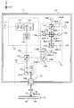
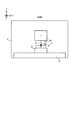
- FIG. 1 is a cross-sectional view schematically showing the overall structure of the processing system of the first embodiment.
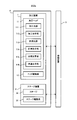
- FIG. 2 is a system configuration diagram showing a system configuration of the processing system of the first embodiment.
- FIG. 3 is a cross-sectional view showing the structure of the processing head of the first embodiment.
- FIG. 4 is a timing chart showing the measurement light incident on the detector and the interference light detected by the detector.
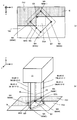
- FIG. 5 is a cross-sectional view showing the structure of the head drive system.
- FIG. 6 is a cross-sectional view showing the structure of the second drive system included in the head drive system.
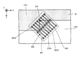
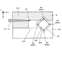
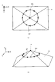
- FIG. 7A is a plan view showing a plurality of irradiated areas on the work, and FIG.
- FIG. 7B is a perspective view showing a plurality of irradiated areas on the work.
- 8 (a) and 8 (b) are cross-sectional views showing a processing head and a work whose positional relationship is controlled so that the distances between the plurality of irradiated areas and the processing head are the same. is there.
- FIG. 9 is a cross-sectional view showing a processed region in which removal processing has been performed and an unprocessed region in which removal processing has not been performed.
- FIG. 10 is a cross-sectional view showing a machining head and a work whose positional relationship is controlled so that the distance between the machined region and the machining head is the same as the distance between the unmachined region and the machining head. is there.
- FIG. 11 is a cross-sectional view showing a processed region in which additional processing has been performed and an unprocessed region in which additional processing has not been performed.
- FIG. 12 is a cross-sectional view showing a machining head and a work whose positional relationship is controlled so that the distance between the machined region and the machining head is the same as the distance between the unmachined region and the machining head. is there.
- FIG. 13 is a plan view showing a plurality of irradiated areas on the work.
- FIG. 14 is a plan view showing a plurality of irradiated areas on the work.
- FIG. 15 is a plan view showing an example of the movement locus of the target irradiation region of the measurement light.
- FIG. 16 is a plan view showing an example of the positional relationship between the target shot area and the measurement shot area.
- FIG. 17 is a plan view showing a work irradiated with processing light.
- FIG. 18A is a top view showing an example of the work, and
- FIG. 18B is a perspective view showing an example of the work.
- FIG. 19 is a plan view showing a plurality of irradiated areas on the work when the third alignment operation is performed.
- FIG. 20 is a plan view showing a work on which an alignment mark is formed.
- FIG. 21 is a cross-sectional view schematically showing the overall structure of the processing system of the second embodiment.
- FIG. 22 is a cross-sectional view showing an example of the structure of a processing apparatus including an end effector.
- each of the X-axis direction and the Y-axis direction is a horizontal direction (that is, a predetermined direction in the horizontal plane), and the Z-axis direction is a vertical direction (that is, a direction orthogonal to the horizontal plane). Yes, in effect, in the vertical direction).
- the rotation directions (in other words, the inclination direction) around the X-axis, the Y-axis, and the Z-axis are referred to as the ⁇ X direction, the ⁇ Y direction, and the ⁇ Z direction, respectively.
- the Z-axis direction may be the direction of gravity.
- the XY plane may be horizontal.
- machining system SYSa Processing system SYSSa of the first embodiment
- machining system SYSa the machining system SYS of the first embodiment
- machining system SYSa the machining system SYS of the first embodiment
- FIG. 1 is a cross-sectional view schematically showing the structure of the processing system SYSA of the first embodiment.
- FIG. 2 is a system configuration diagram showing a system configuration of the processing system SYSA of the first embodiment.
- the processing system SYSa includes a processing device 1, a stage device 3, and a control device 5.
- the processing device 1 and the stage device 3 are housed in the housing 4.
- the processing device 1 and the stage device 3 do not have to be housed in the housing 4. That is, the processing system SYSa does not have to include the housing 4 that houses the processing device 1 and the stage device 3.
- the processing device 1 can process the work W under the control of the control device 5.
- the processing device 1 can perform processing on the work W under the control of the control device 5.
- the work W may be, for example, a metal, an alloy (for example, duralumin, etc.), a semiconductor (for example, silicon), or a resin (for example, CFRP (Carbon Fiber Reinforced)). It may be (Plastic), paint (for example, a paint layer applied to a base material), glass, or an object made of any other material.
- the processing device 1 irradiates the work W with processing light EL in order to process the work W.
- the processing light EL may be any kind of light as long as the work W can be processed by being irradiated with the work W. In the first embodiment, the description will be made using an example in which the processing light EL is a laser light, but the processing light EL may be a type of light different from the laser light.
- the wavelength of the processing light EL may be any wavelength as long as the work W can be processed by irradiating the work W.
- the processed light EL may be visible light or invisible light (for example, at least one of infrared light and ultraviolet light).
- the processed light EL includes pulsed light, but does not have to include pulsed light. In other words, the processed light EL may be continuous light.
- the processing apparatus 1 may irradiate the work W with processing light EL to perform removal processing (typically, cutting processing or grinding processing) to remove a part of the work W.
- the processing apparatus 1 may form a riblet structure on the work W.
- the riblet structure is a structure capable of reducing resistance to fluid on the surface of the work W (particularly, frictional resistance and turbulent frictional resistance).
- the riblet structure is, for example, a second direction in which a groove extending along a first direction (for example, the Y-axis direction) along the surface of the work W is along the surface of the work W and intersects in the first direction. It may include a plurality of structures arranged along (for example, the X-axis direction).
- the processing apparatus 1 removes a part of the coating film so that the base material is not exposed from the coating film. As a result, a riblet structure composed of a coating film remaining without being removed may be formed on the surface of the base material.
- the processing apparatus 1 may perform additional processing to add a new structure to the work W by irradiating the work W with processing light EL in addition to or instead of the removal processing.
- the processing apparatus 1 may form the above-mentioned riblet structure on the surface of the work W by performing additional processing.
- the processing apparatus 1 may perform marking processing for forming a desired mark on the surface of the work W by irradiating the work W with processing light EL in addition to or in place of at least one of the removal processing and the addition processing.
- the processing device 1 can further measure the work W under the control of the control device 5.
- the processing apparatus 1 irradiates the work W with the measurement light ML in order to measure the work W.
- the measurement light ML may be any kind of light as long as the work W can be measured by irradiating the work W. In the first embodiment, the description will be given using an example in which the measurement light ML is a laser light, but the measurement light ML may be a type of light different from the laser light.
- the wavelength of the measurement light ML may be any wavelength as long as the work W can be measured by irradiating the work W.
- the measurement light ML may be visible light or invisible light (for example, at least one of infrared light and ultraviolet light).
- the measurement light ML includes pulsed light.
- the wavelength of the measurement light ML may be different from the wavelength of the processing light EL.
- the wavelength of the measurement light ML may be shorter than the wavelength of the processing light EL.
- light having a wavelength band of 266 nm or 355 nm may be used as the measurement light ML, and light having a wavelength band of 532 nm, 1 ⁇ m or 10 ⁇ m may be used as the processing light EL.
- the spot diameter of the measurement light ML on the work W becomes smaller than the spot diameter of the processing light EL on the work W.
- the wavelength of the measurement light ML does not have to be shorter than the wavelength of the processing light EL.
- the wavelength of the measurement light ML may be the same as the wavelength of the processing light EL.
- the processing device 1 may be capable of measuring the state of the work W.
- the state of the work W may include the position of the work W.
- the position of the work W may include the position of the surface of the work W.
- the position of the surface of the work W may include a position in at least one of the X-axis direction, the Y-axis direction, and the Z-axis direction of each surface portion obtained by subdividing the surface of the work W.
- the state of the work W may include a distance D between the processing head 11 and the work W, which will be described later.
- the distance D between the processing head 11 and the work W may mean a distance in a direction along the Z axis, which is an axis connecting the processing head 11 and the work W.
- the distance D between the machining head 11 and the work W is typically the distance between the reference portion of the machining head 11 and the surface of the work W.
- the distance between the reference portion of the processing head 11 and the surface of the work W may include the distance between the reference portion of the processing head 11 and each surface portion obtained by subdividing the surface of the work W.
- the state of the work W may include the shape of the work W (for example, a three-dimensional shape).
- the shape of the work W may include the shape of the surface of the work W.
- the shape of the surface of the work W is, in addition to or in place of, the position of the surface of the work W described above, the orientation of each surface portion subdivided into the surface of the work W (for example, the orientation of the normal of each surface portion).
- the state of the work W may include the size of the work W (for example, the size in at least one of the X-axis direction, the Y-axis direction, and the Z-axis direction).
- the processing apparatus 1 includes a processing head 11 that emits each of the processing light EL and the measuring light ML to the work W, and a head drive system 12 that moves the processing head 11. ..
- the processing head 11 means an arbitrary member capable of emitting each of the processing light EL and the measuring light ML to the work W. Therefore, although the processing head 11 includes the wording head, it does not necessarily mean a member attached to the tip of any member. Therefore, the processing head 11 may be referred to as a processing member. It can be said that the processing head 11 is a device that performs processing on the work W. It can be said that the processing head 11 is a device for measuring the work W.
- the processing head 11 includes a processing light source 111, a processing optical system 112, a measuring light source 113, a measuring optical system 114, a synthetic optical system 115, and a common optical system 116.
- the structures of the processing head 11 and the head drive system 12 will be described in detail later with reference to FIGS. 3 to 6.
- the processing head 11 may have any structure as long as it can emit the processing light EL and the measurement light ML to the work W. As long as the processing head 11 can emit the processing light EL and the measurement light ML to the work W, the processing light source 111, the processing optical system 112, the measuring light source 113, the measuring optical system 114, and the synthetic optical system 115 And at least one of the common optical systems 116 may not be provided.
- the head drive system 12 moves the machining head 11 along at least one of the X-axis direction, the Y-axis direction, the Z-axis direction, the ⁇ X direction, the ⁇ Y direction, and the ⁇ Z direction.
- the positional relationship between the stage 32 (furthermore, the work W mounted on the stage 32) and the processing head 11, which will be described later, changes. That is, when the machining head 11 moves, the relative positions of the stage 32 and the work W and the machining head 11 change. Therefore, moving the machining head 11 may be regarded as equivalent to changing the positional relationship between the stage 32 and the work W and the machining head 11.
- each optical system that is, the processing optical system 112, the measurement optical system 114, and the synthetic optical system included in the stage 32, the work W, and the processing head 11
- the positional relationship with at least one of 115 and the common optical system 116) changes. Therefore, moving the processing head 11 may be regarded as equivalent to changing the positional relationship between the stage 32 and the work W and each optical system included in the processing head 11. Further, when the positional relationship between the stage 32 and the work W and the processing head 11 changes, the positional relationship between the stage 32 and the work W and the housing 117 of the processing head 11 changes.
- moving the machining head 11 may be regarded as equivalent to changing the positional relationship between the stage 32 and the work W and the housing 117 of the machining head 11. Further, when the positional relationship between the stage 32 and the work W and the processing head 11 changes, the positions of the target irradiation area EA and the target irradiation area MA set on the work W on the work W change.
- the target irradiation area EA is an area where the processing head 11 is scheduled to irradiate the processing light EL.
- the target irradiation area MA is an area where the processing head 11 is scheduled to irradiate the measurement light ML.
- moving the processing head 11 may be regarded as equivalent to changing the positions of the target irradiation area EA and the target irradiation area MA on the work W. Further, when the positional relationship between the stage 32 and the work W and the processing head 11 changes, the irradiation positions where the processing light EL and the measurement light ML are actually irradiated on the work W change. Therefore, moving the processing head 11 may be regarded as equivalent to changing the irradiation positions of the processing light EL and the measurement light ML on the work W.
- the stage device 3 includes a surface plate 31 and a stage 32.
- the surface plate 31 is arranged on the bottom surface of the housing 4 (or on a supporting surface such as a floor surface on which the housing 4 is placed).
- a stage 32 is arranged on the surface plate 31.
- a vibration isolator (not shown) may be installed between the bottom surface of the housing 4 or the support surface such as the floor on which the housing 4 is placed and the surface plate 31.
- a support frame (not shown) that supports the processing apparatus 1 may be arranged on the surface plate 31.
- the stage 32 may hold the mounted work W.
- the stage 32 may hold the work W by vacuum-adsorbing and / or electrostatically adsorbing the work W.
- the stage 32 does not have to hold the mounted work W.
- the stage 32 can move on the surface plate 31 with the work W mounted under the control of the control device 5.
- the stage 32 is movable with respect to at least one of the surface plate 31 and the processing apparatus 1.
- the stage 32 can move along the X-axis direction and the Y-axis direction, respectively.
- the stage 32 can move along the stage running surface (moving surface) parallel to the XY plane.
- the stage 32 may also be movable along at least one of the Z-axis direction, the ⁇ X direction, the ⁇ Y direction, and the ⁇ Z direction.
- the stage device 3 includes a stage drive system 33.
- the stage drive system 33 moves the stage 32 by using, for example, an arbitrary motor (for example, a linear motor or the like).
- the stage device 3 may be provided with a stage position measuring instrument for measuring the position of the stage 32.
- the stage position measuring instrument may include, for example, at least one of an encoder and a laser interferometer.
- the positional relationship between the stage 32 (furthermore, the work W mounted on the stage 32) and the processing head 11 changes. That is, when the stage 32 moves, the relative positions of the processing head 11 and the stage 32 and the work W change. Therefore, moving the stage 32 may be regarded as equivalent to changing the positional relationship between the stage 32 and the work W and the processing head 11. Further, when the positional relationship between the stage 32 and the work W and the processing head 11 changes, the positional relationship between the stage 32 and the work W and each optical system included in the processing head 11 changes. Therefore, moving the stage 32 may be regarded as equivalent to changing the positional relationship between the stage 32 and the work W and each optical system included in the processing head 11.
- moving the stage 32 may be regarded as equivalent to changing the positional relationship between the stage 32 and the work W and the housing 117 of the processing head 11.
- the positions of the target irradiation area EA and the target irradiation area MA on the respective work W change. Therefore, moving the stage 32 may be regarded as equivalent to changing the positions of the target irradiation area EA and the target irradiation area MA on the work W.
- moving the stage 32 may be regarded as equivalent to changing the irradiation positions of the processing light EL and the measurement light ML on the work W.
- the control device 5 controls the operation of the processing system SYS. For example, the control device 5 sets the machining conditions of the work W, and controls the machining device 1 and the stage device 3 so that the work W is machined according to the set machining conditions. For example, the control device 5 sets the measurement conditions of the work W, and controls the processing device 1 and the stage device 3 so that the work W is measured according to the set measurement conditions.
- the control device 5 may include, for example, an arithmetic unit and a storage device.
- the arithmetic unit may include, for example, at least one of a CPU (Central Processing Unit) and a GPU (Graphics Processing Unit).
- the control device 5 functions as a device that controls the operation of the processing system SYS by executing a computer program by the arithmetic unit.
- This computer program is a computer program for causing the control device 5 (for example, an arithmetic unit) to perform (that is, execute) an operation described later to be performed by the control device 5. That is, this computer program is a computer program for causing the control device 5 to function so that the processing system SYSa performs an operation described later.
- the computer program executed by the arithmetic unit may be recorded in a storage device (that is, a recording medium) included in the control device 5, or any storage built in the control device 5 or externally attached to the control device 5. It may be recorded on a medium (for example, a hard disk or a semiconductor memory). Alternatively, the arithmetic unit may download the computer program to be executed from an external device of the control device 5 via the network interface.
- a storage device that is, a recording medium included in the control device 5, or any storage built in the control device 5 or externally attached to the control device 5. It may be recorded on a medium (for example, a hard disk or a semiconductor memory).
- the arithmetic unit may download the computer program to be executed from an external device of the control device 5 via the network interface.
- the control device 5 does not have to be provided inside the processing system SYS, and may be provided as a server or the like outside the processing system SYS, for example.
- the control device 5 and the processing system SYSA may be connected by a wired and / or wireless network (or a data bus and / or a communication line).
- a wired network for example, a network using a serial bus type interface represented by at least one of IEEE1394, RS-232x, RS-422, RS-423, RS-485 and USB may be used.
- a network using a parallel bus interface may be used.
- a network using an Ethernet (registered trademark) compliant interface represented by at least one of 10BASE-T, 100BASE-TX and 1000BASE-T may be used.
- a network using radio waves may be used.
- An example of a network using radio waves is a network conforming to IEEE802.1x (for example, at least one of wireless LAN and Bluetooth®).
- a network using infrared rays may be used.
- a network using optical communication may be used.
- the control device 5 and the processing system SYSA may be configured so that various types of information can be transmitted and received via the network.
- control device 5 may be able to transmit information such as commands and control parameters to the processing system SYSA via the network.
- the processing system SYSa may include a receiving device that receives information such as commands and control parameters from the control device 5 via the network.
- the first control device that performs a part of the processing performed by the control device 5 is provided inside the processing system SYS, the second control device that performs the other part of the processing performed by the control device 5 is performed.
- the control device may be provided outside the processing system SYS.
- the recording medium for recording the computer program executed by the arithmetic unit includes CD-ROM, CD-R, CD-RW, flexible disk, MO, DVD-ROM, DVD-RAM, DVD-R, DVD + R, and DVD-. At least one of optical disks such as RW, DVD + RW and Blu-ray (registered trademark), magnetic media such as magnetic tape, magneto-optical disks, semiconductor memories such as USB memory, and any other medium capable of storing a program is used. You may.
- the recording medium may include a device capable of recording a computer program (for example, a general-purpose device or a dedicated device in which the computer program is implemented in at least one form such as software and firmware).
- each process or function included in the computer program may be realized by a logical processing block realized in the control device 5 by the control device 5 (that is, a computer) executing the computer program. It may be realized by hardware such as a predetermined gate array (FPGA, ASIC) included in the control device 5, or a logical processing block and a partial hardware module that realizes a part of the hardware are mixed. It may be realized in the form of.
- a logical processing block realized in the control device 5 by the control device 5 (that is, a computer) executing the computer program. It may be realized by hardware such as a predetermined gate array (FPGA, ASIC) included in the control device 5, or a logical processing block and a partial hardware module that realizes a part of the hardware are mixed. It may be realized in the form of.
- FPGA predetermined gate array
- FIG. 3 is a cross-sectional view showing an example of the structure of the processing head 11.
- the processing head 11 includes a processing light source 111, a processing optical system 112, a measuring light source 113, a measuring optical system 114, a synthetic optical system 115, and a common optical system 116.
- the processing light source 111, the processing optical system 112, the measurement light source 113, the measurement optical system 114, the synthetic optical system 115, and the common optical system 116 are housed in the housing 117.
- at least one of the processing light source 111, the processing optical system 112, the measuring light source 113, the measuring optical system 114, the synthetic optical system 115, and the common optical system 116 may not be housed in the housing 117.
- each optical system is relative to the machining head 11 (eg, for the housing 117). Placed in a fixed position. That is, as the processing head 11 is moved by the head drive system 12, each optical system also moves in the same manner as the processing head 11 (for example, the housing 117).
- the processing light source 111 can generate processing light EL.
- the processing light source 111 may include, for example, a laser diode. Further, the processing light source 111 may be a light source capable of pulse oscillation. In this case, the processing light source 111 can generate pulsed light (for example, pulsed light having a light emission time of picoseconds or less) as the processing light EL.
- the processing light source 111 emits the generated processing light EL toward the processing optical system 112.
- the processing optical system 112 is an optical system in which the processing light EL emitted from the processing light source 111 is incident.
- the processing optical system 112 is an optical system that emits processing light EL incident on the processing optical system 112 toward the synthetic optical system 115. That is, the processing optical system 112 is an optical system that guides the processing light EL emitted from the processing light source 111 to the synthetic optical system 115.
- the processing light EL emitted by the processing optical system 112 irradiates the work W via the synthetic optical system 115 and the common optical system 116. Therefore, it can be said that the processing optical system 112 is an optical system that emits (irradiates) the processing light EL toward the work W via the synthetic optical system 115 and the common optical system 116.
- the processing optical system 112 includes a position adjustment optical system 1121, an angle adjustment optical system 1122, and a focus adjustment optical system 1123.
- the position adjustment optical system 1121 can adjust the injection position of the processing light EL from the processing optical system 112.
- the position adjusting optical system 1121 may include, for example, a parallel plane plate that can be inclined with respect to the traveling direction of the processing light EL, and the injection position of the processing light EL may be changed by changing the inclination angle of the parallel plane plate.
- the position adjusting optical system 1121 can set the injection position of the processing light EL to an arbitrary position in the YZ plane by using a plurality of parallel plane plates having different inclination directions from each other.
- the angle adjustment optical system 1122 can adjust the injection angle of the processing light EL from the processing optical system 112.
- the angle adjusting optical system 1122 may include, for example, a mirror that can be tilted with respect to the traveling direction of the processing light EL, and the emission angle of the processing light EL may be changed by changing the tilt angle of the mirror.
- the angle adjusting optical system 1122 uses a plurality of mirrors having different inclination directions from each other, and sets the injection angle of the processing light EL toward arbitrary directions around the ⁇ X axis and the ⁇ Y axis.
- Focus adjustment optical system 1123 can adjust (typically change) the focusing position of the processed light EL. Therefore, the focus adjusting optical system 1123 functions as a focus changing member capable of adjusting the focusing position of the processed light EL.
- Focus adjustment optics 1123 includes a plurality of lenses, at least one of which is movable along the optical axis.
- the focus adjustment optical system 1123 adjusts the focusing position of the processed light EL with respect to the surface of the work W in the optical axis direction by moving at least one lens. Specifically, the focus adjustment optical system 1123 moves at least one lens to move the focus position of the processed light EL with respect to the surface of the work W in the direction along the optical axis AX of the f ⁇ lens 1162 (in FIG. 3). In the example shown, the adjustment is made in the Z-axis direction (direction intersecting the surface of the work W).
- the focus adjustment optical system 1123 may typically adjust the focus position of the processing light EL so that the focus position of the processing light EL is located on the surface of the work W.
- the processing optical system 112 does not have to include at least one of the position adjusting optical system 1121, the angle adjusting optical system 1122, and the focus adjusting optical system 1123.
- the processing optical system 112 is added to or in place of at least one of the position adjusting optical system 1121, the angle adjusting optical system 1122, and the focus adjusting optical system 1123, and other optical elements and optical members (these may be referred to as optical systems). Good, the same shall apply hereinafter) may be included.
- the processing light EL emitted from the processing optical system 112 is incident on the synthetic optical system 115.
- the synthetic optical system 115 includes a beam splitter (for example, a polarizing beam splitter) 1151.
- the beam splitter 1151 emits the processed light EL incident on the beam splitter 1151 toward the common optical system 116.
- the processing light EL incident on the beam splitter 1151 is emitted toward the common optical system 116 by passing through the polarization separation surface. Therefore, in the example shown in FIG.
- the processed light EL is applied to the polarization separation surface of the beam splitter 1151 in a state of having a polarization direction (polarization direction that is p-polarized with respect to the polarization separation surface) that can be transmitted through the polarization separation surface.
- the processed light EL emitted from the synthetic optical system 115 is incident on the common optical system 116.
- the common optical system 116 emits the processed light EL incident on the common optical system 116 toward the work W.
- the common optical system 116 includes a galvano mirror 1161 and an f ⁇ lens 1162.
- the processed light EL emitted from the synthetic optical system 115 is incident on the galvano mirror 1161.
- the galvano mirror 1161 changes the irradiation position of the processing light EL on the work W by deflecting the processing light EL (that is, changing the injection angle of the processing light EL). That is, the galvano mirror 1161 changes the position of the target irradiation region EA set on the work W or on the optical path of the processing light EL as the region to be irradiated with the processing light EL by deflecting the processing light EL. To do.
- the galvano mirror 1161 Since the galvano mirror 1161 is arranged at or near the entrance pupil position of the f ⁇ lens 1162, the change in the emission angle of the processed light EL by the galvano mirror 1161 is caused by the f ⁇ lens 1162 at the irradiation position of the processed light EL (that is, that is). , The position of the target irradiation area EA) is converted.
- the galvano mirror 1161 includes an X scanning mirror 1161X and a Y scanning mirror 1161Y. Each of the X scanning mirror 1161X and the Y scanning mirror 1161Y is a tilt angle variable mirror in which the angle of the processed light EL incident on the galvano mirror 1161 with respect to the optical path is changed.
- the X-scanning mirror 1161X swings or rotates so as to change the irradiation position of the processed light EL on the work W along the X-axis direction (that is, changes the angle of the X-scanning mirror 1161X with respect to the optical path of the processed light EL. By doing so, the processing light EL is deflected.
- the Y scanning mirror 1161Y swings or rotates so as to change the irradiation position of the processed light EL on the work W along the Y-axis direction (that is, changes the angle of the Y scanning mirror 1161Y with respect to the optical path of the processed light EL. By doing so, the processing light EL is deflected.
- the processed light EL from the galvano mirror 1161 is incident on the f ⁇ lens 1162. Therefore, the galvanometer mirror 1161 is arranged on the optical path of the processed light EL between the synthetic optical system 115 and the f ⁇ lens 1162.
- the f ⁇ lens 1162 is arranged on the optical path of the processed light EL between the galvano mirror 1161 and the work W.
- the f ⁇ lens 1162 is arranged on the optical path of the processed light EL between the galvanometer mirror 1161 and the target irradiation region EA.
- the f ⁇ lens 1162 is an optical system for irradiating the work W with the processed light EL from the galvano mirror 1161.
- the f ⁇ lens 1162 is an optical system for irradiating the target irradiation region EA with the processed light EL from the galvanometer mirror 1161.
- the f ⁇ lens 1162 is an optical system for condensing the processed light EL from the galvano mirror 1161 on the work W. Therefore, the f ⁇ lens 1162 irradiates the work W with the processed light EL in the convergent state. As a result, the work W is processed by the processing light EL.
- the f ⁇ lens 1162 may be referred to as an irradiation optical system because the work W is irradiated with the processed light EL (particularly, the surface of the work W is irradiated).
- the moving range of the target irradiation area EA that moves on the work W due to the deflection of the processing light EL by the galvano mirror 1161 may be referred to as a processing shot area ESA (see FIG. 7 described later).
- the target irradiation area EA may be regarded as moving within the processed shot area ESA.
- the measurement light source 113 can generate the measurement light ML.
- the measurement light source 113 may include, for example, a laser diode.
- the measurement light source 113 is a light source capable of pulse oscillation.
- the measurement light source 113 can generate pulsed light (for example, pulsed light having a light emission time of picoseconds or less) as the measurement light ML.
- the measurement light source 113 emits the generated measurement light ML toward the measurement optical system 114.
- the measurement light source 113 includes an optical comb light source.
- the optical comb light source is a light source capable of generating light containing frequency components arranged at equal intervals on the frequency axis (hereinafter referred to as "optical frequency comb") as pulsed light.
- the measurement light source 113 emits pulsed light including frequency components arranged at equal intervals on the frequency axis as the measurement light ML.
- the measurement light source 113 does not have to include the optical comb light source.
- the processing head 11 includes a plurality of measurement light sources 113.
- the processing head 11 includes a measurement light source 113 # 1 and a measurement light source 113 # 2.
- the plurality of measurement light sources 113 emit a plurality of measurement light MLs that are phase-locked to each other and have interference with each other.
- the plurality of measurement light sources 113 may have different oscillation frequencies. Therefore, the plurality of measurement light MLs emitted by the plurality of measurement light sources 113 are the plurality of measurement light MLs having different pulse frequencies (for example, the number of pulsed lights per unit time and the reciprocal of the emission cycle of the pulsed light). It becomes.
- the measurement light source 113 # 1 emits the measurement light ML # 1 having a pulse frequency of 25 GHz
- the measurement light source 113 # 2 emits the measurement light ML # 2 having a pulse frequency of 25 GHz + ⁇ (for example, + 100 kHz).
- the processing head 11 may include a single measurement light source 113.
- the measurement optical system 114 is an optical system in which the measurement light ML emitted from the measurement light source 113 is incident.
- the measurement optical system 114 is an optical system that emits the measurement light ML incident on the measurement optical system 114 toward the synthetic optical system 115. That is, the measurement optical system 114 is an optical system that guides the measurement light ML emitted from the measurement light source 113 to the synthetic optical system 115.
- the measurement light ML emitted by the measurement optical system 114 is applied to the work W via the synthetic optical system 115 and the common optical system 116. Therefore, it can be said that the measurement optical system 114 is an optical system that emits the measurement light ML toward the work W via the composite optical system 115 and the common optical system 116.
- the measurement optical system 114 is optically separated from the processing optical system 112. Therefore, the optical path of the processing light EL between the processing light source 111 and the synthetic optical system 115 and the optical path of the measurement light ML between the measurement light source 113 and the synthetic optical system 115 are optically separated. Note that the optical path of one optical system and another optical system are optically separated may mean that the optical path of one optical system and the optical path of another optical system do not overlap each other.
- the measurement optical system 114 includes, for example, a beam splitter 1141, a beam splitter 1142, a detector 1143, a beam splitter 1144, a mirror 1145, a detector 1146, a mirror 1147, and a galvano mirror 1148.
- the measurement light ML emitted from the measurement light source 113 is incident on the beam splitter 1141.
- the measurement light ML emitted from the measurement light source 113 # 1 (hereinafter referred to as “measurement light ML # 1”) and the measurement light ML emitted from the measurement light source 113 # 2 (hereinafter referred to as “measurement light ML”).
- # 2 is incident on the beam splitter 1141.
- the beam splitter 1141 emits the measurement lights ML # 1 and ML # 2 incident on the beam splitter 1141 toward the beam splitter 1142.
- the beam splitter 1142 reflects the measurement light ML # 1-1, which is a part of the measurement light ML # 1 incident on the beam splitter 1142, toward the detector 1143.
- the beam splitter 1142 emits the measurement light ML # 1-2, which is another part of the measurement light ML # 1 incident on the beam splitter 1142, toward the beam splitter 1144. That is, the beam splitter 1142 is a measurement light ML # 1 traveling on an optical path extending from the beam splitter 1142 to the detector 1143 and a measurement light ML # 1-1 traveling on an optical path from the beam splitter 1142 to the beam splitter 1144. It functions as a branching optical system that branches into optical ML # 1-2.
- the beam splitter 1142 reflects the measurement light ML # 2-1 which is a part of the measurement light ML # 2 incident on the beam splitter 1142 toward the detector 1143.
- the beam splitter 1142 emits the measurement light ML # 2-2, which is another part of the measurement light ML # 2 incident on the beam splitter 1142, toward the beam splitter 1144. That is, the beam splitter 1142 is a measurement light ML # 2 traveling on an optical path extending from the beam splitter 1142 to the detector 1143 and a measurement light ML # 2 traveling on an optical path from the beam splitter 1142 to the beam splitter 1144. It functions as a branching optical system that branches into optical ML # 2-2.
- the measurement lights ML # 1-1 and ML # 2-1 emitted from the beam splitter 1142 are incident on the detector 1143.
- the detector 1143 detects the interference light generated by the interference between the measurement light ML # 1-1 and the measurement light ML # 2-1. That is, the detector 1143 detects an interference signal based on the interference light generated by the interference between the measurement light ML # 1-1 and the measurement light ML # 2-1. Specifically, the detector 1143 detects the interference light by receiving the interference light. Therefore, the detector 1143 may be provided with a light receiving element (a light receiving unit, typically a photoelectric conversion element) capable of receiving light. The detection result of the detector 1143 is output to the control device 5.
- a light receiving element a light receiving unit, typically a photoelectric conversion element
- the measurement lights ML # 1-2 and ML # 2-2 emitted from the beam splitter 1142 are incident on the beam splitter 1144.
- the beam splitter 1144 emits at least a part of the measurement light ML # 1-2 incident on the beam splitter 1144 toward the mirror 1145.
- the beam splitter 1144 emits at least a part of the measurement light ML # 2-2 incident on the beam splitter 1144 toward the mirror 1147. That is, the beam splitter 1144 splits the measurement light ML # 1-2 and ML # 2-2 (that is, substantially the measurement light ML from the measurement light source 113) incident on the beam splitter 1144 from the same direction. It functions as a branching optical system that branches into measurement light ML # 1-2 traveling in an optical path extending from 1144 to mirror 1145 and measurement light ML # 2-2 traveling in an optical path extending from a beam splitter 1144 to mirror 1147.
- the measurement light ML # 1-2 emitted from the beam splitter 1144 is incident on the mirror 1145.
- the measurement light ML # 1-2 incident on the mirror 1145 is reflected by the reflecting surface of the mirror 1145 (the reflecting surface may be referred to as a reference surface).
- the mirror 1145 reflects the measurement light ML # 1-2 incident on the mirror 1145 toward the beam splitter 1144. That is, the mirror 1145 emits (returns) the measurement light ML # 1-2 incident on the mirror 1145 toward the beam splitter 1144 as the reflected light measurement light ML # 1-3.
- the measurement light ML # 1-3 emitted from the mirror 1145 is incident on the beam splitter 1144.
- the beam splitter 1144 emits the measurement light ML # 1-3 incident on the beam splitter 1144 toward the beam splitter 1142.
- the measurement light ML # 1-3 emitted from the beam splitter 1144 is incident on the beam splitter 1142.
- the beam splitter 1142 emits the measurement light ML # 1-3 incident on the beam splitter 1142 toward the detector 1146.
- the measurement light ML # 2-2 emitted from the beam splitter 1144 is incident on the mirror 1147.
- the mirror 1147 reflects the measurement light ML # 2-2 incident on the mirror 1147 toward the galvano mirror 1148. That is, the mirror 1147 emits the measurement light ML # 2-2 incident on the mirror 1147 toward the galvano mirror 1148.
- the galvanometer mirror 1148 deflects the measurement light ML # 2-2 (that is, changes the emission angle of the measurement light ML # 2-2) to change the irradiation position of the measurement light ML # 2-2 on the work W. To change. That is, the galvano mirror 1148 is set on the work W or on the optical path of the measurement light ML # 2-2 as a region to be irradiated with the measurement light ML by deflecting the measurement light ML # 2-2. The position of the target irradiation area MA is changed.
- the galvano mirror 1148 includes an X scanning mirror 1148X and a Y scanning mirror 1148Y.
- Each of the X scanning mirror 1148X and the Y scanning mirror 1148Y is a tilt angle variable mirror in which the angle of the measurement light ML # 2-2 incident on the galvano mirror 1148 with respect to the optical path is changed.
- the X scanning mirror 1148X swings or rotates so as to change the irradiation position of the measurement light ML # 2-2 on the work W along the X-axis direction (that is, with respect to the optical path of the measurement light ML # 2-2).
- the measurement light ML # 2-2 is deflected by changing the angle of the X scanning mirror 1148X).
- the Y scanning mirror 1148Y swings or rotates so as to change the irradiation position of the measurement light ML # 2-2 on the work W along the Y-axis direction (that is, with respect to the optical path of the measurement light ML # 2-2).
- the measurement light ML # 2-2 is deflected by changing the angle of the Y scanning mirror 1148Y). Since the irradiation position of the measurement light ML # 2-2 is changed by the galvano mirror 1148, the galvano mirror 1148 may be referred to as an irradiation position change optical system.
- the galvano mirror 1148 emits the deflected measurement light ML # 2-2 toward the synthetic optical system 115.
- the measurement light ML # 2-2 emitted from the galvano mirror 1148 is incident on the synthetic optical system 115.
- the beam splitter 1151 of the synthetic optical system 115 emits the measurement light ML # 2-2 incident on the beam splitter 1151 toward the common optical system 116.
- the measurement light ML # 2-2 incident on the beam splitter 1151 is reflected at the polarization separation surface and is emitted toward the common optical system 116. Therefore, in the example shown in FIG.
- the measurement light ML # 2-2 is a beam splitter 1151 in a state where it has a polarization direction that can be reflected by the polarization separation surface (a polarization direction that is s-polarized with respect to the polarization separation surface). It is incident on the polarization splitting surface.
- the processing light EL is incident on the beam splitter 1151 in addition to the measurement light ML # 2-2. That is, both the measurement light ML # 2-2 and the processing light EL pass through the beam splitter 1151.
- the beam splitter 1151 emits the processing light EL and the measurement light ML # 2-2 that have been incident on the beam splitter 1151 from different directions in the same direction (that is, toward the same common optical system 116). Therefore, the beam splitter 1151 substantially functions as an optical system that synthesizes the processing light EL and the measurement light ML # 2-2.
- the directions in which the processing light EL and the measurement light ML # 2-2 are emitted from the beam splitter 1151 described above are the processing light EL and the measurement light ML in the common optical system 116 located on the emission side of the synthetic optical system 115.
- the processing light EL and the measurement light ML # 2-2 may be set in a direction to be emitted so that # 2-2 is incident. As long as the processing light EL and the measurement light ML # 2-2 are incident on the common optical system 116, the directions in which the processing light EL and the measurement light ML # 2-2 are emitted may be slightly different.
- the synthetic optical system 115 may have any structure as long as the processing light EL and the measurement light ML # 2-2 can be combined.
- the synthetic optical system 115 uses a dichroic mirror that reflects light in one wavelength band and transmits light in another wavelength band in addition to or instead of using a beam splitter 1151 to process light EL and measurement light.
- ML # 2-2 may be synthesized.
- the measurement light ML # 2-2 emitted from the synthetic optical system 115 is incident on the common optical system 116.
- the common optical system 116 emits the measurement light ML # 2-2 incident on the common optical system 116 toward the work W.
- the measurement light ML # 2-2 emitted from the synthetic optical system 115 is incident on the galvano mirror 1161.
- the galvanometer mirror 1161 changes the irradiation position of the measurement light ML # 2-2 on the work W by deflecting the measurement light ML # 2-2. That is, the galvano mirror 1161 is set on the work W or on the optical path of the measurement light ML # 2-2 as a region to be irradiated with the measurement light ML # 2-2 by deflecting the measurement light ML # 2-2.
- the position of the target irradiation area MA to be performed is changed.
- the galvano mirror 1161 Since the galvano mirror 1161 is arranged at or near the entrance pupil position of the f ⁇ lens 1162, the change in the emission angle of the measurement light ML # 2-2 by the galvano mirror 1161 is caused by the f ⁇ lens 1162. It is converted into a change in the irradiation position of 2-2 (that is, the position of the target irradiation area MA).
- the X scanning mirror 1161X swings or rotates so as to change the irradiation position of the measurement light ML # 2-2 on the work W along the X-axis direction (that is, the measurement light ML # 2-2).
- the measurement light ML # 2-2 is deflected by changing the angle of the X scanning mirror 1161X with respect to the optical path).
- the Y scanning mirror 1161Y swings or rotates so as to change the irradiation position of the measurement light ML # 2-2 on the work W along the Y-axis direction (that is, with respect to the optical path of the measurement light ML # 2-2).
- the measurement light ML # 2-2 is deflected. Since the irradiation position of the measurement light ML # 2-2 (furthermore, the irradiation position of the processing light EL) is changed by the galvano mirror 1161, the galvano mirror 1161 may be referred to as an irradiation position change optical system. ..
- the measurement light ML # 2-2 from the galvano mirror 1161 is incident on the f ⁇ lens 1162.
- the f ⁇ lens 1162 is an optical system for condensing the measurement light ML # 2-2 from the galvano mirror 1161 on the work W.
- the f ⁇ lens 1162 is an optical system for irradiating the work W with the measurement light ML # 2-2 from the galvano mirror 1161.
- the f ⁇ lens 1162 is an optical system for irradiating the target irradiation region MA with the measurement light ML # 2-2 from the galvano mirror 1161. Therefore, the f ⁇ lens 1162 is arranged on the optical path of the measurement light ML # 2-2 between the galvanometer mirror 1161 and the target irradiation region MA.
- the f ⁇ lens 1162 irradiates the work W with the measured light ML # 2-2 in a converged state.
- the work W is measured by the measurement light ML (specifically, the measurement light ML # 2-2).
- the f ⁇ lens 1162 may be referred to as an irradiation optical system because it irradiates the work W with the measurement light ML # 2-2 (particularly, irradiates the surface of the work W).
- the movement range of the target irradiation region MA that moves on the work W due to the deflection of the measurement light ML # 2-2 by the galvanometer mirror 1161 may be referred to as a measurement shot region MSA (see FIG. 7 described later). ..
- the target irradiation area MA may be considered to move within the measurement shot area MSA.
- the processing light EL is incident on the common optical system 116 in addition to the measurement light ML # 2-2. That is, the processing light EL and the measurement light ML # 2-2 synthesized by the synthetic optical system 115 are incident on the common optical system 116. Therefore, both the measurement light ML # 2-2 and the processing light EL pass through the same common optical system 116 (specifically, the same galvano mirror 1161 and the same f ⁇ lens 1162).
- the galvano mirror 1161 can be changed in synchronization with the irradiation position of the processing light EL on the work W and the irradiation position of the measurement light ML # 2-2 on the work W.
- the galvano mirror 1161 can change the irradiation position of the processing light EL on the work W and the irradiation position of the measurement light ML # 2-2 on the work W in conjunction with each other. That is, the galvanometer mirror 1161 can change the relative position of the target irradiation region EA with respect to the work W and the relative position of the target irradiation region MA with respect to the work W in synchronization and / or in conjunction with each other.
- the f ⁇ lens 1162 directs both the processing light EL and the measurement light ML in the direction from the f ⁇ lens 1162 toward the work W. Eject. That is, the f ⁇ lens 1162 emits both the processing light EL and the measurement light ML in the same direction. The f ⁇ lens 1162 emits the measurement light ML in the same direction as the processing light EL is emitted from the f ⁇ lens 1162. The f ⁇ lens 1162 emits the processed light EL in the same direction as the measurement light ML is emitted from the f ⁇ lens 1162.
- the processing system SYSa can independently move the irradiation position of the measurement light ML # 2-2 on the work W with respect to the irradiation position of the processing light EL on the work W.
- the processing system SYSa can independently move the target irradiation region MA of the measurement light ML # 2-2 with respect to the target irradiation region EA of the processing light EL.
- the processing system SYSa can independently change the irradiation position of the processing light EL on the work W and the irradiation position of the measurement light ML # 2-2 on the work W.
- the processing system SYSa can independently change the position of the target irradiation region EA and the position of the target irradiation region MA.
- the processing system SYSa can change the positional relationship between the irradiation position of the processing light EL on the work W and the irradiation position of the measurement light ML # 2-2 on the work W.
- the light caused by the irradiation of the measurement light ML # 2-2 is generated from the work W. That is, when the work W is irradiated with the measurement light ML # 2-2, the light caused by the irradiation of the measurement light ML # 2-2 is emitted from the work W.
- the light emitted from the work W due to the irradiation of the measurement light ML # 2-2 (that is, the light caused by the irradiation of the measurement light ML # 2-2) is the measurement light ML # 2 reflected by the work W.
- measurement light ML # 2-2 that is, scattered light
- measurement light ML # 2-2 that is, diffracted light
- At least one of the measurement light ML # 2-2 (that is, transmitted light) transmitted through the work W may be included.
- At least a part of the light emitted from the work W due to the irradiation of the measurement light ML # 2-2 (hereinafter, this light is referred to as “measurement light ML # 2-3”) is incident on the common optical system 116.
- the measurement light ML # 2-3 incident on the common optical system 116 is incident on the composite optical system 115 via the f ⁇ lens 1162 and the galvano mirror 1161.
- the beam splitter 1151 of the synthetic optical system 115 emits the measurement light ML # 2-3 incident on the beam splitter 1151 toward the measurement optical system 114.
- the measurement light ML # 2-3 incident on the beam splitter 1151 is reflected at the polarization separation surface and is emitted toward the measurement optical system 114. Therefore, in the example shown in FIG. 3, the measurement light ML # 2-3 is incident on the polarization separation surface of the beam splitter 1151 in a state of having a polarization direction that can be reflected by the polarization separation surface.
- the measurement light ML # 2-3 emitted from the synthetic optical system 115 is incident on the mirror 1147 via the galvano mirror 1148 of the measurement optical system 114.
- the mirror 1147 reflects the measurement light ML # 2-3 incident on the mirror 1147 toward the beam splitter 1144.
- the beam splitter 1144 emits at least a part of the measurement light ML # 2-3 incident on the beam splitter 1144 toward the beam splitter 1142.
- the beam splitter 1142 emits at least a part of the measurement light ML # 2-3 incident on the beam splitter 1142 toward the detector 1146.
- the detector 1146 travels from the beam splitter 1144 through the mirror 1147, the galvano mirror 1148, the synthetic optical system 115, and the common optical system 116 in this order to reach the work W in the optical path OP # 2-2. At least a part of the light generated by the measurement light ML # 2-2 irradiated on the surface of the work W is incident as the measurement light ML # 2-3.
- the detector 1146 has a common optical system 116, a synthetic optical system 115, and a galvanometer mirror among the lights generated by the measurement light ML # 2-2 that travels through the optical path OP # 2-2 and is applied to the surface of the work W.
- the measurement light ML # 2-3 may be referred to as a measurement light or an object light.
- the measurement light ML # 1-3 is incident on the detector 1146 in addition to the measurement light ML # 2-3. Specifically, the detector 1146 travels from the beam splitter 1144 through the mirror 1145, the beam splitter 1144, and the beam splitter 1142 in this order to reach the detector 1146 through the optical path OP # 1-3, and the detector 1146.
- the measurement light ML # 1-3 that reaches is incident.
- the measurement light ML # 1-3 that travels through the optical path OP # 1-3 formed by the mirror 1145 in other words, the optical path OP # 1-3 via the mirror 1145) and reaches the detector 1146. Is incident.
- the measurement light ML # 1-3 may be referred to as a reference light.
- the measurement light ML # 1-3 and the measurement light # ML2-3 correspond to a plurality of measurement light MLs (particularly, a plurality of optical frequency combs) that are phase-locked and interfere with each other.
- the measurement light sources 113 # 1 and 113 # 2 emit measurement light ML # 1 and ML # 2, which are phase-locked and coherent with each other, respectively.
- the detector 1146 detects the interference light generated by the interference between the measurement light ML # 1-3 and the measurement light ML # 2-3. That is, the detector 1146 detects an interference signal based on the interference light generated by the interference between the measurement light ML # 1-3 and the measurement light ML # 2-3.
- the detector 1146 detects the interference light by receiving the interference light. Therefore, the detector 1146 may be provided with a light receiving element (light receiving unit) capable of receiving light. The detection result of the detector 1146 is output to the control device 5.
- the control device 5 calculates the state of the work W based on the detection result of the detector 1143 (that is, the output of the detector 1143) and the detection result of the detector 1146 (that is, the output of the detector 1146).
- the principle of calculating the state of the work W based on the detection result of the detector 1143 and the detection result of the detector 1146 will be described with reference to FIG.
- FIG. 4 shows the measurement light ML # 1-1 incident on the detector 1143, the measurement light ML # 2-1 incident on the detector 1143, the interference light detected by the detector 1143, and the measurement light ML incident on the detector 1146. It is a timing chart which shows the interference light detected by # 1-3, the measurement light ML # 2-3 incident on the detector 1146, and the detector 1146. Since the pulse frequency of the measurement light ML # 1 and the pulse frequency of the measurement light ML # 2 are different, the pulse frequency of the measurement light ML # 1-1 and the pulse frequency of the measurement light ML # 2-1 are different.
- the interference light between the measurement light ML # 1-1 and the measurement light ML # 2-1 is the pulse light constituting the measurement light ML # 1-1 and the pulse light constituting the measurement light ML # 2-1. At the same time, it becomes interference light in which pulsed light appears in synchronization with the timing of incident on the detector 1143.
- the pulse frequency of the measurement light ML # 1-3 and the pulse frequency of the measurement light ML # 2-3 are different. Therefore, the interference light between the measurement light ML # 1-3 and the measurement light ML # 2-3 includes the pulse light constituting the measurement light ML # 1-3 and the pulse light constituting the measurement light ML # 2-3. At the same time, it becomes interference light in which pulsed light appears in synchronization with the timing of incident on the detector 1146.
- the position (position on the time axis) of the pulsed light that creates the interference light detected by the detector 1146 is the length of the optical path OP # 1-3 including the optical path through which the measurement light ML # 1-3 passes, and the measurement. It varies depending on the difference between the lengths of the optical paths OP # 2-2 and OP # 2-3 including the optical path through which the optical ML # 2-3 passes. Further, while the lengths of the optical paths OP # 2-2 and OP # 2-3 vary depending on the positional relationship between the measurement optical system 114 (particularly, the detector 1146) and the work W, the optical paths OP # 1- The length of 3 does not change depending on the positional relationship between the measurement optical system 114 (particularly, the detector 1146) and the work W.
- the measurement light ML # 2-3 is incident on the detector 1146 via the work W, while the measurement light ML # 1-3 is incident on the detector 1146 without passing through the work W.
- the position of the pulsed light that produces the interference light detected by the detector 1146 fluctuates according to the positional relationship between the measurement optical system 114 (particularly, the detector 1146) and the work W.
- the position (position on the time axis) of the pulsed light that produces the interference light detected by the detector 1143 does not change depending on the positional relationship between the measurement optical system 114 and the work W. This is because the measurement light ML # 1-1 and ML # 2-1 enter the detector 1143 without passing through the work W.
- the time difference between the pulsed light that produces the interference light detected by the detector 1146 and the pulsed light that produces the interference light detected by the detector 1143 is the positional relationship between the measurement optical system 114 and the work W (typically). It can be said that the distance between the measurement optical system 114 and the work W) is indirectly indicated. Further, since each optical system such as the measurement optical system 114 is arranged in the housing 117 of the processing head 11 (that is, the position of each optical system is fixed with respect to the processing head 11), the detector. The time difference between the pulsed light that produces the interference light detected by 1146 and the pulsed light that produces the interference light detected by the detector 1143 is the positional relationship between the processing head 11 and the work W (typically, the processing head 11 and the work W).
- the distance D) between and is indirectly indicated For example, the time difference between the pulsed light that produces the interference light detected by the detector 1146 and the pulsed light that produces the interference light detected by the detector 1143 is the positional relationship between the f ⁇ lens 1162 of the processing head 11 and the work W (typically). Can be said to indirectly indicate the distance D) between the f ⁇ lens 1162 and the work W.
- the control device 5 can calculate the state of the work W based on the time difference between the pulsed light that produces the interference light detected by the detector 1146 and the pulsed light that produces the interference light detected by the detector 1143. .. Specifically, the control device 5 has the length of the optical path OP # 1-3 based on the time difference between the pulsed light that produces the interference light detected by the detector 1146 and the pulsed light that produces the interference light detected by the detector 1143. The difference between the length of the optical path OP # 2-2 and OP # 2-3 can be calculated.
- control device 5 is based on the optical path difference information regarding the calculated difference (that is, the measured amount of the difference between the length of the optical path OP # 1-3 and the lengths of the optical paths OP # 2-2 and OP # 2-3).
- the state of the work W can be calculated. More specifically, the control device 5 can calculate the relative positional relationship between the work W and the processing head 11 based on the optical path difference information. For example, the control device 5 determines the distance between the irradiated region WA (irradiated portion, the same applies hereinafter) and the processing head 11 of the work W, which is irradiated with the measurement light ML # 2-2, based on the optical path difference information. Can be calculated.
- the control device 5 can obtain information on the position of the irradiated region WA irradiated with the measurement light ML # 2-2 in the work W. Further, if the measurement light ML # 2-2 is irradiated to a plurality of places of the work W and / or the measurement light ML # 2-2 is irradiated so as to scan the surface of the work W, the control device 5 The shape of at least a part of the work W can also be calculated based on the distance D between each of the plurality of irradiated areas WA on the work W and the processing head 11.
- Distance information regarding the distance D between the work W and the processing head 11 calculated based on the optical path difference information may be used to control the machining system SYSa. Specifically, the distance information may be used to control the processing apparatus 1. The distance information may be used to control the machining head 11. The distance information may be used to control the head drive system 12. The distance information may be used to control the stage device 3. The distance information may be used to control the stage drive system 33.
- control device 5 may control the relative positional relationship between the work W and the machining head 11 based on the distance information. That is, the control device 5 may control a device that can control (typically, can change) the relative positional relationship between the work W and the machining head 11 based on the distance information.
- a device capable of controlling the relative positional relationship between the work W and the processing head 11 at least one of the head drive system 12 and the stage drive system 33 can be mentioned.
- the processing head 11 includes each optical system (for example, at least one of the processing optical system 112, the measuring optical system 114, the synthetic optical system 115, and the common optical system 116), the work W and the processing head 11
- the operation of controlling the relative positional relationship of the work W may be regarded as substantially equivalent to the operation of controlling the relative positional relationship between the work W and each optical system included in the processing head 11.
- the operation of controlling the relative positional relationship between the work W and the processing head 11 is considered to be substantially equivalent to the operation of controlling the relative positional relationship between the work W and the f ⁇ lens 1162. May be good.
- the operation of controlling the relative positional relationship between the work W and the machining head 11 is such that the relative positional relationship between the work W and the machining head 11 that is not in a predetermined positional relationship becomes a predetermined positional relationship.
- the operation of controlling (typically changing) the relative positional relationship between the work W and the machining head 11 may be included.
- the operation of controlling the relative positional relationship between the work W and the machining head 11 is such that the relative positional relationship between the work W and the machining head 11 which is a predetermined positional relationship is maintained at a predetermined positional relationship.
- the operation of controlling the relative positional relationship between the work W and the machining head 11 may be included.
- the processing head 11 makes the processing light with respect to the work W which is substantially stationary with respect to the processing head 11. It is possible to irradiate EL. That is, the processing head 11 can process the work W that is substantially stationary with respect to the processing head 11. Therefore, the processing quality (for example, processing accuracy) of the work W is improved as compared with the case of processing the work W that is not substantially stationary (for example, moving) with respect to the processing head 11.
- the predetermined positional relationship there is a positional relationship in which the processing light EL can be appropriately irradiated to the processing shot region ESA set at a desired position on the work W.
- the processed shot region ESA indicates the moving range of the target irradiation region EA that is moved on the work W by the galvanometer mirror 1161. That is, the machining shot region ESA indicates a region on the work W where the galvano mirror 1161 can be scanned by the machining light EL without moving the machining head 11 and the stage 32.
- the processing system SYSa may process the work W through the following procedure.
- the machining system SYSa uses the head drive system 12 and / or the stage drive system 33 so that the first machining shot region ESA is set at the first position on the work W, and the work W and the machining head 11 Change the relative positional relationship with.
- the machining system SYSa controls the head drive system 12 and / or the stage drive system 33 so as to maintain a state in which the first machining shot region ESA can be appropriately irradiated with the machining light EL, and the galvanometer mirror 1161 Is used to irradiate a desired region in the first processed shot region ESA with the processed light EL.
- the machining system SYSa can appropriately irradiate the first machining shot region ESA set at the first position on the work W with the machining light EL in the relative positional relationship between the work W and the machining head 11. While controlling the head drive system 12 and / or the stage drive system 33 so as to maintain the first positional relationship, the galvanometer mirror 1161 is used to move the processing light EL into a desired region in the first processing shot region ESA. Irradiate. As a result, the first machined shot region ESA is machined. After that, the work W and the machining head are used by using the head drive system 12 and / or the stage drive system 33 so that the second machining shot region ESA is set at the second position different from the first position on the work W.
- the relative positional relationship with 11 is changed.
- the machining system SYSa controls the head drive system 12 and / or the stage drive system 33 so as to maintain a state in which the second machining shot region ESA can be appropriately irradiated with the machining light EL, and the galvanometer mirror 1161 Is used to irradiate a desired region in the second processed shot region ESA with the processed light EL. That is, the machining system SYSa can appropriately irradiate the second machining shot region ESA set at the second position on the work W with the machining light EL in the relative positional relationship between the work W and the machining head 11.
- the galvanometer mirror 1161 is used to move the light EL to a desired region in the second machining shot region ESA. Irradiate. As a result, the second machined shot region ESA is machined. After that, the same operation is repeated until the machining of the work W is completed.
- the work W is irradiated with the measurement light ML, and the length of the optical path OP # 1-3 and the optical paths OP # 2-2 and OP are based on the detection results of the measurement light ML (that is, the detection results of the detectors 1143 and 1146).
- the operation of calculating the difference from the length of # 2-3 and controlling the relative positional relationship between the work W and the processing head 11 based on the optical path difference information regarding the calculated difference is performed by "alignment”. It is called "operation”.
- the work W is irradiated with the measurement light ML
- the processing head 11 is based on the detection result of the measurement light ML (that is, based on the optical path difference information calculated from the detection result of the measurement light ML).
- An example will be described in which an operation of calculating the distance D between the work W and the work W and controlling the relative positional relationship between the work W and the machining head 11 based on the calculated distance information regarding the distance D is an alignment operation.
- the alignment operation will be described in detail later with reference to FIG. 7 and the like.
- the distance D between the processing head 11 and the work W is from the optical surface on the work W side of the optical member arranged on the work side among the optical members constituting the f ⁇ lens 1162 as the irradiation optical system to the work W.
- the distance may be along the direction parallel to the optical axis AX of the f ⁇ lens 1162.
- the distance D is along the optical path of the measurement light ML from any optical surface of any optical member to the work W among the optical members constituting the irradiation optical system (f ⁇ lens 1162) and the measurement optical system 114. It may be the length in the direction.
- the length of the measurement light ML from an arbitrary position in the optical path to the work W in the direction along the optical path of the measurement light ML may be defined as the distance D.
- the distance D can be an amount obtained by adding a known offset to the optical path difference calculated from the detection result of the measurement light ML.
- the processing system SYS may perform an alignment operation during at least a part of the processing period in which the processing system SYSa is processing the work W.
- the processing system SYSa irradiates the work W with the measurement light ML during at least a part of the processing period, calculates the distance D between the processing head 11 and the work W, and is based on the calculated distance information regarding the distance D.
- the relative positional relationship between the work W and the machining head 11 may be controlled.
- the machining period may include a period during which the machining system SYSa is performing a machining process for the work W.
- the machining period may include at least a part of the period from the start of the machining process for the work W by the machining system SYS to the end of the machining process.
- the machining system SYSA may perform the alignment operation in at least a part of the period different from the machining period.
- the machining system SYSa determines the relative positional relationship between the work W and the machining head 11 during at least a part of the machining shot period in which the machining system SYSa is machining the machining shot region ESA.
- the operation of maintaining the positional relationship of may be performed as a part of the alignment operation.
- the machining system SYSa has the work W and the machining head 11 in at least a part of the period from the completion of machining for one machining shot region ESA to the start of machining for the next machining shot region ESA. Aligns the relative positional relationship of, from the positional relationship in which the processing head 11 can process one processing shot area ESA to the positional relationship in which the processing head 11 can process the next processing shot area ESA. It may be done as part of the operation.
- the position of the target irradiation region EA on the work W (that is, the processing light EL is actually irradiated on the work W). Irradiation position) changes. Therefore, in the alignment operation, the work W is irradiated with the measurement light ML, the distance D between the processing head 11 and the work W is calculated based on the detection result of the measurement light ML, and the calculated distance information regarding the distance D is used. Based on this, an operation of controlling the position of the target irradiation region EA on the work W (that is, the irradiation position of the processing light EL on the work W) may be included.
- the control device 5 sets the target irradiation region EA at a desired position on the work W based on the distance information (that is, the work W of the target irradiation region EA is irradiated with the processing light EL).
- the upper position that is, the irradiation position of the processing light EL on the work W
- the control device 5 sets the target irradiation region EA at a desired position on the work W based on the distance information, so that the position of the target irradiation region EA on the work W (that is, on the work W) is set.
- a device capable of changing the irradiation position of the processing light EL) may be controlled.
- the angle adjusting optical system 1122 of the processing optical system 112 and the processing optical system 112 examples thereof include a focus adjusting optical system 1123, a galvanometer mirror 1161 of a common optical system 116, a head drive system 12, and a stage drive system 33.
- the position of the target irradiation region MA on the work W (that is, the measurement light ML on the work W is actually irradiated. Irradiation position to be performed) changes. Therefore, in the alignment operation, the work W is irradiated with the measurement light ML, the distance D between the processing head 11 and the work W is calculated based on the detection result of the measurement light ML, and the calculated distance information regarding the distance D is used. Based on this, the operation of controlling the position of the target irradiation region MA on the work W (that is, the irradiation position of the measurement light ML on the work W) may be included.
- the control device 5 sets the target irradiation region MA at a desired position on the work W based on the distance information (that is, the work W of the target irradiation region MA is irradiated with the measurement light ML).
- the upper position that is, the irradiation position of the measurement light ML on the work W
- the control device 5 sets the target irradiation region MA at a desired position on the work W based on the distance information, so that the position of the target irradiation region MA on the work W (that is, on the work W) is set.
- a device capable of changing the irradiation position of the measurement light ML) may be controlled.
- the galvano mirror 1161 of the common optical system 116 and the galvano of the measurement optical system 114 examples thereof include a mirror 1148, a head drive system 12, and a stage drive system 33.
- FIG. 5 is a cross-sectional view showing an example of the structure of the head drive system 12.
- the head drive system 12 includes a first drive system 121 and a second drive system 122.
- a second drive system 122 is attached to the first drive system 121.
- the first drive system 121 supports the second drive system 122.
- a processing head 11 is attached to the second drive system 122.
- the second drive system 122 supports the processing head 11. Therefore, the second drive system 122 may substantially function as a connecting device for connecting the first drive system 121 and the processing head 11.
- the first drive system 121 moves the second drive system 122 with respect to the work W under the control of the control device 5. That is, the first drive system 121 functions as a moving device that moves the second drive system 122 with respect to the work W. Since the machining head 11 is attached to the second drive system 122, it can be said that the first drive system 121 moves the machining head 11 with respect to the work W by moving the second drive system 122. That is, the first drive system 121 moves the processing head 11 together with the second drive system 122. The first drive system 121 moves the processing head 11 via the second drive system 122. The first drive system 121 functions as a drive unit that moves (in other words, drives) each optical system included in the processing head 11 via the second drive system 122.
- the second drive system 122 moves the machining head 11 with respect to the work W under the control of the control device 5. That is, the second drive system 122 functions as a moving device for moving the machining head 11 with respect to the work W.
- the second drive system 122 functions as a moving device for moving the machining head 11 with respect to the work W. Since the second drive system 122 supports the machining head 11 as described above, it can be said that the second drive system 122 supports the machining head 11 in a state where the machining head 11 can be displaced with respect to the work W. In this case, the second drive system 122 functions as a support portion that supports each optical system included in the processing head 11 in a state in which each optical system included in the processing head 11 can be displaced with respect to the work W.
- the first drive system 121 includes a base 1211 and an arm drive system 1212.
- the base 1211 is attached to a housing 4 (for example, a ceiling member of the housing 4) or a support frame (support structure) (not shown).
- An arm drive system 1212 is attached to the base 1211.
- the base 1211 supports the arm drive system 1212.
- the base 1211 is used as a base member for supporting the arm drive system 1212.
- the arm drive system 1212 includes a plurality of arm members 12121.
- the plurality of arm members 12121 are oscillatingly connected via at least one joint member 12122. Therefore, the arm drive system 1212 is a robot having a so-called vertical articulated structure.
- the arm drive system 1212 is not limited to a robot having a vertical articulated structure, and is, for example, a robot polar coordinate type robot having a horizontal articulated structure, a cylindrical coordinate type robot, a right angle coordinate type robot, or a parallel link type robot. There may be.
- the arm drive system 1212 may include a single joint (ie, the drive shaft defined by the joint member 12122). Alternatively, the arm drive system 1212 may include a plurality of joints. FIG.
- FIG. 5 shows an example in which the arm drive system 1212 has three joints.
- FIG. 5 shows an example in which the arm drive system 1212 is provided with three actuators 12123 corresponding to three joints.
- at least one arm member 12121 moves. Therefore, at least one arm member 12121 is movable with respect to the work W. That is, at least one arm member 12121 can be moved so that the relative positional relationship between the at least one arm member 12121 and the work W is changed.
- a second drive system 122 is attached to the arm drive system 1212. Specifically, the second drive system 122 is attached to one arm member 12121 located at the position farthest from the base 1211 among the plurality of arm members 12121.
- one arm member 12121 to which the second drive system 122 is attached is referred to as a tip arm member 12124.
- the second drive system 122 may be directly attached to the tip arm member 12124, or may be indirectly attached to the tip arm member 12124 via another member.
- the arm drive system 1212 (that is, the first drive system 121) can move the second drive system 122.
- the arm drive system 1212 can move the second drive system 122 with respect to the work W.
- the arm drive system 1212 can move the second drive system 122 so that the relative positional relationship between the second drive system 122 and the work W is changed.
- the processing head 11 attached to the second drive system 122 also moves. Therefore, the arm drive system 1212 (that is, the first drive system 121) can move the processing head 11.
- the first drive system 121 is not limited to the articulated robot, and may have any structure as long as the second drive system 122 can be moved with respect to the work W. ..
- FIG. 6 is a cross-sectional view showing the structure of the second drive system 122.
- the second drive system 122 includes a support member 1221, a support member 1222, an air spring 1223, a damper member 1224, and a drive member 1225.
- the support member 1221 is attached to the first drive system 121. Specifically, the support member 1221 is attached to the tip arm member 12124 of the first drive system 121. The support member 1222 is attached to the processing head 11.
- the support member 1221 and the support member 1222 are connected via an air spring 1223, a damper member 1224, and a drive member 1225 (in other words, they are connected or are connected). That is, each of the air spring 1223, the damper member 1224, and the drive member 1225 is attached to the support members 1221 and 1222 so as to connect the support member 1221 and the support member 1222. Since the first drive system 121 is attached to the support member 1221 and the processing head 11 is attached to the support member 1222, each of the air spring 1223, the damper member 1224, and the drive member 1225 is substantially the first drive. It can be said that they are attached to the support members 1221 and 1222 so as to connect the system 121 and the processing head 11.
- the air spring 1223 applies an elastic force due to the pressure of a gas (for example, air) to at least one of the support members 1221 and 1222.
- a gas for example, air
- the air spring 1223 applies an elastic force due to the pressure of the gas to at least one of the first drive system 121 and the processing head 11 via at least one of the support members 1221 and 1222.
- the air spring 1223 supports the elastic force caused by the pressure of the gas along the direction in which the support member 1221 and the support member 1222 are aligned (in the example shown in FIG. 6, the Z-axis direction and the gravity direction). It may be applied to at least one of the members 1221 and 1222.
- the air spring 1223 is a gas along the direction in which the first drive system 121 (particularly, the tip arm member 12124) and the processing head 11 are aligned (in the example shown in FIG. 6, the Z-axis direction and the gravity direction).
- the elastic force due to the pressure of the above may be applied to at least one of the first drive system 121 and the processing head 11 via at least one of the support members 1221 and 1222.
- the air spring 1223 may be referred to as an elastic member.
- Gas is supplied to the air spring 1223 from the gas supply device 12261 through the pipe 12262 and the valve 12263 in order to apply the elastic force caused by the pressure of the gas.
- the control device 5 controls at least one of the gas supply device 12261 and the valve 12263 based on the measurement result of the pressure gauge 1226 that measures the pressure of the aircraft in the air spring 1223.
- the gas supply device 12261, the pipe 12262, and the valve 12263 may not be provided. In this case, the air spring 1223 may apply an elastic force due to the pressure of the gas inside to at least one of the support members 1221 and 1222, regardless of the control of the control device 5.
- the air spring 1223 may support the weight of the support member 1222 by utilizing the elastic force under the control of the control device 5. Specifically, the air spring 1223 may use the elastic force to support the weight of the support member 1222 along the direction in which the support member 1221 and the support member 1222 are aligned. Since the processing head 11 is attached to the support member 1222, the air spring 1223 may support the weight of the processing head 11 attached to the support member 1222 by utilizing the elastic force. Specifically, the air spring 1223 uses an elastic force to support the weight of the machining head 11 along the direction in which the first drive system 121 (particularly, the tip arm member 12124) and the machining head 11 are aligned. May be good. In this case, the air spring 1223 may function as a self-weight canceller that cancels the self-weight of the processing head 11. The air spring 1223 may support the weight of the support member 1222 by utilizing the elastic force regardless of the control of the control device 5.
- the air spring 1223 uses elastic force under the control of the control device 5 to reduce the vibration transmitted between the first drive system 121 and the processing head 11 via the second drive system 122.
- the air spring 1223 may use the elastic force to attenuate the vibration transmitted between the first drive system 121 and the processing head 11 via the second drive system 122.
- the air spring 1223 uses elastic force to reduce (attenuate) vibration from the first drive system 121 to the processing head 11 via the second drive system 122 (that is, transmitted).
- the vibration toward the portion to which the system 122 is attached may be reduced (attenuated).
- the control device 5 reduces the vibration transmitted between the first drive system 121 and the processing head 11 via the second drive system 122 (that is, based on the measurement result of the pressure gauge 1226).
- At least one of the gas supply device 12261 and the valve 12263 may be controlled so as to be attenuated).
- the air spring 1223 (or the second drive system 122 including the air spring 1223) may be referred to as a vibration reducing device or a vibration damping device.
- the air spring 1223 uses elastic force to transmit vibration transmitted between the first drive system 121 and the processing head 11 via the second drive system 122 regardless of the control of the control device 5. It may be reduced.
- the damper member 1224 applies an elastic force caused by a factor different from the air pressure to at least one of the support members 1221 and 1222.
- the damper member 1224 applies an elastic force caused by a factor different from the air pressure to at least one of the first drive system 121 and the processing head 11 via at least one of the support members 1221 and 1222.
- the damper member 1224 applies an elastic force to at least the support members 1221 and 1222 along the direction in which the support member 1221 and the support member 1222 are aligned (in the example shown in FIG. 6, the Z-axis direction and the gravity direction). It may be given to one side.
- the damper member 1224 is elastic along the direction in which the first drive system 121 (particularly, the tip arm member 12124) and the processing head 11 are aligned (in the example shown in FIG. 6, the Z-axis direction and the gravity direction). A force may be applied to at least one of the first drive system 121 and the processing head 11 via at least one of the support members 1221 and 1222.
- the damper member 1224 may be referred to as an elastic member.
- the damper member 1224 may be any member as long as elastic force can be applied.
- the damper member 1224 may include a compression spring coil.
- the damper member 1224 may include a leaf spring.
- the damper member 1224 may support the weight of the support member 1222 by utilizing the elastic force. Specifically, the damper member 1224 may use the elastic force to support the weight of the support member 1222 along the direction in which the support member 1221 and the support member 1222 are aligned. Since the processing head 11 is attached to the support member 1222, the damper member 1224 may support the weight of the processing head 11 attached to the support member 1222 by utilizing the elastic force. Specifically, the damper member 1224 uses an elastic force to support the weight of the processing head 11 along the direction in which the first drive system 121 (particularly, the tip arm member 12124) and the processing head 11 are aligned. May be good. In this case, the damper member 1224 may function as a self-weight canceller that cancels the self-weight of the processing head 11.
- the damper member 1224 may utilize the elastic force to reduce the vibration transmitted between the first drive system 121 and the processing head 11 via the second drive system 122. That is, the damper member 1224 may use the elastic force to attenuate the vibration transmitted between the first drive system 121 and the processing head 11 via the second drive system 122. Specifically, the damper member 1224 uses elastic force to reduce (attenuate) vibration from the first drive system 121 to the processing head 11 via the second drive system 122 (that is, transmitted). You may. Therefore, the damper member 1224 (or the second drive system 122 including the damper member 1224) may be referred to as a vibration reducing device or a vibration damping device.
- the damper member 1224 may convert the vibration of the air spring 1223 into a damped vibration by utilizing the elastic force. That is, the damper member 1224 may use the elastic force to convert the vibration transmitted between the first drive system 121 and the processing head 11 via the second drive system 122 into a damped vibration.
- the driving member 1225 can generate a driving force under the control of the control device 5.
- the driving member 1225 can apply the generated driving force to at least one of the supporting members 1221 and 1222.
- the drive member 1225 can apply the generated driving force to at least one of the first drive system 121 and the processing head 11 via at least one of the support members 1221 and 1222.
- the driving member 1225 may have any structure as long as it can generate a driving force.
- the driving member 1225 may have a structure capable of electrically generating a driving force.
- the driving member 1225 may have a structure capable of magnetically generating a driving force. As an example, FIG.
- the driving member 1225 is a voice coil motor (VCM: Voice Coil Motor) capable of electrically generating a driving force.
- VCM Voice Coil Motor
- the drive member 1225 may be a linear motor different from the voice coil motor.
- the driving member 1225 may generate a driving force along a linear axis.
- the drive member 1225 may have a structure in which the member attached to the support member 1221 of the drive member 1225 and the member attached to the support member 1222 of the drive member 1225 do not physically contact each other. ..
- the drive member 1225 is a voice coil motor
- the member attached to the support member 1221 of the drive member 1225 for example, a member including either a coil or a magnetic pole
- the member attached to the support member 1222 does not come into physical contact.
- the drive member 1225 may move at least one of the support members 1221 and 1222 by using the driving force under the control of the control device 5.
- the drive member 1225 may move at least one of the first drive system 121 and the machining head 11 by moving at least one of the support members 1221 and 1222 using the driving force under the control of the control device 5.
- the drive member 1225 may change the relative position between the first drive system 121 and the processing head 11 by moving at least one of the first drive system 121 and the processing head 11 by using the driving force.
- the second drive system 122 including the drive member 1225 connects the first drive system 121 and the processing head 11 so that the relative positions of the first drive system 121 and the processing head 11 can be changed. It can be said that.
- the air spring 1223 and the damper member 1224 (furthermore, the drive member 1225) described above have a first drive system so that the relative positions of the first drive system 121 and the processing head 11 can be changed by the drive member 1225. It can be said that 121 and the processing head 11 are connected.
- the drive member 1225 may be referred to as a position changing device.
- the drive member 1225 may change the relative position between the first drive system 121 and the machining head 11 based on the measurement result of the position measurement device 1227 included in the second drive system 122. ..
- the position measuring device 1227 measures the relative position between the first drive system 121 and the processing head 11.
- the position measuring device 1227 may be an encoder including a detection unit 12217 attached to the support member 1221 and a scale unit 12272 attached to the support member 1222.
- the measurement result of the position measuring device 1227 includes information regarding the relative position between the support member 1221 and the support member 1222.
- the control device 5 can appropriately specify the relative position between the first drive system 121 and the processing head 11. As a result, the control device 5 can appropriately change the relative position between the first drive system 121 and the processing head 11 based on the measurement result of the position measuring device 1227.
- the drive member 1225 changes the relative position of the first drive system 121 and the machining head 11 under the control of the control device 5 (typically, the machining head 11 is moved with respect to the first drive system 121). Therefore, the processing head 11 may be moved with respect to the work W.
- the drive member 1225 may move the machining head 11 so that the relative positional relationship between the machining head 11 and the work W is changed.
- the drive member 1225 is between the first drive system 121 and the processing head 11 by changing the relative position between the first drive system 121 and the processing head 11 by using the driving force.
- the vibration transmitted via the second drive system 122 may be reduced. That is, the drive member 1225 may use the driving force to attenuate the vibration transmitted between the first drive system 121 and the processing head 11 via the second drive system 122. Specifically, the drive member 1225 uses the driving force to reduce (attenuate) the vibration from the first drive system 121 to the processing head 11 via the second drive system 122 (that is, transmitted). You may. Therefore, the drive member 1225 (or the second drive system 122 including the drive member 1225) may be referred to as a vibration reduction device or a vibration damping device.
- the drive member 1225 may convert the vibration of the air spring 1223 into a damped vibration by changing the relative position between the first drive system 121 and the processing head 11 by using the driving force. That is, the drive member 1225 may use the driving force to convert the vibration transmitted between the first drive system 121 and the processing head 11 via the second drive system 122 into damped vibration. In this case, the drive member 1225 uses the driving force to reduce the relative displacement amount between the first drive system 121 and the processing head 11 due to the vibration from the first driving system 121 toward the processing head 11. It can be said that there is. Specifically, the drive member 1225 is connected to the second drive system 122 of the first drive system 121 due to the vibration from the first drive system 121 toward the processing head 11 by utilizing the driving force.
- the relative displacement amount between the portion (that is, the tip arm member 12124) and the portion of the machining head 11 to which the second drive system 122 is connected is reduced.
- the second drive system 122 does not have to include the damper member 1224.
- the second drive system 122 may not include the damper member 1224.
- the number of air springs 1223, the number of damper members 1224, and the number of drive members 1225 do not have to be equal to each other.
- the driving member 1225 may apply a driving force that acts along the direction including the component in the direction in which the air spring 1223 and / or the damper member 1224 applies the elastic force.
- the drive member 1225 is provided along the direction including the component in the Z-axis direction.
- a driving force to act may be applied.
- the driving member 1225 When the driving member 1225 generates a driving force that acts along the direction including the component in the direction in which the air spring 1223 and / or the damper member 1224 applies the elastic force, the driving member 1225 utilizes this driving force. Therefore, the vibration of the air spring 1223 can be converted into the damping vibration.
- the driving member 1225 may change the resonance frequency of the air spring 1223 by utilizing the driving force.
- the driving member 1225 may utilize the driving force to increase the resonance frequency of the air spring 1223.
- a device that actively reduces vibration by using an elastic member such as an air spring 1223 and a driving member 1225 may be referred to as an active vibration isolator. Therefore, the second drive system 122 may be referred to as an active anti-vibration device.
- the active vibration isolation device may be referred to as an active vibration isolation system (AVIS: Active Vibration Isolation System).
- the machining system SYSA may perform at least one of the first alignment operation to the fourth alignment operation as the alignment operation. Therefore, in the following, the first alignment operation to the fourth alignment operation will be described in order.
- the measurement light ML is irradiated to an arbitrary plurality of places on the surface of the work W, and the processing head 11 and the processing head 11 are based on the detection result of the measurement light ML.
- This is an operation of calculating the distance D between the work W and controlling the relative positional relationship between the work W and the machining head 11 based on the calculated distance information regarding the distance D.
- the processing head 11 When performing the first alignment operation, the processing head 11 irradiates each of the three or more irradiated areas WA on the work W with the measurement light ML. That is, the processing head 11 irradiates the measurement light ML to three or more places on the surface of the work W. For example, as shown in FIG. 7 (a) which is a plan view showing a plurality of irradiated areas WA on the work W and FIG. 7 (b) which is a perspective view showing a plurality of irradiated areas WA on the work W.
- the processing head 11 may irradiate each of the four irradiated regions WA (specifically, the irradiated regions WA # 1 to WA # 4) on the work W with the measurement light ML.
- the processing head 11 deflects the measurement light ML # 2-2 using the galvano mirror 1148 to deflect the measurement light ML # 2 which is the measurement light ML # 2-2 in the first deflection state.
- 2-1 is irradiated to the irradiated area WA # 1. That is, the processing head 11 irradiates the irradiated region WA # 1 with the measurement light ML # 2-2-1 traveling in the direction from the f ⁇ lens 1162 toward the irradiated region WA # 1.
- the processing head 11 deflects the measurement light ML # 2-2 using the galvano mirror 1148 to obtain the measurement light ML # 2-2-2 which is the measurement light ML # 2-2 in the second deflection state.
- the processing head 11 irradiates the irradiated region WA # 3 with the measurement light ML # 2-2-3 traveling in the direction from the f ⁇ lens 1162 toward the irradiated region WA # 3.
- the processing head 11 deflects the measurement light ML # 2-2 using the galvano mirror 1148 to obtain the measurement light ML # 2-2-4 which is the measurement light ML # 2-2 in the fourth deflection state.
- the irradiated area WA does not necessarily have to be set in advance on the work W, and even if the area on the surface of the work W that is actually irradiated with the measurement light ML is referred to as the irradiated area WA. Good. That is, the region of the surface of the work W that overlaps with the target irradiation region MA at the timing when the work W is irradiated with the measurement light ML may be referred to as an irradiated region WA.
- the processing head 11 deflects the measurement light ML (specifically, the measurement light ML # 2-2) by using the galvano mirror 1148 so that the measurement light ML is sequentially irradiated to three or more irradiated areas WA. To do. In the example shown in FIGS. 7 (a) and 7 (b), the processing head 11 is measured by using the galvanometer mirror 1148 so that the measurement light ML is sequentially irradiated from the irradiated area WA # 1 to WA # 4. It deflects the light ML.
- the processing head 11 controls the galvanometer mirror 1148 so that the target irradiation region MA overlaps the irradiated region WA # 1, and the measurement light ML is measured at the timing when the target irradiation region MA overlaps the irradiated region WA # 1. Irradiates the irradiated area WA # 1.
- the processing head 11 controls the galvanometer mirror 1148 so that the target irradiation region MA moves from the irradiation region WA # 1 to the irradiation region WA # 2, and the target irradiation region MA becomes the irradiation region WA # 2.
- the measurement light ML is irradiated to the irradiated area WA # 2 at the overlapping timings.
- the processing head 11 controls the galvanometer mirror 1148 so that the target irradiation region MA moves from the irradiation region WA # 2 to the irradiation region WA # 3, and the target irradiation region MA becomes the irradiation region WA # 3.
- the measurement light ML is irradiated to the irradiated area WA # 3 at the overlapping timings.
- the processing head 11 controls the galvanometer mirror 1148 so that the target irradiation region MA moves from the irradiation region WA # 3 to the irradiation region WA # 4, and the target irradiation region MA becomes the irradiation region WA # 4.
- the measurement light ML is irradiated to the irradiated area WA # 4 at the overlapping timings.
- the processing head 11 controls the galvanometer mirror 1148 so that the target irradiation region MA moves from the irradiation region WA # 4 to the irradiation region WA # 1, and the target irradiation region MA becomes the irradiation region WA # 4.
- the measurement light ML is irradiated to the irradiated area WA # 1 at the overlapping timings. After that, the same operation may be repeated.
- the processing head 11 irradiates three or more irradiated areas WA on the work W with different pulsed light. That is, the processing head 11 irradiates the first irradiated region WA with the first pulsed light included in the measurement light ML, and emits a second pulsed light different from the first pulsed light included in the measurement light ML. The second irradiated area different from the first irradiated area WA is irradiated. In the examples shown in FIGS. 7 (a) and 7 (b), the processing head 11 irradiates the irradiated areas WA # 1 to WA # 4 with different pulsed lights.
- the processing head 11 irradiates the irradiated area WA # 1 with the first pulsed light included in the measurement light ML, and irradiates the irradiated area WA # 2 with the second pulsed light included in the measurement light ML.
- the third pulse light included in the measurement light ML is irradiated to the irradiated area WA # 3
- the fourth pulse light included in the measurement light ML is irradiated to the irradiated area WA # 4.
- the detector 1146 receives the measurement light ML (specifically, the measurement light ML) from each of the three or more irradiated areas WA. , The interference light between the measurement light ML # 2-3) and the reference light (specifically, the measurement light ML # 1-3) is detected. In the example shown in FIGS. 7 (a) and 7 (b), the detector 1146 is subject to interference light between the measurement light ML # 2-3 and the measurement light ML # 1-3 from the irradiated area WA # 1.
- the control device 5 can calculate the distance D between each of the three or more irradiated areas WA and the processing head 11.
- the control device 5 has an optical path OP # 1 based on the detection result of the interference light between the measurement light ML # 2-3 and the measurement light ML # 1-3 from the irradiated area WA # 1.
- the distance D # 1 between the head 11 and the head 11 can be calculated.
- the control device 5 determines the length of the optical path OP # 1-3 and the irradiation based on the detection result of the interference light between the measurement light ML # 2-3 and the measurement light ML # 1-3 from the irradiated area WA # 2.
- the difference between the lengths of the optical paths OP # 2-2 and OP # 2-3 via the region WA # 2 is calculated, and the distance between the irradiated region WA # 2 and the processing head 11 based on the calculated difference.
- D # 2 can be calculated.
- the control device 5 determines the length of the optical path OP # 1-3 and the irradiation based on the detection result of the interference light between the measurement light ML # 2-3 and the measurement light ML # 1-3 from the irradiated area WA # 3.
- the difference between the lengths of the optical paths OP # 2-2 and OP # 2-3 via the region WA # 3 is calculated, and the distance between the irradiated region WA # 3 and the processing head 11 based on the calculated difference.
- D # 1 can be calculated.
- the control device 5 determines the length of the optical path OP # 1-3 and the irradiation based on the detection result of the interference light between the measurement light ML # 2-3 and the measurement light ML # 1-3 from the irradiated area WA # 4.
- the difference between the lengths of the optical paths OP # 2-2 and OP # 2-3 via the region WA # 4 is calculated, and the distance between the irradiated region WA # 4 and the processing head 11 based on the calculated difference.
- D # 1 can be calculated.
- the control device 5 controls the relative positional relationship between the work W and the processing head 11 based on the distance information regarding the three or more distances D corresponding to the three or more irradiated areas WA.
- the control device 5 is relative to the work W and the machining head 11 so that the relative positional relationship between the work W and the machining head 11 becomes a predetermined positional relationship based on the distance information.
- Positional relationship may be controlled.
- the "predetermined positional relationship” there is a positional relationship capable of appropriately irradiating the processing shot region ESA set at a desired position on the work W with the processing light EL.
- the control device 5 may control the relative positional relationship between the work W and the machining head 11 so that the three or more distances D have a predetermined distance relationship based on the distance information.
- the control device 5 has a relative relationship between the work W and the machining head 11 so that the distance D # 1 to the distance D # 4 have a predetermined distance relationship.
- the positional relationship may be controlled.
- the surface of the work W is typically a plane along the XY plane and intersects the Z axis.
- the control device 5 controls the relative positional relationship between the work W and the machining head 11 so that the three or more distances D have a predetermined distance relationship, thereby controlling the Z-axis direction, the ⁇ X direction, and the ⁇ Y.
- the relative positional relationship between the work W and the machining head 11 in each direction can be controlled.
- the measurement light ML is applied to each of at least two irradiated regions WA separated along the Y-axis direction. You may. Therefore, when the control device 5 controls the relative positional relationship between the work W and the machining head 11 in the ⁇ X direction, the machining head 11 is of at least two irradiated regions WA separated along the Y-axis direction. Each may be irradiated with the measurement light ML.
- the measurement light ML irradiates each of at least two irradiated regions WA separated along the X-axis direction. May be done. Therefore, when the control device 5 controls the relative positional relationship between the work W and the machining head 11 in the ⁇ Y direction, the machining head 11 is of at least two irradiated regions WA separated along the X-axis direction. Each may be irradiated with the measurement light ML.
- a predetermined distance relationship there is a relationship in which three or more distances D corresponding to three or more irradiated areas WA are the same as each other.
- one example of the predetermined distance relationship is that the distances D # 1 to D # 4 are the same as each other.
- Such a distance relationship may be used, for example, when the surface of the work W is flat.
- the positional relationship is controlled so that the distances D # 1 to D # 4 are the same as each other (specifically, the target value is D_target).
- D_target the target value
- FIGS. 8A and 8B the distance D between the machining head 11 and the work W can be set to the target value D_target.
- the operation of controlling the relative positional relationship between the work W and the machining head 11 in the Z-axis direction substantially controls the condensing position of the machining light EL with respect to the surface of the work W in the Z-axis direction. It may be regarded as equivalent to the operation.
- the control device 5 controls the relative positional relationship between the work W and the machining head 11 in the Z-axis direction so that the distance D between the machining head 11 and the work W becomes the target value D_target.
- the relative positional relationship between the surface of the work W in the Z-axis direction and the condensing position of the processed light EL is the surface of the work W in the Z-axis direction when the distance D is the target value D_target.
- the condensing position of the processing light EL with respect to the surface of the work W in the Z-axis direction may be controlled so as to have the same relative positional relationship with the condensing position of the processing light EL.
- the focus adjusting optical system 1123 of the processing optical system 112 described above can be mentioned.
- unintended inclination of the processing head 11 with respect to the work W is less likely to occur.
- FIG. 8A an unintended inclination of the machining head 11 with respect to the work W in the ⁇ Y direction is less likely to occur. That is, the processing head 11 and the work W have an appropriate positional relationship in the plane along the XZ plane.
- FIG. 8B an unintended inclination of the machining head 11 with respect to the work W in the ⁇ X direction is less likely to occur. That is, the processing head 11 and the work W have an appropriate positional relationship in the plane along the YZ plane.
- the processing system SYSa of the first embodiment processes the work W.
- the surface of the work W may not be flat. That is, the surface of the work W may include an uneven surface. This is because the height (height in the Z-axis direction) of the processed region FA1 on the surface of the work W that has already been processed is the unprocessed region on the surface of the work W that has not yet been processed. This is because it may be different from the height of FA2.
- the relative positional relationship between the work W and the processing head 11 is controlled so that the distance D between each of the three or more irradiated regions WA and the processing head 11 is the same, the following The technical problems shown in 1 may occur.
- the height of the processed region FA1 is the unprocessed region. It may be lower than the height of FA2.
- the distance D between the machined region FA1 and the machining head 11 (distance D # 2 in FIG. 9). ) May be larger than the distance D between the unprocessed region FA2 and the processing head 11 (distance D # 4 in FIG. 9).
- the work W whose distance D # 2 between the processed region FA1 and the processing head 11 is removed by the removal process is larger than the distance D # 4 between the unprocessed region FA2 and the processing head 11.
- the removal amount Ra (or the amount corresponding to the removal amount Ra) corresponding to the size in the thickness direction of is increased.
- the distance D # 2 between the processed region FA1 and the processing head 11 is the riblet formed in the processed region FA1.
- Removal amount Ra rather than the distance D between the virtual surface (typically the surface corresponding to the surface of the unprocessed region FA2) obtained by fitting the portion corresponding to the mountain of the structure and the processing head 11.
- the amount corresponding to the removal amount Ra may be increased.
- the work W and the machining are performed so that the distance D # 2 between the processed region FA1 and the machining head 11 and the distance D # 4 between the unprocessed region FA2 and the machining head 11 are the same. If the relative positional relationship with the head 11 is controlled, as shown in FIG. 10, the machining head 11 which was not initially tilted with respect to the work W may be tilted with respect to the work W. There is.
- the removal processing is actually performed in the processed region FA1 as well as the portion corresponding to the groove of the riblet structure (that is, in the processed region FA1).
- the height of the portion may be lower than the height of the portion corresponding to the peak of the riblet structure (that is, the portion in the processed region FA1 where the removal process was not actually performed).
- the distance D between the portion corresponding to the groove of the riblet structure and the processing head 11 is larger than the distance D between the portion corresponding to the mountain of the riblet structure and the processing head 11.
- the amount may be increased by the amount (amount corresponding to the removal amount Ra).
- the distance D between the portion corresponding to the groove of the riblet structure and the processing head 11 and the distance D between the portion corresponding to the mountain of the riblet structure and the processing head 11 are the same. If the relative positional relationship between the work W and the machining head 11 is controlled, the machining head 11 that was not initially tilted with respect to the work W may be tilted with respect to the work W.
- FIG. 11 which is a cross-sectional view showing a processed region FA1 in which additional processing has been performed and an unprocessed region FA2 in which additional processing has not been performed
- the height of the processed region FA1 is It may be higher than the height of the raw area FA2.
- the distance D between the machined region FA1 and the machining head 11 is the unmachined region. It may be smaller than the distance D between the FA 2 and the processing head 11 (distance D # 2 in FIG. 9).
- the added amount Aa (or the amount corresponding to the added amount Aa) corresponding to the size in the thickness direction of the above will be reduced.
- the work W and the machining are performed so that the distance D # 4 between the processed region FA1 and the machining head 11 and the distance D # 2 between the unprocessed region FA2 and the machining head 11 are the same. If the relative positional relationship with the head 11 is controlled, the machining head 11 that was not initially tilted with respect to the work W may be tilted with respect to the work W.
- the additional processing is actually performed in the processed region FA1 as well as the portion corresponding to the peak of the riblet structure (that is, in the processed region FA1).
- the height of the portion may be higher than the height of the portion corresponding to the groove of the riblet structure (that is, the portion in the processed region FA1 where the additional processing was not actually performed).
- the distance D between the portion corresponding to the mountain of the riblet structure and the processing head 11 is larger than the distance D between the portion corresponding to the groove of the riblet structure and the processing head 11.
- it may be reduced by the amount (amount corresponding to the added amount Aa).
- the distance D between the portion corresponding to the groove of the riblet structure and the processing head 11 and the distance D between the portion corresponding to the mountain of the riblet structure and the processing head 11 are the same. If the relative positional relationship between the work W and the machining head 11 is controlled, the machining head 11 that was not initially tilted with respect to the work W may be tilted with respect to the work W.
- the control device 5 may control the relative positional relationship between the work W and the machining head 11 based on the above-mentioned removal amount Ra and / or addition amount Aa in addition to the distance information. Specifically, in order to control the relative positional relationship between the work W and the machining head 11 based on the removal amount Ra and / or the addition amount Aa, the control device 5 first obtains the distance information and the removal amount Ra. And / or may be corrected based on the additional amount Aa.
- the distance D between the processed region FA1 that has been removed and the processing head 11 is the distance D between the unprocessed region FA2 that has not been removed and the processing head 11.
- the removal amount Ra (or the amount corresponding to the removal amount Ra) is larger than that. Therefore, the control device 5 may perform a removal amount reflection process for eliminating the influence of the removal amount Ra on the distance D calculated from the detection result of the measurement light ML. In the removal amount reflection processing, the removal amount Ra (or the amount corresponding to the removal amount Ra) is subtracted from the distance D between the irradiated area WA located in the processed area FA1 and the processing head 11, but not yet.
- It may include a process of not subtracting the removal amount Ra (or the amount corresponding to the removal amount Ra) from the distance D between the irradiated area WA located in the processing area FA2 and the processing head 11. Further, in the removal amount reflection processing, the removal amount Ra (or the amount corresponding to the removal amount Ra) is subtracted from the distance D between the irradiated region WA located in the portion corresponding to the groove of the riblet structure and the processing head 11. On the other hand, it includes a process of not subtracting the removal amount Ra (or the amount corresponding to the removal amount Ra) from the distance D between the irradiated region WA located in the portion corresponding to the mountain of the riblet structure and the processing head 11. You may be.
- control device 5 may control the relative positional relationship between the work W and the processing head 11 so that the distances D subjected to the removal amount reflection processing are the same as each other. As a result, even if at least a part of the work W has already been removed, an unintended inclination of the processing head 11 with respect to the work W is less likely to occur.
- the control device 5 performs an additional amount reflection process for eliminating the influence of the additional amount Aa on the distance D calculated from the detection result of the measurement light ML.
- the additional amount Aa (or the amount corresponding to the additional amount Aa) is added to the distance D between the irradiated area WA located in the processed area FA1 and the processing head 11, but not yet.
- a process may be included in which the additional amount Aa (or the amount corresponding to the additional amount Aa) is not added to the distance D between the irradiated area WA located in the processing area FA2 and the processing head 11. Further, in the addition amount reflection processing, the addition amount Aa (or the amount corresponding to the addition amount Aa) is added to the distance D between the irradiated region WA located at the portion corresponding to the mountain of the riblet structure and the processing head 11. On the other hand, the process of not adding the additional amount Aa (or the amount corresponding to the additional amount Aa) to the distance D between the irradiated region WA located in the portion corresponding to the groove of the riblet structure and the processing head 11 is included. You may be.
- control device 5 may control the relative positional relationship between the work W and the processing head 11 so that the distances D subjected to the additional amount reflection processing are the same as each other. As a result, even when additional processing has already been performed on at least a part of the work W, an unintended inclination of the processing head 11 with respect to the work W is less likely to occur.
- the operation of correcting the distance information is substantially equivalent to the operation of indirectly correcting the optical path difference information. It may be considered that there is.
- the control device 5 may directly correct the optical path difference information in addition to or instead of correcting the distance information. That is, the control device 5 may indirectly correct the distance information by directly correcting the optical path difference information.
- the removal amount reflection processing is the difference between the lengths of the optical paths OP # 2-2 and OP # 2-3 and the lengths of the optical paths OP # 1-3 via the irradiated area WA located in the processed area FA1.
- the removal amount reflection processing is the difference between the lengths of the optical paths OP # 2-2 and OP # 2-3 and the lengths of the optical paths OP # 1-3 via the irradiated region WA located in the portion corresponding to the groove of the riblet structure.
- a process of not subtracting the removal amount Ra (or the amount corresponding to the removal amount Ra) from the difference between the length of 3 and the length of the optical path OP # 1-3 may be included.
- the additional amount reflection processing adds an amount to the difference between the lengths of the optical paths OP # 2-2 and OP # 2-3 and the lengths of the optical paths OP # 1-3 via the irradiated area WA located in the processed area FA1.
- a process of not adding the additional amount Aa (or the amount corresponding to the additional amount Aa) to the difference in length of # 1-3 may be included.
- the additional amount reflection processing is performed on the lengths of the optical paths OP # 2-2 and OP # 2-3 and the lengths of the optical paths OP # 1-3 via the irradiated region WA located in the portion corresponding to the mountain of the riblet structure.
- the control device 5 may calculate the distance D based on the optical path difference information subjected to the removal amount reflection processing or the addition amount reflection processing.
- the distance D calculated here is substantially the same as the distance D subjected to the removal amount reflection processing or the addition amount reflection processing.
- the control device 5 may control the relative positional relationship between the work W and the machining head 11 so that the calculated distances D are the same as each other.
- the control device 5 determines whether the irradiated area WA irradiated with the measurement light ML is located in the processed area FA1 or not. It may be determined whether or not it is located in the processing area FA2.
- the processing head 11 processes the work W under the control of the control device 5. Therefore, it can be said that the position of the processed region FA1 on the work W is known information for the control device 5. Therefore, in the control device 5, the irradiated area WA irradiated with the measurement light ML is located in the processed area FA1 based on the information used to control the processing head 11 so as to process the work W. It may be determined whether or not it is located in the raw area FA2.
- the control device 5 has processed the irradiated area WA irradiated with the measurement light ML based on the internal information that directly or indirectly indicates the position of the processed area FA1 on the work W. It may be determined whether it is located in the region FA1 or in the raw region FA2.
- control device 5 based on the observation result of the observation device capable of observing the state of the surface of the work, is the irradiated area WA irradiated with the measurement light ML located in the processed area FA1? It may be determined whether or not it is located in the raw region FA2.
- An example of such an observation device is an imaging device such as a camera.
- the position measuring device 6b described in the second embodiment may be used as an observation device.
- the irradiated area WA irradiated with the measurement light ML is based on the relationship between the plurality of distances D corresponding to the plurality of irradiated areas WA (that is, based on the distance information). , It may be determined whether it is located in the processed region FA1 or in the unprocessed region FA2. Specifically, (i) a plurality of distances D corresponding to a plurality of first irradiated area WAs among the plurality of irradiated areas WA are the same as each other, and (ii) among the plurality of irradiated areas WAs.
- the plurality of distances D corresponding to the remaining plurality of second irradiated regions WA other than the plurality of first irradiated regions WA are the same as each other, and (iii) the plurality of first irradiated regions WA.
- the difference between the distance D corresponding to each of the above-mentioned distances D and the distance D corresponding to each of the plurality of second irradiated areas WA matches (or is a constant amount) the above-mentioned removal amount Ra or addition amount Aa.
- the plurality of second irradiated regions WA are located in either the processed region FA1 and the unprocessed region FA2.
- the distance D corresponding to each of the plurality of first irradiated areas WA is larger than the distance D corresponding to each of the plurality of second irradiated areas WA.
- the plurality of first irradiated regions WA are located in the processed region FA1, and the plurality of second irradiated regions WA are not yet. It is highly probable that it is located in the processing area FA2.
- the distance D corresponding to each of the plurality of first irradiated areas WA is larger than the distance D corresponding to each of the plurality of second irradiated areas WA. Is also larger by a certain amount (for example, larger by the above-mentioned additional amount Aa), the plurality of first irradiated regions WA are located in the unprocessed region FA2, and the plurality of second irradiated regions WA are located. It is highly probable that it is located in the processed region FA1.
- the irradiated region WA irradiated with the measurement light ML is placed in the processed region FA1 based on the relationship between the plurality of distances D corresponding to the plurality of irradiated regions WA. It is possible to determine (in other words, estimate) whether it is located or located within the raw region FA2.
- the surface of the work W is not flat due to a factor different from the processing performed by the processing head 11.
- the surface of the work W is not flat even when the processing head 11 is not processing.
- the shape of the surface of the work W may not be flat in the first place.
- the above-mentioned technical problem that the machining head 11 which was not initially inclined with respect to the work W may be inclined with respect to the work W may occur.
- the shape of the surface of the work W is not always known information for the control device 5.
- the possibility that the above-mentioned technical problem will occur is reduced. That is, if the measurement light ML is irradiated while avoiding the non-planar portion of the surface of the work W, the possibility that the above-mentioned technical problem occurs is reduced. This is because the cause of the above-mentioned technical problem is that the measurement light ML is applied to a plurality of portions (for example, uneven surfaces) having different heights on the surface of the work W.
- the control device 5 clearly has an abnormal value as compared with the other distance D from the plurality of distances D corresponding to the plurality of irradiated areas WA (for example, the difference from the other distance D). At least one distance D that can be considered (obviously large) may be excluded. The control device 5 may control the positional relationship between the work W and the machining head 11 based on the distance D not excluded without using the excluded distance D. As a result, an unintended inclination of the processing head 11 with respect to the work W is relatively unlikely to occur. When the difference between one distance D and another distance D is larger than a predetermined value, the one distance D may be determined as an abnormal value and eliminated.
- control device 5 eliminates or instead eliminates the distance D, which can be regarded as an outlier (for example, the difference from another distance D is excessively large), in the surface of the work W.
- a process may be performed to increase the possibility that the measurement light ML is irradiated on the flat portion.
- the control device 5 may change the position of at least one irradiated area WA on the work W. More specifically, the control device 5 may change the position of at least one irradiated region WA on the work W along at least one of the X-axis direction and the Y-axis direction.
- FIG. 13 is a plan view showing how the position of the irradiated area WA # 1 is changed.
- the control device 5 may change the distribution mode of the three or more irradiated regions WA on the work W.
- the position of at least one irradiated area WA changes, the trajectory connecting the three or more irradiated areas WA on the work W also changes. Therefore, the control device 5 may change the locus connecting the three or more irradiated regions WA.
- the position of at least one of three or more irradiated area WAs is changed for each work W placed on the stage 32. Then, there is a high possibility that the measurement light ML is applied to each of the plurality of types of work W.
- a flat portion of the surface of the work W is used by using another measuring device different from the measuring device (measurement light source 113, measurement optical system 114, synthetic optical system 115, common optical system 116) using the measurement light ML. May be specified.
- This other measuring device may be connected to the control device 5.
- the control device 5 uses the output from another measuring device to specify a flat portion of the surface of the work W, and the irradiated region WA to which the measurement light ML is irradiated is positioned in that portion. You may control to change the position of the irradiated area WA so as to do so.
- the control device 5 may change the position of at least one of the three or more irradiated areas WA by changing the irradiation position of the measurement light ML. In this case, the control device 5 may change the irradiation position of the measurement light ML by controlling the galvano mirror 1148. As described above, the irradiated area WA is irradiated with the pulsed light included in the measurement light ML. Therefore, the control device 5 may change the position of at least one of the three or more irradiated regions WA by changing the irradiation position of the pulsed light included in the measurement light ML. In this case, the control device 5 may change the irradiation position of the pulsed light by controlling the galvano mirror 1148.
- control device 5 controls the measurement light source 113 in addition to or instead of controlling the galvano mirror 1148 to change the emission frequency of the pulsed light (that is, change the emission cycle), thereby changing the pulsed light.
- the irradiation position of may be changed. This is because, in a situation where the moving speed of the target irradiation region MA on the work W (that is, the scanning speed of the measured light ML by the galvano mirror 1148) is constant, if the emission frequency of the pulsed light changes, the irradiation position of the pulsed light also changes. Because it will change again.
- control device 5 may change the position of at least one of the three or more irradiated areas WA by changing the movement locus MT of the target irradiation area MA.
- control device 5 may change the movement locus MT by controlling the galvano mirror 1148.
- the measurement light ML is irradiated into the measurement shot area MSA. That is, the irradiated area WA is included in the measurement shot area MSA.
- the process of changing the position of at least one irradiated area WA on the work W may include a process of changing the position of at least one irradiated area WA in the measurement shot area MSA. That is, the control device 5 may change the position of at least one irradiated region WA within the measurement shot region MSA. Further, the control device 5 may change the position of the measurement shot area MSA itself on the work W. In this case, the position of at least one irradiated area WA included in the measurement shot area MSA on the work W is changed as the position of the measurement shot area MSA is changed.
- the control device 5 may change the number of irradiated areas WA.
- the control device 5 may be changed so that the number of irradiated areas WA is large.
- FIG. 14 is a plan view showing an example in which the number of irradiated areas WA is changed from 4 to 8. That is, in FIG.
- the measurement light ML is newly irradiated from the irradiated area WA # 5 to WA # 8 under the condition that the measured light ML is irradiated from the irradiated area WA # 1 to WA # 4.
- FIG. 14 shows how the shape of the movement locus MT of the target irradiation area MA is changed from rectangular to circular.
- the control device 5 may change the number of irradiated areas WA by controlling the scanning speed of the measurement light ML by the galvanometer mirror 1148. That is, the control device 5 may change the number of irradiated areas WA by controlling the galvano mirror 1148.
- the control device 5 controls the measurement light source 113 in addition to or instead of controlling the galvano mirror 1148 to change the emission frequency of the pulsed light (that is, change the emission cycle) to be irradiated.
- the number of regions WA may be changed.
- the control device 5 has a position and / or irradiation of at least one irradiated area WA for a purpose different from the purpose of increasing the possibility that the measurement light ML is irradiated on the flat portion of the surface of the work W.
- the number of regions WA may be changed.
- the control device 5 sets the Z-axis direction, the ⁇ X direction, and the ⁇ Y. The relative positional relationship between the work W and the machining head 11 in each of the directions can be appropriately controlled.
- the processing head 11 may irradiate the two irradiated areas WA with the measurement light ML. That is, the processing head 11 may irradiate the measurement light ML at two places on the surface of the work W.
- the control device 5 can appropriately control the relative positional relationship between the work W and the machining head 11 in each of the Z-axis direction and the direction along one axis orthogonal to the Z-axis. it can.
- the control device 5 is a work W and a machining head 11 in each of the Z-axis direction and the direction along one axis orthogonal to both the Z-axis and the axis connecting the two irradiated regions WA. The relative positional relationship with and can be appropriately controlled.
- the processing head 11 may irradiate a single irradiated area WA with the measurement light ML. That is, the processing head 11 may irradiate only one place on the surface of the work W with the measurement light ML.
- the control device 5 can appropriately control the relative positional relationship between the work W and the machining head 11 in the Z-axis direction.
- the processing head 11 has a processing shot region ESA (processing shot to be processed) in which a locus connecting three or more irradiated regions WA is being processed or is being processed.
- the measurement light ML may be irradiated so as to surround the region ESA or the processed shot region ESA being processed, hereinafter referred to as the target shot region ESA). Since the target irradiation region MA of the measurement light ML moves via three or more irradiated regions WA, the processing head 11 measures the movement locus MT of the target irradiation region MA so as to surround the target shot region ESA. You may irradiate light ML. As described above, the target irradiation region MA moves within the measurement shot region MSA.
- the processing head 11 is in a state where the measurement shot region MSA at least partially overlaps the target shot region ESA, and the measurement light is You may irradiate ML.
- a plurality of irradiated areas WA are distributed over a relatively wide range on the surface of the work W as compared with the case where the locus connecting three or more irradiated areas WA does not surround the target shot area ESA.
- the possibility of doing so is relatively high. That is, the processing head 11 has a relatively high possibility of being able to irradiate the measurement light ML to positions relatively widely dispersed on the surface of the work W.
- the control device 5 can more accurately identify what kind of positional relationship the work W has with respect to the machining head 11 based on the distance information. This is because, if a plurality of irradiated areas WA are biased to a relatively narrow range on the surface of the work W, the positional relationship of the surface of the work W with respect to the processing head 11 can be specified based on the distance information. This is because the range is limited to a relatively narrow range irradiated with the measurement light ML. Therefore, if the measurement light ML is applied to a position relatively widely dispersed on the surface of the work W, the control device 5 determines the relative positional relationship between the work W and the processing head 11 based on the distance information. It can be controlled appropriately.
- FIG. 7 shows an example in which the movement locus MT of the target irradiation region MA is rectangular.
- a rectangular movement locus MT is an example of a movement locus MT capable of surrounding the target shot area ESA.
- a circular movement locus MT see FIG. 14
- an elliptical movement locus MT a polygonal movement locus MT, and a loop-shaped movement. At least one of the locus MTs can be mentioned.
- the movement locus MT does not have to surround the target shot area ESA.
- the locus connecting the three or more irradiated areas WA does not have to surround the target shot area ESA.
- At least a part of the movement locus MT may cross the target shot area ESA.
- At least a part of the movement locus MT may be located inside the target shot area ESA.
- At least a part of the movement locus MT may be located outside the target shot area ESA.
- FIG. 15 is a plan view showing another example of the movement locus MT
- the target irradiation region MA moves in the first direction (may be referred to as a scan direction) in the movement locus MT.
- a locus in which a locus and a locus in which the target irradiation region MA moves in a direction including a directional component in a second direction (which may be referred to as a step direction) intersecting the first direction are alternately repeated. May be good.
- the processing head 11 may irradiate the measurement light ML so that at least one of the three or more irradiated area WAs is arranged in the target shot area ESA. That is, the processing head 11 may irradiate the target shot region ESA with the measurement light ML more than once.
- the processing head 11 may irradiate the measurement light ML so that at least one of the three or more irradiated regions WA is arranged in the vicinity of or in the vicinity of the target shot region ESA. That is, the processing head 11 may irradiate the vicinity or the periphery of the target shot region ESA once or more with the measurement light ML.
- the processing head 11 sets the measurement light ML so that at least one of the three or more irradiated regions WA is arranged at a position separated from the target shot region ESA along at least one of the X-axis direction and the Y-axis direction. You may irradiate. That is, the processing head 11 may irradiate the measurement light ML at a position separated from the target shot region ESA along at least one of the X-axis direction and the Y-axis direction at least once.
- FIGS. 7 and 13 to 14 show an example in which each of the irradiated areas WA # 1 to # 4 is arranged in the vicinity of or in the vicinity of the target shot area ESA. That is, FIGS. 7 and 13 to 14 show an example in which the processing head 11 irradiates the vicinity or the periphery of the target shot region ESA with the measurement light ML a plurality of times.
- the irradiated area WA # 1 is arranged at a position away from the target shot area ESA toward the ⁇ Y side
- the irradiated area WA # 2 is the target shot area ESA.
- the irradiated area WA # 3 is arranged at a position away from the -X side toward the -X side, the irradiated area WA # 3 is arranged at a position separated from the target shot area ESA toward the + Y side, and the irradiated area WA # 4 is the target shot area.
- An example of being arranged at a position away from the ESA toward the + X side is shown. That is, in FIGS. 7 and 13 to 14, the processing head 11 is located away from the target shot region ESA toward the ⁇ Y side, and the irradiated area WA # 2 is directed toward the ⁇ X side from the target shot region ESA.
- FIG. 15 An example is shown in which the measurement light ML is irradiated to each of a position separated from the target shot area ESA toward the + Y side and a position separated from the target shot area ESA toward the + X side.
- a part of the plurality of irradiated areas WA is arranged in the vicinity or the vicinity of the target shot area ESA, and the other part of the plurality of irradiated areas WA is arranged in the target shot area ESA.
- An example is shown.
- FIGS. 7 and 13 to 15 described above both show an example in which the entire target shot area ESA is included in the measurement shot area MSA. However, at least a part of the target shot area ESA may be located outside the measurement shot area MSA.
- FIG. 16 which is a plan view showing an example of the positional relationship between the target shot area ESA and the measurement shot area MSA
- the entire target shot area ESA may be located outside the measurement shot area MSA. ..
- the position of the measurement shot area MSA may be set based on the position of the target shot area ESA.
- the processing head 11 may irradiate the measurement light ML at a position determined based on the position of the target shot region ESA.
- the position of the measurement shot area MSA may be set independently of the position of the target shot area ESA.
- the processing head 11 may irradiate a desired position on the work W with the measurement light ML regardless of the position of the target shot region ESA.
- the processing head 11 at least one of the three or more irradiated regions WA is in the X-axis direction and the Y-axis from the region affected by the processing light EL for the purpose of avoiding the region affected by the processing light EL.
- the measurement light ML may be irradiated so as to be arranged at positions separated along at least one of the directions. That is, the machining head 11 is located at a position separated from the region affected by the machining light EL along at least one of the X-axis direction and the Y-axis direction in order to avoid the region affected by the machining light EL.
- the measurement light ML may be irradiated.
- the measurement shot region MSA itself may be arranged at a position separated along at least one of the X-axis direction and the Y-axis direction from the region affected by the processing light EL.
- the processing head 11 can irradiate the work W with the measurement light ML without being affected by the processing light EL. That is, the processing head 11 can irradiate the work W with the measurement light ML that is not affected by the processing light EL.
- the control device 5 can calculate the distance D between the work W and the processing head 11 with higher accuracy. As a result, the control device 5 can more appropriately control the relative positional relationship between the work W and the machining head 11.
- FIG. 17 is a plan view showing a work W irradiated with the processing light EL.
- fume or other unnecessary substances
- the processing head 11 may irradiate the measurement light ML so that the optical path of the measurement light ML does not overlap with the fume.
- the processing head 11 is arranged so that at least one of the three or more irradiated regions WA is separated from the region into which the fume flows along at least one of the X-axis direction and the Y-axis direction.
- the measurement light ML may be irradiated.
- the measurement shot region MSA may be arranged at a position separated from the region into which the fume flows along at least one of the X-axis direction and the Y-axis direction.
- all of the irradiated areas WA # 1 to # 4 are separated from the region where the fume flows along the + X side (that is, the direction in which the fume flows out from the processing shot area ESA).
- the processing head 11 irradiates the measurement light ML at a position distant from the region where the fume flows along the + X side.
- the measurement shot region MSA itself is separated from the region where the fume flows along the + X side (that is, away from the processing shot region ESA in the direction opposite to the direction in which the fume flows out. It is placed in the position.
- gas may be supplied along the surface of the work W from a gas supply device (not shown) located on the + X axis direction side of the machining shot region ESA.
- a gas supply device located on the + X axis direction side of the machining shot region ESA.
- at least one of the irradiated region WA is between the processed shot region ESA and the gas supply device (particularly, the gas supply port) (when viewed from the optical axis direction of the irradiation optical system, the irradiation optical system and the gas supply device (). In particular, it may be located (between the gas supply port).
- the region affected by the processing light EL there is a region affected by the heat generated by irradiating the work W with the processing light EL.
- the processing head 11 at least one of the three or more irradiated regions WA is in the X-axis direction and the Y-axis direction from the region affected by the heat generated by irradiating the work W with the processing light EL.
- the measurement light ML may be irradiated so as to be arranged at a distance along at least one of the above.
- the processing head 11 sets the measurement light ML at a position separated along at least one of the X-axis direction and the Y-axis direction from the region affected by the heat generated by irradiating the work W with the processing light EL. You may irradiate.
- the measurement shot region MSA may be arranged at a position separated along at least one of the X-axis direction and the Y-axis direction from the region affected by the heat generated by irradiating the work W with the processing light EL.
- the second alignment operation is performed with the work W based on the shape information regarding the shape of the work W in addition to the above-mentioned optical path difference information (that is, the distance information regarding the distance D calculated based on the optical path difference information). This is an operation of controlling the relative positional relationship with the head 11.
- the control device 5 acquires shape information regarding the shape of the work W.
- the shape information may include model data (for example, CAD (Computer Aided Design) data) relating to the work model WM, which is a three-dimensional model of the work W.
- the control device 5 may acquire shape information from an external device of the processing system SYS.
- the processing system SYSa is provided with a three-dimensional shape measuring machine
- the control device 5 may acquire shape information from the three-dimensional shape measuring machine provided in the processing system SYSa.
- An example of a three-dimensional shape measuring machine is a contact-type three-dimensional shape measuring machine having a probe that can move with respect to the work W and can contact the work W.
- the three-dimensional shape measuring machine is a non-contact type three-dimensional shape measuring machine.
- a non-contact type 3D shape measuring machine a pattern projection type 3D shape measuring machine, an optical cutting type 3D shape measuring machine, a time of flight type 3D shape measuring machine, and a moiretopography method
- Examples include a three-dimensional shape measuring machine and a holographic interference type three-dimensional shape measuring machine.
- the processing system SYSa is equipped with a three-dimensional shape measuring machine, the three-dimensional shape measuring machine has a relative positional relationship with the processing head 11 and, by extension, the common optical system 116 (particularly, the f ⁇ lens 1162). It may be fixed.
- the optical axis of the optical three-dimensional shape measuring machine and the optical system of the processing head 11 may be fixed.
- control device 5 has the distance D between each of the three or more irradiated regions WA and the processing head 11 as in the case of performing the first alignment operation. Is calculated.
- the control device 5 estimates the shape of the work W (particularly, the shape of the surface of the work W including the region irradiated with the measurement light ML) based on the calculated distance information regarding the distance D.
- a known method may be used, and a detailed description thereof will be omitted.
- the control device 5 performs matching processing (for example, shape matching processing or pattern matching processing) between the shape of the work W estimated from the distance information and the shape of the work model WM indicated by the shape information. Specifically, the control device 5 performs a matching process so as to specify which part of the surface of the work model WM indicated by the shape information corresponds to a part of the surface of the work W whose shape is estimated from the distance information. Do. After that, the control device 5 fits the work model WM to at least a part of the surface of the work W whose shape is estimated from the distance information based on the result of the matching process. As a result, the control device 5 can specify the relative positional relationship between the machining head 11 and the work model WM.
- matching processing for example, shape matching processing or pattern matching processing
- the control device 5 can specify the current relative positional relationship between the machining head 11 and the work W.
- the control device 5 can specify the current relative positional relationship between the machining head 11 and the work W in each of the X-axis direction, the Y-axis direction, the Z-axis direction, the ⁇ X direction, the ⁇ Y direction, and the ⁇ z direction. it can.
- the control device 5 controls the relative positional relationship between the machining head 11 and the work W based on the current relative positional relationship between the machining head 11 and the work W.
- the control device 5 can control the relative positional relationship between the machining head 11 and the work W in each of the X-axis direction, the Y-axis direction, the Z-axis direction, the ⁇ X direction, the ⁇ Y direction, and the ⁇ z direction.
- the control device 5 has the machining head 11 and the work in the X-axis direction, the Y-axis direction, the Z-axis direction, the ⁇ X direction, the ⁇ Y direction, and the ⁇ z direction, respectively, based on the distance information and the shape information. This is because the current relative positional relationship with W can be specified.
- the control device 5 can control the relative positional relationship between the machining head 11 and the work W having an arbitrary shape. Specifically, regardless of the shape of the work W mounted on the stage 32, the control device 5 can control the relative positional relationship between the machining head 11 and the work W. For example, the control device 5 can control the relative positional relationship between the processing head 11 and the work W whose surface is not flat. For example, the control device 5 can control the relative positional relationship between the processing head 11 and the work W whose surface includes at least one of an uneven surface, a curved surface, and an inclined surface.
- the control device 5 cannot properly complete the matching process.
- the control device 5 cannot appropriately specify which part of the surface of the work model WM indicated by the shape information corresponds to a part of the surface of the work W whose shape is estimated from the distance information.
- the processing head 11 may irradiate the feature point having a characteristic shape on the surface of the work W and / or the vicinity of the feature point with the measurement light ML.
- At least one irradiated region WA to which the measurement light ML is irradiated may be located at a feature point having a characteristic shape on the surface of the work W or in the vicinity of the feature point.
- the apex P of the work W having a cone shape is characteristic.
- the processing head 11 may irradiate the apex P and / or the vicinity of the apex P with the measurement light ML.
- at least one of the sides, corners, concave points, and convex points of the work W can be given as an example of feature points.
- a portion of the surface of the work W having a characteristic shape is used as a feature point, and a portion of the surface of the work W having a characteristic characteristic is used as a feature point.
- a feature point may be used for a portion of the surface of the work W that has a characteristic color (that is, a color different from other portions).
- the portion having a characteristic color may include at least one of a portion having a characteristic spectral transmittance and a portion having a characteristic reflectance characteristic.
- a feature point may be used for a portion of the surface of the work W having a characteristic refractive index (that is, a refractive index different from other portions).
- control device 5 may not be able to specify the position of the feature point of the work W until the current relative positional relationship between the machining head 11 and the work W is specified based on the distance information and the shape information. There is sex. Therefore, the control device 5 performs the above-mentioned "process for increasing the possibility that the measurement light ML is irradiated on the flat portion of the surface of the work W", so that the measurement light ML becomes a feature point and / Alternatively, the possibility of being irradiated in the vicinity of the feature point may be increased.
- control device 5 is irradiated with the measurement light ML in the feature point and / or in the vicinity of the feature point by changing the position of at least one irradiated region WA and / or changing the number of the irradiated region WA. You may increase the possibility of
- the control device 5 controls the relative positional relationship between the machining head 11 and the work W with reference to the feature point of the work W. You may. That is, the control device 5 has a relative positional relationship between the feature point of the work W and the machining head 11 (more specifically, the region including the feature point on the surface of the work W and the machining head 11 are relative to each other. The relative positional relationship between the machining head 11 and the work W may be controlled so that the positional relationship) becomes a predetermined positional relationship.
- the third alignment operation is based on the processing mark information on the processing mark of the work W by the processing optical EL in addition to the above-mentioned optical path difference information (that is, the distance information on the distance D calculated based on the optical path difference information). This is an operation of controlling the relative positional relationship between the work W and the machining head 11.
- the control device 5 calculates the distance D between each of the three or more irradiated areas WA and the processing head 11 as in the case of performing the first alignment operation. To do. As a result, the control device 5 controls the relative positional relationship between the machining head 11 and the work W in the Z-axis direction, the ⁇ X direction, and the ⁇ Y direction, respectively, based on the calculated distance information regarding the distance D.
- the control device 5 When performing the third alignment operation, the control device 5 further specifies the position of the machining mark of the work W by the machining light EL based on the distance information. For example, the control device 5 may specify the position of the processed region FA1. Further, since the region other than the unprocessed region FA2 on the surface of the work W becomes the processed region FA1, it can be said that the position of the unprocessed region FA2 also indirectly indicates the position of the machining trace. Therefore, for example, the control device 5 may specify the position of the raw region FA2 based on the distance information. Further, since the processed region FA1 is adjacent to the unprocessed region FA2 via the boundary B, the position of the boundary B (see FIG.
- the control device 5 may specify the position of the boundary B between the processed region FA1 and the unprocessed region FA2 based on the distance information. As described with reference to FIGS. 8 and 11, the distance D between the processed region FA1 and the processing head 11 is a constant amount with respect to the distance D between the unprocessed region FA2 and the processing head 11. Only different. Therefore, in the control device 5, based on the distance information, whether the irradiated region WA irradiated with the measurement light ML is located in the processed region FA1 or in the unprocessed region FA2. Can be determined. Therefore, the control device 5 can specify the position of the machining mark by using this determination result.
- the control device 5 may control the processing head 11 so that both the processed region FA1 and the unprocessed region FA2 are irradiated with the measurement light ML.
- FIG. 19 which is a plan view showing a plurality of irradiated areas WA on the work W when the third alignment operation is performed, in the processing head 11, the target irradiation area MA is not the processed area FA1.
- the measurement light ML may be irradiated so as to move across the boundary B with the processing region FA2.
- the processing head 11 may irradiate the measurement light ML so that the movement locus MT of the target irradiation region MA intersects the boundary B between the processed region FA1 and the unprocessed region FA2. As a result, both the processed region FA1 and the unprocessed region FA2 are appropriately irradiated with the measurement light ML.
- the control device 5 sets the machining head 11 and the work in each of the X-axis direction, the Y-axis direction, and the ⁇ Z direction based on the machining mark information regarding the machining marks (typically, the information regarding the position of the specified machining marks). Controls the relative positional relationship with W. Specifically, the machining marks form a predetermined pattern on the surface of the work W, which is a surface along the XY plane. For example, in the example shown in FIG. 19, the processing trace extends along the Y-axis direction, the boundary B1, and the boundary B2 extending from the ⁇ Y-side end of the boundary B1 toward the + X side along the X-axis direction.
- a pattern including a boundary B3 extending from the + Y side end of the boundary B1 toward the ⁇ X side along the X-axis direction is formed.
- the pattern of such processing marks is information known to the control device 5. This is because, as described above, when the machining head 11 processes the work W under the control of the control device 5, such a pattern of machining marks is formed. Therefore, the control device 5 can specify the current relative positional relationship between the machining head 11 and the work W based on the pattern of the machining marks. In particular, the control device 5 specifies the current relative positional relationship between the machining head 11 and the work W in each of the X-axis direction, the Y-axis direction, and the ⁇ Z direction based on the pattern of the machining marks. Can be done.
- the control device 5 performs machining in each of the X-axis direction, the Y-axis direction, and the ⁇ Z direction based on the current relative positional relationship between the machining head 11 and the work W specified based on the machining mark information.
- the relative positional relationship between the head 11 and the work W can be controlled.
- the third alignment operation is an operation in which the machining marks of the work W are substantially used as the feature points of the work W.
- the third alignment operation is an operation in which at least a part of the processed region FA1 and / or at least a part of the unprocessed region FA2 is substantially used as a feature point of the work W.
- the third alignment operation is an operation in which a portion of the work W located at least a part of the boundary B is substantially used as a feature point of the work W.
- the third alignment operation can be said to be an operation common to the second alignment operation in that the relative positional relationship between the machining head 11 and the work W is controlled by using the feature points of the work W. ..
- the third alignment operation does not necessarily require shape information regarding the shape of the work W.
- the processing system SYSA may perform the second alignment operation together with the third alignment operation.
- the machining system SYSa controls the relative positional relationship between the machining head 11 and the work W in each of the Z-axis direction, the ⁇ X direction, and the ⁇ Y direction based on at least one of the distance information and the shape information. May be good.
- the machining system SYSa may control the relative positional relationship between the machining head 11 and the work W in each of the X-axis direction, the Y-axis direction, and the ⁇ z direction based on at least one of the shape information and the machining mark information. ..
- the fourth alignment operation is based on the mark information regarding the alignment mark AM formed on the work W in addition to the above-mentioned optical path difference information (that is, the distance information regarding the distance D calculated based on the optical path difference information).
- the processing system SYSA may perform a fourth alignment operation on the work W when the work W on which the alignment mark AM is formed is placed on the stage 32.
- the processing system SYSa does not have to perform the fourth alignment operation on the work W when the work W on which the alignment mark AM is not formed is placed on the stage 32.
- the alignment mark AM may be formed on the surface of the work W.
- the alignment mark AM may be formed in the mark region AMA for forming the alignment mark AM on the surface of the work W.
- the mark region AMA may or may not be processed by the processing light EL.
- At least three alignment mark AMs are formed in the mark region AMA.
- the mark region AMA may be formed with at least three alignment mark AMs including two alignment mark AMs separated along the X-axis direction (that is, different positions in the X-axis direction).
- the mark region AMA may be formed with at least three alignment mark AMs including two alignment mark AMs separated along the Y-axis direction (that is, different positions in the Y-axis direction).
- two or less alignment mark AMs may be formed in the mark region AMA.
- three alignment marks AM are formed in the mark region AMA.
- the control device 5 calculates the distance D between each of the three or more irradiated regions WA and the processing head 11 as in the case of performing the first alignment operation. To do. As a result, the control device 5 controls the relative positional relationship between the machining head 11 and the work W in the Z-axis direction, the ⁇ X direction, and the ⁇ Y direction, respectively, based on the calculated distance information regarding the distance D.
- the control device 5 When performing the fourth alignment operation, the control device 5 further specifies the position of the alignment mark AM based on the distance information. Therefore, when performing the fourth alignment, the processing head 11 irradiates the mark region AMA with the measurement light ML. The processing head 11 irradiates the measurement light ML with the mark region AMA and the measurement shot region MSA at least partially overlapping each other.
- the alignment mark AM has a structure in which the alignment mark AM protrudes from the surface of the work W by a certain amount of protrusion or is recessed by a certain amount of depression along the Z-axis direction. It may be an object (convex or concave structure). Further, the protrusion amount and the depression amount may be information known to the control device 5. In this case, the control device 5 can specify the position of the alignment mark AM based on the distance information in the same manner as in the case of specifying the position of the machining mark based on the distance information. That is, the control device 5 can determine whether the measurement light ML is irradiating the surface of the work W or the alignment mark AM based on the distance information.
- the control device 5 and the machining head 11 in each of the X-axis direction, the Y-axis direction, and the ⁇ Z direction are based on the mark information regarding the alignment mark AM (typically, the information regarding the position of the specified alignment mark AM).
- the alignment marks AM are arranged in a predetermined arrangement pattern on the surface of the work W, which is a surface along the XY plane. It is assumed that this arrangement pattern is information known to the control device 5.
- the control device 5 can identify the relative positional relationship between the machining head 11 and the alignment mark AM based on the mark information (that is, based on the actual position of the alignment mark AM). ..
- the control device 5 can specify the relative positional relationship between the machining head 11 and the work W based on the mark information. ..
- the control device 5 can specify the current relative positional relationship between the machining head 11 and the work W in each of the X-axis direction, the Y-axis direction, and the ⁇ Z direction based on the mark information. This is because the alignment marks AM are arranged in a predetermined arrangement pattern on the surface of the work W along the XY plane.
- control device 5 has a machining head in each of the X-axis direction, the Y-axis direction, and the ⁇ Z direction based on the current relative positional relationship between the machining head 11 and the work W specified based on the mark information.
- the relative positional relationship between 11 and the work W can be controlled.
- the fourth alignment operation is an operation in which the alignment mark AM formed in advance on the work W is substantially used as a feature point of the work W.
- the fourth alignment operation can be said to be an operation common to the second alignment operation in that the relative positional relationship between the machining head 11 and the work W is controlled by using the feature points of the work W. ..
- the fourth alignment operation does not necessarily require shape information regarding the shape of the work W.
- the processing system SYSA may perform at least one of the second alignment operation and the third alignment operation together with the fourth alignment operation.
- the machining system SYSa controls the relative positional relationship between the machining head 11 and the work W in each of the Z-axis direction, the ⁇ X direction, and the ⁇ Y direction based on at least one of the distance information and the shape information. May be good.
- the machining system SYSa controls the relative positional relationship between the machining head 11 and the work W in each of the X-axis direction, the Y-axis direction, and the ⁇ z direction based on at least one of the shape information, the machining mark information, and the mark information. You may.
- the work W may be formed with an arbitrary index different from the alignment mark AM.
- the processing system SYSa can perform a fourth alignment operation on the work W on which the arbitrary index is formed.
- the processing system SYSA described above can appropriately process the work W by using the processing optical EL. Further, the processing system SYSa can appropriately measure the work W by using the measurement light ML.
- the measurement optical ML since the optical frequency comb is used as the measurement optical ML, the measurement accuracy of the work W is improved.
- the measurement light ML light different from the optical frequency comb may be used.
- the processing system SYSa has an optical path difference calculated from the measurement result of the measurement optical ML (that is, a difference between the length of the optical path OP # 1-3 and the lengths of the optical paths OP # 2-2 and OP # 2-3).
- the relative positional relationship between the work W and the machining head 11 can be appropriately controlled.
- the processing head 11 can appropriately process the work W.
- the processing head 11 can process a work W that is substantially stationary with respect to the processing head 11.
- the processing head 11 can process the work W in a state of being substantially stationary with respect to the work W. Therefore, the processing quality (for example, processing accuracy) of the work W is improved as compared with the case of processing the work W that is not substantially stationary (for example, moving) with respect to the processing head 11.
- FIG. 21 is a cross-sectional view schematically showing the overall structure of the processing system SYSb of the second embodiment.
- the processing system SYSb of the second embodiment is different from the processing system SYSa of the first embodiment described above in that it further includes a position measuring device 6b.
- Other features of the machining system SYSb may be the same as the other features of the machining system SYS.
- the position measuring device 6b measures the relative positional relationship between the work W and the machining head 11. In the second embodiment, the position measuring device 6b measures the position of the work W with respect to the machining head 11. In order to measure the position of the work W with respect to the processing head 11, the position measuring device 6b may measure the work W. Since the processing head 11 includes each optical system, the operation of measuring the relative positional relationship between the work W and the processing head 11 is substantially performed by each optical system included in the work W and the processing head 11. It may be regarded as equivalent to the operation of measuring the relative positional relationship with. That is, the operation of measuring the position of the work W with respect to the processing head 11 substantially measures the position of the work W with respect to each optical system included in the processing head 11. The operation of measuring the relative positional relationship between the work W and the processing head 11 may be regarded as substantially equivalent to the operation of measuring the relative positional relationship between the work W and the f ⁇ lens 1162. ..
- the position measuring device 6b may be arranged at a fixed position with respect to the processing head 11 (particularly, each optical system included in the processing head 11).
- the position measuring device 6b may be arranged at a position where the relative position with respect to the processing head 11 is fixed.
- the position measuring device 6b may be arranged at a position where the relative position between the machining head 11 and the position measuring device 6b does not change even if the head drive system 12 moves the machining head 11.
- FIG. 21 shows an example in which the position measuring device 6b is attached to the outer surface of the processing head 11 (for example, the outer surface of the housing 117).
- the output from the position measuring device 6b (that is, the measurement result of the position measuring device 6b) is the output of the work W with respect to the machining head 11. It will contain information about the location. Specifically, the measurement result of the position measuring device 6b includes information regarding the position of the work W with respect to the position measuring device 6b. That is, the measurement result of the position measuring device 6b includes information regarding the position of the work W in the measurement coordinate system of the position measuring device 6b.
- the position measuring device 6b is arranged at a position fixed to the processing head 11
- the information regarding the position of the work W with respect to the position measuring device 6b is substantially transmitted to the position measuring device 6b.
- the information regarding the position of the work W with respect to the processing head 11 arranged at the fixed position is included. Therefore, the control device 5 can appropriately specify the position of the work W with respect to the machining head 11.
- the position measuring device 6b may be any kind of measuring device as long as the work W can be measured.
- the position measuring device 6b may include an imaging device (that is, a camera) capable of imaging the surface of an object such as a work W.
- the position measuring device 6b may include an irradiation device that irradiates the work W with measurement light that draws a predetermined pattern on the work W, and an imaging device that images the pattern drawn on the work W by the measurement light.
- the position measuring device 6b may be a measuring device that measures the work W by a non-contact method (for example, at least one of a light detection method, a sound wave detection method, a radio wave detection method, and the like).
- the measurement result of the position measuring device 6b (that is, information on the position of the work W with respect to the machining head 11) may be used to control the machining system SYS. Specifically, the measurement result of the position measuring device 6b may be used to control the processing device 1. The measurement result of the position measuring device 6b may be used to control the machining head 11. The measurement result of the position measuring device 6b may be used to control the head drive system 12. The measurement result of the position measuring device 6b may be used to control the stage device 3. The measurement result of the position measuring device 6b may be used to control the stage drive system 33.
- the control device 5 may control the relative positional relationship between the work W and the machining head 11 based on the measurement result of the position measuring device 6b.
- the control device 5 relates to the work W so that the target irradiation region EA is set at a desired position on the work W (that is, the processing light EL is irradiated) based on the measurement result of the position measuring device 6b.
- the relative position of the target irradiation area EA may be changed.
- the control device 5 sets the target irradiation region MA at a desired position on the work W based on the measurement result of the position measuring device 6b (that is, the measurement light ML # 2-2 is irradiated).
- the relative position of the target irradiation region MA with respect to the work W may be changed.
- the control device 5 performs an alignment operation for controlling the relative positional relationship between the work W and the machining head 11
- the measurement result of the position measuring device 6b is added to the distance information. You may use it.
- the position measuring device 6b may measure the position of the above-mentioned machining mark.
- the position measuring device 6b can measure the relative positional relationship between the work W and the machining head 11 in each of the X-axis direction and the Y-axis direction. That is, the position measuring device 6b is an axis connecting the work W and the processing head 11 (in particular, an axis connecting the work W and the f ⁇ lens 1162, and is substantially an axis along the optical axis AX of the f ⁇ lens 1162.
- the position measuring device 6b can measure the relative positional relationship between the work W and the machining head 11 in the ⁇ Z direction. That is, the position measuring device 6b is an axis connecting the work W and the processing head 11 (in particular, an axis connecting the work W and the f ⁇ lens 1162, and is substantially an axis along the optical axis AX of the f ⁇ lens 1162. ), The relative positional relationship between the work W and the machining head 11 in the rotation direction around the Z axis can be measured. The reason has already been explained in the third alignment operation described above.
- the control device 5 can control the relative positional relationship between the machining head 11 and the work W in each of the X-axis direction, the Y-axis direction, the Z-axis direction, the ⁇ X direction, the ⁇ Y direction, and the ⁇ Z direction. ..
- the control device 5 controls the relative positional relationship between the machining head 11 and the work W in each of the Z-axis direction, the ⁇ X direction, and the ⁇ Y direction based on the distance information, and the measurement result of the position measuring device 6b (that is, that is).
- the position measuring device 6b may measure the position of the alignment mark AM described above in addition to or instead of measuring the position of the machining mark.
- the position measuring device 6b can measure the relative positional relationship between the work W and the machining head 11 in each of the X-axis direction, the Y-axis direction, and the ⁇ Z direction.
- the control device 5 may control the relative positional relationship between the machining head 11 and the work W in each of the X-axis direction, the Y-axis direction, the Z-axis direction, the ⁇ X direction, the ⁇ Y direction, and the ⁇ Z direction. ..
- control device 5 controls the relative positional relationship between the machining head 11 and the work W in each of the Z-axis direction, the ⁇ X direction, and the ⁇ Y direction based on the distance information, and the measurement result of the position measuring device 6b (that is, that is).
- Information that can be regarded as substantially equivalent to the above-mentioned mark information) and control the relative positional relationship between the machining head 11 and the work W in each of the X-axis direction, the Y-axis direction, and the ⁇ z direction. May be good.
- the position measuring device 6b is attached to the outer surface of the processing head 11, but a part of the position measuring device 6b is attached to the inside of the processing head 11 (inside the housing 117). Alternatively, the entire position measuring device 6b may be mounted inside the processing head 11 (inside the housing 117).
- Such a processing system SYSb of the second embodiment can enjoy the same effect as the effect that can be enjoyed by the processing system SYSa of the first embodiment described above. Further, the processing system SYSb of the seventh embodiment can process the work W by using the detection result of the position measuring device 6b in addition to the detection results of the detectors 1143 and 1146. Therefore, the processing system SYSb can process the work W more appropriately. For example, the machining system SYSb can machine the work W with higher accuracy.
- the processing head 11 measures each of three or more irradiated regions WA on the work W by deflecting a single measurement light ML using a galvano mirror 1148. Irradiate with light ML.
- the processing head 11 may emit three or more measurement light MLs to be irradiated to each of the three or more irradiated areas WA.
- it may be provided with three or more light sources and / or three or more optical systems that emit three or more measurement light MLs that are irradiated to each of the three or more irradiated areas WA.
- the processing head 11 includes a processing light source 111 and a measurement light source 113 inside the housing 117.
- the processing head 11 does not have to include at least one of the processing light source 111 and the measurement light source 113 inside the housing 117.
- the processing head 11 may emit the processing light EL emitted by the processing light source 111 arranged outside the housing 117 or outside the processing head 11 to the work W.
- the processed optical EL emitted from the external processed light source 111 may be incident on the processed optical system 112 inside the housing 117 from the outside of the housing 117 via an optical transmission member such as an optical fiber.
- the processing head 11 may emit the measurement light ML emitted by the measurement light source 113 arranged outside the housing 117 or the outside of the processing head 11 to the work W.
- the measurement light ML emitted from the external measurement light source 113 may be incident on the measurement optical system 114 inside the housing 117 from the outside of the housing 117 via an optical transmission member such as an optical fiber.
- the processing head 11 includes a processing optical system 112 and a measurement optical system 114 inside the housing 117.
- the processing head 11 does not have to include at least one of the processing optical system 112 and the measuring optical system 114 inside the housing 117.
- the processing head 11 may emit the processing light EL emitted by the processing optical system 112 arranged outside the housing 117 or outside the processing head 11 to the work W.
- the processed optical EL emitted from the external processed optical system 112 may be incident on the synthetic optical system 115 inside the housing 117 from the outside of the housing 117 via an optical transmission member such as an optical fiber. ..
- the processing head 11 may emit the measurement light ML emitted by the measurement optical system 114 arranged outside the housing 117 or the outside of the processing head 11 to the work W.
- the measurement optical ML emitted from the external measurement optical system 114 may be incident on the synthetic optical system 115 inside the housing 117 from the outside of the housing 117 via an optical transmission member such as an optical fiber. ..
- the measurement optical system 114 may be the processing head 11 (particularly, each optical system or housing 117 included in the processing head 11). ) May be placed in a fixed position.
- the processing head 11 irradiates the work W with the processing light EL and the measurement light ML synthesized by using the synthetic optical system 115.
- the processing head 11 irradiates the work W with the processing light EL and the measurement light ML without synthesizing the processing light EL and the measurement light ML. That is, the optical path of the processing light EL from the processing light source 111 to the work W and the optical path of the measurement light ML from the measurement light source 113 to the work W may be optically separated. That is, the processing head 11 includes an optical system for irradiating the work W with the processing light EL and an optical system for irradiating the work W with the measurement light ML in a state of being optically separated from each other.
- the processing head 11 has the same configuration as the above-mentioned processing optical system 112 and the above-mentioned common optical system 116 as an optical system for irradiating the work W with the processing light EL, and the processing optical system 112 An irradiation optical system for irradiating the work W with the emitted processed light EL may be provided.
- the processing head 11 has the same configuration as the above-mentioned measurement optical system 114 and the above-mentioned common optical system 116 as an optical system for irradiating the work W with the measurement light ML, and is emitted from the measurement optical system 114.
- An irradiation optical system for irradiating the work W with the measurement light ML may be provided.
- the optical system for irradiating the work W with the measurement light ML is arranged at a fixed position with respect to the processing head 11 (particularly, the optical system for irradiating the work W with the processing light EL and the housing 117). May be done.
- the processing system SYS has a processing head that irradiates the work W with the processing light EL but does not irradiate the work W with the measurement light ML, and a measurement that irradiates the work W with the measurement light ML but does not irradiate the work W with the processing light EL. It may be provided separately from the head. However, the measuring head (particularly, the optical system included in the measuring head) may be arranged at a fixed position with respect to the processing head (particularly, the optical system included in the processing head or the housing 117).
- the control device 5 includes the processing head 11 and the work W based on the detection result of the measurement light ML irradiated to the work W via the measurement optical system 114, the synthetic optical system 115, and the common optical system 116.
- the distance D between them is calculated.
- the method of calculating the distance is not limited to this example. Which of the processing heads 11 (particularly, the measuring optical system 114, the synthetic optical system 115, and the common optical system 116) can calculate the distance between the processing head 11 and the work W using the measurement light ML. It may have such a structure.
- the processing head 11 includes a light receiving unit that receives the measurement light ML from the work W instead of the measurement optical system 114, and the control device 5 determines the time of time based on the light receiving result of the light receiving unit.
- the distance between the processing head 11 and the work W may be calculated by using a distance measuring method such as a flight method.
- the processing system SYS forms a riblet structure on the surface of the work W.
- the processing system SYS may form an arbitrary structure having an arbitrary shape on the surface of the work W.
- the control device 5 controls the machining head 11 and the like so that the machining light EL scans the surface of the work W along the scanning locus according to the structure to be formed, the work W has an arbitrary shape.
- Any structure can be formed.
- An example of an arbitrary structure is a micro-nanometer-order fine texture structure (typically an uneven structure) formed regularly or irregularly.
- Such a fine texture structure may include at least one of a shark skin structure and a dimple structure having a function of reducing resistance due to a fluid (gas and / or liquid).
- the fine texture structure may include a leaf surface structure of a sacred lotus having at least one of a liquid repellent function and a self-cleaning function (for example, having a lotus effect).
- the fine texture structure includes a fine protrusion structure having a liquid transport function (see US Patent Publication No. 2017/0044002), an uneven structure having a liquid-forming function, an uneven structure having an antifouling function, a reflectance reducing function, and a repellent property.
- a moth-eye structure that has at least one of the liquid functions, an uneven structure that enhances only light of a specific wavelength by interference to give a structural color, a pillar array structure that has an adhesive function using van der Waals force, an uneven structure that has an aerodynamic noise reduction function,
- at least one of a honeycomb structure having a droplet collecting function and the like may be included.
- the processing system SYS forms a riblet structure on the work W to reduce the resistance of the surface of the work W to the fluid.
- the machining system SYS may form other structures on the work W that are different from the riblet structure for reducing the resistance of the surface to the fluid.
- the processing system SYS may form a riblet structure on the work W to reduce noise generated when the fluid and the surface of the work W move relatively.
- the processing system SYS may form a structure in the work W that generates a vortex with respect to the flow of fluid on the surface of the work W.
- the processing system SYS may form a structure on the work W to impart hydrophobicity to the surface of the work W.
- the processing system SYS that processes the work W with the processing optical EL is described. That is, in the above description, an example in which the processing system SYS includes the processing head 11 is described.
- the machining system SYS may include an end effector in addition to or in place of the machining head 11.
- the processing system SYS may include the processing device 1c provided with the end effector 13c.
- the end effector 13c is attached to the head 11c, and the second drive system 122 connects the end effector 13c and the first drive system 121 via the head 11c.
- the end effector 13c may be attached to the second drive system 122 without going through the head 11c.
- the processing system SYS provided with such an end effector 13c may be referred to as a robot system. It can be said that the robot system is a system that performs processing using the end effector 13c on the work W.
- the head 11c may be different from the processing head 11 in that the head 11c does not have to include the components related to the processing light EL (specifically, the processing light source 111 and the processing optical system 112). Further, when the head 11c does not have a component related to the processing light EL, the head 11c does not have the synthetic optical system 115 because the processing light EL and the measurement light ML do not have to be combined. May be good. However, the head 11c may include a component related to the processed optical EL and a synthetic optical system 115.
- the processing system SYS provided with such an end effector 13c may also perform the above-mentioned alignment operation. That is, the processing system SYS provided with the end effector 13c also irradiates the work W with the measurement light ML, and calculates and calculates the distance D between the end effector 13c and the work W based on the detection result of the measurement light ML. An alignment operation that controls the relative positional relationship between the work W and the end effector 13c may be performed based on the distance information regarding the distance D.
- the common optical system 116 (particularly, the f ⁇ lens 1162) is arranged with respect to the work W in the direction in which the end effector 13c is arranged with respect to the work W. It may be the same as the direction.
- both the end effector 13c and the common optical system 116 are arranged on the + Z side of the work W. That is, both the end effector 13c and the common optical system 116 (particularly, the f ⁇ lens 1162) are arranged above the work W.
- the end effector 13c may be a member having a function of directly acting (that is, acting) on the work W (or any object, hereinafter the same in this paragraph).
- the end effector 13c may be referred to as an acting member acting on the work W.
- a member having a function of directly acting on the work W at least one of a robot hand, a gripper and a vacuum head can be mentioned.
- the end effector may be a member for acquiring the property of the work W (that is, arbitrary information about the work W). In this case, the end effector 13c may be referred to as an acquisition member that acquires the property of the work W.
- the properties of the work W are the state of the work W, the size of the work W, the shape of the work W, the position of the work W, the position of the feature point of the work W, the posture of the work W, and the surface texture of the work W (for example,). At least one such as reflectance, spectral reflectance, surface roughness and color), and at least one such as hardness of the work W may be included.
- the member for acquiring the property of the work W at least one of a measuring device for measuring the work W, a detecting device for detecting the characteristics of the work W, and an imaging device for imaging the work W can be mentioned.
- the machining head 11 and the position measuring device 6b in the above description can be regarded as a kind of end effector.
- the processing light source 111 and the measurement light source 113 are separate light sources.
- a single light source may be used as each of the processed light source 111 and the measurement light source 113.
- the light generated by a single light source is used as the processing light EL and also as the measurement light ML.
- a galvano mirror is used as the irradiation position changing optical system.
- a polygon mirror or a MEMS mirror may be used in addition to or in place of the galvano mirror.
- a position adjusting optical system capable of changing the light irradiation position may be used in addition to or in place of the galvano mirror.
- the position adjustment optical system used to change the irradiation position of the processing light EL adjusts the position of the processing light EL on a plane orthogonal to the optical path of the processing light EL (for example, it is set to an arbitrary position).
- the position adjustment optical system used to change the irradiation position of the measurement light ML adjusts the position of the measurement light ML on a plane orthogonal to the optical path of the measurement light ML (for example, it is set to an arbitrary position). It may have a parallel plane plate that can be inclined with respect to the traveling direction of the measurement light ML.
- the f ⁇ lens 1162 having a projection characteristic of f ⁇ is used as an irradiation optical system that irradiates the work W with the processing light EL and / or the measurement light ML.
- an optical system having other projection characteristics may be used as the irradiation optical system.
- the irradiation optical system is not limited to the full refraction type optical system (dioptric optical system) as described above, and may be a reflection refraction type optical system (catadioptric optical system). However, it may be a fully reflective optical system (cataptic optical system).
- the head drive system 12 is a robot.
- the head drive system 12 is not limited to the robot as long as the processing head 11 can be moved.
- the head drive system 12 may be, for example, an air vehicle capable of flying at a position away from the work W while supporting the processing head 11. Examples of air vehicles include at least one of aircraft, drones, helicopters, balloons and airships.
- a control device that controls a processing system that processes an object by irradiating at least a part of the object with processing light from a processing light source.
- the processing system A branch optical system that branches the measurement light from the measurement light source into the first light traveling in the first optical path and the second light traveling in the second optical path.
- An irradiation optical system that irradiates the surface of the object with the processing light and irradiates the surface of the object with the second light.
- a position changing device that changes the relative positional relationship between the object and the irradiation optical system, A detection device for detecting interference light between the third light traveling in the third optical path and the first light among the lights generated by the second light applied to the surface of the object is provided.
- a control device that controls the position changing device by using the output from the detection device.
- a control device that controls a processing system that processes an object by irradiating at least a part of the object with processing light from a processing light source.
- the processing system A branch optical system that branches the measurement light from the measurement light source into the first light traveling in the first optical path and the second light traveling in the second optical path.
- An irradiation optical system that irradiates at least a part of the surface of the object with the processing light and irradiates the surface of the object with the second light.
- a position changing device that changes the relative positional relationship between the object and the condensing position of the processed light, and A detection device for detecting interference light between the third light traveling in the third optical path and the first light among the lights generated by the second light applied to the surface of the object is provided.
- a control device that controls the position changing device by using the output from the detection device.
- the processing system A branch optical system that branches the measurement light from the measurement light source into the first light traveling in the first optical path and the second light traveling in the second optical path.
- An irradiation optical system that irradiates the surface of the object with a second light
- a detection device that detects interference light between the third light traveling in the third optical path and the first light among the lights generated by the second light irradiated on the surface of the object.
- a position changing device for changing the relative positional relationship between the working member and at least one of the acquiring members and the object is provided.
- a control device that controls the position changing device by using the output from the detection device.
- a branch optical system that branches the measurement light from the measurement light source into the first light traveling in the first optical path and the second light traveling in the second optical path.
- An irradiation optical system that irradiates the surface of the object with the processing light and irradiates the surface of the object with the second light.
- a position changing device that changes the relative positional relationship between the object and the irradiation optical system,
- a detection device that detects interference light between the third light traveling in the third optical path and the first light among the lights generated by the second light irradiated on the surface of the object.
- a processing system including a receiving device that receives a control signal for controlling the position changing device using an output from the detecting device.
- a processing system that irradiates at least a part of an object with processing light from a processing light source to process the object.
- a branch optical system that branches the measurement light from the measurement light source into the first light traveling in the first optical path and the second light traveling in the second optical path.
- An irradiation optical system that irradiates at least a part of the surface of the object with the processing light and irradiates the surface of the object with the second light.
- a position changing device that changes the relative positional relationship between the object and the condensing position of the processed light, and
- a detection device that detects interference light between the third light traveling in the third optical path and the first light among the lights generated by the second light irradiated on the surface of the object.
- a processing system including a receiving device that receives a control signal for controlling the position changing device using an output from the detecting device.
- a processing system that performs at least one of a process using an acting member acting on an object and a process using an acquisition member that acquires information on the object.
- a branch optical system that branches the measurement light from the measurement light source into the first light traveling in the first optical path and the second light traveling in the second optical path.
- An irradiation optical system that irradiates the surface of the object with a second light
- a detection device that detects interference light between the third light traveling in the third optical path and the first light among the lights generated by the second light irradiated on the surface of the object.
- a position changing device that changes the relative positional relationship between the working member and at least one of the acquired members and the object.
- a processing system including a receiving device that receives a control signal for controlling the position changing device using an output from the detecting device.
- a computer program that irradiates at least a part of an object with processing light from a processing light source and causes a computer that controls a processing system that processes the object to execute the processing light.
- the processing system A branch optical system that branches the measurement light from the measurement light source into the first light traveling in the first optical path and the second light traveling in the second optical path.
- An irradiation optical system that irradiates the surface of the object with the processing light and irradiates the surface of the object with the second light.
- a position changing device that changes the relative positional relationship between the object and the irradiation optical system, A detection device for detecting interference light between the third light traveling in the third optical path and the first light among the lights generated by the second light applied to the surface of the object is provided.
- a computer program that causes the computer to execute a process of controlling the position changing device using the output from the detection device.
- a computer program that irradiates at least a part of an object with processing light from a processing light source and causes a computer that controls a processing system that processes the object to execute the processing light.
- the processing system A branch optical system that branches the measurement light from the measurement light source into the first light traveling in the first optical path and the second light traveling in the second optical path.
- An irradiation optical system that irradiates at least a part of the surface of the object with the processing light and irradiates the surface of the object with the second light.
- a position changing device that changes the relative positional relationship between the object and the condensing position of the processed light, and A detection device for detecting interference light between the third light traveling in the third optical path and the first light among the lights generated by the second light applied to the surface of the object is provided.
- a computer program that causes the computer to execute a process of controlling the position changing device using the output from the detection device [Appendix 9].
- a computer program that causes a computer that controls a processing system that performs at least one of processing using an acting member that acts on an object and processing using an acquisition member that acquires information on the object to be executed.
- the processing system A branch optical system that branches the measurement light from the measurement light source into the first light traveling in the first optical path and the second light traveling in the second optical path.
- An irradiation optical system that irradiates the surface of the object with a second light,
- a detection device that detects interference light between the third light traveling in the third optical path and the first light among the lights generated by the second light irradiated on the surface of the object.
- a position changing device for changing the relative positional relationship between the working member and at least one of the acquiring members and the object is provided.
- a computer program that causes the computer to execute a process of controlling the position changing device using the output from the detection device.
- the present invention can be appropriately modified within the scope of claims and within the scope not contrary to the gist or idea of the invention which can be read from the entire specification, and the processing system, robot system, control device and computer program accompanied by such modification can be appropriately modified. Is also included in the technical idea of the present invention.
- Processing equipment 11 Processing head 111 Processing light source 112 Processing optical system 113 Measuring light source 114 Measuring optical system 115 Synthetic optical system 116 Common optical system 12 Head drive system 5 Control device EL Processing light ML Measurement light SYSTEM processing system
Abstract
This processing system is provided with: a splitting optical system for splitting measurement light into first light traveling on a first optical path and second light traveling on a second optical path; an irradiation optical system that irradiates the surface of an object with processing light and the second light; a position changing device that changes the relative positional relationship of the object and the irradiation optical system; a detection device for detecting interference light between the first light and third light traveling on a third optical path among light resulting from the second light with which the surface of the object was irradiated; and a control device that controls the position changing device using the output from the detection device.
Description
本発明は、物体に対する処理を行う処理システム及びロボットシステムの技術分野に関する。
The present invention relates to a technical field of a processing system and a robot system that process an object.
物体を対象とする処理を行う処理システムの一例として、物体を加工可能な加工システムがあげられる。例えば、特許文献1には、物体の表面に加工光を照射して構造を形成する加工システムが記載されている。この種の処理システムでは、物体を対象とする処理を行うために用いられる部材と物体との相対的な位置関係を適切に制御することが要求される。
An example of a processing system that performs processing on an object is a processing system that can process an object. For example, Patent Document 1 describes a processing system that forms a structure by irradiating the surface of an object with processing light. In this kind of processing system, it is required to appropriately control the relative positional relationship between the member and the object used to perform the processing for the object.
第1の態様によれば、加工光源からの加工光を物体の少なくとも一部に照射して前記物体を加工処理する処理システムであって、計測光源からの計測光を、第1光路を進行する第1光と第2光路を進行する第2光とに分岐する分岐光学系と、前記物体の表面に前記加工光を照射し、前記物体の前記表面に前記第2光を照射する照射光学系と、前記物体と前記照射光学系との相対的な位置関係を変更する位置変更装置と、前記物体の前記表面に照射された前記第2光によって生じる光のうち第3光路を進行する第3光と前記第1光との干渉光を検出する検出装置と、前記検出装置からの出力を用いて、前記位置変更装置を制御する制御装置とを備える処理システムが提供される。
According to the first aspect, the processing system irradiates at least a part of the object with the processing light from the processing light source to process the object, and the measurement light from the measurement light source travels through the first optical path. A branching optical system that branches into a first light and a second light traveling in a second optical path, and an irradiation optical system that irradiates the surface of the object with the processed light and irradiates the surface of the object with the second light. And a position changing device that changes the relative positional relationship between the object and the irradiation optical system, and a third light path that travels in the third light path of the light generated by the second light that irradiates the surface of the object. A processing system including a detection device that detects interference light between light and the first light and a control device that controls the position changing device by using an output from the detection device is provided.
第2の態様によれば、加工光源からの加工光を物体の少なくとも一部に照射して前記物体を加工処理する処理システムであって、計測光源からの計測光を、第1光路を進行する第1光と第2光路を進行する第2光とに分岐する分岐光学系と、前記物体の表面の少なくとも一部に前記加工光を照射し、前記物体の前記表面に前記第2光を照射する照射光学系と、前記物体と前記加工光の集光位置との相対的な位置関係を変更する位置変更装置と、前記物体の前記表面に照射された前記第2光によって生じる光のうち第3光路を進行する第3光と前記第1光との干渉光を検出する検出装置と、前記検出装置からの出力を用いて、前記位置変更装置を制御する制御装置とを備える処理システムが提供される。
According to the second aspect, the processing system irradiates at least a part of the object with the processing light from the processing light source to process the object, and the measurement light from the measurement light source travels through the first optical path. A branched optical system that branches into a first light and a second light traveling in a second light path, and at least a part of the surface of the object is irradiated with the processed light, and the surface of the object is irradiated with the second light. Of the light generated by the irradiation optical system, the position changing device that changes the relative positional relationship between the object and the condensing position of the processing light, and the second light that irradiates the surface of the object. Provided is a processing system including a detection device that detects interference light between the third light traveling in the three optical paths and the first light, and a control device that controls the position change device by using the output from the detection device. Will be done.
第3の態様によれば、物体に対して作用する作用部材を用いた処理、及び前記物体の情報を取得する取得部材を用いた処理のうち少なくとも一方の処理を行う処理システムであって、計測光源からの計測光を、第1光路を進行する第1光と第2光路を進行する第2光とに分岐する分岐光学系と、前記物体の表面に第2光を照射する照射光学系と、前記物体の前記表面に照射された前記第2光によって生じる光のうち第3光路を進行する第3光と前記第1光との干渉光を検出する検出装置と、前記作用部材及び前記取得部材のうちの少なくとも一方と前記物体との相対的な位置関係を変更する位置変更装置と、前記検出装置からの出力を用いて、前記位置変更装置を制御する制御装置とを備える処理システムが提供される。
According to the third aspect, it is a processing system that performs at least one of a process using an acting member acting on an object and a process using an acquisition member that acquires information on the object, and measures the measurement. A branch optical system that branches the measurement light from the light source into a first light traveling in the first optical path and a second light traveling in the second optical path, and an irradiation optical system that irradiates the surface of the object with the second light. , The detection device for detecting the interference light between the third light traveling in the third optical path and the first light among the light generated by the second light irradiated on the surface of the object, the working member, and the acquisition. Provided is a processing system including a position changing device that changes the relative positional relationship between at least one of the members and the object, and a control device that controls the position changing device by using an output from the detection device. Will be done.
以下、図面を参照しながら、処理システム、ロボットシステム、制御装置及びコンピュータプログラムの実施形態について説明する。以下では、加工光ELを用いてワークWを加工する(つまり、ワークWを対象とする加工処理を行う)加工システムSYSを用いて、処理システム、ロボットシステム、制御装置及びコンピュータプログラムの実施形態を説明する。但し、本発明が以下に説明する実施形態に限定されることはない。
Hereinafter, embodiments of a processing system, a robot system, a control device, and a computer program will be described with reference to the drawings. In the following, an embodiment of a processing system, a robot system, a control device, and a computer program will be described using a processing system SYS that processes a work W using a processing optical EL (that is, performs a processing process targeting the work W). explain. However, the present invention is not limited to the embodiments described below.
また、以下の説明では、互いに直交するX軸、Y軸及びZ軸から定義されるXYZ直交座標系を用いて、加工システムSYSを構成する各種構成要素の位置関係について説明する。尚、以下の説明では、説明の便宜上、X軸方向及びY軸方向のそれぞれが水平方向(つまり、水平面内の所定方向)であり、Z軸方向が鉛直方向(つまり、水平面に直交する方向であり、実質的には上下方向)であるものとする。また、X軸、Y軸及びZ軸周りの回転方向(言い換えれば、傾斜方向)を、それぞれ、θX方向、θY方向及びθZ方向と称する。ここで、Z軸方向を重力方向としてもよい。また、XY平面を水平方向としてもよい。
Further, in the following description, the positional relationship of various components constituting the machining system SYS will be described using the XYZ Cartesian coordinate system defined from the X-axis, the Y-axis, and the Z-axis which are orthogonal to each other. In the following description, for convenience of explanation, each of the X-axis direction and the Y-axis direction is a horizontal direction (that is, a predetermined direction in the horizontal plane), and the Z-axis direction is a vertical direction (that is, a direction orthogonal to the horizontal plane). Yes, in effect, in the vertical direction). Further, the rotation directions (in other words, the inclination direction) around the X-axis, the Y-axis, and the Z-axis are referred to as the θX direction, the θY direction, and the θZ direction, respectively. Here, the Z-axis direction may be the direction of gravity. Further, the XY plane may be horizontal.
(1)第1実施形態の加工システムSYSa
初めに、第1実施形態の加工システムSYS(以降、第1実施形態の加工システムSYSを、“加工システムSYSa”と称する)について説明する。 (1) Processing system SYSSa of the first embodiment
First, the machining system SYS of the first embodiment (hereinafter, the machining system SYS of the first embodiment will be referred to as "machining system SYSa") will be described.
(1-1)加工システムSYSaの構造
初めに、図1及び図2を参照しながら、第1実施形態の加工システムSYSaの構造について説明する。図1は、第1実施形態の加工システムSYSaの構造を模式的に示す断面図である。図2は、第1実施形態の加工システムSYSaのシステム構成を示すシステム構成図である。 (1-1) Structure of Machining System SYSA First, the structure of the machining system SYSa of the first embodiment will be described with reference to FIGS. 1 and 2. FIG. 1 is a cross-sectional view schematically showing the structure of the processing system SYSA of the first embodiment. FIG. 2 is a system configuration diagram showing a system configuration of the processing system SYSA of the first embodiment.
初めに、図1及び図2を参照しながら、第1実施形態の加工システムSYSaの構造について説明する。図1は、第1実施形態の加工システムSYSaの構造を模式的に示す断面図である。図2は、第1実施形態の加工システムSYSaのシステム構成を示すシステム構成図である。 (1-1) Structure of Machining System SYSA First, the structure of the machining system SYSa of the first embodiment will be described with reference to FIGS. 1 and 2. FIG. 1 is a cross-sectional view schematically showing the structure of the processing system SYSA of the first embodiment. FIG. 2 is a system configuration diagram showing a system configuration of the processing system SYSA of the first embodiment.
図1及び図2に示すように、加工システムSYSaは、加工装置1と、ステージ装置3と、制御装置5とを備えている。加工装置1及びステージ装置3は、筐体4に収容されている。但し、加工装置1及びステージ装置3は、筐体4に収容されていなくてもよい。つまり加工システムSYSaは、加工装置1及びステージ装置3を収容する筐体4を備えていなくてもよい。
As shown in FIGS. 1 and 2, the processing system SYSa includes a processing device 1, a stage device 3, and a control device 5. The processing device 1 and the stage device 3 are housed in the housing 4. However, the processing device 1 and the stage device 3 do not have to be housed in the housing 4. That is, the processing system SYSa does not have to include the housing 4 that houses the processing device 1 and the stage device 3.
加工装置1は、制御装置5の制御下で、ワークWを加工可能である。加工装置1は、制御装置5の制御下で、ワークWを対象とする加工処理を行うことが可能である。ワークWは、例えば、金属であってもよいし、合金(例えば、ジュラルミン等)であってもよいし、半導体(例えば、シリコン)であってもよいし、樹脂(例えば、CFRP(Carbon Fiber Reinforced Plastic)や塗料(一例として基材に塗布された塗料層)等)であってもよいし、ガラスであってもよいし、それ以外の任意の材料から構成される物体であってもよい。
The processing device 1 can process the work W under the control of the control device 5. The processing device 1 can perform processing on the work W under the control of the control device 5. The work W may be, for example, a metal, an alloy (for example, duralumin, etc.), a semiconductor (for example, silicon), or a resin (for example, CFRP (Carbon Fiber Reinforced)). It may be (Plastic), paint (for example, a paint layer applied to a base material), glass, or an object made of any other material.
加工装置1は、ワークWを加工するために、ワークWに対して加工光ELを照射する。加工光ELは、ワークWに照射されることでワークWを加工可能である限りは、どのような種類の光であってもよい。第1実施形態では、加工光ELがレーザ光である例を用いて説明を進めるが、加工光ELは、レーザ光とは異なる種類の光であってもよい。更に、加工光ELの波長は、ワークWに照射されることでワークWを加工可能である限りは、どのような波長であってもよい。例えば、加工光ELは、可視光であってもよいし、不可視光(例えば、赤外光及び紫外光の少なくとも一方等)であってもよい。加工光ELは、パルス光を含むが、パルス光を含んでいなくてもよい。言い換えると、加工光ELは、連続光であってもよい。
The processing device 1 irradiates the work W with processing light EL in order to process the work W. The processing light EL may be any kind of light as long as the work W can be processed by being irradiated with the work W. In the first embodiment, the description will be made using an example in which the processing light EL is a laser light, but the processing light EL may be a type of light different from the laser light. Further, the wavelength of the processing light EL may be any wavelength as long as the work W can be processed by irradiating the work W. For example, the processed light EL may be visible light or invisible light (for example, at least one of infrared light and ultraviolet light). The processed light EL includes pulsed light, but does not have to include pulsed light. In other words, the processed light EL may be continuous light.
加工装置1は、ワークWに加工光ELを照射して、ワークWの一部を除去する除去加工(典型的には、切削加工又は研削加工)を行ってもよい。除去加工を行う場合には、加工装置1は、リブレット構造をワークW上に形成してもよい。リブレット構造は、ワークWの表面の流体に対する抵抗(特に、摩擦抵抗、乱流摩擦抵抗)を低減可能な構造である。リブレット構造は、例えば、ワークWの表面に沿った第1の方向(例えば、Y軸方向)に沿って延びる溝が、ワークWの表面に沿っており且つ第1の方向に交差する第2方向(例えば、X軸方向)に沿って複数配列された構造を含んでいてもよい。ワークWが基材と基材の表面に塗布された塗装膜(塗料層)とを含む場合には、加工装置1は、基材が塗装膜から露出しないように塗装膜の一部を除去することで、除去されることなく残留した塗装膜から構成されるリブレット構造を基材の表面に形成してもよい。
The processing apparatus 1 may irradiate the work W with processing light EL to perform removal processing (typically, cutting processing or grinding processing) to remove a part of the work W. When performing the removal processing, the processing apparatus 1 may form a riblet structure on the work W. The riblet structure is a structure capable of reducing resistance to fluid on the surface of the work W (particularly, frictional resistance and turbulent frictional resistance). The riblet structure is, for example, a second direction in which a groove extending along a first direction (for example, the Y-axis direction) along the surface of the work W is along the surface of the work W and intersects in the first direction. It may include a plurality of structures arranged along (for example, the X-axis direction). When the work W includes a base material and a coating film (paint layer) applied to the surface of the base material, the processing apparatus 1 removes a part of the coating film so that the base material is not exposed from the coating film. As a result, a riblet structure composed of a coating film remaining without being removed may be formed on the surface of the base material.
加工装置1は、除去加工に加えて又は代えて、ワークWに加工光ELを照射して、ワークWに新たな構造物を付加する付加加工を行ってもよい。この場合、加工装置1は、付加加工を行うことで、上述したリブレット構造をワークWの表面に形成してもよい。加工装置1は、除去加工及び付加加工の少なくとも一方に加えて又は代えて、ワークWに加工光ELを照射して、ワークWの表面に所望のマークを形成するマーキング加工を行ってもよい。
The processing apparatus 1 may perform additional processing to add a new structure to the work W by irradiating the work W with processing light EL in addition to or instead of the removal processing. In this case, the processing apparatus 1 may form the above-mentioned riblet structure on the surface of the work W by performing additional processing. The processing apparatus 1 may perform marking processing for forming a desired mark on the surface of the work W by irradiating the work W with processing light EL in addition to or in place of at least one of the removal processing and the addition processing.
加工装置1は更に、制御装置5の制御下で、ワークWを計測可能である。加工装置1は、ワークWを計測するために、ワークWに対して計測光MLを照射する。計測光MLは、ワークWに照射されることでワークWを計測可能である限りは、どのような種類の光であってもよい。第1実施形態では、計測光MLがレーザ光である例を用いて説明を進めるが、計測光MLは、レーザ光とは異なる種類の光であってもよい。更に、計測光MLの波長は、ワークWに照射されることでワークWを計測可能である限りは、どのような波長であってもよい。例えば、計測光MLは、可視光であってもよいし、不可視光(例えば、赤外光及び紫外光の少なくとも一方等)であってもよい。計測光MLは、パルス光を含む。
The processing device 1 can further measure the work W under the control of the control device 5. The processing apparatus 1 irradiates the work W with the measurement light ML in order to measure the work W. The measurement light ML may be any kind of light as long as the work W can be measured by irradiating the work W. In the first embodiment, the description will be given using an example in which the measurement light ML is a laser light, but the measurement light ML may be a type of light different from the laser light. Further, the wavelength of the measurement light ML may be any wavelength as long as the work W can be measured by irradiating the work W. For example, the measurement light ML may be visible light or invisible light (for example, at least one of infrared light and ultraviolet light). The measurement light ML includes pulsed light.
計測光MLの波長は、加工光ELの波長と異なっていてもよい。例えば、計測光MLの波長は、加工光ELの波長よりも短くてもよい。一例として、計測光MLとして266nm又は355nmの波長帯の光が用いられ、加工光ELとして532nm、1μm又は10μmの波長帯の光が用いられてもよい。この場合、ワークW上での計測光MLのスポット径が、ワークW上での加工光ELのスポット径よりも小さくなる。その結果、加工光ELによる加工分解能よりも、計測光MLによる計測分解能が高くなる。但し、計測光MLの波長は、加工光ELの波長よりも短くなくてもよい。計測光MLの波長は、加工光ELの波長と同じであってもよい。
The wavelength of the measurement light ML may be different from the wavelength of the processing light EL. For example, the wavelength of the measurement light ML may be shorter than the wavelength of the processing light EL. As an example, light having a wavelength band of 266 nm or 355 nm may be used as the measurement light ML, and light having a wavelength band of 532 nm, 1 μm or 10 μm may be used as the processing light EL. In this case, the spot diameter of the measurement light ML on the work W becomes smaller than the spot diameter of the processing light EL on the work W. As a result, the measurement resolution by the measurement light ML is higher than the processing resolution by the processing light EL. However, the wavelength of the measurement light ML does not have to be shorter than the wavelength of the processing light EL. The wavelength of the measurement light ML may be the same as the wavelength of the processing light EL.
加工装置1は、ワークWの状態を計測可能であってもよい。ワークWの状態は、ワークWの位置を含んでいてもよい。ワークWの位置は、ワークWの表面の位置を含んでいてもよい。ワークWの表面の位置は、ワークWの表面を細分化した各面部分のX軸方向、Y軸方向及びZ軸方向の少なくとも一つにおける位置を含んでいてもよい。ワークWの状態は、後述する加工ヘッド11とワークWとの間の距離Dを含んでいてもよい。加工ヘッド11とワークWとの間の距離Dは、加工ヘッド11とワークWとを結ぶ軸であるZ軸に沿った方向における距離を意味していてもよい。加工ヘッド11とワークWとの間の距離Dは、典型的には、加工ヘッド11の基準部分とワークWの表面との間の距離である。加工ヘッド11の基準部分とワークWの表面との間の距離は、加工ヘッド11の基準部分とワークWの表面を細分化した各面部分との間の距離を含んでいてもよい。ワークWの状態は、ワークWの形状(例えば、3次元形状)を含んでいてもよい。ワークWの形状は、ワークWの表面の形状を含んでいてもよい。ワークWの表面の形状は、上述したワークWの表面の位置に加えて又は代えて、ワークWの表面を細分化した各面部分の向き(例えば、各面部分の法線の向きであり、X軸、Y軸及びZ軸の少なくとも一つに対する各面部分の傾斜量と実質的に等価)を含んでいてもよい。ワークWの状態は、ワークWのサイズ(例えば、X軸方向、Y軸方向及びZ軸方向の少なくとも一つにおけるサイズ)を含んでいてもよい。
The processing device 1 may be capable of measuring the state of the work W. The state of the work W may include the position of the work W. The position of the work W may include the position of the surface of the work W. The position of the surface of the work W may include a position in at least one of the X-axis direction, the Y-axis direction, and the Z-axis direction of each surface portion obtained by subdividing the surface of the work W. The state of the work W may include a distance D between the processing head 11 and the work W, which will be described later. The distance D between the processing head 11 and the work W may mean a distance in a direction along the Z axis, which is an axis connecting the processing head 11 and the work W. The distance D between the machining head 11 and the work W is typically the distance between the reference portion of the machining head 11 and the surface of the work W. The distance between the reference portion of the processing head 11 and the surface of the work W may include the distance between the reference portion of the processing head 11 and each surface portion obtained by subdividing the surface of the work W. The state of the work W may include the shape of the work W (for example, a three-dimensional shape). The shape of the work W may include the shape of the surface of the work W. The shape of the surface of the work W is, in addition to or in place of, the position of the surface of the work W described above, the orientation of each surface portion subdivided into the surface of the work W (for example, the orientation of the normal of each surface portion). It may include (substantially equivalent to the amount of inclination of each surface portion with respect to at least one of the X-axis, Y-axis and Z-axis). The state of the work W may include the size of the work W (for example, the size in at least one of the X-axis direction, the Y-axis direction, and the Z-axis direction).
ワークWを加工及び計測するために、加工装置1は、ワークWに対して加工光EL及び計測光MLのそれぞれを射出する加工ヘッド11と、加工ヘッド11を移動させるヘッド駆動系12とを備える。加工ヘッド11は、ワークWに対して加工光EL及び計測光MLのそれぞれを射出することが可能な任意の部材を意味する。このため、加工ヘッド11は、ヘッドという文言を含んでいるものの、必ずしも何かの部材の先端に取り付けられる部材を意味していなくてもよい。このため、加工ヘッド11は、加工部材と称されてもよい。加工ヘッド11は、ワークWに対する加工処理を行う装置であるとも言える。加工ヘッド11は、ワークWを計測する装置であるとも言える。更に、加工ヘッド11は、加工光源111と、加工光学系112と、計測光源113と、計測光学系114と、合成光学系115と、共通光学系116とを備える。尚、加工ヘッド11及びヘッド駆動系12の構造については、図3から図6を参照しながら、後に詳述する。但し、加工ヘッド11は、ワークWに対して加工光EL及び計測光MLのそれぞれを射出することができる限りは、どのような構造を有していてもよい。加工ヘッド11は、ワークWに対して加工光EL及び計測光MLのそれぞれを射出することができる限りは、加工光源111、加工光学系112、計測光源113、計測光学系114、合成光学系115及び共通光学系116の少なくとも一つを備えていなくてもよい。
In order to process and measure the work W, the processing apparatus 1 includes a processing head 11 that emits each of the processing light EL and the measuring light ML to the work W, and a head drive system 12 that moves the processing head 11. .. The processing head 11 means an arbitrary member capable of emitting each of the processing light EL and the measuring light ML to the work W. Therefore, although the processing head 11 includes the wording head, it does not necessarily mean a member attached to the tip of any member. Therefore, the processing head 11 may be referred to as a processing member. It can be said that the processing head 11 is a device that performs processing on the work W. It can be said that the processing head 11 is a device for measuring the work W. Further, the processing head 11 includes a processing light source 111, a processing optical system 112, a measuring light source 113, a measuring optical system 114, a synthetic optical system 115, and a common optical system 116. The structures of the processing head 11 and the head drive system 12 will be described in detail later with reference to FIGS. 3 to 6. However, the processing head 11 may have any structure as long as it can emit the processing light EL and the measurement light ML to the work W. As long as the processing head 11 can emit the processing light EL and the measurement light ML to the work W, the processing light source 111, the processing optical system 112, the measuring light source 113, the measuring optical system 114, and the synthetic optical system 115 And at least one of the common optical systems 116 may not be provided.
ヘッド駆動系12は、X軸方向、Y軸方向、Z軸方向、θX方向、θY方向及びθZ方向の少なくとも一つに沿って加工ヘッド11を移動させる。加工ヘッド11が移動すると、後述するステージ32(更には、ステージ32に載置されたワークW)と加工ヘッド11との位置関係が変わる。つまり、加工ヘッド11が移動すると、ステージ32及びワークWと加工ヘッド11との相対位置が変わる。従って、加工ヘッド11を移動させることは、ステージ32及びワークWと加工ヘッド11との位置関係を変更することと等価であるとみなしてもよい。更には、ステージ32及びワークWと加工ヘッド11との位置関係が変わると、ステージ32及びワークWと加工ヘッド11が備える各光学系(つまり、加工光学系112、計測光学系114、合成光学系115及び共通光学系116の少なくとも一つ)との位置関係が変わる。従って、加工ヘッド11を移動させることは、ステージ32及びワークWと加工ヘッド11が備える各光学系との位置関係を変更することと等価であるとみなしてもよい。更には、ステージ32及びワークWと加工ヘッド11との位置関係が変わると、ステージ32及びワークWと加工ヘッド11の筐体117との位置関係が変わる。従って、加工ヘッド11を移動させることは、ステージ32及びワークWと加工ヘッド11の筐体117との位置関係を変更することと等価であるとみなしてもよい。更には、ステージ32及びワークWと加工ヘッド11との位置関係が変わると、ワークW上に設定される目標照射領域EA及び目標照射領域MAのそれぞれのワークW上での位置が変わる。尚、目標照射領域EAは、加工ヘッド11が加工光ELを照射することが予定されている領域である。目標照射領域MAは、加工ヘッド11が計測光MLを照射することが予定されている領域である。従って、加工ヘッド11を移動させることは、ワークW上での目標照射領域EA及び目標照射領域MAのそれぞれの位置を変更することと等価であるとみなしてもよい。更には、ステージ32及びワークWと加工ヘッド11との位置関係が変わると、ワークW上で加工光EL及び計測光MLのそれぞれが実際に照射される照射位置が変わる。従って、加工ヘッド11を移動させることは、ワークW上での加工光EL及び計測光MLのそれぞれの照射位置を変更することと等価であるとみなしてもよい。
The head drive system 12 moves the machining head 11 along at least one of the X-axis direction, the Y-axis direction, the Z-axis direction, the θX direction, the θY direction, and the θZ direction. When the processing head 11 moves, the positional relationship between the stage 32 (furthermore, the work W mounted on the stage 32) and the processing head 11, which will be described later, changes. That is, when the machining head 11 moves, the relative positions of the stage 32 and the work W and the machining head 11 change. Therefore, moving the machining head 11 may be regarded as equivalent to changing the positional relationship between the stage 32 and the work W and the machining head 11. Further, when the positional relationship between the stage 32 and the work W and the processing head 11 changes, each optical system (that is, the processing optical system 112, the measurement optical system 114, and the synthetic optical system) included in the stage 32, the work W, and the processing head 11 The positional relationship with at least one of 115 and the common optical system 116) changes. Therefore, moving the processing head 11 may be regarded as equivalent to changing the positional relationship between the stage 32 and the work W and each optical system included in the processing head 11. Further, when the positional relationship between the stage 32 and the work W and the processing head 11 changes, the positional relationship between the stage 32 and the work W and the housing 117 of the processing head 11 changes. Therefore, moving the machining head 11 may be regarded as equivalent to changing the positional relationship between the stage 32 and the work W and the housing 117 of the machining head 11. Further, when the positional relationship between the stage 32 and the work W and the processing head 11 changes, the positions of the target irradiation area EA and the target irradiation area MA set on the work W on the work W change. The target irradiation area EA is an area where the processing head 11 is scheduled to irradiate the processing light EL. The target irradiation area MA is an area where the processing head 11 is scheduled to irradiate the measurement light ML. Therefore, moving the processing head 11 may be regarded as equivalent to changing the positions of the target irradiation area EA and the target irradiation area MA on the work W. Further, when the positional relationship between the stage 32 and the work W and the processing head 11 changes, the irradiation positions where the processing light EL and the measurement light ML are actually irradiated on the work W change. Therefore, moving the processing head 11 may be regarded as equivalent to changing the irradiation positions of the processing light EL and the measurement light ML on the work W.
ステージ装置3は、定盤31と、ステージ32とを備える。定盤31は、筐体4の底面上(或いは、筐体4が載置される床面等の支持面上)に配置される。定盤31上には、ステージ32が配置される。筐体4の底面或いは筐体4が載置される床面等の支持面と定盤31との間には、不図示の防振装置が設置されていてもよい。更に、定盤31上には、加工装置1を支持する不図示の支持フレームが配置されていてもよい。
The stage device 3 includes a surface plate 31 and a stage 32. The surface plate 31 is arranged on the bottom surface of the housing 4 (or on a supporting surface such as a floor surface on which the housing 4 is placed). A stage 32 is arranged on the surface plate 31. A vibration isolator (not shown) may be installed between the bottom surface of the housing 4 or the support surface such as the floor on which the housing 4 is placed and the surface plate 31. Further, a support frame (not shown) that supports the processing apparatus 1 may be arranged on the surface plate 31.
ステージ32上には、ワークWが載置される。ステージ32は、載置されたワークWを保持してもよい。例えば、ステージ32は、ワークWを真空吸着及び/又は静電吸着することで、ワークWを保持してもよい。或いは、ステージ32は、載置されたワークWを保持しなくてもよい。
Work W is placed on the stage 32. The stage 32 may hold the mounted work W. For example, the stage 32 may hold the work W by vacuum-adsorbing and / or electrostatically adsorbing the work W. Alternatively, the stage 32 does not have to hold the mounted work W.
ステージ32は、制御装置5の制御下で、ワークWが載置されたまま定盤31上を移動可能である。ステージ32は、定盤31及び加工装置1の少なくとも一方に対して移動可能である。ステージ32は、X軸方向及びY軸方向のそれぞれに沿って移動可能である。この場合、ステージ32は、XY平面に平行なステージ走り面(移動面)に沿って移動可能である。ステージ32は更に、Z軸方向、θX方向、θY方向及びθZ方向の少なくとも一つに沿って移動可能であってもよい。ステージ32を移動させるために、ステージ装置3は、ステージ駆動系33を備えている。ステージ駆動系33は、例えば、任意のモータ(例えば、リニアモータ等)を用いて、ステージ32を移動させる。更に、ステージ装置3は、ステージ32の位置を計測するためステージ位置計測器を備えていてもよい。ステージ位置計測器は、例えば、エンコーダ及びレーザ干渉計のうちの少なくとも一方を含んでいてもよい。
The stage 32 can move on the surface plate 31 with the work W mounted under the control of the control device 5. The stage 32 is movable with respect to at least one of the surface plate 31 and the processing apparatus 1. The stage 32 can move along the X-axis direction and the Y-axis direction, respectively. In this case, the stage 32 can move along the stage running surface (moving surface) parallel to the XY plane. The stage 32 may also be movable along at least one of the Z-axis direction, the θX direction, the θY direction, and the θZ direction. In order to move the stage 32, the stage device 3 includes a stage drive system 33. The stage drive system 33 moves the stage 32 by using, for example, an arbitrary motor (for example, a linear motor or the like). Further, the stage device 3 may be provided with a stage position measuring instrument for measuring the position of the stage 32. The stage position measuring instrument may include, for example, at least one of an encoder and a laser interferometer.
ステージ32が移動すると、ステージ32(更には、ステージ32に載置されたワークW)と加工ヘッド11との位置関係が変わる。つまり、ステージ32が移動すると、加工ヘッド11とステージ32及びワークWとの相対位置が変わる。従って、ステージ32を移動させることは、ステージ32及びワークWと加工ヘッド11との位置関係を変更することと等価であるとみなしてもよい。更には、ステージ32及びワークWと加工ヘッド11との位置関係が変わると、ステージ32及びワークWと加工ヘッド11が備える各光学系との位置関係が変わる。従って、ステージ32を移動させることは、ステージ32及びワークWと加工ヘッド11が備える各光学系との位置関係を変更することと等価であるとみなしてもよい。更には、ステージ32及びワークWと加工ヘッド11との位置関係が変わると、ステージ32及びワークWと加工ヘッド11の筐体117との位置関係が変わる。従って、ステージ32を移動させることは、ステージ32及びワークWと加工ヘッド11の筐体117との位置関係を変更することと等価であるとみなしてもよい。更には、ステージ32及びワークWと加工ヘッド11との位置関係が変わると、目標照射領域EA及び目標照射領域MAのそれぞれのワークW上での位置が変わる。従って、ステージ32を移動させることは、ワークW上での目標照射領域EA及び目標照射領域MAのそれぞれの位置を変更することと等価であるとみなしてもよい。更には、ステージ32及びワークWと加工ヘッド11との位置関係が変わると、ワークW上で加工光EL及び計測光MLのそれぞれが実際に照射される照射位置が変わる。従って、ステージ32を移動させることは、ワークW上での加工光EL及び計測光MLのそれぞれの照射位置を変更することと等価であるとみなしてもよいとみなしてもよい。
When the stage 32 moves, the positional relationship between the stage 32 (furthermore, the work W mounted on the stage 32) and the processing head 11 changes. That is, when the stage 32 moves, the relative positions of the processing head 11 and the stage 32 and the work W change. Therefore, moving the stage 32 may be regarded as equivalent to changing the positional relationship between the stage 32 and the work W and the processing head 11. Further, when the positional relationship between the stage 32 and the work W and the processing head 11 changes, the positional relationship between the stage 32 and the work W and each optical system included in the processing head 11 changes. Therefore, moving the stage 32 may be regarded as equivalent to changing the positional relationship between the stage 32 and the work W and each optical system included in the processing head 11. Further, when the positional relationship between the stage 32 and the work W and the processing head 11 changes, the positional relationship between the stage 32 and the work W and the housing 117 of the processing head 11 changes. Therefore, moving the stage 32 may be regarded as equivalent to changing the positional relationship between the stage 32 and the work W and the housing 117 of the processing head 11. Further, when the positional relationship between the stage 32 and the work W and the processing head 11 changes, the positions of the target irradiation area EA and the target irradiation area MA on the respective work W change. Therefore, moving the stage 32 may be regarded as equivalent to changing the positions of the target irradiation area EA and the target irradiation area MA on the work W. Further, when the positional relationship between the stage 32 and the work W and the processing head 11 changes, the irradiation positions where the processing light EL and the measurement light ML are actually irradiated on the work W change. Therefore, moving the stage 32 may be regarded as equivalent to changing the irradiation positions of the processing light EL and the measurement light ML on the work W.
制御装置5は、加工システムSYSaの動作を制御する。例えば、制御装置5は、ワークWの加工条件を設定すると共に、設定した加工条件に従ってワークWが加工されるように加工装置1及びステージ装置3を制御する。例えば、制御装置5は、ワークWの計測条件を設定すると共に、設定した計測条件に従ってワークWが計測されるように加工装置1及びステージ装置3を制御する。
The control device 5 controls the operation of the processing system SYS. For example, the control device 5 sets the machining conditions of the work W, and controls the machining device 1 and the stage device 3 so that the work W is machined according to the set machining conditions. For example, the control device 5 sets the measurement conditions of the work W, and controls the processing device 1 and the stage device 3 so that the work W is measured according to the set measurement conditions.
制御装置5は、例えば、演算装置と記憶装置とを含んでいてもよい。演算装置は、例えば、CPU(Central Processing Unit)及びGPU(Graphics Processing Unit))の少なくとも一方を含んでいてもよい。制御装置5は、演算装置がコンピュータプログラムを実行することで、加工システムSYSaの動作を制御する装置として機能する。このコンピュータプログラムは、制御装置5が行うべき後述する動作を制御装置5(例えば、演算装置)に行わせる(つまり、実行させる)ためのコンピュータプログラムである。つまり、このコンピュータプログラムは、加工システムSYSaに後述する動作を行わせるように制御装置5を機能させるためのコンピュータプログラムである。演算装置が実行するコンピュータプログラムは、制御装置5が備える記憶装置(つまり、記録媒体)に記録されていてもよいし、制御装置5に内蔵された又は制御装置5に外付け可能な任意の記憶媒体(例えば、ハードディスクや半導体メモリ)に記録されていてもよい。或いは、演算装置は、実行するべきコンピュータプログラムを、ネットワークインタフェースを介して、制御装置5の外部の装置からダウンロードしてもよい。
The control device 5 may include, for example, an arithmetic unit and a storage device. The arithmetic unit may include, for example, at least one of a CPU (Central Processing Unit) and a GPU (Graphics Processing Unit). The control device 5 functions as a device that controls the operation of the processing system SYS by executing a computer program by the arithmetic unit. This computer program is a computer program for causing the control device 5 (for example, an arithmetic unit) to perform (that is, execute) an operation described later to be performed by the control device 5. That is, this computer program is a computer program for causing the control device 5 to function so that the processing system SYSa performs an operation described later. The computer program executed by the arithmetic unit may be recorded in a storage device (that is, a recording medium) included in the control device 5, or any storage built in the control device 5 or externally attached to the control device 5. It may be recorded on a medium (for example, a hard disk or a semiconductor memory). Alternatively, the arithmetic unit may download the computer program to be executed from an external device of the control device 5 via the network interface.
制御装置5は、加工システムSYSaの内部に設けられていなくてもよく、例えば、加工システムSYSa外にサーバ等として設けられていてもよい。この場合、制御装置5と加工システムSYSaとは、有線及び/又は無線のネットワーク(或いは、データバス及び/又は通信回線)で接続されていてもよい。有線のネットワークとして、例えばIEEE1394、RS-232x、RS-422、RS-423、RS-485及びUSBの少なくとも一つに代表されるシリアルバス方式のインタフェースを用いるネットワークが用いられてもよい。有線のネットワークとして、パラレルバス方式のインタフェースを用いるネットワークが用いられてもよい。有線のネットワークとして、10BASE-T、100BASE-TX及び1000BASE-Tの少なくとも一つに代表されるイーサネット(登録商標)に準拠したインタフェースを用いるネットワークが用いられてもよい。無線のネットワークとして、電波を用いたネットワークが用いられてもよい。電波を用いたネットワークの一例として、IEEE802.1xに準拠したネットワーク(例えば、無線LAN及びBluetooth(登録商標)の少なくとも一方)があげられる。無線のネットワークとして、赤外線を用いたネットワークが用いられてもよい。無線のネットワークとして、光通信を用いたネットワークが用いられてもよい。この場合、制御装置5と加工システムSYSaとはネットワークを介して各種の情報の送受信が可能となるように構成されていてもよい。また、制御装置5は、ネットワークを介して加工システムSYSaにコマンドや制御パラメータ等の情報を送信可能であってもよい。加工システムSYSaは、制御装置5からのコマンドや制御パラメータ等の情報を、上記ネットワークを介して受信する受信装置を備えていてもよい。或いは、制御装置5が行う処理のうちの一部を行う第1制御装置が加工システムSYSaの内部に設けられている一方で、制御装置5が行う処理のうちの他の一部を行う第2制御装置が加工システムSYSaの外部に設けられていてもよい。
The control device 5 does not have to be provided inside the processing system SYS, and may be provided as a server or the like outside the processing system SYS, for example. In this case, the control device 5 and the processing system SYSA may be connected by a wired and / or wireless network (or a data bus and / or a communication line). As the wired network, for example, a network using a serial bus type interface represented by at least one of IEEE1394, RS-232x, RS-422, RS-423, RS-485 and USB may be used. As the wired network, a network using a parallel bus interface may be used. As a wired network, a network using an Ethernet (registered trademark) compliant interface represented by at least one of 10BASE-T, 100BASE-TX and 1000BASE-T may be used. As the wireless network, a network using radio waves may be used. An example of a network using radio waves is a network conforming to IEEE802.1x (for example, at least one of wireless LAN and Bluetooth®). As the wireless network, a network using infrared rays may be used. As the wireless network, a network using optical communication may be used. In this case, the control device 5 and the processing system SYSA may be configured so that various types of information can be transmitted and received via the network. Further, the control device 5 may be able to transmit information such as commands and control parameters to the processing system SYSA via the network. The processing system SYSa may include a receiving device that receives information such as commands and control parameters from the control device 5 via the network. Alternatively, while the first control device that performs a part of the processing performed by the control device 5 is provided inside the processing system SYS, the second control device that performs the other part of the processing performed by the control device 5 is performed. The control device may be provided outside the processing system SYS.
尚、演算装置が実行するコンピュータプログラムを記録する記録媒体としては、CD-ROM、CD-R、CD-RWやフレキシブルディスク、MO、DVD-ROM、DVD-RAM、DVD-R、DVD+R、DVD-RW、DVD+RW及びBlu-ray(登録商標)等の光ディスク、磁気テープ等の磁気媒体、光磁気ディスク、USBメモリ等の半導体メモリ、及び、その他プログラムを格納可能な任意の媒体の少なくとも一つが用いられてもよい。記録媒体には、コンピュータプログラムを記録可能な機器(例えば、コンピュータプログラムがソフトウェア及びファームウェア等の少なくとも一方の形態で実行可能な状態に実装された汎用機器又は専用機器)が含まれていてもよい。更に、コンピュータプログラムに含まれる各処理や機能は、制御装置5(つまり、コンピュータ)がコンピュータプログラムを実行することで制御装置5内に実現される論理的な処理ブロックによって実現されてもよいし、制御装置5が備える所定のゲートアレイ(FPGA、ASIC)等のハードウェアによって実現されてもよいし、論理的な処理ブロックとハードウェアの一部の要素を実現する部分的ハードウェアモジュールとが混在する形式で実現してもよい。
The recording medium for recording the computer program executed by the arithmetic unit includes CD-ROM, CD-R, CD-RW, flexible disk, MO, DVD-ROM, DVD-RAM, DVD-R, DVD + R, and DVD-. At least one of optical disks such as RW, DVD + RW and Blu-ray (registered trademark), magnetic media such as magnetic tape, magneto-optical disks, semiconductor memories such as USB memory, and any other medium capable of storing a program is used. You may. The recording medium may include a device capable of recording a computer program (for example, a general-purpose device or a dedicated device in which the computer program is implemented in at least one form such as software and firmware). Further, each process or function included in the computer program may be realized by a logical processing block realized in the control device 5 by the control device 5 (that is, a computer) executing the computer program. It may be realized by hardware such as a predetermined gate array (FPGA, ASIC) included in the control device 5, or a logical processing block and a partial hardware module that realizes a part of the hardware are mixed. It may be realized in the form of.
(1-2)加工ヘッド11の構造
続いて、図3を参照しながら、加工ヘッド11の構造の一例について説明する。図3は、加工ヘッド11の構造の一例を示す断面図である。 (1-2) Structure of theMachining Head 11 Subsequently, an example of the structure of the machining head 11 will be described with reference to FIG. FIG. 3 is a cross-sectional view showing an example of the structure of the processing head 11.
続いて、図3を参照しながら、加工ヘッド11の構造の一例について説明する。図3は、加工ヘッド11の構造の一例を示す断面図である。 (1-2) Structure of the
図3に示すように、加工ヘッド11は、加工光源111と、加工光学系112と、計測光源113と、計測光学系114と、合成光学系115と、共通光学系116とを備える。加工光源111、加工光学系112、計測光源113、計測光学系114、合成光学系115及び共通光学系116は、筐体117内に収容されている。但し、加工光源111、加工光学系112、計測光源113、計測光学系114、合成光学系115及び共通光学系116の少なくとも一つが、筐体117内に収容されていなくてもよい。
As shown in FIG. 3, the processing head 11 includes a processing light source 111, a processing optical system 112, a measuring light source 113, a measuring optical system 114, a synthetic optical system 115, and a common optical system 116. The processing light source 111, the processing optical system 112, the measurement light source 113, the measurement optical system 114, the synthetic optical system 115, and the common optical system 116 are housed in the housing 117. However, at least one of the processing light source 111, the processing optical system 112, the measuring light source 113, the measuring optical system 114, the synthetic optical system 115, and the common optical system 116 may not be housed in the housing 117.
加工ヘッド11が各光学系を備えるがゆえに(つまり、各光学系が加工ヘッド11に配置されるがゆえに)、各光学系は、加工ヘッド11に対して(例えば、筐体117に対して)固定された位置に配置される。つまり、ヘッド駆動系12による加工ヘッド11の移動に伴い、各光学系もまた加工ヘッド11(例えば、筐体117)と同様に移動する。
Because the machining head 11 includes each optical system (ie, because each optical system is located on the machining head 11), each optical system is relative to the machining head 11 (eg, for the housing 117). Placed in a fixed position. That is, as the processing head 11 is moved by the head drive system 12, each optical system also moves in the same manner as the processing head 11 (for example, the housing 117).
加工光源111は、加工光ELを生成可能である。加工光ELがレーザ光である場合には、加工光源111は、例えば、レーザダイオードを含んでいてもよい。更に、加工光源111は、パルス発振可能な光源であってもよい。この場合、加工光源111は、パルス光(例えば、発光時間がピコ秒以下のパルス光)を加工光ELとして生成可能である。加工光源111は、生成した加工光ELを、加工光学系112に向けて射出する。
The processing light source 111 can generate processing light EL. When the processing light EL is a laser light, the processing light source 111 may include, for example, a laser diode. Further, the processing light source 111 may be a light source capable of pulse oscillation. In this case, the processing light source 111 can generate pulsed light (for example, pulsed light having a light emission time of picoseconds or less) as the processing light EL. The processing light source 111 emits the generated processing light EL toward the processing optical system 112.
加工光学系112は、加工光源111から射出された加工光ELが入射する光学系である。加工光学系112は、加工光学系112に入射した加工光ELを、合成光学系115に向けて射出する光学系である。つまり、加工光学系112は、加工光源111から射出された加工光ELを、合成光学系115に導く光学系である。加工光学系112が射出した加工光ELは、合成光学系115及び共通光学系116を介してワークWに照射される。このため、加工光学系112は、合成光学系115及び共通光学系116を介して加工光ELをワークWに向けて射出する(照射する)光学系であるとも言える。
The processing optical system 112 is an optical system in which the processing light EL emitted from the processing light source 111 is incident. The processing optical system 112 is an optical system that emits processing light EL incident on the processing optical system 112 toward the synthetic optical system 115. That is, the processing optical system 112 is an optical system that guides the processing light EL emitted from the processing light source 111 to the synthetic optical system 115. The processing light EL emitted by the processing optical system 112 irradiates the work W via the synthetic optical system 115 and the common optical system 116. Therefore, it can be said that the processing optical system 112 is an optical system that emits (irradiates) the processing light EL toward the work W via the synthetic optical system 115 and the common optical system 116.
加工光学系112は、位置調整光学系1121と、角度調整光学系1122と、フォーカス調整光学系1123を含む。位置調整光学系1121は、加工光学系112からの加工光ELの射出位置を調整可能である。位置調整光学系1121は、例えば、加工光ELの進行方向に対して傾斜可能な平行平面板を備え、平行平面板の傾斜角を変えることで加工光ELの射出位置を変更してもよい。図3の例では、位置調整光学系1121は、互いに傾斜方向が異なる複数の平行平面板を用いて、加工光ELの射出位置をYZ平面内の任意の位置に設定することができる。加工光学系112からの加工光ELの射出位置が変わると、加工光ELの入射角度(例えば、ワークWに対する入射角度)が変わる。角度調整光学系1122は、加工光学系112からの加工光ELの射出角度を調整可能である。角度調整光学系1122は、例えば、加工光ELの進行方向に対して傾斜可能なミラーを備え、このミラーの傾斜角を変えることで加工光ELの射出角度を変更してもよい。図3の例では、角度調整光学系1122は、互いに傾斜方向が異なる複数のミラーを用いて、加工光ELの射出角度を、θX軸周り及びθY軸周りの任意の方向に向かって加工光ELが射出する任意の角度に設定することができる。加工光学系112からの加工光ELの射出角度が変わると、加工光ELの照射位置(例えば、ワークW上での照射位置)が変わる。フォーカス調整光学系1123は、加工光ELの集光位置を調整(典型的には、変更)可能である。このため、フォーカス調整光学系1123は、加工光ELの集光位置を調整可能なフォーカス変更部材として機能する。フォーカス調整光学系1123は、少なくとも一つが光軸に沿って移動可能な複数のレンズを備える。フォーカス調整光学系1123は、少なくとも一つのレンズを移動させることで、ワークWの表面に対する加工光ELの光軸方向の集光位置を調整する。具体的には、フォーカス調整光学系1123は、少なくとも一つのレンズを移動させることで、ワークWの表面に対する加工光ELのフォーカス位置を、fθレンズ1162の光軸AXに沿った方向(図3に示す例では、Z軸方向であり、ワークWの表面に交差する方向)において調整する。尚、フォーカス調整光学系1123は、典型的には、ワークWの表面に加工光ELのフォーカス位置が位置するように、加工光ELのフォーカス位置を調整してもよい。但し、加工光学系112は、位置調整光学系1121、角度調整光学系1122及びフォーカス調整光学系1123の少なくとも一つを含んでいなくてもよい。加工光学系112は、位置調整光学系1121、角度調整光学系1122及びフォーカス調整光学系1123の少なくとも一つに加えて又は代えて、その他の光学素子や光学部材(これらを光学系と称してもよい、以下同じ)を含んでいてもよい。
The processing optical system 112 includes a position adjustment optical system 1121, an angle adjustment optical system 1122, and a focus adjustment optical system 1123. The position adjustment optical system 1121 can adjust the injection position of the processing light EL from the processing optical system 112. The position adjusting optical system 1121 may include, for example, a parallel plane plate that can be inclined with respect to the traveling direction of the processing light EL, and the injection position of the processing light EL may be changed by changing the inclination angle of the parallel plane plate. In the example of FIG. 3, the position adjusting optical system 1121 can set the injection position of the processing light EL to an arbitrary position in the YZ plane by using a plurality of parallel plane plates having different inclination directions from each other. When the injection position of the processing light EL from the processing optical system 112 changes, the incident angle of the processing light EL (for example, the incident angle with respect to the work W) changes. The angle adjustment optical system 1122 can adjust the injection angle of the processing light EL from the processing optical system 112. The angle adjusting optical system 1122 may include, for example, a mirror that can be tilted with respect to the traveling direction of the processing light EL, and the emission angle of the processing light EL may be changed by changing the tilt angle of the mirror. In the example of FIG. 3, the angle adjusting optical system 1122 uses a plurality of mirrors having different inclination directions from each other, and sets the injection angle of the processing light EL toward arbitrary directions around the θX axis and the θY axis. Can be set to any angle at which the light is ejected. When the injection angle of the processing light EL from the processing optical system 112 changes, the irradiation position of the processing light EL (for example, the irradiation position on the work W) changes. The focus adjustment optical system 1123 can adjust (typically change) the focusing position of the processed light EL. Therefore, the focus adjusting optical system 1123 functions as a focus changing member capable of adjusting the focusing position of the processed light EL. Focus adjustment optics 1123 includes a plurality of lenses, at least one of which is movable along the optical axis. The focus adjustment optical system 1123 adjusts the focusing position of the processed light EL with respect to the surface of the work W in the optical axis direction by moving at least one lens. Specifically, the focus adjustment optical system 1123 moves at least one lens to move the focus position of the processed light EL with respect to the surface of the work W in the direction along the optical axis AX of the fθ lens 1162 (in FIG. 3). In the example shown, the adjustment is made in the Z-axis direction (direction intersecting the surface of the work W). The focus adjustment optical system 1123 may typically adjust the focus position of the processing light EL so that the focus position of the processing light EL is located on the surface of the work W. However, the processing optical system 112 does not have to include at least one of the position adjusting optical system 1121, the angle adjusting optical system 1122, and the focus adjusting optical system 1123. The processing optical system 112 is added to or in place of at least one of the position adjusting optical system 1121, the angle adjusting optical system 1122, and the focus adjusting optical system 1123, and other optical elements and optical members (these may be referred to as optical systems). Good, the same shall apply hereinafter) may be included.
加工光学系112から射出された加工光ELは、合成光学系115に入射する。合成光学系115は、ビームスプリッタ(例えば、偏光ビームスプリッタ)1151を含む。ビームスプリッタ1151は、ビームスプリッタ1151に入射した加工光ELを、共通光学系116に向けて射出する。図3に示す例では、ビームスプリッタ1151に入射した加工光ELは、偏光分離面を透過することで共通光学系116に向けて射出される。このため、図3に示す例では、加工光ELは、偏光分離面を透過可能な偏光方向(偏光分離面に対してp偏光となる偏光方向)を有する状態でビームスプリッタ1151の偏光分離面に入射する。
The processing light EL emitted from the processing optical system 112 is incident on the synthetic optical system 115. The synthetic optical system 115 includes a beam splitter (for example, a polarizing beam splitter) 1151. The beam splitter 1151 emits the processed light EL incident on the beam splitter 1151 toward the common optical system 116. In the example shown in FIG. 3, the processing light EL incident on the beam splitter 1151 is emitted toward the common optical system 116 by passing through the polarization separation surface. Therefore, in the example shown in FIG. 3, the processed light EL is applied to the polarization separation surface of the beam splitter 1151 in a state of having a polarization direction (polarization direction that is p-polarized with respect to the polarization separation surface) that can be transmitted through the polarization separation surface. Incident.
合成光学系115から射出された加工光ELは、共通光学系116に入射する。共通光学系116は、共通光学系116に入射した加工光ELを、ワークWに向けて射出する。共通光学系116は、ガルバノミラー1161と、fθレンズ1162とを備える。
The processed light EL emitted from the synthetic optical system 115 is incident on the common optical system 116. The common optical system 116 emits the processed light EL incident on the common optical system 116 toward the work W. The common optical system 116 includes a galvano mirror 1161 and an fθ lens 1162.
ガルバノミラー1161には、合成光学系115から射出された加工光ELが入射する。ガルバノミラー1161は、加工光ELを偏向する(つまり、加工光ELの射出角度を変更する)ことで、ワークW上での加工光ELの照射位置を変更する。つまり、ガルバノミラー1161は、加工光ELを偏向することで、加工光ELが照射される予定の領域としてワークW上に又は加工光ELの光路上に設定される目標照射領域EAの位置を変更する。尚、ガルバノミラー1161がfθレンズ1162の入射瞳位置又はその近傍に配置されているため、ガルバノミラー1161による加工光ELの射出角度の変化は、fθレンズ1162によって、加工光ELの照射位置(つまり、目標照射領域EAの位置)の変化に変換される。例えば、ガルバノミラー1161は、X走査ミラー1161Xと、Y走査ミラー1161Yとを含む。X走査ミラー1161X及びY走査ミラー1161Yのそれぞれは、ガルバノミラー1161に入射する加工光ELの光路に対する角度が変更される傾斜角可変ミラーである。X走査ミラー1161Xは、ワークW上での加工光ELのX軸方向に沿った照射位置を変更するように揺動又は回転する(つまり、加工光ELの光路に対するX走査ミラー1161Xの角度を変更する)ことで加工光ELを偏向する。Y走査ミラー1161Yは、ワークW上での加工光ELのY軸方向に沿った照射位置を変更するように揺動又は回転する(つまり、加工光ELの光路に対するY走査ミラー1161Yの角度を変更する)ことで加工光ELを偏向する。
The processed light EL emitted from the synthetic optical system 115 is incident on the galvano mirror 1161. The galvano mirror 1161 changes the irradiation position of the processing light EL on the work W by deflecting the processing light EL (that is, changing the injection angle of the processing light EL). That is, the galvano mirror 1161 changes the position of the target irradiation region EA set on the work W or on the optical path of the processing light EL as the region to be irradiated with the processing light EL by deflecting the processing light EL. To do. Since the galvano mirror 1161 is arranged at or near the entrance pupil position of the fθ lens 1162, the change in the emission angle of the processed light EL by the galvano mirror 1161 is caused by the fθ lens 1162 at the irradiation position of the processed light EL (that is, that is). , The position of the target irradiation area EA) is converted. For example, the galvano mirror 1161 includes an X scanning mirror 1161X and a Y scanning mirror 1161Y. Each of the X scanning mirror 1161X and the Y scanning mirror 1161Y is a tilt angle variable mirror in which the angle of the processed light EL incident on the galvano mirror 1161 with respect to the optical path is changed. The X-scanning mirror 1161X swings or rotates so as to change the irradiation position of the processed light EL on the work W along the X-axis direction (that is, changes the angle of the X-scanning mirror 1161X with respect to the optical path of the processed light EL. By doing so, the processing light EL is deflected. The Y scanning mirror 1161Y swings or rotates so as to change the irradiation position of the processed light EL on the work W along the Y-axis direction (that is, changes the angle of the Y scanning mirror 1161Y with respect to the optical path of the processed light EL. By doing so, the processing light EL is deflected.
fθレンズ1162には、ガルバノミラー1161からの加工光ELが入射する。このため、ガルバノミラー1161は、合成光学系115とfθレンズ1162との間における加工光ELの光路上に配置される。fθレンズ1162は、ガルバノミラー1161とワークWとの間における加工光ELの光路上に配置される。fθレンズ1162は、ガルバノミラー1161と目標照射領域EAとの間における加工光ELの光路上に配置される。fθレンズ1162は、ガルバノミラー1161からの加工光ELをワークWに照射するための光学系である。fθレンズ1162は、ガルバノミラー1161からの加工光ELを目標照射領域EAに照射するための光学系である。特に、fθレンズ1162は、ガルバノミラー1161からの加工光ELをワークW上に集光するための光学系である。このため、fθレンズ1162は、収斂状態の加工光ELをワークWに照射する。その結果、加工光ELによってワークWが加工される。尚、fθレンズ1162は、加工光ELをワークWに照射する(特に、ワークWの表面に照射する)がゆえに、照射光学系と称されてもよい。尚、ガルバノミラー1161による加工光ELの偏向に起因してワークW上で移動する目標照射領域EAの移動範囲を、加工ショット領域ESA(後述する図7参照)と称してもよい。言い換えると、目標照射領域EAは、加工ショット領域ESA内で移動するものとみなしてもよい。
The processed light EL from the galvano mirror 1161 is incident on the fθ lens 1162. Therefore, the galvanometer mirror 1161 is arranged on the optical path of the processed light EL between the synthetic optical system 115 and the fθ lens 1162. The fθ lens 1162 is arranged on the optical path of the processed light EL between the galvano mirror 1161 and the work W. The fθ lens 1162 is arranged on the optical path of the processed light EL between the galvanometer mirror 1161 and the target irradiation region EA. The fθ lens 1162 is an optical system for irradiating the work W with the processed light EL from the galvano mirror 1161. The fθ lens 1162 is an optical system for irradiating the target irradiation region EA with the processed light EL from the galvanometer mirror 1161. In particular, the fθ lens 1162 is an optical system for condensing the processed light EL from the galvano mirror 1161 on the work W. Therefore, the fθ lens 1162 irradiates the work W with the processed light EL in the convergent state. As a result, the work W is processed by the processing light EL. The fθ lens 1162 may be referred to as an irradiation optical system because the work W is irradiated with the processed light EL (particularly, the surface of the work W is irradiated). The moving range of the target irradiation area EA that moves on the work W due to the deflection of the processing light EL by the galvano mirror 1161 may be referred to as a processing shot area ESA (see FIG. 7 described later). In other words, the target irradiation area EA may be regarded as moving within the processed shot area ESA.
続いて、計測光源113は、計測光MLを生成可能である。計測光MLがレーザ光である場合には、計測光源113は、例えば、レーザダイオードを含んでいてもよい。特に、上述したように計測光MLがパルス光を含むため、計測光源113は、パルス発振可能な光源である。この場合、計測光源113は、パルス光(例えば、発光時間がピコ秒以下のパルス光)を計測光MLとして生成可能である。計測光源113は、生成した計測光MLを、計測光学系114に向けて射出する。
Subsequently, the measurement light source 113 can generate the measurement light ML. When the measurement light ML is a laser light, the measurement light source 113 may include, for example, a laser diode. In particular, since the measurement light ML includes pulse light as described above, the measurement light source 113 is a light source capable of pulse oscillation. In this case, the measurement light source 113 can generate pulsed light (for example, pulsed light having a light emission time of picoseconds or less) as the measurement light ML. The measurement light source 113 emits the generated measurement light ML toward the measurement optical system 114.
第1実施形態では、計測光源113は、光コム光源を含む。光コム光源は、周波数軸上で等間隔に並んだ周波数成分を含む光(以降、“光周波数コム”と称する)をパルス光として生成可能な光源である。この場合、計測光源113は、周波数軸上で等間隔に並んだ周波数成分を含むパルス光を、計測光MLとして射出する。但し、計測光源113は、光コム光源を含んでいなくてもよい。
In the first embodiment, the measurement light source 113 includes an optical comb light source. The optical comb light source is a light source capable of generating light containing frequency components arranged at equal intervals on the frequency axis (hereinafter referred to as "optical frequency comb") as pulsed light. In this case, the measurement light source 113 emits pulsed light including frequency components arranged at equal intervals on the frequency axis as the measurement light ML. However, the measurement light source 113 does not have to include the optical comb light source.
図1に示す例では、加工ヘッド11は、複数の計測光源113を備えている。例えば、加工ヘッド11は、計測光源113#1と、計測光源113#2とを備えている。複数の計測光源113は、互いに位相同期され且つ干渉性のある複数の計測光MLをそれぞれ射出する。例えば、複数の計測光源113は、発振周波数が異なっていてもよい。このため、複数の計測光源113がそれぞれ射出する複数の計測光MLは、パルス周波数(例えば、単位時間当たりのパルス光の数であり、パルス光の発光周期の逆数)が異なる複数の計測光MLとなる。一例として、計測光源113#1は、パルス周波数が25GHzとなる計測光ML#1を射出し、計測光源113#2は、パルス周波数が25GHz+α(例えば、+100kHz)となる計測光ML#2を射出してもよい。但し、加工ヘッド11は、単一の計測光源113を備えていてもよい。
In the example shown in FIG. 1, the processing head 11 includes a plurality of measurement light sources 113. For example, the processing head 11 includes a measurement light source 113 # 1 and a measurement light source 113 # 2. The plurality of measurement light sources 113 emit a plurality of measurement light MLs that are phase-locked to each other and have interference with each other. For example, the plurality of measurement light sources 113 may have different oscillation frequencies. Therefore, the plurality of measurement light MLs emitted by the plurality of measurement light sources 113 are the plurality of measurement light MLs having different pulse frequencies (for example, the number of pulsed lights per unit time and the reciprocal of the emission cycle of the pulsed light). It becomes. As an example, the measurement light source 113 # 1 emits the measurement light ML # 1 having a pulse frequency of 25 GHz, and the measurement light source 113 # 2 emits the measurement light ML # 2 having a pulse frequency of 25 GHz + α (for example, + 100 kHz). You may. However, the processing head 11 may include a single measurement light source 113.
計測光学系114は、計測光源113から射出された計測光MLが入射する光学系である。計測光学系114は、計測光学系114に入射した計測光MLを、合成光学系115に向けて射出する光学系である。つまり、計測光学系114は、計測光源113から射出された計測光MLを、合成光学系115に導く光学系である。計測光学系114が射出した計測光MLは、合成光学系115及び共通光学系116を介してワークWに照射される。このため、計測光学系114は、合成光学系115及び共通光学系116を介して計測光MLをワークWに向けて射出する光学系であるとも言える。
The measurement optical system 114 is an optical system in which the measurement light ML emitted from the measurement light source 113 is incident. The measurement optical system 114 is an optical system that emits the measurement light ML incident on the measurement optical system 114 toward the synthetic optical system 115. That is, the measurement optical system 114 is an optical system that guides the measurement light ML emitted from the measurement light source 113 to the synthetic optical system 115. The measurement light ML emitted by the measurement optical system 114 is applied to the work W via the synthetic optical system 115 and the common optical system 116. Therefore, it can be said that the measurement optical system 114 is an optical system that emits the measurement light ML toward the work W via the composite optical system 115 and the common optical system 116.
計測光学系114は、加工光学系112とは光学的に分離されている。このため、加工光源111と合成光学系115との間における加工光ELの光路と、計測光源113と合成光学系115との間における計測光MLの光路とは、光学的に分離されている。尚、ある光学系と別の光学系とが光学的に分離されているとは、ある光学系の光路と、別の光学系の光路とが互いに重畳しないことを指してもよい。
The measurement optical system 114 is optically separated from the processing optical system 112. Therefore, the optical path of the processing light EL between the processing light source 111 and the synthetic optical system 115 and the optical path of the measurement light ML between the measurement light source 113 and the synthetic optical system 115 are optically separated. Note that the optical path of one optical system and another optical system are optically separated may mean that the optical path of one optical system and the optical path of another optical system do not overlap each other.
計測光学系114は、例えば、ビームスプリッタ1141と、ビームスプリッタ1142と、検出器1143と、ビームスプリッタ1144と、ミラー1145と、検出器1146と、ミラー1147と、ガルバノミラー1148とを備える。
The measurement optical system 114 includes, for example, a beam splitter 1141, a beam splitter 1142, a detector 1143, a beam splitter 1144, a mirror 1145, a detector 1146, a mirror 1147, and a galvano mirror 1148.
計測光源113から射出された計測光MLは、ビームスプリッタ1141に入射する。具体的には、計測光源113#1から射出された計測光ML(以降、“計測光ML#1”と称する)及び計測光源113#2から射出された計測光ML(以降、“計測光ML#2”と称する)は、ビームスプリッタ1141に入射する。ビームスプリッタ1141は、ビームスプリッタ1141に入射した計測光ML#1及びML#2を、ビームスプリッタ1142に向けて射出する。
The measurement light ML emitted from the measurement light source 113 is incident on the beam splitter 1141. Specifically, the measurement light ML emitted from the measurement light source 113 # 1 (hereinafter referred to as “measurement light ML # 1”) and the measurement light ML emitted from the measurement light source 113 # 2 (hereinafter referred to as “measurement light ML”). # 2 ”is incident on the beam splitter 1141. The beam splitter 1141 emits the measurement lights ML # 1 and ML # 2 incident on the beam splitter 1141 toward the beam splitter 1142.
ビームスプリッタ1142は、ビームスプリッタ1142に入射した計測光ML#1の一部である計測光ML#1-1を検出器1143に向けて反射する。ビームスプリッタ1142は、ビームスプリッタ1142に入射した計測光ML#1の他の一部である計測光ML#1-2をビームスプリッタ1144に向けて射出する。つまり、ビームスプリッタ1142は、計測光ML#1を、ビームスプリッタ1142から検出器1143に延びる光路を進行する計測光ML#1-1と、ビームスプリッタ1142からビームスプリッタ1144に向かう光路を進行する計測光ML#1-2とに分岐する分岐光学系として機能する。ビームスプリッタ1142は、ビームスプリッタ1142に入射した計測光ML#2の一部である計測光ML#2-1を検出器1143に向けて反射する。ビームスプリッタ1142は、ビームスプリッタ1142に入射した計測光ML#2の他の一部である計測光ML#2-2をビームスプリッタ1144に向けて射出する。つまり、ビームスプリッタ1142は、計測光ML#2を、ビームスプリッタ1142から検出器1143に延びる光路を進行する計測光ML#2-1と、ビームスプリッタ1142からビームスプリッタ1144に向かう光路を進行する計測光ML#2-2とに分岐する分岐光学系として機能する。
The beam splitter 1142 reflects the measurement light ML # 1-1, which is a part of the measurement light ML # 1 incident on the beam splitter 1142, toward the detector 1143. The beam splitter 1142 emits the measurement light ML # 1-2, which is another part of the measurement light ML # 1 incident on the beam splitter 1142, toward the beam splitter 1144. That is, the beam splitter 1142 is a measurement light ML # 1 traveling on an optical path extending from the beam splitter 1142 to the detector 1143 and a measurement light ML # 1-1 traveling on an optical path from the beam splitter 1142 to the beam splitter 1144. It functions as a branching optical system that branches into optical ML # 1-2. The beam splitter 1142 reflects the measurement light ML # 2-1 which is a part of the measurement light ML # 2 incident on the beam splitter 1142 toward the detector 1143. The beam splitter 1142 emits the measurement light ML # 2-2, which is another part of the measurement light ML # 2 incident on the beam splitter 1142, toward the beam splitter 1144. That is, the beam splitter 1142 is a measurement light ML # 2 traveling on an optical path extending from the beam splitter 1142 to the detector 1143 and a measurement light ML # 2 traveling on an optical path from the beam splitter 1142 to the beam splitter 1144. It functions as a branching optical system that branches into optical ML # 2-2.
ビームスプリッタ1142から射出された計測光ML#1-1及びML#2-1は、検出器1143に入射する。検出器1143は、計測光ML#1-1と計測光ML#2-1とが干渉することで生成される干渉光を検出する。つまり、検出器1143は、計測光ML#1-1と計測光ML#2-1とが干渉することで生成される干渉光に基づく干渉信号を検出する。具体的には、検出器1143は、干渉光を受光することで、干渉光を検出する。このため、検出器1143は、光を受光可能な受光素子(受光部であり、典型的には、光電変換素子)を備えていてもよい。検出器1143の検出結果は、制御装置5に出力される。
The measurement lights ML # 1-1 and ML # 2-1 emitted from the beam splitter 1142 are incident on the detector 1143. The detector 1143 detects the interference light generated by the interference between the measurement light ML # 1-1 and the measurement light ML # 2-1. That is, the detector 1143 detects an interference signal based on the interference light generated by the interference between the measurement light ML # 1-1 and the measurement light ML # 2-1. Specifically, the detector 1143 detects the interference light by receiving the interference light. Therefore, the detector 1143 may be provided with a light receiving element (a light receiving unit, typically a photoelectric conversion element) capable of receiving light. The detection result of the detector 1143 is output to the control device 5.
ビームスプリッタ1142から射出された計測光ML#1-2及びML#2-2は、ビームスプリッタ1144に入射する。ビームスプリッタ1144は、ビームスプリッタ1144に入射した計測光ML#1-2の少なくとも一部をミラー1145に向けて射出する。ビームスプリッタ1144は、ビームスプリッタ1144に入射した計測光ML#2-2の少なくとも一部をミラー1147に向けて射出する。つまり、ビームスプリッタ1144は、ビームスプリッタ1144に同じ方向から入射する計測光ML#1-2及びML#2-2(つまり、実質的には、計測光源113からの計測光ML)を、ビームスプリッタ1144からミラー1145に延びる光路を進行する計測光ML#1-2と、ビームスプリッタ1144からミラー1147に向かう光路を進行する計測光ML#2-2とに分岐する分岐光学系として機能する。
The measurement lights ML # 1-2 and ML # 2-2 emitted from the beam splitter 1142 are incident on the beam splitter 1144. The beam splitter 1144 emits at least a part of the measurement light ML # 1-2 incident on the beam splitter 1144 toward the mirror 1145. The beam splitter 1144 emits at least a part of the measurement light ML # 2-2 incident on the beam splitter 1144 toward the mirror 1147. That is, the beam splitter 1144 splits the measurement light ML # 1-2 and ML # 2-2 (that is, substantially the measurement light ML from the measurement light source 113) incident on the beam splitter 1144 from the same direction. It functions as a branching optical system that branches into measurement light ML # 1-2 traveling in an optical path extending from 1144 to mirror 1145 and measurement light ML # 2-2 traveling in an optical path extending from a beam splitter 1144 to mirror 1147.
ビームスプリッタ1144から射出された計測光ML#1-2は、ミラー1145に入射する。ミラー1145に入射した計測光ML#1-2は、ミラー1145の反射面(反射面は、参照面と称されてもよい)によって反射される。具体的には、ミラー1145は、ミラー1145に入射した計測光ML#1-2をビームスプリッタ1144に向けて反射する。つまり、ミラー1145は、ミラー1145に入射した計測光ML#1-2を、その反射光である計測光ML#1-3としてビームスプリッタ1144に向けて射出する(戻す)。ミラー1145から射出された計測光ML#1-3は、ビームスプリッタ1144に入射する。ビームスプリッタ1144は、ビームスプリッタ1144に入射した計測光ML#1-3をビームスプリッタ1142に向けて射出する。ビームスプリッタ1144から射出された計測光ML#1-3は、ビームスプリッタ1142に入射する。ビームスプリッタ1142は、ビームスプリッタ1142に入射した計測光ML#1-3を検出器1146に向けて射出する。
The measurement light ML # 1-2 emitted from the beam splitter 1144 is incident on the mirror 1145. The measurement light ML # 1-2 incident on the mirror 1145 is reflected by the reflecting surface of the mirror 1145 (the reflecting surface may be referred to as a reference surface). Specifically, the mirror 1145 reflects the measurement light ML # 1-2 incident on the mirror 1145 toward the beam splitter 1144. That is, the mirror 1145 emits (returns) the measurement light ML # 1-2 incident on the mirror 1145 toward the beam splitter 1144 as the reflected light measurement light ML # 1-3. The measurement light ML # 1-3 emitted from the mirror 1145 is incident on the beam splitter 1144. The beam splitter 1144 emits the measurement light ML # 1-3 incident on the beam splitter 1144 toward the beam splitter 1142. The measurement light ML # 1-3 emitted from the beam splitter 1144 is incident on the beam splitter 1142. The beam splitter 1142 emits the measurement light ML # 1-3 incident on the beam splitter 1142 toward the detector 1146.
一方で、ビームスプリッタ1144から射出された計測光ML#2-2は、ミラー1147に入射する。ミラー1147は、ミラー1147に入射した計測光ML#2-2をガルバノミラー1148に向けて反射する。つまり、ミラー1147は、ミラー1147に入射した計測光ML#2-2をガルバノミラー1148に向けて射出する。
On the other hand, the measurement light ML # 2-2 emitted from the beam splitter 1144 is incident on the mirror 1147. The mirror 1147 reflects the measurement light ML # 2-2 incident on the mirror 1147 toward the galvano mirror 1148. That is, the mirror 1147 emits the measurement light ML # 2-2 incident on the mirror 1147 toward the galvano mirror 1148.
ガルバノミラー1148は、計測光ML#2-2を偏向する(つまり、計測光ML#2-2の射出角度を変更する)ことで、ワークW上での計測光ML#2-2の照射位置を変更する。つまり、ガルバノミラー1148は、計測光ML#2-2を偏向することで、計測光MLが照射される予定の領域としてワークW上に又は計測光ML#2-2の光路上に設定される目標照射領域MAの位置を変更する。例えば、ガルバノミラー1148は、X走査ミラー1148Xと、Y走査ミラー1148Yとを含む。X走査ミラー1148X及びY走査ミラー1148Yのそれぞれは、ガルバノミラー1148に入射する計測光ML#2-2の光路に対する角度が変更される傾斜角可変ミラーである。X走査ミラー1148Xは、ワークW上での計測光ML#2-2のX軸方向に沿った照射位置を変更するように揺動又は回転する(つまり、計測光ML#2-2の光路に対するX走査ミラー1148Xの角度を変更する)ことで計測光ML#2-2を偏向する。Y走査ミラー1148Yは、ワークW上での計測光ML#2-2のY軸方向に沿った照射位置を変更するように揺動又は回転する(つまり、計測光ML#2-2の光路に対するY走査ミラー1148Yの角度を変更する)ことで計測光ML#2-2を偏向する。尚、ガルバノミラー1148によって計測光ML#2-2の照射位置が変更されるがゆえに、ガルバノミラー1148は、照射位置変更光学系と称されてもよい。
The galvanometer mirror 1148 deflects the measurement light ML # 2-2 (that is, changes the emission angle of the measurement light ML # 2-2) to change the irradiation position of the measurement light ML # 2-2 on the work W. To change. That is, the galvano mirror 1148 is set on the work W or on the optical path of the measurement light ML # 2-2 as a region to be irradiated with the measurement light ML by deflecting the measurement light ML # 2-2. The position of the target irradiation area MA is changed. For example, the galvano mirror 1148 includes an X scanning mirror 1148X and a Y scanning mirror 1148Y. Each of the X scanning mirror 1148X and the Y scanning mirror 1148Y is a tilt angle variable mirror in which the angle of the measurement light ML # 2-2 incident on the galvano mirror 1148 with respect to the optical path is changed. The X scanning mirror 1148X swings or rotates so as to change the irradiation position of the measurement light ML # 2-2 on the work W along the X-axis direction (that is, with respect to the optical path of the measurement light ML # 2-2). The measurement light ML # 2-2 is deflected by changing the angle of the X scanning mirror 1148X). The Y scanning mirror 1148Y swings or rotates so as to change the irradiation position of the measurement light ML # 2-2 on the work W along the Y-axis direction (that is, with respect to the optical path of the measurement light ML # 2-2). The measurement light ML # 2-2 is deflected by changing the angle of the Y scanning mirror 1148Y). Since the irradiation position of the measurement light ML # 2-2 is changed by the galvano mirror 1148, the galvano mirror 1148 may be referred to as an irradiation position change optical system.
ガルバノミラー1148は、偏向した計測光ML#2-2を、合成光学系115に向けて射出する。ガルバノミラー1148から射出された計測光ML#2-2は、合成光学系115に入射する。合成光学系115のビームスプリッタ1151は、ビームスプリッタ1151に入射した計測光ML#2-2を、共通光学系116に向けて射出する。図3に示す例では、ビームスプリッタ1151に入射した計測光ML#2-2は、偏光分離面において反射されることで共通光学系116に向けて射出される。このため、図3に示す例では、計測光ML#2-2は、偏光分離面で反射可能な偏光方向(偏光分離面に対してs偏光となる偏光方向)を有する状態でビームスプリッタ1151の偏光分離面に入射する。
The galvano mirror 1148 emits the deflected measurement light ML # 2-2 toward the synthetic optical system 115. The measurement light ML # 2-2 emitted from the galvano mirror 1148 is incident on the synthetic optical system 115. The beam splitter 1151 of the synthetic optical system 115 emits the measurement light ML # 2-2 incident on the beam splitter 1151 toward the common optical system 116. In the example shown in FIG. 3, the measurement light ML # 2-2 incident on the beam splitter 1151 is reflected at the polarization separation surface and is emitted toward the common optical system 116. Therefore, in the example shown in FIG. 3, the measurement light ML # 2-2 is a beam splitter 1151 in a state where it has a polarization direction that can be reflected by the polarization separation surface (a polarization direction that is s-polarized with respect to the polarization separation surface). It is incident on the polarization splitting surface.
ここで、上述したように、ビームスプリッタ1151には、計測光ML#2-2に加えて加工光ELが入射する。つまり、計測光ML#2-2及び加工光ELの双方がビームスプリッタ1151を通過する。ビームスプリッタ1151は、ビームスプリッタ1151に異なる方向からそれぞれ入射してきた加工光EL及び計測光ML#2-2を、同じ方向に向けて(つまり、同じ共通光学系116に向けて)射出する。従って、ビームスプリッタ1151は、実質的には、加工光EL及び計測光ML#2-2を合成する光学系として機能する。尚、上述したビームスプリッタ1151から加工光EL及び計測光ML#2-2のそれぞれが射出される方向は、合成光学系115の射出側に位置する共通光学系116に加工光EL及び計測光ML#2-2が入射するように加工光EL及び計測光ML#2-2が射出される方向に設定されてもよい。共通光学系116に加工光EL及び計測光ML#2-2が入射する限りは、加工光EL及び計測光ML#2-2が射出される方向が若干異なっていてもよい。
Here, as described above, the processing light EL is incident on the beam splitter 1151 in addition to the measurement light ML # 2-2. That is, both the measurement light ML # 2-2 and the processing light EL pass through the beam splitter 1151. The beam splitter 1151 emits the processing light EL and the measurement light ML # 2-2 that have been incident on the beam splitter 1151 from different directions in the same direction (that is, toward the same common optical system 116). Therefore, the beam splitter 1151 substantially functions as an optical system that synthesizes the processing light EL and the measurement light ML # 2-2. The directions in which the processing light EL and the measurement light ML # 2-2 are emitted from the beam splitter 1151 described above are the processing light EL and the measurement light ML in the common optical system 116 located on the emission side of the synthetic optical system 115. The processing light EL and the measurement light ML # 2-2 may be set in a direction to be emitted so that # 2-2 is incident. As long as the processing light EL and the measurement light ML # 2-2 are incident on the common optical system 116, the directions in which the processing light EL and the measurement light ML # 2-2 are emitted may be slightly different.
尚、合成光学系115は、加工光EL及び計測光ML#2-2を合成することができる限りは、どのような構造を有していてもよい。例えば、合成光学系115は、ビームスプリッタ1151を用いることに加えて又は代えて、ある波長帯域の光を反射し且つ別の波長帯域の光を透過するダイクロイックミラーを用いて加工光EL及び計測光ML#2-2を合成してもよい。
The synthetic optical system 115 may have any structure as long as the processing light EL and the measurement light ML # 2-2 can be combined. For example, the synthetic optical system 115 uses a dichroic mirror that reflects light in one wavelength band and transmits light in another wavelength band in addition to or instead of using a beam splitter 1151 to process light EL and measurement light. ML # 2-2 may be synthesized.
合成光学系115から射出された計測光ML#2-2は、共通光学系116に入射する。共通光学系116は、共通光学系116に入射した計測光ML#2-2を、ワークWに向けて射出する。
The measurement light ML # 2-2 emitted from the synthetic optical system 115 is incident on the common optical system 116. The common optical system 116 emits the measurement light ML # 2-2 incident on the common optical system 116 toward the work W.
具体的には、ガルバノミラー1161には、合成光学系115から射出された計測光ML#2-2が入射する。ガルバノミラー1161は、計測光ML#2-2を偏向することで、ワークW上での計測光ML#2-2の照射位置を変更する。つまり、ガルバノミラー1161は、計測光ML#2-2を偏向することで、計測光ML#2-2が照射される領域としてワークW上に又は計測光ML#2-2の光路上に設定される目標照射領域MAの位置を変更する。尚、ガルバノミラー1161がfθレンズ1162の入射瞳位置又はその近傍に配置されているため、ガルバノミラー1161による計測光ML#2-2の射出角度の変化は、fθレンズ1162によって、計測光ML#2-2の照射位置(つまり、目標照射領域MAの位置)の変化に変換される。例えば、X走査ミラー1161Xは、ワークW上での計測光ML#2-2のX軸方向に沿った照射位置を変更するように揺動又は回転する(つまり、計測光ML#2-2の光路に対するX走査ミラー1161Xの角度を変更する)ことで計測光ML#2-2を偏向する。Y走査ミラー1161Yは、ワークW上での計測光ML#2-2のY軸方向に沿った照射位置を変更するように揺動又は回転する(つまり、計測光ML#2-2の光路に対するY走査ミラー1161Yの角度を変更する)ことで計測光ML#2-2を偏向する。尚、ガルバノミラー1161によって計測光ML#2-2の照射位置(更には、加工光ELの照射位置)が変更されるがゆえに、ガルバノミラー1161は、照射位置変更光学系と称されてもよい。
Specifically, the measurement light ML # 2-2 emitted from the synthetic optical system 115 is incident on the galvano mirror 1161. The galvanometer mirror 1161 changes the irradiation position of the measurement light ML # 2-2 on the work W by deflecting the measurement light ML # 2-2. That is, the galvano mirror 1161 is set on the work W or on the optical path of the measurement light ML # 2-2 as a region to be irradiated with the measurement light ML # 2-2 by deflecting the measurement light ML # 2-2. The position of the target irradiation area MA to be performed is changed. Since the galvano mirror 1161 is arranged at or near the entrance pupil position of the fθ lens 1162, the change in the emission angle of the measurement light ML # 2-2 by the galvano mirror 1161 is caused by the fθ lens 1162. It is converted into a change in the irradiation position of 2-2 (that is, the position of the target irradiation area MA). For example, the X scanning mirror 1161X swings or rotates so as to change the irradiation position of the measurement light ML # 2-2 on the work W along the X-axis direction (that is, the measurement light ML # 2-2). The measurement light ML # 2-2 is deflected by changing the angle of the X scanning mirror 1161X with respect to the optical path). The Y scanning mirror 1161Y swings or rotates so as to change the irradiation position of the measurement light ML # 2-2 on the work W along the Y-axis direction (that is, with respect to the optical path of the measurement light ML # 2-2). By changing the angle of the Y scanning mirror 1161Y), the measurement light ML # 2-2 is deflected. Since the irradiation position of the measurement light ML # 2-2 (furthermore, the irradiation position of the processing light EL) is changed by the galvano mirror 1161, the galvano mirror 1161 may be referred to as an irradiation position change optical system. ..
fθレンズ1162には、ガルバノミラー1161からの計測光ML#2-2が入射する。fθレンズ1162は、ガルバノミラー1161からの計測光ML#2-2をワークW上に集光するための光学系である。fθレンズ1162は、ガルバノミラー1161からの計測光ML#2-2をワークWに照射するための光学系である。fθレンズ1162は、ガルバノミラー1161からの計測光ML#2-2を目標照射領域MAに照射するための光学系である。このため、fθレンズ1162は、ガルバノミラー1161と目標照射領域MAとの間における計測光ML#2-2の光路上に配置される。特に、fθレンズ1162は、収斂状態の計測光ML#2-2をワークWに照射する。その結果、計測光ML(具体的には、計測光ML#2-2)によってワークWが計測される。尚、fθレンズ1162は、計測光ML#2-2をワークWに照射する(特に、ワークWの表面に照射する)がゆえに、照射光学系と称されてもよい。尚、ガルバノミラー1161による計測光ML#2-2の偏向に起因してワークW上で移動する目標照射領域MAの移動範囲を、計測ショット領域MSA(後述する図7参照)と称してもよい。言い換えると、目標照射領域MAは、計測ショット領域MSA内で移動するものとみなしてもよい。
The measurement light ML # 2-2 from the galvano mirror 1161 is incident on the fθ lens 1162. The fθ lens 1162 is an optical system for condensing the measurement light ML # 2-2 from the galvano mirror 1161 on the work W. The fθ lens 1162 is an optical system for irradiating the work W with the measurement light ML # 2-2 from the galvano mirror 1161. The fθ lens 1162 is an optical system for irradiating the target irradiation region MA with the measurement light ML # 2-2 from the galvano mirror 1161. Therefore, the fθ lens 1162 is arranged on the optical path of the measurement light ML # 2-2 between the galvanometer mirror 1161 and the target irradiation region MA. In particular, the fθ lens 1162 irradiates the work W with the measured light ML # 2-2 in a converged state. As a result, the work W is measured by the measurement light ML (specifically, the measurement light ML # 2-2). The fθ lens 1162 may be referred to as an irradiation optical system because it irradiates the work W with the measurement light ML # 2-2 (particularly, irradiates the surface of the work W). The movement range of the target irradiation region MA that moves on the work W due to the deflection of the measurement light ML # 2-2 by the galvanometer mirror 1161 may be referred to as a measurement shot region MSA (see FIG. 7 described later). .. In other words, the target irradiation area MA may be considered to move within the measurement shot area MSA.
ここで、上述したように、共通光学系116には、計測光ML#2-2に加えて加工光ELが入射する。つまり、共通光学系116には、合成光学系115が合成した加工光EL及び計測光ML#2-2が入射する。従って、計測光ML#2-2及び加工光ELの双方が同じ共通光学系116(具体的には、同じガルバノミラー1161及び同じfθレンズ1162)を通過する。
Here, as described above, the processing light EL is incident on the common optical system 116 in addition to the measurement light ML # 2-2. That is, the processing light EL and the measurement light ML # 2-2 synthesized by the synthetic optical system 115 are incident on the common optical system 116. Therefore, both the measurement light ML # 2-2 and the processing light EL pass through the same common optical system 116 (specifically, the same galvano mirror 1161 and the same fθ lens 1162).
このため、ガルバノミラー1161は、ワークW上での加工光ELの照射位置とワークW上での計測光ML#2-2の照射位置とを同期して変更可能である。ガルバノミラー1161は、ワークW上での加工光ELの照射位置とワークW上での計測光ML#2-2の照射位置とを連動して変更可能である。つまり、ガルバノミラー1161は、ワークWに対する目標照射領域EAの相対位置とワークWに対する目標照射領域MAの相対位置とを同期して及び/又は連動して変更可能である。
Therefore, the galvano mirror 1161 can be changed in synchronization with the irradiation position of the processing light EL on the work W and the irradiation position of the measurement light ML # 2-2 on the work W. The galvano mirror 1161 can change the irradiation position of the processing light EL on the work W and the irradiation position of the measurement light ML # 2-2 on the work W in conjunction with each other. That is, the galvanometer mirror 1161 can change the relative position of the target irradiation region EA with respect to the work W and the relative position of the target irradiation region MA with respect to the work W in synchronization and / or in conjunction with each other.
また、fθレンズ1162は、加工光ELと計測光MLとの双方をワークWに照射するために、加工光ELと計測光MLとの双方を、fθレンズ1162からワークWに向かう方向に向けて射出する。つまり、fθレンズ1162は、加工光ELと計測光MLとの双方を同じ方向に向けて射出する。fθレンズ1162は、fθレンズ1162から加工光ELが射出される方向と同じ方向に向けて計測光MLを射出する。fθレンズ1162は、fθレンズ1162から計測光MLが射出される方向と同じ方向に向けて加工光ELを射出する。
Further, in order to irradiate the work W with both the processing light EL and the measurement light ML, the fθ lens 1162 directs both the processing light EL and the measurement light ML in the direction from the fθ lens 1162 toward the work W. Eject. That is, the fθ lens 1162 emits both the processing light EL and the measurement light ML in the same direction. The fθ lens 1162 emits the measurement light ML in the same direction as the processing light EL is emitted from the fθ lens 1162. The fθ lens 1162 emits the processed light EL in the same direction as the measurement light ML is emitted from the fθ lens 1162.
一方で、上述したように、計測光ML#2-2は、ガルバノミラー1148を介してワークWに照射される一方で、加工光ELは、ガルバノミラー1148を介することなくワークWに照射される。このため、加工システムSYSaは、ワークW上での加工光ELの照射位置に対して、ワークW上での計測光ML#2-2の照射位置を独立して移動させることができる。加工システムSYSaは、加工光ELの目標照射領域EAに対して、計測光ML#2-2の目標照射領域MAを独立して移動させることができる。加工システムSYSaは、ワークW上での加工光ELの照射位置と、ワークW上での計測光ML#2-2の照射位置とを独立して変更することができる。加工システムSYSaは、目標照射領域EAの位置と目標照射領域MAの位置とを独立して変更することができる。加工システムSYSaは、ワークW上での加工光ELの照射位置とワークW上での計測光ML#2-2の照射位置との位置関係を変更することができる。
On the other hand, as described above, the measurement light ML # 2-2 is irradiated to the work W via the galvano mirror 1148, while the processing light EL is irradiated to the work W without passing through the galvano mirror 1148. .. Therefore, the processing system SYSa can independently move the irradiation position of the measurement light ML # 2-2 on the work W with respect to the irradiation position of the processing light EL on the work W. The processing system SYSa can independently move the target irradiation region MA of the measurement light ML # 2-2 with respect to the target irradiation region EA of the processing light EL. The processing system SYSa can independently change the irradiation position of the processing light EL on the work W and the irradiation position of the measurement light ML # 2-2 on the work W. The processing system SYSa can independently change the position of the target irradiation region EA and the position of the target irradiation region MA. The processing system SYSa can change the positional relationship between the irradiation position of the processing light EL on the work W and the irradiation position of the measurement light ML # 2-2 on the work W.
ワークWに計測光ML#2-2が照射されると、計測光ML#2-2の照射に起因した光がワークWから発生する。つまり、ワークWに計測光ML#2-2が照射されると、計測光ML#2-2の照射に起因した光がワークWから射出される。計測光ML#2-2の照射に起因してワークWから射出される光(つまり、計測光ML#2-2の照射に起因した光)は、ワークWで反射された計測光ML#2-2(つまり、反射光)、ワークWで散乱された計測光ML#2-2(つまり、散乱光)、ワークWで回折された計測光ML#2-2(つまり、回折光)、及び、ワークWを透過した計測光ML#2-2(つまり、透過光)のうちの少なくとも一つを含んでいてもよい。
When the work W is irradiated with the measurement light ML # 2-2, the light caused by the irradiation of the measurement light ML # 2-2 is generated from the work W. That is, when the work W is irradiated with the measurement light ML # 2-2, the light caused by the irradiation of the measurement light ML # 2-2 is emitted from the work W. The light emitted from the work W due to the irradiation of the measurement light ML # 2-2 (that is, the light caused by the irradiation of the measurement light ML # 2-2) is the measurement light ML # 2 reflected by the work W. -2 (that is, reflected light), measurement light ML # 2-2 (that is, scattered light) scattered by the work W, measurement light ML # 2-2 (that is, diffracted light) diffracted by the work W, and , At least one of the measurement light ML # 2-2 (that is, transmitted light) transmitted through the work W may be included.
計測光ML#2-2の照射に起因してワークWから射出される光の少なくとも一部(以下、この光を“計測光ML#2-3”と称する)は、共通光学系116に入射する。共通光学系116に入射した計測光ML#2-3は、fθレンズ1162及びガルバノミラー1161を介して、合成光学系115に入射する。合成光学系115のビームスプリッタ1151は、ビームスプリッタ1151に入射した計測光ML#2-3を、計測光学系114に向けて射出する。図3に示す例では、ビームスプリッタ1151に入射した計測光ML#2-3は、偏光分離面において反射されることで計測光学系114に向けて射出される。このため、図3に示す例では、計測光ML#2-3は、偏光分離面で反射可能な偏光方向を有する状態でビームスプリッタ1151の偏光分離面に入射する。
At least a part of the light emitted from the work W due to the irradiation of the measurement light ML # 2-2 (hereinafter, this light is referred to as “measurement light ML # 2-3”) is incident on the common optical system 116. To do. The measurement light ML # 2-3 incident on the common optical system 116 is incident on the composite optical system 115 via the fθ lens 1162 and the galvano mirror 1161. The beam splitter 1151 of the synthetic optical system 115 emits the measurement light ML # 2-3 incident on the beam splitter 1151 toward the measurement optical system 114. In the example shown in FIG. 3, the measurement light ML # 2-3 incident on the beam splitter 1151 is reflected at the polarization separation surface and is emitted toward the measurement optical system 114. Therefore, in the example shown in FIG. 3, the measurement light ML # 2-3 is incident on the polarization separation surface of the beam splitter 1151 in a state of having a polarization direction that can be reflected by the polarization separation surface.
合成光学系115から射出された計測光ML#2-3は、計測光学系114のガルバノミラー1148を介してミラー1147に入射する。ミラー1147は、ミラー1147に入射した計測光ML#2-3をビームスプリッタ1144に向けて反射する。ビームスプリッタ1144は、ビームスプリッタ1144に入射した計測光ML#2-3の少なくとも一部をビームスプリッタ1142に向けて射出する。ビームスプリッタ1142は、ビームスプリッタ1142に入射した計測光ML#2-3の少なくとも一部を検出器1146に向けて射出する。つまり、検出器1146には、ビームスプリッタ1144から、ミラー1147、ガルバノミラー1148、合成光学系115及び共通光学系116をこの順に通過してワークWに到達する光路OP#2-2を進行してワークWの表面に照射された計測光ML#2-2によって生ずる光のうちの少なくとも一部が、計測光ML#2-3として入射する。検出器1146には、光路OP#2-2を進行してワークWの表面に照射された計測光ML#2-2によって生ずる光のうちの、共通光学系116、合成光学系115、ガルバノミラー1148、ミラー1147、ビームスプリッタ1144及びビームスプリッタ1142をこの順に通過して検出器1146に至る光路OP#2-3を進行して検出器1146に到達する計測光ML#2-3が入射する。尚、計測光ML#2-3は、測定光又は物体光と称されてもよい。
The measurement light ML # 2-3 emitted from the synthetic optical system 115 is incident on the mirror 1147 via the galvano mirror 1148 of the measurement optical system 114. The mirror 1147 reflects the measurement light ML # 2-3 incident on the mirror 1147 toward the beam splitter 1144. The beam splitter 1144 emits at least a part of the measurement light ML # 2-3 incident on the beam splitter 1144 toward the beam splitter 1142. The beam splitter 1142 emits at least a part of the measurement light ML # 2-3 incident on the beam splitter 1142 toward the detector 1146. That is, the detector 1146 travels from the beam splitter 1144 through the mirror 1147, the galvano mirror 1148, the synthetic optical system 115, and the common optical system 116 in this order to reach the work W in the optical path OP # 2-2. At least a part of the light generated by the measurement light ML # 2-2 irradiated on the surface of the work W is incident as the measurement light ML # 2-3. The detector 1146 has a common optical system 116, a synthetic optical system 115, and a galvanometer mirror among the lights generated by the measurement light ML # 2-2 that travels through the optical path OP # 2-2 and is applied to the surface of the work W. The measurement light ML # 2-3 that passes through the 1148, the mirror 1147, the beam splitter 1144, and the beam splitter 1142 in this order, travels through the optical path OP # 2-3 to reach the detector 1146, and reaches the detector 1146 is incident. The measurement light ML # 2-3 may be referred to as a measurement light or an object light.
更に、上述したように、検出器1146には、計測光ML#2-3に加えて、計測光ML#1-3が入射する。具体的には、検出器1146には、ビームスプリッタ1144から、ミラー1145、ビームスプリッタ1144及びビームスプリッタ1142をこの順に通過して検出器1146に至る光路OP#1-3を進行して検出器1146に到達する計測光ML#1-3が入射する。検出器1146には、ミラー1145が形成する光路OP#1-3(言い換えれば、ミラー1145を介した光路OP#1-3)を進行して検出器1146に到達する計測光ML#1-3が入射する。尚、計測光ML#1-3は、参照光と称されてもよい。
Further, as described above, the measurement light ML # 1-3 is incident on the detector 1146 in addition to the measurement light ML # 2-3. Specifically, the detector 1146 travels from the beam splitter 1144 through the mirror 1145, the beam splitter 1144, and the beam splitter 1142 in this order to reach the detector 1146 through the optical path OP # 1-3, and the detector 1146. The measurement light ML # 1-3 that reaches is incident. In the detector 1146, the measurement light ML # 1-3 that travels through the optical path OP # 1-3 formed by the mirror 1145 (in other words, the optical path OP # 1-3 via the mirror 1145) and reaches the detector 1146. Is incident. The measurement light ML # 1-3 may be referred to as a reference light.
ここで、計測光ML#1-3及び計測光#ML2-3は、互いに位相同期され且つ干渉性のある複数の計測光ML(特に、複数の光周波数コム)に相当する。なぜならば、上述したように、計測光源113#1及び113#2は、互いに位相同期され且つ干渉性のある計測光ML#1及びML#2をそれぞれ射出するからである。その結果、検出器1146は、計測光ML#1-3と計測光ML#2-3とが干渉することで生成される干渉光を検出する。つまり、検出器1146は、計測光ML#1-3と計測光ML#2-3とが干渉することで生成される干渉光に基づく干渉信号を検出する。具体的には、検出器1146は、干渉光を受光することで、干渉光を検出する。このため、検出器1146は、光を受光可能な受光素子(受光部)を備えていてもよい。検出器1146の検出結果は、制御装置5に出力される。
Here, the measurement light ML # 1-3 and the measurement light # ML2-3 correspond to a plurality of measurement light MLs (particularly, a plurality of optical frequency combs) that are phase-locked and interfere with each other. This is because, as described above, the measurement light sources 113 # 1 and 113 # 2 emit measurement light ML # 1 and ML # 2, which are phase-locked and coherent with each other, respectively. As a result, the detector 1146 detects the interference light generated by the interference between the measurement light ML # 1-3 and the measurement light ML # 2-3. That is, the detector 1146 detects an interference signal based on the interference light generated by the interference between the measurement light ML # 1-3 and the measurement light ML # 2-3. Specifically, the detector 1146 detects the interference light by receiving the interference light. Therefore, the detector 1146 may be provided with a light receiving element (light receiving unit) capable of receiving light. The detection result of the detector 1146 is output to the control device 5.
制御装置5は、検出器1143の検出結果(つまり、検出器1143の出力)及び検出器1146の検出結果(つまり、検出器1146の出力)に基づいて、ワークWの状態を算出する。ここで、図4を参照しながら、検出器1143の検出結果及び検出器1146の検出結果に基づいてワークWの状態を算出する原理について説明する。
The control device 5 calculates the state of the work W based on the detection result of the detector 1143 (that is, the output of the detector 1143) and the detection result of the detector 1146 (that is, the output of the detector 1146). Here, the principle of calculating the state of the work W based on the detection result of the detector 1143 and the detection result of the detector 1146 will be described with reference to FIG.
図4は、検出器1143に入射する計測光ML#1-1、検出器1143に入射する計測光ML#2-1、検出器1143が検出した干渉光、検出器1146に入射する計測光ML#1-3、検出器1146に入射する計測光ML#2-3及び検出器1146が検出した干渉光を示すタイミングチャートである。計測光ML#1のパルス周波数と計測光ML#2のパルス周波数とが異なるため、計測光ML#1-1のパルス周波数と計測光ML#2-1のパルス周波数とが異なる。従って、計測光ML#1-1と計測光ML#2-1との干渉光は、計測光ML#1-1を構成するパルス光と計測光ML#2-1を構成するパルス光とが同時に検出器1143に入射したタイミングに同期してパルス光が現れる干渉光となる。同様に、計測光ML#1-3のパルス周波数と計測光ML#2-3のパルス周波数とが異なる。従って、計測光ML#1-3と計測光ML#2-3との干渉光は、計測光ML#1-3を構成するパルス光と計測光ML#2-3を構成するパルス光とが同時に検出器1146に入射したタイミングに同期してパルス光が現れる干渉光となる。
FIG. 4 shows the measurement light ML # 1-1 incident on the detector 1143, the measurement light ML # 2-1 incident on the detector 1143, the interference light detected by the detector 1143, and the measurement light ML incident on the detector 1146. It is a timing chart which shows the interference light detected by # 1-3, the measurement light ML # 2-3 incident on the detector 1146, and the detector 1146. Since the pulse frequency of the measurement light ML # 1 and the pulse frequency of the measurement light ML # 2 are different, the pulse frequency of the measurement light ML # 1-1 and the pulse frequency of the measurement light ML # 2-1 are different. Therefore, the interference light between the measurement light ML # 1-1 and the measurement light ML # 2-1 is the pulse light constituting the measurement light ML # 1-1 and the pulse light constituting the measurement light ML # 2-1. At the same time, it becomes interference light in which pulsed light appears in synchronization with the timing of incident on the detector 1143. Similarly, the pulse frequency of the measurement light ML # 1-3 and the pulse frequency of the measurement light ML # 2-3 are different. Therefore, the interference light between the measurement light ML # 1-3 and the measurement light ML # 2-3 includes the pulse light constituting the measurement light ML # 1-3 and the pulse light constituting the measurement light ML # 2-3. At the same time, it becomes interference light in which pulsed light appears in synchronization with the timing of incident on the detector 1146.
ここで、検出器1146が検出する干渉光を作るパルス光の位置(時間軸上の位置)は、計測光ML#1-3が通過する光路を含む光路OP#1-3の長さと、計測光ML#2-3が通過する光路を含む光路OP#2-2及びOP#2-3の長さとの差分に応じて変動する。更に、光路OP#2-2及びOP#2-3の長さが、計測光学系114(特に、検出器1146)とワークWとの位置関係に応じて変動する一方で、光路OP#1-3の長さは、計測光学系114(特に、検出器1146)とワークWとの位置関係に応じて変動することはない。なぜならば、計測光ML#2-3がワークWを介して検出器1146に入射する一方で、計測光ML#1-3は、ワークWを介することなく検出器1146に入射するからである。その結果、検出器1146が検出する干渉光を作るパルス光の位置は、計測光学系114(特に、検出器1146)とワークWとの位置関係に応じて変動する。一方で、検出器1143が検出する干渉光を作るパルス光の位置(時間軸上の位置)は、計測光学系114とワークWとの位置関係に応じて変動することはない。なぜならば、計測光ML#1-1及びML#2-1は、ワークWを介することなく検出器1143に入射するからである。このため、検出器1146が検出する干渉光を作るパルス光と検出器1143が検出する干渉光を作るパルス光との時間差は、計測光学系114とワークWとの位置関係(典型的には、計測光学系114とワークWとの間の距離)を間接的に示していると言える。更には、計測光学系114等の各光学系が加工ヘッド11の筐体117に配置されている(つまり、各光学系の位置が加工ヘッド11に対して固定されている)がゆえに、検出器1146が検出する干渉光を作るパルス光と検出器1143が検出する干渉光を作るパルス光との時間差は、加工ヘッド11とワークWとの位置関係(典型的には、加工ヘッド11とワークWとの間の距離D)を間接的に示していると言える。例えば、検出器1146が検出する干渉光を作るパルス光と検出器1143が検出する干渉光を作るパルス光との時間差は、加工ヘッド11のfθレンズ1162とワークWとの位置関係(典型的には、fθレンズ1162とワークWとの間の距離D)を間接的に示していると言える。
Here, the position (position on the time axis) of the pulsed light that creates the interference light detected by the detector 1146 is the length of the optical path OP # 1-3 including the optical path through which the measurement light ML # 1-3 passes, and the measurement. It varies depending on the difference between the lengths of the optical paths OP # 2-2 and OP # 2-3 including the optical path through which the optical ML # 2-3 passes. Further, while the lengths of the optical paths OP # 2-2 and OP # 2-3 vary depending on the positional relationship between the measurement optical system 114 (particularly, the detector 1146) and the work W, the optical paths OP # 1- The length of 3 does not change depending on the positional relationship between the measurement optical system 114 (particularly, the detector 1146) and the work W. This is because the measurement light ML # 2-3 is incident on the detector 1146 via the work W, while the measurement light ML # 1-3 is incident on the detector 1146 without passing through the work W. As a result, the position of the pulsed light that produces the interference light detected by the detector 1146 fluctuates according to the positional relationship between the measurement optical system 114 (particularly, the detector 1146) and the work W. On the other hand, the position (position on the time axis) of the pulsed light that produces the interference light detected by the detector 1143 does not change depending on the positional relationship between the measurement optical system 114 and the work W. This is because the measurement light ML # 1-1 and ML # 2-1 enter the detector 1143 without passing through the work W. Therefore, the time difference between the pulsed light that produces the interference light detected by the detector 1146 and the pulsed light that produces the interference light detected by the detector 1143 is the positional relationship between the measurement optical system 114 and the work W (typically). It can be said that the distance between the measurement optical system 114 and the work W) is indirectly indicated. Further, since each optical system such as the measurement optical system 114 is arranged in the housing 117 of the processing head 11 (that is, the position of each optical system is fixed with respect to the processing head 11), the detector. The time difference between the pulsed light that produces the interference light detected by 1146 and the pulsed light that produces the interference light detected by the detector 1143 is the positional relationship between the processing head 11 and the work W (typically, the processing head 11 and the work W). It can be said that the distance D) between and is indirectly indicated. For example, the time difference between the pulsed light that produces the interference light detected by the detector 1146 and the pulsed light that produces the interference light detected by the detector 1143 is the positional relationship between the fθ lens 1162 of the processing head 11 and the work W (typically). Can be said to indirectly indicate the distance D) between the fθ lens 1162 and the work W.
このため、制御装置5は、検出器1146が検出する干渉光を作るパルス光と検出器1143が検出する干渉光を作るパルス光との時間差に基づいて、ワークWの状態を算出することができる。具体的には、制御装置5は、検出器1146が検出する干渉光を作るパルス光と検出器1143が検出する干渉光を作るパルス光との時間差に基づいて、光路OP#1-3の長さと光路OP#2-2及びOP#2-3の長さとの差分を算出することができる。更に、制御装置5は、算出した差分(つまり、光路OP#1-3の長さと光路OP#2-2及びOP#2-3の長さとの差分の計測量)に関する光路差情報に基づいて、ワークWの状態を算出することができる。より具体的には、制御装置5は、光路差情報に基づいて、ワークWと加工ヘッド11との間の相対的な位置関係を算出することができる。例えば、制御装置5は、光路差情報に基づいて、ワークWのうち計測光ML#2-2が照射された被照射領域WA(被照射部分、以下同じ)と加工ヘッド11との間の距離を算出することができる。つまり、制御装置5は、ワークWのうち計測光ML#2-2が照射された被照射領域WAの位置に関する情報を求めることができる。更には、ワークWの複数個所に計測光ML#2-2が照射されれば及び/又はワークWの表面を走査するように計測光ML#2-2が照射されれば、制御装置5は、ワークW上の複数の被照射領域WAのそれぞれと加工ヘッド11との間の距離Dに基づいて、ワークWの少なくとも一部の形状も算出することができる。
Therefore, the control device 5 can calculate the state of the work W based on the time difference between the pulsed light that produces the interference light detected by the detector 1146 and the pulsed light that produces the interference light detected by the detector 1143. .. Specifically, the control device 5 has the length of the optical path OP # 1-3 based on the time difference between the pulsed light that produces the interference light detected by the detector 1146 and the pulsed light that produces the interference light detected by the detector 1143. The difference between the length of the optical path OP # 2-2 and OP # 2-3 can be calculated. Further, the control device 5 is based on the optical path difference information regarding the calculated difference (that is, the measured amount of the difference between the length of the optical path OP # 1-3 and the lengths of the optical paths OP # 2-2 and OP # 2-3). , The state of the work W can be calculated. More specifically, the control device 5 can calculate the relative positional relationship between the work W and the processing head 11 based on the optical path difference information. For example, the control device 5 determines the distance between the irradiated region WA (irradiated portion, the same applies hereinafter) and the processing head 11 of the work W, which is irradiated with the measurement light ML # 2-2, based on the optical path difference information. Can be calculated. That is, the control device 5 can obtain information on the position of the irradiated region WA irradiated with the measurement light ML # 2-2 in the work W. Further, if the measurement light ML # 2-2 is irradiated to a plurality of places of the work W and / or the measurement light ML # 2-2 is irradiated so as to scan the surface of the work W, the control device 5 The shape of at least a part of the work W can also be calculated based on the distance D between each of the plurality of irradiated areas WA on the work W and the processing head 11.
光路差情報に基づいて算出されたワークWと加工ヘッド11との間の距離Dに関する距離情報(つまり、光路差情報に基づいて算出されたワークWと加工ヘッド11との間の相対的な位置関係に関する位置情報、以下同じ)は、加工システムSYSaを制御するために用いられてもよい。具体的には、距離情報は、加工装置1を制御するために用いられてもよい。距離情報は、加工ヘッド11を制御するために用いられてもよい。距離情報は、ヘッド駆動系12を制御するために用いられてもよい。距離情報は、ステージ装置3を制御するために用いられてもよい。距離情報は、ステージ駆動系33を制御するために用いられてもよい。
Distance information regarding the distance D between the work W and the processing head 11 calculated based on the optical path difference information (that is, the relative position between the work W and the processing head 11 calculated based on the optical path difference information). Positional information about the relationship (same below) may be used to control the machining system SYSa. Specifically, the distance information may be used to control the processing apparatus 1. The distance information may be used to control the machining head 11. The distance information may be used to control the head drive system 12. The distance information may be used to control the stage device 3. The distance information may be used to control the stage drive system 33.
例えば、制御装置5は、距離情報に基づいて、ワークWと加工ヘッド11との相対的な位置関係を制御してもよい。つまり、制御装置5は、距離情報に基づいて、ワークWと加工ヘッド11との相対的な位置関係を制御可能な(典型的には、変更可能な)装置を制御してもよい。ワークWと加工ヘッド11との相対的な位置関係を制御可能な装置の一例として、ヘッド駆動系12及びステージ駆動系33の少なくとも一方があげられる。尚、加工ヘッド11が各光学系(例えば、加工光学系112、計測光学系114、合成光学系115及び共通光学系116の少なくとも一つ)を備えているがゆえに、ワークWと加工ヘッド11との相対的な位置関係を制御する動作は、実質的には、ワークWと加工ヘッド11が備える各光学系との相対的な位置関係を制御する動作と等価であるとみなしてもよい。特に、ワークWと加工ヘッド11との相対的な位置関係を制御する動作は、実質的には、ワークWとfθレンズ1162との相対的な位置関係を制御する動作と等価であるとみなしてもよい。
For example, the control device 5 may control the relative positional relationship between the work W and the machining head 11 based on the distance information. That is, the control device 5 may control a device that can control (typically, can change) the relative positional relationship between the work W and the machining head 11 based on the distance information. As an example of a device capable of controlling the relative positional relationship between the work W and the processing head 11, at least one of the head drive system 12 and the stage drive system 33 can be mentioned. Since the processing head 11 includes each optical system (for example, at least one of the processing optical system 112, the measuring optical system 114, the synthetic optical system 115, and the common optical system 116), the work W and the processing head 11 The operation of controlling the relative positional relationship of the work W may be regarded as substantially equivalent to the operation of controlling the relative positional relationship between the work W and each optical system included in the processing head 11. In particular, the operation of controlling the relative positional relationship between the work W and the processing head 11 is considered to be substantially equivalent to the operation of controlling the relative positional relationship between the work W and the fθ lens 1162. May be good.
ワークWと加工ヘッド11との相対的な位置関係を制御する動作は、所定の位置関係にはなっていないワークWと加工ヘッド11との相対的な位置関係が所定の位置関係となるように、ワークWと加工ヘッド11との相対的な位置関係を制御する(典型的には、変更する)動作を含んでいてもよい。ワークWと加工ヘッド11との相対的な位置関係を制御する動作は、所定の位置関係となっているワークWと加工ヘッド11との相対的な位置関係を所定の位置関係に維持させるように、ワークWと加工ヘッド11との相対的な位置関係を制御する動作を含んでいてもよい。
The operation of controlling the relative positional relationship between the work W and the machining head 11 is such that the relative positional relationship between the work W and the machining head 11 that is not in a predetermined positional relationship becomes a predetermined positional relationship. , The operation of controlling (typically changing) the relative positional relationship between the work W and the machining head 11 may be included. The operation of controlling the relative positional relationship between the work W and the machining head 11 is such that the relative positional relationship between the work W and the machining head 11 which is a predetermined positional relationship is maintained at a predetermined positional relationship. , The operation of controlling the relative positional relationship between the work W and the machining head 11 may be included.
ワークWと加工ヘッド11との相対的な位置関係を所定の位置関係に維持させる場合には、加工ヘッド11は、加工ヘッド11に対して実質的に静止しているワークWに対して加工光ELを照射することができる。つまり、加工ヘッド11は、加工ヘッド11に対して実質的に静止しているワークWを加工することができる。このため、加工ヘッド11に対して実質的に静止していない(例えば、移動する)ワークWを加工する場合と比較して、ワークWの加工品質(例えば、加工精度)が向上する。尚、「所定の位置関係」の一例として、ワークW上の所望位置に設定された加工ショット領域ESAに加工光ELを適切に照射することが可能な位置関係があげられる。加工ショット領域ESAは、上述したように、ガルバノミラー1161によってワークW上で移動する目標照射領域EAの移動範囲を示す。つまり、加工ショット領域ESAは、加工ヘッド11及びステージ32を移動させることなくガルバノミラー1161が加工光ELで走査可能なワークW上の領域を示す。
When the relative positional relationship between the work W and the processing head 11 is maintained at a predetermined positional relationship, the processing head 11 makes the processing light with respect to the work W which is substantially stationary with respect to the processing head 11. It is possible to irradiate EL. That is, the processing head 11 can process the work W that is substantially stationary with respect to the processing head 11. Therefore, the processing quality (for example, processing accuracy) of the work W is improved as compared with the case of processing the work W that is not substantially stationary (for example, moving) with respect to the processing head 11. As an example of the "predetermined positional relationship", there is a positional relationship in which the processing light EL can be appropriately irradiated to the processing shot region ESA set at a desired position on the work W. As described above, the processed shot region ESA indicates the moving range of the target irradiation region EA that is moved on the work W by the galvanometer mirror 1161. That is, the machining shot region ESA indicates a region on the work W where the galvano mirror 1161 can be scanned by the machining light EL without moving the machining head 11 and the stage 32.
この場合、加工システムSYSaは、以下の手順を経て、ワークWを加工してもよい。まず、加工システムSYSaは、ワークW上の第1位置に第1の加工ショット領域ESAが設定されるように、ヘッド駆動系12及び/又はステージ駆動系33を用いて、ワークWと加工ヘッド11との相対的な位置関係を変更する。その後、加工システムSYSaは、第1の加工ショット領域ESAに適切に加工光ELを照射可能となる状態を維持するようにヘッド駆動系12及び/又はステージ駆動系33を制御したまま、ガルバノミラー1161を用いて第1の加工ショット領域ESA内の所望領域に加工光ELを照射する。つまり、加工システムSYSaは、ワークWと加工ヘッド11との相対的な位置関係が、ワークW上の第1位置に設定された第1の加工ショット領域ESAに加工光ELを適切に照射可能となる第1の位置関係のまま維持されるようにヘッド駆動系12及び/又はステージ駆動系33を制御したまま、ガルバノミラー1161を用いて第1の加工ショット領域ESA内の所望領域に加工光ELを照射する。その結果、第1の加工ショット領域ESAが加工される。その後、ワークW上の第1位置とは異なる第2位置に第2の加工ショット領域ESAが設定されるように、ヘッド駆動系12及び/又はステージ駆動系33を用いて、ワークWと加工ヘッド11との相対的な位置関係を変更する。その後、加工システムSYSaは、第2の加工ショット領域ESAに適切に加工光ELを照射可能となる状態を維持するようにヘッド駆動系12及び/又はステージ駆動系33を制御したまま、ガルバノミラー1161を用いて第2の加工ショット領域ESA内の所望領域に加工光ELを照射する。つまり、加工システムSYSaは、ワークWと加工ヘッド11との相対的な位置関係が、ワークW上の第2位置に設定された第2の加工ショット領域ESAに加工光ELを適切に照射可能となる第2の位置関係のまま維持されるようにヘッド駆動系12及び/又はステージ駆動系33を制御したまま、ガルバノミラー1161を用いて第2の加工ショット領域ESA内の所望領域に加工光ELを照射する。その結果、第2の加工ショット領域ESAが加工される。以降、同様の動作が、ワークWの加工が完了するまで繰り返される。
In this case, the processing system SYSa may process the work W through the following procedure. First, the machining system SYSa uses the head drive system 12 and / or the stage drive system 33 so that the first machining shot region ESA is set at the first position on the work W, and the work W and the machining head 11 Change the relative positional relationship with. After that, the machining system SYSa controls the head drive system 12 and / or the stage drive system 33 so as to maintain a state in which the first machining shot region ESA can be appropriately irradiated with the machining light EL, and the galvanometer mirror 1161 Is used to irradiate a desired region in the first processed shot region ESA with the processed light EL. That is, the machining system SYSa can appropriately irradiate the first machining shot region ESA set at the first position on the work W with the machining light EL in the relative positional relationship between the work W and the machining head 11. While controlling the head drive system 12 and / or the stage drive system 33 so as to maintain the first positional relationship, the galvanometer mirror 1161 is used to move the processing light EL into a desired region in the first processing shot region ESA. Irradiate. As a result, the first machined shot region ESA is machined. After that, the work W and the machining head are used by using the head drive system 12 and / or the stage drive system 33 so that the second machining shot region ESA is set at the second position different from the first position on the work W. The relative positional relationship with 11 is changed. After that, the machining system SYSa controls the head drive system 12 and / or the stage drive system 33 so as to maintain a state in which the second machining shot region ESA can be appropriately irradiated with the machining light EL, and the galvanometer mirror 1161 Is used to irradiate a desired region in the second processed shot region ESA with the processed light EL. That is, the machining system SYSa can appropriately irradiate the second machining shot region ESA set at the second position on the work W with the machining light EL in the relative positional relationship between the work W and the machining head 11. While controlling the head drive system 12 and / or the stage drive system 33 so as to maintain the second positional relationship, the galvanometer mirror 1161 is used to move the light EL to a desired region in the second machining shot region ESA. Irradiate. As a result, the second machined shot region ESA is machined. After that, the same operation is repeated until the machining of the work W is completed.
尚、ワークWに計測光MLを照射し、計測光MLの検出結果(つまり、検出器1143及び1146の検出結果)に基づいて光路OP#1-3の長さと光路OP#2-2及びOP#2-3の長さとの差分を算出し、算出した差分に関する光路差情報に基づいてワークWと加工ヘッド11との相対的な位置関係を制御する動作を、第1実施形態では、「アライメント動作」と称する。以下では特に、説明の便宜上、ワークWに計測光MLを照射し、計測光MLの検出結果に基づいて(つまり、計測光MLの検出結果から算出される光路差情報に基づいて)加工ヘッド11とワークWとの間の距離Dを算出し、算出した距離Dに関する距離情報に基づいてワークWと加工ヘッド11との相対的な位置関係を制御する動作がアライメント動作となる例について説明する。尚、アライメント動作については、後に図7等を参照しながら詳述する。ここで、加工ヘッド11とワークWとの距離Dは、照射光学系としてのfθレンズ1162を構成する光学部材のうち最もワーク側に配置される光学部材のワークW側の光学面からワークWまでの、fθレンズ1162の光軸AXと平行な方向に沿った距離としてもよい。尚、距離Dは、照射光学系(fθレンズ1162)及び計測光学系114を構成する光学部材のうち、任意の光学部材の任意の光学面からワークWまでの、計測光MLの光路に沿った方向の長さとしてもよい。また、計測光MLの光路中の任意の位置からワークWまでの、当該計測光MLの光路に沿った方向の長さを距離Dとしてもよい。このように、距離Dは、計測光MLの検出結果から算出される光路差に既知のオフセットをのせた量とすることができる。
The work W is irradiated with the measurement light ML, and the length of the optical path OP # 1-3 and the optical paths OP # 2-2 and OP are based on the detection results of the measurement light ML (that is, the detection results of the detectors 1143 and 1146). In the first embodiment, the operation of calculating the difference from the length of # 2-3 and controlling the relative positional relationship between the work W and the processing head 11 based on the optical path difference information regarding the calculated difference is performed by "alignment". It is called "operation". In the following, in particular, for convenience of explanation, the work W is irradiated with the measurement light ML, and the processing head 11 is based on the detection result of the measurement light ML (that is, based on the optical path difference information calculated from the detection result of the measurement light ML). An example will be described in which an operation of calculating the distance D between the work W and the work W and controlling the relative positional relationship between the work W and the machining head 11 based on the calculated distance information regarding the distance D is an alignment operation. The alignment operation will be described in detail later with reference to FIG. 7 and the like. Here, the distance D between the processing head 11 and the work W is from the optical surface on the work W side of the optical member arranged on the work side among the optical members constituting the fθ lens 1162 as the irradiation optical system to the work W. The distance may be along the direction parallel to the optical axis AX of the fθ lens 1162. The distance D is along the optical path of the measurement light ML from any optical surface of any optical member to the work W among the optical members constituting the irradiation optical system (fθ lens 1162) and the measurement optical system 114. It may be the length in the direction. Further, the length of the measurement light ML from an arbitrary position in the optical path to the work W in the direction along the optical path of the measurement light ML may be defined as the distance D. In this way, the distance D can be an amount obtained by adding a known offset to the optical path difference calculated from the detection result of the measurement light ML.
加工システムSYSaは、加工システムSYSaがワークWを加工している加工期間のうちの少なくとも一部において、アライメント動作を行ってもよい。加工システムSYSaは、加工期間のうちの少なくとも一部において、ワークWに計測光MLを照射し、加工ヘッド11とワークWとの間の距離Dを算出し、算出した距離Dに関する距離情報に基づいて、ワークWと加工ヘッド11との相対的な位置関係を制御してもよい。加工期間は、加工システムSYSaがワークWを対象とする加工処理を行っている期間を含んでいてもよい。加工期間は、加工システムSYSaがワークWを対象とする加工処理を開始してから、当該加工処理を終了するまでの間の期間のうちの少なくとも一部を含んでいてもよい。但し、加工システムSYSaは、加工期間とは異なる期間のうちの少なくとも一部において、アライメント動作を行ってもよい。
The processing system SYS may perform an alignment operation during at least a part of the processing period in which the processing system SYSa is processing the work W. The processing system SYSa irradiates the work W with the measurement light ML during at least a part of the processing period, calculates the distance D between the processing head 11 and the work W, and is based on the calculated distance information regarding the distance D. Alternatively, the relative positional relationship between the work W and the machining head 11 may be controlled. The machining period may include a period during which the machining system SYSa is performing a machining process for the work W. The machining period may include at least a part of the period from the start of the machining process for the work W by the machining system SYS to the end of the machining process. However, the machining system SYSA may perform the alignment operation in at least a part of the period different from the machining period.
より具体的には、加工システムSYSaは、加工システムSYSaが加工ショット領域ESAを加工している加工ショット期間のうちの少なくとも一部において、ワークWと加工ヘッド11との相対的な位置関係を所定の位置関係に維持させる動作を、アライメント動作の一部として行ってもよい。一方で、加工システムSYSaは、一の加工ショット領域ESAに対する加工が完了してから次の加工ショット領域ESAに対する加工を開始するまでの期間のうちの少なくとも一部において、ワークWと加工ヘッド11との相対的な位置関係を、加工ヘッド11が一の加工ショット領域ESAを加工可能な位置関係から、加工ヘッド11が次の加工ショット領域ESAを加工可能な位置関係へと変更する動作を、アライメント動作の一部として行ってもよい。
More specifically, the machining system SYSa determines the relative positional relationship between the work W and the machining head 11 during at least a part of the machining shot period in which the machining system SYSa is machining the machining shot region ESA. The operation of maintaining the positional relationship of may be performed as a part of the alignment operation. On the other hand, the machining system SYSa has the work W and the machining head 11 in at least a part of the period from the completion of machining for one machining shot region ESA to the start of machining for the next machining shot region ESA. Aligns the relative positional relationship of, from the positional relationship in which the processing head 11 can process one processing shot area ESA to the positional relationship in which the processing head 11 can process the next processing shot area ESA. It may be done as part of the operation.
また、上述したように、ワークWと加工ヘッド11との相対的な位置関係が変わると、目標照射領域EAのワークW上での位置(つまり、ワークW上で加工光ELが実際に照射される照射位置)が変わる。このため、アライメント動作は、ワークWに計測光MLを照射し、計測光MLの検出結果に基づいて加工ヘッド11とワークWとの間の距離Dを算出し、算出した距離Dに関する距離情報に基づいて目標照射領域EAのワークW上での位置(つまり、ワークW上での加工光ELの照射位置)を制御する動作を含んでいてもよい。この場合、制御装置5は、距離情報に基づいて、ワークW上の所望位置に目標照射領域EAが設定される(つまり、加工光ELが照射される)ように、目標照射領域EAのワークW上での位置(つまり、ワークW上での加工光ELの照射位置)を変更してもよい。つまり、制御装置5は、距離情報に基づいて、ワークW上の所望位置に目標照射領域EAが設定されるように、目標照射領域EAのワークW上での位置(つまり、ワークW上での加工光ELの照射位置)を変更可能な装置を制御してもよい。目標照射領域EAのワークW上での位置(つまり、ワークW上で加工光ELの照射位置)を変更可能な装置の一例として、加工光学系112の角度調整光学系1122、加工光学系112のフォーカス調整光学系1123、共通光学系116のガルバノミラー1161、ヘッド駆動系12及びステージ駆動系33があげられる。
Further, as described above, when the relative positional relationship between the work W and the processing head 11 changes, the position of the target irradiation region EA on the work W (that is, the processing light EL is actually irradiated on the work W). Irradiation position) changes. Therefore, in the alignment operation, the work W is irradiated with the measurement light ML, the distance D between the processing head 11 and the work W is calculated based on the detection result of the measurement light ML, and the calculated distance information regarding the distance D is used. Based on this, an operation of controlling the position of the target irradiation region EA on the work W (that is, the irradiation position of the processing light EL on the work W) may be included. In this case, the control device 5 sets the target irradiation region EA at a desired position on the work W based on the distance information (that is, the work W of the target irradiation region EA is irradiated with the processing light EL). The upper position (that is, the irradiation position of the processing light EL on the work W) may be changed. That is, the control device 5 sets the target irradiation region EA at a desired position on the work W based on the distance information, so that the position of the target irradiation region EA on the work W (that is, on the work W) is set. A device capable of changing the irradiation position of the processing light EL) may be controlled. As an example of a device capable of changing the position of the target irradiation region EA on the work W (that is, the irradiation position of the processing light EL on the work W), the angle adjusting optical system 1122 of the processing optical system 112 and the processing optical system 112 Examples thereof include a focus adjusting optical system 1123, a galvanometer mirror 1161 of a common optical system 116, a head drive system 12, and a stage drive system 33.
また、上述したように、ワークWと加工ヘッド11との相対的な位置関係が変わると、目標照射領域MAのワークW上での位置(つまり、ワークW上での計測光MLが実際に照射される照射位置)が変わる。このため、アライメント動作は、ワークWに計測光MLを照射し、計測光MLの検出結果に基づいて加工ヘッド11とワークWとの間の距離Dを算出し、算出した距離Dに関する距離情報に基づいて目標照射領域MAのワークW上での位置(つまり、ワークW上での計測光MLの照射位置)を制御する動作を含んでいてもよい。この場合、制御装置5は、距離情報に基づいて、ワークW上の所望位置に目標照射領域MAが設定される(つまり、計測光MLが照射される)ように、目標照射領域MAのワークW上での位置(つまり、ワークW上での計測光MLの照射位置)を変更してもよい。つまり、制御装置5は、距離情報に基づいて、ワークW上の所望位置に目標照射領域MAが設定されるように、目標照射領域MAのワークW上での位置(つまり、ワークW上での計測光MLの照射位置)を変更可能な装置を制御してもよい。目標照射領域MAのワークW上での位置(つまり、ワークW上での計測光MLの照射位置)を変更可能な装置の一例として、共通光学系116のガルバノミラー1161、計測光学系114のガルバノミラー1148、ヘッド駆動系12及びステージ駆動系33があげられる。
Further, as described above, when the relative positional relationship between the work W and the processing head 11 changes, the position of the target irradiation region MA on the work W (that is, the measurement light ML on the work W is actually irradiated. Irradiation position to be performed) changes. Therefore, in the alignment operation, the work W is irradiated with the measurement light ML, the distance D between the processing head 11 and the work W is calculated based on the detection result of the measurement light ML, and the calculated distance information regarding the distance D is used. Based on this, the operation of controlling the position of the target irradiation region MA on the work W (that is, the irradiation position of the measurement light ML on the work W) may be included. In this case, the control device 5 sets the target irradiation region MA at a desired position on the work W based on the distance information (that is, the work W of the target irradiation region MA is irradiated with the measurement light ML). The upper position (that is, the irradiation position of the measurement light ML on the work W) may be changed. That is, the control device 5 sets the target irradiation region MA at a desired position on the work W based on the distance information, so that the position of the target irradiation region MA on the work W (that is, on the work W) is set. A device capable of changing the irradiation position of the measurement light ML) may be controlled. As an example of a device capable of changing the position of the target irradiation region MA on the work W (that is, the irradiation position of the measurement light ML on the work W), the galvano mirror 1161 of the common optical system 116 and the galvano of the measurement optical system 114 Examples thereof include a mirror 1148, a head drive system 12, and a stage drive system 33.
(1-3)ヘッド駆動系12の構造
(1-3-1)ヘッド駆動系12の全体構造
続いて、図5を参照しながら、ヘッド駆動系12の構造の一例について説明する。図5は、ヘッド駆動系12の構造の一例を示す断面図である。 (1-3) Structure ofhead drive system 12
(1-3-1) Overall Structure ofHead Drive System 12 Subsequently, an example of the structure of the head drive system 12 will be described with reference to FIG. FIG. 5 is a cross-sectional view showing an example of the structure of the head drive system 12.
(1-3-1)ヘッド駆動系12の全体構造
続いて、図5を参照しながら、ヘッド駆動系12の構造の一例について説明する。図5は、ヘッド駆動系12の構造の一例を示す断面図である。 (1-3) Structure of
(1-3-1) Overall Structure of
図5に示すように、ヘッド駆動系12は、第1駆動系121と、第2駆動系122とを備える。第1駆動系121には、第2駆動系122が取り付けられている。第1駆動系121は、第2駆動系122を支持する。第2駆動系122には、加工ヘッド11が取り付けられている。第2駆動系122は、加工ヘッド11を支持する。このため、第2駆動系122は、実質的には、第1駆動系121と加工ヘッド11とを接続する接続装置として機能してもよい。
As shown in FIG. 5, the head drive system 12 includes a first drive system 121 and a second drive system 122. A second drive system 122 is attached to the first drive system 121. The first drive system 121 supports the second drive system 122. A processing head 11 is attached to the second drive system 122. The second drive system 122 supports the processing head 11. Therefore, the second drive system 122 may substantially function as a connecting device for connecting the first drive system 121 and the processing head 11.
第1駆動系121は、制御装置5の制御下で、第2駆動系122をワークWに対して移動させる。つまり、第1駆動系121は、第2駆動系122をワークWに対して移動させる移動装置として機能する。第2駆動系122に加工ヘッド11が取り付けられているため、第1駆動系121は、第2駆動系122を移動させることで、加工ヘッド11をワークWに対して移動させていると言える。つまり、第1駆動系121は、第2駆動系122と共に加工ヘッド11を移動させる。第1駆動系121は、第2駆動系122を介して加工ヘッド11を移動させる。第1駆動系121は、第2駆動系122を介して加工ヘッド11が備える各光学系を移動させる(言い換えれば、駆動する)駆動部として機能する。
The first drive system 121 moves the second drive system 122 with respect to the work W under the control of the control device 5. That is, the first drive system 121 functions as a moving device that moves the second drive system 122 with respect to the work W. Since the machining head 11 is attached to the second drive system 122, it can be said that the first drive system 121 moves the machining head 11 with respect to the work W by moving the second drive system 122. That is, the first drive system 121 moves the processing head 11 together with the second drive system 122. The first drive system 121 moves the processing head 11 via the second drive system 122. The first drive system 121 functions as a drive unit that moves (in other words, drives) each optical system included in the processing head 11 via the second drive system 122.
第2駆動系122は、制御装置5の制御下で、加工ヘッド11をワークWに対して移動させる。つまり、第2駆動系122は、加工ヘッド11をワークWに対して移動させる移動装置として機能する。第2駆動系122は、加工ヘッド11をワークWに対して移動させる移動装置として機能する。上述したように第2駆動系122が加工ヘッド11を支持しているため、第2駆動系122は、加工ヘッド11がワークWに対して変位可能な状態で加工ヘッド11を支持すると言える。この場合、第2駆動系122は、加工ヘッド11が備える各光学系がワークWに対して変位可能な状態で加工ヘッド11が備える各光学系を支持する支持部として機能する。
The second drive system 122 moves the machining head 11 with respect to the work W under the control of the control device 5. That is, the second drive system 122 functions as a moving device for moving the machining head 11 with respect to the work W. The second drive system 122 functions as a moving device for moving the machining head 11 with respect to the work W. Since the second drive system 122 supports the machining head 11 as described above, it can be said that the second drive system 122 supports the machining head 11 in a state where the machining head 11 can be displaced with respect to the work W. In this case, the second drive system 122 functions as a support portion that supports each optical system included in the processing head 11 in a state in which each optical system included in the processing head 11 can be displaced with respect to the work W.
以下、このような第1駆動系121及び第2駆動系122について順に説明する。
Hereinafter, such a first drive system 121 and a second drive system 122 will be described in order.
(1-3-1-1)第1駆動系121の構造
図5に示すように、第1駆動系121は、基台1211と、アーム駆動系1212とを備えている。 (1-3-1-1) Structure ofFirst Drive System 121 As shown in FIG. 5, the first drive system 121 includes a base 1211 and an arm drive system 1212.
図5に示すように、第1駆動系121は、基台1211と、アーム駆動系1212とを備えている。 (1-3-1-1) Structure of
基台1211は、筐体4(例えば、筐体4の天井部材)又は不図示の支持フレーム(支持構造体)に取り付けられている。基台1211には、アーム駆動系1212が取り付けられている。基台1211は、アーム駆動系1212を支持する。基台1211は、アーム駆動系1212を支持するためのベース部材として用いられる。
The base 1211 is attached to a housing 4 (for example, a ceiling member of the housing 4) or a support frame (support structure) (not shown). An arm drive system 1212 is attached to the base 1211. The base 1211 supports the arm drive system 1212. The base 1211 is used as a base member for supporting the arm drive system 1212.
アーム駆動系1212は、複数のアーム部材12121を備えている。複数のアーム部材12121は、少なくとも一つのジョイント部材12122を介して揺動自在に連結されている。従って、アーム駆動系1212は、いわゆる垂直多関節構造を有するロボットである。尚、アーム駆動系1212は、垂直多関節構造を有するロボットには限定されず、例えば、水平多関節構造を有するロボット極座標型ロボット、円筒座標型ロボット、直角座標型ロボット、又はパラレルリンク型ロボットであってもよい。アーム駆動系1212は、単一の関節(つまり、ジョイント部材12122によって規定される駆動軸)を備えていてもよい。或いは、アーム駆動系1212は、複数の関節を備えていてもよい。図5は、アーム駆動系1212が三つの関節を備えている例を示している。各関節を介して連結されている二つのアーム部材12121は、各関節に対応するアクチュエータ12123によって揺動する。図5は、三つの関節に対応してアーム駆動系1212が三つのアクチュエータ12123を備えている例を示している。その結果、少なくとも一つのアーム部材12121が移動する。このため、少なくとも一つのアーム部材12121は、ワークWに対して移動可能である。つまり、少なくとも一つのアーム部材12121は、少なくとも一つのアーム部材12121とワークWとの相対的な位置関係が変更されるように移動可能である。
The arm drive system 1212 includes a plurality of arm members 12121. The plurality of arm members 12121 are oscillatingly connected via at least one joint member 12122. Therefore, the arm drive system 1212 is a robot having a so-called vertical articulated structure. The arm drive system 1212 is not limited to a robot having a vertical articulated structure, and is, for example, a robot polar coordinate type robot having a horizontal articulated structure, a cylindrical coordinate type robot, a right angle coordinate type robot, or a parallel link type robot. There may be. The arm drive system 1212 may include a single joint (ie, the drive shaft defined by the joint member 12122). Alternatively, the arm drive system 1212 may include a plurality of joints. FIG. 5 shows an example in which the arm drive system 1212 has three joints. The two arm members 12121 connected via each joint swing by the actuator 12123 corresponding to each joint. FIG. 5 shows an example in which the arm drive system 1212 is provided with three actuators 12123 corresponding to three joints. As a result, at least one arm member 12121 moves. Therefore, at least one arm member 12121 is movable with respect to the work W. That is, at least one arm member 12121 can be moved so that the relative positional relationship between the at least one arm member 12121 and the work W is changed.
アーム駆動系1212には、第2駆動系122が取り付けられている。具体的には、複数のアーム部材12121のうちの基台1211から最も遠い位置に位置する一のアーム部材12121に、第2駆動系122が取り付けられている。以下、説明の便宜上、第2駆動系122が取り付けられる一のアーム部材12121を、先端アーム部材12124と称する。第2駆動系122は、先端アーム部材12124に直接取り付けられていてもよいし、他の部材を介して先端アーム部材12124に間接的に取り付けられていてもよい。
A second drive system 122 is attached to the arm drive system 1212. Specifically, the second drive system 122 is attached to one arm member 12121 located at the position farthest from the base 1211 among the plurality of arm members 12121. Hereinafter, for convenience of explanation, one arm member 12121 to which the second drive system 122 is attached is referred to as a tip arm member 12124. The second drive system 122 may be directly attached to the tip arm member 12124, or may be indirectly attached to the tip arm member 12124 via another member.
上述したアクチュエータ12123によって先端アーム部材12124が移動すると、先端アーム部材12124に取り付けられている第2駆動系122もまた移動する。このため、アーム駆動系1212(つまり、第1駆動系121)は、第2駆動系122を移動させることができる。具体的には、アーム駆動系1212は、ワークWに対して第2駆動系122を移動させることができる。アーム駆動系1212は、第2駆動系122とワークWとの相対的な位置関係が変更されるように、第2駆動系122を移動させることができる。また、第2駆動系122が移動すると、第2駆動系122に取り付けられている加工ヘッド11もまた移動する。このため、アーム駆動系1212(つまり、第1駆動系121)は、加工ヘッド11を移動させることができる。
When the tip arm member 12124 is moved by the actuator 12123 described above, the second drive system 122 attached to the tip arm member 12124 also moves. Therefore, the arm drive system 1212 (that is, the first drive system 121) can move the second drive system 122. Specifically, the arm drive system 1212 can move the second drive system 122 with respect to the work W. The arm drive system 1212 can move the second drive system 122 so that the relative positional relationship between the second drive system 122 and the work W is changed. Further, when the second drive system 122 moves, the processing head 11 attached to the second drive system 122 also moves. Therefore, the arm drive system 1212 (that is, the first drive system 121) can move the processing head 11.
尚、第1駆動系121は、多関節ロボットには限定されず、第2駆動系122をワークWに対して移動させることが可能である限りは、どのような構造を有していてもよい。
The first drive system 121 is not limited to the articulated robot, and may have any structure as long as the second drive system 122 can be moved with respect to the work W. ..
(1-3-1-2)第2駆動系122の構造
続いて、図6を参照しながら、第2駆動系122の構造について説明する。図6は、第2駆動系122の構造を示す断面図である。 (1-3-1-2) Structure ofSecond Drive System 122 Subsequently, the structure of the second drive system 122 will be described with reference to FIG. FIG. 6 is a cross-sectional view showing the structure of the second drive system 122.
続いて、図6を参照しながら、第2駆動系122の構造について説明する。図6は、第2駆動系122の構造を示す断面図である。 (1-3-1-2) Structure of
図6に示すように、第2駆動系122は、支持部材1221と、支持部材1222と、エアスプリング1223と、ダンパ部材1224と、駆動部材1225とを備える。
As shown in FIG. 6, the second drive system 122 includes a support member 1221, a support member 1222, an air spring 1223, a damper member 1224, and a drive member 1225.
支持部材1221は、第1駆動系121に取り付けられている。具体的には、支持部材1221は、第1駆動系121の先端アーム部材12124に取り付けられている。支持部材1222は、加工ヘッド11に取り付けられている。
The support member 1221 is attached to the first drive system 121. Specifically, the support member 1221 is attached to the tip arm member 12124 of the first drive system 121. The support member 1222 is attached to the processing head 11.
支持部材1221と支持部材1222とは、エアスプリング1223、ダンパ部材1224及び駆動部材1225を介して結合されている(言い換えれば、連結されている、或いは、接続されている)。つまり、エアスプリング1223、ダンパ部材1224及び駆動部材1225のそれぞれは、支持部材1221と支持部材1222とを結合するように、支持部材1221及び1222に取り付けられている。支持部材1221に第1駆動系121が取り付けられ且つ支持部材1222に加工ヘッド11が取り付けられているため、エアスプリング1223、ダンパ部材1224及び駆動部材1225のそれぞれは、実質的には、第1駆動系121と加工ヘッド11とを結合するように、支持部材1221及び1222に取り付けられているとも言える。
The support member 1221 and the support member 1222 are connected via an air spring 1223, a damper member 1224, and a drive member 1225 (in other words, they are connected or are connected). That is, each of the air spring 1223, the damper member 1224, and the drive member 1225 is attached to the support members 1221 and 1222 so as to connect the support member 1221 and the support member 1222. Since the first drive system 121 is attached to the support member 1221 and the processing head 11 is attached to the support member 1222, each of the air spring 1223, the damper member 1224, and the drive member 1225 is substantially the first drive. It can be said that they are attached to the support members 1221 and 1222 so as to connect the system 121 and the processing head 11.
エアスプリング1223は、制御装置5の制御下で、気体(一例として空気)の圧力に起因した弾性力を、支持部材1221及び1222の少なくとも一方に付与する。エアスプリング1223は、制御装置5の制御下で、気体の圧力に起因した弾性力を、支持部材1221及び1222の少なくとも一方を介して第1駆動系121及び加工ヘッド11の少なくとも一方に付与する。特に、エアスプリング1223は、支持部材1221と支持部材1222とが並ぶ方向(図6に示す例では、Z軸方向であり、重力方向)に沿って、気体の圧力に起因した弾性力を、支持部材1221及び1222の少なくとも一方に付与してもよい。つまり、エアスプリング1223は、第1駆動系121(特に、先端アーム部材12124)と加工ヘッド11とが並ぶ方向(図6に示す例では、Z軸方向であり、重力方向)に沿って、気体の圧力に起因した弾性力を、支持部材1221及び1222の少なくとも一方を介して第1駆動系121及び加工ヘッド11の少なくとも一方に付与してもよい。尚、エアスプリング1223は、弾性部材と称されてもよい。
Under the control of the control device 5, the air spring 1223 applies an elastic force due to the pressure of a gas (for example, air) to at least one of the support members 1221 and 1222. Under the control of the control device 5, the air spring 1223 applies an elastic force due to the pressure of the gas to at least one of the first drive system 121 and the processing head 11 via at least one of the support members 1221 and 1222. In particular, the air spring 1223 supports the elastic force caused by the pressure of the gas along the direction in which the support member 1221 and the support member 1222 are aligned (in the example shown in FIG. 6, the Z-axis direction and the gravity direction). It may be applied to at least one of the members 1221 and 1222. That is, the air spring 1223 is a gas along the direction in which the first drive system 121 (particularly, the tip arm member 12124) and the processing head 11 are aligned (in the example shown in FIG. 6, the Z-axis direction and the gravity direction). The elastic force due to the pressure of the above may be applied to at least one of the first drive system 121 and the processing head 11 via at least one of the support members 1221 and 1222. The air spring 1223 may be referred to as an elastic member.
気体の圧力に起因した弾性力を付与するために、エアスプリング1223には、気体供給装置12261から配管12262及びバルブ12263を介して気体が供給される。制御装置5は、エアスプリング1223内の機体の圧力を計測する圧力計1226の計測結果に基づいて、気体供給装置12261及びバルブ12263の少なくとも一方を制御する。尚、気体供給装置12261、配管12262及びバルブ12263はなくてもよい。この場合、エアスプリング1223は、制御装置5の制御とは無関係に、内部の気体の圧力に起因した弾性力を、支持部材1221及び1222の少なくとも一方に付与してもよい。
Gas is supplied to the air spring 1223 from the gas supply device 12261 through the pipe 12262 and the valve 12263 in order to apply the elastic force caused by the pressure of the gas. The control device 5 controls at least one of the gas supply device 12261 and the valve 12263 based on the measurement result of the pressure gauge 1226 that measures the pressure of the aircraft in the air spring 1223. The gas supply device 12261, the pipe 12262, and the valve 12263 may not be provided. In this case, the air spring 1223 may apply an elastic force due to the pressure of the gas inside to at least one of the support members 1221 and 1222, regardless of the control of the control device 5.
エアスプリング1223は、制御装置5の制御下で、弾性力を利用して、支持部材1222の重量を支持してもよい。具体的には、エアスプリング1223は、弾性力を利用して、支持部材1221と支持部材1222とが並ぶ方向に沿って支持部材1222の重量を支持してもよい。支持部材1222に加工ヘッド11が取り付けられているため、エアスプリング1223は、弾性力を利用して、支持部材1222に取り付けられた加工ヘッド11の重量を支持してもよい。具体的には、エアスプリング1223は、弾性力を利用して、第1駆動系121(特に、先端アーム部材12124)と加工ヘッド11とが並ぶ方向に沿って加工ヘッド11の重量を支持してもよい。この場合、エアスプリング1223は、加工ヘッド11の自重をキャンセルする自重キャンセラとして機能してもよい。尚、エアスプリング1223は、制御装置5の制御とは無関係に、弾性力を利用して、支持部材1222の重量を支持してもよい。
The air spring 1223 may support the weight of the support member 1222 by utilizing the elastic force under the control of the control device 5. Specifically, the air spring 1223 may use the elastic force to support the weight of the support member 1222 along the direction in which the support member 1221 and the support member 1222 are aligned. Since the processing head 11 is attached to the support member 1222, the air spring 1223 may support the weight of the processing head 11 attached to the support member 1222 by utilizing the elastic force. Specifically, the air spring 1223 uses an elastic force to support the weight of the machining head 11 along the direction in which the first drive system 121 (particularly, the tip arm member 12124) and the machining head 11 are aligned. May be good. In this case, the air spring 1223 may function as a self-weight canceller that cancels the self-weight of the processing head 11. The air spring 1223 may support the weight of the support member 1222 by utilizing the elastic force regardless of the control of the control device 5.
エアスプリング1223は、制御装置5の制御下で、弾性力を利用して、第1駆動系121と加工ヘッド11との間で第2駆動系122を介して伝達される振動を低減してもよい。つまり、エアスプリング1223は、弾性力を利用して、第1駆動系121と加工ヘッド11との間で第2駆動系122を介して伝達される振動を減衰してもよい。具体的には、エアスプリング1223は、弾性力を利用して、第1駆動系121から第2駆動系122を介して加工ヘッド11へと向かう(つまり、伝達される)振動を低減(減衰)してもよい。つまり、エアスプリング1223は、弾性力を利用して、第1駆動系121のうち第2駆動系122が取り付けられている部分(つまり、先端アーム部材12124)から、加工ヘッド11のうち第2駆動系122が取り付けられている部分へと向かう振動を低減(減衰)してもよい。この場合、制御装置5は、圧力計1226の計測結果に基づいて、第1駆動系121と加工ヘッド11との間で第2駆動系122を介して伝達される振動が低減される(つまり、減衰される)ように、気体供給装置12261及びバルブ12263の少なくとも一方を制御してもよい。尚、エアスプリング1223(或いは、エアスプリング1223を含む第2駆動系122)は、振動低減装置又は振動減衰装置と称されてもよい。尚、エアスプリング1223は、制御装置5の制御とは無関係に、弾性力を利用して、第1駆動系121と加工ヘッド11との間で第2駆動系122を介して伝達される振動を低減してもよい。
Even if the air spring 1223 uses elastic force under the control of the control device 5 to reduce the vibration transmitted between the first drive system 121 and the processing head 11 via the second drive system 122. Good. That is, the air spring 1223 may use the elastic force to attenuate the vibration transmitted between the first drive system 121 and the processing head 11 via the second drive system 122. Specifically, the air spring 1223 uses elastic force to reduce (attenuate) vibration from the first drive system 121 to the processing head 11 via the second drive system 122 (that is, transmitted). You may. That is, the air spring 1223 uses elastic force to drive the second drive of the machining head 11 from the portion of the first drive system 121 to which the second drive system 122 is attached (that is, the tip arm member 12124). The vibration toward the portion to which the system 122 is attached may be reduced (attenuated). In this case, the control device 5 reduces the vibration transmitted between the first drive system 121 and the processing head 11 via the second drive system 122 (that is, based on the measurement result of the pressure gauge 1226). At least one of the gas supply device 12261 and the valve 12263 may be controlled so as to be attenuated). The air spring 1223 (or the second drive system 122 including the air spring 1223) may be referred to as a vibration reducing device or a vibration damping device. The air spring 1223 uses elastic force to transmit vibration transmitted between the first drive system 121 and the processing head 11 via the second drive system 122 regardless of the control of the control device 5. It may be reduced.
ダンパ部材1224は、空気の圧力とは異なる要因に起因した弾性力を、支持部材1221及び1222の少なくとも一方に付与する。ダンパ部材1224は、空気の圧力とは異なる要因に起因した弾性力を、支持部材1221及び1222の少なくとも一方を介して第1駆動系121及び加工ヘッド11の少なくとも一方に付与する。特に、ダンパ部材1224は、支持部材1221と支持部材1222とが並ぶ方向(図6に示す例では、Z軸方向であり、重力方向)に沿って、弾性力を、支持部材1221及び1222の少なくとも一方に付与してもよい。つまり、ダンパ部材1224は、第1駆動系121(特に、先端アーム部材12124)と加工ヘッド11とが並ぶ方向(図6に示す例では、Z軸方向であり、重力方向)に沿って、弾性力を、支持部材1221及び1222の少なくとも一方を介して第1駆動系121及び加工ヘッド11の少なくとも一方に付与してもよい。尚、ダンパ部材1224は、弾性部材と称されてもよい。
The damper member 1224 applies an elastic force caused by a factor different from the air pressure to at least one of the support members 1221 and 1222. The damper member 1224 applies an elastic force caused by a factor different from the air pressure to at least one of the first drive system 121 and the processing head 11 via at least one of the support members 1221 and 1222. In particular, the damper member 1224 applies an elastic force to at least the support members 1221 and 1222 along the direction in which the support member 1221 and the support member 1222 are aligned (in the example shown in FIG. 6, the Z-axis direction and the gravity direction). It may be given to one side. That is, the damper member 1224 is elastic along the direction in which the first drive system 121 (particularly, the tip arm member 12124) and the processing head 11 are aligned (in the example shown in FIG. 6, the Z-axis direction and the gravity direction). A force may be applied to at least one of the first drive system 121 and the processing head 11 via at least one of the support members 1221 and 1222. The damper member 1224 may be referred to as an elastic member.
ダンパ部材1224は、弾性力を付与可能である限りはどのような部材であってもよい。例えば、ダンパ部材1224は、圧縮バネコイルを含んでいてもよい。例えば、ダンパ部材1224は、板バネを含んでいてもよい。
The damper member 1224 may be any member as long as elastic force can be applied. For example, the damper member 1224 may include a compression spring coil. For example, the damper member 1224 may include a leaf spring.
ダンパ部材1224は、弾性力を利用して、支持部材1222の重量を支持してもよい。具体的には、ダンパ部材1224は、弾性力を利用して、支持部材1221と支持部材1222とが並ぶ方向に沿って支持部材1222の重量を支持してもよい。支持部材1222に加工ヘッド11が取り付けられているため、ダンパ部材1224は、弾性力を利用して、支持部材1222に取り付けられた加工ヘッド11の重量を支持してもよい。具体的には、ダンパ部材1224は、弾性力を利用して、第1駆動系121(特に、先端アーム部材12124)と加工ヘッド11とが並ぶ方向に沿って加工ヘッド11の重量を支持してもよい。この場合、ダンパ部材1224は、加工ヘッド11の自重をキャンセルする自重キャンセラとして機能してもよい。
The damper member 1224 may support the weight of the support member 1222 by utilizing the elastic force. Specifically, the damper member 1224 may use the elastic force to support the weight of the support member 1222 along the direction in which the support member 1221 and the support member 1222 are aligned. Since the processing head 11 is attached to the support member 1222, the damper member 1224 may support the weight of the processing head 11 attached to the support member 1222 by utilizing the elastic force. Specifically, the damper member 1224 uses an elastic force to support the weight of the processing head 11 along the direction in which the first drive system 121 (particularly, the tip arm member 12124) and the processing head 11 are aligned. May be good. In this case, the damper member 1224 may function as a self-weight canceller that cancels the self-weight of the processing head 11.
ダンパ部材1224は、弾性力を利用して、第1駆動系121と加工ヘッド11との間で第2駆動系122を介して伝達される振動を低減してもよい。つまり、ダンパ部材1224は、弾性力を利用して、第1駆動系121と加工ヘッド11との間で第2駆動系122を介して伝達される振動を減衰してもよい。具体的には、ダンパ部材1224は、弾性力を利用して、第1駆動系121から第2駆動系122を介して加工ヘッド11へと向かう(つまり、伝達される)振動を低減(減衰)してもよい。このため、ダンパ部材1224(或いは、ダンパ部材1224を含む第2駆動系122)は、振動低減装置又は振動減衰装置と称されてもよい。
The damper member 1224 may utilize the elastic force to reduce the vibration transmitted between the first drive system 121 and the processing head 11 via the second drive system 122. That is, the damper member 1224 may use the elastic force to attenuate the vibration transmitted between the first drive system 121 and the processing head 11 via the second drive system 122. Specifically, the damper member 1224 uses elastic force to reduce (attenuate) vibration from the first drive system 121 to the processing head 11 via the second drive system 122 (that is, transmitted). You may. Therefore, the damper member 1224 (or the second drive system 122 including the damper member 1224) may be referred to as a vibration reducing device or a vibration damping device.
ダンパ部材1224は、弾性力を利用して、エアスプリング1223の振動を減衰振動に変換してもよい。つまり、ダンパ部材1224は、弾性力を利用して、第1駆動系121と加工ヘッド11との間で第2駆動系122を介して伝達される振動を減衰振動に変換してもよい。
The damper member 1224 may convert the vibration of the air spring 1223 into a damped vibration by utilizing the elastic force. That is, the damper member 1224 may use the elastic force to convert the vibration transmitted between the first drive system 121 and the processing head 11 via the second drive system 122 into a damped vibration.
駆動部材1225は、制御装置5の制御下で、駆動力を発生可能である。駆動部材1225は、発生させた駆動力を支持部材1221及び1222の少なくとも一方に付与可能である。駆動部材1225は、発生させた駆動力を、支持部材1221及び1222の少なくとも一方を介して、第1駆動系121及び加工ヘッド11の少なくとも一方に付与可能である。駆動部材1225は、駆動力を発生可能である限りは、どのような構造を有していてもよい。例えば、駆動部材1225は、電気的に駆動力を発生可能な構造を有していてもよい。例えば、駆動部材1225は、磁気的に駆動力を発生可能な構造を有していてもよい。一例として、図6は、駆動部材1225が、電気的に駆動力を発生可能なボイスコイルモータ(VCM:Voice Coil Motor)である例を示している。尚、ボイスコイルモータがリニアモータの一種であるところ、駆動部材1225はボイスコイルモータと異なるリニアモータであってもよい。駆動部材1225は、直線状の軸に沿った駆動力を発生させるものであってもよい。
The driving member 1225 can generate a driving force under the control of the control device 5. The driving member 1225 can apply the generated driving force to at least one of the supporting members 1221 and 1222. The drive member 1225 can apply the generated driving force to at least one of the first drive system 121 and the processing head 11 via at least one of the support members 1221 and 1222. The driving member 1225 may have any structure as long as it can generate a driving force. For example, the driving member 1225 may have a structure capable of electrically generating a driving force. For example, the driving member 1225 may have a structure capable of magnetically generating a driving force. As an example, FIG. 6 shows an example in which the driving member 1225 is a voice coil motor (VCM: Voice Coil Motor) capable of electrically generating a driving force. Where the voice coil motor is a kind of linear motor, the drive member 1225 may be a linear motor different from the voice coil motor. The driving member 1225 may generate a driving force along a linear axis.
尚、駆動部材1225は、駆動部材1225のうちの支持部材1221に取り付けられる部材と、駆動部材1225のうちの支持部材1222に取り付けられる部材とが物理的に接触しない構造を有していてもよい。例えば、駆動部材1225がボイスコイルモータである場合には、駆動部材1225のうちの支持部材1221に取り付けられる部材(例えば、コイル及び磁極のいずれか一方を含む部材)と、駆動部材1225のうちの支持部材1222に取り付けられる部材(例えば、コイル及び磁極のいずれか他方を含む部材)とが物理的に接触することはない。
The drive member 1225 may have a structure in which the member attached to the support member 1221 of the drive member 1225 and the member attached to the support member 1222 of the drive member 1225 do not physically contact each other. .. For example, when the drive member 1225 is a voice coil motor, the member attached to the support member 1221 of the drive member 1225 (for example, a member including either a coil or a magnetic pole) and the drive member 1225. The member attached to the support member 1222 (eg, the member including either the coil or the magnetic pole) does not come into physical contact.
駆動部材1225は、制御装置5の制御下で、駆動力を利用して、支持部材1221及び1222の少なくとも一方を移動させてもよい。駆動部材1225は、制御装置5の制御下で、駆動力を利用して支持部材1221及び1222の少なくとも一方を移動させることで、第1駆動系121及び加工ヘッド11の少なくとも一方を移動させてもよい。この場合、駆動部材1225は、駆動力を利用して第1駆動系121及び加工ヘッド11の少なくとも一方を移動させることで、第1駆動系121と加工ヘッド11との相対位置を変更してもよい。この場合、駆動部材1225を含む第2駆動系122は、第1駆動系121と加工ヘッド11との相対位置が変更可能になるように第1駆動系121と加工ヘッド11とを結合していると言える。つまり、上述したエアスプリング1223及びダンパ部材1224(更には、駆動部材1225)は、第1駆動系121と加工ヘッド11との相対位置が駆動部材1225によって変更可能となるように、第1駆動系121と加工ヘッド11とを結合していると言える。尚、駆動部材1225は、位置変更装置と称されてもよい。
The drive member 1225 may move at least one of the support members 1221 and 1222 by using the driving force under the control of the control device 5. The drive member 1225 may move at least one of the first drive system 121 and the machining head 11 by moving at least one of the support members 1221 and 1222 using the driving force under the control of the control device 5. Good. In this case, the drive member 1225 may change the relative position between the first drive system 121 and the processing head 11 by moving at least one of the first drive system 121 and the processing head 11 by using the driving force. Good. In this case, the second drive system 122 including the drive member 1225 connects the first drive system 121 and the processing head 11 so that the relative positions of the first drive system 121 and the processing head 11 can be changed. It can be said that. That is, the air spring 1223 and the damper member 1224 (furthermore, the drive member 1225) described above have a first drive system so that the relative positions of the first drive system 121 and the processing head 11 can be changed by the drive member 1225. It can be said that 121 and the processing head 11 are connected. The drive member 1225 may be referred to as a position changing device.
駆動部材1225は、制御装置5の制御下で、第2駆動系122が備える位置計測装置1227の計測結果に基づいて、第1駆動系121と加工ヘッド11との相対位置を変更してもよい。位置計測装置1227は、第1駆動系121と加工ヘッド11との相対位置を計測する。例えば、位置計測装置1227は、支持部材1221に取り付けられた検出部12271と、支持部材1222に取り付けられたスケール部12272とを含むエンコーダであってもよい。位置計測装置1227の計測結果は、支持部材1221と支持部材1222との相対位置に関する情報を含む。支持部材1221に第1駆動系121が取り付けられ且つ支持部材1222に加工ヘッド11が取り付けられているため、支持部材1221と支持部材1222との相対位置に関する情報は、第1駆動系121と加工ヘッド11との相対位置に関する情報を含む。従って、制御装置5は、第1駆動系121と加工ヘッド11との相対位置を適切に特定することができる。その結果、制御装置5は、位置計測装置1227の計測結果に基づいて、第1駆動系121と加工ヘッド11との相対位置を適切に変更することができる。
Under the control of the control device 5, the drive member 1225 may change the relative position between the first drive system 121 and the machining head 11 based on the measurement result of the position measurement device 1227 included in the second drive system 122. .. The position measuring device 1227 measures the relative position between the first drive system 121 and the processing head 11. For example, the position measuring device 1227 may be an encoder including a detection unit 12217 attached to the support member 1221 and a scale unit 12272 attached to the support member 1222. The measurement result of the position measuring device 1227 includes information regarding the relative position between the support member 1221 and the support member 1222. Since the first drive system 121 is attached to the support member 1221 and the processing head 11 is attached to the support member 1222, the information regarding the relative positions of the support member 1221 and the support member 1222 can be obtained from the first drive system 121 and the processing head. Contains information about the relative position to 11. Therefore, the control device 5 can appropriately specify the relative position between the first drive system 121 and the processing head 11. As a result, the control device 5 can appropriately change the relative position between the first drive system 121 and the processing head 11 based on the measurement result of the position measuring device 1227.
駆動部材1225は、制御装置5の制御下で、第1駆動系121と加工ヘッド11との相対位置を変更する(典型的には、第1駆動系121に対して加工ヘッド11を移動させる)ことで、ワークWに対して加工ヘッド11を移動させてもよい。駆動部材1225は、加工ヘッド11とワークWとの相対的な位置関係が変更されるように、加工ヘッド11を移動させてもよい。
The drive member 1225 changes the relative position of the first drive system 121 and the machining head 11 under the control of the control device 5 (typically, the machining head 11 is moved with respect to the first drive system 121). Therefore, the processing head 11 may be moved with respect to the work W. The drive member 1225 may move the machining head 11 so that the relative positional relationship between the machining head 11 and the work W is changed.
駆動部材1225は、制御装置5の制御下で、駆動力を利用して第1駆動系121と加工ヘッド11との相対位置を変更することで、第1駆動系121と加工ヘッド11との間で第2駆動系122を介して伝達される振動を低減してもよい。つまり、駆動部材1225は、駆動力を利用して、第1駆動系121と加工ヘッド11との間で第2駆動系122を介して伝達される振動を減衰してもよい。具体的には、駆動部材1225は、駆動力を利用して、第1駆動系121から第2駆動系122を介して加工ヘッド11へと向かう(つまり、伝達される)振動を低減(減衰)してもよい。このため、駆動部材1225(或いは、駆動部材1225を含む第2駆動系122)は、振動低減装置又は振動減衰装置と称されてもよい。
Under the control of the control device 5, the drive member 1225 is between the first drive system 121 and the processing head 11 by changing the relative position between the first drive system 121 and the processing head 11 by using the driving force. The vibration transmitted via the second drive system 122 may be reduced. That is, the drive member 1225 may use the driving force to attenuate the vibration transmitted between the first drive system 121 and the processing head 11 via the second drive system 122. Specifically, the drive member 1225 uses the driving force to reduce (attenuate) the vibration from the first drive system 121 to the processing head 11 via the second drive system 122 (that is, transmitted). You may. Therefore, the drive member 1225 (or the second drive system 122 including the drive member 1225) may be referred to as a vibration reduction device or a vibration damping device.
駆動部材1225は、駆動力を利用して第1駆動系121と加工ヘッド11との相対位置を変更することで、エアスプリング1223の振動を減衰振動に変換してもよい。つまり、駆動部材1225は、駆動力を利用して、第1駆動系121と加工ヘッド11との間で第2駆動系122を介して伝達される振動を減衰振動に変換してもよい。この場合、駆動部材1225は、駆動力を利用して、第1駆動系121から加工ヘッド11に向かう振動に起因した第1駆動系121と加工ヘッド11との相対的な変位量を低減していると言える。具体的には、駆動部材1225は、駆動力を利用して、第1駆動系121から加工ヘッド11に向かう振動に起因した、第1駆動系121のうち第2駆動系122が接続されている部分(つまり、先端アーム部材12124)と加工ヘッド11のうち第2駆動系122が接続されている部分との相対的な変位量を低減していると言える。尚、駆動部材1225がエアスプリング1223の振動を減衰振動に変換可能である場合には、第2駆動系122は、ダンパ部材1224を備えていなくてもよい。但し、駆動部材1225がエアスプリング1223の振動を減衰振動に変換可能でない場合であっても、第2駆動系122は、ダンパ部材1224を備えていなくてもよい。また、エアスプリング1223の数と、ダンパ部材1224の数と、駆動部材1225の数とは、互いに等しくなくてもよい。
The drive member 1225 may convert the vibration of the air spring 1223 into a damped vibration by changing the relative position between the first drive system 121 and the processing head 11 by using the driving force. That is, the drive member 1225 may use the driving force to convert the vibration transmitted between the first drive system 121 and the processing head 11 via the second drive system 122 into damped vibration. In this case, the drive member 1225 uses the driving force to reduce the relative displacement amount between the first drive system 121 and the processing head 11 due to the vibration from the first driving system 121 toward the processing head 11. It can be said that there is. Specifically, the drive member 1225 is connected to the second drive system 122 of the first drive system 121 due to the vibration from the first drive system 121 toward the processing head 11 by utilizing the driving force. It can be said that the relative displacement amount between the portion (that is, the tip arm member 12124) and the portion of the machining head 11 to which the second drive system 122 is connected is reduced. When the drive member 1225 can convert the vibration of the air spring 1223 into a damped vibration, the second drive system 122 does not have to include the damper member 1224. However, even when the drive member 1225 cannot convert the vibration of the air spring 1223 into the damped vibration, the second drive system 122 may not include the damper member 1224. Further, the number of air springs 1223, the number of damper members 1224, and the number of drive members 1225 do not have to be equal to each other.
駆動部材1225は、エアスプリング1223及び/又はダンパ部材1224が弾性力を付与する方向の成分を含む方向に沿って作用する駆動力を付与してもよい。図6に示す例で言えば、エアスプリング1223及び/又はダンパ部材1224がZ軸方向に沿った弾性力を付与しているため、駆動部材1225は、Z軸方向の成分を含む方向に沿って作用する駆動力を付与してもよい。エアスプリング1223及び/又はダンパ部材1224が弾性力を付与する方向の成分を含む方向に沿って作用する駆動力を駆動部材1225が発生する場合には、駆動部材1225は、この駆動力を利用して、エアスプリング1223の振動を減衰振動に変換することができる。エアスプリング1223の振動を減衰振動にする際には、駆動部材1225は、駆動力を利用して、エアスプリング1223の共振周波数を変更してもよい。典型的には、駆動部材1225は、駆動力を利用して、エアスプリング1223の共振周波数を高くしてもよい。
The driving member 1225 may apply a driving force that acts along the direction including the component in the direction in which the air spring 1223 and / or the damper member 1224 applies the elastic force. In the example shown in FIG. 6, since the air spring 1223 and / or the damper member 1224 applies an elastic force along the Z-axis direction, the drive member 1225 is provided along the direction including the component in the Z-axis direction. A driving force to act may be applied. When the driving member 1225 generates a driving force that acts along the direction including the component in the direction in which the air spring 1223 and / or the damper member 1224 applies the elastic force, the driving member 1225 utilizes this driving force. Therefore, the vibration of the air spring 1223 can be converted into the damping vibration. When the vibration of the air spring 1223 is made into a damped vibration, the driving member 1225 may change the resonance frequency of the air spring 1223 by utilizing the driving force. Typically, the driving member 1225 may utilize the driving force to increase the resonance frequency of the air spring 1223.
エアスプリング1223等の弾性部材と駆動部材1225とを用いて能動的に振動を低減する装置は、能動型防振装置と称されてもよい。このため、第2駆動系122は、能動型防振装置と称されてもよい。能動型防振装置は、能動型振動分離システム(AVIS:Active Vibration Isolation System)と称されてもよい。
A device that actively reduces vibration by using an elastic member such as an air spring 1223 and a driving member 1225 may be referred to as an active vibration isolator. Therefore, the second drive system 122 may be referred to as an active anti-vibration device. The active vibration isolation device may be referred to as an active vibration isolation system (AVIS: Active Vibration Isolation System).
(1-4)アライメント動作
続いて、アライメント動作について説明する。第1実施形態では、加工システムSYSaは、アライメント動作として、第1のアライメント動作から第4のアライメント動作のうちの少なくとも一つを行ってもよい。従って、以下では、第1のアライメント動作から第4のアライメント動作について順に説明する。 (1-4) Alignment Operation Next, the alignment operation will be described. In the first embodiment, the machining system SYSA may perform at least one of the first alignment operation to the fourth alignment operation as the alignment operation. Therefore, in the following, the first alignment operation to the fourth alignment operation will be described in order.
続いて、アライメント動作について説明する。第1実施形態では、加工システムSYSaは、アライメント動作として、第1のアライメント動作から第4のアライメント動作のうちの少なくとも一つを行ってもよい。従って、以下では、第1のアライメント動作から第4のアライメント動作について順に説明する。 (1-4) Alignment Operation Next, the alignment operation will be described. In the first embodiment, the machining system SYSA may perform at least one of the first alignment operation to the fourth alignment operation as the alignment operation. Therefore, in the following, the first alignment operation to the fourth alignment operation will be described in order.
(1-4-1)第1のアライメント動作
第1のアライメント動作は、ワークWの表面上の任意の複数個所に計測光MLを照射し、計測光MLの検出結果に基づいて加工ヘッド11とワークWとの間の距離Dを算出し、算出した距離Dに関する距離情報に基づいてワークWと加工ヘッド11との相対的な位置関係を制御する動作である。 (1-4-1) First Alignment Operation In the first alignment operation, the measurement light ML is irradiated to an arbitrary plurality of places on the surface of the work W, and theprocessing head 11 and the processing head 11 are based on the detection result of the measurement light ML. This is an operation of calculating the distance D between the work W and controlling the relative positional relationship between the work W and the machining head 11 based on the calculated distance information regarding the distance D.
第1のアライメント動作は、ワークWの表面上の任意の複数個所に計測光MLを照射し、計測光MLの検出結果に基づいて加工ヘッド11とワークWとの間の距離Dを算出し、算出した距離Dに関する距離情報に基づいてワークWと加工ヘッド11との相対的な位置関係を制御する動作である。 (1-4-1) First Alignment Operation In the first alignment operation, the measurement light ML is irradiated to an arbitrary plurality of places on the surface of the work W, and the
第1のアライメント動作を行う場合には、加工ヘッド11は、ワークW上の三つ以上の被照射領域WAのそれぞれに計測光MLを照射する。つまり、加工ヘッド11は、ワークWの表面上の三か所以上に計測光MLを照射する。例えば、ワークW上の複数の被照射領域WAを示す平面図である図7(a)及びワークW上の複数の被照射領域WAを示す斜視図である図7(b)に示すように、加工ヘッド11は、ワークW上の四つの被照射領域WA(具体的には、被照射領域WA#1からWA#4)のそれぞれに計測光MLを照射してもよい。
When performing the first alignment operation, the processing head 11 irradiates each of the three or more irradiated areas WA on the work W with the measurement light ML. That is, the processing head 11 irradiates the measurement light ML to three or more places on the surface of the work W. For example, as shown in FIG. 7 (a) which is a plan view showing a plurality of irradiated areas WA on the work W and FIG. 7 (b) which is a perspective view showing a plurality of irradiated areas WA on the work W. The processing head 11 may irradiate each of the four irradiated regions WA (specifically, the irradiated regions WA # 1 to WA # 4) on the work W with the measurement light ML.
具体的には、加工ヘッド11は、ガルバノミラー1148を用いて計測光ML#2-2を偏向することで、第1の偏向状態にある計測光ML#2-2である計測光ML#2-2-1を、被照射領域WA#1に照射する。つまり、加工ヘッド11は、fθレンズ1162から被照射領域WA#1に向かう方向に沿って進行する計測光ML#2-2-1を、被照射領域WA#1に照射する。加工ヘッド11は、ガルバノミラー1148を用いて計測光ML#2-2を偏向することで、第2の偏向状態にある計測光ML#2-2である計測光ML#2-2-2を、被照射領域WA#2に照射する。つまり、加工ヘッド11は、fθレンズ1162から被照射領域WA#2に向かう方向に沿って進行する計測光ML#2-2-2を、被照射領域WA#2に照射する。加工ヘッド11は、ガルバノミラー1148を用いて計測光ML#2-2を偏向することで、第3の偏向状態にある計測光ML#2-2である計測光ML#2-2-3を、被照射領域WA#3に照射する。つまり、加工ヘッド11は、fθレンズ1162から被照射領域WA#3に向かう方向に沿って進行する計測光ML#2-2-3を、被照射領域WA#3に照射する。加工ヘッド11は、ガルバノミラー1148を用いて計測光ML#2-2を偏向することで、第4の偏向状態にある計測光ML#2-2である計測光ML#2-2-4を、被照射領域WA#4に照射する。つまり、加工ヘッド11は、fθレンズ1162から被照射領域WA#4に向かう方向に沿って進行する計測光ML#2-2-4を、被照射領域WA#4に照射する。
Specifically, the processing head 11 deflects the measurement light ML # 2-2 using the galvano mirror 1148 to deflect the measurement light ML # 2 which is the measurement light ML # 2-2 in the first deflection state. 2-1 is irradiated to the irradiated area WA # 1. That is, the processing head 11 irradiates the irradiated region WA # 1 with the measurement light ML # 2-2-1 traveling in the direction from the fθ lens 1162 toward the irradiated region WA # 1. The processing head 11 deflects the measurement light ML # 2-2 using the galvano mirror 1148 to obtain the measurement light ML # 2-2-2 which is the measurement light ML # 2-2 in the second deflection state. , Irradiate the irradiated area WA # 2. That is, the processing head 11 irradiates the irradiated region WA # 2 with the measurement light ML # 2-2-2 traveling in the direction from the fθ lens 1162 toward the irradiated region WA # 2. The processing head 11 deflects the measurement light ML # 2-2 using the galvano mirror 1148 to obtain the measurement light ML # 2-2-3 which is the measurement light ML # 2-2 in the third deflection state. , Irradiate the irradiated area WA # 3. That is, the processing head 11 irradiates the irradiated region WA # 3 with the measurement light ML # 2-2-3 traveling in the direction from the fθ lens 1162 toward the irradiated region WA # 3. The processing head 11 deflects the measurement light ML # 2-2 using the galvano mirror 1148 to obtain the measurement light ML # 2-2-4 which is the measurement light ML # 2-2 in the fourth deflection state. , Irradiate the irradiated area WA # 4. That is, the processing head 11 irradiates the irradiated region WA # 4 with the measurement light ML # 2-2-4 traveling in the direction from the fθ lens 1162 toward the irradiated region WA # 4.
尚、被照射領域WAは、ワークW上に予め設定されている必要は必ずしもなく、ワークWの表面のうちの計測光MLが実際に照射された領域が、被照射領域WAと称されてもよい。つまり、ワークWの表面のうちのワークWに計測光MLが照射されたタイミングで目標照射領域MAと重なっていた領域が、被照射領域WAと称されてもよい。
The irradiated area WA does not necessarily have to be set in advance on the work W, and even if the area on the surface of the work W that is actually irradiated with the measurement light ML is referred to as the irradiated area WA. Good. That is, the region of the surface of the work W that overlaps with the target irradiation region MA at the timing when the work W is irradiated with the measurement light ML may be referred to as an irradiated region WA.
加工ヘッド11は、計測光MLが三つ以上の被照射領域WAに順に照射されるように、ガルバノミラー1148を用いて計測光ML(具体的には、計測光ML#2-2)を偏向する。図7(a)及び図7(b)に示す例では、加工ヘッド11は、計測光MLが被照射領域WA#1からWA#4に順に照射されるように、ガルバノミラー1148を用いて計測光MLを偏向する。この場合、加工ヘッド11は、目標照射領域MAが被照射領域WA#1に重なるようにガルバノミラー1148を制御すると共に、目標照射領域MAが被照射領域WA#1に重なったタイミングで計測光MLを被照射領域WA#1に照射する。その後、加工ヘッド11は、目標照射領域MAが被照射領域WA#1から被照射領域WA#2に移動するようにガルバノミラー1148を制御すると共に、目標照射領域MAが被照射領域WA#2に重なったタイミングで計測光MLを被照射領域WA#2に照射する。その後、加工ヘッド11は、目標照射領域MAが被照射領域WA#2から被照射領域WA#3に移動するようにガルバノミラー1148を制御すると共に、目標照射領域MAが被照射領域WA#3に重なったタイミングで計測光MLを被照射領域WA#3に照射する。その後、加工ヘッド11は、目標照射領域MAが被照射領域WA#3から被照射領域WA#4に移動するようにガルバノミラー1148を制御すると共に、目標照射領域MAが被照射領域WA#4に重なったタイミングで計測光MLを被照射領域WA#4に照射する。その後、加工ヘッド11は、目標照射領域MAが被照射領域WA#4から被照射領域WA#1に移動するようにガルバノミラー1148を制御すると共に、目標照射領域MAが被照射領域WA#4に重なったタイミングで計測光MLを被照射領域WA#1に照射する。以降、同様の動作が繰り返されてもよい。
The processing head 11 deflects the measurement light ML (specifically, the measurement light ML # 2-2) by using the galvano mirror 1148 so that the measurement light ML is sequentially irradiated to three or more irradiated areas WA. To do. In the example shown in FIGS. 7 (a) and 7 (b), the processing head 11 is measured by using the galvanometer mirror 1148 so that the measurement light ML is sequentially irradiated from the irradiated area WA # 1 to WA # 4. It deflects the light ML. In this case, the processing head 11 controls the galvanometer mirror 1148 so that the target irradiation region MA overlaps the irradiated region WA # 1, and the measurement light ML is measured at the timing when the target irradiation region MA overlaps the irradiated region WA # 1. Irradiates the irradiated area WA # 1. After that, the processing head 11 controls the galvanometer mirror 1148 so that the target irradiation region MA moves from the irradiation region WA # 1 to the irradiation region WA # 2, and the target irradiation region MA becomes the irradiation region WA # 2. The measurement light ML is irradiated to the irradiated area WA # 2 at the overlapping timings. After that, the processing head 11 controls the galvanometer mirror 1148 so that the target irradiation region MA moves from the irradiation region WA # 2 to the irradiation region WA # 3, and the target irradiation region MA becomes the irradiation region WA # 3. The measurement light ML is irradiated to the irradiated area WA # 3 at the overlapping timings. After that, the processing head 11 controls the galvanometer mirror 1148 so that the target irradiation region MA moves from the irradiation region WA # 3 to the irradiation region WA # 4, and the target irradiation region MA becomes the irradiation region WA # 4. The measurement light ML is irradiated to the irradiated area WA # 4 at the overlapping timings. After that, the processing head 11 controls the galvanometer mirror 1148 so that the target irradiation region MA moves from the irradiation region WA # 4 to the irradiation region WA # 1, and the target irradiation region MA becomes the irradiation region WA # 4. The measurement light ML is irradiated to the irradiated area WA # 1 at the overlapping timings. After that, the same operation may be repeated.
ここで、上述したように計測光MLがパルス光を含んでいるため、加工ヘッド11は、ワークW上の三つ以上の被照射領域WAに、それぞれ異なるパルス光を照射する。つまり、加工ヘッド11は、計測光MLに含まれる第1のパルス光を第1の被照射領域WAに照射し、計測光MLに含まれる第1のパルス光とは異なる第2のパルス光を第1の被照射領域WAとは異なる第2の被照射領域に照射する。図7(a)及び図7(b)に示す例では、加工ヘッド11は、被照射領域WA#1からWA#4に、それぞれ異なるパルス光を照射する。つまり、加工ヘッド11は、計測光MLに含まれる第1のパルス光を被照射領域WA#1に照射し、計測光MLに含まれる第2のパルス光を被照射領域WA#2に照射し、計測光MLに含まれる第3のパルス光を被照射領域WA#3に照射し、計測光MLに含まれる第4のパルス光を被照射領域WA#4に照射する。
Here, since the measurement light ML contains pulsed light as described above, the processing head 11 irradiates three or more irradiated areas WA on the work W with different pulsed light. That is, the processing head 11 irradiates the first irradiated region WA with the first pulsed light included in the measurement light ML, and emits a second pulsed light different from the first pulsed light included in the measurement light ML. The second irradiated area different from the first irradiated area WA is irradiated. In the examples shown in FIGS. 7 (a) and 7 (b), the processing head 11 irradiates the irradiated areas WA # 1 to WA # 4 with different pulsed lights. That is, the processing head 11 irradiates the irradiated area WA # 1 with the first pulsed light included in the measurement light ML, and irradiates the irradiated area WA # 2 with the second pulsed light included in the measurement light ML. , The third pulse light included in the measurement light ML is irradiated to the irradiated area WA # 3, and the fourth pulse light included in the measurement light ML is irradiated to the irradiated area WA # 4.
このようにワークW上の三つ以上の被照射領域WAに計測光MLが照射されると、検出器1146は、三つ以上の被照射領域WAのそれぞれからの計測光ML(具体的には、計測光ML#2-3)と参照光(具体的には、計測光ML#1-3)との干渉光を検出する。図7(a)及び図7(b)に示す例では、検出器1146は、被照射領域WA#1からの計測光ML#2-3と計測光ML#1-3との干渉光、被照射領域WA#2からの計測光ML#2-3と計測光ML#1-3との干渉光、被照射領域WA#3からの計測光ML#2-3と計測光ML#1-3との干渉光及び被照射領域WA#4からの計測光ML#2-3と計測光ML#1-3との干渉光を検出する。
When the measurement light ML is applied to the three or more irradiated areas WA on the work W in this way, the detector 1146 receives the measurement light ML (specifically, the measurement light ML) from each of the three or more irradiated areas WA. , The interference light between the measurement light ML # 2-3) and the reference light (specifically, the measurement light ML # 1-3) is detected. In the example shown in FIGS. 7 (a) and 7 (b), the detector 1146 is subject to interference light between the measurement light ML # 2-3 and the measurement light ML # 1-3 from the irradiated area WA # 1. Interference light between the measurement light ML # 2-3 and the measurement light ML # 1-3 from the irradiation area WA # 2, the measurement light ML # 2-3 and the measurement light ML # 1-3 from the irradiation area WA # 3. Interference light with and the interference light between the measurement light ML # 2-3 and the measurement light ML # 1-3 from the irradiated area WA # 4 are detected.
その結果、制御装置5は、三つ以上の被照射領域WAのそれぞれと加工ヘッド11との間の距離Dを算出することができる。図7に示す例では、制御装置5は、被照射領域WA#1からの計測光ML#2-3と計測光ML#1-3との干渉光の検出結果に基づいて、光路OP#1-3の長さと被照射領域WA#1を介した光路OP#2-2及びOP#2-3の長さとの差分を算出し、算出した差分に基づいて、被照射領域WA#1と加工ヘッド11との間の距離D#1を算出することができる。制御装置5は、被照射領域WA#2からの計測光ML#2-3と計測光ML#1-3との干渉光の検出結果に基づいて、光路OP#1-3の長さと被照射領域WA#2を介した光路OP#2-2及びOP#2-3の長さとの差分を算出し、算出した差分に基づいて、被照射領域WA#2と加工ヘッド11との間の距離D#2を算出することができる。制御装置5は、被照射領域WA#3からの計測光ML#2-3と計測光ML#1-3との干渉光の検出結果に基づいて、光路OP#1-3の長さと被照射領域WA#3を介した光路OP#2-2及びOP#2-3の長さとの差分を算出し、算出した差分に基づいて、被照射領域WA#3と加工ヘッド11との間の距離D#1を算出することができる。制御装置5は、被照射領域WA#4からの計測光ML#2-3と計測光ML#1-3との干渉光の検出結果に基づいて、光路OP#1-3の長さと被照射領域WA#4を介した光路OP#2-2及びOP#2-3の長さとの差分を算出し、算出した差分に基づいて、被照射領域WA#4と加工ヘッド11との間の距離D#1を算出することができる。
As a result, the control device 5 can calculate the distance D between each of the three or more irradiated areas WA and the processing head 11. In the example shown in FIG. 7, the control device 5 has an optical path OP # 1 based on the detection result of the interference light between the measurement light ML # 2-3 and the measurement light ML # 1-3 from the irradiated area WA # 1. Calculate the difference between the length of -3 and the lengths of the optical paths OP # 2-2 and OP # 2-3 via the irradiated area WA # 1, and process the irradiated area WA # 1 and processing based on the calculated difference. The distance D # 1 between the head 11 and the head 11 can be calculated. The control device 5 determines the length of the optical path OP # 1-3 and the irradiation based on the detection result of the interference light between the measurement light ML # 2-3 and the measurement light ML # 1-3 from the irradiated area WA # 2. The difference between the lengths of the optical paths OP # 2-2 and OP # 2-3 via the region WA # 2 is calculated, and the distance between the irradiated region WA # 2 and the processing head 11 based on the calculated difference. D # 2 can be calculated. The control device 5 determines the length of the optical path OP # 1-3 and the irradiation based on the detection result of the interference light between the measurement light ML # 2-3 and the measurement light ML # 1-3 from the irradiated area WA # 3. The difference between the lengths of the optical paths OP # 2-2 and OP # 2-3 via the region WA # 3 is calculated, and the distance between the irradiated region WA # 3 and the processing head 11 based on the calculated difference. D # 1 can be calculated. The control device 5 determines the length of the optical path OP # 1-3 and the irradiation based on the detection result of the interference light between the measurement light ML # 2-3 and the measurement light ML # 1-3 from the irradiated area WA # 4. The difference between the lengths of the optical paths OP # 2-2 and OP # 2-3 via the region WA # 4 is calculated, and the distance between the irradiated region WA # 4 and the processing head 11 based on the calculated difference. D # 1 can be calculated.
その後、制御装置5は、三つ以上の被照射領域WAにそれぞれ対応する三つ以上の距離Dに関する距離情報に基づいて、ワークWと加工ヘッド11との相対的な位置関係を制御する。例えば、上述したように、制御装置5は、距離情報に基づいて、ワークWと加工ヘッド11との相対的な位置関係が所定の位置関係となるように、ワークWと加工ヘッド11との相対的な位置関係を制御してもよい。「所定の位置関係」の一例として、上述したように、ワークW上の所望位置に設定された加工ショット領域ESAに加工光ELを適切に照射することが可能な位置関係があげられる。
After that, the control device 5 controls the relative positional relationship between the work W and the processing head 11 based on the distance information regarding the three or more distances D corresponding to the three or more irradiated areas WA. For example, as described above, the control device 5 is relative to the work W and the machining head 11 so that the relative positional relationship between the work W and the machining head 11 becomes a predetermined positional relationship based on the distance information. Positional relationship may be controlled. As an example of the "predetermined positional relationship", as described above, there is a positional relationship capable of appropriately irradiating the processing shot region ESA set at a desired position on the work W with the processing light EL.
「所定の位置関係」の他の一例として、ワークW上の所望位置に設定された加工ショット領域ESAに加工光ELを適切に照射することが可能であることに加えて又は代えて三つ以上の被照射領域WAにそれぞれ対応する三つ以上の距離Dが所定の距離関係を有するという位置関係があげられる。この場合、制御装置5は、距離情報に基づいて、三つ以上の距離Dが所定の距離関係を有するように、ワークWと加工ヘッド11との相対的な位置関係を制御してもよい。図7(a)及び図7(b)に示す例では、制御装置5は、距離D#1から距離D#4が所定の距離関係を有するように、ワークWと加工ヘッド11との相対的な位置関係を制御してもよい。ここで、図7(a)及び図7(b)に示すように、ワークWの表面は、典型的には、XY平面に沿った面であり且つZ軸に交差する。この場合、制御装置5は、三つ以上の距離Dが所定の距離関係を有するようにワークWと加工ヘッド11との相対的な位置関係を制御することで、Z軸方向、θX方向及びθY方向のそれぞれにおけるワークWと加工ヘッド11との相対的な位置関係を制御することができる。
As another example of the "predetermined positional relationship", in addition to or instead of being able to appropriately irradiate the processing shot region ESA set at a desired position on the work W with processing light EL, three or more. There is a positional relationship in which three or more distances D corresponding to each of the irradiated areas WA have a predetermined distance relationship. In this case, the control device 5 may control the relative positional relationship between the work W and the machining head 11 so that the three or more distances D have a predetermined distance relationship based on the distance information. In the example shown in FIGS. 7 (a) and 7 (b), the control device 5 has a relative relationship between the work W and the machining head 11 so that the distance D # 1 to the distance D # 4 have a predetermined distance relationship. The positional relationship may be controlled. Here, as shown in FIGS. 7 (a) and 7 (b), the surface of the work W is typically a plane along the XY plane and intersects the Z axis. In this case, the control device 5 controls the relative positional relationship between the work W and the machining head 11 so that the three or more distances D have a predetermined distance relationship, thereby controlling the Z-axis direction, the θX direction, and the θY. The relative positional relationship between the work W and the machining head 11 in each direction can be controlled.
但し、θX方向におけるワークWと加工ヘッド11との相対的な位置関係を制御するためには、計測光MLは、Y軸方向に沿って離れた少なくとも二つの被照射領域WAのそれぞれに照射されてもよい。従って、制御装置5がθX方向におけるワークWと加工ヘッド11との相対的な位置関係を制御する場合には、加工ヘッド11は、Y軸方向に沿って離れた少なくとも二つの被照射領域WAのそれぞれに計測光MLを照射してもよい。同様に、θY方向におけるワークWと加工ヘッド11との相対的な位置関係を制御するためには、計測光MLは、X軸方向に沿って離れた少なくとも二つの被照射領域WAのそれぞれに照射されてもよい。従って、制御装置5がθY方向におけるワークWと加工ヘッド11との相対的な位置関係を制御する場合には、加工ヘッド11は、X軸方向に沿って離れた少なくとも二つの被照射領域WAのそれぞれに計測光MLを照射してもよい。
However, in order to control the relative positional relationship between the work W and the processing head 11 in the θX direction, the measurement light ML is applied to each of at least two irradiated regions WA separated along the Y-axis direction. You may. Therefore, when the control device 5 controls the relative positional relationship between the work W and the machining head 11 in the θX direction, the machining head 11 is of at least two irradiated regions WA separated along the Y-axis direction. Each may be irradiated with the measurement light ML. Similarly, in order to control the relative positional relationship between the work W and the machining head 11 in the θY direction, the measurement light ML irradiates each of at least two irradiated regions WA separated along the X-axis direction. May be done. Therefore, when the control device 5 controls the relative positional relationship between the work W and the machining head 11 in the θY direction, the machining head 11 is of at least two irradiated regions WA separated along the X-axis direction. Each may be irradiated with the measurement light ML.
所定の距離関係の一例として、三つ以上の被照射領域WAにそれぞれ対応する三つ以上の距離Dが互いに同一になるという関係があげられる。図7(a)及び図7(b)に示す例では、所定の距離関係の一例は、距離D#1から距離D#4が互いに同一になるという関係になる。このような距離関係は、例えば、ワークWの表面が平面である場合に用いられてもよい。
As an example of a predetermined distance relationship, there is a relationship in which three or more distances D corresponding to three or more irradiated areas WA are the same as each other. In the examples shown in FIGS. 7 (a) and 7 (b), one example of the predetermined distance relationship is that the distances D # 1 to D # 4 are the same as each other. Such a distance relationship may be used, for example, when the surface of the work W is flat.
例えば、図8(a)及び図8(b)は、距離D#1から距離D#4が互いに同一になる(具体的には、目標値D_targetになる)ように位置関係が制御されている加工ヘッド11とワークWとを示す断面図である。その結果、図8(a)及び図8(b)に示すように、加工ヘッド11とワークWとの間の距離Dが、目標値D_targetに設定可能となる。
For example, in FIGS. 8A and 8B, the positional relationship is controlled so that the distances D # 1 to D # 4 are the same as each other (specifically, the target value is D_target). It is sectional drawing which shows the processing head 11 and the work W. As a result, as shown in FIGS. 8A and 8B, the distance D between the machining head 11 and the work W can be set to the target value D_target.
尚、Z軸方向におけるワークWと加工ヘッド11との相対的な位置関係(典型的には、上述した距離D)が変わると、Z軸方向におけるワークWの表面に対する加工光ELの集光位置が変わる。このため、Z軸方向におけるワークWと加工ヘッド11との相対的な位置関係を制御する動作は、実質的には、Z軸方向におけるワークWの表面に対する加工光ELの集光位置を制御する動作と等価であるとみなしてもよい。この場合、制御装置5は、加工ヘッド11とワークWとの間の距離Dが目標値D_targetとなるようにZ軸方向におけるワークWと加工ヘッド11との相対的な位置関係を制御することに加えて又は代えて、Z軸方向におけるワークWの表面と加工光ELの集光位置との相対的な位置関係が、距離Dが目標値D_targetとなる場合のZ軸方向におけるワークWの表面と加工光ELの集光位置との相対的な位置関係と同じになるように、Z軸方向におけるワークWの表面に対する加工光ELの集光位置を制御してもよい。尚、Z軸方向におけるワークWの表面に対する加工光ELの集光位置を制御可能な装置の一例として、上述した加工光学系112のフォーカス調整光学系1123があげられる。
When the relative positional relationship between the work W and the processing head 11 in the Z-axis direction (typically, the above-mentioned distance D) changes, the focusing position of the processing light EL with respect to the surface of the work W in the Z-axis direction. Changes. Therefore, the operation of controlling the relative positional relationship between the work W and the machining head 11 in the Z-axis direction substantially controls the condensing position of the machining light EL with respect to the surface of the work W in the Z-axis direction. It may be regarded as equivalent to the operation. In this case, the control device 5 controls the relative positional relationship between the work W and the machining head 11 in the Z-axis direction so that the distance D between the machining head 11 and the work W becomes the target value D_target. In addition or instead, the relative positional relationship between the surface of the work W in the Z-axis direction and the condensing position of the processed light EL is the surface of the work W in the Z-axis direction when the distance D is the target value D_target. The condensing position of the processing light EL with respect to the surface of the work W in the Z-axis direction may be controlled so as to have the same relative positional relationship with the condensing position of the processing light EL. As an example of an apparatus capable of controlling the condensing position of the processing light EL with respect to the surface of the work W in the Z-axis direction, the focus adjusting optical system 1123 of the processing optical system 112 described above can be mentioned.
更には、三つ以上の被照射領域WAにそれぞれ対応する三つ以上の距離Dが互いに同一になる場合には、ワークWに対する加工ヘッド11の意図せぬ傾斜が発生しにくくなる。例えば、図8(a)に示すように、ワークWに対する加工ヘッド11のθY方向における意図せぬ傾斜が発生しにくくなる。つまり、加工ヘッド11とワークWとは、XZ平面に沿った面内において、適切な位置関係を有することになる。同様に、図8(b)に示すように、ワークWに対する加工ヘッド11のθX方向における意図せぬ傾斜が発生しにくくなる。つまり、加工ヘッド11とワークWとは、YZ平面に沿った面内において、適切な位置関係を有することになる。
Furthermore, when three or more distances D corresponding to each of the three or more irradiated areas WA are the same, unintended inclination of the processing head 11 with respect to the work W is less likely to occur. For example, as shown in FIG. 8A, an unintended inclination of the machining head 11 with respect to the work W in the θY direction is less likely to occur. That is, the processing head 11 and the work W have an appropriate positional relationship in the plane along the XZ plane. Similarly, as shown in FIG. 8B, an unintended inclination of the machining head 11 with respect to the work W in the θX direction is less likely to occur. That is, the processing head 11 and the work W have an appropriate positional relationship in the plane along the YZ plane.
但し、上述したように、第1実施形態の加工システムSYSaは、ワークWを加工する。このようなワークWに対する加工の結果、ワークWの表面が平面でなくなる可能性がある。つまり、ワークWの表面が凹凸面を含む可能性がある。なぜならば、ワークWの表面のうち既に加工処理が行われた加工済み領域FA1の高さ(Z軸方向の高さ)は、ワークWの表面のうち未だに加工処理が行われていない未加工領域FA2の高さと異なる可能性があるからである。この場合、三つ以上の被照射領域WAのそれぞれと加工ヘッド11との間の距離Dが互いに同一になるようにワークWと加工ヘッド11との相対的な位置関係が制御されると、以下に示す技術的問題が生ずる可能性がある。
However, as described above, the processing system SYSa of the first embodiment processes the work W. As a result of such processing on the work W, the surface of the work W may not be flat. That is, the surface of the work W may include an uneven surface. This is because the height (height in the Z-axis direction) of the processed region FA1 on the surface of the work W that has already been processed is the unprocessed region on the surface of the work W that has not yet been processed. This is because it may be different from the height of FA2. In this case, if the relative positional relationship between the work W and the processing head 11 is controlled so that the distance D between each of the three or more irradiated regions WA and the processing head 11 is the same, the following The technical problems shown in 1 may occur.
例えば、除去加工が行われた加工済み領域FA1と除去加工が行われていない未加工領域FA2とを示す断面図である図9に示すように、加工済み領域FA1の高さは、未加工領域FA2の高さよりも低くなる可能性がある。その結果、図9に示すようにワークWに対して加工ヘッド11が傾斜していないにも関わらず、加工済み領域FA1と加工ヘッド11との間の距離D(図9では、距離D#2)が、未加工領域FA2と加工ヘッド11との間の距離D(図9では、距離D#4)よりも大きくなってしまう可能性がある。具体的には、加工済み領域FA1と加工ヘッド11との間の距離D#2が、未加工領域FA2と加工ヘッド11との間の距離D#4よりも、除去加工によって除去されるワークWの厚み方向のサイズに相当する除去量Ra(或いは、除去量Raに応じた分量)だけ大きくなってしまう可能性がある。他の一例として、除去加工によって加工済み領域FA1にリブレット構造が形成された場合には、加工済み領域FA1と加工ヘッド11との間の距離D#2は、加工済み領域FA1に形成されたリブレット構造の山に相当する部分をフィッティングすることで得られる仮想的な面(典型的には、未加工領域FA2の表面に対応する面)と加工ヘッド11との間の距離Dよりも除去量Ra(或いは、除去量Raに応じた分量)だけ大きくなってしまう可能性がある。このような状況下で加工済み領域FA1と加工ヘッド11との間の距離D#2と未加工領域FA2と加工ヘッド11との間の距離D#4とが同一になるようにワークWと加工ヘッド11との相対的な位置関係が制御されると、図10に示すように、当初はワークWに対して傾斜していなかった加工ヘッド11が、ワークWに対して傾斜してしまう可能性がある。
For example, as shown in FIG. 9, which is a cross-sectional view showing a processed region FA1 that has been removed and an unprocessed region FA2 that has not been removed, the height of the processed region FA1 is the unprocessed region. It may be lower than the height of FA2. As a result, although the machining head 11 is not tilted with respect to the work W as shown in FIG. 9, the distance D between the machined region FA1 and the machining head 11 (distance D # 2 in FIG. 9). ) May be larger than the distance D between the unprocessed region FA2 and the processing head 11 (distance D # 4 in FIG. 9). Specifically, the work W whose distance D # 2 between the processed region FA1 and the processing head 11 is removed by the removal process is larger than the distance D # 4 between the unprocessed region FA2 and the processing head 11. There is a possibility that the removal amount Ra (or the amount corresponding to the removal amount Ra) corresponding to the size in the thickness direction of is increased. As another example, when a riblet structure is formed in the processed region FA1 by the removal process, the distance D # 2 between the processed region FA1 and the processing head 11 is the riblet formed in the processed region FA1. Removal amount Ra rather than the distance D between the virtual surface (typically the surface corresponding to the surface of the unprocessed region FA2) obtained by fitting the portion corresponding to the mountain of the structure and the processing head 11. (Alternatively, the amount corresponding to the removal amount Ra) may be increased. Under such circumstances, the work W and the machining are performed so that the distance D # 2 between the processed region FA1 and the machining head 11 and the distance D # 4 between the unprocessed region FA2 and the machining head 11 are the same. If the relative positional relationship with the head 11 is controlled, as shown in FIG. 10, the machining head 11 which was not initially tilted with respect to the work W may be tilted with respect to the work W. There is.
或いは、加工済み領域FA1にリブレット構造が形成されている場合には、加工済み領域FA1内においても、リブレット構造の溝に相当する部分(つまり、加工済み領域FA1内において実際に除去加工が行われた部分)の高さは、リブレット構造の山に相当する部分(つまり、加工済み領域FA1内において実際に除去加工が行われなかった部分)の高さよりも低くなる可能性がある。具体的には、リブレット構造の溝に相当する部分と加工ヘッド11との間の距離Dが、リブレット構造の山に相当する部分と加工ヘッド11との間の距離Dよりも、除去量Ra(或いは、除去量Raに応じた分量)だけ大きくなってしまう可能性がある。このような状況下でリブレット構造の溝に相当する部分と加工ヘッド11との間の距離Dとリブレット構造の山に相当する部分と加工ヘッド11との間の距離Dとが同一になるようにワークWと加工ヘッド11との相対的な位置関係が制御されると、当初はワークWに対して傾斜していなかった加工ヘッド11が、ワークWに対して傾斜してしまう可能性がある。
Alternatively, when the riblet structure is formed in the processed region FA1, the removal processing is actually performed in the processed region FA1 as well as the portion corresponding to the groove of the riblet structure (that is, in the processed region FA1). The height of the portion) may be lower than the height of the portion corresponding to the peak of the riblet structure (that is, the portion in the processed region FA1 where the removal process was not actually performed). Specifically, the distance D between the portion corresponding to the groove of the riblet structure and the processing head 11 is larger than the distance D between the portion corresponding to the mountain of the riblet structure and the processing head 11. Alternatively, the amount may be increased by the amount (amount corresponding to the removal amount Ra). Under such circumstances, the distance D between the portion corresponding to the groove of the riblet structure and the processing head 11 and the distance D between the portion corresponding to the mountain of the riblet structure and the processing head 11 are the same. If the relative positional relationship between the work W and the machining head 11 is controlled, the machining head 11 that was not initially tilted with respect to the work W may be tilted with respect to the work W.
同様に、付加加工が行われた加工済み領域FA1と付加加工が行われていない未加工領域FA2とを示す断面図である図11に示すように、例えば、加工済み領域FA1の高さは、未加工領域FA2の高さよりも高くなる可能性がある。その結果、ワークWに対して加工ヘッド11が傾斜していないにも関わらず、加工済み領域FA1と加工ヘッド11との間の距離D(図9では、距離D#4)が、未加工領域FA2と加工ヘッド11との間の距離D(図9では、距離D#2)よりも小さくなってしまう可能性がある。具体的には、加工済み領域FA1と加工ヘッド11との間の距離D#4が、未加工領域FA2と加工ヘッド11との間の距離D#2よりも、付加加工によって付加される構造物の厚み方向のサイズに相当する付加量Aa(或いは、付加量Aaに応じた分量)だけ小さくなってしまう可能性がある。このような状況下で加工済み領域FA1と加工ヘッド11との間の距離D#4と未加工領域FA2と加工ヘッド11との間の距離D#2とが同一になるようにワークWと加工ヘッド11との相対的な位置関係が制御されると、当初はワークWに対して傾斜していなかった加工ヘッド11が、ワークWに対して傾斜してしまう可能性がある。
Similarly, as shown in FIG. 11, which is a cross-sectional view showing a processed region FA1 in which additional processing has been performed and an unprocessed region FA2 in which additional processing has not been performed, for example, the height of the processed region FA1 is It may be higher than the height of the raw area FA2. As a result, although the machining head 11 is not tilted with respect to the work W, the distance D between the machined region FA1 and the machining head 11 (distance D # 4 in FIG. 9) is the unmachined region. It may be smaller than the distance D between the FA 2 and the processing head 11 (distance D # 2 in FIG. 9). Specifically, the structure in which the distance D # 4 between the processed region FA1 and the processing head 11 is added by additional processing rather than the distance D # 2 between the unprocessed region FA2 and the processing head 11. There is a possibility that the added amount Aa (or the amount corresponding to the added amount Aa) corresponding to the size in the thickness direction of the above will be reduced. Under such circumstances, the work W and the machining are performed so that the distance D # 4 between the processed region FA1 and the machining head 11 and the distance D # 2 between the unprocessed region FA2 and the machining head 11 are the same. If the relative positional relationship with the head 11 is controlled, the machining head 11 that was not initially tilted with respect to the work W may be tilted with respect to the work W.
或いは、加工済み領域FA1にリブレット構造が形成されている場合には、加工済み領域FA1内においても、リブレット構造の山に相当する部分(つまり、加工済み領域FA1内において実際に付加加工が行われた部分)の高さは、リブレット構造の溝に相当する部分(つまり、加工済み領域FA1内において実際に付加加工が行われなかった部分)の高さよりも高くなる可能性がある。具体的には、リブレット構造の山に相当する部分と加工ヘッド11との間の距離Dが、リブレット構造の溝に相当する部分と加工ヘッド11との間の距離Dよりも、付加量Aa(或いは、付加量Aaに応じた分量)だけ小さくなってしまう可能性がある。このような状況下でリブレット構造の溝に相当する部分と加工ヘッド11との間の距離Dとリブレット構造の山に相当する部分と加工ヘッド11との間の距離Dとが同一になるようにワークWと加工ヘッド11との相対的な位置関係が制御されると、当初はワークWに対して傾斜していなかった加工ヘッド11が、ワークWに対して傾斜してしまう可能性がある。
Alternatively, when the riblet structure is formed in the processed region FA1, the additional processing is actually performed in the processed region FA1 as well as the portion corresponding to the peak of the riblet structure (that is, in the processed region FA1). The height of the portion) may be higher than the height of the portion corresponding to the groove of the riblet structure (that is, the portion in the processed region FA1 where the additional processing was not actually performed). Specifically, the distance D between the portion corresponding to the mountain of the riblet structure and the processing head 11 is larger than the distance D between the portion corresponding to the groove of the riblet structure and the processing head 11. Alternatively, it may be reduced by the amount (amount corresponding to the added amount Aa). Under such circumstances, the distance D between the portion corresponding to the groove of the riblet structure and the processing head 11 and the distance D between the portion corresponding to the mountain of the riblet structure and the processing head 11 are the same. If the relative positional relationship between the work W and the machining head 11 is controlled, the machining head 11 that was not initially tilted with respect to the work W may be tilted with respect to the work W.
そこで、制御装置5は、距離情報に加えて、上述した除去量Ra及び/又は付加量Aaに基づいて、ワークWと加工ヘッド11との相対的な位置関係を制御してもよい。具体的には、除去量Ra及び/又は付加量Aaに基づいてワークWと加工ヘッド11との相対的な位置関係を制御するために、制御装置5は、まず、距離情報を、除去量Ra及び/又は付加量Aaに基づいて補正してもよい。
Therefore, the control device 5 may control the relative positional relationship between the work W and the machining head 11 based on the above-mentioned removal amount Ra and / or addition amount Aa in addition to the distance information. Specifically, in order to control the relative positional relationship between the work W and the machining head 11 based on the removal amount Ra and / or the addition amount Aa, the control device 5 first obtains the distance information and the removal amount Ra. And / or may be corrected based on the additional amount Aa.
例えば、上述したように、除去加工が行われた加工済み領域FA1と加工ヘッド11との間の距離Dは、除去加工が行われていない未加工領域FA2と加工ヘッド11との間の距離Dよりも除去量Ra(或いは、除去量Raに応じた分量)だけ大きくなってしまう。そこで、制御装置5は、計測光MLの検出結果から算出された距離Dに対して、除去量Raによる影響を排除するための除去量反映処理を施してもよい。除去量反映処理は、加工済み領域FA1内に位置する被照射領域WAと加工ヘッド11との間の距離Dから除去量Ra(或いは、除去量Raに応じた分量)を減算する一方で、未加工領域FA2内に位置する被照射領域WAと加工ヘッド11との間の距離Dから除去量Ra(或いは、除去量Raに応じた分量)を減算しない処理を含んでいてもよい。また、除去量反映処理は、リブレット構造の溝に相当する部分に位置する被照射領域WAと加工ヘッド11との間の距離Dから除去量Ra(或いは、除去量Raに応じた分量)を減算する一方で、リブレット構造の山に相当する部分に位置する被照射領域WAと加工ヘッド11との間の距離Dから除去量Ra(或いは、除去量Raに応じた分量)を減算しない処理を含んでいてもよい。その後、制御装置5は、除去量反映処理が施された距離Dが互いに同一になるように、ワークWと加工ヘッド11との相対的な位置関係を制御してもよい。その結果、ワークWの少なくとも一部に対して既に除去加工が行われた場合であっても、ワークWに対する加工ヘッド11の意図せぬ傾斜が発生しにくくなる。
For example, as described above, the distance D between the processed region FA1 that has been removed and the processing head 11 is the distance D between the unprocessed region FA2 that has not been removed and the processing head 11. The removal amount Ra (or the amount corresponding to the removal amount Ra) is larger than that. Therefore, the control device 5 may perform a removal amount reflection process for eliminating the influence of the removal amount Ra on the distance D calculated from the detection result of the measurement light ML. In the removal amount reflection processing, the removal amount Ra (or the amount corresponding to the removal amount Ra) is subtracted from the distance D between the irradiated area WA located in the processed area FA1 and the processing head 11, but not yet. It may include a process of not subtracting the removal amount Ra (or the amount corresponding to the removal amount Ra) from the distance D between the irradiated area WA located in the processing area FA2 and the processing head 11. Further, in the removal amount reflection processing, the removal amount Ra (or the amount corresponding to the removal amount Ra) is subtracted from the distance D between the irradiated region WA located in the portion corresponding to the groove of the riblet structure and the processing head 11. On the other hand, it includes a process of not subtracting the removal amount Ra (or the amount corresponding to the removal amount Ra) from the distance D between the irradiated region WA located in the portion corresponding to the mountain of the riblet structure and the processing head 11. You may be. After that, the control device 5 may control the relative positional relationship between the work W and the processing head 11 so that the distances D subjected to the removal amount reflection processing are the same as each other. As a result, even if at least a part of the work W has already been removed, an unintended inclination of the processing head 11 with respect to the work W is less likely to occur.
同様に、例えば、上述したように、付加加工が行われた加工済み領域FA1と加工ヘッド11との間の距離Dは、付加加工が行われていない未加工領域FA2と加工ヘッド11との間の距離Dよりも付加量Aa(或いは、付加量Aaに応じた分量)だけ小さくなってしまう。そこで、制御装置5は、計測光MLの検出結果から算出された距離Dに対して、付加量Aaによる影響を排除するための付加量反映処理を施す。付加量反映処理は、加工済み領域FA1内に位置する被照射領域WAと加工ヘッド11との間の距離Dに付加量Aa(或いは、付加量Aaに応じた分量)を加算する一方で、未加工領域FA2内に位置する被照射領域WAと加工ヘッド11との間の距離Dに付加量Aa(或いは、付加量Aaに応じた分量)を加算しない処理を含んでいてもよい。また、付加量反映処理は、リブレット構造の山に相当する部分に位置する被照射領域WAと加工ヘッド11との間の距離Dに付加量Aa(或いは、付加量Aaに応じた分量)を加算する一方で、リブレット構造の溝に相当する部分に位置する被照射領域WAと加工ヘッド11との間の距離Dに付加量Aa(或いは、付加量Aaに応じた分量)を加算しない処理を含んでいてもよい。その後、制御装置5は、付加量反映処理が施された距離Dが互いに同一になるように、ワークWと加工ヘッド11との相対的な位置関係を制御してもよい。その結果、ワークWの少なくとも一部に対して既に付加加工が行われた場合であっても、ワークWに対する加工ヘッド11の意図せぬ傾斜が発生しにくくなる。
Similarly, for example, as described above, the distance D between the processed region FA1 where the additional processing has been performed and the processing head 11 is between the unprocessed region FA2 where the additional processing has not been performed and the processing head 11. The additional amount Aa (or the amount corresponding to the additional amount Aa) is smaller than the distance D of. Therefore, the control device 5 performs an additional amount reflection process for eliminating the influence of the additional amount Aa on the distance D calculated from the detection result of the measurement light ML. In the additional amount reflection processing, the additional amount Aa (or the amount corresponding to the additional amount Aa) is added to the distance D between the irradiated area WA located in the processed area FA1 and the processing head 11, but not yet. A process may be included in which the additional amount Aa (or the amount corresponding to the additional amount Aa) is not added to the distance D between the irradiated area WA located in the processing area FA2 and the processing head 11. Further, in the addition amount reflection processing, the addition amount Aa (or the amount corresponding to the addition amount Aa) is added to the distance D between the irradiated region WA located at the portion corresponding to the mountain of the riblet structure and the processing head 11. On the other hand, the process of not adding the additional amount Aa (or the amount corresponding to the additional amount Aa) to the distance D between the irradiated region WA located in the portion corresponding to the groove of the riblet structure and the processing head 11 is included. You may be. After that, the control device 5 may control the relative positional relationship between the work W and the processing head 11 so that the distances D subjected to the additional amount reflection processing are the same as each other. As a result, even when additional processing has already been performed on at least a part of the work W, an unintended inclination of the processing head 11 with respect to the work W is less likely to occur.
尚、上述したように距離Dが光路差情報に基づいて算出されることを考慮すれば、距離情報を補正する動作は、実質的には、光路差情報を間接的に補正する動作と等価であるとみなしてもよい。或いは、制御装置5は、距離情報を補正することに加えて又は代えて、光路差情報を直接的に補正してもよい。つまり、制御装置5は、光路差情報を直接的に補正することで、距離情報を間接的に補正してもよい。この場合、除去量反映処理は、加工済み領域FA1内に位置する被照射領域WAを介した光路OP#2-2及びOP#2-3の長さと光路OP#1-3の長さの差分から除去量Ra(或いは、除去量Raに応じた分量)を減算する一方で、被照射領域WAを介した光路OP#2-2及びOP#2-3の長さと光路OP#1-3の長さの差分から除去量Ra(或いは、除去量Raに応じた分量)を減算しない処理を含んでいてもよい。除去量反映処理は、リブレット構造の溝に相当する部分に位置する被照射領域WAを介した光路OP#2-2及びOP#2-3の長さと光路OP#1-3の長さの差分から除去量Ra(或いは、除去量Raに応じた分量)を減算する一方で、リブレット構造の山に相当する部分に位置する被照射領域WAを介した光路OP#2-2及びOP#2-3の長さと光路OP#1-3の長さの差分から除去量Ra(或いは、除去量Raに応じた分量)を減算しない処理を含んでいてもよい。付加量反映処理は、加工済み領域FA1内に位置する被照射領域WAを介した光路OP#2-2及びOP#2-3の長さと光路OP#1-3の長さの差分に付加量Aa(或いは、付加量Aaに応じた分量)を加算する一方で、未加工領域FA2内に位置する被照射領域WAを介した光路OP#2-2及びOP#2-3の長さと光路OP#1-3の長さの差分に付加量Aa(或いは、付加量Aaに応じた分量)を加算しない処理を含んでいてもよい。また、付加量反映処理は、リブレット構造の山に相当する部分に位置する被照射領域WAを介した光路OP#2-2及びOP#2-3の長さと光路OP#1-3の長さの差分に付加量Aa(或いは、付加量Aaに応じた分量)を加算する一方で、リブレット構造の溝に相当する部分に位置する被照射領域WAを介した光路OP#2-2及びOP#2-3の長さと光路OP#1-3の長さの差分に付加量Aa(或いは、付加量Aaに応じた分量)を加算しない処理を含んでいてもよい。その後、制御装置5は、除去量反映処理又は付加量反映処理が施された光路差情報に基づいて、距離Dを算出してもよい。ここで算出される距離Dは、除去量反映処理又は付加量反映処理が施された距離Dと実質的に同一になる。その後、制御装置5は、算出した距離Dが互いに同一になるようにワークWと加工ヘッド11との相対的な位置関係を制御してもよい。
Considering that the distance D is calculated based on the optical path difference information as described above, the operation of correcting the distance information is substantially equivalent to the operation of indirectly correcting the optical path difference information. It may be considered that there is. Alternatively, the control device 5 may directly correct the optical path difference information in addition to or instead of correcting the distance information. That is, the control device 5 may indirectly correct the distance information by directly correcting the optical path difference information. In this case, the removal amount reflection processing is the difference between the lengths of the optical paths OP # 2-2 and OP # 2-3 and the lengths of the optical paths OP # 1-3 via the irradiated area WA located in the processed area FA1. While subtracting the removal amount Ra (or the amount corresponding to the removal amount Ra) from, the lengths of the optical paths OP # 2-2 and OP # 2-3 and the optical paths OP # 1-3 via the irradiated region WA A process of not subtracting the removal amount Ra (or the amount corresponding to the removal amount Ra) from the difference in length may be included. The removal amount reflection processing is the difference between the lengths of the optical paths OP # 2-2 and OP # 2-3 and the lengths of the optical paths OP # 1-3 via the irradiated region WA located in the portion corresponding to the groove of the riblet structure. While subtracting the removal amount Ra (or the amount corresponding to the removal amount Ra) from, the optical paths OP # 2-2 and OP # 2- through the irradiated region WA located in the portion corresponding to the mountain of the riblet structure. A process of not subtracting the removal amount Ra (or the amount corresponding to the removal amount Ra) from the difference between the length of 3 and the length of the optical path OP # 1-3 may be included. The additional amount reflection processing adds an amount to the difference between the lengths of the optical paths OP # 2-2 and OP # 2-3 and the lengths of the optical paths OP # 1-3 via the irradiated area WA located in the processed area FA1. While adding Aa (or an amount corresponding to the added amount Aa), the lengths of the optical paths OP # 2-2 and OP # 2-3 and the optical path OP via the irradiated area WA located in the unprocessed area FA2. A process of not adding the additional amount Aa (or the amount corresponding to the additional amount Aa) to the difference in length of # 1-3 may be included. Further, the additional amount reflection processing is performed on the lengths of the optical paths OP # 2-2 and OP # 2-3 and the lengths of the optical paths OP # 1-3 via the irradiated region WA located in the portion corresponding to the mountain of the riblet structure. While adding the additional amount Aa (or the amount corresponding to the additional amount Aa) to the difference between the above, the optical paths OP # 2-2 and OP # via the irradiated region WA located in the portion corresponding to the groove of the riblet structure. A process of not adding the additional amount Aa (or the amount corresponding to the additional amount Aa) to the difference between the length of 2-3 and the length of the optical path OP # 1-3 may be included. After that, the control device 5 may calculate the distance D based on the optical path difference information subjected to the removal amount reflection processing or the addition amount reflection processing. The distance D calculated here is substantially the same as the distance D subjected to the removal amount reflection processing or the addition amount reflection processing. After that, the control device 5 may control the relative positional relationship between the work W and the machining head 11 so that the calculated distances D are the same as each other.
このような除去量反映処理及び/付加量反映処理を行う場合には、制御装置5は、計測光MLが照射された被照射領域WAが、加工済み領域FA1内に位置しているのか又は未加工領域FA2内に位置しているのかを判定してもよい。
When performing such removal amount reflection processing and / addition amount reflection processing, the control device 5 determines whether the irradiated area WA irradiated with the measurement light ML is located in the processed area FA1 or not. It may be determined whether or not it is located in the processing area FA2.
例えば、加工ヘッド11は、制御装置5の制御下でワークWを加工している。従って、ワークW上における加工済み領域FA1の位置は、制御装置5にとって既知の情報であるとも言える。そこで、制御装置5は、ワークWを加工するように加工ヘッド11を制御するために用いた情報に基づいて、計測光MLが照射された被照射領域WAが、加工済み領域FA1内に位置しているのか又は未加工領域FA2内に位置しているのかを判定してもよい。典型的には、制御装置5は、ワークW上における加工済み領域FA1の位置を直接的に又は間接的に示す内部情報に基づいて、計測光MLが照射された被照射領域WAが、加工済み領域FA1内に位置しているのか又は未加工領域FA2内に位置しているのかを判定してもよい。
For example, the processing head 11 processes the work W under the control of the control device 5. Therefore, it can be said that the position of the processed region FA1 on the work W is known information for the control device 5. Therefore, in the control device 5, the irradiated area WA irradiated with the measurement light ML is located in the processed area FA1 based on the information used to control the processing head 11 so as to process the work W. It may be determined whether or not it is located in the raw area FA2. Typically, the control device 5 has processed the irradiated area WA irradiated with the measurement light ML based on the internal information that directly or indirectly indicates the position of the processed area FA1 on the work W. It may be determined whether it is located in the region FA1 or in the raw region FA2.
例えば、制御装置5は、ワークの表面の状態を観察可能な観察装置の観察結果に基づいて、計測光MLが照射された被照射領域WAが、加工済み領域FA1内に位置しているのか又は未加工領域FA2内に位置しているのかを判定してもよい。このような観察装置の一例として、カメラ等の撮像装置があげられる。尚、第2実施形態で説明する位置計測装置6bが、観察装置として用いられてもよい。
For example, in the control device 5, based on the observation result of the observation device capable of observing the state of the surface of the work, is the irradiated area WA irradiated with the measurement light ML located in the processed area FA1? It may be determined whether or not it is located in the raw region FA2. An example of such an observation device is an imaging device such as a camera. The position measuring device 6b described in the second embodiment may be used as an observation device.
例えば、制御装置5は、複数の被照射領域WAにそれぞれ対応する複数の距離Dの間の関係に基づいて(つまり、距離情報に基づいて)、計測光MLが照射された被照射領域WAが、加工済み領域FA1内に位置しているのか又は未加工領域FA2内に位置しているのかを判定してもよい。具体的には、(i)複数の被照射領域WAのうちの複数の第1の被照射領域WAに対応する複数の距離Dが互いに同一であり、(ii)複数の被照射領域WAのうちの複数の第1の被照射領域WA以外の残りの複数の第2の被照射領域WAに対応する複数の距離Dが互いに同一であり、且つ、(iii)複数の第1の被照射領域WAのそれぞれに対応する距離Dと複数の第2の被照射領域WAのそれぞれに対応する距離Dとの差分が上述した除去量Ra又は付加量Aaと一致する(或いは、一定量である)場合には、複数の第1の被照射領域WAが加工済み領域FA1及び未加工領域FA2のいずれか一方に位置しており、複数の第2の被照射領域WAが加工済み領域FA1及び未加工領域FA2のいずれか他方に位置している可能性が相対的に高いと推定される。特に、加工ヘッド11が除去加工を行う状況下では、複数の第1の被照射領域WAのそれぞれに対応する距離Dが、複数の第2の被照射領域WAのそれぞれに対応する距離Dよりも一定量だけ大きい(例えば、上述した除去量Raだけ大きい)場合には、複数の第1の被照射領域WAが加工済み領域FA1に位置しており、複数の第2の被照射領域WAが未加工領域FA2に位置している可能性が相対的に高いと推定される。一方で、加工ヘッド11が付加加工を行う状況下では、複数の第1の被照射領域WAのそれぞれに対応する距離Dが、複数の第2の被照射領域WAのそれぞれに対応する距離Dよりも一定量だけ大きい(例えば、上述した付加量Aaだけ大きい)場合には、複数の第1の被照射領域WAが未加工領域FA2に位置しており、複数の第2の被照射領域WAが加工済み領域FA1に位置している可能性が相対的に高いと推定される。このように、制御装置5は、複数の被照射領域WAにそれぞれ対応する複数の距離Dの間の関係に基づいて、計測光MLが照射された被照射領域WAが、加工済み領域FA1内に位置しているのか又は未加工領域FA2内に位置しているのかを判定する(言い換えれば、推定する)ことができる。
For example, in the control device 5, the irradiated area WA irradiated with the measurement light ML is based on the relationship between the plurality of distances D corresponding to the plurality of irradiated areas WA (that is, based on the distance information). , It may be determined whether it is located in the processed region FA1 or in the unprocessed region FA2. Specifically, (i) a plurality of distances D corresponding to a plurality of first irradiated area WAs among the plurality of irradiated areas WA are the same as each other, and (ii) among the plurality of irradiated areas WAs. The plurality of distances D corresponding to the remaining plurality of second irradiated regions WA other than the plurality of first irradiated regions WA are the same as each other, and (iii) the plurality of first irradiated regions WA. When the difference between the distance D corresponding to each of the above-mentioned distances D and the distance D corresponding to each of the plurality of second irradiated areas WA matches (or is a constant amount) the above-mentioned removal amount Ra or addition amount Aa. Is located in one of the processed region FA1 and the unprocessed region FA2, and the plurality of second irradiated regions WA are located in either the processed region FA1 and the unprocessed region FA2. It is presumed that it is relatively likely that it is located in one of the two. In particular, under the situation where the processing head 11 performs the removal processing, the distance D corresponding to each of the plurality of first irradiated areas WA is larger than the distance D corresponding to each of the plurality of second irradiated areas WA. When it is larger by a certain amount (for example, it is larger by the removal amount Ra described above), the plurality of first irradiated regions WA are located in the processed region FA1, and the plurality of second irradiated regions WA are not yet. It is highly probable that it is located in the processing area FA2. On the other hand, under the situation where the processing head 11 performs additional processing, the distance D corresponding to each of the plurality of first irradiated areas WA is larger than the distance D corresponding to each of the plurality of second irradiated areas WA. Is also larger by a certain amount (for example, larger by the above-mentioned additional amount Aa), the plurality of first irradiated regions WA are located in the unprocessed region FA2, and the plurality of second irradiated regions WA are located. It is highly probable that it is located in the processed region FA1. As described above, in the control device 5, the irradiated region WA irradiated with the measurement light ML is placed in the processed region FA1 based on the relationship between the plurality of distances D corresponding to the plurality of irradiated regions WA. It is possible to determine (in other words, estimate) whether it is located or located within the raw region FA2.
また、加工ヘッド11が行った加工とは異なる要因で、ワークWの表面が平面でない可能性もある。加工ヘッド11が加工を行っていない状況下であってもワークWの表面が平面でない可能性もある。例えば、ワークWの表面の形状がそもそも平面でない可能性がある。この場合にも、当初はワークWに対して傾斜していなかった加工ヘッド11がワークWに対して傾斜してしまう可能性があるという上述した技術的問題が生ずる可能性がある。しかしながら、上述した除去量Ra及び付加量Aaとは異なり、制御装置5にとってワークWの表面の形状が既知の情報であるとは限らない。一方で、ワークWの表面のうち平面となる部分に計測光MLが照射されれば、上述した技術的問題が生ずる可能性は小さくなる。つまり、ワークWの表面のうち平面でない部分を避けて計測光MLが照射されれば、上述した技術的問題が生ずる可能性は小さくなる。なぜならば、上述した技術的問題が生ずる原因は、ワークWの表面のうち高さが異なる複数の部分(例えば、凹凸面)に計測光MLが照射されることであるからである。
Further, there is a possibility that the surface of the work W is not flat due to a factor different from the processing performed by the processing head 11. There is a possibility that the surface of the work W is not flat even when the processing head 11 is not processing. For example, the shape of the surface of the work W may not be flat in the first place. Also in this case, the above-mentioned technical problem that the machining head 11 which was not initially inclined with respect to the work W may be inclined with respect to the work W may occur. However, unlike the removal amount Ra and the addition amount Aa described above, the shape of the surface of the work W is not always known information for the control device 5. On the other hand, if the flat portion of the surface of the work W is irradiated with the measurement light ML, the possibility that the above-mentioned technical problem will occur is reduced. That is, if the measurement light ML is irradiated while avoiding the non-planar portion of the surface of the work W, the possibility that the above-mentioned technical problem occurs is reduced. This is because the cause of the above-mentioned technical problem is that the measurement light ML is applied to a plurality of portions (for example, uneven surfaces) having different heights on the surface of the work W.
そこで、制御装置5は、複数の被照射領域WAにそれぞれ対応する複数の距離Dの中から、他の距離Dと比較して明らかに異常値である(例えば、他の距離Dとの差分が明らかに大きい)とみなすことができる少なくとも一つの距離Dを排除してもよい。制御装置5は、排除した距離Dを用いることなく、排除されなかった距離Dに基づいて、ワークWと加工ヘッド11との間の位置関係を制御してもよい。その結果、ワークWに対する加工ヘッド11の意図せぬ傾斜が相対的に発生しにくくなる。尚、一の距離Dと他の距離Dとの差分が予め決定した値よりも大きいときに、当該一の距離Dを異常値として判定して排除してもよい。
Therefore, the control device 5 clearly has an abnormal value as compared with the other distance D from the plurality of distances D corresponding to the plurality of irradiated areas WA (for example, the difference from the other distance D). At least one distance D that can be considered (obviously large) may be excluded. The control device 5 may control the positional relationship between the work W and the machining head 11 based on the distance D not excluded without using the excluded distance D. As a result, an unintended inclination of the processing head 11 with respect to the work W is relatively unlikely to occur. When the difference between one distance D and another distance D is larger than a predetermined value, the one distance D may be determined as an abnormal value and eliminated.
或いは、制御装置5は、異常値である(例えば、他の距離Dとの差分が過度に大きい)とみなすことができる距離Dを排除することに加えて又は代えて、ワークWの面のうち平面となる部分に計測光MLが照射される可能性を高めるための処理を行ってもよい。
Alternatively, the control device 5 eliminates or instead eliminates the distance D, which can be regarded as an outlier (for example, the difference from another distance D is excessively large), in the surface of the work W. A process may be performed to increase the possibility that the measurement light ML is irradiated on the flat portion.
ワークWの表面のうち平面となる部分に計測光MLが照射される可能性を高めるための処理の一例として、計測光MLが照射される三つ以上の被照射領域WAのうちの少なくとも一つの位置を変更する処理があげられる。この場合、制御装置5は、少なくとも一つの被照射領域WAのワークW上での位置を変更してもよい。より具体的には、制御装置5は、少なくとも一つの被照射領域WAのワークW上での位置を、X軸方向及びY軸方向の少なくとも一方に沿って変更してもよい。例えば、図13は、被照射領域WA#1の位置が変更される様子を示す平面図である。少なくとも一つの被照射領域WAの位置が変わると、ワークW上での三つ以上の被照射領域WAの分布態様もまた変わる。このため、制御装置5は、ワークW上での三つ以上の被照射領域WAの分布態様を変更してもよい。少なくとも一つの被照射領域WAの位置が変わると、ワークW上で三つ以上の被照射領域WAを結ぶ軌跡もまた変わる。このため、制御装置5は、三つ以上の被照射領域WAを結ぶ軌跡を変更してもよい。その結果、三つ以上の被照射領域WAが常に固定されている場合と比較して、ワークWの表面のうち平面となる部分に計測光MLが照射される可能性が高くなる。特に、異なる複数種類のワークWがステージ32に順に載置される状況下において、ステージ32に載置されるワークWごとに三つ以上の被照射領域WAのうちの少なくとも一つの位置が変更されれば、複数種類のワークWのそれぞれに計測光MLが照射される可能性が高くなる。
As an example of the process for increasing the possibility that the flat portion of the surface of the work W is irradiated with the measurement light ML, at least one of three or more irradiated areas WA to which the measurement light ML is irradiated. The process of changing the position can be mentioned. In this case, the control device 5 may change the position of at least one irradiated area WA on the work W. More specifically, the control device 5 may change the position of at least one irradiated region WA on the work W along at least one of the X-axis direction and the Y-axis direction. For example, FIG. 13 is a plan view showing how the position of the irradiated area WA # 1 is changed. When the position of at least one irradiated region WA changes, the distribution mode of three or more irradiated regions WA on the work W also changes. Therefore, the control device 5 may change the distribution mode of the three or more irradiated regions WA on the work W. When the position of at least one irradiated area WA changes, the trajectory connecting the three or more irradiated areas WA on the work W also changes. Therefore, the control device 5 may change the locus connecting the three or more irradiated regions WA. As a result, there is a higher possibility that the measurement light ML is applied to a flat portion of the surface of the work W as compared with the case where three or more irradiated regions WA are always fixed. In particular, in a situation where a plurality of different types of work Ws are sequentially placed on the stage 32, the position of at least one of three or more irradiated area WAs is changed for each work W placed on the stage 32. Then, there is a high possibility that the measurement light ML is applied to each of the plurality of types of work W.
尚、計測光MLを用いた計測装置(計測光源113、計測光学系114、合成光学系115,共通光学系116)と異なる別の計測装置を用いて、ワークWの表面のうち平面となる部分を特定してもよい。この別の計測装置は、制御装置5と接続されていてもよい。このとき、制御装置5は、別の計測装置からの出力を用いて、ワークWの表面のうち平面となる部分を特定し、その部分内に計測光MLが照射される被照射領域WAが位置するように、被照射領域WAの位置を変更する制御をしてもよい。
A flat portion of the surface of the work W is used by using another measuring device different from the measuring device (measurement light source 113, measurement optical system 114, synthetic optical system 115, common optical system 116) using the measurement light ML. May be specified. This other measuring device may be connected to the control device 5. At this time, the control device 5 uses the output from another measuring device to specify a flat portion of the surface of the work W, and the irradiated region WA to which the measurement light ML is irradiated is positioned in that portion. You may control to change the position of the irradiated area WA so as to do so.
制御装置5は、計測光MLの照射位置を変更することで、三つ以上の被照射領域WAのうちの少なくとも一つの位置を変更してもよい。この場合、制御装置5は、ガルバノミラー1148を制御することで、計測光MLの照射位置を変更してもよい。上述したように、被照射領域WAには、計測光MLに含まれるパルス光が照射される。このため、制御装置5は、計測光MLに含まれるパルス光の照射位置を変更することで、三つ以上の被照射領域WAのうちの少なくとも一つの位置を変更してもよい。この場合、制御装置5は、ガルバノミラー1148を制御することで、パルス光の照射位置を変更してもよい。或いは、制御装置5は、ガルバノミラー1148を制御することに加えて又は代えて、計測光源113を制御してパルス光の発光周波数を変更する(つまり、発光周期を変更する)ことで、パルス光の照射位置を変更してもよい。なぜならば、ワークW上での目標照射領域MAの移動速度(つまり、ガルバノミラー1148による計測光MLの走査速度)が一定である状況では、パルス光の発光周波数が変わればパルス光の照射位置もまた変わるからである。例えば、制御装置5は、目標照射領域MAの移動軌跡MTを変更することで、三つ以上の被照射領域WAのうちの少なくとも一つの位置を変更してもよい。この場合、制御装置5は、ガルバノミラー1148を制御することで、移動軌跡MTを変更してもよい。
The control device 5 may change the position of at least one of the three or more irradiated areas WA by changing the irradiation position of the measurement light ML. In this case, the control device 5 may change the irradiation position of the measurement light ML by controlling the galvano mirror 1148. As described above, the irradiated area WA is irradiated with the pulsed light included in the measurement light ML. Therefore, the control device 5 may change the position of at least one of the three or more irradiated regions WA by changing the irradiation position of the pulsed light included in the measurement light ML. In this case, the control device 5 may change the irradiation position of the pulsed light by controlling the galvano mirror 1148. Alternatively, the control device 5 controls the measurement light source 113 in addition to or instead of controlling the galvano mirror 1148 to change the emission frequency of the pulsed light (that is, change the emission cycle), thereby changing the pulsed light. The irradiation position of may be changed. This is because, in a situation where the moving speed of the target irradiation region MA on the work W (that is, the scanning speed of the measured light ML by the galvano mirror 1148) is constant, if the emission frequency of the pulsed light changes, the irradiation position of the pulsed light also changes. Because it will change again. For example, the control device 5 may change the position of at least one of the three or more irradiated areas WA by changing the movement locus MT of the target irradiation area MA. In this case, the control device 5 may change the movement locus MT by controlling the galvano mirror 1148.
上述したように、計測光MLは、計測ショット領域MSA内に照射される。つまり、被照射領域WAは、計測ショット領域MSAに含まれる。この場合、少なくとも一つの被照射領域WAのワークW上での位置を変更する処理は、少なくとも一つの被照射領域WAの計測ショット領域MSA内での位置を変更する処理を含んでいてもよい。つまり、制御装置5は、計測ショット領域MSA内での少なくとも一つの被照射領域WAの位置を変更してもよい。また、制御装置5はワークW上での計測ショット領域MSAそのものの位置を変更してもよい。この場合、計測ショット領域MSAの位置の変更に伴って、計測ショット領域MSAに含まれる少なくとも一つの被照射領域WAのワークW上での位置が変更される。
As described above, the measurement light ML is irradiated into the measurement shot area MSA. That is, the irradiated area WA is included in the measurement shot area MSA. In this case, the process of changing the position of at least one irradiated area WA on the work W may include a process of changing the position of at least one irradiated area WA in the measurement shot area MSA. That is, the control device 5 may change the position of at least one irradiated region WA within the measurement shot region MSA. Further, the control device 5 may change the position of the measurement shot area MSA itself on the work W. In this case, the position of at least one irradiated area WA included in the measurement shot area MSA on the work W is changed as the position of the measurement shot area MSA is changed.
ワークWの表面のうち平面となる部分に計測光MLが照射される可能性を高めるための処理の一例として、被照射領域WAの数を変更する処理があげられる。この場合、制御装置5は、被照射領域WAの数を変更してもよい。例えば、制御装置5は、被照射領域WAの数が多くなるように変更してもよい。例えば、図14は、被照射領域WAの数が、4つから8つに変更される例を示す平面図である。つまり、図14は、被照射領域WA#1からWA#4に計測光MLが照射されている状況下で、計測光MLが新たに被照射領域WA#5からWA#8にも照射されるように被照射領域WAの数が変更される例を示す平面図である。その結果、被照射領域WAの数が相対的に少ない場合と比較して、ワークWの表面のうち平面となる部分に計測光MLが照射される可能性が高くなる。尚、図14は、被照射領域WAの数に加えて、目標照射領域MAの移動軌跡MTの形状が矩形から円形に変更される様子も合わせて示している。
As an example of the process for increasing the possibility that the measurement light ML is irradiated on the flat portion of the surface of the work W, there is a process of changing the number of the irradiated area WA. In this case, the control device 5 may change the number of irradiated areas WA. For example, the control device 5 may be changed so that the number of irradiated areas WA is large. For example, FIG. 14 is a plan view showing an example in which the number of irradiated areas WA is changed from 4 to 8. That is, in FIG. 14, the measurement light ML is newly irradiated from the irradiated area WA # 5 to WA # 8 under the condition that the measured light ML is irradiated from the irradiated area WA # 1 to WA # 4. It is a top view which shows the example in which the number of the irradiated area WA is changed. As a result, there is a higher possibility that the measurement light ML is irradiated on the flat portion of the surface of the work W as compared with the case where the number of the irradiated area WA is relatively small. In addition to the number of irradiated areas WA, FIG. 14 also shows how the shape of the movement locus MT of the target irradiation area MA is changed from rectangular to circular.
尚、上述した別の計測装置を用いてワークWの表面のうち平面となる部分を特定し、その部分内に計測光MLが照射される被照射領域WAが位置するように、被照射領域WAの数を変更してもよい。
It should be noted that, using another measuring device described above, a flat portion of the surface of the work W is specified, and the irradiated region WA so that the irradiated region WA to which the measurement light ML is irradiated is located in that portion You may change the number of.
制御装置5は、ガルバノミラー1148による計測光MLの走査速度を制御することで、被照射領域WAの数を変更してもよい。つまり、制御装置5は、ガルバノミラー1148を制御することで、被照射領域WAの数を変更してもよい。或いは、制御装置5は、ガルバノミラー1148を制御することに加えて又は代えて、計測光源113を制御してパルス光の発光周波数を変更する(つまり、発光周期を変更する)ことで、被照射領域WAの数を変更してもよい。なぜならば、ワークW上での目標照射領域MAの移動速度(つまり、ガルバノミラー1148による計測光MLの走査速度)が一定である状況では、パルス光の発光周波数が変われば一定時間以内にワークWに照射されるパルス光の数もまた変わるからである。
The control device 5 may change the number of irradiated areas WA by controlling the scanning speed of the measurement light ML by the galvanometer mirror 1148. That is, the control device 5 may change the number of irradiated areas WA by controlling the galvano mirror 1148. Alternatively, the control device 5 controls the measurement light source 113 in addition to or instead of controlling the galvano mirror 1148 to change the emission frequency of the pulsed light (that is, change the emission cycle) to be irradiated. The number of regions WA may be changed. This is because, in a situation where the moving speed of the target irradiation region MA on the work W (that is, the scanning speed of the measured light ML by the galvanometer mirror 1148) is constant, if the emission frequency of the pulsed light changes, the work W is within a certain time. This is because the number of pulsed lights radiated to the frequency also changes.
尚、制御装置5は、ワークWの表面のうち平面となる部分に計測光MLが照射される可能性を高める目的とは異なる目的で、少なくとも一つの被照射領域WAの位置及び/又は被照射領域WAの数を変更してもよい
このように、加工ヘッド11が三つ以上の被照射領域WAに計測光MLを照射する場合には、制御装置5は、Z軸方向、θX方向及びθY方向のそれぞれにおけるワークWと加工ヘッド11との相対的な位置関係を適切に制御することができる。 Thecontrol device 5 has a position and / or irradiation of at least one irradiated area WA for a purpose different from the purpose of increasing the possibility that the measurement light ML is irradiated on the flat portion of the surface of the work W. The number of regions WA may be changed. As described above, when the processing head 11 irradiates three or more irradiated regions WA with the measurement light ML, the control device 5 sets the Z-axis direction, the θX direction, and the θY. The relative positional relationship between the work W and the machining head 11 in each of the directions can be appropriately controlled.
このように、加工ヘッド11が三つ以上の被照射領域WAに計測光MLを照射する場合には、制御装置5は、Z軸方向、θX方向及びθY方向のそれぞれにおけるワークWと加工ヘッド11との相対的な位置関係を適切に制御することができる。 The
但し、加工ヘッド11は、二つの被照射領域WAに計測光MLを照射してもよい。つまり、加工ヘッド11は、ワークWの表面上の二か所に計測光MLを照射してもよい。この場合、制御装置5は、Z軸方向と、Z軸に直交する一の軸周りに沿った方向とのそれぞれにおけるワークWと加工ヘッド11との相対的な位置関係を適切に制御することができる。具体的には、制御装置5は、Z軸方向と、Z軸及び二つの被照射領域WAを結ぶ軸の双方に直交する一の軸周りに沿った方向とのそれぞれにおけるワークWと加工ヘッド11との相対的な位置関係を適切に制御することができる。
However, the processing head 11 may irradiate the two irradiated areas WA with the measurement light ML. That is, the processing head 11 may irradiate the measurement light ML at two places on the surface of the work W. In this case, the control device 5 can appropriately control the relative positional relationship between the work W and the machining head 11 in each of the Z-axis direction and the direction along one axis orthogonal to the Z-axis. it can. Specifically, the control device 5 is a work W and a machining head 11 in each of the Z-axis direction and the direction along one axis orthogonal to both the Z-axis and the axis connecting the two irradiated regions WA. The relative positional relationship with and can be appropriately controlled.
或いは、加工ヘッド11は、単一の被照射領域WAに計測光MLを照射してもよい。つまり、加工ヘッド11は、ワークWの表面上のただ一か所に計測光MLを照射してもよい。この場合、制御装置5は、Z軸方向におけるワークWと加工ヘッド11との相対的な位置関係を適切に制御することができる。
Alternatively, the processing head 11 may irradiate a single irradiated area WA with the measurement light ML. That is, the processing head 11 may irradiate only one place on the surface of the work W with the measurement light ML. In this case, the control device 5 can appropriately control the relative positional relationship between the work W and the machining head 11 in the Z-axis direction.
図7及び図14に示すように、加工ヘッド11は、三つ以上の被照射領域WAを結ぶ軌跡が、今から加工される又は今まさに加工されている加工ショット領域ESA(加工予定の加工ショット領域ESA又は加工中の加工ショット領域ESA、以降、対象ショット領域ESAと称する)を取り囲むように、計測光MLを照射してもよい。計測光MLの目標照射領域MAが三つ以上の被照射領域WAを経由して移動することから、加工ヘッド11は、目標照射領域MAの移動軌跡MTが対象ショット領域ESAを取り囲むように、計測光MLを照射してもよい。目標照射領域MAは、計測ショット領域MSA内で移動することは上述した通りである、このため、加工ヘッド11は、計測ショット領域MSAが対象ショット領域ESAと少なくとも部分的に重なる状態で、計測光MLを照射してもよい。この場合、三つ以上の被照射領域WAを結ぶ軌跡が対象ショット領域ESAを取り囲まない場合と比較して、複数の被照射領域WAがワークWの表面上の相対的に広い範囲に渡って分布する可能性が相対的に高くなる。つまり、加工ヘッド11は、ワークWの表面上で相対的に広く分散した位置に計測光MLを照射することができる可能性が相対的に高くなる。その結果、制御装置5は、距離情報に基づいて、ワークWが加工ヘッド11に対してどのような位置関係にあるかをより高精度に特定することができる。なぜならば、仮に複数の被照射領域WAがワークWの表面上の相対的に狭い範囲に偏っている場合には、ワークWの表面のうち加工ヘッド11に対する位置関係を距離情報に基づいて特定できる範囲が、計測光MLが照射された相対的に狭い範囲に限られてしまうからである。従って、ワークWの表面上で相対的に広く分散した位置に計測光MLが照射されれば、制御装置5は、距離情報に基づいてワークWと加工ヘッド11との相対的な位置関係をより適切に制御することができる。
As shown in FIGS. 7 and 14, the processing head 11 has a processing shot region ESA (processing shot to be processed) in which a locus connecting three or more irradiated regions WA is being processed or is being processed. The measurement light ML may be irradiated so as to surround the region ESA or the processed shot region ESA being processed, hereinafter referred to as the target shot region ESA). Since the target irradiation region MA of the measurement light ML moves via three or more irradiated regions WA, the processing head 11 measures the movement locus MT of the target irradiation region MA so as to surround the target shot region ESA. You may irradiate light ML. As described above, the target irradiation region MA moves within the measurement shot region MSA. Therefore, the processing head 11 is in a state where the measurement shot region MSA at least partially overlaps the target shot region ESA, and the measurement light is You may irradiate ML. In this case, a plurality of irradiated areas WA are distributed over a relatively wide range on the surface of the work W as compared with the case where the locus connecting three or more irradiated areas WA does not surround the target shot area ESA. The possibility of doing so is relatively high. That is, the processing head 11 has a relatively high possibility of being able to irradiate the measurement light ML to positions relatively widely dispersed on the surface of the work W. As a result, the control device 5 can more accurately identify what kind of positional relationship the work W has with respect to the machining head 11 based on the distance information. This is because, if a plurality of irradiated areas WA are biased to a relatively narrow range on the surface of the work W, the positional relationship of the surface of the work W with respect to the processing head 11 can be specified based on the distance information. This is because the range is limited to a relatively narrow range irradiated with the measurement light ML. Therefore, if the measurement light ML is applied to a position relatively widely dispersed on the surface of the work W, the control device 5 determines the relative positional relationship between the work W and the processing head 11 based on the distance information. It can be controlled appropriately.
図7は、目標照射領域MAの移動軌跡MTが矩形である例を示している。このような矩形の移動軌跡MTは、対象ショット領域ESAを取り囲むことが可能な移動軌跡MTの一例である。その他、対象ショット領域ESAを取り囲むことが可能な移動軌跡MTの他の一例として、円形の移動軌跡MT(図14参照)、楕円形状の移動軌跡MT、多角形状の移動軌跡MT及びループ状の移動軌跡MTの少なくとも一つがあげられる。
FIG. 7 shows an example in which the movement locus MT of the target irradiation region MA is rectangular. Such a rectangular movement locus MT is an example of a movement locus MT capable of surrounding the target shot area ESA. In addition, as another example of the movement locus MT that can surround the target shot area ESA, a circular movement locus MT (see FIG. 14), an elliptical movement locus MT, a polygonal movement locus MT, and a loop-shaped movement. At least one of the locus MTs can be mentioned.
但し、移動軌跡MTは、対象ショット領域ESAを取り囲んでいなくてもよい。三つ以上の被照射領域WAを結ぶ軌跡が、対象ショット領域ESAを取り囲んでいなくてもよい。移動軌跡MTの少なくとも一部は、対象ショット領域ESAを横切ってもよい。移動軌跡MTの少なくとも一部は、対象ショット領域ESAの内部に位置していてもよい。移動軌跡MTの少なくとも一部は、対象ショット領域ESAの外部に位置していてもよい。例えば、移動軌跡MTの他の例を示す平面図である図15に示すように、移動軌跡MTは、第1の方向(スキャン方向と称してもよい)に向かって目標照射領域MAが移動する軌跡と、第1の方向に交差する第2の方向(ステップ方向と称してもよい)の方向成分を含む方向に向かって目標照射領域MAが移動する軌跡とが交互に繰り返される軌跡であってもよい。
However, the movement locus MT does not have to surround the target shot area ESA. The locus connecting the three or more irradiated areas WA does not have to surround the target shot area ESA. At least a part of the movement locus MT may cross the target shot area ESA. At least a part of the movement locus MT may be located inside the target shot area ESA. At least a part of the movement locus MT may be located outside the target shot area ESA. For example, as shown in FIG. 15, which is a plan view showing another example of the movement locus MT, the target irradiation region MA moves in the first direction (may be referred to as a scan direction) in the movement locus MT. A locus in which a locus and a locus in which the target irradiation region MA moves in a direction including a directional component in a second direction (which may be referred to as a step direction) intersecting the first direction are alternately repeated. May be good.
加工ヘッド11は、三つ以上の被照射領域WAの少なくとも一つが、対象ショット領域ESA内に配置されるように、計測光MLを照射してもよい。つまり、加工ヘッド11は、対象ショット領域ESA内に一回以上、計測光MLを照射してもよい。加工ヘッド11は、三つ以上の被照射領域WAの少なくとも一つが、対象ショット領域ESAの近傍又は周辺に配置されるように、計測光MLを照射してもよい。つまり、加工ヘッド11は、対象ショット領域ESAの近傍又は周辺に一回以上、計測光MLを照射してもよい。加工ヘッド11は、三つ以上の被照射領域WAの少なくとも一つが、対象ショット領域ESAからX軸方向及びY軸方向の少なくとも一方に沿って離れた位置に配置されるように、計測光MLを照射してもよい。つまり、加工ヘッド11は、対象ショット領域ESAからX軸方向及びY軸方向の少なくとも一方に沿って離れた位置に一回以上、計測光MLを照射してもよい。
The processing head 11 may irradiate the measurement light ML so that at least one of the three or more irradiated area WAs is arranged in the target shot area ESA. That is, the processing head 11 may irradiate the target shot region ESA with the measurement light ML more than once. The processing head 11 may irradiate the measurement light ML so that at least one of the three or more irradiated regions WA is arranged in the vicinity of or in the vicinity of the target shot region ESA. That is, the processing head 11 may irradiate the vicinity or the periphery of the target shot region ESA once or more with the measurement light ML. The processing head 11 sets the measurement light ML so that at least one of the three or more irradiated regions WA is arranged at a position separated from the target shot region ESA along at least one of the X-axis direction and the Y-axis direction. You may irradiate. That is, the processing head 11 may irradiate the measurement light ML at a position separated from the target shot region ESA along at least one of the X-axis direction and the Y-axis direction at least once.
図7及び図13から図14は、被照射領域WA#1から#4のそれぞれが、対象ショット領域ESAの近傍又は周辺に配置される例を示している。つまり、図7及び図13から図14は、加工ヘッド11が、対象ショット領域ESAの近傍又は周辺に計測光MLを複数回照射する例を示している。特に、図7及び図13から図14は、被照射領域WA#1が、対象ショット領域ESAから-Y側に向かって離れた位置に配置され、被照射領域WA#2が、対象ショット領域ESAから-X側に向かって離れた位置に配置され、被照射領域WA#3が、対象ショット領域ESAから+Y側に向かって離れた位置に配置され、被照射領域WA#4が、対象ショット領域ESAから+X側に向かって離れた位置に配置される例を示している。つまり、図7及び図13から図14は、加工ヘッド11が、対象ショット領域ESAから-Y側に向かって離れた位置、被照射領域WA#2が、対象ショット領域ESAから-X側に向かって離れた位置、対象ショット領域ESAから+Y側に向かって離れた位置、及び、対象ショット領域ESAから+X側に向かって離れた位置のそれぞれに計測光MLを照射する例を示している。一方で、図15は、複数の被照射領域WAの一部が、対象ショット領域ESAの近傍又は周辺に配置され、複数の被照射領域WAの他の一部が、対象ショット領域ESA内に配置される例を示している。
7 and 13 to 14 show an example in which each of the irradiated areas WA # 1 to # 4 is arranged in the vicinity of or in the vicinity of the target shot area ESA. That is, FIGS. 7 and 13 to 14 show an example in which the processing head 11 irradiates the vicinity or the periphery of the target shot region ESA with the measurement light ML a plurality of times. In particular, in FIGS. 7 and 13 to 14, the irradiated area WA # 1 is arranged at a position away from the target shot area ESA toward the −Y side, and the irradiated area WA # 2 is the target shot area ESA. The irradiated area WA # 3 is arranged at a position away from the -X side toward the -X side, the irradiated area WA # 3 is arranged at a position separated from the target shot area ESA toward the + Y side, and the irradiated area WA # 4 is the target shot area. An example of being arranged at a position away from the ESA toward the + X side is shown. That is, in FIGS. 7 and 13 to 14, the processing head 11 is located away from the target shot region ESA toward the −Y side, and the irradiated area WA # 2 is directed toward the −X side from the target shot region ESA. An example is shown in which the measurement light ML is irradiated to each of a position separated from the target shot area ESA toward the + Y side and a position separated from the target shot area ESA toward the + X side. On the other hand, in FIG. 15, a part of the plurality of irradiated areas WA is arranged in the vicinity or the vicinity of the target shot area ESA, and the other part of the plurality of irradiated areas WA is arranged in the target shot area ESA. An example is shown.
或いは、上述した図7及び図13から図15は、いずれも、対象ショット領域ESAの全体が計測ショット領域MSAに含まれる例を示している。しかしながら、対象ショット領域ESAの少なくとも一部が計測ショット領域MSAの外部に位置していてもよい。例えば、対象ショット領域ESAと計測ショット領域MSAとの位置関係の一例を示す平面図である図16に示すように、対象ショット領域ESAの全体が計測ショット領域MSAの外部に位置していてもよい。この場合、計測ショット領域MSAの位置は、対象ショット領域ESAの位置に基づいて設定されてもよい。加工ヘッド11は、対象ショット領域ESAの位置に基づいて定まる位置に計測光MLを照射してもよい。或いは、計測ショット領域MSAの位置は、対象ショット領域ESAの位置とは無関係に設定されてもよい。加工ヘッド11は、対象ショット領域ESAの位置とは無関係に、ワークW上の所望位置に計測光MLを照射してもよい。
Alternatively, FIGS. 7 and 13 to 15 described above both show an example in which the entire target shot area ESA is included in the measurement shot area MSA. However, at least a part of the target shot area ESA may be located outside the measurement shot area MSA. For example, as shown in FIG. 16, which is a plan view showing an example of the positional relationship between the target shot area ESA and the measurement shot area MSA, the entire target shot area ESA may be located outside the measurement shot area MSA. .. In this case, the position of the measurement shot area MSA may be set based on the position of the target shot area ESA. The processing head 11 may irradiate the measurement light ML at a position determined based on the position of the target shot region ESA. Alternatively, the position of the measurement shot area MSA may be set independently of the position of the target shot area ESA. The processing head 11 may irradiate a desired position on the work W with the measurement light ML regardless of the position of the target shot region ESA.
加工ヘッド11は、加工光ELに起因した影響が及ぶ領域を避ける目的で、三つ以上の被照射領域WAの少なくとも一つが、加工光ELに起因した影響が及ぶ領域からX軸方向及びY軸方向の少なくとも一方に沿って離れた位置に配置されるように、計測光MLを照射してもよい。つまり、加工ヘッド11は、加工光ELに起因した影響が及ぶ領域を避ける目的で、加工光ELに起因した影響が及ぶ領域からX軸方向及びY軸方向の少なくとも一方に沿って離れた位置に、計測光MLを照射してもよい。典型的には、計測ショット領域MSAそのものが、加工光ELに起因した影響が及ぶ領域からX軸方向及びY軸方向の少なくとも一方に沿って離れた位置に配置されてもよい。この場合、加工ヘッド11は、加工光ELに起因した影響を受けることなく、計測光MLをワークWに照射することができる。つまり、加工ヘッド11は、加工光ELに起因した影響を受けていない計測光MLを、ワークWに照射することができる。その結果、制御装置5は、ワークWと加工ヘッド11との間の距離Dをより高精度に算出することができる。その結果、制御装置5は、ワークWと加工ヘッド11との間の相対的な位置関係をより適切に制御することができる。
In the processing head 11, at least one of the three or more irradiated regions WA is in the X-axis direction and the Y-axis from the region affected by the processing light EL for the purpose of avoiding the region affected by the processing light EL. The measurement light ML may be irradiated so as to be arranged at positions separated along at least one of the directions. That is, the machining head 11 is located at a position separated from the region affected by the machining light EL along at least one of the X-axis direction and the Y-axis direction in order to avoid the region affected by the machining light EL. , The measurement light ML may be irradiated. Typically, the measurement shot region MSA itself may be arranged at a position separated along at least one of the X-axis direction and the Y-axis direction from the region affected by the processing light EL. In this case, the processing head 11 can irradiate the work W with the measurement light ML without being affected by the processing light EL. That is, the processing head 11 can irradiate the work W with the measurement light ML that is not affected by the processing light EL. As a result, the control device 5 can calculate the distance D between the work W and the processing head 11 with higher accuracy. As a result, the control device 5 can more appropriately control the relative positional relationship between the work W and the machining head 11.
加工光ELに起因した影響が及ぶ領域の一例として、加工光ELがワークWに照射されることで発生するヒューム(或いは、その他の不要物質)が流れ込む領域があげられる。例えば、図17は、加工光ELが照射されているワークWを示す平面図である。図17に示すように、加工光ELがワークWに照射されると、ヒューム(或いは、その他の不要物質)が発生する可能性がある。このようなヒュームは、ワークWに対する計測光MLの照射を妨げる可能性がある。そこで、加工ヘッド11は、計測光MLの光路がヒュームと重ならないように、計測光MLを照射してもよい。具体的には、加工ヘッド11は、三つ以上の被照射領域WAの少なくとも一つが、ヒュームが流れ込む領域からX軸方向及びY軸方向の少なくとも一方に沿って離れた位置に配置されるように、計測光MLを照射してもよい。計測ショット領域MSAが、ヒュームが流れ込む領域からX軸方向及びY軸方向の少なくとも一方に沿って離れた位置に配置されてもよい。図17に示す例では、加工ヘッド11は、被照射領域WA#1から#4の全てが、ヒュームが流れ込む領域から+X側に沿って離れた(つまり、加工ショット領域ESAからヒュームが流れ出る方向とは逆側の方向に向かって離れた)位置に配置されるように、計測光MLを照射している。つまり、図17に示す例では、加工ヘッド11は、ヒュームが流れ込む領域から+X側に沿って離れた位置に、計測光MLを照射している。特に、図17に示す例では、計測ショット領域MSAそのものが、ヒュームが流れ込む領域から+X側に沿って離れた(つまり、加工ショット領域ESAからヒュームが流れ出る方向とは逆側の方向に向かって離れた)位置に配置されている。
As an example of the region affected by the processed light EL, there is a region into which the fume (or other unnecessary substance) generated by irradiating the work W with the processed light EL flows. For example, FIG. 17 is a plan view showing a work W irradiated with the processing light EL. As shown in FIG. 17, when the work W is irradiated with the processing light EL, fume (or other unnecessary substances) may be generated. Such a fume may interfere with the irradiation of the work W with the measurement light ML. Therefore, the processing head 11 may irradiate the measurement light ML so that the optical path of the measurement light ML does not overlap with the fume. Specifically, the processing head 11 is arranged so that at least one of the three or more irradiated regions WA is separated from the region into which the fume flows along at least one of the X-axis direction and the Y-axis direction. , The measurement light ML may be irradiated. The measurement shot region MSA may be arranged at a position separated from the region into which the fume flows along at least one of the X-axis direction and the Y-axis direction. In the example shown in FIG. 17, in the processing head 11, all of the irradiated areas WA # 1 to # 4 are separated from the region where the fume flows along the + X side (that is, the direction in which the fume flows out from the processing shot area ESA). Is irradiated with the measurement light ML so as to be arranged at a position (distant from each other in the opposite direction). That is, in the example shown in FIG. 17, the processing head 11 irradiates the measurement light ML at a position distant from the region where the fume flows along the + X side. In particular, in the example shown in FIG. 17, the measurement shot region MSA itself is separated from the region where the fume flows along the + X side (that is, away from the processing shot region ESA in the direction opposite to the direction in which the fume flows out. It is placed in the position.
尚、図17に示す例においては、加工ショット領域ESAの+X軸方向側に位置する気体供給装置(不図示)から気体をワークWの表面に沿って供給してもよい。このとき、被照射領域WAの少なくとも一つが加工ショット領域ESAと気体供給装置(特に、その気体供給口)との間(照射光学系の光軸方向から見て、照射光学系と気体供給装置(特に、その気体供給口)との間)に位置していてもよい。
In the example shown in FIG. 17, gas may be supplied along the surface of the work W from a gas supply device (not shown) located on the + X axis direction side of the machining shot region ESA. At this time, at least one of the irradiated region WA is between the processed shot region ESA and the gas supply device (particularly, the gas supply port) (when viewed from the optical axis direction of the irradiation optical system, the irradiation optical system and the gas supply device (). In particular, it may be located (between the gas supply port).
加工光ELに起因した影響が及ぶ領域の他の一例として、加工光ELがワークWに照射されることで発生する熱の影響を受ける領域があげられる。この場合も、加工ヘッド11は、三つ以上の被照射領域WAの少なくとも一つが、加工光ELがワークWに照射されることで発生する熱の影響が及ぶ領域からX軸方向及びY軸方向の少なくとも一方に沿って離れた位置に配置されるように、計測光MLを照射してもよい。つまり、加工ヘッド11は、加工光ELがワークWに照射されることで発生する熱の影響が及ぶ領域からX軸方向及びY軸方向の少なくとも一方に沿って離れた位置に、計測光MLを照射してもよい。計測ショット領域MSAが、加工光ELがワークWに照射されることで発生する熱の影響が及ぶ領域からX軸方向及びY軸方向の少なくとも一方に沿って離れた位置に配置されてもよい。
As another example of the region affected by the processing light EL, there is a region affected by the heat generated by irradiating the work W with the processing light EL. In this case as well, in the processing head 11, at least one of the three or more irradiated regions WA is in the X-axis direction and the Y-axis direction from the region affected by the heat generated by irradiating the work W with the processing light EL. The measurement light ML may be irradiated so as to be arranged at a distance along at least one of the above. That is, the processing head 11 sets the measurement light ML at a position separated along at least one of the X-axis direction and the Y-axis direction from the region affected by the heat generated by irradiating the work W with the processing light EL. You may irradiate. The measurement shot region MSA may be arranged at a position separated along at least one of the X-axis direction and the Y-axis direction from the region affected by the heat generated by irradiating the work W with the processing light EL.
(1-4-2)第2のアライメント動作
続いて、第2のアライメント動作について説明する。第2のアライメント動作は、上述した光路差情報(つまり、光路差情報に基づいて算出される距離Dに関する距離情報)に加えて、ワークWの形状に関する形状情報にも基づいて、ワークWと加工ヘッド11との相対的な位置関係を制御する動作である。 (1-4-2) Second Alignment Operation Next, the second alignment operation will be described. The second alignment operation is performed with the work W based on the shape information regarding the shape of the work W in addition to the above-mentioned optical path difference information (that is, the distance information regarding the distance D calculated based on the optical path difference information). This is an operation of controlling the relative positional relationship with thehead 11.
続いて、第2のアライメント動作について説明する。第2のアライメント動作は、上述した光路差情報(つまり、光路差情報に基づいて算出される距離Dに関する距離情報)に加えて、ワークWの形状に関する形状情報にも基づいて、ワークWと加工ヘッド11との相対的な位置関係を制御する動作である。 (1-4-2) Second Alignment Operation Next, the second alignment operation will be described. The second alignment operation is performed with the work W based on the shape information regarding the shape of the work W in addition to the above-mentioned optical path difference information (that is, the distance information regarding the distance D calculated based on the optical path difference information). This is an operation of controlling the relative positional relationship with the
第2のアライメント動作を行う場合には、制御装置5は、ワークWの形状に関する形状情報を取得する。形状情報は、ワークWの3次元モデルであるワークモデルWMに関するモデルデータ(例えば、CAD(Computer Aided Design)データ)を含んでいてもよい。制御装置5は、加工システムSYSaの外部の装置から形状情報を取得してもよい。或いは、加工システムSYSaが3次元形状計測機を備えている場合には、制御装置5は、加工システムSYSaが備える3次元形状計測機から形状情報を取得してもよい。3次元形状計測機の一例として、ワークWに対して移動可能であって且つワークWに接触可能なプローブを有する接触型の3次元形状計測機があげられる。3次元形状計測機の他の一例として、非接触型の3次元形状計測機があげられる。非接触型の3次元形状計測機の一例として、パターン投影方式の3次元形状計測機、光切断方式の3次元形状計測機、タイム・オブ・フライト方式の3次元形状計測機、モアレトポグラフィ方式の3次元形状計測機及びホログラフィック干渉方式の3次元形状計測機があげられる。尚、加工システムSYSaが3次元形状計測機を備えている場合、この3次元形状計測機は、加工ヘッド11、ひいては、共通光学系116(特に、fθレンズ1162)との相対的な位置関係が固定されていてもよい。また、この3次元形状計測機が光学式の3次元形状計測機である場合には、この光学式の3次元形状計測機の光軸と加工ヘッド11の光学系(特に共通光学系116(特に、fθレンズ1162))の光軸AXとの配置関係が固定されていてもよい。
When performing the second alignment operation, the control device 5 acquires shape information regarding the shape of the work W. The shape information may include model data (for example, CAD (Computer Aided Design) data) relating to the work model WM, which is a three-dimensional model of the work W. The control device 5 may acquire shape information from an external device of the processing system SYS. Alternatively, when the processing system SYSa is provided with a three-dimensional shape measuring machine, the control device 5 may acquire shape information from the three-dimensional shape measuring machine provided in the processing system SYSa. An example of a three-dimensional shape measuring machine is a contact-type three-dimensional shape measuring machine having a probe that can move with respect to the work W and can contact the work W. Another example of the three-dimensional shape measuring machine is a non-contact type three-dimensional shape measuring machine. As an example of a non-contact type 3D shape measuring machine, a pattern projection type 3D shape measuring machine, an optical cutting type 3D shape measuring machine, a time of flight type 3D shape measuring machine, and a moiretopography method Examples include a three-dimensional shape measuring machine and a holographic interference type three-dimensional shape measuring machine. When the processing system SYSa is equipped with a three-dimensional shape measuring machine, the three-dimensional shape measuring machine has a relative positional relationship with the processing head 11 and, by extension, the common optical system 116 (particularly, the fθ lens 1162). It may be fixed. When the three-dimensional shape measuring machine is an optical three-dimensional shape measuring machine, the optical axis of the optical three-dimensional shape measuring machine and the optical system of the processing head 11 (particularly the common optical system 116 (particularly, the common optical system 116 (particularly)). , Fθ lens 1162)) with the optical axis AX may be fixed.
更に、第2のアライメント動作を行う場合においても、第1のアライメント動作を行う場合と同様に、制御装置5は、三つ以上の被照射領域WAのそれぞれと加工ヘッド11との間の距離Dを算出する。
Further, even when the second alignment operation is performed, the control device 5 has the distance D between each of the three or more irradiated regions WA and the processing head 11 as in the case of performing the first alignment operation. Is calculated.
その後、制御装置5は、算出した距離Dに関する距離情報に基づいて、ワークWの形状(特に、ワークWの表面のうち計測光MLが照射された領域を含む面の形状)を推定する。尚、物体の複数個所までの距離に基づいて物体の形状を推定する方法としては、既知の方法を用いてもよいため、その詳細な説明は省略する。
After that, the control device 5 estimates the shape of the work W (particularly, the shape of the surface of the work W including the region irradiated with the measurement light ML) based on the calculated distance information regarding the distance D. As a method of estimating the shape of an object based on the distances to a plurality of places of the object, a known method may be used, and a detailed description thereof will be omitted.
その後、制御装置5は、距離情報から推定したワークWの形状と形状情報が示すワークモデルWMの形状とのマッチング処理(例えば、形状マッチング処理又はパターンマッチング処理)を行う。具体的には、制御装置5は、距離情報から形状を推定したワークWの表面の一部が、形状情報が示すワークモデルWMの表面のどの部分に対応するかを特定するようにマッチング処理を行う。その後、制御装置5は、マッチング処理の結果に基づいて、距離情報から形状を推定したワークWの表面の少なくとも一部に対してワークモデルWMをフィッティングする。その結果、制御装置5は、加工ヘッド11とワークモデルWMとの相対的な位置関係を特定することができる。ここで、ワークWの表面の少なくとも一部に対してワークモデルWMがフィッティングされているがゆえに、加工ヘッド11とワークモデルWMとの相対的な位置関係は、加工ヘッド11とワークWとの相対的な位置関係と等価である。このため、制御装置5は、加工ヘッド11とワークWとの現在の相対的な位置関係を特定することができる。特に、制御装置5は、X軸方向、Y軸方向、Z軸方向、θX方向、θY方向及びθz方向のそれぞれにおける加工ヘッド11とワークWとの現在の相対的な位置関係を特定することができる。
After that, the control device 5 performs matching processing (for example, shape matching processing or pattern matching processing) between the shape of the work W estimated from the distance information and the shape of the work model WM indicated by the shape information. Specifically, the control device 5 performs a matching process so as to specify which part of the surface of the work model WM indicated by the shape information corresponds to a part of the surface of the work W whose shape is estimated from the distance information. Do. After that, the control device 5 fits the work model WM to at least a part of the surface of the work W whose shape is estimated from the distance information based on the result of the matching process. As a result, the control device 5 can specify the relative positional relationship between the machining head 11 and the work model WM. Here, since the work model WM is fitted to at least a part of the surface of the work W, the relative positional relationship between the machining head 11 and the work model WM is relative to the machining head 11 and the work W. It is equivalent to the general positional relationship. Therefore, the control device 5 can specify the current relative positional relationship between the machining head 11 and the work W. In particular, the control device 5 can specify the current relative positional relationship between the machining head 11 and the work W in each of the X-axis direction, the Y-axis direction, the Z-axis direction, the θX direction, the θY direction, and the θz direction. it can.
その後、制御装置5は、加工ヘッド11とワークWとの現在の相対的な位置関係に基づいて、加工ヘッド11とワークWと相対的な位置関係を制御する。特に、制御装置5は、X軸方向、Y軸方向、Z軸方向、θX方向、θY方向及びθz方向のそれぞれにおける加工ヘッド11とワークWとの相対的な位置関係を制御することができる。なぜならば、上述したように、制御装置5は、距離情報及び形状情報に基づいて、X軸方向、Y軸方向、Z軸方向、θX方向、θY方向及びθz方向のそれぞれにおける加工ヘッド11とワークWとの現在の相対的な位置関係を特定することができるからである。
After that, the control device 5 controls the relative positional relationship between the machining head 11 and the work W based on the current relative positional relationship between the machining head 11 and the work W. In particular, the control device 5 can control the relative positional relationship between the machining head 11 and the work W in each of the X-axis direction, the Y-axis direction, the Z-axis direction, the θX direction, the θY direction, and the θz direction. This is because, as described above, the control device 5 has the machining head 11 and the work in the X-axis direction, the Y-axis direction, the Z-axis direction, the θX direction, the θY direction, and the θz direction, respectively, based on the distance information and the shape information. This is because the current relative positional relationship with W can be specified.
このような第2のアライメント動作によれば、制御装置5は、加工ヘッド11と任意の形状を有するワークWとの相対的な位置関係を制御することができる。具体的には、どのような形状を有するワークWがステージ32に載置されたとしても、制御装置5は、加工ヘッド11とワークWとの相対的な位置関係を制御することができる。例えば、制御装置5は、加工ヘッド11と表面が平面でないワークWとの相対的な位置関係を制御することができる。例えば、制御装置5は、加工ヘッド11と表面が凹凸面、曲面及び傾斜面の少なくとも一つを含むワークWとの相対的な位置関係を制御することができる。
According to such a second alignment operation, the control device 5 can control the relative positional relationship between the machining head 11 and the work W having an arbitrary shape. Specifically, regardless of the shape of the work W mounted on the stage 32, the control device 5 can control the relative positional relationship between the machining head 11 and the work W. For example, the control device 5 can control the relative positional relationship between the processing head 11 and the work W whose surface is not flat. For example, the control device 5 can control the relative positional relationship between the processing head 11 and the work W whose surface includes at least one of an uneven surface, a curved surface, and an inclined surface.
但し、ワークWの表面のうちの特徴の少ない部分(例えば、単なる平面となる部分)だけに計測光MLが照射される場合には、制御装置5は、マッチング処理を適切に完了することができない可能性がある。具体的には、制御装置5は、距離情報から形状を推定したワークWの表面の一部が、形状情報が示すワークモデルWMの表面のどの部分に対応するかを適切に特定することができない可能性がある。このため、加工ヘッド11は、ワークWの表面のうちの特徴的な形状を有する特徴点及び/又は当該特徴点の近傍に計測光MLを照射してもよい。つまり、計測光MLが照射される少なくとも一つの被照射領域WAは、ワークWの表面のうちの特徴的な形状を有する特徴点又は当該特徴点の近傍に位置していてもよい。例えば、ワークWの一例を示す上面図である図18(a)及びワークWの一例を示す斜視図である図18(b)に示すように、錐体形状を有するワークWの頂点Pが特徴点として用いられる場合には、加工ヘッド11は、頂点P及び/又は頂点Pの近傍に計測光MLを照射してもよい。その他、ワークWの辺、角、凹点及び凸点の少なくとも一つが、特徴点の一例としてあげられる。
However, if the measurement light ML is irradiated only to a portion of the surface of the work W that has few features (for example, a portion that is simply a flat surface), the control device 5 cannot properly complete the matching process. there is a possibility. Specifically, the control device 5 cannot appropriately specify which part of the surface of the work model WM indicated by the shape information corresponds to a part of the surface of the work W whose shape is estimated from the distance information. there is a possibility. Therefore, the processing head 11 may irradiate the feature point having a characteristic shape on the surface of the work W and / or the vicinity of the feature point with the measurement light ML. That is, at least one irradiated region WA to which the measurement light ML is irradiated may be located at a feature point having a characteristic shape on the surface of the work W or in the vicinity of the feature point. For example, as shown in FIG. 18 (a) which is a top view showing an example of the work W and FIG. 18 (b) which is a perspective view showing an example of the work W, the apex P of the work W having a cone shape is characteristic. When used as a point, the processing head 11 may irradiate the apex P and / or the vicinity of the apex P with the measurement light ML. In addition, at least one of the sides, corners, concave points, and convex points of the work W can be given as an example of feature points.
尚、ワークWの表面のうちの特徴的な形状を有する部分が特徴点として用いられるに加えて又は代えて、ワークWの表面のうちの特徴的な特性を有する部分が特徴点として用いられてもよい。例えば、ワークWの表面のうちの特徴的な色(つまり、その他の部分とは異なる色)を有する部分が、特徴点が用いられてもよい。特徴的な色を有する部分は、特徴的な分光透過率を有する部分及び特徴的な反射率特性を有する部分の少なくとも一方を含んでいてもよい。例えば、ワークWの表面のうちの特徴的な屈折率(つまり、他の部分とは異なる屈折率)を有する部分が、特徴点が用いられてもよい。
In addition to or instead, a portion of the surface of the work W having a characteristic shape is used as a feature point, and a portion of the surface of the work W having a characteristic characteristic is used as a feature point. May be good. For example, a feature point may be used for a portion of the surface of the work W that has a characteristic color (that is, a color different from other portions). The portion having a characteristic color may include at least one of a portion having a characteristic spectral transmittance and a portion having a characteristic reflectance characteristic. For example, a feature point may be used for a portion of the surface of the work W having a characteristic refractive index (that is, a refractive index different from other portions).
但し、制御装置5は、距離情報及び形状情報に基づいて加工ヘッド11とワークWとの現在の相対的な位置関係を特定するまでは、ワークWの特徴点の位置を特定することができない可能性がある。このため、制御装置5は、上述した「ワークWの表面のうち平面となる部分に計測光MLが照射される可能性を高めるための処理」を行うことで、計測光MLが特徴点及び/又は特徴点の近傍に照射される可能性を高めてもよい。つまり、制御装置5は、少なくとも一つの被照射領域WAの位置を変更する及び/又は被照射領域WAの数を変更することで、計測光MLが特徴点及び/又は特徴点の近傍に照射される可能性を高めてもよい。
However, the control device 5 may not be able to specify the position of the feature point of the work W until the current relative positional relationship between the machining head 11 and the work W is specified based on the distance information and the shape information. There is sex. Therefore, the control device 5 performs the above-mentioned "process for increasing the possibility that the measurement light ML is irradiated on the flat portion of the surface of the work W", so that the measurement light ML becomes a feature point and / Alternatively, the possibility of being irradiated in the vicinity of the feature point may be increased. That is, the control device 5 is irradiated with the measurement light ML in the feature point and / or in the vicinity of the feature point by changing the position of at least one irradiated region WA and / or changing the number of the irradiated region WA. You may increase the possibility of
特徴点及び/又は特徴点の近傍に計測光MLが照射される場合には、制御装置5は、ワークWの特徴点を基準に、加工ヘッド11とワークWとの相対的な位置関係を制御してもよい。つまり、制御装置5は、ワークWの特徴点と加工ヘッド11との相対的な位置関係(より具体的には、ワークWの表面のうち特徴点を含む領域と加工ヘッド11との相対的な位置関係)が所定の位置関係となるように、加工ヘッド11とワークWとの相対的な位置関係を制御してもよい。
When the measurement light ML is irradiated to the feature point and / or the vicinity of the feature point, the control device 5 controls the relative positional relationship between the machining head 11 and the work W with reference to the feature point of the work W. You may. That is, the control device 5 has a relative positional relationship between the feature point of the work W and the machining head 11 (more specifically, the region including the feature point on the surface of the work W and the machining head 11 are relative to each other. The relative positional relationship between the machining head 11 and the work W may be controlled so that the positional relationship) becomes a predetermined positional relationship.
(1-4-3)第3のアライメント動作
続いて、第3のアライメント動作について説明する。第3のアライメント動作は、上述した光路差情報(つまり、光路差情報に基づいて算出される距離Dに関する距離情報)に加えて、加工光ELによるワークWの加工跡に関する加工跡情報にも基づいて、ワークWと加工ヘッド11との相対的な位置関係を制御する動作である。 (1-4-3) Third Alignment Operation Next, the third alignment operation will be described. The third alignment operation is based on the processing mark information on the processing mark of the work W by the processing optical EL in addition to the above-mentioned optical path difference information (that is, the distance information on the distance D calculated based on the optical path difference information). This is an operation of controlling the relative positional relationship between the work W and themachining head 11.
続いて、第3のアライメント動作について説明する。第3のアライメント動作は、上述した光路差情報(つまり、光路差情報に基づいて算出される距離Dに関する距離情報)に加えて、加工光ELによるワークWの加工跡に関する加工跡情報にも基づいて、ワークWと加工ヘッド11との相対的な位置関係を制御する動作である。 (1-4-3) Third Alignment Operation Next, the third alignment operation will be described. The third alignment operation is based on the processing mark information on the processing mark of the work W by the processing optical EL in addition to the above-mentioned optical path difference information (that is, the distance information on the distance D calculated based on the optical path difference information). This is an operation of controlling the relative positional relationship between the work W and the
第3のアライメント動作を行う場合においても、第1のアライメント動作を行う場合と同様に、制御装置5は、三つ以上の被照射領域WAのそれぞれと加工ヘッド11との間の距離Dを算出する。その結果、制御装置5は、算出した距離Dに関する距離情報に基づいて、Z軸方向、θX方向及びθY方向のそれぞれにおける加工ヘッド11とワークWとの相対的な位置関係を制御する。
Even when the third alignment operation is performed, the control device 5 calculates the distance D between each of the three or more irradiated areas WA and the processing head 11 as in the case of performing the first alignment operation. To do. As a result, the control device 5 controls the relative positional relationship between the machining head 11 and the work W in the Z-axis direction, the θX direction, and the θY direction, respectively, based on the calculated distance information regarding the distance D.
第3のアライメント動作を行う場合は更に、制御装置5は、距離情報に基づいて、加工光ELによるワークWの加工跡の位置を特定する。例えば、制御装置5は、加工済み領域FA1の位置を特定してもよい。また、ワークWの表面のうち未加工領域FA2以外の領域が加工済み領域FA1になるがゆえに、未加工領域FA2の位置もまた、加工跡の位置を間接的に示していると言える。このため、例えば、制御装置5は、距離情報に基づいて、未加工領域FA2の位置を特定してもよい。また、加工済み領域FA1は境界Bを介して未加工領域FA2と隣接するがゆえに、加工済み領域FA1と未加工領域FA2との境界B(図19参照)の位置もまた、加工跡の位置を間接的に示していると言える。このため、例えば、制御装置5は、距離情報に基づいて、加工済み領域FA1と未加工領域FA2との境界Bの位置を特定してもよい。尚、図8及び図11を参照しながら説明したように、加工済み領域FA1と加工ヘッド11との間の距離Dは、未加工領域FA2と加工ヘッド11との間の距離Dとは一定量だけ異なる。このため、制御装置5は、距離情報に基づいて、計測光MLが照射された被照射領域WAが、加工済み領域FA1内に位置しているのか又は未加工領域FA2内に位置しているのかを判定することができる。従って、制御装置5は、この判定結果を用いて、加工跡の位置を特定することができる。
When performing the third alignment operation, the control device 5 further specifies the position of the machining mark of the work W by the machining light EL based on the distance information. For example, the control device 5 may specify the position of the processed region FA1. Further, since the region other than the unprocessed region FA2 on the surface of the work W becomes the processed region FA1, it can be said that the position of the unprocessed region FA2 also indirectly indicates the position of the machining trace. Therefore, for example, the control device 5 may specify the position of the raw region FA2 based on the distance information. Further, since the processed region FA1 is adjacent to the unprocessed region FA2 via the boundary B, the position of the boundary B (see FIG. 19) between the processed region FA1 and the unprocessed region FA2 also determines the position of the machining trace. It can be said that it is indirectly shown. Therefore, for example, the control device 5 may specify the position of the boundary B between the processed region FA1 and the unprocessed region FA2 based on the distance information. As described with reference to FIGS. 8 and 11, the distance D between the processed region FA1 and the processing head 11 is a constant amount with respect to the distance D between the unprocessed region FA2 and the processing head 11. Only different. Therefore, in the control device 5, based on the distance information, whether the irradiated region WA irradiated with the measurement light ML is located in the processed region FA1 or in the unprocessed region FA2. Can be determined. Therefore, the control device 5 can specify the position of the machining mark by using this determination result.
加工済み領域FA1と加工ヘッド11との間の距離Dと未加工領域FA2と加工ヘッド11との間の距離Dとが一定量だけ異なるという事象が加工跡の位置を特定するために用いられることを考慮すれば、制御装置5は、加工済み領域FA1と未加工領域FA2との双方に計測光MLが照射されるように、加工ヘッド11を制御してもよい。例えば、第3のアライメント動作を行う場合のワークW上の複数の被照射領域WAを示す平面図である図19に示すように、加工ヘッド11は、目標照射領域MAが加工済み領域FA1と未加工領域FA2との境界Bを跨って移動するように、計測光MLを照射してもよい。加工ヘッド11は、目標照射領域MAの移動軌跡MTが加工済み領域FA1と未加工領域FA2との境界Bに交差するように、計測光MLを照射してもよい。その結果、加工済み領域FA1と未加工領域FA2との双方に計測光MLが適切に照射される。
The phenomenon that the distance D between the processed region FA1 and the machining head 11 and the distance D between the unprocessed region FA2 and the machining head 11 differ by a certain amount is used to identify the position of the machining mark. In consideration of the above, the control device 5 may control the processing head 11 so that both the processed region FA1 and the unprocessed region FA2 are irradiated with the measurement light ML. For example, as shown in FIG. 19, which is a plan view showing a plurality of irradiated areas WA on the work W when the third alignment operation is performed, in the processing head 11, the target irradiation area MA is not the processed area FA1. The measurement light ML may be irradiated so as to move across the boundary B with the processing region FA2. The processing head 11 may irradiate the measurement light ML so that the movement locus MT of the target irradiation region MA intersects the boundary B between the processed region FA1 and the unprocessed region FA2. As a result, both the processed region FA1 and the unprocessed region FA2 are appropriately irradiated with the measurement light ML.
その後、制御装置5は、加工跡に関する加工跡情報(典型的には、特定した加工跡の位置に関する情報)に基づいて、X軸方向、Y軸方向、θZ方向のそれぞれにおける加工ヘッド11とワークWとの相対的な位置関係を制御する。具体的には、加工跡は、XY平面に沿った面であるワークWの表面上で所定のパターンを形成している。例えば、図19に示す例では、加工跡が、Y軸方向に沿って延びる境界B1と、境界B1の-Y側の端部からX軸方向に沿って+X側に向かって延びる境界B2と、境界B1の+Y側の端部からX軸方向に沿って-X側に向かって延びる境界B3とを含むパターンを形成している。このような加工跡のパターンは、制御装置5にとって既知の情報である。なぜならば、上述したように、制御装置5の制御下で加工ヘッド11がワークWを加工することで、このような加工跡のパターンが形成されるからである。従って、制御装置5は、このような加工跡のパターンに基づいて、加工ヘッド11とワークWとの現在の相対的な位置関係を特定することができる。特に、制御装置5は、このような加工跡のパターンに基づいて、X軸方向、Y軸方向、θZ方向のそれぞれにおける加工ヘッド11とワークWとの現在の相対的な位置関係を特定することができる。なぜならば、加工跡のパターンは、XY平面に沿ったワークWの表面に形成されているからである。その結果、制御装置5は、加工跡情報に基づいて特定された加工ヘッド11とワークWとの現在の相対的な位置関係に基づいて、X軸方向、Y軸方向、θZ方向のそれぞれにおける加工ヘッド11とワークWと相対的な位置関係を制御することができる。
After that, the control device 5 sets the machining head 11 and the work in each of the X-axis direction, the Y-axis direction, and the θZ direction based on the machining mark information regarding the machining marks (typically, the information regarding the position of the specified machining marks). Controls the relative positional relationship with W. Specifically, the machining marks form a predetermined pattern on the surface of the work W, which is a surface along the XY plane. For example, in the example shown in FIG. 19, the processing trace extends along the Y-axis direction, the boundary B1, and the boundary B2 extending from the −Y-side end of the boundary B1 toward the + X side along the X-axis direction. A pattern including a boundary B3 extending from the + Y side end of the boundary B1 toward the −X side along the X-axis direction is formed. The pattern of such processing marks is information known to the control device 5. This is because, as described above, when the machining head 11 processes the work W under the control of the control device 5, such a pattern of machining marks is formed. Therefore, the control device 5 can specify the current relative positional relationship between the machining head 11 and the work W based on the pattern of the machining marks. In particular, the control device 5 specifies the current relative positional relationship between the machining head 11 and the work W in each of the X-axis direction, the Y-axis direction, and the θZ direction based on the pattern of the machining marks. Can be done. This is because the processing mark pattern is formed on the surface of the work W along the XY plane. As a result, the control device 5 performs machining in each of the X-axis direction, the Y-axis direction, and the θZ direction based on the current relative positional relationship between the machining head 11 and the work W specified based on the machining mark information. The relative positional relationship between the head 11 and the work W can be controlled.
尚、第3のアライメント動作は、ワークWの加工跡をワークWの特徴点として実質的に用いている動作であるとも言える。例えば、第3のアライメント動作は、加工済み領域FA1の少なくとも一部及び/又は未加工領域FA2の少なくとも一部を、ワークWの特徴点として実質的に用いている動作であるとも言える。例えば、第3のアライメント動作は、ワークWのうち境界Bの少なくとも一部に位置する部分を、ワークWの特徴点として実質的に用いている動作であるとも言える。この場合、第3のアライメント動作は、ワークWの特徴点を用いて加工ヘッド11とワークWと相対的な位置関係を制御するという点で、第2のアライメント動作と共通する動作であるとも言える。但し、第3のアライメント動作は、必ずしもワークWの形状に関する形状情報を必要としない。
It can be said that the third alignment operation is an operation in which the machining marks of the work W are substantially used as the feature points of the work W. For example, it can be said that the third alignment operation is an operation in which at least a part of the processed region FA1 and / or at least a part of the unprocessed region FA2 is substantially used as a feature point of the work W. For example, it can be said that the third alignment operation is an operation in which a portion of the work W located at least a part of the boundary B is substantially used as a feature point of the work W. In this case, the third alignment operation can be said to be an operation common to the second alignment operation in that the relative positional relationship between the machining head 11 and the work W is controlled by using the feature points of the work W. .. However, the third alignment operation does not necessarily require shape information regarding the shape of the work W.
また、加工システムSYSaは、第3のアライメント動作と共に、第2のアライメント動作を行ってもよい。具体的には、加工システムSYSaは、距離情報及び形状情報の少なくとも一方に基づいてZ軸方向、θX方向及びθY方向のそれぞれにおける加工ヘッド11とワークWとの相対的な位置関係を制御してもよい。加工システムSYSaは、形状情報及び加工跡情報の少なくとも一方に基づいて、X軸方向、Y軸方向及びθz方向のそれぞれにおける加工ヘッド11とワークWとの相対的な位置関係を制御してもよい。
Further, the processing system SYSA may perform the second alignment operation together with the third alignment operation. Specifically, the machining system SYSa controls the relative positional relationship between the machining head 11 and the work W in each of the Z-axis direction, the θX direction, and the θY direction based on at least one of the distance information and the shape information. May be good. The machining system SYSa may control the relative positional relationship between the machining head 11 and the work W in each of the X-axis direction, the Y-axis direction, and the θz direction based on at least one of the shape information and the machining mark information. ..
(1-4-4)第4のアライメント動作
続いて、第4のアライメント動作について説明する。第4のアライメント動作は、上述した光路差情報(つまり、光路差情報に基づいて算出される距離Dに関する距離情報)に加えて、ワークWに形成されたアライメントマークAMに関するマーク情報にも基づいて、ワークWと加工ヘッド11との相対的な位置関係を制御する動作である。このため、加工システムSYSaは、アライメントマークAMが形成されたワークWがステージ32に載置された場合に、当該ワークWに対して第4のアライメント動作を行ってもよい。一方で、加工システムSYSaは、アライメントマークAMが形成されていないワークWがステージ32に載置された場合に、当該ワークWに対して第4のアライメント動作を行わなくてもよい。 (1-4-4) Fourth Alignment Operation Next, the fourth alignment operation will be described. The fourth alignment operation is based on the mark information regarding the alignment mark AM formed on the work W in addition to the above-mentioned optical path difference information (that is, the distance information regarding the distance D calculated based on the optical path difference information). , Is an operation of controlling the relative positional relationship between the work W and themachining head 11. Therefore, the processing system SYSA may perform a fourth alignment operation on the work W when the work W on which the alignment mark AM is formed is placed on the stage 32. On the other hand, the processing system SYSa does not have to perform the fourth alignment operation on the work W when the work W on which the alignment mark AM is not formed is placed on the stage 32.
続いて、第4のアライメント動作について説明する。第4のアライメント動作は、上述した光路差情報(つまり、光路差情報に基づいて算出される距離Dに関する距離情報)に加えて、ワークWに形成されたアライメントマークAMに関するマーク情報にも基づいて、ワークWと加工ヘッド11との相対的な位置関係を制御する動作である。このため、加工システムSYSaは、アライメントマークAMが形成されたワークWがステージ32に載置された場合に、当該ワークWに対して第4のアライメント動作を行ってもよい。一方で、加工システムSYSaは、アライメントマークAMが形成されていないワークWがステージ32に載置された場合に、当該ワークWに対して第4のアライメント動作を行わなくてもよい。 (1-4-4) Fourth Alignment Operation Next, the fourth alignment operation will be described. The fourth alignment operation is based on the mark information regarding the alignment mark AM formed on the work W in addition to the above-mentioned optical path difference information (that is, the distance information regarding the distance D calculated based on the optical path difference information). , Is an operation of controlling the relative positional relationship between the work W and the
アライメントマークAMの一例が図20に示されている。図20に示すように、アライメントマークAMは、ワークWの表面に形成されていてもよい。アライメントマークAMは、ワークWの表面のうち、アライメントマークAMを形成するためのマーク領域AMAに形成されていてもよい。マーク領域AMAは、加工光ELによって加工されてもよいし、加工されなくてもよい。マーク領域AMAには、少なくとも三つのアライメントマークAMが形成されている。例えば、マーク領域AMAには、X軸方向に沿って離れた(つまり、X軸方向における位置が異なる)二つのアライメントマークAMを含む少なくとも三つのアライメントマークAMが形成されていてもよい。例えば、マーク領域AMAには、Y軸方向に沿って離れた(つまり、Y軸方向における位置が異なる)二つのアライメントマークAMを含む少なくとも三つのアライメントマークAMが形成されていてもよい。但し、マーク領域AMAには、二つ以下のアライメントマークAMが形成されていてもよい。図19に示す例では、マーク領域AMAには、三つのアライメントマークAMが形成されている。
An example of alignment mark AM is shown in FIG. As shown in FIG. 20, the alignment mark AM may be formed on the surface of the work W. The alignment mark AM may be formed in the mark region AMA for forming the alignment mark AM on the surface of the work W. The mark region AMA may or may not be processed by the processing light EL. At least three alignment mark AMs are formed in the mark region AMA. For example, the mark region AMA may be formed with at least three alignment mark AMs including two alignment mark AMs separated along the X-axis direction (that is, different positions in the X-axis direction). For example, the mark region AMA may be formed with at least three alignment mark AMs including two alignment mark AMs separated along the Y-axis direction (that is, different positions in the Y-axis direction). However, two or less alignment mark AMs may be formed in the mark region AMA. In the example shown in FIG. 19, three alignment marks AM are formed in the mark region AMA.
第4のアライメント動作を行う場合においても、第1のアライメント動作を行う場合と同様に、制御装置5は、三つ以上の被照射領域WAのそれぞれと加工ヘッド11との間の距離Dを算出する。その結果、制御装置5は、算出した距離Dに関する距離情報に基づいて、Z軸方向、θX方向及びθY方向のそれぞれにおける加工ヘッド11とワークWとの相対的な位置関係を制御する。
Even when the fourth alignment operation is performed, the control device 5 calculates the distance D between each of the three or more irradiated regions WA and the processing head 11 as in the case of performing the first alignment operation. To do. As a result, the control device 5 controls the relative positional relationship between the machining head 11 and the work W in the Z-axis direction, the θX direction, and the θY direction, respectively, based on the calculated distance information regarding the distance D.
第4のアライメント動作を行う場合は更に、制御装置5は、距離情報に基づいて、アライメントマークAMの位置を特定する。このため、第4のアライメントを行う場合には、加工ヘッド11は、マーク領域AMAに計測光MLを照射する。加工ヘッド11は、マーク領域AMAと計測ショット領域MSAとが少なくとも部分的に重なっている状態で、計測光MLを照射する。
When performing the fourth alignment operation, the control device 5 further specifies the position of the alignment mark AM based on the distance information. Therefore, when performing the fourth alignment, the processing head 11 irradiates the mark region AMA with the measurement light ML. The processing head 11 irradiates the measurement light ML with the mark region AMA and the measurement shot region MSA at least partially overlapping each other.
尚、距離情報に基づいてアライメントマークAMの位置を特定するために、アライメントマークAMは、ワークWの表面からZ軸方向に沿って一定の突き出し量だけ突き出た又は一定のくぼみ量だけ窪んだ構造物(凸又は凹の構造物)であってもよい。また、この突き出し量及び/くぼみ量は、制御装置5にとって既知の情報であってもよい。この場合、制御装置5は、距離情報に基づいて加工跡の位置を特定する場合と同様の方法で、距離情報に基づいて、アライメントマークAMの位置を特定することができる。つまり、制御装置5は、距離情報に基づいて、計測光MLがワークWの表面に照射されているのか又はアライメントマークAMに照射されているのかを判定することができる。
In order to specify the position of the alignment mark AM based on the distance information, the alignment mark AM has a structure in which the alignment mark AM protrudes from the surface of the work W by a certain amount of protrusion or is recessed by a certain amount of depression along the Z-axis direction. It may be an object (convex or concave structure). Further, the protrusion amount and the depression amount may be information known to the control device 5. In this case, the control device 5 can specify the position of the alignment mark AM based on the distance information in the same manner as in the case of specifying the position of the machining mark based on the distance information. That is, the control device 5 can determine whether the measurement light ML is irradiating the surface of the work W or the alignment mark AM based on the distance information.
その後、制御装置5は、アライメントマークAMに関するマーク情報(典型的には、特定したアライメントマークAMの位置に関する情報)に基づいて、X軸方向、Y軸方向、θZ方向のそれぞれにおける加工ヘッド11とワークWとの相対的な位置関係を制御する。具体的には、アライメントマークAMは、XY平面に沿った面であるワークWの表面上で所定の配列パターンで配列されている。この配列パターンは、制御装置5にとって既知の情報であるものとする。この場合、制御装置5は、マーク情報に基づいて(つまり、アライメントマークAMの実際の位置に基づいて)、加工ヘッド11とアライメントマークAMとの間の相対的な位置関係を特定することができる。更に、アライメントマークAMがワークWの表面に形成されているがゆえに、制御装置5は、マーク情報に基づいて、加工ヘッド11とワークWとの間の相対的な位置関係を特定することができる。特に、制御装置5は、マーク情報に基づいて、X軸方向、Y軸方向、θZ方向のそれぞれにおける加工ヘッド11とワークWとの現在の相対的な位置関係を特定することができる。なぜならば、アライメントマークAMは、XY平面に沿ったワークWの表面上で所定の配列パターンで配列されているからである。その結果、制御装置5は、マーク情報に基づいて特定された加工ヘッド11とワークWとの現在の相対的な位置関係に基づいて、X軸方向、Y軸方向、θZ方向のそれぞれにおける加工ヘッド11とワークWと相対的な位置関係を制御することができる。
After that, the control device 5 and the machining head 11 in each of the X-axis direction, the Y-axis direction, and the θZ direction are based on the mark information regarding the alignment mark AM (typically, the information regarding the position of the specified alignment mark AM). Controls the relative positional relationship with the work W. Specifically, the alignment marks AM are arranged in a predetermined arrangement pattern on the surface of the work W, which is a surface along the XY plane. It is assumed that this arrangement pattern is information known to the control device 5. In this case, the control device 5 can identify the relative positional relationship between the machining head 11 and the alignment mark AM based on the mark information (that is, based on the actual position of the alignment mark AM). .. Further, since the alignment mark AM is formed on the surface of the work W, the control device 5 can specify the relative positional relationship between the machining head 11 and the work W based on the mark information. .. In particular, the control device 5 can specify the current relative positional relationship between the machining head 11 and the work W in each of the X-axis direction, the Y-axis direction, and the θZ direction based on the mark information. This is because the alignment marks AM are arranged in a predetermined arrangement pattern on the surface of the work W along the XY plane. As a result, the control device 5 has a machining head in each of the X-axis direction, the Y-axis direction, and the θZ direction based on the current relative positional relationship between the machining head 11 and the work W specified based on the mark information. The relative positional relationship between 11 and the work W can be controlled.
また、第4のアライメント動作は、ワークWに予め形成されたアライメントマークAMをワークWの特徴点として実質的に用いている動作であるとも言える。この場合、第4のアライメント動作は、ワークWの特徴点を用いて加工ヘッド11とワークWと相対的な位置関係を制御するという点で、第2のアライメント動作と共通する動作であるとも言える。但し、第4のアライメント動作は、必ずしもワークWの形状に関する形状情報を必要としない。
Further, it can be said that the fourth alignment operation is an operation in which the alignment mark AM formed in advance on the work W is substantially used as a feature point of the work W. In this case, the fourth alignment operation can be said to be an operation common to the second alignment operation in that the relative positional relationship between the machining head 11 and the work W is controlled by using the feature points of the work W. .. However, the fourth alignment operation does not necessarily require shape information regarding the shape of the work W.
また、加工システムSYSaは、第4のアライメント動作と共に、第2のアライメント動作及び第3のアライメント動作の少なくとも一方を行ってもよい。具体的には、加工システムSYSaは、距離情報及び形状情報の少なくとも一方に基づいてZ軸方向、θX方向及びθY方向のそれぞれにおける加工ヘッド11とワークWとの相対的な位置関係を制御してもよい。加工システムSYSaは、形状情報、加工跡情報及びマーク情報の少なくとも一つに基づいて、X軸方向、Y軸方向及びθz方向のそれぞれにおける加工ヘッド11とワークWとの相対的な位置関係を制御してもよい。
Further, the processing system SYSA may perform at least one of the second alignment operation and the third alignment operation together with the fourth alignment operation. Specifically, the machining system SYSa controls the relative positional relationship between the machining head 11 and the work W in each of the Z-axis direction, the θX direction, and the θY direction based on at least one of the distance information and the shape information. May be good. The machining system SYSa controls the relative positional relationship between the machining head 11 and the work W in each of the X-axis direction, the Y-axis direction, and the θz direction based on at least one of the shape information, the machining mark information, and the mark information. You may.
また、ワークWには、アライメントマークAMとは異なる任意の指標が形成されていてもよい。任意の指標が計測光MLによって計測可能である限りは、加工システムSYSaは、任意の指標が形成されたワークWに対して第4のアライメント動作を行うことができる。
Further, the work W may be formed with an arbitrary index different from the alignment mark AM. As long as any index can be measured by the measurement light ML, the processing system SYSa can perform a fourth alignment operation on the work W on which the arbitrary index is formed.
(1-5)加工システムSYSaの技術的効果
以上説明した加工システムSYSaは、加工光ELを用いてワークWを適切に加工することができる。更に、加工システムSYSaは、計測光MLを用いてワークWを適切に計測することができる。特に、第1実施形態では、計測光MLとして光周波数コムが用いられるがゆえに、ワークWの計測精度が向上する。但し、計測光MLとして、光周波数コムとは異なる光が用いられてもよい。 (1-5) Technical Effects of Processing System SYSA The processing system SYSA described above can appropriately process the work W by using the processing optical EL. Further, the processing system SYSa can appropriately measure the work W by using the measurement light ML. In particular, in the first embodiment, since the optical frequency comb is used as the measurement optical ML, the measurement accuracy of the work W is improved. However, as the measurement light ML, light different from the optical frequency comb may be used.
以上説明した加工システムSYSaは、加工光ELを用いてワークWを適切に加工することができる。更に、加工システムSYSaは、計測光MLを用いてワークWを適切に計測することができる。特に、第1実施形態では、計測光MLとして光周波数コムが用いられるがゆえに、ワークWの計測精度が向上する。但し、計測光MLとして、光周波数コムとは異なる光が用いられてもよい。 (1-5) Technical Effects of Processing System SYSA The processing system SYSA described above can appropriately process the work W by using the processing optical EL. Further, the processing system SYSa can appropriately measure the work W by using the measurement light ML. In particular, in the first embodiment, since the optical frequency comb is used as the measurement optical ML, the measurement accuracy of the work W is improved. However, as the measurement light ML, light different from the optical frequency comb may be used.
また、加工システムSYSaは、計測光MLの計測結果から算出される光路の差分(つまり、光路OP#1-3の長さと光路OP#2-2及びOP#2-3の長さとの差分)に基づいて、ワークWと加工ヘッド11との間の相対的な位置関係を適切に制御することができる。その結果、加工ヘッド11は、ワークWを適切に加工することができる。例えば、加工ヘッド11は、加工ヘッド11に対して実質的に静止しているワークWを加工することができる。加工ヘッド11は、ワークWに対して実質的に静止した状態でワークWを加工することができる。このため、加工ヘッド11に対して実質的に静止していない(例えば、移動する)ワークWを加工する場合と比較して、ワークWの加工品質(例えば、加工精度)が向上する。
In addition, the processing system SYSa has an optical path difference calculated from the measurement result of the measurement optical ML (that is, a difference between the length of the optical path OP # 1-3 and the lengths of the optical paths OP # 2-2 and OP # 2-3). Based on the above, the relative positional relationship between the work W and the machining head 11 can be appropriately controlled. As a result, the processing head 11 can appropriately process the work W. For example, the processing head 11 can process a work W that is substantially stationary with respect to the processing head 11. The processing head 11 can process the work W in a state of being substantially stationary with respect to the work W. Therefore, the processing quality (for example, processing accuracy) of the work W is improved as compared with the case of processing the work W that is not substantially stationary (for example, moving) with respect to the processing head 11.
(2)第2実施形態の加工システムSYSb
続いて、図21を参照しながら、第2実施形態の加工システムSYS(以降、第2実施形態の加工システムSYSを、“加工システムSYSb”と称する)について説明する。図21は、第2実施形態の加工システムSYSbの全体構造を模式的に示す断面図である。 (2) Machining system SYSb of the second embodiment
Subsequently, with reference to FIG. 21, the machining system SYS of the second embodiment (hereinafter, the machining system SYS of the second embodiment will be referred to as “machining system SYSb”) will be described. FIG. 21 is a cross-sectional view schematically showing the overall structure of the processing system SYSb of the second embodiment.
図21に示すように、第2実施形態の加工システムSYSbは、上述した第1実施形態の加工システムSYSaと比較して、位置計測装置6bを更に備えているという点で異なる。加工システムSYSbのその他の特徴は、加工システムSYSaのその他の特徴と同一であってもよい。
As shown in FIG. 21, the processing system SYSb of the second embodiment is different from the processing system SYSa of the first embodiment described above in that it further includes a position measuring device 6b. Other features of the machining system SYSb may be the same as the other features of the machining system SYS.
位置計測装置6bは、ワークWと加工ヘッド11との相対的な位置関係を計測する。第2実施形態では、位置計測装置6bは、加工ヘッド11に対するワークWの位置を計測する。加工ヘッド11に対するワークWの位置を計測するために、位置計測装置6bは、ワークWを計測してもよい。尚、加工ヘッド11が各光学系を備えているため、ワークWと加工ヘッド11との相対的な位置関係を計測する動作は、実質的には、ワークWと加工ヘッド11が備える各光学系との相対的な位置関係を計測する動作と等価であるとみなしてもよい。つまり、加工ヘッド11に対するワークWの位置を計測する動作は、実質的には、加工ヘッド11が備える各光学系に対するワークWの位置を計測する。ワークWと加工ヘッド11との相対的な位置関係を計測する動作は、実質的には、ワークWとfθレンズ1162との相対的な位置関係を計測する動作と等価であるとみなしてもよい。
The position measuring device 6b measures the relative positional relationship between the work W and the machining head 11. In the second embodiment, the position measuring device 6b measures the position of the work W with respect to the machining head 11. In order to measure the position of the work W with respect to the processing head 11, the position measuring device 6b may measure the work W. Since the processing head 11 includes each optical system, the operation of measuring the relative positional relationship between the work W and the processing head 11 is substantially performed by each optical system included in the work W and the processing head 11. It may be regarded as equivalent to the operation of measuring the relative positional relationship with. That is, the operation of measuring the position of the work W with respect to the processing head 11 substantially measures the position of the work W with respect to each optical system included in the processing head 11. The operation of measuring the relative positional relationship between the work W and the processing head 11 may be regarded as substantially equivalent to the operation of measuring the relative positional relationship between the work W and the fθ lens 1162. ..
位置計測装置6bは、加工ヘッド11(特に、加工ヘッド11が備える各光学系)に対して固定された位置に配置されてもよい。位置計測装置6bは、加工ヘッド11に対する相対位置が固定された位置に配置されてもよい。位置計測装置6bは、ヘッド駆動系12が加工ヘッド11を移動させたとしても加工ヘッド11と位置計測装置6bとの相対位置が変わらない位置に配置されてもよい。例えば、図21は、位置計測装置6bが、加工ヘッド11の外面(例えば、筐体117の外面)に取り付けられている例を示している。
The position measuring device 6b may be arranged at a fixed position with respect to the processing head 11 (particularly, each optical system included in the processing head 11). The position measuring device 6b may be arranged at a position where the relative position with respect to the processing head 11 is fixed. The position measuring device 6b may be arranged at a position where the relative position between the machining head 11 and the position measuring device 6b does not change even if the head drive system 12 moves the machining head 11. For example, FIG. 21 shows an example in which the position measuring device 6b is attached to the outer surface of the processing head 11 (for example, the outer surface of the housing 117).
加工ヘッド11に対して固定された位置に位置計測装置6bが配置される場合には、位置計測装置6bからの出力(つまり、位置計測装置6bの計測結果)は、加工ヘッド11に対するワークWの位置に関する情報を含むことになる。具体的には、位置計測装置6bの計測結果は、位置計測装置6bに対するワークWの位置に関する情報を含む。つまり、位置計測装置6bの計測結果は、位置計測装置6bの計測座標系におけるワークWの位置に関する情報を含む。ここで、加工ヘッド11に対して固定された位置に位置計測装置6bが配置されている場合には、位置計測装置6bに対するワークWの位置に関する情報は、実質的には、位置計測装置6bに対して固定された位置に配置されている加工ヘッド11に対するワークWの位置に関する情報を含むことになる。従って、制御装置5は、加工ヘッド11に対するワークWの位置を適切に特定することができる。
When the position measuring device 6b is arranged at a position fixed to the machining head 11, the output from the position measuring device 6b (that is, the measurement result of the position measuring device 6b) is the output of the work W with respect to the machining head 11. It will contain information about the location. Specifically, the measurement result of the position measuring device 6b includes information regarding the position of the work W with respect to the position measuring device 6b. That is, the measurement result of the position measuring device 6b includes information regarding the position of the work W in the measurement coordinate system of the position measuring device 6b. Here, when the position measuring device 6b is arranged at a position fixed to the processing head 11, the information regarding the position of the work W with respect to the position measuring device 6b is substantially transmitted to the position measuring device 6b. On the other hand, the information regarding the position of the work W with respect to the processing head 11 arranged at the fixed position is included. Therefore, the control device 5 can appropriately specify the position of the work W with respect to the machining head 11.
位置計測装置6bは、ワークWを計測可能である限りは、どのような種類の計測装置であってもよい。例えば、位置計測装置6bは、ワークW等の物体の表面を撮像可能な撮像装置(つまり、カメラ)を含んでいてもよい。位置計測装置6bは、ワークW上で所定のパターンを描く計測光をワークWに照射する照射装置と、計測光によってワークWに描かれたパターンを撮像する撮像装置とを含んでいてもよい。このように、位置計測装置6bは、非接触方式(一例として、光検出方式、音波検出方式及び電波検出方式等の少なくとも一つ)でワークWを計測する計測装置であってもよい。
The position measuring device 6b may be any kind of measuring device as long as the work W can be measured. For example, the position measuring device 6b may include an imaging device (that is, a camera) capable of imaging the surface of an object such as a work W. The position measuring device 6b may include an irradiation device that irradiates the work W with measurement light that draws a predetermined pattern on the work W, and an imaging device that images the pattern drawn on the work W by the measurement light. As described above, the position measuring device 6b may be a measuring device that measures the work W by a non-contact method (for example, at least one of a light detection method, a sound wave detection method, a radio wave detection method, and the like).
位置計測装置6bの計測結果(つまり、加工ヘッド11に対するワークWの位置に関する情報)は、加工システムSYSaを制御するために用いられてもよい。具体的には、位置計測装置6bの計測結果は、加工装置1を制御するために用いられてもよい。位置計測装置6bの計測結果は、加工ヘッド11を制御するために用いられてもよい。位置計測装置6bの計測結果は、ヘッド駆動系12を制御するために用いられてもよい。位置計測装置6bの計測結果は、ステージ装置3を制御するために用いられてもよい。位置計測装置6bの計測結果は、ステージ駆動系33を制御するために用いられてもよい。
The measurement result of the position measuring device 6b (that is, information on the position of the work W with respect to the machining head 11) may be used to control the machining system SYS. Specifically, the measurement result of the position measuring device 6b may be used to control the processing device 1. The measurement result of the position measuring device 6b may be used to control the machining head 11. The measurement result of the position measuring device 6b may be used to control the head drive system 12. The measurement result of the position measuring device 6b may be used to control the stage device 3. The measurement result of the position measuring device 6b may be used to control the stage drive system 33.
例えば、制御装置5は、位置計測装置6bの計測結果に基づいて、ワークWと加工ヘッド11との相対的な位置関係を制御してもよい。例えば、制御装置5は、位置計測装置6bの計測結果に基づいて、ワークW上の所望位置に目標照射領域EAが設定される(つまり、加工光ELが照射される)ように、ワークWに対する目標照射領域EAの相対位置を変更してもよい。例えば、制御装置5は、位置計測装置6bの計測結果に基づいて、ワークW上の所望位置に目標照射領域MAが設定される(つまり、計測光ML#2-2が照射される)ように、ワークWに対する目標照射領域MAの相対位置を変更してもよい。
For example, the control device 5 may control the relative positional relationship between the work W and the machining head 11 based on the measurement result of the position measuring device 6b. For example, the control device 5 relates to the work W so that the target irradiation region EA is set at a desired position on the work W (that is, the processing light EL is irradiated) based on the measurement result of the position measuring device 6b. The relative position of the target irradiation area EA may be changed. For example, the control device 5 sets the target irradiation region MA at a desired position on the work W based on the measurement result of the position measuring device 6b (that is, the measurement light ML # 2-2 is irradiated). , The relative position of the target irradiation region MA with respect to the work W may be changed.
第2実施形態では特に、制御装置5は、ワークWと加工ヘッド11との相対的な位置関係を制御するためのアライメント動作を行う際に、距離情報に加えて位置計測装置6bの計測結果を用いてもよい。
In the second embodiment, in particular, when the control device 5 performs an alignment operation for controlling the relative positional relationship between the work W and the machining head 11, the measurement result of the position measuring device 6b is added to the distance information. You may use it.
位置計測装置6bの計測結果がアライメント動作のために用いられる場合には、位置計測装置6bは、上述した加工跡の位置を計測してもよい。この場合、位置計測装置6bは、X軸方向及びY軸方向のそれぞれにおけるワークWと加工ヘッド11との相対的な位置関係を計測することができる。つまり、位置計測装置6bは、ワークWと加工ヘッド11とを結ぶ軸(特に、ワークWとfθレンズ1162とを結ぶ軸であり、実質的には、fθレンズ1162の光軸AXに沿った軸)であるZ軸と交差するX軸方向及びY軸方向のそれぞれにおけるワークWと加工ヘッド11との相対的な位置関係を計測することができる。更には、位置計測装置6bは、θZ方向におけるワークWと加工ヘッド11との相対的な位置関係を計測することができる。つまり、位置計測装置6bは、ワークWと加工ヘッド11とを結ぶ軸(特に、ワークWとfθレンズ1162とを結ぶ軸であり、実質的には、fθレンズ1162の光軸AXに沿った軸)であるZ軸周りの回転方向におけるワークWと加工ヘッド11との相対的な位置関係を計測することができる。その理由は、上述した第3のアライメント動作において説明済みである。その結果、制御装置5は、X軸方向、Y軸方向、Z軸方向、θX方向、θY方向及びθZ方向のそれぞれにおける加工ヘッド11とワークWとの相対的な位置関係を制御することができる。例えば、制御装置5は、距離情報に基づいてZ軸方向、θX方向及びθY方向のそれぞれにおける加工ヘッド11とワークWとの相対的な位置関係を制御し、位置計測装置6bの計測結果(つまり、上述した加工跡情報と実質的に等価であるとみなせる情報)に基づいて、X軸方向、Y軸方向及びθz方向のそれぞれにおける加工ヘッド11とワークWとの相対的な位置関係を制御してもよい。
When the measurement result of the position measuring device 6b is used for the alignment operation, the position measuring device 6b may measure the position of the above-mentioned machining mark. In this case, the position measuring device 6b can measure the relative positional relationship between the work W and the machining head 11 in each of the X-axis direction and the Y-axis direction. That is, the position measuring device 6b is an axis connecting the work W and the processing head 11 (in particular, an axis connecting the work W and the fθ lens 1162, and is substantially an axis along the optical axis AX of the fθ lens 1162. ), The relative positional relationship between the work W and the machining head 11 in each of the X-axis direction and the Y-axis direction intersecting the Z-axis can be measured. Further, the position measuring device 6b can measure the relative positional relationship between the work W and the machining head 11 in the θZ direction. That is, the position measuring device 6b is an axis connecting the work W and the processing head 11 (in particular, an axis connecting the work W and the fθ lens 1162, and is substantially an axis along the optical axis AX of the fθ lens 1162. ), The relative positional relationship between the work W and the machining head 11 in the rotation direction around the Z axis can be measured. The reason has already been explained in the third alignment operation described above. As a result, the control device 5 can control the relative positional relationship between the machining head 11 and the work W in each of the X-axis direction, the Y-axis direction, the Z-axis direction, the θX direction, the θY direction, and the θZ direction. .. For example, the control device 5 controls the relative positional relationship between the machining head 11 and the work W in each of the Z-axis direction, the θX direction, and the θY direction based on the distance information, and the measurement result of the position measuring device 6b (that is, that is). , Information that can be regarded as substantially equivalent to the above-mentioned machining trace information), and controls the relative positional relationship between the machining head 11 and the work W in each of the X-axis direction, the Y-axis direction, and the θz direction. You may.
或いは、位置計測装置6bは、加工跡の位置を計測することに加えて又は代えて、上述したアライメントマークAMの位置を計測してもよい。この場合も、位置計測装置6bは、X軸方向、Y軸方向及びθZ方向のそれぞれにおけるワークWと加工ヘッド11との相対的な位置関係を計測することができる。その理由は、上述した第4のアライメント動作において説明済みである。その結果、制御装置5は、X軸方向、Y軸方向、Z軸方向、θX方向、θY方向及びθZ方向のそれぞれにおける加工ヘッド11とワークWとの相対的な位置関係を制御してもよい。例えば、制御装置5は、距離情報に基づいてZ軸方向、θX方向及びθY方向のそれぞれにおける加工ヘッド11とワークWとの相対的な位置関係を制御し、位置計測装置6bの計測結果(つまり、上述したマーク情報と実質的に等価であるとみなせる情報)に基づいて、X軸方向、Y軸方向及びθz方向のそれぞれにおける加工ヘッド11とワークWとの相対的な位置関係を制御してもよい。
Alternatively, the position measuring device 6b may measure the position of the alignment mark AM described above in addition to or instead of measuring the position of the machining mark. In this case as well, the position measuring device 6b can measure the relative positional relationship between the work W and the machining head 11 in each of the X-axis direction, the Y-axis direction, and the θZ direction. The reason has already been explained in the fourth alignment operation described above. As a result, the control device 5 may control the relative positional relationship between the machining head 11 and the work W in each of the X-axis direction, the Y-axis direction, the Z-axis direction, the θX direction, the θY direction, and the θZ direction. .. For example, the control device 5 controls the relative positional relationship between the machining head 11 and the work W in each of the Z-axis direction, the θX direction, and the θY direction based on the distance information, and the measurement result of the position measuring device 6b (that is, that is). , Information that can be regarded as substantially equivalent to the above-mentioned mark information), and control the relative positional relationship between the machining head 11 and the work W in each of the X-axis direction, the Y-axis direction, and the θz direction. May be good.
尚、第2実施形態において、位置計測装置6bは、加工ヘッド11の外面に取り付けられているが、位置計測装置6bの一部が加工ヘッド11の内部(筐体117の内部)に取り付けられていてもよく、位置計測装置6b全体が加工ヘッド11の内部(筐体117の内部)に取り付けられていてもよい。
In the second embodiment, the position measuring device 6b is attached to the outer surface of the processing head 11, but a part of the position measuring device 6b is attached to the inside of the processing head 11 (inside the housing 117). Alternatively, the entire position measuring device 6b may be mounted inside the processing head 11 (inside the housing 117).
このような第2実施形態の加工システムSYSbは、上述した第1実施形態の加工システムSYSaが享受可能な効果と同様の効果を享受することができる。更に、第7実施形態の加工システムSYSbは、検出器1143及び1146の検出結果に加えて、位置計測装置6bの検出結果を用いてワークWを加工することができる。このため、加工システムSYSbは、より適切にワークWを加工することができる。例えば、加工システムSYSbは、より高精度にワークWを加工することができる。
Such a processing system SYSb of the second embodiment can enjoy the same effect as the effect that can be enjoyed by the processing system SYSa of the first embodiment described above. Further, the processing system SYSb of the seventh embodiment can process the work W by using the detection result of the position measuring device 6b in addition to the detection results of the detectors 1143 and 1146. Therefore, the processing system SYSb can process the work W more appropriately. For example, the machining system SYSb can machine the work W with higher accuracy.
(3)変形例
上述した説明では、加工ヘッド11は、ガルバノミラー1148を用いて単一本の計測光MLを偏向することで、ワークW上の三つ以上の被照射領域WAのそれぞれに計測光MLを照射する。しかしながら、加工ヘッド11は、三つ以上の被照射領域WAにそれぞれ照射される三本以上の計測光MLを射出してもよい。例えば、三つ以上の被照射領域WAにそれぞれ照射される三本以上の計測光MLをそれぞれ射出する三つ以上の光源及び/又は三つ以上の光学系を備えていてもよい。 (3) Deformation Example In the above description, theprocessing head 11 measures each of three or more irradiated regions WA on the work W by deflecting a single measurement light ML using a galvano mirror 1148. Irradiate with light ML. However, the processing head 11 may emit three or more measurement light MLs to be irradiated to each of the three or more irradiated areas WA. For example, it may be provided with three or more light sources and / or three or more optical systems that emit three or more measurement light MLs that are irradiated to each of the three or more irradiated areas WA.
上述した説明では、加工ヘッド11は、ガルバノミラー1148を用いて単一本の計測光MLを偏向することで、ワークW上の三つ以上の被照射領域WAのそれぞれに計測光MLを照射する。しかしながら、加工ヘッド11は、三つ以上の被照射領域WAにそれぞれ照射される三本以上の計測光MLを射出してもよい。例えば、三つ以上の被照射領域WAにそれぞれ照射される三本以上の計測光MLをそれぞれ射出する三つ以上の光源及び/又は三つ以上の光学系を備えていてもよい。 (3) Deformation Example In the above description, the
上述した説明では、加工ヘッド11は、筐体117の内部に加工光源111及び計測光源113を備えている。しかしながら、加工ヘッド11は、筐体117の内部に加工光源111及び計測光源113のうちの少なくとも一方を備えていなくてもよい。加工ヘッド11は、筐体117の外部又は加工ヘッド11の外部に配置される加工光源111が射出する加工光ELを、ワークWに対して射出してもよい。この場合、外部の加工光源111から射出された加工光ELは、光ファイバ等の光伝送部材を介して筐体117の外部から筐体117の内部の加工光学系112に入射してもよい。加工ヘッド11は、筐体117の外部又は加工ヘッド11の外部に配置される計測光源113が射出する計測光MLを、ワークWに対して射出してもよい。この場合、外部の計測光源113から射出された計測光MLは、光ファイバ等の光伝送部材を介して筐体117の外部から筐体117の内部の計測光学系114に入射してもよい。
In the above description, the processing head 11 includes a processing light source 111 and a measurement light source 113 inside the housing 117. However, the processing head 11 does not have to include at least one of the processing light source 111 and the measurement light source 113 inside the housing 117. The processing head 11 may emit the processing light EL emitted by the processing light source 111 arranged outside the housing 117 or outside the processing head 11 to the work W. In this case, the processed optical EL emitted from the external processed light source 111 may be incident on the processed optical system 112 inside the housing 117 from the outside of the housing 117 via an optical transmission member such as an optical fiber. The processing head 11 may emit the measurement light ML emitted by the measurement light source 113 arranged outside the housing 117 or the outside of the processing head 11 to the work W. In this case, the measurement light ML emitted from the external measurement light source 113 may be incident on the measurement optical system 114 inside the housing 117 from the outside of the housing 117 via an optical transmission member such as an optical fiber.
上述した説明では、加工ヘッド11は、筐体117の内部に加工光学系112及び計測光学系114を備えている。しかしながら、加工ヘッド11は、筐体117の内部に加工光学系112及び計測光学系114のうちの少なくとも一方を備えていなくてもよい。加工ヘッド11は、筐体117の外部又は加工ヘッド11の外部に配置される加工光学系112が射出する加工光ELを、ワークWに対して射出してもよい。この場合、外部の加工光学系112から射出された加工光ELは、光ファイバ等の光伝送部材を介して筐体117の外部から筐体117の内部の合成光学系115に入射してもよい。加工ヘッド11は、筐体117の外部又は加工ヘッド11の外部に配置される計測光学系114が射出する計測光MLを、ワークWに対して射出してもよい。この場合、外部の計測光学系114から射出された計測光MLは、光ファイバ等の光伝送部材を介して筐体117の外部から筐体117の内部の合成光学系115に入射してもよい。但し、計測光学系114が筐体117の外部又は加工ヘッド11の外部に配置される場合には、計測光学系114は、加工ヘッド11(特に、加工ヘッド11が備える各光学系や筐体117)に対して固定された位置に配置されてもよい。
In the above description, the processing head 11 includes a processing optical system 112 and a measurement optical system 114 inside the housing 117. However, the processing head 11 does not have to include at least one of the processing optical system 112 and the measuring optical system 114 inside the housing 117. The processing head 11 may emit the processing light EL emitted by the processing optical system 112 arranged outside the housing 117 or outside the processing head 11 to the work W. In this case, the processed optical EL emitted from the external processed optical system 112 may be incident on the synthetic optical system 115 inside the housing 117 from the outside of the housing 117 via an optical transmission member such as an optical fiber. .. The processing head 11 may emit the measurement light ML emitted by the measurement optical system 114 arranged outside the housing 117 or the outside of the processing head 11 to the work W. In this case, the measurement optical ML emitted from the external measurement optical system 114 may be incident on the synthetic optical system 115 inside the housing 117 from the outside of the housing 117 via an optical transmission member such as an optical fiber. .. However, when the measurement optical system 114 is arranged outside the housing 117 or the processing head 11, the measurement optical system 114 may be the processing head 11 (particularly, each optical system or housing 117 included in the processing head 11). ) May be placed in a fixed position.
上述した説明では、加工ヘッド11は、合成光学系115を用いて合成した加工光ELと計測光MLとをワークWに照射している。しかしながら、加工ヘッド11は、加工光ELと計測光MLとを合成することなく、加工光ELと計測光MLとをワークWに照射している。つまり、加工光源111からワークWに至るまでの加工光ELの光路と、計測光源113からワークWに至るまでの計測光MLの光路とは、光学的に分離されていてもよい。つまり、加工ヘッド11は、加工光ELをワークWに照射するための光学系と、計測光MLをワークWに照射するための光学系とを、両者が光学的に分離された状態で備えていてもよい。この場合、加工ヘッド11は、加工光ELをワークWに照射するための光学系として、上述した加工光学系112と、上述した共通光学系116と同一の構成を有し且つ加工光学系112から射出される加工光ELをワークWに照射するための照射光学系とを備えていてもよい。加工ヘッド11は、計測光MLをワークWに照射するための光学系として、上述した計測光学系114と、上述した共通光学系116と同一の構成を有し且つ計測光学系114から射出される計測光MLをワークWに照射するための照射光学系とを備えていてもよい。但し、計測光MLをワークWに照射するための光学系は、加工ヘッド11(特に、加工光ELをワークWに照射するための光学系や筐体117)に対して固定された位置に配置されてもよい。
In the above description, the processing head 11 irradiates the work W with the processing light EL and the measurement light ML synthesized by using the synthetic optical system 115. However, the processing head 11 irradiates the work W with the processing light EL and the measurement light ML without synthesizing the processing light EL and the measurement light ML. That is, the optical path of the processing light EL from the processing light source 111 to the work W and the optical path of the measurement light ML from the measurement light source 113 to the work W may be optically separated. That is, the processing head 11 includes an optical system for irradiating the work W with the processing light EL and an optical system for irradiating the work W with the measurement light ML in a state of being optically separated from each other. You may. In this case, the processing head 11 has the same configuration as the above-mentioned processing optical system 112 and the above-mentioned common optical system 116 as an optical system for irradiating the work W with the processing light EL, and the processing optical system 112 An irradiation optical system for irradiating the work W with the emitted processed light EL may be provided. The processing head 11 has the same configuration as the above-mentioned measurement optical system 114 and the above-mentioned common optical system 116 as an optical system for irradiating the work W with the measurement light ML, and is emitted from the measurement optical system 114. An irradiation optical system for irradiating the work W with the measurement light ML may be provided. However, the optical system for irradiating the work W with the measurement light ML is arranged at a fixed position with respect to the processing head 11 (particularly, the optical system for irradiating the work W with the processing light EL and the housing 117). May be done.
加工システムSYSは、加工光ELをワークWに照射する一方で計測光MLをワークWに照射しない加工ヘッドと、計測光MLをワークWに照射する一方で加工光ELをワークWに照射しない計測ヘッドとを別個に備えていてもよい。但し、計測ヘッド(特に、計測ヘッドが備える光学系)は、加工ヘッド(特に、加工ヘッドが備える光学系や筐体117)に対して固定された位置に配置されてもよい。
The processing system SYS has a processing head that irradiates the work W with the processing light EL but does not irradiate the work W with the measurement light ML, and a measurement that irradiates the work W with the measurement light ML but does not irradiate the work W with the processing light EL. It may be provided separately from the head. However, the measuring head (particularly, the optical system included in the measuring head) may be arranged at a fixed position with respect to the processing head (particularly, the optical system included in the processing head or the housing 117).
上述した説明では、制御装置5は、計測光学系114、合成光学系115及び共通光学系116を介してワークWに照射された計測光MLの検出結果に基づいて、加工ヘッド11とワークWとの間の距離Dを算出している。しかしながら、距離の算出方法がこの例に限定されることはない。加工ヘッド11(特に、計測光学系114、合成光学系115及び共通光学系116)は、計測光MLを用いて加工ヘッド11とワークWとの間の距離を算出することができる限りは、どのような構造を有していてもよい。例えば、加工ヘッド11は、計測光学系114に代えて、ワークWからの計測光MLを受光する受光部を備えており、制御装置5は、受光部の受光結果に基づいて、タイム・オブ・フライト方式等の距離測定方法を用いて加工ヘッド11とワークWとの間の距離を算出してもよい。
In the above description, the control device 5 includes the processing head 11 and the work W based on the detection result of the measurement light ML irradiated to the work W via the measurement optical system 114, the synthetic optical system 115, and the common optical system 116. The distance D between them is calculated. However, the method of calculating the distance is not limited to this example. Which of the processing heads 11 (particularly, the measuring optical system 114, the synthetic optical system 115, and the common optical system 116) can calculate the distance between the processing head 11 and the work W using the measurement light ML. It may have such a structure. For example, the processing head 11 includes a light receiving unit that receives the measurement light ML from the work W instead of the measurement optical system 114, and the control device 5 determines the time of time based on the light receiving result of the light receiving unit. The distance between the processing head 11 and the work W may be calculated by using a distance measuring method such as a flight method.
上述した説明では、加工システムSYSは、ワークWの表面にリブレット構造を形成している。しかしながら、加工システムSYSは、ワークWの表面上に、任意の形状を有する任意の構造を形成してもよい。この場合であっても、形成するべき構造に応じた走査軌跡に沿ってワークWの表面を加工光ELが走査するように制御装置5が加工ヘッド11等を制御すれば、任意の形状を有する任意の構造が形成可能である。任意の構造の一例としては、規則的又は不規則的に形成されたマイクロ・ナノメートルオーダの微細テクスチャ構造(典型的には凹凸構造)があげられる。このような微細テクスチャ構造は、流体(気体及び/又は液体)による抵抗を低減させる機能を有するサメ肌構造及びディンプル構造の少なくとも一方を含んでいてもよい。微細なテクスチャ構造は、撥液機能及びセルフクリーニング機能の少なくとも一方を有する(例えば、ロータス効果を有する)ハスの葉表面構造を含んでいてもよい。微細なテクスチャ構造は、液体輸送機能を有する微細突起構造(米国特許公開第2017/0044002号公報参照)、親液性機能を有する凹凸構造、防汚機能を有する凹凸構造、反射率低減機能及び撥液機能の少なくとも一方を有するモスアイ構造、特定波長の光のみを干渉で強めて構造色を呈する凹凸構造、ファンデルワールス力を利用した接着機能を有するピラーアレイ構造、空力騒音低減機能を有する凹凸構造、及び、液滴捕集機能を有するハニカム構造等の少なくとも一つを含んでいてもよい。
In the above description, the processing system SYS forms a riblet structure on the surface of the work W. However, the processing system SYS may form an arbitrary structure having an arbitrary shape on the surface of the work W. Even in this case, if the control device 5 controls the machining head 11 and the like so that the machining light EL scans the surface of the work W along the scanning locus according to the structure to be formed, the work W has an arbitrary shape. Any structure can be formed. An example of an arbitrary structure is a micro-nanometer-order fine texture structure (typically an uneven structure) formed regularly or irregularly. Such a fine texture structure may include at least one of a shark skin structure and a dimple structure having a function of reducing resistance due to a fluid (gas and / or liquid). The fine texture structure may include a leaf surface structure of a sacred lotus having at least one of a liquid repellent function and a self-cleaning function (for example, having a lotus effect). The fine texture structure includes a fine protrusion structure having a liquid transport function (see US Patent Publication No. 2017/0044002), an uneven structure having a liquid-forming function, an uneven structure having an antifouling function, a reflectance reducing function, and a repellent property. A moth-eye structure that has at least one of the liquid functions, an uneven structure that enhances only light of a specific wavelength by interference to give a structural color, a pillar array structure that has an adhesive function using van der Waals force, an uneven structure that has an aerodynamic noise reduction function, In addition, at least one of a honeycomb structure having a droplet collecting function and the like may be included.
上述した説明では、加工システムSYSは、ワークWの表面の流体に対する抵抗を低減させるためのリブレット構造をワークWに形成している。しかしながら、加工システムSYSは、表面の流体に対する抵抗を低減させるためのリブレット構造とは異なるその他の構造をワークWに形成してもよい。例えば、加工システムSYSは、流体とワークWの表面とが相対的に移動するときに発生する騒音を低減するためのリブレット構造をワークWに形成してもよい。例えば、加工システムSYSは、ワークWの表面上の流体の流れに対して渦を発生する構造をワークWに形成してもよい。例えば、加工システムSYSは、ワークWの表面に疎水性を与えるための構造をワークWに形成してもよい。
In the above description, the processing system SYS forms a riblet structure on the work W to reduce the resistance of the surface of the work W to the fluid. However, the machining system SYS may form other structures on the work W that are different from the riblet structure for reducing the resistance of the surface to the fluid. For example, the processing system SYS may form a riblet structure on the work W to reduce noise generated when the fluid and the surface of the work W move relatively. For example, the processing system SYS may form a structure in the work W that generates a vortex with respect to the flow of fluid on the surface of the work W. For example, the processing system SYS may form a structure on the work W to impart hydrophobicity to the surface of the work W.
上述した説明では、加工光ELでワークWを加工する加工システムSYSについて説明されている。つまり、上述した説明では、加工システムSYSが加工ヘッド11を備える例について説明されている。しかしながら、加工システムSYSは、加工ヘッド11に加えて又は代えて、エンドエフェクタを備えていてもよい。例えば、エンドエフェクタを備える加工装置1cの構造の一例を示す図22に示すように、加工システムSYSは、エンドエフェクタ13cを備える加工装置1cを備えていてもよい。図22に示す例では、エンドエフェクタ13cがヘッド11cに取り付けられており、第2駆動系122は、ヘッド11cを介してエンドエフェクタ13cと第1駆動系121とを接続している。但し、エンドエフェクタ13cがヘッド11cを介することなく第2駆動系122に取り付けられていてもよい。このようなエンドエフェクタ13cを備える加工システムSYSは、ロボットシステムと称されてもよい。ロボットシステムは、エンドエフェクタ13cを用いた処理を、ワークWに対して行うシステムであるとも言える。
In the above description, the processing system SYS that processes the work W with the processing optical EL is described. That is, in the above description, an example in which the processing system SYS includes the processing head 11 is described. However, the machining system SYS may include an end effector in addition to or in place of the machining head 11. For example, as shown in FIG. 22 showing an example of the structure of the processing device 1c provided with the end effector, the processing system SYS may include the processing device 1c provided with the end effector 13c. In the example shown in FIG. 22, the end effector 13c is attached to the head 11c, and the second drive system 122 connects the end effector 13c and the first drive system 121 via the head 11c. However, the end effector 13c may be attached to the second drive system 122 without going through the head 11c. The processing system SYS provided with such an end effector 13c may be referred to as a robot system. It can be said that the robot system is a system that performs processing using the end effector 13c on the work W.
尚、ヘッド11cは、加工光ELに関する構成要素(具体的には、加工光源111及び加工光学系112)を備えていなくてもよいという点で、加工ヘッド11とは異なっていてもよい。更には、ヘッド11cが加工光ELに関する構成要素を備えていない場合には、ヘッド11cは、加工光ELと計測光MLとを合成させなくともよいがゆえに、合成光学系115を備えていなくてもよい。但し、ヘッド11cは、加工光ELに関する構成要素及び合成光学系115を備えていてもよい。
The head 11c may be different from the processing head 11 in that the head 11c does not have to include the components related to the processing light EL (specifically, the processing light source 111 and the processing optical system 112). Further, when the head 11c does not have a component related to the processing light EL, the head 11c does not have the synthetic optical system 115 because the processing light EL and the measurement light ML do not have to be combined. May be good. However, the head 11c may include a component related to the processed optical EL and a synthetic optical system 115.
このようなエンドエフェクタ13cを備える加工システムSYSもまた、上述したアライメント動作を行ってもよい。つまり、エンドエフェクタ13cを備える加工システムSYSもまた、ワークWに計測光MLを照射し、計測光MLの検出結果に基づいてエンドエフェクタ13cとワークWとの間の距離Dを算出し、算出した距離Dに関する距離情報に基づいてワークWとエンドエフェクタ13cとの相対的な位置関係を制御するアライメント動作を行ってもよい。
The processing system SYS provided with such an end effector 13c may also perform the above-mentioned alignment operation. That is, the processing system SYS provided with the end effector 13c also irradiates the work W with the measurement light ML, and calculates and calculates the distance D between the end effector 13c and the work W based on the detection result of the measurement light ML. An alignment operation that controls the relative positional relationship between the work W and the end effector 13c may be performed based on the distance information regarding the distance D.
加工システムSYSがエンドエフェクタ13cを備えている場合には、ワークWに対してエンドエフェクタ13cが配置される方向は、ワークWに対して共通光学系116(特に、fθレンズ1162)が配置される方向と同一であってもよい。図22に示す例では、エンドエフェクタ13c及び共通光学系116(特に、fθレンズ1162)の双方が、ワークWよりも+Z側に配置されている。つまり、エンドエフェクタ13c及び共通光学系116(特に、fθレンズ1162)の双方が、ワークWの上方に配置されている。
When the processing system SYS is provided with the end effector 13c, the common optical system 116 (particularly, the fθ lens 1162) is arranged with respect to the work W in the direction in which the end effector 13c is arranged with respect to the work W. It may be the same as the direction. In the example shown in FIG. 22, both the end effector 13c and the common optical system 116 (particularly, the fθ lens 1162) are arranged on the + Z side of the work W. That is, both the end effector 13c and the common optical system 116 (particularly, the fθ lens 1162) are arranged above the work W.
尚、エンドエフェクタ13cは、ワークW(或いは、任意の物体、以下この段落において同じ)に直接働きかける(つまり、作用する)機能を持つ部材であってもよい。この場合、エンドエフェクタ13cは、ワークWに作用する作用部材と称してもよい。このようなワークWに直接働きかける機能を持つ部材の一例として、ロボットハンド、グリッパー及びバキュームヘッドの少なくとも一つがあげられる。また、エンドエフェクタは、ワークWのプロパティ(つまり、ワークWに関する任意の情報)を取得するための部材であってもよい。この場合、エンドエフェクタ13cは、ワークWのプロパティを取得する取得部材と称してもよい。ここで、ワークWのプロパティは、ワークWの状態、ワークWのサイズ、ワークWの形状、ワークWの位置、ワークWの特徴点の位置、ワークWの姿勢、ワークWの表面性状(例えば、反射率、分光反射率、表面粗さ及び色等の少なくとも一つ)、及び、ワークWの硬さ等の少なくとも一つを含んでいてもよい。このようなワークWのプロパティを取得するための部材の一例として、ワークWを計測する計測装置、ワークWの特性を検出する検出装置及びワークWを撮像する撮像装置の少なくとも一つがあげられる。尚、上述の説明における加工ヘッド11及び位置計測装置6bは、エンドエフェクタの一種であるとみなすことができる。
Note that the end effector 13c may be a member having a function of directly acting (that is, acting) on the work W (or any object, hereinafter the same in this paragraph). In this case, the end effector 13c may be referred to as an acting member acting on the work W. As an example of a member having a function of directly acting on the work W, at least one of a robot hand, a gripper and a vacuum head can be mentioned. Further, the end effector may be a member for acquiring the property of the work W (that is, arbitrary information about the work W). In this case, the end effector 13c may be referred to as an acquisition member that acquires the property of the work W. Here, the properties of the work W are the state of the work W, the size of the work W, the shape of the work W, the position of the work W, the position of the feature point of the work W, the posture of the work W, and the surface texture of the work W (for example,). At least one such as reflectance, spectral reflectance, surface roughness and color), and at least one such as hardness of the work W may be included. As an example of the member for acquiring the property of the work W, at least one of a measuring device for measuring the work W, a detecting device for detecting the characteristics of the work W, and an imaging device for imaging the work W can be mentioned. The machining head 11 and the position measuring device 6b in the above description can be regarded as a kind of end effector.
上述した説明では、加工光源111と計測光源113とが別々の光源となっている。しかしながら、単一の光源が、加工光源111及び計測光源113の夫々として用いられてもよい。この場合、単一の光源が生成する光が、加工光ELとしても用いられるし、計測光MLとしても用いられる。
In the above description, the processing light source 111 and the measurement light source 113 are separate light sources. However, a single light source may be used as each of the processed light source 111 and the measurement light source 113. In this case, the light generated by a single light source is used as the processing light EL and also as the measurement light ML.
上述した説明では、照射位置変更光学系としてガルバノミラーが用いられている。しかしながら、照射位置変更光学系として、ガルバノミラーに加えて又は代えて、ポリゴンミラーやMEMSミラーが用いられてもよい。照射位置変更光学系として、ガルバノミラーに加えて又は代えて、光の照射位置を変更可能な位置調整光学系が用いられてもよい。加工光ELの照射位置を変更するために用いられる位置調整光学系は、加工光ELの光路と直交する面における加工光ELの位置を調整する(例えば、任意の位置に設定する)ために、加工光ELの進行方向に対して傾斜可能な平行平面板を有していてもよい。計測光MLの照射位置を変更するために用いられる位置調整光学系は、計測光MLの光路と直交する面における計測光MLの位置を調整する(例えば、任意の位置に設定する)ために、計測光MLの進行方向に対して傾斜可能な平行平面板を有していてもよい。
In the above description, a galvano mirror is used as the irradiation position changing optical system. However, as the irradiation position changing optical system, a polygon mirror or a MEMS mirror may be used in addition to or in place of the galvano mirror. As the irradiation position changing optical system, a position adjusting optical system capable of changing the light irradiation position may be used in addition to or in place of the galvano mirror. The position adjustment optical system used to change the irradiation position of the processing light EL adjusts the position of the processing light EL on a plane orthogonal to the optical path of the processing light EL (for example, it is set to an arbitrary position). It may have a parallel flat plate that can be inclined with respect to the traveling direction of the processing light EL. The position adjustment optical system used to change the irradiation position of the measurement light ML adjusts the position of the measurement light ML on a plane orthogonal to the optical path of the measurement light ML (for example, it is set to an arbitrary position). It may have a parallel plane plate that can be inclined with respect to the traveling direction of the measurement light ML.
上述した説明では、加工光EL及び/又は計測光MLをワークWに照射する照射光学系として、射影特性がfθであるfθレンズ1162が用いられている。しかしながら、照射光学系として、他の射影特性を有する光学系が用いられてもよい。また、照射光学系は、上述した説明のように全屈折型の光学系(ディオプトリック光学系)には限定されず、反射屈折型の光学系(カタディオプトリック光学系)であってもよいし、全反射型の光学系(カタプトリック光学系)であってもよい。
In the above description, the fθ lens 1162 having a projection characteristic of fθ is used as an irradiation optical system that irradiates the work W with the processing light EL and / or the measurement light ML. However, as the irradiation optical system, an optical system having other projection characteristics may be used. Further, the irradiation optical system is not limited to the full refraction type optical system (dioptric optical system) as described above, and may be a reflection refraction type optical system (catadioptric optical system). However, it may be a fully reflective optical system (cataptic optical system).
上述した説明では、ヘッド駆動系12は、ロボットである。しかしながら、ヘッド駆動系12は、加工ヘッド11を移動可能である限りは、ロボットに限定されることはない。例えば、ヘッド駆動系12は、例えば、加工ヘッド11を支持したまま、ワークWから離れた位置を飛行可能な飛行体であってもよい。飛行体の一例として、航空機、ドローン、ヘリコプター、気球及び飛行船の少なくとも一つがあげられる。
In the above description, the head drive system 12 is a robot. However, the head drive system 12 is not limited to the robot as long as the processing head 11 can be moved. For example, the head drive system 12 may be, for example, an air vehicle capable of flying at a position away from the work W while supporting the processing head 11. Examples of air vehicles include at least one of aircraft, drones, helicopters, balloons and airships.
(9)付記
以上説明した実施形態に関して、更に以下の付記を開示する。
[付記1]
加工光源からの加工光を物体の少なくとも一部に照射して前記物体を加工処理する処理システムを制御する制御装置であって、
前記処理システムは、
計測光源からの計測光を、第1光路を進行する第1光と第2光路を進行する第2光とに分岐する分岐光学系と、
前記物体の表面に前記加工光を照射し、前記物体の前記表面に前記第2光を照射する照射光学系と、
前記物体と前記照射光学系との相対的な位置関係を変更する位置変更装置と、
前記物体の前記表面に照射された前記第2光によって生じる光のうち第3光路を進行する第3光と前記第1光との干渉光を検出する検出装置と
を備え、
前記検出装置からの出力を用いて、前記位置変更装置を制御する
制御装置。
[付記2]
加工光源からの加工光を物体の少なくとも一部に照射して前記物体を加工処理する処理システムを制御する制御装置であって、
前記処理システムは、
計測光源からの計測光を、第1光路を進行する第1光と第2光路を進行する第2光とに分岐する分岐光学系と、
前記物体の表面の少なくとも一部に前記加工光を照射し、前記物体の前記表面に前記第2光を照射する照射光学系と、
前記物体と前記加工光の集光位置との相対的な位置関係を変更する位置変更装置と、
前記物体の前記表面に照射された前記第2光によって生じる光のうち第3光路を進行する第3光と前記第1光との干渉光を検出する検出装置と
を備え、
前記検出装置からの出力を用いて、前記位置変更装置を制御する
制御装置。
[付記3]
物体に対して作用する作用部材を用いた処理、及び前記物体の情報を取得する取得部材を用いた処理のうち少なくとも一方の処理を行う処理システムを制御する制御装置であって、
前記処理システムは、
計測光源からの計測光を、第1光路を進行する第1光と第2光路を進行する第2光とに分岐する分岐光学系と、
前記物体の表面に第2光を照射する照射光学系と、
前記物体の前記表面に照射された前記第2光によって生じる光のうち第3光路を進行する第3光と前記第1光との干渉光を検出する検出装置と、
前記作用部材及び前記取得部材のうちの少なくとも一方と前記物体との相対的な位置関係を変更する位置変更装置と
を備え、
前記検出装置からの出力を用いて、前記位置変更装置を制御する
制御装置。
[付記4]
加工光源からの加工光を物体の少なくとも一部に照射して前記物体を加工処理する処理システムであって、
計測光源からの計測光を、第1光路を進行する第1光と第2光路を進行する第2光とに分岐する分岐光学系と、
前記物体の表面に前記加工光を照射し、前記物体の前記表面に前記第2光を照射する照射光学系と、
前記物体と前記照射光学系との相対的な位置関係を変更する位置変更装置と、
前記物体の前記表面に照射された前記第2光によって生じる光のうち第3光路を進行する第3光と前記第1光との干渉光を検出する検出装置と、
前記検出装置からの出力を用いて前記位置変更装置を制御する制御信号を受信する受信装置と
を備える処理システム。
[付記5]
加工光源からの加工光を物体の少なくとも一部に照射して前記物体を加工処理する処理システムであって、
計測光源からの計測光を、第1光路を進行する第1光と第2光路を進行する第2光とに分岐する分岐光学系と、
前記物体の表面の少なくとも一部に前記加工光を照射し、前記物体の前記表面に前記第2光を照射する照射光学系と、
前記物体と前記加工光の集光位置との相対的な位置関係を変更する位置変更装置と、
前記物体の前記表面に照射された前記第2光によって生じる光のうち第3光路を進行する第3光と前記第1光との干渉光を検出する検出装置と、
前記検出装置からの出力を用いて前記位置変更装置を制御する制御信号を受信する受信装置と
を備える処理システム。
[付記6]
物体に対して作用する作用部材を用いた処理、及び前記物体の情報を取得する取得部材を用いた処理のうち少なくとも一方の処理を行う処理システムであって、
計測光源からの計測光を、第1光路を進行する第1光と第2光路を進行する第2光とに分岐する分岐光学系と、
前記物体の表面に第2光を照射する照射光学系と、
前記物体の前記表面に照射された前記第2光によって生じる光のうち第3光路を進行する第3光と前記第1光との干渉光を検出する検出装置と、
前記作用部材及び前記取得部材のうちの少なくとも一方と前記物体との相対的な位置関係を変更する位置変更装置と、
前記検出装置からの出力を用いて前記位置変更装置を制御する制御信号を受信する受信装置と
を備える処理システム。
[付記7]
加工光源からの加工光を物体の少なくとも一部に照射して前記物体を加工処理する処理システムを制御するコンピュータに実行させるコンピュータプログラムであって、
前記処理システムは、
計測光源からの計測光を、第1光路を進行する第1光と第2光路を進行する第2光とに分岐する分岐光学系と、
前記物体の表面に前記加工光を照射し、前記物体の前記表面に前記第2光を照射する照射光学系と、
前記物体と前記照射光学系との相対的な位置関係を変更する位置変更装置と、
前記物体の前記表面に照射された前記第2光によって生じる光のうち第3光路を進行する第3光と前記第1光との干渉光を検出する検出装置と
を備え、
前記検出装置からの出力を用いて前記位置変更装置を制御する処理を前記コンピュータに実行させる
コンピュータプログラム。
[付記10]
加工光源からの加工光を物体の少なくとも一部に照射して前記物体を加工処理する処理システムを制御するコンピュータに実行させるコンピュータプログラムであって、
前記処理システムは、
計測光源からの計測光を、第1光路を進行する第1光と第2光路を進行する第2光とに分岐する分岐光学系と、
前記物体の表面の少なくとも一部に前記加工光を照射し、前記物体の前記表面に前記第2光を照射する照射光学系と、
前記物体と前記加工光の集光位置との相対的な位置関係を変更する位置変更装置と、
前記物体の前記表面に照射された前記第2光によって生じる光のうち第3光路を進行する第3光と前記第1光との干渉光を検出する検出装置と
を備え、
前記検出装置からの出力を用いて前記位置変更装置を制御する処理を前記コンピュータに実行させる
コンピュータプログラム
[付記9]
物体に対して作用する作用部材を用いた処理、及び前記物体の情報を取得する取得部材を用いた処理のうち少なくとも一方の処理を行う処理システムを制御するコンピュータに実行させるコンピュータプログラムであって、
前記処理システムは、
計測光源からの計測光を、第1光路を進行する第1光と第2光路を進行する第2光とに分岐する分岐光学系と、
前記物体の表面に第2光を照射する照射光学系と、
前記物体の前記表面に照射された前記第2光によって生じる光のうち第3光路を進行する第3光と前記第1光との干渉光を検出する検出装置と、
前記作用部材及び前記取得部材のうちの少なくとも一方と前記物体との相対的な位置関係を変更する位置変更装置と
を備え、
前記検出装置からの出力を用いて前記位置変更装置を制御する処理を前記コンピュータに実行させる
コンピュータプログラム
上述の各実施形態の要件は、適宜組み合わせることができる。上述の各実施形態の要件のうちの一部が用いられなくてもよい。上述の各実施形態の要件は、適宜他の実施形態の要件と置き換えることができる。また、法令で許容される限りにおいて、上述の各実施形態で引用した装置等に関する全ての公開公報及び米国特許の開示を援用して本文の記載の一部とする。 (9) Additional Notes The following additional notes will be further disclosed with respect to the embodiments described above.
[Appendix 1]
A control device that controls a processing system that processes an object by irradiating at least a part of the object with processing light from a processing light source.
The processing system
A branch optical system that branches the measurement light from the measurement light source into the first light traveling in the first optical path and the second light traveling in the second optical path.
An irradiation optical system that irradiates the surface of the object with the processing light and irradiates the surface of the object with the second light.
A position changing device that changes the relative positional relationship between the object and the irradiation optical system,
A detection device for detecting interference light between the third light traveling in the third optical path and the first light among the lights generated by the second light applied to the surface of the object is provided.
A control device that controls the position changing device by using the output from the detection device.
[Appendix 2]
A control device that controls a processing system that processes an object by irradiating at least a part of the object with processing light from a processing light source.
The processing system
A branch optical system that branches the measurement light from the measurement light source into the first light traveling in the first optical path and the second light traveling in the second optical path.
An irradiation optical system that irradiates at least a part of the surface of the object with the processing light and irradiates the surface of the object with the second light.
A position changing device that changes the relative positional relationship between the object and the condensing position of the processed light, and
A detection device for detecting interference light between the third light traveling in the third optical path and the first light among the lights generated by the second light applied to the surface of the object is provided.
A control device that controls the position changing device by using the output from the detection device.
[Appendix 3]
A control device that controls a processing system that performs at least one of processing using an acting member that acts on an object and processing using an acquisition member that acquires information on the object.
The processing system
A branch optical system that branches the measurement light from the measurement light source into the first light traveling in the first optical path and the second light traveling in the second optical path.
An irradiation optical system that irradiates the surface of the object with a second light,
A detection device that detects interference light between the third light traveling in the third optical path and the first light among the lights generated by the second light irradiated on the surface of the object.
A position changing device for changing the relative positional relationship between the working member and at least one of the acquiring members and the object is provided.
A control device that controls the position changing device by using the output from the detection device.
[Appendix 4]
A processing system that irradiates at least a part of an object with processing light from a processing light source to process the object.
A branch optical system that branches the measurement light from the measurement light source into the first light traveling in the first optical path and the second light traveling in the second optical path.
An irradiation optical system that irradiates the surface of the object with the processing light and irradiates the surface of the object with the second light.
A position changing device that changes the relative positional relationship between the object and the irradiation optical system,
A detection device that detects interference light between the third light traveling in the third optical path and the first light among the lights generated by the second light irradiated on the surface of the object.
A processing system including a receiving device that receives a control signal for controlling the position changing device using an output from the detecting device.
[Appendix 5]
A processing system that irradiates at least a part of an object with processing light from a processing light source to process the object.
A branch optical system that branches the measurement light from the measurement light source into the first light traveling in the first optical path and the second light traveling in the second optical path.
An irradiation optical system that irradiates at least a part of the surface of the object with the processing light and irradiates the surface of the object with the second light.
A position changing device that changes the relative positional relationship between the object and the condensing position of the processed light, and
A detection device that detects interference light between the third light traveling in the third optical path and the first light among the lights generated by the second light irradiated on the surface of the object.
A processing system including a receiving device that receives a control signal for controlling the position changing device using an output from the detecting device.
[Appendix 6]
A processing system that performs at least one of a process using an acting member acting on an object and a process using an acquisition member that acquires information on the object.
A branch optical system that branches the measurement light from the measurement light source into the first light traveling in the first optical path and the second light traveling in the second optical path.
An irradiation optical system that irradiates the surface of the object with a second light,
A detection device that detects interference light between the third light traveling in the third optical path and the first light among the lights generated by the second light irradiated on the surface of the object.
A position changing device that changes the relative positional relationship between the working member and at least one of the acquired members and the object.
A processing system including a receiving device that receives a control signal for controlling the position changing device using an output from the detecting device.
[Appendix 7]
A computer program that irradiates at least a part of an object with processing light from a processing light source and causes a computer that controls a processing system that processes the object to execute the processing light.
The processing system
A branch optical system that branches the measurement light from the measurement light source into the first light traveling in the first optical path and the second light traveling in the second optical path.
An irradiation optical system that irradiates the surface of the object with the processing light and irradiates the surface of the object with the second light.
A position changing device that changes the relative positional relationship between the object and the irradiation optical system,
A detection device for detecting interference light between the third light traveling in the third optical path and the first light among the lights generated by the second light applied to the surface of the object is provided.
A computer program that causes the computer to execute a process of controlling the position changing device using the output from the detection device.
[Appendix 10]
A computer program that irradiates at least a part of an object with processing light from a processing light source and causes a computer that controls a processing system that processes the object to execute the processing light.
The processing system
A branch optical system that branches the measurement light from the measurement light source into the first light traveling in the first optical path and the second light traveling in the second optical path.
An irradiation optical system that irradiates at least a part of the surface of the object with the processing light and irradiates the surface of the object with the second light.
A position changing device that changes the relative positional relationship between the object and the condensing position of the processed light, and
A detection device for detecting interference light between the third light traveling in the third optical path and the first light among the lights generated by the second light applied to the surface of the object is provided.
A computer program that causes the computer to execute a process of controlling the position changing device using the output from the detection device [Appendix 9].
A computer program that causes a computer that controls a processing system that performs at least one of processing using an acting member that acts on an object and processing using an acquisition member that acquires information on the object to be executed.
The processing system
A branch optical system that branches the measurement light from the measurement light source into the first light traveling in the first optical path and the second light traveling in the second optical path.
An irradiation optical system that irradiates the surface of the object with a second light,
A detection device that detects interference light between the third light traveling in the third optical path and the first light among the lights generated by the second light irradiated on the surface of the object.
A position changing device for changing the relative positional relationship between the working member and at least one of the acquiring members and the object is provided.
A computer program that causes the computer to execute a process of controlling the position changing device using the output from the detection device. The requirements of the above-described embodiments can be combined as appropriate. Some of the requirements of each of the above embodiments may not be used. The requirements of each of the above embodiments can be appropriately replaced with the requirements of other embodiments. In addition, to the extent permitted by law, all publications and disclosures of US patents relating to the devices and the like cited in each of the above embodiments shall be incorporated as part of the description of the main text.
また、本発明は、請求の範囲及び明細書全体から読み取るこのできる発明の要旨又は思想に反しない範囲で適宜変更可能であり、そのような変更を伴う処理システム、ロボットシステム、制御装置及びコンピュータプログラムもまた本発明の技術思想に含まれる。
Further, the present invention can be appropriately modified within the scope of claims and within the scope not contrary to the gist or idea of the invention which can be read from the entire specification, and the processing system, robot system, control device and computer program accompanied by such modification can be appropriately modified. Is also included in the technical idea of the present invention.
1 加工装置
11 加工ヘッド
111 加工光源
112 加工光学系
113 計測光源
114 計測光学系
115 合成光学系
116 共通光学系
12 ヘッド駆動系
5 制御装置
EL 加工光
ML 計測光
SYS 加工システム 1 Processingequipment 11 Processing head 111 Processing light source 112 Processing optical system 113 Measuring light source 114 Measuring optical system 115 Synthetic optical system 116 Common optical system 12 Head drive system 5 Control device EL Processing light ML Measurement light SYSTEM processing system
11 加工ヘッド
111 加工光源
112 加工光学系
113 計測光源
114 計測光学系
115 合成光学系
116 共通光学系
12 ヘッド駆動系
5 制御装置
EL 加工光
ML 計測光
SYS 加工システム 1 Processing
Claims (61)
- 加工光源からの加工光を物体の少なくとも一部に照射して前記物体を加工処理する処理システムであって、
計測光源からの計測光を、第1光路を進行する第1光と第2光路を進行する第2光とに分岐する分岐光学系と、
前記物体の表面に前記加工光を照射し、前記物体の前記表面に前記第2光を照射する照射光学系と、
前記物体と前記照射光学系との相対的な位置関係を変更する位置変更装置と、
前記物体の前記表面に照射された前記第2光によって生じる光のうち第3光路を進行する第3光と前記第1光との干渉光を検出する検出装置と、
前記検出装置からの出力を用いて、前記位置変更装置を制御する制御装置と
を備える処理システム。 A processing system that irradiates at least a part of an object with processing light from a processing light source to process the object.
A branch optical system that branches the measurement light from the measurement light source into the first light traveling in the first optical path and the second light traveling in the second optical path.
An irradiation optical system that irradiates the surface of the object with the processing light and irradiates the surface of the object with the second light.
A position changing device that changes the relative positional relationship between the object and the irradiation optical system,
A detection device that detects interference light between the third light traveling in the third optical path and the first light among the lights generated by the second light irradiated on the surface of the object.
A processing system including a control device that controls the position changing device by using the output from the detection device. - 前記制御装置は、前記検出装置からの前記出力から得られる前記第2及び第3光路の長さと前記第1光路の長さとの差に関する計測量を用いて、前記位置変更装置を制御する
請求項1に記載の処理システム。 A claim in which the control device controls the position changing device by using a measurement amount relating to a difference between the lengths of the second and third optical paths and the length of the first optical path obtained from the output from the detection device. The processing system according to 1. - 前記制御装置は、前記検出装置からの出力に基づいて、前記物体と前記照射光学系との相対的な位置関係を所定の位置関係に維持させるように前記位置変更装置を制御する
請求項1又は2に記載の処理システム。 The control device controls the position changing device so as to maintain the relative positional relationship between the object and the irradiation optical system at a predetermined positional relationship based on the output from the detection device. 2. The processing system according to 2. - 前記照射光学系は、前記第2光を前記物体の前記表面の複数部分に照射する
請求項1から3のいずれか一項に記載の処理システム。 The processing system according to any one of claims 1 to 3, wherein the irradiation optical system irradiates a plurality of portions of the surface of the object with the second light. - 前記照射光学系は、前記物体の表面の複数部分のうち第1部分に前記第2光を第1方向に沿って照射し、前記物体の表面の複数部分のうち前記第1部分と異なる第2部分に前記第2光を第2方向に沿って照射し、
前記検出装置は、前記第1方向に沿って照射される前記第2光によって前記第1部分から生じる前記第3光と前記第1光との第1干渉光を検出し、前記第2方向に沿って照射される前記第2光によって前記第2部分から生じる前記第3光と前記第1光との第2干渉光を検出し、
前記制御装置は、前記検出装置からの前記第1干渉光の第1検出結果から得られる前記差に関する第1計測量と、前記検出装置からの前記第2干渉光の第2検出結果から得られる前記差に関する第2計測量とを用いて、前記位置変更装置を制御する
請求項4に記載の処理システム。 The irradiation optical system irradiates the first portion of the plurality of portions on the surface of the object with the second light along the first direction, and the second portion of the surface of the object is different from the first portion. The portion is irradiated with the second light along the second direction,
The detection device detects the first interference light between the third light and the first light generated from the first portion by the second light emitted along the first direction, and in the second direction. The second interference light between the third light and the first light generated from the second portion by the second light emitted along the line is detected.
The control device is obtained from the first measurement amount regarding the difference obtained from the first detection result of the first interference light from the detection device and the second detection result of the second interference light from the detection device. The processing system according to claim 4, wherein the position changing device is controlled by using the second measured amount related to the difference. - 前記制御装置は、前記検出装置からの出力に基づいて、前記照射光学系の光軸に沿った方向及び前記光軸と交差する交差方向に沿った交差軸周りの回転方向のそれぞれにおける、前記物体と前記照射光学系との相対的な位置関係を所定の位置関係に維持させるように前記位置変更装置を制御する
請求項5に記載の処理システム。 Based on the output from the detection device, the control device is the object in the direction along the optical axis of the irradiation optical system and the rotation direction around the intersection axis along the intersection direction intersecting with the optical axis. The processing system according to claim 5, wherein the position changing device is controlled so that the relative positional relationship between the device and the irradiation optical system is maintained at a predetermined position. - 前記交差軸は、第1の交差軸であり
前記照射光学系は、前記物体の表面の複数部分のうち前記第1及び第2部分と異なる第3部分に前記第2光を第3方向に沿って照射し、
前記検出装置は、前記第3方向に沿って照射される前記第2光によって前記第3部分から生じる前記第3光と前記第1光との第3干渉光を検出し、
前記交差軸を第1交差軸とするとき、前記制御装置は、前記第1計測量と、前記第2計測量と、前記検出装置からの前記第3干渉光の第3検出結果から得られる前記差に関する第3計測量とを用いて、前記光軸及び前記第1交差軸と交差する第2交差軸周りの回転方向における、前記物体と前記照射光学系との相対的な位置関係を所定の位置関係に維持させるように前記位置変更装置を制御する
請求項6に記載の処理システム。 The crossing axis is a first crossing axis, and the irradiation optical system directs the second light along a third direction in a third portion different from the first and second portions among a plurality of portions on the surface of the object. Irradiate
The detection device detects the third interference light between the third light and the first light generated from the third portion by the second light emitted along the third direction.
When the crossing axis is the first crossing axis, the control device obtains the first measurement amount, the second measurement amount, and the third detection result of the third interference light from the detection device. Using the third measurement amount regarding the difference, the relative positional relationship between the object and the irradiation optical system in the rotation direction around the optical axis and the second crossing axis intersecting the first crossing axis is determined. The processing system according to claim 6, wherein the position changing device is controlled so as to maintain the positional relationship. - 前記物体の前記表面での前記第2光の照射位置を変更する照射位置変更光学系を更に備える
請求項1から7のいずれか一項に記載の処理システム。 The processing system according to any one of claims 1 to 7, further comprising an irradiation position changing optical system for changing the irradiation position of the second light on the surface of the object. - 前記照射位置変更光学系は、前記加工光が前記物体に照射される位置との位置関係が変わるように前記第2光の照射位置を変更する
請求項8に記載の処理システム。 The processing system according to claim 8, wherein the irradiation position changing optical system changes the irradiation position of the second light so that the positional relationship with the position where the processing light is irradiated to the object changes. - 前記照射位置変更光学系は、前記加工光が前記物体に照射される位置を変更する
請求項8又は9に記載の処理システム。 The processing system according to claim 8 or 9, wherein the irradiation position change optical system changes the position where the processing light is applied to the object. - 前記照射光学系は、前記第2光を前記物体の前記表面の複数部分に照射し、
前記照射位置変更光学系は、前記第2光が照射される前記複数部分の分布が変更されるように、前記物体の表面上での前記第2光の照射位置を変更する
請求項8から10のいずれか一項に記載の処理システム。 The irradiation optical system irradiates a plurality of portions of the surface of the object with the second light.
The irradiation position change optical system changes the irradiation position of the second light on the surface of the object so that the distribution of the plurality of portions irradiated with the second light is changed. The processing system according to any one of the above. - 前記照射光学系は、前記第2光を前記物体の前記表面の複数部分に照射し、
前記照射位置変更光学系は、前記第2光が照射される前記複数部分を結ぶ軌跡が変更されるように、前記物体の表面上での前記第2光の照射位置を変更する
請求項8から11のいずれか一項に記載の処理システム。 The irradiation optical system irradiates a plurality of portions of the surface of the object with the second light.
From claim 8, the irradiation position change optical system changes the irradiation position of the second light on the surface of the object so that the locus connecting the plurality of portions irradiated with the second light is changed. The processing system according to any one of 11. - 前記照射光学系は、前記第2光を前記物体の前記表面の複数部分に照射し、
前記照射位置変更光学系は、前記第2光が照射される前記複数部分の数が変更されるように、前記物体の表面上での前記第2光の照射位置を変更する
請求項8から12のいずれか一項に記載の処理システム。 The irradiation optical system irradiates a plurality of portions of the surface of the object with the second light.
The irradiation position change optical system changes the irradiation position of the second light on the surface of the object so that the number of the plurality of portions irradiated with the second light is changed. The processing system according to any one of the above. - 前記照射位置変更光学系は、前記第2光を偏向することで、前記物体の表面上での前記第2光の照射位置を変更する
請求項8から13のいずれか一項に記載の処理システム。 The processing system according to any one of claims 8 to 13, wherein the irradiation position changing optical system changes the irradiation position of the second light on the surface of the object by deflecting the second light. .. - 前記第2光は、パルス光を含み、
前記照射位置変更光学系は、前記物体の表面上での前記パルス光の照射位置を変更する
請求項8から14のいずれか一項に記載の処理システム。 The second light includes pulsed light and includes pulsed light.
The processing system according to any one of claims 8 to 14, wherein the irradiation position changing optical system changes the irradiation position of the pulsed light on the surface of the object. - 前記照射位置変更光学系は、前記第2光が前記物体の表面を走査する走査速度を変更することで、前記物体の表面上での前記パルス光の照射位置を変更する
請求項15に記載の処理システム。 The irradiation position changing optical system according to claim 15, wherein the irradiation position of the pulsed light on the surface of the object is changed by changing the scanning speed at which the second light scans the surface of the object. Processing system. - 前記照射光学系は、前記第2光を前記物体の前記表面の複数部分に照射し、
前記照射位置変更光学系は、前記複数部分に前記第2光が順に照射されるように、前記物体の表面上での前記第2光の照射位置を変更する
請求項8から16のいずれか一項に記載の処理システム。 The irradiation optical system irradiates a plurality of portions of the surface of the object with the second light.
The irradiation position changing optical system is any one of claims 8 to 16 that changes the irradiation position of the second light on the surface of the object so that the second light is sequentially irradiated to the plurality of portions. The processing system described in the section. - 前記照射位置変更光学系に入射した前記加工光及び前記第2光は、前記照射光学系に入射する
請求項8から17のいずれか一項に記載の処理システム。 The processing system according to any one of claims 8 to 17, wherein the processing light and the second light incident on the irradiation position changing optical system are incident on the irradiation optical system. - 前記加工光源からの前記加工光を前記照射位置変更光学系に向けて射出する加工光学系と、
前記分岐光学系と前記第1光路を形成する光学部材とを含み、前記第2光を前記照射位置変更光学系に向けて射出する計測光学系と
を更に備える請求項8から18のいずれか一項に記載の処理システム。 A processing optical system that emits the processing light from the processing light source toward the irradiation position changing optical system, and
Any one of claims 8 to 18, further comprising a branched optical system and an optical member forming the first optical path, and further comprising a measuring optical system that emits the second light toward the irradiation position changing optical system. The processing system described in the section. - 前記計測光学系は、前記検出装置を含む
請求項19に記載の処理システム。 The processing system according to claim 19, wherein the measurement optical system includes the detection device. - 前記加工光源からの前記加工光を前記照射光学系に向けて射出する加工光学系と、
前記分岐光学系と前記第1光路を形成する光学部材とを含み、前記第2光を前記照射光学系に向けて射出する計測光学系と
を更に備える請求項1から20のいずれか一項に記載の処理システム。 A processing optical system that emits the processing light from the processing light source toward the irradiation optical system, and
The item according to any one of claims 1 to 20, further comprising a branch optical system and an optical member forming the first optical path, and a measurement optical system that emits the second light toward the irradiation optical system. Described processing system. - 前記第2光は、パルス光を含み、
前記パルス光の発光周期を変更することで、前記物体の表面上での前記第2光の照射位置を変更する
請求項1から21のいずれか一項に記載の処理システム。 The second light includes pulsed light and includes pulsed light.
The processing system according to any one of claims 1 to 21, wherein the irradiation position of the second light on the surface of the object is changed by changing the emission cycle of the pulsed light. - 前記照射光学系は、前記加工光を、前記第2光が射出される方向と同じ方向に射出する
請求項1から22のいずれか一項に記載の処理システム。 The processing system according to any one of claims 1 to 22, wherein the irradiation optical system emits the processing light in the same direction as the second light is emitted. - 前記第2光が照射される前記物体の前記表面の部分は、前記物体の表面上での前記加工光の照射位置に又は前記加工光の照射位置の近傍若しくは周辺に位置する
請求項1から23のいずれか一項に記載の処理システム。 The surface portion of the object to be irradiated with the second light is located at the irradiation position of the processing light on the surface of the object, or near or near the irradiation position of the processing light, claims 1 to 23. The processing system according to any one of the above. - 前記照射光学系は、前記第2光を前記物体の前記表面の複数部分に照射し、
前記第2光が照射される前記複数部分を結ぶ軌跡が前記物体の表面上での前記加工光の照射位置を取り囲むように、前記複数部分が位置する
請求項1から24のいずれか一項に記載の処理システム。 The irradiation optical system irradiates a plurality of portions of the surface of the object with the second light.
The item according to any one of claims 1 to 24, wherein the plurality of portions are located so that the locus connecting the plurality of portions irradiated with the second light surrounds the irradiation position of the processing light on the surface of the object. The processing system described. - 前記第2光が照射される前記物体の前記表面の部分は、前記物体の表面上での前記加工光の照射位置から前記物体の表面に沿った方向において離れた位置に位置する
請求項1から25のいずれか一項に記載の処理システム。 From claim 1, the portion of the surface of the object to which the second light is irradiated is located at a position distant from the irradiation position of the processing light on the surface of the object in the direction along the surface of the object. The processing system according to any one of 25. - 前記第2光が照射される前記物体の前記表面の部分は、前記物体の特徴点に又は前記特徴点の近傍に位置する
請求項1から26のいずれか一項に記載の処理システム。 The processing system according to any one of claims 1 to 26, wherein the surface portion of the object irradiated with the second light is located at a feature point of the object or in the vicinity of the feature point. - 前記特徴点は、前記物体のうち特徴的な形状を有する部分を含む
請求項27に記載の処理システム。 The processing system according to claim 27, wherein the feature point includes a portion of the object having a characteristic shape. - 前記特徴点は、前記物体に形成された指標を含む
請求項27又は28に記載の処理システム。 The processing system according to claim 27 or 28, wherein the feature point includes an index formed on the object. - 前記特徴点は、前記加工処理による加工跡を含む
請求項27から29のいずれか一項に記載の処理システム。 The processing system according to any one of claims 27 to 29, wherein the feature point includes processing traces due to the processing. - 前記特徴点は、前記物体の表面のうち前記加工処理が行われた部分と前記物体の表面のうち前記加工処理が行われていない部分との境界に位置する
請求項30に記載の処理システム。 The processing system according to claim 30, wherein the feature point is located at a boundary between a portion of the surface of the object that has been processed and the portion of the surface of the object that has not been processed. - 前記制御装置は、前記物体の前記特徴点と前記照射光学系との相対的な位置関係を所定の位置関係に維持させるように前記位置変更装置を制御する
請求項27から31のいずれか一項に記載の処理システム。 Any one of claims 27 to 31, wherein the control device controls the position changing device so that the relative positional relationship between the feature point of the object and the irradiation optical system is maintained at a predetermined positional relationship. The processing system described in. - 前記制御装置は、前記検出装置からの前記出力から得られる前記第2及び第3光路の長さと前記第1光路の長さとの差に関する計測量と、前記物体の形状に関する形状情報とに基づいて、前記物体と前記照射光学系との相対的な位置関係を所定の位置関係に維持させるように前記位置変更装置を制御する
請求項1から32のいずれか一項に記載の処理システム。 The control device is based on a measurement amount regarding the difference between the lengths of the second and third optical paths and the length of the first optical path obtained from the output from the detection device, and shape information regarding the shape of the object. The processing system according to any one of claims 1 to 32, wherein the position changing device is controlled so that the relative positional relationship between the object and the irradiation optical system is maintained at a predetermined positional relationship. - 前記制御装置は、前記計測量と前記形状情報とに基づいて、前記物体と前記照射光学系との相対的な位置関係を特定し、前記特定した位置関係に基づいて、前記物体と前記照射光学系との相対的な位置関係を所定の位置関係に維持させるように前記位置変更装置を制御する
請求項33に記載の処理システム。 The control device identifies the relative positional relationship between the object and the irradiation optical system based on the measured amount and the shape information, and based on the specified positional relationship, the object and the irradiation optics. The processing system according to claim 33, wherein the position changing device is controlled so that the relative positional relationship with the system is maintained at a predetermined positional relationship. - 前記制御装置は、前記計測量と前記形状情報とに基づいて、前記照射光学系の光軸に沿った第1の方向、前記光軸に交差する第1交差軸に沿った第2の方向、前記光軸及び第1交差軸のそれぞれに交差する第2交差軸に沿った第3の方向、前記光軸周りの第1の回転方向、前記第1交差軸周りの第2の回転方向、及び、前記第2交差軸周りの第3の回転方向のそれぞれにおける前記物体と前記照射光学系との相対的な位置関係を特定し、前記特定した位置関係に基づいて、前記第1から第3の方向及び前記第1から第3の回転方向のそれぞれにおける前記物体と前記照射光学系との相対的な位置関係を所定の位置関係に維持させるように前記位置変更装置を制御する
請求項33又は34に記載の処理システム。 The control device has a first direction along the optical axis of the irradiation optical system, a second direction along the first crossing axis intersecting the optical axis, based on the measured amount and the shape information. A third direction along a second crossing axis that intersects each of the optical axis and the first crossing axis, a first rotation direction around the optical axis, a second rotation direction around the first crossing axis, and , The relative positional relationship between the object and the irradiation optical system in each of the third rotation directions around the second crossing axis is specified, and based on the specified positional relationship, the first to third 33 or 34, which controls the position changing device so as to maintain the relative positional relationship between the object and the irradiation optical system in each of the direction and the first to third rotation directions to a predetermined positional relationship. The processing system described in. - 前記制御装置は、前記検出装置からの前記出力から得られる前記第2及び第3光路の長さと前記第1光路の長さとの差に関する計測量と前記加工処理による前記物体の加工量とに基づいて、前記物体と前記照射光学系との相対的な位置関係を所定の位置関係に維持させるように前記位置変更装置を制御する
請求項1から35のいずれか一項に記載の処理システム。 The control device is based on a measured amount regarding the difference between the length of the second and third optical paths obtained from the output from the detection device and the length of the first optical path, and the amount of processing of the object by the processing. The processing system according to any one of claims 1 to 35, wherein the position changing device is controlled so that the relative positional relationship between the object and the irradiation optical system is maintained at a predetermined positional relationship. - 前記加工処理は、前記物体の一部を除去する除去処理を含み、
前記制御装置は、前記除去処理が行われた除去部分についての前記計測量を補正する一方で、前記除去処理が行われていない非除去部分についての前記計測量を補正しない除去量反映処理を行い、前記除去量反映処理が行われた前記計測量に基づいて、前記物体と前記照射光学系との相対的な位置関係を前記所定の位置関係に維持させるように前記位置変更装置を制御する
請求項36に記載の処理システム。 The processing process includes a removal process for removing a part of the object.
The control device corrects the measured amount for the removed portion where the removal process has been performed, while performing a removal amount reflection process which does not correct the measured amount for the non-removed portion where the removal process has not been performed. The claim for controlling the position changing device so as to maintain the relative positional relationship between the object and the irradiation optical system in the predetermined positional relationship based on the measured amount in which the removal amount reflecting process is performed. Item 36. The processing system according to item 36. - 前記除去部分についての前記計測量の補正は、前記計測量を減算することを含む
請求項37に記載の処理システム。 37. The processing system of claim 37, wherein the correction of the measured quantity for the removed portion comprises subtracting the measured quantity. - 前記所定の位置関係は、前記除去量反映処理が行われた前記計測量が一定になるという位置関係を含む
請求項37又は38に記載の処理システム。 The processing system according to claim 37 or 38, wherein the predetermined positional relationship includes a positional relationship in which the measured amount subjected to the removal amount reflecting process becomes constant. - 前記加工処理は、前記物体に構造物を付加する付加処理を含み、
前記制御装置は、前記付加処理が行われた付加部分についての前記計測量を補正する一方で、前記付加処理が行われていない非付加部分についての前記計測量を補正しない付加量反映処理を行い、前記付加量反映処理が行われた前記計測量に基づいて、前記物体と前記照射光学系との相対的な位置関係を前記所定の位置関係に維持させるように前記位置変更装置を制御する
請求項36から39のいずれか一項に記載の処理システム。 The processing process includes an additional process of adding a structure to the object.
The control device corrects the measured amount of the added portion to which the additional processing has been performed, while performing an additional amount reflecting process of the non-added portion not performing the additional processing without correcting the measured amount. The claim for controlling the position changing device so as to maintain the relative positional relationship between the object and the irradiation optical system at the predetermined positional relationship based on the measured amount for which the additional amount reflecting process has been performed. Item 3. The processing system according to any one of Items 36 to 39. - 前記付加部分についての前記計測量の補正は、前記計測量を加算することを含む
請求項40に記載の処理システム。 The processing system according to claim 40, wherein the correction of the measured amount with respect to the additional portion includes adding the measured amount. - 前記所定の位置関係は、前記付加量反映処理が行われた前記計測量が一定になるという位置関係を含む
請求項41に記載の処理システム。 The processing system according to claim 41, wherein the predetermined positional relationship includes a positional relationship in which the measured amount subjected to the additional amount reflection processing becomes constant. - 前記物体と前記照射光学系との間の相対的な位置関係を計測する位置計測装置を備え、
前記制御装置は、前記検出装置からの前記出力から得られる前記第2及び第3光路の長さと前記第1光路の長さとの差に関する計測量と前記位置計測装置の計測結果とに基づいて、前記物体と前記照射光学系との相対的な位置関係を所定の位置関係に維持させるように前記位置変更装置を制御する
請求項1から42のいずれか一項に記載の処理システム。 A position measuring device for measuring the relative positional relationship between the object and the irradiation optical system is provided.
The control device is based on a measurement amount relating to a difference between the length of the second and third optical paths obtained from the output from the detection device and the length of the first optical path, and a measurement result of the position measurement device. The processing system according to any one of claims 1 to 42, which controls the position changing device so as to maintain the relative positional relationship between the object and the irradiation optical system in a predetermined positional relationship. - 前記位置計測装置は、前記物体と前記照射光学系とを結ぶ軸と交差する方向における、前記物体と前記照射光学系との間の相対的な位置関係を計測する
請求項43に記載の処理システム。 The processing system according to claim 43, wherein the position measuring device measures a relative positional relationship between the object and the irradiation optical system in a direction intersecting an axis connecting the object and the irradiation optical system. .. - 前記位置計測装置は、前記物体の表面を撮像する撮像装置を含む
請求項43又は44に記載の処理システム。 The processing system according to claim 43 or 44, wherein the position measuring device includes an imaging device that images the surface of the object. - 前記制御装置は、前記計測量に基づいて、前記照射光学系の光軸に沿った第1の方向、前記光軸に交差する第1交差軸に沿った第2の方向、前記光軸及び第1交差軸のそれぞれに交差する第2交差軸に沿った第3の方向、前記光軸周りの第1の回転方向、前記第1交差軸周りの第2の回転方向、及び、前記第2交差軸周りの第3の回転方向のうちの一部における前記物体と前記照射光学系との相対的な位置関係を前記所定の位置関係に維持させるように前記位置変更装置を制御し、
前記制御装置は、前記位置計測装置の計測結果に基づいて、前記第1から第3の方向及び前記第1から第3の回転方向のうちの他の一部における前記物体と前記照射光学系との相対的な位置関係を前記所定の位置関係に維持させるように前記位置変更装置を制御する
請求項43から45のいずれか一項に記載の処理システム。 Based on the measured amount, the control device has a first direction along the optical axis of the irradiation optical system, a second direction along the first crossing axis intersecting the optical axis, the optical axis, and a first direction. A third direction along a second crossing axis that intersects each of the first crossing axes, a first rotation direction around the optical axis, a second rotation direction around the first crossing axis, and the second crossing. The position changing device is controlled so as to maintain the relative positional relationship between the object and the irradiation optical system in a part of the third rotation direction around the axis at the predetermined positional relationship.
Based on the measurement result of the position measuring device, the control device includes the object and the irradiation optical system in the other part of the first to third directions and the first to third rotation directions. The processing system according to any one of claims 43 to 45, which controls the position changing device so as to maintain the relative positional relationship of the above. - 前記制御装置は、前記計測量に基づいて、前記第1の方向、前記第2の回転方向、及び、前記第3の回転方向のそれぞれにおける前記物体と前記照射光学系との相対的な位置関係を前記所定の位置関係に維持させるように前記位置変更装置を制御し、
前記制御装置は、前記位置計測装置の計測結果に基づいて、前記第2の方向、前記第3の方向及び前記第1の回転方向のそれぞれにおける前記物体と前記照射光学系との相対的な位置関係を前記所定の位置関係に維持させるように前記位置変更装置を制御する
請求項46に記載の処理システム。 Based on the measured quantity, the control device has a relative positional relationship between the object and the irradiation optical system in each of the first direction, the second rotation direction, and the third rotation direction. The position changing device is controlled so as to maintain the predetermined positional relationship.
The control device is a relative position between the object and the irradiation optical system in each of the second direction, the third direction, and the first rotation direction based on the measurement result of the position measuring device. The processing system according to claim 46, which controls the position changing device so as to maintain the relationship in the predetermined positional relationship. - 前記照射光学系は、前記処理システムが前記加工処理を行っている期間の少なくとも一部において、前記物体に前記第2光を照射し、
前記制御装置は、前記処理システムが前記加工処理を行っている期間の少なくとも一部において、前記位置変更装置を制御する
請求項1から47のいずれか一項に記載の処理システム。 The irradiation optical system irradiates the object with the second light during at least a part of the period during which the processing system is performing the processing.
The processing system according to any one of claims 1 to 47, wherein the control device controls the position changing device during at least a part of the period during which the processing system is performing the processing. - 加工光源からの加工光を物体の少なくとも一部に照射して前記物体を加工処理する処理システムであって、
計測光源からの計測光を、第1光路を進行する第1光と第2光路を進行する第2光とに分岐する分岐光学系と、
前記物体の表面の少なくとも一部に前記加工光を照射し、前記物体の前記表面に前記第2光を照射する照射光学系と、
前記物体と前記加工光の集光位置との相対的な位置関係を変更する位置変更装置と、
前記物体の前記表面に照射された前記第2光によって生じる光のうち第3光路を進行する第3光と前記第1光との干渉光を検出する検出装置と、
前記検出装置からの出力を用いて、前記位置変更装置を制御する制御装置と
を備える処理システム。 A processing system that irradiates at least a part of an object with processing light from a processing light source to process the object.
A branch optical system that branches the measurement light from the measurement light source into the first light traveling in the first optical path and the second light traveling in the second optical path.
An irradiation optical system that irradiates at least a part of the surface of the object with the processing light and irradiates the surface of the object with the second light.
A position changing device that changes the relative positional relationship between the object and the condensing position of the processed light, and
A detection device that detects interference light between the third light traveling in the third optical path and the first light among the lights generated by the second light irradiated on the surface of the object.
A processing system including a control device that controls the position changing device by using the output from the detection device. - 前記制御装置は、前記検出装置からの出力から得られる前記第2及び第3光路の長さと前記第1光路の長さとの差に関する計測量を用いて、前記位置変更装置を制御する
請求項49に記載の処理システム。 The control device controls the position changing device by using a measurement amount relating to a difference between the lengths of the second and third optical paths and the length of the first optical path obtained from the output from the detection device. The processing system described in. - 前記位置変更装置は、前記加工光源と前記照射光学系との間に配置され、前記照射光学系の光軸方向における前記加工光の集光位置を変更するフォーカス変更部材を備える
請求項49又は50に記載の処理システム。 Claim 49 or 50, wherein the position changing device is arranged between the processing light source and the irradiation optical system, and includes a focus changing member for changing the condensing position of the processing light in the optical axis direction of the irradiation optical system. The processing system described in. - 物体に対して作用する作用部材を用いた処理、及び前記物体の情報を取得する取得部材を用いた処理のうち少なくとも一方の処理を行う処理システムであって、
計測光源からの計測光を、第1光路を進行する第1光と第2光路を進行する第2光とに分岐する分岐光学系と、
前記物体の表面に第2光を照射する照射光学系と、
前記物体の前記表面に照射された前記第2光によって生じる光のうち第3光路を進行する第3光と前記第1光との干渉光を検出する検出装置と、
前記作用部材及び前記取得部材のうちの少なくとも一方と前記物体との相対的な位置関係を変更する位置変更装置と、
前記検出装置からの出力を用いて、前記位置変更装置を制御する制御装置と
を備える処理システム。 A processing system that performs at least one of a process using an acting member acting on an object and a process using an acquisition member that acquires information on the object.
A branch optical system that branches the measurement light from the measurement light source into the first light traveling in the first optical path and the second light traveling in the second optical path.
An irradiation optical system that irradiates the surface of the object with a second light,
A detection device that detects interference light between the third light traveling in the third optical path and the first light among the lights generated by the second light irradiated on the surface of the object.
A position changing device that changes the relative positional relationship between the working member and at least one of the acquired members and the object.
A processing system including a control device that controls the position changing device by using the output from the detection device. - 前記制御装置は、前記検出装置からの出力から得られる前記第2及び第3光路の長さと前記第1光路の長さとの差に関する計測量を用いて、前記位置変更装置を制御する
請求項52に記載の処理システム。 The control device controls the position change device by using a measurement amount regarding a difference between the lengths of the second and third optical paths and the length of the first optical path obtained from the output from the detection device. The processing system described in. - 前記照射光学系は、前記物体の前記表面における第1部分に前記第2光を第1方向に沿って照射し、前記物体の表面における前記第1部分と異なる第2部分に前記第2光を第2方向に沿って照射し、
前記検出装置は、前記第1方向に沿って照射される前記第2光によって前記第1部分から生じる前記第3光と前記第1光との第1干渉光を検出し、前記第2方向に沿って照射される前記第2光によって前記第2部分から生じる前記第3光と前記第1光との第2干渉光を検出し、
前記制御装置は、前記検出装置からの前記第1干渉光の第1検出結果から得られる前記差に関する第1計測量と、前記検出装置からの前記第2干渉光の第2検出結果から得られる前記差に関する第2計測量とを用いて、前記位置変更装置を制御する
請求項53に記載の処理システム。 The irradiation optical system irradiates the first portion of the surface of the object with the second light along the first direction, and irradiates the second portion of the surface of the object different from the first portion with the second light. Irradiate along the second direction,
The detection device detects the first interference light between the third light and the first light generated from the first portion by the second light emitted along the first direction, and in the second direction. The second interference light between the third light and the first light generated from the second portion by the second light emitted along the line is detected.
The control device is obtained from the first measurement amount regarding the difference obtained from the first detection result of the first interference light from the detection device and the second detection result of the second interference light from the detection device. The processing system according to claim 53, wherein the position changing device is controlled by using the second measurement amount related to the difference. - 前記制御装置は、前記検出装置からの前記出力から得られる前記第2及び第3光路の長さと前記第1光路の長さとの差に関する計測量に基づいて、前記物体と前記作用部材及び前記取得部材の少なくとも一方との相対的な位置関係を所定の位置関係に維持させるように前記位置変更装置を制御する
請求項52から54のいずれか一項に記載の処理システム。 The control device has the object, the working member, and the acquisition based on a measurement amount relating to a difference between the length of the second and third optical paths and the length of the first optical path obtained from the output from the detection device. The processing system according to any one of claims 52 to 54, which controls the position changing device so as to maintain a relative positional relationship with at least one of the members in a predetermined positional relationship. - 前記物体に対して前記作用部材又は前記取得部材が配置される方向と、前記物体に対して前記照射光学系が配置される方向とは同じ方向である
請求項52から55のいずれか一項に記載の処理システム。 According to any one of claims 52 to 55, the direction in which the acting member or the acquisition member is arranged with respect to the object and the direction in which the irradiation optical system is arranged with respect to the object are the same. The processing system described. - 前記物体と前記作用部材及び前記取得部材の少なくとも一方とを結ぶ軸と交差する方向における、前記物体と前記作用部材及び前記取得部材の少なくとも一方との間の相対的な位置関係を計測する位置計測装置を更に備える
請求項52から56のいずれか一項に記載の処理システム。 Position measurement for measuring the relative positional relationship between the object and the working member and at least one of the acquiring members in a direction intersecting an axis connecting the object and the working member and at least one of the acquiring members. The processing system according to any one of claims 52 to 56, further comprising an apparatus. - 前記制御装置は、前記検出装置からの前記出力から得られる前記第2及び第3光路の長さと前記第1光路の長さとの差に関する計測量と前記位置計測装置の計測結果とに基づいて、前記物体と前記作用部材又は前記取得部材との相対的な位置関係を所定の位置関係に維持させるように前記位置変更装置を制御する
請求項57に記載の処理システム。 The control device is based on a measurement amount relating to a difference between the length of the second and third optical paths obtained from the output from the detection device and the length of the first optical path, and a measurement result of the position measurement device. The processing system according to claim 57, which controls the position changing device so as to maintain a relative positional relationship between the object and the working member or the acquiring member in a predetermined positional relationship. - 前記第1光は、互いに位相同期され干渉性のある参照光としての光周波数コムを含み、
前記第2光は、測定光としての光周波数コムを含み、
前記分岐光学系からの前記第1光が入射する参照面を備え、
前記検出装置は、前記物体に照射された前記第2光によって前記物体から生じる前記第3光と、前記参照面から戻された第1光との干渉光に基づく干渉信号を検出する
請求項1から58のいずれか一項に記載の処理システム。 The first light includes an optical frequency comb as a reference light that is phase-locked and coherent with each other.
The second light includes an optical frequency comb as a measurement light.
A reference surface on which the first light from the branched optical system is incident is provided.
The detection device detects an interference signal based on the interference light between the third light generated from the object and the first light returned from the reference surface by the second light applied to the object. 5. The processing system according to any one of 58. - 請求項1から59のいずれか一項に記載の処理システムの少なくとも一部が前記物体に対して変位可能な状態で前記処理システムの少なくとも一部を支持する支持部と、
前記支持部を介して前記処理システムの少なくとも一部を駆動する駆動部と
を備えるロボットシステム。 A support portion that supports at least a part of the processing system in a state in which at least a part of the processing system according to any one of claims 1 to 59 is displaceable with respect to the object.
A robot system including a drive unit that drives at least a part of the processing system via the support unit. - 前記駆動部は、多関節構造を有する
請求項60に記載のロボットシステム。 The robot system according to claim 60, wherein the drive unit has an articulated structure.
Priority Applications (9)
| Application Number | Priority Date | Filing Date | Title |
|---|---|---|---|
| PCT/JP2019/034089 WO2021038821A1 (en) | 2019-08-30 | 2019-08-30 | Processing system and robot system |
| JP2021541916A JP7464055B2 (en) | 2019-08-30 | 2019-08-30 | Processing system and robot system |
| CN202080057800.0A CN114222641A (en) | 2019-08-30 | 2020-08-27 | Processing system |
| JP2021542988A JPWO2021039881A1 (en) | 2019-08-30 | 2020-08-27 | |
| US17/638,028 US20220331898A1 (en) | 2019-08-30 | 2020-08-27 | Process system |
| EP20859129.7A EP4023386A4 (en) | 2019-08-30 | 2020-08-27 | Processing system |
| PCT/JP2020/032294 WO2021039881A1 (en) | 2019-08-30 | 2020-08-27 | Processing system |
| TW109129351A TW202109136A (en) | 2019-08-30 | 2020-08-27 | Processing system and robot system |
| JP2023217886A JP2024026496A (en) | 2019-08-30 | 2023-12-25 | Processing systems and robot systems |
Applications Claiming Priority (1)
| Application Number | Priority Date | Filing Date | Title |
|---|---|---|---|
| PCT/JP2019/034089 WO2021038821A1 (en) | 2019-08-30 | 2019-08-30 | Processing system and robot system |
Publications (1)
| Publication Number | Publication Date |
|---|---|
| WO2021038821A1 true WO2021038821A1 (en) | 2021-03-04 |
Family
ID=74683981
Family Applications (2)
| Application Number | Title | Priority Date | Filing Date |
|---|---|---|---|
| PCT/JP2019/034089 WO2021038821A1 (en) | 2019-08-30 | 2019-08-30 | Processing system and robot system |
| PCT/JP2020/032294 WO2021039881A1 (en) | 2019-08-30 | 2020-08-27 | Processing system |
Family Applications After (1)
| Application Number | Title | Priority Date | Filing Date |
|---|---|---|---|
| PCT/JP2020/032294 WO2021039881A1 (en) | 2019-08-30 | 2020-08-27 | Processing system |
Country Status (6)
| Country | Link |
|---|---|
| US (1) | US20220331898A1 (en) |
| EP (1) | EP4023386A4 (en) |
| JP (3) | JP7464055B2 (en) |
| CN (1) | CN114222641A (en) |
| TW (1) | TW202109136A (en) |
| WO (2) | WO2021038821A1 (en) |
Families Citing this family (2)
| Publication number | Priority date | Publication date | Assignee | Title |
|---|---|---|---|---|
| KR102254339B1 (en) * | 2021-02-03 | 2021-05-21 | 주식회사 21세기 | Precision surface planing-polishing apparatus femtosecond pulse laser and a method thereof |
| DE102022116927A1 (en) | 2022-07-07 | 2024-01-18 | Trumpf Laser Gmbh | Laser processing machine with frequency comb-based distance sensor and associated method with frequency comb-based distance measurement |
Citations (4)
| Publication number | Priority date | Publication date | Assignee | Title |
|---|---|---|---|---|
| JP2014233731A (en) * | 2013-05-31 | 2014-12-15 | 株式会社ディスコ | Laser processor |
| JP2016048188A (en) * | 2014-08-27 | 2016-04-07 | 国立大学法人電気通信大学 | Distance measuring apparatus |
| JP2016538134A (en) * | 2013-09-23 | 2016-12-08 | プレシテク オプトロニク ゲゼルシャフト ミット ベシュレンクテル ハフツング | Method for measuring depth of penetration of laser beam into workpiece and laser processing apparatus |
| JP2018153842A (en) * | 2017-03-17 | 2018-10-04 | トヨタ自動車株式会社 | Measuring device and laser welding device |
Family Cites Families (14)
| Publication number | Priority date | Publication date | Assignee | Title |
|---|---|---|---|---|
| GB2226970B (en) | 1989-01-11 | 1992-10-21 | British Aerospace | Methods of manufacture and surface treatment using laser radiation |
| JPH03264177A (en) * | 1990-03-12 | 1991-11-25 | Fuji Electric Co Ltd | Laser marker |
| DE10207535B4 (en) * | 2002-02-22 | 2006-07-06 | Carl Zeiss | Device for processing and measuring an object and method therefor |
| JP2005169397A (en) * | 2003-12-05 | 2005-06-30 | Seiko Epson Corp | Laser irradiation device, droplet discharge device, laser irradiation method, droplet discharge method, and position controller |
| JP4922584B2 (en) * | 2004-12-10 | 2012-04-25 | 株式会社安川電機 | Robot system |
| JP5013699B2 (en) * | 2005-10-21 | 2012-08-29 | 株式会社キーエンス | Three-dimensional machining data setting device, three-dimensional machining data setting method, three-dimensional machining data setting program, computer-readable recording medium, recorded device, and laser machining device |
| JP2007290931A (en) * | 2006-04-27 | 2007-11-08 | Seiko Epson Corp | Scribing apparatus |
| JP2008212941A (en) * | 2007-02-28 | 2008-09-18 | Sumitomo Heavy Ind Ltd | Laser beam machining apparatus and its control method |
| JP2010082663A (en) * | 2008-09-30 | 2010-04-15 | Sunx Ltd | Laser beam machine |
| WO2014088089A1 (en) | 2012-12-06 | 2014-06-12 | 合同会社3Dragons | Three-dimensional shape measuring device, method for acquiring hologram image, and method for measuring three-dimensional shape |
| CA2905616C (en) * | 2013-03-13 | 2021-08-24 | Queen's University At Kingston | Methods and systems for characterizing laser machining properties by measuring keyhole dynamics using interferometry |
| WO2015163365A1 (en) | 2014-04-23 | 2015-10-29 | 独立行政法人科学技術振興機構 | Combined-blade-type open flow path device and joined body thereof |
| DE112015003040T5 (en) | 2014-06-27 | 2017-03-23 | Keyence Corporation | Photoelectric multi-wavelength meter, confocal meter, interference meter and colorimeter |
| DE102016001661B3 (en) * | 2016-02-12 | 2017-04-13 | Lessmüller Lasertechnik GmbH | Measuring device and method for determining a relative inclination of a workpiece by means of optical coherence tomography during processing |
-
2019
- 2019-08-30 WO PCT/JP2019/034089 patent/WO2021038821A1/en active Application Filing
- 2019-08-30 JP JP2021541916A patent/JP7464055B2/en active Active
-
2020
- 2020-08-27 CN CN202080057800.0A patent/CN114222641A/en active Pending
- 2020-08-27 TW TW109129351A patent/TW202109136A/en unknown
- 2020-08-27 JP JP2021542988A patent/JPWO2021039881A1/ja active Pending
- 2020-08-27 EP EP20859129.7A patent/EP4023386A4/en active Pending
- 2020-08-27 US US17/638,028 patent/US20220331898A1/en active Pending
- 2020-08-27 WO PCT/JP2020/032294 patent/WO2021039881A1/en unknown
-
2023
- 2023-12-25 JP JP2023217886A patent/JP2024026496A/en active Pending
Patent Citations (4)
| Publication number | Priority date | Publication date | Assignee | Title |
|---|---|---|---|---|
| JP2014233731A (en) * | 2013-05-31 | 2014-12-15 | 株式会社ディスコ | Laser processor |
| JP2016538134A (en) * | 2013-09-23 | 2016-12-08 | プレシテク オプトロニク ゲゼルシャフト ミット ベシュレンクテル ハフツング | Method for measuring depth of penetration of laser beam into workpiece and laser processing apparatus |
| JP2016048188A (en) * | 2014-08-27 | 2016-04-07 | 国立大学法人電気通信大学 | Distance measuring apparatus |
| JP2018153842A (en) * | 2017-03-17 | 2018-10-04 | トヨタ自動車株式会社 | Measuring device and laser welding device |
Also Published As
| Publication number | Publication date |
|---|---|
| WO2021039881A1 (en) | 2021-03-04 |
| JP2024026496A (en) | 2024-02-28 |
| TW202109136A (en) | 2021-03-01 |
| JPWO2021038821A1 (en) | 2021-03-04 |
| JP7464055B2 (en) | 2024-04-09 |
| JPWO2021039881A1 (en) | 2021-03-04 |
| CN114222641A (en) | 2022-03-22 |
| EP4023386A4 (en) | 2023-10-04 |
| US20220331898A1 (en) | 2022-10-20 |
| EP4023386A1 (en) | 2022-07-06 |
Similar Documents
| Publication | Publication Date | Title |
|---|---|---|
| JP2024026496A (en) | Processing systems and robot systems | |
| US20220355412A1 (en) | Processing apparatus | |
| JP3554929B2 (en) | Swing-arm optical system for measuring 6-DOF motion of hard disk drive slider using multi-directional reflector | |
| JP2023116669A (en) | Processing system, processing method, robot system, connection device, and end effector device | |
| US20230256537A1 (en) | Processing system | |
| WO2021245861A1 (en) | Processing apparatus | |
| WO2021171371A1 (en) | Processing system | |
| JP7435613B2 (en) | Mobile equipment and processing systems | |
| WO2021210104A1 (en) | Processing system and measurement member | |
| WO2023199473A1 (en) | Processing system and measurement system | |
| WO2022162893A1 (en) | Machine tool, optical systems, and measuring device | |
| WO2023032053A1 (en) | Machining system | |
| WO2023073833A1 (en) | Data generation method, cloud system, processing device, computer program, and recording medium | |
| WO2021220477A1 (en) | Processing system | |
| WO2023032054A1 (en) | Movement error calculating system, machine tool, calculating device, calibration method, and optical measuring device | |
| WO2023228401A1 (en) | Machining system | |
| JP7355103B2 (en) | Processing equipment, processing methods and processing systems | |
| US20230405709A1 (en) | Processing system and display apparatus |
Legal Events
| Date | Code | Title | Description |
|---|---|---|---|
| 121 | Ep: the epo has been informed by wipo that ep was designated in this application |
Ref document number: 19943704 Country of ref document: EP Kind code of ref document: A1 |
|
| ENP | Entry into the national phase |
Ref document number: 2021541916 Country of ref document: JP Kind code of ref document: A |
|
| NENP | Non-entry into the national phase |
Ref country code: DE |
|
| 122 | Ep: pct application non-entry in european phase |
Ref document number: 19943704 Country of ref document: EP Kind code of ref document: A1 |