WO2023199473A1 - Processing system and measurement system - Google Patents
Processing system and measurement system Download PDFInfo
- Publication number
- WO2023199473A1 WO2023199473A1 PCT/JP2022/017814 JP2022017814W WO2023199473A1 WO 2023199473 A1 WO2023199473 A1 WO 2023199473A1 JP 2022017814 W JP2022017814 W JP 2022017814W WO 2023199473 A1 WO2023199473 A1 WO 2023199473A1
- Authority
- WO
- WIPO (PCT)
- Prior art keywords
- processing
- measurement
- measuring
- movement
- head
- Prior art date
Links
- 238000012545 processing Methods 0.000 title claims abstract description 1474
- 238000005259 measurement Methods 0.000 title claims abstract description 540
- 238000000034 method Methods 0.000 claims description 174
- 230000008569 process Effects 0.000 claims description 155
- 238000003754 machining Methods 0.000 claims description 129
- 238000003384 imaging method Methods 0.000 claims description 58
- 230000001678 irradiating effect Effects 0.000 claims description 50
- 230000003287 optical effect Effects 0.000 claims description 46
- 239000000463 material Substances 0.000 claims description 30
- 238000012544 monitoring process Methods 0.000 claims description 29
- 238000012806 monitoring device Methods 0.000 claims description 26
- 230000008859 change Effects 0.000 claims description 21
- 238000010248 power generation Methods 0.000 claims description 10
- 230000005484 gravity Effects 0.000 claims description 4
- 238000004891 communication Methods 0.000 description 36
- 238000004590 computer program Methods 0.000 description 34
- 238000004364 calculation method Methods 0.000 description 32
- 238000012986 modification Methods 0.000 description 28
- 230000004048 modification Effects 0.000 description 28
- 238000003860 storage Methods 0.000 description 25
- 230000006870 function Effects 0.000 description 23
- 238000010586 diagram Methods 0.000 description 19
- NJPPVKZQTLUDBO-UHFFFAOYSA-N novaluron Chemical compound C1=C(Cl)C(OC(F)(F)C(OC(F)(F)F)F)=CC=C1NC(=O)NC(=O)C1=C(F)C=CC=C1F NJPPVKZQTLUDBO-UHFFFAOYSA-N 0.000 description 16
- 238000010801 machine learning Methods 0.000 description 12
- 238000001514 detection method Methods 0.000 description 11
- 238000003672 processing method Methods 0.000 description 10
- 239000007789 gas Substances 0.000 description 9
- 230000007547 defect Effects 0.000 description 8
- RFHAOTPXVQNOHP-UHFFFAOYSA-N fluconazole Chemical compound C1=NC=NN1CC(C=1C(=CC(F)=CC=1)F)(O)CN1C=NC=N1 RFHAOTPXVQNOHP-UHFFFAOYSA-N 0.000 description 8
- 239000012530 fluid Substances 0.000 description 8
- 239000003550 marker Substances 0.000 description 8
- 238000005094 computer simulation Methods 0.000 description 7
- 230000015654 memory Effects 0.000 description 7
- 239000003973 paint Substances 0.000 description 7
- 238000004458 analytical method Methods 0.000 description 6
- 238000013528 artificial neural network Methods 0.000 description 6
- 230000007246 mechanism Effects 0.000 description 6
- 239000003381 stabilizer Substances 0.000 description 6
- 239000012636 effector Substances 0.000 description 5
- 239000012528 membrane Substances 0.000 description 5
- 239000004065 semiconductor Substances 0.000 description 5
- 230000009471 action Effects 0.000 description 3
- 238000013473 artificial intelligence Methods 0.000 description 3
- 238000011960 computer-aided design Methods 0.000 description 3
- 238000012423 maintenance Methods 0.000 description 3
- 238000000691 measurement method Methods 0.000 description 3
- PXFBZOLANLWPMH-UHFFFAOYSA-N 16-Epiaffinine Natural products C1C(C2=CC=CC=C2N2)=C2C(=O)CC2C(=CC)CN(C)C1C2CO PXFBZOLANLWPMH-UHFFFAOYSA-N 0.000 description 2
- 239000004918 carbon fiber reinforced polymer Substances 0.000 description 2
- 230000002950 deficient Effects 0.000 description 2
- 230000000694 effects Effects 0.000 description 2
- 238000011156 evaluation Methods 0.000 description 2
- 238000005305 interferometry Methods 0.000 description 2
- 238000002366 time-of-flight method Methods 0.000 description 2
- 230000001131 transforming effect Effects 0.000 description 2
- 230000032258 transport Effects 0.000 description 2
- 229910000737 Duralumin Inorganic materials 0.000 description 1
- 238000002679 ablation Methods 0.000 description 1
- 229910045601 alloy Inorganic materials 0.000 description 1
- 239000000956 alloy Substances 0.000 description 1
- 238000013459 approach Methods 0.000 description 1
- 201000009310 astigmatism Diseases 0.000 description 1
- 230000005540 biological transmission Effects 0.000 description 1
- 239000011248 coating agent Substances 0.000 description 1
- 238000000576 coating method Methods 0.000 description 1
- 230000000052 comparative effect Effects 0.000 description 1
- 239000002131 composite material Substances 0.000 description 1
- 230000006835 compression Effects 0.000 description 1
- 238000007906 compression Methods 0.000 description 1
- 238000005520 cutting process Methods 0.000 description 1
- 238000013461 design Methods 0.000 description 1
- 238000011161 development Methods 0.000 description 1
- 238000009826 distribution Methods 0.000 description 1
- 238000010894 electron beam technology Methods 0.000 description 1
- 239000000446 fuel Substances 0.000 description 1
- 239000011521 glass Substances 0.000 description 1
- 239000005431 greenhouse gas Substances 0.000 description 1
- 238000002347 injection Methods 0.000 description 1
- 239000007924 injection Substances 0.000 description 1
- 238000010884 ion-beam technique Methods 0.000 description 1
- 238000002955 isolation Methods 0.000 description 1
- 239000007788 liquid Substances 0.000 description 1
- 230000004807 localization Effects 0.000 description 1
- 238000004519 manufacturing process Methods 0.000 description 1
- 238000013507 mapping Methods 0.000 description 1
- 239000002184 metal Substances 0.000 description 1
- 229910052751 metal Inorganic materials 0.000 description 1
- 239000013307 optical fiber Substances 0.000 description 1
- 239000002245 particle Substances 0.000 description 1
- 238000007639 printing Methods 0.000 description 1
- 230000009467 reduction Effects 0.000 description 1
- 239000011347 resin Substances 0.000 description 1
- 229920005989 resin Polymers 0.000 description 1
- 239000000523 sample Substances 0.000 description 1
- 229910052710 silicon Inorganic materials 0.000 description 1
- 239000010703 silicon Substances 0.000 description 1
- 239000007787 solid Substances 0.000 description 1
- 238000012876 topography Methods 0.000 description 1
- 238000003466 welding Methods 0.000 description 1
Images


Classifications
-
- B—PERFORMING OPERATIONS; TRANSPORTING
- B23—MACHINE TOOLS; METAL-WORKING NOT OTHERWISE PROVIDED FOR
- B23K—SOLDERING OR UNSOLDERING; WELDING; CLADDING OR PLATING BY SOLDERING OR WELDING; CUTTING BY APPLYING HEAT LOCALLY, e.g. FLAME CUTTING; WORKING BY LASER BEAM
- B23K26/00—Working by laser beam, e.g. welding, cutting or boring
- B23K26/08—Devices involving relative movement between laser beam and workpiece
Definitions
- the present invention relates to the technical field of, for example, a processing system that processes objects and a measurement system that can measure objects.
- Patent Document 1 describes a processing system that processes an object by irradiating processing light onto the surface of the object. This type of processing system is required to process objects appropriately. Furthermore, measurement systems capable of measuring objects are also required to appropriately measure objects.
- a processing system for processing an object comprising: a processing device capable of processing the object by irradiating the object with a processing beam; and a processing device capable of measuring the position of the object. and a measuring device capable of measuring the position of the processing device; and a control device capable of controlling the processing device; a second moving device on which the first moving device is placed and movable together with the first moving device; A processing system is provided that controls movement by the second movement device based on model information.
- a processing system for processing an object comprising: a processing device capable of processing the object by irradiating the object with a processing beam; and an object processed by the processing device or a measuring device equipped with a measuring head capable of measuring an object processed by the processing device; a second moving device on which a first moving device is placed and movable together with the first moving device; the measuring device includes a third moving device capable of changing the position of the measurement head; A processing system is provided, which includes a fourth moving device on which a fourth moving device is placed and movable together with the third moving device.
- a processing system for processing an object including a processing device capable of processing the object by irradiating the object with a processing beam, and a measuring device capable of measuring the position of the object. and a control device capable of controlling the processing device, and the processing device includes a first moving device capable of changing the position of a processing head that emits the processing beam, and a first moving device on which the first moving device is mounted. , a second moving device movable on a first plane, and the control device is configured to control the movement of the second moving device by the second moving device based on the measurement result of the measuring device and model information regarding the shape of the object.
- a processing system is provided that controls movement in one plane.
- a processing system for processing an object which includes a processing device capable of processing the object by irradiating the object with a processing beam, and an imaging device capable of capturing an image of the object.
- a control device capable of controlling the processing device; the processing device includes a first moving device capable of changing the position of a processing head that emits the processing beam; and a first moving device on which the first moving device is mounted; a second moving device capable of moving on one plane, and the control device is configured to move the first plane by the second moving device based on the imaging result of the imaging device and model information regarding the shape of the object.
- a processing system is provided that controls movement of the top.
- a measuring device including a measuring head capable of measuring the position or shape of an object, and a measuring device capable of measuring the position of the object and capable of measuring the position of the measuring device.
- a control device capable of controlling the measuring device, and the measuring device includes a first moving device capable of changing the position of the measuring head, and a first moving device on which the first moving device is placed and moves on a first plane.
- a second moving device capable of controlling the object, and the control device controls movement on the first plane by the second moving device based on the measurement result of the measuring device and model information regarding the shape of the object.
- the measuring device includes a measuring device including a measuring head capable of measuring the position or shape of an object, a measuring device capable of measuring the position of the object, and a control device capable of controlling the measuring device.
- the measuring device includes a first moving device capable of changing the position of the measuring head, and a second moving device on which the first moving device is placed and movable on a first plane, and the control device provides a measurement system that controls movement on the first plane by the second moving device based on measurement results of the measurement device and model information regarding the shape of the object.
- the measuring device includes a measuring device including a measuring head capable of measuring the position or shape of an object, an imaging device capable of capturing an image of the object, and a control device capable of controlling the measuring device,
- the measuring device includes a first moving device capable of changing the position of the measurement head, and a second moving device on which the first moving device is placed and movable on a first plane
- the control device includes: A measurement system is provided that controls movement of the second moving device on the first plane based on an imaging result of the imaging device and model information regarding the shape of the object.
- a processing system for processing an object including a processing device capable of processing the object by irradiating the object with a processing beam, and a measuring device capable of measuring the position of the object. and a control device capable of controlling the processing device, and the processing device includes a first moving device capable of changing the position of a processing head that emits the processing beam, and a first moving device on which the first moving device is mounted. , and a second moving device movable on the first plane.
- FIG. 1 is a schematic diagram schematically showing an example of the overall configuration of a processing system in this embodiment.
- FIG. 2 is a side view schematically showing the appearance of the processing device in this embodiment.
- FIG. 3 is a block diagram showing the overall configuration of the processing device in this embodiment.
- FIG. 4 is a schematic diagram showing the configuration of the self-propelled drive system and the arm drive system.
- FIG. 5 is a schematic diagram showing the configuration of the fine movement drive system.
- FIG. 6 is a side view schematically showing the appearance of the measuring device in this embodiment.
- FIG. 7 is a block diagram showing the overall configuration of the measuring device in this embodiment.
- FIG. 8 is a schematic diagram showing the configuration of the self-propelled drive system and the arm drive system.
- FIG. 9 is a front view showing the appearance of the position measuring device in this embodiment.
- FIG. 10 is a block diagram showing the configuration of the position measuring device in this embodiment.
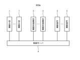
- FIG. 11 is a block diagram showing the configuration of the control server 4 in this embodiment.
- FIG. 12 shows the data structure of the processing information DB.
- FIG. 13 shows the data structure of the measurement information DB.
- FIG. 14 is a schematic diagram showing a specific example of a workpiece processed by the processing device and measured by the measuring device.
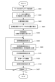
- FIG. 15 is a flowchart showing the flow of processing operations.
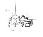
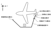
- FIG. 16 is a top view showing the positional relationship between the position measuring device and an aircraft, which is an example of a workpiece.
- FIG. 17 is a top view showing an aircraft as an example of the workpiece.
- FIG. 16 is a top view showing the positional relationship between the position measuring device and an aircraft, which is an example of a workpiece.
- FIG. 17 is a top view showing an aircraft as an example of the work
- FIG. 18 is a flowchart showing the flow of the operation of moving the processing head in step S112 of FIG.
- FIG. 19 is a top view showing an example of the fine adjustment area.
- FIG. 20 is a flowchart showing the flow of the measurement operation.
- FIGS. 21(a) to 21(c) is a cross-sectional view showing a processing device that processes a workpiece and a measuring device that measures the workpiece.
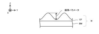
- FIG. 22 is a cross-sectional view showing a work including a base material and a film.
- FIG. 23 is a top view conceptually showing a non-processing area set on a workpiece.
- FIG. 24 is a block diagram showing the configuration of a processing system in the first modification.
- FIG. 25(a) to 25(b) schematically shows an example of the usage of at least two processing devices 1 and the usage of at least two measuring devices 2.
- FIG. 26 is a block diagram showing the configuration of a processing device in a second modification.
- FIG. 27 is a block diagram showing the configuration of the control server in the third modification.
- each of the X-axis direction and the Y-axis direction is a horizontal direction (that is, a predetermined direction within a horizontal plane), and the Z-axis direction is a vertical direction (that is, a direction perpendicular to the horizontal plane). (and substantially in the vertical direction).
- the rotation directions (in other words, the tilt directions) around the X-axis, Y-axis, and Z-axis are referred to as the ⁇ X direction, the ⁇ Y direction, and the ⁇ Z direction, respectively.
- FIG. 1 is a block diagram showing the overall configuration of the processing system SYS in this embodiment.
- the processing system SYS includes a processing device 1, a measuring device 2, a position measuring device 3, and a control server 4.
- Each of the processing device 1, the measuring device 2, and the position measuring device 3 can communicate with the control server 4 via a communication network. That is, the control server 4 can communicate with each of the processing device 1, the measuring device 2, and the position measuring device 3 via the communication network.
- the communication network may typically include a wireless communication network.
- An example of a wireless communication network is a communication network compliant with the IMT (International Mobile Telecommunication) standard (for example, a communication network compliant with 4G, 5G, or 6G).
- Another example of a wireless communication network is a wireless LAN (Local Area Network).
- Another example of a wireless communication network is a communication network that can perform optical wireless communication.
- the processing device 1 is capable of processing a workpiece W, which is an example of an object, under the control of the control server 4.
- the workpiece W may be made of metal, an alloy (such as duralumin), a semiconductor (such as silicon), a resin, or a CFRP. It may be a composite material such as (Carbon Fiber Reinforced Plastic), a paint (as an example, a paint layer applied to a base material), a glass, or any other material. It may also be an object made of material.
- the processing device 1 may perform additional processing on the workpiece W. That is, the processing device 1 may perform additional processing to form a shaped object on the workpiece W.
- the processing device 1 may perform removal processing on the workpiece W. That is, the processing apparatus 1 may perform a removal process to remove a part of the workpiece W.
- the processing device 1 may perform marking processing to form a desired mark on the surface of the workpiece W.
- the processing device 1 may perform peening processing to change the surface characteristics of the workpiece W.
- the processing device 1 may perform a peeling process to peel off the surface of the workpiece W.
- the processing device 1 may perform a welding process to join one work W and another work W.
- the processing device 1 may perform a cutting process to cut the workpiece W.
- the processing device 1 may form a desired structure on the surface of the workpiece W by processing the workpiece W. However, the processing apparatus 1 may perform processing different from the processing for forming a desired structure on the surface of the workpiece W.
- the riblet structure may include a structure capable of reducing resistance (particularly, at least one of frictional resistance and turbulent flow frictional resistance) on the surface of the work W against fluid. For this reason, the riblet structure may be formed on the workpiece W having a member installed (in other words, located) in the fluid.
- the term "fluid” used herein means a medium (for example, at least one of gas and liquid) flowing toward the surface of the workpiece W. For example, if the surface of the workpiece W moves relative to the medium while the medium itself is stationary, this medium may be referred to as a fluid.
- the state in which the medium is stationary may mean a state in which the medium is not moving relative to a predetermined reference object (for example, the ground surface).
- An example of the workpiece W on which the riblet structure is formed is at least one of an aircraft, a windmill, an engine turbine, and a power generation turbine.
- the workpiece W becomes easier to move relative to the fluid. Therefore, the resistance that prevents movement of the workpiece W relative to the fluid is reduced, leading to energy savings.
- the resistance that impedes movement (typically, rotation) of the windmill is reduced, so that the efficiency of the windmill can be improved.
- the workpiece W is an engine turbine (for example, at least a part of the engine turbine)
- the resistance that prevents movement (typically, rotation) of the engine turbine is reduced; This leads to higher efficiency or energy saving of engine turbines.
- the workpiece W is a power generation turbine (for example, at least a part of the power generation turbine)
- the resistance that prevents movement (typically, rotation) of the power generation turbine is reduced; This leads to higher efficiency of power generation turbines (in other words, improved power generation efficiency).
- Processing equipment 1 is designed to meet Goal 13 of the Sustainable Development Goals (SDGs) led by the United Nations, ⁇ Take urgent action to combat climate change and its impacts.'' act ), which has the potential to contribute to "13.2.2 Reduction of Total Greenhouse Gas Emissions per Year", which is one of the goals set forth in 13.2.2.
- SDGs Sustainable Development Goals
- the measuring device 2 is capable of measuring the workpiece W under the control of the control server 4.
- the measuring device 2 may measure the work W to be processed by the processing device 1.
- the measuring device 2 may measure the workpiece W that has been processed by the processing device 1.
- the measuring device 2 may be capable of measuring the position of the workpiece W. That is, the measurement of the workpiece W by the measuring device 2 may include measurement of the position of the workpiece W.
- the measuring device 2 may be capable of measuring the shape (for example, three-dimensional shape) of the workpiece W. That is, the measurement of the work W by the measuring device 2 may include measurement of the shape of the work W.
- the processing system SYS can measure the workpiece W using the measuring device 2
- the processing system SYS may be referred to as a measurement system.
- the position measuring device 3 is capable of measuring the position of the object to be measured.
- the operation of measuring the position of the object to be measured may mean the operation of acquiring information that directly or indirectly indicates the position of the object to be measured as a measurement result.
- the object to be measured may include the workpiece W.
- the object to be measured may include the processing device 1.
- the object to be measured may include the measuring device 2. That is, the position measuring device 3 may be capable of measuring the position of at least one of the work W, the processing device 1, and the measuring device 2.
- the position measuring device 3 is capable of measuring the position of the object to be measured within a measurement coordinate system determined based on the position measuring device 3.
- a measurement coordinate system determined based on the position measuring device 3.
- the measurement coordinate system (that is, the reference coordinate system) has, for example, a horizontal direction in the X-axis direction and a Y-axis direction, a vertical direction in the Z-axis direction, and a position where the position measuring device 3 is arranged. It may be a coordinate system in which the position of the origin is set based on.
- the X-axis, Y-axis, and Z-axis may mean the X-axis, Y-axis, and Z-axis, respectively, in the measurement coordinate system (that is, the reference coordinate system).
- the position measuring device 3 may measure the position of the workpiece W in at least one of the X-axis direction, the Y-axis direction, the Z-axis direction, the ⁇ X direction, the ⁇ Y direction, and the ⁇ Z direction.
- the position measuring device 3 may measure the position of the processing device 1 in at least one of the X-axis direction, the Y-axis direction, the Z-axis direction, the ⁇ X direction, the ⁇ Y direction, and the ⁇ Z direction.
- the position measuring device 3 may measure the position of the measuring device 2 in at least one of the X-axis direction, the Y-axis direction, the Z-axis direction, the ⁇ X direction, the ⁇ Y direction, and the ⁇ Z direction.
- the position of the workpiece W measured by the position measuring device 3 (that is, the position of the workpiece W indicated by the measurement result of the position measuring device 3) may be used as a reference position that serves as a reference for the workpiece W. In this case, the position measuring device 3 may be considered to be measuring the reference position of the workpiece W.
- the position of the processing device 1 measured by the position measuring device 3 (that is, the position of the processing device 1 indicated by the measurement result of the position measuring device 3) may be used as a reference position on which the processing device 1 is based. . In this case, the position measuring device 3 may be considered to be measuring the reference position of the processing device 1.
- the position of the measuring device 2 measured by the position measuring device 3 (that is, the position of the measuring device 2 indicated by the measurement result of the position measuring device 3) may be used as a reference position that is a reference for the measuring device 2.
- the position measuring device 3 may be considered to be measuring the reference position of the measuring device 2.
- the control server 4 may be able to control the processing device 1.
- the control server 4 may control the processing device 1 so that the processing device 1 processes the workpiece W in a desired processing mode.
- the control server 4 receives position information indicating the measurement result of the position of at least one of the workpiece W, the processing device 1, and the measuring device 2 from the position measurement device 3 via the communication network. (that is, acquisition).
- the control server 4 may generate processing control information for controlling the processing device 1 based on the position information.
- the control server 4 may transmit (that is, output) the generated processing control information to the processing device 1 via the communication network.
- the processing device 1 may process the workpiece W based on processing control information transmitted from the control server 4.
- the control server 4 may manage the progress of processing the workpiece W by the processing device 1.
- the control server 4 may receive (that is, acquire) processing progress information regarding the progress of processing the workpiece W by the processing device 1 from the processing device 1 via the communication network.
- the processing device 1 may transmit (that is, output) processing progress information to the control server 4 via the communication network.
- the control server 4 may be able to control the measuring device 2.
- the control server 4 may control the measuring device 2 so that the measuring device 2 measures the workpiece W in a desired measurement manner.
- the control server 4 receives position information indicating the measurement result of the position of at least one of the workpiece W, the processing device 1, and the measuring device 2 from the measuring device 2 via the communication network ( In other words, it may be obtained (obtained).
- the control server 4 may generate measurement control information for controlling the measurement device 2 based on the position information.
- the control server 4 may transmit (that is, output) the generated measurement control information to the measurement device 2 via the communication network.
- the measuring device 2 may measure the workpiece W based on measurement control information transmitted from the control server 4.
- the control server 4 may acquire the measurement results of the workpiece W by the measuring device 2.
- the control server 4 may receive (that is, acquire) measurement result information regarding the measurement results of the workpiece W by the measurement device 2 from the measurement device 2 via the communication network.
- the measuring device 2 may transmit (that is, output) measurement result information to the control server 4 via the communication network.
- the control server 4 may control at least one of the processing device 1 and the measuring device 2 using the measurement result information acquired from the measuring device 2. For example, the control server 4 may generate processing control information based on the above-mentioned position information and measurement result information. For example, the control server 4 may generate measurement control information based on the position information and measurement result information described above.
- the processing system SYS includes at least one of the processing device 1, the measurement device 2, and the position measurement device 3, and at least one other of the processing device 1, the measurement device 2, and the position measurement device 3. It is not necessary to have
- the processing system SYS may include the processing device 1 and the measurement device 2, but may not include the position measurement device 3.
- the processing system SYS may include the measuring device 2 and the position measuring device 3, but may not include the processing device 1.
- the processing system SYS may include the processing device 1 and the position measurement device 3, but may not include the measurement device 2.
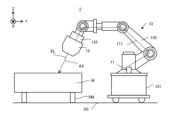
- FIG. 2 is a side view schematically showing the appearance of the processing device 1 in this embodiment.
- the processing device 1 may process the workpiece W placed on the support surface SS.
- the workpiece W may be placed on the support surface SS via a support member SM that supports the workpiece W on the support surface SS.
- the support member SM may be movable on the support surface SS.
- the support member SM may function as a transport device that transports the workpiece W to a desired position.
- the support member SM does not need to be movable on the support surface SS.
- the support member SM may be fixed to the support surface SS.
- the workpiece W may be placed directly on the support surface SS.
- the workpiece W may be placed on a self-propelled drive system or a movable stage. In this case, the position of the work W with respect to the support surface SS can be changed.
- the processing device 1 irradiates the workpiece W with processing light EL (that is, an energy beam having the form of light) in order to process the workpiece W. That is, the processing device 1 processes the workpiece W by irradiating the workpiece W with the processing light EL.
- the processing light EL may be any type of light as long as the workpiece W can be processed by being irradiated onto the workpiece W. In this embodiment, the description will proceed using an example in which the processing light EL is a laser beam. However, the processing light EL may be a different type of light from laser light. Further, the wavelength of the processing light EL may be any wavelength as long as the workpiece W can be processed by being irradiated with the processing light EL.
- the processing light EL may be visible light or invisible light (for example, at least one of infrared light, ultraviolet light, extreme ultraviolet light, etc.).
- the processing light EL may include pulsed light (for example, pulsed light whose emission time is picoseconds or less).
- the processing light EL may not include pulsed light. In other words, the processing light EL may be continuous light.
- the processing apparatus 1 includes a processing light source 11, a processing head 12, as shown in FIG. 2 and FIG. , a head drive system 13, and a control device 14.
- the processing light source 11 can generate processing light EL.
- the processing light source 11 emits the generated processing light EL toward the processing head 12 via a photoconductive member (not shown).
- Examples of the optical transmission member include at least one of an optical fiber and a light pipe.
- the processing head 12 irradiates the work W with the processing light EL emitted from the processing light source 11.
- the processing head 12 includes a processing optical system 121.
- the processing head 12 irradiates the workpiece W with processing light EL via the processing optical system 121. That is, the processing optical system 121 is an optical system for irradiating the workpiece W with the processing light EL. For this reason, the processing optical system 121 may be referred to as an irradiation optical system.
- the processing optical system 121 may include a focus optical element 1211.
- the focus optical element 1211 may be able to change the convergence position of the processing light EL.
- the focus optical element 1211 may be able to change the convergence position of the processing light EL in the direction along the optical axis AX of the processing optical system 121. Since the optical axis AX of the processing light EL typically intersects the surface of the workpiece W, the focus optical element 1211 can change the convergence position of the processing light EL in the direction intersecting the surface of the workpiece W. good.
- the head drive system 13 moves the processing head 12. For this reason, the head drive system 13 may be referred to as a moving device. Specifically, the head drive system 13 moves the processing head 12 relative to the workpiece W. In order to move the processing head 12, the head drive system 13 includes a self-propelled drive system 131, an arm drive system 132, and a fine movement drive system 133. However, the head drive system 13 may not include at least one of the self-propelled drive system 131, the arm drive system 132, and the fine movement drive system 133.
- the self-propelled drive system 131 is movable on the support surface SS that supports or arranges the workpiece W.
- the self-propelled drive system 131 is capable of self-propelled on the support surface SS that supports or arranges the workpiece W.
- the self-propelled drive system 131 moves the processing head 12 (that is, changes the position of the processing head 12) by self-propelled on the support surface SS.
- the arm drive system 132 is a drive system that can function as a robot arm that moves the processing head 12 (that is, changes the position of the processing head 12).
- the fine movement drive system 133 is also a drive system that moves the processing head 12 (that is, changes the position of the processing head 12).
- Each of the self-propelled drive system 131, the arm drive system 132, and the fine movement drive system 133 moves the processing head 12 along at least one of the X-axis direction, the Y-axis direction, the Z-axis direction, the ⁇ X direction, the ⁇ Y direction, and the ⁇ Z direction. move it.
- the self-propelled drive system 131 is self-propelled on the support surface SS.
- the support surface SS is typically a surface along the XY plane. Therefore, in the following description, an example will be described in which the self-propelled drive system 131 can move the processing head 12 along each of the X-axis direction and the Y-axis direction.
- the arm drive system 132 can move the processing head 12 along each of the X-axis direction, Y-axis direction, Z-axis direction, ⁇ X direction, ⁇ Y direction, and ⁇ Z direction. I will explain about it. Note that moving the processing head 12 along at least one of the ⁇ X direction, ⁇ Y direction, and ⁇ Z direction means changing the posture of the processing head 12 around at least one of the X axis, Y axis, and Z axis. They may be considered equivalent.
- moving the processing head 12 along at least one of the ⁇ X direction, the ⁇ Y direction, and the ⁇ Z direction is equivalent to rotating the processing head 12 around at least one of the X axis, the Y axis, and the Z axis.
- the support surface SS may be a surface inclined with respect to the XY plane, or may be a non-planar surface.
- the processing head 12 moves, the positional relationship between the processing head 12 and the workpiece W changes. Furthermore, when the positional relationship between the workpiece W and the processing head 12 changes, the positional relationship between the workpiece W and the processing optical system 121 provided in the processing head 12 changes. Furthermore, when the positional relationship between the workpiece W and the processing head 12 changes, the irradiation position of the processing light EL on the workpiece W changes. Therefore, moving the processing head 12 is equivalent to changing the irradiation position of the processing light EL on the workpiece W.
- the control device 14 controls the operation of the processing device 1.
- the control device 14 controls the processing light source 11, processing head 12, and head drive system included in the processing device 1 to process the workpiece W in a desired processing mode based on processing control information transmitted from the control server 4. At least one of 13 may be controlled. Further, the control device 14 may monitor the progress of machining the workpiece W by the machining device 1 and generate machining progress information regarding the progress of the machining. The control device 14 may transmit the generated processing progress information to the control server 4.
- the control device 14 may include, for example, a calculation device and a storage device.
- the arithmetic device may include, for example, at least one of a CPU (Central Processing Unit) and a GPU (Graphics Processing Unit).
- the storage device may include, for example, memory.
- the control device 14 functions as a device that controls the operation of the processing device 1 by a calculation device executing a computer program.
- This computer program is a computer program for causing the arithmetic device to perform (that is, execute) the operation to be performed by the control device 14, which will be described later. That is, this computer program is a computer program for causing the control device 14 to function so as to cause the processing device 1 to perform the operations described below.
- the computer program executed by the arithmetic device may be recorded in a storage device (that is, a recording medium) included in the control device 14, or may be stored in any storage device built into the control device 14 or externally attachable to the control device 14. It may be recorded on a medium (for example, a hard disk or a semiconductor memory). Alternatively, the computing device may download the computer program to be executed from a device external to the control device 14 via a network interface.
- a storage device that is, a recording medium
- the computing device may download the computer program to be executed from a device external to the control device 14 via a network interface.
- the control device 14 may control the emission mode of the processing light EL by the processing head 12.
- the injection mode may include, for example, at least one of the intensity of the processing light EL and the emission timing of the processing light EL.
- the emission mode is, for example, the light emission time of the pulsed light, the light emission period of the pulsed light, and the ratio of the length of the light emission time of the pulsed light to the light emission period of the pulsed light. (so-called duty ratio).
- the control device 14 may control the manner in which the processing head 12 is moved by the head drive system 13.
- the movement mode may include, for example, at least one of a movement amount, a movement speed, a movement direction, and a movement timing (movement timing).
- the control device 14 does not need to be provided inside the processing device 1.
- the control device 14 may be provided outside the processing device 1 as a server or the like.
- the control device 14 and the processing device 1 may be connected via a wired and/or wireless network (or a data bus and/or a communication line).
- a wired network for example, a network using a serial bus type interface represented by at least one of IEEE1394, RS-232x, RS-422, RS-423, RS-485, and USB may be used.
- a network using a parallel bus interface may be used.
- a network using an interface compliant with Ethernet typified by at least one of 10BASE-T, 100BASE-TX, and 1000BASE-T may be used.
- a network using radio waves may be used.
- An example of a network using radio waves is a network compliant with IEEE802.1x (for example, at least one of a wireless LAN and Bluetooth (registered trademark)).
- a network using infrared rays may be used.
- a network using optical communication may be used as the wireless network.
- the control device 14 and the processing device 1 may be configured to be able to transmit and receive various information via a network.
- control device 14 may be able to transmit information such as commands and control parameters to the processing device 1 via a network.
- the processing device 1 may include a receiving device that receives information such as commands and control parameters from the control device 14 via the network.
- the processing device 1 may include a transmitting device that transmits information such as commands and control parameters to the control device 14 via the network (that is, an output device that outputs information to the control device 14). good.
- a first control device that performs some of the processing performed by the control device 14 is provided inside the processing device 1, while a second control device that performs another part of the processing performed by the control device 14 is provided inside the processing device 1.
- the control device may be provided outside the processing device 1. Note that the control device 14 or the second control device provided outside the processing device 1 may be provided in a location different from the facility (for example, a hangar) where the processing device 1 is used.
- An arithmetic model that can be constructed by machine learning may be implemented in the control device 14 by the arithmetic device executing a computer program.
- An example of a calculation model that can be constructed by machine learning is a calculation model that includes a neural network (so-called artificial intelligence (AI)).
- learning the computational model may include learning parameters (eg, at least one of weights and biases) of the neural network.
- the control device 14 may control the operation of the processing device 1 using the calculation model.
- the operation of controlling the operation of the processing device 1 may include the operation of controlling the operation of the processing device 1 using a calculation model.
- the control device 14 may be equipped with an arithmetic model that has been constructed by offline machine learning using teacher data.
- the calculation model installed in the control device 14 may be updated by online machine learning on the control device 14.
- the control device 14 uses a calculation model installed in a device external to the control device 14 (that is, a device provided outside the processing device 1). The operation of the processing device 1 may be controlled by using the processing device 1.
- the recording medium for recording the computer program executed by the control device 14 includes CD-ROM, CD-R, CD-RW, flexible disk, MO, DVD-ROM, DVD-RAM, DVD-R, DVD+R, and DVD.
- At least one of optical disks such as RW, DVD+RW and Blu-ray (registered trademark), magnetic media such as magnetic tape, magneto-optical disks, semiconductor memories such as USB memory, and any other arbitrary medium capable of storing programs is used. It's okay to be hit.
- the recording medium may include a device capable of recording a computer program (for example, a general-purpose device or a dedicated device in which a computer program is implemented in an executable state in the form of at least one of software and firmware).
- each process or function included in the computer program may be realized by a logical processing block that is realized within the control device 14 when the control device 14 (that is, a computer) executes the computer program, or It may be realized by hardware such as a predetermined gate array (FPGA (Field Programmable Gate Array), ASIC (Application Specific Integrated Circuit)) included in the control device 14, or a logical processing block. and some of the hardware It may also be realized in a mixed format with partial hardware modules that realize the elements.
- FPGA Field Programmable Gate Array
- ASIC Application Specific Integrated Circuit
- the processing device 1 may include a power source.
- the processing device 1 may include a power source disposed on the cart 1311 of the self-propelled drive system 131.
- the processing device 1 may operate using electric power supplied from a power source.
- the processing light source 11 may generate the processing light EL using electric power supplied from a power source.
- the head drive system 13 may move the processing head 12 using electric power supplied from a power source.
- the power source may be rechargeable.
- the power source may be capable of non-contact charging (wireless charging).
- the head drive system 13 includes a self-propelled drive system 131, an arm drive system 132, and a fine movement drive system 133. Therefore, below, the self-propelled drive system 131, the arm drive system 132, and the fine movement drive system 133 will be explained in order.
- FIG. 4 is a cross-sectional view showing the configuration of the self-propelled drive system 131.
- the self-propelled drive system 131 includes a truck 1311 and a motor 1312.
- the trolley 1311 is a platform to which wheels are attached.
- the trolley 1311 is placed on the support surface SS.
- the wheels of the trolley 1311 can be rotated using the power of a motor 1312.
- the trolley 1311 can move on the support surface SS using the power of the motor 1312 driven under the control of the control device 14. That is, the trolley 1311 can self-propel on the support surface SS using the power of the motor 1312.
- the self-propelled drive system 131 is capable of self-propelled on the support surface SS. That is, since the support surface SS is a surface along the XY plane as described above, the self-propelled drive system 131 is capable of self-propelled along at least one of the X-axis direction and the Y-axis direction.
- the "state where the self-propelled drive system 131 self-propels on the support surface SS" referred to here means that the self-propelled drive system 131 uses the power generated by the self-propelled drive system 131 itself to move on the support surface SS. It may also mean a state of movement.
- An arm drive system 132 is mounted on the cart 1311. Specifically, the arm drive system 132 is attached (that is, fixed) to the truck 1311 (in the example shown in FIG. 4, on the upper surface of the truck 1311). Therefore, when the truck 1311 moves, the arm drive system 132 also moves. That is, the self-propelled drive system 131 moves together with the arm drive system 132. Furthermore, a fine movement drive system 133 is connected to the arm drive system 132. Specifically, a fine movement drive system 133 is attached to the arm drive system 132 (that is, it is fixed). Therefore, when the cart 1311 moves, the fine movement drive system 133 also moves. In other words, the self-propelled drive system 131 moves together with the fine movement drive system 133.
- the processing head 12 is connected to the fine movement drive system 133. Specifically, the processing head 12 is attached (that is, fixed) to the fine movement drive system 133. Therefore, when the cart 1311 moves, the processing head 12 also moves. That is, the self-propelled drive system 131 moves together with the processing head 12. Therefore, the self-propelled drive system 131 can function as a moving device that moves the processing head 12 by self-propelled. The self-propelled drive system 131 can function as a moving device that changes the position of the processing head 12.
- FIG. 4 is a cross-sectional view showing the configuration of the arm drive system 132.
- the arm drive system 132 includes a pedestal 1320.
- the frame 1320 is connected to the self-propelled drive system 131 (specifically, the truck 1311).
- the pedestal 1320 is attached (that is, fixed) to the trolley 1311.
- One end of a robot arm 1321 is attached to the pedestal 1320.
- a pedestal 1320 supports a robot arm 1321.
- the robot arm 1321 includes a plurality of arm members 1322.
- the plurality of arm members 1322 are movably connected via at least one joint member 1323.
- the robot arm 1321 may be a manipulator with degrees of freedom in three or more axes. Therefore, the arm drive system 132 may function as a robot having a so-called vertical multi-joint structure.
- the arm drive system 132 is not limited to a robot having a vertical multi-joint structure.
- the arm drive system 132 may function as a polar coordinate robot, a cylindrical coordinate robot, a Cartesian coordinate robot, or a parallel link robot having a horizontal multi-joint structure.
- the joint member 1323 has one arm member 1322 connected to the joint member 1323, and the other arm member 1322 connected to the joint member 1323 having one drive axis (for example, a rotation axis around the X axis, At least two arm members 1322 may be connected so as to be rotatable around at least one of a rotation axis around the Y-axis and a rotation axis around the Z-axis.
- the joint member 1323 has one arm member 1322 connected to the joint member 1323, and the other arm member 1322 connected to the joint member 1323 having one drive axis (for example, a movement axis along the X axis). , a movement axis along the Y-axis, and a movement axis along the Z-axis).
- FIG. 4 shows an example in which the arm drive system 132 includes four actuators 1324 corresponding to four joint members 1323.
- the arm drive system 132 includes four actuators 1324 corresponding to four joint members 1323.
- at least one arm member 1322 moves. Therefore, at least one arm member 1322 is movable with respect to the workpiece W. That is, at least one arm member 1322 is movable so that the relative positional relationship between at least one arm member 1322 and the workpiece W is changed.
- a fine movement drive system 133 is connected to the robot arm 1321. Specifically, the fine movement drive system 133 is connected to one arm member 1322 located farthest from the pedestal 1320 among the plurality of arm members 1322 (that is, it is attached or fixed). ).
- one arm member 1322 to which the fine movement drive system 133 is attached will be referred to as a tip arm member 1325.
- the fine movement drive system 133 may be directly attached to the distal arm member 1325, or may be indirectly attached to the distal arm member 1325 via another member.
- the tip arm member 1325 may be referred to as a connection member to which the fine movement drive system 133 is connected.
- the tip arm member 1325 moves relative to the pedestal 1320. That is, when the tip arm member 1325 moves, the relative position between the pedestal 1320 and the tip arm member 1325 changes. As a result, the fine movement drive system 133 attached to the distal arm member 1325 also moves. Therefore, the arm drive system 132 can move the fine movement drive system 133. Specifically, the arm drive system 132 can move the fine movement drive system 133 relative to the workpiece W. The arm drive system 132 can move the fine movement drive system 133 so that the relative positional relationship between the fine movement drive system 133 and the workpiece W is changed.
- the arm drive system 132 can function as a moving device that moves the processing head 12.
- the arm drive system 132 can function as a moving device that changes the position of the processing head 12.
- the tip arm member 1325 of the robot arm 1321 may be referred to as a movable part.
- FIG. 5 is a sectional view showing the configuration of the fine movement drive system 133.
- the fine movement drive system 133 includes a support member 1331, a support member 1332, an air spring 1333, a damper member 1334, and a drive member 1335.
- the support member 1331 is connected to the arm drive system 132. Specifically, the support member 1331 is attached (that is, fixed) to the tip arm member 1325 of the arm drive system 132. The support member 1332 is attached to the processing head 12.
- the support member 1331 and the support member 1332 are coupled (in other words, connected or connected) via an air spring 1333, a damper member 1334, and a drive member 1335. That is, the air spring 1333, the damper member 1334, and the drive member 1335 are each attached to the support members 1331 and 1332 so as to connect the support members 1331 and 1332. Since the arm drive system 132 is attached to the support member 1331 and the processing head 12 is attached to the support member 1332, each of the air spring 1333, the damper member 1334, and the drive member 1335 is substantially connected to the arm drive system 132. and processing head 12 may be considered to be attached to support members 1331 and 1332.
- the air spring 1333 applies elastic force due to the pressure of gas (air as an example) to at least one of the support members 1331 and 1332.
- the air spring 1333 applies elastic force due to gas pressure to at least one of the arm drive system 132 and the processing head 12 via at least one of the support members 1331 and 1332.
- the air spring 1333 applies elastic force due to gas pressure to at least one of the arm drive system 132 and the processing head 12 along the direction in which the support member 1331 and the support member 1332 are lined up (for example, the Z-axis direction). may be given to
- Gas is supplied to the air spring 1333 from a gas supply device 13361 via a pipe 13362 and a valve 13363 in order to impart elastic force due to gas pressure.
- the control device 14 controls at least one of the gas supply device 13361 and the valve 13363 based on the measurement result of the pressure gauge 1336 that measures the pressure of the gas inside the air spring 1333.
- the air spring 1333 may support the weight of the processing head 12 using elastic force under the control of the control device 14.
- the air spring 1333 may function as a dead weight canceller that cancels the dead weight of the processing head 12.
- the air spring 1333 uses elastic force under the control of the control device 14 to reduce (in other words, dampen) vibrations transmitted between the arm drive system 132 and the processing head 12 via the fine movement drive system 133. ) may be done.
- the damper member 1334 applies elastic force caused by a factor different from air pressure to at least one of the support members 1331 and 1332.
- the damper member 1334 applies elastic force caused by a factor different from air pressure to at least one of the arm drive system 132 and the processing head 12 via at least one of the support members 1331 and 1332.
- the damper member 1334 may apply elastic force to at least one of the arm drive system 132 and the processing head 12 along the direction in which the support member 1331 and the support member 1332 are lined up (for example, the Z-axis direction). .
- the damper member 1334 may support the weight of the processing head 12 using elastic force. Similarly to the air spring 1333, the damper member 1334 may utilize elastic force to reduce vibrations transmitted between the arm drive system 132 and the processing head 12 via the fine movement drive system 133.
- damper member 1334 may be any member as long as it can impart elastic force.
- damper member 1334 may include a compression spring coil.
- damper member 1334 may include a leaf spring.
- the driving member 1335 is capable of generating driving force under the control of the control device 14.
- the driving member 1335 can apply the generated driving force to at least one of the supporting members 1331 and 1332.
- the drive member 1335 can apply the generated drive force to at least one of the arm drive system 132 and the processing head 12 via at least one of the support members 1331 and 1332.
- the driving member 1335 may have any configuration as long as it can generate driving force.
- the driving member 1335 may have a configuration capable of electrically generating driving force.
- the driving member 1335 may have a configuration that can generate a driving force magnetically.
- FIG. 5 shows an example in which the drive member 1335 is a voice coil motor (VCM) that can electrically generate a driving force.
- VCM voice coil motor
- the driving member 1335 may move at least one of the support members 1331 and 1332 using driving force under the control of the control device 14.
- the drive member 1335 may move at least one of the arm drive system 132 and the processing head 12 by using a drive force to move at least one of the support members 1331 and 1332 under the control of the control device 14.
- the drive member 1335 may change the relative position of the arm drive system 132 and the processing head 12 by moving at least one of the arm drive system 132 and the processing head 12 using the driving force.
- the drive member 1335 may change the relative position of the arm drive system 132 and the processing head 12 under the control of the control device 14 based on the measurement results of the position measurement device 1337 included in the fine movement drive system 133.
- the position measuring device 1337 measures the relative position between the arm drive system 132 and the processing head 12.
- the position measuring device 1337 may be an encoder including a detection section 13371 attached to the support member 1331 and a scale section 13372 attached to the support member 1332.
- the measurement result of the position measuring device 1337 includes information regarding the relative positions of the support member 1331 and the support member 1332.
- the control device 14 can appropriately specify the relative position of the arm drive system 132 and the processing head 12. As a result, the control device 14 can appropriately change the relative position between the arm drive system 132 and the processing head 12 based on the measurement result of the position measurement device 1337.
- the drive member 1335 changes the relative position between the arm drive system 132 and the processing head 12 under the control of the control device 14 (typically, by moving the processing head 12 with respect to the arm drive system 132). , the processing head 12 may be moved relative to the workpiece W.
- the driving member 1335 may move the processing head 12 (that is, may drive it) so that the relative positional relationship between the processing head 12 and the workpiece W is changed.
- the support member 1332 to which the processing head 12 is attached is moved by the driving member 1335, the support member 1332 may be referred to as a movable part.
- the fine movement drive system 133 is moved by the arm drive system 132, at least some of the components constituting the fine movement drive system 133 may also be referred to as movable parts.
- the drive member 1335 changes the relative position of the arm drive system 132 and the processing head 12 by using driving force under the control of the control device 14, thereby causing slight movement between the arm drive system 132 and the processing head 12. Vibration transmitted via drive system 133 may be reduced.
- a device that actively reduces vibration using an elastic member such as an air spring 1333 and a drive member 1335 may be referred to as an active vibration isolator.
- the fine movement drive system 133 may be referred to as an active vibration isolator.
- An active vibration isolator may be referred to as an Active Vibration Isolation System (AVIS).
- the arm drive system 132 moves the processing head 12 with a smaller movement stroke than the self-propelled drive system 131.
- the self-propelled drive system 131 moves the processing head 12 with a larger movement stroke than the arm drive system 132.
- the movement stroke may mean the maximum amount of movement in one direction.
- the arm drive system 132 may move the processing head 12 with the same or larger movement stroke than the self-propelled drive system 131.
- the movement accuracy (in other words, movement resolution) of the processing head 12 by the arm drive system 132 is higher than the movement accuracy of the processing head 12 by the self-propelled drive system 131.
- the movement accuracy of the processing head 12 by the self-propelled drive system 131 is lower than the movement accuracy of the processing head 12 by the arm drive system 132.
- the movement accuracy (movement resolution) may mean a limit value of the fineness of movement (for example, minimum movement amount).
- the movement accuracy of the processing head 12 by the arm drive system 132 may be the same as the movement accuracy of the processing head 12 by the self-propelled drive system 131, or may be lower.
- the fine movement drive system 133 moves the processing head 12 with a smaller movement stroke than the arm drive system 132.
- the arm drive system 132 moves the processing head 12 with a larger movement stroke than the fine movement drive system 133.
- the fine movement drive system 133 may move the processing head 12 with the same or larger movement stroke than the arm drive system 132.
- the movement accuracy of the processing head 12 by the fine movement drive system 133 is higher than the movement accuracy of the processing head 12 by the arm drive system 132. In other words, the movement accuracy of the processing head 12 by the arm drive system 132 is lower than the movement accuracy of the processing head 12 by the fine movement drive system 133.
- the movement accuracy of the processing head 12 by the fine movement drive system 133 may be the same as the movement accuracy of the processing head 12 by the arm drive system 132, or may be lower.
- the processing system SYS may position the processing head 12 with respect to the workpiece W using the self-propelled drive system 131.
- the processing system SYS uses the arm drive system 132 to The processing head 12 may be aligned with respect to the workpiece W with finer or higher accuracy than 131.
- the processing system SYS uses the fine movement drive system 133 to move the processing head 12 further than the arm drive system 132.
- the processing head 12 may be aligned with respect to the workpiece W with fine or high precision.
- the machining system SYS uses the fine movement drive system 133 to maintain the desired positional relationship between the workpiece W and the machining head 12 (for example, when the distance between the workpiece W and the machining head 12 is The processing head 12 may be aligned with respect to the workpiece W so that the position of the processing head 12 is maintained constant.
- the processing head 12 since the processing head 12 is moved by the self-propelled drive system 131, the arm drive system 132, and/or the fine movement drive system 133, the processing head 12 may be referred to as a movable part.
- FIG. 6 is a side view schematically showing the appearance of the measuring device 2 in this embodiment.
- the measuring device 2 may measure the workpiece W placed on the support surface SS.
- the measuring device 2 includes a measuring head 22, a head drive system 23, a control device 24, as shown in FIG. 6 and FIG. 7, which is a block diagram showing the overall configuration of the measuring device 2. Equipped with.
- the measurement head 22 measures the workpiece W.
- the measurement head 22 may measure the position of the workpiece W.
- the measurement head 22 may measure the shape (for example, three-dimensional shape) of the workpiece W.
- the measurement head 22 may have any configuration as long as it can measure the workpiece W.
- the measurement head 22 may be a non-contact measuring device that can measure the work W without coming into contact with the work W.
- the measurement head 22 may be a contact-type measurement device that can measure the workpiece W by coming into contact with the workpiece W.
- An example of a non-contact measuring device is an optical measuring device that optically measures the workpiece W.
- An example of a contact-type measuring device is a probe-type measuring device that measures the work W by bringing a probe into contact with the work W.
- An example of an optical measuring device is a measuring device (for example, an imaging device such as a camera) that measures the workpiece W by capturing an image of the workpiece W.
- An example of an optical measuring device is a measuring device that uses a pattern projection method.
- a measuring device using a pattern projection method may measure the workpiece W by projecting slit light onto the surface of the workpiece W and measuring the shape of the projected slit light.
- An example of an optical measuring device is a measuring device that uses a pattern projection method.
- a measuring device using a pattern projection method may measure the work W by projecting pattern light onto the surface of the work W and measuring the shape of the projected pattern light.
- An example of an optical measuring device is a measuring device that uses interferometry.
- a measuring device using interferometry may measure the workpiece W by measuring an interference pattern between an object beam passing through the workpiece W and a reference beam not passing through the workpiece W.
- An example of an optical measuring device is a measuring device that uses the time-of-flight method.
- a measurement device that uses the time-of-flight method projects measurement light onto the surface of the workpiece W, and measures the distance from the measurement device to the workpiece W based on the time it takes for the projected measurement light to return from the workpiece W to the measurement device.
- the work W may be measured by performing the operation of measuring the distance at a plurality of positions on the work W.
- optical measurement devices include moire topography method (specifically, grating irradiation method or grating projection method), holographic interference method, autocollimation method, stereo method, astigmatism method, critical angle method, and Examples include measuring devices that use at least one of the knife edge methods.
- the head drive system 23 moves the measurement head 22.
- the head drive system 23 may be referred to as a moving device.
- the head drive system 23 moves the measurement head 22 relative to the workpiece W.
- the head drive system 23 includes a self-propelled drive system 231, an arm drive system 232, and a fine movement drive system 233.
- the head drive system 23 does not need to include at least one of the self-propelled drive system 231, the arm drive system 232, and the fine movement drive system 233.
- the configuration of the self-propelled drive system 231 included in the measuring device 2 may be the same as the configuration of the self-propelled drive system 131 included in the processing device 1.
- the self-propelled drive system 231 includes a truck 2311 and a motor 2312.
- the features of the trolley 2311 may be the same as those of the trolley 1311 shown in FIG.
- the characteristics of motor 2312 may be the same as the characteristics of motor 1312 shown in FIG. Therefore, in the above description of the self-propelled drive system 131, the words "cart 1311, motor 2312, and processing head 12" are replaced with the words "cart 2311, motor 2312, and measurement head 22," respectively. It can be used as an explanation. Therefore, a detailed explanation of the self-propelled drive system 231 will be omitted.
- the configuration of the arm drive system 232 included in the measuring device 2 may be the same as the configuration of the arm drive system 132 included in the processing device 1.
- the arm drive system 232 includes a pedestal 2320, a robot arm 2321 (specifically, a plurality of robot arms including a tip arm member 2325), arm member 2322, a plurality of joint members 2323, and a plurality of actuators 2324).
- the features of pedestal 2320 may be the same as those of pedestal 1320 shown in FIG.
- the features of the robot arm 2321 may be the same as the features of the robot arm 1321 shown in FIG.
- arm member 2322 may be the same as the features of arm member 1322 shown in FIG.
- the features of joint member 2323 may be the same as the features of joint member 1323 shown in FIG.
- the features of actuator 2324 may be the same as those of actuator 1324 shown in FIG.
- the features of the distal arm member 2325 may be the same as the features of the distal arm member 1325 shown in FIG. Therefore, the above description of the arm drive system 132 includes the pedestal 1320, robot arm 1321, arm member 1322, joint member 1323, actuator 1324, tip arm member 1325, self-propelled drive system 131, fine movement drive system 133, and processing head 12.
- the configuration of the fine movement drive system 233 included in the measuring device 2 may be the same as the configuration of the fine movement drive system 133 included in the processing device 1. That is, the fine movement drive system 233 may have the configuration shown in FIG. 5, which shows the configuration of the fine movement drive system 133. Therefore, detailed explanation of the fine movement drive system 233 will be omitted.
- Each of the self-propelled drive system 231, the arm drive system 232, and the fine movement drive system 233 moves the measurement head 22 along at least one of the X-axis direction, the Y-axis direction, the Z-axis direction, the ⁇ X direction, the ⁇ Y direction, and the ⁇ Z direction. move it.
- the self-propelled drive system 231 is self-propelled on the support surface SS.
- the support surface SS is typically a surface along the XY plane. Therefore, in the following description, an example will be described in which the self-propelled drive system 231 can move the measurement head 22 along each of the X-axis direction and the Y-axis direction.
- the arm drive system 232 can move the measurement head 22 along each of the X-axis direction, Y-axis direction, Z-axis direction, ⁇ X direction, ⁇ Y direction, and ⁇ Z direction. I will explain about it. Note that moving the measurement head 22 along at least one of the ⁇ X direction, ⁇ Y direction, and ⁇ Z direction means changing the posture of the measurement head 22 around at least one of the X axis, Y axis, and Z axis. They may be considered equivalent.
- moving the measurement head 22 along at least one of the ⁇ X direction, the ⁇ Y direction, and the ⁇ Z direction is equivalent to rotating the measurement head 22 around at least one of the X axis, the Y axis, and the Z axis. It may be assumed that
- the measurement head 22 When the measurement head 22 moves, the positional relationship between the measurement head 22 and the workpiece W changes. When the positional relationship between the workpiece W and the measurement head 22 changes, the measurement area of the measurement head 22 moves on the workpiece W. Therefore, moving the measurement head 22 is equivalent to moving the measurement area on the workpiece W. Note that since the measurement head 22 is moved by the self-propelled drive system 231, the arm drive system 232, and/or the fine movement drive system 233, the measurement head 22 may be referred to as a movable part.
- the control device 24 controls the operation of the measuring device 2. For example, the control device 24 controls at least one of the measurement head 22 and the head drive system 23 included in the measurement device 2 so as to measure the workpiece W in a desired measurement manner based on measurement control information transmitted from the control server 4. One may be controlled. Further, the control device 24 may transmit measurement result information regarding the measurement results of the workpiece W by the measurement device 2 to the control server 4.
- the control device 24 may include, for example, a calculation device and a storage device.
- the arithmetic device may include, for example, at least one of a CPU and a GPU.
- the storage device may include, for example, memory.
- the control device 24 functions as a device that controls the operation of the measuring device 2 by a calculation device executing a computer program.
- This computer program is a computer program for causing the arithmetic device to perform (that is, execute) the operation to be performed by the control device 24, which will be described later.
- this computer program is a computer program for causing the control device 24 to function so as to cause the measuring device 2 to perform the operations described below.
- the computer program executed by the arithmetic device may be recorded in a storage device (that is, a recording medium) included in the control device 24, or may be stored in any storage device built into the control device 24 or externally attachable to the control device 24. It may be recorded on a medium (for example, a hard disk or a semiconductor memory). Alternatively, the computing device may download the computer program to be executed from a device external to the control device 24 via a network interface.
- a storage device that is, a recording medium
- the computing device may download the computer program to be executed from a device external to the control device 24 via a network interface.
- the control device 24 may control the manner in which the measurement head 22 measures the workpiece W.
- the measurement aspect may include, for example, at least one of a measurement position and a measurement time.
- the control device 24 may control the manner in which the measurement head 22 is moved by the head drive system 23.
- the movement mode may include, for example, at least one of a movement amount, a movement speed, a movement direction, and a movement timing (movement timing).
- the control device 24 does not need to be provided inside the measuring device 2.
- the control device 24 may be provided outside the measurement device 2 as a server or the like.
- the control device 24 and the measurement device 2 may be connected via a wired and/or wireless network (or a data bus and/or a communication line).
- a wired network for example, a network using a serial bus type interface represented by at least one of IEEE1394, RS-232x, RS-422, RS-423, RS-485, and USB may be used.
- a network using a parallel bus interface may be used.
- a network using an interface compliant with Ethernet typified by at least one of 10BASE-T, 100BASE-TX, and 1000BASE-T may be used.
- a network using radio waves may be used.
- An example of a network using radio waves is a network compliant with IEEE802.1x (for example, at least one of a wireless LAN and Bluetooth (registered trademark)).
- a network using infrared rays may be used.
- a network using optical communication may be used as the wireless network.
- the control device 24 and the measurement device 2 may be configured to be able to transmit and receive various information via a network.
- control device 24 may be able to transmit information such as commands and control parameters to the measurement device 2 via a network.
- the measuring device 2 may include a receiving device that receives information such as commands and control parameters from the control device 24 via the network.
- the measuring device 2 may include a transmitting device that transmits information such as commands and control parameters to the control device 24 via the network (that is, an output device that outputs information to the control device 24). good.
- a first control device that performs some of the processing performed by the control device 24 is provided inside the measuring device 2
- a second control device that performs another part of the processing performed by the control device 24 is provided inside the measurement device 2.
- a control device may be provided outside the measuring device 2.
- An arithmetic model that can be constructed by machine learning may be implemented in the control device 24 by the arithmetic device executing a computer program.
- An example of a computational model that can be constructed by machine learning is a computational model that includes a neural network (so-called artificial intelligence (AI)).
- learning the computational model may include learning parameters (eg, at least one of weights and biases) of the neural network.
- the control device 24 may control the operation of the measuring device 2 using the calculation model. That is, the operation of controlling the operation of the measuring device 2 may include the operation of controlling the operation of the measuring device 2 using a calculation model.
- the control device 24 may be equipped with an arithmetic model that has been constructed by offline machine learning using teacher data.
- the calculation model installed in the control device 24 may be updated by online machine learning on the control device 24.
- the control device 24 uses a calculation model installed in a device external to the control device 24 (that is, a device provided outside the measurement device 2). The operation of the measuring device 2 may be controlled by using the same.
- the recording medium for recording the computer program executed by the control device 24 includes CD-ROM, CD-R, CD-RW, flexible disk, MO, DVD-ROM, DVD-RAM, DVD-R, DVD+R, and DVD.
- At least one of optical disks such as RW, DVD+RW and Blu-ray (registered trademark), magnetic media such as magnetic tape, magneto-optical disks, semiconductor memories such as USB memory, and any other arbitrary medium capable of storing programs is used. It's okay to be hit.
- the recording medium may include a device capable of recording a computer program (for example, a general-purpose device or a dedicated device in which a computer program is implemented in an executable state in the form of at least one of software and firmware).
- each process or function included in the computer program may be realized by a logical processing block that is realized within the control device 24 when the control device 24 (that is, a computer) executes the computer program, or It may be realized by hardware such as a predetermined gate array (FPGA, ASIC) included in the control device 24, or a logical processing block and a partial hardware module that realizes some hardware elements coexist. It may be realized in a format.
- a logical processing block that is realized within the control device 24 when the control device 24 (that is, a computer) executes the computer program
- hardware such as a predetermined gate array (FPGA, ASIC) included in the control device 24, or a logical processing block and a partial hardware module that realizes some hardware elements coexist. It may be realized in a format.
- the measuring device 2 may include a power source.
- the measuring device 2 may include a power source placed on the trolley 2311 of the self-propelled drive system 231.
- the measuring device 2 may operate using power supplied from a power source.
- the measurement unit 221 may measure the workpiece W using power supplied from a power source. Processing light EL may also be generated.
- the head drive system 23 may move the measurement head 22 using power supplied from a power source.
- the power source may be rechargeable.
- the power source may be capable of non-contact charging (wireless charging).
- the position measuring device 3 can measure the position of at least one of the workpiece W, the processing device 1, and the measuring device 2.
- the position measuring device 3 may have any configuration as long as it can measure the position of at least one of the workpiece W, the processing device 1, and the measuring device 2.
- the position measuring device 3 measures the position of a measurement object including at least one of the workpiece W, the processing device 1, and the measuring device 2 using the measurement light ML.
- the position measuring device 3 may measure the position of the measurement target by irradiating the measurement light ML onto the measurement target and detecting the return light of the measurement light ML from the measurement target.
- the return light of the measurement light ML from the measurement target may include at least one of the reflected light of the measurement light ML by the measurement target and the scattered light of the measurement light ML by the measurement target.
- the position measuring device 3 may be placed at a position away from the measuring object. That is, the position measuring device 3 may be placed at a position away from at least one of the workpiece W, the processing device 1, and the measuring device 2. In this case, the position measuring device 3 may irradiate the measurement light ML onto the measurement target from a position away from the measurement target. The position measuring device 3 may detect the return light of the measurement light ML from the measurement target at a position away from the measurement target.
- the position measuring device 3 may irradiate the measurement light ML toward a desired measurement target portion of the measurement target and detect the measurement light ML from the desired measurement target portion of the measurement target.
- a reflector capable of reflecting the measurement light ML typically, capable of retroreflection
- the position measuring device 3 irradiates the measurement light ML toward the reflector, and Alternatively, the measurement light ML may be detected. In either case, the position measuring device 3 can measure the position of a desired measurement target portion of the measurement target.
- the position measuring device 3 may irradiate the measurement light ML toward each of the plurality of measurement target parts of the measurement target and detect the measurement light ML from the plurality of measurement target parts of the measurement target. In this case, the position measuring device 3 can measure the positions of a plurality of measurement target parts of the measurement target.
- FIG. 9 is a front view showing the external appearance of the position measuring device 3.
- FIG. 10 is a block diagram showing the configuration of the position measuring device 3. As shown in FIG.
- the position measuring device 3 includes a pedestal 310 and a housing 320.
- the pedestal 310 is a pedestal that supports the housing 320.
- the pedestal 310 may be arranged, for example, on the support surface SS on which the workpiece W, the processing device 1, and the measuring device 2 are arranged.
- the pedestal 310 may be placed on the support surface SS via a support member (not shown), or may be placed directly on the support surface SS.
- Housing 320 is a member in which optical assembly 330 shown in FIG. 10 is housed.
- Housing 320 may be rotatable around a predetermined rotation axis. In the example shown in FIG. 9, the housing 320 is rotatable about a rotation axis along the Y-axis and a rotation axis along the Z-axis.
- the optical assembly 330 includes a measurement light source 331, a pointing beam source 332, a beam splitter 333, a beam splitter 334, a beam splitter 335, a mirror 336, an optical circuit 337, and a detector 338. Equipped with.
- the measurement light source 331 generates measurement light ML.
- a part of the measurement light ML generated by the measurement light source 331 is emitted from the exit port 321 formed in the housing 320 via beam splitters 334 and 335 and a mirror 336.
- the measurement light ML emitted from the exit port 321 is incident on the object to be measured.
- the position measuring device 3 may rotate the housing 320 so that the measurement light ML is incident on a desired measurement target portion of the measurement target.
- At least a portion of the measurement light ML reflected by the measurement object enters the optical assembly 330 via the exit port 321.
- the returned light RL that has entered the optical assembly 330 enters the detector 338 via the mirror 336 and the beam splitter 335.
- another part of the measurement light ML generated by the measurement light source 331 is generated by the beam splitter 334 and the optical circuit described in U.S. Patent Application Publication No. 2012/188557 (or U.S. Patent No. 4,733,606, etc.). 337 and enters a detector 338 .
- the position measuring device 3 transmits the detection result of the detector 338 to the control server 4 as position information indicating the measurement result of the position of at least one of the workpiece W, the processing device 1, and the measuring device 2.
- the control server 4 calculates the position of the measurement target based on the detection results of the measurement light ML and the return light RL by the detector 338.
- the control server 4 uses the optical heterodyne detection described in U.S. Patent Application Publication No. 2012/188557 (or U.S. Patent No. 4,733,606, etc.) to detect the measurement light ML and the return light by the detector 338.
- the position of the object to be measured is calculated based on the detection result of RL.
- Pointing beam source 332 generates pointing beam B.
- Pointing beam B is used to identify the position on the measurement object to which measurement light ML is directed.
- Pointing beam B may include visible light.
- Pointing beam B generated by pointing beam source 332 is emitted from exit port 321 formed in housing 320 via beam splitters 333 , 334 and 335 and mirror 336 .
- the pointing beam B emitted from the exit port 321 is incident on the object to be measured.
- the optical assembly 330 does not need to irradiate the measuring object with the pointing beam B.
- the position measuring device 3 is not limited to the measuring device including the laser radar system described in US Patent Application Publication No. 2012/188557.
- the position measuring device 3 may be a measuring device including a laser coordinate measuring device described in US Pat. No. 7,800,758 (for example, a measuring device using intensity-modulated measuring light).
- the position measuring device 3 may be a measuring device (for example, a measuring device using intensity-modulated measuring light) that includes an absolute distance meter described in US Pat. No. 6,847,436.
- FIG. 11 is a block diagram showing the configuration of the control server 4 in this embodiment.
- control server 4 may include a calculation device 41, a storage device 42, a communication device 43, an input device 44, and an output device 45.
- the arithmetic device 41, the storage device 42, the communication device 43, the input device 44, and the output device 45 may be connected via a data bus 46.
- the arithmetic device 41 includes, for example, at least one of a CPU and a GPU. Arithmetic device 41 reads a computer program. For example, the arithmetic device 41 may read a computer program stored in the storage device 42. For example, the arithmetic device 41 may read a computer program stored in a computer-readable, non-temporary recording medium using a recording medium reading device (not shown). The arithmetic device 41 may obtain (that is, may download or read) a computer program from a device (not shown) located outside the control server 4 via the communication device 43 . The arithmetic device 41 executes the loaded computer program.
- a logical functional block for executing the operations to be performed by the control server 4 is realized within the arithmetic unit 41.
- the arithmetic device 41 can function as a controller for realizing a logical functional block for executing the operations that the control server 4 should perform.
- a calculation model that can be constructed by machine learning may be implemented in the calculation device 41 by the calculation device 41 executing a computer program.
- An example of a computational model that can be constructed by machine learning is a computational model that includes a neural network (so-called artificial intelligence (AI)).
- learning the computational model may include learning parameters (eg, at least one of weights and biases) of the neural network.
- the calculation device 41 may use the calculation model to execute the operation that the control server 4 should perform.
- the calculation device 41 may be equipped with a calculation model that has been constructed by offline machine learning using teacher data. Further, the calculation model installed in the calculation device 41 may be updated by online machine learning on the calculation device 41.
- the calculation device 41 uses a calculation model installed in a device external to the calculation device 41 (that is, a device provided outside the control server 4).
- the control server 4 may also use the control server 4 to execute operations that should be performed.
- FIG. 11 shows an example of logical functional blocks implemented within the arithmetic unit 41.
- an information acquisition section 411 and a control information generation section 412 are implemented within the arithmetic device 41.
- the information acquisition unit 411 may receive (that is, acquire) processing progress information from the processing device 1 using the communication device 43 .
- the information acquisition unit 411 may receive (that is, acquire) measurement result information from the measurement device 2 using the communication device 43 .
- the information acquisition unit 411 may receive (that is, acquire) position information from the position measurement device 3 using the communication device 43 .
- the control information generation unit 412 may generate processing control information and measurement control information based on the position information.
- the storage device 42 can store desired data.
- the storage device 42 may temporarily store a computer program executed by the arithmetic device 41.
- the storage device 42 may temporarily store data that is temporarily used by the arithmetic device 41 while the arithmetic device 41 is executing a computer program.
- the storage device 42 may store data that the control server 4 stores for a long period of time.
- the storage device 42 may include at least one of a RAM (Random Access Memory), a ROM (Read Only Memory), a hard disk device, a magneto-optical disk device, an SSD (Solid State Drive), and a disk array device. good. That is, the storage device 42 may include a non-temporary recording medium.
- the storage device 42 may store a processing information DB 421 and a measurement information DB 422.
- the processing information DB 421 is a database for storing information regarding the processing device 1.
- the measurement information DB 422 is a database for storing information regarding the measurement device 2.
- the processing information DB 421 includes a plurality of processing information records 4210.
- Each processing information record 4210 may include device identification information 4211, time information 4212, and processing device information 4213.
- the device identification information 4211 is information for uniquely identifying the processing device 1.
- Time information 4212 is information indicating the time corresponding to processing device information 4213.
- the processing device information 4213 is information regarding the processing device 1.
- the processing device information 4213 may include device position information indicating the position of the processing device 1 at the time indicated by the time information 4212.
- the processing device information 4213 may include processing progress information acquired by the information acquisition unit 411.
- the machining progress information may include information regarding the degree of progress of the machining operation at the time indicated by the time information 4212. That is, the machining progress information may include information regarding the ratio of steps completed by the machining device 1 (that is, the progress rate) with respect to the entire process of machining operations to be performed by the machining device 1.
- the machining progress information may include information regarding a machining completion area of the workpiece W where machining by the machining device 1 has been completed.
- the machining progress information may include information regarding an unfinished area of the workpiece W where machining by the machining device 1 has not yet been completed.
- the processing device information 4213 includes information regarding the time during which the processing device 1 can operate using the power stored in the power source (that is, the remaining amount of the power source). You can stay there.
- the information acquisition unit 411 acquires information necessary for constructing the processing information DB 421 (for example, at least one of device identification information 4211, time information 4212, and processing device information 4213) from the processing device 1. It may be received (that is, acquired) from.
- the measurement information DB 421 includes a plurality of measurement information records 4220.
- Each measurement information record 4220 may include device identification information 4221, time information 4222, and measurement device information 4223.
- the device identification information 4221 is information for uniquely identifying the measuring device 2.
- Time information 4222 is information indicating the time corresponding to measuring device information 4223.
- the measuring device information 4223 is information regarding the measuring device 2.
- the measuring device information 4223 may include measurement result information indicating the measurement result by the measuring device 2 at the time indicated by the time information 4222 (that is, the measurement result information acquired by the information acquisition unit 411).
- the measurement device information 4223 may include measurement progress information.
- the measurement progress information may include information regarding the progress of the measurement operation at the time indicated by the time information 4222. That is, the measurement progress information may include information regarding the ratio of steps completed by the measuring device 2 (that is, the progress rate) to the entire steps of the measuring operation that the measuring device 2 should perform.
- the measurement progress information may include information regarding a measurement completion area of the workpiece W where measurement by the measurement device 2 has been completed.
- the measurement progress information may include information regarding unfinished measurement areas of the workpiece W where measurement by the measuring device 2 has not yet been completed.
- the measuring device information 4223 includes information regarding the time during which the measuring device 2 can operate using the power stored in the power source (that is, the remaining amount of the power source). You can stay there.
- the information acquisition unit 411 acquires information necessary for constructing the measurement information DB 422 (for example, at least one of device identification information 4221, time information 4222, and measurement device information 4223) from the measurement device 2. It may be received (that is, acquired) from.
- the storage device 42 may store a processing information DB 421 having an arbitrary data format (in other words, an arbitrary file format). For example, the storage device 42 may store the processing information DB 421 as tabular data (file) shown in FIG. Similarly, the storage device 42 may store the measurement information DB 422 having any data format (in other words, any file format). For example, the storage device 42 may store the measurement information DB 422 as tabular data (file) shown in FIG. 13.
- the communication device 43 is capable of communicating with each of the processing device 1, the measuring device 2, and the position measuring device 3 via the communication network.
- the input device 44 is a device that accepts input of information to the control server 4 from outside the control server 4.
- the input device 44 may include an operating device (eg, at least one of a keyboard, a mouse, and a touch panel) that can be operated by a worker (eg, a user of the processing system SYS).
- the input device 44 may include a reading device capable of reading information recorded as data on a recording medium that can be externally attached to the control server 4.
- the input device 44 may include a receiving device capable of receiving information that a device external to the control server 4 transmits as data to the control server 4 via a communication network.
- the output device 45 is a device that outputs information to the outside of the control server 4.
- the output device 45 may output the information as an image.
- the output device 45 may include a display device (so-called display) capable of displaying an image indicating information desired to be output.
- the output device 45 may output the information as audio.
- the output device 45 may include an audio device (so-called speaker) that can output audio.
- the output device 45 may output information on paper. That is, the output device 45 may include a printing device (so-called printer) that can print desired information on paper.
- the output device 45 may output (for example, display) information stored in at least one of the processing information DB 421 and the measurement information DB 422.
- the output device 45 may display a table (for example, the table shown in FIG. 12) showing information stored in the processing information DB 421.
- the output device 45 may display a table (for example, the table shown in FIG. 13) showing information stored in the measurement information DB 422.
- control server 4 may analyze the information stored in at least one of the processing information DB 421 and the measurement information DB 422, and the output device 45 may output (for example, display) the analysis result.
- the output device 45 may display the analysis results in association with the work W.
- the output device 45 may display the analysis results in a display format in which the analysis results and the work W are associated (for example, a display format different from the display format using the table described above).
- the control server 4 analyzes the machining progress included in the machining information DB 421, and the output device 45 displays the machining information for each part of a display object that imitates a workpiece W (for example, an aircraft).
- the work W and the analysis results may be displayed in a display format in which progress rates are associated. That is, the output device 45 may display a heat map indicating the processing progress rate in association with the workpiece W. As a result, the user of the machining system SYS can intuitively recognize the machining progress rate of each part of the workpiece W.
- the processing device 1 may process a workpiece W that is larger than the processing device 1.
- the processing device 1 processes a workpiece W corresponding to at least a part of an aircraft.
- the processing device 1 may process at least a portion of an aircraft so as to form the above-mentioned riblet structure in at least a portion of the fuselage, main wing, horizontal stabilizer, and/or vertical stabilizer of the aircraft.
- the processing device 1 may process a workpiece W smaller than the processing device 1.
- the processing device 1 may process a workpiece W having the same size as the processing device 1.
- the measuring device 2 may measure a workpiece W that is larger than the measuring device 2.
- the measuring device 2 measures a workpiece W corresponding to at least a part of an aircraft.
- the measuring device 2 may measure at least a portion of the fuselage, main wing, horizontal stabilizer, and/or vertical stabilizer of the aircraft.
- the measuring device 2 may process a work W smaller than the measuring device 2.
- the measuring device 2 may process a work W having the same size as the measuring device 2.
- processing system SYS may perform the processing operation and measurement operation described below.
- FIG. 15 is a flowchart showing the overall flow of the machining operation.
- the control information generation unit 412 of the control server 4 acquires model data indicating a three-dimensional model of the workpiece W to be processed by the processing device 1 (step S411). That is, the control information generation unit 412 acquires model data indicating a three-dimensional model having the designed three-dimensional shape of the workpiece W to be processed by the processing apparatus 1 (step S411).
- An example of model data is CAD (Computer Aided Design) data.
- CAD data file formats include DWF (Design Web Format), DXF (Drawing Exchange Format), DWG, and STEP (Standard for the Exchange of Pr). Examples include at least one of product data) and STL (Stereolithography).
- the model data may be stored in the storage device 42 of the control server 4.
- the control information generation unit 412 may acquire the model data from the storage device 42.
- the model data may be stored in a storage device included in the control device 14 of the processing device 1. In this case, the control information generation unit 412 may acquire model data from the processing device 1.
- the model data may be stored in an external device different from the control server 4 and the processing device 1. In this case, the control information generation unit 412 may acquire model data from an external device.
- the position measuring device 3 measures the respective positions of the workpiece W, the processing device 1, and the measuring device 2 (step S311). However, in the machining operation, the position measuring device 3 does not necessarily have to measure the position of the measuring device 2.
- the position measuring device 3 may measure the positions of multiple measurement target parts of the workpiece W.
- the part to be measured may include a characteristic part of the workpiece W.
- the parts to be measured include a characteristic part of the main wing (e.g., tip), a characteristic part of the horizontal stabilizer (e.g., tip), a characteristic part of the vertical stabilizer (e.g., tip), and a characteristic part of the aircraft body. (e.g., a tip).
- the position measuring device 3 may measure the position of a single measurement target portion of the workpiece W. Note that when the position of the workpiece W can be changed, the position measuring device 3 sets at least a part of the mechanism that changes the position of the workpiece W as a measurement target part, and measures the position of the mechanism. good.
- the position measuring device 3 may measure the positions of a plurality of measurement target parts of the processing device 1.
- the part to be measured may include a characteristic part of the processing device 1.
- the part to be measured may include at least one of a characteristic part of the processing head 12, a characteristic part of the arm drive system 132, and a characteristic part of the self-propelled drive system 131.
- the position measuring device 3 may measure the position of a single measurement target portion of the processing device 1.
- the position measuring device 3 may measure the positions of a plurality of measurement target parts of the measuring device 2.
- the part to be measured may include a characteristic part of the measuring device 2.
- the part to be measured may include at least one of a characteristic part of the measurement head 22, a characteristic part of the arm drive system 232, and a characteristic part of the self-propelled drive system 231.
- the position measuring device 3 may measure the position of a single measurement target portion of the measuring device 2.
- the processing system SYS may include a plurality of position measuring devices 3.
- the first position measuring device 3 of the plurality of position measuring devices 3 may be aligned with the workpiece W so that it can measure the position of the first measurement target portion of the workpiece W. good.
- a second position measuring device 3 different from the first position measuring device 3 among the plurality of position measuring devices 3 measures the position of a second measurement target portion of the workpiece W that is different from the first measurement target portion. It may be aligned with respect to the workpiece W so that it can be measured. As a result, the processing system SYS can appropriately measure the positions of the plurality of measurement target portions of the workpiece W using the plurality of position measuring devices 3.
- the position measuring device 3 may measure the position of the workpiece W by irradiating the measurement light ML toward the reflector attached to the workpiece W as the object to be measured.
- the reflector may be attached to the workpiece W at a predetermined position.
- a plurality of reflectors may be attached to at least three predetermined locations on the work W, respectively.
- a first reflector may be mounted near the cockpit of the aircraft (e.g., near the tip of the aircraft)
- a second reflector may be mounted near the tip of the left wing of the aircraft
- a third reflector may be mounted near the tip of the aircraft's left wing. It may be attached near the tip of the right main wing.
- Other reflectors may be mounted at other locations on the aircraft. Note that the number of reflectors attached to the workpiece W may be three or more or three or less.
- the position measuring device 3 may measure the position of the processing device 1 by irradiating the measurement light ML toward the reflector attached to the processing device 1 as the object to be measured.
- the reflector may be attached to a predetermined position of the processing device 1.
- the reflector may be attached near the tip of the head drive system 13 included in the processing device 1 (for example, at a position where the processing head 12 is attached).
- a reflector may be attached to the processing head 12.
- the position measuring device 3 can appropriately measure the position of the processing head 12.
- a reflector may be attached to the self-propelled drive system 131. In this case, the position measuring device 3 can roughly measure the position of the processing head 12.
- the position measuring device 3 may measure the position of the measuring device 2 by irradiating the measuring light ML toward the reflector attached to the measuring device 2 as the object to be measured.
- the reflector may be attached to the measuring device 2 at a predetermined position.
- the reflector may be attached near the tip of the head drive system 23 included in the measuring device 2 (for example, at a position where the measuring head 22 is attached).
- a reflector may be attached to the measurement head 22.
- the position measuring device 3 can appropriately measure the position of the measurement head 22.
- a reflector may be attached to the self-propelled drive system 231. In this case, the position measuring device 3 can roughly measure the position of the measuring head 22.
- the measurement coordinate system determined based on the position measuring device 3 is used as the reference coordinate system that is the reference for the processing system SYS.
- the processing system SYS includes a plurality of position measuring devices 3
- a first measurement coordinate system determined based on the first position measuring device 3 of the plurality of position measuring devices 3 is used as a reference coordinate system.
- the second position measuring device 3 of the plurality of position measuring devices 3 detects the workpiece W, the processing device 1, and the measuring device within a second measurement coordinate system determined based on the second position measuring device 3. Measure each position of 2.
- the second position measuring device 3 cannot measure the respective positions of the workpiece W, the processing device 1, and the measuring device 2 in the reference coordinate system. I can't.
- the control server 4 uses the position information indicating the measurement results by the second position measurement device 3 (for example, the detection results of the measurement light ML and return light RL by the detector 338 shown in FIG. 10 described above).
- the respective positions of the workpiece W, the processing device 1, and the measuring device 2 in the reference coordinate system may not be calculated.
- one of the first and second position measuring devices 3 may measure the position of the other of the first and second position measuring devices 3. .
- the control server 4 uses the result of measuring the position of the other of the first and second position measuring devices 3 by one of the first and second position measuring devices 3 to provide at least part of the position information. You may also obtain it as In this case, the control server 4 determines the first position based on the measurement result of the position of the other of the first and second position measuring devices 3 by either one of the first and second position measuring devices 3. The relative positional relationship between the measuring device 3 and the second position measuring device 3 can be calculated.
- the control server 4 converts the position in the second measurement coordinate system to the first measurement coordinate system based on the relative positional relationship between the first position measurement device 3 and the second position measurement device 3. It can be converted to a position within the system (that is, a position within the reference coordinate system). That is, the control server 4 can appropriately calculate the positions of the plurality of measurement target parts of the workpiece W within the reference coordinate system using the position information acquired from each of the plurality of position measuring devices 3.
- the processing system SYS includes a plurality of position measuring devices 3, including a position measuring device 3 for measuring the position of the workpiece W, a position measuring device 3 for measuring the position of the processing device 1, and a measuring device 2.
- a position measuring device 3 for measuring the position may be separately provided. That is, the processing system SYS may include the position measuring device 3 that measures the position of the workpiece W but does not need to measure the positions of the processing device 1 and the measuring device 2.
- the processing system SYS may include a position measuring device 3 that measures the position of the processing device 1 but does not need to measure the positions of the workpiece W and the measuring device 2.
- the processing system SYS may include a position measuring device 3 that measures the position of the measuring device 2 but does not need to measure the positions of the work W and the processing device 1.
- the workpiece W may move during at least part of the period during which the machining operation is performed. That is, the position of the workpiece W within the reference coordinate system may be changed during at least part of the period during which the machining operation is performed.
- the information acquisition unit 411 of the control server 4 uses the communication device 43 to transmit position information indicating the measurement results of the respective positions of the workpiece W, processing device 1, and measuring device 2 in step S311. Receive (that is, acquire) from the device 3 (step S412).
- the control information generation unit 412 of the control server 4 uses the reference coordinates based on the model data acquired in step S411 and the position information acquired in step S412 (particularly the position information indicating the measurement result of the position of the workpiece W).
- the position of the workpiece W in the system is calculated (step S413).
- the control information generation unit 412 may calculate the position of the workpiece W in at least one of the X-axis direction, the Y-axis direction, and the Z-axis direction.
- the control information generation unit 412 may calculate the position of the work W (that is, the posture of the work W) in at least one of the ⁇ X direction, the ⁇ Y direction, and the ⁇ Z direction.
- the position information indicating the measurement result of the position of the work W indicates the position of the measurement target part of the work W whose position has been measured by the position measuring device 3; 3 does not indicate the position of the non-measurement target part whose position has not been measured. Therefore, the control information generation unit 412 can only calculate the position of a part of the workpiece W within the reference coordinate system by simply referring to the position information. In other words, the control information generation unit 412 cannot calculate the position of the remaining part of the workpiece W within the reference coordinate system. Therefore, the control information generation unit 412 performs a fitting process to place the same measurement target part of the three-dimensional model indicated by the model data at the position of the measurement target part of the workpiece W indicated by the position information in the reference coordinate system.
- the fitting process may include at least one of a process of translating the three-dimensional model, a process of enlarging or reducing the three-dimensional model, and a process of rotating the three-dimensional model.
- the fitting process may include a process of affine transforming the three-dimensional model.
- the process of affine transforming the three-dimensional model includes at least one of the following: a process of translating the three-dimensional model, a process of enlarging or reducing the three-dimensional model, a process of rotating the three-dimensional model, and a process of skew-transforming the three-dimensional model. It may contain one.
- the three-dimensional model of the workpiece W is placed at a position that is assumed to be the same as the position of the workpiece W within the reference coordinate system.
- a three-dimensional model of the workpiece W is placed in the reference coordinate system in a posture that is assumed to be the same as the posture of the workpiece W.
- the control information generation unit 412 uses the position of the three-dimensional model of the workpiece W within the reference coordinate system as the position of the workpiece W within the reference coordinate system. Specifically, the control information generation unit 412 calculates the position of the measurement target portion of the three-dimensional model of the work W as the position of the measurement target portion of the work W.
- control information generation unit 412 calculates the position of the non-measurement target portion of the three-dimensional model of the work W as the position of the non-measurement target portion of the work W. As a result, the control information generation unit 412 can generate map information indicating the workpiece W mapped within the reference coordinate system. That is, the control information generation unit 412 can generate map information indicating the position of each part of the workpiece W within the reference coordinate system. Note that the map information is information indicating the position of an object called the work W, and therefore may be referred to as work position information or object position information.
- control information generation unit 412 of the control server 4 allocates at least a part of the area of the workpiece W to the processing apparatus 1 as a target processing area to be processed by the processing apparatus 1 (step S414).
- the processing device 1 processes the target processing area assigned in step S414.
- the control information generation unit 412 may set the target machining area in the workpiece W based on the map information generated in step S413. For example, the control information generation unit 412 may set the position of the target processing area in the reference coordinate system. The control information generation unit 412 may set a single target machining area or may set a plurality of target machining areas. After that, when a single target machining area is set, the control information generation unit 412 may allocate the set target machining area to the machining device 1. When a plurality of target machining regions are set, the control information generation unit 412 may allocate at least one of the plurality of target machining regions to the machining device 1. That is, the control information generation unit 412 may allocate a plurality of target processing areas to the processing apparatus 1.
- the control information generation unit 412 of the control server 4 calculates the target movement path TR of the processing head 12 based on the map information generated in step S413 and the target processing area allocated in step S414 (step S415). If a plurality of target machining areas are assigned to the machining device 1 in step S414, the control information generation unit 412 generates map information and one target machining area that has not yet been machined among the plurality of target machining areas. Based on this, the target movement path TR of the processing head 12 is calculated (step S415).
- the target movement path TR in the processing operation includes a movement path for moving the processing head 12 toward a position where the target processing area assigned in step S414 can be processed.
- the target movement route TR may include a movement route along which the self-propelled drive system 131 moves. That is, the target movement path TR may include a movement path along which the self-propelled drive system 131 moves the processing head 12.
- FIG. 17 is a top view showing the workpiece W.
- the control information generation unit 412 may set (in other words, acquire) a movement start position MS corresponding to the starting point of the target movement route TR. That is, the control information generation unit 412 may set the movement start position MS at which the processing head 12 starts moving along the target movement path TR. For example, the control information generation unit 412 may set the movement start position MS based on the position information acquired in step S412. That is, the movement start position MS may be input based on position information. As an example, the control information generation unit 412 calculates the current position of the processing device 1 (for example, the current position of the processing head 12, the same applies hereinafter) based on the position information, and uses the calculated current position of the processing device 1 to start the movement. It may also be set to the position MS.
- the control information generation unit 412 calculates the current position of the processing device 1 (for example, the current position of the processing head 12, the same applies hereinafter) based on the position information, and uses the calculated current position of the processing device 1 to start the movement. It may also be set to the
- control information generation unit 412 may set a position different from the current position of the processing device 1 as the movement start position MS.
- the control information generation unit 412 may set the position of the charging station where the processing device 1 charges the power source as the movement start position MS. .
- the movement start position MS is at least one of the X, Y, and Z coordinates. May contain.
- the control information generation unit 412 may set (in other words, acquire) a movement end position ME corresponding to the end point of the target movement route TR. That is, the control information generation unit 412 may set the movement start position MS at which the processing head 12 ends its movement along the target movement path TR. For example, the control information generation unit 412 may set the movement end position ME based on the position of the target processing area allocated in step S414. As an example, the control information generation unit 412 may set the movement end position ME to a position where the processing head 12 can process the work W without the self-propelled drive system 131 moving the processing head 12.
- control information generation unit 412 may set the movement end position ME to a position where the processing head 12 can process the target processing area without the self-propelled drive system 131 moving the processing head 12.
- control information generation unit 412 may set the movement end position ME to a position where the distance between the workpiece W and the processing head 12 is less than the movement stroke of the processing head 12 by the arm drive system 132. good.
- control information generation unit 412 may set a position where the distance between the target processing area and the processing head 12 is less than the movement stroke of the processing head 12 by the arm drive system 132 as the movement end position ME.
- the movement end position ME may be set at a position a certain distance away from the workpiece W.
- the movement end position ME may include at least one of an X coordinate, a Y coordinate, and a Z coordinate.
- the operation of setting the movement end position ME based on the target machining area is equivalent to setting the movement end position ME based on the model data. may be considered equivalent to the action of setting .
- control information generation unit 412 may set the movement end position ME based on the movement start position MS.
- control information generation unit 412 may set a position that is a certain distance or more away from the movement start position MS as the movement end position ME.
- control information generation unit 412 may calculate the movement route from the movement start position MS to the movement end position ME as the target movement route TR.
- the control information generation unit 412 may calculate the movement route from the movement start position MS to the movement end position ME as the target movement route TR.
- the processing head 12 moves from the movement start position MS to the movement end position ME, which is the target position (that is, the destination), along the target movement path TR.
- the control information generation unit 412 may calculate a target movement path TR that does not interfere with other objects different from the processing device 1. That is, the control information generation unit 412 may calculate the target movement route TR that does not pass through areas where other objects are located. Specifically, the control information generation unit 412 specifies an area where another object is located based on the map information generated in step S413, and creates a target movement route TR that does not pass through (that is, avoids) the specified area. may be calculated. For example, the control information generation unit 412 may calculate the shortest target movement route TR that can ensure a predetermined distance or more between another object and the processing device 1.
- the control information generation unit 412 may calculate a target movement route TR that does not interfere with the workpiece W, as shown in FIG. That is, the control information generation unit 412 may calculate the target movement route TR that does not pass through the area where the workpiece W is located. Specifically, the control information generation unit 412 specifies the area where the workpiece W is located based on the map information generated in step S413, and creates a target movement route TR that does not pass through (that is, avoids) the specified area. It may be calculated. For example, the control information generation unit 412 may calculate the shortest target movement route TR that can ensure the distance between the workpiece W and the processing device 1 to be a predetermined distance or more.
- the control information generation unit 412 may calculate a target movement route TR that does not interfere with the measurement device 2, as shown in FIG. That is, the control information generation unit 412 may calculate the target movement route TR that does not pass through the area where the measuring device 2 is located. Specifically, the control information generation unit 412 identifies the area where the measuring device 2 is located based on the positional information acquired in step S412 (particularly the positional information indicating the measurement result of the position of the measuring device 2). , a target movement route TR that does not pass through (that is, avoids) the specified area may be calculated. For example, the control information generation unit 412 may calculate the shortest target movement route TR that can ensure the distance between the measuring device 2 and the processing device 1 to be a predetermined distance or more.
- the control information generation unit 412 may calculate a target movement route TR that does not interfere with the moving measuring device 2. That is, the control information generation unit 412 may calculate the target movement route TR in which the measuring device 2 and the processing device 1 are not located at the same position at the same time. The control information generation unit 412 may calculate a target movement route TR that does not collide with the measuring device 2 and the processing device 1. Specifically, the control information generation unit 412 calculates a target movement path TR of the processing device 1 that does not interfere with the moving measurement device 2, based on a target movement path TR of the measurement device 2 calculated by a measurement operation described later. You may.
- the control information generation unit 412 may calculate a target movement route TR that does not interfere with the obstacle. That is, the control information generation unit 412 may calculate the target movement route TR that does not pass through an area where an obstacle is located. For example, the control information generation unit 412 may calculate the shortest target movement route TR that can ensure a distance between the obstacle and the processing device 1 at least a predetermined distance.
- control information generation unit 412 calculates at least one of the posture of the arm drive system 132 in the processing apparatus 1 and the movable range of the processing head 12 with respect to the self-propelled drive system 131. One may be considered.
- the control server 4 may typically obtain information regarding obstacles before the machining operation is performed. For example, before a machining operation is started, an obstacle detection device detects an obstacle, and the control server 4 acquires the detection result by the obstacle detection device as information regarding the obstacle. good. Alternatively, the operator may input information regarding the obstacle into the control server 4 using the input device 44. Note that the control server 4 may acquire information regarding obstacles during at least part of the period during which the machining operation is performed. For example, the control server 4 may acquire information regarding obstacles before calculating the target travel route TR.
- the control information generation unit 412 corresponds to the position of the machining head 12 at the time when the machining head 12 actually starts machining the target machining area after completing movement along the target movement path TR.
- the machining start position PS may be set (in other words, acquired).
- the control information generation unit 412 may set the machining start position PS based on the position of the target machining area assigned in step S414.
- the control information generation unit 412 may set a desired position of the target processing area as the processing start position PS.
- the processing start position PS may include at least one of an X coordinate, a Y coordinate, and a Z coordinate.
- control information generation unit 412 may set the processing start position PS based on the movement start position MS.
- control information generation unit 412 may set the processing start position PS to a position that is a certain distance or more away from the movement start position MS.
- the processing head 12 When the processing start position PS is set, the processing head 12 is moved from the movement start position MS to the first target position (that is, the first objective) by the self-propelled drive system 131 along the target movement path TR. The robot moves to the movement end position ME. Thereafter, the processing head 12 is moved by the arm drive system 132 from the movement end position ME to the processing start position PS, which is the second target position (that is, the second destination). In this case, on the movement path of the machining head 12 by the self-propelled drive system 131 and the arm drive system 132, the movement end position ME is considered to be located between the movement start position MS and the machining start position PS. good.
- the length of the movement path from the movement start position MS to the movement end position ME may be longer than the length of the movement path from the movement end position ME to the processing start position PS. That is, the amount of movement of the processing head 12 by the self-propelled drive system 131 (that is, the amount of change in the position of the processing head 12, hereinafter the same) may be larger than the amount of movement of the processing head 12 by the arm drive system 132.
- the control information generation unit 412 may set the movement end position ME based on the machining start position PS. For example, the control information generation unit 412 may set a position that is a certain distance away from the processing start position PS in the direction away from the workpiece W as the movement end position ME. As a result, the possibility that the processing device 1 that has finished moving along the target movement path TR will come into contact with the workpiece W by mistake is reduced. In this case, the control information generation unit 412 may set the movement end position ME to a position that is a distance shorter than the movement stroke of the processing head 12 by the arm drive system 132 from the processing start position PS. As a result, in order to move the processing head 12 from the movement end position ME to the processing start position PS, the self-propelled drive system 131 does not need to move the processing head 12.
- the control information generation unit 412 may set (in other words, acquire) a standby position WP where the processing head 12 temporarily waits after completing movement along the target movement path TR. .
- the control information generation unit 412 selects a position that is a certain distance away from the machining start position PS in the direction away from the workpiece W and a certain distance away from the movement end position ME in the direction towards the workpiece W. It may also be set to the standby position PS. In this case, the distance between the processing start position PS and the standby position WP is shorter than the distance between the processing start position PS and the movement end position ME.
- the standby position WP may include at least one of an X coordinate, a Y coordinate, and a Z coordinate.
- the processing head 12 When the standby position WP is set, the processing head 12 is moved from the movement start position MS to the first target position (that is, the first destination) by the self-propelled drive system 131 along the target movement route TR. ) to the movement end position ME. Thereafter, the processing head 12 is moved by the arm drive system 132 from the movement end position ME to the standby position WP, which is the second target position (that is, the second destination). Thereafter, the processing head 12 is moved by the arm drive system 132 from the standby position WP to the processing start position PS, which is the third target position (that is, the third destination).
- the movement end position ME may be considered to be located between the movement start position MS and the standby position WP on the movement path of the processing head 12 by the self-propelled drive system 131 and the arm drive system 132.
- the standby position WP may be considered to be located between the movement end position ME and the processing start position PS.
- control information generation unit 412 then generates processing control information (step S416).
- the control information generation unit 412 may generate processing control information for controlling the head drive system 13 to move the processing head 12 along the target movement path TR calculated in step S415.
- the control information generation unit 412 may generate processing control information for controlling the processing apparatus 1 to process the target processing area allocated in step S414.
- control information generation unit 412 transmits the processing control information to the processing device 1 using the communication device 43.
- the control device 14 of the processing device 1 receives the processing control information (step S111).
- the control device 14 of the processing apparatus 1 controls the head drive system 13 to move the processing head 12 based on the processing control information received in step S111 (step S112).
- the self-propelled drive system 131 moves the processing head 12 along the target movement path TR. That is, the self-propelled drive system 131 moves the processing head 12 along the target movement path TR by self-propelling on the support surface SS along the target movement path TR.
- the arm drive system 132 may further move the processing head 12 located at the movement end position ME to the standby position WP.
- the arm drive system 132 may further move the machining head 12 located at the movement end position ME or the standby position WP to the machining start position PS.
- control device 14 controls the movement of the processing head 12 based on processing control information generated by the control server 4. In this case, it may be assumed that the control server 4 controls the movement of the processing head 12.
- Step S113 After the processing head 12 finishes moving along the target movement region TR (that is, after the processing head 12 reaches the movement end position ME), the processing device 1 processes the assigned target processing region in step S414. (Step S113).
- the machining system SYS repeats the same operation until it determines to end the machining operation (step S417: Yes). For example, if it is necessary to machine a target machining area different from the target machining area machined in step S113, the machining system SYS may determine not to end the machining operation (step S417: No ). If there is no need to process a target machining area different from the target machining area processed in step S113, the machining system SYS may determine to end the machining operation (step S417: Yes). If it is necessary to process another workpiece W different from the workpiece W processed in step S113, the processing system SYS may determine not to end the processing operation (step S417: No). If there is no need to process a workpiece W different from the workpiece W processed in step S113, the processing system SYS may determine to end the processing operation (step S417: Yes).
- the machining system SYS may perform the operations from step S415 to step S113 again. That is, the control server 4 calculates a target movement path TR including a movement path for moving the processing head 12 toward a position where the processing device 1 can process a new target processing area to be processed next (step S415). . After that, the control server 4 generates processing control information (step S416). After that, the processing device 1 receives processing control information from the control server 4 (step S111). Thereafter, the processing apparatus 1 controls the head drive system 13 to move the processing head 12 based on the processing control information (step S112). After that, the processing device 1 processes a new target processing area to be processed next by the processing device 1 (step S113).
- step S417: No the machining system SYS may perform the operations from step S311 to step S113 again.
- the position measuring device 3 may measure the respective positions of the workpiece W, the machining device 1, and the measuring device 2 again (step S417: No). S311).
- the control server 4 may calculate the position of the work W in the reference coordinate system again (step S413). In this case, even if at least one of the shape and position of the workpiece W changes as the workpiece W is processed, the control server 4 can accurately calculate the position of the workpiece W. As a result, the control server 4 can appropriately calculate the target movement path TR even if at least one of the shape and position of the workpiece W changes as the workpiece W is processed.
- the power source may be charged after the processing operation is completed.
- the machining device 1 may move to a charging station where the machining device 1 charges the power source, and may charge the power source.
- FIG. 18 is a flowchart showing the flow of the operation of moving the processing head 12 in step S112 of FIG.
- the processing system SYS does not have to perform the operation shown in FIG.
- control device 14 of the processing apparatus 1 controls the head drive system 13 to move the processing head 12 based on the processing control information received in step S111 of FIG. S1121). As a result, the processing head 12 moves along the target movement path TR.
- step S1121 the control device 14 moves the processing head 12 using the self-propelled drive system 131. That is, the control device 14 controls the self-propelled drive system 131 to move the processing head 12 based on the processing control information. As a result, the self-propelled drive system 131 moves along the target movement path TR together with the processing head 12. That is, the processing head 12 moves along the target movement path TR.
- control device 14 of the processing device 1 may determine whether or not the processing head 12 has entered the fine adjustment area AA (step S1122).
- the fine adjustment area AA may be an area determined based on the workpiece W.
- the fine adjustment area AA may be an area that includes the workpiece W, as shown in FIG. 19(a).
- the fine adjustment area AA may be an area where the distance from the work W is equal to or less than a predetermined first distance, as shown in FIG. 19(b).
- the fine adjustment area AA may be an area determined independently of the workpiece W.
- the information regarding the fine adjustment area AA (for example, information regarding the position of the fine adjustment area AA within the reference coordinate system) may be information known to the control device 14.
- the control device 14 may acquire position information indicating the measurement result of the position of the processing device 1 from the position measuring device 3. Thereafter, the control device 14 may determine whether the processing head 12 has entered the fine adjustment area AA based on the acquired position information and information regarding the fine adjustment area AA. Specifically, the control device 14 calculates the current position of the processing head 12 based on the position information, and the calculated current position of the processing head 12 is set in the fine adjustment area where the information regarding the fine adjustment area AA indicates the position. It may be determined whether or not it is included in AA. If it is determined that the current position of the processing head 12 is included in the fine adjustment area AA, the control device 14 may determine that the processing head 12 has entered the fine adjustment area AA.
- the control device 14 determines whether the processing head 12 has entered the fine adjustment area AA. The processing is performed based on the position of the workpiece W calculated in step S413 of FIG. 15 and the positional information acquired in step S412 of FIG. The distance between the head 12 and the workpiece W may be calculated. The control device 14 may determine that the processing head 12 has entered the fine adjustment area AA when the calculated distance is shorter than the first distance that defines the fine adjustment area AA.
- the movement end position ME where the self-propelled drive system 131 ends the movement of the processing head 12 is typically set at a position a certain distance away from the workpiece W.
- the fine adjustment area AA determined based on the workpiece W may be considered to be an area determined based on the movement end position ME that is a certain distance away from the workpiece W.
- the fine adjustment area AA may be an area where the distance from the movement end position ME is equal to or less than a predetermined second distance.
- the fine adjustment area AA may be set by the control server 4 that sets the movement end position ME.
- the control device 14 controls the processing head 12 and the processing head 12 based on the position information indicating the measurement result of the position of the processing device 1.
- the distance from the movement end position ME may also be calculated.
- the control device 14 may determine that the processing head 12 has entered the fine adjustment area AA when the calculated distance is shorter than the second distance that defines the fine adjustment area AA.
- At least one of the first distance and the second distance may be set in consideration of the movable range of the processing head 12 based on the self-propelled drive system 131.
- step S1122 the processing head 12 has not entered the fine adjustment area AA (for example, the distance between the processing head 12 and the movement end position ME is not shorter than the second distance). If it is determined that (step S1122: No), the control device 14 continues to move the processing head 12 along the target movement path TR using the self-propelled drive system 131 (step S1121).
- Step S1122 when it is determined that the processing head 12 has entered the fine adjustment area AA (for example, the distance between the processing head 12 and the movement end position ME is shorter than the second distance) as a result of the determination in step S1122. (Step S1122: Yes), the control device 14 moves the processing head 12 along the target movement path TR using the self-propelled drive system 131 (Step S1123). However, in step S1123, the control device 14 newly acquires position information indicating the measurement result of the position of the processing device 1 by the position measurement device 3 from the position measurement device 3, and combines the newly acquired position information and processing control information. Based on this, the processing head 12 is moved along the target movement path TR.
- the control device 14 can calculate the accurate current position of the processing device 1 (that is, the accurate current position of the processing head 12) based on the position information. Therefore, compared to the case where position information is not used, the control device 14 can appropriately move the processing head 12 along the target movement path TR. Therefore, the processing device 1 can prevent a collision between the processing device 1 and the workpiece W due to the control device 14 not being able to accurately grasp the current position of the processing device 1.
- the control device 14 moves the processing head 12 along the target movement path based on position information indicating the measurement result of the position of the processing device 1 by the position measurement device 3. It may be moved along the TR.
- the position measuring device 3 may continue to measure the position of the processing device 1 while the processing head 12 is moving.
- the position measuring device 3 may continue to measure the position of the processing device 1 at predetermined intervals while the processing head 12 is moving. In this case, the control device 14 will not be unable to grasp the current position of the processing device 1. Therefore, the control device 14 can appropriately move the processing head 12 along the target movement path TR.
- the self-propelled drive system 131 moves the processing head 12 with higher movement accuracy than the movement accuracy of the processing head 12 before the processing head 12 enters the fine adjustment area AA. may be moved. That is, until the processing head 12 enters the fine adjustment area AA, the self-propelled drive system 131 moves the processing head 12 with the first movement accuracy, and after the processing head 12 enters the fine adjustment area AA, The self-propelled drive system 131 may move the processing head 12 with a second movement accuracy higher than the first movement accuracy.
- the processing device 1 can prevent a collision between the processing device 1 and the workpiece W due to low movement accuracy of the processing head 12 at a position close to the workpiece W.
- control device 14 uses the self-propelled drive system 131 to move the processing head 12 along the target movement path TR based on the position information until the processing head 12 reaches the movement end position ME (step S1124: No). and continues to move (step S1123).
- step S1124: Yes the control device 14 causes the processing head 12 that has reached the movement end position ME to move to the standby position WP or the processing start position PS.
- the arm drive system 132 may be controlled (step S1125).
- step S1125 the control device 14 may move the processing head 12 based on position information indicating the measurement result of the position of the processing device 1 by the position measuring device 3.
- the control device 14 can move from the movement end position ME to the standby position based on the position information.
- the processing head 12 can be appropriately moved to the position WP or the processing start position PS.
- the processing device 1 can prevent a collision between the processing device 1 and the work W due to the controller 14 not being able to accurately grasp the current position of the processing device 1.
- control device 14 may control the arm drive system 132 to move the processing head 12 during at least part of the period in which the self-propelled drive system 131 is moving the processing head 12.
- the processing head 12 is moved to the standby position WP or the processing start position PS. The time required is reduced.
- FIG. 20 is a flowchart showing the overall flow of the measurement operation.
- step S421 the control information generation unit 412 of the control server 4 acquires model data indicating a three-dimensional model of the workpiece W to be measured by the measuring device 2 (step S421).
- the operation in step S421 may be the same as the operation in step S411 in FIG. 15 described above.
- the position measuring device 3 measures the respective positions of the workpiece W, the processing device 1, and the measuring device 2 (step S321).
- the operation in step S321 may be the same as the operation in step S311 in FIG. 15 described above. However, in the measurement operation, the position measuring device 3 does not necessarily need to measure the position of the processing device 1.
- the information acquisition unit 411 of the control server 4 uses the communication device 43 to receive position information indicating the measurement results of the respective positions of the workpiece W, the processing device 1, and the measuring device 2 in step S321 from the position measuring device 3. Receive (that is, acquire) (step S422).
- control information generation unit 412 of the control server 4 uses the reference coordinates based on the model data acquired in step S421 and the position information acquired in step S412 (in particular, the position information indicating the measurement result of the position of the workpiece W).
- the position of the workpiece W in the system is calculated (step S423).
- the operation in step S423 may be the same as the operation in step S413 in FIG. 15 described above.
- step S424 the control information generation unit 412 of the control server 4 allocates at least a part of the area of the workpiece W to the measuring device 2 as a target measurement area to be measured by the measuring device 2 (step S424).
- the measuring device 2 measures the target measurement area allocated in step S424.
- the operation in step S424 may be the same as the operation in step S414 in FIG. 15 described above. Specifically, the explanation regarding the operation of step S414 in FIG. 15 described above can be explained by replacing the words "processing device 1" and "target machining area” with the words “measuring device 2" and “target measurement area”, respectively. , can be used as an explanation regarding the operation of step S424.
- the control information generation unit 412 of the control server 4 calculates the target movement route TR of the measurement head 22 based on the map information generated in step S423 and the target measurement area allocated in step S424 (step S425).
- the target movement path TR in the measurement operation includes a movement path for moving the measurement head 22 toward a position where the target measurement area assigned in step S424 can be measured.
- the target movement route TR may include a movement route along which the self-propelled drive system 231 moves. That is, the target movement path TR may include a movement path along which the self-propelled drive system 231 moves the measurement head 22.
- step S425 may be the same as the operation in step S415 in FIG. 15 described above.
- the explanation regarding the operation of step S415 in FIG. 15 described above includes “processing device 1,” “processing head 12,” “self-propelled drive system 131,” “arm drive system 132,” and “measuring device 2.”
- machining operation “target machining area,” “machining start position,” and “machining” are replaced by “measuring device 2," “measuring head 22,” “self-propelled drive system 231,” and “arm drive system 232.”
- “Processing device 1", “Measurement operation”, “Target measurement area”, “Measurement start position”, and “Measurement”, respectively, can be used as a description of the operation of step S425.
- control information generation unit 412 After that, the control information generation unit 412 generates measurement control information (step S426). For example, the control information generation unit 412 may generate measurement control information for controlling the head drive system 23 to move the measurement head 22 along the target movement path TR calculated in step S425. For example, the control information generation unit 412 may generate measurement control information for controlling the measurement device 2 to measure the target measurement area allocated in step S424.
- control information generation unit 412 transmits the measurement control information to the measurement device 2 using the communication device 43.
- the control device 24 of the measuring device 2 receives the measurement control information (step S121).
- step S122 the control device 24 of the measurement device 2 controls the head drive system 23 to move the measurement head 22 based on the measurement control information received in step S121 (step S122).
- the operation in step S122 may be the same as the operation in step S112 in FIG. 15 described above.
- the self-propelled drive system 231 moves the measurement head 22 along the target movement path TR. That is, the self-propelled drive system 231 moves the measurement head 22 along the target movement path TR by self-propelled on the support surface SS along the target movement path TR.
- the arm drive system 232 may further move the measurement head 22 located at the movement end position ME to the standby position WP.
- the arm drive system 232 may further move the measurement head 22 located at the movement end position ME or the standby position WP to the machining start position PS.
- step S122 the processing system SYS may perform an operation similar to the operation shown in FIG. 18. Specifically, the explanation regarding the operation shown in FIG. ⁇ Processing control information'', ⁇ Figure 15'', and ⁇ Step S413'' are replaced with ⁇ measuring device 2'', ⁇ measuring head 22'', ⁇ self-propelled drive system 231'', ⁇ arm drive system 232'', ⁇ control device 24'', By replacing the words "measurement control information", "FIG. 20", and "step S423", it can be used as a description of the operation that may be performed in step S122.
- control device 24 controls the movement of the measurement head 22 based on measurement control information generated by the control server 4. In this case, it may be assumed that the control server 4 controls the movement of the measurement head 22.
- the measurement device 2 measures the assigned target measurement region in step S424. (Step S123).
- the processing system SYS repeats the same operation until it determines to end the measurement operation (step S427: Yes). For example, if it is necessary to measure a target measurement area different from the target measurement area measured in step S123, the processing system SYS may determine not to end the measurement operation (step S427: No ). If there is no need to process a target measurement area different from the target measurement area measured in step S123, the processing system SYS may determine to end the measurement operation (step S427: Yes). If it is necessary to measure another workpiece W different from the workpiece W measured in step S123, the processing system SYS may determine not to end the measurement operation (step S427: No). If there is no need to measure a workpiece W different from the workpiece W measured in step S123, the processing system SYS may determine to end the measurement operation (step S427: Yes).
- the measuring device 2 may measure the workpiece W before the processing device 1 processes the workpiece W. For example, as shown in FIG. 21(a), the measuring device 2 measures the workpiece W before the processing device 1 processes the first portion P1 of the workpiece W by irradiating the first portion P1 with the processing light EL. You may measure the first portion P1 of. After the measuring device 2 measures the first portion P1 of the workpiece W, the processing device 1 may process the first portion P1 of the workpiece W by irradiating the first portion P1 with the processing light EL.
- the control information generation unit 412 may generate processing control information for controlling the processing device 1 to process the first portion P1 based on the measurement results of the first portion P1 by the measuring device 2. For example, the control information generation unit 412 generates processing control information including a processing path indicating the irradiation position of the processing light EL for processing the first portion P1, based on the measurement result of the first portion P1 by the measuring device 2. You may. In this case, the processing device 1 processes the first portion P1 of the workpiece W based on the measurement result of the first portion P1 of the workpiece W (that is, the preliminary measurement performed before the first portion P1 is processed). can do. That is, the processing apparatus 1 can process the workpiece W based on the result of the preliminary measurement of the workpiece W.
- the processing apparatus 1 can process the first portion P1 of the workpiece W more appropriately than in the case where the result of the preliminary measurement of the first portion P1 of the workpiece W is not used. In other words, the processing apparatus 1 can process the workpiece W more appropriately than in the case where the results of preliminary measurement of the workpiece W are not used.
- the measuring device 2 measures the first portion P1 of the workpiece W at a first time
- the processing device 1 measures the first portion P1 of the workpiece W at a second time after the first time. It can also be said that it shows an example of processing.
- the measuring device 2 may measure the second portion P2 of the workpiece W, which is different from the first portion P1, at the second time when the processing device 1 processes the first portion P1 of the workpiece W. In this case, since the processing of the workpiece W by the processing device 1 and the measurement of the workpiece W by the measuring device 2 are performed in parallel, the overall throughput regarding processing and measurement of the workpiece W is improved.
- the measuring device 2 may measure the work W after the processing device 1 processes the work W. For example, as shown in FIG. 21(b), the measuring device 2 processes the third portion P3 of the workpiece W after the processing device 1 processes the third portion P3 of the workpiece W by irradiating the third portion P3 with the processing light EL. The third portion P3 may also be measured. The processing device 1 may process the third portion P3 of the workpiece W by irradiating the third portion P3 of the workpiece W with the processing light EL before the measuring device 2 measures the third portion P3 of the workpiece W.
- control information generation unit 412 of the control server 4 determines (in other words, evaluates) whether the processing performed on the workpiece W by the processing device 1 is appropriate based on the measurement results by the measurement device 2. You can. In particular, the control information generation unit 412 determines whether or not the processing performed by the processing device 1 on the third portion P3 of the workpiece W is appropriate (in other words, based on the measurement results of the third portion P3 by the measuring device 2). evaluation).
- the control information generation unit 412 calculates the shape of the third portion P3 based on the measurement result of the third portion P3 by the measuring device 2, and determines that the calculated shape of the third portion P3 is the target shape (that is, the processed It may be determined later whether the shape is the shape that the third portion P3 should have.
- the control information generation unit 412 may determine that the processing performed on the third portion P3 of the workpiece W by the processing device 1 is appropriate.
- the control information generation unit 412 may determine that the processing performed by the processing device 1 on the third portion P3 of the workpiece W is not appropriate. .
- the control information generation unit 412 causes the processing device 1 to further process the third portion P3. May be controlled.
- the control information generation unit 412 may generate processing control information for controlling the processing apparatus 1 to perform processing to make the shape of the third portion P3 a target shape.
- the processing device 1 processes the third portion P3 of the workpiece W based on the results of the measurement of the third portion P3 of the workpiece W (that is, the post-measurement performed after the third portion P3 is processed). be able to. That is, the processing apparatus 1 can process the workpiece W based on the result of the post-measurement of the workpiece W.
- the processing apparatus 1 can process the third portion P3 of the workpiece W more appropriately than in the case where the results of the post-measurement of the third portion P3 of the workpiece W are not used. In other words, the processing apparatus 1 can process the workpiece W more appropriately than in the case where the results of the post-measurement of the workpiece W are not used.
- the control information generation unit 412 When it is determined that the machining performed on the workpiece W by the machining device 1 is not appropriate, the control information generation unit 412 generates a machining defect area of the workpiece W where it is determined that the machining has not been appropriately performed. You may store the information related to the processing information DB 421 (particularly processing progress information) or the measurement information DB 422 (particularly measurement progress information). The information regarding the machining defect area stored in the machining information DB 421 or the measurement information DB 422 may be presented to the operator (for example, the user of the machining system SYS), as will be detailed later in the third modification.
- the processing device 1 processes the third portion P3 of the workpiece W at a third time
- the measuring device 2 processes the third portion P3 of the workpiece W at a fourth time after the third time. It can also be said that it shows an example of measurement.
- the processing device 1 may process the fourth portion P4 of the workpiece W, which is different from the third portion P3, at the fourth time when the measuring device 2 measures the third portion P3 of the workpiece W. In this case, since the processing of the workpiece W by the processing device 1 and the measurement of the workpiece W by the measuring device 2 are performed in parallel, the overall throughput regarding processing and measurement of the workpiece W is improved.
- the measuring device 2 may measure the workpiece W during at least part of the period in which the processing device 1 is processing the workpiece W. For example, as shown in FIG. 21(c), the measuring device 2 measures at least the period during which the processing device 1 is processing the fifth portion P5 of the workpiece W by irradiating the processing light EL to the fifth portion P5. In part, the fifth portion P5 of the workpiece W may be measured.
- the processing device 1 measures the fifth portion P5 of the work W by irradiating the fifth portion P5 of the work W with the processing light EL during at least part of the period in which the measuring device 2 measures the fifth portion P5 of the work W. May be processed. In this case, since the processing of the workpiece W by the processing device 1 and the measurement of the workpiece W by the measuring device 2 are performed in parallel, the overall throughput regarding processing and measurement of the workpiece W is improved.
- control information generation unit 412 of the control server 4 generates processing control information for controlling the processing device 1 to process the fifth portion P5 based on the measurement result of the fifth portion P5 by the measuring device 2. May be generated.
- the control information generation unit 412 determines whether or not the processing performed by the processing device 1 on the workpiece W (particularly the fifth portion P5) is appropriate based on the measurement result of the fifth portion P5 by the measuring device 2. (In other words, evaluation).
- the control information generation unit 412 causes the processing device 1 to process the fifth portion P5 appropriately. may be controlled.
- the film thickness measurement processing system SYS may perform the film thickness measurement described below as an example of the above-mentioned preliminary measurement. The film thickness measurement will be explained below.
- the workpiece W may include a base material BM and a film CF formed on the surface of the base material BM.
- the membrane CF may include, for example, a painted membrane.
- the base material BM may include the fuselage of the aircraft
- the film CF may include a paint film applied to the fuselage of the aircraft.
- the processing device 1 may perform a removal process to remove a part of the film CF.
- the processing apparatus 1 may perform a removal process to form a riblet structure in the film CF by removing a part of the film CF.
- the processing apparatus 1 may perform a removal process to remove a part of the film CF without exposing the base material BM from the film CF.
- the processing device 1 performs a removal process to form the above-mentioned riblet structure on the film CF (paint film) without exposing the base material BM, which corresponds to the base material of the aircraft body, from the film CF, which corresponds to the paint film. You may do so.
- the control information generation unit 412 may calculate the thickness of the film CF based on the measurement results of the workpiece W by the measuring device 2. Specifically, the control information generation unit 412 may calculate a film thickness parameter that directly or indirectly indicates the thickness of the film CF based on the measurement result of the workpiece W by the measuring device 2.
- the measurement result of the work W by the measuring device 2 includes information regarding the shape (for example, three-dimensional shape) of the work W.
- the control information generation unit 412 generates a height difference (i.e. , mountain height) may be calculated as a film thickness parameter that directly or indirectly indicates the thickness of the film CF in the local region.
- the smaller the film thickness parameter the thinner the film CF becomes. This is because the smaller the film thickness parameter, the lower the peak of the film CF corresponding to the thicker part of the film CF.
- the control information generation unit 412 sets a non-processing area on the surface of the workpiece W that should not be processed by the processing apparatus 1 based on the thickness of the film CF (that is, the film thickness parameter). It's okay.
- the control information generation unit 412 may set an area of the workpiece W where the thickness of the film CF is thinner than a predetermined thickness threshold as a non-processing area.
- the control information generation unit 412 may set an area where the above-mentioned film thickness parameter is smaller than a predetermined thickness threshold as a non-processing area.
- the processing apparatus 1 can selectively process the film CF without exposing the base material BM from the film CF.
- the processing device 1 can selectively process the riblet structure described above into the film CF without exposing the base material BM, which corresponds to the base material of the aircraft body, from the film CF, which corresponds to the paint film.
- the predetermined thickness threshold value used for setting the non-processing area is set to a thickness that will cause the base material BM to be exposed from the film CF when the processing apparatus 1 processes the film CF.
- the thickness of the CF may be set to a desired value that can distinguish the thickness of the film CF from which the base material BM is not exposed from the film CF even if the processing apparatus 1 processes the film CF.
- the processing device 1 may process the non-processing area with a processing amount smaller than the normal processing amount. That is, the processing device 1 may process the non-processing area so that the processing amount in the non-processing area is smaller than the processing amount in an area on the work W different from the non-processing area.
- the processing device 1 controls the focus optical element 1211 to adjust the defocus amount of the processing light EL for processing a non-processing area, and the defocus amount of the processing light EL for processing an area different from the non-processing area.
- the non-processing area may be processed with a processing amount smaller than the normal processing amount.
- the processing apparatus 1 can selectively process the film CF without exposing the base material BM from the film CF even in the non-processing area.
- the film CF may be re-formed in an unprocessed area where the film CF is thin.
- a coating film as the film CF may be repainted on an unprocessed area where the film CF is thin.
- information regarding the thickness distribution of the film CF is sent from the control information generation unit 412 via the output device 45 to the film CF. It may also be output to a device that performs reshaping.
- control information generation unit 412 may set the non-processing area based on the measurement results of the workpiece W by the measuring device 2, regardless of the thickness of the film CF. Alternatively, even when the workpiece W does not include the base material BM and the film CF, the control information generation unit 412 may set the non-processing area based on the measurement result of the workpiece W by the measuring device 2.
- control information generation unit 412 may determine whether or not a defect has occurred in the workpiece W based on the measurement result of the workpiece W by the measuring device 2.
- the defects may include defects that make appropriate processing by the processing device 1 difficult.
- the control information generation unit 412 converts the defective area of the workpiece W that is determined to have a defect into a non-processing area where the processing apparatus 1 should not process the defective area. It may be set to
- control information generation unit 412 may determine whether or not there is a structure in the workpiece W that should not be processed by the processing device 1 based on the measurement result of the workpiece W by the measurement device 2. good.
- examples of structures that should not be processed by the processing device 1 include at least one of rivets (especially their heads) and bolts (especially their heads). If it is determined that there is a structure in the workpiece W that should not be machined by the processing device 1, the control information generation unit 412 processes an area of the workpiece W where there is a structure that should not be machined by the processing device 1. It may be set in a non-processing area where the device 1 should not process.
- control information generation unit 412 may store information regarding the non-processing area in the processing information DB 421 regarding the processing apparatus 1.
- the information regarding the non-processing area stored in the processing information DB 421 may be presented to an operator (for example, a user of the processing system SYS), as will be detailed later in the third modification.
- the processing system SYS of this embodiment includes a movable processing device 1 and a measuring device 2 that is movable independently of the processing device 1. ing. Therefore, compared to the processing system of the comparative example in which the processing device 1 and the measuring device 2 are integrated (that is, the processing device 1 and the measuring device 2 cannot be moved separately), the processing device 1 The possibility that the machining position where the machine performs machining is restricted by the measurement position where the measuring device 2 performs measurement becomes low. Similarly, the possibility that the measurement position where the measurement device 2 performs measurement is restricted by the processing position where the processing device 1 performs processing becomes low. Therefore, the processing system SYS can efficiently process and measure the work W by using the processing device 1 and the measuring device 2 properly.
- the processing system SYS operates the processing head 12 and the measurement system based on model data indicating a three-dimensional model of the workpiece W and position information indicating the measurement result of the position of the workpiece W by the position measuring device 3.
- Each target movement path TR of the head 22 can be calculated. Therefore, compared to the case where the model data and the position information indicating the measurement result of the position of the workpiece W by the position measuring device 3 specialized for measuring the position of the object to be measured are not used, the machining system SYS , the target travel route TR can be generated with high accuracy.
- the processing system SYS determines the position indicating the measurement result of the position of the processing device 1 or the measurement device 2 by the position measurement device 3. Based on the information, processing head 12 or measurement head 22 can be moved. Therefore, the processing system SYS can move the processing head 12 or the measurement head 22 to a more accurate position in the vicinity of the workpiece W. Furthermore, since the processing system SYS can recognize the exact position of the processing head 12 or the measurement head 22, the processing system SYS can recognize the exact position of the processing head 12 or the measurement head 22. can be moved.
- FIG. 24 is a block diagram showing the configuration of a first modified example of the processing system SYS.
- the first modification of the processing system SYS will be referred to as the "processing system SYSa.”
- the processing system SYSa in the first modification differs from the processing system SYS described above in that it may include a plurality of processing devices 1 and a plurality of measurement devices 2. However, while the processing system SYSa includes a plurality of processing devices 1, it may also include a single measurement device 2. The processing system SYSa includes a single processing device 1, but may also include a plurality of measuring devices 2. Other characteristics of the processing system SYSa may be the same as other characteristics of the processing system SYS.
- the number of processing devices 1 and the number of measuring devices 2 may be the same. Alternatively, the number of processing devices 1 and the number of measuring devices 2 may be different. For example, the number of processing devices 1 may be greater than the number of measuring devices 2. For example, the number of measuring devices 2 may be greater than the number of processing devices 1.
- the control server 4 may be able to control a plurality of processing devices 1.
- the control server 4 may function as an edge server arranged at the base where the plurality of processing apparatuses 1 are arranged.
- the control server 4 may function as a cloud server placed on a network when viewed from the plurality of processing devices 1.
- the control server 4 may function as a cloud server arranged on the network when viewed from the plurality of processing apparatuses 1.
- the control server 4 may be able to control a plurality of measuring devices 2. When a plurality of measuring devices 2 are located at the same base, the control server 4 may function as an edge server located at the base where the multiple measuring devices 2 are located. The control server 4 may function as a cloud server placed on a network when viewed from the plurality of measurement devices 2. When at least two of the plurality of measurement devices 2 are located at different locations, the control server 4 may function as a cloud server arranged on the network from the perspective of the plurality of measurement devices 2.
- the processing system SYSa may use at least two of the plurality of processing devices 1 for different purposes.
- the processing system SYSa may use at least two of the plurality of measuring devices 2 for different purposes.
- an example of the usage of at least two processing devices 1 and the usage of at least two measuring devices 2 will be described with reference to FIGS. 25(a) to 25(c).
- the processing system SYSa uses the first measurement device 2 (2#1) for the purpose of the preliminary measurement described above, and uses a second measurement device 2 (2#1) different from the first measurement device 2#1.
- the measurement device 2 (2#2) may be used for the above-mentioned post-measurement purpose.
- the first measuring device 2#1 may perform preliminary measurement to measure the first portion P11 of the workpiece W, as shown in FIG. 25(a).
- the control server 4 may generate processing control information for controlling the processing device 1 to process the first portion P11 based on the results of preliminary measurement by the first measuring device 2 #1.
- the processing device 1 may process the first portion P11 based on the processing control information.
- the second measuring device 2#2 may perform a post-measurement to measure the first portion P11 of the workpiece W processed by the processing device 1.
- the machining system SYSa uses the first machining device 1 (1#1) for machining the workpiece W with a first machining accuracy.
- a second processing apparatus 1 (1#2) different from the first processing apparatus 1 may be used for processing the workpiece W with a second processing accuracy higher than the first processing accuracy.
- the machining by the first machining device 1#1 may be referred to as rough machining
- the machining by the second machining device 1#2 may be referred to as finishing machining or fine machining.
- the processing system SYSa uses the third measuring device 2 (2#3) for preliminary measurement to generate processing control information for the first processing device 1#1.
- a fourth measuring device 2 (2#4) different from #3 may be used for preliminary measurement to generate processing control information for the second processing device 1#2.
- the third measuring device 2#3 may perform preliminary measurement for measuring the second portion P12 of the workpiece W.
- the control server 4 performs the first processing for controlling the first processing device 1#1 to process the second portion P12 based on the result of the preliminary measurement by the third measuring device 2#3.
- Control information may also be generated.
- the first processing device 1#1 may process the second portion P12 based on the first processing control information.
- the fourth measuring device 2#4 may perform preliminary measurement to measure the second portion P12 of the workpiece W processed by the first processing device 1#1.
- control server 4 performs a second processing to control the second processing device 1#2 to process the second portion P12 based on the result of the preliminary measurement by the fourth measurement device 2#4. Control information may also be generated. Thereafter, the second processing device 1#2 may process the second portion P12 based on the second processing control information.
- the first processing device 1#1 and the second processing device 1#2 have the characteristics of the processing light EL used by the first processing device 1#1 and the processing light EL used by the second processing device 1#2. may be different in that their characteristics are different.
- the first processing device 1#1 generates pulsed light with a pulse width of nanoseconds (for example, pulsed light generated using a CO 2 laser) in order to process the workpiece W with the first processing accuracy. May be used.
- the processing by the first processing device 1#1 may be thermal processing.
- the second processing device 1#2 may use pulsed light having a pulse width of picoseconds or femtoseconds in order to process the workpiece W with the second processing accuracy.
- the processing by the second processing device 1#2 may be non-thermal processing (for example, ablation processing).
- the processing system SYSa uses the third processing device 1 (1#3) to reduce the flatness of the surface of the workpiece W compared to before processing (that is, the surface of the workpiece W has a smaller flatness than before processing).
- the fourth processing device 1 (1#4), which is different from the third processing device 1#3, is used to process the workpiece W so that the surface approaches a flat surface), and the fourth processing device 1 (1#4), which is different from the third processing device 1#3, is attached to the surface of the workpiece W with the above-mentioned riblet structure. It may also be used for processing a workpiece W so as to form a .
- the processing system SYSa uses the third processing device 1 (1#3) to process fine irregularities on the surface of the workpiece W (specifically, fine irregularities distributed at a pitch shorter than the pitch of the undulations on the entire surface of the workpiece W). It may also be used to reduce or eliminate unevenness.
- the processing performed by the third processing device 1#3 may be referred to as planar processing
- the processing performed by the fourth processing device 1#4 may be referred to as riblet processing.
- the processing system SYSa uses the fifth measuring device 2 (2#5) for preliminary measurement to generate processing control information for the third processing device 1#3.
- a sixth measuring device 2 (2#6) different from #5 may be used for preliminary measurement to generate processing control information for the fourth processing device 1#4.
- the fifth measuring device 2#5 may perform preliminary measurement for measuring the third portion P13 of the workpiece W, as shown in FIG. 25(c). Thereafter, the control server 4 performs a third processing process to control the third processing device 1#3 to process the third portion P13 based on the result of the preliminary measurement by the fifth measuring device 2#5. Control information may also be generated. Thereafter, the third processing device 1#3 may process the third portion P13 based on the third processing control information. Thereafter, the sixth measuring device 2#6 may perform preliminary measurement to measure the third portion P13 of the workpiece W processed by the third processing device 1#3.
- control server 4 performs the fourth processing for controlling the fourth processing device 1#4 to process the third portion P13 based on the result of the preliminary measurement by the sixth measuring device 2#6.
- Control information may also be generated.
- the fourth processing device 1#4 may process the third portion P13 based on the fourth processing control information.
- the processing system SYS uses the third processing device 1 (1#3). may be used for a purpose different from that in which the workpiece W becomes smaller than before processing. Specifically, the processing system SYS uses the third processing device 1 (1#3) to determine the shape of the surface of the workpiece W (in this case, the surface of the film CF) of the base material BM by comparing it with the shape before processing. It may also be used to create a curved surface in the same way as a surface.
- the third processing apparatus 1 (1#3) may process the film CF so that the surface shape of the film CF becomes a curved surface similar to the surface of the base material BM.
- the third processing device 1 (1#3) specifies the shape of the surface of the base material BM based on a three-dimensional model indicating the three-dimensional shape of the base material BM, and Based on the shape of the film CF, the shape of the surface of the film CF formed on the curved surface region of the base material BM becomes a curved surface similar to the surface of the curved surface region of the base material BM. may be processed.
- the third processing device 1 (1#3) may process the film CF so that the curvature of the surface of the film CF becomes smaller than a predetermined ratio.
- the third processing device 1 (1#3) is configured to reduce or eliminate fine irregularities on the surface of the membrane CF (specifically, fine irregularities distributed at a pitch shorter than the pitch of the undulations on the entire surface of the membrane CF).
- the membrane CF may also be processed.
- FIG. 26 is a block diagram showing the configuration of the processing device 1b in the second modification.
- the processing apparatus 1b in the second modification differs from the processing apparatus 1 described above in that it further includes a surrounding monitoring device 15b.
- Other features of the processing device 1b may be the same as other features of the processing device 1.
- the surroundings monitoring device 15b is a device that can monitor the situation around the processing device 1.
- the surroundings monitoring device 15b may include an object detection device capable of detecting objects existing around the processing device 1.
- objects that exist around one processing device 1 include at least one of a work W, another processing device 1, a measuring device 2, and other obstacles.
- An example of such a surroundings monitoring device 15b is at least one of a 3D scanner, an imaging device, a radar, and a LiDAR (Light Detection and Ranging).
- the processing device 1 may perform SLAM (Simultaneous Localization and Mapping) movement using the monitoring results by the surrounding monitoring device 15b. Specifically, the processing device 1 may estimate its own position based on the monitoring result by the surrounding monitoring device 15b. Furthermore, the processing device 1 may reflect the monitoring result by the surrounding monitoring device 15b in the map information generated by the control server 4. For example, the processing device 1 updates the map information so that the map information generated by the control server 4 includes information regarding an object detected as an object existing around the processing device 1 by the surrounding monitoring device 15b. Good too. Therefore, when performing SLAM movement, the processing device 1 may acquire map information from the control server 4 and update the acquired map information.
- SLAM Simultaneous Localization and Mapping
- the processing device 1 may move along the target movement route TR based on the estimation result of the position of the processing device 1 itself and the updated map information. In this case, even if the position measuring device 3 does not measure the position of the processing device 1 while the processing device 1 is moving along the target movement path TR, the processing device 1 can move with relatively high accuracy. can. Alternatively, even if the processing device 1 moves out of the measurement field of the position measuring device 3 during the process of moving the processing device 1 along the target movement path TR, the processing device 1 can move with relatively high accuracy. . Alternatively, even if the processing device 1 is located in a blind spot of the measurement field of view of the position measuring device 3 during the process of moving the processing device 1 along the target movement path TR, the processing device 1 can move with relatively high accuracy. can.
- the processing device 1 may transmit information regarding the monitoring results by the surrounding monitoring device 15b to the control server 4.
- the control server 4 may reflect the monitoring results by the surrounding monitoring device 15b in the map information.
- the control server 4 may update the map information so that the map information includes information regarding an object detected as an object existing around the processing device 1 by the surrounding monitoring device 15b.
- the control server 4 may calculate the target travel route TR based on the updated map information. That is, the control server 4 may generate processing control information (furthermore, measurement control information) including the target movement route TR based on the updated map information.
- the processing device 1 selects at least one with high reliability from among the plurality of monitoring results by the plurality of different types of surrounding monitoring devices 15b.
- One monitoring result may be selected, and SLAM movement may be performed based on the selected at least one monitoring result.
- the control server 4 selects at least one highly reliable monitoring result from the plurality of monitoring results obtained by the plurality of different types of surrounding monitoring devices 15b, and generates map information based on the selected at least one monitoring result. It may be updated (that is, the target travel route TR may be calculated).
- the processing apparatus 1 may, in principle, perform SLAM movement using the monitoring results by LiDAR. If the results of monitoring by LiDAR cannot be used, the processing device 1 may perform SLAM movement using the results of monitoring by the imaging device. If the monitoring result by the imaging device cannot be used, the processing device 1 may perform SLAM movement using the monitoring result by 3D scanning.
- control server 4 may update the map information using the monitoring results by LiDAR. If the results of monitoring by LiDAR cannot be used, the control server 4 may update the map information using the results of monitoring by the imaging device. If the monitoring results from the imaging device cannot be used, the control server 4 may update the map information using the monitoring results from 3D scanning.
- the processing device 1b is equipped with the surroundings monitoring device 15b, but the measuring device 2 may be equipped with the surroundings monitoring device 15b.
- the surroundings monitoring device 15b of the measuring device 2 may monitor the situation around the measuring device 2.
- the measuring device 2 may perform SLAM movement using the monitoring result by the surrounding monitoring device 15b when moving along the target movement route TR.
- the control server 4 may update the map information so that the map information includes information regarding an object detected as an object existing around the measuring device 2 by the surrounding monitoring device 15b.
- the processing device 1b (or the measuring device 2) is equipped with an imaging device as the surrounding monitoring device 15b, the image generated by the imaging device (that is, the imaging result by the imaging device) is not affected by the SLAM movement described above.
- the image generated by the imaging device may be used by a worker for maintenance work on the aircraft.
- the processing system SYSb may include an imaging device.
- the processing system SYSb may include an imaging device that captures an image of the workpiece W from a position where the workpiece W can be viewed from above. Even in this case, the image generated by the imaging device may be used for maintenance work by an operator (for example, a user of the processing system SYSb).
- the processing system SYSb When the processing system SYSb is equipped with an imaging device, the imaging device is used as a position measuring device 3 capable of measuring the position of the work W (furthermore, the respective positions of the processing device 1 and the measuring device 2). It's okay. That is, the processing system SYSb may include an imaging device that can function as the position measuring device 3. For example, the processing system SYSb may include a monocular camera or a stereo camera as an imaging device capable of functioning as the position measuring device 3. Even in this case, the control server 4 can calculate the position of the measurement object (that is, at least one of the workpiece W, the processing device 1, and the measuring device 2) based on the image generated by the imaging device. . Therefore, the processing system SYSb can appropriately perform the above-described processing operations and measurement operations.
- the processing system SYSb can appropriately perform the above-described processing operations and measurement operations.
- FIG. 27 is a block diagram showing the configuration of the control server 4c in the third modification.
- control server 4c in the third modification differs from the control server 4 described above in that a UI (User Interface) display control unit 413c is implemented within the arithmetic unit 41. .
- Other characteristics of the control server 4c may be the same as other characteristics of the control server 4.
- the UI display control unit 413c controls the display device, which is an example of the output device 45, to display a route setting UI that can be operated by a worker (for example, a user of the processing system SYSc) to set the target movement route TR. Control.
- the worker may set the target travel route TR by operating the route setting UI using the input device 44. That is, in the third modification, the target movement route TR may be automatically calculated by the control information generation unit 412, or may be manually set by the operator.
- the worker may set the above-mentioned movement start position MS (see FIG. 17) using the route setting UI. That is, the worker may input information regarding the movement start position MS into the control server 4 using the route setting UI.
- the worker may use the route setting UI to set the above-mentioned movement end position ME (see FIG. 17). That is, the worker may input information regarding the movement end position ME to the control server 4 using the route setting UI.
- the operator may set the above-mentioned processing start position PS (see FIG. 17) using the route setting UI. That is, the operator may input information regarding the processing start position PS to the control server 4 using the route setting UI.
- the worker may set the above-mentioned standby position WP (see FIG. 17) using the route setting UI. That is, the worker may input information regarding the standby position WP to the control server 4 using the route setting UI.
- the control information generation unit 412 of the control server 4 may calculate the target travel route TR based on information set by the operator. For example, the control information generation unit 412 may calculate the target movement route TR whose starting point is the movement start position MS set by the worker. For example, the control information generation unit 412 may calculate the target movement route TR whose end point is the movement end position ME set by the operator. As a result, the control information generation unit 412 can calculate a target movement route that reflects the worker's wishes.
- the control information generation unit 412 may calculate a plurality of different travel routes as candidates for the target travel route TR.
- the UI display control unit 413c is an example of the output device 45 so as to display a route setting UI including a screen that allows the worker to select one of the plurality of different travel routes as the target travel route TR. You may control a display device that is. The worker may select one of a plurality of different travel routes as the target travel route TR.
- the control information generation unit 412 may generate processing control information or measurement control information including the target movement route TR selected by the operator. As a result, the control information generation unit 412 can calculate the target movement route TR that reflects the worker's wishes.
- the UI display control unit 413c may control a display device, which is an example of the output device 45, to display a route setting UI including a screen displaying the calculated target travel route TR.
- the UI display control unit 413c outputs a route setting UI including a screen that displays the target movement route TR in a three-dimensional space corresponding to the reference coordinate system (that is, displays it three-dimensionally).
- a display device which is an example of the device 45, may be controlled.
- the UI display control unit 413c includes a screen that displays a target movement route TR within a two-dimensional plane obtained by projecting a three-dimensional space corresponding to a reference coordinate system onto a predetermined plane (for example, an XY plane).
- a display device, which is an example of the output device 45 may be controlled to display the route setting UI. As a result, the worker can intuitively recognize the target travel route TR.
- the UI display control unit 413c controls the display device, which is an example of the output device 45, to display a route setting UI including a screen that allows the worker to set a prohibited area where the processing device 1 or the measuring device 2 is prohibited from entering. may be controlled.
- the worker may set a prohibited area using the route setting UI.
- the control information generation unit 412 may calculate a target travel route TR that does not pass through (that is, avoid) a prohibited area set by the worker. As a result, the control information generation unit 412 can calculate the target movement route TR that reflects the worker's wishes.
- the UI display control unit 413c may control a display device, which is an example of the output device 45, to display information regarding the processing device 1 in addition to or instead of displaying the route setting GUI described above.
- the UI display control unit 413c may display information regarding the current position of the processing device 1.
- the UI display control unit 413c may display information regarding the time required for the processing device 1 to move along the target movement route TR.
- the UI display control unit 413c may display information stored in the processing information DB 421. As a result, the operator can appropriately recognize the state of the processing device 1.
- the UI display control unit 413c may control a display device, which is an example of the output device 45, to display information regarding the measuring device 2.
- the UI display control unit 413c may display information regarding the current position of the measuring device 2.
- the UI display control unit 413c may display information regarding the time required for the measuring device 2 to move along the target movement route TR.
- the UI display control unit 413c may display information stored in the measurement information DB 422. As a result, the operator (for example, the user of the processing system SYS) can appropriately recognize the state of the measuring device 2.
- the UI display control unit 413c displays an image of the workpiece W generated by the imaging device.
- a display device which is an example of the output device 45, may be controlled.
- the UI display control unit 413c may superimpose information regarding the work W on the image of the work W.
- the UI display control unit 413c may superimpose information regarding the work W stored in at least one of the processing information DB 421 and the measurement information DB 422 on the image of the work W.
- Examples of information related to the workpiece W stored in at least one of the processing information DB 421 and the measurement information DB 422 include information regarding a processing completed area of the workpiece W where processing by the processing device 1 has been completed, and processing device 1 of the workpiece W.
- Information regarding the unfinished area where machining has not yet been completed information regarding the measurement completed area of the workpiece W where measurement by the measuring device 2 has been completed, and information regarding the measurement completed area of the workpiece W where the measurement by the measuring device 2 has not yet been completed.
- the head drive system 13 of the processing device 1 includes the self-propelled drive system 131 that can self-propel on the support surface SS.
- the head drive system 13 may include a flight drive system such as a drone that can move within a three-dimensional space.
- a flight drivetrain is a drivetrain capable of flight.
- the flight drive system is a drive system that moves the arm drive system 132, fine movement drive system 133, and processing head 12 by flying together with the arm drive system 132, fine movement drive system 133, and processing head 12.
- the head drive system 23 of the measurement device 2 also flies together with the arm drive system 232, fine movement drive system 233, and measurement head 22, so that the arm drive system 232, fine movement A flight drive system for moving the drive system 233 and the measurement head 22 may be provided.
- the head drive system 13 includes an arm drive system 132, a fine movement drive system 133, and the processing head 12 (arm drive system 232, fine movement drive system 233, and A three-dimensional drive mechanism that moves the measurement head 22) within a three-dimensional space may be provided.
- the head drive system 23 includes a three-dimensional drive mechanism that moves the arm drive system 232, fine movement drive system 233, and measurement head 22 in the three-dimensional space, in addition to or in place of the flight drive system that can move in the three-dimensional space. You may be prepared.
- a three-dimensional drive mechanism is, for example, a gantry stage.
- the processing device 1 processes the workpiece W, and the measurement device 2 measures the workpiece W.
- the processing device 1 may process the workpiece W and may also measure the workpiece W.
- the processing device 1 processes the workpiece W by irradiating the workpiece W with the processing light EL via the processing optical system 121, and irradiates the workpiece W with the measurement light ML via the same processing optical system 121.
- the work W may be measured by this.
- the processing device 1 may measure the workpiece W and may also process the workpiece W.
- the measuring device 2 measures the workpiece W by irradiating the workpiece W with the measurement light ML via a measurement optical system (not shown) included in the measurement unit 221, and also measures the workpiece W by irradiating the workpiece W with the measurement light ML through the same measurement optical system.
- the workpiece W may be processed by irradiating the workpiece W with the light.
- the processing system SYS includes a processing device 1 that is capable of processing the workpiece W and capable of measuring the workpiece W, and a measuring device 2 that is capable of processing the workpiece W and capable of measuring the workpiece W. It's okay.
- the processing system SYS may include a processing device 1 that can process and measure the workpiece W, and a measuring device 2 that cannot process the workpiece W but can measure the workpiece W.
- the processing system SYS may include a processing device 1 that can process the workpiece W but cannot measure the workpiece W, and a measuring device 2 that can process the workpiece W and can measure the workpiece W.
- the control server 4 calculates the target movement path TR of each of the processing head 12 and the measurement head 22.
- a device different from the control server 4 may calculate the target movement path TR of at least one of the processing head 12 and the measurement head 22.
- the control device 14 of the processing device 1 may calculate the target movement path TR of at least one of the processing head 12 and the measurement head 22.
- the control device 24 of the measuring device 2 may calculate the target movement path TR of at least one of the processing head 12 and the measuring head 22.
- the processing system SYS may include a drawing device that draws a line marker indicating the target movement route TR on the support surface SS.
- the processing system SYS may include, as a drawing device, a projection device that projects a line marker indicating the target movement route TR onto the support surface SS.
- the processing system SYS may include, as a drawing device, a laser irradiation device that draws a line marker indicating the target movement route TR on the support surface SS with a laser beam.
- Each of the processing device 1 and the measuring device 2 may move along the line marker projected on the support surface SS (that is, along the target movement path TR).
- the processing device 1 includes an imaging device that images the line marker projected on the support surface SS, and the self-propelled drive system 131 moves along the line marker based on the image generated by the imaging device. You may move.
- the measuring device 2 includes an imaging device that images the line marker projected on the support surface SS, and the self-propelled drive system 231 moves along the line marker based on the image generated by the imaging device. You may move. In this case, the control server 4 does not need to transmit information regarding the target movement route TR to each of the processing device 1 and the measurement device 2.
- the processing system SYS may include a movement restriction device that limits the movement of each of the processing device 1 and the measurement device 2.
- the processing system SYS may include, as a movement restriction device, an infrared transmitting/receiving device capable of setting a prohibited area into which the processing device 1 and the measuring device 2 are prohibited to enter using infrared rays.
- the processing system SYS can appropriately prevent the processing device 1 and the measuring device 2 from entering the prohibited area.
- the control server 4 may switch the state of the infrared transmitting/receiving device between an on state in which a no-entry area is set and an off state in which no entry-prohibited area is set.
- the processing system SYS may include a holding device that includes an end effector that can hold the workpiece W.
- the holding device may be a different device from the processing device 1 in that it includes an end effector instead of the processing head 12.
- the holding device may be a different device from the measuring device 2 in that it includes an end effector instead of the measuring head 22.
- the end effector may include a robot hand that can grip the workpiece W.
- the end effector may include a suction mechanism capable of suctioning the workpiece W.
- the processing apparatus 1 processes the workpiece W by irradiating the workpiece W with the processing light EL.
- the processing apparatus 1 may process the workpiece W by irradiating the workpiece W with an arbitrary energy beam different from light (this energy beam may also be referred to as a "processing beam").
- the processing apparatus 1 may include, in addition to or instead of the processing light source 11, a beam source capable of generating an arbitrary energy beam.
- arbitrary energy beams include charged particle beams such as electron beams and ion beams.
- Another example of arbitrary energy beams is electromagnetic waves.
- the processing device 1 may process the workpiece W by irradiating the workpiece W with a single processing beam (for example, a single processing light EL).
- the processing apparatus 1 may process the workpiece W by simultaneously irradiating the workpiece W with a plurality of processing beams (for example, a plurality of processing lights EL).
- the processing apparatus 1 may use the plurality of processing beams to respectively form a plurality of grooves forming the riblet structure described above.
- the control server 4 When a riblet structure is formed using a plurality of processing beams, the control server 4 performs fluid analysis to analyze the flow of fluid on the surface of the workpiece W, thereby determining the structure that should be formed on the surface of the workpiece W.
- the pitch of the grooves may also be calculated.
- the processing apparatus 1 may form a riblet structure by irradiating a plurality of processing beams onto different positions on the surface of the work W based on the pitch calculated by the control server 4. Even when the pitch of the grooves changes depending on the position on the surface of the workpiece W, the numerical aperture of the processing optical system 121 included in the processing apparatus 1 may be constant.
- the processing device 1 may form the riblet structure using interference light obtained by interference of at least two of the plurality of processing beams.
- the processing apparatus 1 may form interference fringes on the surface of the workpiece W using interference light, and thereby remove the portion of the workpiece W that is irradiated with the bright part of the interference fringes. As a result, a riblet structure having a pitch corresponding to the interference fringes is formed.
- a processing system for processing objects a processing device capable of processing the object by irradiating the object with a processing beam; a measuring device capable of measuring the position of the object and the position of the processing device; a control device capable of controlling the processing device;
- the processing device includes: a first moving device capable of changing the position of the processing head that emits the processing beam; a second moving device on which the first moving device is placed and movable together with the first moving device;
- the control device controls movement by the second moving device based on the measurement result of the measuring device and model information regarding the shape of the object.
- the control device calculates a target movement path that is a movement path from a movement start position where movement is started by the second movement device to a first target position based on the measurement results and the model information. death, The processing system according to supplementary note 1, wherein the second moving device is movable along the target moving path.
- the second moving device moves the processing head along the target movement path until the distance between the processing head and the first target position becomes shorter than a predetermined distance, At least one of the first moving device and the second moving device adjusts the measurement result of the measuring device after the distance between the processing head and the first target position becomes shorter than the predetermined distance.
- the processing system according to supplementary note 2, wherein the processing head is moved to the first target position based on the processing information.
- the second moving device moves the processing device with the first movement accuracy until the distance between the processing device and a movement end position, which is a position where movement by the second moving device ends, becomes shorter than a predetermined distance. After the processing device is moved and the distance between the processing device and the movement end position becomes shorter than the predetermined distance, the processing device is moved with a second movement accuracy higher than the first movement accuracy.
- the processing device further includes a monitoring device capable of monitoring the surrounding situation of the processing device, The control device determines a movement path from a movement start position where movement is started by the second movement device to a first target position based on the measurement results, the model information, and the monitoring results by the monitoring device.
- the processing system according to any one of Supplementary Notes 1 to 4, wherein the processing system calculates a target movement path that is .
- the control device acquires position information regarding the position of at least a first portion of the object as the measurement result, and sets a shape indicated by the model information at a position of the first portion of the object within a coordinate system of the position information.
- the first moving device is capable of moving the position of the processing head from the first target position to a second target position,
- the distance between the processing start position where processing is started by the processing device and the second target position is shorter than the distance between the processing start position and the first target position, or the distance between the processing start position and the second target position is shorter than the distance between the processing start position and the first target position.
- the processing system according to appendix 9 or 10, wherein at least one of the first target position and the second target position is input by an operator.
- the control device includes: obtaining the first target position based on at least one of the movement start position, the machining start position, and the model information; The machining system according to any one of Supplementary Notes 9 to 11, wherein the second target position is acquired based on at least one of the movement start position, the machining start position, and the model information.
- the second target position is the processing start position, The processing system according to any one of Supplementary Notes 9 to 12, wherein the first target position is located between the movement start position and the processing start position.
- the first moving device is capable of moving the position of the processing head from a first target position to a second target position,
- the distance between the processing start position where processing is started by the processing device and the second target position is shorter than the distance between the processing start position and the first target position, or the distance between the processing start position and the second target position is shorter than the distance between the processing start position and the first target position.
- the processing system according to any one of Supplementary Notes 1 to 13, wherein the start position is the second target position.
- the measuring device is capable of measuring the position of the object from a position remote from the object and the processing device, The processing system according to any one of Supplementary Notes 1 to 14, wherein the control device acquires position information of the object from the measurement device as the measurement result.
- the processing system includes a plurality of the measurement devices, The processing system according to any one of Supplementary Notes 1 to 16, wherein a first measuring device among the plurality of measuring devices is capable of measuring a position of a second measuring device among the plurality of measuring devices.
- the second moving device is capable of moving the processing head in a first axis direction and a second axis direction that intersect with the direction of gravity
- the first moving device is capable of moving the processing head in the first axial direction, the second axial direction, and a third axial direction intersecting the first and second axial directions.
- Supplementary Notes 1 to 19 The processing system according to any one of the above.
- the first moving device moves the processing head in a first rotational direction around a rotational axis along the first axial direction, a second rotational direction around the rotational axis along the second axial direction, and a second rotational direction around the rotational axis along the second axial direction.
- a processing system for processing objects a processing device capable of processing the object by irradiating the object with a processing beam; a measuring device equipped with a measurement head capable of measuring an object processed by the processing device or an object processed by the processing device,
- the processing device includes: a first moving device capable of changing the position of the processing head that emits the processing beam; a second moving device on which the first moving device is placed and movable together with the first moving device;
- the measuring device includes: a third moving device capable of changing the position of the measurement head; and a fourth moving device on which the third moving device is placed and movable together with the third moving device.
- the measuring device measures a first portion of the object, The processing system according to attachment 22, wherein the processing device processes the first portion by irradiating the first portion with the processing beam after the measuring device measures the first portion.
- the processing device processes the second portion of the object by irradiating the second portion with the processing beam, The processing system according to appendix 22 or 23, wherein the measuring device measures the second portion after the processing device processes the second portion.
- the processing device processes the third portion of the object by irradiating the third portion with the processing beam, and the measurement device processes at least part of the period during which the processing device processes the third portion. 25.
- the processing system according to any one of appendices 22 to 24, wherein the third portion is measured.
- the measuring device measures a first portion of the object at a first time, and measures a second portion of the object at a second time after the first time, The processing system according to attachment 22, wherein the processing device processes the first portion at the second time using the measurement result of the first portion by the measuring device.
- the processing device processes a first portion of the object at a first time, and processes a second portion of the object at a second time after the first time, The processing system according to attachment 22, wherein the measuring device measures the first portion processed by the processing device at the second time.
- the first processing device processes the fourth portion so that the flatness of the surface of the fourth portion is smaller than before processing, The processing system according to attachment 29, wherein the second processing device processes the fourth portion so as to form a desired structure in the fourth portion.
- a first measuring device of the plurality of measuring devices measures a fifth portion of the object, A second measuring device different from the first measuring device among the plurality of measuring devices measures the fifth portion after the first measuring device measures the fifth portion. Processing system described.
- the processing system further includes a measuring device capable of measuring the position of the object and the position of the processing device, The control device determines a first target movement path, which is a movement path from a first movement start position where movement is started by the second movement device to a first target position, based on the measurement results of the measurement device. Calculate, The processing system according to any one of appendices 34 to 37, wherein the second moving device is movable along the first target moving path.
- the measuring device is further capable of measuring the position of the measuring device, The control device calculates a second target movement path, which is a movement path from a second movement start position where movement is started by the fourth movement device to a second target position, based on the measurement results.
- the amount of change in the position of the processing head by the second movement device is greater than the amount of change in the position of the processing head by the first movement device,
- the object includes a base material and a film formed on the base material,
- the control device calculates the thickness of the film based on the measurement result of the object by the measurement device, and controls the processing device based on the calculated thickness of the film.
- the processing system described in item (1) The control device identifies a non-processing portion of the object that should not be processed by the processing device based on the calculated thickness of the film, and controls the processing device so as not to process the non-processing portion. Controlling the processing system according to appendix 41.
- the processing device includes an optical element capable of changing a convergence position of the processing beam in a direction intersecting the surface of the object, The processing system according to appendix 41 or 42, wherein the control device controls the optical element based on the calculated film thickness.
- the processing system according to any one of appendices 22 to 43, wherein the object that can be processed by the processing device includes at least one of an aircraft, a windmill, and a power generation turbine.
- the second moving device is capable of moving the processing head in a first axis direction and a second axis direction that intersect with the direction of gravity
- the first moving device is capable of moving the processing head in the first axial direction, the second axial direction, and a third axial direction intersecting the first and second axial directions
- the fourth moving device is capable of moving the measurement head in the first axial direction and the second axial direction
- the processing system according to any one of appendices 22 to 44, wherein the third moving device is capable of moving the measurement head in the first axial direction, the second axial direction, and the third axial direction.
- the first moving device moves the processing head in a first rotational direction around a rotational axis along the first axial direction, a second rotational direction around the rotational axis along the second axial direction, and a second rotational direction around the rotational axis along the second axial direction.
- a processing system for processing objects a processing device capable of processing the object by irradiating the object with a processing beam; a measuring device capable of measuring the position of the object; a control device capable of controlling the processing device;
- the processing device includes: a first moving device capable of changing the position of the processing head that emits the processing beam; a second moving device on which the first moving device is placed and movable on a first plane; The control device controls the movement of the second moving device on the first plane based on the measurement result of the measuring device and model information regarding the shape of the object.
- a processing system for processing objects a processing device capable of processing the object by irradiating the object with a processing beam; an imaging device capable of imaging the object; a control device capable of controlling the processing device;
- the processing device includes: a first moving device capable of changing the position of the processing head that emits the processing beam; a second moving device on which the first moving device is placed and movable on a first plane;
- the control device controls the movement of the second moving device on the first plane based on the imaging result of the imaging device and model information regarding the shape of the object.
- the measuring device includes: a first moving device capable of changing the position of the measurement head; a second moving device on which the first moving device is placed and movable on a first plane;
- the control device controls the movement of the second movement device on the first plane based on the measurement result of the measurement device and model information regarding the shape of the object.
- the measuring device includes: a first moving device capable of changing the position of the measurement head; a second moving device on which the first moving device is placed and movable on a first plane;
- the control device controls the movement of the second moving device on the first plane based on the measurement result of the measuring device and model information regarding the shape of the object.
- the measuring device includes: a first moving device capable of changing the position of the measurement head; a second moving device on which the first moving device is placed and movable on a first plane;
- the control device controls the movement of the second moving device on the first plane based on the imaging result of the imaging device and model information regarding the shape of the object.
- a processing system for processing objects a processing device capable of processing the object by irradiating the object with a processing beam; a measuring device capable of measuring the position of the object; a control device capable of controlling the processing device;
- the processing device includes: a first moving device capable of changing the position of the processing head that emits the processing beam; and a second moving device on which the first moving device is placed and movable on a first plane.
- a processing device including a first moving device capable of changing the position of a processing head that emits a processing beam, and a second moving device on which the first moving device is placed and movable together with the first moving device.
- a processing method for processing an object processing the object by irradiating the object with the processing beam from the processing head; Measuring the position of the object and the position of the processing device using a measuring device;
- a processing method comprising: controlling movement by the second moving device based on a measurement result of the measuring device and model information regarding the shape of the object.
- a processing method for processing an object processing the object by irradiating the object with a processing beam from a processing device; measuring an object processed by the processing device or an object processed by the processing device using a measurement head included in the measurement device,
- the processing device includes: a first moving device capable of changing the position of the processing head that emits the processing beam; a second moving device on which the first moving device is placed and movable together with the first moving device;
- the measuring device includes: a third moving device capable of changing the position of the measurement head; and a fourth moving device on which the third moving device is placed and movable together with the third moving device.
- a processing method for processing an object processing the object by irradiating the object with the processing beam from the processing head; Measuring a reference position that serves as a reference for the object using a measuring device; A processing method comprising: controlling movement on the first plane by the second moving device based on a measurement result of the measuring device and model information regarding the shape of the object.
- a processing method for processing an object processing the object by irradiating the object with the processing beam from the processing head; Imaging the object using an imaging device; A processing method comprising: controlling movement on the first plane by the second moving device based on an imaging result of the imaging device and model information regarding the shape of the object.
- Measurement of measuring an object using a measuring device including a first moving device capable of changing the position of a measurement head, and a second moving device on which the first moving device is placed and movable on a first plane.
- a method Measuring the position or shape of the object using the measurement head; Measuring the position of the object and the position of the measuring device using a measuring device;
- a measuring method comprising: controlling movement on the first plane by the second moving device based on a measurement result of the measuring device and model information regarding the shape of the object.
- Measurement of measuring an object using a measuring device including a first moving device capable of changing the position of a measurement head, and a second moving device on which the first moving device is placed and movable on a first plane.
- a method Measuring the position or shape of the object using the measurement head; Measuring the position of the object using a measuring device; A measuring method comprising: controlling movement on the first plane by the second moving device based on a measurement result of the measuring device and model information regarding the shape of the object.
- Measurement of measuring an object using a measuring device including a first moving device capable of changing the position of a measurement head, and a second moving device on which the first moving device is placed and movable on a first plane.
- a method Measuring the position or shape of the object using the measurement head; Imaging the object using an imaging device; A measuring method comprising: controlling movement on the first plane by the second moving device based on an imaging result of the imaging device and model information regarding the shape of the object.
- Processing device 12 Processing head 13 Head drive system 131 Self-propelled drive system 132 Arm drive system 14
- Control device 2 Measuring device 22 Measurement head 23 Head drive system 231 Self-propelled drive system 232 Arm drive system 24
- Control device 3 Position measuring device 4
Abstract
This processing system comprises a processing device capable of processing an object by radiating a processing beam at the object, a measurement device capable of measuring the positions of the object and the processing device, and a control device capable of controlling the processing device. The processing device comprises a first movement device capable of changing the position of a processing head for emitting the processing beam, and a second movement device on which the first movement device is placed and that is capable of moving with the first movement device. The control device controls the movement by the second movement device on the basis of the result of measurement by the measurement device and model information pertaining to the shape of the object.
Description
本発明は、例えば、物体を加工する加工システム、及び、物体を計測可能な計測システムの技術分野に関する。
The present invention relates to the technical field of, for example, a processing system that processes objects and a measurement system that can measure objects.
物体を加工可能な加工システムとして、特許文献1には、物体の表面に加工光を照射して物体を加工する加工システムが記載されている。この種の加工システムでは、物体を適切に加工することが要求されている。また、物体を計測可能な計測システムにおいても、物体を適切に計測することが要求されている。
As a processing system capable of processing an object, Patent Document 1 describes a processing system that processes an object by irradiating processing light onto the surface of the object. This type of processing system is required to process objects appropriately. Furthermore, measurement systems capable of measuring objects are also required to appropriately measure objects.
第1の態様によれば、物体を加工するための加工システムであって、前記物体に加工ビームを照射することで前記物体を加工可能である加工装置と、前記物体の位置を測定可能であり、且つ、前記加工装置の位置を測定可能な測定装置と、前記加工装置を制御可能な制御装置とを備え、前記加工装置は、前記加工ビームを射出する加工ヘッドの位置を変更可能な第1移動装置と、前記第1移動装置が載置され、前記第1移動装置と共に移動可能な第2移動装置とを備え、前記制御装置は、前記測定装置の測定結果、及び、前記物体の形状に関するモデル情報に基づいて、前記第2移動装置による移動を制御する加工システムが提供される。
According to a first aspect, there is provided a processing system for processing an object, comprising: a processing device capable of processing the object by irradiating the object with a processing beam; and a processing device capable of measuring the position of the object. and a measuring device capable of measuring the position of the processing device; and a control device capable of controlling the processing device; a second moving device on which the first moving device is placed and movable together with the first moving device; A processing system is provided that controls movement by the second movement device based on model information.
第2の態様によれば、物体を加工するための加工システムであって、前記物体に加工ビームを照射することで前記物体を加工可能である加工装置と、前記加工装置によって加工される物体又は前記加工装置によって加工された物体を計測可能な計測ヘッドを備えた計測装置とを備え、前記加工装置は、前記加工ビームを射出する加工ヘッドの位置を変更可能な第1移動装置と、前記第1移動装置が載置され、前記第1移動装置と共に移動可能な第2移動装置とを備え、前記計測装置は、前記計測ヘッドの位置を変更可能な第3移動装置と、前記第3移動装置が載置され、前記第3移動装置と共に移動可能な第4移動装置とを備える加工システムが提供される。
According to a second aspect, there is provided a processing system for processing an object, comprising: a processing device capable of processing the object by irradiating the object with a processing beam; and an object processed by the processing device or a measuring device equipped with a measuring head capable of measuring an object processed by the processing device; a second moving device on which a first moving device is placed and movable together with the first moving device; the measuring device includes a third moving device capable of changing the position of the measurement head; A processing system is provided, which includes a fourth moving device on which a fourth moving device is placed and movable together with the third moving device.
第3の態様によれば、物体を加工するための加工システムであって、前記物体に加工ビームを照射することで前記物体を加工可能である加工装置と、前記物体の位置を測定可能な測定装置と、前記加工装置を制御可能な制御装置とを備え、前記加工装置は、前記加工ビームを射出する加工ヘッドの位置を変更可能な第1移動装置と、前記第1移動装置が載置され、第1平面上を移動可能な第2移動装置とを備え、前記制御装置は、前記測定装置の測定結果、及び、前記物体の形状に関するモデル情報に基づいて、前記第2移動装置による前記第1平面上の移動を制御する加工システムが提供される。
According to a third aspect, there is provided a processing system for processing an object, including a processing device capable of processing the object by irradiating the object with a processing beam, and a measuring device capable of measuring the position of the object. and a control device capable of controlling the processing device, and the processing device includes a first moving device capable of changing the position of a processing head that emits the processing beam, and a first moving device on which the first moving device is mounted. , a second moving device movable on a first plane, and the control device is configured to control the movement of the second moving device by the second moving device based on the measurement result of the measuring device and model information regarding the shape of the object. A processing system is provided that controls movement in one plane.
第4の態様によれば、物体を加工するための加工システムであって、前記物体に加工ビームを照射することで前記物体を加工可能である加工装置と、前記物体を撮像可能な撮像装置と、前記加工装置を制御可能な制御装置とを備え、前記加工装置は、前記加工ビームを射出する加工ヘッドの位置を変更可能な第1移動装置と、前記第1移動装置が載置され、第1平面上を移動可能な第2移動装置とを備え、前記制御装置は、前記撮像装置の撮像結果、及び、前記物体の形状に関するモデル情報に基づいて、前記第2移動装置による前記第1平面上の移動を制御する加工システムが提供される。
According to a fourth aspect, there is provided a processing system for processing an object, which includes a processing device capable of processing the object by irradiating the object with a processing beam, and an imaging device capable of capturing an image of the object. , a control device capable of controlling the processing device; the processing device includes a first moving device capable of changing the position of a processing head that emits the processing beam; and a first moving device on which the first moving device is mounted; a second moving device capable of moving on one plane, and the control device is configured to move the first plane by the second moving device based on the imaging result of the imaging device and model information regarding the shape of the object. A processing system is provided that controls movement of the top.
第5の態様によれば、物体の位置又は形状を計測可能な計測ヘッドを備えた計測装置と、前記物体の位置を測定可能であり、且つ、前記計測装置の位置を測定可能な測定装置と、前記計測装置を制御可能な制御装置とを備え、前記計測装置は、前記計測ヘッドの位置を変更可能な第1移動装置と、前記第1移動装置が載置され、第1平面上を移動可能な第2移動装置とを備え、前記制御装置は、前記測定装置の測定結果、及び、前記物体の形状に関するモデル情報に基づいて、前記第2移動装置による前記第1平面上の移動を制御する計測システムが提供される。
According to a fifth aspect, there is provided a measuring device including a measuring head capable of measuring the position or shape of an object, and a measuring device capable of measuring the position of the object and capable of measuring the position of the measuring device. , a control device capable of controlling the measuring device, and the measuring device includes a first moving device capable of changing the position of the measuring head, and a first moving device on which the first moving device is placed and moves on a first plane. and a second moving device capable of controlling the object, and the control device controls movement on the first plane by the second moving device based on the measurement result of the measuring device and model information regarding the shape of the object. A measurement system is provided.
第6の態様によれば、物体の位置又は形状を計測可能な計測ヘッドを備えた計測装置と、前記物体の位置を測定可能な測定装置と、前記計測装置を制御可能な制御装置とを備え、前記計測装置は、前記計測ヘッドの位置を変更可能な第1移動装置と、前記第1移動装置が載置され、第1平面上を移動可能な第2移動装置とを備え、前記制御装置は、前記測定装置の測定結果、及び、前記物体の形状に関するモデル情報と基づいて、前記第2移動装置による前記第1平面上の移動を制御する計測システムが提供される。
According to the sixth aspect, the measuring device includes a measuring device including a measuring head capable of measuring the position or shape of an object, a measuring device capable of measuring the position of the object, and a control device capable of controlling the measuring device. , the measuring device includes a first moving device capable of changing the position of the measuring head, and a second moving device on which the first moving device is placed and movable on a first plane, and the control device provides a measurement system that controls movement on the first plane by the second moving device based on measurement results of the measurement device and model information regarding the shape of the object.
第7の態様によれば、物体の位置又は形状を計測可能な計測ヘッドを備えた計測装置と、前記物体を撮像可能な撮像装置と、前記計測装置を制御可能な制御装置とを備え、前記計測装置は、前記計測ヘッドの位置を変更可能な第1移動装置と、前記第1移動装置が載置され、第1平面上を移動可能な第2移動装置とを備え、前記制御装置は、前記撮像装置の撮像結果、及び、前記物体の形状に関するモデル情報に基づいて、前記第2移動装置による前記第1平面上の移動を制御する計測システムが提供される。
According to the seventh aspect, the measuring device includes a measuring device including a measuring head capable of measuring the position or shape of an object, an imaging device capable of capturing an image of the object, and a control device capable of controlling the measuring device, The measuring device includes a first moving device capable of changing the position of the measurement head, and a second moving device on which the first moving device is placed and movable on a first plane, and the control device includes: A measurement system is provided that controls movement of the second moving device on the first plane based on an imaging result of the imaging device and model information regarding the shape of the object.
第8の態様によれば、物体を加工するための加工システムであって、前記物体に加工ビームを照射することで前記物体を加工可能である加工装置と、前記物体の位置を測定可能な測定装置と、前記加工装置を制御可能な制御装置とを備え、前記加工装置は、前記加工ビームを射出する加工ヘッドの位置を変更可能な第1移動装置と、前記第1移動装置が載置され、第1平面上を移動可能な第2移動装置とを備える加工システムが提供される。
According to an eighth aspect, there is provided a processing system for processing an object, including a processing device capable of processing the object by irradiating the object with a processing beam, and a measuring device capable of measuring the position of the object. and a control device capable of controlling the processing device, and the processing device includes a first moving device capable of changing the position of a processing head that emits the processing beam, and a first moving device on which the first moving device is mounted. , and a second moving device movable on the first plane.
以下、図面を参照しながら、加工システム、加工方法、計測システム及び計測方法の実施形態について説明する。以下では、加工システムSYSを用いて、加工システム、加工方法、計測システム及び計測方法の実施形態を説明する。但し、本発明が以下に説明する実施形態に限定されることはない。
Hereinafter, embodiments of a processing system, a processing method, a measurement system, and a measurement method will be described with reference to the drawings. Below, embodiments of a processing system, a processing method, a measurement system, and a measurement method will be described using the processing system SYS. However, the present invention is not limited to the embodiments described below.
また、以下の説明では、互いに直交するX軸、Y軸及びZ軸から定義されるXYZ直交座標系を用いて、加工システムSYSを構成する各種構成要素の位置関係について説明する。尚、以下の説明では、説明の便宜上、X軸方向及びY軸方向のそれぞれが水平方向(つまり、水平面内の所定方向)であり、Z軸方向が鉛直方向(つまり、水平面に直交する方向であり、実質的には上下方向)であるものとする。また、X軸、Y軸及びZ軸周りの回転方向(言い換えれば、傾斜方向)を、それぞれ、θX方向、θY方向及びθZ方向と称する。
Furthermore, in the following description, the positional relationships of various components constituting the processing system SYS will be explained using an XYZ orthogonal coordinate system defined by mutually orthogonal X, Y, and Z axes. In the following explanation, for convenience of explanation, each of the X-axis direction and the Y-axis direction is a horizontal direction (that is, a predetermined direction within a horizontal plane), and the Z-axis direction is a vertical direction (that is, a direction perpendicular to the horizontal plane). (and substantially in the vertical direction). Further, the rotation directions (in other words, the tilt directions) around the X-axis, Y-axis, and Z-axis are referred to as the θX direction, the θY direction, and the θZ direction, respectively.
(1)加工システムSYSの構成
はじめに、本実施形態における加工システムSYSの構成について説明する。 (1) Configuration of the processing system SYS First, the configuration of the processing system SYS in this embodiment will be described.
はじめに、本実施形態における加工システムSYSの構成について説明する。 (1) Configuration of the processing system SYS First, the configuration of the processing system SYS in this embodiment will be described.
(1-1)加工システムSYSの全体構成
はじめに、図1を参照しながら、本実施形態における加工システムSYSの全体構成について説明する。図1は、本実施形態における加工システムSYSの全体構成を示すブロック図である。 (1-1) Overall configuration of processing system SYS First, the overall configuration of processing system SYS in this embodiment will be described with reference to FIG. FIG. 1 is a block diagram showing the overall configuration of the processing system SYS in this embodiment.
はじめに、図1を参照しながら、本実施形態における加工システムSYSの全体構成について説明する。図1は、本実施形態における加工システムSYSの全体構成を示すブロック図である。 (1-1) Overall configuration of processing system SYS First, the overall configuration of processing system SYS in this embodiment will be described with reference to FIG. FIG. 1 is a block diagram showing the overall configuration of the processing system SYS in this embodiment.
図1に示すように、加工システムSYSは、加工装置1と、計測装置2と、位置測定装置3と、制御サーバ4とを備えている。
As shown in FIG. 1, the processing system SYS includes a processing device 1, a measuring device 2, a position measuring device 3, and a control server 4.
加工装置1、計測装置2及び位置測定装置3のそれぞれは、制御サーバ4と、通信ネットワークを介して通信可能である。つまり、制御サーバ4は、加工装置1、計測装置2及び位置測定装置3のそれぞれと、通信ネットワークを介して通信可能である。通信ネットワークは、典型的には無線の通信ネットワークを含んでいてもよい。無線の通信ネットワークの一例として、IMT(International Mobile Telecommunication)規格に準拠した通信ネットワーク(例えば、4G、5G又は6Gに準拠した通信ネットワーク)があげられる。無線の通信ネットワークの他の一例として、無線LAN(Local Area Network)があげられる。無線の通信ネットワークの他の一例として、光無線通信を行うことが可能な通信ネットワークがあげられる。
Each of the processing device 1, the measuring device 2, and the position measuring device 3 can communicate with the control server 4 via a communication network. That is, the control server 4 can communicate with each of the processing device 1, the measuring device 2, and the position measuring device 3 via the communication network. The communication network may typically include a wireless communication network. An example of a wireless communication network is a communication network compliant with the IMT (International Mobile Telecommunication) standard (for example, a communication network compliant with 4G, 5G, or 6G). Another example of a wireless communication network is a wireless LAN (Local Area Network). Another example of a wireless communication network is a communication network that can perform optical wireless communication.
加工装置1は、制御サーバ4の制御下で、物体の一例であるワークWを加工可能である。ワークWは、例えば、金属であってもよいし、合金(例えば、ジュラルミン等)であってもよいし、半導体(例えば、シリコン)であってもよいし、樹脂であってもよいし、CFRP(Carbon Fiber Reinforced Plastic)等の複合材料であってもよいし、塗料(一例として基材に塗布された塗料層)であってもよいし、ガラスであってもよいし、それ以外の任意の材料から構成される物体であってもよい。
The processing device 1 is capable of processing a workpiece W, which is an example of an object, under the control of the control server 4. The workpiece W may be made of metal, an alloy (such as duralumin), a semiconductor (such as silicon), a resin, or a CFRP. It may be a composite material such as (Carbon Fiber Reinforced Plastic), a paint (as an example, a paint layer applied to a base material), a glass, or any other material. It may also be an object made of material.
加工装置1は、ワークWに対して付加加工を行ってもよい。つまり、加工装置1は、ワークWに造形物を造形する付加加工を行ってもよい。加工装置1は、ワークWに対して除去加工を行ってもよい。つまり、加工装置1は、ワークWの一部を除去する除去加工を行ってもよい。加工装置1は、ワークWの表面に所望のマークを形成するマーキング加工を行ってもよい。加工装置1は、ワークWの表面の特性を変更するピーニング加工を行ってもよい。加工装置1は、ワークWの表面を剥離する剥離加工を行ってもよい。加工装置1は、一のワークWと他のワークWとを接合する溶接加工を行ってもよい。加工装置1は、ワークWを切断する切断加工を行ってもよい。
The processing device 1 may perform additional processing on the workpiece W. That is, the processing device 1 may perform additional processing to form a shaped object on the workpiece W. The processing device 1 may perform removal processing on the workpiece W. That is, the processing apparatus 1 may perform a removal process to remove a part of the workpiece W. The processing device 1 may perform marking processing to form a desired mark on the surface of the workpiece W. The processing device 1 may perform peening processing to change the surface characteristics of the workpiece W. The processing device 1 may perform a peeling process to peel off the surface of the workpiece W. The processing device 1 may perform a welding process to join one work W and another work W. The processing device 1 may perform a cutting process to cut the workpiece W.
加工装置1は、ワークWを加工することで、ワークWの表面に所望構造を形成してもよい。但し、加工装置1は、ワークWの表面に所望構造を形成するための加工とは異なる加工を行ってもよい。
The processing device 1 may form a desired structure on the surface of the workpiece W by processing the workpiece W. However, the processing apparatus 1 may perform processing different from the processing for forming a desired structure on the surface of the workpiece W.
所望構造の一例として、リブレット構造があげられる。リブレット構造は、ワークWの表面の流体に対する抵抗(特に、摩擦抵抗及び乱流摩擦抵抗の少なくとも一方)を低減可能な構造を含んでいてもよい。このため、リブレット構造は、流体中に設置される(言い換えれば、位置する)部材を有するワークWに形成されてもよい。尚、ここでいう「流体」とは、ワークWの表面に対して流れている媒質(例えば、気体及び液体の少なくとも一方)を意味する。例えば、媒質自体が静止している状況下でワークWの表面が媒質に対して移動する場合には、この媒質を流体と称してもよい。尚、媒質が静止している状態は、所定の基準物(例えば、地表面)に対して媒質が移動していない状態を意味していてもよい。
An example of a desired structure is a riblet structure. The riblet structure may include a structure capable of reducing resistance (particularly, at least one of frictional resistance and turbulent flow frictional resistance) on the surface of the work W against fluid. For this reason, the riblet structure may be formed on the workpiece W having a member installed (in other words, located) in the fluid. Note that the term "fluid" used herein means a medium (for example, at least one of gas and liquid) flowing toward the surface of the workpiece W. For example, if the surface of the workpiece W moves relative to the medium while the medium itself is stationary, this medium may be referred to as a fluid. Note that the state in which the medium is stationary may mean a state in which the medium is not moving relative to a predetermined reference object (for example, the ground surface).
リブレット構造が形成されるワークWの一例として、航空機、風車、エンジン用タービン、及び、発電用タービンのうちの少なくとも一つがあげられる。このようなリブレット構造がワークWに形成される場合には、ワークWは、流体に対して相対的に移動しやすくなる。このため、流体に対するワークWの移動を妨げる抵抗が低減されるがゆえに、省エネルギー化につながる。つまり、環境にやさしいワークWの製造が可能となる。例えば、ワークWが、航空機の機体表面に露出する部材である(例えば、航空機の少なくとも一部である)場合には、航空機の移動を妨げる抵抗が低減されるがゆえに、航空機の省燃費化につながる。例えば、ワークWが風車である(例えば、風車の少なくとも一部である)場合には、風車の移動(典型的には、回転)を妨げる抵抗が低減されるがゆえに、風車の高効率化につながる。例えば、ワークWがエンジン用タービンである(例えば、エンジン用タービンの少なくとも一部である)場合には、エンジン用タービンの移動(典型的には、回転)を妨げる抵抗が低減されるがゆえに、エンジン用タービンの高効率化又は省エネルギー化につながる。例えば、ワークWが発電用タービンである(例えば、発電用タービンの少なくとも一部である)場合には、発電用タービンの移動(典型的には、回転)を妨げる抵抗が低減されるがゆえに、発電用タービンの高効率化(つまり、発電効率の向上)につながる。加工装置1は、国連が主導する持続可能な開発目標(SDGs)の目標13(Goal 13)「気候変動及びその影響を軽減するための緊急対策を講じる(Take urgent action to conbat climate chnage and its impact)に掲げられている目標の中の「13.2.2 年間温室効果ガス総排出量(Total Greenhouse gas emissions per year)の削減」に貢献できる可能性がある。
An example of the workpiece W on which the riblet structure is formed is at least one of an aircraft, a windmill, an engine turbine, and a power generation turbine. When such a riblet structure is formed on the workpiece W, the workpiece W becomes easier to move relative to the fluid. Therefore, the resistance that prevents movement of the workpiece W relative to the fluid is reduced, leading to energy savings. In other words, it is possible to manufacture an environmentally friendly workpiece W. For example, if the workpiece W is a member exposed on the surface of the aircraft body (for example, at least a part of the aircraft), the resistance that impedes the movement of the aircraft is reduced, which contributes to the fuel efficiency of the aircraft. Connect. For example, when the workpiece W is a windmill (for example, at least a part of the windmill), the resistance that impedes movement (typically, rotation) of the windmill is reduced, so that the efficiency of the windmill can be improved. Connect. For example, when the workpiece W is an engine turbine (for example, at least a part of the engine turbine), the resistance that prevents movement (typically, rotation) of the engine turbine is reduced; This leads to higher efficiency or energy saving of engine turbines. For example, when the workpiece W is a power generation turbine (for example, at least a part of the power generation turbine), the resistance that prevents movement (typically, rotation) of the power generation turbine is reduced; This leads to higher efficiency of power generation turbines (in other words, improved power generation efficiency). Processing equipment 1 is designed to meet Goal 13 of the Sustainable Development Goals (SDGs) led by the United Nations, ``Take urgent action to combat climate change and its impacts.'' act ), which has the potential to contribute to "13.2.2 Reduction of Total Greenhouse Gas Emissions per Year", which is one of the goals set forth in 13.2.2.
計測装置2は、制御サーバ4の制御下で、ワークWを計測可能である。例えば、計測装置2は、加工装置1によって加工される予定のワークWを計測してもよい。例えば、計測装置2は、加工装置1によって加工済みのワークWを計測してもよい。計測装置2は、ワークWの位置を計測可能であってもよい。つまり、計測装置2によるワークWの計測は、ワークWの位置の計測を含んでいてもよい。計測装置2は、ワークWの形状(例えば、三次元形状)を計測可能であってもよい。つまり、計測装置2によるワークWの計測は、ワークWの形状の計測を含んでいてもよい。
The measuring device 2 is capable of measuring the workpiece W under the control of the control server 4. For example, the measuring device 2 may measure the work W to be processed by the processing device 1. For example, the measuring device 2 may measure the workpiece W that has been processed by the processing device 1. The measuring device 2 may be capable of measuring the position of the workpiece W. That is, the measurement of the workpiece W by the measuring device 2 may include measurement of the position of the workpiece W. The measuring device 2 may be capable of measuring the shape (for example, three-dimensional shape) of the workpiece W. That is, the measurement of the work W by the measuring device 2 may include measurement of the shape of the work W.
尚、加工システムSYSが計測装置2を用いてワークWを計測可能であるがゆえに、加工システムSYSは、計測システムと称されてもよい。
Note that since the processing system SYS can measure the workpiece W using the measuring device 2, the processing system SYS may be referred to as a measurement system.
位置測定装置3は、測定対象物の位置を測定可能である。測定対象物の位置を測定する動作は、測定対象物の位置を直接的に又は間接的に示す情報を測定結果として取得する動作を意味していてもよい。測定対象物は、ワークWを含んでいてもよい。測定対象物は、加工装置1を含んでいてもよい。測定対象物は、計測装置2を含んでいてもよい。つまり、位置測定装置3は、ワークW、加工装置1及び計測装置2の少なくとも一つの位置を測定可能であってもよい。
The position measuring device 3 is capable of measuring the position of the object to be measured. The operation of measuring the position of the object to be measured may mean the operation of acquiring information that directly or indirectly indicates the position of the object to be measured as a measurement result. The object to be measured may include the workpiece W. The object to be measured may include the processing device 1. The object to be measured may include the measuring device 2. That is, the position measuring device 3 may be capable of measuring the position of at least one of the work W, the processing device 1, and the measuring device 2.
位置測定装置3は、位置測定装置3を基準に定まる測定座標系内での測定対象物の位置を測定可能である。本実施形態では、位置測定装置3の測定座標系が、加工システムSYSの基準となる基準座標系として用いられる例について説明する。測定座標系(つまり、基準座標系)は、例えば、X軸方向及びY軸方向のそれぞれが水平方向であり、Z軸方向が鉛直方向であり、且つ、位置測定装置3が配置されている位置に基づいて原点の位置が設定されている座標系であってもよい。以下の説明では、特段の説明がない場合には、X軸、Y軸及びZ軸は、測定座標系(つまり、基準座標系)におけるX軸、Y軸及びZ軸をそれぞれ意味していてもよい。例えば、位置測定装置3は、X軸方向、Y軸方向、Z軸方向、θX方向、θY方向及びθZ方向の少なくとも一つにおけるワークWの位置を測定してもよい。例えば、位置測定装置3は、X軸方向、Y軸方向、Z軸方向、θX方向、θY方向及びθZ方向の少なくとも一つにおける加工装置1の位置を測定してもよい。例えば、位置測定装置3は、X軸方向、Y軸方向、Z軸方向、θX方向、θY方向及びθZ方向の少なくとも一つにおける計測装置2の位置を測定してもよい。
The position measuring device 3 is capable of measuring the position of the object to be measured within a measurement coordinate system determined based on the position measuring device 3. In this embodiment, an example will be described in which the measurement coordinate system of the position measuring device 3 is used as a reference coordinate system serving as a reference for the processing system SYS. The measurement coordinate system (that is, the reference coordinate system) has, for example, a horizontal direction in the X-axis direction and a Y-axis direction, a vertical direction in the Z-axis direction, and a position where the position measuring device 3 is arranged. It may be a coordinate system in which the position of the origin is set based on. In the following explanation, unless otherwise specified, the X-axis, Y-axis, and Z-axis may mean the X-axis, Y-axis, and Z-axis, respectively, in the measurement coordinate system (that is, the reference coordinate system). good. For example, the position measuring device 3 may measure the position of the workpiece W in at least one of the X-axis direction, the Y-axis direction, the Z-axis direction, the θX direction, the θY direction, and the θZ direction. For example, the position measuring device 3 may measure the position of the processing device 1 in at least one of the X-axis direction, the Y-axis direction, the Z-axis direction, the θX direction, the θY direction, and the θZ direction. For example, the position measuring device 3 may measure the position of the measuring device 2 in at least one of the X-axis direction, the Y-axis direction, the Z-axis direction, the θX direction, the θY direction, and the θZ direction.
位置測定装置3が測定したワークWの位置(つまり、位置測定装置3の測定結果が示すワークWの位置)は、ワークWの基準となる基準位置として用いられてもよい。この場合、位置測定装置3は、ワークWの基準位置を測定しているとみなしてもよい。同様に、位置測定装置3が測定した加工装置1の位置(つまり、位置測定装置3の測定結果が示す加工装置1の位置)は、加工装置1の基準となる基準位置として用いられてもよい。この場合、位置測定装置3は、加工装置1の基準位置を測定しているとみなしてもよい。同様に、位置測定装置3が測定した計測装置2の位置(つまり、位置測定装置3の測定結果が示す計測装置2の位置)は、計測装置2の基準となる基準位置として用いられてもよい。この場合、位置測定装置3は、計測装置2の基準位置を測定しているとみなしてもよい。
The position of the workpiece W measured by the position measuring device 3 (that is, the position of the workpiece W indicated by the measurement result of the position measuring device 3) may be used as a reference position that serves as a reference for the workpiece W. In this case, the position measuring device 3 may be considered to be measuring the reference position of the workpiece W. Similarly, the position of the processing device 1 measured by the position measuring device 3 (that is, the position of the processing device 1 indicated by the measurement result of the position measuring device 3) may be used as a reference position on which the processing device 1 is based. . In this case, the position measuring device 3 may be considered to be measuring the reference position of the processing device 1. Similarly, the position of the measuring device 2 measured by the position measuring device 3 (that is, the position of the measuring device 2 indicated by the measurement result of the position measuring device 3) may be used as a reference position that is a reference for the measuring device 2. . In this case, the position measuring device 3 may be considered to be measuring the reference position of the measuring device 2.
制御サーバ4は、加工装置1を制御可能であってもよい。例えば、制御サーバ4は、加工装置1が所望の加工態様でワークWを加工するように、加工装置1を制御してもよい。加工装置1を制御するために、制御サーバ4は、通信ネットワークを介して、位置測定装置3から、ワークW、加工装置1及び計測装置2の少なくとも一つの位置の測定結果を示す位置情報を受信(つまり、取得)してもよい。制御サーバ4は、位置情報に基づいて、加工装置1を制御するための加工制御情報を生成してもよい。制御サーバ4は、通信ネットワークを介して、加工装置1に対して、生成した加工制御情報を送信(つまり、出力)してもよい。加工装置1は、制御サーバ4から送信される加工制御情報に基づいて、ワークWを加工してもよい。
The control server 4 may be able to control the processing device 1. For example, the control server 4 may control the processing device 1 so that the processing device 1 processes the workpiece W in a desired processing mode. In order to control the processing device 1, the control server 4 receives position information indicating the measurement result of the position of at least one of the workpiece W, the processing device 1, and the measuring device 2 from the position measurement device 3 via the communication network. (that is, acquisition). The control server 4 may generate processing control information for controlling the processing device 1 based on the position information. The control server 4 may transmit (that is, output) the generated processing control information to the processing device 1 via the communication network. The processing device 1 may process the workpiece W based on processing control information transmitted from the control server 4.
制御サーバ4は、加工装置1によるワークWの加工の進捗状況を管理してもよい。この場合、制御サーバ4は、通信ネットワークを介して、加工装置1から、加工装置1によるワークWの加工の進捗状況に関する加工進捗情報を受信(つまり、取得)してもよい。加工装置1は、通信ネットワークを介して、制御サーバ4に対して、加工進捗情報を送信(つまり、出力)してもよい。
The control server 4 may manage the progress of processing the workpiece W by the processing device 1. In this case, the control server 4 may receive (that is, acquire) processing progress information regarding the progress of processing the workpiece W by the processing device 1 from the processing device 1 via the communication network. The processing device 1 may transmit (that is, output) processing progress information to the control server 4 via the communication network.
制御サーバ4は、加工装置1を制御可能であることに加えて又は代えて、計測装置2を制御可能であってもよい。例えば、制御サーバ4は、計測装置2が所望の計測態様でワークWを計測するように、計測装置2を制御してもよい。計測装置2を制御するために、制御サーバ4は、通信ネットワークを介して、計測装置2から、ワークW、加工装置1及び計測装置2の少なくとも一つの位置の測定結果を示す位置情報を受信(つまり、取得)してもよい。制御サーバ4は、位置情報に基づいて、計測装置2を制御するための計測制御情報を生成してもよい。制御サーバ4は、通信ネットワークを介して、計測装置2に対して、生成した計測制御情報を送信(つまり、出力)してもよい。計測装置2は、制御サーバ4から送信される計測制御情報に基づいて、ワークWを計測してもよい。
In addition to or instead of being able to control the processing device 1, the control server 4 may be able to control the measuring device 2. For example, the control server 4 may control the measuring device 2 so that the measuring device 2 measures the workpiece W in a desired measurement manner. In order to control the measuring device 2, the control server 4 receives position information indicating the measurement result of the position of at least one of the workpiece W, the processing device 1, and the measuring device 2 from the measuring device 2 via the communication network ( In other words, it may be obtained (obtained). The control server 4 may generate measurement control information for controlling the measurement device 2 based on the position information. The control server 4 may transmit (that is, output) the generated measurement control information to the measurement device 2 via the communication network. The measuring device 2 may measure the workpiece W based on measurement control information transmitted from the control server 4.
制御サーバ4は、計測装置2によるワークWの計測結果を取得してもよい。この場合、制御サーバ4は、通信ネットワークを介して、計測装置2から、計測装置2によるワークWの計測結果に関する計測結果情報を受信(つまり、取得)してもよい。計測装置2は、通信ネットワークを介して、制御サーバ4に対して、計測結果情報を送信(つまり、出力)してもよい。
The control server 4 may acquire the measurement results of the workpiece W by the measuring device 2. In this case, the control server 4 may receive (that is, acquire) measurement result information regarding the measurement results of the workpiece W by the measurement device 2 from the measurement device 2 via the communication network. The measuring device 2 may transmit (that is, output) measurement result information to the control server 4 via the communication network.
制御サーバ4は、計測装置2から取得した計測結果情報を用いて、加工装置1及び計測装置2の少なくとも一方を制御してもよい。例えば、制御サーバ4は、上述した位置情報と計測結果情報とに基づいて、加工制御情報を生成してもよい。例えば、制御サーバ4は、上述した位置情報と計測結果情報とに基づいて、計測制御情報を生成してもよい。
The control server 4 may control at least one of the processing device 1 and the measuring device 2 using the measurement result information acquired from the measuring device 2. For example, the control server 4 may generate processing control information based on the above-mentioned position information and measurement result information. For example, the control server 4 may generate measurement control information based on the position information and measurement result information described above.
尚、加工システムSYSは、加工装置1、計測装置2及び位置測定装置3のうちの少なくとも一つを備える一方で、加工装置1、計測装置2及び位置測定装置3のうちの少なくとも他の一つを備えていなくてもよい。例えば、加工システムSYSは、加工装置1及び計測装置2を備える一方で、位置測定装置3を備えていなくてもよい。例えば、加工システムSYSは、計測装置2及び位置測定装置3を備える一方で、加工装置1を備えていなくてもよい。例えば、加工システムSYSは、加工装置1及び位置測定装置3を備える一方で、計測装置2を備えていなくてもよい。
Note that the processing system SYS includes at least one of the processing device 1, the measurement device 2, and the position measurement device 3, and at least one other of the processing device 1, the measurement device 2, and the position measurement device 3. It is not necessary to have For example, the processing system SYS may include the processing device 1 and the measurement device 2, but may not include the position measurement device 3. For example, the processing system SYS may include the measuring device 2 and the position measuring device 3, but may not include the processing device 1. For example, the processing system SYS may include the processing device 1 and the position measurement device 3, but may not include the measurement device 2.
(1-2)加工装置1の構成
続いて、本実施形態における加工装置1の構成について説明する。 (1-2) Configuration ofProcessing Apparatus 1 Next, the configuration of the processing apparatus 1 in this embodiment will be described.
続いて、本実施形態における加工装置1の構成について説明する。 (1-2) Configuration of
(1-2-1)加工装置1の全体構成
はじめに、図2を参照しながら、本実施形態における加工装置1の全体構成について説明する。図2は、本実施形態における加工装置1の外観を模式的に示す側面図である。 (1-2-1) Overall configuration ofprocessing apparatus 1 First , with reference to FIG. 2, the overall configuration of processing apparatus 1 in this embodiment will be described. FIG. 2 is a side view schematically showing the appearance of the processing device 1 in this embodiment.
はじめに、図2を参照しながら、本実施形態における加工装置1の全体構成について説明する。図2は、本実施形態における加工装置1の外観を模式的に示す側面図である。 (1-2-1) Overall configuration of
図2に示すように、加工装置1は、支持面SS上に配置されているワークWを加工してもよい。図2に示す例では、ワークWは、支持面SS上でワークWを支持する支持部材SMを介して支持面SS上に配置されてもよい。支持部材SMは、支持面SS上を移動可能であってもよい。この場合、支持部材SMは、ワークWを所望位置に搬送する搬送装置として機能してもよい。或いは、支持部材SMは、支持面SS上を移動可能でなくてもよい。支持部材SMは、支持面SSに固定されていてもよい。或いは、ワークWは、支持面SS上に直接配置されてもよい。尚、ワークWは、自走駆動系又は可動ステージ上に載置されていてもよい。この場合、支持面SSに対するワークWの位置が変更可能となる。
As shown in FIG. 2, the processing device 1 may process the workpiece W placed on the support surface SS. In the example shown in FIG. 2, the workpiece W may be placed on the support surface SS via a support member SM that supports the workpiece W on the support surface SS. The support member SM may be movable on the support surface SS. In this case, the support member SM may function as a transport device that transports the workpiece W to a desired position. Alternatively, the support member SM does not need to be movable on the support surface SS. The support member SM may be fixed to the support surface SS. Alternatively, the workpiece W may be placed directly on the support surface SS. Note that the workpiece W may be placed on a self-propelled drive system or a movable stage. In this case, the position of the work W with respect to the support surface SS can be changed.
本実施形態では、加工装置1は、ワークWを加工するために、ワークWに対して加工光EL(つまり、光の形態を有するエネルギビーム)を照射する。つまり、加工装置1は、加工光ELをワークWに照射することで、ワークWを加工する。加工光ELは、ワークWに照射されることでワークWを加工可能である限りは、どのような種類の光であってもよい。本実施形態では、加工光ELがレーザ光である例を用いて説明を進める。但し、加工光ELは、レーザ光とは異なる種類の光であってもよい。更に、加工光ELの波長は、ワークWに照射されることでワークWを加工可能である限りは、どのような波長であってもよい。例えば、加工光ELは、可視光であってもよいし、不可視光(例えば、赤外光、紫外光及び極端紫外光等の少なくとも一つ)であってもよい。加工光ELは、パルス光(例えば、発光時間がピコ秒以下のパルス光)を含んでいてもよい。或いは、加工光ELは、パルス光を含んでいなくてもよい。言い換えると、加工光ELは、連続光であってもよい。
In this embodiment, the processing device 1 irradiates the workpiece W with processing light EL (that is, an energy beam having the form of light) in order to process the workpiece W. That is, the processing device 1 processes the workpiece W by irradiating the workpiece W with the processing light EL. The processing light EL may be any type of light as long as the workpiece W can be processed by being irradiated onto the workpiece W. In this embodiment, the description will proceed using an example in which the processing light EL is a laser beam. However, the processing light EL may be a different type of light from laser light. Further, the wavelength of the processing light EL may be any wavelength as long as the workpiece W can be processed by being irradiated with the processing light EL. For example, the processing light EL may be visible light or invisible light (for example, at least one of infrared light, ultraviolet light, extreme ultraviolet light, etc.). The processing light EL may include pulsed light (for example, pulsed light whose emission time is picoseconds or less). Alternatively, the processing light EL may not include pulsed light. In other words, the processing light EL may be continuous light.
加工光ELを用いてワークWを加工するために、図2及び加工装置1の全体構成を示すブロック図である図3に示すように、加工装置1は、加工光源11と、加工ヘッド12と、ヘッド駆動系13と、制御装置14とを備える。
In order to process the workpiece W using the processing light EL, the processing apparatus 1 includes a processing light source 11, a processing head 12, as shown in FIG. 2 and FIG. , a head drive system 13, and a control device 14.
加工光源11は、加工光ELを生成可能である。加工光源11は、不図示の光伝導部材を介して、生成した加工光ELを加工ヘッド12に向けて射出する。光伝送部材の一例として、光ファイバ及びライトパイプの少なくとも一方があげられる。
The processing light source 11 can generate processing light EL. The processing light source 11 emits the generated processing light EL toward the processing head 12 via a photoconductive member (not shown). Examples of the optical transmission member include at least one of an optical fiber and a light pipe.
加工ヘッド12は、加工光源11から射出された加工光ELをワークWに照射する。加工光ELをワークWに照射するために、加工ヘッド12は、加工光学系121を備える。加工ヘッド12は、加工光学系121を介して、加工光ELをワークWに照射する。つまり、加工光学系121は、加工光ELをワークWに照射するための光学系である。このため、加工光学系121は、照射光学系と称されてもよい。
The processing head 12 irradiates the work W with the processing light EL emitted from the processing light source 11. In order to irradiate the workpiece W with the processing light EL, the processing head 12 includes a processing optical system 121. The processing head 12 irradiates the workpiece W with processing light EL via the processing optical system 121. That is, the processing optical system 121 is an optical system for irradiating the workpiece W with the processing light EL. For this reason, the processing optical system 121 may be referred to as an irradiation optical system.
加工光学系121は、フォーカス光学素子1211を含んでいてもよい。例えば、フォーカス光学素子1211は、加工光ELの収斂位置を変更可能であってもよい。特に、フォーカス光学素子1211は、加工光学系121の光軸AXに沿った方向における加工光ELの収斂位置を変更可能であってもよい。加工光ELの光軸AXが典型的にはワークWの表面に交差するがゆえに、フォーカス光学素子1211は、ワークWの表面に交差する方向における加工光ELの収斂位置を変更可能であってもよい。
The processing optical system 121 may include a focus optical element 1211. For example, the focus optical element 1211 may be able to change the convergence position of the processing light EL. In particular, the focus optical element 1211 may be able to change the convergence position of the processing light EL in the direction along the optical axis AX of the processing optical system 121. Since the optical axis AX of the processing light EL typically intersects the surface of the workpiece W, the focus optical element 1211 can change the convergence position of the processing light EL in the direction intersecting the surface of the workpiece W. good.
ヘッド駆動系13は、加工ヘッド12を移動させる。このため、ヘッド駆動系13は、移動装置と称されてもよい。具体的には、ヘッド駆動系13は、ワークWに対して加工ヘッド12を移動させる。加工ヘッド12を移動させるために、ヘッド駆動系13は、自走駆動系131と、アーム駆動系132と、微動駆動系133とを備える。但し、ヘッド駆動系13は、自走駆動系131、アーム駆動系132及び微動駆動系133の少なくとも一つを備えていなくてもよい。
The head drive system 13 moves the processing head 12. For this reason, the head drive system 13 may be referred to as a moving device. Specifically, the head drive system 13 moves the processing head 12 relative to the workpiece W. In order to move the processing head 12, the head drive system 13 includes a self-propelled drive system 131, an arm drive system 132, and a fine movement drive system 133. However, the head drive system 13 may not include at least one of the self-propelled drive system 131, the arm drive system 132, and the fine movement drive system 133.
自走駆動系131、アーム駆動系132及び微動駆動系133のそれぞれの構成については、図4から図5を参照しながら、後に詳述する。ここでは、自走駆動系131、アーム駆動系132及び微動駆動系133の概要について、以下に簡単に説明する。自走駆動系131は、ワークWを支持又は配置する支持面SS上を移動可能である。特に、自走駆動系131は、ワークWを支持又は配置する支持面SS上を自走可能である。自走駆動系131は、支持面SS上を自走することで、加工ヘッド12を移動させる(つまり、加工ヘッド12の位置を変更する)。アーム駆動系132は、加工ヘッド12を移動させる(つまり、加工ヘッド12の位置を変更する)ロボットアームとして機能可能な駆動系である。微動駆動系133もまた、アーム駆動系132と同様に、加工ヘッド12を移動させる(つまり、加工ヘッド12の位置を変更する)駆動系である。
The respective configurations of the self-propelled drive system 131, arm drive system 132, and fine movement drive system 133 will be described in detail later with reference to FIGS. 4 to 5. Here, the outline of the self-propelled drive system 131, the arm drive system 132, and the fine movement drive system 133 will be briefly explained below. The self-propelled drive system 131 is movable on the support surface SS that supports or arranges the workpiece W. In particular, the self-propelled drive system 131 is capable of self-propelled on the support surface SS that supports or arranges the workpiece W. The self-propelled drive system 131 moves the processing head 12 (that is, changes the position of the processing head 12) by self-propelled on the support surface SS. The arm drive system 132 is a drive system that can function as a robot arm that moves the processing head 12 (that is, changes the position of the processing head 12). Like the arm drive system 132, the fine movement drive system 133 is also a drive system that moves the processing head 12 (that is, changes the position of the processing head 12).
自走駆動系131、アーム駆動系132及び微動駆動系133のそれぞれは、X軸方向、Y軸方向、Z軸方向、θX方向、θY方向及びθZ方向の少なくとも一つに沿って加工ヘッド12を移動させる。但し、本実施形態では、自走駆動系131は、支持面SS上を自走する。支持面SSは、典型的には、XY平面に沿った面である。このため、以下の説明では、自走駆動系131がX軸方向及びY軸方向のそれぞれに沿って加工ヘッド12を移動させることが可能である例について説明する。更に、以下の説明では、アーム駆動系132が、X軸方向、Y軸方向、Z軸方向、θX方向、θY方向及びθZ方向のそれぞれに沿って加工ヘッド12を移動させることが可能である例について説明する。尚、加工ヘッド12をθX方向、θY方向及びθZ方向の少なくとも一つに沿って移動させることは、加工ヘッド12のX軸、Y軸及びZ軸の少なくとも一つの廻りの姿勢を変更することと等価あるとみなしてもよい。或いは、加工ヘッド12をθX方向、θY方向及びθZ方向の少なくとも一つに沿って移動させることは、加工ヘッド12をX軸、Y軸及びZ軸の少なくとも一つの廻りに回転移動させることと等価であるとみなしてもよい。尚、支持面SSはXY平面に対して傾斜した面であってもよいし、非平面であってもよい。
Each of the self-propelled drive system 131, the arm drive system 132, and the fine movement drive system 133 moves the processing head 12 along at least one of the X-axis direction, the Y-axis direction, the Z-axis direction, the θX direction, the θY direction, and the θZ direction. move it. However, in this embodiment, the self-propelled drive system 131 is self-propelled on the support surface SS. The support surface SS is typically a surface along the XY plane. Therefore, in the following description, an example will be described in which the self-propelled drive system 131 can move the processing head 12 along each of the X-axis direction and the Y-axis direction. Furthermore, in the following description, an example will be described in which the arm drive system 132 can move the processing head 12 along each of the X-axis direction, Y-axis direction, Z-axis direction, θX direction, θY direction, and θZ direction. I will explain about it. Note that moving the processing head 12 along at least one of the θX direction, θY direction, and θZ direction means changing the posture of the processing head 12 around at least one of the X axis, Y axis, and Z axis. They may be considered equivalent. Alternatively, moving the processing head 12 along at least one of the θX direction, the θY direction, and the θZ direction is equivalent to rotating the processing head 12 around at least one of the X axis, the Y axis, and the Z axis. It may be considered that Note that the support surface SS may be a surface inclined with respect to the XY plane, or may be a non-planar surface.
加工ヘッド12が移動すると、加工ヘッド12とワークWとの位置関係が変わる。更には、ワークWと加工ヘッド12との位置関係が変わると、ワークWと加工ヘッド12が備える加工光学系121との位置関係が変わる。更には、ワークWと加工ヘッド12との位置関係が変わると、ワークW上での加工光ELの照射位置が変わる。従って、加工ヘッド12を移動させることは、ワークW上での加工光ELの照射位置を変更することと等価である。
When the processing head 12 moves, the positional relationship between the processing head 12 and the workpiece W changes. Furthermore, when the positional relationship between the workpiece W and the processing head 12 changes, the positional relationship between the workpiece W and the processing optical system 121 provided in the processing head 12 changes. Furthermore, when the positional relationship between the workpiece W and the processing head 12 changes, the irradiation position of the processing light EL on the workpiece W changes. Therefore, moving the processing head 12 is equivalent to changing the irradiation position of the processing light EL on the workpiece W.
制御装置14は、加工装置1の動作を制御する。例えば、制御装置14は、制御サーバ4から送信される加工制御情報に基づいて、所望の加工態様でワークWを加工するように、加工装置1が備える加工光源11、加工ヘッド12及びヘッド駆動系13の少なくとも一つを制御してもよい。更に、制御装置14は、加工装置1によるワークWの加工の進捗状況を監視すると共に、加工の進捗状況に関する加工進捗情報を生成してもよい。制御装置14は、生成した加工進捗情報を、制御サーバ4に送信してもよい。
The control device 14 controls the operation of the processing device 1. For example, the control device 14 controls the processing light source 11, processing head 12, and head drive system included in the processing device 1 to process the workpiece W in a desired processing mode based on processing control information transmitted from the control server 4. At least one of 13 may be controlled. Further, the control device 14 may monitor the progress of machining the workpiece W by the machining device 1 and generate machining progress information regarding the progress of the machining. The control device 14 may transmit the generated processing progress information to the control server 4.
制御装置14は、例えば、演算装置と、記憶装置とを備えていてもよい。演算装置は、例えば、CPU(Central Processing Unit)及びGPU(Graphics Processing Unit)の少なくとも一方を含んでいてもよい。記憶装置は、例えば、メモリを含んでいてもよい。制御装置14は、演算装置がコンピュータプログラムを実行することで、加工装置1の動作を制御する装置として機能する。このコンピュータプログラムは、制御装置14が行うべき後述する動作を演算装置に行わせる(つまり、実行させる)ためのコンピュータプログラムである。つまり、このコンピュータプログラムは、加工装置1に後述する動作を行わせるように制御装置14を機能させるためのコンピュータプログラムである。演算装置が実行するコンピュータプログラムは、制御装置14が備える記憶装置(つまり、記録媒体)に記録されていてもよいし、制御装置14に内蔵された又は制御装置14に外付け可能な任意の記憶媒体(例えば、ハードディスクや半導体メモリ)に記録されていてもよい。或いは、演算装置は、実行するべきコンピュータプログラムを、ネットワークインタフェースを介して、制御装置14の外部の装置からダウンロードしてもよい。
The control device 14 may include, for example, a calculation device and a storage device. The arithmetic device may include, for example, at least one of a CPU (Central Processing Unit) and a GPU (Graphics Processing Unit). The storage device may include, for example, memory. The control device 14 functions as a device that controls the operation of the processing device 1 by a calculation device executing a computer program. This computer program is a computer program for causing the arithmetic device to perform (that is, execute) the operation to be performed by the control device 14, which will be described later. That is, this computer program is a computer program for causing the control device 14 to function so as to cause the processing device 1 to perform the operations described below. The computer program executed by the arithmetic device may be recorded in a storage device (that is, a recording medium) included in the control device 14, or may be stored in any storage device built into the control device 14 or externally attachable to the control device 14. It may be recorded on a medium (for example, a hard disk or a semiconductor memory). Alternatively, the computing device may download the computer program to be executed from a device external to the control device 14 via a network interface.
制御装置14は、加工ヘッド12による加工光ELの射出態様を制御してもよい。射出態様は、例えば、加工光ELの強度及び加工光ELの射出タイミングの少なくとも一方を含んでいてもよい。加工光ELが複数のパルス光を含む場合には、射出態様は、例えば、パルス光の発光時間、パルス光の発光周期、及び、パルス光の発光時間の長さとパルス光の発光周期との比(いわゆる、デューティ比)の少なくとも一つを含んでいてもよい。更に、制御装置14は、ヘッド駆動系13による加工ヘッド12の移動態様を制御してもよい。移動態様は、例えば、移動量、移動速度、移動方向及び移動タイミング(移動時期)の少なくとも一つを含んでいてもよい。
The control device 14 may control the emission mode of the processing light EL by the processing head 12. The injection mode may include, for example, at least one of the intensity of the processing light EL and the emission timing of the processing light EL. When the processing light EL includes a plurality of pulsed lights, the emission mode is, for example, the light emission time of the pulsed light, the light emission period of the pulsed light, and the ratio of the length of the light emission time of the pulsed light to the light emission period of the pulsed light. (so-called duty ratio). Further, the control device 14 may control the manner in which the processing head 12 is moved by the head drive system 13. The movement mode may include, for example, at least one of a movement amount, a movement speed, a movement direction, and a movement timing (movement timing).
制御装置14は、加工装置1の内部に設けられていなくてもよい。例えば、制御装置14は、加工装置1外にサーバ等として設けられていてもよい。この場合、制御装置14と加工装置1とは、有線及び/又は無線のネットワーク(或いは、データバス及び/又は通信回線)で接続されていてもよい。有線のネットワークとして、例えばIEEE1394、RS-232x、RS-422、RS-423、RS-485及びUSBの少なくとも一つに代表されるシリアルバス方式のインタフェースを用いるネットワークが用いられてもよい。有線のネットワークとして、パラレルバス方式のインタフェースを用いるネットワークが用いられてもよい。有線のネットワークとして、10BASE-T、100BASE-TX及び1000BASE-Tの少なくとも一つに代表されるイーサネット(登録商標)に準拠したインタフェースを用いるネットワークが用いられてもよい。無線のネットワークとして、電波を用いたネットワークが用いられてもよい。電波を用いたネットワークの一例として、IEEE802.1xに準拠したネットワーク(例えば、無線LAN及びBluetooth(登録商標)の少なくとも一方)があげられる。無線のネットワークとして、赤外線を用いたネットワークが用いられてもよい。無線のネットワークとして、光通信を用いたネットワークが用いられてもよい。この場合、制御装置14と加工装置1とはネットワークを介して各種の情報の送受信が可能となるように構成されていてもよい。また、制御装置14は、ネットワークを介して加工装置1にコマンドや制御パラメータ等の情報を送信可能であってもよい。加工装置1は、制御装置14からのコマンドや制御パラメータ等の情報を、上記ネットワークを介して受信する受信装置を備えていてもよい。加工装置1は、制御装置14に対してコマンドや制御パラメータ等の情報を、上記ネットワークを介して送信する送信装置(つまり、制御装置14に対して情報を出力する出力装置)を備えていてもよい。或いは、制御装置14が行う処理のうちの一部を行う第1制御装置が加工装置1の内部に設けられている一方で、制御装置14が行う処理のうちの他の一部を行う第2制御装置が加工装置1の外部に設けられていてもよい。尚、制御装置14又は加工装置1の外部に設けられる第2制御装置は、加工装置1が使用される施設(例えば、格納庫)とは異なる場所に設けられていてもよい。
The control device 14 does not need to be provided inside the processing device 1. For example, the control device 14 may be provided outside the processing device 1 as a server or the like. In this case, the control device 14 and the processing device 1 may be connected via a wired and/or wireless network (or a data bus and/or a communication line). As the wired network, for example, a network using a serial bus type interface represented by at least one of IEEE1394, RS-232x, RS-422, RS-423, RS-485, and USB may be used. As the wired network, a network using a parallel bus interface may be used. As the wired network, a network using an interface compliant with Ethernet (registered trademark) typified by at least one of 10BASE-T, 100BASE-TX, and 1000BASE-T may be used. As the wireless network, a network using radio waves may be used. An example of a network using radio waves is a network compliant with IEEE802.1x (for example, at least one of a wireless LAN and Bluetooth (registered trademark)). As the wireless network, a network using infrared rays may be used. A network using optical communication may be used as the wireless network. In this case, the control device 14 and the processing device 1 may be configured to be able to transmit and receive various information via a network. Further, the control device 14 may be able to transmit information such as commands and control parameters to the processing device 1 via a network. The processing device 1 may include a receiving device that receives information such as commands and control parameters from the control device 14 via the network. The processing device 1 may include a transmitting device that transmits information such as commands and control parameters to the control device 14 via the network (that is, an output device that outputs information to the control device 14). good. Alternatively, a first control device that performs some of the processing performed by the control device 14 is provided inside the processing device 1, while a second control device that performs another part of the processing performed by the control device 14 is provided inside the processing device 1. The control device may be provided outside the processing device 1. Note that the control device 14 or the second control device provided outside the processing device 1 may be provided in a location different from the facility (for example, a hangar) where the processing device 1 is used.
制御装置14内には、演算装置がコンピュータプログラムを実行することで、機械学習によって構築可能な演算モデルが実装されてもよい。機械学習によって構築可能な演算モデルの一例として、例えば、ニューラルネットワークを含む演算モデル(いわゆる、人工知能(AI:Artificial Intelligence))があげられる。この場合、演算モデルの学習は、ニューラルネットワークのパラメータ(例えば、重み及びバイアスの少なくとも一つ)の学習を含んでいてもよい。制御装置14は、演算モデルを用いて、加工装置1の動作を制御してもよい。つまり、加工装置1の動作を制御する動作は、演算モデルを用いて加工装置1の動作を制御する動作を含んでいてもよい。尚、制御装置14には、教師データを用いたオフラインでの機械学習により構築済みの演算モデルが実装されてもよい。また、制御装置14に実装された演算モデルは、制御装置14上においてオンラインでの機械学習によって更新されてもよい。或いは、制御装置14は、制御装置14に実装されている演算モデルに加えて又は代えて、制御装置14の外部の装置(つまり、加工装置1の外部に設けられる装置に実装された演算モデルを用いて、加工装置1の動作を制御してもよい。
An arithmetic model that can be constructed by machine learning may be implemented in the control device 14 by the arithmetic device executing a computer program. An example of a calculation model that can be constructed by machine learning is a calculation model that includes a neural network (so-called artificial intelligence (AI)). In this case, learning the computational model may include learning parameters (eg, at least one of weights and biases) of the neural network. The control device 14 may control the operation of the processing device 1 using the calculation model. In other words, the operation of controlling the operation of the processing device 1 may include the operation of controlling the operation of the processing device 1 using a calculation model. Note that the control device 14 may be equipped with an arithmetic model that has been constructed by offline machine learning using teacher data. Further, the calculation model installed in the control device 14 may be updated by online machine learning on the control device 14. Alternatively, in addition to or in place of the calculation model installed in the control device 14, the control device 14 uses a calculation model installed in a device external to the control device 14 (that is, a device provided outside the processing device 1). The operation of the processing device 1 may be controlled by using the processing device 1.
尚、制御装置14が実行するコンピュータプログラムを記録する記録媒体としては、CD-ROM、CD-R、CD-RWやフレキシブルディスク、MO、DVD-ROM、DVD-RAM、DVD-R、DVD+R、DVD-RW、DVD+RW及びBlu-ray(登録商標)等の光ディスク、磁気テープ等の磁気媒体、光磁気ディスク、USBメモリ等の半導体メモリ、及び、その他プログラムを格納可能な任意の媒体の少なくとも一つが用いられてもよい。記録媒体には、コンピュータプログラムを記録可能な機器(例えば、コンピュータプログラムがソフトウェア及びファームウェア等の少なくとも一方の形態で実行可能な状態に実装された汎用機器又は専用機器)が含まれていてもよい。更に、コンピュータプログラムに含まれる各処理や機能は、制御装置14(つまり、コンピュータ)がコンピュータプログラムを実行することで制御装置14内に実現される論理的な処理ブロックによって実現されてもよいし、制御装置14が備える所定のゲートアレイ(FPGA(Field Programmable Gate Array)、ASIC(Application Specific Integrated Circuit))等のハードウェアによって実現されてもよいし、論理的な処理ブロックとハードウェアの一部の要素を実現する部分的ハードウェアモジュールとが混在する形式で実現してもよい。
The recording medium for recording the computer program executed by the control device 14 includes CD-ROM, CD-R, CD-RW, flexible disk, MO, DVD-ROM, DVD-RAM, DVD-R, DVD+R, and DVD. - At least one of optical disks such as RW, DVD+RW and Blu-ray (registered trademark), magnetic media such as magnetic tape, magneto-optical disks, semiconductor memories such as USB memory, and any other arbitrary medium capable of storing programs is used. It's okay to be hit. The recording medium may include a device capable of recording a computer program (for example, a general-purpose device or a dedicated device in which a computer program is implemented in an executable state in the form of at least one of software and firmware). Furthermore, each process or function included in the computer program may be realized by a logical processing block that is realized within the control device 14 when the control device 14 (that is, a computer) executes the computer program, or It may be realized by hardware such as a predetermined gate array (FPGA (Field Programmable Gate Array), ASIC (Application Specific Integrated Circuit)) included in the control device 14, or a logical processing block. and some of the hardware It may also be realized in a mixed format with partial hardware modules that realize the elements.
尚、加工装置1は、電源を備えていてもよい。例えば、加工装置1は、自走駆動系131の台車1311に配置される電源を備えていてもよい。加工装置1は、電源から供給される電力を用いて動作してもよい。例えば、加工光源11は、電源から供給される電力を用いて加工光ELを生成してもよい。例えば、ヘッド駆動系13は、電源から供給される電力を用いて加工ヘッド12を移動させてもよい。電源は、充電可能であってもよい。例えば、電源は、非接触充電(無線充電)可能であってもよい。
Note that the processing device 1 may include a power source. For example, the processing device 1 may include a power source disposed on the cart 1311 of the self-propelled drive system 131. The processing device 1 may operate using electric power supplied from a power source. For example, the processing light source 11 may generate the processing light EL using electric power supplied from a power source. For example, the head drive system 13 may move the processing head 12 using electric power supplied from a power source. The power source may be rechargeable. For example, the power source may be capable of non-contact charging (wireless charging).
(1-2-2)ヘッド駆動系13の構成
続いて、ヘッド駆動系13の構成の一例について説明する。上述したように、ヘッド駆動系13は、自走駆動系131と、アーム駆動系132と、微動駆動系133とを備えている。このため、以下では、自走駆動系131と、アーム駆動系132と、微動駆動系133とについて順に説明する。 (1-2-2) Configuration ofhead drive system 13 Next, an example of the configuration of the head drive system 13 will be described. As described above, the head drive system 13 includes a self-propelled drive system 131, an arm drive system 132, and a fine movement drive system 133. Therefore, below, the self-propelled drive system 131, the arm drive system 132, and the fine movement drive system 133 will be explained in order.
続いて、ヘッド駆動系13の構成の一例について説明する。上述したように、ヘッド駆動系13は、自走駆動系131と、アーム駆動系132と、微動駆動系133とを備えている。このため、以下では、自走駆動系131と、アーム駆動系132と、微動駆動系133とについて順に説明する。 (1-2-2) Configuration of
(1-2-2-1)自走駆動系131の構成
初めに、図4を参照しながら、自走駆動系131について説明する。図4は、自走駆動系131の構成を示す断面図である。 (1-2-2-1) Configuration of self-propelleddrive system 131 First, the self-propelled drive system 131 will be explained with reference to FIG. 4. FIG. 4 is a cross-sectional view showing the configuration of the self-propelled drive system 131.
初めに、図4を参照しながら、自走駆動系131について説明する。図4は、自走駆動系131の構成を示す断面図である。 (1-2-2-1) Configuration of self-propelled
図4に示すように、自走駆動系131は、台車1311と、モータ1312とを備えている。台車1311は、車輪が取り付けられた台である。台車1311は、支持面SS上に配置されている。台車1311の車輪は、モータ1312の動力を用いて回転可能である。その結果、台車1311は、制御装置14の制御下で駆動するモータ1312の動力を用いて、支持面SS上を移動可能である。つまり、台車1311は、モータ1312の動力を用いて、支持面SS上を自走可能である。
As shown in FIG. 4, the self-propelled drive system 131 includes a truck 1311 and a motor 1312. The trolley 1311 is a platform to which wheels are attached. The trolley 1311 is placed on the support surface SS. The wheels of the trolley 1311 can be rotated using the power of a motor 1312. As a result, the trolley 1311 can move on the support surface SS using the power of the motor 1312 driven under the control of the control device 14. That is, the trolley 1311 can self-propel on the support surface SS using the power of the motor 1312.
このように、自走駆動系131は、支持面SS上を自走可能である。つまり、上述したように支持面SSがXY平面に沿った面であるがゆえに、自走駆動系131は、X軸方向及びY軸方向の少なくとも一方に沿って自走可能である。尚、ここで言う「自走駆動系131が支持面SS上を自走する状態」は、自走駆動系131が、自走駆動系131自身が生成した動力を用いて支持面SSに対して移動する状態を意味していてもよい。
In this way, the self-propelled drive system 131 is capable of self-propelled on the support surface SS. That is, since the support surface SS is a surface along the XY plane as described above, the self-propelled drive system 131 is capable of self-propelled along at least one of the X-axis direction and the Y-axis direction. Note that the "state where the self-propelled drive system 131 self-propels on the support surface SS" referred to here means that the self-propelled drive system 131 uses the power generated by the self-propelled drive system 131 itself to move on the support surface SS. It may also mean a state of movement.
台車1311には、アーム駆動系132が載置されている。具体的には、台車1311には(図4に示す例では、台車1311の上面には)、アーム駆動系132が取り付けられている(つまり、固定されている)。このため、台車1311が移動すると、アーム駆動系132もまた移動する。つまり、自走駆動系131は、アーム駆動系132と共に移動する。更に、アーム駆動系132には、微動駆動系133が接続されている。具体的には、アーム駆動系132には、微動駆動系133が取り付けられている(つまり、固定されている)。このため、台車1311が移動すると、微動駆動系133もまた移動する。つまり、自走駆動系131は、微動駆動系133と共に移動する。更に、微動駆動系133には、加工ヘッド12が接続されている。具体的には、微動駆動系133には、加工ヘッド12が取り付けられている(つまり、固定されている)。このため、台車1311が移動すると、加工ヘッド12もまた移動する。つまり、自走駆動系131は、加工ヘッド12と共に移動する。このため、自走駆動系131は、自走することで加工ヘッド12を移動させる移動装置として機能することが可能である。自走駆動系131は、加工ヘッド12の位置を変更する移動装置として機能することが可能である。
An arm drive system 132 is mounted on the cart 1311. Specifically, the arm drive system 132 is attached (that is, fixed) to the truck 1311 (in the example shown in FIG. 4, on the upper surface of the truck 1311). Therefore, when the truck 1311 moves, the arm drive system 132 also moves. That is, the self-propelled drive system 131 moves together with the arm drive system 132. Furthermore, a fine movement drive system 133 is connected to the arm drive system 132. Specifically, a fine movement drive system 133 is attached to the arm drive system 132 (that is, it is fixed). Therefore, when the cart 1311 moves, the fine movement drive system 133 also moves. In other words, the self-propelled drive system 131 moves together with the fine movement drive system 133. Further, the processing head 12 is connected to the fine movement drive system 133. Specifically, the processing head 12 is attached (that is, fixed) to the fine movement drive system 133. Therefore, when the cart 1311 moves, the processing head 12 also moves. That is, the self-propelled drive system 131 moves together with the processing head 12. Therefore, the self-propelled drive system 131 can function as a moving device that moves the processing head 12 by self-propelled. The self-propelled drive system 131 can function as a moving device that changes the position of the processing head 12.
(1-2-2-2)アーム駆動系132の構成
続いて、図4を参照しながら、アーム駆動系132の構成について説明する。図4は、アーム駆動系132の構成を示す断面図である。 (1-2-2-2) Configuration ofArm Drive System 132 Next, the configuration of the arm drive system 132 will be described with reference to FIG. 4. FIG. 4 is a cross-sectional view showing the configuration of the arm drive system 132.
続いて、図4を参照しながら、アーム駆動系132の構成について説明する。図4は、アーム駆動系132の構成を示す断面図である。 (1-2-2-2) Configuration of
図4に示すように、アーム駆動系132は、架台1320を備えている。架台1320は、自走駆動系131(具体的には、台車1311)に接続されている。つまり、架台1320は、台車1311に取り付けられている(つまり、固定されている)。架台1320には、ロボットアーム1321の一方の端部が取り付けられている。架台1320は、ロボットアーム1321を支持する。
As shown in FIG. 4, the arm drive system 132 includes a pedestal 1320. The frame 1320 is connected to the self-propelled drive system 131 (specifically, the truck 1311). In other words, the pedestal 1320 is attached (that is, fixed) to the trolley 1311. One end of a robot arm 1321 is attached to the pedestal 1320. A pedestal 1320 supports a robot arm 1321.
ロボットアーム1321は、複数のアーム部材1322を備えている。複数のアーム部材1322は、少なくとも一つのジョイント部材1323を介して可動自在に連結されている。ロボットアーム1321は、3軸以上の自由度を持つマニピュレータであってもよい。従って、アーム駆動系132は、いわゆる垂直多関節構造を有するロボットとして機能してもよい。尚、アーム駆動系132は、垂直多関節構造を有するロボットには限定されない。例えば、アーム駆動系132は、水平多関節構造を有するロボット極座標型ロボット、円筒座標型ロボット、直角座標型ロボット、又はパラレルリンク型ロボットとして機能してもよい。
The robot arm 1321 includes a plurality of arm members 1322. The plurality of arm members 1322 are movably connected via at least one joint member 1323. The robot arm 1321 may be a manipulator with degrees of freedom in three or more axes. Therefore, the arm drive system 132 may function as a robot having a so-called vertical multi-joint structure. Note that the arm drive system 132 is not limited to a robot having a vertical multi-joint structure. For example, the arm drive system 132 may function as a polar coordinate robot, a cylindrical coordinate robot, a Cartesian coordinate robot, or a parallel link robot having a horizontal multi-joint structure.
ジョイント部材1323は、ジョイント部材1323に接続されている一方のアーム部材1322に対して、ジョイント部材1323に接続されている他方のアーム部材1322が一の駆動軸(例えば、X軸周りの回転軸、Y軸周りの回転軸及びZ軸周りの回転軸の少なくとも一つ)廻りに回転可能となるように、少なくとも二つのアーム部材1322を連結してもよい。ジョイント部材1323は、ジョイント部材1323に接続されている一方のアーム部材1322に対して、ジョイント部材1323に接続されている他方のアーム部材1322が一の駆動軸(例えば、X軸に沿った移動軸、Y軸に沿った移動軸及びZ軸に沿った移動軸の少なくとも一つ)に沿って移動可能となるように、少なくとも二つのアーム部材を連結してもよい。
The joint member 1323 has one arm member 1322 connected to the joint member 1323, and the other arm member 1322 connected to the joint member 1323 having one drive axis (for example, a rotation axis around the X axis, At least two arm members 1322 may be connected so as to be rotatable around at least one of a rotation axis around the Y-axis and a rotation axis around the Z-axis. The joint member 1323 has one arm member 1322 connected to the joint member 1323, and the other arm member 1322 connected to the joint member 1323 having one drive axis (for example, a movement axis along the X axis). , a movement axis along the Y-axis, and a movement axis along the Z-axis).
ジョイント部材1323を介して連結されている二つのアーム部材1322は、各関節に対応するアクチュエータ1324によって動く。図4は、四つのジョイント部材1323に対応してアーム駆動系132が四つのアクチュエータ1324を備えている例を示している。その結果、少なくとも一つのアーム部材1322が移動する。このため、少なくとも一つのアーム部材1322は、ワークWに対して移動可能である。つまり、少なくとも一つのアーム部材1322は、少なくとも一つのアーム部材1322とワークWとの相対的な位置関係が変更されるように移動可能である。
Two arm members 1322 connected via a joint member 1323 are moved by actuators 1324 corresponding to each joint. FIG. 4 shows an example in which the arm drive system 132 includes four actuators 1324 corresponding to four joint members 1323. As a result, at least one arm member 1322 moves. Therefore, at least one arm member 1322 is movable with respect to the workpiece W. That is, at least one arm member 1322 is movable so that the relative positional relationship between at least one arm member 1322 and the workpiece W is changed.
ロボットアーム1321には、微動駆動系133が接続されている。具体的には、複数のアーム部材1322のうちの架台1320から最も遠い位置に位置する一のアーム部材1322に、微動駆動系133が接続されている(つまり、取り付けられている又は固定されている)。以下、説明の便宜上、微動駆動系133が取り付けられる一のアーム部材1322を、先端アーム部材1325と称する。微動駆動系133は、先端アーム部材1325に直接取り付けられていてもよいし、他の部材を介して先端アーム部材1325に間接的に取り付けられていてもよい。先端アーム部材1325は、微動駆動系133が接続される接続部材と称されてもよい。
A fine movement drive system 133 is connected to the robot arm 1321. Specifically, the fine movement drive system 133 is connected to one arm member 1322 located farthest from the pedestal 1320 among the plurality of arm members 1322 (that is, it is attached or fixed). ). Hereinafter, for convenience of explanation, one arm member 1322 to which the fine movement drive system 133 is attached will be referred to as a tip arm member 1325. The fine movement drive system 133 may be directly attached to the distal arm member 1325, or may be indirectly attached to the distal arm member 1325 via another member. The tip arm member 1325 may be referred to as a connection member to which the fine movement drive system 133 is connected.
上述したアクチュエータ1324によって先端アーム部材1325が移動すると、架台1320に対して先端アーム部材1325が移動する。つまり、先端アーム部材1325が移動すると、架台1320と先端アーム部材1325との相対位置が変わる。その結果、先端アーム部材1325に取り付けられている微動駆動系133もまた移動する。このため、アーム駆動系132は、微動駆動系133を移動させることができる。具体的には、アーム駆動系132は、ワークWに対して微動駆動系133を移動させることができる。アーム駆動系132は、微動駆動系133とワークWとの相対的な位置関係が変更されるように、微動駆動系133を移動させることができる。また、微動駆動系133が移動すると、微動駆動系133に取り付けられている加工ヘッド12もまた移動する。このため、アーム駆動系132は、加工ヘッド12を移動させる移動装置として機能することが可能である。アーム駆動系132は、加工ヘッド12の位置を変更する移動装置として機能することが可能である。ここで、ロボットアーム1321の先端アーム部材1325を可動部分と称してもよい。
When the tip arm member 1325 is moved by the actuator 1324 described above, the tip arm member 1325 moves relative to the pedestal 1320. That is, when the tip arm member 1325 moves, the relative position between the pedestal 1320 and the tip arm member 1325 changes. As a result, the fine movement drive system 133 attached to the distal arm member 1325 also moves. Therefore, the arm drive system 132 can move the fine movement drive system 133. Specifically, the arm drive system 132 can move the fine movement drive system 133 relative to the workpiece W. The arm drive system 132 can move the fine movement drive system 133 so that the relative positional relationship between the fine movement drive system 133 and the workpiece W is changed. Further, when the fine movement drive system 133 moves, the processing head 12 attached to the fine movement drive system 133 also moves. Therefore, the arm drive system 132 can function as a moving device that moves the processing head 12. The arm drive system 132 can function as a moving device that changes the position of the processing head 12. Here, the tip arm member 1325 of the robot arm 1321 may be referred to as a movable part.
(1-2-2-3)微動駆動系133の構成
続いて、図5を参照しながら、微動駆動系133の構成について説明する。図5は、微動駆動系133の構成を示す断面図である。 (1-2-2-3) Configuration of FineMovement Drive System 133 Next, the configuration of the fine movement drive system 133 will be described with reference to FIG. 5. FIG. 5 is a sectional view showing the configuration of the fine movement drive system 133.
続いて、図5を参照しながら、微動駆動系133の構成について説明する。図5は、微動駆動系133の構成を示す断面図である。 (1-2-2-3) Configuration of Fine
図5に示すように、微動駆動系133は、支持部材1331と、支持部材1332と、エアスプリング1333と、ダンパ部材1334と、駆動部材1335とを備える。
As shown in FIG. 5, the fine movement drive system 133 includes a support member 1331, a support member 1332, an air spring 1333, a damper member 1334, and a drive member 1335.
支持部材1331は、アーム駆動系132に接続されている。具体的には、支持部材1331は、アーム駆動系132の先端アーム部材1325に取り付けられている(つまり、固定されている)。支持部材1332は、加工ヘッド12に取り付けられている。
The support member 1331 is connected to the arm drive system 132. Specifically, the support member 1331 is attached (that is, fixed) to the tip arm member 1325 of the arm drive system 132. The support member 1332 is attached to the processing head 12.
支持部材1331と支持部材1332とは、エアスプリング1333、ダンパ部材1334及び駆動部材1335を介して結合されている(言い換えれば、連結されている、或いは、接続されている)。つまり、エアスプリング1333、ダンパ部材1334及び駆動部材1335のそれぞれは、支持部材1331と支持部材1332とを結合するように、支持部材1331及び1332に取り付けられている。支持部材1331にアーム駆動系132が取り付けられ且つ支持部材1332に加工ヘッド12が取り付けられているため、エアスプリング1333、ダンパ部材1334及び駆動部材1335のそれぞれは、実質的には、アーム駆動系132と加工ヘッド12とを結合するように、支持部材1331及び1332に取り付けられているとみなしてもよい。
The support member 1331 and the support member 1332 are coupled (in other words, connected or connected) via an air spring 1333, a damper member 1334, and a drive member 1335. That is, the air spring 1333, the damper member 1334, and the drive member 1335 are each attached to the support members 1331 and 1332 so as to connect the support members 1331 and 1332. Since the arm drive system 132 is attached to the support member 1331 and the processing head 12 is attached to the support member 1332, each of the air spring 1333, the damper member 1334, and the drive member 1335 is substantially connected to the arm drive system 132. and processing head 12 may be considered to be attached to support members 1331 and 1332.
エアスプリング1333は、制御装置14の制御下で、気体(一例として空気)の圧力に起因した弾性力を、支持部材1331及び1332の少なくとも一方に付与する。エアスプリング1333は、制御装置14の制御下で、気体の圧力に起因した弾性力を、支持部材1331及び1332の少なくとも一方を介してアーム駆動系132及び加工ヘッド12の少なくとも一方に付与する。特に、エアスプリング1333は、支持部材1331と支持部材1332とが並ぶ方向(例えば、Z軸方向)に沿って、気体の圧力に起因した弾性力を、アーム駆動系132及び加工ヘッド12の少なくとも一方に付与してもよい。
Under the control of the control device 14, the air spring 1333 applies elastic force due to the pressure of gas (air as an example) to at least one of the support members 1331 and 1332. Under the control of the control device 14, the air spring 1333 applies elastic force due to gas pressure to at least one of the arm drive system 132 and the processing head 12 via at least one of the support members 1331 and 1332. In particular, the air spring 1333 applies elastic force due to gas pressure to at least one of the arm drive system 132 and the processing head 12 along the direction in which the support member 1331 and the support member 1332 are lined up (for example, the Z-axis direction). may be given to
気体の圧力に起因した弾性力を付与するために、エアスプリング1333には、気体供給装置13361から配管13362及びバルブ13363を介して気体が供給される。制御装置14は、エアスプリング1333内の気体の圧力を計測する圧力計1336の計測結果に基づいて、気体供給装置13361及びバルブ13363の少なくとも一方を制御する。
Gas is supplied to the air spring 1333 from a gas supply device 13361 via a pipe 13362 and a valve 13363 in order to impart elastic force due to gas pressure. The control device 14 controls at least one of the gas supply device 13361 and the valve 13363 based on the measurement result of the pressure gauge 1336 that measures the pressure of the gas inside the air spring 1333.
エアスプリング1333は、制御装置14の制御下で、弾性力を利用して、加工ヘッド12の重量を支持してもよい。この場合、エアスプリング1333は、加工ヘッド12の自重をキャンセルする自重キャンセラとして機能してもよい。エアスプリング1333は、制御装置14の制御下で、弾性力を利用して、アーム駆動系132と加工ヘッド12との間で微動駆動系133を介して伝達される振動を低減(言い換えれば、減衰)してもよい。
The air spring 1333 may support the weight of the processing head 12 using elastic force under the control of the control device 14. In this case, the air spring 1333 may function as a dead weight canceller that cancels the dead weight of the processing head 12. The air spring 1333 uses elastic force under the control of the control device 14 to reduce (in other words, dampen) vibrations transmitted between the arm drive system 132 and the processing head 12 via the fine movement drive system 133. ) may be done.
ダンパ部材1334は、空気の圧力とは異なる要因に起因した弾性力を、支持部材1331及び1332の少なくとも一方に付与する。ダンパ部材1334は、空気の圧力とは異なる要因に起因した弾性力を、支持部材1331及び1332の少なくとも一方を介してアーム駆動系132及び加工ヘッド12の少なくとも一方に付与する。特に、ダンパ部材1334は、支持部材1331と支持部材1332とが並ぶ方向(例えば、Z軸方向)に沿って、弾性力を、アーム駆動系132及び加工ヘッド12の少なくとも一方に付与してもよい。
The damper member 1334 applies elastic force caused by a factor different from air pressure to at least one of the support members 1331 and 1332. The damper member 1334 applies elastic force caused by a factor different from air pressure to at least one of the arm drive system 132 and the processing head 12 via at least one of the support members 1331 and 1332. In particular, the damper member 1334 may apply elastic force to at least one of the arm drive system 132 and the processing head 12 along the direction in which the support member 1331 and the support member 1332 are lined up (for example, the Z-axis direction). .
ダンパ部材1334は、エアスプリング1333と同様に、弾性力を利用して、加工ヘッド12の重量を支持してもよい。ダンパ部材1334は、エアスプリング1333と同様に、弾性力を利用して、アーム駆動系132と加工ヘッド12との間で微動駆動系133を介して伝達される振動を低減してもよい。
Similarly to the air spring 1333, the damper member 1334 may support the weight of the processing head 12 using elastic force. Similarly to the air spring 1333, the damper member 1334 may utilize elastic force to reduce vibrations transmitted between the arm drive system 132 and the processing head 12 via the fine movement drive system 133.
ダンパ部材1334は、弾性力を付与可能である限りはどのような部材であってもよい。例えば、ダンパ部材1334は、圧縮バネコイルを含んでいてもよい。例えば、ダンパ部材1334は、板バネを含んでいてもよい。
The damper member 1334 may be any member as long as it can impart elastic force. For example, damper member 1334 may include a compression spring coil. For example, damper member 1334 may include a leaf spring.
駆動部材1335は、制御装置14の制御下で、駆動力を発生可能である。駆動部材1335は、発生させた駆動力を支持部材1331及び1332の少なくとも一方に付与可能である。駆動部材1335は、発生させた駆動力を、支持部材1331及び1332の少なくとも一方を介して、アーム駆動系132及び加工ヘッド12の少なくとも一方に付与可能である。駆動部材1335は、駆動力を発生可能である限りは、どのような構成を有していてもよい。例えば、駆動部材1335は、電気的に駆動力を発生可能な構成を有していてもよい。例えば、駆動部材1335は、磁気的に駆動力を発生可能な構成を有していてもよい。一例として、図5は、駆動部材1335が、電気的に駆動力を発生可能なボイスコイルモータ(VCM:Voice Coil Motor)である例を示している。
The driving member 1335 is capable of generating driving force under the control of the control device 14. The driving member 1335 can apply the generated driving force to at least one of the supporting members 1331 and 1332. The drive member 1335 can apply the generated drive force to at least one of the arm drive system 132 and the processing head 12 via at least one of the support members 1331 and 1332. The driving member 1335 may have any configuration as long as it can generate driving force. For example, the driving member 1335 may have a configuration capable of electrically generating driving force. For example, the driving member 1335 may have a configuration that can generate a driving force magnetically. As an example, FIG. 5 shows an example in which the drive member 1335 is a voice coil motor (VCM) that can electrically generate a driving force.
駆動部材1335は、制御装置14の制御下で、駆動力を利用して、支持部材1331及び1332の少なくとも一方を移動させてもよい。駆動部材1335は、制御装置14の制御下で、駆動力を利用して支持部材1331及び1332の少なくとも一方を移動させることで、アーム駆動系132及び加工ヘッド12の少なくとも一方を移動させてもよい。この場合、駆動部材1335は、駆動力を利用してアーム駆動系132及び加工ヘッド12の少なくとも一方を移動させることで、アーム駆動系132と加工ヘッド12との相対位置を変更してもよい。
The driving member 1335 may move at least one of the support members 1331 and 1332 using driving force under the control of the control device 14. The drive member 1335 may move at least one of the arm drive system 132 and the processing head 12 by using a drive force to move at least one of the support members 1331 and 1332 under the control of the control device 14. . In this case, the drive member 1335 may change the relative position of the arm drive system 132 and the processing head 12 by moving at least one of the arm drive system 132 and the processing head 12 using the driving force.
駆動部材1335は、制御装置14の制御下で、微動駆動系133が備える位置計測装置1337の計測結果に基づいて、アーム駆動系132と加工ヘッド12との相対位置を変更してもよい。位置計測装置1337は、アーム駆動系132と加工ヘッド12との相対位置を計測する。例えば、位置計測装置1337は、支持部材1331に取り付けられた検出部13371と、支持部材1332に取り付けられたスケール部13372とを含むエンコーダであってもよい。位置計測装置1337の計測結果は、支持部材1331と支持部材1332との相対位置に関する情報を含む。支持部材1331にアーム駆動系132が取り付けられ且つ支持部材1332に加工ヘッド12が取り付けられているため、支持部材1331と支持部材1332との相対位置に関する情報は、アーム駆動系132と加工ヘッド12との相対位置に関する情報を含む。従って、制御装置14は、アーム駆動系132と加工ヘッド12との相対位置を適切に特定することができる。その結果、制御装置14は、位置計測装置1337の計測結果に基づいて、アーム駆動系132と加工ヘッド12との相対位置を適切に変更することができる。
The drive member 1335 may change the relative position of the arm drive system 132 and the processing head 12 under the control of the control device 14 based on the measurement results of the position measurement device 1337 included in the fine movement drive system 133. The position measuring device 1337 measures the relative position between the arm drive system 132 and the processing head 12. For example, the position measuring device 1337 may be an encoder including a detection section 13371 attached to the support member 1331 and a scale section 13372 attached to the support member 1332. The measurement result of the position measuring device 1337 includes information regarding the relative positions of the support member 1331 and the support member 1332. Since the arm drive system 132 is attached to the support member 1331 and the processing head 12 is attached to the support member 1332, information regarding the relative positions of the support member 1331 and the support member 1332 is obtained from the arm drive system 132 and the processing head 12. Contains information about the relative position of. Therefore, the control device 14 can appropriately specify the relative position of the arm drive system 132 and the processing head 12. As a result, the control device 14 can appropriately change the relative position between the arm drive system 132 and the processing head 12 based on the measurement result of the position measurement device 1337.
駆動部材1335は、制御装置14の制御下で、アーム駆動系132と加工ヘッド12との相対位置を変更する(典型的には、アーム駆動系132に対して加工ヘッド12を移動させる)ことで、ワークWに対して加工ヘッド12を移動させてもよい。駆動部材1335は、加工ヘッド12とワークWとの相対的な位置関係が変更されるように、加工ヘッド12を移動させてもよい(つまり、駆動させてもよい)。
The drive member 1335 changes the relative position between the arm drive system 132 and the processing head 12 under the control of the control device 14 (typically, by moving the processing head 12 with respect to the arm drive system 132). , the processing head 12 may be moved relative to the workpiece W. The driving member 1335 may move the processing head 12 (that is, may drive it) so that the relative positional relationship between the processing head 12 and the workpiece W is changed.
ここで、加工ヘッド12が取り付けられている支持部材1332が駆動部材1335によって移動することから、支持部材1332を可動部分と称してもよい。また、微動駆動系133がアーム駆動系132によって移動することから、微動駆動系133を構成する少なくとも一部の構成要素も可動部分と称してもよい。
Here, since the support member 1332 to which the processing head 12 is attached is moved by the driving member 1335, the support member 1332 may be referred to as a movable part. Furthermore, since the fine movement drive system 133 is moved by the arm drive system 132, at least some of the components constituting the fine movement drive system 133 may also be referred to as movable parts.
駆動部材1335は、制御装置14の制御下で、駆動力を利用してアーム駆動系132と加工ヘッド12との相対位置を変更することで、アーム駆動系132と加工ヘッド12との間で微動駆動系133を介して伝達される振動を低減してもよい。エアスプリング1333等の弾性部材と駆動部材1335とを用いて能動的に振動を低減する装置は、能動型防振装置と称されてもよい。このため、微動駆動系133は、能動型防振装置と称されてもよい。能動型防振装置は、能動型振動分離システム(AVIS:Active Vibration Isolation System)と称されてもよい。
The drive member 1335 changes the relative position of the arm drive system 132 and the processing head 12 by using driving force under the control of the control device 14, thereby causing slight movement between the arm drive system 132 and the processing head 12. Vibration transmitted via drive system 133 may be reduced. A device that actively reduces vibration using an elastic member such as an air spring 1333 and a drive member 1335 may be referred to as an active vibration isolator. For this reason, the fine movement drive system 133 may be referred to as an active vibration isolator. An active vibration isolator may be referred to as an Active Vibration Isolation System (AVIS).
(1-2-2-4)自走駆動系131とアーム駆動系132と微動駆動系133との関係
アーム駆動系132は、自走駆動系131よりも小さな移動ストロークで加工ヘッド12を移動させる。言い換えれば、自走駆動系131は、アーム駆動系132よりも大きな移動ストロークで加工ヘッド12を移動させる。尚、移動ストロークは、一の方向における最大移動量を意味していてもよい。但し、アーム駆動系132は、自走駆動系131と同じ又はより大きな移動ストロークで加工ヘッド12を移動してもよい。 (1-2-2-4) Relationship among the self-propelleddrive system 131, arm drive system 132, and fine movement drive system 133 The arm drive system 132 moves the processing head 12 with a smaller movement stroke than the self-propelled drive system 131. . In other words, the self-propelled drive system 131 moves the processing head 12 with a larger movement stroke than the arm drive system 132. Note that the movement stroke may mean the maximum amount of movement in one direction. However, the arm drive system 132 may move the processing head 12 with the same or larger movement stroke than the self-propelled drive system 131.
アーム駆動系132は、自走駆動系131よりも小さな移動ストロークで加工ヘッド12を移動させる。言い換えれば、自走駆動系131は、アーム駆動系132よりも大きな移動ストロークで加工ヘッド12を移動させる。尚、移動ストロークは、一の方向における最大移動量を意味していてもよい。但し、アーム駆動系132は、自走駆動系131と同じ又はより大きな移動ストロークで加工ヘッド12を移動してもよい。 (1-2-2-4) Relationship among the self-propelled
一方で、アーム駆動系132による加工ヘッド12の移動精度(言い換えれば、移動分解能)は、自走駆動系131よる加工ヘッド12の移動精度よりも高い。言い換えれば、自走駆動系131による加工ヘッド12の移動精度は、アーム駆動系132による加工ヘッド12の移動精度よりも低い。尚、移動精度(移動分解能)は、移動の細かさの限界値(例えば、最小移動量)を意味していてもよい。但し、アーム駆動系132による加工ヘッド12の移動精度は、自走駆動系131による加工ヘッド12の移動精度と同じであってもよいし、低くてもよい。
On the other hand, the movement accuracy (in other words, movement resolution) of the processing head 12 by the arm drive system 132 is higher than the movement accuracy of the processing head 12 by the self-propelled drive system 131. In other words, the movement accuracy of the processing head 12 by the self-propelled drive system 131 is lower than the movement accuracy of the processing head 12 by the arm drive system 132. Note that the movement accuracy (movement resolution) may mean a limit value of the fineness of movement (for example, minimum movement amount). However, the movement accuracy of the processing head 12 by the arm drive system 132 may be the same as the movement accuracy of the processing head 12 by the self-propelled drive system 131, or may be lower.
微動駆動系133は、アーム駆動系132よりも小さな移動ストロークで加工ヘッド12を移動させる。言い換えれば、アーム駆動系132は、微動駆動系133よりも大きな移動ストロークで加工ヘッド12を移動させる。但し、微動駆動系133は、アーム駆動系132と同じ又はより大きな移動ストロークで加工ヘッド12を移動してもよい。
The fine movement drive system 133 moves the processing head 12 with a smaller movement stroke than the arm drive system 132. In other words, the arm drive system 132 moves the processing head 12 with a larger movement stroke than the fine movement drive system 133. However, the fine movement drive system 133 may move the processing head 12 with the same or larger movement stroke than the arm drive system 132.
一方で、微動駆動系133による加工ヘッド12の移動精度は、アーム駆動系132よる加工ヘッド12の移動精度よりも高い。言い換えれば、アーム駆動系132による加工ヘッド12の移動精度は、微動駆動系133による加工ヘッド12の移動精度よりも低い。但し、微動駆動系133による加工ヘッド12の移動精度は、アーム駆動系132による加工ヘッド12の移動精度と同じであってもよいし、低くてもよい。
On the other hand, the movement accuracy of the processing head 12 by the fine movement drive system 133 is higher than the movement accuracy of the processing head 12 by the arm drive system 132. In other words, the movement accuracy of the processing head 12 by the arm drive system 132 is lower than the movement accuracy of the processing head 12 by the fine movement drive system 133. However, the movement accuracy of the processing head 12 by the fine movement drive system 133 may be the same as the movement accuracy of the processing head 12 by the arm drive system 132, or may be lower.
この場合、加工システムSYSは、自走駆動系131を用いて、ワークWに対して加工ヘッド12を位置合わせしてもよい。自走駆動系131による加工ヘッド12の位置合わせと並行して又は自走駆動系131による加工ヘッド12の位置合わせに続けて、加工システムSYSは、アーム駆動系132を用いて、自走駆動系131よりも細かい又は高い精度で、ワークWに対して加工ヘッド12を位置合わせしてもよい。アーム駆動系132による加工ヘッド12の位置合わせと並行して又はアーム駆動系132による加工ヘッド12の位置合わせに続けて、加工システムSYSは、微動駆動系133を用いて、アーム駆動系132よりも細かい又は高い精度で、ワークWに対して加工ヘッド12を位置合わせしてもよい。或いは、加工システムSYSは、微動駆動系133を用いて、ワークWと加工ヘッド12との位置関係が所望の位置関係のまま維持される(例えば、ワークWと加工ヘッド12との間の距離が一定に維持される)ように、ワークWに対して加工ヘッド12を位置合わせしてもよい。
In this case, the processing system SYS may position the processing head 12 with respect to the workpiece W using the self-propelled drive system 131. In parallel with the alignment of the processing head 12 by the self-propelled drive system 131 or following the alignment of the processing head 12 by the self-propelled drive system 131, the processing system SYS uses the arm drive system 132 to The processing head 12 may be aligned with respect to the workpiece W with finer or higher accuracy than 131. In parallel with or following the positioning of the processing head 12 by the arm drive system 132, the processing system SYS uses the fine movement drive system 133 to move the processing head 12 further than the arm drive system 132. The processing head 12 may be aligned with respect to the workpiece W with fine or high precision. Alternatively, the machining system SYS uses the fine movement drive system 133 to maintain the desired positional relationship between the workpiece W and the machining head 12 (for example, when the distance between the workpiece W and the machining head 12 is The processing head 12 may be aligned with respect to the workpiece W so that the position of the processing head 12 is maintained constant.
なお、加工ヘッド12が自走駆動系131、アーム駆動系132及び/又は微動駆動系133によって移動することから、加工ヘッド12を可動部分と称してもよい。
Note that since the processing head 12 is moved by the self-propelled drive system 131, the arm drive system 132, and/or the fine movement drive system 133, the processing head 12 may be referred to as a movable part.
(1-3)計測装置2の構成
続いて、図6を参照しながら、本実施形態における計測装置2の構成について説明する。図6は、本実施形態における計測装置2の外観を模式的に示す側面図である。 (1-3) Configuration ofMeasuring Device 2 Next, the configuration of the measuring device 2 in this embodiment will be described with reference to FIG. FIG. 6 is a side view schematically showing the appearance of the measuring device 2 in this embodiment.
続いて、図6を参照しながら、本実施形態における計測装置2の構成について説明する。図6は、本実施形態における計測装置2の外観を模式的に示す側面図である。 (1-3) Configuration of
図6に示すように、計測装置2は、支持面SS上に配置されているワークWを計測してもよい。ワークWを計測するために、図6及び計測装置2の全体構成を示すブロック図である図7に示すように、計測装置2は、計測ヘッド22と、ヘッド駆動系23と、制御装置24とを備える。
As shown in FIG. 6, the measuring device 2 may measure the workpiece W placed on the support surface SS. In order to measure the work W, the measuring device 2 includes a measuring head 22, a head drive system 23, a control device 24, as shown in FIG. 6 and FIG. 7, which is a block diagram showing the overall configuration of the measuring device 2. Equipped with.
計測ヘッド22は、ワークWを計測する。例えば、計測ヘッド22は、ワークWの位置を計測してもよい。例えば、計測ヘッド22は、ワークWの形状(例えば、三次元形状)を計測してもよい。
The measurement head 22 measures the workpiece W. For example, the measurement head 22 may measure the position of the workpiece W. For example, the measurement head 22 may measure the shape (for example, three-dimensional shape) of the workpiece W.
計測ヘッド22は、ワークWを計測可能である限りは、どのような構成を有していてもよい。例えば、計測ヘッド22は、ワークWに接触することなくワークWを計測可能な非接触式の計測装置であってもよい。例えば、計測ヘッド22は、ワークWに接触することでワークWを計測可能な接触式の計測装置であってもよい。非接触式の計測装置の一例として、光学的にワークWを計測する光学式の計測装置があげられる。接触式の計測装置の一例として、ワークWにプローブを接触させることでワークWを計測するプローブ式の計測装置があげられる。
The measurement head 22 may have any configuration as long as it can measure the workpiece W. For example, the measurement head 22 may be a non-contact measuring device that can measure the work W without coming into contact with the work W. For example, the measurement head 22 may be a contact-type measurement device that can measure the workpiece W by coming into contact with the workpiece W. An example of a non-contact measuring device is an optical measuring device that optically measures the workpiece W. An example of a contact-type measuring device is a probe-type measuring device that measures the work W by bringing a probe into contact with the work W.
光学式の計測装置の一例として、ワークWを撮像することでワークWを計測する計測装置(例えば、カメラ等の撮像装置)があげられる。光学式の計測装置の一例として、パターン投影法を用いる計測装置があげられる。パターン投影法を用いる計測装置は、ワークWの表面にスリット光を投影すると共に、投影されたスリット光の形状を計測することで、ワークWを計測してもよい。光学式の計測装置の一例として、パターン投影法を用いる計測装置があげられる。パターン投影法を用いる計測装置は、ワークWの表面にパターン光を投影し且つ投影されたパターン光の形状を計測することで、ワークWを計測してもよい。光学式の計測装置の一例として、干渉法を用いる計測装置があげられる。干渉法を用いる計測装置は、ワークWを介した物体光とワークWを介していない参照光との干渉パターンを計測することで、ワークWを計測してもよい。光学式の計測装置の一例として、タイム・オブ・フライト法を用いる計測装置があげられる。タイム・オブ・フライト法を用いる計測装置は、ワークWの表面に計測光を投射し且つ投射された計測光がワークWから計測装置に戻ってくるまでの時間に基づいて計測装置からワークWまでの距離を測定する動作を、ワークW上の複数の位置で行うことで、ワークWを計測してもよい。その他、光学式の計測装置の一例として、モアレトポグラフィ法(具体的には、格子照射法若しくは格子投影法)、ホログラフィック干渉法、オートコリメーション法、ステレオ法、非点収差法、臨界角法及びナイフエッジ法のうちの少なくとも一つを用いる計測装置があげられる。
An example of an optical measuring device is a measuring device (for example, an imaging device such as a camera) that measures the workpiece W by capturing an image of the workpiece W. An example of an optical measuring device is a measuring device that uses a pattern projection method. A measuring device using a pattern projection method may measure the workpiece W by projecting slit light onto the surface of the workpiece W and measuring the shape of the projected slit light. An example of an optical measuring device is a measuring device that uses a pattern projection method. A measuring device using a pattern projection method may measure the work W by projecting pattern light onto the surface of the work W and measuring the shape of the projected pattern light. An example of an optical measuring device is a measuring device that uses interferometry. A measuring device using interferometry may measure the workpiece W by measuring an interference pattern between an object beam passing through the workpiece W and a reference beam not passing through the workpiece W. An example of an optical measuring device is a measuring device that uses the time-of-flight method. A measurement device that uses the time-of-flight method projects measurement light onto the surface of the workpiece W, and measures the distance from the measurement device to the workpiece W based on the time it takes for the projected measurement light to return from the workpiece W to the measurement device. The work W may be measured by performing the operation of measuring the distance at a plurality of positions on the work W. Other examples of optical measurement devices include moire topography method (specifically, grating irradiation method or grating projection method), holographic interference method, autocollimation method, stereo method, astigmatism method, critical angle method, and Examples include measuring devices that use at least one of the knife edge methods.
ヘッド駆動系23は、計測ヘッド22を移動させる。このため、ヘッド駆動系23は、移動装置と称されてもよい。具体的には、ヘッド駆動系23は、ワークWに対して計測ヘッド22を移動させる。計測ヘッド22を移動させるために、ヘッド駆動系23は、自走駆動系231と、アーム駆動系232と、微動駆動系233とを備える。但し、ヘッド駆動系23は、自走駆動系231、アーム駆動系232及び微動駆動系233の少なくとも一つを備えていなくてもよい。
The head drive system 23 moves the measurement head 22. For this reason, the head drive system 23 may be referred to as a moving device. Specifically, the head drive system 23 moves the measurement head 22 relative to the workpiece W. In order to move the measurement head 22, the head drive system 23 includes a self-propelled drive system 231, an arm drive system 232, and a fine movement drive system 233. However, the head drive system 23 does not need to include at least one of the self-propelled drive system 231, the arm drive system 232, and the fine movement drive system 233.
計測装置2が備える自走駆動系231の構成は、加工装置1が備える自走駆動系131の構成と同一であってもよい。具体的には、自走駆動系231の構成を示す断面図である図8に示すように、自走駆動系231は、台車2311と、モータ2312とを備えている。台車2311の特徴は、図4に示す台車1311の特徴と同一であってもよい。モータ2312の特徴は、図4に示すモータ1312の特徴と同一であってもよい。このため、上述した自走駆動系131の説明は、台車1311、モータ2312及び加工ヘッド12という文言を、それぞれ、台車2311、モータ2312及び計測ヘッド22という文言に置き換えることで、自走駆動系231の説明として流用可能である。このため、自走駆動系231の詳細な説明は省略する。
The configuration of the self-propelled drive system 231 included in the measuring device 2 may be the same as the configuration of the self-propelled drive system 131 included in the processing device 1. Specifically, as shown in FIG. 8, which is a cross-sectional view showing the configuration of the self-propelled drive system 231, the self-propelled drive system 231 includes a truck 2311 and a motor 2312. The features of the trolley 2311 may be the same as those of the trolley 1311 shown in FIG. The characteristics of motor 2312 may be the same as the characteristics of motor 1312 shown in FIG. Therefore, in the above description of the self-propelled drive system 131, the words "cart 1311, motor 2312, and processing head 12" are replaced with the words "cart 2311, motor 2312, and measurement head 22," respectively. It can be used as an explanation. Therefore, a detailed explanation of the self-propelled drive system 231 will be omitted.
計測装置2が備えるアーム駆動系232の構成は、加工装置1が備えるアーム駆動系132の構成と同一であってもよい。具体的には、アーム駆動系232の構成を示す断面図である図8に示すように、アーム駆動系232は、架台2320と、ロボットアーム2321(具体的には、先端アーム部材2325を含む複数のアーム部材2322と、複数のジョイント部材2323と、複数のアクチュエータ2324)とを備える。架台2320の特徴は、図4に示す架台1320の特徴と同一であってもよい。ロボットアーム2321の特徴は、図4に示すロボットアーム1321の特徴と同一であってもよい。アーム部材2322の特徴は、図4に示すアーム部材1322の特徴と同一であってもよい。ジョイント部材2323の特徴は、図4に示すジョイント部材1323の特徴と同一であってもよい。アクチュエータ2324の特徴は、図4に示すアクチュエータ1324の特徴と同一であってもよい。先端アーム部材2325の特徴は、図4に示す先端アーム部材1325の特徴と同一であってもよい。このため、上述したアーム駆動系132の説明は、架台1320、ロボットアーム1321、アーム部材1322、ジョイント部材1323、アクチュエータ1324、先端アーム部材1325、自走駆動系131、微動駆動系133及び加工ヘッド12という文言を、それぞれ、架台2320、ロボットアーム2321、アーム部材2322、ジョイント部材2323、アクチュエータ2324、先端アーム部材2325、自走駆動系231、微動駆動系233及び計測ヘッド22という文言に置き換えることで、アーム駆動系232の説明として流用可能である。このため、アーム駆動系232の詳細な説明は省略する。
The configuration of the arm drive system 232 included in the measuring device 2 may be the same as the configuration of the arm drive system 132 included in the processing device 1. Specifically, as shown in FIG. 8, which is a cross-sectional view showing the configuration of the arm drive system 232, the arm drive system 232 includes a pedestal 2320, a robot arm 2321 (specifically, a plurality of robot arms including a tip arm member 2325), arm member 2322, a plurality of joint members 2323, and a plurality of actuators 2324). The features of pedestal 2320 may be the same as those of pedestal 1320 shown in FIG. The features of the robot arm 2321 may be the same as the features of the robot arm 1321 shown in FIG. The features of arm member 2322 may be the same as the features of arm member 1322 shown in FIG. The features of joint member 2323 may be the same as the features of joint member 1323 shown in FIG. The features of actuator 2324 may be the same as those of actuator 1324 shown in FIG. The features of the distal arm member 2325 may be the same as the features of the distal arm member 1325 shown in FIG. Therefore, the above description of the arm drive system 132 includes the pedestal 1320, robot arm 1321, arm member 1322, joint member 1323, actuator 1324, tip arm member 1325, self-propelled drive system 131, fine movement drive system 133, and processing head 12. By replacing the words ``frame 2320'', robot arm 2321, arm member 2322, joint member 2323, actuator 2324, tip arm member 2325, self-propelled drive system 231, fine movement drive system 233, and measurement head 22, respectively, This can be used as a description of the arm drive system 232. Therefore, a detailed description of the arm drive system 232 will be omitted.
計測装置2が備える微動駆動系233の構成は、加工装置1が備える微動駆動系133の構成と同一であってもよい。つまり、微動駆動系233は、微動駆動系133の構成を示す図5に示す構成を有していてもよい。このため、微動駆動系233の詳細な説明は省略する。
The configuration of the fine movement drive system 233 included in the measuring device 2 may be the same as the configuration of the fine movement drive system 133 included in the processing device 1. That is, the fine movement drive system 233 may have the configuration shown in FIG. 5, which shows the configuration of the fine movement drive system 133. Therefore, detailed explanation of the fine movement drive system 233 will be omitted.
自走駆動系231、アーム駆動系232及び微動駆動系233のそれぞれは、X軸方向、Y軸方向、Z軸方向、θX方向、θY方向及びθZ方向の少なくとも一つに沿って計測ヘッド22を移動させる。但し、本実施形態では、自走駆動系231は、支持面SS上を自走する。支持面SSは、典型的には、XY平面に沿った面である。このため、以下の説明では、自走駆動系231がX軸方向及びY軸方向のそれぞれに沿って計測ヘッド22を移動させることが可能である例について説明する。更に、以下の説明では、アーム駆動系232が、X軸方向、Y軸方向、Z軸方向、θX方向、θY方向及びθZ方向のそれぞれに沿って計測ヘッド22を移動させることが可能である例について説明する。尚、計測ヘッド22をθX方向、θY方向及びθZ方向の少なくとも一つに沿って移動させることは、計測ヘッド22のX軸、Y軸及びZ軸の少なくとも一つの廻りの姿勢を変更することと等価であるとみなしてもよい。或いは、計測ヘッド22をθX方向、θY方向及びθZ方向の少なくとも一つに沿って移動させることは、計測ヘッド22をX軸、Y軸及びZ軸の少なくとも一つの廻りに回転移動させることと等価であるとみなしてもよい。
Each of the self-propelled drive system 231, the arm drive system 232, and the fine movement drive system 233 moves the measurement head 22 along at least one of the X-axis direction, the Y-axis direction, the Z-axis direction, the θX direction, the θY direction, and the θZ direction. move it. However, in this embodiment, the self-propelled drive system 231 is self-propelled on the support surface SS. The support surface SS is typically a surface along the XY plane. Therefore, in the following description, an example will be described in which the self-propelled drive system 231 can move the measurement head 22 along each of the X-axis direction and the Y-axis direction. Furthermore, in the following description, an example will be described in which the arm drive system 232 can move the measurement head 22 along each of the X-axis direction, Y-axis direction, Z-axis direction, θX direction, θY direction, and θZ direction. I will explain about it. Note that moving the measurement head 22 along at least one of the θX direction, θY direction, and θZ direction means changing the posture of the measurement head 22 around at least one of the X axis, Y axis, and Z axis. They may be considered equivalent. Alternatively, moving the measurement head 22 along at least one of the θX direction, the θY direction, and the θZ direction is equivalent to rotating the measurement head 22 around at least one of the X axis, the Y axis, and the Z axis. It may be assumed that
計測ヘッド22が移動すると、計測ヘッド22とワークWとの位置関係が変わる。ワークWと計測ヘッド22との位置関係が変わると、計測ヘッド22の計測領域がワークW上で移動する。従って、計測ヘッド22を移動させることは、ワークW上での計測領域を移動させることと等価である。なお、計測ヘッド22が自走駆動系231、アーム駆動系232及び/又は微動駆動系233によって移動することから、計測ヘッド22を可動部分と称してもよい。
When the measurement head 22 moves, the positional relationship between the measurement head 22 and the workpiece W changes. When the positional relationship between the workpiece W and the measurement head 22 changes, the measurement area of the measurement head 22 moves on the workpiece W. Therefore, moving the measurement head 22 is equivalent to moving the measurement area on the workpiece W. Note that since the measurement head 22 is moved by the self-propelled drive system 231, the arm drive system 232, and/or the fine movement drive system 233, the measurement head 22 may be referred to as a movable part.
制御装置24は、計測装置2の動作を制御する。例えば、制御装置24は、制御サーバ4から送信される計測制御情報に基づいて、所望の計測態様でワークWを計測するように、計測装置2が備える計測ヘッド22及びヘッド駆動系23の少なくとも一つを制御してもよい。更に、制御装置24は、計測装置2によるワークWの計測結果に関する計測結果情報を、制御サーバ4に送信してもよい。
The control device 24 controls the operation of the measuring device 2. For example, the control device 24 controls at least one of the measurement head 22 and the head drive system 23 included in the measurement device 2 so as to measure the workpiece W in a desired measurement manner based on measurement control information transmitted from the control server 4. One may be controlled. Further, the control device 24 may transmit measurement result information regarding the measurement results of the workpiece W by the measurement device 2 to the control server 4.
制御装置24は、例えば、演算装置と、記憶装置とを備えていてもよい。演算装置は、例えば、CPU及びGPUの少なくとも一方を含んでいてもよい。記憶装置は、例えば、メモリを含んでいてもよい。制御装置24は、演算装置がコンピュータプログラムを実行することで、計測装置2の動作を制御する装置として機能する。このコンピュータプログラムは、制御装置24が行うべき後述する動作を演算装置に行わせる(つまり、実行させる)ためのコンピュータプログラムである。つまり、このコンピュータプログラムは、計測装置2に後述する動作を行わせるように制御装置24を機能させるためのコンピュータプログラムである。演算装置が実行するコンピュータプログラムは、制御装置24が備える記憶装置(つまり、記録媒体)に記録されていてもよいし、制御装置24に内蔵された又は制御装置24に外付け可能な任意の記憶媒体(例えば、ハードディスクや半導体メモリ)に記録されていてもよい。或いは、演算装置は、実行するべきコンピュータプログラムを、ネットワークインタフェースを介して、制御装置24の外部の装置からダウンロードしてもよい。
The control device 24 may include, for example, a calculation device and a storage device. The arithmetic device may include, for example, at least one of a CPU and a GPU. The storage device may include, for example, memory. The control device 24 functions as a device that controls the operation of the measuring device 2 by a calculation device executing a computer program. This computer program is a computer program for causing the arithmetic device to perform (that is, execute) the operation to be performed by the control device 24, which will be described later. In other words, this computer program is a computer program for causing the control device 24 to function so as to cause the measuring device 2 to perform the operations described below. The computer program executed by the arithmetic device may be recorded in a storage device (that is, a recording medium) included in the control device 24, or may be stored in any storage device built into the control device 24 or externally attachable to the control device 24. It may be recorded on a medium (for example, a hard disk or a semiconductor memory). Alternatively, the computing device may download the computer program to be executed from a device external to the control device 24 via a network interface.
制御装置24は、計測ヘッド22によるワークWの計測態様を制御してもよい。計測態様は、例えば、計測位置及び計測時間の少なくとも一方を含んでいてもよい。制御装置24は、ヘッド駆動系23による計測ヘッド22の移動態様を制御してもよい。移動態様は、例えば、移動量、移動速度、移動方向及び移動タイミング(移動時期)の少なくとも一つを含んでいてもよい。
The control device 24 may control the manner in which the measurement head 22 measures the workpiece W. The measurement aspect may include, for example, at least one of a measurement position and a measurement time. The control device 24 may control the manner in which the measurement head 22 is moved by the head drive system 23. The movement mode may include, for example, at least one of a movement amount, a movement speed, a movement direction, and a movement timing (movement timing).
制御装置24は、計測装置2の内部に設けられていなくてもよい。例えば、制御装置24は、計測装置2外にサーバ等として設けられていてもよい。この場合、制御装置24と計測装置2とは、有線及び/又は無線のネットワーク(或いは、データバス及び/又は通信回線)で接続されていてもよい。有線のネットワークとして、例えばIEEE1394、RS-232x、RS-422、RS-423、RS-485及びUSBの少なくとも一つに代表されるシリアルバス方式のインタフェースを用いるネットワークが用いられてもよい。有線のネットワークとして、パラレルバス方式のインタフェースを用いるネットワークが用いられてもよい。有線のネットワークとして、10BASE-T、100BASE-TX及び1000BASE-Tの少なくとも一つに代表されるイーサネット(登録商標)に準拠したインタフェースを用いるネットワークが用いられてもよい。無線のネットワークとして、電波を用いたネットワークが用いられてもよい。電波を用いたネットワークの一例として、IEEE802.1xに準拠したネットワーク(例えば、無線LAN及びBluetooth(登録商標)の少なくとも一方)があげられる。無線のネットワークとして、赤外線を用いたネットワークが用いられてもよい。無線のネットワークとして、光通信を用いたネットワークが用いられてもよい。この場合、制御装置24と計測装置2とはネットワークを介して各種の情報の送受信が可能となるように構成されていてもよい。また、制御装置24は、ネットワークを介して計測装置2にコマンドや制御パラメータ等の情報を送信可能であってもよい。計測装置2は、制御装置24からのコマンドや制御パラメータ等の情報を、上記ネットワークを介して受信する受信装置を備えていてもよい。計測装置2は、制御装置24に対してコマンドや制御パラメータ等の情報を、上記ネットワークを介して送信する送信装置(つまり、制御装置24に対して情報を出力する出力装置)を備えていてもよい。或いは、制御装置24が行う処理のうちの一部を行う第1制御装置が計測装置2の内部に設けられている一方で、制御装置24が行う処理のうちの他の一部を行う第2制御装置が計測装置2の外部に設けられていてもよい。
The control device 24 does not need to be provided inside the measuring device 2. For example, the control device 24 may be provided outside the measurement device 2 as a server or the like. In this case, the control device 24 and the measurement device 2 may be connected via a wired and/or wireless network (or a data bus and/or a communication line). As the wired network, for example, a network using a serial bus type interface represented by at least one of IEEE1394, RS-232x, RS-422, RS-423, RS-485, and USB may be used. As the wired network, a network using a parallel bus interface may be used. As the wired network, a network using an interface compliant with Ethernet (registered trademark) typified by at least one of 10BASE-T, 100BASE-TX, and 1000BASE-T may be used. As the wireless network, a network using radio waves may be used. An example of a network using radio waves is a network compliant with IEEE802.1x (for example, at least one of a wireless LAN and Bluetooth (registered trademark)). As the wireless network, a network using infrared rays may be used. A network using optical communication may be used as the wireless network. In this case, the control device 24 and the measurement device 2 may be configured to be able to transmit and receive various information via a network. Further, the control device 24 may be able to transmit information such as commands and control parameters to the measurement device 2 via a network. The measuring device 2 may include a receiving device that receives information such as commands and control parameters from the control device 24 via the network. The measuring device 2 may include a transmitting device that transmits information such as commands and control parameters to the control device 24 via the network (that is, an output device that outputs information to the control device 24). good. Alternatively, a first control device that performs some of the processing performed by the control device 24 is provided inside the measuring device 2, while a second control device that performs another part of the processing performed by the control device 24 is provided inside the measurement device 2. A control device may be provided outside the measuring device 2.
制御装置24内には、演算装置がコンピュータプログラムを実行することで、機械学習によって構築可能な演算モデルが実装されてもよい。機械学習によって構築可能な演算モデルの一例として、例えば、ニューラルネットワークを含む演算モデル(いわゆる、人工知能(AI))があげられる。この場合、演算モデルの学習は、ニューラルネットワークのパラメータ(例えば、重み及びバイアスの少なくとも一つ)の学習を含んでいてもよい。制御装置24は、演算モデルを用いて、計測装置2の動作を制御してもよい。つまり、計測装置2の動作を制御する動作は、演算モデルを用いて計測装置2の動作を制御する動作を含んでいてもよい。尚、制御装置24には、教師データを用いたオフラインでの機械学習により構築済みの演算モデルが実装されてもよい。また、制御装置24に実装された演算モデルは、制御装置24上においてオンラインでの機械学習によって更新されてもよい。或いは、制御装置24は、制御装置24に実装されている演算モデルに加えて又は代えて、制御装置24の外部の装置(つまり、計測装置2の外部に設けられる装置に実装された演算モデルを用いて、計測装置2の動作を制御してもよい。
An arithmetic model that can be constructed by machine learning may be implemented in the control device 24 by the arithmetic device executing a computer program. An example of a computational model that can be constructed by machine learning is a computational model that includes a neural network (so-called artificial intelligence (AI)). In this case, learning the computational model may include learning parameters (eg, at least one of weights and biases) of the neural network. The control device 24 may control the operation of the measuring device 2 using the calculation model. That is, the operation of controlling the operation of the measuring device 2 may include the operation of controlling the operation of the measuring device 2 using a calculation model. Note that the control device 24 may be equipped with an arithmetic model that has been constructed by offline machine learning using teacher data. Further, the calculation model installed in the control device 24 may be updated by online machine learning on the control device 24. Alternatively, in addition to or in place of the calculation model installed in the control device 24, the control device 24 uses a calculation model installed in a device external to the control device 24 (that is, a device provided outside the measurement device 2). The operation of the measuring device 2 may be controlled by using the same.
尚、制御装置24が実行するコンピュータプログラムを記録する記録媒体としては、CD-ROM、CD-R、CD-RWやフレキシブルディスク、MO、DVD-ROM、DVD-RAM、DVD-R、DVD+R、DVD-RW、DVD+RW及びBlu-ray(登録商標)等の光ディスク、磁気テープ等の磁気媒体、光磁気ディスク、USBメモリ等の半導体メモリ、及び、その他プログラムを格納可能な任意の媒体の少なくとも一つが用いられてもよい。記録媒体には、コンピュータプログラムを記録可能な機器(例えば、コンピュータプログラムがソフトウェア及びファームウェア等の少なくとも一方の形態で実行可能な状態に実装された汎用機器又は専用機器)が含まれていてもよい。更に、コンピュータプログラムに含まれる各処理や機能は、制御装置24(つまり、コンピュータ)がコンピュータプログラムを実行することで制御装置24内に実現される論理的な処理ブロックによって実現されてもよいし、制御装置24が備える所定のゲートアレイ(FPGA、ASIC)等のハードウェアによって実現されてもよいし、論理的な処理ブロックとハードウェアの一部の要素を実現する部分的ハードウモジュールとが混在する形式で実現してもよい。
Note that the recording medium for recording the computer program executed by the control device 24 includes CD-ROM, CD-R, CD-RW, flexible disk, MO, DVD-ROM, DVD-RAM, DVD-R, DVD+R, and DVD. - At least one of optical disks such as RW, DVD+RW and Blu-ray (registered trademark), magnetic media such as magnetic tape, magneto-optical disks, semiconductor memories such as USB memory, and any other arbitrary medium capable of storing programs is used. It's okay to be hit. The recording medium may include a device capable of recording a computer program (for example, a general-purpose device or a dedicated device in which a computer program is implemented in an executable state in the form of at least one of software and firmware). Furthermore, each process or function included in the computer program may be realized by a logical processing block that is realized within the control device 24 when the control device 24 (that is, a computer) executes the computer program, or It may be realized by hardware such as a predetermined gate array (FPGA, ASIC) included in the control device 24, or a logical processing block and a partial hardware module that realizes some hardware elements coexist. It may be realized in a format.
尚、計測装置2は、電源を備えていてもよい。例えば、計測装置2は、自走駆動系231の台車2311に配置される電源を備えていてもよい。計測装置2は、電源から供給される電力を用いて動作してもよい。例えば、計測ユニット221は、電源から供給される電力を用いてワークWを計測してもよい。加工光ELを生成してもよい。例えば、ヘッド駆動系23は、電源から供給される電力を用いて計測ヘッド22を移動させてもよい。電源は、充電可能であってもよい。例えば、電源は、非接触充電(無線充電)可能であってもよい。
Note that the measuring device 2 may include a power source. For example, the measuring device 2 may include a power source placed on the trolley 2311 of the self-propelled drive system 231. The measuring device 2 may operate using power supplied from a power source. For example, the measurement unit 221 may measure the workpiece W using power supplied from a power source. Processing light EL may also be generated. For example, the head drive system 23 may move the measurement head 22 using power supplied from a power source. The power source may be rechargeable. For example, the power source may be capable of non-contact charging (wireless charging).
(1-4)位置測定装置3の構成
続いて、位置測定装置3の構成について説明する。上述したように、位置測定装置3は、ワークW、加工装置1及び計測装置2の少なくとも一つの位置を測定可能である。位置測定装置3は、ワークW、加工装置1及び計測装置2の少なくとも一つの位置を測定可能である限りは、どのような構成を有していてもよい。 (1-4) Configuration ofPosition Measuring Device 3 Next, the configuration of the position measuring device 3 will be explained. As described above, the position measuring device 3 can measure the position of at least one of the workpiece W, the processing device 1, and the measuring device 2. The position measuring device 3 may have any configuration as long as it can measure the position of at least one of the workpiece W, the processing device 1, and the measuring device 2.
続いて、位置測定装置3の構成について説明する。上述したように、位置測定装置3は、ワークW、加工装置1及び計測装置2の少なくとも一つの位置を測定可能である。位置測定装置3は、ワークW、加工装置1及び計測装置2の少なくとも一つの位置を測定可能である限りは、どのような構成を有していてもよい。 (1-4) Configuration of
本実施形態では、位置測定装置3が、ワークW、加工装置1及び計測装置2の少なくとも一つを含む測定対象物の位置を、測定光MLを用いて測定する例について説明する。この場合、位置測定装置3は、測定対象物に測定光MLを照射し、測定対象物からの測定光MLの戻り光を検出することで、測定対象物の位置を測定してもよい。測定対象物からの測定光MLの戻り光は、測定対象物による測定光MLの反射光及び測定対象物による測定光MLの散乱光の少なくとも一方を含んでいてもよい。
In this embodiment, an example will be described in which the position measuring device 3 measures the position of a measurement object including at least one of the workpiece W, the processing device 1, and the measuring device 2 using the measurement light ML. In this case, the position measuring device 3 may measure the position of the measurement target by irradiating the measurement light ML onto the measurement target and detecting the return light of the measurement light ML from the measurement target. The return light of the measurement light ML from the measurement target may include at least one of the reflected light of the measurement light ML by the measurement target and the scattered light of the measurement light ML by the measurement target.
測定対象物に対して測定光MLを照射するために、位置測定装置3は、測定対象物から離れた位置に配置されていてもよい。つまり、位置測定装置3は、ワークW、加工装置1及び計測装置2の少なくとも一つから離れた位置に配置されていてもよい。この場合、位置測定装置3は、測定対象物から離れた位置から、測定対象物に対して測定光MLを照射してもよい。位置測定装置3は、測定対象物からの測定光MLの戻り光を、測定対象物から離れた位置において検出してもよい。
In order to irradiate the measuring object with the measurement light ML, the position measuring device 3 may be placed at a position away from the measuring object. That is, the position measuring device 3 may be placed at a position away from at least one of the workpiece W, the processing device 1, and the measuring device 2. In this case, the position measuring device 3 may irradiate the measurement light ML onto the measurement target from a position away from the measurement target. The position measuring device 3 may detect the return light of the measurement light ML from the measurement target at a position away from the measurement target.
位置測定装置3は、測定対象物の所望の測定対象部分に向けて測定光MLを照射し、測定対象物の所望の測定対象部分からの測定光MLを検出してもよい。測定対象部分に測定光MLを反射可能な(典型的には、再帰反射可能な)リフレクタが取り付けられている場合には、位置測定装置3は、リフレクタに向けて測定光MLを照射し、リフレクタからの測定光MLを検出してもよい。いずれの場合においても、位置測定装置3は、測定対象物の所望の測定対象部分の位置を測定することができる。
The position measuring device 3 may irradiate the measurement light ML toward a desired measurement target portion of the measurement target and detect the measurement light ML from the desired measurement target portion of the measurement target. When a reflector capable of reflecting the measurement light ML (typically, capable of retroreflection) is attached to the part to be measured, the position measuring device 3 irradiates the measurement light ML toward the reflector, and Alternatively, the measurement light ML may be detected. In either case, the position measuring device 3 can measure the position of a desired measurement target portion of the measurement target.
位置測定装置3は、測定対象物の複数の測定対象部分のそれぞれに向けて測定光MLを照射し、測定対象物の複数の測定対象部分からの測定光MLを検出してもよい。この場合、位置測定装置3は、測定対象物の複数の測定対象部分の位置を測定することができる。
The position measuring device 3 may irradiate the measurement light ML toward each of the plurality of measurement target parts of the measurement target and detect the measurement light ML from the plurality of measurement target parts of the measurement target. In this case, the position measuring device 3 can measure the positions of a plurality of measurement target parts of the measurement target.
測定光MLを用いて測定対象物の位置を測定する位置測定装置3の一例として、米国特許出願公開第2012/188557号明細書に記載されたレーザーレーダーシステムを含む測定装置(例えば、周波数変調した測定光を利用した測定装置)があげられる。以下、米国特許出願公開第2012/188557号明細書に記載されたレーザーレーダーシステムを含む位置測定装置3の一例について、図9及び図10を参照しながら説明する。図9は、位置測定装置3の外観を示す正面図である。図10は、位置測定装置3の構成を示すブロック図である。
As an example of the position measuring device 3 that measures the position of the object to be measured using the measuring light ML, a measuring device including a laser radar system (for example, a frequency modulated (measuring device that uses measurement light). Hereinafter, an example of the position measuring device 3 including the laser radar system described in US Patent Application Publication No. 2012/188557 will be described with reference to FIGS. 9 and 10. FIG. 9 is a front view showing the external appearance of the position measuring device 3. As shown in FIG. FIG. 10 is a block diagram showing the configuration of the position measuring device 3. As shown in FIG.
図9に示すように、位置測定装置3は、架台310と、ハウジング320とを備えている。架台310は、ハウジング320を支持する台である。架台310は、例えば、ワークW、加工装置1及び計測装置2が配置される支持面SSに配置されてもよい。架台310は、不図示の支持部材を介して支持面SSに配置されてもよいし、支持面SSに直接配置されてもよい。ハウジング320は、図10に示す光学アセンブリ330が収容される部材である。ハウジング320は、所定の回転軸廻りに回転可能であってもよい。図9に示す例では、ハウジング320は、Y軸に沿った回転軸及びZ軸に沿った回転軸廻りに回転可能である。
As shown in FIG. 9, the position measuring device 3 includes a pedestal 310 and a housing 320. The pedestal 310 is a pedestal that supports the housing 320. The pedestal 310 may be arranged, for example, on the support surface SS on which the workpiece W, the processing device 1, and the measuring device 2 are arranged. The pedestal 310 may be placed on the support surface SS via a support member (not shown), or may be placed directly on the support surface SS. Housing 320 is a member in which optical assembly 330 shown in FIG. 10 is housed. Housing 320 may be rotatable around a predetermined rotation axis. In the example shown in FIG. 9, the housing 320 is rotatable about a rotation axis along the Y-axis and a rotation axis along the Z-axis.
図10に示すように、光学アセンブリ330は、測定光源331と、ポインティングビーム源332と、ビームスプリッタ333と、ビームスプリッタ334と、ビームスプリッタ335と、ミラー336と、光学回路337と、検出器338とを備える。
As shown in FIG. 10, the optical assembly 330 includes a measurement light source 331, a pointing beam source 332, a beam splitter 333, a beam splitter 334, a beam splitter 335, a mirror 336, an optical circuit 337, and a detector 338. Equipped with.
測定光源331は、測定光MLを生成する。測定光源331が生成した測定光MLの一部は、ビームスプリッタ334及び335並びにミラー336を介して、ハウジング320に形成された射出口321から射出される。射出口321から射出された測定光MLは、測定対象物に入射する。上述したようにハウジング320が回転軸廻りに回転すると、位置測定装置3からの測定光MLの射出方向が変わる。このため、位置測定装置3は、測定対象物の所望の測定対象部分に測定光MLが入射するように、ハウジング320を回転させてもよい。測定対象物によって反射された測定光MLの少なくとも一部(以降、“戻り光RL”と称する)は、射出口321を介して光学アセンブリ330に入射する。光学アセンブリ330に入射した戻り光RLは、ミラー336及びビームスプリッタ335を介して、検出器338に入射する。一方で、測定光源331が生成した測定光MLの他の一部は、ビームスプリッタ334及び米国特許出願公開第2012/188557号明細書(或いは、米国特許第4733606号等)に記載された光学回路337を介して、検出器338に入射する。位置測定装置3は、検出器338の検出結果を、ワークW、加工装置1及び計測装置2の少なくとも一つの位置の測定結果を示す位置情報として、制御サーバ4に送信する。
The measurement light source 331 generates measurement light ML. A part of the measurement light ML generated by the measurement light source 331 is emitted from the exit port 321 formed in the housing 320 via beam splitters 334 and 335 and a mirror 336. The measurement light ML emitted from the exit port 321 is incident on the object to be measured. As described above, when the housing 320 rotates around the rotation axis, the direction of emission of the measurement light ML from the position measurement device 3 changes. Therefore, the position measuring device 3 may rotate the housing 320 so that the measurement light ML is incident on a desired measurement target portion of the measurement target. At least a portion of the measurement light ML reflected by the measurement object (hereinafter referred to as "return light RL") enters the optical assembly 330 via the exit port 321. The returned light RL that has entered the optical assembly 330 enters the detector 338 via the mirror 336 and the beam splitter 335. On the other hand, another part of the measurement light ML generated by the measurement light source 331 is generated by the beam splitter 334 and the optical circuit described in U.S. Patent Application Publication No. 2012/188557 (or U.S. Patent No. 4,733,606, etc.). 337 and enters a detector 338 . The position measuring device 3 transmits the detection result of the detector 338 to the control server 4 as position information indicating the measurement result of the position of at least one of the workpiece W, the processing device 1, and the measuring device 2.
制御サーバ4は、検出器338による測定光ML及び戻り光RLの検出結果に基づいて、測定対象物の位置を算出する。例えば、制御サーバ4は、米国特許出願公開第2012/188557号明細書(或いは、米国特許第4733606号等)に記載された光ヘテロダイン式検出を用いて、検出器338による測定光ML及び戻り光RLの検出結果に基づいて、測定対象物の位置を算出する。
The control server 4 calculates the position of the measurement target based on the detection results of the measurement light ML and the return light RL by the detector 338. For example, the control server 4 uses the optical heterodyne detection described in U.S. Patent Application Publication No. 2012/188557 (or U.S. Patent No. 4,733,606, etc.) to detect the measurement light ML and the return light by the detector 338. The position of the object to be measured is calculated based on the detection result of RL.
ポインティングビーム源332は、ポインティングビームBを生成する。ポインティングビームBは、測定光MLが向けられる測定対象物上の位置を識別するために用いられる。ポインティングビームBは、可視光を含んでいてもよい。ポインティングビーム源332が生成したポインティングビームBは、ビームスプリッタ333、334及び335並びにミラー336を介して、ハウジング320に形成された射出口321から射出される。射出口321から射出されたポインティングビームBは、測定対象物に入射する。但し、光学アセンブリ330は、ポインティングビームBを測定対象物に照射しなくてもよい。
Pointing beam source 332 generates pointing beam B. Pointing beam B is used to identify the position on the measurement object to which measurement light ML is directed. Pointing beam B may include visible light. Pointing beam B generated by pointing beam source 332 is emitted from exit port 321 formed in housing 320 via beam splitters 333 , 334 and 335 and mirror 336 . The pointing beam B emitted from the exit port 321 is incident on the object to be measured. However, the optical assembly 330 does not need to irradiate the measuring object with the pointing beam B.
尚、位置測定装置3は、米国特許出願公開第2012/188557号明細書に記載されたレーザーレーダーシステムを含む測定装置に限定されない。例えば、位置測定装置3は、米国特許第7800758号に記載されたレーザ座標測定装置を含む測定装置(例えば、強度変調した測定光を利用した測定装置)であってもよい。例えば、位置測定装置3は、米国特許第6847436号に記載された絶対距離計を含む測定装置(例えば、強度変調した測定光を利用した測定装置)であってもよい。
Note that the position measuring device 3 is not limited to the measuring device including the laser radar system described in US Patent Application Publication No. 2012/188557. For example, the position measuring device 3 may be a measuring device including a laser coordinate measuring device described in US Pat. No. 7,800,758 (for example, a measuring device using intensity-modulated measuring light). For example, the position measuring device 3 may be a measuring device (for example, a measuring device using intensity-modulated measuring light) that includes an absolute distance meter described in US Pat. No. 6,847,436.
(1-5)制御サーバ4の構成
続いて、図11を参照しながら、本実施形態における制御サーバ4について説明する。図11は、本実施形態における制御サーバ4の構成を示すブロック図である。 (1-5) Configuration ofControl Server 4 Next, the control server 4 in this embodiment will be described with reference to FIG. FIG. 11 is a block diagram showing the configuration of the control server 4 in this embodiment.
続いて、図11を参照しながら、本実施形態における制御サーバ4について説明する。図11は、本実施形態における制御サーバ4の構成を示すブロック図である。 (1-5) Configuration of
図11に示すように、制御サーバ4は、演算装置41と、記憶装置42と、通信装置43と、入力装置44と、出力装置45とを備えていてもよい。演算装置41と、記憶装置42と、通信装置43と、入力装置44と、出力装置45とは、データバス46を介して接続されていてもよい。
As shown in FIG. 11, the control server 4 may include a calculation device 41, a storage device 42, a communication device 43, an input device 44, and an output device 45. The arithmetic device 41, the storage device 42, the communication device 43, the input device 44, and the output device 45 may be connected via a data bus 46.
演算装置41は、例えば、CPU及びGPUの少なくとも一方を含む。演算装置41は、コンピュータプログラムを読み込む。例えば、演算装置41は、記憶装置42が記憶しているコンピュータプログラムを読み込んでもよい。例えば、演算装置41は、コンピュータで読み取り可能であって且つ一時的でない記録媒体が記憶しているコンピュータプログラムを、図示しない記録媒体読み取り装置を用いて読み込んでもよい。演算装置41は、通信装置43を介して、制御サーバ4の外部に配置される不図示の装置からコンピュータプログラムを取得してもよい(つまり、ダウンロードしてもよい又は読み込んでもよい)。演算装置41は、読み込んだコンピュータプログラムを実行する。その結果、演算装置41内には、制御サーバ4が行うべき動作を実行するための論理的な機能ブロックが実現される。つまり、演算装置41は、制御サーバ4が行うべき動作を実行するための論理的な機能ブロックを実現するためのコントローラとして機能可能である。
The arithmetic device 41 includes, for example, at least one of a CPU and a GPU. Arithmetic device 41 reads a computer program. For example, the arithmetic device 41 may read a computer program stored in the storage device 42. For example, the arithmetic device 41 may read a computer program stored in a computer-readable, non-temporary recording medium using a recording medium reading device (not shown). The arithmetic device 41 may obtain (that is, may download or read) a computer program from a device (not shown) located outside the control server 4 via the communication device 43 . The arithmetic device 41 executes the loaded computer program. As a result, a logical functional block for executing the operations to be performed by the control server 4 is realized within the arithmetic unit 41. In other words, the arithmetic device 41 can function as a controller for realizing a logical functional block for executing the operations that the control server 4 should perform.
演算装置41内には、演算装置41がコンピュータプログラムを実行することで、機械学習によって構築可能な演算モデルが実装されてもよい。機械学習によって構築可能な演算モデルの一例として、例えば、ニューラルネットワークを含む演算モデル(いわゆる、人工知能(AI))があげられる。この場合、演算モデルの学習は、ニューラルネットワークのパラメータ(例えば、重み及びバイアスの少なくとも一つ)の学習を含んでいてもよい。演算装置41は、演算モデルを用いて、制御サーバ4が行うべき動作を実行してもよい。尚、演算装置41には、教師データを用いたオフラインでの機械学習により構築済みの演算モデルが実装されてもよい。また、演算装置41に実装された演算モデルは、演算装置41上においてオンラインでの機械学習によって更新されてもよい。或いは、演算装置41は、演算装置41に実装されている演算モデルに加えて又は代えて、演算装置41の外部の装置(つまり、制御サーバ4の外部に設けられる装置に実装された演算モデルを用いて、制御サーバ4が行うべき動作を実行してもよい。
A calculation model that can be constructed by machine learning may be implemented in the calculation device 41 by the calculation device 41 executing a computer program. An example of a computational model that can be constructed by machine learning is a computational model that includes a neural network (so-called artificial intelligence (AI)). In this case, learning the computational model may include learning parameters (eg, at least one of weights and biases) of the neural network. The calculation device 41 may use the calculation model to execute the operation that the control server 4 should perform. Note that the calculation device 41 may be equipped with a calculation model that has been constructed by offline machine learning using teacher data. Further, the calculation model installed in the calculation device 41 may be updated by online machine learning on the calculation device 41. Alternatively, in addition to or in place of the calculation model installed in the calculation device 41, the calculation device 41 uses a calculation model installed in a device external to the calculation device 41 (that is, a device provided outside the control server 4). The control server 4 may also use the control server 4 to execute operations that should be performed.
図11には、演算装置41内に実現される論理的な機能ブロックの一例が示されている。図11に示すように、演算装置41内には、情報取得部411と、制御情報生成部412とが実現される。情報取得部411は、通信装置43を用いて、加工装置1から、加工進捗情報を受信(つまり、取得)してもよい。情報取得部411は、通信装置43を用いて、計測装置2から、計測結果情報を受信(つまり、取得)してもよい。情報取得部411は、通信装置43を用いて、位置測定装置3から、位置情報を受信(つまり、取得)してもよい。制御情報生成部412は、位置情報に基づいて、加工制御情報及び計測制御情報を生成してもよい。
FIG. 11 shows an example of logical functional blocks implemented within the arithmetic unit 41. As shown in FIG. 11, an information acquisition section 411 and a control information generation section 412 are implemented within the arithmetic device 41. The information acquisition unit 411 may receive (that is, acquire) processing progress information from the processing device 1 using the communication device 43 . The information acquisition unit 411 may receive (that is, acquire) measurement result information from the measurement device 2 using the communication device 43 . The information acquisition unit 411 may receive (that is, acquire) position information from the position measurement device 3 using the communication device 43 . The control information generation unit 412 may generate processing control information and measurement control information based on the position information.
記憶装置42は、所望のデータを記憶可能である。例えば、記憶装置42は、演算装置41が実行するコンピュータプログラムを一時的に記憶していてもよい。記憶装置42は、演算装置41がコンピュータプログラムを実行している際に演算装置41が一時的に使用するデータを一時的に記憶してもよい。記憶装置42は、制御サーバ4が長期的に保存するデータを記憶してもよい。尚、記憶装置42は、RAM(Random Access Memory)、ROM(Read Only Memory)、ハードディスク装置、光磁気ディスク装置、SSD(Solid State Drive)及びディスクアレイ装置のうちの少なくとも一つを含んでいてもよい。つまり、記憶装置42は、一時的でない記録媒体を含んでいてもよい。
The storage device 42 can store desired data. For example, the storage device 42 may temporarily store a computer program executed by the arithmetic device 41. The storage device 42 may temporarily store data that is temporarily used by the arithmetic device 41 while the arithmetic device 41 is executing a computer program. The storage device 42 may store data that the control server 4 stores for a long period of time. Note that the storage device 42 may include at least one of a RAM (Random Access Memory), a ROM (Read Only Memory), a hard disk device, a magneto-optical disk device, an SSD (Solid State Drive), and a disk array device. good. That is, the storage device 42 may include a non-temporary recording medium.
本実施形態では、記憶装置42は、加工情報DB421と、計測情報DB422とを記憶していてもよい。加工情報DB421は、加工装置1に関する情報を格納するためのデータベースである。計測情報DB422は、計測装置2に関する情報を格納するためのデータベースである。
In this embodiment, the storage device 42 may store a processing information DB 421 and a measurement information DB 422. The processing information DB 421 is a database for storing information regarding the processing device 1. The measurement information DB 422 is a database for storing information regarding the measurement device 2.
加工情報DB421のデータ構造の一例が、図12に示されている。図12に示すように、加工情報DB421は、複数の加工情報レコード4210を含む。各加工情報レコード4210は、装置識別情報4211と、時刻情報4212と、加工装置情報4213とを含んでいてもよい。装置識別情報4211は、加工装置1を固有に識別するための情報である。時刻情報4212は、加工装置情報4213に対応する時刻を示す情報である。加工装置情報4213は、加工装置1に関する情報である。例えば、加工装置情報4213は、時刻情報4212が示す時刻における加工装置1の位置を示す装置位置情報を含んでいてもよい。加工装置情報4213は、情報取得部411が取得した加工進捗情報を含んでいてもよい。加工進捗情報は、時刻情報4212が示す時刻における加工動作の進捗度に関する情報を含んでいてもよい。つまり、加工進捗情報は、加工装置1が行うべき加工動作の全体の工程に対して、加工装置1が完了した工程の割合(つまり、進捗率)に関する情報を含んでいてもよい。加工進捗情報は、ワークWのうちの加工装置1による加工が完了した加工完了エリアに関する情報を含んでいてもよい。加工進捗情報は、ワークWのうちの加工装置1による加工が未だ完了してしない加工未完了エリアに関する情報を含んでいてもよい。加工装置1が電源を備えている場合には、加工装置情報4213は、電源に蓄積されている電力(つまり、電源の残量)を用いて加工装置1が動作可能な時間に関する情報を含んでいてもよい。
An example of the data structure of the processing information DB 421 is shown in FIG. 12. As shown in FIG. 12, the processing information DB 421 includes a plurality of processing information records 4210. Each processing information record 4210 may include device identification information 4211, time information 4212, and processing device information 4213. The device identification information 4211 is information for uniquely identifying the processing device 1. Time information 4212 is information indicating the time corresponding to processing device information 4213. The processing device information 4213 is information regarding the processing device 1. For example, the processing device information 4213 may include device position information indicating the position of the processing device 1 at the time indicated by the time information 4212. The processing device information 4213 may include processing progress information acquired by the information acquisition unit 411. The machining progress information may include information regarding the degree of progress of the machining operation at the time indicated by the time information 4212. That is, the machining progress information may include information regarding the ratio of steps completed by the machining device 1 (that is, the progress rate) with respect to the entire process of machining operations to be performed by the machining device 1. The machining progress information may include information regarding a machining completion area of the workpiece W where machining by the machining device 1 has been completed. The machining progress information may include information regarding an unfinished area of the workpiece W where machining by the machining device 1 has not yet been completed. When the processing device 1 is equipped with a power source, the processing device information 4213 includes information regarding the time during which the processing device 1 can operate using the power stored in the power source (that is, the remaining amount of the power source). You can stay there.
情報取得部411は、加工進捗情報に加えて、加工情報DB421を構築するために必要な情報(例えば、装置識別情報4211、時刻情報4212及び加工装置情報4213の少なくとも一つ)を、加工装置1から受信(つまり、取得)してもよい。
In addition to the processing progress information, the information acquisition unit 411 acquires information necessary for constructing the processing information DB 421 (for example, at least one of device identification information 4211, time information 4212, and processing device information 4213) from the processing device 1. It may be received (that is, acquired) from.
計測情報DB422のデータ構造の一例が、図13に示されている。図13に示すように、計測情報DB421は、複数の計測情報レコード4220を含む。各計測情報レコード4220は、装置識別情報4221と、時刻情報4222と、計測装置情報4223とを含んでいてもよい。装置識別情報4221は、計測装置2を固有に識別するための情報である。時刻情報4222は、計測装置情報4223に対応する時刻を示す情報である。計測装置情報4223は、計測装置2に関する情報である。例えば、計測装置情報4223は、時刻情報4222が示す時刻における計測装置2による計測結果を示す計測結果情報(つまり、情報取得部411が取得した計測結果情報)を含んでいてもよい。計測装置情報4223は、計測進捗情報を含んでいてもよい。計測進捗情報は、時刻情報4222が示す時刻における計測動作の進捗度に関する情報を含んでいてもよい。つまり、計測進捗情報は、計測装置2が行うべき計測動作の全体の工程に対して、計測装置2が完了した工程の割合(つまり、進捗率)に関する情報を含んでいてもよい。計測進捗情報は、ワークWのうちの計測装置2による計測が完了した計測完了エリアに関する情報を含んでいてもよい。計測進捗情報は、ワークWのうちの計測装置2による計測が未だ完了してしない計測未完了エリアに関する情報を含んでいてもよい。計測装置2が電源を備えている場合には、計測装置情報4223は、電源に蓄積されている電力(つまり、電源の残量)を用いて計測装置2が動作可能な時間に関する情報を含んでいてもよい。
An example of the data structure of the measurement information DB 422 is shown in FIG. 13. As shown in FIG. 13, the measurement information DB 421 includes a plurality of measurement information records 4220. Each measurement information record 4220 may include device identification information 4221, time information 4222, and measurement device information 4223. The device identification information 4221 is information for uniquely identifying the measuring device 2. Time information 4222 is information indicating the time corresponding to measuring device information 4223. The measuring device information 4223 is information regarding the measuring device 2. For example, the measuring device information 4223 may include measurement result information indicating the measurement result by the measuring device 2 at the time indicated by the time information 4222 (that is, the measurement result information acquired by the information acquisition unit 411). The measurement device information 4223 may include measurement progress information. The measurement progress information may include information regarding the progress of the measurement operation at the time indicated by the time information 4222. That is, the measurement progress information may include information regarding the ratio of steps completed by the measuring device 2 (that is, the progress rate) to the entire steps of the measuring operation that the measuring device 2 should perform. The measurement progress information may include information regarding a measurement completion area of the workpiece W where measurement by the measurement device 2 has been completed. The measurement progress information may include information regarding unfinished measurement areas of the workpiece W where measurement by the measuring device 2 has not yet been completed. When the measuring device 2 is equipped with a power source, the measuring device information 4223 includes information regarding the time during which the measuring device 2 can operate using the power stored in the power source (that is, the remaining amount of the power source). You can stay there.
情報取得部411は、計測結果情報に加えて、計測情報DB422を構築するために必要な情報(例えば、装置識別情報4221、時刻情報4222及び計測装置情報4223の少なくとも一つ)を、計測装置2から受信(つまり、取得)してもよい。
In addition to the measurement result information, the information acquisition unit 411 acquires information necessary for constructing the measurement information DB 422 (for example, at least one of device identification information 4221, time information 4222, and measurement device information 4223) from the measurement device 2. It may be received (that is, acquired) from.
記憶装置42は、任意のデータ形式(言い換えれば、任意のファイル形式)を有する加工情報DB421を記憶していてもよい。例えば、記憶装置42は、図12に示す表形式のデータ(ファイル)として、加工情報DB421を記憶していてもよい。同様に、記憶装置42は、任意のデータ形式(言い換えれば、任意のファイル形式)を有する計測情報DB422を記憶していてもよい。例えば、記憶装置42は、図13に示す表形式のデータ(ファイル)として、計測情報DB422を記憶していてもよい。
The storage device 42 may store a processing information DB 421 having an arbitrary data format (in other words, an arbitrary file format). For example, the storage device 42 may store the processing information DB 421 as tabular data (file) shown in FIG. Similarly, the storage device 42 may store the measurement information DB 422 having any data format (in other words, any file format). For example, the storage device 42 may store the measurement information DB 422 as tabular data (file) shown in FIG. 13.
再び図11において、通信装置43は、通信ネットワークを介して、加工装置1、計測装置2及び位置測定装置3のそれぞれと通信可能である。
Referring again to FIG. 11, the communication device 43 is capable of communicating with each of the processing device 1, the measuring device 2, and the position measuring device 3 via the communication network.
入力装置44は、制御サーバ4の外部からの制御サーバ4に対する情報の入力を受け付ける装置である。例えば、入力装置44は、作業者(例えば、加工システムSYSのユーザ)が操作可能な操作装置(例えば、キーボード、マウス及びタッチパネルのうちの少なくとも一つ)を含んでいてもよい。例えば、入力装置44は、制御サーバ4に対して外付け可能な記録媒体にデータとして記録されている情報を読み取り可能な読取装置を含んでいてもよい。例えば、入力装置44は、制御サーバ4の外部の装置が通信ネットワークを介して制御サーバ4にデータとして送信する情報を受信可能な受信装置を含んでいてもよい。
The input device 44 is a device that accepts input of information to the control server 4 from outside the control server 4. For example, the input device 44 may include an operating device (eg, at least one of a keyboard, a mouse, and a touch panel) that can be operated by a worker (eg, a user of the processing system SYS). For example, the input device 44 may include a reading device capable of reading information recorded as data on a recording medium that can be externally attached to the control server 4. For example, the input device 44 may include a receiving device capable of receiving information that a device external to the control server 4 transmits as data to the control server 4 via a communication network.
出力装置45は、制御サーバ4の外部に対して情報を出力する装置である。例えば、出力装置45は、情報を画像として出力してもよい。つまり、出力装置45は、出力したい情報を示す画像を表示可能な表示装置(いわゆる、ディスプレイ)を含んでいてもよい。例えば、出力装置45は、情報を音声として出力してもよい。つまり、出力装置45は、音声を出力可能な音声装置(いわゆる、スピーカ)を含んでいてもよい。例えば、出力装置45は、紙面に情報を出力してもよい。つまり、出力装置45は、紙面に所望の情報を印刷可能な印刷装置(いわゆる、プリンタ)を含んでいてもよい。
The output device 45 is a device that outputs information to the outside of the control server 4. For example, the output device 45 may output the information as an image. That is, the output device 45 may include a display device (so-called display) capable of displaying an image indicating information desired to be output. For example, the output device 45 may output the information as audio. That is, the output device 45 may include an audio device (so-called speaker) that can output audio. For example, the output device 45 may output information on paper. That is, the output device 45 may include a printing device (so-called printer) that can print desired information on paper.
出力装置45は、加工情報DB421及び計測情報DB422の少なくとも一方に格納されている情報を出力(例えば、表示)してもよい。例えば、出力装置45は、加工情報DB421に格納されている情報を示す表(例えば、図12に示す表)を表示してもよい。例えば、出力装置45は、計測情報DB422に格納されている情報を示す表(例えば、図13に示す表)を表示してもよい。
The output device 45 may output (for example, display) information stored in at least one of the processing information DB 421 and the measurement information DB 422. For example, the output device 45 may display a table (for example, the table shown in FIG. 12) showing information stored in the processing information DB 421. For example, the output device 45 may display a table (for example, the table shown in FIG. 13) showing information stored in the measurement information DB 422.
或いは、制御サーバ4は、加工情報DB421及び計測情報DB422の少なくとも一方に格納されている情報を分析し、出力装置45は、分析結果を出力(例えば、表示)してもよい。例えば、出力装置45は、分析結果をワークWと関連付けて表示してもよい。例えば、出力装置45は、分析結果とワークWとが関連付けられた表示形式(例えば、上述した表を用いた表示形式とは異なる表示形式)で、分析結果を表示してもよい。一例として、制御サーバ4は、加工情報DB421に含まれている加工進捗状況を分析し、出力装置45は、ワークW(例えば、航空機)を模した表示オブジェクトの各部分に、各部分の加工の進捗率を関連付けた表示形式で、ワークWと分析結果とを表示してもよい。つまり、出力装置45は、加工の進捗率を示すヒートマップを、ワークWに関連付けて表示してもよい。その結果、加工システムSYSのユーザは、ワークWの各部分の加工の進捗率を直感的に認識することができる。
Alternatively, the control server 4 may analyze the information stored in at least one of the processing information DB 421 and the measurement information DB 422, and the output device 45 may output (for example, display) the analysis result. For example, the output device 45 may display the analysis results in association with the work W. For example, the output device 45 may display the analysis results in a display format in which the analysis results and the work W are associated (for example, a display format different from the display format using the table described above). As an example, the control server 4 analyzes the machining progress included in the machining information DB 421, and the output device 45 displays the machining information for each part of a display object that imitates a workpiece W (for example, an aircraft). The work W and the analysis results may be displayed in a display format in which progress rates are associated. That is, the output device 45 may display a heat map indicating the processing progress rate in association with the workpiece W. As a result, the user of the machining system SYS can intuitively recognize the machining progress rate of each part of the workpiece W.
(2)加工システムSYSの動作
続いて、ワークWを加工するために加工システムSYSが行う加工動作と、ワークWを計測するために加工システムSYSが行う計測動作とについて説明する。 (2) Operation of the machining system SYS Next, the machining operation performed by the machining system SYS to process the workpiece W and the measurement operation performed by the machining system SYS to measure the workpiece W will be described.
続いて、ワークWを加工するために加工システムSYSが行う加工動作と、ワークWを計測するために加工システムSYSが行う計測動作とについて説明する。 (2) Operation of the machining system SYS Next, the machining operation performed by the machining system SYS to process the workpiece W and the measurement operation performed by the machining system SYS to measure the workpiece W will be described.
(2-1)加工動作及び計測動作の対象となるワークWの具体例
初めに、図14を参照しながら、加工動作及び計測動作の対象となるワークWの一具体例について説明する。 (2-1) Specific example of workpiece W to be subjected to machining and measurement operations First, a specific example of workpiece W to be subjected to machining and measurement operations will be described with reference to FIG.
初めに、図14を参照しながら、加工動作及び計測動作の対象となるワークWの一具体例について説明する。 (2-1) Specific example of workpiece W to be subjected to machining and measurement operations First, a specific example of workpiece W to be subjected to machining and measurement operations will be described with reference to FIG.
図14に示すように、加工装置1は、加工装置1よりも大きなワークWを加工してもよい。図14に示す例では、加工装置1は、航空機の少なくとも一部に相当するワークWを加工している。例えば、加工装置1は、航空機の機体、主翼、水平尾翼及び/又は垂直尾翼のうちの少なくとも一部に上述したリブレット構造を形成するように、航空機の少なくとも一部を加工してもよい。但し、加工装置1は、加工装置1よりも小さなワークWを加工してもよい。加工装置1は、加工装置1と同じ大きさのワークWを加工してもよい。
As shown in FIG. 14, the processing device 1 may process a workpiece W that is larger than the processing device 1. In the example shown in FIG. 14, the processing device 1 processes a workpiece W corresponding to at least a part of an aircraft. For example, the processing device 1 may process at least a portion of an aircraft so as to form the above-mentioned riblet structure in at least a portion of the fuselage, main wing, horizontal stabilizer, and/or vertical stabilizer of the aircraft. However, the processing device 1 may process a workpiece W smaller than the processing device 1. The processing device 1 may process a workpiece W having the same size as the processing device 1.
図14に示すように、計測装置2は、計測装置2よりも大きなワークWを計測してもよい。図14に示す例では、計測装置2は、航空機の少なくとも一部に相当するワークWを計測している。例えば、計測装置2は、航空機の機体、主翼、水平尾翼及び/又は垂直尾翼のうちの少なくとも一部を計測してもよい。但し、計測装置2は、計測装置2よりも小さなワークWを加工してもよい。計測装置2は、計測装置2と同じ大きさのワークWを加工してもよい。
As shown in FIG. 14, the measuring device 2 may measure a workpiece W that is larger than the measuring device 2. In the example shown in FIG. 14, the measuring device 2 measures a workpiece W corresponding to at least a part of an aircraft. For example, the measuring device 2 may measure at least a portion of the fuselage, main wing, horizontal stabilizer, and/or vertical stabilizer of the aircraft. However, the measuring device 2 may process a work W smaller than the measuring device 2. The measuring device 2 may process a work W having the same size as the measuring device 2.
以下の説明では、ワークWが、航空機の少なくとも一部である場合に行われる加工動作及び計測動作について説明する。但し、ワークWが航空機の少なくとも一部でない場合においても、加工システムSYSは、以下に説明する加工動作及び計測動作を行ってもよい。
In the following description, processing operations and measurement operations that are performed when the workpiece W is at least a part of an aircraft will be described. However, even when the workpiece W is not at least a part of an aircraft, the processing system SYS may perform the processing operation and measurement operation described below.
(2-2)加工動作
続いて、加工システムSYSが行う加工動作について説明する。 (2-2) Processing Operation Next, the processing operation performed by the processing system SYS will be explained.
続いて、加工システムSYSが行う加工動作について説明する。 (2-2) Processing Operation Next, the processing operation performed by the processing system SYS will be explained.
(2-2-1)加工動作の全体の流れ
はじめに、図15を参照しながら、加工動作の全体の流れについて説明する。図15は、加工動作の全体の流れを示すフローチャートである。 (2-2-1) Overall flow of machining operation First, the overall flow of machining operation will be explained with reference to FIG. FIG. 15 is a flowchart showing the overall flow of the machining operation.
はじめに、図15を参照しながら、加工動作の全体の流れについて説明する。図15は、加工動作の全体の流れを示すフローチャートである。 (2-2-1) Overall flow of machining operation First, the overall flow of machining operation will be explained with reference to FIG. FIG. 15 is a flowchart showing the overall flow of the machining operation.
図15に示すように、まず、制御サーバ4の制御情報生成部412は、加工装置1が加工するべきワークWの三次元モデルを示すモデルデータを取得する(ステップS411)。つまり、制御情報生成部412は、加工装置1が加工するべきワークWの設計上の三次元形状を有する三次元モデルを示すモデルデータを取得する(ステップS411)。モデルデータの一例として、CAD(Computer Aided Design)データがあげられる。CADデータのファイル形式の一例として、DWF(Design Web Format)、DXF(Drawing Exchange Format)、DWG、STEP(Standard for the Exchange of Product Data)及びSTL(Stereolithography)のうちの少なくとも一つがあげられる。
As shown in FIG. 15, first, the control information generation unit 412 of the control server 4 acquires model data indicating a three-dimensional model of the workpiece W to be processed by the processing device 1 (step S411). That is, the control information generation unit 412 acquires model data indicating a three-dimensional model having the designed three-dimensional shape of the workpiece W to be processed by the processing apparatus 1 (step S411). An example of model data is CAD (Computer Aided Design) data. Examples of CAD data file formats include DWF (Design Web Format), DXF (Drawing Exchange Format), DWG, and STEP (Standard for the Exchange of Pr). Examples include at least one of product data) and STL (Stereolithography).
モデルデータは、制御サーバ4の記憶装置42に記憶されていてもよい。この場合、制御情報生成部412は、記憶装置42からモデルデータを取得してもよい。モデルデータは、加工装置1の制御装置14が備える記憶装置に記憶されていてもよい。この場合、制御情報生成部412は、加工装置1からモデルデータを取得してもよい。モデルデータは、制御サーバ4及び加工装置1とは異なる外部装置に記憶されていてもよい。この場合、制御情報生成部412は、外部装置からモデルデータを取得してもよい。
The model data may be stored in the storage device 42 of the control server 4. In this case, the control information generation unit 412 may acquire the model data from the storage device 42. The model data may be stored in a storage device included in the control device 14 of the processing device 1. In this case, the control information generation unit 412 may acquire model data from the processing device 1. The model data may be stored in an external device different from the control server 4 and the processing device 1. In this case, the control information generation unit 412 may acquire model data from an external device.
ステップS411の動作と並行して又は相前後して、位置測定装置3は、ワークW、加工装置1及び計測装置2のそれぞれの位置を測定する(ステップS311)。但し、加工動作においては、位置測定装置3は、計測装置2の位置を必ずしも測定しなくてもよい。
In parallel or in succession to the operation in step S411, the position measuring device 3 measures the respective positions of the workpiece W, the processing device 1, and the measuring device 2 (step S311). However, in the machining operation, the position measuring device 3 does not necessarily have to measure the position of the measuring device 2.
位置測定装置3は、ワークWの複数の測定対象部分の位置を測定してもよい。測定対象部分は、ワークWの特徴部分を含んでいてもよい。例えば、ワークWが航空機である場合には、測定対象部分は、主翼の特徴部分(例えば、先端)、水平尾翼の特徴部分(例えば、先端)、垂直尾翼の特徴部分(例えば、先端)及び機体の特徴部分(例えば、先端)のうちの少なくとも一つを含んでいてもよい。但し、位置測定装置3は、ワークWの単一の測定対象部分の位置を測定してもよい。尚、ワークWの位置が変更可能である場合には、位置測定装置3は、ワークWの位置を変更する機構の少なくとも一部を測定対象部分に設定し、当該機構の位置を測定してもよい。
The position measuring device 3 may measure the positions of multiple measurement target parts of the workpiece W. The part to be measured may include a characteristic part of the workpiece W. For example, when the workpiece W is an aircraft, the parts to be measured include a characteristic part of the main wing (e.g., tip), a characteristic part of the horizontal stabilizer (e.g., tip), a characteristic part of the vertical stabilizer (e.g., tip), and a characteristic part of the aircraft body. (e.g., a tip). However, the position measuring device 3 may measure the position of a single measurement target portion of the workpiece W. Note that when the position of the workpiece W can be changed, the position measuring device 3 sets at least a part of the mechanism that changes the position of the workpiece W as a measurement target part, and measures the position of the mechanism. good.
位置測定装置3は、加工装置1の複数の測定対象部分の位置を測定してもよい。測定対象部分は、加工装置1の特徴部分を含んでいてもよい。例えば、測定対象部分は、加工ヘッド12の特徴部分、アーム駆動系132の特徴部分及び自走駆動系131の特徴部分の少なくとも一つを含んでいてもよい。但し、位置測定装置3は、加工装置1の単一の測定対象部分の位置を測定してもよい。
The position measuring device 3 may measure the positions of a plurality of measurement target parts of the processing device 1. The part to be measured may include a characteristic part of the processing device 1. For example, the part to be measured may include at least one of a characteristic part of the processing head 12, a characteristic part of the arm drive system 132, and a characteristic part of the self-propelled drive system 131. However, the position measuring device 3 may measure the position of a single measurement target portion of the processing device 1.
位置測定装置3は、計測装置2の複数の測定対象部分の位置を測定してもよい。測定対象部分は、計測装置2の特徴部分を含んでいてもよい。例えば、測定対象部分は、計測ヘッド22の特徴部分、アーム駆動系232の特徴部分及び自走駆動系231の特徴部分の少なくとも一つを含んでいてもよい。但し、位置測定装置3は、計測装置2の単一の測定対象部分の位置を測定してもよい。
The position measuring device 3 may measure the positions of a plurality of measurement target parts of the measuring device 2. The part to be measured may include a characteristic part of the measuring device 2. For example, the part to be measured may include at least one of a characteristic part of the measurement head 22, a characteristic part of the arm drive system 232, and a characteristic part of the self-propelled drive system 231. However, the position measuring device 3 may measure the position of a single measurement target portion of the measuring device 2.
ワークWが航空機のように大きな物体である場合には、ワークWの一部が、位置測定装置3が測定可能な範囲(例えば、位置測定装置3の測定視野)から外れる可能性がある。その結果、位置測定装置3がワークWの複数の測定対象部分の位置を適切に測定できない可能性がある。そこで、ワークWと位置測定装置3との位置関係を示す図16に示すように、加工システムSYSは、複数の位置測定装置3を備えていてもよい。この場合、複数の位置測定装置3のうちの第1の位置測定装置3は、ワークWの第1測定対象部分の位置を測定可能となるように、ワークWに対して位置合わせされていてもよい。一方で、複数の位置測定装置3のうちの第1の位置測定装置3とは異なる第2の位置測定装置3は、第1測定対象部分とは異なるワークWの第2測定対象部分の位置を測定可能となるように、ワークWに対して位置合わせされていてもよい。その結果、加工システムSYSは、複数の位置測定装置3を用いて、ワークWの複数の測定対象部分の位置を適切に測定することができる。
When the workpiece W is a large object such as an aircraft, there is a possibility that a part of the workpiece W is out of the measurable range of the position measuring device 3 (for example, the measurement field of view of the position measuring device 3). As a result, the position measuring device 3 may not be able to appropriately measure the positions of the plurality of measurement target portions of the workpiece W. Therefore, as shown in FIG. 16 showing the positional relationship between the workpiece W and the position measuring device 3, the processing system SYS may include a plurality of position measuring devices 3. In this case, the first position measuring device 3 of the plurality of position measuring devices 3 may be aligned with the workpiece W so that it can measure the position of the first measurement target portion of the workpiece W. good. On the other hand, a second position measuring device 3 different from the first position measuring device 3 among the plurality of position measuring devices 3 measures the position of a second measurement target portion of the workpiece W that is different from the first measurement target portion. It may be aligned with respect to the workpiece W so that it can be measured. As a result, the processing system SYS can appropriately measure the positions of the plurality of measurement target portions of the workpiece W using the plurality of position measuring devices 3.
位置測定装置3が、測定対象物としてのワークWに取り付けられたリフレクタに向けて計測光MLを照射することでワークWの位置を測定してもよいことは、上述したとおりである。この場合、リフレクタが、ワークWの予め決められた位置に取り付けられていてもよい。特に、ワークWが航空機のように大きな物体である場合には、複数のリフレクタがワークWの予め決められた少なくとも三箇所にそれぞれ取り付けられていてもよい。一例として、第1のリフレクタが航空機のコクピットの近傍(例えば、航空機の先端の近傍)に取り付けられ、第2のリフレクタが航空機の左の主翼の先端の近傍に取り付けられ、第3のリフレクタが航空機の右の主翼の先端の近傍に取り付けられていてもよい。その他のリフレクタが、航空機のその他の位置に取り付けられていてもよい。尚、ワークWに取り付けられるリフレクタの数は、三つ以上であってもよいし、三つ以下であってもよい。
As described above, the position measuring device 3 may measure the position of the workpiece W by irradiating the measurement light ML toward the reflector attached to the workpiece W as the object to be measured. In this case, the reflector may be attached to the workpiece W at a predetermined position. In particular, when the work W is a large object such as an aircraft, a plurality of reflectors may be attached to at least three predetermined locations on the work W, respectively. As an example, a first reflector may be mounted near the cockpit of the aircraft (e.g., near the tip of the aircraft), a second reflector may be mounted near the tip of the left wing of the aircraft, and a third reflector may be mounted near the tip of the aircraft's left wing. It may be attached near the tip of the right main wing. Other reflectors may be mounted at other locations on the aircraft. Note that the number of reflectors attached to the workpiece W may be three or more or three or less.
位置測定装置3が、測定対象物としての加工装置1に取り付けられたリフレクタに向けて計測光MLを照射することで加工装置1の位置を測定してもよいことは、上述したとおりである。この場合、リフレクタが、加工装置1の予め決められた位置に取り付けられていてもよい。例えば、リフレクタが、加工装置1が備えるヘッド駆動系13の先端の近傍(例えば、加工ヘッド12が取り付けられる位置)に取り付けられていてもよい。例えば、リフレクタが、加工ヘッド12に取り付けられていてもよい。この場合、位置測定装置3は、加工ヘッド12の位置を適切に測定することができる。例えば、リフレクタが、自走駆動系131に取り付けられていてもよい。この場合、位置測定装置3は、加工ヘッド12の大まかな位置を測定することができる。
As described above, the position measuring device 3 may measure the position of the processing device 1 by irradiating the measurement light ML toward the reflector attached to the processing device 1 as the object to be measured. In this case, the reflector may be attached to a predetermined position of the processing device 1. For example, the reflector may be attached near the tip of the head drive system 13 included in the processing device 1 (for example, at a position where the processing head 12 is attached). For example, a reflector may be attached to the processing head 12. In this case, the position measuring device 3 can appropriately measure the position of the processing head 12. For example, a reflector may be attached to the self-propelled drive system 131. In this case, the position measuring device 3 can roughly measure the position of the processing head 12.
位置測定装置3が、測定対象物としての計測装置2に取り付けられたリフレクタに向けて計測光MLを照射することで計測装置2の位置を測定してもよいことは、上述したとおりである。この場合、リフレクタが、計測装置2の予め決められた位置に取り付けられていてもよい。例えば、リフレクタが、計測装置2が備えるヘッド駆動系23の先端の近傍(例えば、計測ヘッド22が取り付けられる位置)に取り付けられていてもよい。例えば、リフレクタが、計測ヘッド22に取り付けられていてもよい。この場合、位置測定装置3は、計測ヘッド22の位置を適切に測定することができる。例えば、リフレクタが、自走駆動系231に取り付けられていてもよい。この場合、位置測定装置3は、計測ヘッド22の大まかな位置を測定することができる。
As described above, the position measuring device 3 may measure the position of the measuring device 2 by irradiating the measuring light ML toward the reflector attached to the measuring device 2 as the object to be measured. In this case, the reflector may be attached to the measuring device 2 at a predetermined position. For example, the reflector may be attached near the tip of the head drive system 23 included in the measuring device 2 (for example, at a position where the measuring head 22 is attached). For example, a reflector may be attached to the measurement head 22. In this case, the position measuring device 3 can appropriately measure the position of the measurement head 22. For example, a reflector may be attached to the self-propelled drive system 231. In this case, the position measuring device 3 can roughly measure the position of the measuring head 22.
上述したように、本実施形態では、位置測定装置3を基準に定まる測定座標系が、加工システムSYSの基準となる基準座標系として用いられる。加工システムSYSが複数の位置測定装置3を備えている場合には、複数の位置測定装置3のうちの第1の位置測定装置3を基準に定まる第1の測定座標系が、基準座標系として用いられてもよい。一方で、複数の位置測定装置3のうちの第2の位置測定装置3は、第2の位置測定装置3を基準に定まる第2の測定座標系内において、ワークW、加工装置1及び計測装置2のそれぞれの位置を測定する。しかしながら、第2の測定座標系が基準座標系とは異なるがゆえに、第2の位置測定装置3は、基準座標系でのワークW、加工装置1及び計測装置2のそれぞれの位置を測定することができない。具体的には、制御サーバ4は、第2の位置測定装置3による測定結果(例えば、上述した図10に示す検出器338による測定光ML及び戻り光RLの検出結果)を示す位置情報から、基準座標系でのワークW、加工装置1及び計測装置2のそれぞれの位置を算出することができない可能性があるという技術的問題が生ずる。
As described above, in this embodiment, the measurement coordinate system determined based on the position measuring device 3 is used as the reference coordinate system that is the reference for the processing system SYS. When the processing system SYS includes a plurality of position measuring devices 3, a first measurement coordinate system determined based on the first position measuring device 3 of the plurality of position measuring devices 3 is used as a reference coordinate system. may be used. On the other hand, the second position measuring device 3 of the plurality of position measuring devices 3 detects the workpiece W, the processing device 1, and the measuring device within a second measurement coordinate system determined based on the second position measuring device 3. Measure each position of 2. However, since the second measurement coordinate system is different from the reference coordinate system, the second position measuring device 3 cannot measure the respective positions of the workpiece W, the processing device 1, and the measuring device 2 in the reference coordinate system. I can't. Specifically, the control server 4 uses the position information indicating the measurement results by the second position measurement device 3 (for example, the detection results of the measurement light ML and return light RL by the detector 338 shown in FIG. 10 described above). A technical problem arises in that the respective positions of the workpiece W, the processing device 1, and the measuring device 2 in the reference coordinate system may not be calculated.
このような技術的問題を解決するために、第1及び第2の位置測定装置3のいずれか一方は、第1及び第2の位置測定装置3のいずれか他方の位置を測定してもよい。この場合、制御サーバ4は、第1及び第2の位置測定装置3のいずれか一方による第1及び第2の位置測定装置3のいずれか他方の位置の測定結果を、位置情報の少なくとも一部として取得してもよい。この場合、制御サーバ4は、第1及び第2の位置測定装置3のいずれか一方による第1及び第2の位置測定装置3のいずれか他方の位置の測定結果に基づいて、第1の位置測定装置3と第2の位置測定装置3との相対的な位置関係を算出することができる。その結果、制御サーバ4は、第1の位置測定装置3と第2の位置測定装置3との相対的な位置関係に基づいて、第2の測定座標系内の位置を、第1の測定座標系内の位置(つまり、基準座標系内の位置)に変換することができる。つまり、制御サーバ4は、複数の位置測定装置3のそれぞれから取得した位置情報を用いて、基準座標系内でのワークWの複数の測定対象部分の位置を適切に算出することができる。
In order to solve such a technical problem, one of the first and second position measuring devices 3 may measure the position of the other of the first and second position measuring devices 3. . In this case, the control server 4 uses the result of measuring the position of the other of the first and second position measuring devices 3 by one of the first and second position measuring devices 3 to provide at least part of the position information. You may also obtain it as In this case, the control server 4 determines the first position based on the measurement result of the position of the other of the first and second position measuring devices 3 by either one of the first and second position measuring devices 3. The relative positional relationship between the measuring device 3 and the second position measuring device 3 can be calculated. As a result, the control server 4 converts the position in the second measurement coordinate system to the first measurement coordinate system based on the relative positional relationship between the first position measurement device 3 and the second position measurement device 3. It can be converted to a position within the system (that is, a position within the reference coordinate system). That is, the control server 4 can appropriately calculate the positions of the plurality of measurement target parts of the workpiece W within the reference coordinate system using the position information acquired from each of the plurality of position measuring devices 3.
尚、加工システムSYSは、複数の位置測定装置3として、ワークWの位置を測定するための位置測定装置3と、加工装置1の位置を測定するための位置測定装置3と、計測装置2の位置を測定するための位置測定装置3とを別々に備えていてもよい。つまり、加工システムSYSは、ワークWの位置を測定する一方で、加工装置1及び計測装置2の位置を測定しなくてもよい位置測定装置3を備えていてもよい。加工システムSYSは、加工装置1の位置を測定する一方で、ワークW及び計測装置2の位置を測定しなくてもよい位置測定装置3を備えていてもよい。加工システムSYSは、計測装置2の位置を測定する一方で、ワークW及び加工装置1の位置を測定しなくてもよい位置測定装置3を備えていてもよい。この場合には、加工動作が行われている期間の少なくとも一部において、ワークWが移動してもよい。つまり、加工動作が行われている期間の少なくとも一部において、基準座標系内でのワークWの位置が変更されてもよい。
The processing system SYS includes a plurality of position measuring devices 3, including a position measuring device 3 for measuring the position of the workpiece W, a position measuring device 3 for measuring the position of the processing device 1, and a measuring device 2. A position measuring device 3 for measuring the position may be separately provided. That is, the processing system SYS may include the position measuring device 3 that measures the position of the workpiece W but does not need to measure the positions of the processing device 1 and the measuring device 2. The processing system SYS may include a position measuring device 3 that measures the position of the processing device 1 but does not need to measure the positions of the workpiece W and the measuring device 2. The processing system SYS may include a position measuring device 3 that measures the position of the measuring device 2 but does not need to measure the positions of the work W and the processing device 1. In this case, the workpiece W may move during at least part of the period during which the machining operation is performed. That is, the position of the workpiece W within the reference coordinate system may be changed during at least part of the period during which the machining operation is performed.
再び図15において、制御サーバ4の情報取得部411は、通信装置43を用いて、ステップS311におけるワークW、加工装置1及び計測装置2のそれぞれの位置の計測結果を示す位置情報を、位置測定装置3から受信(つまり、取得)する(ステップS412)。
Referring again to FIG. 15, the information acquisition unit 411 of the control server 4 uses the communication device 43 to transmit position information indicating the measurement results of the respective positions of the workpiece W, processing device 1, and measuring device 2 in step S311. Receive (that is, acquire) from the device 3 (step S412).
その後、制御サーバ4の制御情報生成部412は、ステップS411で取得したモデルデータとステップS412で取得した位置情報(特に、ワークWの位置の測定結果を示す位置情報)とに基づいて、基準座標系でのワークWの位置を算出する(ステップS413)。例えば、制御情報生成部412は、X軸方向、Y軸方向及びZ軸方向の少なくとも一つにおけるワークWの位置を算出してもよい。例えば、制御情報生成部412は、θX方向、θY方向及びθZ方向の少なくとも一つにおけるワークWの位置(つまり、ワークWの姿勢)を算出してもよい。
Thereafter, the control information generation unit 412 of the control server 4 uses the reference coordinates based on the model data acquired in step S411 and the position information acquired in step S412 (particularly the position information indicating the measurement result of the position of the workpiece W). The position of the workpiece W in the system is calculated (step S413). For example, the control information generation unit 412 may calculate the position of the workpiece W in at least one of the X-axis direction, the Y-axis direction, and the Z-axis direction. For example, the control information generation unit 412 may calculate the position of the work W (that is, the posture of the work W) in at least one of the θX direction, the θY direction, and the θZ direction.
ここで、ワークWの位置の測定結果を示す位置情報は、ワークWのうちの位置測定装置3が位置を測定した測定対象部分の位置を示している一方で、ワークWのうちの位置測定装置3が位置を測定していない非測定対象部分の位置を示していない。このため、制御情報生成部412は、位置情報を参照するだけでは、基準座標系内においてワークWのうちの一部の位置を算出することができるに過ぎない。つまり、制御情報生成部412は、基準座標系内においてワークWのうちの残りの一部の位置を算出することができない。そこで、制御情報生成部412は、基準座標系内において、位置情報が示すワークWの測定対象部分の位置に、モデルデータが示す三次元モデルの同じ測定対象部分を配置するフィッティング処理を行う。フィッティング処理は、三次元モデルを平行移動する処理、三次元モデルを拡大又は縮小する処理、及び、三次元モデルを回転する処理の少なくとも一つを含んでいてもよい。尚、フィッティング処理は、三次元モデルをアフィン変換する処理を含んでいてもよい。三次元モデルをアフィン変換する処理は、三次元モデルを平行移動する処理、三次元モデルを拡大又は縮小する処理、三次元モデルを回転する処理、及び、三次元モデルをスキュー変形する処理の少なくとも一つを含んでいてもよい。その結果、基準座標系内において、ワークWの位置と同じであると想定される位置に、ワークWの三次元モデルが配置される。基準座標系内において、ワークWの姿勢と同じであると想定される姿勢で、ワークWの三次元モデルが配置される。この場合、制御情報生成部412は、基準座標系内でのワークWの三次元モデルの位置を、基準座標系内でのワークWの位置として用いる。具体的には、制御情報生成部412は、ワークWの三次元モデルの測定対象部分の位置を、ワークWの測定対象部分の位置として算出する。更に、制御情報生成部412は、ワークWの三次元モデルの非測定対象部分の位置を、ワークWの非測定対象部分の位置として算出する。その結果、制御情報生成部412は、基準座標系内にマッピングされたワークWを示すマップ情報を生成することができる。つまり、制御情報生成部412は、基準座標系内でのワークWの各部分の位置を示すマップ情報を生成することができる。尚、マップ情報は、ワークWという物体の位置を示す情報であるがゆえに、ワーク位置情報又は物体位置情報と称されてもよい。
Here, the position information indicating the measurement result of the position of the work W indicates the position of the measurement target part of the work W whose position has been measured by the position measuring device 3; 3 does not indicate the position of the non-measurement target part whose position has not been measured. Therefore, the control information generation unit 412 can only calculate the position of a part of the workpiece W within the reference coordinate system by simply referring to the position information. In other words, the control information generation unit 412 cannot calculate the position of the remaining part of the workpiece W within the reference coordinate system. Therefore, the control information generation unit 412 performs a fitting process to place the same measurement target part of the three-dimensional model indicated by the model data at the position of the measurement target part of the workpiece W indicated by the position information in the reference coordinate system. The fitting process may include at least one of a process of translating the three-dimensional model, a process of enlarging or reducing the three-dimensional model, and a process of rotating the three-dimensional model. Note that the fitting process may include a process of affine transforming the three-dimensional model. The process of affine transforming the three-dimensional model includes at least one of the following: a process of translating the three-dimensional model, a process of enlarging or reducing the three-dimensional model, a process of rotating the three-dimensional model, and a process of skew-transforming the three-dimensional model. It may contain one. As a result, the three-dimensional model of the workpiece W is placed at a position that is assumed to be the same as the position of the workpiece W within the reference coordinate system. A three-dimensional model of the workpiece W is placed in the reference coordinate system in a posture that is assumed to be the same as the posture of the workpiece W. In this case, the control information generation unit 412 uses the position of the three-dimensional model of the workpiece W within the reference coordinate system as the position of the workpiece W within the reference coordinate system. Specifically, the control information generation unit 412 calculates the position of the measurement target portion of the three-dimensional model of the work W as the position of the measurement target portion of the work W. Further, the control information generation unit 412 calculates the position of the non-measurement target portion of the three-dimensional model of the work W as the position of the non-measurement target portion of the work W. As a result, the control information generation unit 412 can generate map information indicating the workpiece W mapped within the reference coordinate system. That is, the control information generation unit 412 can generate map information indicating the position of each part of the workpiece W within the reference coordinate system. Note that the map information is information indicating the position of an object called the work W, and therefore may be referred to as work position information or object position information.
その後、制御サーバ4の制御情報生成部412は、加工装置1に対して、ワークWのうちの少なくとも一部の領域を、加工装置1が加工するべき目標加工領域として加工装置1に割り当てる(ステップS414)。この場合、加工装置1は、ステップS414で割り当てられた目標加工領域を加工する。
Thereafter, the control information generation unit 412 of the control server 4 allocates at least a part of the area of the workpiece W to the processing apparatus 1 as a target processing area to be processed by the processing apparatus 1 (step S414). In this case, the processing device 1 processes the target processing area assigned in step S414.
加工装置1に目標加工領域を割り当てるために、制御情報生成部412は、ステップS413において生成されたマップ情報に基づいて、ワークWにおいて、目標加工領域を設定してもよい。例えば、制御情報生成部412は、基準座標系での目標加工領域の位置を設定してもよい。制御情報生成部412は、単一の目標加工領域を設定してもよいし、複数の目標加工領域を設定してもよい。その後、単一の目標加工領域が設定された場合には、制御情報生成部412は、設定した目標加工領域を、加工装置1に割り当ててもよい。複数の目標加工領域が設定された場合には、制御情報生成部412は、複数の目標加工領域のうちの少なくとも一つを、加工装置1に割り当ててもよい。つまり、制御情報生成部412は、複数の目標加工領域を、加工装置1に割り当ててもよい。
In order to allocate the target machining area to the machining device 1, the control information generation unit 412 may set the target machining area in the workpiece W based on the map information generated in step S413. For example, the control information generation unit 412 may set the position of the target processing area in the reference coordinate system. The control information generation unit 412 may set a single target machining area or may set a plurality of target machining areas. After that, when a single target machining area is set, the control information generation unit 412 may allocate the set target machining area to the machining device 1. When a plurality of target machining regions are set, the control information generation unit 412 may allocate at least one of the plurality of target machining regions to the machining device 1. That is, the control information generation unit 412 may allocate a plurality of target processing areas to the processing apparatus 1.
その後、制御サーバ4の制御情報生成部412は、ステップS413において生成されたマップ情報と、ステップS414において割り当てられた目標加工領域とに基づいて、加工ヘッド12の目標移動経路TRを算出する(ステップS415)。ステップS414において複数の目標加工領域が加工装置1に割り当てられている場合には、制御情報生成部412は、マップ情報と複数の目標加工領域のうちの未だ加工されていない一の目標加工領域とに基づいて、加工ヘッド12の目標移動経路TRを算出する(ステップS415)。加工動作における目標移動経路TRは、ステップS414において割り当てられた目標加工領域を加工可能な位置に向けて加工ヘッド12を移動させる移動経路を含む。特に、目標移動経路TRは、自走駆動系131が移動する移動経路を含んでいてもよい。つまり、目標移動経路TRは、自走駆動系131が加工ヘッド12を移動させる移動経路を含んでいてもよい。
Thereafter, the control information generation unit 412 of the control server 4 calculates the target movement path TR of the processing head 12 based on the map information generated in step S413 and the target processing area allocated in step S414 (step S415). If a plurality of target machining areas are assigned to the machining device 1 in step S414, the control information generation unit 412 generates map information and one target machining area that has not yet been machined among the plurality of target machining areas. Based on this, the target movement path TR of the processing head 12 is calculated (step S415). The target movement path TR in the processing operation includes a movement path for moving the processing head 12 toward a position where the target processing area assigned in step S414 can be processed. In particular, the target movement route TR may include a movement route along which the self-propelled drive system 131 moves. That is, the target movement path TR may include a movement path along which the self-propelled drive system 131 moves the processing head 12.
以下、図17を参照しながら、目標移動経路TRを算出する動作の一例について説明する。図17は、ワークWを示す上面図である。
Hereinafter, an example of the operation of calculating the target travel route TR will be described with reference to FIG. 17. FIG. 17 is a top view showing the workpiece W.
図17に示すように、制御情報生成部412は、目標移動経路TRの始点に相当する移動開始位置MSを設定(言い換えれば、取得)してもよい。つまり、制御情報生成部412は、目標移動経路TRに沿った移動を加工ヘッド12が開始する移動開始位置MSを設定してもよい。例えば、制御情報生成部412は、ステップS412で取得した位置情報に基づいて、移動開始位置MSを設定してもよい。つまり、移動開始位置MSは、位置情報に基づいて入力されてもよい。一例として、制御情報生成部412は、位置情報に基づいて加工装置1の現在位置(例えば、加工ヘッド12の現在位置、以下同じ)を算出し、算出した加工装置1の現在位置を、移動開始位置MSに設定してもよい。或いは、制御情報生成部412は、加工装置1の現在位置とは異なる位置を、移動開始位置MSに設定してもよい。例えば、上述したように加工装置1が電源を備えている場合には、制御情報生成部412は、加工装置1が電源を充電する充電ステーションの位置を、移動開始位置MSに設定してもよい。尚、上述したようにX軸、Y軸及びZ軸で定義される基準座標系内を加工ヘッド12が移動するがゆえに、移動開始位置MSは、X座標、Y座標及びZ座標の少なくとも一つを含んでいてもよい。
As shown in FIG. 17, the control information generation unit 412 may set (in other words, acquire) a movement start position MS corresponding to the starting point of the target movement route TR. That is, the control information generation unit 412 may set the movement start position MS at which the processing head 12 starts moving along the target movement path TR. For example, the control information generation unit 412 may set the movement start position MS based on the position information acquired in step S412. That is, the movement start position MS may be input based on position information. As an example, the control information generation unit 412 calculates the current position of the processing device 1 (for example, the current position of the processing head 12, the same applies hereinafter) based on the position information, and uses the calculated current position of the processing device 1 to start the movement. It may also be set to the position MS. Alternatively, the control information generation unit 412 may set a position different from the current position of the processing device 1 as the movement start position MS. For example, if the processing device 1 is equipped with a power source as described above, the control information generation unit 412 may set the position of the charging station where the processing device 1 charges the power source as the movement start position MS. . Note that, as described above, since the processing head 12 moves within the reference coordinate system defined by the X, Y, and Z axes, the movement start position MS is at least one of the X, Y, and Z coordinates. May contain.
図17に示すように、制御情報生成部412は、目標移動経路TRの終点に相当する移動終了位置MEを設定(言い換えれば、取得)してもよい。つまり、制御情報生成部412は、目標移動経路TRに沿った移動を加工ヘッド12が終了する移動開始位置MSを設定してもよい。例えば、制御情報生成部412は、ステップS414において割り当てられた目標加工領域の位置に基づいて、移動終了位置MEを設定してもよい。一例として、制御情報生成部412は、自走駆動系131が加工ヘッド12を移動させなくても加工ヘッド12がワークWを加工可能となる位置を、移動終了位置MEに設定してもよい。特に、制御情報生成部412は、自走駆動系131が加工ヘッド12を移動させなくても加工ヘッド12が目標加工領域を加工可能となる位置を、移動終了位置MEに設定してもよい。他の一例として、制御情報生成部412は、ワークWと加工ヘッド12との間の距離が、アーム駆動系132による加工ヘッド12の移動ストロークを下回る位置を、移動終了位置MEに設定してもよい。特に、制御情報生成部412は、目標加工領域と加工ヘッド12との間の距離が、アーム駆動系132による加工ヘッド12の移動ストロークを下回る位置を、移動終了位置MEに設定してもよい。いずれの例においても、移動終了位置MEは、ワークWから一定距離だけ離れた位置に設定されてもよい。尚、移動終了位置MEは、X座標、Y座標及びZ座標の少なくとも一つを含んでいてもよい。
As shown in FIG. 17, the control information generation unit 412 may set (in other words, acquire) a movement end position ME corresponding to the end point of the target movement route TR. That is, the control information generation unit 412 may set the movement start position MS at which the processing head 12 ends its movement along the target movement path TR. For example, the control information generation unit 412 may set the movement end position ME based on the position of the target processing area allocated in step S414. As an example, the control information generation unit 412 may set the movement end position ME to a position where the processing head 12 can process the work W without the self-propelled drive system 131 moving the processing head 12. In particular, the control information generation unit 412 may set the movement end position ME to a position where the processing head 12 can process the target processing area without the self-propelled drive system 131 moving the processing head 12. As another example, the control information generation unit 412 may set the movement end position ME to a position where the distance between the workpiece W and the processing head 12 is less than the movement stroke of the processing head 12 by the arm drive system 132. good. In particular, the control information generation unit 412 may set a position where the distance between the target processing area and the processing head 12 is less than the movement stroke of the processing head 12 by the arm drive system 132 as the movement end position ME. In either example, the movement end position ME may be set at a position a certain distance away from the workpiece W. Note that the movement end position ME may include at least one of an X coordinate, a Y coordinate, and a Z coordinate.
尚、目標加工領域が、モデルデータに基づいて生成されるマップ情報に基づいて割り当てられるがゆえに、目標加工領域に基づいて移動終了位置MEを設定する動作は、モデルデータに基づいて移動終了位置MEを設定する動作と等価であるとみなしてもよい。
Note that, since the target machining area is assigned based on map information generated based on model data, the operation of setting the movement end position ME based on the target machining area is equivalent to setting the movement end position ME based on the model data. may be considered equivalent to the action of setting .
或いは、制御情報生成部412は、移動開始位置MSに基づいて移動終了位置MEを設定してもよい。例えば、制御情報生成部412は、移動開始位置MSから一定距離以上離れた位置を、移動終了位置MEに設定してもよい。
Alternatively, the control information generation unit 412 may set the movement end position ME based on the movement start position MS. For example, the control information generation unit 412 may set a position that is a certain distance or more away from the movement start position MS as the movement end position ME.
その後、制御情報生成部412は、移動開始位置MSから移動終了位置MEまでの間の移動経路を、目標移動経路TRとして算出してもよい。制御情報生成部412は、移動開始位置MSから移動終了位置MEに至る移動経路を、目標移動経路TRとして算出してもよい。この場合、加工ヘッド12は、移動開始位置MSから、目標移動経路TRに沿って、目標位置(つまり、目的地)である移動終了位置MEまで移動する。
Thereafter, the control information generation unit 412 may calculate the movement route from the movement start position MS to the movement end position ME as the target movement route TR. The control information generation unit 412 may calculate the movement route from the movement start position MS to the movement end position ME as the target movement route TR. In this case, the processing head 12 moves from the movement start position MS to the movement end position ME, which is the target position (that is, the destination), along the target movement path TR.
制御情報生成部412は、図17に示すように、加工装置1とは異なる他の物体と干渉しない目標移動経路TRを算出してもよい。つまり、制御情報生成部412は、他の物体が位置する領域を通過しない目標移動経路TRを算出してもよい。具体的には、制御情報生成部412は、ステップS413において生成されたマップ情報に基づいて、他の物体が位置する領域を特定し、特定した領域を通過しない(つまり、避ける)目標移動経路TRを算出してもよい。例えば、制御情報生成部412は、他の物体と加工装置1との間の距離を所定距離以上確保可能な最短の目標移動経路TRを算出してもよい。
As shown in FIG. 17, the control information generation unit 412 may calculate a target movement path TR that does not interfere with other objects different from the processing device 1. That is, the control information generation unit 412 may calculate the target movement route TR that does not pass through areas where other objects are located. Specifically, the control information generation unit 412 specifies an area where another object is located based on the map information generated in step S413, and creates a target movement route TR that does not pass through (that is, avoids) the specified area. may be calculated. For example, the control information generation unit 412 may calculate the shortest target movement route TR that can ensure a predetermined distance or more between another object and the processing device 1.
他の物体の一例として、ワークWがあげられる。この場合、制御情報生成部412は、図17に示すように、ワークWと干渉しない目標移動経路TRを算出してもよい。つまり、制御情報生成部412は、ワークWが位置する領域を通過しない目標移動経路TRを算出してもよい。具体的には、制御情報生成部412は、ステップS413において生成されたマップ情報に基づいて、ワークWが位置する領域を特定し、特定した領域を通過しない(つまり、避ける)目標移動経路TRを算出してもよい。例えば、制御情報生成部412は、ワークWと加工装置1との間の距離を所定距離以上確保可能な最短の目標移動経路TRを算出してもよい。
An example of another object is the workpiece W. In this case, the control information generation unit 412 may calculate a target movement route TR that does not interfere with the workpiece W, as shown in FIG. That is, the control information generation unit 412 may calculate the target movement route TR that does not pass through the area where the workpiece W is located. Specifically, the control information generation unit 412 specifies the area where the workpiece W is located based on the map information generated in step S413, and creates a target movement route TR that does not pass through (that is, avoids) the specified area. It may be calculated. For example, the control information generation unit 412 may calculate the shortest target movement route TR that can ensure the distance between the workpiece W and the processing device 1 to be a predetermined distance or more.
他の物体の一例として、計測装置2があげられる。この場合、制御情報生成部412は、図17に示すように、計測装置2と干渉しない目標移動経路TRを算出してもよい。つまり、制御情報生成部412は、計測装置2が位置する領域を通過しない目標移動経路TRを算出してもよい。具体的には、制御情報生成部412は、ステップS412において取得された位置情報(特に、計測装置2の位置の測定結果を示す位置情報)に基づいて、計測装置2が位置する領域を特定し、特定した領域を通過しない(つまり、避ける)目標移動経路TRを算出してもよい。例えば、制御情報生成部412は、計測装置2と加工装置1との間の距離を所定距離以上確保可能な最短の目標移動経路TRを算出してもよい。
An example of the other object is the measuring device 2. In this case, the control information generation unit 412 may calculate a target movement route TR that does not interfere with the measurement device 2, as shown in FIG. That is, the control information generation unit 412 may calculate the target movement route TR that does not pass through the area where the measuring device 2 is located. Specifically, the control information generation unit 412 identifies the area where the measuring device 2 is located based on the positional information acquired in step S412 (particularly the positional information indicating the measurement result of the position of the measuring device 2). , a target movement route TR that does not pass through (that is, avoids) the specified area may be calculated. For example, the control information generation unit 412 may calculate the shortest target movement route TR that can ensure the distance between the measuring device 2 and the processing device 1 to be a predetermined distance or more.
後述するように、計測装置2が移動する可能性がある。この場合、制御情報生成部412は、移動する計測装置2と干渉しない目標移動経路TRを算出してもよい。つまり、制御情報生成部412は、計測装置2と加工装置1とが同時に同じ位置に位置することがない目標移動経路TRを算出してもよい。制御情報生成部412は、計測装置2と加工装置1と衝突しない目標移動経路TRを算出してもよい。具体的には、制御情報生成部412は、後述する計測動作で算出される計測装置2の目標移動経路TRに基づいて、移動する計測装置2と干渉しない加工装置1の目標移動経路TRを算出してもよい。
As will be described later, there is a possibility that the measuring device 2 will move. In this case, the control information generation unit 412 may calculate a target movement route TR that does not interfere with the moving measuring device 2. That is, the control information generation unit 412 may calculate the target movement route TR in which the measuring device 2 and the processing device 1 are not located at the same position at the same time. The control information generation unit 412 may calculate a target movement route TR that does not collide with the measuring device 2 and the processing device 1. Specifically, the control information generation unit 412 calculates a target movement path TR of the processing device 1 that does not interfere with the moving measurement device 2, based on a target movement path TR of the measurement device 2 calculated by a measurement operation described later. You may.
加工ヘッド12の移動にとって障害となる障害物に関する情報が制御サーバ4にとって既知の情報である場合には、制御情報生成部412は、障害物と干渉しない目標移動経路TRを算出してもよい。つまり、制御情報生成部412は、障害物が位置する領域を通過しない目標移動経路TRを算出してもよい。例えば、制御情報生成部412は、障害物と加工装置1との間の距離を所定距離以上確保可能な最短の目標移動経路TRを算出してもよい。
If the information regarding an obstacle that obstructs the movement of the processing head 12 is information known to the control server 4, the control information generation unit 412 may calculate a target movement route TR that does not interfere with the obstacle. That is, the control information generation unit 412 may calculate the target movement route TR that does not pass through an area where an obstacle is located. For example, the control information generation unit 412 may calculate the shortest target movement route TR that can ensure a distance between the obstacle and the processing device 1 at least a predetermined distance.
尚、制御情報生成部412は、目標移動経路TRを算出するために、加工装置1におけるアーム駆動系132の姿勢及び自走駆動系131を基準とした加工ヘッド12の移動可能範囲等の少なくとも一つを考慮してもよい。
In addition, in order to calculate the target movement path TR, the control information generation unit 412 calculates at least one of the posture of the arm drive system 132 in the processing apparatus 1 and the movable range of the processing head 12 with respect to the self-propelled drive system 131. One may be considered.
制御サーバ4は、典型的には、加工動作が行われる前に障害物に関する情報を取得してもよい。例えば、加工動作が開始される前に、障害物を検出する障害物検出装置が障害物を検出し、制御サーバ4は、障害物検出装置による検出結果を、障害物に関する情報として取得してもよい。或いは、作業者が、入力装置44を用いて、障害物に関する情報を制御サーバ4に入力してもよい。尚、制御サーバ4は、加工動作が行われている期間の少なくとも一部に、障害物に関する情報を取得してもよい。例えば、制御サーバ4は、目標移動経路TRを算出する前に障害物に関する情報を取得してもよい。
The control server 4 may typically obtain information regarding obstacles before the machining operation is performed. For example, before a machining operation is started, an obstacle detection device detects an obstacle, and the control server 4 acquires the detection result by the obstacle detection device as information regarding the obstacle. good. Alternatively, the operator may input information regarding the obstacle into the control server 4 using the input device 44. Note that the control server 4 may acquire information regarding obstacles during at least part of the period during which the machining operation is performed. For example, the control server 4 may acquire information regarding obstacles before calculating the target travel route TR.
図17に示すように、制御情報生成部412は、目標移動経路TRに沿った移動を終了した後に加工ヘッド12が実際に目標加工領域の加工を開始する時点での加工ヘッド12の位置に相当する加工開始位置PSを設定(言い換えれば、取得)してもよい。例えば、制御情報生成部412は、ステップS414において割り当てられた目標加工領域の位置に基づいて、加工開始位置PSを設定してもよい。一例として、制御情報生成部412は、目標加工領域の所望の位置を、加工開始位置PSに設定してもよい。尚、目標加工領域が、モデルデータに基づいて生成されるマップ情報に基づいて割り当てられるがゆえに、目標加工領域に基づいて加工開始位置PSを設定する動作は、モデルデータに基づいて加工開始位置PSを設定する動作と等価であるとみなしてもよい。尚、加工開始位置PSは、X座標、Y座標及びZ座標の少なくとも一つを含んでいてもよい。
As shown in FIG. 17, the control information generation unit 412 corresponds to the position of the machining head 12 at the time when the machining head 12 actually starts machining the target machining area after completing movement along the target movement path TR. The machining start position PS may be set (in other words, acquired). For example, the control information generation unit 412 may set the machining start position PS based on the position of the target machining area assigned in step S414. As an example, the control information generation unit 412 may set a desired position of the target processing area as the processing start position PS. Note that since the target machining area is assigned based on map information generated based on model data, the operation of setting the machining start position PS based on the target machining area is equivalent to setting the machining start position PS based on the model data. may be considered equivalent to the action of setting . Note that the processing start position PS may include at least one of an X coordinate, a Y coordinate, and a Z coordinate.
或いは、制御情報生成部412は、移動開始位置MSに基づいて加工開始位置PSを設定してもよい。例えば、制御情報生成部412は、移動開始位置MSから一定距離以上離れた位置を、加工開始位置PSに設定してもよい。
Alternatively, the control information generation unit 412 may set the processing start position PS based on the movement start position MS. For example, the control information generation unit 412 may set the processing start position PS to a position that is a certain distance or more away from the movement start position MS.
加工開始位置PSが設定された場合には、加工ヘッド12は、自走駆動系131によって、移動開始位置MSから、目標移動経路TRに沿って、第1の目標位置(つまり、第1の目的地)である移動終了位置MEまで移動する。その後、加工ヘッド12は、アーム駆動系132によって、移動終了位置MEから、第2の目標位置(つまり、第2の目的地)である加工開始位置PSまで移動する。この場合、自走駆動系131及びアーム駆動系132による加工ヘッド12の移動経路上において、移動終了位置MEは、移動開始位置MSと加工開始位置PSとの間に位置しているとみなしてもよい。この場合、典型的には、移動開始位置MSから移動終了位置MEまでの移動経路の長さは、移動終了位置MEから加工開始位置PSまでの移動経路の長さよりも長くなってもよい。つまり、自走駆動系131による加工ヘッド12の移動量(つまり、加工ヘッド12の位置の変更量、以下同じ)は、アーム駆動系132による加工ヘッド12の移動量よりも大きくなってもよい。
When the processing start position PS is set, the processing head 12 is moved from the movement start position MS to the first target position (that is, the first objective) by the self-propelled drive system 131 along the target movement path TR. The robot moves to the movement end position ME. Thereafter, the processing head 12 is moved by the arm drive system 132 from the movement end position ME to the processing start position PS, which is the second target position (that is, the second destination). In this case, on the movement path of the machining head 12 by the self-propelled drive system 131 and the arm drive system 132, the movement end position ME is considered to be located between the movement start position MS and the machining start position PS. good. In this case, typically, the length of the movement path from the movement start position MS to the movement end position ME may be longer than the length of the movement path from the movement end position ME to the processing start position PS. That is, the amount of movement of the processing head 12 by the self-propelled drive system 131 (that is, the amount of change in the position of the processing head 12, hereinafter the same) may be larger than the amount of movement of the processing head 12 by the arm drive system 132.
加工開始位置PSが設定された場合には、制御情報生成部412は、加工開始位置PSに基づいて移動終了位置MEを設定してもよい。例えば、制御情報生成部412は、ワークWから離れる方向に向かって加工開始位置PSから一定距離離れた位置を、移動終了位置MEに設定してもよい。その結果、目標移動経路TRに沿った移動を終了した加工装置1が誤ってワークWに接触する可能性が低くなる。この場合、制御情報生成部412は、アーム駆動系132による加工ヘッド12の移動ストロークよりも短い距離だけ加工開始位置PSから離れた位置を、移動終了位置MEに設定してもよい。その結果、加工ヘッド12を移動終了位置MEから加工開始位置PSに移動させるために、自走駆動系131が加工ヘッド12を移動させなくてもよくなる。
When the machining start position PS is set, the control information generation unit 412 may set the movement end position ME based on the machining start position PS. For example, the control information generation unit 412 may set a position that is a certain distance away from the processing start position PS in the direction away from the workpiece W as the movement end position ME. As a result, the possibility that the processing device 1 that has finished moving along the target movement path TR will come into contact with the workpiece W by mistake is reduced. In this case, the control information generation unit 412 may set the movement end position ME to a position that is a distance shorter than the movement stroke of the processing head 12 by the arm drive system 132 from the processing start position PS. As a result, in order to move the processing head 12 from the movement end position ME to the processing start position PS, the self-propelled drive system 131 does not need to move the processing head 12.
図17に示すように、制御情報生成部412は、目標移動経路TRに沿った移動を終了した後に加工ヘッド12が一時的に待機する待機位置WPを設定(言い換えれば、取得)してもよい。例えば、制御情報生成部412は、ワークWから離れる方向に向かって加工開始位置PSから一定距離離れており、且つ、ワークWに近づく方向に向かって移動終了位置MEから一定距離離れた位置を、待機位置PSに設定してもよい。この場合、加工開始位置PSと待機位置WPとの間の距離は、加工開始位置PSと移動終了位置MEとの間の距離よりも短くなる。その結果、目標移動経路TRに沿った移動を終了した加工装置1が誤ってワークWに接触する可能性が低くなる。更に、加工ヘッド12が移動終了位置MEで待機している場合と比較して、加工ヘッド12が加工開始位置PSに移動するために必要な時間が短くなる。このため、加工ヘッド12は、迅速に加工を開始することができる。尚、待機位置WPは、X座標、Y座標及びZ座標の少なくとも一つを含んでいてもよい。
As shown in FIG. 17, the control information generation unit 412 may set (in other words, acquire) a standby position WP where the processing head 12 temporarily waits after completing movement along the target movement path TR. . For example, the control information generation unit 412 selects a position that is a certain distance away from the machining start position PS in the direction away from the workpiece W and a certain distance away from the movement end position ME in the direction towards the workpiece W. It may also be set to the standby position PS. In this case, the distance between the processing start position PS and the standby position WP is shorter than the distance between the processing start position PS and the movement end position ME. As a result, the possibility that the processing device 1 that has finished moving along the target movement path TR will come into contact with the workpiece W by mistake is reduced. Furthermore, the time required for the processing head 12 to move to the processing start position PS is shorter than when the processing head 12 is waiting at the movement end position ME. Therefore, the processing head 12 can quickly start processing. Note that the standby position WP may include at least one of an X coordinate, a Y coordinate, and a Z coordinate.
待機位置WPが設定された場合には、加工ヘッド12は、自走駆動系131によって、移動開始位置MSから、目標移動経路TRに沿って、第1の目標位置(つまり、第1の目的地)である移動終了位置MEまで移動する。その後、加工ヘッド12は、アーム駆動系132によって、移動終了位置MEから、第2の目標位置(つまり、第2の目的地)である待機位置WPまで移動する。その後、加工ヘッド12は、アーム駆動系132によって、待機位置WPから、第3の目標位置(つまり、第3の目的地)である加工開始位置PSまで移動する。この場合、自走駆動系131及びアーム駆動系132による加工ヘッド12の移動経路上において、移動終了位置MEは、移動開始位置MSと待機位置WPとの間に位置しているとみなしてもよい。待機位置WPは、移動終了位置MEと加工開始位置PSとの間に位置しているとみなしてもよい。
When the standby position WP is set, the processing head 12 is moved from the movement start position MS to the first target position (that is, the first destination) by the self-propelled drive system 131 along the target movement route TR. ) to the movement end position ME. Thereafter, the processing head 12 is moved by the arm drive system 132 from the movement end position ME to the standby position WP, which is the second target position (that is, the second destination). Thereafter, the processing head 12 is moved by the arm drive system 132 from the standby position WP to the processing start position PS, which is the third target position (that is, the third destination). In this case, the movement end position ME may be considered to be located between the movement start position MS and the standby position WP on the movement path of the processing head 12 by the self-propelled drive system 131 and the arm drive system 132. . The standby position WP may be considered to be located between the movement end position ME and the processing start position PS.
再び図15において、その後、制御情報生成部412は、加工制御情報を生成する(ステップS416)。例えば、制御情報生成部412は、ステップS415において算出された目標移動経路TRに沿って加工ヘッド12を移動させるようにヘッド駆動系13を制御するための加工制御情報を生成してもよい。例えば、制御情報生成部412は、ステップS414において割り当てられた目標加工領域を加工するように加工装置1を制御するための加工制御情報を生成してもよい。
Referring back to FIG. 15, the control information generation unit 412 then generates processing control information (step S416). For example, the control information generation unit 412 may generate processing control information for controlling the head drive system 13 to move the processing head 12 along the target movement path TR calculated in step S415. For example, the control information generation unit 412 may generate processing control information for controlling the processing apparatus 1 to process the target processing area allocated in step S414.
その後、制御情報生成部412は、通信装置43を用いて、加工制御情報を加工装置1に送信する。その結果、加工装置1の制御装置14は、加工制御情報を受信する(ステップS111)。
After that, the control information generation unit 412 transmits the processing control information to the processing device 1 using the communication device 43. As a result, the control device 14 of the processing device 1 receives the processing control information (step S111).
その後、加工装置1の制御装置14は、ステップS111において受信された加工制御情報に基づいて、加工ヘッド12を移動させるように、ヘッド駆動系13を制御する(ステップS112)。具体的には、自走駆動系131は、目標移動経路TRに沿って加工ヘッド12を移動させる。つまり、自走駆動系131は、目標移動経路TRに沿って支持面SS上を自走することで、目標移動経路TRに沿って加工ヘッド12を移動させる。待機位置WPが設定されている場合には、更に、アーム駆動系132は、移動終了位置MEに位置している加工ヘッド12を待機位置WPに移動させてもよい。加工開始位置PSが設定されている場合には、更に、アーム駆動系132は、移動終了位置ME又は待機位置WPに位置している加工ヘッド12を加工開始位置PSに移動させてもよい。
Thereafter, the control device 14 of the processing apparatus 1 controls the head drive system 13 to move the processing head 12 based on the processing control information received in step S111 (step S112). Specifically, the self-propelled drive system 131 moves the processing head 12 along the target movement path TR. That is, the self-propelled drive system 131 moves the processing head 12 along the target movement path TR by self-propelling on the support surface SS along the target movement path TR. When the standby position WP is set, the arm drive system 132 may further move the processing head 12 located at the movement end position ME to the standby position WP. When the machining start position PS is set, the arm drive system 132 may further move the machining head 12 located at the movement end position ME or the standby position WP to the machining start position PS.
尚、制御装置14は、制御サーバ4が生成した加工制御情報に基づいて、加工ヘッド12の移動を制御している。この場合、制御サーバ4が加工ヘッド12の移動を制御しているとみなしてもよい。
Note that the control device 14 controls the movement of the processing head 12 based on processing control information generated by the control server 4. In this case, it may be assumed that the control server 4 controls the movement of the processing head 12.
加工ヘッド12が目標移動領域TRに沿って移動し終えた後(つまり、加工ヘッド12が移動終了位置MEに到達した後)、加工装置1は、ステップS414において割り当てられた目標加工領域を加工する(ステップS113)。
After the processing head 12 finishes moving along the target movement region TR (that is, after the processing head 12 reaches the movement end position ME), the processing device 1 processes the assigned target processing region in step S414. (Step S113).
以降、加工システムSYSは、加工動作を終了すると判定するまで(ステップS417:Yes)、同様の動作を繰り返す。例えば、ステップS113において加工された目標加工領域とは異なる他の目標加工領域を加工する必要がある場合には、加工システムSYSは、加工動作を終了しないと判定してもよい(ステップS417:No)。ステップS113において加工された目標加工領域とは異なる他の目標加工領域を加工する必要がない場合には、加工システムSYSは、加工動作を終了すると判定してもよい(ステップS417:Yes)。ステップS113において加工されたワークWとは異なる他のワークWを加工する必要がある場合には、加工システムSYSは、加工動作を終了しないと判定してもよい(ステップS417:No)。ステップS113において加工されたワークWとは異なる他のワークWを加工する必要がない場合には、加工システムSYSは、加工動作を終了すると判定してもよい(ステップS417:Yes)。
Thereafter, the machining system SYS repeats the same operation until it determines to end the machining operation (step S417: Yes). For example, if it is necessary to machine a target machining area different from the target machining area machined in step S113, the machining system SYS may determine not to end the machining operation (step S417: No ). If there is no need to process a target machining area different from the target machining area processed in step S113, the machining system SYS may determine to end the machining operation (step S417: Yes). If it is necessary to process another workpiece W different from the workpiece W processed in step S113, the processing system SYS may determine not to end the processing operation (step S417: No). If there is no need to process a workpiece W different from the workpiece W processed in step S113, the processing system SYS may determine to end the processing operation (step S417: Yes).
加工動作を終了しないと判定された場合には(ステップS417:No)、加工システムSYSは、ステップS415からステップS113までの動作を再度行ってもよい。つまり、制御サーバ4は、加工装置1が次に加工するべき新たな目標加工領域を加工可能な位置に向けて加工ヘッド12を移動させる移動経路を含む目標移動経路TRを算出する(ステップS415)。その後、制御サーバ4は、加工制御情報を生成する(ステップS416)。その後、加工装置1は、制御サーバ4から加工制御情報を受信する(ステップS111)。その後、加工装置1、加工制御情報に基づいて、加工ヘッド12を移動させるように、ヘッド駆動系13を制御する(ステップS112)。その後、加工装置1は、加工装置1が次に加工するべき新たな目標加工領域を加工する(ステップS113)。
If it is determined that the machining operation is not finished (step S417: No), the machining system SYS may perform the operations from step S415 to step S113 again. That is, the control server 4 calculates a target movement path TR including a movement path for moving the processing head 12 toward a position where the processing device 1 can process a new target processing area to be processed next (step S415). . After that, the control server 4 generates processing control information (step S416). After that, the processing device 1 receives processing control information from the control server 4 (step S111). Thereafter, the processing apparatus 1 controls the head drive system 13 to move the processing head 12 based on the processing control information (step S112). After that, the processing device 1 processes a new target processing area to be processed next by the processing device 1 (step S113).
尚、加工動作を終了しないと判定された場合には(ステップS417:No)、加工システムSYSは、ステップS311からステップS113までの動作を再度行ってもよい。つまり、加工動作を終了しないと判定された場合には(ステップS417:No)、位置測定装置3は、ワークW、加工装置1及び計測装置2のそれぞれの位置を再度測定してもよい(ステップS311)。更に、制御サーバ4は、基準座標系でのワークWの位置を再度算出してもよい(ステップS413)。この場合、ワークWの加工に伴ってワークWの形状及び位置の少なくとも一方が変わる場合であっても、制御サーバ4は、ワークWの位置を正確に算出することができる。その結果、制御サーバ4は、ワークWの加工に伴ってワークWの形状及び位置の少なくとも一方が変わる場合であっても、目標移動経路TRを適切に算出することができる。
Note that if it is determined that the machining operation is not finished (step S417: No), the machining system SYS may perform the operations from step S311 to step S113 again. In other words, if it is determined that the machining operation is not finished (step S417: No), the position measuring device 3 may measure the respective positions of the workpiece W, the machining device 1, and the measuring device 2 again (step S417: No). S311). Furthermore, the control server 4 may calculate the position of the work W in the reference coordinate system again (step S413). In this case, even if at least one of the shape and position of the workpiece W changes as the workpiece W is processed, the control server 4 can accurately calculate the position of the workpiece W. As a result, the control server 4 can appropriately calculate the target movement path TR even if at least one of the shape and position of the workpiece W changes as the workpiece W is processed.
尚、上述したように加工装置1が電源を備えている場合には、加工動作が終了した後に電源が充電されてもよい。例えば、加工動作が終了した後に、加工装置1は、加工装置1が電源を充電する充電ステーションに移動し、電源を充電してもよい。
Note that, as described above, if the processing device 1 is equipped with a power source, the power source may be charged after the processing operation is completed. For example, after the machining operation is completed, the machining device 1 may move to a charging station where the machining device 1 charges the power source, and may charge the power source.
(2-2-2)加工ヘッド12を移動させる動作の変形例
加工システムSYSは、上述した図15のステップS112において加工ヘッド12を移動させる場合において、図18に示す動作を行ってもよい。図18は、図15のステップS112において加工ヘッド12を移動させる動作の流れを示すフローチャートである。但し、加工システムSYSは、図18に示す動作を行わなくてもよい。 (2-2-2) Modified example of operation for movingprocessing head 12 When moving processing head 12 in step S112 of FIG. 15 described above, processing system SYS may perform the operation shown in FIG. 18. FIG. 18 is a flowchart showing the flow of the operation of moving the processing head 12 in step S112 of FIG. However, the processing system SYS does not have to perform the operation shown in FIG.
加工システムSYSは、上述した図15のステップS112において加工ヘッド12を移動させる場合において、図18に示す動作を行ってもよい。図18は、図15のステップS112において加工ヘッド12を移動させる動作の流れを示すフローチャートである。但し、加工システムSYSは、図18に示す動作を行わなくてもよい。 (2-2-2) Modified example of operation for moving
図18に示すように、加工装置1の制御装置14は、図15のステップS111において受信された加工制御情報に基づいて、加工ヘッド12を移動させるように、ヘッド駆動系13を制御する(ステップS1121)。その結果、加工ヘッド12が目標移動経路TRに沿って移動する。
As shown in FIG. 18, the control device 14 of the processing apparatus 1 controls the head drive system 13 to move the processing head 12 based on the processing control information received in step S111 of FIG. S1121). As a result, the processing head 12 moves along the target movement path TR.
特にステップS1121では、制御装置14は、自走駆動系131を用いて加工ヘッド12を移動させる。つまり、制御装置14は、加工制御情報に基づいて、加工ヘッド12を移動させるように、自走駆動系131を制御する。その結果、自走駆動系131が、加工ヘッド12と共に、目標移動経路TRに沿って移動する。つまり、加工ヘッド12が目標移動経路TRに沿って移動する。
In particular, in step S1121, the control device 14 moves the processing head 12 using the self-propelled drive system 131. That is, the control device 14 controls the self-propelled drive system 131 to move the processing head 12 based on the processing control information. As a result, the self-propelled drive system 131 moves along the target movement path TR together with the processing head 12. That is, the processing head 12 moves along the target movement path TR.
加工ヘッド12が目標移動経路TRに沿って移動している期間中において、加工装置1の制御装置14は、加工ヘッド12が微調整エリアAAに進入したか否かを判定してもよい(ステップS1122)。
During the period when the processing head 12 is moving along the target movement path TR, the control device 14 of the processing device 1 may determine whether or not the processing head 12 has entered the fine adjustment area AA (step S1122).
微調整エリアAAの一例が、図19(a)及び図19(b)に示されている。図19(a)及び図19(b)に示すように、微調整エリアAAは、ワークWを基準に定まるエリアであってもよい。例えば、微調整エリアAAは、図19(a)に示すように、ワークWを包含するエリアであってもよい。例えば、微調整エリアAAは、図19(b)に示すように、ワークWからの距離が所定の第1距離以下となるエリアであってもよい。但し、微調整エリアAAは、ワークWとは無関係に定まるエリアであってもよい。尚、微調整エリアAAに関する情報(例えば、基準座標系内での微調整エリアAAの位置に関する情報)は、制御装置14にとって既知の情報であってもよい。
An example of the fine adjustment area AA is shown in FIGS. 19(a) and 19(b). As shown in FIGS. 19(a) and 19(b), the fine adjustment area AA may be an area determined based on the workpiece W. For example, the fine adjustment area AA may be an area that includes the workpiece W, as shown in FIG. 19(a). For example, the fine adjustment area AA may be an area where the distance from the work W is equal to or less than a predetermined first distance, as shown in FIG. 19(b). However, the fine adjustment area AA may be an area determined independently of the workpiece W. Note that the information regarding the fine adjustment area AA (for example, information regarding the position of the fine adjustment area AA within the reference coordinate system) may be information known to the control device 14.
加工ヘッド12が微調整エリアAAに進入したか否かを判定するために、制御装置14は、位置測定装置3から加工装置1の位置の測定結果を示す位置情報を取得してもよい。その後、制御装置14は、取得した位置情報と、微調整エリアAAに関する情報とに基づいて、加工ヘッド12が微調整エリアAAに進入したか否かを判定してもよい。具体的には、制御装置14は、位置情報に基づいて、加工ヘッド12の現在位置を算出し、算出した加工ヘッド12の現在位置が、微調整エリアAAに関する情報がその位置を示す微調整エリアAAに含まれるか否かを判定してもよい。加工ヘッド12の現在位置が微調整エリアAAに含まれると判定される場合には、制御装置14は、加工ヘッド12が微調整エリアAAに進入したと判定してもよい。
In order to determine whether the processing head 12 has entered the fine adjustment area AA, the control device 14 may acquire position information indicating the measurement result of the position of the processing device 1 from the position measuring device 3. Thereafter, the control device 14 may determine whether the processing head 12 has entered the fine adjustment area AA based on the acquired position information and information regarding the fine adjustment area AA. Specifically, the control device 14 calculates the current position of the processing head 12 based on the position information, and the calculated current position of the processing head 12 is set in the fine adjustment area where the information regarding the fine adjustment area AA indicates the position. It may be determined whether or not it is included in AA. If it is determined that the current position of the processing head 12 is included in the fine adjustment area AA, the control device 14 may determine that the processing head 12 has entered the fine adjustment area AA.
微調整エリアAAが、ワークWからの距離が所定の第1距離以下となるエリアである場合には、加工ヘッド12が微調整エリアAAに進入したか否かを判定するために、制御装置14は、図15のステップS413で算出されたワークWの位置と、図15のステップS412において取得された位置情報(特に、加工装置1の位置の測定結果を示す位置情報)とに基づいて、加工ヘッド12とワークWとの間の距離を算出してもよい。制御装置14は、算出した距離が、微調整エリアAAを定める第1距離よりも短い場合に、加工ヘッド12が微調整エリアAAに進入したと判定してもよい。
When the fine adjustment area AA is an area where the distance from the work W is equal to or less than a predetermined first distance, the control device 14 determines whether the processing head 12 has entered the fine adjustment area AA. The processing is performed based on the position of the workpiece W calculated in step S413 of FIG. 15 and the positional information acquired in step S412 of FIG. The distance between the head 12 and the workpiece W may be calculated. The control device 14 may determine that the processing head 12 has entered the fine adjustment area AA when the calculated distance is shorter than the first distance that defines the fine adjustment area AA.
上述したように、自走駆動系131が加工ヘッド12の移動を終了する移動終了位置MEは、典型的には、ワークWから一定距離離れた位置に設定される。この場合、ワークWを基準に定まる微調整エリアAAは、ワークWから一定距離離れた移動終了位置MEに基づいて定まるエリアであるとみなしてもよい。具体的には、微調整エリアAAは、移動終了位置MEからの距離が所定の第2距離以下となるエリアであってもよい。この場合、微調整エリアAAは、移動終了位置MEを設定する制御サーバ4によって設定されてもよい。更に、この場合、加工ヘッド12が微調整エリアAAに進入したか否かを判定するために、制御装置14は、加工装置1の位置の測定結果を示す位置情報に基づいて、加工ヘッド12と移動終了位置MEとの間の距離を算出してもよい。制御装置14は、算出した距離が、微調整エリアAAを定める第2距離よりも短い場合に、加工ヘッド12が微調整エリアAAに進入したと判定してもよい。
As described above, the movement end position ME where the self-propelled drive system 131 ends the movement of the processing head 12 is typically set at a position a certain distance away from the workpiece W. In this case, the fine adjustment area AA determined based on the workpiece W may be considered to be an area determined based on the movement end position ME that is a certain distance away from the workpiece W. Specifically, the fine adjustment area AA may be an area where the distance from the movement end position ME is equal to or less than a predetermined second distance. In this case, the fine adjustment area AA may be set by the control server 4 that sets the movement end position ME. Furthermore, in this case, in order to determine whether the processing head 12 has entered the fine adjustment area AA, the control device 14 controls the processing head 12 and the processing head 12 based on the position information indicating the measurement result of the position of the processing device 1. The distance from the movement end position ME may also be calculated. The control device 14 may determine that the processing head 12 has entered the fine adjustment area AA when the calculated distance is shorter than the second distance that defines the fine adjustment area AA.
尚、第1距離及び第2距離のうち少なくとも一方は、自走駆動系131を基準とした加工ヘッド12の移動可能範囲を考慮して設定されてもよい。
Note that at least one of the first distance and the second distance may be set in consideration of the movable range of the processing head 12 based on the self-propelled drive system 131.
再び図18において、ステップS1122における判定の結果、加工ヘッド12が微調整エリアAAに進入していない(例えば、加工ヘッド12と移動終了位置MEとの間の距離が第2距離よりも短くない)と判定される場合には(ステップS1122:No)、制御装置14は、自走駆動系131を用いて加工ヘッド12を目標移動経路TRに沿って移動させ続ける(ステップS1121)。
Referring again to FIG. 18, as a result of the determination in step S1122, the processing head 12 has not entered the fine adjustment area AA (for example, the distance between the processing head 12 and the movement end position ME is not shorter than the second distance). If it is determined that (step S1122: No), the control device 14 continues to move the processing head 12 along the target movement path TR using the self-propelled drive system 131 (step S1121).
他方で、ステップS1122における判定の結果、加工ヘッド12が微調整エリアAAに進入した(例えば、加工ヘッド12と移動終了位置MEとの間の距離が第2距離よりも短い)と判定される場合においても(ステップS1122:Yes)、制御装置14は、自走駆動系131を用いて加工ヘッド12を目標移動経路TRに沿って移動させる(ステップS1123)。但し、ステップS1123では、制御装置14は、位置測定装置3による加工装置1の位置の測定結果を示す位置情報を位置測定装置3から新たに取得し、新たに取得した位置情報と加工制御情報とに基づいて、加工ヘッド12を目標移動経路TRに沿って移動させる。この場合、制御装置14は、位置情報に基づいて加工装置1の正確な現在位置(つつまり、加工ヘッド12の正確な現在位置)を算出することができる。このため、位置情報が用いられない場合と比較して、制御装置14は、加工ヘッド12を目標移動経路TRに沿って適切に移動させることができる。このため、加工装置1は、制御装置14が加工装置1の現在位置を正確に把握できていないことに起因した加工装置1とワークWとの衝突を防止することができる。
On the other hand, when it is determined that the processing head 12 has entered the fine adjustment area AA (for example, the distance between the processing head 12 and the movement end position ME is shorter than the second distance) as a result of the determination in step S1122. (Step S1122: Yes), the control device 14 moves the processing head 12 along the target movement path TR using the self-propelled drive system 131 (Step S1123). However, in step S1123, the control device 14 newly acquires position information indicating the measurement result of the position of the processing device 1 by the position measurement device 3 from the position measurement device 3, and combines the newly acquired position information and processing control information. Based on this, the processing head 12 is moved along the target movement path TR. In this case, the control device 14 can calculate the accurate current position of the processing device 1 (that is, the accurate current position of the processing head 12) based on the position information. Therefore, compared to the case where position information is not used, the control device 14 can appropriately move the processing head 12 along the target movement path TR. Therefore, the processing device 1 can prevent a collision between the processing device 1 and the workpiece W due to the control device 14 not being able to accurately grasp the current position of the processing device 1.
但し、加工ヘッド12が微調整エリアAAに進入する前においても、制御装置14は、位置測定装置3による加工装置1の位置の測定結果を示す位置情報に基づいて、加工ヘッド12を目標移動経路TRに沿って移動させてもよい。例えば、位置測定装置3は、加工ヘッド12が移動している期間中に、常に加工装置1の位置を測定し続けてもよい。例えば、位置測定装置3は、加工ヘッド12が移動している期間中に、所定の周期で加工装置1の位置を測定し続けてもよい。この場合、制御装置14が、加工装置1の現在位置を把握できなくなることはなくなる。従って、制御装置14は、加工ヘッド12を目標移動経路TRに沿って適切に移動させることができる。
However, even before the processing head 12 enters the fine adjustment area AA, the control device 14 moves the processing head 12 along the target movement path based on position information indicating the measurement result of the position of the processing device 1 by the position measurement device 3. It may be moved along the TR. For example, the position measuring device 3 may continue to measure the position of the processing device 1 while the processing head 12 is moving. For example, the position measuring device 3 may continue to measure the position of the processing device 1 at predetermined intervals while the processing head 12 is moving. In this case, the control device 14 will not be unable to grasp the current position of the processing device 1. Therefore, the control device 14 can appropriately move the processing head 12 along the target movement path TR.
加工ヘッド12が微調整エリアAAに進入した後は、自走駆動系131は、加工ヘッド12が微調整エリアAAに進入する前の加工ヘッド12の移動精度よりも高い移動精度で、加工ヘッド12を移動させてもよい。つまり、加工ヘッド12が微調整エリアAAに進入するまでは、自走駆動系131は、第1の移動精度で加工ヘッド12を移動させ、加工ヘッド12が微調整エリアAAに進入した後には、自走駆動系131は、第1の移動精度よりも高い第2の移動精度で加工ヘッド12を移動させてもよい。その結果、加工装置1は、ワークWに近い位置での加工ヘッド12の移動精度が低いことに起因した加工装置1とワークWとの衝突を防止することができる。
After the processing head 12 enters the fine adjustment area AA, the self-propelled drive system 131 moves the processing head 12 with higher movement accuracy than the movement accuracy of the processing head 12 before the processing head 12 enters the fine adjustment area AA. may be moved. That is, until the processing head 12 enters the fine adjustment area AA, the self-propelled drive system 131 moves the processing head 12 with the first movement accuracy, and after the processing head 12 enters the fine adjustment area AA, The self-propelled drive system 131 may move the processing head 12 with a second movement accuracy higher than the first movement accuracy. As a result, the processing device 1 can prevent a collision between the processing device 1 and the workpiece W due to low movement accuracy of the processing head 12 at a position close to the workpiece W.
その後、制御装置14は、加工ヘッド12が移動終了位置MEに到達するまで(ステップS1124:No)、自走駆動系131を用いて、位置情報に基づいて加工ヘッド12を目標移動経路TRに沿って移動させ続ける(ステップS1123)。
Thereafter, the control device 14 uses the self-propelled drive system 131 to move the processing head 12 along the target movement path TR based on the position information until the processing head 12 reaches the movement end position ME (step S1124: No). and continues to move (step S1123).
その後、加工ヘッド12が移動終了位置MEに到達した後には(ステップS1124:Yes)、制御装置14は、移動終了位置MEに到達した加工ヘッド12が待機位置WP又は加工開始位置PSに移動するように、アーム駆動系132を制御してもよい(ステップS1125)。ステップS1125においても、制御装置14は、位置測定装置3による加工装置1の位置の測定結果を示す位置情報に基づいて、加工ヘッド12を移動させてもよい。その結果、移動終了位置MEから待機位置WP又は加工開始位置PSまでの目標移動経路が予め設定されていない場合であっても、制御装置14は、位置情報に基づいて、移動終了位置MEから待機位置WP又は加工開始位置PSまで加工ヘッド12を適切に移動させることができる。更には、加工装置1は、制御装置14が加工装置1の現在位置を正確に把握できていないことに起因した加工装置1とワークWとの衝突を防止することができる。
Thereafter, after the processing head 12 reaches the movement end position ME (step S1124: Yes), the control device 14 causes the processing head 12 that has reached the movement end position ME to move to the standby position WP or the processing start position PS. Then, the arm drive system 132 may be controlled (step S1125). Also in step S1125, the control device 14 may move the processing head 12 based on position information indicating the measurement result of the position of the processing device 1 by the position measuring device 3. As a result, even if the target movement path from the movement end position ME to the standby position WP or the machining start position PS is not set in advance, the control device 14 can move from the movement end position ME to the standby position based on the position information. The processing head 12 can be appropriately moved to the position WP or the processing start position PS. Furthermore, the processing device 1 can prevent a collision between the processing device 1 and the work W due to the controller 14 not being able to accurately grasp the current position of the processing device 1.
また、制御装置14は、自走駆動系131が加工ヘッド12を移動させている期間の少なくとも一部において、加工ヘッド12を移動させるようにアーム駆動系132を制御してもよい。この場合、自走駆動系131が加工ヘッド12を移動させ終えてからアーム駆動系132が加工ヘッド12を移動させる場合と比較して、待機位置WP又は加工開始位置PSへの加工ヘッド12の移動に要する時間が短縮される。
Furthermore, the control device 14 may control the arm drive system 132 to move the processing head 12 during at least part of the period in which the self-propelled drive system 131 is moving the processing head 12. In this case, compared to the case where the arm drive system 132 moves the processing head 12 after the self-propelled drive system 131 finishes moving the processing head 12, the processing head 12 is moved to the standby position WP or the processing start position PS. The time required is reduced.
(2-3)計測動作
続いて、加工システムSYSが行う計測動作について説明する。 (2-3) Measurement Operation Next, the measurement operation performed by the processing system SYS will be explained.
続いて、加工システムSYSが行う計測動作について説明する。 (2-3) Measurement Operation Next, the measurement operation performed by the processing system SYS will be explained.
(2-3-1)計測動作の全体の流れ
はじめに、図20を参照しながら、計測動作の全体の流れについて説明する。図20は、計測動作の全体の流れを示すフローチャートである。 (2-3-1) Overall flow of measurement operation First, the overall flow of measurement operation will be explained with reference to FIG. FIG. 20 is a flowchart showing the overall flow of the measurement operation.
はじめに、図20を参照しながら、計測動作の全体の流れについて説明する。図20は、計測動作の全体の流れを示すフローチャートである。 (2-3-1) Overall flow of measurement operation First, the overall flow of measurement operation will be explained with reference to FIG. FIG. 20 is a flowchart showing the overall flow of the measurement operation.
図20に示すように、まず、制御サーバ4の制御情報生成部412は、計測装置2が計測するべきワークWの三次元モデルを示すモデルデータを取得する(ステップS421)。ステップS421の動作は、上述した図15のステップS411の動作と同一であってもよい。
As shown in FIG. 20, first, the control information generation unit 412 of the control server 4 acquires model data indicating a three-dimensional model of the workpiece W to be measured by the measuring device 2 (step S421). The operation in step S421 may be the same as the operation in step S411 in FIG. 15 described above.
ステップS421の動作と並行して又は相前後して、位置測定装置3は、ワークW、加工装置1及び計測装置2のそれぞれの位置を測定する(ステップS321)。ステップS321の動作は、上述した図15のステップS311の動作と同一であってもよい。但し、計測動作においては、位置測定装置3は、加工装置1の位置を必ずしも測定しなくてもよい。
In parallel or in sequence with the operation in step S421, the position measuring device 3 measures the respective positions of the workpiece W, the processing device 1, and the measuring device 2 (step S321). The operation in step S321 may be the same as the operation in step S311 in FIG. 15 described above. However, in the measurement operation, the position measuring device 3 does not necessarily need to measure the position of the processing device 1.
その後、制御サーバ4の情報取得部411は、通信装置43を用いて、ステップS321におけるワークW、加工装置1及び計測装置2のそれぞれの位置の計測結果を示す位置情報を、位置測定装置3から受信(つまり、取得)する(ステップS422)。
Thereafter, the information acquisition unit 411 of the control server 4 uses the communication device 43 to receive position information indicating the measurement results of the respective positions of the workpiece W, the processing device 1, and the measuring device 2 in step S321 from the position measuring device 3. Receive (that is, acquire) (step S422).
その後、制御サーバ4の制御情報生成部412は、ステップS421で取得したモデルデータとステップS412で取得した位置情報(特に、ワークWの位置の測定結果を示す位置情報)とに基づいて、基準座標系でのワークWの位置を算出する(ステップS423)。ステップS423の動作は、上述した図15のステップS413の動作と同一であってもよい。
Thereafter, the control information generation unit 412 of the control server 4 uses the reference coordinates based on the model data acquired in step S421 and the position information acquired in step S412 (in particular, the position information indicating the measurement result of the position of the workpiece W). The position of the workpiece W in the system is calculated (step S423). The operation in step S423 may be the same as the operation in step S413 in FIG. 15 described above.
その後、制御サーバ4の制御情報生成部412は、計測装置2に対して、ワークWのうちの少なくとも一部の領域を、計測装置2が計測するべき目標計測領域として計測装置2に割り当てる(ステップS424)。この場合、計測装置2は、ステップS424で割り当てられた目標計測領域を計測する。ステップS424の動作は、上述した図15のステップS414の動作と同一であってもよい。具体的には、上述した図15のステップS414の動作に関する説明は、「加工装置1」及び「目標加工領域」という文言を「計測装置2」及び「目標計測領域」という文言にそれぞれ置き換えることで、ステップS424の動作に関する説明として流用可能である。
Thereafter, the control information generation unit 412 of the control server 4 allocates at least a part of the area of the workpiece W to the measuring device 2 as a target measurement area to be measured by the measuring device 2 (step S424). In this case, the measuring device 2 measures the target measurement area allocated in step S424. The operation in step S424 may be the same as the operation in step S414 in FIG. 15 described above. Specifically, the explanation regarding the operation of step S414 in FIG. 15 described above can be explained by replacing the words "processing device 1" and "target machining area" with the words "measuring device 2" and "target measurement area", respectively. , can be used as an explanation regarding the operation of step S424.
その後、制御サーバ4の制御情報生成部412は、ステップS423において生成されたマップ情報と、ステップS424において割り当てられた目標計測領域とに基づいて、計測ヘッド22の目標移動経路TRを算出する(ステップS425)。計測動作における目標移動経路TRは、ステップS424において割り当てられた目標計測領域を計測可能な位置に向けて計測ヘッド22を移動させる移動経路を含む。特に、目標移動経路TRは、自走駆動系231が移動する移動経路を含んでいてもよい。つまり、目標移動経路TRは、自走駆動系231が計測ヘッド22を移動させる移動経路を含んでいてもよい。
Thereafter, the control information generation unit 412 of the control server 4 calculates the target movement route TR of the measurement head 22 based on the map information generated in step S423 and the target measurement area allocated in step S424 (step S425). The target movement path TR in the measurement operation includes a movement path for moving the measurement head 22 toward a position where the target measurement area assigned in step S424 can be measured. In particular, the target movement route TR may include a movement route along which the self-propelled drive system 231 moves. That is, the target movement path TR may include a movement path along which the self-propelled drive system 231 moves the measurement head 22.
ステップS425の動作は、上述した図15のステップS415の動作と同一であってもよい。具体的には、上述した図15のステップS415の動作に関する説明は、「加工装置1」、「加工ヘッド12」、「自走駆動系131」、「アーム駆動系132」、「計測装置2」、「加工動作」、「目標加工領域」、「加工開始位置」及び「加工」という文言を「計測装置2」、「計測ヘッド22」、「自走駆動系231」、「アーム駆動系232」、「加工装置1」、「計測動作」、「目標計測領域」、「計測開始位置」及び「計測」という文言にそれぞれ置き換えることで、ステップS425の動作に関する説明として流用可能である。
The operation in step S425 may be the same as the operation in step S415 in FIG. 15 described above. Specifically, the explanation regarding the operation of step S415 in FIG. 15 described above includes "processing device 1," "processing head 12," "self-propelled drive system 131," "arm drive system 132," and "measuring device 2." , "machining operation," "target machining area," "machining start position," and "machining" are replaced by "measuring device 2," "measuring head 22," "self-propelled drive system 231," and "arm drive system 232." , "Processing device 1", "Measurement operation", "Target measurement area", "Measurement start position", and "Measurement", respectively, can be used as a description of the operation of step S425.
その後、制御情報生成部412は、計測制御情報を生成する(ステップS426)。例えば、制御情報生成部412は、ステップS425において算出された目標移動経路TRに沿って計測ヘッド22を移動させるようにヘッド駆動系23を制御するための計測制御情報を生成してもよい。例えば、制御情報生成部412は、ステップS424において割り当てられた目標計測領域を計測するように計測装置2を制御するための計測制御情報を生成してもよい。
After that, the control information generation unit 412 generates measurement control information (step S426). For example, the control information generation unit 412 may generate measurement control information for controlling the head drive system 23 to move the measurement head 22 along the target movement path TR calculated in step S425. For example, the control information generation unit 412 may generate measurement control information for controlling the measurement device 2 to measure the target measurement area allocated in step S424.
その後、制御情報生成部412は、通信装置43を用いて、計測制御情報を計測装置2に送信する。その結果、計測装置2の制御装置24は、計測制御情報を受信する(ステップS121)。
After that, the control information generation unit 412 transmits the measurement control information to the measurement device 2 using the communication device 43. As a result, the control device 24 of the measuring device 2 receives the measurement control information (step S121).
その後、計測装置2の制御装置24は、ステップS121において受信された計測制御情報に基づいて、計測ヘッド22を移動させるように、ヘッド駆動系23を制御する(ステップS122)。ステップS122の動作は、上述した図15のステップS112の動作と同一であってもよい。具体的には、自走駆動系231は、目標移動経路TRに沿って計測ヘッド22を移動させる。つまり、自走駆動系231は、目標移動経路TRに沿って支持面SS上を自走することで、目標移動経路TRに沿って計測ヘッド22を移動させる。待機位置WPが設定されている場合には、更に、アーム駆動系232は、移動終了位置MEに位置している計測ヘッド22を待機位置WPに移動させてもよい。加工開始位置PSが設定されている場合には、更に、アーム駆動系232は、移動終了位置ME又は待機位置WPに位置している計測ヘッド22を加工開始位置PSに移動させてもよい。
Thereafter, the control device 24 of the measurement device 2 controls the head drive system 23 to move the measurement head 22 based on the measurement control information received in step S121 (step S122). The operation in step S122 may be the same as the operation in step S112 in FIG. 15 described above. Specifically, the self-propelled drive system 231 moves the measurement head 22 along the target movement path TR. That is, the self-propelled drive system 231 moves the measurement head 22 along the target movement path TR by self-propelled on the support surface SS along the target movement path TR. When the standby position WP is set, the arm drive system 232 may further move the measurement head 22 located at the movement end position ME to the standby position WP. When the machining start position PS is set, the arm drive system 232 may further move the measurement head 22 located at the movement end position ME or the standby position WP to the machining start position PS.
更に、ステップS122において、加工システムSYSは、図18に示す動作と同様の動作を行ってもよい。具体的には、上述した図18に示す動作に関する説明は、「加工装置1」、「加工ヘッド12」、「自走駆動系131」、「アーム駆動系132」、「制御装置14」、「加工制御情報」、「図15」及び「ステップS413」という文言を「計測装置2」、「計測ヘッド22」、「自走駆動系231」、「アーム駆動系232」、「制御装置24」、「計測制御情報」、「図20」及び「ステップS423」という文言にそれぞれ置き換えることで、ステップS122において行われてもよい動作に関する説明として流用可能である。
Furthermore, in step S122, the processing system SYS may perform an operation similar to the operation shown in FIG. 18. Specifically, the explanation regarding the operation shown in FIG. ``Processing control information'', ``Figure 15'', and ``Step S413'' are replaced with ``measuring device 2'', ``measuring head 22'', ``self-propelled drive system 231'', ``arm drive system 232'', ``control device 24'', By replacing the words "measurement control information", "FIG. 20", and "step S423", it can be used as a description of the operation that may be performed in step S122.
尚、制御装置24は、制御サーバ4が生成した計測制御情報に基づいて、計測ヘッド22の移動を制御している。この場合、制御サーバ4が計測ヘッド22の移動を制御しているとみなしてもよい。
Note that the control device 24 controls the movement of the measurement head 22 based on measurement control information generated by the control server 4. In this case, it may be assumed that the control server 4 controls the movement of the measurement head 22.
計測ヘッド22が目標移動領域TRに沿って移動し終えた後(つまり、計測ヘッド22が移動終了位置MEに到達した後)、計測装置2は、ステップS424において割り当てられた目標計測領域を計測する(ステップS123)。
After the measurement head 22 finishes moving along the target movement region TR (that is, after the measurement head 22 reaches the movement end position ME), the measurement device 2 measures the assigned target measurement region in step S424. (Step S123).
以降、加工システムSYSは、計測動作を終了すると判定するまで(ステップS427:Yes)、同様の動作を繰り返す。例えば、ステップS123において計測された目標計測領域とは異なる他の目標計測領域を計測する必要がある場合には、加工システムSYSは、計測動作を終了しないと判定してもよい(ステップS427:No)。ステップS123において計測された目標計測領域とは異なる他の目標計測領域を加工する必要がない場合には、加工システムSYSは、計測動作を終了すると判定してもよい(ステップS427:Yes)。ステップS123において計測されたワークWとは異なる他のワークWを計測する必要がある場合には、加工システムSYSは、計測動作を終了しないと判定してもよい(ステップS427:No)。ステップS123において計測されたワークWとは異なる他のワークWを計測する必要がない場合には、加工システムSYSは、計測動作を終了すると判定してもよい(ステップS427:Yes)。
Thereafter, the processing system SYS repeats the same operation until it determines to end the measurement operation (step S427: Yes). For example, if it is necessary to measure a target measurement area different from the target measurement area measured in step S123, the processing system SYS may determine not to end the measurement operation (step S427: No ). If there is no need to process a target measurement area different from the target measurement area measured in step S123, the processing system SYS may determine to end the measurement operation (step S427: Yes). If it is necessary to measure another workpiece W different from the workpiece W measured in step S123, the processing system SYS may determine not to end the measurement operation (step S427: No). If there is no need to measure a workpiece W different from the workpiece W measured in step S123, the processing system SYS may determine to end the measurement operation (step S427: Yes).
(2-3-2)計測動作の具体例
続いて、計測動作の具体例について説明する。 (2-3-2) Specific example of measurement operation Next, a specific example of measurement operation will be explained.
続いて、計測動作の具体例について説明する。 (2-3-2) Specific example of measurement operation Next, a specific example of measurement operation will be explained.
(2-3-2-1)事前計測
計測装置2は、加工装置1がワークWを加工する前に、ワークWを計測してもよい。例えば、図21(a)に示すように、計測装置2は、加工装置1がワークWの第1部分P1に加工光ELを照射することで当該第1部分P1を加工する前に、ワークWの第1部分P1を計測してもよい。加工装置1は、計測装置2がワークWの第1部分P1を計測した後に、ワークWの第1部分P1に加工光ELを照射することで当該第1部分P1を加工してもよい。 (2-3-2-1) Preliminary Measurement The measuringdevice 2 may measure the workpiece W before the processing device 1 processes the workpiece W. For example, as shown in FIG. 21(a), the measuring device 2 measures the workpiece W before the processing device 1 processes the first portion P1 of the workpiece W by irradiating the first portion P1 with the processing light EL. You may measure the first portion P1 of. After the measuring device 2 measures the first portion P1 of the workpiece W, the processing device 1 may process the first portion P1 of the workpiece W by irradiating the first portion P1 with the processing light EL.
計測装置2は、加工装置1がワークWを加工する前に、ワークWを計測してもよい。例えば、図21(a)に示すように、計測装置2は、加工装置1がワークWの第1部分P1に加工光ELを照射することで当該第1部分P1を加工する前に、ワークWの第1部分P1を計測してもよい。加工装置1は、計測装置2がワークWの第1部分P1を計測した後に、ワークWの第1部分P1に加工光ELを照射することで当該第1部分P1を加工してもよい。 (2-3-2-1) Preliminary Measurement The measuring
制御情報生成部412は、計測装置2による第1部分P1の計測結果に基づいて、第1部分P1を加工するように加工装置1を制御するための加工制御情報を生成してもよい。例えば、制御情報生成部412は、計測装置2による第1部分P1の計測結果に基づいて、第1部分P1を加工するための加工光ELの照射位置を示す加工パスを含む加工制御情報を生成してもよい。この場合、加工装置1は、ワークWの第1部分P1の計測(つまり、第1部分P1が加工される前に行われる事前計測)の結果に基づいて、ワークWの第1部分P1を加工することができる。つまり、加工装置1は、ワークWの事前計測の結果に基づいて、ワークWを加工することができる。このため、ワークWの第1部分P1の事前計測の結果が用いられない場合と比較して、加工装置1は、ワークWの第1部分P1をより適切に加工することができる。つまり、ワークWの事前計測の結果が用いられない場合と比較して、加工装置1は、ワークWをより適切に加工することができる。
The control information generation unit 412 may generate processing control information for controlling the processing device 1 to process the first portion P1 based on the measurement results of the first portion P1 by the measuring device 2. For example, the control information generation unit 412 generates processing control information including a processing path indicating the irradiation position of the processing light EL for processing the first portion P1, based on the measurement result of the first portion P1 by the measuring device 2. You may. In this case, the processing device 1 processes the first portion P1 of the workpiece W based on the measurement result of the first portion P1 of the workpiece W (that is, the preliminary measurement performed before the first portion P1 is processed). can do. That is, the processing apparatus 1 can process the workpiece W based on the result of the preliminary measurement of the workpiece W. Therefore, the processing apparatus 1 can process the first portion P1 of the workpiece W more appropriately than in the case where the result of the preliminary measurement of the first portion P1 of the workpiece W is not used. In other words, the processing apparatus 1 can process the workpiece W more appropriately than in the case where the results of preliminary measurement of the workpiece W are not used.
図21(a)は、第1時刻に計測装置2がワークWの第1部分P1を計測し、第1時刻よりも後の第2時刻に、加工装置1がワークWの第1部分P1を加工する例を示しているとも言える。この場合、計測装置2は、加工装置1がワークWの第1部分P1を加工する第2時刻において、第1部分P1とは異なるワークWの第2部分P2を計測してもよい。この場合、加工装置1によるワークWの加工と計測装置2によるワークWの計測とが並行して行われるがゆえに、ワークWの加工及び計測に関する全体としてのスループットが向上する。
In FIG. 21(a), the measuring device 2 measures the first portion P1 of the workpiece W at a first time, and the processing device 1 measures the first portion P1 of the workpiece W at a second time after the first time. It can also be said that it shows an example of processing. In this case, the measuring device 2 may measure the second portion P2 of the workpiece W, which is different from the first portion P1, at the second time when the processing device 1 processes the first portion P1 of the workpiece W. In this case, since the processing of the workpiece W by the processing device 1 and the measurement of the workpiece W by the measuring device 2 are performed in parallel, the overall throughput regarding processing and measurement of the workpiece W is improved.
(2-3-2-2)事後計測
計測装置2は、加工装置1がワークWを加工した後に、ワークWを計測してもよい。例えば、図21(b)に示すように、計測装置2は、加工装置1がワークWの第3部分P3に加工光ELを照射することで当該第3部分P3を加工した後に、ワークWの第3部分P3を計測してもよい。加工装置1は、計測装置2がワークWの第3部分P3を計測する前に、ワークWの第3部分P3に加工光ELを照射することで当該第3部分P3を加工してもよい。 (2-3-2-2) Post-measurement The measuringdevice 2 may measure the work W after the processing device 1 processes the work W. For example, as shown in FIG. 21(b), the measuring device 2 processes the third portion P3 of the workpiece W after the processing device 1 processes the third portion P3 of the workpiece W by irradiating the third portion P3 with the processing light EL. The third portion P3 may also be measured. The processing device 1 may process the third portion P3 of the workpiece W by irradiating the third portion P3 of the workpiece W with the processing light EL before the measuring device 2 measures the third portion P3 of the workpiece W.
計測装置2は、加工装置1がワークWを加工した後に、ワークWを計測してもよい。例えば、図21(b)に示すように、計測装置2は、加工装置1がワークWの第3部分P3に加工光ELを照射することで当該第3部分P3を加工した後に、ワークWの第3部分P3を計測してもよい。加工装置1は、計測装置2がワークWの第3部分P3を計測する前に、ワークWの第3部分P3に加工光ELを照射することで当該第3部分P3を加工してもよい。 (2-3-2-2) Post-measurement The measuring
この場合、制御サーバ4の制御情報生成部412は、計測装置2による計測結果に基づいて、加工装置1がワークWに対して行った加工が適切か否かを判定(言い換えれば、評価)してもよい。特に、制御情報生成部412は、計測装置2による第3部分P3の計測結果に基づいて、加工装置1がワークWの第3部分P3に対して行った加工が適切か否かを判定(言い換えれば、評価)してもよい。例えば、制御情報生成部412は、計測装置2による第3部分P3の計測結果に基づいて、第3部分P3の形状を算出し、算出された第3部分P3の形状が目標形状(つまり、加工後に第3部分P3が有するべき形状)であるか否かを判定してもよい。第3部分P3の形状が目標形状である場合には、制御情報生成部412は、加工装置1がワークWの第3部分P3に対して行った加工が適切であると判定してもよい。一方で、第3部分P3の形状が目標形状でない場合には、制御情報生成部412は、加工装置1がワークWの第3部分P3に対して行った加工が適切でないと判定してもよい。
In this case, the control information generation unit 412 of the control server 4 determines (in other words, evaluates) whether the processing performed on the workpiece W by the processing device 1 is appropriate based on the measurement results by the measurement device 2. You can. In particular, the control information generation unit 412 determines whether or not the processing performed by the processing device 1 on the third portion P3 of the workpiece W is appropriate (in other words, based on the measurement results of the third portion P3 by the measuring device 2). evaluation). For example, the control information generation unit 412 calculates the shape of the third portion P3 based on the measurement result of the third portion P3 by the measuring device 2, and determines that the calculated shape of the third portion P3 is the target shape (that is, the processed It may be determined later whether the shape is the shape that the third portion P3 should have. When the shape of the third portion P3 is the target shape, the control information generation unit 412 may determine that the processing performed on the third portion P3 of the workpiece W by the processing device 1 is appropriate. On the other hand, if the shape of the third portion P3 is not the target shape, the control information generation unit 412 may determine that the processing performed by the processing device 1 on the third portion P3 of the workpiece W is not appropriate. .
加工装置1がワークWの第3部分P3に対して行った加工が適切でないと判定された場合には、制御情報生成部412は、第3部分P3を更に加工するように、加工装置1を制御してもよい。例えば、制御情報生成部412は、第3部分P3の形状を目標形状にする加工を行うように加工装置1を制御するための加工制御情報を生成してもよい。この場合、加工装置1は、ワークWの第3部分P3の計測(つまり、第3部分P3が加工された後に行われる事後計測)の結果に基づいて、ワークWの第3部分P3を加工することができる。つまり、加工装置1は、ワークWの事後計測の結果に基づいて、ワークWを加工することができる。このため、ワークWの第3部分P3の事後計測の結果が用いられない場合と比較して、加工装置1は、ワークWの第3部分P3をより適切に加工することができる。つまり、ワークWの事後計測の結果が用いられない場合と比較して、加工装置1は、ワークWをより適切に加工することができる。
If it is determined that the processing performed by the processing device 1 on the third portion P3 of the workpiece W is not appropriate, the control information generation unit 412 causes the processing device 1 to further process the third portion P3. May be controlled. For example, the control information generation unit 412 may generate processing control information for controlling the processing apparatus 1 to perform processing to make the shape of the third portion P3 a target shape. In this case, the processing device 1 processes the third portion P3 of the workpiece W based on the results of the measurement of the third portion P3 of the workpiece W (that is, the post-measurement performed after the third portion P3 is processed). be able to. That is, the processing apparatus 1 can process the workpiece W based on the result of the post-measurement of the workpiece W. Therefore, the processing apparatus 1 can process the third portion P3 of the workpiece W more appropriately than in the case where the results of the post-measurement of the third portion P3 of the workpiece W are not used. In other words, the processing apparatus 1 can process the workpiece W more appropriately than in the case where the results of the post-measurement of the workpiece W are not used.
加工装置1がワークWに対して行った加工が適切でないと判定された場合には、制御情報生成部412は、ワークWのうちの加工が適切に行われていないと判定された加工不良エリアに関する情報を、加工情報DB421(特に、加工進捗情報)又は計測情報DB422(特に、計測進捗情報)に格納してもよい。加工情報DB421又は計測情報DB422に格納された加工不良エリアに関する情報は、後に第3変形例で詳述するように、作業者(例えば、加工システムSYSのユーザ)に提示されてもよい。
When it is determined that the machining performed on the workpiece W by the machining device 1 is not appropriate, the control information generation unit 412 generates a machining defect area of the workpiece W where it is determined that the machining has not been appropriately performed. You may store the information related to the processing information DB 421 (particularly processing progress information) or the measurement information DB 422 (particularly measurement progress information). The information regarding the machining defect area stored in the machining information DB 421 or the measurement information DB 422 may be presented to the operator (for example, the user of the machining system SYS), as will be detailed later in the third modification.
図21(b)は、第3時刻に加工装置1がワークWの第3部分P3を加工し、第3時刻よりも後の第4時刻に、計測装置2がワークWの第3部分P3を計測する例を示しているとも言える。この場合、加工装置1は、計測装置2がワークWの第3部分P3を計測する第4時刻において、第3部分P3とは異なるワークWの第4部分P4を加工してもよい。この場合、加工装置1によるワークWの加工と計測装置2によるワークWの計測とが並行して行われるがゆえに、ワークWの加工及び計測に関する全体としてのスループットが向上する。
In FIG. 21(b), the processing device 1 processes the third portion P3 of the workpiece W at a third time, and the measuring device 2 processes the third portion P3 of the workpiece W at a fourth time after the third time. It can also be said that it shows an example of measurement. In this case, the processing device 1 may process the fourth portion P4 of the workpiece W, which is different from the third portion P3, at the fourth time when the measuring device 2 measures the third portion P3 of the workpiece W. In this case, since the processing of the workpiece W by the processing device 1 and the measurement of the workpiece W by the measuring device 2 are performed in parallel, the overall throughput regarding processing and measurement of the workpiece W is improved.
(2-3-2-3)同時計測
計測装置2は、加工装置1がワークWを加工している期間の少なくとも一部において、ワークWを計測してもよい。例えば、図21(c)に示すように、計測装置2は、加工装置1がワークWの第5部分P5に加工光ELを照射することで当該第5部分P5を加工している期間の少なくとも一部において、ワークWの第5部分P5を計測してもよい。加工装置1は、計測装置2がワークWの第5部分P5を計測している期間の少なくとも一部において、ワークWの第5部分P5に加工光ELを照射することで当該第5部分P5を加工してもよい。この場合、加工装置1によるワークWの加工と計測装置2によるワークWの計測とが並行して行われるがゆえに、ワークWの加工及び計測に関する全体としてのスループットが向上する。 (2-3-2-3) Simultaneous Measurement The measuringdevice 2 may measure the workpiece W during at least part of the period in which the processing device 1 is processing the workpiece W. For example, as shown in FIG. 21(c), the measuring device 2 measures at least the period during which the processing device 1 is processing the fifth portion P5 of the workpiece W by irradiating the processing light EL to the fifth portion P5. In part, the fifth portion P5 of the workpiece W may be measured. The processing device 1 measures the fifth portion P5 of the work W by irradiating the fifth portion P5 of the work W with the processing light EL during at least part of the period in which the measuring device 2 measures the fifth portion P5 of the work W. May be processed. In this case, since the processing of the workpiece W by the processing device 1 and the measurement of the workpiece W by the measuring device 2 are performed in parallel, the overall throughput regarding processing and measurement of the workpiece W is improved.
計測装置2は、加工装置1がワークWを加工している期間の少なくとも一部において、ワークWを計測してもよい。例えば、図21(c)に示すように、計測装置2は、加工装置1がワークWの第5部分P5に加工光ELを照射することで当該第5部分P5を加工している期間の少なくとも一部において、ワークWの第5部分P5を計測してもよい。加工装置1は、計測装置2がワークWの第5部分P5を計測している期間の少なくとも一部において、ワークWの第5部分P5に加工光ELを照射することで当該第5部分P5を加工してもよい。この場合、加工装置1によるワークWの加工と計測装置2によるワークWの計測とが並行して行われるがゆえに、ワークWの加工及び計測に関する全体としてのスループットが向上する。 (2-3-2-3) Simultaneous Measurement The measuring
この場合、制御サーバ4の制御情報生成部412は、計測装置2による第5部分P5の計測結果に基づいて、第5部分P5を加工するように加工装置1を制御するための加工制御情報を生成してもよい。制御情報生成部412は、計測装置2による第5部分P5の計測結果に基づいて、加工装置1がワークW(特に、その第5部分P5)に対して行った加工が適切か否かを判定(言い換えれば、評価)してもよい。加工装置1がワークWの第5部分P5に対して行った加工が適切でないと判定された場合には、制御情報生成部412は、第5部分P5を適切に加工するように、加工装置1を制御してもよい。
In this case, the control information generation unit 412 of the control server 4 generates processing control information for controlling the processing device 1 to process the fifth portion P5 based on the measurement result of the fifth portion P5 by the measuring device 2. May be generated. The control information generation unit 412 determines whether or not the processing performed by the processing device 1 on the workpiece W (particularly the fifth portion P5) is appropriate based on the measurement result of the fifth portion P5 by the measuring device 2. (In other words, evaluation). When it is determined that the processing performed by the processing device 1 on the fifth portion P5 of the workpiece W is not appropriate, the control information generation unit 412 causes the processing device 1 to process the fifth portion P5 appropriately. may be controlled.
(2-3-2-4)膜厚計測
加工システムSYSは、上述した事前計測の一例として、以下に説明する膜厚計測を行ってもよい。以下、膜厚計測について説明する。 (2-3-2-4) The film thickness measurement processing system SYS may perform the film thickness measurement described below as an example of the above-mentioned preliminary measurement. The film thickness measurement will be explained below.
加工システムSYSは、上述した事前計測の一例として、以下に説明する膜厚計測を行ってもよい。以下、膜厚計測について説明する。 (2-3-2-4) The film thickness measurement processing system SYS may perform the film thickness measurement described below as an example of the above-mentioned preliminary measurement. The film thickness measurement will be explained below.
図22に示すように、ワークWは、基材BMと、基材BMの表面に形成された膜CFとを含んでいてもよい。膜CFは、例えば、塗装膜を含んでいてもよい。一例として、ワークWが航空機である場合には、基材BMは、航空機の機体を含んでいてもよいし、膜CFは、航空機の機体に塗布される塗装膜を含んでいてもよい。
As shown in FIG. 22, the workpiece W may include a base material BM and a film CF formed on the surface of the base material BM. The membrane CF may include, for example, a painted membrane. As an example, when the workpiece W is an aircraft, the base material BM may include the fuselage of the aircraft, and the film CF may include a paint film applied to the fuselage of the aircraft.
この場合、加工装置1は、膜CFの一部を除去する除去加工を行ってもよい。例えば、加工装置1は、膜CFの一部を除去することで膜CFにリブレット構造を形成するための除去加工を行ってもよい。この場合、加工装置1は、基材BMを膜CFから露出させることなく、膜CFの一部を除去する除去加工を行ってもよい。例えば、加工装置1は、航空機の機体の下地に相当する基材BMを塗装膜に相当する膜CFから露出させることなく、上述したリブレット構造を膜CF(塗装膜)に形成するための除去加工を行ってもよい。
In this case, the processing device 1 may perform a removal process to remove a part of the film CF. For example, the processing apparatus 1 may perform a removal process to form a riblet structure in the film CF by removing a part of the film CF. In this case, the processing apparatus 1 may perform a removal process to remove a part of the film CF without exposing the base material BM from the film CF. For example, the processing device 1 performs a removal process to form the above-mentioned riblet structure on the film CF (paint film) without exposing the base material BM, which corresponds to the base material of the aircraft body, from the film CF, which corresponds to the paint film. You may do so.
この場合には、制御情報生成部412は、計測装置2によるワークWの計測結果に基づいて、膜CFの厚さを算出してもよい。具体的には、制御情報生成部412は、計測装置2によるワークWの計測結果に基づいて、膜CFの厚さを直接的に又は間接的に示す膜厚パラメータを算出してもよい。例えば、計測装置2によるワークWの計測結果は、ワークWの形状(例えば、三次元形状)に関する情報を含んでいる。この場合、制御情報生成部412は、ワークWのある局所的な領域における膜CFの最上部(つまり、山)と膜CFの最下部(つまり、谷)との間の高さの差(つまり、山の高さ)を、当該局所的な領域における膜CFの厚さを直接的に又は間接的に示す膜厚パラメータとして算出してもよい。この場合、膜厚パラメータが小さくなるほど、膜CFの厚さが薄くなる。なぜならば、膜厚パラメータが小さくなるほど、膜CFの厚い部分に相当する膜CFの山が低くなるからである。
In this case, the control information generation unit 412 may calculate the thickness of the film CF based on the measurement results of the workpiece W by the measuring device 2. Specifically, the control information generation unit 412 may calculate a film thickness parameter that directly or indirectly indicates the thickness of the film CF based on the measurement result of the workpiece W by the measuring device 2. For example, the measurement result of the work W by the measuring device 2 includes information regarding the shape (for example, three-dimensional shape) of the work W. In this case, the control information generation unit 412 generates a height difference (i.e. , mountain height) may be calculated as a film thickness parameter that directly or indirectly indicates the thickness of the film CF in the local region. In this case, the smaller the film thickness parameter, the thinner the film CF becomes. This is because the smaller the film thickness parameter, the lower the peak of the film CF corresponding to the thicker part of the film CF.
制御情報生成部412は、図23に示すように、膜CFの厚さ(つまり、膜厚パラメータ)に基づいて、ワークWの表面に、加工装置1が加工するべきでない非加工エリアを設定してもよい。例えば、制御情報生成部412は、ワークWのうちの膜CFの厚さが所定の厚さ閾値よりも薄くなるエリアを、非加工エリアに設定してもよい。例えば、制御情報生成部412は、上述した膜厚パラメータが所定の厚さ閾値よりも小さくなるエリアを、非加工エリアに設定してもよい。
As shown in FIG. 23, the control information generation unit 412 sets a non-processing area on the surface of the workpiece W that should not be processed by the processing apparatus 1 based on the thickness of the film CF (that is, the film thickness parameter). It's okay. For example, the control information generation unit 412 may set an area of the workpiece W where the thickness of the film CF is thinner than a predetermined thickness threshold as a non-processing area. For example, the control information generation unit 412 may set an area where the above-mentioned film thickness parameter is smaller than a predetermined thickness threshold as a non-processing area.
この場合、膜CFの厚さが薄い非加工エリアが加工装置1によって加工されないがゆえに、非加工エリアにおいて、膜CFが除去されて基材BMが外部に露出してしまう可能性が低くなる。このため、加工装置1は、基材BMを膜CFから露出させることなく、膜CFを選択的に加工することができる。例えば、加工装置1は、航空機の機体の下地に相当する基材BMを塗装膜に相当する膜CFから露出させることなく、上述したリブレット構造を膜CFに選択的に加工することができる。
In this case, since the non-processed area where the film CF is thin is not processed by the processing apparatus 1, there is a low possibility that the film CF will be removed and the base material BM will be exposed to the outside in the non-processed area. Therefore, the processing apparatus 1 can selectively process the film CF without exposing the base material BM from the film CF. For example, the processing device 1 can selectively process the riblet structure described above into the film CF without exposing the base material BM, which corresponds to the base material of the aircraft body, from the film CF, which corresponds to the paint film.
このような技術的効果を考慮すると、非加工エリアを設定するために用いる所定の厚さ閾値は、加工装置1が膜CFを加工すると基材BMが膜CFから露出してしまうことになる膜CFの厚さと、加工装置1が膜CFを加工したとしても基材BMが膜CFから露出することがない膜CFの厚さとを区別可能な所望の値に設定されていてもよい。
Considering such technical effects, the predetermined thickness threshold value used for setting the non-processing area is set to a thickness that will cause the base material BM to be exposed from the film CF when the processing apparatus 1 processes the film CF. The thickness of the CF may be set to a desired value that can distinguish the thickness of the film CF from which the base material BM is not exposed from the film CF even if the processing apparatus 1 processes the film CF.
或いは、加工装置1は、通常の加工量よりも少ない加工量で、非加工エリアを加工してもよい。つまり、加工装置1は、非加工エリアにおける加工量が、非加工エリアとは異なるワークW上のエリアにおける加工量よりも少なくなるように、非加工エリアを加工してもよい。例えば、加工装置1は、フォーカス光学素子1211を制御して、非加工エリアを加工するための加工光ELのデフォーカス量を、非加工エリアとは異なるエリアを加工するための加工光ELのデフォーカス量よりも大きくすることで、通常の加工量よりも少ない加工量で、非加工エリアを加工してもよい。その結果、加工装置1は、非加工エリアにおいても、基材BMを膜CFから露出させることなく、膜CFを選択的に加工することができる。
Alternatively, the processing device 1 may process the non-processing area with a processing amount smaller than the normal processing amount. That is, the processing device 1 may process the non-processing area so that the processing amount in the non-processing area is smaller than the processing amount in an area on the work W different from the non-processing area. For example, the processing device 1 controls the focus optical element 1211 to adjust the defocus amount of the processing light EL for processing a non-processing area, and the defocus amount of the processing light EL for processing an area different from the non-processing area. By making the amount larger than the focus amount, the non-processing area may be processed with a processing amount smaller than the normal processing amount. As a result, the processing apparatus 1 can selectively process the film CF without exposing the base material BM from the film CF even in the non-processing area.
尚、膜CFの厚さが薄い非加工エリアに、膜CFが再形成されてもよい。例えば、膜CFの厚さが薄い非加工エリアに、膜CFとしての塗装膜が再塗装されてもよい。この場合、膜CFの再形成のために(例えば、塗装膜の再塗装のために)、膜CFの厚さ分布に関する情報が、制御情報生成部412から出力装置45を介して、膜CFの再形成を行う装置に出力されてもよい。
Note that the film CF may be re-formed in an unprocessed area where the film CF is thin. For example, a coating film as the film CF may be repainted on an unprocessed area where the film CF is thin. In this case, in order to re-form the film CF (for example, to repaint the paint film), information regarding the thickness distribution of the film CF is sent from the control information generation unit 412 via the output device 45 to the film CF. It may also be output to a device that performs reshaping.
尚、制御情報生成部412は、計測装置2によるワークWの計測結果に基づいて、膜CFの厚さとは無関係に非加工エリアを設定してもよい。或いは、ワークWが基材BMと膜CFとを含んでいない場合においても、制御情報生成部412は、計測装置2によるワークWの計測結果に基づいて、非加工エリアを設定してもよい。
Note that the control information generation unit 412 may set the non-processing area based on the measurement results of the workpiece W by the measuring device 2, regardless of the thickness of the film CF. Alternatively, even when the workpiece W does not include the base material BM and the film CF, the control information generation unit 412 may set the non-processing area based on the measurement result of the workpiece W by the measuring device 2.
一例として、制御情報生成部412は、計測装置2によるワークWの計測結果に基づいて、ワークWに欠陥が生じているか否かを判定してもよい。欠陥は、加工装置1による適切な加工を困難にする欠陥を含んでいてもよい。ワークWに欠陥が生じていると判定された場合、制御情報生成部412は、ワークWのうちの欠陥が生じていると判定された欠陥エリアを、加工装置1が加工するべきでない非加工エリアに設定してもよい。
As an example, the control information generation unit 412 may determine whether or not a defect has occurred in the workpiece W based on the measurement result of the workpiece W by the measuring device 2. The defects may include defects that make appropriate processing by the processing device 1 difficult. When it is determined that the workpiece W has a defect, the control information generation unit 412 converts the defective area of the workpiece W that is determined to have a defect into a non-processing area where the processing apparatus 1 should not process the defective area. It may be set to
他の一例として、制御情報生成部412は、計測装置2によるワークWの計測結果に基づいて、ワークWに、加工装置1が加工するべきでない構造物が存在するか否かを判定してもよい。例えば、ワークWが航空機である場合には、加工装置1が加工するべきでない構造物の一例として、リベット(特に、その頭)及びボルト(特に、その頭)の少なくとも一つがあげられる。ワークWに加工装置1が加工するべきでない構造物が存在すると判定された場合、制御情報生成部412は、ワークWのうちの加工装置1が加工するべきでない構造物が存在するエリアを、加工装置1が加工するべきでない非加工エリアに設定してもよい。
As another example, the control information generation unit 412 may determine whether or not there is a structure in the workpiece W that should not be processed by the processing device 1 based on the measurement result of the workpiece W by the measurement device 2. good. For example, when the workpiece W is an aircraft, examples of structures that should not be processed by the processing device 1 include at least one of rivets (especially their heads) and bolts (especially their heads). If it is determined that there is a structure in the workpiece W that should not be machined by the processing device 1, the control information generation unit 412 processes an area of the workpiece W where there is a structure that should not be machined by the processing device 1. It may be set in a non-processing area where the device 1 should not process.
非加工エリアが設定された場合には、制御情報生成部412は、非加工エリアに関する情報を、加工装置1に関する加工情報DB421に格納してもよい。加工情報DB421に格納された非加工エリアに関する情報は、後に第3変形例で詳述するように、作業者(例えば、加工システムSYSのユーザ)に提示されてもよい。
When a non-processing area is set, the control information generation unit 412 may store information regarding the non-processing area in the processing information DB 421 regarding the processing apparatus 1. The information regarding the non-processing area stored in the processing information DB 421 may be presented to an operator (for example, a user of the processing system SYS), as will be detailed later in the third modification.
(3)加工システムSYSの技術的効果
以上説明したように、本実施形態の加工システムSYSは、移動可能な加工装置1と、加工装置1とは独立して移動可能な計測装置2とを備えている。このため、加工装置1と計測装置2とが一体化されている(つまり、加工装置1と計測装置2とが別々に移動することができない)比較例の加工システムと比較して、加工装置1が加工を行う加工位置が、計測装置2が計測を行う計測位置によって制約される可能性は低くなる。同様に、計測装置2が計測を行う計測位置が、加工装置1が加工を行う加工位置によって制約される可能性は低くなる。このため、加工システムSYSは、加工装置1と計測装置2とを使い分けることで、ワークWを効率的に加工し且つ計測することができる。 (3) Technical effects of the processing system SYS As explained above, the processing system SYS of this embodiment includes amovable processing device 1 and a measuring device 2 that is movable independently of the processing device 1. ing. Therefore, compared to the processing system of the comparative example in which the processing device 1 and the measuring device 2 are integrated (that is, the processing device 1 and the measuring device 2 cannot be moved separately), the processing device 1 The possibility that the machining position where the machine performs machining is restricted by the measurement position where the measuring device 2 performs measurement becomes low. Similarly, the possibility that the measurement position where the measurement device 2 performs measurement is restricted by the processing position where the processing device 1 performs processing becomes low. Therefore, the processing system SYS can efficiently process and measure the work W by using the processing device 1 and the measuring device 2 properly.
以上説明したように、本実施形態の加工システムSYSは、移動可能な加工装置1と、加工装置1とは独立して移動可能な計測装置2とを備えている。このため、加工装置1と計測装置2とが一体化されている(つまり、加工装置1と計測装置2とが別々に移動することができない)比較例の加工システムと比較して、加工装置1が加工を行う加工位置が、計測装置2が計測を行う計測位置によって制約される可能性は低くなる。同様に、計測装置2が計測を行う計測位置が、加工装置1が加工を行う加工位置によって制約される可能性は低くなる。このため、加工システムSYSは、加工装置1と計測装置2とを使い分けることで、ワークWを効率的に加工し且つ計測することができる。 (3) Technical effects of the processing system SYS As explained above, the processing system SYS of this embodiment includes a
更に、本実施形態では、加工システムSYSは、ワークWの三次元モデルを示すモデルデータと、位置測定装置3によるワークWの位置の測定結果を示す位置情報とに基づいて、加工ヘッド12及び計測ヘッド22のそれぞれの目標移動経路TRを算出することができる。このため、モデルデータと、測定対象物の位置を測定することに特化した位置測定装置3によるワークWの位置の測定結果を示す位置情報とを用いない場合と比較して、加工システムSYSは、目標移動経路TRを精度よく生成することができる。
Furthermore, in this embodiment, the processing system SYS operates the processing head 12 and the measurement system based on model data indicating a three-dimensional model of the workpiece W and position information indicating the measurement result of the position of the workpiece W by the position measuring device 3. Each target movement path TR of the head 22 can be calculated. Therefore, compared to the case where the model data and the position information indicating the measurement result of the position of the workpiece W by the position measuring device 3 specialized for measuring the position of the object to be measured are not used, the machining system SYS , the target travel route TR can be generated with high accuracy.
更に、本実施形態では、加工システムSYSは、加工ヘッド12又は計測ヘッド22が微調整エリアAAに進入した後には、位置測定装置3による加工装置1又は計測装置2の位置の測定結果を示す位置情報に基づいて、加工ヘッド12又は計測ヘッド22を移動させることができる。このため、加工システムSYSは、ワークWの近傍において、加工ヘッド12又は計測ヘッド22を、より正確な位置に移動させることができる。更には、加工システムSYSは、加工ヘッド12又は計測ヘッド22の正確な位置を認識できるがゆえに、加工装置1又は計測装置2とワークWとの衝突を防止しながら、加工ヘッド12又は計測ヘッド22を移動させることができる。
Furthermore, in this embodiment, after the processing head 12 or the measurement head 22 enters the fine adjustment area AA, the processing system SYS determines the position indicating the measurement result of the position of the processing device 1 or the measurement device 2 by the position measurement device 3. Based on the information, processing head 12 or measurement head 22 can be moved. Therefore, the processing system SYS can move the processing head 12 or the measurement head 22 to a more accurate position in the vicinity of the workpiece W. Furthermore, since the processing system SYS can recognize the exact position of the processing head 12 or the measurement head 22, the processing system SYS can recognize the exact position of the processing head 12 or the measurement head 22. can be moved.
(4)変形例
続いて、加工システムSYSの変形例について説明する。 (4) Modification Next, a modification of the processing system SYS will be described.
続いて、加工システムSYSの変形例について説明する。 (4) Modification Next, a modification of the processing system SYS will be described.
(4-1)第1変形例
はじめに、図24を参照しながら、加工システムSYSの第1変形例について説明する。図24は、加工システムSYSの第1変形例の構成を示すブロック図である。尚、以下の説明では、加工システムSYSの第1変形例を、“加工システムSYSa”と称する。 (4-1) First Modification First , a first modification of the processing system SYS will be described with reference to FIG. FIG. 24 is a block diagram showing the configuration of a first modified example of the processing system SYS. In the following description, the first modification of the processing system SYS will be referred to as the "processing system SYSa."
はじめに、図24を参照しながら、加工システムSYSの第1変形例について説明する。図24は、加工システムSYSの第1変形例の構成を示すブロック図である。尚、以下の説明では、加工システムSYSの第1変形例を、“加工システムSYSa”と称する。 (4-1) First Modification First , a first modification of the processing system SYS will be described with reference to FIG. FIG. 24 is a block diagram showing the configuration of a first modified example of the processing system SYS. In the following description, the first modification of the processing system SYS will be referred to as the "processing system SYSa."
図24に示すように、第1変形例における加工システムSYSaは、上述した加工システムSYSと比較して、複数の加工装置1と、複数の計測装置2を備えていてもよいという点で異なる。但し、加工システムSYSaは、複数の加工装置1を備える一方で、単一の計測装置2を備えていてもよい。加工システムSYSaは、単一の加工装置1を備える一方で、複数の計測装置2を備えていてもよい。加工システムSYSaのその他の特徴は、加工システムSYSのその他の特徴と同じであってもよい。
As shown in FIG. 24, the processing system SYSa in the first modification differs from the processing system SYS described above in that it may include a plurality of processing devices 1 and a plurality of measurement devices 2. However, while the processing system SYSa includes a plurality of processing devices 1, it may also include a single measurement device 2. The processing system SYSa includes a single processing device 1, but may also include a plurality of measuring devices 2. Other characteristics of the processing system SYSa may be the same as other characteristics of the processing system SYS.
加工装置1の数と計測装置2の数とは同じであってもよい。或いは、加工装置1の数と計測装置2の数とは異なっていてもよい。例えば、加工装置1の数は、計測装置2の数よりも多くてもよい。例えば、計測装置2の数は、加工装置1の数よりも多くてもよい。
The number of processing devices 1 and the number of measuring devices 2 may be the same. Alternatively, the number of processing devices 1 and the number of measuring devices 2 may be different. For example, the number of processing devices 1 may be greater than the number of measuring devices 2. For example, the number of measuring devices 2 may be greater than the number of processing devices 1.
制御サーバ4は、複数の加工装置1を制御可能であってもよい。複数の加工装置1が同じ拠点に配置されている場合には、制御サーバ4は、複数の加工装置1が配置されている拠点に配置されるエッジサーバとして機能してもよい。制御サーバ4は、複数の加工装置1から見てネットワーク上に配置されるクラウドサーバとして機能してもよい。複数の加工装置1のうちの少なくとも二つが異なる拠点に配置されている場合には、制御サーバ4は、複数の加工装置1から見てネットワーク上に配置されるクラウドサーバとして機能してもよい。
The control server 4 may be able to control a plurality of processing devices 1. When a plurality of processing apparatuses 1 are arranged at the same base, the control server 4 may function as an edge server arranged at the base where the plurality of processing apparatuses 1 are arranged. The control server 4 may function as a cloud server placed on a network when viewed from the plurality of processing devices 1. When at least two of the plurality of processing apparatuses 1 are located at different bases, the control server 4 may function as a cloud server arranged on the network when viewed from the plurality of processing apparatuses 1.
制御サーバ4は、複数の計測装置2を制御可能であってもよい。複数の計測装置2が同じ拠点に配置されている場合には、制御サーバ4は、複数の計測装置2が配置されている拠点に配置されるエッジサーバとして機能してもよい。制御サーバ4は、複数の計測装置2から見てネットワーク上に配置されるクラウドサーバとして機能してもよい。複数の計測装置2のうちの少なくとも二つが異なる拠点に配置されている場合には、制御サーバ4は、複数の計測装置2から見てネットワーク上に配置されるクラウドサーバとして機能してもよい。
The control server 4 may be able to control a plurality of measuring devices 2. When a plurality of measuring devices 2 are located at the same base, the control server 4 may function as an edge server located at the base where the multiple measuring devices 2 are located. The control server 4 may function as a cloud server placed on a network when viewed from the plurality of measurement devices 2. When at least two of the plurality of measurement devices 2 are located at different locations, the control server 4 may function as a cloud server arranged on the network from the perspective of the plurality of measurement devices 2.
加工システムSYSaは、複数の加工装置1のうちの少なくとも二つを、それぞれ異なる用途で用いてもよい。加工システムSYSaは、複数の計測装置2のうちの少なくとも二つを、それぞれ異なる用途で用いてもよい。以下、図25(a)から図25(c)を参照しながら、少なくとも二つの加工装置1の用途と少なくとも二つの計測装置2の用途との一例について説明する。
The processing system SYSa may use at least two of the plurality of processing devices 1 for different purposes. The processing system SYSa may use at least two of the plurality of measuring devices 2 for different purposes. Hereinafter, an example of the usage of at least two processing devices 1 and the usage of at least two measuring devices 2 will be described with reference to FIGS. 25(a) to 25(c).
図25(a)に示すように、加工システムSYSaは、第1の計測装置2(2#1)を、上述した事前計測の用途で用い、第1の計測装置2#1とは異なる第2の計測装置2(2#2)を、上述した事後計測の用途で用いてもよい。この場合、図25(a)に示すように、第1の計測装置2#1は、ワークWの第1部分P11を計測するための事前計測を行ってもよい。その後、制御サーバ4は、第1の計測装置2#1による事前計測の結果に基づいて、第1部分P11を加工するように加工装置1を制御するための加工制御情報を生成してもよい。その後、加工装置1は、加工制御情報に基づいて、第1部分P11を加工してもよい。その後、第2の計測装置2#2は、加工装置1が加工したワークWの第1部分P11を計測する事後計測を行ってもよい。
As shown in FIG. 25(a), the processing system SYSa uses the first measurement device 2 (2#1) for the purpose of the preliminary measurement described above, and uses a second measurement device 2 (2#1) different from the first measurement device 2#1. The measurement device 2 (2#2) may be used for the above-mentioned post-measurement purpose. In this case, the first measuring device 2#1 may perform preliminary measurement to measure the first portion P11 of the workpiece W, as shown in FIG. 25(a). Thereafter, the control server 4 may generate processing control information for controlling the processing device 1 to process the first portion P11 based on the results of preliminary measurement by the first measuring device 2 #1. . Thereafter, the processing device 1 may process the first portion P11 based on the processing control information. After that, the second measuring device 2#2 may perform a post-measurement to measure the first portion P11 of the workpiece W processed by the processing device 1.
図25(b)に示すように、加工システムSYSaは、第1の加工装置1(1#1)を、ワークWを第1の加工精度で加工する用途で用い、第1の加工装置1#1とは異なる第2の加工装置1(1#2)を、ワークWを第1の加工精度よりも高い第2の加工精度で加工する用途で用いてもよい。この場合、第1の加工装置1#1による加工は、粗加工と称されてもよいし、第2の加工装置1#2による加工は、仕上げ加工又はファイン加工と称されてもよい。更に、加工システムSYSaは、第3の計測装置2(2#3)を、第1の加工装置1#1の加工制御情報を生成するための事前計測の用途で用い、第3の計測装置2#3とは異なる第4の計測装置2(2#4)を、第2の加工装置1#2の加工制御情報を生成するための事前計測の用途で用いてもよい。この場合、図25(b)に示すように、第3の計測装置2#3は、ワークWの第2部分P12を計測するための事前計測を行ってもよい。その後、制御サーバ4は、第3の計測装置2#3による事前計測の結果に基づいて、第2部分P12を加工するように第1の加工装置1#1を制御するための第1の加工制御情報を生成してもよい。その後、第1の加工装置1#1は、第1の加工制御情報に基づいて、第2部分P12を加工してもよい。その後、第4の計測装置2#4は、第1の加工装置1#1が加工したワークWの第2部分P12を計測する事前計測を行ってもよい。その後、制御サーバ4は、第4の計測装置2#4による事前計測の結果に基づいて、第2部分P12を加工するように第2の加工装置1#2を制御するための第2の加工制御情報を生成してもよい。その後、第2の加工装置1#2は、第2の加工制御情報に基づいて、第2部分P12を加工してもよい。
As shown in FIG. 25(b), the machining system SYSa uses the first machining device 1 (1#1) for machining the workpiece W with a first machining accuracy. A second processing apparatus 1 (1#2) different from the first processing apparatus 1 may be used for processing the workpiece W with a second processing accuracy higher than the first processing accuracy. In this case, the machining by the first machining device 1#1 may be referred to as rough machining, and the machining by the second machining device 1#2 may be referred to as finishing machining or fine machining. Furthermore, the processing system SYSa uses the third measuring device 2 (2#3) for preliminary measurement to generate processing control information for the first processing device 1#1. A fourth measuring device 2 (2#4) different from #3 may be used for preliminary measurement to generate processing control information for the second processing device 1#2. In this case, as shown in FIG. 25(b), the third measuring device 2#3 may perform preliminary measurement for measuring the second portion P12 of the workpiece W. Thereafter, the control server 4 performs the first processing for controlling the first processing device 1#1 to process the second portion P12 based on the result of the preliminary measurement by the third measuring device 2#3. Control information may also be generated. After that, the first processing device 1#1 may process the second portion P12 based on the first processing control information. Thereafter, the fourth measuring device 2#4 may perform preliminary measurement to measure the second portion P12 of the workpiece W processed by the first processing device 1#1. Thereafter, the control server 4 performs a second processing to control the second processing device 1#2 to process the second portion P12 based on the result of the preliminary measurement by the fourth measurement device 2#4. Control information may also be generated. Thereafter, the second processing device 1#2 may process the second portion P12 based on the second processing control information.
第1の加工装置1#1と第2の加工装置1#2とは、第1の加工装置1#1が用いる加工光ELの特性と、第2の加工装置1#2が用いる加工光ELの特性とが異なるという点で異なっていてもよい。例えば、第1の加工装置1#1は、ワークWを第1の加工精度で加工するために、パルス幅がナノ秒となるパルス光(例えば、CO2レーザを用いて生成するパルス光)を用いてもよい。この場合、第1の加工装置1#1による加工は、熱加工であってもよい。例えば、第2の加工装置1#2は、ワークWを第2の加工精度で加工するために、パルス幅がピコ秒又はフェムト秒となるパルス光を用いてもよい。この場合、第2の加工装置1#2による加工は、非熱加工(例えば、アブレーション加工)であってもよい。
The first processing device 1#1 and the second processing device 1#2 have the characteristics of the processing light EL used by the first processing device 1#1 and the processing light EL used by the second processing device 1#2. may be different in that their characteristics are different. For example, the first processing device 1#1 generates pulsed light with a pulse width of nanoseconds (for example, pulsed light generated using a CO 2 laser) in order to process the workpiece W with the first processing accuracy. May be used. In this case, the processing by the first processing device 1#1 may be thermal processing. For example, the second processing device 1#2 may use pulsed light having a pulse width of picoseconds or femtoseconds in order to process the workpiece W with the second processing accuracy. In this case, the processing by the second processing device 1#2 may be non-thermal processing (for example, ablation processing).
図25(c)に示すように、加工システムSYSaは、第3の加工装置1(1#3)を、加工前と比較してワークWの表面の平面度が小さくなる(つまり、ワークWの表面が平面に近づく)ようにワークWを加工する用途で用い、第3の加工装置1#3とは異なる第4の加工装置1(1#4)を、ワークWの表面に上述したリブレット構造を形成するようにワークWを加工する用途で用いてもよい。或いは、加工システムSYSaは、第3の加工装置1(1#3)を、ワークWの表面の細かい凹凸(具体的には、ワークWの表面全体のうねりのピッチよりも短いピッチで分布する細かい凹凸)を減らす又はなくす用途で用いてもよい。この場合、第3の加工装置1#3による加工は、平面加工と称されてもよいし、第4の加工装置1#4による加工は、リブレット加工と称されてもよい。更に、加工システムSYSaは、第5の計測装置2(2#5)を、第3の加工装置1#3の加工制御情報を生成するための事前計測の用途で用い、第5の計測装置2#5とは異なる第6の計測装置2(2#6)を、第4の加工装置1#4の加工制御情報を生成するための事前計測の用途で用いてもよい。この場合、図25(c)に示すように、第5の計測装置2#5は、ワークWの第3部分P13を計測するための事前計測を行ってもよい。その後、制御サーバ4は、第5の計測装置2#5による事前計測の結果に基づいて、第3部分P13を加工するように第3の加工装置1#3を制御するための第3の加工制御情報を生成してもよい。その後、第3の加工装置1#3は、第3の加工制御情報に基づいて、第3部分P13を加工してもよい。その後、第6の計測装置2#6は、第3の加工装置1#3が加工したワークWの第3部分P13を計測する事前計測を行ってもよい。その後、制御サーバ4は、第6の計測装置2#6による事前計測の結果に基づいて、第3部分P13を加工するように第4の加工装置1#4を制御するための第4の加工制御情報を生成してもよい。その後、第4の加工装置1#4は、第4の加工制御情報に基づいて、第3部分P13を加工してもよい。
As shown in FIG. 25(c), the processing system SYSa uses the third processing device 1 (1#3) to reduce the flatness of the surface of the workpiece W compared to before processing (that is, the surface of the workpiece W has a smaller flatness than before processing). The fourth processing device 1 (1#4), which is different from the third processing device 1#3, is used to process the workpiece W so that the surface approaches a flat surface), and the fourth processing device 1 (1#4), which is different from the third processing device 1#3, is attached to the surface of the workpiece W with the above-mentioned riblet structure. It may also be used for processing a workpiece W so as to form a . Alternatively, the processing system SYSa uses the third processing device 1 (1#3) to process fine irregularities on the surface of the workpiece W (specifically, fine irregularities distributed at a pitch shorter than the pitch of the undulations on the entire surface of the workpiece W). It may also be used to reduce or eliminate unevenness. In this case, the processing performed by the third processing device 1#3 may be referred to as planar processing, and the processing performed by the fourth processing device 1#4 may be referred to as riblet processing. Furthermore, the processing system SYSa uses the fifth measuring device 2 (2#5) for preliminary measurement to generate processing control information for the third processing device 1#3. A sixth measuring device 2 (2#6) different from #5 may be used for preliminary measurement to generate processing control information for the fourth processing device 1#4. In this case, the fifth measuring device 2#5 may perform preliminary measurement for measuring the third portion P13 of the workpiece W, as shown in FIG. 25(c). Thereafter, the control server 4 performs a third processing process to control the third processing device 1#3 to process the third portion P13 based on the result of the preliminary measurement by the fifth measuring device 2#5. Control information may also be generated. Thereafter, the third processing device 1#3 may process the third portion P13 based on the third processing control information. Thereafter, the sixth measuring device 2#6 may perform preliminary measurement to measure the third portion P13 of the workpiece W processed by the third processing device 1#3. Thereafter, the control server 4 performs the fourth processing for controlling the fourth processing device 1#4 to process the third portion P13 based on the result of the preliminary measurement by the sixth measuring device 2#6. Control information may also be generated. Thereafter, the fourth processing device 1#4 may process the third portion P13 based on the fourth processing control information.
但し、図22に示すようにワークWが基材BMと膜CFとを備え且つ基材BMの表面が曲面である場合には、加工システムSYSは、第3の加工装置1(1#3)を、加工前と比較してワークWの小さくなる用途とは異なる用途で用いてもよい。具体的には、加工システムSYSは、第3の加工装置1(1#3)を、加工前と比較してワークWの表面(この場合、膜CFの表面)の形状を、基材BMの表面と同様に曲面にする用途で用いてもよい。つまり、第3の加工装置1(1#3)は、膜CFの表面の形状が基材BMの表面と同様に曲面になるように、膜CFを加工してもよい。一例として、第3の加工装置1(1#3)は、基材BMの三次元形状を示す三次元モデルに基づいて、基材BMの表面の形状を特定し、特定した基材BMの表面の形状に基づいて、基材BMのうちの曲面となる曲面領域上に形成されている膜CFの表面の形状が、基材BMの曲面領域の表面と同様に曲面になるように、膜CFを加工してもよい。この場合、第3の加工装置1(1#3)は、膜CFの表面の曲率が所定率よりも小さくなるように、膜CFを加工してもよい。第3の加工装置1(1#3)は、膜CFの表面の細かい凹凸(具体的には、膜CFの表面全体のうねりのピッチよりも短いピッチで分布する細かい凹凸)が減る又はなくなるように、膜CFを加工してもよい。
However, as shown in FIG. 22, when the work W includes a base material BM and a film CF and the surface of the base material BM is a curved surface, the processing system SYS uses the third processing device 1 (1#3). may be used for a purpose different from that in which the workpiece W becomes smaller than before processing. Specifically, the processing system SYS uses the third processing device 1 (1#3) to determine the shape of the surface of the workpiece W (in this case, the surface of the film CF) of the base material BM by comparing it with the shape before processing. It may also be used to create a curved surface in the same way as a surface. That is, the third processing apparatus 1 (1#3) may process the film CF so that the surface shape of the film CF becomes a curved surface similar to the surface of the base material BM. As an example, the third processing device 1 (1#3) specifies the shape of the surface of the base material BM based on a three-dimensional model indicating the three-dimensional shape of the base material BM, and Based on the shape of the film CF, the shape of the surface of the film CF formed on the curved surface region of the base material BM becomes a curved surface similar to the surface of the curved surface region of the base material BM. may be processed. In this case, the third processing device 1 (1#3) may process the film CF so that the curvature of the surface of the film CF becomes smaller than a predetermined ratio. The third processing device 1 (1#3) is configured to reduce or eliminate fine irregularities on the surface of the membrane CF (specifically, fine irregularities distributed at a pitch shorter than the pitch of the undulations on the entire surface of the membrane CF). The membrane CF may also be processed.
(4-2)第2変形例
続いて、加工システムSYSの第2変形例について説明する。尚、以下の説明では、加工システムSYSの第2変形例を、“加工システムSYSb”と称する。第2変形例における加工システムSYSbは、上述した加工システムSYS又はSYSaと比較して、加工装置1に代えて加工装置1bを備えているという点で異なる。加工システムSYSbのその他の特徴は、加工システムSYS又はSYSaのその他の特徴と同じであってもよい。このため、以下では、図26を参照しながら、第2変形例における加工装置1bの構成について説明する。図26は、第2変形例における加工装置1bの構成を示すブロック図である。 (4-2) Second Modification Next, a second modification of the processing system SYS will be described. In the following description, the second modification of the processing system SYS will be referred to as a "processing system SYSb." The processing system SYSb in the second modification differs from the processing system SYS or SYSa described above in that it includes aprocessing device 1b instead of the processing device 1. Other characteristics of the processing system SYSb may be the same as other characteristics of the processing system SYS or SYSa. Therefore, the configuration of the processing device 1b in the second modification will be described below with reference to FIG. 26. FIG. 26 is a block diagram showing the configuration of the processing device 1b in the second modification.
続いて、加工システムSYSの第2変形例について説明する。尚、以下の説明では、加工システムSYSの第2変形例を、“加工システムSYSb”と称する。第2変形例における加工システムSYSbは、上述した加工システムSYS又はSYSaと比較して、加工装置1に代えて加工装置1bを備えているという点で異なる。加工システムSYSbのその他の特徴は、加工システムSYS又はSYSaのその他の特徴と同じであってもよい。このため、以下では、図26を参照しながら、第2変形例における加工装置1bの構成について説明する。図26は、第2変形例における加工装置1bの構成を示すブロック図である。 (4-2) Second Modification Next, a second modification of the processing system SYS will be described. In the following description, the second modification of the processing system SYS will be referred to as a "processing system SYSb." The processing system SYSb in the second modification differs from the processing system SYS or SYSa described above in that it includes a
図26に示すように、第2変形例における加工装置1bは、上述した加工装置1と比較して、周辺監視装置15bを更に備えているという点で異なる。加工装置1bのその他の特徴は、加工装置1のその他の特徴と同じであってもよい。
As shown in FIG. 26, the processing apparatus 1b in the second modification differs from the processing apparatus 1 described above in that it further includes a surrounding monitoring device 15b. Other features of the processing device 1b may be the same as other features of the processing device 1.
周辺監視装置15bは、加工装置1の周辺の状況を監視可能な装置である。例えば、周辺監視装置15bは、加工装置1の周辺に存在する物体を検出可能な物体検出装置を含んでいてもよい。一の加工装置1の周辺に存在する物体の一例として、ワークW、他の加工装置1、計測装置2及びその他の障害物の少なくとも一つがあげられる。このような周辺監視装置15bの一例として、3Dスキャナ、撮像装置、レーダ及びLiDAR(Light Detection and Ranging)の少なくとも一つがあげられる。
The surroundings monitoring device 15b is a device that can monitor the situation around the processing device 1. For example, the surroundings monitoring device 15b may include an object detection device capable of detecting objects existing around the processing device 1. Examples of objects that exist around one processing device 1 include at least one of a work W, another processing device 1, a measuring device 2, and other obstacles. An example of such a surroundings monitoring device 15b is at least one of a 3D scanner, an imaging device, a radar, and a LiDAR (Light Detection and Ranging).
加工装置1は、目標移動経路TRに沿って移動する場合において、周辺監視装置15bによる監視結果を用いて、SLAM(Simultanous Localization and Mapping)移動を行ってもよい。具体的には、加工装置1は、周辺監視装置15bによる監視結果に基づいて、加工装置1自身の位置を推定してもよい。更に、加工装置1は、周辺監視装置15bによる監視結果を、制御サーバ4が生成したマップ情報に反映してもよい。例えば、加工装置1は、周辺監視装置15bによって加工装置1の周辺に存在する物体として検出された物体に関する情報が、制御サーバ4が生成したマップ情報に含まれるように、マップ情報を更新してもよい。このため、SLAM移動を行う場合には、加工装置1は、制御サーバ4からマップ情報を取得し、取得したマップ情報を更新してもよい。その後、加工装置1は、加工装置1自身の位置の推定結果と、更新したマップ情報とに基づいて、目標移動経路TRに沿って移動してもよい。この場合、目標移動経路TRに沿って加工装置1が移動する過程で位置測定装置3が加工装置1の位置を測定していなかったとしても、加工装置1は、比較的精度よく移動することができる。或いは、目標移動経路TRに沿って加工装置1が移動する過程で加工装置1が位置測定装置3の測定視野から外れてしまったとしても、加工装置1は、比較的精度よく移動することができる。或いは、目標移動経路TRに沿って加工装置1が移動する過程で加工装置1が位置測定装置3の測定視野の死角に位置していとしても、加工装置1は、比較的精度よく移動することができる。
When moving along the target movement route TR, the processing device 1 may perform SLAM (Simultaneous Localization and Mapping) movement using the monitoring results by the surrounding monitoring device 15b. Specifically, the processing device 1 may estimate its own position based on the monitoring result by the surrounding monitoring device 15b. Furthermore, the processing device 1 may reflect the monitoring result by the surrounding monitoring device 15b in the map information generated by the control server 4. For example, the processing device 1 updates the map information so that the map information generated by the control server 4 includes information regarding an object detected as an object existing around the processing device 1 by the surrounding monitoring device 15b. Good too. Therefore, when performing SLAM movement, the processing device 1 may acquire map information from the control server 4 and update the acquired map information. After that, the processing device 1 may move along the target movement route TR based on the estimation result of the position of the processing device 1 itself and the updated map information. In this case, even if the position measuring device 3 does not measure the position of the processing device 1 while the processing device 1 is moving along the target movement path TR, the processing device 1 can move with relatively high accuracy. can. Alternatively, even if the processing device 1 moves out of the measurement field of the position measuring device 3 during the process of moving the processing device 1 along the target movement path TR, the processing device 1 can move with relatively high accuracy. . Alternatively, even if the processing device 1 is located in a blind spot of the measurement field of view of the position measuring device 3 during the process of moving the processing device 1 along the target movement path TR, the processing device 1 can move with relatively high accuracy. can.
加工装置1は、周辺監視装置15bによる監視結果に関する情報を、制御サーバ4に送信してもよい。制御サーバ4は、周辺監視装置15bによる監視結果を、マップ情報に反映してもよい。例えば、制御サーバ4は、周辺監視装置15bによって加工装置1の周辺に存在する物体として検出された物体に関する情報が、マップ情報に含まれるように、マップ情報を更新してもよい。その後、制御サーバ4は、更新したマップ情報に基づいて、目標移動経路TRを算出してもよい。つまり、制御サーバ4は、更新したマップ情報に基づいて、目標移動経路TRを含む加工制御情報(更には、計測制御情報)を生成してもよい。
The processing device 1 may transmit information regarding the monitoring results by the surrounding monitoring device 15b to the control server 4. The control server 4 may reflect the monitoring results by the surrounding monitoring device 15b in the map information. For example, the control server 4 may update the map information so that the map information includes information regarding an object detected as an object existing around the processing device 1 by the surrounding monitoring device 15b. Thereafter, the control server 4 may calculate the target travel route TR based on the updated map information. That is, the control server 4 may generate processing control information (furthermore, measurement control information) including the target movement route TR based on the updated map information.
加工装置1が複数の異なる種類の周辺監視装置15bを備えている場合には、加工装置1は、複数の異なる種類の周辺監視装置15bによる複数の監視結果の中から、信頼度の高い少なくとも一つの監視結果を選択し、選択した少なくとも一つの監視結果に基づいて、SLAM移動を行ってもよい。制御サーバ4は、複数の異なる種類の周辺監視装置15bによる複数の監視結果の中から、信頼度の高い少なくとも一つの監視結果を選択し、選択した少なくとも一つの監視結果に基づいて、マップ情報を更新してもよい(つまり、目標移動経路TRを算出してもよい)。一例として、加工装置1が複数の異なる種類の周辺監視装置15bとして、3Dスキャナ、撮像装置及びLiDARを備えている場合には、LiDARによる監視結果の信頼度が最も高く、撮像装置による監視結果の信頼度がその次に高く、3Dスキャンによる監視結果の信頼度がその次に高い。この場合、加工装置1は、原則として、LiDARによる監視結果を用いてSLAM移動を行ってもよい。LiDARによる監視結果を用いることができない場合には、加工装置1は、撮像装置による監視結果を用いてSLAM移動を行ってもよい。撮像装置による監視結果を用いることができない場合には、加工装置1は、3Dスキャンによる監視結果を用いてSLAM移動を行ってもよい。制御サーバ4は、原則として、LiDARによる監視結果を用いてマップ情報を更新してもよい。LiDARによる監視結果を用いることができない場合には、制御サーバ4は、撮像装置による監視結果を用いてマップ情報を更新してもよい。撮像装置による監視結果を用いることができない場合には、制御サーバ4は、3Dスキャンによる監視結果を用いてマップ情報を更新してもよい。
When the processing device 1 includes a plurality of different types of surrounding monitoring devices 15b, the processing device 1 selects at least one with high reliability from among the plurality of monitoring results by the plurality of different types of surrounding monitoring devices 15b. One monitoring result may be selected, and SLAM movement may be performed based on the selected at least one monitoring result. The control server 4 selects at least one highly reliable monitoring result from the plurality of monitoring results obtained by the plurality of different types of surrounding monitoring devices 15b, and generates map information based on the selected at least one monitoring result. It may be updated (that is, the target travel route TR may be calculated). As an example, if the processing device 1 is equipped with a 3D scanner, an imaging device, and LiDAR as a plurality of different types of surrounding monitoring devices 15b, the reliability of the monitoring result by LiDAR is the highest, and the reliability of the monitoring result by the imaging device is The reliability is the second highest, and the reliability of monitoring results by 3D scanning is the next highest. In this case, the processing apparatus 1 may, in principle, perform SLAM movement using the monitoring results by LiDAR. If the results of monitoring by LiDAR cannot be used, the processing device 1 may perform SLAM movement using the results of monitoring by the imaging device. If the monitoring result by the imaging device cannot be used, the processing device 1 may perform SLAM movement using the monitoring result by 3D scanning. In principle, the control server 4 may update the map information using the monitoring results by LiDAR. If the results of monitoring by LiDAR cannot be used, the control server 4 may update the map information using the results of monitoring by the imaging device. If the monitoring results from the imaging device cannot be used, the control server 4 may update the map information using the monitoring results from 3D scanning.
尚、上述した説明では、加工装置1bが周辺監視装置15bを備えているが、計測装置2が、周辺監視装置15bを備えていてもよい。この場合、計測装置2の周辺監視装置15bは、計測装置2の周辺の状況を監視してもよい。計測装置2は、加工装置1bと同様に、目標移動経路TRに沿って移動する場合において、周辺監視装置15bによる監視結果を用いて、SLAM移動を行ってもよい。制御サーバ4は、周辺監視装置15bによって計測装置2の周辺に存在する物体として検出された物体に関する情報が、マップ情報に含まれるように、マップ情報を更新してもよい。
In the above description, the processing device 1b is equipped with the surroundings monitoring device 15b, but the measuring device 2 may be equipped with the surroundings monitoring device 15b. In this case, the surroundings monitoring device 15b of the measuring device 2 may monitor the situation around the measuring device 2. Similarly to the processing device 1b, the measuring device 2 may perform SLAM movement using the monitoring result by the surrounding monitoring device 15b when moving along the target movement route TR. The control server 4 may update the map information so that the map information includes information regarding an object detected as an object existing around the measuring device 2 by the surrounding monitoring device 15b.
また、加工装置1b(或いは、計測装置2)が周辺監視装置15bとして撮像装置を備えている場合には、撮像装置が生成した画像(つまり、撮像装置による撮像結果)は、上述したSLAM移動のために用いられることに加えて又は代えて、作業者(例えば、加工システムSYSのユーザ)によるメンテナンス作業のために用いられてもよい。例えば、ワークWが航空機である場合には、撮像装置が生成した画像は、作業者による航空機のメンテナンス作業のために用いられてもよい。
Furthermore, when the processing device 1b (or the measuring device 2) is equipped with an imaging device as the surrounding monitoring device 15b, the image generated by the imaging device (that is, the imaging result by the imaging device) is not affected by the SLAM movement described above. In addition to or instead of being used for maintenance work by an operator (for example, a user of the processing system SYS). For example, when the workpiece W is an aircraft, the image generated by the imaging device may be used by a worker for maintenance work on the aircraft.
或いは、加工装置1b(或いは、計測装置2)が周辺監視装置15bとして撮像装置を備えることに加えて又は代えて、加工システムSYSbが撮像装置を備えていてもよい。例えば、加工システムSYSbは、ワークWを俯瞰可能な位置からワークWを撮像する撮像装置を備えていてもよい。この場合においても、撮像装置が生成した画像は、作業者(例えば、加工システムSYSbのユーザ)によるメンテナンス作業のために用いられてもよい。
Alternatively, in addition to or in place of the processing device 1b (or measurement device 2) including an imaging device as the surrounding monitoring device 15b, the processing system SYSb may include an imaging device. For example, the processing system SYSb may include an imaging device that captures an image of the workpiece W from a position where the workpiece W can be viewed from above. Even in this case, the image generated by the imaging device may be used for maintenance work by an operator (for example, a user of the processing system SYSb).
加工システムSYSbが撮像装置を備えている場合には、当該撮像装置は、ワークWの位置(更には、加工装置1及び計測装置2のそれぞれの位置)を測定可能な位置測定装置3として用いられてもよい。つまり、加工システムSYSbは、位置測定装置3として機能可能な撮像装置を備えていてもよい。例えば、加工システムSYSbは、単眼カメラ又はステレオカメラを、位置測定装置3として機能可能な撮像装置として備えていてもよい。この場合であっても、制御サーバ4は、撮像装置が生成した画像に基づいて、測定対象物(つまり、ワークW、加工装置1及び計測装置2の少なくとも一つ)の位置を算出可能である。従って、加工システムSYSbは、上述した加工動作及び計測動作を適切に行うことができる。
When the processing system SYSb is equipped with an imaging device, the imaging device is used as a position measuring device 3 capable of measuring the position of the work W (furthermore, the respective positions of the processing device 1 and the measuring device 2). It's okay. That is, the processing system SYSb may include an imaging device that can function as the position measuring device 3. For example, the processing system SYSb may include a monocular camera or a stereo camera as an imaging device capable of functioning as the position measuring device 3. Even in this case, the control server 4 can calculate the position of the measurement object (that is, at least one of the workpiece W, the processing device 1, and the measuring device 2) based on the image generated by the imaging device. . Therefore, the processing system SYSb can appropriately perform the above-described processing operations and measurement operations.
(4-3)第3変形例
続いて、加工システムSYSの第3変形例について説明する。尚、以下の説明では、加工システムSYSの第3変形例を、“加工システムSYSc”と称する。第3変形例における加工システムSYScは、上述した加工システムSYS、SYSa又はSYSbと比較して、制御サーバ4に代えて制御サーバ4cを備えているという点で異なる。加工システムSYScのその他の特徴は、加工システムSYS、SYSa又はSYSbのその他の特徴と同じであってもよい。このため、以下では、図27を参照しながら、第3変形例における制御サーバ4cの構成について説明する。図27は、第3変形例における制御サーバ4cの構成を示すブロック図である。 (4-3) Third Modification Next, a third modification of the processing system SYS will be explained. In the following description, the third modification of the processing system SYS will be referred to as a "processing system SYSc." The processing system SYSc in the third modification is different from the above-described processing systems SYS, SYSa, or SYSb in that it includes acontrol server 4c instead of the control server 4. Other characteristics of the processing system SYSc may be the same as other characteristics of the processing system SYS, SYSa or SYSb. Therefore, the configuration of the control server 4c in the third modification will be described below with reference to FIG. 27. FIG. 27 is a block diagram showing the configuration of the control server 4c in the third modification.
続いて、加工システムSYSの第3変形例について説明する。尚、以下の説明では、加工システムSYSの第3変形例を、“加工システムSYSc”と称する。第3変形例における加工システムSYScは、上述した加工システムSYS、SYSa又はSYSbと比較して、制御サーバ4に代えて制御サーバ4cを備えているという点で異なる。加工システムSYScのその他の特徴は、加工システムSYS、SYSa又はSYSbのその他の特徴と同じであってもよい。このため、以下では、図27を参照しながら、第3変形例における制御サーバ4cの構成について説明する。図27は、第3変形例における制御サーバ4cの構成を示すブロック図である。 (4-3) Third Modification Next, a third modification of the processing system SYS will be explained. In the following description, the third modification of the processing system SYS will be referred to as a "processing system SYSc." The processing system SYSc in the third modification is different from the above-described processing systems SYS, SYSa, or SYSb in that it includes a
図27に示すように、第3変形例における制御サーバ4cは、上述した制御サーバ4と比較して、演算装置41内にUI(User Interface)表示制御部413cが実現されているという点で異なる。制御サーバ4cのその他の特徴は、制御サーバ4のその他の特徴と同じであってもよい。
As shown in FIG. 27, the control server 4c in the third modification differs from the control server 4 described above in that a UI (User Interface) display control unit 413c is implemented within the arithmetic unit 41. . Other characteristics of the control server 4c may be the same as other characteristics of the control server 4.
UI表示制御部413cは、目標移動経路TRを設定するために作業者(例えば、加工システムSYScのユーザ)が操作可能な経路設定UIを表示するように、出力装置45の一例である表示装置を制御する。この場合、作業者は、入力装置44を用いて経路設定UIを操作することで、目標移動経路TRを設定してもよい。つまり、第3変形例では、目標移動経路TRは、制御情報生成部412によって自動的に算出されてもよいし、作業者によってマニュアルで設定されてもよい。
The UI display control unit 413c controls the display device, which is an example of the output device 45, to display a route setting UI that can be operated by a worker (for example, a user of the processing system SYSc) to set the target movement route TR. Control. In this case, the worker may set the target travel route TR by operating the route setting UI using the input device 44. That is, in the third modification, the target movement route TR may be automatically calculated by the control information generation unit 412, or may be manually set by the operator.
例えば、作業者は、経路設定UIを用いて、上述した移動開始位置MS(図17参照)を設定してもよい。つまり、作業者は、経路設定UIを用いて、移動開始位置MSに関する情報を制御サーバ4に入力してもよい。例えば、作業者は、経路設定UIを用いて、上述した移動終了位置ME(図17参照)を設定してもよい。つまり、作業者は、経路設定UIを用いて、移動終了位置MEに関する情報を制御サーバ4に入力してもよい。例えば、作業者は、経路設定UIを用いて、上述した加工開始位置PS(図17参照)を設定してもよい。つまり、作業者は、経路設定UIを用いて、加工開始位置PSに関する情報を制御サーバ4に入力してもよい。例えば、作業者は、経路設定UIを用いて、上述した待機位置WP(図17参照)を設定してもよい。つまり、作業者は、経路設定UIを用いて、待機位置WPに関する情報を制御サーバ4に入力してもよい。
For example, the worker may set the above-mentioned movement start position MS (see FIG. 17) using the route setting UI. That is, the worker may input information regarding the movement start position MS into the control server 4 using the route setting UI. For example, the worker may use the route setting UI to set the above-mentioned movement end position ME (see FIG. 17). That is, the worker may input information regarding the movement end position ME to the control server 4 using the route setting UI. For example, the operator may set the above-mentioned processing start position PS (see FIG. 17) using the route setting UI. That is, the operator may input information regarding the processing start position PS to the control server 4 using the route setting UI. For example, the worker may set the above-mentioned standby position WP (see FIG. 17) using the route setting UI. That is, the worker may input information regarding the standby position WP to the control server 4 using the route setting UI.
制御サーバ4の制御情報生成部412は、作業者が設定した情報に基づいて、目標移動経路TRを算出してもよい。例えば、制御情報生成部412は、作業者が設定した移動開始位置MSが始点に設定された目標移動経路TRを算出してもよい。例えば、制御情報生成部412は、作業者が設定した移動終了位置MEが終点に設定された目標移動経路TRを算出してもよい。その結果、制御情報生成部412は、作業者の希望が反映された目標移動経路を算出することができる。
The control information generation unit 412 of the control server 4 may calculate the target travel route TR based on information set by the operator. For example, the control information generation unit 412 may calculate the target movement route TR whose starting point is the movement start position MS set by the worker. For example, the control information generation unit 412 may calculate the target movement route TR whose end point is the movement end position ME set by the operator. As a result, the control information generation unit 412 can calculate a target movement route that reflects the worker's wishes.
制御情報生成部412は、複数の異なる移動経路を、目標移動経路TRの候補として算出してもよい。この場合、UI表示制御部413cは、複数の異なる移動経路のうちの一の移動経路を目標移動経路TRとして作業者に選択させる画面を含む経路設定UIを表示するように、出力装置45の一例である表示装置を制御してもよい。作業者は、複数の異なる移動経路のうちの一の移動経路を目標移動経路TRとして選択してもよい。制御情報生成部412は、作業者が選択した目標移動経路TRを含む加工制御情報又は計測制御情報を生成してもよい。その結果、制御情報生成部412は、作業者の希望が反映された目標移動経路TRを算出することができる。
The control information generation unit 412 may calculate a plurality of different travel routes as candidates for the target travel route TR. In this case, the UI display control unit 413c is an example of the output device 45 so as to display a route setting UI including a screen that allows the worker to select one of the plurality of different travel routes as the target travel route TR. You may control a display device that is. The worker may select one of a plurality of different travel routes as the target travel route TR. The control information generation unit 412 may generate processing control information or measurement control information including the target movement route TR selected by the operator. As a result, the control information generation unit 412 can calculate the target movement route TR that reflects the worker's wishes.
UI表示制御部413cは、算出された目標移動経路TRを表示する画面を含む経路設定UIを表示するように、出力装置45の一例である表示装置を制御してもよい。例えば、UI表示制御部413cは、基準座標系に相当する三次元空間内での目標移動経路TRを表示する(つまり、立体的に表示する)画面を含む経路設定UIを表示するように、出力装置45の一例である表示装置を制御してもよい。例えば、UI表示制御部413cは、基準座標系に相当する三次元空間を所定面(例えば、XY面)に投影することで得られる二次元平面内での目標移動経路TRを表示する画面を含む経路設定UIを表示するように、出力装置45の一例である表示装置を制御してもよい。その結果、作業者は、目標移動経路TRを直感的に認識することができる。
The UI display control unit 413c may control a display device, which is an example of the output device 45, to display a route setting UI including a screen displaying the calculated target travel route TR. For example, the UI display control unit 413c outputs a route setting UI including a screen that displays the target movement route TR in a three-dimensional space corresponding to the reference coordinate system (that is, displays it three-dimensionally). A display device, which is an example of the device 45, may be controlled. For example, the UI display control unit 413c includes a screen that displays a target movement route TR within a two-dimensional plane obtained by projecting a three-dimensional space corresponding to a reference coordinate system onto a predetermined plane (for example, an XY plane). A display device, which is an example of the output device 45, may be controlled to display the route setting UI. As a result, the worker can intuitively recognize the target travel route TR.
UI表示制御部413cは、加工装置1又は計測装置2の進入が禁止される進入禁止エリアを作業者に設定させる画面を含む経路設定UIを表示するように、出力装置45の一例である表示装置を制御してもよい。作業者は、経路設定UIを用いて、進入禁止エリアを設定してもよい。制御情報生成部412は、作業者が設定した進入禁止エリアを通過しない(つまり、避ける)目標移動経路TRを算出してもよい。その結果、制御情報生成部412は、作業者の希望が反映された目標移動経路TRを算出することができる。
The UI display control unit 413c controls the display device, which is an example of the output device 45, to display a route setting UI including a screen that allows the worker to set a prohibited area where the processing device 1 or the measuring device 2 is prohibited from entering. may be controlled. The worker may set a prohibited area using the route setting UI. The control information generation unit 412 may calculate a target travel route TR that does not pass through (that is, avoid) a prohibited area set by the worker. As a result, the control information generation unit 412 can calculate the target movement route TR that reflects the worker's wishes.
UI表示制御部413cは、上述した経路設定GUIを表示することに加えて又は代えて、加工装置1に関する情報を表示するように、出力装置45の一例である表示装置を制御してもよい。例えば、UI表示制御部413cは、加工装置1の現在位置に関する情報を表示してもよい。例えば、UI表示制御部413cは、目標移動経路TRを加工装置1が移動するために要する時間に関する情報を表示してもよい。例えば、UI表示制御部413cは、加工情報DB421に格納されている情報を表示してもよい。その結果、作業者は、加工装置1の状態を適切に認識することができる。
The UI display control unit 413c may control a display device, which is an example of the output device 45, to display information regarding the processing device 1 in addition to or instead of displaying the route setting GUI described above. For example, the UI display control unit 413c may display information regarding the current position of the processing device 1. For example, the UI display control unit 413c may display information regarding the time required for the processing device 1 to move along the target movement route TR. For example, the UI display control unit 413c may display information stored in the processing information DB 421. As a result, the operator can appropriately recognize the state of the processing device 1.
UI表示制御部413cは、上述した経路設定GUIを表示することに加えて又は代えて、計測装置2に関する情報を表示するように、出力装置45の一例である表示装置を制御してもよい。例えば、UI表示制御部413cは、計測装置2の現在位置に関する情報を表示してもよい。例えば、UI表示制御部413cは、目標移動経路TRを計測装置2が移動するために要する時間に関する情報を表示してもよい。例えば、UI表示制御部413cは、計測情報DB422に格納されている情報を表示してもよい。その結果、作業者(例えば、加工システムSYSのユーザ)は、計測装置2の状態を適切に認識することができる。
In addition to or instead of displaying the route setting GUI described above, the UI display control unit 413c may control a display device, which is an example of the output device 45, to display information regarding the measuring device 2. For example, the UI display control unit 413c may display information regarding the current position of the measuring device 2. For example, the UI display control unit 413c may display information regarding the time required for the measuring device 2 to move along the target movement route TR. For example, the UI display control unit 413c may display information stored in the measurement information DB 422. As a result, the operator (for example, the user of the processing system SYS) can appropriately recognize the state of the measuring device 2.
第2変形例で説明したように加工システムSYSがワークWを撮像可能な撮像装置を備えている場合には、UI表示制御部413cは、撮像装置が生成したワークWの画像を表示するように、出力装置45の一例である表示装置を制御してもよい。この場合、UI表示制御部413cは、ワークWの画像に対して、ワークWに関する情報を重畳してもよい。例えば、UI表示制御部413cは、ワークWの画像に対して、加工情報DB421及び計測情報DB422の少なくとも一方に格納されているワークWに関する情報を重畳してもよい。加工情報DB421及び計測情報DB422の少なくとも一方に格納されているワークWに関する情報の一例として、ワークWのうちの加工装置1による加工が完了した加工完了エリアに関する情報、ワークWのうちの加工装置1による加工が未だ完了してしない加工未完了エリアに関する情報、ワークWのうちの計測装置2による計測が完了した計測完了エリアに関する情報、ワークWのうちの計測装置2による計測が未だ完了してしない計測未完了エリアに関する情報、ワークWのうちの加工装置1が加工するべきでない非加工エリアに関する情報、ワークWのうちの上述した事後計測によって加工が適切に行われていないと判定された加工不良エリアに関する情報のうちの少なくとも一つがあげられる。その結果、作業者は、ワークWの状態を適切に認識することができる。
As explained in the second modification, when the processing system SYS is equipped with an imaging device capable of capturing an image of the workpiece W, the UI display control unit 413c displays an image of the workpiece W generated by the imaging device. , a display device, which is an example of the output device 45, may be controlled. In this case, the UI display control unit 413c may superimpose information regarding the work W on the image of the work W. For example, the UI display control unit 413c may superimpose information regarding the work W stored in at least one of the processing information DB 421 and the measurement information DB 422 on the image of the work W. Examples of information related to the workpiece W stored in at least one of the processing information DB 421 and the measurement information DB 422 include information regarding a processing completed area of the workpiece W where processing by the processing device 1 has been completed, and processing device 1 of the workpiece W. Information regarding the unfinished area where machining has not yet been completed, information regarding the measurement completed area of the workpiece W where measurement by the measuring device 2 has been completed, and information regarding the measurement completed area of the workpiece W where the measurement by the measuring device 2 has not yet been completed. Information regarding unfinished measurement areas, information regarding non-processing areas of the workpiece W that should not be processed by the processing device 1, and processing defects determined by the above-mentioned post-measurement of the workpiece W as not being processed properly. At least one piece of information regarding the area is included. As a result, the operator can appropriately recognize the state of the workpiece W.
(4-4)その他の変形例
上述した説明では、加工装置1のヘッド駆動系13は、支持面SS上を自走可能な自走駆動系131を備えている。しかしながら、ヘッド駆動系13は、自走駆動系131に加えて又は代えて、3次元空間内で移動可能なドローン等の飛行駆動系を備えていてもよい。飛行駆動系は、飛行可能な駆動系である。飛行駆動系は、アーム駆動系132、微動駆動系133及び加工ヘッド12と共に飛行することで、アーム駆動系132、微動駆動系133及び加工ヘッド12を移動させる駆動系である。尚、計測装置2のヘッド駆動系23もまた、自走駆動系231に加えて又は代えて、アーム駆動系232、微動駆動系233及び計測ヘッド22と共に飛行することで、アーム駆動系232、微動駆動系233及び計測ヘッド22を移動させる飛行駆動系を備えていてもよい。尚、ヘッド駆動系13は、3次元空間内で移動可能な飛行駆動系に加えて又は代えて、アーム駆動系132、微動駆動系133及び加工ヘッド12(アーム駆動系232、微動駆動系233及び計測ヘッド22)を3次元空間内で移動させる3次元駆動機構を備えていてもよい。ヘッド駆動系23は、3次元空間内で移動可能な飛行駆動系に加えて又は代えて、アーム駆動系232、微動駆動系233及び計測ヘッド22を3次元空間内で移動させる3次元駆動機構を備えていてもよい。このような3次元駆動機構の一例としては、例えばガントリーステージがあげられる。 (4-4) Other Modifications In the above description, thehead drive system 13 of the processing device 1 includes the self-propelled drive system 131 that can self-propel on the support surface SS. However, in addition to or in place of the self-propelled drive system 131, the head drive system 13 may include a flight drive system such as a drone that can move within a three-dimensional space. A flight drivetrain is a drivetrain capable of flight. The flight drive system is a drive system that moves the arm drive system 132, fine movement drive system 133, and processing head 12 by flying together with the arm drive system 132, fine movement drive system 133, and processing head 12. In addition to or instead of the self-propelled drive system 231, the head drive system 23 of the measurement device 2 also flies together with the arm drive system 232, fine movement drive system 233, and measurement head 22, so that the arm drive system 232, fine movement A flight drive system for moving the drive system 233 and the measurement head 22 may be provided. The head drive system 13 includes an arm drive system 132, a fine movement drive system 133, and the processing head 12 (arm drive system 232, fine movement drive system 233, and A three-dimensional drive mechanism that moves the measurement head 22) within a three-dimensional space may be provided. The head drive system 23 includes a three-dimensional drive mechanism that moves the arm drive system 232, fine movement drive system 233, and measurement head 22 in the three-dimensional space, in addition to or in place of the flight drive system that can move in the three-dimensional space. You may be prepared. An example of such a three-dimensional drive mechanism is, for example, a gantry stage.
上述した説明では、加工装置1のヘッド駆動系13は、支持面SS上を自走可能な自走駆動系131を備えている。しかしながら、ヘッド駆動系13は、自走駆動系131に加えて又は代えて、3次元空間内で移動可能なドローン等の飛行駆動系を備えていてもよい。飛行駆動系は、飛行可能な駆動系である。飛行駆動系は、アーム駆動系132、微動駆動系133及び加工ヘッド12と共に飛行することで、アーム駆動系132、微動駆動系133及び加工ヘッド12を移動させる駆動系である。尚、計測装置2のヘッド駆動系23もまた、自走駆動系231に加えて又は代えて、アーム駆動系232、微動駆動系233及び計測ヘッド22と共に飛行することで、アーム駆動系232、微動駆動系233及び計測ヘッド22を移動させる飛行駆動系を備えていてもよい。尚、ヘッド駆動系13は、3次元空間内で移動可能な飛行駆動系に加えて又は代えて、アーム駆動系132、微動駆動系133及び加工ヘッド12(アーム駆動系232、微動駆動系233及び計測ヘッド22)を3次元空間内で移動させる3次元駆動機構を備えていてもよい。ヘッド駆動系23は、3次元空間内で移動可能な飛行駆動系に加えて又は代えて、アーム駆動系232、微動駆動系233及び計測ヘッド22を3次元空間内で移動させる3次元駆動機構を備えていてもよい。このような3次元駆動機構の一例としては、例えばガントリーステージがあげられる。 (4-4) Other Modifications In the above description, the
上述した説明では、加工装置1がワークWを加工し、計測装置2がワークWを計測している。しかしながら、加工装置1は、ワークWを加工すると共に、ワークWを計測してもよい。例えば、加工装置1は、加工光学系121を介して加工光ELをワークWに照射することでワークWを加工し、且つ、同じ加工光学系121を介して計測光MLをワークWに照射することでワークWを計測してもよい。同様に、加工装置1は、ワークWを計測すると共に、ワークWを加工してもよい。例えば、計測装置2は、計測ユニット221が備える不図示の計測光学系を介して計測光MLをワークWに照射することでワークWを計測し、且つ、同じ計測光学系を介して加工光ELをワークWに照射することでワークWを加工してもよい。
In the above description, the processing device 1 processes the workpiece W, and the measurement device 2 measures the workpiece W. However, the processing device 1 may process the workpiece W and may also measure the workpiece W. For example, the processing device 1 processes the workpiece W by irradiating the workpiece W with the processing light EL via the processing optical system 121, and irradiates the workpiece W with the measurement light ML via the same processing optical system 121. The work W may be measured by this. Similarly, the processing device 1 may measure the workpiece W and may also process the workpiece W. For example, the measuring device 2 measures the workpiece W by irradiating the workpiece W with the measurement light ML via a measurement optical system (not shown) included in the measurement unit 221, and also measures the workpiece W by irradiating the workpiece W with the measurement light ML through the same measurement optical system. The workpiece W may be processed by irradiating the workpiece W with the light.
この場合、加工システムSYSは、ワークWを加工可能であって且つワークWを計測可能な加工装置1と、ワークWを加工可能であって且つワークWを計測可能な計測装置2とを備えていてもよい。加工システムSYSは、ワークWを加工可能であって且つワークWを計測可能な加工装置1と、ワークWを加工可能でないもののワークWを計測可能な計測装置2とを備えていてもよい。加工システムSYSは、ワークWを加工可能であるもののワークWを計測可能でない加工装置1と、ワークWを加工可能であって且つワークWを計測可能な計測装置2とを備えていてもよい。
In this case, the processing system SYS includes a processing device 1 that is capable of processing the workpiece W and capable of measuring the workpiece W, and a measuring device 2 that is capable of processing the workpiece W and capable of measuring the workpiece W. It's okay. The processing system SYS may include a processing device 1 that can process and measure the workpiece W, and a measuring device 2 that cannot process the workpiece W but can measure the workpiece W. The processing system SYS may include a processing device 1 that can process the workpiece W but cannot measure the workpiece W, and a measuring device 2 that can process the workpiece W and can measure the workpiece W.
上述した説明では、制御サーバ4が、加工ヘッド12及び計測ヘッド22のそれぞれの目標移動経路TRを算出している。しかしながら、制御サーバ4とは異なる装置が、加工ヘッド12及び計測ヘッド22の少なくとも一方の目標移動経路TRを算出してもよい。例えば、加工装置1の制御装置14が、加工ヘッド12及び計測ヘッド22の少なくとも一方の目標移動経路TRを算出してもよい。例えば、計測装置2の制御装置24が、加工ヘッド12及び計測ヘッド22の少なくとも一方の目標移動経路TRを算出してもよい。
In the above explanation, the control server 4 calculates the target movement path TR of each of the processing head 12 and the measurement head 22. However, a device different from the control server 4 may calculate the target movement path TR of at least one of the processing head 12 and the measurement head 22. For example, the control device 14 of the processing device 1 may calculate the target movement path TR of at least one of the processing head 12 and the measurement head 22. For example, the control device 24 of the measuring device 2 may calculate the target movement path TR of at least one of the processing head 12 and the measuring head 22.
加工システムSYSは、目標移動経路TRを示すラインマーカを支持面SSに描画する描画装置を備えていてもよい。例えば、加工システムSYSは、描画装置として、目標移動経路TRを示すラインマーカを支持面SSに投影する投影装置を備えていてもよい。加工システムSYSは、描画装置として、目標移動経路TRを示すラインマーカを支持面SSにレーザ光で描画するレーザ照射装置を備えていてもよい。加工装置1及び計測装置2のそれぞれは、支持面SSに投影されたラインマーカに沿って(つまり、目標移動経路TRに沿って)移動してもよい。例えば、加工装置1は、支持面SSに投影されたラインマーカを撮像する撮像装置を備え、撮像装置が生成した画像に基づいて、自走駆動系131がラインマーカに沿って移動するように、移動してもよい。例えば、計測装置2は、支持面SSに投影されたラインマーカを撮像する撮像装置を備え、撮像装置が生成した画像に基づいて、自走駆動系231がラインマーカに沿って移動するように、移動してもよい。この場合、制御サーバ4は、目標移動経路TRに関する情報を加工装置1及び計測装置2のそれぞれに送信しなくてもよい。
The processing system SYS may include a drawing device that draws a line marker indicating the target movement route TR on the support surface SS. For example, the processing system SYS may include, as a drawing device, a projection device that projects a line marker indicating the target movement route TR onto the support surface SS. The processing system SYS may include, as a drawing device, a laser irradiation device that draws a line marker indicating the target movement route TR on the support surface SS with a laser beam. Each of the processing device 1 and the measuring device 2 may move along the line marker projected on the support surface SS (that is, along the target movement path TR). For example, the processing device 1 includes an imaging device that images the line marker projected on the support surface SS, and the self-propelled drive system 131 moves along the line marker based on the image generated by the imaging device. You may move. For example, the measuring device 2 includes an imaging device that images the line marker projected on the support surface SS, and the self-propelled drive system 231 moves along the line marker based on the image generated by the imaging device. You may move. In this case, the control server 4 does not need to transmit information regarding the target movement route TR to each of the processing device 1 and the measurement device 2.
加工システムSYSは、加工装置1及び計測装置2のそれぞれの移動を制限する移動制限装置を備えていてもよい。例えば、加工システムSYSは、移動制限装置として、赤外線を用いて加工装置1及び計測装置2が進入することが禁止される進入禁止エリアを設定可能な赤外線送受信装置を備えていてもよい。この場合、加工システムSYSは、加工装置1及び計測装置2が進入禁止エリアに進入することを適切に防止することができる。尚、制御サーバ4は、赤外線送受信装置の状態を、進入禁止エリアを設定しているオン状態と、進入禁止エリアを設定していないオフ状態との間で切り替えてもよい。
The processing system SYS may include a movement restriction device that limits the movement of each of the processing device 1 and the measurement device 2. For example, the processing system SYS may include, as a movement restriction device, an infrared transmitting/receiving device capable of setting a prohibited area into which the processing device 1 and the measuring device 2 are prohibited to enter using infrared rays. In this case, the processing system SYS can appropriately prevent the processing device 1 and the measuring device 2 from entering the prohibited area. Note that the control server 4 may switch the state of the infrared transmitting/receiving device between an on state in which a no-entry area is set and an off state in which no entry-prohibited area is set.
上述した説明では、加工システムSYSは、ワークWを保持可能なエンドエフェクタを備える保持装置を備えていてもよい。保持装置は、加工装置1と比較して、加工ヘッド12に代えてエンドエフェクタを備えるという点で異なる装置であってもよい。保持装置は、計測装置2と比較して、計測ヘッド22に代えてエンドエフェクタを備えるという点で異なる装置であってもよい。エンドエフェクタは、ワークWを掴むことが可能なロボットハンドを含んでいてもよい。エンドエフェクタは、ワークWを吸着することが可能な吸着機構を含んでいてもよい。
In the above description, the processing system SYS may include a holding device that includes an end effector that can hold the workpiece W. The holding device may be a different device from the processing device 1 in that it includes an end effector instead of the processing head 12. The holding device may be a different device from the measuring device 2 in that it includes an end effector instead of the measuring head 22. The end effector may include a robot hand that can grip the workpiece W. The end effector may include a suction mechanism capable of suctioning the workpiece W.
上述した説明では、加工装置1は、ワークWに加工光ELを照射することで、ワークWを加工している。しかしながら、加工装置1は、光とは異なる任意のエネルギビーム(このエネルギビームを、“加工ビーム”と称してもよい)をワークWに照射して、ワークWを加工してもよい。この場合、加工装置1は、加工光源11に加えて又は代えて、任意のエネルギビームを生成可能なビーム源を備えていてもよい。任意のエネルギビームの一例として、電子ビーム及びイオンビーム等の荷電粒子ビームがあげられる。任意のエネルギビームの他の一例として、電磁波があげられる。
In the above description, the processing apparatus 1 processes the workpiece W by irradiating the workpiece W with the processing light EL. However, the processing apparatus 1 may process the workpiece W by irradiating the workpiece W with an arbitrary energy beam different from light (this energy beam may also be referred to as a "processing beam"). In this case, the processing apparatus 1 may include, in addition to or instead of the processing light source 11, a beam source capable of generating an arbitrary energy beam. Examples of arbitrary energy beams include charged particle beams such as electron beams and ion beams. Another example of arbitrary energy beams is electromagnetic waves.
加工装置1は、単一の加工ビーム(例えば、単一の加工光EL)をワークWに照射することで、ワークWを加工してもよい。或いは、加工装置1は、複数の加工ビーム(例えば、複数の加工光EL)をワークWに同時に照射することで、ワークWを加工してもよい。複数の加工ビームをワークWに同時に照射する場合には、加工装置1は、上述したリブレット構造を形成する複数の溝を複数の加工ビームでそれぞれ形成してもよい。
The processing device 1 may process the workpiece W by irradiating the workpiece W with a single processing beam (for example, a single processing light EL). Alternatively, the processing apparatus 1 may process the workpiece W by simultaneously irradiating the workpiece W with a plurality of processing beams (for example, a plurality of processing lights EL). When simultaneously irradiating the workpiece W with a plurality of processing beams, the processing apparatus 1 may use the plurality of processing beams to respectively form a plurality of grooves forming the riblet structure described above.
複数の加工ビームを用いてリブレット構造が形成される場合には、制御サーバ4は、ワークWの表面における流体の流れを解析するための流体解析を行うことで、ワークWの表面に形成するべき溝のピッチを算出してもよい。加工装置1は、制御サーバ4が算出したピッチに基づいて、複数の加工ビームをワークWの表面のそれぞれ異なる位置に照射することで、リブレット構造を形成してもよい。ワークWの表面上での位置に応じて溝のピッチが変わる場合にであっても、加工装置1が備える加工光学系121の開口数は一定であってもよい。
When a riblet structure is formed using a plurality of processing beams, the control server 4 performs fluid analysis to analyze the flow of fluid on the surface of the workpiece W, thereby determining the structure that should be formed on the surface of the workpiece W. The pitch of the grooves may also be calculated. The processing apparatus 1 may form a riblet structure by irradiating a plurality of processing beams onto different positions on the surface of the work W based on the pitch calculated by the control server 4. Even when the pitch of the grooves changes depending on the position on the surface of the workpiece W, the numerical aperture of the processing optical system 121 included in the processing apparatus 1 may be constant.
或いは、加工装置1は、複数の加工ビームのうちの少なくとも二つが干渉することで得られる干渉光を用いて、リブレット構造を形成してもよい。例えば、加工装置1は、干渉光を用いてワークWの表面に干渉縞を形成することで、ワークWのうちの干渉縞の明部が照射された部分を除去してもよい。その結果、干渉縞に応じたピッチを有するリブレット構造が形成される。
Alternatively, the processing device 1 may form the riblet structure using interference light obtained by interference of at least two of the plurality of processing beams. For example, the processing apparatus 1 may form interference fringes on the surface of the workpiece W using interference light, and thereby remove the portion of the workpiece W that is irradiated with the bright part of the interference fringes. As a result, a riblet structure having a pitch corresponding to the interference fringes is formed.
(5)付記
以上説明した実施形態に関して、更に以下の付記を記載する。
[付記1]
物体を加工するための加工システムであって、
前記物体に加工ビームを照射することで前記物体を加工可能である加工装置と、
前記物体の位置を測定可能であり、且つ、前記加工装置の位置を測定可能な測定装置と、
前記加工装置を制御可能な制御装置と
を備え、
前記加工装置は、
前記加工ビームを射出する加工ヘッドの位置を変更可能な第1移動装置と、
前記第1移動装置が載置され、前記第1移動装置と共に移動可能な第2移動装置と
を備え、
前記制御装置は、前記測定装置の測定結果、及び、前記物体の形状に関するモデル情報に基づいて、前記第2移動装置による移動を制御する
加工システム。
[付記2]
前記制御装置は、前記測定結果と前記モデル情報とに基づいて、前記第2移動装置によって移動が開始される移動開始位置から第1の目標位置までの間の移動経路である目標移動経路を算出し、
前記第2移動装置は、前記目標移動経路に沿って移動可能である
付記1に記載の加工システム。
[付記3]
前記第2移動装置は、前記加工ヘッドと第1の目標位置との距離が所定距離よりも短くなるまでは、前記目標移動経路に沿って、前記加工ヘッドを移動させ、
前記第1移動装置及び前記第2移動装置の少なくとも一方は、前記加工ヘッドと前記第1の目標位置との間の前記距離が前記所定距離よりも短くなった後に、前記測定装置の測定結果に基づいて、前記加工ヘッドを前記第1の目標位置に移動させる
付記2に記載の加工システム。
[付記4]
前記第2移動装置は、前記加工装置と前記第2移動装置による移動が終了される位置である移動終了位置との間の距離が所定距離よりも短くなるまでは、第1の移動精度で前記加工装置を移動させ、前記加工装置と前記移動終了位置との間の前記距離が前記所定距離よりも短くなった後に、前記第1の移動精度よりも高い第2の移動精度で前記加工装置を移動させる
付記1から3のいずれか一項に記載の加工システム。
[付記5]
前記加工装置は、前記加工装置の周囲の状況を監視可能な監視装置を更に備え、
前記制御装置は、前記測定結果と前記モデル情報と前記監視装置による監視結果とに基づいて、前記第2移動装置によって移動が開始される移動開始位置から第1の目標位置までの間の移動経路である目標移動経路を算出する
付記1から4のいずれか一項に記載の加工システム。
[付記6]
前記制御装置は、少なくとも前記物体の第1部分の位置に関する位置情報を前記測定結果として取得し、前記位置情報の座標系内において前記物体の前記第1部分の位置に、前記モデル情報が示す形状を有する前記物体の三次元モデルの前記第1部分を配置するフィッティング処理を行うことで、前記座標系内において前記物体の前記第1部分の位置と、前記第1部分とは異なる前記物体の第2部分の位置とを示す物体位置情報を生成し、前記物体位置情報に基づいて、前記第2移動装置によって移動が開始される移動開始位置から第1の目標位置までの間の移動経路である目標移動経路を算出する
付記1から5のいずれか一項に記載の加工システム。
[付記7]
前記移動開始位置は、前記測定装置の測定結果に基づいて入力される
付記2又は3に記載の加工システム。
[付記8]
前記移動開始位置は、作業者によって入力される
付記2、3又は7に記載の加工システム。
[付記9]
前記第1移動装置は、前記第1の目標位置から第2の目標位置に前記加工ヘッドの位置を移動可能であり、
前記加工装置によって加工が開始される加工開始位置と前記第2の目標位置との間の距離は、前記加工開始位置と前記第1の目標位置との間の距離よりも短い、又は、前記加工開始位置は、前記第2の目標位置である
付記2、3、7又は8に記載の加工システム。
[付記10]
前記移動開始位置、及び、前記加工開始位置の少なくとも一方は作業者によって入力される
付記9に記載の加工システム。
[付記11]
前記第1の目標位置、及び、前記第2の目標位置の少なくとも一方は作業者によって入力される
付記9又は10に記載の加工システム。
[付記12]
前記制御装置は、
前記第1の目標位置を、前記移動開始位置、前記加工開始位置、及び、前記モデル情報の少なくとも一つに基づいて取得し、
前記第2の目標位置を、前記移動開始位置、前記加工開始位置、及び、前記モデル情報の少なくとも一つに基づいて取得する
付記9から11のいずれか一項に記載の加工システム。
[付記13]
前記第2の目標位置は、前記加工開始位置であり、
前記第1の目標位置は、前記移動開始位置と前記加工開始位置の間に位置する
付記9から12のいずれか一項に記載の加工システム。
[付記14]
前記第1移動装置は、第1の目標位置から第2の目標位置に前記加工ヘッドの位置を移動可能であり、
前記加工装置によって加工が開始される加工開始位置と前記第2の目標位置との間の距離は、前記加工開始位置と前記第1の目標位置との間の距離よりも短い、又は、前記加工開始位置は、前記第2の目標位置である
付記1から13のいずれか一項に記載の加工システム。
[付記15]
前記測定装置は、前記物体及び前記加工装置から離れた位置から前記物体の位置を測定可能であり、
前記制御装置は、前記測定装置から前記物体の位置情報を前記測定結果として取得する
付記1から14のいずれか一項に記載の加工システム。
[付記16]
前記測定装置は、前記物体の複数部分のそれぞれの位置を測定可能である
付記1から15のいずれか一項に記載の加工システム。
[付記17]
前記加工システムは、前記測定装置を複数備え、
前記複数の測定装置のうちの第1の測定装置は、前記複数の測定装置のうちの第2の測定装置の位置を測定可能である
付記1から16のいずれか一項に記載の加工システム。
[付記18]
前記第2移動装置による前記加工ヘッドの位置の変更量は、前記第1移動装置による前記加工ヘッドの位置の変更量よりも大きい
付記1から17のいずれか一項に記載の加工システム。
[付記19]
前記加工装置によって加工可能な前記物体は、航空機、風車、エンジン用タービン、及び、発電用タービンのうちの少なくとも一つを含む
付記1から18のいずれか一項に記載の加工システム。
[付記20]
前記第2移動装置は、前記加工ヘッドを、重力方向と交差する第1軸方向及び第2軸方向に移動可能であり、
前記第1移動装置は、前記加工ヘッドを、前記第1軸方向、前記第2軸方向、及び、前記第1及び第2軸方向と交差する第3軸方向に移動可能である
付記1から19のいずれか一項に記載の加工システム。
[付記21]
前記第1移動装置は、前記加工ヘッドを、前記第1軸方向に沿った回転軸周りの第1回転方向、前記第2軸方向に沿った回転軸周りの第2回転方向、及び、前記第3軸方向に沿った回転軸周りの第3回転方向に移動可能である
付記20に記載の加工システム。
[付記22]
物体を加工するための加工システムであって、
前記物体に加工ビームを照射することで前記物体を加工可能である加工装置と、
前記加工装置によって加工される物体又は前記加工装置によって加工された物体を計測可能な計測ヘッドを備えた計測装置と
を備え、
前記加工装置は、
前記加工ビームを射出する加工ヘッドの位置を変更可能な第1移動装置と、
前記第1移動装置が載置され、前記第1移動装置と共に移動可能な第2移動装置と
を備え、
前記計測装置は、
前記計測ヘッドの位置を変更可能な第3移動装置と、
前記第3移動装置が載置され、前記第3移動装置と共に移動可能な第4移動装置と
を備える加工システム。
[付記23]
前記計測装置は、前記物体の第1部分を計測し、
前記加工装置は、前記計測装置が前記第1部分を計測した後に、前記第1部分に前記加工ビームを照射することで前記第1部分を加工する
付記22に記載の加工システム。
[付記24]
前記加工装置は、前記物体の第2部分に前記加工ビームを照射することで前記第2部分を加工し、
前記計測装置は、前記加工装置が前記第2部分を加工した後に、前記第2部分を計測する
付記22又は23に記載の加工システム。
[付記25]
前記加工装置は、前記物体の第3部分に前記加工ビームを照射することで前記第3部分を加工し
前記計測装置は、前記加工装置が前記第3部分を加工している期間の少なくとも一部において、前記第3部分を計測する
付記22から24のいずれか一項に記載の加工システム。
[付記26]
前記計測装置は、第1時刻に前記物体の第1部分を計測し、且つ、前記第1時刻よりも後の第2時刻に前記物体の第2部分を計測し、
前記加工装置は、前記第2時刻に、前記計測装置による前記第1部分の計測結果を用いて前記第1部分を加工する
付記22に記載の加工システム。
[付記27]
前記加工装置は、第1時刻に前記物体の第1部分を加工し、且つ、前記第1時刻よりも後の第2時刻に前記物体の第2部分を加工し、
前記計測装置は、前記第2時刻に、前記加工装置により加工された前記第1部分を計測する
付記22に記載の加工システム。
[付記28]
前記加工システムは、前記加工装置を複数備える
付記22から27のいずれか一項に記載の加工システム。
[付記29]
前記複数の加工装置のうちの第1の加工装置は、前記物体の第4部分に前記加工ビームを照射することで前記第4部分を加工し、
前記複数の加工装置のうちの前記第1の加工装置とは異なる第2の加工装置は、前記第1の加工装置が前記第4部分を加工した後に、前記第4部分に前記加工ビームを照射することで前記第4部分を加工する
付記28に記載の加工システム。
[付記30]
前記第1の加工装置は、前記第4部分を第1の加工精度で加工し、
前記第2の加工装置は、前記第4部分を前記第1の加工精度よりも高い第2の加工精度で加工する
付記29に記載の加工システム。
[付記31]
前記第1の加工装置は、加工前と比較して前記第4部分の表面の平面度が小さくなるように、前記第4部分を加工し、
前記第2の加工装置は、前記第4部分に所望構造を形成するように、前記第4部分を加工する
付記29に記載の加工システム。
[付記32]
前記加工システムは、前記計測装置を複数備える
付記22から31のいずれか一項に記載の加工システム。
[付記33]
前記複数の計測装置のうちの第1の計測装置は、前記物体の第5部分を計測し、
前記複数の計測装置のうちの前記第1の計測装置とは異なる第2の計測装置は、前記第1の計測装置が前記第5部分を計測した後に、前記第5部分を計測する
付記32に記載の加工システム。
[付記34]
前記加工システムは、前記加工装置及び前記計測装置の少なくとも一つを制御する制御装置を更に備える
付記22から33のいずれか一項に記載の加工システム。
[付記35]
前記制御装置は、前記計測装置による前記物体の計測結果に基づいて、前記物体を加工するように前記加工装置を制御する
付記34に記載の加工システム。
[付記36]
前記制御装置は、前記計測装置による前記物体の計測結果に基づいて、前記加工装置が行った加工が適切か否かを判定する
付記34又は35に記載の加工システム。
[付記37]
前記制御装置は、前記加工装置が行った加工が適切でないと判定した場合に、前記物体を加工するように前記加工装置を制御する
付記36に記載の加工システム。
[付記38]
前記加工システムは、前記物体の位置を測定可能であり、且つ、前記加工装置の位置を測定可能な測定装置を更に備え、
前記制御装置は、前記測定装置の測定結果に基づいて、前記第2移動装置によって移動が開始される第1移動開始位置から第1の目標位置までの間の移動経路である第1目標移動経路を算出し、
前記第2移動装置は、前記第1目標移動経路に沿って移動可能である
付記34から37のいずれか一項に記載の加工システム。
[付記39]
前記測定装置は更に、前記計測装置の位置を測定可能であり、
前記制御装置は、前記測定結果に基づいて、前記第4移動装置によって移動が開始される第2移動開始位置から第2の目標位置までの間の移動経路である第2目標移動経路を算出し、
前記第4移動装置は、前記第2目標移動経路に沿って移動可能である
付記38に記載の加工システム。
[付記40]
前記第2移動装置による前記加工ヘッドの位置の変更量は、前記第1移動装置による前記加工ヘッドの位置の変更量よりも大きく、
前記第4移動装置による前記計測ヘッドの位置の変更量は、前記第3移動装置による前記計測ヘッドの位置の変更量よりも大きい
付記22から39のいずれか一項に記載の加工システム。
[付記41]
前記物体は、基材と、前記基材上に形成された膜とを含み、
前記制御装置は、前記計測装置による前記物体の計測結果に基づいて、前記膜の厚さを算出し、前記算出した膜の厚さに基づいて、前記加工装置を制御する
付記34から39のいずれか一項に記載の加工システム。
[付記42]
前記制御装置は、前記算出した膜の厚さに基づいて、前記物体のうちの前記加工装置が加工するべきではない非加工部分を特定し、前記非加工部分を加工しないように前記加工装置を制御する
付記41に記載の加工システム。
[付記43]
前記加工装置は、前記物体の表面に交差する方向における前記加工ビームの収斂位置を変更可能な光学素子を含み、
前記制御装置は、前記算出した膜の厚さに基づいて、前記光学素子を制御する
付記41又は42に記載の加工システム。
[付記44]
前記加工装置によって加工可能な前記物体は、航空機、風車、及び、発電用タービンのうちの少なくとも一つを含む
付記22から43のいずれか一項に記載の加工システム。
[付記45]
前記第2移動装置は、前記加工ヘッドを、重力方向と交差する第1軸方向及び第2軸方向に移動可能であり、
前記第1移動装置は、前記加工ヘッドを、前記第1軸方向、前記第2軸方向、及び、前記第1及び第2軸方向と交差する第3軸方向に移動可能であり、
前記第4移動装置は、前記計測ヘッドを、前記第1軸方向及び前記第2軸方向に移動可能であり、
前記第3移動装置は、前記計測ヘッドを、前記第1軸方向、前記第2軸方向、及び、前記第3軸方向に移動可能である
付記22から44のいずれか一項に記載の加工システム。
[付記46]
前記第1移動装置は、前記加工ヘッドを、前記第1軸方向に沿った回転軸周りの第1回転方向、前記第2軸方向に沿った回転軸周りの第2回転方向、及び、前記第3軸方向に沿った回転軸周りの第3回転方向に移動可能であり、
前記第3移動装置は、前記計測ヘッドを、前記第1回転方向、前記第2回転方向、及び、前記第3回転方向に移動可能である
付記45に記載の加工システム。
[付記47]
物体を加工するための加工システムであって、
前記物体に加工ビームを照射することで前記物体を加工可能である加工装置と、
前記物体の位置を測定可能な測定装置と、
前記加工装置を制御可能な制御装置と
を備え、
前記加工装置は、
前記加工ビームを射出する加工ヘッドの位置を変更可能な第1移動装置と、
前記第1移動装置が載置され、第1平面上を移動可能な第2移動装置と
を備え、
前記制御装置は、前記測定装置の測定結果、及び、前記物体の形状に関するモデル情報に基づいて、前記第2移動装置による前記第1平面上の移動を制御する
加工システム。
[付記48]
物体を加工するための加工システムであって、
前記物体に加工ビームを照射することで前記物体を加工可能である加工装置と、
前記物体を撮像可能な撮像装置と、
前記加工装置を制御可能な制御装置と
を備え、
前記加工装置は、
前記加工ビームを射出する加工ヘッドの位置を変更可能な第1移動装置と、
前記第1移動装置が載置され、第1平面上を移動可能な第2移動装置と
を備え、
前記制御装置は、前記撮像装置の撮像結果、及び、前記物体の形状に関するモデル情報に基づいて、前記第2移動装置による前記第1平面上の移動を制御する
加工システム。
[付記49]
物体の位置又は形状を計測可能な計測ヘッドを備えた計測装置と、
前記物体の位置を測定可能であり、且つ、前記計測装置の位置を測定可能な測定装置と、
前記計測装置を制御可能な制御装置と
を備え、
前記計測装置は、
前記計測ヘッドの位置を変更可能な第1移動装置と、
前記第1移動装置が載置され、第1平面上を移動可能な第2移動装置と
を備え、
前記制御装置は、前記測定装置の測定結果、及び、前記物体の形状に関するモデル情報に基づいて、前記第2移動装置による前記第1平面上の移動を制御する
計測システム。
[付記50]
物体の位置又は形状を計測可能な計測ヘッドを備えた計測装置と、
前記物体の位置を測定可能な測定装置と、
前記計測装置を制御可能な制御装置と
を備え、
前記計測装置は、
前記計測ヘッドの位置を変更可能な第1移動装置と、
前記第1移動装置が載置され、第1平面上を移動可能な第2移動装置と
を備え、
前記制御装置は、前記測定装置の測定結果、及び、前記物体の形状に関するモデル情報と基づいて、前記第2移動装置による前記第1平面上の移動を制御する
計測システム。
[付記51]
物体の位置又は形状を計測可能な計測ヘッドを備えた計測装置と、
前記物体を撮像可能な撮像装置と、
前記計測装置を制御可能な制御装置と
を備え、
前記計測装置は、
前記計測ヘッドの位置を変更可能な第1移動装置と、
前記第1移動装置が載置され、第1平面上を移動可能な第2移動装置と
を備え、
前記制御装置は、前記撮像装置の撮像結果、及び、前記物体の形状に関するモデル情報に基づいて、前記第2移動装置による前記第1平面上の移動を制御する
計測システム。
[付記52]
物体を加工するための加工システムであって、
前記物体に加工ビームを照射することで前記物体を加工可能である加工装置と、
前記物体の位置を測定可能な測定装置と、
前記加工装置を制御可能な制御装置と
を備え、
前記加工装置は、
前記加工ビームを射出する加工ヘッドの位置を変更可能な第1移動装置と、
前記第1移動装置が載置され、第1平面上を移動可能な第2移動装置と
を備える加工システム。
[付記53]
加工ビームを射出する加工ヘッドの位置を変更可能な第1移動装置と、前記第1移動装置が載置され且つ前記第1移動装置と共に移動可能な第2移動装置とを備える加工装置を用いて、物体を加工する加工方法であって、
前記加工ヘッドから前記物体に前記加工ビームを照射することで前記物体を加工することと、
測定装置を用いて、前記物体の位置と、前記加工装置の位置とを測定することと、
前記測定装置の測定結果、及び、前記物体の形状に関するモデル情報に基づいて、前記第2移動装置による移動を制御することと
を含む加工方法。
[付記54]
物体を加工するための加工方法であって、
加工装置から前記物体に加工ビームを照射することで前記物体を加工することと、
計測装置が備える計測ヘッドを用いて、前記加工装置によって加工される物体又は前記加工装置によって加工された物体を計測することと
を含み、
前記加工装置は、
前記加工ビームを射出する加工ヘッドの位置を変更可能な第1移動装置と、
前記第1移動装置が載置され、前記第1移動装置と共に移動可能な第2移動装置と
を備え、
前記計測装置は、
前記計測ヘッドの位置を変更可能な第3移動装置と、
前記第3移動装置が載置され、前記第3移動装置と共に移動可能な第4移動装置と
を備える加工方法。
[付記55]
加工ビームを射出する加工ヘッドの位置を変更可能な第1移動装置と、前記第1移動装置が載置され且つ第1平面上を移動可能な第2移動装置とを備える加工装置を用いて、物体を加工する加工方法であって、
前記加工ヘッドから前記物体に前記加工ビームを照射することで前記物体を加工することと、
測定装置を用いて、前記物体の基準となる基準位置を測定することと、
前記測定装置の測定結果、及び、前記物体の形状に関するモデル情報に基づいて、前記第2移動装置による前記第1平面上の移動を制御することと
を含む加工方法。
[付記56]
加工ビームを射出する加工ヘッドの位置を変更可能な第1移動装置と、前記第1移動装置が載置され且つ第1平面上を移動可能な第2移動装置とを備える加工装置を用いて、物体を加工する加工方法であって、
前記加工ヘッドから前記物体に前記加工ビームを照射することで前記物体を加工することと、
撮像装置を用いて前記物体を撮像することと、
前記撮像装置の撮像結果、及び、前記物体の形状に関するモデル情報に基づいて、前記第2移動装置による前記第1平面上の移動を制御することと
を含む加工方法。
[付記57]
計測ヘッドの位置を変更可能な第1移動装置と、前記第1移動装置が載置され且つ第1平面上を移動可能な第2移動装置とを備える計測装置を用いて、物体を計測する計測方法であって、
前記計測ヘッドを用いて前記物体の位置又は形状を計測することと、
測定装置を用いて、前記物体の位置と、前記計測装置の位置とを測定することと、
前記測定装置の測定結果、及び、前記物体の形状に関するモデル情報に基づいて、前記第2移動装置による前記第1平面上の移動を制御することと
を含む計測方法。
[付記58]
計測ヘッドの位置を変更可能な第1移動装置と、前記第1移動装置が載置され且つ第1平面上を移動可能な第2移動装置とを備える計測装置を用いて、物体を計測する計測方法であって、
前記計測ヘッドを用いて前記物体の位置又は形状を計測することと、
測定装置を用いて、前記物体の位置を測定することと、
前記測定装置の測定結果、及び、前記物体の形状に関するモデル情報に基づいて、前記第2移動装置による前記第1平面上の移動を制御することと
を含む計測方法。
[付記59]
計測ヘッドの位置を変更可能な第1移動装置と、前記第1移動装置が載置され且つ第1平面上を移動可能な第2移動装置とを備える計測装置を用いて、物体を計測する計測方法であって、
前記計測ヘッドを用いて前記物体の位置又は形状を計測することと、
撮像装置を用いて前記物体を撮像することと、
前記撮像装置の撮像結果、及び、前記物体の形状に関するモデル情報に基づいて、前記第2移動装置による前記第1平面上の移動を制御することと
を含む計測方法。 (5) Additional Notes Regarding the embodiments described above, the following additional notes will be further described.
[Additional note 1]
A processing system for processing objects,
a processing device capable of processing the object by irradiating the object with a processing beam;
a measuring device capable of measuring the position of the object and the position of the processing device;
a control device capable of controlling the processing device;
The processing device includes:
a first moving device capable of changing the position of the processing head that emits the processing beam;
a second moving device on which the first moving device is placed and movable together with the first moving device;
The control device controls movement by the second moving device based on the measurement result of the measuring device and model information regarding the shape of the object. The processing system.
[Additional note 2]
The control device calculates a target movement path that is a movement path from a movement start position where movement is started by the second movement device to a first target position based on the measurement results and the model information. death,
The processing system according tosupplementary note 1, wherein the second moving device is movable along the target moving path.
[Additional note 3]
The second moving device moves the processing head along the target movement path until the distance between the processing head and the first target position becomes shorter than a predetermined distance,
At least one of the first moving device and the second moving device adjusts the measurement result of the measuring device after the distance between the processing head and the first target position becomes shorter than the predetermined distance. The processing system according tosupplementary note 2, wherein the processing head is moved to the first target position based on the processing information.
[Additional note 4]
The second moving device moves the processing device with the first movement accuracy until the distance between the processing device and a movement end position, which is a position where movement by the second moving device ends, becomes shorter than a predetermined distance. After the processing device is moved and the distance between the processing device and the movement end position becomes shorter than the predetermined distance, the processing device is moved with a second movement accuracy higher than the first movement accuracy. The processing system according to any one ofSupplementary Notes 1 to 3.
[Additional note 5]
The processing device further includes a monitoring device capable of monitoring the surrounding situation of the processing device,
The control device determines a movement path from a movement start position where movement is started by the second movement device to a first target position based on the measurement results, the model information, and the monitoring results by the monitoring device. The processing system according to any one ofSupplementary Notes 1 to 4, wherein the processing system calculates a target movement path that is .
[Additional note 6]
The control device acquires position information regarding the position of at least a first portion of the object as the measurement result, and sets a shape indicated by the model information at a position of the first portion of the object within a coordinate system of the position information. By performing a fitting process to arrange the first part of the three-dimensional model of the object having and a movement path from a movement start position where movement is started by the second moving device to a first target position based on the object position information. The processing system according to any one ofSupplementary Notes 1 to 5, which calculates a target movement path.
[Additional note 7]
The processing system according to appendix 2 or 3, wherein the movement start position is input based on a measurement result of the measurement device.
[Additional note 8]
The processing system according to appendix 2, 3, or 7, wherein the movement start position is input by an operator.
[Additional note 9]
The first moving device is capable of moving the position of the processing head from the first target position to a second target position,
The distance between the processing start position where processing is started by the processing device and the second target position is shorter than the distance between the processing start position and the first target position, or the distance between the processing start position and the second target position is shorter than the distance between the processing start position and the first target position. The processing system according to appendix 2, 3, 7, or 8, wherein the start position is the second target position.
[Additional note 10]
The processing system according to appendix 9, wherein at least one of the movement start position and the processing start position is input by an operator.
[Additional note 11]
The processing system according to appendix 9 or 10, wherein at least one of the first target position and the second target position is input by an operator.
[Additional note 12]
The control device includes:
obtaining the first target position based on at least one of the movement start position, the machining start position, and the model information;
The machining system according to any one of Supplementary Notes 9 to 11, wherein the second target position is acquired based on at least one of the movement start position, the machining start position, and the model information.
[Additional note 13]
The second target position is the processing start position,
The processing system according to any one of Supplementary Notes 9 to 12, wherein the first target position is located between the movement start position and the processing start position.
[Additional note 14]
The first moving device is capable of moving the position of the processing head from a first target position to a second target position,
The distance between the processing start position where processing is started by the processing device and the second target position is shorter than the distance between the processing start position and the first target position, or the distance between the processing start position and the second target position is shorter than the distance between the processing start position and the first target position. The processing system according to any one ofSupplementary Notes 1 to 13, wherein the start position is the second target position.
[Additional note 15]
The measuring device is capable of measuring the position of the object from a position remote from the object and the processing device,
The processing system according to any one ofSupplementary Notes 1 to 14, wherein the control device acquires position information of the object from the measurement device as the measurement result.
[Additional note 16]
The processing system according to any one ofSupplementary Notes 1 to 15, wherein the measuring device is capable of measuring the positions of each of a plurality of parts of the object.
[Additional note 17]
The processing system includes a plurality of the measurement devices,
The processing system according to any one ofSupplementary Notes 1 to 16, wherein a first measuring device among the plurality of measuring devices is capable of measuring a position of a second measuring device among the plurality of measuring devices.
[Additional note 18]
The processing system according to any one ofSupplementary Notes 1 to 17, wherein the amount of change in the position of the processing head by the second moving device is larger than the amount of change in the position of the processing head by the first movement device.
[Additional note 19]
The processing system according to any one ofSupplementary Notes 1 to 18, wherein the object that can be processed by the processing device includes at least one of an aircraft, a windmill, an engine turbine, and a power generation turbine.
[Additional note 20]
The second moving device is capable of moving the processing head in a first axis direction and a second axis direction that intersect with the direction of gravity,
The first moving device is capable of moving the processing head in the first axial direction, the second axial direction, and a third axial direction intersecting the first and second axial directions.Supplementary Notes 1 to 19 The processing system according to any one of the above.
[Additional note 21]
The first moving device moves the processing head in a first rotational direction around a rotational axis along the first axial direction, a second rotational direction around the rotational axis along the second axial direction, and a second rotational direction around the rotational axis along the second axial direction. The processing system according to appendix 20, wherein the processing system is movable in a third rotational direction around a rotational axis along three axial directions.
[Additional note 22]
A processing system for processing objects,
a processing device capable of processing the object by irradiating the object with a processing beam;
a measuring device equipped with a measurement head capable of measuring an object processed by the processing device or an object processed by the processing device,
The processing device includes:
a first moving device capable of changing the position of the processing head that emits the processing beam;
a second moving device on which the first moving device is placed and movable together with the first moving device;
The measuring device includes:
a third moving device capable of changing the position of the measurement head;
and a fourth moving device on which the third moving device is placed and movable together with the third moving device.
[Additional note 23]
The measuring device measures a first portion of the object,
The processing system according toattachment 22, wherein the processing device processes the first portion by irradiating the first portion with the processing beam after the measuring device measures the first portion.
[Additional note 24]
The processing device processes the second portion of the object by irradiating the second portion with the processing beam,
The processing system according to appendix 22 or 23, wherein the measuring device measures the second portion after the processing device processes the second portion.
[Additional note 25]
The processing device processes the third portion of the object by irradiating the third portion with the processing beam, and the measurement device processes at least part of the period during which the processing device processes the third portion. 25. The processing system according to any one ofappendices 22 to 24, wherein the third portion is measured.
[Additional note 26]
The measuring device measures a first portion of the object at a first time, and measures a second portion of the object at a second time after the first time,
The processing system according toattachment 22, wherein the processing device processes the first portion at the second time using the measurement result of the first portion by the measuring device.
[Additional note 27]
The processing device processes a first portion of the object at a first time, and processes a second portion of the object at a second time after the first time,
The processing system according toattachment 22, wherein the measuring device measures the first portion processed by the processing device at the second time.
[Additional note 28]
The processing system according to any one ofSupplementary Notes 22 to 27, wherein the processing system includes a plurality of the processing devices.
[Additional note 29]
A first processing device of the plurality of processing devices processes the fourth portion of the object by irradiating the fourth portion with the processing beam,
A second processing device different from the first processing device among the plurality of processing devices irradiates the processing beam on the fourth portion after the first processing device processes the fourth portion. The processing system according to appendix 28, wherein the fourth portion is processed by:
[Additional note 30]
The first processing device processes the fourth portion with a first processing accuracy,
The processing system according to attachment 29, wherein the second processing device processes the fourth portion with a second processing accuracy higher than the first processing accuracy.
[Additional note 31]
The first processing device processes the fourth portion so that the flatness of the surface of the fourth portion is smaller than before processing,
The processing system according to attachment 29, wherein the second processing device processes the fourth portion so as to form a desired structure in the fourth portion.
[Additional note 32]
The processing system according to any one ofSupplementary Notes 22 to 31, wherein the processing system includes a plurality of the measuring devices.
[Additional note 33]
A first measuring device of the plurality of measuring devices measures a fifth portion of the object,
A second measuring device different from the first measuring device among the plurality of measuring devices measures the fifth portion after the first measuring device measures the fifth portion. Processing system described.
[Additional note 34]
The processing system according to any one ofSupplementary Notes 22 to 33, further comprising a control device that controls at least one of the processing device and the measuring device.
[Additional note 35]
The processing system according to attachment 34, wherein the control device controls the processing device to process the object based on a measurement result of the object by the measurement device.
[Appendix 36]
The processing system according to attachment 34 or 35, wherein the control device determines whether or not the processing performed by the processing device is appropriate based on the measurement result of the object by the measurement device.
[Additional note 37]
The processing system according to attachment 36, wherein the control device controls the processing device to process the object when determining that the processing performed by the processing device is inappropriate.
[Appendix 38]
The processing system further includes a measuring device capable of measuring the position of the object and the position of the processing device,
The control device determines a first target movement path, which is a movement path from a first movement start position where movement is started by the second movement device to a first target position, based on the measurement results of the measurement device. Calculate,
The processing system according to any one of appendices 34 to 37, wherein the second moving device is movable along the first target moving path.
[Additional note 39]
The measuring device is further capable of measuring the position of the measuring device,
The control device calculates a second target movement path, which is a movement path from a second movement start position where movement is started by the fourth movement device to a second target position, based on the measurement results. ,
The processing system according to attachment 38, wherein the fourth moving device is movable along the second target moving path.
[Additional note 40]
The amount of change in the position of the processing head by the second movement device is greater than the amount of change in the position of the processing head by the first movement device,
The processing system according to any one ofappendices 22 to 39, wherein the amount of change in the position of the measurement head by the fourth moving device is greater than the amount of change in the position of the measurement head by the third movement device.
[Additional note 41]
The object includes a base material and a film formed on the base material,
The control device calculates the thickness of the film based on the measurement result of the object by the measurement device, and controls the processing device based on the calculated thickness of the film. The processing system described in item (1).
[Additional note 42]
The control device identifies a non-processing portion of the object that should not be processed by the processing device based on the calculated thickness of the film, and controls the processing device so as not to process the non-processing portion. Controlling the processing system according toappendix 41.
[Additional note 43]
The processing device includes an optical element capable of changing a convergence position of the processing beam in a direction intersecting the surface of the object,
The processing system according to appendix 41 or 42, wherein the control device controls the optical element based on the calculated film thickness.
[Additional note 44]
44. The processing system according to any one ofappendices 22 to 43, wherein the object that can be processed by the processing device includes at least one of an aircraft, a windmill, and a power generation turbine.
[Additional note 45]
The second moving device is capable of moving the processing head in a first axis direction and a second axis direction that intersect with the direction of gravity,
The first moving device is capable of moving the processing head in the first axial direction, the second axial direction, and a third axial direction intersecting the first and second axial directions,
The fourth moving device is capable of moving the measurement head in the first axial direction and the second axial direction,
The processing system according to any one ofappendices 22 to 44, wherein the third moving device is capable of moving the measurement head in the first axial direction, the second axial direction, and the third axial direction. .
[Additional note 46]
The first moving device moves the processing head in a first rotational direction around a rotational axis along the first axial direction, a second rotational direction around the rotational axis along the second axial direction, and a second rotational direction around the rotational axis along the second axial direction. movable in a third rotational direction around a rotational axis along three axial directions;
The processing system according toattachment 45, wherein the third moving device is capable of moving the measurement head in the first rotation direction, the second rotation direction, and the third rotation direction.
[Additional note 47]
A processing system for processing objects,
a processing device capable of processing the object by irradiating the object with a processing beam;
a measuring device capable of measuring the position of the object;
a control device capable of controlling the processing device;
The processing device includes:
a first moving device capable of changing the position of the processing head that emits the processing beam;
a second moving device on which the first moving device is placed and movable on a first plane;
The control device controls the movement of the second moving device on the first plane based on the measurement result of the measuring device and model information regarding the shape of the object.
[Additional note 48]
A processing system for processing objects,
a processing device capable of processing the object by irradiating the object with a processing beam;
an imaging device capable of imaging the object;
a control device capable of controlling the processing device;
The processing device includes:
a first moving device capable of changing the position of the processing head that emits the processing beam;
a second moving device on which the first moving device is placed and movable on a first plane;
The control device controls the movement of the second moving device on the first plane based on the imaging result of the imaging device and model information regarding the shape of the object.
[Additional note 49]
A measuring device equipped with a measuring head capable of measuring the position or shape of an object;
a measuring device capable of measuring the position of the object and the position of the measuring device;
a control device capable of controlling the measuring device;
The measuring device includes:
a first moving device capable of changing the position of the measurement head;
a second moving device on which the first moving device is placed and movable on a first plane;
The control device controls the movement of the second movement device on the first plane based on the measurement result of the measurement device and model information regarding the shape of the object. The measurement system.
[Additional note 50]
A measuring device equipped with a measuring head capable of measuring the position or shape of an object;
a measuring device capable of measuring the position of the object;
a control device capable of controlling the measuring device;
The measuring device includes:
a first moving device capable of changing the position of the measurement head;
a second moving device on which the first moving device is placed and movable on a first plane;
The control device controls the movement of the second moving device on the first plane based on the measurement result of the measuring device and model information regarding the shape of the object.
[Additional note 51]
A measuring device equipped with a measuring head capable of measuring the position or shape of an object;
an imaging device capable of imaging the object;
a control device capable of controlling the measuring device;
The measuring device includes:
a first moving device capable of changing the position of the measurement head;
a second moving device on which the first moving device is placed and movable on a first plane;
The control device controls the movement of the second moving device on the first plane based on the imaging result of the imaging device and model information regarding the shape of the object.
[Additional note 52]
A processing system for processing objects,
a processing device capable of processing the object by irradiating the object with a processing beam;
a measuring device capable of measuring the position of the object;
a control device capable of controlling the processing device;
The processing device includes:
a first moving device capable of changing the position of the processing head that emits the processing beam;
and a second moving device on which the first moving device is placed and movable on a first plane.
[Additional note 53]
Using a processing device including a first moving device capable of changing the position of a processing head that emits a processing beam, and a second moving device on which the first moving device is placed and movable together with the first moving device. , a processing method for processing an object,
processing the object by irradiating the object with the processing beam from the processing head;
Measuring the position of the object and the position of the processing device using a measuring device;
A processing method comprising: controlling movement by the second moving device based on a measurement result of the measuring device and model information regarding the shape of the object.
[Additional note 54]
A processing method for processing an object,
processing the object by irradiating the object with a processing beam from a processing device;
measuring an object processed by the processing device or an object processed by the processing device using a measurement head included in the measurement device,
The processing device includes:
a first moving device capable of changing the position of the processing head that emits the processing beam;
a second moving device on which the first moving device is placed and movable together with the first moving device;
The measuring device includes:
a third moving device capable of changing the position of the measurement head;
and a fourth moving device on which the third moving device is placed and movable together with the third moving device.
[Additional note 55]
Using a processing device including a first moving device capable of changing the position of a processing head that emits a processing beam, and a second moving device on which the first moving device is placed and movable on a first plane, A processing method for processing an object,
processing the object by irradiating the object with the processing beam from the processing head;
Measuring a reference position that serves as a reference for the object using a measuring device;
A processing method comprising: controlling movement on the first plane by the second moving device based on a measurement result of the measuring device and model information regarding the shape of the object.
[Additional note 56]
Using a processing device including a first moving device capable of changing the position of a processing head that emits a processing beam, and a second moving device on which the first moving device is placed and movable on a first plane, A processing method for processing an object,
processing the object by irradiating the object with the processing beam from the processing head;
Imaging the object using an imaging device;
A processing method comprising: controlling movement on the first plane by the second moving device based on an imaging result of the imaging device and model information regarding the shape of the object.
[Additional note 57]
Measurement of measuring an object using a measuring device including a first moving device capable of changing the position of a measurement head, and a second moving device on which the first moving device is placed and movable on a first plane. A method,
Measuring the position or shape of the object using the measurement head;
Measuring the position of the object and the position of the measuring device using a measuring device;
A measuring method comprising: controlling movement on the first plane by the second moving device based on a measurement result of the measuring device and model information regarding the shape of the object.
[Additional note 58]
Measurement of measuring an object using a measuring device including a first moving device capable of changing the position of a measurement head, and a second moving device on which the first moving device is placed and movable on a first plane. A method,
Measuring the position or shape of the object using the measurement head;
Measuring the position of the object using a measuring device;
A measuring method comprising: controlling movement on the first plane by the second moving device based on a measurement result of the measuring device and model information regarding the shape of the object.
[Additional note 59]
Measurement of measuring an object using a measuring device including a first moving device capable of changing the position of a measurement head, and a second moving device on which the first moving device is placed and movable on a first plane. A method,
Measuring the position or shape of the object using the measurement head;
Imaging the object using an imaging device;
A measuring method comprising: controlling movement on the first plane by the second moving device based on an imaging result of the imaging device and model information regarding the shape of the object.
以上説明した実施形態に関して、更に以下の付記を記載する。
[付記1]
物体を加工するための加工システムであって、
前記物体に加工ビームを照射することで前記物体を加工可能である加工装置と、
前記物体の位置を測定可能であり、且つ、前記加工装置の位置を測定可能な測定装置と、
前記加工装置を制御可能な制御装置と
を備え、
前記加工装置は、
前記加工ビームを射出する加工ヘッドの位置を変更可能な第1移動装置と、
前記第1移動装置が載置され、前記第1移動装置と共に移動可能な第2移動装置と
を備え、
前記制御装置は、前記測定装置の測定結果、及び、前記物体の形状に関するモデル情報に基づいて、前記第2移動装置による移動を制御する
加工システム。
[付記2]
前記制御装置は、前記測定結果と前記モデル情報とに基づいて、前記第2移動装置によって移動が開始される移動開始位置から第1の目標位置までの間の移動経路である目標移動経路を算出し、
前記第2移動装置は、前記目標移動経路に沿って移動可能である
付記1に記載の加工システム。
[付記3]
前記第2移動装置は、前記加工ヘッドと第1の目標位置との距離が所定距離よりも短くなるまでは、前記目標移動経路に沿って、前記加工ヘッドを移動させ、
前記第1移動装置及び前記第2移動装置の少なくとも一方は、前記加工ヘッドと前記第1の目標位置との間の前記距離が前記所定距離よりも短くなった後に、前記測定装置の測定結果に基づいて、前記加工ヘッドを前記第1の目標位置に移動させる
付記2に記載の加工システム。
[付記4]
前記第2移動装置は、前記加工装置と前記第2移動装置による移動が終了される位置である移動終了位置との間の距離が所定距離よりも短くなるまでは、第1の移動精度で前記加工装置を移動させ、前記加工装置と前記移動終了位置との間の前記距離が前記所定距離よりも短くなった後に、前記第1の移動精度よりも高い第2の移動精度で前記加工装置を移動させる
付記1から3のいずれか一項に記載の加工システム。
[付記5]
前記加工装置は、前記加工装置の周囲の状況を監視可能な監視装置を更に備え、
前記制御装置は、前記測定結果と前記モデル情報と前記監視装置による監視結果とに基づいて、前記第2移動装置によって移動が開始される移動開始位置から第1の目標位置までの間の移動経路である目標移動経路を算出する
付記1から4のいずれか一項に記載の加工システム。
[付記6]
前記制御装置は、少なくとも前記物体の第1部分の位置に関する位置情報を前記測定結果として取得し、前記位置情報の座標系内において前記物体の前記第1部分の位置に、前記モデル情報が示す形状を有する前記物体の三次元モデルの前記第1部分を配置するフィッティング処理を行うことで、前記座標系内において前記物体の前記第1部分の位置と、前記第1部分とは異なる前記物体の第2部分の位置とを示す物体位置情報を生成し、前記物体位置情報に基づいて、前記第2移動装置によって移動が開始される移動開始位置から第1の目標位置までの間の移動経路である目標移動経路を算出する
付記1から5のいずれか一項に記載の加工システム。
[付記7]
前記移動開始位置は、前記測定装置の測定結果に基づいて入力される
付記2又は3に記載の加工システム。
[付記8]
前記移動開始位置は、作業者によって入力される
付記2、3又は7に記載の加工システム。
[付記9]
前記第1移動装置は、前記第1の目標位置から第2の目標位置に前記加工ヘッドの位置を移動可能であり、
前記加工装置によって加工が開始される加工開始位置と前記第2の目標位置との間の距離は、前記加工開始位置と前記第1の目標位置との間の距離よりも短い、又は、前記加工開始位置は、前記第2の目標位置である
付記2、3、7又は8に記載の加工システム。
[付記10]
前記移動開始位置、及び、前記加工開始位置の少なくとも一方は作業者によって入力される
付記9に記載の加工システム。
[付記11]
前記第1の目標位置、及び、前記第2の目標位置の少なくとも一方は作業者によって入力される
付記9又は10に記載の加工システム。
[付記12]
前記制御装置は、
前記第1の目標位置を、前記移動開始位置、前記加工開始位置、及び、前記モデル情報の少なくとも一つに基づいて取得し、
前記第2の目標位置を、前記移動開始位置、前記加工開始位置、及び、前記モデル情報の少なくとも一つに基づいて取得する
付記9から11のいずれか一項に記載の加工システム。
[付記13]
前記第2の目標位置は、前記加工開始位置であり、
前記第1の目標位置は、前記移動開始位置と前記加工開始位置の間に位置する
付記9から12のいずれか一項に記載の加工システム。
[付記14]
前記第1移動装置は、第1の目標位置から第2の目標位置に前記加工ヘッドの位置を移動可能であり、
前記加工装置によって加工が開始される加工開始位置と前記第2の目標位置との間の距離は、前記加工開始位置と前記第1の目標位置との間の距離よりも短い、又は、前記加工開始位置は、前記第2の目標位置である
付記1から13のいずれか一項に記載の加工システム。
[付記15]
前記測定装置は、前記物体及び前記加工装置から離れた位置から前記物体の位置を測定可能であり、
前記制御装置は、前記測定装置から前記物体の位置情報を前記測定結果として取得する
付記1から14のいずれか一項に記載の加工システム。
[付記16]
前記測定装置は、前記物体の複数部分のそれぞれの位置を測定可能である
付記1から15のいずれか一項に記載の加工システム。
[付記17]
前記加工システムは、前記測定装置を複数備え、
前記複数の測定装置のうちの第1の測定装置は、前記複数の測定装置のうちの第2の測定装置の位置を測定可能である
付記1から16のいずれか一項に記載の加工システム。
[付記18]
前記第2移動装置による前記加工ヘッドの位置の変更量は、前記第1移動装置による前記加工ヘッドの位置の変更量よりも大きい
付記1から17のいずれか一項に記載の加工システム。
[付記19]
前記加工装置によって加工可能な前記物体は、航空機、風車、エンジン用タービン、及び、発電用タービンのうちの少なくとも一つを含む
付記1から18のいずれか一項に記載の加工システム。
[付記20]
前記第2移動装置は、前記加工ヘッドを、重力方向と交差する第1軸方向及び第2軸方向に移動可能であり、
前記第1移動装置は、前記加工ヘッドを、前記第1軸方向、前記第2軸方向、及び、前記第1及び第2軸方向と交差する第3軸方向に移動可能である
付記1から19のいずれか一項に記載の加工システム。
[付記21]
前記第1移動装置は、前記加工ヘッドを、前記第1軸方向に沿った回転軸周りの第1回転方向、前記第2軸方向に沿った回転軸周りの第2回転方向、及び、前記第3軸方向に沿った回転軸周りの第3回転方向に移動可能である
付記20に記載の加工システム。
[付記22]
物体を加工するための加工システムであって、
前記物体に加工ビームを照射することで前記物体を加工可能である加工装置と、
前記加工装置によって加工される物体又は前記加工装置によって加工された物体を計測可能な計測ヘッドを備えた計測装置と
を備え、
前記加工装置は、
前記加工ビームを射出する加工ヘッドの位置を変更可能な第1移動装置と、
前記第1移動装置が載置され、前記第1移動装置と共に移動可能な第2移動装置と
を備え、
前記計測装置は、
前記計測ヘッドの位置を変更可能な第3移動装置と、
前記第3移動装置が載置され、前記第3移動装置と共に移動可能な第4移動装置と
を備える加工システム。
[付記23]
前記計測装置は、前記物体の第1部分を計測し、
前記加工装置は、前記計測装置が前記第1部分を計測した後に、前記第1部分に前記加工ビームを照射することで前記第1部分を加工する
付記22に記載の加工システム。
[付記24]
前記加工装置は、前記物体の第2部分に前記加工ビームを照射することで前記第2部分を加工し、
前記計測装置は、前記加工装置が前記第2部分を加工した後に、前記第2部分を計測する
付記22又は23に記載の加工システム。
[付記25]
前記加工装置は、前記物体の第3部分に前記加工ビームを照射することで前記第3部分を加工し
前記計測装置は、前記加工装置が前記第3部分を加工している期間の少なくとも一部において、前記第3部分を計測する
付記22から24のいずれか一項に記載の加工システム。
[付記26]
前記計測装置は、第1時刻に前記物体の第1部分を計測し、且つ、前記第1時刻よりも後の第2時刻に前記物体の第2部分を計測し、
前記加工装置は、前記第2時刻に、前記計測装置による前記第1部分の計測結果を用いて前記第1部分を加工する
付記22に記載の加工システム。
[付記27]
前記加工装置は、第1時刻に前記物体の第1部分を加工し、且つ、前記第1時刻よりも後の第2時刻に前記物体の第2部分を加工し、
前記計測装置は、前記第2時刻に、前記加工装置により加工された前記第1部分を計測する
付記22に記載の加工システム。
[付記28]
前記加工システムは、前記加工装置を複数備える
付記22から27のいずれか一項に記載の加工システム。
[付記29]
前記複数の加工装置のうちの第1の加工装置は、前記物体の第4部分に前記加工ビームを照射することで前記第4部分を加工し、
前記複数の加工装置のうちの前記第1の加工装置とは異なる第2の加工装置は、前記第1の加工装置が前記第4部分を加工した後に、前記第4部分に前記加工ビームを照射することで前記第4部分を加工する
付記28に記載の加工システム。
[付記30]
前記第1の加工装置は、前記第4部分を第1の加工精度で加工し、
前記第2の加工装置は、前記第4部分を前記第1の加工精度よりも高い第2の加工精度で加工する
付記29に記載の加工システム。
[付記31]
前記第1の加工装置は、加工前と比較して前記第4部分の表面の平面度が小さくなるように、前記第4部分を加工し、
前記第2の加工装置は、前記第4部分に所望構造を形成するように、前記第4部分を加工する
付記29に記載の加工システム。
[付記32]
前記加工システムは、前記計測装置を複数備える
付記22から31のいずれか一項に記載の加工システム。
[付記33]
前記複数の計測装置のうちの第1の計測装置は、前記物体の第5部分を計測し、
前記複数の計測装置のうちの前記第1の計測装置とは異なる第2の計測装置は、前記第1の計測装置が前記第5部分を計測した後に、前記第5部分を計測する
付記32に記載の加工システム。
[付記34]
前記加工システムは、前記加工装置及び前記計測装置の少なくとも一つを制御する制御装置を更に備える
付記22から33のいずれか一項に記載の加工システム。
[付記35]
前記制御装置は、前記計測装置による前記物体の計測結果に基づいて、前記物体を加工するように前記加工装置を制御する
付記34に記載の加工システム。
[付記36]
前記制御装置は、前記計測装置による前記物体の計測結果に基づいて、前記加工装置が行った加工が適切か否かを判定する
付記34又は35に記載の加工システム。
[付記37]
前記制御装置は、前記加工装置が行った加工が適切でないと判定した場合に、前記物体を加工するように前記加工装置を制御する
付記36に記載の加工システム。
[付記38]
前記加工システムは、前記物体の位置を測定可能であり、且つ、前記加工装置の位置を測定可能な測定装置を更に備え、
前記制御装置は、前記測定装置の測定結果に基づいて、前記第2移動装置によって移動が開始される第1移動開始位置から第1の目標位置までの間の移動経路である第1目標移動経路を算出し、
前記第2移動装置は、前記第1目標移動経路に沿って移動可能である
付記34から37のいずれか一項に記載の加工システム。
[付記39]
前記測定装置は更に、前記計測装置の位置を測定可能であり、
前記制御装置は、前記測定結果に基づいて、前記第4移動装置によって移動が開始される第2移動開始位置から第2の目標位置までの間の移動経路である第2目標移動経路を算出し、
前記第4移動装置は、前記第2目標移動経路に沿って移動可能である
付記38に記載の加工システム。
[付記40]
前記第2移動装置による前記加工ヘッドの位置の変更量は、前記第1移動装置による前記加工ヘッドの位置の変更量よりも大きく、
前記第4移動装置による前記計測ヘッドの位置の変更量は、前記第3移動装置による前記計測ヘッドの位置の変更量よりも大きい
付記22から39のいずれか一項に記載の加工システム。
[付記41]
前記物体は、基材と、前記基材上に形成された膜とを含み、
前記制御装置は、前記計測装置による前記物体の計測結果に基づいて、前記膜の厚さを算出し、前記算出した膜の厚さに基づいて、前記加工装置を制御する
付記34から39のいずれか一項に記載の加工システム。
[付記42]
前記制御装置は、前記算出した膜の厚さに基づいて、前記物体のうちの前記加工装置が加工するべきではない非加工部分を特定し、前記非加工部分を加工しないように前記加工装置を制御する
付記41に記載の加工システム。
[付記43]
前記加工装置は、前記物体の表面に交差する方向における前記加工ビームの収斂位置を変更可能な光学素子を含み、
前記制御装置は、前記算出した膜の厚さに基づいて、前記光学素子を制御する
付記41又は42に記載の加工システム。
[付記44]
前記加工装置によって加工可能な前記物体は、航空機、風車、及び、発電用タービンのうちの少なくとも一つを含む
付記22から43のいずれか一項に記載の加工システム。
[付記45]
前記第2移動装置は、前記加工ヘッドを、重力方向と交差する第1軸方向及び第2軸方向に移動可能であり、
前記第1移動装置は、前記加工ヘッドを、前記第1軸方向、前記第2軸方向、及び、前記第1及び第2軸方向と交差する第3軸方向に移動可能であり、
前記第4移動装置は、前記計測ヘッドを、前記第1軸方向及び前記第2軸方向に移動可能であり、
前記第3移動装置は、前記計測ヘッドを、前記第1軸方向、前記第2軸方向、及び、前記第3軸方向に移動可能である
付記22から44のいずれか一項に記載の加工システム。
[付記46]
前記第1移動装置は、前記加工ヘッドを、前記第1軸方向に沿った回転軸周りの第1回転方向、前記第2軸方向に沿った回転軸周りの第2回転方向、及び、前記第3軸方向に沿った回転軸周りの第3回転方向に移動可能であり、
前記第3移動装置は、前記計測ヘッドを、前記第1回転方向、前記第2回転方向、及び、前記第3回転方向に移動可能である
付記45に記載の加工システム。
[付記47]
物体を加工するための加工システムであって、
前記物体に加工ビームを照射することで前記物体を加工可能である加工装置と、
前記物体の位置を測定可能な測定装置と、
前記加工装置を制御可能な制御装置と
を備え、
前記加工装置は、
前記加工ビームを射出する加工ヘッドの位置を変更可能な第1移動装置と、
前記第1移動装置が載置され、第1平面上を移動可能な第2移動装置と
を備え、
前記制御装置は、前記測定装置の測定結果、及び、前記物体の形状に関するモデル情報に基づいて、前記第2移動装置による前記第1平面上の移動を制御する
加工システム。
[付記48]
物体を加工するための加工システムであって、
前記物体に加工ビームを照射することで前記物体を加工可能である加工装置と、
前記物体を撮像可能な撮像装置と、
前記加工装置を制御可能な制御装置と
を備え、
前記加工装置は、
前記加工ビームを射出する加工ヘッドの位置を変更可能な第1移動装置と、
前記第1移動装置が載置され、第1平面上を移動可能な第2移動装置と
を備え、
前記制御装置は、前記撮像装置の撮像結果、及び、前記物体の形状に関するモデル情報に基づいて、前記第2移動装置による前記第1平面上の移動を制御する
加工システム。
[付記49]
物体の位置又は形状を計測可能な計測ヘッドを備えた計測装置と、
前記物体の位置を測定可能であり、且つ、前記計測装置の位置を測定可能な測定装置と、
前記計測装置を制御可能な制御装置と
を備え、
前記計測装置は、
前記計測ヘッドの位置を変更可能な第1移動装置と、
前記第1移動装置が載置され、第1平面上を移動可能な第2移動装置と
を備え、
前記制御装置は、前記測定装置の測定結果、及び、前記物体の形状に関するモデル情報に基づいて、前記第2移動装置による前記第1平面上の移動を制御する
計測システム。
[付記50]
物体の位置又は形状を計測可能な計測ヘッドを備えた計測装置と、
前記物体の位置を測定可能な測定装置と、
前記計測装置を制御可能な制御装置と
を備え、
前記計測装置は、
前記計測ヘッドの位置を変更可能な第1移動装置と、
前記第1移動装置が載置され、第1平面上を移動可能な第2移動装置と
を備え、
前記制御装置は、前記測定装置の測定結果、及び、前記物体の形状に関するモデル情報と基づいて、前記第2移動装置による前記第1平面上の移動を制御する
計測システム。
[付記51]
物体の位置又は形状を計測可能な計測ヘッドを備えた計測装置と、
前記物体を撮像可能な撮像装置と、
前記計測装置を制御可能な制御装置と
を備え、
前記計測装置は、
前記計測ヘッドの位置を変更可能な第1移動装置と、
前記第1移動装置が載置され、第1平面上を移動可能な第2移動装置と
を備え、
前記制御装置は、前記撮像装置の撮像結果、及び、前記物体の形状に関するモデル情報に基づいて、前記第2移動装置による前記第1平面上の移動を制御する
計測システム。
[付記52]
物体を加工するための加工システムであって、
前記物体に加工ビームを照射することで前記物体を加工可能である加工装置と、
前記物体の位置を測定可能な測定装置と、
前記加工装置を制御可能な制御装置と
を備え、
前記加工装置は、
前記加工ビームを射出する加工ヘッドの位置を変更可能な第1移動装置と、
前記第1移動装置が載置され、第1平面上を移動可能な第2移動装置と
を備える加工システム。
[付記53]
加工ビームを射出する加工ヘッドの位置を変更可能な第1移動装置と、前記第1移動装置が載置され且つ前記第1移動装置と共に移動可能な第2移動装置とを備える加工装置を用いて、物体を加工する加工方法であって、
前記加工ヘッドから前記物体に前記加工ビームを照射することで前記物体を加工することと、
測定装置を用いて、前記物体の位置と、前記加工装置の位置とを測定することと、
前記測定装置の測定結果、及び、前記物体の形状に関するモデル情報に基づいて、前記第2移動装置による移動を制御することと
を含む加工方法。
[付記54]
物体を加工するための加工方法であって、
加工装置から前記物体に加工ビームを照射することで前記物体を加工することと、
計測装置が備える計測ヘッドを用いて、前記加工装置によって加工される物体又は前記加工装置によって加工された物体を計測することと
を含み、
前記加工装置は、
前記加工ビームを射出する加工ヘッドの位置を変更可能な第1移動装置と、
前記第1移動装置が載置され、前記第1移動装置と共に移動可能な第2移動装置と
を備え、
前記計測装置は、
前記計測ヘッドの位置を変更可能な第3移動装置と、
前記第3移動装置が載置され、前記第3移動装置と共に移動可能な第4移動装置と
を備える加工方法。
[付記55]
加工ビームを射出する加工ヘッドの位置を変更可能な第1移動装置と、前記第1移動装置が載置され且つ第1平面上を移動可能な第2移動装置とを備える加工装置を用いて、物体を加工する加工方法であって、
前記加工ヘッドから前記物体に前記加工ビームを照射することで前記物体を加工することと、
測定装置を用いて、前記物体の基準となる基準位置を測定することと、
前記測定装置の測定結果、及び、前記物体の形状に関するモデル情報に基づいて、前記第2移動装置による前記第1平面上の移動を制御することと
を含む加工方法。
[付記56]
加工ビームを射出する加工ヘッドの位置を変更可能な第1移動装置と、前記第1移動装置が載置され且つ第1平面上を移動可能な第2移動装置とを備える加工装置を用いて、物体を加工する加工方法であって、
前記加工ヘッドから前記物体に前記加工ビームを照射することで前記物体を加工することと、
撮像装置を用いて前記物体を撮像することと、
前記撮像装置の撮像結果、及び、前記物体の形状に関するモデル情報に基づいて、前記第2移動装置による前記第1平面上の移動を制御することと
を含む加工方法。
[付記57]
計測ヘッドの位置を変更可能な第1移動装置と、前記第1移動装置が載置され且つ第1平面上を移動可能な第2移動装置とを備える計測装置を用いて、物体を計測する計測方法であって、
前記計測ヘッドを用いて前記物体の位置又は形状を計測することと、
測定装置を用いて、前記物体の位置と、前記計測装置の位置とを測定することと、
前記測定装置の測定結果、及び、前記物体の形状に関するモデル情報に基づいて、前記第2移動装置による前記第1平面上の移動を制御することと
を含む計測方法。
[付記58]
計測ヘッドの位置を変更可能な第1移動装置と、前記第1移動装置が載置され且つ第1平面上を移動可能な第2移動装置とを備える計測装置を用いて、物体を計測する計測方法であって、
前記計測ヘッドを用いて前記物体の位置又は形状を計測することと、
測定装置を用いて、前記物体の位置を測定することと、
前記測定装置の測定結果、及び、前記物体の形状に関するモデル情報に基づいて、前記第2移動装置による前記第1平面上の移動を制御することと
を含む計測方法。
[付記59]
計測ヘッドの位置を変更可能な第1移動装置と、前記第1移動装置が載置され且つ第1平面上を移動可能な第2移動装置とを備える計測装置を用いて、物体を計測する計測方法であって、
前記計測ヘッドを用いて前記物体の位置又は形状を計測することと、
撮像装置を用いて前記物体を撮像することと、
前記撮像装置の撮像結果、及び、前記物体の形状に関するモデル情報に基づいて、前記第2移動装置による前記第1平面上の移動を制御することと
を含む計測方法。 (5) Additional Notes Regarding the embodiments described above, the following additional notes will be further described.
[Additional note 1]
A processing system for processing objects,
a processing device capable of processing the object by irradiating the object with a processing beam;
a measuring device capable of measuring the position of the object and the position of the processing device;
a control device capable of controlling the processing device;
The processing device includes:
a first moving device capable of changing the position of the processing head that emits the processing beam;
a second moving device on which the first moving device is placed and movable together with the first moving device;
The control device controls movement by the second moving device based on the measurement result of the measuring device and model information regarding the shape of the object. The processing system.
[Additional note 2]
The control device calculates a target movement path that is a movement path from a movement start position where movement is started by the second movement device to a first target position based on the measurement results and the model information. death,
The processing system according to
[Additional note 3]
The second moving device moves the processing head along the target movement path until the distance between the processing head and the first target position becomes shorter than a predetermined distance,
At least one of the first moving device and the second moving device adjusts the measurement result of the measuring device after the distance between the processing head and the first target position becomes shorter than the predetermined distance. The processing system according to
[Additional note 4]
The second moving device moves the processing device with the first movement accuracy until the distance between the processing device and a movement end position, which is a position where movement by the second moving device ends, becomes shorter than a predetermined distance. After the processing device is moved and the distance between the processing device and the movement end position becomes shorter than the predetermined distance, the processing device is moved with a second movement accuracy higher than the first movement accuracy. The processing system according to any one of
[Additional note 5]
The processing device further includes a monitoring device capable of monitoring the surrounding situation of the processing device,
The control device determines a movement path from a movement start position where movement is started by the second movement device to a first target position based on the measurement results, the model information, and the monitoring results by the monitoring device. The processing system according to any one of
[Additional note 6]
The control device acquires position information regarding the position of at least a first portion of the object as the measurement result, and sets a shape indicated by the model information at a position of the first portion of the object within a coordinate system of the position information. By performing a fitting process to arrange the first part of the three-dimensional model of the object having and a movement path from a movement start position where movement is started by the second moving device to a first target position based on the object position information. The processing system according to any one of
[Additional note 7]
The processing system according to
[Additional note 8]
The processing system according to
[Additional note 9]
The first moving device is capable of moving the position of the processing head from the first target position to a second target position,
The distance between the processing start position where processing is started by the processing device and the second target position is shorter than the distance between the processing start position and the first target position, or the distance between the processing start position and the second target position is shorter than the distance between the processing start position and the first target position. The processing system according to
[Additional note 10]
The processing system according to appendix 9, wherein at least one of the movement start position and the processing start position is input by an operator.
[Additional note 11]
The processing system according to appendix 9 or 10, wherein at least one of the first target position and the second target position is input by an operator.
[Additional note 12]
The control device includes:
obtaining the first target position based on at least one of the movement start position, the machining start position, and the model information;
The machining system according to any one of Supplementary Notes 9 to 11, wherein the second target position is acquired based on at least one of the movement start position, the machining start position, and the model information.
[Additional note 13]
The second target position is the processing start position,
The processing system according to any one of Supplementary Notes 9 to 12, wherein the first target position is located between the movement start position and the processing start position.
[Additional note 14]
The first moving device is capable of moving the position of the processing head from a first target position to a second target position,
The distance between the processing start position where processing is started by the processing device and the second target position is shorter than the distance between the processing start position and the first target position, or the distance between the processing start position and the second target position is shorter than the distance between the processing start position and the first target position. The processing system according to any one of
[Additional note 15]
The measuring device is capable of measuring the position of the object from a position remote from the object and the processing device,
The processing system according to any one of
[Additional note 16]
The processing system according to any one of
[Additional note 17]
The processing system includes a plurality of the measurement devices,
The processing system according to any one of
[Additional note 18]
The processing system according to any one of
[Additional note 19]
The processing system according to any one of
[Additional note 20]
The second moving device is capable of moving the processing head in a first axis direction and a second axis direction that intersect with the direction of gravity,
The first moving device is capable of moving the processing head in the first axial direction, the second axial direction, and a third axial direction intersecting the first and second axial directions.
[Additional note 21]
The first moving device moves the processing head in a first rotational direction around a rotational axis along the first axial direction, a second rotational direction around the rotational axis along the second axial direction, and a second rotational direction around the rotational axis along the second axial direction. The processing system according to appendix 20, wherein the processing system is movable in a third rotational direction around a rotational axis along three axial directions.
[Additional note 22]
A processing system for processing objects,
a processing device capable of processing the object by irradiating the object with a processing beam;
a measuring device equipped with a measurement head capable of measuring an object processed by the processing device or an object processed by the processing device,
The processing device includes:
a first moving device capable of changing the position of the processing head that emits the processing beam;
a second moving device on which the first moving device is placed and movable together with the first moving device;
The measuring device includes:
a third moving device capable of changing the position of the measurement head;
and a fourth moving device on which the third moving device is placed and movable together with the third moving device.
[Additional note 23]
The measuring device measures a first portion of the object,
The processing system according to
[Additional note 24]
The processing device processes the second portion of the object by irradiating the second portion with the processing beam,
The processing system according to
[Additional note 25]
The processing device processes the third portion of the object by irradiating the third portion with the processing beam, and the measurement device processes at least part of the period during which the processing device processes the third portion. 25. The processing system according to any one of
[Additional note 26]
The measuring device measures a first portion of the object at a first time, and measures a second portion of the object at a second time after the first time,
The processing system according to
[Additional note 27]
The processing device processes a first portion of the object at a first time, and processes a second portion of the object at a second time after the first time,
The processing system according to
[Additional note 28]
The processing system according to any one of
[Additional note 29]
A first processing device of the plurality of processing devices processes the fourth portion of the object by irradiating the fourth portion with the processing beam,
A second processing device different from the first processing device among the plurality of processing devices irradiates the processing beam on the fourth portion after the first processing device processes the fourth portion. The processing system according to appendix 28, wherein the fourth portion is processed by:
[Additional note 30]
The first processing device processes the fourth portion with a first processing accuracy,
The processing system according to attachment 29, wherein the second processing device processes the fourth portion with a second processing accuracy higher than the first processing accuracy.
[Additional note 31]
The first processing device processes the fourth portion so that the flatness of the surface of the fourth portion is smaller than before processing,
The processing system according to attachment 29, wherein the second processing device processes the fourth portion so as to form a desired structure in the fourth portion.
[Additional note 32]
The processing system according to any one of
[Additional note 33]
A first measuring device of the plurality of measuring devices measures a fifth portion of the object,
A second measuring device different from the first measuring device among the plurality of measuring devices measures the fifth portion after the first measuring device measures the fifth portion. Processing system described.
[Additional note 34]
The processing system according to any one of
[Additional note 35]
The processing system according to attachment 34, wherein the control device controls the processing device to process the object based on a measurement result of the object by the measurement device.
[Appendix 36]
The processing system according to attachment 34 or 35, wherein the control device determines whether or not the processing performed by the processing device is appropriate based on the measurement result of the object by the measurement device.
[Additional note 37]
The processing system according to attachment 36, wherein the control device controls the processing device to process the object when determining that the processing performed by the processing device is inappropriate.
[Appendix 38]
The processing system further includes a measuring device capable of measuring the position of the object and the position of the processing device,
The control device determines a first target movement path, which is a movement path from a first movement start position where movement is started by the second movement device to a first target position, based on the measurement results of the measurement device. Calculate,
The processing system according to any one of appendices 34 to 37, wherein the second moving device is movable along the first target moving path.
[Additional note 39]
The measuring device is further capable of measuring the position of the measuring device,
The control device calculates a second target movement path, which is a movement path from a second movement start position where movement is started by the fourth movement device to a second target position, based on the measurement results. ,
The processing system according to attachment 38, wherein the fourth moving device is movable along the second target moving path.
[Additional note 40]
The amount of change in the position of the processing head by the second movement device is greater than the amount of change in the position of the processing head by the first movement device,
The processing system according to any one of
[Additional note 41]
The object includes a base material and a film formed on the base material,
The control device calculates the thickness of the film based on the measurement result of the object by the measurement device, and controls the processing device based on the calculated thickness of the film. The processing system described in item (1).
[Additional note 42]
The control device identifies a non-processing portion of the object that should not be processed by the processing device based on the calculated thickness of the film, and controls the processing device so as not to process the non-processing portion. Controlling the processing system according to
[Additional note 43]
The processing device includes an optical element capable of changing a convergence position of the processing beam in a direction intersecting the surface of the object,
The processing system according to
[Additional note 44]
44. The processing system according to any one of
[Additional note 45]
The second moving device is capable of moving the processing head in a first axis direction and a second axis direction that intersect with the direction of gravity,
The first moving device is capable of moving the processing head in the first axial direction, the second axial direction, and a third axial direction intersecting the first and second axial directions,
The fourth moving device is capable of moving the measurement head in the first axial direction and the second axial direction,
The processing system according to any one of
[Additional note 46]
The first moving device moves the processing head in a first rotational direction around a rotational axis along the first axial direction, a second rotational direction around the rotational axis along the second axial direction, and a second rotational direction around the rotational axis along the second axial direction. movable in a third rotational direction around a rotational axis along three axial directions;
The processing system according to
[Additional note 47]
A processing system for processing objects,
a processing device capable of processing the object by irradiating the object with a processing beam;
a measuring device capable of measuring the position of the object;
a control device capable of controlling the processing device;
The processing device includes:
a first moving device capable of changing the position of the processing head that emits the processing beam;
a second moving device on which the first moving device is placed and movable on a first plane;
The control device controls the movement of the second moving device on the first plane based on the measurement result of the measuring device and model information regarding the shape of the object.
[Additional note 48]
A processing system for processing objects,
a processing device capable of processing the object by irradiating the object with a processing beam;
an imaging device capable of imaging the object;
a control device capable of controlling the processing device;
The processing device includes:
a first moving device capable of changing the position of the processing head that emits the processing beam;
a second moving device on which the first moving device is placed and movable on a first plane;
The control device controls the movement of the second moving device on the first plane based on the imaging result of the imaging device and model information regarding the shape of the object.
[Additional note 49]
A measuring device equipped with a measuring head capable of measuring the position or shape of an object;
a measuring device capable of measuring the position of the object and the position of the measuring device;
a control device capable of controlling the measuring device;
The measuring device includes:
a first moving device capable of changing the position of the measurement head;
a second moving device on which the first moving device is placed and movable on a first plane;
The control device controls the movement of the second movement device on the first plane based on the measurement result of the measurement device and model information regarding the shape of the object. The measurement system.
[Additional note 50]
A measuring device equipped with a measuring head capable of measuring the position or shape of an object;
a measuring device capable of measuring the position of the object;
a control device capable of controlling the measuring device;
The measuring device includes:
a first moving device capable of changing the position of the measurement head;
a second moving device on which the first moving device is placed and movable on a first plane;
The control device controls the movement of the second moving device on the first plane based on the measurement result of the measuring device and model information regarding the shape of the object.
[Additional note 51]
A measuring device equipped with a measuring head capable of measuring the position or shape of an object;
an imaging device capable of imaging the object;
a control device capable of controlling the measuring device;
The measuring device includes:
a first moving device capable of changing the position of the measurement head;
a second moving device on which the first moving device is placed and movable on a first plane;
The control device controls the movement of the second moving device on the first plane based on the imaging result of the imaging device and model information regarding the shape of the object.
[Additional note 52]
A processing system for processing objects,
a processing device capable of processing the object by irradiating the object with a processing beam;
a measuring device capable of measuring the position of the object;
a control device capable of controlling the processing device;
The processing device includes:
a first moving device capable of changing the position of the processing head that emits the processing beam;
and a second moving device on which the first moving device is placed and movable on a first plane.
[Additional note 53]
Using a processing device including a first moving device capable of changing the position of a processing head that emits a processing beam, and a second moving device on which the first moving device is placed and movable together with the first moving device. , a processing method for processing an object,
processing the object by irradiating the object with the processing beam from the processing head;
Measuring the position of the object and the position of the processing device using a measuring device;
A processing method comprising: controlling movement by the second moving device based on a measurement result of the measuring device and model information regarding the shape of the object.
[Additional note 54]
A processing method for processing an object,
processing the object by irradiating the object with a processing beam from a processing device;
measuring an object processed by the processing device or an object processed by the processing device using a measurement head included in the measurement device,
The processing device includes:
a first moving device capable of changing the position of the processing head that emits the processing beam;
a second moving device on which the first moving device is placed and movable together with the first moving device;
The measuring device includes:
a third moving device capable of changing the position of the measurement head;
and a fourth moving device on which the third moving device is placed and movable together with the third moving device.
[Additional note 55]
Using a processing device including a first moving device capable of changing the position of a processing head that emits a processing beam, and a second moving device on which the first moving device is placed and movable on a first plane, A processing method for processing an object,
processing the object by irradiating the object with the processing beam from the processing head;
Measuring a reference position that serves as a reference for the object using a measuring device;
A processing method comprising: controlling movement on the first plane by the second moving device based on a measurement result of the measuring device and model information regarding the shape of the object.
[Additional note 56]
Using a processing device including a first moving device capable of changing the position of a processing head that emits a processing beam, and a second moving device on which the first moving device is placed and movable on a first plane, A processing method for processing an object,
processing the object by irradiating the object with the processing beam from the processing head;
Imaging the object using an imaging device;
A processing method comprising: controlling movement on the first plane by the second moving device based on an imaging result of the imaging device and model information regarding the shape of the object.
[Additional note 57]
Measurement of measuring an object using a measuring device including a first moving device capable of changing the position of a measurement head, and a second moving device on which the first moving device is placed and movable on a first plane. A method,
Measuring the position or shape of the object using the measurement head;
Measuring the position of the object and the position of the measuring device using a measuring device;
A measuring method comprising: controlling movement on the first plane by the second moving device based on a measurement result of the measuring device and model information regarding the shape of the object.
[Additional note 58]
Measurement of measuring an object using a measuring device including a first moving device capable of changing the position of a measurement head, and a second moving device on which the first moving device is placed and movable on a first plane. A method,
Measuring the position or shape of the object using the measurement head;
Measuring the position of the object using a measuring device;
A measuring method comprising: controlling movement on the first plane by the second moving device based on a measurement result of the measuring device and model information regarding the shape of the object.
[Additional note 59]
Measurement of measuring an object using a measuring device including a first moving device capable of changing the position of a measurement head, and a second moving device on which the first moving device is placed and movable on a first plane. A method,
Measuring the position or shape of the object using the measurement head;
Imaging the object using an imaging device;
A measuring method comprising: controlling movement on the first plane by the second moving device based on an imaging result of the imaging device and model information regarding the shape of the object.
上述の各実施形態の要件は、適宜組み合わせることができる。上述の各実施形態の要件のうちの一部が用いられなくてもよい。上述の各実施形態の要件は、適宜他の実施形態の要件と置き換えることができる。また、法令で許容される限りにおいて、上述の各実施形態で引用した装置等に関する全ての公開公報及び米国特許の開示を援用して本文の記載の一部とする。
The requirements of each embodiment described above can be combined as appropriate. Some of the requirements of each embodiment described above may not be used. The requirements of each embodiment described above can be replaced with requirements of other embodiments as appropriate. In addition, to the extent permitted by law, all publications and US patents related to the devices and the like cited in each of the above-mentioned embodiments are incorporated into this text.
また、本発明は、請求の範囲及び明細書全体から読み取るこのできる発明の要旨又は思想に反しない範囲で適宜変更可能であり、そのような変更を伴う加工システム、計測システム、加工方法及び計測方法もまた本発明の技術思想に含まれる。
In addition, the present invention can be modified as appropriate within the scope of the invention as read from the claims and the entire specification, and the processing system, measurement system, processing method, and measurement method that involve such changes can be modified as appropriate. is also included in the technical idea of the present invention.
1 加工装置
12 加工ヘッド
13 ヘッド駆動系
131 自走駆動系
132 アーム駆動系
14 制御装置
2 計測装置
22 計測ヘッド
23 ヘッド駆動系
231 自走駆動系
232 アーム駆動系
24 制御装置
3 位置測定装置
4 制御サーバ
EL 加工光
W ワーク
SYS 加工システム 1 Processingdevice 12 Processing head 13 Head drive system 131 Self-propelled drive system 132 Arm drive system 14 Control device 2 Measuring device 22 Measurement head 23 Head drive system 231 Self-propelled drive system 232 Arm drive system 24 Control device 3 Position measuring device 4 Control Server EL Processing light W Work SYS Processing system
12 加工ヘッド
13 ヘッド駆動系
131 自走駆動系
132 アーム駆動系
14 制御装置
2 計測装置
22 計測ヘッド
23 ヘッド駆動系
231 自走駆動系
232 アーム駆動系
24 制御装置
3 位置測定装置
4 制御サーバ
EL 加工光
W ワーク
SYS 加工システム 1 Processing
Claims (52)
- 物体を加工するための加工システムであって、
前記物体に加工ビームを照射することで前記物体を加工可能である加工装置と、
前記物体の位置を測定可能であり、且つ、前記加工装置の位置を測定可能な測定装置と、
前記加工装置を制御可能な制御装置と
を備え、
前記加工装置は、
前記加工ビームを射出する加工ヘッドの位置を変更可能な第1移動装置と、
前記第1移動装置が載置され、前記第1移動装置と共に移動可能な第2移動装置と
を備え、
前記制御装置は、前記測定装置の測定結果、及び、前記物体の形状に関するモデル情報に基づいて、前記第2移動装置による移動を制御する
加工システム。 A processing system for processing objects,
a processing device capable of processing the object by irradiating the object with a processing beam;
a measuring device capable of measuring the position of the object and the position of the processing device;
a control device capable of controlling the processing device;
The processing device includes:
a first moving device capable of changing the position of the processing head that emits the processing beam;
a second moving device on which the first moving device is placed and movable together with the first moving device;
The control device controls movement by the second moving device based on the measurement result of the measuring device and model information regarding the shape of the object. The processing system. - 前記制御装置は、前記測定結果と前記モデル情報とに基づいて、前記第2移動装置によって移動が開始される移動開始位置から第1の目標位置までの間の移動経路である目標移動経路を算出し、
前記第2移動装置は、前記目標移動経路に沿って移動可能である
請求項1に記載の加工システム。 The control device calculates a target movement path that is a movement path from a movement start position where movement is started by the second movement device to a first target position based on the measurement result and the model information. death,
The processing system according to claim 1, wherein the second moving device is movable along the target moving path. - 前記第2移動装置は、前記加工ヘッドと第1の目標位置との距離が所定距離よりも短くなるまでは、前記目標移動経路に沿って、前記加工ヘッドを移動させ、
前記第1移動装置及び前記第2移動装置の少なくとも一方は、前記加工ヘッドと前記第1の目標位置との間の前記距離が前記所定距離よりも短くなった後に、前記測定装置の測定結果に基づいて、前記加工ヘッドを前記第1の目標位置に移動させる
請求項2に記載の加工システム。 The second moving device moves the processing head along the target movement path until the distance between the processing head and the first target position becomes shorter than a predetermined distance,
At least one of the first moving device and the second moving device adjusts the measurement result of the measuring device after the distance between the processing head and the first target position becomes shorter than the predetermined distance. The processing system according to claim 2, wherein the processing head is moved to the first target position based on the processing information. - 前記第2移動装置は、前記加工装置と前記第2移動装置による移動が終了される位置である移動終了位置との間の距離が所定距離よりも短くなるまでは、第1の移動精度で前記加工装置を移動させ、前記加工装置と前記移動終了位置との間の前記距離が前記所定距離よりも短くなった後に、前記第1の移動精度よりも高い第2の移動精度で前記加工装置を移動させる
請求項1から3のいずれか一項に記載の加工システム。 The second moving device moves the processing device with the first movement accuracy until the distance between the processing device and a movement end position, which is a position where movement by the second moving device ends, becomes shorter than a predetermined distance. After the processing device is moved and the distance between the processing device and the movement end position becomes shorter than the predetermined distance, the processing device is moved with a second movement accuracy higher than the first movement accuracy. The processing system according to any one of claims 1 to 3, wherein the processing system is moved. - 前記加工装置は、前記加工装置の周囲の状況を監視可能な監視装置を更に備え、
前記制御装置は、前記測定結果と前記モデル情報と前記監視装置による監視結果とに基づいて、前記第2移動装置によって移動が開始される移動開始位置から第1の目標位置までの間の移動経路である目標移動経路を算出する
請求項1から4のいずれか一項に記載の加工システム。 The processing device further includes a monitoring device capable of monitoring the surrounding situation of the processing device,
The control device determines a movement path from a movement start position where movement is started by the second movement device to a first target position based on the measurement results, the model information, and the monitoring results by the monitoring device. The processing system according to any one of claims 1 to 4, wherein a target movement path is calculated. - 前記制御装置は、少なくとも前記物体の第1部分の位置に関する位置情報を前記測定結果として取得し、前記位置情報の座標系内において前記物体の前記第1部分の位置に、前記モデル情報が示す形状を有する前記物体の三次元モデルの前記第1部分を配置するフィッティング処理を行うことで、前記座標系内において前記物体の前記第1部分の位置と、前記第1部分とは異なる前記物体の第2部分の位置とを示す物体位置情報を生成し、前記物体位置情報に基づいて、前記第2移動装置によって移動が開始される移動開始位置から第1の目標位置までの間の移動経路である目標移動経路を算出する
請求項1から5のいずれか一項に記載の加工システム。 The control device acquires position information regarding the position of at least a first portion of the object as the measurement result, and sets a shape indicated by the model information at a position of the first portion of the object within a coordinate system of the position information. By performing a fitting process to arrange the first part of the three-dimensional model of the object having and a movement path from a movement start position where movement is started by the second moving device to a first target position based on the object position information. The processing system according to any one of claims 1 to 5, wherein a target movement path is calculated. - 前記移動開始位置は、前記測定装置の測定結果に基づいて入力される
請求項2又は3に記載の加工システム。 The processing system according to claim 2 or 3, wherein the movement start position is input based on a measurement result of the measurement device. - 前記移動開始位置は、作業者によって入力される
請求項2、3又は7に記載の加工システム。 The processing system according to claim 2, 3, or 7, wherein the movement start position is input by an operator. - 前記第1移動装置は、前記第1の目標位置から第2の目標位置に前記加工ヘッドの位置を移動可能であり、
前記加工装置によって加工が開始される加工開始位置と前記第2の目標位置との間の距離は、前記加工開始位置と前記第1の目標位置との間の距離よりも短い、又は、前記加工開始位置は、前記第2の目標位置である
請求項2、3、7又は8に記載の加工システム。 The first moving device is capable of moving the position of the processing head from the first target position to a second target position,
The distance between the processing start position where processing is started by the processing device and the second target position is shorter than the distance between the processing start position and the first target position, or the distance between the processing start position and the second target position is shorter than the distance between the processing start position and the first target position. The processing system according to claim 2, 3, 7, or 8, wherein the start position is the second target position. - 前記移動開始位置、及び、前記加工開始位置の少なくとも一方は作業者によって入力される
請求項9に記載の加工システム。 The processing system according to claim 9, wherein at least one of the movement start position and the processing start position is input by an operator. - 前記第1の目標位置、及び、前記第2の目標位置の少なくとも一方は作業者によって入力される
請求項9又は10に記載の加工システム。 The processing system according to claim 9 or 10, wherein at least one of the first target position and the second target position is input by an operator. - 前記制御装置は、
前記第1の目標位置を、前記移動開始位置、前記加工開始位置、及び、前記モデル情報の少なくとも一つに基づいて取得し、
前記第2の目標位置を、前記移動開始位置、前記加工開始位置、及び、前記モデル情報の少なくとも一つに基づいて取得する
請求項9から11のいずれか一項に記載の加工システム。 The control device includes:
obtaining the first target position based on at least one of the movement start position, the machining start position, and the model information;
The processing system according to any one of claims 9 to 11, wherein the second target position is acquired based on at least one of the movement start position, the processing start position, and the model information. - 前記第2の目標位置は、前記加工開始位置であり、
前記第1の目標位置は、前記移動開始位置と前記加工開始位置の間に位置する
請求項9から12のいずれか一項に記載の加工システム。 The second target position is the processing start position,
The processing system according to any one of claims 9 to 12, wherein the first target position is located between the movement start position and the processing start position. - 前記第1移動装置は、第1の目標位置から第2の目標位置に前記加工ヘッドの位置を移動可能であり、
前記加工装置によって加工が開始される加工開始位置と前記第2の目標位置との間の距離は、前記加工開始位置と前記第1の目標位置との間の距離よりも短い、又は、前記加工開始位置は、前記第2の目標位置である
請求項1から13のいずれか一項に記載の加工システム。 The first moving device is capable of moving the position of the processing head from a first target position to a second target position,
The distance between the processing start position where processing is started by the processing device and the second target position is shorter than the distance between the processing start position and the first target position, or the distance between the processing start position and the second target position is shorter than the distance between the processing start position and the first target position. The processing system according to any one of claims 1 to 13, wherein the start position is the second target position. - 前記測定装置は、前記物体及び前記加工装置から離れた位置から前記物体の位置を測定可能であり、
前記制御装置は、前記測定装置から前記物体の位置情報を前記測定結果として取得する
請求項1から14のいずれか一項に記載の加工システム。 The measuring device is capable of measuring the position of the object from a position remote from the object and the processing device,
The processing system according to any one of claims 1 to 14, wherein the control device acquires position information of the object from the measurement device as the measurement result. - 前記測定装置は、前記物体の複数部分のそれぞれの位置を測定可能である
請求項1から15のいずれか一項に記載の加工システム。 The processing system according to any one of claims 1 to 15, wherein the measuring device is capable of measuring the positions of each of the plurality of parts of the object. - 前記加工システムは、前記測定装置を複数備え、
前記複数の測定装置のうちの第1の測定装置は、前記複数の測定装置のうちの第2の測定装置の位置を測定可能である
請求項1から16のいずれか一項に記載の加工システム。 The processing system includes a plurality of the measurement devices,
The processing system according to any one of claims 1 to 16, wherein a first measuring device among the plurality of measuring devices is capable of measuring a position of a second measuring device among the plurality of measuring devices. . - 前記第2移動装置による前記加工ヘッドの位置の変更量は、前記第1移動装置による前記加工ヘッドの位置の変更量よりも大きい
請求項1から17のいずれか一項に記載の加工システム。 The processing system according to any one of claims 1 to 17, wherein the amount of change in the position of the processing head by the second moving device is larger than the amount of change in the position of the processing head by the first movement device. - 前記加工装置によって加工可能な前記物体は、航空機、風車、エンジン用タービン、及び、発電用タービンのうちの少なくとも一つを含む
請求項1から18のいずれか一項に記載の加工システム。 The processing system according to any one of claims 1 to 18, wherein the object that can be processed by the processing device includes at least one of an aircraft, a windmill, an engine turbine, and a power generation turbine. - 前記第2移動装置は、前記加工ヘッドを、重力方向と交差する第1軸方向及び第2軸方向に移動可能であり、
前記第1移動装置は、前記加工ヘッドを、前記第1軸方向、前記第2軸方向、及び、前記第1及び第2軸方向と交差する第3軸方向に移動可能である
請求項1から19のいずれか一項に記載の加工システム。 The second moving device is capable of moving the processing head in a first axis direction and a second axis direction that intersect with the direction of gravity,
The first moving device is capable of moving the processing head in the first axial direction, the second axial direction, and a third axial direction intersecting the first and second axial directions. 20. The processing system according to any one of 19. - 前記第1移動装置は、前記加工ヘッドを、前記第1軸方向に沿った回転軸周りの第1回転方向、前記第2軸方向に沿った回転軸周りの第2回転方向、及び、前記第3軸方向に沿った回転軸周りの第3回転方向に移動可能である
請求項20に記載の加工システム。 The first moving device moves the processing head in a first rotational direction around a rotational axis along the first axial direction, a second rotational direction around the rotational axis along the second axial direction, and a second rotational direction around the rotational axis along the second axial direction. The processing system according to claim 20, wherein the processing system is movable in a third rotational direction around a rotational axis along three axial directions. - 物体を加工するための加工システムであって、
前記物体に加工ビームを照射することで前記物体を加工可能である加工装置と、
前記加工装置によって加工される物体又は前記加工装置によって加工された物体を計測可能な計測ヘッドを備えた計測装置と
を備え、
前記加工装置は、
前記加工ビームを射出する加工ヘッドの位置を変更可能な第1移動装置と、
前記第1移動装置が載置され、前記第1移動装置と共に移動可能な第2移動装置と
を備え、
前記計測装置は、
前記計測ヘッドの位置を変更可能な第3移動装置と、
前記第3移動装置が載置され、前記第3移動装置と共に移動可能な第4移動装置と
を備える加工システム。 A processing system for processing objects,
a processing device capable of processing the object by irradiating the object with a processing beam;
a measuring device equipped with a measurement head capable of measuring an object processed by the processing device or an object processed by the processing device,
The processing device includes:
a first moving device capable of changing the position of the processing head that emits the processing beam;
a second moving device on which the first moving device is placed and movable together with the first moving device;
The measuring device includes:
a third moving device capable of changing the position of the measurement head;
and a fourth moving device on which the third moving device is placed and movable together with the third moving device. - 前記計測装置は、前記物体の第1部分を計測し、
前記加工装置は、前記計測装置が前記第1部分を計測した後に、前記第1部分に前記加工ビームを照射することで前記第1部分を加工する
請求項22に記載の加工システム。 The measuring device measures a first portion of the object,
The processing system according to claim 22, wherein the processing device processes the first portion by irradiating the first portion with the processing beam after the measuring device measures the first portion. - 前記加工装置は、前記物体の第2部分に前記加工ビームを照射することで前記第2部分を加工し、
前記計測装置は、前記加工装置が前記第2部分を加工した後に、前記第2部分を計測する
請求項22又は23に記載の加工システム。 The processing device processes the second portion of the object by irradiating the second portion with the processing beam,
The processing system according to claim 22 or 23, wherein the measuring device measures the second portion after the processing device processes the second portion. - 前記加工装置は、前記物体の第3部分に前記加工ビームを照射することで前記第3部分を加工し
前記計測装置は、前記加工装置が前記第3部分を加工している期間の少なくとも一部において、前記第3部分を計測する
請求項22から24のいずれか一項に記載の加工システム。 The processing device processes the third portion of the object by irradiating the third portion with the processing beam, and the measurement device processes at least part of the period during which the processing device processes the third portion. The processing system according to any one of claims 22 to 24, wherein the third portion is measured in the step of measuring the third portion. - 前記計測装置は、第1時刻に前記物体の第1部分を計測し、且つ、前記第1時刻よりも後の第2時刻に前記物体の第2部分を計測し、
前記加工装置は、前記第2時刻に、前記計測装置による前記第1部分の計測結果を用いて前記第1部分を加工する
請求項22に記載の加工システム。 The measuring device measures a first portion of the object at a first time, and measures a second portion of the object at a second time after the first time,
The processing system according to claim 22, wherein the processing device processes the first portion at the second time using a measurement result of the first portion by the measuring device. - 前記加工装置は、第1時刻に前記物体の第1部分を加工し、且つ、前記第1時刻よりも後の第2時刻に前記物体の第2部分を加工し、
前記計測装置は、前記第2時刻に、前記加工装置により加工された前記第1部分を計測する
請求項22に記載の加工システム。 The processing device processes a first portion of the object at a first time, and processes a second portion of the object at a second time after the first time,
The processing system according to claim 22, wherein the measuring device measures the first portion processed by the processing device at the second time. - 前記加工システムは、前記加工装置を複数備える
請求項22から27のいずれか一項に記載の加工システム。 The processing system according to any one of claims 22 to 27, wherein the processing system includes a plurality of the processing devices. - 前記複数の加工装置のうちの第1の加工装置は、前記物体の第4部分に前記加工ビームを照射することで前記第4部分を加工し、
前記複数の加工装置のうちの前記第1の加工装置とは異なる第2の加工装置は、前記第1の加工装置が前記第4部分を加工した後に、前記第4部分に前記加工ビームを照射することで前記第4部分を加工する
請求項28に記載の加工システム。 A first processing device of the plurality of processing devices processes the fourth portion of the object by irradiating the fourth portion with the processing beam,
A second processing device different from the first processing device among the plurality of processing devices irradiates the processing beam on the fourth portion after the first processing device processes the fourth portion. The processing system according to claim 28, wherein the fourth portion is processed by. - 前記第1の加工装置は、前記第4部分を第1の加工精度で加工し、
前記第2の加工装置は、前記第4部分を前記第1の加工精度よりも高い第2の加工精度で加工する
請求項29に記載の加工システム。 The first processing device processes the fourth portion with a first processing accuracy,
The processing system according to claim 29, wherein the second processing device processes the fourth portion with a second processing accuracy higher than the first processing accuracy. - 前記第1の加工装置は、加工前と比較して前記第4部分の表面の平面度が小さくなるように、前記第4部分を加工し、
前記第2の加工装置は、前記第4部分に所望構造を形成するように、前記第4部分を加工する
請求項29に記載の加工システム。 The first processing device processes the fourth portion so that the flatness of the surface of the fourth portion is smaller than before processing,
The processing system according to claim 29, wherein the second processing device processes the fourth portion so as to form a desired structure in the fourth portion. - 前記加工システムは、前記計測装置を複数備える
請求項22から31のいずれか一項に記載の加工システム。 The processing system according to any one of claims 22 to 31, wherein the processing system includes a plurality of the measuring devices. - 前記複数の計測装置のうちの第1の計測装置は、前記物体の第5部分を計測し、
前記複数の計測装置のうちの前記第1の計測装置とは異なる第2の計測装置は、前記第1の計測装置が前記第5部分を計測した後に、前記第5部分を計測する
請求項32に記載の加工システム。 A first measuring device of the plurality of measuring devices measures a fifth portion of the object,
A second measuring device different from the first measuring device among the plurality of measuring devices measures the fifth portion after the first measuring device measures the fifth portion. Processing system described in. - 前記加工システムは、前記加工装置及び前記計測装置の少なくとも一つを制御する制御装置を更に備える
請求項22から33のいずれか一項に記載の加工システム。 The processing system according to any one of claims 22 to 33, further comprising a control device that controls at least one of the processing device and the measuring device. - 前記制御装置は、前記計測装置による前記物体の計測結果に基づいて、前記物体を加工するように前記加工装置を制御する
請求項34に記載の加工システム。 The processing system according to claim 34, wherein the control device controls the processing device to process the object based on a measurement result of the object by the measurement device. - 前記制御装置は、前記計測装置による前記物体の計測結果に基づいて、前記加工装置が行った加工が適切か否かを判定する
請求項34又は35に記載の加工システム。 The processing system according to claim 34 or 35, wherein the control device determines whether or not the processing performed by the processing device is appropriate based on the measurement result of the object by the measuring device. - 前記制御装置は、前記加工装置が行った加工が適切でないと判定した場合に、前記物体を加工するように前記加工装置を制御する
請求項36に記載の加工システム。 The processing system according to claim 36, wherein the control device controls the processing device to process the object when determining that the processing performed by the processing device is inappropriate. - 前記加工システムは、前記物体の位置を測定可能であり、且つ、前記加工装置の位置を測定可能な測定装置を更に備え、
前記制御装置は、前記測定装置の測定結果に基づいて、前記第2移動装置によって移動が開始される第1移動開始位置から第1の目標位置までの間の移動経路である第1目標移動経路を算出し、
前記第2移動装置は、前記第1目標移動経路に沿って移動可能である
請求項34から37のいずれか一項に記載の加工システム。 The processing system further includes a measuring device capable of measuring the position of the object and the position of the processing device,
The control device determines a first target movement path, which is a movement path from a first movement start position where movement is started by the second movement device to a first target position, based on the measurement results of the measurement device. Calculate,
The processing system according to any one of claims 34 to 37, wherein the second movement device is movable along the first target movement path. - 前記測定装置は更に、前記計測装置の位置を測定可能であり、
前記制御装置は、前記測定結果に基づいて、前記第4移動装置によって移動が開始される第2移動開始位置から第2の目標位置までの間の移動経路である第2目標移動経路を算出し、
前記第4移動装置は、前記第2目標移動経路に沿って移動可能である
請求項38に記載の加工システム。 The measuring device is further capable of measuring the position of the measuring device,
The control device calculates a second target movement path, which is a movement path from a second movement start position where movement is started by the fourth movement device to a second target position, based on the measurement results. ,
The processing system according to claim 38, wherein the fourth moving device is movable along the second target moving path. - 前記第2移動装置による前記加工ヘッドの位置の変更量は、前記第1移動装置による前記加工ヘッドの位置の変更量よりも大きく、
前記第4移動装置による前記計測ヘッドの位置の変更量は、前記第3移動装置による前記計測ヘッドの位置の変更量よりも大きい
請求項22から39のいずれか一項に記載の加工システム。 The amount of change in the position of the processing head by the second movement device is greater than the amount of change in the position of the processing head by the first movement device,
The processing system according to any one of claims 22 to 39, wherein the amount of change in the position of the measurement head by the fourth movement device is larger than the amount of change in the position of the measurement head by the third movement device. - 前記物体は、基材と、前記基材上に形成された膜とを含み、
前記制御装置は、前記計測装置による前記物体の計測結果に基づいて、前記膜の厚さを算出し、前記算出した膜の厚さに基づいて、前記加工装置を制御する
請求項34から39のいずれか一項に記載の加工システム。 The object includes a base material and a film formed on the base material,
The control device calculates the thickness of the film based on the measurement result of the object by the measurement device, and controls the processing device based on the calculated thickness of the film. Processing system according to any one of the items. - 前記制御装置は、前記算出した膜の厚さに基づいて、前記物体のうちの前記加工装置が加工するべきではない非加工部分を特定し、前記非加工部分を加工しないように前記加工装置を制御する
請求項41に記載の加工システム。 The control device identifies a non-processing portion of the object that should not be processed by the processing device based on the calculated thickness of the film, and controls the processing device so as not to process the non-processing portion. 42. The processing system according to claim 41. - 前記加工装置は、前記物体の表面に交差する方向における前記加工ビームの収斂位置を変更可能な光学素子を含み、
前記制御装置は、前記算出した膜の厚さに基づいて、前記光学素子を制御する
請求項41又は42に記載の加工システム。 The processing device includes an optical element capable of changing a convergence position of the processing beam in a direction intersecting the surface of the object,
The processing system according to claim 41 or 42, wherein the control device controls the optical element based on the calculated film thickness. - 前記加工装置によって加工可能な前記物体は、航空機、風車、及び、発電用タービンのうちの少なくとも一つを含む
請求項22から43のいずれか一項に記載の加工システム。 The processing system according to any one of claims 22 to 43, wherein the object that can be processed by the processing device includes at least one of an aircraft, a windmill, and a power generation turbine. - 前記第2移動装置は、前記加工ヘッドを、重力方向と交差する第1軸方向及び第2軸方向に移動可能であり、
前記第1移動装置は、前記加工ヘッドを、前記第1軸方向、前記第2軸方向、及び、前記第1及び第2軸方向と交差する第3軸方向に移動可能であり、
前記第4移動装置は、前記計測ヘッドを、前記第1軸方向及び前記第2軸方向に移動可能であり、
前記第3移動装置は、前記計測ヘッドを、前記第1軸方向、前記第2軸方向、及び、前記第3軸方向に移動可能である
請求項22から44のいずれか一項に記載の加工システム。 The second moving device is capable of moving the processing head in a first axis direction and a second axis direction that intersect with the direction of gravity,
The first moving device is capable of moving the processing head in the first axial direction, the second axial direction, and a third axial direction intersecting the first and second axial directions,
The fourth moving device is capable of moving the measurement head in the first axial direction and the second axial direction,
The processing according to any one of claims 22 to 44, wherein the third moving device is capable of moving the measurement head in the first axial direction, the second axial direction, and the third axial direction. system. - 前記第1移動装置は、前記加工ヘッドを、前記第1軸方向に沿った回転軸周りの第1回転方向、前記第2軸方向に沿った回転軸周りの第2回転方向、及び、前記第3軸方向に沿った回転軸周りの第3回転方向に移動可能であり、
前記第3移動装置は、前記計測ヘッドを、前記第1回転方向、前記第2回転方向、及び、前記第3回転方向に移動可能である
請求項45に記載の加工システム。 The first moving device moves the processing head in a first rotational direction around a rotational axis along the first axial direction, a second rotational direction around the rotational axis along the second axial direction, and a second rotational direction around the rotational axis along the second axial direction. movable in a third rotational direction around a rotational axis along three axial directions;
The processing system according to claim 45, wherein the third moving device is capable of moving the measurement head in the first rotation direction, the second rotation direction, and the third rotation direction. - 物体を加工するための加工システムであって、
前記物体に加工ビームを照射することで前記物体を加工可能である加工装置と、
前記物体の位置を測定可能な測定装置と、
前記加工装置を制御可能な制御装置と
を備え、
前記加工装置は、
前記加工ビームを射出する加工ヘッドの位置を変更可能な第1移動装置と、
前記第1移動装置が載置され、第1平面上を移動可能な第2移動装置と
を備え、
前記制御装置は、前記測定装置の測定結果、及び、前記物体の形状に関するモデル情報に基づいて、前記第2移動装置による前記第1平面上の移動を制御する
加工システム。 A processing system for processing objects,
a processing device capable of processing the object by irradiating the object with a processing beam;
a measuring device capable of measuring the position of the object;
a control device capable of controlling the processing device;
The processing device includes:
a first moving device capable of changing the position of the processing head that emits the processing beam;
a second moving device on which the first moving device is placed and movable on a first plane;
The control device controls the movement of the second moving device on the first plane based on the measurement result of the measuring device and model information regarding the shape of the object. - 物体を加工するための加工システムであって、
前記物体に加工ビームを照射することで前記物体を加工可能である加工装置と、
前記物体を撮像可能な撮像装置と、
前記加工装置を制御可能な制御装置と
を備え、
前記加工装置は、
前記加工ビームを射出する加工ヘッドの位置を変更可能な第1移動装置と、
前記第1移動装置が載置され、第1平面上を移動可能な第2移動装置と
を備え、
前記制御装置は、前記撮像装置の撮像結果、及び、前記物体の形状に関するモデル情報に基づいて、前記第2移動装置による前記第1平面上の移動を制御する
加工システム。 A processing system for processing objects,
a processing device capable of processing the object by irradiating the object with a processing beam;
an imaging device capable of imaging the object;
a control device capable of controlling the processing device;
The processing device includes:
a first moving device capable of changing the position of the processing head that emits the processing beam;
a second moving device on which the first moving device is placed and movable on a first plane;
The control device controls the movement of the second moving device on the first plane based on the imaging result of the imaging device and model information regarding the shape of the object. - 物体の位置又は形状を計測可能な計測ヘッドを備えた計測装置と、
前記物体の位置を測定可能であり、且つ、前記計測装置の位置を測定可能な測定装置と、
前記計測装置を制御可能な制御装置と
を備え、
前記計測装置は、
前記計測ヘッドの位置を変更可能な第1移動装置と、
前記第1移動装置が載置され、第1平面上を移動可能な第2移動装置と
を備え、
前記制御装置は、前記測定装置の測定結果、及び、前記物体の形状に関するモデル情報に基づいて、前記第2移動装置による前記第1平面上の移動を制御する
計測システム。 A measuring device equipped with a measuring head capable of measuring the position or shape of an object;
a measuring device capable of measuring the position of the object and the position of the measuring device;
a control device capable of controlling the measuring device;
The measuring device includes:
a first moving device capable of changing the position of the measurement head;
a second moving device on which the first moving device is placed and movable on a first plane;
The control device controls the movement of the second movement device on the first plane based on the measurement result of the measurement device and model information regarding the shape of the object. The measurement system. - 物体の位置又は形状を計測可能な計測ヘッドを備えた計測装置と、
前記物体の位置を測定可能な測定装置と、
前記計測装置を制御可能な制御装置と
を備え、
前記計測装置は、
前記計測ヘッドの位置を変更可能な第1移動装置と、
前記第1移動装置が載置され、第1平面上を移動可能な第2移動装置と
を備え、
前記制御装置は、前記測定装置の測定結果、及び、前記物体の形状に関するモデル情報と基づいて、前記第2移動装置による前記第1平面上の移動を制御する
計測システム。 A measuring device equipped with a measuring head capable of measuring the position or shape of an object;
a measuring device capable of measuring the position of the object;
a control device capable of controlling the measuring device;
The measuring device includes:
a first moving device capable of changing the position of the measurement head;
a second moving device on which the first moving device is placed and movable on a first plane;
The control device controls the movement of the second moving device on the first plane based on the measurement result of the measuring device and model information regarding the shape of the object. - 物体の位置又は形状を計測可能な計測ヘッドを備えた計測装置と、
前記物体を撮像可能な撮像装置と、
前記計測装置を制御可能な制御装置と
を備え、
前記計測装置は、
前記計測ヘッドの位置を変更可能な第1移動装置と、
前記第1移動装置が載置され、第1平面上を移動可能な第2移動装置と
を備え、
前記制御装置は、前記撮像装置の撮像結果、及び、前記物体の形状に関するモデル情報に基づいて、前記第2移動装置による前記第1平面上の移動を制御する
計測システム。 A measuring device equipped with a measuring head capable of measuring the position or shape of an object;
an imaging device capable of imaging the object;
a control device capable of controlling the measuring device;
The measuring device includes:
a first moving device capable of changing the position of the measurement head;
a second moving device on which the first moving device is placed and movable on a first plane;
The control device controls the movement of the second moving device on the first plane based on the imaging result of the imaging device and model information regarding the shape of the object. - 物体を加工するための加工システムであって、
前記物体に加工ビームを照射することで前記物体を加工可能である加工装置と、
前記物体の位置を測定可能な測定装置と、
前記加工装置を制御可能な制御装置と
を備え、
前記加工装置は、
前記加工ビームを射出する加工ヘッドの位置を変更可能な第1移動装置と、
前記第1移動装置が載置され、第1平面上を移動可能な第2移動装置と
を備える加工システム。 A processing system for processing objects,
a processing device capable of processing the object by irradiating the object with a processing beam;
a measuring device capable of measuring the position of the object;
a control device capable of controlling the processing device;
The processing device includes:
a first moving device capable of changing the position of the processing head that emits the processing beam;
and a second moving device on which the first moving device is placed and movable on a first plane.
Priority Applications (2)
| Application Number | Priority Date | Filing Date | Title |
|---|---|---|---|
| PCT/JP2022/017814 WO2023199473A1 (en) | 2022-04-14 | 2022-04-14 | Processing system and measurement system |
| TW112113822A TW202346008A (en) | 2022-04-14 | 2023-04-13 | Processing system and measurement system |
Applications Claiming Priority (1)
| Application Number | Priority Date | Filing Date | Title |
|---|---|---|---|
| PCT/JP2022/017814 WO2023199473A1 (en) | 2022-04-14 | 2022-04-14 | Processing system and measurement system |
Publications (1)
| Publication Number | Publication Date |
|---|---|
| WO2023199473A1 true WO2023199473A1 (en) | 2023-10-19 |
Family
ID=88329388
Family Applications (1)
| Application Number | Title | Priority Date | Filing Date |
|---|---|---|---|
| PCT/JP2022/017814 WO2023199473A1 (en) | 2022-04-14 | 2022-04-14 | Processing system and measurement system |
Country Status (2)
| Country | Link |
|---|---|
| TW (1) | TW202346008A (en) |
| WO (1) | WO2023199473A1 (en) |
Citations (6)
| Publication number | Priority date | Publication date | Assignee | Title |
|---|---|---|---|---|
| JPH11142139A (en) * | 1997-11-11 | 1999-05-28 | Kawasaki Heavy Ind Ltd | Measurement error correction method for automatic three-dimensional measurement device |
| US20170132355A1 (en) * | 2015-11-06 | 2017-05-11 | The Boeing Company | Advanced automated process for the wing-to-body join of an aircraft with predictive surface scanning |
| WO2021002219A1 (en) * | 2019-07-03 | 2021-01-07 | 日立オートモティブシステムズ株式会社 | Vehicle control device |
| JP2021076532A (en) * | 2019-11-12 | 2021-05-20 | 株式会社豊田中央研究所 | Measuring device |
| JP2021527571A (en) * | 2018-06-22 | 2021-10-14 | サウスウェスト リサーチ インスティテュート | Laser beam placement method using patterned mirrors |
| WO2022024246A1 (en) * | 2020-07-29 | 2022-02-03 | 株式会社ニコン | Processing system |
-
2022
- 2022-04-14 WO PCT/JP2022/017814 patent/WO2023199473A1/en unknown
-
2023
- 2023-04-13 TW TW112113822A patent/TW202346008A/en unknown
Patent Citations (6)
| Publication number | Priority date | Publication date | Assignee | Title |
|---|---|---|---|---|
| JPH11142139A (en) * | 1997-11-11 | 1999-05-28 | Kawasaki Heavy Ind Ltd | Measurement error correction method for automatic three-dimensional measurement device |
| US20170132355A1 (en) * | 2015-11-06 | 2017-05-11 | The Boeing Company | Advanced automated process for the wing-to-body join of an aircraft with predictive surface scanning |
| JP2021527571A (en) * | 2018-06-22 | 2021-10-14 | サウスウェスト リサーチ インスティテュート | Laser beam placement method using patterned mirrors |
| WO2021002219A1 (en) * | 2019-07-03 | 2021-01-07 | 日立オートモティブシステムズ株式会社 | Vehicle control device |
| JP2021076532A (en) * | 2019-11-12 | 2021-05-20 | 株式会社豊田中央研究所 | Measuring device |
| WO2022024246A1 (en) * | 2020-07-29 | 2022-02-03 | 株式会社ニコン | Processing system |
Also Published As
| Publication number | Publication date |
|---|---|
| TW202346008A (en) | 2023-12-01 |
Similar Documents
| Publication | Publication Date | Title |
|---|---|---|
| JP6737581B2 (en) | System, method and apparatus for automatic predictive shimming for large structures | |
| JP6426143B2 (en) | Controlled autonomous robot system and method for complex surface inspection and processing | |
| JP5599524B2 (en) | Automatic measurement of dimensional data by laser tracker | |
| KR101606447B1 (en) | Measuring system for determining 3D coordinates of an object surface | |
| US8576409B2 (en) | Method for measuring the internal space of an aircraft | |
| CN106346498A (en) | Position measurement system | |
| JPH06300542A (en) | Shape feature extraction device with two-dimensional laser pattern and two-dimensional laser pattern | |
| CN104655024A (en) | Image measurement equipment as well as quick and accurate height measurement device and method of image measurement equipment | |
| CN107234634B (en) | Collision protection in a robot manufacturing environment | |
| US20220355412A1 (en) | Processing apparatus | |
| CN106705880A (en) | Large diameter mirror surface profile in-place detecting method and device | |
| JP2024026496A (en) | Processing systems and robot systems | |
| JP2013160762A (en) | Apparatus and method for calibrating laser projection system | |
| US20230256537A1 (en) | Processing system | |
| US11828711B2 (en) | Method and system for inspecting repair or assembly operations | |
| WO2023199473A1 (en) | Processing system and measurement system | |
| CN113727804A (en) | Machining system, machining method, robot system, connecting device, and terminal effector device | |
| US20140081428A1 (en) | System for locating a machine and/or a part in a coordinate system | |
| US20230405709A1 (en) | Processing system and display apparatus | |
| EP4354245A1 (en) | Position-measuring device, position-measuring system, and measuring device | |
| WO2023073833A1 (en) | Data generation method, cloud system, processing device, computer program, and recording medium | |
| JPWO2018180175A1 (en) | Moving object, signal processing device, and computer program | |
| Vishvaksenan et al. | Recent Trends in Robotics and Computer Integrated Manufacturing: An Overview | |
| WO2023170877A1 (en) | Measurement device, robot system, management method, target member, and measurement method | |
| JP2023063102A (en) | Automatic measurement system of object to be measured |
Legal Events
| Date | Code | Title | Description |
|---|---|---|---|
| 121 | Ep: the epo has been informed by wipo that ep was designated in this application |
Ref document number: 22937452 Country of ref document: EP Kind code of ref document: A1 |