WO2021038821A1 - Système de traitement et système robotique - Google Patents
Système de traitement et système robotique Download PDFInfo
- Publication number
- WO2021038821A1 WO2021038821A1 PCT/JP2019/034089 JP2019034089W WO2021038821A1 WO 2021038821 A1 WO2021038821 A1 WO 2021038821A1 JP 2019034089 W JP2019034089 W JP 2019034089W WO 2021038821 A1 WO2021038821 A1 WO 2021038821A1
- Authority
- WO
- WIPO (PCT)
- Prior art keywords
- light
- processing
- work
- optical system
- positional relationship
- Prior art date
Links
Images


Classifications
-
- B—PERFORMING OPERATIONS; TRANSPORTING
- B23—MACHINE TOOLS; METAL-WORKING NOT OTHERWISE PROVIDED FOR
- B23K—SOLDERING OR UNSOLDERING; WELDING; CLADDING OR PLATING BY SOLDERING OR WELDING; CUTTING BY APPLYING HEAT LOCALLY, e.g. FLAME CUTTING; WORKING BY LASER BEAM
- B23K26/00—Working by laser beam, e.g. welding, cutting or boring
- B23K26/02—Positioning or observing the workpiece, e.g. with respect to the point of impact; Aligning, aiming or focusing the laser beam
- B23K26/03—Observing, e.g. monitoring, the workpiece
- B23K26/032—Observing, e.g. monitoring, the workpiece using optical means
-
- B—PERFORMING OPERATIONS; TRANSPORTING
- B23—MACHINE TOOLS; METAL-WORKING NOT OTHERWISE PROVIDED FOR
- B23K—SOLDERING OR UNSOLDERING; WELDING; CLADDING OR PLATING BY SOLDERING OR WELDING; CUTTING BY APPLYING HEAT LOCALLY, e.g. FLAME CUTTING; WORKING BY LASER BEAM
- B23K26/00—Working by laser beam, e.g. welding, cutting or boring
- B23K26/02—Positioning or observing the workpiece, e.g. with respect to the point of impact; Aligning, aiming or focusing the laser beam
- B23K26/035—Aligning the laser beam
-
- B—PERFORMING OPERATIONS; TRANSPORTING
- B23—MACHINE TOOLS; METAL-WORKING NOT OTHERWISE PROVIDED FOR
- B23K—SOLDERING OR UNSOLDERING; WELDING; CLADDING OR PLATING BY SOLDERING OR WELDING; CUTTING BY APPLYING HEAT LOCALLY, e.g. FLAME CUTTING; WORKING BY LASER BEAM
- B23K26/00—Working by laser beam, e.g. welding, cutting or boring
- B23K26/02—Positioning or observing the workpiece, e.g. with respect to the point of impact; Aligning, aiming or focusing the laser beam
- B23K26/06—Shaping the laser beam, e.g. by masks or multi-focusing
- B23K26/0604—Shaping the laser beam, e.g. by masks or multi-focusing by a combination of beams
-
- B—PERFORMING OPERATIONS; TRANSPORTING
- B23—MACHINE TOOLS; METAL-WORKING NOT OTHERWISE PROVIDED FOR
- B23K—SOLDERING OR UNSOLDERING; WELDING; CLADDING OR PLATING BY SOLDERING OR WELDING; CUTTING BY APPLYING HEAT LOCALLY, e.g. FLAME CUTTING; WORKING BY LASER BEAM
- B23K26/00—Working by laser beam, e.g. welding, cutting or boring
- B23K26/02—Positioning or observing the workpiece, e.g. with respect to the point of impact; Aligning, aiming or focusing the laser beam
- B23K26/06—Shaping the laser beam, e.g. by masks or multi-focusing
- B23K26/062—Shaping the laser beam, e.g. by masks or multi-focusing by direct control of the laser beam
- B23K26/0622—Shaping the laser beam, e.g. by masks or multi-focusing by direct control of the laser beam by shaping pulses
-
- B—PERFORMING OPERATIONS; TRANSPORTING
- B23—MACHINE TOOLS; METAL-WORKING NOT OTHERWISE PROVIDED FOR
- B23K—SOLDERING OR UNSOLDERING; WELDING; CLADDING OR PLATING BY SOLDERING OR WELDING; CUTTING BY APPLYING HEAT LOCALLY, e.g. FLAME CUTTING; WORKING BY LASER BEAM
- B23K26/00—Working by laser beam, e.g. welding, cutting or boring
- B23K26/08—Devices involving relative movement between laser beam and workpiece
- B23K26/082—Scanning systems, i.e. devices involving movement of the laser beam relative to the laser head
-
- B—PERFORMING OPERATIONS; TRANSPORTING
- B23—MACHINE TOOLS; METAL-WORKING NOT OTHERWISE PROVIDED FOR
- B23K—SOLDERING OR UNSOLDERING; WELDING; CLADDING OR PLATING BY SOLDERING OR WELDING; CUTTING BY APPLYING HEAT LOCALLY, e.g. FLAME CUTTING; WORKING BY LASER BEAM
- B23K26/00—Working by laser beam, e.g. welding, cutting or boring
- B23K26/08—Devices involving relative movement between laser beam and workpiece
- B23K26/0823—Devices involving rotation of the workpiece
-
- B—PERFORMING OPERATIONS; TRANSPORTING
- B23—MACHINE TOOLS; METAL-WORKING NOT OTHERWISE PROVIDED FOR
- B23K—SOLDERING OR UNSOLDERING; WELDING; CLADDING OR PLATING BY SOLDERING OR WELDING; CUTTING BY APPLYING HEAT LOCALLY, e.g. FLAME CUTTING; WORKING BY LASER BEAM
- B23K26/00—Working by laser beam, e.g. welding, cutting or boring
- B23K26/08—Devices involving relative movement between laser beam and workpiece
- B23K26/083—Devices involving movement of the workpiece in at least one axial direction
- B23K26/0853—Devices involving movement of the workpiece in at least in two axial directions, e.g. in a plane
- B23K26/0861—Devices involving movement of the workpiece in at least in two axial directions, e.g. in a plane in at least in three axial directions
-
- B—PERFORMING OPERATIONS; TRANSPORTING
- B23—MACHINE TOOLS; METAL-WORKING NOT OTHERWISE PROVIDED FOR
- B23K—SOLDERING OR UNSOLDERING; WELDING; CLADDING OR PLATING BY SOLDERING OR WELDING; CUTTING BY APPLYING HEAT LOCALLY, e.g. FLAME CUTTING; WORKING BY LASER BEAM
- B23K26/00—Working by laser beam, e.g. welding, cutting or boring
- B23K26/08—Devices involving relative movement between laser beam and workpiece
- B23K26/0869—Devices involving movement of the laser head in at least one axial direction
- B23K26/0876—Devices involving movement of the laser head in at least one axial direction in at least two axial directions
- B23K26/0884—Devices involving movement of the laser head in at least one axial direction in at least two axial directions in at least in three axial directions, e.g. manipulators, robots
-
- B—PERFORMING OPERATIONS; TRANSPORTING
- B23—MACHINE TOOLS; METAL-WORKING NOT OTHERWISE PROVIDED FOR
- B23K—SOLDERING OR UNSOLDERING; WELDING; CLADDING OR PLATING BY SOLDERING OR WELDING; CUTTING BY APPLYING HEAT LOCALLY, e.g. FLAME CUTTING; WORKING BY LASER BEAM
- B23K26/00—Working by laser beam, e.g. welding, cutting or boring
- B23K26/36—Removing material
- B23K26/362—Laser etching
-
- B—PERFORMING OPERATIONS; TRANSPORTING
- B23—MACHINE TOOLS; METAL-WORKING NOT OTHERWISE PROVIDED FOR
- B23K—SOLDERING OR UNSOLDERING; WELDING; CLADDING OR PLATING BY SOLDERING OR WELDING; CUTTING BY APPLYING HEAT LOCALLY, e.g. FLAME CUTTING; WORKING BY LASER BEAM
- B23K26/00—Working by laser beam, e.g. welding, cutting or boring
- B23K26/36—Removing material
- B23K26/38—Removing material by boring or cutting
-
- B—PERFORMING OPERATIONS; TRANSPORTING
- B23—MACHINE TOOLS; METAL-WORKING NOT OTHERWISE PROVIDED FOR
- B23K—SOLDERING OR UNSOLDERING; WELDING; CLADDING OR PLATING BY SOLDERING OR WELDING; CUTTING BY APPLYING HEAT LOCALLY, e.g. FLAME CUTTING; WORKING BY LASER BEAM
- B23K26/00—Working by laser beam, e.g. welding, cutting or boring
- B23K26/36—Removing material
- B23K26/40—Removing material taking account of the properties of the material involved
- B23K26/402—Removing material taking account of the properties of the material involved involving non-metallic material, e.g. isolators
-
- B—PERFORMING OPERATIONS; TRANSPORTING
- B23—MACHINE TOOLS; METAL-WORKING NOT OTHERWISE PROVIDED FOR
- B23K—SOLDERING OR UNSOLDERING; WELDING; CLADDING OR PLATING BY SOLDERING OR WELDING; CUTTING BY APPLYING HEAT LOCALLY, e.g. FLAME CUTTING; WORKING BY LASER BEAM
- B23K26/00—Working by laser beam, e.g. welding, cutting or boring
- B23K26/70—Auxiliary operations or equipment
-
- B—PERFORMING OPERATIONS; TRANSPORTING
- B23—MACHINE TOOLS; METAL-WORKING NOT OTHERWISE PROVIDED FOR
- B23K—SOLDERING OR UNSOLDERING; WELDING; CLADDING OR PLATING BY SOLDERING OR WELDING; CUTTING BY APPLYING HEAT LOCALLY, e.g. FLAME CUTTING; WORKING BY LASER BEAM
- B23K37/00—Auxiliary devices or processes, not specially adapted to a procedure covered by only one of the preceding main groups
- B23K37/04—Auxiliary devices or processes, not specially adapted to a procedure covered by only one of the preceding main groups for holding or positioning work
-
- B—PERFORMING OPERATIONS; TRANSPORTING
- B23—MACHINE TOOLS; METAL-WORKING NOT OTHERWISE PROVIDED FOR
- B23K—SOLDERING OR UNSOLDERING; WELDING; CLADDING OR PLATING BY SOLDERING OR WELDING; CUTTING BY APPLYING HEAT LOCALLY, e.g. FLAME CUTTING; WORKING BY LASER BEAM
- B23K2101/00—Articles made by soldering, welding or cutting
- B23K2101/34—Coated articles, e.g. plated or painted; Surface treated articles
-
- B—PERFORMING OPERATIONS; TRANSPORTING
- B23—MACHINE TOOLS; METAL-WORKING NOT OTHERWISE PROVIDED FOR
- B23K—SOLDERING OR UNSOLDERING; WELDING; CLADDING OR PLATING BY SOLDERING OR WELDING; CUTTING BY APPLYING HEAT LOCALLY, e.g. FLAME CUTTING; WORKING BY LASER BEAM
- B23K2101/00—Articles made by soldering, welding or cutting
- B23K2101/36—Electric or electronic devices
- B23K2101/40—Semiconductor devices
-
- B—PERFORMING OPERATIONS; TRANSPORTING
- B23—MACHINE TOOLS; METAL-WORKING NOT OTHERWISE PROVIDED FOR
- B23K—SOLDERING OR UNSOLDERING; WELDING; CLADDING OR PLATING BY SOLDERING OR WELDING; CUTTING BY APPLYING HEAT LOCALLY, e.g. FLAME CUTTING; WORKING BY LASER BEAM
- B23K2103/00—Materials to be soldered, welded or cut
- B23K2103/16—Composite materials, e.g. fibre reinforced
- B23K2103/166—Multilayered materials
- B23K2103/172—Multilayered materials wherein at least one of the layers is non-metallic
-
- B—PERFORMING OPERATIONS; TRANSPORTING
- B23—MACHINE TOOLS; METAL-WORKING NOT OTHERWISE PROVIDED FOR
- B23K—SOLDERING OR UNSOLDERING; WELDING; CLADDING OR PLATING BY SOLDERING OR WELDING; CUTTING BY APPLYING HEAT LOCALLY, e.g. FLAME CUTTING; WORKING BY LASER BEAM
- B23K2103/00—Materials to be soldered, welded or cut
- B23K2103/30—Organic material
- B23K2103/42—Plastics
-
- B—PERFORMING OPERATIONS; TRANSPORTING
- B23—MACHINE TOOLS; METAL-WORKING NOT OTHERWISE PROVIDED FOR
- B23K—SOLDERING OR UNSOLDERING; WELDING; CLADDING OR PLATING BY SOLDERING OR WELDING; CUTTING BY APPLYING HEAT LOCALLY, e.g. FLAME CUTTING; WORKING BY LASER BEAM
- B23K2103/00—Materials to be soldered, welded or cut
- B23K2103/50—Inorganic material, e.g. metals, not provided for in B23K2103/02 – B23K2103/26
- B23K2103/56—Inorganic material, e.g. metals, not provided for in B23K2103/02 – B23K2103/26 semiconducting
Definitions
- the present invention relates to a technical field of a processing system and a robot system that process an object.
- Patent Document 1 describes a processing system that forms a structure by irradiating the surface of an object with processing light. In this kind of processing system, it is required to appropriately control the relative positional relationship between the member and the object used to perform the processing for the object.
- the processing system irradiates at least a part of the object with the processing light from the processing light source to process the object, and the measurement light from the measurement light source travels through the first optical path.
- a branching optical system that branches into a first light and a second light traveling in a second optical path, and an irradiation optical system that irradiates the surface of the object with the processed light and irradiates the surface of the object with the second light.
- a position changing device that changes the relative positional relationship between the object and the irradiation optical system, and a third light path that travels in the third light path of the light generated by the second light that irradiates the surface of the object.
- a processing system including a detection device that detects interference light between light and the first light and a control device that controls the position changing device by using an output from the detection device is provided.
- the processing system irradiates at least a part of the object with the processing light from the processing light source to process the object, and the measurement light from the measurement light source travels through the first optical path.
- a branched optical system that branches into a first light and a second light traveling in a second light path, and at least a part of the surface of the object is irradiated with the processed light, and the surface of the object is irradiated with the second light.
- the position changing device that changes the relative positional relationship between the object and the condensing position of the processing light, and the second light that irradiates the surface of the object.
- a processing system including a detection device that detects interference light between the third light traveling in the three optical paths and the first light, and a control device that controls the position change device by using the output from the detection device. Will be done.
- a processing system that performs at least one of a process using an acting member acting on an object and a process using an acquisition member that acquires information on the object, and measures the measurement.
- a branch optical system that branches the measurement light from the light source into a first light traveling in the first optical path and a second light traveling in the second optical path, and an irradiation optical system that irradiates the surface of the object with the second light.
- the detection device for detecting the interference light between the third light traveling in the third optical path and the first light among the light generated by the second light irradiated on the surface of the object, the working member, and the acquisition.
- a processing system including a position changing device that changes the relative positional relationship between at least one of the members and the object, and a control device that controls the position changing device by using an output from the detection device. Will be done.
- FIG. 1 is a cross-sectional view schematically showing the overall structure of the processing system of the first embodiment.
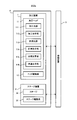
- FIG. 2 is a system configuration diagram showing a system configuration of the processing system of the first embodiment.
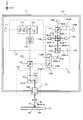
- FIG. 3 is a cross-sectional view showing the structure of the processing head of the first embodiment.
- FIG. 4 is a timing chart showing the measurement light incident on the detector and the interference light detected by the detector.
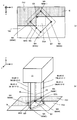
- FIG. 5 is a cross-sectional view showing the structure of the head drive system.
- FIG. 6 is a cross-sectional view showing the structure of the second drive system included in the head drive system.
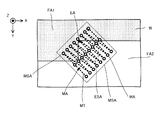
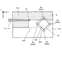
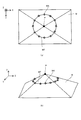
- FIG. 7A is a plan view showing a plurality of irradiated areas on the work, and FIG.
- FIG. 7B is a perspective view showing a plurality of irradiated areas on the work.
- 8 (a) and 8 (b) are cross-sectional views showing a processing head and a work whose positional relationship is controlled so that the distances between the plurality of irradiated areas and the processing head are the same. is there.
- FIG. 9 is a cross-sectional view showing a processed region in which removal processing has been performed and an unprocessed region in which removal processing has not been performed.
- FIG. 10 is a cross-sectional view showing a machining head and a work whose positional relationship is controlled so that the distance between the machined region and the machining head is the same as the distance between the unmachined region and the machining head. is there.
- FIG. 11 is a cross-sectional view showing a processed region in which additional processing has been performed and an unprocessed region in which additional processing has not been performed.
- FIG. 12 is a cross-sectional view showing a machining head and a work whose positional relationship is controlled so that the distance between the machined region and the machining head is the same as the distance between the unmachined region and the machining head. is there.
- FIG. 13 is a plan view showing a plurality of irradiated areas on the work.
- FIG. 14 is a plan view showing a plurality of irradiated areas on the work.
- FIG. 15 is a plan view showing an example of the movement locus of the target irradiation region of the measurement light.
- FIG. 16 is a plan view showing an example of the positional relationship between the target shot area and the measurement shot area.
- FIG. 17 is a plan view showing a work irradiated with processing light.
- FIG. 18A is a top view showing an example of the work, and
- FIG. 18B is a perspective view showing an example of the work.
- FIG. 19 is a plan view showing a plurality of irradiated areas on the work when the third alignment operation is performed.
- FIG. 20 is a plan view showing a work on which an alignment mark is formed.
- FIG. 21 is a cross-sectional view schematically showing the overall structure of the processing system of the second embodiment.
- FIG. 22 is a cross-sectional view showing an example of the structure of a processing apparatus including an end effector.
- each of the X-axis direction and the Y-axis direction is a horizontal direction (that is, a predetermined direction in the horizontal plane), and the Z-axis direction is a vertical direction (that is, a direction orthogonal to the horizontal plane). Yes, in effect, in the vertical direction).
- the rotation directions (in other words, the inclination direction) around the X-axis, the Y-axis, and the Z-axis are referred to as the ⁇ X direction, the ⁇ Y direction, and the ⁇ Z direction, respectively.
- the Z-axis direction may be the direction of gravity.
- the XY plane may be horizontal.
- machining system SYSa Processing system SYSSa of the first embodiment
- machining system SYSa the machining system SYS of the first embodiment
- machining system SYSa the machining system SYS of the first embodiment
- FIG. 1 is a cross-sectional view schematically showing the structure of the processing system SYSA of the first embodiment.
- FIG. 2 is a system configuration diagram showing a system configuration of the processing system SYSA of the first embodiment.
- the processing system SYSa includes a processing device 1, a stage device 3, and a control device 5.
- the processing device 1 and the stage device 3 are housed in the housing 4.
- the processing device 1 and the stage device 3 do not have to be housed in the housing 4. That is, the processing system SYSa does not have to include the housing 4 that houses the processing device 1 and the stage device 3.
- the processing device 1 can process the work W under the control of the control device 5.
- the processing device 1 can perform processing on the work W under the control of the control device 5.
- the work W may be, for example, a metal, an alloy (for example, duralumin, etc.), a semiconductor (for example, silicon), or a resin (for example, CFRP (Carbon Fiber Reinforced)). It may be (Plastic), paint (for example, a paint layer applied to a base material), glass, or an object made of any other material.
- the processing device 1 irradiates the work W with processing light EL in order to process the work W.
- the processing light EL may be any kind of light as long as the work W can be processed by being irradiated with the work W. In the first embodiment, the description will be made using an example in which the processing light EL is a laser light, but the processing light EL may be a type of light different from the laser light.
- the wavelength of the processing light EL may be any wavelength as long as the work W can be processed by irradiating the work W.
- the processed light EL may be visible light or invisible light (for example, at least one of infrared light and ultraviolet light).
- the processed light EL includes pulsed light, but does not have to include pulsed light. In other words, the processed light EL may be continuous light.
- the processing apparatus 1 may irradiate the work W with processing light EL to perform removal processing (typically, cutting processing or grinding processing) to remove a part of the work W.
- the processing apparatus 1 may form a riblet structure on the work W.
- the riblet structure is a structure capable of reducing resistance to fluid on the surface of the work W (particularly, frictional resistance and turbulent frictional resistance).
- the riblet structure is, for example, a second direction in which a groove extending along a first direction (for example, the Y-axis direction) along the surface of the work W is along the surface of the work W and intersects in the first direction. It may include a plurality of structures arranged along (for example, the X-axis direction).
- the processing apparatus 1 removes a part of the coating film so that the base material is not exposed from the coating film. As a result, a riblet structure composed of a coating film remaining without being removed may be formed on the surface of the base material.
- the processing apparatus 1 may perform additional processing to add a new structure to the work W by irradiating the work W with processing light EL in addition to or instead of the removal processing.
- the processing apparatus 1 may form the above-mentioned riblet structure on the surface of the work W by performing additional processing.
- the processing apparatus 1 may perform marking processing for forming a desired mark on the surface of the work W by irradiating the work W with processing light EL in addition to or in place of at least one of the removal processing and the addition processing.
- the processing device 1 can further measure the work W under the control of the control device 5.
- the processing apparatus 1 irradiates the work W with the measurement light ML in order to measure the work W.
- the measurement light ML may be any kind of light as long as the work W can be measured by irradiating the work W. In the first embodiment, the description will be given using an example in which the measurement light ML is a laser light, but the measurement light ML may be a type of light different from the laser light.
- the wavelength of the measurement light ML may be any wavelength as long as the work W can be measured by irradiating the work W.
- the measurement light ML may be visible light or invisible light (for example, at least one of infrared light and ultraviolet light).
- the measurement light ML includes pulsed light.
- the wavelength of the measurement light ML may be different from the wavelength of the processing light EL.
- the wavelength of the measurement light ML may be shorter than the wavelength of the processing light EL.
- light having a wavelength band of 266 nm or 355 nm may be used as the measurement light ML, and light having a wavelength band of 532 nm, 1 ⁇ m or 10 ⁇ m may be used as the processing light EL.
- the spot diameter of the measurement light ML on the work W becomes smaller than the spot diameter of the processing light EL on the work W.
- the wavelength of the measurement light ML does not have to be shorter than the wavelength of the processing light EL.
- the wavelength of the measurement light ML may be the same as the wavelength of the processing light EL.
- the processing device 1 may be capable of measuring the state of the work W.
- the state of the work W may include the position of the work W.
- the position of the work W may include the position of the surface of the work W.
- the position of the surface of the work W may include a position in at least one of the X-axis direction, the Y-axis direction, and the Z-axis direction of each surface portion obtained by subdividing the surface of the work W.
- the state of the work W may include a distance D between the processing head 11 and the work W, which will be described later.
- the distance D between the processing head 11 and the work W may mean a distance in a direction along the Z axis, which is an axis connecting the processing head 11 and the work W.
- the distance D between the machining head 11 and the work W is typically the distance between the reference portion of the machining head 11 and the surface of the work W.
- the distance between the reference portion of the processing head 11 and the surface of the work W may include the distance between the reference portion of the processing head 11 and each surface portion obtained by subdividing the surface of the work W.
- the state of the work W may include the shape of the work W (for example, a three-dimensional shape).
- the shape of the work W may include the shape of the surface of the work W.
- the shape of the surface of the work W is, in addition to or in place of, the position of the surface of the work W described above, the orientation of each surface portion subdivided into the surface of the work W (for example, the orientation of the normal of each surface portion).
- the state of the work W may include the size of the work W (for example, the size in at least one of the X-axis direction, the Y-axis direction, and the Z-axis direction).
- the processing apparatus 1 includes a processing head 11 that emits each of the processing light EL and the measuring light ML to the work W, and a head drive system 12 that moves the processing head 11. ..
- the processing head 11 means an arbitrary member capable of emitting each of the processing light EL and the measuring light ML to the work W. Therefore, although the processing head 11 includes the wording head, it does not necessarily mean a member attached to the tip of any member. Therefore, the processing head 11 may be referred to as a processing member. It can be said that the processing head 11 is a device that performs processing on the work W. It can be said that the processing head 11 is a device for measuring the work W.
- the processing head 11 includes a processing light source 111, a processing optical system 112, a measuring light source 113, a measuring optical system 114, a synthetic optical system 115, and a common optical system 116.
- the structures of the processing head 11 and the head drive system 12 will be described in detail later with reference to FIGS. 3 to 6.
- the processing head 11 may have any structure as long as it can emit the processing light EL and the measurement light ML to the work W. As long as the processing head 11 can emit the processing light EL and the measurement light ML to the work W, the processing light source 111, the processing optical system 112, the measuring light source 113, the measuring optical system 114, and the synthetic optical system 115 And at least one of the common optical systems 116 may not be provided.
- the head drive system 12 moves the machining head 11 along at least one of the X-axis direction, the Y-axis direction, the Z-axis direction, the ⁇ X direction, the ⁇ Y direction, and the ⁇ Z direction.
- the positional relationship between the stage 32 (furthermore, the work W mounted on the stage 32) and the processing head 11, which will be described later, changes. That is, when the machining head 11 moves, the relative positions of the stage 32 and the work W and the machining head 11 change. Therefore, moving the machining head 11 may be regarded as equivalent to changing the positional relationship between the stage 32 and the work W and the machining head 11.
- each optical system that is, the processing optical system 112, the measurement optical system 114, and the synthetic optical system included in the stage 32, the work W, and the processing head 11
- the positional relationship with at least one of 115 and the common optical system 116) changes. Therefore, moving the processing head 11 may be regarded as equivalent to changing the positional relationship between the stage 32 and the work W and each optical system included in the processing head 11. Further, when the positional relationship between the stage 32 and the work W and the processing head 11 changes, the positional relationship between the stage 32 and the work W and the housing 117 of the processing head 11 changes.
- moving the machining head 11 may be regarded as equivalent to changing the positional relationship between the stage 32 and the work W and the housing 117 of the machining head 11. Further, when the positional relationship between the stage 32 and the work W and the processing head 11 changes, the positions of the target irradiation area EA and the target irradiation area MA set on the work W on the work W change.
- the target irradiation area EA is an area where the processing head 11 is scheduled to irradiate the processing light EL.
- the target irradiation area MA is an area where the processing head 11 is scheduled to irradiate the measurement light ML.
- moving the processing head 11 may be regarded as equivalent to changing the positions of the target irradiation area EA and the target irradiation area MA on the work W. Further, when the positional relationship between the stage 32 and the work W and the processing head 11 changes, the irradiation positions where the processing light EL and the measurement light ML are actually irradiated on the work W change. Therefore, moving the processing head 11 may be regarded as equivalent to changing the irradiation positions of the processing light EL and the measurement light ML on the work W.
- the stage device 3 includes a surface plate 31 and a stage 32.
- the surface plate 31 is arranged on the bottom surface of the housing 4 (or on a supporting surface such as a floor surface on which the housing 4 is placed).
- a stage 32 is arranged on the surface plate 31.
- a vibration isolator (not shown) may be installed between the bottom surface of the housing 4 or the support surface such as the floor on which the housing 4 is placed and the surface plate 31.
- a support frame (not shown) that supports the processing apparatus 1 may be arranged on the surface plate 31.
- the stage 32 may hold the mounted work W.
- the stage 32 may hold the work W by vacuum-adsorbing and / or electrostatically adsorbing the work W.
- the stage 32 does not have to hold the mounted work W.
- the stage 32 can move on the surface plate 31 with the work W mounted under the control of the control device 5.
- the stage 32 is movable with respect to at least one of the surface plate 31 and the processing apparatus 1.
- the stage 32 can move along the X-axis direction and the Y-axis direction, respectively.
- the stage 32 can move along the stage running surface (moving surface) parallel to the XY plane.
- the stage 32 may also be movable along at least one of the Z-axis direction, the ⁇ X direction, the ⁇ Y direction, and the ⁇ Z direction.
- the stage device 3 includes a stage drive system 33.
- the stage drive system 33 moves the stage 32 by using, for example, an arbitrary motor (for example, a linear motor or the like).
- the stage device 3 may be provided with a stage position measuring instrument for measuring the position of the stage 32.
- the stage position measuring instrument may include, for example, at least one of an encoder and a laser interferometer.
- the positional relationship between the stage 32 (furthermore, the work W mounted on the stage 32) and the processing head 11 changes. That is, when the stage 32 moves, the relative positions of the processing head 11 and the stage 32 and the work W change. Therefore, moving the stage 32 may be regarded as equivalent to changing the positional relationship between the stage 32 and the work W and the processing head 11. Further, when the positional relationship between the stage 32 and the work W and the processing head 11 changes, the positional relationship between the stage 32 and the work W and each optical system included in the processing head 11 changes. Therefore, moving the stage 32 may be regarded as equivalent to changing the positional relationship between the stage 32 and the work W and each optical system included in the processing head 11.
- moving the stage 32 may be regarded as equivalent to changing the positional relationship between the stage 32 and the work W and the housing 117 of the processing head 11.
- the positions of the target irradiation area EA and the target irradiation area MA on the respective work W change. Therefore, moving the stage 32 may be regarded as equivalent to changing the positions of the target irradiation area EA and the target irradiation area MA on the work W.
- moving the stage 32 may be regarded as equivalent to changing the irradiation positions of the processing light EL and the measurement light ML on the work W.
- the control device 5 controls the operation of the processing system SYS. For example, the control device 5 sets the machining conditions of the work W, and controls the machining device 1 and the stage device 3 so that the work W is machined according to the set machining conditions. For example, the control device 5 sets the measurement conditions of the work W, and controls the processing device 1 and the stage device 3 so that the work W is measured according to the set measurement conditions.
- the control device 5 may include, for example, an arithmetic unit and a storage device.
- the arithmetic unit may include, for example, at least one of a CPU (Central Processing Unit) and a GPU (Graphics Processing Unit).
- the control device 5 functions as a device that controls the operation of the processing system SYS by executing a computer program by the arithmetic unit.
- This computer program is a computer program for causing the control device 5 (for example, an arithmetic unit) to perform (that is, execute) an operation described later to be performed by the control device 5. That is, this computer program is a computer program for causing the control device 5 to function so that the processing system SYSa performs an operation described later.
- the computer program executed by the arithmetic unit may be recorded in a storage device (that is, a recording medium) included in the control device 5, or any storage built in the control device 5 or externally attached to the control device 5. It may be recorded on a medium (for example, a hard disk or a semiconductor memory). Alternatively, the arithmetic unit may download the computer program to be executed from an external device of the control device 5 via the network interface.
- a storage device that is, a recording medium included in the control device 5, or any storage built in the control device 5 or externally attached to the control device 5. It may be recorded on a medium (for example, a hard disk or a semiconductor memory).
- the arithmetic unit may download the computer program to be executed from an external device of the control device 5 via the network interface.
- the control device 5 does not have to be provided inside the processing system SYS, and may be provided as a server or the like outside the processing system SYS, for example.
- the control device 5 and the processing system SYSA may be connected by a wired and / or wireless network (or a data bus and / or a communication line).
- a wired network for example, a network using a serial bus type interface represented by at least one of IEEE1394, RS-232x, RS-422, RS-423, RS-485 and USB may be used.
- a network using a parallel bus interface may be used.
- a network using an Ethernet (registered trademark) compliant interface represented by at least one of 10BASE-T, 100BASE-TX and 1000BASE-T may be used.
- a network using radio waves may be used.
- An example of a network using radio waves is a network conforming to IEEE802.1x (for example, at least one of wireless LAN and Bluetooth®).
- a network using infrared rays may be used.
- a network using optical communication may be used.
- the control device 5 and the processing system SYSA may be configured so that various types of information can be transmitted and received via the network.
- control device 5 may be able to transmit information such as commands and control parameters to the processing system SYSA via the network.
- the processing system SYSa may include a receiving device that receives information such as commands and control parameters from the control device 5 via the network.
- the first control device that performs a part of the processing performed by the control device 5 is provided inside the processing system SYS, the second control device that performs the other part of the processing performed by the control device 5 is performed.
- the control device may be provided outside the processing system SYS.
- the recording medium for recording the computer program executed by the arithmetic unit includes CD-ROM, CD-R, CD-RW, flexible disk, MO, DVD-ROM, DVD-RAM, DVD-R, DVD + R, and DVD-. At least one of optical disks such as RW, DVD + RW and Blu-ray (registered trademark), magnetic media such as magnetic tape, magneto-optical disks, semiconductor memories such as USB memory, and any other medium capable of storing a program is used. You may.
- the recording medium may include a device capable of recording a computer program (for example, a general-purpose device or a dedicated device in which the computer program is implemented in at least one form such as software and firmware).
- each process or function included in the computer program may be realized by a logical processing block realized in the control device 5 by the control device 5 (that is, a computer) executing the computer program. It may be realized by hardware such as a predetermined gate array (FPGA, ASIC) included in the control device 5, or a logical processing block and a partial hardware module that realizes a part of the hardware are mixed. It may be realized in the form of.
- a logical processing block realized in the control device 5 by the control device 5 (that is, a computer) executing the computer program. It may be realized by hardware such as a predetermined gate array (FPGA, ASIC) included in the control device 5, or a logical processing block and a partial hardware module that realizes a part of the hardware are mixed. It may be realized in the form of.
- FPGA predetermined gate array
- FIG. 3 is a cross-sectional view showing an example of the structure of the processing head 11.
- the processing head 11 includes a processing light source 111, a processing optical system 112, a measuring light source 113, a measuring optical system 114, a synthetic optical system 115, and a common optical system 116.
- the processing light source 111, the processing optical system 112, the measurement light source 113, the measurement optical system 114, the synthetic optical system 115, and the common optical system 116 are housed in the housing 117.
- at least one of the processing light source 111, the processing optical system 112, the measuring light source 113, the measuring optical system 114, the synthetic optical system 115, and the common optical system 116 may not be housed in the housing 117.
- each optical system is relative to the machining head 11 (eg, for the housing 117). Placed in a fixed position. That is, as the processing head 11 is moved by the head drive system 12, each optical system also moves in the same manner as the processing head 11 (for example, the housing 117).
- the processing light source 111 can generate processing light EL.
- the processing light source 111 may include, for example, a laser diode. Further, the processing light source 111 may be a light source capable of pulse oscillation. In this case, the processing light source 111 can generate pulsed light (for example, pulsed light having a light emission time of picoseconds or less) as the processing light EL.
- the processing light source 111 emits the generated processing light EL toward the processing optical system 112.
- the processing optical system 112 is an optical system in which the processing light EL emitted from the processing light source 111 is incident.
- the processing optical system 112 is an optical system that emits processing light EL incident on the processing optical system 112 toward the synthetic optical system 115. That is, the processing optical system 112 is an optical system that guides the processing light EL emitted from the processing light source 111 to the synthetic optical system 115.
- the processing light EL emitted by the processing optical system 112 irradiates the work W via the synthetic optical system 115 and the common optical system 116. Therefore, it can be said that the processing optical system 112 is an optical system that emits (irradiates) the processing light EL toward the work W via the synthetic optical system 115 and the common optical system 116.
- the processing optical system 112 includes a position adjustment optical system 1121, an angle adjustment optical system 1122, and a focus adjustment optical system 1123.
- the position adjustment optical system 1121 can adjust the injection position of the processing light EL from the processing optical system 112.
- the position adjusting optical system 1121 may include, for example, a parallel plane plate that can be inclined with respect to the traveling direction of the processing light EL, and the injection position of the processing light EL may be changed by changing the inclination angle of the parallel plane plate.
- the position adjusting optical system 1121 can set the injection position of the processing light EL to an arbitrary position in the YZ plane by using a plurality of parallel plane plates having different inclination directions from each other.
- the angle adjustment optical system 1122 can adjust the injection angle of the processing light EL from the processing optical system 112.
- the angle adjusting optical system 1122 may include, for example, a mirror that can be tilted with respect to the traveling direction of the processing light EL, and the emission angle of the processing light EL may be changed by changing the tilt angle of the mirror.
- the angle adjusting optical system 1122 uses a plurality of mirrors having different inclination directions from each other, and sets the injection angle of the processing light EL toward arbitrary directions around the ⁇ X axis and the ⁇ Y axis.
- Focus adjustment optical system 1123 can adjust (typically change) the focusing position of the processed light EL. Therefore, the focus adjusting optical system 1123 functions as a focus changing member capable of adjusting the focusing position of the processed light EL.
- Focus adjustment optics 1123 includes a plurality of lenses, at least one of which is movable along the optical axis.
- the focus adjustment optical system 1123 adjusts the focusing position of the processed light EL with respect to the surface of the work W in the optical axis direction by moving at least one lens. Specifically, the focus adjustment optical system 1123 moves at least one lens to move the focus position of the processed light EL with respect to the surface of the work W in the direction along the optical axis AX of the f ⁇ lens 1162 (in FIG. 3). In the example shown, the adjustment is made in the Z-axis direction (direction intersecting the surface of the work W).
- the focus adjustment optical system 1123 may typically adjust the focus position of the processing light EL so that the focus position of the processing light EL is located on the surface of the work W.
- the processing optical system 112 does not have to include at least one of the position adjusting optical system 1121, the angle adjusting optical system 1122, and the focus adjusting optical system 1123.
- the processing optical system 112 is added to or in place of at least one of the position adjusting optical system 1121, the angle adjusting optical system 1122, and the focus adjusting optical system 1123, and other optical elements and optical members (these may be referred to as optical systems). Good, the same shall apply hereinafter) may be included.
- the processing light EL emitted from the processing optical system 112 is incident on the synthetic optical system 115.
- the synthetic optical system 115 includes a beam splitter (for example, a polarizing beam splitter) 1151.
- the beam splitter 1151 emits the processed light EL incident on the beam splitter 1151 toward the common optical system 116.
- the processing light EL incident on the beam splitter 1151 is emitted toward the common optical system 116 by passing through the polarization separation surface. Therefore, in the example shown in FIG.
- the processed light EL is applied to the polarization separation surface of the beam splitter 1151 in a state of having a polarization direction (polarization direction that is p-polarized with respect to the polarization separation surface) that can be transmitted through the polarization separation surface.
- the processed light EL emitted from the synthetic optical system 115 is incident on the common optical system 116.
- the common optical system 116 emits the processed light EL incident on the common optical system 116 toward the work W.
- the common optical system 116 includes a galvano mirror 1161 and an f ⁇ lens 1162.
- the processed light EL emitted from the synthetic optical system 115 is incident on the galvano mirror 1161.
- the galvano mirror 1161 changes the irradiation position of the processing light EL on the work W by deflecting the processing light EL (that is, changing the injection angle of the processing light EL). That is, the galvano mirror 1161 changes the position of the target irradiation region EA set on the work W or on the optical path of the processing light EL as the region to be irradiated with the processing light EL by deflecting the processing light EL. To do.
- the galvano mirror 1161 Since the galvano mirror 1161 is arranged at or near the entrance pupil position of the f ⁇ lens 1162, the change in the emission angle of the processed light EL by the galvano mirror 1161 is caused by the f ⁇ lens 1162 at the irradiation position of the processed light EL (that is, that is). , The position of the target irradiation area EA) is converted.
- the galvano mirror 1161 includes an X scanning mirror 1161X and a Y scanning mirror 1161Y. Each of the X scanning mirror 1161X and the Y scanning mirror 1161Y is a tilt angle variable mirror in which the angle of the processed light EL incident on the galvano mirror 1161 with respect to the optical path is changed.
- the X-scanning mirror 1161X swings or rotates so as to change the irradiation position of the processed light EL on the work W along the X-axis direction (that is, changes the angle of the X-scanning mirror 1161X with respect to the optical path of the processed light EL. By doing so, the processing light EL is deflected.
- the Y scanning mirror 1161Y swings or rotates so as to change the irradiation position of the processed light EL on the work W along the Y-axis direction (that is, changes the angle of the Y scanning mirror 1161Y with respect to the optical path of the processed light EL. By doing so, the processing light EL is deflected.
- the processed light EL from the galvano mirror 1161 is incident on the f ⁇ lens 1162. Therefore, the galvanometer mirror 1161 is arranged on the optical path of the processed light EL between the synthetic optical system 115 and the f ⁇ lens 1162.
- the f ⁇ lens 1162 is arranged on the optical path of the processed light EL between the galvano mirror 1161 and the work W.
- the f ⁇ lens 1162 is arranged on the optical path of the processed light EL between the galvanometer mirror 1161 and the target irradiation region EA.
- the f ⁇ lens 1162 is an optical system for irradiating the work W with the processed light EL from the galvano mirror 1161.
- the f ⁇ lens 1162 is an optical system for irradiating the target irradiation region EA with the processed light EL from the galvanometer mirror 1161.
- the f ⁇ lens 1162 is an optical system for condensing the processed light EL from the galvano mirror 1161 on the work W. Therefore, the f ⁇ lens 1162 irradiates the work W with the processed light EL in the convergent state. As a result, the work W is processed by the processing light EL.
- the f ⁇ lens 1162 may be referred to as an irradiation optical system because the work W is irradiated with the processed light EL (particularly, the surface of the work W is irradiated).
- the moving range of the target irradiation area EA that moves on the work W due to the deflection of the processing light EL by the galvano mirror 1161 may be referred to as a processing shot area ESA (see FIG. 7 described later).
- the target irradiation area EA may be regarded as moving within the processed shot area ESA.
- the measurement light source 113 can generate the measurement light ML.
- the measurement light source 113 may include, for example, a laser diode.
- the measurement light source 113 is a light source capable of pulse oscillation.
- the measurement light source 113 can generate pulsed light (for example, pulsed light having a light emission time of picoseconds or less) as the measurement light ML.
- the measurement light source 113 emits the generated measurement light ML toward the measurement optical system 114.
- the measurement light source 113 includes an optical comb light source.
- the optical comb light source is a light source capable of generating light containing frequency components arranged at equal intervals on the frequency axis (hereinafter referred to as "optical frequency comb") as pulsed light.
- the measurement light source 113 emits pulsed light including frequency components arranged at equal intervals on the frequency axis as the measurement light ML.
- the measurement light source 113 does not have to include the optical comb light source.
- the processing head 11 includes a plurality of measurement light sources 113.
- the processing head 11 includes a measurement light source 113 # 1 and a measurement light source 113 # 2.
- the plurality of measurement light sources 113 emit a plurality of measurement light MLs that are phase-locked to each other and have interference with each other.
- the plurality of measurement light sources 113 may have different oscillation frequencies. Therefore, the plurality of measurement light MLs emitted by the plurality of measurement light sources 113 are the plurality of measurement light MLs having different pulse frequencies (for example, the number of pulsed lights per unit time and the reciprocal of the emission cycle of the pulsed light). It becomes.
- the measurement light source 113 # 1 emits the measurement light ML # 1 having a pulse frequency of 25 GHz
- the measurement light source 113 # 2 emits the measurement light ML # 2 having a pulse frequency of 25 GHz + ⁇ (for example, + 100 kHz).
- the processing head 11 may include a single measurement light source 113.
- the measurement optical system 114 is an optical system in which the measurement light ML emitted from the measurement light source 113 is incident.
- the measurement optical system 114 is an optical system that emits the measurement light ML incident on the measurement optical system 114 toward the synthetic optical system 115. That is, the measurement optical system 114 is an optical system that guides the measurement light ML emitted from the measurement light source 113 to the synthetic optical system 115.
- the measurement light ML emitted by the measurement optical system 114 is applied to the work W via the synthetic optical system 115 and the common optical system 116. Therefore, it can be said that the measurement optical system 114 is an optical system that emits the measurement light ML toward the work W via the composite optical system 115 and the common optical system 116.
- the measurement optical system 114 is optically separated from the processing optical system 112. Therefore, the optical path of the processing light EL between the processing light source 111 and the synthetic optical system 115 and the optical path of the measurement light ML between the measurement light source 113 and the synthetic optical system 115 are optically separated. Note that the optical path of one optical system and another optical system are optically separated may mean that the optical path of one optical system and the optical path of another optical system do not overlap each other.
- the measurement optical system 114 includes, for example, a beam splitter 1141, a beam splitter 1142, a detector 1143, a beam splitter 1144, a mirror 1145, a detector 1146, a mirror 1147, and a galvano mirror 1148.
- the measurement light ML emitted from the measurement light source 113 is incident on the beam splitter 1141.
- the measurement light ML emitted from the measurement light source 113 # 1 (hereinafter referred to as “measurement light ML # 1”) and the measurement light ML emitted from the measurement light source 113 # 2 (hereinafter referred to as “measurement light ML”).
- # 2 is incident on the beam splitter 1141.
- the beam splitter 1141 emits the measurement lights ML # 1 and ML # 2 incident on the beam splitter 1141 toward the beam splitter 1142.
- the beam splitter 1142 reflects the measurement light ML # 1-1, which is a part of the measurement light ML # 1 incident on the beam splitter 1142, toward the detector 1143.
- the beam splitter 1142 emits the measurement light ML # 1-2, which is another part of the measurement light ML # 1 incident on the beam splitter 1142, toward the beam splitter 1144. That is, the beam splitter 1142 is a measurement light ML # 1 traveling on an optical path extending from the beam splitter 1142 to the detector 1143 and a measurement light ML # 1-1 traveling on an optical path from the beam splitter 1142 to the beam splitter 1144. It functions as a branching optical system that branches into optical ML # 1-2.
- the beam splitter 1142 reflects the measurement light ML # 2-1 which is a part of the measurement light ML # 2 incident on the beam splitter 1142 toward the detector 1143.
- the beam splitter 1142 emits the measurement light ML # 2-2, which is another part of the measurement light ML # 2 incident on the beam splitter 1142, toward the beam splitter 1144. That is, the beam splitter 1142 is a measurement light ML # 2 traveling on an optical path extending from the beam splitter 1142 to the detector 1143 and a measurement light ML # 2 traveling on an optical path from the beam splitter 1142 to the beam splitter 1144. It functions as a branching optical system that branches into optical ML # 2-2.
- the measurement lights ML # 1-1 and ML # 2-1 emitted from the beam splitter 1142 are incident on the detector 1143.
- the detector 1143 detects the interference light generated by the interference between the measurement light ML # 1-1 and the measurement light ML # 2-1. That is, the detector 1143 detects an interference signal based on the interference light generated by the interference between the measurement light ML # 1-1 and the measurement light ML # 2-1. Specifically, the detector 1143 detects the interference light by receiving the interference light. Therefore, the detector 1143 may be provided with a light receiving element (a light receiving unit, typically a photoelectric conversion element) capable of receiving light. The detection result of the detector 1143 is output to the control device 5.
- a light receiving element a light receiving unit, typically a photoelectric conversion element
- the measurement lights ML # 1-2 and ML # 2-2 emitted from the beam splitter 1142 are incident on the beam splitter 1144.
- the beam splitter 1144 emits at least a part of the measurement light ML # 1-2 incident on the beam splitter 1144 toward the mirror 1145.
- the beam splitter 1144 emits at least a part of the measurement light ML # 2-2 incident on the beam splitter 1144 toward the mirror 1147. That is, the beam splitter 1144 splits the measurement light ML # 1-2 and ML # 2-2 (that is, substantially the measurement light ML from the measurement light source 113) incident on the beam splitter 1144 from the same direction. It functions as a branching optical system that branches into measurement light ML # 1-2 traveling in an optical path extending from 1144 to mirror 1145 and measurement light ML # 2-2 traveling in an optical path extending from a beam splitter 1144 to mirror 1147.
- the measurement light ML # 1-2 emitted from the beam splitter 1144 is incident on the mirror 1145.
- the measurement light ML # 1-2 incident on the mirror 1145 is reflected by the reflecting surface of the mirror 1145 (the reflecting surface may be referred to as a reference surface).
- the mirror 1145 reflects the measurement light ML # 1-2 incident on the mirror 1145 toward the beam splitter 1144. That is, the mirror 1145 emits (returns) the measurement light ML # 1-2 incident on the mirror 1145 toward the beam splitter 1144 as the reflected light measurement light ML # 1-3.
- the measurement light ML # 1-3 emitted from the mirror 1145 is incident on the beam splitter 1144.
- the beam splitter 1144 emits the measurement light ML # 1-3 incident on the beam splitter 1144 toward the beam splitter 1142.
- the measurement light ML # 1-3 emitted from the beam splitter 1144 is incident on the beam splitter 1142.
- the beam splitter 1142 emits the measurement light ML # 1-3 incident on the beam splitter 1142 toward the detector 1146.
- the measurement light ML # 2-2 emitted from the beam splitter 1144 is incident on the mirror 1147.
- the mirror 1147 reflects the measurement light ML # 2-2 incident on the mirror 1147 toward the galvano mirror 1148. That is, the mirror 1147 emits the measurement light ML # 2-2 incident on the mirror 1147 toward the galvano mirror 1148.
- the galvanometer mirror 1148 deflects the measurement light ML # 2-2 (that is, changes the emission angle of the measurement light ML # 2-2) to change the irradiation position of the measurement light ML # 2-2 on the work W. To change. That is, the galvano mirror 1148 is set on the work W or on the optical path of the measurement light ML # 2-2 as a region to be irradiated with the measurement light ML by deflecting the measurement light ML # 2-2. The position of the target irradiation area MA is changed.
- the galvano mirror 1148 includes an X scanning mirror 1148X and a Y scanning mirror 1148Y.
- Each of the X scanning mirror 1148X and the Y scanning mirror 1148Y is a tilt angle variable mirror in which the angle of the measurement light ML # 2-2 incident on the galvano mirror 1148 with respect to the optical path is changed.
- the X scanning mirror 1148X swings or rotates so as to change the irradiation position of the measurement light ML # 2-2 on the work W along the X-axis direction (that is, with respect to the optical path of the measurement light ML # 2-2).
- the measurement light ML # 2-2 is deflected by changing the angle of the X scanning mirror 1148X).
- the Y scanning mirror 1148Y swings or rotates so as to change the irradiation position of the measurement light ML # 2-2 on the work W along the Y-axis direction (that is, with respect to the optical path of the measurement light ML # 2-2).
- the measurement light ML # 2-2 is deflected by changing the angle of the Y scanning mirror 1148Y). Since the irradiation position of the measurement light ML # 2-2 is changed by the galvano mirror 1148, the galvano mirror 1148 may be referred to as an irradiation position change optical system.
- the galvano mirror 1148 emits the deflected measurement light ML # 2-2 toward the synthetic optical system 115.
- the measurement light ML # 2-2 emitted from the galvano mirror 1148 is incident on the synthetic optical system 115.
- the beam splitter 1151 of the synthetic optical system 115 emits the measurement light ML # 2-2 incident on the beam splitter 1151 toward the common optical system 116.
- the measurement light ML # 2-2 incident on the beam splitter 1151 is reflected at the polarization separation surface and is emitted toward the common optical system 116. Therefore, in the example shown in FIG.
- the measurement light ML # 2-2 is a beam splitter 1151 in a state where it has a polarization direction that can be reflected by the polarization separation surface (a polarization direction that is s-polarized with respect to the polarization separation surface). It is incident on the polarization splitting surface.
- the processing light EL is incident on the beam splitter 1151 in addition to the measurement light ML # 2-2. That is, both the measurement light ML # 2-2 and the processing light EL pass through the beam splitter 1151.
- the beam splitter 1151 emits the processing light EL and the measurement light ML # 2-2 that have been incident on the beam splitter 1151 from different directions in the same direction (that is, toward the same common optical system 116). Therefore, the beam splitter 1151 substantially functions as an optical system that synthesizes the processing light EL and the measurement light ML # 2-2.
- the directions in which the processing light EL and the measurement light ML # 2-2 are emitted from the beam splitter 1151 described above are the processing light EL and the measurement light ML in the common optical system 116 located on the emission side of the synthetic optical system 115.
- the processing light EL and the measurement light ML # 2-2 may be set in a direction to be emitted so that # 2-2 is incident. As long as the processing light EL and the measurement light ML # 2-2 are incident on the common optical system 116, the directions in which the processing light EL and the measurement light ML # 2-2 are emitted may be slightly different.
- the synthetic optical system 115 may have any structure as long as the processing light EL and the measurement light ML # 2-2 can be combined.
- the synthetic optical system 115 uses a dichroic mirror that reflects light in one wavelength band and transmits light in another wavelength band in addition to or instead of using a beam splitter 1151 to process light EL and measurement light.
- ML # 2-2 may be synthesized.
- the measurement light ML # 2-2 emitted from the synthetic optical system 115 is incident on the common optical system 116.
- the common optical system 116 emits the measurement light ML # 2-2 incident on the common optical system 116 toward the work W.
- the measurement light ML # 2-2 emitted from the synthetic optical system 115 is incident on the galvano mirror 1161.
- the galvanometer mirror 1161 changes the irradiation position of the measurement light ML # 2-2 on the work W by deflecting the measurement light ML # 2-2. That is, the galvano mirror 1161 is set on the work W or on the optical path of the measurement light ML # 2-2 as a region to be irradiated with the measurement light ML # 2-2 by deflecting the measurement light ML # 2-2.
- the position of the target irradiation area MA to be performed is changed.
- the galvano mirror 1161 Since the galvano mirror 1161 is arranged at or near the entrance pupil position of the f ⁇ lens 1162, the change in the emission angle of the measurement light ML # 2-2 by the galvano mirror 1161 is caused by the f ⁇ lens 1162. It is converted into a change in the irradiation position of 2-2 (that is, the position of the target irradiation area MA).
- the X scanning mirror 1161X swings or rotates so as to change the irradiation position of the measurement light ML # 2-2 on the work W along the X-axis direction (that is, the measurement light ML # 2-2).
- the measurement light ML # 2-2 is deflected by changing the angle of the X scanning mirror 1161X with respect to the optical path).
- the Y scanning mirror 1161Y swings or rotates so as to change the irradiation position of the measurement light ML # 2-2 on the work W along the Y-axis direction (that is, with respect to the optical path of the measurement light ML # 2-2).
- the measurement light ML # 2-2 is deflected. Since the irradiation position of the measurement light ML # 2-2 (furthermore, the irradiation position of the processing light EL) is changed by the galvano mirror 1161, the galvano mirror 1161 may be referred to as an irradiation position change optical system. ..
- the measurement light ML # 2-2 from the galvano mirror 1161 is incident on the f ⁇ lens 1162.
- the f ⁇ lens 1162 is an optical system for condensing the measurement light ML # 2-2 from the galvano mirror 1161 on the work W.
- the f ⁇ lens 1162 is an optical system for irradiating the work W with the measurement light ML # 2-2 from the galvano mirror 1161.
- the f ⁇ lens 1162 is an optical system for irradiating the target irradiation region MA with the measurement light ML # 2-2 from the galvano mirror 1161. Therefore, the f ⁇ lens 1162 is arranged on the optical path of the measurement light ML # 2-2 between the galvanometer mirror 1161 and the target irradiation region MA.
- the f ⁇ lens 1162 irradiates the work W with the measured light ML # 2-2 in a converged state.
- the work W is measured by the measurement light ML (specifically, the measurement light ML # 2-2).
- the f ⁇ lens 1162 may be referred to as an irradiation optical system because it irradiates the work W with the measurement light ML # 2-2 (particularly, irradiates the surface of the work W).
- the movement range of the target irradiation region MA that moves on the work W due to the deflection of the measurement light ML # 2-2 by the galvanometer mirror 1161 may be referred to as a measurement shot region MSA (see FIG. 7 described later). ..
- the target irradiation area MA may be considered to move within the measurement shot area MSA.
- the processing light EL is incident on the common optical system 116 in addition to the measurement light ML # 2-2. That is, the processing light EL and the measurement light ML # 2-2 synthesized by the synthetic optical system 115 are incident on the common optical system 116. Therefore, both the measurement light ML # 2-2 and the processing light EL pass through the same common optical system 116 (specifically, the same galvano mirror 1161 and the same f ⁇ lens 1162).
- the galvano mirror 1161 can be changed in synchronization with the irradiation position of the processing light EL on the work W and the irradiation position of the measurement light ML # 2-2 on the work W.
- the galvano mirror 1161 can change the irradiation position of the processing light EL on the work W and the irradiation position of the measurement light ML # 2-2 on the work W in conjunction with each other. That is, the galvanometer mirror 1161 can change the relative position of the target irradiation region EA with respect to the work W and the relative position of the target irradiation region MA with respect to the work W in synchronization and / or in conjunction with each other.
- the f ⁇ lens 1162 directs both the processing light EL and the measurement light ML in the direction from the f ⁇ lens 1162 toward the work W. Eject. That is, the f ⁇ lens 1162 emits both the processing light EL and the measurement light ML in the same direction. The f ⁇ lens 1162 emits the measurement light ML in the same direction as the processing light EL is emitted from the f ⁇ lens 1162. The f ⁇ lens 1162 emits the processed light EL in the same direction as the measurement light ML is emitted from the f ⁇ lens 1162.
- the processing system SYSa can independently move the irradiation position of the measurement light ML # 2-2 on the work W with respect to the irradiation position of the processing light EL on the work W.
- the processing system SYSa can independently move the target irradiation region MA of the measurement light ML # 2-2 with respect to the target irradiation region EA of the processing light EL.
- the processing system SYSa can independently change the irradiation position of the processing light EL on the work W and the irradiation position of the measurement light ML # 2-2 on the work W.
- the processing system SYSa can independently change the position of the target irradiation region EA and the position of the target irradiation region MA.
- the processing system SYSa can change the positional relationship between the irradiation position of the processing light EL on the work W and the irradiation position of the measurement light ML # 2-2 on the work W.
- the light caused by the irradiation of the measurement light ML # 2-2 is generated from the work W. That is, when the work W is irradiated with the measurement light ML # 2-2, the light caused by the irradiation of the measurement light ML # 2-2 is emitted from the work W.
- the light emitted from the work W due to the irradiation of the measurement light ML # 2-2 (that is, the light caused by the irradiation of the measurement light ML # 2-2) is the measurement light ML # 2 reflected by the work W.
- measurement light ML # 2-2 that is, scattered light
- measurement light ML # 2-2 that is, diffracted light
- At least one of the measurement light ML # 2-2 (that is, transmitted light) transmitted through the work W may be included.
- At least a part of the light emitted from the work W due to the irradiation of the measurement light ML # 2-2 (hereinafter, this light is referred to as “measurement light ML # 2-3”) is incident on the common optical system 116.
- the measurement light ML # 2-3 incident on the common optical system 116 is incident on the composite optical system 115 via the f ⁇ lens 1162 and the galvano mirror 1161.
- the beam splitter 1151 of the synthetic optical system 115 emits the measurement light ML # 2-3 incident on the beam splitter 1151 toward the measurement optical system 114.
- the measurement light ML # 2-3 incident on the beam splitter 1151 is reflected at the polarization separation surface and is emitted toward the measurement optical system 114. Therefore, in the example shown in FIG. 3, the measurement light ML # 2-3 is incident on the polarization separation surface of the beam splitter 1151 in a state of having a polarization direction that can be reflected by the polarization separation surface.
- the measurement light ML # 2-3 emitted from the synthetic optical system 115 is incident on the mirror 1147 via the galvano mirror 1148 of the measurement optical system 114.
- the mirror 1147 reflects the measurement light ML # 2-3 incident on the mirror 1147 toward the beam splitter 1144.
- the beam splitter 1144 emits at least a part of the measurement light ML # 2-3 incident on the beam splitter 1144 toward the beam splitter 1142.
- the beam splitter 1142 emits at least a part of the measurement light ML # 2-3 incident on the beam splitter 1142 toward the detector 1146.
- the detector 1146 travels from the beam splitter 1144 through the mirror 1147, the galvano mirror 1148, the synthetic optical system 115, and the common optical system 116 in this order to reach the work W in the optical path OP # 2-2. At least a part of the light generated by the measurement light ML # 2-2 irradiated on the surface of the work W is incident as the measurement light ML # 2-3.
- the detector 1146 has a common optical system 116, a synthetic optical system 115, and a galvanometer mirror among the lights generated by the measurement light ML # 2-2 that travels through the optical path OP # 2-2 and is applied to the surface of the work W.
- the measurement light ML # 2-3 may be referred to as a measurement light or an object light.
- the measurement light ML # 1-3 is incident on the detector 1146 in addition to the measurement light ML # 2-3. Specifically, the detector 1146 travels from the beam splitter 1144 through the mirror 1145, the beam splitter 1144, and the beam splitter 1142 in this order to reach the detector 1146 through the optical path OP # 1-3, and the detector 1146.
- the measurement light ML # 1-3 that reaches is incident.
- the measurement light ML # 1-3 that travels through the optical path OP # 1-3 formed by the mirror 1145 in other words, the optical path OP # 1-3 via the mirror 1145) and reaches the detector 1146. Is incident.
- the measurement light ML # 1-3 may be referred to as a reference light.
- the measurement light ML # 1-3 and the measurement light # ML2-3 correspond to a plurality of measurement light MLs (particularly, a plurality of optical frequency combs) that are phase-locked and interfere with each other.
- the measurement light sources 113 # 1 and 113 # 2 emit measurement light ML # 1 and ML # 2, which are phase-locked and coherent with each other, respectively.
- the detector 1146 detects the interference light generated by the interference between the measurement light ML # 1-3 and the measurement light ML # 2-3. That is, the detector 1146 detects an interference signal based on the interference light generated by the interference between the measurement light ML # 1-3 and the measurement light ML # 2-3.
- the detector 1146 detects the interference light by receiving the interference light. Therefore, the detector 1146 may be provided with a light receiving element (light receiving unit) capable of receiving light. The detection result of the detector 1146 is output to the control device 5.
- the control device 5 calculates the state of the work W based on the detection result of the detector 1143 (that is, the output of the detector 1143) and the detection result of the detector 1146 (that is, the output of the detector 1146).
- the principle of calculating the state of the work W based on the detection result of the detector 1143 and the detection result of the detector 1146 will be described with reference to FIG.
- FIG. 4 shows the measurement light ML # 1-1 incident on the detector 1143, the measurement light ML # 2-1 incident on the detector 1143, the interference light detected by the detector 1143, and the measurement light ML incident on the detector 1146. It is a timing chart which shows the interference light detected by # 1-3, the measurement light ML # 2-3 incident on the detector 1146, and the detector 1146. Since the pulse frequency of the measurement light ML # 1 and the pulse frequency of the measurement light ML # 2 are different, the pulse frequency of the measurement light ML # 1-1 and the pulse frequency of the measurement light ML # 2-1 are different.
- the interference light between the measurement light ML # 1-1 and the measurement light ML # 2-1 is the pulse light constituting the measurement light ML # 1-1 and the pulse light constituting the measurement light ML # 2-1. At the same time, it becomes interference light in which pulsed light appears in synchronization with the timing of incident on the detector 1143.
- the pulse frequency of the measurement light ML # 1-3 and the pulse frequency of the measurement light ML # 2-3 are different. Therefore, the interference light between the measurement light ML # 1-3 and the measurement light ML # 2-3 includes the pulse light constituting the measurement light ML # 1-3 and the pulse light constituting the measurement light ML # 2-3. At the same time, it becomes interference light in which pulsed light appears in synchronization with the timing of incident on the detector 1146.
- the position (position on the time axis) of the pulsed light that creates the interference light detected by the detector 1146 is the length of the optical path OP # 1-3 including the optical path through which the measurement light ML # 1-3 passes, and the measurement. It varies depending on the difference between the lengths of the optical paths OP # 2-2 and OP # 2-3 including the optical path through which the optical ML # 2-3 passes. Further, while the lengths of the optical paths OP # 2-2 and OP # 2-3 vary depending on the positional relationship between the measurement optical system 114 (particularly, the detector 1146) and the work W, the optical paths OP # 1- The length of 3 does not change depending on the positional relationship between the measurement optical system 114 (particularly, the detector 1146) and the work W.
- the measurement light ML # 2-3 is incident on the detector 1146 via the work W, while the measurement light ML # 1-3 is incident on the detector 1146 without passing through the work W.
- the position of the pulsed light that produces the interference light detected by the detector 1146 fluctuates according to the positional relationship between the measurement optical system 114 (particularly, the detector 1146) and the work W.
- the position (position on the time axis) of the pulsed light that produces the interference light detected by the detector 1143 does not change depending on the positional relationship between the measurement optical system 114 and the work W. This is because the measurement light ML # 1-1 and ML # 2-1 enter the detector 1143 without passing through the work W.
- the time difference between the pulsed light that produces the interference light detected by the detector 1146 and the pulsed light that produces the interference light detected by the detector 1143 is the positional relationship between the measurement optical system 114 and the work W (typically). It can be said that the distance between the measurement optical system 114 and the work W) is indirectly indicated. Further, since each optical system such as the measurement optical system 114 is arranged in the housing 117 of the processing head 11 (that is, the position of each optical system is fixed with respect to the processing head 11), the detector. The time difference between the pulsed light that produces the interference light detected by 1146 and the pulsed light that produces the interference light detected by the detector 1143 is the positional relationship between the processing head 11 and the work W (typically, the processing head 11 and the work W).
- the distance D) between and is indirectly indicated For example, the time difference between the pulsed light that produces the interference light detected by the detector 1146 and the pulsed light that produces the interference light detected by the detector 1143 is the positional relationship between the f ⁇ lens 1162 of the processing head 11 and the work W (typically). Can be said to indirectly indicate the distance D) between the f ⁇ lens 1162 and the work W.
- the control device 5 can calculate the state of the work W based on the time difference between the pulsed light that produces the interference light detected by the detector 1146 and the pulsed light that produces the interference light detected by the detector 1143. .. Specifically, the control device 5 has the length of the optical path OP # 1-3 based on the time difference between the pulsed light that produces the interference light detected by the detector 1146 and the pulsed light that produces the interference light detected by the detector 1143. The difference between the length of the optical path OP # 2-2 and OP # 2-3 can be calculated.
- control device 5 is based on the optical path difference information regarding the calculated difference (that is, the measured amount of the difference between the length of the optical path OP # 1-3 and the lengths of the optical paths OP # 2-2 and OP # 2-3).
- the state of the work W can be calculated. More specifically, the control device 5 can calculate the relative positional relationship between the work W and the processing head 11 based on the optical path difference information. For example, the control device 5 determines the distance between the irradiated region WA (irradiated portion, the same applies hereinafter) and the processing head 11 of the work W, which is irradiated with the measurement light ML # 2-2, based on the optical path difference information. Can be calculated.
- the control device 5 can obtain information on the position of the irradiated region WA irradiated with the measurement light ML # 2-2 in the work W. Further, if the measurement light ML # 2-2 is irradiated to a plurality of places of the work W and / or the measurement light ML # 2-2 is irradiated so as to scan the surface of the work W, the control device 5 The shape of at least a part of the work W can also be calculated based on the distance D between each of the plurality of irradiated areas WA on the work W and the processing head 11.
- Distance information regarding the distance D between the work W and the processing head 11 calculated based on the optical path difference information may be used to control the machining system SYSa. Specifically, the distance information may be used to control the processing apparatus 1. The distance information may be used to control the machining head 11. The distance information may be used to control the head drive system 12. The distance information may be used to control the stage device 3. The distance information may be used to control the stage drive system 33.
- control device 5 may control the relative positional relationship between the work W and the machining head 11 based on the distance information. That is, the control device 5 may control a device that can control (typically, can change) the relative positional relationship between the work W and the machining head 11 based on the distance information.
- a device capable of controlling the relative positional relationship between the work W and the processing head 11 at least one of the head drive system 12 and the stage drive system 33 can be mentioned.
- the processing head 11 includes each optical system (for example, at least one of the processing optical system 112, the measuring optical system 114, the synthetic optical system 115, and the common optical system 116), the work W and the processing head 11
- the operation of controlling the relative positional relationship of the work W may be regarded as substantially equivalent to the operation of controlling the relative positional relationship between the work W and each optical system included in the processing head 11.
- the operation of controlling the relative positional relationship between the work W and the processing head 11 is considered to be substantially equivalent to the operation of controlling the relative positional relationship between the work W and the f ⁇ lens 1162. May be good.
- the operation of controlling the relative positional relationship between the work W and the machining head 11 is such that the relative positional relationship between the work W and the machining head 11 that is not in a predetermined positional relationship becomes a predetermined positional relationship.
- the operation of controlling (typically changing) the relative positional relationship between the work W and the machining head 11 may be included.
- the operation of controlling the relative positional relationship between the work W and the machining head 11 is such that the relative positional relationship between the work W and the machining head 11 which is a predetermined positional relationship is maintained at a predetermined positional relationship.
- the operation of controlling the relative positional relationship between the work W and the machining head 11 may be included.
- the processing head 11 makes the processing light with respect to the work W which is substantially stationary with respect to the processing head 11. It is possible to irradiate EL. That is, the processing head 11 can process the work W that is substantially stationary with respect to the processing head 11. Therefore, the processing quality (for example, processing accuracy) of the work W is improved as compared with the case of processing the work W that is not substantially stationary (for example, moving) with respect to the processing head 11.
- the predetermined positional relationship there is a positional relationship in which the processing light EL can be appropriately irradiated to the processing shot region ESA set at a desired position on the work W.
- the processed shot region ESA indicates the moving range of the target irradiation region EA that is moved on the work W by the galvanometer mirror 1161. That is, the machining shot region ESA indicates a region on the work W where the galvano mirror 1161 can be scanned by the machining light EL without moving the machining head 11 and the stage 32.
- the processing system SYSa may process the work W through the following procedure.
- the machining system SYSa uses the head drive system 12 and / or the stage drive system 33 so that the first machining shot region ESA is set at the first position on the work W, and the work W and the machining head 11 Change the relative positional relationship with.
- the machining system SYSa controls the head drive system 12 and / or the stage drive system 33 so as to maintain a state in which the first machining shot region ESA can be appropriately irradiated with the machining light EL, and the galvanometer mirror 1161 Is used to irradiate a desired region in the first processed shot region ESA with the processed light EL.
- the machining system SYSa can appropriately irradiate the first machining shot region ESA set at the first position on the work W with the machining light EL in the relative positional relationship between the work W and the machining head 11. While controlling the head drive system 12 and / or the stage drive system 33 so as to maintain the first positional relationship, the galvanometer mirror 1161 is used to move the processing light EL into a desired region in the first processing shot region ESA. Irradiate. As a result, the first machined shot region ESA is machined. After that, the work W and the machining head are used by using the head drive system 12 and / or the stage drive system 33 so that the second machining shot region ESA is set at the second position different from the first position on the work W.
- the relative positional relationship with 11 is changed.
- the machining system SYSa controls the head drive system 12 and / or the stage drive system 33 so as to maintain a state in which the second machining shot region ESA can be appropriately irradiated with the machining light EL, and the galvanometer mirror 1161 Is used to irradiate a desired region in the second processed shot region ESA with the processed light EL. That is, the machining system SYSa can appropriately irradiate the second machining shot region ESA set at the second position on the work W with the machining light EL in the relative positional relationship between the work W and the machining head 11.
- the galvanometer mirror 1161 is used to move the light EL to a desired region in the second machining shot region ESA. Irradiate. As a result, the second machined shot region ESA is machined. After that, the same operation is repeated until the machining of the work W is completed.
- the work W is irradiated with the measurement light ML, and the length of the optical path OP # 1-3 and the optical paths OP # 2-2 and OP are based on the detection results of the measurement light ML (that is, the detection results of the detectors 1143 and 1146).
- the operation of calculating the difference from the length of # 2-3 and controlling the relative positional relationship between the work W and the processing head 11 based on the optical path difference information regarding the calculated difference is performed by "alignment”. It is called "operation”.
- the work W is irradiated with the measurement light ML
- the processing head 11 is based on the detection result of the measurement light ML (that is, based on the optical path difference information calculated from the detection result of the measurement light ML).
- An example will be described in which an operation of calculating the distance D between the work W and the work W and controlling the relative positional relationship between the work W and the machining head 11 based on the calculated distance information regarding the distance D is an alignment operation.
- the alignment operation will be described in detail later with reference to FIG. 7 and the like.
- the distance D between the processing head 11 and the work W is from the optical surface on the work W side of the optical member arranged on the work side among the optical members constituting the f ⁇ lens 1162 as the irradiation optical system to the work W.
- the distance may be along the direction parallel to the optical axis AX of the f ⁇ lens 1162.
- the distance D is along the optical path of the measurement light ML from any optical surface of any optical member to the work W among the optical members constituting the irradiation optical system (f ⁇ lens 1162) and the measurement optical system 114. It may be the length in the direction.
- the length of the measurement light ML from an arbitrary position in the optical path to the work W in the direction along the optical path of the measurement light ML may be defined as the distance D.
- the distance D can be an amount obtained by adding a known offset to the optical path difference calculated from the detection result of the measurement light ML.
- the processing system SYS may perform an alignment operation during at least a part of the processing period in which the processing system SYSa is processing the work W.
- the processing system SYSa irradiates the work W with the measurement light ML during at least a part of the processing period, calculates the distance D between the processing head 11 and the work W, and is based on the calculated distance information regarding the distance D.
- the relative positional relationship between the work W and the machining head 11 may be controlled.
- the machining period may include a period during which the machining system SYSa is performing a machining process for the work W.
- the machining period may include at least a part of the period from the start of the machining process for the work W by the machining system SYS to the end of the machining process.
- the machining system SYSA may perform the alignment operation in at least a part of the period different from the machining period.
- the machining system SYSa determines the relative positional relationship between the work W and the machining head 11 during at least a part of the machining shot period in which the machining system SYSa is machining the machining shot region ESA.
- the operation of maintaining the positional relationship of may be performed as a part of the alignment operation.
- the machining system SYSa has the work W and the machining head 11 in at least a part of the period from the completion of machining for one machining shot region ESA to the start of machining for the next machining shot region ESA. Aligns the relative positional relationship of, from the positional relationship in which the processing head 11 can process one processing shot area ESA to the positional relationship in which the processing head 11 can process the next processing shot area ESA. It may be done as part of the operation.
- the position of the target irradiation region EA on the work W (that is, the processing light EL is actually irradiated on the work W). Irradiation position) changes. Therefore, in the alignment operation, the work W is irradiated with the measurement light ML, the distance D between the processing head 11 and the work W is calculated based on the detection result of the measurement light ML, and the calculated distance information regarding the distance D is used. Based on this, an operation of controlling the position of the target irradiation region EA on the work W (that is, the irradiation position of the processing light EL on the work W) may be included.
- the control device 5 sets the target irradiation region EA at a desired position on the work W based on the distance information (that is, the work W of the target irradiation region EA is irradiated with the processing light EL).
- the upper position that is, the irradiation position of the processing light EL on the work W
- the control device 5 sets the target irradiation region EA at a desired position on the work W based on the distance information, so that the position of the target irradiation region EA on the work W (that is, on the work W) is set.
- a device capable of changing the irradiation position of the processing light EL) may be controlled.
- the angle adjusting optical system 1122 of the processing optical system 112 and the processing optical system 112 examples thereof include a focus adjusting optical system 1123, a galvanometer mirror 1161 of a common optical system 116, a head drive system 12, and a stage drive system 33.
- the position of the target irradiation region MA on the work W (that is, the measurement light ML on the work W is actually irradiated. Irradiation position to be performed) changes. Therefore, in the alignment operation, the work W is irradiated with the measurement light ML, the distance D between the processing head 11 and the work W is calculated based on the detection result of the measurement light ML, and the calculated distance information regarding the distance D is used. Based on this, the operation of controlling the position of the target irradiation region MA on the work W (that is, the irradiation position of the measurement light ML on the work W) may be included.
- the control device 5 sets the target irradiation region MA at a desired position on the work W based on the distance information (that is, the work W of the target irradiation region MA is irradiated with the measurement light ML).
- the upper position that is, the irradiation position of the measurement light ML on the work W
- the control device 5 sets the target irradiation region MA at a desired position on the work W based on the distance information, so that the position of the target irradiation region MA on the work W (that is, on the work W) is set.
- a device capable of changing the irradiation position of the measurement light ML) may be controlled.
- the galvano mirror 1161 of the common optical system 116 and the galvano of the measurement optical system 114 examples thereof include a mirror 1148, a head drive system 12, and a stage drive system 33.
- FIG. 5 is a cross-sectional view showing an example of the structure of the head drive system 12.
- the head drive system 12 includes a first drive system 121 and a second drive system 122.
- a second drive system 122 is attached to the first drive system 121.
- the first drive system 121 supports the second drive system 122.
- a processing head 11 is attached to the second drive system 122.
- the second drive system 122 supports the processing head 11. Therefore, the second drive system 122 may substantially function as a connecting device for connecting the first drive system 121 and the processing head 11.
- the first drive system 121 moves the second drive system 122 with respect to the work W under the control of the control device 5. That is, the first drive system 121 functions as a moving device that moves the second drive system 122 with respect to the work W. Since the machining head 11 is attached to the second drive system 122, it can be said that the first drive system 121 moves the machining head 11 with respect to the work W by moving the second drive system 122. That is, the first drive system 121 moves the processing head 11 together with the second drive system 122. The first drive system 121 moves the processing head 11 via the second drive system 122. The first drive system 121 functions as a drive unit that moves (in other words, drives) each optical system included in the processing head 11 via the second drive system 122.
- the second drive system 122 moves the machining head 11 with respect to the work W under the control of the control device 5. That is, the second drive system 122 functions as a moving device for moving the machining head 11 with respect to the work W.
- the second drive system 122 functions as a moving device for moving the machining head 11 with respect to the work W. Since the second drive system 122 supports the machining head 11 as described above, it can be said that the second drive system 122 supports the machining head 11 in a state where the machining head 11 can be displaced with respect to the work W. In this case, the second drive system 122 functions as a support portion that supports each optical system included in the processing head 11 in a state in which each optical system included in the processing head 11 can be displaced with respect to the work W.
- the first drive system 121 includes a base 1211 and an arm drive system 1212.
- the base 1211 is attached to a housing 4 (for example, a ceiling member of the housing 4) or a support frame (support structure) (not shown).
- An arm drive system 1212 is attached to the base 1211.
- the base 1211 supports the arm drive system 1212.
- the base 1211 is used as a base member for supporting the arm drive system 1212.
- the arm drive system 1212 includes a plurality of arm members 12121.
- the plurality of arm members 12121 are oscillatingly connected via at least one joint member 12122. Therefore, the arm drive system 1212 is a robot having a so-called vertical articulated structure.
- the arm drive system 1212 is not limited to a robot having a vertical articulated structure, and is, for example, a robot polar coordinate type robot having a horizontal articulated structure, a cylindrical coordinate type robot, a right angle coordinate type robot, or a parallel link type robot. There may be.
- the arm drive system 1212 may include a single joint (ie, the drive shaft defined by the joint member 12122). Alternatively, the arm drive system 1212 may include a plurality of joints. FIG.
- FIG. 5 shows an example in which the arm drive system 1212 has three joints.
- FIG. 5 shows an example in which the arm drive system 1212 is provided with three actuators 12123 corresponding to three joints.
- at least one arm member 12121 moves. Therefore, at least one arm member 12121 is movable with respect to the work W. That is, at least one arm member 12121 can be moved so that the relative positional relationship between the at least one arm member 12121 and the work W is changed.
- a second drive system 122 is attached to the arm drive system 1212. Specifically, the second drive system 122 is attached to one arm member 12121 located at the position farthest from the base 1211 among the plurality of arm members 12121.
- one arm member 12121 to which the second drive system 122 is attached is referred to as a tip arm member 12124.
- the second drive system 122 may be directly attached to the tip arm member 12124, or may be indirectly attached to the tip arm member 12124 via another member.
- the arm drive system 1212 (that is, the first drive system 121) can move the second drive system 122.
- the arm drive system 1212 can move the second drive system 122 with respect to the work W.
- the arm drive system 1212 can move the second drive system 122 so that the relative positional relationship between the second drive system 122 and the work W is changed.
- the processing head 11 attached to the second drive system 122 also moves. Therefore, the arm drive system 1212 (that is, the first drive system 121) can move the processing head 11.
- the first drive system 121 is not limited to the articulated robot, and may have any structure as long as the second drive system 122 can be moved with respect to the work W. ..
- FIG. 6 is a cross-sectional view showing the structure of the second drive system 122.
- the second drive system 122 includes a support member 1221, a support member 1222, an air spring 1223, a damper member 1224, and a drive member 1225.
- the support member 1221 is attached to the first drive system 121. Specifically, the support member 1221 is attached to the tip arm member 12124 of the first drive system 121. The support member 1222 is attached to the processing head 11.
- the support member 1221 and the support member 1222 are connected via an air spring 1223, a damper member 1224, and a drive member 1225 (in other words, they are connected or are connected). That is, each of the air spring 1223, the damper member 1224, and the drive member 1225 is attached to the support members 1221 and 1222 so as to connect the support member 1221 and the support member 1222. Since the first drive system 121 is attached to the support member 1221 and the processing head 11 is attached to the support member 1222, each of the air spring 1223, the damper member 1224, and the drive member 1225 is substantially the first drive. It can be said that they are attached to the support members 1221 and 1222 so as to connect the system 121 and the processing head 11.
- the air spring 1223 applies an elastic force due to the pressure of a gas (for example, air) to at least one of the support members 1221 and 1222.
- a gas for example, air
- the air spring 1223 applies an elastic force due to the pressure of the gas to at least one of the first drive system 121 and the processing head 11 via at least one of the support members 1221 and 1222.
- the air spring 1223 supports the elastic force caused by the pressure of the gas along the direction in which the support member 1221 and the support member 1222 are aligned (in the example shown in FIG. 6, the Z-axis direction and the gravity direction). It may be applied to at least one of the members 1221 and 1222.
- the air spring 1223 is a gas along the direction in which the first drive system 121 (particularly, the tip arm member 12124) and the processing head 11 are aligned (in the example shown in FIG. 6, the Z-axis direction and the gravity direction).
- the elastic force due to the pressure of the above may be applied to at least one of the first drive system 121 and the processing head 11 via at least one of the support members 1221 and 1222.
- the air spring 1223 may be referred to as an elastic member.
- Gas is supplied to the air spring 1223 from the gas supply device 12261 through the pipe 12262 and the valve 12263 in order to apply the elastic force caused by the pressure of the gas.
- the control device 5 controls at least one of the gas supply device 12261 and the valve 12263 based on the measurement result of the pressure gauge 1226 that measures the pressure of the aircraft in the air spring 1223.
- the gas supply device 12261, the pipe 12262, and the valve 12263 may not be provided. In this case, the air spring 1223 may apply an elastic force due to the pressure of the gas inside to at least one of the support members 1221 and 1222, regardless of the control of the control device 5.
- the air spring 1223 may support the weight of the support member 1222 by utilizing the elastic force under the control of the control device 5. Specifically, the air spring 1223 may use the elastic force to support the weight of the support member 1222 along the direction in which the support member 1221 and the support member 1222 are aligned. Since the processing head 11 is attached to the support member 1222, the air spring 1223 may support the weight of the processing head 11 attached to the support member 1222 by utilizing the elastic force. Specifically, the air spring 1223 uses an elastic force to support the weight of the machining head 11 along the direction in which the first drive system 121 (particularly, the tip arm member 12124) and the machining head 11 are aligned. May be good. In this case, the air spring 1223 may function as a self-weight canceller that cancels the self-weight of the processing head 11. The air spring 1223 may support the weight of the support member 1222 by utilizing the elastic force regardless of the control of the control device 5.
- the air spring 1223 uses elastic force under the control of the control device 5 to reduce the vibration transmitted between the first drive system 121 and the processing head 11 via the second drive system 122.
- the air spring 1223 may use the elastic force to attenuate the vibration transmitted between the first drive system 121 and the processing head 11 via the second drive system 122.
- the air spring 1223 uses elastic force to reduce (attenuate) vibration from the first drive system 121 to the processing head 11 via the second drive system 122 (that is, transmitted).
- the vibration toward the portion to which the system 122 is attached may be reduced (attenuated).
- the control device 5 reduces the vibration transmitted between the first drive system 121 and the processing head 11 via the second drive system 122 (that is, based on the measurement result of the pressure gauge 1226).
- At least one of the gas supply device 12261 and the valve 12263 may be controlled so as to be attenuated).
- the air spring 1223 (or the second drive system 122 including the air spring 1223) may be referred to as a vibration reducing device or a vibration damping device.
- the air spring 1223 uses elastic force to transmit vibration transmitted between the first drive system 121 and the processing head 11 via the second drive system 122 regardless of the control of the control device 5. It may be reduced.
- the damper member 1224 applies an elastic force caused by a factor different from the air pressure to at least one of the support members 1221 and 1222.
- the damper member 1224 applies an elastic force caused by a factor different from the air pressure to at least one of the first drive system 121 and the processing head 11 via at least one of the support members 1221 and 1222.
- the damper member 1224 applies an elastic force to at least the support members 1221 and 1222 along the direction in which the support member 1221 and the support member 1222 are aligned (in the example shown in FIG. 6, the Z-axis direction and the gravity direction). It may be given to one side.
- the damper member 1224 is elastic along the direction in which the first drive system 121 (particularly, the tip arm member 12124) and the processing head 11 are aligned (in the example shown in FIG. 6, the Z-axis direction and the gravity direction). A force may be applied to at least one of the first drive system 121 and the processing head 11 via at least one of the support members 1221 and 1222.
- the damper member 1224 may be referred to as an elastic member.
- the damper member 1224 may be any member as long as elastic force can be applied.
- the damper member 1224 may include a compression spring coil.
- the damper member 1224 may include a leaf spring.
- the damper member 1224 may support the weight of the support member 1222 by utilizing the elastic force. Specifically, the damper member 1224 may use the elastic force to support the weight of the support member 1222 along the direction in which the support member 1221 and the support member 1222 are aligned. Since the processing head 11 is attached to the support member 1222, the damper member 1224 may support the weight of the processing head 11 attached to the support member 1222 by utilizing the elastic force. Specifically, the damper member 1224 uses an elastic force to support the weight of the processing head 11 along the direction in which the first drive system 121 (particularly, the tip arm member 12124) and the processing head 11 are aligned. May be good. In this case, the damper member 1224 may function as a self-weight canceller that cancels the self-weight of the processing head 11.
- the damper member 1224 may utilize the elastic force to reduce the vibration transmitted between the first drive system 121 and the processing head 11 via the second drive system 122. That is, the damper member 1224 may use the elastic force to attenuate the vibration transmitted between the first drive system 121 and the processing head 11 via the second drive system 122. Specifically, the damper member 1224 uses elastic force to reduce (attenuate) vibration from the first drive system 121 to the processing head 11 via the second drive system 122 (that is, transmitted). You may. Therefore, the damper member 1224 (or the second drive system 122 including the damper member 1224) may be referred to as a vibration reducing device or a vibration damping device.
- the damper member 1224 may convert the vibration of the air spring 1223 into a damped vibration by utilizing the elastic force. That is, the damper member 1224 may use the elastic force to convert the vibration transmitted between the first drive system 121 and the processing head 11 via the second drive system 122 into a damped vibration.
- the driving member 1225 can generate a driving force under the control of the control device 5.
- the driving member 1225 can apply the generated driving force to at least one of the supporting members 1221 and 1222.
- the drive member 1225 can apply the generated driving force to at least one of the first drive system 121 and the processing head 11 via at least one of the support members 1221 and 1222.
- the driving member 1225 may have any structure as long as it can generate a driving force.
- the driving member 1225 may have a structure capable of electrically generating a driving force.
- the driving member 1225 may have a structure capable of magnetically generating a driving force. As an example, FIG.
- the driving member 1225 is a voice coil motor (VCM: Voice Coil Motor) capable of electrically generating a driving force.
- VCM Voice Coil Motor
- the drive member 1225 may be a linear motor different from the voice coil motor.
- the driving member 1225 may generate a driving force along a linear axis.
- the drive member 1225 may have a structure in which the member attached to the support member 1221 of the drive member 1225 and the member attached to the support member 1222 of the drive member 1225 do not physically contact each other. ..
- the drive member 1225 is a voice coil motor
- the member attached to the support member 1221 of the drive member 1225 for example, a member including either a coil or a magnetic pole
- the member attached to the support member 1222 does not come into physical contact.
- the drive member 1225 may move at least one of the support members 1221 and 1222 by using the driving force under the control of the control device 5.
- the drive member 1225 may move at least one of the first drive system 121 and the machining head 11 by moving at least one of the support members 1221 and 1222 using the driving force under the control of the control device 5.
- the drive member 1225 may change the relative position between the first drive system 121 and the processing head 11 by moving at least one of the first drive system 121 and the processing head 11 by using the driving force.
- the second drive system 122 including the drive member 1225 connects the first drive system 121 and the processing head 11 so that the relative positions of the first drive system 121 and the processing head 11 can be changed. It can be said that.
- the air spring 1223 and the damper member 1224 (furthermore, the drive member 1225) described above have a first drive system so that the relative positions of the first drive system 121 and the processing head 11 can be changed by the drive member 1225. It can be said that 121 and the processing head 11 are connected.
- the drive member 1225 may be referred to as a position changing device.
- the drive member 1225 may change the relative position between the first drive system 121 and the machining head 11 based on the measurement result of the position measurement device 1227 included in the second drive system 122. ..
- the position measuring device 1227 measures the relative position between the first drive system 121 and the processing head 11.
- the position measuring device 1227 may be an encoder including a detection unit 12217 attached to the support member 1221 and a scale unit 12272 attached to the support member 1222.
- the measurement result of the position measuring device 1227 includes information regarding the relative position between the support member 1221 and the support member 1222.
- the control device 5 can appropriately specify the relative position between the first drive system 121 and the processing head 11. As a result, the control device 5 can appropriately change the relative position between the first drive system 121 and the processing head 11 based on the measurement result of the position measuring device 1227.
- the drive member 1225 changes the relative position of the first drive system 121 and the machining head 11 under the control of the control device 5 (typically, the machining head 11 is moved with respect to the first drive system 121). Therefore, the processing head 11 may be moved with respect to the work W.
- the drive member 1225 may move the machining head 11 so that the relative positional relationship between the machining head 11 and the work W is changed.
- the drive member 1225 is between the first drive system 121 and the processing head 11 by changing the relative position between the first drive system 121 and the processing head 11 by using the driving force.
- the vibration transmitted via the second drive system 122 may be reduced. That is, the drive member 1225 may use the driving force to attenuate the vibration transmitted between the first drive system 121 and the processing head 11 via the second drive system 122. Specifically, the drive member 1225 uses the driving force to reduce (attenuate) the vibration from the first drive system 121 to the processing head 11 via the second drive system 122 (that is, transmitted). You may. Therefore, the drive member 1225 (or the second drive system 122 including the drive member 1225) may be referred to as a vibration reduction device or a vibration damping device.
- the drive member 1225 may convert the vibration of the air spring 1223 into a damped vibration by changing the relative position between the first drive system 121 and the processing head 11 by using the driving force. That is, the drive member 1225 may use the driving force to convert the vibration transmitted between the first drive system 121 and the processing head 11 via the second drive system 122 into damped vibration. In this case, the drive member 1225 uses the driving force to reduce the relative displacement amount between the first drive system 121 and the processing head 11 due to the vibration from the first driving system 121 toward the processing head 11. It can be said that there is. Specifically, the drive member 1225 is connected to the second drive system 122 of the first drive system 121 due to the vibration from the first drive system 121 toward the processing head 11 by utilizing the driving force.
- the relative displacement amount between the portion (that is, the tip arm member 12124) and the portion of the machining head 11 to which the second drive system 122 is connected is reduced.
- the second drive system 122 does not have to include the damper member 1224.
- the second drive system 122 may not include the damper member 1224.
- the number of air springs 1223, the number of damper members 1224, and the number of drive members 1225 do not have to be equal to each other.
- the driving member 1225 may apply a driving force that acts along the direction including the component in the direction in which the air spring 1223 and / or the damper member 1224 applies the elastic force.
- the drive member 1225 is provided along the direction including the component in the Z-axis direction.
- a driving force to act may be applied.
- the driving member 1225 When the driving member 1225 generates a driving force that acts along the direction including the component in the direction in which the air spring 1223 and / or the damper member 1224 applies the elastic force, the driving member 1225 utilizes this driving force. Therefore, the vibration of the air spring 1223 can be converted into the damping vibration.
- the driving member 1225 may change the resonance frequency of the air spring 1223 by utilizing the driving force.
- the driving member 1225 may utilize the driving force to increase the resonance frequency of the air spring 1223.
- a device that actively reduces vibration by using an elastic member such as an air spring 1223 and a driving member 1225 may be referred to as an active vibration isolator. Therefore, the second drive system 122 may be referred to as an active anti-vibration device.
- the active vibration isolation device may be referred to as an active vibration isolation system (AVIS: Active Vibration Isolation System).
- the machining system SYSA may perform at least one of the first alignment operation to the fourth alignment operation as the alignment operation. Therefore, in the following, the first alignment operation to the fourth alignment operation will be described in order.
- the measurement light ML is irradiated to an arbitrary plurality of places on the surface of the work W, and the processing head 11 and the processing head 11 are based on the detection result of the measurement light ML.
- This is an operation of calculating the distance D between the work W and controlling the relative positional relationship between the work W and the machining head 11 based on the calculated distance information regarding the distance D.
- the processing head 11 When performing the first alignment operation, the processing head 11 irradiates each of the three or more irradiated areas WA on the work W with the measurement light ML. That is, the processing head 11 irradiates the measurement light ML to three or more places on the surface of the work W. For example, as shown in FIG. 7 (a) which is a plan view showing a plurality of irradiated areas WA on the work W and FIG. 7 (b) which is a perspective view showing a plurality of irradiated areas WA on the work W.
- the processing head 11 may irradiate each of the four irradiated regions WA (specifically, the irradiated regions WA # 1 to WA # 4) on the work W with the measurement light ML.
- the processing head 11 deflects the measurement light ML # 2-2 using the galvano mirror 1148 to deflect the measurement light ML # 2 which is the measurement light ML # 2-2 in the first deflection state.
- 2-1 is irradiated to the irradiated area WA # 1. That is, the processing head 11 irradiates the irradiated region WA # 1 with the measurement light ML # 2-2-1 traveling in the direction from the f ⁇ lens 1162 toward the irradiated region WA # 1.
- the processing head 11 deflects the measurement light ML # 2-2 using the galvano mirror 1148 to obtain the measurement light ML # 2-2-2 which is the measurement light ML # 2-2 in the second deflection state.
- the processing head 11 irradiates the irradiated region WA # 3 with the measurement light ML # 2-2-3 traveling in the direction from the f ⁇ lens 1162 toward the irradiated region WA # 3.
- the processing head 11 deflects the measurement light ML # 2-2 using the galvano mirror 1148 to obtain the measurement light ML # 2-2-4 which is the measurement light ML # 2-2 in the fourth deflection state.
- the irradiated area WA does not necessarily have to be set in advance on the work W, and even if the area on the surface of the work W that is actually irradiated with the measurement light ML is referred to as the irradiated area WA. Good. That is, the region of the surface of the work W that overlaps with the target irradiation region MA at the timing when the work W is irradiated with the measurement light ML may be referred to as an irradiated region WA.
- the processing head 11 deflects the measurement light ML (specifically, the measurement light ML # 2-2) by using the galvano mirror 1148 so that the measurement light ML is sequentially irradiated to three or more irradiated areas WA. To do. In the example shown in FIGS. 7 (a) and 7 (b), the processing head 11 is measured by using the galvanometer mirror 1148 so that the measurement light ML is sequentially irradiated from the irradiated area WA # 1 to WA # 4. It deflects the light ML.
- the processing head 11 controls the galvanometer mirror 1148 so that the target irradiation region MA overlaps the irradiated region WA # 1, and the measurement light ML is measured at the timing when the target irradiation region MA overlaps the irradiated region WA # 1. Irradiates the irradiated area WA # 1.
- the processing head 11 controls the galvanometer mirror 1148 so that the target irradiation region MA moves from the irradiation region WA # 1 to the irradiation region WA # 2, and the target irradiation region MA becomes the irradiation region WA # 2.
- the measurement light ML is irradiated to the irradiated area WA # 2 at the overlapping timings.
- the processing head 11 controls the galvanometer mirror 1148 so that the target irradiation region MA moves from the irradiation region WA # 2 to the irradiation region WA # 3, and the target irradiation region MA becomes the irradiation region WA # 3.
- the measurement light ML is irradiated to the irradiated area WA # 3 at the overlapping timings.
- the processing head 11 controls the galvanometer mirror 1148 so that the target irradiation region MA moves from the irradiation region WA # 3 to the irradiation region WA # 4, and the target irradiation region MA becomes the irradiation region WA # 4.
- the measurement light ML is irradiated to the irradiated area WA # 4 at the overlapping timings.
- the processing head 11 controls the galvanometer mirror 1148 so that the target irradiation region MA moves from the irradiation region WA # 4 to the irradiation region WA # 1, and the target irradiation region MA becomes the irradiation region WA # 4.
- the measurement light ML is irradiated to the irradiated area WA # 1 at the overlapping timings. After that, the same operation may be repeated.
- the processing head 11 irradiates three or more irradiated areas WA on the work W with different pulsed light. That is, the processing head 11 irradiates the first irradiated region WA with the first pulsed light included in the measurement light ML, and emits a second pulsed light different from the first pulsed light included in the measurement light ML. The second irradiated area different from the first irradiated area WA is irradiated. In the examples shown in FIGS. 7 (a) and 7 (b), the processing head 11 irradiates the irradiated areas WA # 1 to WA # 4 with different pulsed lights.
- the processing head 11 irradiates the irradiated area WA # 1 with the first pulsed light included in the measurement light ML, and irradiates the irradiated area WA # 2 with the second pulsed light included in the measurement light ML.
- the third pulse light included in the measurement light ML is irradiated to the irradiated area WA # 3
- the fourth pulse light included in the measurement light ML is irradiated to the irradiated area WA # 4.
- the detector 1146 receives the measurement light ML (specifically, the measurement light ML) from each of the three or more irradiated areas WA. , The interference light between the measurement light ML # 2-3) and the reference light (specifically, the measurement light ML # 1-3) is detected. In the example shown in FIGS. 7 (a) and 7 (b), the detector 1146 is subject to interference light between the measurement light ML # 2-3 and the measurement light ML # 1-3 from the irradiated area WA # 1.
- the control device 5 can calculate the distance D between each of the three or more irradiated areas WA and the processing head 11.
- the control device 5 has an optical path OP # 1 based on the detection result of the interference light between the measurement light ML # 2-3 and the measurement light ML # 1-3 from the irradiated area WA # 1.
- the distance D # 1 between the head 11 and the head 11 can be calculated.
- the control device 5 determines the length of the optical path OP # 1-3 and the irradiation based on the detection result of the interference light between the measurement light ML # 2-3 and the measurement light ML # 1-3 from the irradiated area WA # 2.
- the difference between the lengths of the optical paths OP # 2-2 and OP # 2-3 via the region WA # 2 is calculated, and the distance between the irradiated region WA # 2 and the processing head 11 based on the calculated difference.
- D # 2 can be calculated.
- the control device 5 determines the length of the optical path OP # 1-3 and the irradiation based on the detection result of the interference light between the measurement light ML # 2-3 and the measurement light ML # 1-3 from the irradiated area WA # 3.
- the difference between the lengths of the optical paths OP # 2-2 and OP # 2-3 via the region WA # 3 is calculated, and the distance between the irradiated region WA # 3 and the processing head 11 based on the calculated difference.
- D # 1 can be calculated.
- the control device 5 determines the length of the optical path OP # 1-3 and the irradiation based on the detection result of the interference light between the measurement light ML # 2-3 and the measurement light ML # 1-3 from the irradiated area WA # 4.
- the difference between the lengths of the optical paths OP # 2-2 and OP # 2-3 via the region WA # 4 is calculated, and the distance between the irradiated region WA # 4 and the processing head 11 based on the calculated difference.
- D # 1 can be calculated.
- the control device 5 controls the relative positional relationship between the work W and the processing head 11 based on the distance information regarding the three or more distances D corresponding to the three or more irradiated areas WA.
- the control device 5 is relative to the work W and the machining head 11 so that the relative positional relationship between the work W and the machining head 11 becomes a predetermined positional relationship based on the distance information.
- Positional relationship may be controlled.
- the "predetermined positional relationship” there is a positional relationship capable of appropriately irradiating the processing shot region ESA set at a desired position on the work W with the processing light EL.
- the control device 5 may control the relative positional relationship between the work W and the machining head 11 so that the three or more distances D have a predetermined distance relationship based on the distance information.
- the control device 5 has a relative relationship between the work W and the machining head 11 so that the distance D # 1 to the distance D # 4 have a predetermined distance relationship.
- the positional relationship may be controlled.
- the surface of the work W is typically a plane along the XY plane and intersects the Z axis.
- the control device 5 controls the relative positional relationship between the work W and the machining head 11 so that the three or more distances D have a predetermined distance relationship, thereby controlling the Z-axis direction, the ⁇ X direction, and the ⁇ Y.
- the relative positional relationship between the work W and the machining head 11 in each direction can be controlled.
- the measurement light ML is applied to each of at least two irradiated regions WA separated along the Y-axis direction. You may. Therefore, when the control device 5 controls the relative positional relationship between the work W and the machining head 11 in the ⁇ X direction, the machining head 11 is of at least two irradiated regions WA separated along the Y-axis direction. Each may be irradiated with the measurement light ML.
- the measurement light ML irradiates each of at least two irradiated regions WA separated along the X-axis direction. May be done. Therefore, when the control device 5 controls the relative positional relationship between the work W and the machining head 11 in the ⁇ Y direction, the machining head 11 is of at least two irradiated regions WA separated along the X-axis direction. Each may be irradiated with the measurement light ML.
- a predetermined distance relationship there is a relationship in which three or more distances D corresponding to three or more irradiated areas WA are the same as each other.
- one example of the predetermined distance relationship is that the distances D # 1 to D # 4 are the same as each other.
- Such a distance relationship may be used, for example, when the surface of the work W is flat.
- the positional relationship is controlled so that the distances D # 1 to D # 4 are the same as each other (specifically, the target value is D_target).
- D_target the target value
- FIGS. 8A and 8B the distance D between the machining head 11 and the work W can be set to the target value D_target.
- the operation of controlling the relative positional relationship between the work W and the machining head 11 in the Z-axis direction substantially controls the condensing position of the machining light EL with respect to the surface of the work W in the Z-axis direction. It may be regarded as equivalent to the operation.
- the control device 5 controls the relative positional relationship between the work W and the machining head 11 in the Z-axis direction so that the distance D between the machining head 11 and the work W becomes the target value D_target.
- the relative positional relationship between the surface of the work W in the Z-axis direction and the condensing position of the processed light EL is the surface of the work W in the Z-axis direction when the distance D is the target value D_target.
- the condensing position of the processing light EL with respect to the surface of the work W in the Z-axis direction may be controlled so as to have the same relative positional relationship with the condensing position of the processing light EL.
- the focus adjusting optical system 1123 of the processing optical system 112 described above can be mentioned.
- unintended inclination of the processing head 11 with respect to the work W is less likely to occur.
- FIG. 8A an unintended inclination of the machining head 11 with respect to the work W in the ⁇ Y direction is less likely to occur. That is, the processing head 11 and the work W have an appropriate positional relationship in the plane along the XZ plane.
- FIG. 8B an unintended inclination of the machining head 11 with respect to the work W in the ⁇ X direction is less likely to occur. That is, the processing head 11 and the work W have an appropriate positional relationship in the plane along the YZ plane.
- the processing system SYSa of the first embodiment processes the work W.
- the surface of the work W may not be flat. That is, the surface of the work W may include an uneven surface. This is because the height (height in the Z-axis direction) of the processed region FA1 on the surface of the work W that has already been processed is the unprocessed region on the surface of the work W that has not yet been processed. This is because it may be different from the height of FA2.
- the relative positional relationship between the work W and the processing head 11 is controlled so that the distance D between each of the three or more irradiated regions WA and the processing head 11 is the same, the following The technical problems shown in 1 may occur.
- the height of the processed region FA1 is the unprocessed region. It may be lower than the height of FA2.
- the distance D between the machined region FA1 and the machining head 11 (distance D # 2 in FIG. 9). ) May be larger than the distance D between the unprocessed region FA2 and the processing head 11 (distance D # 4 in FIG. 9).
- the work W whose distance D # 2 between the processed region FA1 and the processing head 11 is removed by the removal process is larger than the distance D # 4 between the unprocessed region FA2 and the processing head 11.
- the removal amount Ra (or the amount corresponding to the removal amount Ra) corresponding to the size in the thickness direction of is increased.
- the distance D # 2 between the processed region FA1 and the processing head 11 is the riblet formed in the processed region FA1.
- Removal amount Ra rather than the distance D between the virtual surface (typically the surface corresponding to the surface of the unprocessed region FA2) obtained by fitting the portion corresponding to the mountain of the structure and the processing head 11.
- the amount corresponding to the removal amount Ra may be increased.
- the work W and the machining are performed so that the distance D # 2 between the processed region FA1 and the machining head 11 and the distance D # 4 between the unprocessed region FA2 and the machining head 11 are the same. If the relative positional relationship with the head 11 is controlled, as shown in FIG. 10, the machining head 11 which was not initially tilted with respect to the work W may be tilted with respect to the work W. There is.
- the removal processing is actually performed in the processed region FA1 as well as the portion corresponding to the groove of the riblet structure (that is, in the processed region FA1).
- the height of the portion may be lower than the height of the portion corresponding to the peak of the riblet structure (that is, the portion in the processed region FA1 where the removal process was not actually performed).
- the distance D between the portion corresponding to the groove of the riblet structure and the processing head 11 is larger than the distance D between the portion corresponding to the mountain of the riblet structure and the processing head 11.
- the amount may be increased by the amount (amount corresponding to the removal amount Ra).
- the distance D between the portion corresponding to the groove of the riblet structure and the processing head 11 and the distance D between the portion corresponding to the mountain of the riblet structure and the processing head 11 are the same. If the relative positional relationship between the work W and the machining head 11 is controlled, the machining head 11 that was not initially tilted with respect to the work W may be tilted with respect to the work W.
- FIG. 11 which is a cross-sectional view showing a processed region FA1 in which additional processing has been performed and an unprocessed region FA2 in which additional processing has not been performed
- the height of the processed region FA1 is It may be higher than the height of the raw area FA2.
- the distance D between the machined region FA1 and the machining head 11 is the unmachined region. It may be smaller than the distance D between the FA 2 and the processing head 11 (distance D # 2 in FIG. 9).
- the added amount Aa (or the amount corresponding to the added amount Aa) corresponding to the size in the thickness direction of the above will be reduced.
- the work W and the machining are performed so that the distance D # 4 between the processed region FA1 and the machining head 11 and the distance D # 2 between the unprocessed region FA2 and the machining head 11 are the same. If the relative positional relationship with the head 11 is controlled, the machining head 11 that was not initially tilted with respect to the work W may be tilted with respect to the work W.
- the additional processing is actually performed in the processed region FA1 as well as the portion corresponding to the peak of the riblet structure (that is, in the processed region FA1).
- the height of the portion may be higher than the height of the portion corresponding to the groove of the riblet structure (that is, the portion in the processed region FA1 where the additional processing was not actually performed).
- the distance D between the portion corresponding to the mountain of the riblet structure and the processing head 11 is larger than the distance D between the portion corresponding to the groove of the riblet structure and the processing head 11.
- it may be reduced by the amount (amount corresponding to the added amount Aa).
- the distance D between the portion corresponding to the groove of the riblet structure and the processing head 11 and the distance D between the portion corresponding to the mountain of the riblet structure and the processing head 11 are the same. If the relative positional relationship between the work W and the machining head 11 is controlled, the machining head 11 that was not initially tilted with respect to the work W may be tilted with respect to the work W.
- the control device 5 may control the relative positional relationship between the work W and the machining head 11 based on the above-mentioned removal amount Ra and / or addition amount Aa in addition to the distance information. Specifically, in order to control the relative positional relationship between the work W and the machining head 11 based on the removal amount Ra and / or the addition amount Aa, the control device 5 first obtains the distance information and the removal amount Ra. And / or may be corrected based on the additional amount Aa.
- the distance D between the processed region FA1 that has been removed and the processing head 11 is the distance D between the unprocessed region FA2 that has not been removed and the processing head 11.
- the removal amount Ra (or the amount corresponding to the removal amount Ra) is larger than that. Therefore, the control device 5 may perform a removal amount reflection process for eliminating the influence of the removal amount Ra on the distance D calculated from the detection result of the measurement light ML. In the removal amount reflection processing, the removal amount Ra (or the amount corresponding to the removal amount Ra) is subtracted from the distance D between the irradiated area WA located in the processed area FA1 and the processing head 11, but not yet.
- It may include a process of not subtracting the removal amount Ra (or the amount corresponding to the removal amount Ra) from the distance D between the irradiated area WA located in the processing area FA2 and the processing head 11. Further, in the removal amount reflection processing, the removal amount Ra (or the amount corresponding to the removal amount Ra) is subtracted from the distance D between the irradiated region WA located in the portion corresponding to the groove of the riblet structure and the processing head 11. On the other hand, it includes a process of not subtracting the removal amount Ra (or the amount corresponding to the removal amount Ra) from the distance D between the irradiated region WA located in the portion corresponding to the mountain of the riblet structure and the processing head 11. You may be.
- control device 5 may control the relative positional relationship between the work W and the processing head 11 so that the distances D subjected to the removal amount reflection processing are the same as each other. As a result, even if at least a part of the work W has already been removed, an unintended inclination of the processing head 11 with respect to the work W is less likely to occur.
- the control device 5 performs an additional amount reflection process for eliminating the influence of the additional amount Aa on the distance D calculated from the detection result of the measurement light ML.
- the additional amount Aa (or the amount corresponding to the additional amount Aa) is added to the distance D between the irradiated area WA located in the processed area FA1 and the processing head 11, but not yet.
- a process may be included in which the additional amount Aa (or the amount corresponding to the additional amount Aa) is not added to the distance D between the irradiated area WA located in the processing area FA2 and the processing head 11. Further, in the addition amount reflection processing, the addition amount Aa (or the amount corresponding to the addition amount Aa) is added to the distance D between the irradiated region WA located at the portion corresponding to the mountain of the riblet structure and the processing head 11. On the other hand, the process of not adding the additional amount Aa (or the amount corresponding to the additional amount Aa) to the distance D between the irradiated region WA located in the portion corresponding to the groove of the riblet structure and the processing head 11 is included. You may be.
- control device 5 may control the relative positional relationship between the work W and the processing head 11 so that the distances D subjected to the additional amount reflection processing are the same as each other. As a result, even when additional processing has already been performed on at least a part of the work W, an unintended inclination of the processing head 11 with respect to the work W is less likely to occur.
- the operation of correcting the distance information is substantially equivalent to the operation of indirectly correcting the optical path difference information. It may be considered that there is.
- the control device 5 may directly correct the optical path difference information in addition to or instead of correcting the distance information. That is, the control device 5 may indirectly correct the distance information by directly correcting the optical path difference information.
- the removal amount reflection processing is the difference between the lengths of the optical paths OP # 2-2 and OP # 2-3 and the lengths of the optical paths OP # 1-3 via the irradiated area WA located in the processed area FA1.
- the removal amount reflection processing is the difference between the lengths of the optical paths OP # 2-2 and OP # 2-3 and the lengths of the optical paths OP # 1-3 via the irradiated region WA located in the portion corresponding to the groove of the riblet structure.
- a process of not subtracting the removal amount Ra (or the amount corresponding to the removal amount Ra) from the difference between the length of 3 and the length of the optical path OP # 1-3 may be included.
- the additional amount reflection processing adds an amount to the difference between the lengths of the optical paths OP # 2-2 and OP # 2-3 and the lengths of the optical paths OP # 1-3 via the irradiated area WA located in the processed area FA1.
- a process of not adding the additional amount Aa (or the amount corresponding to the additional amount Aa) to the difference in length of # 1-3 may be included.
- the additional amount reflection processing is performed on the lengths of the optical paths OP # 2-2 and OP # 2-3 and the lengths of the optical paths OP # 1-3 via the irradiated region WA located in the portion corresponding to the mountain of the riblet structure.
- the control device 5 may calculate the distance D based on the optical path difference information subjected to the removal amount reflection processing or the addition amount reflection processing.
- the distance D calculated here is substantially the same as the distance D subjected to the removal amount reflection processing or the addition amount reflection processing.
- the control device 5 may control the relative positional relationship between the work W and the machining head 11 so that the calculated distances D are the same as each other.
- the control device 5 determines whether the irradiated area WA irradiated with the measurement light ML is located in the processed area FA1 or not. It may be determined whether or not it is located in the processing area FA2.
- the processing head 11 processes the work W under the control of the control device 5. Therefore, it can be said that the position of the processed region FA1 on the work W is known information for the control device 5. Therefore, in the control device 5, the irradiated area WA irradiated with the measurement light ML is located in the processed area FA1 based on the information used to control the processing head 11 so as to process the work W. It may be determined whether or not it is located in the raw area FA2.
- the control device 5 has processed the irradiated area WA irradiated with the measurement light ML based on the internal information that directly or indirectly indicates the position of the processed area FA1 on the work W. It may be determined whether it is located in the region FA1 or in the raw region FA2.
- control device 5 based on the observation result of the observation device capable of observing the state of the surface of the work, is the irradiated area WA irradiated with the measurement light ML located in the processed area FA1? It may be determined whether or not it is located in the raw region FA2.
- An example of such an observation device is an imaging device such as a camera.
- the position measuring device 6b described in the second embodiment may be used as an observation device.
- the irradiated area WA irradiated with the measurement light ML is based on the relationship between the plurality of distances D corresponding to the plurality of irradiated areas WA (that is, based on the distance information). , It may be determined whether it is located in the processed region FA1 or in the unprocessed region FA2. Specifically, (i) a plurality of distances D corresponding to a plurality of first irradiated area WAs among the plurality of irradiated areas WA are the same as each other, and (ii) among the plurality of irradiated areas WAs.
- the plurality of distances D corresponding to the remaining plurality of second irradiated regions WA other than the plurality of first irradiated regions WA are the same as each other, and (iii) the plurality of first irradiated regions WA.
- the difference between the distance D corresponding to each of the above-mentioned distances D and the distance D corresponding to each of the plurality of second irradiated areas WA matches (or is a constant amount) the above-mentioned removal amount Ra or addition amount Aa.
- the plurality of second irradiated regions WA are located in either the processed region FA1 and the unprocessed region FA2.
- the distance D corresponding to each of the plurality of first irradiated areas WA is larger than the distance D corresponding to each of the plurality of second irradiated areas WA.
- the plurality of first irradiated regions WA are located in the processed region FA1, and the plurality of second irradiated regions WA are not yet. It is highly probable that it is located in the processing area FA2.
- the distance D corresponding to each of the plurality of first irradiated areas WA is larger than the distance D corresponding to each of the plurality of second irradiated areas WA. Is also larger by a certain amount (for example, larger by the above-mentioned additional amount Aa), the plurality of first irradiated regions WA are located in the unprocessed region FA2, and the plurality of second irradiated regions WA are located. It is highly probable that it is located in the processed region FA1.
- the irradiated region WA irradiated with the measurement light ML is placed in the processed region FA1 based on the relationship between the plurality of distances D corresponding to the plurality of irradiated regions WA. It is possible to determine (in other words, estimate) whether it is located or located within the raw region FA2.
- the surface of the work W is not flat due to a factor different from the processing performed by the processing head 11.
- the surface of the work W is not flat even when the processing head 11 is not processing.
- the shape of the surface of the work W may not be flat in the first place.
- the above-mentioned technical problem that the machining head 11 which was not initially inclined with respect to the work W may be inclined with respect to the work W may occur.
- the shape of the surface of the work W is not always known information for the control device 5.
- the possibility that the above-mentioned technical problem will occur is reduced. That is, if the measurement light ML is irradiated while avoiding the non-planar portion of the surface of the work W, the possibility that the above-mentioned technical problem occurs is reduced. This is because the cause of the above-mentioned technical problem is that the measurement light ML is applied to a plurality of portions (for example, uneven surfaces) having different heights on the surface of the work W.
- the control device 5 clearly has an abnormal value as compared with the other distance D from the plurality of distances D corresponding to the plurality of irradiated areas WA (for example, the difference from the other distance D). At least one distance D that can be considered (obviously large) may be excluded. The control device 5 may control the positional relationship between the work W and the machining head 11 based on the distance D not excluded without using the excluded distance D. As a result, an unintended inclination of the processing head 11 with respect to the work W is relatively unlikely to occur. When the difference between one distance D and another distance D is larger than a predetermined value, the one distance D may be determined as an abnormal value and eliminated.
- control device 5 eliminates or instead eliminates the distance D, which can be regarded as an outlier (for example, the difference from another distance D is excessively large), in the surface of the work W.
- a process may be performed to increase the possibility that the measurement light ML is irradiated on the flat portion.
- the control device 5 may change the position of at least one irradiated area WA on the work W. More specifically, the control device 5 may change the position of at least one irradiated region WA on the work W along at least one of the X-axis direction and the Y-axis direction.
- FIG. 13 is a plan view showing how the position of the irradiated area WA # 1 is changed.
- the control device 5 may change the distribution mode of the three or more irradiated regions WA on the work W.
- the position of at least one irradiated area WA changes, the trajectory connecting the three or more irradiated areas WA on the work W also changes. Therefore, the control device 5 may change the locus connecting the three or more irradiated regions WA.
- the position of at least one of three or more irradiated area WAs is changed for each work W placed on the stage 32. Then, there is a high possibility that the measurement light ML is applied to each of the plurality of types of work W.
- a flat portion of the surface of the work W is used by using another measuring device different from the measuring device (measurement light source 113, measurement optical system 114, synthetic optical system 115, common optical system 116) using the measurement light ML. May be specified.
- This other measuring device may be connected to the control device 5.
- the control device 5 uses the output from another measuring device to specify a flat portion of the surface of the work W, and the irradiated region WA to which the measurement light ML is irradiated is positioned in that portion. You may control to change the position of the irradiated area WA so as to do so.
- the control device 5 may change the position of at least one of the three or more irradiated areas WA by changing the irradiation position of the measurement light ML. In this case, the control device 5 may change the irradiation position of the measurement light ML by controlling the galvano mirror 1148. As described above, the irradiated area WA is irradiated with the pulsed light included in the measurement light ML. Therefore, the control device 5 may change the position of at least one of the three or more irradiated regions WA by changing the irradiation position of the pulsed light included in the measurement light ML. In this case, the control device 5 may change the irradiation position of the pulsed light by controlling the galvano mirror 1148.
- control device 5 controls the measurement light source 113 in addition to or instead of controlling the galvano mirror 1148 to change the emission frequency of the pulsed light (that is, change the emission cycle), thereby changing the pulsed light.
- the irradiation position of may be changed. This is because, in a situation where the moving speed of the target irradiation region MA on the work W (that is, the scanning speed of the measured light ML by the galvano mirror 1148) is constant, if the emission frequency of the pulsed light changes, the irradiation position of the pulsed light also changes. Because it will change again.
- control device 5 may change the position of at least one of the three or more irradiated areas WA by changing the movement locus MT of the target irradiation area MA.
- control device 5 may change the movement locus MT by controlling the galvano mirror 1148.
- the measurement light ML is irradiated into the measurement shot area MSA. That is, the irradiated area WA is included in the measurement shot area MSA.
- the process of changing the position of at least one irradiated area WA on the work W may include a process of changing the position of at least one irradiated area WA in the measurement shot area MSA. That is, the control device 5 may change the position of at least one irradiated region WA within the measurement shot region MSA. Further, the control device 5 may change the position of the measurement shot area MSA itself on the work W. In this case, the position of at least one irradiated area WA included in the measurement shot area MSA on the work W is changed as the position of the measurement shot area MSA is changed.
- the control device 5 may change the number of irradiated areas WA.
- the control device 5 may be changed so that the number of irradiated areas WA is large.
- FIG. 14 is a plan view showing an example in which the number of irradiated areas WA is changed from 4 to 8. That is, in FIG.
- the measurement light ML is newly irradiated from the irradiated area WA # 5 to WA # 8 under the condition that the measured light ML is irradiated from the irradiated area WA # 1 to WA # 4.
- FIG. 14 shows how the shape of the movement locus MT of the target irradiation area MA is changed from rectangular to circular.
- the control device 5 may change the number of irradiated areas WA by controlling the scanning speed of the measurement light ML by the galvanometer mirror 1148. That is, the control device 5 may change the number of irradiated areas WA by controlling the galvano mirror 1148.
- the control device 5 controls the measurement light source 113 in addition to or instead of controlling the galvano mirror 1148 to change the emission frequency of the pulsed light (that is, change the emission cycle) to be irradiated.
- the number of regions WA may be changed.
- the control device 5 has a position and / or irradiation of at least one irradiated area WA for a purpose different from the purpose of increasing the possibility that the measurement light ML is irradiated on the flat portion of the surface of the work W.
- the number of regions WA may be changed.
- the control device 5 sets the Z-axis direction, the ⁇ X direction, and the ⁇ Y. The relative positional relationship between the work W and the machining head 11 in each of the directions can be appropriately controlled.
- the processing head 11 may irradiate the two irradiated areas WA with the measurement light ML. That is, the processing head 11 may irradiate the measurement light ML at two places on the surface of the work W.
- the control device 5 can appropriately control the relative positional relationship between the work W and the machining head 11 in each of the Z-axis direction and the direction along one axis orthogonal to the Z-axis. it can.
- the control device 5 is a work W and a machining head 11 in each of the Z-axis direction and the direction along one axis orthogonal to both the Z-axis and the axis connecting the two irradiated regions WA. The relative positional relationship with and can be appropriately controlled.
- the processing head 11 may irradiate a single irradiated area WA with the measurement light ML. That is, the processing head 11 may irradiate only one place on the surface of the work W with the measurement light ML.
- the control device 5 can appropriately control the relative positional relationship between the work W and the machining head 11 in the Z-axis direction.
- the processing head 11 has a processing shot region ESA (processing shot to be processed) in which a locus connecting three or more irradiated regions WA is being processed or is being processed.
- the measurement light ML may be irradiated so as to surround the region ESA or the processed shot region ESA being processed, hereinafter referred to as the target shot region ESA). Since the target irradiation region MA of the measurement light ML moves via three or more irradiated regions WA, the processing head 11 measures the movement locus MT of the target irradiation region MA so as to surround the target shot region ESA. You may irradiate light ML. As described above, the target irradiation region MA moves within the measurement shot region MSA.
- the processing head 11 is in a state where the measurement shot region MSA at least partially overlaps the target shot region ESA, and the measurement light is You may irradiate ML.
- a plurality of irradiated areas WA are distributed over a relatively wide range on the surface of the work W as compared with the case where the locus connecting three or more irradiated areas WA does not surround the target shot area ESA.
- the possibility of doing so is relatively high. That is, the processing head 11 has a relatively high possibility of being able to irradiate the measurement light ML to positions relatively widely dispersed on the surface of the work W.
- the control device 5 can more accurately identify what kind of positional relationship the work W has with respect to the machining head 11 based on the distance information. This is because, if a plurality of irradiated areas WA are biased to a relatively narrow range on the surface of the work W, the positional relationship of the surface of the work W with respect to the processing head 11 can be specified based on the distance information. This is because the range is limited to a relatively narrow range irradiated with the measurement light ML. Therefore, if the measurement light ML is applied to a position relatively widely dispersed on the surface of the work W, the control device 5 determines the relative positional relationship between the work W and the processing head 11 based on the distance information. It can be controlled appropriately.
- FIG. 7 shows an example in which the movement locus MT of the target irradiation region MA is rectangular.
- a rectangular movement locus MT is an example of a movement locus MT capable of surrounding the target shot area ESA.
- a circular movement locus MT see FIG. 14
- an elliptical movement locus MT a polygonal movement locus MT, and a loop-shaped movement. At least one of the locus MTs can be mentioned.
- the movement locus MT does not have to surround the target shot area ESA.
- the locus connecting the three or more irradiated areas WA does not have to surround the target shot area ESA.
- At least a part of the movement locus MT may cross the target shot area ESA.
- At least a part of the movement locus MT may be located inside the target shot area ESA.
- At least a part of the movement locus MT may be located outside the target shot area ESA.
- FIG. 15 is a plan view showing another example of the movement locus MT
- the target irradiation region MA moves in the first direction (may be referred to as a scan direction) in the movement locus MT.
- a locus in which a locus and a locus in which the target irradiation region MA moves in a direction including a directional component in a second direction (which may be referred to as a step direction) intersecting the first direction are alternately repeated. May be good.
- the processing head 11 may irradiate the measurement light ML so that at least one of the three or more irradiated area WAs is arranged in the target shot area ESA. That is, the processing head 11 may irradiate the target shot region ESA with the measurement light ML more than once.
- the processing head 11 may irradiate the measurement light ML so that at least one of the three or more irradiated regions WA is arranged in the vicinity of or in the vicinity of the target shot region ESA. That is, the processing head 11 may irradiate the vicinity or the periphery of the target shot region ESA once or more with the measurement light ML.
- the processing head 11 sets the measurement light ML so that at least one of the three or more irradiated regions WA is arranged at a position separated from the target shot region ESA along at least one of the X-axis direction and the Y-axis direction. You may irradiate. That is, the processing head 11 may irradiate the measurement light ML at a position separated from the target shot region ESA along at least one of the X-axis direction and the Y-axis direction at least once.
- FIGS. 7 and 13 to 14 show an example in which each of the irradiated areas WA # 1 to # 4 is arranged in the vicinity of or in the vicinity of the target shot area ESA. That is, FIGS. 7 and 13 to 14 show an example in which the processing head 11 irradiates the vicinity or the periphery of the target shot region ESA with the measurement light ML a plurality of times.
- the irradiated area WA # 1 is arranged at a position away from the target shot area ESA toward the ⁇ Y side
- the irradiated area WA # 2 is the target shot area ESA.
- the irradiated area WA # 3 is arranged at a position away from the -X side toward the -X side, the irradiated area WA # 3 is arranged at a position separated from the target shot area ESA toward the + Y side, and the irradiated area WA # 4 is the target shot area.
- An example of being arranged at a position away from the ESA toward the + X side is shown. That is, in FIGS. 7 and 13 to 14, the processing head 11 is located away from the target shot region ESA toward the ⁇ Y side, and the irradiated area WA # 2 is directed toward the ⁇ X side from the target shot region ESA.
- FIG. 15 An example is shown in which the measurement light ML is irradiated to each of a position separated from the target shot area ESA toward the + Y side and a position separated from the target shot area ESA toward the + X side.
- a part of the plurality of irradiated areas WA is arranged in the vicinity or the vicinity of the target shot area ESA, and the other part of the plurality of irradiated areas WA is arranged in the target shot area ESA.
- An example is shown.
- FIGS. 7 and 13 to 15 described above both show an example in which the entire target shot area ESA is included in the measurement shot area MSA. However, at least a part of the target shot area ESA may be located outside the measurement shot area MSA.
- FIG. 16 which is a plan view showing an example of the positional relationship between the target shot area ESA and the measurement shot area MSA
- the entire target shot area ESA may be located outside the measurement shot area MSA. ..
- the position of the measurement shot area MSA may be set based on the position of the target shot area ESA.
- the processing head 11 may irradiate the measurement light ML at a position determined based on the position of the target shot region ESA.
- the position of the measurement shot area MSA may be set independently of the position of the target shot area ESA.
- the processing head 11 may irradiate a desired position on the work W with the measurement light ML regardless of the position of the target shot region ESA.
- the processing head 11 at least one of the three or more irradiated regions WA is in the X-axis direction and the Y-axis from the region affected by the processing light EL for the purpose of avoiding the region affected by the processing light EL.
- the measurement light ML may be irradiated so as to be arranged at positions separated along at least one of the directions. That is, the machining head 11 is located at a position separated from the region affected by the machining light EL along at least one of the X-axis direction and the Y-axis direction in order to avoid the region affected by the machining light EL.
- the measurement light ML may be irradiated.
- the measurement shot region MSA itself may be arranged at a position separated along at least one of the X-axis direction and the Y-axis direction from the region affected by the processing light EL.
- the processing head 11 can irradiate the work W with the measurement light ML without being affected by the processing light EL. That is, the processing head 11 can irradiate the work W with the measurement light ML that is not affected by the processing light EL.
- the control device 5 can calculate the distance D between the work W and the processing head 11 with higher accuracy. As a result, the control device 5 can more appropriately control the relative positional relationship between the work W and the machining head 11.
- FIG. 17 is a plan view showing a work W irradiated with the processing light EL.
- fume or other unnecessary substances
- the processing head 11 may irradiate the measurement light ML so that the optical path of the measurement light ML does not overlap with the fume.
- the processing head 11 is arranged so that at least one of the three or more irradiated regions WA is separated from the region into which the fume flows along at least one of the X-axis direction and the Y-axis direction.
- the measurement light ML may be irradiated.
- the measurement shot region MSA may be arranged at a position separated from the region into which the fume flows along at least one of the X-axis direction and the Y-axis direction.
- all of the irradiated areas WA # 1 to # 4 are separated from the region where the fume flows along the + X side (that is, the direction in which the fume flows out from the processing shot area ESA).
- the processing head 11 irradiates the measurement light ML at a position distant from the region where the fume flows along the + X side.
- the measurement shot region MSA itself is separated from the region where the fume flows along the + X side (that is, away from the processing shot region ESA in the direction opposite to the direction in which the fume flows out. It is placed in the position.
- gas may be supplied along the surface of the work W from a gas supply device (not shown) located on the + X axis direction side of the machining shot region ESA.
- a gas supply device located on the + X axis direction side of the machining shot region ESA.
- at least one of the irradiated region WA is between the processed shot region ESA and the gas supply device (particularly, the gas supply port) (when viewed from the optical axis direction of the irradiation optical system, the irradiation optical system and the gas supply device (). In particular, it may be located (between the gas supply port).
- the region affected by the processing light EL there is a region affected by the heat generated by irradiating the work W with the processing light EL.
- the processing head 11 at least one of the three or more irradiated regions WA is in the X-axis direction and the Y-axis direction from the region affected by the heat generated by irradiating the work W with the processing light EL.
- the measurement light ML may be irradiated so as to be arranged at a distance along at least one of the above.
- the processing head 11 sets the measurement light ML at a position separated along at least one of the X-axis direction and the Y-axis direction from the region affected by the heat generated by irradiating the work W with the processing light EL. You may irradiate.
- the measurement shot region MSA may be arranged at a position separated along at least one of the X-axis direction and the Y-axis direction from the region affected by the heat generated by irradiating the work W with the processing light EL.
- the second alignment operation is performed with the work W based on the shape information regarding the shape of the work W in addition to the above-mentioned optical path difference information (that is, the distance information regarding the distance D calculated based on the optical path difference information). This is an operation of controlling the relative positional relationship with the head 11.
- the control device 5 acquires shape information regarding the shape of the work W.
- the shape information may include model data (for example, CAD (Computer Aided Design) data) relating to the work model WM, which is a three-dimensional model of the work W.
- the control device 5 may acquire shape information from an external device of the processing system SYS.
- the processing system SYSa is provided with a three-dimensional shape measuring machine
- the control device 5 may acquire shape information from the three-dimensional shape measuring machine provided in the processing system SYSa.
- An example of a three-dimensional shape measuring machine is a contact-type three-dimensional shape measuring machine having a probe that can move with respect to the work W and can contact the work W.
- the three-dimensional shape measuring machine is a non-contact type three-dimensional shape measuring machine.
- a non-contact type 3D shape measuring machine a pattern projection type 3D shape measuring machine, an optical cutting type 3D shape measuring machine, a time of flight type 3D shape measuring machine, and a moiretopography method
- Examples include a three-dimensional shape measuring machine and a holographic interference type three-dimensional shape measuring machine.
- the processing system SYSa is equipped with a three-dimensional shape measuring machine, the three-dimensional shape measuring machine has a relative positional relationship with the processing head 11 and, by extension, the common optical system 116 (particularly, the f ⁇ lens 1162). It may be fixed.
- the optical axis of the optical three-dimensional shape measuring machine and the optical system of the processing head 11 may be fixed.
- control device 5 has the distance D between each of the three or more irradiated regions WA and the processing head 11 as in the case of performing the first alignment operation. Is calculated.
- the control device 5 estimates the shape of the work W (particularly, the shape of the surface of the work W including the region irradiated with the measurement light ML) based on the calculated distance information regarding the distance D.
- a known method may be used, and a detailed description thereof will be omitted.
- the control device 5 performs matching processing (for example, shape matching processing or pattern matching processing) between the shape of the work W estimated from the distance information and the shape of the work model WM indicated by the shape information. Specifically, the control device 5 performs a matching process so as to specify which part of the surface of the work model WM indicated by the shape information corresponds to a part of the surface of the work W whose shape is estimated from the distance information. Do. After that, the control device 5 fits the work model WM to at least a part of the surface of the work W whose shape is estimated from the distance information based on the result of the matching process. As a result, the control device 5 can specify the relative positional relationship between the machining head 11 and the work model WM.
- matching processing for example, shape matching processing or pattern matching processing
- the control device 5 can specify the current relative positional relationship between the machining head 11 and the work W.
- the control device 5 can specify the current relative positional relationship between the machining head 11 and the work W in each of the X-axis direction, the Y-axis direction, the Z-axis direction, the ⁇ X direction, the ⁇ Y direction, and the ⁇ z direction. it can.
- the control device 5 controls the relative positional relationship between the machining head 11 and the work W based on the current relative positional relationship between the machining head 11 and the work W.
- the control device 5 can control the relative positional relationship between the machining head 11 and the work W in each of the X-axis direction, the Y-axis direction, the Z-axis direction, the ⁇ X direction, the ⁇ Y direction, and the ⁇ z direction.
- the control device 5 has the machining head 11 and the work in the X-axis direction, the Y-axis direction, the Z-axis direction, the ⁇ X direction, the ⁇ Y direction, and the ⁇ z direction, respectively, based on the distance information and the shape information. This is because the current relative positional relationship with W can be specified.
- the control device 5 can control the relative positional relationship between the machining head 11 and the work W having an arbitrary shape. Specifically, regardless of the shape of the work W mounted on the stage 32, the control device 5 can control the relative positional relationship between the machining head 11 and the work W. For example, the control device 5 can control the relative positional relationship between the processing head 11 and the work W whose surface is not flat. For example, the control device 5 can control the relative positional relationship between the processing head 11 and the work W whose surface includes at least one of an uneven surface, a curved surface, and an inclined surface.
- the control device 5 cannot properly complete the matching process.
- the control device 5 cannot appropriately specify which part of the surface of the work model WM indicated by the shape information corresponds to a part of the surface of the work W whose shape is estimated from the distance information.
- the processing head 11 may irradiate the feature point having a characteristic shape on the surface of the work W and / or the vicinity of the feature point with the measurement light ML.
- At least one irradiated region WA to which the measurement light ML is irradiated may be located at a feature point having a characteristic shape on the surface of the work W or in the vicinity of the feature point.
- the apex P of the work W having a cone shape is characteristic.
- the processing head 11 may irradiate the apex P and / or the vicinity of the apex P with the measurement light ML.
- at least one of the sides, corners, concave points, and convex points of the work W can be given as an example of feature points.
- a portion of the surface of the work W having a characteristic shape is used as a feature point, and a portion of the surface of the work W having a characteristic characteristic is used as a feature point.
- a feature point may be used for a portion of the surface of the work W that has a characteristic color (that is, a color different from other portions).
- the portion having a characteristic color may include at least one of a portion having a characteristic spectral transmittance and a portion having a characteristic reflectance characteristic.
- a feature point may be used for a portion of the surface of the work W having a characteristic refractive index (that is, a refractive index different from other portions).
- control device 5 may not be able to specify the position of the feature point of the work W until the current relative positional relationship between the machining head 11 and the work W is specified based on the distance information and the shape information. There is sex. Therefore, the control device 5 performs the above-mentioned "process for increasing the possibility that the measurement light ML is irradiated on the flat portion of the surface of the work W", so that the measurement light ML becomes a feature point and / Alternatively, the possibility of being irradiated in the vicinity of the feature point may be increased.
- control device 5 is irradiated with the measurement light ML in the feature point and / or in the vicinity of the feature point by changing the position of at least one irradiated region WA and / or changing the number of the irradiated region WA. You may increase the possibility of
- the control device 5 controls the relative positional relationship between the machining head 11 and the work W with reference to the feature point of the work W. You may. That is, the control device 5 has a relative positional relationship between the feature point of the work W and the machining head 11 (more specifically, the region including the feature point on the surface of the work W and the machining head 11 are relative to each other. The relative positional relationship between the machining head 11 and the work W may be controlled so that the positional relationship) becomes a predetermined positional relationship.
- the third alignment operation is based on the processing mark information on the processing mark of the work W by the processing optical EL in addition to the above-mentioned optical path difference information (that is, the distance information on the distance D calculated based on the optical path difference information). This is an operation of controlling the relative positional relationship between the work W and the machining head 11.
- the control device 5 calculates the distance D between each of the three or more irradiated areas WA and the processing head 11 as in the case of performing the first alignment operation. To do. As a result, the control device 5 controls the relative positional relationship between the machining head 11 and the work W in the Z-axis direction, the ⁇ X direction, and the ⁇ Y direction, respectively, based on the calculated distance information regarding the distance D.
- the control device 5 When performing the third alignment operation, the control device 5 further specifies the position of the machining mark of the work W by the machining light EL based on the distance information. For example, the control device 5 may specify the position of the processed region FA1. Further, since the region other than the unprocessed region FA2 on the surface of the work W becomes the processed region FA1, it can be said that the position of the unprocessed region FA2 also indirectly indicates the position of the machining trace. Therefore, for example, the control device 5 may specify the position of the raw region FA2 based on the distance information. Further, since the processed region FA1 is adjacent to the unprocessed region FA2 via the boundary B, the position of the boundary B (see FIG.
- the control device 5 may specify the position of the boundary B between the processed region FA1 and the unprocessed region FA2 based on the distance information. As described with reference to FIGS. 8 and 11, the distance D between the processed region FA1 and the processing head 11 is a constant amount with respect to the distance D between the unprocessed region FA2 and the processing head 11. Only different. Therefore, in the control device 5, based on the distance information, whether the irradiated region WA irradiated with the measurement light ML is located in the processed region FA1 or in the unprocessed region FA2. Can be determined. Therefore, the control device 5 can specify the position of the machining mark by using this determination result.
- the control device 5 may control the processing head 11 so that both the processed region FA1 and the unprocessed region FA2 are irradiated with the measurement light ML.
- FIG. 19 which is a plan view showing a plurality of irradiated areas WA on the work W when the third alignment operation is performed, in the processing head 11, the target irradiation area MA is not the processed area FA1.
- the measurement light ML may be irradiated so as to move across the boundary B with the processing region FA2.
- the processing head 11 may irradiate the measurement light ML so that the movement locus MT of the target irradiation region MA intersects the boundary B between the processed region FA1 and the unprocessed region FA2. As a result, both the processed region FA1 and the unprocessed region FA2 are appropriately irradiated with the measurement light ML.
- the control device 5 sets the machining head 11 and the work in each of the X-axis direction, the Y-axis direction, and the ⁇ Z direction based on the machining mark information regarding the machining marks (typically, the information regarding the position of the specified machining marks). Controls the relative positional relationship with W. Specifically, the machining marks form a predetermined pattern on the surface of the work W, which is a surface along the XY plane. For example, in the example shown in FIG. 19, the processing trace extends along the Y-axis direction, the boundary B1, and the boundary B2 extending from the ⁇ Y-side end of the boundary B1 toward the + X side along the X-axis direction.
- a pattern including a boundary B3 extending from the + Y side end of the boundary B1 toward the ⁇ X side along the X-axis direction is formed.
- the pattern of such processing marks is information known to the control device 5. This is because, as described above, when the machining head 11 processes the work W under the control of the control device 5, such a pattern of machining marks is formed. Therefore, the control device 5 can specify the current relative positional relationship between the machining head 11 and the work W based on the pattern of the machining marks. In particular, the control device 5 specifies the current relative positional relationship between the machining head 11 and the work W in each of the X-axis direction, the Y-axis direction, and the ⁇ Z direction based on the pattern of the machining marks. Can be done.
- the control device 5 performs machining in each of the X-axis direction, the Y-axis direction, and the ⁇ Z direction based on the current relative positional relationship between the machining head 11 and the work W specified based on the machining mark information.
- the relative positional relationship between the head 11 and the work W can be controlled.
- the third alignment operation is an operation in which the machining marks of the work W are substantially used as the feature points of the work W.
- the third alignment operation is an operation in which at least a part of the processed region FA1 and / or at least a part of the unprocessed region FA2 is substantially used as a feature point of the work W.
- the third alignment operation is an operation in which a portion of the work W located at least a part of the boundary B is substantially used as a feature point of the work W.
- the third alignment operation can be said to be an operation common to the second alignment operation in that the relative positional relationship between the machining head 11 and the work W is controlled by using the feature points of the work W. ..
- the third alignment operation does not necessarily require shape information regarding the shape of the work W.
- the processing system SYSA may perform the second alignment operation together with the third alignment operation.
- the machining system SYSa controls the relative positional relationship between the machining head 11 and the work W in each of the Z-axis direction, the ⁇ X direction, and the ⁇ Y direction based on at least one of the distance information and the shape information. May be good.
- the machining system SYSa may control the relative positional relationship between the machining head 11 and the work W in each of the X-axis direction, the Y-axis direction, and the ⁇ z direction based on at least one of the shape information and the machining mark information. ..
- the fourth alignment operation is based on the mark information regarding the alignment mark AM formed on the work W in addition to the above-mentioned optical path difference information (that is, the distance information regarding the distance D calculated based on the optical path difference information).
- the processing system SYSA may perform a fourth alignment operation on the work W when the work W on which the alignment mark AM is formed is placed on the stage 32.
- the processing system SYSa does not have to perform the fourth alignment operation on the work W when the work W on which the alignment mark AM is not formed is placed on the stage 32.
- the alignment mark AM may be formed on the surface of the work W.
- the alignment mark AM may be formed in the mark region AMA for forming the alignment mark AM on the surface of the work W.
- the mark region AMA may or may not be processed by the processing light EL.
- At least three alignment mark AMs are formed in the mark region AMA.
- the mark region AMA may be formed with at least three alignment mark AMs including two alignment mark AMs separated along the X-axis direction (that is, different positions in the X-axis direction).
- the mark region AMA may be formed with at least three alignment mark AMs including two alignment mark AMs separated along the Y-axis direction (that is, different positions in the Y-axis direction).
- two or less alignment mark AMs may be formed in the mark region AMA.
- three alignment marks AM are formed in the mark region AMA.
- the control device 5 calculates the distance D between each of the three or more irradiated regions WA and the processing head 11 as in the case of performing the first alignment operation. To do. As a result, the control device 5 controls the relative positional relationship between the machining head 11 and the work W in the Z-axis direction, the ⁇ X direction, and the ⁇ Y direction, respectively, based on the calculated distance information regarding the distance D.
- the control device 5 When performing the fourth alignment operation, the control device 5 further specifies the position of the alignment mark AM based on the distance information. Therefore, when performing the fourth alignment, the processing head 11 irradiates the mark region AMA with the measurement light ML. The processing head 11 irradiates the measurement light ML with the mark region AMA and the measurement shot region MSA at least partially overlapping each other.
- the alignment mark AM has a structure in which the alignment mark AM protrudes from the surface of the work W by a certain amount of protrusion or is recessed by a certain amount of depression along the Z-axis direction. It may be an object (convex or concave structure). Further, the protrusion amount and the depression amount may be information known to the control device 5. In this case, the control device 5 can specify the position of the alignment mark AM based on the distance information in the same manner as in the case of specifying the position of the machining mark based on the distance information. That is, the control device 5 can determine whether the measurement light ML is irradiating the surface of the work W or the alignment mark AM based on the distance information.
- the control device 5 and the machining head 11 in each of the X-axis direction, the Y-axis direction, and the ⁇ Z direction are based on the mark information regarding the alignment mark AM (typically, the information regarding the position of the specified alignment mark AM).
- the alignment marks AM are arranged in a predetermined arrangement pattern on the surface of the work W, which is a surface along the XY plane. It is assumed that this arrangement pattern is information known to the control device 5.
- the control device 5 can identify the relative positional relationship between the machining head 11 and the alignment mark AM based on the mark information (that is, based on the actual position of the alignment mark AM). ..
- the control device 5 can specify the relative positional relationship between the machining head 11 and the work W based on the mark information. ..
- the control device 5 can specify the current relative positional relationship between the machining head 11 and the work W in each of the X-axis direction, the Y-axis direction, and the ⁇ Z direction based on the mark information. This is because the alignment marks AM are arranged in a predetermined arrangement pattern on the surface of the work W along the XY plane.
- control device 5 has a machining head in each of the X-axis direction, the Y-axis direction, and the ⁇ Z direction based on the current relative positional relationship between the machining head 11 and the work W specified based on the mark information.
- the relative positional relationship between 11 and the work W can be controlled.
- the fourth alignment operation is an operation in which the alignment mark AM formed in advance on the work W is substantially used as a feature point of the work W.
- the fourth alignment operation can be said to be an operation common to the second alignment operation in that the relative positional relationship between the machining head 11 and the work W is controlled by using the feature points of the work W. ..
- the fourth alignment operation does not necessarily require shape information regarding the shape of the work W.
- the processing system SYSA may perform at least one of the second alignment operation and the third alignment operation together with the fourth alignment operation.
- the machining system SYSa controls the relative positional relationship between the machining head 11 and the work W in each of the Z-axis direction, the ⁇ X direction, and the ⁇ Y direction based on at least one of the distance information and the shape information. May be good.
- the machining system SYSa controls the relative positional relationship between the machining head 11 and the work W in each of the X-axis direction, the Y-axis direction, and the ⁇ z direction based on at least one of the shape information, the machining mark information, and the mark information. You may.
- the work W may be formed with an arbitrary index different from the alignment mark AM.
- the processing system SYSa can perform a fourth alignment operation on the work W on which the arbitrary index is formed.
- the processing system SYSA described above can appropriately process the work W by using the processing optical EL. Further, the processing system SYSa can appropriately measure the work W by using the measurement light ML.
- the measurement optical ML since the optical frequency comb is used as the measurement optical ML, the measurement accuracy of the work W is improved.
- the measurement light ML light different from the optical frequency comb may be used.
- the processing system SYSa has an optical path difference calculated from the measurement result of the measurement optical ML (that is, a difference between the length of the optical path OP # 1-3 and the lengths of the optical paths OP # 2-2 and OP # 2-3).
- the relative positional relationship between the work W and the machining head 11 can be appropriately controlled.
- the processing head 11 can appropriately process the work W.
- the processing head 11 can process a work W that is substantially stationary with respect to the processing head 11.
- the processing head 11 can process the work W in a state of being substantially stationary with respect to the work W. Therefore, the processing quality (for example, processing accuracy) of the work W is improved as compared with the case of processing the work W that is not substantially stationary (for example, moving) with respect to the processing head 11.
- FIG. 21 is a cross-sectional view schematically showing the overall structure of the processing system SYSb of the second embodiment.
- the processing system SYSb of the second embodiment is different from the processing system SYSa of the first embodiment described above in that it further includes a position measuring device 6b.
- Other features of the machining system SYSb may be the same as the other features of the machining system SYS.
- the position measuring device 6b measures the relative positional relationship between the work W and the machining head 11. In the second embodiment, the position measuring device 6b measures the position of the work W with respect to the machining head 11. In order to measure the position of the work W with respect to the processing head 11, the position measuring device 6b may measure the work W. Since the processing head 11 includes each optical system, the operation of measuring the relative positional relationship between the work W and the processing head 11 is substantially performed by each optical system included in the work W and the processing head 11. It may be regarded as equivalent to the operation of measuring the relative positional relationship with. That is, the operation of measuring the position of the work W with respect to the processing head 11 substantially measures the position of the work W with respect to each optical system included in the processing head 11. The operation of measuring the relative positional relationship between the work W and the processing head 11 may be regarded as substantially equivalent to the operation of measuring the relative positional relationship between the work W and the f ⁇ lens 1162. ..
- the position measuring device 6b may be arranged at a fixed position with respect to the processing head 11 (particularly, each optical system included in the processing head 11).
- the position measuring device 6b may be arranged at a position where the relative position with respect to the processing head 11 is fixed.
- the position measuring device 6b may be arranged at a position where the relative position between the machining head 11 and the position measuring device 6b does not change even if the head drive system 12 moves the machining head 11.
- FIG. 21 shows an example in which the position measuring device 6b is attached to the outer surface of the processing head 11 (for example, the outer surface of the housing 117).
- the output from the position measuring device 6b (that is, the measurement result of the position measuring device 6b) is the output of the work W with respect to the machining head 11. It will contain information about the location. Specifically, the measurement result of the position measuring device 6b includes information regarding the position of the work W with respect to the position measuring device 6b. That is, the measurement result of the position measuring device 6b includes information regarding the position of the work W in the measurement coordinate system of the position measuring device 6b.
- the position measuring device 6b is arranged at a position fixed to the processing head 11
- the information regarding the position of the work W with respect to the position measuring device 6b is substantially transmitted to the position measuring device 6b.
- the information regarding the position of the work W with respect to the processing head 11 arranged at the fixed position is included. Therefore, the control device 5 can appropriately specify the position of the work W with respect to the machining head 11.
- the position measuring device 6b may be any kind of measuring device as long as the work W can be measured.
- the position measuring device 6b may include an imaging device (that is, a camera) capable of imaging the surface of an object such as a work W.
- the position measuring device 6b may include an irradiation device that irradiates the work W with measurement light that draws a predetermined pattern on the work W, and an imaging device that images the pattern drawn on the work W by the measurement light.
- the position measuring device 6b may be a measuring device that measures the work W by a non-contact method (for example, at least one of a light detection method, a sound wave detection method, a radio wave detection method, and the like).
- the measurement result of the position measuring device 6b (that is, information on the position of the work W with respect to the machining head 11) may be used to control the machining system SYS. Specifically, the measurement result of the position measuring device 6b may be used to control the processing device 1. The measurement result of the position measuring device 6b may be used to control the machining head 11. The measurement result of the position measuring device 6b may be used to control the head drive system 12. The measurement result of the position measuring device 6b may be used to control the stage device 3. The measurement result of the position measuring device 6b may be used to control the stage drive system 33.
- the control device 5 may control the relative positional relationship between the work W and the machining head 11 based on the measurement result of the position measuring device 6b.
- the control device 5 relates to the work W so that the target irradiation region EA is set at a desired position on the work W (that is, the processing light EL is irradiated) based on the measurement result of the position measuring device 6b.
- the relative position of the target irradiation area EA may be changed.
- the control device 5 sets the target irradiation region MA at a desired position on the work W based on the measurement result of the position measuring device 6b (that is, the measurement light ML # 2-2 is irradiated).
- the relative position of the target irradiation region MA with respect to the work W may be changed.
- the control device 5 performs an alignment operation for controlling the relative positional relationship between the work W and the machining head 11
- the measurement result of the position measuring device 6b is added to the distance information. You may use it.
- the position measuring device 6b may measure the position of the above-mentioned machining mark.
- the position measuring device 6b can measure the relative positional relationship between the work W and the machining head 11 in each of the X-axis direction and the Y-axis direction. That is, the position measuring device 6b is an axis connecting the work W and the processing head 11 (in particular, an axis connecting the work W and the f ⁇ lens 1162, and is substantially an axis along the optical axis AX of the f ⁇ lens 1162.
- the position measuring device 6b can measure the relative positional relationship between the work W and the machining head 11 in the ⁇ Z direction. That is, the position measuring device 6b is an axis connecting the work W and the processing head 11 (in particular, an axis connecting the work W and the f ⁇ lens 1162, and is substantially an axis along the optical axis AX of the f ⁇ lens 1162. ), The relative positional relationship between the work W and the machining head 11 in the rotation direction around the Z axis can be measured. The reason has already been explained in the third alignment operation described above.
- the control device 5 can control the relative positional relationship between the machining head 11 and the work W in each of the X-axis direction, the Y-axis direction, the Z-axis direction, the ⁇ X direction, the ⁇ Y direction, and the ⁇ Z direction. ..
- the control device 5 controls the relative positional relationship between the machining head 11 and the work W in each of the Z-axis direction, the ⁇ X direction, and the ⁇ Y direction based on the distance information, and the measurement result of the position measuring device 6b (that is, that is).
- the position measuring device 6b may measure the position of the alignment mark AM described above in addition to or instead of measuring the position of the machining mark.
- the position measuring device 6b can measure the relative positional relationship between the work W and the machining head 11 in each of the X-axis direction, the Y-axis direction, and the ⁇ Z direction.
- the control device 5 may control the relative positional relationship between the machining head 11 and the work W in each of the X-axis direction, the Y-axis direction, the Z-axis direction, the ⁇ X direction, the ⁇ Y direction, and the ⁇ Z direction. ..
- control device 5 controls the relative positional relationship between the machining head 11 and the work W in each of the Z-axis direction, the ⁇ X direction, and the ⁇ Y direction based on the distance information, and the measurement result of the position measuring device 6b (that is, that is).
- Information that can be regarded as substantially equivalent to the above-mentioned mark information) and control the relative positional relationship between the machining head 11 and the work W in each of the X-axis direction, the Y-axis direction, and the ⁇ z direction. May be good.
- the position measuring device 6b is attached to the outer surface of the processing head 11, but a part of the position measuring device 6b is attached to the inside of the processing head 11 (inside the housing 117). Alternatively, the entire position measuring device 6b may be mounted inside the processing head 11 (inside the housing 117).
- Such a processing system SYSb of the second embodiment can enjoy the same effect as the effect that can be enjoyed by the processing system SYSa of the first embodiment described above. Further, the processing system SYSb of the seventh embodiment can process the work W by using the detection result of the position measuring device 6b in addition to the detection results of the detectors 1143 and 1146. Therefore, the processing system SYSb can process the work W more appropriately. For example, the machining system SYSb can machine the work W with higher accuracy.
- the processing head 11 measures each of three or more irradiated regions WA on the work W by deflecting a single measurement light ML using a galvano mirror 1148. Irradiate with light ML.
- the processing head 11 may emit three or more measurement light MLs to be irradiated to each of the three or more irradiated areas WA.
- it may be provided with three or more light sources and / or three or more optical systems that emit three or more measurement light MLs that are irradiated to each of the three or more irradiated areas WA.
- the processing head 11 includes a processing light source 111 and a measurement light source 113 inside the housing 117.
- the processing head 11 does not have to include at least one of the processing light source 111 and the measurement light source 113 inside the housing 117.
- the processing head 11 may emit the processing light EL emitted by the processing light source 111 arranged outside the housing 117 or outside the processing head 11 to the work W.
- the processed optical EL emitted from the external processed light source 111 may be incident on the processed optical system 112 inside the housing 117 from the outside of the housing 117 via an optical transmission member such as an optical fiber.
- the processing head 11 may emit the measurement light ML emitted by the measurement light source 113 arranged outside the housing 117 or the outside of the processing head 11 to the work W.
- the measurement light ML emitted from the external measurement light source 113 may be incident on the measurement optical system 114 inside the housing 117 from the outside of the housing 117 via an optical transmission member such as an optical fiber.
- the processing head 11 includes a processing optical system 112 and a measurement optical system 114 inside the housing 117.
- the processing head 11 does not have to include at least one of the processing optical system 112 and the measuring optical system 114 inside the housing 117.
- the processing head 11 may emit the processing light EL emitted by the processing optical system 112 arranged outside the housing 117 or outside the processing head 11 to the work W.
- the processed optical EL emitted from the external processed optical system 112 may be incident on the synthetic optical system 115 inside the housing 117 from the outside of the housing 117 via an optical transmission member such as an optical fiber. ..
- the processing head 11 may emit the measurement light ML emitted by the measurement optical system 114 arranged outside the housing 117 or the outside of the processing head 11 to the work W.
- the measurement optical ML emitted from the external measurement optical system 114 may be incident on the synthetic optical system 115 inside the housing 117 from the outside of the housing 117 via an optical transmission member such as an optical fiber. ..
- the measurement optical system 114 may be the processing head 11 (particularly, each optical system or housing 117 included in the processing head 11). ) May be placed in a fixed position.
- the processing head 11 irradiates the work W with the processing light EL and the measurement light ML synthesized by using the synthetic optical system 115.
- the processing head 11 irradiates the work W with the processing light EL and the measurement light ML without synthesizing the processing light EL and the measurement light ML. That is, the optical path of the processing light EL from the processing light source 111 to the work W and the optical path of the measurement light ML from the measurement light source 113 to the work W may be optically separated. That is, the processing head 11 includes an optical system for irradiating the work W with the processing light EL and an optical system for irradiating the work W with the measurement light ML in a state of being optically separated from each other.
- the processing head 11 has the same configuration as the above-mentioned processing optical system 112 and the above-mentioned common optical system 116 as an optical system for irradiating the work W with the processing light EL, and the processing optical system 112 An irradiation optical system for irradiating the work W with the emitted processed light EL may be provided.
- the processing head 11 has the same configuration as the above-mentioned measurement optical system 114 and the above-mentioned common optical system 116 as an optical system for irradiating the work W with the measurement light ML, and is emitted from the measurement optical system 114.
- An irradiation optical system for irradiating the work W with the measurement light ML may be provided.
- the optical system for irradiating the work W with the measurement light ML is arranged at a fixed position with respect to the processing head 11 (particularly, the optical system for irradiating the work W with the processing light EL and the housing 117). May be done.
- the processing system SYS has a processing head that irradiates the work W with the processing light EL but does not irradiate the work W with the measurement light ML, and a measurement that irradiates the work W with the measurement light ML but does not irradiate the work W with the processing light EL. It may be provided separately from the head. However, the measuring head (particularly, the optical system included in the measuring head) may be arranged at a fixed position with respect to the processing head (particularly, the optical system included in the processing head or the housing 117).
- the control device 5 includes the processing head 11 and the work W based on the detection result of the measurement light ML irradiated to the work W via the measurement optical system 114, the synthetic optical system 115, and the common optical system 116.
- the distance D between them is calculated.
- the method of calculating the distance is not limited to this example. Which of the processing heads 11 (particularly, the measuring optical system 114, the synthetic optical system 115, and the common optical system 116) can calculate the distance between the processing head 11 and the work W using the measurement light ML. It may have such a structure.
- the processing head 11 includes a light receiving unit that receives the measurement light ML from the work W instead of the measurement optical system 114, and the control device 5 determines the time of time based on the light receiving result of the light receiving unit.
- the distance between the processing head 11 and the work W may be calculated by using a distance measuring method such as a flight method.
- the processing system SYS forms a riblet structure on the surface of the work W.
- the processing system SYS may form an arbitrary structure having an arbitrary shape on the surface of the work W.
- the control device 5 controls the machining head 11 and the like so that the machining light EL scans the surface of the work W along the scanning locus according to the structure to be formed, the work W has an arbitrary shape.
- Any structure can be formed.
- An example of an arbitrary structure is a micro-nanometer-order fine texture structure (typically an uneven structure) formed regularly or irregularly.
- Such a fine texture structure may include at least one of a shark skin structure and a dimple structure having a function of reducing resistance due to a fluid (gas and / or liquid).
- the fine texture structure may include a leaf surface structure of a sacred lotus having at least one of a liquid repellent function and a self-cleaning function (for example, having a lotus effect).
- the fine texture structure includes a fine protrusion structure having a liquid transport function (see US Patent Publication No. 2017/0044002), an uneven structure having a liquid-forming function, an uneven structure having an antifouling function, a reflectance reducing function, and a repellent property.
- a moth-eye structure that has at least one of the liquid functions, an uneven structure that enhances only light of a specific wavelength by interference to give a structural color, a pillar array structure that has an adhesive function using van der Waals force, an uneven structure that has an aerodynamic noise reduction function,
- at least one of a honeycomb structure having a droplet collecting function and the like may be included.
- the processing system SYS forms a riblet structure on the work W to reduce the resistance of the surface of the work W to the fluid.
- the machining system SYS may form other structures on the work W that are different from the riblet structure for reducing the resistance of the surface to the fluid.
- the processing system SYS may form a riblet structure on the work W to reduce noise generated when the fluid and the surface of the work W move relatively.
- the processing system SYS may form a structure in the work W that generates a vortex with respect to the flow of fluid on the surface of the work W.
- the processing system SYS may form a structure on the work W to impart hydrophobicity to the surface of the work W.
- the processing system SYS that processes the work W with the processing optical EL is described. That is, in the above description, an example in which the processing system SYS includes the processing head 11 is described.
- the machining system SYS may include an end effector in addition to or in place of the machining head 11.
- the processing system SYS may include the processing device 1c provided with the end effector 13c.
- the end effector 13c is attached to the head 11c, and the second drive system 122 connects the end effector 13c and the first drive system 121 via the head 11c.
- the end effector 13c may be attached to the second drive system 122 without going through the head 11c.
- the processing system SYS provided with such an end effector 13c may be referred to as a robot system. It can be said that the robot system is a system that performs processing using the end effector 13c on the work W.
- the head 11c may be different from the processing head 11 in that the head 11c does not have to include the components related to the processing light EL (specifically, the processing light source 111 and the processing optical system 112). Further, when the head 11c does not have a component related to the processing light EL, the head 11c does not have the synthetic optical system 115 because the processing light EL and the measurement light ML do not have to be combined. May be good. However, the head 11c may include a component related to the processed optical EL and a synthetic optical system 115.
- the processing system SYS provided with such an end effector 13c may also perform the above-mentioned alignment operation. That is, the processing system SYS provided with the end effector 13c also irradiates the work W with the measurement light ML, and calculates and calculates the distance D between the end effector 13c and the work W based on the detection result of the measurement light ML. An alignment operation that controls the relative positional relationship between the work W and the end effector 13c may be performed based on the distance information regarding the distance D.
- the common optical system 116 (particularly, the f ⁇ lens 1162) is arranged with respect to the work W in the direction in which the end effector 13c is arranged with respect to the work W. It may be the same as the direction.
- both the end effector 13c and the common optical system 116 are arranged on the + Z side of the work W. That is, both the end effector 13c and the common optical system 116 (particularly, the f ⁇ lens 1162) are arranged above the work W.
- the end effector 13c may be a member having a function of directly acting (that is, acting) on the work W (or any object, hereinafter the same in this paragraph).
- the end effector 13c may be referred to as an acting member acting on the work W.
- a member having a function of directly acting on the work W at least one of a robot hand, a gripper and a vacuum head can be mentioned.
- the end effector may be a member for acquiring the property of the work W (that is, arbitrary information about the work W). In this case, the end effector 13c may be referred to as an acquisition member that acquires the property of the work W.
- the properties of the work W are the state of the work W, the size of the work W, the shape of the work W, the position of the work W, the position of the feature point of the work W, the posture of the work W, and the surface texture of the work W (for example,). At least one such as reflectance, spectral reflectance, surface roughness and color), and at least one such as hardness of the work W may be included.
- the member for acquiring the property of the work W at least one of a measuring device for measuring the work W, a detecting device for detecting the characteristics of the work W, and an imaging device for imaging the work W can be mentioned.
- the machining head 11 and the position measuring device 6b in the above description can be regarded as a kind of end effector.
- the processing light source 111 and the measurement light source 113 are separate light sources.
- a single light source may be used as each of the processed light source 111 and the measurement light source 113.
- the light generated by a single light source is used as the processing light EL and also as the measurement light ML.
- a galvano mirror is used as the irradiation position changing optical system.
- a polygon mirror or a MEMS mirror may be used in addition to or in place of the galvano mirror.
- a position adjusting optical system capable of changing the light irradiation position may be used in addition to or in place of the galvano mirror.
- the position adjustment optical system used to change the irradiation position of the processing light EL adjusts the position of the processing light EL on a plane orthogonal to the optical path of the processing light EL (for example, it is set to an arbitrary position).
- the position adjustment optical system used to change the irradiation position of the measurement light ML adjusts the position of the measurement light ML on a plane orthogonal to the optical path of the measurement light ML (for example, it is set to an arbitrary position). It may have a parallel plane plate that can be inclined with respect to the traveling direction of the measurement light ML.
- the f ⁇ lens 1162 having a projection characteristic of f ⁇ is used as an irradiation optical system that irradiates the work W with the processing light EL and / or the measurement light ML.
- an optical system having other projection characteristics may be used as the irradiation optical system.
- the irradiation optical system is not limited to the full refraction type optical system (dioptric optical system) as described above, and may be a reflection refraction type optical system (catadioptric optical system). However, it may be a fully reflective optical system (cataptic optical system).
- the head drive system 12 is a robot.
- the head drive system 12 is not limited to the robot as long as the processing head 11 can be moved.
- the head drive system 12 may be, for example, an air vehicle capable of flying at a position away from the work W while supporting the processing head 11. Examples of air vehicles include at least one of aircraft, drones, helicopters, balloons and airships.
- a control device that controls a processing system that processes an object by irradiating at least a part of the object with processing light from a processing light source.
- the processing system A branch optical system that branches the measurement light from the measurement light source into the first light traveling in the first optical path and the second light traveling in the second optical path.
- An irradiation optical system that irradiates the surface of the object with the processing light and irradiates the surface of the object with the second light.
- a position changing device that changes the relative positional relationship between the object and the irradiation optical system, A detection device for detecting interference light between the third light traveling in the third optical path and the first light among the lights generated by the second light applied to the surface of the object is provided.
- a control device that controls the position changing device by using the output from the detection device.
- a control device that controls a processing system that processes an object by irradiating at least a part of the object with processing light from a processing light source.
- the processing system A branch optical system that branches the measurement light from the measurement light source into the first light traveling in the first optical path and the second light traveling in the second optical path.
- An irradiation optical system that irradiates at least a part of the surface of the object with the processing light and irradiates the surface of the object with the second light.
- a position changing device that changes the relative positional relationship between the object and the condensing position of the processed light, and A detection device for detecting interference light between the third light traveling in the third optical path and the first light among the lights generated by the second light applied to the surface of the object is provided.
- a control device that controls the position changing device by using the output from the detection device.
- the processing system A branch optical system that branches the measurement light from the measurement light source into the first light traveling in the first optical path and the second light traveling in the second optical path.
- An irradiation optical system that irradiates the surface of the object with a second light
- a detection device that detects interference light between the third light traveling in the third optical path and the first light among the lights generated by the second light irradiated on the surface of the object.
- a position changing device for changing the relative positional relationship between the working member and at least one of the acquiring members and the object is provided.
- a control device that controls the position changing device by using the output from the detection device.
- a branch optical system that branches the measurement light from the measurement light source into the first light traveling in the first optical path and the second light traveling in the second optical path.
- An irradiation optical system that irradiates the surface of the object with the processing light and irradiates the surface of the object with the second light.
- a position changing device that changes the relative positional relationship between the object and the irradiation optical system,
- a detection device that detects interference light between the third light traveling in the third optical path and the first light among the lights generated by the second light irradiated on the surface of the object.
- a processing system including a receiving device that receives a control signal for controlling the position changing device using an output from the detecting device.
- a processing system that irradiates at least a part of an object with processing light from a processing light source to process the object.
- a branch optical system that branches the measurement light from the measurement light source into the first light traveling in the first optical path and the second light traveling in the second optical path.
- An irradiation optical system that irradiates at least a part of the surface of the object with the processing light and irradiates the surface of the object with the second light.
- a position changing device that changes the relative positional relationship between the object and the condensing position of the processed light, and
- a detection device that detects interference light between the third light traveling in the third optical path and the first light among the lights generated by the second light irradiated on the surface of the object.
- a processing system including a receiving device that receives a control signal for controlling the position changing device using an output from the detecting device.
- a processing system that performs at least one of a process using an acting member acting on an object and a process using an acquisition member that acquires information on the object.
- a branch optical system that branches the measurement light from the measurement light source into the first light traveling in the first optical path and the second light traveling in the second optical path.
- An irradiation optical system that irradiates the surface of the object with a second light
- a detection device that detects interference light between the third light traveling in the third optical path and the first light among the lights generated by the second light irradiated on the surface of the object.
- a position changing device that changes the relative positional relationship between the working member and at least one of the acquired members and the object.
- a processing system including a receiving device that receives a control signal for controlling the position changing device using an output from the detecting device.
- a computer program that irradiates at least a part of an object with processing light from a processing light source and causes a computer that controls a processing system that processes the object to execute the processing light.
- the processing system A branch optical system that branches the measurement light from the measurement light source into the first light traveling in the first optical path and the second light traveling in the second optical path.
- An irradiation optical system that irradiates the surface of the object with the processing light and irradiates the surface of the object with the second light.
- a position changing device that changes the relative positional relationship between the object and the irradiation optical system, A detection device for detecting interference light between the third light traveling in the third optical path and the first light among the lights generated by the second light applied to the surface of the object is provided.
- a computer program that causes the computer to execute a process of controlling the position changing device using the output from the detection device.
- a computer program that irradiates at least a part of an object with processing light from a processing light source and causes a computer that controls a processing system that processes the object to execute the processing light.
- the processing system A branch optical system that branches the measurement light from the measurement light source into the first light traveling in the first optical path and the second light traveling in the second optical path.
- An irradiation optical system that irradiates at least a part of the surface of the object with the processing light and irradiates the surface of the object with the second light.
- a position changing device that changes the relative positional relationship between the object and the condensing position of the processed light, and A detection device for detecting interference light between the third light traveling in the third optical path and the first light among the lights generated by the second light applied to the surface of the object is provided.
- a computer program that causes the computer to execute a process of controlling the position changing device using the output from the detection device [Appendix 9].
- a computer program that causes a computer that controls a processing system that performs at least one of processing using an acting member that acts on an object and processing using an acquisition member that acquires information on the object to be executed.
- the processing system A branch optical system that branches the measurement light from the measurement light source into the first light traveling in the first optical path and the second light traveling in the second optical path.
- An irradiation optical system that irradiates the surface of the object with a second light,
- a detection device that detects interference light between the third light traveling in the third optical path and the first light among the lights generated by the second light irradiated on the surface of the object.
- a position changing device for changing the relative positional relationship between the working member and at least one of the acquiring members and the object is provided.
- a computer program that causes the computer to execute a process of controlling the position changing device using the output from the detection device.
- the present invention can be appropriately modified within the scope of claims and within the scope not contrary to the gist or idea of the invention which can be read from the entire specification, and the processing system, robot system, control device and computer program accompanied by such modification can be appropriately modified. Is also included in the technical idea of the present invention.
- Processing equipment 11 Processing head 111 Processing light source 112 Processing optical system 113 Measuring light source 114 Measuring optical system 115 Synthetic optical system 116 Common optical system 12 Head drive system 5 Control device EL Processing light ML Measurement light SYSTEM processing system
Abstract
Système de traitement comprenant : un système optique de division qui divise une lumière de mesure en une première lumière se déplaçant sur un premier trajet optique et en une deuxième lumière se déplaçant sur un deuxième trajet optique ; un système optique d'irradiation qui expose la surface d'un objet à une lumière de traitement et à la deuxième lumière ; un dispositif de changement de position qui change la relation de position relative de l'objet et du système optique d'irradiation ; un dispositif de détection qui détecte une lumière d'interférence entre la première lumière et une troisième lumière se déplaçant sur un troisième trajet optique parmi la lumière résultant de la deuxième lumière à laquelle la surface de l'objet a été exposée ; et un dispositif de commande qui commande le dispositif de changement de position à l'aide de la sortie du dispositif de détection.
Priority Applications (9)
| Application Number | Priority Date | Filing Date | Title |
|---|---|---|---|
| JP2021541916A JP7464055B2 (ja) | 2019-08-30 | 2019-08-30 | 処理システム及びロボットシステム |
| PCT/JP2019/034089 WO2021038821A1 (fr) | 2019-08-30 | 2019-08-30 | Système de traitement et système robotique |
| JP2021542988A JPWO2021039881A1 (fr) | 2019-08-30 | 2020-08-27 | |
| US17/638,028 US20220331898A1 (en) | 2019-08-30 | 2020-08-27 | Process system |
| CN202080057800.0A CN114222641A (zh) | 2019-08-30 | 2020-08-27 | 处理系统 |
| PCT/JP2020/032294 WO2021039881A1 (fr) | 2019-08-30 | 2020-08-27 | Système de traitement |
| TW109129351A TW202109136A (zh) | 2019-08-30 | 2020-08-27 | 處理系統及機器人系統 |
| EP20859129.7A EP4023386A4 (fr) | 2019-08-30 | 2020-08-27 | Système de traitement |
| JP2023217886A JP2024026496A (ja) | 2019-08-30 | 2023-12-25 | 処理システム及びロボットシステム |
Applications Claiming Priority (1)
| Application Number | Priority Date | Filing Date | Title |
|---|---|---|---|
| PCT/JP2019/034089 WO2021038821A1 (fr) | 2019-08-30 | 2019-08-30 | Système de traitement et système robotique |
Publications (1)
| Publication Number | Publication Date |
|---|---|
| WO2021038821A1 true WO2021038821A1 (fr) | 2021-03-04 |
Family
ID=74683981
Family Applications (2)
| Application Number | Title | Priority Date | Filing Date |
|---|---|---|---|
| PCT/JP2019/034089 WO2021038821A1 (fr) | 2019-08-30 | 2019-08-30 | Système de traitement et système robotique |
| PCT/JP2020/032294 WO2021039881A1 (fr) | 2019-08-30 | 2020-08-27 | Système de traitement |
Family Applications After (1)
| Application Number | Title | Priority Date | Filing Date |
|---|---|---|---|
| PCT/JP2020/032294 WO2021039881A1 (fr) | 2019-08-30 | 2020-08-27 | Système de traitement |
Country Status (6)
| Country | Link |
|---|---|
| US (1) | US20220331898A1 (fr) |
| EP (1) | EP4023386A4 (fr) |
| JP (3) | JP7464055B2 (fr) |
| CN (1) | CN114222641A (fr) |
| TW (1) | TW202109136A (fr) |
| WO (2) | WO2021038821A1 (fr) |
Families Citing this family (2)
| Publication number | Priority date | Publication date | Assignee | Title |
|---|---|---|---|---|
| KR102254339B1 (ko) * | 2021-02-03 | 2021-05-21 | 주식회사 21세기 | 펨토초 펄스 레이저를 이용한 플래닝-폴리싱 장치 및 방법 |
| DE102022116927A1 (de) | 2022-07-07 | 2024-01-18 | Trumpf Laser Gmbh | Laserbearbeitungsmaschine mit frequenzkammbasiertem Abstandssensor sowie zugehöriges Verfahren mit frequenzkammbasierter Abstandsmessung |
Citations (4)
| Publication number | Priority date | Publication date | Assignee | Title |
|---|---|---|---|---|
| JP2014233731A (ja) * | 2013-05-31 | 2014-12-15 | 株式会社ディスコ | レーザー加工装置 |
| JP2016048188A (ja) * | 2014-08-27 | 2016-04-07 | 国立大学法人電気通信大学 | 距離測定装置 |
| JP2016538134A (ja) * | 2013-09-23 | 2016-12-08 | プレシテク オプトロニク ゲゼルシャフト ミット ベシュレンクテル ハフツング | 工作物へのレーザービームの進入深さを測定する方法、及び、レーザー加工装置 |
| JP2018153842A (ja) * | 2017-03-17 | 2018-10-04 | トヨタ自動車株式会社 | 計測装置およびレーザ溶接装置 |
Family Cites Families (14)
| Publication number | Priority date | Publication date | Assignee | Title |
|---|---|---|---|---|
| GB2226970B (en) | 1989-01-11 | 1992-10-21 | British Aerospace | Methods of manufacture and surface treatment using laser radiation |
| JPH03264177A (ja) * | 1990-03-12 | 1991-11-25 | Fuji Electric Co Ltd | レーザ刻印装置 |
| DE10207535B4 (de) * | 2002-02-22 | 2006-07-06 | Carl Zeiss | Vorrichtung zum Bearbeiten und Vermessen eines Objekts sowie Verfahren hierzu |
| JP2005169397A (ja) * | 2003-12-05 | 2005-06-30 | Seiko Epson Corp | レーザ照射装置、液滴吐出装置、レーザ照射方法、液滴吐出方法及び位置制御装置 |
| JP4922584B2 (ja) * | 2004-12-10 | 2012-04-25 | 株式会社安川電機 | ロボットシステム |
| JP5013699B2 (ja) * | 2005-10-21 | 2012-08-29 | 株式会社キーエンス | 3次元加工データ設定装置、3次元加工データ設定方法、3次元加工データ設定プログラム、コンピュータで読み取り可能な記録媒体及び記録した機器並びにレーザ加工装置 |
| JP2007290931A (ja) * | 2006-04-27 | 2007-11-08 | Seiko Epson Corp | スクライブ装置 |
| JP2008212941A (ja) * | 2007-02-28 | 2008-09-18 | Sumitomo Heavy Ind Ltd | レーザ加工装置及びレーザ加工装置の制御方法 |
| JP2010082663A (ja) * | 2008-09-30 | 2010-04-15 | Sunx Ltd | レーザ加工機 |
| WO2014088089A1 (fr) | 2012-12-06 | 2014-06-12 | 合同会社3Dragons | Dispositif de mesure de forme tridimensionnelle, procédé d'acquisition d'image d'hologramme et procédé de mesure de forme tridimensionnelle |
| DK2972479T3 (da) * | 2013-03-13 | 2020-11-30 | Ipg Photonics Canada Inc | Fremgangsmåder og systemer til beskrivelse af laserbearbejdningsegenskaber ved at måle keyholedynamik ved hjælp af interferometri |
| JP6244017B2 (ja) | 2014-04-23 | 2017-12-06 | 国立研究開発法人科学技術振興機構 | ブレード複合型開放流路装置およびその接合体 |
| DE112015003040T5 (de) | 2014-06-27 | 2017-03-23 | Keyence Corporation | Fotoelektrisches Multi-Wellenlängen-Messgerät, konfokales Messgerät, Interferenz-Messgerät und Farbmessgerät |
| DE102016001661B3 (de) * | 2016-02-12 | 2017-04-13 | Lessmüller Lasertechnik GmbH | Messvorrichtung und Verfahren zum Ermitteln einer relativen Neigung eines Werkstücks mittels optischer Kohärenztomographie bei einer Bearbeitung |
-
2019
- 2019-08-30 WO PCT/JP2019/034089 patent/WO2021038821A1/fr active Application Filing
- 2019-08-30 JP JP2021541916A patent/JP7464055B2/ja active Active
-
2020
- 2020-08-27 WO PCT/JP2020/032294 patent/WO2021039881A1/fr unknown
- 2020-08-27 TW TW109129351A patent/TW202109136A/zh unknown
- 2020-08-27 US US17/638,028 patent/US20220331898A1/en active Pending
- 2020-08-27 EP EP20859129.7A patent/EP4023386A4/fr active Pending
- 2020-08-27 JP JP2021542988A patent/JPWO2021039881A1/ja active Pending
- 2020-08-27 CN CN202080057800.0A patent/CN114222641A/zh active Pending
-
2023
- 2023-12-25 JP JP2023217886A patent/JP2024026496A/ja active Pending
Patent Citations (4)
| Publication number | Priority date | Publication date | Assignee | Title |
|---|---|---|---|---|
| JP2014233731A (ja) * | 2013-05-31 | 2014-12-15 | 株式会社ディスコ | レーザー加工装置 |
| JP2016538134A (ja) * | 2013-09-23 | 2016-12-08 | プレシテク オプトロニク ゲゼルシャフト ミット ベシュレンクテル ハフツング | 工作物へのレーザービームの進入深さを測定する方法、及び、レーザー加工装置 |
| JP2016048188A (ja) * | 2014-08-27 | 2016-04-07 | 国立大学法人電気通信大学 | 距離測定装置 |
| JP2018153842A (ja) * | 2017-03-17 | 2018-10-04 | トヨタ自動車株式会社 | 計測装置およびレーザ溶接装置 |
Also Published As
| Publication number | Publication date |
|---|---|
| JP2024026496A (ja) | 2024-02-28 |
| CN114222641A (zh) | 2022-03-22 |
| JP7464055B2 (ja) | 2024-04-09 |
| JPWO2021038821A1 (fr) | 2021-03-04 |
| JPWO2021039881A1 (fr) | 2021-03-04 |
| TW202109136A (zh) | 2021-03-01 |
| WO2021039881A1 (fr) | 2021-03-04 |
| EP4023386A4 (fr) | 2023-10-04 |
| EP4023386A1 (fr) | 2022-07-06 |
| US20220331898A1 (en) | 2022-10-20 |
Similar Documents
| Publication | Publication Date | Title |
|---|---|---|
| JP2024026496A (ja) | 処理システム及びロボットシステム | |
| US20220355412A1 (en) | Processing apparatus | |
| JP3554929B2 (ja) | 多方向反射体を用いたハードディスクドライブスライダーの6自由度運動の測定のためのスイングアーム光学系 | |
| JP2023116669A (ja) | 加工システム、加工方法、ロボットシステム、接続装置及びエンドエフェクタ装置 | |
| US20230256537A1 (en) | Processing system | |
| WO2021245861A1 (fr) | Appareil de traitement | |
| JP7435613B2 (ja) | 移動体装置及び加工システム | |
| WO2021210104A1 (fr) | Système de traitement et élément de mesure | |
| WO2023199473A1 (fr) | Système de traitement et système de mesure | |
| WO2022162893A1 (fr) | Machine-outil, systèmes optiques et dispositif de mesure | |
| WO2023032053A1 (fr) | Système d'usinage | |
| WO2023073833A1 (fr) | Procédé de génération de données, système en nuage, dispositif de traitement, programme informatique et support d'enregistrement | |
| WO2021220477A1 (fr) | Système de traitement | |
| WO2024084694A1 (fr) | Dispositif optique, dispositif de traitement optique, procédé de traitement optique et élément de correction | |
| WO2023032054A1 (fr) | Système de calcul d'erreur de mouvement, machine-outil, dispositif de calcul, procédé d'étalonnage et dispositif de mesure optique | |
| WO2023228401A1 (fr) | Système d'usinage | |
| JP7355103B2 (ja) | 加工装置、加工方法及び加工システム | |
| US20230405709A1 (en) | Processing system and display apparatus | |
| CN117940735A (en) | Movement error calculation system, machine tool, calculation device, calibration method, and optical measurement device |
Legal Events
| Date | Code | Title | Description |
|---|---|---|---|
| 121 | Ep: the epo has been informed by wipo that ep was designated in this application |
Ref document number: 19943704 Country of ref document: EP Kind code of ref document: A1 |
|
| ENP | Entry into the national phase |
Ref document number: 2021541916 Country of ref document: JP Kind code of ref document: A |
|
| NENP | Non-entry into the national phase |
Ref country code: DE |
|
| 122 | Ep: pct application non-entry in european phase |
Ref document number: 19943704 Country of ref document: EP Kind code of ref document: A1 |