JP7355103B2 - Processing equipment, processing methods and processing systems - Google Patents
Processing equipment, processing methods and processing systems Download PDFInfo
- Publication number
- JP7355103B2 JP7355103B2 JP2021515384A JP2021515384A JP7355103B2 JP 7355103 B2 JP7355103 B2 JP 7355103B2 JP 2021515384 A JP2021515384 A JP 2021515384A JP 2021515384 A JP2021515384 A JP 2021515384A JP 7355103 B2 JP7355103 B2 JP 7355103B2
- Authority
- JP
- Japan
- Prior art keywords
- light
- processing
- optical system
- elk
- lights
- Prior art date
- Legal status (The legal status is an assumption and is not a legal conclusion. Google has not performed a legal analysis and makes no representation as to the accuracy of the status listed.)
- Active
Links
Images


Classifications
-
- B—PERFORMING OPERATIONS; TRANSPORTING
- B23—MACHINE TOOLS; METAL-WORKING NOT OTHERWISE PROVIDED FOR
- B23K—SOLDERING OR UNSOLDERING; WELDING; CLADDING OR PLATING BY SOLDERING OR WELDING; CUTTING BY APPLYING HEAT LOCALLY, e.g. FLAME CUTTING; WORKING BY LASER BEAM
- B23K26/00—Working by laser beam, e.g. welding, cutting or boring
- B23K26/02—Positioning or observing the workpiece, e.g. with respect to the point of impact; Aligning, aiming or focusing the laser beam
- B23K26/06—Shaping the laser beam, e.g. by masks or multi-focusing
- B23K26/067—Dividing the beam into multiple beams, e.g. multifocusing
- B23K26/0676—Dividing the beam into multiple beams, e.g. multifocusing into dependently operating sub-beams, e.g. an array of spots with fixed spatial relationship or for performing simultaneously identical operations
-
- B—PERFORMING OPERATIONS; TRANSPORTING
- B23—MACHINE TOOLS; METAL-WORKING NOT OTHERWISE PROVIDED FOR
- B23K—SOLDERING OR UNSOLDERING; WELDING; CLADDING OR PLATING BY SOLDERING OR WELDING; CUTTING BY APPLYING HEAT LOCALLY, e.g. FLAME CUTTING; WORKING BY LASER BEAM
- B23K26/00—Working by laser beam, e.g. welding, cutting or boring
- B23K26/352—Working by laser beam, e.g. welding, cutting or boring for surface treatment
- B23K26/359—Working by laser beam, e.g. welding, cutting or boring for surface treatment by providing a line or line pattern, e.g. a dotted break initiation line
-
- B—PERFORMING OPERATIONS; TRANSPORTING
- B23—MACHINE TOOLS; METAL-WORKING NOT OTHERWISE PROVIDED FOR
- B23K—SOLDERING OR UNSOLDERING; WELDING; CLADDING OR PLATING BY SOLDERING OR WELDING; CUTTING BY APPLYING HEAT LOCALLY, e.g. FLAME CUTTING; WORKING BY LASER BEAM
- B23K26/00—Working by laser beam, e.g. welding, cutting or boring
- B23K26/0006—Working by laser beam, e.g. welding, cutting or boring taking account of the properties of the material involved
-
- B—PERFORMING OPERATIONS; TRANSPORTING
- B23—MACHINE TOOLS; METAL-WORKING NOT OTHERWISE PROVIDED FOR
- B23K—SOLDERING OR UNSOLDERING; WELDING; CLADDING OR PLATING BY SOLDERING OR WELDING; CUTTING BY APPLYING HEAT LOCALLY, e.g. FLAME CUTTING; WORKING BY LASER BEAM
- B23K26/00—Working by laser beam, e.g. welding, cutting or boring
- B23K26/02—Positioning or observing the workpiece, e.g. with respect to the point of impact; Aligning, aiming or focusing the laser beam
- B23K26/06—Shaping the laser beam, e.g. by masks or multi-focusing
- B23K26/062—Shaping the laser beam, e.g. by masks or multi-focusing by direct control of the laser beam
- B23K26/0622—Shaping the laser beam, e.g. by masks or multi-focusing by direct control of the laser beam by shaping pulses
- B23K26/0624—Shaping the laser beam, e.g. by masks or multi-focusing by direct control of the laser beam by shaping pulses using ultrashort pulses, i.e. pulses of 1ns or less
-
- B—PERFORMING OPERATIONS; TRANSPORTING
- B23—MACHINE TOOLS; METAL-WORKING NOT OTHERWISE PROVIDED FOR
- B23K—SOLDERING OR UNSOLDERING; WELDING; CLADDING OR PLATING BY SOLDERING OR WELDING; CUTTING BY APPLYING HEAT LOCALLY, e.g. FLAME CUTTING; WORKING BY LASER BEAM
- B23K26/00—Working by laser beam, e.g. welding, cutting or boring
- B23K26/02—Positioning or observing the workpiece, e.g. with respect to the point of impact; Aligning, aiming or focusing the laser beam
- B23K26/06—Shaping the laser beam, e.g. by masks or multi-focusing
- B23K26/064—Shaping the laser beam, e.g. by masks or multi-focusing by means of optical elements, e.g. lenses, mirrors or prisms
-
- B—PERFORMING OPERATIONS; TRANSPORTING
- B23—MACHINE TOOLS; METAL-WORKING NOT OTHERWISE PROVIDED FOR
- B23K—SOLDERING OR UNSOLDERING; WELDING; CLADDING OR PLATING BY SOLDERING OR WELDING; CUTTING BY APPLYING HEAT LOCALLY, e.g. FLAME CUTTING; WORKING BY LASER BEAM
- B23K26/00—Working by laser beam, e.g. welding, cutting or boring
- B23K26/02—Positioning or observing the workpiece, e.g. with respect to the point of impact; Aligning, aiming or focusing the laser beam
- B23K26/06—Shaping the laser beam, e.g. by masks or multi-focusing
- B23K26/067—Dividing the beam into multiple beams, e.g. multifocusing
- B23K26/0673—Dividing the beam into multiple beams, e.g. multifocusing into independently operating sub-beams, e.g. beam multiplexing to provide laser beams for several stations
-
- B—PERFORMING OPERATIONS; TRANSPORTING
- B23—MACHINE TOOLS; METAL-WORKING NOT OTHERWISE PROVIDED FOR
- B23K—SOLDERING OR UNSOLDERING; WELDING; CLADDING OR PLATING BY SOLDERING OR WELDING; CUTTING BY APPLYING HEAT LOCALLY, e.g. FLAME CUTTING; WORKING BY LASER BEAM
- B23K26/00—Working by laser beam, e.g. welding, cutting or boring
- B23K26/08—Devices involving relative movement between laser beam and workpiece
- B23K26/082—Scanning systems, i.e. devices involving movement of the laser beam relative to the laser head
-
- B—PERFORMING OPERATIONS; TRANSPORTING
- B23—MACHINE TOOLS; METAL-WORKING NOT OTHERWISE PROVIDED FOR
- B23K—SOLDERING OR UNSOLDERING; WELDING; CLADDING OR PLATING BY SOLDERING OR WELDING; CUTTING BY APPLYING HEAT LOCALLY, e.g. FLAME CUTTING; WORKING BY LASER BEAM
- B23K26/00—Working by laser beam, e.g. welding, cutting or boring
- B23K26/12—Working by laser beam, e.g. welding, cutting or boring in a special atmosphere, e.g. in an enclosure
- B23K26/123—Working by laser beam, e.g. welding, cutting or boring in a special atmosphere, e.g. in an enclosure in an atmosphere of particular gases
-
- B—PERFORMING OPERATIONS; TRANSPORTING
- B23—MACHINE TOOLS; METAL-WORKING NOT OTHERWISE PROVIDED FOR
- B23K—SOLDERING OR UNSOLDERING; WELDING; CLADDING OR PLATING BY SOLDERING OR WELDING; CUTTING BY APPLYING HEAT LOCALLY, e.g. FLAME CUTTING; WORKING BY LASER BEAM
- B23K26/00—Working by laser beam, e.g. welding, cutting or boring
- B23K26/12—Working by laser beam, e.g. welding, cutting or boring in a special atmosphere, e.g. in an enclosure
- B23K26/127—Working by laser beam, e.g. welding, cutting or boring in a special atmosphere, e.g. in an enclosure in an enclosure
-
- B—PERFORMING OPERATIONS; TRANSPORTING
- B23—MACHINE TOOLS; METAL-WORKING NOT OTHERWISE PROVIDED FOR
- B23K—SOLDERING OR UNSOLDERING; WELDING; CLADDING OR PLATING BY SOLDERING OR WELDING; CUTTING BY APPLYING HEAT LOCALLY, e.g. FLAME CUTTING; WORKING BY LASER BEAM
- B23K26/00—Working by laser beam, e.g. welding, cutting or boring
- B23K26/14—Working by laser beam, e.g. welding, cutting or boring using a fluid stream, e.g. a jet of gas, in conjunction with the laser beam; Nozzles therefor
- B23K26/1462—Nozzles; Features related to nozzles
- B23K26/1464—Supply to, or discharge from, nozzles of media, e.g. gas, powder, wire
- B23K26/1476—Features inside the nozzle for feeding the fluid stream through the nozzle
-
- B—PERFORMING OPERATIONS; TRANSPORTING
- B23—MACHINE TOOLS; METAL-WORKING NOT OTHERWISE PROVIDED FOR
- B23K—SOLDERING OR UNSOLDERING; WELDING; CLADDING OR PLATING BY SOLDERING OR WELDING; CUTTING BY APPLYING HEAT LOCALLY, e.g. FLAME CUTTING; WORKING BY LASER BEAM
- B23K26/00—Working by laser beam, e.g. welding, cutting or boring
- B23K26/16—Removal of by-products, e.g. particles or vapours produced during treatment of a workpiece
-
- B—PERFORMING OPERATIONS; TRANSPORTING
- B23—MACHINE TOOLS; METAL-WORKING NOT OTHERWISE PROVIDED FOR
- B23K—SOLDERING OR UNSOLDERING; WELDING; CLADDING OR PLATING BY SOLDERING OR WELDING; CUTTING BY APPLYING HEAT LOCALLY, e.g. FLAME CUTTING; WORKING BY LASER BEAM
- B23K26/00—Working by laser beam, e.g. welding, cutting or boring
- B23K26/352—Working by laser beam, e.g. welding, cutting or boring for surface treatment
- B23K26/355—Texturing
-
- B—PERFORMING OPERATIONS; TRANSPORTING
- B23—MACHINE TOOLS; METAL-WORKING NOT OTHERWISE PROVIDED FOR
- B23K—SOLDERING OR UNSOLDERING; WELDING; CLADDING OR PLATING BY SOLDERING OR WELDING; CUTTING BY APPLYING HEAT LOCALLY, e.g. FLAME CUTTING; WORKING BY LASER BEAM
- B23K26/00—Working by laser beam, e.g. welding, cutting or boring
- B23K26/36—Removing material
- B23K26/362—Laser etching
-
- B—PERFORMING OPERATIONS; TRANSPORTING
- B23—MACHINE TOOLS; METAL-WORKING NOT OTHERWISE PROVIDED FOR
- B23K—SOLDERING OR UNSOLDERING; WELDING; CLADDING OR PLATING BY SOLDERING OR WELDING; CUTTING BY APPLYING HEAT LOCALLY, e.g. FLAME CUTTING; WORKING BY LASER BEAM
- B23K26/00—Working by laser beam, e.g. welding, cutting or boring
- B23K26/36—Removing material
- B23K26/40—Removing material taking account of the properties of the material involved
- B23K26/402—Removing material taking account of the properties of the material involved involving non-metallic material, e.g. isolators
-
- B—PERFORMING OPERATIONS; TRANSPORTING
- B23—MACHINE TOOLS; METAL-WORKING NOT OTHERWISE PROVIDED FOR
- B23K—SOLDERING OR UNSOLDERING; WELDING; CLADDING OR PLATING BY SOLDERING OR WELDING; CUTTING BY APPLYING HEAT LOCALLY, e.g. FLAME CUTTING; WORKING BY LASER BEAM
- B23K2101/00—Articles made by soldering, welding or cutting
- B23K2101/006—Vehicles
-
- B—PERFORMING OPERATIONS; TRANSPORTING
- B23—MACHINE TOOLS; METAL-WORKING NOT OTHERWISE PROVIDED FOR
- B23K—SOLDERING OR UNSOLDERING; WELDING; CLADDING OR PLATING BY SOLDERING OR WELDING; CUTTING BY APPLYING HEAT LOCALLY, e.g. FLAME CUTTING; WORKING BY LASER BEAM
- B23K2101/00—Articles made by soldering, welding or cutting
- B23K2101/34—Coated articles, e.g. plated or painted; Surface treated articles
-
- B—PERFORMING OPERATIONS; TRANSPORTING
- B23—MACHINE TOOLS; METAL-WORKING NOT OTHERWISE PROVIDED FOR
- B23K—SOLDERING OR UNSOLDERING; WELDING; CLADDING OR PLATING BY SOLDERING OR WELDING; CUTTING BY APPLYING HEAT LOCALLY, e.g. FLAME CUTTING; WORKING BY LASER BEAM
- B23K2103/00—Materials to be soldered, welded or cut
- B23K2103/16—Composite materials, e.g. fibre reinforced
- B23K2103/166—Multilayered materials
- B23K2103/172—Multilayered materials wherein at least one of the layers is non-metallic
-
- B—PERFORMING OPERATIONS; TRANSPORTING
- B23—MACHINE TOOLS; METAL-WORKING NOT OTHERWISE PROVIDED FOR
- B23K—SOLDERING OR UNSOLDERING; WELDING; CLADDING OR PLATING BY SOLDERING OR WELDING; CUTTING BY APPLYING HEAT LOCALLY, e.g. FLAME CUTTING; WORKING BY LASER BEAM
- B23K2103/00—Materials to be soldered, welded or cut
- B23K2103/30—Organic material
- B23K2103/42—Plastics
Landscapes
- Physics & Mathematics (AREA)
- Optics & Photonics (AREA)
- Engineering & Computer Science (AREA)
- Plasma & Fusion (AREA)
- Mechanical Engineering (AREA)
- Laser Beam Processing (AREA)
Description
本発明は、加工光を照射して物体を加工可能な加工装置、加工方法及び加工システムの技術分野に関する。 The present invention relates to the technical field of a processing device, a processing method, and a processing system capable of processing an object by irradiating processing light.
物体を加工可能な加工装置として、特許文献1には、物体の表面にレーザ光線を照射して構造を形成する加工装置が記載されている。この種の加工装置では、物体に構造を適切に形成することが要求されている。
As a processing device capable of processing an object,
第1の態様によれば、物体の表面に加工光を照射して前記物体を加工する加工装置において、第1加工光を照射して前記表面に第1照射領域を形成すると共に、第2加工光を照射して前記表面に前記第1照射領域と少なくとも一部が重なる第2照射領域を形成する光照射装置を備え、前記光照射装置は、前記第1及び第2照射領域の重なり状態を変更可能な変更部材を有する加工装置が提供される。 According to the first aspect, in the processing apparatus that processes the object by irradiating the surface of the object with processing light, the first processing light is irradiated to form a first irradiation area on the surface, and the second processing a light irradiation device that irradiates light to form a second irradiation area on the surface that at least partially overlaps the first irradiation area, the light irradiation device detects an overlapping state of the first and second irradiation areas; A processing device having a changeable change member is provided.
第2の態様によれば、物体の表面に加工光を照射して前記物体を加工する加工方法において、第1加工光を照射して前記表面に第1照射領域を形成することと、第2加工光を照射して前記表面に前記第1照射領域と一部が重なる第2照射領域を形成することと、前記第1及び第2照射領域の重なり状態を変更することとを含む加工方法が提供される。 According to a second aspect, in the processing method of processing the object by irradiating the surface of the object with processing light, the method includes: irradiating the surface with the first processing light to form a first irradiation area on the surface; A processing method comprising: irradiating processing light to form a second irradiation area on the surface that partially overlaps the first irradiation area; and changing an overlapping state of the first and second irradiation areas. provided.
第3の態様によれば、物体に加工光を照射して前記物体を加工する加工装置であって、入射光を、第1光と第2光とに分岐する第1光学系と、前記第1光学系からの前記第1光を、第3光として前記第1光学系に戻す第2光学系と、前記第1光学系からの前記第2光を、第4光として前記第1光学系に戻す第3光学系とを備え、前記第1光学系は、前記第2光学系からの前記第3光及び前記第3光学系からの前記第4光を、前記物体の表面上の異なる位置に照射される複数の前記加工光として射出する加工システムが提供される。 According to a third aspect, there is provided a processing apparatus that processes an object by irradiating the object with processing light, the first optical system branching incident light into first light and second light; a second optical system that returns the first light from the first optical system to the first optical system as third light; and a second optical system that returns the second light from the first optical system to the first optical system as fourth light. a third optical system that returns the third light from the second optical system and the fourth light from the third optical system to different positions on the surface of the object. A processing system is provided that emits a plurality of the processing lights that are irradiated to the processing light.
第4の態様によれば、物体に複数の加工光を照射して前記物体を加工する光照射装置と、所望のパターン構造が前記物体に形成されるように、前記物体の表面上での前記複数の加工光の照射位置の相対的な位置関係を変更する照射位置変更装置とを備える加工装置が提供される。 According to a fourth aspect, there is provided a light irradiation device that processes an object by irradiating the object with a plurality of processing lights, and a light irradiation device that processes the object by irradiating the object with a plurality of processing lights; A processing apparatus is provided that includes an irradiation position changing device that changes the relative positional relationship between irradiation positions of a plurality of processing lights.
第5の態様によれば、物体に加工光を照射して所望方向に延在するパターン構造を前記物体に形成するように前記物体を加工する加工システムであって、前記物体の表面に沿った第1方向における前記加工光の照射位置と前記物体の表面との相対位置を変更するように可動する第1可動装置と、前記物体の表面に沿っており且つ前記第1の方向に交差する第2の方向における前記加工光の照射位置と前記物体の表面との相対位置を変更するように可動すると共に、前記第1可動装置よりも重い及び/又は大きい第2可動装置とを備え、前記所望方向に延びる軸と前記第1方向に延びる軸とがなす第1角度が、前記所望方向に延びる軸と前記第2方向に延びる軸とがなす第2角度よりも小さくなるように、前記第1及び第2可動装置が前記表面に対して位置合わせされている加工システムが提供される。 According to a fifth aspect, there is provided a processing system for processing an object so as to form a pattern structure extending in a desired direction on the object by irradiating the object with processing light, the processing system comprising: a first movable device movable to change the relative position between the irradiation position of the processing light and the surface of the object in a first direction; and a first movable device that extends along the surface of the object and intersects the first direction. a second movable device that is movable to change the relative position between the irradiation position of the processing light and the surface of the object in two directions, and is heavier and/or larger than the first movable device; the first angle formed by the axis extending in the desired direction and the axis extending in the first direction is smaller than the second angle formed by the axis extending in the desired direction and the axis extending in the second direction. and a second movable device aligned with the surface.
第6の態様によれば、物体に加工光を照射して前記物体の表面に所望方向に延在するパターン構造を形成するように前記物体を加工する加工装置と、前記パターン構造が形成された前記物体をシミュレートするシミュレーションモデルから生成される前記パターン構造に関するパターン情報に基づいて、前記パターン構造を形成するように前記加工装置を制御する制御装置とを備える加工システムが提供される。 According to a sixth aspect, there is provided a processing device that processes the object by irradiating the object with processing light to form a pattern structure extending in a desired direction on the surface of the object; A processing system is provided that includes a control device that controls the processing device to form the pattern structure based on pattern information regarding the pattern structure generated from a simulation model that simulates the object.
第7の態様によれば、物体の表面に加工光を照射する光照射装置と、前記物体の表面における前記加工光の目標照射位置と前記表面との相対位置を変更する位置変更装置とを備え、前記光照射装置及び前記位置変更装置を用いて、前記表面に沿った第1軸に沿って前記加工光を前記表面上で走査させる第1動作と、前記第1軸に交差し且つ前記表面に沿った第2軸に沿って前記加工光と前記表面との相対位置を変更する第2動作とを交互に繰り返し、前記第1動作は、前記第1軸に沿った第1の方向に向かって前記目標照射位置が前記表面に対して相対的に移動するように前記加工光を前記表面上で走査させる第1スキャン動作と、前記第1軸に沿っており且つ前記第1の方向とは逆向きの第2の方向に向かって前記目標照射位置が前記表面に対して相対的に移動するように前記加工光を前記表面上で走査させる第2スキャン動作とを含む加工システムが提供される。 According to the seventh aspect, the light irradiation device includes a light irradiation device that irradiates processing light onto the surface of an object, and a position change device that changes a relative position between a target irradiation position of the processing light on the surface of the object and the surface. , a first operation of scanning the processing light on the surface along a first axis along the surface using the light irradiation device and the position changing device; and a second operation of changing the relative position of the processing light and the surface along a second axis along the first axis, and the first operation is directed in a first direction along the first axis. a first scan operation in which the processing light is scanned on the surface so that the target irradiation position moves relative to the surface; and the first scan operation is along the first axis and in the first direction. a second scanning operation for scanning the processing light on the surface so that the target irradiation position moves relative to the surface in a second opposite direction. .
第8の態様によれば、光源からの加工光を物体の表面に照射して前記表面を加工する加工システムにおいて、前記光源からの前記加工光の光路に配置される第1光学系と、前記光源からの前記加工光の光路に配置され、前記加工光を前記表面に集光する第2光学系とを備え、前記第1及び第2光学系を介した前記加工光の収斂位置におけるビーム断面の大きさは、前記第2光学系を介した加工光の収斂位置におけるビーム断面の大きさよりも大きい加工システムが提供される。 According to an eighth aspect, in the processing system that processes the surface of an object by irradiating the processing light from the light source onto the surface of the object, the first optical system is arranged in the optical path of the processing light from the light source; a second optical system disposed in the optical path of the processing light from the light source and condensing the processing light on the surface, a beam cross section at a convergence position of the processing light via the first and second optical systems; A processing system is provided in which the size of is larger than the size of the beam cross section at the convergence position of the processing light via the second optical system.
以下、図面を参照しながら、加工装置、加工方法及び加工システムの実施形態について説明する。以下では、加工光ELkを用いて加工対象物Sの表面に形成された塗装膜SFを加工する加工システムSYSを用いて、加工装置、加工方法及び加工システムの実施形態を説明する。但し、本発明が以下に説明する実施形態に限定されることはない。 Hereinafter, embodiments of a processing apparatus, a processing method, and a processing system will be described with reference to the drawings. Below, embodiments of a processing device, a processing method, and a processing system will be described using a processing system SYS that processes a coating film SF formed on the surface of a workpiece S using processing light ELk. However, the present invention is not limited to the embodiments described below.
また、以下の説明では、互いに直交するX軸、Y軸及びZ軸から定義されるXYZ直交座標系を用いて、加工システムSYSを構成する各種構成要素の位置関係について説明する。尚、以下の説明では、説明の便宜上、X軸方向及びY軸方向のそれぞれが水平方向(つまり、水平面内の所定方向)であり、Z軸方向が鉛直方向(つまり、水平面に直交する方向であり、実質的には上下方向)であるものとする。また、X軸、Y軸及びZ軸周りの回転方向(言い換えれば、傾斜方向)を、それぞれ、θX方向、θY方向及びθZ方向と称する。ここで、Z軸方向を重力方向としてもよい。また、XY平面を水平方向としてもよい。 Furthermore, in the following description, the positional relationships of various components constituting the processing system SYS will be explained using an XYZ orthogonal coordinate system defined by mutually orthogonal X, Y, and Z axes. In the following explanation, for convenience of explanation, each of the X-axis direction and the Y-axis direction is a horizontal direction (that is, a predetermined direction within a horizontal plane), and the Z-axis direction is a vertical direction (that is, a direction perpendicular to the horizontal plane). (and substantially in the vertical direction). Further, the rotation directions (in other words, the tilt directions) around the X-axis, Y-axis, and Z-axis are referred to as the θX direction, the θY direction, and the θZ direction, respectively. Here, the Z-axis direction may be the direction of gravity. Further, the XY plane may be set in the horizontal direction.
(1)第1実施形態の加工システムSYSa
初めに、第1実施形態の加工システムSYS(以降、第1実施形態の加工システムSYSを、“加工システムSYSa”と称する)について説明する。 (1) Processing system SYSa of the first embodiment
First, the processing system SYS of the first embodiment (hereinafter, the processing system SYS of the first embodiment will be referred to as the "processing system SYSa") will be described.
(1-1)加工システムSYSaの構造
初めに、図1を参照しながら、第1実施形態の加工システムSYSaの構造について説明する。図1は、第1実施形態の加工システムSYSaの構造を模式的に示す断面図である。 (1-1) Structure of processing system SYSa First, the structure of the processing system SYSa of the first embodiment will be described with reference to FIG. FIG. 1 is a cross-sectional view schematically showing the structure of the processing system SYSa of the first embodiment.
図1に示すように、加工システムSYSは、加工対象物Sの表面に形成された(例えば、塗布された)塗装膜SFを加工する。加工対象物Sは、例えば、金属であってもよいし、合金(例えば、ジュラルミン等)であってもよいし、樹脂(例えば、CFRP(Carbon Fiber Reinforced Plastic)等)であってもよいし、ガラスであってもよいし、それ以外の任意の材料から構成される物体であってもよい。塗装膜SFは、加工対象物Sの表面を覆う塗料の膜である。このため、塗装膜SFは、塗料層と称してもよい。加工対象物Sは、塗装膜SFに対する基材となる。塗装膜SFの厚みは、例えば数十マイクロメートルから数百マイクロメートルであるが、その他の任意のサイズであってもよい。塗装膜SFを構成する塗料は、例えば、樹脂性の塗料を含んでいてもよいし、それ以外の種類の塗料を含んでいてもよい。樹脂製の塗料は、例えば、アクリル系の塗料(例えば、アクリルポリオールを含む塗料)、ポリウレタン系の塗料(例えば、ポリウレタンポリオールを含む塗料)、ポリエステル系の塗料(例えば、ポリエステルポリオールを含む塗料)、ビニル系の塗料、フッ素系の塗料(例えば、フッ素系ポリオールを含む塗料)、シリコン系の塗料及びエポキシ系の塗料のうちの少なくとも一つを含んでいてもよい。 As shown in FIG. 1, the processing system SYS processes the paint film SF formed (for example, applied) on the surface of the workpiece S. The workpiece S may be, for example, a metal, an alloy (for example, duralumin, etc.), a resin (for example, CFRP (Carbon Fiber Reinforced Plastic), etc.), or The object may be made of glass or any other material. The paint film SF is a film of paint that covers the surface of the workpiece S. For this reason, the paint film SF may be referred to as a paint layer. The workpiece S becomes a base material for the coating film SF. The thickness of the coating film SF is, for example, from several tens of micrometers to several hundred micrometers, but may be any other size. The paint constituting the paint film SF may include, for example, a resinous paint or other types of paint. Examples of resin paints include acrylic paints (e.g., paints containing acrylic polyols), polyurethane paints (e.g., paints containing polyurethane polyols), polyester paints (e.g., paints containing polyester polyols), It may contain at least one of a vinyl paint, a fluorine paint (for example, a paint containing a fluorine polyol), a silicone paint, and an epoxy paint.
図1は、水平面(つまり、XY平面)に沿った表面を有する加工対象物S上に加工システムSYSa(特に、加工システムSYSaが備える後述の加工装置1)が配置されている例を示している。しかしながら、加工システムSYSaは、水平面に沿った表面を有する加工対象物S上に配置されるとは限らない。例えば、図5等を参照しながら後に詳述するように、加工システムSYSaは、水平面に交差する表面を有する加工対象物S上に配置されてもよい。加工システムSYSaは、加工対象物Sから吊り下がるように配置されてもよい。この場合には、X軸方向及びY軸方向は、便宜上、加工対象物Sの表面に沿った方向(典型的には、平行な方向)として定義されてもよく、Z軸方向は、便宜上、加工対象物Sの表面に交差する方向(典型的には、直交する方向)として定義されてもよい。
FIG. 1 shows an example in which a processing system SYSa (in particular, a
加工システムSYSaは、塗装膜SFを加工するために、塗装膜SFに対して加工光ELkを照射する。加工光ELkは、塗装膜SFに照射されることで塗装膜SFを加工可能である限りは、どのような種類の光であってもよい。一例として、加工光ELkは、レーザ光であってもよい。更に、加工光ELkは、塗装膜SFに照射されることで塗装膜SFを加工可能である限りは、どのような波長の光であってもよい。第1実施形態では、加工光ELkが不可視光(例えば、赤外光及び紫外光の少なくとも一方等)である例を用いて説明を進める。つまり、第1実施形態では、加工光ELkが、可視光の波長帯域よりも短い波長帯域に含まれる波長の光、及び、可視光の波長帯域よりも長い波長帯域に含まれる波長の光の少なくとも一方である例を用いて説明を進める。但し、加工光ELkは、可視光であってもよい。 The processing system SYSa irradiates the coating film SF with processing light ELk in order to process the coating film SF. The processing light ELk may be any type of light as long as the coating film SF can be processed by being irradiated with the processing light ELk. As an example, the processing light ELk may be a laser beam. Further, the processing light ELk may have any wavelength as long as it can process the coating film SF by being irradiated onto the coating film SF. In the first embodiment, the description will proceed using an example in which the processing light ELk is invisible light (for example, at least one of infrared light and ultraviolet light). In other words, in the first embodiment, the processing light ELk includes at least one of light with a wavelength included in a wavelength band shorter than the wavelength band of visible light, and light with a wavelength included in a wavelength band longer than the wavelength band of visible light. On the other hand, we will proceed with the explanation using an example. However, the processing light ELk may be visible light.
ここで、図2(a)及び図2(b)を参照しながら、加工光ELkを用いた塗装膜SFの加工の様子について説明する。図2(a)及び図2(b)のそれぞれは、加工対象物Sの表面に形成された塗装膜SFの加工の様子を模式的に示す断面図である。 Here, with reference to FIGS. 2(a) and 2(b), a description will be given of how the coating film SF is processed using the processing light ELk. Each of FIGS. 2(a) and 2(b) is a cross-sectional view schematically showing how the coating film SF formed on the surface of the workpiece S is processed.
図2(a)に示すように、加工システムSYSaは、塗装膜SFの表面に設定される目標照射領域EAに対して加工光ELkを照射する。尚、目標照射領域EAは、加工システムSYSaが加工光ELkを照射することが予定されている領域である。図2(a)に示すように、目標照射領域EAに加工光ELkが照射されると、目標照射領域EAと重なる塗装膜SF(つまり、目標照射領域EAの-Z側に位置する塗装膜)の一部が加工光ELkによって蒸発する。このとき、塗装膜SFの厚み方向において、目標照射領域EAに重なる塗装膜SFの全てが蒸発しない。つまり、塗装膜SFの厚み方向において、目標照射領域EAに重なる塗装膜SFの一部(具体的には、塗装膜SFのうち目標照射領域EAに相対的に近い部分)が蒸発する一方で、目標照射領域EAに重なる塗装膜SFの他の一部(具体的には、塗装膜SFのうち目標照射領域EAから相対的に遠い部分)が蒸発しない。言い換えれば、塗装膜SFは、塗装膜SFから加工対象物Sが露出しない程度にしか蒸発しない。このため、加工光ELkの特性は、塗装膜SFから加工対象物Sが露出しない程度にしか塗装膜SFを蒸発させることがない所望の特性に設定されていてもよい。加工光ELkの特性は、加工光ELkの照射によって加工対象物Sに影響を与えない所望の特性に設定されていてもよい。加工光ELkの特性は、加工光ELkの照射によって塗装膜SFのみに影響を与える所望の特性に設定されていてもよい。尚、加工光ELkの特性は、加工光ELkの波長、塗装膜SFの表面に対して加工光ELkから伝達される単位時間当たりの及び/又は単位面積当たりのエネルギー量、塗装膜SFの表面における加工光ELkの強度分布、塗装膜SFの表面に対する加工光ELkの照射時間、及び、塗装膜SFの表面における加工光ELkのサイズ(一例として、スポット径及び面積の少なくとも一方)の少なくとも一つを含んでいてもよい。 As shown in FIG. 2(a), the processing system SYSa irradiates a target irradiation area EA set on the surface of the paint film SF with processing light ELk. Note that the target irradiation area EA is an area where the processing system SYSa is scheduled to irradiate the processing light ELk. As shown in FIG. 2(a), when the target irradiation area EA is irradiated with the processing light ELk, the paint film SF overlaps with the target irradiation area EA (that is, the paint film located on the −Z side of the target irradiation area EA) A part of it is evaporated by the processing light ELk. At this time, in the thickness direction of the paint film SF, not all of the paint film SF overlapping the target irradiation area EA is evaporated. That is, in the thickness direction of the paint film SF, while a part of the paint film SF overlapping the target irradiation area EA (specifically, a part of the paint film SF that is relatively close to the target irradiation area EA) evaporates, Another part of the paint film SF that overlaps the target irradiation area EA (specifically, a part of the paint film SF that is relatively far from the target irradiation area EA) does not evaporate. In other words, the paint film SF evaporates only to the extent that the workpiece S is not exposed from the paint film SF. Therefore, the characteristics of the processing light ELk may be set to desired characteristics that evaporate the paint film SF only to the extent that the workpiece S is not exposed from the paint film SF. The characteristics of the processing light ELk may be set to desired characteristics that do not affect the workpiece S by irradiation with the processing light ELk. The characteristics of the processing light ELk may be set to desired characteristics that only affect the coating film SF by irradiation with the processing light ELk. The characteristics of the processing light ELk include the wavelength of the processing light ELk, the amount of energy per unit time and/or per unit area transmitted from the processing light ELk to the surface of the coating film SF, and the amount of energy transmitted from the processing light ELk to the surface of the coating film SF. At least one of the intensity distribution of the processing light ELk, the irradiation time of the processing light ELk on the surface of the coating film SF, and the size (for example, at least one of the spot diameter and area) of the processing light ELk on the surface of the coating film SF. May contain.
このとき、塗装膜SFに照射される加工光ELkのエネルギーは、加工光ELkの照射によって加工対象物Sに影響を与えないように定められる。加工光ELkのエネルギーは、加工光ELkが塗装膜SFを貫通して加工対象物Sに到達しないように定められる。言い換えると、加工光ELkのエネルギーは、加工光ELkの照射によって塗装膜SFのみに影響を与えるように定められる。 At this time, the energy of the processing light ELk irradiated onto the coating film SF is determined so as not to affect the workpiece S by the irradiation of the processing light ELk. The energy of the processing light ELk is determined so that the processing light ELk does not penetrate the coating film SF and reach the workpiece S. In other words, the energy of the processing light ELk is determined so that the irradiation of the processing light ELk affects only the coating film SF.
その結果、塗装膜SFが蒸発した部分では、塗装膜SFが除去される。一方で、塗装膜SFが蒸発しなかった部分では、塗装膜SFがそのまま残留する。つまり、図2(b)に示すように、加工光ELkが照射された部分において、塗装膜SFが部分的に除去される。その結果、図2(b)に示すように、加工光ELkが照射された部分において、加工光ELkが照射されていない部分と比較して、塗装膜SFの厚みが薄くなる。言い換えれば、図2(b)に示すように、加工対象物Sの表面上には、加工光ELkが照射されていないがゆえに相対的に厚いままの塗装膜SFと、加工光ELkが照射されたがゆえに相対的に薄くなった塗装膜SFとが存在することになる。つまり、加工光ELkの照射により、塗装膜SFの厚みが少なくとも部分的に調整される。加工光ELkの照射により、厚さ方向(図2(b)に示す例では、Z軸方向)において塗装膜SFの一部が除去される。その結果、塗装膜SFの表面に、塗装膜SFが相対的に薄い部分に相当する凹部(言い換えれば、溝部)Cが形成される。従って、本実施形態における「塗装膜SFを加工する動作」は、塗装膜SFの厚みを調整する動作、塗装膜SFの一部を除去する動作、及び、塗装膜SFに凹部Cを形成する動作の少なくとも一つを含む。 As a result, the paint film SF is removed in the portion where the paint film SF has evaporated. On the other hand, in parts where the paint film SF has not evaporated, the paint film SF remains as it is. That is, as shown in FIG. 2(b), the paint film SF is partially removed in the portion irradiated with the processing light ELk. As a result, as shown in FIG. 2(b), the thickness of the coating film SF becomes thinner in the portion irradiated with the processing light ELk than in the portion not irradiated with the processing light ELk. In other words, as shown in FIG. 2(b), on the surface of the workpiece S, the coating film SF remains relatively thick because the processing light ELk is not irradiated, and the processing light ELk is irradiated. Therefore, a relatively thin coating film SF exists. That is, the thickness of the coating film SF is at least partially adjusted by irradiation with the processing light ELk. By irradiating the processing light ELk, a part of the coating film SF is removed in the thickness direction (in the example shown in FIG. 2B, the Z-axis direction). As a result, a recess (in other words, a groove) C corresponding to a relatively thin portion of the paint film SF is formed on the surface of the paint film SF. Therefore, "the operation of processing the paint film SF" in this embodiment includes the operation of adjusting the thickness of the paint film SF, the operation of removing a part of the paint film SF, and the operation of forming the recess C in the paint film SF. Contains at least one of the following.
塗装膜SFは、加工光ELkを吸収することで蒸発する。つまり、塗装膜SFは、加工光ELkのエネルギーが塗装膜SFに伝達されることで、例えば光化学的に分解されて除去される。尚、加工光ELkがレーザ光である場合には、加工光ELkのエネルギーが塗装膜SFに伝達されることで塗装膜SF等が光化学的に分解されて除去される現象を、レーザーアブレーションと称することもある。このため、塗装膜SFは、加工光ELkを吸収可能な材料を含んでいる。具体的には、例えば、塗装膜SFは、加工光ELkに関する吸収率(例えば、加工光ELkが不可視光である場合には、可視光の波長帯域とは異なる波長を含む波長帯域の光に関する吸収率)が所定の第1吸収閾値以上となる材料を含んでいてもよい。逆に言えば、塗装膜SFによる吸収率が所定の第1吸収閾値以上となる波長帯域の光成分が、加工光ELkとして用いられてもよい。 The paint film SF evaporates by absorbing the processing light ELk. That is, the paint film SF is photochemically decomposed and removed, for example, by the energy of the processing light ELk being transmitted to the paint film SF. In addition, when the processing light ELk is a laser beam, the phenomenon in which the energy of the processing light ELk is transmitted to the paint film SF and the paint film SF etc. is photochemically decomposed and removed is called laser ablation. Sometimes. For this reason, the coating film SF includes a material capable of absorbing the processing light ELk. Specifically, for example, the coating film SF has an absorption rate for processing light ELk (for example, if processing light ELk is invisible light, absorption for light in a wavelength band including wavelengths different from the wavelength band of visible light). %) is equal to or higher than a predetermined first absorption threshold. Conversely, a light component in a wavelength band in which the absorption rate by the coating film SF is equal to or higher than a predetermined first absorption threshold may be used as the processing light ELk.
塗装膜SFを構成する材料は、色素(具体的には、例えば、顔料及び染料の少なくとも一方)を含んでいてもよい。塗装膜SFが色素を含む場合には、当該色素は、可視光の照射時に所望色を呈する色素であってもよい。その結果、このような色素を含む塗装膜SFは、所望色を呈することとなる。この場合、当該色素は、塗装膜SFが所望色を呈するように、可視光の波長帯域のうち塗装膜SFによって反射されることで所望色の光として人間に認識される波長を含む第1波長帯域の光成分の吸収率と、可視光のうち第1波長帯域とは異なる第2波長帯域の光成分の吸収率とが異なるという特性を有していてもよい。例えば、色素は、第1波長帯域の光成分の吸収率が第2波長帯域の光成分の吸収率よりも小さくなるという特性を有していてもよい。例えば、色素は、第1波長帯域の光成分の吸収率が所定の第2吸収閾値(但し、第2吸収閾値は、第1吸収閾値よりも小さい)以下になり、且つ、第2波長帯域の光成分の吸収率が所定の第3吸収閾値(但し、第3吸収閾値は、第2吸収閾値よりも大きい)以上になるという特性を有していてもよい。このような不可視光である加工光ELkを相応に吸収可能である一方で所望色を呈する色素の一例として、例えば、ウクライナ国キエフに所在するスペクトラムインフォ社製の近赤外線吸収色素(一例として、テトラフルオロホウ素化4-((E)-2-{(3E)-2-クロロ-3-[2-(2,6-ジフェニル-4H-チオピラン-4-イリデン)エチリデン]シクロヘキサ-1-エン-1-イル}ビニル)-2,6-ジフェニルチオピリリウム)があげられる。尚、塗装膜SFが透明である場合、塗装膜SFは色素を含んでいなくてもよい。 The material constituting the coating film SF may contain a pigment (specifically, for example, at least one of a pigment and a dye). When the coating film SF contains a dye, the dye may be a dye that exhibits a desired color upon irradiation with visible light. As a result, the coating film SF containing such a dye exhibits a desired color. In this case, the dye has a first wavelength in the wavelength band of visible light that includes a wavelength that is recognized by humans as light of the desired color when reflected by the paint film SF so that the paint film SF exhibits the desired color. It may have a characteristic that the absorption rate of a light component in a band is different from the absorption rate of a light component in a second wavelength band of visible light that is different from the first wavelength band. For example, the dye may have a property that the absorption rate of the light component in the first wavelength band is smaller than the absorption rate of the light component in the second wavelength band. For example, the dye has an absorbance of a light component in the first wavelength band that is less than or equal to a predetermined second absorption threshold (however, the second absorption threshold is smaller than the first absorption threshold), and It may have a characteristic that the absorption rate of the light component is equal to or higher than a predetermined third absorption threshold (however, the third absorption threshold is larger than the second absorption threshold). As an example of a dye that can appropriately absorb processed light ELk, which is invisible light, and exhibit a desired color, for example, a near-infrared absorbing dye (for example, Tetra Fluoroborated 4-((E)-2-{(3E)-2-chloro-3-[2-(2,6-diphenyl-4H-thiopyran-4-ylidene)ethylidene]cyclohex-1-ene-1 -yl}vinyl)-2,6-diphenylthiopyrylium). In addition, when the coating film SF is transparent, the coating film SF does not need to contain a pigment.
或いは、塗装膜SFが色素を含む場合には、当該色素は、可視光に対して透明な色素であってもよい。その結果、このような色素を含む塗装膜SFは、透明な膜(いわゆる、クリアコート)となる。尚、ここでいう「透明な膜」は、可視光の波長帯域のうちの少なくとも一部の波長帯域の光成分が通過することが可能な膜を意味していてもよい。この場合、当該色素は、塗装膜SFが透明になるように、可視光をあまり吸収しない(つまり、相応に反射する)という特性を有していてもよい。例えば、色素は、可視光の吸収率が所定の第4吸収閾値よりも小さくなるという特性を有していてもよい。このような不可視光である加工光ELkを相応に吸収可能である一方で可視光に対して透明になる色素の一例として、例えば、スペクトラムインフォ社製の近赤外線吸収色素(一例として、テトラフルオロホウ素化6-クロロ-2-[(E)-2-(3-{(E)-2-[6-クロロ-1-エチルベンゾ[cd]インドール-2(1H)-イリデン]エチリデン}-2-フェニル-1-シクロペンテン-1-イル)エテニル]-1-エチルベンゾ[cd]インドリウム)があげられる。 Alternatively, when the coating film SF contains a dye, the dye may be a dye that is transparent to visible light. As a result, the paint film SF containing such a pigment becomes a transparent film (so-called clear coat). Note that the "transparent film" herein may mean a film through which light components in at least a part of the wavelength range of visible light can pass. In this case, the pigment may have the property of not absorbing much visible light (that is, reflecting it accordingly) so that the coating film SF is transparent. For example, the dye may have a property that the absorbance of visible light is smaller than a predetermined fourth absorption threshold. As an example of a dye that can appropriately absorb processing light ELk, which is invisible light, but is transparent to visible light, there is, for example, a near-infrared absorbing dye manufactured by Spectrum Info (for example, tetrafluoroboron). 6-chloro-2-[(E)-2-(3-{(E)-2-[6-chloro-1-ethylbenzo[cd]indole-2(1H)-ylidene]ethylidene}-2-phenyl -1-cyclopenten-1-yl)ethenyl]-1-ethylbenzo[cd]indolium).
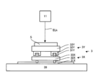
再び図1において、塗装膜SFを加工するために、加工システムSYSaは、加工装置1と、制御装置2とを備えている。更に、加工装置1は、光照射装置11と、駆動系12と、収容装置13と、支持装置14と、駆動系15と、排気装置16と、気体供給装置17とを備える。
Referring again to FIG. 1, the processing system SYSa includes a
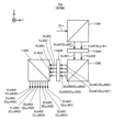
光照射装置11は、制御装置2の制御下で、塗装膜SFに対して加工光ELkを照射可能である。加工光ELkを照射するために、光照射装置11は、光照射装置11の構造を示す斜視図である図3に示すように、光源光ELsを射出可能な光源110と、フォーカスレンズ111と、マルチビーム光学系112と、ガルバノミラー113と、fθレンズ114とを備える。
The
光源110は、光源光ELoを射出する。光源光ELoは、例えば、加工光ELkと同じ特性(例えば、種類、波長及びエネルギーの少なくとも一つ)を有する光であるが、加工光ELkと異なる特性を有する光であってもよい。光源110は、例えば、パルス光を光源光ELoとして射出する。パルス光の発光時間幅(以下、“パルス幅”と称する)が短くなるほど、加工精度(例えば、後述するリブレット構造の形成精度)が向上する。従って、光源1111は、パルス幅が相対的に短いパルス光を、光源光ELoとして射出してもよい。例えば、光源1111は、パルス幅が1000ナノ秒以下となるパルス光を、光源光ELoとして射出してもよい。
The
フォーカスレンズ111は、1以上のレンズで構成され、その少なくとも一部のレンズの光軸方向に沿った位置を調整することで、光源光ELoの集光位置(つまり、光照射装置11の焦点位置)を調整するための光学素子である。
The
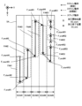
マルチビーム光学系112は、光源111からの光源光ELoを複数の加工光ELkに分岐(言い換えれば、分離又は分割)する。光源光ELoを複数の加工光ELkに分岐するために、マルチビーム光学系112は、マルチビーム光学系112の構造を示す断面図である図4に示すように、偏光ビームスプリッタ1121と、1/4波長板1122と、反射ミラー1123と、1/4波長板1124と、反射ミラー1125とを備える。
The multi-beam
光源111からの光源光ELoは、偏光ビームスプリッタ1121の分離面11211に入射する。光源光ELoのうちのs偏光ELs1は、分離面11211において反射される。一方で、光源光ELoのうちのp偏光ELp2は、分離面11211を通過する。つまり、偏光ビームスプリッタ1121は、光源光ELoを、s偏光ELs1とp偏光ELp2とに分岐する。
Source light ELo from the
偏光ビームスプリッタ1121によって反射されたs偏光ELs1は、1/4波長板1122を通過する。その結果、s偏光ELs1は、円偏光ELc1に変換される。1/4波長板1122を通過した円偏光ELc1は、反射ミラー1123の反射面11231によって反射される。反射ミラー1123によって反射された円偏光ELc1は、1/4波長板1122を再度通過して、p偏光ELp1に変換される。1/4波長板1122を通過したp偏光ELp1は、偏光ビームスプリッタ1121の分離面11211に入射する。
The s-polarized light ELs1 reflected by the
一方で、偏光ビームスプリッタ1121を通過したp偏光ELp2は、1/4波長板1124を通過する。その結果、p偏光ELp2は、円偏光ELc2に変換される。1/4波長板1124を通過した円偏光ELc2は、反射ミラー1125の反射面11251によって反射される。反射ミラー1125によって反射された円偏光ELc2は、1/4波長板1124を再度通過して、s偏光ELs2に変換される。1/4波長板1124を通過したs偏光ELs2は、偏光ビームスプリッタ1121の分離面11211に入射する。
On the other hand, the p-polarized light ELp2 that has passed through the
分離面11211に入射したp偏光ELp1は、分離面11211を通過する。分離面11211を通過したp偏光ELp1は、複数の加工光ELkのうちの一つとしてマルチビーム光学系112からガルバノミラー113に向けて射出される。一方で、分離面11211に入射したs偏光ELs2は、分離面11211によって反射される。分離面11211によって反射されたs偏光ELs2は、複数の加工光ELkのうちの一つとしてマルチビーム光学系112からガルバノミラー113に向けて射出される。つまり、偏光ビームスプリッタ1121は、光源光ELoをs偏光ELs1及びp偏光ELp2に分岐する光学系として機能するだけでなく、異なる方向から偏光ビームスプリッタ1121に入射してくるp偏光ELp1及びs偏光ELs2を、ガルバノミラー113に向かう複数の加工光ELkとして合流させる光学系としても機能する。
The p-polarized light ELp1 incident on the
ここで、図4に示すように、反射ミラー1123の反射面11231に対する円偏光ELc1の入射角度が、反射ミラー1125の反射面11251に対する円偏光ELc2の入射角度とは異なるものとなるように、反射ミラー1123及び1125が位置合わせされている。つまり、反射ミラー1123の反射面11231と円偏光ELc1の進行方向に沿った軸とがなす角度が、反射ミラー1125の反射面11251と円偏光ELc2の進行方向に沿った軸とがなす角度とは異なるものとなるように、反射ミラー1123及び1125が位置合わせされている。図4は、反射面11231に対して円偏光ELc1が垂直入射する一方で、反射面11251に対して円偏光ELc2が斜入射するように、反射ミラー1123及び1125が位置合わせされている例を示している。その結果、分離面11211を通過したp偏光ELp1の進行方向に沿った軸と、分離面11211によって反射されたs偏光ELs2の進行方向に沿った軸とが交差することになる。つまり、マルチビーム光学系112から射出される複数の加工光ELkの進行方向にそれぞれ沿った複数の軸が交差することになる。この場合、反射ミラー1123及び1125は、複数の加工光ELkの進行方向を互いに異ならせる光学系として機能させることが可能である。その結果、図5(a)に示すように、複数の加工光ELkの進行方向に交差する光学面上においては、複数の加工光ELkが異なる位置を通過する。つまり、複数の加工光ELkの進行方向に交差する光学面上においては、複数の加工光ELkが複数のビームスポットをそれぞれ形成する。その結果、このような複数の加工光ELkが塗装膜SFに照射されると、図5(b)に示すように、塗装膜SF上において、複数の加工光ELkが複数のビームスポット(つまり、照射領域)をそれぞれ形成する。つまり、マルチビーム光学系112は、塗装膜SF上の異なる位置にそれぞれ照射される複数の加工光ELkを射出する。その結果、塗装膜SFに、複数の加工光ELkが同時に照射される。つまり、塗装膜SF上には、複数の目標照射領域EAが同時に設定される。
Here, as shown in FIG. 4, the reflection is performed so that the incident angle of the circularly polarized light ELc1 on the reflecting
再び図3において、ガルバノミラー113は、複数の加工光ELkの光路上に配置される。ガルバノミラー113は、マルチビーム光学系112とfθレンズ114との間に配置される。ガルバノミラー113は、マルチビーム光学系112が射出する複数の加工光ELkが塗装膜SFの表面を走査する(つまり、複数の加工光ELkがそれぞれ照射される複数の目標照射領域EAが塗装膜SFの表面を移動する)ように、複数の加工光ELkを偏向する。尚、ガルバノミラー113によって、マルチビーム光学系112が射出する複数の加工光ELkが塗装膜SFの表面を掃引してもよい。ガルバノミラー113は、X走査ミラー113Xと、Y走査ミラー113Yとを備える。Y走査ミラー113Yは、マルチビーム光学系112が射出する複数の加工光ELkをX走査ミラー113Xに向けて反射する。Y走査ミラー113Yは、θX方向(つまり、X軸周りの回転方向)に揺動又は回転可能である。Y走査ミラー113Yの揺動又は回転により、複数の加工光ELkは、塗装膜SFの表面をY軸方向に沿って走査する。Y走査ミラー113Yの揺動又は回転により、複数の加工光ELkは、塗装膜SFの表面をY軸方向に沿って掃引される。Y走査ミラー113Yの揺動又は回転により、複数の加工光ELkが塗装膜SFの表面をY軸方向に沿って走査するように、複数の加工光ELkの進行方向が変更される。Y走査ミラー113Yの揺動又は回転により、複数の目標照射領域EAは、塗装膜SF上をY軸方向に沿って移動する。Y走査ミラー113Yは、複数の目標照射領域EAと塗装膜SFとの間のY軸方向に沿った相対的な位置関係を変更する。X走査ミラー113Xは、Y走査ミラー113Yが反射した複数の加工光ELkをfθレンズ114に向けて反射する。X走査ミラー113Xは、θY方向(つまり、Y軸周りの回転方向)に揺動又は回転可能である。X走査ミラー113Xの揺動又は回転により、複数の加工光ELkは、塗装膜SFの表面をX軸方向に沿って走査する。X走査ミラー113Xの揺動又は回転により、複数の加工光ELkは、塗装膜SFの表面をX軸方向に沿って掃引される。X走査ミラー113Xの揺動又は回転により、複数の加工光ELkが塗装膜SFの表面をX軸方向に沿って走査するように、複数の加工光ELkの進行方向が変更される。X走査ミラー113Xの揺動又は回転により、複数の目標照射領域EAは、塗装膜SF上をX軸方向に沿って移動する。X走査ミラー113Xは、複数の目標照射領域EAと塗装膜SFとの間のX軸方向に沿った相対的な位置関係を変更する。尚、ガルバノミラー113は、塗装膜SFの表面上において目標照射領域EAを移動させる(つまり、変位させる)ことが可能であるがゆえに、変位部材と称してもよい。
Referring again to FIG. 3, the
fθレンズ114は、ガルバノミラー113からの複数の加工光ELkの光路上に配置される。fθレンズ114は、ガルバノミラー113からの複数の加工光ELkを塗装膜SF上に集光するための光学素子である。fθレンズ114は、光照射装置11が備える光学素子のうち光照射装置11の最も光射出側に位置する(言い換えれば、塗装膜SFに最も近い、又は、複数の加工光ELkの光路の終端に位置する)終端光学素子である。fθレンズ114は、光照射装置11に対して脱着可能なように構成されていてもよい。その結果、光照射装置11から古いfθレンズ114を取り外した後に、光照射装置11に別のfθレンズ114を取り付けることが可能となる。但し、光照射装置11は、fθレンズ114よりも光射出側に設けられた光学素子(例えば、カバーレンズ等)を備えていてもよい。fθレンズ114よりも光射出側に設けられた光学素子(例えば、カバーレンズ等)が、光照射装置11に対して脱着可能なように構成されていてもよい。
The
再び図1において、駆動系12は、制御装置2の制御下で、光照射装置11を、塗装膜SFに対して(つまり、塗装膜SFが表面に形成された加工対象物Sに対して)移動させる。つまり、駆動系12は、光照射装置11と塗装膜SFとの相対的な位置関係を変更するように、光照射装置11を塗装膜SFに対して移動させる。光照射装置11と塗装膜SFとの間の相対的な位置関係が変更されると、複数の加工光ELkがそれぞれ照射される複数の目標照射領域EAと塗装膜SFとの間の相対的な位置関係もまた変更される。このため、駆動系12は、複数の目標照射領域EAと塗装膜SFとの相対的な位置関係を変更するように、光照射装置11を塗装膜SFに対して移動させるとも言える。
Referring again to FIG. 1, the
駆動系12は、塗装膜SFの表面に沿って、光照射装置11を移動させてもよい。図1に示す例では、塗装膜SFの表面は、X軸及びY軸のうち少なくとも一方に平行な平面であるため、駆動系12は、X軸及びY軸の少なくとも一方に沿って、光照射装置11を移動させてもよい。その結果、塗装膜SF上で目標照射領域EAがX軸及びY軸の少なくとも一方に沿って移動する。駆動系12は、塗装膜SFの厚み方向(つまり、塗装膜SFの表面に交差する方向)に沿って、光照射装置11を移動させてもよい。図1に示す例では、塗装膜SFの厚み方向は、Z軸に沿った方向であるため、駆動系12は、Z軸方向に沿って、光照射装置11を移動させてもよい。駆動系12は、X軸、Y軸及びZ軸の少なくとも一つに加えて、θX方向、θY方向及びθZ方向(つまり、Z軸周りの回転方向)の少なくとも一つに沿って、光照射装置11を移動させてもよい。
The
駆動系12は、光照射装置11を支持すると共に、当該支持している光照射装置11を移動させる。この場合、駆動系12は、例えば、光照射装置11を支持する第1支持部材と、当該第1支持部材を移動させる第1移動機構とを備えていてもよい。
The
収容装置13は、天井部材131と、隔壁部材132とを備えている。天井部材131は、光照射装置11の+Z側に配置される。天井部材131は、XY平面に沿った板状の部材である。天井部材131は、支持部材133を介して駆動系12を支持する。天井部材131の-Z側の面の外縁(或いは、その近傍)には、隔壁部材132が配置されている。隔壁部材132は、天井部材131から-Z側に向かって延伸する筒状(例えば、円筒状の又は矩形筒状の)の部材である。天井部材131と隔壁部材132とによって囲まれた空間は、光照射装置11及び駆動系12を収容するための収容空間SPとなる。従って、上述した駆動系12は、収容空間SP内で光照射装置11を移動させる。更に、収容空間SPは、光照射装置11と塗装膜SFとの間の空間(特に、加工光ELkの光路を含む空間)を含んでいる。より具体的には、収容空間SPは、光照射装置11が備える終端光学素子(例えば、fθレンズ1123)と塗装膜SFとの間の空間(特に、加工光ELkの光路を含む空間)を含んでいる。
The
天井部材131及び隔壁部材132のそれぞれは、加工光ELkを遮光可能な部材である。つまり、天井部材131及び隔壁部材132のそれぞれは、加工光ELkの波長に対して不透明である。その結果、収容空間SP内を伝搬する加工光ELkが収容空間SPの外部(つまり、収容装置13の外部)に漏れ出てくることはない。尚、天井部材131及び隔壁部材132のそれぞれは、加工光ELkを減光可能な部材であってもよい。つまり、天井部材131及び隔壁部材132のそれぞれは、加工光ELkの波長に対して半透明であってもよい。更に、天井部材131及び隔壁部材132のそれぞれは、加工光ELkの照射によって発生した不要物質を透過させない(つまり、遮蔽可能な)部材である。不要物質の一例として、塗装膜SFの蒸気及びヒュームの少なくとも一方があげられる。その結果、収容空間SP内で発生した不要物質が収容空間SPの外部(つまり、収容装置13の外部)に漏れ出てくることはない。
Each of the
隔壁部材132の端部(具体的には、塗装膜SF側の端部であり、図1に示す例では、-Z側の端部)134は、塗装膜SFの表面に接触可能である。端部134が塗装膜SFに接触する場合には、収容装置13(つまり、天井部材131及び隔壁部材132)は、塗装膜SFと協働して収容空間SPの密閉性を維持する。端部134は、塗装膜SFと接触した場合に、塗装膜SFの表面の形状に応じてその形状(特に、端部134のうち塗装膜SFに接触する接触面(図1に示す例では、-Z側の面)の形状、以下同じ)を変化させることが可能である。例えば、表面が平面形状の塗装膜SFに端部134が接触する場合には、端部134の形状は、塗装膜SFと同様に平面形状になる。例えば、表面が曲面形状の塗装膜SFに端部134が接触する場合には、端部134の形状は、塗装膜SFと同様に曲面形状になる。その結果、端部134が塗装膜SFの表面の形状に応じてその形状を変化させることができない場合と比較して、収容空間SPの密閉性が向上する。形状を変化させることが可能な端部134の一例として、ゴム等の弾性を有する部材(言い換えれば、柔軟な部材)から形成されている端部134があげられる。尚、形状を変化させることが可能な端部134として、例えば弾性を有する構造である蛇腹状の端部134aが用いられてもよい。
An end (specifically, an end on the paint film SF side, in the example shown in FIG. 1, an end on the -Z side) 134 of the
端部134は、塗装膜SFに接触した状態で塗装膜SFに付着可能であってもよい。例えば、端部134は、塗装膜SFに吸着可能な吸着機構を備えていてもよい。端部134が塗装膜SFに付着すると、端部134が塗装膜SFに付着していない場合と比較して、収容空間SPの密閉性がより一層向上する。但し、端部134が塗装膜SFに付着可能でなくてもよい。この場合であっても、端部134が塗装膜SFに接触する限りは、収容空間SPの密閉性が相応に維持されることに変わりはない。
The
隔壁部材132は、制御装置2の制御下で動作する不図示の駆動系(例えば、アクチュエータ)によって、Z軸方向に沿って伸縮可能な部材である。例えば、隔壁部材132は、蛇腹状の部材(いわゆる、ベローズ)であってもよい。この場合、隔壁部材132は、蛇腹部分の伸縮によって伸縮可能である。或いは、例えば、隔壁部材132は、異なる径を有する複数の中空状の円筒部材が組み合わせられたテレスコピックパイプを備えていてもよい。この場合、隔壁部材132は、複数の円筒部材の相対的な移動によって伸縮可能である。隔壁部材132の状態は、少なくとも、隔壁部材132がZ軸方向に沿って伸びることでZ軸方向の長さが相対的に長い第1伸長状態と、隔壁部材132がZ軸方向に沿って縮小することでZ軸方向の長さが相対的に短い第1縮小状態とに設定可能である。
The
隔壁部材132が第1伸長状態にある場合には、端部134は、塗装膜SFに接触可能な第1接触状態にある。一方で、隔壁部材132が第1縮小状態にある場合には、端部134は、塗装膜SFに接触しない第1非接触状態にある。つまり、隔壁部材132が第1縮小状態にある場合には、端部134は、塗装膜SFから+Z側に離れている第1非接触状態にある。尚、端部134の状態を第1接触状態と第1非接触状態との間で切り換えるための構成は、隔壁部材132を伸縮する構成には限定されない。例えば、収容装置13自体を±Z方向に沿って移動可能な構成とすることで、端部134の状態を第1接触状態と第1非接触状態との間で切り換えてもよい。
When the
収容装置13は更に、検出装置135を備えている。検出装置135は、収容空間SP内の不要物質(つまり、加工光ELkの照射によって発生した物質)を検出する。検出装置135の検出結果は、後に詳述するように、隔壁部材132の状態を第1伸長状態から第1縮小状態へと変える際に制御装置2によって参照される。
The
支持装置14は、収容装置13を支持する。収容装置13が駆動系12及び光照射装置11を支持しているため、支持装置14は、実質的には、収容装置13を介して駆動系12及び光照射装置11を支持している。収容装置13を支持するために、支持装置14は、梁部材141と、複数の脚部材142とを備えている。梁部材141は、収容装置13の+Z側に配置される。梁部材141は、XY平面に沿って延伸する梁状の部材である。梁部材141は、支持部材143を介して収容装置13を支持する。梁部材141には、複数の脚部材142が配置されている。脚部材142は、梁部材141から-Z側に向かって延伸する棒状の部材である。
The
脚部材142の端部(具体的には、塗装膜SF側の端部であり、図1に示す例では、-Z側の端部)144は、塗装膜SFの表面に接触可能である。その結果、支持装置14は、塗装膜SFによって(つまり、加工対象物Sによって)支持される。つまり、支持装置14は、端部144が塗装膜SFに接触した状態で(言い換えれば、支持装置14が塗装膜Sによって支持された状態で)収容装置13を支持する。端部144は、収容装置13の端部134と同様に、塗装膜SFと接触した場合に、塗装膜SFの表面の形状に応じてその形状(特に、端部144のうち塗装膜SFに接触する接触面(図1に示す例では、-Z側の面)の形状、以下同じ)を変化させることが可能であってもよい。端部144は、塗装膜SFに接触した状態で塗装膜SFに付着可能であってもよい。例えば、端部144は、塗装膜SFに吸着可能な吸着機構を備えていてもよい。端部144が塗装膜SFに付着すると、端部144が塗装膜SFに付着していない場合と比較して、支持装置14の安定性が向上する。但し、端部144が塗装膜SFに付着可能でなくてもよい。
An
梁部材141は、制御装置2の制御下で動作する駆動系15によって、X軸及びY軸の少なくとも一方に沿って(或いは、XY平面に沿った任意の方向に沿って)伸縮可能な部材である。例えば、梁部材141は、異なる径を有する複数の筒部材が組み合わせられたテレスコピックパイプを備えていてもよい。この場合、梁部材141は、複数の筒部材の相対的な移動によって伸縮可能である。
The
脚部材142は、制御装置2の制御下で動作する駆動系15によって、Z軸方向に沿って伸縮可能な部材である。例えば、脚部材142は、異なる径を有する複数の筒部材が組み合わせられたテレスコピックパイプを備えていてもよい。この場合、脚部材142は、複数の筒部材の相対的な移動によって伸縮可能である。脚部材142の状態は、少なくとも、脚部材142がZ軸方向に沿って伸びることでZ軸方向の長さが相対的に長い第2伸長状態と、脚部材142がZ軸方向に沿って縮小することでZ軸方向の長さが相対的に短い第2縮小状態とに設定可能である。脚部材142が第2伸長状態にある場合には、端部144は、塗装膜SFに接触可能な第2接触状態にある。一方で、脚部材142が第2縮小状態にある場合には、端部144は、塗装膜SFに接触しない第2非接触状態にある。つまり、脚部材142が第2縮小状態にある場合には、端部144は、塗装膜SFから+Z側に離れている第2非接触状態にある。
The
駆動系15は、制御装置2の制御下で、支持装置14を塗装膜SFに対して(つまり、塗装膜SFが表面に形成された加工対象物Sに対して)移動させる。つまり、駆動系15は、支持装置14と塗装膜SFとの相対的な位置関係を変更するように、支持装置14を塗装膜SFに対して移動させる。支持装置14が収容装置13を支持しているため、駆動系15は、実質的には、支持装置14を移動させることで、収容装置13を塗装膜SFに対して移動させる。つまり、駆動系15は、実質的には、収容装置13と塗装膜SFとの相対的な位置関係を変更するように、支持装置14を塗装膜SFに対して移動させる。更に、収容装置13は、駆動系12を介して光照射装置11を支持している。このため、駆動系15は、実質的には、支持装置14を移動させることで、光照射装置11を塗装膜SFに対して移動させることができる。つまり、駆動系15は、実質的には、光照射装置11と塗装膜SFとの相対的な位置関係を変更するように、支持装置14を塗装膜SFに対して移動させることができる。言い換えれば、駆動系15は、実質的には、複数の目標照射領域EAと塗装膜SFとの相対的な位置関係を変更するように、支持装置14を塗装膜SFに対して移動させることができる。
The
駆動系15は、支持装置14を移動させるために、制御装置2の制御下で、梁部材141を伸縮させる。更に、駆動系15は、支持装置14を移動させるために、制御装置2の制御下で、複数の脚部材142を伸縮させる。尚、駆動系15による支持装置14の移動態様については、図8から図17を参照しながら後に詳述する。
The
排気装置16は、排気管161を介して収容空間SPに連結されている。排気装置16は、収容空間SP内の気体を排気可能である。特に、排気装置16は、収容空間SP内の気体を排気することで、加工光ELkの照射によって発生した不要物質を、収容空間SPから収容空間SPの外部に吸引可能である。特に、この不要物質が加工光ELkの光路上に存在する場合、塗装膜SFに対する加工光ELkの照射に影響を与える可能性がある。このため、排気装置16は特に、光照射装置11の終端光学素子と塗装膜SFとの間の加工光ELkの光路を含む空間から、当該空間内の気体と共に不要物質を吸引する。排気装置16が収容空間SPから吸引した不要物質は、フィルタ162を介して加工システムSYSの外部へと排出される。フィルタ162は、不要物質を吸着する。尚、フィルタ162は、着脱可能であってもよいし、交換可能であってもよい。
The exhaust device 16 is connected to the housing space SP via an exhaust pipe 161. The exhaust device 16 is capable of exhausting gas within the accommodation space SP. In particular, the exhaust device 16 can suck unnecessary substances generated by irradiation of the processing light ELk from the accommodation space SP to the outside of the accommodation space SP by exhausting the gas in the accommodation space SP. In particular, if this unnecessary substance exists on the optical path of the processing light ELk, it may affect the irradiation of the processing light ELk onto the coating film SF. For this reason, the exhaust device 16 particularly sucks unnecessary substances together with the gas in the space from the space including the optical path of the processing light ELk between the terminal optical element of the
気体供給装置17は、吸気管171を介して収容空間SPに連結されている。気体供給装置17は、収容空間SPに気体を供給可能である。収容空間SPに供給する気体としては、大気、CDA(クリーン・ドライ・エア)及び不活性ガスの少なくとも一つがあげられる。不活性ガスの一例として、窒素ガスがあげられる。第1実施形態では、気体供給装置17はCDAを供給するものとする。このため、収容空間SPは、CDAによってパージされた空間となる。収容空間SPに供給されたCDAの少なくとも一部は、排気装置16によって吸引される。排気装置16が収容空間SPから吸引したCDAは、フィルタ162を通過して加工システムSYSaの外部へと排出される。
The gas supply device 17 is connected to the accommodation space SP via an
気体供給装置17は特に、図3に示すfθレンズ114の収容空間SP側の光学面1141(つまり、光照射装置11の終端光学素子の収容空間SP側の光学面)にCDA等の気体を供給する。光学面1141は、収容空間SPに面しているがゆえに、加工光ELkの照射によって発生した不要物質にさらされる可能性がある。その結果、光学面1141に不要物質が付着してしまう可能性がある。更に、加工光ELkが光学面1141を通過するがゆえに、光学面1141通過する加工光ELkによって光学面1141に付着した不要物質が焼き付けられる(つまり、固着してしまう)可能性がある。光学面1141に付着した(更には、固着した)不要物質は、光学面1141の汚れとなって加工光ELkの特性に影響を与えかねない。しかるに、光学面1141にCDA等の気体が供給されると、光学面1141と不要物質との接触が防止される。このため、光学面1141への汚れの付着が防止される。従って、気体供給装置17は、光学面1141への汚れの付着を防止する付着防止装置としても機能する。更には、光学面1141に汚れが付着(更には、固着)してしまった場合であっても、光学面1141に供給されたCDAによって汚れが除去される(例えば、吹き飛ばされる)可能性がある。従って、気体供給装置17は、光学面1141に付着した汚れを除去する付着防止装置としても機能し得る。
The gas supply device 17 particularly supplies gas such as CDA to the
制御装置2は、加工システムSYSaの全体の動作を制御する。特に、制御装置2は、後に詳述するように、所望の形状の凹部Cが所望の位置に形成されるように、光照射装置11、駆動系12、収容装置13及び駆動系15を制御する。
The
制御装置2は、例えば、CPU(Central Processing Unit)(或いは、CPUに加えて又は代えてGPU(Graphics Processing Unit))と、メモリとを含んでいてもよい。制御装置2は、CPUがコンピュータプログラムを実行することで、加工システムSYSaの動作を制御する装置として機能する。このコンピュータプログラムは、制御装置2が行うべき後述する動作を制御装置2(例えば、CPU)に行わせる(つまり、実行させる)ためのコンピュータプログラムである。つまり、このコンピュータプログラムは、加工システムSYSaに後述する動作を行わせるように制御装置2を機能させるためのコンピュータプログラムである。CPUが実行するコンピュータプログラムは、制御装置2が備えるメモリ(つまり、記録媒体)に記録されていてもよいし、制御装置2に内蔵された又は制御装置2に外付け可能な任意の記憶媒体(例えば、ハードディスクや半導体メモリ)に記録されていてもよい。或いは、CPUは、実行するべきコンピュータプログラムを、ネットワークインタフェースを介して、制御装置2の外部の装置からダウンロードしてもよい。
The
制御装置2は、加工システムSYSaの内部に設けられていなくてもよく、例えば、加工システムSYSa外にサーバ等として設けられていてもよい。この場合、制御装置2と加工システムSYSaとは、有線及び/又は無線のネットワーク(或いは、データバス及び/又は通信回線)で接続されていてもよい。有線のネットワークとして、例えばIEEE1394、RS-232x、RS-422、RS-423、RS-485及びUSBの少なくとも一つに代表されるシリアルバス方式のインタフェースを用いるネットワークが用いられてもよい。有線のネットワークとして、パラレルバス方式のインタフェースを用いるネットワークが用いられてもよい。有線のネットワークとして、10BASE-T、100BASE-TX及び1000BASE-Tの少なくとも一つに代表されるイーサネット(登録商標)に準拠したインタフェースを用いるネットワークが用いられてもよい。無線のネットワークとして、電波を用いたネットワークが用いられてもよい。電波を用いたネットワークの一例として、IEEE802.1xに準拠したネットワーク(例えば、無線LAN及びBluetooth(登録商標)の少なくとも一方)があげられる。無線のネットワークとして、赤外線を用いたネットワークが用いられてもよい。無線のネットワークとして、光通信を用いたネットワークが用いられてもよい。この場合、制御装置2と加工システムSYSaとはネットワークを介して各種の情報の送受信が可能となるように構成されていてもよい。また、制御装置2は、ネットワークを介して加工システムSYSaにコマンドや制御パラメータ等の情報を送信可能であってもよい。加工システムSYSaは、制御装置2からのコマンドや制御パラメータ等の情報を、上記ネットワークを介して受信する受信装置を備えていてもよい。或いは、制御装置2が行う処理のうちの一部を行う第1制御装置が加工システムSYSaの内部に設けられている一方で、制御装置2が行う処理のうちの他の一部を行う第2制御装置が加工システムSYSaの外部に設けられていてもよい。
The
尚、CPUが実行するコンピュータプログラムを記録する記録媒体としては、CD-ROM、CD-R、CD-RWやフレキシブルディスク、MO、DVD-ROM、DVD-RAM、DVD-R、DVD+R、DVD-RW、DVD+RW及びBlu-ray(登録商標)等の光ディスク、磁気テープ等の磁気媒体、光磁気ディスク、USBメモリ等の半導体メモリ、及び、その他プログラムを格納可能な任意の媒体の少なくとも一つが用いられてもよい。記録媒体には、コンピュータプログラムを記録可能な機器(例えば、コンピュータプログラムがソフトウェア及びファームウェア等の少なくとも一方の形態で実行可能な状態に実装された汎用機器又は専用機器)が含まれていてもよい。更に、コンピュータプログラムに含まれる各処理や機能は、制御装置2(つまり、コンピュータ)がコンピュータプログラムを実行することで制御装置2内に実現される論理的な処理ブロックによって実現されてもよいし、制御装置2が備える所定のゲートアレイ(FPGA、ASIC)等のハードウェアによって実現されてもよいし、論理的な処理ブロックとハードウェアの一部の要素を実現する部分的ハードウェアモジュールとが混在する形式で実現してもよい。
Note that recording media for recording computer programs executed by the CPU include CD-ROM, CD-R, CD-RW, flexible disk, MO, DVD-ROM, DVD-RAM, DVD-R, DVD+R, and DVD-RW. , an optical disk such as DVD+RW and Blu-ray (registered trademark), a magnetic medium such as a magnetic tape, a magneto-optical disk, a semiconductor memory such as a USB memory, or any other medium capable of storing a program. Good too. The recording medium may include a device capable of recording a computer program (for example, a general-purpose device or a dedicated device in which a computer program is implemented in an executable state in the form of at least one of software and firmware). Furthermore, each process or function included in the computer program may be realized by a logical processing block that is realized within the
(1-2)加工システムSYSaによる加工動作の具体例
(1-2-1)加工動作によって形成される構造の具体例
図2を用いて説明したように、第1実施形態では、加工システムSYSaは、塗装膜SFに凹部Cを形成する。凹部Cは、塗装膜SFのうち加工光ELkが実際に照射された部分に形成される。このため、塗装膜SF上で加工光ELkが実際に照射される位置(つまり、加工光ELkが照射されることが予定されている目標照射領域EAが設定される位置)を適切に設定すれば、塗装膜SFの所望位置に凹部Cが形成可能となる。つまり、加工対象物S上に、塗装膜SFによる構造を形成可能となる。 (1-2) Specific example of machining operation by machining system SYSa
(1-2-1) Specific example of structure formed by processing operation As described using FIG. 2, in the first embodiment, the processing system SYSa forms the recess C in the coating film SF. The recess C is formed in a portion of the coating film SF that is actually irradiated with the processing light ELk. Therefore, if the position where the processing light ELk is actually irradiated on the paint film SF (that is, the position where the target irradiation area EA is set where the processing light ELk is scheduled to be irradiated) is appropriately set. , the recess C can be formed at a desired position on the coating film SF. In other words, it is possible to form a structure using the coating film SF on the workpiece S.
具体的には、加工システムSYSaは、上述したように、ガルバノミラー113及び駆動系12の少なくとも一方を用いて、目標照射領域EAに塗装膜SFの表面を移動させる。加工システムSYSaは、塗装膜SFの表面を目標照射領域EAが移動する期間中に、塗装膜SFの表面のうち加工光ELkを実際に照射するべき領域(つまり、加工するべき領域)に目標照射領域EAが重なるタイミングで加工光ELkを照射する。一方で、加工システムSYSaは、塗装膜SFの表面を目標照射領域EAが移動する期間中に、塗装膜SFの表面のうち加工光ELkを実際に照射するべき領域に目標照射領域EAが重ならないタイミングでは加工光ELkを照射しない。つまり、加工システムSYSaは、塗装膜SFの表面を目標照射領域EAが移動する期間中に、塗装膜SFの表面のうち加工光ELkを実際に照射するべきでない領域(つまり、加工すべきでない領域)に目標照射領域EAが重なるタイミングでは加工光ELkを照射しない。その結果、加工対象物S上に、塗装膜SFのうち加工光ELkが実際に照射された領域のパターンに応じた塗装膜SFによる構造が形成される。
Specifically, as described above, the processing system SYSa uses at least one of the
第1実施形態では、加工システムSYSaは、制御装置2の制御下で、このような塗装膜SFによる構造の一例であるリブレット構造を加工対象物S上に形成する。リブレット構造は、塗装膜SFの表面の流体に対する抵抗(特に、摩擦抵抗、乱流摩擦抵抗)を低減可能な構造である。リブレット構造が形成された加工対象物Sの表面の流体に対する抵抗は、リブレット構造が形成されていない加工対象物Sの表面の流体に対する抵抗よりも小さくなる。このため、リブレット構造は、加工対象物Sの表面の流体に対する抵抗を低減可能な構造であるとも言える。尚、ここでいう流体とは、塗装膜SFの表面に対して相対的に流れている媒質(気体、液体)であればよい。例えば、静止している加工対象物SFに対して流れている媒質、及び、移動している加工対象物SFの周囲に分布する静止している媒質のそれぞれは、流体の一例である。
In the first embodiment, the processing system SYSa forms, under the control of the
リブレット構造の一例が図6(a)及び図6(b)に示されている。図6(a)及び図6(b)に示すように、リブレット構造は、例えば、第1の方向(図6(a)及び図6(b)に示す例では、Y軸方向)に沿って凹部Cを連続的に形成することで形成される凹状構造CP1(つまり、第1の方向に沿って延伸するように直線状に形成された凹状構造CP1)が、第1の方向に交差する第2方向(図6(a)及び図6(b)に示す例では、X軸方向)に沿って複数配列された構造である。つまり、リブレット構造は、例えば、第1の方向に沿って延びる複数の凹状構造CP1が、第1の方向に交差する第2方向に周期方向を有する構造である。隣り合う2つの凹状構造CP1の間には、周囲から突き出た凸状構造CP2が実質的に存在する。従って、リブレット構造は、例えば、第1の方向(例えば、Y軸方向)に沿って直線状に延伸する凸状構造CP2が、第1の方向に交差する第2方向(例えば、X軸方向)に沿って複数配列された構造であるとも言える。つまり、リブレット構造は、例えば、第1の方向に沿って延びる複数の凸状構造CP2が、第1の方向に交差する第2方向に周期方向を有する構造であるとも言える。図6(a)及び図6(b)に示されるリブレット構造は、周期的な構造である。 An example of a riblet structure is shown in FIGS. 6(a) and 6(b). As shown in FIGS. 6(a) and 6(b), the riblet structure, for example, The concave structure CP1 formed by continuously forming the concave portions C (that is, the concave structure CP1 formed linearly so as to extend along the first direction) has a concave structure CP1 formed by continuously forming concave portions C (that is, a concave structure CP1 formed linearly so as to extend along the first direction). It has a structure in which a plurality of them are arranged along two directions (in the example shown in FIGS. 6(a) and 6(b), the X-axis direction). That is, the riblet structure is, for example, a structure in which a plurality of concave structures CP1 extending along a first direction have a periodic direction in a second direction intersecting the first direction. A convex structure CP2 protruding from the periphery substantially exists between two adjacent concave structures CP1. Therefore, in the riblet structure, for example, a convex structure CP2 extending linearly along a first direction (e.g., Y-axis direction) extends in a second direction (e.g., X-axis direction) intersecting the first direction. It can also be said that it has a structure in which multiple lines are arranged along the . In other words, the riblet structure can be said to be a structure in which, for example, a plurality of convex structures CP2 extending along the first direction have a periodic direction in the second direction intersecting the first direction. The riblet structure shown in FIGS. 6(a) and 6(b) is a periodic structure.
隣り合う2つの凹状構造CP1の間隔(つまり、凹状構造CP1の配列ピッチP1)は、例えば、数ミクロンから数百ミクロンであるが、その他のサイズであってもよい。更に、各凹状構造CP1の深さ(つまり、Z軸方向の深さ)Dは、例えば、数ミクロンから数百ミクロンであるが、その他のサイズであってもよい。各凹状構造CP1の深さDは、凹状構造CP1の配列ピッチP1以下であってもよい。各凹状構造CP1の深さDは、凹状構造CP1の配列ピッチP1の半分以下であってもよい。各凹状構造CP1のZ軸を含む断面(具体的には、XZ平面に沿った断面)の形状は、お椀型の曲線形状であるが、三角形であってもよいし、四角形であってもよいし、五角形以上の多角形であってもよい。 The interval between two adjacent concave structures CP1 (that is, the arrangement pitch P1 of the concave structures CP1) is, for example, from several microns to several hundred microns, but may be any other size. Further, the depth (that is, the depth in the Z-axis direction) D of each concave structure CP1 is, for example, from several microns to several hundred microns, but may be other sizes. The depth D of each concave structure CP1 may be equal to or less than the arrangement pitch P1 of the concave structures CP1. The depth D of each concave structure CP1 may be less than half the arrangement pitch P1 of the concave structures CP1. The shape of the cross section including the Z axis (specifically, the cross section along the XZ plane) of each concave structure CP1 is a bowl-shaped curved shape, but it may be triangular or quadrangular. However, it may be a polygon of pentagon or more.
隣り合う2つの凸状構造CP2の間隔(つまり、凸状構造CP2の配列ピッチP2)は、例えば、数ミクロンから数百ミクロンであるが、その他のサイズであってもよい。更に、各凸状構造CP2の高さ(つまり、Z軸方向の高さ)Hは、例えば、数ミクロンから数百ミクロンであるが、その他のサイズであってもよい。各凸状構造CP2の高さHは、凸状構造CP2の配列ピッチP2以下であってもよい。各凸状構造CP2の高さHは、凸状構造CP2の配列ピッチP2の半分以下であってもよい。各凸状構造CP2のZ軸を含む断面(具体的には、XZ平面に沿った断面)の形状は、斜面が曲線となる山形の形状であるが、三角形であってもよいし、四角形であってもよいし、五角形以上の多角形であってもよい。また、各凸状構造CP2は稜線を有していてもよい。 The interval between two adjacent convex structures CP2 (that is, the arrangement pitch P2 of the convex structures CP2) is, for example, from several microns to several hundred microns, but may be any other size. Further, the height (that is, the height in the Z-axis direction) H of each convex structure CP2 is, for example, from several microns to several hundred microns, but may be other sizes. The height H of each convex structure CP2 may be equal to or less than the arrangement pitch P2 of the convex structures CP2. The height H of each convex structure CP2 may be less than half the arrangement pitch P2 of the convex structures CP2. The shape of the cross section including the Z axis (specifically, the cross section along the XZ plane) of each convex structure CP2 is a mountain shape with a curved slope, but it may also be triangular or square. It may be a polygon of pentagon or more. Moreover, each convex structure CP2 may have a ridgeline.
尚、加工システムSYSaが形成するリブレット構造自体は、例えば、日本機械学会編『機械工学便覧基礎編 α4流体工学』第5章に記述されるような既存のリブレット構造であってもよいため、リブレット構造そのものについての詳細な説明は省略する。
Note that the riblet structure itself formed by the processing system SYSa may be an existing riblet structure as described in
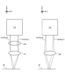
このようなリブレット構造は、上述したように、リブレット構造が形成された加工対象物Sの表面の流体に対する抵抗を低減可能である。このため、加工対象物Sは、流体に対する抵抗を低減することが望まれる物体(例えば、構造体)であってもよい。例えば、加工対象物Sは、少なくとも一部が流体(例えば、気体及び液体の少なくとも一方)内を進むように移動可能な物体(つまり、移動体)を含んでいてもよい。具体的には、例えば、加工対象物Sは、図7(a)から図7(c)に示すように、航空機PLの機体(例えば、胴体PL1、主翼PL2、垂直尾翼PL3及び水平尾翼PL4のうち少なくとも1つ)を含んでいてもよい。この場合、図7(a)及び図7(c)に示すように、加工装置1(或いは、加工システムSYSa、以下この段落において同じ)は、支持装置14により航空機PLの機体上で自立していてもよい。或いは、支持装置14の脚部材142の端部144が塗装膜SFに付着可能であるがゆえに、図7(b)に示すように、加工装置1は、支持装置14により航空機PLの機体から吊り下がる(つまり、ぶら下がる)ように航空機PLの機体に付着してもよい。更に、支持装置14の脚部材142の端部144が塗装膜SFに付着可能であり且つ収容装置13の隔壁部材132の端部134が塗装膜SFに付着可能であるがゆえに、加工装置1は、塗装膜SFの表面が上方を向いている状態で水平面に対して傾斜している場合であっても、塗装膜SF上で自立可能である。更には、加工装置1は、塗装膜SFの表面が下方を向いている状態で水平面に対して傾斜している場合であっても、塗装膜SFから吊り下がるように塗装膜SFに付着可能である。いずれの場合であっても、光照射装置11は、駆動系12により及び/又は支持装置14の移動により、機体の表面に沿って移動可能である。従って、加工システムSYSは、航空機の機体のような加工対象物S(つまり、表面が曲面となる、表面が水平面に対して傾斜している又は表面が下方を向いている加工対象物S)にも、塗装膜SFによるリブレット構造を形成可能である。
As described above, such a riblet structure can reduce the resistance to fluid on the surface of the workpiece S on which the riblet structure is formed. Therefore, the workpiece S may be an object (for example, a structure) whose resistance to fluid is desired to be reduced. For example, the workpiece S may include an object (that is, a moving object) that is movable so that at least a portion of the object moves through a fluid (for example, at least one of gas and liquid). Specifically, for example, the workpiece S is the body of the aircraft PL (for example, the fuselage PL1, the main wing PL2, the vertical stabilizer PL3, and the horizontal stabilizer PL4), as shown in FIGS. 7(a) to 7(c). at least one of these). In this case, as shown in FIGS. 7(a) and 7(c), the processing device 1 (or processing system SYSa, hereinafter the same in this paragraph) is supported by the
その他、例えば、加工対象物Sは、自動車の車体及び空力パーツの少なくとも一方を含んでいてもよい。例えば、加工対象物Sは、船舶の船体を含んでいてもよい。例えば、加工対象物Sは、ロケットの機体を含んでいてもよい。例えば、加工対象物Sは、タービン(例えば、水力タービン及び風力タービン等の少なくとも一つであり、特にそのタービンブレード)を含んでいてもよい。例えば、加工対象物Sは、少なくとも一部が流体内を進むように移動可能な物体を構成する部品を含んでいてもよい。例えば、加工対象物Sは、流動している流体内に少なくとも一部が固定される物体を含んでいてもよい。具体的には、例えば、加工対象物Sは、川又は海の中に設置される橋桁を含んでいてもよい。例えば、加工対象物Sは、内部を流体が流れる配管を含んでいてもよい。この場合、配管の内壁が上述した加工対象物Sの表面となり得る。 In addition, for example, the workpiece S may include at least one of an automobile body and an aerodynamic part. For example, the workpiece S may include the hull of a ship. For example, the workpiece S may include a rocket body. For example, the workpiece S may include a turbine (for example, at least one of a water turbine, a wind turbine, etc., in particular turbine blades thereof). For example, the workpiece S may include parts constituting an object that is movable so that at least a portion thereof moves through a fluid. For example, the workpiece S may include an object that is at least partially fixed within a flowing fluid. Specifically, for example, the workpiece S may include a bridge girder installed in a river or the sea. For example, the workpiece S may include a pipe through which a fluid flows. In this case, the inner wall of the pipe can become the surface of the workpiece S described above.
尚、ここにあげた加工対象物Sの一例は、比較的に大きな物体(例えば、数メートルから数百メートルのオーダーのサイズの物体)である。この場合、図7(a)から図7(c)に示すように、光照射装置11の大きさは、加工対象物Sの大きさよりも小さい。しかしながら、加工対象物Sは、どのようなサイズの物体であってもよい。例えば、加工対象物Sは、キロメートル、センチメートル、ミリメートル又はマイクロメートルのオーダーのサイズの物体であってもよい。
An example of the workpiece S mentioned here is a relatively large object (for example, an object with a size on the order of several meters to several hundred meters). In this case, as shown in FIGS. 7(a) to 7(c), the size of the
上述したリブレット構造の特性は、加工対象物Sがどのような物体であるかに応じて、摩擦の低減効果が適切に得られるような適切な特性に設定されてもよい。つまり、上述したリブレット構造の特性は、加工対象物Sがどのような物体であるかに応じて、摩擦の低減効果が適切に得られるように最適化されてもよい。より具体的には、リブレット構造の特性は、使用中の(つまり、運用中)の加工対象物Sの周囲に分布する流体の種類、加工対象物Sの流体に対する相対速度、及び、加工対象物Sの形状等の少なくとも一つに応じて、摩擦の低減効果が適切に得られる適切な特性に設定されてもよい。更に、上述したリブレット構造の特性は、加工対象物Sがどのような物体であり且つその物体のどの部分にリブレット構造が形成されるかに応じて、摩擦の低減効果が適切に得られるような適切な特性に設定されてもよい。例えば、加工対象物Sが航空機PLの機体である場合には、胴体PL1に形成されるリブレット構造の特性と、主翼PL2に形成されるリブレット構造の特性とが異なっていてもよい。 The characteristics of the riblet structure described above may be set to appropriate characteristics so that the effect of reducing friction can be appropriately obtained depending on what kind of object the workpiece S is. That is, the characteristics of the riblet structure described above may be optimized depending on what kind of object S is to be processed so that the effect of reducing friction can be appropriately obtained. More specifically, the characteristics of the riblet structure include the type of fluid distributed around the workpiece S during use (that is, during operation), the relative velocity of the workpiece S with respect to the fluid, and the Depending on at least one of the shape of S, etc., it may be set to an appropriate characteristic that can appropriately obtain the effect of reducing friction. Furthermore, the characteristics of the riblet structure described above are such that the friction reduction effect can be appropriately obtained depending on what kind of object the workpiece S is and in which part of the object the riblet structure is formed. It may be set to an appropriate characteristic. For example, when the workpiece S is the body of an aircraft PL, the characteristics of the riblet structure formed on the fuselage PL1 and the characteristics of the riblet structure formed on the main wing PL2 may be different.
リブレット構造の特性は、リブレット構造のサイズを含んでいてもよい。リブレット構造のサイズは、凹状構造CP1の配列ピッチP1、各凹状構造CP1の深さD、凸状構造CP2の配列ピッチP2、各凸状構造CP2の高さH等の少なくとも一つを含んでいてもよい。リブレット構造の特性は、リブレット構造の形状(例えば、Z軸を含む断面(具体的には、XZ平面に沿った断面)の形状)を含んでいてもよい。リブレット構造の特性は、リブレット構造の延伸方向(つまり、凹状構造CP1の延伸方向)を含んでいてもよい。リブレット構造の特性は、リブレット構造の形成位置を含んでいてもよい。 The characteristics of the riblet structure may include the size of the riblet structure. The size of the riblet structure includes at least one of the arrangement pitch P1 of the concave structures CP1, the depth D of each concave structure CP1, the arrangement pitch P2 of the convex structures CP2, the height H of each convex structure CP2, etc. Good too. The characteristics of the riblet structure may include the shape of the riblet structure (for example, the shape of a cross section including the Z axis (specifically, a cross section along the XZ plane)). The characteristics of the riblet structure may include the stretching direction of the riblet structure (ie, the stretching direction of the concave structure CP1). The characteristics of the riblet structure may include the location where the riblet structure is formed.
リブレット構造の特性は、加工対象物Sをシミュレートするシミュレーションモデルに基づいて決定されてもよい。特に、リブレット構造の特性は、流体内を移動する加工対象物Sをシミュレートする(言い換えれば、移動する加工対象物Sの周囲の流体の流れをシミュレートする)シミュレーションモデルに基づいて決定されてもよい。具体的には、制御装置2(或いは、シミュレーションモデルに基づく演算を行うその他の演算装置)は、流体シミュレーションモデルに基づいて、摩擦の低減効果が適切に得られるリブレット構造の特性を決定してもよい。つまり、制御装置2(或いは、シミュレーションモデルに基づく演算を行うその他の演算装置)は、流体シミュレーションモデルに基づいて、摩擦の低減効果が適切に得られるように、リブレット構造の特性を最適化してもよい。その後、制御装置2は、決定した(つまり、最適化された)リブレット構造の特性に関するリブレット情報に基づいて、決定した特性を有するリブレット構造を形成するように加工装置1を制御してもよい。リブレット情報は、例えば、どのようなサイズ、形状及び延伸方向の凹状構造CP1を、加工対象物Sのどの位置に形成するかを示す情報を含んでいてもよい。リブレット情報は、例えば、どのようなサイズ、形状及び延伸方向の凹状構造CP1を、加工対象物Sのどの位置に形成するかを、シミュレーションモデルと対応付けて示す情報を含んでいてもよい。
The characteristics of the riblet structure may be determined based on a simulation model that simulates the workpiece S. In particular, the characteristics of the riblet structure are determined based on a simulation model that simulates the workpiece S moving in a fluid (in other words, simulates the flow of fluid around the moving workpiece S). Good too. Specifically, the control device 2 (or other calculation device that performs calculations based on the simulation model) determines the characteristics of the riblet structure that can appropriately obtain the friction reduction effect based on the fluid simulation model. good. In other words, the control device 2 (or other calculation device that performs calculations based on the simulation model) optimizes the characteristics of the riblet structure based on the fluid simulation model so that the friction reduction effect can be appropriately obtained. good. Thereafter, the
尚、マルチビーム光学系112を備える加工システムSYSaに限らず、加工対象物Sを加工してリブレット構造を形成する任意の加工システムにおいて、リブレット構造の特性は、加工対象物Sをシミュレートするシミュレーションモデルに基づいて決定されてもよい。つまり、加工対象物Sを加工してリブレット構造を形成する任意の加工システムにおいて、流体シミュレーションモデルに基づいて摩擦の低減効果が適切に得られるようにリブレット構造の特性が最適化され、最適化されたリブレット構造の特性に関するリブレット情報に基づいて最適化された特性を有するリブレット構造が形成されてもよい。
Note that, not only the processing system SYSa including the multi-beam
(1-2-2)加工動作の流れ
続いて、図8から図19を参照しながら、リブレット構造を形成するための加工動作の流れについて説明する。 (1-2-2) Flow of Processing Operations Next, the flow of processing operations for forming the riblet structure will be described with reference to FIGS. 8 to 19.
まず、上述したように、複数の加工光ELkは、ガルバノミラー113によって偏向される。リブレット構造を形成するためには、ガルバノミラー113は、塗装膜SFの表面上で複数の目標照射領域EAをY軸方向に沿って移動させながら所望のタイミングで複数の加工光ELkのそれぞれを対応する目標照射領域EAに照射するスキャン動作と、塗装膜SFの表面上で複数の目標照射領域EAを少なくともX軸方向に沿って所定量だけ移動させるステップ動作とを交互に繰り返すように、複数の加工光ELkを偏向する。この場合、Y軸を、スキャン軸と称してもよいし、X軸を、ステップ軸と称してもよい。
First, as described above, the plurality of processing lights ELk are deflected by the
ここで、塗装膜SFに対して光照射装置11を静止させたままガルバノミラー113の制御で複数の加工光ELkを走査させることができる塗装膜SFの表面上の領域のサイズには限界がある。従って、第1実施形態では、図8に示すように、制御装置2は、塗装膜SFの表面(特に、塗装膜SFのうちリブレット構造を形成するべき領域)に、複数の加工ショット領域SAを設定してもよい。各加工ショット領域SAは、塗装膜SFに対して光照射装置11を静止させたままガルバノミラー113の制御で複数の加工光ELkを走査させることができる塗装膜SF上の領域に相当する。各加工ショット領域SAの形状は四角形であるが、その形状は任意である。
Here, there is a limit to the size of the area on the surface of the paint film SF that can be scanned with a plurality of processing lights ELk under the control of the
制御装置2は、ガルバノミラー113によって偏向される複数の加工光ELkを一の加工ショット領域SA(例えばSA1)の少なくとも一部に照射するように光照射装置11を制御することで、当該一の加工ショット領域SA(SA1)にリブレット構造を形成する。その後、制御装置2は、塗装膜SFに対して光照射装置11を移動させるように駆動系12及び15の少なくとも一方を制御することで、光照射装置11を、他の加工ショット領域SA(例えばSA2)に複数の加工光ELkを照射することが可能な位置に配置する。その後、制御装置2は、ガルバノミラー113によって偏向される複数の加工光ELkを他の加工ショット領域SA(SA2)の少なくとも一部に照射するように光照射装置11を制御することで、当該他の加工ショット領域SAにリブレット構造を形成する。制御装置2は以下の動作を全ての加工ショット領域SA1からSA16を対象に繰り返すことで、リブレット構造を形成する。
The
制御装置2は、各加工ショット領域SAにリブレット構造を形成する際には、上述したシミュレーションモデルに基づいて最適化されたリブレット構造の特性に関するリブレット情報から、各加工ショット領域SAに形成されるべきリブレット構造の特性に相当する情報を取得し、当該取得した情報に基づいて各加工ショット領域SAに最適化された特性を有するリブレット構造を各加工ショット領域SAに形成する。
When forming a riblet structure in each processed shot area SA, the
以下、図8に示す加工ショット領域SA1からSA4にリブレット構造を形成する動作を例にあげて説明を続ける。以下では、X軸方向に沿って隣接する2つの加工ショット領域SAが収容空間SP内に位置する例を用いて説明をする。しかしながら、収容空間SP内に任意の数の加工ショット領域SAが位置する場合においても、同様の動作が行われることに変わりはない。また、以下に示すリブレット構造を形成する動作は、あくまで一例であって、加工システムSYSは、以下に示す動作とは異なる動作を行ってリブレット構造を形成してもよい。要は、加工システムSYSは、複数の加工光ELkを加工対象物Sに照射して加工対象物Sにリブレット構造を形成することができる限りは、どのような動作を行ってもよい。 The explanation will be continued below, taking as an example the operation of forming a riblet structure in the processed shot areas SA1 to SA4 shown in FIG. Below, explanation will be given using an example in which two processing shot areas SA adjacent to each other along the X-axis direction are located within the accommodation space SP. However, even when an arbitrary number of processing shot areas SA are located within the accommodation space SP, the same operation is still performed. Further, the operation for forming the riblet structure shown below is just an example, and the processing system SYS may form the riblet structure by performing an operation different from the operation shown below. In short, the processing system SYS may perform any operation as long as it can form a riblet structure on the workpiece S by irradiating the workpiece S with the plurality of processing lights ELk.
図9に示すように、まず、制御装置2は、収容空間SP内に加工ショット領域SA1及びSA2が位置する第1収容位置に収容装置13が配置されるように、駆動系15を制御して塗装膜SFに対して支持装置14を移動させる。つまり、制御装置2は、収容装置13により加工ショット領域SA1及びSA2が覆われるように、支持装置14が支持する収容装置13を移動させる。更に、制御装置2は、光照射装置11が加工ショット領域SA1に複数の加工光ELkを照射することが可能な第1照射位置に配置されるように、駆動系12を制御して塗装膜SFに対して光照射装置11を移動させる。収容装置13が第1収容位置に配置され且つ光照射装置11が第1照射位置に配置された後は、隔壁部材132は、第1伸長状態になる。従って、隔壁部材132の端部134は、塗装膜SFに接触し且つ付着する。同様に、複数の脚部材142は、第2伸長状態になる。従って、複数の脚部材142の端部144は、塗装膜SFに接触し且つ付着する。
As shown in FIG. 9, first, the
その後、図10(a)及び図10(b)に示すように、制御装置2は、複数の加工光ELkが加工ショット領域SA1を走査するように、光照射装置11(特に、ガルバノミラー113)を制御する。具体的には、制御装置2は、上述したスキャン動作を行うために、加工ショット領域SA1内のある領域を複数の加工光ELkがY軸方向に沿って走査するように、ガルバノミラー113のY走査ミラー113Yを制御する。スキャン動作が行われている間は、光源110は、光源光ELoを射出する。その結果、スキャン動作が行われている間は、マルチビーム光学系112は、複数の加工光ELkを射出する。その後、制御装置2は、上述したステップ動作を行うために、ガルバノミラー113のX走査ミラー113Xを単位ステップ量だけ回転させる。ステップ動作が行われている間は、光源110は、光源光ELoを射出しない。その結果、ステップ動作が行われている間は、マルチビーム光学系112は、複数の加工光ELkを射出しない。その後、制御装置2は、上述したスキャン動作を行うために、加工ショット領域SA1内のある領域を複数の加工光ELkがY軸方向に沿って走査するように、ガルバノミラー113のY走査ミラー113Yを制御する。このように、制御装置2は、スキャン動作とステップ動作とを交互に繰り返して加工ショット領域SA1の全体(或いは、加工ショット領域SA1のうちリブレット構造を形成するべき一部の領域)を複数の加工光ELkが走査するように、ガルバノミラー113を制御する。尚、ステップ動作が行われている間において、光源110から光源光ELoを射出して複数の加工光ELkを射出してもよい。
Thereafter, as shown in FIGS. 10(a) and 10(b), the
第1実施形態では、スキャン動作とステップ動作とが繰り返される期間中の加工光ELkの走査軌跡(つまり、目標照射領域EAの移動軌跡)を示す平面図である図11に示すように、加工装置1は、加工ショット領域SA内に設定される複数のスキャン領域SCAに対して順にスキャン動作を行う。図11は、加工ショット領域SA内に6個のスキャン領域SCA#1からSCA#6が設定される例を示している。各スキャン領域SCAは、1回のスキャン動作(つまり、ステップ動作を挟まない一連のスキャン動作)で照射される複数の加工光ELkによって走査される領域である。各スキャン領域SCAは、1回のスキャン動作で複数の目標照射領域EAが移動する領域である。この場合、1回のスキャン動作で、目標照射領域EAは、各スキャン領域SCAのスキャン開始位置SC_startからスキャン終了位置SC_endに向かって移動する。このようなスキャン領域SCAは、典型的には、Y軸方向(つまり、複数の加工光ELkの走査方向)に沿って延びる領域となる。複数のスキャン領域SCAは、X軸方向(つまり、複数の加工光ELkの走査方向に交差する方向)に沿って並ぶ。
In the first embodiment, as shown in FIG. 11, which is a plan view showing the scanning trajectory of the processing light ELk (that is, the movement trajectory of the target irradiation area EA) during a period in which the scanning operation and the step operation are repeated, the
この場合、加工システムSYSaは、例えば、ある加工ショット領域SAに設定される複数のスキャン領域SCAのうち最も+X側又は最も-X側に位置する一のスキャン領域SCAからスキャン動作を開始する。例えば、図11は、加工システムSYSaが、最も-X側に位置するショット領域SCA#1からスキャン動作を開始する例を示している。この場合、制御装置2は、スキャン領域SCA#1のスキャン開始位置SC_start#1(例えば、スキャン領域SCA#1内の-Y側の端部又はその近傍)に対して加工光ELkを照射可能となるように、ガルバノミラー113を制御する。つまり、制御装置2は、スキャン領域SCA#1のスキャン開始位置SC_start#1に目標照射領域EAが設定されるように、ガルバノミラー113を制御する。その後、加工システムSYSaは、スキャン領域SCA#1に対してスキャン動作を行う。具体的には、制御装置2は、スキャン領域SCA#1のスキャン開始位置SC_start#1からスキャン領域SCA#1のスキャン終了位置SC_end#1(例えば、スキャン領域SCA#1内の+Y側の端部又はその近傍)に向かって複数の目標照射領域EAが移動するように、ガルバノミラー113を制御する。更に、制御装置2は、所望のタイミングで複数の加工光ELkのそれぞれが対応する目標照射領域EAに照射されるように光照射装置11を制御する。その結果、複数の加工光ELkによってスキャン領域SCA#1が走査される。尚、図11では、図面の簡略化のために、各スキャン領域SCA内における1つの目標照射領域EAの移動軌跡を示しているが、実際には、各スキャン領域SCA内で複数の目標照射領域EAが移動する。つまり、図11では、図面の簡略化のために、各スキャン領域SCA内における1つの加工光ELkの走査軌跡を示しているが、実際には、各スキャン領域SCAは複数の加工光ELkによって走査される。
In this case, the processing system SYSa starts the scanning operation from, for example, one scan area SCA located furthest to the +X side or furthest to the −X side among the plurality of scan areas SCA set in a certain machining shot area SA. For example, FIG. 11 shows an example in which the processing system SYSa starts the scan operation from the shot
スキャン領域SCA#1に対するスキャン動作が完了した後、加工システムSYSaは、スキャン領域SCA#1とは異なる他のスキャン領域SCAに対してスキャン動作を行うために、ステップ動作を行う。具体的には、制御装置2は、スキャン領域SCA#1に対してX軸方向に沿って隣接するスキャン領域SCA#2のスキャン開始位置SC_start#2(例えば、スキャン領域SCA#2内の-Y側の端部又はその近傍)に対して加工光ELkを照射可能となるように、ガルバノミラー113を制御する。つまり、制御装置2は、スキャン領域SCA#2のスキャン開始位置SC_start#2に目標照射領域EAが設定されるように、ガルバノミラー113を制御する。その結果、図11に示すように、目標照射位置EAは、X軸方向及びY軸方向のそれぞれに沿って移動する。この際、X軸方向における目標照射位置EAの移動量は、X軸方向におけるスキャン領域SCAのサイズと同じであってもよい。Y軸方向における目標照射位置EAの移動量は、Y軸方向におけるスキャン領域SCAのサイズと同じであってもよい。
After the scan operation for the scan
その後、加工システムSYSaは、スキャン領域SCA#2に対してスキャン動作を行う。具体的には、制御装置2は、スキャン領域SCA#2のスキャン開始位置SC_start#2からスキャン領域SCA#2のスキャン終了位置SC_end#2(例えば、スキャン領域SCA#2内の+Y側の端部又はその近傍)に向かって複数の目標照射領域EAが移動するように、ガルバノミラー113を制御する。更に、制御装置2は、所望のタイミングで複数の加工光ELkのそれぞれが対応する目標照射領域EAに照射されるように光照射装置11を制御する。その結果、複数の加工光ELkによってスキャン領域SCA#2が走査される。
After that, the processing system SYSa performs a scan operation on the scan
以降、スキャン領域SCA#3からSCA#6に対するスキャン動作が完了するまで、同様の動作が繰り返される。
Thereafter, similar operations are repeated until the scan operations for scan
図11に示す例では、スキャン動作による加工光ELkの走査方向は、+Y軸方向に固定されている。スキャン動作による目標照射領域EAの移動方向は、+Y軸方向に固定されている。つまり、図11に示す例では、加工ショット領域SA内で複数回行われるスキャン動作による加工光ELkの走査方向(つまり、目標照射領域EAの移動方向、以下同じ)は、互いに同じになる。複数のスキャン領域SCAをそれぞれ走査する複数の加工光ELkの走査方向は、互いに同じになる。複数のスキャン領域SCA内での目標照射領域EAの移動方向は、互いに同じになる。具体的には、スキャン領域SCA#1に対して行われるスキャン動作による加工光ELkの走査方向と、スキャン領域SCA#2に対して行われるスキャン動作による加工光ELkの走査方向と、・・・、スキャン領域SCA#6に対して行われるスキャン動作による加工光ELkの走査方向とは互いに同一である。但し、後に変形例において説明するように、一のスキャン領域SCAに対して行われるスキャン動作による加工光ELkの走査方向と、他のスキャン領域SCAに対して行われるスキャン動作による加工光ELkの走査方向とが異なっていてもよい。一のスキャン領域SCAに対して行われるスキャン動作による加工光ELkの走査方向が、スキャン動作の途中で変わってもよい。
In the example shown in FIG. 11, the scanning direction of the processing light ELk by the scanning operation is fixed in the +Y-axis direction. The direction of movement of the target irradiation area EA by the scan operation is fixed in the +Y-axis direction. That is, in the example shown in FIG. 11, the scanning direction of the processing light ELk (that is, the moving direction of the target irradiation area EA, hereinafter the same) of the scanning operation performed multiple times within the processing shot area SA is the same. The scanning directions of the plurality of processing lights ELk that respectively scan the plurality of scan areas SCA are the same. The movement directions of the target irradiation areas EA within the plurality of scan areas SCA are mutually the same. Specifically, the scanning direction of the processing light ELk due to the scan operation performed on the scan
このようなスキャン動作とステップ動作との繰り返しによって、加工ショット領域SA1にリブレット構造が形成される。尚、図10(a)及び図10(b)に示すように、加工光ELkが走査する領域の幅(つまり、加工ショット領域SAの幅、特にX軸方向の幅)は、光照射装置11の幅(特に、X軸方向の幅)よりも大きい。 By repeating such scan operations and step operations, a riblet structure is formed in the processing shot area SA1. As shown in FIGS. 10(a) and 10(b), the width of the area scanned by the processing light ELk (that is, the width of the processing shot area SA, especially the width in the X-axis direction) (especially the width in the X-axis direction).
制御装置2は、光照射装置11が加工光ELkを照射している期間中は、複数の脚部材142が第2伸長状態のまま維持されるように、駆動系15を制御する。その結果、複数の脚部材142の端部144は、塗装膜SFに付着し続ける。その結果、支持装置14の安定性が向上するため、支持装置14の不安定性に起因して加工光ELkの目標照射領域EAが塗装膜SF上で意図せずにずれてしまう可能性が小さくなる。但し、光照射装置11が光ELを照射している期間の少なくとも一部において、支持装置14が塗装膜SF上で自立可能(或いは、塗装膜SFから吊り下がるように塗装膜SFに付着可能)である限りは、複数の脚部材142の一部が第2縮小状態にあってもよい。
The
制御装置2は、光照射装置11が加工光ELkを照射している期間中は、隔壁部材132が第1伸長状態のまま維持されるように、隔壁部材132を伸縮させる不図示の駆動系を制御する。その結果、隔壁部材132の端部134は、塗装膜SFに付着し続ける。その結果、収容空間SPの密閉性が維持されるため、収容空間SP内を伝搬する加工光ELkが収容空間SPの外部(つまり、収容装置13の外部)に漏れ出てくることはない。更には、収容空間SP内で発生した不要物質が収容空間SPの外部(つまり、収容装置13の外部)に漏れ出てくることはない。
The
尚、塗装膜SFに付着しているはずの端部134の少なくとも一部が、何らかの要因によって塗装膜SFから離れてしまう事態が生ずる可能性がある。この場合に光照射装置11が加工光ELkを照射し続けると、加工光ELk及び不要物質の少なくとも一方が収容装置13の外部に漏れ出てしまう可能性がある。そこで、制御装置2は、光照射装置11が加工光ELkを照射している期間中に端部134の少なくとも一部が塗装膜SFから離れたことを検出した場合には、加工光ELkの照射を停止するように光照射装置11を制御してもよい。
Note that there is a possibility that at least a portion of the
その後、図12に示すように、制御装置2は、光照射装置11が、第1照射位置から、光照射装置11が加工ショット領域SA2に複数の加工光ELkを照射することが可能な第2照射位置へと移動するように、駆動系12を制御する。光照射装置11が移動している期間中は、制御装置2は、光照射装置11が加工光ELkを照射しないように、光照射装置11を制御する。
Thereafter, as shown in FIG. 12, the
その後、図13(a)及び図13(b)に示すように、制御装置2は、複数の加工光ELkが加工ショット領域SA2を走査するように、光照射装置11(特に、ガルバノミラー113)を制御する。具体的には、制御装置2は、上述したスキャン動作と上述したステップ動作とを交互に繰り返して加工ショット領域SA2の全体(或いは、加工ショット領域SA2のうちリブレット構造を形成するべき一部の領域)を複数の加工光ELkが走査するように、光照射装置11(特に、ガルバノミラー113)を制御する。その結果、加工ショット領域SA2にリブレット構造が形成される。尚、加工ショット領域SA1内のリブレット構造を構成する複数の凹部CP1は、加工ショット領域SA1に隣接する加工ショット領域SA2(或いは、その他の加工ショット領域SA)内のリブレット構造を構成する複数の凹部CP1のそれぞれと、互いに連続に連結されるように形成されてもよい。或いは、加工ショット領域SA1内のリブレット構造を構成する複数の凹部CP1は、加工ショット領域SA2内のリブレット構造を構成する複数の凹部CP1のそれぞれと、互いに連結されないように形成されてもよい。例えば、加工ショット領域SA内で加工光ELkを走査した結果として形成される1本の凹部CP1の連続長は、加工ショット領域SAのサイズ(特に、加工光ELkの走査方向であるY軸方向のサイズ)に依存する。従って、加工ショット領域SAのサイズが、リブレット構造が上述した機能を果たしうる連続長を実現できるだけのサイズとなる場合には、加工ショット領域SA1内のリブレット構造を構成する複数の凹部CP1は、加工ショット領域SA2内のリブレット構造を構成する複数の凹部CP1のそれぞれと、互いに連結されないように形成されてもよい。一例として、加工対象物Sが航空機である場合には、リブレット構造が上述した機能を果たしうる連続長は、航空機の使用時(典型的には、巡航時)における対気速度と乱流現象の周波数とに基づく演算によれば、およそ数mmとなる。このため、Y軸方向のサイズがおよそ数mmよりも大きい加工ショット領域SAを塗装膜SFの表面に設定することができる場合には、加工ショット領域SA1内のリブレット構造を構成する複数の凹部CP1は、加工ショット領域SA2内のリブレット構造を構成する複数の凹部CP1のそれぞれと、互いに連結されないように形成されてもよい。
Thereafter, as shown in FIGS. 13(a) and 13(b), the
加工ショット領域SA2にリブレット構造が形成された時点で、収容空間SPには、リブレット構造が未だ形成されていない加工ショット領域SAが残っていない。このため、駆動系12によって収容空間SP内で光照射装置11を移動させるだけでは、光照射装置11は、未だリブレット構造が形成されていない加工ショット領域SAに複数の加工光ELkを照射してリブレット構造を形成することができない。そこで、リブレット構造が未だ形成されていない加工ショット領域SAが収容空間SPに残っていない状態になった場合には、制御装置2は、支持装置14を移動させることで(つまり、収容装置13を移動させることで)、リブレット構造が未だ形成されていない加工ショット領域SAが収容空間SP内に新たに位置するように、駆動系15を制御する。
At the time when the riblet structure is formed in the processed shot area SA2, there remains no processed shot area SA in which the riblet structure is not yet formed in the housing space SP. Therefore, simply moving the
具体的には、まず、図14に示すように、制御装置2は、隔壁部材132の状態が第1伸長状態から第1縮小状態に切り替わるように、隔壁部材132を伸縮させる不図示の駆動系を制御する。その結果、隔壁部材132の端部134が塗装膜SFから離れる。尚、支持装置14が移動する期間中は、制御装置2は、光照射装置11が加工光ELkを照射しないように、光照射装置11を制御する。このため、端部134が塗装膜SFから離れたとしても、加工光ELk及び不要物質の少なくとも一方が収容装置13の外部に漏れ出てくる可能性はない。
Specifically, first, as shown in FIG. 14, the
但し、収容空間SPに存在していた不要物質は、上述した排気装置16によって収容空間SPの外部に吸引されるものの、何らかの要因によって、収容空間SPに存在していた不要物質の全てが排気装置16によって吸引されていない(つまり、収容空間SPに不要物質が残留してしまう)可能性がある。この場合には、端部134が塗装膜SFから離れると、不要物質が収容装置13の外部に漏れ出てくる可能性がある。このため、制御装置2は、収容空間SP内の不要物質を検出する検出装置135の検出結果に基づいて、隔壁部材132を第1伸長状態から第1縮小状態へと切り替えるか否かを判定してもよい。収容空間SPに不要物質が残留している場合には、制御装置2は、隔壁部材132を第1伸長状態から第1縮小状態へと切り替えなくてもよい。この場合、排気装置16によって、収容空間SPに残留している不要物質が吸引され続ける。一方で、収容空間SPに不要物質が残留していない場合には、制御装置2は、隔壁部材132を第1伸長状態から第1縮小状態へと切り替えてもよい。
However, although the unnecessary substances present in the accommodation space SP are sucked out of the accommodation space SP by the above-mentioned exhaust device 16, due to some factor, all the unnecessary substances present in the accommodation space SP are removed by the exhaust device 16. 16 (that is, unnecessary substances may remain in the accommodation space SP). In this case, when the
更に、制御装置2は、複数の脚部材142のうち支持装置14の移動(特に、後述するように、縮小していた梁部材141の伸長)に伴って塗装膜SFに対して移動する少なくとも一部の脚部材142の状態が、第2伸長状態から第2縮小状態に切り替わるように、駆動系15を制御する。縮小していた梁部材141の伸長に伴って塗装膜SFに対して移動する脚部材142は、典型的には、複数の脚部材142のうち支持装置14の移動方向(つまり、収容装置13の移動方向)の前方側に位置する脚部材142である。図14に示す例では、支持装置14が+X側に向かって移動し、支持装置14の移動方向の前方側に位置する脚部材142は、+X側に位置する脚部材142である。以下、支持装置14の移動方向の前方側に位置する脚部材142を、“前方脚部材142”と称する。その結果、前方脚部材142の端部144が塗装膜SFから離れる。
Furthermore, the
その後、図15に示すように、制御装置2は、収容装置13が、第1収容位置から、収容空間SP内に加工ショット領域SA3及SA4が位置する第2収容位置へと移動するように、駆動系15を制御する。具体的には、制御装置2は、支持装置14の移動方向に沿って梁部材141が伸長するように、駆動系15を制御する。その結果、梁部材141は、収容装置13を支持したまま(更には、収容装置13が支持する光照射装置11を支持したまま)伸長する。更に、支持装置14の移動と並行して、制御装置2は、光照射装置11が、第2照射位置から、光照射装置11が加工ショット領域SA3に複数の加工光ELkを照射することが可能な第3照射位置へと移動するように、駆動系12を制御する。
Thereafter, as shown in FIG. 15, the
支持装置14が移動している(つまり、縮小していた梁部材141が伸びている)期間中は、制御装置2は、隔壁部材132が第1縮小状態のまま維持されるように、隔壁部材132を伸縮させる不図示の駆動系を制御する。その結果、隔壁部材132の端部134と塗装膜SFとの接触によって支持装置14の移動(つまり、収容装置13の移動)が妨げられることはない。更には、支持装置14の移動中に端部134と塗装膜SFとの接触によって塗装膜SFが傷つけられることはない。但し、端部134と塗装膜SFとの接触によって支持装置14の移動が妨げられることがない場合には、支持装置14が移動している期間の少なくとも一部において、端部134の少なくとも一部が塗装膜SFに接触していてもよい。支持装置14の移動中に端部134と塗装膜SFとの接触によって塗装膜SFが傷つけられることがない場合には、支持装置14が移動している期間の少なくとも一部において、端部134の少なくとも一部が塗装膜SFに接触していてもよい。
While the
更に、支持装置14が移動している期間中は、制御装置2は、前方脚部材142が第2縮小状態のまま維持されるように、駆動系15を制御する。その結果、前方脚部材142の端部144と塗装膜SFとの接触によって支持装置14の移動(つまり、収容装置13の移動)が妨げられることはない。更には、支持装置14の移動中に端部144と塗装膜SFとの接触によって塗装膜SFが傷つけられることはない。但し、端部144と塗装膜SFとの接触によって支持装置14の移動が妨げられることがない場合には、支持装置14が移動している期間の少なくとも一部において、端部144の少なくとも一部が塗装膜SFに接触していてもよい。支持装置14の移動中に端部144と塗装膜SFとの接触によって塗装膜SFが傷つけられることがない場合には、支持装置14が移動している期間の少なくとも一部において、端部144の少なくとも一部が塗装膜SFに接触していてもよい。
Further, while the
更に、支持装置14が移動している期間中は、制御装置2は、複数の脚部材142のうち前方脚部材142以外の他の脚部材142が第1伸長状態のまま維持されるように、駆動系15を制御する。その結果、前方脚部材142の端部144が塗装膜SFから離れたとしても、前方脚部材142以外の他の脚部材142の端部144が塗装膜SFに接触している。このため、複数の脚部材142の全ての端部144が塗装膜SFに接触している場合と同様に、支持装置14が塗装膜SF上で自立可能(或いは、塗装膜SFから吊り下がるように塗装膜SFに付着可能)であることに変わりはない。
Furthermore, while the
更に、支持装置14が移動している期間中は、制御装置2は、光照射装置11が加工光ELkを照射しないように、光照射装置11を制御する。
Further, while the
収容装置13が第2収容位置に配置された後、図16に示すように、制御装置2は、隔壁部材132が第1縮小状態から第1伸長状態に切り替わるように、隔壁部材132を伸縮させる不図示の駆動系を制御する。その結果、隔壁部材132の端部134が塗装膜SFに接触し且つ付着する。更に、制御装置2は、前方脚部材142が第2縮小状態から第2伸長状態に切り替わるように、駆動系15を制御する。その結果、前方脚部材142の端部144が塗装膜SFに接触し且つ付着する。ここで、隔壁部材132の伸長動作と前方脚部材142の伸長動作とは同時に行われてもよいし、時間差をもって行われてもよい。
After the
その後、図17に示すように、制御装置2は、複数の脚部材142のうち支持装置14の移動(特に、後述するように、伸長していた梁部材141の縮小)に伴って塗装膜SFに対して移動する少なくとも一部の脚部材142の状態が、第2伸長状態から第2縮小状態に切り替わるように、駆動系15を制御する。伸長していた梁部材141の縮小に伴って塗装膜SFに対して移動する脚部材142は、典型的には、複数の脚部材142のうち支持装置14の移動方向の後方側に位置する脚部材142である。図17に示す例では、支持装置14の移動方向の後方側に位置する脚部材142は、-X側に位置する脚部材142である。以下、支持装置14の移動方向の後方側に位置する脚部材142を、“後方脚部材142”と称する。その結果、後方脚部材142の端部144が塗装膜SFから離れる。
Thereafter, as shown in FIG. 17, the
その後、図18に示すように、制御装置2は、支持装置14の移動方向に沿って伸長していた梁部材141が縮小するように、駆動系15を制御する。
Thereafter, as shown in FIG. 18, the
梁部材141の縮小が完了した後、図19に示すように、制御装置2は、後方脚部材142が第2縮小状態から第2伸長状態に切り替わるように、駆動系15を制御する。その結果、後方脚部材142の端部144が塗装膜SFに接触して付着する。
After the reduction of the
その後は、制御装置2は、複数の加工光ELkが加工ショット領域SA1及びSA2を走査する場合と同様に、複数の加工光ELkが加工ショット領域SA3及びSA4を走査するように、光照射装置11を制御する。以下、同様の動作が繰り返されることで、塗装膜SFの表面(特に、塗装膜SFのうちリブレット構造を形成するべき領域)に複数の加工光ELkが照射される。その結果、加工対象物S上に、塗装膜SFによるリブレット構造が形成される。
After that, the
(1-3)加工システムSYSaの技術的効果
以上説明したように、第1実施形態の加工システムSYSaは、加工光ELkを加工対象物S(特に、その表面に形成された塗装膜SF)に照射することで、加工対象物Sの表面に、塗装膜SFによるリブレット構造を形成することができる。このため、加工システムSYSaは、加工対象物Sの表面をエンドミル等の切削工具で削り取ることでリブレット構造を形成する加工装置と比較して、比較的容易に且つ相対的に短時間でリブレット構造を形成することができる。 (1-3) Technical effects of the processing system SYSa As explained above, the processing system SYSa of the first embodiment directs the processing light ELk to the workpiece S (particularly the coating film SF formed on the surface thereof). By irradiating, a riblet structure of the coating film SF can be formed on the surface of the workpiece S. For this reason, the processing system SYSa can form a riblet structure relatively easily and in a relatively short time compared to a processing device that forms a riblet structure by scraping the surface of the workpiece S with a cutting tool such as an end mill. can be formed.
更に、加工システムSYSaは、複数の加工光ELkを同時に照射して複数の凹状構造CP1を同時に形成することができる。このため、単一の加工光ELkを照射して一度に単一の凹状構造CP1しか形成することができない加工システムと比較して、リブレット構造の形成に関するスループットが向上する。 Furthermore, the processing system SYSa can simultaneously form a plurality of concave structures CP1 by simultaneously irradiating a plurality of processing lights ELk. Therefore, compared to a processing system that can form only a single concave structure CP1 at a time by irradiating a single processing light ELk, the throughput regarding the formation of the riblet structure is improved.
更に、加工システムSYSaは、ガルバノミラー113で複数の加工光ELkを偏向して、塗装膜SFを相対的に高速に走査することができる。このため、リブレット構造の形成に関するスループットが向上する。
Furthermore, the processing system SYSa can scan the paint film SF at a relatively high speed by deflecting the plurality of processing lights ELk using the
更に、加工システムSYSaは、加工対象物Sを直接的に加工することに代えて、加工対象物Sの表面に形成されている塗装膜SFを加工することで、加工対象物Sの表面にリブレット構造を形成することができる。このため、リブレット構造を形成するための特別な材料を加工対象物Sの表面(つまり、塗装膜SFの表面)に新たに付加する(例えば、貼り付ける)ことでリブレット構造を形成する加工システムと比較して、リブレット構造の形成に起因した加工対象物Sの重量の増加が回避可能である。 Furthermore, instead of directly processing the workpiece S, the processing system SYSa processes the coating film SF formed on the surface of the workpiece S, thereby forming riblets on the surface of the workpiece S. structure can be formed. For this reason, there is a processing system that forms a riblet structure by newly adding (for example, pasting) a special material for forming the riblet structure to the surface of the workpiece S (that is, the surface of the coating film SF). In comparison, an increase in the weight of the workpiece S due to the formation of the riblet structure can be avoided.
更に、加工システムSYSaは、加工対象物Sを直接的に加工しないがゆえに、リブレット構造を比較的容易に再形成することができる。具体的には、リブレット構造の再形成の際には、まずは、塗装膜SFによるリブレット構造が一旦剥離され、その後、新たな塗装膜SFが塗布される。その後、加工システムSYSaは、新たに塗布された塗装膜SFを加工することで、新たなリブレット構造を形成することができる。従って、リブレット構造の劣化(例えば、破損等)に対して、リブレット構造の再形成によって相対的に容易に対処可能となる。 Furthermore, since the processing system SYSa does not directly process the workpiece S, the riblet structure can be reshaped relatively easily. Specifically, when re-forming the riblet structure, first, the riblet structure formed by the coating film SF is once peeled off, and then a new coating film SF is applied. Thereafter, the processing system SYSa can form a new riblet structure by processing the newly applied coating film SF. Therefore, deterioration (for example, breakage, etc.) of the riblet structure can be relatively easily dealt with by reforming the riblet structure.
更に、加工システムSYSaは、加工対象物Sを直接的に加工しないがゆえに、直接の加工が困難な又はリブレット構造がもともと形成されていない加工対象物Sの表面にもリブレット構造を形成することができる。つまり、加工対象物Sの表面に塗装膜SFが塗布された後に加工システムSYSaが塗装膜SFを加工すれば、リブレット構造を比較的容易に形成可能である。 Furthermore, since the processing system SYSa does not directly process the workpiece S, it is not possible to form a riblet structure on the surface of the workpiece S where direct processing is difficult or where a riblet structure is not originally formed. can. That is, if the processing system SYSa processes the coating film SF after the coating film SF is applied to the surface of the workpiece S, the riblet structure can be formed relatively easily.
尚、加工対象物Sに塗装膜SFを塗布した後に塗装膜SFを加工する場合には、加工対象物Sを加工する加工動作は、加工対象物Sに塗装膜SFを塗布する(つまり、形成する)動作と、塗装膜SFを加工する(例えば、塗装膜SFを部分的に除去する)動作とを含んでいてもよい。加工対象物Sに塗装膜SFを塗布する動作は、加工システムSYSaによって行われてもよい。この場合、加工システムSYSaは、加工対象物Sに塗装膜SFを塗布するための塗布装置を備えていてもよい。加工対象物Sに塗装膜SFを塗布する動作は、加工システムSYSaの外部で行われてもよい。例えば、加工対象物Sに塗装膜SFを塗布する動作は、加工システムSYSaの外部の塗布装置によって行われてもよい。 In addition, when processing the paint film SF after applying the paint film SF to the workpiece S, the processing operation for processing the workpiece S involves applying the paint film SF to the workpiece S (that is, forming ) and an operation of processing the paint film SF (for example, partially removing the paint film SF). The operation of applying the paint film SF to the workpiece S may be performed by the processing system SYSa. In this case, the processing system SYSa may include a coating device for applying the coating film SF to the workpiece S. The operation of applying the paint film SF to the workpiece S may be performed outside the processing system SYSa. For example, the operation of applying the paint film SF to the workpiece S may be performed by a coating device external to the processing system SYSa.
更に、加工システムSYSaは、塗装膜SFによるリブレット構造を形成することができる。塗装膜SFは、通常は、外部環境(例えば、熱、光、及び風等の少なくとも一つ)に対して相対的に高い耐久性を有している。このため、加工システムSYSaは、相対的に高い耐久性を有するリブレット構造を、比較的容易に形成することができる。 Furthermore, the processing system SYSa can form a riblet structure using the paint film SF. The paint film SF usually has relatively high durability against the external environment (for example, at least one of heat, light, wind, etc.). Therefore, the processing system SYSa can relatively easily form a riblet structure having relatively high durability.
更に、第1実施形態では、光照射装置11の終端光学素子と塗装膜SFとの間における加工光ELkの光路が収容空間SP内に含まれている。このため、加工光ELkの光路が収容空間SPに含まれていない(つまり、開放空間に開放されている)加工システムと比較して、塗装膜SFに照射された加工光ELk(或いは、当該加工光ELkの塗装膜SFからの散乱光ないしは反射光等)が加工システムSYSaの周囲へ伝搬する(言い換えれば、散乱してしまう)ことを適切に防止可能である。更には、加工光ELkの照射によって発生した不要物質が加工システムSYSaの周囲へ伝搬する(言い換えれば、飛散してしまう)ことを適切に防止可能である。
Furthermore, in the first embodiment, the optical path of the processing light ELk between the terminal optical element of the
更に、第1実施形態では、塗装膜SF上を移動可能な支持装置14によって光照射装置11が支持されている。このため、加工システムSYSaは、相対的に広範囲に広がる塗装膜SFを比較的容易に加工することができる。つまり、加工システムSYSaは、加工対象物Sの表面の相対的に広い範囲に渡って塗装膜SFによるリブレット構造を形成することができる。更には、加工システムSYSaは、加工対象物Sを移動させなくてもよいため、相対的に大きな又は重い加工対象物Sの表面にも、相対的に容易にリブレット構造を形成することができる。
Furthermore, in the first embodiment, the
更に、加工システムSYSaは、排気装置16を用いて、加工光ELkの照射によって発生した不要物質を、収容空間SPの外部に吸引可能である。このため、塗装膜SFへの加工光ELkの照射が、不要物質によって妨げられることは殆どない。このため、排気装置16を備えていない(つまり、塗装膜SFへの加工光ELkの照射が不要物質によって妨げられる可能性がある)加工システムと比較して、加工光ELkの照射精度が向上する。その結果、リブレット構造の形成精度が向上する。 Further, the processing system SYSa can use the exhaust device 16 to suck unnecessary substances generated by irradiation with the processing light ELk to the outside of the accommodation space SP. Therefore, the irradiation of the processing light ELk onto the coating film SF is hardly hindered by unnecessary substances. Therefore, the irradiation accuracy of the processing light ELk is improved compared to a processing system that is not equipped with the exhaust device 16 (that is, the irradiation of the processing light ELk to the paint film SF may be obstructed by unnecessary substances). . As a result, the accuracy of forming the riblet structure is improved.
更に、加工システムSYSaは、気体供給装置17を用いて、fθレンズ114の光学面1141(つまり、光照射装置11の終端光学素子の収容空間SP側の光学面)への汚れの付着を防止することができる。このため、気体供給装置17を備えていない加工装置と比較して、塗装膜SFへの加工光ELkの照射が、光学面1141に付着してしまった汚れによって妨げられる可能性が小さくなる。このため、加工光ELkの照射精度が向上する。その結果、リブレット構造の形成精度が向上する。
Furthermore, the processing system SYSa uses the gas supply device 17 to prevent dirt from adhering to the
更に、第1実施形態では、マルチビーム光学系112は、偏光ビームスプリッタ1121を用いて、光源光ELoを複数の加工光ELkに分岐する。このため、マルチビーム光学系112は、光源光ELoを複数の加工光ELkに分岐する過程でのエネルギーロス(例えば、光の減衰)を抑制することができる。その結果、加工システムSYSaは、光源光ELoを複数の加工光ELkに分岐する過程でのエネルギーロスが抑制されない場合と比較して、相対的に強度の高い複数の加工光ELkを塗装膜SFに照射して加工対象物Sを加工することができる。従って、相対的に強度の低い複数の加工光ELkを塗装膜SFに照射して加工対象物Sを加工する場合と比較して、リブレット構造の形成に関するスループットが向上する。
Furthermore, in the first embodiment, the multi-beam
但し、光源光ELoを複数の加工光ELkに分岐することができる限りは、加工システムSYSaは、偏光ビームスプリッタ1121を備えていないマルチビーム光学系を用いて光源光ELoを複数の加工光ELkに分岐してもよい。例えば、加工システムSYSaは、マルチビーム光学系の他の例の構造を示す断面図である図20に示すように、光源光ELoを第1光EL1及び第2光EL2(例えば、状態が異なる又は同じ第1光EL1及び第2光EL2)に分岐する光学素子(例えば、ビームスプリッタ、ハーフミラー及びダイクロイックミラーの少なくとも一つ)を含む光学系1121’と、光学系1121’からの第1光EL1を、第3光EL3として光学系1121’に戻す光学素子(例えば、反射ミラー等の反射光学素子及びレンズ等の屈折光学素子の少なくとも一方)を含む光学系1123’と、光学系1121’からの第2光EL2を、第4光EL4として光学系1121’に戻す光学素子(例えば、反射ミラー等の反射光学素子及びレンズ等の屈折光学素子の少なくとも一方)を含む光学系1125’とを備え、光学系1121’が、光学系1123’からの第3光EL3及び光学系1125’からの第4光EL4を合流させて複数の加工光ELkとしてガルバノミラー113に向けて射出するマルチビーム光学系112’を用いて、光源光ELoを複数の加工光ELkに分岐してもよい。この場合においても、マルチビーム光学系112’から射出される複数の加工光ELkの進行方向にそれぞれ沿った複数の軸が交差するように、光学系1121’、光学系1123’及び光学系1125’が位置合わせされていてもよい。尚、上述したマルチビーム光学系112が備える偏光ビームスプリッタ1121は、光学系1121’の一具体例に相当する。上述したマルチビーム光学系112が備える1/4波長板1122及び反射ミラー1123は、光学系1123’の一具体例に相当する。上述したマルチビーム光学系112が備える1/4波長板1124及び反射ミラー1125は、光学系1125’の一具体例に相当する。
However, as long as the light source light ELo can be split into a plurality of processing lights ELk, the processing system SYSa can split the light source light ELo into a plurality of processing lights ELk using a multi-beam optical system that does not include the
更に、第1実施形態では、偏光ビームスプリッタ1121は、光源光ELoをs偏光ELs1及びp偏光ELp2に分岐する光学系として機能するだけでなく、異なる方向から偏光ビームスプリッタ1121に入射してくるp偏光ELp1及びs偏光ELs2を、ガルバノミラー113に向かう複数の加工光ELkとして合流させる光学系としても機能する。このため、光源光ELoをs偏光ELs1及びp偏光ELp2に分岐する光学系(例えば、偏光ビームスプリッタ)と、p偏光ELp1及びs偏光ELs2を複数の加工光ELkとして合流させる光学系(例えば、偏光ビームスプリッタ)とを別個に備える場合と比較して、マルチビーム光学系112の小型化が可能となる。
Furthermore, in the first embodiment, the
(2)第2実施形態の加工システムSYSb
続いて、第2実施形態の加工システムSYS(以降、第2実施形態の加工システムSYSを、“加工システムSYSb”と称する)について説明する。第2実施形態の加工システムSYSbは、光源光ELoを3つ以上の加工光ELkに分岐可能であるという点で、光源光ELoを2つ加工光ELkに分岐する上述した第1実施形態の加工システムSYSとは異なる。加工システムSYSbは、光源光ELoを3つ以上の加工光ELkに分岐するために、上述した加工システムSYSaと比較して、光照射装置11に代えて光照射装置11bを備えているという点で異なる。光照射装置11bは、光照射装置11と比較して、複数のマルチビーム光学系112を備えているという点で異なっている。第1変形例の加工システムSYSaのその他の特徴は、上述した加工システムSYSのその他の特徴と同じであってもよい。 (2) Processing system SYSb of the second embodiment
Next, the processing system SYS of the second embodiment (hereinafter, the processing system SYS of the second embodiment will be referred to as the "processing system SYSb") will be described. The processing system SYSb of the second embodiment is capable of branching the light source light ELo into three or more processing lights ELk. It is different from the system SYS. The processing system SYSb is different from the processing system SYSa described above in that it includes a light irradiation device 11b instead of the
複数のマルチビーム光学系112は、図21に示すように、光路に沿って直列に多段接続される。つまり、複数のマルチビーム光学系112は、一のマルチビーム光学系112が射出する複数の加工光ELkが、一のマルチビーム光学系112の次段に接続される他のマルチビーム光学系112に複数の光源光ELoとして入射するように配置されている。
As shown in FIG. 21, the plurality of multi-beam
更に、図21に示すように、一のマルチビーム光学系112と当該一のマルチビーム光学系112の次段に接続される他のマルチビーム光学系112との間の光路上には、波長板115bが配置されている。従って、一のマルチビーム光学系112が射出する複数の加工光ELkは、波長板115bを介して、他のマルチビーム光学系112に複数の光源光ELoとして入射する。
Furthermore, as shown in FIG. 21, a wavelength plate is provided on the optical path between one multi-beam
波長板115bは、波長板115bを通過する各加工光ELkの偏光状態を変更可能な光学素子である。波長板115bは、例えば1/4波長板であるが、その他の種類の波長板(例えば、1/2波長板、1/8波長板及び1波長板の少なくとも一つ)であってもよい。例えば、波長板115bは、各加工光ELkを円偏光(或いは、直線偏光以外の偏光又は非偏光)に変換可能であってもよい。波長板115bが1/4波長板である場合には、波長板115bは、直線偏光である各加工光ELkを円偏光に変換可能である。或いは、波長板115bが1/4波長板でない場合であっても、波長板115bの特性が適切に設定されれば、波長板115bは、各加工光ELkを円偏光(或いは、直線偏光以外の偏光又は非偏光)に変換可能である。例えば、波長板115bの板厚が、各加工光ELkの偏光状態を所望状態に変更することが可能な所望の板厚に設定されていてもよい。例えば、波長板115bの光学軸の方向が、各加工光ELkの偏光状態を所望状態に変更することが可能な所望の方向に設定されていてもよい。その結果、一のマルチビーム光学系112が射出する各加工光ELkは、偏光状態が変更された後に、入射光ELiとして他のマルチビーム光学系112に入射する。他のマルチビーム光学系112は、入射してくる光源光ELoを複数の加工光ELkに分岐する場合と同様に、入射してくる複数の入射光ELiのそれぞれを、複数の加工光ELkに分岐する。このため、他のマルチビーム光学系112が射出する加工光ELkの数は、一のマルチビーム光学系112が射出する加工光ELkの数よりも多くなる。具体的には、他のマルチビーム光学系112が射出する加工光ELkの数は、一のマルチビーム光学系112が射出する加工光ELkの数の2倍になる。
The
図21は、3つのマルチビーム光学系112(具体的には、マルチビーム光学系112#1から112#3)が光路に沿って直列に多段接続される一例を示している。この場合、光源110からの光源光ELo#1は、まずマルチビーム光学系112#1に入射する。マルチビーム光学系112#1は、図21及び光源光ELoの様子を示す断面図である図22(a)に示すように、光源光ELo#1を、2つの加工光ELk#1(つまり、p偏光ELp1#1及びs偏光ELs2#1)に分岐する。尚、図22(b)は、2つの加工光ELk#1に交差する光学面上において2つの加工光ELk#1が形成するビームスポットを示している。マルチビーム光学系112#1が射出する2つの加工光ELk#1は、マルチビーム光学系112#1とマルチビーム光学系112#1の次段に接続されるマルチビーム光学系112#2との間の光路上に配置される波長板115b#1を通過する。その結果、2つの加工光ELk#1は、p偏光及びs偏光とは異なる2つの入射光ELi#21及びELi#22にそれぞれ変換される。
FIG. 21 shows an example in which three multi-beam optical systems 112 (specifically, multi-beam
波長板115b#1を通過した2つの入射光ELi#21及びELi#22は、マルチビーム光学系112#2に入射する。マルチビーム光学系112#2は、図21及び図22(a)に示すように、入射光ELi#21を、2つの加工光ELk#21(つまり、p偏光ELp1#21及びs偏光ELs2#21)に分岐する。更に、マルチビーム光学系112#2は、図21及び図22(a)に示すように、入射光ELi#22を、2つの加工光ELk#22(つまり、p偏光ELp1#22及びs偏光ELs2#22)に分岐する。従って、マルチビーム光学系112#2は、4つの加工光ELk#21及びELk#22を射出する。尚、図22(b)は、4つの加工光ELk#21及びELk#22に交差する光学面上において4つの加工光ELk#21及びELk#22が形成するビームスポットを示している。マルチビーム光学系112#2が射出する4つの加工光ELk#21及びELk#22は、マルチビーム光学系112#2とマルチビーム光学系112#2の次段に接続されるマルチビーム光学系112#3との間の光路上に配置される波長板115b#2を通過する。その結果、2つの加工光ELk#21の偏光状態が変更され、且つ、2つの加工光ELk#22の偏光状態が変更される。
The two incident
波長板115b#2を通過した4つの入射光ELi#31からELi#34は、マルチビーム光学系112#3に入射する。マルチビーム光学系112#3は、図21及び図22(a)に示すように、入射光ELi#31を、2つの加工光ELk#31(つまり、p偏光ELp1#31及びs偏光ELs2#31)に分岐する。更に、マルチビーム光学系112#3は、図21及び図22(a)に示すように、入射光ELi#32を、2つの加工光ELk#32(つまり、p偏光ELp1#32及びs偏光ELs2#32)に分岐する。更に、マルチビーム光学系112#3は、図21及び図22(a)に示すように、入射光ELi#33を、2つの加工光ELk#33(つまり、p偏光ELp1#33及びs偏光ELs2#33)に分岐する。更に、マルチビーム光学系112#3は、図21及び図22(a)に示すように、入射光ELi#34を、2つの加工光ELk#34(つまり、p偏光ELp1#34及びs偏光ELs2#34)に分岐する。従って、マルチビーム光学系112#4は、8つの加工光ELk#31からELk#34を射出する。
The four incident
このように、第2実施形態の加工システムSYSbは、上述した第1実施形態の加工システムSYSaよりも多くの数の複数の加工光ELkを塗装膜SFに同時に照射することができる。具体的には、加工システムSYSbがN(但し、Nは2以上の整数)段接続されたN個のマルチビーム光学系112を備えている場合には、加工システムSYSbは、上述した加工システムSYSaの2^(N-1)倍の数の複数の加工光ELkを塗装膜SFに同時に照射することができる。つまり、加工システムSYSbは、2^N本の加工光ELkを塗装膜SFに同時に照射することができる。このため、リブレット構造の形成に関するスループットが向上する。
In this way, the processing system SYSb of the second embodiment can simultaneously irradiate the paint film SF with a larger number of processing lights ELk than the processing system SYSa of the first embodiment described above. Specifically, when the processing system SYSb is equipped with N multi-beam
尚、一のマルチビーム光学系112が射出する2つの加工光ELk(特に、同じ光源光ELoから分岐されるp偏光ELp1及びs偏光ELs2)の進行方向に沿った2つの軸がなす角度(つまり、当該2つの軸が交差する角度)は、一のマルチビーム光学系112の次段に接続される他のマルチビーム光学系112が射出する2つの加工光ELk(特に、同じ光源光ELoから分岐されるp偏光ELp1及びs偏光ELs2)の進行方向に沿った2つの軸がなす角度と同じであってもよい。図22に示す例では、マルチビーム光学系112#1が射出する2つの加工光ELk#1の進行方向に沿った2つの軸がなす角度θ#1は、マルチビーム光学系112#2が射出する2つの加工光ELk#21の進行方向に沿った2つの軸がなす角度θ#2及びマルチビーム光学系112#2が射出する2つの加工光ELk#22の進行方向に沿った2つの軸がなす角度θ#2と同じであってもよい。同様に、マルチビーム光学系112#2が射出する2つの加工光ELk#21の進行方向に沿った2つの軸がなす角度θ#2及びマルチビーム光学系112#2が射出する2つの加工光ELk#22の進行方向に沿った2つの軸がなす角度θ#2は、マルチビーム光学系112#3が射出する2つの加工光ELk#31の進行方向に沿った2つの軸がなす角度θ#3、マルチビーム光学系112#3が射出する2つの加工光ELk#32の進行方向に沿った2つの軸がなす角度θ#3、マルチビーム光学系112#3が射出する2つの加工光ELk#33の進行方向に沿った2つの軸がなす角度θ#3及びマルチビーム光学系112#3が射出する2つの加工光ELk#34の進行方向に沿った2つの軸がなす角度θ#3と同じであってもよい。
Note that the angle formed by the two axes along the traveling direction of the two processing lights ELk (in particular, the p-polarized light ELp1 and the s-polarized light ELs2 branched from the same light source light ELo) emitted by one multi-beam optical system 112 (that is, , the angle at which the two axes intersect) is the angle between the two processing lights ELk (in particular, the angle at which the two axes intersect from the same light source ELo) emitted by another multibeam
或いは、一のマルチビーム光学系112が射出する2つの加工光ELkの進行方向に沿った2つの軸がなす角度は、一のマルチビーム光学系112の次段に接続される他のマルチビーム光学系112が射出する2つの加工光ELkの進行方向に沿った2つの軸がなす角度と異なっていてもよい。図22に示す例では、2つの加工光ELk#1の進行方向に沿った2つの軸がなす角度θ#1は、2つの加工光ELk#21の進行方向に沿った2つの軸がなす角度θ#2及び2つの加工光ELk#22の進行方向に沿った2つの軸がなす角度θ#2と異なっていてもよい。同様に、2つの加工光ELk#21の進行方向に沿った2つの軸がなす角度θ#2及び2つの加工光ELk#22の進行方向に沿った2つの軸がなす角度θ#2は、2つの加工光ELk#31の進行方向に沿った2つの軸がなす角度θ#3、2つの加工光ELk#32の進行方向に沿った2つの軸がなす角度θ#3、2つの加工光ELk#33の進行方向に沿った2つの軸がなす角度θ#3及び2つの加工光ELk#34の進行方向に沿った2つの軸がなす角度θ#3と異なっていてもよい。
Alternatively, the angle formed by the two axes along the traveling direction of the two processing lights ELk emitted by one multibeam
この場合、一のマルチビーム光学系112が射出する2つの加工光ELkの進行方向に沿った2つの軸がなす角度は、一のマルチビーム光学系112の次段に接続される他のマルチビーム光学系112が射出する2つの加工光ELkの進行方向に沿った2つの軸がなす角度よりも小さくてもよい。つまり、相対的に前段に配置されるマルチビーム光学系112が射出する2つの加工光ELkの進行方向に沿った2つの軸がなす角度は、相対的に後段に配置されるマルチビーム光学系112が射出する2つの加工光ELkの進行方向に沿った2つの軸がなす角度よりも小さくてもよい。図22に示す例では、2つの加工光ELk#1の進行方向に沿った2つの軸がなす角度θ#1は、2つの加工光ELk#21の進行方向に沿った2つの軸がなす角度θ#2及び2つの加工光ELk#22の進行方向に沿った2つの軸がなす角度θ#2よりも小さくてもよい。同様に、2つの加工光ELk#21の進行方向に沿った2つの軸がなす角度θ#2及び2つの加工光ELk#22の進行方向に沿った2つの軸がなす角度θ#2は、2つの加工光ELk#31の進行方向に沿った2つの軸がなす角度θ#3、2つの加工光ELk#32の進行方向に沿った2つの軸がなす角度θ#3、2つの加工光ELk#33の進行方向に沿った2つの軸がなす角度θ#3及び2つの加工光ELk#34の進行方向に沿った2つの軸がなす角度θ#3よりも小さくてもよい。その結果、相対的に前段に配置されるマルチビーム光学系112が射出する2つの加工光ELkの進行方向に沿った2つの軸がなす角度が、相対的に後段に配置されるマルチビーム光学系112が射出する2つの加工光ELkの進行方向に沿った2つの軸がなす角度よりも大きくなる場合と比較して、fθレンズ114での複数の加工光ELkのケラレが発生する可能性が小さくなる。但し、相対的に前段に配置されるマルチビーム光学系112が射出する2つの加工光ELkの進行方向に沿った2つの軸がなす角度は、相対的に後段に配置されるマルチビーム光学系112が射出する2つの加工光ELkの進行方向に沿った2つの軸がなす角度よりも大きくなってもよい。
In this case, the angle formed by the two axes along the traveling direction of the two processing lights ELk emitted by one multibeam
(3)第3実施形態の加工システムSYSc
続いて、第3実施形態の加工システムSYS(以降、第3実施形態の加工システムSYSを、“加工システムSYSc”と称する)について説明する。第3実施形態の加工システムSYScは、上述した第1実施形態の加工システムSYSaと比較して、マルチビーム光学系112に代えてマルチビーム光学系112cを備えているという点で異なる。加工システムSYScのその他の特徴は、上述した加工システムSYSaのその他の特徴と同じであってもよい。従って、以下では、図23を参照しながら、第3実施形態のマルチビーム光学系112cについて説明する。図23は、第3実施形態のマルチビーム光学系112cの構造を示す断面図である。 (3) Processing system SYSc of third embodiment
Next, the processing system SYS of the third embodiment (hereinafter, the processing system SYS of the third embodiment will be referred to as the "processing system SYSc") will be described. The processing system SYSc of the third embodiment differs from the processing system SYSa of the first embodiment described above in that it includes a multi-beam
図23に示すように、マルチビーム光学系112cは、上述したマルチビーム光学系112と比較して、駆動系1126cを備えているという点で異なっている。マルチビーム光学系112cのその他の特徴は、上述したマルチビーム光学系112のその他の特徴と同じであってもよい。
As shown in FIG. 23, the multi-beam
駆動系1126cは、制御装置2の制御下で、反射ミラー1125を移動可能である。駆動系1126cは、反射ミラー1125に入射してくる円偏光ELc2に対して反射ミラー1125を移動可能である。具体的には、駆動系1126cは、反射ミラー1125に入射してくる円偏光ELc2に交差する(典型的には、直交する)面に沿った軸周りに反射ミラー1125が回転するように、反射ミラー1125を移動可能である。駆動系1126cは、反射ミラー1125に入射してくる円偏光ELc2に交差する面に沿った単一の軸周りに反射ミラー1125が回転するように、反射ミラー1125を移動可能であってもよい。或いは、駆動系1126cは、反射ミラー1125に入射してくる円偏光ELc2に交差する面に沿っており且つ互いに交差する(典型的には、直交する)2つの軸周りに反射ミラー1125が回転するように、反射ミラー1125を移動可能であってもよい。
The
反射ミラー1125が移動すると、反射ミラー1125の反射面11251に対する円偏光ELc2の入射角度が変わる。反射ミラー1125の反射面11251に対する円偏光ELc2の入射角度が変わると、分離面11211を通過したp偏光ELp1の進行方向に対して、分離面11211によって反射されたs偏光ELs2の進行方向が変わる。p偏光ELp1の進行方向に対してs偏光ELs2の進行方向が変わると、p偏光ELp1の進行方向に沿った軸とs偏光ELs2の進行方向に沿った軸とが交差する交差角度が変わる。つまり、マルチビーム光学系112cが射出する複数の加工光ELkの進行方向に沿った複数の軸が交差する交差角度が変わる。この場合、反射ミラー1123及び1125は、複数の加工光ELkの進行方向に沿った複数の軸が交差する交差角度(つまり、複数の加工光ELkの進行方向がなす角度)変える光学系として機能可能である。複数の加工光ELkの進行方向に沿った複数の軸が交差する交差角度が変わると、複数の加工光ELkの進行方向に交差する光学面上において複数の加工光ELkがそれぞれ形成する複数のビームスポットの位置関係(特に、光学面に沿った方向における相対的な位置関係)が変わる。つまり、複数の加工光ELkの進行方向に沿った複数の軸が交差する交差角度が変わると、塗装膜SF上において複数の加工光ELkがそれぞれ形成する複数のビームスポットの位置関係(特に、塗装膜SFに沿った方向における相対的な位置関係)が変わる。言い換えれば、複数の加工光ELkの進行方向に沿った複数の軸が交差する交差角度が変わると、塗装膜SF上に設定される複数の目標照射領域EAの位置関係(特に、塗装膜SFの表面に沿った方向における相対的な位置関係)が変わる。従って、駆動系1126cは、反射ミラー1125を移動して、塗装膜SF上に設定される複数の目標照射領域EAの位置関係を変更可能である。
When the reflecting
一例として、図24(a)は、駆動系1126cが反射ミラー1125を所望量だけ移動させる前における(例えば、反射ミラー1125が初期位置にある)マルチビーム光学系112cを示している。図24(a)に示す状態にあるマルチビーム光学系112cが射出する複数の加工光ELkは、塗装膜SF上において、図24(b)に示す複数のビームスポットをそれぞれ形成する。一方で、図24(c)は、図24(a)に示す状態にある反射ミラー1125を駆動系1126cが所望量だけ移動させた後におけるマルチビーム光学系112cを示している。図24(c)に示すように、駆動系1126cが反射ミラー1125を移動させると、駆動系1126cが反射ミラー1125を移動させる前と比較して、反射ミラー1125の反射面11251に対する円偏光ELc2の入射角度、及び、p偏光ELp1の進行方向に沿った軸とs偏光ELs2の進行方向に沿った軸とが交差する交差角度(つまり、マルチビーム光学系112cが射出する複数の加工光ELkの進行方向に沿った複数の軸が交差する交差角度)が変わることが分かる。図24(c)に示す状態にあるマルチビーム光学系112cが射出する複数の加工光ELkは、塗装膜SF上において、図24(d)に示す複数のビームスポットをそれぞれ形成する。図24(d)に示すように、駆動系1126cが反射ミラー1125を移動させると、駆動系1126cが反射ミラー1125を移動させる前と比較して、塗装膜SF上において複数の加工光ELkがそれぞれ形成する複数のビームスポットの位置関係(つまり、塗装膜SF上における複数の目標照射領域EAの位置関係)が変わることが分かる。特に、反射ミラー1125が移動するがゆえに、移動する反射ミラー1125を介した加工光ELkに相当するs偏光ELs2が形成するビームスポットが、移動しない反射ミラー1123を介した加工光ELkに相当するp偏光ELp1が形成するビームスポットに対して移動することで、複数の目標照射領域EAの位置関係が変わる。
As an example, FIG. 24(a) shows the multi-beam
上述したように、駆動系1126cは、単一の軸周りに反射ミラー1125が回転するように、反射ミラー1125を移動可能であってもよい。この場合、駆動系1126cは、反射ミラー1125を移動して、塗装膜SFに沿った単一の方向において、複数の目標照射領域EAの位置関係を変更可能である。例えば、駆動系1126cは、反射ミラー1125を移動して、X軸方向及びY軸方向のいずれか一方において、複数の目標照射領域EAの位置関係を変更可能である。或いは、上述したように、駆動系1126cは、複数の軸周りに反射ミラー1125が回転するように、反射ミラー1125を移動可能であってもよい。この場合、駆動系1126cは、反射ミラー1125を移動して、塗装膜SFに沿った複数の方向のそれぞれにおいて、複数の目標照射領域EAの位置関係を変更可能である。例えば、駆動系1126cは、反射ミラー1125を移動して、X軸方向及びY軸方向のそれぞれにおいて、複数の目標照射領域EAの位置関係を変更可能である。
As described above,
駆動系1126cは、制御装置2の制御下で、所望の特性を有するリブレット構造が形成されるように、反射ミラー1125を移動してもよい。つまり、駆動系1126cは、制御装置2の制御下で、所望の特性を有するリブレット構造が形成されるように、複数の目標照射領域EAの位置関係を変更してもよい。以下、Y軸方向に沿って延伸する凹状構造CP1がX軸方向に沿って複数配列されたリブレット構造(図6(a)及び図6(b)参照)を形成する場合における駆動系1126cの動作の一例について、説明する。
The
駆動系1126cは、反射ミラー1125を移動して、複数の凹状構造CP1が配列されるX軸方向(つまり、各凹状構造CP1が延びるY軸方向に交差する方向)において、複数の目標照射領域EAの位置関係を変更してもよい。この場合、複数の目標照射領域EAの位置関係の変更に伴って、例えば、複数の凹状構造CP1の配列ピッチP1(更には、凸状構造CP2の配列ピッチP2)が変更可能である。従って、駆動系1126cは、複数の凹状構造CP1の配列ピッチP1が所望のピッチとなるように、反射ミラー1125を移動してもよい。例えば、図25(a)は、駆動系1126cが反射ミラー1125を所望量だけ移動させる前における(例えば、反射ミラー1125が初期位置にある場合における)複数の目標照射領域EAの位置関係を示している。図25(a)に示すように複数の目標照射領域EAが設定されると、加工対象物Sには、図25(b)に示すように、配列ピッチP1が所定の第1ピッチp1となる凹状構造CP1が形成される。一方で、図25(c)は、駆動系1126cが反射ミラー1125を所望量だけ移動させた後における複数の目標照射領域EAの位置関係を示している。図25(c)は、X軸に沿って複数の目標照射領域EAが離れるように反射ミラー1125が移動した例を示している。この場合、加工対象物Sには、図25(d)に示すように、配列ピッチP1が上述した第1ピッチp1よりも大きい所定の第2ピッチp2となる凹状構造CP1が形成される。或いは、説明の簡略化のために図示しないものの、X軸に沿って複数の目標照射領域EAが近づくように反射ミラー1125が移動した場合には、加工対象物Sには、配列ピッチP1が上述した第1ピッチp1よりも小さい所定の第3ピッチp3となる凹状構造CP1が形成される。
The
駆動系1126cは、反射ミラー1125を移動して、複数の凹状構造CP1が延伸するY軸に沿った方向において、複数の目標照射領域EAの位置関係を変更してもよい。駆動系1126cは、反射ミラー1125を移動して、X軸及びY軸の双方に交差する方向において、複数の目標照射領域EAの位置関係を変更してもよい。この場合においても、複数の目標照射領域EAの位置関係の変更に伴って、リブレット構造の特性が変更可能である。
The
駆動系1126cは、反射ミラー1125を移動して複数の目標照射領域EAの位置関係を変更する際に、図26(a)に示すように、複数の目標照射領域EAのうちの少なくとも2つを少なくとも部分的に重ねてもよい。複数の目標照射領域EAのうちの少なくとも2つが少なくとも部分的に重なる場合には、図26(b)に示すように、ある1つの凹部Cが2つ以上の加工光ELkの照射によって形成される。従って、駆動系1126cは、複数の加工光ELkのうちの少なくとも2つを用いて同じ凹部C(つまり、凹状構造CP1)を形成するように、反射ミラー1125を移動してもよい。
When moving the
特に、複数の目標照射領域EAのうちの少なくとも2つが少なくとも部分的に重なる場合には、複数の目標照射領域EAが重ならない場合と比較して、塗装膜SF上における複数の加工光ELkの強度分布が変わる。その結果、複数の目標照射領域EAのうちの少なくとも2つが少なくとも部分的に重なる場合には、複数の目標照射領域EAが重ならない場合と比較して、形成されるリブレット構造の特性が変わる。このため、駆動系1126cは、塗装膜SF上における複数の加工光ELkの強度分布が、所望の特性を有するリブレット構造を形成可能な所望の強度分布となるように、反射ミラー1125を移動して複数の目標照射領域EAのうちの少なくとも2つを少なくとも部分的に重ねてもよい。駆動系1126cは、塗装膜SF上における複数の加工光ELkの強度分布が、所望の特性を有するリブレット構造を形成可能な所望の強度分布となるように、反射ミラー1125を移動して複数の目標照射領域EAのうちの少なくとも2つの重なり状態を変更してもよい。尚、ここで言う重なり状態の変更は、少なくとも2つの目標照射領域EAが少なくとも部分的に重なっている状態で少なくとも2つの目標照射領域EAの重なり状態を変更することのみならず、少なくとも2つの目標照射領域EAの状態を、少なくとも部分的に重なっている状態と重なっていない状態との間で変更すること、及び、少なくとも2つの目標照射領域EAが重なっていない状態で少なくとも2つの目標照射領域EAの相対位置を変更することをも含んでいてもよい。例えば、塗装膜SF上における複数の加工光ELkの強度分布が変わると、リブレット構造のサイズ(特に、凹状構造CP1の深さD及び凸状構造CP2の高さHの少なくとも一方)が変わる可能性がある。従って、駆動系1126cは、リブレット構造のサイズが所望のサイズとなるように、反射ミラー1125を移動してもよい。例えば、塗装膜SF上における複数の加工光ELkの強度分布が変わると、リブレット構造の形状が変わる可能性がある。従って、駆動系1126cは、リブレット構造の形状が所望の形状となるように、反射ミラー1125を移動してもよい。
In particular, when at least two of the multiple target irradiation areas EA at least partially overlap, the intensity of the multiple processing lights ELk on the paint film SF is higher than when the multiple target irradiation areas EA do not overlap. The distribution changes. As a result, when at least two of the plurality of target irradiation areas EA at least partially overlap, the characteristics of the formed riblet structure change compared to the case where the plurality of target irradiation areas EA do not overlap. For this reason, the
尚、上述した説明では、マルチビーム光学系112cは、反射ミラー1125を移動させる駆動系1126cを備えている。しかしながら、マルチビーム光学系112cは、駆動系1126cに加えて又は代えて、反射ミラー1123を移動させる駆動系を備えていてもよい。この駆動系は、駆動系1126cが反射ミラー1125を移動させる移動態様と同様の移動態様で、反射ミラー1123を移動させることが可能であってもよい。この場合であっても、上述した効果と同様の効果が享受可能である。
In the above description, the multi-beam
上述した説明では、マルチビーム光学系112cは、反射ミラー1125を制御装置2の制御下で移動させる駆動系1126cを備えている。しかしながら、押し引きネジ等のメカニカルな構成を用いて手動で反射ミラー1125を移動(回転)させてもよい。
In the above description, the multi-beam
また、上述した説明では、加工システムSYScは、反射ミラー1125を移動して塗装膜SF上での複数の目標照射領域EAの位置関係を変更している。しかしながら、加工システムSYSbは、反射ミラー1125を移動する方法とは異なる方法で、塗装膜SF上での複数の目標照射領域EAの位置関係を変更してもよい。例えば、加工システムSYScは、マルチビーム光学系112cがレンズ等の屈折光学素子を備えている場合には、当該屈折光学素子を用いて、塗装膜SF上での複数の目標照射領域EAの位置関係を変更してもよい。例えば、加工システムSYScは、屈折光学素子を移動して(例えば、ある軸回りに回転させて)複数の加工光ELkの少なくとも一つの進行方向を変えることで、複数の目標照射領域EAの位置関係を変更してもよい。例えば、加工システムSYScは、屈折光学素子の屈折率を変更して複数の加工光ELkの少なくとも一つの進行方向を変えることで、複数の目標照射領域EAの位置関係を変更してもよい。屈折率が可変な屈折光学素子の一例として、液晶レンズがあげられる。
Furthermore, in the above description, the processing system SYSc moves the
更に、上述した加工システムSYScは、マルチビーム光学系112c(特に、偏光ビームスプリッタ1121)を用いて、複数の加工光ELkを塗装膜SFに照射している。しかしながら、複数の加工光ELkを塗装膜SFに照射するための方法として、マルチビーム光学系112c(特に、偏光ビームスプリッタ1121)を用いない方法もまた存在する。例えば、光照射装置11が複数の光源110を備えている場合には、加工システムSYScは、マルチビーム光学系112c(特に、偏光ビームスプリッタ1121)を用いることなく、複数の光源110がそれぞれ射出する複数の光源光ELoを、複数の加工光ELkとして塗装膜SFに照射可能である。このようなマルチビーム光学系112cを用いることなく複数の加工光ELkを塗装膜SFに照射する場合においても、加工システムSYScは、複数の目標照射領域EAの位置関係を変更してもよい。
Further, the processing system SYSc described above uses a multi-beam
また、上述した説明では、加工システムSYScは、単一のマルチビーム光学系112cを備えている。つまり、上述した説明では、2つの加工光ELkを塗装膜SFに同時に照射する加工システムSYScを用いて説明を進めた。しかしながら、加工システムSYScは、第2実施形態の加工システムSYSbと同様に、複数のマルチビーム光学系112を備えていてもよい。つまり、加工システムSYScは、3つ以上(典型的には、2^N本の)加工光ELkを塗装膜SFに同時に照射してもよい。言い換えれば、加工システムSYScは、第2実施形態の加工システムSYSbに特有の構成要件(具体的には、3つ以上の加工光ELkの照射に関する構成要件)を備えていてもよい。この場合には、加工システムSYScが備える複数のマルチビーム光学系112のうちの少なくとも一つが、第3実施形態で説明したマルチビーム光学系112cであってもよい。この場合であっても、加工システムSYScは、塗装膜SF上において複数の加工光ELkがそれぞれ形成する複数のビームスポットの位置関係(つまり、塗装膜SF上における複数の目標照射領域EAの位置関係)を変更することができる。
Furthermore, in the above description, the processing system SYSc includes the single multi-beam
一例として、少なくとも一つがマルチビーム光学系112cである2つのマルチビーム光学系112を備える加工システムSYScは、塗装膜SFに対して4つの加工光ELkを同時に照射可能である。つまり、加工システムSYScは、図21に示すマルチビーム光学系112#2が射出する4つの加工光ELkを塗装膜SFに対して同時に照射可能である。この場合、図27(a)に示すように、加工システムSYScは、4つの加工光ELkがそれぞれ照射される4つの目標照射領域EAが互いに重ならないように、反射ミラー1125を移動してもよい。その結果、図27(b)に示すように、加工システムSYScは、4つの加工光ELkを塗装膜SFに同時に照射して、4本の凹状構造CP1を同時に形成してもよい。或いは、図27(c)に示すように、加工システムSYScは、目標照射領域EAが2つずつ部分的に重なるように、反射ミラー1125を移動してもよい。その結果、図27(d)に示すように、加工システムSYScは、4つの加工光ELkを塗装膜SFに同時に照射して、2本の凹状構造CP1を同時に形成してもよい。或いは、図27(e)に示すように、加工システムSYScは、4つの目標照射領域EAが部分的に重なるように、反射ミラー1125を移動してもよい。その結果、図27(f)に示すように、加工システムSYScは、4つの加工光ELkを塗装膜SFに同時に照射して、1本の凹状構造CP1を形成してもよい。
As an example, the processing system SYSc including two multi-beam
尚、第3実施形態の
(4)第4実施形態の加工システムSYSd
続いて、第4実施形態の加工システムSYS(以降、第4実施形態の加工システムSYSを、“加工システムSYSd”と称する)について説明する。第4実施形態の加工システムSYScは、上述した第1実施形態の加工システムSYSaと比較して、光照射装置11に代えて光照射装置11dを備えているという点で異なる。加工システムSYSdのその他の特徴は、上述した加工システムSYSaのその他の特徴と同じであってもよい。従って、以下では、図28を参照しながら、第4実施形態の光照射装置11dについて説明する。図28は、第4実施形態の光照射装置11dの構造を示す断面図である。In addition, in the third embodiment
(4) Processing system SYSd of the fourth embodiment
Next, the processing system SYS of the fourth embodiment (hereinafter, the processing system SYS of the fourth embodiment will be referred to as the "processing system SYSd") will be described. The processing system SYSc of the fourth embodiment differs from the processing system SYSa of the first embodiment described above in that it includes a
図28に示すように、第4実施形態の光照射装置11dは、上述した光照射装置11と比較して、リレー光学系116dを更に備えているという点で異なる。光照射装置11dのその他の特徴は、上述した光照射装置11等のその他の特徴と同じであってもよい。
As shown in FIG. 28, the
リレー光学系116dは、マルチビーム光学系112とガルバノミラー113との間における複数の加工光ELkの光路上に配置される。従って、マルチビーム光学系112が射出した複数の加工光ELkは、リレー光学系116dを介してガルバノミラー113に入射する。リレー光学系116dは、リレー光学系116dの後側焦点面(言い換えれば、射出側焦点面)がfθレンズ114の入射面(その近傍を含む)に位置するように、fθレンズ114に対して位置合わせされている。
The relay
リレー光学系116dは、複数の加工光ELkをガルバノミラー113に導く光学系である。リレー光学系116dは、図29(a)及び図29(b)に示すように、リレー光学系116dを通過した複数の加工光ELkをそれぞれ構成する複数の光束がfθレンズ114の瞳面において通過する位置の差が、リレー光学系116dを通過していない複数の加工光ELkをそれぞれ構成する複数の光束がfθレンズ114の瞳面において通過する位置の差よりも小さくすることが可能な所望の光学特性を有している。尚、図29(a)は、マルチビーム光学系112及びリレー光学系116dの双方を通過した複数の加工光ELkをそれぞれ構成する複数の光束がfθレンズ114の瞳面において通過する位置を示している。一方で、図29(b)は、マルチビーム光学系112を通過する一方でリレー光学系116dを通過していない複数の加工光ELkをそれぞれ構成する複数の光束がfθレンズ114の瞳面において通過する位置を示している。
The relay
複数の加工光ELkをそれぞれ構成する複数の光束がfθレンズ114の瞳面において通過する位置の差が小さくなればなるほど、fθレンズ114による加工光ELkのケラレが発生する可能性が小さくなる。従って、加工システムSYSdは、複数の加工光ELkを適切に塗装膜SFに照射することができる。
The smaller the difference in the positions at which the plurality of light beams constituting the plurality of processing lights ELk pass in the pupil plane of the
更に、複数の加工光ELkをそれぞれ構成する複数の光束がfθレンズ114の瞳面において通過する位置の差が小さくなればなるほど、複数の加工光ELkが結像する像面(例えば、塗装膜SFの表面又はその近傍)に対する複数の加工光ELkの入射角度の差が小さくなる。なぜならば、瞳面での光が通過する位置の差は、像面での光の入射角度の差と等価であるからである。このため、複数の加工光ELkをそれぞれ構成する複数の光束がfθレンズ114の瞳面において通過する位置の差が小さくなればなるほど、加工システムSYSdが複数の加工光ELkを塗装膜SFに照射する状態が、テレセントリックな光学系を介して複数の加工光ELkを塗装膜SFに照射する状態に近づく。従って、加工システムSYSdは、複数の加工光ELkを適切に塗装膜SFに照射することができる。
Furthermore, the smaller the difference in the positions through which the plurality of light fluxes constituting the plurality of processing lights ELk passes in the pupil plane of the
リレー光学系116dは、光照射装置11dのマルチビーム光学系112の反射ミラー1123及び1125のそれぞれの反射面11231及び11251と、fθレンズ114の瞳面とを光学的に共役にする光学系であってもよい。また、複数のマルチビーム光学系112を用いる場合には、リレー光学系116dは、複数のマルチビーム光学系112のうちいずれか一つの反射ミラーの反射面とfθレンズ114の瞳面とを光学的に共役にしてもよい。例えば、リレー光学系116dは、複数のマルチビーム光学系112のうちいずれか一つの反射ミラー1123又は1125の反射面11231又は11251とfθレンズ114の瞳面とを光学的に共役にしてもよい。リレー光学径116dは、光路において、最も光源110側のマルチビーム光学系112の反射ミラーの反射面と、最もfθレンズ114側のマルチビーム光学系112の反射ミラーの反射面との間とfθレンズ114の瞳面とを光学的に共役にしてもよい。例えば、リレー光学径116dは、光路において、複数のマルチビーム光学系112のうち最も光源110側のマルチビーム光学系112の反射ミラー1123又は1125の反射面11231又は11251と、複数のマルチビーム光学系112のうち最もfθレンズ114側のマルチビーム光学系112の反射ミラー1123又は1125の反射面11231又は11251との間の光学面と、fθレンズ114の瞳面とを光学的に共役にしてもよい。
The relay
尚、第4実施形態の加工システムSYSdは、上述した第2実施形態の加工システムSYSbから第3実施形態の加工システムSYScの少なくとも一つに特有の構成要件を備えていてもよい。第3実施形態の加工システムSYScに特有の構成要件は、複数の目標照射領域EAの位置関係の変更に関する構成要件(例えば、駆動系1126c)を含む。
Note that the processing system SYSd of the fourth embodiment may include configuration requirements unique to at least one of the processing systems SYSb of the second embodiment to the processing system SYSc of the third embodiment described above. The structural requirements specific to the processing system SYSc of the third embodiment include structural requirements related to changing the positional relationship of the plurality of target irradiation areas EA (for example, the
(5)第5実施形態の加工システムSYSe
続いて、第5実施形態の加工システムSYS(以降、第5実施形態の加工システムSYSを、“加工システムSYSe”と称する)について説明する。第5実施形態の加工システムSYSeは、上述した第1実施形態の加工システムSYSaと比較して、光照射装置11に代えて光照射装置11eを備えているという点で異なる。光照射装置11eは、光照射装置11と比較して、強度調整装置117eを備えているという点で異なる。加工システムSYSeのその他の特徴は、上述した加工システムSYSaのその他の特徴と同じであってもよい。従って、以下では、図30を参照しながら、第5実施形態の光照射装置11eが備える強度調整装置117eについて説明する。図30は、第5実施形態の強度調整装置117eを示す断面図である。 (5) Processing system SYSe of the fifth embodiment
Next, the processing system SYS of the fifth embodiment (hereinafter, the processing system SYS of the fifth embodiment will be referred to as the "processing system SYSe") will be described. The processing system SYSe of the fifth embodiment differs from the processing system SYSa of the first embodiment described above in that it includes a
強度調整装置117eは、マルチビーム光学系112が射出する複数の加工光ELkの少なくとも一つの強度を調整する。例えば、強度調整装置117eは、マルチビーム光学系112が射出する複数の加工光ELkの強度が同じになる(つまり、揃う)ように、複数の加工光ELkの少なくとも一つの強度を調整してもよい。或いは、例えば、強度調整装置117eは、マルチビーム光学系112が射出する複数の加工光ELkのうちの少なくとも2つの強度が異なるものとなるように、複数の加工光ELkの少なくとも一つの強度を調整してもよい。尚、強度調整装置117eは、マルチビーム光学系112が射出する複数の加工光ELkの強度比を調整してもよい。
The
複数の加工光ELkの少なくとも一つの強度を調整するために、強度調整装置117eは、図30に示すように、例えば、強度センサ1171eと、強度センサ1172eと、波長板1173eと、駆動系1174eとを備えていてもよい。
In order to adjust the intensity of at least one of the plural processing lights ELk, the
強度センサ1171eは、反射ミラー1123に配置されている。強度センサ1171eは、反射ミラー1123に入射してくる円偏光ELc1の強度を検出可能な検出装置である。円偏光ELc1の強度は、分離面11211で反射したs偏光ELs1の強度に比例する。なぜならば、s偏光ELs1は、1/4波長板1122を通過して円偏光ELc1に変換されるからである。従って、強度センサ1171eは、円偏光ELc1の強度を検出して、s偏光ELs1の強度を間接的に検出可能な検出装置であるとも言える。更に、円偏光ELc1の強度は、加工光ELkとして射出されるp偏光ELp1の強度に比例する。なぜならば、円偏光ELc1は、1/4波長板1122を通過してp偏光ELp1に変換されるからである。従って、強度センサ1171eは、円偏光ELc1の強度を検出して、p偏光ELp1の強度(つまり、複数の加工光ELkのうちの一つの強度)を間接的に検出可能な検出装置であるとも言える。尚、強度センサ1171eは、反射ミラー1123の反射面を透過する漏れ光を検出してもよい。この場合には、強度センサ1171eは、反射ミラー1123の裏面側に配置されていてもよい。
強度センサ1172eは、反射ミラー1125に配置されている。強度センサ1172eは、反射ミラー1125に入射してくる円偏光ELc2の強度を検出可能な検出装置である。円偏光ELc2の強度は、分離面11211を通過したp偏光ELp2の強度に比例する。なぜならば、p偏光ELp2は、1/4波長板1124を通過して円偏光ELc2に変換されるからである。従って、強度センサ1172eは、円偏光ELc2の強度を検出して、p偏光ELp2の強度を間接的に検出可能な検出装置であるとも言える。更に、円偏光ELc2の強度は、加工光ELkとして射出されるs偏光ELs2の強度に比例する。なぜならば、円偏光ELc2は、1/4波長板1124を通過してs偏光ELs2に変換されるからである。従って、強度センサ1172eは、円偏光ELc2の強度を検出して、s偏光ELs2の強度(つまり、複数の加工光ELkのうちの一つの強度)を間接的に検出可能な検出装置であるとも言える。尚、強度センサ1172eは、反射ミラー1125の反射面を透過する漏れ光を検出してもよい。この場合には、強度センサ1172eは、反射ミラー1125の裏面側に配置されていてもよい。
波長板1173eは、光源110と偏光ビームスプリッタ1121との間における光源光ELoの光路上に配置されている。このため、第4変形例では、光源光ELoは、波長板1173eを介して偏光ビームスプリッタ1121に入射する。波長板1173eは、波長板1173eを通過する光源光ELoの偏光状態を変更する。波長板1173eは、例えば1/2波長板であるが、その他の種類の波長板(例えば、1/4波長板、1/8波長板及び1波長板の少なくとも一つ)であってもよい。
The
駆動系1174eは、制御装置2の制御下で、波長板1173eを移動可能である。具体的には、駆動系1174eは、光源光ELoの進行方向に沿った軸周りに波長板1173eが回転するように、波長板1173eを移動可能である。波長板1173eの光学軸を含む面は、通常、光源光ELoの進行方向に対して交差する。このため、駆動系1174eは、光源光ELoの進行方向に沿った軸周りに波長板1173eの光学軸を含む面が回転するように、波長板1173eを移動可能であるとも言える。
The
波長板1173eが回転すると、波長板1173eを通過した光源光ELoの偏光状態が変わる。特に、波長板1173eが回転すると、波長板1173eを通過した光源光ELoに含まれるp偏光及びs偏光の強度比が変わる。波長板1173eを通過した光源光ELoに含まれるp偏光及びs偏光の強度比が変わると、偏光ビームスプリッタ1121の分離面11211で反射されるs偏光ELs1及び分離面11211を通過するp偏光ELp1の強度比が変わる。s偏光ELs1及びp偏光ELp2の強度比が変わると、s偏光ELs1から変換される加工光ELk(つまり、p偏光ELp1)及びp偏光ELp2から変換される加工光ELk(s偏光ELs2)の強度比が変わる。つまり、図31に示すように、波長板1173eが回転すると、その回転角度に応じて、マルチビーム光学系112が射出する複数の加工光ELkの強度比が変わる。複数の加工光ELkの強度比が変わると、複数の加工光ELkのそれぞれの強度もまた変わる。
When the
このため、駆動系1174eは、制御装置2の制御下で、波長板1173eを通過した光源光ELoに含まれるp偏光及びs偏光の強度比が所望の比率となるように波長板1173eを回転させることで、マルチビーム光学系112が射出する複数の加工光ELkの強度比を所望の比率に設定することができる。つまり、駆動系1174eは、制御装置2の制御下で、波長板1173eを通過した光源光ELoに含まれるp偏光及びs偏光のそれぞれの強度が所望の強度となるように波長板1173eを回転させることで、マルチビーム光学系112が射出する複数の加工光ELkのそれぞれの強度を所望の強度に設定することができる。具体的には、制御装置2は、強度センサ1171e及び1172eの検出結果に基づいて、円偏光ELc1及びELc2の強度(更には、強度比)を特定することができる。円偏光ELc1及びELc2の強度(更には、強度比)は、複数の加工光ELkの強度(更には、強度比)と等価であることは上述したとおりである。このため、制御装置2は、強度センサ1171e及び1172eの検出結果に基づいて、複数の加工光ELkの強度が所望の強度になるように及び/又は複数の加工光ELkの強度比が所望の比率になるように、駆動系1174eを制御して波長板1173eを回転させることができる。
Therefore, under the control of the
例えば、駆動系1174eは、制御装置2の制御下で、強度センサ1171e及び1172eの検出結果から特定可能な円偏光ELc1及びELc2の強度が同じになるように、波長板1173eを回転させてもよい。この場合、マルチビーム光学系112が射出する複数の加工光ELkの強度が同じになる(つまり、揃う)。その結果、加工システムSYSeは、強度が揃っている複数の加工光ELkを照射して、特性が同じになる複数の凹状構造CP1を同時に形成することができる。或いは、例えば、駆動系1174eは、制御装置2の制御下で、強度センサ1171e及び1172eの検出結果から特定可能な円偏光ELc1及びELc2の強度が異なるものとなるように、波長板1173eを回転させてもよい。この場合、マルチビーム光学系112が射出する複数の加工光ELkの強度が異なるものとなる。その結果、加工システムSYSeは、強度が異なる複数の加工光ELkを照射して、特性が異なる複数の凹状構造CP1を同時に形成することができる。
For example, the
尚、上述した説明では、強度センサ1171eは、円偏光ELc1の強度を検出している。しかしながら、強度センサ1171eは、円偏光ELc1から変換され且つ加工光ELkとして射出されるp偏光ELp1の強度を検出してもよい。強度センサ1171eは、円偏光ELc1に変換されるs偏光ELs1の強度を検出してもよい。同様に、上述した説明では、強度センサ1172eは、円偏光ELc2の強度を検出している。しかしながら、強度センサ1172eは、円偏光ELc2から変換され且つ加工光ELkとして射出されるs偏光ELs2の強度を検出してもよい。強度センサ1172eは、円偏光ELc2に変換されるp偏光ELp2の強度を検出してもよい。
In the above description, the
尚、上述した説明では、波長板1173eを制御装置2の制御下で移動(回転)させる駆動系1174eを備えている。しかしながら、メカニカルな機構を用いて手動で波長板1173eを移動(回転)させてもよい。
In the above description, the
また、上述した説明では、強度センサ1171e及び1172eを反射ミラー1123及び1125に設けている。しかしながら、強度センサ1171e及び1172eは、fθレンズ114の射出側に設けられていてもよい。この場合、一つの強度センサをfθレンズ114の光軸と交差する面内で移動可能に設けてもよい。尚、加工システムSYSeは強度センサ1171e及び1172eを備えていなくてもよい。
Furthermore, in the above description, the
第5実施形態の加工システムSYSeは、上述した第2実施形態の加工システムSYSbから第4実施形態の加工システムSYSdの少なくとも一つに特有の構成要件を備えていてもよい。第4実施形態の加工システムSYSdに特有の構成要件は、リレー光学系116dに関する構成要件を含む。
The processing system SYSe of the fifth embodiment may include configuration requirements unique to at least one of the processing systems SYSb of the second embodiment to the processing system SYSd of the fourth embodiment described above. The structural requirements specific to the processing system SYSd of the fourth embodiment include the structural requirements regarding the relay
(6)第6実施形態の加工システムSYSf
続いて、第6実施形態の加工システムSYS(以降、第6実施形態の加工システムSYSを、“加工システムSYSf”と称する)について説明する。第6実施形態の加工システムSYSfは、上述した加工システムSYSaと比較して、光照射装置11に代えて光照射装置11fを備えているという点で異なる。光照射装置11fは、光照射装置11と比較して、強度調整装置117fを備えているという点で異なる。第6実施形態の加工システムSYSfのその他の特徴は、上述した加工システムSYSaのその他の特徴と同じであってもよい。従って、以下では、図32を参照しながら、第6実施形態の光照射装置11fが備える強度調整装置117fについて説明する。図32は、強度調整装置117fの構造を示す断面図である。 (6) Processing system SYSf of the sixth embodiment
Next, the processing system SYS of the sixth embodiment (hereinafter, the processing system SYS of the sixth embodiment will be referred to as the "processing system SYSf") will be described. The processing system SYSf of the sixth embodiment differs from the processing system SYSa described above in that it includes a
強度調整装置117fは、第5実施形態の強度調整装置117eと同様に、マルチビーム光学系112が射出する複数の加工光ELkの少なくとも一つの強度を調整する。強度調整装置117fは、光源110と偏光ビームスプリッタ1121との間における光源光ELoの光路上に配置されている。このため、第6実施形態では、光源光ELoは、強度調整装置117fを介して偏光ビームスプリッタ1121に入射する。
The
複数の加工光ELkの少なくとも一つの強度を調整するために、強度調整装置117fは、図32に示すように、例えば、偏光ビームスプリッタ1171fと、1/4波長板1172fと、反射ミラー1173fと、1/4波長板1174fと、反射ミラー1175fと、波長板1176fとを備える。
In order to adjust the intensity of at least one of the plurality of processing lights ELk, the
光源111からの光源光ELoは、偏光ビームスプリッタ1171fの分離面11711fに入射する。光源光ELoのうちのs偏光ELs01は、分離面11711fにおいて反射される。一方で、光源光ELoのうちのp偏光ELp02は、分離面11711fを通過する。つまり、偏光ビームスプリッタ1171fは、光源光ELoを、s偏光ELs01とp偏光ELp02とに分岐する。
The source light ELo from the
偏光ビームスプリッタ1171fによって反射されたs偏光ELs01は、1/4波長板1172fを通過する。その結果、s偏光ELs01は、円偏光ELc01に変換される。1/4波長板1172fを通過した円偏光ELc01は、反射ミラー1173fの反射面11731fによって反射される。反射ミラー1173fによって反射された円偏光ELc01は、1/4波長板1172fを再度通過して、p偏光ELp01に変換される。1/4波長板1172fを通過したp偏光ELp01は、偏光ビームスプリッタ1171fの分離面11711fに入射する。
The s-polarized light ELs01 reflected by the
一方で、偏光ビームスプリッタ1171eを通過したp偏光ELp02は、1/4波長板1174fを通過する。その結果、p偏光ELp02は、円偏光ELc02に変換される。1/4波長板1174fを通過した円偏光ELc02は、反射ミラー1175fの反射面11751fによって反射される。反射ミラー1175fによって反射された円偏光ELc02は、1/4波長板1174fを再度通過して、s偏光ELs02に変換される。1/4波長板1174fを通過したs偏光ELs02は、偏光ビームスプリッタ1171fの分離面11711fに入射する。
On the other hand, the p-polarized light ELp02 that has passed through the
分離面11711fに入射したp偏光ELp01は、分離面11711fを通過する。一方で、分離面11711fに入射したs偏光ELs02は、分離面11711fによって反射される。ここで、図32に示すように、反射ミラー1173fの反射面11731fに対する円偏光ELc01の入射角度が、反射ミラー1175fの反射面11751fに対する円偏光ELc02の入射角度とは同じになるように、反射ミラー1173f及び1175fが位置合わせされている。つまり、反射ミラー1173fの反射面11731fと円偏光ELc01の進行方向に沿った軸とがなす角度が、反射ミラー1175fの反射面11751fと円偏光ELc02の進行方向に沿った軸とがなす角度と同じになるように、反射ミラー1173f及び1175fが位置合わせされている。図32は、反射面11731fに対して円偏光ELc01が垂直入射し、且つ、反射面11751fに対して円偏光ELc02が垂直入射するように、反射ミラー1173f及び1175fが位置合わせされている例を示している。その結果、分離面11711fを通過したp偏光ELp01の進行方向に沿った軸と、分離面11711fによって反射されたs偏光ELs02の進行方向に沿った軸とが平行になる。つまり、分離面11711fを通過したp偏光ELp01の進行方向と、分離面11711fによって反射されたs偏光ELs02の進行方向とが揃う。言い換えれば、分離面11711fを通過したp偏光ELp01の光路と、分離面11711fによって反射されたs偏光ELs02の光路とが重なり合う。従って、偏光ビームスプリッタ1171fは、p偏光ELp01に相当する射出光ELg01とs偏光ELs02に相当する射出光ELg02とが重なった合成光ELgを射出する。つまり、射出光ELg01及びELg02という2本の光を射出する偏光ビームスプリッタ1171fは、実質的には、射出光ELg01及びELg02が合成された実質的に1本の合成光ELgを射出する。尚、図32では、説明の便宜上、分離面11711fを通過したp偏光ELp01の光路(つまり、射出光ELg01の光路)と、分離面11711fによって反射されたs偏光ELs02の光路(つまり、射出光ELg02の光路)とがわずかにずらして記載してあるが、実際は、この2つの光路は重なり合っている。
The p-polarized light ELp01 incident on the
偏光ビームスプリッタ1171fが射出した合成光ELgは、波長板1176fに入射する。波長板1176eは、波長板1176eを通過する合成光ELgの偏光状態(つまり、合成光ELgを構成する2本の合成光ELg01及びELg02のそれぞれの偏光状態)を変更可能な光学素子である。波長板1176fは、例えば1/4波長板であるが、その他の種類の波長板(例えば、1/2波長板、1/8波長板及び1波長板の少なくとも一つ)であってもよい。例えば、波長板1176fは、合成光ELgを円偏光(或いは、直線偏光以外の偏光又は非偏光)に変換可能であってもよい。波長板1176fが1/4波長板である場合には、波長板1176fは、直線偏光である合成光ELgを円偏光に変換可能である。或いは、波長板1176fが1/4波長板でない場合であっても、波長板1176fの特性が適切に設定されれば、波長板1176fは、合成光ELgを円偏光(或いは、直線偏光以外の偏光又は非偏光)に変換可能である。例えば、波長板1176fの板厚が、合成光ELgの偏光状態を所望状態に変更することが可能な所望の板厚に設定されていてもよい。例えば、波長板1176fの光学軸の方向が、合成光ELgの偏光状態を所望状態に変更することが可能な所望の方向に設定されていてもよい。
The combined light ELg emitted by the
波長板1176fを通過した光は、新たな光源光ELo’としてマルチビーム光学系112に入射する。このため、新たな光源光ELo’は、射出光ELg01の偏光状態を波長板1176fで偏向することで得られる光源光ELo01’と射出光ELg02の偏光状態を波長板1176fで偏向することで得られる光源光ELo02’とが重なった光に相当する。このような駆動光ELo’がマルチビーム光学系112に入射する場合においても、上述した駆動光ELoがマルチビーム光学系112に入射する場合と同様に、マルチビーム光学系112は、光源光ELo’を複数の加工光ELkに分岐する。
The light that has passed through the
尚、図32から分かるように、強度調整装置117fが備える偏光ビームスプリッタ1171f、1/4波長板1172f、反射ミラー1173f、1/4波長板1174f及び反射ミラー1175fは、それぞれ、マルチビーム光学系112が備える偏光ビームスプリッタ1121、1/4波長板1122、反射ミラー1123、1/4波長板1124及び反射ミラー1125と同じ機能を有している。但し、強度調整装置117fは、反射ミラー1173fに対する円偏光ELc01の入射角度と反射ミラー1175fに対する円偏光ELc02の入射角度とは同じになるという点で、反射ミラー1123に対する円偏光ELc1の入射角度と反射ミラー1125に対する円偏光ELc2の入射角度とは異なるマルチビーム光学系112とは異なる。更には、強度調整装置117fが備える波長板1176fは、第2実施形態で説明した波長板115b(つまり、2つのマルチビーム光学系112の間の光路に配置される波長板115b)と同じ機能を有している。従って、強度調整装置117fは、第2実施形態の加工システムSYSbが備える最上段の(つまり、光源110に最も近い)マルチビーム光学系112及び当該最上段のマルチビーム光学系112が射出する加工光ELkが通過する波長板115bを含む光学系(但し、反射ミラー1123に対する円偏光ELc1の入射角度と反射ミラー1125に対する円偏光ELc2の入射角度とが同じになるように、反射ミラー1123及び1125が位置合わせされている)と等価であると言える。
As can be seen from FIG. 32, the
このような強度調整装置117fを介して光源光ELoがマルチビーム光学系112に入射すると、マルチビーム光学系112が射出する複数の加工光ELkの強度が同じになる(つまり、揃う)。以下の、その技術的理由について、図33(a)から図33(c)を参照しながら説明する。図33(a)から図33(c)のそれぞれは、強度調整装置117f及びマルチビーム光学系112を介して光源光ELoが複数の加工光ELkに分岐される過程を、その過程で生成される光の強度及び当該光が塗装膜SF(或いは、所定の光学面)上に形成するビームスポットと共に示している。但し、図33(a)は、光源110が射出する光源光ELoに強度が揃ったp偏光ELp02及びs偏光ELs01が含まれている場合において光源光ELoが複数の加工光ELkに分岐される過程を示している。図33(b)は、光源110が射出する光源光ELoにp偏光ELp02よりも強度が低いs偏光ELs01が含まれている場合において光源光ELoが複数の加工光ELkに分岐される過程を示している。図33(c)は、光源110が射出する光源光ELoにp偏光ELp02よりも強度が高いs偏光ELs01が含まれている場合において光源光ELoが複数の加工光ELkに分岐される過程を示している。
When the light source light ELo enters the multi-beam
図33(a)から図33(c)に示すように、強度調整装置117fは、まず、偏光ビームスプリッタ1171fを用いて、光源光ELoをp偏光ELp02とs偏光ELs01とに分岐する。この場合、図33(a)に示す例では、分岐されたp偏光ELp02及びs偏光ELs01の強度は揃っている。尚、ここで言う強度は、塗装膜SF上での単位面積当たりの強度を意味するものとする。このため、図33(a)に示す例では、分岐されたp偏光ELp02及びs偏光ELs01が仮に塗装膜SFに照射されると仮定すると、分岐されたp偏光ELp02及びs偏光ELs01が形成するビームスポットは概ね同じ大きさになる。一方で、図33(b)及び図33(c)のそれぞれに示す例では、分岐されたp偏光ELp02及びs偏光ELs01の強度は揃っていない。このため、図33(b)及び図33(c)のそれぞれに示す例では、分岐されたp偏光ELp02及びs偏光ELs01が仮に塗装膜SFに照射されると仮定すると、分岐されたp偏光ELp02及びs偏光ELs01が形成するビームスポットは異なる大きさになる。
As shown in FIGS. 33(a) to 33(c), the
その後、強度調整装置117fは、1/4波長板1172f及び1174f並びに反射ミラー1173f及び1175fを用いて、分岐したp偏光ELp02及びs偏光ELs01を、s偏光ELs02及びp偏光ELp01(つまり、射出光ELg01及びELg02)に変換する。図33(a)に示す例では、p偏光ELp02及びs偏光ELs01の強度が揃っているがゆえに、p偏光ELp02及びs偏光ELs01からそれぞれ生成される射出光ELg01及びELg02の強度もまた揃っている。一方で、図33(b)及び図33(c)のそれぞれに示す例では、p偏光ELp02及びs偏光ELs01の強度が揃っていないがゆえに、p偏光ELp02及びs偏光ELs01からそれぞれ生成される射出光ELg01及びELg02の強度もまた揃っていない。
Thereafter, the
その後、強度調整装置117fは、偏光ビームスプリッタ1171fを用いて、射出光ELg01及びELg02を合成して合成光ELgを生成し、その後、波長板1176eを用いて、合成光ELgを新たな光源光ELo’に変換する。新たな光源光ELo’は、射出光ELg01の偏光状態を波長板1176fで変更することで得られる光源光ELo01’と射出光ELg02の偏光状態を波長板1176fで変更することで得られる光源光ELo02’とが重なった光である。
After that, the
その後、マルチビーム光学系112は、新たな光源光ELo’を複数の加工光ELkに分岐する。具体的には、光源光ELo’が光源光ELo01’及びELo02’が重なった光であるため、マルチビーム光学系112は、光源光ELo01’を複数の加工光ELk01に分岐すると共に、光源光ELo02’を複数の加工光ELk02に分岐する。但し、光源光ELo01’及びELo02’が重なっている(つまり、光源光ELo01’の光路と光源光ELo02’の光路とが重なっている)ため、複数の加工光ELk01と複数の加工光ELk02ともまたそれぞれ重なり合う。その結果、図33(a)から図33(c)に示すように、マルチビーム光学系112が射出する複数の加工光ELkのそれぞれは、加工光ELk01と加工光ELk02とが合成された光となる。このため、光源光ELoに含まれるs偏光ELs01及びp偏光ELp02の強度比がどのような場合であっても、複数の加工光ELkの強度が揃う。つまり、s偏光ELs01及びp偏光ELp02の強度が揃っている場合及びs偏光ELs01及びp偏光ELp02の強度が揃っていない場合のいずれにおいても、複数の加工光ELkの強度が揃う。
After that, the multi-beam
尚、比較例として、図34(a)から図34(c)は、強度調整装置117fを介することなくマルチビーム光学系112によって光源光ELoが複数の加工光ELkに分岐される過程を、その過程で生成される光の強度及び当該光が塗装膜SF(或いは、所定の光学面)上に形成するビームスポットと共に示している。特に、図34(a)は、光源光ELoに強度が揃ったp偏光ELp2及びs偏光ELs1が含まれている場合において光源光ELoが複数の加工光ELkに分岐される過程を示している。図34(b)は、光源光ELoにp偏光ELp2よりも強度が低いs偏光ELs1が含まれている場合において光源光ELoが複数の加工光ELkに分岐される過程を示している。図34(c)は、光源光ELoにp偏光ELp2よりも強度が高いs偏光ELs1が含まれている場合において光源光ELoが複数の加工光ELkに分岐される過程を示している。図34(a)に示すように、光源光ELoに強度が揃ったp偏光ELp02及びs偏光ELs01が含まれている場合には、強度調整装置117fを用いなくても、マルチビーム光学系112が射出する複数の加工光ELkの強度が揃う。一方で、図34(b)及び図34(c)に示すように、光源光ELoに強度が揃っていないp偏光ELp02及びs偏光ELs01が含まれている場合には、強度調整装置117fを用いなければ、マルチビーム光学系112が射出する複数の加工光ELkの強度が揃わなくなる。従って、第6実施形態で説明した強度調整装置1117fは、光源光ELoに強度が揃っていないp偏光ELp02及びs偏光ELs01が含まれている状況下でマルチビーム光学系112が射出する複数の加工光ELkの強度を揃えたい場合に特に有用である。
As a comparative example, FIGS. 34(a) to 34(c) show the process in which the light source light ELo is branched into a plurality of processing lights ELk by the multi-beam
尚、光源110の特性によっては、光源110が射出する光源光ELoの強度を変えると、当該光源光ELoの偏光状態(例えば、偏光方向及び楕円率)が変わる場合がある。更には、光源110の特性によっては、光源110が光源光ELoを射出している期間中に、当該光源光ELoの偏光状態が変わる場合がある。特に、光源110が光源光ELoを射出し始めてから所定時間が経過するまでの期間中に、当該光源光ELoの偏光状態が変わる可能性が相対的に高い。このように光源光ELoの偏光状態が変わる場合であっても、第6実施形態の強度調整装置117fは、光源光ELoの偏光状態の変化に応じた特別な処理を行うことなく、マルチビーム光学系112が射出する複数の加工光ELkの強度を揃えることができる。尚、上述した第5実施形態の強度調整装置117eであっても、光源光ELoの偏光状態の変化に合わせて波長板1173eを回転させれば、マルチビーム光学系112が射出する複数の加工光ELkの強度を揃える又は複数の加工光ELkのそれぞれの強度を所望の強度に設定することができる。
Depending on the characteristics of the
尚、第6実施形態の加工システムSYSfは、上述した第2実施形態の加工システムSYSbから第5実施形態の加工システムSYSeの少なくとも一つに特有の構成要件を備えていてもよい。第5実施形態の加工システムSYSeに特有の構成要件は、強度調整装置117eに関する構成要件を含む。
Note that the processing system SYSf of the sixth embodiment may include configuration requirements unique to at least one of the processing systems SYSb of the second embodiment to the processing system SYSse of the fifth embodiment described above. The structural requirements specific to the processing system SYSe of the fifth embodiment include the structural requirements regarding the
(7)第7実施形態の加工システムSYSg
続いて、第7実施形態の加工システムSYS(以降、第7実施形態の加工システムSYSを、“加工システムSYSg”と称する)について説明する。第7実施形態の加工システムSYSgは、上述した第2実施形態の加工システムSYSbと同様に、光源光ELoを3つ以上の加工光ELkに分岐する。但し、第7実施形態の加工システムSYSgは、単一のマルチビーム光学系112gを用いて光源光ELoを3つ以上の加工光ELkに分岐するという点で、複数のマルチビーム光学系112を多段接続して光源光ELoを3つ以上の加工光ELkに分岐する上述した加工システムSYSbとは異なる。第7実施形態の加工システムSYSgのその他の特徴は、上述した加工システムSYSbのその他の特徴と同じであってもよい。従って、以下では、図35から図39を参照しながら、第7実施形態のマルチビーム光学系112gについて説明する。尚、図35は、光源光ELoを16本の加工光ELkに分岐するマルチビーム光学系112gの構造の一例を示しているが、光源光ELoを3つ以上の加工光ELkに分岐することができる限りは、マルチビーム光学系112gの構造は、図35に示す構造に限定されない。 (7) Processing system SYSg of the seventh embodiment
Next, the processing system SYS of the seventh embodiment (hereinafter, the processing system SYS of the seventh embodiment will be referred to as the "processing system SYSg") will be described. The processing system SYSg of the seventh embodiment branches the light source light ELo into three or more processing lights ELk, similarly to the processing system SYSb of the second embodiment described above. However, the processing system SYSg of the seventh embodiment uses a single multi-beam
図35に示すように、マルチビーム光学系112gは、偏光ビームスプリッタ1121gと、1/4波長板1122gと、反射ミラー1123g-1と、反射ミラー1123g-2と、反射ミラー1123g-3と、1/4波長板1124gと、反射ミラー1125g-1と、反射ミラー1125g-2と、反射ミラー1125g-3と、波長板1126g-1と、反射プリズム(或いは、その他任意の反射光学素子であって、例えば再帰反射ミラー)1127g-1と、波長板1126g-2と、反射プリズム(或いは、その他任意の反射光学素子であって、例えば再帰反射ミラー)1127g-2と、反射ミラー1128gとを備えている。
As shown in FIG. 35, the multi-beam
図36に示すように、光源111からの光源光ELo#1は、偏光ビームスプリッタ1121gの分離面11211gに入射する。この際、図36に示す例では、光源光ELo#1は、1/4波長板1126g-2を介して偏光ビームスプリッタ1121gに入射しているが、1/4波長板1126g-2を介することなく偏光ビームスプリッタ1121gに入射してもよい。光源光ELo#1のうちのs偏光ELs1#1は、分離面11211gにおいて反射される。一方で、光源光ELo#1のうちのp偏光ELp2#1は、分離面11211gを通過する。
As shown in FIG. 36, the source
偏光ビームスプリッタ1121gによって反射されたs偏光ELs1#1は、1/4波長板1124gを通過する。その結果、s偏光ELs1#1は、円偏光ELc1#1に変換される。1/4波長板1124gを通過した円偏光ELc1#1は、反射ミラー1125g-1の反射面11251g-1によって反射される。反射ミラー1125g-1によって反射された円偏光ELc1#1は、1/4波長板1124gを再度通過して、p偏光ELp1#1に変換される。1/4波長板1124gを通過したp偏光ELp1#1は、偏光ビームスプリッタ1121gの分離面11211gに入射する。一方で、偏光ビームスプリッタ1121gを通過したp偏光ELp2#1は、1/4波長板1122gを通過する。その結果、p偏光ELp2#1は、円偏光ELc2#1に変換される。1/4波長板1122gを通過した円偏光ELc2#1は、反射ミラー1123g-1の反射面11231g-1によって反射される。反射ミラー1123g-1によって反射された円偏光ELc2#1は、1/4波長板1122gを再度通過して、s偏光ELs2#1に変換される。1/4波長板1122gを通過したs偏光ELs2#1は、偏光ビームスプリッタ1121gの分離面11211gに入射する。
The s-polarized
分離面11211gに入射したp偏光ELp1#1は、分離面11211gを通過する。一方で、分離面11211gに入射したs偏光ELs2#1は、分離面11211gによって反射される。ここで、反射ミラー1125g-1の反射面11251g-1に対する円偏光ELc1#1の入射角度が、反射ミラー1123gの反射面11231g-1に対する円偏光ELc2#1の入射角度とは異なるものとなるように、反射ミラー1123g-1及び1125g-1が位置合わせされている。その結果、分離面11211gを通過したp偏光ELp1#1の進行方向に沿った軸と、分離面11211gによって反射されたs偏光ELs2#1の進行方向に沿った軸とが交差することになる。このため、分離面11211gを通過したp偏光ELp1#1及び分離面11211gで反射したs偏光ELs2#1は、それぞれ、射出光ELe#21及びELe#22として、偏光ビームスプリッタ1121gから波長板1126g-1に向けて射出される。この段階では、まずは、光源光ELoが2つの射出光ELe#21及びELe#22に分岐される。
The p-polarized
その後、図37に示すように、偏光ビームスプリッタ1121gから射出された2つの射出光ELe#21及びELe#22のそれぞれは、波長板1126g-1を通過し、反射プリズム1127g-1によって反射され、波長板1126g-1を再度通過する。波長板1126g-1を2回通過した2つの射出光ELe#21及びELe#22は、それぞれ、2つの入射光ELi#21及びELi#22として偏光ビームスプリッタ1121gの分離面11211gに入射する。つまり、波長板1126g-1及び反射プリズム1127g-1は、偏光ビームスプリッタ1121gから射出される射出光ELeを、偏光ビームスプリッタ1121gに入射する入射光ELiに変換する(更には、変換した入射光ELiを偏光ビームスプリッタ1121gに戻す)光学系として機能する。反射プリズム1127g-1は、互いに交差する複数の反射面を持つ直角プリズムとすることができる。
Thereafter, as shown in FIG. 37, each of the two emitted
波長板1126g-1は、波長板1126g-1を通過する射出光ELe#21及びELe#22のそれぞれの偏光状態を変更する。波長板1126g-1は、例えば1/4波長板であるが、その他の種類の波長板(例えば、1/2波長板、1/8波長板及び1波長板の少なくとも一つ)であってもよい。第7実施形態では特に、波長板1126g-1は、2つの射出光ELe#21及びELe#22のそれぞれの偏光状態を変更して入射光ELi#21及びELi#22のそれぞれ(つまり、波長板1126g-1を2回通過した射出光ELe#21及びELe#22のそれぞれ)が円偏光(或いは、直線偏光以外の偏光又は非偏光)となるように、その特性が設定されている。尚、波長板1126g-1の特性の一例として、波長板1126g-1の板厚、波長板1126g-1の光学軸の方向、及び、波長板1126g-1と反射プリズム1127g-1との相対位置(特に、波長板1126g-1の光学軸と反射プリズム1127g-1の移送軸との相対的な方位の関係)の少なくとも一つがあげられる。ここで、反射プリズム1127g-1の移送軸は、反射プリズム1127g-1が互いに交差する2つの反射面を持つ直角プリズムである場合には、2つの反射面の稜線と直交する方向に伸びた軸としてもよいし、2つの反射面のうち一方の反射面から他方の反射面に向かう光の進行方向に沿った軸としてもよい。また、反射プリズム1127g-1の移送軸は、反射プリズム1127g-1への入射光の(入射面上での)入射位置と当該入射光が反射プリズム1127g-1から射出される際の(射出面上での)射出位置とを結ぶ軸としてもよい。
The
入射光ELi#21のうちのs偏光ELs1#21は、分離面11211gにおいて反射される。一方で、入射光ELi#21のうちのp偏光ELp2#21は、分離面11211gを通過する。同様に、入射光ELi#22のうちのs偏光ELs1#22は、分離面11211gにおいて反射される。一方で、入射光ELi#22のうちのp偏光ELp2#22は、分離面11211gを通過する。
The s-polarized
偏光ビームスプリッタ1121gによって反射されたs偏光ELs1#21及びELs1#22は、1/4波長板1122gを通過する。その結果、s偏光ELs1#21及びELs1#22は、それぞれ、円偏光ELc1#21及びELc1#22に変換される。1/4波長板1122gを通過した円偏光ELc1#21及びELc1#22のそれぞれは、反射ミラー1123g-2の反射面11231g-2によって反射される。反射ミラー1123g-2によって反射された円偏光ELc1#21及びELc#22は、1/4波長板1122gを再度通過して、それぞれ、p偏光ELp1#21及びELp1#22に変換される。1/4波長板1122gを通過したp偏光ELp1#21及びELp1#22は、偏光ビームスプリッタ1121gの分離面11211gに入射する。一方で、偏光ビームスプリッタ1121gを通過したp偏光ELp2#21及びELp2#22は、1/4波長板1124gを通過する。その結果、p偏光ELp2#21及びELp2#22は、それぞれ、円偏光ELc2#21及びELc2#22に変換される。1/4波長板1124gを通過した円偏光ELc2#21及びELc2#22は、反射ミラー1125g-1の反射面11251g-1によって反射される。反射ミラー1125g-1によって反射された円偏光ELc2#21及びELc2#22は、1/4波長板1124gを再度通過して、それぞれ、s偏光ELs2#21及びELs2#22に変換される。1/4波長板1124gを通過したs偏光ELs2#21及びELs#22は、偏光ビームスプリッタ1121gの分離面11211gに入射する。
The s-polarized
分離面11211gに入射したp偏光ELp1#21及びELp1#22は、分離面11211gを通過する。一方で、分離面11211gに入射したs偏光ELs2#21及びELs2#22は、分離面11211gによって反射される。ここで、反射ミラー1123g-2の反射面11231g-2に対する円偏光ELc1#21及びELc1#22の入射角度が、反射ミラー1125g-1の反射面11251g-1に対する円偏光ELc2#21及びELc2#22の入射角度とはそれぞれ異なるものとなるように、反射ミラー1123g-2及び1125g-1が位置合わせされている。その結果、分離面11211gを通過したp偏光ELp1#21及びELp1#22の進行方向に沿った軸と、分離面11211gによって反射されたs偏光ELs2#21及びELs2#22の進行方向に沿った軸とがそれぞれ交差することになる。このため、分離面11211gを通過したp偏光ELp1#21及びELp1#22並びに分離面11211fで反射したs偏光ELs2#21及びELs2#22は、それぞれ、射出光ELe#31からELe#34として、偏光ビームスプリッタ1121gから波長板1126g-2に向けて射出される。このように、図37に示す過程では、2つの入射光ELi#21及びELi#22が、4つの射出光ELe#31からELe#34に分岐される。つまり、この段階では、光源光ELoは、4つの射出光ELe#31からELe#34に分岐される。
The p-polarized
図36及び図37から分かるように、図36に示す過程での光路(つまり、光源光ELoが2つの射出光ELe#21及びELe#22に分岐される過程での光路)と、図37に示す過程での光路(つまり、2つの射出光ELe#21及びELe#22が4つの射出光ELe#31からELe#34に分岐される過程での光路)とは、重なることはない。言い換えれば、図36に示す過程での光路と図37に示す過程での光路とは、光学的に分離されている。つまり、図37に示す過程では、光は、図36に示す過程で光が伝搬する光路(つまり、空間)とは異なる光路を伝搬する。但し、図36に示す過程での光路と図37に示す過程での光路とが少なくとも部分的に重なっていてもよい。
As can be seen from FIGS. 36 and 37, the optical path in the process shown in FIG. The optical path in the process shown (that is, the optical path in the process in which the two emitted
その後、図38に示すように、偏光ビームスプリッタ1121gから射出された4つの射出光ELe#31からELe#34のそれぞれは、波長板1126g-2を通過し、反射プリズム1127g-2によって反射され、波長板1126g-2を再度通過する。波長板1126g-2を2回通過した4つの射出光ELe#31からELe#34は、それぞれ、4つの入射光ELi#31からELi#34として偏光ビームスプリッタ1121gの分離面11211gに入射する。つまり、波長板1126g-2及び反射プリズム1127g-2は、偏光ビームスプリッタ1121gから射出される射出光ELeを、偏光ビームスプリッタ1121gに入射する入射光ELiに変換する(更には、変換した入射光ELiを偏光ビームスプリッタ1121fに戻す)光学系として機能する。反射プリズム1127g-2は、互いに交差する複数の反射面を持つ直角プリズムとすることができる。
Thereafter, as shown in FIG. 38, each of the four emitted
波長板1126g-2は、波長板1126g-2を通過する射出光ELe#31からELe#34のそれぞれの偏光状態を変更する。波長板1126g-2は、例えば1/4波長板であるが、その他の種類の波長板(例えば、1/2波長板、1/8波長板及び1波長板の少なくとも一つ)であってもよい。第7実施形態では特に、波長板1126g-2は、4つの射出光ELe#31からELe#34のそれぞれの偏光状態を変更して入射光ELi#31からELi#34のそれぞれ(つまり、波長板1126g-2を2回通過した射出光ELe#31からELe#34のそれぞれ)が円偏光(或いは、直線偏光以外の偏光又は非偏光)となるように、その特性が設定されている。尚、波長板1126g-2の特性の一例として、波長板1126g-2の板厚、波長板1126g-2の光学軸の方向、及び、波長板1126g-2と反射プリズム1127g-2との相対位置(特に、波長板1126g-2の光学軸と反射プリズム1127g-2の移送軸との相対的な方位の関係)の少なくとも一つがあげられる。ここで、反射プリズム1127g-2の移送軸は、反射プリズム1127g-2が互いに交差する2つの反射面を持つ直角プリズムである場合には、2つの反射面の稜線と直交する方向に伸びた軸としてもよいし、2つの反射面のうち一方の反射面から他方の反射面に向かう光の進行方向に沿った軸としてもよい。また、反射プリズム1127g-2の移送軸は、反射プリズム1127g-2への入射光の(入射面上での)入射位置と当該入射光が反射プリズム1127g-2から射出される際の(射出面上での)射出位置とを結ぶ軸としてもよい。
The
入射光ELi#31からELi#34にそれぞれ含まれるs偏光ELs1#31からELs1#34は、分離面11211gにおいて反射される。一方で、入射光ELi#31からELi#34にそれぞれ含まれるp偏光ELp2#31からELp2#34は、分離面11211gを通過する。
The s-polarized
偏光ビームスプリッタ1121gによって反射されたs偏光ELs1#31からELs1#34は、1/4波長板1124gを通過する。その結果、s偏光ELs1#31からELs1#34は、それぞれ、円偏光ELc1#31からELc1#34に変換される。1/4波長板1124gを通過した円偏光ELc1#31からELc1#34のそれぞれは、反射ミラー1125g-2の反射面11251g-2によって反射される。反射ミラー1125g-2によって反射された円偏光ELc1#31からELc#34は、1/4波長板1124gを再度通過して、それぞれ、p偏光ELp1#31からELp1#34に変換される。1/4波長板1124gを通過したp偏光ELp1#31からELp1#34は、偏光ビームスプリッタ1121gの分離面11211gに入射する。一方で、偏光ビームスプリッタ1121gを通過したp偏光ELp2#31からELp2#34は、1/4波長板1122gを通過する。その結果、p偏光ELp2#31からELp2#34は、それぞれ、円偏光ELc2#31からELc2#34に変換される。1/4波長板1122gを通過した円偏光ELc2#31からELc2#34は、反射ミラー1123g-3の反射面11231g-3によって反射される。反射ミラー1123g-3によって反射された円偏光ELc2#31からELc2#34は、1/4波長板1122gを再度通過して、それぞれ、s偏光ELs2#31からELs2#34に変換される。1/4波長板1122gを通過したs偏光ELs2#31からELs#34は、偏光ビームスプリッタ1121gの分離面11211gに入射する。
The s-polarized
分離面11211gに入射したp偏光ELp1#31からELp1#34は、分離面11211gを通過する。一方で、分離面11211gに入射したs偏光ELs2#31からELs2#34は、分離面11211gによって反射される。ここで、反射ミラー1125g-2の反射面11251g-2に対する円偏光ELc1#31からELc1#34の入射角度が、反射ミラー1123g-3の反射面11231g-3に対する円偏光ELc2#31からELc2#34の入射角度とは異なるものとなるように、反射ミラー1123g-3及び1125g-2が位置合わせされている。その結果、分離面11211gを通過したp偏光ELp1#31からELp1#34の進行方向に沿った軸と、分離面11211gによって反射されたs偏光ELs2#31からELs2#34の進行方向に沿った軸とがそれぞれ交差することになる。このため、分離面11211gを通過したp偏光ELp1#31からELp1#34並びに分離面11211gで反射したs偏光ELs2#31からELs2#34は、それぞれ、射出光ELe#41からELe#48として、偏光ビームスプリッタ1121gから波長板1126g-1に向けて射出される。このように、図38に示す過程では、4つの入射光ELi#31からELi#34が、8つの射出光ELe#41からELe#48に分岐される。つまり、この段階では、光源光ELoは、8つの射出光ELe#41からELe#48に分岐される。
The p-polarized
図36乃至図38から分かるように、図36及び図37のそれぞれに示す過程での光路と、図38に示す過程での光路(つまり、4つの射出光ELe#31からELe#34が8つの射出光ELe#41からELe#48に分岐される過程での光路)とは、重なることはない。但し、図38に示す過程での光路と図36から図37の少なくとも一つに示す過程の少なくとも一方での光路とが少なくとも部分的に重なっていてもよい。
As can be seen from FIGS. 36 to 38, the optical path in the process shown in FIGS. 36 and 37, and the optical path in the process shown in FIG. The optical path in the process of being branched from the emitted
その後、図39に示すように、偏光ビームスプリッタ1121gから射出された8つの射出光ELe#41からELe#48のそれぞれは、波長板1126g-1を通過し、反射プリズム1127g-1によって反射され、波長板1126g-1を再度通過する。波長板1126g-1を2回通過した8つの射出光ELe#41からELe#48は、それぞれ、8つの入射光ELi#41からELi#48として偏光ビームスプリッタ1121gの分離面11211gに入射する。波長板1126g-1は、8つの射出光ELe#41からELe#41のそれぞれの偏光状態を変更して入射光ELi#41からELi#48のそれぞれ(つまり、波長板1126f-1を2回通過した射出光ELe#41からELe#48のそれぞれ)が円偏光(或いは、直線偏光以外の偏光又は非偏光)となるように、その特性が設定されている。
Thereafter, as shown in FIG. 39, each of the eight emitted
入射光ELi#41からELi#48にそれぞれ含まれるs偏光ELs1#41からELs1#48は、分離面11211gにおいて反射される。一方で、入射光ELi#41からELi#48にそれぞれ含まれるp偏光ELp2#41からELp2#48は、分離面11211gを通過する。
The s-polarized
偏光ビームスプリッタ1121gによって反射されたs偏光ELs1#41からELs1#48は、1/4波長板1122gを通過する。その結果、s偏光ELs1#41からELs1#48は、それぞれ、円偏光ELc1#41からELc1#48に変換される。1/4波長板1122gを通過した円偏光ELc1#41からELc1#48のそれぞれは、反射ミラー1123g-3の反射面11231g-3によって反射される。反射ミラー1123g-3によって反射された円偏光ELc1#41からELc#48は、1/4波長板1122gを再度通過して、それぞれ、p偏光ELp1#41からELp1#48に変換される。1/4波長板1122gを通過したp偏光ELp1#41からELp1#48は、偏光ビームスプリッタ1121gの分離面11211gに入射する。一方で、偏光ビームスプリッタ1121gを通過したp偏光ELp2#41からELp2#48は、1/4波長板1124gを通過する。その結果、p偏光ELp2#41からELp2#48は、それぞれ、円偏光ELc2#41からELc2#48に変換される。1/4波長板1124gを通過した円偏光ELc2#41からELc2#48は、反射ミラー1125g-3の反射面11251g-3によって反射される。反射ミラー1125g-3によって反射された円偏光ELc2#41からELc2#48は、1/4波長板1124gを再度通過して、それぞれ、s偏光ELs2#41からELs2#48に変換される。1/4波長板1124gを通過したs偏光ELs2#41からELs#48は、偏光ビームスプリッタ1121gの分離面11211gに入射する。
The s-polarized
分離面11211gに入射したp偏光ELp1#41からELp1#48は、分離面11211gを通過する。一方で、分離面11211gに入射したs偏光ELs2#41からELs2#48は、分離面11211gによって反射される。ここで、反射ミラー1123g-3の反射面11231g-3に対する円偏光ELc1#41からELc1#48の入射角度が、反射ミラー1125g-3の反射面11251g-3に対する円偏光ELc2#41からELc2#48の入射角度とは異なるものとなるように、反射ミラー1123g-3及び1125g-3が位置合わせされている。その結果、分離面11211gを通過したp偏光ELp1#41からELp1#48の進行方向に沿った軸と、分離面11211gによって反射されたs偏光ELs2#41からELs2#48の進行方向に沿った軸とがそれぞれ交差することになる。このため、分離面11211gを通過したp偏光ELp1#41からELp1#48並びに分離面11211gで反射したs偏光ELs2#41からELs2#48は、それぞれ、射出光ELe#001からELe#016として、偏光ビームスプリッタ1121gから反射ミラー1128gに向けて射出される。このように、図39に示す過程では、8つの入射光ELi#41からELi#48が、16本の射出光ELe#001からELe#016に分岐される。つまり、この段階では、光源光ELoは、16本の射出光ELe#001からELe#016に分岐される。
The p-polarized
図36乃至図39から分かるように、図36から図38のそれぞれに示す過程での光路と、図39に示す過程での光路(つまり、8つの射出光ELe#41からELe#48が16本の射出光ELe#001からELe#016に分岐される過程での光路)とは、重なることはない。但し、図39に示す過程での光路と図36から図38の少なくとも一つに示す過程での光路とが少なくとも部分的に重なっていてもよい。
As can be seen from FIGS. 36 to 39, the optical path in the process shown in each of FIGS. 36 to 38 and the optical path in the process shown in FIG. (the optical path in the process of being branched from the emitted
反射ミラー1128gは、16本の射出光ELe#001からELe#016を、16本の加工光ELkとして、ガルバノミラー113に向けて反射する。従って、マルチビーム光学系112gは、光源光ELoを16本の加工光ELkに分岐した上で、当該16本の加工光ELkをガルバノミラー113に向けて射出可能である。
The reflecting
このように、第7実施形態の加工システムSYSgは、第2実施形態の加工システムSYSbと同様に、2^N本の加工光ELkを塗装膜SFに同時に照射することができる。このため、リブレット構造の形成に関するスループットが向上する。更に、第7実施形態の加工システムSYSgは、単一のマルチビーム光学系112gを用いて、光源光ELoを3本以上の加工光ELkに分岐することができる。このため、マルチビーム光学系112gの小型化が可能となる。
In this way, the processing system SYSg of the seventh embodiment can simultaneously irradiate the coating film SF with 2^N processing lights ELk, similarly to the processing system SYSb of the second embodiment. This improves the throughput for forming the riblet structure. Furthermore, the processing system SYSg of the seventh embodiment can branch the light source light ELo into three or more processing lights ELk using a single multi-beam
加えて、第7実施形態の加工システムSYSgは、偏光ビームスプリッタ1121gから射出されるp偏光又はs偏光を偏光ビームスプリッタ1121gへ戻すための光学素子として、複数の反射ミラー1123g-1から1123g-3及び1125g-1から1125g-3を別個に備えている。例えば、加工システムSYSgは、光源光ELoを2つの射出光ELi#21からELi#22に分岐する過程(図36参照)で偏光ビームスプリッタ1121gから射出されるp偏光又はs偏光を偏光ビームスプリッタ1121gへ戻す反射ミラー1123g-1及び1125g-1と、2つの射出光ELi#21からELi#22を4つの射出光ELi#31からELi#34に分岐する過程(図37参照)で偏光ビームスプリッタ1121gから射出されるp偏光又はs偏光を偏光ビームスプリッタ1121gへ戻す反射ミラー1123g-2及び1125g-1と、4つの射出光ELi#31からELi#34を8つの射出光ELi#41からELi#48に分岐する過程(図38参照)で偏光ビームスプリッタ1121gから射出されるp偏光又はs偏光を偏光ビームスプリッタ1121gへ戻す反射ミラー1123g-3及び1125g-2と、8つの射出光ELi#41からELi#48を16本の射出光ELi#001からELi#016に分岐する過程(図39参照)で偏光ビームスプリッタ1121gから射出されるp偏光又はs偏光を偏光ビームスプリッタ1121gへ戻す反射ミラー1123g-3及び1125g-3とを備えている。この場合、仮に加工システムSYSgが第3実施形態で説明した駆動系1126c等を備えていれば、反射ミラー1123g-1から1123g-3及び1125g-1から1125g-3のうちの少なくとも一つを、反射ミラー1123g-1から1123g-3及び1125g-1から1125g-3のうちの残りとは別個に移動可能となる。このため、複数の加工光ELkのビームスポットの位置(つまり、複数の目標照射領域EAの位置)の調整に関する自由度が向上する。
In addition, the processing system SYSg of the seventh embodiment includes a plurality of reflecting
尚、光源光ELoを2つの射出光ELi#21からELi#22に分岐する過程(図36参照)では、加工システムSYSgは、反射ミラー1123g-1及び1125g-1の少なくとも一方を移動させれば、複数の加工光ELkのビームスポットの位置を調整することができる。2つの射出光ELi#21からELi#22を4つの射出光ELi#31からELi#34に分岐する過程(図37参照)では、加工システムSYSgは、反射ミラー1123g-2及び1125g-1の少なくとも一方を移動させれば、複数の加工光ELkのビームスポットの位置を調整することができる。4つの射出光ELi#31からELi#34を8つの射出光ELi#41からELi#48に分岐する過程(図38参照)では、加工システムSYSgは、反射ミラー1123g-3及び1125g-2の少なくとも一方を移動させれば、複数の加工光ELkのビームスポットの位置を調整することができる。8つの射出光ELi#41からELi#48を16本の射出光ELi#001からELi#016に分岐する過程(図39参照)では、加工システムSYSgは、反射ミラー1123g-3及び1125g-3の少なくとも一方を移動させれば、複数の加工光ELkのビームスポットの位置を調整することができる。この場合、反射ミラー1123g-1、1123g-2、1125g-2及び1125g-3が移動可能であれば、反射ミラー1123g-3及び1125g-1が移動可能でなくても、全ての過程において複数の加工光ELkのビームスポットの位置が調整可能となる。
In addition, in the process of branching the light source light ELo into the two emission
但し、図40に示すように、加工システムSYSgは、反射ミラー1123g-1から1123g-3に代えて、反射ミラー1123g-1から1123g-3として機能する単一の反射ミラー1123gを備えていてもよい。同様に、図40に示すように、加工システムSYSgは、反射ミラー1125g-1から1125g-3に代えて、反射ミラー1125g-1から1125g-3として機能する単一の反射ミラー1125gを備えていてもよい。
However, as shown in FIG. 40, the processing system SYSg may include a single
第7実施形態の加工システムSYSgは、上述した第2実施形態の加工システムSYSbから第6実施形態の加工システムSYSfの少なくとも一つに特有の構成要件を備えていてもよい。第6実施形態の加工システムSYSfに特有の構成要件は、強度調整装置117fに関する構成要件を含む。
The processing system SYSg of the seventh embodiment may include configuration requirements specific to at least one of the processing systems SYSb of the second embodiment to SYSf of the sixth embodiment described above. The structural requirements specific to the processing system SYSf of the sixth embodiment include the structural requirements regarding the
(8)第8実施形態の加工システムSYSh
続いて、第8実施形態の加工システムSYS(以降、第8実施形態の加工システムSYSを、“加工システムSYSh”と称する)について説明する。第8実施形態の加工システムSYShは、上述した第7実施形態の加工システムSYSgと同様に、単一のマルチビーム光学系112hを用いて光源光ELoを3つ以上の加工光ELkに分岐するという点で同じである。但し、第8実施形態のマルチビーム光学系112hの構造を示す斜視図である図41に示すように、第8実施形態のマルチビーム光学系112hは、上述したマルチビーム光学系112gと比較して、波長板1126g-1及び1126g-2を備えていなくてもよいという点で異なる。第8実施形態のマルチビーム光学系112hのその他の構造は、上述したマルチビーム光学系112gのその他の構造と同じであってもよい。 (8) Processing system SYSh of the eighth embodiment
Next, the processing system SYS of the eighth embodiment (hereinafter, the processing system SYS of the eighth embodiment will be referred to as "processing system SYSh") will be described. Similar to the processing system SYSg of the seventh embodiment described above, the processing system SYSh of the eighth embodiment branches the light source light ELo into three or more processing lights ELk using a single multi-beam
つまり、上述した第7実施形態の加工システムSYSgは、偏光ビームスプリッタ1121gから射出される射出光ELeを、偏光ビームスプリッタ1121gに入射する入射光ELiに変換する(更には、変換した入射光ELiを偏光ビームスプリッタ1121gに戻す)光学系として、波長板1126g-1及び反射プリズム1127g-1を含む光学系と、波長板1126g-2及び反射プリズム1127g-2を含む光学系とのそれぞれを備えている。一方で、第8実施形態の加工システムSYShは、偏光ビームスプリッタ1121gから射出される射出光ELeを、偏光ビームスプリッタ1121gに入射する入射光ELiに変換する光学系として、波長板1126g-1を含むことなく反射プリズム1127g-1を含む光学系と、波長板1126g-2を含むことなく反射プリズム1127g-2を含む光学系とのそれぞれを備えている。
In other words, the processing system SYSg of the seventh embodiment described above converts the emitted light ELe emitted from the
但し、第8実施形態では、反射プリズム1127g-1の移送軸AX7g-1が、偏光ビームスプリッタ1121gから反射プリズム1127g-1に入射する射出光ELeの偏光面に対して22.5度の角度をなすように、反射プリズム1127g-1が偏光ビームスプリッタ1121gに対して位置合わせされる。射出光ELeの偏光面の方向は、偏光ビームスプリッタ1121gの透過偏光方位(又は反射偏光方位)AX1gに依存して定まる。従って、反射プリズム1127g-1の移送軸AX7g-1と光ビームスプリッタ1121gの透過偏光方位(又は反射偏光方位)AX1gとの関係を示す図42(a)に示すように、反射プリズム1127g-1の移送軸AX7g-1が、偏光ビームスプリッタ1121gの透過偏光方位(又は反射偏光方位)AX1gに対して22.5度の角度をなすように、反射プリズム1127g-1が偏光ビームスプリッタ1121gに対して位置合わせされていてもよい。その結果、マルチビーム光学系112hが波長板1126g-1を備えていない場合であっても、反射プリズム1127g-1によって反射された射出光ELeは、円偏光(或いは、直線偏光以外の偏光又は非偏光)となる入射光ELiに変換される。
However, in the eighth embodiment, the transfer axis AX7g-1 of the
同様に、反射プリズム1127g-2の移送軸AX7g-2が、偏光ビームスプリッタ1121gから反射プリズム1127g-2に入射する射出光ELeの偏光面に対して22.5度の角度をなすように、反射プリズム1127g-2が偏光ビームスプリッタ1121gに対して位置合わせされる。射出光ELeの偏光面の方向は、偏光ビームスプリッタ1121gの透過偏光方位(反射偏光方位)gAX1gに依存して定まる。従って、反射プリズム1127g-2の移送軸AX7g-2と偏光ビームスプリッタ1121gの透過偏光方位(又は反射偏光方位)AX1gとの関係を示す図42(b)に示すように、反射プリズム1127g-2の移送軸AX7g-2が、偏光ビームスプリッタ1121gの透過偏光方位(又は反射偏光方位)AX1gに対して22.5度の角度をなすように、反射プリズム1127g-2が偏光ビームスプリッタ1121gに対して位置合わせされていてもよい。その結果、このような反射プリズム1127g-2によって反射された射出光ELeは、円偏光(或いは、直線偏光以外の偏光又は非偏光)となる入射光ELiに変換される。
Similarly, the reflection is performed so that the transfer axis AX7g-2 of the
このような第8実施形態の加工システムSYShは、第7実施形態の加工システムSYSgが享受可能な効果と同様の効果を享受することができる。更に、波長板1126g-1及び1126g-2が不要となるため、加工システムSYShの小型化が可能となる。
The processing system SYSh of the eighth embodiment can enjoy the same effects as the processing system SYSg of the seventh embodiment. Furthermore, since the
(9)第9実施形態の加工システムSYSi
続いて、第9実施形態の加工システムSYS(以降、第9実施形態の加工システムSYSを、“加工システムSYSi”と称する)について説明する。第9実施形態の加工システムSYSiは、上述した加工システムSYSaの構造と同一であってもよい。更に、第9実施形態の加工システムSYSiは、上述した加工システムSYSaと同様に、複数の加工光ELkがX軸及びY軸のいずれか一方に沿って塗装膜SFを走査するスキャン動作と、塗装膜SF上で複数の目標照射領域EAをX軸及びY軸のいずれか他方に沿って所定量だけ移動させるステップ動作とを交互に繰り返してリブレット構造を形成する。但し、第9実施形態の加工システムSYSiは、上述した加工システムSYSaと比較して、以下の点で異なっている。 (9) Processing system SYSi of the ninth embodiment
Next, the processing system SYS of the ninth embodiment (hereinafter, the processing system SYS of the ninth embodiment will be referred to as the "processing system SYSi") will be described. The processing system SYSi of the ninth embodiment may have the same structure as the processing system SYSa described above. Furthermore, like the processing system SYSa described above, the processing system SYSi of the ninth embodiment includes a scanning operation in which a plurality of processing lights ELk scans the paint film SF along either the X axis or the Y axis, and a coating operation. A riblet structure is formed by alternately repeating a step operation of moving a plurality of target irradiation areas EA by a predetermined amount along either the X axis or the Y axis on the film SF. However, the processing system SYSi of the ninth embodiment differs from the processing system SYSa described above in the following points.
具体的には、第9実施形態の加工システムSYSi(特に、制御装置2)は、リブレット構造を構成する凹状構造CP1の延伸方向とスキャン動作によって複数の加工光ELkが塗装膜SFを走査する方向(以降、“スキャン方向”と称する)とを揃える。つまり、加工システムSYSiは、凹状構造CP1の延伸方向とスキャン方向とを平行にする。言い換えれば、加工システムSYSiは、凹状構造CP1の延伸方向とスキャン方向とがなす角度をゼロ度に設定する。 Specifically, the processing system SYSi (in particular, the control device 2) of the ninth embodiment operates in the direction in which the concave structure CP1 constituting the riblet structure extends and in the direction in which the plurality of processing lights ELk scan the paint film SF by the scanning operation. (hereinafter referred to as the "scan direction"). That is, the processing system SYSi makes the extending direction of the concave structure CP1 parallel to the scanning direction. In other words, the processing system SYSi sets the angle between the stretching direction of the concave structure CP1 and the scanning direction to be zero degrees.
加工システムSYSi(特に、制御装置2)は更に、スキャン方向を、ガルバノミラー113の特性(つまり、X走査ミラー113X及びY走査ミラー113Yの特性)に基づいて決定する。具体的には、例えば、加工システムSYSiは、X軸方向及びY軸方向のうちガルバノミラー113の特性に基づいて選択される一の方向を、スキャン方向として決定する。この場合、加工システムSYSiは、スキャン動作を行っている期間中に、X走査ミラー113X及びY走査ミラー113Yのうち決定された一の方向に沿って複数の加工光ELkを塗装膜SF上で走査させることが可能な一方のミラーで複数の加工光ELkを偏向する。例えば、X軸方向がスキャン方向として決定された場合には、加工システムSYSiは、スキャン動作を行っている期間中に、X走査ミラー113Xで複数の加工光ELkを偏向して、X軸に沿って複数の加工光ELkを塗装膜SF上で走査させる。例えば、Y軸方向がスキャン方向として決定された場合には、加工システムSYSiは、スキャン動作を行っている期間中に、Y走査ミラー113Yで複数の加工光ELkを偏向して、Y軸に沿って複数の加工光ELkを塗装膜SF上で走査させる。
The processing system SYSi (in particular, the control device 2) further determines the scanning direction based on the characteristics of the galvanometer mirror 113 (that is, the characteristics of the
ガルバノミラー113の特性は、X走査ミラー113X及びY走査ミラー113Yの質量を含んでいてもよい。例えば、X走査ミラー113X及びY走査ミラー113Yは、加工光ELkを偏向するために、相対的に高速に回転(或いは、揺動)する。ここで、スキャン動作が行われている期間中に加工光ELkを偏向するミラーは、ステップ動作が行われている期間中に加工光ELkを偏光するミラーよりも高速に回転する。なぜならば、ステップ動作は、スキャン動作によって加工光ELkが塗装膜SFをスキャン方向に沿って走査した後に、当該加工光ELkの照射位置である目標照射領域EAを、スキャン方向に交差する(典型的には、直交する)ステップ方向に所定量だけ移動させる動作であるからである。一般的には、相対的に重いミラーを高速に回転させることよりも、相対的に軽いミラーを高速に回転させることの方が容易である。従って、加工システムSYSiは、X走査ミラー113X及びY走査ミラー113Yのうち質量が軽い方のミラーが加工光ELkを走査する方向を、スキャン方向として決定してもよい。つまり、加工システムSYSiは、X走査ミラー113Xの方がY走査ミラー113Yよりも軽い場合には、X軸方向を、スキャン方向として決定してもよい。一方で、加工システムSYSiは、Y走査ミラー113Yの方がX走査ミラー113Xよりも軽い場合には、Y軸方向を、スキャン方向として決定してもよい。
The characteristics of the
ガルバノミラー113の特性は、X走査ミラー113X及びY走査ミラー113Yのサイズを含んでいてもよい。具体的には、一般的には、相対的に大きいミラーを高速に回転させることよりも、相対的に小さいミラーを高速に回転させることの方が容易である。従って、加工システムSYSiは、X走査ミラー113X及びY走査ミラー113Yのうちサイズが小さい方のミラーが加工光ELkを走査する方向を、スキャン方向として決定してもよい。つまり、加工システムSYSiは、X走査ミラー113Xの方がY走査ミラー113Yよりも小さい場合には、X軸方向を、スキャン方向として決定してもよい。一方で、加工システムSYSiは、Y走査ミラー113Yの方がX走査ミラー113Xよりも小さい場合には、Y軸方向を、スキャン方向として決定してもよい。尚、上述したように、マルチビーム光学系112からの加工光ELkは、Y走査ミラー113Yで反射された後にX走査ミラー113Xで反射される。つまり、Y走査ミラー113Yは、マルチビーム光学系112からの光路が変わらない加工光ELk(つまり、相対的に狭い範囲を伝搬する加工光ELk)を反射する一方で、X走査ミラー113Xは、Y走査ミラー113Yの回転に起因してY走査ミラー113Yからの光路が変わる加工光ELk(つまり、相対的に広い範囲を伝搬する加工光ELk)を反射する。このため、通常は、X走査ミラー113Xは、Y走査ミラー113Yよりも大きくなる可能性が高い。
The characteristics of the
ガルバノミラー113の特性は、X走査ミラー113X及びY走査ミラー113Yを回転させるために必要なモーメント(つまり、力)の大きさを含んでいてもよい。具体的には、回転させるために必要なモーメントが相対的に大きいミラーを高速に回転させることよりも、回転させるために必要なモーメントが相対的に小さいミラーを高速に回転させることの方が容易である。従って、加工システムSYSiは、X走査ミラー113X及びY走査ミラー113Yのうち回転させるために必要なモーメントが小さい方のミラーが加工光ELkを走査する方向を、スキャン方向として決定してもよい。つまり、加工システムSYSiは、X走査ミラー113Xを回転させるために必要なモーメントの方がY走査ミラー113Yを回転させるために必要なモーメントよりも小さい場合には、X軸方向を、スキャン方向として決定してもよい。一方で、加工システムSYSiは、Y走査ミラー113Yを回転させるために必要なモーメントの方がX走査ミラー113Xを回転させるために必要なモーメントよりも小さい場合には、Y軸方向を、スキャン方向として決定してもよい。
The characteristics of
尚、X走査ミラー113X及びY走査ミラー113Yの質量は、X走査ミラー113X及びY走査ミラー113Yを回転させるために必要なモーメントに影響を与える一つの要因である可能性がある。このため、X走査ミラー113X及びY走査ミラー113Yの質量に基づいてスキャン方向を決定する動作は、X走査ミラー113X及びY走査ミラー113Yを回転させるために必要なモーメントに基づいてスキャン方向を決定する動作の一具体例であるとも言える。更に、X走査ミラー113X及びY走査ミラー113Yの大きさは、X走査ミラー113X及びY走査ミラー113Yを回転させるために必要なモーメントに影響を与える一つの要因である可能性がある。このため、X走査ミラー113X及びY走査ミラー113Yの大きさに基づいてスキャン方向を決定する動作は、X走査ミラー113X及びY走査ミラー113Yを回転させるために必要なモーメントに基づいてスキャン方向を決定する動作の一具体例であるとも言える。
Note that the mass of the
スキャン方向は、上述したように、ステップ方向に交差(典型的には、直交)する。このため、スキャン方向が決定されると、ステップ方向もまた実質的に決定される。従って、X走査ミラー113X及びY走査ミラー113Yの特性に基づいてスキャン方向を決定する動作は、X走査ミラー113X及びY走査ミラー113Yの特性に基づいてステップ方向を決定する動作と等価であるとも言える。
The scan direction intersects (typically perpendicular to) the step direction, as described above. Therefore, once the scan direction is determined, the step direction is also substantially determined. Therefore, it can be said that the operation of determining the scanning direction based on the characteristics of the
第9実施形態では、加工システムSYSiは、加工対象物Sの加工(つまり、凹状構造CP1の形成)に先立って、スキャン方向を決定する(或いは設定する)と共に、決定したスキャン方向と形成しようとしている凹状構造CP1の延伸方向とが揃うように、加工対象物Sに対して加工装置1を位置合わせしてもよい。具体的には、加工システムSYSiは、まずは、スキャン方向を決定する。尚、ガルバノミラー113の特性が時間の経過と共に変わりにくい場合には、スキャン方向が予め決定されていてもよい。更に、加工システムSYSiは、上述したシミュレーションモデルに基づいて最適化されたリブレット構造の特性に関するリブレット情報から、加工対象物S(具体的には、上述した加工ショット領域SA)に形成されるべきリブレット構造の延伸方向(つまり、凹状構造CP1の延伸方向)を特定する。その後、加工システムSYSiは、決定したスキャン方向と特定した凹状構造CP1の延伸方向とが揃うように(平行となるように)、加工対象物Sに対して加工装置1(特に、加工光ELkを加工対象物Sに照射する光照射装置11)を位置合わせする。この場合、例えば、駆動系12が光照射装置11を移動させることで、加工対象物Sに対して加工装置1が位置合わせされてもよい。例えば、駆動系15が光照射装置11を支持する支持装置14を移動させることで、加工対象物Sに対して加工装置1が位置合わせされてもよい。典型的には、加工システムSYSiは、塗装膜SFに交差する軸まわり(具体的には、Z軸まわり)に光照射装置11を回転させることで、スキャン方向と特定した凹状構造CP1の延伸方向とが揃うように(平行となるように)加工対象物Sに対して加工装置1が位置合わせしてもよい。
In the ninth embodiment, the processing system SYSi determines (or sets) the scan direction prior to processing the workpiece S (that is, forming the concave structure CP1), and also determines (or sets) the scanning direction and the processing to be performed in the determined scan direction. The
例えば、図43(a)は、Y軸方向がスキャン方向に決定(設定)された場合における塗装膜SF上での複数の目標照射領域EAの移動軌跡(つまり、複数の加工光ELkの走査軌跡)を示している。この場合には、加工システムSYSiは、図43(b)に示すように、Y軸に沿って延伸する凹状構造CP1を形成することで、加工対象物S上において所望方向に延伸する凹状構造CP1を形成する。従って、凹状構造CP1の形成に先立って、加工装置1は、Y軸に沿って延伸する凹状構造CP1を形成することで加工対象物S上において所望方向に延伸する凹状構造CP1が形成されるように、加工対象物Sに対して位置合わせされる。一方で、例えば、図43(c)は、X軸方向がスキャン方向に決定(設定)された場合における塗装膜SF上での複数の目標照射領域EAの移動軌跡を示している。この場合には、加工システムSYSiは、図43(d)に示すように、X軸に沿って延伸する凹状構造CP1を形成することで、加工対象物S上において所望方向に延伸する凹状構造CP1を形成する。この場合、凹状構造CP1の形成に先立って、加工装置1は、X軸に沿って延伸する凹状構造CP1を形成することで加工対象物S上において所望方向に延伸する凹状構造CP1が形成されるように、加工対象物Sに対して位置合わせされる。
For example, FIG. 43(a) shows the movement trajectories of the plurality of target irradiation areas EA on the paint film SF (that is, the scanning trajectories of the plurality of processing lights ELk) when the Y-axis direction is determined (set) as the scanning direction. ) is shown. In this case, as shown in FIG. 43(b), the processing system SYSi forms a concave structure CP1 extending along the Y axis, thereby forming a concave structure CP1 extending in a desired direction on the workpiece S. form. Therefore, prior to forming the concave structure CP1, the
このように加工対象物Sに対して加工装置1が位置合わせされると、スキャン方向に沿った軸と凹状構造CP1の延伸方向に沿った軸とがなす角度は、ステップ方向に沿った軸と凹状構造CP1の延伸方向に沿った軸とがなす角度よりも小さくなっていく。最終的には、スキャン方向に沿った軸と凹状構造CP1の延伸方向に沿った軸とがなす角度がゼロ度になるように、加工対象物Sに対して加工装置1が位置合わせされる。但し、スキャン方向に沿った軸と凹状構造CP1の延伸方向に沿った軸とがなす角度が必ずしもゼロ度になるまで、加工対象物Sに対して加工装置1が位置合わせされていなくてもよい。例えば、スキャン方向に沿った軸と凹状構造CP1の延伸方向に沿った軸とがなす角度が実質的にゼロ度であるとみなす(つまり、スキャン方向と凹状構造CP1とが実質的に平行であるとみなす)ことができる程度に、加工対象物Sに対して加工装置1が位置合わせされてもよい。例えば、スキャン方向に沿った軸と凹状構造CP1の延伸方向に沿った軸とがなす角度が、ステップ方向に沿った軸と凹状構造CP1の延伸方向に沿った軸とがなす角度よりも小さくなる程度に、加工対象物Sに対して加工装置1が位置合わせされてもよい。
When the
このように、第9実施形態の加工システムSYSiは、スキャン方向と凹状構造CP1の延伸方向とを揃えることができる。このため、加工システムSYSiは、スキャン動作を行っている期間中に光源110から光源光ELoを連続的に射出させ続ければ、スキャン方向に沿って延伸する凹状構造CP1を形成することができる。つまり、加工システムSYSiは、スキャン動作を行っている期間中に光源110からの光源光ELoの照射のオン及びオフを切り替える制御を行うことなく、スキャン方向に沿って延伸する凹状構造CP1を形成することができる。従って、加工システムSYSiは、比較的容易に、所望方向に延伸する凹状構造CP1を形成することができる。
In this way, the processing system SYSi of the ninth embodiment can align the scanning direction and the extending direction of the concave structure CP1. Therefore, the processing system SYSi can form the concave structure CP1 extending along the scanning direction by continuously emitting the source light ELo from the
更に、第9実施形態の加工システムSYSiは、ガルバノミラー113の特性に基づいてスキャン方向を決定することができる。その結果、加工システムSYSiは、ガルバノミラー113の特性に基づいてスキャン方向を決定しない場合と比較して、ガルバノミラー113を回転させるための負荷を過度に増加させることなく、リブレット構造を形成することができる。
Furthermore, the processing system SYSi of the ninth embodiment can determine the scan direction based on the characteristics of the
尚、加工システムSYSiは、ガルバノミラー113で加工光ELkを偏向することに加えて又は代えて、光照射装置11を移動させる(特に、塗装膜SFに対して移動させる)ことで、複数の加工光ELkを塗装膜SFの表面上で走査させてもよい。尚、加工システムSYSiに限らず、上述した加工システムSYSaからSYShのそれぞれもまた、ガルバノミラー113で加工光ELkを偏向することに加えて又は代えて、光照射装置11を移動させることで、複数の加工光ELkを塗装膜SFの表面上で走査させてもよい。
In addition to or instead of deflecting the processing light ELk with the
この場合、例えば、加工システムSYSiは、駆動系12を制御して、塗装膜SFの表面を加工光ELkが走査するように光照射装置11を塗装膜SFに対して相対的に移動させてもよい。このように光照射装置11を移動させる駆動系12は、例えば、駆動系12の構造を示す断面図である図44に示すように、X軸に沿って加工光ELkを加工対象物S上で走査させるように光照射装置11をX軸方向に沿って移動させる駆動装置12Xと、Y軸に沿って加工光ELkを加工対象物S上で走査させるように光照射装置11をY軸方向に沿って移動させる駆動装置12Yとを備えていてもよい。尚、駆動装置12Xは、例えば、支持部材133によって支持され且つX軸方向に延びるXガイド部材121Xと、Xガイド部材121Xに沿って移動可能なX可動子122Xと、X可動子122Xに連結されたXステージ123Xとを備えていてもよい。駆動装置12Yは、例えば、Xステージ123Xによって支持され且つY軸方向に延びるYガイド部材121Yと、Yガイド部材121Yに沿って移動可能であって且つ光照射装置11に連結されたY可動子122Yとを備えていてもよい。このような駆動装置12X及び12Yによれば、X可動子122XがXガイド部材121Xに沿って移動すると、X可動子122Xに連結されたXステージ123XがYガイド部材121Y及びY可動子122Yを介して支持する光照射装置11がX軸に沿って移動する。更に、Y可動子122YがYガイド部材121Yに沿って移動すると、Y可動子122Xに連結された光照射装置11がY軸に沿って移動する。この場合、加工システムSYSiは、駆動装置12X及び駆動装置12Yの特性に基づいてスキャン方向を決定してもよい。例えば、加工システムSYSiは、駆動装置12Xが駆動装置12Yよりも軽い場合、駆動装置12Xが駆動装置12Yよりも小さい場合、及び/又は、駆動装置12Xを可動させる(例えば、X可動子122X及びXステージ123Xを移動させる)ために必要な力が駆動装置12Yを可動させる(例えば、Y可動子122Yを移動させる)ために必要な力よりも小さい場合には、X軸方向をスキャン方向に決定してもよい。例えば、加工システムSYSiは、駆動装置12Yが駆動装置12Xよりも軽い場合、駆動装置12Yが駆動装置12Xよりも小さい場合、及び/又は、駆動装置12Yを可動させるために必要な力が駆動装置12Xを可動させるために必要な力よりも小さい場合には、Y軸方向をスキャン方向に決定してもよい。尚、図44に示す例では、駆動装置12Xが駆動装置12Yを介して光照射装置11をX軸に沿って移動させるがゆえに、駆動装置12Xは、光照射装置11を移動させるためには、駆動装置12Yも合わせて移動させる必要がある。一方で、駆動装置12Yが駆動装置12Xを介することなく光照射装置11をY軸に沿って移動させるがゆえに、駆動装置12Yは、光照射装置11を移動させるためには、駆動装置12Xを移動させなくてもよい。従って、図44に示す例では、通常は、駆動装置12Yを可動させるために必要な力が駆動装置12Xを可動させるために必要な力よりも小さくなる可能性が高い。尚、支持部材133は、航空機等の格納庫の構造物の一部であってもよく、この構造物に取り付けられるものであってもよい。
In this case, for example, the processing system SYSi may control the
或いは、例えば、加工対象物Sのサイズがそれほど大きくない(例えば、上述した航空機等ほどには大きくない)場合には、加工システムSYSiは、ガルバノミラー113で加工光ELkを偏向することに加えて又は代えて、加工対象物Sを移動させる(特に、光照射装置11に対して移動させる)ことで、複数の加工光ELkを塗装膜SFの表面上でてもよい。尚、加工システムSYSiに限らず、上述した加工システムSYSaからSYShのそれぞれもまた、ガルバノミラー113で加工光ELkを偏向することに加えて又は代えて、加工対象物Sを移動させることで、複数の加工光ELkを塗装膜SFの表面上で走査させてもよい。
Alternatively, for example, if the size of the workpiece S is not so large (for example, not as large as the above-mentioned aircraft), the processing system SYSi may, in addition to deflecting the processing light ELk with the
この場合、加工システムSYSiは、加工対象物Sを保持したまま移動可能なステージ装置3を備えており、且つ、制御装置2は、当該ステージ装置3を制御して、塗装膜SFの表面を加工光ELkが走査するように光照射装置11に対して塗装膜SFを相対的に移動させてもよい。尚、このようなステージ装置3は、例えば、ステージ装置3の構造を示す断面図である図45に示すように、X軸に沿って加工光ELkを加工対象物S上で走査させるように加工対象物SをX軸方向に沿って移動させるように可動するステージ装置3Xと、Y軸に沿って加工光ELkを加工対象物S上で走査させるように加工対象物SをY軸方向に沿って移動させるように可動するステージ装置3Yとを備えていてもよい。尚、ステージ装置3Xは、例えば、定盤等の支持部材39によって支持され且つX軸方向に延びるXガイド部材31Xと、Xガイド部材31Xに沿って移動可能なX可動子32Xと、X可動子32Xに連結されたXステージ33Xとを備えていてもよい。ステージ装置3Yは、例えば、Xステージ33Xによって支持され且つY軸方向に延びるYガイド部材31Yと、Yガイド部材31Yに沿って移動可能なY可動子32Yと、Y可動子に連結され且つ加工対象物Sを保持可能なYステージ33Yとを備えていてもよい。このようなステージ装置3X及び3Yによれば、X可動子32XがXガイド部材31Xに沿って移動すると、X可動子32Xに連結されたXステージ33XによってYガイド部材31Y、Y可動子32Y及びYステージ33Yを介して支持される加工対象物SがX軸に沿って移動する。更に、Y可動子32YがYガイド部材31Yに沿って移動すると、Y可動子32XによってYステージ33Xを介して支持される光照射装置11がY軸に沿って移動する。この場合、加工システムSYSiは、ステージ装置3X及びステージ装置3Yの特性に基づいてスキャン方向を決定してもよい。例えば、加工システムSYSiは、ステージ装置3Xがステージ装置3Yよりも軽い場合、ステージ装置3Xがステージ装置3Yよりも小さい場合、及び/又は、ステージ装置3Xを可動させる(例えば、X可動子32X及びXステージ33Xを移動させる)ために必要な力がステージ装置3Yを可動させる(例えば、Y可動子32Y及びYステージ33Yを移動させる)ために必要な力よりも小さい場合には、X軸方向をスキャン方向に決定してもよい。例えば、加工システムSYSiは、ステージ装置3Yがステージ装置3Xよりも軽い場合、ステージ装置3Yがステージ装置3Xよりも小さい場合、及び/又は、ステージ装置3Yを可動させるために必要な力がステージ装置3Xを可動させるために必要な力よりも小さい場合には、Y軸方向をスキャン方向に決定してもよい。尚、図45に示す例では、ステージ装置3Xがステージ装置3Yを介して加工対象物SをX軸に沿って移動させるがゆえに、ステージ装置3Xは、加工対象物Sを移動させるためには、ステージ装置3Yも合わせて移動させる必要がある。一方で、ステージ装置3Yがステージ装置3Xを介することなく加工対象物SをY軸に沿って移動させるがゆえに、ステージ装置3Yは、加工対象物Sを移動させるためには、ステージ装置3Xを移動させなくてもよい。従って、図45に示す例では、通常は、ステージ装置3Yを可動させるために必要な力がステージ装置3Xを可動させるために必要な力よりも小さくなる可能性が高い。尚、加工対象物Sのサイズが大きい(例えば、上述した航空機等ほどのサイズ)場合であっても、図45に示す例に従って加工対象物Sを移動させてもよい。
In this case, the processing system SYSi includes a
ガルバノミラー113、駆動系12及びステージ装置3は、いずれも、加工光ELkを加工対象物S上で走査させるための装置であると言える。つまり、ガルバノミラー113、駆動系12及びステージ装置3は、いずれも、塗装膜SFの表面で目標照射領域EAを移動させるための装置であると言える。このため、加工システムSYSiは、加工光ELkを加工対象物S上で走査させるように可動する(つまり、物理的に動く)可動装置の特性に基づいてスキャン方向を決定しているとも言える。この場合、例えば、加工システムSYSiは、X軸及びY軸のいずれか一方に沿って加工光ELkを加工対象物S上で走査させるように可動する第1可動装置がX軸及びY軸のいずれか他方に沿って加工光ELkを加工対象物S上で走査させるように可動する第2可動装置がよりも軽い場合には、X軸及びY軸のいずれか一方をスキャン方向に決定してもよい。例えば、加工システムSYSiは、X軸及びY軸のいずれか一方に沿って加工光ELkを加工対象物S上で走査させるように可動する第1可動装置がX軸及びY軸のいずれか他方に沿って加工光ELkを加工対象物S上で走査させるように可動する第2可動装置がよりも小さい場合には、X軸及びY軸のいずれか一方をスキャン方向に決定してもよい。例えば、加工システムSYSiは、X軸及びY軸のいずれか一方に沿って加工光ELkを加工対象物S上で走査させるように可動する第1可動装置を可動させるために必要な力がX軸及びY軸のいずれか他方に沿って加工光ELkを加工対象物S上で走査させるように可動する第2可動装置を可動させるために必要な力よりも小さい場合には、X軸及びY軸のいずれか一方をスキャン方向に決定してもよい。
It can be said that the
また、マルチビーム光学系112を備える加工システムSYSi等に限らず、加工対象物Sを加工してリブレット構造を形成する任意の加工システムが、スキャン方向と凹状構造CP1とを揃えてもよい。同様に、加工対象物Sを加工してリブレット構造を形成する任意の加工システムが、加工光ELkを加工対象物S上で走査させるように可動する可動装置の特性に基づいてスキャン方向を決定してもよい。つまり、加工システムSYSiは、マルチビーム光学系112を備えていなくてもよい。この場合、第3実施形態において説明したいように、加工システムSYSiは、複数の加工光ELkを塗装膜SFに照射するために、複数の光源110を備えていてもよい。
Furthermore, not only the processing system SYSi including the multi-beam
第9実施形態の加工システムSYSiは、上述した第2実施形態の加工システムSYSbから第8実施形態の加工システムSYShの少なくとも一つに特有の構成要件を備えていてもよい。第7実施形態の加工システムSYSgに特有の構成要件は、マルチビーム光学系112gに関する構成要件を含む。第8実施形態の加工システムSYSgに特有の構成要件は、マルチビーム光学系112hに関する構成要件を含む。
The machining system SYSi of the ninth embodiment may include configuration requirements specific to at least one of the machining system SYSb of the second embodiment to the machining system SYSh of the eighth embodiment described above. The structural requirements specific to the processing system SYSg of the seventh embodiment include the structural requirements regarding the multi-beam
(10)第10実施形態の加工システムSYSj
続いて、第10実施形態の加工システムSYS(以降、第10実施形態の加工システムSYSを、“加工システムSYSj”と称する)について説明する。 (10) Processing system SYSj of the tenth embodiment
Next, the processing system SYS according to the tenth embodiment (hereinafter, the processing system SYS according to the tenth embodiment will be referred to as "processing system SYSj") will be described.
(10-1)加工システムSYSjの構造
初めに、第10実施形態の加工システムSYSjの構造について説明する。第10実施形態の加工システムSYSjは、上述した加工システムSYSaと比較して、光照射装置11に代えて光照射装置11jを備えているという点で異なる。第10実施形態の加工システムSYSjのその他の特徴は、上述した加工システムSYSaのその他の特徴と同じであってもよい。従って、以下では、図46を参照しながら、第10実施形態の光照射装置11jについて説明する。図46は、第10実施形態の光照射装置11jの構造を示す斜視図である。 (10-1) Structure of processing system SYSj First, the structure of processing system SYSj according to the tenth embodiment will be explained. The processing system SYSj of the tenth embodiment differs from the processing system SYSa described above in that it includes a light irradiation device 11j instead of the
図46に示すように、光照射装置11jは、上述した光照射装置11と比較して、拡大光学系1181jを更に備えているという点で異なる。光学系112bのその他の特徴は、光学系112のその他の特徴と同一であってもよい。
As shown in FIG. 46, the light irradiation device 11j differs from the
拡大光学系1181jは、複数の加工光ELkの光路上に配置される。このため、第10実施形態では、加工システムSYSjは、拡大光学系1181jを介して複数の加工光ELkを塗装膜SFに照射する。図46は、拡大光学系1181jが、マルチビーム光学系112とガルバノミラー113との間における複数の加工光ELkの光路上に配置される例を示している。但し、拡大光学系1181jは、図46に示す位置とは異なる位置に配置されていてもよい。
The enlarging
拡大光学系1181jは、拡大光学系1181jを介して塗装膜SFに照射される加工光ELkの特性を、拡大光学系1181jを介することなく塗装膜SFに照射される加工光ELkの特性とは異なるものにするという特性を有する。より具体的には、拡大光学系1181jは、拡大光学系1181jとfθレンズ114とを介して塗装膜SFに照射される加工光ELkの特性を、拡大光学系1181jを介さない一方でfθレンズ114を介して塗装膜SFに照射される加工光ELkの特性とは異なるものにするという特性を有する。
The enlarging
拡大光学系1181jが変える加工光ELkの特性は、加工光ELkが最も収斂している収斂位置(つまり、フォーカス位置)BF(後述する図47(a)及び図47(b)参照)における加工光ELkのビーム断面の大きさを含んでいてもよい。尚、加工光ELkのビーム断面は、加工光ELkの進行方向に交差する面(つまり、光学系112bの光軸に交差する面)における加工光ELkのビーム断面を意味する。このようなビーム断面は、典型的には、円形(楕円形を含む)となるため、以降、ビーム断面の大きさを表す指標の一例として、“ビーム径φ(後述する図47(a)及び図47(b)参照)”を用いる。尚、ここで言うビーム径φは、加工光ELkの進行方向に交差する面(つまり、光学系112bの光軸に交差する面)内において加工光ELkの強度が所定閾値以上となる領域の径を意味していてもよい。この場合、拡大光学系1181jは、拡大光学系1181jとfθレンズ114とを介して塗装膜SFに照射される加工光ELkの収斂位置BFにおけるビーム径φを、拡大光学系1181jを介さない一方でfθレンズ114を介して塗装膜SFに照射される加工光ELkの収斂位置BFにおけるビーム径φとは異なるものにするという特性を有する。以降、拡大光学系1181jとfθレンズ114とを介して塗装膜SFに照射される加工光ELkの収斂位置BFにおけるビーム径φを、“ビーム径φa”と称する。また、拡大光学系1181jを介さない一方でfθレンズ114を介して塗装膜SFに照射される加工光ELkの収斂位置BFにおけるビーム径φを、“ビーム径φb”と称する。
The characteristics of the processing light ELk that are changed by the enlarging
第10実施形態では特に、拡大光学系1181jは、ビーム径φaをビーム径φbよりも大きくするという特性を有する。つまり、拡大光学系1181jは、拡大光学系1181jとfθレンズ114とを介して塗装膜SFに照射される加工光ELkの収斂位置BFにおけるビーム断面の大きさを、拡大光学系1181jを介さない一方でfθレンズ114を介して塗装膜SFに照射される加工光ELkの収斂位置BFにおけるビーム断面の大きさよりも大きくするという特性を有する。具体的には、拡大光学系1181jを介して塗装膜SFに照射される加工光ELkのXZ平面に沿った断面を、加工光ELkのXY平面に沿った断面と関連付けて示す断面図である図47(a)に示すように、ビーム径φaは、第1の径φ1となる。一方で、拡大光学系1181jを介することなく塗装膜SFに照射される加工光ELkのXZ平面に沿った断面を、加工光ELkのXY平面に沿った断面と関連付けて示す断面図である図47(b)に示すように、ビーム径φbは、第1の径φ1よりも小さい第2の径φ2となる。つまり、拡大光学系1181jは、加工光ELkの収斂位置BFにおけるビーム径φを広げるための光学系として機能可能である。
Particularly in the tenth embodiment, the enlarging
拡大光学系1181jが変える加工光ELkの特性は、収斂位置BFの近傍における加工光ELkのビーム径φの変化率(特に、加工光ELkの進行方向に沿った方向における変化率)を含んでいてもよい。つまり、拡大光学系1181jが変える加工光ELkの特性は、収斂位置BFの近傍に相当する領域内での、加工光ELkの進行方向に沿った方向における加工光ELkのビーム径φの変化率を含んでいてもよい。ここで言う収斂位置BFの近傍に相当する領域は、光照射装置11jの光学系(具体的には、フォーカスレンズ111、マルチビーム光学系112、ガルバノミラー113、fθレンズ114及び拡大光学系1181jを含む光学系)の焦点深度(DOF:Depth of Focus)の範囲内に収まる領域を意味していてもよい。つまり、収斂位置BFの近傍に相当する領域は、その領域内に塗装膜SFが配置された場合に塗装膜SFを加工可能な強度分布を有する加工光ELkが照射される領域を意味していてもよい。
The characteristics of the processing light ELk that are changed by the enlarging
第10実施形態では特に、拡大光学系1181jは、ビーム径φaの変化率をビーム径φbの変化率よりも小さくするという特性を有する。具体的には、図47(a)及び図47(b)に示すように、加工光ELkのビーム径φは、収斂位置BFから加工光ELkの進行方向(図47(a)及び図47(b)に示す例では、Z軸方向)に沿って離れるにつれて大きくなるように変化する。この場合、図47(a)に示すように、収斂位置BFにおけるビーム径φaに対する収斂位置BFから所定距離離れた位置におけるビーム径φaの変化率(言い換えれば、差分)が相対的に小さくなる。一方で、図47(b)に示すように、収斂位置BFにおけるビーム径φbに対する収斂位置BFから同じ所定距離離れた位置におけるビーム径φbの変化率(言い換えれば、差分)が相対的に大きくなる。つまり、拡大光学系1181jは、収斂位置BFの近傍におけるビーム径φの変化率を小さくするための光学系として機能可能である。
Particularly in the tenth embodiment, the enlarging
このような拡大光学系1181jを備えている加工システムSYSjは、塗装膜SFを相対的に細かい微細度で加工可能な波長を有する加工光ELkを用いて、塗装膜SFを相対的に粗い微細度で加工することができるという技術的効果を有する。以下、このような第10実施形態の加工システムSYSjが享受可能な技術的効果について、図48(a)及び図48(b)を参照しながら説明する。図48(a)は、拡大光学系1181jを備えていない比較例の加工システムが、塗装膜SFを相対的に細かい微細度で加工可能な波長を有する加工光ELkを用いて、塗装膜SFを相対的に粗い微細度で加工する様子を示す断面図である。図48(b)は、拡大光学系1181jを備えている第10実施形態の加工システムSYSjが、塗装膜SFを相対的に細かい微細度で加工可能な波長を有する加工光ELkを用いて、塗装膜SFを相対的に粗い微細度で加工する様子を示す断面図である。
The processing system SYSj equipped with such an enlarging
拡大光学系1181jを備えていない比較例の加工システムは、拡大光学系1181jを介することなく加工光ELkを塗装膜SFに照射する。このため、図25(a)に示すように、収斂位置BFにおける加工光ELkのビーム径φ(つまり、ビーム径φb)は、相対的に小さい第1の径φ11となる。通常、フォーカスレンズ1121は、収斂位置BFが塗装膜SFの表面(或いは、その近傍)に位置するように加工光ELkの収斂位置BFを調整する。この場合、塗装膜SFの表面における加工光ELkのビーム径φは、概ね第1の径φ11となる。塗装膜SFの表面における加工光ELkのビーム径φが小さくなるほど、塗装膜SFはより細かい微細度で加工可能となる。そうすると、この場合、比較例の加工システムは、1回の加工光ELkの照射(つまり、1回のスキャン動作)で相対的に広い幅を有する凹状構造CP1を形成することが困難である。つまり、比較例の加工システムは、塗装膜SFの表面におけるビーム径φが相対的に小さい1本の加工光ELkの照射(つまり、1回のスキャン動作)で相対的に広い幅を有する凹状構造CP1を形成することが困難である。このため、比較例の加工システムは、相対的に広い幅を有する1本の凹状構造CP1(つまり、相対的に大きい配列ピッチP1の凹状構造CP1)を形成するために、相対的に狭い幅を有する複数の凹状構造CP1を互いに部分的に重複するように形成する必要がある。つまり、比較例の加工システムは、本来であれば相対的に狭い幅を有する複数本の凹状構造CP1を同時にそれぞれ形成するように照射される複数の加工光ELkを、相対的に広い幅を有する1本の凹状構造CP1を形成するために用いる必要がある。その結果、相対的に粗い微細度で塗装膜SFを加工するために必要な時間が相対的に長くなる(つまり、スループットが悪化する)可能性がある。
The processing system of the comparative example that does not include the enlarging
一方で、加工光ELkのビーム径φは、収斂位置BFから加工光ELkの進行方向(図48(a)及び図48(b)に示す例では、Z軸方向)に沿って離れれば離れるほど大きくなる。このため、比較例の加工システムにおいても、図48(a)に示すように収斂位置BFからZ軸方向に沿って離れた位置DFに塗装膜SFが位置するように駆動系12が光照射装置11をZ軸方向に沿って移動させれば、塗装膜SF上での加工光ELkのビーム径φは、相対的に広い幅を有する凹状構造CP1を形成するのに適した第2の径φ12(但し、第2の径φ12は、第1の径φ11よりも大きい)になる。その結果、比較例の加工システムは、塗装膜SFの表面におけるビーム径φが相対的に大きい1本の加工光ELkの照射(つまり、1回のスキャン動作)で相対的に広い幅を有する凹状構造CP1を形成することができるようになる。しかしながら、この場合には、図48(a)に示すように、相対的に広い幅を有する凹状構造CP1を形成することが可能な焦点深度の範囲が相対的に狭くなってしまう。具体的には、図48(a)に示すように、相対的に広い幅を有する凹状構造CP1を形成することが可能な焦点深度の範囲は、相対的に狭い第1の範囲DOF#1に制限される。なぜならば、比較例における加工システムでは、収斂位置BF及び位置DFのそれぞれの近傍における加工光ELkのビーム径φの変化率(特に、加工光ELkの進行方向に沿った方向における変化率)が相対的に大きいからである。具体的には、加工光ELkのビーム径φの変化率が相対的に大きい場合には、位置DFを基点に収斂位置BFから離れる方向に相対的に少ない移動量だけ塗装膜SFが移動しただけで、加工光ELkから塗装膜SFに対して単位時間当たりに及び/又は単位面積当たりに伝達されるエネルギー量が相対的に大きく減少してしまう。その結果、加工光ELkによって塗装膜SFを蒸発させることができなくなる。また、加工光ELkのビーム径φの変化率が相対的に大きい場合には、位置DFを基点に収斂位置BFに近づく方向に相対的に少ない移動量だけ塗装膜SFが移動しただけで、塗装膜SFの表面上における加工光ELkのビーム径φが相対的に急激に小さくなる。その結果、塗装膜SFの表面上における加工光ELkのビーム径φが、相対的に広い幅を有する凹状構造CP1を形成することができなくなるまで小さくなってしまう。
On the other hand, the beam diameter φ of the processing light ELk increases as it moves away from the convergence position BF along the traveling direction of the processing light ELk (in the examples shown in FIGS. 48(a) and 48(b), the Z-axis direction). growing. Therefore, in the processing system of the comparative example as well, the
他方で、第10実施形態では、拡大光学系1181jを介して加工光ELkが塗装膜SFに照射される。このため、図48(b)に示すように、加工システムSYSjが照射する加工光ELkの収斂位置BFにおけるビーム径φ(つまり、φa)は、比較例の加工システムが照射する加工光ELkの収斂位置BFにおけるビーム径φ(つまり、図48(a)に示す第1の径φ11)よりも大きくなる。例えば、第10実施形態では、加工光ELkの収斂位置BFにおけるビーム径φは、相対的に広い幅を有する凹状構造CP1を形成するのに適した径φ12にまで拡大する。逆に言えば、拡大光学系1181jの特性は、加工光ELkの収斂位置BFにおけるビーム径φを、相対的に広い幅を有する凹状構造CP1を形成するのに適した径φ12にまで拡大することが可能な所望特性にされている。
On the other hand, in the tenth embodiment, the processing light ELk is irradiated onto the coating film SF via the enlarging
更には、第10実施形態では、拡大光学系1181jを介して加工光ELkが塗装膜SFに照射されるがゆえに、収斂位置BFの近傍におけるビーム径φの変化率は、比較例の加工システムが照射する加工光ELkの収斂位置BFの近傍におけるビーム径φの変化率よりも小さくなる。このため、第10実施形態では、比較例と比較して、相対的に広い幅を有する凹状構造CP1を形成することが可能な焦点深度の範囲が広くなる。このため、収斂位置BFを基点に収斂位置BFから離れる方向に塗装膜SFが移動すると、加工光ELkから塗装膜SFに対して単位時間当たりに及び/又は単位面積当たりに伝達されるエネルギー量は相対的に緩やかに減少するに過ぎない(つまり、急激に減少することはない)。その結果、加工光ELkによって塗装膜SFを蒸発させることができなくなる可能性は相対的に小さい。このため、図48(b)に示すように、相対的に広い幅を有する凹状構造CP1を形成することが可能な焦点深度の範囲は、比較例における第1の範囲DOF#1よりも広い第2の範囲DOF#2にまで広がる。
Furthermore, in the tenth embodiment, since the processing light ELk is irradiated onto the paint film SF via the enlarging
このように、第10実施形態の加工システムSYSjは、塗装膜SFを相対的に細かい微細度で加工可能な波長を有する加工光ELkを用いて、塗装膜SFを相対的に粗い微細度で加工することができる。更には、加工システムSYSjは、相対的に広い幅を有する凹状構造CP1を形成することが可能な焦点深度の範囲を過度に狭くしてしまうことはない。このため、Z軸方向における塗装膜SFと光照射装置11jとの相対位置の変動に対する耐性が強くなる。つまり、Z軸方向における塗装膜SFと光照射装置11jとの相対位置が変動したとしても、加工システムSYSjが塗装膜SFを適切に加工できる可能性が高くなる。更には、加工システムSYSjは、上述した加工システムSYSaが享受可能な効果と同様の効果もまた享受可能である。 In this way, the processing system SYSj of the tenth embodiment processes the paint film SF with a relatively coarse fineness using the processing light ELk having a wavelength that allows the painting film SF to be processed with a relatively fine fineness. can do. Furthermore, the processing system SYSj does not excessively narrow the range of depth of focus in which the concave structure CP1 having a relatively wide width can be formed. Therefore, the resistance against fluctuations in the relative position between the coating film SF and the light irradiation device 11j in the Z-axis direction becomes stronger. In other words, even if the relative position between the coating film SF and the light irradiation device 11j in the Z-axis direction changes, there is a high possibility that the processing system SYSj can appropriately process the coating film SF. Furthermore, the processing system SYSj can also enjoy the same effects as the above-mentioned processing system SYSa.
(10-2)拡大光学系1181jの具体例
続いて、拡大光学系1181jの具体例について説明する。 (10-2) Specific example of enlarging
(10-2-1)拡大光学系1181jの第1具体例
拡大光学系1181jは、ソフトフォーカスレンズ(つまり、軟焦点レンズ)を含んでいてもよい。ソフトフォーカスレンズは、ソフトフォーカスレンズを拡大光学系1181jとして含まない光照射装置11の光学系を介した加工光ELkの収斂位置BFにおけるビーム径φ(つまり、ビーム径φb)と比較して、ソフトフォーカスレンズを拡大光学系1181jとして含む光照射装置11jの光学系を介した加工光ELkの収斂位置BFにおけるビーム径φ(つまり、ビーム径φa)を拡大可能な光学素子である。更に、ソフトフォーカスレンズは、ソフトフォーカスレンズを拡大光学系1181jとして含まない光照射装置11の光学系の焦点深度と比較して、ソフトフォーカスレンズを拡大光学系1181jとして含む光照射装置11jの光学系の焦点深度を広げることが可能な光学素子である。光照射装置11の光学系の焦点深度が広がるほど収斂位置BFの近傍における加工光ELkのビーム径φの変化率が小さくなるがゆえに、ソフトフォーカスレンズは、ビーム径φbの変化率と比較してビーム径φの変化率aを小さくすることが可能な光学素子であると言える。このため、ソフトフォーカスレンズは、拡大光学系1181jとして機能可能である。 (10-2-1) First specific example of the magnifying
ソフトフォーカスレンズは、例えば、複数のレンズを含む。ソフトフォーカスレンズは、複数のレンズを介して、複数のレンズを通過する加工光ELkに対して縦収差(典型的には、球面収差)を付与する。ソフトフォーカスレンズは、加工光ELkに縦収差(典型的には、球面収差)を付与することで、加工光ELkの特性2を上述した態様で変える。尚、ソフトフォーカスレンズは、加工光ELkに対して球面収差を付与するものには限定されない。
A soft focus lens includes, for example, multiple lenses. The soft focus lens imparts longitudinal aberration (typically, spherical aberration) to the processing light ELk that passes through the plurality of lenses. The soft focus lens changes the
(10-2-2)拡大光学系1181jの第2具体例
ソフトフォーカスレンズが加工光ELkに球面収差を付与することで加工光ELkの特性を上述した態様で変えていることを考慮すると、拡大光学系1181jは、ソフトフォーカスレンズに加えて又は代えて、加工光ELkに球面収差を付与する収差付与光学素子を含んでいてもよい。或いは、収差付与光学素子は、球面収差に加えて又は変えて、光学系112bの光軸(特に、拡大光学系1181jの光軸)に対して回転対称な収差を加工光ELkに対して付与してもよい。この場合、収差付与光学素子は、球面収差又は光照射装置11jの光学系の光軸(特に、拡大光学系1181jの光軸)に対して回転対称な収差を加工光ELkに対して付与することで、加工光ELkの特性を上述した態様で変える。このため、収差付与光学素子の特性(特に、加工光ELkに対する収差の付与に関する特性)は、収差付与光学素子を含む拡大光学系1181jを介して塗装膜SFに照射される加工光ELkの特性を、収差付与光学素子を含む拡大光学系1181jを介することなく塗装膜SFに照射される加工光ELkの特性とは異なるものにすることが可能な所望特性に設定されている。 (10-2-2) Second specific example of enlarging
(10-2-3)拡大光学系1181jの第3具体例
拡大光学系1181jは、ソフトフォーカスレンズ及び収差付与光学素子の少なくとも一方に加えて又は代えて、粗面光学素子を含んでいてもよい。粗面光学素子は、表面の少なくとも一部が粗面となっている光学素子であってもよい。粗面光学素子は、表面の少なくとも一部が光を散乱させることが可能な散乱面となっている光学素子であってもよい。粗面光学素子は、微小な凹凸が表面に形成された光学素子であってもよい。このような粗面光学素子の一例として、すりガラス、つや消しガラス、オパールガラス及びレモンスキン板のうち少なくとも一つがあげられる。尚、レモンスキン板は、すりガラスを酸で処理してその凹凸を滑らかにしたものである。 (10-2-3) Third specific example of the magnifying
粗面光学素子は、粗面となっている、散乱面となっている及び/又は凹凸が形成された表面を介して粗面光学素子に入射した加工光ELkを実質的には拡散させる。粗面光学素子は、加工光ELkを拡散させることで、加工光ELkの特性を上述した態様で変える。このため、粗面光学素子の特性(特に、加工光ELkの拡散に関する特性)は、粗面光学素子を含む拡大光学系1181jを介して塗装膜SFに照射される加工光ELkの特性を、粗面光学素子を含む拡大光学系1181jを介することなく塗装膜SFに照射される加工光ELkの特性とは異なるものにすることが可能な所望特性に設定されている。
The rough surface optical element substantially diffuses the processed light ELk that is incident on the rough surface optical element through the surface that is a rough surface, has a scattering surface, and/or has an uneven surface. The rough surface optical element changes the characteristics of the processing light ELk in the manner described above by diffusing the processing light ELk. Therefore, the characteristics of the rough optical element (particularly the characteristics related to the diffusion of the processed light ELk) make the characteristics of the processed light ELk irradiated onto the coating film SF via the magnifying
(10-2-4)拡大光学系1181jの第4具体例
粗面光学素子が加工光ELkを拡散させることで加工光ELkの特性を上述した態様で変えていることを考慮すると、拡大光学系1181jは、ソフトフォーカスレンズ、収差付与光学素子及び粗面光学素子の少なくとも一つに加えて又は代えて、加工光ELkを拡散可能な拡散光学素子を含んでいてもよい。このような拡散光学素子の一例として、拡散板、乳白色の樹脂及び和紙の少なくとも一つがあげられる。 (10-2-4) Fourth specific example of the enlarging
拡散光学素子は、加工光ELkを拡散させることで、加工光ELkの特性を上述した態様で変える。このため、拡散光学素子の特性(特に、加工光ELkの拡散に関する特性)は、拡散光学素子を含む拡大光学系1181jを介して塗装膜SFに照射される加工光ELkの特性を、拡散光学素子を含む拡大光学系1181jを介することなく塗装膜SFに照射される加工光ELkの特性とは異なるものにすることが可能な所望特性に設定されている。
The diffusing optical element changes the characteristics of the processing light ELk in the manner described above by diffusing the processing light ELk. Therefore, the characteristics of the diffusing optical element (especially the characteristics regarding the diffusion of the processing light ELk) are such that the characteristics of the processing light ELk irradiated onto the coating film SF via the enlarging
(10-3)マルチビーム光学系112による拡大光学系1181jの代替
上述したように、本来であれば相対的に狭い幅を有する複数本の凹状構造CP1を同時にそれぞれ形成するように照射される複数の加工光ELkを、相対的に広い幅を有する1本の凹状構造CP1を形成するために用いる方法は、加工システムSYSjのスループットの悪化につながる。しかしながら、この方法によれば、塗装膜SFを相対的に細かい微細度で加工可能な波長を有する加工光ELkを用いて、塗装膜SFを相対的に粗い微細度で加工することができることに変わりはない。つまり、加工システムSYSjは、本来であれば相対的に狭い幅を有する複数本の凹状構造CP1を同時にそれぞれ形成するように照射される複数の加工光ELkを、相対的に広い幅を有する1本の凹状構造CP1を形成するために用いてもよい。 (10-3) Replacement of the enlarging
この場合、マルチビーム光学系112は、複数の加工光ELkを重ね合わせてもよい。具体的には、複数の加工光ELkを重ね合わせる様子を示す断面図である図49の左側に示すように、マルチビーム光学系112は、複数の加工光ELk(図49に示す例では、加工光ELk#1からELk#n)を重ね合わせる。その結果、図49の右側に示すように、光照射装置11j(特に、マルチビーム光学系112)からは、複数の加工光ELkが重なることであたかも1本の光としてみなすことが可能な加工光ELkjが射出される。その結果、マルチビーム光学系112が射出する加工光ELkjの収斂位置BFにおけるビーム径φは、光源110が射出する加工光ELkの収斂位置BFにおけるビーム径φよりも大きくなる。図49に示す例では、光源110が射出する加工光ELkの収斂位置BFにおけるビーム径φが上述した第1の径φ1である一方で、マルチビーム光学系112が射出する加工光ELkjの収斂位置BFにおけるビーム径φは、第1の径φ1よりも大きい上述した第2の径φ2になっている。
In this case, the multi-beam
尚、マルチビーム光学系112が複数の加工光ELkを重ね合わせることで加工光ELjが生成される場合には、光照射装置11jは、拡大光学系1181jを備えていなくてもよい。或いは、拡大光学系1181jが、マルチビーム光学系112が射出する複数の加工光ELkを重ね合わせることが可能な合成光学素子を含んでいてもよい。また、マルチビーム光学系112によって複数の加工光ELkを重ね合わせて加工光ELjを生成する場合に、拡大光学系1181jを併用してもよい。
Note that when the processing light ELj is generated by the multi-beam
但し、複数の加工光ELkが重ね合わせられることで加工光ELjが生成される場合には、加工光ELjの収斂位置BFの近傍におけるビーム径φの変化率が、加工光ELkの収斂位置BFの近傍におけるビーム径φの変化率よりも小さくならない可能性がある。このため、複数の加工光ELkが重ね合わせられることで加工光ELjが生成される場合には、光照射装置11jは、加工光ELjの収斂位置BFの近傍におけるビーム径φの変化率を、加工光ELkの収斂位置BFの近傍におけるビーム径φの変化率よりも小さくすることが可能な変化率調整光学素子を含んでいてもよい。 However, when the processing light ELj is generated by superimposing a plurality of processing lights ELk, the rate of change of the beam diameter φ in the vicinity of the convergence position BF of the processing light ELj is the same as that of the convergence position BF of the processing light ELk. There is a possibility that the change rate of the beam diameter φ is not smaller than the rate of change of the beam diameter φ in the vicinity. Therefore, when the processing light ELj is generated by superimposing a plurality of processing lights ELk, the light irradiation device 11j changes the rate of change in the beam diameter φ in the vicinity of the convergence position BF of the processing light ELj to the processing light ELj. It may include a change rate adjusting optical element that can make the change rate of the beam diameter φ smaller than the change rate in the vicinity of the convergence position BF of the light ELk.
このような変化率調整光学素子の一例として、光照射装置11jの光学系(特に、マルチビーム光学系112又は拡大光学系1181j)の開口数を調整するためのNA(Numerical Aperture:開口数)調整光学素子があげられる。NA調整光学素子は、NA調整光学素子を含む光学系の開口数を、NA調整光学素子を含まない光学系の開口数よりも小さくするという特性を有する。その結果、NA調整光学素子を含む光学系から塗装膜SFに照射される加工光ELj及びNA調整光学素子を含まない光学系から塗装膜SFに照射される加工光ELjを示す断面図である図50に示すように、NA調整光学素子を含む光学系から塗装膜SFに照射される加工光ELjの収斂位置BFの近傍におけるビーム径φの変化率は、NA調整光学素子を含まない光学系から塗装膜SFに照射される加工光ELjの収斂位置BFの近傍におけるビーム径φの変化率よりも小さくなる。
An example of such a change rate adjusting optical element is NA (Numerical Aperture) adjustment for adjusting the numerical aperture of the optical system of the light irradiation device 11j (in particular, the multi-beam
(10-4)拡大光学系1181jの状態制御
拡大光学系1181jの状態は、拡大光学系1181jが加工光ELkの光路上に位置する状態と、拡大光学系1181jが加工光ELkの光路上に位置しない状態(つまり、加工光ELkが拡大光学系1181jを介することなく塗装膜SFに照射される状態)との間で切り替えられてもよい。拡大光学系1181jが加工光ELkの光路上に位置する状態は、加工光ELkが拡大光学系1181jを介して塗装膜SFに照射される状態と等価である。拡大光学系1181jが加工光ELkの光路上に位置しない状態は、加工光ELkが拡大光学系1181jを介することなく塗装膜SFに照射される状態と等価である。このため、拡大光学系1181jの状態は、加工光ELkが拡大光学系1181jを介して塗装膜SFに照射される状態と、加工光ELkが拡大光学系1181jを介することなく塗装膜SFに照射される状態との間で切り替えられるとも言える。 (10-4) State control of the enlarging
拡大光学系1181jの状態を切り替えるために、光照射装置11jは、第10実施形態における光照射装置11jの他の例を示す斜視図である図51に示すように、駆動系1182jを備えていてもよい。駆動系1182jは、制御装置2の制御下で、拡大光学系1181jを移動させる。例えば、駆動系1182jは、光照射装置11jが備える光学系の光軸(特に、拡大光学系1181jの光軸)に交差する方向に沿って拡大光学系1181jを移動させる。例えば、駆動系1182jを、加工光ELkの光路上に位置する拡大光学系1181jを、拡大光学系1181jが加工光ELkの光路上に位置しなくなるまで移動させる。例えば、駆動系1182jを、加工光ELkの光路上に位置していない拡大光学系1181jを、拡大光学系1181jが加工光ELkの光路上に位置するようになるまで移動させる。つまり、駆動系1182jにより、拡大光学系1181jは、加工光ELkの光路に対して挿脱可能であってもよい。
In order to switch the state of the enlarging
このような拡大光学系1181jの状態の切り替えに伴って、加工システムSYSjの状態は、拡大光学系1181jを介して加工光ELkを塗装膜SFに照射される第1状態と、拡大光学系1181jを介することなく加工光ELkを塗装膜SFに照射される第2状態との間で切り替えられる。第1状態にある加工システムSYSjは、収斂位置BFの近傍におけるビーム径φが相対的に大きい加工光ELk(図48(a)参照)を用いて塗装膜SFを加工することができる。つまり、第1状態にある加工システムSYSjは、相対的に粗い微細度で塗装膜SFを加工することができる。一方で、第2状態にある加工システムSYSjは、収斂位置BFの近傍におけるビーム径φが相対的に小さい加工光ELk(図48(b)参照)を用いて塗装膜SFを加工することができる。つまり、第2状態にある加工システムSYSjは、相対的に細かい微細度で塗装膜SFを加工することができる。
With this switching of the state of the enlarging
このため、制御装置2は、加工対象物Sの加工に要求される微細度に関する条件を含む加工対象物Sの加工条件に基づいて加工システムSYSjの状態(つまり、拡大光学系1181jの状態)を切り替えてもよい。つまり、制御装置2は、塗装膜SF又は塗装膜SF’の加工条件に基づいて加工システムSYSjの状態(つまり、拡大光学系1181jの状態)を切り替えてもよい。例えば、制御装置2は、加工対象物Sの加工条件が第1の条件#1bである場合には、加工システムSYSjの状態が第1及び第2状態のいずれか一方になるように、拡大光学系1181jの状態を制御してもよい。例えば、制御装置2は、加工対象物Sの加工条件が第1の条件#1bとは異なる第2の条件#2bであるである場合には、加工システムSYSjの状態が第1及び第2状態のいずれか他方になるように、拡大光学系1181jの状態を制御してもよい。例えば、制御装置2は、加工対象物Sの加工に要求される微細度が第1の微細度#11bである場合には、加工システムSYSjの状態が第1及び第2状態のいずれか一方になるように、拡大光学系1181jの状態を制御してもよい。例えば、制御装置2は、加工対象物Sの加工に要求される微細度が第1の微細度#11bとは異なる第2の微細度#12bである場合には、加工システムSYSjの状態が第1及び第2状態のいずれか他方になるように、拡大光学系1181jの状態を制御してもよい。
Therefore, the
具体的には、例えば、制御装置2は、加工対象物Sの加工に要求される微細度が第1の微細度#21bである場合には、加工システムSYSjの状態が第1状態になるように、拡大光学系1181jの状態を制御してもよい。例えば、制御装置2は、加工対象物Sの加工に要求される微細度が第1の微細度#21bよりも細かい第2の微細度#22bである場合には、加工システムSYSjの状態が第2状態になるように、拡大光学系1181jの状態を制御してもよい。或いは、例えば、制御装置2は、加工対象物Sの加工に要求される微細度が第1の微細度#31bである場合には、加工システムSYSjの状態が第2状態になるように、拡大光学系1181jの状態を制御してもよい。例えば、制御装置2は、加工対象物Sの加工に要求される微細度が第1の微細度#31bよりも粗い第2の微細度#32bである場合には、加工システムSYSjの状態が第1状態になるように、拡大光学系1181jの状態を制御してもよい。
Specifically, for example, when the fineness required for machining the workpiece S is the first fineness #21b, the
例えば、制御装置2は、第1の配列ピッチP1#11bの凹状構造CP1及び/又は第1の配列ピッチP2#11bの凸状構造CP2を形成する場合には、加工システムSYSjの状態が第1状態になるように、拡大光学系1181jの状態を制御してもよい。例えば、制御装置2は、第1の配列ピッチP1#11bよりも小さい第2の配列ピッチP1#12bの凹状構造CP1及び/又は第1の配列ピッチP2#11bよりも小さい第2の配列ピッチP2#12bの凸状構造CP2を形成する場合には、加工システムSYSjの状態が第2状態になるように、拡大光学系1181jの状態を制御してもよい。或いは、例えば、制御装置2は、第1の配列ピッチP1#21bの凹状構造CP1及び/又は第1の配列ピッチP2#21bの凸状構造CP2を形成する場合には、加工システムSYSjの状態が第2状態になるように、拡大光学系1181jの状態を制御してもよい。例えば、制御装置2は、第1の配列ピッチP1#21bよりも大きい第2の配列ピッチP1#22bの凹状構造CP1及び/又は第1の配列ピッチP2#21bよりも大きい第2の配列ピッチP2#22bの凸状構造CP2を形成する場合には、加工システムSYSjの状態が第2状態になるように、拡大光学系1181jの状態を制御してもよい。
For example, when forming the concave structure CP1 with the first arrangement pitch P1#11b and/or the convex structure CP2 with the first arrangement pitch P2#11b, the
例えば、制御装置2は、第1の幅#111bを有する凹状構造CP1及び/又は第1の幅#211bを有する凸状構造CP2を形成する場合には、加工システムSYSjの状態が第1状態になるように、拡大光学系1181jの状態を制御してもよい。例えば、制御装置2は、第1の幅#111bよりも狭い第2を有する幅#112bの凹状構造CP1及び/又は第1の幅#211bよりも狭い第2の幅#212bを有する凸状構造CP2を形成する場合には、加工システムSYSjの状態が第2状態になるように、拡大光学系1181jの状態を制御してもよい。或いは、例えば、制御装置2は、第1の幅#121bを有する凹状構造CP1及び/又は第1の幅#221bを有する凸状構造CP2を形成する場合には、加工システムSYSjの状態が第2状態になるように、拡大光学系1181jの状態を制御してもよい。例えば、制御装置2は、第1の幅#121bよりも広い第2を有する幅#122bの凹状構造CP1及び/又は第1の幅#221bよりも広い第2の幅#222bを有する凸状構造CP2を形成する場合には、加工システムSYSjの状態が第1状態になるように、拡大光学系1181jの状態を制御してもよい。
For example, when forming a concave structure CP1 having a first width #111b and/or a convex structure CP2 having a first width #211b, the
このように拡大光学系1181jの状態を切替可能な加工システムSYSjは、拡大光学系1181jの状態が切り替えることができない加工システムと比較して、塗装膜SFをより適切に加工することができる。具体的には、加工システムSYSjは、加工対象物Sの加工に要求される微細度の大小に関わらず塗装膜SFを適切に加工することができる。
The processing system SYSj in which the state of the enlarging
尚、拡大光学系1181jは、アフォーカル光学系であってもよい。また、拡大光学系1181jの倍率(アフォーカル光学系の場合は角倍率)は変更可能であってもよい。拡大光学系1181jは変倍光学系、又はズーム光学系であってもよい。尚、拡大光学系1181jの倍率は拡大倍率には限定されず、等倍であってもよく、縮小倍率であってもよい。
Note that the enlarging
尚、マルチビーム光学系112を備える加工システムSYSj等に限らず、加工対象物Sを加工してリブレット構造を形成する任意の加工システムが、拡大光学系1181jを備えていてもよい。同様に、加工対象物Sを加工してリブレット構造を形成する任意の加工システムが、拡大光学系1181jを移動させる駆動系1182jを備えていてもよい。つまり、加工システムSYSjは、マルチビーム光学系112を備えていなくてもよい。
Note that not only the processing system SYSj and the like including the multi-beam
第10実施形態の加工システムSYSjは、上述した第2実施形態の加工システムSYSbから第9実施形態の加工システムSYSiの少なくとも一つに特有の構成要件を備えていてもよい。第9実施形態の加工システムSYSiに特有の構成要件は、スキャン方向の決定に関する構成要件を含む。 The processing system SYSj of the tenth embodiment may include configuration requirements unique to at least one of the processing systems SYSb of the second embodiment to processing system SYSi of the ninth embodiment described above. The structural requirements specific to the processing system SYSi of the ninth embodiment include the structural requirements regarding determination of the scanning direction.
(11)第11実施形態の加工システムSYSk
続いて、第11実施形態の加工システムSYS(以降、第11実施形態の加工システムSYSを、“加工システムSYSk”と称する)について説明する。第11実施形態の加工システムSYSkは、上述した加工システムSYSaの構造と同一であってもよい。更に、第9実施形態の加工システムSYSkは、上述した加工システムSYSaと同様に、複数の加工光ELkがX軸及びY軸のいずれか一方に沿って塗装膜SFを走査するスキャン動作と、塗装膜SF上で複数の目標照射領域EAをX軸及びY軸のいずれか他方に沿って所定量だけ移動させるステップ動作とを交互に繰り返してリブレット構造を形成する。但し、第11実施形態の加工システムSYSkは、上述した加工システムSYSaと比較して、以下の点で異なっている。 (11) Processing system SYSk of the eleventh embodiment
Next, a processing system SYS according to the eleventh embodiment (hereinafter, the processing system SYS according to the eleventh embodiment will be referred to as "processing system SYSk") will be described. The processing system SYSk of the eleventh embodiment may have the same structure as the processing system SYSa described above. Furthermore, like the processing system SYSa described above, the processing system SYSk of the ninth embodiment includes a scanning operation in which a plurality of processing lights ELk scan the paint film SF along either the X axis or the Y axis, and a coating operation. A riblet structure is formed by alternately repeating a step operation of moving a plurality of target irradiation areas EA by a predetermined amount along either the X axis or the Y axis on the film SF. However, the processing system SYSk of the eleventh embodiment differs from the processing system SYSa described above in the following points.
具体的には、加工システムSYSaでは、図11に示したように、加工ショット領域SA内で複数回行われるスキャン動作による加工光ELkの走査方向(つまり、目標照射領域EAの移動方向、以下同じ)は、互いに同じになる。つまり、加工ショット領域SA内に設定される複数のスキャン領域SCAをそれぞれ走査する複数の加工光ELkの走査方向は、互いに同じになる。複数のスキャン領域SCA内での目標照射領域EAの移動方向は、互いに同じになる。一方で、第11実施形態の加工システムSYSkは、スキャン動作による加工光ELkの走査方向を変更してもよい。加工システムSYSkは、スキャン動作による目標照射領域EAの移動方向を変更してもよい。つまり、制御装置2は、加工対象物Sを加工する期間中に、スキャン動作による加工光ELkの走査方向を変更するように、加工装置1を制御してもよい。制御装置2は、加工対象物Sを加工する期間中に、スキャン動作による目標照射領域EAの移動方向を変更するように、加工装置1を制御してもよい。尚、目標照射領域EAの移動方向と加工光ELkの走査方向とは同じになるため、以下の説明では、特段の説明がない限りは、目標照射領域EAの移動方向に関する説明は、加工光ELkの走査方向に関する説明として取り扱ってもよい。
Specifically, in the processing system SYSa, as shown in FIG. ) are the same as each other. That is, the scanning directions of the plurality of processing lights ELk that respectively scan the plurality of scan areas SCA set within the processing shot area SA are the same. The movement directions of the target irradiation areas EA within the plurality of scan areas SCA are mutually the same. On the other hand, the processing system SYSk of the eleventh embodiment may change the scanning direction of the processing light ELk by the scan operation. The processing system SYSk may change the direction of movement of the target irradiation area EA by the scanning operation. That is, the
目標照射領域EAの移動方向を変更する場合、加工システムSYSkは、スキャン動作として、塗装膜SFの表面上において目標照射領域EAを一の方向(例えば、-Y側から+Y側に向かう方向であり、以降“+Y方向”と称する)に向かって移動させながら所望のタイミングで目標照射領域EAに加工光ELkを照射するスキャン動作(以降、“スキャン動作(+Y)”と称する)と、塗装膜SFの表面上において目標照射領域EAを一の方向とは逆向きの他の方向(例えば、+Y側から-Y側に向かう方向であり、以降“-Y方向”と称する)に向かって移動させながら所望のタイミングで目標照射領域EAに加工光ELkを照射するスキャン動作(以降、“スキャン動作(-Y)”と称する)とを行う。この場合、加工装置1は、加工対象物Sを加工する期間中にスキャン動作(+Y)とスキャン動作(-Y)とをそれぞれ少なくとも1回以上行うことになる。
When changing the movement direction of the target irradiation area EA, the processing system SYSk moves the target irradiation area EA in one direction (for example, from the -Y side to the +Y side) as a scanning operation. , hereinafter referred to as the "+Y direction") and irradiates the target irradiation area EA with the processing light ELk at a desired timing (hereinafter referred to as the "scan operation (+Y)"), and the coating film SF On the surface of A scan operation (hereinafter referred to as "scan operation (-Y)") is performed to irradiate the target irradiation area EA with the processing light ELk at a desired timing. In this case, the
加工システムSYSkは、複数のスキャン領域SCAのうちの一のスキャン領域SCA内での目標照射領域EAの移動方向と、他のスキャン領域SCA内での目標照射領域EAの移動方向とが異なるものとなるように、目標照射領域EAの移動方向を変更してもよい。具体的には、加工システムSYSkは、一のスキャン領域SCAに対して、スキャン動作(+Y)及びスキャン動作(-Y)のいずれか一方を行い、その後、ステップ動作を行い、その後、他のスキャン領域SCAに対して、スキャン動作(+Y)及びスキャン動作(-Y)のいずれか他方を行う。 The processing system SYSk is configured such that the moving direction of the target irradiation area EA in one of the plurality of scan areas SCA is different from the moving direction of the target irradiation area EA in the other scan areas SCA. The moving direction of the target irradiation area EA may be changed so that the target irradiation area EA is moved. Specifically, the processing system SYSk performs either a scan operation (+Y) or a scan operation (-Y) on one scan area SCA, then performs a step operation, and then performs another scan operation. The other of the scan operation (+Y) and the scan operation (-Y) is performed on the area SCA.
一例として、目標照射領域EAの移動軌跡の一例を示す平面図である図52に示すように、加工システムSYSkは、スキャン領域SCA#1に対して、スキャン動作(+Y)を行う。その結果、スキャン領域SCA#1内において目標照射領域EAがY軸方向に沿って且つ-Y側から+Y側に向かって移動する。この場合、スキャン領域SCA#1の-Y側の端部が、スキャン領域SCA#1のスキャン開始位置SC_start#1となり、スキャン領域SCA#1の+Y側の端部が、スキャン領域SCA#1のスキャン終了位置SC_end#1となる。加工システムSYSkは、スキャン領域SCA#1内において目標照射領域EAが移動する期間中に、所望のタイミングで加工光ELkを照射する。その後、加工システムSYSkは、スキャン領域SCA#1に対してX軸方向に沿って隣接するスキャン領域SCA#2に対してスキャン動作を行うために、ステップ動作を行う。つまり、加工システムSYSkは、目標照射領域EAがスキャン領域SCA#1のスキャン終了位置SC_end#1からスキャン領域SCA#2のスキャン開始位置SC_start#2へと移動するように、ステップ動作を行う。この際、スキャン領域SCA#2ではスキャン動作(-Y)が行われるため、スキャン領域SCA#2の+Y側の端部が、スキャン領域SCA#2のスキャン開始位置SC_start#2となる。その後、加工システムSYSkは、スキャン領域SCA#2に対して、スキャン動作(-Y)を行う。その結果、スキャン領域SCA#2内において目標照射領域EAがY軸方向に沿って且つ+Y側から-Y側に向かって移動する。この場合、スキャン領域SCA#2の-Y側の端部が、スキャン領域SCA#2のスキャン終了位置SC_end#2となる。加工装置1は、スキャン領域SCA#2内において目標照射領域EAが移動する期間中に、所望のタイミングで加工光ELkを照射する。
As an example, as shown in FIG. 52, which is a plan view showing an example of the movement trajectory of the target irradiation area EA, the processing system SYSk performs a scan operation (+Y) on the scan
図52に示す例では、スキャン終了位置SC_end#1となるスキャン領域SCA#1の+Y側の端部からスキャン開始位置SC_start#2となるスキャン領域SCA#2の+Y側の端部までの距離は、スキャン領域SCA#1の+Y側の端部からスキャン領域SCA#2の+Y側の端部(つまり、目標照射領域EAの移動方向が変更されない場合にスキャン開始位置SC_start#2となる位置であり、図11参照)までの距離よりも短くなる。このため、図52に示す例では、目標照射領域EAの移動方向が変更される場合におけるステップ動作による目標照射領域EAの移動量は、目標照射領域EAの移動方向が変更されない場合におけるステップ動作による目標照射領域EAの移動量(図11参照)よりも少なくなる。その結果、目標照射領域EAを移動させるために動作するガルバノミラー113の負荷が低減される。
In the example shown in FIG. 52, the distance from the +Y side end of scan
例えば、加工システムSYSkは、一のスキャン領域SCAのうちの第1部分内での目標照射領域EAの移動方向と、同じ一のスキャン領域SCAうちの第2部分内での目標照射領域EAの移動方向とが異なるものとなるように、目標照射領域EAの移動方向を変更してもよい。この場合、加工システムSYSkは、一のスキャン領域SCAに対して、スキャン動作(+Y)及びスキャン動作(-Y)の双方を行う。 For example, the processing system SYSk moves the target irradiation area EA in the first part of one scan area SCA and the target irradiation area EA in the second part of the same one scan area SCA. The moving direction of the target irradiation area EA may be changed so that the direction is different from that of the target irradiation area EA. In this case, the processing system SYSk performs both a scan operation (+Y) and a scan operation (-Y) with respect to one scan area SCA.
一例として、目標照射領域EAの移動軌跡の一例を示す平面図である図53に示すように、一のスキャン領域SCAに対して、スキャン動作(+Y)及びスキャン動作(-Y)の双方が行われる場合には、一のスキャン領域SCA内において、各スキャン動作で加工光ELkが実際に照射されることが予定されている領域である加工領域FAが複数設定される。図53に示す例では、一のスキャン領域SCA内に加工領域FA#1及びFA#2が設定される。従って、この例では、加工システムSYSkは、加工領域FA#1に対してスキャン動作(+Y)及びスキャン動作(-Y)のいずれか一方を行い、加工領域FA#2に対してスキャン動作(+Y)及びスキャン動作(-Y)のいずれか他方を行う。例えば、加工領域FA#1に対してスキャン動作(+Y)を行う場合には、加工領域FA#1の-Y側の端部が加工領域FA#1の加工開始位置F_start#1になり、加工領域FA#1の+Y側の端部が加工領域FA#1の加工終了位置F_end#1になる。その結果、加工領域FA#1内において目標照射領域EAがY軸方向に沿って且つ-Y側から+Y側に向かって移動する。加工システムSYSkは、加工領域FA#1内において目標照射領域EAが移動する期間中に、所望のタイミングで加工光ELkを照射する。その後、加工システムSYSkは、加工領域FA#1とは異なる加工領域FA#2に対してスキャン動作(-Y)を行う。この場合、加工領域FA#2の+Y側の端部が加工領域FA#2の加工開始位置F_start#2になり、加工領域FA#2の-Y側の端部が加工領域FA#2の加工終了位置F_end#2になる。このため、加工システムSYSkは、ガルバノミラー113を用いて、目標照射領域EAを、加工領域FA#1の加工終了位置F_end#1から加工領域FA#2の加工開始位置F_start#2へと向かうように、Y軸方向に沿って且つ-Y側から+Y側に向かって移動させる。尚、図53は、説明の便宜上、目標照射領域EAがY軸方向のみならずX軸方向にも沿って移動しているかのように目標移動領域EAの移動軌跡を描画しているが、実際には、目標移動領域EAは、X軸方向に沿って移動していなくてもよい。この際、加工システムSYSkは、加工光ELkを照射しない。尚、加工光ELkを照射することなく目標照射領域EAをY軸方向に沿って移動させる動作は、目標照射領域EAを少なくともX軸方向に沿って移動させる動作ではないがゆえに、ステップ動作ではない。第11実施形態では、この動作を、説明の便宜上、“スキャン動作(非照射)”と称する。従って、図53に示す例では、加工システムSYSkは、スキャン動作を行い、その後、ステップ動作を行うことなくスキャン動作(非照射)を行い、その後、スキャン動作を行っていると言える。つまり、図53に示す例では、加工システムSYSkは、スキャン動作を行う都度、ステップ動作を行うことなくスキャン動作(非照射)を行った上で、再度スキャン動作を行っていると言える。その後、加工システムSYSkは、加工領域FA#2に対して、スキャン動作(-Y)を行う。その結果、加工領域FA#2内において目標照射領域EAがY軸方向に沿って且つ+Y側から-Y側に向かって移動する。加工システムSYSkは、加工領域FA#2内において目標照射領域EAが移動する期間中に、所望のタイミングで加工光ELkを照射する。スキャン領域SCAに更に加工領域FAが含まれている場合には、加工システムSYSkは、同様の動作を繰り返す。この場合、加工システムSYSkは、同じスキャン領域SCA内でスキャン動作(+Y)とスキャン動作(-Y)とをそれぞれ少なくとも1回以上行うことになる。スキャン領域SCAに対するスキャン動作が完了した後(つまり、スキャン領域SCAに含まれる複数の加工領域FAに対してそれぞれ行われる複数のスキャン動作が完了した後)には、ステップ動作が行われた後に、別のスキャン領域SCAに対してスキャン動作が行われる。
As an example, as shown in FIG. 53, which is a plan view showing an example of the movement trajectory of the target irradiation area EA, both a scan operation (+Y) and a scan operation (-Y) are performed on one scan area SCA. In this case, a plurality of processing areas FA are set within one scan area SCA, which are areas to which processing light ELk is actually scheduled to be irradiated in each scan operation. In the example shown in FIG. 53, processing
尚、一のスキャン領域SCAに対して、スキャン動作(+Y)及びスキャン動作(-Y)のいずれか一方が行われる(つまり、スキャン動作(+Y)及びスキャン動作(-Y)のいずれか他方が行われない)場合であっても、一のスキャン領域SCA内において、各スキャン動作で加工光ELkが実際に照射される領域である加工領域FAが複数設定されてもよい。例えば、上述したように、加工システムSYSkは、スキャン領域SCA内において目標照射領域EAが移動する期間中に、所望のタイミングで加工光ELkを照射する。つまり、加工システムSYSkは、スキャン領域SCAのうち加工光ELkを実際に照射するべき領域に目標照射領域EAが重なるタイミングで加工光ELkを照射する一方で、スキャン領域SCAのうち加工光ELkを実際に照射するべき領域に目標照射領域EAが重ならないタイミングでは加工光ELkを照射しない。この場合、スキャン領域SCAのうち加工光ELkを実際に照射するべき領域が、実質的には加工領域FAに相当する。このため、目標照射領域EAの移動軌跡の一例を示す平面図である図54に示すように、一のスキャン領域SCAに対して、スキャン動作(+Y)及びスキャン動作(-Y)のいずれか一方が行われる場合であっても、一のスキャン領域SCA内において複数の加工領域FAが設定されてもよい。但し、この場合には、各加工領域FA内において目標移動領域EAの移動方向は同じである。各加工領域FA内において目標移動領域EAの移動方向は同じになるという点を除いて、図54に示すスキャン動作の流れは、図53に示すスキャン動作の流れと同一であってもよい。 Note that either scan operation (+Y) or scan operation (-Y) is performed for one scan area SCA (that is, either scan operation (+Y) or scan operation (-Y) is performed Even in the case where processing is not performed), a plurality of processing areas FA, which are areas to which processing light ELk is actually irradiated in each scan operation, may be set within one scan area SCA. For example, as described above, the processing system SYSk irradiates the processing light ELk at a desired timing during a period in which the target irradiation area EA moves within the scan area SCA. In other words, the machining system SYSk irradiates the machining light ELk at a timing when the target irradiation area EA overlaps the area to which the machining light ELk is actually to be irradiated in the scan area SCA, while the machining system SYSk irradiates the machining light ELk in the scan area SCA at a timing when the target irradiation area EA overlaps with the area to which the machining light ELk is actually to be irradiated. The processing light ELk is not irradiated at a timing when the target irradiation area EA does not overlap the area to be irradiated. In this case, the area of the scan area SCA that should actually be irradiated with the processing light ELk substantially corresponds to the processing area FA. Therefore, as shown in FIG. 54, which is a plan view showing an example of the movement trajectory of the target irradiation area EA, one of the scan operation (+Y) and the scan operation (-Y) is performed for one scan area SCA. Even when processing is performed, a plurality of processing areas FA may be set within one scan area SCA. However, in this case, the movement direction of the target movement area EA is the same within each processing area FA. The flow of the scan operation shown in FIG. 54 may be the same as the flow of the scan operation shown in FIG. 53, except that the movement direction of the target movement area EA in each processing area FA is the same.
制御装置2は、所定の基準を満たすように、各スキャン領域SCAにおける目標照射領域EAの移動方向を設定してもよい。具体的には、制御装置2は、各スキャン領域SCAにおける目標照射領域EAの移動方向を、+Y方向及び-Y方向のうち所定の基準を満たすいずれか一方又は双方の方向に設定してもよい。この場合、加工システムSYSkは、各スキャン領域SCAにおいて、スキャン動作(+Y)及びスキャン動作(-Y)のうち所定の基準を満たすいずれか一方又は双方のスキャン動作を行う。
The
例えば、制御装置2は、複数のスキャン領域SCAにおける目標照射領域EAの移動方向が全て同じである場合(上述した図11参照)と比較して、各スキャン領域SCAに対してスキャン動作を行うために行われるステップ動作による目標照射領域EAの移動量が少なくなるというステップ移動量基準を満たすように、各スキャン領域SCAにおける目標照射領域EAの移動方向を設定してもよい。例えば、制御装置2は、ステップ移動量基準を満たすように目標照射領域EAの移動方向が設定されなかった場合と比較して、各スキャン領域SCAに対してスキャン動作を行うために行われるステップ動作による目標照射領域EAの移動量が少なくなるというステップ移動量基準を満たすように、各スキャン領域SCAにおける目標照射領域EAの移動方向を設定してもよい。例えば、制御装置2は、各スキャン領域SCAに対してスキャン動作を行うために行われるステップ動作による目標照射領域EAの移動量が最少となるというステップ移動量基準を満たすように、各スキャン領域SCAにおける目標照射領域EAの移動方向を設定してもよい。
For example, compared to the case where the movement direction of the target irradiation area EA in a plurality of scan areas SCA is all the same (see FIG. 11 described above), the
ステップ動作による目標照射領域EAの移動量が少なくなればなるほど、ステップ動作に要する時間が短くなる。このため、例えば、制御装置2は、複数のスキャン領域SCAにおける目標照射領域EAの移動方向が全て同じである場合と比較して、各スキャン領域SCAに対してスキャン動作を行うために行われるステップ動作に要する時間が短くなるというステップ移動時間基準を満たすように、各スキャン領域SCAにおける目標照射領域EAの移動方向を設定してもよい。例えば、制御装置2は、ステップ移動時間基準を満たすように目標照射領域EAの移動方向が設定されなかった場合と比較して、各スキャン領域SCAに対してスキャン動作を行うために行われるステップ動作に要する時間が短くなるというステップ移動量基準を満たすように、各スキャン領域SCAにおける目標照射領域EAの移動方向を設定してもよい。例えば、制御装置2は、各スキャン領域SCAに対してスキャン動作を行うために行われるステップ動作に要する時間が最短となるというステップ移動時間基準を満たすように、各スキャン領域SCAにおける目標照射領域EAの移動方向を設定してもよい。
The smaller the amount of movement of the target irradiation area EA by the step operation, the shorter the time required for the step operation. For this reason, for example, the
例えば、制御装置2は、複数のスキャン領域SCAにおける目標照射領域EAの移動方向が全て同じである場合と比較して、各スキャン領域SCAに対して行われるスキャン動作による目標照射領域EAの移動量が少なくなるというスキャン移動量基準を満たすように、各スキャン領域SCAにおける目標照射領域EAの移動方向を設定してもよい。例えば、制御装置2は、スキャン移動量基準を満たすように目標照射領域EAの移動方向が設定されなかった場合と比較して、各スキャン領域SCAに対して行われるスキャン動作による目標照射領域EAの移動量が少なくなるというスキャン移動量基準を満たすように、各スキャン領域SCAにおける目標照射領域EAの移動方向を設定してもよい。例えば、制御装置2は、各スキャン領域SCAに対して行われるスキャン動作による目標照射領域EAの移動量が最少となるというスキャン移動量基準を満たすように、各スキャン領域SCAにおける目標照射領域EAの移動方向を設定してもよい。
For example, the
スキャン動作による目標照射領域EAの移動量が少なくなればなるほど、スキャン動作に要する時間が短くなる。このため、例えば、制御装置2は、複数のスキャン領域SCAにおける目標照射領域EAの移動方向が全て同じである場合と比較して、各スキャン領域SCAに対してスキャン動作を行うために要する時間が短くなるというスキャン移動時間基準を満たすように、各スキャン領域SCAにおける目標照射領域EAの移動方向を設定してもよい。例えば、制御装置2は、スキャン移動時間基準を満たすように目標照射領域EAの移動方向が設定されなかった場合と比較して、各スキャン領域SCAに対して行われるスキャン動作に要する時間が短くなるというスキャン移動時間基準を満たすように、各スキャン領域SCAにおける目標照射領域EAの移動方向を設定してもよい。例えば、制御装置2は、各スキャン領域SCAに対してスキャン動作を行うために要する時間が最短となるというスキャン移動時間基準を満たすように、各スキャン領域SCAにおける目標照射領域EAの移動方向を設定してもよい。
The smaller the amount of movement of the target irradiation area EA due to the scan operation, the shorter the time required for the scan operation. For this reason, for example, the
例えば、制御装置2は、複数のスキャン領域SCAにおける目標照射領域EAの移動方向が全て同じである場合と比較して、各スキャン領域SCAに対して行われるスキャン動作(非照射)による目標照射領域EAの移動量が少なくなるというスキャン移動量基準(非照射)を満たすように、各スキャン領域SCAにおける目標照射領域EAの移動方向を設定してもよい。例えば、制御装置2は、スキャン移動量基準(非照射)を満たすように目標照射領域EAの移動方向が設定されなかった場合と比較して、各スキャン領域SCAに対して行われるスキャン動作(非照射)による目標照射領域EAの移動量が少なくなるというスキャン移動量基準(非照射)を満たすように、各スキャン領域SCAにおける目標照射領域EAの移動方向を設定してもよい。例えば、制御装置2は、各スキャン領域SCAに対して行われるスキャン動作(非照射)による目標照射領域EAの移動量が最少となるというスキャン移動量基準(非照射)を満たすように、各スキャン領域SCAにおける目標照射領域EAの移動方向を設定してもよい。
For example, compared to a case where the movement directions of the target irradiation areas EA in a plurality of scan areas SCA are all the same, the
スキャン動作(非照射)による目標照射領域EAの移動量が少なくなればなるほど、スキャン動作(非照射)に要する時間が短くなる。このため、例えば、制御装置2は、複数のスキャン領域SCAにおける目標照射領域EAの移動方向が全て同じである場合と比較して、各スキャン領域SCAに対してスキャン動作(非照射)を行うために要する時間が短くなるというスキャン移動時間基準(非照射)を満たすように、各スキャン領域SCAにおける目標照射領域EAの移動方向を設定してもよい。例えば、制御装置2は、スキャン移動時間基準(非照射)を満たすように目標照射領域EAの移動方向が設定されなかった場合と比較して、各スキャン領域SCAに対して行われるスキャン動作(非照射)に要する時間が短くなるというスキャン移動時間基準(非照射)を満たすように、各スキャン領域SCAにおける目標照射領域EAの移動方向を設定してもよい。例えば、制御装置2は、各スキャン領域SCAに対してスキャン動作(非照射)を行うために要する時間が最短となるというスキャン移動時間基準(非照射)を満たすように、各スキャン領域SCAにおける目標照射領域EAの移動方向を設定してもよい。
The smaller the amount of movement of the target irradiation area EA due to the scan operation (non-irradiation), the shorter the time required for the scan operation (non-irradiation). For this reason, for example, the
目標照射領域EAの移動量が少なくなればなるほど、加工ショット領域SAを加工するために要する時間が短くなる。このため、塗装膜SFを加工するために必要な時間もまた短くなる。つまり、加工対象物Sの加工に関するスループットが向上する。 The smaller the amount of movement of the target irradiation area EA, the shorter the time required to process the processing shot area SA. Therefore, the time required to process the paint film SF is also shortened. In other words, the throughput for processing the workpiece S is improved.
制御装置2は、所望のタイミングで、各スキャン領域SCAにおける目標照射領域EAの移動方向を設定してもよい。例えば、制御装置2は、加工対象物Sの加工を開始する前に、各スキャン領域SCAにおける目標照射領域EAの移動方向を設定してもよい。例えば、制御装置2は、加工対象物Sの加工を開始した後に、各スキャン領域SCAにおける目標照射領域EAの移動方向を設定してもよい。例えば、制御装置2は、一の加工ショット領域SAの加工を開始する前に、一の加工ショット領域SA内の各スキャン領域SCAにおける目標照射領域EAの移動方向を設定してもよい。例えば、制御装置2は、一の加工ショット領域SAの加工を開始した後に、一の加工ショット領域SA内の各スキャン領域SCAにおける目標照射領域EAの移動方向を設定してもよい。例えば、制御装置2は、各スキャン領域SCAの加工を開始する前に、各スキャン領域SCAにおける目標照射領域EAの移動方向を設定してもよい。
The
以下、目標照射領域EAの移動方向を設定する基準の具体例について説明する。 A specific example of the criteria for setting the moving direction of the target irradiation area EA will be described below.
(6-1)第1の基準
制御装置2は、スキャン動作(+Y)及びスキャン動作(-Y)のいずれか一方を行い、その後、ステップ動作を行い、スキャン動作(+Y)及びスキャン動作(-Y)のいずれか他方を行い、その後、ステップ動作を行うという第1基準動作が繰り返されるという第1の基準が満たされるように、目標照射領域EAの移動方向を設定してもよい。つまり、制御装置2は、一のスキャン領域SCAに対してスキャン動作(+Y)及びスキャン動作(-Y)のいずれか一方を行い、その後、ステップ動作を行い、その後、他のスキャン領域SCAに対してスキャン動作(+Y)及びスキャン動作(-Y)のいずれか他方を行う動作が繰り返されるという第1の基準が満たされるように、目標照射領域EAの移動方向を設定してもよい。 (6-1) The first
第1の基準を満たすように移動方向が設定された場合の目標照射領域EAの移動軌跡の一例が図55に示されている。図55に示す例では、加工システムSYSkは、まず、スキャン領域SCA#1に対してスキャン動作(+Y)を行う。その後、加工システムSYSkは、ステップ動作を行った後、X軸方向に沿ってスキャン領域SCA#1に隣接する未加工のスキャン領域SCA#1に対してスキャン動作(-Y)を行う。その後、加工システムSYSkは、ステップ動作を行った後、X軸方向に沿ってスキャン領域SCA#2に隣接する未加工のスキャン領域SCA#3に対してスキャン動作(+Y)を行う。その後、加工システムSYSkは、ステップ動作を行った後、X軸方向に沿ってスキャン領域SCA#3に隣接する未加工のスキャン領域SCA#4に対してスキャン動作(-Y)を行う。その後、加工システムSYSkは、ステップ動作を行った後、X軸方向に沿ってスキャン領域SCA#4に隣接する未加工のスキャン領域SCA#5に対してスキャン動作(+Y)を行う。その後、加工システムSYSkは、ステップ動作を行った後、X軸方向に沿ってスキャン領域SCA#5に隣接する未加工のスキャン領域SCA#6に対してスキャン動作(-Y)を行う。
FIG. 55 shows an example of the movement trajectory of the target irradiation area EA when the movement direction is set so as to satisfy the first criterion. In the example shown in FIG. 55, the processing system SYSk first performs a scan operation (+Y) on the scan
このように第1の基準を満たすように移動方向が設定された場合には、複数のスキャン領域SCAにおける目標照射領域EAの移動方向が全て同じである場合と比較して、目標照射領域EAのステップ動作における移動量が少なくなる。その理由は、図53を用いて既に説明したように、一のスキャン領域SCAにおけるスキャン終了位置SC_endと一のスキャン領域SCAにおけるスキャン開始位置SC_startまでの距離に関して、第1の基準を満たすように目標照射領域EAの移動方向が設定された場合の方が、複数のスキャン領域SCAにおける目標照射領域EAの移動方向が全て同じである場合(図9参照)よりも短くなるからである。従って、第1の基準は、ステップ移動量基準及びステップ移動時間基準のそれぞれの一例であると言える。 When the movement direction is set to satisfy the first criterion in this way, the movement direction of the target irradiation area EA in the plurality of scan areas SCA is compared to the case where the movement direction of the target irradiation area EA is the same. The amount of movement in step motion is reduced. The reason for this is that, as already explained with reference to FIG. This is because the length is shorter when the moving direction of the irradiation area EA is set than when the moving direction of the target irradiation area EA in the plurality of scan areas SCA is all the same (see FIG. 9). Therefore, it can be said that the first standard is an example of each of the step movement amount standard and the step movement time standard.
また、第1の基準は、各スキャン領域SCAに対してスキャン動作を行うために行われるステップ動作による目標照射領域EAの移動量を最少にすることが可能な基準の一例であるとも言える。つまり、第1の基準は、各スキャン領域SCAにおける目標照射領域EAの移動方向を、+Y方向及び-Y方向のうち、各スキャン領域SCAに対してスキャン動作を行うために行われるステップ動作による目標照射領域EAの移動量を少なくすることが可能ないずれか一方の方向に設定するという基準の一例であるとも言える。例えば、スキャン領域SCA#2における目標照射領域EAの移動方向が-Y方向である場合の方(図55)が、スキャン領域SCA#2における目目標照射領域EAの移動方向が+Y方向である場合(図11参照)よりも、スキャン領域SCA#2に対してスキャン動作を行うために行われるステップ動作による目標照射領域EAの移動量が少なくなる。このため、制御装置2は、スキャン領域SCA#2における目標照射領域EAの移動方向を、+Y方向ではなく-Y方向に設定する。
Furthermore, it can be said that the first standard is an example of a standard that can minimize the amount of movement of the target irradiation area EA due to the step operation performed to perform the scan operation on each scan area SCA. In other words, the first criterion is that the movement direction of the target irradiation area EA in each scan area SCA is determined by the step operation performed to perform the scan operation for each scan area SCA in the +Y direction or -Y direction. It can also be said that this is an example of a criterion of setting in one of the directions in which the amount of movement of the irradiation area EA can be reduced. For example, the case where the moving direction of the target irradiation area EA in scan
(6-2)第2の基準
制御装置2は、各加工ショット領域SAを加工する期間中にスキャン動作(+Y)及びスキャン動作(-Y)の双方が少なくとも1回行われるという第2の基準が満たされるように、目標照射領域EAの移動方向を設定してもよい。第2の基準を満たすように移動方向が設定された場合の目標照射領域EAの移動軌跡の一例が図56に示されている。図56に示す例では、加工システムSYSkは、まず、スキャン領域SCA#1に対してスキャン動作(+Y)を行う。その後、加工システムSYSkは、ステップ動作を行った後、X軸方向に沿ってスキャン領域SCA#1に隣接する未加工のスキャン領域SCA#1に対してスキャン動作(+Y)を行う。その後、加工システムSYSkは、ステップ動作を行った後、X軸方向に沿ってスキャン領域SCA#2に隣接する未加工のスキャン領域SCA#3に対してスキャン動作(+Y)を行う。その後、加工システムSYSkは、ステップ動作を行った後、X軸方向に沿ってスキャン領域SCA#3に隣接する未加工のスキャン領域SCA#4に対してスキャン動作(-Y)を行う。その後、加工システムSYSkは、ステップ動作を行った後、X軸方向に沿ってスキャン領域SCA#4に隣接する未加工のスキャン領域SCA#5に対してスキャン動作(-Y)を行う。その後、加工システムSYSkは、ステップ動作を行った後、X軸方向に沿ってスキャン領域SCA#5に隣接する未加工のスキャン領域SCA#6に対してスキャン動作(-Y)を行う。 (6-2) The second
このように第2の基準を満たすように移動方向が設定された目標照射領域EAのステップ動作における移動量もまた、複数のスキャン領域SCAにおける目標照射領域EAの移動方向が全て同じである場合におけるステップ動作による目標照射領域EAの移動量よりも少なくなる。なぜならば、少なくとも1回のステップ動作(具体的に、目標照射領域EAの移動方向が変更されるタイミングで行われるステップ動作であり、図56に示す例では、スキャン領域SCA#3に対するスキャン動作が完了してからスキャン領域SCA#4に対するスキャン動作を開始するまでに行われるステップ動作)における目標照射領域EAの移動量が、複数のスキャン領域SCAにおける目標照射領域EAの移動方向が全て同じである場合に行われる1回のステップ動作による目標照射領域EAの移動量(図11参照)よりも少なくなるからである。従って、第2の基準は、ステップ移動量基準及びステップ移動時間基準のそれぞれの一例であると言える。
The movement amount in the step operation of the target irradiation area EA whose movement direction is set to satisfy the second criterion in this way is also the same when the movement direction of the target irradiation area EA in the plurality of scan areas SCA is all the same. The amount of movement of the target irradiation area EA by the step operation is smaller than the amount of movement of the target irradiation area EA. This is because at least one step operation (specifically, a step operation performed at the timing when the moving direction of the target irradiation area EA is changed; in the example shown in FIG. 56, the scan operation for the scan
(6-3)第3の基準
各スキャン領域SCAに単一の加工領域FAが設定されている場合には、制御装置2は、一のスキャン領域SCA内の一の加工領域FAにおける目標照射領域EAの移動方向を、一のスキャン領域SCAに先立ってスキャン動作が行われた他のスキャン領域SCA内の他の加工領域FAに対するスキャン動作が完了した時点での加工光ELkの照射位置(つまり、加工終了位置F_end)と一の加工領域FAとの位置関係に応じて定まる第3の基準を満たすように設定してもよい。つまり、制御装置2は、一のスキャン領域SCA内の一の加工領域FAにおける目標照射領域EAの移動方向を、一のスキャン領域SCAに隣接する他のスキャン領域SCA内の他の加工領域FAに対するスキャン動作が完了した時点での加工光ELkの照射位置(つまり、加工終了位置F_end)と一の加工領域FAとの位置関係に応じて定まる第3の基準を満たすように設定してもよい。 (6-3) Third Criterion When a single processing area FA is set in each scan area SCA, the
例えば、制御装置2は、一の加工領域FAにおける目標照射領域EAの移動方向を、他の加工領域FAの加工終了位置F_endと一の加工領域FAの+Y側の端部及び-Y側の端部との位置関係に応じて定まる第3の基準を満たすように設定してもよい。この場合、第3の基準は、一の加工領域FAの+Y側の端部及び-Y側の端部のうち他の加工領域FAの加工終了位置F_endに近い方の端部からスキャン動作が開始されるという基準であってもよい。第3の基準は、一の加工領域FAの+Y側の端部及び-Y側の端部のうち他の加工領域FAの加工終了位置F_endに近い一方の端部が一の加工領域FAの加工開始位置F_startに設定され、一の加工領域FAの+Y側の端部及び-Y側の端部のうち他の加工領域FAの加工終了位置F_endから遠い方の端部が一の加工領域FAの加工終了位置F_endに設定されるという基準であってもよい。
For example, the
以下、このような第3の基準を満たすように設定される目標照射領域EAの移動方向について、図57を参照しながら説明する。図57は、第3の基準を満たすように移動方向が設定された場合の目標照射領域EAの移動軌跡の一例を示す平面図である。 Hereinafter, the moving direction of the target irradiation area EA that is set to satisfy such a third criterion will be described with reference to FIG. 57. FIG. 57 is a plan view showing an example of a movement trajectory of the target irradiation area EA when the movement direction is set so as to satisfy the third criterion.
図57は、加工ショット領域SAに5つのスキャン領域SCA#1からスキャン領域SCA#5が設定され、且つ、スキャン領域SCA#1からスキャン領域SCA#5に加工領域FA#1から加工領域FA#5がそれぞれ設定されている例を示している。この場合、加工システムSYSkは、まず、スキャン領域SCA#1に対してスキャン動作を行う。図57に示す例では、加工システムSYSkは、スキャン領域SCA#1に対してスキャン動作(+Y)を行っている。つまり、図57に示す例では、加工領域FA#1の-Y側の端部が加工領域FA#1の加工開始位置F_start#1に設定され、加工領域FA#1の+Y側の端部が加工領域FA#1の加工終了位置F_end#1に設定されている。
In FIG. 57, five scan
その後、加工システムSYSkは、スキャン領域SCA#1に対してX軸方向に沿って隣接するスキャン領域SCA#2内の加工領域FA#2に対してスキャン動作を行う。この際、スキャン領域SCA#2(加工領域FA#2)における目標照射領域EAの移動方向は、スキャン領域SCA#1(加工領域FA#1)に対するスキャン動作が完了した時点での加工光ELkの照射位置(つまり、加工終了位置F_end#1)と加工領域FA#2との位置関係に応じて定まる第3の基準を満たすように予め設定される。具体的には、加工領域FA#2の-Y側の端部よりも、加工領域FA#2の+Y側の端部の方が、加工領域FA#1の加工終了位置F_end#1に近い。このため、加工領域FA#2の+Y側の端部が、加工領域FA#2の加工開始位置F_start#2に設定され、加工領域FA#2の-Y側の端部が、加工領域FA#2の加工終了位置F_end#2に設定されている。このため、スキャン領域SCA#2(加工領域FA#2)における目標照射領域EAの移動方向は、-Y方向に設定される。つまり、加工領域FA#2の+Y側の端部からスキャン動作が開始されるように、スキャン領域SCA#2(加工領域FA#2)における目標照射領域EAの移動方向が設定される。
After that, the processing system SYSk performs a scanning operation on the processing
このため、加工システムSYSkは、まずは、目標照射領域EAが加工領域FA#1の加工終了位置F_end#1から加工領域FA#2の加工開始位置F_start#2まで移動するように、ステップ動作を行う。その後、加工システムSYSkは、加工領域FA#2に対してスキャン動作(-Y)を行う。
For this reason, the processing system SYSk first performs a step operation so that the target irradiation area EA moves from the processing end
その後、加工システムSYSkは、スキャン領域SCA#2に対してX軸方向に沿って隣接するスキャン領域SCA#3内の加工領域FA#3に対してスキャン動作を行う。この場合、加工領域FA#3の-Y側の端部よりも、加工領域FA#3の+Y側の端部の方が、加工領域FA#2の加工終了位置F_end#2に近い。このため、加工領域FA#3の+Y側の端部が、加工領域FA#3の加工開始位置F_start#3に設定され、加工領域FA#3の-Y側の端部が、加工領域FA#3の加工終了位置F_end#3に設定される。スキャン領域SCA#3(加工領域FA#3)における目標照射領域EAの移動方向が、-Y方向に設定される。このため、加工システムSYSkは、まずは、目標照射領域EAが加工領域FA#2の加工終了位置F_end#2から加工領域FA#3の加工開始位置F_start#3まで移動するように、ステップ動作を行う。その後、加工システムSYSkは、加工領域FA#3に対してスキャン動作(-Y)を行う。
After that, the processing system SYSk performs a scanning operation on the processing
その後、加工システムSYSkは、スキャン領域SCA#3に対してX軸方向に沿って隣接するスキャン領域SCA#4内の加工領域FA#4に対してスキャン動作を行う。この場合、加工領域FA#4の+Y側の端部よりも、加工領域FA#4の-Y側の端部の方が、加工領域FA#3の加工終了位置F_end#3に近い。このため、加工領域FA#4の-Y側の端部が、加工領域FA#4の加工開始位置F_start#4に設定され、加工領域FA#4の+Y側の端部が、加工領域FA#4の加工終了位置F_end#4に設定される。スキャン領域SCA#4(加工領域FA#4)における目標照射領域EAの移動方向が、+Y方向に設定される。このため、加工システムSYSkは、まずは、目標照射領域EAが加工領域FA#3の加工終了位置F_end#3から加工領域FA#4の加工開始位置F_start#4まで移動するように、ステップ動作を行う。その後、加工システムSYSkは、加工領域FA#4に対してスキャン動作(+Y)を行う。
After that, the processing system SYSk performs a scanning operation on the processing
その後、加工システムSYSkは、スキャン領域SCA#4に対してX軸方向に沿って隣接するスキャン領域SCA#5内の加工領域FA#5に対してスキャン動作を行う。この場合、加工領域FA#5の-Y側の端部よりも、加工領域FA#5の+Y側の端部の方が、加工領域FA#4の加工終了位置F_end#4に近い。このため、加工領域FA#5の+Y側の端部が、加工領域FA#5の加工開始位置F_start#5に設定され、加工領域FA#5の-Y側の端部が、加工領域FA#5の加工終了位置F_end#5に設定される。スキャン領域SCA#5(加工領域FA#5)における目標照射領域EAの移動方向が、-Y方向に設定されている。このため、加工システムSYSkは、まずは、目標照射領域EAが加工領域FA#4の加工終了位置F_end#4から加工領域FA#5の加工開始位置F_start#5まで移動するように、ステップ動作を行う。その後、加工システムSYSkは、加工領域FA#5に対してスキャン動作(-Y)を行う。
Thereafter, the processing system SYSk performs a scanning operation on the processing
このように第3の基準を満たすように移動方向が設定された目標照射領域EAのステップ動作における移動量もまた、複数のスキャン領域SCAにおける目標照射領域EAの移動方向が全て同じである場合におけるステップ動作による目標照射領域EAの移動量よりも少なくなる。従って、第3の基準は、ステップ移動量基準及びステップ移動時間基準のそれぞれの一例であると言える。 The movement amount in the step operation of the target irradiation area EA whose movement direction is set to satisfy the third criterion in this way is also the same when the movement direction of the target irradiation area EA in a plurality of scan areas SCA is all the same. The amount of movement of the target irradiation area EA by the step operation is smaller than the amount of movement of the target irradiation area EA. Therefore, it can be said that the third standard is an example of each of the step movement amount standard and the step movement time standard.
尚、図58は、図57に示す加工領域FA#1からFA#5における目標照射領域EAの移動方向が、第1の基準を満たすように設定された場合の目標照射領域EAの移動軌跡を示している。図57及び図58から分かるように、第3の基準を満たすように目標照射領域EAの移動方向が設定される場合には、第1の基準を満たすように目標照射領域EAの移動方向が設定される場合よりもステップ動作による目標照射領域EAの移動量及び移動時間が短くなる可能性がある。
Note that FIG. 58 shows the movement locus of the target irradiation area EA when the movement direction of the target irradiation area EA in the processing
但し、各スキャン領域SCAと各スキャン領域SCA内の加工領域FAとが一致する(つまり、各スキャン領域SCAの全体が加工領域FAになる)場合には、第3の基準を満たすように設定される目標照射領域EAの移動方向は、第1の基準を満たすように設定される目標照射領域EAの移動方向と同じになり得る。 However, if each scan area SCA and the processing area FA within each scan area SCA match (that is, the entirety of each scan area SCA becomes the processing area FA), the third criterion is set to be satisfied. The moving direction of the target irradiation area EA may be the same as the moving direction of the target irradiation area EA that is set to satisfy the first criterion.
(6-4)第4の基準
一のスキャン領域SCAに複数の加工領域FAが設定されている場合には、制御装置2は、各加工領域FAのそれぞれの移動方向を、直前のスキャン動作が完了した時点での加工光ELkの照射位置に最も近い端部を有する加工領域FAから順にスキャン動作が行われ、且つ、各加工領域FA内では、直前のスキャン動作が完了した時点での加工光ELkの照射位置に近い方の端部から直前のスキャン動作が完了した時点での加工光ELkの照射位置から遠い方の端部に向かって目標照射領域EAが移動するという第4の基準を満たすように設定してもよい。 (6-4) Fourth Criterion When a plurality of processing areas FA are set in the first scan area SCA, the
以下、このような第4の基準を満たすように設定される目標照射領域EAの移動方向について、図59を参照しながら説明する。図59は、第4の基準を満たすように移動方向が設定された場合の目標照射領域EAの移動軌跡の一例を示す平面図である。 Hereinafter, the moving direction of the target irradiation area EA that is set to satisfy the fourth criterion will be described with reference to FIG. 59. FIG. 59 is a plan view showing an example of a movement trajectory of the target irradiation area EA when the movement direction is set so as to satisfy the fourth criterion.
図59は、加工ショット領域SAに5つのスキャン領域SCA#1からスキャン領域SCA#5が設定され、スキャン領域SCA#1からスキャン領域SCA#4に加工領域FA#1から加工領域FA#4がそれぞれ設定され、且つ、スキャン領域SCA#5に3つの加工領域FA#51からFA#53が設定されている例を示している。尚、スキャン領域SCA#1からスキャン領域SCA#4に加工領域FA#1から加工領域FA#4については、図57に示す加工領域FA#1からFA#4と同一であるものとする。このため、スキャン領域SCA#1からSCA#4(加工領域FA#1からFA#4)に対するスキャン動作の説明については、図57に示すスキャン動作と同一であるため、その説明を省略する。
In FIG. 59, five scan
スキャン領域SCA#4(加工領域FA#4)に対するスキャン動作が完了した後、加工システムSYSkは、スキャン領域SCA#5内の加工領域FA#51からFA#53に対して順にスキャン動作を行う。ここで、加工領域FA#51の-Y側の端部及び+Y側の端部、加工領域FA#52の-Y側の端部及び+Y側の端部並びに加工領域FA#53の-Y側の端部よりも、加工領域FA#53の+Y側の端部の方が、直前のスキャン動作が完了した時点での加工光ELkの照射位置である加工領域FA#4の加工終了位置F_end#4に近い。このため、スキャン領域SCA#5では、まず加工領域FA#53に対してスキャン動作が行われる。上述したように、加工領域FA#53における目標照射領域EAの移動方向は、加工終了位置F_end#4に近い方の端部から加工終了位置F_end#4から遠い方の端部に向かう方向となるように予め設定される。つまり、加工領域FA#53の+Y側の端部が、加工領域FA#53の加工開始位置F_start#53に設定され、加工領域FA#53の-Y側の端部が、加工領域FA#53の加工終了位置F_end#53に設定される。つまり、加工領域FA#53における目標照射領域EAの移動方向は、-Y方向に設定される。
After completing the scan operation for scan area SCA#4 (process area FA#4), processing system SYSk sequentially performs a scan operation for process
このため、加工システムSYSkは、まずは、目標照射領域EAが加工領域FA#4の加工終了位置F_end#4から加工領域FA#53の加工開始位置F_start#53まで移動するように、ステップ動作を行う。その後、加工システムSYSkは、加工領域FA#53に対してスキャン動作(-Y)を行う。
For this reason, the processing system SYSk first performs a step operation so that the target irradiation area EA moves from the processing end
その後、加工システムSYSkは、スキャン領域SCA#5内の未加工の加工領域FA#51からFA#52に対してスキャン動作を行う。ここで、加工領域FA#51の-Y側の端部及び+Y側の端部、並びに、加工領域FA#52の-Y側の端部よりも、加工領域FA#52の+Y側の端部の方が、直前のスキャン動作が完了した時点での加工光ELkの照射位置である加工領域FA#53の加工終了位置F_end#53に近い。このため、スキャン領域SCA#5では、加工領域FA#53の次に、加工領域FA#52に対してスキャン動作が行われる。上述したように、加工領域FA#52における目標照射領域EAの移動方向は、加工終了位置F_end#53に近い方の端部から加工終了位置F_end#53から遠い方の端部に向かう方向となるように予め設定される。つまり、加工領域FA#52の+Y側の端部が、加工領域FA#52の加工開始位置F_start#52に設定され、加工領域FA#52の-Y側の端部が、加工領域FA#52の加工終了位置F_end#52に設定される。つまり、加工領域FA#52における目標照射領域EAの移動方向は、-Y方向に設定されている。
After that, the processing system SYSk performs a scanning operation on the unprocessed
このため、加工システムSYSkは、まずは、目標照射領域EAが加工領域FA#53の加工終了位置F_end#53から加工領域FA#52の加工開始位置F_start#52まで移動するように、ステップ動作を行う。その後、加工システムSYSkは、加工領域FA#52に対してスキャン動作(-Y)を行う。
For this reason, the processing system SYSk first performs a step operation so that the target irradiation area EA moves from the processing end
その後、加工システムSYSkは、スキャン領域SCA#5内の未加工の加工領域FA#51に対してスキャン動作を行う。加工領域FA#51における目標照射領域EAの移動方向は、直前のスキャン動作が完了した時点での加工光ELkの照射位置である加工領域FA#52の加工終了位置F_end#52に近い方の端部から加工終了位置F_end#52から遠い方の端部に向かう方向となるように予め設定されている。つまり、加工領域FA#51の+Y側の端部が、加工領域FA#51の加工開始位置F_start#51に設定され、加工領域FA#51の-Y側の端部が、加工領域FA#51の加工終了位置F_end#51に設定されている。つまり、加工領域FA#51における目標照射領域EAの移動方向は、-Y方向に設定されている。
After that, the processing system SYSk performs a scanning operation on the unprocessed
このため、加工システムSYSkは、まずは、目標照射領域EAが加工領域FA#52の加工終了位置F_end#52から加工領域FA#51の加工開始位置F_start#51まで移動するように、ステップ動作を行う。その後、加工システムSYSkは、加工領域FA#51に対してスキャン動作(-Y)を行う。
For this reason, the processing system SYSk first performs a step operation so that the target irradiation area EA moves from the processing end
このように第4の基準を満たすように移動方向が設定された目標照射領域EAのステップ動作における移動量もまた、複数のスキャン領域SCAにおける目標照射領域EAの移動方向が全て同じである場合におけるステップ動作による目標照射領域EAの移動量よりも少なくなる。従って、第4の基準は、ステップ移動量基準及びステップ移動時間基準のそれぞれの一例であると言える。 The movement amount in the step operation of the target irradiation area EA whose movement direction is set to satisfy the fourth criterion in this way is also the same when the movement direction of the target irradiation area EA in a plurality of scan areas SCA is all the same. The amount of movement of the target irradiation area EA by the step operation is smaller than the amount of movement of the target irradiation area EA. Therefore, it can be said that the fourth standard is an example of each of the step movement amount standard and the step movement time standard.
また、第4の基準を満たすように目標照射領域EAの移動方向が設定された場合には、場合によっては、スキャン動作(非照射)による目標照射領域EAのおける移動量が少なくなる可能性がある。例えば、図60は、図59に示す加工領域FA#1からFA#4及びFA#51からFA#53における目標照射領域EAの移動方向が、第1の基準を満たすように設定された場合の目標照射領域EAの移動軌跡を示している。図59及び図60から分かるように、第4の基準を満たすように目標照射領域EAの移動方向が設定される場合には、第1の基準を満たすように目標照射領域EAの移動方向が設定される場合と比較して、特にスキャン領域SCA#5内で行われるスキャン動作(非照射)による目標照射領域EAの移動量及び移動時間が短くなる可能性がある。従って、第4の基準は、スキャン移動量基準(非照射)及びスキャン移動時間基準(非照射)のそれぞれの一例であると言える。
Furthermore, if the movement direction of the target irradiation area EA is set to satisfy the fourth criterion, depending on the case, the amount of movement of the target irradiation area EA due to scanning operation (non-irradiation) may be reduced. be. For example, FIG. 60 shows a case where the movement direction of the target irradiation area EA in the processing
尚、マルチビーム光学系112を備える加工システムSYSkに限らず、加工対象物Sを加工してリブレット構造を形成する任意の加工システムが、スキャン方向と凹状構造CP1とを揃えてもよい。同様に、加工対象物Sを加工してリブレット構造を形成する任意の加工システムが、目標照射領域EAの移動方向を変更してもよい。つまり、加工システムSYSkは、マルチビーム光学系112を備えていなくてもよい。
Note that not only the processing system SYSk including the multi-beam
第11実施形態の加工システムSYSkは、上述した第2実施形態の加工システムSYSbから第10実施形態の加工システムSYSjの少なくとも一つに特有の構成要件を備えていてもよい。第10実施形態の加工システムSYSjに特有の構成要件は、拡大ビーム光学系1181jに関する構成要件を含む。
The processing system SYSk of the eleventh embodiment may include configuration requirements specific to at least one of the processing system SYSb of the second embodiment to the processing system SYSj of the tenth embodiment described above. The structural requirements specific to the processing system SYSj of the tenth embodiment include the structural requirements regarding the expanded beam
(12)その他の変形例
上述した説明では、加工システムSYSは、複数の加工光ELkを塗装膜SFの表面上で走査させるために、ガルバノミラー113で加工光ELkを偏向している。しかしながら、加工装置1は、ガルバノミラー113で加工光ELkを偏向することに加えて又は代えて、塗装膜SFに対して光照射装置11を相対的に移動させることで、複数の加工光ELkを塗装膜SFの表面上で走査させてもよい。つまり、制御装置2は、駆動系12を制御して、塗装膜SFの表面を加工光ELkが走査するように光照射装置11を塗装膜SFに対して相対的に移動させてもよい。 (12) Other Modifications In the above description, the processing system SYS deflects the processing light ELk with the
駆動系12が光照射装置11を塗装膜SFに対して相対的に移動させる目的の一つは、上述したように加工光ELkを塗装膜SFの表面上で走査させることである。このため、光照射装置11が移動しなくても加工光ELkによる塗装膜SFの走査が実現できる場合には、光照射装置11は移動しなくてもよい。つまり、加工システムSYSは、駆動系12を備えていなくてもよい。
One of the purposes for which the
駆動系12が光照射装置11を塗装膜SFに対して相対的に移動させる目的の一つは、収容装置13の収容空間SPに複数の加工ショット領域SAが収容される場合において、収容装置13及び支持装置14を移動させることなく、複数の加工ショット領域SAを順に加工光ELkで走査するためである。このため、収容空間SPに単一の加工ショット領域SAが収容される場合には、光照射装置11は移動しなくてもよい。つまり、加工システムSYSは、駆動系12を備えていなくてもよい。
One purpose of the
上述した説明では、加工装置1は、収容装置13と、支持装置14と、駆動系15と、排気装置16と、気体供給装置17とを備えている。しかしながら、加工装置1は、加工対象物Sを加工可能である限りは、収容装置13、支持装置14、駆動系15、排気装置16及び気体供給装置17の少なくとも一つを備えていなくてもよい。加工装置1は、加工対象物Sを加工可能である限りは、収容装置13、支持装置14、駆動系15、排気装置16及び気体供給装置17の少なくとも一部を備えていなくてもよい。更に、上述した収容装置13、支持装置14、駆動系15、排気装置16及び気体供給装置17のそれぞれの構造は一例に過ぎず、加工装置1は、上述した構造とは異なる構造を有する収容装置13、支持装置14、駆動系15、排気装置16及び気体供給装置17の少なくとも一つを備えてもよい。
In the above description, the
上述した説明では、加工システムSYSは、加工対象物Sの表面上に、塗装膜SFによるリブレット構造を形成している。しかしながら、加工システムSYSは、加工対象物Sの表面上に、任意の形状を有する塗装膜SFによる任意の構造を形成してもよい。この場合であっても、形成するべき構造に応じた走査軌跡に沿って塗装膜SFの表面を加工光ELkが走査するように制御装置2が光照射装置11等を制御すれば、任意の形状を有する任意の構造が形成可能である。任意の構造の一例としては、規則的又は不規則的に形成されたマイクロ・ナノメートルオーダの微細テクスチャ構造(典型的には、凹凸構造)があげられる。このような微細テクスチャ構造は、流体(気体及び/又は液体)による抵抗を低減させる機能を有するサメ肌構造及びディンプル構造の少なくとも一方を含んでいてもよい。微細テクスチャ構造は、撥液機能及びセルフクリーニング機能の少なくとも一方を有する(例えば、ロータス効果を有する)ハスの葉表面構造を含んでいてもよい。微細テクスチャ構造は、液体輸送機能を有する微細突起構造(米国特許公開第2017/0044002号公報参照)、親液性機能を有する凹凸構造、防汚機能を有する凹凸構造、反射率低減機能及び撥液機能の少なくとも一方を有するモスアイ構造、特定波長の光のみを干渉で強めて構造色を呈する凹凸構造、ファンデルワールス力を利用した接着機能を有するピラーアレイ構造、空力騒音低減機能を有する凹凸構造、及び、液滴捕集機能を有するハニカム構造等の少なくとも一つを含んでいてもよい。
In the above description, the processing system SYS forms a riblet structure using the coating film SF on the surface of the workpiece S. However, the processing system SYS may form an arbitrary structure on the surface of the workpiece S using the coating film SF having an arbitrary shape. Even in this case, if the
上述した説明では、加工システムSYSは、加工光ELkの照射によって塗装膜SFを蒸発させることで、塗装膜SFを除去している。しかしながら、加工システムSYSは、加工光ELkの照射によって塗装膜SFを蒸発させることに加えて又は代えて、加工光ELkの照射によって塗装膜SFの性質を変えることで塗装膜SFを除去してもよい。例えば、加工システムSYSは、加工光ELkの照射によって塗装膜SFを溶融させ、溶融させた塗装膜SFを除去することで塗装膜SFを除去してもよい。例えば、加工システムSYSは、加工光ELkの照射によって塗装膜SFを脆くし、脆くした塗装膜SFを剥離することで塗装膜SFを除去してもよい。上述した説明では、加工システムSYSは、加工対象物Sの表面に形成された塗装膜SFをアブレーション加工している。しかしながら、加工システムSYSは、加工対象物Sの表面に形成された塗装膜SFの一部を熱加工によって除去してもよい。 In the above description, the processing system SYS removes the paint film SF by evaporating the paint film SF by irradiating the processing light ELk. However, in addition to or instead of evaporating the paint film SF by irradiating the processing light ELk, the processing system SYS may remove the paint film SF by changing the properties of the paint film SF by irradiating the processing light ELk. good. For example, the processing system SYS may remove the paint film SF by melting the paint film SF by irradiating the processing light ELk and removing the melted paint film SF. For example, the processing system SYS may remove the coating film SF by making the coating film SF brittle by irradiating the processing light ELk and peeling off the brittle coating film SF. In the above description, the processing system SYS performs ablation processing on the paint film SF formed on the surface of the workpiece S. However, the processing system SYS may remove a part of the paint film SF formed on the surface of the workpiece S by thermal processing.
上述した説明では、加工システムSYSは、塗装膜SFを除去することで凹部C(或いは、凹状構造CP1、又は、当該凹状構造CP1によるリブレット構造等の任意の構造)を形成している。つまり、加工システムSYSは、塗装膜SFを部分的に薄くするように塗装膜SFを加工している。しかしながら、加工システムSYSは、塗装膜SFを部分的に薄くすることに加えて又は代えて、塗装膜SFを部分的に厚くするように塗装膜SFを加工してもよい。つまり、加工システムSYSは、塗装膜SFを除去することで凹部Cを形成することに加えて又は代えて、塗装膜SFを付加することで凸部(或いは、凸状構造CP2又は、当該凸状構造CP2による任意の構造)を形成してもよい。例えば、加工システムSYSは、塗装膜SFの第1部分に加工光ELkを照射することで第1部分の塗装膜SFを除去し、その後、除去した塗装膜SFを塗装膜SFの第2部分に定着させることで、当該第2部分における塗装膜SFを相対的に厚くしてもよい(つまり、第2部分に凸部を形成してもよい)。 In the above description, the processing system SYS forms the recess C (or the recessed structure CP1, or any structure such as a riblet structure formed by the recessed structure CP1) by removing the paint film SF. In other words, the processing system SYS processes the paint film SF so as to partially thin the paint film SF. However, in addition to or instead of partially thinning the paint film SF, the processing system SYS may process the paint film SF so as to partially thicken the paint film SF. In other words, in addition to or instead of forming the recess C by removing the paint film SF, the processing system SYS forms the convex part (or the convex structure CP2 or the convex part C) by adding the paint film SF. An arbitrary structure according to structure CP2) may be formed. For example, the processing system SYS removes the first part of the paint film SF by irradiating the first part of the paint film SF with the processing light ELk, and then transfers the removed paint film SF to the second part of the paint film SF. By fixing, the coating film SF in the second portion may be made relatively thick (that is, a convex portion may be formed in the second portion).
上述した説明では、加工システムSYSは、加工対象物Sの表面に形成された塗装膜SFを加工している。しかしながら、加工システムSYSは、加工対象物Sの表面に形成された、塗装膜SF以外の任意の被膜を加工してもよい。或いは、加工システムSYSは、複数の層が積層された構造体を加工してもよい。具体的には、加工システムSYSは、構造体を構成する複数の層のうちの少なくとも一つの層(典型的には、最も表面側の層を含む少なくとも一つの層)を加工してもよい。加工システムSYSは、構造体を構成する複数の層のうちの少なくとも一つの層を加工して、当該層による構造を形成してもよい。この場合、加工される少なくとも一つの層が上述した塗装膜SFの相当し、当該少なくとも一つの層以外の他の層が加工対象物Sに相当する。或いは、加工システムSYSは、加工対象物Sそのものを加工してもよい。つまり、加工システムSYSは、表面に塗装膜SF又は任意の被膜が形成されていない加工対象物Sを加工してもよい。 In the above description, the processing system SYS processes the paint film SF formed on the surface of the workpiece S. However, the processing system SYS may process any film other than the paint film SF formed on the surface of the workpiece S. Alternatively, the processing system SYS may process a structure in which a plurality of layers are stacked. Specifically, the processing system SYS may process at least one layer (typically, at least one layer including the outermost layer) among the plurality of layers that constitute the structure. The processing system SYS may process at least one layer among the plurality of layers constituting the structure to form a structure using the layer. In this case, at least one layer to be processed corresponds to the above-mentioned coating film SF, and layers other than the at least one layer correspond to the object S to be processed. Alternatively, the processing system SYS may process the workpiece S itself. That is, the processing system SYS may process the workpiece S on which the paint film SF or any film is not formed.
上述した説明では、加工システムSYSは、加工対象物Sの表面の流体に対する抵抗を低減させるためのリブレット構造を加工対象物Sに形成している。しかしながら、加工システムSYSは、表面の流体に対する抵抗を低減させるためのリブレット構造とは異なるその他の構造を加工対象物Sに形成してもよい。例えば、加工システムSYSは、流体と加工対象物Sの表面とが相対的に移動するときに発生する騒音を低減するためのリブレット構造を加工対象物Sに形成してもよい。例えば、加工システムSYSは、加工対象物Sの表面上の流体の流れに対して渦を発生する構造を加工対象物Sに形成してもよい。例えば、加工システムSYSは、加工対象物Sの表面に疎水性を与えるための構造を加工対象物Sに形成してもよい。 In the above description, the processing system SYS forms the riblet structure on the workpiece S to reduce resistance to fluid on the surface of the workpiece S. However, the processing system SYS may form a structure other than the riblet structure on the workpiece S to reduce resistance to fluid on the surface. For example, the processing system SYS may form a riblet structure on the workpiece S to reduce noise generated when the fluid and the surface of the workpiece S move relative to each other. For example, the processing system SYS may form a structure on the workpiece S that generates a vortex in the flow of fluid on the surface of the workpiece S. For example, the processing system SYS may form a structure on the workpiece S to impart hydrophobicity to the surface of the workpiece S.
上述した説明では、光源光ELoを複数の加工光ELkに分岐するマルチビーム光学系112は、加工対象物Sを加工する加工システムSYSが備えている。しかしながら、光(特に、複数の光)を用いて所望の動作を行う任意の装置が、上述したマルチビーム光学系112(或いは、その変形例)を備えていてもよい。この場合、任意の装置は、マルチビーム光学系112が射出する複数の光(つまり、複数の加工光ELk)を用いて所望の動作を行ってもよい。尚、任意の装置の一例として、計測対象物に対して光を照射して計測対象物の特性を計測する計測装置、及び、露光対象物(例えば、レジストが塗布された基板)に対して光を照射して露光対象物を露光する露光装置の少なくとも一つがあげられる。
In the above description, the processing system SYS that processes the workpiece S is provided with the multi-beam
上述した説明では、複数のスキャン領域SCAは互いに重畳していないが、複数のスキャン領域を互いに重畳させてもよい。図61は、加工ショット領域SA内に設定される、互いに重畳したスキャン領域SCA#1及びSCA#2を示している。各スキャン領域SCAは、1回のスキャン動作(つまり、ステップ動作を挟まない一連のスキャン動作)で照射される加工光ELkによって走査される領域である。各スキャン領域SCAは、1回のスキャン動作で複数の目標照射領域EAが移動する領域である。この場合、1回のスキャン動作で、目標照射領域EAは、各スキャン領域SCAのスキャン開始位置SC_startからスキャン終了位置SC_endに向かって移動する。このようなスキャン領域SCAは、典型的には、Y軸方向(つまり、加工光ELkの走査方向)に沿って延びる領域となる。複数のスキャン領域SCAは、X軸方向(つまり、加工光ELkの走査方向に交差する方向)に沿って並ぶ。
In the above description, the multiple scan areas SCA do not overlap each other, but the multiple scan areas may overlap each other. FIG. 61 shows scan
この場合、加工システムは、例えば、ある加工ショット領域SAに設定される複数のスキャン領域SCAのうち最も+X側又は最も-X側に位置する一のスキャン領域SCAからスキャン動作を開始する。例えば、図61は、加工システムSYSが、最も-X側に位置するショット領域SCA#1からスキャン動作を開始する例を示している。
In this case, the processing system starts the scanning operation from, for example, one scan area SCA located furthest to the +X side or furthest to the −X side among a plurality of scan areas SCA set in a certain machining shot area SA. For example, FIG. 61 shows an example in which the processing system SYS starts the scanning operation from the shot
スキャン領域SCA#1に対するスキャン動作が完了した後、加工システムは、スキャン領域SCA#1と一部重畳するスキャン領域SCA#2に対してスキャン動作を行うために、ステップ動作を行う。具体的には、制御装置2は、スキャン領域SCA#1に対してX軸方向に沿って隣接するスキャン領域SCA#2のスキャン開始位置SC_start#2(例えば、スキャン領域SCA#2内の-Y側の端部又はその近傍)に対して加工光ELkを照射可能となるように、ガルバノミラー113を制御する。このとき、制御装置2は、スキャン領域SCA#1とスキャン領域SCA#2とがスキャン方向(Y軸方向)と交差する方向(典型的にはX軸方向)において一部重畳するように、スキャン領域SCA#2のスキャン開始位置SC_start#2に目標照射領域EAを設定する。
After completing the scan operation for scan
このように、複数の目標照射領域EAのうちの少なくとも2つが少なくとも部分的に重なる場合は、複数の目標照射領域EAのうちの少なくとも2つが同時に重なる場合と、複数の目標照射領域EAのうちの少なくとも2つが時間差をおいて重なる場合(例えば、複数の目標照射領域EAのうちの少なくとも2つが、時間差をおいて塗装膜SF上の少なくとも部分的に同じ位置に位置する場合)とを含む。 In this way, when at least two of the plurality of target irradiation areas EA at least partially overlap, there is a case where at least two of the plurality of target irradiation areas EA overlap at the same time, and a case where at least two of the plurality of target irradiation areas EA overlap at the same time. This includes a case where at least two of them overlap with a time difference (for example, a case where at least two of the plurality of target irradiation areas EA are located at least partially at the same position on the paint film SF with a time difference).
尚、このとき、スキャン領域SCA#1とスキャン領域SCA#2とをスキャン方向(Y軸方向)と交差する方向(典型的にはX軸方向)において全部重畳させてもよい。
Note that at this time, scan
また、光源110がパルス光を光源光ELoとして射出する場合、複数のパルス光のうち一のパルス光と別のパルス光とを塗装膜SF上において互いにオーバーラップさせてもよい。別の言い方をすると、複数のパルス光のうち一のパルス光が向かう目標照射領域EAと、別のパルス光が向かう目標照射領域EAとが互いに重畳していてもよい。ここで、異なるパルス光による複数の目標照射領域EA同士の重なり状態は変更可能であってもよい。
Moreover, when the
また、複数回のスキャン動作によって1つのスキャン領域を走査(掃引)してもよい。この場合、光源110がパルス光を射出するとき、図62(a)から図62(c)に示すように、1回目の加工光ELkによる目標照射領域EA1と、2回目の加工光ELkによる目標照射領域EA2と、3回目の加工光ELkによる目標照射領域EA3とを互いに異なる位置に設定してもよい。より詳細には、スキャン方向において、1回目の加工光ELkによる目標照射領域EA1と、2回目の加工光ELkによる目標照射領域EA2と、3回目の加工光ELkによる目標照射領域EA3とを互いに異ならせてもよい。言い換えると、複数回の目標照射領域EAのスキャンを行う際に、各回の目標照射領域EAのスキャン方向の位置を互いに異ならせてもよい。尚、複数回の目標照射領域EAのスキャンを行う際に、各回の目標照射領域EAのスキャン方向は互いに同じであってもよい。これにより、全ての目標照射領域EA1からEA3が同じ位置に重なっていた場合に形成される凹部CP1(図62(d)参照)に比べて、目標照射領域EA1からEA3が異なる位置に設定した場合に形成される凹部CP1(図62(e)参照)の側面の粗さをより平滑にすることができる。
Further, one scan area may be scanned (swept) by multiple scan operations. In this case, when the
上述した説明では、塗装膜SF上の複数の目標照射領域EAの大きさは同一であった。しかしながら、図63(a)に示すように、複数の目標照射領域EAの大きさが互いに異なっていてもよい。また、上述した説明では、複数の加工光ELkの光軸方向(Z軸方向)の集光位置は、互いに同じ位置であった。しかしながら、図63(b)に示すように、1つの加工光ELkが集光される面CSの光軸方向(Z軸方向)の位置と、他の加工光ELkが集光される位置とを異ならせてもよい。 In the above explanation, the sizes of the plurality of target irradiation areas EA on the paint film SF were the same. However, as shown in FIG. 63(a), the sizes of the plurality of target irradiation areas EA may be different from each other. Furthermore, in the above description, the plurality of processing lights ELk are focused at the same position in the optical axis direction (Z-axis direction). However, as shown in FIG. 63(b), the position in the optical axis direction (Z-axis direction) of the surface CS where one processing light ELk is focused and the position where the other processing light ELk is focused are different from each other. It may be different.
上述した説明では、加工光ELkの照射によって形成されるリブレットの断面形状はU次形状であった。しかしながら、リブレットの断面形状は、様々な形状であってもよい。例えば、図64(a)に示すように、リブレットの断面形状は、逆台形状の凹部CP1と台形状の凸部CP2とを持つ形状であってもよい。例えば、図64(b)に示すように、リブレットの断面形状は、逆三角形状の凹部CP1と三角形状の凸部CP2とを持つ形状、例えば、図64(c)に示すように、リブレットの断面形状は、逆台形状の凹部CP1と三角形状の凸部CP2とを持つ形状であってもよい。このような形状は、複数の加工光ELkの重なり状態を変えることによって得ることができる。 In the above description, the cross-sectional shape of the riblet formed by irradiation with the processing light ELk was U-shaped. However, the cross-sectional shape of the riblet may be of various shapes. For example, as shown in FIG. 64(a), the cross-sectional shape of the riblet may have an inverted trapezoidal concave portion CP1 and a trapezoidal convex portion CP2. For example, as shown in FIG. 64(b), the cross-sectional shape of the riblet has an inverted triangular concave portion CP1 and a triangular convex portion CP2; The cross-sectional shape may have an inverted trapezoidal concave portion CP1 and a triangular convex portion CP2. Such a shape can be obtained by changing the overlapping state of the plurality of processing lights ELk.
上述した説明では、複数回の目標照射領域のスキャンを行う際に、各回の目標照射領域EAのスキャン方向の位置を互いに異ならせていた。しかしながら、複数回の目標照射領域EAのスキャンを行う際に、塗装膜SF(加工対象物S)上における各回の目標照射領域EAのスキャン方向と交差する方向の位置を互いに異ならせてもよい。図65(a)から(h)を参照して説明する。図65(a)は、1回目の加工光EAによる目標照射領域EA1をスキャン方向(図中左右方向)に走査(掃引)した状態を示す図であり、この目標照射領域EA1の走査により、塗装膜SFには、図65(b)に示す凹部CP11が形成される。そして、図65(c)に示すように、1回目の目標照射領域EA1の走査軌跡に対して、塗装膜SF上におけるスキャン方向と交差する方向で、目標照射領域EA1と一部重畳するように、目標照射領域EA2を走査(掃引)させると、図65(d)に示すように、塗装膜SF上に、凹部CP11よりも幅の広い凹部FCP12が形成される。 In the above description, when the target irradiation area is scanned multiple times, the position of the target irradiation area EA in the scan direction is made different each time. However, when scanning the target irradiation area EA multiple times, the position of the target irradiation area EA each time on the paint film SF (workpiece S) in the direction intersecting the scanning direction may be made different from each other. This will be explained with reference to FIGS. 65(a) to 65(h). FIG. 65(a) is a diagram showing a state in which the target irradiation area EA1 is scanned (swept) in the scan direction (horizontal direction in the figure) by the first processing light EA. A recess CP11 shown in FIG. 65(b) is formed in the film SF. Then, as shown in FIG. 65(c), with respect to the scanning locus of the first target irradiation area EA1, in a direction intersecting the scan direction on the paint film SF, the target irradiation area EA1 is partially overlapped. When the target irradiation area EA2 is scanned (swept), a recess FCP12 wider than the recess CP11 is formed on the coating film SF, as shown in FIG. 65(d).
次に、図65(e)に示すように、2回目の目標照射領域EA2の走査軌跡に対して、塗装膜SF上におけるスキャン方向と交差する方向で、目標照射領域EA2と隣接するように(重畳しないように)、目標照射領域EA3を走査(掃引)させると、図25(f)に示すように、凹部CP12の隣に凹部CP13が形成されると共に、凹部CP12と凹部CP13との間に凸部CP21が形成される。そして、図65(g)に示すように、3回目の目標照射領域EA3の走査軌跡に対して、塗装膜SF上におけるスキャン方向と交差する方向で、目標照射領域EA3と一部重畳するように、目標照射領域EA4を走査(掃引)させると、図65(h)に示すように、塗装膜SF上に、凹部CP13よりも幅の広い凹部FCP14が形成される。 Next, as shown in FIG. 65(e), with respect to the scanning locus of the second target irradiation area EA2, the target irradiation area EA2 is adjacent to ( When the target irradiation area EA3 is scanned (swept so as not to overlap), as shown in FIG. 25(f), a recess CP13 is formed next to the recess CP12, and a recess CP12 and a A convex portion CP21 is formed. Then, as shown in FIG. 65(g), with respect to the scanning locus of the third target irradiation area EA3, the scan trajectory is set such that it partially overlaps with the target irradiation area EA3 in a direction intersecting the scan direction on the paint film SF. When the target irradiation area EA4 is scanned (swept), a recess FCP14 wider than the recess CP13 is formed on the coating film SF, as shown in FIG. 65(h).
尚、図65(a)から図65(h)までに示した例では、複数回の目標照射領域EA1からEA4の走査を非同時に行ったが、同時に行ってもよい。 In the examples shown in FIGS. 65(a) to 65(h), the target irradiation areas EA1 to EA4 are scanned multiple times non-simultaneously, but they may be scanned simultaneously.
(13)付記
以上説明した実施形態に関して、更に以下の付記を開示する。
[付記1]
物体に加工光を照射して前記物体を加工する加工システムであって、
入射光を、第1光と第2光とに分岐する第1光学系と、
前記第1光学系からの前記第1光を、第3光として前記第1光学系に戻す第2光学系と、
前記第1光学系からの前記第2光を、第4光として前記第1光学系に戻す第3光学系と
を備え、
前記第1光学系は、前記第2光学系からの前記第3光及び前記第3光学系からの前記第4光を、前記物体の表面上の異なる位置に照射される複数の前記加工光として射出する
加工システム。
[付記2]
前記第1光学系から射出される前記第3光の進行方向に沿った軸と前記第1光学系から射出される前記第4光の進行方向に沿った軸とは交差する
付記1に記載の加工システム。
[付記3]
物体に加工光を照射して前記物体を加工する加工システムであって、
入射光を、第1光と第2光とに分岐する第1光学系と、
前記第1光学系からの前記第1光を、第3光として前記第1光学系に戻す第2光学系と、
前記第1光学系からの前記第2光を、第4光として前記第1光学系に戻す第3光学系と
を備え、
前記第1光学系は、前記第2光学系からの前記第3光及び前記第3光学系からの前記第4光を、複数の前記加工光として射出し、
前記第1光学系から射出される前記第3光の進行方向に沿った軸と前記第1光学系から射出される前記第4光の進行方向に沿った軸とは交差する
加工システム。
[付記4]
前記第1光学系から射出される前記第3光の進行方向に沿った軸と前記第1光学系から射出される前記第4光の進行方向に沿った軸とが交差するように、前記第1光から前記第4光の少なくとも一つを反射及び/又は屈折させる光学素子を更に備える
付記1から3のいずれか一項に記載の加工システム。
[付記5]
前記第1光学系から射出される前記第3光の進行方向に沿った軸と前記第1光学系から射出される前記第4光の進行方向に沿った軸とが交差する交差角度を変更する交差角度変更装置を更に備える
付記1から4のいずれか一項に記載の加工システム。
[付記6]
前記交差角度変更装置を用いて前記交差角度を変更して、前記物体の表面上での前記複数の加工光の照射位置の相対的な位置関係を変更する
付記5に記載の加工システム。
[付記7]
所望のパターン構造が前記物体に形成されるように、前記物体の表面上での前記複数の加工光の照射位置の相対的な位置関係を変更する照射位置変更装置を更に備える
付記1から6のいずれか一項に記載の加工システム。
[付記8]
前記パターン構造は、一の方向に延在する凸状構造又は凹状構造が、前記一の方向に交差する他の方向に沿って複数配列された周期構造を含み、
前記照射位置変更装置は、前記物体の表面に交差する方向における前記凸状構造及び前記凹状構造の少なくとも一方の高さ、前記物体の表面に沿った方向における前記凸状構造及び前記凹状構造の少なくとも一方の幅、前記物体の表面に交差する軸を含む前記凸状構造及び前記凹状構造の少なくとも一方の断面の形状、並びに、前記凸状構造及び前記凹状構造の少なくとも一方の配列ピッチの少なくとも一つに基づいて、前記物体の表面上での前記複数の加工光の照射位置の相対的な位置関係を変更する
付記7に記載の加工システム。
[付記9]
前記照射位置変更装置は、前記一の方向における前記複数の加工光の照射位置の相対的な位置関係を変更する
付記8に記載の加工システム。
[付記10]
前記照射位置変更装置を用いて前記複数の加工光の照射位置の相対的な位置関係を変更して、前記複数の加工光のうちの少なくとも2つの加工光で同じ前記凸状構造又は前記凹状構造を形成する
付記9に記載の加工システム。
[付記11]
前記照射位置変更装置を用いて前記複数の加工光のうちの少なくとも2つの加工光の照射位置を前記物体の表面上において少なくとも部分的に重複させて、前記少なくとも2つの加工光で同じ前記凸状構造又は前記凹状構造を形成する
付記10に記載の加工システム。
[付記12]
前記照射位置変更装置は、前記複数の加工光のうちの少なくとも2つの加工光の照射位置が前記物体の表面上において少なくとも部分的に重複するように、前記複数の加工光の照射位置の相対的な位置関係を変更する
付記7から11のいずれか一項に記載の加工システム。
[付記13]
前記第1光学系は、前記入射光のうちの第1の状態にある光成分を反射する一方で、前記入射光のうちの前記第1の状態とは異なる第2の状態にある光成分を透過する第1光学面を備えており、前記第1光学面を用いて、前記入射光を、前記第1の状態にある前記第1光と前記第2の状態にある前記第2光とに分岐し、
前記第2光学系は、前記第1光学系からの前記第1光を前記第2の状態にある光に変換して、変換した光を前記第3光として前記第1光学面に戻し、
前記第3光学系は、前記第1光学系からの前記第2光を前記第1の状態にある光に変換して、変換した光を前記第4光として前記第1光学面に戻し、
前記第1光学系は、前記第1光学面を透過した前記第2光学系からの前記第3光及び前記第1光学面で反射した前記第3光学系からの前記第4光を、前記複数の加工光として射出する
付記1から12のいずれか一項に記載の加工システム。
[付記14]
物体に加工光を照射して前記物体を加工する加工システムであって、
入射光のうちの第1の状態にある第1光を反射する一方で、前記入射光のうちの前記第1の状態とは異なる第2の状態にある第2光を透過する第1光学面を有する第1光学系と、
前記第1光学系からの前記第1光を前記第2の状態にある第3光に変換して、前記第3光を前記第1光学面に戻す第2光学系と、
前記第1光学系からの前記第2光を前記第1の状態にある第4光に変換して、前記第4光を前記第1光学面に戻す第3光学系と
を備え、
前記第1光学系は、前記第1光学面を透過した前記第2光学系からの前記第3光及び前記第1光学面で反射した前記第3光学系からの前記第4光を、前記物体の表面上の異なる位置に照射される複数の加工光として射出する
加工システム。
[付記15]
前記第1の状態は、s偏光及びp偏光のいずれか一方となる状態を含み、
前記第2の状態は、s偏光及びp偏光のいずれか他方となる状態を含む
付記13又は14に記載の加工システム。
[付記16]
前記第1光学系は、偏光ビームスプリッタを含み、
前記第2光学系は、光を反射する第1反射面を有する第1反射光学素子、及び、前記第1光学面と前記第1反射面との間の光路上に配置される第1の1/4波長板を含み、
前記第3光学系は、光を反射する第2反射面を有する第2反射光学素子、及び、前記第1光学面と前記第2反射面との間の光路上に配置される第2の1/4波長板を含む
付記15に記載の加工システム。
[付記17]
前記第1光学系からの光の前記第1反射面に対する第1入射角度と、前記第1光学系からの光の前記第2反射面に対する第2入射角度とが異なる
付記16に記載の加工システム。
[付記18]
前記第1光学系からの光の前記第1反射面に対する第1入射角度及び前記第1光学系からの光の前記第2反射面に対する第2入射角度の少なくとも一方を変更する入射角度変更装置を更に備える
付記16又は17に記載の加工システム。
[付記19]
前記入射角度変更装置を用いて前記第1及び第2入射角度の少なくとも一方を変更して、前記第1光学系から射出される前記第3光の進行方向に沿った軸と前記第1光学系から射出される前記第4光の進行方向に沿った軸とが交差する交差角度を変更する
付記18に記載の加工システム。
[付記20]
前記入射角度変更装置を用いて前記第1及び第2入射角度の少なくとも一方を変更して、前記物体の表面上での前記複数の加工光の照射位置の相対的な位置関係を変更する
付記18又は19に記載の加工システム。
[付記21]
前記入射角度変更装置は、前記第1及び第2反射面の少なくとも一方を移動して、前記第1及び第2入射角度の少なくとも一方を変更する
付記18から20のいずれか一項に記載の加工システム。
[付記22]
前記第1光学系から射出される前記複数の加工光を前記物体の表面に集光する第4光学系と、
前記第1光学系と前記第4光学系との間における前記複数の加工光の光路上に配置される第5光学系と
を更に備え、
前記第5光学系が配置されている場合には、前記第5光学系が配置されていない場合と比較して、前記第4光学系の瞳面上で前記複数の加工光がそれぞれ通過する複数の領域のずれが少なくなる
付記1から21のいずれか一項に記載の加工システム。
[付記23]
前記第5光学系の射出側焦点面は、前記第4光学系の入射面に設定される
付記22に記載の加工システム。
[付記24]
前記第4光学系は、ガルバノスキャナとfθレンズとを含み、
前記第5光学系の射出側焦点面は、fθレンズの入射面に設定される
付記22又は23に記載の加工システム。
[付記25]
それぞれが前記第1、第2及び第3光学系を備える第1の光学ユニット及び第2の光学ユニットを備えており、
前記第1の光学ユニットから射出される前記複数の加工光のそれぞれが、前記第2の光学ユニットに前記入射光として入射する
付記1から24のいずれか一項に記載の加工システム。
[付記26]
前記第1の光学ユニットと前記第2の光学ユニットとの間における光路上に、前記第1の光学ユニットから射出される前記複数の加工光の偏光状態を変更する変換光学素子を更に備える
付記25に記載の加工システム。
[付記27]
前記変換光学素子は、波長板を含む
付記26に記載の加工システム。
[付記28]
前記第1の光学ユニットから射出される前記第3光の進行方向に沿った軸と前記第1の光学ユニットから射出される前記第4光の進行方向に沿った軸とが交差する交差角度は、前記第2の光学ユニットから射出される前記第3光の進行方向に沿った軸と前記第2の光学ユニットから射出される前記第4光の進行方向に沿った軸とが交差する交差角度よりも小さい
付記25から27のいずれか一項に記載の加工システム。
[付記29]
前記第1光学系が射出する前記複数の加工光のうちの少なくとも一つの強度を調整する調整装置を更に備える
付記1から28のいずれか一項に記載の加工システム。
[付記30]
前記調整装置は、前記第1光学系が射出する前記複数の加工光の強度が同じになるように、前記前記複数の加工光の強度を調整する
付記29に記載の加工システム。
[付記31]
前記調整装置は、前記第1光学系が射出する前記複数の加工光の強度が異なるものとなるように、前記前記複数の加工光の強度を調整する
付記29に記載の加工システム。
[付記32]
前記調整装置は、前記入射光が前記第1光学系に入射する前に通過する通過光学系を含む
付記29から31のいずれか一項に記載の加工システム。
[付記33]
前記通過光学系は、波長板を含む
付記32に記載の加工システム。
[付記34]
前記調整装置は、前記第1光学系からの前記第1光及び前記第2光の強度を検出する検出装置と、前記検出結果に基づいて、前記入射光の進行方向に沿った軸周りに前記波長板を回転駆動する駆動装置とを含む
付記33に記載の加工システム。
[付記35]
前記駆動装置は、前記検出結果に基づいて、前記入射光の進行方向に交差する面内での前記波長板の光学軸の方向が、前記第1光学系から前記加工光として射出される前記第3光の強度を第1所望強度とし且つ前記第1光学系から前記加工光として射出される前記第4光の強度を第2所望強度とすることが可能な所望方向となるように、前記波長板を回転駆動する
付記34に記載の加工システム。
[付記36]
前記通過光学系は、
前記第1光学系に入射する前の前記入射光を、第5光と第6光とに分岐する第6光学系と、
前記第6光学系からの前記第5光を、第7光として前記第6光学系に戻す第7光学系と、
前記第6光学系からの前記第6光を、第8光として前記第6光学系に戻す第8光学系と
を含み、
前記第6光学系は、前記第7光学系からの前記第7光及び前記第8光学系からの前記第8光を合成した光を、前記第1光学系に入射する前記入射光として射出し、
前記第6光学系からの前記第7光の進行方向に沿った軸と前記第6光学系からの前記第8光の進行方向に沿った軸とは平行である
付記32から35のいずれか一項に記載の加工システム。
[付記37]
前記第6光学系は、前記第1光学系に入射する前の前記入射光のうちの第1の状態にある光成分を反射する一方で、前記入射光のうちの前記第1の状態とは異なる第2の状態にある光成分を透過する第2光学面を備え、前記第2光学面を用いて、前記第1光学系に入射する前の前記入射光を、前記第1の状態にある前記第5光と前記第2の状態にある前記第6光とに分岐し、
前記第7光学系は、前記第6光学系からの前記第5光を前記第2の状態にある光に変換して、変換した光を前記第7光として前記第2光学面に戻し、
前記第8光学系は、前記第6光学系からの前記第6光を前記第1の状態にある光に変換して、変換した光を前記第8光として前記第2光学面に戻し、
前記第6光学系は、前記第7光学系からの前記第7光及び前記第8光学系からの前記第8光を前記第2光学面を介して合成して、前記第1光学系に入射する前記入射光として射出する
付記36に記載の加工システム。
[付記38]
前記第1の状態は、s偏光及びp偏光のいずれか一方となる状態を含み、
前記第2の状態は、s偏光及びp偏光のいずれか他方となる状態を含む
付記37に記載の加工システム。
[付記39]
前記第6光学系は、偏光ビームスプリッタを含み、
前記第7光学系は、光を反射する第3反射面を有する第3反射光学素子、及び、前記第2光学面と前記第3反射面との間の光路上に配置される第3の1/4波長板を含み、
前記第8光学系は、光を反射する第4反射面を有する第4反射光学素子、及び、前記第2光学面と前記第4反射面との間の光路上に配置される第4の1/4波長板を含む
付記37又は38に記載の加工システム。
[付記40]
前記第1光学系から射出される前記複数の加工光を、複数の前記入射光としてそれぞれ前記第1光学系に戻す第9光学系を更に備える
付記1から39のいずれか一項に記載の加工システム。
[付記41]
前記第9光学系は、前記第1光学系から射出される前記複数の加工光のそれぞれの偏光状態を変更し、偏光状態が変更された光を前記入射光として前記第1光学系に戻す
付記40に記載の加工システム。
[付記42]
前記第9光学系は、光を反射する第5反射面を有する第5反射光学素子、及び、前記第1光学面と前記第5反射面との間の光路上に配置される波長板を含む
付記40又は41に記載の加工システム。
[付記43]
前記波長板は、前記第1光学系から射出される前記複数の加工光のそれぞれの偏光状態を変更して、偏光状態が変更された光を前記入射光として前記第1光学系に戻すことが可能な特性を有する
付記42に記載の加工システム。
[付記44]
前記第9光学系は、光を反射する第5反射面を有し且つ光学軸が前記第1光学系から射出される前記複数の加工光の偏光面に対して交差する位置関係にある第5反射光学素子を含む
付記40又は41に記載の加工システム。
[付記45]
前記第5反射光学素子の光学軸は、前記第1光学系から射出される前記複数の加工光の偏光面に対して22.5度の角度で交差する位置関係にある
付記44に記載の加工システム。
[付記46]
前記第1光学系は、第1の前記入射光を複数の第1の前記加工光に分岐して前記第9光学系に射出し、
前記第9光学系は、前記複数の第1の加工光を複数の第2の前記入射光として前記第1光学系に戻し、
前記第1光学系は、前記複数の第2の入射光の夫々を複数の第2の前記加工光に分岐して射出し、
前記第1光学系内において、前記第1の入射光を前記複数の第1の加工光に分岐する過程での光路と、前記複数の第2の入射光を前記複数の第2の加工光に分岐する過程での光路とは、光学的に分離されている
付記40から45のいずれか一項に記載の加工システム。
[付記47]
前記第2光学系は、前記第1の入射光を前記複数の第1の加工光に分岐する過程での第1光路中に配置され且つ前記第1光路で前記第1光を前記第3光として前記第1光学系に戻す光学素子と、前記複数の第2の入射光を前記複数の第2の加工光に分岐する過程での第2光路中に配置され且つ前記第2光路で前記第1光を前記第3光として前記第1光学系に戻す光学素子とを別個に備えている
付記40から46のいずれか一項に記載の加工システム。
[付記48]
前記第2光学系は、前記第1の入射光を前記複数の第1の加工光に分岐する過程での第1光路中に配置され且つ前記第1光路で前記第1光を前記第3光として前記第1光学系に戻すと共に、前記複数の第2の入射光を前記複数の第2の加工光に分岐する過程での第2光路中に配置され且つ前記第2光路で前記第1光を前記第3光として前記第1光学系に戻す光学素子を備えている
付記40から46のいずれか一項に記載の加工システム。
[付記49]
前記第3光学系は、前記第1の入射光を前記複数の第1の加工光に分岐する過程での第3光路中に配置され且つ前記第3光路で前記第2光を前記第4光として前記第1光学系に戻す光学素子と、前記複数の第2の入射光を前記複数の第2の加工光に分岐する過程での第4光路中に配置され且つ前記第4光路で前記第2光を前記第4光として前記第1光学系に戻す光学素子とを別個に備えている
付記40から48のいずれか一項に記載の加工システム。
[付記50]
前記第3光学系は、前記第1の入射光を前記複数の第1の加工光に分岐する過程での第3光路中に配置され且つ前記第3光路で前記第2光を前記第4光として前記第1光学系に戻すと共に、前記複数の第2の入射光を前記複数の第2の加工光に分岐する過程での第4光路中に配置され且つ前記第4光路で前記第2光を前記第4光として前記第1光学系に戻す光学素子を備えている
付記40から49のいずれか一項に記載の加工システム。
[付記51]
前記第9光学系からの前記複数の入射光が入射した前記第1光学系は、前記第9光学系から前記第1光学系に入射する前記入射光の数よりも多い数の前記加工光を射出する
付記40から50のいずれか一項に記載の加工システム。
[付記52]
前記第9光学系からの前記複数の入射光が入射した前記第1光学系は、前記第9光学系から前記第1光学系に入射する前記入射光の数の2倍の数の前記加工光を射出する
付記40から51のいずれか一項に記載の加工システム。
[付記53]
物体に複数の加工光を照射して前記物体を加工する光照射装置と、
所望のパターン構造が前記物体に形成されるように、前記物体の表面上での前記複数の加工光の照射位置の相対的な位置関係を変更する照射位置変更装置と
を備える加工システム。
[付記54]
前記パターン構造は、一の方向に延在する凸状構造又は凹状構造が、前記一の方向に交差する他の方向に沿って複数配列された周期構造を含み、
前記照射位置変更装置は、前記物体の表面に交差する方向における前記凸状構造及び前記凹状構造の少なくとも一方の高さ、前記物体の表面に沿った方向における前記凸状構造及び前記凹状構造の少なくとも一方の幅、前記物体の表面に交差する軸を含む前記凸状構造及び前記凹状構造の少なくとも一方の断面の形状、並びに、前記凸状構造及び前記凹状構造の少なくとも一方の配列ピッチの少なくとも一つに基づいて、前記物体の表面上での前記複数の加工光の照射位置の相対的な位置関係を変更する
付記53に記載の加工システム。
[付記55]
前記照射位置変更装置は、前記一の方向における前記複数の加工光の照射位置の相対的な位置関係を変更する
付記54に記載の加工システム。
[付記56]
前記照射位置変更装置を用いて前記複数の加工光の照射位置の相対的な位置関係を変更して、前記複数の加工光のうちの少なくとも2つの加工光で同じ前記凸状構造又は前記凹状構造を形成する
付記54又は55に記載の加工システム。
[付記57]
前記照射位置変更装置を用いて前記複数の加工光のうちの少なくとも2つの加工光の照射位置を前記物体の表面上において少なくとも部分的に重複させて、前記少なくとも2つの加工光で同じ前記凸状構造又は前記凹状構造を形成する
付記56に記載の加工システム。
[付記58]
前記照射位置変更装置は、前記複数の加工光のうちの少なくとも2つの加工光の照射位置が前記物体の表面上において少なくとも部分的に重複するように、前記複数の加工光の照射位置の相対的な位置関係を変更する
付記53から57のいずれか一項に記載の加工システム。
[付記59]
前記加工システムは、所望方向に延在するパターン構造を前記物体に形成するように前記物体を加工し、
前記物体の表面に沿った第1方向における前記加工光の照射位置と前記物体の表面との相対位置を変更するように可動する第1可動装置と、前記物体の表面に沿っており且つ前記第1の方向に交差する第2の方向における前記加工光の照射位置と前記物体の表面との相対位置を変更するように可動すると共に、前記第1可動装置よりも重い及び/又は大きい第2可動装置とを更に備え、
前記所望方向に延びる軸と前記第1方向に延びる軸とがなす第1角度が、前記所望方向に延びる軸と前記第2方向に延びる軸とがなす第2角度よりも小さくなるように、前記第1及び第2可動装置が前記表面に対して位置合わせされている
付記1から58のいずれか一項に記載の加工システム。
[付記60]
物体に加工光を照射して所望方向に延在するパターン構造を前記物体に形成するように前記物体を加工する加工システムであって、
前記物体の表面に沿った第1方向における前記加工光の照射位置と前記物体の表面との相対位置を変更するように可動する第1可動装置と、
前記物体の表面に沿っており且つ前記第1の方向に交差する第2の方向における前記加工光の照射位置と前記物体の表面との相対位置を変更するように可動すると共に、前記第1可動装置よりも重い及び/又は大きい第2可動装置と
を備え、
前記所望方向に延びる軸と前記第1方向に延びる軸とがなす第1角度が、前記所望方向に延びる軸と前記第2方向に延びる軸とがなす第2角度よりも小さくなるように、前記第1及び第2可動装置が前記表面に対して位置合わせされている
加工システム。
[付記61]
前記第1角度が前記第2角度よりも小さくなるように、前記表面と前記第1及び第2可動装置との相対位置を変更する相対位置変更装置を更に備える
付記59又は60に記載の加工システム。
[付記62]
前記相対位置変更装置は、前記表面に交差する軸周りに沿った方向における前記表面と前記第1及び第2可動装置との相対位置を変更する
付記61に記載の加工システム。
[付記63]
前記相対位置変更装置を用いて、前記第1角度が前記第2角度よりも小さくなるように前記第1及び第2可動装置が前記表面に対して位置合わせされている
付記61又は62に記載の加工システム。
[付記64]
前記第1角度が前記第2角度よりも小さくなることは、前記所望方向に延びる軸が前記第1方向に延びる軸に平行になることを含む
付記59から63のいずれか一項に記載の加工システム。
[付記65]
前記第1角度が前記第2角度よりも小さくなることは、前記第1角度がゼロ度になることを含む
付記59から64のいずれか一項に記載の加工システム。
[付記66]
前記加工システムは、所望方向に延在するパターン構造を前記物体に形成するように前記物体を加工し、
前記物体の表面に沿った第1方向における前記加工光の照射位置と前記物体の表面との相対位置を変更するように可動する第1可動装置と、前記物体の表面に沿っており且つ前記第1の方向に交差する第2の方向における前記加工光の照射位置と前記物体の表面との相対位置を変更するように可動すると共に、可動に要する力が前記第1可動装置よりも大きい第2可動装置とを備え、
前記所望方向と前記第1及び第2方向の少なくとも一方との相対位置に基づいて、前記表面と前記第1及び第2可動装置との相対位置を変更する相対位置変更装置と
を更に備える付記1から65のいずれか一項に記載の加工システム。
[付記67]
物体に加工光を照射して所望方向に延在するパターン構造を前記物体に形成するように前記物体を加工する加工システムであって、
前記物体の表面に沿った第1の方向における前記加工光の照射位置と前記物体の表面との相対位置を変更するように可動する第1可動装置と、
前記物体の表面に沿っており且つ前記第1の方向に交差する第2の方向における前記加工光の照射位置と前記物体の表面との相対位置を変更するように可動すると共に、可動に要する力が前記第1可動装置よりも大きい第2可動装置と、
前記所望方向と前記第1及び第2方向の少なくとも一方との相対位置に基づいて、前記表面と前記第1及び第2可動装置との相対位置を変更する相対位置変更装置と
を備える加工システム。
[付記68]
前記第2可動装置は、前記第1可動装置よりも重い及び/又は大きい
付記66又は67に記載の加工システム。
[付記69]
前記相対位置変更装置は、前記所望方向に延びる軸と前記第1方向に延びる軸とがなす第1角度及び前記所望方向に延びる軸と前記第2方向に延びる軸とがなす第2角度の少なくとも一方に基づいて、前記表面と前記第1及び第2可動装置との相対位置を変更する
付記66から68のいずれか一項に記載の加工システム。
[付記70]
前記相対位置変更装置は、前記第1角度が前記第2角度よりも小さくなるように、前記表面と前記第1及び第2可動装置との相対位置を変更する
付記69に記載の加工システム。
[付記71]
前記第1角度が前記第2角度よりも小さくなることは、前記所望方向に延びる軸が前記第1方向に延びる軸に平行になることを含む
付記70に記載の加工システム。
[付記72]
前記第1角度が前記第2角度よりも小さくなることは、前記第1角度がゼロ度になることを含む
付記70又は71のいずれか一項に記載の加工システム。
[付記73]
前記相対位置変更装置は、前記表面に交差する軸周りに沿った方向における前記表面と前記第1及び第2可動装置との相対位置を変更する
付記66から72のいずれか一項に記載の加工システム。
[付記74]
前記第1可動装置は、前記加工光を偏向するように可動して前記第1方向における前記加工光の照射位置と前記物体の表面との相対位置を変更する第1偏向装置を含み、
前記第2可動装置は、前記加工光を偏向するように可動して前記第2方向における前記加工光の照射位置と前記物体の表面との相対位置を変更する第2偏向装置を含む
付記59から73のいずれか一項に記載の加工システム。
[付記75]
前記第1偏向装置としての第1ミラー及び前記第2偏向装置としての第2ミラーを含むガルバノスキャナを備えている
付記74に記載の加工システム。
[付記76]
前記第1可動装置は、前記加工光を照射する光照射装置及び前記物体の少なくとも一方を前記第1方向に沿って移動させるように可動して前記第1方向における前記加工光の照射位置と前記物体の表面との相対位置を変更する第1移動装置を含み、
前記第2可動装置は、前記光照射装置及び前記物体の少なくとも一方を前記第2方向に沿って移動させるように可動して前記第2方向における前記加工光の照射位置と前記物体の表面との相対位置を変更する第2移動装置を含む
付記59から75のいずれか一項に記載の加工システム。
[付記77]
前記物体に加工光を照射して前記物体の表面に所望方向に延在するパターン構造を形成するように前記物体を加工する加工装置と
前記パターン構造が形成された前記物体をシミュレートするシミュレーションモデルから生成される前記パターン構造に関するパターン情報に基づいて、前記パターン構造を形成するように前記加工装置を制御する制御装置と
を更に備える付記1から76のいずれか一項に記載の加工システム。
[付記78]
物体に加工光を照射して前記物体の表面に所望方向に延在するパターン構造を形成するように前記物体を加工する加工装置と
前記パターン構造が形成された前記物体をシミュレートするシミュレーションモデルから生成される前記パターン構造に関するパターン情報に基づいて、前記パターン構造を形成するように前記加工装置を制御する制御装置と
を備える加工システム。
[付記79]
前記パターン構造は、所望方向に延在する凸状構造又は凹状構造が、前記所望方向に交差する他の方向に沿って複数配列された周期構造を含む
付記77又は78に記載の加工システム。
[付記80]
前記パターン構造は、前記物体の流体に対する摩擦抵抗を低減可能なリブレット構造を含む
付記77から79のいずれか一項に記載の加工システム。
[付記81]
前記シミュレーションモデルは、前記流体内に位置する前記物体をシミュレートする流体シミュレーションモデルを含む
付記80に記載の加工システム。
[付記82]
前記パターン情報は、前記シミュレーションモデルに基づいて前記物体に最適化された前記パターン構造に関する情報を含む
付記77から81のいずれか一項に記載の加工システム。
[付記83]
前記パターン情報は、前記物体の表面に交差する方向における前記パターン構造の高さ、前記物体の表面に沿った方向における前記パターン構造の幅、前記パターン構造の配列ピッチ、前記パターン構造の形状、及び、前記パターン構造が延在する前記所望方向の少なくとも一つに関する構造情報を含む
付記77から82のいずれか一項に記載の加工システム。
[付記84]
前記パターン情報は、前記パターン構造を前記物体の表面上のどの位置に形成するかを示す位置情報を含む
付記77から83のいずれか一項に記載の加工システム。
[付記85]
物体に加工光を照射して前記物体を加工する加工方法であって、
光学系を用いて、入射光を第1光と第2光とに分岐することと、
前記第1光を、第3光として前記光学系に戻すことと、
前記第2光を、第4光として前記光学系に戻すことと、
前記光学系を用いて、前記第3光及び前記第4光を、前記物体の表面上の異なる位置に照射される複数の前記加工光として射出することと
を含む加工方法。
[付記86]
物体に加工光を照射して前記物体を加工する加工方法であって、
光学系を用いて、入射光を第1光と第2光とに分岐することと、
前記第1光を、第3光として前記光学系に戻すことと、
前記第2光を、第4光として前記光学系に戻すことと、
前記光学系を用いて、前記第3光及び前記第4光を、複数の前記加工光として射出することと
を含み、
前記光学系から射出される前記第3光の進行方向に沿った軸と前記光学系から射出される前記第4光の進行方向に沿った軸とは交差する
加工方法。
[付記87]
物体に加工光を照射して前記物体を加工する加工方法であって、
入射光のうちの第1の状態にある第1光を反射する一方で、前記入射光のうちの前記第1の状態とは異なる第2の状態にある第2光を透過する光学面を用いて、前記入射光を前記第1光と前記第2光とに分岐することと、
前記光学面からの前記第1光を前記第2の状態にある第3光に変換して、前記第3光を前記光学面に戻すことと、
前記光学面からの前記第2光を前記第1の状態にある第4光に変換して、前記第4光を前記光学面に戻すことと、
前記光学面を用いて、前記第3光及び前記第4光を、前記物体の表面上の異なる位置に照射される複数の加工光として射出することと
を含む加工方法。
[付記88]
物体に複数の加工光を照射して前記物体を加工することと、
所望のパターン構造が前記物体に形成されるように、前記物体の表面上での前記複数の加工光の照射位置の相対的な位置関係を変更することと
を含む加工方法。
[付記89]
物体に加工光を照射して所望方向に延在するパターン構造を前記物体に形成するように前記物体を加工する加工方法であって、
前記物体の表面に沿った第1方向における前記加工光の照射位置と前記物体の表面との相対位置を変更するように可動する第1可動装置を用いて、前記第1方向における前記加工光の照射位置と前記物体の表面との相対位置を変更することと、
前記物体の表面に沿っており且つ前記第1の方向に交差する第2の方向における前記加工光の照射位置と前記物体の表面との相対位置を変更するように可動すると共に、前記第1可動装置よりも重い及び/又は大きい第2可動装置を用いて、前記第2方向における前記加工光の照射位置と前記物体の表面との相対位置を変更することと、
前記所望方向に延びる軸と前記第1方向に延びる軸とがなす第1角度が、前記所望方向に延びる軸と前記第2方向に延びる軸とがなす第2角度よりも小さくなるように、前記第1及び第2可動装置を前記表面に対して位置合わせすることと
を含む加工方法。
[付記90]
物体に加工光を照射して所望方向に延在するパターン構造を前記物体に形成するように前記物体を加工する加工方法であって、
前記物体の表面に沿った第1方向における前記加工光の照射位置と前記物体の表面との相対位置を変更するように可動する第1可動装置を用いて、前記第1方向における前記加工光の照射位置と前記物体の表面との相対位置を変更することと、
前記物体の表面に沿っており且つ前記第1の方向に交差する第2の方向における前記加工光の照射位置と前記物体の表面との相対位置を変更するように可動すると共に、前記第1可動装置よりも重い及び/又は大きい第2可動装置を用いて、前記第2方向における前記加工光の照射位置と前記物体の表面との相対位置を変更することと、
前記所望方向に延びる軸と前記第1方向に延びる軸とがなす第1角度及び前記所望方向に延びる軸と前記第2方向に延びる軸とがなす第2角度に基づいて、前記表面と前記第1及び第2可動装置との相対位置を変更することと
を含む加工方法。
[付記91]
物体に加工光を照射して前記物体の表面に所望方向に延在するパターン構造を形成するように前記物体を加工する加工方法であって
パターン構造が形成された物体をシミュレートするシミュレーションモデルから生成される前記パターン構造に関するパターン情報を取得することと、
前記パターン情報に基づいて、前記パターン構造を形成するように前記物体を加工することと
を含む加工方法。
[付記92]
付記1から84のいずれか一項に記載の加工システムを用いて前記物体を加工する加工方法。
[付記93]
物体の表面に加工光を照射する光照射装置と、
前記物体の表面における前記加工光の目標照射位置と前記表面との相対位置を変更する位置変更装置と
を備え、
前記光照射装置及び前記位置変更装置を用いて、前記表面に沿った第1軸に沿って前記加工光を前記表面上で走査させる第1動作と、前記第1軸に交差し且つ前記表面に沿った第2軸に沿って前記加工光と前記表面との相対位置を変更する第2動作とを交互に繰り返し、
前記第1動作は、前記第1軸に沿った第1の方向に向かって前記目標照射位置が前記表面に対して相対的に移動するように前記加工光を前記表面上で走査させる第1スキャン動作と、前記第1軸に沿っており且つ前記第1の方向とは逆向きの第2の方向に向かって前記目標照射位置が前記表面に対して相対的に移動するように前記加工光を前記表面上で走査させる第2スキャン動作とを含む
加工システム。
[付記94]
前記第1動作と前記第2動作とを繰り返す期間中に、前記第1及び第2スキャン動作のそれぞれを少なくとも1回以上行う
付記93に記載の加工システム。
[付記95]
前記第1スキャン動作と、前記第2動作と、前記第2スキャン動作と、前記第2動作とをこの順に行う
付記93又は94に記載の加工システム。
[付記96]
前記第1スキャン動作と、前記第2動作と、前記第2スキャン動作と、前記第2動作とをこの順に行う動作を繰り返す
付記93から95のいずれか一項に記載の加工システム。
[付記97]
前記表面のうち前記第1軸に沿って延びる第1スキャン領域に対して前記第1スキャン動作を行い、
前記第1スキャン領域に対する前記第1スキャン動作が完了した後に、前記表面のうち前記第1軸に沿って延び且つ前記第1スキャン領域とは前記第2軸に沿った位置が異なる第2スキャン領域に対して前記加工光が照射可能となるように、前記第2動作を行い、
前記第2スキャン領域に対して前記加工光が照射可能となるように前記第2動作を行った後に、前記第2スキャン領域に対して前記第2スキャン動作を行い、
前記第2スキャン領域に対する前記第2スキャン動作が完了した後に、前記表面のうち前記第1軸に沿って延び且つ前記第1及び第2スキャン領域とは前記第2軸に沿った位置が異なる第3スキャン領域に対して前記加工光が照射可能となるように、前記第2動作を行い、
前記第3スキャン領域に対して前記加工光が照射可能となるように前記第2動作を行った後に、前記第3スキャン領域に対して前記第1スキャン動作を行う
付記93から96のいずれか一項に記載の加工システム。
[付記98]
前記表面のうち前記第1軸に沿って延びるスキャン領域内で複数回の前記第1スキャン動作を行う
付記93から97のいずれか一項に記載の加工システム。
[付記99]
前記第1スキャン動作を1回行った後に、前記第2動作を行うことなく前記第1スキャン動作を再度行い、
複数回の前記第1スキャン動作が完了した後に、前記第2動作を行う
付記98に記載の加工システム。
[付記100]
前記第1スキャン動作を1回行う都度、前記目標照射位置と前記表面との相対位置を前記第1軸に沿って変更した上で、前記第1スキャン動作を再度行う
付記98又は99に記載の加工システム。
[付記101]
前記表面のうち前記第1軸に沿って延びる第1スキャン領域の一部に対して前記第1スキャン動作を1回行い、
前記第1スキャン動作を1回行う都度、前記目標照射位置と前記表面との相対位置を前記第1軸に沿って変更した上で、前記第1スキャン領域の他の一部に対して前記第1スキャン動作を再度行い、
前記第1スキャン領域に対する複数回の前記第1スキャン動作が完了した後に、前記表面のうち前記第1軸に沿って延び且つ前記第1スキャン領域とは前記第2軸に沿った位置が異なる第2スキャン領域に対して前記加工光が照射可能となるように、前記第2動作を行う
付記98から100のいずれか一項に記載の加工システム。
[付記102]
前記表面のうち前記第1軸に沿って延びるスキャン領域内で、前記第1及び第2スキャン動作のうちのいずれか一方を行う
付記93から101のいずれか一項に記載の加工システム。
[付記103]
前記表面のうち前記第1軸に沿って延びるスキャン領域内で、前記第1及び第2スキャン動作の双方を行う
付記93から101のいずれか一項に記載の加工システム。
[付記104]
前記表面のうち前記第1軸に沿って延びるスキャン領域に対して、前記第1及び第2スキャン動作のうち、前記スキャン領域に対する前記第1動作に先立って行われる前記第2動作による前記目標照射位置と前記表面との相対位置の変更量を少なくすることが可能ないずれか一方の動作を行って前記第1動作を開始する
付記93から103のいずれか一項に記載の加工システム。
[付記105]
記表面のうち前記第1軸に沿って延びるスキャン領域に対して、前記第1及び第2スキャン動作のうち、前記スキャン領域に対する前記第1動作に先立って行われる前記第2動作に要する時間を短くすることが可能ないずれか一方の動作を行って前記第1動作を開始する
付記93から104のいずれか一項に記載の加工システム。
[付記106]
前記表面のうち前記第1軸に沿って延びる第1のスキャン領域に対する前記スキャン動作が完了した時点で前記加工光が照射されていた照射完了地点と、前記表面のうち前記第1軸に沿って延び且つ前記第1のスキャン領域とは前記第2軸に沿った位置が異なる第2のスキャン領域内において前記加工光が照射されることが予定されている照射予定領域との間の位置関係に基づいて、前記第1スキャン動作で前記照射予定領域に前記加工光を照射するか又は前記第2スキャン動作で前記照射予定領域に前記加工光を照射するかが決定される
付記93から105のいずれか一項に記載の加工システム。
[付記107]
前記照射予定領域は、前記第1軸に沿って延びた領域であり、
前記照射完了位置と、前記照射予定領域の一方の端部及び他方の端部との間の位置関係に基づいて、前記第1スキャン動作で前記照射予定領域に前記加工光を照射するか又は前記第2スキャン動作で前記照射予定領域に前記加工光を照射するかが決定される
付記106に記載の加工システム。
[付記108]
前記第1及び第2スキャン動作のうち、前記一方の端部及び前記他方の端部のうちの前記照射完了位置に近い方から、前記一方の端部及び前記他方の端部のうちの前記照射完了位置から遠い方に向かって前記加工光を前記照射予定領域内で走査させることが可能な方の動作によって、前記照射加工領域に前記加工光を照射する
付記107に記載の加工システム。
[付記109]
前記一方の端部の方が前記他方の端部よりも前記照射完了位置に近い場合には、前記第1及び第2スキャン動作のうち、前記一方の端部から前記他方の端部に向かう方向に向かって前記加工光を前記照射予定領域内で走査させることが可能な方の動作によって前記加工領域に前記加工光を照射し、
前記他方の端部の方が前記一方の端部よりも前記照射完了位置に近い場合には、前記第1及び第2スキャン動作のうち、前記他方の端部から前記一方の端部に向かう方向に向かって前記加工光を前記照射予定領域内で走査させることが可能な方の動作によって前記加工領域に前記加工光を照射する
付記107又は108に記載の加工システム。
[付記110]
前記一方の端部から前記他方の端部に向かう方向が前記第1の方向であり、
前記他方の端部から前記一方の端部に向かう方向が前記第2の方向であり、
前記一方の端部の方が前記他方の端部よりも前記照射完了位置に近い場合には、前記第1スキャン動作によって前記照射予定領域に前記加工光を照射し、
前記他方の端部の方が前記一方の端部よりも前記照射完了位置に近い場合には、前記第2スキャン動作によって前記照射予定領域に前記加工光を照射し、
付記107から109のいずれか一項に記載の加工システム。
[付記111]
前記第2のスキャン領域内に複数の前記照射予定領域が設定されており、
前記複数の照射予定領域のうち前記照射完了位置に最も近い一の端部を有する一の照射予定領域から前記加工光の照射を開始する
付記108から110のいずれか一項に記載の加工システム。
[付記112]
前記第2のスキャン領域内に複数の前記照射予定領域が設定されており、
前記第1及び第2スキャン動作のうち、前記一の照射予定領域の前記一の端部から、前記一の端部とは別の前記一の照射予定領域の他の端部に向かって、前記加工光を前記一の照射予定領域内で走査させることが可能な方の動作によって前記一の照射予定領域に前記加工光を照射する
付記111に記載の加工システム。
[付記113]
前記一の照射予定領域に対する前記第1動作が完了した後、前記複数の照射予定領域のうち前記一の照射予定領域に対する前記第1動作が完了した時点で前記加工光が照射されていた一の照射完了地点に最も近い端部を有する他の照射予定領域に前記加工光を照射する
付記112に記載の加工システム。
[付記114]
前記加工光を前記物体に照射することによって前記物体の一部の厚みを変更する
付記93から113のいずれか一項に記載の加工システム。
[付記115]
前記加工光を前記物体に照射することによって前記物体の一部を除去する
付記93から114のいずれか一項に記載の加工システム。
[付記116]
前記物体の表面に前記加工光を照射することで所定形状の構造を形成する
付記93から115のいずれか一項に記載の加工システム。
[付記117]
前記物体の表面の流体に対する摩擦抵抗を低減するための構造を形成する
付記93から116のいずれか一項に記載の加工システム。
[付記118]
前記物体の表面に周期的な構造を形成する
付記93から117のいずれか一項に記載の加工システム。
[付記119]
物体の表面に加工光を照射することと、
前記物体の表面における前記加工光の目標照射位置と前記表面との相対位置を変更することと
を備え、
前記表面に沿った第1軸に沿って前記加工光を前記表面上で走査させる第1動作と、前記第1軸に交差し且つ前記表面に沿った第2軸に沿って前記加工光と前記表面との相対位置を変更する第2動作とを交互に繰り返し、
前記第1動作は、前記第1軸に沿った第1の方向に向かって前記目標照射位置が前記表面に対して相対的に移動するように前記加工光を前記表面上bで走査させる第1スキャン動作と、前記第1軸に沿っており且つ前記第1の方向とは逆向きの第2の方向に向かって前記目標照射位置が前記表面に対して相対的に移動するように前記加工光を前記表面上で走査させる第2スキャン動作とを含む
を含む、流体中を移動する移動体の加工方法。
[付記120]
光源からの加工光を物体の表面に照射して前記表面を加工する加工システムにおいて、
前記光源からの前記加工光の光路に配置される第1光学系と、
前記光源からの前記加工光の光路に配置され、前記加工光を前記表面に集光する第2光学系と
を備え、
前記第1及び第2光学系を介した前記加工光の収斂位置におけるビーム断面の大きさは、前記第2光学系を介した加工光の収斂位置におけるビーム断面の大きさよりも大きい
加工システム。
[付記121]
前記第1光学系の光軸に関して回転対称な収差によって、前記第1及び第2光学系を介した前記加工光の収斂位置におけるビーム断面の大きさを、前記第2光学系を介した加工光の収斂位置におけるビーム断面の大きさよりも大きくする
付記120に記載の加工システム。
[付記122]
前記第1光学系の前記回転対称な収差は、球面収差を含む
付記121に記載の加工システム。
[付記123]
前記光照射装置は、複数の前記加工光を前記表面に照射し、
前記第1光学系は、前記表面内において前記複数の加工光を部分的に重ね合わせる
付記120から122のいずれか一項に記載の加工システム。
[付記124]
前記光照射装置は、前記複数の加工光を同時に前記表面に照射する
付記123に記載の加工システム。
[付記125]
前記光照射装置は、前記複数の加工光のうち第1加工光を前記表面に照射した後に、前記複数の加工光のうち前記第1加工光と異なる第2加工光を前記表面に照射する
付記123又は124に記載の加工システム。
[付記126]
前記第1光学系は、前記加工光を散乱させる散乱面を含む
付記120から125のいずれか一項に記載の加工システム。
[付記127]
前記第1光学系を介することなく前記物体の表面に照射される前記加工光と比較して、前記第1及び第2光学系を介して前記物体の表面に照射される前記加工光の、前記加工光の収斂位置の近傍において、前記光学系の光軸に交差する前記加工光の断面のサイズの、前記光軸に沿った方向における変化量が少なくなっている
付記120から126のいずれか一項に記載の加工システム。
[付記128]
光源からの加工光を物体の表面に照射して前記表面を加工する加工システムにおいて、
前記光源からの前記加工光の光路に配置される第1光学系と、
前記光源からの前記加工光の光路に配置され、前記加工光を前記表面に集光する第2光学系と
を備え、
前記光学系を介することなく前記物体の表面に照射される前記加工光と比較して、前記光学系を介して前記物体の表面に照射される前記加工光は、前記加工光の収斂位置の近傍において、前記光学系の光軸に交差する面に沿った前記加工光のビーム径の前記光軸に沿った方向における変化量が小さい
る加工システム。
[付記129]
前記第1光学系は、前記加工光の前記光路に対して挿脱可能である
付記120から128のいずれか一項に記載の加工システム。
[付記130]
光源から加工光を射出することと、
前記光源からの前記加工光を、第1光学系に入射させることと、
前記加工光を第2光学系を用いて物体上に集光することと
を含み、
前記第1光学系を介することなく前記物体の表面に照射される前記加工光と比較して、前記第1及び第2光学系を介して前記物体の表面に照射される前記加工光の、前記加工光の収斂位置におけるビーム径が大きくなる
流体中を移動する移動体の加工方法。
[付記131]
光源から加工光を射出することと、
前記光源からの前記加工光を、第1光学系に入射させることと、
前記加工光を第2光学系を用いて物体上に集光することと
を含み、
前記第1光学系を介することなく前記物体の表面に照射される前記加工光と比較して、前記第1及び第2光学系を介して前記物体の表面に照射される前記加工光は、前記加工光の収斂位置の近傍において、前記光学系の光軸に交差する面に沿った前記加工光のビーム径の前記光軸に沿った方向における変化量が小さい
流体中を移動する移動体の加工方法。
[付記132]
物体の表面に加工光を照射して前記物体を加工する加工装置において、
前記表面に第1加工光が照射される第1照射領域を形成し、第2加工光が照射される第2照射領域を形成する光照射装置を備え、
前記光照射装置は、前記第1及び第2照射領域が互いに重なるように前記第1及び第2加工光を照射する
加工装置。
[付記133]
前記第1照射領域は、前記表面における第1方向に沿って走査される
付記132に記載の加工装置。
[付記134]
前記第2照射領域は、前記表面における第2方向に沿って走査される
付記133に記載の加工装置。
[付記135]
前記第1照射領域と前記第2照射領域とは、前記第1方向又は前記第2方向において少なくとも一部が重畳する
付記134に記載の加工装置。
[付記136]
前記第1照射領域と前記第2照射領域とは、前記表面上における前記第1方向又は前記第2方向と交差する第3方向において少なくとも一部が重畳する
付記134又は135に記載の加工装置。
[付記137]
前記第1方向と前記第2方向とは同一又は平行である
付記134から136に記載の加工装置。
[付記138]
前記光照射装置は、前記第1加工光と前記第2加工光とを前記表面に非同時に照射する
付記132から137のいずれかに記載の加工装置。
[付記139]
前記光照射装置は、前記第1加工光を前記表面に照射した後、前記第2加工光を前記表面に照射する
付記132から138のいずれかに記載の加工装置。
[付記140]
前記光照射装置は、前記第1加工光と前記第2加工光とを前記表面に同時に照射する
付記132から137のいずれかに記載の加工装置。 (13) Additional Notes Regarding the embodiments described above, the following additional notes are further disclosed.
[Additional note 1]
A processing system that processes an object by irradiating the object with processing light,
a first optical system that branches incident light into first light and second light;
a second optical system that returns the first light from the first optical system to the first optical system as third light;
a third optical system that returns the second light from the first optical system to the first optical system as fourth light,
The first optical system uses the third light from the second optical system and the fourth light from the third optical system as a plurality of processing lights that are irradiated onto different positions on the surface of the object. Injection processing system.
[Additional note 2]
According to
[Additional note 3]
A processing system that processes an object by irradiating the object with processing light,
a first optical system that branches incident light into first light and second light;
a second optical system that returns the first light from the first optical system to the first optical system as third light;
a third optical system that returns the second light from the first optical system to the first optical system as fourth light,
The first optical system emits the third light from the second optical system and the fourth light from the third optical system as a plurality of processing lights,
An axis along the traveling direction of the third light emitted from the first optical system and an axis along the traveling direction of the fourth light emitted from the first optical system intersect.
[Additional note 4]
the third light emitted from the first optical system such that the axis along the traveling direction of the third light emitted from the first optical system intersects the axis along the traveling direction of the fourth light emitted from the first optical system; The processing system according to any one of
[Additional note 5]
changing an intersection angle at which an axis along the traveling direction of the third light emitted from the first optical system intersects with an axis along the traveling direction of the fourth light emitted from the first optical system; The processing system according to any one of
[Additional note 6]
The processing system according to
[Additional note 7]
[Additional note 8]
The pattern structure includes a periodic structure in which a plurality of convex structures or concave structures extending in one direction are arranged along another direction intersecting the one direction,
The irradiation position changing device is configured to adjust the height of at least one of the convex structure and the concave structure in a direction intersecting the surface of the object, and the height of at least one of the convex structure and the concave structure in a direction along the surface of the object. at least one of one width, a cross-sectional shape of at least one of the convex structure and the concave structure including an axis intersecting the surface of the object, and an arrangement pitch of at least one of the convex structure and the concave structure. The processing system according to appendix 7, wherein the relative positional relationship of the irradiation positions of the plurality of processing lights on the surface of the object is changed based on.
[Additional note 9]
The processing system according to appendix 8, wherein the irradiation position changing device changes the relative positional relationship of the irradiation positions of the plurality of processing lights in the one direction.
[Additional note 10]
The relative positional relationship of the irradiation positions of the plurality of processing lights is changed using the irradiation position changing device to produce the same convex structure or the concave structure in at least two of the plurality of processing lights. The processing system described in Appendix 9.
[Additional note 11]
The irradiation position changing device is used to at least partially overlap the irradiation positions of at least two of the plurality of processing lights on the surface of the object, so that the at least two processing lights are used to form the same convex shape. The processing system according to appendix 10, wherein the processing system forms the structure or the concave structure.
[Additional note 12]
The irradiation position changing device adjusts the relative irradiation positions of the plurality of processing lights such that the irradiation positions of at least two of the plurality of processing lights overlap at least partially on the surface of the object. The processing system according to any one of Supplementary Notes 7 to 11, wherein the processing system changes the positional relationship.
[Additional note 13]
The first optical system reflects a light component of the incident light in a first state, and reflects a light component of the incident light in a second state different from the first state. A transmitting first optical surface is provided, and the incident light is divided into the first light in the first state and the second light in the second state using the first optical surface. branch,
The second optical system converts the first light from the first optical system into light in the second state and returns the converted light to the first optical surface as the third light,
The third optical system converts the second light from the first optical system into light in the first state and returns the converted light to the first optical surface as the fourth light,
The first optical system transmits the third light from the second optical system that has passed through the first optical surface and the fourth light from the third optical system that has been reflected by the first optical surface to the plurality of optical systems. The processing system according to any one of
[Additional note 14]
A processing system that processes an object by irradiating the object with processing light,
a first optical surface that reflects a first light of the incident light in a first state and transmits a second light of the incident light in a second state different from the first state; a first optical system having
a second optical system that converts the first light from the first optical system into third light in the second state and returns the third light to the first optical surface;
a third optical system that converts the second light from the first optical system into fourth light in the first state and returns the fourth light to the first optical surface;
The first optical system transmits the third light from the second optical system that has passed through the first optical surface and the fourth light from the third optical system that has been reflected by the first optical surface to the object. A processing system that emits multiple processing beams that are irradiated to different positions on the surface of the
[Additional note 15]
The first state includes a state of either s-polarized light or p-polarized light,
The processing system according to
[Additional note 16]
The first optical system includes a polarizing beam splitter,
The second optical system includes a first reflective optical element having a first reflective surface that reflects light, and a first reflective optical element disposed on an optical path between the first optical surface and the first reflective surface. /4 wave plate included,
The third optical system includes a second reflective optical element having a second reflective surface that reflects light, and a second reflective optical element disposed on an optical path between the first optical surface and the second reflective surface. The processing system according to
[Additional note 17]
The processing system according to appendix 16, wherein a first incident angle of light from the first optical system with respect to the first reflective surface is different from a second incident angle of light from the first optical system with respect to the second reflective surface. .
[Additional note 18]
An incident angle changing device that changes at least one of a first incident angle of light from the first optical system with respect to the first reflecting surface and a second incident angle of light from the first optical system with respect to the second reflecting surface. The processing system according to appendix 16 or 17, further comprising:
[Additional note 19]
By changing at least one of the first and second incident angles using the incident angle changing device, an axis along the traveling direction of the third light emitted from the first optical system and the first optical system The processing system according to appendix 18, wherein an angle at which the fourth light intersects with an axis along the traveling direction of the fourth light emitted from the fourth light beam is changed.
[Additional note 20]
At least one of the first and second incident angles is changed using the incident angle changing device to change the relative positional relationship of the irradiation positions of the plurality of processing lights on the surface of the object. Supplementary Note 18 Or the processing system according to 19.
[Additional note 21]
The processing according to any one of Supplementary Notes 18 to 20, wherein the incident angle changing device moves at least one of the first and second reflecting surfaces to change at least one of the first and second incident angles. system.
[Additional note 22]
a fourth optical system that focuses the plurality of processing lights emitted from the first optical system on the surface of the object;
further comprising: a fifth optical system disposed on the optical path of the plurality of processing lights between the first optical system and the fourth optical system;
When the fifth optical system is arranged, compared to the case where the fifth optical system is not arranged, the plurality of processing lights each pass through the pupil plane of the fourth optical system. The processing system according to any one of
[Additional note 23]
The processing system according to
[Additional note 24]
The fourth optical system includes a galvano scanner and an fθ lens,
The processing system according to
[Additional note 25]
comprising a first optical unit and a second optical unit each comprising the first, second and third optical systems,
25. The processing system according to any one of
[Additional note 26]
Supplementary note 25: further comprising a conversion optical element that changes the polarization state of the plurality of processing lights emitted from the first optical unit, on an optical path between the first optical unit and the second optical unit. Processing system described in.
[Additional note 27]
The processing system according to attachment 26, wherein the conversion optical element includes a wavelength plate.
[Additional note 28]
The intersection angle at which the axis along the traveling direction of the third light emitted from the first optical unit intersects with the axis along the traveling direction of the fourth light emitted from the first optical unit is , an intersection angle at which an axis along the traveling direction of the third light emitted from the second optical unit intersects with an axis along the traveling direction of the fourth light emitted from the second optical unit; The processing system according to any one of appendices 25 to 27.
[Additional note 29]
29. The processing system according to any one of
[Additional note 30]
The processing system according to attachment 29, wherein the adjustment device adjusts the intensity of the plurality of processing lights such that the intensity of the plurality of processing lights emitted by the first optical system becomes the same.
[Additional note 31]
The processing system according to attachment 29, wherein the adjustment device adjusts the intensity of the plurality of processing lights such that the intensities of the plurality of processing lights emitted by the first optical system are different.
[Additional note 32]
The processing system according to any one of attachments 29 to 31, wherein the adjustment device includes a passage optical system through which the incident light passes before entering the first optical system.
[Additional note 33]
The processing system according to
[Additional note 34]
The adjustment device includes a detection device that detects the intensity of the first light and the second light from the first optical system, and a detection device that detects the intensity of the first light and the second light from the first optical system, and a detection device that detects the intensity of the first light and the second light from the first optical system. The processing system according to
[Additional note 35]
The driving device determines, based on the detection result, that the direction of the optical axis of the wavelength plate in a plane intersecting the traveling direction of the incident light is such that the direction of the optical axis of the wavelength plate is such that the first optical system emits the processing light. The wavelength of The processing system according to
[Appendix 36]
The passing optical system is
a sixth optical system that branches the incident light before entering the first optical system into a fifth light and a sixth light;
a seventh optical system that returns the fifth light from the sixth optical system to the sixth optical system as seventh light;
an eighth optical system that returns the sixth light from the sixth optical system to the sixth optical system as eighth light;
The sixth optical system outputs light that is a combination of the seventh light from the seventh optical system and the eighth light from the eighth optical system as the incident light that enters the first optical system. ,
Any one of
[Additional note 37]
The sixth optical system reflects a light component in a first state of the incident light before entering the first optical system, while reflecting the light component in the first state of the incident light. A second optical surface that transmits light components in a different second state is provided, and the second optical surface is used to transmit the incident light that is in the first state before entering the first optical system. branching into the fifth light and the sixth light in the second state,
The seventh optical system converts the fifth light from the sixth optical system into light in the second state, and returns the converted light to the second optical surface as the seventh light,
The eighth optical system converts the sixth light from the sixth optical system into light in the first state and returns the converted light to the second optical surface as the eighth light,
The sixth optical system combines the seventh light from the seventh optical system and the eighth light from the eighth optical system through the second optical surface, and makes the synthesized light enter the first optical system. The processing system according to appendix 36, wherein the processing system emits the incident light as the incident light.
[Appendix 38]
The first state includes a state of either s-polarized light or p-polarized light,
The processing system according to attachment 37, wherein the second state includes a state in which the light is either s-polarized light or p-polarized light.
[Additional note 39]
The sixth optical system includes a polarizing beam splitter,
The seventh optical system includes a third reflective optical element having a third reflective surface that reflects light, and a third reflective optical element disposed on an optical path between the second optical surface and the third reflective surface. /4 wave plate included,
The eighth optical system includes a fourth reflective optical element having a fourth reflective surface that reflects light, and a fourth reflective optical element disposed on an optical path between the second optical surface and the fourth reflective surface. The processing system according to appendix 37 or 38, including a /4 wavelength plate.
[Additional note 40]
The processing according to any one of
[Additional note 41]
The ninth optical system changes the polarization state of each of the plurality of processed lights emitted from the first optical system, and returns the light whose polarization state has been changed to the first optical system as the incident light. 40. The processing system according to 40.
[Additional note 42]
The ninth optical system includes a fifth reflective optical element having a fifth reflective surface that reflects light, and a wavelength plate disposed on the optical path between the first optical surface and the fifth reflective surface. The processing system according to
[Additional note 43]
The wavelength plate may change the polarization state of each of the plurality of processed lights emitted from the first optical system, and return the light whose polarization state has been changed to the first optical system as the incident light. The processing system according to appendix 42, having the following characteristics.
[Additional note 44]
The ninth optical system has a fifth reflective surface that reflects light, and the fifth optical system has a positional relationship in which the optical axis intersects with the polarization plane of the plurality of processing lights emitted from the first optical system. The processing system according to
[Additional note 45]
Processing according to attachment 44, wherein the optical axis of the fifth reflective optical element intersects the polarization plane of the plurality of processing lights emitted from the first optical system at an angle of 22.5 degrees. system.
[Additional note 46]
The first optical system branches the first incident light into a plurality of first processing lights and outputs them to the ninth optical system,
The ninth optical system returns the plurality of first processing lights to the first optical system as a plurality of second incident lights,
The first optical system branches each of the plurality of second incident lights into a plurality of second processing lights and emits them;
In the first optical system, an optical path in the process of branching the first incident light into the plurality of first processing lights, and an optical path in the process of branching the plurality of second incident lights into the plurality of second processing lights. The processing system according to any one of appendices 40 to 45, wherein the optical path in the process of branching is optically separated.
[Additional note 47]
The second optical system is disposed in a first optical path in the process of branching the first incident light into the plurality of first processing lights, and in the first optical path, the first light is split into the third light. an optical element which is arranged in a second optical path in the process of branching the plurality of second incident beams into the plurality of second processing beams, and which returns the plurality of second incident beams to the first optical system; 47. The processing system according to any one of appendices 40 to 46, further comprising: an optical element that returns one light as the third light to the first optical system.
[Additional note 48]
The second optical system is disposed in a first optical path in the process of branching the first incident light into the plurality of first processing lights, and in the first optical path, the first light is split into the third light. and is arranged in a second optical path in the process of branching the plurality of second incident lights into the plurality of second processing lights, and is arranged in the second optical path to return the first light to the first optical system. 47. The processing system according to any one of appendices 40 to 46, further comprising an optical element that returns the third light to the first optical system.
[Additional note 49]
The third optical system is disposed in a third optical path in the process of branching the first incident light into the plurality of first processing lights, and the third optical system splits the second light into the fourth light in the third optical path. an optical element which is arranged in a fourth optical path in the process of branching the plurality of second incident lights into the plurality of second processing lights, and which returns the plurality of second incident lights to the first optical system; 49. The processing system according to any one of appendices 40 to 48, further comprising an optical element that returns the two lights as the fourth light to the first optical system.
[Additional note 50]
The third optical system is disposed in a third optical path in the process of branching the first incident light into the plurality of first processing lights, and the third optical system splits the second light into the fourth light in the third optical path. and is arranged in a fourth optical path in the process of branching the plurality of second incident lights into the plurality of second processing lights, and returns the second light beams in the fourth optical path to the first optical system. The processing system according to any one of appendices 40 to 49, further comprising an optical element that returns the fourth light to the first optical system.
[Additional note 51]
The first optical system, into which the plurality of incident lights from the ninth optical system is incident, receives a greater number of processed lights than the number of incident lights that enter the first optical system from the ninth optical system. The processing system according to any one of appendices 40 to 50, which injects.
[Additional note 52]
The first optical system, into which the plurality of incident lights from the ninth optical system enters, processes the processing lights in a number twice as many as the number of incident lights that enter the first optical system from the ninth optical system. The processing system according to any one of Supplementary Notes 40 to 51.
[Additional note 53]
a light irradiation device that processes the object by irradiating the object with a plurality of processing lights;
A processing system comprising: an irradiation position changing device that changes the relative positional relationship of irradiation positions of the plurality of processing lights on the surface of the object so that a desired pattern structure is formed on the object.
[Additional note 54]
The pattern structure includes a periodic structure in which a plurality of convex structures or concave structures extending in one direction are arranged along another direction intersecting the one direction,
The irradiation position changing device is configured to adjust the height of at least one of the convex structure and the concave structure in a direction intersecting the surface of the object, and the height of at least one of the convex structure and the concave structure in a direction along the surface of the object. at least one of one width, a cross-sectional shape of at least one of the convex structure and the concave structure including an axis intersecting the surface of the object, and an arrangement pitch of at least one of the convex structure and the concave structure. The processing system according to
[Additional note 55]
55. The processing system according to attachment 54, wherein the irradiation position changing device changes the relative positional relationship of the irradiation positions of the plurality of processing lights in the one direction.
[Additional note 56]
The relative positional relationship of the irradiation positions of the plurality of processing lights is changed using the irradiation position changing device to produce the same convex structure or the concave structure in at least two of the plurality of processing lights. The processing system according to appendix 54 or 55.
[Additional note 57]
The irradiation position changing device is used to at least partially overlap the irradiation positions of at least two of the plurality of processing lights on the surface of the object, so that the at least two processing lights are used to form the same convex shape. 57. The processing system according to appendix 56, wherein the processing system forms the structure or the concave structure.
[Additional note 58]
The irradiation position changing device adjusts the relative irradiation positions of the plurality of processing lights such that the irradiation positions of at least two of the plurality of processing lights overlap at least partially on the surface of the object. The processing system according to any one of
[Additional note 59]
The processing system processes the object to form a pattern structure on the object that extends in a desired direction;
a first movable device movable to change the relative position between the irradiation position of the processing light and the surface of the object in a first direction along the surface of the object; a second movable device that is heavier and/or larger than the first movable device; further comprising a device;
the first angle formed by the axis extending in the desired direction and the axis extending in the first direction is smaller than the second angle formed by the axis extending in the desired direction and the axis extending in the second direction; 59. The processing system according to any one of
[Additional note 60]
A processing system for processing an object so as to form a pattern structure extending in a desired direction on the object by irradiating the object with processing light, the processing system comprising:
a first movable device that is movable to change the relative position between the irradiation position of the processing light and the surface of the object in a first direction along the surface of the object;
The first movable member is movable so as to change the relative position between the irradiation position of the processing light and the surface of the object in a second direction along the surface of the object and intersecting the first direction; a second movable device that is heavier and/or larger than the device;
the first angle formed by the axis extending in the desired direction and the axis extending in the first direction is smaller than the second angle formed by the axis extending in the desired direction and the axis extending in the second direction; A processing system, wherein first and second movable devices are aligned with respect to the surface.
[Additional note 61]
The processing system according to attachment 59 or 60, further comprising a relative position changing device that changes the relative position of the surface and the first and second movable devices so that the first angle is smaller than the second angle. .
[Additional note 62]
The processing system according to attachment 61, wherein the relative position changing device changes the relative positions of the surface and the first and second movable devices in a direction along an axis intersecting the surface.
[Additional note 63]
Supplementary note 61 or 62, wherein the first and second movable devices are aligned with the surface using the relative position changing device so that the first angle is smaller than the second angle. processing system.
[Additional note 64]
The processing according to any one of appendices 59 to 63, wherein the first angle being smaller than the second angle includes the axis extending in the desired direction becoming parallel to the axis extending in the first direction. system.
[Additional note 65]
The processing system according to any one of attachments 59 to 64, wherein the first angle being smaller than the second angle includes the first angle being zero degrees.
[Additional note 66]
The processing system processes the object to form a pattern structure on the object that extends in a desired direction;
a first movable device movable to change the relative position between the irradiation position of the processing light and the surface of the object in a first direction along the surface of the object; a second movable device that is movable to change the relative position between the irradiation position of the processing light and the surface of the object in a second direction intersecting the first direction, and whose force required for the movable motion is greater than that of the first movable device; A movable device,
[Additional note 67]
A processing system for processing an object so as to form a pattern structure extending in a desired direction on the object by irradiating the object with processing light, the processing system comprising:
a first movable device that is movable to change the relative position between the irradiation position of the processing light and the surface of the object in a first direction along the surface of the object;
movable so as to change the relative position between the irradiation position of the processing light and the surface of the object in a second direction along the surface of the object and intersecting the first direction, and the force required for the movement; a second movable device that is larger than the first movable device;
A processing system comprising: a relative position changing device that changes the relative position between the surface and the first and second movable devices based on the relative position between the desired direction and at least one of the first and second directions.
[Additional note 68]
The processing system according to attachment 66 or 67, wherein the second movable device is heavier and/or larger than the first movable device.
[Additional note 69]
The relative position changing device includes at least a first angle formed between the axis extending in the desired direction and the axis extending in the first direction, and a second angle formed between the axis extending in the desired direction and the axis extending in the second direction. 69. The processing system according to any one of appendices 66 to 68, wherein the relative positions of the surface and the first and second movable devices are changed based on one of the two movable devices.
[Additional note 70]
The processing system according to attachment 69, wherein the relative position changing device changes the relative positions of the surface and the first and second movable devices so that the first angle becomes smaller than the second angle.
[Additional note 71]
The processing system according to attachment 70, wherein the first angle being smaller than the second angle includes that the axis extending in the desired direction becomes parallel to the axis extending in the first direction.
[Additional note 72]
The processing system according to any one of attachments 70 and 71, wherein the first angle becoming smaller than the second angle includes the first angle becoming zero degrees.
[Additional note 73]
The processing according to any one of appendices 66 to 72, wherein the relative position changing device changes the relative position of the surface and the first and second movable devices in a direction along an axis intersecting the surface. system.
[Additional note 74]
The first movable device includes a first deflection device that is movable to deflect the processing light and changes the relative position between the irradiation position of the processing light and the surface of the object in the first direction,
From appendix 59, the second movable device includes a second deflection device that is movable to deflect the processing light and changes the relative position between the irradiation position of the processing light and the surface of the object in the second direction. 73. The processing system according to any one of 73.
[Additional note 75]
The processing system according to attachment 74, further comprising a galvano scanner including a first mirror as the first deflection device and a second mirror as the second deflection device.
[Additional note 76]
The first movable device is movable so as to move at least one of a light irradiation device that irradiates the processing light and the object along the first direction, and moves the irradiation position of the processing light in the first direction and the object. including a first moving device that changes the relative position with the surface of the object;
The second movable device is movable to move at least one of the light irradiation device and the object along the second direction, and is configured to move between the irradiation position of the processing light and the surface of the object in the second direction. The processing system according to any one of appendices 59 to 75, including a second moving device that changes the relative position.
[Additional note 77]
a processing device that processes the object by irradiating the object with processing light to form a pattern structure extending in a desired direction on the surface of the object; and a simulation model that simulates the object with the pattern structure formed thereon. 77. The processing system according to any one of
[Additional note 78]
A processing device that processes the object by irradiating the object with processing light to form a pattern structure extending in a desired direction on the surface of the object; and a simulation model that simulates the object with the pattern structure formed thereon. A processing system comprising: a control device that controls the processing device to form the pattern structure based on generated pattern information regarding the pattern structure.
[Additional note 79]
The processing system according to attachment 77 or 78, wherein the pattern structure includes a periodic structure in which a plurality of convex structures or concave structures extending in a desired direction are arranged along another direction intersecting the desired direction.
[Additional note 80]
79. The processing system according to any one of attachments 77 to 79, wherein the pattern structure includes a riblet structure capable of reducing frictional resistance of the object to fluid.
[Additional note 81]
81. The processing system according to attachment 80, wherein the simulation model includes a fluid simulation model that simulates the object located within the fluid.
[Additional note 82]
The processing system according to any one of attachments 77 to 81, wherein the pattern information includes information regarding the pattern structure optimized for the object based on the simulation model.
[Additional note 83]
The pattern information includes the height of the pattern structure in a direction intersecting the surface of the object, the width of the pattern structure in the direction along the surface of the object, the arrangement pitch of the pattern structure, the shape of the pattern structure, and , includes structural information regarding at least one of the desired directions in which the pattern structure extends.
[Additional note 84]
The processing system according to any one of attachments 77 to 83, wherein the pattern information includes position information indicating where on the surface of the object the pattern structure is formed.
[Additional note 85]
A processing method for processing an object by irradiating the object with processing light, the method comprising:
splitting the incident light into first light and second light using an optical system;
returning the first light to the optical system as third light;
returning the second light to the optical system as fourth light;
A processing method comprising: using the optical system, emitting the third light and the fourth light as a plurality of processing lights that are irradiated onto different positions on the surface of the object.
[Additional note 86]
A processing method for processing an object by irradiating the object with processing light, the method comprising:
splitting the incident light into first light and second light using an optical system;
returning the first light to the optical system as third light;
returning the second light to the optical system as fourth light;
emitting the third light and the fourth light as a plurality of the processing lights using the optical system,
An axis along the traveling direction of the third light emitted from the optical system and an axis along the traveling direction of the fourth light emitted from the optical system intersect.
[Additional note 87]
A processing method for processing an object by irradiating the object with processing light, the method comprising:
Using an optical surface that reflects a first light of the incident light in a first state and transmits a second light of the incident light in a second state different from the first state. branching the incident light into the first light and the second light;
converting the first light from the optical surface into third light in the second state and returning the third light to the optical surface;
converting the second light from the optical surface into fourth light in the first state and returning the fourth light to the optical surface;
A processing method comprising: using the optical surface to emit the third light and the fourth light as a plurality of processing lights that are irradiated onto different positions on the surface of the object.
[Additional note 88]
processing the object by irradiating the object with a plurality of processing lights;
A processing method comprising: changing the relative positional relationship of irradiation positions of the plurality of processing lights on the surface of the object so that a desired pattern structure is formed on the object.
[Additional note 89]
A processing method for processing an object so as to form a pattern structure extending in a desired direction on the object by irradiating the object with processing light, the method comprising:
The processing light is applied in the first direction using a first movable device that is movable to change the relative position between the irradiation position of the processing light and the surface of the object in a first direction along the surface of the object. changing the relative position between the irradiation position and the surface of the object;
The first movable member is movable so as to change the relative position between the irradiation position of the processing light and the surface of the object in a second direction along the surface of the object and intersecting the first direction; changing the relative position between the irradiation position of the processing light and the surface of the object in the second direction using a second movable device that is heavier and/or larger than the device;
the first angle formed by the axis extending in the desired direction and the axis extending in the first direction is smaller than the second angle formed by the axis extending in the desired direction and the axis extending in the second direction; and aligning first and second movable devices with respect to the surface.
[Additional note 90]
A processing method for processing an object so as to form a pattern structure extending in a desired direction on the object by irradiating the object with processing light, the method comprising:
The processing light is applied in the first direction using a first movable device that is movable to change the relative position between the irradiation position of the processing light and the surface of the object in a first direction along the surface of the object. changing the relative position between the irradiation position and the surface of the object;
The first movable member is movable so as to change the relative position between the irradiation position of the processing light and the surface of the object in a second direction along the surface of the object and intersecting the first direction; changing the relative position between the irradiation position of the processing light and the surface of the object in the second direction using a second movable device that is heavier and/or larger than the device;
Based on a first angle formed by an axis extending in the desired direction and an axis extending in the first direction, and a second angle formed between an axis extending in the desired direction and an axis extending in the second direction, A processing method comprising: changing the relative position with the first and second movable devices.
[Additional note 91]
A processing method for processing an object so as to form a pattern structure extending in a desired direction on the surface of the object by irradiating the object with processing light, the method comprising: using a simulation model for simulating the object on which the pattern structure is formed; obtaining pattern information regarding the pattern structure to be generated;
Processing the object to form the pattern structure based on the pattern information.
[Additional note 92]
85. A processing method for processing the object using the processing system according to any one of
[Additional note 93]
a light irradiation device that irradiates processing light onto the surface of an object;
a position changing device that changes a relative position between a target irradiation position of the processing light on the surface of the object and the surface;
A first operation of scanning the processing light on the surface along a first axis along the surface using the light irradiation device and the position changing device; alternatingly repeating a second operation of changing the relative position of the processing light and the surface along a second axis;
The first operation is a first scan in which the processing light is scanned over the surface so that the target irradiation position moves relative to the surface in a first direction along the first axis. and applying the processing light so that the target irradiation position moves relative to the surface in a second direction along the first axis and opposite to the first direction. and a second scanning operation that scans the surface.
[Additional note 94]
The processing system according to attachment 93, wherein each of the first and second scan operations is performed at least once during a period in which the first operation and the second operation are repeated.
[Appendix 95]
The processing system according to attachment 93 or 94, wherein the first scan operation, the second operation, the second scan operation, and the second operation are performed in this order.
[Additional note 96]
96. The processing system according to any one of appendices 93 to 95, wherein an operation of performing the first scan operation, the second operation, the second scan operation, and the second operation in this order is repeated.
[Additional note 97]
performing the first scanning operation on a first scanning area extending along the first axis on the surface;
After the first scan operation for the first scan area is completed, a second scan area of the surface extends along the first axis and has a different position along the second axis than the first scan area. performing the second operation so that the processing light can be applied to the processing light;
After performing the second operation so that the processing light can be irradiated to the second scan area, performing the second scan operation on the second scan area,
After the second scan operation for the second scan area is completed, a second scan area is formed on the surface that extends along the first axis and is located at a different position along the second axis than the first and second scan areas. performing the second operation so that the processing light can be irradiated to three scan areas;
After performing the second operation so that the third scan area can be irradiated with the processing light, the first scan operation is performed on the third scan area. The processing system described in section.
[Additional note 98]
98. The processing system according to any one of appendices 93 to 97, wherein the first scan operation is performed a plurality of times within a scan region extending along the first axis on the surface.
[Additional note 99]
After performing the first scan operation once, performing the first scan operation again without performing the second operation,
The processing system according to attachment 98, wherein the second operation is performed after the first scan operation is completed a plurality of times.
[Additional note 100]
Each time the first scan operation is performed, the relative position between the target irradiation position and the surface is changed along the first axis, and then the first scan operation is performed again. processing system.
[Additional note 101]
performing the first scanning operation once on a part of the first scanning area extending along the first axis on the surface;
Each time the first scan operation is performed, the relative position between the target irradiation position and the surface is changed along the first axis, and then the first scan operation is performed with respect to another part of the first scan area. Perform the 1 scan operation again,
After completing the plurality of first scan operations for the first scan area, a second scan area extending along the first axis on the surface and having a different position along the second axis from the first scan area is formed. The processing system according to any one of appendices 98 to 100, wherein the second operation is performed so that the processing light can be applied to two scan areas.
[Additional note 102]
The processing system according to any one of Supplementary Notes 93 to 101, wherein one of the first and second scanning operations is performed within a scanning region extending along the first axis on the surface.
[Additional note 103]
The processing system according to any one of appendices 93 to 101, wherein both the first and second scan operations are performed within a scan region extending along the first axis on the surface.
[Additional note 104]
The target irradiation by the second operation performed prior to the first operation on the scan area of the first and second scan operations on a scan area extending along the first axis on the surface. The processing system according to any one of appendices 93 to 103, wherein the first operation is started by performing one of the operations that can reduce the amount of change in the relative position between the position and the surface.
[Additional note 105]
The time required for the second operation performed prior to the first operation on the scan area among the first and second scan operations with respect to the scan area extending along the first axis on the surface The processing system according to any one of appendices 93 to 104, wherein the first operation is started by performing one of the operations that can be shortened.
[Additional note 106]
An irradiation completion point where the processing light was irradiated at the time when the scanning operation for the first scanning area extending along the first axis on the surface was completed, and an irradiation completion point on the surface along the first axis. and a positional relationship between a scheduled irradiation area that is scheduled to be irradiated with the processing light within a second scan area that extends and is located at a different position along the second axis from the first scan area. Based on the above, it is determined whether to irradiate the planned irradiation area with the processing light in the first scanning operation or to irradiate the planned irradiation area with the processing light in the second scan operation. The processing system described in item (1).
[Additional note 107]
The scheduled irradiation area is an area extending along the first axis,
Based on the positional relationship between the irradiation completion position and one end and the other end of the irradiation scheduled area, the processing light is irradiated to the irradiation scheduled area in the first scan operation, or The processing system according to attachment 106, wherein it is determined whether to irradiate the processing light to the irradiation scheduled area in a second scan operation.
[Additional note 108]
Of the first and second scanning operations, the irradiation of the one end and the other end is started from the one of the one end and the other end that is closer to the irradiation completion position. The processing system according to attachment 107, wherein the processing light is irradiated to the irradiation processing region by an operation that allows the processing light to scan within the irradiation scheduled region toward a direction farther from the completion position.
[Additional note 109]
If the one end is closer to the irradiation completion position than the other end, the direction from the one end to the other end of the first and second scanning operations. irradiating the processing light onto the processing area by an operation that allows the processing light to scan within the planned irradiation area;
If the other end is closer to the irradiation completion position than the one end, the direction from the other end toward the one end of the first and second scanning operations. The processing system according to appendix 107 or 108, wherein the processing light is irradiated onto the processing region by an operation that allows the processing light to scan within the irradiation planned region.
[Additional note 110]
The direction from the one end toward the other end is the first direction,
The direction from the other end toward the one end is the second direction,
If the one end is closer to the irradiation completion position than the other end, irradiating the processing light to the irradiation scheduled area by the first scan operation,
If the other end is closer to the irradiation completion position than the one end, irradiating the processing light to the irradiation scheduled area by the second scan operation;
The processing system according to any one of Supplementary Notes 107 to 109.
[Additional note 111]
A plurality of the irradiation scheduled areas are set within the second scan area,
The processing system according to any one of appendices 108 to 110, wherein irradiation of the processing light is started from one scheduled irradiation region having one end closest to the irradiation completion position among the plurality of scheduled irradiation regions.
[Additional note 112]
A plurality of the irradiation scheduled areas are set within the second scan area,
In the first and second scanning operations, from the one end of the one scheduled irradiation area to the other end of the one scheduled irradiation area that is different from the one end, 112. The processing system according to
[Additional note 113]
After the first operation for the one scheduled irradiation area is completed, one of the plurality of scheduled irradiation areas that was irradiated with the processing light at the time the first operation for the one scheduled irradiation area was completed. The processing system according to
[Additional note 114]
The processing system according to any one of appendices 93 to 113, wherein the thickness of a part of the object is changed by irradiating the object with the processing light.
[Additional note 115]
The processing system according to any one of appendices 93 to 114, wherein a part of the object is removed by irradiating the object with the processing light.
[Additional note 116]
The processing system according to any one of appendices 93 to 115, wherein a structure having a predetermined shape is formed by irradiating the surface of the object with the processing light.
[Additional note 117]
116. The processing system according to any one of appendices 93 to 116, wherein a structure is formed to reduce frictional resistance to fluid on the surface of the object.
[Additional note 118]
The processing system according to any one of appendices 93 to 117, wherein a periodic structure is formed on the surface of the object.
[Additional note 119]
Irradiating processing light onto the surface of an object,
changing a relative position between a target irradiation position of the processing light on the surface of the object and the surface;
a first operation of scanning the processing light over the surface along a first axis along the surface; and scanning the processing light and the processing light along a second axis intersecting the first axis and along the surface. Alternately repeating the second operation of changing the relative position with the surface,
The first operation includes scanning the processing light over the surface b such that the target irradiation position moves relative to the surface in a first direction along the first axis. a scanning operation, and the processing light such that the target irradiation position moves relative to the surface toward a second direction along the first axis and opposite to the first direction. and a second scanning operation of scanning the surface on the surface.
[Additional note 120]
In a processing system that processes the surface of an object by irradiating processing light from a light source onto the surface of the object,
a first optical system disposed in the optical path of the processing light from the light source;
a second optical system that is disposed in the optical path of the processing light from the light source and focuses the processing light on the surface;
The size of the beam cross section at the convergence position of the processing light via the first and second optical systems is larger than the size of the beam cross section at the convergence position of the processing light via the second optical system.
[Additional note 121]
Due to rotationally symmetrical aberration with respect to the optical axis of the first optical system, the size of the beam cross section at the convergence position of the processing light passing through the first and second optical systems is reduced by the processing light passing through the second optical system. The processing system according to appendix 120, wherein the size of the beam cross section at the convergence position is larger than the size of the beam cross section at the convergence position.
[Additional note 122]
The processing system according to attachment 121, wherein the rotationally symmetrical aberration of the first optical system includes spherical aberration.
[Additional note 123]
The light irradiation device irradiates the surface with a plurality of the processing lights,
The processing system according to any one of appendices 120 to 122, wherein the first optical system partially overlaps the plurality of processing lights within the surface.
[Additional note 124]
The processing system according to
[Additional note 125]
The light irradiation device irradiates the surface with a first processing light among the plurality of processing lights, and then irradiates the surface with a second processing light different from the first processing light among the plurality of processing lights. 123 or 124.
[Additional note 126]
The processing system according to any one of appendices 120 to 125, wherein the first optical system includes a scattering surface that scatters the processing light.
[Additional note 127]
The processing light that is irradiated onto the surface of the object via the first and second optical systems is more Any one of appendices 120 to 126, in which the size of the cross section of the processing light intersecting the optical axis of the optical system in the vicinity of the convergence position of the processing light in the direction along the optical axis is small. The processing system described in section.
[Additional note 128]
In a processing system that processes the surface of an object by irradiating processing light from a light source onto the surface of the object,
a first optical system disposed in the optical path of the processing light from the light source;
a second optical system that is disposed in the optical path of the processing light from the light source and focuses the processing light on the surface;
Compared to the processing light that is irradiated onto the surface of the object without passing through the optical system, the processing light that is irradiated onto the surface of the object via the optical system is closer to the convergence position of the processing light. In the processing system, the amount of change in the beam diameter of the processing light along a plane intersecting the optical axis of the optical system in the direction along the optical axis is small.
[Additional note 129]
128. The processing system according to any one of appendices 120 to 128, wherein the first optical system can be inserted into and removed from the optical path of the processing light.
[Additional note 130]
Emitting processing light from a light source,
Injecting the processing light from the light source into a first optical system;
focusing the processing light onto an object using a second optical system;
The processing light that is irradiated onto the surface of the object via the first and second optical systems is more A method of processing a moving object that moves in a fluid in which the beam diameter becomes larger at the convergence position of the processing light.
[Additional note 131]
Emitting processing light from a light source,
Injecting the processing light from the light source into a first optical system;
focusing the processing light onto an object using a second optical system;
Compared to the processing light that is irradiated onto the surface of the object without going through the first optical system, the processing light that is irradiated onto the surface of the object via the first and second optical systems is In the vicinity of the convergence position of the processing light, the amount of change in the beam diameter of the processing light along the plane intersecting the optical axis of the optical system in the direction along the optical axis is small. Processing of a moving object that moves in a fluid. Method.
[Additional note 132]
In a processing device that processes the object by irradiating the surface of the object with processing light,
comprising a light irradiation device forming a first irradiation area on which the surface is irradiated with a first processing light and a second irradiation area on which the second processing light is irradiated;
The light irradiation device irradiates the first and second processing light so that the first and second irradiation regions overlap with each other. Processing device.
[Additional note 133]
The processing apparatus according to
[Additional note 134]
The processing apparatus according to
[Additional note 135]
The processing apparatus according to
[Additional note 136]
The processing apparatus according to
[Additional note 137]
The processing device according to
[Additional note 138]
The processing device according to any one of
[Additional note 139]
The processing device according to any one of
[Additional note 140]
The processing device according to any one of
上述の各実施形態の要件は、適宜組み合わせることができる。上述の各実施形態の要件のうちの一部が用いられなくてもよい。上述の各実施形態の要件は、適宜他の実施形態の要件と置き換えることができる。また、法令で許容される限りにおいて、上述の各実施形態で引用した装置等に関する全ての公開公報及び米国特許の開示を援用して本文の記載の一部とする。 The requirements of each embodiment described above can be combined as appropriate. Some of the requirements of each embodiment described above may not be used. The requirements of each embodiment described above can be replaced with requirements of other embodiments as appropriate. In addition, to the extent permitted by law, all publications and US patents related to the devices and the like cited in each of the above-mentioned embodiments are incorporated into this text.
また、本発明は、請求の範囲及び明細書全体から読み取るこのできる発明の要旨又は思想に反しない範囲で適宜変更可能であり、そのような変更を伴う加工装置、加工方法、加工システム及び移動体の加工方法もまた本発明の技術思想に含まれる。 Furthermore, the present invention can be modified as appropriate within the scope or spirit of the invention as read from the claims and the entire specification, and the processing apparatus, processing method, processing system, and movable body that involve such changes can be modified as appropriate. The processing method is also included in the technical concept of the present invention.
1 加工装置
11 光照射装置
111 光源
112 マルチビーム光学系
1121 偏光ビームスプリッタ
1122、1124 1/4波長板
1123、1125 反射ミラー
1126c 駆動系
113 ガルバノミラー
114 fθレンズ
115b 波長板
117e 強度調整装置
1171e、1172e 強度センサ
1173e 波長板
1174e 駆動系
117f
1171f 偏光ビームスプリッタ
1172f、1174f 1/4波長板
1173f、1175f 反射ミラー
1176f 波長板
1181j 拡大光学系
1182j 駆動系
2 制御装置
C 凹部
CP1 凹状構造
EA 照射領域
ELk 加工光
ELo 光源光
S 加工対象物
SF 塗装膜
SYS 加工システム
SA 加工ショット領域
SCA スキャン領域
FA 加工領域
SC_start スキャン開始位置
SC_end スキャン終了位置
F_start 加工開始位置
F_end 加工終了位置1 Processing
1171f Polarizing
Claims (16)
所望のパターン構造が前記物体に形成されるように、前記物体の表面上での前記複数の加工光の照射位置の相対的な位置関係を変更する変更部材と
を備え、
前記光照射装置は、前記複数の加工光のうち第1加工光を照射して前記表面に第1照射領域を形成し、前記複数の加工光のうち第2加工光を照射して前記表面に前記第1照射領域と少なくとも一部が重なる第2照射領域を形成可能であり、
前記変更部材は、前記第1及び第2照射領域の重なり状態を変更可能であり、
前記分岐光学系は、
入射光を、第1光と第2光とに分岐する第1光学系と、
前記第1光学系からの前記第1光を、第3光として前記第1光学系に戻す第2光学系と、
前記第1光学系からの前記第2光を、第4光として前記第1光学系に戻す第3光学系と
を備え、
前記第1光学系を介した前記第2光学系からの前記第3光は、前記第1加工光として前記表面に照射され、
前記第1光学系を介した前記第3光学系からの前記第4光は、前記第2加工光として前記表面に照射される
加工装置。 A branching optical system that branches processing light from a light source to generate a plurality of processing lights, and an irradiation optical system that irradiates an object with the plurality of processing lights from the branching optical system, the light for processing the object. an irradiation device;
a changing member that changes the relative positional relationship of the irradiation positions of the plurality of processing lights on the surface of the object so that a desired pattern structure is formed on the object ;
The light irradiation device irradiates the surface with a first processing light among the plurality of processing lights to form a first irradiation area on the surface, and irradiates the surface with a second processing light among the plurality of processing lights. A second irradiation area that at least partially overlaps the first irradiation area can be formed,
The changing member is capable of changing the overlapping state of the first and second irradiation areas,
The branching optical system is
a first optical system that branches incident light into first light and second light;
a second optical system that returns the first light from the first optical system to the first optical system as third light;
a third optical system that returns the second light from the first optical system to the first optical system as fourth light;
Equipped with
The third light from the second optical system via the first optical system is irradiated onto the surface as the first processing light,
The fourth light from the third optical system via the first optical system is irradiated onto the surface as the second processing light. The processing apparatus.
前記変位部材は、前記分岐光学系からの前記複数の加工光を偏向して前記照射光学系に入射させる
請求項1に記載の加工装置。 The light irradiation device includes a displacement member that moves the irradiation position of the plurality of processing lights on the object in one direction along the surface of the object,
The processing apparatus according to claim 1, wherein the displacement member deflects the plurality of processing lights from the branching optical system and makes them enter the irradiation optical system.
請求項1又は2に記載の加工装置。 The processing apparatus according to claim 1 or 2, wherein a recess is formed on the surface of the object by irradiating the first and second processing lights.
前記表面に前記第1照射領域と少なくとも一部が重なる前記第2照射領域が形成されている場合に、前記物体の表面に前記一の方向に伸びた一つの凹部を形成し、
前記表面に前記第1照射領域と重なっていない前記第2照射領域が形成されている場合に、前記物体の表面に前記一の方向に伸びた複数の凹部を形成する
請求項1から3のいずれか一項に記載の加工装置。 The light irradiation device includes a displacement member that moves the first and second irradiation regions in one direction along the surface of the object,
forming a recess extending in the one direction on the surface of the object when the second irradiation area that at least partially overlaps with the first irradiation area is formed on the surface ;
forming a plurality of recesses extending in the one direction on the surface of the object when the second irradiation area that does not overlap with the first irradiation area is formed on the surface;
The processing device according to any one of claims 1 to 3 .
請求項4に記載の加工装置。 The processing apparatus according to claim 4 , wherein the changing member changes the relative positional relationship of the first and second irradiation areas in another direction intersecting the one direction on the surface of the object.
前記変更部材により重なり状態を変更することにより、前記他の方向における前記凹部の幅を調整する
請求項5に記載の加工装置。 The one recess is formed by moving the first and second irradiation areas in the one direction by the displacement member,
The processing device according to claim 5 , wherein the width of the recess in the other direction is adjusted by changing the overlapping state with the changing member.
前記変更部材により重なり状態を変更することにより、前記凹部の深さを調整する
請求項5又は6に記載の加工装置。 The one recess is formed by moving the first and second irradiation areas in the one direction by the displacement member,
The processing device according to claim 5 or 6 , wherein the depth of the recess is adjusted by changing the overlapping state using the changing member.
前記変更部材により前記他の方向における前記第1及び第2照射領域の相対的な位置関係を変更することにより、前記他の方向における前記第1凹部と前記第2凹部の間隔を調整する
請求項5に記載の加工装置。 By moving the first and second irradiation areas in the one direction by the displacement member, a first recess and a second recess are formed as the plurality of recesses,
The interval between the first recess and the second recess in the other direction is adjusted by changing the relative positional relationship of the first and second irradiation areas in the other direction with the changing member. 5. The processing device according to 5 .
前記物体の表面に、前記他の方向に周期方向を持つ複数の凹部を形成する
請求項4から8のいずれか一項に記載の加工装置。 The displacement member moves the first and second irradiation areas on the surface of the object in another direction intersecting the one direction,
The processing apparatus according to any one of claims 4 to 8 , wherein a plurality of recesses having a periodic direction in the other direction are formed on the surface of the object.
請求項1から9のいずれか一項に記載の加工装置。 At least one of the second and third optical systems includes the third light from the second optical system via the first optical system and the third optical system via the first optical system. The processing apparatus according to any one of claims 1 to 9, wherein the traveling directions of the fourth light and the fourth light are different from each other.
請求項1から10のいずれか一項に記載の加工装置。 At least one of the second and third optical systems has a direction in which the third light is transmitted from the second optical system via the first optical system and a direction in which the third light is transmitted via the first optical system. The processing device according to any one of claims 1 to 10, wherein an angle between the fourth light beam and the traveling direction from the third optical system is changed.
請求項11に記載の加工装置。 The processing apparatus according to claim 11 , wherein the changing member includes at least one of the second and third optical systems.
請求項1から12のいずれか一項に記載の加工装置。 The light irradiation device is arranged in an optical path of the third light from the second optical system via the first optical system and the fourth light from the third optical system via the first optical system. The processing apparatus according to any one of claims 1 to 12, further comprising a fourth optical system arranged to condense the third and fourth lights.
請求項13に記載の加工装置。 14. The light irradiation device includes a fifth optical system that is disposed between the first optical system and the fourth optical system and changes the traveling direction of the third light and the fourth light. processing equipment.
前記変位部材は前記第5光学系を含む
請求項14に記載の加工装置。 The light irradiation device includes a displacement member that moves the first and second irradiation regions in one direction along the surface of the object,
The processing apparatus according to claim 14 , wherein the displacement member includes the fifth optical system.
分岐光学系を用いて、光源からの加工光を分岐して複数の加工光を生成することと、
分岐された前記複数の加工光を前記物体に照射することと、
所望のパターン構造が前記物体に形成されるように、前記物体の表面上での前記複数の加工光の照射位置の相対的な位置関係を変更することと、
分岐された前記複数の加工光を偏向して、前記複数の加工光の前記物体上での位置を前記物体の表面に沿った一の方向に移動させることと
を含み、
分岐された前記複数の加工光を前記物体に照射することは、前記複数の加工光のうち第1加工光を照射して前記表面に第1照射領域を形成し、前記複数の加工光のうち第2加工光を照射して前記表面に前記第1照射領域と少なくとも一部が重なる第2照射領域を形成することを含み、
前記複数の加工光の照射位置の相対的な位置関係を変更することは、前記第1及び第2照射領域の重なり状態を変更することを含み、
前記分岐光学系は、
入射光を、第1光と第2光とに分岐する第1光学系と、
前記第1光学系からの前記第1光を、第3光として前記第1光学系に戻す第2光学系と、
前記第1光学系からの前記第2光を、第4光として前記第1光学系に戻す第3光学系と
を備え、
分岐された前記複数の加工光を前記物体に照射することは、
前記第1光学系を介した前記第2光学系からの前記第3光を、前記第1加工光として前記表面に照射することと、
前記第1光学系を介した前記第3光学系からの前記第4光を、前記第2加工光として前記表面に照射することと
を含む加工方法。 In a processing method of processing an object by irradiating the surface of the object with processing light,
branching processing light from a light source to generate a plurality of processing lights using a branching optical system ;
irradiating the object with the plurality of branched processing lights;
changing the relative positional relationship of the irradiation positions of the plurality of processing lights on the surface of the object so that a desired pattern structure is formed on the object;
deflecting the plurality of branched processing lights to move the position of the plurality of processing lights on the object in one direction along the surface of the object ;
Irradiating the object with the plurality of branched processing lights includes irradiating a first processing light among the plurality of processing lights to form a first irradiation area on the surface; irradiating with a second processing light to form a second irradiation area on the surface that at least partially overlaps the first irradiation area,
Changing the relative positional relationship of the irradiation positions of the plurality of processing lights includes changing the overlapping state of the first and second irradiation areas,
The branching optical system is
a first optical system that branches incident light into first light and second light;
a second optical system that returns the first light from the first optical system to the first optical system as third light;
a third optical system that returns the second light from the first optical system to the first optical system as fourth light;
Equipped with
Irradiating the object with the plurality of branched processing lights,
irradiating the surface with the third light from the second optical system via the first optical system as the first processing light;
irradiating the surface with the fourth light from the third optical system via the first optical system as the second processing light;
Processing methods including .
Priority Applications (1)
| Application Number | Priority Date | Filing Date | Title |
|---|---|---|---|
| JP2023144342A JP2023160932A (en) | 2019-04-24 | 2023-09-06 | Device, method and system for processing |
Applications Claiming Priority (1)
| Application Number | Priority Date | Filing Date | Title |
|---|---|---|---|
| PCT/JP2019/017483 WO2020217353A1 (en) | 2019-04-24 | 2019-04-24 | Machining apparatus, machining method, and machining system |
Related Child Applications (1)
| Application Number | Title | Priority Date | Filing Date |
|---|---|---|---|
| JP2023144342A Division JP2023160932A (en) | 2019-04-24 | 2023-09-06 | Device, method and system for processing |
Publications (3)
| Publication Number | Publication Date |
|---|---|
| JPWO2020217353A1 JPWO2020217353A1 (en) | 2020-10-29 |
| JPWO2020217353A5 JPWO2020217353A5 (en) | 2022-03-29 |
| JP7355103B2 true JP7355103B2 (en) | 2023-10-03 |
Family
ID=72940641
Family Applications (2)
| Application Number | Title | Priority Date | Filing Date |
|---|---|---|---|
| JP2021515384A Active JP7355103B2 (en) | 2019-04-24 | 2019-04-24 | Processing equipment, processing methods and processing systems |
| JP2023144342A Pending JP2023160932A (en) | 2019-04-24 | 2023-09-06 | Device, method and system for processing |
Family Applications After (1)
| Application Number | Title | Priority Date | Filing Date |
|---|---|---|---|
| JP2023144342A Pending JP2023160932A (en) | 2019-04-24 | 2023-09-06 | Device, method and system for processing |
Country Status (5)
| Country | Link |
|---|---|
| US (1) | US20220203477A1 (en) |
| EP (1) | EP3960359A4 (en) |
| JP (2) | JP7355103B2 (en) |
| TW (1) | TW202045288A (en) |
| WO (1) | WO2020217353A1 (en) |
Citations (4)
| Publication number | Priority date | Publication date | Assignee | Title |
|---|---|---|---|---|
| JP2003080388A (en) | 2001-09-07 | 2003-03-18 | Komatsu Ltd | Laser beam machining device |
| JP2012024784A (en) | 2010-07-20 | 2012-02-09 | Disco Corp | Optical device and laser beam machining apparatus having the same |
| JP2013119106A (en) | 2011-12-08 | 2013-06-17 | Canon Inc | Laser beam machining device, laser beam machining method, and inkjet head substrate |
| US20170248793A1 (en) | 2016-02-29 | 2017-08-31 | Universal Laser Systems, Inc. | Laser processing system with modified beam energy distribution |
Family Cites Families (8)
| Publication number | Priority date | Publication date | Assignee | Title |
|---|---|---|---|---|
| GB2226970B (en) | 1989-01-11 | 1992-10-21 | British Aerospace | Methods of manufacture and surface treatment using laser radiation |
| US4958900A (en) * | 1989-03-27 | 1990-09-25 | General Electric Company | Multi-fiber holder for output coupler and methods using same |
| DE19634190C2 (en) * | 1996-08-23 | 2002-01-31 | Baasel Carl Lasertech | Multi-head laser engraving machine |
| DE19636458C1 (en) * | 1996-09-07 | 1998-04-02 | Schweistechnische Lehr Und Ver | Manually positioning and operating unit for laser beam welding of lap joint welded seams |
| JP6244017B2 (en) | 2014-04-23 | 2017-12-06 | 国立研究開発法人科学技術振興機構 | Blade composite type open channel device and joined body thereof |
| US10569365B2 (en) * | 2015-11-23 | 2020-02-25 | The Boeing Company | Method for preparing a fluid flow surface |
| DE102017206968B4 (en) * | 2017-04-26 | 2019-10-10 | 4Jet Microtech Gmbh & Co. Kg | Method and device for producing riblets |
| US20220281104A1 (en) * | 2019-04-12 | 2022-09-08 | Nikon Corporation | Processing system, processing method, robot system, connecting apparatus and end effector apparatus |
-
2019
- 2019-04-24 JP JP2021515384A patent/JP7355103B2/en active Active
- 2019-04-24 WO PCT/JP2019/017483 patent/WO2020217353A1/en unknown
- 2019-04-24 EP EP19926011.8A patent/EP3960359A4/en active Pending
- 2019-04-24 US US17/604,252 patent/US20220203477A1/en active Pending
-
2020
- 2020-04-21 TW TW109113237A patent/TW202045288A/en unknown
-
2023
- 2023-09-06 JP JP2023144342A patent/JP2023160932A/en active Pending
Patent Citations (4)
| Publication number | Priority date | Publication date | Assignee | Title |
|---|---|---|---|---|
| JP2003080388A (en) | 2001-09-07 | 2003-03-18 | Komatsu Ltd | Laser beam machining device |
| JP2012024784A (en) | 2010-07-20 | 2012-02-09 | Disco Corp | Optical device and laser beam machining apparatus having the same |
| JP2013119106A (en) | 2011-12-08 | 2013-06-17 | Canon Inc | Laser beam machining device, laser beam machining method, and inkjet head substrate |
| US20170248793A1 (en) | 2016-02-29 | 2017-08-31 | Universal Laser Systems, Inc. | Laser processing system with modified beam energy distribution |
Also Published As
| Publication number | Publication date |
|---|---|
| JP2023160932A (en) | 2023-11-02 |
| US20220203477A1 (en) | 2022-06-30 |
| EP3960359A1 (en) | 2022-03-02 |
| JPWO2020217353A1 (en) | 2020-10-29 |
| TW202045288A (en) | 2020-12-16 |
| EP3960359A4 (en) | 2023-01-25 |
| WO2020217353A1 (en) | 2020-10-29 |
Similar Documents
| Publication | Publication Date | Title |
|---|---|---|
| US8338745B2 (en) | Apparatus and methods for drilling holes with no taper or reverse taper | |
| JP7363894B2 (en) | Processing system and inspection system | |
| JPWO2019082315A1 (en) | Processing equipment and manufacturing method of moving body | |
| JPWO2019082309A1 (en) | Processing equipment, paint, processing method, and manufacturing method of moving body | |
| JP2022107680A (en) | Processing device and method for manufacturing mobile body | |
| US20220157483A1 (en) | Reconfigurable counterpropagating holographic optical tweezers with low-na lens | |
| JP2024026496A (en) | Processing systems and robot systems | |
| CN114206538A (en) | Processing device | |
| WO2020208808A1 (en) | Machining system, machining method, robot system, connecting device, and end effector device | |
| JP7355103B2 (en) | Processing equipment, processing methods and processing systems | |
| JP7238781B2 (en) | Processing device and method for manufacturing moving body | |
| TW202135965A (en) | Laser processing device and method for laser-processing a workpiece | |
| TW202042947A (en) | Processing method and processing apparatus | |
| WO2021245861A1 (en) | Processing apparatus | |
| JP7230822B2 (en) | Processing device and method for manufacturing moving body | |
| JP7298764B2 (en) | Processing device and method for manufacturing moving body | |
| WO2023218581A1 (en) | Processing optical system, processing device, and processing method | |
| JP7315463B2 (en) | Processing device and method for manufacturing moving body | |
| KR101163167B1 (en) | Beam scanning system with axicon lense | |
| JP2023116670A (en) | Processing device, and method for manufacturing movable body | |
| JPWO2019082314A1 (en) | Manufacturing method for processing equipment, processing system, and moving body | |
| JPH05232398A (en) | Optical trapping method |
Legal Events
| Date | Code | Title | Description |
|---|---|---|---|
| A521 | Request for written amendment filed |
Free format text: JAPANESE INTERMEDIATE CODE: A523 Effective date: 20220318 |
|
| A621 | Written request for application examination |
Free format text: JAPANESE INTERMEDIATE CODE: A621 Effective date: 20220318 |
|
| A131 | Notification of reasons for refusal |
Free format text: JAPANESE INTERMEDIATE CODE: A131 Effective date: 20230207 |
|
| A601 | Written request for extension of time |
Free format text: JAPANESE INTERMEDIATE CODE: A601 Effective date: 20230405 |
|
| A521 | Request for written amendment filed |
Free format text: JAPANESE INTERMEDIATE CODE: A523 Effective date: 20230607 |
|
| TRDD | Decision of grant or rejection written | ||
| A01 | Written decision to grant a patent or to grant a registration (utility model) |
Free format text: JAPANESE INTERMEDIATE CODE: A01 Effective date: 20230822 |
|
| A61 | First payment of annual fees (during grant procedure) |
Free format text: JAPANESE INTERMEDIATE CODE: A61 Effective date: 20230904 |
|
| R150 | Certificate of patent or registration of utility model |
Ref document number: 7355103 Country of ref document: JP Free format text: JAPANESE INTERMEDIATE CODE: R150 |