JP7468614B2 - Processing System - Google Patents
Processing System Download PDFInfo
- Publication number
- JP7468614B2 JP7468614B2 JP2022502373A JP2022502373A JP7468614B2 JP 7468614 B2 JP7468614 B2 JP 7468614B2 JP 2022502373 A JP2022502373 A JP 2022502373A JP 2022502373 A JP2022502373 A JP 2022502373A JP 7468614 B2 JP7468614 B2 JP 7468614B2
- Authority
- JP
- Japan
- Prior art keywords
- processing
- stage
- processing system
- workpiece
- measurement
- Prior art date
- Legal status (The legal status is an assumption and is not a legal conclusion. Google has not performed a legal analysis and makes no representation as to the accuracy of the status listed.)
- Active
Links
Images


Classifications
-
- B—PERFORMING OPERATIONS; TRANSPORTING
- B23—MACHINE TOOLS; METAL-WORKING NOT OTHERWISE PROVIDED FOR
- B23K—SOLDERING OR UNSOLDERING; WELDING; CLADDING OR PLATING BY SOLDERING OR WELDING; CUTTING BY APPLYING HEAT LOCALLY, e.g. FLAME CUTTING; WORKING BY LASER BEAM
- B23K26/00—Working by laser beam, e.g. welding, cutting or boring
- B23K26/02—Positioning or observing the workpiece, e.g. with respect to the point of impact; Aligning, aiming or focusing the laser beam
- B23K26/03—Observing, e.g. monitoring, the workpiece
-
- B—PERFORMING OPERATIONS; TRANSPORTING
- B23—MACHINE TOOLS; METAL-WORKING NOT OTHERWISE PROVIDED FOR
- B23K—SOLDERING OR UNSOLDERING; WELDING; CLADDING OR PLATING BY SOLDERING OR WELDING; CUTTING BY APPLYING HEAT LOCALLY, e.g. FLAME CUTTING; WORKING BY LASER BEAM
- B23K26/00—Working by laser beam, e.g. welding, cutting or boring
- B23K26/34—Laser welding for purposes other than joining
- B23K26/342—Build-up welding
-
- B—PERFORMING OPERATIONS; TRANSPORTING
- B22—CASTING; POWDER METALLURGY
- B22F—WORKING METALLIC POWDER; MANUFACTURE OF ARTICLES FROM METALLIC POWDER; MAKING METALLIC POWDER; APPARATUS OR DEVICES SPECIALLY ADAPTED FOR METALLIC POWDER
- B22F10/00—Additive manufacturing of workpieces or articles from metallic powder
- B22F10/20—Direct sintering or melting
- B22F10/25—Direct deposition of metal particles, e.g. direct metal deposition [DMD] or laser engineered net shaping [LENS]
-
- B—PERFORMING OPERATIONS; TRANSPORTING
- B22—CASTING; POWDER METALLURGY
- B22F—WORKING METALLIC POWDER; MANUFACTURE OF ARTICLES FROM METALLIC POWDER; MAKING METALLIC POWDER; APPARATUS OR DEVICES SPECIALLY ADAPTED FOR METALLIC POWDER
- B22F10/00—Additive manufacturing of workpieces or articles from metallic powder
- B22F10/30—Process control
- B22F10/31—Calibration of process steps or apparatus settings, e.g. before or during manufacturing
-
- B—PERFORMING OPERATIONS; TRANSPORTING
- B22—CASTING; POWDER METALLURGY
- B22F—WORKING METALLIC POWDER; MANUFACTURE OF ARTICLES FROM METALLIC POWDER; MAKING METALLIC POWDER; APPARATUS OR DEVICES SPECIALLY ADAPTED FOR METALLIC POWDER
- B22F10/00—Additive manufacturing of workpieces or articles from metallic powder
- B22F10/50—Treatment of workpieces or articles during build-up, e.g. treatments applied to fused layers during build-up
-
- B—PERFORMING OPERATIONS; TRANSPORTING
- B22—CASTING; POWDER METALLURGY
- B22F—WORKING METALLIC POWDER; MANUFACTURE OF ARTICLES FROM METALLIC POWDER; MAKING METALLIC POWDER; APPARATUS OR DEVICES SPECIALLY ADAPTED FOR METALLIC POWDER
- B22F10/00—Additive manufacturing of workpieces or articles from metallic powder
- B22F10/60—Treatment of workpieces or articles after build-up
- B22F10/66—Treatment of workpieces or articles after build-up by mechanical means
-
- B—PERFORMING OPERATIONS; TRANSPORTING
- B22—CASTING; POWDER METALLURGY
- B22F—WORKING METALLIC POWDER; MANUFACTURE OF ARTICLES FROM METALLIC POWDER; MAKING METALLIC POWDER; APPARATUS OR DEVICES SPECIALLY ADAPTED FOR METALLIC POWDER
- B22F10/00—Additive manufacturing of workpieces or articles from metallic powder
- B22F10/80—Data acquisition or data processing
- B22F10/85—Data acquisition or data processing for controlling or regulating additive manufacturing processes
-
- B—PERFORMING OPERATIONS; TRANSPORTING
- B22—CASTING; POWDER METALLURGY
- B22F—WORKING METALLIC POWDER; MANUFACTURE OF ARTICLES FROM METALLIC POWDER; MAKING METALLIC POWDER; APPARATUS OR DEVICES SPECIALLY ADAPTED FOR METALLIC POWDER
- B22F12/00—Apparatus or devices specially adapted for additive manufacturing; Auxiliary means for additive manufacturing; Combinations of additive manufacturing apparatus or devices with other processing apparatus or devices
- B22F12/20—Cooling means
-
- B—PERFORMING OPERATIONS; TRANSPORTING
- B22—CASTING; POWDER METALLURGY
- B22F—WORKING METALLIC POWDER; MANUFACTURE OF ARTICLES FROM METALLIC POWDER; MAKING METALLIC POWDER; APPARATUS OR DEVICES SPECIALLY ADAPTED FOR METALLIC POWDER
- B22F12/00—Apparatus or devices specially adapted for additive manufacturing; Auxiliary means for additive manufacturing; Combinations of additive manufacturing apparatus or devices with other processing apparatus or devices
- B22F12/30—Platforms or substrates
- B22F12/37—Rotatable
-
- B—PERFORMING OPERATIONS; TRANSPORTING
- B22—CASTING; POWDER METALLURGY
- B22F—WORKING METALLIC POWDER; MANUFACTURE OF ARTICLES FROM METALLIC POWDER; MAKING METALLIC POWDER; APPARATUS OR DEVICES SPECIALLY ADAPTED FOR METALLIC POWDER
- B22F12/00—Apparatus or devices specially adapted for additive manufacturing; Auxiliary means for additive manufacturing; Combinations of additive manufacturing apparatus or devices with other processing apparatus or devices
- B22F12/90—Means for process control, e.g. cameras or sensors
-
- B—PERFORMING OPERATIONS; TRANSPORTING
- B23—MACHINE TOOLS; METAL-WORKING NOT OTHERWISE PROVIDED FOR
- B23K—SOLDERING OR UNSOLDERING; WELDING; CLADDING OR PLATING BY SOLDERING OR WELDING; CUTTING BY APPLYING HEAT LOCALLY, e.g. FLAME CUTTING; WORKING BY LASER BEAM
- B23K26/00—Working by laser beam, e.g. welding, cutting or boring
- B23K26/08—Devices involving relative movement between laser beam and workpiece
- B23K26/0823—Devices involving rotation of the workpiece
-
- B—PERFORMING OPERATIONS; TRANSPORTING
- B23—MACHINE TOOLS; METAL-WORKING NOT OTHERWISE PROVIDED FOR
- B23K—SOLDERING OR UNSOLDERING; WELDING; CLADDING OR PLATING BY SOLDERING OR WELDING; CUTTING BY APPLYING HEAT LOCALLY, e.g. FLAME CUTTING; WORKING BY LASER BEAM
- B23K26/00—Working by laser beam, e.g. welding, cutting or boring
- B23K26/08—Devices involving relative movement between laser beam and workpiece
- B23K26/0869—Devices involving movement of the laser head in at least one axial direction
- B23K26/0876—Devices involving movement of the laser head in at least one axial direction in at least two axial directions
-
- B—PERFORMING OPERATIONS; TRANSPORTING
- B23—MACHINE TOOLS; METAL-WORKING NOT OTHERWISE PROVIDED FOR
- B23K—SOLDERING OR UNSOLDERING; WELDING; CLADDING OR PLATING BY SOLDERING OR WELDING; CUTTING BY APPLYING HEAT LOCALLY, e.g. FLAME CUTTING; WORKING BY LASER BEAM
- B23K26/00—Working by laser beam, e.g. welding, cutting or boring
- B23K26/12—Working by laser beam, e.g. welding, cutting or boring in a special environment or atmosphere, e.g. in an enclosure
- B23K26/127—Working by laser beam, e.g. welding, cutting or boring in a special environment or atmosphere, e.g. in an enclosure in an enclosure
-
- B—PERFORMING OPERATIONS; TRANSPORTING
- B23—MACHINE TOOLS; METAL-WORKING NOT OTHERWISE PROVIDED FOR
- B23K—SOLDERING OR UNSOLDERING; WELDING; CLADDING OR PLATING BY SOLDERING OR WELDING; CUTTING BY APPLYING HEAT LOCALLY, e.g. FLAME CUTTING; WORKING BY LASER BEAM
- B23K26/00—Working by laser beam, e.g. welding, cutting or boring
- B23K26/14—Working by laser beam, e.g. welding, cutting or boring using a fluid stream, e.g. a jet of gas, in conjunction with the laser beam; Nozzles therefor
- B23K26/144—Working by laser beam, e.g. welding, cutting or boring using a fluid stream, e.g. a jet of gas, in conjunction with the laser beam; Nozzles therefor the fluid stream containing particles, e.g. powder
-
- B—PERFORMING OPERATIONS; TRANSPORTING
- B23—MACHINE TOOLS; METAL-WORKING NOT OTHERWISE PROVIDED FOR
- B23K—SOLDERING OR UNSOLDERING; WELDING; CLADDING OR PLATING BY SOLDERING OR WELDING; CUTTING BY APPLYING HEAT LOCALLY, e.g. FLAME CUTTING; WORKING BY LASER BEAM
- B23K26/00—Working by laser beam, e.g. welding, cutting or boring
- B23K26/14—Working by laser beam, e.g. welding, cutting or boring using a fluid stream, e.g. a jet of gas, in conjunction with the laser beam; Nozzles therefor
- B23K26/1462—Nozzles; Features related to nozzles
- B23K26/1464—Supply to, or discharge from, nozzles of media, e.g. gas, powder, wire
- B23K26/147—Features outside the nozzle for feeding the fluid stream towards the workpiece
-
- B—PERFORMING OPERATIONS; TRANSPORTING
- B23—MACHINE TOOLS; METAL-WORKING NOT OTHERWISE PROVIDED FOR
- B23K—SOLDERING OR UNSOLDERING; WELDING; CLADDING OR PLATING BY SOLDERING OR WELDING; CUTTING BY APPLYING HEAT LOCALLY, e.g. FLAME CUTTING; WORKING BY LASER BEAM
- B23K26/00—Working by laser beam, e.g. welding, cutting or boring
- B23K26/34—Laser welding for purposes other than joining
-
- B—PERFORMING OPERATIONS; TRANSPORTING
- B23—MACHINE TOOLS; METAL-WORKING NOT OTHERWISE PROVIDED FOR
- B23K—SOLDERING OR UNSOLDERING; WELDING; CLADDING OR PLATING BY SOLDERING OR WELDING; CUTTING BY APPLYING HEAT LOCALLY, e.g. FLAME CUTTING; WORKING BY LASER BEAM
- B23K37/00—Auxiliary devices or processes, not specially adapted for a procedure covered by only one of the other main groups of this subclass
- B23K37/02—Carriages for supporting the welding or cutting element
- B23K37/0211—Carriages for supporting the welding or cutting element travelling on a guide member, e.g. rail, track
- B23K37/0235—Carriages for supporting the welding or cutting element travelling on a guide member, e.g. rail, track the guide member forming part of a portal
-
- B—PERFORMING OPERATIONS; TRANSPORTING
- B29—WORKING OF PLASTICS; WORKING OF SUBSTANCES IN A PLASTIC STATE IN GENERAL
- B29C—SHAPING OR JOINING OF PLASTICS; SHAPING OF MATERIAL IN A PLASTIC STATE, NOT OTHERWISE PROVIDED FOR; AFTER-TREATMENT OF THE SHAPED PRODUCTS, e.g. REPAIRING
- B29C64/00—Additive manufacturing, i.e. manufacturing of three-dimensional [3D] objects by additive deposition, additive agglomeration or additive layering, e.g. by 3D printing, stereolithography or selective laser sintering
- B29C64/20—Apparatus for additive manufacturing; Details thereof or accessories therefor
- B29C64/227—Driving means
- B29C64/236—Driving means for motion in a direction within the plane of a layer
-
- B—PERFORMING OPERATIONS; TRANSPORTING
- B29—WORKING OF PLASTICS; WORKING OF SUBSTANCES IN A PLASTIC STATE IN GENERAL
- B29C—SHAPING OR JOINING OF PLASTICS; SHAPING OF MATERIAL IN A PLASTIC STATE, NOT OTHERWISE PROVIDED FOR; AFTER-TREATMENT OF THE SHAPED PRODUCTS, e.g. REPAIRING
- B29C64/00—Additive manufacturing, i.e. manufacturing of three-dimensional [3D] objects by additive deposition, additive agglomeration or additive layering, e.g. by 3D printing, stereolithography or selective laser sintering
- B29C64/20—Apparatus for additive manufacturing; Details thereof or accessories therefor
- B29C64/227—Driving means
- B29C64/241—Driving means for rotary motion
-
- B—PERFORMING OPERATIONS; TRANSPORTING
- B29—WORKING OF PLASTICS; WORKING OF SUBSTANCES IN A PLASTIC STATE IN GENERAL
- B29C—SHAPING OR JOINING OF PLASTICS; SHAPING OF MATERIAL IN A PLASTIC STATE, NOT OTHERWISE PROVIDED FOR; AFTER-TREATMENT OF THE SHAPED PRODUCTS, e.g. REPAIRING
- B29C64/00—Additive manufacturing, i.e. manufacturing of three-dimensional [3D] objects by additive deposition, additive agglomeration or additive layering, e.g. by 3D printing, stereolithography or selective laser sintering
- B29C64/20—Apparatus for additive manufacturing; Details thereof or accessories therefor
- B29C64/245—Platforms or substrates
-
- B—PERFORMING OPERATIONS; TRANSPORTING
- B29—WORKING OF PLASTICS; WORKING OF SUBSTANCES IN A PLASTIC STATE IN GENERAL
- B29C—SHAPING OR JOINING OF PLASTICS; SHAPING OF MATERIAL IN A PLASTIC STATE, NOT OTHERWISE PROVIDED FOR; AFTER-TREATMENT OF THE SHAPED PRODUCTS, e.g. REPAIRING
- B29C64/00—Additive manufacturing, i.e. manufacturing of three-dimensional [3D] objects by additive deposition, additive agglomeration or additive layering, e.g. by 3D printing, stereolithography or selective laser sintering
- B29C64/20—Apparatus for additive manufacturing; Details thereof or accessories therefor
- B29C64/264—Arrangements for irradiation
-
- B—PERFORMING OPERATIONS; TRANSPORTING
- B29—WORKING OF PLASTICS; WORKING OF SUBSTANCES IN A PLASTIC STATE IN GENERAL
- B29C—SHAPING OR JOINING OF PLASTICS; SHAPING OF MATERIAL IN A PLASTIC STATE, NOT OTHERWISE PROVIDED FOR; AFTER-TREATMENT OF THE SHAPED PRODUCTS, e.g. REPAIRING
- B29C64/00—Additive manufacturing, i.e. manufacturing of three-dimensional [3D] objects by additive deposition, additive agglomeration or additive layering, e.g. by 3D printing, stereolithography or selective laser sintering
- B29C64/30—Auxiliary operations or equipment
- B29C64/364—Conditioning of environment
- B29C64/371—Conditioning of environment using an environment other than air, e.g. inert gas
-
- B—PERFORMING OPERATIONS; TRANSPORTING
- B29—WORKING OF PLASTICS; WORKING OF SUBSTANCES IN A PLASTIC STATE IN GENERAL
- B29C—SHAPING OR JOINING OF PLASTICS; SHAPING OF MATERIAL IN A PLASTIC STATE, NOT OTHERWISE PROVIDED FOR; AFTER-TREATMENT OF THE SHAPED PRODUCTS, e.g. REPAIRING
- B29C64/00—Additive manufacturing, i.e. manufacturing of three-dimensional [3D] objects by additive deposition, additive agglomeration or additive layering, e.g. by 3D printing, stereolithography or selective laser sintering
- B29C64/30—Auxiliary operations or equipment
- B29C64/386—Data acquisition or data processing for additive manufacturing
- B29C64/393—Data acquisition or data processing for additive manufacturing for controlling or regulating additive manufacturing processes
-
- B—PERFORMING OPERATIONS; TRANSPORTING
- B33—ADDITIVE MANUFACTURING TECHNOLOGY
- B33Y—ADDITIVE MANUFACTURING, i.e. MANUFACTURING OF THREE-DIMENSIONAL [3D] OBJECTS BY ADDITIVE DEPOSITION, ADDITIVE AGGLOMERATION OR ADDITIVE LAYERING, e.g. BY 3D PRINTING, STEREOLITHOGRAPHY OR SELECTIVE LASER SINTERING
- B33Y30/00—Apparatus for additive manufacturing; Details thereof or accessories therefor
-
- B—PERFORMING OPERATIONS; TRANSPORTING
- B33—ADDITIVE MANUFACTURING TECHNOLOGY
- B33Y—ADDITIVE MANUFACTURING, i.e. MANUFACTURING OF THREE-DIMENSIONAL [3D] OBJECTS BY ADDITIVE DEPOSITION, ADDITIVE AGGLOMERATION OR ADDITIVE LAYERING, e.g. BY 3D PRINTING, STEREOLITHOGRAPHY OR SELECTIVE LASER SINTERING
- B33Y50/00—Data acquisition or data processing for additive manufacturing
- B33Y50/02—Data acquisition or data processing for additive manufacturing for controlling or regulating additive manufacturing processes
-
- G—PHYSICS
- G01—MEASURING; TESTING
- G01B—MEASURING LENGTH, THICKNESS OR SIMILAR LINEAR DIMENSIONS; MEASURING ANGLES; MEASURING AREAS; MEASURING IRREGULARITIES OF SURFACES OR CONTOURS
- G01B11/00—Measuring arrangements characterised by the use of optical techniques
- G01B11/14—Measuring arrangements characterised by the use of optical techniques for measuring distance or clearance between spaced objects or spaced apertures
-
- G—PHYSICS
- G05—CONTROLLING; REGULATING
- G05B—CONTROL OR REGULATING SYSTEMS IN GENERAL; FUNCTIONAL ELEMENTS OF SUCH SYSTEMS; MONITORING OR TESTING ARRANGEMENTS FOR SUCH SYSTEMS OR ELEMENTS
- G05B19/00—Program-control systems
- G05B19/02—Program-control systems electric
- G05B19/18—Numerical control [NC], i.e. automatically operating machines, in particular machine tools, e.g. in a manufacturing environment, so as to execute positioning, movement or co-ordinated operations by means of program data in numerical form
- G05B19/401—Numerical control [NC], i.e. automatically operating machines, in particular machine tools, e.g. in a manufacturing environment, so as to execute positioning, movement or co-ordinated operations by means of program data in numerical form characterised by control arrangements for measuring, e.g. calibration and initialisation, measuring workpiece for machining purposes
-
- B—PERFORMING OPERATIONS; TRANSPORTING
- B22—CASTING; POWDER METALLURGY
- B22F—WORKING METALLIC POWDER; MANUFACTURE OF ARTICLES FROM METALLIC POWDER; MAKING METALLIC POWDER; APPARATUS OR DEVICES SPECIALLY ADAPTED FOR METALLIC POWDER
- B22F12/00—Apparatus or devices specially adapted for additive manufacturing; Auxiliary means for additive manufacturing; Combinations of additive manufacturing apparatus or devices with other processing apparatus or devices
- B22F12/40—Radiation means
- B22F12/46—Radiation means with translatory movement
- B22F12/48—Radiation means with translatory movement in height, e.g. perpendicular to the deposition plane
-
- B—PERFORMING OPERATIONS; TRANSPORTING
- B22—CASTING; POWDER METALLURGY
- B22F—WORKING METALLIC POWDER; MANUFACTURE OF ARTICLES FROM METALLIC POWDER; MAKING METALLIC POWDER; APPARATUS OR DEVICES SPECIALLY ADAPTED FOR METALLIC POWDER
- B22F2999/00—Aspects linked to processes or compositions used in powder metallurgy
-
- B—PERFORMING OPERATIONS; TRANSPORTING
- B23—MACHINE TOOLS; METAL-WORKING NOT OTHERWISE PROVIDED FOR
- B23K—SOLDERING OR UNSOLDERING; WELDING; CLADDING OR PLATING BY SOLDERING OR WELDING; CUTTING BY APPLYING HEAT LOCALLY, e.g. FLAME CUTTING; WORKING BY LASER BEAM
- B23K2101/00—Articles made by soldering, welding or cutting
- B23K2101/04—Tubular or hollow articles
- B23K2101/06—Tubes
-
- B—PERFORMING OPERATIONS; TRANSPORTING
- B23—MACHINE TOOLS; METAL-WORKING NOT OTHERWISE PROVIDED FOR
- B23K—SOLDERING OR UNSOLDERING; WELDING; CLADDING OR PLATING BY SOLDERING OR WELDING; CUTTING BY APPLYING HEAT LOCALLY, e.g. FLAME CUTTING; WORKING BY LASER BEAM
- B23K26/00—Working by laser beam, e.g. welding, cutting or boring
- B23K26/70—Auxiliary operations or equipment
- B23K26/702—Auxiliary equipment
- B23K26/703—Cooling arrangements
-
- B—PERFORMING OPERATIONS; TRANSPORTING
- B33—ADDITIVE MANUFACTURING TECHNOLOGY
- B33Y—ADDITIVE MANUFACTURING, i.e. MANUFACTURING OF THREE-DIMENSIONAL [3D] OBJECTS BY ADDITIVE DEPOSITION, ADDITIVE AGGLOMERATION OR ADDITIVE LAYERING, e.g. BY 3D PRINTING, STEREOLITHOGRAPHY OR SELECTIVE LASER SINTERING
- B33Y10/00—Processes of additive manufacturing
Landscapes
- Engineering & Computer Science (AREA)
- Physics & Mathematics (AREA)
- Optics & Photonics (AREA)
- Chemical & Material Sciences (AREA)
- Materials Engineering (AREA)
- Manufacturing & Machinery (AREA)
- Mechanical Engineering (AREA)
- Plasma & Fusion (AREA)
- Automation & Control Theory (AREA)
- Health & Medical Sciences (AREA)
- Toxicology (AREA)
- General Physics & Mathematics (AREA)
- Human Computer Interaction (AREA)
- Analytical Chemistry (AREA)
- Environmental & Geological Engineering (AREA)
- Laser Beam Processing (AREA)
- Powder Metallurgy (AREA)
- Machine Tool Sensing Apparatuses (AREA)
Description
本発明は、例えば、物体を加工する加工システムの技術分野に関する。 The present invention relates, for example, to the technical field of processing systems for processing objects.
特許文献1には、物体を加工する加工システムの一例が記載されている。このような加工システムでは、物体を適切に加工することが技術的課題となる。
第1の態様によれば、物体を加工する加工システムにおいて、前記物体を加工する加工装置と、前記物体を保持する保持部を回転させる回転装置と、前記加工装置と前記保持部とのうち少なくとも一方を移動させる移動装置と、前記保持部に保持された前記物体の少なくとも一部を計測する計測装置と、前記計測装置の計測結果に基づいて前記移動装置及び前記回転装置を制御して、前記保持部を回転させ且つ前記加工装置と前記保持部とのうち少なくとも一方を移動させる制御装置とを備える加工システムが提供される。According to a first aspect, a processing system for processing an object is provided, the processing system comprising: a processing device for processing the object; a rotation device for rotating a holding part that holds the object; a moving device for moving at least one of the processing device and the holding part; a measuring device for measuring at least a portion of the object held in the holding part; and a control device for controlling the moving device and the rotation device based on the measurement results of the measuring device to rotate the holding part and move at least one of the processing device and the holding part.
第2の態様によれば、物体を加工する加工システムにおいて、前記物体にエネルギビームを照射して前記物体を加工する加工装置と、前記エネルギビームの照射位置と前記物体とのうち少なくとも一方を移動させる移動装置と、前記物体を保持する保持部を回転させる回転装置と、前記物体の少なくとも一部を計測する計測装置と、前記計測装置の計測結果に基づいて前記移動装置及び前記回転装置を制御して、前記物体を回転させ且つ前記照射位置と前記物体とのうち少なくとも一方を移動させる制御装置とを備える加工システムが提供される。According to a second aspect, a processing system for processing an object is provided, the processing system including a processing device that irradiates an energy beam onto the object to process the object, a moving device that moves at least one of the irradiation position of the energy beam and the object, a rotating device that rotates a holding part that holds the object, a measuring device that measures at least a part of the object, and a control device that controls the moving device and the rotating device based on the measurement results of the measuring device to rotate the object and move at least one of the irradiation position and the object.
第3の態様によれば、物体を加工する加工システムにおいて、前記物体を加工する加工装置と、前記物体を保持する保持部を回転させる回転装置と、前記加工装置と前記保持部とのうち少なくとも一方を移動させる移動装置と、前記保持部に保持された前記物体の少なくとも一部を計測する計測装置と、前記計測装置の計測結果に基づいて、前記保持部に保持された前記物体と前記回転装置の回転軸との関係を取得する制御装置とを備える加工システムが提供される。According to a third aspect, there is provided a processing system for processing an object, the processing system comprising: a processing device for processing the object; a rotation device for rotating a holding part that holds the object; a moving device for moving at least one of the processing device and the holding part; a measuring device for measuring at least a portion of the object held in the holding part; and a control device for acquiring the relationship between the object held in the holding part and the rotation axis of the rotation device based on the measurement results of the measuring device.
第4の態様によれば、物体を加工する加工システムにおいて、前記物体を加工する加工装置と、前記物体が載置される第1面と、前記第1面とは異なる第2面とを備える保持部と、前記第2面を冷却する冷却装置とを備える加工システムが提供される。According to a fourth aspect, there is provided a processing system for processing an object, the processing system comprising: a processing device for processing the object; a holding unit having a first surface on which the object is placed and a second surface different from the first surface; and a cooling device for cooling the second surface.
第5の態様によれば、物体を加工する加工システムにおいて、前記物体を加工する加工装置と、前記物体が載置される第1面と、前記第1面とは異なる第2面とを備える保持部と、前記第2面に面する空間に気体を供給する気体供給装置とを備える加工システムが提供される。According to a fifth aspect, there is provided a processing system for processing an object, the processing system comprising: a processing device for processing the object; a holding section having a first surface on which the object is placed and a second surface different from the first surface; and a gas supply device for supplying gas to a space facing the second surface.
本発明の作用及び他の利得は次に説明する実施するための形態から明らかにされる。The operation and other advantages of the present invention will become apparent from the detailed description of the embodiments described below.
以下、図面を参照しながら、加工システムの一実施形態である加工システムSYSについて説明する。以下の説明では、互いに直交するX軸、Y軸及びZ軸から定義されるXYZ直交座標系を用いて、加工システムSYSを構成する各種構成要素の位置関係について説明する。尚、以下の説明では、説明の便宜上、X軸方向及びY軸方向のそれぞれが水平方向(つまり、水平面内の所定方向)であり、Z軸方向が鉛直方向(つまり、水平面に直交する方向であり、実質的には上下方向或いは重力方向)であるものとする。また、X軸、Y軸及びZ軸周りの回転方向(言い換えれば、傾斜方向)を、それぞれ、θX方向、θY方向及びθZ方向と称する。ここで、Z軸方向を重力方向としてもよい。また、XY平面を水平方向としてもよい。 The following describes the machining system SYS, which is one embodiment of the machining system, with reference to the drawings. In the following description, the positional relationship of various components constituting the machining system SYS will be described using an XYZ orthogonal coordinate system defined by the mutually orthogonal X-axis, Y-axis, and Z-axis. For convenience of explanation, in the following description, the X-axis direction and the Y-axis direction are each horizontal (i.e., a predetermined direction in a horizontal plane), and the Z-axis direction is a vertical direction (i.e., a direction perpendicular to the horizontal plane, and essentially a vertical direction or a direction of gravity). In addition, the rotation directions (in other words, tilt directions) around the X-axis, Y-axis, and Z-axis are referred to as the θX direction, the θY direction, and the θZ direction, respectively. Here, the Z-axis direction may be the direction of gravity. In addition, the XY plane may be the horizontal direction.
(1)第1実施形態の加工システムSYS
初めに、第1実施形態の加工システムSYS(以降、第1実施形態の加工システムSYSを、“加工システムSYSa”と称する)について説明する。第1実施形態の加工システムSYSaは、付加加工を行うことで3次元構造物STを形成可能な加工システムである。加工システムSYSaは、例えば、レーザ肉盛溶接法(LMD:Laser Metal Deposition)に基づく付加加工を行うことで3次元構造物STを形成可能である。尚、レーザ肉盛溶接法(LMD)は、ダイレクト・メタル・デポジション、ダイレクト・エナジー・デポジション、レーザクラッディング、レーザ・エンジニアード・ネット・シェイピング、ダイレクト・ライト・ファブリケーション、レーザ・コンソリデーション、シェイプ・デポジション・マニュファクチャリング、ワイヤ-フィード・レーザ・デポジション、ガス・スルー・ワイヤ、レーザ・パウダー・フージョン、レーザ・メタル・フォーミング、セレクティブ・レーザ・パウダー・リメルティング、レーザ・ダイレクト・キャスティング、レーザ・パウダー・デポジション、レーザ・アディティブ・マニュファクチャリング、レーザ・ラピッド・フォーミングと称してもよい。但し、加工システムSYSaは、その他の付加加工法に基づく付加加工を行うことで3次元構造物STを形成してもよい。 (1) Machining system SYS of the first embodiment
First, a processing system SYS of a first embodiment (hereinafter, the processing system SYS of the first embodiment will be referred to as a "processing system SYSa") will be described. The processing system SYSa of the first embodiment is a processing system capable of forming a three-dimensional structure ST by performing additional processing. The processing system SYSa can form a three-dimensional structure ST by performing additional processing based on, for example, a laser metal deposition (LMD) method. In addition, the laser build-up welding method (LMD) may be called direct metal deposition, direct energy deposition, laser cladding, laser engineered net shaping, direct light fabrication, laser consolidation, shape deposition manufacturing, wire-feed laser deposition, gas through wire, laser powder fusion, laser metal forming, selective laser powder remelting, laser direct casting, laser powder deposition, laser additive manufacturing, laser rapid forming, etc. However, the processing system SYSa may form a three-dimensional structure ST by performing additive processing based on other additive processing methods.
以下、このような付加加工を行う加工システムSYSaの構造及び動作について、順に説明する。 Below, we will explain the structure and operation of the processing system SYSa that performs such additional processing.
(1-1)加工システムSYSaの構造
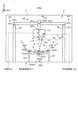
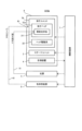
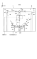
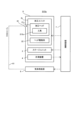
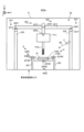
初めに、図1から図3を参照しながら、第1実施形態の加工システムSYSaの構造について説明する。図1は、第1実施形態の加工システムSYSaのシステム構成を示すシステム構成図である。図2及び図3のそれぞれは、第1実施形態の加工システムSYSaの構造を模式的に示す断面図である。 (1-1) Structure of the machining system SYSa First, the structure of the machining system SYSa of the first embodiment will be described with reference to Fig. 1 to Fig. 3. Fig. 1 is a system configuration diagram showing the system configuration of the machining system SYSa of the first embodiment. Fig. 2 and Fig. 3 are each a cross-sectional view showing a schematic structure of the machining system SYSa of the first embodiment.
加工システムSYSaは、3次元構造物(つまり、3次元方向のいずれの方向においても大きさを持つ3次元の物体であり、立体物、言い換えると、X軸方向、Y軸方向及びZ軸方向において大きさを持つ物体)STを形成可能である。加工システムSYSaは、3次元構造物STを形成するための基礎(つまり、母材)となるワークW上に、3次元構造物STを形成可能である。加工システムSYSaは、ワークWに付加加工を行うことで、3次元構造物STを形成可能である。ワークWが後述するステージ31である場合には、加工システムSYSaは、ステージ31上に、3次元構造物STを形成可能である。ワークWがステージ31に載置されている物体である載置物である場合には、加工システムSYSaは、載置物上に、3次元構造物STを形成可能である。この場合、加工システムSYSaは、載置物と一体化された3次元構造物STを形成してもよい。載置物と一体化された3次元構造物STを形成する動作は、載置物に新たな構造物を付加する動作と等価である。或いは、加工システムSYSaは、載置物と分離可能な3次元構造物STを形成してもよい。ステージ31に載置される載置物は、加工システムSYSaが形成した別の3次元構造物ST(つまり、既存構造物)であってもよい。以下では、ワークWがステージ31に載置されている載置物である例を用いて説明を進める。The processing system SYSa can form a three-dimensional structure ST (i.e., a three-dimensional object having a size in all three-dimensional directions, a solid object, in other words, an object having a size in the X-axis direction, the Y-axis direction, and the Z-axis direction). The processing system SYSa can form the three-dimensional structure ST on the workpiece W, which is the base (i.e., the base material) for forming the three-dimensional structure ST. The processing system SYSa can form the three-dimensional structure ST by performing additional processing on the workpiece W. When the workpiece W is the
上述したように、加工システムSYSaは、レーザ肉盛溶接法により造形物を形成可能である。つまり、加工システムSYSaは、積層造形技術を用いて物体を形成する3Dプリンタであるとも言える。尚、積層造形技術は、ラピッドプロトタイピング(Rapid Prototyping)、ラピッドマニュファクチャリング(Rapid Manufacturing)、又は、アディティブマニュファクチャリング(Additive Manufacturing)とも称されてもよい。As described above, the processing system SYSa can form a molded object by the laser build-up welding method. In other words, the processing system SYSa can also be said to be a 3D printer that forms an object using additive manufacturing technology. In addition, additive manufacturing technology may also be called rapid prototyping, rapid manufacturing, or additive manufacturing.
加工システムSYSaは、造形材料Mを加工光ELで加工して造形物を形成する。造形材料Mは、所定強度以上の加工光ELの照射によって溶融可能な材料である。このような造形材料Mとして、例えば、金属性の材料及び樹脂性の材料の少なくとも一方が使用可能である。但し、造形材料Mとして、金属性の材料及び樹脂性の材料とは異なるその他の材料が用いられてもよい。造形材料Mは、粉状の又は粒状の材料である。つまり、造形材料Mは、粉粒体である。但し、造形材料Mは、粉粒体でなくてもよい。例えば、造形材料Mとして、ワイヤ状の造形材料及びガス状の造形材料の少なくとも一方が用いられてもよい。The processing system SYSa processes the modeling material M with the processing light EL to form a model. The modeling material M is a material that can be melted by irradiation with processing light EL of a predetermined intensity or higher. For example, at least one of a metallic material and a resinous material can be used as the modeling material M. However, other materials other than the metallic material and the resinous material may also be used as the modeling material M. The modeling material M is a powder or granular material. In other words, the modeling material M is a powdered or granular material. However, the modeling material M does not have to be a powdered or granular material. For example, at least one of a wire-shaped modeling material and a gaseous modeling material may be used as the modeling material M.
3次元構造物STを形成するために、加工システムSYSaは、図1から図3に示すように、材料供給源1と、加工ユニット2と、ステージユニット3と、計測装置4と、光源5と、気体供給源6と、制御装置7とを備える。加工ユニット2と、ステージユニット3と、計測装置4とは、筐体8の内部空間に収容されていてもよい。
To form the three-dimensional structure ST, the processing system SYSa includes a
材料供給源1は、加工ユニット2に造形材料Mを供給する。材料供給源1は、3次元構造物STを形成するために単位時間あたりに必要とする分量の造形材料Mが加工ユニット2に供給されるように、当該必要な分量に応じた所望量の造形材料Mを供給する。The
加工ユニット2は、材料供給源1から供給される造形材料Mを加工して3次元構造物STを形成する。3次元構造物を形成するために、加工ユニット2は、加工ヘッド21と、ヘッド駆動系22とを備える。更に、加工ヘッド21は、照射光学系211と、材料ノズル(つまり造形材料Mを供給する供給系)212とを備えている。尚、加工ヘッド21は、加工装置と称されてもよい。The
照射光学系211は、射出部213から加工光ELを射出するための光学系(例えば、集光光学系)である。具体的には、照射光学系211は、加工光ELを発する光源5と、光ファイバやライトパイプ等の光伝送部材51を介して光学的に接続されている。照射光学系211は、光伝送部材51を介して光源5から伝搬してくる加工光ELを射出する。照射光学系211は、照射光学系211から下方(つまり、-Z側)に向けて加工光ELを照射する。照射光学系211の下方には、ステージ31が配置されている。ステージ31にワークWが載置されている場合には、照射光学系211は、ワークWに向けて加工光ELを照射する。このため、照射光学系211は、照射装置と称されてもよい。具体的には、照射光学系211は、加工光ELが照射される(典型的には、集光される)領域としてワークW上に又はワークWの近傍に設定される目標照射領域EAに加工光ELを照射可能である。更に、照射光学系211の状態は、制御装置7の制御下で、目標照射領域EAに加工光ELを照射する状態と、目標照射領域EAに加工光ELを照射しない状態との間で切替可能である。尚、照射光学系211から射出される加工光ELの方向は真下(つまり、-Z軸方向と一致)には限定されず、例えば、Z軸に対して所定の角度だけ傾いた方向であってもよい。The irradiation
材料ノズル212には、供給アウトレット214が形成されている。材料ノズル212は、供給アウトレット214から造形材料Mを供給する(例えば、射出する、噴射する、噴出する、又は、吹き付ける)。材料ノズル212は、供給管11及び混合装置12を介して造形材料Mの供給源である材料供給源1と物理的に接続されている。材料ノズル212は、供給管11及び混合装置12を介して材料供給源1から供給される造形材料Mを供給する。材料ノズル212は、供給管11を介して材料供給源1から供給される造形材料Mを圧送してもよい。即ち、材料供給源1からの造形材料Mと搬送用の気体(つまり、圧送ガスであり、例えば、窒素やアルゴン等の不活性ガス)とは、混合装置12で混合された後に供給管11を介して材料ノズル212に圧送されてもよい。その結果、材料ノズル212は、搬送用の気体と共に造形材料Mを供給する。搬送用の気体として、例えば、気体供給源6から供給されるパージガスが用いられる。但し、搬送用の気体として、気体供給源6とは異なる気体供給源から供給される気体が用いられてもよい。尚、図1において材料ノズル212は、チューブ状に描かれているが、材料ノズル212の形状は、この形状に限定されない。材料ノズル212は、材料ノズル212から下方(つまり、-Z側)に向けて造形材料Mを供給する。材料ノズル212の下方には、ステージ31が配置されている。ステージ31にワークWが搭載されている場合には、材料ノズル212は、ワークW又はワークWの近傍に向けて造形材料Mを供給する。尚、材料ノズル212から供給される造形材料Mの進行方向はZ軸方向に対して所定の角度(一例として鋭角)だけ傾いた方向であるが、-Z側(つまり、真下)であってもよい。The
本実施形態では、材料ノズル212は、照射光学系211が加工光ELを照射する目標照射領域EAに向けて造形材料Mを供給するように、照射光学系211に対して位置合わせされている。つまり、材料ノズル212が造形材料Mを供給する領域としてワークW上に又はワークWの近傍に設定される目標供給領域MAと目標照射領域EAとが一致する(或いは、少なくとも部分的に重複する)ように、材料ノズル212と照射光学系211とが位置合わせされている。尚、照射光学系211から射出された加工光ELによって形成される溶融池MP(後述)に、材料ノズル212が造形材料Mを供給するように、材料ノズル212と照射光学系211とが位置合わせされていてもよい。尚、材料ノズル212は、溶融池MPに材料を供給しなくてもよい。例えば、加工システムSYSaは、材料ノズル212からの造形材料MがワークWに到達する前に当該造形材料Mを照射光学系211によって溶融させ、溶融した造形材料MをワークWに付着させてもよい。In this embodiment, the
ヘッド駆動系22は、加工ヘッド21を移動させる。このため、ヘッド駆動系22は、移動装置と称されてもよい。ヘッド駆動系22は、例えば、X軸、Y軸、Z軸、θX方向、θY方向及びθZ方向の少なくとも一つに沿って加工ヘッド21を移動させる。図2から図3に示す例では、ヘッド駆動系22は、X軸、Y軸及びZ軸のそれぞれに沿って加工ヘッド21を移動させる。この場合、ヘッド駆動系22は、ヘッド駆動系22Xと、ヘッド駆動系22Yと、ヘッド駆動系22Zとを備えていてもよい。ヘッド駆動系22Xは、X軸に沿って加工ヘッド21を移動させる。ヘッド駆動系22Yは、Y軸に沿って加工ヘッド21を移動させる。ヘッド駆動系22Zは、Z軸に沿って加工ヘッド21を移動させる。The
ヘッド駆動系22Yは、筐体8の底面(或いは、筐体8の底面に配置される定盤)に空気ばね等の防振装置を介して設置される支持フレーム224に接続され且つY軸に沿って延びるYガイド部材221Yと、Yガイド部材221Yに沿って移動可能なYスライド部材222Yと、Yスライド部材222Yを移動させる不図示のモータとを備える。ヘッド駆動系22Yは、Yスライド部材222Yに接続され且つX軸に沿って延びるXガイド部材221Xと、Xガイド部材221Xに沿って移動可能なXスライド部材222Xと、Xスライド部材222Xを移動させる不図示のモータとを備える。ヘッド駆動系22Zは、Xスライド部材222Xに接続され且つZ軸に沿って延びるZガイド部材221Zと、Zガイド部材221Zに沿って移動可能なZスライド部材222Zと、Zスライド部材222Zを移動させる不図示のモータとを備える。Zスライド部材222Zには、加工ヘッド21が接続されている。Yスライド部材222YがYガイド部材221Yに沿って移動すると、ヘッド駆動系22X及び22Zを介してYスライド部材222Yに接続されている加工ヘッド21がY軸に沿って移動する。Xスライド部材222XがXガイド部材221Xに沿って移動すると、ヘッド駆動系22Zを介してXスライド部材222Xに接続されている加工ヘッド21がX軸に沿って移動する。Zスライド部材222ZがZガイド部材221Zに沿って移動すると、Zスライド部材222Zに接続されている加工ヘッド21がZ軸に沿って移動する。The
ヘッド駆動系22が加工ヘッド21を移動させると、加工ヘッド21とステージ31及びステージ31に載置されたワークWのそれぞれとの相対位置が変わる。つまり、照射光学系211及び材料ノズル212(供給アウトレット214)のそれぞれとステージ31及びワークWのそれぞれとの相対位置が変わる。このため、ヘッド駆動系22は、照射光学系211及び材料ノズル212(供給アウトレット214)のそれぞれとステージ31及びワークWのそれぞれとの相対的な位置関係を変更するための位置変更装置として機能してもよい。更に、加工ヘッド21とステージ31及びワークWのそれぞれとの相対位置が変わると、目標照射領域EA及び目標供給領域MA(更には、溶融池MP)がワークWに対して相対的に移動する。このため、ヘッド駆動系22は、目標照射領域EA及び目標供給領域MA(更には、溶融池MP)をワークWに対して相対的に移動させる移動装置として機能してもよい。When the
ステージユニット3は、ステージ31と、ステージ駆動系32と、位置計測器33とを備えている。尚、ステージ31は、テーブルと称されてもよい。The
ステージ31は、ワークWを支持可能である。尚、ここで言う「ステージ31がワークWを支持する」状態は、ワークWがステージ31によって直接的に又は間接的に支えられている状態を意味していてもよい。ステージ31は、ステージ31に載置されたワークWを保持可能であってもよい。つまり、ステージ31は、ワークWを保持することでワークWを支持してもよい。このため、ステージ31は、ワークWを保持する保持部として機能してもよい。或いは、ステージ31は、ワークWを保持可能でなくてもよい。このとき、ワークWは、クランプレスでステージ31に載置されていてもよい。更に、ステージ31は、ワークWが保持されている場合には、保持したワークWをリリース可能である。上述した照射光学系211は、ステージ31がワークWを支持している期間の少なくとも一部において加工光ELを照射する。更に、上述した材料ノズル212は、ステージ31がワークWを支持している期間の少なくとも一部において造形材料Mを供給する。尚、ステージ31は、ワークWを保持するために、機械的なチャックや真空吸着チャック等を備えていてもよい。The
本実施形態では、ステージ31は、ステージ31θXと、ステージ31θZとを含む。ステージ31がステージ31θXとステージ31θZとを含む理由は、後に詳述するように、後述するステージ駆動系32によってステージ31をθX方向及びθZ方向のそれぞれに沿って移動させるためである。ワークWは、ステージ31θZによって支持されている。ステージ31θXは、後述するように、ステージ駆動系32によってθX方向に沿って移動可能(つまり、X軸に沿った回転軸周りに回転可能)である。ステージ31θZは、ステージ31θXの回転に合わせてステージ31θXと共にX軸に沿った回転軸周りに回転可能となるように、ステージ31θXに形成された凹部に配置されている。ステージ31θZは、後述するように、ステージ31θXの回転とは無関係にステージ駆動系32によってθZ方向に沿って移動可能(つまり、Z軸に沿った回転軸周りに回転可能)となるように、ステージ31θXに形成された凹部に配置されている。尚、ステージ31の構成は、図2及び図3に示した構成には限定されない。一例として、ステージ31θZがステージ31θXに形成された凹部に配置されていなくてもよい。In this embodiment, the
ステージ駆動系32は、ステージ31を移動させる。このため、ステージ駆動系32は、移動装置と称されてもよい。ステージ駆動系32は、例えば、X軸、Y軸、Z軸、θX方向、θY方向及びθZ方向の少なくとも一つに沿ってステージ31を移動させる。図2から図3に示す例では、ステージ駆動系32は、θX方向及びθZ方向のそれぞれに沿ってステージ31を移動させる。つまり、ステージ駆動系32は、X軸に沿った回転軸周りにステージ31を回転させ、Z軸に沿った回転軸周りにステージ31を回転させる。このため、ステージ駆動系32は、回転装置と称されてもよい。この場合、ステージ駆動系32は、ステージ駆動系32θXと、ステージ駆動系32θZとを備えていてもよい。ステージ駆動系32θXは、X軸に沿った回転軸周りにステージ31(特に、ステージ31θX)を回転させる。ステージ駆動系32θZは、Z軸に沿った回転軸周りにステージ31(特に、ステージ31θZ)を回転させる。ステージ駆動系32θXは、筐体8の底面(或いは、筐体8の底面に配置される定盤)に空気ばね等の防振装置を介して設置される一対の支持フレーム323にそれぞれ回転可能に接続される一対の回転シャフト321θXと、一対の回転シャフト321θXをX軸に沿った回転軸周りに回転させるモータ322θXとを備える。一対の回転シャフト321θXは、X軸方向に沿って延びる。一対の回転シャフト321θXは、X軸方向に沿ってステージ31を挟み込むように、ステージ31θXに接続されている。ステージ駆動系32θZは、Z軸方向に沿って延び且つステージ31θXの底面(具体的には、ステージ31θZに対向する面)に接続される回転シャフト321θZと、回転シャフト321θZをZ軸に沿った回転軸周りに回転させるモータ322θZとを備える。一対の回転シャフト321θXが回転すると、ステージ31θXがX軸に沿った回転軸周りに回転する。その結果、ステージ31θXが支持するステージ31θZ(更には、ステージ31θZが支持するワークW)もまた、X軸に沿った回転軸周りに回転する。回転シャフト321θZが回転すると、ステージ31θZ(更には、ステージ31θZが支持するワークW)もまた、Z軸に沿った回転軸周りに回転する。尚、図2及び図3に示したステージ31は、ステージ31θXが支持フレーム323によって両側から支持される両持ち構造を有している。しかしながら、ステージ31は、ステージ31θXが支持フレーム323によって片側から支持される片持ち構造を有していてもよい。The
ステージ駆動系32がステージ31を移動させると、加工ヘッド21とステージ31及びステージ31に載置されたワークWのそれぞれとの相対位置が変わる。つまり、照射光学系211及び材料ノズル212(供給アウトレット214)のそれぞれとステージ31及びワークWのそれぞれとの相対位置が変わる。このため、ステージ駆動系32は、照射光学系211及び材料ノズル212(供給アウトレット214)のそれぞれとステージ31及びワークWのそれぞれとの相対的な位置関係を変更するための位置変更装置として機能してもよい。更に、加工ヘッド21とステージ31及びワークWのそれぞれとの相対位置が変わると、目標照射領域EA及び目標供給領域MA(更には、溶融池MP)がワークWに対して相対的に移動する。このため、ステージ駆動系32は、目標照射領域EA及び目標供給領域MA(更には、溶融池MP)をワークWに対して相対的に移動させる移動装置として機能してもよい。When the
位置計測器33は、ステージ31の位置を計測可能(言い換えれば、検出可能)である。本実施形態では、上述したようにステージ31が回転可能であるがゆえに、位置計測器33は、ステージ31の回転方向における位置を計測可能であってもよい。例えば、位置計測器33は、ステージ31の回転角度を計測可能な角度検出装置(角度検出部)を含んでいてもよい。より具体的には、位置計測器33は、X軸に沿った回転軸周りのステージ31(特に、ステージ31θX)の回転角度と、Z軸に沿った回転軸周りのステージ31(特に、ステージ31θZ)の回転角度とを計測可能であってもよい。このような位置計測器33の一例として、エンコーダが挙げられる。尚、位置計測器33は、ステージ駆動系32に組み込まれていてもよい。The
計測装置4は、計測対象物の少なくとも一部を計測可能な装置である。例えば、計測装置4は、計測対象物の少なくとも一部の形状を計測可能であってもよい。例えば、計測装置4は、計測対象物の少なくとも一部の位置を計測可能であってもよい。このような計測装置の一例として、計測対象物を3次元計測する3次元計測機(言い換えれば、3Dスキャナ)があげられる。この場合、計測装置4は、計測対象物の表面に計測光MLを照射することで当該表面に光パターンを投影し、投影されたパターンの形状を計測するパターン投影法又は光切断法を用いて、計測対象物を計測してもよい。或いは、計測装置4は、計測対象物の表面に計測光MLを投射し、投射された計測光MLが戻ってくるまでの時間から物体までの距離を測定し、これを物体上の複数の位置で行うタイム・オブ・フライト法を用いて、計測対象物を計測してもよい。或いは、計測装置4は、モアレトポグラフィ法(具体的には、格子照射法若しくは格子投影法)、ホログラフィック干渉法、オートコリメーション法、ステレオ法、非点収差法、臨界角法及びナイフエッジ法のうちの少なくとも一つを用いて、計測対象物を計測してもよい。尚、計測対象物の一例として、ワークW、3次元構造物ST(つまり、3次元構造物STと一体化されたワークW)、3次元構造物STを構成する後述する構造層SL(つまり、3次元構造物STと一体化されたワークW)、及び、ステージ31の少なくとも一つがあげられる。The measuring
計測装置4は、例えば、支持フレーム224に固定されていてもよい。この場合、ステージ駆動系32がステージ31を回転させると、計測装置4とステージ31及びステージ31が支持するワークWとの相対的な位置関係が変わる。特に、ステージ駆動系32がステージ31を回転させると、計測装置4の計測軸(例えば、計測装置4が計測光MLを射出するために備えている光学系の光軸)に対するステージ31及びステージ31が支持するワークWの回転軸(つまり、ステージ駆動系32の回転軸)の角度が変わる。従って、ステージ駆動系32は、計測装置4の計測軸に対するステージ駆動系32の回転軸の角度を変更する角度変更装置として機能してもよい。尚、計測装置4が移動可能であってもよい。例えば、計測装置4は、X軸、Y軸、Z軸、θX方向、θY方向及びθZ方向の少なくとも一つに沿って移動可能であってもよい。例えば、計測装置4は、X軸に沿った回転軸、Y軸に沿った回転軸及びZ軸に沿った回転軸の少なくとも一つの周りに回転可能であってもよい。計測装置4が回転する場合には、計測装置4の計測軸に対するステージ駆動系32の回転軸の角度が変わる。尚、計測装置4は、筐体8に固定されていてもよい。The measuring
光源5は、例えば、赤外光、可視光及び紫外光のうちの少なくとも一つを、加工光ELとして射出する。但し、加工光ELとして、その他の種類の光が用いられてもよい。加工光ELは、複数のパルス光(つまり、複数のパルスビーム)を含んでいてもよい。加工光ELは、レーザ光であってもよい。この場合、光源5は、レーザ光源(例えば、レーザダイオード(LD:Laser Diode)等の半導体レーザを含んでいてもよい。レーザ光源としては、ファイバ・レーザやCO2レーザ、YAGレーザ、エキシマレーザ等であってもよい。但し、加工光ELはレーザ光でなくてもよい。光源5は、任意の光源(例えば、LED(Light Emitting Diode)及び放電ランプ等の少なくとも一つ)を含んでいてもよい。
The
気体供給源6は、筐体8の内部空間をパージするためのパージガスの供給源である。パージガスは、不活性ガスを含む。不活性ガスの一例として、窒素ガス又はアルゴンガスがあげられる。気体供給源6は、気体供給源6と筐体8とを接続する供給管61を介して、筐体8の内部空間にパージガスを供給する。その結果、筐体8の内部空間は、パージガスによってパージされた空間となる。尚、気体供給源6は、窒素ガスやアルゴンガス等の不活性ガスが格納されたボンベであってもよい。不活性ガスが窒素ガスである場合には、気体供給源6は、大気を原料として窒素ガスを発生する窒素ガス発生装置であってもよい。The
上述したように、材料ノズル212がパージガスと共に造形材料Mを供給する場合には、気体供給源6は、材料供給源1からの造形材料Mが供給される混合装置12にパージガスを供給してもよい。具体的には、気体供給源6は、気体供給源6と混合装置12とを接続する供給管62を介して混合装置12と接続されていてもよい。その結果、気体供給源6は、供給管62を介して、混合装置12にパージガスを供給する。この場合、材料供給源1からの造形材料Mは、供給管62を介して気体供給源6から供給されたパージガスによって、供給管11内を通って材料ノズル212に向けて供給(具体的には、圧送)されてもよい。つまり、気体供給源6は、供給管62、混合装置12及び供給管11を介して、材料ノズル212に接続されていてもよい。その場合、材料ノズル212は、供給アウトレット214から、造形材料Mを圧送するためのパージガスと共に造形材料Mを供給することになる。As described above, when the
制御装置7は、加工システムSYSaの動作を制御する。制御装置7は、例えば、演算装置と、記憶装置とを備えていてもよい。演算装置は、例えば、CPU(Central Processing Unit)及びGPU(Graphics Processing Unit)の少なくとも一方を含んでいてもよい。記憶装置は、例えば、メモリを含んでいてもよい。制御装置7は、演算装置がコンピュータプログラムを実行することで、加工システムSYSaの動作を制御する装置として機能する。このコンピュータプログラムは、制御装置7が行うべき後述する動作を演算装置に行わせる(つまり、実行させる)ためのコンピュータプログラムである。つまり、このコンピュータプログラムは、加工システムSYSに後述する動作を行わせるように制御装置7を機能させるためのコンピュータプログラムである。演算装置が実行するコンピュータプログラムは、制御装置7が備える記憶装置(つまり、記録媒体)に記録されていてもよいし、制御装置7に内蔵された又は制御装置7に外付け可能な任意の記憶媒体(例えば、ハードディスクや半導体メモリ)に記録されていてもよい。或いは、演算装置は、実行するべきコンピュータプログラムを、ネットワークインタフェースを介して、制御装置7の外部の装置からダウンロードしてもよい。The
例えば、制御装置7は、照射光学系211による加工光ELの射出態様を制御してもよい。射出態様は、例えば、加工光ELの強度及び加工光ELの射出タイミングの少なくとも一方を含んでいてもよい。加工光ELが複数のパルス光を含む場合には、射出態様は、例えば、パルス光の発光時間、パルス光の発光周期、及び、パルス光の発光時間の長さとパルス光の発光周期との比(いわゆる、デューティ比)の少なくとも一つを含んでいてもよい。更に、制御装置7は、ヘッド駆動系22による加工ヘッド21の移動態様を制御してもよい。制御装置7は、ステージ駆動系32によるステージ31の移動態様を制御してもよい。移動態様は、例えば、移動量、移動速度、移動方向及び移動タイミング(移動時期)の少なくとも一つを含んでいてもよい。更に、制御装置7は、材料ノズル212による造形材料Mの供給態様を制御してもよい。供給態様は、例えば、供給量(特に、単位時間当たりの供給量)及び供給タイミング(供給時期)の少なくとも一方を含んでいてもよい。For example, the
制御装置7は、加工システムSYSaの内部に設けられていなくてもよい。例えば、制御装置7は、加工システムSYSa外にサーバ等として設けられていてもよい。この場合、制御装置7と加工システムSYSaとは、有線及び/又は無線のネットワーク(或いは、データバス及び/又は通信回線)で接続されていてもよい。有線のネットワークとして、例えばIEEE1394、RS-232x、RS-422、RS-423、RS-485及びUSBの少なくとも一つに代表されるシリアルバス方式のインタフェースを用いるネットワークが用いられてもよい。有線のネットワークとして、パラレルバス方式のインタフェースを用いるネットワークが用いられてもよい。有線のネットワークとして、10BASE-T、100BASE-TX及び1000BASE-Tの少なくとも一つに代表されるイーサネット(登録商標)に準拠したインタフェースを用いるネットワークが用いられてもよい。無線のネットワークとして、電波を用いたネットワークが用いられてもよい。電波を用いたネットワークの一例として、IEEE802.1xに準拠したネットワーク(例えば、無線LAN及びBluetooth(登録商標)の少なくとも一方)があげられる。無線のネットワークとして、赤外線を用いたネットワークが用いられてもよい。無線のネットワークとして、光通信を用いたネットワークが用いられてもよい。この場合、制御装置7と加工システムSYSaとはネットワークを介して各種の情報の送受信が可能となるように構成されていてもよい。また、制御装置7は、ネットワークを介して加工システムSYSaにコマンドや制御パラメータ等の情報を送信可能であってもよい。加工システムSYSaは、制御装置7からのコマンドや制御パラメータ等の情報を、上記ネットワークを介して受信する受信装置を備えていてもよい。加工システムSYSaは、制御装置7に対してコマンドや制御パラメータ等の情報を、上記ネットワークを介して送信する送信装置(つまり、制御装置7に対して情報を出力する出力装置)を備えていてもよい。或いは、制御装置7が行う処理のうちの一部を行う第1制御装置が加工システムSYSaの内部に設けられている一方で、制御装置7が行う処理のうちの他の一部を行う第2制御装置が加工システムSYSaの外部に設けられていてもよい。The
尚、制御装置7が実行するコンピュータプログラムを記録する記録媒体としては、CD-ROM、CD-R、CD-RWやフレキシブルディスク、MO、DVD-ROM、DVD-RAM、DVD-R、DVD+R、DVD-RW、DVD+RW及びBlu-ray(登録商標)等の光ディスク、磁気テープ等の磁気媒体、光磁気ディスク、USBメモリ等の半導体メモリ、及び、その他プログラムを格納可能な任意の媒体の少なくとも一つが用いられてもよい。記録媒体には、コンピュータプログラムを記録可能な機器(例えば、コンピュータプログラムがソフトウェア及びファームウェア等の少なくとも一方の形態で実行可能な状態に実装された汎用機器又は専用機器)が含まれていてもよい。更に、コンピュータプログラムに含まれる各処理や機能は、制御装置7(つまり、コンピュータ)がコンピュータプログラムを実行することで制御装置7内に実現される論理的な処理ブロックによって実現されてもよいし、制御装置7が備える所定のゲートアレイ(FPGA、ASIC)等のハードウェアによって実現されてもよいし、論理的な処理ブロックとハードウェアの一部の要素を実現する部分的ハードウェアモジュールとが混在する形式で実現してもよい。
As a recording medium for recording the computer program executed by the
(1-2)加工システムSYSaの動作
続いて、加工システムSYSaの動作について説明する。第1実施形態では、加工システムSYSaは、ワークWに3次元構造物STを形成するための付加加工動作を行う。更に、加工システムSYSaは、付加加工動作を行う前に(或いは、付加加工動作を行っている間に又は付加加工動作を終了した後に)、ヘッド駆動系22が加工ヘッド21を移動させる際に用いる加工座標系と、ステージ駆動系32がステージ31を移動させる際に用いるステージ座標系とを関連付けるための座標マッチング動作を行う。更に、加工システムSYSaは、付加加工動作を行う前に(或いは、付加加工動作を行っている間に又は付加加工動作を終了した後に)、ステージ31の回転軸(つまり、回転装置として機能するステージ駆動系32の回転軸)とステージ31に支持されたワークWの理想的な回転軸とのずれ量(典型的には、偏心量δ)を取得するための偏心量取得動作とを行う。このため、以下では、付加加工動作、座標マッチング動作及び偏心量取得動作について順に説明する。 (1-2) Operation of the machining system SYSa Next, the operation of the machining system SYSa will be described. In the first embodiment, the machining system SYSa performs an additional machining operation for forming a three-dimensional structure ST on the workpiece W. Furthermore, before performing the additional machining operation (or while performing the additional machining operation or after the additional machining operation is completed), the machining system SYSa performs a coordinate matching operation for associating a machining coordinate system used when the
(1-2-1)付加加工動作
初めに、付加加工動作について説明する。上述したように、加工システムSYSaは、レーザ肉盛溶接法により3次元構造物STを形成する。このため、加工システムSYSaは、レーザ肉盛溶接法に準拠した既存の付加加工動作(この場合、造形動作)を行うことで、3次元構造物STを形成してもよい。以下、レーザ肉盛溶接法を用いて3次元構造物STを形成する付加加工動作の一例について簡単に説明する。 (1-2-1) Additional Processing Operation First, the additional processing operation will be described. As described above, the processing system SYSa forms a three-dimensional structure ST by the laser build-up welding method. For this reason, the processing system SYSa may form the three-dimensional structure ST by performing an existing additional processing operation (in this case, a molding operation) that complies with the laser build-up welding method. Below, an example of the additional processing operation that forms the three-dimensional structure ST using the laser build-up welding method will be briefly described.
加工システムSYSaは、形成するべき3次元構造物STの3次元モデルデータ(例えば、CAD(Computer Aided Design)データ)等に基づいて、ワークW上に3次元構造物STを形成する。3次元モデルデータとして、加工システムSYSa内に設けられた不図示の計測装置及び加工システムSYSaとは別に設けられた3次元形状計測機の少なくとも一方で計測された立体物の計測データが用いられてもよい。加工システムSYSaは、3次元構造物STを形成するために、例えば、Z軸方向に沿って並ぶ複数の層状の部分構造物(以下、“構造層”と称する)SLを順に形成していく。例えば、加工システムSYSaは、3次元構造物STをZ軸方向に沿って輪切りにすることで得られる複数の構造層SLを1層ずつ順に形成していく。その結果、複数の構造層SLが積層された積層構造体である3次元構造物STが形成される。以下、複数の構造層SLを1層ずつ順に形成していくことで3次元構造物STを形成する動作の流れについて説明する。The processing system SYSa forms a three-dimensional structure ST on the workpiece W based on three-dimensional model data (e.g., CAD (Computer Aided Design) data) of the three-dimensional structure ST to be formed. Measurement data of a solid object measured by at least one of a measuring device (not shown) provided in the processing system SYSa and a three-dimensional shape measuring device provided separately from the processing system SYSa may be used as the three-dimensional model data. In order to form the three-dimensional structure ST, the processing system SYSa sequentially forms, for example, a plurality of layered partial structures (hereinafter referred to as "structural layers") SL arranged along the Z-axis direction. For example, the processing system SYSa sequentially forms a plurality of structural layers SL obtained by slicing the three-dimensional structure ST along the Z-axis direction, one by one. As a result, a three-dimensional structure ST, which is a laminated structure in which a plurality of structural layers SL are stacked, is formed. Below, the flow of operations for forming the three-dimensional structure ST by sequentially forming a plurality of structural layers SL one by one will be described.
まず、各構造層SLを形成する動作について図4(a)から図4(e)を参照して説明する。加工システムSYSaは、制御装置7の制御下で、ワークWの表面又は形成済みの構造層SLの表面に相当する造形面MS上の所望領域に目標照射領域EAが設定されるように、加工ヘッド21及びステージ31の少なくとも一方を移動させる。加工システムSYSaは、加工ヘッド21及びステージ31の少なくとも一方を移動させる際に、座標マッチング動作及び偏心量取得動作の結果を用いる。つまり、加工システムSYSaは、座標マッチング動作及び偏心量取得動作の結果に基づいて、造形面MS上の所望領域に目標照射領域EAが設定されるように、加工ヘッド21及びステージ31の少なくとも一方を移動させる。その後、加工システムSYSaは、目標照射領域EAに対して照射光学系211から加工光ELを照射する。この際、加工光ELのフォーカス位置(つまり、集光位置)は、造形面MSに一致していてもよい。その結果、図4(a)に示すように、加工光ELが照射された造形面MS上に溶融池(つまり、加工光ELによって溶融した金属のプール)MPが形成される。更に、加工システムSYSaは、制御装置7の制御下で、材料ノズル212から造形材料Mを供給する。ここで、上述したように造形材料Mが供給される目標供給領域MAが目標照射領域EAと一致しているため、目標供給領域MAは、溶融池MPが形成された領域の少なくとも一部を含む。このため、加工システムSYSaは、図4(b)に示すように、溶融池MPに対して、材料ノズル212から造形材料Mを供給する。その結果、溶融池MPに供給された造形材料Mが溶融する。その後、加工ヘッド21の移動に伴って溶融池MPに加工光ELが照射されなくなると、溶融池MPにおいて溶融した造形材料Mは、冷却されて固化(つまり、凝固)する。その結果、図4(c)に示すように、固化した造形材料Mが造形面MS上に堆積される。つまり、固化した造形材料Mの堆積物による造形物が形成される。First, the operation of forming each structure layer SL will be described with reference to FIG. 4(a) to FIG. 4(e). Under the control of the
加工システムSYSaは、図4(d)に示すように、このような加工光ELの照射による溶融池MPの形成、溶融池MPへの造形材料Mの供給、供給された造形材料Mの溶融及び溶融した造形材料Mの固化を含む一連の造形処理を、加工ヘッド21とワークWとの相対的な位置関係(つまり、加工ヘッド21と造形面MSとの相対的な位置関係)を変更しながら繰り返す。図4(d)に示す例では、X軸方向が長手方向となる円筒形状のワークWをX軸に沿った回転軸周りに回転させながら一連の造形処理が繰り返されている。この際、加工システムSYSaは、造形面MS上において造形物を形成したい領域に加工光ELを照射する一方で、造形面MS上において造形物を形成したくない領域に加工光ELを照射しない。つまり、加工システムSYSaは、造形面MS上を所定の移動軌跡に沿って目標照射領域EAを移動させながら、造形物を形成したい領域の分布の態様に応じたタイミングで加工光ELを造形面MSに照射する。その結果、溶融池MPもまた、目標照射領域EAの移動軌跡に応じた移動軌跡に沿って造形面MS上を移動することになる。具体的には、溶融池MPは、造形面MS上において、目標照射領域EAの移動軌跡に沿った領域のうち加工光ELが照射された部分に順次形成される。更に、上述したように目標照射領域EAと目標供給領域MAとが一致しているため、目標供給領域MAもまた、目標照射領域EAの移動軌跡に応じた移動軌跡に沿って造形面MS上を移動することになる。その結果、図4(e)に示すように、造形面MS上に、溶融した後に固化した造形材料Mによる造形物の集合体に相当する構造層SLが形成される。つまり、溶融池MPの移動軌跡に応じたパターンで造形面MS上に形成された造形物の集合体に相当する構造層SL(つまり、平面視において、溶融池MPの移動軌跡に応じた形状を有する構造層SL)が形成される。尚、造形物を形成したくない領域に目標照射領域EAが設定されている場合、加工システムSYSaは、加工光ELを目標照射領域EAに照射するとともに、造形材料Mの供給を停止してもよい。また、造形物を形成したくない領域に目標照射領域EAが設定されている場合に、加工システムSYSaは、造形材料Mを目標照射領域EAに供給するとともに、溶融池MPができない強度の加工光ELを目標照射領域EAに照射してもよい。As shown in FIG. 4(d), the processing system SYSa repeats a series of forming processes, including the formation of a molten pool MP by irradiating the processing light EL, the supply of the forming material M to the molten pool MP, the melting of the supplied forming material M, and the solidification of the molten forming material M, while changing the relative positional relationship between the processing
加工システムSYSaは、このような構造層SLを形成するための動作を、制御装置7の制御下で、3次元モデルデータに基づいて繰り返し行う。具体的には、まず、制御装置7は、3次元モデルデータを積層ピッチでスライス処理してスライスデータを作成する。尚、加工システムSYSaの特性に応じてこのスライスデータを一部修正したデータが用いられてもよい。加工システムSYSaは、ワークWの表面に相当する造形面MS上に1層目の構造層SL#1を形成するための動作を、構造層SL#1に対応する3次元モデルデータ(つまり、構造層SL#1に対応するスライスデータ)に基づいて行う。その結果、造形面MS上には、図5(a)に示すように、構造層SL#1が形成される。その後、加工システムSYSaは、構造層SL#1の表面(つまり、上面)を新たな造形面MSに設定した上で、当該新たな造形面MS上に2層目の構造層SL#2を形成する。構造層SL#2を形成するために、制御装置7は、目標照射領域EA及び目標供給領域MAが構造層SL#1の表面(つまり、新たな造形面MS)に設定されるように、加工ヘッド21及びステージ31の少なくとも一方を移動させる。これにより、加工光ELのフォーカス位置が新たな造形面MSに一致する。その後、加工システムSYSaは、制御装置7の制御下で、構造層SL#1を形成する動作と同様の動作で、構造層SL#2に対応するスライスデータに基づいて、構造層SL#1上に構造層SL#2を形成する。その結果、図5(b)に示すように、構造層SL#2が形成される。以降、同様の動作が、ワークW上に形成するべき3次元構造物STを構成する全ての構造層SLが形成されるまで繰り返される。その結果、図5(c)に示すように、複数の構造層SLが積層された積層構造体によって、3次元構造物STが形成される。The processing system SYSa repeatedly performs the operation for forming such a structural layer SL based on the three-dimensional model data under the control of the
(1-2-2)座標マッチング動作
続いて、図6を参照しながら、座標マッチング動作について説明する。図6は、座標マッチング動作の流れを示すフローチャートである。 (1-2-2) Coordinate Matching Operation Next, the coordinate matching operation will be described with reference to Fig. 6. Fig. 6 is a flowchart showing the flow of the coordinate matching operation.
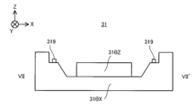
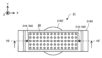
図6に示すように、まずは、ステージ31にキャリブレーションプレート34が載置される(ステップS11)。特に、キャリブレーションプレート34は、キャリブレーションプレート34とステージ31との位置関係が所望の位置関係となるように、ステージ31に載置される。第1実施形態では、キャリブレーションプレート34とステージ31との位置関係が所望の位置関係となるようにキャリブレーションプレート34をステージ31に載置するために、キャリブレーションプレート34とステージ31との双方に、位置合わせ用の目印が形成される。以下、図7から図11を参照しながら、位置合わせ用の目印が形成されたステージ31及びキャリブレーションプレート34の一例について説明する。図7は、位置合わせ用の目印が形成されたステージ31を示す平面図である。図8は、図7に示すステージ31のVII-VII’断面図である。図9は、位置合わせ用の目印が形成されたキャリブレーションプレート34を示す平面図である。図10は、図9に示すキャリブレーションプレート34のIX-IX’断面図である。図11は、ステージ31に載置されたキャリブレーションプレート34を示す平面図である。As shown in FIG. 6, first, the
図7及び図8に示すように、ステージ31には、位置合わせ用の目印として、複数のピン319が形成されている。図7及び図8に示す例では、ステージ31を構成するステージ31θXの上面(特に、ステージ31θZの上面よりも高い又は同じ高さに位置する上面)に、二つのピン319が形成されている。但し、ピン319の形成位置及び数が、図7及び図8に示す例に限定されることはない。ピン319は、ステージ31の上面(図7及び図8に示す例では、ステージ31θXの上面)からZ軸方向に沿って突き出る部材である。尚、ステージ座標系内でのピン319の位置に関する情報は、制御装置7にとって既知の情報である。As shown in Figures 7 and 8,
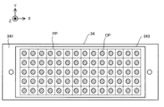
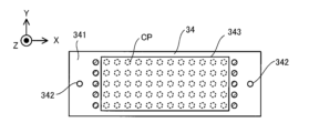
図9及び図10に示すように、キャリブレーションプレート34は、ベース部材341を備えている。ベース部材341は、板状の部材である。ベース部材341は、ステージ31に載置可能な形状及びサイズを有している。ベース部材341には、位置合わせ用の目印として、複数の貫通孔342が形成されている。図9及び図10に示す例では、ベース部材341には、2つの貫通孔342が形成されている。貫通孔342は、Z軸方向に沿ってベース部材341を貫通する。
As shown in Figures 9 and 10, the
第1実施形態では、図11に示す通り、キャリブレーションプレート34は、貫通孔342にピン319が挿入されるように、ステージ31上に載置される。キャリブレーションプレート34は、貫通孔322にピン319が挿入された状態でステージ31上に(つまり、ステージ31θX及びステージ31θZ上に)載置される。ステージ31は、貫通孔322にピン319が挿入された状態でキャリブレーションプレート34を支持する(例えば、保持する)。このため、貫通孔342の配列態様は、ピン319の配列態様と同一である。更に、貫通孔342の数は、ピン319の数と同一である(或いは、多くてもよい)。その結果、キャリブレーションプレート34は、ステージ31に対して所望の位置関係を有するようにステージ31に載置される。具体的には、キャリブレーションプレート34は、ステージ31上のピン319に対して所望の位置関係を有するようにステージ31に載置される。ピン319が形成されている位置は、ステージ31にキャリブレーションプレート34を載置する際のステージ31上の基準位置として用いられてもよい。この場合、キャリブレーションプレート34は、ステージ31上の基準位置に対して所望の位置関係を有するように位置合わせされた状態でステージ31に載置される。11, the
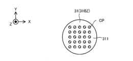
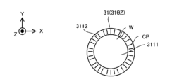
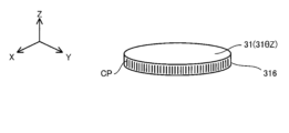
キャリブレーションプレート34には、計測装置4によって計測可能なキャリブレーションパターンCPが形成されている。図9に示す例では、キャリブレーションパターンCPは、マトリクス状に配置されている複数のキャリブレーションマーカCMから構成される計測パターンである。キャリブレーションプレート34上でのキャリブレーションパターンCPの形成位置(図9に示す例では、複数のキャリブレーションマーカCMの形成位置)は、制御装置7にとって既知の情報である。この場合、ステージ座標系内での既知の位置に配置されているピン319に対してキャリブレーションプレート34が所望の位置関係を有するようにステージ31に載置されるため、ステージ座標系内でのキャリブレーションパターンCPの形成位置もまた、制御装置7にとって既知の情報となる。A calibration pattern CP that can be measured by the
キャリブレーションプレート34には、加工光ELに対する感熱性(つまり、感応性)を有する感熱膜343が形成されている。尚、感熱膜343に加えて又は代えて、加工光ELに対する感光性(つまり、感応性)を有する感光膜がキャリブレーションプレート34に形成されていてもよい。感熱膜343は、キャリブレーションパターンCPを覆うように、キャリブレーションプレート34に形成されている。感熱膜343は、計測装置4が用いる計測光ML(例えば、可視光)に対して透明である。このため、計測装置4は、感熱膜343に覆われたキャリブレーションパターンCPを計測することができる。A thermally
再び図6において、キャリブレーションプレート34がステージ31に載置された後、制御装置7は、キャリブレーションプレート34の少なくとも一部に対して加工光ELを照射するように、加工ユニット2及びステージユニット3を照射する(ステップS12)。具体的には、制御装置7は、キャリブレーションプレート34の感熱膜343の少なくとも一部の上を目標照射領域EAが所定の移動パターンで移動するように、加工ヘッド21とステージ31との相対的な位置関係を変更する。具体的には、制御装置7は、キャリブレーションプレート34の感熱膜343の少なくとも一部の上を目標照射領域EAが所定の移動軌跡に沿って移動するように、加工ヘッド21を移動させる。この際、制御装置7は、ステージ31を移動させなくてもよい。更に、制御装置7は、感熱膜343の少なくとも一部の上を所定の移動軌跡に沿って移動する目標照射領域EAに加工光ELを照射する。その結果、加工光ELが照射されたキャリブレーションプレート34を示す平面図である図12に示すように、感熱膜343の少なくとも一部には、目標照射領域EAの移動軌跡に対応する感熱パターンPPが形成される。図12に示す例では、目標照射領域EAは、複数のキャリブレーションマーカCMの間をX軸方向及びY軸方向のそれぞれに沿って延びる移動軌跡を含む格子状の移動軌跡に沿って移動している。6 again, after the
その後、計測装置4は、キャリブレーションプレート34の少なくとも一部を計測する(ステップS13)。具体的には、計測装置4は、キャリブレーションプレート34の感熱膜343に形成された感熱パターンPPを計測する。つまり、計測装置4は、感熱膜343のうち加工光ELに感熱した部分を計測する。また、感熱膜343が計測光MLに対して透明であるため、計測装置4は、感熱パターンPPと共にキャリブレーションパターンCPも合わせて計測する。従って、ステップS13における計測装置4の計測結果は、感熱パターンPPの計測結果に関する情報と、キャリブレーションパターンCPの計測結果に関する情報とを含む。Thereafter, the measuring
その後、制御装置7は、ステップS13における計測装置4の計測結果に基づいて、加工座標系とステージ座標系とを関連付ける(ステップS14)。具体的には、制御装置7は、計測装置4の計測結果に基づいて、感熱パターンPPの位置と、キャリブレーションパターンCPの位置とを算出する。ここで、上述したようにキャリブレーションパターンCPが形成されているキャリブレーションプレート34がステージ31のステージθZと所定の位置関係を有しており且つキャリブレーションパターンCPの形成位置が制御装置7にとって既知の情報である。このため、算出されたキャリブレーションパターンCPの位置は、実質的には、ステージ座標系内でのキャリブレーションパターンCPの位置に相当する。このため、制御装置7は、ステージ座標系内でのキャリブレーションパターンCPの位置と感熱パターンPPの位置とを比較することで、ステージ座標系内での感熱パターンPPの位置を算出することができる。更に、加工ヘッド21からの加工光ELによって感熱パターンPPが形成されているがゆえに、感熱パターンPPの位置は、加工ヘッド21の位置を間接的に示している。つまり、感熱パターンPPの位置は、加工座標系における加工ヘッド21の位置を間接的に示している。このため、制御装置7は、感熱パターンPPの位置とキャリブレーションパターンCPの位置とに基づいて、加工座標系内における加工ヘッド21の位置とステージ座標系におけるキャリブレーションパターンCPの位置とを関連付けることができる。その結果、制御装置7は、加工座標系とステージ座標系とを関連付けることができる。尚、感熱パターンPPの位置と、キャリブレーションパターンCPとの位置とを計測装置4とは異なる計測装置(一例として、外部の計測装置)で計測してもよい。
After that, the
加工座標系とステージ座標系とが関連付けられると、ステージ座標系に対する加工座標系のずれが判明する。ステージ座標系に対する加工座標系のずれは、理想的な(つまり、設計上の)感熱パターンPPの位置と、実際に計測された感熱パターンPPの位置とのずれに対応する。このようなステージ座標系に対する加工座標系のずれは、例えば、ステージ座標系の原点と加工座標系の原点との間のずれを含んでいてもよい。ステージ座標系に対する加工座標系のずれは、例えば、ステージ座標系を構成する軸(例えば、上述したステージ31の回転軸)に対する加工ヘッド21の走り面(例えば、X軸に沿って加工ヘッド21が移動する際の走り面及びY軸に沿って加工ヘッド21が移動する際の走り面の少なくとも一方)のずれを含んでいてもよい。この場合、制御装置7は、このようなずれを相殺する(言い換えれば、補正する)ように加工ヘッド21を移動させるための移動補正値を算出してもよい。例えば、制御装置7は、X軸方向に沿って加工ヘッド21を移動させる際に移動方向を補正するための移動補正値と、X軸方向に沿って加工ヘッド21を移動させる際に移動量を補正するための移動補正値と、Y軸方向に沿って加工ヘッド21を移動させる際に移動方向を補正するための移動補正値と、Y軸方向に沿って加工ヘッド21を移動させる際に移動量を補正するための移動補正値との少なくとも一つを算出してもよい。上述した付加加工動作を行う際には、制御装置7は、座標マッチング動作で算出された移動補正値を用いて、加工ヘッド21を移動させてもよい。つまり、上述した付加加工動作を行う際には、制御装置7は、座標マッチング動作でのキャリブレーションプレート34の計測結果に基づいて、加工ヘッド21を移動させてもよい。その結果、ステージ座標系に対して加工座標系がずれていたとしても、制御装置7は、ステージ座標系に対して加工座標系がずれていない場合と同様に加工ヘッド21を移動させることができる。つまり、その結果、ステージ座標系に対して加工座標系がずれていたとしても、制御装置7は、ワークWの所望位置に加工光ELが照射されるように、加工ヘッド21を移動させることができる。When the machining coordinate system and the stage coordinate system are associated, the deviation of the machining coordinate system with respect to the stage coordinate system is determined. The deviation of the machining coordinate system with respect to the stage coordinate system corresponds to the deviation between the ideal (i.e., designed) position of the thermal pattern PP and the actually measured position of the thermal pattern PP. Such a deviation of the machining coordinate system with respect to the stage coordinate system may include, for example, the deviation between the origin of the stage coordinate system and the origin of the machining coordinate system. The deviation of the machining coordinate system with respect to the stage coordinate system may include, for example, the deviation of the running surface of the
また、加工座標系とステージ座標系とが関連付けられると、制御装置7は、加工座標系及びステージ座標系のいずれか一方のある座標位置を、加工座標系及びステージ座標系のいずれか他方の座標位置に変換することができる。このため、「加工座標系とステージ座標系とを関連付ける」動作は、実質的には、加工座標系及びステージ座標系のいずれか一方のある座標位置を加工座標系及びステージ座標系のいずれか他方の座標位置に変換するために用いられる情報(例えば、変換行列)を算出する動作と等価であるとみなしてもよい。Furthermore, when the machining coordinate system and the stage coordinate system are associated, the
尚、上述した例では、キャリブレーションプレート34がステージ31θXに取り付けられていたが、ステージ31θZに取り付けられていてもよい。
In the above example, the
(1-2-3)偏心量取得動作
続いて、偏心量取得動作について説明する。以下では、初めに偏心量取得動作を行う技術的理由について説明した後に、偏心量取得動作の流れについて説明する。 (1-2-3) Eccentricity Amount Acquisition Operation Next, the eccentricity amount acquisition operation will be described. First, the technical reasons for performing the eccentricity amount acquisition operation will be described, and then the flow of the eccentricity amount acquisition operation will be described.
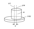
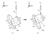
まず、図13は、ステージ31の回転軸とワークWの理想的な回転軸とのずれ量である偏心量δがゼロとなるようにステージ31によって支持されているワークWを示している。尚、図13から図17では、図面の簡略化のために、ワークWをステージ31に固定するための保持金具の図示を省略している。第1実施形態では、ステージ31θZがワークWを支持しているため、偏心量δは、ステージ31θZの回転軸(以降、“回転軸φZ”と称する)とワークWの理想的な回転軸(以降、“回転軸φW”と称する)とのずれ量を意味するものとする。特に、偏心量δは、回転軸φZに交差する方向における回転軸φZと回転軸φWとのずれ量を意味するものとする。尚、回転軸φWは、典型的には、ワークWの質量中心(つまり、重心)を通過する軸であってもよい。図13に示す例では、回転軸φZに沿った方向に延びる円筒形状のワークWの回転軸φWが、円筒の中心を通過する軸となる。この場合、偏心量δは、回転軸φZとワークWの質量中心とのずれ量を意味していてもよい。13 shows the workpiece W supported by the
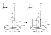
図13に示すように偏心量δがゼロになる場合には、ステージ31θZが回転軸φZ周りに回転すると、加工ヘッド21が静止した状態で加工ヘッド21とワークWとの相対的な位置関係が変動することはない。具体的には、図14(a)は、偏心量δがゼロとなる状態でZ軸に平行な回転軸φZ周りに回転しているステージ31θZによって支持されているワークWと加工ヘッド21との相対的な位置関係を示す。図14(b)は、偏心量δがゼロとなる状態でZ軸に対して傾斜した回転軸φZ周りに回転しているステージ31θZによって支持されているワークWと加工ヘッド21との相対的な位置関係を示す。図14(c)は、偏心量δがゼロとなる状態でZ軸に対して直交する回転軸φZ周りに回転しているステージ31θZによって支持されているワークWと加工ヘッド21との相対的な位置関係を示す。尚、Z軸に対する回転軸φZの状態は、ステージ31θXの回転によって変更可能である。図14(a)から図14(c)に示すように、偏心量δがゼロになる場合には、回転軸φZと回転軸φWとが重なる(つまり、一致する)。このため、ステージ31θZが回転軸φZ周りに回転すると、ワークWは、回転軸φW周りに回転する。その結果、加工ヘッド21とワークWとの相対的な位置関係が変動することはない。
When the eccentricity δ becomes zero as shown in FIG. 13, when the stage 31θZ rotates around the rotation axis φZ, the relative positional relationship between the machining
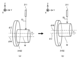
一方で、図15は、偏心量δがゼロとならないようにステージ31によって支持されているワークWを示している。偏心量δがゼロにならない場合には、ステージ31θZが回転軸φZ周りに回転すると、加工ヘッド21が静止しているにも関わらず加工ヘッド21とワークWとの相対的な位置関係が変動する可能性がある。即ち、加工座標系とワークWとの相対的な位置関係が変動する可能性がある。15 shows the workpiece W supported by the
具体的には、図16(a)及び図16(b)は、偏心量δがゼロとならない状態でZ軸に平行な回転軸φZ周りに回転しているステージ31θZによって支持されているワークWと加工ヘッド21との相対的な位置関係を示す。図16(a)及び図16(b)に示すように、偏心量δがゼロにならない場合には、回転軸φZと回転軸φWとが重ならない(つまり、一致しない)。このため、ステージ31θZが回転軸φZ周りに回転すると、ワークWは、回転軸φWとは異なる回転軸φZ周りに回転する。その結果、ワークWは、加工ヘッド21に対して(加工座標系に対して)、回転軸φZ周りのステージ31θZの回転角度に応じた方向に向かって、回転軸φZ周りのステージ31θZの回転角度に応じた変位量だけ変位する。具体的には、ワークWは、加工ヘッド21に対して(加工座標系に対して)、回転軸φZに直交する面(図16(a)及び図16(b)に示す例では、XY平面)内で変位する。16(a) and 16(b) show the relative positional relationship between the workpiece W supported by the stage 31θZ rotating around the rotation axis φZ parallel to the Z axis with the eccentricity δ not being zero, and the
図17(a)及び図17(b)は、偏心量δがゼロとならない状態でZ軸に対して傾斜した回転軸φZ周りに回転しているステージ31θZによって支持されているワークWと加工ヘッド21との相対的な位置関係を示す。この場合も、ワークWは、加工ヘッド21に対して(加工座標系に対して)、回転軸φZに直交する面(図17(a)及び図17(b)に示す例では、X軸、Y軸及びZ軸に交差する面)内で変位する。17(a) and 17(b) show the relative positional relationship between the workpiece W supported by the stage 31θZ rotating around the rotation axis φZ inclined with respect to the Z axis with the eccentricity δ not being zero, and the
図18(a)及び図18(b)は、偏心量δがゼロとならない状態でZ軸に直交した回転軸φZ周りに回転しているステージ31θZによって支持されているワークWと加工ヘッド21との相対的な位置関係を示す。この場合も、ワークWは、加工ヘッド21に対して(加工座標系に対して)、回転軸φZに直交する面(図18(a)及び図18(b)に示す例では、XZ面)内で変位する。18(a) and 18(b) show the relative positional relationship between the workpiece W supported by the stage 31θZ rotating around the rotation axis φZ perpendicular to the Z axis with the eccentricity δ not being zero, and the
このようなステージ31θZの回転に伴う加工ヘッド21に対するワークWの変位(つまり、加工ヘッド21とワークWとの相対的な位置関係の変動)は、ワークW上での加工光ELの照射位置の意図しない変動につながる可能性がある。その結果、加工ヘッド21は、ワークW上の所望位置に加工光ELを照射することができなくなる可能性がある。そこで、第1実施形態では、加工システムSYSaは、偏心量取得動作によって偏心量δを取得し、付加加工動作を行う際に(つまり、ワークWの加工中に、加工光ELの照射中に)、取得した偏心量δに基づいてワークWを加工する。具体的には、加工システムSYSaは、取得した偏心量δに基づいて、ステージ31(例えば、ステージ31θX及び31θZの少なくとも一方)を回転させると共に加工ヘッド21を移動させる。つまり、加工システムSYSaは、取得した偏心量δに基づいて、ステージ31の回転と並行して加工ヘッド21を移動させる。Such a displacement of the workpiece W relative to the
より具体的には、加工システムSYSaは、偏心量δに基づいて、ステージ31を回転させると共に、ステージ31の回転に伴う加工ヘッド21に対するワークWの変位の影響を低減する(典型的には、相殺する、以下同じ)ように、偏心量δに基づいて、加工ヘッド21を移動させる。ここで、上述したように、ステージ31の回転に伴い、ワークWは、加工ヘッド21に対して(加工座標系に対して)回転軸φZに直交する面内で変位する。このため、加工システムSYSaは、ステージ31θZの回転に伴って加工ヘッド21に対してワークWが変位する場合であってもワークW上の所望位置に加工光ELを照射されるように、偏心量δに基づいて、回転軸φZに直交する面内で加工ヘッド21を移動させてもよい。例えば、図16(a)及び図16(b)に示すようにXY平面内でワークWが加工ヘッド21に対して(加工座標系に対して)変位する場合には、加工システムSYSaは、ステージ31の回転に伴って加工ヘッド21に対してワークWが変位しても、ワークWの所望位置に加工光ELが照射されるように、XY平面内で加工ヘッド21を移動させてもよい。この場合、加工システムSYSaは、X軸方向及びY軸方向の少なくとも一方に沿って加工ヘッド21を移動させてもよい。例えば、図17(a)及び図17(b)に示すようにX軸、Y軸及びZ軸に交差する面(つまり、加工ヘッド21の移動方向に対して傾斜している面)内でワークWが加工ヘッド21に対して変位する場合には、加工システムSYSaは、ステージ31の回転に伴って加工ヘッド21に対してワークWが変位しても、ワークW上の所望位置に加工光ELが照射されるように、X軸、Y軸及びZ軸に交差する面内で加工ヘッド21を移動させてもよい。この場合、加工システムSYSaは、Z軸方向に沿って加工ヘッド21を移動させる(つまり、上下動させる)と共に、X軸方向及びY軸方向の少なくとも一方に沿って加工ヘッド21を移動させてもよい。例えば、図18(a)及び図18(b)に示すようにXZ平面内でワークWが加工ヘッド21に対して(加工座標系に対して)変位する場合には、加工システムSYSaは、ステージ31の回転に伴って加工ヘッド21に対してワークWが変位しても、ワークW上の所望位置に加工光ELが照射されるように、XZ平面内で加工ヘッド21を移動させてもよい。この場合、加工システムSYSaは、Z軸方向に沿って加工ヘッド21を移動させてもよい(つまり、上下動させてもよい)。More specifically, the machining system SYSa rotates the
加工システムSYSaは、ステージ31θZの回転に伴って加工ヘッド21に対して(加工座標系に対して)ワークWが変位する場合であっても、加工ヘッド21を移動させて、ワークW上の所望位置に加工光ELを照射することができる。その結果、加工システムSYSaは、回転するステージ31上に厳密にワークWを位置合わせしなくても、ワークW上の所望位置に加工光ELを照射することができる。Even if the workpiece W is displaced relative to the machining head 21 (relative to the machining coordinate system) as the stage 31θZ rotates, the machining system SYSa can move the
加工システムSYSaは、加工ヘッド21を移動させるために、ステージ31の位置を計測する位置計測器33の計測結果を用いてもよい。例えば、加工システムSYSaは、位置計測器33の計測結果に基づいて、回転軸φZ周りのステージ31θZの回転角度を算出し、算出した回転角度に基づいて、加工ヘッド21を移動させてもよい。The machining system SYSa may use the measurement results of the
尚、ステージ31がX軸、Y軸及びZ軸の少なくとも一つに沿って移動可能である場合には、加工システムSYSaは、ステージ31の回転に伴って加工ヘッド21に対してワークWが変位してもワークW上の所望位置に加工光ELが照射されるように、加工ヘッド21に加えて又は代えてステージ31を移動させてもよい。つまり、加工システムSYSaは、ステージ31の回転に伴う加工ヘッド21に対するワークWの変位を考慮して、加工ヘッド21に加えて又は代えてワークWを移動させてもよい。
When the
また、ワークW上での加工光ELの照射位置を変更するように移動可能な照射位置変更光学部材を照射光学系211が備えている場合には、加工システムSYSaは、ステージ31の回転に伴う加工ヘッド21に対するワークWの変位を考慮して、加工ヘッド21に加えて又は代えて照射位置変更光学部材を移動させてもよい。照射位置変更光学部材の一例として、照射光学系211の構成を示す図19に示すように、ガルバノミラー2111があげられる。この場合、加工システムSYSaは、ステージ31の回転に伴う加工ヘッド21に対するワークWの変位を考慮して、ガルバノミラー2111を移動してもよい(具体的には、ガルバノミラー2111の動きを制御してもよい)。照射位置変更光学部材の他の一例として、ポリゴンミラーがあげられる。In addition, when the irradiation
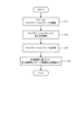
続いて、図20を参照しながら、偏心量δを取得するための偏心量取得動作の流れについて説明する。図20は、偏心量取得動作の流れを示すフローチャートである。Next, the flow of the eccentricity acquisition operation for acquiring the eccentricity amount δ will be described with reference to Figure 20. Figure 20 is a flowchart showing the flow of the eccentricity acquisition operation.
図20に示すように、制御装置7は、計測装置4によるステージ31の計測結果を用いて、ステージ31の回転軸(第1実施形態では、ステージ31θZの回転軸φZ)を算出する(ステップS21)。尚、回転軸φZを算出する動作の具体的内容については、図21を参照しながら後に詳述する。更に、制御装置7は、計測装置4によるワークWの計測結果を用いて、ステップS21に相前後して、ワークWの回転軸φWを算出する(ステップS22)。尚、回転軸φWを算出する動作の具体的内容については、図22を参照しながら後に詳述する。その後、制御装置7は、ステップS21で算出した回転軸φZと、ステップS22で算出した回転軸φWとに基づいて、偏心量δを算出する(ステップS23)。20, the
尚、ステップS21で算出される回転軸φZは、ステージ31の位置に固有の情報である。このため、ステップS21で算出される回転軸φZは、ステージ31の位置に関するステージ位置情報の一具体例であるとも言える。この場合、制御装置7は、回転軸φZに加えて又は代えて、計測装置4によるステージ31の計測結果を用いて、ステージ31の位置に関する任意のステージ位置情報を算出してもよい。その後、制御装置7は、ステージ位置情報に基づいて偏心量δを算出してもよい。
The rotation axis φZ calculated in step S21 is information specific to the position of the
尚、回転軸φZの位置やステージ31の位置が既知である場合には、このステップS21を実行しなくてもよい。
Furthermore, if the position of the rotation axis φZ and the position of the
ステップS22で算出される回転軸φWは、ワークWの位置に固有の情報である。このため、ステップS22で算出される回転軸φWは、ワークWの位置に関するワーク位置情報の一具体例であるとも言える。この場合、制御装置7は、回転軸φWに加えて又は代えて、計測装置4によるワークWの計測結果を用いて、ワークWの位置に関する任意のワーク位置情報を算出してもよい。その後、制御装置7は、ワーク位置情報に基づいて偏心量δを算出してもよい。The rotation axis φW calculated in step S22 is information specific to the position of the workpiece W. For this reason, it can be said that the rotation axis φW calculated in step S22 is one specific example of workpiece position information related to the position of the workpiece W. In this case, the
ステップS23で算出される偏心量δは、ステージ31θZの回転軸φZとワークWとの位置関係に関する位置関係情報の一具体例であるとも言える。つまり、ステップS23で算出される偏心量δは、ステージ31とワークWとの位置関係に関する位置関係情報の一具体例であるとも言える。この場合、制御装置7は、偏心量δに加えて又は代えて、ステージ31θZの回転軸φZとワークWとの位置関係に関する任意の位置関係情報を算出してもよい。その後、加工システムSYSaは、付加加工動作において、任意の位置関係情報に基づいて、ステージ31の回転に伴う加工ヘッド21に対するワークWの変位を考慮して加工ヘッド21を移動させてもよい。It can be said that the eccentricity amount δ calculated in step S23 is a specific example of positional relationship information regarding the positional relationship between the rotation axis φZ of the stage 31θZ and the workpiece W. In other words, it can be said that the eccentricity amount δ calculated in step S23 is a specific example of positional relationship information regarding the positional relationship between the
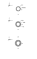
続いて、図21を参照しながら、図20のステップS21におけるステージ31θZの回転軸φZを算出する動作の流れについて説明する。図21は、図20のステップS21におけるステージ31θZの回転軸φZを算出する動作の流れを示すフローチャートである。Next, the flow of the operation of calculating the rotation axis φZ of the stage 31θZ in step S21 of Fig. 20 will be described with reference to Fig. 21. Fig. 21 is a flowchart showing the flow of the operation of calculating the rotation axis φZ of the stage 31θZ in step S21 of Fig. 20.
上述したように、制御装置7は、計測装置4によるステージ31の計測結果を用いて、ステージ31θZの回転軸φZを算出する。但し、第1実施形態では、計測装置4の計測結果から回転軸φZを算出しやすくするために、計測装置4は、ステージ31の少なくとも一部を直接的に計測することに代えて、ステージ31に載置されたキャリブレーションプレート34の少なくとも一部を計測する。つまり、計測装置4は、ステージ31に載置されたキャリブレーションプレート34の少なくとも一部を計測することで、ステージ31の少なくとも一部を間接的に計測する。但し、計測装置4は、ステージ31の少なくとも一部を直接的に計測してもよい。例えば、後述するように、ステージ31にキャリブレーションパターンCPが形成されている場合には、計測装置4は、ステージ31の少なくとも一部(例えば、キャリブレーションパターンCPが形成された部分)を直接的に計測してもよい。As described above, the
このため、図21に示すように、まずは、ステージ31のステージ31θZにキャリブレーションプレート34が載置される(ステップS210)。偏心量取得動作においても、座標マッチング動作と同様に、キャリブレーションプレート34は、キャリブレーションプレート34とステージ31のステージ31θZとの位置関係が所望の位置関係となるように、ステージ31に載置されてもよい。但し、偏心量取得動作においてステージ31に載置されるキャリブレーションプレート34には、感熱膜343が形成されていなくてもよい。尚、キャリブレーションプレート34に代えて、所望のキャリブレーションパターンCPが形成された別のキャリブレーションプレートがステージ31に載置されてもよい。21, first, the
その後、制御装置7は、ステージ31が原点位置に位置するように、ステージ駆動系32を制御する(ステップS211)。原点位置は、位置計測器33が計測する回転角度がゼロになる位置であってもよい。Thereafter, the
その後、計測装置4は、キャリブレーションプレート34の少なくとも一部を計測する(ステップS212)。具体的には、計測装置4は、キャリブレーションプレート34に形成されたキャリブレーションパターンCPを計測する。Then, the measuring
その後、制御装置7は、キャリブレーションプレート34の計測を終了するか否かを判定する(ステップS213)。例えば、制御装置7は、計測装置4がキャリブレーションプレート34を第1所望回数計測した場合には、キャリブレーションプレート34の計測を終了すると判定してもよい。第1所望回数は、少なくとも2回であることが好ましい。Thereafter, the
ステップS213における判定の結果、キャリブレーションプレート34の計測を終了しないと判定された場合には(ステップS213:No)、制御装置7は、ステージ31θZを回転軸φZ周りに第1所望角度だけ回転させる(ステップS214)。第1所望角度は、360度未満の任意の角度であってもよい。第1所望角度は、360度の倍数とは異なる任意の角度であってもよい。その後、計測装置4は、キャリブレーションプレート34を再度計測する(ステップS211)。つまり、第1実施形態では、計測装置4は、ステージ31が回転する都度キャリブレーションプレート34を計測する。計測装置4は、キャリブレーションプレート34を異なる方向から複数回計測する。計測装置4は、異なる回転姿勢のキャリブレーションプレート34を複数回計測する。
If it is determined in step S213 that the measurement of the
他方で、ステップS213における判定の結果、キャリブレーションプレート34の計測を終了すると判定された場合には(ステップS213:Yes)、制御装置7は、ステップS212における計測装置4によるキャリブレーションプレート34の計測結果を用いて、ステージ31θZの回転軸φZを算出する(ステップS215)。具体的には、制御装置7は、キャリブレーションプレート34の計測結果に基づいて、キャリブレーションパターンCPの位置を算出することができる。キャリブレーションパターンCPの位置は、実質的には、キャリブレーションプレート34を支持するステージ31の位置に対応する。従って、制御装置7は、キャリブレーションパターンCPの位置を算出することで、ステージ31の位置を間接的に算出しているとみなしてもよい。計測装置4は、キャリブレーションパターンCPの位置を計測することで、ステージ31の位置を間接的に計測しているとみなしてもよい。制御装置7は、キャリブレーションパターンCPの位置を、ステージ31θZが回転した回数だけ算出する。つまり、制御装置7は、キャリブレーションパターンCPの位置を、キャリブレーションプレート34の計測時におけるステージ31θZの回転角度毎に算出する。その後、制御装置7は、ステージ31θZの回転角度毎に算出されたキャリブレーションパターンCPの位置を、円でフィッティングする。その後、制御装置7は、フィッティングにより求められた円の中心を通過し且つ当該円に直交する軸を、ステージ31θZの回転軸φZとして算出する。On the other hand, if it is determined in step S213 that the measurement of the
尚、制御装置7は、図21に示す動作と同様の動作を行うことで、ステージ31θXの回転軸を算出してもよい。
Furthermore, the
続いて、図22を参照しながら、図20のステップS22におけるワークWの回転軸φWを算出する動作の流れについて説明する。図22は、図20のステップS22におけるワークWの回転軸φWを算出する動作の流れを示すフローチャートである。Next, the flow of the operation of calculating the rotation axis φW of the workpiece W in step S22 of Fig. 20 will be described with reference to Fig. 22. Fig. 22 is a flowchart showing the flow of the operation of calculating the rotation axis φW of the workpiece W in step S22 of Fig. 20.
図22に示すように、まずは、ステージ31にワークWが載置される(ステップS221)。その後、計測装置4は、ワークWの少なくとも一部を計測する(ステップS222)。As shown in Figure 22, first, the workpiece W is placed on the stage 31 (step S221). Then, the measuring
その後、制御装置7は、ワークWの計測を終了するか否かを判定する(ステップS223)。例えば、制御装置7は、計測装置4がワークWを第2所望回数計測した場合には、ワークWの計測を終了すると判定してもよい。第2所望回数は、少なくとも2回であることが好ましい。Thereafter, the
ステップS223における判定の結果、ワークWの計測を終了しないと判定された場合には(ステップS223:No)、制御装置7は、ステージ31θZを回転軸φZ周りに第2所望角度だけ回転させる(ステップS224)。第2所望角度は、360度未満の角度であってもよい。第2所望角度は、360度の倍数とは異なる角度であってもよい。その後、計測装置4は、ワークWを再度計測する(ステップS211)。つまり、第1実施形態では、計測装置4は、ステージ31が回転する都度ワークWを計測する。計測装置4は、ワークWを異なる方向から複数回計測する。計測装置4は、異なる回転姿勢のワークWを複数回計測する。
If it is determined in step S223 that the measurement of the workpiece W is not to be completed (step S223: No), the
他方で、ステップS223における判定の結果、ワークWの計測を終了すると判定された場合には(ステップS223:Yes)、制御装置7は、ステップS222における計測装置4によるワークWの計測結果を用いて、ワークWの回転軸φWを算出する(ステップS225)。具体的には、制御装置7は、ある回転姿勢のワークWの計測結果に基づいて、ある回転姿勢のワークWのうち計測装置4の計測範囲に含まれる部分の位置及び/又は形状に関する情報を生成する。一例として、制御装置7は、ある回転姿勢のワークWの計測結果に基づいて、ある回転姿勢のワークWの表面のうち計測装置4の計測範囲に含まれる部分を構成する複数の点に関する点群情報を生成してもよい。制御装置7は、ワークWの少なくとも一部の位置及び/又は形状に関する情報を生成する動作を、ワークWを計測した回数だけ繰り返す。その後、ワークWの回転姿勢に応じて、ワークWの少なくとも一部の位置及び/又は形状に関する情報をマージする。例えば、制御装置7は、第1の回転姿勢のワークWの計測結果から第1の点群情報を生成し、第2の回転姿勢のワークWの計測結果から第2の点群情報を生成し、第1及び第2の点群情報を、第1及び第2の回転姿勢に基づいてマージしてもよい。その結果、計測装置4が一方向のみからワークWを計測した場合と比較して、ワークWの表面に対して点群情報がその存在を示す領域が占める部分が多くなる。つまり、制御装置7は、ワークWの全体像を把握できる可能性が高くなる。尚、ワークWのうちマージ済みの点群情報がその存在を示していない部分が存在することが判明した場合には、制御装置7は、当該部分を新たに計測するように計測装置4を制御し、この計測装置4の計測結果を更にマージ済みの点群情報に更にマージしてもよい。その後、制御装置7は、マージした点群情報に基づいて、ワークWの回転軸φWを算出する。例えば、ワークWの3次元モデル(例えば、設計情報)が取得可能である場合には、制御装置7は、マージした点群情報にワークWの3次元モデルをフィッティングし、フィッティングした3次元モデルに基づいて、ワークWの回転軸φWを算出してもよい。或いは、ワークWの3次元モデルが取得可能でない場合には、制御装置7は、マージした点群情報に基づいてワークWのサーフェスモデル(或いは、ソリッドモデル)を生成し、生成したサーフェスモデル(或いは、ソリッドモデル)に基づいて、ワークWの回転軸φWを算出してもよい。On the other hand, if it is determined in step S223 that the measurement of the workpiece W is to be terminated (step S223: Yes), the
以上説明した制御装置7についてまとめると、制御装置7は、図20のステップS21において、キャリブレーションプレート34を異なる方向から複数回計測することで得られる複数の計測結果を取得し、複数の計測結果に基づいて、ステージ31の回転軸φZを算出している。更に、制御装置7は、図20のステップS22において、ワークWを異なる方向から複数回計測することで得られる複数の計測結果を取得し、複数の計測結果に基づいて、ワークWの回転軸φWを算出している。更に、制御装置7は、算出した回転軸φZ及びφWに基づいて、偏心量δを算出している。このため、制御装置7は、第1の方向から計測されたワークW(つまり、第1の回転姿勢のワークW)の第1の計測結果と第2の方向から計測されたワークW(つまり、第2の回転姿勢のワークW)の第2の計測結果とを得る計測部と、第1及び第2の計測結果に基づいて偏心量δ(つまり、回転軸φZとワークWとの関係に関する情報)を得る関係取得部とを備える計測装置又は演算装置として機能しているとみなしてもよい。また、偏心量δは、偏心量取得動作においてステージ31θZを回転させた(つまり、ワークWを回転させた)ときのワークWの一点についての移動成分のうち回転移動成分を除いた平行移動成分に相当する。このため、制御装置7は、第1の方向から計測されたワークW(つまり、第1の回転姿勢のワークW)の第1の計測結果と第2の方向から計測されたワークW(つまり、第2の回転姿勢のワークW)の第2の計測結果とを得る計測部と、第1及び第2の計測結果に基づいて、偏心量取得動作においてステージ31θZを回転させた(つまり、ワークWを回転させた)ときのワークWの一点についての移動成分のうち回転移動成分を除いた平行移動成分を求めるずれ取得部とを備える計測装置又は演算装置として機能しているとみなしてもよい。To summarize the
尚、ここでは、制御装置7は、点群情報からワークWの回転軸φWまで求めているが、上述したように、制御装置7は、点群情報からワークWの位置に関する任意の情報を求めてもよい。
Here, the
(1-3)技術的効果
以上説明したように、第1実施形態の加工システムSYSaは、計測装置4の計測結果から得られる偏心量δに基づいて、ステージ31を回転させ、且つ、ステージ31の回転に伴う加工ヘッド21に対するワークWの変位を考慮して加工ヘッド21を移動させることができる。このため、ステージ31の回転に伴って加工ヘッド21に対してワークWが変位する場合であっても、加工システムSYSaは、ワークW上の所望位置に加工光ELを照射することができる。その結果、加工システムSYSaは、ワークWを適切に加工することができる。一例として、加工システムSYSaは、少ない加工誤差のもとでワークWを加工することができる。 (1-3) Technical Effects As described above, the machining system SYSa of the first embodiment can rotate the
(2)第2実施形態の加工システムSYS
続いて、第2実施形態の加工システムSYS(以降、第2実施形態の加工システムSYSを、“加工システムSYSb”と称する)について説明する。第2実施形態の加工システムSYSbは、上述した第1実施形態の加工システムSYSaと比較して、ワークWに加工光ELを照射して、ワークWの一部を除去する除去加工を行ってもよいという点で異なる。例えば、加工システムSYSbは、ワークWの形状が所望の形状になるように除去加工を行ってもよい。例えば、加工システムSYSbは、ワークWに所望の構造を形成するように除去加工を行ってもよい。例えば、加工システムSYSbは、ワークWの表面に所望の構造を形成するように除去加工を行ってもよい。例えば、加工システムSYSbは、ワークWの表面が研磨されるように除去加工を行ってもよい。 (2) Machining system SYS of the second embodiment
Next, a processing system SYS of a second embodiment (hereinafter, the processing system SYS of the second embodiment is referred to as "processing system SYSb") will be described. The processing system SYSb of the second embodiment is different from the processing system SYSa of the first embodiment described above in that the processing system SYSb of the second embodiment may perform a removal process to remove a part of the workpiece W by irradiating the processing light EL onto the workpiece W. For example, the processing system SYSb may perform the removal process so that the shape of the workpiece W becomes a desired shape. For example, the processing system SYSb may perform the removal process so that a desired structure is formed on the workpiece W. For example, the processing system SYSb may perform the removal process so that a desired structure is formed on the surface of the workpiece W. For example, the processing system SYSb may perform the removal process so that the surface of the workpiece W is polished.
除去加工を行う場合には、加工システムSYSbは、リブレット構造をワークW上に形成してもよい。リブレット構造は、ワークWの表面の流体に対する抵抗(特に、摩擦抵抗及び乱流摩擦抵抗の少なくとも一方)を低減可能な構造であってもよい。リブレット構造は、流体とワークWの表面とが相対的に移動するときに発生する騒音を低減可能な構造を含んでいてもよい。リブレット構造は、例えば、ワークWの表面に沿った第1の方向(例えば、Y軸方向)に沿って延びる溝が、ワークWの表面に沿っており且つ第1の方向に交差する第2方向(例えば、X軸方向)に沿って複数配列された構造を含んでいてもよい。When performing removal processing, the processing system SYSb may form a riblet structure on the workpiece W. The riblet structure may be a structure capable of reducing the resistance of the surface of the workpiece W to the fluid (particularly, at least one of frictional resistance and turbulent frictional resistance). The riblet structure may include a structure capable of reducing noise generated when the fluid and the surface of the workpiece W move relatively to each other. The riblet structure may include, for example, a structure in which grooves extending along a first direction (e.g., the Y-axis direction) along the surface of the workpiece W are arranged in a plurality of rows along a second direction (e.g., the X-axis direction) along the surface of the workpiece W and intersecting the first direction.
除去加工を行う場合には、加工システムSYSbは、ワークWの表面上に、任意の形状を有する任意の構造を形成してもよい。任意の構造の一例として、ワークWの表面上の流体の流れに対して渦を発生させる構造があげられる。任意の構造の他の一例として、ワークWの表面に疎水性を与えるための構造があげられる。任意の構造の他の一例としては、規則的又は不規則的に形成されたマイクロ・ナノメートルオーダの微細テクスチャ構造(典型的には凹凸構造)があげられる。このような微細テクスチャ構造は、流体(気体及び/又は液体)による抵抗を低減させる機能を有するサメ肌構造及びディンプル構造の少なくとも一方を含んでいてもよい。微細なテクスチャ構造は、撥液機能及びセルフクリーニング機能の少なくとも一方を有する(例えば、ロータス効果を有する)ハスの葉表面構造を含んでいてもよい。微細なテクスチャ構造は、液体輸送機能を有する微細突起構造(米国特許公開第2017/0044002号公報参照)、親液性機能を有する凹凸構造、防汚機能を有する凹凸構造、反射率低減機能及び撥液機能の少なくとも一方を有するモスアイ構造、特定波長の光のみを干渉で強めて構造色を呈する凹凸構造、ファンデルワールス力を利用した接着機能を有するピラーアレイ構造、空力騒音低減機能を有する凹凸構造、並びに、液滴捕集機能を有するハニカム構造等の少なくとも一つを含んでいてもよい。When performing removal processing, the processing system SYSb may form an arbitrary structure having an arbitrary shape on the surface of the workpiece W. An example of an arbitrary structure is a structure that generates a vortex in the flow of a fluid on the surface of the workpiece W. Another example of an arbitrary structure is a structure for imparting hydrophobicity to the surface of the workpiece W. Another example of an arbitrary structure is a fine texture structure (typically a concave-convex structure) of the micro-nanometer order formed regularly or irregularly. Such a fine texture structure may include at least one of a shark skin structure and a dimple structure that have the function of reducing resistance by a fluid (gas and/or liquid). The fine texture structure may include a lotus leaf surface structure that has at least one of a liquid repellent function and a self-cleaning function (for example, having a lotus effect). The fine texture structure may include at least one of a fine protrusion structure having a liquid transport function (see U.S. Patent Publication No. 2017/0044002), a concave-convex structure having a lyophilic function, a concave-convex structure having an anti-fouling function, a moth-eye structure having at least one of a reflectance reducing function and a liquid repellent function, a concave-convex structure that exhibits a structural color by intensifying only light of a specific wavelength through interference, a pillar array structure having an adhesive function utilizing van der Waals forces, a concave-convex structure having an aerodynamic noise reducing function, and a honeycomb structure having a droplet collecting function.
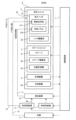
このような加工システムSYSbが図23及び図24に示されている。図23は、加工システムSYSbのシステム構成を示すブロック図である。図24は、加工システムSYSbの構造を示す断面図である。図23及び図24に示すように、加工システムSYSbは、加工システムSYSaと比較して、材料供給源1及び混合装置12を備えていなくてもよいという点で異なる。更に、加工システムSYSbは、加工システムSYSaと比較して、材料ノズル212を備えていなくてもよいという点で異なる。具体的には、加工システムSYSbは、加工システムSYSaと比較して、材料ノズル212を備えている加工ヘッド21を備える加工ユニット2に代えて、材料ノズル212を備えていない加工ヘッド21bを備える加工ユニット2bを備えているという点で異なる。つまり、加工システムSYSbは、加工システムSYSaと比較して、造形材料Mを供給するための構成要件を備えていなくてもよいという点で異なる。加工システムSYSbのその他の特徴は、加工システムSYSaのその他の特徴と同様であってもよい。Such a processing system SYSb is shown in FIG. 23 and FIG. 24. FIG. 23 is a block diagram showing the system configuration of the processing system SYSb. FIG. 24 is a cross-sectional view showing the structure of the processing system SYSb. As shown in FIG. 23 and FIG. 24, the processing system SYSb differs from the processing system SYSa in that it may not have a
以上説明した加工システムSYSbもまた、加工システムSYSaと同様に、ワークWを加工する(つまり、除去加工する)際に、座標マッチング動作及び偏心量取得動作の結果に基づいて、加工ヘッド21b及びステージ31の少なくとも一方を移動させてもよい。例えば、加工システムSYSbは、加工光ELをワークWに照射している間に、偏心量取得動作の結果に基づいて、ステージ31を回転させ且つ加工ヘッド21b(更には、ステージ31)を移動させてもよい。その結果、加工システムSYSbは、加工システムSYSaが享受可能な効果と同様の効果を享受することができる。Like the processing system SYSa, the processing system SYSb described above may also move at least one of the
尚、加工システムSYSbが図19に示した照射位置変更光学部材(例えば、ガルバノミラー2111)を有している場合には、加工システムSYSbは、加工ヘッド21を移動させることに代えて又は加えて、照射位置変更光学部材によって加工光ELの照射位置を変更してもよい。このとき、加工システムSYSbは、計測装置4による計測結果から得られる偏心量δに基づいて、加工光ELの照射位置を変更してもよい。19 (e.g., galvanometer mirror 2111), the processing system SYSb may change the irradiation position of the processing light EL by the irradiation position changing optical member instead of or in addition to moving the
尚、除去加工を行う場合には、加工システムSYSbは、複数のパルス光を含む加工光ELをワークWに照射してもよい。例えば、加工システムSYSbは、発光時間がナノ秒以下の複数のパルス光を含む加工光ELをワークWに照射してもよい。When performing removal processing, the processing system SYSb may irradiate the workpiece W with processing light EL including multiple pulsed lights. For example, the processing system SYSb may irradiate the workpiece W with processing light EL including multiple pulsed lights having an emission time of nanoseconds or less.
(3)第3実施形態の加工システムSYS
続いて、第3実施形態の加工システムSYS(以降、第3実施形態の加工システムSYSを、“加工システムSYSc”と称する)について説明する。第3実施形態の加工システムSYScは、上述した第1実施形態の加工システムSYSaと比較して、加工光ELに加えて又は代えて、ワークWを機械加工するための工具215c(後述する図25及び図21参照)を用いてワークWを加工してもよいという点で異なる。つまり、加工システムSYScは、加工システムSYSaと比較して、ワークWを機械加工してもよいという点で異なる。例えば、加工システムSYScは、ワークWに工具を接触させることで、ワークWを切削加工、研削加工、研磨加工又は切断加工してもよい。例えば、加工システムSYScは、ワークWの形状が所望の形状になるようにワークWを機械加工してもよい。例えば、加工システムSYScは、ワークWに所望の構造を形成するようにワークWを機械加工してもよい。例えば、加工システムSYScは、ワークWの表面に所望の構造を形成するようにワークWを機械加工してもよい。例えば、加工システムSYScは、ワークWの表面が研磨されるようにワークWを機械加工してもよい。 (3) Machining system SYS of the third embodiment
Next, a processing system SYS of a third embodiment (hereinafter, the processing system SYS of the third embodiment is referred to as the "processing system SYSc") will be described. The processing system SYSc of the third embodiment is different from the processing system SYSa of the first embodiment described above in that the workpiece W may be machined using a
このような加工システムSYScが図25及び図26に示されている。図25は、加工システムSYScのシステム構成を示すブロック図である。図26は、加工システムSYScの構造を示す断面図である。図25及び図26に示すように、加工システムSYScは、加工システムSYSaと比較して、光源5を備えていなくてもよいという点で異なる。更に、加工システムSYScは、加工システムSYSaと比較して、照射光学系211を備えていなくてもよいという点で異なる。具体的には、加工システムSYScは、加工システムSYSaと比較して、照射光学系211を備えている加工ヘッド21を備える加工ユニット2に代えて、照射光学系211を備えていない加工ヘッド21cを備える加工ユニット2cを備えているという点で異なる。つまり、加工システムSYSbは、加工システムSYSaと比較して、ワークWに加工光ELを照射するための構成要件を備えていなくてもよいという点で異なる。更に、加工システムSYScは、加工システムSYSbと同様に、造形材料Mを供給するための構成要件を備えていなくてもよいという点で異なる。更に、加工システムSYScは、加工システムSYSaと比較して、加工ヘッド21に代えて、工具215cを備える加工ヘッド21cを備えているという点で異なる。加工システムSYScのその他の特徴は、加工システムSYSaのその他の特徴と同様であってもよい。Such a processing system SYSc is shown in FIG. 25 and FIG. 26. FIG. 25 is a block diagram showing the system configuration of the processing system SYSc. FIG. 26 is a cross-sectional view showing the structure of the processing system SYSc. As shown in FIG. 25 and FIG. 26, the processing system SYSc differs from the processing system SYSa in that it does not have to be equipped with a
以上説明した加工システムSYScもまた、加工システムSYSaと同様に、ワークWを加工する(つまり、除去加工する)際に、座標マッチング動作及び偏心量取得動作の結果に基づいて、加工ヘッド21c及びステージ31の少なくとも一方を移動させてもよい。例えば、加工システムSYScは、工具215cをワークWに接触させている間に、偏心量取得動作の結果に基づいて、ステージ31を回転させ且つ加工ヘッド21(更には、ステージ31)を移動させてもよい。その結果、加工システムSYScは、加工システムSYSaが享受可能な効果と同様の効果を享受することができる。Like the machining system SYSa, the machining system SYSc described above may also move at least one of the
(4)第4実施形態の加工システムSYS
続いて、図27を参照しながら、第4実施形態の加工システムSYS(以降、第4実施形態の加工システムSYSを、“加工システムSYSd”と称する)について説明する。図27は、第4実施形態の加工システムSYSdのシステム構成を示すブロック図である。 (4) Machining system SYS of the fourth embodiment
Next, a machining system SYS according to a fourth embodiment (hereinafter, the machining system SYS according to the fourth embodiment will be referred to as a "machining system SYSd") will be described with reference to Fig. 27. Fig. 27 is a block diagram showing a system configuration of the machining system SYSd according to the fourth embodiment.
図27に示すように、第4実施形態の加工システムSYSdは、加工システムSYSaと比較して、冷却装置9dを更に備えているという点で異なる。加工システムSYSdのその他の特徴は、加工システムSYSaのその他の特徴と同様であってもよい。27, the processing system SYSd of the fourth embodiment differs from the processing system SYSa in that it further includes a
冷却装置9dは、ワークWが載置されるステージ31(第4実施形態では、ステージ31θZ)を冷却するための装置である。具体的には、ステージ31θZに載置されたワークWには、加工光ELが照射される。ワークWに加工光ELが照射されると、加工光ELからワークWに対して熱が伝達される。ワークWに熱が伝達されると、ワークWからワークWが載置されているステージ31θZに対して熱が伝達される。その結果、ステージ31θZの温度が相対的に高くなってしまう可能性がある。冷却装置9dは、このように温度が相対的に高くなる可能性があるステージ31θZを冷却する。尚、ステージ31θZが筐体8の内部空間に収容されているため、冷却装置9dもまた、筐体8の内部空間に収容される。The
冷却装置9dは、空冷式の冷却装置を含んでいてもよい。例えば、冷却装置9dは、ステージ31θZに気体を供給することで、ステージ31θZを冷却してもよい。つまり、冷却装置9dは、ステージ31θZに面する空間に気体を供給することで、ステージ31θZを冷却してもよい。冷却装置9dは、ステージ31θZに面する空間に気体の流れを形成することで、ステージ31θZを冷却してもよい。以下、図28を参照しながら、ステージ31θZに面する空間に気体を供給することでステージ31θZを冷却する冷却装置9dの一例について説明する。図28は、冷却装置9dの構造の一例を示す断面図である。The
図28に示すように、冷却装置9dは、上面311にワークWが載置されるステージ31θZの下面312(つまり、上面311の反対側の面)に気体を供給することで、ステージ31θZを冷却してもよい。つまり、冷却装置9dは、ステージ31θZの下面312に面する空間SP1に気体を供給することで、ステージ31θZを冷却してもよい。ステージ31θZの下面312は、ステージ31θXに面している。このため、空間SP1は、ステージ31θZの下面312とステージ31θXとの間の空間の少なくとも一部を含んでいてもよい。但し、冷却装置9dは、ステージ31θZの下面312以外の面に面する空間に気体を供給することで、ステージ31θZを冷却してもよい。28, the
冷却装置9dは、ステージ31θZの下方から空間SP1に気体を供給してもよい。ステージ31θZの下方からステージ31θZの下面312に面する空間SP1に気体が供給される場合、ステージ31θZの上面311に面する空間(つまり、ワークWに面する空間)に気体の流れが形成される可能性は低くなる。このため、上面311に載置されたワークWに供給される造形材料Mが、ステージ31θZを冷却するための気体によって吹き飛ばされにくくなる。従って、材料ノズル212は、ステージ31θZを冷却するための気体の影響を受けることなく、ワークWに造形材料Mを供給することができる。The
ステージ31θZの下面312がステージ31θXに面しているため、冷却装置9dは、ステージ31θXの内部を介して、空間SP1に気体を供給してもよい。冷却装置9dは、ステージ31θXの内部に形成される気体の供給路を介して、空間SP1に気体を供給してもよい。具体的には、図28に示すように、ステージ31θXの筐体313dの内部には、空間SP1に気体を供給するための供給路(言い換えれば、供給空間)SP2が形成されていてもよい。供給路SP2は、筐体313dの外部から筐体313dの内部(特に、供給路SP2)に気体を取り込むために筐体313dに形成された開口314dに接続されている。この場合、冷却装置9dは、開口314dに配置されるファン91dを備えていてもよい。ファン91dは、筐体313dの外部から筐体313dの内部(特に、供給路SP2)に気体を取り込むように駆動可能である。更に、供給路SP2は、筐体313dの内部の供給路SP2から筐体313dの外部の空間SP1に気体を供給するために筐体313dに形成された開口315dに接続されている。開口315dは、筐体8のうち空間SP1に面する部分(例えば、ステージ31θZの下方に位置する部分)に形成されている。この場合、冷却装置9dは、開口314dに配置されたファン91dを介して筐体313dの外部から供給路SP2に気体を取り込み、取り込んだ気体を供給路SP2及び開口315dを介して、空間SP1に供給する。その結果、空間SP1に気体の流れが形成され、当該気体の流れによってステージ31θZが冷却される。尚、この場合に空間SP1に供給される気体は、気体供給源6から筐体8の内部に供給されるパージガスの少なくとも一部を含んでいてもよい。Since the
ステージ31θXの筐体313の内部には、ステージ31θZを回転させるための回転機構(移動機構)として機能可能なモータ322θZが収容される収容空間SP3が形成されていてもよい。モータ322θZが発生した力は、ステージ31θZに接続される動力伝達機構(移動機構)である回転シャフト321θZ及びモータ322θZの回転軸と回転シャフト321θZとを接続する動力伝達機構(移動機構)であるベルト323θZを介して、ステージ31θZに伝達される。この場合、回転シャフト321θZ及びベルト323θZの少なくとも一部もまた、収容空間SP3に収容されていてもよい。収容空間SP3は、隔壁部材36dを介して、供給路SP2と空間的に分離されていてもよい。収容空間SP3が隔壁部材36dを介して供給路SP2と空間的に分離される場合には、造形材料Mが収容空間SP3に侵入する(その結果、モータ322θZ等が造形材料Mによって汚染される)ことが抑制される。尚、モータ322θZの回転軸と回転シャフト321θZとを、ベルト323θZを介さずに直結してもよい。Inside the housing 313 of the stage 31θX, a storage space SP3 may be formed in which a motor 322θZ capable of functioning as a rotation mechanism (movement mechanism) for rotating the stage 31θZ is stored. The force generated by the motor 322θZ is transmitted to the stage 31θZ via a rotating shaft 321θZ, which is a power transmission mechanism (movement mechanism) connected to the stage 31θZ, and a belt 323θZ, which is a power transmission mechanism (movement mechanism) connecting the rotation axis of the motor 322θZ and the rotating shaft 321θZ. In this case, at least a part of the rotating shaft 321θZ and the belt 323θZ may also be stored in the storage space SP3. The storage space SP3 may be spatially separated from the supply path SP2 via the
ステージ31θXと回転シャフト321θXとは、減速機324dを介して接続されていてもよい。例えば、減速機324dは、ステージ31θXの下面と回転シャフト321θXとを接続してもよい。この場合、減速機324dが発熱する可能性があるが、ステージ31θZを冷却するための気体の流れによって減速機324dもまた冷却されてもよい。The stage 31θX and the rotating shaft 321θX may be connected via a reducer 324d. For example, the reducer 324d may connect the lower surface of the stage 31θX and the rotating shaft 321θX. In this case, the reducer 324d may generate heat, but the reducer 324d may also be cooled by the flow of gas for cooling the stage 31θZ.
冷却装置9dは更に、導風部材92dを備えていてもよい。導風部材92dは、空間SP1から空間SP1の外部に向かう気体を空間SP1に戻すように機能してもよい。その結果、冷却装置9dが導風部材92dを備えていない場合と比較して、ステージ31θZの冷却効率が高くなる。The
以上説明したように、加工システムSYSdは、加工システムSYSaが享受可能な効果と同様の効果を享受しながら、ワークWが載置されるステージ31(例えば、ステージ31θZ)を冷却することができる。As described above, the processing system SYSd can cool the stage 31 (e.g., stage 31θZ) on which the workpiece W is placed while enjoying effects similar to those that can be enjoyed by the processing system SYSa.
尚、第2実施形態の加工システムSYSb及び第3実施形態の加工システムSYScの少なくとも一方が冷却装置9dを備えていてもよい。
Furthermore, at least one of the processing system SYSb of the second embodiment and the processing system SYSc of the third embodiment may be equipped with a
(5)変形例
続いて、加工システムSYSの変形例について説明する。 (5) Modifications Next, modifications of the machining system SYS will be described.
(5-1)キャリブレーションプレート34の変形例
上述した説明では、キャリブレーションプレート34に形成されている感熱膜343は、計測装置4の計測光MLに対して透明である。しかしながら、感熱膜343の少なくとも一部は、計測装置4の計測光MLに対して不透明であってもよい。 (5-1) Modifications of the
感熱膜343が不透明である場合には、キャリブレーションプレート34の一例を示す平面図である図29に示すように、感熱膜343は、キャリブレーションパターンCPの全体を覆っていてもよい。この場合、加工システムSYSは、上述したキャリブレーション動作において、感熱膜343に加工光ELを照射し(図6のステップS12)、その後、感熱膜343が形成されたキャリブレーションプレート34を計測することで、感熱パターンPPを計測し(図6のステップS13)、その後、感熱膜343が除去された後に、感熱膜343が除去されたキャリブレーションプレート34を計測することで、キャリブレーションパターンCPを計測し(図6のステップS13)、その後、感熱パターンPPの計測結果とキャリブレーションパターンCPの計測結果とをマージすることで、加工座標系とステージ座標系とを関連付けてもよい。
When the
或いは、キャリブレーションプレート34の一例を示す平面図である図30に示すように、感熱膜343は、キャリブレーションパターンCPの一部を覆っていてもよい。つまり、キャリブレーションパターンCPの他の一部が感熱膜343によって覆われていなくてもよい。この場合、加工システムSYSは、上述したキャリブレーション動作において、感熱膜343に加工光ELを照射し(図6のステップS12)、その後、感熱膜343が形成されたキャリブレーションプレート34を計測することで、感熱パターンPP及びキャリブレーションパターンCPの一部を計測し(図6のステップS13)、その後、感熱膜343が除去された後に、感熱膜343が除去されたキャリブレーションプレート34を計測することで、キャリブレーションパターンCPを計測し(図6のステップS13)、その後、感熱パターンPPの計測結果とキャリブレーションパターンCPの計測結果とをマージすることで、加工座標系とステージ座標系とを関連付けてもよい。この場合、加工システムSYSは、感熱パターンPPの計測結果及びキャリブレーションパターンCPの計測結果の双方に含まれるキャリブレーションパターンCPの一部(つまり、感熱膜343によって覆われていなかったキャリブレーションパターンCPの一部)の計測結果を用いて、感熱パターンPPの計測結果とキャリブレーションパターンCPの計測結果とを相対的に高精度にマージすることができる。尚、感熱膜343が透明である場合においても、感熱膜343は、キャリブレーションパターンCPの一部を覆っている一方で、キャリブレーションパターンCPの他の一部を覆っていなくてもよい。
Alternatively, as shown in FIG. 30, which is a plan view showing an example of the
或いは、キャリブレーションプレート34の一例を示す平面図である図31に示すように、感熱膜343は、キャリブレーションパターンCPを覆っていなくてもよい。つまり、ベース部材341の第1部分に感熱膜343が形成され、ベース部材341の第1部分にキャリブレーションパターンCPが形成されていてもよい。尚、感熱膜343が透明である場合においても、感熱膜343は、キャリブレーションパターンCPを覆っていなくてもよい。31, which is a plan view showing an example of the
(5-2)キャリブレーションパターンCPの変形例
上述した説明では、キャリブレーションパターンCPは、キャリブレーションプレート34に形成されている。しかしながら、キャリブレーションパターンCPは、キャリブレーションプレート34とは異なる部材に形成されていてもよい。例えば、キャリブレーションパターンCPは、ステージ31に載置されている、ワークWとは異なる部材(例えば、基準部材)に形成されていてもよい。例えば、図32から図34に示すように、キャリブレーションパターンCPは、ステージ31に形成されていてもよい。図32から図34は、キャリブレーションパターンCPがステージ31θZに形成される例を示しているが、キャリブレーションパターンCPは、ステージ31θXに形成されていてもよい。図32は、キャリブレーションパターンCPが、ステージ31θZの上面311(つまり、ワークWが載置される面)に形成される例を示している。図33は、キャリブレーションパターンCPが、ステージ31θZの上面311のうちワークWに面して当該ワークWを実際に保持する保持面3111とは異なる面(例えば、保持面3111の外側に位置する外周面3112)に形成される例を示している。図34は、キャリブレーションパターンCPが、ステージ31θZの側面316に形成される例を示している。 (5-2) Modification of Calibration Pattern CP In the above description, the calibration pattern CP is formed on the
図33及び図34に示すように、ステージ31θZの保持面3111とは異なる面にキャリブレーションパターンCPが形成される場合には、加工システムSYSは、ワークWがステージ31θZに載置された状態で上述した座標マッチング動作及び偏心量取得動作のそれぞれを行うことができる。更には、ステージ31θZの保持面3111とは異なる面にキャリブレーションパターンCPが形成される場合には、加工システムSYSは、偏心量取得動作において、キャリブレーションパターンCPの少なくとも一部とワークWの少なくとも一部との双方を同時に計測することができる。つまり、加工システムSYSは、ワークWの少なくとも一部と共に、ステージ31のキャリブレーションパターンCPの少なくとも一部を計測することができる。このため、ステージ31θZの回転軸φZを算出するための計測装置4によるキャリブレーションパターンCPの計測と、ワークWの回転軸φWを算出するための計測装置4によるワークWの計測とが別々に行われなくてもよくなる。このため、偏心量取得動作に要する時間が低減可能となる。33 and 34, when the calibration pattern CP is formed on a surface other than the holding
尚、ステージ31θX及び31θZのそれぞれが回転するため、キャリブレーションパターンCPは、回転するステージ31θX及び31θZの少なくとも一方の位置を特定可能なパターンを含んでいてもよい。例えば、図33及び図34に示すように、キャリブレーションパターンCPは、エンコーダパターン(例えば、格子パターン)を含んでいてもよい。このエンコーダパターンは、アブソリュート・パターンであってもよい。Since each of the stages 31θX and 31θZ rotates, the calibration pattern CP may include a pattern that can identify the position of at least one of the rotating stages 31θX and 31θZ. For example, as shown in Figures 33 and 34, the calibration pattern CP may include an encoder pattern (e.g., a grid pattern). This encoder pattern may be an absolute pattern.
尚、キャリブレーションパターンCPがステージ31に形成されている場合、計測装置4は、ワークWがステージ31に載置されている状態で、このステージ31上のキャリブレーションパターンCPを計測してもよい。
Furthermore, when the calibration pattern CP is formed on the
専用のキャリブレーションパターンCPに加えて又は代えて、ステージ31に形成された既存の構造物が、キャリブレーションパターンCPの少なくとも一部として用いられてもよい。例えば、ステージ31に形成された凹部(例えば、ネジ穴等の開口)が、キャリブレーションパターンCPの少なくとも一部として用いられてもよい。例えば、ステージ31に形成された凸部(例えば、突起物)が、キャリブレーションパターンCPの少なくとも一部として用いられてもよい。この場合、計測装置4は、ワークWがステージ31に載置されている状態で、キャリブレーションパターンCPの少なくとも一部として用いられる既存の構造物を計測してもよい。In addition to or instead of a dedicated calibration pattern CP, an existing structure formed on the
(5-3)その他の変形例
上述した説明では、加工システムSYSは、キャリブレーションパターンCPを計測して回転軸φZを求めている(つまり、算出している)。しかしながら、加工システムSYSは、キャリブレーションパターンCPの少なくとも一部を計測して回転軸φXを求めてもよい。 (5-3) Other Modifications In the above description, the machining system SYS measures the calibration pattern CP to determine (i.e., calculates) the rotation axis φZ. However, the machining system SYS may measure at least a part of the calibration pattern CP to determine the rotation axis φX.
上述した説明では、加工システムSYSは、キャリブレーションパターンCPを計測して回転軸φZ(φX)を求めている。しかしながら、加工システムSYSは、ステージ31(ステージ31θZ)の少なくとも一部を計測して回転軸φZを計測してもよい。例えば、加工システムSYSは、ステージ31(ステージ31θZ)の三次元形状計測結果を、予め準備されたステージ31(ステージ31θZ)の設計モデルと計測座標系上で座標マッチングさせ、計測座標系上で設計モデルが有している回転軸を、得るべき回転軸(例えば、回転軸φZ)としてもよい。In the above description, the processing system SYS measures the calibration pattern CP to obtain the rotation axis φZ (φX). However, the processing system SYS may measure at least a part of the stage 31 (stage 31θZ) to measure the rotation axis φZ. For example, the processing system SYS may coordinate-match the three-dimensional shape measurement result of the stage 31 (stage 31θZ) with a previously prepared design model of the stage 31 (stage 31θZ) on the measurement coordinate system, and may set the rotation axis of the design model on the measurement coordinate system as the rotation axis to be obtained (for example, the rotation axis φZ).
上述した説明では、加工システムSYSは、回転軸φZ(φX)を求めている。しかしながら、加工システムSYSは、回転軸φZ(φX)を求めなくてよい。例えば、加工システムSYSは、ステージ31にワークWを保持した状態で、ステージ31の少なくとも一部とワークWの少なくとも一部の三次元形状の計測を行い、計測されたステージ31の点群情報及び計測されたワークWの点群情報を、仮想的な座標系においてステージ31の設計モデル及びワークWのモデルとマッチングさせてもよい。そして、加工システムSYSは、仮想的な座標系においてステージ31を回転させたときのワークWの変位を算出して、その算出結果を用いて、加工ヘッド21の移動を制御してもよい。In the above description, the machining system SYS determines the rotation axis φZ (φX). However, the machining system SYS does not need to determine the rotation axis φZ (φX). For example, the machining system SYS may measure the three-dimensional shapes of at least a part of the
上述した説明では、ワークWが円筒形であったが、ワークWの形状は円筒形のような回転対称な形状には限定されない。In the above description, the workpiece W is cylindrical, but the shape of the workpiece W is not limited to a rotationally symmetric shape such as a cylinder.
尚、上述した説明では、ステージ31θZでの保持手法についての詳細説明を省略したが、例えば、図35(a)及び図35(b)に示すように、ステージ31θZに設けられたネジ穴31θZtp(図35(a)参照)に、一つ以上の保持金具317を介してワークWを固定してもよい。In the above explanation, detailed explanation of the holding method on stage 31θZ has been omitted, but for example, as shown in Figures 35(a) and 35(b), the workpiece W may be fixed via one or more holding
上述した説明では、加工システムSYSは、加工光ELをワークWに照射することでワークWを加工している。しかしながら、加工システムSYSは、任意のエネルギビームをワークWに照射することで、ワークWを加工してもよい。この場合、加工システムSYSは、光源5及び照射光学系211に加えて又は代えて、任意のエネルギビームを照射可能なビーム照射装置を備えていてもよい。任意のエネルギビームの一例として、荷電粒子ビーム及び電磁波等の少なくとも一方があげられる。荷電粒子ビームの一例として、電子ビーム及びイオンビーム等の少なくとも一方があげられる。In the above description, the processing system SYS processes the workpiece W by irradiating the workpiece W with the processing light EL. However, the processing system SYS may also process the workpiece W by irradiating the workpiece W with an arbitrary energy beam. In this case, the processing system SYS may be equipped with a beam irradiation device capable of irradiating an arbitrary energy beam in addition to or instead of the
(6)付記
以上説明した実施形態に関して、更に以下の付記を開示する。
[付記1]
エネルギビームを用いて物体を加工する加工システムにおいて、
前記物体及び前記エネルギビームに対する感応性を有する感応膜が形成された計測部材の夫々を保持可能な保持部と、
前記物体及び前記計測部材の夫々に前記エネルギビームを照射可能な照射装置と、
前記照射装置と前記保持部との相対的な位置関係を変更する位置変更装置と、
前記計測部材の少なくとも一部を計測する計測装置と、
前記位置変更装置を制御する制御装置と
を備え、
前記保持部が前記計測部材を保持している第1期間の少なくとも一部において、前記位置変更装置は、前記照射装置と前記保持部との相対的な位置関係を変更し、且つ、前記照射装置は、前記計測部材の前記感応膜の少なくとも一部に前記エネルギビームを照射し、
前記制御装置は、前記保持部が前記物体を保持している第2期間の少なくとも一部において、前記エネルギビームが照射された前記計測部材の計測結果に基づいて、前記位置変更装置を制御する
加工システム。
[付記2]
前記エネルギビームが照射された前記計測部材の計測結果は、前記感応膜のうち前記エネルギビームに感応した部分の計測結果を含む
付記1に記載の加工システム。
[付記3]
前記計測部材には、所定の計測パターンが形成されており、
前記感応膜は、前記計測装置が前記計測部材を計測するために用いる計測光に対して透明であって且つ前記計測パターンの少なくとも一部を覆うように形成されている
付記1又は2に記載の加工システム。
[付記4]
前記計測部材には、所定の計測パターンが形成されており、
前記感応膜は、前記計測装置が前記計測部材を計測するために用いる計測光に対して不透明であって且つ前記計測パターンの少なくとも一部を覆うように形成されており、
前記第1期間の少なくとも一部において、前記計測装置は、前記エネルギビームが照射された前記感応部材を計測し、その後、前記感応膜が除去された前記計測部材を計測する
付記1から3のいずれか一項に記載の加工システム。
[付記5]
前記第2期間の少なくとも一部において、前記制御装置は、前記照射装置が前記物体の所望位置に前記エネルギビームを照射するように、前記位置変更装置を制御する
付記1から4のいずれか一項に記載の加工システム。
[付記6]
載置物を回転可能な回転装置に載置された物体を計測する計測装置であって、
前記回転装置上の前記物体の第1計測結果と、前記第1計測結果を得たときの前記物体の回転姿勢とは異なる姿勢で前記物体を計測した際の第2計測結果とを得る計測部と、
前記第1及び第2計測結果に基づいて、前記物体と前記回転装置の回転軸との関係を得る関係取得部と
を備える計測装置。
[付記7]
載置物を回転可能な回転装置に載置された物体を計測する計測装置であって、
前記回転装置上の前記物体の第1計測結果と、前記第1計測結果を得たときの前記物体の回転姿勢とは異なる姿勢で前記物体を計測した際の第2計測結果とを得る計測部と、
前記第1及び第2計測結果に基づいて、前記物体を回転させたときの前記物体の一点についての移動成分のうち回転移動成分を除いた平行移動成分を求めるずれ取得部と
を備える計測装置。
[付記8]
載置物を回転可能な回転装置に載置された物体を計測する計測装置に接続される演算装置であって、
前記回転装置上の前記物体の第1計測結果と、前記第1計測結果を得たときの前記物体の回転姿勢とは異なる姿勢で前記物体を計測した際の第2計測結果とを得る計測部と、
前記第1及び第2計測結果に基づいて、前記物体と前記回転装置の回転軸との関係を得る関係取得部と
を備える演算装置。
[付記9]
載置物を回転可能な回転装置に載置された物体を計測する計測装置に接続される演算装置であって、
前記回転装置上の前記物体の第1計測結果と、前記第1計測結果を得たときの前記物体の回転姿勢とは異なる姿勢で前記物体を計測した際の第2計測結果とを得る計測部と、
前記第1および第2計測結果に基づいて、前記物体を回転させたときの前記物体の一点についての移動成分のうち回転移動成分を除いた平行移動成分を求めるずれ取得部と
を備える演算装置。
[付記10]
物体を加工する加工システムにおいて、
前記物体を加工する加工装置と、
前記物体を保持する保持部を回転させる回転装置と、
前記保持部によって保持された前記物体の少なくとも一部を計測する計測装置と、
前記回転装置及び前記計測装置を制御して、前記物体を計測した後に前記保持部を回転させ、前記保持部を回転させた後に前記物体を計測する制御装置と
を備える加工システム。
[付記11]
前記制御装置は、前記保持部を回転させる前に前記物体を計測して得られる第1計測結果と、前記保持部を回転させた後に前記物体を計測して得られる第2計測結果とに基づいて、前記保持部に保持された前記物体の位置情報を取得する
付記10に記載の加工システム。
[付記12]
前記加工装置は、前記制御装置によって求められた前記物体の位置情報に基づいて、前記物体を加工する
付記11に記載の加工システム。
[付記13]
前記制御装置は、前記第1計測結果を得た後に、前記物体を360度未満の回転角だけ回転させて前記物体を計測して第2計測結果を得るように、前記回転装置及び前記計測装置を制御する
付記11又は12に記載の加工システム。
[付記14]
前記回転装置の回転軸の前記計測装置の計測軸に対する角度を変更する角度変更装置を更に備える
付記11から13のいずれか一項に記載の加工システム。 (6) Supplementary Notes The following supplementary notes are further disclosed with respect to the embodiment described above.
[Appendix 1]
1. A processing system for processing an object using an energy beam, comprising:
a holding part capable of holding each of the object and a measuring member having a sensitive film sensitive to the energy beam;
an irradiation device capable of irradiating the object and the measuring member with the energy beam;
a position changing device that changes a relative positional relationship between the irradiation device and the holding unit;
A measuring device that measures at least a portion of the measuring member;
A control device for controlling the position changing device,
During at least a part of a first period in which the holding section holds the measurement member, the position changing device changes a relative positional relationship between the irradiation device and the holding section, and the irradiation device irradiates the energy beam onto at least a part of the sensitive film of the measurement member;
The control device controls the position changing device based on a measurement result of the measurement member irradiated with the energy beam during at least a part of a second period in which the holding part holds the object.
[Appendix 2]
The processing system according to
[Appendix 3]
A predetermined measurement pattern is formed on the measurement member,
The processing system according to
[Appendix 4]
A predetermined measurement pattern is formed on the measurement member,
the sensitive film is opaque to measurement light used by the measurement device to measure the measurement member and is formed so as to cover at least a portion of the measurement pattern;
The processing system according to any one of
[Appendix 5]
The processing system of any one of
[Appendix 6]
A measurement device that measures an object placed on a rotation device that can rotate a placed object,
a measurement unit that obtains a first measurement result of the object on the rotation device and a second measurement result when the object is measured in a rotational orientation different from a rotational orientation of the object when the first measurement result is obtained;
a relationship acquisition unit that acquires a relationship between the object and a rotation axis of the rotating device based on the first and second measurement results.
[Appendix 7]
A measurement device that measures an object placed on a rotation device that can rotate a placed object,
a measurement unit that obtains a first measurement result of the object on the rotation device and a second measurement result when the object is measured in a rotational orientation different from a rotational orientation of the object when the first measurement result is obtained;
a deviation acquisition unit that determines a translation component, excluding a rotational movement component, of movement components for a point on the object when the object is rotated, based on the first and second measurement results.
[Appendix 8]
A calculation device connected to a measurement device that measures an object placed on a rotation device that can rotate a placed object,
a measurement unit that obtains a first measurement result of the object on the rotation device and a second measurement result when the object is measured in a rotational orientation different from a rotational orientation of the object when the first measurement result is obtained;
a relationship acquisition unit that acquires a relationship between the object and a rotation axis of the rotating device based on the first and second measurement results.
[Appendix 9]
A calculation device connected to a measurement device that measures an object placed on a rotation device that can rotate a placed object,
a measurement unit that obtains a first measurement result of the object on the rotation device and a second measurement result when the object is measured in a rotational orientation different from a rotational orientation of the object when the first measurement result is obtained;
a deviation acquisition unit that determines a translation component, excluding a rotational movement component, of movement components for a point on the object when the object is rotated, based on the first and second measurement results.
[Appendix 10]
In a processing system for processing an object,
A processing device for processing the object;
A rotation device that rotates a holding portion that holds the object;
a measuring device that measures at least a portion of the object held by the holding unit;
a control device that controls the rotation device and the measurement device to rotate the holding unit after measuring the object, and to measure the object after rotating the holding unit.
[Appendix 11]
The control device obtains position information of the object held in the holding unit based on a first measurement result obtained by measuring the object before rotating the holding unit and a second measurement result obtained by measuring the object after rotating the holding unit.
[Appendix 12]
The processing system according to
[Appendix 13]
13. The machining system according to
[Appendix 14]
The processing system according to any one of
上述の各実施形態の構成要件の少なくとも一部は、上述の各実施形態の構成要件の少なくとも他の一部と適宜組み合わせることができる。上述の各実施形態の構成要件のうちの一部が用いられなくてもよい。また、法令で許容される限りにおいて、上述の各実施形態で引用した全ての公開公報及び米国特許の開示を援用して本文の記載の一部とする。At least a portion of the constituent elements of each of the above-described embodiments may be appropriately combined with at least a portion of other constituent elements of each of the above-described embodiments. Some of the constituent elements of each of the above-described embodiments may not be used. In addition, to the extent permitted by law, the disclosures of all publications and U.S. patents cited in each of the above-described embodiments are incorporated by reference into the present description.
本発明は、上述した実施例に限られるものではなく、特許請求の範囲及び明細書全体から読み取れる発明の要旨或いは思想に反しない範囲で適宜変更可能であり、そのような変更を伴う加工システムもまた本発明の技術的範囲に含まれるものである。The present invention is not limited to the above-described embodiments, but may be modified as appropriate within the scope of the claims and the gist or concept of the invention as can be read from the entire specification, and processing systems involving such modifications are also included in the technical scope of the present invention.
2 加工ユニット
21 加工ヘッド
22 ヘッド駆動系
3 ステージユニット
31、31θX、31θZ ステージ
32 ステージ駆動系
34 キャリブレーションプレート
343 感熱膜
4 計測装置
7 制御装置
9d 冷却装置
91d ファン
92d 導風部材
W ワーク
EL 加工光
CP キャリブレーションパターン
CM キャリブレーションマーカ
2 Machining
Claims (39)
前記物体を加工する加工装置と、
前記物体を保持する保持部を回転させる回転装置と、
前記加工装置と前記保持部とのうち少なくとも一方を移動させる移動装置と、
前記保持部と、前記保持部に保持された前記物体の少なくとも一部と、の位置関係を計測する計測装置と、
前記加工装置での前記物体の加工時に、前記計測装置の計測結果に基づいた前記移動装置及び前記回転装置の制御が実行されるように、前記保持部を回転させ且つ前記加工装置と前記保持部とのうち少なくとも一方を移動させる制御装置と
を備える加工システム。 In a processing system for processing an object,
A processing device for processing the object;
A rotation device that rotates a holding portion that holds the object;
a moving device that moves at least one of the processing device and the holding unit;
a measuring device that measures a positional relationship between the holding unit and at least a part of the object held by the holding unit;
a control device that rotates the holding part and moves at least one of the processing device and the holding part so that control of the moving device and the rotating device is performed based on a measurement result of the measuring device when the object is processed by the processing device.
請求項1に記載の加工システム。 The processing system according to claim 1 , wherein the holding part is rotated and at least one of the processing device and the object is moved while the object is being processed by the processing device.
請求項1又は2に記載の加工システム。 The processing system according to claim 1 or 2, further comprising: controlling the moving device and the rotating device based on a measurement result of the measuring device, and moving at least one of the processing device and the object in parallel with the rotation of the holding part.
請求項1から3のいずれか一項に記載の加工システム。 The processing system according to claim 1 , wherein the moving device moves at least one of the processing device and the holding unit within a plane perpendicular to a rotation axis of the rotating device.
請求項1から4のいずれか一項に記載の加工システム。 The processing system according to claim 1 , wherein a rotation axis of the rotation device is inclined with respect to a direction of movement of the movement device.
前記移動装置は、前記加工装置と前記物体とのうち少なくとも一方を上下動させる
請求項1から5のいずれか一項に記載の加工システム。 a rotation axis of the rotation device is inclined with respect to a direction of movement of the movement device,
The processing system according to claim 1 , wherein the moving device moves at least one of the processing device and the object up and down.
前記照射装置からのエネルギビームを前記物体に照射することによって前記物体を加工する
請求項1から6のいずれか一項に記載の加工システム。 The processing device has an irradiation device,
The processing system according to claim 1 , wherein the object is processed by irradiating the object with an energy beam from the irradiation device.
前記加工装置の移動により、前記エネルギビームの照射位置を移動させる
請求項7に記載の加工システム。 The moving device moves the processing device,
The processing system according to claim 7 , wherein the irradiation position of the energy beam is moved by moving the processing device.
請求項7又は8に記載の加工システム。 The processing system according to claim 7 or 8, wherein the movement of the processing device includes moving at least one optical member of the irradiation device.
請求項7から9のいずれか一項に記載の加工システム。 The processing system according to claim 7 , wherein the processing device includes a material supplying device that supplies a material toward an irradiation position of the energy beam.
請求項7から10のいずれか一項に記載の加工システム。 The processing system according to claim 7 , wherein the processing device irradiates the object with the energy beam to remove a part of the object.
請求項1から11のいずれか一項に記載の加工システム。 The processing system according to claim 1 , wherein the processing device machines the object.
前記移動装置は、前記工具を移動させる
請求項12に記載の加工システム。 the processing device comprises a tool for machining the object;
The processing system according to claim 12 , wherein the movement device moves the tool.
請求項1から13のいずれか一項に記載の加工システム。 The processing system according to claim 1 , wherein the measurement device also measures the position of the object.
請求項1から14のいずれか一項に記載の加工システム。 The machining system according to claim 1 , wherein the control device generates positional relationship information regarding a positional relationship between a rotation axis of the rotation device and the object based on the measurement result.
請求項15に記載の加工システム。 The machining system according to claim 15 , wherein the control device generates the positional relationship information based on information related to the rotation axis of the rotation device and the measurement result of the measurement device, the information being adapted to the rotation device.
請求項15又は16に記載の加工システム。 The processing system according to claim 15 or 16, wherein the control device generates object position information relating to a position of the object based on the measurement result, and generates the positional relationship information based on the object position information.
請求項17に記載の加工システム。 The processing system according to claim 17 , wherein the control device generates the object position information by using the measurement result and design information of the object.
請求項1から18のいずれか一項に記載の加工システム。 The processing system according to claim 1 , wherein the holding unit includes a stage on which the object is placed and which is rotated by the rotation device.
請求項1から19のいずれか一項に記載の加工システム。 The processing system according to claim 1 , wherein the measurement device measures at least a portion of the holder together with the object.
請求項1から20のいずれか一項に記載の加工システム。 The processing system according to claim 1 , wherein the measurement device includes a three-dimensional measuring device that performs three-dimensional measurement of the object.
前記物体にエネルギビームを照射して前記物体を加工する加工装置と、
前記エネルギビームの照射位置と前記物体とのうち少なくとも一方を移動させる移動装置と、
前記物体を保持する保持部を回転させる回転装置と、
前記物体の少なくとも一部を計測する計測装置と、
前記加工装置での前記物体の加工時に、前記計測装置の計測結果に基づいた前記移動装置及び前記回転装置の制御が実行されるように、前記物体を回転させ且つ前記照射位置と前記物体とのうち少なくとも一方を移動させる制御装置と
を備える加工システム。 In a processing system for processing an object,
a processing device that processes the object by irradiating the object with an energy beam;
a moving device that moves at least one of the irradiation position of the energy beam and the object;
A rotation device that rotates a holding portion that holds the object;
a measurement device configured to measure at least a portion of the object;
a control device that rotates the object and moves at least one of the irradiation position and the object so that control of the moving device and the rotating device is performed based on a measurement result of the measuring device when the object is processed by the processing device.
請求項22に記載の加工システム。 The processing system of claim 22 , wherein the moving device moves the processing device.
前記物体を加工する加工装置と、
前記物体を保持する保持部を回転させる回転装置と、
前記加工装置と前記保持部とのうち少なくとも一方を移動させる移動装置と、
前記保持部に保持された前記物体の少なくとも一部を計測する計測装置と、
前記計測装置の計測結果に基づいて、前記保持部に保持された前記物体と前記回転装置の回転軸との関係を取得し、前記加工装置での前記物体の加工時に、前記取得された関係に基づいた前記移動装置及び前記回転装置の制御が実行されるように、前記保持部を回転させ且つ前記加工装置と前記保持部とのうち少なくとも一方を移動させる制御装置と
を備える加工システム。 In a processing system for processing an object,
A processing device for processing the object;
A rotation device that rotates a holding portion that holds the object;
a moving device that moves at least one of the processing device and the holding unit;
a measuring device that measures at least a portion of the object held by the holding unit;
a control device that acquires a relationship between the object held in the holding unit and the rotation axis of the rotating device based on a measurement result of the measuring device, and rotates the holding unit and moves at least one of the processing device and the holding unit so that control of the moving device and the rotating device based on the acquired relationship is performed when the object is processed by the processing device.
請求項1から24のいずれか一項に記載の加工システム。 The processing system according to claim 1 , wherein the measurement device measures the object a plurality of times from different directions.
請求項1から25のいずれか一項に記載の加工システム。 The processing system according to claim 1 , wherein the rotation device rotates the holding unit during at least a portion of a period during which the measurement device measures at least a portion of the object.
請求項24から26のいずれか一項に記載の加工システム。 The machining system according to claim 24 , wherein the measurement device measures at least a portion of the object each time the rotation device rotates the holding part.
前記制御装置は、前記角度検出部からの出力と前記計測結果とに基づいて前記移動装置及び前記回転装置を制御する
請求項24から27のいずれか一項に記載の加工システム。 the rotation device includes an angle detection unit that detects a rotation angle of the holding unit,
The processing system according to any one of claims 24 to 27, wherein the control device controls the moving device and the rotating device based on an output from the angle detection unit and the measurement result.
請求項1から28のいずれか一項に記載の加工システム。 The machining system according to claim 1 , wherein the measurement device measures at least a portion of the holding portion.
請求項29に記載の加工システム。 The processing system according to claim 29 , wherein the measurement device measures a position of at least a part of the holding portion.
前記計測装置は、前記計測部材の少なくとも一部を計測することで前記保持部の少なくとも一部を計測する
請求項29又は30に記載の加工システム。 the holding unit holds a measurement member on which a predetermined measurement pattern is formed,
The processing system according to claim 29 or 30, wherein the measurement device measures at least a part of the holding part by measuring at least a part of the measurement member.
請求項29から31のいずれか一項に記載の加工システム。 The processing system according to claim 29 , wherein a predetermined measurement pattern is formed on the holding part.
前記計測パターンは、前記他の面に形成されている
請求項32に記載の加工システム。 The holding portion includes a holding surface that holds the object and another surface different from the holding surface,
The processing system according to claim 32 , wherein the measurement pattern is formed on the other surface.
請求項29から33のいずれか一項に記載の加工システム。 The machining system according to claim 29 , wherein the rotation device rotates the holding part during at least a portion of a period during which the measurement device measures at least a portion of the holding part.
請求項29から34のいずれか一項に記載の加工システム。 The machining system according to any one of claims 29 to 34, wherein the measurement device measures at least a portion of the holding part each time the rotation device rotates the holding part.
請求項29から35のいずれか一項に記載の加工システム。 The processing system according to any one of claims 29 to 35, wherein the control device generates component position information regarding the position of the holding part based on a measurement result of the holding part by the measuring device, and generates positional relationship information regarding the relationship between the object held by the holding part and a rotation axis of the rotating device based on the component position information.
請求項36に記載の加工システム。 The machining system according to claim 36 , wherein the member position information includes information regarding a position of a rotation axis of the rotating device that is a rotation center of the holding part.
請求項1から37のいずれか一項に記載の加工システム。 The processing system of claim 1 , wherein the metrology device comprises a 3D scanner.
前記物体を保持する保持部と、前記保持部に保持された前記物体の少なくとも一部と、の位置関係を計測することと、
計測された前記位置関係に基づいて、前記物体を加工する加工装置と、前記保持部と、のうち少なくとも一方を前記保持部の回転に応じて移動させて、前記物体を加工することと
を含む加工方法。 A processing method for processing an object, comprising:
Measuring a positional relationship between a holder that holds the object and at least a portion of the object held by the holder;
and processing the object by moving at least one of a processing device for processing the object and the holding part in accordance with the rotation of the holding part based on the measured positional relationship.
Priority Applications (2)
| Application Number | Priority Date | Filing Date | Title |
|---|---|---|---|
| JP2024059993A JP7736112B2 (en) | 2020-02-25 | 2024-04-03 | Processing System |
| JP2025138101A JP2025183235A (en) | 2020-02-25 | 2025-08-21 | Processing System |
Applications Claiming Priority (1)
| Application Number | Priority Date | Filing Date | Title |
|---|---|---|---|
| PCT/JP2020/007493 WO2021171371A1 (en) | 2020-02-25 | 2020-02-25 | Processing system |
Related Child Applications (1)
| Application Number | Title | Priority Date | Filing Date |
|---|---|---|---|
| JP2024059993A Division JP7736112B2 (en) | 2020-02-25 | 2024-04-03 | Processing System |
Publications (3)
| Publication Number | Publication Date |
|---|---|
| JPWO2021171371A1 JPWO2021171371A1 (en) | 2021-09-02 |
| JPWO2021171371A5 JPWO2021171371A5 (en) | 2022-10-21 |
| JP7468614B2 true JP7468614B2 (en) | 2024-04-16 |
Family
ID=77490843
Family Applications (3)
| Application Number | Title | Priority Date | Filing Date |
|---|---|---|---|
| JP2022502373A Active JP7468614B2 (en) | 2020-02-25 | 2020-02-25 | Processing System |
| JP2024059993A Active JP7736112B2 (en) | 2020-02-25 | 2024-04-03 | Processing System |
| JP2025138101A Pending JP2025183235A (en) | 2020-02-25 | 2025-08-21 | Processing System |
Family Applications After (2)
| Application Number | Title | Priority Date | Filing Date |
|---|---|---|---|
| JP2024059993A Active JP7736112B2 (en) | 2020-02-25 | 2024-04-03 | Processing System |
| JP2025138101A Pending JP2025183235A (en) | 2020-02-25 | 2025-08-21 | Processing System |
Country Status (4)
| Country | Link |
|---|---|
| US (1) | US20230079144A1 (en) |
| EP (1) | EP4112221A4 (en) |
| JP (3) | JP7468614B2 (en) |
| WO (1) | WO2021171371A1 (en) |
Families Citing this family (5)
| Publication number | Priority date | Publication date | Assignee | Title |
|---|---|---|---|---|
| WO2021220477A1 (en) * | 2020-04-30 | 2021-11-04 | 株式会社ニコン | Processing system |
| US20220219256A1 (en) * | 2021-01-08 | 2022-07-14 | Clay Hubler | Orbital welding purge systems |
| JP7803054B2 (en) * | 2021-07-28 | 2026-01-21 | セイコーエプソン株式会社 | Modeling stage and three-dimensional modeling device |
| DE102021212624A1 (en) * | 2021-11-10 | 2023-05-11 | SLM Solutions Group AG | Additive layer construction process with different raw material powders and system for it |
| CN117987829B (en) * | 2024-04-07 | 2024-06-04 | 广东中科德弗激光科技有限公司 | High-speed laser cladding equipment and method |
Citations (6)
| Publication number | Priority date | Publication date | Assignee | Title |
|---|---|---|---|---|
| JP2006007397A (en) | 2004-06-29 | 2006-01-12 | Niigata Machine Techno Co Ltd | Control method for positioning rotary table in machine tool and apparatus therefor |
| JP2007216379A (en) | 2006-02-13 | 2007-08-30 | Stama Maschinenfabrik Gmbh | Machine tool and method for machining a plurality of workpieces, in particular a plurality of metal workpieces |
| JP2017001155A (en) | 2015-06-12 | 2017-01-05 | オリンパス株式会社 | Work holding mechanism, processing apparatus, and work processing method |
| JP2018147292A (en) | 2017-03-07 | 2018-09-20 | 東京エレクトロン株式会社 | Work processing apparatus, work processing method, program, and computer storage medium |
| JP2018153935A (en) | 2017-03-15 | 2018-10-04 | 株式会社東芝 | Laminated modeling apparatus, processing apparatus, and additive manufacturing method |
| WO2019151239A1 (en) | 2018-01-31 | 2019-08-08 | 株式会社ニコン | Processing system, processing method, computer program, recording medium, and control device |
Family Cites Families (11)
| Publication number | Priority date | Publication date | Assignee | Title |
|---|---|---|---|---|
| DE102011106614A1 (en) | 2011-06-16 | 2014-03-06 | Arburg Gmbh + Co Kg | Apparatus and method for producing a three-dimensional object |
| JP2015077754A (en) * | 2013-10-18 | 2015-04-23 | ローランドディー.ジー.株式会社 | Three-dimensional shaping device |
| US9849631B1 (en) * | 2014-02-14 | 2017-12-26 | Marvell International Ltd. | Three dimensional (3D) printing by selective rotation of a build platform |
| US10258982B2 (en) | 2014-04-23 | 2019-04-16 | Japan Science And Technology Agency | Combined-blade open flow path device and joined body thereof |
| JP5878604B1 (en) * | 2014-10-21 | 2016-03-08 | アドバンスト・リサーチ・フォー・マニュファクチャリング・システムズ・リミテッド・ライアビリティ・カンパニーAdvanced Research For Manufacturing Systems, Llc | Manufacturing method of composite material |
| CN111112618B (en) * | 2014-11-14 | 2022-09-16 | 株式会社尼康 | Molding device and molding method |
| JP2017144580A (en) * | 2016-02-15 | 2017-08-24 | ローランドディー.ジー.株式会社 | Molding equipment |
| JP7099443B2 (en) * | 2017-03-31 | 2022-07-12 | 株式会社ニコン | Modeling system and modeling method |
| WO2019116454A1 (en) * | 2017-12-12 | 2019-06-20 | 株式会社ニコン | Processing device, processing method, marking method, and manufacturing method |
| JP6886422B2 (en) * | 2018-03-30 | 2021-06-16 | 株式会社ニコン | Modeling equipment and modeling method |
| US20190351484A1 (en) * | 2018-05-20 | 2019-11-21 | 3D Flexible, Inc. | Metal pastes for additive manufacturing |
-
2020
- 2020-02-25 US US17/802,411 patent/US20230079144A1/en active Pending
- 2020-02-25 JP JP2022502373A patent/JP7468614B2/en active Active
- 2020-02-25 WO PCT/JP2020/007493 patent/WO2021171371A1/en not_active Ceased
- 2020-02-25 EP EP20921895.7A patent/EP4112221A4/en active Pending
-
2024
- 2024-04-03 JP JP2024059993A patent/JP7736112B2/en active Active
-
2025
- 2025-08-21 JP JP2025138101A patent/JP2025183235A/en active Pending
Patent Citations (6)
| Publication number | Priority date | Publication date | Assignee | Title |
|---|---|---|---|---|
| JP2006007397A (en) | 2004-06-29 | 2006-01-12 | Niigata Machine Techno Co Ltd | Control method for positioning rotary table in machine tool and apparatus therefor |
| JP2007216379A (en) | 2006-02-13 | 2007-08-30 | Stama Maschinenfabrik Gmbh | Machine tool and method for machining a plurality of workpieces, in particular a plurality of metal workpieces |
| JP2017001155A (en) | 2015-06-12 | 2017-01-05 | オリンパス株式会社 | Work holding mechanism, processing apparatus, and work processing method |
| JP2018147292A (en) | 2017-03-07 | 2018-09-20 | 東京エレクトロン株式会社 | Work processing apparatus, work processing method, program, and computer storage medium |
| JP2018153935A (en) | 2017-03-15 | 2018-10-04 | 株式会社東芝 | Laminated modeling apparatus, processing apparatus, and additive manufacturing method |
| WO2019151239A1 (en) | 2018-01-31 | 2019-08-08 | 株式会社ニコン | Processing system, processing method, computer program, recording medium, and control device |
Also Published As
| Publication number | Publication date |
|---|---|
| WO2021171371A1 (en) | 2021-09-02 |
| EP4112221A4 (en) | 2023-11-08 |
| EP4112221A1 (en) | 2023-01-04 |
| JP7736112B2 (en) | 2025-09-09 |
| JP2025183235A (en) | 2025-12-16 |
| JPWO2021171371A1 (en) | 2021-09-02 |
| JP2024098983A (en) | 2024-07-24 |
| US20230079144A1 (en) | 2023-03-16 |
Similar Documents
| Publication | Publication Date | Title |
|---|---|---|
| JP7468614B2 (en) | Processing System | |
| JP7380769B2 (en) | Processing equipment and processing methods, processing methods, and modeling equipment and modeling methods | |
| JP7647530B2 (en) | Processing System | |
| JP3231517U (en) | Processing system | |
| JP7476886B2 (en) | Modeling Unit | |
| JP7841881B2 (en) | Modeling system | |
| WO2019151240A1 (en) | Processing device, processing method, computer program, recording medium, and control device | |
| JP2025087784A (en) | Processing System | |
| JP2025001033A (en) | Molding system | |
| JP2024038158A (en) | Processing system and optical equipment | |
| JP7619435B2 (en) | Molding apparatus and molding method | |
| JP7647765B2 (en) | Processing system and display device | |
| WO2024166291A1 (en) | Information processing method, information processing device, machining device, and machining method | |
| WO2025027849A1 (en) | Shaping system and shaping method | |
| WO2023233514A1 (en) | Processing system | |
| WO2022254648A1 (en) | Shaping apparatus and shaping method |
Legal Events
| Date | Code | Title | Description |
|---|---|---|---|
| A521 | Request for written amendment filed |
Free format text: JAPANESE INTERMEDIATE CODE: A523 Effective date: 20220803 |
|
| A621 | Written request for application examination |
Free format text: JAPANESE INTERMEDIATE CODE: A621 Effective date: 20221223 |
|
| A131 | Notification of reasons for refusal |
Free format text: JAPANESE INTERMEDIATE CODE: A131 Effective date: 20230822 |
|
| A521 | Request for written amendment filed |
Free format text: JAPANESE INTERMEDIATE CODE: A523 Effective date: 20231011 |
|
| A131 | Notification of reasons for refusal |
Free format text: JAPANESE INTERMEDIATE CODE: A131 Effective date: 20231205 |
|
| A521 | Request for written amendment filed |
Free format text: JAPANESE INTERMEDIATE CODE: A523 Effective date: 20240111 |
|
| TRDD | Decision of grant or rejection written | ||
| A01 | Written decision to grant a patent or to grant a registration (utility model) |
Free format text: JAPANESE INTERMEDIATE CODE: A01 Effective date: 20240305 |
|
| A61 | First payment of annual fees (during grant procedure) |
Free format text: JAPANESE INTERMEDIATE CODE: A61 Effective date: 20240318 |
|
| R150 | Certificate of patent or registration of utility model |
Ref document number: 7468614 Country of ref document: JP Free format text: JAPANESE INTERMEDIATE CODE: R150 |