WO2021040028A1 - 塗装装置、塗装膜および塗装方法 - Google Patents
塗装装置、塗装膜および塗装方法 Download PDFInfo
- Publication number
- WO2021040028A1 WO2021040028A1 PCT/JP2020/032768 JP2020032768W WO2021040028A1 WO 2021040028 A1 WO2021040028 A1 WO 2021040028A1 JP 2020032768 W JP2020032768 W JP 2020032768W WO 2021040028 A1 WO2021040028 A1 WO 2021040028A1
- Authority
- WO
- WIPO (PCT)
- Prior art keywords
- head
- coating
- recess
- length
- nozzle surface
- Prior art date
- Legal status (The legal status is an assumption and is not a legal conclusion. Google has not performed a legal analysis and makes no representation as to the accuracy of the status listed.)
- Ceased
Links
Images





Classifications
-
- B—PERFORMING OPERATIONS; TRANSPORTING
- B05—SPRAYING OR ATOMISING IN GENERAL; APPLYING FLUENT MATERIALS TO SURFACES, IN GENERAL
- B05B—SPRAYING APPARATUS; ATOMISING APPARATUS; NOZZLES
- B05B13/00—Machines or plants for applying liquids or other fluent materials to surfaces of objects or other work by spraying, not covered by groups B05B1/00 - B05B11/00
- B05B13/02—Means for supporting work; Arrangement or mounting of spray heads; Adaptation or arrangement of means for feeding work
- B05B13/04—Means for supporting work; Arrangement or mounting of spray heads; Adaptation or arrangement of means for feeding work the spray heads being moved during spraying operation
- B05B13/0431—Means for supporting work; Arrangement or mounting of spray heads; Adaptation or arrangement of means for feeding work the spray heads being moved during spraying operation with spray heads moved by robots or articulated arms, e.g. for applying liquid or other fluent material to three-dimensional [3D] surfaces
- B05B13/0433—Means for supporting work; Arrangement or mounting of spray heads; Adaptation or arrangement of means for feeding work the spray heads being moved during spraying operation with spray heads moved by robots or articulated arms, e.g. for applying liquid or other fluent material to three-dimensional [3D] surfaces the work being vehicle components, e.g. vehicle bodies
-
- B—PERFORMING OPERATIONS; TRANSPORTING
- B05—SPRAYING OR ATOMISING IN GENERAL; APPLYING FLUENT MATERIALS TO SURFACES, IN GENERAL
- B05C—APPARATUS FOR APPLYING FLUENT MATERIALS TO SURFACES, IN GENERAL
- B05C5/00—Apparatus in which liquid or other fluent material is projected, poured or allowed to flow on to the surface of the work
- B05C5/02—Apparatus in which liquid or other fluent material is projected, poured or allowed to flow on to the surface of the work the liquid or other fluent material being discharged through an outlet orifice by pressure, e.g. from an outlet device in contact or almost in contact, with the work
- B05C5/0291—Apparatus in which liquid or other fluent material is projected, poured or allowed to flow on to the surface of the work the liquid or other fluent material being discharged through an outlet orifice by pressure, e.g. from an outlet device in contact or almost in contact, with the work the material being discharged on the work through discrete orifices as discrete droplets, beads or strips that coalesce on the work or are spread on the work so as to form a continuous coating
-
- B—PERFORMING OPERATIONS; TRANSPORTING
- B05—SPRAYING OR ATOMISING IN GENERAL; APPLYING FLUENT MATERIALS TO SURFACES, IN GENERAL
- B05B—SPRAYING APPARATUS; ATOMISING APPARATUS; NOZZLES
- B05B1/00—Nozzles, spray heads or other outlets, with or without auxiliary devices such as valves, heating means
- B05B1/14—Nozzles, spray heads or other outlets, with or without auxiliary devices such as valves, heating means with multiple outlet openings; with strainers in or outside the outlet opening
-
- B—PERFORMING OPERATIONS; TRANSPORTING
- B05—SPRAYING OR ATOMISING IN GENERAL; APPLYING FLUENT MATERIALS TO SURFACES, IN GENERAL
- B05B—SPRAYING APPARATUS; ATOMISING APPARATUS; NOZZLES
- B05B13/00—Machines or plants for applying liquids or other fluent materials to surfaces of objects or other work by spraying, not covered by groups B05B1/00 - B05B11/00
- B05B13/002—Machines or plants for applying coating liquids or other fluent materials by inkjet
-
- B—PERFORMING OPERATIONS; TRANSPORTING
- B05—SPRAYING OR ATOMISING IN GENERAL; APPLYING FLUENT MATERIALS TO SURFACES, IN GENERAL
- B05B—SPRAYING APPARATUS; ATOMISING APPARATUS; NOZZLES
- B05B13/00—Machines or plants for applying liquids or other fluent materials to surfaces of objects or other work by spraying, not covered by groups B05B1/00 - B05B11/00
- B05B13/02—Means for supporting work; Arrangement or mounting of spray heads; Adaptation or arrangement of means for feeding work
- B05B13/04—Means for supporting work; Arrangement or mounting of spray heads; Adaptation or arrangement of means for feeding work the spray heads being moved during spraying operation
- B05B13/0431—Means for supporting work; Arrangement or mounting of spray heads; Adaptation or arrangement of means for feeding work the spray heads being moved during spraying operation with spray heads moved by robots or articulated arms, e.g. for applying liquid or other fluent material to three-dimensional [3D] surfaces
-
- B—PERFORMING OPERATIONS; TRANSPORTING
- B05—SPRAYING OR ATOMISING IN GENERAL; APPLYING FLUENT MATERIALS TO SURFACES, IN GENERAL
- B05C—APPARATUS FOR APPLYING FLUENT MATERIALS TO SURFACES, IN GENERAL
- B05C11/00—Component parts, details or accessories not specifically provided for in groups B05C1/00 - B05C9/00
- B05C11/10—Storage, supply or control of liquid or other fluent material; Recovery of excess liquid or other fluent material
-
- B—PERFORMING OPERATIONS; TRANSPORTING
- B05—SPRAYING OR ATOMISING IN GENERAL; APPLYING FLUENT MATERIALS TO SURFACES, IN GENERAL
- B05D—PROCESSES FOR APPLYING FLUENT MATERIALS TO SURFACES, IN GENERAL
- B05D1/00—Processes for applying liquids or other fluent materials
- B05D1/26—Processes for applying liquids or other fluent materials performed by applying the liquid or other fluent material from an outlet device in contact with, or almost in contact with, the surface
-
- B—PERFORMING OPERATIONS; TRANSPORTING
- B05—SPRAYING OR ATOMISING IN GENERAL; APPLYING FLUENT MATERIALS TO SURFACES, IN GENERAL
- B05B—SPRAYING APPARATUS; ATOMISING APPARATUS; NOZZLES
- B05B12/00—Arrangements for controlling delivery; Arrangements for controlling the spray area
- B05B12/08—Arrangements for controlling delivery; Arrangements for controlling the spray area responsive to condition of liquid or other fluent material to be discharged, of ambient medium or of target ; responsive to condition of spray devices or of supply means, e.g. pipes, pumps or their drive means
- B05B12/12—Arrangements for controlling delivery; Arrangements for controlling the spray area responsive to condition of liquid or other fluent material to be discharged, of ambient medium or of target ; responsive to condition of spray devices or of supply means, e.g. pipes, pumps or their drive means responsive to conditions of ambient medium or target, e.g. humidity, temperature position or movement of the target relative to the spray apparatus
- B05B12/124—Arrangements for controlling delivery; Arrangements for controlling the spray area responsive to condition of liquid or other fluent material to be discharged, of ambient medium or of target ; responsive to condition of spray devices or of supply means, e.g. pipes, pumps or their drive means responsive to conditions of ambient medium or target, e.g. humidity, temperature position or movement of the target relative to the spray apparatus responsive to distance between spray apparatus and target
-
- B—PERFORMING OPERATIONS; TRANSPORTING
- B05—SPRAYING OR ATOMISING IN GENERAL; APPLYING FLUENT MATERIALS TO SURFACES, IN GENERAL
- B05C—APPARATUS FOR APPLYING FLUENT MATERIALS TO SURFACES, IN GENERAL
- B05C11/00—Component parts, details or accessories not specifically provided for in groups B05C1/00 - B05C9/00
- B05C11/10—Storage, supply or control of liquid or other fluent material; Recovery of excess liquid or other fluent material
- B05C11/1002—Means for controlling supply, i.e. flow or pressure, of liquid or other fluent material to the applying apparatus, e.g. valves
- B05C11/1015—Means for controlling supply, i.e. flow or pressure, of liquid or other fluent material to the applying apparatus, e.g. valves responsive to a conditions of ambient medium or target, e.g. humidity, temperature ; responsive to position or movement of the coating head relative to the target
- B05C11/1021—Means for controlling supply, i.e. flow or pressure, of liquid or other fluent material to the applying apparatus, e.g. valves responsive to a conditions of ambient medium or target, e.g. humidity, temperature ; responsive to position or movement of the coating head relative to the target responsive to presence or shape of target
-
- B—PERFORMING OPERATIONS; TRANSPORTING
- B05—SPRAYING OR ATOMISING IN GENERAL; APPLYING FLUENT MATERIALS TO SURFACES, IN GENERAL
- B05C—APPARATUS FOR APPLYING FLUENT MATERIALS TO SURFACES, IN GENERAL
- B05C5/00—Apparatus in which liquid or other fluent material is projected, poured or allowed to flow on to the surface of the work
- B05C5/02—Apparatus in which liquid or other fluent material is projected, poured or allowed to flow on to the surface of the work the liquid or other fluent material being discharged through an outlet orifice by pressure, e.g. from an outlet device in contact or almost in contact, with the work
- B05C5/027—Coating heads with several outlets, e.g. aligned transversally to the moving direction of a web to be coated
-
- B—PERFORMING OPERATIONS; TRANSPORTING
- B05—SPRAYING OR ATOMISING IN GENERAL; APPLYING FLUENT MATERIALS TO SURFACES, IN GENERAL
- B05D—PROCESSES FOR APPLYING FLUENT MATERIALS TO SURFACES, IN GENERAL
- B05D7/00—Processes, other than flocking, specially adapted for applying liquids or other fluent materials to particular surfaces or for applying particular liquids or other fluent materials
- B05D7/22—Processes, other than flocking, specially adapted for applying liquids or other fluent materials to particular surfaces or for applying particular liquids or other fluent materials to internal surfaces, e.g. of tubes
Definitions
- FIG. 7A is an explanatory view showing the relationship between the head and the recess of the coating apparatus according to the fourth embodiment.
- FIG. 7B is an explanatory view showing the relationship between the head and the recess of the coating apparatus.
- FIG. 8 is a plan view showing an example of a head included in the coating apparatus according to the fifth embodiment.
- FIG. 9 is a plan view showing an example of the nozzle surface of the head.
- FIG. 10 is an explanatory view showing the relationship between the head and the recess of the coating apparatus according to the sixth embodiment.
- FIG. 11A is a cross-sectional view showing an example of the coated body according to the embodiment.
- FIG. 11B is a cross-sectional view showing an example of the coated body according to the embodiment.
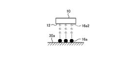
- FIG. 1 is an explanatory diagram of a coating apparatus according to an embodiment.
- FIG. 1 illustrates a three-dimensional Cartesian coordinate system including a Z-axis having a vertically upward direction as a positive direction and a vertically downward direction as a negative direction.
- Such a Cartesian coordinate system may also be shown in other drawings used in the description below.
- the same components as those of the coating apparatus 1 shown in FIG. 1 are designated by the same reference numerals, and the description thereof will be omitted or simplified.
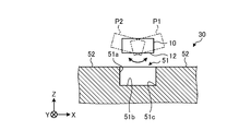
- FIG. 6 is an explanatory view showing an example of painting a recess by the painting device according to the third embodiment.
- the head 10 included in the coating apparatus 1 according to the present embodiment swings from position P1 to position P2 so that the nozzle surface 12 faces the inner surface of the recess, that is, the first surface 51a and the second surface 51b.
- By swinging the head 10 in this way it is easy to appropriately distribute the coating material not only to the first surface 51a and the second surface 51b but also to the corner portion 51c where the first surface 51a and the second surface 51b intersect. Become. Therefore, the coating quality can be improved.
- the nozzle surface 12 has a row having a plurality of discharge holes 11 arranged along the length direction of the head 10-3, here, along the X-axis direction as one unit, in the width direction of the head 10-3. ,
- the inclination in the vertical direction that is, the angle ⁇ has a relationship of, for example, tan ⁇ ⁇ (x / y).
- the thickness t2 of the second coating layer 34 as the coating film located on the second surface 51b as the bottom surface of the recess is located on the portion 52 where the recess is not located. It is larger than the thickness t1 of 34.
- the second coating layer 34 is less likely to peel off even when a member such as a roof rail is attached to the portion 51, for example. Therefore, according to the coating film according to the embodiment, the coating quality is improved and the environmental strength of the coated body 38 is improved.
- the coated body 38 shown in FIG. 11C has a convex portion 33a protruding in the Z-axis direction on a corner portion 53 located at an end portion on the head side of the first surface 51a as a side surface of the concave portion.
- the thickness (t1 + t3) of the second coating layer 34 located on the corner portion 53 in the Z-axis direction becomes larger than the thickness t1 of the second coating layer 34 located on the portion 52 where the recess is not located.
- the second coating layer 34 is less likely to peel off even when a member such as a roof rail is attached to the portion 51, for example. Therefore, according to the coating film according to the embodiment, the coating quality is improved and the environmental strength of the coated body 38 is improved.
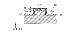
- the object to be coated 30 shown in FIG. 12 has a portion 51A in which a convex portion extending along the Y-axis direction as the first direction is located and a portion 52A in which the convex portion is not located.
- Part 51 is, for example, a vortex generator or a corrugated roof.
- the thickness t12 of the second coating layer 34 located on the portion 51A as the convex portion is the thickness t11 of the second coating layer 34 located on the portion 52A where the convex portion is not located. Greater than.
- the second coating layer 34 is less likely to peel off even when the member is attached to the portion 51A, for example. Therefore, according to the coating film according to the embodiment, the coating quality is improved and the environmental strength of the coated body 38 is improved.
- the width w11 in the X-axis direction of the second coating layer 34 located at the portion 51A as the convex portion is located on the portion 52A where the convex portion is not located. It is larger than the thickness t11 of.
- the coating device 1 including one head 10 for discharging a monochromatic coating material has been described.
- magenta (M), yellow (Y), cyan (C), and black (K) have been described.
- a robot 20 may be provided that holds the heads 10 for discharging the coating materials of the basic colors such as.
- the present invention is not limited to this, and for example, the Z-axis negative direction side may be painted, and the YZ plane or ZX The side surface located along the plane may be the surface to be painted 30a. Further, the coating device 1 may be applied when coating the surface to be coated 30a located obliquely with respect to the Z axis.
- the coating apparatus 1 coats the object to be coated 30 having a recess extending in the first direction.
- the painting device 1 includes a head 10, an arm 21, and a control unit 41.
- the head 10 has a nozzle surface 12.
- the arm 21 holds the head 10.
- the control unit 41 controls the movement of the head 10 via the arm 21.
- the control unit 41 faces the nozzle surface 12 and the recess in a posture in which the length of the first component of the head 10 along the first direction is larger than the length of the second component of the head 10 intersecting the first component. While moving the head 10 in the first direction. Therefore, the coating quality can be improved.
Landscapes
- Engineering & Computer Science (AREA)
- Robotics (AREA)
- Coating Apparatus (AREA)
- Application Of Or Painting With Fluid Materials (AREA)
- Spray Control Apparatus (AREA)
Priority Applications (5)
| Application Number | Priority Date | Filing Date | Title |
|---|---|---|---|
| JP2021543086A JP7181417B2 (ja) | 2019-08-30 | 2020-08-28 | 塗装装置および塗装方法 |
| CN202080060266.9A CN114364464A (zh) | 2019-08-30 | 2020-08-28 | 涂装装置、涂装膜以及涂装方法 |
| EP20857105.9A EP4023344B1 (en) | 2019-08-30 | 2020-08-28 | Painting device, painted film, and painting method |
| US17/638,175 US12350705B2 (en) | 2019-08-30 | 2020-08-28 | Coating device, coating film, and coating method |
| JP2022184397A JP7490034B2 (ja) | 2019-08-30 | 2022-11-17 | 塗装装置および塗装方法 |
Applications Claiming Priority (2)
| Application Number | Priority Date | Filing Date | Title |
|---|---|---|---|
| JP2019159144 | 2019-08-30 | ||
| JP2019-159144 | 2019-08-30 |
Publications (1)
| Publication Number | Publication Date |
|---|---|
| WO2021040028A1 true WO2021040028A1 (ja) | 2021-03-04 |
Family
ID=74685186
Family Applications (1)
| Application Number | Title | Priority Date | Filing Date |
|---|---|---|---|
| PCT/JP2020/032768 Ceased WO2021040028A1 (ja) | 2019-08-30 | 2020-08-28 | 塗装装置、塗装膜および塗装方法 |
Country Status (5)
| Country | Link |
|---|---|
| US (1) | US12350705B2 (https=) |
| EP (1) | EP4023344B1 (https=) |
| JP (2) | JP7181417B2 (https=) |
| CN (1) | CN114364464A (https=) |
| WO (1) | WO2021040028A1 (https=) |
Citations (9)
| Publication number | Priority date | Publication date | Assignee | Title |
|---|---|---|---|---|
| JP2005138013A (ja) * | 2003-11-05 | 2005-06-02 | Seiko Epson Corp | 液滴吐出装置の制御方法及び液滴吐出装置 |
| JP2007117963A (ja) * | 2005-10-31 | 2007-05-17 | Kubota Matsushitadenko Exterior Works Ltd | 建築板の塗装装置 |
| JP2013202781A (ja) | 2012-03-29 | 2013-10-07 | Heiderberger Druckmaschinen Ag | 対象物に印刷を行うシステム |
| JP2015168061A (ja) * | 2014-03-04 | 2015-09-28 | 株式会社リコー | 画像処理装置、画像処理プログラム、画像処理方法、及び画像処理システム |
| JP2015168202A (ja) * | 2014-03-10 | 2015-09-28 | 株式会社リコー | 三次元造形物の成形システム、三次元造形物の成形制御方法、および、三次元造形物の成形制御プログラム |
| JP2017047569A (ja) * | 2015-08-31 | 2017-03-09 | セーレン株式会社 | インクジェットプリント物および該インクジェットプリント物の製造方法 |
| JP2017154135A (ja) * | 2016-03-04 | 2017-09-07 | エクセル インダストリー | コーティング用製品のアプリケータ、そのようなアプリケータを含む複数軸ロボット、及びコーティング用製品の適用方法 |
| JP2018131876A (ja) * | 2017-02-17 | 2018-08-23 | ケイミュー株式会社 | 塗装建築板及びその製造方法 |
| JP2018202344A (ja) | 2017-06-07 | 2018-12-27 | 日産自動車株式会社 | ツートーン塗装方法 |
Family Cites Families (20)
| Publication number | Priority date | Publication date | Assignee | Title |
|---|---|---|---|---|
| DE3070338D1 (en) | 1980-11-12 | 1985-04-25 | Treuhand Gmbh Fides | Process for preparing wall and floor coverings with relief structure and apparatus for performing the process |
| JPS61202839A (ja) | 1985-03-06 | 1986-09-08 | 大日本印刷株式会社 | うずくり調木目化粧材 |
| TWI242663B (en) | 2002-07-09 | 2005-11-01 | Seiko Epson Corp | Jetting method of liquid, jetting apparatus of liquid, production method of substrate for electro-optical apparatus and production method of electro-optical apparatus |
| DE502006003548D1 (de) * | 2006-08-23 | 2009-06-04 | Siemens Ag | Beschichtete Turbinenschaufel |
| FI119922B (fi) | 2007-07-04 | 2009-05-15 | Theta Optics Ltd Oy | Menetelmä ja laitteisto pinnoittaa tuotteita |
| CA2641508C (en) * | 2008-10-22 | 2016-07-12 | Honda Motor Co., Ltd. | Spray coating system and method |
| DE102008053178A1 (de) | 2008-10-24 | 2010-05-12 | Dürr Systems GmbH | Beschichtungseinrichtung und zugehöriges Beschichtungsverfahren |
| US9720326B2 (en) * | 2009-10-01 | 2017-08-01 | David A. Recchia | Method of improving print performance in flexographic printing plates |
| JP2011121218A (ja) * | 2009-12-09 | 2011-06-23 | Seiko Epson Corp | ノズルプレート、吐出ヘッド及びそれらの製造方法並びに吐出装置 |
| US20130199916A1 (en) * | 2012-02-08 | 2013-08-08 | Empire Technology Development Llc | Elongational structures |
| US9321257B2 (en) | 2013-04-04 | 2016-04-26 | Nike, Inc. | Cylinder with recessed portions for holding tubular articles for printing |
| EP2848421B1 (en) | 2013-09-12 | 2016-07-13 | Agfa Graphics Nv | Large cuboid shaped object inkjet printing |
| TWI601577B (zh) * | 2014-01-10 | 2017-10-11 | 石井表記股份有限公司 | 膜形成裝置以及膜形成方法 |
| DE102014012395A1 (de) * | 2014-08-21 | 2016-02-25 | Heidelberger Druckmaschinen Ag | Verfahren und Vorrichtung zum Bedrucken einer gekrümmten Oberfläche eines Objekts mit einem Tintenstrahlkopf |
| EP3111892B1 (de) | 2015-06-30 | 2018-09-12 | Jossi Holding AG | Implantat und verfahren zum beschichten eines implantatgrundkörpers |
| JP6270896B2 (ja) * | 2016-03-29 | 2018-01-31 | 本田技研工業株式会社 | 塗装ノズル及び塗装装置並びにそれらを用いた塗装方法 |
| DE102016014944A1 (de) * | 2016-12-14 | 2018-06-14 | Dürr Systems Ag | Beschichtungsverfahren und entsprechende Beschichtungseinrichtung |
| FR3095132B1 (fr) | 2019-04-19 | 2021-05-07 | Exel Ind | Applicateur de produit de revêtement, installation d’application comprenant un tel applicateur et procédé d’application au moyen d’un tel applicateur |
| CN114173936A (zh) | 2019-07-31 | 2022-03-11 | 京瓷株式会社 | 涂装装置及涂装方法 |
| EP4023343B1 (en) | 2019-08-30 | 2026-02-25 | Kyocera Corporation | Coating device, coating film, and coating method |
-
2020
- 2020-08-28 EP EP20857105.9A patent/EP4023344B1/en active Active
- 2020-08-28 CN CN202080060266.9A patent/CN114364464A/zh active Pending
- 2020-08-28 US US17/638,175 patent/US12350705B2/en active Active
- 2020-08-28 JP JP2021543086A patent/JP7181417B2/ja active Active
- 2020-08-28 WO PCT/JP2020/032768 patent/WO2021040028A1/ja not_active Ceased
-
2022
- 2022-11-17 JP JP2022184397A patent/JP7490034B2/ja active Active
Patent Citations (9)
| Publication number | Priority date | Publication date | Assignee | Title |
|---|---|---|---|---|
| JP2005138013A (ja) * | 2003-11-05 | 2005-06-02 | Seiko Epson Corp | 液滴吐出装置の制御方法及び液滴吐出装置 |
| JP2007117963A (ja) * | 2005-10-31 | 2007-05-17 | Kubota Matsushitadenko Exterior Works Ltd | 建築板の塗装装置 |
| JP2013202781A (ja) | 2012-03-29 | 2013-10-07 | Heiderberger Druckmaschinen Ag | 対象物に印刷を行うシステム |
| JP2015168061A (ja) * | 2014-03-04 | 2015-09-28 | 株式会社リコー | 画像処理装置、画像処理プログラム、画像処理方法、及び画像処理システム |
| JP2015168202A (ja) * | 2014-03-10 | 2015-09-28 | 株式会社リコー | 三次元造形物の成形システム、三次元造形物の成形制御方法、および、三次元造形物の成形制御プログラム |
| JP2017047569A (ja) * | 2015-08-31 | 2017-03-09 | セーレン株式会社 | インクジェットプリント物および該インクジェットプリント物の製造方法 |
| JP2017154135A (ja) * | 2016-03-04 | 2017-09-07 | エクセル インダストリー | コーティング用製品のアプリケータ、そのようなアプリケータを含む複数軸ロボット、及びコーティング用製品の適用方法 |
| JP2018131876A (ja) * | 2017-02-17 | 2018-08-23 | ケイミュー株式会社 | 塗装建築板及びその製造方法 |
| JP2018202344A (ja) | 2017-06-07 | 2018-12-27 | 日産自動車株式会社 | ツートーン塗装方法 |
Non-Patent Citations (1)
| Title |
|---|
| See also references of EP4023344A4 |
Also Published As
| Publication number | Publication date |
|---|---|
| US12350705B2 (en) | 2025-07-08 |
| JP2023022118A (ja) | 2023-02-14 |
| JP7490034B2 (ja) | 2024-05-24 |
| JP7181417B2 (ja) | 2022-11-30 |
| CN114364464A (zh) | 2022-04-15 |
| JPWO2021040028A1 (https=) | 2021-03-04 |
| EP4023344A1 (en) | 2022-07-06 |
| EP4023344B1 (en) | 2025-11-12 |
| EP4023344A4 (en) | 2023-08-23 |
| US20220347713A1 (en) | 2022-11-03 |
Similar Documents
| Publication | Publication Date | Title |
|---|---|---|
| WO2021039292A1 (ja) | 塗装装置、塗装膜および塗装方法 | |
| JP7617891B2 (ja) | 塗装装置および塗装方法 | |
| US11383540B2 (en) | Printing apparatus | |
| CN1207342A (zh) | 液体排出方法和液体喷出设备 | |
| JP7490034B2 (ja) | 塗装装置および塗装方法 | |
| WO2023190533A1 (ja) | 塗装方法および塗装装置 | |
| JP7758048B2 (ja) | インクジェット記録装置及び塗装方法 | |
| JP6072523B2 (ja) | 塗装建築部材の製造方法 | |
| CN114641352B (zh) | 涂装膜、机动车及涂装方法 | |
| CN114630716B (zh) | 涂装膜、机动车以及涂装方法 | |
| JP2024108552A (ja) | インクジェット装置を用いた印刷方法及びインクジェット装置 | |
| CN118494028A (zh) | 立体物印刷装置以及印刷方法 | |
| JP2025065799A (ja) | インクジェット式画像形成装置 |
Legal Events
| Date | Code | Title | Description |
|---|---|---|---|
| 121 | Ep: the epo has been informed by wipo that ep was designated in this application |
Ref document number: 20857105 Country of ref document: EP Kind code of ref document: A1 |
|
| ENP | Entry into the national phase |
Ref document number: 2021543086 Country of ref document: JP Kind code of ref document: A |
|
| NENP | Non-entry into the national phase |
Ref country code: DE |
|
| ENP | Entry into the national phase |
Ref document number: 2020857105 Country of ref document: EP Effective date: 20220330 |
|
| WWG | Wipo information: grant in national office |
Ref document number: 17638175 Country of ref document: US |
|
| WWG | Wipo information: grant in national office |
Ref document number: 2020857105 Country of ref document: EP |