WO2021039179A1 - 磁気クランプ装置 - Google Patents
磁気クランプ装置 Download PDFInfo
- Publication number
- WO2021039179A1 WO2021039179A1 PCT/JP2020/027620 JP2020027620W WO2021039179A1 WO 2021039179 A1 WO2021039179 A1 WO 2021039179A1 JP 2020027620 W JP2020027620 W JP 2020027620W WO 2021039179 A1 WO2021039179 A1 WO 2021039179A1
- Authority
- WO
- WIPO (PCT)
- Prior art keywords
- magnetic
- magnetic pole
- magnet
- plate body
- cavity
- Prior art date
- Legal status (The legal status is an assumption and is not a legal conclusion. Google has not performed a legal analysis and makes no representation as to the accuracy of the status listed.)
- Ceased
Links
Images


Classifications
-
- H—ELECTRICITY
- H01—ELECTRIC ELEMENTS
- H01F—MAGNETS; INDUCTANCES; TRANSFORMERS; SELECTION OF MATERIALS FOR THEIR MAGNETIC PROPERTIES
- H01F7/00—Magnets
- H01F7/02—Permanent magnets [PM]
- H01F7/04—Means for releasing the attractive force
-
- B—PERFORMING OPERATIONS; TRANSPORTING
- B23—MACHINE TOOLS; METAL-WORKING NOT OTHERWISE PROVIDED FOR
- B23Q—DETAILS, COMPONENTS, OR ACCESSORIES FOR MACHINE TOOLS, e.g. ARRANGEMENTS FOR COPYING OR CONTROLLING; MACHINE TOOLS IN GENERAL CHARACTERISED BY THE CONSTRUCTION OF PARTICULAR DETAILS OR COMPONENTS; COMBINATIONS OR ASSOCIATIONS OF METAL-WORKING MACHINES, NOT DIRECTED TO A PARTICULAR RESULT
- B23Q3/00—Devices holding, supporting, or positioning work or tools, of a kind normally removable from the machine
- B23Q3/15—Devices for holding work using magnetic or electric force acting directly on the work
- B23Q3/154—Stationary devices
- B23Q3/1546—Stationary devices using permanent magnets
-
- B—PERFORMING OPERATIONS; TRANSPORTING
- B29—WORKING OF PLASTICS; WORKING OF SUBSTANCES IN A PLASTIC STATE IN GENERAL
- B29C—SHAPING OR JOINING OF PLASTICS; SHAPING OF MATERIAL IN A PLASTIC STATE, NOT OTHERWISE PROVIDED FOR; AFTER-TREATMENT OF THE SHAPED PRODUCTS, e.g. REPAIRING
- B29C33/00—Moulds or cores; Details thereof or accessories therefor
- B29C33/30—Mounting, exchanging or centering
- B29C33/32—Mounting, exchanging or centering using magnetic means
-
- B—PERFORMING OPERATIONS; TRANSPORTING
- B29—WORKING OF PLASTICS; WORKING OF SUBSTANCES IN A PLASTIC STATE IN GENERAL
- B29C—SHAPING OR JOINING OF PLASTICS; SHAPING OF MATERIAL IN A PLASTIC STATE, NOT OTHERWISE PROVIDED FOR; AFTER-TREATMENT OF THE SHAPED PRODUCTS, e.g. REPAIRING
- B29C45/00—Injection moulding, i.e. forcing the required volume of moulding material through a nozzle into a closed mould; Apparatus therefor
- B29C45/17—Component parts, details or accessories; Auxiliary operations
- B29C45/1742—Mounting of moulds; Mould supports
- B29C45/1744—Mould support platens
-
- F—MECHANICAL ENGINEERING; LIGHTING; HEATING; WEAPONS; BLASTING
- F16—ENGINEERING ELEMENTS AND UNITS; GENERAL MEASURES FOR PRODUCING AND MAINTAINING EFFECTIVE FUNCTIONING OF MACHINES OR INSTALLATIONS; THERMAL INSULATION IN GENERAL
- F16B—DEVICES FOR FASTENING OR SECURING CONSTRUCTIONAL ELEMENTS OR MACHINE PARTS TOGETHER, e.g. NAILS, BOLTS, CIRCLIPS, CLAMPS, CLIPS OR WEDGES; JOINTS OR JOINTING
- F16B2/00—Friction-grip releasable fastenings
- F16B2/02—Clamps, i.e. with gripping action effected by positive means other than the inherent resistance to deformation of the material of the fastening
- F16B2/06—Clamps, i.e. with gripping action effected by positive means other than the inherent resistance to deformation of the material of the fastening external, i.e. with contracting action
-
- H—ELECTRICITY
- H01—ELECTRIC ELEMENTS
- H01F—MAGNETS; INDUCTANCES; TRANSFORMERS; SELECTION OF MATERIALS FOR THEIR MAGNETIC PROPERTIES
- H01F7/00—Magnets
-
- B—PERFORMING OPERATIONS; TRANSPORTING
- B29—WORKING OF PLASTICS; WORKING OF SUBSTANCES IN A PLASTIC STATE IN GENERAL
- B29C—SHAPING OR JOINING OF PLASTICS; SHAPING OF MATERIAL IN A PLASTIC STATE, NOT OTHERWISE PROVIDED FOR; AFTER-TREATMENT OF THE SHAPED PRODUCTS, e.g. REPAIRING
- B29C45/00—Injection moulding, i.e. forcing the required volume of moulding material through a nozzle into a closed mould; Apparatus therefor
- B29C45/17—Component parts, details or accessories; Auxiliary operations
- B29C45/1742—Mounting of moulds; Mould supports
- B29C2045/1746—Mounting of moulds; Mould supports using magnetic means
Definitions
- the present invention relates to a magnetic clamp device having a disassembled structure that is easy to maintain.
- a magnetic clamp device that utilizes magnetic attraction is known for fixing molds in injection molding machines.
- the magnetic clamp device is a technique for attaching a magnetic plate body to a platen of an injection molding machine and magnetically fixing a mold.
- a plurality of magnetic pads are provided on the plate body.
- Each magnetic pad has a non-reversible magnet (eg, a neodymium magnet) provided around the magnetic pole and a reversible magnet (eg, an alnico magnet) located behind the magnetic pole.
- a non-reversible magnet eg, a neodymium magnet
- a reversible magnet eg, an alnico magnet
- the magnetic clamping device is generally cooled by cooling water until the molded product inside the mold is cooled and cured while the mold is still clamped, and the cooling water is inside the magnetic clamping device.
- the magnetic clamping device employs a liquid-tight structure in order to prevent corrosion and short circuit of the coil and the like due to intrusion.
- a non-magnetic ring made of brass is arranged on the outer peripheral surface of the magnetic pole, and a liquid is provided by providing an outer peripheral groove for receiving an O-ring on the outer peripheral surface of the ring.
- a magnetic clamping device having tightness is disclosed.
- the outer peripheral edge portion of the magnetic pole and the inner peripheral portion of the non-magnetic annular body are screwed and fitted in a male screw / female screw relationship, and are sealed in the fitting portion.
- a magnetic clamping device to which the agent is arranged is disclosed.
- the liquidtightness of the electric system such as the coil inside the plate body of the magnetic clamping device can be improved by the O-ring or the sealing agent, but water for a long period of time can be improved.
- the intrusion cannot be completely eliminated, and it is expected that someday maintenance of the inside of the magnetic clamping device will be required.
- a central fastening hole central hole
- a bolt screw
- a bolt penetrates the plate body and the alnico magnet from the plate body side through the fastening hole and is screwed to the magnetic pole.
- Patent Document 1 and Patent Document 2 it is possible to mechanically separate the magnetic pole from the alnico magnet and the plate body by removing the respective bolts.
- the magnetic force of the neodymium magnet is extremely strong, and it is not easy to peel off the magnetic pole from the plate body.
- the magnetic clamp devices of Patent Documents 1 and 2 require a special tool that pushes a magnetic pole and an alnico magnet from the back side of the plate body to the front side of the plate body against the force of the neodymium magnet.
- paragraph 0067 of Patent Document 2 when an extra gap is filled with a sealing material made of synthetic resin as needed, it becomes more difficult to extrude.
- An object of the present invention is to provide a magnetic clamp device having a disassembled structure that is easy to maintain.
- a plate body made of a magnetic material having a bottomed cavity on the surface and a magnetic pad arranged in the cavity, which are a magnetic pole, the magnetic pole, and the cavity.
- a magnetic pad having a reversible magnet provided between the bottom surface and a reversible magnet provided between the magnetic pole and the irreversible magnet provided between the magnetic pole and the side surface of the inner circumference of the cavity is provided.
- the magnetic pole and the reversible magnet each have a fastening hole that communicates with each other, and the cavity has an opening that penetrates from the bottom surface to the back side of the plate body.
- a cap having a base portion having a bolt hole communicating with the fastening hole and a flange portion having a contact surface in contact with the back surface of the plate is inserted. Then, a bolt inserted into the fastening hole of the magnetic pole and the reversible magnet from the front side of the magnetic pad is screwed into or screwed into a female screw thread provided in the bolt hole of the cap. The bolt hole is penetrated through the back side of the plate body, and a bolt inserted into the fastening hole of the bolt hole and the reversible magnet from the flange side of the cap is provided in the fastening hole of the magnetic pole. It is screwed against the screw thread.
- the tool bolt when the cap is removed from the opening and the tool bolt is screwed into the female thread of the opening, the tool bolt abuts on the alnico magnet.
- the alnico magnet and the magnetic pole are peeled off from the plate body. In this way, it can be easily peeled off with one tool bolt.
- FIG. 1A is a view showing a magnetic clamp device
- FIG. 1A is a view of the magnetic clamp device from the front side
- FIG. 1B is a cross-sectional view of one magnetic pad
- FIG. 1C is an exploded view
- 2A and 2B are views showing the action
- FIG. 2A is a view before peeling
- FIG. 2B is a view after peeling
- 3A and 3B are views of another embodiment
- FIG. 3A is a cross-sectional view
- FIG. 3B is a view before peeling
- FIG. 3C is a view after peeling
- FIG. 4 is a view of the third embodiment
- FIG. 4A is a cross-sectional view
- FIG. 4B is a view after peeling.
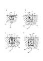
- FIG. 5A and 5B are views showing a modified portion of the third embodiment, FIG. 5A is a partially enlarged view, and FIG. 5B is a view showing a plurality of magnetic poles. It is a figure which shows the magnetic flux of the outer peripheral part of the magnetic pole when the magnetic clamp device is deactivated, FIG. 6A is Example 1 and Example 2, FIG. 6B and FIG. 6C are Example 3, and FIG. 6D is Example. The magnetic flux of the outer peripheral portion of 4 is shown.
- FIG. 1 is a diagram showing a magnetic clamp device 1.
- 1A is a front view of the magnetic clamp device 1
- FIG. 1B is a cross-sectional view of one magnetic pad 2
- FIG. 1C is an exploded view of the magnetic pad 2.
- the magnetic clamp device 1 has a plate body 3 made of a magnetic material and a large number of magnetic pads 2 arranged in a bottomed cavity 31 provided on the surface of the plate body 3.
- the surface of the plate body 3 is also provided with a proximity sensor 4, a through hole 5 into which an ejector rod (not shown) is inserted, and the like.
- the circular dotted line in the figure indicates a space (wiring chamber 32) provided on the back side of the plate main body 3.
- the wiring chamber 32 is arranged so as to partially overlap the adjacent cavity portions 31 in a plan view, and necessary cables are connected.
- the magnetic pad 2 has a cylindrical shape (hereinafter, the center of the magnetic pad 2 is referred to as a central axis c), and the magnetic pole 21 and the polar inversion provided around the magnetic pole 21 cannot be reversed.
- a magnet non-reversible magnet, for example, neodymium magnet 22
- a polarity reversible magnet reversible magnet, for example, Arnico magnet 23
- It has a magnet 24 and a coil 25 wound around the magnet 24.
- the magnetic pole 21 is made of a ferromagnetic material such as steel.
- the magnetic pole 21 and the alnico magnet 23 each have fastening holes 21a and 23a along the central axis c, and the fastening holes 21a and 23a communicate with each other.
- the bolt 8 is inserted from the front side of the plate body 3 (the side that clamps the mold, the upper side in the drawing) so that the bolt 8 can be penetrated.
- the fastening holes 21a and 23a are through holes without threads.
- the magnetic pole 21 is provided with a neodymium magnet 22 along the wall of the side surface 21b on the outer periphery thereof.
- the neodymium magnet 22 is polarized in the radial direction of the magnetic pole 21.
- the neodymium magnet 22 is divided into a plurality of parts in the circumferential direction, and one piece thereof has an arc shape.
- the neodymium magnet 22 is formed as little as possible between the inner peripheral side surface 31a of the cavity 31 and the outer peripheral side surface 21b of the magnetic pole 21. Placed in.
- the alnico magnet 23 is arranged on the back side of the magnetic pole 21.
- the coil 25 wound around the alnico magnet 23 forms a magnet whose magnetic polarity can be switched by the alnico magnet 23.
- the alnico magnet 23 is arranged between the bottom surface 31b of the cavity 31 and the bottom surface 21d of the magnetic pole 21.
- a part of the cavity 31 of the plate body 3 communicates with the wiring chamber 32.
- the terminal 25a of the coil 25 of the magnetic pad 2 appears in the wiring chamber 32 by utilizing this communicated portion.
- the connection 26 is made to the terminal 25a of the coil 25 so that a required control current can be supplied.
- the wiring chamber 32 is also used for connecting other electric circuits such as the proximity sensor 4 (not shown).
- a lid 6 is attached to the wiring chamber 32 so that the wiring chamber 32 can be closed from the back side of the plate body 3. Further, the lid 6 is attached to the plate body 3 via the gasket 61 in order to prevent the liquid from entering from the periphery of the wiring chamber 32 of the plate body 3 and to ensure the liquidtightness.
- the bottom surface 31b of the cavity 31 facing the magnetic pole 21 is provided with an opening 33 having a circular cross section that penetrates the back side of the plate body 3 along the central axis c.
- the diameter of the opening 33 is larger than the diameter of the fastening holes 21a and 23a.
- the base portion 71 of the cap 7 is inserted into the opening 33.
- the cap 7 is a magnetic material or a non-magnetic material, and has a base portion 71 having a circular cross section, an O-ring groove 73, and a flange portion 72 from the top of the drawing with the central axis c.
- a sealing material 75 (O-ring) that comes into contact with the inner circumference of the opening 33 is arranged in the O-ring groove 73.
- Bolt holes 74 are opened in the base portion 71 along the central axis c.
- the bolt holes 74 are non-penetrating, and when the base portion 71 is inserted into the opening 33, the bolt holes 74 communicate with the fastening holes 21a and 23a.
- a female thread 74a into which the bolt 8 is screwed is provided on the inner circumference of the bolt hole 74.
- the flange portion 72 is provided with a contact surface 72a that comes into contact with the surface 3b on the back side of the plate body 3.
- a widening portion 34 is provided at the entrance of the opening 33 in order to accommodate the collar portion 72 on the plate main body 3 side and reduce the unevenness on the back side of the plate main body 3.
- a female thread 33a is provided on the inner circumference of the opening 33 on the bottom surface 31b side of the cavity 31.
- the range of the inner circumference of the opening 33 provided with the female thread 33a is a part, and is limited to a range that does not interfere with the O-ring 75 of the O-ring groove 73.
- a male thread may be provided on the outer periphery of the base portion 71 of the cap 7 and screwed with the female thread 33a.
- a sealing material 75 (O-ring) is installed in the O-ring groove 73 to perform sealing with the inner circumference of the opening 33 with improved liquidtightness.
- the magnetic pole 21, the alnico magnet 23, the cap 7, and the surface 3b of the plate body 3 are fixed in the central axis c direction without an elastic body. Therefore, it is easy to make the surface surfaces 3a and 21c of the plate body 3 and the magnetic pole 21 on the front side uniform.
- the bolt 8 fixes the magnetic pole 21 via a sealing material 81 (seal washer).
- the magnetic clamp device 1 is in the operating state (magnetized state). Since the alnico magnet 23 does not have a relatively high coercive force as a permanent magnet, when the mold is momentarily separated, the magnetic force of the neodymium magnet 22 cancels the magnetic force of the alnico magnet 23 in whole or in part. The clamping force of the magnetic clamping device 1 is lost.
- the alnico magnet 23 By passing a current in the opposite direction from the outside to the coil 25 of the alnico magnet 23, the alnico magnet 23 generates a new magnetic field in the opposite direction. At this time, the magnetic clamping device 1 is switched to the non-operating state (demagnetized state), and the clamping force acting on the mold is lost.
- FIG. 2 is a diagram showing the operation of the embodiment
- FIG. 2A is a diagram before peeling
- FIG. 2B is a diagram after peeling.
- the lid 6 is opened and the connection 26 of the terminal 25a of the coil 25 is removed. Unscrew the bolt 8 and the cap 7.
- the tool bolt 10 is screwed into the female thread 33a of the opening 33
- the tool bolt 10 abuts on the alnico magnet 23.
- the tool bolt 10 peels off the alnico magnet 23 and the neodymium magnet 22 from the plate body 3 which is magnetically attracted. In this way, it can be easily peeled off with one tool bolt 10.
- the tool bolt 10 may be a bolt made for peeling, or may be a commercially available general bolt of JIS standard or inch standard. It is preferable to set the female thread 33a of the opening 33 so that a general bolt can also be used as the tool bolt 10.
- the neodymium magnet 22 is attracted to the magnetic pole 21 side and comes out from the cavity 31 of the plate body 3. This is because a slight protrusion 21f is provided between the bobbin 24 and the neodymium magnet 22 from the side surface 21b of the magnetic pole 21, and the neodymium magnet 22 is lifted by being guided by the movement of the magnetic pole 21.
- the bobbin 24 since the bobbin 24 has a size in the radial direction larger than the outside of the magnetic pole 21, the neodymium magnet 22 remains in the cavity 31 without the protruding portion 21f, and the bobbin 24 becomes the neodymium magnet 22. It interferes and cannot be taken out.
- the neodymium magnet 22 may remain on the plate body 3 side.
- fastening holes 21a and 23a that penetrate the magnetic pole 21 and the alnico magnet 23 are provided, and the bolt 8 penetrates the magnetic pole 21 and the alnico magnet 23 from the magnetic pole 21 side through the fastening holes 21a and 23a and caps. It is fixed to the plate body 3 by being screwed into 7.
- the bolt 8 penetrates from the back side of the plate body 3 through the bolt hole 74 of the cap 7 and the fastening hole 23a of the alnico magnet 23 and is screwed to the magnetic pole 21. ..
- FIG. 3A is a cross-sectional view
- FIG. 3B is a view before peeling
- FIG. 3C is a view after peeling.
- the same quotation marks are attached to the configurations having the same functions as those in the first embodiment.
- the magnetic pad 2 of the second embodiment has a different configuration of the magnetic pole 21 and the cap 7 and the mounting direction of the bolt 8 from the magnetic pad 2 of the first embodiment.
- the magnetic pole 21 is formed with a fastening hole 21a, which is a stop hole, from the back surface side.
- the fastening hole 21a is provided with a female thread 21g into which the bolt 8 is screwed.
- the bolt hole 74 is not provided with a female screw thread 74a, and is a hole that communicates with the dowel hole 76 having a diameter larger than that of the bolt hole 74 and penetrates the cap 7 as a whole.
- the bolt 8 can be inserted from the back side of the plate body 3 through the bolt hole 74 and the dowel hole 76.
- the fastening hole 23a and the bolt hole 74 are through holes.
- the dowel hole 76 can accommodate the head portion 8a of the bolt 8.
- Example 2 The operation of Example 2 will be described with reference to FIGS. 3A to 3C.
- the lid 6 is opened and the connection 26 of the terminal 25a of the coil 25 is removed. Unscrew the bolt 8 and the magnetic pole 21.
- the tool bolt 10 is screwed into the female thread 33a of the opening 33, the tool bolt 10 abuts on the alnico magnet 23.
- the alnico magnet 23 and the magnetic pole 21 are peeled off from the plate body 3. In this way, it can be easily peeled off with one of the tool bolts 10.
- the base portion 71 is cylindrical, but the shape of the flange portion 72 in a plan view does not have to be circular.
- a sealing material such as a gasket may be used between the contact surface 72a and the surface 3b on the plate body side to which the contact surface 72a abuts.
- care must be taken during polishing.
- the magnetic clamp device 1 of the third embodiment shown in FIG. 4 is an example in which the magnetic pole 21 is connected to the plate body 3 by a bolt 8 penetrating from the back side of the plate body 3 through the fastening hole 23a of the alnico magnet 23. Unlike the magnetic clamp device 1 of the second embodiment, the cap 7 is not provided.
- the magnetic pole 21 is formed with a fastening hole 21a, which is a stop hole, from the back surface side.
- the fastening hole 21a is provided with a female thread 21g into which the bolt 8 is screwed.
- the fastening hole 23a of the alnico magnet 23 is a threadless through hole through which the bolt 8 penetrates.
- the diameter of the opening 33a of the plate body 3 is set to be larger than the fastening hole 21a and the fastening hole 23a. For this reason, the head 8a of the bolt 8 or the washer 82 used together with the bolt 8 as needed cannot penetrate.
- a female thread 33a is formed on the inner circumference of the opening 33a.
- the fastening hole 21a, the fastening hole 23a, and the opening 33a communicate with each other in a straight line.
- a widening portion 34 is provided at the entrance of the opening 33a on the back side of the plate body 3.
- the widening portion 34 has a size sufficient to accommodate the head portion 8a of the bolt 8 screwed into the female thread 21g from the back side of the plate body 3 and reduce the unevenness on the back side of the plate body 3. Have.
- a minute convex cylindrical guide 21h is provided on the bottom surface thereof.
- the inner circumference of the cylindrical guide 21h is slightly larger than that of the alnico magnet 23.
- the upper portion of the alnico magnet 23 enters the cylindrical guide 21h, thereby roughly defining the positional relationship between the two.
- the cylindrical guide 21h is used in the assembly process of fixing the neodymium magnet 22, the magnetic pole 21, and the alnico magnet 23 to the plate body 3.
- the alnico magnet 23 is placed in the cylindrical guide 21h, and then the magnetized neodymium magnet 22 is attached to the magnetic pole 21.
- the alnico magnet 23 is attracted to the magnetic pole 21 by the magnetic force of the neodymium magnet 22 and integrated.
- the fastening hole 23a of the alnico magnet 23 and the fastening hole 21a of the magnetic pole 21 are also automatically communicated with each other by the cylindrical guide 21h. Since the neodymium magnet 22, the magnetic pole 21, and the alnico magnet 23 can be handled as one integrated part after that, the screwing with the bolt 8 can be performed by one worker.
- FIG. 5 is a diagram illustrating a portion of the magnetic clamp device 1 of the third embodiment that has been changed as compared with the first embodiment or the second embodiment.
- the upper side of the neodymium magnet 22 makes the outer peripheral portion 21e of the magnetic pole 21 come into contact with the inner peripheral side surface 31a of the plate body 3 with a thin thickness / or. It extends to close proximity.
- the outer peripheral portion 21e of the magnetic pole 21 exceeds the side surface 31a of the inner circumference of the plate main body 3 and slightly covers the side surface 31a.
- a shim 21f that magnetically connects the outer peripheral portion 21e and the plate main body 3 is covered with the outer peripheral portion 21e and is in contact with the plate main body 3.
- the lid 6 is fitted into the wiring chamber 32 by an elastic force. Further, the sealing material is attached to the lid 6 side in advance. The work of attaching the lid 6 to the plate body 3 is simplified by simply fitting it.
- the search coil 62 for measuring the magnetic flux passing through the magnetic pole 21 is wound around the magnetic pole 21 for several turns between the neodymium magnet 22 and the sealing material 9.
- the adjacent magnetic poles 21 are magnetized to different magnetic poles. Assuming that the left magnetic pole 21 is the north pole in the drawing of FIG. 5C, the right magnetic pole 21 is the south pole.
- the search coil 62 may be wound around all the magnetic poles 21. On the other hand, it is not necessary to wind it around some magnetic poles 21 and not around other poles. For example, it is not necessary to wind it only around the magnetic pole 21 of the north pole and not around the magnetic pole 21 of the south pole.
- Example 3 Unscrew the bolt 8 and the magnetic pole 21.
- the tool bolt 10 When the tool bolt 10 is screwed into the female thread 33a of the opening 33, the tool bolt 10 abuts on the alnico magnet 23.
- the alnico magnet 23 and the magnetic pole 21 are peeled off from the plate body 3. In this way, it can be easily peeled off with one tool bolt 10.
- FIG. 6D the third embodiment is slightly modified, and instead of the shim 21f that magnetically connects the outer peripheral portion 21e and the plate main body 3, the plate main body 3 is placed below the outer peripheral portion 21e.
- a short-circuit portion 21g that magnetically short-circuits is provided.
- FIG. 6 compares the state of the magnetic flux on the outer peripheral portion of the magnetic pole 21 when the magnetic clamp device 1 is inactive.
- FIG. 6A is a diagram corresponding to Examples 1 and 2.
- the outer peripheral portion 21e is magnetically connected to the plate main body 3, and the magnetic flux passes between the outer peripheral portion 21e and the plate main body 3 in the non-operating state.
- FIG. 6B and 6C are the third embodiment, but in FIG. 6B, the shim 21f is excluded. In the absence of the shim 21f, the magnetic flux has leaked from the magnetic pole 21 in the non-operating state. With this, the mold cannot be released successfully. On the other hand, by providing the shim 21f as shown in FIG. 6C, the magnetic flux passes through the shim 21f and does not leak from the magnetic pole 21. Further, in FIG. 6D showing the fourth embodiment, the magnetic flux does not pass through the short-circuited portion 21g on the lower side of the outer peripheral portion 21e and leak from the magnetic pole 21.
Landscapes
- Engineering & Computer Science (AREA)
- Mechanical Engineering (AREA)
- Physics & Mathematics (AREA)
- Electromagnetism (AREA)
- Power Engineering (AREA)
- General Engineering & Computer Science (AREA)
- Manufacturing & Machinery (AREA)
- Jigs For Machine Tools (AREA)
- Moulds For Moulding Plastics Or The Like (AREA)
Priority Applications (3)
| Application Number | Priority Date | Filing Date | Title |
|---|---|---|---|
| JP2021542616A JP7518548B2 (ja) | 2019-08-29 | 2020-07-16 | 磁気クランプ装置 |
| EP20858877.2A EP3988273A4 (en) | 2019-08-29 | 2020-07-16 | MAGNETIC CLAMPING DEVICE |
| US17/631,483 US11923135B2 (en) | 2019-08-29 | 2020-07-16 | Magnetic clamp device |
Applications Claiming Priority (2)
| Application Number | Priority Date | Filing Date | Title |
|---|---|---|---|
| JP2019-156704 | 2019-08-29 | ||
| JP2019156704 | 2019-08-29 |
Publications (1)
| Publication Number | Publication Date |
|---|---|
| WO2021039179A1 true WO2021039179A1 (ja) | 2021-03-04 |
Family
ID=74685029
Family Applications (1)
| Application Number | Title | Priority Date | Filing Date |
|---|---|---|---|
| PCT/JP2020/027620 Ceased WO2021039179A1 (ja) | 2019-08-29 | 2020-07-16 | 磁気クランプ装置 |
Country Status (4)
| Country | Link |
|---|---|
| US (1) | US11923135B2 (https=) |
| EP (1) | EP3988273A4 (https=) |
| JP (1) | JP7518548B2 (https=) |
| WO (1) | WO2021039179A1 (https=) |
Cited By (1)
| Publication number | Priority date | Publication date | Assignee | Title |
|---|---|---|---|---|
| WO2025032950A1 (ja) * | 2023-08-10 | 2025-02-13 | 株式会社コスメック | 磁気クランプ装置 |
Families Citing this family (2)
| Publication number | Priority date | Publication date | Assignee | Title |
|---|---|---|---|---|
| WO2025233783A1 (en) * | 2024-05-06 | 2025-11-13 | Mag-Autoblok Tecnomagnete S.P.A. | Magnetic equipment for magnetically anchoring ferrous elements |
| US12595812B1 (en) * | 2025-08-29 | 2026-04-07 | Tractian Technologies Inc | Adhesive-free encapsulated magnetic mounting base |
Citations (5)
| Publication number | Priority date | Publication date | Assignee | Title |
|---|---|---|---|---|
| JPS531117B2 (https=) | 1972-04-28 | 1978-01-14 | ||
| JP2001056010A (ja) * | 1999-08-16 | 2001-02-27 | Sannohashi:Kk | ボルト |
| JP2017213650A (ja) * | 2016-05-27 | 2017-12-07 | カネテック株式会社 | 永電磁式磁気吸着装置 |
| JP2018112292A (ja) * | 2017-01-13 | 2018-07-19 | 日東精工株式会社 | 締結構造 |
| JP2019076981A (ja) | 2017-10-23 | 2019-05-23 | パスカルエンジニアリング株式会社 | 磁気式クランプ装置及び磁気式クランプ装置用磁力発生機構 |
Family Cites Families (13)
| Publication number | Priority date | Publication date | Assignee | Title |
|---|---|---|---|---|
| JPS531117Y2 (https=) | 1973-12-07 | 1978-01-13 | ||
| IT1022923B (it) * | 1974-10-16 | 1978-04-20 | Cardone Magneto Tecnica | Apparecchiatura magnetica di ancoraggio |
| US4777463A (en) * | 1987-09-25 | 1988-10-11 | Dana Corporation | Magnetic fixture assembly |
| FR2902361B1 (fr) * | 2006-06-16 | 2008-08-08 | Staubli Faverges Sca | Dispositif de bridage magnetique, machine de moulage par injection equipee d'un tel dispositif et procede de fabrication d'un tel dispositif |
| ITMI20071779A1 (it) * | 2007-09-14 | 2009-03-15 | Milano Politecnico | Piastra monolitica multipolare per una apparecchiatura magnetica di ancoraggio, processo per la realizzazione di tale piastra e apparecchiatura magnetica utilizzante detta piastra. |
| BRPI0822611B1 (pt) * | 2008-04-22 | 2020-07-21 | Tecnomagnete S.P.A. | aparelho magnético monolítico e processo para fabricar o dito aparelho magnético monolítico |
| PL2476509T3 (pl) * | 2008-04-22 | 2014-03-31 | Tecnomagnete Spa | Sposób bezpiecznego montowania i/albo usuwania urządzenia magnetycznego z elementów żelaznych |
| US9061400B1 (en) * | 2011-03-18 | 2015-06-23 | Greatbatch Ltd. | Magnetic fixture |
| KR101319052B1 (ko) * | 2013-06-07 | 2013-10-17 | 최태광 | 영구자석 에너지 제어를 이용한 자성체 홀딩 장치 |
| WO2016178473A1 (ko) * | 2015-05-04 | 2016-11-10 | 최태광 | 자기흐름 제어장치 |
| WO2019024748A1 (zh) * | 2017-08-04 | 2019-02-07 | 株洲悍威磁电科技有限公司 | 一种电永磁吸盘 |
| WO2019202957A1 (ja) * | 2018-04-18 | 2019-10-24 | 株式会社コスメック | 磁気クランプ装置 |
| JP7088546B2 (ja) * | 2018-07-12 | 2022-06-21 | 株式会社コスメック | 磁気クランプ装置 |
-
2020
- 2020-07-16 WO PCT/JP2020/027620 patent/WO2021039179A1/ja not_active Ceased
- 2020-07-16 US US17/631,483 patent/US11923135B2/en active Active
- 2020-07-16 EP EP20858877.2A patent/EP3988273A4/en not_active Withdrawn
- 2020-07-16 JP JP2021542616A patent/JP7518548B2/ja active Active
Patent Citations (5)
| Publication number | Priority date | Publication date | Assignee | Title |
|---|---|---|---|---|
| JPS531117B2 (https=) | 1972-04-28 | 1978-01-14 | ||
| JP2001056010A (ja) * | 1999-08-16 | 2001-02-27 | Sannohashi:Kk | ボルト |
| JP2017213650A (ja) * | 2016-05-27 | 2017-12-07 | カネテック株式会社 | 永電磁式磁気吸着装置 |
| JP2018112292A (ja) * | 2017-01-13 | 2018-07-19 | 日東精工株式会社 | 締結構造 |
| JP2019076981A (ja) | 2017-10-23 | 2019-05-23 | パスカルエンジニアリング株式会社 | 磁気式クランプ装置及び磁気式クランプ装置用磁力発生機構 |
Non-Patent Citations (1)
| Title |
|---|
| See also references of EP3988273A4 |
Cited By (1)
| Publication number | Priority date | Publication date | Assignee | Title |
|---|---|---|---|---|
| WO2025032950A1 (ja) * | 2023-08-10 | 2025-02-13 | 株式会社コスメック | 磁気クランプ装置 |
Also Published As
| Publication number | Publication date |
|---|---|
| JPWO2021039179A1 (https=) | 2021-03-04 |
| EP3988273A1 (en) | 2022-04-27 |
| US20220277876A1 (en) | 2022-09-01 |
| EP3988273A4 (en) | 2022-09-21 |
| JP7518548B2 (ja) | 2024-07-18 |
| US11923135B2 (en) | 2024-03-05 |
Similar Documents
| Publication | Publication Date | Title |
|---|---|---|
| US11923135B2 (en) | Magnetic clamp device | |
| CN110771017B (zh) | 具有壳体的电驱动单元 | |
| JP7093984B2 (ja) | 磁気式クランプ装置及び磁気式クランプ装置用磁力発生機構 | |
| US20210352388A1 (en) | Sound transmission device | |
| EP0818155B1 (en) | Magnetic closure with casing made of nonferromagnetic material, for bags, items of clothing and the like | |
| US20080290972A1 (en) | Actuation magnet for moving a closure needle of a hot-runner nozzle of an injection molding tool | |
| AU2007359402B2 (en) | Electromagnet actuator | |
| KR101933803B1 (ko) | 브레이크를 구비한 모터 | |
| WO2020241090A1 (ja) | 吸着力確認方法及び吸着力確認装置 | |
| JP3217116U (ja) | 磁気吸着装置 | |
| JP2020516074A (ja) | 改良型磁気装置 | |
| US3593239A (en) | Magnetic system | |
| JP2018099738A (ja) | 磁気式クランプ装置 | |
| JP2020529741A (ja) | 電気永久磁石チャック | |
| JP2003264971A (ja) | ブラシレスモータ | |
| US6019587A (en) | Stamper plate attaching/detaching device of an injection mold for forming an optical disc substrate | |
| US11869711B2 (en) | Magnetic clamp device | |
| WO2020059654A1 (ja) | アウターロータ型電動機用ロータ | |
| TWI796939B (zh) | 電磁閥 | |
| JP2017144525A (ja) | 磁気吸着装置 | |
| JP3779586B2 (ja) | 切り換え可能の永久磁石チャック | |
| CN212110056U (zh) | 一种自带零点位置的磁性编码器 | |
| US2615996A (en) | Magnet pole structure | |
| JP2007329639A (ja) | スピーカ装置の製造方法、およびスピーカ装置 | |
| JP2025002201A (ja) | 磁気クランプ装置 |
Legal Events
| Date | Code | Title | Description |
|---|---|---|---|
| 121 | Ep: the epo has been informed by wipo that ep was designated in this application |
Ref document number: 20858877 Country of ref document: EP Kind code of ref document: A1 |
|
| DPE1 | Request for preliminary examination filed after expiration of 19th month from priority date (pct application filed from 20040101) | ||
| ENP | Entry into the national phase |
Ref document number: 2021542616 Country of ref document: JP Kind code of ref document: A |
|
| ENP | Entry into the national phase |
Ref document number: 2020858877 Country of ref document: EP Effective date: 20220119 |
|
| NENP | Non-entry into the national phase |
Ref country code: DE |
|
| WWW | Wipo information: withdrawn in national office |
Ref document number: 2020858877 Country of ref document: EP |