WO2021038996A1 - 細胞製造装置及びその製造方法 - Google Patents
細胞製造装置及びその製造方法 Download PDFInfo
- Publication number
- WO2021038996A1 WO2021038996A1 PCT/JP2020/021240 JP2020021240W WO2021038996A1 WO 2021038996 A1 WO2021038996 A1 WO 2021038996A1 JP 2020021240 W JP2020021240 W JP 2020021240W WO 2021038996 A1 WO2021038996 A1 WO 2021038996A1
- Authority
- WO
- WIPO (PCT)
- Prior art keywords
- fluid
- cell
- fluid circuit
- plate
- cell production
- Prior art date
Links
- 238000004519 manufacturing process Methods 0.000 title claims abstract description 124
- 239000012530 fluid Substances 0.000 claims abstract description 217
- 238000002347 injection Methods 0.000 claims abstract description 27
- 239000007924 injection Substances 0.000 claims abstract description 27
- 230000006698 induction Effects 0.000 claims abstract description 23
- 238000003860 storage Methods 0.000 claims description 37
- 238000012546 transfer Methods 0.000 claims description 21
- 238000000034 method Methods 0.000 claims description 15
- 238000002156 mixing Methods 0.000 claims description 15
- 238000000926 separation method Methods 0.000 claims description 13
- 238000004891 communication Methods 0.000 claims description 8
- 239000000463 material Substances 0.000 claims description 8
- 230000002572 peristaltic effect Effects 0.000 claims description 8
- 238000007599 discharging Methods 0.000 claims description 6
- 238000007789 sealing Methods 0.000 claims description 5
- 238000000465 moulding Methods 0.000 claims description 4
- 230000000149 penetrating effect Effects 0.000 claims description 4
- 230000008569 process Effects 0.000 claims description 4
- 238000004113 cell culture Methods 0.000 abstract description 21
- 210000004027 cell Anatomy 0.000 description 186
- IJGRMHOSHXDMSA-UHFFFAOYSA-N Atomic nitrogen Chemical compound N#N IJGRMHOSHXDMSA-UHFFFAOYSA-N 0.000 description 10
- 239000003153 chemical reaction reagent Substances 0.000 description 9
- CURLTUGMZLYLDI-UHFFFAOYSA-N Carbon dioxide Chemical compound O=C=O CURLTUGMZLYLDI-UHFFFAOYSA-N 0.000 description 8
- 230000008672 reprogramming Effects 0.000 description 7
- 239000000853 adhesive Substances 0.000 description 6
- 230000001070 adhesive effect Effects 0.000 description 6
- 239000007788 liquid Substances 0.000 description 6
- 210000001082 somatic cell Anatomy 0.000 description 6
- 210000000130 stem cell Anatomy 0.000 description 6
- 238000003466 welding Methods 0.000 description 6
- 230000008859 change Effects 0.000 description 5
- 230000004069 differentiation Effects 0.000 description 5
- 229910052757 nitrogen Inorganic materials 0.000 description 5
- 238000002360 preparation method Methods 0.000 description 5
- 229910002092 carbon dioxide Inorganic materials 0.000 description 4
- 239000001569 carbon dioxide Substances 0.000 description 4
- 238000006243 chemical reaction Methods 0.000 description 4
- 238000011109 contamination Methods 0.000 description 4
- 230000001939 inductive effect Effects 0.000 description 4
- 244000005700 microbiome Species 0.000 description 4
- 108090000623 proteins and genes Proteins 0.000 description 4
- 239000000243 solution Substances 0.000 description 4
- 239000000126 substance Substances 0.000 description 4
- 238000002054 transplantation Methods 0.000 description 4
- 241000700605 Viruses Species 0.000 description 3
- QVGXLLKOCUKJST-UHFFFAOYSA-N atomic oxygen Chemical compound [O] QVGXLLKOCUKJST-UHFFFAOYSA-N 0.000 description 3
- 230000021164 cell adhesion Effects 0.000 description 3
- 239000011248 coating agent Substances 0.000 description 3
- 239000007789 gas Substances 0.000 description 3
- 238000005259 measurement Methods 0.000 description 3
- 239000001301 oxygen Substances 0.000 description 3
- 229910052760 oxygen Inorganic materials 0.000 description 3
- 230000001954 sterilising effect Effects 0.000 description 3
- 238000004659 sterilization and disinfection Methods 0.000 description 3
- 230000009466 transformation Effects 0.000 description 3
- 241000282412 Homo Species 0.000 description 2
- 108010085895 Laminin Proteins 0.000 description 2
- VYPSYNLAJGMNEJ-UHFFFAOYSA-N Silicium dioxide Chemical compound O=[Si]=O VYPSYNLAJGMNEJ-UHFFFAOYSA-N 0.000 description 2
- 239000003146 anticoagulant agent Substances 0.000 description 2
- 229940127219 anticoagulant drug Drugs 0.000 description 2
- 230000004663 cell proliferation Effects 0.000 description 2
- 239000003795 chemical substances by application Substances 0.000 description 2
- 238000012790 confirmation Methods 0.000 description 2
- 238000001816 cooling Methods 0.000 description 2
- 238000012864 cross contamination Methods 0.000 description 2
- 238000012258 culturing Methods 0.000 description 2
- LOKCTEFSRHRXRJ-UHFFFAOYSA-I dipotassium trisodium dihydrogen phosphate hydrogen phosphate dichloride Chemical compound P(=O)(O)(O)[O-].[K+].P(=O)(O)([O-])[O-].[Na+].[Na+].[Cl-].[K+].[Cl-].[Na+] LOKCTEFSRHRXRJ-UHFFFAOYSA-I 0.000 description 2
- 210000002919 epithelial cell Anatomy 0.000 description 2
- 210000002950 fibroblast Anatomy 0.000 description 2
- 238000010438 heat treatment Methods 0.000 description 2
- 238000005286 illumination Methods 0.000 description 2
- 230000001965 increasing effect Effects 0.000 description 2
- 239000000411 inducer Substances 0.000 description 2
- 230000001678 irradiating effect Effects 0.000 description 2
- 238000012423 maintenance Methods 0.000 description 2
- 239000002953 phosphate buffered saline Substances 0.000 description 2
- 238000012545 processing Methods 0.000 description 2
- 102000004169 proteins and genes Human genes 0.000 description 2
- 239000003507 refrigerant Substances 0.000 description 2
- 239000011347 resin Substances 0.000 description 2
- 229920005989 resin Polymers 0.000 description 2
- 239000000758 substrate Substances 0.000 description 2
- 238000011144 upstream manufacturing Methods 0.000 description 2
- 229920002818 (Hydroxyethyl)methacrylate Polymers 0.000 description 1
- 108010035532 Collagen Proteins 0.000 description 1
- 102000008186 Collagen Human genes 0.000 description 1
- 102000004190 Enzymes Human genes 0.000 description 1
- 108090000790 Enzymes Proteins 0.000 description 1
- 102100037362 Fibronectin Human genes 0.000 description 1
- 108010067306 Fibronectins Proteins 0.000 description 1
- 108010010803 Gelatin Proteins 0.000 description 1
- 108700021430 Kruppel-Like Factor 4 Proteins 0.000 description 1
- 241000699670 Mus sp. Species 0.000 description 1
- 101710135898 Myc proto-oncogene protein Proteins 0.000 description 1
- 102100038895 Myc proto-oncogene protein Human genes 0.000 description 1
- 208000018737 Parkinson disease Diseases 0.000 description 1
- 108010039918 Polylysine Proteins 0.000 description 1
- 101100247004 Rattus norvegicus Qsox1 gene Proteins 0.000 description 1
- 101150086694 SLC22A3 gene Proteins 0.000 description 1
- 239000006087 Silane Coupling Agent Substances 0.000 description 1
- 210000001744 T-lymphocyte Anatomy 0.000 description 1
- 101710150448 Transcriptional regulator Myc Proteins 0.000 description 1
- 102000004142 Trypsin Human genes 0.000 description 1
- 108090000631 Trypsin Proteins 0.000 description 1
- 206010067584 Type 1 diabetes mellitus Diseases 0.000 description 1
- 108010031318 Vitronectin Proteins 0.000 description 1
- 102100035140 Vitronectin Human genes 0.000 description 1
- 239000002250 absorbent Substances 0.000 description 1
- 230000002745 absorbent Effects 0.000 description 1
- 239000006096 absorbing agent Substances 0.000 description 1
- 230000002411 adverse Effects 0.000 description 1
- 238000003556 assay Methods 0.000 description 1
- 210000000227 basophil cell of anterior lobe of hypophysis Anatomy 0.000 description 1
- 210000000601 blood cell Anatomy 0.000 description 1
- 210000001612 chondrocyte Anatomy 0.000 description 1
- 229920001436 collagen Polymers 0.000 description 1
- 238000000748 compression moulding Methods 0.000 description 1
- 230000008021 deposition Effects 0.000 description 1
- 238000010586 diagram Methods 0.000 description 1
- 201000010099 disease Diseases 0.000 description 1
- 208000037265 diseases, disorders, signs and symptoms Diseases 0.000 description 1
- 238000006073 displacement reaction Methods 0.000 description 1
- 229940079593 drug Drugs 0.000 description 1
- 239000003814 drug Substances 0.000 description 1
- 238000010894 electron beam technology Methods 0.000 description 1
- 210000001671 embryonic stem cell Anatomy 0.000 description 1
- 238000005516 engineering process Methods 0.000 description 1
- 239000010419 fine particle Substances 0.000 description 1
- 238000000684 flow cytometry Methods 0.000 description 1
- 239000012634 fragment Substances 0.000 description 1
- 238000004388 gamma ray sterilization Methods 0.000 description 1
- 239000008273 gelatin Substances 0.000 description 1
- 229920000159 gelatin Polymers 0.000 description 1
- 235000019322 gelatine Nutrition 0.000 description 1
- 235000011852 gelatine desserts Nutrition 0.000 description 1
- 239000011521 glass Substances 0.000 description 1
- 210000003494 hepatocyte Anatomy 0.000 description 1
- 239000012535 impurity Substances 0.000 description 1
- 210000004263 induced pluripotent stem cell Anatomy 0.000 description 1
- 238000001746 injection moulding Methods 0.000 description 1
- 238000011081 inoculation Methods 0.000 description 1
- 208000032839 leukemia Diseases 0.000 description 1
- 108010082117 matrigel Proteins 0.000 description 1
- 238000000691 measurement method Methods 0.000 description 1
- 239000012528 membrane Substances 0.000 description 1
- 210000002901 mesenchymal stem cell Anatomy 0.000 description 1
- 239000002184 metal Substances 0.000 description 1
- 238000012986 modification Methods 0.000 description 1
- 230000004048 modification Effects 0.000 description 1
- 210000000663 muscle cell Anatomy 0.000 description 1
- 230000002107 myocardial effect Effects 0.000 description 1
- 210000002569 neuron Anatomy 0.000 description 1
- 108020004707 nucleic acids Proteins 0.000 description 1
- 102000039446 nucleic acids Human genes 0.000 description 1
- 150000007523 nucleic acids Chemical class 0.000 description 1
- 210000000056 organ Anatomy 0.000 description 1
- 238000001139 pH measurement Methods 0.000 description 1
- 238000012856 packing Methods 0.000 description 1
- 238000004091 panning Methods 0.000 description 1
- 239000002245 particle Substances 0.000 description 1
- 244000052769 pathogen Species 0.000 description 1
- 230000001717 pathogenic effect Effects 0.000 description 1
- 230000002093 peripheral effect Effects 0.000 description 1
- 239000012466 permeate Substances 0.000 description 1
- 230000035479 physiological effects, processes and functions Effects 0.000 description 1
- 229920002338 polyhydroxyethylmethacrylate Polymers 0.000 description 1
- 229920000656 polylysine Polymers 0.000 description 1
- 239000000843 powder Substances 0.000 description 1
- 230000001376 precipitating effect Effects 0.000 description 1
- 239000002243 precursor Substances 0.000 description 1
- 238000004321 preservation Methods 0.000 description 1
- 230000002207 retinal effect Effects 0.000 description 1
- 238000010008 shearing Methods 0.000 description 1
- 239000000741 silica gel Substances 0.000 description 1
- 229910002027 silica gel Inorganic materials 0.000 description 1
- 238000005245 sintering Methods 0.000 description 1
- HUAUNKAZQWMVFY-UHFFFAOYSA-M sodium;oxocalcium;hydroxide Chemical compound [OH-].[Na+].[Ca]=O HUAUNKAZQWMVFY-UHFFFAOYSA-M 0.000 description 1
- 238000001179 sorption measurement Methods 0.000 description 1
- 238000004114 suspension culture Methods 0.000 description 1
- 238000012360 testing method Methods 0.000 description 1
- 239000012588 trypsin Substances 0.000 description 1
- 210000005167 vascular cell Anatomy 0.000 description 1
- 230000000007 visual effect Effects 0.000 description 1
Images


Classifications
-
- C—CHEMISTRY; METALLURGY
- C12—BIOCHEMISTRY; BEER; SPIRITS; WINE; VINEGAR; MICROBIOLOGY; ENZYMOLOGY; MUTATION OR GENETIC ENGINEERING
- C12M—APPARATUS FOR ENZYMOLOGY OR MICROBIOLOGY; APPARATUS FOR CULTURING MICROORGANISMS FOR PRODUCING BIOMASS, FOR GROWING CELLS OR FOR OBTAINING FERMENTATION OR METABOLIC PRODUCTS, i.e. BIOREACTORS OR FERMENTERS
- C12M23/00—Constructional details, e.g. recesses, hinges
- C12M23/42—Integrated assemblies, e.g. cassettes or cartridges
-
- C—CHEMISTRY; METALLURGY
- C12—BIOCHEMISTRY; BEER; SPIRITS; WINE; VINEGAR; MICROBIOLOGY; ENZYMOLOGY; MUTATION OR GENETIC ENGINEERING
- C12M—APPARATUS FOR ENZYMOLOGY OR MICROBIOLOGY; APPARATUS FOR CULTURING MICROORGANISMS FOR PRODUCING BIOMASS, FOR GROWING CELLS OR FOR OBTAINING FERMENTATION OR METABOLIC PRODUCTS, i.e. BIOREACTORS OR FERMENTERS
- C12M41/00—Means for regulation, monitoring, measurement or control, e.g. flow regulation
- C12M41/48—Automatic or computerized control
-
- C—CHEMISTRY; METALLURGY
- C12—BIOCHEMISTRY; BEER; SPIRITS; WINE; VINEGAR; MICROBIOLOGY; ENZYMOLOGY; MUTATION OR GENETIC ENGINEERING
- C12M—APPARATUS FOR ENZYMOLOGY OR MICROBIOLOGY; APPARATUS FOR CULTURING MICROORGANISMS FOR PRODUCING BIOMASS, FOR GROWING CELLS OR FOR OBTAINING FERMENTATION OR METABOLIC PRODUCTS, i.e. BIOREACTORS OR FERMENTERS
- C12M23/00—Constructional details, e.g. recesses, hinges
- C12M23/02—Form or structure of the vessel
- C12M23/04—Flat or tray type, drawers
-
- C—CHEMISTRY; METALLURGY
- C12—BIOCHEMISTRY; BEER; SPIRITS; WINE; VINEGAR; MICROBIOLOGY; ENZYMOLOGY; MUTATION OR GENETIC ENGINEERING
- C12M—APPARATUS FOR ENZYMOLOGY OR MICROBIOLOGY; APPARATUS FOR CULTURING MICROORGANISMS FOR PRODUCING BIOMASS, FOR GROWING CELLS OR FOR OBTAINING FERMENTATION OR METABOLIC PRODUCTS, i.e. BIOREACTORS OR FERMENTERS
- C12M23/00—Constructional details, e.g. recesses, hinges
- C12M23/02—Form or structure of the vessel
- C12M23/10—Petri dish
-
- C—CHEMISTRY; METALLURGY
- C12—BIOCHEMISTRY; BEER; SPIRITS; WINE; VINEGAR; MICROBIOLOGY; ENZYMOLOGY; MUTATION OR GENETIC ENGINEERING
- C12M—APPARATUS FOR ENZYMOLOGY OR MICROBIOLOGY; APPARATUS FOR CULTURING MICROORGANISMS FOR PRODUCING BIOMASS, FOR GROWING CELLS OR FOR OBTAINING FERMENTATION OR METABOLIC PRODUCTS, i.e. BIOREACTORS OR FERMENTERS
- C12M23/00—Constructional details, e.g. recesses, hinges
- C12M23/02—Form or structure of the vessel
- C12M23/14—Bags
-
- C—CHEMISTRY; METALLURGY
- C12—BIOCHEMISTRY; BEER; SPIRITS; WINE; VINEGAR; MICROBIOLOGY; ENZYMOLOGY; MUTATION OR GENETIC ENGINEERING
- C12M—APPARATUS FOR ENZYMOLOGY OR MICROBIOLOGY; APPARATUS FOR CULTURING MICROORGANISMS FOR PRODUCING BIOMASS, FOR GROWING CELLS OR FOR OBTAINING FERMENTATION OR METABOLIC PRODUCTS, i.e. BIOREACTORS OR FERMENTERS
- C12M23/00—Constructional details, e.g. recesses, hinges
- C12M23/22—Transparent or translucent parts
-
- C—CHEMISTRY; METALLURGY
- C12—BIOCHEMISTRY; BEER; SPIRITS; WINE; VINEGAR; MICROBIOLOGY; ENZYMOLOGY; MUTATION OR GENETIC ENGINEERING
- C12M—APPARATUS FOR ENZYMOLOGY OR MICROBIOLOGY; APPARATUS FOR CULTURING MICROORGANISMS FOR PRODUCING BIOMASS, FOR GROWING CELLS OR FOR OBTAINING FERMENTATION OR METABOLIC PRODUCTS, i.e. BIOREACTORS OR FERMENTERS
- C12M23/00—Constructional details, e.g. recesses, hinges
- C12M23/34—Internal compartments or partitions
-
- C—CHEMISTRY; METALLURGY
- C12—BIOCHEMISTRY; BEER; SPIRITS; WINE; VINEGAR; MICROBIOLOGY; ENZYMOLOGY; MUTATION OR GENETIC ENGINEERING
- C12M—APPARATUS FOR ENZYMOLOGY OR MICROBIOLOGY; APPARATUS FOR CULTURING MICROORGANISMS FOR PRODUCING BIOMASS, FOR GROWING CELLS OR FOR OBTAINING FERMENTATION OR METABOLIC PRODUCTS, i.e. BIOREACTORS OR FERMENTERS
- C12M23/00—Constructional details, e.g. recesses, hinges
- C12M23/38—Caps; Covers; Plugs; Pouring means
-
- C—CHEMISTRY; METALLURGY
- C12—BIOCHEMISTRY; BEER; SPIRITS; WINE; VINEGAR; MICROBIOLOGY; ENZYMOLOGY; MUTATION OR GENETIC ENGINEERING
- C12M—APPARATUS FOR ENZYMOLOGY OR MICROBIOLOGY; APPARATUS FOR CULTURING MICROORGANISMS FOR PRODUCING BIOMASS, FOR GROWING CELLS OR FOR OBTAINING FERMENTATION OR METABOLIC PRODUCTS, i.e. BIOREACTORS OR FERMENTERS
- C12M25/00—Means for supporting, enclosing or fixing the microorganisms, e.g. immunocoatings
- C12M25/06—Plates; Walls; Drawers; Multilayer plates
-
- C—CHEMISTRY; METALLURGY
- C12—BIOCHEMISTRY; BEER; SPIRITS; WINE; VINEGAR; MICROBIOLOGY; ENZYMOLOGY; MUTATION OR GENETIC ENGINEERING
- C12M—APPARATUS FOR ENZYMOLOGY OR MICROBIOLOGY; APPARATUS FOR CULTURING MICROORGANISMS FOR PRODUCING BIOMASS, FOR GROWING CELLS OR FOR OBTAINING FERMENTATION OR METABOLIC PRODUCTS, i.e. BIOREACTORS OR FERMENTERS
- C12M27/00—Means for mixing, agitating or circulating fluids in the vessel
- C12M27/02—Stirrer or mobile mixing elements
-
- C—CHEMISTRY; METALLURGY
- C12—BIOCHEMISTRY; BEER; SPIRITS; WINE; VINEGAR; MICROBIOLOGY; ENZYMOLOGY; MUTATION OR GENETIC ENGINEERING
- C12M—APPARATUS FOR ENZYMOLOGY OR MICROBIOLOGY; APPARATUS FOR CULTURING MICROORGANISMS FOR PRODUCING BIOMASS, FOR GROWING CELLS OR FOR OBTAINING FERMENTATION OR METABOLIC PRODUCTS, i.e. BIOREACTORS OR FERMENTERS
- C12M29/00—Means for introduction, extraction or recirculation of materials, e.g. pumps
- C12M29/18—External loop; Means for reintroduction of fermented biomass or liquid percolate
-
- C—CHEMISTRY; METALLURGY
- C12—BIOCHEMISTRY; BEER; SPIRITS; WINE; VINEGAR; MICROBIOLOGY; ENZYMOLOGY; MUTATION OR GENETIC ENGINEERING
- C12M—APPARATUS FOR ENZYMOLOGY OR MICROBIOLOGY; APPARATUS FOR CULTURING MICROORGANISMS FOR PRODUCING BIOMASS, FOR GROWING CELLS OR FOR OBTAINING FERMENTATION OR METABOLIC PRODUCTS, i.e. BIOREACTORS OR FERMENTERS
- C12M33/00—Means for introduction, transport, positioning, extraction, harvesting, peeling or sampling of biological material in or from the apparatus
- C12M33/04—Means for introduction, transport, positioning, extraction, harvesting, peeling or sampling of biological material in or from the apparatus by injection or suction, e.g. using pipettes, syringes, needles
-
- C—CHEMISTRY; METALLURGY
- C12—BIOCHEMISTRY; BEER; SPIRITS; WINE; VINEGAR; MICROBIOLOGY; ENZYMOLOGY; MUTATION OR GENETIC ENGINEERING
- C12M—APPARATUS FOR ENZYMOLOGY OR MICROBIOLOGY; APPARATUS FOR CULTURING MICROORGANISMS FOR PRODUCING BIOMASS, FOR GROWING CELLS OR FOR OBTAINING FERMENTATION OR METABOLIC PRODUCTS, i.e. BIOREACTORS OR FERMENTERS
- C12M35/00—Means for application of stress for stimulating the growth of microorganisms or the generation of fermentation or metabolic products; Means for electroporation or cell fusion
- C12M35/08—Chemical, biochemical or biological means, e.g. plasma jet, co-culture
-
- C—CHEMISTRY; METALLURGY
- C12—BIOCHEMISTRY; BEER; SPIRITS; WINE; VINEGAR; MICROBIOLOGY; ENZYMOLOGY; MUTATION OR GENETIC ENGINEERING
- C12M—APPARATUS FOR ENZYMOLOGY OR MICROBIOLOGY; APPARATUS FOR CULTURING MICROORGANISMS FOR PRODUCING BIOMASS, FOR GROWING CELLS OR FOR OBTAINING FERMENTATION OR METABOLIC PRODUCTS, i.e. BIOREACTORS OR FERMENTERS
- C12M41/00—Means for regulation, monitoring, measurement or control, e.g. flow regulation
- C12M41/30—Means for regulation, monitoring, measurement or control, e.g. flow regulation of concentration
- C12M41/36—Means for regulation, monitoring, measurement or control, e.g. flow regulation of concentration of biomass, e.g. colony counters or by turbidity measurements
-
- C—CHEMISTRY; METALLURGY
- C12—BIOCHEMISTRY; BEER; SPIRITS; WINE; VINEGAR; MICROBIOLOGY; ENZYMOLOGY; MUTATION OR GENETIC ENGINEERING
- C12M—APPARATUS FOR ENZYMOLOGY OR MICROBIOLOGY; APPARATUS FOR CULTURING MICROORGANISMS FOR PRODUCING BIOMASS, FOR GROWING CELLS OR FOR OBTAINING FERMENTATION OR METABOLIC PRODUCTS, i.e. BIOREACTORS OR FERMENTERS
- C12M41/00—Means for regulation, monitoring, measurement or control, e.g. flow regulation
- C12M41/44—Means for regulation, monitoring, measurement or control, e.g. flow regulation of volume or liquid level
-
- C—CHEMISTRY; METALLURGY
- C12—BIOCHEMISTRY; BEER; SPIRITS; WINE; VINEGAR; MICROBIOLOGY; ENZYMOLOGY; MUTATION OR GENETIC ENGINEERING
- C12M—APPARATUS FOR ENZYMOLOGY OR MICROBIOLOGY; APPARATUS FOR CULTURING MICROORGANISMS FOR PRODUCING BIOMASS, FOR GROWING CELLS OR FOR OBTAINING FERMENTATION OR METABOLIC PRODUCTS, i.e. BIOREACTORS OR FERMENTERS
- C12M47/00—Means for after-treatment of the produced biomass or of the fermentation or metabolic products, e.g. storage of biomass
- C12M47/04—Cell isolation or sorting
-
- B—PERFORMING OPERATIONS; TRANSPORTING
- B01—PHYSICAL OR CHEMICAL PROCESSES OR APPARATUS IN GENERAL
- B01L—CHEMICAL OR PHYSICAL LABORATORY APPARATUS FOR GENERAL USE
- B01L3/00—Containers or dishes for laboratory use, e.g. laboratory glassware; Droppers
- B01L3/50—Containers for the purpose of retaining a material to be analysed, e.g. test tubes
- B01L3/502—Containers for the purpose of retaining a material to be analysed, e.g. test tubes with fluid transport, e.g. in multi-compartment structures
- B01L3/5027—Containers for the purpose of retaining a material to be analysed, e.g. test tubes with fluid transport, e.g. in multi-compartment structures by integrated microfluidic structures, i.e. dimensions of channels and chambers are such that surface tension forces are important, e.g. lab-on-a-chip
- B01L3/502707—Containers for the purpose of retaining a material to be analysed, e.g. test tubes with fluid transport, e.g. in multi-compartment structures by integrated microfluidic structures, i.e. dimensions of channels and chambers are such that surface tension forces are important, e.g. lab-on-a-chip characterised by the manufacture of the container or its components
Definitions
- the present invention relates to a cell manufacturing apparatus and a manufacturing method thereof, and more particularly to a cell manufacturing apparatus and a manufacturing method thereof that simultaneously realizes rationalization of manufacturing of the cell manufacturing apparatus and compatibility with an automated system.
- Embryonic stem cells are stem cells established from the early cups of humans and mice, and have pluripotency that allows them to differentiate into all cells existing in the living body.
- Human ES cells are believed to be available for cell transplantation for many diseases such as Parkinson's disease, juvenile diabetes, and leukemia.
- ES cell transplantation has the problem of inducing rejection, similar to organ transplantation.
- iPS cells induced pluripotent stem cells
- Induced stem cells such as iPS cells are established by introducing inducing factors such as genes into cells, and are expanded and cryopreserved.
- inducing factors such as genes
- GLP clinical iPS cells
- a clean room kept very clean is required, and a high maintenance cost is required.
- the issue was how to improve the efficiency of clean room operation methods and strive to reduce costs.
- iPS cells are mostly produced manually, there are few engineers who can produce clinical iPS cells. There is a problem that a series of operations from the establishment of stem cells to their preservation is complicated. In clinical cell culture, it is necessary to perform three steps: confirmation of standard process (SOP: Standard Of Process), operation according to SOP, and confirmation of whether or not it was carried out according to SOP. It is very unproductive for humans to perform these steps. Since cell culture needs to be managed 24 hours a day, and stem cells are preserved for decades, there is a limit to managing them by human resources alone.
- SOP Standard Of Process
- a closed cell production device that does not require a highly clean clean room and can work in a normally controlled area (for example, at least one of microorganisms and fine particles in the WHO-GMP standard is grade D level or higher).
- a normally controlled area for example, at least one of microorganisms and fine particles in the WHO-GMP standard is grade D level or higher.
- Patent Document 3 describes a pre-introduction cell delivery path, a factor introduction device that introduces a somatic cell inducer into a pre-introduction cell to produce an inducer-introduced cell, and a somatic cell by culturing the inducer-introduced cell.
- a somatic cell production system in which a cell production device for a cell production is packaged in one housing is disclosed.
- Patent Document 4 discloses a cell culture container in which the culture container and the flow path are closed, and the cell culture container eccentrically holds the second container in the first container to grow the cell culture. Can be clearly observed.
- Patent Document 5 discloses a cell culture device in which a medium storage means, a cell inoculation means, and a culture container are configured as a closed system.
- the cell culture device determines the cell culture status from the image of the cells in the culture vessel, and executes the culture operation based on this determination, thereby reducing the labor of the operator.
- Patent Document 6 includes a main body having a side wall surrounding the volume of the cell culture chamber, a lid covering the cell culture chamber, and a bottom plate arranged under the main body, and the main body includes an inflow / discharge connector and a cell culture chamber.
- a cell culture device in which a microfluidic conduit for fluid communication with the cell is integrally formed is disclosed.
- Patent Document 7 discloses a microchip reactor provided with a bubble removing means for moving bubbles in the internal space of the microchip to the external space.
- Patent Document 8 discloses a cell culture apparatus provided with a vent hole capable of discharging gas from a first culture solution storage chamber and a second culture solution storage chamber, and an air filter provided in the vent hole.
- Patent Document 9 discloses a cell culture plate provided with a liquid mixing portion in which two flow paths meet.
- Patent Document 10 discloses an apparatus that includes a substrate that supports radially distributed microchannel components and a cover plate that is arranged on the substrate, and performs cell proliferation and cell assay.
- the microchannel component includes an introduction channel for introducing the liquid sample, a cell proliferation chamber and a test chamber having a relatively large flow path area, and a discharge channel for removing the liquid sample.
- Patent Document 11 discloses a culture apparatus including a first layer that defines a first microfluidic channel and a second layer that defines a second microfluidic channel.
- Patent Document 12 discloses a cell culture device including a flow path integrated plate and a base plate.
- the flow path integrated plate includes a flow path plate forming a flow path of the culture solution and a pump unit in which a group of peristaltic pumps for supplying and discharging the culture solution is arranged, and the base plate is provided with a drive source such as a motor. ing.
- Many of the conventional devices are cell culture devices that integrally configure only cell culture functions such as a medium storage reservoir, a medium supply / discharge channel, and a cell culture container, and cell reprogramming, reprogramming, and fate change by introducing an inducer.
- Direct reprogramming, differentiation conversion, differentiation induction, transformation, and other cell-inducing functions are rarely integrated.
- a complicated process such as closedly connecting separate members via tubes, pumps, connectors, etc. is required, which increases manufacturing man-hours, manufacturing costs, and the like. There is a captive. Further, if the cell production by such an apparatus is completely automated, the cell production apparatus composed of separate members becomes difficult for the robot to handle.
- One aspect of the present disclosure includes a cell production plate including a fluid circuit in which a plurality of functional sites are integrated, and a closed connector for closedly connecting the fluid circuit to an external space, and the fluid circuit includes a plurality of fluid circuits.
- a cell production plate including a fluid circuit in which a plurality of functional sites are integrated, and a closed connector for closedly connecting the fluid circuit to an external space, and the fluid circuit includes a plurality of fluid circuits.
- an injection / discharge part that injects fluid into or out of the fluid circuit via a closed connector
- a variable volume part that stores the fluid extruded or drawn by the injected or discharged fluid
- an injection part Provided is a cell manufacturing apparatus including a cell-induced culture unit that induces and cultures cells based on the resulting fluid.
- aspects of the present disclosure include a step of molding a flat plate having a fluid circuit in which a plurality of functional parts are integrated, a step of fixing a lid to the flat plate so as to cover the fluid circuit, and a step of forming a cell production plate, and a fluid circuit.
- the fluid circuit comprises, as multiple functional sites, injecting fluid into the fluid circuit through the closed connector, including the step of attaching a closed connector to the cell production plate to closely connect the fluid to the external space.
- An injection / discharge unit that discharges out of the fluid circuit, a volume variable unit that stores the fluid extruded or drawn by the injected or discharged fluid, and a cell-guided culture unit that induces and cultures cells based on the injected fluid.
- a method of manufacturing a cell manufacturing apparatus comprising at least one of.
- Another aspect of the present disclosure comprises a cell production plate comprising a fluid circuit in which a plurality of functional sites are aggregated, and a closed connector for closedly connecting the fluid circuit to an external space, wherein the fluid circuit is plural.
- an injection / discharge unit that injects a fluid into or out of a fluid circuit via a closed connector
- a cell-guided culture unit that induces and cultures cells based on the injected fluid.
- a cell manufacturing apparatus comprising.
- a manufacturing process such as closedly connecting separate parts via a tube, a pump, a connector, or the like becomes unnecessary. Man-hours for manufacturing cell manufacturing equipment, manufacturing costs, etc. are reduced.
- the fluid extruded or drawn out by the injected or discharged fluid is confined in the fluid circuit, there is no need to let the fluid escape to the outside of the cell production plate or take in the fluid from the outside, and the fluid circuit It becomes possible to form a cell production plate in a plate shape while maintaining airtightness.
- Such cell production plates are easy for robots to handle and improve their suitability for automated systems.
- the term "closed” in this document means that contamination sources such as microorganisms and viruses do not invade the inside of the device and cause biological contamination, and / or the fluid inside the device (cells, microorganisms, virus particles, proteins, etc.) It means that (including substances such as nucleic acids) does not leak and cause cross-contamination, and / or that even if the fluid of the donor infected with the pathogen is handled inside the device, no biohazard is generated.
- the device in this document may be configured so that a fluid that is not a pollution source, such as carbon dioxide, nitrogen, or oxygen, enters the device or leaks to the outside of the device.
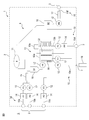
- FIG. 1 shows the configuration of the cell manufacturing apparatus 1 in this embodiment.
- the cell manufacturing apparatus 1 is a cell induction apparatus having a cell induction function of performing cell reprogramming, reprogramming, fate conversion, direct reprogramming, differentiation conversion, differentiation induction, transformation, etc. by introducing an inducing factor.
- a cell culture apparatus having only a cell culture function for simply culturing, expanding culture, or the like may be used.
- the cell manufacturing apparatus 1 injects a fluid containing original cells (for example, somatic cells such as blood cells and fibroblasts, or stem cells such as ES cells and iPS cells), and the target cells (for example, stem cells and precursor cells, etc.) are injected from the original cells.
- original cells for example, somatic cells such as blood cells and fibroblasts, or stem cells such as ES cells and iPS cells
- the target cells for example, stem cells and precursor cells, etc.
- the final differentiated cells are produced and the fluid containing the target cells is discharged.
- Target cells include fibroblasts, nerve cells, retinal epithelial cells, hepatocytes, ⁇ cells, renal cells, mesenchymal stem cells, blood cells, megacariosites, T cells, chondrocytes, myocardial cells, muscle cells, and vascular cells.
- Epithelial cells, renal cells, or other differentiated cells such as somatic cells may be produced.
- the cell manufacturing apparatus 1 is a closed system cell processing apparatus in which all the parts that should be highly clean are integrated inside, and can be used in a normal controlled area.
- the enclosed space inside the device is configured so as not to exchange gases, viruses, microorganisms, impurities, etc. with the outside.
- a fluid that is not a pollution source may be interchangeable between the inside and the outside of the device by additionally providing a fluid exchange filter or the like described later in the device.
- the cell production apparatus 1 includes a cell production plate 2 and a closed connector 3.
- the cell production plate 2 includes a closed fluid circuit 4 shielded from the external space S, and the fluid circuit 4 has a flow path in which a plurality of functional sites are highly integrated.
- the closed connector 3 is a connector for injecting a fluid into the fluid circuit 4 or discharging the fluid from the fluid circuit 4, and is attached to the cell production plate 2.
- the closed connector 3 is a connector for closedly connecting the fluid circuit 4 and the fluid container to the external space S, and may be, for example, a sterile connection connector, a needleless connector, a needle connector, a heat fusing tube, or the like.
- the needleless connector may be a split septum type or a mechanical valve type.
- the fluid container is a syringe, a variable volume bag, or the like, and the fluid circuit 4 communicates with the fluid container when the closed connector 3 and the fluid container are connected, while the fluid is connected when the closed connector 3 and the fluid container are not connected.
- the circuit 4 is cut off from the external space S. This can prevent biological contamination, cross-contamination, and biohazard of the fluid circuit 4.
- the cell manufacturing apparatus 1 preferably includes a plurality of closed connectors 3 in order to allow injection or discharge of a plurality of types of fluids.
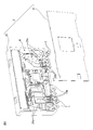
- FIG. 2 shows an example of the cell production plate 2.
- the cell production plate 2 includes a flat plate 20 and a lid 21.
- the flat plate 20 can be formed of, for example, a biologically safe resin, metal, or the like.
- the flat plate 20 is preferably molded by molding processing using a mold, for example, injection molding, compression molding, or the like, but the flat plate 20 may be molded using a 3D printer or the like.
- As the 3D printer various modeling methods such as stereolithography, fused deposition modeling, powder sintering, and inkjet can be adopted.
- a groove 20a is provided as a flow path for flowing a fluid on at least one of the front surface and the back surface of the flat plate 20, and a fluid circuit 4 is formed by combining a plurality of grooves 20a. Further, a portion where the width or depth of the groove 20a is relatively large is provided in a part of the fluid circuit 4, and a storage tank 20b for temporarily storing the fluid is formed.
- the walls of the groove 20a and the storage tank 20b may be coated with poly-HEMA (poly2-hydroxyethylmethacrylate) to make the cells non-adhesive.
- the walls of the groove 20a and the storage tank 20b may be made low in protein adsorption.
- At least a part of the groove 20a and the storage tank 20b is preferably white or black in order to observe changes over time in fluids, cells, cell clusters, etc. with an image recognition sensor, an ultrasonic recognition sensor, or the like.
- the lid 21 may be made of, for example, a biologically safe resin, quartz glass, or the like.
- the lid 21 (that is, at least a part of the cell preparation plate 2) is transparent because the change with time of the fluid, cells, cell mass, etc. in the fluid circuit 4 is observed by an image recognition sensor, an ultrasonic recognition sensor, or the like. Is preferable. This observation makes it possible to move to the next cell manufacturing process at an appropriate timing.
- the lid 21 is fixed to the flat plate 20 so as to cover the fluid circuit 4 by a biologically safe fixing method such as chemical bond, welding bond, adhesive bond or the like.
- a silane coupling agent, plasma irradiation or the like may be used.
- the cell preparation plate 2 is sterilized by heat sterilization, gamma ray sterilization, ultraviolet ray sterilization, electron beam sterilization, or the like to bring the fluid circuit 4 into a highly clean state.
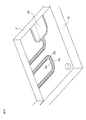
- FIGS. 3A-3B show an example of a method of fixing the flat plate and the lid.
- bank portions 20c are formed in advance on both sides of the groove 20a and the storage tank 20b, the flat plate 20 is covered with a lid 21, and at least the bank portion 20c is exposed to laser light, ultrasonic waves, or the like.
- the groove 20a and the storage tank 20b may be sealed by irradiating or applying to heat the bank portion 20c and welding the flat plate 20 and the lid 21.
- the flat plate 20 including the groove 20a and the storage tank 20b is covered with a lid 21, and at least a portion other than the groove 20a and the storage tank 20b is heated by irradiating or applying laser light, ultrasonic waves, or the like to the flat plate 20.
- the groove 20a and the storage tank 20b may be sealed by welding the lid 21. In this case, all the portions other than the groove 20a and the storage tank 20b are fixed, so that the fixing strength is increased.
- the fluid circuit 4 includes at least an injection / discharge unit 10 and a cell induction culture unit 13 as a plurality of functional sites.
- the fluid circuit 4 may include a volume variable section 11, a transfer section 12, a fluid reservoir 14, a fluid mixing section 15, a cell separation section 16, and a cell mass crushing section 17. Since these various functional sites are integrated in one cell production plate 2, the manufacturing process of connecting separate parts in a closed manner via a tube, a pump, a connector, or the like becomes unnecessary, and the cell manufacturing apparatus 1 is manufactured. Man-hours, manufacturing costs, etc. are reduced.
- the injection / discharge unit 10 includes an injection / discharge channel for injecting or discharging a fluid into the fluid circuit 4 via the closed connector 3.
- the injection / discharge unit 10 preferably includes a plurality of injection / discharge channels 10a-10f.
- the first injection / discharge channel 10a can inject or discharge a fluid or the like containing the original cells
- the second injection / discharge channel 10b is a fluid such as a reagent for separating the original cells, an anticoagulant, or a phosphate buffered saline. Can be injected or discharged.
- the third injection / discharge channel 10c can inject or discharge a fluid such as an inducer-introducing reagent
- the fourth injection / discharge channel 10d is used for various media such as initialization or induction medium, trypsin alternative recombinant enzyme and the like. Fluids such as cell detachment reagent, single cell separation reagent, and intercellular adhesive detachable agent can be injected or discharged.
- the induction medium includes an initialization medium, a reprogramming medium, a fate conversion medium, a direct programming medium, a transdifferentiation medium, a differentiation induction medium, a transformation medium and the like.
- the fifth injection / discharge channel 10e can discharge or inject a fluid containing cells subjected to at least one of induction and culture into the fluid container 19 as a sample
- the sixth injection / discharge channel 10f can discharge or inject the fluid containing the target cells into the fluid container. Can be discharged or injected into.
- the fluid container 19 for discharging the sample may be a closed connector 3, for example, a variable volume bag connected to a heat fusing tube or the like.
- a refrigerant such as liquid nitrogen may be supplied around the sixth injection / discharge channel 10f to freeze the fluid containing the target cells to seal the cell preparation plate.
- the fluid container discharged from the sixth injection / discharge channel 10f via the closed connector 3 may be frozen with a refrigerant such as liquid nitrogen.
- the variable volume unit 11 includes a physical or chemical variable volume material that stores the fluid extruded or drawn out by the injected or discharged fluid.
- a fluid escape flow path for releasing the fluid originally contained in the fluid circuit 4 is provided, and a physical volume variable material is connected to the fluid release flow path, or a pressure valve that opens and closes at a constant pressure is provided in the fluid release flow path.
- the physically variable volume material may be, for example, a flexible bag, a syringe, or the like.
- the chemically variable volume material may include, for example, a fluid absorber such as soda lime or silica gel, and a fluid release agent placed in a storage tank different from the storage tank in which the fluid absorbent is placed. Due to the volume variable material, the internal pressure of the closed fluid circuit 4 becomes substantially constant, and the fluid extruded or drawn out by the injected or discharged fluid is confined in the cell production plate 2, so that it is outside the cell production plate 2. It is not necessary to let the fluid escape or take in the fluid from the outside, and the cell production plate 2 can be formed into a plate shape while maintaining the airtightness of the fluid circuit 4. Such a cell preparation plate 2 is easy for the robot to handle.
- a fluid absorber such as soda lime or silica gel
- a fluid release agent placed in a storage tank different from the storage tank in which the fluid absorbent is placed. Due to the volume variable material, the internal pressure of the closed fluid circuit 4 becomes substantially constant, and the fluid extruded or drawn out by the injected or discharged fluid is confined in
- the transfer unit 12 includes a pump that transfers a fluid in the fluid circuit 4.
- the pump may be a positive displacement pump whose flow rate can be controlled, for example, a rotary pump, a reciprocating pump, or the like.
- a peristaltic pump is preferable.
- a flexible tube is hermetically connected to a connector provided at the end of the flow path, and the fluid is transferred by handling the tube with a roller. Since the tube is blocked by a roller, the fluid flow is blocked when the pump is stopped, and the flow rate can be controlled.
- a diaphragm pump is desirable as the reciprocating pump. However, in the case of a diaphragm pump, since the diaphragm does not shut off the flow path, the flow rate can be controlled by using the flow path shutoff valve together.
- the transfer unit 12 includes a plurality of pumps P1-P8.
- the first pump P1-the third pump P3 transfers the fluid stored in the fluid reservoirs A1-A3 at an appropriate timing
- the fourth pump P4 and the eighth pump P8 appropriately transfer the fluid stored in the cell separation unit 16. Transfer at the right timing.
- the fifth pump P5 transfers the fluid stored in the fluid reservoir A4 at an appropriate timing
- the sixth pump P6-seventh pump P7 transfers the fluid stored in the cell induction culture unit 13 at an appropriate timing.
- the rotation of the pump is used to obtain information on whether the pump is operating normally, such as whether the pump has rotated reliably or by an appropriate angle.
- a rotary encoder capable of detecting the amount of rotation may be provided on the spindle.
- a visual mark may be provided at the end of the rotation spindle of the pump, and the rotational movement of the mark may be directly captured by an image recognition sensor.
- a flow rate measuring unit (not shown) may be further provided in the front stage or the rear stage of the pump.
- the flow rate measuring unit captures, for example, a flow rate sensor provided adjacent to at least one of the flow path and the storage tank communicating with the transfer unit, or an image of a change in fluid over time in at least one of the flow path and the storage tank communicating with the transfer unit.
- An image recognition sensor or the like that captures the image may be used.
- the flow rate sensor can employ various measurement methods that do not adversely affect cells, such as the Karman vortex type, impeller type, and diaphragm type, and directly acquires the flow rate information of the fluid.
- the image recognition sensor acquires flow rate information from the movement of the fluid by recognizing an image from an external camera or the like via a transparent lid 21. As the image recognition sensor, other image recognition sensors described in this document may be diverted, whereby the number of parts and the manufacturing cost can be reduced.
- the cell-induced culture unit 13 includes a cell-induced culture tank 13a that induces and cultures cells based on the transferred fluid, a medium circulation path 13b that communicates with the cell-induced culture tank 13a and circulates the medium. It has.
- the cell induction culture tank 13a is heated to a predetermined culture temperature, for example, 37 ° C. by a heating element.
- the medium circulation passage 13b is cooled to a predetermined medium quality maintenance temperature, for example, 4 ° C. to 8 ° C. by a cooling element.
- the cell induction culture tank 13a is in a closed state and does not need to be supplied with a fluid such as carbon dioxide, nitrogen, oxygen, etc., but carbon dioxide, carbon dioxide, is supplied to at least one of the cell induction culture tank 13a and the medium circulation path 13b.
- a fluid exchange filter for exchanging fluids such as nitrogen and oxygen inside and outside the apparatus may be further provided.
- the cell induction culture tank 13a may be a three-dimensional culture tank for performing cell suspension culture, but may also be a two-dimensional culture tank for performing adhesive culture.
- the cell induction culture tank 13a may be coated with a cell adhesion coating agent such as matrigel, collagen, polylysine, fibronectin, vitronectin, gelatin, and laminin, laminin fragment, or hollow threads. It may be filled. Further, the cell-induced culture tank 13a may integrally include a culture tank 30 and a medium tank 31 for supplying a medium to the culture tank 30. In this case, it is preferable that the cell-induced culture tank 13a is provided with a specific component permeation member 32, for example, a semipermeable membrane, which allows only specific components to flow between the culture tank 30 and the medium tank 31. The specific component permeation member 32 permeates specific components such as various media, cell adhesion coating agents, and cell detachment reagents.
- a cell adhesion coating agent such as matrigel, collagen, polylysine, fibronectin, vitronectin, gelatin, and laminin, laminin fragment, or hollow threads. It may be filled.
- the cell-induced culture unit 13 may further include a pH measuring unit 13c for measuring the pH value of the medium used.
- the pH measuring unit 13c is preferably provided in the medium circulation channel 13b or the cell induction culture tank 13a in order to measure the pH value of the medium used.
- the pH measuring unit 13c may be, for example, an image recognition sensor, an electrode measuring sensor, or the like.
- the image recognition sensor measures the pH value with an external camera or the like through a transparent lid.
- the electrode measurement sensor measures the pH value by the glass electrode method. In the case of hue measurement, the hue can be accurately detected by making at least a part of the medium circulation path 13b (for example, the bottom surface of the hue measurement portion) white. This pH value makes it possible to quantitatively grasp the state of the medium.
- illumination is applied from at least one of the front, the peripheral direction (for example, the direction orthogonal to the observation surface), and the rear of the cell induction culture tank 13a. It is preferable that the portion is further provided.
- the lighting unit may include, for example, LED lighting, and may be embedded inside the cell production plate 2, or the cell induction culture tank 13a may be provided outside the cell production plate 2 so as to be more convex than the cell production plate 2.
- the culture tank 30 may be covered with a transparent member that allows light to pass through so that the illumination reaches the cells.
- the fluid storage unit 14 includes a storage tank for storing fluid to be injected into the fluid circuit 4 or discharged to the outside of the fluid circuit 4.
- the fluid storage unit 14 includes a plurality of storage tanks A1-A4.
- the storage tanks A1-A4 are formed as locations where the width or depth of the flow path is relatively large, and enable various fluids to be used in a predetermined amount at an appropriate timing.
- the first storage tank A1 stores a fluid containing original cells
- the second storage tank A2 stores fluids such as a reagent for separating original cells, an anticoagulant, and a phosphate buffered saline, and stores a third.
- the tank A3 stores fluids such as an inducer-introducing reagent
- the fourth liquid storage tank A4 stores fluids such as various media, cell adhesion coating agents, and cell detachment reagents. It may be provided with a storage tank for storing a fluid or the like containing a target cell.
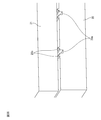
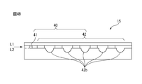
- the fluid mixing unit 15 is provided with a mixing flow path for mixing a plurality of fluids that are immiscible with each other.
- 4A-4B show an example of a mixing flow path.
- the mixing flow path 40 preferably includes a fluid mixing flow path 41 and a mixing flow generation path 42.
- the fluid merging flow path 41 is a flow path for merging the mutually immiscible fluids L1-L2 into one flow path
- the mixed flow generation path 42 is a flow path for generating a mixed flow in the merging fluid L1-L2. ..
- the mixed flow generation path 42 is, for example, a flow path in which the cross-sectional area of the flow path is discontinuously changed, and at least one of the flow path width and the flow path depth is changed in a direction different from the traveling direction of the fluid. Is preferable.
- the mixed flow generation path 42 includes a flow path width changing portion 42a and a flow path depth changing portion 42b alternately with respect to the traveling direction of the fluid.
- the mixed flow generation path 42 may be a spiral flow path penetrating from the front surface to the back surface of the flat plate.
- two spiral flow paths penetrating the flat plate are provided, and a communication passage for fluid communication between these spiral flow paths is provided on the back surface of the flat plate.
- the cell separation unit 16 includes separation tanks D1-D2 for separating cells or cell clusters.
- the separation tanks D1-D2 are storage tanks formed by relatively increasing the width or depth of the flow path, and the first separation tank D1 changes from a fluid containing original cells to a fluid containing only original cells.
- the second separation tank D2 separates from other cell masses by precipitating only a relatively large cell mass.
- a reagent for separating the original cells panning, magnetic cell separation (MACS), flow cytometry and the like can be used.
- the cell mass crushing unit 17 is provided with a crushing flow path for further crushing the separated cell mass (mass of one or more cells).
- FIG. 5 shows an example of a crushing flow path.
- the crushing flow path 50 has a relatively small flow path area as compared with the upstream flow path 51, and preferably meanders. By meandering the flow path, a latent flow is generated, and shear stress is applied to the cell mass to decompose the large cell mass into small cell masses.
- a subsurface current is, for example, a flow that causes a swirl, a turbulent flow, a backflow, a flow that causes a part having a different flow speed, a flow that causes a shearing force, and a flow that causes a part where a flow having a different traveling direction collides. Say one of.
- FIG. 6 shows an example of the cross flow path.
- the cross flow path includes a first flow path 60 extending in the X direction and a second flow path 61 extending in the Y direction different from the X direction on the front side of the cell production plate 2, and the first flow path 60 Provided a detour 62 extending toward the back side of the cell production plate 2 and bypassing the second flow path 61.
- the detour circuit 62 may include two through holes 62a-62b penetrating from the front surface to the back surface of the flat plate 20, and a communication passage 62c communicating the through holes 62a-62b with each other on the back surface of the flat plate 20.
- a communication passage 62c communicating the through holes 62a-62b with each other on the back surface of the flat plate 20.
- the lid 21 is provided with a front lid 21a covering the front surface of the flat plate 20 and a back cover 21b covering the back surface of the flat plate 20.
- Such cross-channels make it possible to provide a small cell production plate 2 with a highly integrated fluid circuit 4.
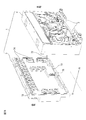
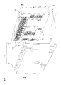
- the cell production apparatus 1 further includes a base plate that is detachably connected to the cell production plate 2.
- 7A-7B show an example of a base plate.
- the base plate 5 controls the fluid, temperature, etc. of the cell production plate 2.
- the cell preparation plate 2 is arranged so as to face the dangerous area side 70 on which the robot or the like acts, while the base plate 5 faces the safe area side 71 opposite to the dangerous area side 70. Be placed. From the viewpoint of preventing biological contamination, the cell production plate 2 may be disposable and the base plate 5 may be reused. Further, the cell manufacturing apparatus 1 is configured to be maintainable from the safety area side 71. When the cell manufacturing apparatus 1 is provided with such a two-sided structure, a robot or the like can be involved with a plurality of cell manufacturing apparatus 1 on a one-to-many basis.
- the cell manufacturing apparatus 1 may further include a positioning member 72 and a plate sealing member 73 on the connecting surface between the cell production plate 2 and the base plate 5.
- the positioning member 72 may be a convex portion or a concave portion that fits each other, and positions the connection position between the cell production plate 2 and the base plate 5.
- the plate sealing member 73 may be a gasket, packing, or the like attached to the outer periphery of the connecting surface.
- the drive unit 74 includes, for example, a motor that drives a peristaltic pump. Further, it is preferable that the connecting surface between the cell production plate 2 and the base plate 5 is provided with an electric contact 75 for supplying electric power to an electric element arranged on the cell production plate 2, such as a heating element, a cooling element, and a flow rate sensor.
- the manufacturing apparatus 1 since a plurality of functional sites are integrated in one cell production plate 2, it is not necessary to connect separate parts in a closed manner via a tube, a pump, a connector, or the like, and the cells are eliminated.
- the production of the manufacturing apparatus 1 is rationalized.
- the fluid extruded or withdrawn by the injected or discharged fluid is confined in the cell production plate 2, there is no need to let the fluid escape to the outside of the cell production plate 2 or take in the fluid from the outside. It becomes possible to form the cell production plate 2 in a plate shape while maintaining the airtightness of the fluid circuit.
- Such a plate-shaped cell production plate 2 is easy for the robot to handle and improves compatibility with the automation system.
Priority Applications (4)
| Application Number | Priority Date | Filing Date | Title |
|---|---|---|---|
| EP20856545.7A EP4023741A4 (en) | 2019-08-29 | 2020-05-28 | DEVICE FOR CELL PRODUCTION AND METHOD FOR CELL PRODUCTION |
| CN202080062103.4A CN114341341A (zh) | 2019-08-29 | 2020-05-28 | 细胞制造装置及其制造方法 |
| JP2021542013A JP7391339B2 (ja) | 2019-08-29 | 2020-05-28 | 細胞製造装置及びその製造方法 |
| US17/637,812 US20230038829A1 (en) | 2019-08-29 | 2020-05-28 | Cell production device and cell production method |
Applications Claiming Priority (2)
| Application Number | Priority Date | Filing Date | Title |
|---|---|---|---|
| US201962893605P | 2019-08-29 | 2019-08-29 | |
| US62/893,605 | 2019-08-29 |
Publications (1)
| Publication Number | Publication Date |
|---|---|
| WO2021038996A1 true WO2021038996A1 (ja) | 2021-03-04 |
Family
ID=74683626
Family Applications (1)
| Application Number | Title | Priority Date | Filing Date |
|---|---|---|---|
| PCT/JP2020/021240 WO2021038996A1 (ja) | 2019-08-29 | 2020-05-28 | 細胞製造装置及びその製造方法 |
Country Status (5)
| Country | Link |
|---|---|
| US (1) | US20230038829A1 (zh) |
| EP (1) | EP4023741A4 (zh) |
| JP (1) | JP7391339B2 (zh) |
| CN (1) | CN114341341A (zh) |
| WO (1) | WO2021038996A1 (zh) |
Cited By (2)
| Publication number | Priority date | Publication date | Assignee | Title |
|---|---|---|---|---|
| TWI796893B (zh) * | 2021-12-23 | 2023-03-21 | 財團法人工業技術研究院 | 細胞與組織層片成型包裝與細胞灌注設備 |
| WO2023221023A1 (zh) * | 2022-05-19 | 2023-11-23 | 京东方科技集团股份有限公司 | 基因检测基板、基因检测芯片及基因检测样本的制备方法 |
Citations (19)
| Publication number | Priority date | Publication date | Assignee | Title |
|---|---|---|---|---|
| JPH09500818A (ja) * | 1993-05-07 | 1997-01-28 | バイオスコット リミテッド | 細胞培養に使用される粒子沈降タンク |
| JP2002512783A (ja) | 1998-04-27 | 2002-05-08 | アメルシャム ファルマシア バイオテック ユー ケイ リミテッド | 細胞に基づく検定に用いる微細加工された装置 |
| JP2005080607A (ja) | 2003-09-10 | 2005-03-31 | National Food Research Institute | 細胞培養プレートおよびその製造方法 |
| WO2007052716A1 (ja) | 2005-11-01 | 2007-05-10 | Medinet Co., Ltd. | 細胞培養装置、細胞培養方法、細胞培養プログラム、及び細胞培養システム |
| JP4183742B1 (ja) | 2005-12-13 | 2008-11-19 | 国立大学法人京都大学 | 誘導多能性幹細胞の製造方法 |
| CN103667054A (zh) * | 2013-09-18 | 2014-03-26 | 中国航天员科研训练中心 | 一种集成化微流控细胞培养芯片及其制备方法 |
| WO2014049701A1 (ja) | 2012-09-26 | 2014-04-03 | 株式会社日立製作所 | 細胞培養容器およびそれを用いた細胞培養装置 |
| JP2014064475A (ja) * | 2012-09-24 | 2014-04-17 | Terumo Corp | 膜状組織の保存輸送容器および保存輸送方法 |
| JP2014226623A (ja) | 2013-05-24 | 2014-12-08 | 株式会社島津製作所 | マイクロチップ反応装置 |
| JP2017046592A (ja) * | 2014-01-09 | 2017-03-09 | 東京エレクトロン株式会社 | 細胞培養容器および細胞継代培養システム並びに細胞継代培養方法 |
| WO2017038887A1 (ja) * | 2015-08-31 | 2017-03-09 | アイ・ピース株式会社 | 多能性幹細胞製造システム |
| WO2017154880A1 (ja) | 2016-03-08 | 2017-09-14 | 国立研究開発法人産業技術総合研究所 | 細胞培養装置および細胞培養方法 |
| JP2017221166A (ja) | 2016-06-17 | 2017-12-21 | 株式会社アイカムス・ラボ | 細胞培養装置 |
| JP2018019685A (ja) | 2016-08-04 | 2018-02-08 | ファナック株式会社 | 幹細胞製造システム、幹細胞情報管理システム、細胞輸送設備、及び幹細胞冷凍保存設備 |
| JP2018513684A (ja) * | 2015-04-22 | 2018-05-31 | バークレー ライツ,インコーポレイテッド | マイクロ流体細胞培養 |
| WO2018154788A1 (ja) | 2017-02-27 | 2018-08-30 | 剛士 田邊 | 体細胞製造システム |
| WO2019043130A1 (en) * | 2017-08-31 | 2019-03-07 | Philip Morris Products S.A. | CELL CULTURE PLATE, IN VITRO EXPOSURE DEVICES AND METHODS |
| WO2020040135A1 (ja) * | 2018-08-20 | 2020-02-27 | 剛士 田邊 | 細胞の培養又は誘導方法 |
| WO2020040118A1 (ja) * | 2018-08-20 | 2020-02-27 | アイ ピース, インコーポレイテッド | 細胞培養器 |
Family Cites Families (11)
| Publication number | Priority date | Publication date | Assignee | Title |
|---|---|---|---|---|
| US6645432B1 (en) * | 2000-05-25 | 2003-11-11 | President & Fellows Of Harvard College | Microfluidic systems including three-dimensionally arrayed channel networks |
| AU2003218572B2 (en) * | 2002-04-08 | 2009-08-20 | Octane Biotech, Inc. | Automated tissue engineering system |
| TW200702660A (en) | 2003-11-21 | 2007-01-16 | Ebara Corp | Microfluidic treatment method and device |
| JP2005287425A (ja) * | 2004-03-31 | 2005-10-20 | Koojin Bio Kk | 培地バッグ付き培養バッグ |
| WO2006043642A1 (ja) | 2004-10-20 | 2006-04-27 | Ebara Corporation | 流体反応装置 |
| JP2007136322A (ja) | 2005-11-17 | 2007-06-07 | Konica Minolta Medical & Graphic Inc | 反応物質同士の拡散および反応を効率化したマイクロリアクタ、およびそれを用いた反応方法 |
| CN103068962B (zh) | 2010-08-12 | 2015-08-05 | 株式会社日立制作所 | 自动培养装置 |
| WO2013175580A1 (ja) * | 2012-05-23 | 2013-11-28 | 株式会社日立製作所 | 培養容器及び自動培養装置 |
| JP6727617B2 (ja) * | 2014-12-18 | 2020-07-22 | ジーイー・ヘルスケア・ユーケイ・リミテッド | バイオリアクターから廃棄物を収集するための装置、方法及びシステム |
| TWI744230B (zh) * | 2015-04-22 | 2021-11-01 | 美商伯克利之光生命科技公司 | 微流體器件及在該微流體器件中培養生物細胞之方法 |
| US11484879B2 (en) * | 2016-05-02 | 2022-11-01 | Integriculture Inc. | System for aging induction, control device for aging induction, method for controlling aging induction, and program for controlling aging induction |
-
2020
- 2020-05-28 JP JP2021542013A patent/JP7391339B2/ja active Active
- 2020-05-28 EP EP20856545.7A patent/EP4023741A4/en active Pending
- 2020-05-28 CN CN202080062103.4A patent/CN114341341A/zh active Pending
- 2020-05-28 US US17/637,812 patent/US20230038829A1/en active Pending
- 2020-05-28 WO PCT/JP2020/021240 patent/WO2021038996A1/ja unknown
Patent Citations (19)
| Publication number | Priority date | Publication date | Assignee | Title |
|---|---|---|---|---|
| JPH09500818A (ja) * | 1993-05-07 | 1997-01-28 | バイオスコット リミテッド | 細胞培養に使用される粒子沈降タンク |
| JP2002512783A (ja) | 1998-04-27 | 2002-05-08 | アメルシャム ファルマシア バイオテック ユー ケイ リミテッド | 細胞に基づく検定に用いる微細加工された装置 |
| JP2005080607A (ja) | 2003-09-10 | 2005-03-31 | National Food Research Institute | 細胞培養プレートおよびその製造方法 |
| WO2007052716A1 (ja) | 2005-11-01 | 2007-05-10 | Medinet Co., Ltd. | 細胞培養装置、細胞培養方法、細胞培養プログラム、及び細胞培養システム |
| JP4183742B1 (ja) | 2005-12-13 | 2008-11-19 | 国立大学法人京都大学 | 誘導多能性幹細胞の製造方法 |
| JP2014064475A (ja) * | 2012-09-24 | 2014-04-17 | Terumo Corp | 膜状組織の保存輸送容器および保存輸送方法 |
| WO2014049701A1 (ja) | 2012-09-26 | 2014-04-03 | 株式会社日立製作所 | 細胞培養容器およびそれを用いた細胞培養装置 |
| JP2014226623A (ja) | 2013-05-24 | 2014-12-08 | 株式会社島津製作所 | マイクロチップ反応装置 |
| CN103667054A (zh) * | 2013-09-18 | 2014-03-26 | 中国航天员科研训练中心 | 一种集成化微流控细胞培养芯片及其制备方法 |
| JP2017046592A (ja) * | 2014-01-09 | 2017-03-09 | 東京エレクトロン株式会社 | 細胞培養容器および細胞継代培養システム並びに細胞継代培養方法 |
| JP2018513684A (ja) * | 2015-04-22 | 2018-05-31 | バークレー ライツ,インコーポレイテッド | マイクロ流体細胞培養 |
| WO2017038887A1 (ja) * | 2015-08-31 | 2017-03-09 | アイ・ピース株式会社 | 多能性幹細胞製造システム |
| WO2017154880A1 (ja) | 2016-03-08 | 2017-09-14 | 国立研究開発法人産業技術総合研究所 | 細胞培養装置および細胞培養方法 |
| JP2017221166A (ja) | 2016-06-17 | 2017-12-21 | 株式会社アイカムス・ラボ | 細胞培養装置 |
| JP2018019685A (ja) | 2016-08-04 | 2018-02-08 | ファナック株式会社 | 幹細胞製造システム、幹細胞情報管理システム、細胞輸送設備、及び幹細胞冷凍保存設備 |
| WO2018154788A1 (ja) | 2017-02-27 | 2018-08-30 | 剛士 田邊 | 体細胞製造システム |
| WO2019043130A1 (en) * | 2017-08-31 | 2019-03-07 | Philip Morris Products S.A. | CELL CULTURE PLATE, IN VITRO EXPOSURE DEVICES AND METHODS |
| WO2020040135A1 (ja) * | 2018-08-20 | 2020-02-27 | 剛士 田邊 | 細胞の培養又は誘導方法 |
| WO2020040118A1 (ja) * | 2018-08-20 | 2020-02-27 | アイ ピース, インコーポレイテッド | 細胞培養器 |
Non-Patent Citations (1)
| Title |
|---|
| See also references of EP4023741A4 |
Cited By (2)
| Publication number | Priority date | Publication date | Assignee | Title |
|---|---|---|---|---|
| TWI796893B (zh) * | 2021-12-23 | 2023-03-21 | 財團法人工業技術研究院 | 細胞與組織層片成型包裝與細胞灌注設備 |
| WO2023221023A1 (zh) * | 2022-05-19 | 2023-11-23 | 京东方科技集团股份有限公司 | 基因检测基板、基因检测芯片及基因检测样本的制备方法 |
Also Published As
| Publication number | Publication date |
|---|---|
| CN114341341A (zh) | 2022-04-12 |
| EP4023741A1 (en) | 2022-07-06 |
| EP4023741A4 (en) | 2023-11-08 |
| US20230038829A1 (en) | 2023-02-09 |
| JPWO2021038996A1 (zh) | 2021-03-04 |
| JP7391339B2 (ja) | 2023-12-05 |
Similar Documents
| Publication | Publication Date | Title |
|---|---|---|
| KR102383028B1 (ko) | 일회용 용기 내 업스트리임 및 다운스트리임 처리 | |
| ES2882661T3 (es) | Sistema de matriz de cultivo celular para ensayos automatizados y métodos de funcionamiento y de fabricación del mismo | |
| Gao et al. | Recent developments in microfluidic devices for in vitro cell culture for cell-biology research | |
| WO2021038996A1 (ja) | 細胞製造装置及びその製造方法 | |
| US11566224B2 (en) | Dendritic cell generator | |
| WO2007044088A2 (en) | Biomems cartridges | |
| GB2605767A (en) | Fluidic array systems and testing for cells, organoids, organs culture | |
| US10711234B2 (en) | Microfluidic platform for investigating cell-based interactions | |
| US20220025308A1 (en) | Tissue culture platform having multiple well chambers fluidically coupled via microfluidic channels and selector valves | |
| JP2021520847A (ja) | 流体オートサンプラ及び培養器 | |
| US20230174919A1 (en) | Method for gas enrichment and simultaneously for displacement of a fluid, and system for controlling the cell environment on a corresponding multi-well cell culture plate | |
| US20220306981A1 (en) | Erythrocyte removal device, mononuclear cell collector, cell culture device, cell culture system, cell culture method, and method for collecting mononuclear cells | |
| US11958050B2 (en) | Fluidic devices for closed cell culture applications under current good manufacturing practice | |
| CN206215248U (zh) | 一种负压引导的微流体自律运动的微流控芯片 | |
| WO2021038997A1 (ja) | 細胞製造装置 | |
| WO2021038998A1 (ja) | 細胞製造装置及びそのシステム | |
| CN106391153B (zh) | 一种负压引导的微流体自律运动的微流控芯片 | |
| CN109055204B (zh) | 药物筛选用器官芯片 | |
| WO2010077784A1 (en) | Test cartridges for flow assays and methods for their use | |
| Yan | Development of an epoxy-based microfluidic device for automated circulating tumour cell separation | |
| CN111566198A (zh) | 平面模块化微流体系统 | |
| Schneider | Organ-on-a-Disc: A Scalable Platform Technology for the Generation and Cultivation of Microphysiological Tissues | |
| Perozziello et al. | Microfluidics for Cellular Applications | |
| CN116445278A (zh) | 一种微流控细胞培养芯片 | |
| Macown | Microfabricated Devices for Adherent Stem Cell Culture |
Legal Events
| Date | Code | Title | Description |
|---|---|---|---|
| 121 | Ep: the epo has been informed by wipo that ep was designated in this application |
Ref document number: 20856545 Country of ref document: EP Kind code of ref document: A1 |
|
| ENP | Entry into the national phase |
Ref document number: 2021542013 Country of ref document: JP Kind code of ref document: A |
|
| NENP | Non-entry into the national phase |
Ref country code: DE |
|
| ENP | Entry into the national phase |
Ref document number: 2020856545 Country of ref document: EP Effective date: 20220329 |