WO2021038996A1 - Cell production device and cell production method - Google Patents
Cell production device and cell production method Download PDFInfo
- Publication number
- WO2021038996A1 WO2021038996A1 PCT/JP2020/021240 JP2020021240W WO2021038996A1 WO 2021038996 A1 WO2021038996 A1 WO 2021038996A1 JP 2020021240 W JP2020021240 W JP 2020021240W WO 2021038996 A1 WO2021038996 A1 WO 2021038996A1
- Authority
- WO
- WIPO (PCT)
- Prior art keywords
- fluid
- cell
- fluid circuit
- plate
- cell production
- Prior art date
Links
- 238000004519 manufacturing process Methods 0.000 title claims abstract description 124
- 239000012530 fluid Substances 0.000 claims abstract description 217
- 238000002347 injection Methods 0.000 claims abstract description 27
- 239000007924 injection Substances 0.000 claims abstract description 27
- 230000006698 induction Effects 0.000 claims abstract description 23
- 238000003860 storage Methods 0.000 claims description 37
- 238000012546 transfer Methods 0.000 claims description 21
- 238000000034 method Methods 0.000 claims description 15
- 238000002156 mixing Methods 0.000 claims description 15
- 238000000926 separation method Methods 0.000 claims description 13
- 238000004891 communication Methods 0.000 claims description 8
- 239000000463 material Substances 0.000 claims description 8
- 230000002572 peristaltic effect Effects 0.000 claims description 8
- 238000007599 discharging Methods 0.000 claims description 6
- 238000007789 sealing Methods 0.000 claims description 5
- 238000000465 moulding Methods 0.000 claims description 4
- 230000000149 penetrating effect Effects 0.000 claims description 4
- 230000008569 process Effects 0.000 claims description 4
- 238000004113 cell culture Methods 0.000 abstract description 21
- 210000004027 cell Anatomy 0.000 description 186
- IJGRMHOSHXDMSA-UHFFFAOYSA-N Atomic nitrogen Chemical compound N#N IJGRMHOSHXDMSA-UHFFFAOYSA-N 0.000 description 10
- 239000003153 chemical reaction reagent Substances 0.000 description 9
- CURLTUGMZLYLDI-UHFFFAOYSA-N Carbon dioxide Chemical compound O=C=O CURLTUGMZLYLDI-UHFFFAOYSA-N 0.000 description 8
- 230000008672 reprogramming Effects 0.000 description 7
- 239000000853 adhesive Substances 0.000 description 6
- 230000001070 adhesive effect Effects 0.000 description 6
- 239000007788 liquid Substances 0.000 description 6
- 210000001082 somatic cell Anatomy 0.000 description 6
- 210000000130 stem cell Anatomy 0.000 description 6
- 238000003466 welding Methods 0.000 description 6
- 230000008859 change Effects 0.000 description 5
- 230000004069 differentiation Effects 0.000 description 5
- 229910052757 nitrogen Inorganic materials 0.000 description 5
- 238000002360 preparation method Methods 0.000 description 5
- 229910002092 carbon dioxide Inorganic materials 0.000 description 4
- 239000001569 carbon dioxide Substances 0.000 description 4
- 238000006243 chemical reaction Methods 0.000 description 4
- 238000011109 contamination Methods 0.000 description 4
- 230000001939 inductive effect Effects 0.000 description 4
- 244000005700 microbiome Species 0.000 description 4
- 108090000623 proteins and genes Proteins 0.000 description 4
- 239000000243 solution Substances 0.000 description 4
- 239000000126 substance Substances 0.000 description 4
- 238000002054 transplantation Methods 0.000 description 4
- 241000700605 Viruses Species 0.000 description 3
- QVGXLLKOCUKJST-UHFFFAOYSA-N atomic oxygen Chemical compound [O] QVGXLLKOCUKJST-UHFFFAOYSA-N 0.000 description 3
- 230000021164 cell adhesion Effects 0.000 description 3
- 239000011248 coating agent Substances 0.000 description 3
- 239000007789 gas Substances 0.000 description 3
- 238000005259 measurement Methods 0.000 description 3
- 239000001301 oxygen Substances 0.000 description 3
- 229910052760 oxygen Inorganic materials 0.000 description 3
- 230000001954 sterilising effect Effects 0.000 description 3
- 238000004659 sterilization and disinfection Methods 0.000 description 3
- 230000009466 transformation Effects 0.000 description 3
- 241000282412 Homo Species 0.000 description 2
- 108010085895 Laminin Proteins 0.000 description 2
- VYPSYNLAJGMNEJ-UHFFFAOYSA-N Silicium dioxide Chemical compound O=[Si]=O VYPSYNLAJGMNEJ-UHFFFAOYSA-N 0.000 description 2
- 239000003146 anticoagulant agent Substances 0.000 description 2
- 229940127219 anticoagulant drug Drugs 0.000 description 2
- 230000004663 cell proliferation Effects 0.000 description 2
- 239000003795 chemical substances by application Substances 0.000 description 2
- 238000012790 confirmation Methods 0.000 description 2
- 238000001816 cooling Methods 0.000 description 2
- 238000012864 cross contamination Methods 0.000 description 2
- 238000012258 culturing Methods 0.000 description 2
- LOKCTEFSRHRXRJ-UHFFFAOYSA-I dipotassium trisodium dihydrogen phosphate hydrogen phosphate dichloride Chemical compound P(=O)(O)(O)[O-].[K+].P(=O)(O)([O-])[O-].[Na+].[Na+].[Cl-].[K+].[Cl-].[Na+] LOKCTEFSRHRXRJ-UHFFFAOYSA-I 0.000 description 2
- 210000002919 epithelial cell Anatomy 0.000 description 2
- 210000002950 fibroblast Anatomy 0.000 description 2
- 238000010438 heat treatment Methods 0.000 description 2
- 238000005286 illumination Methods 0.000 description 2
- 230000001965 increasing effect Effects 0.000 description 2
- 239000000411 inducer Substances 0.000 description 2
- 230000001678 irradiating effect Effects 0.000 description 2
- 238000012423 maintenance Methods 0.000 description 2
- 239000002953 phosphate buffered saline Substances 0.000 description 2
- 238000012545 processing Methods 0.000 description 2
- 102000004169 proteins and genes Human genes 0.000 description 2
- 239000003507 refrigerant Substances 0.000 description 2
- 239000011347 resin Substances 0.000 description 2
- 229920005989 resin Polymers 0.000 description 2
- 239000000758 substrate Substances 0.000 description 2
- 238000011144 upstream manufacturing Methods 0.000 description 2
- 229920002818 (Hydroxyethyl)methacrylate Polymers 0.000 description 1
- 108010035532 Collagen Proteins 0.000 description 1
- 102000008186 Collagen Human genes 0.000 description 1
- 102000004190 Enzymes Human genes 0.000 description 1
- 108090000790 Enzymes Proteins 0.000 description 1
- 102100037362 Fibronectin Human genes 0.000 description 1
- 108010067306 Fibronectins Proteins 0.000 description 1
- 108010010803 Gelatin Proteins 0.000 description 1
- 108700021430 Kruppel-Like Factor 4 Proteins 0.000 description 1
- 241000699670 Mus sp. Species 0.000 description 1
- 101710135898 Myc proto-oncogene protein Proteins 0.000 description 1
- 102100038895 Myc proto-oncogene protein Human genes 0.000 description 1
- 208000018737 Parkinson disease Diseases 0.000 description 1
- 108010039918 Polylysine Proteins 0.000 description 1
- 101100247004 Rattus norvegicus Qsox1 gene Proteins 0.000 description 1
- 101150086694 SLC22A3 gene Proteins 0.000 description 1
- 239000006087 Silane Coupling Agent Substances 0.000 description 1
- 210000001744 T-lymphocyte Anatomy 0.000 description 1
- 101710150448 Transcriptional regulator Myc Proteins 0.000 description 1
- 102000004142 Trypsin Human genes 0.000 description 1
- 108090000631 Trypsin Proteins 0.000 description 1
- 206010067584 Type 1 diabetes mellitus Diseases 0.000 description 1
- 108010031318 Vitronectin Proteins 0.000 description 1
- 102100035140 Vitronectin Human genes 0.000 description 1
- 239000002250 absorbent Substances 0.000 description 1
- 230000002745 absorbent Effects 0.000 description 1
- 239000006096 absorbing agent Substances 0.000 description 1
- 230000002411 adverse Effects 0.000 description 1
- 238000003556 assay Methods 0.000 description 1
- 210000000227 basophil cell of anterior lobe of hypophysis Anatomy 0.000 description 1
- 210000000601 blood cell Anatomy 0.000 description 1
- 210000001612 chondrocyte Anatomy 0.000 description 1
- 229920001436 collagen Polymers 0.000 description 1
- 238000000748 compression moulding Methods 0.000 description 1
- 230000008021 deposition Effects 0.000 description 1
- 238000010586 diagram Methods 0.000 description 1
- 201000010099 disease Diseases 0.000 description 1
- 208000037265 diseases, disorders, signs and symptoms Diseases 0.000 description 1
- 238000006073 displacement reaction Methods 0.000 description 1
- 229940079593 drug Drugs 0.000 description 1
- 239000003814 drug Substances 0.000 description 1
- 238000010894 electron beam technology Methods 0.000 description 1
- 210000001671 embryonic stem cell Anatomy 0.000 description 1
- 238000005516 engineering process Methods 0.000 description 1
- 239000010419 fine particle Substances 0.000 description 1
- 238000000684 flow cytometry Methods 0.000 description 1
- 239000012634 fragment Substances 0.000 description 1
- 238000004388 gamma ray sterilization Methods 0.000 description 1
- 239000008273 gelatin Substances 0.000 description 1
- 229920000159 gelatin Polymers 0.000 description 1
- 235000019322 gelatine Nutrition 0.000 description 1
- 235000011852 gelatine desserts Nutrition 0.000 description 1
- 239000011521 glass Substances 0.000 description 1
- 210000003494 hepatocyte Anatomy 0.000 description 1
- 239000012535 impurity Substances 0.000 description 1
- 210000004263 induced pluripotent stem cell Anatomy 0.000 description 1
- 238000001746 injection moulding Methods 0.000 description 1
- 238000011081 inoculation Methods 0.000 description 1
- 208000032839 leukemia Diseases 0.000 description 1
- 108010082117 matrigel Proteins 0.000 description 1
- 238000000691 measurement method Methods 0.000 description 1
- 239000012528 membrane Substances 0.000 description 1
- 210000002901 mesenchymal stem cell Anatomy 0.000 description 1
- 239000002184 metal Substances 0.000 description 1
- 238000012986 modification Methods 0.000 description 1
- 230000004048 modification Effects 0.000 description 1
- 210000000663 muscle cell Anatomy 0.000 description 1
- 230000002107 myocardial effect Effects 0.000 description 1
- 210000002569 neuron Anatomy 0.000 description 1
- 108020004707 nucleic acids Proteins 0.000 description 1
- 102000039446 nucleic acids Human genes 0.000 description 1
- 150000007523 nucleic acids Chemical class 0.000 description 1
- 210000000056 organ Anatomy 0.000 description 1
- 238000001139 pH measurement Methods 0.000 description 1
- 238000012856 packing Methods 0.000 description 1
- 238000004091 panning Methods 0.000 description 1
- 239000002245 particle Substances 0.000 description 1
- 244000052769 pathogen Species 0.000 description 1
- 230000001717 pathogenic effect Effects 0.000 description 1
- 230000002093 peripheral effect Effects 0.000 description 1
- 239000012466 permeate Substances 0.000 description 1
- 230000035479 physiological effects, processes and functions Effects 0.000 description 1
- 229920002338 polyhydroxyethylmethacrylate Polymers 0.000 description 1
- 229920000656 polylysine Polymers 0.000 description 1
- 239000000843 powder Substances 0.000 description 1
- 230000001376 precipitating effect Effects 0.000 description 1
- 239000002243 precursor Substances 0.000 description 1
- 238000004321 preservation Methods 0.000 description 1
- 230000002207 retinal effect Effects 0.000 description 1
- 238000010008 shearing Methods 0.000 description 1
- 239000000741 silica gel Substances 0.000 description 1
- 229910002027 silica gel Inorganic materials 0.000 description 1
- 238000005245 sintering Methods 0.000 description 1
- HUAUNKAZQWMVFY-UHFFFAOYSA-M sodium;oxocalcium;hydroxide Chemical compound [OH-].[Na+].[Ca]=O HUAUNKAZQWMVFY-UHFFFAOYSA-M 0.000 description 1
- 238000001179 sorption measurement Methods 0.000 description 1
- 238000004114 suspension culture Methods 0.000 description 1
- 238000012360 testing method Methods 0.000 description 1
- 239000012588 trypsin Substances 0.000 description 1
- 210000005167 vascular cell Anatomy 0.000 description 1
- 230000000007 visual effect Effects 0.000 description 1
Images


Classifications
-
- C—CHEMISTRY; METALLURGY
- C12—BIOCHEMISTRY; BEER; SPIRITS; WINE; VINEGAR; MICROBIOLOGY; ENZYMOLOGY; MUTATION OR GENETIC ENGINEERING
- C12M—APPARATUS FOR ENZYMOLOGY OR MICROBIOLOGY; APPARATUS FOR CULTURING MICROORGANISMS FOR PRODUCING BIOMASS, FOR GROWING CELLS OR FOR OBTAINING FERMENTATION OR METABOLIC PRODUCTS, i.e. BIOREACTORS OR FERMENTERS
- C12M23/00—Constructional details, e.g. recesses, hinges
- C12M23/42—Integrated assemblies, e.g. cassettes or cartridges
-
- C—CHEMISTRY; METALLURGY
- C12—BIOCHEMISTRY; BEER; SPIRITS; WINE; VINEGAR; MICROBIOLOGY; ENZYMOLOGY; MUTATION OR GENETIC ENGINEERING
- C12M—APPARATUS FOR ENZYMOLOGY OR MICROBIOLOGY; APPARATUS FOR CULTURING MICROORGANISMS FOR PRODUCING BIOMASS, FOR GROWING CELLS OR FOR OBTAINING FERMENTATION OR METABOLIC PRODUCTS, i.e. BIOREACTORS OR FERMENTERS
- C12M41/00—Means for regulation, monitoring, measurement or control, e.g. flow regulation
- C12M41/48—Automatic or computerized control
-
- C—CHEMISTRY; METALLURGY
- C12—BIOCHEMISTRY; BEER; SPIRITS; WINE; VINEGAR; MICROBIOLOGY; ENZYMOLOGY; MUTATION OR GENETIC ENGINEERING
- C12M—APPARATUS FOR ENZYMOLOGY OR MICROBIOLOGY; APPARATUS FOR CULTURING MICROORGANISMS FOR PRODUCING BIOMASS, FOR GROWING CELLS OR FOR OBTAINING FERMENTATION OR METABOLIC PRODUCTS, i.e. BIOREACTORS OR FERMENTERS
- C12M23/00—Constructional details, e.g. recesses, hinges
- C12M23/02—Form or structure of the vessel
- C12M23/04—Flat or tray type, drawers
-
- C—CHEMISTRY; METALLURGY
- C12—BIOCHEMISTRY; BEER; SPIRITS; WINE; VINEGAR; MICROBIOLOGY; ENZYMOLOGY; MUTATION OR GENETIC ENGINEERING
- C12M—APPARATUS FOR ENZYMOLOGY OR MICROBIOLOGY; APPARATUS FOR CULTURING MICROORGANISMS FOR PRODUCING BIOMASS, FOR GROWING CELLS OR FOR OBTAINING FERMENTATION OR METABOLIC PRODUCTS, i.e. BIOREACTORS OR FERMENTERS
- C12M23/00—Constructional details, e.g. recesses, hinges
- C12M23/02—Form or structure of the vessel
- C12M23/10—Petri dish
-
- C—CHEMISTRY; METALLURGY
- C12—BIOCHEMISTRY; BEER; SPIRITS; WINE; VINEGAR; MICROBIOLOGY; ENZYMOLOGY; MUTATION OR GENETIC ENGINEERING
- C12M—APPARATUS FOR ENZYMOLOGY OR MICROBIOLOGY; APPARATUS FOR CULTURING MICROORGANISMS FOR PRODUCING BIOMASS, FOR GROWING CELLS OR FOR OBTAINING FERMENTATION OR METABOLIC PRODUCTS, i.e. BIOREACTORS OR FERMENTERS
- C12M23/00—Constructional details, e.g. recesses, hinges
- C12M23/02—Form or structure of the vessel
- C12M23/14—Bags
-
- C—CHEMISTRY; METALLURGY
- C12—BIOCHEMISTRY; BEER; SPIRITS; WINE; VINEGAR; MICROBIOLOGY; ENZYMOLOGY; MUTATION OR GENETIC ENGINEERING
- C12M—APPARATUS FOR ENZYMOLOGY OR MICROBIOLOGY; APPARATUS FOR CULTURING MICROORGANISMS FOR PRODUCING BIOMASS, FOR GROWING CELLS OR FOR OBTAINING FERMENTATION OR METABOLIC PRODUCTS, i.e. BIOREACTORS OR FERMENTERS
- C12M23/00—Constructional details, e.g. recesses, hinges
- C12M23/22—Transparent or translucent parts
-
- C—CHEMISTRY; METALLURGY
- C12—BIOCHEMISTRY; BEER; SPIRITS; WINE; VINEGAR; MICROBIOLOGY; ENZYMOLOGY; MUTATION OR GENETIC ENGINEERING
- C12M—APPARATUS FOR ENZYMOLOGY OR MICROBIOLOGY; APPARATUS FOR CULTURING MICROORGANISMS FOR PRODUCING BIOMASS, FOR GROWING CELLS OR FOR OBTAINING FERMENTATION OR METABOLIC PRODUCTS, i.e. BIOREACTORS OR FERMENTERS
- C12M23/00—Constructional details, e.g. recesses, hinges
- C12M23/34—Internal compartments or partitions
-
- C—CHEMISTRY; METALLURGY
- C12—BIOCHEMISTRY; BEER; SPIRITS; WINE; VINEGAR; MICROBIOLOGY; ENZYMOLOGY; MUTATION OR GENETIC ENGINEERING
- C12M—APPARATUS FOR ENZYMOLOGY OR MICROBIOLOGY; APPARATUS FOR CULTURING MICROORGANISMS FOR PRODUCING BIOMASS, FOR GROWING CELLS OR FOR OBTAINING FERMENTATION OR METABOLIC PRODUCTS, i.e. BIOREACTORS OR FERMENTERS
- C12M23/00—Constructional details, e.g. recesses, hinges
- C12M23/38—Caps; Covers; Plugs; Pouring means
-
- C—CHEMISTRY; METALLURGY
- C12—BIOCHEMISTRY; BEER; SPIRITS; WINE; VINEGAR; MICROBIOLOGY; ENZYMOLOGY; MUTATION OR GENETIC ENGINEERING
- C12M—APPARATUS FOR ENZYMOLOGY OR MICROBIOLOGY; APPARATUS FOR CULTURING MICROORGANISMS FOR PRODUCING BIOMASS, FOR GROWING CELLS OR FOR OBTAINING FERMENTATION OR METABOLIC PRODUCTS, i.e. BIOREACTORS OR FERMENTERS
- C12M25/00—Means for supporting, enclosing or fixing the microorganisms, e.g. immunocoatings
- C12M25/06—Plates; Walls; Drawers; Multilayer plates
-
- C—CHEMISTRY; METALLURGY
- C12—BIOCHEMISTRY; BEER; SPIRITS; WINE; VINEGAR; MICROBIOLOGY; ENZYMOLOGY; MUTATION OR GENETIC ENGINEERING
- C12M—APPARATUS FOR ENZYMOLOGY OR MICROBIOLOGY; APPARATUS FOR CULTURING MICROORGANISMS FOR PRODUCING BIOMASS, FOR GROWING CELLS OR FOR OBTAINING FERMENTATION OR METABOLIC PRODUCTS, i.e. BIOREACTORS OR FERMENTERS
- C12M27/00—Means for mixing, agitating or circulating fluids in the vessel
- C12M27/02—Stirrer or mobile mixing elements
-
- C—CHEMISTRY; METALLURGY
- C12—BIOCHEMISTRY; BEER; SPIRITS; WINE; VINEGAR; MICROBIOLOGY; ENZYMOLOGY; MUTATION OR GENETIC ENGINEERING
- C12M—APPARATUS FOR ENZYMOLOGY OR MICROBIOLOGY; APPARATUS FOR CULTURING MICROORGANISMS FOR PRODUCING BIOMASS, FOR GROWING CELLS OR FOR OBTAINING FERMENTATION OR METABOLIC PRODUCTS, i.e. BIOREACTORS OR FERMENTERS
- C12M29/00—Means for introduction, extraction or recirculation of materials, e.g. pumps
- C12M29/18—External loop; Means for reintroduction of fermented biomass or liquid percolate
-
- C—CHEMISTRY; METALLURGY
- C12—BIOCHEMISTRY; BEER; SPIRITS; WINE; VINEGAR; MICROBIOLOGY; ENZYMOLOGY; MUTATION OR GENETIC ENGINEERING
- C12M—APPARATUS FOR ENZYMOLOGY OR MICROBIOLOGY; APPARATUS FOR CULTURING MICROORGANISMS FOR PRODUCING BIOMASS, FOR GROWING CELLS OR FOR OBTAINING FERMENTATION OR METABOLIC PRODUCTS, i.e. BIOREACTORS OR FERMENTERS
- C12M33/00—Means for introduction, transport, positioning, extraction, harvesting, peeling or sampling of biological material in or from the apparatus
- C12M33/04—Means for introduction, transport, positioning, extraction, harvesting, peeling or sampling of biological material in or from the apparatus by injection or suction, e.g. using pipettes, syringes, needles
-
- C—CHEMISTRY; METALLURGY
- C12—BIOCHEMISTRY; BEER; SPIRITS; WINE; VINEGAR; MICROBIOLOGY; ENZYMOLOGY; MUTATION OR GENETIC ENGINEERING
- C12M—APPARATUS FOR ENZYMOLOGY OR MICROBIOLOGY; APPARATUS FOR CULTURING MICROORGANISMS FOR PRODUCING BIOMASS, FOR GROWING CELLS OR FOR OBTAINING FERMENTATION OR METABOLIC PRODUCTS, i.e. BIOREACTORS OR FERMENTERS
- C12M35/00—Means for application of stress for stimulating the growth of microorganisms or the generation of fermentation or metabolic products; Means for electroporation or cell fusion
- C12M35/08—Chemical, biochemical or biological means, e.g. plasma jet, co-culture
-
- C—CHEMISTRY; METALLURGY
- C12—BIOCHEMISTRY; BEER; SPIRITS; WINE; VINEGAR; MICROBIOLOGY; ENZYMOLOGY; MUTATION OR GENETIC ENGINEERING
- C12M—APPARATUS FOR ENZYMOLOGY OR MICROBIOLOGY; APPARATUS FOR CULTURING MICROORGANISMS FOR PRODUCING BIOMASS, FOR GROWING CELLS OR FOR OBTAINING FERMENTATION OR METABOLIC PRODUCTS, i.e. BIOREACTORS OR FERMENTERS
- C12M41/00—Means for regulation, monitoring, measurement or control, e.g. flow regulation
- C12M41/30—Means for regulation, monitoring, measurement or control, e.g. flow regulation of concentration
- C12M41/36—Means for regulation, monitoring, measurement or control, e.g. flow regulation of concentration of biomass, e.g. colony counters or by turbidity measurements
-
- C—CHEMISTRY; METALLURGY
- C12—BIOCHEMISTRY; BEER; SPIRITS; WINE; VINEGAR; MICROBIOLOGY; ENZYMOLOGY; MUTATION OR GENETIC ENGINEERING
- C12M—APPARATUS FOR ENZYMOLOGY OR MICROBIOLOGY; APPARATUS FOR CULTURING MICROORGANISMS FOR PRODUCING BIOMASS, FOR GROWING CELLS OR FOR OBTAINING FERMENTATION OR METABOLIC PRODUCTS, i.e. BIOREACTORS OR FERMENTERS
- C12M41/00—Means for regulation, monitoring, measurement or control, e.g. flow regulation
- C12M41/44—Means for regulation, monitoring, measurement or control, e.g. flow regulation of volume or liquid level
-
- C—CHEMISTRY; METALLURGY
- C12—BIOCHEMISTRY; BEER; SPIRITS; WINE; VINEGAR; MICROBIOLOGY; ENZYMOLOGY; MUTATION OR GENETIC ENGINEERING
- C12M—APPARATUS FOR ENZYMOLOGY OR MICROBIOLOGY; APPARATUS FOR CULTURING MICROORGANISMS FOR PRODUCING BIOMASS, FOR GROWING CELLS OR FOR OBTAINING FERMENTATION OR METABOLIC PRODUCTS, i.e. BIOREACTORS OR FERMENTERS
- C12M47/00—Means for after-treatment of the produced biomass or of the fermentation or metabolic products, e.g. storage of biomass
- C12M47/04—Cell isolation or sorting
-
- B—PERFORMING OPERATIONS; TRANSPORTING
- B01—PHYSICAL OR CHEMICAL PROCESSES OR APPARATUS IN GENERAL
- B01L—CHEMICAL OR PHYSICAL LABORATORY APPARATUS FOR GENERAL USE
- B01L3/00—Containers or dishes for laboratory use, e.g. laboratory glassware; Droppers
- B01L3/50—Containers for the purpose of retaining a material to be analysed, e.g. test tubes
- B01L3/502—Containers for the purpose of retaining a material to be analysed, e.g. test tubes with fluid transport, e.g. in multi-compartment structures
- B01L3/5027—Containers for the purpose of retaining a material to be analysed, e.g. test tubes with fluid transport, e.g. in multi-compartment structures by integrated microfluidic structures, i.e. dimensions of channels and chambers are such that surface tension forces are important, e.g. lab-on-a-chip
- B01L3/502707—Containers for the purpose of retaining a material to be analysed, e.g. test tubes with fluid transport, e.g. in multi-compartment structures by integrated microfluidic structures, i.e. dimensions of channels and chambers are such that surface tension forces are important, e.g. lab-on-a-chip characterised by the manufacture of the container or its components
Definitions
- the present invention relates to a cell manufacturing apparatus and a manufacturing method thereof, and more particularly to a cell manufacturing apparatus and a manufacturing method thereof that simultaneously realizes rationalization of manufacturing of the cell manufacturing apparatus and compatibility with an automated system.
- Embryonic stem cells are stem cells established from the early cups of humans and mice, and have pluripotency that allows them to differentiate into all cells existing in the living body.
- Human ES cells are believed to be available for cell transplantation for many diseases such as Parkinson's disease, juvenile diabetes, and leukemia.
- ES cell transplantation has the problem of inducing rejection, similar to organ transplantation.
- iPS cells induced pluripotent stem cells
- Induced stem cells such as iPS cells are established by introducing inducing factors such as genes into cells, and are expanded and cryopreserved.
- inducing factors such as genes
- GLP clinical iPS cells
- a clean room kept very clean is required, and a high maintenance cost is required.
- the issue was how to improve the efficiency of clean room operation methods and strive to reduce costs.
- iPS cells are mostly produced manually, there are few engineers who can produce clinical iPS cells. There is a problem that a series of operations from the establishment of stem cells to their preservation is complicated. In clinical cell culture, it is necessary to perform three steps: confirmation of standard process (SOP: Standard Of Process), operation according to SOP, and confirmation of whether or not it was carried out according to SOP. It is very unproductive for humans to perform these steps. Since cell culture needs to be managed 24 hours a day, and stem cells are preserved for decades, there is a limit to managing them by human resources alone.
- SOP Standard Of Process
- a closed cell production device that does not require a highly clean clean room and can work in a normally controlled area (for example, at least one of microorganisms and fine particles in the WHO-GMP standard is grade D level or higher).
- a normally controlled area for example, at least one of microorganisms and fine particles in the WHO-GMP standard is grade D level or higher.
- Patent Document 3 describes a pre-introduction cell delivery path, a factor introduction device that introduces a somatic cell inducer into a pre-introduction cell to produce an inducer-introduced cell, and a somatic cell by culturing the inducer-introduced cell.
- a somatic cell production system in which a cell production device for a cell production is packaged in one housing is disclosed.
- Patent Document 4 discloses a cell culture container in which the culture container and the flow path are closed, and the cell culture container eccentrically holds the second container in the first container to grow the cell culture. Can be clearly observed.
- Patent Document 5 discloses a cell culture device in which a medium storage means, a cell inoculation means, and a culture container are configured as a closed system.
- the cell culture device determines the cell culture status from the image of the cells in the culture vessel, and executes the culture operation based on this determination, thereby reducing the labor of the operator.
- Patent Document 6 includes a main body having a side wall surrounding the volume of the cell culture chamber, a lid covering the cell culture chamber, and a bottom plate arranged under the main body, and the main body includes an inflow / discharge connector and a cell culture chamber.
- a cell culture device in which a microfluidic conduit for fluid communication with the cell is integrally formed is disclosed.
- Patent Document 7 discloses a microchip reactor provided with a bubble removing means for moving bubbles in the internal space of the microchip to the external space.
- Patent Document 8 discloses a cell culture apparatus provided with a vent hole capable of discharging gas from a first culture solution storage chamber and a second culture solution storage chamber, and an air filter provided in the vent hole.
- Patent Document 9 discloses a cell culture plate provided with a liquid mixing portion in which two flow paths meet.
- Patent Document 10 discloses an apparatus that includes a substrate that supports radially distributed microchannel components and a cover plate that is arranged on the substrate, and performs cell proliferation and cell assay.
- the microchannel component includes an introduction channel for introducing the liquid sample, a cell proliferation chamber and a test chamber having a relatively large flow path area, and a discharge channel for removing the liquid sample.
- Patent Document 11 discloses a culture apparatus including a first layer that defines a first microfluidic channel and a second layer that defines a second microfluidic channel.
- Patent Document 12 discloses a cell culture device including a flow path integrated plate and a base plate.
- the flow path integrated plate includes a flow path plate forming a flow path of the culture solution and a pump unit in which a group of peristaltic pumps for supplying and discharging the culture solution is arranged, and the base plate is provided with a drive source such as a motor. ing.
- Many of the conventional devices are cell culture devices that integrally configure only cell culture functions such as a medium storage reservoir, a medium supply / discharge channel, and a cell culture container, and cell reprogramming, reprogramming, and fate change by introducing an inducer.
- Direct reprogramming, differentiation conversion, differentiation induction, transformation, and other cell-inducing functions are rarely integrated.
- a complicated process such as closedly connecting separate members via tubes, pumps, connectors, etc. is required, which increases manufacturing man-hours, manufacturing costs, and the like. There is a captive. Further, if the cell production by such an apparatus is completely automated, the cell production apparatus composed of separate members becomes difficult for the robot to handle.
- One aspect of the present disclosure includes a cell production plate including a fluid circuit in which a plurality of functional sites are integrated, and a closed connector for closedly connecting the fluid circuit to an external space, and the fluid circuit includes a plurality of fluid circuits.
- a cell production plate including a fluid circuit in which a plurality of functional sites are integrated, and a closed connector for closedly connecting the fluid circuit to an external space, and the fluid circuit includes a plurality of fluid circuits.
- an injection / discharge part that injects fluid into or out of the fluid circuit via a closed connector
- a variable volume part that stores the fluid extruded or drawn by the injected or discharged fluid
- an injection part Provided is a cell manufacturing apparatus including a cell-induced culture unit that induces and cultures cells based on the resulting fluid.
- aspects of the present disclosure include a step of molding a flat plate having a fluid circuit in which a plurality of functional parts are integrated, a step of fixing a lid to the flat plate so as to cover the fluid circuit, and a step of forming a cell production plate, and a fluid circuit.
- the fluid circuit comprises, as multiple functional sites, injecting fluid into the fluid circuit through the closed connector, including the step of attaching a closed connector to the cell production plate to closely connect the fluid to the external space.
- An injection / discharge unit that discharges out of the fluid circuit, a volume variable unit that stores the fluid extruded or drawn by the injected or discharged fluid, and a cell-guided culture unit that induces and cultures cells based on the injected fluid.
- a method of manufacturing a cell manufacturing apparatus comprising at least one of.
- Another aspect of the present disclosure comprises a cell production plate comprising a fluid circuit in which a plurality of functional sites are aggregated, and a closed connector for closedly connecting the fluid circuit to an external space, wherein the fluid circuit is plural.
- an injection / discharge unit that injects a fluid into or out of a fluid circuit via a closed connector
- a cell-guided culture unit that induces and cultures cells based on the injected fluid.
- a cell manufacturing apparatus comprising.
- a manufacturing process such as closedly connecting separate parts via a tube, a pump, a connector, or the like becomes unnecessary. Man-hours for manufacturing cell manufacturing equipment, manufacturing costs, etc. are reduced.
- the fluid extruded or drawn out by the injected or discharged fluid is confined in the fluid circuit, there is no need to let the fluid escape to the outside of the cell production plate or take in the fluid from the outside, and the fluid circuit It becomes possible to form a cell production plate in a plate shape while maintaining airtightness.
- Such cell production plates are easy for robots to handle and improve their suitability for automated systems.
- the term "closed” in this document means that contamination sources such as microorganisms and viruses do not invade the inside of the device and cause biological contamination, and / or the fluid inside the device (cells, microorganisms, virus particles, proteins, etc.) It means that (including substances such as nucleic acids) does not leak and cause cross-contamination, and / or that even if the fluid of the donor infected with the pathogen is handled inside the device, no biohazard is generated.
- the device in this document may be configured so that a fluid that is not a pollution source, such as carbon dioxide, nitrogen, or oxygen, enters the device or leaks to the outside of the device.
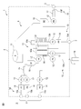
- FIG. 1 shows the configuration of the cell manufacturing apparatus 1 in this embodiment.
- the cell manufacturing apparatus 1 is a cell induction apparatus having a cell induction function of performing cell reprogramming, reprogramming, fate conversion, direct reprogramming, differentiation conversion, differentiation induction, transformation, etc. by introducing an inducing factor.
- a cell culture apparatus having only a cell culture function for simply culturing, expanding culture, or the like may be used.
- the cell manufacturing apparatus 1 injects a fluid containing original cells (for example, somatic cells such as blood cells and fibroblasts, or stem cells such as ES cells and iPS cells), and the target cells (for example, stem cells and precursor cells, etc.) are injected from the original cells.
- original cells for example, somatic cells such as blood cells and fibroblasts, or stem cells such as ES cells and iPS cells
- the target cells for example, stem cells and precursor cells, etc.
- the final differentiated cells are produced and the fluid containing the target cells is discharged.
- Target cells include fibroblasts, nerve cells, retinal epithelial cells, hepatocytes, ⁇ cells, renal cells, mesenchymal stem cells, blood cells, megacariosites, T cells, chondrocytes, myocardial cells, muscle cells, and vascular cells.
- Epithelial cells, renal cells, or other differentiated cells such as somatic cells may be produced.
- the cell manufacturing apparatus 1 is a closed system cell processing apparatus in which all the parts that should be highly clean are integrated inside, and can be used in a normal controlled area.
- the enclosed space inside the device is configured so as not to exchange gases, viruses, microorganisms, impurities, etc. with the outside.
- a fluid that is not a pollution source may be interchangeable between the inside and the outside of the device by additionally providing a fluid exchange filter or the like described later in the device.
- the cell production apparatus 1 includes a cell production plate 2 and a closed connector 3.
- the cell production plate 2 includes a closed fluid circuit 4 shielded from the external space S, and the fluid circuit 4 has a flow path in which a plurality of functional sites are highly integrated.
- the closed connector 3 is a connector for injecting a fluid into the fluid circuit 4 or discharging the fluid from the fluid circuit 4, and is attached to the cell production plate 2.
- the closed connector 3 is a connector for closedly connecting the fluid circuit 4 and the fluid container to the external space S, and may be, for example, a sterile connection connector, a needleless connector, a needle connector, a heat fusing tube, or the like.
- the needleless connector may be a split septum type or a mechanical valve type.
- the fluid container is a syringe, a variable volume bag, or the like, and the fluid circuit 4 communicates with the fluid container when the closed connector 3 and the fluid container are connected, while the fluid is connected when the closed connector 3 and the fluid container are not connected.
- the circuit 4 is cut off from the external space S. This can prevent biological contamination, cross-contamination, and biohazard of the fluid circuit 4.
- the cell manufacturing apparatus 1 preferably includes a plurality of closed connectors 3 in order to allow injection or discharge of a plurality of types of fluids.
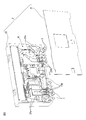
- FIG. 2 shows an example of the cell production plate 2.
- the cell production plate 2 includes a flat plate 20 and a lid 21.
- the flat plate 20 can be formed of, for example, a biologically safe resin, metal, or the like.
- the flat plate 20 is preferably molded by molding processing using a mold, for example, injection molding, compression molding, or the like, but the flat plate 20 may be molded using a 3D printer or the like.
- As the 3D printer various modeling methods such as stereolithography, fused deposition modeling, powder sintering, and inkjet can be adopted.
- a groove 20a is provided as a flow path for flowing a fluid on at least one of the front surface and the back surface of the flat plate 20, and a fluid circuit 4 is formed by combining a plurality of grooves 20a. Further, a portion where the width or depth of the groove 20a is relatively large is provided in a part of the fluid circuit 4, and a storage tank 20b for temporarily storing the fluid is formed.
- the walls of the groove 20a and the storage tank 20b may be coated with poly-HEMA (poly2-hydroxyethylmethacrylate) to make the cells non-adhesive.
- the walls of the groove 20a and the storage tank 20b may be made low in protein adsorption.
- At least a part of the groove 20a and the storage tank 20b is preferably white or black in order to observe changes over time in fluids, cells, cell clusters, etc. with an image recognition sensor, an ultrasonic recognition sensor, or the like.
- the lid 21 may be made of, for example, a biologically safe resin, quartz glass, or the like.
- the lid 21 (that is, at least a part of the cell preparation plate 2) is transparent because the change with time of the fluid, cells, cell mass, etc. in the fluid circuit 4 is observed by an image recognition sensor, an ultrasonic recognition sensor, or the like. Is preferable. This observation makes it possible to move to the next cell manufacturing process at an appropriate timing.
- the lid 21 is fixed to the flat plate 20 so as to cover the fluid circuit 4 by a biologically safe fixing method such as chemical bond, welding bond, adhesive bond or the like.
- a silane coupling agent, plasma irradiation or the like may be used.
- the cell preparation plate 2 is sterilized by heat sterilization, gamma ray sterilization, ultraviolet ray sterilization, electron beam sterilization, or the like to bring the fluid circuit 4 into a highly clean state.
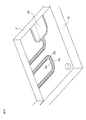
- FIGS. 3A-3B show an example of a method of fixing the flat plate and the lid.
- bank portions 20c are formed in advance on both sides of the groove 20a and the storage tank 20b, the flat plate 20 is covered with a lid 21, and at least the bank portion 20c is exposed to laser light, ultrasonic waves, or the like.
- the groove 20a and the storage tank 20b may be sealed by irradiating or applying to heat the bank portion 20c and welding the flat plate 20 and the lid 21.
- the flat plate 20 including the groove 20a and the storage tank 20b is covered with a lid 21, and at least a portion other than the groove 20a and the storage tank 20b is heated by irradiating or applying laser light, ultrasonic waves, or the like to the flat plate 20.
- the groove 20a and the storage tank 20b may be sealed by welding the lid 21. In this case, all the portions other than the groove 20a and the storage tank 20b are fixed, so that the fixing strength is increased.
- the fluid circuit 4 includes at least an injection / discharge unit 10 and a cell induction culture unit 13 as a plurality of functional sites.
- the fluid circuit 4 may include a volume variable section 11, a transfer section 12, a fluid reservoir 14, a fluid mixing section 15, a cell separation section 16, and a cell mass crushing section 17. Since these various functional sites are integrated in one cell production plate 2, the manufacturing process of connecting separate parts in a closed manner via a tube, a pump, a connector, or the like becomes unnecessary, and the cell manufacturing apparatus 1 is manufactured. Man-hours, manufacturing costs, etc. are reduced.
- the injection / discharge unit 10 includes an injection / discharge channel for injecting or discharging a fluid into the fluid circuit 4 via the closed connector 3.
- the injection / discharge unit 10 preferably includes a plurality of injection / discharge channels 10a-10f.
- the first injection / discharge channel 10a can inject or discharge a fluid or the like containing the original cells
- the second injection / discharge channel 10b is a fluid such as a reagent for separating the original cells, an anticoagulant, or a phosphate buffered saline. Can be injected or discharged.
- the third injection / discharge channel 10c can inject or discharge a fluid such as an inducer-introducing reagent
- the fourth injection / discharge channel 10d is used for various media such as initialization or induction medium, trypsin alternative recombinant enzyme and the like. Fluids such as cell detachment reagent, single cell separation reagent, and intercellular adhesive detachable agent can be injected or discharged.
- the induction medium includes an initialization medium, a reprogramming medium, a fate conversion medium, a direct programming medium, a transdifferentiation medium, a differentiation induction medium, a transformation medium and the like.
- the fifth injection / discharge channel 10e can discharge or inject a fluid containing cells subjected to at least one of induction and culture into the fluid container 19 as a sample
- the sixth injection / discharge channel 10f can discharge or inject the fluid containing the target cells into the fluid container. Can be discharged or injected into.
- the fluid container 19 for discharging the sample may be a closed connector 3, for example, a variable volume bag connected to a heat fusing tube or the like.
- a refrigerant such as liquid nitrogen may be supplied around the sixth injection / discharge channel 10f to freeze the fluid containing the target cells to seal the cell preparation plate.
- the fluid container discharged from the sixth injection / discharge channel 10f via the closed connector 3 may be frozen with a refrigerant such as liquid nitrogen.
- the variable volume unit 11 includes a physical or chemical variable volume material that stores the fluid extruded or drawn out by the injected or discharged fluid.
- a fluid escape flow path for releasing the fluid originally contained in the fluid circuit 4 is provided, and a physical volume variable material is connected to the fluid release flow path, or a pressure valve that opens and closes at a constant pressure is provided in the fluid release flow path.
- the physically variable volume material may be, for example, a flexible bag, a syringe, or the like.
- the chemically variable volume material may include, for example, a fluid absorber such as soda lime or silica gel, and a fluid release agent placed in a storage tank different from the storage tank in which the fluid absorbent is placed. Due to the volume variable material, the internal pressure of the closed fluid circuit 4 becomes substantially constant, and the fluid extruded or drawn out by the injected or discharged fluid is confined in the cell production plate 2, so that it is outside the cell production plate 2. It is not necessary to let the fluid escape or take in the fluid from the outside, and the cell production plate 2 can be formed into a plate shape while maintaining the airtightness of the fluid circuit 4. Such a cell preparation plate 2 is easy for the robot to handle.
- a fluid absorber such as soda lime or silica gel
- a fluid release agent placed in a storage tank different from the storage tank in which the fluid absorbent is placed. Due to the volume variable material, the internal pressure of the closed fluid circuit 4 becomes substantially constant, and the fluid extruded or drawn out by the injected or discharged fluid is confined in
- the transfer unit 12 includes a pump that transfers a fluid in the fluid circuit 4.
- the pump may be a positive displacement pump whose flow rate can be controlled, for example, a rotary pump, a reciprocating pump, or the like.
- a peristaltic pump is preferable.
- a flexible tube is hermetically connected to a connector provided at the end of the flow path, and the fluid is transferred by handling the tube with a roller. Since the tube is blocked by a roller, the fluid flow is blocked when the pump is stopped, and the flow rate can be controlled.
- a diaphragm pump is desirable as the reciprocating pump. However, in the case of a diaphragm pump, since the diaphragm does not shut off the flow path, the flow rate can be controlled by using the flow path shutoff valve together.
- the transfer unit 12 includes a plurality of pumps P1-P8.
- the first pump P1-the third pump P3 transfers the fluid stored in the fluid reservoirs A1-A3 at an appropriate timing
- the fourth pump P4 and the eighth pump P8 appropriately transfer the fluid stored in the cell separation unit 16. Transfer at the right timing.
- the fifth pump P5 transfers the fluid stored in the fluid reservoir A4 at an appropriate timing
- the sixth pump P6-seventh pump P7 transfers the fluid stored in the cell induction culture unit 13 at an appropriate timing.
- the rotation of the pump is used to obtain information on whether the pump is operating normally, such as whether the pump has rotated reliably or by an appropriate angle.
- a rotary encoder capable of detecting the amount of rotation may be provided on the spindle.
- a visual mark may be provided at the end of the rotation spindle of the pump, and the rotational movement of the mark may be directly captured by an image recognition sensor.
- a flow rate measuring unit (not shown) may be further provided in the front stage or the rear stage of the pump.
- the flow rate measuring unit captures, for example, a flow rate sensor provided adjacent to at least one of the flow path and the storage tank communicating with the transfer unit, or an image of a change in fluid over time in at least one of the flow path and the storage tank communicating with the transfer unit.
- An image recognition sensor or the like that captures the image may be used.
- the flow rate sensor can employ various measurement methods that do not adversely affect cells, such as the Karman vortex type, impeller type, and diaphragm type, and directly acquires the flow rate information of the fluid.
- the image recognition sensor acquires flow rate information from the movement of the fluid by recognizing an image from an external camera or the like via a transparent lid 21. As the image recognition sensor, other image recognition sensors described in this document may be diverted, whereby the number of parts and the manufacturing cost can be reduced.
- the cell-induced culture unit 13 includes a cell-induced culture tank 13a that induces and cultures cells based on the transferred fluid, a medium circulation path 13b that communicates with the cell-induced culture tank 13a and circulates the medium. It has.
- the cell induction culture tank 13a is heated to a predetermined culture temperature, for example, 37 ° C. by a heating element.
- the medium circulation passage 13b is cooled to a predetermined medium quality maintenance temperature, for example, 4 ° C. to 8 ° C. by a cooling element.
- the cell induction culture tank 13a is in a closed state and does not need to be supplied with a fluid such as carbon dioxide, nitrogen, oxygen, etc., but carbon dioxide, carbon dioxide, is supplied to at least one of the cell induction culture tank 13a and the medium circulation path 13b.
- a fluid exchange filter for exchanging fluids such as nitrogen and oxygen inside and outside the apparatus may be further provided.
- the cell induction culture tank 13a may be a three-dimensional culture tank for performing cell suspension culture, but may also be a two-dimensional culture tank for performing adhesive culture.
- the cell induction culture tank 13a may be coated with a cell adhesion coating agent such as matrigel, collagen, polylysine, fibronectin, vitronectin, gelatin, and laminin, laminin fragment, or hollow threads. It may be filled. Further, the cell-induced culture tank 13a may integrally include a culture tank 30 and a medium tank 31 for supplying a medium to the culture tank 30. In this case, it is preferable that the cell-induced culture tank 13a is provided with a specific component permeation member 32, for example, a semipermeable membrane, which allows only specific components to flow between the culture tank 30 and the medium tank 31. The specific component permeation member 32 permeates specific components such as various media, cell adhesion coating agents, and cell detachment reagents.
- a cell adhesion coating agent such as matrigel, collagen, polylysine, fibronectin, vitronectin, gelatin, and laminin, laminin fragment, or hollow threads. It may be filled.
- the cell-induced culture unit 13 may further include a pH measuring unit 13c for measuring the pH value of the medium used.
- the pH measuring unit 13c is preferably provided in the medium circulation channel 13b or the cell induction culture tank 13a in order to measure the pH value of the medium used.
- the pH measuring unit 13c may be, for example, an image recognition sensor, an electrode measuring sensor, or the like.
- the image recognition sensor measures the pH value with an external camera or the like through a transparent lid.
- the electrode measurement sensor measures the pH value by the glass electrode method. In the case of hue measurement, the hue can be accurately detected by making at least a part of the medium circulation path 13b (for example, the bottom surface of the hue measurement portion) white. This pH value makes it possible to quantitatively grasp the state of the medium.
- illumination is applied from at least one of the front, the peripheral direction (for example, the direction orthogonal to the observation surface), and the rear of the cell induction culture tank 13a. It is preferable that the portion is further provided.
- the lighting unit may include, for example, LED lighting, and may be embedded inside the cell production plate 2, or the cell induction culture tank 13a may be provided outside the cell production plate 2 so as to be more convex than the cell production plate 2.
- the culture tank 30 may be covered with a transparent member that allows light to pass through so that the illumination reaches the cells.
- the fluid storage unit 14 includes a storage tank for storing fluid to be injected into the fluid circuit 4 or discharged to the outside of the fluid circuit 4.
- the fluid storage unit 14 includes a plurality of storage tanks A1-A4.
- the storage tanks A1-A4 are formed as locations where the width or depth of the flow path is relatively large, and enable various fluids to be used in a predetermined amount at an appropriate timing.
- the first storage tank A1 stores a fluid containing original cells
- the second storage tank A2 stores fluids such as a reagent for separating original cells, an anticoagulant, and a phosphate buffered saline, and stores a third.
- the tank A3 stores fluids such as an inducer-introducing reagent
- the fourth liquid storage tank A4 stores fluids such as various media, cell adhesion coating agents, and cell detachment reagents. It may be provided with a storage tank for storing a fluid or the like containing a target cell.
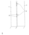
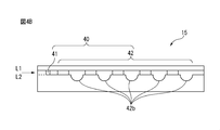
- the fluid mixing unit 15 is provided with a mixing flow path for mixing a plurality of fluids that are immiscible with each other.
- 4A-4B show an example of a mixing flow path.
- the mixing flow path 40 preferably includes a fluid mixing flow path 41 and a mixing flow generation path 42.
- the fluid merging flow path 41 is a flow path for merging the mutually immiscible fluids L1-L2 into one flow path
- the mixed flow generation path 42 is a flow path for generating a mixed flow in the merging fluid L1-L2. ..
- the mixed flow generation path 42 is, for example, a flow path in which the cross-sectional area of the flow path is discontinuously changed, and at least one of the flow path width and the flow path depth is changed in a direction different from the traveling direction of the fluid. Is preferable.
- the mixed flow generation path 42 includes a flow path width changing portion 42a and a flow path depth changing portion 42b alternately with respect to the traveling direction of the fluid.
- the mixed flow generation path 42 may be a spiral flow path penetrating from the front surface to the back surface of the flat plate.
- two spiral flow paths penetrating the flat plate are provided, and a communication passage for fluid communication between these spiral flow paths is provided on the back surface of the flat plate.
- the cell separation unit 16 includes separation tanks D1-D2 for separating cells or cell clusters.
- the separation tanks D1-D2 are storage tanks formed by relatively increasing the width or depth of the flow path, and the first separation tank D1 changes from a fluid containing original cells to a fluid containing only original cells.
- the second separation tank D2 separates from other cell masses by precipitating only a relatively large cell mass.
- a reagent for separating the original cells panning, magnetic cell separation (MACS), flow cytometry and the like can be used.
- the cell mass crushing unit 17 is provided with a crushing flow path for further crushing the separated cell mass (mass of one or more cells).
- FIG. 5 shows an example of a crushing flow path.
- the crushing flow path 50 has a relatively small flow path area as compared with the upstream flow path 51, and preferably meanders. By meandering the flow path, a latent flow is generated, and shear stress is applied to the cell mass to decompose the large cell mass into small cell masses.
- a subsurface current is, for example, a flow that causes a swirl, a turbulent flow, a backflow, a flow that causes a part having a different flow speed, a flow that causes a shearing force, and a flow that causes a part where a flow having a different traveling direction collides. Say one of.
- FIG. 6 shows an example of the cross flow path.
- the cross flow path includes a first flow path 60 extending in the X direction and a second flow path 61 extending in the Y direction different from the X direction on the front side of the cell production plate 2, and the first flow path 60 Provided a detour 62 extending toward the back side of the cell production plate 2 and bypassing the second flow path 61.
- the detour circuit 62 may include two through holes 62a-62b penetrating from the front surface to the back surface of the flat plate 20, and a communication passage 62c communicating the through holes 62a-62b with each other on the back surface of the flat plate 20.
- a communication passage 62c communicating the through holes 62a-62b with each other on the back surface of the flat plate 20.
- the lid 21 is provided with a front lid 21a covering the front surface of the flat plate 20 and a back cover 21b covering the back surface of the flat plate 20.
- Such cross-channels make it possible to provide a small cell production plate 2 with a highly integrated fluid circuit 4.
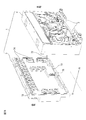
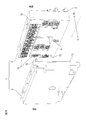
- the cell production apparatus 1 further includes a base plate that is detachably connected to the cell production plate 2.
- 7A-7B show an example of a base plate.
- the base plate 5 controls the fluid, temperature, etc. of the cell production plate 2.
- the cell preparation plate 2 is arranged so as to face the dangerous area side 70 on which the robot or the like acts, while the base plate 5 faces the safe area side 71 opposite to the dangerous area side 70. Be placed. From the viewpoint of preventing biological contamination, the cell production plate 2 may be disposable and the base plate 5 may be reused. Further, the cell manufacturing apparatus 1 is configured to be maintainable from the safety area side 71. When the cell manufacturing apparatus 1 is provided with such a two-sided structure, a robot or the like can be involved with a plurality of cell manufacturing apparatus 1 on a one-to-many basis.
- the cell manufacturing apparatus 1 may further include a positioning member 72 and a plate sealing member 73 on the connecting surface between the cell production plate 2 and the base plate 5.
- the positioning member 72 may be a convex portion or a concave portion that fits each other, and positions the connection position between the cell production plate 2 and the base plate 5.
- the plate sealing member 73 may be a gasket, packing, or the like attached to the outer periphery of the connecting surface.
- the drive unit 74 includes, for example, a motor that drives a peristaltic pump. Further, it is preferable that the connecting surface between the cell production plate 2 and the base plate 5 is provided with an electric contact 75 for supplying electric power to an electric element arranged on the cell production plate 2, such as a heating element, a cooling element, and a flow rate sensor.
- the manufacturing apparatus 1 since a plurality of functional sites are integrated in one cell production plate 2, it is not necessary to connect separate parts in a closed manner via a tube, a pump, a connector, or the like, and the cells are eliminated.
- the production of the manufacturing apparatus 1 is rationalized.
- the fluid extruded or withdrawn by the injected or discharged fluid is confined in the cell production plate 2, there is no need to let the fluid escape to the outside of the cell production plate 2 or take in the fluid from the outside. It becomes possible to form the cell production plate 2 in a plate shape while maintaining the airtightness of the fluid circuit.
- Such a plate-shaped cell production plate 2 is easy for the robot to handle and improves compatibility with the automation system.
Abstract
This cell production device comprises: a cell production plate including a fluid circuit in which multiple functional sites are integrated; and an exclusive connector that exclusively connects the fluid circuit to the outside space. The fluid circuit comprises, as the multiple functional sites, the following: an injection/discharge unit that, through the exclusive connector, injects the fluid into the fluid circuit or discharges the fluid out of the fluid circuit; a variable capacity unit that stores the fluid which is pushed out or pulled in by the fluid that is injected or discharged; and a cell induction/culture unit that performs at least one of cell induction and cell culture on the basis of the injected fluid.
Description
本発明は、細胞製造装置及びその製造方法に関し、特に細胞製造装置の製造の合理化と自動化システムへの適合性を同時に実現した細胞製造装置及びその製造方法に関する。
The present invention relates to a cell manufacturing apparatus and a manufacturing method thereof, and more particularly to a cell manufacturing apparatus and a manufacturing method thereof that simultaneously realizes rationalization of manufacturing of the cell manufacturing apparatus and compatibility with an automated system.
胚性幹細胞(ES細胞)は、ヒトやマウスの初期杯から樹立された幹細胞であり、生体に存在する全ての細胞へと分化できる多能性を有する。ヒトES細胞は、パーキンソン病、若年性糖尿病、及び白血病等、多くの疾患に対する細胞移植法に利用可能であると考えられている。しかし、ES細胞の移植は、臓器移植と同様に、拒絶反応を惹起するという問題がある。また、ヒト杯を破壊して樹立されるES細胞の利用に対しては、倫理的見地から反対意見が多い。
Embryonic stem cells (ES cells) are stem cells established from the early cups of humans and mice, and have pluripotency that allows them to differentiate into all cells existing in the living body. Human ES cells are believed to be available for cell transplantation for many diseases such as Parkinson's disease, juvenile diabetes, and leukemia. However, ES cell transplantation has the problem of inducing rejection, similar to organ transplantation. In addition, there are many dissenting opinions from an ethical point of view regarding the use of ES cells established by destroying the human cup.
これに対し、京都大学山中伸弥教授は、4種の遺伝子:Oct3/4、Klf4、c-Myc、及びSox2を体細胞に導入することにより、誘導多能性幹細胞(iPS細胞)を樹立することに成功し、2012年のノーベル生理学・医学賞を受賞した(例えば、特許文献1参照。)。iPS細胞は、拒絶反応や倫理的問題のない理想的な多能性細胞であり、細胞移植法への利用が期待されている。
On the other hand, Professor Shinya Yamanaka of Kyoto University established induced pluripotent stem cells (iPS cells) by introducing four genes: Oct3 / 4, Klf4, c-Myc, and Sox2 into somatic cells. Succeeded in receiving the 2012 Nobel Prize in Physiology or Medicine (see, for example, Patent Document 1). iPS cells are ideal pluripotent cells without rejection and ethical problems, and are expected to be used in cell transplantation methods.
iPS細胞のような誘導幹細胞は、細胞に遺伝子等の誘導因子を導入することによって樹立され、拡大培養、凍結保存される。しかし、例えば臨床用iPS細胞(GLP,GMPグレード)等を作製するには、非常に綺麗に保たれたクリーンルームを必要とし、高額な維持コストが掛かる。産業化のためには、クリーンルームの運用方法をいかに効率化してコスト削減に努めるかが課題になっていた。
Induced stem cells such as iPS cells are established by introducing inducing factors such as genes into cells, and are expanded and cryopreserved. However, for example, in order to produce clinical iPS cells (GLP, GMP grade), a clean room kept very clean is required, and a high maintenance cost is required. For industrialization, the issue was how to improve the efficiency of clean room operation methods and strive to reduce costs.
またiPS細胞の作製は手作業によるところが大きいが、臨床用iPS細胞を作製できる技術者は少ない。幹細胞の樹立から保存までの一連の作業が複雑であるという問題がある。臨床用の細胞培養では、標準的な工程(SOP:Standard Of Process)の確認と、SOPに従った操作と、SOP通りに実施されたか否かの確認、という3つのステップを行う必要があり、これらステップを人が行う事は非常に非生産的である。細胞培養は24時間毎日管理する必要があり、幹細胞の保存は何十年にも及ぶため、人材だけで管理するのは限界があった。
Although iPS cells are mostly produced manually, there are few engineers who can produce clinical iPS cells. There is a problem that a series of operations from the establishment of stem cells to their preservation is complicated. In clinical cell culture, it is necessary to perform three steps: confirmation of standard process (SOP: Standard Of Process), operation according to SOP, and confirmation of whether or not it was carried out according to SOP. It is very unproductive for humans to perform these steps. Since cell culture needs to be managed 24 hours a day, and stem cells are preserved for decades, there is a limit to managing them by human resources alone.
そこで、高度に清浄なクリーンルームを不要とし、通常管理区域(例えばWHO-GMP規格において微生物及び微粒子の少なくとも一方がグレードDレベル又はそれ以上)で作業可能な閉鎖系の細胞製造装置が開発されてきた(例えば、特許文献2参照。)。また人材も排除して複雑な細胞製造工程を自動化するため、細胞製造を補助するロボットを備えた細胞製造システムも開発されている。斯かる細胞製造装置に関する先行技術としては、次の文献が公知である。
Therefore, a closed cell production device has been developed that does not require a highly clean clean room and can work in a normally controlled area (for example, at least one of microorganisms and fine particles in the WHO-GMP standard is grade D level or higher). (See, for example, Patent Document 2.). In addition, in order to eliminate human resources and automate complicated cell manufacturing processes, cell manufacturing systems equipped with robots that assist cell manufacturing have also been developed. The following documents are known as prior arts relating to such cell production devices.
特許文献3には、導入前細胞送液路と、導入前細胞に体細胞誘導因子を導入して誘導因子導入細胞を作製する因子導入装置と、誘導因子導入細胞を培養して体細胞を作製する細胞作製装置と、を1つの筐体内にパッケージ化した体細胞製造システムが開示されている。
Patent Document 3 describes a pre-introduction cell delivery path, a factor introduction device that introduces a somatic cell inducer into a pre-introduction cell to produce an inducer-introduced cell, and a somatic cell by culturing the inducer-introduced cell. A somatic cell production system in which a cell production device for a cell production is packaged in one housing is disclosed.
特許文献4には、培養容器及び流路を閉鎖系にした細胞培養容器が開示されており、細胞培養容器が第一容器内に第二容器を偏心して保持することにより、細胞培養の育成状態が明瞭に観察できる。
Patent Document 4 discloses a cell culture container in which the culture container and the flow path are closed, and the cell culture container eccentrically holds the second container in the first container to grow the cell culture. Can be clearly observed.
特許文献5には、培地貯溜手段、細胞接種手段、及び培養容器が閉鎖系で構成された細胞培養装置が開示されている。細胞培養装置は、培養容器内の細胞の画像から細胞の培養状況を判定し、この判定に基づき培養操作を実行することにより、操作者の労力を軽減している。
Patent Document 5 discloses a cell culture device in which a medium storage means, a cell inoculation means, and a culture container are configured as a closed system. The cell culture device determines the cell culture status from the image of the cells in the culture vessel, and executes the culture operation based on this determination, thereby reducing the labor of the operator.
特許文献6には、細胞培養チャンバの容積を囲む側壁を有する本体と、細胞培養チャンバを覆う蓋と、本体下部に配置された底板と、を備え、本体には、流入排出コネクタと細胞培養チャンバとの間を流体連通させるマイクロ流体導管を一体形成した細胞培養装置が開示されている。
Patent Document 6 includes a main body having a side wall surrounding the volume of the cell culture chamber, a lid covering the cell culture chamber, and a bottom plate arranged under the main body, and the main body includes an inflow / discharge connector and a cell culture chamber. A cell culture device in which a microfluidic conduit for fluid communication with the cell is integrally formed is disclosed.
特許文献7には、マイクロチップの内部空間の気泡を外部空間に移動させる気泡除去手段を備えたマイクロチップ反応装置が開示されている。特許文献8には、第1培養液貯留室及び第2培養液貯留室から気体を排出可能な通気孔を備え、通気孔にエアフィルタを設けた細胞培養装置が開示されている。
Patent Document 7 discloses a microchip reactor provided with a bubble removing means for moving bubbles in the internal space of the microchip to the external space. Patent Document 8 discloses a cell culture apparatus provided with a vent hole capable of discharging gas from a first culture solution storage chamber and a second culture solution storage chamber, and an air filter provided in the vent hole.
特許文献9には、2つの流路が合流する液体混合部を備えた細胞培養プレートが開示されている。特許文献10には、放射状に分布する微小チャネル部品を支持する基板と、基板上に配置されるカバープレートと、を備え、細胞増殖及び細胞検定を行う装置が開示されている。微小チャネル部品は、液体試料を導入する導入チャネルと、流路面積を相対的に大きくした細胞増殖チャンバ及び検定チャンバと、液体試料を除去する排出チャネルと、を備えている。
Patent Document 9 discloses a cell culture plate provided with a liquid mixing portion in which two flow paths meet. Patent Document 10 discloses an apparatus that includes a substrate that supports radially distributed microchannel components and a cover plate that is arranged on the substrate, and performs cell proliferation and cell assay. The microchannel component includes an introduction channel for introducing the liquid sample, a cell proliferation chamber and a test chamber having a relatively large flow path area, and a discharge channel for removing the liquid sample.
特許文献11は、第一のマイクロ流体チャネルを画定する第一の層と、第二のマイクロ流体チャネルを画定する第二の層と、を備える培養装置が開示されている。
Patent Document 11 discloses a culture apparatus including a first layer that defines a first microfluidic channel and a second layer that defines a second microfluidic channel.
特許文献12には、流路一体プレート及びベースプレートを備えた細胞培養装置が開示されている。流路一体プレートは、培養液の流路を形成した流路プレートと、培養液の供給及び排出を行うペリスタルティックポンプ群を配置したポンプ部と、を備え、ベースプレートがモータ等の駆動源を備えている。
Patent Document 12 discloses a cell culture device including a flow path integrated plate and a base plate. The flow path integrated plate includes a flow path plate forming a flow path of the culture solution and a pump unit in which a group of peristaltic pumps for supplying and discharging the culture solution is arranged, and the base plate is provided with a drive source such as a motor. ing.
従来の装置は、培地貯留リザーバ、培地供給排出流路、細胞培養容器といった細胞培養機能のみを一体的に構成した細胞培養装置が多く、誘導因子導入による、細胞の初期化、リプログラミング、運命転換、ダイレクトリプログラミング、分化転換、分化誘導、形質転換といった細胞誘導機能までを一体化したものは少ない。これら種々の機能部位を閉鎖系で構成するためには、別個の部材をチューブ、ポンプ、コネクタ等を介して閉鎖的に接続するといった煩雑な工程を要するため、製造工数、製造コスト等を増大させる虜がある。また、斯かる装置による細胞製造を完全に自動化するとなると、別個の部材で構成された細胞製造装置がロボットにとって取扱い難いものとなる。
Many of the conventional devices are cell culture devices that integrally configure only cell culture functions such as a medium storage reservoir, a medium supply / discharge channel, and a cell culture container, and cell reprogramming, reprogramming, and fate change by introducing an inducer. , Direct reprogramming, differentiation conversion, differentiation induction, transformation, and other cell-inducing functions are rarely integrated. In order to configure these various functional parts in a closed system, a complicated process such as closedly connecting separate members via tubes, pumps, connectors, etc. is required, which increases manufacturing man-hours, manufacturing costs, and the like. There is a captive. Further, if the cell production by such an apparatus is completely automated, the cell production apparatus composed of separate members becomes difficult for the robot to handle.
そこで、細胞製造装置の製造の合理化と自動化システムへの適合性を同時に実現する技術が求められている。
Therefore, there is a need for a technology that simultaneously realizes rationalization of manufacturing of cell manufacturing equipment and compatibility with automated systems.
本開示の一態様は、複数の機能部位を集約した流体回路を備える細胞作製プレートと、流体回路を外部空間に対して閉鎖的に接続する閉鎖式コネクタと、を備え、流体回路は、複数の機能部位として、閉鎖式コネクタを介して流体を流体回路内に注入又は流体回路外に排出する注入排出部と、注入又は排出した流体によって押出又は引出される流体を貯溜する容積可変部と、注入した流体に基づき細胞の誘導及び培養の少なくとも一方を行う細胞誘導培養部と、を備える、細胞製造装置を提供する。
本開示の他の態様は、複数の機能部位を集約した流体回路を備える平板を成型する工程と、流体回路を覆うように蓋を平板に固着して細胞作製プレートを形成する工程と、流体回路を外部空間に対して閉鎖的に接続する閉鎖式コネクタを細胞作製プレートに取付ける工程と、を含み、流体回路は、複数の機能部位として、閉鎖式コネクタを介して流体を流体回路内に注入又は流体回路外に排出する注入排出部と、注入又は排出した流体によって押出又は引出される流体を貯溜する容積可変部と、注入した流体に基づき細胞の誘導及び培養の少なくとも一方を行う細胞誘導培養部と、のうちの少なくとも1つを備える、細胞製造装置の製造方法を提供する。
本開示の別の態様は、複数の機能部位を集約した流体回路を備える細胞作製プレートと、流体回路を外部空間に対して閉鎖的に接続する閉鎖式コネクタと、を備え、流体回路は、複数の機能部位として、閉鎖式コネクタを介して流体を流体回路内に注入又は流体回路外に排出する注入排出部と、注入した流体に基づき細胞の誘導及び培養の少なくとも一方を行う細胞誘導培養部と、を備える、細胞製造装置を提供する。 One aspect of the present disclosure includes a cell production plate including a fluid circuit in which a plurality of functional sites are integrated, and a closed connector for closedly connecting the fluid circuit to an external space, and the fluid circuit includes a plurality of fluid circuits. As functional parts, an injection / discharge part that injects fluid into or out of the fluid circuit via a closed connector, a variable volume part that stores the fluid extruded or drawn by the injected or discharged fluid, and an injection part. Provided is a cell manufacturing apparatus including a cell-induced culture unit that induces and cultures cells based on the resulting fluid.
Other aspects of the present disclosure include a step of molding a flat plate having a fluid circuit in which a plurality of functional parts are integrated, a step of fixing a lid to the flat plate so as to cover the fluid circuit, and a step of forming a cell production plate, and a fluid circuit. The fluid circuit comprises, as multiple functional sites, injecting fluid into the fluid circuit through the closed connector, including the step of attaching a closed connector to the cell production plate to closely connect the fluid to the external space. An injection / discharge unit that discharges out of the fluid circuit, a volume variable unit that stores the fluid extruded or drawn by the injected or discharged fluid, and a cell-guided culture unit that induces and cultures cells based on the injected fluid. And, a method of manufacturing a cell manufacturing apparatus comprising at least one of.
Another aspect of the present disclosure comprises a cell production plate comprising a fluid circuit in which a plurality of functional sites are aggregated, and a closed connector for closedly connecting the fluid circuit to an external space, wherein the fluid circuit is plural. As functional parts of, an injection / discharge unit that injects a fluid into or out of a fluid circuit via a closed connector, and a cell-guided culture unit that induces and cultures cells based on the injected fluid. Provided is a cell manufacturing apparatus comprising.
本開示の態様によれば、複数の機能部位が1つの細胞作製プレート内に集約されるため、別個の部品をチューブ、ポンプ、コネクタ等を介して閉鎖的に接続するといった製造工程が不要となり、細胞製造装置の製造工数、製造コスト等が削減される。また同時に、注入又は排出した流体によって押出又は引出される流体が流体回路内に閉じ込められるため、細胞作製プレートの外部に流体を逃がしたり又は外部から流体を取込んだりする必要がなく、流体回路の密閉性を保ちながら細胞作製プレートをプレート状に形成することが可能になる。斯かる細胞作製プレートは、ロボットにとって取扱い易く、自動化システムへの適合性を向上させる。
According to the aspect of the present disclosure, since a plurality of functional sites are integrated in one cell production plate, a manufacturing process such as closedly connecting separate parts via a tube, a pump, a connector, or the like becomes unnecessary. Man-hours for manufacturing cell manufacturing equipment, manufacturing costs, etc. are reduced. At the same time, since the fluid extruded or drawn out by the injected or discharged fluid is confined in the fluid circuit, there is no need to let the fluid escape to the outside of the cell production plate or take in the fluid from the outside, and the fluid circuit It becomes possible to form a cell production plate in a plate shape while maintaining airtightness. Such cell production plates are easy for robots to handle and improve their suitability for automated systems.
以下、添付図面を参照して本開示の実施形態を詳細に説明する。各図面において、同一又は類似の構成要素には同一又は類似の符号が付与されている。また、以下に記載する実施形態は、特許請求の範囲に記載される発明の技術的範囲及び用語の意義を限定するものではない。なお、本書における用語「閉鎖」とは、微生物、ウイルス等の汚染源が装置内部に侵入して生物学的汚染を発生しないこと、及び/又は装置内部の流体(細胞、微生物、ウイルス粒子、タンパク質、核酸等の物質を含む。)が漏出して交叉汚染を発生しないこと、及び/又は病原体に感染したドナーの流体を装置内部で取扱ってもバイオハザードを発生しないことを意味する。但し、本書における装置は、例えば二酸化炭素、窒素、酸素等の汚染源でない流体が装置内部に侵入又は装置外部へ漏出するように構成してもよい。
Hereinafter, embodiments of the present disclosure will be described in detail with reference to the accompanying drawings. In each drawing, the same or similar components are given the same or similar reference numerals. In addition, the embodiments described below do not limit the technical scope of the invention and the meaning of terms described in the claims. The term "closed" in this document means that contamination sources such as microorganisms and viruses do not invade the inside of the device and cause biological contamination, and / or the fluid inside the device (cells, microorganisms, virus particles, proteins, etc.) It means that (including substances such as nucleic acids) does not leak and cause cross-contamination, and / or that even if the fluid of the donor infected with the pathogen is handled inside the device, no biohazard is generated. However, the device in this document may be configured so that a fluid that is not a pollution source, such as carbon dioxide, nitrogen, or oxygen, enters the device or leaks to the outside of the device.
図1は本実施形態における細胞製造装置1の構成を示している。細胞製造装置1は、誘導因子導入による、細胞の初期化、リプログラミング、運命転換、ダイレクトリプログラミング、分化転換、分化誘導、形質転換等を行う細胞誘導機能を備えた細胞誘導装置であるが、単に培養、拡大培養等を行う細胞培養機能のみを備えた細胞培養装置でもよい。細胞製造装置1は、元細胞(例えば血液細胞、線維芽細胞等の体細胞、又はES細胞、iPS細胞等の幹細胞)を含む流体を注入し、元細胞から目的細胞(例えば幹細胞、前駆細胞、最終分化細胞)を製造すると共に、目的細胞を含む流体を排出する。目的細胞として、線維芽細胞、神経細胞、網膜上皮細胞、肝細胞、β細胞、腎細胞、間葉系幹細胞、血液細胞、メガカリオサイト、T細胞、軟骨細胞、心筋細胞、筋細胞、血管細胞、上皮細胞、腎細胞、又は他の体細胞等の分化細胞を作製してもよい。細胞製造装置1は、高度にクリーンであるべき部分を全て内部に集約した閉鎖系の細胞処理装置であり、通常管理区域でも使用可能である。装置内部の閉鎖空間は、気体、ウイルス、微生物、不純物等を外部と交換しないように構成される。但し、後述の流体交換フィルタ等を装置に付加的に設けることにより、汚染源でない流体を装置内部と外部で交換可能に構成してもよい。
FIG. 1 shows the configuration of the cell manufacturing apparatus 1 in this embodiment. The cell manufacturing apparatus 1 is a cell induction apparatus having a cell induction function of performing cell reprogramming, reprogramming, fate conversion, direct reprogramming, differentiation conversion, differentiation induction, transformation, etc. by introducing an inducing factor. A cell culture apparatus having only a cell culture function for simply culturing, expanding culture, or the like may be used. The cell manufacturing apparatus 1 injects a fluid containing original cells (for example, somatic cells such as blood cells and fibroblasts, or stem cells such as ES cells and iPS cells), and the target cells (for example, stem cells and precursor cells, etc.) are injected from the original cells. The final differentiated cells) are produced and the fluid containing the target cells is discharged. Target cells include fibroblasts, nerve cells, retinal epithelial cells, hepatocytes, β cells, renal cells, mesenchymal stem cells, blood cells, megacariosites, T cells, chondrocytes, myocardial cells, muscle cells, and vascular cells. , Epithelial cells, renal cells, or other differentiated cells such as somatic cells may be produced. The cell manufacturing apparatus 1 is a closed system cell processing apparatus in which all the parts that should be highly clean are integrated inside, and can be used in a normal controlled area. The enclosed space inside the device is configured so as not to exchange gases, viruses, microorganisms, impurities, etc. with the outside. However, a fluid that is not a pollution source may be interchangeable between the inside and the outside of the device by additionally providing a fluid exchange filter or the like described later in the device.
図1に示すように、細胞製造装置1は細胞作製プレート2及び閉鎖式コネクタ3を備えている。細胞作製プレート2は外部空間Sから遮断された閉鎖系の流体回路4を備えており、流体回路4は複数の機能部位を高度に集約した流路を備えている。閉鎖式コネクタ3は、流体回路4へ流体を注入し、又は流体回路4から流体を排出するためのコネクタであり、細胞作製プレート2に取付けられる。閉鎖式コネクタ3は、流体回路4と流体容器を外部空間Sに対して閉鎖的に接続するコネクタであり、例えば無菌接続コネクタ、ニードルレスコネクタ、ニードルコネクタ、熱溶断チューブ等でよい。ニードルレスコネクタは、スプリットセプタム型でもよいし、メカニカルバルブ型でもよい。流体容器とは、シリンジ、容積可変バッグ等であり、閉鎖式コネクタ3と流体容器との接続時には流体回路4が流体容器と流体連通する一方、閉鎖式コネクタ3と流体容器との非接続時には流体回路4が外部空間Sから遮断される。これにより、流体回路4の生物学的汚染、交叉汚染、及びバイオハザードを防止できる。複数種類の流体の注入又は排出を可能にするため、細胞製造装置1は複数の閉鎖式コネクタ3を備えていることが好ましい。
As shown in FIG. 1, the cell production apparatus 1 includes a cell production plate 2 and a closed connector 3. The cell production plate 2 includes a closed fluid circuit 4 shielded from the external space S, and the fluid circuit 4 has a flow path in which a plurality of functional sites are highly integrated. The closed connector 3 is a connector for injecting a fluid into the fluid circuit 4 or discharging the fluid from the fluid circuit 4, and is attached to the cell production plate 2. The closed connector 3 is a connector for closedly connecting the fluid circuit 4 and the fluid container to the external space S, and may be, for example, a sterile connection connector, a needleless connector, a needle connector, a heat fusing tube, or the like. The needleless connector may be a split septum type or a mechanical valve type. The fluid container is a syringe, a variable volume bag, or the like, and the fluid circuit 4 communicates with the fluid container when the closed connector 3 and the fluid container are connected, while the fluid is connected when the closed connector 3 and the fluid container are not connected. The circuit 4 is cut off from the external space S. This can prevent biological contamination, cross-contamination, and biohazard of the fluid circuit 4. The cell manufacturing apparatus 1 preferably includes a plurality of closed connectors 3 in order to allow injection or discharge of a plurality of types of fluids.
図2は細胞作製プレート2の一例を示している。図2に示すように、細胞作製プレート2は平板20及び蓋21を備えている。平板20は、例えば生物学的に安全な樹脂、金属等で成形することができる。平板20は、金型を用いた成型加工、例えば射出成形、圧縮成形等によって成型するのが好ましいが、3Dプリンタ等を用いて平板20を成形してもよい。3Dプリンタとしては、光造形、熱溶解積層、粉末焼結、インクジェット等の種々の造形方式を採用できる。平板20の表面及び裏面の少なくとも一方に、流体を流す流路として溝20aを設け、複数の溝20aを組み合わせることによって流体回路4を形成する。また、流体回路4の一部に、溝20aの幅又は深さを相対的に大きくした箇所を設け、流体を一時的に貯溜する貯溜槽20bを形成する。溝20a及び貯溜槽20bの壁面には、poly-HEMA(poly 2-hydroxyethyl methacrylate)をコーティングして細胞非接着性にしてもよい。逆に、細胞が溝20a又は貯溜槽20bに入り難い場合には、溝20a及び貯溜槽20bの壁面を低タンパク吸着性にしてもよい。溝20a及び貯溜槽20bの少なくとも一部は、流体、細胞、細胞塊等の経時変化を画像認識センサ、超音波認識センサ等によって観察するため、白色又は黒色とすることが好ましい。
FIG. 2 shows an example of the cell production plate 2. As shown in FIG. 2, the cell production plate 2 includes a flat plate 20 and a lid 21. The flat plate 20 can be formed of, for example, a biologically safe resin, metal, or the like. The flat plate 20 is preferably molded by molding processing using a mold, for example, injection molding, compression molding, or the like, but the flat plate 20 may be molded using a 3D printer or the like. As the 3D printer, various modeling methods such as stereolithography, fused deposition modeling, powder sintering, and inkjet can be adopted. A groove 20a is provided as a flow path for flowing a fluid on at least one of the front surface and the back surface of the flat plate 20, and a fluid circuit 4 is formed by combining a plurality of grooves 20a. Further, a portion where the width or depth of the groove 20a is relatively large is provided in a part of the fluid circuit 4, and a storage tank 20b for temporarily storing the fluid is formed. The walls of the groove 20a and the storage tank 20b may be coated with poly-HEMA (poly2-hydroxyethylmethacrylate) to make the cells non-adhesive. On the contrary, when it is difficult for cells to enter the groove 20a or the storage tank 20b, the walls of the groove 20a and the storage tank 20b may be made low in protein adsorption. At least a part of the groove 20a and the storage tank 20b is preferably white or black in order to observe changes over time in fluids, cells, cell clusters, etc. with an image recognition sensor, an ultrasonic recognition sensor, or the like.
蓋21は、例えば生物学的に安全な樹脂、石英ガラス等で形成されてもよい。蓋21(即ち、細胞作製プレート2の少なくとも一部)は、流体回路4内の流体、細胞、細胞塊等の経時変化を画像認識センサ、超音波認識センサ等によって観察するため、透明であることが好ましい。この観察により、適切なタイミングで次の細胞製造工程に移行することが可能になる。蓋21は、流体回路4を外部空間から遮断するため、生物学的に安全な固着方法、例えば化学結合、溶着結合、接着結合等によって流体回路4を覆うように平板20に固着される。化学結合としては、シランカップリング剤、プラズマ照射等を用いてもよい。また溶着結合としては、レーザ溶着、超音波溶着等を用いてよく、接着結合としては、紫外線硬化接着剤等を用いてもよい。平板20と蓋21の固着後に、細胞作製プレート2に対して殺菌処理、例えば加熱滅菌、ガンマ線滅菌、紫外線滅菌、電子線滅菌等を施し、流体回路4を高度にクリーンな状態にする。
The lid 21 may be made of, for example, a biologically safe resin, quartz glass, or the like. The lid 21 (that is, at least a part of the cell preparation plate 2) is transparent because the change with time of the fluid, cells, cell mass, etc. in the fluid circuit 4 is observed by an image recognition sensor, an ultrasonic recognition sensor, or the like. Is preferable. This observation makes it possible to move to the next cell manufacturing process at an appropriate timing. In order to block the fluid circuit 4 from the external space, the lid 21 is fixed to the flat plate 20 so as to cover the fluid circuit 4 by a biologically safe fixing method such as chemical bond, welding bond, adhesive bond or the like. As the chemical bond, a silane coupling agent, plasma irradiation or the like may be used. Further, as the welding bond, laser welding, ultrasonic welding or the like may be used, and as the adhesive bond, an ultraviolet curable adhesive or the like may be used. After the flat plate 20 and the lid 21 are fixed, the cell preparation plate 2 is sterilized by heat sterilization, gamma ray sterilization, ultraviolet ray sterilization, electron beam sterilization, or the like to bring the fluid circuit 4 into a highly clean state.
図3A-図3Bは平板と蓋の固着方法の一例を示している。流体回路4を外部空間から遮断するため、溝20aと貯溜槽20bの両側に土手部20cを予め形成しておき、平板20を蓋21で覆い、少なくとも土手部20cにレーザ光、超音波等を照射又は印加して土手部20cを加熱し、平板20と蓋21を溶着することによって溝20aと貯溜槽20bを密封してもよい。或いは、溝20a及び貯溜槽20bを含む平板20に対して蓋21をして、少なくとも溝20a及び貯溜槽20b以外の部分をレーザ光、超音波等を照射又は印加して加熱し、平板20と蓋21を溶着することによって溝20aと貯溜槽20bを密封してもよい。この場合、溝20a及び貯溜槽20b以外の部分が全て固着されるため、固着強度が高まる。
FIGS. 3A-3B show an example of a method of fixing the flat plate and the lid. In order to block the fluid circuit 4 from the external space, bank portions 20c are formed in advance on both sides of the groove 20a and the storage tank 20b, the flat plate 20 is covered with a lid 21, and at least the bank portion 20c is exposed to laser light, ultrasonic waves, or the like. The groove 20a and the storage tank 20b may be sealed by irradiating or applying to heat the bank portion 20c and welding the flat plate 20 and the lid 21. Alternatively, the flat plate 20 including the groove 20a and the storage tank 20b is covered with a lid 21, and at least a portion other than the groove 20a and the storage tank 20b is heated by irradiating or applying laser light, ultrasonic waves, or the like to the flat plate 20. The groove 20a and the storage tank 20b may be sealed by welding the lid 21. In this case, all the portions other than the groove 20a and the storage tank 20b are fixed, so that the fixing strength is increased.
図1を再び参照すると、流体回路4は、複数の機能部位として、注入排出部10及び細胞誘導培養部13を少なくとも備えている。流体回路4は、所望により、容積可変部11、移送部12、流体溜め部14、流体混合部15、細胞分離部16、及び細胞塊破砕部17を備えていてもよい。これら種々の機能部位が1つの細胞作製プレート2内に集約されるため、別個の部品をチューブ、ポンプ、コネクタ等を介して閉鎖的に接続するといった製造工程が不要となり、細胞製造装置1の製造工数、製造コスト等が削減される。
With reference to FIG. 1 again, the fluid circuit 4 includes at least an injection / discharge unit 10 and a cell induction culture unit 13 as a plurality of functional sites. If desired, the fluid circuit 4 may include a volume variable section 11, a transfer section 12, a fluid reservoir 14, a fluid mixing section 15, a cell separation section 16, and a cell mass crushing section 17. Since these various functional sites are integrated in one cell production plate 2, the manufacturing process of connecting separate parts in a closed manner via a tube, a pump, a connector, or the like becomes unnecessary, and the cell manufacturing apparatus 1 is manufactured. Man-hours, manufacturing costs, etc. are reduced.
注入排出部10は、閉鎖式コネクタ3を介して流体を流体回路4内に注入又は排出する注入排出チャネルを備えている。複数種類の流体を注入又は排出可能にするため、注入排出部10は複数の注入排出チャネル10a-10fを備えていることが好ましい。例えば、第1注入排出チャネル10aは元細胞を含む流体等を注入又は排出可能であり、第2注入排出チャネル10bは、元細胞分離用試薬、抗凝固剤、リン酸緩衝生理食塩水等の流体を注入又は排出可能である。また第3注入排出チャネル10cは誘導因子導入試薬等の流体を注入又は排出可能であり、第4注入排出チャネル10dは、初期化用又は誘導用培地等の種々の培地、トリプシン代替組替え酵素等の細胞剥離試薬、シングルセル分離試薬、細胞間接着剥離薬等の流体を注入又は排出可能である。誘導用培地は、初期化用培地、リプログラミング用培地、運命転換用培地、ダイレクトプログラミング用培地、分化転換用培地、分化誘導用培地、形質転換用培地等を含む。さらに第5注入排出チャネル10eは誘導及び培養の少なくとも一方を施した細胞を含む流体をサンプルとして流体容器19に排出又は注入可能であり、第6注入排出チャネル10fは目的細胞を含む流体を流体容器に排出又は注入可能である。サンプル排出用の流体容器19は、閉鎖式コネクタ3、例えば熱溶断チューブに接続する容積可変バッグ等でよい。また、目的細胞を含む流体を排出する際に、第6注入排出チャネル10fの周囲に液体窒素等の冷媒を供給し、目的細胞を含む流体を凍結させて細胞作製プレートをシーリングしてもよいし、又は第6注入排出チャネル10fから閉鎖式コネクタ3を介して排出した流体容器を液体窒素等の冷媒で凍結してもよい。
The injection / discharge unit 10 includes an injection / discharge channel for injecting or discharging a fluid into the fluid circuit 4 via the closed connector 3. In order to enable injection or discharge of a plurality of types of fluids, the injection / discharge unit 10 preferably includes a plurality of injection / discharge channels 10a-10f. For example, the first injection / discharge channel 10a can inject or discharge a fluid or the like containing the original cells, and the second injection / discharge channel 10b is a fluid such as a reagent for separating the original cells, an anticoagulant, or a phosphate buffered saline. Can be injected or discharged. Further, the third injection / discharge channel 10c can inject or discharge a fluid such as an inducer-introducing reagent, and the fourth injection / discharge channel 10d is used for various media such as initialization or induction medium, trypsin alternative recombinant enzyme and the like. Fluids such as cell detachment reagent, single cell separation reagent, and intercellular adhesive detachable agent can be injected or discharged. The induction medium includes an initialization medium, a reprogramming medium, a fate conversion medium, a direct programming medium, a transdifferentiation medium, a differentiation induction medium, a transformation medium and the like. Further, the fifth injection / discharge channel 10e can discharge or inject a fluid containing cells subjected to at least one of induction and culture into the fluid container 19 as a sample, and the sixth injection / discharge channel 10f can discharge or inject the fluid containing the target cells into the fluid container. Can be discharged or injected into. The fluid container 19 for discharging the sample may be a closed connector 3, for example, a variable volume bag connected to a heat fusing tube or the like. Further, when the fluid containing the target cells is discharged, a refrigerant such as liquid nitrogen may be supplied around the sixth injection / discharge channel 10f to freeze the fluid containing the target cells to seal the cell preparation plate. Alternatively, the fluid container discharged from the sixth injection / discharge channel 10f via the closed connector 3 may be frozen with a refrigerant such as liquid nitrogen.
容積可変部11は、注入又は排出した流体によって押出又は引出される流体を貯溜する物理的又は化学的な容積可変材を備えている。流体回路4内に元々入っていた流体を逃がす流体逃がし流路を設け、流体逃がし流路に物理的な容積可変材を接続するか、又は流体逃がし流路に一定の圧力で開閉する圧力弁を設けて貯溜槽に化学的な容積可変材を留置することにより、流体回路4の密閉性を保ちながら流体の移動を可能にする。物理的な容積可変材は、例えば柔軟性バッグ、シリンジ等でよい。化学的な容積可変材は、例えばソーダ石灰、シリカゲル等の流体吸収剤と、流体吸収剤を留置する貯溜槽とは別の貯溜槽に留置した流体放出剤と、を含んでいてよい。容積可変材により、閉鎖された流体回路4の内圧が概ね一定になると共に、注入又は排出した流体によって押出又は引出される流体が細胞作製プレート2内に閉じ込められるため、細胞作製プレート2の外部に流体を逃がしたり又は外部から流体を取込んだりする必要がなく、流体回路4の密閉性を保ちながら細胞作製プレート2をプレート状に形成することが可能になる。このような細胞作製プレート2はロボットにとって取扱い易い。
The variable volume unit 11 includes a physical or chemical variable volume material that stores the fluid extruded or drawn out by the injected or discharged fluid. A fluid escape flow path for releasing the fluid originally contained in the fluid circuit 4 is provided, and a physical volume variable material is connected to the fluid release flow path, or a pressure valve that opens and closes at a constant pressure is provided in the fluid release flow path. By providing and indwelling a chemically variable volume material in the storage tank, it is possible to move the fluid while maintaining the airtightness of the fluid circuit 4. The physically variable volume material may be, for example, a flexible bag, a syringe, or the like. The chemically variable volume material may include, for example, a fluid absorber such as soda lime or silica gel, and a fluid release agent placed in a storage tank different from the storage tank in which the fluid absorbent is placed. Due to the volume variable material, the internal pressure of the closed fluid circuit 4 becomes substantially constant, and the fluid extruded or drawn out by the injected or discharged fluid is confined in the cell production plate 2, so that it is outside the cell production plate 2. It is not necessary to let the fluid escape or take in the fluid from the outside, and the cell production plate 2 can be formed into a plate shape while maintaining the airtightness of the fluid circuit 4. Such a cell preparation plate 2 is easy for the robot to handle.
移送部12は、流体回路4内で流体を移送するポンプを備えている。ポンプは、流量制御可能な容積式ポンプ、例えば回転ポンプ、往復ポンプ等でよい。回転ポンプとしては、ペリスタルティックポンプが好ましい。ペリスタルティックポンプの場合、流路の端部に設けたコネクタに柔軟性チューブを密閉接続し、チューブをローラで扱くことによって流体を移送する。チューブはローラで遮断されているので、ポンプ停止時は、流体の流れが遮断され、流量制御が可能となる。また往復ポンプとしては、ダイヤフラムポンプが望ましい。但しダイヤフラムポンプの場合、ダイヤフラムが流路を遮断しないため、流路遮断弁を併用することにより、流量制御が可能になる。
The transfer unit 12 includes a pump that transfers a fluid in the fluid circuit 4. The pump may be a positive displacement pump whose flow rate can be controlled, for example, a rotary pump, a reciprocating pump, or the like. As the rotary pump, a peristaltic pump is preferable. In the case of a peristaltic pump, a flexible tube is hermetically connected to a connector provided at the end of the flow path, and the fluid is transferred by handling the tube with a roller. Since the tube is blocked by a roller, the fluid flow is blocked when the pump is stopped, and the flow rate can be controlled. A diaphragm pump is desirable as the reciprocating pump. However, in the case of a diaphragm pump, since the diaphragm does not shut off the flow path, the flow rate can be controlled by using the flow path shutoff valve together.
適切なタイミングで適切な機能部位に流体を移送するため、移送部12は複数のポンプP1-P8を備えていることが好ましい。例えば、第1ポンプP1-第3ポンプP3は流体溜め部A1-A3に貯溜する流体を適切なタイミングで移送し、第4ポンプP4及び第8ポンプP8は細胞分離部16に貯溜する流体を適切なタイミングで移送する。第5ポンプP5は流体溜め部A4に貯溜する流体を適切なタイミングで移送し、第6ポンプP6-第7ポンプP7は細胞誘導培養部13に貯溜する流体を適切なタイミングで移送する。ポンプとして例えばペリスタルティックポンプを使用する場合、ポンプが確実に回転したか、又は適切な角度だけ回転したか等、ポンプが正常に作動しているか否かの情報を取得するために、ポンプの回転主軸に回転量を検知できるロータリーエンコーダを備えてもよい。或いは、例えばポンプの回転主軸端部に視覚的な目印を設けておき、画像認識センサによって目印の回転運動を画像で直接捉えてもよい。ポンプによる移送が確実に行われていることを確認するため、ポンプの前段又は後段に流量計測部(図示せず)をさらに備えていてもよい。流量計測部は、例えば移送部に連通する流路及び貯溜槽の少なくとも一方に隣接して設けた流量センサ、又は移送部に連通する流路及び貯溜槽の少なくとも一方における流体の経時変化を画像に捉える画像認識センサ等でよい。流量センサは、例えばカルマン渦式、羽根車式、ダイヤフラム式等、細胞に悪影響を及ぼさない種々の計測方式を採用でき、直接流体の流量情報を取得する。画像認識センサは、透明な蓋21を介して外部カメラ等から画像認識することによって流体の動きから流量情報を取得する。画像認識センサは、本書に記載の他の画像認識センサを流用してもよく、これにより部品点数及び製造コストを低減できる。
In order to transfer the fluid to an appropriate functional part at an appropriate timing, it is preferable that the transfer unit 12 includes a plurality of pumps P1-P8. For example, the first pump P1-the third pump P3 transfers the fluid stored in the fluid reservoirs A1-A3 at an appropriate timing, and the fourth pump P4 and the eighth pump P8 appropriately transfer the fluid stored in the cell separation unit 16. Transfer at the right timing. The fifth pump P5 transfers the fluid stored in the fluid reservoir A4 at an appropriate timing, and the sixth pump P6-seventh pump P7 transfers the fluid stored in the cell induction culture unit 13 at an appropriate timing. When using a peristaltic pump as a pump, for example, the rotation of the pump is used to obtain information on whether the pump is operating normally, such as whether the pump has rotated reliably or by an appropriate angle. A rotary encoder capable of detecting the amount of rotation may be provided on the spindle. Alternatively, for example, a visual mark may be provided at the end of the rotation spindle of the pump, and the rotational movement of the mark may be directly captured by an image recognition sensor. In order to confirm that the transfer by the pump is surely performed, a flow rate measuring unit (not shown) may be further provided in the front stage or the rear stage of the pump. The flow rate measuring unit captures, for example, a flow rate sensor provided adjacent to at least one of the flow path and the storage tank communicating with the transfer unit, or an image of a change in fluid over time in at least one of the flow path and the storage tank communicating with the transfer unit. An image recognition sensor or the like that captures the image may be used. The flow rate sensor can employ various measurement methods that do not adversely affect cells, such as the Karman vortex type, impeller type, and diaphragm type, and directly acquires the flow rate information of the fluid. The image recognition sensor acquires flow rate information from the movement of the fluid by recognizing an image from an external camera or the like via a transparent lid 21. As the image recognition sensor, other image recognition sensors described in this document may be diverted, whereby the number of parts and the manufacturing cost can be reduced.
細胞誘導培養部13は、移送した流体に基づき細胞の誘導及び培養の少なくとも一方を行う細胞誘導培養槽13aと、細胞誘導培養槽13aに流体連通していて培地を循環させる培地循環路13bと、を備えている。細胞誘導培養槽13aは、加温素子によって所定の培養温度、例えば37℃に加温される。培地循環路13bは、冷却素子によって所定の培地品質保持温度、例えば4℃-8℃に冷却される。細胞誘導培養槽13aは、密閉された状態であり、二酸化炭素、窒素、酸素等の流体を供給されなくてもよいが、細胞誘導培養槽13a及び培地循環路13bの少なくとも一方に、二酸化炭素、窒素、酸素等の流体を装置内部と外部で交換する流体交換フィルタをさらに備えていてもよい。また、細胞誘導培養槽13aは、細胞浮遊培養を行う三次元培養槽でよいが、接着培養を行う二次元培養槽でもよい。接着培養のため、細胞誘導培養槽13aは、マトリゲル、コラーゲン、ポリリジン、フィブロネクチン、ヴィトロネクチン、ゼラチン、及びラミニン、ラミニンフラグメント等の細胞接着用コーティング剤でコーティングされてもよいし、又は中空糸を充填されていてもよい。さらに、細胞誘導培養槽13aは、培養槽30と、培養槽30に培地を供給する培地槽31と、を一体的に備えていてもよい。この場合、細胞誘導培養槽13aは、培養槽30と培地槽31との間に特定成分のみの行き来を許容する特定成分透過部材32、例えば半透膜を備えていることが好ましい。特定成分透過部材32は、例えば種々の培地、細胞接着用コーティング剤、細胞剥離用試薬等の特定成分を透過する。
The cell-induced culture unit 13 includes a cell-induced culture tank 13a that induces and cultures cells based on the transferred fluid, a medium circulation path 13b that communicates with the cell-induced culture tank 13a and circulates the medium. It has. The cell induction culture tank 13a is heated to a predetermined culture temperature, for example, 37 ° C. by a heating element. The medium circulation passage 13b is cooled to a predetermined medium quality maintenance temperature, for example, 4 ° C. to 8 ° C. by a cooling element. The cell induction culture tank 13a is in a closed state and does not need to be supplied with a fluid such as carbon dioxide, nitrogen, oxygen, etc., but carbon dioxide, carbon dioxide, is supplied to at least one of the cell induction culture tank 13a and the medium circulation path 13b. A fluid exchange filter for exchanging fluids such as nitrogen and oxygen inside and outside the apparatus may be further provided. Further, the cell induction culture tank 13a may be a three-dimensional culture tank for performing cell suspension culture, but may also be a two-dimensional culture tank for performing adhesive culture. For adhesion culture, the cell induction culture tank 13a may be coated with a cell adhesion coating agent such as matrigel, collagen, polylysine, fibronectin, vitronectin, gelatin, and laminin, laminin fragment, or hollow threads. It may be filled. Further, the cell-induced culture tank 13a may integrally include a culture tank 30 and a medium tank 31 for supplying a medium to the culture tank 30. In this case, it is preferable that the cell-induced culture tank 13a is provided with a specific component permeation member 32, for example, a semipermeable membrane, which allows only specific components to flow between the culture tank 30 and the medium tank 31. The specific component permeation member 32 permeates specific components such as various media, cell adhesion coating agents, and cell detachment reagents.
細胞誘導培養部13は、使用した培地のpH値を測定するpH測定部13cをさらに備えていてもよい。pH測定部13cは、使用した培地のpH値を測定するため、培地循環路13b又は細胞誘導培養槽13aに設けることが好ましい。pH測定部13cは、例えば画像認識センサ、電極計測センサ等でよい。画像認識センサはpH値を透明な蓋を介して外部カメラ等で色相計測する。電極計測センサはガラス電極法によってpH値を計測する。色相計測の場合、培地循環路13bの少なくとも一部(例えば、色相計測箇所の底面等)を白色とすることにより、色相を正確に検出できるようになる。このpH値により、培地の状態を定量的に把握することが可能になる。また、画像上の細胞の像の輪郭を鮮明にするため、細胞誘導培養槽13aの前方、周囲方向(例えば、観察面と直交する方向)、及び後方のうちの少なくとも1つから照明を当てる照明部をさらに備えていることが好ましい。照明部は、例えばLED照明等を含み、細胞作製プレート2の内部に埋め込むか、又は細胞誘導培養槽13aを細胞作製プレート2よりも凸状にして細胞作製プレート2の外部に設けてもよい。照明が細胞に到達するように、培養槽30は光を通す透明部材で覆われていてもよい。
The cell-induced culture unit 13 may further include a pH measuring unit 13c for measuring the pH value of the medium used. The pH measuring unit 13c is preferably provided in the medium circulation channel 13b or the cell induction culture tank 13a in order to measure the pH value of the medium used. The pH measuring unit 13c may be, for example, an image recognition sensor, an electrode measuring sensor, or the like. The image recognition sensor measures the pH value with an external camera or the like through a transparent lid. The electrode measurement sensor measures the pH value by the glass electrode method. In the case of hue measurement, the hue can be accurately detected by making at least a part of the medium circulation path 13b (for example, the bottom surface of the hue measurement portion) white. This pH value makes it possible to quantitatively grasp the state of the medium. Further, in order to clarify the outline of the image of the cell on the image, illumination is applied from at least one of the front, the peripheral direction (for example, the direction orthogonal to the observation surface), and the rear of the cell induction culture tank 13a. It is preferable that the portion is further provided. The lighting unit may include, for example, LED lighting, and may be embedded inside the cell production plate 2, or the cell induction culture tank 13a may be provided outside the cell production plate 2 so as to be more convex than the cell production plate 2. The culture tank 30 may be covered with a transparent member that allows light to pass through so that the illumination reaches the cells.
流体溜め部14は、流体回路4内に注入又は流体回路4外へ排出すべき流体を貯溜する貯溜槽を備えている。複数種類の流体を貯溜可能にするため、流体溜め部14は複数の貯溜槽A1-A4を備えていることが好ましい。貯溜槽A1-A4は、流路の幅又は深さを相対的に大きくした箇所として形成され、種々の流体を適切なタイミングで所定量だけ利用するのを可能にする。例えば、第1貯溜槽A1は元細胞を含む流体を貯溜し、第2貯溜槽A2は、元細胞分離用試薬、抗凝固剤、リン酸緩衝生理食塩水等の流体を貯溜し、第3貯溜槽A3は誘導因子導入試薬等の流体を貯溜し、第4貯液槽A4は種々の培地、細胞接着用コーティング剤、細胞剥離用試薬等の流体を貯溜する。目的細胞を含む流体等を貯溜する貯溜槽を備えていてもよい。
The fluid storage unit 14 includes a storage tank for storing fluid to be injected into the fluid circuit 4 or discharged to the outside of the fluid circuit 4. In order to enable storage of a plurality of types of fluids, it is preferable that the fluid storage unit 14 includes a plurality of storage tanks A1-A4. The storage tanks A1-A4 are formed as locations where the width or depth of the flow path is relatively large, and enable various fluids to be used in a predetermined amount at an appropriate timing. For example, the first storage tank A1 stores a fluid containing original cells, and the second storage tank A2 stores fluids such as a reagent for separating original cells, an anticoagulant, and a phosphate buffered saline, and stores a third. The tank A3 stores fluids such as an inducer-introducing reagent, and the fourth liquid storage tank A4 stores fluids such as various media, cell adhesion coating agents, and cell detachment reagents. It may be provided with a storage tank for storing a fluid or the like containing a target cell.
流体混合部15は、相互に不混和な複数の流体を混合する混合流路を備えている。図4A-図4Bは混合流路の一例を示している。混合流路40は、流体合流路41及び混合流発生路42を備えていることが好ましい。流体合流路41は相互に不混和な流体L1-L2を1本の流路に合流させる流路であり、混合流発生路42は合流した流体L1-L2に混合流を発生させる流路である。混合流発生路42は、例えば流路の断面積を不連続に変化させた流路であり、流体の進行方向とは異なる方向に流路幅及び流路深さの少なくとも一方を変化させていることが好ましい。例えば、混合流発生路42は、流体の進行方向に対して交互に、流路幅変化部42a及び流路深さ変化部42bを備えている。これにより、流路幅方向に流れが変化する混合流と流路深さ方向に流れが変化する混合流が交互に発生し、相互に不混和な流体L1-L2が混合され易くなる。また代替実施形態として、混合流発生路42は、平板の表面から裏面へ向かって貫通する螺旋流路でもよい。平板の裏面から表面へ流体を戻すため、平板を貫通する2つの螺旋流路を設け、平板の裏面にはこれら螺旋流路間を流体連通する連通路を設ける。
The fluid mixing unit 15 is provided with a mixing flow path for mixing a plurality of fluids that are immiscible with each other. 4A-4B show an example of a mixing flow path. The mixing flow path 40 preferably includes a fluid mixing flow path 41 and a mixing flow generation path 42. The fluid merging flow path 41 is a flow path for merging the mutually immiscible fluids L1-L2 into one flow path, and the mixed flow generation path 42 is a flow path for generating a mixed flow in the merging fluid L1-L2. .. The mixed flow generation path 42 is, for example, a flow path in which the cross-sectional area of the flow path is discontinuously changed, and at least one of the flow path width and the flow path depth is changed in a direction different from the traveling direction of the fluid. Is preferable. For example, the mixed flow generation path 42 includes a flow path width changing portion 42a and a flow path depth changing portion 42b alternately with respect to the traveling direction of the fluid. As a result, a mixed flow whose flow changes in the flow path width direction and a mixed flow whose flow changes in the flow path depth direction are alternately generated, and the fluids L1-L2 which are immiscible with each other are easily mixed. Further, as an alternative embodiment, the mixed flow generation path 42 may be a spiral flow path penetrating from the front surface to the back surface of the flat plate. In order to return the fluid from the back surface to the front surface of the flat plate, two spiral flow paths penetrating the flat plate are provided, and a communication passage for fluid communication between these spiral flow paths is provided on the back surface of the flat plate.
再び図1を参照すると、細胞分離部16は、細胞又は細胞塊を分離する分離槽D1-D2を備えている。例えば、分離槽D1-D2は、流路の幅又は深さを相対的に大きくして形成された貯溜槽であり、第1分離槽D1は元細胞を含む流体から元細胞のみを含む流体に分離し、第2分離槽D2は比較的大きな細胞塊のみを沈降させることで、それ以外の細胞塊と分離する。元細胞の分離方法としては、元細胞分離用試薬、パニング、磁気細胞分離(MACS)、フローサイトメトリー等を用いることができる。
With reference to FIG. 1 again, the cell separation unit 16 includes separation tanks D1-D2 for separating cells or cell clusters. For example, the separation tanks D1-D2 are storage tanks formed by relatively increasing the width or depth of the flow path, and the first separation tank D1 changes from a fluid containing original cells to a fluid containing only original cells. After separation, the second separation tank D2 separates from other cell masses by precipitating only a relatively large cell mass. As a method for separating the original cells, a reagent for separating the original cells, panning, magnetic cell separation (MACS), flow cytometry and the like can be used.
細胞塊破砕部17は、分離した細胞塊(1以上の細胞の塊)をさらに破砕する破砕流路を備えている。図5は破砕流路の一例を示している。破砕流路50は、上流流路51と比べて相対的に小さい流路面積を有し、蛇行することが好ましい。流路を蛇行させることにより、潜流を発生させ、細胞塊に剪断応力を加えて大きく成長した細胞塊を小さな細胞塊に分解する。潜流とは、例えば、渦巻きを生じさせる流れ、乱流、逆流、流れの速さの異なる部分を生じさせる流れ、剪断力を生じさせる流れ、及び進行方向の異なる流れが衝突する部分を生じさせる流れのいずれかをいう。
The cell mass crushing unit 17 is provided with a crushing flow path for further crushing the separated cell mass (mass of one or more cells). FIG. 5 shows an example of a crushing flow path. The crushing flow path 50 has a relatively small flow path area as compared with the upstream flow path 51, and preferably meanders. By meandering the flow path, a latent flow is generated, and shear stress is applied to the cell mass to decompose the large cell mass into small cell masses. A subsurface current is, for example, a flow that causes a swirl, a turbulent flow, a backflow, a flow that causes a part having a different flow speed, a flow that causes a shearing force, and a flow that causes a part where a flow having a different traveling direction collides. Say one of.
以上のような複数の機能部位が1つの細胞作製プレート2内の流体回路4に集約されているため、流体回路4は種々の方向に延びて複雑に交差した交差流路を備えている。図6は交差流路の一例を示している。交差流路は、細胞作製プレート2の表側に、X方向に延びる第1流路60と、X方向とは異なるY方向に延びる第2流路61と、を備えており、第1流路60は細胞作製プレート2の裏側に向かって延びて第2流路61を迂回する迂回路62を備えている。例えば、迂回路62は、平板20の表面から裏面へ貫通する2つの貫通穴62a-62bと、平板20の裏面で貫通穴62a-62b同士を連通する連通路62cと、を備えていることが好ましい。平板20の裏面に形成した連通路62cを覆うため、蓋21は、平板20の表面を覆う表蓋21aと、平板20の裏面を覆う裏蓋21bと、を備えていることが望ましい。このような交差流路により、高度に集積した流体回路4を備えた小型な細胞作製プレート2を提供できるようになる。
Since the plurality of functional sites as described above are integrated in the fluid circuit 4 in one cell production plate 2, the fluid circuit 4 has an intersecting flow path extending in various directions and intersecting in a complicated manner. FIG. 6 shows an example of the cross flow path. The cross flow path includes a first flow path 60 extending in the X direction and a second flow path 61 extending in the Y direction different from the X direction on the front side of the cell production plate 2, and the first flow path 60 Provided a detour 62 extending toward the back side of the cell production plate 2 and bypassing the second flow path 61. For example, the detour circuit 62 may include two through holes 62a-62b penetrating from the front surface to the back surface of the flat plate 20, and a communication passage 62c communicating the through holes 62a-62b with each other on the back surface of the flat plate 20. preferable. In order to cover the communication passage 62c formed on the back surface of the flat plate 20, it is desirable that the lid 21 is provided with a front lid 21a covering the front surface of the flat plate 20 and a back cover 21b covering the back surface of the flat plate 20. Such cross-channels make it possible to provide a small cell production plate 2 with a highly integrated fluid circuit 4.
細胞製造装置1は、細胞作製プレート2に着脱可能に連結するベースプレートをさらに備えていることが好ましい。図7A-図7Bはベースプレートの一例を示している。ベースプレート5は、細胞作製プレート2の流体制御、温度制御等を行う。細胞作製プレート2はロボット等が作用を及ぼす危険領域側70の方を向くように配置されるのに対し、ベースプレート5は危険領域側70とは反対側の安全領域側71の方を向くように配置される。生物学的汚染防止の観点から、細胞作製プレート2を使い捨て可能とし、ベースプレート5を使い回し可能としてもよい。また、細胞製造装置1は安全領域側71からメンテナンス可能に構成する。細胞製造装置1がこのような二面的構造を備えることにより、ロボット等が複数の細胞製造装置1に対して1対多で関わり合えるようになる。
It is preferable that the cell production apparatus 1 further includes a base plate that is detachably connected to the cell production plate 2. 7A-7B show an example of a base plate. The base plate 5 controls the fluid, temperature, etc. of the cell production plate 2. The cell preparation plate 2 is arranged so as to face the dangerous area side 70 on which the robot or the like acts, while the base plate 5 faces the safe area side 71 opposite to the dangerous area side 70. Be placed. From the viewpoint of preventing biological contamination, the cell production plate 2 may be disposable and the base plate 5 may be reused. Further, the cell manufacturing apparatus 1 is configured to be maintainable from the safety area side 71. When the cell manufacturing apparatus 1 is provided with such a two-sided structure, a robot or the like can be involved with a plurality of cell manufacturing apparatus 1 on a one-to-many basis.
細胞製造装置1は、細胞作製プレート2とベースプレート5の連結面に、位置決め部材72及びプレート封止部材73をさらに備えていてもよい。位置決め部材72は、相互に嵌合する凸部及び凹部でよく、細胞作製プレート2とベースプレート5との連結位置を位置決めする。プレート封止部材73は、連結面外周に取付けたガスケット、パッキン等でよく、細胞作製プレート2とベースプレート5を連結することにより、プレート封止部材73の内側が外部空間から遮断され、細胞作製プレート2の裏面からのガス透過が抑制される。ベースプレート5は、移送部12を駆動する駆動部74を備えている。駆動部74は、例えばペリスタルティックポンプを駆動するモータを備えている。さらに、細胞作製プレート2とベースプレート5の連結面に、細胞作製プレート2に配置する電気素子、例えば加温素子、冷却素子、流量センサ等に電力供給する電気接点75を備えていることが好ましい。
The cell manufacturing apparatus 1 may further include a positioning member 72 and a plate sealing member 73 on the connecting surface between the cell production plate 2 and the base plate 5. The positioning member 72 may be a convex portion or a concave portion that fits each other, and positions the connection position between the cell production plate 2 and the base plate 5. The plate sealing member 73 may be a gasket, packing, or the like attached to the outer periphery of the connecting surface. By connecting the cell production plate 2 and the base plate 5, the inside of the plate sealing member 73 is blocked from the external space, and the cell production plate Gas permeation from the back surface of 2 is suppressed. The base plate 5 includes a drive unit 74 that drives the transfer unit 12. The drive unit 74 includes, for example, a motor that drives a peristaltic pump. Further, it is preferable that the connecting surface between the cell production plate 2 and the base plate 5 is provided with an electric contact 75 for supplying electric power to an electric element arranged on the cell production plate 2, such as a heating element, a cooling element, and a flow rate sensor.
以上の実施形態によれば、複数の機能部位が1つの細胞作製プレート2内に集約されるため、別個の部品をチューブ、ポンプ、コネクタ等を介して閉鎖的に接続するといった手間が無くなり、細胞製造装置1の製造が合理化される。また同時に、注入又は排出した流体によって押出又は引出される流体が細胞作製プレート2内に閉じ込められるため、細胞作製プレート2の外部に流体を逃がしたり又は外部から流体を取込んだりする必要がなく、流体回路の密閉性を保ちながら細胞作製プレート2をプレート状に形成することが可能になる。このようなプレート状の細胞作製プレート2は、ロボットにとって取扱い易く、自動化システムへの適合性を向上させる。
According to the above embodiment, since a plurality of functional sites are integrated in one cell production plate 2, it is not necessary to connect separate parts in a closed manner via a tube, a pump, a connector, or the like, and the cells are eliminated. The production of the manufacturing apparatus 1 is rationalized. At the same time, since the fluid extruded or withdrawn by the injected or discharged fluid is confined in the cell production plate 2, there is no need to let the fluid escape to the outside of the cell production plate 2 or take in the fluid from the outside. It becomes possible to form the cell production plate 2 in a plate shape while maintaining the airtightness of the fluid circuit. Such a plate-shaped cell production plate 2 is easy for the robot to handle and improves compatibility with the automation system.
本明細書において種々の実施形態について説明したが、本発明は、前述した種々の実施形態に限定されるものではなく、以下の特許請求の範囲に記載された範囲内において種々の変更を行えることを認識されたい。
Although various embodiments have been described herein, the present invention is not limited to the various embodiments described above, and various modifications can be made within the scope of the claims described below. Please be recognized.
1 細胞製造装置
2 細胞作製プレート
3 閉鎖式コネクタ
4 流体回路
5 ベースプレート
10 注入排出部
10a-10f 第1-第6注入排出チャネル
11 容積可変部
12 移送部
13 細胞誘導培養部
13a 細胞誘導培養槽
13b 培地循環路
13c pH測定部
14 流体溜め部
15 流体混合部
16 細胞分離部
17 細胞塊破砕部
19 流体容器
20 平板
20a 溝
20b 貯溜槽
20c 土手部
21 蓋
21a 表蓋
21b 裏蓋
30 培養槽
31 培地槽
32 特定成分透過部材
40 混合流路
41 流体合流路
42 混合流発生路
42a 流路幅変化部
42b 流路深さ変化部
50 破砕流路
51 上流流路
60 第1流路
61 第2流路
62 迂回路
62a-62b 貫通穴
62c 連通路
70 危険領域側
71 安全領域側
72 位置決め部材
73 プレート封止部材
74 駆動部
75 電気接点
A1-A4 第1-第4貯溜槽
D1-D2 第1-第2分離槽
L1-L2 第1-第2流体
P1-P8 第1-第8ポンプ
S 外部空間 1Cell production device 2 Cell production plate 3 Closed connector 4 Fluid circuit 5 Base plate 10 Injection / discharge part 10a-10f 1st to 6th injection / discharge channels 11 Volume variable part 12 Transfer part 13 Cell induction culture part 13a Cell induction culture tank 13b Medium circulation path 13c pH measurement part 14 Fluid storage part 15 Fluid mixing part 16 Cell separation part 17 Cell mass crushing part 19 Fluid container 20 Flat plate 20a Groove 20b Storage tank 20c Bank part 21 Lid 21a Front lid 21b Back cover 30 Culture tank 31 Medium Tank 32 Specific component permeation member 40 Mixing flow path 41 Fluid merging flow path 42 Mixed flow generation path 42a Flow path width change part 42b Flow path depth change part 50 Crushing flow path 51 Upstream flow path 60 First flow path 61 Second flow path 62 Detour 62a-62b Through hole 62c Communication path 70 Danger area side 71 Safety area side 72 Positioning member 73 Plate sealing member 74 Drive unit 75 Electrical contact A1-A4 1st to 4th storage tank D1-D2 1st to 1st 2 Separation tank L1-L2 1st-2nd fluid P1-P8 1st-8th pump S External space
2 細胞作製プレート
3 閉鎖式コネクタ
4 流体回路
5 ベースプレート
10 注入排出部
10a-10f 第1-第6注入排出チャネル
11 容積可変部
12 移送部
13 細胞誘導培養部
13a 細胞誘導培養槽
13b 培地循環路
13c pH測定部
14 流体溜め部
15 流体混合部
16 細胞分離部
17 細胞塊破砕部
19 流体容器
20 平板
20a 溝
20b 貯溜槽
20c 土手部
21 蓋
21a 表蓋
21b 裏蓋
30 培養槽
31 培地槽
32 特定成分透過部材
40 混合流路
41 流体合流路
42 混合流発生路
42a 流路幅変化部
42b 流路深さ変化部
50 破砕流路
51 上流流路
60 第1流路
61 第2流路
62 迂回路
62a-62b 貫通穴
62c 連通路
70 危険領域側
71 安全領域側
72 位置決め部材
73 プレート封止部材
74 駆動部
75 電気接点
A1-A4 第1-第4貯溜槽
D1-D2 第1-第2分離槽
L1-L2 第1-第2流体
P1-P8 第1-第8ポンプ
S 外部空間 1
Claims (20)
- 複数の機能部位を集約した流体回路を備える細胞作製プレートと、
前記流体回路を外部空間に対して閉鎖的に接続する閉鎖式コネクタと、
を備え、
前記流体回路は、前記複数の機能部位として、
前記閉鎖式コネクタを介して流体を前記流体回路内に注入又は流体回路外に排出する注入排出部と、
注入又は排出した前記流体によって押出又は引出される流体を貯溜する容積可変部と、
注入した前記流体に基づき細胞の誘導及び培養の少なくとも一方を行う細胞誘導培養部と、
を備える、細胞製造装置。 A cell production plate equipped with a fluid circuit that integrates multiple functional sites,
A closed connector that closely connects the fluid circuit to the external space,
With
The fluid circuit serves as the plurality of functional parts.
An injection / discharge unit that injects fluid into or out of the fluid circuit via the closed connector.
A variable volume unit that stores the fluid extruded or drawn by the injected or discharged fluid, and
A cell-induced culture section that induces and cultures cells based on the injected fluid, and
A cell manufacturing device. - 前記容積可変部は、物理的又は化学的な容積可変材を備える、請求項1に記載の細胞製造。 The cell production according to claim 1, wherein the volume variable portion includes a physically or chemically volume variable material.
- 前記物理的な容積可変材は、柔軟性バッグ又はシリンジを備える、請求項2に記載の細胞製造装置。 The cell production apparatus according to claim 2, wherein the physically variable volume material includes a flexible bag or a syringe.
- 前記流体回路は、注入した前記流体を前記流体回路内で移送する移送部をさらに備える、請求項1から3のいずれか一項に記載の細胞製造装置。 The cell manufacturing apparatus according to any one of claims 1 to 3, further comprising a transfer unit for transferring the injected fluid in the fluid circuit.
- 前記流体回路は、前記移送部の前段又は後段に流量計測部をさらに備える、請求項4に記載の細胞製造装置。 The cell manufacturing apparatus according to claim 4, wherein the fluid circuit further includes a flow rate measuring unit in front of or after the transfer unit.
- 前記流量計測部は、前記移送部に連通する流路及び貯溜漕の少なくとも一方に隣接して設けた流量センサを備える、請求項5に記載の細胞製造装置。 The cell manufacturing apparatus according to claim 5, wherein the flow rate measuring unit includes a flow rate sensor provided adjacent to at least one of a flow path communicating with the transfer unit and a storage tank.
- 前記流量計測部は、前記移送部に連通する流路及び貯溜漕の少なくとも一方における流体の継時変化を画像に捉える画像認識センサを備える、請求項5に記載の細胞製造装置。 The cell manufacturing apparatus according to claim 5, wherein the flow rate measuring unit includes an image recognition sensor that captures an image of changes in fluid over time in at least one of a flow path communicating with the transfer unit and a storage tank.
- 前記注入排出部は、前記誘導及び前記培養の少なくとも一方を施した細胞を含む流体をサンプルとして前記流体回路外に排出又は前記流体回路内に注入可能な注入排出チャネルを備える、請求項1から7のいずれか一項に記載の細胞製造装置。 The injection / discharge unit includes an injection / discharge channel capable of discharging a fluid containing cells subjected to at least one of the induction and the culture as a sample to the outside of the fluid circuit or injecting into the fluid circuit. The cell production apparatus according to any one of the above.
- 前記流体回路は、相互に不混和な複数の流体を混合する流体混合部をさらに備える、請求項1から8のいずれか一項に記載の細胞製造装置。 The cell manufacturing apparatus according to any one of claims 1 to 8, wherein the fluid circuit further includes a fluid mixing unit that mixes a plurality of fluids that are immiscible with each other.
- 前記流体混合部は、前記流体の進行方向とは異なる方向に流路幅及び流路深さの少なくとも一方を変化させる、請求項9に記載の細胞製造装置。 The cell manufacturing apparatus according to claim 9, wherein the fluid mixing unit changes at least one of a flow path width and a flow path depth in a direction different from the traveling direction of the fluid.
- 前記流体回路は、細胞又は細胞塊を分離する細胞分離部をさらに備える、請求項1から10のいずれか一項に記載の細胞製造装置。 The cell manufacturing apparatus according to any one of claims 1 to 10, wherein the fluid circuit further includes a cell separation unit for separating cells or cell masses.
- 前記細胞作製プレートの少なくとも一部が透明である、請求項1から11のいずれか一項に記載の細胞製造装置。 The cell production apparatus according to any one of claims 1 to 11, wherein at least a part of the cell production plate is transparent.
- 前記流体回路は、前記細胞作製プレートの表側で、第1方向に延びる第1流路と、前記第1方向とは異なる第2方向に延びる第2流路と、を備え、前記第1流路は前記細胞作製プレートの裏側に向かって延びて前記第2流路を迂回する迂回路を備える、請求項1から12のいずれか一項に記載の細胞製造装置。 The fluid circuit includes a first flow path extending in the first direction and a second flow path extending in a second direction different from the first direction on the front side of the cell production plate, and the first flow path is provided. The cell production apparatus according to any one of claims 1 to 12, further comprising a detour that extends toward the back side of the cell production plate and bypasses the second flow path.
- 前記細胞作製プレートは、平板と、前記平板を覆う蓋と、を備え、前記迂回路は、前記平板の表面から裏面へ貫通する複数の貫通穴と、前記平板の前記裏面で前記貫通穴同士を連通する連通路と、を備える、請求項13に記載の細胞製造装置。 The cell-producing plate includes a flat plate and a lid covering the flat plate, and the detour has a plurality of through holes penetrating from the front surface to the back surface of the flat plate and the through holes on the back surface of the flat plate. The cell production apparatus according to claim 13, further comprising a communication passage for communication.
- 前記細胞作製プレートに着脱可能に連結するベースプレートと、前記細胞作製プレート及び前記ベースプレートの連結面に取付けられたプレート封止部材と、をさらに備える、請求項1から14のいずれか一項に記載の細胞製造装置。 The invention according to any one of claims 1 to 14, further comprising a base plate that is detachably connected to the cell production plate, and a plate sealing member attached to the cell production plate and the connecting surface of the base plate. Cell manufacturing equipment.
- 前記細胞作製プレートに着脱可能に連結するベースプレートを備え、前記流体回路は注入した前記流体を前記流体回路内で移送するペリスタルティックポンプを備え、前記ベースプレートが前記ペリスタルティックポンプを駆動する駆動部を備える、請求項1から15のいずれか一項に記載の細胞製造装置。 A base plate detachably connected to the cell production plate is provided, the fluid circuit is provided with a peristaltic pump for transferring the injected fluid in the fluid circuit, and the base plate is provided with a drive unit for driving the peristaltic pump. , The cell production apparatus according to any one of claims 1 to 15.
- 前記ペリスタルティックポンプの回転運動の状態を画像に捉える画像認識センサをさらに備える、請求項16に記載の細胞製造装置。 The cell manufacturing apparatus according to claim 16, further comprising an image recognition sensor that captures an image of the state of rotational motion of the peristaltic pump.
- 複数の機能部位を集約した流体回路を備える平板を成型する工程と、
前記流体回路を覆うように蓋を前記平板に固着して細胞作製プレートを形成する工程と、
前記流体回路を外部空間に対して閉鎖的に接続する閉鎖式コネクタを前記細胞作製プレートに取付ける工程と、
を備え、
前記流体回路は、前記複数の機能部位として、
前記閉鎖式コネクタを介して前記流体回路内に流体を注入又は流体回路外に排出する注入排出部と、
注入又は排出した前記流体によって押出又は引出される流体を貯溜する容積可変部と、
注入した前記流体を前記流体回路内で移送する移送部と、
移送した前記流体に基づき細胞の誘導及び培養の少なくとも一方を行う細胞誘導培養部と、
のうちの少なくとも1つを備える、細胞製造装置の製造方法。 The process of molding a flat plate with a fluid circuit that integrates multiple functional parts,
A step of fixing the lid to the flat plate so as to cover the fluid circuit to form a cell production plate, and
A step of attaching a closed connector to the cell production plate, which connects the fluid circuit in a closed manner to an external space,
With
The fluid circuit serves as the plurality of functional parts.
An injection / discharge unit that injects fluid into the fluid circuit or discharges the fluid out of the fluid circuit via the closed connector.
A variable volume unit that stores the fluid extruded or drawn by the injected or discharged fluid, and
A transfer unit that transfers the injected fluid in the fluid circuit,
A cell-induced culture section that induces and cultures cells based on the transferred fluid,
A method for manufacturing a cell manufacturing apparatus, comprising at least one of. - 前記平板を成型する工程は、前記平板の表面及び裏面の少なくとも一方に前記流体回路として溝又は貯溜槽を形成する工程を含む、請求項18に記載の細胞製造装置の製造方法。 The method for manufacturing a cell manufacturing apparatus according to claim 18, wherein the step of molding the flat plate includes a step of forming a groove or a storage tank as the fluid circuit on at least one of the front surface and the back surface of the flat plate.
- 複数の機能部位を集約した流体回路を備える細胞作製プレートと、
前記流体回路を外部空間に対して閉鎖的に接続する閉鎖式コネクタと、
を備え、
前記流体回路は、前記複数の機能部位として、
前記閉鎖式コネクタを介して流体を前記流体回路内に注入又は流体回路外に排出する注入排出部と、
注入した前記流体に基づき細胞の誘導及び培養の少なくとも一方を行う細胞誘導培養部と、
を備える、細胞製造装置。 A cell production plate equipped with a fluid circuit that integrates multiple functional sites,
A closed connector that closely connects the fluid circuit to the external space,
With
The fluid circuit serves as the plurality of functional parts.
An injection / discharge unit that injects fluid into or out of the fluid circuit via the closed connector.
A cell-induced culture section that induces and cultures cells based on the injected fluid, and
A cell manufacturing device.
Priority Applications (4)
| Application Number | Priority Date | Filing Date | Title |
|---|---|---|---|
| CN202080062103.4A CN114341341A (en) | 2019-08-29 | 2020-05-28 | Cell manufacturing apparatus and method for manufacturing same |
| EP20856545.7A EP4023741A4 (en) | 2019-08-29 | 2020-05-28 | Cell production device and cell production method |
| US17/637,812 US20230038829A1 (en) | 2019-08-29 | 2020-05-28 | Cell production device and cell production method |
| JP2021542013A JP7391339B2 (en) | 2019-08-29 | 2020-05-28 | Cell manufacturing device and its manufacturing method |
Applications Claiming Priority (2)
| Application Number | Priority Date | Filing Date | Title |
|---|---|---|---|
| US201962893605P | 2019-08-29 | 2019-08-29 | |
| US62/893,605 | 2019-08-29 |
Publications (1)
| Publication Number | Publication Date |
|---|---|
| WO2021038996A1 true WO2021038996A1 (en) | 2021-03-04 |
Family
ID=74683626
Family Applications (1)
| Application Number | Title | Priority Date | Filing Date |
|---|---|---|---|
| PCT/JP2020/021240 WO2021038996A1 (en) | 2019-08-29 | 2020-05-28 | Cell production device and cell production method |
Country Status (5)
| Country | Link |
|---|---|
| US (1) | US20230038829A1 (en) |
| EP (1) | EP4023741A4 (en) |
| JP (1) | JP7391339B2 (en) |
| CN (1) | CN114341341A (en) |
| WO (1) | WO2021038996A1 (en) |
Cited By (2)
| Publication number | Priority date | Publication date | Assignee | Title |
|---|---|---|---|---|
| TWI796893B (en) * | 2021-12-23 | 2023-03-21 | 財團法人工業技術研究院 | Cell and tissue sheet forming package and cell injection equipment |
| WO2023221023A1 (en) * | 2022-05-19 | 2023-11-23 | 京东方科技集团股份有限公司 | Gene detection substrate, gene detection chip, and preparation method for gene detection sample |
Citations (19)
| Publication number | Priority date | Publication date | Assignee | Title |
|---|---|---|---|---|
| JPH09500818A (en) * | 1993-05-07 | 1997-01-28 | バイオスコット リミテッド | Particle sedimentation tank used for cell culture |
| JP2002512783A (en) | 1998-04-27 | 2002-05-08 | アメルシャム ファルマシア バイオテック ユー ケイ リミテッド | Microfabricated device for cell-based assays |
| JP2005080607A (en) | 2003-09-10 | 2005-03-31 | National Food Research Institute | Cell culture plate and method for producing the same |
| WO2007052716A1 (en) | 2005-11-01 | 2007-05-10 | Medinet Co., Ltd. | Cell culture apparatus, cell culture method, cell culture program and cell culture system |
| JP4183742B1 (en) | 2005-12-13 | 2008-11-19 | 国立大学法人京都大学 | Method for producing induced pluripotent stem cells |
| CN103667054A (en) * | 2013-09-18 | 2014-03-26 | 中国航天员科研训练中心 | Integrated microfluidic cell culture chip and preparation method thereof |
| WO2014049701A1 (en) | 2012-09-26 | 2014-04-03 | 株式会社日立製作所 | Cell-culturing vessel and cell-culturing device using same |
| JP2014064475A (en) * | 2012-09-24 | 2014-04-17 | Terumo Corp | Storage/transport container and storage/transport method of membrane-like tissue |
| JP2014226623A (en) | 2013-05-24 | 2014-12-08 | 株式会社島津製作所 | Microchip reactor |
| WO2017038887A1 (en) * | 2015-08-31 | 2017-03-09 | アイ・ピース株式会社 | Pluripotent stem cell production system |
| JP2017046592A (en) * | 2014-01-09 | 2017-03-09 | 東京エレクトロン株式会社 | Cell culture container and cell subculture system as well as cell subculture method |
| WO2017154880A1 (en) | 2016-03-08 | 2017-09-14 | 国立研究開発法人産業技術総合研究所 | Cell culture device and cell culture method |
| JP2017221166A (en) | 2016-06-17 | 2017-12-21 | 株式会社アイカムス・ラボ | Cell culture apparatus |
| JP2018019685A (en) | 2016-08-04 | 2018-02-08 | ファナック株式会社 | Stem cell production system, stem cell information management system, stem cell transportation facility, and stem cell refrigeration storage facility |
| JP2018513684A (en) * | 2015-04-22 | 2018-05-31 | バークレー ライツ,インコーポレイテッド | Microfluidic cell culture |
| WO2018154788A1 (en) | 2017-02-27 | 2018-08-30 | 剛士 田邊 | Somatic cell production system |
| WO2019043130A1 (en) * | 2017-08-31 | 2019-03-07 | Philip Morris Products S.A. | Cell culture plate, devices and methods for in vitro exposure |
| WO2020040118A1 (en) * | 2018-08-20 | 2020-02-27 | アイ ピース, インコーポレイテッド | Cell incubator |
| WO2020040135A1 (en) * | 2018-08-20 | 2020-02-27 | 剛士 田邊 | Method for cultivating or inducing cells |
Family Cites Families (11)
| Publication number | Priority date | Publication date | Assignee | Title |
|---|---|---|---|---|
| US6645432B1 (en) * | 2000-05-25 | 2003-11-11 | President & Fellows Of Harvard College | Microfluidic systems including three-dimensionally arrayed channel networks |
| JP2005531300A (en) * | 2002-04-08 | 2005-10-20 | ミレニアム・バイオロジクス,インコーポレイテッド | Automatic tissue engineering module |
| US7588671B2 (en) | 2003-11-21 | 2009-09-15 | Ebara Corporation | Microfluidic treatment method and device |
| JP2005287425A (en) * | 2004-03-31 | 2005-10-20 | Koojin Bio Kk | Culture bag with culture medium bag |
| WO2006043642A1 (en) | 2004-10-20 | 2006-04-27 | Ebara Corporation | Fluid reactor |
| JP2007136322A (en) * | 2005-11-17 | 2007-06-07 | Konica Minolta Medical & Graphic Inc | Micro-reactor increasing efficiency of diffusion and reaction of reactants and reaction method using it |
| JP5722329B2 (en) * | 2010-08-12 | 2015-05-20 | 株式会社日立製作所 | Automatic culture equipment |
| JP5960256B2 (en) * | 2012-05-23 | 2016-08-02 | 株式会社日立製作所 | Culture container and automatic culture device |
| WO2016096845A1 (en) * | 2014-12-18 | 2016-06-23 | Ge Healthcare Uk Limited | Devices, methods and systems for collecting waste from a bioreactor |
| EP3286296A4 (en) * | 2015-04-22 | 2019-01-09 | Berkeley Lights, Inc. | Microfluidic cell culture |
| DE112016006830B4 (en) * | 2016-05-02 | 2024-02-22 | Integriculture Inc. | INTELLIGENT INDUCTION SYSTEM, AGING INDUCTION CONTROL DEVICE, AGING INDUCTION CONTROL METHOD AND AGING INDUCTION CONTROL PROGRAM |
-
2020
- 2020-05-28 JP JP2021542013A patent/JP7391339B2/en active Active
- 2020-05-28 CN CN202080062103.4A patent/CN114341341A/en active Pending
- 2020-05-28 WO PCT/JP2020/021240 patent/WO2021038996A1/en unknown
- 2020-05-28 US US17/637,812 patent/US20230038829A1/en active Pending
- 2020-05-28 EP EP20856545.7A patent/EP4023741A4/en active Pending
Patent Citations (19)
| Publication number | Priority date | Publication date | Assignee | Title |
|---|---|---|---|---|
| JPH09500818A (en) * | 1993-05-07 | 1997-01-28 | バイオスコット リミテッド | Particle sedimentation tank used for cell culture |
| JP2002512783A (en) | 1998-04-27 | 2002-05-08 | アメルシャム ファルマシア バイオテック ユー ケイ リミテッド | Microfabricated device for cell-based assays |
| JP2005080607A (en) | 2003-09-10 | 2005-03-31 | National Food Research Institute | Cell culture plate and method for producing the same |
| WO2007052716A1 (en) | 2005-11-01 | 2007-05-10 | Medinet Co., Ltd. | Cell culture apparatus, cell culture method, cell culture program and cell culture system |
| JP4183742B1 (en) | 2005-12-13 | 2008-11-19 | 国立大学法人京都大学 | Method for producing induced pluripotent stem cells |
| JP2014064475A (en) * | 2012-09-24 | 2014-04-17 | Terumo Corp | Storage/transport container and storage/transport method of membrane-like tissue |
| WO2014049701A1 (en) | 2012-09-26 | 2014-04-03 | 株式会社日立製作所 | Cell-culturing vessel and cell-culturing device using same |
| JP2014226623A (en) | 2013-05-24 | 2014-12-08 | 株式会社島津製作所 | Microchip reactor |
| CN103667054A (en) * | 2013-09-18 | 2014-03-26 | 中国航天员科研训练中心 | Integrated microfluidic cell culture chip and preparation method thereof |
| JP2017046592A (en) * | 2014-01-09 | 2017-03-09 | 東京エレクトロン株式会社 | Cell culture container and cell subculture system as well as cell subculture method |
| JP2018513684A (en) * | 2015-04-22 | 2018-05-31 | バークレー ライツ,インコーポレイテッド | Microfluidic cell culture |
| WO2017038887A1 (en) * | 2015-08-31 | 2017-03-09 | アイ・ピース株式会社 | Pluripotent stem cell production system |
| WO2017154880A1 (en) | 2016-03-08 | 2017-09-14 | 国立研究開発法人産業技術総合研究所 | Cell culture device and cell culture method |
| JP2017221166A (en) | 2016-06-17 | 2017-12-21 | 株式会社アイカムス・ラボ | Cell culture apparatus |
| JP2018019685A (en) | 2016-08-04 | 2018-02-08 | ファナック株式会社 | Stem cell production system, stem cell information management system, stem cell transportation facility, and stem cell refrigeration storage facility |
| WO2018154788A1 (en) | 2017-02-27 | 2018-08-30 | 剛士 田邊 | Somatic cell production system |
| WO2019043130A1 (en) * | 2017-08-31 | 2019-03-07 | Philip Morris Products S.A. | Cell culture plate, devices and methods for in vitro exposure |
| WO2020040118A1 (en) * | 2018-08-20 | 2020-02-27 | アイ ピース, インコーポレイテッド | Cell incubator |
| WO2020040135A1 (en) * | 2018-08-20 | 2020-02-27 | 剛士 田邊 | Method for cultivating or inducing cells |
Non-Patent Citations (1)
| Title |
|---|
| See also references of EP4023741A4 |
Cited By (2)
| Publication number | Priority date | Publication date | Assignee | Title |
|---|---|---|---|---|
| TWI796893B (en) * | 2021-12-23 | 2023-03-21 | 財團法人工業技術研究院 | Cell and tissue sheet forming package and cell injection equipment |
| WO2023221023A1 (en) * | 2022-05-19 | 2023-11-23 | 京东方科技集团股份有限公司 | Gene detection substrate, gene detection chip, and preparation method for gene detection sample |
Also Published As
| Publication number | Publication date |
|---|---|
| EP4023741A4 (en) | 2023-11-08 |
| JPWO2021038996A1 (en) | 2021-03-04 |
| CN114341341A (en) | 2022-04-12 |
| JP7391339B2 (en) | 2023-12-05 |
| EP4023741A1 (en) | 2022-07-06 |
| US20230038829A1 (en) | 2023-02-09 |
Similar Documents
| Publication | Publication Date | Title |
|---|---|---|
| KR102383028B1 (en) | Upstream and downstream processing in disposable containers | |
| ES2882661T3 (en) | Cell culture matrix system for automated assays and methods of operation and manufacturing thereof | |
| Gao et al. | Recent developments in microfluidic devices for in vitro cell culture for cell-biology research | |
| WO2021038996A1 (en) | Cell production device and cell production method | |
| US11566224B2 (en) | Dendritic cell generator | |
| WO2007044088A2 (en) | Biomems cartridges | |
| US10711234B2 (en) | Microfluidic platform for investigating cell-based interactions | |
| US20220025308A1 (en) | Tissue culture platform having multiple well chambers fluidically coupled via microfluidic channels and selector valves | |
| JP2021520847A (en) | Fluid autosampler and incubator | |
| US20230174919A1 (en) | Method for gas enrichment and simultaneously for displacement of a fluid, and system for controlling the cell environment on a corresponding multi-well cell culture plate | |
| US20220306981A1 (en) | Erythrocyte removal device, mononuclear cell collector, cell culture device, cell culture system, cell culture method, and method for collecting mononuclear cells | |
| CN206215248U (en) | A kind of micro-fluidic chip of the microfluid spontaneous vasomotion of negative pressure guiding | |
| WO2021038997A1 (en) | Cell production device | |
| WO2021038998A1 (en) | Cell production device and system therefor | |
| CN106391153B (en) | A kind of micro-fluidic chip of the microfluid spontaneous vasomotion of negative pressure guidance | |
| CN109055204B (en) | Organ chip for drug screening | |
| WO2010077784A1 (en) | Test cartridges for flow assays and methods for their use | |
| JP7041325B2 (en) | Cell incubator and cell incubator | |
| US11958050B2 (en) | Fluidic devices for closed cell culture applications under current good manufacturing practice | |
| Yan | Development of an epoxy-based microfluidic device for automated circulating tumour cell separation | |
| CN111566198A (en) | Planar modular microfluidic system | |
| US20190358633A1 (en) | Fluidic devices for closed cell culture applications under current Good Manufacturing Practice | |
| US20220306993A1 (en) | Erythrocyte removal device, mononuclear cell collector, cell culture device, cell culture system, cell culture method, and mononuclear cell collection method | |
| Schneider | Organ-on-a-Disc: A Scalable Platform Technology for the Generation and Cultivation of Microphysiological Tissues | |
| CN116445278A (en) | Microfluidic cell culture chip |
Legal Events
| Date | Code | Title | Description |
|---|---|---|---|
| 121 | Ep: the epo has been informed by wipo that ep was designated in this application |
Ref document number: 20856545 Country of ref document: EP Kind code of ref document: A1 |
|
| ENP | Entry into the national phase |
Ref document number: 2021542013 Country of ref document: JP Kind code of ref document: A |
|
| NENP | Non-entry into the national phase |
Ref country code: DE |
|
| ENP | Entry into the national phase |
Ref document number: 2020856545 Country of ref document: EP Effective date: 20220329 |