WO2021029214A1 - 切削工具、切削工具用ホルダ、工具システム、通信方法および旋削用工具 - Google Patents
切削工具、切削工具用ホルダ、工具システム、通信方法および旋削用工具 Download PDFInfo
- Publication number
- WO2021029214A1 WO2021029214A1 PCT/JP2020/028800 JP2020028800W WO2021029214A1 WO 2021029214 A1 WO2021029214 A1 WO 2021029214A1 JP 2020028800 W JP2020028800 W JP 2020028800W WO 2021029214 A1 WO2021029214 A1 WO 2021029214A1
- Authority
- WO
- WIPO (PCT)
- Prior art keywords
- measurement
- sensor
- state
- wireless communication
- communication unit
- Prior art date
- Legal status (The legal status is an assumption and is not a legal conclusion. Google has not performed a legal analysis and makes no representation as to the accuracy of the status listed.)
- Ceased
Links
Images





Classifications
-
- B—PERFORMING OPERATIONS; TRANSPORTING
- B23—MACHINE TOOLS; METAL-WORKING NOT OTHERWISE PROVIDED FOR
- B23B—TURNING; BORING
- B23B27/00—Tools for turning or boring machines; Tools of a similar kind in general; Accessories therefor
-
- B—PERFORMING OPERATIONS; TRANSPORTING
- B23—MACHINE TOOLS; METAL-WORKING NOT OTHERWISE PROVIDED FOR
- B23B—TURNING; BORING
- B23B29/00—Holders for non-rotary cutting tools; Boring bars or boring heads; Accessories for tool holders
- B23B29/04—Tool holders for a single cutting tool
- B23B29/12—Special arrangements on tool holders
-
- B—PERFORMING OPERATIONS; TRANSPORTING
- B23—MACHINE TOOLS; METAL-WORKING NOT OTHERWISE PROVIDED FOR
- B23Q—DETAILS, COMPONENTS, OR ACCESSORIES FOR MACHINE TOOLS, e.g. ARRANGEMENTS FOR COPYING OR CONTROLLING; MACHINE TOOLS IN GENERAL CHARACTERISED BY THE CONSTRUCTION OF PARTICULAR DETAILS OR COMPONENTS; COMBINATIONS OR ASSOCIATIONS OF METAL-WORKING MACHINES, NOT DIRECTED TO A PARTICULAR RESULT
- B23Q11/00—Accessories fitted to machine tools for keeping tools or parts of the machine in good working condition or for cooling work; Safety devices specially combined with or arranged in, or specially adapted for use in connection with, machine tools
-
- B—PERFORMING OPERATIONS; TRANSPORTING
- B23—MACHINE TOOLS; METAL-WORKING NOT OTHERWISE PROVIDED FOR
- B23Q—DETAILS, COMPONENTS, OR ACCESSORIES FOR MACHINE TOOLS, e.g. ARRANGEMENTS FOR COPYING OR CONTROLLING; MACHINE TOOLS IN GENERAL CHARACTERISED BY THE CONSTRUCTION OF PARTICULAR DETAILS OR COMPONENTS; COMBINATIONS OR ASSOCIATIONS OF METAL-WORKING MACHINES, NOT DIRECTED TO A PARTICULAR RESULT
- B23Q17/00—Arrangements for observing, indicating or measuring on machine tools
- B23Q17/09—Arrangements for observing, indicating or measuring on machine tools for indicating or measuring cutting pressure or for determining cutting-tool condition, e.g. cutting ability, load on tool
-
- B—PERFORMING OPERATIONS; TRANSPORTING
- B23—MACHINE TOOLS; METAL-WORKING NOT OTHERWISE PROVIDED FOR
- B23Q—DETAILS, COMPONENTS, OR ACCESSORIES FOR MACHINE TOOLS, e.g. ARRANGEMENTS FOR COPYING OR CONTROLLING; MACHINE TOOLS IN GENERAL CHARACTERISED BY THE CONSTRUCTION OF PARTICULAR DETAILS OR COMPONENTS; COMBINATIONS OR ASSOCIATIONS OF METAL-WORKING MACHINES, NOT DIRECTED TO A PARTICULAR RESULT
- B23Q17/00—Arrangements for observing, indicating or measuring on machine tools
- B23Q17/12—Arrangements for observing, indicating or measuring on machine tools for indicating or measuring vibration
Definitions
- the present disclosure relates to cutting tools, cutting tool holders, tool systems, communication methods and turning tools.
- This application claims priority on the basis of Japanese Application Japanese Patent Application No. 2019-147395 filed on August 9, 2019, and incorporates all of its disclosures herein.
- Patent Document 1 Japanese Unexamined Patent Publication No. 2014-46407 discloses the following cutting tools. That is, the cutting tool includes a cutting edge processing portion in which the cutting edge treatment is performed in the region connecting the flank surface and the rake face, and a cutting edge ridge line formed at the boundary between the cutting edge processing portion and the flank surface.
- the width of the cutting tool is the shortest distance connecting the boundary between the cutting edge processing portion and the rake face and the cutting edge ridge line when the cutting tool is viewed in a plan view from the rake face side.
- a groove along the cutting edge ridge line involved in cutting is provided in a region from the boundary between the cutting edge processing section and the rake face to 90% of the width of the cutting edge processing section.
- the cutting tool of the present disclosure is a cutting tool including a cutting insert having a cutting edge, a holder for holding the cutting insert, and a battery, a measurement sensor, and a wireless communication unit provided in the holder.
- the communication unit is driven by the power supplied from the battery and wirelessly transmits measurement information including the measurement result of the measurement sensor or information based on the measurement result.
- the tool system of the present disclosure includes a cutting insert having a cutting edge, a holder for holding the cutting insert, and a cutting tool provided in the holder including a battery, a measuring sensor, and a wireless communication unit, and a management device.
- the cutting tool wirelessly transmits measurement information including a measurement result of the measurement sensor or information based on the measurement result to the management device.
- the communication method of the present disclosure includes a cutting insert having a cutting edge, a holder for holding the cutting insert, and a cutting tool provided in the holder including a battery, a measuring sensor, and a wireless communication unit, and a tool including a management device.
- a communication method in the system, wherein the management device and the cutting tool provide measurement information including a step of establishing a communication connection and the cutting tool a measurement result of the measurement sensor or information based on the measurement result. Includes a step of wireless transmission to the management device.
- the turning tool of the present disclosure includes a cutting insert having a cutting edge, a holder for holding the cutting insert, and a battery, a measurement sensor, a start sensor, a memory, and a wireless communication unit provided in the holder for turning.
- a tool the battery supplies power to the measurement sensor, the activation sensor, the memory and the wireless communication unit, the measurement sensor includes an acceleration sensor or a strain sensor, and the activation sensor is a proximity sensor.
- Distance sensor, ultrasonic sensor, photoelectric sensor, laser sensor, temperature sensor and illuminance sensor, and the wireless communication unit includes the measurement result of the measurement sensor or information based on the measurement result. Radio transmission of measurement information.
- the holder for a cutting tool of the present disclosure includes a holding unit for holding a cutting insert, a battery, a measurement sensor, and a wireless communication unit.
- the wireless communication unit is driven by power supplied from the battery, and the measurement sensor is driven.
- the measurement information including the measurement result of the above or the information based on the measurement result is transmitted wirelessly.
- One aspect of the present disclosure can be realized as a semiconductor integrated circuit that realizes a part or all of a cutting tool. Further, one aspect of the present disclosure can be realized as a semiconductor integrated circuit that realizes a part or all of a turning tool. Further, one aspect of the present disclosure can be realized as a semiconductor integrated circuit that realizes a part or all of a tool system. Further, one aspect of the present disclosure can be realized as a program for causing a computer to execute a processing step in a communication method. Further, one aspect of the present disclosure can be realized as a semiconductor integrated circuit that realizes a part or all of a holder for a cutting tool.
- FIG. 1 is a diagram showing a configuration of a tool system according to an embodiment of the present disclosure.
- FIG. 2 is a diagram showing an example of a sensor packet transmitted by the cutting tool according to the embodiment of the present disclosure.
- FIG. 3 is a cross-sectional view showing another example of the configuration of the cutting tool according to the embodiment of the present disclosure.
- FIG. 4 is a diagram showing a configuration of a management device according to an embodiment of the present disclosure.
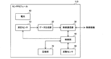
- FIG. 5 is a diagram showing a configuration of a sensor module according to the embodiment of the present disclosure.
- FIG. 6 is a diagram showing an example of the format of the advertisement packet transmitted by the management device in the tool system according to the embodiment of the present disclosure.
- FIG. 1 is a diagram showing a configuration of a tool system according to an embodiment of the present disclosure.
- FIG. 2 is a diagram showing an example of a sensor packet transmitted by the cutting tool according to the embodiment of the present disclosure.
- FIG. 3 is a cross-sectional view showing another example of
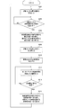
- FIG. 7 is a flowchart defining an example of an operation procedure when the cutting tool transmits a sensor packet to the management device in the tool system according to the embodiment of the present disclosure.
- FIG. 8 is a flowchart defining another example of the operation procedure when the cutting tool transmits a sensor packet to the management device in the tool system according to the embodiment of the present disclosure.
- FIG. 9 is a flowchart defining another example of the operation procedure when the cutting tool transmits a sensor packet to the management device in the tool system according to the embodiment of the present disclosure.
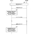
- FIG. 10 is a diagram showing an example of a sequence of communication processing in the tool system according to the embodiment of the present disclosure.
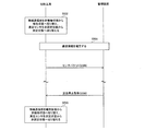
- FIG. 11 is a diagram showing an example of a sequence of communication processing in the tool system according to the embodiment of the present disclosure.
- the present disclosure has been made to solve the above-mentioned problems, and the purpose of the present disclosure is to realize cutting tools, cutting tool holders, tool systems, and communications capable of realizing excellent functions for predicting the life of cutting tools. To provide a method and a turning tool.
- the cutting tool includes a cutting insert having a cutting edge, a holder for holding the cutting insert, and a battery, a measurement sensor, and a wireless communication unit provided in the holder.
- a cutting tool, the wireless communication unit is driven by the power supplied from the battery, and wirelessly transmits measurement information including a measurement result of the measurement sensor or information based on the measurement result.
- the cutting tool and an external device such as a management device can be connected by wire, or the cutting tool can be connected to the cutting tool by wirelessly transmitting the measurement result of the measurement sensor provided in the holder or the measurement information including the information based on the measurement result.
- the measurement information can be transmitted to the external device without connecting to the processing machine by wire. Therefore, it is possible to realize an excellent function regarding the prediction of the life of the cutting tool.
- the cutting tool further includes a control unit provided in the holder, and the control unit wirelessly transmits the measurement information to the wireless communication unit, and the measurement information. It is possible to switch to the non-reporting state without wireless transmission.
- the configuration that can switch between the reporting state and the non-reporting state of the wireless communication unit can reduce the power consumption required for wirelessly transmitting the measurement information and reduce the frequency of battery replacement or charging. At the same time, it is possible to suppress an increase in wireless traffic.
- the cutting tool further includes a control unit provided in the holder, and the control unit can switch the measurement sensor between a measurement state and a non-measurement state.
- the configuration that can switch between the measurement state and the non-measurement state of the measurement sensor can suppress the power consumption by the measurement sensor and reduce the frequency of battery replacement or charging.
- control unit can switch the measurement sensor between a measurement state and a non-measurement state.
- the configuration that can switch between the measurement state and the non-measurement state of the measurement sensor can suppress the power consumption by the measurement sensor and reduce the frequency of battery replacement or charging.
- the wireless communication unit in the non-reporting state, periodically transitions to a state in which an instruction from the outside of the cutting tool can be received, and the wireless communication unit is the control unit. Upon receiving the instruction, the wireless communication unit is switched from the non-reporting state to the reporting state, and the measurement sensor is switched from the non-measuring state to the measuring state.
- the wireless communication unit can be switched from the non-reporting state to the reporting state, and the measurement sensor can be switched from the non-measuring state to the measuring state, for example, by using an instruction from an external device such as a management device as a trigger.
- the wireless communication unit is required to receive the instruction regarding switching between the states of the wireless communication unit and the measurement sensor from the outside by the configuration that periodically transitions to the state in which the instruction can be received in the non-reporting state. It is possible to reduce power consumption.
- the cutting tool further includes a start sensor provided in the holder, and the control unit sets the wireless communication unit when the measurement result of the start sensor satisfies the first condition. At the same time as switching from the non-reporting state to the reporting state, the measurement sensor is switched from the non-measuring state to the measuring state.
- the states of the wireless communication unit and the measurement sensor can be switched using the measurement result of the activation sensor as a trigger. Therefore, the trigger for switching the states of the wireless communication unit and the measurement sensor is from the outside of the cutting tool. No reception is required. Further, as the start sensor, for example, by using a sensor that consumes less current than the measurement sensor or by intermittently driving the start sensor, the power required to acquire the timing for switching the state of the wireless communication unit and the measurement sensor is obtained. Can reduce the consumption of.
- the control unit stops the activation sensor, and the control unit receives the measurement information from the wireless communication unit. After wireless transmission, the wireless communication unit is switched from the reported state to the non-reported state, and the measurement sensor is switched from the measured state to the non-measured state.
- the wireless communication unit can be switched to the non-reporting state and the measurement sensor can be switched to the non-measuring state while reducing the power consumption of the activation sensor.
- the control unit switches the wireless communication unit from the reporting state to the non-reporting state, and switches the measurement sensor from the measuring state to the non-reporting state. Switch to the measurement state.
- the wireless communication unit can be switched from the reporting state to the non-reporting state, and the measurement sensor can be switched from the measuring state to the non-measuring state, for example, by using an instruction from an external device such as a management device as a trigger.
- control unit switches the wireless communication unit from the reporting state to the non-reporting state, and switches the measurement sensor to the non-reporting state.
- the measurement state is switched to the non-measurement state.
- the wireless communication unit can be switched from the reporting state to the non-reporting state and the measurement sensor can be switched from the measuring state to the non-measuring state by using the measurement result of the activation sensor as a trigger. It is not necessary to receive the trigger related to the switching of the sensor state from the outside of the cutting tool.
- the tool system includes a cutting insert having a cutting edge, a holder for holding the cutting insert, and a cutting tool provided in the holder including a battery, a measuring sensor, and a wireless communication unit.
- the cutting tool wirelessly transmits measurement information including the measurement result of the measurement sensor or information based on the measurement result to the management device.
- the cutting tool can be connected by wire to the management device by wirelessly transmitting the measurement result of the measurement sensor provided in the holder or the measurement information including the information based on the measurement result to the management device.
- Measurement information can be transmitted to the management device without connecting the cutting tool and the processing machine by wire. Therefore, it is possible to realize an excellent function regarding the prediction of the life of the cutting tool.
- the management device transmits a transmission start instruction indicating that the transmission of the measurement information should be started to the cutting tool, and when the cutting tool receives the transmission start instruction, the measurement information Start wireless transmission.
- the cutting tool can start wireless transmission of measurement information by using the transmission start instruction received from the management device as a trigger. Therefore, the cutting tool itself detects the trigger for starting the transmission start instruction.
- the configuration of is unnecessary.
- the cutting tool further includes a start sensor provided in the holder and a control unit provided in the holder, and the control unit measures the measurement sensor in a measurement state and a non-measurement state.
- the wireless communication unit can be switched between a reporting state in which the measurement information is wirelessly transmitted to the management device and a non-reporting state in which the measurement information is not wirelessly transmitted.
- the wireless communication unit is switched from the non-reporting state to the reporting state, and the measurement sensor is switched from the non-measuring state to the measuring state.
- the configuration in which the reporting state and the non-reporting state of the wireless communication unit can be switched and the measuring state and the non-measurement state of the measurement sensor can be switched It is possible to reduce power consumption, reduce the frequency of battery replacement or charging, and suppress an increase in wireless traffic.
- the state of the wireless communication unit and the measurement sensor can be switched using the measurement result of the activation sensor as a trigger, it is not necessary to receive the trigger related to the switching of the state of the wireless communication unit and the measurement sensor from the outside of the cutting tool. Become.
- the power required to acquire the timing for switching the state of the wireless communication unit and the measurement sensor is obtained. Can reduce the consumption of.
- the control unit stops the activation sensor, and the control unit manages the measurement information by the wireless communication unit. After transmitting to the device, the wireless communication unit is switched from the reporting state to the non-reporting state, and the measurement sensor is switched from the measuring state to the non-measuring state.
- the wireless communication unit can be switched to the non-reporting state and the measurement sensor can be switched to the non-measuring state while reducing the power consumption of the activation sensor.
- the control unit switches the wireless communication unit from the reporting state to the non-reporting state, and measures the measurement sensor. The state is switched to the non-measurement state.
- the wireless communication unit can be switched from the reporting state to the non-reporting state and the measurement sensor can be switched from the measuring state to the non-measuring state by using the instruction from the management device as a trigger.
- control unit switches the wireless communication unit from the reporting state to the non-reporting state, and switches the measurement sensor to the non-reporting state.
- the measurement state is switched to the non-measurement state.
- the wireless communication unit can be switched from the reporting state to the non-reporting state and the measurement sensor can be switched from the measuring state to the non-measuring state by using the measurement result of the activation sensor as a trigger. It is not necessary to receive the trigger related to the switching of the sensor state from the outside of the cutting tool.
- the communication method includes a cutting insert having a cutting edge, a holder for holding the cutting insert, and a cutting tool provided in the holder including a battery, a measuring sensor, and a wireless communication unit. And a communication method in a tool system including a management device, wherein the management device and the cutting tool establish a communication connection, and the cutting tool is based on the measurement result of the measurement sensor or the measurement result.
- the step includes wirelessly transmitting measurement information including information to the management device.
- the cutting tool can connect the cutting tool and the management device by wire by a method of wirelessly transmitting the measurement result of the measurement sensor provided in the holder or the measurement information including the information based on the measurement result to the management device.
- Measurement information can be transmitted to the management device without connecting the cutting tool and the processing machine by wire. Therefore, it is possible to realize an excellent function regarding the prediction of the life of the cutting tool.
- the turning tool includes a cutting insert having a cutting edge, a holder for holding the cutting insert, a battery, a measurement sensor, a start sensor, a memory, and a battery, a measurement sensor, a start sensor, and a memory provided in the holder.
- a turning tool including a wireless communication unit, wherein the battery supplies power to the measurement sensor, the activation sensor, the memory, and the wireless communication unit, and the measurement sensor is at least an acceleration sensor and a strain sensor.
- the activation sensor includes at least one of a proximity sensor, a distance sensor, an ultrasonic sensor, a photoelectric sensor, a laser sensor, a temperature sensor, and an illuminance sensor, and the wireless communication unit includes any one.
- the measurement information including the measurement result of the measurement sensor or the information based on the measurement result is transmitted wirelessly.
- the turning tool and the external device such as the management device can be connected by wire or used for turning.
- the measurement information can be transmitted to the external device without connecting the tool and the processing machine by wire. Therefore, it is possible to realize an excellent function regarding the prediction of the life of the cutting tool.
- the turning tool further includes a control unit provided in the holder, and the control unit can switch the measurement sensor between a measurement state and a non-measurement state, and the wireless communication.
- the unit can be switched between a reporting state in which the measurement information is wirelessly transmitted and a non-reporting state in which the measurement information is not transmitted wirelessly, and the control unit has a predetermined control unit in which the measurement result of the activation sensor is stored in the memory.
- the wireless communication unit is switched from the non-reporting state to the reporting state, and the measurement sensor is switched from the non-measuring state to the measuring state.
- the configuration in which the reporting state and the non-reporting state of the wireless communication unit can be switched and the measuring state and the non-measurement state of the measurement sensor can be switched It is possible to reduce power consumption, reduce the frequency of battery replacement or charging, and suppress an increase in wireless traffic.
- the state of the wireless communication unit and the measurement sensor can be switched using the measurement result of the activation sensor as a trigger, it is not necessary to receive the trigger related to the switching of the state of the wireless communication unit and the measurement sensor from the outside of the turning tool. It becomes.
- the power required to acquire the timing for switching the state of the wireless communication unit and the measurement sensor is obtained. Can reduce the consumption of.
- the holder for a cutting tool includes a holding unit for holding a cutting insert, a battery, a measurement sensor, and a wireless communication unit, and the wireless communication unit is supplied from the battery. It is driven by electric power and wirelessly transmits measurement information including the measurement result of the measurement sensor or information based on the measurement result.
- the cutting tool and an external device such as a management device can be connected by wire by the configuration of wirelessly transmitting the measurement result of the measurement sensor provided in the holder for the cutting tool or the measurement information including the information based on the measurement result.
- the measurement information can be transmitted to the external device without connecting the cutting tool and the processing machine by wire. Therefore, it is possible to realize an excellent function regarding the prediction of the life of the cutting tool.
- the cutting tool holder further includes a control unit, and the control unit wirelessly transmits the measurement information to the wireless communication unit, and does not transmit the measurement information wirelessly. It is possible to switch to the reporting state.
- the configuration that can switch between the reporting state and the non-reporting state of the wireless communication unit can reduce the power consumption required for wirelessly transmitting the measurement information and reduce the frequency of battery replacement or charging. At the same time, it is possible to suppress an increase in wireless traffic.
- control unit can switch the measurement sensor between a measurement state and a non-measurement state.
- the configuration that can switch between the measurement state and the non-measurement state of the measurement sensor can suppress the power consumption by the measurement sensor and reduce the frequency of battery replacement or charging.
- FIG. 1 is a diagram showing a configuration of a tool system according to an embodiment of the present disclosure.
- the tool system 300 includes a cutting tool 100, a management device 200, and a wireless master unit 201.
- the cutting tool 100 includes a cutting tool holder 2 and a sensor module 110.
- the sensor module 110 includes a measurement sensor.
- the holder 2 for a cutting tool is also simply referred to as a holder 2.
- the wireless master unit 201 is connected to the management device 200, for example, by wire.
- the wireless master unit 201 is, for example, an access point.
- the cutting tool 100 is, for example, a tool for turning and is attached to a turning machine.
- the holder 2 holds a cutting insert 1 having a cutting edge.
- the sensor module 110 is provided in the holder 2.
- the holder 2 includes fixing members 3A and 3B.
- the fixing members 3A and 3B hold the cutting insert 1.
- the fixing members 3A and 3B are examples of the holding portion.
- the cutting insert 1 has a polygonal shape such as a triangle, a square, a rhombus, and a pentagon when viewed from above.
- the cutting insert 1 has, for example, a through hole formed in the center of the upper surface thereof, and is fixed to the holder 2 by the fixing members 3A and 3B.
- the tool system 300 is not limited to the configuration including one cutting tool 100, and may be configured to include a plurality of cutting tools 100. Further, the tool system 300 is not limited to the configuration including one management device 200, and may be configured to include a plurality of management devices 200.
- the cutting tool 100 wirelessly transmits measurement information including the measurement result of the measurement sensor in the sensor module 110 to the wireless master unit 201. Alternatively, the cutting tool 100 wirelessly transmits measurement information including information based on the measurement result of the measurement sensor in the sensor module 110 to the wireless master unit 201.
- the cutting tool 100 wirelessly transmits a sensor packet including measurement information to the wireless master unit 201.
- the cutting tool 100 and the wireless master unit 201 are, for example, compliant with ZigBee (registered trademark) compliant with IEEE 802.15.4, Bluetooth® compliant with IEEE 802.15.1, and IEEE 802.15.3a.
- Wireless communication is performed using a communication protocol such as UWB (Ultra Wide Band).
- UWB Ultra Wide Band
- a communication protocol other than the above may be used between the cutting tool 100 and the wireless master unit 201.
- the wireless master unit 201 relays the sensor packet received from the cutting tool 100 to the management device 200.
- FIG. 2 is a diagram showing an example of a sensor packet transmitted by the cutting tool according to the embodiment of the present disclosure.
- the sensor module 110 in the cutting tool 100 creates a sensor packet 401 in which the measurement information and the sensor ID, which is the ID of the measurement sensor, are stored in the “sensor data” field.
- a predetermined preamble is stored in the field of the "synchronization header" in the sensor packet 401.
- the field of "MAC (Media Access Control) header for example, the MAC address of the sensor module 110 and the like are stored.
- the data length of the "sensor data” field is 20 octets in FIG. 2, but it can be changed according to the type of physical quantity included in the measurement information, the number of the physical quantity, and the like.
- the wireless master unit 201 acquires a sensor packet included in the wireless signal received from the cutting tool 100 and transmits it to the management device 200.
- FIG. 3 is a cross-sectional view showing another example of the configuration of the cutting tool according to the embodiment of the present disclosure.
- the cutting tool 100 may be a tool for milling that is attached to the milling machine. More specifically, the cutting tool 100 for milling includes a holder 2A for holding a plurality of cutting inserts 1A having a cutting edge, and a sensor module 110 provided on the holder 2A including a measuring sensor.
- the holder 2A includes a fixing member 3C.
- the fixing member 3C holds the cutting insert 1A.
- the cutting insert 1A is fixed to the holder 2A by, for example, the fixing member 3C.
- the fixing member 3C is an example of a holding portion.
- FIG. 4 is a diagram showing a configuration of a management device according to an embodiment of the present disclosure.
- the management device 200 includes a communication unit 210, a processing unit 220, and a storage unit 230.
- the storage unit 230 is, for example, a flash memory.
- the communication unit 210 When the communication unit 210 receives the sensor packet from the cutting tool 100 via the wireless master unit 201, the communication unit 210 acquires measurement information and the sensor ID from the received sensor packet, and outputs the acquired measurement information and the sensor ID to the processing unit 220.
- the processing unit 220 When the processing unit 220 receives the measurement information and the sensor ID from the communication unit 210, the processing unit 220 associates the measurement information with the sensor ID and stores it in the storage unit 230.
- the processing unit 220 predicts the life of the cutting insert 1 in the cutting tool 100 corresponding to the corresponding sensor ID based on the measurement information in the storage unit 230. Then, the processing unit 220 notifies the user to replace the cutting insert 1 based on the prediction result.
- FIG. 5 is a diagram showing a configuration of a sensor module according to the embodiment of the present disclosure.
- the sensor module 110 includes a measurement sensor 10, a data generation unit 20, a wireless communication unit 30, a control unit 40, a start-up sensor 50, a battery 60, and a storage unit 70.
- the storage unit 70 is, for example, a flash memory.
- the wireless communication unit 30 is realized by, for example, a wireless communication chip.
- the battery 60 is, for example, a power storage device including a primary battery, a secondary battery, a solar cell, a capacitor, and the like.
- the battery 60 stores energy and uses the stored energy to supply electric power to each circuit such as the wireless communication unit 30 in the sensor module 110.
- the activation sensor 50 includes, for example, at least one of a proximity sensor, a distance sensor, an ultrasonic sensor, a photoelectric sensor, a laser sensor, a temperature sensor, and an illuminance sensor.
- the activation sensor 50 measures at least one of physical quantities such as distance, temperature, and illuminance between an object, for example, a workpiece, and outputs an analog signal indicating the measured physical quantity to the control unit 40.
- the activation sensor 50 is driven by, for example, the electric power supplied from the battery 60.
- the control unit 40 is, for example, a processor such as a CPU (Central Processing Unit).
- the activation sensor 50 is activated by, for example, the control unit 40, performs measurement in the activated state, and outputs an analog signal indicating the measured physical quantity to the control unit 40.
- the measurement sensor 10 includes, for example, at least one of an acceleration sensor, a strain sensor, a pressure sensor, a sound sensor, and a temperature sensor.
- the measurement sensor 10 is provided, for example, in the vicinity of the cutting insert 1 in the holders 2 and 2A.
- the measurement sensor 10 measures at least one of physical quantities such as acceleration, strain, pressure, sound, and temperature, and outputs an analog signal indicating the measured physical quantity to the data generation unit 20.
- the measurement sensor 10 is driven by, for example, the electric power supplied from the battery 60.
- the measurement sensor 10 switches between a measurement state and a non-measurement state, for example.
- the measurement sensor 10 performs measurement in the measurement state, outputs an analog signal indicating the measured physical quantity to the data generation unit 20, and stops in the non-measurement state.
- the data generation unit 20 creates measurement information including the measurement result of the measurement sensor 10 or information based on the measurement result. More specifically, the data generation unit 20 receives an analog signal from the measurement sensor 10 and converts the received analog signal into AD (Analog Digital) measurement information including a sensor measurement value, or an average with respect to the sensor measurement value. Create measurement information including values that have undergone calculations such as conversion.
- AD Analog Digital
- the data generation unit 20 generates a sensor packet in which the generated measurement information and the sensor ID of the measurement sensor 10 are stored, and outputs the generated sensor packet to the wireless communication unit 30.
- the wireless communication unit 30 wirelessly transmits measurement information to the wireless master unit 201 outside the cutting tool 100. More specifically, the wireless communication unit 30 wirelessly transmits the sensor packet in which the measurement information and the sensor ID received from the data generation unit 22 are stored to the wireless master unit 201. The wireless communication unit 30 is driven by the electric power supplied from the battery.
- the wireless communication unit 30 switches between the reporting state and the non-reporting state.
- the wireless communication unit 30 wirelessly transmits the sensor packet to the wireless master unit 201 in the reporting state, but does not wirelessly transmit the sensor packet to the wireless master unit 201 in the non-reporting state.
- the control unit 40 controls the operations of the wireless communication unit 30, the measurement sensor 10, and the activation sensor 50.
- control unit 40 performs a switching process for switching between the reported state and the non-reported state of the wireless communication unit 30 and the measured state and the non-measured state of the measurement sensor 10. Further, for example, the control unit 40 controls the start and stop of the start sensor 50.
- the control unit 40 in the sensor module 110 of the cutting tool 100 performs a connection process for establishing a communication connection with the management device 200.
- the management device 200 transmits an advertisement packet to the cutting tool 100.
- FIG. 6 is a diagram showing an example of the format of the advertisement packet transmitted by the management device in the tool system according to the embodiment of the present invention.
- the advertisement packet is composed of the PHY header, the MAC header, and the fields corresponding to the message types in this order from the beginning.
- the management device 200 sets a broadcast address as a destination in the MAC header, sets its own ID such as a MAC address as a source in the MAC header, and sets an identifier indicating that it is an advertisement packet in the field corresponding to the message type. An advertisement packet is generated, and the generated advertisement packet is transmitted to the wireless master unit 201.
- the wireless master unit 201 transmits a wireless signal including an advertisement packet received from the management device 200 to the cutting tool 100.
- the wireless communication unit 30 in the sensor module 110 receives a wireless signal from the wireless master unit 201 in the activated state, and acquires an advertisement packet included in the received wireless signal.
- the wireless communication unit 30 outputs the acquired advertisement packet to the control unit 40.
- control unit 40 in the sensor module 110 receives the advertisement packet from the wireless communication unit 30, the control unit 40 sets the management device 200 having the MAC address of the source included in the received advertisement packet as the communication target as the connection process. Specifically, the control unit 40 registers the MAC address in the storage unit 70 as the MAC address of the management device 200 to be communicated.
- control unit 40 generates a response packet which is a response to the received advertisement packet as a connection process, and outputs the generated response packet to the wireless communication unit 30.
- the format of the response packet generated by the control unit 40 is, for example, the same as the format of the advertisement packet shown in FIG.
- control unit 40 sets the MAC address of the management device 200 as the destination in the MAC header, sets the MAC address of its own sensor module 110 as the source in the MAC header, for example, and sets the response packet in the field corresponding to the message type.
- a response packet in which an identifier indicating the above is set is generated, and the generated response packet is output to the wireless communication unit 30.
- the wireless communication unit 30 transmits a wireless signal including a response packet received from the control unit 40 in the activated state.
- the management device 200 When the management device 200 receives the response packet from the sensor module 110 of the cutting tool 100 via the wireless master unit 201, the management device 200 sets the sensor module 110 having the MAC address of the source included in the received response packet as the communication target. Specifically, when the processing unit 220 in the management device 200 receives the response packet from the sensor module 110 via the wireless master unit 201 and the communication unit 210, the processing unit 220 communicates with the MAC address of the source included in the received response packet. It is registered in the storage unit 70 as the MAC address of the sensor module 110 of the above.
- the wireless communication unit 30 in the sensor module 110 periodically transitions to a state in which the instruction from the management device 200 can be received in the non-reporting state.
- the control unit 40 in the sensor module 110 intermittently drives the wireless communication unit 30 in the non-reporting state of the wireless communication unit 30. More specifically, the control unit 40 intermittently puts the wireless communication unit 30 into the activated state by switching between the stopped state and the activated state of the wireless communication unit 30 at a predetermined switching cycle.
- the stopped state includes a state in which some functions are stopped, that is, a sleep state.
- the management device 200 transmits an advertisement packet to the cutting tool 100 in a cycle shorter than the switching cycle.
- the wireless communication unit 30 in the sensor module 110 receives the advertisement packet from the management device 200 in the activated state in the intermittent drive, the wireless communication unit 30 outputs the received advertisement packet to the control unit 40.
- control unit 40 in the sensor module 110 receives the advertisement packet from the wireless communication unit 30, the control unit 40 performs a connection process for establishing a communication connection with the management device 200, starts continuous driving of the wireless communication unit 30, and starts the wireless communication unit 30.
- the activated state of 30 is maintained.
- the management device 200 transmits a transmission start instruction indicating that the transmission of measurement information should be started to the cutting tool 100 to be communicated. More specifically, the management device 200 transmits the transmission start instruction to the wireless master unit 201.
- the wireless master unit 201 transmits a wireless signal including a transmission start instruction received from the management device 200 to the cutting tool 100.
- the cutting tool 100 When the cutting tool 100 receives the transmission start instruction from the management device 200, the cutting tool 100 starts wireless transmission of the measurement information.
- the wireless communication unit 30 in the sensor module 110 of the cutting tool 100 receives the transmission start instruction from the management device 200 via the wireless master unit 201, the wireless communication unit 30 outputs the received transmission start instruction to the control unit 40.
- control unit 40 When the control unit 40 receives a transmission start instruction from the wireless communication unit 30, the control unit 40 switches the wireless communication unit 30 from the non-reporting state to the reporting state, and switches the measurement sensor 10 from the non-measurement state to the measurement state.
- control unit 40 outputs a report start instruction indicating that the wireless transmission of the sensor packet should be started to the wireless communication unit 30, and switches the measurement sensor 10 from the stopped state to the activated state.
- the measurement sensor 10 When the measurement sensor 10 switches to the measurement state, that is, the activation state, the measurement sensor 10 starts measurement and starts outputting an analog signal indicating the measured physical quantity to the data generation unit 20.
- the wireless communication unit 30 Upon receiving the report start instruction from the control unit 40, the wireless communication unit 30 starts wireless transmission of the sensor packet including the measurement information generated by the data generation unit 20 to the management device 200, periodically or irregularly. ..
- the management device 200 transmits a transmission stop instruction indicating that the transmission of measurement information should be stopped to the cutting tool 100. More specifically, the management device 200 transmits a transmission stop instruction to the wireless master unit 201.
- the wireless master unit 201 transmits a wireless signal including a transmission stop instruction received from the management device 200 to the cutting tool 100.
- the cutting tool 100 When the cutting tool 100 receives the transmission stop instruction from the management device 200, the cutting tool 100 stops the wireless transmission of the sensor packet.
- the wireless communication unit 30 in the sensor module 110 of the cutting tool 100 receives the transmission stop instruction from the management device 200 via the wireless master unit 201, the wireless communication unit 30 outputs the received transmission stop instruction to the control unit 40.
- control unit 40 When the control unit 40 receives a transmission stop instruction from the wireless communication unit 30, the control unit 40 switches the wireless communication unit 30 from the reporting state to the non-reporting state, and switches the measurement sensor 10 from the measuring state to the non-measuring state.
- control unit 40 outputs a report stop instruction indicating that the wireless transmission of the sensor packet should be stopped to the wireless communication unit 30, and switches the measurement sensor 10 from the activated state to the stopped state.
- the wireless communication unit 30 When the wireless communication unit 30 receives a report stop instruction from the control unit 40, the wireless communication unit 30 stops wireless transmission of the sensor packet to the management device 200.
- control unit 40 When the control unit 40 switches the wireless communication unit 30 to the non-reporting state, the control unit 40 resumes the intermittent drive of the wireless communication unit 30 and waits for the advertisement packet from the management device 200.
- control unit 40 in the sensor module 110 intermittently drives the activation sensor 50. More specifically, the control unit 40 intermittently puts the start sensor 50 into the start state by switching between the stop state and the start state of the start sensor 50 at a predetermined switching cycle.
- the wireless communication unit 30 switches to the reporting state when the measurement result of the activation sensor 50 satisfies a predetermined condition in the non-reporting state.
- the control unit 40 when the measurement result of the activation sensor satisfies the first condition, the control unit 40 performs the switching process.
- the control unit 40 monitors the analog signal received from the activation sensor 50, and when the level of the analog signal exceeds a predetermined threshold value ThA stored in the storage unit 70, the wireless communication unit 30 is released from the non-reporting state.
- the measurement sensor 10 is switched from the non-measurement state to the measurement state.
- the control unit 40 exceeds a predetermined threshold value ThA1.
- the wireless communication unit 30 is switched to the reporting state, and the measurement sensor 10 is switched to the measuring state. That is, the control unit 40 switches the wireless communication unit 30 and the measurement sensor 10 from the stopped state to the activated state.
- the control unit 40 has a measurement result of a distance sensor, a proximity sensor, or an ultrasonic sensor as an example of the activation sensor 50, in which the distance between the cutting tool 100 and the workpiece is a predetermined threshold ThA2, for example, 10 mm or less. Then, the wireless communication unit 30 is switched to the reporting state, and the measurement sensor 10 is switched to the measuring state. That is, the control unit 40 switches the wireless communication unit 30 and the measurement sensor 10 from the stopped state to the activated state.
- ThA2 a predetermined threshold
- control unit 40 when the control unit 40 detects that the cutting tool 100 has reached a predetermined position by the photoelectric sensor and the laser sensor, which are examples of the activation sensor 50, the control unit 40 switches the wireless communication unit 30 to the reporting state and the measurement sensor 10. To the measurement state. That is, the control unit 40 switches the wireless communication unit 30 and the measurement sensor 10 from the stopped state to the activated state.
- the control unit 40 detects that the temperature of the cutting tool 100 has fallen below a predetermined value due to, for example, the coolant liquid by the ultrasonic sensor and the temperature sensor, which are examples of the activation sensor 50, the wireless communication unit 30 is not reported.
- the measurement sensor 10 is switched to the measurement state while switching from the state to the reporting state.
- the activation sensor 50 stops when the measurement result of the activation sensor 50 satisfies a predetermined condition.
- the control unit 40 stops the intermittent drive of the activation sensor 50 and maintains the stopped state of the activation sensor 50.
- the control unit 40 receives an advertisement packet from the management device 200 via the wireless communication unit 30 in the reporting state of the wireless communication unit 30, and performs a connection process for establishing a communication connection with the management device 200.
- control unit 40 When the control unit 40 establishes the communication connection with the management device 200, the control unit 40 outputs a report start instruction indicating that the wireless transmission of the sensor packet should be started to the wireless communication unit 30.
- the measurement sensor 10 When the measurement sensor 10 switches to the measurement state, that is, the activation state, the measurement sensor 10 starts measurement and starts outputting an analog signal indicating the measured physical quantity to the data generation unit 20.
- the wireless communication unit 30 Upon receiving the report start instruction from the control unit 40, the wireless communication unit 30 starts wireless transmission of the sensor packet including the measurement information generated by the data generation unit 20 to the management device 200, periodically or irregularly. ..
- the wireless communication unit 30 switches to the non-reporting state after transmitting the sensor packet to the management device 200.
- the management device 200 transmits a transmission stop instruction to the cutting tool 100 via the wireless master unit 201.
- the cutting tool 100 When the cutting tool 100 receives the transmission stop instruction from the management device 200, the cutting tool 100 stops the wireless transmission of the sensor packet.
- the control unit 40 in the sensor module 110 of the cutting tool 100 switches the wireless communication unit 30 from the reporting state to the non-reporting state, and switches the measurement sensor 10 from the measuring state to the non-reporting state. Switch to the measurement state. More specifically, when the control unit 40 receives the transmission stop instruction from the management device 200 via the wireless communication unit 30, the control unit 40 switches the wireless communication unit 30 to the non-reporting state and switches the measurement sensor 10 to the non-measurement state.
- control unit 40 switches the wireless communication unit 30 and the measurement sensor 10 from the activated state to the stopped state.
- the control unit 40 restarts the intermittent drive of the activation sensor 50 and monitors the analog signal received from the activation sensor 50.
- control unit 40 in the sensor module 110 intermittently drives the activation sensor 50.
- the wireless communication unit 30 switches to the activated state when the measurement result of the activated sensor 50 satisfies a predetermined condition.
- control unit 40 monitors the analog signal received from the activation sensor 50, and when the level of the analog signal exceeds a predetermined threshold value ThA, the control unit 40 switches the wireless communication unit 30 from the non-reporting state to the reporting state. At the same time, the measurement sensor 10 is switched from the non-measurement state to the measurement state.
- control unit 40 switches the wireless communication unit 30 and the measurement sensor 10 from the stopped state to the activated state.
- the control unit 40 receives an advertisement packet from the management device 200 via the wireless communication unit 30 in the reporting state of the wireless communication unit 30, and performs a connection process for establishing a communication connection with the management device 200.
- control unit 40 When the control unit 40 establishes the communication connection with the management device 200, the control unit 40 outputs a report start instruction indicating that the wireless transmission of the sensor packet should be started to the wireless communication unit 30.
- the measurement sensor 10 When the measurement sensor 10 switches to the measurement state, that is, the activation state, the measurement sensor 10 starts measurement and starts outputting an analog signal indicating the measured physical quantity to the data generation unit 20.
- the wireless communication unit 30 Upon receiving the report start instruction from the control unit 40, the wireless communication unit 30 starts wireless transmission of the sensor packet including the measurement information generated by the data generation unit 20 to the management device 200, periodically or irregularly. ..
- the wireless communication unit 30 switches to the non-reporting state when the measurement result of the activation sensor 50 satisfies, for example, the second condition, which is a predetermined condition, in the reporting state.
- control unit 40 monitors the analog signal received from the activation sensor 50 after switching the wireless communication unit 30 from the non-reporting state to the reporting state, and the level of the analog signal again sets the threshold value ThA. When it exceeds, the wireless communication unit 30 is switched from the reporting state to the non-reporting state, and the measurement sensor 10 is switched from the measuring state to the non-measuring state.
- control unit 40 switches the wireless communication unit 30 and the measurement sensor 10 from the activated state to the stopped state.
- the user illuminates the cutting tool 100 with a lighting tool or the like to switch between the reported state and the non-reported state of the wireless communication unit 30, and the measured state and the non-measured state of the measurement sensor 10. be able to.
- control unit 40 is the measurement result of the illuminance sensor as an example of the activation sensor 50.
- the wireless communication unit 30 To the reporting state and the measurement sensor 10 to the measuring state.
- the control unit 40 monitors the measurement result of the illuminance sensor, and the brightness of the light illuminating the cutting tool 100 exceeds the threshold value ThA1 again. Then, the wireless communication unit 30 is switched from the reporting state to the non-reporting state, and the measurement sensor 10 is switched from the measuring state to the non-measuring state.
- control unit 40 uses the same threshold value ThA to switch the wireless communication unit 30 from the non-reporting state to the reporting state and from the reporting state to the non-reporting state. Yes, but it is not limited to this.
- control unit 40 has a configuration in which the measurement sensor 10 is switched from the non-measurement state to the measurement state and from the measurement state to the non-measurement state by using the same threshold value ThA.
- ThA threshold value
- control unit 40 receives an analog signal from the activation sensor 50 after switching from the non-reporting state of the wireless communication unit 30 to the reporting state and switching from the non-measurement state of the measurement sensor 10 to the measurement state.
- the level exceeds a threshold value ThB different from the threshold value ThA
- the wireless communication unit 30 is switched from the reporting state to the non-reporting state
- the measurement sensor 10 is switched from the measuring state to the non-measuring state.
- the control unit 40 sets the distance between the cutting tool 100 and the workpiece to be a predetermined threshold value ThA2, for example, 10 mm or less, which is the measurement result of the distance sensor as an example of the activation sensor 50. Then, the wireless communication unit 30 is switched to the reporting state, and the measurement sensor 10 is switched to the measuring state.
- ThA2 a predetermined threshold value
- control unit 40 monitors the measurement result of the distance sensor after switching to the reporting state of the wireless communication unit 30 and the measuring state of the measuring sensor 10, and between the cutting tool 100 and the workpiece.
- the distance between the two is a predetermined threshold ThB2, for example, 20 mm or more
- the wireless communication unit 30 is switched from the reporting state to the non-reporting state
- the measuring sensor 10 is switched from the measuring state to the non-measuring state.
- Each device in the tool system according to the embodiment of the present disclosure includes a computer including a memory, and an arithmetic processing unit such as a CPU in the computer includes a program including a part or all of each step of the following flowchart and sequence. Read from the memory and execute. The programs of these plurality of devices can be installed from the outside. The programs of these plurality of devices are distributed in a state of being stored in a recording medium.
- FIG. 7 is a flowchart defining an example of an operation procedure when the cutting tool transmits a sensor packet to the management device in the tool system according to the embodiment of the present disclosure.
- FIG. 7 shows the operation procedure of the cutting tool 100 in the above-mentioned specific example 1 of the switching process.
- the cutting tool 100 starts the intermittent drive of the wireless communication unit 30 in the non-reporting state of the wireless communication unit 30 (step S102).
- Step S106 when the cutting tool 100 listens for the advertisement packet from the management device 200 (NO in step S104) and receives the advertisement packet from the management device 200 (YES in step S104), the cutting tool 100 starts continuous driving of the wireless communication unit 30.
- the cutting tool 100 establishes a communication connection with the management device 200 (step S108).
- the wireless communication unit 30 is in a non-reporting state.
- the measurement sensor 10 is switched from the non-measurement state to the measurement state (step S112).
- the cutting tool 100 starts wireless transmission of the sensor packet to the management device 200 (step S114).
- the cutting tool 100 continues wireless transmission of the sensor packet to the management device 200 until the transmission stop instruction is received from the management device 200 (NO in step S116), and when the transmission stop instruction is received from the management device 200 (NO). YES in step S116), the wireless communication unit 30 is switched from the reporting state to the non-reporting state, and the measurement sensor 10 is switched from the measuring state to the non-measuring state (step S118).
- the cutting tool 100 restarts the intermittent drive of the wireless communication unit 30 (step S102) and waits for the advertisement packet from the management device 200 (step S104).
- FIG. 8 is a flowchart defining another example of the operation procedure when the cutting tool transmits a sensor packet to the management device in the tool system according to the embodiment of the present disclosure.
- FIG. 8 shows the operation procedure of the cutting tool 100 in the above-mentioned specific example 2 of the switching process.
- the cutting tool 100 starts the intermittent drive of the start sensor 50 in the non-reported state of the wireless communication unit 30 (step S202).
- the cutting tool 100 monitors the measurement result of the start sensor 50, and when the measurement result satisfies a predetermined condition (YES in step S204), the wireless communication unit 30 is switched from the non-reporting state to the reporting state and measured.
- the sensor 10 is switched from the non-measurement state to the measurement state (step S206).
- the cutting tool 100 switches the start sensor 50 from the start state to the stop state and maintains the stop state (step S208).
- the cutting tool 100 establishes a communication connection with the management device 200 (step S210).
- the cutting tool 100 starts wireless transmission of the sensor packet to the management device 200 (step S212).
- the cutting tool 100 continues wireless transmission of the sensor packet to the management device 200 until the transmission stop instruction is received from the management device 200 (NO in step S214), and when the transmission stop instruction is received from the management device 200 (NO). YES in step S214), the wireless communication unit 30 is switched from the reporting state to the non-reporting state, and the measurement sensor 10 is switched from the measuring state to the non-measuring state (step S216).
- the cutting tool 100 restarts the intermittent drive of the start sensor 50 (step S202) and monitors the measurement result of the start sensor 50 (step S204).
- FIG. 9 is a flowchart defining another example of the operation procedure when the cutting tool transmits a sensor packet to the management device in the tool system according to the embodiment of the present disclosure.
- FIG. 9 shows an operation procedure of the cutting tool 100 in the above-mentioned specific example 3 of the switching process.
- the cutting tool 100 performs the same processing as steps S202 to S206 in FIG. 8 as the processing of steps S302 to S306.
- the cutting tool 100 establishes a communication connection with the management device 200 (step S308).
- the cutting tool 100 starts wireless transmission of the sensor packet to the management device 200 (step S310).
- the cutting tool 100 continues wireless transmission of the sensor packet to the management device 200 until the measurement result of the start sensor 50 satisfies the predetermined condition (NO in step S312), and the measurement result of the start sensor 50 satisfies the predetermined condition.
- the wireless communication unit 30 is switched from the reporting state to the non-reporting state, and the measurement sensor 10 is switched from the measuring state to the non-measuring state (step S314).
- the cutting tool 100 waits for the measurement result of the start sensor 50 to satisfy a predetermined condition (NO in step S304).
- FIG. 10 is a diagram showing an example of a sequence of communication processing in the tool system according to the embodiment of the present disclosure.
- FIG. 10 shows a sequence of communication processing in the above-described specific example 1 of switching processing.
- step S402 the management device 200 and the cutting tool 100 establish a communication connection.
- the management device 200 transmits a transmission start instruction to the cutting tool 100 (step S404).
- the cutting tool 100 switches the wireless communication unit 30 from the non-reporting state to the reporting state, and switches the measurement sensor 10 from the non-measuring state to the measuring state (step S406).
- the cutting tool 100 wirelessly transmits the sensor packet including the measurement information to the management device 200 periodically or irregularly (step S408).
- the management device 200 transmits a transmission stop instruction to the cutting tool 100 (step S410).
- the cutting tool 100 switches the wireless communication unit 30 from the reporting state to the non-reporting state, and switches the measurement sensor 10 from the measuring state to the non-measuring state (step S412).
- FIG. 11 is a diagram showing an example of a sequence of communication processing in the tool system according to the embodiment of the present disclosure.
- FIG. 11 shows a sequence of communication processing in the above-mentioned specific example 2 of the switching processing.
- the cutting tool 100 switches the wireless communication unit 30 from the non-reporting state to the reporting state, and switches the measurement sensor 10 from the non-measurement state. Switch to the measurement state (step S502).
- step S504 the management device 200 and the cutting tool 100 establish a communication connection.
- the cutting tool 100 wirelessly transmits the sensor packet including the measurement information to the management device 200 periodically or irregularly (step S506).
- the management device 200 transmits a transmission stop instruction to the cutting tool 100 (step S508).
- the cutting tool 100 switches the wireless communication unit 30 from the reporting state to the non-reporting state, and switches the measurement sensor 10 from the non-measuring state to the measuring state (step S510).
- the management device 200 transmits an advertisement packet to the cutting tool 100 via the wireless master unit 201, and the cutting tool 100 sends a response packet via the wireless master unit 201 to the management device.
- the configuration is to transmit to 200
- the present invention is not limited to this.
- the cutting tool 100 may transmit the advertisement packet to the management device 200 via the wireless master unit 201, and the management device 200 may transmit the response packet to the cutting tool 100 via the wireless master unit 201.
- control unit 40 in the sensor module 110 sets a broadcast address as the destination in the MAC header, sets the MAC address of its own sensor module 110 as the source in the MAC header, and sets the fields corresponding to the message type.
- An advertisement packet in which an identifier indicating that the packet is an advertisement packet is set is generated, and the generated advertisement packet is output to the wireless communication unit 30.
- the wireless communication unit 30 in the sensor module 110 transmits a wireless signal including an advertisement packet received from the control unit 40 in the activated state.
- the management device 200 When the management device 200 receives the advertisement packet from the sensor module 110 via the wireless master unit 201, the management device 200 sets the sensor module 110 having the MAC address of the source included in the received advertisement packet as the communication target.
- the management device 200 generates a response packet that is a response to the received advertisement packet, and transmits the generated response packet to the wireless master unit 201.
- the management device 200 sets the MAC address of the sensor module 110 as the destination in the MAC header, sets its own MAC address as the source in the MAC header, and indicates that it is a response packet in the field corresponding to the message type.
- a response packet with an identifier set is generated, and the generated response packet is transmitted to the wireless master unit 201.
- the wireless master unit 201 transmits a wireless signal including a response packet received from the management device 200.
- the wireless communication unit 30 in the sensor module 110 receives the response packet from the management device 200 via the wireless master unit 201 in the activated state, the wireless communication unit 30 outputs the received response packet to the control unit 40.
- control unit 40 in the sensor module 110 receives the response packet from the wireless communication unit 30, the control unit 40 sets the management device 200 having the MAC address of the source included in the received advertisement packet as the communication target.
- the wireless communication unit 30 has a configuration in which the reporting state and the non-reporting state are switched, but the present invention is not limited to this.
- the wireless communication unit 30 may always be in the reporting state without switching to the non-reporting state.
- the measurement sensor 10 has a configuration in which the measurement state and the non-measurement state are switched, but the present invention is not limited to this.
- the measurement sensor 10 may always be in the measurement state without switching to the non-measurement state.
- control unit 40 switches between the reported state and the non-reported state of the wireless communication unit 30 and the measured state and the non-measured state of the measurement sensor 10 as a switching process.
- the control unit 40 may be configured to switch between the reported state and the non-reported state of the wireless communication unit 30 and the measured state and the non-measured state of the measurement sensor 10 as the switching process.
- the control unit 40 is configured to perform a switching process of switching the measurement sensor 10 between the measurement state and the non-measurement state, but the present invention is not limited to this. Absent.
- the control unit 40 sets the data generation unit 20 into a generation state in which measurement information is generated and a non-generation state in which measurement information is not generated. It may be configured to switch to. Specifically, for example, when the measurement sensor 10 is a thermocouple, the control unit 40 switches the data generation unit 20 between the generated state and the non-generated state instead of the switching process of the measurement sensor 10.
- the measurement sensor 10 is configured to output an analog signal indicating the measured physical quantity to the data generation unit 20, but the present invention is not limited to this.
- the measurement sensor 10 may be configured to AD-convert the analog signal to generate a digital signal and output the generated digital signal to the data generation unit 20.
- the cutting tool 100 is configured to include a start sensor 50, but the present invention is not limited to this.
- the cutting tool 100 may not be provided with the start sensor 50, for example, in the above-described specific example 1 of the switching process.
- control unit 40 is configured to intermittently drive the start sensor 50, but the present invention is not limited to this.
- the control unit 40 may be configured to continuously drive the activation sensor 50.
- the wireless communication unit 30 is configured to wirelessly transmit measurement information to the management device 200, but the present invention is not limited to this.
- the wireless communication unit 30 may be configured to wirelessly transmit measurement information to a device other than the management device 200.
- a technique is desired in which a sensor is mounted on a cutting tool 100 and the life of a tool such as a cutting insert can be predicted based on the measurement result by the sensor.
- the cutting tool 100 for milling rotates during machining, so that the measurement result of the sensor is transmitted from the cutting tool 100 to an external device. It is difficult to transmit by wire to.
- the turret rotates in each process to automatically rotate the cutting tool 100 used for machining. It is difficult to transmit the measurement result of the sensor from the cutting tool 100 to the external device by wire in the processing machine replaced with.
- the processing machine needs to be configured to receive the measurement result of the sensor. Therefore, the conventional processing machine can be used for general purposes. It will be difficult.
- the cutting insert 1 has a cutting edge.
- the holder 2 holds the cutting insert 1.
- the battery 60, the measurement sensor 10, and the wireless communication unit 30 are provided in the holder 2.
- the wireless communication unit 30 is driven by the electric power supplied from the battery 60, and wirelessly transmits measurement information including the measurement result of the measurement sensor 10 or information based on the measurement result.
- the cutting tool 100 and an external device such as the management device 200 can be connected by wire by the configuration of wirelessly transmitting the measurement result of the measurement sensor 10 provided in the holder 2 or the measurement information including the information based on the measurement result.
- the measurement information can be transmitted to the external device without connecting the cutting tool 100 and the processing machine by wire.
- the cutting tool 100 can realize an excellent function for predicting the life of the cutting tool.
- control unit 40 is provided in the holder 2.
- the control unit 40 can switch the wireless communication unit 30 between a reporting state in which the measurement information is wirelessly transmitted and a non-reporting state in which the measurement information is not wirelessly transmitted.
- the configuration that can switch between the reporting state and the non-reporting state of the wireless communication unit 30 suppresses the consumption of power required for wirelessly transmitting the measurement information, and reduces the frequency of battery replacement or charging. At the same time, it is possible to suppress an increase in wireless traffic.
- control unit 40 is provided in the holder 2.
- the control unit 40 can switch the measurement sensor 10 between a measurement state and a non-measurement state.
- the configuration capable of switching between the measurement state and the non-measurement state of the measurement sensor 10 can suppress the power consumption by the measurement sensor 10 and reduce the frequency of battery replacement or charging.
- control unit 40 can switch the measurement sensor 10 between the measurement state and the non-measurement state.
- the configuration capable of switching between the measurement state and the non-measurement state of the measurement sensor 10 can suppress the power consumption by the measurement sensor 10 and reduce the frequency of battery replacement or charging.
- the wireless communication unit 30 periodically transitions to a state in which an instruction from the outside of the cutting tool 100 can be received in a non-reporting state.
- the control unit 40 switches the wireless communication unit 30 from the non-reporting state to the reporting state, and switches the measurement sensor 10 from the non-measurement state to the measurement state.
- the wireless communication unit 30 can be switched from the non-reporting state to the reporting state and the measurement sensor 10 can be switched from the non-measuring state to the measuring state by using an instruction from an external device such as the management device 200 as a trigger. it can. Further, in the non-reporting state, the wireless communication unit 30 periodically transitions to a state in which the instruction can be received, so that the wireless communication unit 30 receives the instruction regarding switching of the states of the wireless communication unit 30 and the measurement sensor 10 from the outside. The power consumption required for wireless communication can be reduced.
- the start sensor 50 is provided in the holder 2.
- the control unit 40 switches the wireless communication unit 30 from the non-reporting state to the reporting state, and switches the measurement sensor 10 from the non-measurement state to the measurement state.
- the states of the wireless communication unit 30 and the measurement sensor 10 can be switched using the measurement result of the activation sensor 50 as a trigger. Therefore, the trigger for switching the states of the wireless communication unit 30 and the measurement sensor 10 is cut. Reception from the outside of the tool 100 becomes unnecessary.
- the activation sensor 50 for example, a sensor having a smaller current consumption than the measurement sensor 10 is used, or the activation sensor 50 is intermittently driven to acquire the timing for switching the states of the wireless communication unit 30 and the measurement sensor 10. Therefore, the power consumption required for this can be reduced.
- the control unit 40 stops the start sensor 50 when the measurement result of the start sensor 50 satisfies the first condition. After the wireless communication unit 30 wirelessly transmits the measurement information, the control unit 40 switches the wireless communication unit 30 from the reporting state to the non-reporting state, and switches the measurement sensor 10 from the measuring state to the non-measuring state.
- the wireless communication unit 30 can be switched to the non-reporting state and the measurement sensor 10 can be switched to the non-measuring state while reducing the power consumption of the activation sensor 50.
- the control unit 40 switches the wireless communication unit 30 from the reporting state to the non-reporting state, and switches the measurement sensor 10. Switch from the measured state to the non-measured state.
- the wireless communication unit 30 can be switched from the reporting state to the non-reporting state and the measurement sensor 10 can be switched from the measuring state to the non-measuring state by using an instruction from an external device such as the management device 200 as a trigger. it can.
- control unit 40 switches the wireless communication unit 30 from the reporting state to the non-reporting state when the measurement result of the activation sensor 50 satisfies the second condition.
- the measurement sensor 10 is switched from the measurement state to the non-measurement state.
- the wireless communication unit 30 can be switched from the reporting state to the non-reporting state by using the measurement result of the activation sensor 50 as a trigger, and the measurement sensor 10 can be switched from the measuring state to the non-measuring state. It is not necessary to receive the trigger related to the switching of the states of the 30 and the measurement sensor 10 from the outside of the cutting tool 100.
- the cutting tool 100 includes a cutting insert 1 having a cutting edge, a holder 2 for holding the cutting insert 1, and a battery and a measuring sensor 10 provided on the holder 2. And the wireless communication unit.
- the cutting tool 100 wirelessly transmits the measurement information including the measurement result of the measurement sensor 10 or the information based on the measurement result to the management device 200.
- the cutting tool 100 and the management device 200 are configured to wirelessly transmit the measurement result of the measurement sensor 10 provided in the holder 2 or the measurement information including the information based on the measurement result to the management device 200.
- the measurement information can be transmitted to the management device 200 without connecting the cutting tool 100 and the processing machine by wire.
- the tool system 300 can realize an excellent function regarding the prediction of the life of the cutting tool.
- the management device 200 transmits a transmission start instruction indicating that the transmission of measurement information should be started to the cutting tool 100. Upon receiving the transmission start instruction, the cutting tool 100 starts wireless transmission of the measurement information.
- the cutting tool 100 can start wireless transmission of measurement information by using the transmission start instruction received from the management device 200 as a trigger. Therefore, the cutting tool 100 itself triggers the transmission start instruction. No configuration is required for detection.
- the cutting tool 100 includes a start sensor 50 provided in the holder 2 and a control unit 40 provided in the holder 2.
- the control unit 40 can switch the measurement sensor 10 between the measurement state and the non-measurement state, and the wireless communication unit 30 wirelessly transmits the measurement information to the management device 200 and the non-report state in which the measurement information is not transmitted wirelessly. It is possible to switch to the state.
- the control unit 40 switches the wireless communication unit 30 from the non-reporting state to the reporting state, and switches the measurement sensor 10 from the non-measurement state to the measurement state.
- the wireless communication unit 30 in order to wirelessly transmit the measurement information by the configuration in which the reporting state and the non-reporting state of the wireless communication unit 30 can be switched and the measuring state and the non-measuring state of the measuring sensor 10 can be switched. It is possible to reduce the consumption of required power, reduce the frequency of battery replacement or charging, and suppress the increase in wireless traffic. Further, since the states of the wireless communication unit 30 and the measurement sensor 10 can be switched by using the measurement result of the activation sensor 50 as a trigger, the outside of the cutting tool 100 of the trigger related to the switching of the states of the wireless communication unit 30 and the measurement sensor 10. No need to receive from.
- the activation sensor 50 for example, a sensor having a smaller current consumption than the measurement sensor 10 is used, or the activation sensor 50 is intermittently driven to acquire the timing for switching the states of the wireless communication unit 30 and the measurement sensor 10. Therefore, the power consumption required for this can be reduced.
- the control unit 40 stops the start sensor 50 when the measurement result of the start sensor 50 satisfies the first condition. After the wireless communication unit 30 transmits the measurement information to the management device 200, the control unit 40 switches the wireless communication unit 30 from the reporting state to the non-reporting state, and switches the measurement sensor 10 from the measuring state to the non-measuring state.
- the wireless communication unit 30 can be switched to the non-reporting state and the measurement sensor 10 can be switched to the non-measuring state while reducing the power consumption of the activation sensor 50.
- control unit 40 switches the wireless communication unit 30 from the reporting state to the non-reporting state when the wireless communication unit 30 receives an instruction from the management device 200.
- the measurement sensor 10 is switched from the measurement state to the non-measurement state.
- the wireless communication unit 30 can be switched from the reporting state to the non-reporting state and the measurement sensor 10 can be switched from the measuring state to the non-measuring state by using the instruction from the management device 200 as a trigger.
- control unit 40 switches the wireless communication unit 30 from the reporting state to the non-reporting state when the measurement result of the activation sensor 50 satisfies the second condition.
- the measurement sensor 10 is switched from the measurement state to the non-measurement state.
- the wireless communication unit 30 can be switched from the reporting state to the non-reporting state and the measurement sensor 10 can be switched from the measuring state to the non-measuring state by using the measurement result of the activation sensor 50 as a trigger. It is not necessary to receive the trigger related to the switching of the states of the unit 30 and the measurement sensor 10 from the outside of the cutting tool 100.
- the communication method includes a cutting insert 1 having a cutting edge, a holder 2 for holding the cutting insert 1, and a battery, a measurement sensor 10, and a wireless communication unit provided in the holder 2.
- the management device 200 and the cutting tool 100 establish a communication connection.
- the cutting tool 100 wirelessly transmits the measurement information including the measurement result of the measurement sensor 10 or the information based on the measurement result to the management device 200.
- the cutting tool 100 and the management device 200 are subjected to a method in which the cutting tool 100 wirelessly transmits the measurement result of the measurement sensor 10 provided in the holder 2 or the measurement information including the information based on the measurement result to the management device 200.
- the measurement information can be transmitted to the management device 200 without connecting the cutting tool 100 and the processing machine by wire.
- the communication method according to the embodiment of the present disclosure can realize an excellent function related to the prediction of the life of the cutting tool.
- the cutting insert 1 has a cutting edge.
- the holder 2 holds the cutting insert 1.
- the battery 60, the measurement sensor 10, the activation sensor 50, the storage unit 70, and the wireless communication unit 30 are provided in the holder 2.
- the battery 60 supplies electric power to the measurement sensor 10, the activation sensor 50, the storage unit 70, and the wireless communication unit 30.
- the measurement sensor 10 includes at least one of an acceleration sensor and a strain sensor.
- the activation sensor 50 includes at least one of a proximity sensor, a distance sensor, an ultrasonic sensor, a photoelectric sensor, a laser sensor, a temperature sensor, and an illuminance sensor.
- the wireless communication unit 30 wirelessly transmits measurement information including the measurement result of the measurement sensor 10 or information based on the measurement result.
- the turning tool and the external device such as the management device 200 can be connected by wire.
- the measurement information can be transmitted to the external device without connecting the turning tool and the processing machine by wire.
- the turning tool according to the embodiment of the present disclosure can realize an excellent function for predicting the life of the cutting tool.
- the control unit 40 is provided in the holder 2.
- the control unit 40 can switch the measurement sensor 10 between the measurement state and the non-measurement state, and switches the wireless communication unit 30 between the reporting state in which the measurement information is wirelessly transmitted and the non-reporting state in which the measurement information is not wirelessly transmitted. It is possible.
- the control unit 40 switches the wireless communication unit 30 from the non-reporting state to the reporting state, and switches the measurement sensor 10 from the non-measurement state to the measurement state. Switch to.
- the activation sensor 50 for example, a sensor having a smaller current consumption than the measurement sensor 10 is used, or the activation sensor 50 is intermittently driven to acquire the timing for switching the states of the wireless communication unit 30 and the measurement sensor 10. Therefore, the power consumption required for this can be reduced.
- the fixing members 3A, 3B, and 3C hold the cutting insert 1.
- the wireless communication unit 30 is driven by the electric power supplied from the battery 60, and wirelessly transmits measurement information including the measurement result of the measurement sensor 10 or information based on the measurement result.
- the cutting tool 100 and an external device such as the management device 200 can be connected by wire by the configuration of wirelessly transmitting the measurement result of the measurement sensor 10 provided in the holder 2 or the measurement information including the information based on the measurement result.
- the measurement information can be transmitted to the external device without connecting the cutting tool 100 and the processing machine by wire.
- the holder 2 according to the embodiment of the present disclosure can realize an excellent function regarding the prediction of the life of the cutting tool.
- control unit 40 can switch the wireless communication unit 30 between a reporting state in which the measurement information is wirelessly transmitted and a non-reporting state in which the measurement information is not wirelessly transmitted. ..
- the configuration that can switch between the reporting state and the non-reporting state of the wireless communication unit 30 suppresses the consumption of power required for wirelessly transmitting the measurement information, and reduces the frequency of battery replacement or charging. At the same time, it is possible to suppress an increase in wireless traffic.
- control unit 40 can switch the measurement sensor 10 between the measurement state and the non-measurement state.
- the configuration capable of switching between the measurement state and the non-measurement state of the measurement sensor 10 can suppress the power consumption by the measurement sensor 10 and reduce the frequency of battery replacement or charging.
- [Appendix 1] It ’s a cutting tool, A holder that holds an insert with a cutting edge, It is provided with a battery, a measurement sensor, and a wireless communication unit provided in the holder.
- the wireless communication unit is driven by the electric power supplied from the battery, and wirelessly transmits measurement information including the measurement result of the measurement sensor or information based on the measurement result to a management device outside the cutting tool.
- the cutting tool is a tool for turning and
- the measuring sensor is a cutting tool provided in the vicinity of the insert in the holder.
- Appendix 2 A holder that holds an insert with a cutting edge, and a cutting tool that includes a measuring sensor provided in the holder. Equipped with a management device The cutting tool wirelessly transmits measurement information including the measurement result of the measurement sensor or information based on the measurement result to the management device.
- the cutting tool is a tool for turning and
- the measuring sensor is a tool system provided in the vicinity of the insert in the holder.
Landscapes
- Engineering & Computer Science (AREA)
- Mechanical Engineering (AREA)
- Machine Tool Sensing Apparatuses (AREA)
- Cutting Tools, Boring Holders, And Turrets (AREA)
- Arrangements For Transmission Of Measured Signals (AREA)
Priority Applications (1)
| Application Number | Priority Date | Filing Date | Title |
|---|---|---|---|
| JP2021523312A JP6948025B2 (ja) | 2019-08-09 | 2020-07-28 | 切削工具、切削工具用ホルダ、工具システム、通信方法および旋削用工具 |
Applications Claiming Priority (2)
| Application Number | Priority Date | Filing Date | Title |
|---|---|---|---|
| JP2019-147395 | 2019-08-09 | ||
| JP2019147395 | 2019-08-09 |
Publications (1)
| Publication Number | Publication Date |
|---|---|
| WO2021029214A1 true WO2021029214A1 (ja) | 2021-02-18 |
Family
ID=74569418
Family Applications (1)
| Application Number | Title | Priority Date | Filing Date |
|---|---|---|---|
| PCT/JP2020/028800 Ceased WO2021029214A1 (ja) | 2019-08-09 | 2020-07-28 | 切削工具、切削工具用ホルダ、工具システム、通信方法および旋削用工具 |
Country Status (2)
| Country | Link |
|---|---|
| JP (2) | JP6948025B2 (https=) |
| WO (1) | WO2021029214A1 (https=) |
Cited By (2)
| Publication number | Priority date | Publication date | Assignee | Title |
|---|---|---|---|---|
| US12397389B2 (en) * | 2022-07-13 | 2025-08-26 | Chengdu Aircraft Industrial (Group) Co., Ltd. | Methods for cutting tools test |
| CN121131822A (zh) * | 2025-11-19 | 2025-12-16 | 中北大学 | 一种阶梯内孔加工用超声切削刀具系统 |
Families Citing this family (2)
| Publication number | Priority date | Publication date | Assignee | Title |
|---|---|---|---|---|
| JP7496609B2 (ja) * | 2020-09-02 | 2024-06-07 | 株式会社Kmc | センサシステム、子タグ及び情報処理プログラム |
| JP7231125B1 (ja) * | 2022-06-10 | 2023-03-01 | 住友電気工業株式会社 | 切削工具 |
Citations (8)
| Publication number | Priority date | Publication date | Assignee | Title |
|---|---|---|---|---|
| JPS5822441B2 (ja) * | 1974-03-28 | 1983-05-09 | クミアイカガクコウギヨウ カブシキガイシヤ | シバフヨウセンタクセイジヨソウザイ |
| JPS6113242Y2 (https=) * | 1977-06-14 | 1986-04-24 | ||
| DE102007036002A1 (de) * | 2007-07-30 | 2009-02-05 | Genesis Adaptive Systeme Deutschland Gmbh | In-Prozess-Überwachungsvorrichtung für ein Bearbeitungswerkzeug |
| JP2015200941A (ja) * | 2014-04-04 | 2015-11-12 | 株式会社メトロール | 位置測定システム |
| US20170252884A1 (en) * | 2014-06-16 | 2017-09-07 | Centre Technique Des Industries Mecaniques Et Du Decolletage | Instrumented tool post, and associated tool holder |
| JP2018103286A (ja) * | 2016-12-26 | 2018-07-05 | 株式会社東京精密 | 無線通信装置における消費電力の低減方法および無線通信装置 |
| JP2018535105A (ja) * | 2015-10-21 | 2018-11-29 | ハイマー・ゲーエムベーハー | センサが組み込まれたツールホルダ |
| JP6473494B1 (ja) * | 2017-12-14 | 2019-02-20 | バックス情報システム株式会社 | 電池駆動型無線通信システムおよび同期補正方式 |
Family Cites Families (14)
| Publication number | Priority date | Publication date | Assignee | Title |
|---|---|---|---|---|
| JPH0663724B2 (ja) * | 1982-10-11 | 1994-08-22 | レニショウ パブリック リミテッド カンパニー | 位置検知装置 |
| JPS609640A (ja) * | 1983-06-30 | 1985-01-18 | Yamatake Eng Service Kk | 工具欠損検出装置 |
| JP3105537B2 (ja) | 1990-11-30 | 2000-11-06 | 日立建機株式会社 | 回転工具の異常予知装置及びその方法 |
| JPH0938845A (ja) * | 1995-07-27 | 1997-02-10 | Fanuc Ltd | 数値制御装置 |
| JPH0976144A (ja) * | 1995-09-14 | 1997-03-25 | Fanuc Ltd | 工作機械における加工状態監視方法 |
| JP2003200333A (ja) | 2001-12-28 | 2003-07-15 | Kenji Shiba | 切削工具の摩耗検出装置 |
| JP4105905B2 (ja) | 2002-07-01 | 2008-06-25 | 株式会社ディスコ | 切削装置の切削ブレード監視装置 |
| GB0308149D0 (en) | 2003-04-09 | 2003-05-14 | Renishaw Plc | Probe for sensing the position of an object |
| JP2005111588A (ja) | 2003-10-06 | 2005-04-28 | Hitachi Industries Co Ltd | 工具異常監視方法と工具異常監視システム |
| JP2006205350A (ja) | 2004-12-28 | 2006-08-10 | Fanuc Ltd | 工具損傷異常検出装置 |
| JP5822441B2 (ja) * | 2010-07-13 | 2015-11-24 | 株式会社幸和電熱計器 | 切削加工評価装置 |
| JP5831216B2 (ja) | 2011-12-27 | 2015-12-09 | Jfeスチール株式会社 | 工具損傷検出方法及び装置 |
| EP3292930B1 (en) | 2016-09-09 | 2023-03-01 | Sandvik Intellectual Property AB | Cutting tool and method for estimation of deflection of the cutting edge |
| WO2018047834A1 (ja) | 2016-09-09 | 2018-03-15 | 株式会社NejiLaw | 切削ヘッド、切削バイト、切削加工システム |
-
2020
- 2020-07-28 WO PCT/JP2020/028800 patent/WO2021029214A1/ja not_active Ceased
- 2020-07-28 JP JP2021523312A patent/JP6948025B2/ja active Active
-
2021
- 2021-09-10 JP JP2021147673A patent/JP7409361B2/ja active Active
Patent Citations (8)
| Publication number | Priority date | Publication date | Assignee | Title |
|---|---|---|---|---|
| JPS5822441B2 (ja) * | 1974-03-28 | 1983-05-09 | クミアイカガクコウギヨウ カブシキガイシヤ | シバフヨウセンタクセイジヨソウザイ |
| JPS6113242Y2 (https=) * | 1977-06-14 | 1986-04-24 | ||
| DE102007036002A1 (de) * | 2007-07-30 | 2009-02-05 | Genesis Adaptive Systeme Deutschland Gmbh | In-Prozess-Überwachungsvorrichtung für ein Bearbeitungswerkzeug |
| JP2015200941A (ja) * | 2014-04-04 | 2015-11-12 | 株式会社メトロール | 位置測定システム |
| US20170252884A1 (en) * | 2014-06-16 | 2017-09-07 | Centre Technique Des Industries Mecaniques Et Du Decolletage | Instrumented tool post, and associated tool holder |
| JP2018535105A (ja) * | 2015-10-21 | 2018-11-29 | ハイマー・ゲーエムベーハー | センサが組み込まれたツールホルダ |
| JP2018103286A (ja) * | 2016-12-26 | 2018-07-05 | 株式会社東京精密 | 無線通信装置における消費電力の低減方法および無線通信装置 |
| JP6473494B1 (ja) * | 2017-12-14 | 2019-02-20 | バックス情報システム株式会社 | 電池駆動型無線通信システムおよび同期補正方式 |
Cited By (3)
| Publication number | Priority date | Publication date | Assignee | Title |
|---|---|---|---|---|
| US12397389B2 (en) * | 2022-07-13 | 2025-08-26 | Chengdu Aircraft Industrial (Group) Co., Ltd. | Methods for cutting tools test |
| CN121131822A (zh) * | 2025-11-19 | 2025-12-16 | 中北大学 | 一种阶梯内孔加工用超声切削刀具系统 |
| CN121131822B (zh) * | 2025-11-19 | 2026-03-13 | 中北大学 | 一种阶梯内孔加工用超声切削刀具系统 |
Also Published As
| Publication number | Publication date |
|---|---|
| JP2022001404A (ja) | 2022-01-06 |
| JPWO2021029214A1 (ja) | 2021-09-30 |
| JP6948025B2 (ja) | 2021-10-13 |
| JP7409361B2 (ja) | 2024-01-09 |
Similar Documents
| Publication | Publication Date | Title |
|---|---|---|
| JP6948025B2 (ja) | 切削工具、切削工具用ホルダ、工具システム、通信方法および旋削用工具 | |
| Mesquita et al. | Assessing the ESP8266 WiFi module for the Internet of Things | |
| US8089910B2 (en) | Sensor node of wireless sensor networks and operating method thereof | |
| KR101309840B1 (ko) | 무선 센서 네트워크에서의 전력 충전장치 및 방법 | |
| US9030981B2 (en) | Device power management in a wireless network | |
| CN110854945B (zh) | 无线耳机充电控制方法及充电装置 | |
| EP2605552B1 (en) | Method and apparatus for managing device discovery in wireless system | |
| US20090268652A1 (en) | Power management mode aware mesh beacon collision avoidance and information update mechanism | |
| US11968622B2 (en) | Intelligent power saving | |
| JP7036297B1 (ja) | 切削工具、工具システムおよび通信制御方法 | |
| US20140105063A1 (en) | Duty cycle control method and apparatus to mitigate latency for duty cycle-based wireless low-power mac | |
| EP3035742B1 (en) | Discovery of a wireless communication device | |
| KR20080097016A (ko) | 애드 혹(ad-hoc) 네트워크에서 비컨 스케줄링 노드장치 및 스케줄링 방법, 및 데이터 전송 방법 | |
| JP6885530B1 (ja) | 切削工具、切削工具用ホルダ、工具システムおよび通信方法 | |
| CN108307471B (zh) | 一种能量平衡的簇头节点选择方法 | |
| CN115379540A (zh) | 无线通信系统 | |
| KR20100005670A (ko) | 수면 모드 관리 방법, 단말 및 수면 모드 관리 장치 | |
| JP2022081626A (ja) | 切削工具、工具システムおよび切削情報送信方法 | |
| KR20080021278A (ko) | 센서 네트워크에서 전원 상태 정보를 이용한 데이터 통신장치 및 그 방법 | |
| KR20230049908A (ko) | 센서 디바이스의 배터리 수명 극대화 시스템 및 방법 | |
| JAKOVLJEVIC et al. | 34 th INTERNATIONAL CONFERENCE ON PRODUCTION ENGINEERING | |
| Stephan et al. | Multi-hop synchronization and timeslot distribution method for IEEE 802.15. 4 based positioning networks | |
| Udhawani et al. | Review of Wireless Sensor Networks and Energy Efficient MAC Protocols | |
| Harrison | Connected coverage with rapid forwarding in energy harvesting wireless sensor networks for critical rare events | |
| Jakovljević et al. | Wireless sensor network application in monitoring of machining operations |
Legal Events
| Date | Code | Title | Description |
|---|---|---|---|
| 121 | Ep: the epo has been informed by wipo that ep was designated in this application |
Ref document number: 20852807 Country of ref document: EP Kind code of ref document: A1 |
|
| ENP | Entry into the national phase |
Ref document number: 2021523312 Country of ref document: JP Kind code of ref document: A |
|
| NENP | Non-entry into the national phase |
Ref country code: DE |
|
| 122 | Ep: pct application non-entry in european phase |
Ref document number: 20852807 Country of ref document: EP Kind code of ref document: A1 |