WO2021029201A1 - ケーブル付きコネクタ - Google Patents
ケーブル付きコネクタ Download PDFInfo
- Publication number
- WO2021029201A1 WO2021029201A1 PCT/JP2020/028470 JP2020028470W WO2021029201A1 WO 2021029201 A1 WO2021029201 A1 WO 2021029201A1 JP 2020028470 W JP2020028470 W JP 2020028470W WO 2021029201 A1 WO2021029201 A1 WO 2021029201A1
- Authority
- WO
- WIPO (PCT)
- Prior art keywords
- cable
- barrel
- sleeve
- connector
- folded
- Prior art date
- Legal status (The legal status is an assumption and is not a legal conclusion. Google has not performed a legal analysis and makes no representation as to the accuracy of the status listed.)
- Ceased
Links
Images


Classifications
-
- H—ELECTRICITY
- H01—ELECTRIC ELEMENTS
- H01R—ELECTRICALLY-CONDUCTIVE CONNECTIONS; STRUCTURAL ASSOCIATIONS OF A PLURALITY OF MUTUALLY-INSULATED ELECTRICAL CONNECTING ELEMENTS; COUPLING DEVICES; CURRENT COLLECTORS
- H01R13/00—Details of coupling devices of the kinds covered by groups H01R12/70 or H01R24/00 - H01R33/00
- H01R13/46—Bases; Cases
- H01R13/502—Bases; Cases composed of different pieces
-
- H—ELECTRICITY
- H01—ELECTRIC ELEMENTS
- H01R—ELECTRICALLY-CONDUCTIVE CONNECTIONS; STRUCTURAL ASSOCIATIONS OF A PLURALITY OF MUTUALLY-INSULATED ELECTRICAL CONNECTING ELEMENTS; COUPLING DEVICES; CURRENT COLLECTORS
- H01R24/00—Two-part coupling devices, or either of their cooperating parts, characterised by their overall structure
- H01R24/20—Coupling parts carrying sockets, clips or analogous contacts and secured only to wire or cable
- H01R24/22—Coupling parts carrying sockets, clips or analogous contacts and secured only to wire or cable with additional earth or shield contacts
-
- H—ELECTRICITY
- H01—ELECTRIC ELEMENTS
- H01R—ELECTRICALLY-CONDUCTIVE CONNECTIONS; STRUCTURAL ASSOCIATIONS OF A PLURALITY OF MUTUALLY-INSULATED ELECTRICAL CONNECTING ELEMENTS; COUPLING DEVICES; CURRENT COLLECTORS
- H01R4/00—Electrically-conductive connections between two or more conductive members in direct contact, i.e. touching one another; Means for effecting or maintaining such contact; Electrically-conductive connections having two or more spaced connecting locations for conductors and using contact members penetrating insulation
- H01R4/10—Electrically-conductive connections between two or more conductive members in direct contact, i.e. touching one another; Means for effecting or maintaining such contact; Electrically-conductive connections having two or more spaced connecting locations for conductors and using contact members penetrating insulation effected solely by twisting, wrapping, bending, crimping, or other permanent deformation
- H01R4/18—Electrically-conductive connections between two or more conductive members in direct contact, i.e. touching one another; Means for effecting or maintaining such contact; Electrically-conductive connections having two or more spaced connecting locations for conductors and using contact members penetrating insulation effected solely by twisting, wrapping, bending, crimping, or other permanent deformation by crimping
- H01R4/183—Electrically-conductive connections between two or more conductive members in direct contact, i.e. touching one another; Means for effecting or maintaining such contact; Electrically-conductive connections having two or more spaced connecting locations for conductors and using contact members penetrating insulation effected solely by twisting, wrapping, bending, crimping, or other permanent deformation by crimping for cylindrical elongated bodies, e.g. cables having circular cross-section
- H01R4/184—Electrically-conductive connections between two or more conductive members in direct contact, i.e. touching one another; Means for effecting or maintaining such contact; Electrically-conductive connections having two or more spaced connecting locations for conductors and using contact members penetrating insulation effected solely by twisting, wrapping, bending, crimping, or other permanent deformation by crimping for cylindrical elongated bodies, e.g. cables having circular cross-section comprising a U-shaped wire-receiving portion
-
- H—ELECTRICITY
- H01—ELECTRIC ELEMENTS
- H01R—ELECTRICALLY-CONDUCTIVE CONNECTIONS; STRUCTURAL ASSOCIATIONS OF A PLURALITY OF MUTUALLY-INSULATED ELECTRICAL CONNECTING ELEMENTS; COUPLING DEVICES; CURRENT COLLECTORS
- H01R13/00—Details of coupling devices of the kinds covered by groups H01R12/70 or H01R24/00 - H01R33/00
- H01R13/40—Securing contact members in or to a base or case; Insulating of contact members
- H01R13/405—Securing in non-demountable manner, e.g. moulding, riveting
-
- H—ELECTRICITY
- H01—ELECTRIC ELEMENTS
- H01R—ELECTRICALLY-CONDUCTIVE CONNECTIONS; STRUCTURAL ASSOCIATIONS OF A PLURALITY OF MUTUALLY-INSULATED ELECTRICAL CONNECTING ELEMENTS; COUPLING DEVICES; CURRENT COLLECTORS
- H01R13/00—Details of coupling devices of the kinds covered by groups H01R12/70 or H01R24/00 - H01R33/00
- H01R13/62—Means for facilitating engagement or disengagement of coupling parts or for holding them in engagement
- H01R13/627—Snap or like fastening
- H01R13/6271—Latching means integral with the housing
-
- H—ELECTRICITY
- H01—ELECTRIC ELEMENTS
- H01R—ELECTRICALLY-CONDUCTIVE CONNECTIONS; STRUCTURAL ASSOCIATIONS OF A PLURALITY OF MUTUALLY-INSULATED ELECTRICAL CONNECTING ELEMENTS; COUPLING DEVICES; CURRENT COLLECTORS
- H01R13/00—Details of coupling devices of the kinds covered by groups H01R12/70 or H01R24/00 - H01R33/00
- H01R13/648—Protective earth or shield arrangements on coupling devices, e.g. anti-static shielding
- H01R13/658—High frequency shielding arrangements, e.g. against EMI [Electro-Magnetic Interference] or EMP [Electro-Magnetic Pulse]
- H01R13/6591—Specific features or arrangements of connection of shield to conductive members
- H01R13/65912—Specific features or arrangements of connection of shield to conductive members for shielded multiconductor cable
- H01R13/65914—Connection of shield to additional grounding conductors
-
- H—ELECTRICITY
- H01—ELECTRIC ELEMENTS
- H01R—ELECTRICALLY-CONDUCTIVE CONNECTIONS; STRUCTURAL ASSOCIATIONS OF A PLURALITY OF MUTUALLY-INSULATED ELECTRICAL CONNECTING ELEMENTS; COUPLING DEVICES; CURRENT COLLECTORS
- H01R43/00—Apparatus or processes specially adapted for manufacturing, assembling, maintaining, or repairing of line connectors or current collectors or for joining electric conductors
- H01R43/04—Apparatus or processes specially adapted for manufacturing, assembling, maintaining, or repairing of line connectors or current collectors or for joining electric conductors for forming connections by deformation, e.g. crimping tool
- H01R43/048—Crimping apparatus or processes
Definitions
- This disclosure relates to a connector with a cable.
- Japanese Unexamined Patent Publication No. 2018-147564 describes a shielded electric wire having a terminal connected to the end.
- a braided wire is interposed between the electric wire and the jacket, and the braided wire is provided with a folded portion in which the braided wire exposed from the terminal of the jacket is folded back toward the jacket.
- a terminal having a barrel for sandwiching the portion is provided, and the barrel is formed with a protrusion protruding inward in the radial direction of the shielded wire at a position rearward of the rear end of the sleeve in the axial direction of the shielded wire. Has been done.
- the protrusion formed on the barrel supports the rear end of the sleeve from the rear, so that the fixing force between the shielded wire and the terminal is improved.
- an object of the present disclosure is to improve the adhesive force between the cable and the connector.
- the present disclosure is a connector with a cable in which a connector is connected to an end of a cable, and includes an electric wire, a sheath portion, and a braided member interposed between the electric wire and the sheath portion.
- the braided member is made by knitting a conductive wire rod, and the braided member is provided with a cable provided with a folded portion in which the braided member exposed from the terminal of the sheath portion is folded back toward the sheath portion, and the above.
- a metal shield member having a barrel for sandwiching the folded portion and a housing covered with the shield member are provided, and the barrel is positioned rearward of the rear end portion of the sleeve in the axial direction of the cable.
- a barrel-side protrusion that protrudes inward in the radial direction of the cable is formed, and a sleeve-side protrusion that protrudes outward in the radial direction of the cable is formed at the rear end of the sleeve. ing.
- the adhesive force between the cable and the connector is improved.
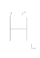
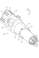
- FIG. 1 is an exploded perspective view showing a connector with a cable according to the first embodiment.
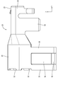
- FIG. 2 is a perspective view showing a connector with a cable.
- FIG. 3 is a side view showing the sleeve.
- FIG. 4 is a side sectional view showing the sleeve.
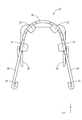
- FIG. 5 is a rear view showing the second shield member.
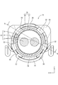
- FIG. 6 is a rear view showing the connector.
- FIG. 7 is a side view showing the second shield member.
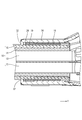
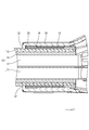
- FIG. 8 is a cross-sectional view taken along the line AA in FIG. 6 showing a state in which the barrel-side protrusion and the sleeve-side protrusion are separated from each other.
- FIG. 9 is a cross-sectional view taken along the line AA in FIG.
- FIG. 10 is a perspective view showing a connector with a cable according to the second embodiment.
- FIG. 11 is a rear view showing the second shield member.
- FIG. 12 is a rear view showing a connector with a cable.
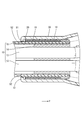
- FIG. 13 is a cross-sectional view taken along the line BB in FIG.
- the present disclosure is a connector with a cable in which a connector is connected to an end of a cable, and includes an electric wire, a sheath portion, and a braided member interposed between the electric wire and the sheath portion.
- a metal sleeve that is inside the folded-back portion and is externally fitted to the outer surface of the sheath portion, and the sleeve in a state of being crimped to the outer surface of the folded-back portion.
- a metal shield member having a barrel that sandwiches the folded portion between them, and a housing covered with the shield member are provided, and the barrel is provided with the barrel in the axial direction of the cable rather than the rear end portion of the sleeve.
- a barrel-side protrusion that protrudes inward in the radial direction of the cable is formed at a rear position, and a sleeve-side protrusion that protrudes outward in the radial direction of the cable is formed at the rear end of the sleeve. Is formed.
- the area of contact between the barrel side protrusion and the rear end of the sleeve is increased as compared with the case where the sleeve side protrusion protruding outward in the radial direction of the cable is not formed. ..
- the adhesive force between the cable and the connector can be improved.
- the inner surface of the rear end edge of the sleeve is formed with a tapered surface whose diameter increases toward the rear.
- the tapered surface and the cable are in sliding contact with each other, so that the cable is guided into the sleeve.
- the efficiency of the work of inserting the cable into the sleeve can be improved, so that the manufacturing efficiency of the connector with the cable can be improved.
- the barrel is provided with a plurality of barrel-side protrusions at intervals in the circumferential direction of the cable.
- the area of contact between the barrel side protrusion and the trailing edge of the sleeve can be increased as compared with the case where there is only one barrel side protrusion, so that the cable and the connector are fixed. It is possible to improve the wearing force.
- the present embodiment is a connector 12 with a cable in which the connector 11 is connected to the end of the cable 10.
- the direction indicated by the arrow Z is defined as upward
- the direction indicated by arrow Y is defined as forward
- the direction indicated by arrow X is defined as left.
- a reference numeral may be added to only a part of the members, and the reference numeral may be omitted for the other members.
- the cable 10 is made of an electric wire 13 (two in this embodiment), a braided member 14 surrounding the outer circumference of the electric wire 13, and an insulating synthetic resin surrounding the outer circumference of the braided member 14.
- the sheath portion 15 is provided.
- the electric wire 13 includes a core wire and an insulating coating made of an insulating synthetic resin that surrounds the outer circumference of the core wire.
- the metal constituting the core wire any metal such as copper, copper alloy, aluminum, and aluminum alloy can be appropriately selected as required. In this embodiment, copper or a copper alloy is used.
- a terminal (not shown) is connected to the tip of the electric wire 13.
- the braided member 14 is formed by knitting a plurality of conductive wires into a tubular shape.
- the conductive wire is not particularly limited, but in the present embodiment, it is a metal wire.
- any metal such as copper and copper alloy can be appropriately selected as required. In this embodiment, copper or a copper alloy is used.
- a metal foil may be attached to the surface of the wire rod made of synthetic resin.
- the sheath portion 15 of the front end portion (front end portion in the axial direction of the cable 10) of the cable 10 is peeled off.
- the electric wire 13 and the braided member 14 are exposed from the terminal of the cable 10.
- the braided member 14 exposed from the terminal of the sheath portion 15 has a folded portion 18 folded back toward the terminal side of the sheath portion 15.
- the folded-back portion 18 has a shape in which the braided member 14 exposed forward in the axial direction from the front end portion of the sheath portion 15 is folded back in the axial direction.
- the axial direction of the cable 10 will be described as a direction parallel to the front-rear direction.
- the folded-back portion 18 is formed so as to overlap the sheath portion 15 of the cable 10 from the outside in the radial direction of the cable 10.
- the sleeve 19 is made of metal and is formed in a cylindrical shape.
- any metal such as copper, copper alloy, aluminum, and aluminum alloy can be appropriately selected as required. Copper or a copper alloy is used in this embodiment.
- a sleeve-side protrusion 20 is formed at the rear end of the sleeve 19 so as to project outward in the radial direction of the sleeve 19.
- the sleeve side protrusion 20 according to the present embodiment is continuously formed in the circumferential direction of the sleeve 19.
- a tapered surface 21 whose diameter increases toward the rear is formed at a position corresponding to the sleeve side protrusion 20.
- the connector 11 includes a metal shield member 40 and a housing 41 covered with the shield member 40.
- the housing 41 is formed by injection molding an insulating synthetic resin material.
- the housing 41 has a substantially rectangular parallelepiped shape.
- a terminal (not shown) is housed inside the housing 41.
- the shield member 40 is formed by pressing a metal plate material into a predetermined shape.
- the metal constituting the shield member 40 any metal such as copper, copper alloy, aluminum, and aluminum alloy can be appropriately selected as needed. In this embodiment, copper or a copper alloy is used.
- the shield member 40 includes a first shield member 22 arranged on the lower side and a second shield member 23 attached on the upper side of the first shield member 22.
- the vertical direction is used for convenience of explanation, and does not limit the configuration of the shield member 40.
- the first shield member 22 is formed by pressing a metal plate material into a predetermined shape.
- the first shield member 22 includes a tubular portion 27, an inclined portion 28 extending diagonally rearward from the rear end portion of the tubular portion 27, and a tongue piece 29 extending rearward from the rear end portion of the inclined portion 28.
- the tubular portion 27 extends in the front-rear direction and has a flat square tubular shape in the vertical direction.
- a housing 41 is inserted into the inside of the tubular portion 27 from the rear so as to be accommodated.
- the housing 41 is held inside the tubular portion 27 in a rearward retaining state by a known method such as a lock structure.
- the inclined portion 28 is connected to the lower wall of the tubular portion 27 and the portion of the tubular portion 27 near the lower ends of the left and right side walls, and extends diagonally downward and rearward.
- the tongue piece 29 extends rearward from the vicinity of the center in the left-right direction at the rear end of the inclined portion 28.
- the tongue piece 29 has a plate shape extending in the anteroposterior direction.
- the second shield member 23 has an upper wall 25 and a side wall 26 extending downward from the left and right side edges of the upper wall 25.
- a fixing piece 34 that is crimped to the tubular portion 27 of the first shield member 22 so as to wrap around the lower wall extends from the lower end edge of the side wall 26.
- the first shield member 22 and the second shield member 23 are integrally assembled by crimping the fixing piece 34 so as to wrap around the lower wall of the tubular portion 27. ..
- a barrel 30 is formed behind the upper wall 25 and the side wall 26.
- the barrel 30 is formed by opening downward in the state before being crimped to the cable 10. By crimping the barrel 30 so as to wrap around the folded-back portion 18 of the cable 10 from the outside, the first shield member 22, the second shield member 23, and the cable 10 are connected. There is.
- two right-opening stopper pieces 35 extending downward are formed on the lower right edge of the barrel 30 at intervals in the front-rear direction.
- One left opening stopper 36 extending downward is formed on the lower left edge of the barrel 30. When viewed from the right, the left opening stop piece 36 is formed so as to be located between the two right opening stop pieces 35 in the front-rear direction.
- a right locking portion 37 is formed at the tip of the right opening stopper piece 35.
- the right locking portion 37 is formed by bending the tip portion of the right opening stopper piece 35 so as to fold back inward.
- a left locking portion 38 is formed at the tip of the left opening stopper piece 36.
- the left locking portion 38 is formed by bending the tip portion of the left opening stopper piece 36 so as to fold back inward.
- Barrel side protrusion 32 As shown in FIG. 5, a plurality of (four in the present embodiment) barrel-side protrusions 32 are provided on the trailing edge of the barrel 30 in the radial direction of the cable 10 at intervals in the circumferential direction of the cable 10. It protrudes inward.
- the barrel-side protrusion 32 has a substantially rectangular shape with rounded corners when viewed from the rear.
- the barrel side protrusion 32 is bent inward in the radial direction at a substantially right angle from the rear end edge of the barrel 30.
- the rear end edge of the barrel side protrusion 32 is formed substantially flush with the rear end edge of the barrel 30.
- the barrel side protrusion 32 does not project rearward from the rear end edge of the barrel 30.
- the barrel-side protrusion 32 is arranged at a position rearward from the rear end portion of the sleeve 19 in the axial direction of the cable 10. ing.
- the radial inward protrusion dimension of the barrel side protrusion 32 is the axis of the cable 10 with respect to the rear end edge of the sleeve 19 in a state where the barrel 30 is crimped to the outer circumference of the folded portion 18. It is set so that it can be locked from the rear of the direction. As a result, when a force that pulls the cable 10 backward in the axial direction is applied, the barrel-side protrusion 32 comes into contact with the rear end edge of the sleeve 19 from the rear in the axial direction. (See FIG. 9).
- the plurality of barrel-side protrusions 32 at the rear end of the barrel 30 are arranged symmetrically when viewed from the rear. As a result, when the cable 10 is pulled backward in the axial direction, the sleeve 19 can be received by the barrel-side protrusions 32 arranged symmetrically, so that the force is biased to the specific barrel-side protrusions 32. It is designed to be suppressed.
- a metal pipe is cut to a predetermined length, and one end thereof is expanded in diameter by drawing to form a sleeve side protrusion 20 and a tapered surface 21.
- the sleeve 19 is externally fitted at a position near the front end of the sheath portion 15.
- the braided member 14 exposed from the front end portion of the sheath portion 15 is folded back toward the front end portion of the sheath portion 15.
- the braided member 14 exposed from the front end portion of the sheath portion 15 is folded back in the axial direction of the cable 10.
- the folded-back portion 18 is formed on the outer side of the sleeve 19 in the radial direction of the cable 10.
- first shield member 22 and the second shield member 23 are integrally assembled by crimping the fixing piece 34 of the second shield member 23 to the tubular portion 27 of the first shield member 22. Subsequently, the barrel 30 is crimped so as to be wound around the outer circumference of the folded-back portion 18. As a result, the barrel 30 and the folded-back portion 18 are electrically and physically connected. From the above, the connector 12 with a cable is completed.
- the present embodiment is a connector 12 with a cable in which a connector 11 is connected to the end of a cable 10, and a braided member 14 interposed between the electric wire 13, the sheath portion 15, and the electric wire 13 and the sheath portion 15.
- the braided member 14 is formed by knitting a conductive wire rod, and the braided member 14 exposed from the terminal of the sheath portion 15 is folded back toward the sheath portion 15 in the braided member 14.
- the cable 10 provided with the cable 10 and the metal sleeve 19 inside the folded-back portion 18 and fitted on the outer surface of the sheath portion 15 in the radial direction of the cable 10 are crimped to the outer surface of the folded-back portion 18.
- a metal shield member 40 having a barrel 30 for sandwiching the folded-back portion 18 with the sleeve 19 in a state of being in the state, and a housing 41 covered with the shield member 40 are provided, and the barrel 30 is provided with an axis of a cable 10.
- a barrel-side protrusion 32 that projects inward in the radial direction of the cable 10 is formed at a position rearward of the rear end of the sleeve 19 in the direction, and the diameter of the cable 10 is formed at the rear end of the sleeve 19.
- a sleeve-side protrusion 20 projecting outward in the direction is formed.
- the area of contact between the barrel-side protrusion 32 and the rear end of the sleeve 19 is larger than the case where the sleeve-side protrusion 20 is not formed so as to project outward in the radial direction of the cable 10. And increase. As a result, the adhesive force between the cable 10 and the connector 11 can be improved.
- a tapered surface 21 whose diameter increases toward the rear is formed on the inner surface of the rear end edge of the sleeve 19.
- the barrel 30 is provided with a plurality of barrel-side protrusions 32 at intervals in the circumferential direction of the cable 10.
- the area of contact between the barrel-side protrusion 32 and the rear end edge of the sleeve 19 can be increased as compared with the case where the barrel-side protrusion 32 is one, so that the cable 10 and the connector 11 can be connected to each other.
- the fixing force can be improved.
- FIG. 10 in the connector 50 with a cable according to the present embodiment, the configuration of the barrel side protrusion 51 is different from that of the first embodiment.
- FIG. 11 at the rear end edge of the barrel 30, a plurality of barrel-side protrusions 51 (two in the present embodiment) are provided at intervals in the circumferential direction of the cable 10 in the radial direction of the cable 10. It protrudes inward.
- the barrel-side protrusions 51 are formed on the right side and the left side of the barrel 30 when viewed from the rear.
- the protruding end edge of the barrel side protrusion 51 is depressed in a valley shape when viewed from the rear near the substantially center in the vertical direction.
- a relief portion 52 is formed.
- the relief portion 52 is formed in a concave shape on the protruding end edge of the barrel side protrusion 51 in the radial direction of the cable 10.
- the relief portion 52 formed at the protruding end edge of the barrel side protrusion 51 has the barrel 30 in the circumferential direction of the cable 10. It is smaller than the state before crimping to the cable 10.
- the barrel-side protrusion 51 is arranged at a position rearward from the rear end portion of the sleeve 19 in the axial direction of the cable 10. ing.
- the protruding end edge of the barrel side protrusion 51 is compressed in the circumferential direction of the cable 10. Therefore, there is a concern that the metal plate material forming the inner edge of the barrel-side protrusion 51 may gather at the protruding end edge of the barrel-side protrusion 51 to form wrinkles.
- a relief portion 52 that sinks into a valley shape is formed at the protruding end edge of the barrel side protrusion 51.
- the area of contact between the barrel-side protrusions 51 and the rear end edge of the sleeve 19 can be increased, so that the cable 10 and the connector 53 can be used.
- the fixing force of the barrel can be improved.
- the barrel side protrusions may be provided on the barrel 30 with one, three, or five or more.
- the plurality of sleeve-side protrusions 20 may be formed at intervals in the circumferential direction of the sleeve.
Landscapes
- Engineering & Computer Science (AREA)
- Manufacturing & Machinery (AREA)
- Details Of Connecting Devices For Male And Female Coupling (AREA)
Priority Applications (3)
| Application Number | Priority Date | Filing Date | Title |
|---|---|---|---|
| CN202080055137.0A CN114175412A (zh) | 2019-08-09 | 2020-07-22 | 带电缆连接器 |
| US17/629,734 US11862907B2 (en) | 2019-08-09 | 2020-07-22 | Connector with cable |
| DE112020003792.4T DE112020003792T5 (de) | 2019-08-09 | 2020-07-22 | Verbinder mit einem Kabel |
Applications Claiming Priority (2)
| Application Number | Priority Date | Filing Date | Title |
|---|---|---|---|
| JP2019147192A JP7240607B2 (ja) | 2019-08-09 | 2019-08-09 | ケーブル付きコネクタ |
| JP2019-147192 | 2019-08-09 |
Publications (1)
| Publication Number | Publication Date |
|---|---|
| WO2021029201A1 true WO2021029201A1 (ja) | 2021-02-18 |
Family
ID=74569410
Family Applications (1)
| Application Number | Title | Priority Date | Filing Date |
|---|---|---|---|
| PCT/JP2020/028470 Ceased WO2021029201A1 (ja) | 2019-08-09 | 2020-07-22 | ケーブル付きコネクタ |
Country Status (5)
| Country | Link |
|---|---|
| US (1) | US11862907B2 (enExample) |
| JP (1) | JP7240607B2 (enExample) |
| CN (1) | CN114175412A (enExample) |
| DE (1) | DE112020003792T5 (enExample) |
| WO (1) | WO2021029201A1 (enExample) |
Cited By (3)
| Publication number | Priority date | Publication date | Assignee | Title |
|---|---|---|---|---|
| WO2021230039A1 (ja) * | 2020-05-14 | 2021-11-18 | 株式会社オートネットワーク技術研究所 | シールド導電路 |
| WO2023282225A1 (ja) * | 2021-07-07 | 2023-01-12 | 株式会社オートネットワーク技術研究所 | シールド導電路 |
| WO2023233938A1 (ja) * | 2022-05-30 | 2023-12-07 | 株式会社オートネットワーク技術研究所 | 電線と外導体との圧着構造 |
Families Citing this family (4)
| Publication number | Priority date | Publication date | Assignee | Title |
|---|---|---|---|---|
| CN115943101A (zh) | 2020-08-27 | 2023-04-07 | 株式会社电装 | 车辆用显示装置 |
| JP7552490B2 (ja) * | 2021-04-19 | 2024-09-18 | 株式会社オートネットワーク技術研究所 | ケーブル付きコネクタ |
| JP2022169146A (ja) * | 2021-04-27 | 2022-11-09 | 株式会社オートネットワーク技術研究所 | ケーブル付きコネクタ |
| JP7771873B2 (ja) * | 2022-05-25 | 2025-11-18 | 住友電気工業株式会社 | コネクタ付きケーブル |
Citations (3)
| Publication number | Priority date | Publication date | Assignee | Title |
|---|---|---|---|---|
| JP2010170934A (ja) * | 2009-01-26 | 2010-08-05 | Sumitomo Wiring Syst Ltd | シールドコネクタ及びシールドシェル |
| JP2012221924A (ja) * | 2011-04-14 | 2012-11-12 | Sumitomo Wiring Syst Ltd | シールドコネクタ |
| JP2018147564A (ja) * | 2017-03-01 | 2018-09-20 | 株式会社オートネットワーク技術研究所 | 端子付きシールド電線 |
Family Cites Families (14)
| Publication number | Priority date | Publication date | Assignee | Title |
|---|---|---|---|---|
| US6452102B1 (en) * | 2000-12-29 | 2002-09-17 | Pen Cabling Technologies Llc | High voltage cable termination |
| DE60313538T2 (de) * | 2002-07-02 | 2008-01-10 | Tyco Electronics Amp Gmbh | Koaxialer Winkelsteckverbinder |
| US6692299B1 (en) * | 2002-11-04 | 2004-02-17 | Hitachi Cable Indiana, Inc. | Electrical connector for coaxial cable |
| JP4316482B2 (ja) * | 2004-12-03 | 2009-08-19 | 矢崎総業株式会社 | シールド電線のアース処理方法及びアース処理構造 |
| CN101950905A (zh) * | 2010-09-19 | 2011-01-19 | 温州科奇比威自动化设备有限公司 | 钩型换向器的换向片 |
| JP5961031B2 (ja) * | 2012-04-26 | 2016-08-02 | 矢崎総業株式会社 | ワイヤハーネス |
| JP2014017181A (ja) * | 2012-07-11 | 2014-01-30 | Tyco Electronics Japan Kk | シールドケーブルハーネスの端末構造およびその製造方法 |
| EP2784785A1 (en) * | 2013-03-26 | 2014-10-01 | Tyco Electronics Nederland B.V. | Cable assembly |
| JP2016072067A (ja) * | 2014-09-30 | 2016-05-09 | ホシデン株式会社 | コネクタ |
| CN106207544B (zh) * | 2015-04-29 | 2019-01-25 | 广濑电机株式会社 | 外筒端子及具有该外筒端子的连接器 |
| JP6290957B2 (ja) * | 2016-03-18 | 2018-03-07 | 矢崎総業株式会社 | シールド端子の接続構造 |
| JP6414272B1 (ja) * | 2017-04-26 | 2018-10-31 | 住友電装株式会社 | 編組加工装置及び編組付ケーブル加工方法 |
| FR3074616B1 (fr) * | 2017-12-06 | 2019-11-01 | Raydiall | Piece d'adaptation d'impedance electrique pour connecteur monte sur cable a fils electriques isoles |
| US11462875B2 (en) * | 2020-12-16 | 2022-10-04 | Aptiv Technologies Limited | Barrel crimp retention feature for connector with braided wire |
-
2019
- 2019-08-09 JP JP2019147192A patent/JP7240607B2/ja active Active
-
2020
- 2020-07-22 CN CN202080055137.0A patent/CN114175412A/zh active Pending
- 2020-07-22 WO PCT/JP2020/028470 patent/WO2021029201A1/ja not_active Ceased
- 2020-07-22 US US17/629,734 patent/US11862907B2/en active Active
- 2020-07-22 DE DE112020003792.4T patent/DE112020003792T5/de active Granted
Patent Citations (3)
| Publication number | Priority date | Publication date | Assignee | Title |
|---|---|---|---|---|
| JP2010170934A (ja) * | 2009-01-26 | 2010-08-05 | Sumitomo Wiring Syst Ltd | シールドコネクタ及びシールドシェル |
| JP2012221924A (ja) * | 2011-04-14 | 2012-11-12 | Sumitomo Wiring Syst Ltd | シールドコネクタ |
| JP2018147564A (ja) * | 2017-03-01 | 2018-09-20 | 株式会社オートネットワーク技術研究所 | 端子付きシールド電線 |
Cited By (10)
| Publication number | Priority date | Publication date | Assignee | Title |
|---|---|---|---|---|
| WO2021230039A1 (ja) * | 2020-05-14 | 2021-11-18 | 株式会社オートネットワーク技術研究所 | シールド導電路 |
| JP2021180115A (ja) * | 2020-05-14 | 2021-11-18 | 株式会社オートネットワーク技術研究所 | シールド導電路 |
| JP7406711B2 (ja) | 2020-05-14 | 2023-12-28 | 株式会社オートネットワーク技術研究所 | シールド導電路 |
| US12413013B2 (en) | 2020-05-14 | 2025-09-09 | Autonetworks Technologies, Ltd. | Shielded electrically conductive cable connector |
| WO2023282225A1 (ja) * | 2021-07-07 | 2023-01-12 | 株式会社オートネットワーク技術研究所 | シールド導電路 |
| JP2023009381A (ja) * | 2021-07-07 | 2023-01-20 | 株式会社オートネットワーク技術研究所 | シールド導電路 |
| JP7533384B2 (ja) | 2021-07-07 | 2024-08-14 | 株式会社オートネットワーク技術研究所 | シールド導電路 |
| WO2023233938A1 (ja) * | 2022-05-30 | 2023-12-07 | 株式会社オートネットワーク技術研究所 | 電線と外導体との圧着構造 |
| JP2023175333A (ja) * | 2022-05-30 | 2023-12-12 | 株式会社オートネットワーク技術研究所 | 電線と外導体との圧着構造 |
| JP7737613B2 (ja) | 2022-05-30 | 2025-09-11 | 株式会社オートネットワーク技術研究所 | 電線と外導体との圧着構造 |
Also Published As
| Publication number | Publication date |
|---|---|
| JP7240607B2 (ja) | 2023-03-16 |
| US20220255270A1 (en) | 2022-08-11 |
| CN114175412A (zh) | 2022-03-11 |
| US11862907B2 (en) | 2024-01-02 |
| JP2021028873A (ja) | 2021-02-25 |
| DE112020003792T5 (de) | 2022-05-12 |
Similar Documents
| Publication | Publication Date | Title |
|---|---|---|
| WO2021029201A1 (ja) | ケーブル付きコネクタ | |
| US7491071B2 (en) | Shield end processing structure | |
| JP5528007B2 (ja) | シールド電線の固定構造およびその固定方法 | |
| JP5352345B2 (ja) | 加締め型及びシールド電線の編組固定構造 | |
| US10910734B2 (en) | Shielded cable with terminal | |
| CN102576962B (zh) | 屏蔽连接器 | |
| CN113196584B (zh) | 连接器结构体 | |
| JP7096123B2 (ja) | シールド電線の端子接続構造 | |
| CN113196590B (zh) | 连接器结构体及连接器结构体的制造方法 | |
| JP6033113B2 (ja) | シールド編組線の接続構造およびシールドコネクタ | |
| JP6290957B2 (ja) | シールド端子の接続構造 | |
| JP7533384B2 (ja) | シールド導電路 | |
| CN113196589B (zh) | 连接器结构体及连接器结构体的制造方法 | |
| JP6129714B2 (ja) | 編組シールドの端末処理構造 | |
| CN115443585A (zh) | 屏蔽导电路径 | |
| JP6527707B2 (ja) | シールドコネクタ | |
| JP7171293B2 (ja) | シールドコネクタ | |
| JP7624154B2 (ja) | シールド導電路 | |
| JP2006310139A (ja) | シールドコネクタ | |
| JP5344899B2 (ja) | 同軸ケーブル用コネクタ | |
| JP2025080993A (ja) | 端子付き電線、及び、端子付き電線の製造方法 |
Legal Events
| Date | Code | Title | Description |
|---|---|---|---|
| 121 | Ep: the epo has been informed by wipo that ep was designated in this application |
Ref document number: 20852503 Country of ref document: EP Kind code of ref document: A1 |
|
| 122 | Ep: pct application non-entry in european phase |
Ref document number: 20852503 Country of ref document: EP Kind code of ref document: A1 |