WO2021024982A1 - クリーニング装置 - Google Patents
クリーニング装置 Download PDFInfo
- Publication number
- WO2021024982A1 WO2021024982A1 PCT/JP2020/029661 JP2020029661W WO2021024982A1 WO 2021024982 A1 WO2021024982 A1 WO 2021024982A1 JP 2020029661 W JP2020029661 W JP 2020029661W WO 2021024982 A1 WO2021024982 A1 WO 2021024982A1
- Authority
- WO
- WIPO (PCT)
- Prior art keywords
- cleaning
- die
- cleaning device
- guide
- parison
- Prior art date
- Legal status (The legal status is an assumption and is not a legal conclusion. Google has not performed a legal analysis and makes no representation as to the accuracy of the status listed.)
- Ceased
Links
Images



Classifications
-
- B—PERFORMING OPERATIONS; TRANSPORTING
- B08—CLEANING
- B08B—CLEANING IN GENERAL; PREVENTION OF FOULING IN GENERAL
- B08B1/00—Cleaning by methods involving the use of tools
- B08B1/10—Cleaning by methods involving the use of tools characterised by the type of cleaning tool
-
- B—PERFORMING OPERATIONS; TRANSPORTING
- B29—WORKING OF PLASTICS; WORKING OF SUBSTANCES IN A PLASTIC STATE IN GENERAL
- B29C—SHAPING OR JOINING OF PLASTICS; SHAPING OF MATERIAL IN A PLASTIC STATE, NOT OTHERWISE PROVIDED FOR; AFTER-TREATMENT OF THE SHAPED PRODUCTS, e.g. REPAIRING
- B29C33/00—Moulds or cores; Details thereof or accessories therefor
- B29C33/70—Maintenance
- B29C33/72—Cleaning
-
- B—PERFORMING OPERATIONS; TRANSPORTING
- B29—WORKING OF PLASTICS; WORKING OF SUBSTANCES IN A PLASTIC STATE IN GENERAL
- B29C—SHAPING OR JOINING OF PLASTICS; SHAPING OF MATERIAL IN A PLASTIC STATE, NOT OTHERWISE PROVIDED FOR; AFTER-TREATMENT OF THE SHAPED PRODUCTS, e.g. REPAIRING
- B29C48/00—Extrusion moulding, i.e. expressing the moulding material through a die or nozzle which imparts the desired form; Apparatus therefor
- B29C48/03—Extrusion moulding, i.e. expressing the moulding material through a die or nozzle which imparts the desired form; Apparatus therefor characterised by the shape of the extruded material at extrusion
- B29C48/09—Articles with cross-sections having partially or fully enclosed cavities, e.g. pipes or channels
-
- B—PERFORMING OPERATIONS; TRANSPORTING
- B29—WORKING OF PLASTICS; WORKING OF SUBSTANCES IN A PLASTIC STATE IN GENERAL
- B29C—SHAPING OR JOINING OF PLASTICS; SHAPING OF MATERIAL IN A PLASTIC STATE, NOT OTHERWISE PROVIDED FOR; AFTER-TREATMENT OF THE SHAPED PRODUCTS, e.g. REPAIRING
- B29C48/00—Extrusion moulding, i.e. expressing the moulding material through a die or nozzle which imparts the desired form; Apparatus therefor
- B29C48/25—Component parts, details or accessories; Auxiliary operations
- B29C48/27—Cleaning; Purging; Avoiding contamination
-
- B—PERFORMING OPERATIONS; TRANSPORTING
- B29—WORKING OF PLASTICS; WORKING OF SUBSTANCES IN A PLASTIC STATE IN GENERAL
- B29C—SHAPING OR JOINING OF PLASTICS; SHAPING OF MATERIAL IN A PLASTIC STATE, NOT OTHERWISE PROVIDED FOR; AFTER-TREATMENT OF THE SHAPED PRODUCTS, e.g. REPAIRING
- B29C48/00—Extrusion moulding, i.e. expressing the moulding material through a die or nozzle which imparts the desired form; Apparatus therefor
- B29C48/25—Component parts, details or accessories; Auxiliary operations
- B29C48/30—Extrusion nozzles or dies
- B29C48/32—Extrusion nozzles or dies with annular openings, e.g. for forming tubular articles
-
- B—PERFORMING OPERATIONS; TRANSPORTING
- B29—WORKING OF PLASTICS; WORKING OF SUBSTANCES IN A PLASTIC STATE IN GENERAL
- B29C—SHAPING OR JOINING OF PLASTICS; SHAPING OF MATERIAL IN A PLASTIC STATE, NOT OTHERWISE PROVIDED FOR; AFTER-TREATMENT OF THE SHAPED PRODUCTS, e.g. REPAIRING
- B29C49/00—Blow-moulding, i.e. blowing a preform or parison to a desired shape within a mould; Apparatus therefor
- B29C49/02—Combined blow-moulding and manufacture of the preform or the parison
- B29C49/04—Extrusion blow-moulding
- B29C49/04116—Extrusion blow-moulding characterised by the die
-
- B—PERFORMING OPERATIONS; TRANSPORTING
- B29—WORKING OF PLASTICS; WORKING OF SUBSTANCES IN A PLASTIC STATE IN GENERAL
- B29C—SHAPING OR JOINING OF PLASTICS; SHAPING OF MATERIAL IN A PLASTIC STATE, NOT OTHERWISE PROVIDED FOR; AFTER-TREATMENT OF THE SHAPED PRODUCTS, e.g. REPAIRING
- B29C49/00—Blow-moulding, i.e. blowing a preform or parison to a desired shape within a mould; Apparatus therefor
- B29C49/42—Component parts, details or accessories; Auxiliary operations
Definitions
- the present invention relates to a cleaning device.
- a technique of hanging a parison between dies to form a molded body is known.
- the molten parison is extruded from a slit provided in the die head, but the parison remaining in the vicinity of the slit may be hardened. Since the residual parison adversely affects the quality of the molded product, the residual parison is cleaned.
- Patent Document 1 discloses a technique for positively peeling a molten resin and preventing its retention.
- Patent Document 1 a ring for peeling the molten resin is provided so as to surround the discharge port of the parison in the annular die, and there is a concern that the number of parts may increase.
- the present invention has been made in view of such circumstances, and an object of the present invention is to provide a cleaning device capable of efficiently cleaning the bottom surface of a die having an annular bottom surface.
- the cleaning device is configured so that the die of the molding device can be cleaned, and the die is formed between an annular bottom surface and a peripheral surface, and between the bottom surface and the peripheral surface.
- the cleaning device is provided with a cleaning member, which is provided with an annular slit and is configured to be able to extrude a parison from the slit, and the cleaning member is relative to the bottom surface in the first direction and the second direction.
- the cleaning device includes a cleaning member configured to be movable relative to the bottom surface of the die in the first direction and the second direction.
- the second direction is a direction that intersects perpendicularly with the first direction. And such relative movement is movement along the annular shape of the bottom surface.
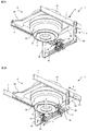
- FIG. 2A is a bottom perspective view of the cleaning device 1.
- FIG. 2B is a diagram showing a state in which the holding member 8 is advanced in the X direction from the state shown in FIG. 2A, and the cleaning members 3a and 3b are moved in the Y direction so as to be separated from each other.
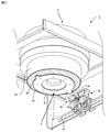
- FIG. 2A is a partially enlarged view of the vicinity of the guide member 4 of the cleaning device 1 shown in FIG. 2A.
- the perspective view of the cleaning member 3a, 3b and the holding rail 81 are examples of the cleaning member 3a, 3b and the holding rail 81.
- the cleaning device 1 As shown in FIGS. 1, 2A and 2B, the cleaning device 1 according to the present embodiment includes a cleaning member 3.
- the number of cleaning members 3 is not particularly limited, but in the present embodiment, the cleaning device 1 includes a pair of cleaning members 3a and 3b.
- the cleaning device 1 is configured to be capable of cleaning the die 2 of a molding device typified by injection molding, blow molding, or the like.
- the die 2 includes a main body portion 21, an annular bottom surface 22, a peripheral surface 23, and an annular slit 24.
- the slit 24 is formed between the bottom surface 22 and the peripheral surface 23.
- the slit 24 is configured to extrude the parison.
- hatching is provided on the bottom surface 22 and the slit 24 in order to improve visibility.
- the bottom surface 22 corresponds to the lower surface of the main body 21 of the die 2 and is a surface perpendicular to the hanging direction of the parison extruded from the slit 24.
- the peripheral surface 23 is a tubular surface erected from the peripheral edge of the bottom surface 22.
- the parison is formed by extruding the molten resin obtained by heating the resin from the slit 24.
- the parison extruded from the slit 24 is also annular.
- Such a parison is molded by a mold arranged in the hanging direction of the parison, and an arbitrary molded body is formed.
- the molten parison may remain in the vicinity of the slit 24.
- residual parison is particularly likely to adhere to the bottom surface 22.
- the cleaning device 1 according to the present embodiment cleans the bottom surface 22 of the die 2.
- the cleaning device 1 includes a fixing member 6.
- the fixing member 6 includes a support rail 62 facing the support rail 62 and a guide rail 61 supported by the support rail 62 and facing the support rail 62.
- the opposing moving members 7 are provided so as to cover the support rail 62.
- the moving member 7 is connected to a holding member 8 described later, and is configured to be movable in the first direction (X direction in FIG. 2B) along the support rail 62.
- the holding member 8 includes a holding rail 81 and a connecting member 82.
- the holding rail 81 holds the cleaning members 3a and 3b, and the cleaning members 3a and 3b are configured to be movable in the second direction (Y direction in FIG. 2B) along the extending direction of the holding rail 81. ..
- the connecting member 82 is provided at both ends of the holding rail 81, and connects the holding rail 81 to the moving member 7.
- the connecting member 82 moves in the first direction as the moving member 7 moves.
- the holding rail 81 fixed by the connecting member 82 also moves in the first direction.
- the cleaning member 3 moves in the first direction with respect to the bottom surface 22.
- the cleaning device 1 includes a guide member 4.
- the guide member 4 is configured to be able to guide the relative movement of the cleaning member 3 when the cleaning member 3 is relatively moved with respect to the bottom surface 22.
- the guide member 4 is provided at a position facing the bottom surface 22.
- the guide member 4 is fixed to the bottom surface 22 by a plurality of screws 5.
- the guide member 4 is fixed to the bottom surface 22 by eight screws 5.
- the guide member 4 is provided at a position where the guide surface 41 of the guide member 4 and the non-guide surfaces 33a, 33b (see FIG. 5) provided inside the cleaning members 3a, 3b come into contact with each other. Then, as shown in FIGS. 2B and 4, when the cleaning members 3a and 3b are moved in the first direction and the second direction, the guide surface 41 guides the non-guide surfaces 33a and 33b to clean the bottom surface 22. The relative movement of the members 3a and 3b is performed smoothly.
- the cleaning member 3 has a first direction (X direction in FIGS. 2B and 5) and a second direction (Y direction in FIGS. 2B and 5) with respect to the bottom surface 22. It is configured to be relatively movable.
- the second direction is a direction that intersects the first direction perpendicularly. Further, such relative movement is movement along the annular shape of the bottom surface 22.
- the cleaning member 3a moves in the second direction (direction away from the center of the bottom surface 22) shown in FIG. 2B, and the cleaning member 3b is in the opposite direction to the cleaning member 3a (direction away from the center of the bottom surface 22).
- Is movable That is, the pair of cleaning members 3a and 3b are configured to be line-symmetrically movable relative to the bottom surface 22.
- the cleaning members 3a and 3b include cleaning heads 31a and 31b.
- cleaning surfaces 32a and 32b are provided on the upper surfaces of the cleaning heads 31a and 31b.
- the cleaning surfaces 32a and 32b clean the bottom surface 22, and the cleaning members 3a and 3b are located at positions where the cleaning surfaces 32a and 32b and the bottom surface 22 come into contact with each other while the cleaning members 3a and 3b are close to the bottom surface 22.
- the cleaning members 3a and 3b are variably configured so that the cleaning surfaces 32a and 32b come into contact with the bottom surface 22.
- the cleaning members 3a and 3b may be urged in a direction approaching each other by an elastic member or the like.
- the cleaning members 3a and 3b may be urged toward the bottom surface 22 by an elastic member or the like.
- it may be mechanically urged by an air cylinder, an actuator or the like.
- the cleaning head 31 may be made of brass at least a part of the portion in contact with the bottom surface 22.
- the cleaning surfaces 32a and 32b of the cleaning heads 31a and 31b are made of brass. Thereby, the residual parison can be removed without damaging the bottom surface 22.
- the cleaning heads 31a and 31b may be provided with a water cooling mechanism for cooling the heat generated on the cleaning surfaces 32a and 32b due to friction with the bottom surface 22.
- the cleaning member 3 can clean the bottom surface 22 by moving relative to the bottom surface 22 in the first direction and the second direction.
- the connecting member 82 connected to the moving member 7 and the holding rail 81 fixed to the connecting member 82 also move in the first direction.
- the cleaning members 3a and 3b provided on the holding rail 81 move in the first direction.
- the guide surface 41 of the cleaning members 3a and 3b comes into contact with the non-guide surface 33.
- the cleaning members 3a and 3b move in the first direction while the guide surface 41 is guided by the non-guide surface 33, so that the cleaning members 3a and 3b can freely move in the second direction with respect to the holding rail 81.
- the cleaning members 3a and 3b move in the second direction due to the drag force generated from the guide surface 41.
- the cleaning members 3a and 3b are urged in opposite directions, so that the guide member 4 is not. It moves in the second direction along the guide surface 33.
- the cleaning surfaces 32a and 32b of the cleaning members 3a and 3b simply move the moving member 7 in the first direction, and the cleaning surfaces 32a and 32b are kept in contact with the bottom surface 22 with respect to the bottom surface 22. It is moved relative to the first direction and the second direction.
- the cleaning members 3a and 3b move relative to the bottom surface 22 in the first and second directions, so that the cleaning surfaces 32a and 32b of the cleaning members 3a and 3b pressed against the bottom surface 22
- the bottom surface 22 can be cleaned.
- the cleaning of the bottom surface 22 by the cleaning members 3a and 3b can be executed at an arbitrary timing.
- the cleaning members 3a and 3b move relative to the bottom surface 22 after the parison is pushed out from the die 2 to clean the bottom surface 22.
- the bottom surface 22 is cleaned at least once by the cleaning members 3a and 3b after one parison (one molded product) is extruded from the die 2 for molding the desired molded product. Is preferable.
- the cleaning members 3a and 3b can scrape off the residual parisons adhering to the bottom surface 22, that is, before the molten resin is cooled and solidified.
- the residual parison is cooled and solidified, it is necessary to strongly press the cleaning members 3a and 3b against the bottom surface 22, which is not preferable because a large amount of energy is required to sufficiently clean the residual parison.
- the cleaning device 1 according to the present embodiment can also be implemented in the following aspects.
- one cleaning member 3 is provided, and the bottom surface 22 is cleaned by one cleaning member 3 by relatively moving the moving member 7 so as to face the bottom surface 22 in combination with the rotational movement of the moving member 7. May be good.
- the cleaning device 1 may be moved relative to the bottom surface 22 in the first direction by another moving device.
- the cleaning member 3 may be configured to be able to move up and down in the vertical direction.
- the timing of raising and lowering for example, it is preferable to raise the die at a timing equal to or less than the outer diameter of the die 2 and lower it at a timing of exiting the outer diameter.
- the cleaning member 3 may be provided with a spring, a magnet, a ball plunger, or the like so that the cleaning member 3 has a fixed orientation at the standby position.
- the cleaning member 3 adheres to the annular bottom surface 22 by relatively moving the cleaning member 3 in the first direction and the second direction with respect to the bottom surface 22 to which the residual parison tends to adhere. Residual parison can be cleaned efficiently.
- the cleaning member 3 since the cleaning member 3 may be arranged in one direction with respect to the bottom surface 22, it is not necessary to provide an annular molten resin peeling ring as in the conventional case, which contributes to a reduction in the number of parts.
- the cleaning device is a cleaning device and is configured to be able to clean the die of the molding device.
- the die has an annular bottom surface, a peripheral surface, and an annular slit formed between the bottom surface and the peripheral surface.
- the cleaning device includes a cleaning member, and the cleaning member moves relative to the bottom surface in the first direction and the second direction so that the parison can be extruded from the slit. Is provided so that the second direction intersects the first direction perpendicularly, and the relative movement is a movement along an annular shape of the bottom surface.
- the cleaning members are paired and are configured to be line-symmetrically movable relative to the bottom surface.
- the cleaning device further includes a guide member, and the guide member is configured to be able to guide the relative movement of the cleaning member when the cleaning member is relatively moved with respect to the bottom surface.
- the guide member is provided at a position facing the bottom surface.
- the cleaning member is configured to be able to clean the bottom surface by moving relative to the bottom surface after the parison is extruded from the die.
- the cleaning member includes a cleaning head, and the cleaning head is made of brass at least a part of a portion in contact with the bottom surface.
- the cleaning head further includes a water cooling mechanism. Of course, this is not the case.
Landscapes
- Engineering & Computer Science (AREA)
- Mechanical Engineering (AREA)
- Manufacturing & Machinery (AREA)
- Moulds For Moulding Plastics Or The Like (AREA)
- Cleaning In General (AREA)
- Extrusion Moulding Of Plastics Or The Like (AREA)
- Blow-Moulding Or Thermoforming Of Plastics Or The Like (AREA)
Abstract
【課題】円環状の底面を有するダイに対し、底面を効率的に清掃可能なクリーニング装置を提供すること。 【解決手段】本発明の一態様によれば、クリーニング装置であって、成形装置のダイを清掃可能に構成され、前記ダイは、円環状の底面と、周面と、前記底面と前記周面の間に形成された円環状のスリットとを備え、前記スリットからパリソンを押出可能に構成され、本クリーニング装置は、クリーニング部材を備え、前記クリーニング部材は、前記底面に対して第1方向及び第2方向に相対移動することにより、前記底面を清掃可能に構成され、ここで、前記第2方向は前記第1方向と垂直に交わる方向であり、且つ、前記相対移動は前記底面の円環状に沿った移動であるものが提供される。
Description
本発明は、クリーニング装置に関する。
製造業において、金型間にパリソンを垂下させ、成形体を成形する技術が知られている。かかる技術では、溶融状態のパリソンがダイヘッドに設けられたスリットから押し出されるが、スリット近傍に残留したパリソンが硬化することがある。かかる残留パリソンにより、成形体の品質に悪影響を与えるため、残留パリソンの清掃が行われている。
特許文献1には、溶融樹脂を積極的に剥離し、その滞留を防止する技術が開示されている。
ところが、特許文献1に開示された技術では、円環状のダイにおけるパリソンの吐出口を取り囲むように溶融樹脂剥離用リングを設けており、部品数の増大が懸念される。
本発明は、かかる事情を鑑みてなされたものであり、円環状の底面を有するダイに対し、底面を効率的に清掃可能なクリーニング装置を提供することを目的とする。
本発明の一態様によれば、クリーニング装置であって、成形装置のダイを清掃可能に構成され、前記ダイは、円環状の底面と、周面と、前記底面と前記周面の間に形成された円環状のスリットとを備え、前記スリットからパリソンを押出可能に構成され、本クリーニング装置は、クリーニング部材を備え、前記クリーニング部材は、前記底面に対して第1方向及び第2方向に相対移動することにより、前記底面を清掃可能に構成され、ここで、前記第2方向は前記第1方向と垂直に交わる方向であり、且つ、前記相対移動は前記底面の円環状に沿った移動であるものが提供される。
本発明の一態様に係るクリーニング装置は、ダイの底面に対して第1方向及び第2方向に相対移動可能に構成されたクリーニング部材を備える。ここで、第2方向は、第1方向に対して垂直に交わる方向である。そして、かかる相対移動は、底面の円環状に沿った移動である。これにより、ダイの周囲を取り囲むリング状の清掃部材を設けることなく、効率的にダイに設けられた円環状の底面を清掃することができる。
以下、図面を用いて実施形態について説明する。以下に示す実施形態中で示した各種特徴事項は、互いに組み合わせ可能である。また、各特徴事項について独立して発明が成立する。
1.クリーニング装置1
図1、図2A及び図2Bに示すように、本実施形態に係るクリーニング装置1は、クリーニング部材3を備える。クリーニング部材3の数は特に限定されないが、本実施形態では、クリーニング装置1は、一対のクリーニング部材3a,3bを備える。かかるクリーニング装置1は、射出成形、ブロー成形等に代表される成形装置のダイ2を清掃可能に構成される。
図1、図2A及び図2Bに示すように、本実施形態に係るクリーニング装置1は、クリーニング部材3を備える。クリーニング部材3の数は特に限定されないが、本実施形態では、クリーニング装置1は、一対のクリーニング部材3a,3bを備える。かかるクリーニング装置1は、射出成形、ブロー成形等に代表される成形装置のダイ2を清掃可能に構成される。
<ダイ2>
図3に示すように、ダイ2は、本体部21と、円環状の底面22と、周面23と、円環状のスリット24を備える。スリット24は、底面22と周面23の間に形成される。そして、スリット24は、パリソンを押出可能に構成される。ここで、図3においては、視認性の向上のため、底面22とスリット24にハッチングを付している。本実施形態では、底面22は、ダイ2の本体部21の下面に相当し、スリット24から押し出されるパリソンの垂下方向に対して垂直な面である。周面23は、底面22の周縁から立設した筒状の面である。
図3に示すように、ダイ2は、本体部21と、円環状の底面22と、周面23と、円環状のスリット24を備える。スリット24は、底面22と周面23の間に形成される。そして、スリット24は、パリソンを押出可能に構成される。ここで、図3においては、視認性の向上のため、底面22とスリット24にハッチングを付している。本実施形態では、底面22は、ダイ2の本体部21の下面に相当し、スリット24から押し出されるパリソンの垂下方向に対して垂直な面である。周面23は、底面22の周縁から立設した筒状の面である。
パリソンは、樹脂を加熱した溶融樹脂をスリット24から押し出すことにより形成される。本実施形態では、スリット24は円環状であるので、スリット24から押し出されるパリソンも円環状となる。かかるパリソンは、パリソンの垂下方向に配置された金型により成形され、任意の成形体が形成される。
一般的に、スリット24から所定量のパリソンを押し出した後に、溶融状態のパリソンがスリット24近傍に残留する場合がある。図3に示される構成のダイ2においては、特に底面22に残留パリソンが付着しやすい。本実施形態に係るクリーニング装置1は、ダイ2のうち、特に底面22を清掃するものである。
<固定部材6>
図1~図3に示すように、クリーニング装置1は、固定部材6を備える。固定部材6は、対向する支持レール62と、支持レール62に支持されて対向するガイドレール61を備える。
図1~図3に示すように、クリーニング装置1は、固定部材6を備える。固定部材6は、対向する支持レール62と、支持レール62に支持されて対向するガイドレール61を備える。
<移動部材7>
図1及び図2Bに示すように、支持レール62を覆うように、対向する移動部材7が設けられる。移動部材7は、後述の保持部材8と接続されており、支持レール62に沿って第1方向(図2BのX方向)に移動可能に構成される。
図1及び図2Bに示すように、支持レール62を覆うように、対向する移動部材7が設けられる。移動部材7は、後述の保持部材8と接続されており、支持レール62に沿って第1方向(図2BのX方向)に移動可能に構成される。
<保持部材8>
図1~図3に示すように、保持部材8は、保持レール81及び接続部材82を備える。保持レール81は、クリーニング部材3a,3bを保持するものであり、保持レール81の延在方向に沿ってクリーニング部材3a,3bが第2方向(図2BのY方向)に移動可能に構成される。接続部材82は、保持レール81の両端に設けられ、移動部材7に対して保持レール81を接続するものである。本実施形態では、移動部材7の移動に伴って接続部材82が第1方向に移動する。そして、接続部材82により固定された保持レール81も第1方向に移動する。これにより、クリーニング部材3が底面22に対して第1方向に移動する。
図1~図3に示すように、保持部材8は、保持レール81及び接続部材82を備える。保持レール81は、クリーニング部材3a,3bを保持するものであり、保持レール81の延在方向に沿ってクリーニング部材3a,3bが第2方向(図2BのY方向)に移動可能に構成される。接続部材82は、保持レール81の両端に設けられ、移動部材7に対して保持レール81を接続するものである。本実施形態では、移動部材7の移動に伴って接続部材82が第1方向に移動する。そして、接続部材82により固定された保持レール81も第1方向に移動する。これにより、クリーニング部材3が底面22に対して第1方向に移動する。
<ガイド部材4>
図2A,2B及び図3に示すように、本実施形態では、クリーニング装置1はガイド部材4を備える。ガイド部材4は、底面22に対するクリーニング部材3の相対移動に際し、クリーニング部材3の相対移動をガイド可能に構成される。本実施形態では、ガイド部材4は、底面22に対向する位置に設けられる。図3に示すように、本実施形態では、ガイド部材4は、複数のビス5により底面22に固定される。なお、図3の例では、8個のビス5によりガイド部材4が底面22に固定される。ここで、視認性の向上のため、図3においては全てのビス5に符号を付していないことに留意されたい。
図2A,2B及び図3に示すように、本実施形態では、クリーニング装置1はガイド部材4を備える。ガイド部材4は、底面22に対するクリーニング部材3の相対移動に際し、クリーニング部材3の相対移動をガイド可能に構成される。本実施形態では、ガイド部材4は、底面22に対向する位置に設けられる。図3に示すように、本実施形態では、ガイド部材4は、複数のビス5により底面22に固定される。なお、図3の例では、8個のビス5によりガイド部材4が底面22に固定される。ここで、視認性の向上のため、図3においては全てのビス5に符号を付していないことに留意されたい。
図4に示すように、ガイド部材4のガイド面41と、クリーニング部材3a,3bの内側に設けられた非ガイド面33a,33b(図5参照)が当接する位置にガイド部材4が設けられる。そして、図2B及び図4に示すように、クリーニング部材3a,3bの第1方向及び第2方向への移動に際し、ガイド面41が非ガイド面33a,33bをガイドすることにより、底面22に対するクリーニング部材3a,3bの相対移動が滑らかに行われる。
<クリーニング部材3>
図2B、図3及び図5に示すように、クリーニング部材3は、底面22に対して第1方向(図2B及び図5のX方向)及び第2方向(図2B及び図5のY方向)に相対移動可能に構成される。ここで、第2方向は第1方向と垂直に交わる方向である。また、かかる相対移動は、底面22の円環状に沿った移動である。本実施形態では、クリーニング部材3aは、図2Bに示される第2方向(底面22の中心から遠ざかる方向)に移動し、クリーニング部材3bは、クリーニング部材3aと逆向き(底面22の中心から遠ざかる方向)に移動可能に構成される。すなわち、一対のクリーニング部材3a,3bは、底面22に対して線対称に相対移動可能に構成される。
図2B、図3及び図5に示すように、クリーニング部材3は、底面22に対して第1方向(図2B及び図5のX方向)及び第2方向(図2B及び図5のY方向)に相対移動可能に構成される。ここで、第2方向は第1方向と垂直に交わる方向である。また、かかる相対移動は、底面22の円環状に沿った移動である。本実施形態では、クリーニング部材3aは、図2Bに示される第2方向(底面22の中心から遠ざかる方向)に移動し、クリーニング部材3bは、クリーニング部材3aと逆向き(底面22の中心から遠ざかる方向)に移動可能に構成される。すなわち、一対のクリーニング部材3a,3bは、底面22に対して線対称に相対移動可能に構成される。
また、図3に示すように、クリーニング部材3a,3bは、クリーニングヘッド31a,31bを備える。図5に示すように、クリーニングヘッド31a,31bの上面には、清掃面32a,32bが設けられる。清掃面32a,32bは底面22を清掃するものであり、クリーニング部材3a,3bが底面22に対して接近した状態で、清掃面32a,32bと底面22が接触する位置にクリーニング部材3a,3bが到達する。特に、清掃面32a,32bと底面22が接触するように、クリーニング部材3a,3bが可変に構成されることが好ましい。ここで、クリーニング部材3a,3bは、弾性部材等により互いに接近する向きに付勢されていてもよい。また、クリーニング部材3a,3bは、弾性部材等により底面22に向けて付勢されていてもよい。ここで、弾性部材等により付勢に代えて、エアシリンダーやアクチュエータ等により機械的に付勢されていてもよい。
また、クリーニングヘッド31は、底面22と接触する箇所の少なくとも一部が真鍮により構成されてもよい。本実施形態では、クリーニングヘッド31a,31bの清掃面32a,32bが真鍮により構成される。これにより、底面22を傷つけることなく残留するパリソンを除去することができる。
さらに、クリーニングヘッド31a,31bには、底面22との摩擦により清掃面32a,32bに生じる熱を冷却するための水冷機構が設けられてもよい。
かかる構成により、クリーニング部材3は、底面22に対して第1方向及び第2方向に相対移動することにより、底面22を清掃することができる。具体的には、本実施形態では、移動部材7が第1方向に移動することにより、移動部材7に接続された接続部材82及び接続部材82に固定された保持レール81も第1方向に移動する。これにより、図2Bに示すように、保持レール81に設けられたクリーニング部材3a,3bが第1方向に移動する。また、クリーニング部材3a,3bの第1方向への移動に伴い、クリーニング部材3a,3bのガイド面41が非ガイド面33に当接する。そして、ガイド面41が非ガイド面33にガイドされた状態でクリーニング部材3a,3bが第1方向に移動することにより、保持レール81に対して第2方向に自由移動可能なクリーニング部材3a,3bに対してガイド面41から生じる抗力により、クリーニング部材3a,3bが第2方向に移動する。
その後、クリーニング部材3から見たガイド部材4の第2方向の直径が最大となる位置を通過した後は、クリーニング部材3a,3bは互いに対向する向きに付勢されるので、ガイド部材4の非ガイド面33に沿って第2方向に移動する。これにより、クリーニング部材3a,3bの清掃面32a,32bは、移動部材7を第1方向に移動するだけで、清掃面32a,32bが底面22に接触した状態を維持しつつ底面22に対して第1方向及び第2方向に相対移動される。
このように、クリーニング部材3a,3bが底面22に対して第1方向及び第2方向に相対移動することにより、底面22に対して押圧されているクリーニング部材3a,3bの清掃面32a,32bが底面22を清掃することが可能になる。
ここで、クリーニング部材3a,3bによる底面22の清掃は、任意のタイミングで実行することができる。特に、クリーニング部材3a,3bは、ダイ2からパリソンが押し出された後、底面22に対して相対移動して底面22を清掃することが好ましい。具体的には、所望の成形品の成形のため、ダイ2から1回分(成形体1個分)のパリソンが押し出された後、クリーニング部材3a,3bにより底面22が少なくとも1回は清掃されることが好ましい。これにより、底面22に付着した残留パリソン、すなわち、溶融状態の樹脂が冷却されて固まる前に、溶融状態の残留パリソンをクリーニング部材3a,3bがこそぎ落とすことが可能になる。一方、残留パリソンが冷却されて固まった後においては、底面22に対してクリーニング部材3a,3bを強く押し付ける必要があるので、残留パリソンを十分に清掃するために大きなエネルギーを要するため、好ましくない。
2.その他
本実施形態に係るクリーニング装置1は、以下の態様でも実施可能である。
本実施形態に係るクリーニング装置1は、以下の態様でも実施可能である。
第一に、クリーニング部材3を1つ設け、移動部材7の回転移動と組み合わせて底面22に対向するように相対移動させることにより、1つのクリーニング部材3で底面22を清掃するように実施してもよい。
第二に、移動部材7に代えて、他の移動装置によりクリーニング装置1を底面22に対して第1方向に相対移動させてもよい。
第三に、クリーニング部材3を鉛直方向に昇降可能に構成されてもよい。特に、昇降させるタイミングに関しては、例えばダイ2の外径以下となるタイミングで上昇させ、これを抜けるタイミングで下降させるとよい。
第四に、クリーニング部材3は、待機位置で一定の向きとなる様、スプリング、マグネット、ボールプランジャー等を具備していてもよい。
3.結言
以上のように、本実施形態によれば、残留パリソンが付着しやすい底面22に対し、クリーニング部材3を第1方向及び第2方向に相対移動させることにより、円環状の底面22に付着した残留パリソンを効率的に清掃することができる。ここで、クリーニング部材3は、底面22に対して一方向に配置すればよいので、従来のように円環状の溶融樹脂剥離用リングを設ける必要がなく、部品数の低減に寄与する。
以上のように、本実施形態によれば、残留パリソンが付着しやすい底面22に対し、クリーニング部材3を第1方向及び第2方向に相対移動させることにより、円環状の底面22に付着した残留パリソンを効率的に清掃することができる。ここで、クリーニング部材3は、底面22に対して一方向に配置すればよいので、従来のように円環状の溶融樹脂剥離用リングを設ける必要がなく、部品数の低減に寄与する。
すなわち、クリーニング装置であって、成形装置のダイを清掃可能に構成され、前記ダイは、円環状の底面と、周面と、前記底面と前記周面の間に形成された円環状のスリットとを備え、前記スリットからパリソンを押出可能に構成され、本クリーニング装置は、クリーニング部材を備え、前記クリーニング部材は、前記底面に対して第1方向及び第2方向に相対移動することにより、前記底面を清掃可能に構成され、ここで、前記第2方向は前記第1方向と垂直に交わる方向であり、且つ、前記相対移動は前記底面の円環状に沿った移動であるものが提供される。
次に記載の各態様で提供されてもよい。
前記クリーニング装置において、前記クリーニング部材が一対であり、前記底面に対して線対称に相対移動可能に構成されるもの。
前記クリーニング装置において、ガイド部材をさらに備え、前記ガイド部材は、前記底面に対する前記クリーニング部材の前記相対移動に際し、前記クリーニング部材の前記相対移動をガイド可能に構成されるもの。
前記クリーニング装置において、前記ガイド部材は、前記底面に対向する位置に設けられるもの。
前記クリーニング装置において、前記クリーニング部材は、前記ダイから前記パリソンが押し出された後、前記底面に対して前記相対移動して前記底面を清掃可能に構成されるもの。
前記クリーニング装置において、前記クリーニング部材は、クリーニングヘッドを備え、前記クリーニングヘッドは、前記底面と接触する箇所の少なくとも一部が真鍮により構成されるもの。
前記クリーニング装置において、前記クリーニングヘッドは、水冷機構をさらに備えるもの。
もちろん、この限りではない。
前記クリーニング装置において、前記クリーニング部材が一対であり、前記底面に対して線対称に相対移動可能に構成されるもの。
前記クリーニング装置において、ガイド部材をさらに備え、前記ガイド部材は、前記底面に対する前記クリーニング部材の前記相対移動に際し、前記クリーニング部材の前記相対移動をガイド可能に構成されるもの。
前記クリーニング装置において、前記ガイド部材は、前記底面に対向する位置に設けられるもの。
前記クリーニング装置において、前記クリーニング部材は、前記ダイから前記パリソンが押し出された後、前記底面に対して前記相対移動して前記底面を清掃可能に構成されるもの。
前記クリーニング装置において、前記クリーニング部材は、クリーニングヘッドを備え、前記クリーニングヘッドは、前記底面と接触する箇所の少なくとも一部が真鍮により構成されるもの。
前記クリーニング装置において、前記クリーニングヘッドは、水冷機構をさらに備えるもの。
もちろん、この限りではない。
本発明の実施形態を説明したが、あくまでも例として提示したものであり、発明の範囲を限定することは意図していない。これら新規な実施形態は、その他の様々な形態で実施されることが可能であり、発明の要旨を逸脱しない範囲で、種々の省略、置き換え、変更を行うことができる。これら実施形態やその変形は、発明の範囲や要旨に含まれるとともに、特許請求の範囲に記載された発明とその均等の範囲に含まれるものである。
1:クリーニング装置、2:ダイ、3:クリーニング部材、3a:クリーニング部材、3b:クリーニング部材、4:ガイド部材、5:ビス、6:固定部材、7:移動部材、8:保持部材、21:本体部、22:底面、23:周面、24:スリット、31:クリーニングヘッド、31a:クリーニングヘッド、31b:クリーニングヘッド、32a:清掃面、32b:清掃面、33:非ガイド面、33a:非ガイド面、33b:非ガイド面、41:ガイド面、61:ガイドレール、62:支持レール、81:保持レール、82:接続部材
Claims (7)
- クリーニング装置であって、成形装置のダイを清掃可能に構成され、前記ダイは、円環状の底面と、周面と、前記底面と前記周面の間に形成された円環状のスリットとを備え、前記スリットからパリソンを押出可能に構成され、
本クリーニング装置は、クリーニング部材を備え、
前記クリーニング部材は、前記底面に対して第1方向及び第2方向に相対移動することにより、前記底面を清掃可能に構成され、ここで、前記第2方向は前記第1方向と垂直に交わる方向であり、且つ、前記相対移動は前記底面の円環状に沿った移動であるもの。 - 請求項1に記載のクリーニング装置において、
前記クリーニング部材が一対であり、前記底面に対して線対称に相対移動可能に構成さ
れるもの。 - 請求項1又は請求項2に記載のクリーニング装置において、
ガイド部材をさらに備え、
前記ガイド部材は、前記底面に対する前記クリーニング部材の前記相対移動に際し、前記クリーニング部材の前記相対移動をガイド可能に構成されるもの。 - 請求項3に記載のクリーニング装置において、
前記ガイド部材は、前記底面に対向する位置に設けられるもの。 - 請求項1~請求項4の何れか1つに記載のクリーニング装置において、
前記クリーニング部材は、前記ダイから前記パリソンが押し出された後、前記底面に対して前記相対移動して前記底面を清掃可能に構成されるもの。 - 請求項1~請求項5の何れか1つに記載のクリーニング装置において、
前記クリーニング部材は、クリーニングヘッドを備え、
前記クリーニングヘッドは、前記底面と接触する箇所の少なくとも一部が真鍮により構成されるもの。 - 請求項6に記載のクリーニング装置において、
前記クリーニングヘッドは、水冷機構をさらに備えるもの。
Applications Claiming Priority (2)
| Application Number | Priority Date | Filing Date | Title |
|---|---|---|---|
| JP2019144192A JP7319532B2 (ja) | 2019-08-06 | 2019-08-06 | クリーニング装置 |
| JP2019-144192 | 2019-08-06 |
Publications (1)
| Publication Number | Publication Date |
|---|---|
| WO2021024982A1 true WO2021024982A1 (ja) | 2021-02-11 |
Family
ID=74503895
Family Applications (1)
| Application Number | Title | Priority Date | Filing Date |
|---|---|---|---|
| PCT/JP2020/029661 Ceased WO2021024982A1 (ja) | 2019-08-06 | 2020-08-03 | クリーニング装置 |
Country Status (2)
| Country | Link |
|---|---|
| JP (1) | JP7319532B2 (ja) |
| WO (1) | WO2021024982A1 (ja) |
Cited By (1)
| Publication number | Priority date | Publication date | Assignee | Title |
|---|---|---|---|---|
| WO2022158479A1 (ja) * | 2021-01-25 | 2022-07-28 | キョーラク株式会社 | 樹脂カス除去装置 |
Citations (3)
| Publication number | Priority date | Publication date | Assignee | Title |
|---|---|---|---|---|
| JPS62102622U (ja) * | 1985-12-17 | 1987-06-30 | ||
| JPH11286041A (ja) * | 1998-04-01 | 1999-10-19 | Placo Co Ltd | パリソン形成方法とその装置及びこれに使用されるブローダイヘッド |
| JP2014520005A (ja) * | 2011-06-07 | 2014-08-21 | マウザー−ヴェルケ ゲゼルシャフト ミット ベシュレンクテル ハフツング | 押出ヘッドをクリーニングする方法及び装置 |
Family Cites Families (2)
| Publication number | Priority date | Publication date | Assignee | Title |
|---|---|---|---|---|
| JP2665475B2 (ja) * | 1988-12-21 | 1997-10-22 | 株式会社プラコー | ブロー成形機における材料替え方法 |
| JPH02206527A (ja) * | 1989-02-03 | 1990-08-16 | Placo Co Ltd | ブロー成形機における材料替え装置 |
-
2019
- 2019-08-06 JP JP2019144192A patent/JP7319532B2/ja active Active
-
2020
- 2020-08-03 WO PCT/JP2020/029661 patent/WO2021024982A1/ja not_active Ceased
Patent Citations (3)
| Publication number | Priority date | Publication date | Assignee | Title |
|---|---|---|---|---|
| JPS62102622U (ja) * | 1985-12-17 | 1987-06-30 | ||
| JPH11286041A (ja) * | 1998-04-01 | 1999-10-19 | Placo Co Ltd | パリソン形成方法とその装置及びこれに使用されるブローダイヘッド |
| JP2014520005A (ja) * | 2011-06-07 | 2014-08-21 | マウザー−ヴェルケ ゲゼルシャフト ミット ベシュレンクテル ハフツング | 押出ヘッドをクリーニングする方法及び装置 |
Cited By (2)
| Publication number | Priority date | Publication date | Assignee | Title |
|---|---|---|---|---|
| WO2022158479A1 (ja) * | 2021-01-25 | 2022-07-28 | キョーラク株式会社 | 樹脂カス除去装置 |
| US12552082B2 (en) | 2021-01-25 | 2026-02-17 | Kyoraku Co., Ltd. | Resin residue removal device |
Also Published As
| Publication number | Publication date |
|---|---|
| JP7319532B2 (ja) | 2023-08-02 |
| JP2021024201A (ja) | 2021-02-22 |
Similar Documents
| Publication | Publication Date | Title |
|---|---|---|
| JP5377300B2 (ja) | 予備成形物の後処理のための装置並びに方法 | |
| US20190022934A1 (en) | Manufacturing apparatus and method for three-dimensional object, and material supply unit to be used in the manufacturing apparatus | |
| CA2654166A1 (en) | Mold tool for the production of extrusion blow molded products | |
| KR102531823B1 (ko) | 조정식 코어 센터링 디바이스를 구비한 사출 성형 공구 | |
| BR0000134B1 (pt) | cabeçote de extrusão para moldagem por sopro extrusão de recipientes de material plástico. | |
| US20180319059A1 (en) | Device for producing a product by means of injection molding, and method | |
| JP7319532B2 (ja) | クリーニング装置 | |
| JPS6033657B2 (ja) | 射出成形用金型 | |
| US20140322376A1 (en) | Molding machine | |
| JP5350646B2 (ja) | 成形品取出方法および射出成形装置。 | |
| EP4220768A3 (en) | Molding production method, molding die, molding production apparatus, burr removal method, and burr removal device | |
| JP7295427B2 (ja) | クリーニング装置 | |
| US20250214296A1 (en) | Operation mechanism, blow molding mechanism, split mold, and mold unit | |
| CN210415525U (zh) | 一种3d的打印喷头 | |
| JP2016043677A (ja) | ベローズの製造方法およびベローズ | |
| JPS60232914A (ja) | 成形用金型における通気装置 | |
| KR20140059260A (ko) | 금형 | |
| CN214088263U (zh) | 用于生产玻璃瓶的初模 | |
| JP2003191293A (ja) | 成形型 | |
| CN210257230U (zh) | 一种吹瓶机的加热机构 | |
| CN210233858U (zh) | 一种塑制品加工用分型面为哈呋的抽芯机构 | |
| JP2016087795A (ja) | ブロー成形方法及びブロー成形用金型 | |
| JP7096483B2 (ja) | 成形装置 | |
| JP2024150374A (ja) | ガスベントユニットおよびこれを装着した成型金型 | |
| JP2016043674A (ja) | ベローズの製造方法およびベローズ |
Legal Events
| Date | Code | Title | Description |
|---|---|---|---|
| 121 | Ep: the epo has been informed by wipo that ep was designated in this application |
Ref document number: 20849287 Country of ref document: EP Kind code of ref document: A1 |
|
| NENP | Non-entry into the national phase |
Ref country code: DE |
|
| 122 | Ep: pct application non-entry in european phase |
Ref document number: 20849287 Country of ref document: EP Kind code of ref document: A1 |