WO2021002451A1 - 加工冷却装置 - Google Patents
加工冷却装置 Download PDFInfo
- Publication number
- WO2021002451A1 WO2021002451A1 PCT/JP2020/026173 JP2020026173W WO2021002451A1 WO 2021002451 A1 WO2021002451 A1 WO 2021002451A1 JP 2020026173 W JP2020026173 W JP 2020026173W WO 2021002451 A1 WO2021002451 A1 WO 2021002451A1
- Authority
- WO
- WIPO (PCT)
- Prior art keywords
- tool
- center line
- protrusion
- work
- cooling oil
- Prior art date
- Legal status (The legal status is an assumption and is not a legal conclusion. Google has not performed a legal analysis and makes no representation as to the accuracy of the status listed.)
- Ceased
Links
Images










Classifications
-
- B—PERFORMING OPERATIONS; TRANSPORTING
- B23—MACHINE TOOLS; METAL-WORKING NOT OTHERWISE PROVIDED FOR
- B23Q—DETAILS, COMPONENTS, OR ACCESSORIES FOR MACHINE TOOLS, e.g. ARRANGEMENTS FOR COPYING OR CONTROLLING; MACHINE TOOLS IN GENERAL CHARACTERISED BY THE CONSTRUCTION OF PARTICULAR DETAILS OR COMPONENTS; COMBINATIONS OR ASSOCIATIONS OF METAL-WORKING MACHINES, NOT DIRECTED TO A PARTICULAR RESULT
- B23Q11/00—Accessories fitted to machine tools for keeping tools or parts of the machine in good working condition or for cooling work; Safety devices specially combined with or arranged in, or specially adapted for use in connection with, machine tools
- B23Q11/10—Arrangements for cooling or lubricating tools or work
-
- B—PERFORMING OPERATIONS; TRANSPORTING
- B23—MACHINE TOOLS; METAL-WORKING NOT OTHERWISE PROVIDED FOR
- B23B—TURNING; BORING
- B23B29/00—Holders for non-rotary cutting tools; Boring bars or boring heads; Accessories for tool holders
- B23B29/04—Tool holders for a single cutting tool
- B23B29/12—Special arrangements on tool holders
-
- B—PERFORMING OPERATIONS; TRANSPORTING
- B23—MACHINE TOOLS; METAL-WORKING NOT OTHERWISE PROVIDED FOR
- B23B—TURNING; BORING
- B23B31/00—Chucks; Expansion mandrels; Adaptations thereof for remote control
-
- B—PERFORMING OPERATIONS; TRANSPORTING
- B23—MACHINE TOOLS; METAL-WORKING NOT OTHERWISE PROVIDED FOR
- B23B—TURNING; BORING
- B23B47/00—Constructional features of components specially designed for boring or drilling machines; Accessories therefor
-
- B—PERFORMING OPERATIONS; TRANSPORTING
- B23—MACHINE TOOLS; METAL-WORKING NOT OTHERWISE PROVIDED FOR
- B23B—TURNING; BORING
- B23B51/00—Tools for drilling machines
- B23B51/12—Adapters for drills or chucks; Tapered sleeves
Definitions
- the present invention relates to a processing cooling device and a cooling method.
- an injection nozzle 73 is provided on the front surface of the tool holder 72 installed on the tool post 71, and the injection nozzle 73 is supported by the tool holder 72.
- the injection nozzle 73 could not be placed near the tool 74, and the injection nozzle 73 was arranged outward from the tool 74, and the injection nozzle 73 directed the cooling oil 74 from the position away from the tool 74 toward the cutting edge of the tool 74. It has a structure that sprays diagonally. Therefore, as shown in FIG.
- the present invention has been made in view of the above background technology, and an object of the present invention is to provide a machining cooling device capable of satisfactorily cooling even if machining by a tool progresses to the depth of a work.
- the present invention is a machining cooling device that cools a portion of a work installed in a work installation portion to be machined with a tool supported by a tool post in the tool installation portion with cooling oil, and the machining cooling device has a protrusion.
- the cooling oil injected into the space from the injection port is introduced into the protrusion from the outer peripheral surface of the protrusion and is led out from the front surface of the protrusion toward the processed portion. It is characterized in that both the cooling oil introduction portion and the outlet portion in the direction changing portion are configured as openings.
- the cooling oil is blown into the space from the injection port provided on the front surface of the tool post, and the direction in which the cooling oil blown into this space flows is projected toward the work from the tool post. It is converted by the direction changing part provided in the part, and the cooling oil whose flow direction is changed is transferred from the opening provided as the lead-out part of the direction changing part to the machined part by the work and the tool on the front surface of the protrusion of the tool holder. It is characterized by deriving.
- the outlet since an outlet as a lead-out portion of the direction changing portion is provided on the front surface of the protrusion protruding toward the work from the tool post of the tool holder, the outlet can be arranged near the tool, and the outlet is the tool.
- the cooling oil can be ejected in parallel from the outlet along and in contact with the outer surface of the tool. Therefore, even if the machining of the work by the tool progresses to the back of the work, most of the cooling oil injected from the outlet does not bounce off the front surface facing the injection nozzle of the work, and the internal holes and tools machined in the work.
- the direction changing portion passes through the center from the center line extending in the vertical direction at the upper part between the center line extending in the vertical direction through the center of the protrusion and the center line extending in the horizontal direction through the center.
- a straight line having an angle ⁇ 1 of 30 to 45 degrees with respect to the center line extending in the left-right direction is provided at a point where a straight line intersects with one circumference centered on the center, and extends in the vertical direction. If it is provided at the intersection of the center line and the circumference, the tool holder can be used for the tool post of a processing machine manufactured by various manufacturing companies.
- the cooling oil 7 is bundled without being scattered from the outlet 13. Be ejected.
- the sandwiching angle between the center line of the hole on the side of the lead-out portion and the center line of the tool accommodating hole is provided at 0 to 15 degrees, the cooling oil 7 is bundled without being scattered from the outlet 13. Be ejected.
- the structure of the present invention is simple if the direction changing portion is configured on a flat slope that gradually becomes a downward slope from the side of the cooling oil introduction portion to the side of the outlet portion. In the present invention, if the angle between the flat slope and the center line of the tool accommodating hole is provided at 0 to 15 degrees, the cooling oil is closer to be in contact with the outer surface of the tool from the outlet. Can be ejected in parallel with.
- FIG. 9 is a cross-sectional view taken along the line 101-101 of FIG.
- the rear view which shows the tool holder which concerns on Embodiment 8 for carrying out an invention.
- the perspective view which shows the combination of the tool post and a tool holder which concerns on Embodiment 9 for carrying out an invention.
- the schematic diagram which shows the investigation result of the position where the injection port part was provided about the tool post in developing the tool holder which concerns on Embodiment 10 for carrying out the invention.
- FIG. 6 is a schematic view showing a verification result regarding an angle between a vertical hole on the inlet side and a horizontal hole on the outlet side of the direction changing unit in developing the tool holder according to the eleventh embodiment for carrying out the invention.
- the schematic diagram which shows the verification result about the relationship between the three direction change part, the tool accommodating hole, and a set screw in the tool holder which concerns on Embodiment 12 for carrying out the invention.
- a tool holder according to a thirteenth aspect for carrying out the invention is shown.
- A is a front view
- B is a side view
- C is a plan view
- D is a front view
- E is a side view
- F is a plan view. ..
- a tool holder according to a fourteenth aspect for carrying out the invention is shown, FIG.
- FIG. A is a front view
- FIG. B is a side view
- FIG. C is a plan view.
- the side view which shows the case where the machining by the tool with respect to the workpiece of the conventional machining cooling apparatus progresses to the depth of the workpiece.
- the front view of the tool holder of FIG. 15C of FIG. 15 of Embodiment 12 for carrying out the invention.
- the rear view of the tool holder of FIG. 15C of FIG. 15 of Embodiment 12 for carrying out the invention.
- the left side view of the tool holder of FIG. 15C of FIG. 15 of the embodiment 12 for carrying out the invention.
- the right side view of the tool holder of FIG. 15C of FIG. 15 of the embodiment 12 for carrying out the invention.
- FIG. 15 is a plan view of the tool holder of FIG. 15C of FIG. 15 of the embodiment 12 for carrying out the invention.
- FIG. 15A is a cross-sectional view taken along the line AA in the front view of the tool holder of FIG. 15C of FIG.
- FIG. 15 is a perspective view of the tool holder of FIG. 15C of FIG. 15 of the embodiment 12 for carrying out the invention.
- the front view which shows the characteristic part of the tool holder of FIG. 15C of FIG. 15 of FIG. 15 for carrying out the invention by a solid line, and the others by a broken line.
- the rear view which shows the characteristic part of the tool holder of FIG. 15C of FIG.
- Embodiment 12 for carrying out the invention by a solid line, and the others by a broken line.
- the left side view which shows the characteristic part of the tool holder of FIG. 15C of FIG. 15 of FIG.
- the right side view which shows the characteristic part of the tool holder of FIG. 15C of FIG. 15 of FIG.
- the plan view which shows the characteristic part of the tool holder of FIG. 15C of FIG. 15 of Embodiment 12 for carrying out the invention by a solid line, and the others by a broken line.
- the bottom view which shows the characteristic part of the tool holder of FIG. 15C of FIG. 15 of FIG. 15 for carrying out the invention by a solid line, and the others by a broken line.
- FIG. 5 is a front view of a portion of a protrusion provided with a direction changing portion of the tool holder of FIG. 15C of FIG. 15 of FIG. 15 for carrying out the invention.
- FIG. 15 is a plan view of a portion of a protrusion provided with a direction changing portion of the tool holder shown in FIG. 15C of FIG. 15 of FIG. 15 for carrying out the invention.
- FIG. 5 is a perspective view of a portion of a protrusion provided with a direction changing portion of the tool holder of FIG. 15C of FIG. 15 of FIG. 15 for carrying out the invention.
- the front view which shows the characteristic part of the protrusion part provided with the direction change part of the tool holder of FIG. 15C of FIG. 15 of FIG. 15 for carrying out the invention by a solid line, and the others by a broken line.
- the rear view which shows the characteristic part of the protrusion part provided with the direction change part of the tool holder of FIG.
- FIG. 15 for carrying out the invention by a solid line, and the others by a broken line.
- the bottom view which shows the characteristic part of the protrusion part provided with the direction change part of the tool holder of FIG. 15C of FIG. 15 of FIG.
- FIG. 5 is a perspective view in which the characteristic portion of the protruding portion provided with the direction changing portion of the tool holder shown in FIG. 15C of FIG. 15 of FIG. 15 for carrying out the invention is represented by a solid line and the others are represented by a broken line.
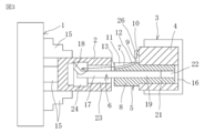
- the machining cooling device exemplifies boring with a turret lathe as a machining device, and a blade of the tool mounting section 3 with respect to the work 2 installed in the work setting section 1.
- the cooling oil 7 is supplied from the side of the tool installation portion 3 to the portion to be machined by the tool 6 supported by the tool holder 5 installed on the table 4.
- the injection port 10 directs the cooling oil 7 toward the outer peripheral surface of the protrusion 8 protruding from the tool holder 5 toward the work 2 and in space. It is provided so as to inject into 9.
- the injection port portion 10 may have a structure provided with an injection nozzle.
- the direction changing portion 11 introduces the cooling oil 7 injected into the space 9 from the injection port portion 10 into the protrusion 8 from the outer peripheral surface of the protrusion 8 from the front surface of the protrusion 8 facing the work 2. It is provided so as to be led out toward the machined portion by the work 2 and the tool 6.
- both the introduction portion 12 of the cooling oil 7 on the outer peripheral surface of the protrusion 8 and the outlet portion 13 of the cooling oil 7 on the front surface of the protrusion 8 of the direction changing portion 11 are configured as openings.
- the introduction portion 12 of the cooling oil 7 is referred to as an inlet 12, and the outlet portion 13 of the cooling oil 7 is referred to as an outlet 13.
- the outlet 13 of the direction changing portion 11 is provided on the front surface of the protrusion 8.
- the outlet 13 is arranged near the tool 6 supported by the tool holder 5.
- the cooling oil 7 is close to the outlet 13 along and in contact with the outer surface of the tool 6. Eject in parallel.
- the portion between the inlet 12 and the outlet 13 of the direction changing portion 11 opens to the outer peripheral surface and the front surface of the protrusion 8, and the depth from the outer peripheral surface to the inside of the protrusion 8 is the tool post 4.
- the structure of the direction changing portion 11 is simple because it has a groove shape with an arcuate bottom that goes from the inlet 12 on the side of the work to the exit 13 on the side of the work installation portion 1.
- the work 2 is captured and installed from the outside by a plurality of claws 15 provided in the work installation portion 1 in the work installation portion 1 called the work chuck of the turret lathe.
- the work 2 installed in the work installation unit 1 circulates around the center line of the work installation unit 1 extending in the lateral direction in one direction with the rotation drive of the work installation unit 1. It is driven to rotate.
- a tool 6 called a boring bar is attached to one tool post 4 in a tool installation portion 3 called a turret of a turret lathe with a tool holder 5 interposed therebetween.
- a holder accommodating hole 16 is formed laterally from the front surface of the tool post 4 facing the work 2 toward the rear end side.
- the tool 6 includes a main body portion 17, a blade portion 18, and an attachment portion 19 to the tool holder 5.
- the main body 17 is located on the side facing the work 2 and has a long rod shape in the lateral direction.
- the blade portion 18 is provided at the front end portion of the main body portion 17 on the side facing the work 2.
- the mounting portion 19 has a rod shape extending concentrically from the main body portion 17 to the rear side.
- the tool holder 5 includes a protrusion 8, a mounting portion 21 to the tool post 4, and a tool accommodating hole 22.
- the protrusion 8 has a larger outer shape than the mounting portion 21.
- the mounting portion 21 has a smaller outer shape than the protruding portion 8.
- the tool accommodating hole 22 is formed laterally in the center of the tool holder 5 from the front surface on the side facing the work installation portion 1 toward the side of the mounting portion 21. Then, the mounting portion 19 of the tool 6 is accommodated and fixed in the tool accommodating hole 22 from the front side of the tool holder 5, and the main body portion 17 and the blade portion 18 of the tool 6 face the work 2 rather than the protruding portion 8 of the tool holder 5. It is projected to the side to be used.
- the work 2 installed in the work installation unit 1 has a tool (not shown) attached to one tool stand (not shown) provided in the tool installation unit 3 other than the tool 6.
- the embodiment in which the internal hole 23 is formed in advance in a barrel shape from the front surface on the side of the work 2 facing the tool installation portion 3 toward the inside is illustrated.
- the work 2 is rotationally driven by the work installation portion 1, and the main body portion 17 and the blade portion 18 of the tool 6 are inserted into the inside of the internal hole 23 from the opening on the side of the internal hole 23 of the work 2 facing the tool installation portion 3.
- the blade portion 18 moves outward in the radial direction with respect to the rotation of the work 2 and moves laterally with the center line extending with respect to the rotation of the work 2 due to the machining operation of the tool post 4 with respect to the tool installation portion 3.
- the boring hole 24 having a diameter larger than that of the internal hole 23 is machined.
- the work 2 is rotationally driven, and the tool 6 does not rotate and moves outward in the radial direction with respect to the rotation of the work 2 and the lateral direction in which the center line extends with respect to the rotation of the work 2.
- it can be applied at least by moving in the lateral direction in which the center line extends with respect to the rotation of the work 2.
- Cooling oil 7 pressurized to a predetermined pressure is supplied to the injection port portion 10 from a supply source (not shown) via a supply path (not shown) provided inside the tool post 4.
- the supplied cooling oil 7 is injected from the injection port portion 10 toward the inlet 12 into the space in front of the tool post 4. Since the cooling oil is injected into the space from the injection port, it is not necessary to connect the injection port and the direction changing part of the protrusion with piping, and when replacing the tool holder, only the tool holder needs to be removed from the tool post. The tool holder can be easily replaced.
- the injection direction of the cooling oil 7 is from the diameter direction of the tool holder 5 to the main body of the tool 6.
- the direction is changed so as to be parallel to the center line of the tool 6 toward the gap between the 17 and the internal hole 23.
- the cooling oil 7 taken into the gap between the main body 17 and the internal hole 23 from the direction changing portion 11 reaches the machined portion by the work 2 and the blade portion 18, and both the work 2 and the blade portion 18 Cool well.
- the cooling oil 7 that has cooled both the work 2 and the blade portion 18 is shown after the cutting chips have been removed by a cooling oil recovery path (not shown) and a filter provided in the cooling oil recovery path. Returned to a source that has not.
- a cover 25 covering the opening on the outer peripheral surface side of the protrusion 8 in the groove-shaped direction changing portion 11 is provided on the protrusion 8.
- the cooling oil 7 that has entered the direction changing unit 11 is prevented from scattering.
- a straightening pipe 26 such as a bent pipe joint called an elbow is provided at the injection port portion 10, and the straightening pipe 26 and the inlet 12 are provided.
- the space distance between the two is reduced so that the cooling oil 7 injected into the space from the straightening pipe 26 can be easily taken into the inlet 12.
- the injection direction of the cooling oil 7 is corrected so that the cooling oil 7 injected by the straightening pipe 26 is parallel to the front surface of the tool post 4 facing the work 2, the inlet 12 is on the side of the tool post 4. It can be installed at a close position, the path of the direction changing unit 11 becomes long, and the injection direction of the cooling oil 7 injected from the outlet 13 becomes stable.
- the direction changing portion 11 provided in the tool holder 5 has a hole shape. That is, the direction changing unit 11 is the center line of the tool 6 from the front surface facing the work 2 of the tool holder 5 on the side of the outlet 13 and the vertical hole dented inside in the radial direction from the outer peripheral surface of the tool holder 5 on the side of the inlet 12.
- the cooling oil 7 is provided with a horizontal hole extending in a direction parallel to the vertical hole and connected to the vertical hole, and the cooling oil 7 injected from the injection port portion 10 or the straightening pipe 26 to the inlet 12 via the space on the front surface side of the tool post 4.
- the cooling oil 7 is guided to the outlet 13 from the direction changing unit 11 without escaping to the outside, and the injection direction of the cooling oil 7 from the outlet 13 via the space between the work 2 and the tool holder 5 is stabilized.
- the orthodontic tube 26 is removed and applicable.
- the machining cooling device is provided with a receiving wall 27 around the inlet 12 of the tool holder 5 so as to project outward in the radial direction of the tool holder 5 and receives the receiving wall 27.
- the wall 27 is configured to guide the cooling oil 7 injected from the injection port portion 10 to the inlet 12 of the direction changing portion 11 in the space on the front side of the tool post 4.
- the receiving wall 27 uses one of the divided pipes in which the pipe is divided into two along the center line extending in the vertical direction of the pipe, and the upper end of the divided pipe is projected toward the injection port portion 10. It has a hood-like structure with.
- a ball joint is formed in which the end portion of the receiving wall 27 has a spherical shape and is slidably supported in a receiving recess provided around the inlet 12 of the tool holder 5.
- the inclination of the receiving wall 27 may be adjustable.
- the machining cooling device according to the sixth embodiment for carrying out the invention shown in FIG. 6 has a structure in which a taper drill is installed on the tool post 4 as a tool 6. That is, since the outer shape of the mounting portion 19 of the tool 6 has a tapered shape that gradually narrows from the side of the work 2 toward the rear, the tool accommodating hole 22 of the tool holder 5 has a tapered shape that matches the tapered shape. It has become. As a result, the mounting portion 19 of the tool 6 is inscribed and fixed in the tool accommodating hole 22 as it is accommodated in the tool accommodating hole 22 from the front side of the tool holder 5.
- the outlet 13 of the direction changing portion 11 is provided on the front surface of the protrusion 8, the outlet 13 can be arranged near the tool 6 supported by the tool holder 5, and the outlet 13 is the tool holder 5.
- the cooling oil 7 is ejected in parallel from the outlet 13 along and in contact with the outer surface of the tool 6.
- the tool 6 processes the work 2. Even if it progresses to the back of the work 2, most of the cooling oil 7 ejected from the outlet 13 does not bounce off the front surface facing the injection port portion 10 of the work 2, and the internal hole 23 of the work 2 and the tool 6 The machined portion formed by the work 2 located at the back of the work 2 and the tip of the blade 18 of the tool 6 is reached through the gap between the workpieces 2, and the machined portion formed by the work 2 and the tool 6 is satisfactorily cooled by the cooling oil 7. To. In FIG. 6, the orthodontic tube 26 is removed and applicable.
- the machining cooling device uses a tool holder 5 called a straight arbor for installing the drill chuck 31 on the tool post 4, and the protrusion of the tool holder 5 is used.
- An outlet 13 is provided at the center of the tip tapered portion 32 protruding from the portion 8 toward the work 2, and is ejected from the injection port portion 10 or the straightening pipe 26 to the inlet 12 via the space on the front side of the tool post 4.
- the cooling oil 7 is guided from the direction changing unit 11 to the outlet 13 without escaping to the outside, and is called a drill supported by the claw 34 and the claw 34 of the drill chuck 31 from the outlet 13 through the core hole 33 of the drill chuck 31.
- the straightening tube 26 may be removed, or the drill chuck 31 may be replaced with a collet chuck, which is similarly applicable. Further, in FIG. 7, it is applicable even if the receiving wall 27 of FIG. 5 is provided instead of the correction tube 26.
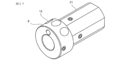
- the tool holder 5 according to the eighth embodiment for carrying out the invention shown in FIGS. 8 to 11 includes three direction changing units 11. These three direction changing portions 11 separate the cooling oil 7 taken into the inlet 12 which is opened at the outer peripheral surface of the protrusion 8 of the tool holder 5 in the circumferential direction from each other in the circumferential direction to the front surface of the protrusion 8.
- the structure is independent of each other so as to be discharged from the opened outlet 13. Inside each outlet 13, a rectifying member 35 that concentrates the flow of the cooling oil 7 injected into the space from the outlet 13 in a predetermined direction is provided.
- a chamfered portion 36 is formed in an annular shape so as to go around the outer peripheral surface at a portion where the outer peripheral surface and the front surface of the protrusion 8 intersect.
- the chamfered portion 36 has a slope that gradually becomes a downward slope from the rear side to the front side (see FIG. 10).
- the protrusion 8 is provided with a set screw 37 for fixing the tool 6 (see FIG. 6) to the tool holder 5 so as not to interfere with the direction changing portion 11.
- the set screw 37 passes through the center of the tool holder 5 and extends in the left-right direction. Two left and right positions where one straight line intersects the outer peripheral surface of the protrusion 8 and one position where one straight line extending in the vertical direction through the center of the tool holder 5 intersects at the lower part of the outer peripheral surface of the protrusion 8. It is provided in a total of 3 places.
- the set screw 37 is individually attached to the screw hole 38 penetrating the outer peripheral surface of the protrusion 8 and the tool accommodating hole 22.
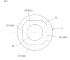
- four mounting flat portions 39 are formed on the outer peripheral surface of the mounting portion 21 of the tool holder 5. As shown in FIG. 11, two of the four mounting flat portions 39 are parallel to each other on the center line L1 with the center of the tool holder 5 in between, and the other two mounting flat portions 39 are center lines. On the center line L2 orthogonal to L1, they are parallel to each other with the center of the tool holder 5 in between.
- the tool holder 5 can be used for the tool post 4 of a processing machine manufactured by various manufacturing companies. Specifically, the positional relationship between the set screw 40 for fixing the tool holder 5 to the tool post 4 and the injection port portion 10 varies depending on the manufacturing company of the processing machine.
- the injection port portion 10 was inserted into the holder accommodating hole 16 as shown in FIG.
- the set screw 40 is on the upper surface like the tool post 4A or on the right side like the tool post 4B or on the lower surface like the tool post 4C or on the tool post 4D. It was provided on the left side as shown.
- four mounting flat portions 39 are provided on the mounting portion 21 of the tool holder 5.
- the upper mounting plane portion 39 of the four mounting plane portions 39 is represented by 39A
- the right mounting plane portion 39 is represented by 39B
- the left mounting plane portion 39 is represented by 39B. It is expressed as 39C
- the lower mounting plane portion 39 is expressed as 39D to distinguish each of the four mounting plane portions 39.
- a set screw 40 for fixing the tool holder 5 to the tool post 4A is provided on the upper surface extending rearward from the upper edge of the front surface provided with the injection port portion 10, and in the tool post 4B, the tool post 4B is provided.
- a set screw 40 for fixing the tool holder 5 is provided on the right side surface extending rearward from the right edge of the front surface provided with the injection port portion 10, and in the tool post 4C, a set screw 40 for fixing the tool holder 5 to the tool post 4C is provided.
- a set screw 40 for fixing the tool holder 5 to the tool post 4D is provided on the front surface where the injection port portion 10 is provided. The case where it is provided on the left side surface extending behind the left edge is illustrated.
- FIG. 12 when the tool holder 5 is attached to the tool post 4A, the tool holder 5 is circular in plan view so that the inlet 12 of the tool holder 5 is located directly below the injection port 10 of the tool post 4A.
- the mounting portion 21 having four mounting flat portions 39 (39A, 39B, 39C, 39D in FIG. 11) on the outer peripheral surface is shown after being inserted into the holder accommodating hole 16 having a circular view in plan view of the tool post 4A.
- the set screw 40 advances toward the holder accommodating hole 16 while being guided by the female screw to which the set screw 40 is mounted by an artificial operation with a tightening tool such as a screwdriver, and the tip of the set screw 40 is the tool holder 5.
- the tool holder 5 is fixed to the tool post 4A by abutting on the upper mounting surface portion 39A.
- the tool holder 5 when the tool holder 5 is attached to the tool post 4B, the tool holder 5 is circular in a plan view so that the inlet 12 of the tool holder 5 is located directly below the injection port 10 of the tool post 4B.
- the mounting portion 21 having four mounting flat portions 39 (39A, 39B, 39C, 39D in FIG. 11) on the outer peripheral surface is inserted into the holder accommodating hole 16 which is circular in plan view of the tool post 4B, the figure is shown.
- the set screw 40 advances toward the holder accommodating hole 16 while being guided by the female screw to which the set screw 40 is mounted by an artificial operation with a tightening tool such as a screwdriver, and the tip of the set screw 40 advances to the side of the holder accommodating hole 16.
- the tool holder 5 is fixed to the tool post 4B by abutting on the mounting flat portion 39B on the right side of the tool holder 5.
- the tool holder 5 when the tool holder 5 is attached to the tool post 4C, the tool holder 5 is circular in a plan view so that the inlet 12 of the tool holder 5 is located directly below the injection port 10 of the tool post 4.
- the mounting portion 21 having the four mounting flat portions 39 (39A, 39B, 39C, 39D in FIG. 11) on the outer peripheral surface is inserted into the holder accommodating hole 16 having a circular view in plan view of the tool post 4, the figure is shown.
- the set screw 40 advances toward the holder accommodating hole 16 while being guided by the female screw to which the set screw 40 is mounted by an artificial operation with a tightening tool such as a screwdriver, and the tip of the set screw 40 advances to the side of the holder accommodating hole 16.
- the tool holder 5 is fixed to the tool post 4 by abutting on the mounting flat portion 39 on the right side of the above, that is, the mounting flat portion 39C in FIG.
- the tool holder 5 when the tool holder 5 is attached to the tool post 4D, the tool holder 5 is circular in plan view so that the inlet 12 of the tool holder 5 is located directly below the injection port 10 of the tool post 4.
- the mounting portion 21 having the four mounting flat portions 39 (39A, 39B, 39C, 39D in FIG. 11) on the outer peripheral surface is inserted into the holder accommodating hole 16 having a circular view in plan view of the tool post 4, the figure is shown.
- the set screw 40 advances toward the holder accommodating hole 16 while being guided by the female screw to which the set screw 40 is mounted by an artificial operation with a tightening tool such as a screwdriver, and the tip of the set screw 40 advances to the side of the holder accommodating hole 16.
- the tool holder 5 is fixed to the tool post 4 by abutting on the mounting flat portion 39 on the left side of the above, that is, the mounting flat portion 39D in FIG.
- FIG. 14 was used to verify the angle between the vertical hole on the inlet 12 side and the horizontal hole on the outlet 13 side of the direction changing unit 11. The results will be described.
- the clearance angle ⁇ 2 between the center line L6 extending in the vertical direction of the vertical hole on the side of the inlet 12 and the center line L7 extending in the lateral direction of the tool accommodating hole 22 is 45 to 55 degrees, which is an allowable range of 50 degrees.
- the clearance angle ⁇ 3 between the center line L8 extending in the left-right direction of the lateral hole on the side of the outlet 13 and the center line L7 extending in the lateral direction of the tool accommodating hole 22 is 5 to 10 degrees within the allowable range of 0 to 15 degrees. It was confirmed that the degree was optimum and the cooling oil 7 was ejected in a bundle without being scattered from the outlet 13. Further, when the bottom portion 41 at which the vertical hole on the inlet 12 side and the horizontal hole on the outlet 13 side intersect has an arc shape that is recessed downward, ⁇ 3 is 0 degrees, that is, the cooling oil 7 is discharged from the outlet 13. It was confirmed that it was derived in parallel with the center line L7.
- FIG. 15 will be described as a result of verifying the relationship between the three direction changing portions 11, the tool accommodating holes 22, and the set screw 37 in the tool holder 5 according to the morphology 12 for carrying out the invention.
- FIG. A of FIG. 15 since the diameter of the tool accommodating hole 22 is large, even if the inlet 12 and the outlet 13 of the direction changing portion 11 are individually provided, if there is no interference with the set screw 37. , The cooling oil 7 is injected in a bundle from the outlet 13 without being scattered, which is the best structure.
- the tool accommodating holes 22 can be integrated into one outlet 13 as shown in FIG.
- the cooling oil 7 is ejected as a bundle without being scattered.
- the direction changing portion 11 in the tool holder 5 according to the thirteenth aspect for carrying out the invention shown in FIGS. A to C of FIG. It is constructed as a flat slope with a gradual downward slope toward the side of. With this configuration, the structure of the direction changing unit 11 is simple.
- the portion between the inlet 12 and the outlet 13 of the direction changing portion 11 opens to the outer peripheral surface and the front surface of the protrusion 8.
- the direction changing portion 11 is in a state of being cut out in a straight line in the left-right direction, and has a shape that is curved upward and protrudes like the chamfered portion 36 shown in FIG. is not.
- the angle ⁇ 4 formed by the flat slope of the direction changing portion 11 and the center line L7 extending in the lateral direction of the tool accommodating hole 22 is not particularly limited. However, it can be set to the angle of ⁇ 3 in FIG. By being configured at this angle, more cooling oil can be ejected from the outlet in parallel along and in contact with the outer surface of the tool.
- the tool holder 5 shown in FIGS. D to F of FIG. 16 has a configuration in which three flat slopes, which are direction changing portions 11, are provided adjacent to the protrusions 8 in the left-right direction.
- the respective angles of the angle ⁇ 4 formed by the flat slope of the direction changing unit 11 and the center line L7 extending in the lateral direction of the tool accommodating hole 22 are shown in FIG. It can be set to an angle of ⁇ 3 of 14. Further, as shown in FIG.
- the angle formed by the two flat slopes of the adjacent direction changing units 11 (the angle on the side of the center P1) ⁇ 5 and
- the angle of ⁇ 6 is preferably 135 degrees to 150 degrees. If it is configured at this angle, as shown in FIG. 13, the tool holder 5 is preferable because it can correspond to the tool post 4 of the processing machine manufactured by various manufacturing companies.
- the most preferable angle is that the angles of ⁇ 5 and ⁇ 6 are 145 degrees.
- the angles of ⁇ 5 and ⁇ 6 may be the same or different.
- the direction changing unit 11 may be provided with 2, 4, or 5 or more. When a plurality of direction changing units 11 are provided, a plurality of direction changing units 11 may be provided individually, or a plurality of direction changing units 11 may be provided adjacent to each other.
- the direction changing portion 11 in the tool holder 5 according to the fourth embodiment for carrying out the invention shown in FIGS. A to C of FIG. 17 has an upper portion of the protrusion 8 above the tool accommodating hole 22 from the side of the inlet 12 to the outlet 13. It is configured as a flat slope that gradually becomes a downward slope toward the side of, and is composed of a steep slope on the entrance 12 side and a gentle slope on the exit 13 side.
- the steep slope is a flat slope.
- the gentle slope is a flat slope.
- the steep slope and the gentle slope are in a state of being cut out in a straight line in the left-right direction, and have a shape that is curved upward and protrudes like the chamfered portion 36 shown in FIG. is not. Therefore, when the cooling oil 7 hits a steep slope and a gentle slope, it is possible to prevent the injection direction of the cooling oil 7 from being divided into the left and right directions.
- the angle ⁇ 7 formed by the steep slope on the entrance 12 side and the center line L7 extending in the lateral direction of the tool accommodating hole 22 is not particularly limited, but is not particularly limited. It can be set to an angle of ⁇ 2.
- the steep slope on the side of the entrance 12 is configured as a slope that gradually becomes a downward slope from the side of the entrance 12 to the side of the exit 13.
- the angle ⁇ 8 formed by the gentle slope on the exit 13 side and the center line L7 extending in the lateral direction of the tool accommodating hole 22 is not particularly limited, but is shown in FIG. It can be set to an angle of ⁇ 3 of 14. At this angle, more cooling oil can be ejected from the outlet in parallel along and in contact with the outer surface of the tool.
- the gentle slope on the side of the outlet 13 is configured as a slope that gradually becomes a downward slope from the side of the entrance 12 toward the side of the exit 13.
- the number of direction changing units 11 is not limited to one, and may be two, three, four, or five or more.
- a direction changing portion 11 composed of a steep slope on the entrance 12 side and a gentle slope on the exit 13 side is adjacent to the protrusion 8 in the left-right direction as in FIGS. 16D to 16F. May be provided in plurality.
- the respective angles of the angle ⁇ 7 formed by the steep slope of the direction changing unit 11 and the center line L7 extending in the lateral direction of the tool accommodating hole 22 are shown in FIG. It can be set to an angle of ⁇ 2 of 14.
- the respective angles ⁇ 8 formed by the gentle slope on the exit 13 side of the direction changing unit 11 and the center line L7 extending in the lateral direction of the tool accommodating hole 22 can be set to the angle ⁇ 3 in FIG. it can.
- the angle formed by the gentle slopes on the sides of the two outlets 13 of the adjacent direction changing units 11 is 135 degrees to 150 degrees. It is preferable to have. If it is configured at this angle, as shown in FIG. 13, the tool holder 5 is preferable because it can correspond to the tool post 4 of the processing machine manufactured by various manufacturing companies. The most preferable angle of the angle is 145 degrees.
- a plurality of direction changing units 11 may be provided individually, or a plurality of direction changing units 11 may be provided adjacent to each other.
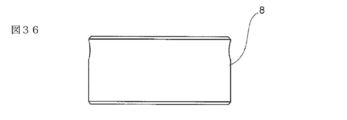
- the tool post 4 and the tool holder 5 may be integrated. That is, the protrusion 8 may be provided on the front surface of the tool post 4, and the tool 6 may be supported on the protrusion 8 and the direction changing portion 11 may be provided. Further, the tool 6 may be provided with a protrusion 8 having a direction changing portion 11. At that time, as shown in FIGS. 36 to 51, the protrusion 8 of the tool holder 5 from which the mounting portion 21 has been removed may be detachably provided on the tool 6, and the protrusion 8 is integrated with the tool 6. Either of the cases where it is provided as a structure may be used.
- the direction changing portion 11 in the protruding portion 8 of the tool holder 5 from which the mounting portion 21 has been removed can be applied with embodiments 1 to 14 for carrying out the invention.
Landscapes
- Engineering & Computer Science (AREA)
- Mechanical Engineering (AREA)
- Auxiliary Devices For Machine Tools (AREA)
Priority Applications (2)
| Application Number | Priority Date | Filing Date | Title |
|---|---|---|---|
| CN202080038419.XA CN113905848B (zh) | 2019-07-04 | 2020-07-03 | 加工冷却装置 |
| JP2021529199A JP7602801B2 (ja) | 2019-07-04 | 2020-07-03 | 加工冷却装置 |
Applications Claiming Priority (2)
| Application Number | Priority Date | Filing Date | Title |
|---|---|---|---|
| JP2019-125639 | 2019-07-04 | ||
| JP2019125639 | 2019-07-04 |
Publications (1)
| Publication Number | Publication Date |
|---|---|
| WO2021002451A1 true WO2021002451A1 (ja) | 2021-01-07 |
Family
ID=74100339
Family Applications (1)
| Application Number | Title | Priority Date | Filing Date |
|---|---|---|---|
| PCT/JP2020/026173 Ceased WO2021002451A1 (ja) | 2019-07-04 | 2020-07-03 | 加工冷却装置 |
Country Status (4)
| Country | Link |
|---|---|
| JP (1) | JP7602801B2 (https=) |
| CN (1) | CN113905848B (https=) |
| TW (1) | TWI857092B (https=) |
| WO (1) | WO2021002451A1 (https=) |
Cited By (2)
| Publication number | Priority date | Publication date | Assignee | Title |
|---|---|---|---|---|
| JP2022117739A (ja) * | 2021-02-01 | 2022-08-12 | Dmg森精機株式会社 | 工作機械 |
| WO2022202938A1 (ja) | 2021-03-26 | 2022-09-29 | 富士フイルム株式会社 | 凍結乾燥用容器 |
Citations (6)
| Publication number | Priority date | Publication date | Assignee | Title |
|---|---|---|---|---|
| JPS61178651U (https=) * | 1985-04-25 | 1986-11-07 | ||
| JPH0453647A (ja) * | 1990-06-15 | 1992-02-21 | Riken Seiki Kk | 旋盤加工時の切削油供給方法及びこの際に用する旋盤用シャンク |
| JP2009220200A (ja) * | 2008-03-14 | 2009-10-01 | Jtekt Corp | 流体供給装置 |
| JP2011088270A (ja) * | 2009-09-25 | 2011-05-06 | Mori Seiki Co Ltd | 工具内流路を有する円筒状回転工具およびこの工具による加工方法 |
| US20150283627A1 (en) * | 2014-04-04 | 2015-10-08 | Kennametal lndia Limited | Reducer sleeve with thru coolant flow and a cutting assembly using such reducer sleeve |
| JP2019147226A (ja) * | 2018-02-27 | 2019-09-05 | 株式会社堀内製作所 | クーラント供給装置及びクーランント供給方法およびクーラント射出方向変換装置 |
Family Cites Families (22)
| Publication number | Priority date | Publication date | Assignee | Title |
|---|---|---|---|---|
| JPH047873Y2 (https=) * | 1987-04-21 | 1992-02-28 | ||
| DE3831693A1 (de) * | 1988-09-17 | 1990-03-22 | Bbc York Kaelte Klima | Verfahren zum umweltfreundlichen entsorgen eines kuehlsystems sowie vorrichtung zur durchfuehrung des verfahrens |
| JP2674487B2 (ja) * | 1993-11-30 | 1997-11-12 | 双葉電子工業株式会社 | 工作機械のクーラント供給装置 |
| JP3519536B2 (ja) * | 1996-02-29 | 2004-04-19 | 東芝機械株式会社 | クーラント噴出ノズル付き主軸装置およびクーラント供給切削加工方法 |
| SE514939C2 (sv) * | 1999-09-02 | 2001-05-21 | Sandvik Ab | Maskin för spånavskiljande bearbetning jämte skärverktyg för dylika maskiner |
| JP2002154032A (ja) * | 2000-11-15 | 2002-05-28 | Canon Inc | 工具ホルダ及びクーラント供給方法 |
| SE0100652L (sv) * | 2001-02-27 | 2002-08-28 | Sandvik Ab | Förfarande för spånavskiljande bearbetning samt skärverktyg för spånavskiljande bearbetning |
| US7134812B2 (en) * | 2002-07-17 | 2006-11-14 | Kevin Beckington | Tool coolant application and direction assembly |
| JP2005262348A (ja) * | 2004-03-17 | 2005-09-29 | Nippon Seratekku Kk | 回転刃物体および回転刃物体による孔あけ方法 |
| JP2006289567A (ja) * | 2005-04-13 | 2006-10-26 | Honda Motor Co Ltd | 工作機械 |
| KR101144617B1 (ko) * | 2010-01-11 | 2012-05-11 | 한국기계연구원 | 형상기억합금 콜렛척 |
| WO2012101751A1 (ja) * | 2011-01-24 | 2012-08-02 | Lee Sung Geun | 工具ホルダ及び工作機械 |
| US8388268B2 (en) * | 2011-03-07 | 2013-03-05 | Kennametal Inc. | Cutting assembly |
| DE102012018389A1 (de) * | 2012-09-18 | 2014-03-20 | Maximilian Bähr | Vorrichtung zum Sprühen eines Mediums auf eine Bearbeitungsstelle eines Werkzeuges |
| FR3034696B1 (fr) * | 2015-04-08 | 2017-09-01 | Snecma | Porte-outil pour outil de coupe a lubrifier |
| CN205968448U (zh) * | 2016-08-23 | 2017-02-22 | 浙江纳迪克数控设备有限公司 | 一种数控机床刀柄内部喷射冷却液装置 |
| CN205996687U (zh) * | 2016-08-23 | 2017-03-08 | 中国一拖集团有限公司 | 一种机床主轴前端切削液出水结构 |
| TWM534055U (en) * | 2016-09-22 | 2016-12-21 | bao-yuan Zhang | Rotational main shaft having cooling device |
| KR102004698B1 (ko) * | 2017-10-24 | 2019-07-29 | 한국생산기술연구원 | 분사 각도 제어를 위한 노즐 어셈블리를 포함하는 유체분사장치 |
| CN208961626U (zh) * | 2018-11-14 | 2019-06-11 | Towa半导体设备(苏州)有限公司 | 一种切削液喷射装置 |
| CN109664154B (zh) * | 2018-12-29 | 2024-09-24 | 汇专科技集团股份有限公司 | 一种自动化喷嘴替换系统及其应用方法 |
| TWM577780U (zh) * | 2019-01-15 | 2019-05-11 | 中暘切削工具有限公司 | Cutting tool with spray cutting fluid function and nozzle structure thereof |
-
2020
- 2020-07-03 CN CN202080038419.XA patent/CN113905848B/zh active Active
- 2020-07-03 WO PCT/JP2020/026173 patent/WO2021002451A1/ja not_active Ceased
- 2020-07-03 JP JP2021529199A patent/JP7602801B2/ja active Active
- 2020-07-03 TW TW109122580A patent/TWI857092B/zh active
Patent Citations (6)
| Publication number | Priority date | Publication date | Assignee | Title |
|---|---|---|---|---|
| JPS61178651U (https=) * | 1985-04-25 | 1986-11-07 | ||
| JPH0453647A (ja) * | 1990-06-15 | 1992-02-21 | Riken Seiki Kk | 旋盤加工時の切削油供給方法及びこの際に用する旋盤用シャンク |
| JP2009220200A (ja) * | 2008-03-14 | 2009-10-01 | Jtekt Corp | 流体供給装置 |
| JP2011088270A (ja) * | 2009-09-25 | 2011-05-06 | Mori Seiki Co Ltd | 工具内流路を有する円筒状回転工具およびこの工具による加工方法 |
| US20150283627A1 (en) * | 2014-04-04 | 2015-10-08 | Kennametal lndia Limited | Reducer sleeve with thru coolant flow and a cutting assembly using such reducer sleeve |
| JP2019147226A (ja) * | 2018-02-27 | 2019-09-05 | 株式会社堀内製作所 | クーラント供給装置及びクーランント供給方法およびクーラント射出方向変換装置 |
Cited By (2)
| Publication number | Priority date | Publication date | Assignee | Title |
|---|---|---|---|---|
| JP2022117739A (ja) * | 2021-02-01 | 2022-08-12 | Dmg森精機株式会社 | 工作機械 |
| WO2022202938A1 (ja) | 2021-03-26 | 2022-09-29 | 富士フイルム株式会社 | 凍結乾燥用容器 |
Also Published As
| Publication number | Publication date |
|---|---|
| TW202110568A (zh) | 2021-03-16 |
| TWI857092B (zh) | 2024-10-01 |
| CN113905848A (zh) | 2022-01-07 |
| JPWO2021002451A1 (https=) | 2021-01-07 |
| CN113905848B (zh) | 2023-09-19 |
| JP7602801B2 (ja) | 2024-12-19 |
Similar Documents
| Publication | Publication Date | Title |
|---|---|---|
| KR101162942B1 (ko) | 절삭 공구와 절삭 공구의 공구 헤드 | |
| EP0579371B1 (en) | A method and an apparatus for machining a workpiece | |
| JP6833900B2 (ja) | クーラントチャネルを有するクランプ装置、当該クランプ装置の製造方法、及び、そのようなクランプ装置を有する旋削装置のための工具ホルダプレート | |
| KR102434409B1 (ko) | 공작기계용 다축 앵글헤드 장치 | |
| CN105382625A (zh) | 凸缘机构以及切削装置 | |
| CN101175592B (zh) | 用于以非常规高度定位切割刀片的刀夹和刀夹组件 | |
| WO2021002451A1 (ja) | 加工冷却装置 | |
| EP1495840B1 (en) | Method of manufacturing coolant nozzle | |
| JP6596113B2 (ja) | クーラント供給装置及びクーラント供給方法およびクーラント射出方向変換装置 | |
| JP7262201B2 (ja) | 冷却液供給装置 | |
| US20040060402A1 (en) | Vertical machine tool with a movable main spindle | |
| CN1613608B (zh) | 使用冷却剂流体进行金属加工的设备 | |
| CN220445907U (zh) | 一种具有液冷通道的刀具夹持装置 | |
| JP2006289567A (ja) | 工作機械 | |
| JP6961848B1 (ja) | 工作機械 | |
| KR101195753B1 (ko) | 조정나사가 설치된 터렛용 공구홀더 | |
| JPH06134647A (ja) | クーラント供給方法および装置 | |
| US8413680B2 (en) | Fluid distribution apparatus | |
| JP2004074376A (ja) | マシニングセンタによるワークの加工方法、及びワーク取付台 | |
| JP2021098242A (ja) | クーラント穴付きカッターおよびそのカッター本体 | |
| KR102890145B1 (ko) | 쿨런트 공급 장치 및 공작 기계 | |
| KR101076711B1 (ko) | 스토퍼가 내장된 터렛용 공구홀더 | |
| JP4291680B2 (ja) | 穴加工装置 | |
| JP2023002110A (ja) | 工具取付け構造 | |
| WO2019167697A1 (ja) | クーラント供給装置及びクーラント供給方法およびクーラント射出方向変換装置 |
Legal Events
| Date | Code | Title | Description |
|---|---|---|---|
| 121 | Ep: the epo has been informed by wipo that ep was designated in this application |
Ref document number: 20834967 Country of ref document: EP Kind code of ref document: A1 |
|
| ENP | Entry into the national phase |
Ref document number: 2021529199 Country of ref document: JP Kind code of ref document: A |
|
| NENP | Non-entry into the national phase |
Ref country code: DE |
|
| 122 | Ep: pct application non-entry in european phase |
Ref document number: 20834967 Country of ref document: EP Kind code of ref document: A1 |