WO2021002451A1 - Machining cooling device - Google Patents
Machining cooling device Download PDFInfo
- Publication number
- WO2021002451A1 WO2021002451A1 PCT/JP2020/026173 JP2020026173W WO2021002451A1 WO 2021002451 A1 WO2021002451 A1 WO 2021002451A1 JP 2020026173 W JP2020026173 W JP 2020026173W WO 2021002451 A1 WO2021002451 A1 WO 2021002451A1
- Authority
- WO
- WIPO (PCT)
- Prior art keywords
- tool
- center line
- protrusion
- work
- cooling oil
- Prior art date
Links
Images


Classifications
-
- B—PERFORMING OPERATIONS; TRANSPORTING
- B23—MACHINE TOOLS; METAL-WORKING NOT OTHERWISE PROVIDED FOR
- B23Q—DETAILS, COMPONENTS, OR ACCESSORIES FOR MACHINE TOOLS, e.g. ARRANGEMENTS FOR COPYING OR CONTROLLING; MACHINE TOOLS IN GENERAL CHARACTERISED BY THE CONSTRUCTION OF PARTICULAR DETAILS OR COMPONENTS; COMBINATIONS OR ASSOCIATIONS OF METAL-WORKING MACHINES, NOT DIRECTED TO A PARTICULAR RESULT
- B23Q11/00—Accessories fitted to machine tools for keeping tools or parts of the machine in good working condition or for cooling work; Safety devices specially combined with or arranged in, or specially adapted for use in connection with, machine tools
- B23Q11/10—Arrangements for cooling or lubricating tools or work
-
- B—PERFORMING OPERATIONS; TRANSPORTING
- B23—MACHINE TOOLS; METAL-WORKING NOT OTHERWISE PROVIDED FOR
- B23B—TURNING; BORING
- B23B29/00—Holders for non-rotary cutting tools; Boring bars or boring heads; Accessories for tool holders
- B23B29/04—Tool holders for a single cutting tool
- B23B29/12—Special arrangements on tool holders
-
- B—PERFORMING OPERATIONS; TRANSPORTING
- B23—MACHINE TOOLS; METAL-WORKING NOT OTHERWISE PROVIDED FOR
- B23B—TURNING; BORING
- B23B31/00—Chucks; Expansion mandrels; Adaptations thereof for remote control
-
- B—PERFORMING OPERATIONS; TRANSPORTING
- B23—MACHINE TOOLS; METAL-WORKING NOT OTHERWISE PROVIDED FOR
- B23B—TURNING; BORING
- B23B47/00—Constructional features of components specially designed for boring or drilling machines; Accessories therefor
-
- B—PERFORMING OPERATIONS; TRANSPORTING
- B23—MACHINE TOOLS; METAL-WORKING NOT OTHERWISE PROVIDED FOR
- B23B—TURNING; BORING
- B23B51/00—Tools for drilling machines
- B23B51/12—Adapters for drills or chucks; Tapered sleeves
Definitions
- the present invention relates to a processing cooling device and a cooling method.
- an injection nozzle 73 is provided on the front surface of the tool holder 72 installed on the tool post 71, and the injection nozzle 73 is supported by the tool holder 72.
- the injection nozzle 73 could not be placed near the tool 74, and the injection nozzle 73 was arranged outward from the tool 74, and the injection nozzle 73 directed the cooling oil 74 from the position away from the tool 74 toward the cutting edge of the tool 74. It has a structure that sprays diagonally. Therefore, as shown in FIG.
- the present invention has been made in view of the above background technology, and an object of the present invention is to provide a machining cooling device capable of satisfactorily cooling even if machining by a tool progresses to the depth of a work.
- the present invention is a machining cooling device that cools a portion of a work installed in a work installation portion to be machined with a tool supported by a tool post in the tool installation portion with cooling oil, and the machining cooling device has a protrusion.
- the cooling oil injected into the space from the injection port is introduced into the protrusion from the outer peripheral surface of the protrusion and is led out from the front surface of the protrusion toward the processed portion. It is characterized in that both the cooling oil introduction portion and the outlet portion in the direction changing portion are configured as openings.
- the cooling oil is blown into the space from the injection port provided on the front surface of the tool post, and the direction in which the cooling oil blown into this space flows is projected toward the work from the tool post. It is converted by the direction changing part provided in the part, and the cooling oil whose flow direction is changed is transferred from the opening provided as the lead-out part of the direction changing part to the machined part by the work and the tool on the front surface of the protrusion of the tool holder. It is characterized by deriving.
- the outlet since an outlet as a lead-out portion of the direction changing portion is provided on the front surface of the protrusion protruding toward the work from the tool post of the tool holder, the outlet can be arranged near the tool, and the outlet is the tool.
- the cooling oil can be ejected in parallel from the outlet along and in contact with the outer surface of the tool. Therefore, even if the machining of the work by the tool progresses to the back of the work, most of the cooling oil injected from the outlet does not bounce off the front surface facing the injection nozzle of the work, and the internal holes and tools machined in the work.
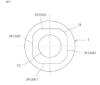
- the direction changing portion passes through the center from the center line extending in the vertical direction at the upper part between the center line extending in the vertical direction through the center of the protrusion and the center line extending in the horizontal direction through the center.
- a straight line having an angle ⁇ 1 of 30 to 45 degrees with respect to the center line extending in the left-right direction is provided at a point where a straight line intersects with one circumference centered on the center, and extends in the vertical direction. If it is provided at the intersection of the center line and the circumference, the tool holder can be used for the tool post of a processing machine manufactured by various manufacturing companies.
- the cooling oil 7 is bundled without being scattered from the outlet 13. Be ejected.
- the sandwiching angle between the center line of the hole on the side of the lead-out portion and the center line of the tool accommodating hole is provided at 0 to 15 degrees, the cooling oil 7 is bundled without being scattered from the outlet 13. Be ejected.
- the structure of the present invention is simple if the direction changing portion is configured on a flat slope that gradually becomes a downward slope from the side of the cooling oil introduction portion to the side of the outlet portion. In the present invention, if the angle between the flat slope and the center line of the tool accommodating hole is provided at 0 to 15 degrees, the cooling oil is closer to be in contact with the outer surface of the tool from the outlet. Can be ejected in parallel with.
- FIG. 9 is a cross-sectional view taken along the line 101-101 of FIG.
- the rear view which shows the tool holder which concerns on Embodiment 8 for carrying out an invention.
- the perspective view which shows the combination of the tool post and a tool holder which concerns on Embodiment 9 for carrying out an invention.
- the schematic diagram which shows the investigation result of the position where the injection port part was provided about the tool post in developing the tool holder which concerns on Embodiment 10 for carrying out the invention.
- FIG. 6 is a schematic view showing a verification result regarding an angle between a vertical hole on the inlet side and a horizontal hole on the outlet side of the direction changing unit in developing the tool holder according to the eleventh embodiment for carrying out the invention.
- the schematic diagram which shows the verification result about the relationship between the three direction change part, the tool accommodating hole, and a set screw in the tool holder which concerns on Embodiment 12 for carrying out the invention.
- a tool holder according to a thirteenth aspect for carrying out the invention is shown.
- A is a front view
- B is a side view
- C is a plan view
- D is a front view
- E is a side view
- F is a plan view. ..
- a tool holder according to a fourteenth aspect for carrying out the invention is shown, FIG.
- FIG. A is a front view
- FIG. B is a side view
- FIG. C is a plan view.
- the side view which shows the case where the machining by the tool with respect to the workpiece of the conventional machining cooling apparatus progresses to the depth of the workpiece.
- the front view of the tool holder of FIG. 15C of FIG. 15 of Embodiment 12 for carrying out the invention.
- the rear view of the tool holder of FIG. 15C of FIG. 15 of Embodiment 12 for carrying out the invention.
- the left side view of the tool holder of FIG. 15C of FIG. 15 of the embodiment 12 for carrying out the invention.
- the right side view of the tool holder of FIG. 15C of FIG. 15 of the embodiment 12 for carrying out the invention.
- FIG. 15 is a plan view of the tool holder of FIG. 15C of FIG. 15 of the embodiment 12 for carrying out the invention.
- FIG. 15A is a cross-sectional view taken along the line AA in the front view of the tool holder of FIG. 15C of FIG.
- FIG. 15 is a perspective view of the tool holder of FIG. 15C of FIG. 15 of the embodiment 12 for carrying out the invention.
- the front view which shows the characteristic part of the tool holder of FIG. 15C of FIG. 15 of FIG. 15 for carrying out the invention by a solid line, and the others by a broken line.
- the rear view which shows the characteristic part of the tool holder of FIG. 15C of FIG.
- Embodiment 12 for carrying out the invention by a solid line, and the others by a broken line.
- the left side view which shows the characteristic part of the tool holder of FIG. 15C of FIG. 15 of FIG.
- the right side view which shows the characteristic part of the tool holder of FIG. 15C of FIG. 15 of FIG.
- the plan view which shows the characteristic part of the tool holder of FIG. 15C of FIG. 15 of Embodiment 12 for carrying out the invention by a solid line, and the others by a broken line.
- the bottom view which shows the characteristic part of the tool holder of FIG. 15C of FIG. 15 of FIG. 15 for carrying out the invention by a solid line, and the others by a broken line.
- FIG. 5 is a front view of a portion of a protrusion provided with a direction changing portion of the tool holder of FIG. 15C of FIG. 15 of FIG. 15 for carrying out the invention.
- FIG. 15 is a plan view of a portion of a protrusion provided with a direction changing portion of the tool holder shown in FIG. 15C of FIG. 15 of FIG. 15 for carrying out the invention.
- FIG. 5 is a perspective view of a portion of a protrusion provided with a direction changing portion of the tool holder of FIG. 15C of FIG. 15 of FIG. 15 for carrying out the invention.
- the front view which shows the characteristic part of the protrusion part provided with the direction change part of the tool holder of FIG. 15C of FIG. 15 of FIG. 15 for carrying out the invention by a solid line, and the others by a broken line.
- the rear view which shows the characteristic part of the protrusion part provided with the direction change part of the tool holder of FIG.
- FIG. 15 for carrying out the invention by a solid line, and the others by a broken line.
- the bottom view which shows the characteristic part of the protrusion part provided with the direction change part of the tool holder of FIG. 15C of FIG. 15 of FIG.
- FIG. 5 is a perspective view in which the characteristic portion of the protruding portion provided with the direction changing portion of the tool holder shown in FIG. 15C of FIG. 15 of FIG. 15 for carrying out the invention is represented by a solid line and the others are represented by a broken line.
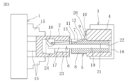
- the machining cooling device exemplifies boring with a turret lathe as a machining device, and a blade of the tool mounting section 3 with respect to the work 2 installed in the work setting section 1.
- the cooling oil 7 is supplied from the side of the tool installation portion 3 to the portion to be machined by the tool 6 supported by the tool holder 5 installed on the table 4.
- the injection port 10 directs the cooling oil 7 toward the outer peripheral surface of the protrusion 8 protruding from the tool holder 5 toward the work 2 and in space. It is provided so as to inject into 9.
- the injection port portion 10 may have a structure provided with an injection nozzle.
- the direction changing portion 11 introduces the cooling oil 7 injected into the space 9 from the injection port portion 10 into the protrusion 8 from the outer peripheral surface of the protrusion 8 from the front surface of the protrusion 8 facing the work 2. It is provided so as to be led out toward the machined portion by the work 2 and the tool 6.
- both the introduction portion 12 of the cooling oil 7 on the outer peripheral surface of the protrusion 8 and the outlet portion 13 of the cooling oil 7 on the front surface of the protrusion 8 of the direction changing portion 11 are configured as openings.
- the introduction portion 12 of the cooling oil 7 is referred to as an inlet 12, and the outlet portion 13 of the cooling oil 7 is referred to as an outlet 13.
- the outlet 13 of the direction changing portion 11 is provided on the front surface of the protrusion 8.
- the outlet 13 is arranged near the tool 6 supported by the tool holder 5.
- the cooling oil 7 is close to the outlet 13 along and in contact with the outer surface of the tool 6. Eject in parallel.
- the portion between the inlet 12 and the outlet 13 of the direction changing portion 11 opens to the outer peripheral surface and the front surface of the protrusion 8, and the depth from the outer peripheral surface to the inside of the protrusion 8 is the tool post 4.
- the structure of the direction changing portion 11 is simple because it has a groove shape with an arcuate bottom that goes from the inlet 12 on the side of the work to the exit 13 on the side of the work installation portion 1.
- the work 2 is captured and installed from the outside by a plurality of claws 15 provided in the work installation portion 1 in the work installation portion 1 called the work chuck of the turret lathe.
- the work 2 installed in the work installation unit 1 circulates around the center line of the work installation unit 1 extending in the lateral direction in one direction with the rotation drive of the work installation unit 1. It is driven to rotate.
- a tool 6 called a boring bar is attached to one tool post 4 in a tool installation portion 3 called a turret of a turret lathe with a tool holder 5 interposed therebetween.
- a holder accommodating hole 16 is formed laterally from the front surface of the tool post 4 facing the work 2 toward the rear end side.
- the tool 6 includes a main body portion 17, a blade portion 18, and an attachment portion 19 to the tool holder 5.
- the main body 17 is located on the side facing the work 2 and has a long rod shape in the lateral direction.
- the blade portion 18 is provided at the front end portion of the main body portion 17 on the side facing the work 2.
- the mounting portion 19 has a rod shape extending concentrically from the main body portion 17 to the rear side.
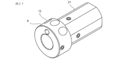
- the tool holder 5 includes a protrusion 8, a mounting portion 21 to the tool post 4, and a tool accommodating hole 22.
- the protrusion 8 has a larger outer shape than the mounting portion 21.
- the mounting portion 21 has a smaller outer shape than the protruding portion 8.
- the tool accommodating hole 22 is formed laterally in the center of the tool holder 5 from the front surface on the side facing the work installation portion 1 toward the side of the mounting portion 21. Then, the mounting portion 19 of the tool 6 is accommodated and fixed in the tool accommodating hole 22 from the front side of the tool holder 5, and the main body portion 17 and the blade portion 18 of the tool 6 face the work 2 rather than the protruding portion 8 of the tool holder 5. It is projected to the side to be used.
- the work 2 installed in the work installation unit 1 has a tool (not shown) attached to one tool stand (not shown) provided in the tool installation unit 3 other than the tool 6.
- the embodiment in which the internal hole 23 is formed in advance in a barrel shape from the front surface on the side of the work 2 facing the tool installation portion 3 toward the inside is illustrated.
- the work 2 is rotationally driven by the work installation portion 1, and the main body portion 17 and the blade portion 18 of the tool 6 are inserted into the inside of the internal hole 23 from the opening on the side of the internal hole 23 of the work 2 facing the tool installation portion 3.
- the blade portion 18 moves outward in the radial direction with respect to the rotation of the work 2 and moves laterally with the center line extending with respect to the rotation of the work 2 due to the machining operation of the tool post 4 with respect to the tool installation portion 3.
- the boring hole 24 having a diameter larger than that of the internal hole 23 is machined.
- the work 2 is rotationally driven, and the tool 6 does not rotate and moves outward in the radial direction with respect to the rotation of the work 2 and the lateral direction in which the center line extends with respect to the rotation of the work 2.
- it can be applied at least by moving in the lateral direction in which the center line extends with respect to the rotation of the work 2.
- Cooling oil 7 pressurized to a predetermined pressure is supplied to the injection port portion 10 from a supply source (not shown) via a supply path (not shown) provided inside the tool post 4.
- the supplied cooling oil 7 is injected from the injection port portion 10 toward the inlet 12 into the space in front of the tool post 4. Since the cooling oil is injected into the space from the injection port, it is not necessary to connect the injection port and the direction changing part of the protrusion with piping, and when replacing the tool holder, only the tool holder needs to be removed from the tool post. The tool holder can be easily replaced.
- the injection direction of the cooling oil 7 is from the diameter direction of the tool holder 5 to the main body of the tool 6.
- the direction is changed so as to be parallel to the center line of the tool 6 toward the gap between the 17 and the internal hole 23.
- the cooling oil 7 taken into the gap between the main body 17 and the internal hole 23 from the direction changing portion 11 reaches the machined portion by the work 2 and the blade portion 18, and both the work 2 and the blade portion 18 Cool well.
- the cooling oil 7 that has cooled both the work 2 and the blade portion 18 is shown after the cutting chips have been removed by a cooling oil recovery path (not shown) and a filter provided in the cooling oil recovery path. Returned to a source that has not.
- a cover 25 covering the opening on the outer peripheral surface side of the protrusion 8 in the groove-shaped direction changing portion 11 is provided on the protrusion 8.
- the cooling oil 7 that has entered the direction changing unit 11 is prevented from scattering.
- a straightening pipe 26 such as a bent pipe joint called an elbow is provided at the injection port portion 10, and the straightening pipe 26 and the inlet 12 are provided.
- the space distance between the two is reduced so that the cooling oil 7 injected into the space from the straightening pipe 26 can be easily taken into the inlet 12.
- the injection direction of the cooling oil 7 is corrected so that the cooling oil 7 injected by the straightening pipe 26 is parallel to the front surface of the tool post 4 facing the work 2, the inlet 12 is on the side of the tool post 4. It can be installed at a close position, the path of the direction changing unit 11 becomes long, and the injection direction of the cooling oil 7 injected from the outlet 13 becomes stable.
- the direction changing portion 11 provided in the tool holder 5 has a hole shape. That is, the direction changing unit 11 is the center line of the tool 6 from the front surface facing the work 2 of the tool holder 5 on the side of the outlet 13 and the vertical hole dented inside in the radial direction from the outer peripheral surface of the tool holder 5 on the side of the inlet 12.
- the cooling oil 7 is provided with a horizontal hole extending in a direction parallel to the vertical hole and connected to the vertical hole, and the cooling oil 7 injected from the injection port portion 10 or the straightening pipe 26 to the inlet 12 via the space on the front surface side of the tool post 4.
- the cooling oil 7 is guided to the outlet 13 from the direction changing unit 11 without escaping to the outside, and the injection direction of the cooling oil 7 from the outlet 13 via the space between the work 2 and the tool holder 5 is stabilized.
- the orthodontic tube 26 is removed and applicable.
- the machining cooling device is provided with a receiving wall 27 around the inlet 12 of the tool holder 5 so as to project outward in the radial direction of the tool holder 5 and receives the receiving wall 27.
- the wall 27 is configured to guide the cooling oil 7 injected from the injection port portion 10 to the inlet 12 of the direction changing portion 11 in the space on the front side of the tool post 4.
- the receiving wall 27 uses one of the divided pipes in which the pipe is divided into two along the center line extending in the vertical direction of the pipe, and the upper end of the divided pipe is projected toward the injection port portion 10. It has a hood-like structure with.
- a ball joint is formed in which the end portion of the receiving wall 27 has a spherical shape and is slidably supported in a receiving recess provided around the inlet 12 of the tool holder 5.
- the inclination of the receiving wall 27 may be adjustable.
- the machining cooling device according to the sixth embodiment for carrying out the invention shown in FIG. 6 has a structure in which a taper drill is installed on the tool post 4 as a tool 6. That is, since the outer shape of the mounting portion 19 of the tool 6 has a tapered shape that gradually narrows from the side of the work 2 toward the rear, the tool accommodating hole 22 of the tool holder 5 has a tapered shape that matches the tapered shape. It has become. As a result, the mounting portion 19 of the tool 6 is inscribed and fixed in the tool accommodating hole 22 as it is accommodated in the tool accommodating hole 22 from the front side of the tool holder 5.
- the outlet 13 of the direction changing portion 11 is provided on the front surface of the protrusion 8, the outlet 13 can be arranged near the tool 6 supported by the tool holder 5, and the outlet 13 is the tool holder 5.
- the cooling oil 7 is ejected in parallel from the outlet 13 along and in contact with the outer surface of the tool 6.
- the tool 6 processes the work 2. Even if it progresses to the back of the work 2, most of the cooling oil 7 ejected from the outlet 13 does not bounce off the front surface facing the injection port portion 10 of the work 2, and the internal hole 23 of the work 2 and the tool 6 The machined portion formed by the work 2 located at the back of the work 2 and the tip of the blade 18 of the tool 6 is reached through the gap between the workpieces 2, and the machined portion formed by the work 2 and the tool 6 is satisfactorily cooled by the cooling oil 7. To. In FIG. 6, the orthodontic tube 26 is removed and applicable.
- the machining cooling device uses a tool holder 5 called a straight arbor for installing the drill chuck 31 on the tool post 4, and the protrusion of the tool holder 5 is used.
- An outlet 13 is provided at the center of the tip tapered portion 32 protruding from the portion 8 toward the work 2, and is ejected from the injection port portion 10 or the straightening pipe 26 to the inlet 12 via the space on the front side of the tool post 4.
- the cooling oil 7 is guided from the direction changing unit 11 to the outlet 13 without escaping to the outside, and is called a drill supported by the claw 34 and the claw 34 of the drill chuck 31 from the outlet 13 through the core hole 33 of the drill chuck 31.
- the straightening tube 26 may be removed, or the drill chuck 31 may be replaced with a collet chuck, which is similarly applicable. Further, in FIG. 7, it is applicable even if the receiving wall 27 of FIG. 5 is provided instead of the correction tube 26.
- the tool holder 5 according to the eighth embodiment for carrying out the invention shown in FIGS. 8 to 11 includes three direction changing units 11. These three direction changing portions 11 separate the cooling oil 7 taken into the inlet 12 which is opened at the outer peripheral surface of the protrusion 8 of the tool holder 5 in the circumferential direction from each other in the circumferential direction to the front surface of the protrusion 8.
- the structure is independent of each other so as to be discharged from the opened outlet 13. Inside each outlet 13, a rectifying member 35 that concentrates the flow of the cooling oil 7 injected into the space from the outlet 13 in a predetermined direction is provided.
- a chamfered portion 36 is formed in an annular shape so as to go around the outer peripheral surface at a portion where the outer peripheral surface and the front surface of the protrusion 8 intersect.
- the chamfered portion 36 has a slope that gradually becomes a downward slope from the rear side to the front side (see FIG. 10).
- the protrusion 8 is provided with a set screw 37 for fixing the tool 6 (see FIG. 6) to the tool holder 5 so as not to interfere with the direction changing portion 11.
- the set screw 37 passes through the center of the tool holder 5 and extends in the left-right direction. Two left and right positions where one straight line intersects the outer peripheral surface of the protrusion 8 and one position where one straight line extending in the vertical direction through the center of the tool holder 5 intersects at the lower part of the outer peripheral surface of the protrusion 8. It is provided in a total of 3 places.
- the set screw 37 is individually attached to the screw hole 38 penetrating the outer peripheral surface of the protrusion 8 and the tool accommodating hole 22.
- four mounting flat portions 39 are formed on the outer peripheral surface of the mounting portion 21 of the tool holder 5. As shown in FIG. 11, two of the four mounting flat portions 39 are parallel to each other on the center line L1 with the center of the tool holder 5 in between, and the other two mounting flat portions 39 are center lines. On the center line L2 orthogonal to L1, they are parallel to each other with the center of the tool holder 5 in between.
- the tool holder 5 can be used for the tool post 4 of a processing machine manufactured by various manufacturing companies. Specifically, the positional relationship between the set screw 40 for fixing the tool holder 5 to the tool post 4 and the injection port portion 10 varies depending on the manufacturing company of the processing machine.
- the injection port portion 10 was inserted into the holder accommodating hole 16 as shown in FIG.
- the set screw 40 is on the upper surface like the tool post 4A or on the right side like the tool post 4B or on the lower surface like the tool post 4C or on the tool post 4D. It was provided on the left side as shown.
- four mounting flat portions 39 are provided on the mounting portion 21 of the tool holder 5.
- the upper mounting plane portion 39 of the four mounting plane portions 39 is represented by 39A
- the right mounting plane portion 39 is represented by 39B
- the left mounting plane portion 39 is represented by 39B. It is expressed as 39C
- the lower mounting plane portion 39 is expressed as 39D to distinguish each of the four mounting plane portions 39.
- a set screw 40 for fixing the tool holder 5 to the tool post 4A is provided on the upper surface extending rearward from the upper edge of the front surface provided with the injection port portion 10, and in the tool post 4B, the tool post 4B is provided.
- a set screw 40 for fixing the tool holder 5 is provided on the right side surface extending rearward from the right edge of the front surface provided with the injection port portion 10, and in the tool post 4C, a set screw 40 for fixing the tool holder 5 to the tool post 4C is provided.
- a set screw 40 for fixing the tool holder 5 to the tool post 4D is provided on the front surface where the injection port portion 10 is provided. The case where it is provided on the left side surface extending behind the left edge is illustrated.
- FIG. 12 when the tool holder 5 is attached to the tool post 4A, the tool holder 5 is circular in plan view so that the inlet 12 of the tool holder 5 is located directly below the injection port 10 of the tool post 4A.
- the mounting portion 21 having four mounting flat portions 39 (39A, 39B, 39C, 39D in FIG. 11) on the outer peripheral surface is shown after being inserted into the holder accommodating hole 16 having a circular view in plan view of the tool post 4A.
- the set screw 40 advances toward the holder accommodating hole 16 while being guided by the female screw to which the set screw 40 is mounted by an artificial operation with a tightening tool such as a screwdriver, and the tip of the set screw 40 is the tool holder 5.
- the tool holder 5 is fixed to the tool post 4A by abutting on the upper mounting surface portion 39A.
- the tool holder 5 when the tool holder 5 is attached to the tool post 4B, the tool holder 5 is circular in a plan view so that the inlet 12 of the tool holder 5 is located directly below the injection port 10 of the tool post 4B.
- the mounting portion 21 having four mounting flat portions 39 (39A, 39B, 39C, 39D in FIG. 11) on the outer peripheral surface is inserted into the holder accommodating hole 16 which is circular in plan view of the tool post 4B, the figure is shown.
- the set screw 40 advances toward the holder accommodating hole 16 while being guided by the female screw to which the set screw 40 is mounted by an artificial operation with a tightening tool such as a screwdriver, and the tip of the set screw 40 advances to the side of the holder accommodating hole 16.
- the tool holder 5 is fixed to the tool post 4B by abutting on the mounting flat portion 39B on the right side of the tool holder 5.
- the tool holder 5 when the tool holder 5 is attached to the tool post 4C, the tool holder 5 is circular in a plan view so that the inlet 12 of the tool holder 5 is located directly below the injection port 10 of the tool post 4.
- the mounting portion 21 having the four mounting flat portions 39 (39A, 39B, 39C, 39D in FIG. 11) on the outer peripheral surface is inserted into the holder accommodating hole 16 having a circular view in plan view of the tool post 4, the figure is shown.
- the set screw 40 advances toward the holder accommodating hole 16 while being guided by the female screw to which the set screw 40 is mounted by an artificial operation with a tightening tool such as a screwdriver, and the tip of the set screw 40 advances to the side of the holder accommodating hole 16.
- the tool holder 5 is fixed to the tool post 4 by abutting on the mounting flat portion 39 on the right side of the above, that is, the mounting flat portion 39C in FIG.
- the tool holder 5 when the tool holder 5 is attached to the tool post 4D, the tool holder 5 is circular in plan view so that the inlet 12 of the tool holder 5 is located directly below the injection port 10 of the tool post 4.
- the mounting portion 21 having the four mounting flat portions 39 (39A, 39B, 39C, 39D in FIG. 11) on the outer peripheral surface is inserted into the holder accommodating hole 16 having a circular view in plan view of the tool post 4, the figure is shown.
- the set screw 40 advances toward the holder accommodating hole 16 while being guided by the female screw to which the set screw 40 is mounted by an artificial operation with a tightening tool such as a screwdriver, and the tip of the set screw 40 advances to the side of the holder accommodating hole 16.
- the tool holder 5 is fixed to the tool post 4 by abutting on the mounting flat portion 39 on the left side of the above, that is, the mounting flat portion 39D in FIG.
- FIG. 14 was used to verify the angle between the vertical hole on the inlet 12 side and the horizontal hole on the outlet 13 side of the direction changing unit 11. The results will be described.
- the clearance angle ⁇ 2 between the center line L6 extending in the vertical direction of the vertical hole on the side of the inlet 12 and the center line L7 extending in the lateral direction of the tool accommodating hole 22 is 45 to 55 degrees, which is an allowable range of 50 degrees.
- the clearance angle ⁇ 3 between the center line L8 extending in the left-right direction of the lateral hole on the side of the outlet 13 and the center line L7 extending in the lateral direction of the tool accommodating hole 22 is 5 to 10 degrees within the allowable range of 0 to 15 degrees. It was confirmed that the degree was optimum and the cooling oil 7 was ejected in a bundle without being scattered from the outlet 13. Further, when the bottom portion 41 at which the vertical hole on the inlet 12 side and the horizontal hole on the outlet 13 side intersect has an arc shape that is recessed downward, ⁇ 3 is 0 degrees, that is, the cooling oil 7 is discharged from the outlet 13. It was confirmed that it was derived in parallel with the center line L7.
- FIG. 15 will be described as a result of verifying the relationship between the three direction changing portions 11, the tool accommodating holes 22, and the set screw 37 in the tool holder 5 according to the morphology 12 for carrying out the invention.
- FIG. A of FIG. 15 since the diameter of the tool accommodating hole 22 is large, even if the inlet 12 and the outlet 13 of the direction changing portion 11 are individually provided, if there is no interference with the set screw 37. , The cooling oil 7 is injected in a bundle from the outlet 13 without being scattered, which is the best structure.
- the tool accommodating holes 22 can be integrated into one outlet 13 as shown in FIG.
- the cooling oil 7 is ejected as a bundle without being scattered.
- the direction changing portion 11 in the tool holder 5 according to the thirteenth aspect for carrying out the invention shown in FIGS. A to C of FIG. It is constructed as a flat slope with a gradual downward slope toward the side of. With this configuration, the structure of the direction changing unit 11 is simple.
- the portion between the inlet 12 and the outlet 13 of the direction changing portion 11 opens to the outer peripheral surface and the front surface of the protrusion 8.
- the direction changing portion 11 is in a state of being cut out in a straight line in the left-right direction, and has a shape that is curved upward and protrudes like the chamfered portion 36 shown in FIG. is not.
- the angle ⁇ 4 formed by the flat slope of the direction changing portion 11 and the center line L7 extending in the lateral direction of the tool accommodating hole 22 is not particularly limited. However, it can be set to the angle of ⁇ 3 in FIG. By being configured at this angle, more cooling oil can be ejected from the outlet in parallel along and in contact with the outer surface of the tool.
- the tool holder 5 shown in FIGS. D to F of FIG. 16 has a configuration in which three flat slopes, which are direction changing portions 11, are provided adjacent to the protrusions 8 in the left-right direction.
- the respective angles of the angle ⁇ 4 formed by the flat slope of the direction changing unit 11 and the center line L7 extending in the lateral direction of the tool accommodating hole 22 are shown in FIG. It can be set to an angle of ⁇ 3 of 14. Further, as shown in FIG.
- the angle formed by the two flat slopes of the adjacent direction changing units 11 (the angle on the side of the center P1) ⁇ 5 and
- the angle of ⁇ 6 is preferably 135 degrees to 150 degrees. If it is configured at this angle, as shown in FIG. 13, the tool holder 5 is preferable because it can correspond to the tool post 4 of the processing machine manufactured by various manufacturing companies.
- the most preferable angle is that the angles of ⁇ 5 and ⁇ 6 are 145 degrees.
- the angles of ⁇ 5 and ⁇ 6 may be the same or different.
- the direction changing unit 11 may be provided with 2, 4, or 5 or more. When a plurality of direction changing units 11 are provided, a plurality of direction changing units 11 may be provided individually, or a plurality of direction changing units 11 may be provided adjacent to each other.
- the direction changing portion 11 in the tool holder 5 according to the fourth embodiment for carrying out the invention shown in FIGS. A to C of FIG. 17 has an upper portion of the protrusion 8 above the tool accommodating hole 22 from the side of the inlet 12 to the outlet 13. It is configured as a flat slope that gradually becomes a downward slope toward the side of, and is composed of a steep slope on the entrance 12 side and a gentle slope on the exit 13 side.
- the steep slope is a flat slope.
- the gentle slope is a flat slope.
- the steep slope and the gentle slope are in a state of being cut out in a straight line in the left-right direction, and have a shape that is curved upward and protrudes like the chamfered portion 36 shown in FIG. is not. Therefore, when the cooling oil 7 hits a steep slope and a gentle slope, it is possible to prevent the injection direction of the cooling oil 7 from being divided into the left and right directions.
- the angle ⁇ 7 formed by the steep slope on the entrance 12 side and the center line L7 extending in the lateral direction of the tool accommodating hole 22 is not particularly limited, but is not particularly limited. It can be set to an angle of ⁇ 2.
- the steep slope on the side of the entrance 12 is configured as a slope that gradually becomes a downward slope from the side of the entrance 12 to the side of the exit 13.
- the angle ⁇ 8 formed by the gentle slope on the exit 13 side and the center line L7 extending in the lateral direction of the tool accommodating hole 22 is not particularly limited, but is shown in FIG. It can be set to an angle of ⁇ 3 of 14. At this angle, more cooling oil can be ejected from the outlet in parallel along and in contact with the outer surface of the tool.
- the gentle slope on the side of the outlet 13 is configured as a slope that gradually becomes a downward slope from the side of the entrance 12 toward the side of the exit 13.
- the number of direction changing units 11 is not limited to one, and may be two, three, four, or five or more.
- a direction changing portion 11 composed of a steep slope on the entrance 12 side and a gentle slope on the exit 13 side is adjacent to the protrusion 8 in the left-right direction as in FIGS. 16D to 16F. May be provided in plurality.
- the respective angles of the angle ⁇ 7 formed by the steep slope of the direction changing unit 11 and the center line L7 extending in the lateral direction of the tool accommodating hole 22 are shown in FIG. It can be set to an angle of ⁇ 2 of 14.
- the respective angles ⁇ 8 formed by the gentle slope on the exit 13 side of the direction changing unit 11 and the center line L7 extending in the lateral direction of the tool accommodating hole 22 can be set to the angle ⁇ 3 in FIG. it can.
- the angle formed by the gentle slopes on the sides of the two outlets 13 of the adjacent direction changing units 11 is 135 degrees to 150 degrees. It is preferable to have. If it is configured at this angle, as shown in FIG. 13, the tool holder 5 is preferable because it can correspond to the tool post 4 of the processing machine manufactured by various manufacturing companies. The most preferable angle of the angle is 145 degrees.
- a plurality of direction changing units 11 may be provided individually, or a plurality of direction changing units 11 may be provided adjacent to each other.
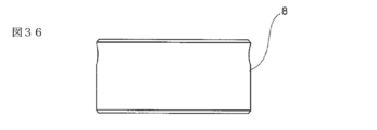
- the tool post 4 and the tool holder 5 may be integrated. That is, the protrusion 8 may be provided on the front surface of the tool post 4, and the tool 6 may be supported on the protrusion 8 and the direction changing portion 11 may be provided. Further, the tool 6 may be provided with a protrusion 8 having a direction changing portion 11. At that time, as shown in FIGS. 36 to 51, the protrusion 8 of the tool holder 5 from which the mounting portion 21 has been removed may be detachably provided on the tool 6, and the protrusion 8 is integrated with the tool 6. Either of the cases where it is provided as a structure may be used.
- the direction changing portion 11 in the protruding portion 8 of the tool holder 5 from which the mounting portion 21 has been removed can be applied with embodiments 1 to 14 for carrying out the invention.
Abstract
[Problem] To provide a machining cooling device that can perform cooling properly even when machining with a tool progresses deep into a workpiece. [Solution] An outlet 13 of a direction changing part 11 is provided on a front surface of a projecting part 8. This makes it possible to place the outlet 13 in the vicinity of a tool 6 supported by a tool holder 5. Placing the outlet 13 in the vicinity of and adjacent to the tool 6 supported by the tool holder 5 allows a cooling oil 7 to be injected from the outlet 13 along an outer surface of the tool 6 and in parallel therewith so as to be close enough to come in contact therewith. Thus, even when machining of a workpiece 2 with the tool 6 progresses deep into the workpiece 2, most of the cooling oil 7 injected from the outlet 13 reaches, through a gap between an internal hole 23 of the workpiece 2 and the tool 6, a machined portion located deep in the workpiece 2 and defined by the workpiece 2 and a tip of a cutting part 18 of the tool 6, without being splashed by a front surface of the workpiece 2 facing a jet orifice part 10. As a result, the machined portion defined by the workpiece 2 and the tool 6 is cooled properly by the cooling oil 7.
Description
本発明は、加工冷却装置及び冷却方法に関する。
The present invention relates to a processing cooling device and a cooling method.
図18に示したように、特許文献1で開示された加工冷却装置は、刃物台71に設置された工具ホルダー72の前面に噴射ノズル73が設けられ、噴射ノズル73が工具ホルダー72で支持された工具74の近くに配置することができず、噴射ノズル73が工具74から外側に離れて配置され、噴射ノズル73が冷却油74を工具74から外側に離れた位置から工具74の刃先に向けて斜めに噴射する構造になっている。そのため、図19に示したように、ワーク76に対する工具74による加工がワーク76の奥へと進行すると、噴射ノズル73から噴射された冷却油75の殆どがワーク76の噴射ノズル73に対向する前面で跳ね返り、ワーク76の奥に位置するワーク76と工具74の刃先とによる加工部分に到達する冷却油量が減少し、ワーク76と工具74の刃先との冷却が悪くなるという欠点がある。
As shown in FIG. 18, in the processing cooling device disclosed in Patent Document 1, an injection nozzle 73 is provided on the front surface of the tool holder 72 installed on the tool post 71, and the injection nozzle 73 is supported by the tool holder 72. The injection nozzle 73 could not be placed near the tool 74, and the injection nozzle 73 was arranged outward from the tool 74, and the injection nozzle 73 directed the cooling oil 74 from the position away from the tool 74 toward the cutting edge of the tool 74. It has a structure that sprays diagonally. Therefore, as shown in FIG. 19, when the machining of the work 76 by the tool 74 proceeds to the depth of the work 76, most of the cooling oil 75 injected from the injection nozzle 73 faces the front surface of the work 76 facing the injection nozzle 73. There is a drawback that the amount of cooling oil that reaches the machined portion by the work 76 located at the back of the work 76 and the cutting edge of the tool 74 is reduced, and the cooling between the work 76 and the cutting edge of the tool 74 is deteriorated.
本発明は、上記背景技術に鑑みてなされたものであり、工具による加工がワークの奥へと進行しても良好に冷却できる加工冷却装置の提供を目的とする。
The present invention has been made in view of the above background technology, and an object of the present invention is to provide a machining cooling device capable of satisfactorily cooling even if machining by a tool progresses to the depth of a work.
本発明は、ワーク設置部に設置されたワークに対し工具設置部における刃物台で支持された工具で加工を行う部分を冷却油で冷却する加工冷却装置であって、加工冷却装置は突起部を有し、前記突起部には方向変換部が噴射口部から空間に噴射された冷却油を前記突起部の外周面から導入しかつ前記突起部の前面から前記加工部分に向けて導出するように設けられ、この方向変換部における冷却油の導入部と導出部との双方が開口に構成されたことを特徴とする。換言するならば、本発明は、刃物台の前面に設けられた噴射口部から空間に冷却油を飛ばし、この空間に飛ばされた冷却油の流れる方向を刃物台よりワークの側に突出した突起部に設けられた方向変換部で変換し、この流れる方向の変換された冷却油を工具ホルダーの突起部の前面に方向変換部の導出部として設けられた開口からワークと工具とによる加工部分に導出することを特徴とする。
The present invention is a machining cooling device that cools a portion of a work installed in a work installation portion to be machined with a tool supported by a tool post in the tool installation portion with cooling oil, and the machining cooling device has a protrusion. The cooling oil injected into the space from the injection port is introduced into the protrusion from the outer peripheral surface of the protrusion and is led out from the front surface of the protrusion toward the processed portion. It is characterized in that both the cooling oil introduction portion and the outlet portion in the direction changing portion are configured as openings. In other words, in the present invention, the cooling oil is blown into the space from the injection port provided on the front surface of the tool post, and the direction in which the cooling oil blown into this space flows is projected toward the work from the tool post. It is converted by the direction changing part provided in the part, and the cooling oil whose flow direction is changed is transferred from the opening provided as the lead-out part of the direction changing part to the machined part by the work and the tool on the front surface of the protrusion of the tool holder. It is characterized by deriving.
本発明は、工具ホルダーの刃物台よりワークの側に突出した突起部の前面に方向変換部の導出部としての出口が設けられたので出口を工具の近くに配置することができ、出口が工具に隣接するように近くに配置されることにより、冷却油が出口から工具の外面に沿うようにかつ接触するように近くで平行に射出することができる。したがって、ワークに対する工具による加工がワークの奥へと進行しても、出口から射出された冷却油の殆どがワークの噴射ノズルに対向する前面で跳ね返ることがなくワークに加工された内部孔と工具との間の隙間を経由してワークの奥に位置するワークと工具の刃部の先端とによる加工部分に到達し、ワークと工具による加工部分が冷却油で良好に冷却されるという効果がある。又、本発明は、刃物台のワークに対向する側の前面には噴射口部が冷却油を空間に噴射するので、噴射口部と突起部の方向変換部とが配管で繋げる必要がなく、工具ホルダーを交換する場合、工具ホルダーだけを刃物台から取り外せばよく、工具ホルダーが容易に交換できる。本発明において、前記方向変換部が突起部の中心を通り上下方向に延びる中心線と前記中心を通り左右方向に延びる中心線との間の上部において前記上下方向に延びる中心線から前記中心を通り前記左右方向に延びる中心線とに向けての角度θ1が30度乃至45度を有する直線とが前記中心を中心とした1つの円周と交差する箇所とに設けられ、かつ前記上下方向に延びる中心線と円周と交差する箇所に設けられれば、工具ホルダーを種々の製造会社で製造された加工機械の刃物台に対応可能になる。本発明は、導入部の側の孔の中心線と工具収容孔の中心線とによる挟角が、45度から55度に設けられれば、冷却油7が出口13から散らばることなく束となって射出される。本発明は、導出部の側の孔の中心線と工具収容孔の中心線とによる挟角が、0度から15度に設けられれば、冷却油7が出口13から散らばることなく束となって射出される。本発明は、方向変換部が、冷却油の導入部の側から導出部の側に行くに従って徐々に下り勾配となる平坦な斜面に構成されれば、構造が簡単である。本発明は、平坦な斜面と、工具収容孔の中心線とのなす角は、0度から15度に設けられれば、より冷却油が出口から工具の外面に沿うようにかつ接触するように近くで平行に射出することができる。
In the present invention, since an outlet as a lead-out portion of the direction changing portion is provided on the front surface of the protrusion protruding toward the work from the tool post of the tool holder, the outlet can be arranged near the tool, and the outlet is the tool. By being placed close to adjacent to, the cooling oil can be ejected in parallel from the outlet along and in contact with the outer surface of the tool. Therefore, even if the machining of the work by the tool progresses to the back of the work, most of the cooling oil injected from the outlet does not bounce off the front surface facing the injection nozzle of the work, and the internal holes and tools machined in the work. It has the effect of reaching the machined part by the work located at the back of the work and the tip of the blade of the tool through the gap between the work and the tool, and the machined part by the work and the tool is cooled well by the cooling oil. .. Further, in the present invention, since the injection port portion injects the cooling oil into the space on the front surface of the tool post facing the work, it is not necessary to connect the injection port portion and the direction changing portion of the protrusion by piping. When replacing the tool holder, only the tool holder needs to be removed from the tool post, and the tool holder can be easily replaced. In the present invention, the direction changing portion passes through the center from the center line extending in the vertical direction at the upper part between the center line extending in the vertical direction through the center of the protrusion and the center line extending in the horizontal direction through the center. A straight line having an angle θ1 of 30 to 45 degrees with respect to the center line extending in the left-right direction is provided at a point where a straight line intersects with one circumference centered on the center, and extends in the vertical direction. If it is provided at the intersection of the center line and the circumference, the tool holder can be used for the tool post of a processing machine manufactured by various manufacturing companies. In the present invention, if the sandwiching angle between the center line of the hole on the side of the introduction portion and the center line of the tool accommodating hole is provided at 45 to 55 degrees, the cooling oil 7 is bundled without being scattered from the outlet 13. Be ejected. In the present invention, if the sandwiching angle between the center line of the hole on the side of the lead-out portion and the center line of the tool accommodating hole is provided at 0 to 15 degrees, the cooling oil 7 is bundled without being scattered from the outlet 13. Be ejected. The structure of the present invention is simple if the direction changing portion is configured on a flat slope that gradually becomes a downward slope from the side of the cooling oil introduction portion to the side of the outlet portion. In the present invention, if the angle between the flat slope and the center line of the tool accommodating hole is provided at 0 to 15 degrees, the cooling oil is closer to be in contact with the outer surface of the tool from the outlet. Can be ejected in parallel with.
図1に示した発明を実施するための形態1に係る加工冷却装置は、加工装置としてタレット旋盤によるボーリング加工を例示し、ワーク設置部1に設置されたワーク2に対し工具設置部3の刃物台4に設置された工具ホルダー5で支持された工具6で加工を行う部分に工具設置部3の側から冷却油7を供給する構成になっている。
The machining cooling device according to the first embodiment shown in FIG. 1 exemplifies boring with a turret lathe as a machining device, and a blade of the tool mounting section 3 with respect to the work 2 installed in the work setting section 1. The cooling oil 7 is supplied from the side of the tool installation portion 3 to the portion to be machined by the tool 6 supported by the tool holder 5 installed on the table 4.
そして、刃物台4のワーク2に対向する側の前面には噴射口部10が冷却油7を工具ホルダー5の刃物台4よりワーク2の側に突出した突起部8の外周面に向けかつ空間9に噴射するように設けられている。噴射口部10は噴射ノズルを備えた構造でもよい。
Then, on the front surface of the tool post 4 facing the work 2, the injection port 10 directs the cooling oil 7 toward the outer peripheral surface of the protrusion 8 protruding from the tool holder 5 toward the work 2 and in space. It is provided so as to inject into 9. The injection port portion 10 may have a structure provided with an injection nozzle.
又、突起部8には方向変換部11が噴射口部10から空間9に噴射された冷却油7を突起部8の外周面から導入して突起部8のワーク2に対向する側の前面からワーク2と工具6とによる加工部分に向けて導出するように設けられている。
Further, the direction changing portion 11 introduces the cooling oil 7 injected into the space 9 from the injection port portion 10 into the protrusion 8 from the outer peripheral surface of the protrusion 8 from the front surface of the protrusion 8 facing the work 2. It is provided so as to be led out toward the machined portion by the work 2 and the tool 6.
さらに、方向変換部11における突起部8の外周面の冷却油7の導入部12と突起部8の前面の冷却油7の導出部13との双方が開口として構成されている。
Further, both the introduction portion 12 of the cooling oil 7 on the outer peripheral surface of the protrusion 8 and the outlet portion 13 of the cooling oil 7 on the front surface of the protrusion 8 of the direction changing portion 11 are configured as openings.
以下、冷却油7の導入部12を入口12と表現し、冷却油7の導出部13を出口13と表現する。
Hereinafter, the introduction portion 12 of the cooling oil 7 is referred to as an inlet 12, and the outlet portion 13 of the cooling oil 7 is referred to as an outlet 13.
図1に示した加工冷却装置によれば、突起部8の前面に方向変換部11の出口13が設けられたことから、出口13を工具ホルダー5で支持された工具6の近くに配置することができ、出口13が工具ホルダー5で支持された工具6に隣接するように近くに配置されることにより、冷却油7が出口13から工具6の外面に沿うようにかつ接触するように近くで平行に射出する。
According to the machining cooling device shown in FIG. 1, since the outlet 13 of the direction changing portion 11 is provided on the front surface of the protrusion 8, the outlet 13 is arranged near the tool 6 supported by the tool holder 5. And by arranging the outlet 13 close to the tool 6 supported by the tool holder 5, the cooling oil 7 is close to the outlet 13 along and in contact with the outer surface of the tool 6. Eject in parallel.
したがって、ワーク2に対する工具6による加工がワーク2の奥へと進行しても、出口13から射出された冷却油7の殆どがワーク2の噴射口部10に対向する前面で跳ね返ることがなくワーク2の内部孔23と工具6との間の隙間を経由してワーク2の奥に位置するワーク2と工具6の刃部18の先端とによる加工部分に到達し、ワーク2と工具6による加工部分が冷却油7で良好に冷却される。
Therefore, even if the machining of the work 2 by the tool 6 proceeds to the back of the work 2, most of the cooling oil 7 ejected from the outlet 13 does not bounce off the front surface of the work 2 facing the injection port portion 10 of the work 2. Through the gap between the internal hole 23 of 2 and the tool 6, the work 2 located at the back of the work 2 and the tip of the blade 18 of the tool 6 reach the machined portion, and the work 2 and the tool 6 work. The portion is cooled well with the cooling oil 7.
図1では、方向変換部11の入口12と出口13との間の部分は、突起部8の外周面と前面とに開口し、突起部8の外周面から内部への深さが刃物台4の側の入口12からワーク設置部1の側の出口13に行く従って深くなる弧状の底部を備えた、溝状になっているので、方向変換部11の構造が簡単である。
In FIG. 1, the portion between the inlet 12 and the outlet 13 of the direction changing portion 11 opens to the outer peripheral surface and the front surface of the protrusion 8, and the depth from the outer peripheral surface to the inside of the protrusion 8 is the tool post 4. The structure of the direction changing portion 11 is simple because it has a groove shape with an arcuate bottom that goes from the inlet 12 on the side of the work to the exit 13 on the side of the work installation portion 1.
タレット旋盤のワークチャックと称するワーク設置部1にはワーク2がワーク設置部1に設けられた複数の爪15で外側から捕捉されて設置される。ワーク設置部1に設置されたワーク2は、ワーク設置部1の回転駆動に伴い、横方向に延びたワーク設置部1の中心線を回転中心として当該中心線の周りを一方向に周回するように回転駆動される。タレット旋盤のタレットと称する工具設置部3における1つの刃物台4にはボーリングバーと称する工具6が工具ホルダー5を介在させて取り付けられる。
The work 2 is captured and installed from the outside by a plurality of claws 15 provided in the work installation portion 1 in the work installation portion 1 called the work chuck of the turret lathe. The work 2 installed in the work installation unit 1 circulates around the center line of the work installation unit 1 extending in the lateral direction in one direction with the rotation drive of the work installation unit 1. It is driven to rotate. A tool 6 called a boring bar is attached to one tool post 4 in a tool installation portion 3 called a turret of a turret lathe with a tool holder 5 interposed therebetween.
具体的には、刃物台4の内部には、ホルダー収容孔16が刃物台4のワーク2に対向する側の前面から後端側に向けて横向きに形成されている。工具6は、本体部17と、刃部18と、工具ホルダー5への取付部19とを備える。本体部17はワーク2に対向する側に位置し、横方向に長い棒状になっている。刃部18は本体部17のワーク2に対向する側の前端部に設けられている。取付部19は本体部17から後側に同心状に延びた棒状になっている。
Specifically, inside the tool post 4, a holder accommodating hole 16 is formed laterally from the front surface of the tool post 4 facing the work 2 toward the rear end side. The tool 6 includes a main body portion 17, a blade portion 18, and an attachment portion 19 to the tool holder 5. The main body 17 is located on the side facing the work 2 and has a long rod shape in the lateral direction. The blade portion 18 is provided at the front end portion of the main body portion 17 on the side facing the work 2. The mounting portion 19 has a rod shape extending concentrically from the main body portion 17 to the rear side.
工具ホルダー5は、突起部8と、刃物台4への取付部21と、工具収容孔22とを備える。突起部8は取付部21よりも外形の大きな形状になっている。取付部21は突起部8よりも外形の小さな形状になっている。工具収容孔22は工具ホルダー5の中心部にワーク設置部1と対向する側の前面から取付部21の側に向けて横向きに形成されている。そして、工具6の取付部19が工具ホルダー5の前側から工具収容孔22に収容されて固定され、工具6の本体部17及び刃部18が工具ホルダー5の突起部8よりもワーク2に対向する側に突出される。
The tool holder 5 includes a protrusion 8, a mounting portion 21 to the tool post 4, and a tool accommodating hole 22. The protrusion 8 has a larger outer shape than the mounting portion 21. The mounting portion 21 has a smaller outer shape than the protruding portion 8. The tool accommodating hole 22 is formed laterally in the center of the tool holder 5 from the front surface on the side facing the work installation portion 1 toward the side of the mounting portion 21. Then, the mounting portion 19 of the tool 6 is accommodated and fixed in the tool accommodating hole 22 from the front side of the tool holder 5, and the main body portion 17 and the blade portion 18 of the tool 6 face the work 2 rather than the protruding portion 8 of the tool holder 5. It is projected to the side to be used.
尚、図1では、ワーク設置部1に設置されたワーク2には、工具6以外で工具設置部3に設けられた図示のされていない1つの刃物台に取り付けられた図示のされていない工具により内部孔23がワーク2の工具設置部3に対向する側の前面から内部に向けて寸胴状に予め形成された態様を例示した。
In FIG. 1, the work 2 installed in the work installation unit 1 has a tool (not shown) attached to one tool stand (not shown) provided in the tool installation unit 3 other than the tool 6. The embodiment in which the internal hole 23 is formed in advance in a barrel shape from the front surface on the side of the work 2 facing the tool installation portion 3 toward the inside is illustrated.
そして、ワーク2がワーク設置部1で回転駆動され、ワーク2における内部孔23の工具設置部3に対向する側の開口から内部孔23の内部に工具6の本体部17及び刃部18が挿入された状態において、刃部18が工具設置部3に対する刃物台4の加工動作に伴いワーク2の回転に対する直径方向の外側への移動とワーク2の回転に対する中心線の延びる横方向への移動とにより内部孔23よりも直径の大きな中ぐり孔24を加工する。つまり、ワーク2に工具6で加工を行う場合、ワーク2が回転駆動し、工具6が回転しないでワーク2の回転に対する直径方向の外側への移動とワーク2の回転に対する中心線の延びる横方向への移動とをしてもよいが、少なくとも、ワーク2の回転に対する中心線の延びる横方向に移動すれば適用可能である。
Then, the work 2 is rotationally driven by the work installation portion 1, and the main body portion 17 and the blade portion 18 of the tool 6 are inserted into the inside of the internal hole 23 from the opening on the side of the internal hole 23 of the work 2 facing the tool installation portion 3. In this state, the blade portion 18 moves outward in the radial direction with respect to the rotation of the work 2 and moves laterally with the center line extending with respect to the rotation of the work 2 due to the machining operation of the tool post 4 with respect to the tool installation portion 3. The boring hole 24 having a diameter larger than that of the internal hole 23 is machined. That is, when machining the work 2 with the tool 6, the work 2 is rotationally driven, and the tool 6 does not rotate and moves outward in the radial direction with respect to the rotation of the work 2 and the lateral direction in which the center line extends with respect to the rotation of the work 2. However, it can be applied at least by moving in the lateral direction in which the center line extends with respect to the rotation of the work 2.
噴射口部10には図示のされていない供給源から所定の圧力に加圧された冷却油7が刃物台4の内部に設けられた図示のされていない供給経路を経由して供給され、この供給された冷却油7が噴射口部10から入口12に向けつつ刃物台4よりも前側の空間に噴射される。噴射口部から冷却油を空間に噴射するので、噴射口部と突起部の方向変換部とが配管で繋げる必要がなく、工具ホルダーを交換する場合、工具ホルダーだけを刃物台から取り外せばよく、工具ホルダーが容易に交換できる。
Cooling oil 7 pressurized to a predetermined pressure is supplied to the injection port portion 10 from a supply source (not shown) via a supply path (not shown) provided inside the tool post 4. The supplied cooling oil 7 is injected from the injection port portion 10 toward the inlet 12 into the space in front of the tool post 4. Since the cooling oil is injected into the space from the injection port, it is not necessary to connect the injection port and the direction changing part of the protrusion with piping, and when replacing the tool holder, only the tool holder needs to be removed from the tool post. The tool holder can be easily replaced.
上記空間に噴射された冷却油7は入口12から方向変換部11を経由して出口13に向けて移動する過程において、冷却油7の射出方向が工具ホルダー5の直径方向から工具6の本体部17と内部孔23との間の隙間に向けて工具6の中心線に平行となるような方向に変換される。
In the process of moving the cooling oil 7 injected into the space from the inlet 12 to the outlet 13 via the direction changing unit 11, the injection direction of the cooling oil 7 is from the diameter direction of the tool holder 5 to the main body of the tool 6. The direction is changed so as to be parallel to the center line of the tool 6 toward the gap between the 17 and the internal hole 23.
よって、方向変換部11から本体部17と内部孔23との間の隙間に取り込まれた冷却油7がワーク2と刃部18とによる加工部分に到達してワーク2と刃部18との双方を良好に冷却する。このワーク2と刃部18との双方を冷却した冷却油7は、図示のされていない冷却油回収経路及び当該冷却油回収経路に設けられたフィルタで切削屑の除去を受けた後に図示のされていない供給源に戻される。
Therefore, the cooling oil 7 taken into the gap between the main body 17 and the internal hole 23 from the direction changing portion 11 reaches the machined portion by the work 2 and the blade portion 18, and both the work 2 and the blade portion 18 Cool well. The cooling oil 7 that has cooled both the work 2 and the blade portion 18 is shown after the cutting chips have been removed by a cooling oil recovery path (not shown) and a filter provided in the cooling oil recovery path. Returned to a source that has not.
図2に示した発明を実施するための形態2に係る加工冷却装置は、溝状の方向変換部11における突起部8の外周面の側の開口を被覆するカバー25が突起部8に設けられて方向変換部11に入った冷却油7の飛散を防止するようになっている。
In the processing / cooling device according to the second aspect for carrying out the invention shown in FIG. 2, a cover 25 covering the opening on the outer peripheral surface side of the protrusion 8 in the groove-shaped direction changing portion 11 is provided on the protrusion 8. The cooling oil 7 that has entered the direction changing unit 11 is prevented from scattering.
図3に示した発明を実施するための形態3に係る加工冷却装置は、噴射口部10にエルボと称される曲がり配管継手のような矯正管26が設けられ、矯正管26と入口12との間の空間距離を少なくし矯正管26から空間に噴射された冷却油7を入口12に取り込まれやすくした構成になっている。尚、矯正管26が射出した冷却油7を刃物台4のワーク2に対向する側の前面と平行となるように冷却油7の噴射方向を矯正すれば、入口12が刃物台4の側の近接する位置に設置でき、方向変換部11の経路が長くなり、出口13から射出する冷却油7の射出方向が安定する。
In the processing cooling device according to the third embodiment for carrying out the invention shown in FIG. 3, a straightening pipe 26 such as a bent pipe joint called an elbow is provided at the injection port portion 10, and the straightening pipe 26 and the inlet 12 are provided. The space distance between the two is reduced so that the cooling oil 7 injected into the space from the straightening pipe 26 can be easily taken into the inlet 12. If the injection direction of the cooling oil 7 is corrected so that the cooling oil 7 injected by the straightening pipe 26 is parallel to the front surface of the tool post 4 facing the work 2, the inlet 12 is on the side of the tool post 4. It can be installed at a close position, the path of the direction changing unit 11 becomes long, and the injection direction of the cooling oil 7 injected from the outlet 13 becomes stable.
図4に示した発明を実施するための形態4に係る加工冷却装置は、工具ホルダー5に設けられた方向変換部11が孔状になっている。つまり、方向変換部11は入口12の側における工具ホルダー5の外周面から直径方向の内部の窪む縦孔と出口13の側における工具ホルダー5のワーク2に対向する前面から工具6の中心線に平行となる方向に延びて前記縦孔に繋がる横孔とを備え、噴射口部10又は矯正管26から刃物台4の前面側の空間を経由して入口12に噴射された冷却油7が方向変換部11から外部に逃げることなく出口13に導かれ、出口13からワーク2と工具ホルダー5との間の空間を経由する冷却油7の射出方向が安定するようになっている。図4では矯正管26が除去されて適用可能である。
In the machining cooling device according to the fourth embodiment for carrying out the invention shown in FIG. 4, the direction changing portion 11 provided in the tool holder 5 has a hole shape. That is, the direction changing unit 11 is the center line of the tool 6 from the front surface facing the work 2 of the tool holder 5 on the side of the outlet 13 and the vertical hole dented inside in the radial direction from the outer peripheral surface of the tool holder 5 on the side of the inlet 12. The cooling oil 7 is provided with a horizontal hole extending in a direction parallel to the vertical hole and connected to the vertical hole, and the cooling oil 7 injected from the injection port portion 10 or the straightening pipe 26 to the inlet 12 via the space on the front surface side of the tool post 4. The cooling oil 7 is guided to the outlet 13 from the direction changing unit 11 without escaping to the outside, and the injection direction of the cooling oil 7 from the outlet 13 via the space between the work 2 and the tool holder 5 is stabilized. In FIG. 4, the orthodontic tube 26 is removed and applicable.
図5に示した発明を実施するための形態5に係る加工冷却装置は、工具ホルダー5の入口12の周囲に受容壁27が工具ホルダー5の直径方向の外側に突出するように設けられ、受容壁27が噴射口部10から噴射された冷却油7を刃物台4の前面側の空間において方向変換部11の入口12に誘導する構成になっている。受容壁27は、管を当該管の上下方向に延びる中心線に沿って二つに分割した一方の分割管を用い、当該分割管の上端部を噴射口部10の側に突出させた被覆部を備えたフードのような構造になっている。尚、図5に図示はされていないが、受容壁27の端部が球形になって工具ホルダー5の入口12の周囲に設けられた受容凹部に摺動可能に支持されたボールジョイントを構成し、受容壁27の傾きが調整可能になっていてもよい。
The machining cooling device according to the fifth embodiment shown in FIG. 5 is provided with a receiving wall 27 around the inlet 12 of the tool holder 5 so as to project outward in the radial direction of the tool holder 5 and receives the receiving wall 27. The wall 27 is configured to guide the cooling oil 7 injected from the injection port portion 10 to the inlet 12 of the direction changing portion 11 in the space on the front side of the tool post 4. The receiving wall 27 uses one of the divided pipes in which the pipe is divided into two along the center line extending in the vertical direction of the pipe, and the upper end of the divided pipe is projected toward the injection port portion 10. It has a hood-like structure with. Although not shown in FIG. 5, a ball joint is formed in which the end portion of the receiving wall 27 has a spherical shape and is slidably supported in a receiving recess provided around the inlet 12 of the tool holder 5. , The inclination of the receiving wall 27 may be adjustable.
図6に示した発明を実施するための形態6に係る加工冷却装置は、工具6としてテーパードリルを刃物台4に設置した構造になっている。つまり、工具6の取付部19の外形がワーク2の側から後方に行くに従って徐々に細くなるテーパー形状になっていることから、工具ホルダー5の工具収容孔22が上記テーパー形状に整合するテーパー形状になっている。これによって、工具6の取付部19が工具ホルダー5の前側から工具収容孔22に収容されるに伴い工具収容孔22に内接嵌合して固定される。
The machining cooling device according to the sixth embodiment for carrying out the invention shown in FIG. 6 has a structure in which a taper drill is installed on the tool post 4 as a tool 6. That is, since the outer shape of the mounting portion 19 of the tool 6 has a tapered shape that gradually narrows from the side of the work 2 toward the rear, the tool accommodating hole 22 of the tool holder 5 has a tapered shape that matches the tapered shape. It has become. As a result, the mounting portion 19 of the tool 6 is inscribed and fixed in the tool accommodating hole 22 as it is accommodated in the tool accommodating hole 22 from the front side of the tool holder 5.
そして、突起部8の前面に方向変換部11の出口13が設けられたことから、出口13を工具ホルダー5で支持された工具6の近くに配置することができ、出口13が工具ホルダー5で支持された工具6に隣接するように近くに配置されることにより、冷却油7が出口13から工具6の外面に沿うようにかつ接触するように近くで平行に射出する。
Since the outlet 13 of the direction changing portion 11 is provided on the front surface of the protrusion 8, the outlet 13 can be arranged near the tool 6 supported by the tool holder 5, and the outlet 13 is the tool holder 5. By being placed close to the supported tool 6, the cooling oil 7 is ejected in parallel from the outlet 13 along and in contact with the outer surface of the tool 6.
したがって、工具6の本体部17の先端から本体部17の後方まで形成された螺旋状の刃部18がワーク2に寸胴状の内部孔28を加工する際に、ワーク2に対する工具6による加工がワーク2の奥へと進行しても、出口13から射出された冷却油7の殆どがワーク2の噴射口部10に対向する前面で跳ね返ることがなくワーク2の内部孔23と工具6との間の隙間を経由してワーク2の奥に位置するワーク2と工具6の刃部18の先端とによる加工部分に到達し、ワーク2と工具6による加工部分が冷却油7で良好に冷却される。図6では矯正管26が除去されて適用可能である。
Therefore, when the spiral blade portion 18 formed from the tip of the main body portion 17 of the tool 6 to the rear of the main body portion 17 processes the internal hole 28 having a barrel shape in the work 2, the tool 6 processes the work 2. Even if it progresses to the back of the work 2, most of the cooling oil 7 ejected from the outlet 13 does not bounce off the front surface facing the injection port portion 10 of the work 2, and the internal hole 23 of the work 2 and the tool 6 The machined portion formed by the work 2 located at the back of the work 2 and the tip of the blade 18 of the tool 6 is reached through the gap between the workpieces 2, and the machined portion formed by the work 2 and the tool 6 is satisfactorily cooled by the cooling oil 7. To. In FIG. 6, the orthodontic tube 26 is removed and applicable.
図7に示した発明を実施するための形態7に係る加工冷却装置は、刃物台4にドリルチャック31を設置するためのストレートアーバーと称される工具ホルダー5が用いられ、工具ホルダー5の突起部8からワーク2の側に突出した先端テーパー部32の中心部に出口13が設けられ、噴射口部10又は矯正管26から刃物台4の前面側の空間を経由して入口12に噴射された冷却油7が方向変換部11から外部に逃げることなく出口13に導かれ、出口13からドリルチャック31の芯孔33を介してドリルチャック31の爪34と爪34に支持されたドリルと称される工具6との間の隙間を経由してワーク2と刃部18とによる加工部分に到達してワーク2と刃部18との双方を冷却するようになっている。図7では矯正管26を除去してもよく、ドリルチャック31をコレットチャックに交換しても同様に適用可能である。又、図7では矯正管26に代えて図5の受容壁27が設けられても適用可能である。
The machining cooling device according to the seventh embodiment shown in FIG. 7 uses a tool holder 5 called a straight arbor for installing the drill chuck 31 on the tool post 4, and the protrusion of the tool holder 5 is used. An outlet 13 is provided at the center of the tip tapered portion 32 protruding from the portion 8 toward the work 2, and is ejected from the injection port portion 10 or the straightening pipe 26 to the inlet 12 via the space on the front side of the tool post 4. The cooling oil 7 is guided from the direction changing unit 11 to the outlet 13 without escaping to the outside, and is called a drill supported by the claw 34 and the claw 34 of the drill chuck 31 from the outlet 13 through the core hole 33 of the drill chuck 31. It reaches the machined portion by the work 2 and the blade portion 18 through the gap between the work 2 and the blade portion 18 to cool both the work 2 and the blade portion 18. In FIG. 7, the straightening tube 26 may be removed, or the drill chuck 31 may be replaced with a collet chuck, which is similarly applicable. Further, in FIG. 7, it is applicable even if the receiving wall 27 of FIG. 5 is provided instead of the correction tube 26.
図8から図11に示した発明を実施するための形態8に係る工具ホルダー5は、3個の方向変換部11を備える。これら3個の方向変換部11は、工具ホルダー5の突起部8の外周面に周方向に離間して開口した入口12に取り込まれた冷却油7を突起部8の前面に周方向に互いに離間して開口した出口13から放出するように、互いに独立した構造になっている。各出口13の内部には出口13から空間に射出される冷却油7の流れを所定方向に集中させる整流部材35が設けられている。
The tool holder 5 according to the eighth embodiment for carrying out the invention shown in FIGS. 8 to 11 includes three direction changing units 11. These three direction changing portions 11 separate the cooling oil 7 taken into the inlet 12 which is opened at the outer peripheral surface of the protrusion 8 of the tool holder 5 in the circumferential direction from each other in the circumferential direction to the front surface of the protrusion 8. The structure is independent of each other so as to be discharged from the opened outlet 13. Inside each outlet 13, a rectifying member 35 that concentrates the flow of the cooling oil 7 injected into the space from the outlet 13 in a predetermined direction is provided.
突起部8の外周面と前面との交差する部分には、面取り部36が外周面を一周するように環状に形成されている。面取り部36は、後側から前側に行く従って徐々に下り勾配となる斜面になっている(図10参照)。
A chamfered portion 36 is formed in an annular shape so as to go around the outer peripheral surface at a portion where the outer peripheral surface and the front surface of the protrusion 8 intersect. The chamfered portion 36 has a slope that gradually becomes a downward slope from the rear side to the front side (see FIG. 10).
図8及び図10に示したように、突起部8には、工具ホルダー5に工具6(図6参照)を固定する止めねじ37が方向変換部11に干渉しないように設けられている。具体的には、図8に示したように方向変換部11が上側に位置する態様で、工具ホルダー5を前側から見た場合において、止めねじ37が工具ホルダー5の中心を通り左右方向に延びる1本の直線が突起部8の外周面と交差する2つの左右の位置と工具ホルダー5の中心を通り上下方向に延びる1本の直線が突起部8の外周面の下部で交差する1つの位置との合計3か所に設けられている。又、図10に示したように止めねじ37は突起部8の外周面と工具収容孔22とに貫通するねじ孔38に個別に装着されている。
As shown in FIGS. 8 and 10, the protrusion 8 is provided with a set screw 37 for fixing the tool 6 (see FIG. 6) to the tool holder 5 so as not to interfere with the direction changing portion 11. Specifically, as shown in FIG. 8, when the direction changing unit 11 is located on the upper side and the tool holder 5 is viewed from the front side, the set screw 37 passes through the center of the tool holder 5 and extends in the left-right direction. Two left and right positions where one straight line intersects the outer peripheral surface of the protrusion 8 and one position where one straight line extending in the vertical direction through the center of the tool holder 5 intersects at the lower part of the outer peripheral surface of the protrusion 8. It is provided in a total of 3 places. Further, as shown in FIG. 10, the set screw 37 is individually attached to the screw hole 38 penetrating the outer peripheral surface of the protrusion 8 and the tool accommodating hole 22.
又、図8及び図11に示したように工具ホルダー5の取付部21の外周面には取付平面部39が4個形成されている。図11に示したように、4個のうちの2個の取付平面部39が中心線L1上で工具ホルダー5の中心を挟んで互いに平行となり、別の2個の取付平面部39が中心線L1に直交する中心線L2上で工具ホルダー5の中心を挟んで互いに平行となっている。
Further, as shown in FIGS. 8 and 11, four mounting flat portions 39 are formed on the outer peripheral surface of the mounting portion 21 of the tool holder 5. As shown in FIG. 11, two of the four mounting flat portions 39 are parallel to each other on the center line L1 with the center of the tool holder 5 in between, and the other two mounting flat portions 39 are center lines. On the center line L2 orthogonal to L1, they are parallel to each other with the center of the tool holder 5 in between.
取付平面部39が4個設けられたことにより、工具ホルダー5が種々の製造会社で製造された加工機械の刃物台4に対応可能になる。具体的には、刃物台4に工具ホルダー5を固定する止めねじ40と噴射口部10との位置関係は加工機械の製造会社ごとにまちまちになっている。
By providing four mounting flat surfaces 39, the tool holder 5 can be used for the tool post 4 of a processing machine manufactured by various manufacturing companies. Specifically, the positional relationship between the set screw 40 for fixing the tool holder 5 to the tool post 4 and the injection port portion 10 varies depending on the manufacturing company of the processing machine.
工具ホルダー5を開発するにあたり、種々の製造会社で製造された刃物台4について止めねじ40が設けられている位置を調査したところ、図12に示したように噴射口部10をホルダー収容孔16より上方に位置するように、刃物台4を置いた場合において、止めねじ40が刃物台4Aのように上面又は刃物台4Bのように右側面又は刃物台4Cのように下面又は刃物台4Dのように左側面に設けられていた。この調査結果を踏まえ、図11に示したように工具ホルダー5の取付部21に4個の取付平面部39を設けた。工具ホルダー5を正面から見て、4個の取付平面部39のうちの上側の取付平面部39を39Aと表現し、右側の取付平面部39を39Bと表現し、左側の取付平面部39を39Cと表現し、下側の取付平面部39を39Dと表現して、4個の取付平面部39のそれぞれを区別する。
In developing the tool holder 5, when the position where the set screw 40 was provided was investigated for the tool post 4 manufactured by various manufacturing companies, the injection port portion 10 was inserted into the holder accommodating hole 16 as shown in FIG. When the tool post 4 is placed so as to be located higher, the set screw 40 is on the upper surface like the tool post 4A or on the right side like the tool post 4B or on the lower surface like the tool post 4C or on the tool post 4D. It was provided on the left side as shown. Based on the results of this investigation, as shown in FIG. 11, four mounting flat portions 39 are provided on the mounting portion 21 of the tool holder 5. When the tool holder 5 is viewed from the front, the upper mounting plane portion 39 of the four mounting plane portions 39 is represented by 39A, the right mounting plane portion 39 is represented by 39B, and the left mounting plane portion 39 is represented by 39B. It is expressed as 39C, and the lower mounting plane portion 39 is expressed as 39D to distinguish each of the four mounting plane portions 39.
図12では、刃物台4Aでは刃物台4Aに工具ホルダー5を固定する止めねじ40が噴射口部10の設けられた前面の上縁より後方に延びる上面に設けられ、刃物台4Bでは刃物台4Bに工具ホルダー5を固定する止めねじ40が噴射口部10の設けられた前面の右縁より後方に延びる右側面に設けられ、刃物台4Cでは刃物台4Cに工具ホルダー5を固定する止めねじ40が噴射口部10の設けられた前面の下縁より後方に延びる下面に設けられ、刃物台4Dでは刃物台4Dに工具ホルダー5を固定する止めねじ40が噴射口部10の設けられた前面の左縁より後方に延びる左側面に設けられた場合を例示した。
In FIG. 12, in the tool post 4A, a set screw 40 for fixing the tool holder 5 to the tool post 4A is provided on the upper surface extending rearward from the upper edge of the front surface provided with the injection port portion 10, and in the tool post 4B, the tool post 4B is provided. A set screw 40 for fixing the tool holder 5 is provided on the right side surface extending rearward from the right edge of the front surface provided with the injection port portion 10, and in the tool post 4C, a set screw 40 for fixing the tool holder 5 to the tool post 4C is provided. Is provided on the lower surface extending rearward from the lower edge of the front surface where the injection port portion 10 is provided, and in the tool post 4D, a set screw 40 for fixing the tool holder 5 to the tool post 4D is provided on the front surface where the injection port portion 10 is provided. The case where it is provided on the left side surface extending behind the left edge is illustrated.
図12示した発明を実施するための形態9に係る刃物台4Aから4Dと工具ホルダー5との組み合わせについて説明する。図12おいて、工具ホルダー5を刃物台4Aに取り付ける場合には、工具ホルダー5の入口12が刃物台4Aの噴射口部10の真下に位置されるように、工具ホルダー5の平面視円形な外周面に4個の取付平面部39(図11の39A、39B、39C、39D)を備えた取付部21が刃物台4Aの平面視円形なホルダー収容孔16に挿入された後、図示のされていないドライバーのような締め付け工具で止めねじ40が人為的な操作で止めねじ40の装着された雌ねじに案内されながらホルダー収容孔16の側に進行し、止めねじ40の先端が工具ホルダー5の上側の取付平面部39Aに当接することにより、工具ホルダー5が刃物台4Aに固定される。
The combination of the tool post 4A to 4D and the tool holder 5 according to the ninth embodiment for carrying out the invention shown in FIG. 12 will be described. In FIG. 12, when the tool holder 5 is attached to the tool post 4A, the tool holder 5 is circular in plan view so that the inlet 12 of the tool holder 5 is located directly below the injection port 10 of the tool post 4A. The mounting portion 21 having four mounting flat portions 39 (39A, 39B, 39C, 39D in FIG. 11) on the outer peripheral surface is shown after being inserted into the holder accommodating hole 16 having a circular view in plan view of the tool post 4A. The set screw 40 advances toward the holder accommodating hole 16 while being guided by the female screw to which the set screw 40 is mounted by an artificial operation with a tightening tool such as a screwdriver, and the tip of the set screw 40 is the tool holder 5. The tool holder 5 is fixed to the tool post 4A by abutting on the upper mounting surface portion 39A.
又、図12において、工具ホルダー5を刃物台4Bに取り付ける場合には、工具ホルダー5の入口12が刃物台4Bの噴射口部10の真下に位置されるように、工具ホルダー5の平面視円形な外周面に4個の取付平面部39(図11の39A、39B、39C、39D)を備えた取付部21が刃物台4Bの平面視円形なホルダー収容孔16に挿入された後、図示のされていないドライバーのような締め付け工具で止めねじ40が人為的な操作で止めねじ40の装着された雌ねじに案内されながらホルダー収容孔16の側に進行し、止めねじ40の先端が工具ホルダー5の右側の取付平面部39Bに当接することにより、工具ホルダー5が刃物台4Bに固定される。
Further, in FIG. 12, when the tool holder 5 is attached to the tool post 4B, the tool holder 5 is circular in a plan view so that the inlet 12 of the tool holder 5 is located directly below the injection port 10 of the tool post 4B. After the mounting portion 21 having four mounting flat portions 39 (39A, 39B, 39C, 39D in FIG. 11) on the outer peripheral surface is inserted into the holder accommodating hole 16 which is circular in plan view of the tool post 4B, the figure is shown. The set screw 40 advances toward the holder accommodating hole 16 while being guided by the female screw to which the set screw 40 is mounted by an artificial operation with a tightening tool such as a screwdriver, and the tip of the set screw 40 advances to the side of the holder accommodating hole 16. The tool holder 5 is fixed to the tool post 4B by abutting on the mounting flat portion 39B on the right side of the tool holder 5.
又、図12において、工具ホルダー5を刃物台4Cに取り付ける場合には、工具ホルダー5の入口12が刃物台4の噴射口部10の真下に位置されるように、工具ホルダー5の平面視円形な外周面に4個の取付平面部39(図11の39A、39B、39C、39D)を備えた取付部21が刃物台4の平面視円形なホルダー収容孔16に挿入された後、図示のされていないドライバーのような締め付け工具で止めねじ40が人為的な操作で止めねじ40の装着された雌ねじに案内されながらホルダー収容孔16の側に進行し、止めねじ40の先端が工具ホルダー5の右側の取付平面部39つまり図11の取付平面部39Cに当接することにより、工具ホルダー5が刃物台4に固定される。
Further, in FIG. 12, when the tool holder 5 is attached to the tool post 4C, the tool holder 5 is circular in a plan view so that the inlet 12 of the tool holder 5 is located directly below the injection port 10 of the tool post 4. After the mounting portion 21 having the four mounting flat portions 39 (39A, 39B, 39C, 39D in FIG. 11) on the outer peripheral surface is inserted into the holder accommodating hole 16 having a circular view in plan view of the tool post 4, the figure is shown. The set screw 40 advances toward the holder accommodating hole 16 while being guided by the female screw to which the set screw 40 is mounted by an artificial operation with a tightening tool such as a screwdriver, and the tip of the set screw 40 advances to the side of the holder accommodating hole 16. The tool holder 5 is fixed to the tool post 4 by abutting on the mounting flat portion 39 on the right side of the above, that is, the mounting flat portion 39C in FIG.
又、図12において、工具ホルダー5を刃物台4Dに取り付ける場合には、工具ホルダー5の入口12が刃物台4の噴射口部10の真下に位置されるように、工具ホルダー5の平面視円形な外周面に4個の取付平面部39(図11の39A、39B、39C、39D)を備えた取付部21が刃物台4の平面視円形なホルダー収容孔16に挿入された後、図示のされていないドライバーのような締め付け工具で止めねじ40が人為的な操作で止めねじ40の装着された雌ねじに案内されながらホルダー収容孔16の側に進行し、止めねじ40の先端が工具ホルダー5の左側の取付平面部39つまり図11の取付平面部39Dに当接することにより、工具ホルダー5が刃物台4に固定される。
Further, in FIG. 12, when the tool holder 5 is attached to the tool post 4D, the tool holder 5 is circular in plan view so that the inlet 12 of the tool holder 5 is located directly below the injection port 10 of the tool post 4. After the mounting portion 21 having the four mounting flat portions 39 (39A, 39B, 39C, 39D in FIG. 11) on the outer peripheral surface is inserted into the holder accommodating hole 16 having a circular view in plan view of the tool post 4, the figure is shown. The set screw 40 advances toward the holder accommodating hole 16 while being guided by the female screw to which the set screw 40 is mounted by an artificial operation with a tightening tool such as a screwdriver, and the tip of the set screw 40 advances to the side of the holder accommodating hole 16. The tool holder 5 is fixed to the tool post 4 by abutting on the mounting flat portion 39 on the left side of the above, that is, the mounting flat portion 39D in FIG.
図13に示した発明を実施するための形態10に係る工具ホルダー5を開発するにあたり、種々の製造会社で製造された刃物台4について噴射口部10が設けられた位置を調査した結果について説明する。図13において、調査した全部の噴射口部10は、仮想線で示したように、工具ホルダー5の突起部8の中心P1を通り上下方向に延びる中心線L1と中心P1を通り左右方向に延びる中心線L2との間に上部において、中心線L1から中心線L2に向けての角度θ1が30度乃至45度を有する2本の直線L3とL4との範囲に集中していることが把握できた。この調査結果に基づき、中心線L1と2本の直線L3とL4とが中心P1を中心とした1つの円周L5と交差する3か所に、3個の方向変換部11における入口12と出口13とが個別に設けられたことにより、工具ホルダー5が種々の製造会社で製造された加工機械の刃物台4に対応可能になった。尚、最も好適な角度はθ1=35度であった。又、直線L3とL4と円周L5とが交差する2か所に、方向変換部11における入口12と出口13とが個別に設けられてもよく、直線L3とL4と円周L5とが交差するどちらか1か所に、1個の方向変換部11における入口12と出口13とが個別に設けられてもよい。
In developing the tool holder 5 according to the tenth aspect for carrying out the invention shown in FIG. 13, the result of investigating the position where the injection port portion 10 is provided in the tool post 4 manufactured by various manufacturing companies will be described. To do. In FIG. 13, all the injection port portions 10 investigated extend in the left-right direction through the center line L1 and the center P1 extending in the vertical direction through the center P1 of the protrusion 8 of the tool holder 5, as shown by the virtual line. It can be seen that the angle θ1 from the center line L1 to the center line L2 is concentrated in the range of two straight lines L3 and L4 having 30 to 45 degrees in the upper part between the center line L2. It was. Based on the results of this investigation, the entrance 12 and the exit of the three direction changing units 11 at three locations where the center line L1 and the two straight lines L3 and L4 intersect one circumference L5 centered on the center P1. Since the tools 13 and 13 are provided separately, the tool holder 5 can be used for the tool post 4 of a processing machine manufactured by various manufacturing companies. The most suitable angle was θ1 = 35 degrees. Further, the inlet 12 and the exit 13 in the direction changing unit 11 may be individually provided at two places where the straight lines L3, L4 and the circumference L5 intersect, and the straight lines L3, L4 and the circumference L5 intersect. The inlet 12 and the outlet 13 in one direction changing unit 11 may be individually provided at either one of the locations.
図14を用いて、発明を実施するための形態11に係る工具ホルダー5を開発するにあたり、方向変換部11の入口12の側の縦孔と出口13の側の横孔との角度について検証した結果について説明する。図14では、入口12の側の縦孔の上下方向に延びる中心線L6と工具収容孔22の横方方向に延びる中心線L7とによる挟角θ2は45から55度が許容範囲で50度が最適であり、出口13の側の横孔の左右方向に延びる中心線L8と工具収容孔22の横方方向に延びる中心線L7とによる挟角θ3は0から15度が許容範囲で5から10度が最適であり、冷却油7が出口13から散らばることなく束となって射出されることが確認できた。又、入口12の側の縦孔と出口13の側の横孔との交差する底部41が下側に窪む弧状になっていると、θ3が0度、つまり、冷却油7が出口13から中心線L7と平行に導出されることを確認できた。
In developing the tool holder 5 according to the eleventh embodiment for carrying out the invention, FIG. 14 was used to verify the angle between the vertical hole on the inlet 12 side and the horizontal hole on the outlet 13 side of the direction changing unit 11. The results will be described. In FIG. 14, the clearance angle θ2 between the center line L6 extending in the vertical direction of the vertical hole on the side of the inlet 12 and the center line L7 extending in the lateral direction of the tool accommodating hole 22 is 45 to 55 degrees, which is an allowable range of 50 degrees. Optimal, the clearance angle θ3 between the center line L8 extending in the left-right direction of the lateral hole on the side of the outlet 13 and the center line L7 extending in the lateral direction of the tool accommodating hole 22 is 5 to 10 degrees within the allowable range of 0 to 15 degrees. It was confirmed that the degree was optimum and the cooling oil 7 was ejected in a bundle without being scattered from the outlet 13. Further, when the bottom portion 41 at which the vertical hole on the inlet 12 side and the horizontal hole on the outlet 13 side intersect has an arc shape that is recessed downward, θ3 is 0 degrees, that is, the cooling oil 7 is discharged from the outlet 13. It was confirmed that it was derived in parallel with the center line L7.
図15を用いて、発明を実施するための形態12に係る工具ホルダー5における3個の方向変換部11と工具収容孔22と止めねじ37との関係について検証した結果について説明する。図15のA図に示したように、工具収容孔22の直径が大きいことから、方向変換部11の入口12も出口13も3つずつ個別に設けても止めねじ37との干渉がなければ、冷却油7が出口13から散らばることなく束となって射出され、最良な構造である。
FIG. 15 will be described as a result of verifying the relationship between the three direction changing portions 11, the tool accommodating holes 22, and the set screw 37 in the tool holder 5 according to the morphology 12 for carrying out the invention. As shown in FIG. A of FIG. 15, since the diameter of the tool accommodating hole 22 is large, even if the inlet 12 and the outlet 13 of the direction changing portion 11 are individually provided, if there is no interference with the set screw 37. , The cooling oil 7 is injected in a bundle from the outlet 13 without being scattered, which is the best structure.
しかしながら、図15のB図に示したように、工具収容孔22の直径が小さいことから、方向変換部11の入口12も出口13も3つずつ止めねじ37との干渉なく個別に設けようとしても3つの出口13の隣接分が互いに繋がってしまうと、冷却油7が互いに繋がった3つの出口13から散らばって射出され、冷却油7の射出が良くないことを確認した。
However, as shown in FIG. 15B, since the diameter of the tool accommodating hole 22 is small, three inlets 12 and three outlets 13 of the direction changing unit 11 are individually provided without interference with the set screw 37. However, when the adjacent portions of the three outlets 13 were connected to each other, the cooling oil 7 was scatteredly ejected from the three outlets 13 connected to each other, and it was confirmed that the injection of the cooling oil 7 was not good.
そこで、工具収容孔22の直径が小さいことから、方向変換部11の入口12も出口13も3つずつ止めねじ37との干渉なく個別に設けようとしても3つの出口13の隣接分が互いに繋がってしまう場合には、図15のC図に示したように、方向変換部11の入口12が3つで出口13を1つに集約することで、止めねじ37との干渉が避けられ、1つの出口13から冷却油7が散らばることなく束となって射出され、最良な構造である。
Therefore, since the diameter of the tool accommodating hole 22 is small, even if the inlet 12 and the outlet 13 of the direction changing portion 11 are individually provided without interference with the set screw 37, the adjacent portions of the three outlets 13 are connected to each other. In this case, as shown in FIG. C of FIG. 15, by consolidating the outlets 13 into one with three inlets 12 of the direction changing unit 11, interference with the set screw 37 can be avoided and 1 The cooling oil 7 is ejected as a bundle from one outlet 13 without being scattered, which is the best structure.
つまり、工具収容孔22の直径が小さく、止めねじ37との干渉なく出口13を3つ設けることが困難な場合は、図15のC図に示すように1つの出口13に集約させることで、冷却油7が散らばることなく束となって射出される。
That is, when the diameter of the tool accommodating hole 22 is small and it is difficult to provide three outlets 13 without interference with the set screw 37, the tool accommodating holes 22 can be integrated into one outlet 13 as shown in FIG. The cooling oil 7 is ejected as a bundle without being scattered.
図16のA図からC図に示した発明を実施するための形態13に係る工具ホルダー5における方向変換部11は、突起部8の工具収容孔22によりも上部を入口12の側から出口13の側に行くに従って徐々に下り勾配となる平坦な斜面として構成される。この構成により、方向変換部11の構造が簡単である。方向変換部11の入口12と出口13との間の部分は、突起部8の外周面と前面とに開口する。この方向変換部11は、図16Aに示すように、左右方向に一直線状に切り取られた状態になっており、図9に示す面取り部36のように、上方向に湾曲して突出する形状になっていない。よって、冷却油7が平坦な斜面に当たった際に、冷却油7の噴射方向が左右方向に分かれることを防止できる。
また、図16Bのように側面から工具ホルダー5を見た場合において、方向変換部11の平坦な斜面と工具収容孔22の横方方向に延びる中心線L7とがなす角θ4は、特に限定されないが、図14のθ3の角度に設定することができる。この角度に構成されることにより、より冷却油が出口から工具の外面に沿うようにかつ接触するように近くで平行に射出することができる。 Thedirection changing portion 11 in the tool holder 5 according to the thirteenth aspect for carrying out the invention shown in FIGS. A to C of FIG. It is constructed as a flat slope with a gradual downward slope toward the side of. With this configuration, the structure of the direction changing unit 11 is simple. The portion between the inlet 12 and the outlet 13 of the direction changing portion 11 opens to the outer peripheral surface and the front surface of the protrusion 8. As shown in FIG. 16A, the direction changing portion 11 is in a state of being cut out in a straight line in the left-right direction, and has a shape that is curved upward and protrudes like the chamfered portion 36 shown in FIG. is not. Therefore, when the cooling oil 7 hits a flat slope, it is possible to prevent the injection direction of the cooling oil 7 from being divided into the left and right directions.
Further, when thetool holder 5 is viewed from the side surface as shown in FIG. 16B, the angle θ4 formed by the flat slope of the direction changing portion 11 and the center line L7 extending in the lateral direction of the tool accommodating hole 22 is not particularly limited. However, it can be set to the angle of θ3 in FIG. By being configured at this angle, more cooling oil can be ejected from the outlet in parallel along and in contact with the outer surface of the tool.
また、図16Bのように側面から工具ホルダー5を見た場合において、方向変換部11の平坦な斜面と工具収容孔22の横方方向に延びる中心線L7とがなす角θ4は、特に限定されないが、図14のθ3の角度に設定することができる。この角度に構成されることにより、より冷却油が出口から工具の外面に沿うようにかつ接触するように近くで平行に射出することができる。 The
Further, when the
また、図16のD図からF図に示す工具ホルダー5は、方向変換部11である平坦な斜面が突起部8に左右方向に隣接して3個設けられた構成である。方向変換部11である平坦な斜面が複数設けられた場合、方向変換部11の平坦な斜面と工具収容孔22の横方方向に延びる中心線L7とがなす角θ4のそれぞれの角度は、図14のθ3の角度に設定することができる。
また、図16のD図に示すように、方向変換部11を正面の側から見た場合における隣接する方向変換部11の2つの平坦な斜面のなす角(中心P1の側の角)θ5及びθ6の角度は、135度から150度であることが好ましい。この角度で構成されれば、図13に示すように、工具ホルダー5が種々の製造会社で製造された加工機械の刃物台4に対応できることから好ましい。なお、最も好ましい角度は、θ5及びθ6の角度が145度である。 Further, thetool holder 5 shown in FIGS. D to F of FIG. 16 has a configuration in which three flat slopes, which are direction changing portions 11, are provided adjacent to the protrusions 8 in the left-right direction. When a plurality of flat slopes of the direction changing unit 11 are provided, the respective angles of the angle θ4 formed by the flat slope of the direction changing unit 11 and the center line L7 extending in the lateral direction of the tool accommodating hole 22 are shown in FIG. It can be set to an angle of θ3 of 14.
Further, as shown in FIG. 16D, when thedirection changing unit 11 is viewed from the front side, the angle formed by the two flat slopes of the adjacent direction changing units 11 (the angle on the side of the center P1) θ5 and The angle of θ6 is preferably 135 degrees to 150 degrees. If it is configured at this angle, as shown in FIG. 13, the tool holder 5 is preferable because it can correspond to the tool post 4 of the processing machine manufactured by various manufacturing companies. The most preferable angle is that the angles of θ5 and θ6 are 145 degrees.
また、図16のD図に示すように、方向変換部11を正面の側から見た場合における隣接する方向変換部11の2つの平坦な斜面のなす角(中心P1の側の角)θ5及びθ6の角度は、135度から150度であることが好ましい。この角度で構成されれば、図13に示すように、工具ホルダー5が種々の製造会社で製造された加工機械の刃物台4に対応できることから好ましい。なお、最も好ましい角度は、θ5及びθ6の角度が145度である。 Further, the
Further, as shown in FIG. 16D, when the
θ5とθ6との角度は、同じ角度であっても、異なる角度であってもよい。また、方向変換部11は2個、4個または5個以上設けられてもよい。方向変換部11が複数個設けられる場合、個別に複数個設けてもよく、また、隣接して複数個設けてもよい。
The angles of θ5 and θ6 may be the same or different. Further, the direction changing unit 11 may be provided with 2, 4, or 5 or more. When a plurality of direction changing units 11 are provided, a plurality of direction changing units 11 may be provided individually, or a plurality of direction changing units 11 may be provided adjacent to each other.
図17のA図からC図に示した発明を実施するための形態14に係る工具ホルダー5における方向変換部11は、突起部8の工具収容孔22よりも上部を入口12の側から出口13の側に行くに従って徐々に下り勾配となる平坦な斜面として構成されており、入口12の側の急斜面と出口13の側の緩斜面とから構成されている。急斜面は平坦な斜面である。また、緩斜面は平坦な斜面である。急斜面と緩斜面とは、図17Aに示すように、左右方向に一直線状に切り取られた状態になっており、図9に示す面取り部36のように、上方向に湾曲して突出する形状になっていない。よって、冷却油7が急斜面と緩斜面に当たった際に、冷却油7の噴射方向が左右方向に分かれることを防止できる。
The direction changing portion 11 in the tool holder 5 according to the fourth embodiment for carrying out the invention shown in FIGS. A to C of FIG. 17 has an upper portion of the protrusion 8 above the tool accommodating hole 22 from the side of the inlet 12 to the outlet 13. It is configured as a flat slope that gradually becomes a downward slope toward the side of, and is composed of a steep slope on the entrance 12 side and a gentle slope on the exit 13 side. The steep slope is a flat slope. The gentle slope is a flat slope. As shown in FIG. 17A, the steep slope and the gentle slope are in a state of being cut out in a straight line in the left-right direction, and have a shape that is curved upward and protrudes like the chamfered portion 36 shown in FIG. is not. Therefore, when the cooling oil 7 hits a steep slope and a gentle slope, it is possible to prevent the injection direction of the cooling oil 7 from being divided into the left and right directions.
図17Bのように側面から工具ホルダー5を見た場合において、入口12の側の急斜面と工具収容孔22の横方方向に延びる中心線L7とのなす角θ7は、特に限定されないが、図14のθ2の角度に設定することができる。入口12の側の急斜面は、入口12の側から出口13の側に行くに従って徐々に下り勾配となる斜面として構成されている。
When the tool holder 5 is viewed from the side surface as shown in FIG. 17B, the angle θ7 formed by the steep slope on the entrance 12 side and the center line L7 extending in the lateral direction of the tool accommodating hole 22 is not particularly limited, but is not particularly limited. It can be set to an angle of θ2. The steep slope on the side of the entrance 12 is configured as a slope that gradually becomes a downward slope from the side of the entrance 12 to the side of the exit 13.
図17Bのように側面から工具ホルダー5を見た場合において、出口13の側の緩斜面と工具収容孔22の横方方向に延びる中心線L7とのなす角θ8は、特に限定されないが、図14のθ3の角度に設定することができる。この角度であれば、より冷却油が出口から工具の外面に沿うようにかつ接触するように近くで平行に射出することができる。出口13の側の緩斜面は、入口12の側から出口13の側に行くに従って徐々に下り勾配となる斜面として構成されている。尚、方向変換部11の個数は1個に限定されるものではなく、2個、3個、4個または5個以上でもよい。
When the tool holder 5 is viewed from the side surface as shown in FIG. 17B, the angle θ8 formed by the gentle slope on the exit 13 side and the center line L7 extending in the lateral direction of the tool accommodating hole 22 is not particularly limited, but is shown in FIG. It can be set to an angle of θ3 of 14. At this angle, more cooling oil can be ejected from the outlet in parallel along and in contact with the outer surface of the tool. The gentle slope on the side of the outlet 13 is configured as a slope that gradually becomes a downward slope from the side of the entrance 12 toward the side of the exit 13. The number of direction changing units 11 is not limited to one, and may be two, three, four, or five or more.
また、図示はしないが、図16Dから図16Fと同様に、入口12の側の急斜面と出口13の側の緩斜面とから構成された方向変換部11が、突起部8に左右方向に隣接して複数個設けられてもよい。
方向変換部11である急斜面と緩斜面とが複数設けられた場合、方向変換部11の急斜面と工具収容孔22の横方方向に延びる中心線L7とがなす角θ7のそれぞれの角度は、図14のθ2の角度に設定することができる。また、方向変換部11の出口13の側の緩斜面と工具収容孔22の横方方向に延びる中心線L7とがなす角θ8のそれぞれの角度は、図14のθ3の角度に設定することができる。
方向変換部11を正面の側から見た場合における隣接する方向変換部11の2つの出口13の側の緩斜面のなす角(中心P1の側の角)の角度は、135度から150度であることが好ましい。この角度で構成されれば、図13に示すように、工具ホルダー5が種々の製造会社で製造された加工機械の刃物台4に対応できることから好ましい。なお、最も好ましいなす角の角度は、145度である。 Further, although not shown, adirection changing portion 11 composed of a steep slope on the entrance 12 side and a gentle slope on the exit 13 side is adjacent to the protrusion 8 in the left-right direction as in FIGS. 16D to 16F. May be provided in plurality.
When a plurality of steep slopes and gentle slopes of thedirection changing unit 11 are provided, the respective angles of the angle θ7 formed by the steep slope of the direction changing unit 11 and the center line L7 extending in the lateral direction of the tool accommodating hole 22 are shown in FIG. It can be set to an angle of θ2 of 14. Further, the respective angles θ8 formed by the gentle slope on the exit 13 side of the direction changing unit 11 and the center line L7 extending in the lateral direction of the tool accommodating hole 22 can be set to the angle θ3 in FIG. it can.
When thedirection changing unit 11 is viewed from the front side, the angle formed by the gentle slopes on the sides of the two outlets 13 of the adjacent direction changing units 11 (the angle on the center P1 side) is 135 degrees to 150 degrees. It is preferable to have. If it is configured at this angle, as shown in FIG. 13, the tool holder 5 is preferable because it can correspond to the tool post 4 of the processing machine manufactured by various manufacturing companies. The most preferable angle of the angle is 145 degrees.
方向変換部11である急斜面と緩斜面とが複数設けられた場合、方向変換部11の急斜面と工具収容孔22の横方方向に延びる中心線L7とがなす角θ7のそれぞれの角度は、図14のθ2の角度に設定することができる。また、方向変換部11の出口13の側の緩斜面と工具収容孔22の横方方向に延びる中心線L7とがなす角θ8のそれぞれの角度は、図14のθ3の角度に設定することができる。
方向変換部11を正面の側から見た場合における隣接する方向変換部11の2つの出口13の側の緩斜面のなす角(中心P1の側の角)の角度は、135度から150度であることが好ましい。この角度で構成されれば、図13に示すように、工具ホルダー5が種々の製造会社で製造された加工機械の刃物台4に対応できることから好ましい。なお、最も好ましいなす角の角度は、145度である。 Further, although not shown, a
When a plurality of steep slopes and gentle slopes of the
When the
方向変換部11を正面の側から見た場合における隣接する方向変換部11の2つの出口13の側の緩斜面のなす角(中心P1の側の角)の角度は、同じ角度であっても、異なる角度であってもよい。また、方向変換部11が複数個設けられる場合、個別に複数個設けてもよく、また、隣接して複数個設けてもよい。
Even if the angle formed by the gentle slopes on the sides of the two outlets 13 of the adjacent direction changing units 11 (the angle on the side of the center P1) when the direction changing unit 11 is viewed from the front side is the same angle. , May be different angles. When a plurality of direction changing units 11 are provided, a plurality of direction changing units 11 may be provided individually, or a plurality of direction changing units 11 may be provided adjacent to each other.
尚、前記各発明を実施するための形態では刃物台4と工具ホルダー5とを別部材とした構造を例示したが、刃物台4と工具ホルダー5とを一体構造としてもよい。つまり、刃物台4の前面に突起部8を設け、突起部8に工具6を支持するとともに方向変換部11を設けてもよい。又、方向変換部11を有する突起部8が工具6に設けられてもよい。その際、図36乃至図51に示すように、取付部21が除去された工具ホルダー5の突起部8を工具6に着脱可能に設けられるようにしてもよく、突起部8が工具6に一体構造として設けられる場合のどちらでもよい。取付部21が除去された工具ホルダー5の突起部8における方向変換部11は、発明を実施するための形態1乃至14を適用可能である。
Although the structure in which the tool post 4 and the tool holder 5 are separate members is illustrated in the embodiment for carrying out each of the inventions, the tool post 4 and the tool holder 5 may be integrated. That is, the protrusion 8 may be provided on the front surface of the tool post 4, and the tool 6 may be supported on the protrusion 8 and the direction changing portion 11 may be provided. Further, the tool 6 may be provided with a protrusion 8 having a direction changing portion 11. At that time, as shown in FIGS. 36 to 51, the protrusion 8 of the tool holder 5 from which the mounting portion 21 has been removed may be detachably provided on the tool 6, and the protrusion 8 is integrated with the tool 6. Either of the cases where it is provided as a structure may be used. The direction changing portion 11 in the protruding portion 8 of the tool holder 5 from which the mounting portion 21 has been removed can be applied with embodiments 1 to 14 for carrying out the invention.
ワーク設置部1
ワーク2
工具設置部3
刃物台4
工具ホルダー5
工具6
冷却油7
突起部8
空間9
噴射口部10
方向変換部11
入口12
出口13
爪15
ホルダー収容孔16
本体部17
刃部18
取付部19
取付部21
工具収容孔22
内部孔23
中ぐり孔24
カバー25
矯正管26
受容壁27
内部孔28
ドリルチャック31
先端テーパー部32
芯孔33
整流部材35
面取り部36
止めねじ37
取付平面部39
止めねじ40
底部41
Work installation part 1
Work 2
Tool installation unit 3
Tool stand 4
Tool holder 5
Tool 6
Coolingoil 7
Protrusion 8
Space 9
Injection port 10
Direction change unit 11
Entrance 12
Exit 13
Claw 15
Holder accommodating hole 16
Body 17
Blade 18
Mountingpart 19
Mountingpart 21
Tool accommodating hole 22
Internal hole 23
Boringhole 24
Cover 25
Orthodontic tube 26
Receptive wall 27
Internal hole 28
Drill chuck 31
Tip taper portion 32
Core hole 33
Rectifyingmember 35
Chamferingpart 36
Setscrew 37
Mountingplane 39
Setscrew 40
Bottom 41
ワーク2
工具設置部3
刃物台4
工具ホルダー5
工具6
冷却油7
突起部8
空間9
噴射口部10
方向変換部11
入口12
出口13
爪15
ホルダー収容孔16
本体部17
刃部18
取付部19
取付部21
工具収容孔22
内部孔23
中ぐり孔24
カバー25
矯正管26
受容壁27
内部孔28
ドリルチャック31
先端テーパー部32
芯孔33
整流部材35
面取り部36
止めねじ37
取付平面部39
止めねじ40
底部41
Cooling
Mounting
Mounting
Boring
Rectifying
Chamfering
Set
Mounting
Set
Claims (19)
- ワーク設置部に設置されたワークに対し工具設置部における刃物台で支持された工具で加工を行う部分を冷却油で冷却する加工冷却装置であって、加工冷却装置は突起部を有し、前記突起部には方向変換部が噴射口部から空間に噴射された冷却油を前記突起部の外周面から導入しかつ前記突起部の前面から前記加工部分に向けて導出するように設けられ、この方向変換部における冷却油の導入部と導出部との双方が開口に構成されたことを特徴とする加工冷却装置。 A machining cooling device that cools a portion of a work installed in a work installation section with a tool supported by a tool post in the tool setting section with cooling oil. The machining cooling device has a protrusion and is described above. The protrusion is provided with a direction changing portion so as to introduce the cooling oil injected into the space from the injection port from the outer peripheral surface of the protrusion and to lead it out from the front surface of the protrusion toward the processed portion. A processing cooling device characterized in that both the cooling oil introduction part and the outlet part of the direction changing part are configured as openings.
- ワーク設置部に設置されたワークに対し工具設置部における刃物台に工具を支持する工具ホルダーであって、前記刃物台の前面より前記工具の周りで前記ワークの側に突出した工具ホルダーの突起部には方向変換部が前記刃物台の前記ワークに対向する側の前面の噴射口部から噴射された冷却油を前記突起部の外周面から導入しかつ前記突起部の前面から前記加工部分に向けて導出するように設けられ、この方向変換部における冷却油の導入部と導出部との双方が開口に構成されたことを特徴とする工具ホルダー。 A tool holder that supports a tool on the tool post in the tool installation section with respect to the work installed in the work installation section, and is a protrusion of the tool holder that projects from the front surface of the tool post to the work side around the tool. The cooling oil injected from the injection port on the front side of the tool post facing the work is introduced from the outer peripheral surface of the protrusion and directed from the front surface of the protrusion toward the processed portion. A tool holder that is provided so as to be led out by means of an opening, and both the introduction part and the out-drawing part of the cooling oil in the direction changing part are configured as openings.
- ワーク設置部に設置されたワークに対し工具設置部に工具を支持する刃物台であって、前記刃物台の前記ワークに対向する側の前面には噴射口部が冷却油を前記工具の周りで前記前面よりワークの側に突出した突起部の外周面に向けつつ空間に噴射するように設けられ、前記突起部には方向変換部が前記噴射口部から噴射された冷却油を前記突起部の外周面から導入しかつ前記突起部の前面から前記加工部分に向けて導出するように設けられ、この方向変換部における冷却油の導入部と導出部との双方が開口に構成されたことを特徴とする刃物台。 A tool post that supports a tool in the tool installation section with respect to the work installed in the work installation section, and an injection port portion on the front surface of the tool post on the side facing the work allows cooling oil to be applied around the tool. It is provided so as to inject into the space while facing the outer peripheral surface of the protrusion protruding from the front surface toward the work side, and the direction changing portion is provided on the protrusion so as to inject the cooling oil sprayed from the injection port portion of the protrusion. It is characterized in that it is introduced from the outer peripheral surface and is provided so as to be led out from the front surface of the protrusion toward the processed portion, and both the introduction portion and the outlet portion of the cooling oil in this direction changing portion are configured as openings. Tool stand.
- 前記方向変換部が突起部の中心を通り上下方向に延びる中心線と前記中心を通り左右方向に延びる中心線との間の上部において前記上下方向に延びる中心線から前記中心を通り前記左右方向に延びる中心線とに向けての角度θ1が30度乃至45度を有する直線と前記中心を中心とした1つの円周と交差する箇所とに設けられ、かつ前記上下方向に延びる中心線と前記円周と交差する箇所に設けられたことを特徴とする請求項1記載の加工冷却装置。 At the upper part between the center line extending in the vertical direction through the center of the protrusion and the center line extending in the horizontal direction through the center, the center line extending in the vertical direction passes through the center in the horizontal direction. A center line extending in the vertical direction and the circle provided at a point where a straight line having an angle θ1 toward the extending center line of 30 to 45 degrees intersects with one circumference centered on the center. The processing cooling device according to claim 1, wherein the processing cooling device is provided at a position intersecting the circumference.
- 前記方向変換部が突起部の中心を通り上下方向に延びる中心線と前記中心を通り左右方向に延びる中心線との間の上部において前記上下方向に延びる中心線から前記中心を通り前記左右方向に延びる中心線とに向けての角度θ1が30度乃至45度を有する直線とが前記中心を中心とした1つの円周と交差する箇所とに設けられ、かつ前記上下方向に延びる中心線と円周と交差する箇所に設けられたことを特徴とする請求項2記載の工具ホルダー。 At the upper part between the center line extending in the vertical direction through the center of the protrusion and the center line extending in the horizontal direction through the center, the center line extending in the vertical direction passes through the center in the horizontal direction. A straight line having an angle θ1 toward the extending center line of 30 to 45 degrees is provided at a point where a straight line intersects with one circumference centered on the center, and the center line and the circle extending in the vertical direction are provided. The tool holder according to claim 2, wherein the tool holder is provided at a position intersecting the circumference.
- 前記方向変換部が突起部の中心を通り上下方向に延びる中心線と前記中心を通り左右方向に延びる中心線との間の上部において前記上下方向に延びる中心線から前記中心を通り前記左右方向に延びる中心線とに向けての角度θ1が30度乃至45度を有する直線とが前記中心を中心とした1つの円周と交差する箇所とに設けられ、かつ前記上下方向に延びる中心線と円周と交差する箇所に設けられたことを特徴とする請求項3記載の刃物台。 At the upper part between the center line extending in the vertical direction through the center of the protrusion and the center line extending in the horizontal direction through the center, the center line extending in the vertical direction passes through the center in the horizontal direction. A straight line having an angle θ1 toward the extending center line of 30 to 45 degrees is provided at a point where a straight line intersects with one circumference centered on the center, and the center line and the circle extending in the vertical direction are provided. The tool post according to claim 3, wherein the tool post is provided at a position intersecting the circumference.
- ワーク設置部に設置されたワークに対し工具設置部における刃物台で支持された工具で加工を行う部分を冷却油で冷却する冷却方法であって、前記請求項1記載の加工冷却装置、前記請求項2記載の工具ホルダー又は前記請求項3に記載の刃物台を用いて冷却を行うことを特徴とする冷却方法。 The processing cooling device according to claim 1, wherein a cooling method for cooling a portion of a work installed in a work installation portion to be machined with a tool supported by a tool post in the tool installation portion with cooling oil. A cooling method, characterized in that cooling is performed using the tool holder according to item 2 or the tool post according to claim 3.
- 前記導入部の側の孔の中心線と工具収容孔の中心線とによる挟角は、45度から55度であることを特徴とする請求項1記載の加工冷却装置。 The processing cooling device according to claim 1, wherein the sandwiching angle between the center line of the hole on the side of the introduction portion and the center line of the tool accommodating hole is 45 degrees to 55 degrees.
- 前記導入部の側の孔の中心線と工具収容孔の中心線とによる挟角は、45度から55度であることを特徴とする請求項2記載の工具ホルダー。 The tool holder according to claim 2, wherein the sandwiching angle between the center line of the hole on the side of the introduction portion and the center line of the tool accommodating hole is 45 degrees to 55 degrees.
- 前記導入部の側の孔の中心線と工具収容孔の中心線とによる挟角は、45度から55度であることを特徴とする請求項3記載の刃物台。 The tool post according to claim 3, wherein the angle between the center line of the hole on the side of the introduction portion and the center line of the tool accommodating hole is 45 to 55 degrees.
- 前記導出部の側の孔の中心線と工具収容孔の中心線とによる挟角は、0度から15度であることを特徴とする請求項1記載の加工冷却装置。 The processing cooling device according to claim 1, wherein the sandwiching angle between the center line of the hole on the side of the lead-out portion and the center line of the tool accommodating hole is 0 to 15 degrees.
- 前記導出部の側の孔の中心線と工具収容孔の中心線とによる挟角は、0度から15度であることを特徴とする請求項2記載の工具ホルダー。 The tool holder according to claim 2, wherein the sandwiching angle between the center line of the hole on the side of the lead-out portion and the center line of the tool accommodating hole is 0 to 15 degrees.
- 前記導出部の側の孔の中心線と工具収容孔の中心線とによる挟角は、0度から15度であることを特徴とする請求項3記載の刃物台。 The tool post according to claim 3, wherein the angle between the center line of the hole on the side of the lead-out portion and the center line of the tool accommodating hole is 0 to 15 degrees.
- ワーク設置部に設置されたワークに対し工具設置部における刃物台で支持された工具で加工を行う部分を冷却油で冷却する加工冷却装置であって、加工冷却装置は突起部を有し、前記突起部には方向変換部が噴射口部から空間に噴射された冷却油を前記突起部の外周面から導入しかつ前記突起部の前面から前記加工部分に向けて導出するように設けられ、この方向変換部は、冷却油の導入部の側から導出部の側に行くに従って徐々に下り勾配となる平坦な斜面に構成されたことを特徴とする加工冷却装置。 A machining cooling device that cools a portion of a work installed in a work installation section with a tool supported by a tool post in the tool setting section with cooling oil. The machining cooling device has a protrusion and is described above. The protrusion is provided with a direction changing portion so as to introduce the cooling oil injected into the space from the injection port from the outer peripheral surface of the protrusion and to lead it out from the front surface of the protrusion toward the processed portion. The direction changing unit is a processing cooling device characterized in that it is configured on a flat slope that gradually becomes a downward slope from the side of the cooling oil introduction unit to the side of the outlet unit.
- ワーク設置部に設置されたワークに対し工具設置部における刃物台に工具を支持する工具ホルダーであって、前記刃物台の前面より前記工具の周りで前記ワークの側に突出した工具ホルダーの突起部には方向変換部が前記刃物台の前記ワークに対向する側の前面の噴射口部から噴射された冷却油を前記突起部の外周面から導入しかつ前記突起部の前面から前記加工部分に向けて導出するように設けられ、この方向変換部における冷却油の導入部の側から導出部の側に行くに従って徐々に下り勾配となる平坦な斜面に構成されたことを特徴とする工具ホルダー。 A tool holder that supports a tool on the tool post in the tool installation section with respect to the work installed in the work installation section, and is a protrusion of the tool holder that projects from the front surface of the tool post to the work side around the tool. The cooling oil injected from the injection port on the front side of the tool post facing the work is introduced from the outer peripheral surface of the protrusion and directed from the front surface of the protrusion toward the machined portion. The tool holder is provided so as to be led out by the tool holder, and is characterized by being formed on a flat slope in which the slope gradually decreases from the side of the cooling oil introduction portion to the side of the outlet portion in this direction changing portion.
- ワーク設置部に設置されたワークに対し工具設置部に工具を支持する刃物台であって、前記刃物台の前記ワークに対向する側の前面には噴射口部が冷却油を前記工具の周りで前記前面よりワークの側に突出した突起部の外周面に向けつつ空間に噴射するように設けられ、前記突起部には方向変換部が前記噴射口部から噴射された冷却油を前記突起部の外周面から導入しかつ前記突起部の前面から前記加工部分に向けて導出するように設けられ、この方向変換部における冷却油の導入部の側から導出部の側に行くに従って徐々に下り勾配となる平坦な斜面に構成されたことを特徴とする刃物台。 A tool post that supports a tool in the tool installation section with respect to the work installed in the work installation section, and an injection port portion on the front surface of the tool post on the side facing the work allows cooling oil to be applied around the tool. It is provided so as to inject into the space while facing the outer peripheral surface of the protrusion protruding from the front surface toward the work side, and the direction changing portion is provided on the protrusion so as to inject the cooling oil injected from the injection port portion of the protrusion. It is provided so as to be introduced from the outer peripheral surface and led out from the front surface of the protrusion toward the processed portion, and gradually descends from the side of the cooling oil introduction portion to the side of the outlet portion in this direction changing portion. A tool post characterized by being constructed on a flat slope.
- 前記平坦な斜面と、工具収容孔の中心線とのなす角は、0度から15度であることを特徴とする請求項14記載の加工冷却装置。 The processing cooling device according to claim 14, wherein the angle formed by the flat slope and the center line of the tool accommodating hole is 0 to 15 degrees.
- 前記平坦な斜面と、工具収容孔の中心線とのなす角は、0度から15度であることを特徴とする請求項15記載の工具ホルダー。 The tool holder according to claim 15, wherein the angle formed by the flat slope and the center line of the tool accommodating hole is 0 to 15 degrees.
- 前記平坦な斜面と、工具収容孔の中心線とのなす角は、0度から15度であることを特徴とする請求項16記載の刃物台。 The tool post according to claim 16, wherein the angle formed by the flat slope and the center line of the tool accommodating hole is 0 to 15 degrees.
Priority Applications (2)
| Application Number | Priority Date | Filing Date | Title |
|---|---|---|---|
| JP2021529199A JPWO2021002451A1 (en) | 2019-07-04 | 2020-07-03 | |
| CN202080038419.XA CN113905848B (en) | 2019-07-04 | 2020-07-03 | Machining cooling device |
Applications Claiming Priority (2)
| Application Number | Priority Date | Filing Date | Title |
|---|---|---|---|
| JP2019-125639 | 2019-07-04 | ||
| JP2019125639 | 2019-07-04 |
Publications (1)
| Publication Number | Publication Date |
|---|---|
| WO2021002451A1 true WO2021002451A1 (en) | 2021-01-07 |
Family
ID=74100339
Family Applications (1)
| Application Number | Title | Priority Date | Filing Date |
|---|---|---|---|
| PCT/JP2020/026173 WO2021002451A1 (en) | 2019-07-04 | 2020-07-03 | Machining cooling device |
Country Status (4)
| Country | Link |
|---|---|
| JP (1) | JPWO2021002451A1 (en) |
| CN (1) | CN113905848B (en) |
| TW (1) | TW202110568A (en) |
| WO (1) | WO2021002451A1 (en) |
Cited By (2)
| Publication number | Priority date | Publication date | Assignee | Title |
|---|---|---|---|---|
| JP6961848B1 (en) * | 2021-02-01 | 2021-11-05 | Dmg森精機株式会社 | Machine Tools |
| WO2022202938A1 (en) | 2021-03-26 | 2022-09-29 | 富士フイルム株式会社 | Freeze-drying container |
Citations (6)
| Publication number | Priority date | Publication date | Assignee | Title |
|---|---|---|---|---|
| JPS61178651U (en) * | 1985-04-25 | 1986-11-07 | ||
| JPH0453647A (en) * | 1990-06-15 | 1992-02-21 | Riken Seiki Kk | Cutting oil feeding method at time of lathe turning and lathing shank in use thereat |
| JP2009220200A (en) * | 2008-03-14 | 2009-10-01 | Jtekt Corp | Fluid feeding unit |
| JP2011088270A (en) * | 2009-09-25 | 2011-05-06 | Mori Seiki Co Ltd | Cylindrical rotating tool including internal fluid passage and machining method using the same |
| US20150283627A1 (en) * | 2014-04-04 | 2015-10-08 | Kennametal lndia Limited | Reducer sleeve with thru coolant flow and a cutting assembly using such reducer sleeve |
| JP2019147226A (en) * | 2018-02-27 | 2019-09-05 | 株式会社堀内製作所 | Coolant supply device, coolant supply method, and coolant injection direction changing unit |
Family Cites Families (21)
| Publication number | Priority date | Publication date | Assignee | Title |
|---|---|---|---|---|
| JPH047873Y2 (en) * | 1987-04-21 | 1992-02-28 | ||
| DE3831693A1 (en) * | 1988-09-17 | 1990-03-22 | Bbc York Kaelte Klima | METHOD FOR THE ENVIRONMENTALLY FRIENDLY DISPOSAL OF A COOLING SYSTEM AND DEVICE FOR IMPLEMENTING THE METHOD |
| JP2674487B2 (en) * | 1993-11-30 | 1997-11-12 | 双葉電子工業株式会社 | Machine tool coolant supply device |
| JP3519536B2 (en) * | 1996-02-29 | 2004-04-19 | 東芝機械株式会社 | Spindle device with coolant ejection nozzle and coolant supply cutting method |
| SE514939C2 (en) * | 1999-09-02 | 2001-05-21 | Sandvik Ab | Machine for chip separating machining and cutting tools for such machines |
| JP2002154032A (en) * | 2000-11-15 | 2002-05-28 | Canon Inc | Tool holder and coolant supply method |
| SE0100652L (en) * | 2001-02-27 | 2002-08-28 | Sandvik Ab | Process for chip separating machining and cutting tool for chip separating machining |
| US7134812B2 (en) * | 2002-07-17 | 2006-11-14 | Kevin Beckington | Tool coolant application and direction assembly |
| JP2005262348A (en) * | 2004-03-17 | 2005-09-29 | Nippon Seratekku Kk | Rotary cutter body and boring method by rotary cutter body |
| JP2006289567A (en) * | 2005-04-13 | 2006-10-26 | Honda Motor Co Ltd | Machine tool |
| KR101144617B1 (en) * | 2010-01-11 | 2012-05-11 | 한국기계연구원 | Collet chuck using shape memory alloy |
| JP4818487B1 (en) * | 2011-01-24 | 2011-11-16 | 成根 李 | Tool holder and machine tool |
| US8388268B2 (en) * | 2011-03-07 | 2013-03-05 | Kennametal Inc. | Cutting assembly |
| DE102012018389A1 (en) * | 2012-09-18 | 2014-03-20 | Maximilian Bähr | Device for spraying medium on processing location of e.g. drill used for processing workpieces made of metal, has pivoting device engaging at nozzle bodies, and causing simultaneous pivoting of nozzle bodies |
| FR3034696B1 (en) * | 2015-04-08 | 2017-09-01 | Snecma | TOOL HOLDER FOR LUBRICATING CUTTING TOOL |
| CN205968448U (en) * | 2016-08-23 | 2017-02-22 | 浙江纳迪克数控设备有限公司 | Inside jet cooling liquid device of digit control machine tool handle of a knife |
| CN205996687U (en) * | 2016-08-23 | 2017-03-08 | 中国一拖集团有限公司 | A kind of machine tool chief axis front end cutting fluid outlet structure |
| TWM534055U (en) * | 2016-09-22 | 2016-12-21 | bao-yuan Zhang | Rotational main shaft having cooling device |
| KR102004698B1 (en) * | 2017-10-24 | 2019-07-29 | 한국생산기술연구원 | Fluid Jet Apparatus Having Nozzle Assembly for Controlling Injection Angle |
| CN208961626U (en) * | 2018-11-14 | 2019-06-11 | Towa半导体设备(苏州)有限公司 | A kind of cutting liquid jetting device |
| CN109664154A (en) * | 2018-12-29 | 2019-04-23 | 汇专绿色工具有限公司 | A kind of automation nozzle replacement system and its application method |
-
2020
- 2020-07-03 WO PCT/JP2020/026173 patent/WO2021002451A1/en active Application Filing
- 2020-07-03 CN CN202080038419.XA patent/CN113905848B/en active Active
- 2020-07-03 JP JP2021529199A patent/JPWO2021002451A1/ja active Pending
- 2020-07-03 TW TW109122580A patent/TW202110568A/en unknown
Patent Citations (6)
| Publication number | Priority date | Publication date | Assignee | Title |
|---|---|---|---|---|
| JPS61178651U (en) * | 1985-04-25 | 1986-11-07 | ||
| JPH0453647A (en) * | 1990-06-15 | 1992-02-21 | Riken Seiki Kk | Cutting oil feeding method at time of lathe turning and lathing shank in use thereat |
| JP2009220200A (en) * | 2008-03-14 | 2009-10-01 | Jtekt Corp | Fluid feeding unit |
| JP2011088270A (en) * | 2009-09-25 | 2011-05-06 | Mori Seiki Co Ltd | Cylindrical rotating tool including internal fluid passage and machining method using the same |
| US20150283627A1 (en) * | 2014-04-04 | 2015-10-08 | Kennametal lndia Limited | Reducer sleeve with thru coolant flow and a cutting assembly using such reducer sleeve |
| JP2019147226A (en) * | 2018-02-27 | 2019-09-05 | 株式会社堀内製作所 | Coolant supply device, coolant supply method, and coolant injection direction changing unit |
Cited By (3)
| Publication number | Priority date | Publication date | Assignee | Title |
|---|---|---|---|---|
| JP6961848B1 (en) * | 2021-02-01 | 2021-11-05 | Dmg森精機株式会社 | Machine Tools |
| JP2022117739A (en) * | 2021-02-01 | 2022-08-12 | Dmg森精機株式会社 | Machine tool |
| WO2022202938A1 (en) | 2021-03-26 | 2022-09-29 | 富士フイルム株式会社 | Freeze-drying container |
Also Published As
| Publication number | Publication date |
|---|---|
| CN113905848A (en) | 2022-01-07 |
| CN113905848B (en) | 2023-09-19 |
| JPWO2021002451A1 (en) | 2021-01-07 |
| TW202110568A (en) | 2021-03-16 |
Similar Documents
| Publication | Publication Date | Title |
|---|---|---|
| WO2021002451A1 (en) | Machining cooling device | |
| KR101162942B1 (en) | Cutting tool and associated tool head | |
| EP0579371B1 (en) | A method and an apparatus for machining a workpiece | |
| KR102334778B1 (en) | Turning tool holder and cutting tool insert | |
| JP6833900B2 (en) | Clamping devices with coolant channels, methods of manufacturing the clamping devices, and tool holder plates for turning devices with such clamping devices. | |
| US7866641B1 (en) | Machining center adaptor having a fluid-emitting orifice arrangement for cleaning work piece chucks | |
| JP6596113B2 (en) | Coolant supply device, coolant supply method, and coolant injection direction changing device | |
| JP7262201B2 (en) | Coolant supply device | |
| EP1495840B1 (en) | Method of manufacturing coolant nozzle | |
| US7024974B2 (en) | Vertical machine tool with a movable main spindle | |
| EP1190814A1 (en) | Machining method and mist supplying apparatus for use in the method | |
| WO2006112074A1 (en) | Machine tool | |
| KR20130061241A (en) | Device for providing fluid pressure to the jig of a machine tool | |
| KR102434409B1 (en) | Multi-axis angle head for machine tool | |
| JP6961848B1 (en) | Machine Tools | |
| JP2511368B2 (en) | Coolant supply method and device | |
| JP2021503383A (en) | Waring tool | |
| KR101195753B1 (en) | tool holder with control screw for turret | |
| KR20190060084A (en) | System for direct injection of cutting oil in a spindle of a machine tool | |
| US8413680B2 (en) | Fluid distribution apparatus | |
| JP2004074376A (en) | Method for machining workpiece in machining center, and workpiece mount | |
| WO2019167697A1 (en) | Coolant supply device, coolant supply method, and coolant ejection direction changing device | |
| JP2008168386A (en) | Rotary tool | |
| JP4291680B2 (en) | Hole processing equipment | |
| JP6668000B2 (en) | Machining center |
Legal Events
| Date | Code | Title | Description |
|---|---|---|---|
| 121 | Ep: the epo has been informed by wipo that ep was designated in this application |
Ref document number: 20834967 Country of ref document: EP Kind code of ref document: A1 |
|
| ENP | Entry into the national phase |
Ref document number: 2021529199 Country of ref document: JP Kind code of ref document: A |
|
| NENP | Non-entry into the national phase |
Ref country code: DE |
|
| 122 | Ep: pct application non-entry in european phase |
Ref document number: 20834967 Country of ref document: EP Kind code of ref document: A1 |