WO2021002404A1 - Véhicule inclinable - Google Patents
Véhicule inclinable Download PDFInfo
- Publication number
- WO2021002404A1 WO2021002404A1 PCT/JP2020/025902 JP2020025902W WO2021002404A1 WO 2021002404 A1 WO2021002404 A1 WO 2021002404A1 JP 2020025902 W JP2020025902 W JP 2020025902W WO 2021002404 A1 WO2021002404 A1 WO 2021002404A1
- Authority
- WO
- WIPO (PCT)
- Prior art keywords
- front wheel
- guard
- foot
- body frame
- lean vehicle
- Prior art date
Links
Images


Classifications
-
- B—PERFORMING OPERATIONS; TRANSPORTING
- B62—LAND VEHICLES FOR TRAVELLING OTHERWISE THAN ON RAILS
- B62K—CYCLES; CYCLE FRAMES; CYCLE STEERING DEVICES; RIDER-OPERATED TERMINAL CONTROLS SPECIALLY ADAPTED FOR CYCLES; CYCLE AXLE SUSPENSIONS; CYCLE SIDE-CARS, FORECARS, OR THE LIKE
- B62K5/00—Cycles with handlebars, equipped with three or more main road wheels
- B62K5/10—Cycles with handlebars, equipped with three or more main road wheels with means for inwardly inclining the vehicle body on bends
-
- B—PERFORMING OPERATIONS; TRANSPORTING
- B62—LAND VEHICLES FOR TRAVELLING OTHERWISE THAN ON RAILS
- B62J—CYCLE SADDLES OR SEATS; AUXILIARY DEVICES OR ACCESSORIES SPECIALLY ADAPTED TO CYCLES AND NOT OTHERWISE PROVIDED FOR, e.g. ARTICLE CARRIERS OR CYCLE PROTECTORS
- B62J15/00—Mud-guards for wheels
-
- B—PERFORMING OPERATIONS; TRANSPORTING
- B62—LAND VEHICLES FOR TRAVELLING OTHERWISE THAN ON RAILS
- B62J—CYCLE SADDLES OR SEATS; AUXILIARY DEVICES OR ACCESSORIES SPECIALLY ADAPTED TO CYCLES AND NOT OTHERWISE PROVIDED FOR, e.g. ARTICLE CARRIERS OR CYCLE PROTECTORS
- B62J23/00—Other protectors specially adapted for cycles
-
- B—PERFORMING OPERATIONS; TRANSPORTING
- B62—LAND VEHICLES FOR TRAVELLING OTHERWISE THAN ON RAILS
- B62J—CYCLE SADDLES OR SEATS; AUXILIARY DEVICES OR ACCESSORIES SPECIALLY ADAPTED TO CYCLES AND NOT OTHERWISE PROVIDED FOR, e.g. ARTICLE CARRIERS OR CYCLE PROTECTORS
- B62J25/00—Foot-rests; Knee grips; Passenger hand-grips
- B62J25/04—Floor-type foot rests
-
- B—PERFORMING OPERATIONS; TRANSPORTING
- B62—LAND VEHICLES FOR TRAVELLING OTHERWISE THAN ON RAILS
- B62J—CYCLE SADDLES OR SEATS; AUXILIARY DEVICES OR ACCESSORIES SPECIALLY ADAPTED TO CYCLES AND NOT OTHERWISE PROVIDED FOR, e.g. ARTICLE CARRIERS OR CYCLE PROTECTORS
- B62J50/00—Arrangements specially adapted for use on cycles not provided for in main groups B62J1/00 - B62J45/00
- B62J50/20—Information-providing devices
- B62J50/25—Information-providing devices intended to provide information to other road users, e.g. signs or flags
- B62J50/26—Number plates
-
- B—PERFORMING OPERATIONS; TRANSPORTING
- B62—LAND VEHICLES FOR TRAVELLING OTHERWISE THAN ON RAILS
- B62J—CYCLE SADDLES OR SEATS; AUXILIARY DEVICES OR ACCESSORIES SPECIALLY ADAPTED TO CYCLES AND NOT OTHERWISE PROVIDED FOR, e.g. ARTICLE CARRIERS OR CYCLE PROTECTORS
- B62J6/00—Arrangement of optical signalling or lighting devices on cycles; Mounting or supporting thereof; Circuits therefor
- B62J6/04—Rear lights
-
- B—PERFORMING OPERATIONS; TRANSPORTING
- B62—LAND VEHICLES FOR TRAVELLING OTHERWISE THAN ON RAILS
- B62J—CYCLE SADDLES OR SEATS; AUXILIARY DEVICES OR ACCESSORIES SPECIALLY ADAPTED TO CYCLES AND NOT OTHERWISE PROVIDED FOR, e.g. ARTICLE CARRIERS OR CYCLE PROTECTORS
- B62J6/00—Arrangement of optical signalling or lighting devices on cycles; Mounting or supporting thereof; Circuits therefor
- B62J6/20—Arrangement of reflectors, e.g. on the wheel spokes ; Lighting devices mounted on wheel spokes
-
- B—PERFORMING OPERATIONS; TRANSPORTING
- B62—LAND VEHICLES FOR TRAVELLING OTHERWISE THAN ON RAILS
- B62K—CYCLES; CYCLE FRAMES; CYCLE STEERING DEVICES; RIDER-OPERATED TERMINAL CONTROLS SPECIALLY ADAPTED FOR CYCLES; CYCLE AXLE SUSPENSIONS; CYCLE SIDE-CARS, FORECARS, OR THE LIKE
- B62K5/00—Cycles with handlebars, equipped with three or more main road wheels
- B62K5/02—Tricycles
- B62K5/027—Motorcycles with three wheels
-
- B—PERFORMING OPERATIONS; TRANSPORTING
- B62—LAND VEHICLES FOR TRAVELLING OTHERWISE THAN ON RAILS
- B62K—CYCLES; CYCLE FRAMES; CYCLE STEERING DEVICES; RIDER-OPERATED TERMINAL CONTROLS SPECIALLY ADAPTED FOR CYCLES; CYCLE AXLE SUSPENSIONS; CYCLE SIDE-CARS, FORECARS, OR THE LIKE
- B62K5/00—Cycles with handlebars, equipped with three or more main road wheels
- B62K5/02—Tricycles
- B62K5/05—Tricycles characterised by a single rear wheel
-
- B—PERFORMING OPERATIONS; TRANSPORTING
- B62—LAND VEHICLES FOR TRAVELLING OTHERWISE THAN ON RAILS
- B62K—CYCLES; CYCLE FRAMES; CYCLE STEERING DEVICES; RIDER-OPERATED TERMINAL CONTROLS SPECIALLY ADAPTED FOR CYCLES; CYCLE AXLE SUSPENSIONS; CYCLE SIDE-CARS, FORECARS, OR THE LIKE
- B62K2204/00—Adaptations for driving cycles by electric motor
-
- B—PERFORMING OPERATIONS; TRANSPORTING
- B62—LAND VEHICLES FOR TRAVELLING OTHERWISE THAN ON RAILS
- B62K—CYCLES; CYCLE FRAMES; CYCLE STEERING DEVICES; RIDER-OPERATED TERMINAL CONTROLS SPECIALLY ADAPTED FOR CYCLES; CYCLE AXLE SUSPENSIONS; CYCLE SIDE-CARS, FORECARS, OR THE LIKE
- B62K3/00—Bicycles
- B62K3/002—Bicycles without a seat, i.e. the rider operating the vehicle in a standing position, e.g. non-motorized scooters; non-motorized scooters with skis or runners
Definitions
- the present invention relates to a lean vehicle.
- Non-Patent Document 1 discloses a standing two-wheeled vehicle.
- the left foot step portion and the right foot step portion are each fixed to the vehicle body frame.
- the left foot step portion is located between the front wheels and the rear wheels when the two-wheeled vehicle is viewed from the left-right direction, and to the left of the front wheels and the rear wheels.
- the right foot step portion is located between the front wheels and the rear wheels when the two-wheeled vehicle is viewed from the left-right direction, and to the right of the front wheels and the rear wheels.
- a water splash prevention member is arranged on the front portion of the two-wheeled vehicle of Non-Patent Document 1 to prevent the driver's feet from getting wet due to the water splash of the front wheels. Since the water splash prevention member is attached to a member that supports the front wheels, when the front wheels are rotated around the steering axis, they rotate left and right together with the front wheels.
- Patent Document 1 describes a vehicle body frame, a left front wheel, a right front wheel, a left suspension portion that supports the left front wheel, a right suspension portion that supports the right front wheel, the left front wheel, and the right. It is provided with a link mechanism that is located above the front wheels and is configured to tilt the vehicle body frame to the left or right of the vehicle by changing the relative positions of the left front wheel and the right front wheel with respect to the vehicle body frame.
- the vehicle is disclosed.
- the link mechanism includes an upper cross member and a lower cross member extending in the left-right direction, a right side member that rotatably supports the upper cross member and the right end portion of the lower cross member, and the upper cross member and the lower cross member. Includes a left side member that rotatably supports the left end of the.
- the vehicle disclosed in Patent Document 1 is provided with a load transmission mechanism for transmitting a load to the link mechanism.
- the load transmission mechanism includes a left foot rest portion and a right foot rest portion.
- the left foot rest portion includes a left foot rest surface and a left connecting member.
- the right foot rest portion includes a right foot rest surface and a right connecting member.
- the left foot of the standing driver is placed on the left foot resting surface.
- the left connecting member connects the left foot resting surface and the left side member.
- the right foot of the standing driver is placed on the right foot resting surface.
- the left connecting member connects the left foot resting surface and the left side member.
- the left front wheel is used when traveling on a wet road surface. And the water splashed by the right front wheel can hit the driver's feet.
- the vehicle has a left water splash prevention member that prevents the driver's feet from getting wet due to the water splash of the left front wheel and a right water splash prevention member that prevents the driver's feet from getting wet due to the water splash of the right front wheel. It is conceivable to provide.
- the member that supports the left front wheel is provided with a large left water splash prevention member that prevents the driver's feet from getting wet due to the water splash of the left front wheel, and the member that supports the right front wheel is provided with the water splash of the right front wheel.
- the left water splash prevention member is the left front wheel.
- the right water splash prevention member rotates together with the right front wheel. Therefore, the vehicle needs a space between the left front wheel and the left connecting portion for the large left water splash prevention member to rotate, and the large right between the right front wheel and the right connecting portion. A space is required for the water splash prevention member to rotate.
- the head pipe is arranged so as to avoid the space which is the rotation region of the left front wheel and the left water splash prevention member.
- the head pipe that would normally be arranged at a low position of the vehicle cannot be arranged at a low position, and it is difficult to make the vehicle compact in the vertical direction.
- the vehicle is compact in the front-rear direction and the vertical direction. Difficult to configure.
- the present invention provides a lean vehicle having a left front wheel and a right front wheel, which can prevent the driver's feet from getting wet due to water splashing on the left front wheel and the right front wheel while making the vehicle compact. With the goal.
- the present inventors have studied a configuration that can prevent the driver's feet from getting wet due to water splashing on the left front wheel and the right front wheel when the lean vehicle runs on a wet road surface.
- the lean vehicle has a vehicle body frame, a link mechanism supported by the vehicle body frame and having a cross portion, a left side portion and a right side portion, and a left steering axis with respect to the left side portion.
- the left front wheel is rotatably supported and non-displaceable in the axial direction of the left steering axis
- the right side portion is rotatably supported around the right steering axis and said.
- the right front wheel that is non-displaceablely supported in the axial direction of the right steering axis, the left foot step portion that is located behind the left front wheel and has a left foot mounting surface on which the driver's left foot is placed, and the right front wheel.
- the right foot step portion which is located behind and has a right foot mounting surface on which the driver's right foot is placed, the left foot step connecting portion that connects the left foot step portion to the left side portion, and the right foot step portion.
- It is a lean vehicle equipped with a right foot step connecting portion that connects to the right side portion, and tilts to the left when turning to the left and to the right when turning to the right.
- the positional relationship of the vehicle body frame with respect to the vehicle body frame in the vertical direction changes while the vehicle body frame is tilted, while the positional relationship of the vehicle body frame with respect to the left side portion and the left foot step portion in the vertical direction does not change.
- the left front wheel does not rotate together with the left front wheel while the left front wheel is rotating around the left steering axis, and the positional relationship with respect to the left side portion and the left foot step portion does not change.
- the left front guard portion changes its positional relationship with respect to the vehicle body frame in the vertical direction of the vehicle body frame while the lean vehicle is tilted, while the left side portion and the left foot in the vertical direction of the vehicle body frame.
- the positional relationship with respect to the left side portion and the left foot step portion does not change with respect to the left front wheel while the left front wheel is rotating around the left steering axis so that the positional relationship with respect to the step portion does not change. It is supported by the left foot step connecting part between the left foot step part and the left front wheel so as not to change.
- the driver's left foot placed on the left foot step portion is moved to the left. It can be covered from the front by the front guard part. Therefore, it is possible to prevent the driver's left foot from getting wet due to the water splash of the left front wheel.
- the right front guard portion changes its positional relationship with respect to the vehicle body frame in the vertical direction of the vehicle body frame while the lean vehicle is tilted, while the positional relationship with respect to the right side portion and the right foot step portion in the vertical direction of the vehicle body frame. And so that while the right front wheel is rotating around the right steering axis, it does not rotate with the right front wheel and the positional relationship with respect to the right side portion and the right foot step portion does not change. , It is supported by the right foot step connecting part between the right foot step part and the right front wheel.
- the driver's right foot placed on the right foot step portion is moved to the right. It can be covered from the front by the front guard part. Therefore, it is possible to prevent the driver's right foot from getting wet due to the water splash of the right front wheel.
- the left front guard portion is supported by the left foot step connecting portion so as not to rotate together with the left front wheel while the left front wheel is rotating around the left steering axis.
- the right front guard portion is supported by the right foot step connecting portion so as not to rotate together with the right front wheel while the right front wheel is rotating around the right steering axis. That is, in the above-mentioned lean vehicle, the space for the left front guard portion to rotate between the left front wheel and the left foot step connecting portion, and the right front guard portion rotating between the right front wheel and the right foot step connecting portion. There is no need to provide a space for this.
- the vehicle can be made compact in the front-rear direction. Further, with the above configuration, it is not necessary to provide a space for arranging a large water splash prevention member above the left front wheel and the right front wheel, so that the vehicle can be made compact in the vertical direction.
- the lean vehicle preferably includes the following configurations.
- the left front guard portion extends along the left foot step connecting portion.
- the right front guard portion extends along the right foot step connecting portion.
- the front of the left foot step portion connected to the left foot step connecting portion can be more reliably covered by the left front guard portion. Therefore, it is possible to more reliably prevent the left foot of the driver placed on the left foot step portion from getting wet due to the splash of water on the left front wheel.
- the front of the right foot step portion connected to the right foot step connecting portion can be more reliably covered by the right front guard portion. Therefore, it is possible to more reliably prevent the right foot of the driver placed on the right foot step portion from getting wet due to the splash of water on the right front wheel.
- the lean vehicle preferably includes the following configurations.
- the left front guard portion is provided so as to overlap the left front wheel when viewed in the front-rear direction of the lean vehicle and to overlap the left front wheel when viewed in the vertical direction of the lean vehicle.
- the right front guard portion is provided so as to overlap the right front wheel when viewed in the front-rear direction of the lean vehicle and to overlap the right front wheel when viewed in the vertical direction of the lean vehicle.
- the rear and upper parts of the left front wheel can be more reliably covered by the left front guard part. Therefore, the left front guard portion can more reliably prevent the water splashed by the left front wheel from being applied to the feet of the driver's left foot.
- the rear and upper parts of the right front wheel can be covered more reliably by the right front guard part. Therefore, the right front guard portion can more reliably prevent the water splashed by the right front wheel from being applied to the feet of the driver's right foot.
- the lean vehicle preferably includes the following configurations.
- the left foot step connecting portion extends behind the left front wheel so as to be located downward along the left front wheel from the left side portion toward the rear, the front portion is connected to the left side portion, and the rear portion is It supports the front portion of the left foot step portion.
- the right foot step connecting portion extends behind the right front wheel so as to be located downward along the right front wheel from the right side portion toward the rear, the front portion is connected to the right side portion, and the rear portion is It supports the front portion of the right foot step portion.
- the gap between the left front wheel and the left foot step connecting portion can be reduced. Therefore, the left front guard portion attached to the left foot step connecting portion can be arranged at a position closer to the left front wheel. Therefore, the left front guard portion can more reliably prevent the water splashed by the left front wheel from being applied to the feet of the driver's left foot.
- the gap between the right front wheel and the right foot step connection can be reduced. Therefore, the right front guard portion attached to the right foot step connecting portion can be arranged at a position closer to the right front wheel. Therefore, the right front guard portion can more reliably prevent the water splashed by the right front wheel from being applied to the feet of the driver's right foot.
- the lean vehicle preferably includes the following configurations.
- the lower end of the left front guard portion is located at the same height as or below the front end portion of the left foot mounting surface of the left foot step portion.
- the lower end of the right front guard portion is located at the same height as or below the front end portion of the right foot mounting surface of the right foot step portion.
- the front guard portion can more reliably cover the front of the foot step portion. Therefore, it is possible to prevent the water splashed by the left front wheel from being applied to the feet of the driver's left foot from under the left front guard portion. In addition, it is possible to prevent the water splashed by the right front wheel from being applied to the feet of the driver's right foot from under the right front guard portion.
- the lean vehicle preferably includes the following configurations.
- the left foot step portion and the right foot step portion each have a water passage prevention structure that does not allow water to pass in the vertical direction.
- the lean vehicle preferably includes the following configurations.
- the lean vehicle has a plate shape extending in the vertical direction and the front-rear direction, and is attached to at least one of the left foot step portion and the left foot step connecting portion so as to be located to the right of the left foot step portion, and holds the left foot of the occupant.
- It also has a right side guard that guards the right foot of the car.
- the right end of the left foot step portion is located to the right of the left surface of the left side guard.
- the left end of the right foot step portion is located to the left of the right surface of the right side guard.
- the right side guard can prevent the water splashed by the left front wheel from being applied to the driver's right foot while the lean vehicle is running.
- the left side guard can prevent the water splashed by the right front wheel from being applied to the driver's left foot while the lean vehicle is running.
- the right end of the left foot step portion is located to the right of the left surface of the left side guard. Therefore, the left foot step portion can more reliably cover the bottom of the left side guard. Therefore, it is possible to prevent the water splashed by the right front wheel from being applied to the driver's left foot from under the left foot step portion.
- the left end of the right foot step portion is located to the left of the right surface of the right side guard. Therefore, the right foot step portion can more reliably cover the bottom of the right side guard. Therefore, it is possible to prevent the water splashed by the left front wheel from being applied to the driver's right foot from under the right foot step portion.
- This specification describes an embodiment of a lean vehicle according to the present invention.
- the lean vehicle is a vehicle that turns in an inclined posture.
- a lean vehicle is a vehicle that tilts to the left when turning to the left and tilts to the right when turning to the right.
- the lean vehicle may be a single-seater vehicle or a vehicle that can accommodate a plurality of people.
- the rear portion of the front wheel means a portion of the front wheel behind the wheel axle, which is the center of rotation of the front wheel.
- the upper part of the front wheel means a portion of the front wheel above the wheel shaft which is the center of rotation of the front wheel.
- the lower end portion of the left connecting portion is a portion of the lower portion of the left connecting portion located in a region where water splashed by the left front wheel is scattered toward the driver's left foot.
- the lower end of the left connecting portion is an end portion of the left connecting portion close to the left foot mounting portion to which the left connecting portion is connected.
- the lower end portion of the right connecting portion is a portion of the lower portion of the right connecting portion located in a region where water splashed by the right front wheel is scattered toward the driver's right foot.
- the lower end of the right connecting portion is the end of the right connecting portion close to the right foot mounting portion to which the right connecting portion is connected.
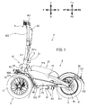
- FIG. 1 is a left side view showing the overall configuration of the lean vehicle according to the embodiment.
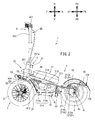
- FIG. 2 is a left side view of the lean vehicle with the main frame cover removed.
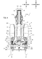
- FIG. 3 is a front view showing the configuration of the front part of the vehicle when the lean vehicle is viewed from the front.
- FIG. 4 is a top view showing the configuration of the lean vehicle.
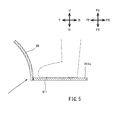
- FIG. 5 is a diagram schematically showing the positional relationship between the left foot mounting portion and the left front guard portion when the lean vehicle is viewed from the left.
- FIG. 6 is a diagram schematically showing the positional relationship between the left foot mounting portion and the left side guard and the positional relationship between the right foot mounting portion and the right side guard when the lean vehicle is viewed from the front.
- FIG. 1 is a left side view showing the overall configuration of the lean vehicle according to the embodiment.
- FIG. 2 is a left side view of the lean vehicle with the main frame cover removed.
- FIG. 3 is a front view showing the configuration of
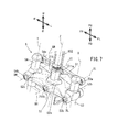
- FIG. 7 is an enlarged perspective view showing the link mechanism.
- FIG. 8 is a rear view showing the configuration of the lean vehicle.
- FIG. 9 is a front view showing the configuration of a lean vehicle tilted to the left.
- FIG. 10 is a rear view showing the configuration of a lean vehicle tilted to the left.
- FIG. 11 is a perspective view of the lean vehicle when the lean vehicle is viewed from the front right.
- FIG. 12 is a perspective view of the lean vehicle when the lean vehicle is viewed from the rear right.
- 13A and 13B are a rear view schematically showing the configuration of a lean vehicle in an upright state, (b) a rear view schematically showing a configuration of a lean vehicle in an inclined state, and (c) a left front wheel around the left steering axis. It is a top view which shows typically the relationship between a front wheel, a left front guard part, and a right front guard part in a lean vehicle in a state where the right front wheel is rotated around the right steering axis.
- the arrow F in the figure indicates the forward direction of the lean vehicle 1.
- the arrow B in the figure indicates the rear direction of the lean vehicle 1.
- the arrow U in the figure indicates the upward direction of the lean vehicle 1.
- the arrow D in the figure indicates the downward direction of the lean vehicle 1.
- the arrow R in the figure indicates the right direction of the lean vehicle 1.
- the arrow L in the figure indicates the left direction of the lean vehicle 1.
- the front-rear direction, the left-right direction, and the up-down direction of the lean vehicle 1 mean the front-back direction, the left-right direction, and the up-down direction with respect to the lean vehicle 1 when viewed from the driver who drives the lean vehicle 1, respectively. ..
- the lean vehicle 1 of the present embodiment turns by inclining the vehicle body frame in the left-right direction with respect to the vertical direction. Therefore, in addition to the above-mentioned direction based on the vehicle, the direction based on the vehicle body frame is defined as follows.
- the arrow FF in the figure indicates the front direction of the vehicle body frame.
- the arrow FB in the figure indicates the rear direction of the vehicle body frame.
- the arrow FU in the figure indicates the upward direction of the vehicle body frame.
- the arrow FD in the figure indicates the downward direction of the vehicle body frame.
- the arrow FR in the figure indicates the right direction of the vehicle body frame.
- the arrow FL in the figure indicates the left direction of the vehicle body frame.
- front-rear direction, the left-right direction, and the up-down direction of the vehicle body frame mean the front-rear direction, the left-right direction, and the up-down direction with respect to the vehicle body frame, respectively, when viewed from the driver who drives the lean vehicle.
- FIG. 1 is a left side view showing an outline of the overall configuration of the lean vehicle 1 according to the embodiment.
- FIG. 2 is a left side view showing a state in which the main frame cover 25 is removed in the lean vehicle 1.
- the lean vehicle 1 includes a vehicle body 2, a pair of left and right front wheels 3, a rear wheel 4, a link mechanism 5, a steering mechanism 6, and a load transmission mechanism 8. That is, the lean vehicle 1 in this embodiment is a three-wheeled vehicle having a pair of left and right front wheels 3.
- the lean vehicle 1 is a vehicle that inclines to the left when turning to the left and to the right when turning to the right.
- the lean vehicle 1 is not provided with a seat on which the driver sits. That is, the lean vehicle 1 is a so-called standing vehicle in which the driver rides while standing. Further, the lean vehicle 1 is not provided with a rear arm that supports the rear wheels 4. The rear wheel 4 of the lean vehicle 1 is supported by a vehicle body frame 21 described later. Further, the lean vehicle 1 is not provided with a shock absorber that elastically supports the front wheels 3 and the rear wheels 4 so as to be displaceable. The front wheels 3 and the rear wheels 4 of the lean vehicle 1 are supported by the vehicle body frame 21, which will be described later, without a shock absorber.
- the vehicle body 2 includes a body frame 21 and a power unit 22.
- the vehicle body frame 21 is in an upright state.
- the vehicle body frame 21 is premised on an upright state.
- the upright state of the vehicle body frame 21 means that the vertical direction of the vehicle body frame 21 is the same as the vertical direction.
- the vehicle body frame 21 supports the power unit 22 and the like.
- the vehicle body frame 21 includes a head pipe 211 (link support portion) and a main frame 212.
- the head pipe 211 is located at the front of the lean vehicle 1. When the lean vehicle 1 is viewed from the left, the upper portion of the head pipe 211 is located behind the lower portion of the head pipe 211 in the front-rear direction of the vehicle body frame 21.
- a link mechanism 5 is arranged around the head pipe 211.
- a steering shaft 652, which will be described later, is rotatably inserted into the head pipe 211.
- the main frame 212 is connected to the head pipe 211.
- the main frame 212 is located behind the head pipe 211 in the front-rear direction of the vehicle body frame 21.
- the main frame 212 supports the power unit 22.
- the rear end portion of the main frame 212 rotatably supports the rear wheel 4 about the wheel shaft 41.
- the main frame 212 is covered by the main frame cover 25.
- the main frame cover 25 is supported by the main frame 212.
- the main frame cover 25 is a resin member.
- the main frame 212 includes an upper frame 213 and an under frame 214.
- the upper frame 213 When the vehicle body frame 21 is viewed from the left, the upper frame 213 extends from the head pipe 211 toward the rear wheels 4 behind the vehicle body frame 21 in the front-rear direction and downward in the vertical direction of the vehicle body frame 21.
- the rear end portion of the upper frame 213 is branched into two so as to be located on the left and right sides of the rear wheel 4. That is, the upper frame 213 has an upper frame left rear end portion 213a located to the left of the rear wheel 4 and an upper frame right rear end portion 213b located to the right of the rear wheel 4.
- the upper left rear end portion 213a and the upper frame right rear end portion 213b support the rear wheel 4 together with the underframe left rear end portion 214c and the underframe right rear end portion 214d described later.
- the power unit 22 is supported by the upper frame 213.
- the underframe 214 has an underframe front portion 214a and an underframe rear portion 214b.
- the underframe front portion 214a extends from the head pipe 211 to the rear of the vehicle body frame 21 in the front-rear direction and downward in the vertical direction of the vehicle body frame 21 when the vehicle body frame 21 is viewed from the left.
- the front end of the underframe front portion 214a is connected to the head pipe 211.
- the underframe rear portion 214b extends rearward from the rear end portion of the underframe front portion 214a in the front-rear direction of the vehicle body frame 21.
- the rear end of the underframe rear portion 214b is branched into two so as to be located on the left and right sides of the rear wheel 4. That is, the underframe rear portion 214b has an underframe left rear end portion 214c located to the left of the rear wheel 4 and an underframe right rear end portion 214d located to the right of the rear wheel 4.
- the left rear end portion 214c of the under frame is connected to the left rear end portion 213a of the upper frame. By connecting the left rear end portion 214c of the under frame and the left rear end portion 213a of the upper frame in this way, the left rear end portion 212a of the main frame is configured.
- the right rear end portion 214d of the underframe is connected to the right rear end portion 213b of the upper frame. By connecting the right rear end portion 214d of the under frame and the right rear end portion 213b of the upper frame in this way, the right rear end portion 212b of the main frame is configured.
- the left rear end portion 212a of the main frame and the right rear end portion 212b of the main frame support the rear wheels 4.
- the main frame 212 since the main frame 212 has the upper frame 213 and the under frame 214, the strength and rigidity of the main frame 212 can be improved.
- the main frame may have only the under frame.
- FIG. 3 is a front view of the front part of the lean vehicle 1 as viewed from the front.
- the vehicle body frame 21 is in an upright state.
- the vehicle body frame 21 is premised on an upright state.
- the pair of left and right front wheels 3 are located below the head pipe 211 and the link mechanism 5 in the vertical direction of the vehicle body frame 21. As shown in FIG. 2, the pair of left and right front wheels 3 are supported by the left suspension portion 61 and the right suspension portion 62, which will be described later.
- the rear wheels 4 are located behind the pair of left and right front wheels 3 in the front-rear direction of the vehicle body frame 21.
- the power unit 22 generates a driving force for driving the lean vehicle 1. As shown in FIG. 2, the power unit 22 is located in front of the wheel shaft 41 of the rear wheels 4 in the front-rear direction of the vehicle body frame 21. The power unit 22 is fixed to the vehicle body frame 21.
- the power unit 22 includes a motor and a battery 221 (not shown). In this embodiment, the motor is arranged in the wheel 4a of the rear wheel 4. Electric power is supplied to the motor from the battery 221 fixed to the upper frame 213 of the vehicle body frame 21.
- the pair of left and right front wheels 3 includes a left front wheel 31 and a right front wheel 32.
- the left front wheel 31 is located to the left of the head pipe 211, which is a part of the vehicle body frame 21, in the left-right direction of the vehicle body frame 21.
- the right front wheel 32 is located to the right of the head pipe 211 in the left-right direction of the vehicle body frame 21. That is, the left front wheel 31 and the right front wheel 32 are located side by side in the left-right direction of the vehicle body frame 21.
- the left front wheel 31 is connected to the left suspension portion 61. Specifically, the left front wheel 31 is connected to the lower part of the left suspension portion 61. The left front wheel 31 is rotatably supported by the left suspension portion 61 around the left axle 311. The left axle 311 is arranged below the left suspension portion 61 so as to extend in the left-right direction of the vehicle body frame 21.
- the right front wheel 32 is connected to the right suspension portion 62. Specifically, the right front wheel 32 is connected to the lower part of the right suspension portion 62. The right front wheel 32 is rotatably supported by the right suspension portion 62 around the right axle 321. The right axle 321 is arranged below the right suspension portion 62 so as to extend in the left-right direction of the vehicle body frame 21.
- FIG. 4 is a top view of the lean vehicle 1 viewed from above in the vertical direction of the vehicle body frame 21.
- FIG. 7 is an enlarged perspective view of the link mechanism 5.
- the vehicle body frame 21 is in an upright state. In the following description, when referring to FIGS. 4 and 7, the vehicle body frame 21 is premised on an upright state.
- the link mechanism 5 is a parallel four-node link (also called a parallelogram link) type link mechanism.
- the link mechanism 5 is located below the handlebar 651 in the vertical direction of the vehicle body frame 21.
- the link mechanism 5 is located above the left front wheel 31 and the right front wheel 32 in the vertical direction of the vehicle body frame 21.
- the link mechanism 5 includes an upper cross portion 51, a lower cross portion 52, a left side portion 53, and a right side portion 54.
- the link mechanism 5 is not interlocked with the rotation of the steering shaft 652 about the intermediate steering axis Z accompanying the operation of the handlebar 651. That is, the link mechanism 5 does not rotate with respect to the vehicle body frame 21 about the intermediate steering axis Z.
- the upper cross portion 51 and the lower cross portion 52 correspond to the cross portion.
- the upper cross portion 51 is located behind the head pipe 211 in the front-rear direction of the vehicle body frame 21. As shown in FIG. 3, the upper cross portion 51 extends in the left-right direction of the vehicle body frame 21.
- the lower cross portion 52 is located below the upper cross portion 51 in the vertical direction of the vehicle body frame 21. As shown in FIG. 3, the lower cross portion 52 extends in the left-right direction of the vehicle body frame 21.
- the lower cross portion 52 has a through hole 52a through which the head pipe 211 penetrates in the central portion in the left-right direction. Further, the lower cross portion 52 has a left notch 52b in which the left side portion 53 is located at the left end portion in the left-right direction of the vehicle body frame 21, and a right notch portion 52b in which the right side portion 54 is located at the right end portion. It has a part 52c.
- the left side portion 53 is located to the left of the head pipe 211 in the left-right direction of the vehicle body frame 21.
- the left side portion 53 is located above the left front wheel 31 in the vertical direction of the vehicle body frame 21.
- the left side portion 53 extends in the direction in which the head pipe 211 extends.
- the left side portion 53 extends in the direction in which the intermediate steering axis Z of the steering shaft 652 extends.
- the upper portion of the left side portion 53 is located behind the lower portion of the left side portion 53 in the front-rear direction of the vehicle body frame 21.
- the right side portion 54 is located to the right of the head pipe 211 in the left-right direction of the vehicle body frame 21.
- the right side portion 54 is located above the right front wheel 32 in the vertical direction of the vehicle body frame 21.
- the right side portion 54 extends in the direction in which the head pipe 211 extends.
- the right side portion 54 extends in the direction in which the intermediate steering axis Z of the steering shaft 652 extends.
- the upper portion of the right side portion 54 is located behind the lower portion of the right side portion 54 in the front-rear direction of the vehicle body frame 21.
- the head pipe 211 has an upper intermediate connecting portion 211a and a lower intermediate connecting portion 211b.
- the intermediate portion of the upper cross portion 51 is rotatably connected to the head pipe 211 via the upper intermediate connecting portion 211a. That is, the upper cross portion 51 is rotatable with respect to the head pipe 211 about the upper intermediate connecting axis UI (intermediate axis) extending in the front-rear direction of the vehicle body frame 21 through the upper intermediate connecting portion 211a.
- UI intermediate axis
- the intermediate portion of the lower cross portion 52 is rotatably connected to the head pipe 211 via the lower intermediate connecting portion 211b. That is, the lower cross portion 52 is rotatable with respect to the head pipe 211 about the lower intermediate connecting axis DI (intermediate axis) extending in the front-rear direction of the vehicle body frame 21 through the lower intermediate connecting portion 211b.
- DI intermediate axis
- the left side portion 53 has an upper left connecting portion 53a and a lower left connecting portion 53b.
- the left end portion of the upper cross portion 51 is rotatably connected to the left side portion 53 via the upper left connecting portion 53a. That is, the upper cross portion 51 is rotatable with respect to the left side portion 53 about the upper left connecting axis UL (left axis) extending in the front-rear direction of the vehicle body frame 21 through the upper left connecting portion 53a.
- the left end portion of the lower cross portion 52 is rotatably connected to the left side portion 53 via the lower left connecting portion 53b. That is, the lower cross portion 52 is rotatable with respect to the left side portion 53 about the lower left connecting axis DL (left axis) extending in the front-rear direction of the vehicle body frame 21 through the lower left connecting portion 53b.
- the right side portion 54 has an upper right connecting portion 54a and a lower right connecting portion 54b.
- the right end of the upper cross portion 51 is rotatably connected to the right side portion 54 via the upper right connecting portion 54a. That is, the upper cross portion 51 is rotatable with respect to the right side portion 54 about the upper right connecting axis UR (right axis) extending in the front-rear direction of the vehicle body frame 21 through the upper right connecting portion 54a.
- the right end portion of the lower cross portion 52 is rotatably connected to the right side portion 54 via the lower right connecting portion 54b. That is, the lower cross portion 52 is rotatable with respect to the right side portion 54 about the lower right connecting axis DR (right axis) extending in the front-rear direction of the vehicle body frame 21 through the lower right connecting portion 54b.
- the upper intermediate connecting axis UI, the upper right connecting axis UR, the upper left connecting axis UL, the lower intermediate connecting axis DI, the lower right connecting axis DR, and the lower left connecting axis DL extend in parallel with each other.
- the upper middle connecting axis UI, the upper right connecting axis UR, the upper left connecting axis UL, the lower middle connecting axis DI, the lower right connecting axis DR and the lower left connecting axis DL are the left front wheel 31 and the right in the vertical direction of the vehicle body frame 21. It is located above the front wheel 32.
- the upper cross portion 51 and the lower cross portion 52 maintain a posture parallel to each other, and the left side.
- the portion 53 and the right side portion 54 are supported by the vehicle body frame 21 so as to maintain a posture parallel to each other.
- the steering mechanism 6 includes a left suspension portion 61, a right suspension portion 62, a left bracket 63, a right bracket 64, a steering member 65, and a steering force transmission mechanism 66.
- the configuration of the steering mechanism 6 is the same as that of the steering mechanism disclosed in International Publication 2020/11254. Therefore, the detailed description of the configuration of the steering mechanism 6 will be omitted. Therefore, the steering operation of the lean vehicle 1 using the steering mechanism 6 is the same as the steering operation disclosed in International Publication 2020/11254, and therefore detailed description thereof will be omitted.
- the left suspension portion 61 supports the left front wheel 31 with respect to the link mechanism 5.
- the left suspension portion 61 extends in the direction in which the intermediate steering axis Z extends.
- the lower end of the left suspension 61 supports the left front wheel 31.
- the left suspension portion 61 supports the left front wheel 31 so that the gap between the left front wheel 31 and the left connecting portion 812, which will be described later, is not displaced.
- the upper end of the left suspension 61 is fixed to the left bracket 63.
- the left bracket 63 has a counterclockwise rotating member (not shown) above the left bracket 63.
- the counterclockwise rotating member is located inside the left side portion 53 of the link mechanism 5, and extends in the direction in which the left side portion 53 extends.
- the left rotation member can rotate about the left steering axis X with respect to the left side portion 53. That is, the left bracket 63 can rotate about the left steering axis X with respect to the left side portion 53.
- the left steering axis X extends in the direction in which the left side portion 53 extends.
- the left steering axis X extends in the vertical direction of the vehicle body frame 21 in parallel with the intermediate steering axis Z of the steering shaft 652.
- the right bracket 64 has a clockwise rotating member (not shown) above the right bracket 64.
- the right-handed rotating member is located inside the right side portion 54 of the link mechanism 5, and extends in the direction in which the right side portion 54 extends.
- the right-handed rotating member can rotate about the right steering axis Y with respect to the right side portion 54. That is, the right bracket 64 can rotate about the right steering axis Y with respect to the right side portion 54.
- the right steering axis Y extends in the direction in which the right side portion 54 extends.
- the right suspension portion 62 supports the right front wheel 32 with respect to the link mechanism 5.
- the right suspension portion 62 extends in the direction in which the intermediate steering axis Z extends.
- the lower end of the right suspension 62 supports the right front wheel 32.
- the right suspension portion 62 supports the right front wheel 32 so that the gap between the right front wheel 32 and the right connecting portion 822, which will be described later, is not displaced.
- the upper end of the right suspension portion 62 is fixed to the right bracket 64.
- the right steering axis Y extends in the vertical direction of the vehicle body frame 21 in parallel with the intermediate steering axis Z of the steering shaft 652.
- the steering member 65 includes a handlebar 651 and a steering shaft 652.
- the handlebar 651 is connected to the upper part of the steering shaft 652.
- a part of the steering shaft 652 is rotatably supported by the head pipe 211.
- the steering shaft 652 rotates about the intermediate steering axis Z in response to the operation of the handlebar 651 by the driver.
- the steering force transmission mechanism 66 rotates the left suspension portion 61 in the rotation direction of the steering member 65 about the left steering axis X in accordance with the rotation of the steering member 65. Similarly, the steering force transmission mechanism 66 rotates the right suspension portion 62 in the rotation direction of the steering member 65 about the right steering axis Y in accordance with the rotation of the steering member 65. As a result, the steering force transmission mechanism 66 transmits the steering force to the left front wheel 31 and the right front wheel 32 in response to the operation of the steering member 65 by the driver. The left front wheel 31 and the right front wheel 32 rotate about the left steering axis X and the right steering axis Y, respectively, in a direction corresponding to the operation direction of the steering member 65 by the driver.
- the tilting motion of the lean vehicle 1 to the left or right is the same as the tilting motion disclosed in the above-mentioned International Publication 2020/11254. Therefore, detailed description of the operation of the lean vehicle 1 tilting to the left or right will be omitted.
- the load transmission mechanism 8 includes a left foot load transmission unit 81, a right foot load transmission unit 82, and a left / right connecting member 83.
- the left foot load transmitting portion 81 has a left foot mounting portion 811 (left foot step portion) and a left connecting portion 812 (left foot step connecting portion).
- the left foot mounting portion 811 has a left foot mounting surface 811a on which the left foot of the standing driver is placed.
- the left foot mounting portion 811 has a water passage prevention structure that prevents water from passing in the vertical direction.
- the left foot mounting portion 811 has a plate shape having no through hole penetrating in the vertical direction. As a result, it is possible to prevent the water splashed by the left front wheel 31 while the lean vehicle 1 is traveling from being applied to the driver's left foot from under the left foot mounting portion 811.
- the left connecting portion 812 connects the left foot mounting portion 811 and the left side portion 53 of the link mechanism 5. As shown in FIG. 1, the left connecting portion 812 is behind the left front wheel 31 and along the left front wheel 31 from the left side portion 53 to the rear of the vehicle body frame 21 in the front-rear direction and below the vehicle body frame 21 in the vertical direction. Extends to. It should be noted that the left connecting portion 812 is along the left front wheel 31 not only when the left connecting portion 812 is curved in an arc shape when viewed from the left, but also when the left connecting portion 812 is linearly inclined when viewed from the left.
- the left connecting portion 812 When the left connecting portion 812 has a curved shape when viewed from the left, when the left connecting portion 812 has a shape combining a curved line and a straight line when viewed from the left, the left connecting portion 812 has an angle when viewed from the left. It also includes the case where the shape is a combination of a plurality of straight lines having different characteristics.
- the rear end of the left connecting portion 812 is connected to the left foot mounting portion 811.
- the left foot load transmitting portion 81 is configured to be able to transmit the driver's load input via the left foot mounting portion 811 to the left side portion 53.
- the left connecting portion may be integrated with the left side portion.
- the right foot load transmitting portion 82 has a right foot mounting portion 821 (right foot step portion) and a right connecting portion 822 (right foot step connecting portion).
- the right foot mounting portion 821 has a right foot mounting surface 821a on which the right foot of the standing driver is placed.
- the right foot mounting portion 821 has a water passage prevention structure that prevents water from passing in the vertical direction.
- the right foot mounting portion 821 has a plate shape having no through hole penetrating in the vertical direction. As a result, it is possible to prevent the water splashed by the right front wheel 32 while the lean vehicle 1 is traveling from being applied to the driver's right foot from under the right foot mounting portion 821.
- the right connecting portion 822 connects the right foot mounting portion 821 and the right side portion 54 of the link mechanism 5.
- the right connecting portion 822 extends behind the right front wheel 32 from the right side portion 54 to the rear in the front-rear direction of the vehicle body frame 21 and downward in the vertical direction of the vehicle body frame 21 along the right front wheel 32.
- the right connecting portion 822 is along the right front wheel 32 not only when the right connecting portion 822 is curved in an arc shape when viewed from the right, but also when the right connecting portion 822 is inclined linearly when viewed from the right.
- the right connecting portion 822 when viewed from the right has a curved shape
- the right connecting portion 822 when viewed from the right has a shape that combines a curved line and a straight line
- the right connecting portion 822 when viewed from the right has an angle. It also includes the case where the shape is a combination of a plurality of straight lines having different characteristics.
- the rear end of the right connecting portion 822 is connected to the right foot mounting portion 821.
- the right foot load transmitting portion 82 is configured to be able to transmit the driver's load input via the right foot mounting portion 821 to the right side portion 54.
- the right connecting portion may be integrated with the right side portion.
- the load applied to the left foot mounting portion 811 via the driver's left foot and the load applied to the right foot mounting portion 821 via the driver's right foot are individually adjusted to adjust the vehicle body.
- the inclination of the frame 21 can be controlled.
- FIG. 10 is a rear view of the front portion of the lean vehicle 1 in a state where the vehicle body frame 21 is tilted to the left, as viewed from the rear of the vehicle body frame 21.
- the right side portion 54 is located above the left side portion 53 in the vertical direction of the vehicle body frame 21.
- a load is applied to the right side portion 54 via the right foot mounting portion 821 with the right foot, a force that causes the vehicle body frame 21 to be displaced downward acts on the right side portion 54.
- a force that causes the vehicle body frame 21 to be displaced downward acts on the right side portion 54.
- the normal direction of the left foot mounting portion 811 with respect to the mounting surface and the normal direction of the right foot mounting portion 821 with respect to the mounting surface change.
- the angle formed by the direction in which the head pipe 211 extends (the direction in which the intermediate steering axis Z extends) and the mounting surface of the left foot mounting portion 811 and the mounting surface of the right foot mounting portion 821 do not change. That is, the normal direction of the left foot mounting portion 811 with respect to the mounting surface and the normal direction of the right foot mounting portion 821 with respect to the mounting surface are always the same as the vertical direction of the vehicle body frame 21.
- the left / right connecting member 83 connects the left foot mounting portion 811 and the right foot mounting portion 821 in the left-right direction of the vehicle body frame 21 under the vehicle body frame 21.
- the central portion of the left-right connecting member 83 is rotatably supported around the underframe 214 by a rotation support portion (not shown) fixed to the lower part of the underframe 214 of the vehicle body frame 21. ing. Therefore, the left-right connecting member 83 tilts in the vertical direction in the vertical direction of the vehicle body frame 21 in accordance with the vertical movement of the left foot mounting portion 811 and the right foot mounting portion 821.
- the left foot mounting portion 811 and the right foot mounting portion 821 move up and down in conjunction with each other in response to the load input of the left foot to the left foot mounting portion 811 or the load input of the right foot to the right foot mounting portion 821. Therefore, the left or right inclination of the vehicle body frame 21 can be easily suppressed by the load input of the left foot to the left foot mounting portion 811 or the load input of the right foot to the right foot mounting portion 821 as described above.
- the lean vehicle 1 has a left front fender 33 and a right front fender 34.
- the left front fender 33 is located above the left front wheel 31 in the vertical direction of the vehicle body frame 21. As shown in FIGS. 1 and 2, the left front fender 33 has an arc shape along the left front wheel 31 when viewed from the left.
- the left front fender 33 is arranged along the left front wheel 31 so that the distance between the left front wheel 31 and the left front wheel 31 is smaller than the distance between the left front wheel 31 and the left connecting portion 812.
- the left front fender 33 is attached to the left transmission plate 664 rotatably attached to the lower end of the left side portion 53 of the link mechanism 5 via the left front fender attachment member 331.
- the left front fender 33 is arranged on the left front wheel 31 so as to overlap a part of the left front guard portion 86 described later when viewed from above.
- the left front fender 33 covers the upper part of the left front wheel 31 over a range of 90 degrees or less at a central angle when viewed from the left.
- the left front fender 33 may cover the upper part of the left front wheel 31 over a range wider than 90 degrees at a central angle when viewed from the left.
- the left front fender 33 By arranging the left front fender 33 on the left front wheel 31 as described above, the water splashed by the left front wheel 31 when the lean vehicle 1 is running is prevented by the left front fender 33 from being applied to the driver's left foot. Can be prevented.
- the left front fender 33 is miniaturized and attached to the left transmission plate 664 rotatably attached to the lower end of the left side portion 53 of the link mechanism 5 via the left front fender attachment member 331.
- the front fender 33 can be supported with a simple configuration. That is, since the left front fender 33 of the present embodiment is small, it is not necessary to support it at a plurality of points. Therefore, it is possible to prevent the left front fender 33 from interfering with other parts.
- the left front fender 33 by downsizing the left front fender 33, even if the left front fender 33 vibrates while the lean vehicle 1 is running, the left front fender 33, the left side guard 84 described later, and the left front are used. Interference with the guard portion 86 can be prevented.
- the right front fender 34 is located above the right front wheel 32 in the vertical direction of the vehicle body frame 21.
- the right front fender 34 has an arc shape along the right front wheel 32 when viewed from the right.
- the right front fender 34 is arranged along the right front wheel 32 so that the distance from the right front wheel 32 is smaller than the distance between the right front wheel 32 and the right connecting portion 822 described later.
- the right front fender 34 is attached to a right transmission plate 665 rotatably attached to the lower end of the right side portion 54 of the link mechanism 5, which will be described later, via the right front fender attachment member 341.
- the right front fender 34 is arranged on the right front wheel 32 so as to overlap a part of the right front guard portion 87 described later when viewed from above.
- the right front fender 34 covers the upper part of the right front wheel 32 over a range of 90 degrees or less at a central angle when viewed from the right.
- the right front fender 34 may cover the upper part of the right front wheel 32 over a range wider than 90 degrees at a central angle when viewed from the right.
- the right front fender 34 By arranging the right front fender 34 on the right front wheel 32 as described above, the water splashed by the right front wheel 32 when the lean vehicle 1 is running is prevented by the right front fender 34 from being applied to the driver's right foot. Can be prevented.
- the right front fender 34 is miniaturized and attached to the right transmission plate 665 rotatably attached to the lower end of the right side portion 54 of the link mechanism 5 via the right front fender attachment member 341 to the right.
- the front fender 34 can be supported with a simple configuration. That is, since the right front fender 34 of the present embodiment is small, it is not necessary to support it at a plurality of points. Therefore, it is possible to prevent the right front fender 34 from interfering with other parts.
- FIG. 6 is a diagram schematically showing the positional relationship between the left foot mounting portion 811 and the left side guard 84 and the positional relationship between the right foot mounting portion 821 and the right side guard 85 when the lean vehicle 1 is viewed from the front. Is.
- the solid line arrow indicates the movement of the water bounced off by the wheels.
- the left foot mounting portion 811, the right foot mounting portion 821, the left side guard 84, and the right side guard 85 are shown by diagonal lines for the sake of explanation.
- the alternate long and short dash line indicates the driver's foot.
- the left side guard 84 is made of resin and has a triangular plate shape in a side view extending in the vertical direction and the front-rear direction.
- the left side guard 84 is fixed to the right end portion and the left connecting portion 812 of the left foot mounting portion 811.
- the lower end of the left side guard 84 is attached to the right end of the left foot mounting portion 811.
- the right end of the left foot mounting portion 811 is located to the right of the left surface 84a of the left side guard 84.
- the front end portion of the left side guard 84 is attached to the left connecting portion 812.
- the left side guard 84 is fixed to the left foot mounting portion 811 and the left connecting portion 812, and the height in the vertical direction increases toward the front.
- the left side guard 84 having the above configuration By arranging the left side guard 84 having the above configuration to the right of the left foot mounting portion 811, the left foot mounted on the left foot mounting portion 811 can be positioned and protected, and the lean vehicle 1 can be mounted. It is possible to prevent the water splashed by the right front wheel 32 from being applied to the driver's left foot when traveling. In particular, the left side guard 84 can prevent the water splashed by the right front wheel 32 from being applied to the driver's left foot when the lean vehicle 1 travels in an inclined state.
- the right side guard 85 is made of resin and has a triangular plate shape in a side view extending in the vertical direction and the front-rear direction.
- the right side guard 85 is fixed to the left end portion and the right connecting portion 822 of the right foot mounting portion 821.
- the lower end of the right side guard 85 is attached to the left end of the right foot mounting portion 821.
- the left end of the right foot mounting portion 821 is located to the left of the right surface 85a of the right side guard 85.
- the front end portion of the right side guard 85 is attached to the right connecting portion 822.
- the right side guard 85 is fixed to the right foot mounting portion 821 and the right connecting portion 822, and the height in the vertical direction increases toward the front.
- the right side guard 85 By arranging the right side guard 85 having the above configuration to the left of the right foot mounting portion 821, the right foot mounted on the right foot mounting portion 821 can be positioned and protected, and FIGS. 9 and 9 and FIGS. As shown in FIG. 10, when the lean vehicle 1 travels, it is possible to prevent the water splashed by the left front wheel 31 from getting on the driver's right foot.
- the right side guard 85 can prevent the water splashed by the left front wheel 31 from being applied to the driver's right foot when the lean vehicle 1 travels in an inclined state.
- FIGS. 1, 5, 8, 11 to 13 the lean vehicle 1 has a left front guard portion 86 and a right front guard portion 87.
- FIG. 5 is a diagram schematically showing the positional relationship between the left foot mounting portion 811 and the left front guard portion 86 when the lean vehicle 1 is viewed from the left.
- 13A and 13B are a rear view schematically showing the configuration of the lean vehicle 1 in the upright state, (b) a rear view schematically showing the configuration of the lean vehicle 1 in the inclined state, and (c) the left front wheel 31 on the left.
- the relationship between the front wheel 3 and the left front guard portion 86 and the right front guard portion 87 is schematically shown in the lean vehicle 1 in which the right front wheel 32 is rotated around the steering axis X and the right front wheel 32 is rotated around the right steering axis Y. It is a top view.
- the solid line arrow indicates the movement of the water bounced off by the wheels.
- the alternate long and short dash line indicates the driver's foot.
- the alternate long and short dash line indicates the rotation of the left front wheel 31 around the left steering axis X and the rotation of the right front wheel 32 around the right steering axis Y.
- the left front guard portion 86 is attached to at least the lower end portion of the left connecting portion 812 so as to cover at least a part of the rear portion of the left front wheel 31.
- the lower end portion of the left connecting portion 812 is a portion of the lower portion of the left connecting portion 812 located in a region where water splashed by the left front wheel 31 is scattered toward the driver's left foot. Is.
- the left connecting portion 812 extends from the left side portion 53 to the height of the left axle 311 of the left front wheel 31.
- the left front guard portion 86 is attached to the left connecting portion 812 so as to cover a portion of the left front wheel 31 located behind the left axle 311.
- the left front guard portion 86 extends upward from the lower end portion of the left connecting portion 812 along the left connecting portion 812. That is, the left front guard portion 86 is a rectangular resin plate member in a plan view, and covers the rear portion and the upper portion of the left front wheel 31.
- the left front guard portion 86 is fixed to the left connecting portion 812 so that the longitudinal direction is along the extending direction of the left connecting portion 812. At this time, the left front guard portion 86 is attached to the left connecting portion 812 in front.
- the left front guard portion 86 may be provided below the portion where the gap between the left connecting portion 812 and the left front wheel 31 in the front-rear direction is the smallest with respect to the left connecting portion 812. As a result, it is possible to prevent the water splashed by the left front wheel 31 from being applied to the driver's left foot as described later.
- the left front guard portion 86 is a vehicle body while the lean vehicle 1 is tilted. While the positional relationship of the frame 21 with respect to the vehicle body frame 21 in the vertical direction changes, the positional relationship of the vehicle body frame 21 with respect to the left side portion 53 and the left foot mounting portion 811 in the vertical direction does not change. That is, the position of the left front guard portion 86 in the vertical direction of the vehicle body frame 21 changes during the inclination of the lean vehicle 1.
- the left front guard portion 86 is fixed to the left connecting portion 812 connected to the left side portion 53 and the left foot mounting portion 811, the vehicle body frame 21 is moved up and down even when the lean vehicle 1 is tilted. In the direction, the positions of the left front guard portion 86 with respect to the left side portion 53 and the left foot mounting portion 811 do not change.
- the left front guard portion 86 does not rotate together with the left front wheel 31, and the left side portion 53 and the left foot
- the positional relationship with respect to the mounting portion 811 does not change.
- the positional relationship of the left front guard portion 86 with respect to the left side portion 53 and the left foot mounting portion 811 while the left front wheel 31 is rotating around the left steering axis X is the front-rear direction with respect to the lean vehicle 1. It is a positional relationship in the left-right direction and the up-down direction.
- the left front guard portion 86 changes the positional relationship of the vehicle body frame 21 with respect to the vehicle body frame 21 in the vertical direction while the lean vehicle 1 is tilted, while the left side portion 53 and the vehicle body frame 21 in the vertical direction change.
- the left side portion 53 and the left foot mounting portion do not rotate together with the left front wheel 31 while the left front wheel 31 is rotating around the left steering axis X so that the positional relationship with respect to the left foot mounting portion 811 does not change. It is supported by the left connecting portion 812 between the left foot mounting portion 811 and the left front wheel 31 so that the positional relationship with respect to the 811 does not change.
- the driver's left foot mounted on the left foot mounting portion 811 is placed on the left front. It can be covered from the front by the guard portion 86. Therefore, it is possible to prevent the driver's left foot from getting wet due to the water splash of the left front wheel 31.
- the left front guard portion 86 has a left front guard first hook portion 86a and a pair of left front guard second hook portions 86b that engage with the left connecting portion 812 on the right portion.
- the left front guard first hook portion 86a and the pair of left front guard second hook portions 86b are provided side by side in the longitudinal direction on the right portion of the left front guard portion 86, and each protrudes to the right from the left front guard portion 86. ing.
- the left front guard first hook portion 86a and the pair of left front guard second hook portions 86b are integrally provided with the left front guard portion 86.
- the left front guard first hook portion 86a is located in front of the left connecting portion 812, and the pair of left front guard second hook portions 86b are left connecting portions. It is located behind the 812.
- the left front guard first hook portion 86a and the pair of left front guard second hook portions 86b are formed in a semicircular shape when viewed from the longitudinal direction of the left front guard portion 86 so as to follow the outer shape of the left connecting portion 812. There is.
- the left front guard first hook portion 86a and the pair of left front guard second hook portions 86b are securely engaged by the left connecting portion 812. Therefore, the left front guard portion 86 can be securely fixed by the left connecting portion 812.
- the left front guard portion 86 In a state where the left front guard portion 86 is fixed to the left connecting portion 812, as shown in FIG. 5, the left front guard portion 86 is below the height of the front end portion of the left foot mounting surface 811a of the left foot mounting portion 811. Extends to.
- the left front guard portion may extend to the same position as the height of the front end portion of the left foot mounting surface of the left foot mounting portion.
- the left front guard portion 86 has an arc shape that follows the outer shape of the left front wheel 31 when viewed from the left in a state of being fixed to the left connecting portion 812 as described above. Further, the left front guard portion 86 is located at a position overlapping a part of the left front fender 33 when viewed from above in a state of being fixed to the left connecting portion 812 as described above. The lower end of the left front guard portion 86 is located in front of the left foot mounting portion 811 in a state of being fixed to the left connecting portion 812 as described above.
- the left front guard portion 86 can prevent the water splashed by the left front wheel 31 from being applied to the driver's left foot while the lean vehicle 1 is traveling. Moreover, as described above, since the left front guard portion 86 is fixed to the left connecting portion 812, when the lean vehicle 1 is tilted to the left, the left front guard portion 86 is also tilted to the left together with the left connecting portion 812. When the lean vehicle 1 is tilted to the right, the left front guard portion 86 is also tilted to the right together with the left connecting portion 812. Therefore, the left front guard portion 86 can more reliably prevent the water splashed by the left front wheel 31 from being applied to the driver's left foot while the lean vehicle 1 is traveling.
- the left front guard portion 86 is located at a position where it overlaps a part of the left front fender 33 when viewed from above, so that the left front wheel is used when the lean vehicle 1 is traveling at a relatively high speed.
- the left front guard portion 86 and the left front fender 33 can more reliably prevent the water splashed by the 31 from splashing on the driver's left foot.
- Lean vehicle 1 can be allowed to tilt to the left or right.
- the left front guard portion 86 extends below the left foot mounting surface 811a, the left foot mounting portion 811 can be more reliably covered from the front by the left front guard portion 86. Therefore, it is possible to prevent the water splashed by the left front wheel 31 while the lean vehicle 1 is traveling from being applied to the driver's left foot from under the left front guard portion 86.
- the left front guard portion 86 since the left front guard portion 86 is fixed to the left connecting portion 812, the left front guard portion 86 does not rotate together with the left front wheel 31 when the left front wheel 31 is steered. Therefore, it is not necessary to provide a space for the left front guard portion 86 to rotate between the left front wheel 31 and the left connecting portion 812, and the gap between the left front wheel 31 and the left connecting portion 812 can be reduced. Further, the left front wheel 31 of the lean vehicle 1 is supported by the vehicle body frame 21 without a shock absorber. Therefore, since the gap between the left front wheel 31 and the left connecting portion 812 is not displaced, the gap can be reduced.
- the right front guard portion 87 is attached to at least the lower end portion of the right connecting portion 822 so as to cover at least a part of the rear portion of the right front wheel 32.
- the lower end portion of the right connecting portion 822 is a portion of the lower portion of the right connecting portion 822 located in a region where the water splashed by the right front wheel 32 is scattered toward the driver's right foot. Is.
- the right connecting portion 822 extends from the right side portion 54 to the height of the right axle 321 of the right front wheel 32.
- the right front guard portion 87 is attached to the right connecting portion 822 so as to cover a portion of the right front wheel 32 located behind the right axle 321.
- the right front guard portion 87 extends upward from the lower end portion of the right connecting portion 822 along the right connecting portion 822. That is, the right front guard portion 87 is a rectangular resin plate member in a plan view, and covers the rear portion and the upper portion of the right front wheel 32. The right front guard portion 87 is fixed to the right connecting portion 822 so that the longitudinal direction is along the extending direction of the right connecting portion 822. At this time, the right front guard portion 87 is attached to the right connecting portion 822 in front.
- the right front guard portion 87 may be provided below the portion where the gap between the right connecting portion 822 and the right front wheel 32 in the front-rear direction is the smallest with respect to the right connecting portion 822. As a result, it is possible to prevent the water splashed by the right front wheel 32 from being applied to the driver's right foot as described later.
- the right front guard portion 87 is a vehicle body while the lean vehicle 1 is tilted. While the positional relationship of the frame 21 with respect to the vehicle body frame 21 in the vertical direction changes, the positional relationship of the vehicle body frame 21 with respect to the right side portion 54 and the right foot mounting portion 821 in the vertical direction does not change. That is, the position of the right front guard portion 87 in the vertical direction of the vehicle body frame 21 changes during the inclination of the lean vehicle 1.
- the vehicle body frame 21 is moved up and down even while the lean vehicle 1 is tilted. In the direction, the positions of the right front guard portion 87 with respect to the right side portion 54 and the right foot mounting portion 821 do not change.
- the right front guard portion 87 does not rotate together with the right front wheel 32, and the right side portion 54 and the right foot
- the positional relationship with respect to the mounting portion 821 does not change.
- the positional relationship of the right front guard portion 87 with respect to the right side portion 54 and the right foot mounting portion 821 while the right front wheel 32 is rotating around the right steering axis Y is the front-rear direction with respect to the lean vehicle 1. It is a positional relationship in the left-right direction and the up-down direction.
- the right front guard portion 87 changes the positional relationship of the vehicle body frame 21 with respect to the vehicle body frame 21 in the vertical direction while the lean vehicle 1 is tilted, while the right side portion 54 and the vehicle body frame 21 in the vertical direction change.
- the right side portion 54 and the right foot mounting portion do not rotate together with the right front wheel 32 while the right front wheel 32 is rotating around the right steering axis Y so that the positional relationship with respect to the right foot mounting portion 821 does not change. It is supported by the right connecting portion 822 between the right foot mounting portion 821 and the right front wheel 32 so that the positional relationship with respect to 821 does not change.
- the driver's right foot mounted on the right foot mounting portion 821 can be moved to the right front. It can be covered from the front by the guard portion 87. Therefore, it is possible to prevent the driver's right foot from getting wet due to the water splash of the right front wheel 32.
- the right front guard portion 87 has a right front guard first hook portion 87a and a pair of right front guard second hook portions 87b that engage with the right connecting portion 822 on the left portion.
- the right front guard first hook portion 87a and the pair of right front guard second hook portions 87b are provided side by side in the longitudinal direction on the right portion of the right front guard portion 87, and each project to the left of the right front guard portion 87. ing.
- the right front guard first hook portion 87a and the pair of right front guard second hook portions 87b are integrally provided with the right front guard portion 87.
- the right front guard first hook portion 87a is located in front of the right connecting portion 822, and the pair of right front guard second hook portions 87b are right connecting portions. Located behind 822.
- the right front guard first hook portion 87a and the pair of right front guard second hook portions 87b are formed in a semicircular shape when viewed from the longitudinal direction of the right front guard portion 87 so as to follow the outer shape of the right connecting portion 822. There is.
- the right front guard first hook portion 87a and the pair of right front guard second hook portions 87b are securely engaged by the right connecting portion 822. Therefore, the right front guard portion 87 can be securely fixed by the right connecting portion 822.
- the right front guard portion 87 In a state where the right front guard portion 87 is fixed to the right connecting portion 822, the right front guard portion 87 extends below the height of the front end portion of the right foot mounting surface 821a of the right foot mounting portion 821, although not particularly shown. ing. The right front guard portion 87 may extend to the same position as the height of the front end portion of the right foot mounting surface 821a of the right foot mounting portion 821.
- the right front guard portion 87 has an arc shape that follows the outer shape of the right front wheel 32 when viewed from the right in a state of being fixed to the right connecting portion 822 as described above. Further, the right front guard portion 87 is located at a position overlapping a part of the right front fender 34 when viewed from above in a state of being fixed to the right connecting portion 822 as described above. The lower end of the right front guard portion 87 is located in front of the right foot mounting portion 821 in a state of being fixed to the right connecting portion 822 as described above.
- the right front guard portion 87 can prevent the water splashed by the right front wheel 32 from being applied to the driver's right foot while the lean vehicle 1 is traveling. Moreover, as described above, since the right front guard portion 87 is fixed to the right connecting portion 822, when the lean vehicle 1 is tilted to the left, the right front guard portion 87 is also tilted to the left together with the right connecting portion 822. When the lean vehicle 1 is tilted to the right, the right front guard portion 87 is also tilted to the right together with the right connecting portion 822. Therefore, the left front guard portion 86 can more reliably prevent the water splashed by the right front wheel 32 from being applied to the driver's right foot while the lean vehicle 1 is traveling.
- the right front guard portion 87 is located at a position where it overlaps a part of the right front fender 34 when viewed from above, so that the right front wheel is used when the lean vehicle 1 is traveling at a relatively high speed.
- the right front guard portion 87 and the right front fender 34 can more reliably prevent the water splashed by the 32 from splashing on the driver's right foot.
- the right front guard portion 87 separately from the right front fender 34, the water splashed by the right front wheel 32 while the lean vehicle 1 is traveling is prevented from being applied to the driver's right foot. , Lean vehicle 1 can be allowed to tilt to the left or right.
- the right front guard portion 87 extends below the right foot mounting surface 821a, the right front guard portion 87 can more reliably cover the right foot mounting portion 821 from the front. Therefore, it is possible to prevent the water splashed by the right front wheel 32 while the lean vehicle 1 is traveling from being applied to the driver's right foot from under the right front guard portion 87.
- the right front guard portion 87 since the right front guard portion 87 is fixed to the right connecting portion 822, the right front guard portion 87 does not rotate together with the right front wheel 32 when the right front wheel 32 is steered. Therefore, it is not necessary to provide a space for the right front guard portion 87 to rotate between the right front wheel 32 and the right connecting portion 822, and the gap between the right front wheel 32 and the right connecting portion 822 can be reduced. Further, the right front wheel 32 of the lean vehicle 1 is supported by the vehicle body frame 21 without a shock absorber. Therefore, since the gap between the right front wheel 32 and the right connecting portion 822 is not displaced, the gap can be reduced.
- the lean vehicle 1 has a rear fender 42.
- the rear fender 42 is supported by the main frame 212 at the front and rear, respectively.
- a pair of license plate support members 45 are connected to the rear fender 42, and the reflective portion 101 and the license plate 102 are supported by the pair of license plate support members 45.
- the lean vehicle 1 of the present embodiment has a vehicle body frame 21, a link mechanism supported by the vehicle body frame 21 and having an upper cross portion 51, a lower cross portion 52, a left side portion 53, and a right side portion 54, and a left side portion 53.
- the left front wheel 31 rotatably supported around the left steering axis X and non-displaceable in the axial direction of the left steering axis X, and the right steering axis Y around the right side portion 54.
- the right front wheel 32 which is rotatably supported and non-displaceable in the axial direction of the right steering axis Y, and the left foot mounting surface 811a, which is located behind the left front wheel 31 and on which the driver's left foot is placed.
- the left foot mounting portion 811 having the right foot mounting portion 811 and the right foot mounting portion 821 located behind the right front wheel 32 and having the right foot mounting surface 821a on which the driver's right foot is placed and the left foot mounting portion 811 are connected to the left side portion 53. It is provided with a left connecting portion 812 and a right connecting portion 822 that connects the right foot mounting portion 821 to the right side portion 54, and tilts to the left when turning to the left and to the right when turning to the right. It is a lean vehicle that tilts.
- the lean vehicle 1 changes its positional relationship with respect to the vehicle body frame 21 in the vertical direction of the vehicle body frame 21 while the lean vehicle 1 is tilted, while the position of the vehicle body frame 21 with respect to the left side portion 53 and the left foot mounting portion 811 in the vertical direction.
- the relationship does not change, and while the left front wheel 31 is rotating around the left steering axis X, it does not rotate together with the left front wheel 31, and the positional relationship with respect to the left side portion 53 and the left foot mounting portion 811 does not change.
- the left front guard portion 86 supported by the left connecting portion 812 and the vehicle body frame 21 in the vertical direction of the vehicle body frame 21 while the lean vehicle 1 is tilted.
- the positional relationship with respect to the vehicle body frame 21 changes, the positional relationship with respect to the right side portion 54 and the right foot mounting portion 821 in the vertical direction of the vehicle body frame 21 does not change, and the right front wheel 32 rotates around the right steering axis Y. In between, it is supported by the left connecting portion 812 between the right foot mounting portion 821 and the right front wheel 32 so that it does not rotate together with the right front wheel 32 and the positional relationship with respect to the right side portion 54 and the right foot mounting portion 821 does not change.
- the right front guard portion 87 is provided.
- the left front guard portion 86 changes the positional relationship of the body frame 21 with respect to the vehicle body frame 21 in the vertical direction while the lean vehicle 1 is tilted, while the left side portion of the vehicle body frame 21 in the vertical direction.
- the left side portion 53 and the left foot mounting portion 53 and the left foot mounting portion do not rotate together with the left front wheel 31 while the left front wheel 31 is rotating around the left steering axis X so that the positional relationship with respect to the 53 and the left foot mounting portion 811 does not change. It is supported by the left connecting portion 812 between the left foot mounting portion 811 and the left front wheel 31 so that the positional relationship with respect to the placing portion 811 does not change.
- the driver's left foot mounted on the left foot mounting portion 811 is placed on the left front. It can be covered from the front by the guard portion 86. Therefore, it is possible to prevent the driver's left foot from getting wet due to the water splash of the left front wheel 31.
- the right front guard portion 87 changes its positional relationship with respect to the vehicle body frame 21 in the vertical direction of the vehicle body frame 21 while the lean vehicle 1 is tilted, while the right side portion 54 and the right foot mounting portion 821 in the vertical direction of the vehicle body frame 21. While the right front wheel 32 is rotating around the right steering axis Y, it does not rotate with the right front wheel 32, and the positional relationship with respect to the right side portion 54 and the right foot mounting portion 821 is changed. It is supported by the right connecting portion 822 between the right foot mounting portion 821 and the right front wheel 32 so as not to change.
- the driver's right foot mounted on the right foot mounting portion 821 can be moved to the right front. It can be covered from the front by the guard portion 87. Therefore, it is possible to prevent the driver's right foot from getting wet due to the water splash of the right front wheel 32.
- the left front guard portion 86 is supported by the left connecting portion 812 so as not to rotate together with the left front wheel 31 while the left front wheel 31 is rotating around the left steering axis X. ..
- the right front guard portion 87 is supported by the right connecting portion 822 so as not to rotate together with the right front wheel 32 while the right front wheel 32 is rotating around the right steering axis Y. That is, in the lean vehicle 1 described above, the space for the left front guard portion 86 to rotate between the left front wheel 31 and the left connecting portion 812, and the right front guard portion between the right front wheel 32 and the right connecting portion 822. It is not necessary to provide a space for the 87 to rotate.
- the lean vehicle 1 can be made compact in the front-rear direction. Further, with the above configuration, it is not necessary to provide a space for arranging a large front fender above the left front wheel 31 and the right front wheel 32, so that the lean vehicle 1 can be made compact in the vertical direction.
- the lean vehicle 1 having the left front wheel 31 and the right front wheel 32, the lean vehicle 1 can be made compact, and the driver's feet can be prevented from getting wet due to water splashing of the left front wheel 31 and the right front wheel 32. Can be obtained.
- the left front guard portion 86 extends along the left connecting portion 812.
- the right front guard portion 87 extends along the right connecting portion 822.
- the front of the left foot mounting portion 811 connected to the left connecting portion 812 can be more reliably covered by the left front guard portion 86. Therefore, it is possible to more reliably prevent the left foot of the driver mounted on the left foot mounting portion 811 from getting wet due to the water splash of the left front wheel 31. Further, the front of the right foot mounting portion 821 connected to the right connecting portion 822 can be more reliably covered by the right front guard portion 87. Therefore, it is possible to more reliably prevent the right foot of the driver mounted on the right foot mounting portion 821 from getting wet due to the water splash of the right front wheel 32. ..
- the left front guard portion 86 is provided so as to overlap the left front wheel 31 when viewed in the front-rear direction of the lean vehicle 1 and to overlap the left front wheel 31 when viewed in the vertical direction of the lean vehicle 1.
- the right front guard portion 87 is provided so as to overlap the right front wheel 32 when viewed in the front-rear direction of the lean vehicle 1 and to overlap the right front wheel 32 when viewed in the vertical direction of the lean vehicle 1.
- the rear and upper parts of the left front wheel 31 can be more reliably covered by the left front guard portion 86. Therefore, the left front guard portion 86 can more reliably prevent the water splashed by the left front wheel 31 from being applied to the feet of the driver's left foot. Further, the rear portion and the upper portion of the right front wheel 32 can be more reliably covered by the right front guard portion 87. Therefore, the right front guard portion 87 can more reliably prevent the water splashed by the right front wheel 32 from being applied to the feet of the driver's right foot.
- the left connecting portion 812 extends behind the left front wheel 31 along the left front wheel 31 so as to be located downward from the left side portion 53 toward the rear, and the front portion is the left side portion. It is connected to 53 and its rear portion supports the front portion of the left foot mounting portion 811.
- the right connecting portion 822 extends behind the right front wheel 32 along the right front wheel 32 so as to be positioned downward from the right side portion 54 toward the rear, the front portion is connected to the right side portion 54, and the rear portion is mounted on the right foot. It supports the front part of the placement part 821.
- the gap between the left front wheel 31 and the left connecting portion 812 can be reduced. Therefore, the left front guard portion 86 attached to the left connecting portion 812 can be arranged at a position closer to the left front wheel 31. Therefore, the left front guard portion 86 can more reliably prevent the water splashed by the left front wheel 31 from being applied to the feet of the driver's left foot. Further, the gap between the right front wheel 32 and the right connecting portion 822 can be reduced. Therefore, the right front guard portion 87 attached to the right connecting portion 822 can be arranged at a position closer to the right front wheel 32. Therefore, the right front guard portion 87 can more reliably prevent the water splashed by the right front wheel 32 from being applied to the feet of the driver's right foot.
- the lower end of the left front guard portion 86 is located at the same height as or below the left foot mounting surface 811a of the left foot mounting portion 811.
- the lower end of the right front guard portion 87 is located at the same height as or below the right foot mounting surface 821a of the right foot mounting portion 821.
- the left front guard portion 86 can more reliably cover the front of the left foot mounting portion 811, and the right front guard portion 87 can more reliably cover the front of the right foot mounting portion 821. Therefore, it is possible to prevent the water splashed by the left front wheel 31 from being applied to the feet of the driver's left foot from under the left front guard portion 86. Further, it is possible to prevent the water splashed by the right front wheel 32 from being applied to the feet of the driver's right foot from under the right front guard portion 87.
- the left foot mounting portion 811 and the right foot mounting portion 821 each have a water passage prevention structure that does not allow water to pass in the vertical direction.
- a water passage prevention structure that does not allow water to pass in the vertical direction.
- the lean vehicle 1 of the present embodiment has a plate shape extending in the vertical direction and the front-rear direction, and is attached to at least one of the left foot mounting portion 811 and the left connecting portion 812 so as to be located to the right of the left foot mounting portion 811. It is attached to at least one of the right foot mounting portion 821 and the right connecting portion 822 so as to be located on the left side of the right foot mounting portion 821 in a plate shape extending in the vertical direction and the front-back direction with the left side guard 84 that guards the left foot of the vehicle.
- a right side guard 85 that guards the occupant's right foot is further provided.
- the right end of the left foot mounting portion 811 is located to the right of the left surface 84a of the left side guard 84.
- the left end of the right foot mounting portion 821 is located to the left of the right surface 85a of the right side guard 85.
- the right side guard 85 can prevent the water splashed by the left front wheel 31 from being applied to the driver's right foot while the lean vehicle 1 is running.
- the left side guard 84 can prevent the water splashed by the right front wheel 32 from being applied to the driver's left foot while the lean vehicle 1 is traveling.
- the right end of the left foot mounting portion 811 is located to the right of the left surface 84a of the left side guard 84. Therefore, the left foot mounting portion 811 can more reliably cover the bottom of the left side guard 84. Therefore, it is possible to prevent the water splashed by the right front wheel 32 from being applied to the driver's left foot from under the left foot mounting portion 811.
- the left end of the right foot mounting portion 821 is located to the left of the right surface 85a of the right side guard 85. Therefore, the right foot mounting portion 821 can more reliably cover the bottom of the right side guard 85. Therefore, it is possible to prevent the water splashed by the left front wheel 31 from being applied to the driver's right foot from under the right foot mounting portion 821.
- the lower end of the left front guard portion 86 is located below the front end portion of the left foot mounting surface 811a, and the lower end of the right front guard portion 87 is below the front end portion of the right foot mounting surface 821a.
- the lower end of the left front guard portion may be located above the front end portion of the left foot mounting surface.
- the lower end of the right front guard portion may be located above the front end portion of the right foot mounting surface.
- the right end of the left foot mounting portion 811 is located to the right of the left surface 84a of the left side guard 84, and the left end of the right foot mounting portion 821 is located to the left of the right surface 85a of the right side guard 85. ..
- the right end of the left foot resting portion may be located to the left of the left surface of the left side guard.
- the left end of the right foot resting portion may be located to the left of the right surface of the right side guard.
- the water passage prevention structure is configured by forming the left foot mounting portion 811 and the right foot mounting portion 821 into a plate shape having no through hole.
- the water passage prevention structure is provided in the left foot mounting portion and the right foot mounting portion so that the water splashed by the wheels does not directly enter the through holes provided in the left foot mounting portion and the right foot mounting portion. It may be composed of through holes whose opening direction is rearward or left and right. Further, the water passage prevention structure may be configured by providing a cover at the opening of the through hole.
- the water passage prevention structure may be realized by different configurations of the left foot mounting portion and the right foot mounting portion.
- the lean vehicle 1 has a left side guard 84 and a right side guard 85.
- lean vehicles do not have to have a left side guard.
- Lean vehicles do not have to have a right side guard.
- the left front guard portion 86 is attached to the left connecting portion 812 in front.
- the left front guard portion may be attached to the rear of the left connecting portion or may be attached to the center in the front-rear direction with respect to the left connecting portion.
- the right front guard portion 87 is attached to the right connecting portion 822 in front.
- the right front guard portion may be attached to the rear of the right connecting portion or may be attached to the center in the front-rear direction with respect to the right connecting portion.
- At least one of the left front guard portion and the right front guard portion has a structure for preventing water splashed by the front wheels from wrapping around the left and right ends of the front guard portion and getting on the driver's feet. You may have. Specifically, at least one of the left front guard portion and the right front guard portion may have bent portions that are bent forward at both left and right ends. In addition, another member projecting forward may be provided at at least one of the left and right ends of the left front guard portion and the right front guard portion.
- the left front guard portion 86 is fixed to the left connecting portion 812 by engaging the left front guard first hook portion 86a and the pair of left front guard second hook portions 86b with the left connecting portion 812. There is.
- the left front guard portion may be fixed to the left connecting portion by a fastening member such as a bolt.
- the left front guard portion may be fixed to the left connecting portion with an adhesive or the like.
- the right front guard portion 87 is fixed to the right connecting portion 822 by engaging the right front guard first hook portion 87a and the pair of right front guard second hook portions 87b with the right connecting portion 822.
- the right front guard portion may be fixed to the right connecting portion by a fastening member such as a bolt.
- the right front guard portion may be fixed to the right connecting portion with an adhesive or the like.
- the left foot mounting portion 811 and the left front guard portion 86 are separate bodies, and the right foot mounting portion 821 and the right front guard portion 87 are separate bodies.
- the left foot mounting portion 811 and the left front guard portion 86 may be integrated, and the right foot mounting portion 821 and the right front guard portion 87 may be integrated.
- the left foot mounting portion 811 and the left side guard 84 are separate bodies, and the right foot mounting portion 821 and the right side guard 85 are separate bodies.
- the left foot mounting portion 811 and the left side guard 84 may be integrated, and the right foot mounting portion 821 and the right side guard 85 may be integrated.
- the left front guard portion 86 and the left side guard 84 are separate bodies.
- the right front guard portion 87 and the right side guard 85 are separate bodies.
- the left front guard portion and the left side guard portion may be integrated.
- the right front guard portion and the right side guard portion may be integrated.
- the lean vehicle 1 has a left front fender 33 and a right front fender 34.
- the lean vehicle may have only one of the left front fender and the right front fender, or may not have either the left front fender or the right front fender.
- the link mechanism 5 has an upper cross portion 51 and a lower cross portion 52 whose intermediate portion is rotatably supported by the head pipe 211 in the left-right direction of the vehicle body frame 21.
- the link mechanism may have other configurations.
- the lean vehicle 1 is not provided with a seat on which the driver sits.
- the lean vehicle may have a seat.
- the lean vehicle 1 is not provided with a rear arm that supports the rear wheels 4.
- lean vehicles may have a rear arm that supports the rear wheels.
Landscapes
- Engineering & Computer Science (AREA)
- Mechanical Engineering (AREA)
- Automatic Cycles, And Cycles In General (AREA)
- Motorcycle And Bicycle Frame (AREA)
- Vehicle Body Suspensions (AREA)
- Vehicle Step Arrangements And Article Storage (AREA)
Abstract
L'invention concerne un véhicule inclinable comprenant une roue avant gauche et une roue avant droite, et permettant d'augmenter la compacité du véhicule tout en empêchant les pieds du conducteur d'être mouillés par l'eau éclaboussée par les roues avant gauche et droite. Le véhicule inclinable (1) selon l'invention comprend : un élément de protection avant gauche (86) soutenu par une partie de raccord gauche (812) entre un repose-pied gauche (811) et la roue avant gauche (31); et un élément de protection avant droit (87) soutenu par une partie de raccord droite (822) entre un repose-pied droit (821) et la roue avant droite (32). La relation de position de l'élément de protection avant gauche (86) et de l'élément de protection avant droit (87) par rapport à un châssis de carrosserie (21) de véhicule change dans le sens vertical dudit châssis (21) lorsque le véhicule inclinable est incliné. La relation de position par rapport aux parties latérales et aux repose-pieds pendant ce temps ne change pas dans le sens vertical du châssis de carrosserie (21), et l'élément de protection avant gauche (86) et l'élément de protection avant droit (87) ne tournent pas conjointement avec la roue avant gauche (31) et la roue avant droite (32). En outre, la relation de position par rapport aux parties latérales et aux repose-pieds ne change pas lorsque la roue avant gauche (31) et la roue avant droite (31) tournent autour d'un axe de direction.
Priority Applications (4)
| Application Number | Priority Date | Filing Date | Title |
|---|---|---|---|
| EP20835391.2A EP3978340A4 (fr) | 2019-07-01 | 2020-07-01 | Véhicule inclinable |
| TW109122300A TWI738397B (zh) | 2019-07-01 | 2020-07-01 | 傾斜車輛 |
| JP2021529170A JP7252335B2 (ja) | 2019-07-01 | 2020-07-01 | リーン車両 |
| US17/566,786 US20220119069A1 (en) | 2019-07-01 | 2021-12-31 | Leaning vehicle |
Applications Claiming Priority (2)
| Application Number | Priority Date | Filing Date | Title |
|---|---|---|---|
| JP2019123219 | 2019-07-01 | ||
| JP2019-123219 | 2019-07-01 |
Related Child Applications (1)
| Application Number | Title | Priority Date | Filing Date |
|---|---|---|---|
| US17/566,786 Continuation-In-Part US20220119069A1 (en) | 2019-07-01 | 2021-12-31 | Leaning vehicle |
Publications (1)
| Publication Number | Publication Date |
|---|---|
| WO2021002404A1 true WO2021002404A1 (fr) | 2021-01-07 |
Family
ID=74100384
Family Applications (2)
| Application Number | Title | Priority Date | Filing Date |
|---|---|---|---|
| PCT/JP2020/025855 WO2021002391A1 (fr) | 2019-07-01 | 2020-07-01 | Véhicule inclinable |
| PCT/JP2020/025902 WO2021002404A1 (fr) | 2019-07-01 | 2020-07-01 | Véhicule inclinable |
Family Applications Before (1)
| Application Number | Title | Priority Date | Filing Date |
|---|---|---|---|
| PCT/JP2020/025855 WO2021002391A1 (fr) | 2019-07-01 | 2020-07-01 | Véhicule inclinable |
Country Status (6)
| Country | Link |
|---|---|
| US (2) | US20220119062A1 (fr) |
| EP (2) | EP3981677B1 (fr) |
| JP (2) | JP7252335B2 (fr) |
| ES (1) | ES2966376T3 (fr) |
| TW (2) | TWI738397B (fr) |
| WO (2) | WO2021002391A1 (fr) |
Families Citing this family (3)
| Publication number | Priority date | Publication date | Assignee | Title |
|---|---|---|---|---|
| IT201900021255A1 (it) * | 2019-11-15 | 2021-05-15 | Piaggio & C Spa | Veicolo tiltante a tre ruote |
| JP7177869B2 (ja) * | 2021-02-04 | 2022-11-24 | カワサキモータース株式会社 | 乗物 |
| CN216269711U (zh) * | 2021-11-12 | 2022-04-12 | 北京小米移动软件有限公司 | 电动滑板车 |
Citations (3)
| Publication number | Priority date | Publication date | Assignee | Title |
|---|---|---|---|---|
| JP2017094906A (ja) * | 2015-11-24 | 2017-06-01 | ヤマハ発動機株式会社 | 車両 |
| WO2018216727A1 (fr) | 2017-05-24 | 2018-11-29 | ヤマハ発動機株式会社 | Véhicule à inclinaison |
| WO2020111254A1 (fr) | 2018-11-29 | 2020-06-04 | ヤマハ発動機株式会社 | Véhicule inclinable |
Family Cites Families (17)
| Publication number | Priority date | Publication date | Assignee | Title |
|---|---|---|---|---|
| US4020914A (en) * | 1976-02-23 | 1977-05-03 | Wolfgang Trautwein | Stabilized three-wheeled vehicle |
| JPS58135384U (ja) * | 1982-03-09 | 1983-09-12 | 本田技研工業株式会社 | 自動二輪車の照射窓付きリアフエンダ |
| US4787470A (en) * | 1986-06-30 | 1988-11-29 | Yamaha Hatsudoki Kabushiki Kaisha | Three wheel vehicle |
| JP2004114870A (ja) * | 2002-09-26 | 2004-04-15 | Honda Motor Co Ltd | 低床式車両のリヤクッション取付構造 |
| US7249644B2 (en) * | 2003-05-30 | 2007-07-31 | Honda Motor Co., Ltd. | Electric vehicle |
| NO20033026L (no) * | 2003-07-01 | 2005-01-03 | Friend Internat As | Trehjuls kjoretoy |
| JP5829979B2 (ja) | 2012-06-13 | 2015-12-09 | ブリヂストンサイクル株式会社 | 三輪車 |
| EP2937270B1 (fr) * | 2012-12-18 | 2018-08-22 | Yamaha Hatsudoki Kabushiki Kaisha | Véhicule |
| CN104487322B (zh) * | 2012-12-18 | 2017-03-08 | 雅马哈发动机株式会社 | 车辆 |
| ES2610200T3 (es) | 2012-12-21 | 2017-04-26 | Yamaha Hatsudoki Kabushiki Kaisha | Vehículo |
| US10131394B2 (en) * | 2013-07-01 | 2018-11-20 | Yamaha Hatsudoki Kabushiki Kaisha | Vehicle |
| CN105813935B (zh) * | 2013-11-29 | 2019-07-05 | 庞巴迪动力产品公司 | 车辆的可调搁脚架 |
| JP2017121850A (ja) * | 2016-01-06 | 2017-07-13 | ヤマハ発動機株式会社 | 鞍乗型車両 |
| CN106394763B (zh) * | 2016-11-16 | 2022-01-11 | 苏州速蝶科技有限公司 | 双前轮电动三轮车 |
| WO2019098284A1 (fr) * | 2017-11-17 | 2019-05-23 | ヤマハ発動機株式会社 | Véhicule à inclinaison |
| JP7368356B2 (ja) * | 2017-12-21 | 2023-10-24 | ピアッジオ・エ・チ・ソチエタ・ペル・アツィオーニ | 三輪または四輪の傾斜原動機付き車両、および三輪または四輪の傾斜原動機付き車両の傾斜運動を安全に妨げる方法 |
| CN207889908U (zh) * | 2018-01-16 | 2018-09-21 | 深圳市逸风行科技有限公司 | 一种可折叠的滑板车 |
-
2020
- 2020-07-01 JP JP2021529170A patent/JP7252335B2/ja active Active
- 2020-07-01 TW TW109122300A patent/TWI738397B/zh active
- 2020-07-01 TW TW109122283A patent/TWI768390B/zh active
- 2020-07-01 WO PCT/JP2020/025855 patent/WO2021002391A1/fr unknown
- 2020-07-01 ES ES20835070T patent/ES2966376T3/es active Active
- 2020-07-01 WO PCT/JP2020/025902 patent/WO2021002404A1/fr unknown
- 2020-07-01 EP EP20835070.2A patent/EP3981677B1/fr active Active
- 2020-07-01 JP JP2021529164A patent/JPWO2021002391A1/ja active Pending
- 2020-07-01 EP EP20835391.2A patent/EP3978340A4/fr active Pending
-
2021
- 2021-12-31 US US17/566,795 patent/US20220119062A1/en active Pending
- 2021-12-31 US US17/566,786 patent/US20220119069A1/en active Pending
Patent Citations (3)
| Publication number | Priority date | Publication date | Assignee | Title |
|---|---|---|---|---|
| JP2017094906A (ja) * | 2015-11-24 | 2017-06-01 | ヤマハ発動機株式会社 | 車両 |
| WO2018216727A1 (fr) | 2017-05-24 | 2018-11-29 | ヤマハ発動機株式会社 | Véhicule à inclinaison |
| WO2020111254A1 (fr) | 2018-11-29 | 2020-06-04 | ヤマハ発動機株式会社 | Véhicule inclinable |
Also Published As
| Publication number | Publication date |
|---|---|
| EP3978340A4 (fr) | 2022-08-10 |
| EP3981677A4 (fr) | 2022-08-10 |
| US20220119069A1 (en) | 2022-04-21 |
| ES2966376T3 (es) | 2024-04-22 |
| EP3978340A1 (fr) | 2022-04-06 |
| JPWO2021002404A1 (fr) | 2021-01-07 |
| EP3981677A1 (fr) | 2022-04-13 |
| EP3981677B1 (fr) | 2023-10-04 |
| TWI768390B (zh) | 2022-06-21 |
| TW202108433A (zh) | 2021-03-01 |
| TWI738397B (zh) | 2021-09-01 |
| WO2021002391A1 (fr) | 2021-01-07 |
| JPWO2021002391A1 (fr) | 2021-01-07 |
| TW202108434A (zh) | 2021-03-01 |
| US20220119062A1 (en) | 2022-04-21 |
| JP7252335B2 (ja) | 2023-04-04 |
Similar Documents
| Publication | Publication Date | Title |
|---|---|---|
| WO2021002404A1 (fr) | Véhicule inclinable | |
| EP2982585B1 (fr) | Véhicule | |
| JP5710850B1 (ja) | 車両 | |
| JP5797367B1 (ja) | 車両 | |
| US9475535B2 (en) | Vehicle | |
| WO2014046287A1 (fr) | Véhicule | |
| EP3372479B1 (fr) | Véhicule à inclinaison | |
| JP2016068917A (ja) | 自動二輪車 | |
| WO2015002170A1 (fr) | Véhicule | |
| WO2013094649A1 (fr) | Véhicule électrique du type à enfourcher | |
| EP3771625A1 (fr) | Véhicule de déplacement | |
| JP7337178B2 (ja) | リーン車両 | |
| WO2021039990A1 (fr) | Véhicule inclinable | |
| TWI570013B (zh) | vehicle | |
| JP2022083251A (ja) | 車両 | |
| US11135886B2 (en) | Vehicle | |
| JP2004114808A (ja) | 揺動機構を有する自動二輪車 | |
| JP2023092841A (ja) | 自動三輪車 | |
| JP2012111336A (ja) | 揺動式車両の自立操作装置 | |
| JP2012046082A (ja) | 三輪車両 | |
| OA17617A (en) | Vehicle | |
| OA17611A (en) | Vehicle. |
Legal Events
| Date | Code | Title | Description |
|---|---|---|---|
| 121 | Ep: the epo has been informed by wipo that ep was designated in this application |
Ref document number: 20835391 Country of ref document: EP Kind code of ref document: A1 |
|
| ENP | Entry into the national phase |
Ref document number: 2021529170 Country of ref document: JP Kind code of ref document: A |
|
| NENP | Non-entry into the national phase |
Ref country code: DE |
|
| ENP | Entry into the national phase |
Ref document number: 2020835391 Country of ref document: EP Effective date: 20211228 |