WO2021002404A1 - Leaning vehicle - Google Patents
Leaning vehicle Download PDFInfo
- Publication number
- WO2021002404A1 WO2021002404A1 PCT/JP2020/025902 JP2020025902W WO2021002404A1 WO 2021002404 A1 WO2021002404 A1 WO 2021002404A1 JP 2020025902 W JP2020025902 W JP 2020025902W WO 2021002404 A1 WO2021002404 A1 WO 2021002404A1
- Authority
- WO
- WIPO (PCT)
- Prior art keywords
- front wheel
- guard
- foot
- body frame
- lean vehicle
- Prior art date
Links
Images


Classifications
-
- B—PERFORMING OPERATIONS; TRANSPORTING
- B62—LAND VEHICLES FOR TRAVELLING OTHERWISE THAN ON RAILS
- B62K—CYCLES; CYCLE FRAMES; CYCLE STEERING DEVICES; RIDER-OPERATED TERMINAL CONTROLS SPECIALLY ADAPTED FOR CYCLES; CYCLE AXLE SUSPENSIONS; CYCLE SIDE-CARS, FORECARS, OR THE LIKE
- B62K5/00—Cycles with handlebars, equipped with three or more main road wheels
- B62K5/10—Cycles with handlebars, equipped with three or more main road wheels with means for inwardly inclining the vehicle body on bends
-
- B—PERFORMING OPERATIONS; TRANSPORTING
- B62—LAND VEHICLES FOR TRAVELLING OTHERWISE THAN ON RAILS
- B62J—CYCLE SADDLES OR SEATS; AUXILIARY DEVICES OR ACCESSORIES SPECIALLY ADAPTED TO CYCLES AND NOT OTHERWISE PROVIDED FOR, e.g. ARTICLE CARRIERS OR CYCLE PROTECTORS
- B62J15/00—Mud-guards for wheels
-
- B—PERFORMING OPERATIONS; TRANSPORTING
- B62—LAND VEHICLES FOR TRAVELLING OTHERWISE THAN ON RAILS
- B62J—CYCLE SADDLES OR SEATS; AUXILIARY DEVICES OR ACCESSORIES SPECIALLY ADAPTED TO CYCLES AND NOT OTHERWISE PROVIDED FOR, e.g. ARTICLE CARRIERS OR CYCLE PROTECTORS
- B62J23/00—Other protectors specially adapted for cycles
-
- B—PERFORMING OPERATIONS; TRANSPORTING
- B62—LAND VEHICLES FOR TRAVELLING OTHERWISE THAN ON RAILS
- B62J—CYCLE SADDLES OR SEATS; AUXILIARY DEVICES OR ACCESSORIES SPECIALLY ADAPTED TO CYCLES AND NOT OTHERWISE PROVIDED FOR, e.g. ARTICLE CARRIERS OR CYCLE PROTECTORS
- B62J25/00—Foot-rests; Knee grips; Passenger hand-grips
- B62J25/04—Floor-type foot rests
-
- B—PERFORMING OPERATIONS; TRANSPORTING
- B62—LAND VEHICLES FOR TRAVELLING OTHERWISE THAN ON RAILS
- B62J—CYCLE SADDLES OR SEATS; AUXILIARY DEVICES OR ACCESSORIES SPECIALLY ADAPTED TO CYCLES AND NOT OTHERWISE PROVIDED FOR, e.g. ARTICLE CARRIERS OR CYCLE PROTECTORS
- B62J50/00—Arrangements specially adapted for use on cycles not provided for in main groups B62J1/00 - B62J45/00
- B62J50/20—Information-providing devices
- B62J50/25—Information-providing devices intended to provide information to other road users, e.g. signs or flags
- B62J50/26—Number plates
-
- B—PERFORMING OPERATIONS; TRANSPORTING
- B62—LAND VEHICLES FOR TRAVELLING OTHERWISE THAN ON RAILS
- B62J—CYCLE SADDLES OR SEATS; AUXILIARY DEVICES OR ACCESSORIES SPECIALLY ADAPTED TO CYCLES AND NOT OTHERWISE PROVIDED FOR, e.g. ARTICLE CARRIERS OR CYCLE PROTECTORS
- B62J6/00—Arrangement of optical signalling or lighting devices on cycles; Mounting or supporting thereof; Circuits therefor
- B62J6/04—Rear lights
-
- B—PERFORMING OPERATIONS; TRANSPORTING
- B62—LAND VEHICLES FOR TRAVELLING OTHERWISE THAN ON RAILS
- B62J—CYCLE SADDLES OR SEATS; AUXILIARY DEVICES OR ACCESSORIES SPECIALLY ADAPTED TO CYCLES AND NOT OTHERWISE PROVIDED FOR, e.g. ARTICLE CARRIERS OR CYCLE PROTECTORS
- B62J6/00—Arrangement of optical signalling or lighting devices on cycles; Mounting or supporting thereof; Circuits therefor
- B62J6/20—Arrangement of reflectors, e.g. on the wheel spokes ; Lighting devices mounted on wheel spokes
-
- B—PERFORMING OPERATIONS; TRANSPORTING
- B62—LAND VEHICLES FOR TRAVELLING OTHERWISE THAN ON RAILS
- B62K—CYCLES; CYCLE FRAMES; CYCLE STEERING DEVICES; RIDER-OPERATED TERMINAL CONTROLS SPECIALLY ADAPTED FOR CYCLES; CYCLE AXLE SUSPENSIONS; CYCLE SIDE-CARS, FORECARS, OR THE LIKE
- B62K5/00—Cycles with handlebars, equipped with three or more main road wheels
- B62K5/02—Tricycles
- B62K5/027—Motorcycles with three wheels
-
- B—PERFORMING OPERATIONS; TRANSPORTING
- B62—LAND VEHICLES FOR TRAVELLING OTHERWISE THAN ON RAILS
- B62K—CYCLES; CYCLE FRAMES; CYCLE STEERING DEVICES; RIDER-OPERATED TERMINAL CONTROLS SPECIALLY ADAPTED FOR CYCLES; CYCLE AXLE SUSPENSIONS; CYCLE SIDE-CARS, FORECARS, OR THE LIKE
- B62K5/00—Cycles with handlebars, equipped with three or more main road wheels
- B62K5/02—Tricycles
- B62K5/05—Tricycles characterised by a single rear wheel
-
- B—PERFORMING OPERATIONS; TRANSPORTING
- B62—LAND VEHICLES FOR TRAVELLING OTHERWISE THAN ON RAILS
- B62K—CYCLES; CYCLE FRAMES; CYCLE STEERING DEVICES; RIDER-OPERATED TERMINAL CONTROLS SPECIALLY ADAPTED FOR CYCLES; CYCLE AXLE SUSPENSIONS; CYCLE SIDE-CARS, FORECARS, OR THE LIKE
- B62K2204/00—Adaptations for driving cycles by electric motor
-
- B—PERFORMING OPERATIONS; TRANSPORTING
- B62—LAND VEHICLES FOR TRAVELLING OTHERWISE THAN ON RAILS
- B62K—CYCLES; CYCLE FRAMES; CYCLE STEERING DEVICES; RIDER-OPERATED TERMINAL CONTROLS SPECIALLY ADAPTED FOR CYCLES; CYCLE AXLE SUSPENSIONS; CYCLE SIDE-CARS, FORECARS, OR THE LIKE
- B62K3/00—Bicycles
- B62K3/002—Bicycles without a seat, i.e. the rider operating the vehicle in a standing position, e.g. non-motorized scooters; non-motorized scooters with skis or runners
Definitions
- the present invention relates to a lean vehicle.
- Non-Patent Document 1 discloses a standing two-wheeled vehicle.
- the left foot step portion and the right foot step portion are each fixed to the vehicle body frame.
- the left foot step portion is located between the front wheels and the rear wheels when the two-wheeled vehicle is viewed from the left-right direction, and to the left of the front wheels and the rear wheels.
- the right foot step portion is located between the front wheels and the rear wheels when the two-wheeled vehicle is viewed from the left-right direction, and to the right of the front wheels and the rear wheels.
- a water splash prevention member is arranged on the front portion of the two-wheeled vehicle of Non-Patent Document 1 to prevent the driver's feet from getting wet due to the water splash of the front wheels. Since the water splash prevention member is attached to a member that supports the front wheels, when the front wheels are rotated around the steering axis, they rotate left and right together with the front wheels.
- Patent Document 1 describes a vehicle body frame, a left front wheel, a right front wheel, a left suspension portion that supports the left front wheel, a right suspension portion that supports the right front wheel, the left front wheel, and the right. It is provided with a link mechanism that is located above the front wheels and is configured to tilt the vehicle body frame to the left or right of the vehicle by changing the relative positions of the left front wheel and the right front wheel with respect to the vehicle body frame.
- the vehicle is disclosed.
- the link mechanism includes an upper cross member and a lower cross member extending in the left-right direction, a right side member that rotatably supports the upper cross member and the right end portion of the lower cross member, and the upper cross member and the lower cross member. Includes a left side member that rotatably supports the left end of the.
- the vehicle disclosed in Patent Document 1 is provided with a load transmission mechanism for transmitting a load to the link mechanism.
- the load transmission mechanism includes a left foot rest portion and a right foot rest portion.
- the left foot rest portion includes a left foot rest surface and a left connecting member.
- the right foot rest portion includes a right foot rest surface and a right connecting member.
- the left foot of the standing driver is placed on the left foot resting surface.
- the left connecting member connects the left foot resting surface and the left side member.
- the right foot of the standing driver is placed on the right foot resting surface.
- the left connecting member connects the left foot resting surface and the left side member.
- the left front wheel is used when traveling on a wet road surface. And the water splashed by the right front wheel can hit the driver's feet.
- the vehicle has a left water splash prevention member that prevents the driver's feet from getting wet due to the water splash of the left front wheel and a right water splash prevention member that prevents the driver's feet from getting wet due to the water splash of the right front wheel. It is conceivable to provide.
- the member that supports the left front wheel is provided with a large left water splash prevention member that prevents the driver's feet from getting wet due to the water splash of the left front wheel, and the member that supports the right front wheel is provided with the water splash of the right front wheel.
- the left water splash prevention member is the left front wheel.
- the right water splash prevention member rotates together with the right front wheel. Therefore, the vehicle needs a space between the left front wheel and the left connecting portion for the large left water splash prevention member to rotate, and the large right between the right front wheel and the right connecting portion. A space is required for the water splash prevention member to rotate.
- the head pipe is arranged so as to avoid the space which is the rotation region of the left front wheel and the left water splash prevention member.
- the head pipe that would normally be arranged at a low position of the vehicle cannot be arranged at a low position, and it is difficult to make the vehicle compact in the vertical direction.
- the vehicle is compact in the front-rear direction and the vertical direction. Difficult to configure.
- the present invention provides a lean vehicle having a left front wheel and a right front wheel, which can prevent the driver's feet from getting wet due to water splashing on the left front wheel and the right front wheel while making the vehicle compact. With the goal.
- the present inventors have studied a configuration that can prevent the driver's feet from getting wet due to water splashing on the left front wheel and the right front wheel when the lean vehicle runs on a wet road surface.
- the lean vehicle has a vehicle body frame, a link mechanism supported by the vehicle body frame and having a cross portion, a left side portion and a right side portion, and a left steering axis with respect to the left side portion.
- the left front wheel is rotatably supported and non-displaceable in the axial direction of the left steering axis
- the right side portion is rotatably supported around the right steering axis and said.
- the right front wheel that is non-displaceablely supported in the axial direction of the right steering axis, the left foot step portion that is located behind the left front wheel and has a left foot mounting surface on which the driver's left foot is placed, and the right front wheel.
- the right foot step portion which is located behind and has a right foot mounting surface on which the driver's right foot is placed, the left foot step connecting portion that connects the left foot step portion to the left side portion, and the right foot step portion.
- It is a lean vehicle equipped with a right foot step connecting portion that connects to the right side portion, and tilts to the left when turning to the left and to the right when turning to the right.
- the positional relationship of the vehicle body frame with respect to the vehicle body frame in the vertical direction changes while the vehicle body frame is tilted, while the positional relationship of the vehicle body frame with respect to the left side portion and the left foot step portion in the vertical direction does not change.
- the left front wheel does not rotate together with the left front wheel while the left front wheel is rotating around the left steering axis, and the positional relationship with respect to the left side portion and the left foot step portion does not change.
- the left front guard portion changes its positional relationship with respect to the vehicle body frame in the vertical direction of the vehicle body frame while the lean vehicle is tilted, while the left side portion and the left foot in the vertical direction of the vehicle body frame.
- the positional relationship with respect to the left side portion and the left foot step portion does not change with respect to the left front wheel while the left front wheel is rotating around the left steering axis so that the positional relationship with respect to the step portion does not change. It is supported by the left foot step connecting part between the left foot step part and the left front wheel so as not to change.
- the driver's left foot placed on the left foot step portion is moved to the left. It can be covered from the front by the front guard part. Therefore, it is possible to prevent the driver's left foot from getting wet due to the water splash of the left front wheel.
- the right front guard portion changes its positional relationship with respect to the vehicle body frame in the vertical direction of the vehicle body frame while the lean vehicle is tilted, while the positional relationship with respect to the right side portion and the right foot step portion in the vertical direction of the vehicle body frame. And so that while the right front wheel is rotating around the right steering axis, it does not rotate with the right front wheel and the positional relationship with respect to the right side portion and the right foot step portion does not change. , It is supported by the right foot step connecting part between the right foot step part and the right front wheel.
- the driver's right foot placed on the right foot step portion is moved to the right. It can be covered from the front by the front guard part. Therefore, it is possible to prevent the driver's right foot from getting wet due to the water splash of the right front wheel.
- the left front guard portion is supported by the left foot step connecting portion so as not to rotate together with the left front wheel while the left front wheel is rotating around the left steering axis.
- the right front guard portion is supported by the right foot step connecting portion so as not to rotate together with the right front wheel while the right front wheel is rotating around the right steering axis. That is, in the above-mentioned lean vehicle, the space for the left front guard portion to rotate between the left front wheel and the left foot step connecting portion, and the right front guard portion rotating between the right front wheel and the right foot step connecting portion. There is no need to provide a space for this.
- the vehicle can be made compact in the front-rear direction. Further, with the above configuration, it is not necessary to provide a space for arranging a large water splash prevention member above the left front wheel and the right front wheel, so that the vehicle can be made compact in the vertical direction.
- the lean vehicle preferably includes the following configurations.
- the left front guard portion extends along the left foot step connecting portion.
- the right front guard portion extends along the right foot step connecting portion.
- the front of the left foot step portion connected to the left foot step connecting portion can be more reliably covered by the left front guard portion. Therefore, it is possible to more reliably prevent the left foot of the driver placed on the left foot step portion from getting wet due to the splash of water on the left front wheel.
- the front of the right foot step portion connected to the right foot step connecting portion can be more reliably covered by the right front guard portion. Therefore, it is possible to more reliably prevent the right foot of the driver placed on the right foot step portion from getting wet due to the splash of water on the right front wheel.
- the lean vehicle preferably includes the following configurations.
- the left front guard portion is provided so as to overlap the left front wheel when viewed in the front-rear direction of the lean vehicle and to overlap the left front wheel when viewed in the vertical direction of the lean vehicle.
- the right front guard portion is provided so as to overlap the right front wheel when viewed in the front-rear direction of the lean vehicle and to overlap the right front wheel when viewed in the vertical direction of the lean vehicle.
- the rear and upper parts of the left front wheel can be more reliably covered by the left front guard part. Therefore, the left front guard portion can more reliably prevent the water splashed by the left front wheel from being applied to the feet of the driver's left foot.
- the rear and upper parts of the right front wheel can be covered more reliably by the right front guard part. Therefore, the right front guard portion can more reliably prevent the water splashed by the right front wheel from being applied to the feet of the driver's right foot.
- the lean vehicle preferably includes the following configurations.
- the left foot step connecting portion extends behind the left front wheel so as to be located downward along the left front wheel from the left side portion toward the rear, the front portion is connected to the left side portion, and the rear portion is It supports the front portion of the left foot step portion.
- the right foot step connecting portion extends behind the right front wheel so as to be located downward along the right front wheel from the right side portion toward the rear, the front portion is connected to the right side portion, and the rear portion is It supports the front portion of the right foot step portion.
- the gap between the left front wheel and the left foot step connecting portion can be reduced. Therefore, the left front guard portion attached to the left foot step connecting portion can be arranged at a position closer to the left front wheel. Therefore, the left front guard portion can more reliably prevent the water splashed by the left front wheel from being applied to the feet of the driver's left foot.
- the gap between the right front wheel and the right foot step connection can be reduced. Therefore, the right front guard portion attached to the right foot step connecting portion can be arranged at a position closer to the right front wheel. Therefore, the right front guard portion can more reliably prevent the water splashed by the right front wheel from being applied to the feet of the driver's right foot.
- the lean vehicle preferably includes the following configurations.
- the lower end of the left front guard portion is located at the same height as or below the front end portion of the left foot mounting surface of the left foot step portion.
- the lower end of the right front guard portion is located at the same height as or below the front end portion of the right foot mounting surface of the right foot step portion.
- the front guard portion can more reliably cover the front of the foot step portion. Therefore, it is possible to prevent the water splashed by the left front wheel from being applied to the feet of the driver's left foot from under the left front guard portion. In addition, it is possible to prevent the water splashed by the right front wheel from being applied to the feet of the driver's right foot from under the right front guard portion.
- the lean vehicle preferably includes the following configurations.
- the left foot step portion and the right foot step portion each have a water passage prevention structure that does not allow water to pass in the vertical direction.
- the lean vehicle preferably includes the following configurations.
- the lean vehicle has a plate shape extending in the vertical direction and the front-rear direction, and is attached to at least one of the left foot step portion and the left foot step connecting portion so as to be located to the right of the left foot step portion, and holds the left foot of the occupant.
- It also has a right side guard that guards the right foot of the car.
- the right end of the left foot step portion is located to the right of the left surface of the left side guard.
- the left end of the right foot step portion is located to the left of the right surface of the right side guard.
- the right side guard can prevent the water splashed by the left front wheel from being applied to the driver's right foot while the lean vehicle is running.
- the left side guard can prevent the water splashed by the right front wheel from being applied to the driver's left foot while the lean vehicle is running.
- the right end of the left foot step portion is located to the right of the left surface of the left side guard. Therefore, the left foot step portion can more reliably cover the bottom of the left side guard. Therefore, it is possible to prevent the water splashed by the right front wheel from being applied to the driver's left foot from under the left foot step portion.
- the left end of the right foot step portion is located to the left of the right surface of the right side guard. Therefore, the right foot step portion can more reliably cover the bottom of the right side guard. Therefore, it is possible to prevent the water splashed by the left front wheel from being applied to the driver's right foot from under the right foot step portion.
- This specification describes an embodiment of a lean vehicle according to the present invention.
- the lean vehicle is a vehicle that turns in an inclined posture.
- a lean vehicle is a vehicle that tilts to the left when turning to the left and tilts to the right when turning to the right.
- the lean vehicle may be a single-seater vehicle or a vehicle that can accommodate a plurality of people.
- the rear portion of the front wheel means a portion of the front wheel behind the wheel axle, which is the center of rotation of the front wheel.
- the upper part of the front wheel means a portion of the front wheel above the wheel shaft which is the center of rotation of the front wheel.
- the lower end portion of the left connecting portion is a portion of the lower portion of the left connecting portion located in a region where water splashed by the left front wheel is scattered toward the driver's left foot.
- the lower end of the left connecting portion is an end portion of the left connecting portion close to the left foot mounting portion to which the left connecting portion is connected.
- the lower end portion of the right connecting portion is a portion of the lower portion of the right connecting portion located in a region where water splashed by the right front wheel is scattered toward the driver's right foot.
- the lower end of the right connecting portion is the end of the right connecting portion close to the right foot mounting portion to which the right connecting portion is connected.
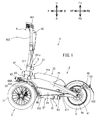
- FIG. 1 is a left side view showing the overall configuration of the lean vehicle according to the embodiment.
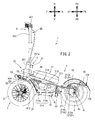
- FIG. 2 is a left side view of the lean vehicle with the main frame cover removed.
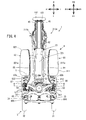
- FIG. 3 is a front view showing the configuration of the front part of the vehicle when the lean vehicle is viewed from the front.
- FIG. 4 is a top view showing the configuration of the lean vehicle.
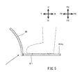
- FIG. 5 is a diagram schematically showing the positional relationship between the left foot mounting portion and the left front guard portion when the lean vehicle is viewed from the left.
- FIG. 6 is a diagram schematically showing the positional relationship between the left foot mounting portion and the left side guard and the positional relationship between the right foot mounting portion and the right side guard when the lean vehicle is viewed from the front.
- FIG. 1 is a left side view showing the overall configuration of the lean vehicle according to the embodiment.
- FIG. 2 is a left side view of the lean vehicle with the main frame cover removed.
- FIG. 3 is a front view showing the configuration of
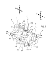
- FIG. 7 is an enlarged perspective view showing the link mechanism.
- FIG. 8 is a rear view showing the configuration of the lean vehicle.
- FIG. 9 is a front view showing the configuration of a lean vehicle tilted to the left.
- FIG. 10 is a rear view showing the configuration of a lean vehicle tilted to the left.
- FIG. 11 is a perspective view of the lean vehicle when the lean vehicle is viewed from the front right.
- FIG. 12 is a perspective view of the lean vehicle when the lean vehicle is viewed from the rear right.
- 13A and 13B are a rear view schematically showing the configuration of a lean vehicle in an upright state, (b) a rear view schematically showing a configuration of a lean vehicle in an inclined state, and (c) a left front wheel around the left steering axis. It is a top view which shows typically the relationship between a front wheel, a left front guard part, and a right front guard part in a lean vehicle in a state where the right front wheel is rotated around the right steering axis.
- the arrow F in the figure indicates the forward direction of the lean vehicle 1.
- the arrow B in the figure indicates the rear direction of the lean vehicle 1.
- the arrow U in the figure indicates the upward direction of the lean vehicle 1.
- the arrow D in the figure indicates the downward direction of the lean vehicle 1.
- the arrow R in the figure indicates the right direction of the lean vehicle 1.
- the arrow L in the figure indicates the left direction of the lean vehicle 1.
- the front-rear direction, the left-right direction, and the up-down direction of the lean vehicle 1 mean the front-back direction, the left-right direction, and the up-down direction with respect to the lean vehicle 1 when viewed from the driver who drives the lean vehicle 1, respectively. ..
- the lean vehicle 1 of the present embodiment turns by inclining the vehicle body frame in the left-right direction with respect to the vertical direction. Therefore, in addition to the above-mentioned direction based on the vehicle, the direction based on the vehicle body frame is defined as follows.
- the arrow FF in the figure indicates the front direction of the vehicle body frame.
- the arrow FB in the figure indicates the rear direction of the vehicle body frame.
- the arrow FU in the figure indicates the upward direction of the vehicle body frame.
- the arrow FD in the figure indicates the downward direction of the vehicle body frame.
- the arrow FR in the figure indicates the right direction of the vehicle body frame.
- the arrow FL in the figure indicates the left direction of the vehicle body frame.
- front-rear direction, the left-right direction, and the up-down direction of the vehicle body frame mean the front-rear direction, the left-right direction, and the up-down direction with respect to the vehicle body frame, respectively, when viewed from the driver who drives the lean vehicle.
- FIG. 1 is a left side view showing an outline of the overall configuration of the lean vehicle 1 according to the embodiment.
- FIG. 2 is a left side view showing a state in which the main frame cover 25 is removed in the lean vehicle 1.
- the lean vehicle 1 includes a vehicle body 2, a pair of left and right front wheels 3, a rear wheel 4, a link mechanism 5, a steering mechanism 6, and a load transmission mechanism 8. That is, the lean vehicle 1 in this embodiment is a three-wheeled vehicle having a pair of left and right front wheels 3.
- the lean vehicle 1 is a vehicle that inclines to the left when turning to the left and to the right when turning to the right.
- the lean vehicle 1 is not provided with a seat on which the driver sits. That is, the lean vehicle 1 is a so-called standing vehicle in which the driver rides while standing. Further, the lean vehicle 1 is not provided with a rear arm that supports the rear wheels 4. The rear wheel 4 of the lean vehicle 1 is supported by a vehicle body frame 21 described later. Further, the lean vehicle 1 is not provided with a shock absorber that elastically supports the front wheels 3 and the rear wheels 4 so as to be displaceable. The front wheels 3 and the rear wheels 4 of the lean vehicle 1 are supported by the vehicle body frame 21, which will be described later, without a shock absorber.
- the vehicle body 2 includes a body frame 21 and a power unit 22.
- the vehicle body frame 21 is in an upright state.
- the vehicle body frame 21 is premised on an upright state.
- the upright state of the vehicle body frame 21 means that the vertical direction of the vehicle body frame 21 is the same as the vertical direction.
- the vehicle body frame 21 supports the power unit 22 and the like.
- the vehicle body frame 21 includes a head pipe 211 (link support portion) and a main frame 212.
- the head pipe 211 is located at the front of the lean vehicle 1. When the lean vehicle 1 is viewed from the left, the upper portion of the head pipe 211 is located behind the lower portion of the head pipe 211 in the front-rear direction of the vehicle body frame 21.
- a link mechanism 5 is arranged around the head pipe 211.
- a steering shaft 652, which will be described later, is rotatably inserted into the head pipe 211.
- the main frame 212 is connected to the head pipe 211.
- the main frame 212 is located behind the head pipe 211 in the front-rear direction of the vehicle body frame 21.
- the main frame 212 supports the power unit 22.
- the rear end portion of the main frame 212 rotatably supports the rear wheel 4 about the wheel shaft 41.
- the main frame 212 is covered by the main frame cover 25.
- the main frame cover 25 is supported by the main frame 212.
- the main frame cover 25 is a resin member.
- the main frame 212 includes an upper frame 213 and an under frame 214.
- the upper frame 213 When the vehicle body frame 21 is viewed from the left, the upper frame 213 extends from the head pipe 211 toward the rear wheels 4 behind the vehicle body frame 21 in the front-rear direction and downward in the vertical direction of the vehicle body frame 21.
- the rear end portion of the upper frame 213 is branched into two so as to be located on the left and right sides of the rear wheel 4. That is, the upper frame 213 has an upper frame left rear end portion 213a located to the left of the rear wheel 4 and an upper frame right rear end portion 213b located to the right of the rear wheel 4.
- the upper left rear end portion 213a and the upper frame right rear end portion 213b support the rear wheel 4 together with the underframe left rear end portion 214c and the underframe right rear end portion 214d described later.
- the power unit 22 is supported by the upper frame 213.
- the underframe 214 has an underframe front portion 214a and an underframe rear portion 214b.
- the underframe front portion 214a extends from the head pipe 211 to the rear of the vehicle body frame 21 in the front-rear direction and downward in the vertical direction of the vehicle body frame 21 when the vehicle body frame 21 is viewed from the left.
- the front end of the underframe front portion 214a is connected to the head pipe 211.
- the underframe rear portion 214b extends rearward from the rear end portion of the underframe front portion 214a in the front-rear direction of the vehicle body frame 21.
- the rear end of the underframe rear portion 214b is branched into two so as to be located on the left and right sides of the rear wheel 4. That is, the underframe rear portion 214b has an underframe left rear end portion 214c located to the left of the rear wheel 4 and an underframe right rear end portion 214d located to the right of the rear wheel 4.
- the left rear end portion 214c of the under frame is connected to the left rear end portion 213a of the upper frame. By connecting the left rear end portion 214c of the under frame and the left rear end portion 213a of the upper frame in this way, the left rear end portion 212a of the main frame is configured.
- the right rear end portion 214d of the underframe is connected to the right rear end portion 213b of the upper frame. By connecting the right rear end portion 214d of the under frame and the right rear end portion 213b of the upper frame in this way, the right rear end portion 212b of the main frame is configured.
- the left rear end portion 212a of the main frame and the right rear end portion 212b of the main frame support the rear wheels 4.
- the main frame 212 since the main frame 212 has the upper frame 213 and the under frame 214, the strength and rigidity of the main frame 212 can be improved.
- the main frame may have only the under frame.
- FIG. 3 is a front view of the front part of the lean vehicle 1 as viewed from the front.
- the vehicle body frame 21 is in an upright state.
- the vehicle body frame 21 is premised on an upright state.
- the pair of left and right front wheels 3 are located below the head pipe 211 and the link mechanism 5 in the vertical direction of the vehicle body frame 21. As shown in FIG. 2, the pair of left and right front wheels 3 are supported by the left suspension portion 61 and the right suspension portion 62, which will be described later.
- the rear wheels 4 are located behind the pair of left and right front wheels 3 in the front-rear direction of the vehicle body frame 21.
- the power unit 22 generates a driving force for driving the lean vehicle 1. As shown in FIG. 2, the power unit 22 is located in front of the wheel shaft 41 of the rear wheels 4 in the front-rear direction of the vehicle body frame 21. The power unit 22 is fixed to the vehicle body frame 21.
- the power unit 22 includes a motor and a battery 221 (not shown). In this embodiment, the motor is arranged in the wheel 4a of the rear wheel 4. Electric power is supplied to the motor from the battery 221 fixed to the upper frame 213 of the vehicle body frame 21.
- the pair of left and right front wheels 3 includes a left front wheel 31 and a right front wheel 32.
- the left front wheel 31 is located to the left of the head pipe 211, which is a part of the vehicle body frame 21, in the left-right direction of the vehicle body frame 21.
- the right front wheel 32 is located to the right of the head pipe 211 in the left-right direction of the vehicle body frame 21. That is, the left front wheel 31 and the right front wheel 32 are located side by side in the left-right direction of the vehicle body frame 21.
- the left front wheel 31 is connected to the left suspension portion 61. Specifically, the left front wheel 31 is connected to the lower part of the left suspension portion 61. The left front wheel 31 is rotatably supported by the left suspension portion 61 around the left axle 311. The left axle 311 is arranged below the left suspension portion 61 so as to extend in the left-right direction of the vehicle body frame 21.
- the right front wheel 32 is connected to the right suspension portion 62. Specifically, the right front wheel 32 is connected to the lower part of the right suspension portion 62. The right front wheel 32 is rotatably supported by the right suspension portion 62 around the right axle 321. The right axle 321 is arranged below the right suspension portion 62 so as to extend in the left-right direction of the vehicle body frame 21.
- FIG. 4 is a top view of the lean vehicle 1 viewed from above in the vertical direction of the vehicle body frame 21.
- FIG. 7 is an enlarged perspective view of the link mechanism 5.
- the vehicle body frame 21 is in an upright state. In the following description, when referring to FIGS. 4 and 7, the vehicle body frame 21 is premised on an upright state.
- the link mechanism 5 is a parallel four-node link (also called a parallelogram link) type link mechanism.
- the link mechanism 5 is located below the handlebar 651 in the vertical direction of the vehicle body frame 21.
- the link mechanism 5 is located above the left front wheel 31 and the right front wheel 32 in the vertical direction of the vehicle body frame 21.
- the link mechanism 5 includes an upper cross portion 51, a lower cross portion 52, a left side portion 53, and a right side portion 54.
- the link mechanism 5 is not interlocked with the rotation of the steering shaft 652 about the intermediate steering axis Z accompanying the operation of the handlebar 651. That is, the link mechanism 5 does not rotate with respect to the vehicle body frame 21 about the intermediate steering axis Z.
- the upper cross portion 51 and the lower cross portion 52 correspond to the cross portion.
- the upper cross portion 51 is located behind the head pipe 211 in the front-rear direction of the vehicle body frame 21. As shown in FIG. 3, the upper cross portion 51 extends in the left-right direction of the vehicle body frame 21.
- the lower cross portion 52 is located below the upper cross portion 51 in the vertical direction of the vehicle body frame 21. As shown in FIG. 3, the lower cross portion 52 extends in the left-right direction of the vehicle body frame 21.
- the lower cross portion 52 has a through hole 52a through which the head pipe 211 penetrates in the central portion in the left-right direction. Further, the lower cross portion 52 has a left notch 52b in which the left side portion 53 is located at the left end portion in the left-right direction of the vehicle body frame 21, and a right notch portion 52b in which the right side portion 54 is located at the right end portion. It has a part 52c.
- the left side portion 53 is located to the left of the head pipe 211 in the left-right direction of the vehicle body frame 21.
- the left side portion 53 is located above the left front wheel 31 in the vertical direction of the vehicle body frame 21.
- the left side portion 53 extends in the direction in which the head pipe 211 extends.
- the left side portion 53 extends in the direction in which the intermediate steering axis Z of the steering shaft 652 extends.
- the upper portion of the left side portion 53 is located behind the lower portion of the left side portion 53 in the front-rear direction of the vehicle body frame 21.
- the right side portion 54 is located to the right of the head pipe 211 in the left-right direction of the vehicle body frame 21.
- the right side portion 54 is located above the right front wheel 32 in the vertical direction of the vehicle body frame 21.
- the right side portion 54 extends in the direction in which the head pipe 211 extends.
- the right side portion 54 extends in the direction in which the intermediate steering axis Z of the steering shaft 652 extends.
- the upper portion of the right side portion 54 is located behind the lower portion of the right side portion 54 in the front-rear direction of the vehicle body frame 21.
- the head pipe 211 has an upper intermediate connecting portion 211a and a lower intermediate connecting portion 211b.
- the intermediate portion of the upper cross portion 51 is rotatably connected to the head pipe 211 via the upper intermediate connecting portion 211a. That is, the upper cross portion 51 is rotatable with respect to the head pipe 211 about the upper intermediate connecting axis UI (intermediate axis) extending in the front-rear direction of the vehicle body frame 21 through the upper intermediate connecting portion 211a.
- UI intermediate axis
- the intermediate portion of the lower cross portion 52 is rotatably connected to the head pipe 211 via the lower intermediate connecting portion 211b. That is, the lower cross portion 52 is rotatable with respect to the head pipe 211 about the lower intermediate connecting axis DI (intermediate axis) extending in the front-rear direction of the vehicle body frame 21 through the lower intermediate connecting portion 211b.
- DI intermediate axis
- the left side portion 53 has an upper left connecting portion 53a and a lower left connecting portion 53b.
- the left end portion of the upper cross portion 51 is rotatably connected to the left side portion 53 via the upper left connecting portion 53a. That is, the upper cross portion 51 is rotatable with respect to the left side portion 53 about the upper left connecting axis UL (left axis) extending in the front-rear direction of the vehicle body frame 21 through the upper left connecting portion 53a.
- the left end portion of the lower cross portion 52 is rotatably connected to the left side portion 53 via the lower left connecting portion 53b. That is, the lower cross portion 52 is rotatable with respect to the left side portion 53 about the lower left connecting axis DL (left axis) extending in the front-rear direction of the vehicle body frame 21 through the lower left connecting portion 53b.
- the right side portion 54 has an upper right connecting portion 54a and a lower right connecting portion 54b.
- the right end of the upper cross portion 51 is rotatably connected to the right side portion 54 via the upper right connecting portion 54a. That is, the upper cross portion 51 is rotatable with respect to the right side portion 54 about the upper right connecting axis UR (right axis) extending in the front-rear direction of the vehicle body frame 21 through the upper right connecting portion 54a.
- the right end portion of the lower cross portion 52 is rotatably connected to the right side portion 54 via the lower right connecting portion 54b. That is, the lower cross portion 52 is rotatable with respect to the right side portion 54 about the lower right connecting axis DR (right axis) extending in the front-rear direction of the vehicle body frame 21 through the lower right connecting portion 54b.
- the upper intermediate connecting axis UI, the upper right connecting axis UR, the upper left connecting axis UL, the lower intermediate connecting axis DI, the lower right connecting axis DR, and the lower left connecting axis DL extend in parallel with each other.
- the upper middle connecting axis UI, the upper right connecting axis UR, the upper left connecting axis UL, the lower middle connecting axis DI, the lower right connecting axis DR and the lower left connecting axis DL are the left front wheel 31 and the right in the vertical direction of the vehicle body frame 21. It is located above the front wheel 32.
- the upper cross portion 51 and the lower cross portion 52 maintain a posture parallel to each other, and the left side.
- the portion 53 and the right side portion 54 are supported by the vehicle body frame 21 so as to maintain a posture parallel to each other.
- the steering mechanism 6 includes a left suspension portion 61, a right suspension portion 62, a left bracket 63, a right bracket 64, a steering member 65, and a steering force transmission mechanism 66.
- the configuration of the steering mechanism 6 is the same as that of the steering mechanism disclosed in International Publication 2020/11254. Therefore, the detailed description of the configuration of the steering mechanism 6 will be omitted. Therefore, the steering operation of the lean vehicle 1 using the steering mechanism 6 is the same as the steering operation disclosed in International Publication 2020/11254, and therefore detailed description thereof will be omitted.
- the left suspension portion 61 supports the left front wheel 31 with respect to the link mechanism 5.
- the left suspension portion 61 extends in the direction in which the intermediate steering axis Z extends.
- the lower end of the left suspension 61 supports the left front wheel 31.
- the left suspension portion 61 supports the left front wheel 31 so that the gap between the left front wheel 31 and the left connecting portion 812, which will be described later, is not displaced.
- the upper end of the left suspension 61 is fixed to the left bracket 63.
- the left bracket 63 has a counterclockwise rotating member (not shown) above the left bracket 63.
- the counterclockwise rotating member is located inside the left side portion 53 of the link mechanism 5, and extends in the direction in which the left side portion 53 extends.
- the left rotation member can rotate about the left steering axis X with respect to the left side portion 53. That is, the left bracket 63 can rotate about the left steering axis X with respect to the left side portion 53.
- the left steering axis X extends in the direction in which the left side portion 53 extends.
- the left steering axis X extends in the vertical direction of the vehicle body frame 21 in parallel with the intermediate steering axis Z of the steering shaft 652.
- the right bracket 64 has a clockwise rotating member (not shown) above the right bracket 64.
- the right-handed rotating member is located inside the right side portion 54 of the link mechanism 5, and extends in the direction in which the right side portion 54 extends.
- the right-handed rotating member can rotate about the right steering axis Y with respect to the right side portion 54. That is, the right bracket 64 can rotate about the right steering axis Y with respect to the right side portion 54.
- the right steering axis Y extends in the direction in which the right side portion 54 extends.
- the right suspension portion 62 supports the right front wheel 32 with respect to the link mechanism 5.
- the right suspension portion 62 extends in the direction in which the intermediate steering axis Z extends.
- the lower end of the right suspension 62 supports the right front wheel 32.
- the right suspension portion 62 supports the right front wheel 32 so that the gap between the right front wheel 32 and the right connecting portion 822, which will be described later, is not displaced.
- the upper end of the right suspension portion 62 is fixed to the right bracket 64.
- the right steering axis Y extends in the vertical direction of the vehicle body frame 21 in parallel with the intermediate steering axis Z of the steering shaft 652.
- the steering member 65 includes a handlebar 651 and a steering shaft 652.
- the handlebar 651 is connected to the upper part of the steering shaft 652.
- a part of the steering shaft 652 is rotatably supported by the head pipe 211.
- the steering shaft 652 rotates about the intermediate steering axis Z in response to the operation of the handlebar 651 by the driver.
- the steering force transmission mechanism 66 rotates the left suspension portion 61 in the rotation direction of the steering member 65 about the left steering axis X in accordance with the rotation of the steering member 65. Similarly, the steering force transmission mechanism 66 rotates the right suspension portion 62 in the rotation direction of the steering member 65 about the right steering axis Y in accordance with the rotation of the steering member 65. As a result, the steering force transmission mechanism 66 transmits the steering force to the left front wheel 31 and the right front wheel 32 in response to the operation of the steering member 65 by the driver. The left front wheel 31 and the right front wheel 32 rotate about the left steering axis X and the right steering axis Y, respectively, in a direction corresponding to the operation direction of the steering member 65 by the driver.
- the tilting motion of the lean vehicle 1 to the left or right is the same as the tilting motion disclosed in the above-mentioned International Publication 2020/11254. Therefore, detailed description of the operation of the lean vehicle 1 tilting to the left or right will be omitted.
- the load transmission mechanism 8 includes a left foot load transmission unit 81, a right foot load transmission unit 82, and a left / right connecting member 83.
- the left foot load transmitting portion 81 has a left foot mounting portion 811 (left foot step portion) and a left connecting portion 812 (left foot step connecting portion).
- the left foot mounting portion 811 has a left foot mounting surface 811a on which the left foot of the standing driver is placed.
- the left foot mounting portion 811 has a water passage prevention structure that prevents water from passing in the vertical direction.
- the left foot mounting portion 811 has a plate shape having no through hole penetrating in the vertical direction. As a result, it is possible to prevent the water splashed by the left front wheel 31 while the lean vehicle 1 is traveling from being applied to the driver's left foot from under the left foot mounting portion 811.
- the left connecting portion 812 connects the left foot mounting portion 811 and the left side portion 53 of the link mechanism 5. As shown in FIG. 1, the left connecting portion 812 is behind the left front wheel 31 and along the left front wheel 31 from the left side portion 53 to the rear of the vehicle body frame 21 in the front-rear direction and below the vehicle body frame 21 in the vertical direction. Extends to. It should be noted that the left connecting portion 812 is along the left front wheel 31 not only when the left connecting portion 812 is curved in an arc shape when viewed from the left, but also when the left connecting portion 812 is linearly inclined when viewed from the left.
- the left connecting portion 812 When the left connecting portion 812 has a curved shape when viewed from the left, when the left connecting portion 812 has a shape combining a curved line and a straight line when viewed from the left, the left connecting portion 812 has an angle when viewed from the left. It also includes the case where the shape is a combination of a plurality of straight lines having different characteristics.
- the rear end of the left connecting portion 812 is connected to the left foot mounting portion 811.
- the left foot load transmitting portion 81 is configured to be able to transmit the driver's load input via the left foot mounting portion 811 to the left side portion 53.
- the left connecting portion may be integrated with the left side portion.
- the right foot load transmitting portion 82 has a right foot mounting portion 821 (right foot step portion) and a right connecting portion 822 (right foot step connecting portion).
- the right foot mounting portion 821 has a right foot mounting surface 821a on which the right foot of the standing driver is placed.
- the right foot mounting portion 821 has a water passage prevention structure that prevents water from passing in the vertical direction.
- the right foot mounting portion 821 has a plate shape having no through hole penetrating in the vertical direction. As a result, it is possible to prevent the water splashed by the right front wheel 32 while the lean vehicle 1 is traveling from being applied to the driver's right foot from under the right foot mounting portion 821.
- the right connecting portion 822 connects the right foot mounting portion 821 and the right side portion 54 of the link mechanism 5.
- the right connecting portion 822 extends behind the right front wheel 32 from the right side portion 54 to the rear in the front-rear direction of the vehicle body frame 21 and downward in the vertical direction of the vehicle body frame 21 along the right front wheel 32.
- the right connecting portion 822 is along the right front wheel 32 not only when the right connecting portion 822 is curved in an arc shape when viewed from the right, but also when the right connecting portion 822 is inclined linearly when viewed from the right.
- the right connecting portion 822 when viewed from the right has a curved shape
- the right connecting portion 822 when viewed from the right has a shape that combines a curved line and a straight line
- the right connecting portion 822 when viewed from the right has an angle. It also includes the case where the shape is a combination of a plurality of straight lines having different characteristics.
- the rear end of the right connecting portion 822 is connected to the right foot mounting portion 821.
- the right foot load transmitting portion 82 is configured to be able to transmit the driver's load input via the right foot mounting portion 821 to the right side portion 54.
- the right connecting portion may be integrated with the right side portion.
- the load applied to the left foot mounting portion 811 via the driver's left foot and the load applied to the right foot mounting portion 821 via the driver's right foot are individually adjusted to adjust the vehicle body.
- the inclination of the frame 21 can be controlled.
- FIG. 10 is a rear view of the front portion of the lean vehicle 1 in a state where the vehicle body frame 21 is tilted to the left, as viewed from the rear of the vehicle body frame 21.
- the right side portion 54 is located above the left side portion 53 in the vertical direction of the vehicle body frame 21.
- a load is applied to the right side portion 54 via the right foot mounting portion 821 with the right foot, a force that causes the vehicle body frame 21 to be displaced downward acts on the right side portion 54.
- a force that causes the vehicle body frame 21 to be displaced downward acts on the right side portion 54.
- the normal direction of the left foot mounting portion 811 with respect to the mounting surface and the normal direction of the right foot mounting portion 821 with respect to the mounting surface change.
- the angle formed by the direction in which the head pipe 211 extends (the direction in which the intermediate steering axis Z extends) and the mounting surface of the left foot mounting portion 811 and the mounting surface of the right foot mounting portion 821 do not change. That is, the normal direction of the left foot mounting portion 811 with respect to the mounting surface and the normal direction of the right foot mounting portion 821 with respect to the mounting surface are always the same as the vertical direction of the vehicle body frame 21.
- the left / right connecting member 83 connects the left foot mounting portion 811 and the right foot mounting portion 821 in the left-right direction of the vehicle body frame 21 under the vehicle body frame 21.
- the central portion of the left-right connecting member 83 is rotatably supported around the underframe 214 by a rotation support portion (not shown) fixed to the lower part of the underframe 214 of the vehicle body frame 21. ing. Therefore, the left-right connecting member 83 tilts in the vertical direction in the vertical direction of the vehicle body frame 21 in accordance with the vertical movement of the left foot mounting portion 811 and the right foot mounting portion 821.
- the left foot mounting portion 811 and the right foot mounting portion 821 move up and down in conjunction with each other in response to the load input of the left foot to the left foot mounting portion 811 or the load input of the right foot to the right foot mounting portion 821. Therefore, the left or right inclination of the vehicle body frame 21 can be easily suppressed by the load input of the left foot to the left foot mounting portion 811 or the load input of the right foot to the right foot mounting portion 821 as described above.
- the lean vehicle 1 has a left front fender 33 and a right front fender 34.
- the left front fender 33 is located above the left front wheel 31 in the vertical direction of the vehicle body frame 21. As shown in FIGS. 1 and 2, the left front fender 33 has an arc shape along the left front wheel 31 when viewed from the left.
- the left front fender 33 is arranged along the left front wheel 31 so that the distance between the left front wheel 31 and the left front wheel 31 is smaller than the distance between the left front wheel 31 and the left connecting portion 812.
- the left front fender 33 is attached to the left transmission plate 664 rotatably attached to the lower end of the left side portion 53 of the link mechanism 5 via the left front fender attachment member 331.
- the left front fender 33 is arranged on the left front wheel 31 so as to overlap a part of the left front guard portion 86 described later when viewed from above.
- the left front fender 33 covers the upper part of the left front wheel 31 over a range of 90 degrees or less at a central angle when viewed from the left.
- the left front fender 33 may cover the upper part of the left front wheel 31 over a range wider than 90 degrees at a central angle when viewed from the left.
- the left front fender 33 By arranging the left front fender 33 on the left front wheel 31 as described above, the water splashed by the left front wheel 31 when the lean vehicle 1 is running is prevented by the left front fender 33 from being applied to the driver's left foot. Can be prevented.
- the left front fender 33 is miniaturized and attached to the left transmission plate 664 rotatably attached to the lower end of the left side portion 53 of the link mechanism 5 via the left front fender attachment member 331.
- the front fender 33 can be supported with a simple configuration. That is, since the left front fender 33 of the present embodiment is small, it is not necessary to support it at a plurality of points. Therefore, it is possible to prevent the left front fender 33 from interfering with other parts.
- the left front fender 33 by downsizing the left front fender 33, even if the left front fender 33 vibrates while the lean vehicle 1 is running, the left front fender 33, the left side guard 84 described later, and the left front are used. Interference with the guard portion 86 can be prevented.
- the right front fender 34 is located above the right front wheel 32 in the vertical direction of the vehicle body frame 21.
- the right front fender 34 has an arc shape along the right front wheel 32 when viewed from the right.
- the right front fender 34 is arranged along the right front wheel 32 so that the distance from the right front wheel 32 is smaller than the distance between the right front wheel 32 and the right connecting portion 822 described later.
- the right front fender 34 is attached to a right transmission plate 665 rotatably attached to the lower end of the right side portion 54 of the link mechanism 5, which will be described later, via the right front fender attachment member 341.
- the right front fender 34 is arranged on the right front wheel 32 so as to overlap a part of the right front guard portion 87 described later when viewed from above.
- the right front fender 34 covers the upper part of the right front wheel 32 over a range of 90 degrees or less at a central angle when viewed from the right.
- the right front fender 34 may cover the upper part of the right front wheel 32 over a range wider than 90 degrees at a central angle when viewed from the right.
- the right front fender 34 By arranging the right front fender 34 on the right front wheel 32 as described above, the water splashed by the right front wheel 32 when the lean vehicle 1 is running is prevented by the right front fender 34 from being applied to the driver's right foot. Can be prevented.
- the right front fender 34 is miniaturized and attached to the right transmission plate 665 rotatably attached to the lower end of the right side portion 54 of the link mechanism 5 via the right front fender attachment member 341 to the right.
- the front fender 34 can be supported with a simple configuration. That is, since the right front fender 34 of the present embodiment is small, it is not necessary to support it at a plurality of points. Therefore, it is possible to prevent the right front fender 34 from interfering with other parts.
- FIG. 6 is a diagram schematically showing the positional relationship between the left foot mounting portion 811 and the left side guard 84 and the positional relationship between the right foot mounting portion 821 and the right side guard 85 when the lean vehicle 1 is viewed from the front. Is.
- the solid line arrow indicates the movement of the water bounced off by the wheels.
- the left foot mounting portion 811, the right foot mounting portion 821, the left side guard 84, and the right side guard 85 are shown by diagonal lines for the sake of explanation.
- the alternate long and short dash line indicates the driver's foot.
- the left side guard 84 is made of resin and has a triangular plate shape in a side view extending in the vertical direction and the front-rear direction.
- the left side guard 84 is fixed to the right end portion and the left connecting portion 812 of the left foot mounting portion 811.
- the lower end of the left side guard 84 is attached to the right end of the left foot mounting portion 811.
- the right end of the left foot mounting portion 811 is located to the right of the left surface 84a of the left side guard 84.
- the front end portion of the left side guard 84 is attached to the left connecting portion 812.
- the left side guard 84 is fixed to the left foot mounting portion 811 and the left connecting portion 812, and the height in the vertical direction increases toward the front.
- the left side guard 84 having the above configuration By arranging the left side guard 84 having the above configuration to the right of the left foot mounting portion 811, the left foot mounted on the left foot mounting portion 811 can be positioned and protected, and the lean vehicle 1 can be mounted. It is possible to prevent the water splashed by the right front wheel 32 from being applied to the driver's left foot when traveling. In particular, the left side guard 84 can prevent the water splashed by the right front wheel 32 from being applied to the driver's left foot when the lean vehicle 1 travels in an inclined state.
- the right side guard 85 is made of resin and has a triangular plate shape in a side view extending in the vertical direction and the front-rear direction.
- the right side guard 85 is fixed to the left end portion and the right connecting portion 822 of the right foot mounting portion 821.
- the lower end of the right side guard 85 is attached to the left end of the right foot mounting portion 821.
- the left end of the right foot mounting portion 821 is located to the left of the right surface 85a of the right side guard 85.
- the front end portion of the right side guard 85 is attached to the right connecting portion 822.
- the right side guard 85 is fixed to the right foot mounting portion 821 and the right connecting portion 822, and the height in the vertical direction increases toward the front.
- the right side guard 85 By arranging the right side guard 85 having the above configuration to the left of the right foot mounting portion 821, the right foot mounted on the right foot mounting portion 821 can be positioned and protected, and FIGS. 9 and 9 and FIGS. As shown in FIG. 10, when the lean vehicle 1 travels, it is possible to prevent the water splashed by the left front wheel 31 from getting on the driver's right foot.
- the right side guard 85 can prevent the water splashed by the left front wheel 31 from being applied to the driver's right foot when the lean vehicle 1 travels in an inclined state.
- FIGS. 1, 5, 8, 11 to 13 the lean vehicle 1 has a left front guard portion 86 and a right front guard portion 87.
- FIG. 5 is a diagram schematically showing the positional relationship between the left foot mounting portion 811 and the left front guard portion 86 when the lean vehicle 1 is viewed from the left.
- 13A and 13B are a rear view schematically showing the configuration of the lean vehicle 1 in the upright state, (b) a rear view schematically showing the configuration of the lean vehicle 1 in the inclined state, and (c) the left front wheel 31 on the left.
- the relationship between the front wheel 3 and the left front guard portion 86 and the right front guard portion 87 is schematically shown in the lean vehicle 1 in which the right front wheel 32 is rotated around the steering axis X and the right front wheel 32 is rotated around the right steering axis Y. It is a top view.
- the solid line arrow indicates the movement of the water bounced off by the wheels.
- the alternate long and short dash line indicates the driver's foot.
- the alternate long and short dash line indicates the rotation of the left front wheel 31 around the left steering axis X and the rotation of the right front wheel 32 around the right steering axis Y.
- the left front guard portion 86 is attached to at least the lower end portion of the left connecting portion 812 so as to cover at least a part of the rear portion of the left front wheel 31.
- the lower end portion of the left connecting portion 812 is a portion of the lower portion of the left connecting portion 812 located in a region where water splashed by the left front wheel 31 is scattered toward the driver's left foot. Is.
- the left connecting portion 812 extends from the left side portion 53 to the height of the left axle 311 of the left front wheel 31.
- the left front guard portion 86 is attached to the left connecting portion 812 so as to cover a portion of the left front wheel 31 located behind the left axle 311.
- the left front guard portion 86 extends upward from the lower end portion of the left connecting portion 812 along the left connecting portion 812. That is, the left front guard portion 86 is a rectangular resin plate member in a plan view, and covers the rear portion and the upper portion of the left front wheel 31.
- the left front guard portion 86 is fixed to the left connecting portion 812 so that the longitudinal direction is along the extending direction of the left connecting portion 812. At this time, the left front guard portion 86 is attached to the left connecting portion 812 in front.
- the left front guard portion 86 may be provided below the portion where the gap between the left connecting portion 812 and the left front wheel 31 in the front-rear direction is the smallest with respect to the left connecting portion 812. As a result, it is possible to prevent the water splashed by the left front wheel 31 from being applied to the driver's left foot as described later.
- the left front guard portion 86 is a vehicle body while the lean vehicle 1 is tilted. While the positional relationship of the frame 21 with respect to the vehicle body frame 21 in the vertical direction changes, the positional relationship of the vehicle body frame 21 with respect to the left side portion 53 and the left foot mounting portion 811 in the vertical direction does not change. That is, the position of the left front guard portion 86 in the vertical direction of the vehicle body frame 21 changes during the inclination of the lean vehicle 1.
- the left front guard portion 86 is fixed to the left connecting portion 812 connected to the left side portion 53 and the left foot mounting portion 811, the vehicle body frame 21 is moved up and down even when the lean vehicle 1 is tilted. In the direction, the positions of the left front guard portion 86 with respect to the left side portion 53 and the left foot mounting portion 811 do not change.
- the left front guard portion 86 does not rotate together with the left front wheel 31, and the left side portion 53 and the left foot
- the positional relationship with respect to the mounting portion 811 does not change.
- the positional relationship of the left front guard portion 86 with respect to the left side portion 53 and the left foot mounting portion 811 while the left front wheel 31 is rotating around the left steering axis X is the front-rear direction with respect to the lean vehicle 1. It is a positional relationship in the left-right direction and the up-down direction.
- the left front guard portion 86 changes the positional relationship of the vehicle body frame 21 with respect to the vehicle body frame 21 in the vertical direction while the lean vehicle 1 is tilted, while the left side portion 53 and the vehicle body frame 21 in the vertical direction change.
- the left side portion 53 and the left foot mounting portion do not rotate together with the left front wheel 31 while the left front wheel 31 is rotating around the left steering axis X so that the positional relationship with respect to the left foot mounting portion 811 does not change. It is supported by the left connecting portion 812 between the left foot mounting portion 811 and the left front wheel 31 so that the positional relationship with respect to the 811 does not change.
- the driver's left foot mounted on the left foot mounting portion 811 is placed on the left front. It can be covered from the front by the guard portion 86. Therefore, it is possible to prevent the driver's left foot from getting wet due to the water splash of the left front wheel 31.
- the left front guard portion 86 has a left front guard first hook portion 86a and a pair of left front guard second hook portions 86b that engage with the left connecting portion 812 on the right portion.
- the left front guard first hook portion 86a and the pair of left front guard second hook portions 86b are provided side by side in the longitudinal direction on the right portion of the left front guard portion 86, and each protrudes to the right from the left front guard portion 86. ing.
- the left front guard first hook portion 86a and the pair of left front guard second hook portions 86b are integrally provided with the left front guard portion 86.
- the left front guard first hook portion 86a is located in front of the left connecting portion 812, and the pair of left front guard second hook portions 86b are left connecting portions. It is located behind the 812.
- the left front guard first hook portion 86a and the pair of left front guard second hook portions 86b are formed in a semicircular shape when viewed from the longitudinal direction of the left front guard portion 86 so as to follow the outer shape of the left connecting portion 812. There is.
- the left front guard first hook portion 86a and the pair of left front guard second hook portions 86b are securely engaged by the left connecting portion 812. Therefore, the left front guard portion 86 can be securely fixed by the left connecting portion 812.
- the left front guard portion 86 In a state where the left front guard portion 86 is fixed to the left connecting portion 812, as shown in FIG. 5, the left front guard portion 86 is below the height of the front end portion of the left foot mounting surface 811a of the left foot mounting portion 811. Extends to.
- the left front guard portion may extend to the same position as the height of the front end portion of the left foot mounting surface of the left foot mounting portion.
- the left front guard portion 86 has an arc shape that follows the outer shape of the left front wheel 31 when viewed from the left in a state of being fixed to the left connecting portion 812 as described above. Further, the left front guard portion 86 is located at a position overlapping a part of the left front fender 33 when viewed from above in a state of being fixed to the left connecting portion 812 as described above. The lower end of the left front guard portion 86 is located in front of the left foot mounting portion 811 in a state of being fixed to the left connecting portion 812 as described above.
- the left front guard portion 86 can prevent the water splashed by the left front wheel 31 from being applied to the driver's left foot while the lean vehicle 1 is traveling. Moreover, as described above, since the left front guard portion 86 is fixed to the left connecting portion 812, when the lean vehicle 1 is tilted to the left, the left front guard portion 86 is also tilted to the left together with the left connecting portion 812. When the lean vehicle 1 is tilted to the right, the left front guard portion 86 is also tilted to the right together with the left connecting portion 812. Therefore, the left front guard portion 86 can more reliably prevent the water splashed by the left front wheel 31 from being applied to the driver's left foot while the lean vehicle 1 is traveling.
- the left front guard portion 86 is located at a position where it overlaps a part of the left front fender 33 when viewed from above, so that the left front wheel is used when the lean vehicle 1 is traveling at a relatively high speed.
- the left front guard portion 86 and the left front fender 33 can more reliably prevent the water splashed by the 31 from splashing on the driver's left foot.
- Lean vehicle 1 can be allowed to tilt to the left or right.
- the left front guard portion 86 extends below the left foot mounting surface 811a, the left foot mounting portion 811 can be more reliably covered from the front by the left front guard portion 86. Therefore, it is possible to prevent the water splashed by the left front wheel 31 while the lean vehicle 1 is traveling from being applied to the driver's left foot from under the left front guard portion 86.
- the left front guard portion 86 since the left front guard portion 86 is fixed to the left connecting portion 812, the left front guard portion 86 does not rotate together with the left front wheel 31 when the left front wheel 31 is steered. Therefore, it is not necessary to provide a space for the left front guard portion 86 to rotate between the left front wheel 31 and the left connecting portion 812, and the gap between the left front wheel 31 and the left connecting portion 812 can be reduced. Further, the left front wheel 31 of the lean vehicle 1 is supported by the vehicle body frame 21 without a shock absorber. Therefore, since the gap between the left front wheel 31 and the left connecting portion 812 is not displaced, the gap can be reduced.
- the right front guard portion 87 is attached to at least the lower end portion of the right connecting portion 822 so as to cover at least a part of the rear portion of the right front wheel 32.
- the lower end portion of the right connecting portion 822 is a portion of the lower portion of the right connecting portion 822 located in a region where the water splashed by the right front wheel 32 is scattered toward the driver's right foot. Is.
- the right connecting portion 822 extends from the right side portion 54 to the height of the right axle 321 of the right front wheel 32.
- the right front guard portion 87 is attached to the right connecting portion 822 so as to cover a portion of the right front wheel 32 located behind the right axle 321.
- the right front guard portion 87 extends upward from the lower end portion of the right connecting portion 822 along the right connecting portion 822. That is, the right front guard portion 87 is a rectangular resin plate member in a plan view, and covers the rear portion and the upper portion of the right front wheel 32. The right front guard portion 87 is fixed to the right connecting portion 822 so that the longitudinal direction is along the extending direction of the right connecting portion 822. At this time, the right front guard portion 87 is attached to the right connecting portion 822 in front.
- the right front guard portion 87 may be provided below the portion where the gap between the right connecting portion 822 and the right front wheel 32 in the front-rear direction is the smallest with respect to the right connecting portion 822. As a result, it is possible to prevent the water splashed by the right front wheel 32 from being applied to the driver's right foot as described later.
- the right front guard portion 87 is a vehicle body while the lean vehicle 1 is tilted. While the positional relationship of the frame 21 with respect to the vehicle body frame 21 in the vertical direction changes, the positional relationship of the vehicle body frame 21 with respect to the right side portion 54 and the right foot mounting portion 821 in the vertical direction does not change. That is, the position of the right front guard portion 87 in the vertical direction of the vehicle body frame 21 changes during the inclination of the lean vehicle 1.
- the vehicle body frame 21 is moved up and down even while the lean vehicle 1 is tilted. In the direction, the positions of the right front guard portion 87 with respect to the right side portion 54 and the right foot mounting portion 821 do not change.
- the right front guard portion 87 does not rotate together with the right front wheel 32, and the right side portion 54 and the right foot
- the positional relationship with respect to the mounting portion 821 does not change.
- the positional relationship of the right front guard portion 87 with respect to the right side portion 54 and the right foot mounting portion 821 while the right front wheel 32 is rotating around the right steering axis Y is the front-rear direction with respect to the lean vehicle 1. It is a positional relationship in the left-right direction and the up-down direction.
- the right front guard portion 87 changes the positional relationship of the vehicle body frame 21 with respect to the vehicle body frame 21 in the vertical direction while the lean vehicle 1 is tilted, while the right side portion 54 and the vehicle body frame 21 in the vertical direction change.
- the right side portion 54 and the right foot mounting portion do not rotate together with the right front wheel 32 while the right front wheel 32 is rotating around the right steering axis Y so that the positional relationship with respect to the right foot mounting portion 821 does not change. It is supported by the right connecting portion 822 between the right foot mounting portion 821 and the right front wheel 32 so that the positional relationship with respect to 821 does not change.
- the driver's right foot mounted on the right foot mounting portion 821 can be moved to the right front. It can be covered from the front by the guard portion 87. Therefore, it is possible to prevent the driver's right foot from getting wet due to the water splash of the right front wheel 32.
- the right front guard portion 87 has a right front guard first hook portion 87a and a pair of right front guard second hook portions 87b that engage with the right connecting portion 822 on the left portion.
- the right front guard first hook portion 87a and the pair of right front guard second hook portions 87b are provided side by side in the longitudinal direction on the right portion of the right front guard portion 87, and each project to the left of the right front guard portion 87. ing.
- the right front guard first hook portion 87a and the pair of right front guard second hook portions 87b are integrally provided with the right front guard portion 87.
- the right front guard first hook portion 87a is located in front of the right connecting portion 822, and the pair of right front guard second hook portions 87b are right connecting portions. Located behind 822.
- the right front guard first hook portion 87a and the pair of right front guard second hook portions 87b are formed in a semicircular shape when viewed from the longitudinal direction of the right front guard portion 87 so as to follow the outer shape of the right connecting portion 822. There is.
- the right front guard first hook portion 87a and the pair of right front guard second hook portions 87b are securely engaged by the right connecting portion 822. Therefore, the right front guard portion 87 can be securely fixed by the right connecting portion 822.
- the right front guard portion 87 In a state where the right front guard portion 87 is fixed to the right connecting portion 822, the right front guard portion 87 extends below the height of the front end portion of the right foot mounting surface 821a of the right foot mounting portion 821, although not particularly shown. ing. The right front guard portion 87 may extend to the same position as the height of the front end portion of the right foot mounting surface 821a of the right foot mounting portion 821.
- the right front guard portion 87 has an arc shape that follows the outer shape of the right front wheel 32 when viewed from the right in a state of being fixed to the right connecting portion 822 as described above. Further, the right front guard portion 87 is located at a position overlapping a part of the right front fender 34 when viewed from above in a state of being fixed to the right connecting portion 822 as described above. The lower end of the right front guard portion 87 is located in front of the right foot mounting portion 821 in a state of being fixed to the right connecting portion 822 as described above.
- the right front guard portion 87 can prevent the water splashed by the right front wheel 32 from being applied to the driver's right foot while the lean vehicle 1 is traveling. Moreover, as described above, since the right front guard portion 87 is fixed to the right connecting portion 822, when the lean vehicle 1 is tilted to the left, the right front guard portion 87 is also tilted to the left together with the right connecting portion 822. When the lean vehicle 1 is tilted to the right, the right front guard portion 87 is also tilted to the right together with the right connecting portion 822. Therefore, the left front guard portion 86 can more reliably prevent the water splashed by the right front wheel 32 from being applied to the driver's right foot while the lean vehicle 1 is traveling.
- the right front guard portion 87 is located at a position where it overlaps a part of the right front fender 34 when viewed from above, so that the right front wheel is used when the lean vehicle 1 is traveling at a relatively high speed.
- the right front guard portion 87 and the right front fender 34 can more reliably prevent the water splashed by the 32 from splashing on the driver's right foot.
- the right front guard portion 87 separately from the right front fender 34, the water splashed by the right front wheel 32 while the lean vehicle 1 is traveling is prevented from being applied to the driver's right foot. , Lean vehicle 1 can be allowed to tilt to the left or right.
- the right front guard portion 87 extends below the right foot mounting surface 821a, the right front guard portion 87 can more reliably cover the right foot mounting portion 821 from the front. Therefore, it is possible to prevent the water splashed by the right front wheel 32 while the lean vehicle 1 is traveling from being applied to the driver's right foot from under the right front guard portion 87.
- the right front guard portion 87 since the right front guard portion 87 is fixed to the right connecting portion 822, the right front guard portion 87 does not rotate together with the right front wheel 32 when the right front wheel 32 is steered. Therefore, it is not necessary to provide a space for the right front guard portion 87 to rotate between the right front wheel 32 and the right connecting portion 822, and the gap between the right front wheel 32 and the right connecting portion 822 can be reduced. Further, the right front wheel 32 of the lean vehicle 1 is supported by the vehicle body frame 21 without a shock absorber. Therefore, since the gap between the right front wheel 32 and the right connecting portion 822 is not displaced, the gap can be reduced.
- the lean vehicle 1 has a rear fender 42.
- the rear fender 42 is supported by the main frame 212 at the front and rear, respectively.
- a pair of license plate support members 45 are connected to the rear fender 42, and the reflective portion 101 and the license plate 102 are supported by the pair of license plate support members 45.
- the lean vehicle 1 of the present embodiment has a vehicle body frame 21, a link mechanism supported by the vehicle body frame 21 and having an upper cross portion 51, a lower cross portion 52, a left side portion 53, and a right side portion 54, and a left side portion 53.
- the left front wheel 31 rotatably supported around the left steering axis X and non-displaceable in the axial direction of the left steering axis X, and the right steering axis Y around the right side portion 54.
- the right front wheel 32 which is rotatably supported and non-displaceable in the axial direction of the right steering axis Y, and the left foot mounting surface 811a, which is located behind the left front wheel 31 and on which the driver's left foot is placed.
- the left foot mounting portion 811 having the right foot mounting portion 811 and the right foot mounting portion 821 located behind the right front wheel 32 and having the right foot mounting surface 821a on which the driver's right foot is placed and the left foot mounting portion 811 are connected to the left side portion 53. It is provided with a left connecting portion 812 and a right connecting portion 822 that connects the right foot mounting portion 821 to the right side portion 54, and tilts to the left when turning to the left and to the right when turning to the right. It is a lean vehicle that tilts.
- the lean vehicle 1 changes its positional relationship with respect to the vehicle body frame 21 in the vertical direction of the vehicle body frame 21 while the lean vehicle 1 is tilted, while the position of the vehicle body frame 21 with respect to the left side portion 53 and the left foot mounting portion 811 in the vertical direction.
- the relationship does not change, and while the left front wheel 31 is rotating around the left steering axis X, it does not rotate together with the left front wheel 31, and the positional relationship with respect to the left side portion 53 and the left foot mounting portion 811 does not change.
- the left front guard portion 86 supported by the left connecting portion 812 and the vehicle body frame 21 in the vertical direction of the vehicle body frame 21 while the lean vehicle 1 is tilted.
- the positional relationship with respect to the vehicle body frame 21 changes, the positional relationship with respect to the right side portion 54 and the right foot mounting portion 821 in the vertical direction of the vehicle body frame 21 does not change, and the right front wheel 32 rotates around the right steering axis Y. In between, it is supported by the left connecting portion 812 between the right foot mounting portion 821 and the right front wheel 32 so that it does not rotate together with the right front wheel 32 and the positional relationship with respect to the right side portion 54 and the right foot mounting portion 821 does not change.
- the right front guard portion 87 is provided.
- the left front guard portion 86 changes the positional relationship of the body frame 21 with respect to the vehicle body frame 21 in the vertical direction while the lean vehicle 1 is tilted, while the left side portion of the vehicle body frame 21 in the vertical direction.
- the left side portion 53 and the left foot mounting portion 53 and the left foot mounting portion do not rotate together with the left front wheel 31 while the left front wheel 31 is rotating around the left steering axis X so that the positional relationship with respect to the 53 and the left foot mounting portion 811 does not change. It is supported by the left connecting portion 812 between the left foot mounting portion 811 and the left front wheel 31 so that the positional relationship with respect to the placing portion 811 does not change.
- the driver's left foot mounted on the left foot mounting portion 811 is placed on the left front. It can be covered from the front by the guard portion 86. Therefore, it is possible to prevent the driver's left foot from getting wet due to the water splash of the left front wheel 31.
- the right front guard portion 87 changes its positional relationship with respect to the vehicle body frame 21 in the vertical direction of the vehicle body frame 21 while the lean vehicle 1 is tilted, while the right side portion 54 and the right foot mounting portion 821 in the vertical direction of the vehicle body frame 21. While the right front wheel 32 is rotating around the right steering axis Y, it does not rotate with the right front wheel 32, and the positional relationship with respect to the right side portion 54 and the right foot mounting portion 821 is changed. It is supported by the right connecting portion 822 between the right foot mounting portion 821 and the right front wheel 32 so as not to change.
- the driver's right foot mounted on the right foot mounting portion 821 can be moved to the right front. It can be covered from the front by the guard portion 87. Therefore, it is possible to prevent the driver's right foot from getting wet due to the water splash of the right front wheel 32.
- the left front guard portion 86 is supported by the left connecting portion 812 so as not to rotate together with the left front wheel 31 while the left front wheel 31 is rotating around the left steering axis X. ..
- the right front guard portion 87 is supported by the right connecting portion 822 so as not to rotate together with the right front wheel 32 while the right front wheel 32 is rotating around the right steering axis Y. That is, in the lean vehicle 1 described above, the space for the left front guard portion 86 to rotate between the left front wheel 31 and the left connecting portion 812, and the right front guard portion between the right front wheel 32 and the right connecting portion 822. It is not necessary to provide a space for the 87 to rotate.
- the lean vehicle 1 can be made compact in the front-rear direction. Further, with the above configuration, it is not necessary to provide a space for arranging a large front fender above the left front wheel 31 and the right front wheel 32, so that the lean vehicle 1 can be made compact in the vertical direction.
- the lean vehicle 1 having the left front wheel 31 and the right front wheel 32, the lean vehicle 1 can be made compact, and the driver's feet can be prevented from getting wet due to water splashing of the left front wheel 31 and the right front wheel 32. Can be obtained.
- the left front guard portion 86 extends along the left connecting portion 812.
- the right front guard portion 87 extends along the right connecting portion 822.
- the front of the left foot mounting portion 811 connected to the left connecting portion 812 can be more reliably covered by the left front guard portion 86. Therefore, it is possible to more reliably prevent the left foot of the driver mounted on the left foot mounting portion 811 from getting wet due to the water splash of the left front wheel 31. Further, the front of the right foot mounting portion 821 connected to the right connecting portion 822 can be more reliably covered by the right front guard portion 87. Therefore, it is possible to more reliably prevent the right foot of the driver mounted on the right foot mounting portion 821 from getting wet due to the water splash of the right front wheel 32. ..
- the left front guard portion 86 is provided so as to overlap the left front wheel 31 when viewed in the front-rear direction of the lean vehicle 1 and to overlap the left front wheel 31 when viewed in the vertical direction of the lean vehicle 1.
- the right front guard portion 87 is provided so as to overlap the right front wheel 32 when viewed in the front-rear direction of the lean vehicle 1 and to overlap the right front wheel 32 when viewed in the vertical direction of the lean vehicle 1.
- the rear and upper parts of the left front wheel 31 can be more reliably covered by the left front guard portion 86. Therefore, the left front guard portion 86 can more reliably prevent the water splashed by the left front wheel 31 from being applied to the feet of the driver's left foot. Further, the rear portion and the upper portion of the right front wheel 32 can be more reliably covered by the right front guard portion 87. Therefore, the right front guard portion 87 can more reliably prevent the water splashed by the right front wheel 32 from being applied to the feet of the driver's right foot.
- the left connecting portion 812 extends behind the left front wheel 31 along the left front wheel 31 so as to be located downward from the left side portion 53 toward the rear, and the front portion is the left side portion. It is connected to 53 and its rear portion supports the front portion of the left foot mounting portion 811.
- the right connecting portion 822 extends behind the right front wheel 32 along the right front wheel 32 so as to be positioned downward from the right side portion 54 toward the rear, the front portion is connected to the right side portion 54, and the rear portion is mounted on the right foot. It supports the front part of the placement part 821.
- the gap between the left front wheel 31 and the left connecting portion 812 can be reduced. Therefore, the left front guard portion 86 attached to the left connecting portion 812 can be arranged at a position closer to the left front wheel 31. Therefore, the left front guard portion 86 can more reliably prevent the water splashed by the left front wheel 31 from being applied to the feet of the driver's left foot. Further, the gap between the right front wheel 32 and the right connecting portion 822 can be reduced. Therefore, the right front guard portion 87 attached to the right connecting portion 822 can be arranged at a position closer to the right front wheel 32. Therefore, the right front guard portion 87 can more reliably prevent the water splashed by the right front wheel 32 from being applied to the feet of the driver's right foot.
- the lower end of the left front guard portion 86 is located at the same height as or below the left foot mounting surface 811a of the left foot mounting portion 811.
- the lower end of the right front guard portion 87 is located at the same height as or below the right foot mounting surface 821a of the right foot mounting portion 821.
- the left front guard portion 86 can more reliably cover the front of the left foot mounting portion 811, and the right front guard portion 87 can more reliably cover the front of the right foot mounting portion 821. Therefore, it is possible to prevent the water splashed by the left front wheel 31 from being applied to the feet of the driver's left foot from under the left front guard portion 86. Further, it is possible to prevent the water splashed by the right front wheel 32 from being applied to the feet of the driver's right foot from under the right front guard portion 87.
- the left foot mounting portion 811 and the right foot mounting portion 821 each have a water passage prevention structure that does not allow water to pass in the vertical direction.
- a water passage prevention structure that does not allow water to pass in the vertical direction.
- the lean vehicle 1 of the present embodiment has a plate shape extending in the vertical direction and the front-rear direction, and is attached to at least one of the left foot mounting portion 811 and the left connecting portion 812 so as to be located to the right of the left foot mounting portion 811. It is attached to at least one of the right foot mounting portion 821 and the right connecting portion 822 so as to be located on the left side of the right foot mounting portion 821 in a plate shape extending in the vertical direction and the front-back direction with the left side guard 84 that guards the left foot of the vehicle.
- a right side guard 85 that guards the occupant's right foot is further provided.
- the right end of the left foot mounting portion 811 is located to the right of the left surface 84a of the left side guard 84.
- the left end of the right foot mounting portion 821 is located to the left of the right surface 85a of the right side guard 85.
- the right side guard 85 can prevent the water splashed by the left front wheel 31 from being applied to the driver's right foot while the lean vehicle 1 is running.
- the left side guard 84 can prevent the water splashed by the right front wheel 32 from being applied to the driver's left foot while the lean vehicle 1 is traveling.
- the right end of the left foot mounting portion 811 is located to the right of the left surface 84a of the left side guard 84. Therefore, the left foot mounting portion 811 can more reliably cover the bottom of the left side guard 84. Therefore, it is possible to prevent the water splashed by the right front wheel 32 from being applied to the driver's left foot from under the left foot mounting portion 811.
- the left end of the right foot mounting portion 821 is located to the left of the right surface 85a of the right side guard 85. Therefore, the right foot mounting portion 821 can more reliably cover the bottom of the right side guard 85. Therefore, it is possible to prevent the water splashed by the left front wheel 31 from being applied to the driver's right foot from under the right foot mounting portion 821.
- the lower end of the left front guard portion 86 is located below the front end portion of the left foot mounting surface 811a, and the lower end of the right front guard portion 87 is below the front end portion of the right foot mounting surface 821a.
- the lower end of the left front guard portion may be located above the front end portion of the left foot mounting surface.
- the lower end of the right front guard portion may be located above the front end portion of the right foot mounting surface.
- the right end of the left foot mounting portion 811 is located to the right of the left surface 84a of the left side guard 84, and the left end of the right foot mounting portion 821 is located to the left of the right surface 85a of the right side guard 85. ..
- the right end of the left foot resting portion may be located to the left of the left surface of the left side guard.
- the left end of the right foot resting portion may be located to the left of the right surface of the right side guard.
- the water passage prevention structure is configured by forming the left foot mounting portion 811 and the right foot mounting portion 821 into a plate shape having no through hole.
- the water passage prevention structure is provided in the left foot mounting portion and the right foot mounting portion so that the water splashed by the wheels does not directly enter the through holes provided in the left foot mounting portion and the right foot mounting portion. It may be composed of through holes whose opening direction is rearward or left and right. Further, the water passage prevention structure may be configured by providing a cover at the opening of the through hole.
- the water passage prevention structure may be realized by different configurations of the left foot mounting portion and the right foot mounting portion.
- the lean vehicle 1 has a left side guard 84 and a right side guard 85.
- lean vehicles do not have to have a left side guard.
- Lean vehicles do not have to have a right side guard.
- the left front guard portion 86 is attached to the left connecting portion 812 in front.
- the left front guard portion may be attached to the rear of the left connecting portion or may be attached to the center in the front-rear direction with respect to the left connecting portion.
- the right front guard portion 87 is attached to the right connecting portion 822 in front.
- the right front guard portion may be attached to the rear of the right connecting portion or may be attached to the center in the front-rear direction with respect to the right connecting portion.
- At least one of the left front guard portion and the right front guard portion has a structure for preventing water splashed by the front wheels from wrapping around the left and right ends of the front guard portion and getting on the driver's feet. You may have. Specifically, at least one of the left front guard portion and the right front guard portion may have bent portions that are bent forward at both left and right ends. In addition, another member projecting forward may be provided at at least one of the left and right ends of the left front guard portion and the right front guard portion.
- the left front guard portion 86 is fixed to the left connecting portion 812 by engaging the left front guard first hook portion 86a and the pair of left front guard second hook portions 86b with the left connecting portion 812. There is.
- the left front guard portion may be fixed to the left connecting portion by a fastening member such as a bolt.
- the left front guard portion may be fixed to the left connecting portion with an adhesive or the like.
- the right front guard portion 87 is fixed to the right connecting portion 822 by engaging the right front guard first hook portion 87a and the pair of right front guard second hook portions 87b with the right connecting portion 822.
- the right front guard portion may be fixed to the right connecting portion by a fastening member such as a bolt.
- the right front guard portion may be fixed to the right connecting portion with an adhesive or the like.
- the left foot mounting portion 811 and the left front guard portion 86 are separate bodies, and the right foot mounting portion 821 and the right front guard portion 87 are separate bodies.
- the left foot mounting portion 811 and the left front guard portion 86 may be integrated, and the right foot mounting portion 821 and the right front guard portion 87 may be integrated.
- the left foot mounting portion 811 and the left side guard 84 are separate bodies, and the right foot mounting portion 821 and the right side guard 85 are separate bodies.
- the left foot mounting portion 811 and the left side guard 84 may be integrated, and the right foot mounting portion 821 and the right side guard 85 may be integrated.
- the left front guard portion 86 and the left side guard 84 are separate bodies.
- the right front guard portion 87 and the right side guard 85 are separate bodies.
- the left front guard portion and the left side guard portion may be integrated.
- the right front guard portion and the right side guard portion may be integrated.
- the lean vehicle 1 has a left front fender 33 and a right front fender 34.
- the lean vehicle may have only one of the left front fender and the right front fender, or may not have either the left front fender or the right front fender.
- the link mechanism 5 has an upper cross portion 51 and a lower cross portion 52 whose intermediate portion is rotatably supported by the head pipe 211 in the left-right direction of the vehicle body frame 21.
- the link mechanism may have other configurations.
- the lean vehicle 1 is not provided with a seat on which the driver sits.
- the lean vehicle may have a seat.
- the lean vehicle 1 is not provided with a rear arm that supports the rear wheels 4.
- lean vehicles may have a rear arm that supports the rear wheels.
Abstract
Provided is a leaning vehicle that has a left front wheel and a right front wheel and that makes it possible to increase the compactness of the vehicle while preventing the feet of a driver from becoming wet as a result of splashed water from the left front wheel and the right front wheel. The leaning vehicle 1 is provided with: a left front guard 86 supported by a left connection section 812 between a left foot rest 811 and the left front wheel 31; and a right front guard 87 supported by a right connection section 822 between a right foot rest 821 and the right front wheel 32. The positional relationship of the left front guard 86 and the right front guard 87 with respect to a vehicle body frame 21 changes in the vertical direction of the vehicle body frame 21 while the leaning vehicle 1 is inclined, the positional relationship with respect to side sections and the foot rests meanwhile does not change in the vertical direction of the vehicle body frame 21, and the left front guard 86 and the right front guard 87 do not rotate together with the left front wheel 31 and the right front wheel 32 and the positional relationship with respect to the side sections and the foot rests does not change while the left front wheel 31 and the right front wheel 32 are rotating around a steering axis.
Description
本発明は、リーン車両に関する。
The present invention relates to a lean vehicle.
運転者が左フートステップ部に左足を載せるとともに右フートステップ部に右足を載せて乗車する立ち乗り型のリーン車両が知られている。このようなリーン車両として、例えば非特許文献1には、立ち乗り型の2輪車両が開示されている。
There is known a standing-type lean vehicle in which the driver puts his left foot on the left foot step and puts his right foot on the right foot step. As such a lean vehicle, for example, Non-Patent Document 1 discloses a standing two-wheeled vehicle.
前記非特許文献1の2輪車両では、左フートステップ部および右フートステップ部は、それぞれ、車体フレームに固定されている。前記左フートステップ部は、2輪車両を左右方向から見て前輪と後輪との間で、且つ、前輪および後輪よりも左に位置している。前記右フートステップ部は、2輪車両を左右方向から見て前輪と後輪との間で、且つ、前輪および後輪よりも右に位置している。
In the two-wheeled vehicle of Non-Patent Document 1, the left foot step portion and the right foot step portion are each fixed to the vehicle body frame. The left foot step portion is located between the front wheels and the rear wheels when the two-wheeled vehicle is viewed from the left-right direction, and to the left of the front wheels and the rear wheels. The right foot step portion is located between the front wheels and the rear wheels when the two-wheeled vehicle is viewed from the left-right direction, and to the right of the front wheels and the rear wheels.
前記非特許文献1の2輪車両の前部には、前輪の水跳ねによって運転者の足元が濡れるのを防止する水跳ね防止部材が配置されている。前記水跳ね防止部材は、前輪を支持する部材に取り付けられているため、前輪を操舵軸回りに回転させると、前輪と共に左右に回転する。
A water splash prevention member is arranged on the front portion of the two-wheeled vehicle of Non-Patent Document 1 to prevent the driver's feet from getting wet due to the water splash of the front wheels. Since the water splash prevention member is attached to a member that supports the front wheels, when the front wheels are rotated around the steering axis, they rotate left and right together with the front wheels.
特許文献1には、車体フレームと、左前輪と、右前輪と、前記左前輪を支持している左懸架部と、前記右前輪を支持している右懸架部と、前記左前輪及び前記右前輪よりも上に位置し、前記車体フレームに対する前記左前輪及び前記右前輪の相対位置を変更して前記車体フレームを前記車両の左または右に傾斜させるように構成されているリンク機構とを備えた車両が開示されている。前記リンク機構は、左右方向に延びる上クロス部材及び下クロス部材と、前記上クロス部材及び前記下クロス部材の右端部を回転可能に支持する右サイド部材と、前記上クロス部材及び前記下クロス部材の左端部を回転可能に支持する左サイド部材とを含んでいる。
Patent Document 1 describes a vehicle body frame, a left front wheel, a right front wheel, a left suspension portion that supports the left front wheel, a right suspension portion that supports the right front wheel, the left front wheel, and the right. It is provided with a link mechanism that is located above the front wheels and is configured to tilt the vehicle body frame to the left or right of the vehicle by changing the relative positions of the left front wheel and the right front wheel with respect to the vehicle body frame. The vehicle is disclosed. The link mechanism includes an upper cross member and a lower cross member extending in the left-right direction, a right side member that rotatably supports the upper cross member and the right end portion of the lower cross member, and the upper cross member and the lower cross member. Includes a left side member that rotatably supports the left end of the.
また、特許文献1に開示された車両は、前記リンク機構に荷重を伝達する荷重伝達機構を備えている。前記荷重伝達機構は、左足置き部と右足置き部とを含んでいる。前記左足置き部は、左足置き面と左連結部材とを含んでいる。前記右足置き部は、右足置き面と右連結部材とを含んでいる。前記左足置き面上には、起立した運転者の左足が載置される。前記左連結部材は、左足置き面と左サイド部材とを連結している。前記右足置き面上には、起立した運転者の右足が載置される。前記左連結部材は、左足置き面と左サイド部材とを連結している。
Further, the vehicle disclosed in Patent Document 1 is provided with a load transmission mechanism for transmitting a load to the link mechanism. The load transmission mechanism includes a left foot rest portion and a right foot rest portion. The left foot rest portion includes a left foot rest surface and a left connecting member. The right foot rest portion includes a right foot rest surface and a right connecting member. The left foot of the standing driver is placed on the left foot resting surface. The left connecting member connects the left foot resting surface and the left side member. The right foot of the standing driver is placed on the right foot resting surface. The left connecting member connects the left foot resting surface and the left side member.
ところで、前記特許文献1に開示されているように左前輪の後ろに左足置き面が位置すると共に右前輪の後ろに右足置き面が位置する車両では、濡れた路面を走行する際に、左前輪および右前輪によって跳ね上げられた水が運転者の足元にかかる可能性がある。
By the way, in a vehicle in which the left foot resting surface is located behind the left front wheel and the right foot resting surface is located behind the right front wheel as disclosed in Patent Document 1, the left front wheel is used when traveling on a wet road surface. And the water splashed by the right front wheel can hit the driver's feet.
そのため、車両に、左前輪の水跳ねにより運転者の足元が濡れるのを防止する左水跳ね防止部材と、右前輪の水跳ねにより運転者の足元が濡れるのを防止する右水跳ね防止部材とを設けることが考えられる。前記左前輪を支持する部材に、左前輪の水跳ねによって運転者の足元が濡れないような大型の左水跳ね防止部材を設けるとともに、前記右前輪を支持する部材に、右前輪の水跳ねによって運転者の足元が濡れないような大型の右水跳ね防止部材を設けた場合、前記左前輪および前記右前輪を操舵して左右に回転させた際に、前記左水跳ね防止部材が前記左前輪と共に回転し、前記右水跳ね防止部材が前記右前輪と共に回転する。従って、車両には、前記左前輪と左連結部との間に前記大型の左水跳ね防止部材が回転するための空間が必要となり、前記右前輪と右連結部との間に前記大型の右水跳ね防止部材が回転するための空間が必要となる。
Therefore, the vehicle has a left water splash prevention member that prevents the driver's feet from getting wet due to the water splash of the left front wheel and a right water splash prevention member that prevents the driver's feet from getting wet due to the water splash of the right front wheel. It is conceivable to provide. The member that supports the left front wheel is provided with a large left water splash prevention member that prevents the driver's feet from getting wet due to the water splash of the left front wheel, and the member that supports the right front wheel is provided with the water splash of the right front wheel. When a large right water splash prevention member is provided so that the driver's feet do not get wet, when the left front wheel and the right front wheel are steered and rotated to the left or right, the left water splash prevention member is the left front wheel. The right water splash prevention member rotates together with the right front wheel. Therefore, the vehicle needs a space between the left front wheel and the left connecting portion for the large left water splash prevention member to rotate, and the large right between the right front wheel and the right connecting portion. A space is required for the water splash prevention member to rotate.
上述のように左前輪と左連結部との間に空間を設ける場合には、前記左前輪に対して、前記左連結部を後ろまたは上にずらして配置する必要がある。前記左連結部を後ろにずらして空間を設けた場合には、車両の前後方向の長さが大きくなる。
When a space is provided between the left front wheel and the left connecting portion as described above, it is necessary to displace the left connecting portion rearward or upward with respect to the left front wheel. When the left connecting portion is shifted rearward to provide a space, the length of the vehicle in the front-rear direction becomes large.
一方、前記左連結部を上にずらして上述のような空間を設けた場合には、前記左前輪及び前記左水跳ね防止部材の回転領域である前記空間を避けるように、ヘッドパイプを配置する必要がある。そのため、本来であれば車両の低い位置に配置したいヘッドパイプを低い位置に配置することができず、車両を上下方向にコンパクトな構成にすることが難しい。なお、上述のように左前輪と左連結部との間に空間を設ける場合と同様に、右前輪と右連結部との間に空間を設ける場合も、車両を前後方向及び上下方向にコンパクトな構成にすることが難しい。
On the other hand, when the left connecting portion is shifted upward to provide the space as described above, the head pipe is arranged so as to avoid the space which is the rotation region of the left front wheel and the left water splash prevention member. There is a need. Therefore, the head pipe that would normally be arranged at a low position of the vehicle cannot be arranged at a low position, and it is difficult to make the vehicle compact in the vertical direction. In addition, as in the case of providing a space between the left front wheel and the left connecting portion as described above, when providing a space between the right front wheel and the right connecting portion, the vehicle is compact in the front-rear direction and the vertical direction. Difficult to configure.
本発明は、左前輪および右前輪を有するリーン車両において、車両のコンパクト化を図りつつ、前記左前輪および前記右前輪の水跳ねにより運転者の足元が濡れるのを防止可能な構成を提供することを目的とする。
The present invention provides a lean vehicle having a left front wheel and a right front wheel, which can prevent the driver's feet from getting wet due to water splashing on the left front wheel and the right front wheel while making the vehicle compact. With the goal.
本発明者らは、路面が濡れた状態でリーン車両が走行した際に、左前輪および右前輪の水跳ねにより運転者の足元が濡れるのを防止可能な構成について検討した。
The present inventors have studied a configuration that can prevent the driver's feet from getting wet due to water splashing on the left front wheel and the right front wheel when the lean vehicle runs on a wet road surface.
本発明者らは、鋭意検討の結果、以下のような構成に想到した。
As a result of diligent studies, the present inventors have come up with the following configuration.
本発明の一実施形態に係るリーン車両は、車体フレームと、前記車体フレームに支持され、クロス部、左サイド部及び右サイド部を有するリンク機構と、前記左サイド部に対して、左操舵軸線回りに回転可能に支持され、かつ、前記左操舵軸線の軸線方向に変位不能に支持される左前輪と、前記右サイド部に対して、右操舵軸線回りに回転可能に支持され、かつ、前記右操舵軸線の軸線方向に変位不能に支持される右前輪と、前記左前輪よりも後ろに位置し、運転者の左足を載せる左足載置面を有する左フートステップ部と、前記右前輪よりも後ろに位置し、運転者の右足を載せる右足載置面を有する右フートステップ部と、前記左フートステップ部を前記左サイド部に連結する左フートステップ連結部と、前記右フートステップ部を前記右サイド部に連結する右フートステップ連結部と、を備え、左に旋回する際には左に傾斜し、右に旋回する際には右に傾斜するリーン車両である。このリーン車両は、傾斜中に、前記車体フレームの上下方向における前記車体フレームに対する位置関係が変化する一方、前記車体フレームの上下方向における前記左サイド部及び前記左フートステップ部に対する位置関係が変化しないように、且つ、前記左前輪が前記左操舵軸線回りに回転している間に、前記左前輪と共に回転せず、前記左サイド部及び前記左フートステップ部に対する位置関係が変化しないように、前記左フートステップ部と前記左前輪との間で、前記左フートステップ連結部に支持される左フロントガード部と、前記リーン車両の傾斜中に、前記車体フレームの上下方向における前記車体フレームに対する位置関係が変化する一方、前記車体フレームの上下方向における前記右サイド部及び前記右フートステップ部に対する位置関係が変化しないように、且つ、前記右前輪が前記右操舵軸線回りに回転している間に、前記右前輪と共に回転せず、前記右サイド部及び前記右フートステップ部に対する位置関係が変化しないように、前記右フートステップ部と前記右前輪との間で、前記右フートステップ連結部に支持される右フロントガード部と、を備える。
The lean vehicle according to an embodiment of the present invention has a vehicle body frame, a link mechanism supported by the vehicle body frame and having a cross portion, a left side portion and a right side portion, and a left steering axis with respect to the left side portion. The left front wheel is rotatably supported and non-displaceable in the axial direction of the left steering axis, and the right side portion is rotatably supported around the right steering axis and said. The right front wheel that is non-displaceablely supported in the axial direction of the right steering axis, the left foot step portion that is located behind the left front wheel and has a left foot mounting surface on which the driver's left foot is placed, and the right front wheel. The right foot step portion, which is located behind and has a right foot mounting surface on which the driver's right foot is placed, the left foot step connecting portion that connects the left foot step portion to the left side portion, and the right foot step portion. It is a lean vehicle equipped with a right foot step connecting portion that connects to the right side portion, and tilts to the left when turning to the left and to the right when turning to the right. In this lean vehicle, the positional relationship of the vehicle body frame with respect to the vehicle body frame in the vertical direction changes while the vehicle body frame is tilted, while the positional relationship of the vehicle body frame with respect to the left side portion and the left foot step portion in the vertical direction does not change. As described above, the left front wheel does not rotate together with the left front wheel while the left front wheel is rotating around the left steering axis, and the positional relationship with respect to the left side portion and the left foot step portion does not change. The positional relationship between the left foot step portion and the left front wheel, the left front guard portion supported by the left foot step connecting portion, and the vehicle body frame in the vertical direction of the vehicle body frame while the lean vehicle is tilted. While changing, the positional relationship between the right side portion and the right foot step portion in the vertical direction of the vehicle body frame does not change, and while the right front wheel is rotating around the right steering axis. It is supported by the right foot step connecting portion between the right foot step portion and the right front wheel so as not to rotate together with the right front wheel and the positional relationship with respect to the right side portion and the right foot step portion does not change. It is equipped with a right front guard part.
上述のリーン車両では、左フロントガード部は、前記リーン車両の傾斜中に、車体フレームの上下方向における前記車体フレームに対する位置関係が変化する一方、前記車体フレームの上下方向における左サイド部及び左フートステップ部に対する位置関係が変化しないように、且つ、左前輪が左操舵軸線回りに回転している間に、前記左前輪と共に回転せず、前記左サイド部及び前記左フートステップ部に対する位置関係が変化しないように、左フートステップ部と左前輪との間で、左フートステップ連結部に支持される。
In the lean vehicle described above, the left front guard portion changes its positional relationship with respect to the vehicle body frame in the vertical direction of the vehicle body frame while the lean vehicle is tilted, while the left side portion and the left foot in the vertical direction of the vehicle body frame. The positional relationship with respect to the left side portion and the left foot step portion does not change with respect to the left front wheel while the left front wheel is rotating around the left steering axis so that the positional relationship with respect to the step portion does not change. It is supported by the left foot step connecting part between the left foot step part and the left front wheel so as not to change.
これにより、前記リーン車両が傾斜している場合でも、前記左前輪が前記左操舵軸線回りに回転している場合でも、前記左フートステップ部上に載置された運転者の左足を、前記左フロントガード部によって前から覆うことができる。したがって、前記左前輪の水跳ねによって、運転者の左足が濡れるのを防止できる。
As a result, even when the lean vehicle is tilted or the left front wheel is rotating around the left steering axis, the driver's left foot placed on the left foot step portion is moved to the left. It can be covered from the front by the front guard part. Therefore, it is possible to prevent the driver's left foot from getting wet due to the water splash of the left front wheel.
右フロントガード部は、前記リーン車両の傾斜中に、前記車体フレームの上下方向における前記車体フレームに対する位置関係が変化する一方、前記車体フレームの上下方向における右サイド部及び右フートステップ部に対する位置関係が変化しないように、かつ、前記右前輪が右操舵軸線回りに回転している間に、前記右前輪と共に回転せず、前記右サイド部及び前記右フートステップ部に対する位置関係が変化しないように、右フートステップ部と右前輪との間で、右フートステップ連結部に支持される。
The right front guard portion changes its positional relationship with respect to the vehicle body frame in the vertical direction of the vehicle body frame while the lean vehicle is tilted, while the positional relationship with respect to the right side portion and the right foot step portion in the vertical direction of the vehicle body frame. And so that while the right front wheel is rotating around the right steering axis, it does not rotate with the right front wheel and the positional relationship with respect to the right side portion and the right foot step portion does not change. , It is supported by the right foot step connecting part between the right foot step part and the right front wheel.
これにより、前記リーン車両が傾斜している場合でも、前記右前輪が前記右操舵軸線回りに回転している場合でも、前記右フートステップ部上に載置された運転者の右足を、前記右フロントガード部によって前から覆うことができる。したがって、前記右前輪の水跳ねによって、運転者の右足が濡れるのを防止できる。
As a result, even when the lean vehicle is tilted or the right front wheel is rotating around the right steering axis, the driver's right foot placed on the right foot step portion is moved to the right. It can be covered from the front by the front guard part. Therefore, it is possible to prevent the driver's right foot from getting wet due to the water splash of the right front wheel.
しかも、上述のリーン車両では、左フロントガード部は、左前輪が左操舵軸線回りに回転している間に、左前輪と共に回転しないように、左フートステップ連結部に支持される。右フロントガード部は、右前輪が右操舵軸線回りに回転している間に、右前輪と共に回転しないように、右フートステップ連結部に支持される。すなわち、上述のリーン車両では、左前輪と左フートステップ連結部との間に左フロントガード部が回転するための空間、および右前輪と右フートステップ連結部との間に右フロントガード部が回転するための空間を設ける必要がない。
Moreover, in the above-mentioned lean vehicle, the left front guard portion is supported by the left foot step connecting portion so as not to rotate together with the left front wheel while the left front wheel is rotating around the left steering axis. The right front guard portion is supported by the right foot step connecting portion so as not to rotate together with the right front wheel while the right front wheel is rotating around the right steering axis. That is, in the above-mentioned lean vehicle, the space for the left front guard portion to rotate between the left front wheel and the left foot step connecting portion, and the right front guard portion rotating between the right front wheel and the right foot step connecting portion. There is no need to provide a space for this.
従って、上述の構成により、左前輪に対して左フートステップ連結部を後ろにずらす必要がなく、右前輪に対して右フートステップ連結部を後ろにずらす必要がない。よって、車両を前後方向にコンパクトな構成にすることができる。また、上述の構成により、左前輪及び右前輪の上方に大型の水跳ね防止部材を配置するための空間を設ける必要がないため、車両を上下方向にコンパクトな構成にすることができる。
Therefore, with the above configuration, it is not necessary to shift the left foot step connecting portion to the rear with respect to the left front wheel, and it is not necessary to shift the right foot step connecting portion to the rear with respect to the right front wheel. Therefore, the vehicle can be made compact in the front-rear direction. Further, with the above configuration, it is not necessary to provide a space for arranging a large water splash prevention member above the left front wheel and the right front wheel, so that the vehicle can be made compact in the vertical direction.
上述の構成によって、左前輪および右前輪を有するリーン車両において、車両のコンパクト化を図りつつ、前記左前輪および前記右前輪の水跳ねにより運転者の足元が濡れるのを防止可能な構成を得ることができる。
With the above configuration, in a lean vehicle having a left front wheel and a right front wheel, it is possible to obtain a configuration capable of preventing the driver's feet from getting wet due to water splashing of the left front wheel and the right front wheel while making the vehicle compact. Can be done.
他の観点によれば、リーン車両は、以下の構成を含むことが好ましい。前記左フロントガード部は、前記左フートステップ連結部に沿って延びている。前記右フロントガード部は、前記右フートステップ連結部に沿って延びている。
From another point of view, the lean vehicle preferably includes the following configurations. The left front guard portion extends along the left foot step connecting portion. The right front guard portion extends along the right foot step connecting portion.
これにより、左フートステップ連結部に連結された左フートステップ部の前を、左フロントガード部によってより確実に覆うことができる。したがって、左前輪の水跳ねにより前記左フートステップ部上に載置された運転者の左足が濡れるのをより確実に防止できる。
As a result, the front of the left foot step portion connected to the left foot step connecting portion can be more reliably covered by the left front guard portion. Therefore, it is possible to more reliably prevent the left foot of the driver placed on the left foot step portion from getting wet due to the splash of water on the left front wheel.
また、右フートステップ連結部に連結された右フートステップ部の前を、右フロントガード部によってより確実に覆うことができる。したがって、右前輪の水跳ねにより前記右フートステップ部上に載置された運転者の右足が濡れるのをより確実に防止できる。
In addition, the front of the right foot step portion connected to the right foot step connecting portion can be more reliably covered by the right front guard portion. Therefore, it is possible to more reliably prevent the right foot of the driver placed on the right foot step portion from getting wet due to the splash of water on the right front wheel.
他の観点によれば、リーン車両は、以下の構成を含むことが好ましい。前記左フロントガード部は、前記リーン車両の前後方向に見て前記左前輪と重なり且つ前記リーン車両の上下方向に見て前記左前輪と重なるように設けられる。前記右フロントガード部は、前記リーン車両の前後方向に見て前記右前輪と重なり且つ前記リーン車両の上下方向に見て前記右前輪と重なるように設けられる。
From another point of view, the lean vehicle preferably includes the following configurations. The left front guard portion is provided so as to overlap the left front wheel when viewed in the front-rear direction of the lean vehicle and to overlap the left front wheel when viewed in the vertical direction of the lean vehicle. The right front guard portion is provided so as to overlap the right front wheel when viewed in the front-rear direction of the lean vehicle and to overlap the right front wheel when viewed in the vertical direction of the lean vehicle.
これにより、左前輪の後部且つ上部を、左フロントガード部によって、より確実に覆うことができる。したがって、前記左前輪によって跳ね上げられた水が運転者の左足の足元にかかるのを、前記左フロントガード部によってより確実に防止できる。
As a result, the rear and upper parts of the left front wheel can be more reliably covered by the left front guard part. Therefore, the left front guard portion can more reliably prevent the water splashed by the left front wheel from being applied to the feet of the driver's left foot.
また、右前輪の後部且つ上部を、右フロントガード部によって、より確実に覆うことができる。したがって、前記右前輪によって跳ね上げられた水が運転者の右足の足元にかかるのを、前記右フロントガード部によってより確実に防止できる。
Also, the rear and upper parts of the right front wheel can be covered more reliably by the right front guard part. Therefore, the right front guard portion can more reliably prevent the water splashed by the right front wheel from being applied to the feet of the driver's right foot.
他の観点によれば、リーン車両は、以下の構成を含むことが好ましい。前記左フートステップ連結部は、前記左前輪の後ろに前記左前輪に沿って前記左サイド部から後ろに向かうほど下に位置するように延び、前部が前記左サイド部に接続され、後部が前記左フートステップ部の前部を支持している。前記右フートステップ連結部は、前記右前輪の後ろに前記右前輪に沿って前記右サイド部から後ろに向かうほど下に位置するように延び、前部が前記右サイド部に接続され、後部が前記右フートステップ部の前部を支持している。
From another point of view, the lean vehicle preferably includes the following configurations. The left foot step connecting portion extends behind the left front wheel so as to be located downward along the left front wheel from the left side portion toward the rear, the front portion is connected to the left side portion, and the rear portion is It supports the front portion of the left foot step portion. The right foot step connecting portion extends behind the right front wheel so as to be located downward along the right front wheel from the right side portion toward the rear, the front portion is connected to the right side portion, and the rear portion is It supports the front portion of the right foot step portion.
これにより、左前輪と左フートステップ連結部との隙間を小さくすることができる。よって、前記左フートステップ連結部に取り付けられた左フロントガード部を、前記左前輪により近い位置に配置することができる。したがって、前記左前輪によって跳ね上げられた水が運転者の左足の足元にかかるのを、前記左フロントガード部によってより確実に防止できる。
As a result, the gap between the left front wheel and the left foot step connecting portion can be reduced. Therefore, the left front guard portion attached to the left foot step connecting portion can be arranged at a position closer to the left front wheel. Therefore, the left front guard portion can more reliably prevent the water splashed by the left front wheel from being applied to the feet of the driver's left foot.
また、右前輪と右フートステップ連結部との隙間を小さくすることができる。よって、前記右フートステップ連結部に取り付けられた右フロントガード部を、前記右前輪により近い位置に配置することができる。したがって、前記右前輪によって跳ね上げられた水が運転者の右足の足元にかかるのを、前記右フロントガード部によってより確実に防止できる。
Also, the gap between the right front wheel and the right foot step connection can be reduced. Therefore, the right front guard portion attached to the right foot step connecting portion can be arranged at a position closer to the right front wheel. Therefore, the right front guard portion can more reliably prevent the water splashed by the right front wheel from being applied to the feet of the driver's right foot.
他の観点によれば、リーン車両は、以下の構成を含むことが好ましい。前記左フロントガード部の下端は、前記左フートステップ部の前記左足載置面の前端部と同じ高さかそれよりも下に位置している。前記右フロントガード部の下端は、前記右フートステップ部の前記右足載置面の前端部と同じ高さかそれよりも下に位置している。
From another point of view, the lean vehicle preferably includes the following configurations. The lower end of the left front guard portion is located at the same height as or below the front end portion of the left foot mounting surface of the left foot step portion. The lower end of the right front guard portion is located at the same height as or below the front end portion of the right foot mounting surface of the right foot step portion.
これにより、フロントガード部によって、フートステップ部の前をより確実に覆うことができる。従って、左前輪によって跳ね上げられた水が左フロントガード部の下から運転者の左足の足元にかかるのを防止できる。また、右前輪によって跳ね上げられた水が右フロントガード部の下から運転者の右足の足元にかかるのを防止できる。
As a result, the front guard portion can more reliably cover the front of the foot step portion. Therefore, it is possible to prevent the water splashed by the left front wheel from being applied to the feet of the driver's left foot from under the left front guard portion. In addition, it is possible to prevent the water splashed by the right front wheel from being applied to the feet of the driver's right foot from under the right front guard portion.
他の観点によれば、リーン車両は、以下の構成を含むことが好ましい。前記左フートステップ部および前記右フートステップ部は、それぞれ、上下方向に水を通さない水通過防止構造を有する。
From another point of view, the lean vehicle preferably includes the following configurations. The left foot step portion and the right foot step portion each have a water passage prevention structure that does not allow water to pass in the vertical direction.
これにより、左前輪によって跳ね上げられた水が、左フートステップ部を上下方向に通過して運転者の左足の足元にかかるのを防止できる。また、右前輪によって跳ね上げられた水が、右フートステップ部を上下方向に通過して運転者の右足の足元にかかるのを防止できる。
This makes it possible to prevent the water splashed by the left front wheel from passing through the left foot step portion in the vertical direction and getting on the feet of the driver's left foot. In addition, it is possible to prevent the water splashed by the right front wheel from passing through the right foot step portion in the vertical direction and getting on the feet of the driver's right foot.
他の観点によれば、リーン車両は、以下の構成を含むことが好ましい。リーン車両は、上下方向および前後方向に延びる板状で、前記左フートステップ部の右に位置するように前記左フートステップ部および前記左フートステップ連結部の少なくとも一方に取り付けられ、乗員の左足をガードする左サイドガードと、上下方向および前後方向に延びる板状で、前記右フートステップ部の左に位置するように前記右フートステップ部および前記右フートステップ連結部の少なくとも一方に取り付けられ、乗員の右足をガードする右サイドガードと、をさらに備える。前記左フートステップ部の右端は、前記左サイドガードの左面よりも右に位置している。前記右フートステップ部の左端は、前記右サイドガードの右面よりも左に位置している。
From another point of view, the lean vehicle preferably includes the following configurations. The lean vehicle has a plate shape extending in the vertical direction and the front-rear direction, and is attached to at least one of the left foot step portion and the left foot step connecting portion so as to be located to the right of the left foot step portion, and holds the left foot of the occupant. A left side guard to guard and a plate-like shape extending in the vertical and front-rear directions, which are attached to at least one of the right foot step portion and the right foot step connecting portion so as to be located to the left of the right foot step portion, and are attached to an occupant. It also has a right side guard that guards the right foot of the car. The right end of the left foot step portion is located to the right of the left surface of the left side guard. The left end of the right foot step portion is located to the left of the right surface of the right side guard.
これにより、例えばリーン車両の走行中に左前輪によって跳ね上げられた水が運転者の右足にかかるのを、右サイドガードによって防止できる。同様に、例えばリーン車両の走行中に右前輪によって跳ね上げられた水が運転者の左足にかかるのを、左サイドガードによって防止できる。
As a result, for example, the right side guard can prevent the water splashed by the left front wheel from being applied to the driver's right foot while the lean vehicle is running. Similarly, for example, the left side guard can prevent the water splashed by the right front wheel from being applied to the driver's left foot while the lean vehicle is running.
しかも、左フートステップ部の右端は、前記左サイドガードの左面よりも右に位置している。よって、前記左フートステップ部によって、前記左サイドガードの下をより確実に覆うことができる。従って、前記右前輪によって跳ね上げられた水が前記左フートステップ部の下から運転者の左足にかかるのを防止できる。また、右フートステップ部の左端は、前記右サイドガードの右面よりも左に位置している。よって、前記右フートステップ部によって、前記右サイドガードの下をより確実に覆うことができる。従って、前記左前輪によって跳ね上げられた水が前記右フートステップ部の下から運転者の右足にかかるのを防止できる。
Moreover, the right end of the left foot step portion is located to the right of the left surface of the left side guard. Therefore, the left foot step portion can more reliably cover the bottom of the left side guard. Therefore, it is possible to prevent the water splashed by the right front wheel from being applied to the driver's left foot from under the left foot step portion. Further, the left end of the right foot step portion is located to the left of the right surface of the right side guard. Therefore, the right foot step portion can more reliably cover the bottom of the right side guard. Therefore, it is possible to prevent the water splashed by the left front wheel from being applied to the driver's right foot from under the right foot step portion.
本明細書で使用される専門用語は、特定の実施例のみを定義する目的で使用されるのであって、前記専門用語によって発明を制限する意図はない。
The technical terms used in the present specification are used for the purpose of defining only specific examples, and there is no intention of limiting the invention by the technical terms.
本明細書で使用される「及び/または」は、一つまたは複数の関連して列挙された構成物のすべての組み合わせを含む。
As used herein, "and / or" includes all combinations of one or more relatedly listed components.
本明細書において、「含む、備える(including)」、「含む、備える(comprising)」または「有する(having)」及びそれらの変形の使用は、記載された特徴、工程、要素、成分、及び/または、それらの等価物の存在を特定するが、ステップ、動作、要素、コンポーネント、及び/または、それらのグループのうちの1つまたは複数を含むことができる。
In the present specification, the use of "including," "comprising," or "having" and variations thereof is described in the features, processes, elements, components, and /. Alternatively, it identifies the existence of their equivalents, but may include steps, actions, elements, components, and / or one or more of their groups.
本明細書において、「取り付けられた」、「接続された」、「結合された」、及び/または、それらの等価物は、広義の意味で使用され、“直接的及び間接的な”取り付け、接続及び結合の両方を包含する。さらに、「接続された」及び「結合された」は、物理的または機械的な接続または結合に限定されず、直接的または間接的な接続または結合を含むことができる。
In the present specification, "attached", "connected", "combined", and / or their equivalents are used in a broad sense and are "direct and indirect" attachments. Includes both connection and connection. Further, "connected" and "connected" are not limited to physical or mechanical connections or connections, but can include direct or indirect connections or connections.
他に定義されない限り、本明細書で使用される全ての用語(技術用語及び科学用語を含む)は、本発明が属する技術分野の当業者によって一般的に理解される意味と同じ意味を有する。
Unless otherwise defined, all terms used herein (including technical and scientific terms) have the same meaning as commonly understood by one of ordinary skill in the art to which the present invention belongs.
一般的に使用される辞書に定義された用語は、関連する技術及び本開示の文脈における意味と一致する意味を有すると解釈されるべきであり、本明細書で明示的に定義されていない限り、理想的または過度に形式的な意味で解釈されることはない。
Terms defined in commonly used dictionaries should be construed to have meaning consistent with the relevant technology and meaning in the context of the present disclosure, unless expressly defined herein. , Is not interpreted in an ideal or overly formal sense.
本発明の説明においては、いくつもの技術及び工程が開示されていると理解される。これらの各々は、個別の利益を有し、他に開示された技術の1つ以上、または、場合によっては全てと共に使用することもできる。
It is understood that a number of techniques and processes are disclosed in the description of the present invention. Each of these has individual benefits and can be used with one or more of the other disclosed techniques, or in some cases all.
したがって、明確にするために、本発明の説明では、不要に個々のステップの可能な組み合わせをすべて繰り返すことを控える。しかしながら、本明細書及び特許請求の範囲は、そのような組み合わせがすべて本発明の範囲内であることを理解して読まれるべきである。
Therefore, for the sake of clarity, the description of the present invention refrains from unnecessarily repeating all possible combinations of individual steps. However, the specification and claims should be read with the understanding that all such combinations are within the scope of the present invention.
本明細書では、本発明に係るリーン車両の実施形態について説明する。
This specification describes an embodiment of a lean vehicle according to the present invention.
以下の説明では、本発明の完全な理解を提供するために多数の具体的な例を述べる。しかしながら、当業者は、これらの具体的な例がなくても本発明を実施できることが明らかである。
In the following description, a number of specific examples will be given to provide a complete understanding of the present invention. However, it will be apparent to those skilled in the art that the present invention can be practiced without these specific examples.
よって、以下の開示は、本発明の例示として考慮されるべきであり、本発明を以下の図面または説明によって示される特定の実施形態に限定することを意図するものではない。
Therefore, the following disclosure should be considered as an example of the invention and is not intended to limit the invention to the particular embodiments set forth in the drawings or description below.
[リーン車両]
本明細書において、リーン車両とは、傾斜姿勢で旋回する車両である。具体的には、リーン車両は、左に旋回する際に左に傾斜し、右に旋回する際に右に傾斜する車両である。リーン車両は、一人乗りの車両であってもよいし、複数人が乗車可能な車両であってもよい。 [Lean vehicle]
In the present specification, the lean vehicle is a vehicle that turns in an inclined posture. Specifically, a lean vehicle is a vehicle that tilts to the left when turning to the left and tilts to the right when turning to the right. The lean vehicle may be a single-seater vehicle or a vehicle that can accommodate a plurality of people.
[前輪の後部]
本明細書において、前輪の後部とは、前輪において、該前輪の回転中心である車輪軸よりも後ろの部分を意味する。 [Rear of front wheel]
In the present specification, the rear portion of the front wheel means a portion of the front wheel behind the wheel axle, which is the center of rotation of the front wheel.
本明細書において、前輪の後部とは、前輪において、該前輪の回転中心である車輪軸よりも後ろの部分を意味する。 [Rear of front wheel]
In the present specification, the rear portion of the front wheel means a portion of the front wheel behind the wheel axle, which is the center of rotation of the front wheel.
[前輪の上部]
本明細書において、前輪の上部とは、前輪において、該前輪の回転中心である車輪軸よりも上の部分を意味する。 [Upper front wheel]
In the present specification, the upper part of the front wheel means a portion of the front wheel above the wheel shaft which is the center of rotation of the front wheel.
本明細書において、前輪の上部とは、前輪において、該前輪の回転中心である車輪軸よりも上の部分を意味する。 [Upper front wheel]
In the present specification, the upper part of the front wheel means a portion of the front wheel above the wheel shaft which is the center of rotation of the front wheel.
[左連結部の下端部]
本明細書において、左連結部の下端部とは、左連結部の下部のうち、左前輪によって跳ね上げられた水が運転者の左足に向かって飛散する領域に位置する部分である。左連結部の下端部は、左連結部において、該左連結部が接続される左足載置部に近い端部である。 [Lower end of left connection]
In the present specification, the lower end portion of the left connecting portion is a portion of the lower portion of the left connecting portion located in a region where water splashed by the left front wheel is scattered toward the driver's left foot. The lower end of the left connecting portion is an end portion of the left connecting portion close to the left foot mounting portion to which the left connecting portion is connected.
[右連結部の下端部]
本明細書において、右連結部の下端部とは、右連結部の下部のうち、右前輪によって跳ね上げられた水が運転者の右足に向かって飛散する領域に位置する部分である。右連結部の下端部は、右連結部において、該右連結部が接続される右足載置部に近い端部である。 [Lower end of right connection]
In the present specification, the lower end portion of the right connecting portion is a portion of the lower portion of the right connecting portion located in a region where water splashed by the right front wheel is scattered toward the driver's right foot. The lower end of the right connecting portion is the end of the right connecting portion close to the right foot mounting portion to which the right connecting portion is connected.
本発明の一実施形態によれば、左前輪および右前輪を有するリーン車両において、車両のコンパクト化を図りつつ、前記左前輪および前記右前輪の水跳ねにより運転者の足元が濡れるのを防止可能な構成を提供することができる。
According to one embodiment of the present invention, in a lean vehicle having a left front wheel and a right front wheel, it is possible to prevent the driver's feet from getting wet due to water splashing of the left front wheel and the right front wheel while making the vehicle compact. Configuration can be provided.
以下で、実施形態について、図面を参照しながら説明する。各図において、同一部分には同一の符号を付して、その同一部分の説明は繰り返さない。なお、各図中の構成部材の寸法は、実際の構成部材の寸法及び各構成部材の寸法比率等を忠実に表したものではない。
Hereinafter, the embodiment will be described with reference to the drawings. In each figure, the same parts are designated by the same reference numerals, and the description of the same parts will not be repeated. The dimensions of the constituent members in each drawing do not faithfully represent the actual dimensions of the constituent members, the dimensional ratio of each constituent member, and the like.
以下、図中の矢印Fは、リーン車両1の前方向を示す。図中の矢印Bは、リーン車両1の後方向を示す。図中の矢印Uは、リーン車両1の上方向を示す。図中の矢印Dは、リーン車両1の下方向を示す。図中の矢印Rは、リーン車両1の右方向を示す。図中の矢印Lは、リーン車両1の左方向を示す。また、リーン車両1の前後方向、左右方向及び上下方向は、それぞれ、リーン車両1を運転する運転者から見た場合に、リーン車両1を基準とした前後方向、左右方向及び上下方向を意味する。
Hereinafter, the arrow F in the figure indicates the forward direction of the lean vehicle 1. The arrow B in the figure indicates the rear direction of the lean vehicle 1. The arrow U in the figure indicates the upward direction of the lean vehicle 1. The arrow D in the figure indicates the downward direction of the lean vehicle 1. The arrow R in the figure indicates the right direction of the lean vehicle 1. The arrow L in the figure indicates the left direction of the lean vehicle 1. Further, the front-rear direction, the left-right direction, and the up-down direction of the lean vehicle 1 mean the front-back direction, the left-right direction, and the up-down direction with respect to the lean vehicle 1 when viewed from the driver who drives the lean vehicle 1, respectively. ..
本実施形態のリーン車両1は、鉛直方向に対して車体フレームを左右方向に傾斜させて旋回する。そのため、上述の車両を基準とした方向に加え、車体フレームを基準とした方向を以下のように定める。図中の矢印FFは、車体フレームの前方向を示す。図中の矢印FBは、車体フレームの後方向を示す。図中の矢印FUは、車体フレームの上方向を示す。図中の矢印FDは、車体フレームの下方向を示す。図中の矢印FRは、車体フレームの右方向を示す。図中の矢印FLは、車体フレームの左方向を示す。また、車体フレームの前後方向、左右方向及び上下方向は、それぞれ、リーン車両を運転する運転者から見た場合に、車体フレームを基準とした前後方向、左右方向及び上下方向を意味する。
The lean vehicle 1 of the present embodiment turns by inclining the vehicle body frame in the left-right direction with respect to the vertical direction. Therefore, in addition to the above-mentioned direction based on the vehicle, the direction based on the vehicle body frame is defined as follows. The arrow FF in the figure indicates the front direction of the vehicle body frame. The arrow FB in the figure indicates the rear direction of the vehicle body frame. The arrow FU in the figure indicates the upward direction of the vehicle body frame. The arrow FD in the figure indicates the downward direction of the vehicle body frame. The arrow FR in the figure indicates the right direction of the vehicle body frame. The arrow FL in the figure indicates the left direction of the vehicle body frame. Further, the front-rear direction, the left-right direction, and the up-down direction of the vehicle body frame mean the front-rear direction, the left-right direction, and the up-down direction with respect to the vehicle body frame, respectively, when viewed from the driver who drives the lean vehicle.
(全体構成)
図1は、実施形態に係るリーン車両1の全体構成の概略を示す左側面図である。図2は、リーン車両1において、メインフレームカバー25を外した状態を示す左側面図である。リーン車両1は、車両本体2と、左右一対の前輪3と、後輪4と、リンク機構5と、操舵機構6と、荷重伝達機構8とを備えている。すなわち、この実施形態におけるリーン車両1は、左右一対の前輪3を有する3輪車である。また、リーン車両1は、左に旋回する際に左に傾斜し、右に旋回する際に右に傾斜する車両である。 (overall structure)
FIG. 1 is a left side view showing an outline of the overall configuration of thelean vehicle 1 according to the embodiment. FIG. 2 is a left side view showing a state in which the main frame cover 25 is removed in the lean vehicle 1. The lean vehicle 1 includes a vehicle body 2, a pair of left and right front wheels 3, a rear wheel 4, a link mechanism 5, a steering mechanism 6, and a load transmission mechanism 8. That is, the lean vehicle 1 in this embodiment is a three-wheeled vehicle having a pair of left and right front wheels 3. The lean vehicle 1 is a vehicle that inclines to the left when turning to the left and to the right when turning to the right.
図1は、実施形態に係るリーン車両1の全体構成の概略を示す左側面図である。図2は、リーン車両1において、メインフレームカバー25を外した状態を示す左側面図である。リーン車両1は、車両本体2と、左右一対の前輪3と、後輪4と、リンク機構5と、操舵機構6と、荷重伝達機構8とを備えている。すなわち、この実施形態におけるリーン車両1は、左右一対の前輪3を有する3輪車である。また、リーン車両1は、左に旋回する際に左に傾斜し、右に旋回する際に右に傾斜する車両である。 (overall structure)
FIG. 1 is a left side view showing an outline of the overall configuration of the
なお、リーン車両1には、運転者が着座するシートが設けられていない。すなわち、リーン車両1は、運転者が立った状態で乗車する、いわゆる立ち乗り車両である。また、リーン車両1には、後輪4を支持するリアアームが設けられていない。リーン車両1の後輪4は、後述の車体フレーム21によって支持されている。また、リーン車両1には、前輪3及び後輪4を変位可能に弾性支持する緩衝装置が設けられていない。リーン車両1の前輪3及び後輪4は、後述の車体フレーム21に対して緩衝装置を介さずに支持されている。
Note that the lean vehicle 1 is not provided with a seat on which the driver sits. That is, the lean vehicle 1 is a so-called standing vehicle in which the driver rides while standing. Further, the lean vehicle 1 is not provided with a rear arm that supports the rear wheels 4. The rear wheel 4 of the lean vehicle 1 is supported by a vehicle body frame 21 described later. Further, the lean vehicle 1 is not provided with a shock absorber that elastically supports the front wheels 3 and the rear wheels 4 so as to be displaceable. The front wheels 3 and the rear wheels 4 of the lean vehicle 1 are supported by the vehicle body frame 21, which will be described later, without a shock absorber.
車両本体2は、車体フレーム21と、パワーユニット22とを備えている。図1及び図2において、車体フレーム21は直立状態である。以下の説明において、図1または図2を参照する場合には、車体フレーム21は直立状態を前提としている。なお、車体フレーム21が直立状態とは、車体フレーム21の上下方向が鉛直方向と同じ状態を意味する。
The vehicle body 2 includes a body frame 21 and a power unit 22. In FIGS. 1 and 2, the vehicle body frame 21 is in an upright state. In the following description, when referring to FIG. 1 or 2, the vehicle body frame 21 is premised on an upright state. The upright state of the vehicle body frame 21 means that the vertical direction of the vehicle body frame 21 is the same as the vertical direction.
図2に示すように、車体フレーム21は、パワーユニット22等を支持している。車体フレーム21は、ヘッドパイプ211(リンク支持部)と、メインフレーム212とを備えている。
As shown in FIG. 2, the vehicle body frame 21 supports the power unit 22 and the like. The vehicle body frame 21 includes a head pipe 211 (link support portion) and a main frame 212.
ヘッドパイプ211は、リーン車両1の前部に位置する。リーン車両1を左から見て、ヘッドパイプ211の上部は、車体フレーム21の前後方向において、ヘッドパイプ211の下部よりも後ろに位置する。ヘッドパイプ211の周囲には、リンク機構5が配置されている。ヘッドパイプ211には、後述のステアリングシャフト652が回転可能に挿入されている。
The head pipe 211 is located at the front of the lean vehicle 1. When the lean vehicle 1 is viewed from the left, the upper portion of the head pipe 211 is located behind the lower portion of the head pipe 211 in the front-rear direction of the vehicle body frame 21. A link mechanism 5 is arranged around the head pipe 211. A steering shaft 652, which will be described later, is rotatably inserted into the head pipe 211.
メインフレーム212は、ヘッドパイプ211に接続されている。メインフレーム212は、車体フレーム21の前後方向において、ヘッドパイプ211よりも後ろに位置する。メインフレーム212は、パワーユニット22を支持している。メインフレーム212の後端部は、後輪4を、車輪軸41を中心として回転可能に支持している。図1に示すように、メインフレーム212は、メインフレームカバー25によって覆われている。メインフレームカバー25は、メインフレーム212に支持されている。メインフレームカバー25は、樹脂製の部材である。
The main frame 212 is connected to the head pipe 211. The main frame 212 is located behind the head pipe 211 in the front-rear direction of the vehicle body frame 21. The main frame 212 supports the power unit 22. The rear end portion of the main frame 212 rotatably supports the rear wheel 4 about the wheel shaft 41. As shown in FIG. 1, the main frame 212 is covered by the main frame cover 25. The main frame cover 25 is supported by the main frame 212. The main frame cover 25 is a resin member.
図2に示すように、メインフレーム212は、アッパーフレーム213と、アンダーフレーム214とを備えている。
As shown in FIG. 2, the main frame 212 includes an upper frame 213 and an under frame 214.
アッパーフレーム213は、車体フレーム21を左から見て、ヘッドパイプ211から後輪4に向かって、車体フレーム21の前後方向における後ろ且つ車体フレーム21の上下方向における下に延びている。アッパーフレーム213の後端部は、後輪4の左右にそれぞれ位置するように2つに分岐されている。すなわち、アッパーフレーム213は、後輪4の左に位置するアッパーフレーム左後端部213a及び後輪4の右に位置するアッパーフレーム右後端部213bを有する。アッパーフレーム左後端部213a及びアッパーフレーム右後端部213bは、後述のアンダーフレーム左後端部214c及びアンダーフレーム右後端部214dとともに、後輪4を支持する。パワーユニット22は、アッパーフレーム213に支持されている。
When the vehicle body frame 21 is viewed from the left, the upper frame 213 extends from the head pipe 211 toward the rear wheels 4 behind the vehicle body frame 21 in the front-rear direction and downward in the vertical direction of the vehicle body frame 21. The rear end portion of the upper frame 213 is branched into two so as to be located on the left and right sides of the rear wheel 4. That is, the upper frame 213 has an upper frame left rear end portion 213a located to the left of the rear wheel 4 and an upper frame right rear end portion 213b located to the right of the rear wheel 4. The upper left rear end portion 213a and the upper frame right rear end portion 213b support the rear wheel 4 together with the underframe left rear end portion 214c and the underframe right rear end portion 214d described later. The power unit 22 is supported by the upper frame 213.
アンダーフレーム214は、アンダーフレーム前部214aと、アンダーフレーム後部214bとを有する。アンダーフレーム前部214aは、車体フレーム21を左から見て、ヘッドパイプ211から車体フレーム21の前後方向における後ろ且つ車体フレーム21の上下方向における下に延びている。アンダーフレーム前部214aの前端部は、ヘッドパイプ211に接続されている。
The underframe 214 has an underframe front portion 214a and an underframe rear portion 214b. The underframe front portion 214a extends from the head pipe 211 to the rear of the vehicle body frame 21 in the front-rear direction and downward in the vertical direction of the vehicle body frame 21 when the vehicle body frame 21 is viewed from the left. The front end of the underframe front portion 214a is connected to the head pipe 211.
アンダーフレーム後部214bは、車体フレーム21の前後方向において、アンダーフレーム前部214aの後端部から後ろに延びている。アンダーフレーム後部214bの後端部は、後輪4の左右にそれぞれ位置するように2つに分岐されている。すなわち、アンダーフレーム後部214bは、後輪4の左に位置するアンダーフレーム左後端部214c及び後輪4の右に位置するアンダーフレーム右後端部214dを有する。
The underframe rear portion 214b extends rearward from the rear end portion of the underframe front portion 214a in the front-rear direction of the vehicle body frame 21. The rear end of the underframe rear portion 214b is branched into two so as to be located on the left and right sides of the rear wheel 4. That is, the underframe rear portion 214b has an underframe left rear end portion 214c located to the left of the rear wheel 4 and an underframe right rear end portion 214d located to the right of the rear wheel 4.
アンダーフレーム左後端部214cは、アッパーフレーム左後端部213aに接続されている。このようにアンダーフレーム左後端部214c及びアッパーフレーム左後端部213aが接続されることにより、メインフレーム左後端部212aが構成される。アンダーフレーム右後端部214dは、アッパーフレーム右後端部213bに接続されている。このようにアンダーフレーム右後端部214d及びアッパーフレーム右後端部213bが接続されることにより、メインフレーム右後端部212bが構成される。メインフレーム左後端部212a及びメインフレーム右後端部212bは、後輪4を支持する。
The left rear end portion 214c of the under frame is connected to the left rear end portion 213a of the upper frame. By connecting the left rear end portion 214c of the under frame and the left rear end portion 213a of the upper frame in this way, the left rear end portion 212a of the main frame is configured. The right rear end portion 214d of the underframe is connected to the right rear end portion 213b of the upper frame. By connecting the right rear end portion 214d of the under frame and the right rear end portion 213b of the upper frame in this way, the right rear end portion 212b of the main frame is configured. The left rear end portion 212a of the main frame and the right rear end portion 212b of the main frame support the rear wheels 4.
このように、メインフレーム212がアッパーフレーム213及びアンダーフレーム214を有することにより、メインフレーム212の強度及び剛性を向上することができる。なお、メインフレームにおける車体フレームの上下方向の高さをより低くする場合には、メインフレームはアンダーフレームのみを有していてもよい。
As described above, since the main frame 212 has the upper frame 213 and the under frame 214, the strength and rigidity of the main frame 212 can be improved. When the height of the vehicle body frame in the main frame in the vertical direction is made lower, the main frame may have only the under frame.
図3は、リーン車両1の前部を前から見た正面図である。図3において、車体フレーム21は、直立状態である。以下の説明において、図3を参照する場合には、車体フレーム21は直立状態を前提としている。
FIG. 3 is a front view of the front part of the lean vehicle 1 as viewed from the front. In FIG. 3, the vehicle body frame 21 is in an upright state. In the following description, when referring to FIG. 3, the vehicle body frame 21 is premised on an upright state.
図1から図3に示すように、左右一対の前輪3は、車体フレーム21の上下方向において、ヘッドパイプ211及びリンク機構5よりも下に位置する。図2に示すように、左右一対の前輪3は、後述する左懸架部61及び右懸架部62によって、支持されている。
As shown in FIGS. 1 to 3, the pair of left and right front wheels 3 are located below the head pipe 211 and the link mechanism 5 in the vertical direction of the vehicle body frame 21. As shown in FIG. 2, the pair of left and right front wheels 3 are supported by the left suspension portion 61 and the right suspension portion 62, which will be described later.
図1及び図2に示すように、後輪4は、車体フレーム21の前後方向において、左右一対の前輪3よりも後ろに位置する。
As shown in FIGS. 1 and 2, the rear wheels 4 are located behind the pair of left and right front wheels 3 in the front-rear direction of the vehicle body frame 21.
パワーユニット22は、リーン車両1を走行させる駆動力を発生する。図2に示すように、パワーユニット22は、車体フレーム21の前後方向において、後輪4の車輪軸41よりも前に位置する。パワーユニット22は、車体フレーム21に固定されている。パワーユニット22は、図示しないモータ及びバッテリ221を含む。本実施形態では、前記モータは、後輪4のホイール4a内に配置されている。前記モータには、車体フレーム21のアッパーフレーム213に固定されたバッテリ221から電力が供給される。
The power unit 22 generates a driving force for driving the lean vehicle 1. As shown in FIG. 2, the power unit 22 is located in front of the wheel shaft 41 of the rear wheels 4 in the front-rear direction of the vehicle body frame 21. The power unit 22 is fixed to the vehicle body frame 21. The power unit 22 includes a motor and a battery 221 (not shown). In this embodiment, the motor is arranged in the wheel 4a of the rear wheel 4. Electric power is supplied to the motor from the battery 221 fixed to the upper frame 213 of the vehicle body frame 21.
図3に示すように、左右一対の前輪3は、左前輪31と、右前輪32とを含む。左前輪31は、車体フレーム21の左右方向において、車体フレーム21の一部であるヘッドパイプ211よりも左に位置する。右前輪32は、車体フレーム21の左右方向において、ヘッドパイプ211よりも右に位置する。すなわち、左前輪31及び右前輪32は、車体フレーム21の左右方向に並んで位置する。
As shown in FIG. 3, the pair of left and right front wheels 3 includes a left front wheel 31 and a right front wheel 32. The left front wheel 31 is located to the left of the head pipe 211, which is a part of the vehicle body frame 21, in the left-right direction of the vehicle body frame 21. The right front wheel 32 is located to the right of the head pipe 211 in the left-right direction of the vehicle body frame 21. That is, the left front wheel 31 and the right front wheel 32 are located side by side in the left-right direction of the vehicle body frame 21.
図3に示すように、左前輪31は、左懸架部61に接続されている。詳しくは、左前輪31は、左懸架部61の下部に接続されている。左前輪31は、左懸架部61に、左車軸311を中心として回転可能に支持されている。左車軸311は、左懸架部61の下部に、車体フレーム21の左右方向に延びるように配置されている。
As shown in FIG. 3, the left front wheel 31 is connected to the left suspension portion 61. Specifically, the left front wheel 31 is connected to the lower part of the left suspension portion 61. The left front wheel 31 is rotatably supported by the left suspension portion 61 around the left axle 311. The left axle 311 is arranged below the left suspension portion 61 so as to extend in the left-right direction of the vehicle body frame 21.
右前輪32は、右懸架部62に接続されている。詳しくは、右前輪32は、右懸架部62の下部に接続されている。右前輪32は、右懸架部62に、右車軸321を中心として回転可能に支持されている。右車軸321は、右懸架部62の下部に、車体フレーム21の左右方向に延びるように配置されている。
The right front wheel 32 is connected to the right suspension portion 62. Specifically, the right front wheel 32 is connected to the lower part of the right suspension portion 62. The right front wheel 32 is rotatably supported by the right suspension portion 62 around the right axle 321. The right axle 321 is arranged below the right suspension portion 62 so as to extend in the left-right direction of the vehicle body frame 21.
図4は、車体フレーム21の上下方向において、リーン車両1を上から見た上面図である。図7は、リンク機構5を拡大して示す斜視図である。図4及び図7において、車体フレーム21は直立状態である。以下の説明において、図4及び図7を参照する場合には、車体フレーム21は直立状態を前提としている。
FIG. 4 is a top view of the lean vehicle 1 viewed from above in the vertical direction of the vehicle body frame 21. FIG. 7 is an enlarged perspective view of the link mechanism 5. In FIGS. 4 and 7, the vehicle body frame 21 is in an upright state. In the following description, when referring to FIGS. 4 and 7, the vehicle body frame 21 is premised on an upright state.
リンク機構5は、平行四節リンク(パラレログラムリンクとも呼ばれる)方式のリンク機構である。
The link mechanism 5 is a parallel four-node link (also called a parallelogram link) type link mechanism.
図1から図3に示すように、リンク機構5は、車体フレーム21の上下方向において、ハンドルバー651よりも下に位置する。リンク機構5は、車体フレーム21の上下方向において、左前輪31及び右前輪32よりも上に位置する。
As shown in FIGS. 1 to 3, the link mechanism 5 is located below the handlebar 651 in the vertical direction of the vehicle body frame 21. The link mechanism 5 is located above the left front wheel 31 and the right front wheel 32 in the vertical direction of the vehicle body frame 21.
図1から図3及び図7に示すように、リンク機構5は、上クロス部51と、下クロス部52と、左サイド部53と、右サイド部54とを含む。リンク機構5は、ハンドルバー651の操作に伴うステアリングシャフト652の中間操舵軸線Zを中心とする回転に対して連動しない。すなわち、リンク機構5は、中間操舵軸線Zを中心として、車体フレーム21に対して回転しない。なお、上クロス部51及び下クロス部52が、クロス部に対応する。
As shown in FIGS. 1 to 3 and 7, the link mechanism 5 includes an upper cross portion 51, a lower cross portion 52, a left side portion 53, and a right side portion 54. The link mechanism 5 is not interlocked with the rotation of the steering shaft 652 about the intermediate steering axis Z accompanying the operation of the handlebar 651. That is, the link mechanism 5 does not rotate with respect to the vehicle body frame 21 about the intermediate steering axis Z. The upper cross portion 51 and the lower cross portion 52 correspond to the cross portion.
図1に示すように、上クロス部51は、車体フレーム21の前後方向において、ヘッドパイプ211よりも後ろに位置する。図3に示すように、上クロス部51は、車体フレーム21の左右方向に延びている。
As shown in FIG. 1, the upper cross portion 51 is located behind the head pipe 211 in the front-rear direction of the vehicle body frame 21. As shown in FIG. 3, the upper cross portion 51 extends in the left-right direction of the vehicle body frame 21.
図1及び図2に示すように、下クロス部52は、車体フレーム21の上下方向において、上クロス部51よりも下に位置する。図3に示すように、下クロス部52は、車体フレーム21の左右方向に延びている。
As shown in FIGS. 1 and 2, the lower cross portion 52 is located below the upper cross portion 51 in the vertical direction of the vehicle body frame 21. As shown in FIG. 3, the lower cross portion 52 extends in the left-right direction of the vehicle body frame 21.
図7に示すように、下クロス部52は、左右方向中央部に、ヘッドパイプ211が貫通する貫通孔52aを有する。また、下クロス部52は、車体フレーム21の左右方向において、左端部に、左サイド部53が位置する左切り欠き部52bを有し、右端部に、右サイド部54が位置する右切り欠き部52cを有する。
As shown in FIG. 7, the lower cross portion 52 has a through hole 52a through which the head pipe 211 penetrates in the central portion in the left-right direction. Further, the lower cross portion 52 has a left notch 52b in which the left side portion 53 is located at the left end portion in the left-right direction of the vehicle body frame 21, and a right notch portion 52b in which the right side portion 54 is located at the right end portion. It has a part 52c.
図3及び図4に示すように、左サイド部53は、車体フレーム21の左右方向において、ヘッドパイプ211の左に位置する。左サイド部53は、車体フレーム21の上下方向において、左前輪31よりも上に位置する。左サイド部53は、ヘッドパイプ211が延びる方向に延びている。左サイド部53は、ステアリングシャフト652の中間操舵軸線Zが延びる方向に延びている。左サイド部53の上部は、車体フレーム21の前後方向において、左サイド部53の下部よりも後ろに位置する。
As shown in FIGS. 3 and 4, the left side portion 53 is located to the left of the head pipe 211 in the left-right direction of the vehicle body frame 21. The left side portion 53 is located above the left front wheel 31 in the vertical direction of the vehicle body frame 21. The left side portion 53 extends in the direction in which the head pipe 211 extends. The left side portion 53 extends in the direction in which the intermediate steering axis Z of the steering shaft 652 extends. The upper portion of the left side portion 53 is located behind the lower portion of the left side portion 53 in the front-rear direction of the vehicle body frame 21.
右サイド部54は、車体フレーム21の左右方向において、ヘッドパイプ211の右に位置する。右サイド部54は、車体フレーム21の上下方向において、右前輪32よりも上に位置する。右サイド部54は、ヘッドパイプ211が延びる方向に延びている。右サイド部54は、ステアリングシャフト652の中間操舵軸線Zが延びる方向に延びている。右サイド部54の上部は、車体フレーム21の前後方向において、右サイド部54の下部よりも後ろに位置する。
The right side portion 54 is located to the right of the head pipe 211 in the left-right direction of the vehicle body frame 21. The right side portion 54 is located above the right front wheel 32 in the vertical direction of the vehicle body frame 21. The right side portion 54 extends in the direction in which the head pipe 211 extends. The right side portion 54 extends in the direction in which the intermediate steering axis Z of the steering shaft 652 extends. The upper portion of the right side portion 54 is located behind the lower portion of the right side portion 54 in the front-rear direction of the vehicle body frame 21.
図7に示すように、ヘッドパイプ211は、上中間連結部211aと、下中間連結部211bとを有する。
As shown in FIG. 7, the head pipe 211 has an upper intermediate connecting portion 211a and a lower intermediate connecting portion 211b.
上クロス部51の中間部は、上中間連結部211aを介してヘッドパイプ211に回転可能に連結されている。すなわち、上クロス部51は、上中間連結部211aを通り車体フレーム21の前後方向に延びる上中間連結軸線UI(中間軸線)を中心として、ヘッドパイプ211に対して回転可能である。
The intermediate portion of the upper cross portion 51 is rotatably connected to the head pipe 211 via the upper intermediate connecting portion 211a. That is, the upper cross portion 51 is rotatable with respect to the head pipe 211 about the upper intermediate connecting axis UI (intermediate axis) extending in the front-rear direction of the vehicle body frame 21 through the upper intermediate connecting portion 211a.
下クロス部52の中間部は、下中間連結部211bを介してヘッドパイプ211に回転可能に連結されている。すなわち、下クロス部52は、下中間連結部211bを通り車体フレーム21の前後方向に延びる下中間連結軸線DI(中間軸線)を中心として、ヘッドパイプ211に対して回転可能である。
The intermediate portion of the lower cross portion 52 is rotatably connected to the head pipe 211 via the lower intermediate connecting portion 211b. That is, the lower cross portion 52 is rotatable with respect to the head pipe 211 about the lower intermediate connecting axis DI (intermediate axis) extending in the front-rear direction of the vehicle body frame 21 through the lower intermediate connecting portion 211b.
左サイド部53は、上左連結部53aと、下左連結部53bとを有する。
The left side portion 53 has an upper left connecting portion 53a and a lower left connecting portion 53b.
上クロス部51の左端部は、上左連結部53aを介して左サイド部53に回転可能に連結されている。すなわち、上クロス部51は、上左連結部53aを通り車体フレーム21の前後方向に延びる上左連結軸線UL(左軸線)を中心として、左サイド部53に対して回転可能である。
The left end portion of the upper cross portion 51 is rotatably connected to the left side portion 53 via the upper left connecting portion 53a. That is, the upper cross portion 51 is rotatable with respect to the left side portion 53 about the upper left connecting axis UL (left axis) extending in the front-rear direction of the vehicle body frame 21 through the upper left connecting portion 53a.
下クロス部52の左端部は、下左連結部53bを介して左サイド部53に回転可能に連結されている。すなわち、下クロス部52は、下左連結部53bを通り車体フレーム21の前後方向に延びる下左連結軸線DL(左軸線)を中心として、左サイド部53に対して回転可能である。
The left end portion of the lower cross portion 52 is rotatably connected to the left side portion 53 via the lower left connecting portion 53b. That is, the lower cross portion 52 is rotatable with respect to the left side portion 53 about the lower left connecting axis DL (left axis) extending in the front-rear direction of the vehicle body frame 21 through the lower left connecting portion 53b.
右サイド部54は、上右連結部54aと、下右連結部54bとを有する。
The right side portion 54 has an upper right connecting portion 54a and a lower right connecting portion 54b.
上クロス部51の右端部は、上右連結部54aを介して右サイド部54に回転可能に連結されている。すなわち、上クロス部51は、上右連結部54aを通り車体フレーム21の前後方向に延びる上右連結軸線UR(右軸線)を中心として、右サイド部54に対して回転可能である。
The right end of the upper cross portion 51 is rotatably connected to the right side portion 54 via the upper right connecting portion 54a. That is, the upper cross portion 51 is rotatable with respect to the right side portion 54 about the upper right connecting axis UR (right axis) extending in the front-rear direction of the vehicle body frame 21 through the upper right connecting portion 54a.
下クロス部52の右端部は、下右連結部54bを介して右サイド部54に回転可能に連結されている。すなわち、下クロス部52は、下右連結部54bを通り車体フレーム21の前後方向に延びる下右連結軸線DR(右軸線)を中心として、右サイド部54に対して回転可能である。
The right end portion of the lower cross portion 52 is rotatably connected to the right side portion 54 via the lower right connecting portion 54b. That is, the lower cross portion 52 is rotatable with respect to the right side portion 54 about the lower right connecting axis DR (right axis) extending in the front-rear direction of the vehicle body frame 21 through the lower right connecting portion 54b.
上中間連結軸線UI、上右連結軸線UR、上左連結軸線UL、下中間連結軸線DI、下右連結軸線DR及び下左連結軸線DLは、互いに平行に延びている。上中間連結軸線UI、上右連結軸線UR、上左連結軸線UL、下中間連結軸線DI、下右連結軸線DR及び下左連結軸線DLは、車体フレーム21の上下方向において、左前輪31及び右前輪32よりも上に位置する。
The upper intermediate connecting axis UI, the upper right connecting axis UR, the upper left connecting axis UL, the lower intermediate connecting axis DI, the lower right connecting axis DR, and the lower left connecting axis DL extend in parallel with each other. The upper middle connecting axis UI, the upper right connecting axis UR, the upper left connecting axis UL, the lower middle connecting axis DI, the lower right connecting axis DR and the lower left connecting axis DL are the left front wheel 31 and the right in the vertical direction of the vehicle body frame 21. It is located above the front wheel 32.
以上説明したように、上クロス部51、下クロス部52、左サイド部53及び右サイド部54は、上クロス部51と下クロス部52とが相互に平行な姿勢を保ち、且つ、左サイド部53と右サイド部54とが相互に平行な姿勢を保つように、車体フレーム21に支持されている。
As described above, in the upper cross portion 51, the lower cross portion 52, the left side portion 53, and the right side portion 54, the upper cross portion 51 and the lower cross portion 52 maintain a posture parallel to each other, and the left side. The portion 53 and the right side portion 54 are supported by the vehicle body frame 21 so as to maintain a posture parallel to each other.
図3に示すように、操舵機構6は、左懸架部61と、右懸架部62と、左ブラケット63と、右ブラケット64と、操舵部材65と、操舵力伝達機構66とを含む。なお、操舵機構6の構成は、国際公開2020/111254に開示されている操舵機構と同様の構成である。よって、操舵機構6の詳しい構成の説明は省略する。よって、操舵機構6を用いたリーン車両1の操舵動作も、国際公開2020/111254に開示されている操舵動作と同様であるため、詳しい説明を省略する。
As shown in FIG. 3, the steering mechanism 6 includes a left suspension portion 61, a right suspension portion 62, a left bracket 63, a right bracket 64, a steering member 65, and a steering force transmission mechanism 66. The configuration of the steering mechanism 6 is the same as that of the steering mechanism disclosed in International Publication 2020/11254. Therefore, the detailed description of the configuration of the steering mechanism 6 will be omitted. Therefore, the steering operation of the lean vehicle 1 using the steering mechanism 6 is the same as the steering operation disclosed in International Publication 2020/11254, and therefore detailed description thereof will be omitted.
左懸架部61は、リンク機構5に対して左前輪31を支持する。左懸架部61は、中間操舵軸線Zが延びる方向に延びている。左懸架部61の下端部は、左前輪31を支持している。左懸架部61は、左前輪31と後述する左連結部812との間の隙間が変位しないように左前輪31を支持している。左懸架部61の上端部は、左ブラケット63に固定されている。
The left suspension portion 61 supports the left front wheel 31 with respect to the link mechanism 5. The left suspension portion 61 extends in the direction in which the intermediate steering axis Z extends. The lower end of the left suspension 61 supports the left front wheel 31. The left suspension portion 61 supports the left front wheel 31 so that the gap between the left front wheel 31 and the left connecting portion 812, which will be described later, is not displaced. The upper end of the left suspension 61 is fixed to the left bracket 63.
左ブラケット63は、その上部に図示しない左回転部材を有する。前記左回転部材は、リンク機構5の左サイド部53の内部に位置し、左サイド部53が延びる方向に延びている。前記左回転部材は、左サイド部53に対して、左操舵軸線Xを中心として回転可能である。すなわち、左ブラケット63は、左サイド部53に対して、左操舵軸線Xを中心として回転可能である。左操舵軸線Xは、左サイド部53が延びる方向に延びている。
The left bracket 63 has a counterclockwise rotating member (not shown) above the left bracket 63. The counterclockwise rotating member is located inside the left side portion 53 of the link mechanism 5, and extends in the direction in which the left side portion 53 extends. The left rotation member can rotate about the left steering axis X with respect to the left side portion 53. That is, the left bracket 63 can rotate about the left steering axis X with respect to the left side portion 53. The left steering axis X extends in the direction in which the left side portion 53 extends.
図3に示すように、左操舵軸線Xは、ステアリングシャフト652の中間操舵軸線Zと平行に、車体フレーム21の上下方向に延びている。
As shown in FIG. 3, the left steering axis X extends in the vertical direction of the vehicle body frame 21 in parallel with the intermediate steering axis Z of the steering shaft 652.
右ブラケット64は、その上部に図示しない右回転部材を有する。前記右回転部材は、リンク機構5の右サイド部54の内部に位置し、右サイド部54が延びる方向に延びている。前記右回転部材は、右サイド部54に対して、右操舵軸線Yを中心として回転可能である。すなわち、右ブラケット64は、右サイド部54に対して、右操舵軸線Yを中心として回転可能である。右操舵軸線Yは、右サイド部54が延びる方向に延びている。
The right bracket 64 has a clockwise rotating member (not shown) above the right bracket 64. The right-handed rotating member is located inside the right side portion 54 of the link mechanism 5, and extends in the direction in which the right side portion 54 extends. The right-handed rotating member can rotate about the right steering axis Y with respect to the right side portion 54. That is, the right bracket 64 can rotate about the right steering axis Y with respect to the right side portion 54. The right steering axis Y extends in the direction in which the right side portion 54 extends.
右懸架部62は、リンク機構5に対して右前輪32を支持する。右懸架部62は、中間操舵軸線Zが延びる方向に延びている。右懸架部62の下端部は、右前輪32を支持している。右懸架部62は、右前輪32と後述する右連結部822との間の隙間が変位しないように右前輪32を支持している。右懸架部62の上端部は、右ブラケット64に固定されている。
The right suspension portion 62 supports the right front wheel 32 with respect to the link mechanism 5. The right suspension portion 62 extends in the direction in which the intermediate steering axis Z extends. The lower end of the right suspension 62 supports the right front wheel 32. The right suspension portion 62 supports the right front wheel 32 so that the gap between the right front wheel 32 and the right connecting portion 822, which will be described later, is not displaced. The upper end of the right suspension portion 62 is fixed to the right bracket 64.
図3に示すように、右操舵軸線Yは、ステアリングシャフト652の中間操舵軸線Zと平行に、車体フレーム21の上下方向に延びている。
As shown in FIG. 3, the right steering axis Y extends in the vertical direction of the vehicle body frame 21 in parallel with the intermediate steering axis Z of the steering shaft 652.
操舵部材65は、ハンドルバー651と、ステアリングシャフト652とを含む。
The steering member 65 includes a handlebar 651 and a steering shaft 652.
ハンドルバー651は、ステアリングシャフト652の上部に接続されている。ステアリングシャフト652は、その一部がヘッドパイプ211に回転可能に支持されている。ステアリングシャフト652は、運転者によるハンドルバー651の操作に応じて、中間操舵軸線Zを中心として回転する。
The handlebar 651 is connected to the upper part of the steering shaft 652. A part of the steering shaft 652 is rotatably supported by the head pipe 211. The steering shaft 652 rotates about the intermediate steering axis Z in response to the operation of the handlebar 651 by the driver.
操舵力伝達機構66は、操舵部材65の回転に応じて、左操舵軸線Xを中心として左懸架部61を操舵部材65の回転方向に回転させる。同様に、操舵力伝達機構66は、操舵部材65の回転に応じて、右操舵軸線Yを中心として右懸架部62を操舵部材65の回転方向に回転させる。これにより、操舵力伝達機構66は、運転者による操舵部材65の操作に応じて、操舵力を左前輪31及び右前輪32に伝達する。左前輪31及び右前輪32は、それぞれ、左操舵軸線X及び右操舵軸線Yを中心として、運転者による操舵部材65の操作方向に応じた方向に回転する。
The steering force transmission mechanism 66 rotates the left suspension portion 61 in the rotation direction of the steering member 65 about the left steering axis X in accordance with the rotation of the steering member 65. Similarly, the steering force transmission mechanism 66 rotates the right suspension portion 62 in the rotation direction of the steering member 65 about the right steering axis Y in accordance with the rotation of the steering member 65. As a result, the steering force transmission mechanism 66 transmits the steering force to the left front wheel 31 and the right front wheel 32 in response to the operation of the steering member 65 by the driver. The left front wheel 31 and the right front wheel 32 rotate about the left steering axis X and the right steering axis Y, respectively, in a direction corresponding to the operation direction of the steering member 65 by the driver.
リーン車両1が左または右に傾斜する動作も、既述の国際公開2020/111254に開示されている傾斜動作と同様である。よって、リーン車両1が左または右に傾斜する動作の詳しい説明は省略する。
The tilting motion of the lean vehicle 1 to the left or right is the same as the tilting motion disclosed in the above-mentioned International Publication 2020/11254. Therefore, detailed description of the operation of the lean vehicle 1 tilting to the left or right will be omitted.
図4及び図8に示すように、荷重伝達機構8は、左足荷重伝達部81と、右足荷重伝達部82と、左右連結部材83とを有する。
As shown in FIGS. 4 and 8, the load transmission mechanism 8 includes a left foot load transmission unit 81, a right foot load transmission unit 82, and a left / right connecting member 83.
左足荷重伝達部81は、左足載置部811(左フートステップ部)と、左連結部812(左フートステップ連結部)とを有する。
The left foot load transmitting portion 81 has a left foot mounting portion 811 (left foot step portion) and a left connecting portion 812 (left foot step connecting portion).
左足載置部811は、起立した運転者の左足が載置される左足載置面811aを有する。左足載置部811は、上下方向に水を通過させない水通過防止構造を有する。たとえば、左足載置部811は、上下方向に貫通する貫通孔を有さない板状である。これにより、リーン車両1が走行している際に左前輪31によって跳ね上げられた水が、左足載置部811の下から運転者の左足にかかるのを防止できる。
The left foot mounting portion 811 has a left foot mounting surface 811a on which the left foot of the standing driver is placed. The left foot mounting portion 811 has a water passage prevention structure that prevents water from passing in the vertical direction. For example, the left foot mounting portion 811 has a plate shape having no through hole penetrating in the vertical direction. As a result, it is possible to prevent the water splashed by the left front wheel 31 while the lean vehicle 1 is traveling from being applied to the driver's left foot from under the left foot mounting portion 811.
左連結部812は、左足載置部811とリンク機構5の左サイド部53とを連結している。図1に示すように、左連結部812は、左前輪31の後ろに、左前輪31に沿うように、左サイド部53から車体フレーム21の前後方向における後ろ且つ車体フレーム21の上下方向における下に延びている。なお、左連結部812が左前輪31に沿うとは、左から見て、左連結部812が円弧状に湾曲している場合だけでなく、左から見て左連結部812が直線状に傾斜している場合、左から見て左連結部812が曲線形状を有する場合、左から見て左連結部812が曲線及び直線を組み合わせた形状を有する場合、左から見て左連結部812が角度の異なる複数の直線を組み合わせた形状を有する場合なども含む。左連結部812の後端部は、左足載置部811に連結されている。左足荷重伝達部81は、左足載置部811を介して入力される運転者の荷重を、左サイド部53に伝達可能に構成されている。左連結部は、左サイド部と一体でもよい。
The left connecting portion 812 connects the left foot mounting portion 811 and the left side portion 53 of the link mechanism 5. As shown in FIG. 1, the left connecting portion 812 is behind the left front wheel 31 and along the left front wheel 31 from the left side portion 53 to the rear of the vehicle body frame 21 in the front-rear direction and below the vehicle body frame 21 in the vertical direction. Extends to. It should be noted that the left connecting portion 812 is along the left front wheel 31 not only when the left connecting portion 812 is curved in an arc shape when viewed from the left, but also when the left connecting portion 812 is linearly inclined when viewed from the left. When the left connecting portion 812 has a curved shape when viewed from the left, when the left connecting portion 812 has a shape combining a curved line and a straight line when viewed from the left, the left connecting portion 812 has an angle when viewed from the left. It also includes the case where the shape is a combination of a plurality of straight lines having different characteristics. The rear end of the left connecting portion 812 is connected to the left foot mounting portion 811. The left foot load transmitting portion 81 is configured to be able to transmit the driver's load input via the left foot mounting portion 811 to the left side portion 53. The left connecting portion may be integrated with the left side portion.
図4及び図8に示すように、右足荷重伝達部82は、右足載置部821(右フートステップ部)と、右連結部822(右フートステップ連結部)とを有する。
As shown in FIGS. 4 and 8, the right foot load transmitting portion 82 has a right foot mounting portion 821 (right foot step portion) and a right connecting portion 822 (right foot step connecting portion).
右足載置部821は、起立した運転者の右足が載置される右足載置面821aを有する。右足載置部821は、上下方向に水を通過させない水通過防止構造を有する。たとえば、右足載置部821は、上下方向に貫通する貫通孔を有さない板状である。これにより、リーン車両1が走行している際に右前輪32によって跳ね上げられた水が、右足載置部821の下から運転者の右足にかかるのを防止できる。
The right foot mounting portion 821 has a right foot mounting surface 821a on which the right foot of the standing driver is placed. The right foot mounting portion 821 has a water passage prevention structure that prevents water from passing in the vertical direction. For example, the right foot mounting portion 821 has a plate shape having no through hole penetrating in the vertical direction. As a result, it is possible to prevent the water splashed by the right front wheel 32 while the lean vehicle 1 is traveling from being applied to the driver's right foot from under the right foot mounting portion 821.
右連結部822は、右足載置部821とリンク機構5の右サイド部54とを連結している。右連結部822は、右前輪32の後ろに、右前輪32に沿うように、右サイド部54から車体フレーム21の前後方向における後ろ且つ車体フレーム21の上下方向における下に延びている。なお、右連結部822が右前輪32に沿うとは、右から見て、右連結部822が円弧状に湾曲している場合だけでなく、右から見て右連結部822が直線状に傾斜している場合、右から見て右連結部822が曲線形状を有する場合、右から見て右連結部822が曲線及び直線を組み合わせた形状を有する場合、右から見て右連結部822が角度の異なる複数の直線を組み合わせた形状を有する場合なども含む。右連結部822の後端部は、右足載置部821に連結されている。右足荷重伝達部82は、右足載置部821を介して入力される運転者の荷重を、右サイド部54に伝達可能に構成されている。右連結部は、右サイド部と一体でもよい。
The right connecting portion 822 connects the right foot mounting portion 821 and the right side portion 54 of the link mechanism 5. The right connecting portion 822 extends behind the right front wheel 32 from the right side portion 54 to the rear in the front-rear direction of the vehicle body frame 21 and downward in the vertical direction of the vehicle body frame 21 along the right front wheel 32. The right connecting portion 822 is along the right front wheel 32 not only when the right connecting portion 822 is curved in an arc shape when viewed from the right, but also when the right connecting portion 822 is inclined linearly when viewed from the right. When the right connecting portion 822 when viewed from the right has a curved shape, when the right connecting portion 822 when viewed from the right has a shape that combines a curved line and a straight line, the right connecting portion 822 when viewed from the right has an angle. It also includes the case where the shape is a combination of a plurality of straight lines having different characteristics. The rear end of the right connecting portion 822 is connected to the right foot mounting portion 821. The right foot load transmitting portion 82 is configured to be able to transmit the driver's load input via the right foot mounting portion 821 to the right side portion 54. The right connecting portion may be integrated with the right side portion.
上述の構成により、運転者の左足を介して左足載置部811に加えられる荷重と、当該運転者の右足を介して右足載置部821に加えられる荷重とを個別に調整することにより、車体フレーム21の傾斜を制御できる。
According to the above configuration, the load applied to the left foot mounting portion 811 via the driver's left foot and the load applied to the right foot mounting portion 821 via the driver's right foot are individually adjusted to adjust the vehicle body. The inclination of the frame 21 can be controlled.
例えば、図9及び図10に示すように車体フレーム21がリーン車両1の左に傾斜すると、車体フレーム21の上下方向において、左サイド部53は、右サイド部54よりも上に位置する。図10は、車体フレーム21が左に傾斜した状態におけるリーン車両1の前部を、車体フレーム21の後方から見た背面図である。
For example, when the vehicle body frame 21 is tilted to the left of the lean vehicle 1 as shown in FIGS. 9 and 10, the left side portion 53 is located above the right side portion 54 in the vertical direction of the vehicle body frame 21. FIG. 10 is a rear view of the front portion of the lean vehicle 1 in a state where the vehicle body frame 21 is tilted to the left, as viewed from the rear of the vehicle body frame 21.
左足で左足載置部811を介して左サイド部53に荷重を加えると、左サイド部53に対して車体フレーム21の下方向に変位させる力が作用する。これにより、リーン車両1の左右方向において、車体フレーム21が左へ傾斜するのを抑制できる。
When a load is applied to the left side portion 53 via the left foot mounting portion 811 with the left foot, a force that causes the vehicle body frame 21 to be displaced downward acts on the left side portion 53. As a result, it is possible to prevent the vehicle body frame 21 from tilting to the left in the left-right direction of the lean vehicle 1.
逆に、車体フレーム21がリーン車両1の右に傾斜すると、車体フレーム21の上下方向において、右サイド部54は、左サイド部53よりも上に位置する。右足で右足載置部821を介して右サイド部54に荷重を加えると、右サイド部54に対して車体フレーム21の下方向に変位させる力が作用する。これにより、リーン車両1の左右方向において、車体フレーム21が右に傾斜するのを抑制できる。
On the contrary, when the vehicle body frame 21 is tilted to the right of the lean vehicle 1, the right side portion 54 is located above the left side portion 53 in the vertical direction of the vehicle body frame 21. When a load is applied to the right side portion 54 via the right foot mounting portion 821 with the right foot, a force that causes the vehicle body frame 21 to be displaced downward acts on the right side portion 54. As a result, it is possible to prevent the vehicle body frame 21 from tilting to the right in the left-right direction of the lean vehicle 1.
車体フレーム21が直立状態から左または右に傾斜すると、左足載置部811の載置面に対する法線方向及び右足載置部821の載置面に対する法線方向が変化する。しかしながら、ヘッドパイプ211が延びている方向(中間操舵軸線Zが延びている方向)と左足載置部811の載置面及び右足載置部821の載置面とがなす角度は変化しない。すなわち、左足載置部811の載置面に対する法線方向及び右足載置部821の載置面に対する法線方向は、車体フレーム21の上下方向と常に同じである。
When the vehicle body frame 21 is tilted to the left or right from the upright state, the normal direction of the left foot mounting portion 811 with respect to the mounting surface and the normal direction of the right foot mounting portion 821 with respect to the mounting surface change. However, the angle formed by the direction in which the head pipe 211 extends (the direction in which the intermediate steering axis Z extends) and the mounting surface of the left foot mounting portion 811 and the mounting surface of the right foot mounting portion 821 do not change. That is, the normal direction of the left foot mounting portion 811 with respect to the mounting surface and the normal direction of the right foot mounting portion 821 with respect to the mounting surface are always the same as the vertical direction of the vehicle body frame 21.
左右連結部材83は、左足載置部811と右足載置部821とを、車体フレーム21の下で車体フレーム21の左右方向に連結している。車体フレーム21の左右方向において、左右連結部材83の中央部は、車体フレーム21のアンダーフレーム214の下部に固定された回転支持部(図示省略)に、アンダーフレーム214を中心として回転可能に支持されている。よって、左右連結部材83は、車体フレーム21の上下方向において、左足載置部811及び右足載置部821の上下移動に応じて、上下方向に傾く。
The left / right connecting member 83 connects the left foot mounting portion 811 and the right foot mounting portion 821 in the left-right direction of the vehicle body frame 21 under the vehicle body frame 21. In the left-right direction of the vehicle body frame 21, the central portion of the left-right connecting member 83 is rotatably supported around the underframe 214 by a rotation support portion (not shown) fixed to the lower part of the underframe 214 of the vehicle body frame 21. ing. Therefore, the left-right connecting member 83 tilts in the vertical direction in the vertical direction of the vehicle body frame 21 in accordance with the vertical movement of the left foot mounting portion 811 and the right foot mounting portion 821.
これにより、左足載置部811及び右足載置部821は、左足載置部811への左足の荷重入力または右足載置部821への右足の荷重入力に応じて、連動して上下動する。よって、上述のような左足載置部811への左足の荷重入力または右足載置部821への右足の荷重入力によって、車体フレーム21の左または右の傾斜を容易に抑制できる。
As a result, the left foot mounting portion 811 and the right foot mounting portion 821 move up and down in conjunction with each other in response to the load input of the left foot to the left foot mounting portion 811 or the load input of the right foot to the right foot mounting portion 821. Therefore, the left or right inclination of the vehicle body frame 21 can be easily suppressed by the load input of the left foot to the left foot mounting portion 811 or the load input of the right foot to the right foot mounting portion 821 as described above.
(フロントフェンダー)
図1から図3、図9及び図11に示すように、リーン車両1は、左フロントフェンダー33及び右フロントフェンダー34を有する。 (Front fender)
As shown in FIGS. 1 to 3, 9 and 11, thelean vehicle 1 has a left front fender 33 and a right front fender 34.
図1から図3、図9及び図11に示すように、リーン車両1は、左フロントフェンダー33及び右フロントフェンダー34を有する。 (Front fender)
As shown in FIGS. 1 to 3, 9 and 11, the
左フロントフェンダー33は、車体フレーム21の上下方向において、左前輪31の上に位置する。図1及び図2に示すように、左フロントフェンダー33は、左から見て左前輪31に沿った円弧状である。左フロントフェンダー33は、左前輪31との間隔が左前輪31と左連結部812との間隔よりも小さくなるように、左前輪31に沿って配置されている。左フロントフェンダー33は、リンク機構5の左サイド部53の下端部に回転可能に取り付けられた左伝達プレート664に、左フロントフェンダー取付部材331を介して取り付けられている。
The left front fender 33 is located above the left front wheel 31 in the vertical direction of the vehicle body frame 21. As shown in FIGS. 1 and 2, the left front fender 33 has an arc shape along the left front wheel 31 when viewed from the left. The left front fender 33 is arranged along the left front wheel 31 so that the distance between the left front wheel 31 and the left front wheel 31 is smaller than the distance between the left front wheel 31 and the left connecting portion 812. The left front fender 33 is attached to the left transmission plate 664 rotatably attached to the lower end of the left side portion 53 of the link mechanism 5 via the left front fender attachment member 331.
左フロントフェンダー33は、上から見て、後述する左フロントガード部86の一部と重なるように、左前輪31の上に配置されている。
The left front fender 33 is arranged on the left front wheel 31 so as to overlap a part of the left front guard portion 86 described later when viewed from above.
左フロントフェンダー33は、左から見て、左前輪31の上部を中心角で90度以下の範囲に亘って覆っている。なお、左フロントフェンダー33は、左から見て、左前輪31の上部を中心角で90度よりも広い範囲に亘って覆っていてもよい。
The left front fender 33 covers the upper part of the left front wheel 31 over a range of 90 degrees or less at a central angle when viewed from the left. The left front fender 33 may cover the upper part of the left front wheel 31 over a range wider than 90 degrees at a central angle when viewed from the left.
上述のような左フロントフェンダー33を左前輪31の上に配置することで、リーン車両1の走行時に左前輪31によって跳ね上げられた水が、運転者の左足にかかるのを左フロントフェンダー33によって防止できる。
By arranging the left front fender 33 on the left front wheel 31 as described above, the water splashed by the left front wheel 31 when the lean vehicle 1 is running is prevented by the left front fender 33 from being applied to the driver's left foot. Can be prevented.
しかも、左フロントフェンダー33を、小型化して、リンク機構5の左サイド部53の下端部に回転可能に取り付けられた左伝達プレート664に、左フロントフェンダー取付部材331を介して取り付けることにより、左フロントフェンダー33を簡易な構成で支持できる。すなわち、本実施形態の左フロントフェンダー33は、小型であるため、複数点で支持する必要がない。よって、左フロントフェンダー33が他の部品と干渉するのを防止できる。
Moreover, the left front fender 33 is miniaturized and attached to the left transmission plate 664 rotatably attached to the lower end of the left side portion 53 of the link mechanism 5 via the left front fender attachment member 331. The front fender 33 can be supported with a simple configuration. That is, since the left front fender 33 of the present embodiment is small, it is not necessary to support it at a plurality of points. Therefore, it is possible to prevent the left front fender 33 from interfering with other parts.
また、上述のように、左フロントフェンダー33を小型化することにより、リーン車両1の走行時に左フロントフェンダー33に振動が生じた場合でも、左フロントフェンダー33と後述の左サイドガード84及び左フロントガード部86との干渉を防止できる。
Further, as described above, by downsizing the left front fender 33, even if the left front fender 33 vibrates while the lean vehicle 1 is running, the left front fender 33, the left side guard 84 described later, and the left front are used. Interference with the guard portion 86 can be prevented.
図3及び図11に示すように、右フロントフェンダー34は、車体フレーム21の上下方向において、右前輪32の上に位置する。右フロントフェンダー34は、右から見て右前輪32に沿った円弧状である。右フロントフェンダー34は、右前輪32との間隔が右前輪32と後述する右連結部822との間隔よりも小さくなるように、右前輪32に沿って配置されている。右フロントフェンダー34は、後述するリンク機構5の右サイド部54の下端部に回転可能に取り付けられた右伝達プレート665に、右フロントフェンダー取付部材341を介して取り付けられている。
As shown in FIGS. 3 and 11, the right front fender 34 is located above the right front wheel 32 in the vertical direction of the vehicle body frame 21. The right front fender 34 has an arc shape along the right front wheel 32 when viewed from the right. The right front fender 34 is arranged along the right front wheel 32 so that the distance from the right front wheel 32 is smaller than the distance between the right front wheel 32 and the right connecting portion 822 described later. The right front fender 34 is attached to a right transmission plate 665 rotatably attached to the lower end of the right side portion 54 of the link mechanism 5, which will be described later, via the right front fender attachment member 341.
右フロントフェンダー34は、上から見て、後述する右フロントガード部87の一部と重なるように、右前輪32の上に配置されている。
The right front fender 34 is arranged on the right front wheel 32 so as to overlap a part of the right front guard portion 87 described later when viewed from above.
右フロントフェンダー34は、右から見て、右前輪32の上部を中心角で90度以下の範囲に亘って覆っている。なお、右フロントフェンダー34は、右から見て、右前輪32の上部を中心角で90度よりも広い範囲に亘って覆っていてもよい。
The right front fender 34 covers the upper part of the right front wheel 32 over a range of 90 degrees or less at a central angle when viewed from the right. The right front fender 34 may cover the upper part of the right front wheel 32 over a range wider than 90 degrees at a central angle when viewed from the right.
上述のような右フロントフェンダー34を右前輪32の上に配置することで、リーン車両1の走行時に右前輪32によって跳ね上げられた水が、運転者の右足にかかるのを右フロントフェンダー34によって防止できる。
By arranging the right front fender 34 on the right front wheel 32 as described above, the water splashed by the right front wheel 32 when the lean vehicle 1 is running is prevented by the right front fender 34 from being applied to the driver's right foot. Can be prevented.
しかも、右フロントフェンダー34を、小型化して、リンク機構5の右サイド部54の下端部に回転可能に取り付けられた右伝達プレート665に、右フロントフェンダー取付部材341を介して取り付けることにより、右フロントフェンダー34を簡易な構成で支持できる。すなわち、本実施形態の右フロントフェンダー34は、小型であるため、複数点で支持する必要がない。よって、右フロントフェンダー34が他の部品と干渉するのを防止できる。
Moreover, the right front fender 34 is miniaturized and attached to the right transmission plate 665 rotatably attached to the lower end of the right side portion 54 of the link mechanism 5 via the right front fender attachment member 341 to the right. The front fender 34 can be supported with a simple configuration. That is, since the right front fender 34 of the present embodiment is small, it is not necessary to support it at a plurality of points. Therefore, it is possible to prevent the right front fender 34 from interfering with other parts.
また、上述のように、右フロントフェンダー34を小型化することにより、リーン車両1の走行時に右フロントフェンダー34に振動が生じた場合でも、右フロントフェンダー34と後述の右サイドガード85及び右フロントガード部87との干渉を防止できる。
Further, as described above, by downsizing the right front fender 34, even if the right front fender 34 vibrates while the lean vehicle 1 is running, the right front fender 34 and the right side guard 85 and the right front described later will be described. Interference with the guard portion 87 can be prevented.
(サイドガード)
図1、図6、図8、図10から図12に示すように、リーン車両1は、左サイドガード84及び右サイドガード85を有する。図6は、リーン車両1を前から見た場合の左足載置部811と左サイドガード84との位置関係、および右足載置部821と右サイドガード85との位置関係を模式的に示す図である。なお、図6において、実線矢印は、車輪によって跳ね上げられた水の動きを示している。また、図6では、断面ではないが、説明のために、左足載置部811、右足載置部821、左サイドガード84及び右サイドガード85を斜線で示す。さらに、図6では、二点鎖線は、運転者の足を示している。 (Side guard)
As shown in FIGS. 1, 6, 8, 10 to 12, thelean vehicle 1 has a left side guard 84 and a right side guard 85. FIG. 6 is a diagram schematically showing the positional relationship between the left foot mounting portion 811 and the left side guard 84 and the positional relationship between the right foot mounting portion 821 and the right side guard 85 when the lean vehicle 1 is viewed from the front. Is. In FIG. 6, the solid line arrow indicates the movement of the water bounced off by the wheels. Further, in FIG. 6, although it is not a cross section, the left foot mounting portion 811, the right foot mounting portion 821, the left side guard 84, and the right side guard 85 are shown by diagonal lines for the sake of explanation. Further, in FIG. 6, the alternate long and short dash line indicates the driver's foot.
図1、図6、図8、図10から図12に示すように、リーン車両1は、左サイドガード84及び右サイドガード85を有する。図6は、リーン車両1を前から見た場合の左足載置部811と左サイドガード84との位置関係、および右足載置部821と右サイドガード85との位置関係を模式的に示す図である。なお、図6において、実線矢印は、車輪によって跳ね上げられた水の動きを示している。また、図6では、断面ではないが、説明のために、左足載置部811、右足載置部821、左サイドガード84及び右サイドガード85を斜線で示す。さらに、図6では、二点鎖線は、運転者の足を示している。 (Side guard)
As shown in FIGS. 1, 6, 8, 10 to 12, the
図1に示すように、左サイドガード84は、樹脂製であり、上下方向および前後方向に延びる側面視で三角形の板状である。左サイドガード84は、左足載置部811の右端部及び左連結部812に固定されている。具体的には、左サイドガード84の下端部は、左足載置部811の右端部に取り付けられている。本実施形態では、図6に示すように、左足載置部811の右端は、左サイドガード84の左面84aよりも右に位置する。これにより、リーン車両1の走行中に、左前輪31によって跳ねられた水が、左サイドガード84の下から運転者の左足にかかるのを防止できる。
As shown in FIG. 1, the left side guard 84 is made of resin and has a triangular plate shape in a side view extending in the vertical direction and the front-rear direction. The left side guard 84 is fixed to the right end portion and the left connecting portion 812 of the left foot mounting portion 811. Specifically, the lower end of the left side guard 84 is attached to the right end of the left foot mounting portion 811. In the present embodiment, as shown in FIG. 6, the right end of the left foot mounting portion 811 is located to the right of the left surface 84a of the left side guard 84. As a result, it is possible to prevent the water splashed by the left front wheel 31 from being applied to the driver's left foot from under the left side guard 84 while the lean vehicle 1 is traveling.
図1に示すように、左サイドガード84の前端部は、左連結部812に取り付けられている。左サイドガード84は、左足載置部811及び左連結部812に固定された状態で、前に向かうほど上下方向の高さが大きい。
As shown in FIG. 1, the front end portion of the left side guard 84 is attached to the left connecting portion 812. The left side guard 84 is fixed to the left foot mounting portion 811 and the left connecting portion 812, and the height in the vertical direction increases toward the front.
上述の構成を有する左サイドガード84を左足載置部811の右に配置することで、左足載置部811上に載置された左足の位置決め及び保護を行うことができるとともに、リーン車両1が走行した際に右前輪32によって跳ね上げられた水が運転者の左足にかかるのを防止できる。特に、左サイドガード84は、リーン車両1が傾斜した状態で走行した際に右前輪32によって跳ね上げられた水が運転者の左足にかかるのを防止できる。
By arranging the left side guard 84 having the above configuration to the right of the left foot mounting portion 811, the left foot mounted on the left foot mounting portion 811 can be positioned and protected, and the lean vehicle 1 can be mounted. It is possible to prevent the water splashed by the right front wheel 32 from being applied to the driver's left foot when traveling. In particular, the left side guard 84 can prevent the water splashed by the right front wheel 32 from being applied to the driver's left foot when the lean vehicle 1 travels in an inclined state.
図11及び図12に示すように、右サイドガード85は、樹脂製であり、上下方向および前後方向に延びる側面視で三角形の板状である。右サイドガード85は、右足載置部821の左端部及び右連結部822に固定されている。具体的には、右サイドガード85の下端部は、右足載置部821の左端部に取り付けられている。本実施形態では、右足載置部821の左端は、右サイドガード85の右面85aよりも左に位置する。これにより、リーン車両1の走行中に、右前輪32によって跳ねられた水が、右サイドガード85の下から運転者の右足にかかるのを防止できる。
As shown in FIGS. 11 and 12, the right side guard 85 is made of resin and has a triangular plate shape in a side view extending in the vertical direction and the front-rear direction. The right side guard 85 is fixed to the left end portion and the right connecting portion 822 of the right foot mounting portion 821. Specifically, the lower end of the right side guard 85 is attached to the left end of the right foot mounting portion 821. In the present embodiment, the left end of the right foot mounting portion 821 is located to the left of the right surface 85a of the right side guard 85. As a result, it is possible to prevent the water splashed by the right front wheel 32 from being applied to the driver's right foot from under the right side guard 85 while the lean vehicle 1 is traveling.
図12に示すように、右サイドガード85の前端部は、右連結部822に取り付けられている。右サイドガード85は、右足載置部821及び右連結部822に固定された状態で、前に向かうほど上下方向の高さが大きい。
As shown in FIG. 12, the front end portion of the right side guard 85 is attached to the right connecting portion 822. The right side guard 85 is fixed to the right foot mounting portion 821 and the right connecting portion 822, and the height in the vertical direction increases toward the front.
上述の構成を有する右サイドガード85を右足載置部821の左に配置することで、右足載置部821上に載置された右足の位置決め及び保護を行うことができるとともに、図9及び図10に示すようにリーン車両1が走行した際に左前輪31によって跳ね上げられた水が運転者の右足にかかるのを防止できる。特に、右サイドガード85は、リーン車両1が傾斜した状態で走行した際に左前輪31によって跳ね上げられた水が運転者の右足にかかるのを防止できる。
By arranging the right side guard 85 having the above configuration to the left of the right foot mounting portion 821, the right foot mounted on the right foot mounting portion 821 can be positioned and protected, and FIGS. 9 and 9 and FIGS. As shown in FIG. 10, when the lean vehicle 1 travels, it is possible to prevent the water splashed by the left front wheel 31 from getting on the driver's right foot. In particular, the right side guard 85 can prevent the water splashed by the left front wheel 31 from being applied to the driver's right foot when the lean vehicle 1 travels in an inclined state.
(フロントガード部)
図1、図5、図8、図11から図13に示すように、リーン車両1は、左フロントガード部86と、右フロントガード部87とを有する。図5は、リーン車両1を左から見た場合の左足載置部811と左フロントガード部86との位置関係を模式的に示す図である。図13は、(a)直立状態のリーン車両1の構成を模式的に示す背面図、(b)傾斜状態のリーン車両1の構成を模式的に示す背面図、(c)左前輪31を左操舵軸線X回りに回転させるとともに右前輪32を右操舵軸線Y回りに回転させた状態のリーン車両1において、前輪3と左フロントガード部86及び右フロントガード部87との関係を模式的に示す上面図である。 (Front guard part)
As shown in FIGS. 1, 5, 8, 11 to 13, thelean vehicle 1 has a left front guard portion 86 and a right front guard portion 87. FIG. 5 is a diagram schematically showing the positional relationship between the left foot mounting portion 811 and the left front guard portion 86 when the lean vehicle 1 is viewed from the left. 13A and 13B are a rear view schematically showing the configuration of the lean vehicle 1 in the upright state, (b) a rear view schematically showing the configuration of the lean vehicle 1 in the inclined state, and (c) the left front wheel 31 on the left. The relationship between the front wheel 3 and the left front guard portion 86 and the right front guard portion 87 is schematically shown in the lean vehicle 1 in which the right front wheel 32 is rotated around the steering axis X and the right front wheel 32 is rotated around the right steering axis Y. It is a top view.
図1、図5、図8、図11から図13に示すように、リーン車両1は、左フロントガード部86と、右フロントガード部87とを有する。図5は、リーン車両1を左から見た場合の左足載置部811と左フロントガード部86との位置関係を模式的に示す図である。図13は、(a)直立状態のリーン車両1の構成を模式的に示す背面図、(b)傾斜状態のリーン車両1の構成を模式的に示す背面図、(c)左前輪31を左操舵軸線X回りに回転させるとともに右前輪32を右操舵軸線Y回りに回転させた状態のリーン車両1において、前輪3と左フロントガード部86及び右フロントガード部87との関係を模式的に示す上面図である。 (Front guard part)
As shown in FIGS. 1, 5, 8, 11 to 13, the
なお、図1および図5において、実線矢印は、車輪によって跳ね上げられた水の動きを示している。また、図5において、二点鎖線は、運転者の足を示している。図13(c)において、二点鎖線は、左前輪31の左操舵軸線X回りの回転を示し、右前輪32の右操舵軸線Y回りの回転を示す。
Note that in FIGS. 1 and 5, the solid line arrow indicates the movement of the water bounced off by the wheels. Further, in FIG. 5, the alternate long and short dash line indicates the driver's foot. In FIG. 13 (c), the alternate long and short dash line indicates the rotation of the left front wheel 31 around the left steering axis X and the rotation of the right front wheel 32 around the right steering axis Y.
左フロントガード部86は、左前輪31の後部の少なくとも一部を覆うように、左連結部812の少なくとも下端部に取り付けられる。左連結部812の下端部とは、図1に示すように、左連結部812の下部のうち、左前輪31によって跳ね上げられた水が運転者の左足に向かって飛散する領域に位置する部分である。本実施形態では、左連結部812が左サイド部53から左前輪31の左車軸311の高さまで延びている。左フロントガード部86は、左前輪31の左車軸311の後ろに位置する部分を覆うように、左連結部812に取り付けられている。
The left front guard portion 86 is attached to at least the lower end portion of the left connecting portion 812 so as to cover at least a part of the rear portion of the left front wheel 31. As shown in FIG. 1, the lower end portion of the left connecting portion 812 is a portion of the lower portion of the left connecting portion 812 located in a region where water splashed by the left front wheel 31 is scattered toward the driver's left foot. Is. In the present embodiment, the left connecting portion 812 extends from the left side portion 53 to the height of the left axle 311 of the left front wheel 31. The left front guard portion 86 is attached to the left connecting portion 812 so as to cover a portion of the left front wheel 31 located behind the left axle 311.
具体的には、本実施形態では、左フロントガード部86は、左連結部812の下端部から左連結部812に沿って上に延びている。すなわち、左フロントガード部86は、平面視で長方形の樹脂製板部材であって、左前輪31の後部且つ上部を覆っている。左フロントガード部86は、長手方向が左連結部812の延びる方向に沿うように、左連結部812に固定されている。この際、左フロントガード部86は、左連結部812に対して前に取り付けられる。
Specifically, in the present embodiment, the left front guard portion 86 extends upward from the lower end portion of the left connecting portion 812 along the left connecting portion 812. That is, the left front guard portion 86 is a rectangular resin plate member in a plan view, and covers the rear portion and the upper portion of the left front wheel 31. The left front guard portion 86 is fixed to the left connecting portion 812 so that the longitudinal direction is along the extending direction of the left connecting portion 812. At this time, the left front guard portion 86 is attached to the left connecting portion 812 in front.
なお、左フロントガード部86は、左連結部812に対して、左連結部812と左前輪31との前後方向の隙間が最も小さい部分よりも下に設けられていてもよい。これにより、後述するように左前輪31によって跳ね上げられた水が運転者の左足にかかるのを防止できる。
The left front guard portion 86 may be provided below the portion where the gap between the left connecting portion 812 and the left front wheel 31 in the front-rear direction is the smallest with respect to the left connecting portion 812. As a result, it is possible to prevent the water splashed by the left front wheel 31 from being applied to the driver's left foot as described later.
上述のように、左連結部812に左フロントガード部86を設けることにより、図13(a)、(b)に示すように、リーン車両1の傾斜中では、左フロントガード部86は、車体フレーム21の上下方向における車体フレーム21に対する位置関係が変化する一方、車体フレーム21の上下方向における左サイド部53及び左足載置部811に対する位置関係が変化しない。すなわち、車体フレーム21の上下方向における左フロントガード部86の位置は、リーン車両1の傾斜中に変化する。一方、左フロントガード部86は、左サイド部53及び左足載置部811に連結された左連結部812に固定されているため、リーン車両1の傾斜中であっても、車体フレーム21の上下方向において、左サイド部53及び左足載置部811に対する左フロントガード部86の位置は変化しない。
As described above, by providing the left front guard portion 86 in the left connecting portion 812, as shown in FIGS. 13 (a) and 13 (b), the left front guard portion 86 is a vehicle body while the lean vehicle 1 is tilted. While the positional relationship of the frame 21 with respect to the vehicle body frame 21 in the vertical direction changes, the positional relationship of the vehicle body frame 21 with respect to the left side portion 53 and the left foot mounting portion 811 in the vertical direction does not change. That is, the position of the left front guard portion 86 in the vertical direction of the vehicle body frame 21 changes during the inclination of the lean vehicle 1. On the other hand, since the left front guard portion 86 is fixed to the left connecting portion 812 connected to the left side portion 53 and the left foot mounting portion 811, the vehicle body frame 21 is moved up and down even when the lean vehicle 1 is tilted. In the direction, the positions of the left front guard portion 86 with respect to the left side portion 53 and the left foot mounting portion 811 do not change.
また、図13(c)に示すように、左前輪31が左操舵軸線X回りに回転している間では、左フロントガード部86は、左前輪31と共に回転せず、左サイド部53及び左足載置部811に対する位置関係が変化しない。なお、左前輪31が左操舵軸線X回りに回転している間における左サイド部53及び左足載置部811に対する左フロントガード部86の位置関係とは、リーン車両1を基準とした前後方向、左右方向及び上下方向の位置関係である。
Further, as shown in FIG. 13C, while the left front wheel 31 is rotating around the left steering axis X, the left front guard portion 86 does not rotate together with the left front wheel 31, and the left side portion 53 and the left foot The positional relationship with respect to the mounting portion 811 does not change. The positional relationship of the left front guard portion 86 with respect to the left side portion 53 and the left foot mounting portion 811 while the left front wheel 31 is rotating around the left steering axis X is the front-rear direction with respect to the lean vehicle 1. It is a positional relationship in the left-right direction and the up-down direction.
以上のように、左フロントガード部86は、リーン車両1の傾斜中に、車体フレーム21の上下方向における車体フレーム21に対する位置関係が変化する一方、車体フレーム21の上下方向における左サイド部53及び左足載置部811に対する位置関係が変化しないように、且つ、左前輪31が左操舵軸線X回りに回転している間に、左前輪31と共に回転せず、左サイド部53及び左足載置部811に対する位置関係が変化しないように、左足載置部811と左前輪31との間で、左連結部812に支持される。
As described above, the left front guard portion 86 changes the positional relationship of the vehicle body frame 21 with respect to the vehicle body frame 21 in the vertical direction while the lean vehicle 1 is tilted, while the left side portion 53 and the vehicle body frame 21 in the vertical direction change. The left side portion 53 and the left foot mounting portion do not rotate together with the left front wheel 31 while the left front wheel 31 is rotating around the left steering axis X so that the positional relationship with respect to the left foot mounting portion 811 does not change. It is supported by the left connecting portion 812 between the left foot mounting portion 811 and the left front wheel 31 so that the positional relationship with respect to the 811 does not change.
これにより、リーン車両1が傾斜している場合でも、左前輪31が左操舵軸線X回りに回転している場合でも、左足載置部811上に載置された運転者の左足を、左フロントガード部86によって前から覆うことができる。したがって、左前輪31の水跳ねによって、運転者の左足が濡れるのを防止できる。
As a result, even when the lean vehicle 1 is tilted or the left front wheel 31 is rotating around the left steering axis X, the driver's left foot mounted on the left foot mounting portion 811 is placed on the left front. It can be covered from the front by the guard portion 86. Therefore, it is possible to prevent the driver's left foot from getting wet due to the water splash of the left front wheel 31.
左フロントガード部86は、右部に、左連結部812に係合する左フロントガード第1フック部86a及び一対の左フロントガード第2フック部86bを有する。左フロントガード第1フック部86a及び一対の左フロントガード第2フック部86bは、左フロントガード部86の右部に長手方向に並んで設けられていて、それぞれ左フロントガード部86から右に突出している。左フロントガード第1フック部86a及び一対の左フロントガード第2フック部86bは、左フロントガード部86に一体に設けられている。
The left front guard portion 86 has a left front guard first hook portion 86a and a pair of left front guard second hook portions 86b that engage with the left connecting portion 812 on the right portion. The left front guard first hook portion 86a and the pair of left front guard second hook portions 86b are provided side by side in the longitudinal direction on the right portion of the left front guard portion 86, and each protrudes to the right from the left front guard portion 86. ing. The left front guard first hook portion 86a and the pair of left front guard second hook portions 86b are integrally provided with the left front guard portion 86.
左フロントガード部86が左連結部812に取り付けられた状態で、左フロントガード第1フック部86aは左連結部812の前に位置し、一対の左フロントガード第2フック部86bは左連結部812の後ろに位置する。左フロントガード第1フック部86a及び一対の左フロントガード第2フック部86bは、左連結部812の外形に沿うように、左フロントガード部86の長手方向から見て半円状に形成されている。
With the left front guard portion 86 attached to the left connecting portion 812, the left front guard first hook portion 86a is located in front of the left connecting portion 812, and the pair of left front guard second hook portions 86b are left connecting portions. It is located behind the 812. The left front guard first hook portion 86a and the pair of left front guard second hook portions 86b are formed in a semicircular shape when viewed from the longitudinal direction of the left front guard portion 86 so as to follow the outer shape of the left connecting portion 812. There is.
これにより、左フロントガード第1フック部86a及び一対の左フロントガード第2フック部86bが左連結部812により確実に係合する。よって、左フロントガード部86を左連結部812により確実に固定することができる。
As a result, the left front guard first hook portion 86a and the pair of left front guard second hook portions 86b are securely engaged by the left connecting portion 812. Therefore, the left front guard portion 86 can be securely fixed by the left connecting portion 812.
左フロントガード部86が左連結部812に固定された状態において、図5に示すように、左フロントガード部86は、左足載置部811の左足載置面811aの前端部の高さよりも下に延びている。なお、左フロントガード部は、左足載置部の左足載置面の前端部の高さと同じ位置まで延びていてもよい。
In a state where the left front guard portion 86 is fixed to the left connecting portion 812, as shown in FIG. 5, the left front guard portion 86 is below the height of the front end portion of the left foot mounting surface 811a of the left foot mounting portion 811. Extends to. The left front guard portion may extend to the same position as the height of the front end portion of the left foot mounting surface of the left foot mounting portion.
左フロントガード部86は、上述のように左連結部812に固定された状態で、左から見て、左前輪31の外形に沿うような円弧状である。また、左フロントガード部86は、上述のように左連結部812に固定された状態で、上から見て、左フロントフェンダー33の一部と重なる位置に位置する。左フロントガード部86の下端部は、上述のように左連結部812に固定された状態で、左足載置部811の前に位置する。
The left front guard portion 86 has an arc shape that follows the outer shape of the left front wheel 31 when viewed from the left in a state of being fixed to the left connecting portion 812 as described above. Further, the left front guard portion 86 is located at a position overlapping a part of the left front fender 33 when viewed from above in a state of being fixed to the left connecting portion 812 as described above. The lower end of the left front guard portion 86 is located in front of the left foot mounting portion 811 in a state of being fixed to the left connecting portion 812 as described above.
これにより、リーン車両1が走行している際に左前輪31によって跳ね上げられた水が運転者の左足にかかるのを、左フロントガード部86によって防止できる。しかも、上述のように、左フロントガード部86が左連結部812に固定されることで、リーン車両1が左に傾斜した際に、左連結部812とともに左フロントガード部86も左に傾斜し、リーン車両1が右に傾斜した際に、左連結部812とともに左フロントガード部86も右に傾斜する。よって、リーン車両1が走行している際に左前輪31によって跳ね上げられた水が運転者の左足にかかるのを、左フロントガード部86によって、より確実に防止できる。
As a result, the left front guard portion 86 can prevent the water splashed by the left front wheel 31 from being applied to the driver's left foot while the lean vehicle 1 is traveling. Moreover, as described above, since the left front guard portion 86 is fixed to the left connecting portion 812, when the lean vehicle 1 is tilted to the left, the left front guard portion 86 is also tilted to the left together with the left connecting portion 812. When the lean vehicle 1 is tilted to the right, the left front guard portion 86 is also tilted to the right together with the left connecting portion 812. Therefore, the left front guard portion 86 can more reliably prevent the water splashed by the left front wheel 31 from being applied to the driver's left foot while the lean vehicle 1 is traveling.
また、上述のように、上から見て、左フロントガード部86が左フロントフェンダー33の一部と重なる位置に位置することで、リーン車両1が比較的高速で走行している場合に左前輪31によって跳ね上げられる水が、運転者の左足にかかるのを、左フロントガード部86及び左フロントフェンダー33によってより確実に防止できる。
Further, as described above, the left front guard portion 86 is located at a position where it overlaps a part of the left front fender 33 when viewed from above, so that the left front wheel is used when the lean vehicle 1 is traveling at a relatively high speed. The left front guard portion 86 and the left front fender 33 can more reliably prevent the water splashed by the 31 from splashing on the driver's left foot.
また、左フロントフェンダー33とは別に左フロントガード部86を設けることで、リーン車両1が走行している際に左前輪31によって跳ね上げられた水が運転者の左足にかかるのを防止しつつ、リーン車両1が左または右に傾斜することを許容できる。
Further, by providing the left front guard portion 86 separately from the left front fender 33, it is possible to prevent the water splashed by the left front wheel 31 from being applied to the driver's left foot when the lean vehicle 1 is traveling. , Lean vehicle 1 can be allowed to tilt to the left or right.
また、上述のように、左フロントガード部86が左足載置面811aよりも下に延びているので、左フロントガード部86によって左足載置部811をより確実に前から覆うことができる。従って、リーン車両1が走行している際に左前輪31によって跳ね上げられた水が、左フロントガード部86の下から運転者の左足にかかるのを防止できる。
Further, as described above, since the left front guard portion 86 extends below the left foot mounting surface 811a, the left foot mounting portion 811 can be more reliably covered from the front by the left front guard portion 86. Therefore, it is possible to prevent the water splashed by the left front wheel 31 while the lean vehicle 1 is traveling from being applied to the driver's left foot from under the left front guard portion 86.
しかも、上述のように、左フロントガード部86が左連結部812に固定されているので、左フロントガード部86は、左前輪31の操舵時に左前輪31と共に回転しない。従って、左前輪31と左連結部812との間に左フロントガード部86が回転する空間を設ける必要がなく、左前輪31と左連結部812との間の隙間を小さくできる。また、リーン車両1の左前輪31は、車体フレーム21に対して緩衝装置を介さずに支持されている。従って、左前輪31と左連結部812との間の隙間が変位しないので、前記隙間を小さくできる。
Moreover, as described above, since the left front guard portion 86 is fixed to the left connecting portion 812, the left front guard portion 86 does not rotate together with the left front wheel 31 when the left front wheel 31 is steered. Therefore, it is not necessary to provide a space for the left front guard portion 86 to rotate between the left front wheel 31 and the left connecting portion 812, and the gap between the left front wheel 31 and the left connecting portion 812 can be reduced. Further, the left front wheel 31 of the lean vehicle 1 is supported by the vehicle body frame 21 without a shock absorber. Therefore, since the gap between the left front wheel 31 and the left connecting portion 812 is not displaced, the gap can be reduced.
右フロントガード部87は、右前輪32の後部の少なくとも一部を覆うように、右連結部822の少なくとも下端部に取り付けられる。右連結部822の下端部とは、図1に示すように、右連結部822の下部のうち、右前輪32によって跳ね上げられた水が運転者の右足に向かって飛散する領域に位置する部分である。本実施形態では、右連結部822が右サイド部54から右前輪32の右車軸321の高さまで延びている。右フロントガード部87は、右前輪32の右車軸321の後ろに位置する部分を覆うように、右連結部822に取り付けられている。
The right front guard portion 87 is attached to at least the lower end portion of the right connecting portion 822 so as to cover at least a part of the rear portion of the right front wheel 32. As shown in FIG. 1, the lower end portion of the right connecting portion 822 is a portion of the lower portion of the right connecting portion 822 located in a region where the water splashed by the right front wheel 32 is scattered toward the driver's right foot. Is. In the present embodiment, the right connecting portion 822 extends from the right side portion 54 to the height of the right axle 321 of the right front wheel 32. The right front guard portion 87 is attached to the right connecting portion 822 so as to cover a portion of the right front wheel 32 located behind the right axle 321.
具体的には、本実施形態では、右フロントガード部87は、右連結部822の下端部から右連結部822に沿って上に延びている。すなわち、右フロントガード部87は、平面視で長方形の樹脂製板部材であって、右前輪32の後部且つ上部を覆っている。右フロントガード部87は、長手方向が右連結部822の延びる方向に沿うように、右連結部822に固定されている。この際、右フロントガード部87は、右連結部822に対して前に取り付けられる。
Specifically, in the present embodiment, the right front guard portion 87 extends upward from the lower end portion of the right connecting portion 822 along the right connecting portion 822. That is, the right front guard portion 87 is a rectangular resin plate member in a plan view, and covers the rear portion and the upper portion of the right front wheel 32. The right front guard portion 87 is fixed to the right connecting portion 822 so that the longitudinal direction is along the extending direction of the right connecting portion 822. At this time, the right front guard portion 87 is attached to the right connecting portion 822 in front.
なお、右フロントガード部87は、右連結部822に対して、右連結部822と右前輪32との前後方向の隙間が最も小さい部分よりも下に設けられていてもよい。これにより、後述するように右前輪32によって跳ね上げられた水が運転者の右足にかかるのを防止できる。
The right front guard portion 87 may be provided below the portion where the gap between the right connecting portion 822 and the right front wheel 32 in the front-rear direction is the smallest with respect to the right connecting portion 822. As a result, it is possible to prevent the water splashed by the right front wheel 32 from being applied to the driver's right foot as described later.
上述のように、右連結部822に右フロントガード部87を設けることにより、図13(a)、(b)に示すように、リーン車両1の傾斜中では、右フロントガード部87は、車体フレーム21の上下方向における車体フレーム21に対する位置関係が変化する一方、車体フレーム21の上下方向における右サイド部54及び右足載置部821に対する位置関係が変化しない。すなわち、車体フレーム21の上下方向における右フロントガード部87の位置は、リーン車両1の傾斜中に変化する。一方、右フロントガード部87は、右サイド部54及び右足載置部821に連結された右連結部822に固定されているため、リーン車両1の傾斜中であっても、車体フレーム21の上下方向において、右サイド部54及び右足載置部821に対する右フロントガード部87の位置は変化しない。
As described above, by providing the right front guard portion 87 on the right connecting portion 822, as shown in FIGS. 13 (a) and 13 (b), the right front guard portion 87 is a vehicle body while the lean vehicle 1 is tilted. While the positional relationship of the frame 21 with respect to the vehicle body frame 21 in the vertical direction changes, the positional relationship of the vehicle body frame 21 with respect to the right side portion 54 and the right foot mounting portion 821 in the vertical direction does not change. That is, the position of the right front guard portion 87 in the vertical direction of the vehicle body frame 21 changes during the inclination of the lean vehicle 1. On the other hand, since the right front guard portion 87 is fixed to the right connecting portion 822 connected to the right side portion 54 and the right foot mounting portion 821, the vehicle body frame 21 is moved up and down even while the lean vehicle 1 is tilted. In the direction, the positions of the right front guard portion 87 with respect to the right side portion 54 and the right foot mounting portion 821 do not change.
また、図13(c)に示すように、右前輪32が右操舵軸線Y回りに回転している間では、右フロントガード部87は、右前輪32と共に回転せず、右サイド部54及び右足載置部821に対する位置関係が変化しない。なお、右前輪32が右操舵軸線Y回りに回転している間における右サイド部54及び右足載置部821に対する右フロントガード部87の位置関係とは、リーン車両1を基準とした前後方向、左右方向及び上下方向の位置関係である。
Further, as shown in FIG. 13C, while the right front wheel 32 is rotating around the right steering axis Y, the right front guard portion 87 does not rotate together with the right front wheel 32, and the right side portion 54 and the right foot The positional relationship with respect to the mounting portion 821 does not change. The positional relationship of the right front guard portion 87 with respect to the right side portion 54 and the right foot mounting portion 821 while the right front wheel 32 is rotating around the right steering axis Y is the front-rear direction with respect to the lean vehicle 1. It is a positional relationship in the left-right direction and the up-down direction.
以上のように、右フロントガード部87は、リーン車両1の傾斜中に、車体フレーム21の上下方向における車体フレーム21に対する位置関係が変化する一方、車体フレーム21の上下方向における右サイド部54及び右足載置部821に対する位置関係が変化しないように、且つ、右前輪32が右操舵軸線Y回りに回転している間に、右前輪32と共に回転せず、右サイド部54及び右足載置部821に対する位置関係が変化しないように、右足載置部821と右前輪32との間で、右連結部822に支持される。
As described above, the right front guard portion 87 changes the positional relationship of the vehicle body frame 21 with respect to the vehicle body frame 21 in the vertical direction while the lean vehicle 1 is tilted, while the right side portion 54 and the vehicle body frame 21 in the vertical direction change. The right side portion 54 and the right foot mounting portion do not rotate together with the right front wheel 32 while the right front wheel 32 is rotating around the right steering axis Y so that the positional relationship with respect to the right foot mounting portion 821 does not change. It is supported by the right connecting portion 822 between the right foot mounting portion 821 and the right front wheel 32 so that the positional relationship with respect to 821 does not change.
これにより、リーン車両1が傾斜している場合でも、右前輪32が右操舵軸線Y回りに回転している場合でも、右足載置部821上に載置された運転者の右足を、右フロントガード部87によって前から覆うことができる。したがって、右前輪32の水跳ねによって、運転者の右足が濡れるのを防止できる。
As a result, even when the lean vehicle 1 is tilted or the right front wheel 32 is rotating around the right steering axis Y, the driver's right foot mounted on the right foot mounting portion 821 can be moved to the right front. It can be covered from the front by the guard portion 87. Therefore, it is possible to prevent the driver's right foot from getting wet due to the water splash of the right front wheel 32.
右フロントガード部87は、左部に、右連結部822に係合する右フロントガード第1フック部87a及び一対の右フロントガード第2フック部87bを有する。右フロントガード第1フック部87a及び一対の右フロントガード第2フック部87bは、右フロントガード部87の右部に長手方向に並んで設けられていて、それぞれ右フロントガード部87の左に突出している。右フロントガード第1フック部87a及び一対の右フロントガード第2フック部87bは、右フロントガード部87に一体に設けられている。
The right front guard portion 87 has a right front guard first hook portion 87a and a pair of right front guard second hook portions 87b that engage with the right connecting portion 822 on the left portion. The right front guard first hook portion 87a and the pair of right front guard second hook portions 87b are provided side by side in the longitudinal direction on the right portion of the right front guard portion 87, and each project to the left of the right front guard portion 87. ing. The right front guard first hook portion 87a and the pair of right front guard second hook portions 87b are integrally provided with the right front guard portion 87.
右フロントガード部87が右連結部822に取り付けられた状態で、右フロントガード第1フック部87aは右連結部822の前に位置し、一対の右フロントガード第2フック部87bは右連結部822の後ろに位置する。右フロントガード第1フック部87a及び一対の右フロントガード第2フック部87bは、右連結部822の外形に沿うように、右フロントガード部87の長手方向から見て半円状に形成されている。
With the right front guard portion 87 attached to the right connecting portion 822, the right front guard first hook portion 87a is located in front of the right connecting portion 822, and the pair of right front guard second hook portions 87b are right connecting portions. Located behind 822. The right front guard first hook portion 87a and the pair of right front guard second hook portions 87b are formed in a semicircular shape when viewed from the longitudinal direction of the right front guard portion 87 so as to follow the outer shape of the right connecting portion 822. There is.
これにより、右フロントガード第1フック部87a及び一対の右フロントガード第2フック部87bが右連結部822により確実に係合する。よって、右フロントガード部87を右連結部822により確実に固定することができる。
As a result, the right front guard first hook portion 87a and the pair of right front guard second hook portions 87b are securely engaged by the right connecting portion 822. Therefore, the right front guard portion 87 can be securely fixed by the right connecting portion 822.
右フロントガード部87が右連結部822に固定された状態において、特に図示しないが、右フロントガード部87は、右足載置部821の右足載置面821aの前端部の高さよりも下に延びている。なお、右フロントガード部87は、右足載置部821の右足載置面821aの前端部の高さと同じ位置まで延びていてもよい。
In a state where the right front guard portion 87 is fixed to the right connecting portion 822, the right front guard portion 87 extends below the height of the front end portion of the right foot mounting surface 821a of the right foot mounting portion 821, although not particularly shown. ing. The right front guard portion 87 may extend to the same position as the height of the front end portion of the right foot mounting surface 821a of the right foot mounting portion 821.
右フロントガード部87は、上述のように右連結部822に固定された状態で、右から見て、右前輪32の外形に沿うような円弧状である。また、右フロントガード部87は、上述のように右連結部822に固定された状態で、上から見て、右フロントフェンダー34の一部と重なる位置に位置する。右フロントガード部87の下端部は、上述のように右連結部822に固定された状態で、右足載置部821の前に位置する。
The right front guard portion 87 has an arc shape that follows the outer shape of the right front wheel 32 when viewed from the right in a state of being fixed to the right connecting portion 822 as described above. Further, the right front guard portion 87 is located at a position overlapping a part of the right front fender 34 when viewed from above in a state of being fixed to the right connecting portion 822 as described above. The lower end of the right front guard portion 87 is located in front of the right foot mounting portion 821 in a state of being fixed to the right connecting portion 822 as described above.
これにより、リーン車両1が走行している際に右前輪32によって跳ね上げられた水が運転者の右足にかかるのを、右フロントガード部87によって防止できる。しかも、上述のように、右フロントガード部87が右連結部822に固定されることで、リーン車両1が左に傾斜した際に、右連結部822とともに右フロントガード部87も左に傾斜し、リーン車両1が右に傾斜した際に、右連結部822とともに右フロントガード部87も右に傾斜する。よって、リーン車両1が走行している際に右前輪32によって跳ね上げられた水が運転者の右足にかかるのを、左フロントガード部86によって、より確実に防止できる。
As a result, the right front guard portion 87 can prevent the water splashed by the right front wheel 32 from being applied to the driver's right foot while the lean vehicle 1 is traveling. Moreover, as described above, since the right front guard portion 87 is fixed to the right connecting portion 822, when the lean vehicle 1 is tilted to the left, the right front guard portion 87 is also tilted to the left together with the right connecting portion 822. When the lean vehicle 1 is tilted to the right, the right front guard portion 87 is also tilted to the right together with the right connecting portion 822. Therefore, the left front guard portion 86 can more reliably prevent the water splashed by the right front wheel 32 from being applied to the driver's right foot while the lean vehicle 1 is traveling.
また、上述のように、上から見て、右フロントガード部87が右フロントフェンダー34の一部と重なる位置に位置することで、リーン車両1が比較的高速で走行している場合に右前輪32によって跳ね上げられる水が、運転者の右足にかかるのを、右フロントガード部87及び右フロントフェンダー34によってより確実に防止できる。
Further, as described above, the right front guard portion 87 is located at a position where it overlaps a part of the right front fender 34 when viewed from above, so that the right front wheel is used when the lean vehicle 1 is traveling at a relatively high speed. The right front guard portion 87 and the right front fender 34 can more reliably prevent the water splashed by the 32 from splashing on the driver's right foot.
また、右フロントフェンダー34とは別に右フロントガード部87を設けることで、リーン車両1が走行している際に右前輪32によって跳ね上げられた水が運転者の右足にかかるのを防止しつつ、リーン車両1が左または右に傾斜することを許容できる。
Further, by providing the right front guard portion 87 separately from the right front fender 34, the water splashed by the right front wheel 32 while the lean vehicle 1 is traveling is prevented from being applied to the driver's right foot. , Lean vehicle 1 can be allowed to tilt to the left or right.
また、上述のように、右フロントガード部87が右足載置面821aよりも下に延びているので、右フロントガード部87によって右足載置部821のより確実に前から覆うことができる。従って、リーン車両1が走行している際に右前輪32によって跳ね上げられた水が、右フロントガード部87の下から運転者の右足にかかるのを防止できる。
Further, as described above, since the right front guard portion 87 extends below the right foot mounting surface 821a, the right front guard portion 87 can more reliably cover the right foot mounting portion 821 from the front. Therefore, it is possible to prevent the water splashed by the right front wheel 32 while the lean vehicle 1 is traveling from being applied to the driver's right foot from under the right front guard portion 87.
しかも、上述のように、右フロントガード部87が右連結部822に固定されているので、右フロントガード部87は、右前輪32の操舵時に右前輪32と共に回転しない。従って、右前輪32と右連結部822との間に右フロントガード部87が回転する空間を設ける必要がなく、右前輪32と右連結部822との間の隙間を小さくできる。また、リーン車両1の右前輪32は、車体フレーム21に対して緩衝装置を介さずに支持されている。従って、右前輪32と右連結部822との間の隙間が変位しないので、前記隙間を小さくできる。
Moreover, as described above, since the right front guard portion 87 is fixed to the right connecting portion 822, the right front guard portion 87 does not rotate together with the right front wheel 32 when the right front wheel 32 is steered. Therefore, it is not necessary to provide a space for the right front guard portion 87 to rotate between the right front wheel 32 and the right connecting portion 822, and the gap between the right front wheel 32 and the right connecting portion 822 can be reduced. Further, the right front wheel 32 of the lean vehicle 1 is supported by the vehicle body frame 21 without a shock absorber. Therefore, since the gap between the right front wheel 32 and the right connecting portion 822 is not displaced, the gap can be reduced.
図1、図2、図4、図8、図11及び図12に示すように、リーン車両1は、リアフェンダー42を有する。リアフェンダー42は、前部及び後部で、それぞれメインフレーム212に支持されている。リアフェンダー42には、一対のライセンスプレート支持部材45が接続されており、前記一対のライセンスプレート支持部材45に反射部101およびライセンスプレート102が支持される。
As shown in FIGS. 1, 2, 4, 8, 11, and 12, the lean vehicle 1 has a rear fender 42. The rear fender 42 is supported by the main frame 212 at the front and rear, respectively. A pair of license plate support members 45 are connected to the rear fender 42, and the reflective portion 101 and the license plate 102 are supported by the pair of license plate support members 45.
本実施形態のリーン車両1は、車体フレーム21と、車体フレーム21に支持され、上クロス部51、下クロス部52、左サイド部53及び右サイド部54を有するリンク機構と、左サイド部53に対して、左操舵軸線X回りに回転可能に支持され、かつ、左操舵軸線Xの軸線方向に変位不能に支持される左前輪31と、右サイド部54に対して、右操舵軸線Y回りに回転可能に支持され、かつ、右操舵軸線Yの軸線方向に変位不能に支持される右前輪32と、左前輪31よりも後ろに位置し、運転者の左足を載せる左足載置面811aを有する左足載置部811と、右前輪32よりも後ろに位置し、運転者の右足を載せる右足載置面821aを有する右足載置部821と、左足載置部811を左サイド部53に連結する左連結部812と、右足載置部821を右サイド部54に連結する右連結部822と、を備え、左に旋回する際には左に傾斜し、右に旋回する際には右に傾斜するリーン車両である。
The lean vehicle 1 of the present embodiment has a vehicle body frame 21, a link mechanism supported by the vehicle body frame 21 and having an upper cross portion 51, a lower cross portion 52, a left side portion 53, and a right side portion 54, and a left side portion 53. With respect to the left front wheel 31 rotatably supported around the left steering axis X and non-displaceable in the axial direction of the left steering axis X, and the right steering axis Y around the right side portion 54. The right front wheel 32, which is rotatably supported and non-displaceable in the axial direction of the right steering axis Y, and the left foot mounting surface 811a, which is located behind the left front wheel 31 and on which the driver's left foot is placed. The left foot mounting portion 811 having the right foot mounting portion 811 and the right foot mounting portion 821 located behind the right front wheel 32 and having the right foot mounting surface 821a on which the driver's right foot is placed and the left foot mounting portion 811 are connected to the left side portion 53. It is provided with a left connecting portion 812 and a right connecting portion 822 that connects the right foot mounting portion 821 to the right side portion 54, and tilts to the left when turning to the left and to the right when turning to the right. It is a lean vehicle that tilts.
リーン車両1は、リーン車両1の傾斜中に、車体フレーム21の上下方向における車体フレーム21に対する位置関係が変化する一方、車体フレーム21の上下方向における左サイド部53及び左足載置部811に対する位置関係が変化しないように、且つ、左前輪31が左操舵軸線X回りに回転している間に、左前輪31と共に回転せず、左サイド部53及び左足載置部811に対する位置関係が変化しないように、左足載置部811と左前輪31との間で、左連結部812に支持される左フロントガード部86と、リーン車両1の傾斜中に、車体フレーム21の上下方向における車体フレーム21に対する位置関係が変化する一方、車体フレーム21の上下方向における右サイド部54及び右足載置部821に対する位置関係が変化しないように、且つ、右前輪32が右操舵軸線Y回りに回転している間に、右前輪32と共に回転せず、右サイド部54及び右足載置部821に対する位置関係が変化しないように、右足載置部821と右前輪32との間で、左連結部812に支持される右フロントガード部87とを備える。
The lean vehicle 1 changes its positional relationship with respect to the vehicle body frame 21 in the vertical direction of the vehicle body frame 21 while the lean vehicle 1 is tilted, while the position of the vehicle body frame 21 with respect to the left side portion 53 and the left foot mounting portion 811 in the vertical direction. The relationship does not change, and while the left front wheel 31 is rotating around the left steering axis X, it does not rotate together with the left front wheel 31, and the positional relationship with respect to the left side portion 53 and the left foot mounting portion 811 does not change. As described above, between the left foot mounting portion 811 and the left front wheel 31, the left front guard portion 86 supported by the left connecting portion 812 and the vehicle body frame 21 in the vertical direction of the vehicle body frame 21 while the lean vehicle 1 is tilted. While the positional relationship with respect to the vehicle body frame 21 changes, the positional relationship with respect to the right side portion 54 and the right foot mounting portion 821 in the vertical direction of the vehicle body frame 21 does not change, and the right front wheel 32 rotates around the right steering axis Y. In between, it is supported by the left connecting portion 812 between the right foot mounting portion 821 and the right front wheel 32 so that it does not rotate together with the right front wheel 32 and the positional relationship with respect to the right side portion 54 and the right foot mounting portion 821 does not change. The right front guard portion 87 is provided.
上述のリーン車両1では、左フロントガード部86は、リーン車両1の傾斜中に、車体フレーム21の上下方向における車体フレーム21に対する位置関係が変化する一方、車体フレーム21の上下方向における左サイド部53及び左足載置部811に対する位置関係が変化しないように、且つ、左前輪31が左操舵軸線X回りに回転している間に、左前輪31と共に回転せず、左サイド部53及び左足載置部811に対する位置関係が変化しないように、左足載置部811と左前輪31との間で、左連結部812に支持される。
In the lean vehicle 1 described above, the left front guard portion 86 changes the positional relationship of the body frame 21 with respect to the vehicle body frame 21 in the vertical direction while the lean vehicle 1 is tilted, while the left side portion of the vehicle body frame 21 in the vertical direction. The left side portion 53 and the left foot mounting portion 53 and the left foot mounting portion do not rotate together with the left front wheel 31 while the left front wheel 31 is rotating around the left steering axis X so that the positional relationship with respect to the 53 and the left foot mounting portion 811 does not change. It is supported by the left connecting portion 812 between the left foot mounting portion 811 and the left front wheel 31 so that the positional relationship with respect to the placing portion 811 does not change.
これにより、リーン車両1が傾斜している場合でも、左前輪31が左操舵軸線X回りに回転している場合でも、左足載置部811上に載置された運転者の左足を、左フロントガード部86によって前から覆うことができる。したがって、左前輪31の水跳ねによって、運転者の左足が濡れるのを防止できる。
As a result, even when the lean vehicle 1 is tilted or the left front wheel 31 is rotating around the left steering axis X, the driver's left foot mounted on the left foot mounting portion 811 is placed on the left front. It can be covered from the front by the guard portion 86. Therefore, it is possible to prevent the driver's left foot from getting wet due to the water splash of the left front wheel 31.
右フロントガード部87は、リーン車両1の傾斜中に、車体フレーム21の上下方向における車体フレーム21に対する位置関係が変化する一方、車体フレーム21の上下方向における右サイド部54及び右足載置部821に対する位置関係が変化しないように、且つ、右前輪32が右操舵軸線Y回りに回転している間に、右前輪32と共に回転せず、右サイド部54及び右足載置部821に対する位置関係が変化しないように、右足載置部821と右前輪32との間で、右連結部822に支持される。
The right front guard portion 87 changes its positional relationship with respect to the vehicle body frame 21 in the vertical direction of the vehicle body frame 21 while the lean vehicle 1 is tilted, while the right side portion 54 and the right foot mounting portion 821 in the vertical direction of the vehicle body frame 21. While the right front wheel 32 is rotating around the right steering axis Y, it does not rotate with the right front wheel 32, and the positional relationship with respect to the right side portion 54 and the right foot mounting portion 821 is changed. It is supported by the right connecting portion 822 between the right foot mounting portion 821 and the right front wheel 32 so as not to change.
これにより、リーン車両1が傾斜している場合でも、右前輪32が右操舵軸線Y回りに回転している場合でも、右足載置部821上に載置された運転者の右足を、右フロントガード部87によって前から覆うことができる。したがって、右前輪32の水跳ねによって、運転者の右足が濡れるのを防止できる。
As a result, even when the lean vehicle 1 is tilted or the right front wheel 32 is rotating around the right steering axis Y, the driver's right foot mounted on the right foot mounting portion 821 can be moved to the right front. It can be covered from the front by the guard portion 87. Therefore, it is possible to prevent the driver's right foot from getting wet due to the water splash of the right front wheel 32.
しかも、上述のリーン車両1では、左フロントガード部86は、左前輪31が左操舵軸線X回りに回転している間に、左前輪31と共に回転しないように、左連結部812に支持される。右フロントガード部87は、右前輪32が右操舵軸線Y回りに回転している間に、右前輪32と共に回転しないように、右連結部822に支持される。すなわち、上述のリーン車両1では、左前輪31と左連結部812との間に左フロントガード部86が回転するための空間、および右前輪32と右連結部822との間に右フロントガード部87が回転するための空間を設ける必要がない。
Moreover, in the lean vehicle 1 described above, the left front guard portion 86 is supported by the left connecting portion 812 so as not to rotate together with the left front wheel 31 while the left front wheel 31 is rotating around the left steering axis X. .. The right front guard portion 87 is supported by the right connecting portion 822 so as not to rotate together with the right front wheel 32 while the right front wheel 32 is rotating around the right steering axis Y. That is, in the lean vehicle 1 described above, the space for the left front guard portion 86 to rotate between the left front wheel 31 and the left connecting portion 812, and the right front guard portion between the right front wheel 32 and the right connecting portion 822. It is not necessary to provide a space for the 87 to rotate.
従って、左前輪31に対して左連結部812を後ろにずらす必要がなく、右前輪32に対して右連結部822を後ろにずらす必要がないため、車両の前後方向の長さを短くできる。よって、リーン車両1を前後方向にコンパクトな構成にすることができる。また、上述の構成により、左前輪31及び右前輪32の上方に大型のフロントフェンダーを配置するための空間を設ける必要がないため、リーン車両1を上下方向にコンパクトな構成にすることができる。
Therefore, it is not necessary to shift the left connecting portion 812 to the rear with respect to the left front wheel 31, and it is not necessary to shift the right connecting portion 822 to the rear with respect to the right front wheel 32, so that the length in the front-rear direction of the vehicle can be shortened. Therefore, the lean vehicle 1 can be made compact in the front-rear direction. Further, with the above configuration, it is not necessary to provide a space for arranging a large front fender above the left front wheel 31 and the right front wheel 32, so that the lean vehicle 1 can be made compact in the vertical direction.
以上より、左前輪31および右前輪32を有するリーン車両1において、リーン車両1のコンパクト化を図りつつ、左前輪31および右前輪32の水跳ねにより運転者の足元が濡れるのを防止可能な構成を得ることができる。
Based on the above, in the lean vehicle 1 having the left front wheel 31 and the right front wheel 32, the lean vehicle 1 can be made compact, and the driver's feet can be prevented from getting wet due to water splashing of the left front wheel 31 and the right front wheel 32. Can be obtained.
しかも、左前輪31及び右前輪32に大型のフロントフェンダーを設けた場合には、左前輪31及びフロントフェンダーが回転する空間を左前輪31の上に設けるとともに、右前輪32及びフロントフェンダーが回転する空間を右前輪32の上に設ける必要がある。この場合には、これらの空間と干渉しないようにヘッドパイプを配置する必要がある。これに対し、本実施形態のような左フロントガード部86及び右フロントガード部87をリーン車両1に設けることにより、上述のような空間を設ける必要がなくなる。これにより、リーン車両1におけるヘッドパイプ211の位置を下げることができる。したがって、フレームの低重心化および軽量化を図ることができる。また、本実施形態の構成によりリーン車両1のフレームが低くなるため、運転者がリーン車両1に容易に乗車することができる。
Moreover, when a large front fender is provided on the left front wheel 31 and the right front wheel 32, a space for the left front wheel 31 and the front fender to rotate is provided on the left front wheel 31, and the right front wheel 32 and the front fender rotate. It is necessary to provide a space above the right front wheel 32. In this case, it is necessary to arrange the head pipe so as not to interfere with these spaces. On the other hand, by providing the left front guard portion 86 and the right front guard portion 87 as in the present embodiment in the lean vehicle 1, it is not necessary to provide the space as described above. As a result, the position of the head pipe 211 in the lean vehicle 1 can be lowered. Therefore, the center of gravity of the frame can be lowered and the weight can be reduced. Further, since the frame of the lean vehicle 1 is lowered by the configuration of the present embodiment, the driver can easily get on the lean vehicle 1.
本実施形態のリーン車両1では、左フロントガード部86は、左連結部812に沿って延びている。右フロントガード部87は、右連結部822に沿って延びている。
In the lean vehicle 1 of the present embodiment, the left front guard portion 86 extends along the left connecting portion 812. The right front guard portion 87 extends along the right connecting portion 822.
これにより、左連結部812に連結された左足載置部811の前を、左フロントガード部86によってより確実に覆うことができる。したがって、左前輪31の水跳ねにより左足載置部811上に載置された運転者の左足が濡れるのをより確実に防止できる。また、右連結部822に連結された右足載置部821の前を、右フロントガード部87によってより確実に覆うことができる。したがって、右前輪32の水跳ねにより右足載置部821上に載置された運転者の右足が濡れるのをより確実に防止できる。。
As a result, the front of the left foot mounting portion 811 connected to the left connecting portion 812 can be more reliably covered by the left front guard portion 86. Therefore, it is possible to more reliably prevent the left foot of the driver mounted on the left foot mounting portion 811 from getting wet due to the water splash of the left front wheel 31. Further, the front of the right foot mounting portion 821 connected to the right connecting portion 822 can be more reliably covered by the right front guard portion 87. Therefore, it is possible to more reliably prevent the right foot of the driver mounted on the right foot mounting portion 821 from getting wet due to the water splash of the right front wheel 32. ..
本実施形態のリーン車両1では、左フロントガード部86は、リーン車両1の前後方向に見て左前輪31と重なり且つリーン車両1の上下方向に見て左前輪31と重なるように設けられる。右フロントガード部87は、リーン車両1の前後方向に見て右前輪32と重なり且つリーン車両1の上下方向に見て右前輪32と重なるように設けられる。
In the lean vehicle 1 of the present embodiment, the left front guard portion 86 is provided so as to overlap the left front wheel 31 when viewed in the front-rear direction of the lean vehicle 1 and to overlap the left front wheel 31 when viewed in the vertical direction of the lean vehicle 1. The right front guard portion 87 is provided so as to overlap the right front wheel 32 when viewed in the front-rear direction of the lean vehicle 1 and to overlap the right front wheel 32 when viewed in the vertical direction of the lean vehicle 1.
これにより、左前輪31の後部且つ上部を、左フロントガード部86によって、より確実に覆うことができる。したがって、左前輪31によって跳ね上げられた水が運転者の左足の足元にかかるのを、左フロントガード部86によってより確実に防止できる。また、右前輪32の後部且つ上部を、右フロントガード部87によって、より確実に覆うことができる。したがって、右前輪32によって跳ね上げられた水が運転者の右足の足元にかかるのを、右フロントガード部87によってより確実に防止できる。
As a result, the rear and upper parts of the left front wheel 31 can be more reliably covered by the left front guard portion 86. Therefore, the left front guard portion 86 can more reliably prevent the water splashed by the left front wheel 31 from being applied to the feet of the driver's left foot. Further, the rear portion and the upper portion of the right front wheel 32 can be more reliably covered by the right front guard portion 87. Therefore, the right front guard portion 87 can more reliably prevent the water splashed by the right front wheel 32 from being applied to the feet of the driver's right foot.
本実施形態のリーン車両1では、左連結部812は、左前輪31の後ろに左前輪31に沿って左サイド部53から後ろに向かうほど下に位置するように延び、前部が左サイド部53に接続され、後部が左足載置部811の前部を支持している。右連結部822は、右前輪32の後ろに右前輪32に沿って右サイド部54から後ろに向かうほど下に位置するように延び、前部が右サイド部54に接続され、後部が右足載置部821の前部を支持している。
In the lean vehicle 1 of the present embodiment, the left connecting portion 812 extends behind the left front wheel 31 along the left front wheel 31 so as to be located downward from the left side portion 53 toward the rear, and the front portion is the left side portion. It is connected to 53 and its rear portion supports the front portion of the left foot mounting portion 811. The right connecting portion 822 extends behind the right front wheel 32 along the right front wheel 32 so as to be positioned downward from the right side portion 54 toward the rear, the front portion is connected to the right side portion 54, and the rear portion is mounted on the right foot. It supports the front part of the placement part 821.
これにより、左前輪31と左連結部812との間の隙間を小さくすることができる。よって、左連結部812に取り付けられた左フロントガード部86を、左前輪31のより近い位置に配置することができる。したがって、左前輪31によって跳ね上げられた水が運転者の左足の足元にかかるのを、左フロントガード部86によってより確実に防止できる。また、右前輪32と右連結部822との間の隙間を小さくすることができる。よって、右連結部822に取り付けられた右フロントガード部87を、右前輪32のより近い位置に配置することができる。したがって、右前輪32によって跳ね上げられた水が運転者の右足の足元にかかるのを、右フロントガード部87によってより確実に防止できる。
As a result, the gap between the left front wheel 31 and the left connecting portion 812 can be reduced. Therefore, the left front guard portion 86 attached to the left connecting portion 812 can be arranged at a position closer to the left front wheel 31. Therefore, the left front guard portion 86 can more reliably prevent the water splashed by the left front wheel 31 from being applied to the feet of the driver's left foot. Further, the gap between the right front wheel 32 and the right connecting portion 822 can be reduced. Therefore, the right front guard portion 87 attached to the right connecting portion 822 can be arranged at a position closer to the right front wheel 32. Therefore, the right front guard portion 87 can more reliably prevent the water splashed by the right front wheel 32 from being applied to the feet of the driver's right foot.
本実施形態のリーン車両1では、左フロントガード部86の下端は、左足載置部811の左足載置面811aと同じ高さかそれよりも下に位置している。右フロントガード部87の下端は、右足載置部821の右足載置面821aと同じ高さかそれよりも下に位置している。
In the lean vehicle 1 of the present embodiment, the lower end of the left front guard portion 86 is located at the same height as or below the left foot mounting surface 811a of the left foot mounting portion 811. The lower end of the right front guard portion 87 is located at the same height as or below the right foot mounting surface 821a of the right foot mounting portion 821.
これにより、左フロントガード部86によって左足載置部811の前をより確実に覆うことができ、右フロントガード部87によって右足載置部821の前をより確実に覆うことができる。従って、左前輪31によって跳ね上げられた水が左フロントガード部86の下から運転者の左足の足元にかかるのを防止できる。また、右前輪32によって跳ね上げられた水が右フロントガード部87の下から運転者の右足の足元にかかるのを防止できる。
As a result, the left front guard portion 86 can more reliably cover the front of the left foot mounting portion 811, and the right front guard portion 87 can more reliably cover the front of the right foot mounting portion 821. Therefore, it is possible to prevent the water splashed by the left front wheel 31 from being applied to the feet of the driver's left foot from under the left front guard portion 86. Further, it is possible to prevent the water splashed by the right front wheel 32 from being applied to the feet of the driver's right foot from under the right front guard portion 87.
本実施形態のリーン車両1では、左足載置部811および右足載置部821は、それぞれ、上下方向に水を通さない水通過防止構造を有する。これにより、左前輪31によって跳ね上げられた水が、左足載置部811を上下方向に通過して運転者の左足の足元にかかるのを防止できる。また、右前輪32によって跳ね上げられた水が、右足載置部821を上下方向に通過して運転者の右足の足元にかかるのを防止できる。
In the lean vehicle 1 of the present embodiment, the left foot mounting portion 811 and the right foot mounting portion 821 each have a water passage prevention structure that does not allow water to pass in the vertical direction. As a result, it is possible to prevent the water splashed by the left front wheel 31 from passing through the left foot resting portion 811 in the vertical direction and getting on the feet of the driver's left foot. Further, it is possible to prevent the water splashed by the right front wheel 32 from passing through the right foot mounting portion 821 in the vertical direction and getting on the feet of the driver's right foot.
本実施形態のリーン車両1は、上下方向および前後方向に延びる板状で、左足載置部811の右に位置するように左足載置部811および左連結部812の少なくとも一方に取り付けられ、乗員の左足をガードする左サイドガード84と、上下方向および前後方向に延びる板状で、右足載置部821の左に位置するように右足載置部821および右連結部822の少なくとも一方に取り付けられ、乗員の右足をガードする右サイドガード85と、をさらに備える。左足載置部811の右端は、左サイドガード84の左面84aよりも右に位置している。右足載置部821の左端は、右サイドガード85の右面85aよりも左に位置している。
The lean vehicle 1 of the present embodiment has a plate shape extending in the vertical direction and the front-rear direction, and is attached to at least one of the left foot mounting portion 811 and the left connecting portion 812 so as to be located to the right of the left foot mounting portion 811. It is attached to at least one of the right foot mounting portion 821 and the right connecting portion 822 so as to be located on the left side of the right foot mounting portion 821 in a plate shape extending in the vertical direction and the front-back direction with the left side guard 84 that guards the left foot of the vehicle. A right side guard 85 that guards the occupant's right foot is further provided. The right end of the left foot mounting portion 811 is located to the right of the left surface 84a of the left side guard 84. The left end of the right foot mounting portion 821 is located to the left of the right surface 85a of the right side guard 85.
これにより、例えばリーン車両1の走行中に左前輪31によって跳ね上げられた水が運転者の右足にかかるのを、右サイドガード85によって防止できる。同様に、例えばリーン車両1の走行中に右前輪32によって跳ね上げられた水が運転者の左足にかかるのを、左サイドガード84によって防止できる。
As a result, for example, the right side guard 85 can prevent the water splashed by the left front wheel 31 from being applied to the driver's right foot while the lean vehicle 1 is running. Similarly, for example, the left side guard 84 can prevent the water splashed by the right front wheel 32 from being applied to the driver's left foot while the lean vehicle 1 is traveling.
しかも、左足載置部811の右端は、左サイドガード84の左面84aよりも右に位置している。よって、左足載置部811によって、左サイドガード84の下をより確実に覆うことができる。従って、右前輪32によって跳ね上げられた水が左足載置部811の下から運転者の左足にかかるのを防止できる。また、右足載置部821の左端は、右サイドガード85の右面85aよりも左に位置している。よって、右足載置部821によって、右サイドガード85の下をより確実に覆うことができる。従って、左前輪31によって跳ね上げられた水が右足載置部821の下から運転者の右足にかかるのを防止できる。
Moreover, the right end of the left foot mounting portion 811 is located to the right of the left surface 84a of the left side guard 84. Therefore, the left foot mounting portion 811 can more reliably cover the bottom of the left side guard 84. Therefore, it is possible to prevent the water splashed by the right front wheel 32 from being applied to the driver's left foot from under the left foot mounting portion 811. Further, the left end of the right foot mounting portion 821 is located to the left of the right surface 85a of the right side guard 85. Therefore, the right foot mounting portion 821 can more reliably cover the bottom of the right side guard 85. Therefore, it is possible to prevent the water splashed by the left front wheel 31 from being applied to the driver's right foot from under the right foot mounting portion 821.
(その他の実施形態)
以上、本発明の実施の形態を説明したが、上述した実施の形態は本発明を実施するための例示に過ぎない。よって、本発明は上述した実施の形態に限定されることなく、その趣旨を逸脱しない範囲内で上述した実施の形態を適宜変形して実施することが可能である。 (Other embodiments)
Although the embodiments of the present invention have been described above, the above-described embodiments are merely examples for carrying out the present invention. Therefore, the present invention is not limited to the above-described embodiment, and the above-described embodiment can be appropriately modified and implemented within a range that does not deviate from the gist thereof.
前記実施形態において、左フロントガード部86の下端は、左足載置面811aの前端部よりも下に位置し、右フロントガード部87の下端は、右足載置面821aの前端部よりも下に位置する。しかしながら、左フロントガード部の下端は、左足載置面の前端部よりも上に位置していてもよい。右フロントガード部の下端は、右足載置面の前端部よりも上に位置していてもよい。
In the above embodiment, the lower end of the left front guard portion 86 is located below the front end portion of the left foot mounting surface 811a, and the lower end of the right front guard portion 87 is below the front end portion of the right foot mounting surface 821a. To position. However, the lower end of the left front guard portion may be located above the front end portion of the left foot mounting surface. The lower end of the right front guard portion may be located above the front end portion of the right foot mounting surface.
前記実施形態において、左足載置部811の右端は、左サイドガード84の左面84aよりも右に位置し、右足載置部821の左端は、右サイドガード85の右面85aよりも左に位置する。しかしながら、左足載置部の右端は、左サイドガードの左面よりも左に位置していてもよい。右足載置部の左端は、右サイドガードの右面よりも左に位置していてもよい。
In the above embodiment, the right end of the left foot mounting portion 811 is located to the right of the left surface 84a of the left side guard 84, and the left end of the right foot mounting portion 821 is located to the left of the right surface 85a of the right side guard 85. .. However, the right end of the left foot resting portion may be located to the left of the left surface of the left side guard. The left end of the right foot resting portion may be located to the left of the right surface of the right side guard.
前記実施形態では、左足載置部811および右足載置部821を貫通孔のない板状とすることによって、水通過防止構造が構成されている。しかしながら、水通過防止構造は、左足載置部および右足載置部に設けられた貫通孔内に、車輪によって跳ね上げられた水が直接、進入しないように、左足載置部および右足載置部の下部に位置する開口部の開口方向が後ろまたは左右である貫通孔によって構成されていてもよい。また、水通過防止構造は、貫通孔の開口にカバーを設けることによって構成されていてもよい。水通過防止構造は、左足載置部と右足載置部とで、異なる構成によって実現されてもよい。
In the above embodiment, the water passage prevention structure is configured by forming the left foot mounting portion 811 and the right foot mounting portion 821 into a plate shape having no through hole. However, the water passage prevention structure is provided in the left foot mounting portion and the right foot mounting portion so that the water splashed by the wheels does not directly enter the through holes provided in the left foot mounting portion and the right foot mounting portion. It may be composed of through holes whose opening direction is rearward or left and right. Further, the water passage prevention structure may be configured by providing a cover at the opening of the through hole. The water passage prevention structure may be realized by different configurations of the left foot mounting portion and the right foot mounting portion.
前記実施形態では、リーン車両1は、左サイドガード84及び右サイドガード85を有する。しかしながら、リーン車両は、左サイドガードを有していなくてもよい。リーン車両は、右サイドガードを有していなくてもよい。
In the above embodiment, the lean vehicle 1 has a left side guard 84 and a right side guard 85. However, lean vehicles do not have to have a left side guard. Lean vehicles do not have to have a right side guard.
前記実施形態では、左フロントガード部86は、左連結部812に対して前に取り付けられる。しかしながら、左フロントガード部は、左連結部に対して後ろに取り付けてもよいし、左連結部に対して前後方向中央に取り付けてもよい。また、前記実施形態では、右フロントガード部87は、右連結部822に対して前に取り付けられる。しかしながら、右フロントガード部は、右連結部に対して後ろに取り付けてもよいし、右連結部に対して前後方向中央に取り付けてもよい。
In the above embodiment, the left front guard portion 86 is attached to the left connecting portion 812 in front. However, the left front guard portion may be attached to the rear of the left connecting portion or may be attached to the center in the front-rear direction with respect to the left connecting portion. Further, in the above embodiment, the right front guard portion 87 is attached to the right connecting portion 822 in front. However, the right front guard portion may be attached to the rear of the right connecting portion or may be attached to the center in the front-rear direction with respect to the right connecting portion.
前記実施形態において、左フロントガード部及び右フロントガード部の少なくとも一方は、前輪によって跳ね上げられた水がフロントガード部の左右端部を回り込んで運転者の足にかかるのを防止する構造を有していてもよい。具体的には、左フロントガード部および右フロントガード部の少なくとも一方は、左右両端部に前に折り曲げられた折曲部を有していてもよい。なお、左フロントガード部および右フロントガード部の少なくとも一方の左右両端部に、前に突出する別の部材を設けてもよい。
In the above embodiment, at least one of the left front guard portion and the right front guard portion has a structure for preventing water splashed by the front wheels from wrapping around the left and right ends of the front guard portion and getting on the driver's feet. You may have. Specifically, at least one of the left front guard portion and the right front guard portion may have bent portions that are bent forward at both left and right ends. In addition, another member projecting forward may be provided at at least one of the left and right ends of the left front guard portion and the right front guard portion.
前記実施形態では、左フロントガード第1フック部86a及び一対の左フロントガード第2フック部86bを左連結部812に係合させることにより、左フロントガード部86は左連結部812に固定されている。しかしながら、左フロントガード部は、左連結部にボルト等の締結部材によって固定されてもよい。左フロントガード部は、左連結部に接着剤等によって固定されてもよい。
In the above embodiment, the left front guard portion 86 is fixed to the left connecting portion 812 by engaging the left front guard first hook portion 86a and the pair of left front guard second hook portions 86b with the left connecting portion 812. There is. However, the left front guard portion may be fixed to the left connecting portion by a fastening member such as a bolt. The left front guard portion may be fixed to the left connecting portion with an adhesive or the like.
前記実施形態では、右フロントガード第1フック部87a及び一対の右フロントガード第2フック部87bを右連結部822に係合させることにより、右フロントガード部87は右連結部822に固定されている。しかしながら、右フロントガード部は、右連結部にボルト等の締結部材によって固定されてもよい。右フロントガード部は、右連結部に接着剤等によって固定されてもよい。
In the above embodiment, the right front guard portion 87 is fixed to the right connecting portion 822 by engaging the right front guard first hook portion 87a and the pair of right front guard second hook portions 87b with the right connecting portion 822. There is. However, the right front guard portion may be fixed to the right connecting portion by a fastening member such as a bolt. The right front guard portion may be fixed to the right connecting portion with an adhesive or the like.
前記実施形態では、左足載置部811と左フロントガード部86とは別体であり、右足載置部821と右フロントガード部87とは別体である。しかしながら、左足載置部811と左フロントガード部86とを一体とし、右足載置部821と右フロントガード部87とを一体としてもよい。
In the above embodiment, the left foot mounting portion 811 and the left front guard portion 86 are separate bodies, and the right foot mounting portion 821 and the right front guard portion 87 are separate bodies. However, the left foot mounting portion 811 and the left front guard portion 86 may be integrated, and the right foot mounting portion 821 and the right front guard portion 87 may be integrated.
前記実施形態では、左足載置部811と左サイドガード84とは別体であり、右足載置部821と右サイドガード85とは別体である。しかしながら、左足載置部811と左サイドガード84とを一体とし、右足載置部821と右サイドガード85とを一体としてもよい。
In the above embodiment, the left foot mounting portion 811 and the left side guard 84 are separate bodies, and the right foot mounting portion 821 and the right side guard 85 are separate bodies. However, the left foot mounting portion 811 and the left side guard 84 may be integrated, and the right foot mounting portion 821 and the right side guard 85 may be integrated.
前記実施形態では、左フロントガード部86と左サイドガード84とは別体である。右フロントガード部87と右サイドガード85とは別体である。しかしながら、左フロントガード部と左サイドガード部とを一体にしてもよい。右フロントガード部と右サイドガード部とを一体にしてもよい。
In the above embodiment, the left front guard portion 86 and the left side guard 84 are separate bodies. The right front guard portion 87 and the right side guard 85 are separate bodies. However, the left front guard portion and the left side guard portion may be integrated. The right front guard portion and the right side guard portion may be integrated.
前記実施形態では、リーン車両1は、左フロントフェンダー33及び右フロントフェンダー34を有する。しかしながら、リーン車両は、左フロントフェンダー及び右フロントフェンダーの一方のみを有していてもよいし、左フロントフェンダー及び右フロントフェンダーのいずれも有していなくてもよい。
In the above embodiment, the lean vehicle 1 has a left front fender 33 and a right front fender 34. However, the lean vehicle may have only one of the left front fender and the right front fender, or may not have either the left front fender or the right front fender.
前記実施形態では、リンク機構5は、車体フレーム21の左右方向において、中間部がヘッドパイプ211に回転可能に支持された上クロス部51及び下クロス部52を有する。しかしながら、リンク機構は、他の構成を有していてもよい。
In the above embodiment, the link mechanism 5 has an upper cross portion 51 and a lower cross portion 52 whose intermediate portion is rotatably supported by the head pipe 211 in the left-right direction of the vehicle body frame 21. However, the link mechanism may have other configurations.
前記実施形態では、リーン車両1には、運転者が着座するシートが設けられていない。しかしながら、リーン車両は、シートを有していてもよい。
In the above embodiment, the lean vehicle 1 is not provided with a seat on which the driver sits. However, the lean vehicle may have a seat.
前記実施形態では、リーン車両1には、後輪4を支持するリアアームが設けられていない。しかしながら、リーン車両は、後輪を支持するリアアームを有していてもよい。
In the above embodiment, the lean vehicle 1 is not provided with a rear arm that supports the rear wheels 4. However, lean vehicles may have a rear arm that supports the rear wheels.
1 リーン車両
2 車両本体
3 前輪
4 後輪
5 リンク機構
6 操舵機構
8 荷重伝達機構
21 車体フレーム
22 パワーユニット
211 ヘッドパイプ
212 メインフレーム
212a メインフレーム左後端部
212b メインフレーム右後端部
213 アッパーフレーム
213a アッパーフレーム左後端部
213b アッパーフレーム右後端部
214 アンダーフレーム
214a アンダーフレーム前部
214b アンダーフレーム後部
214c アンダーフレーム左後端部
214d アンダーフレーム右後端部
221 バッテリ
25 メインフレームカバー
31 左前輪
32 右前輪
33 左フロントフェンダー
331 左フロントフェンダー取付部材
34 右フロントフェンダー
341 右フロントフェンダー取付部材
41 車輪軸
42 リアフェンダー
45 ライセンスプレート支持部材
51 上クロス部(クロス部)
52 下クロス部(クロス部)
53 左サイド部
54 右サイド部
61 左懸架部
62 右懸架部
65 操舵部材
651 ハンドルバー
652 ステアリングシャフト
66 操舵力伝達機構
81 左足荷重伝達部
811 左足載置部(左フートステップ部)
811a 左足載置面
812 左連結部(左フートステップ連結部)
82 右足荷重伝達部
821 右足載置部(右フートステップ部)
821a 右足載置面
822 右連結部(右フートステップ連結部)
83 左右連結部材
84 左サイドガード
84a 左面
85 右サイドガード
85a 右面
86 左フロントガード部
86a 左フロントガード第1フック部
86b 左フロントガード第2フック部
87 右フロントガード部
87a 右フロントガード第1フック部
87b 右フロントガード第2フック部
101 反射部
102 ライセンスプレート
X 左操舵軸線
Y 右操舵軸線
Z 中間操舵軸線
UI 上中間連結軸線
UL 上左連結軸線
UR 上右連結軸線
DI 下中間連結軸線
DL 下左連結軸線
DR 下左連結軸線 1Lean vehicle 2 Vehicle body 3 Front wheels 4 Rear wheels 5 Link mechanism 6 Steering mechanism 8 Load transmission mechanism 21 Body frame 22 Power unit 211 Head pipe 212 Main frame 212a Main frame Left rear end 212b Main frame Right rear end 213 Upper frame 213a Upper frame left rear end 213b Upper frame right rear end 214 Underframe 214a Underframe front 214b Underframe rear 214c Underframe left rear end 214d Underframe right rear end 221 Battery 25 Main frame cover 31 Left front wheel 32 Right Front wheel 33 Left front fender 331 Left front fender mounting member 34 Right front fender 341 Right front fender mounting member 41 Wheel axle 42 Rear fender 45 License plate support member 51 Upper cross part (cross part)
52 Lower cross part (cross part)
53Left side part 54 Right side part 61 Left suspension part 62 Right suspension part 65 Steering member 651 Handlebar 652 Steering shaft 66 Steering force transmission mechanism 81 Left foot load transmission part 811 Left foot mounting part (left foot step part)
811a Leftfoot mounting surface 812 Left connecting part (left foot step connecting part)
82 Right footload transmission part 821 Right foot mounting part (right foot step part)
821a Rightfoot mounting surface 822 Right connecting part (right foot step connecting part)
83 Left and right connectingmembers 84 Left side guard 84a Left side 85 Right side guard 85a Right side 86 Left front guard part 86a Left front guard first hook part 86b Left front guard second hook part 87 Right front guard part 87a Right front guard first hook part 87b Right front guard 2nd hook 101 Reflection 102 License plate X Left steering axis Y Right steering axis Z Intermediate steering axis UI Upper intermediate connecting axis UL Upper left connecting axis UR Upper right connecting axis DI Lower intermediate connecting axis DL Lower left connecting Axis DR Lower left connecting axis
2 車両本体
3 前輪
4 後輪
5 リンク機構
6 操舵機構
8 荷重伝達機構
21 車体フレーム
22 パワーユニット
211 ヘッドパイプ
212 メインフレーム
212a メインフレーム左後端部
212b メインフレーム右後端部
213 アッパーフレーム
213a アッパーフレーム左後端部
213b アッパーフレーム右後端部
214 アンダーフレーム
214a アンダーフレーム前部
214b アンダーフレーム後部
214c アンダーフレーム左後端部
214d アンダーフレーム右後端部
221 バッテリ
25 メインフレームカバー
31 左前輪
32 右前輪
33 左フロントフェンダー
331 左フロントフェンダー取付部材
34 右フロントフェンダー
341 右フロントフェンダー取付部材
41 車輪軸
42 リアフェンダー
45 ライセンスプレート支持部材
51 上クロス部(クロス部)
52 下クロス部(クロス部)
53 左サイド部
54 右サイド部
61 左懸架部
62 右懸架部
65 操舵部材
651 ハンドルバー
652 ステアリングシャフト
66 操舵力伝達機構
81 左足荷重伝達部
811 左足載置部(左フートステップ部)
811a 左足載置面
812 左連結部(左フートステップ連結部)
82 右足荷重伝達部
821 右足載置部(右フートステップ部)
821a 右足載置面
822 右連結部(右フートステップ連結部)
83 左右連結部材
84 左サイドガード
84a 左面
85 右サイドガード
85a 右面
86 左フロントガード部
86a 左フロントガード第1フック部
86b 左フロントガード第2フック部
87 右フロントガード部
87a 右フロントガード第1フック部
87b 右フロントガード第2フック部
101 反射部
102 ライセンスプレート
X 左操舵軸線
Y 右操舵軸線
Z 中間操舵軸線
UI 上中間連結軸線
UL 上左連結軸線
UR 上右連結軸線
DI 下中間連結軸線
DL 下左連結軸線
DR 下左連結軸線 1
52 Lower cross part (cross part)
53
811a Left
82 Right foot
821a Right
83 Left and right connecting
Claims (7)
- 車体フレームと、
前記車体フレームに支持され、クロス部、左サイド部及び右サイド部を有するリンク機構と、
前記左サイド部に対して、左操舵軸線回りに回転可能に支持され、かつ、前記左操舵軸線の軸線方向に変位不能に支持される左前輪と、
前記右サイド部に対して、右操舵軸線回りに回転可能に支持され、かつ、前記右操舵軸線の軸線方向に変位不能に支持される右前輪と、
前記左前輪よりも後ろに位置し、運転者の左足を載せる左足載置面を有する左フートステップ部と、
前記右前輪よりも後ろに位置し、運転者の右足を載せる右足載置面を有する右フートステップ部と、
前記左フートステップ部を前記左サイド部に連結する左フートステップ連結部と、
前記右フートステップ部を前記右サイド部に連結する右フートステップ連結部と、
を備え、
左に旋回する際には左に傾斜し、右に旋回する際には右に傾斜するリーン車両であって、
前記リーン車両の傾斜中に、前記車体フレームの上下方向における前記車体フレームに対する位置関係が変化する一方、前記車体フレームの上下方向における前記左サイド部及び前記左フートステップ部に対する位置関係が変化しないように、且つ、前記左前輪が前記左操舵軸線回りに回転している間に、前記左前輪と共に回転せず、前記左サイド部及び前記左フートステップ部に対する位置関係が変化しないように、前記左フートステップ部と前記左前輪との間で、前記左フートステップ連結部に支持される左フロントガード部と、
前記リーン車両の傾斜中に、前記車体フレームの上下方向における前記車体フレームに対する位置関係が変化する一方、前記車体フレームの上下方向における前記右サイド部及び前記右フートステップ部に対する位置関係が変化しないように、且つ、前記右前輪が前記右操舵軸線回りに回転している間に、前記右前輪と共に回転せず、前記右サイド部及び前記右フートステップ部に対する位置関係が変化しないように、前記右フートステップ部と前記右前輪との間で、前記右フートステップ連結部に支持される右フロントガード部と、
を備える、リーン車両。 Body frame and
A link mechanism supported by the vehicle body frame and having a cross portion, a left side portion and a right side portion,
A left front wheel that is rotatably supported around the left steering axis and non-displaceable in the axial direction of the left steering axis with respect to the left side portion.
A right front wheel that is rotatably supported around the right steering axis and non-displaceable in the axial direction of the right steering axis with respect to the right side portion.
A left foot step portion that is located behind the left front wheel and has a left foot mounting surface on which the driver's left foot is placed.
A right foot step portion that is located behind the right front wheel and has a right foot mounting surface on which the driver's right foot is placed.
A left foot step connecting portion that connects the left foot step portion to the left side portion,
A right foot step connecting portion that connects the right foot step portion to the right side portion,
With
A lean vehicle that tilts to the left when turning to the left and to the right when turning to the right.
While the lean vehicle is tilted, the positional relationship of the vehicle body frame with respect to the vehicle body frame in the vertical direction does not change, while the positional relationship of the vehicle body frame with respect to the left side portion and the left foot step portion in the vertical direction does not change. In addition, while the left front wheel is rotating around the left steering axis, the left front wheel does not rotate together with the left front wheel, and the positional relationship with respect to the left side portion and the left foot step portion does not change. Between the foot step portion and the left front wheel, a left front guard portion supported by the left foot step connecting portion and a left front guard portion.
While the lean vehicle is tilted, the positional relationship of the vehicle body frame with respect to the vehicle body frame in the vertical direction does not change, while the positional relationship of the vehicle body frame with respect to the right side portion and the right foot step portion in the vertical direction does not change. In addition, while the right front wheel is rotating around the right steering axis, the right front wheel does not rotate together with the right front wheel, and the positional relationship with respect to the right side portion and the right foot step portion does not change. Between the foot step portion and the right front wheel, a right front guard portion supported by the right foot step connecting portion and a right front guard portion.
A lean vehicle equipped with. - 請求項1に記載のリーン車両において、
前記左フロントガード部は、前記左フートステップ連結部に沿って延びており、
前記右フロントガード部は、前記右フートステップ連結部に沿って延びている、リーン車両。 In the lean vehicle according to claim 1,
The left front guard portion extends along the left foot step connecting portion.
The right front guard portion is a lean vehicle extending along the right foot step connecting portion. - 請求項2に記載のリーン車両において、
前記左フロントガード部は、
前記リーン車両の前後方向に見て前記左前輪と重なり且つ前記リーン車両の上下方向に見て前記左前輪と重なるように設けられ、
前記右フロントガード部は、前記リーン車両の前後方向に見て前記右前輪と重なり且つ前記リーン車両の上下方向に見て前記右前輪と重なるように設けられる、リーン車両。 In the lean vehicle according to claim 2.
The left front guard portion
It is provided so as to overlap the left front wheel when viewed in the front-rear direction of the lean vehicle and overlap the left front wheel when viewed in the vertical direction of the lean vehicle.
The right front guard portion is provided so as to overlap the right front wheel when viewed in the front-rear direction of the lean vehicle and to overlap the right front wheel when viewed in the vertical direction of the lean vehicle. - 請求項1から3のいずれか1項に記載のリーン車両において、
前記左フートステップ連結部は、前記左前輪の後ろに前記左前輪に沿って前記左サイド部から後ろに向かうほど下に位置するように延び、前部が前記左サイド部に接続され、後部が前記左フートステップ部の前部を支持し、
前記右フートステップ連結部は、前記右前輪の後ろに前記右前輪に沿って前記右サイド部から後ろに向かうほど下に位置するように延び、前部が前記右サイド部に接続され、後部が前記右フートステップ部の前部を支持している、リーン車両。 In the lean vehicle according to any one of claims 1 to 3,
The left foot step connecting portion extends behind the left front wheel so as to be located downward along the left front wheel from the left side portion toward the rear, the front portion is connected to the left side portion, and the rear portion is Supporting the front part of the left foot step part,
The right foot step connecting portion extends behind the right front wheel so as to be located downward along the right front wheel from the right side portion toward the rear, the front portion is connected to the right side portion, and the rear portion is A lean vehicle that supports the front of the right footstep. - 請求項1から4のいずれか一つに記載のリーン車両において、
前記左フロントガード部の下端は、前記左フートステップ部の前記左足載置面の前端部と同じ高さかそれよりも下に位置し、
前記右フロントガード部の下端は、前記右フートステップ部の前記右足載置面の前端部と同じ高さかそれよりも下に位置している、リーン車両。 In the lean vehicle according to any one of claims 1 to 4.
The lower end of the left front guard portion is located at the same height as or below the front end portion of the left foot mounting surface of the left foot step portion.
A lean vehicle in which the lower end of the right front guard portion is located at the same height as or below the front end portion of the right foot mounting surface of the right foot step portion. - 請求項1から5のいずれか一つに記載のリーン車両において、
前記左フートステップ部および前記右フートステップ部は、それぞれ、上下方向に水を通さない水通過防止構造を有する、リーン車両。 In the lean vehicle according to any one of claims 1 to 5,
The left foot step portion and the right foot step portion are lean vehicles each having a water passage prevention structure that does not allow water to pass in the vertical direction. - 請求項1から6のいずれか一つに記載のリーン車両において、
上下方向および前後方向に延びる板状で、前記左フートステップ部の右に位置するように前記左フートステップ部および前記左フートステップ連結部の少なくとも一方に取り付けられ、運転者の左足をガードする左サイドガード部と、
上下方向および前後方向に延びる板状で、前記右フートステップ部の左に位置するように前記右フートステップ部および前記右フートステップ連結部の少なくとも一方に取り付けられ、運転者の右足をガードする右サイドガード部と、
をさらに備え、
前記左フートステップ部の右端は、前記左サイドガード部の左面よりも右に位置し、
前記右フートステップ部の左端は、前記右サイドガード部の右面よりも左に位置している、リーン車両。 In the lean vehicle according to any one of claims 1 to 6.
A plate that extends in the vertical and front-back directions and is attached to at least one of the left foot step portion and the left foot step connecting portion so as to be located to the right of the left foot step portion, and is attached to at least one of the left foot step connecting portions to guard the driver's left foot. Side guard part and
A plate that extends in the vertical and front-rear directions and is attached to at least one of the right foot step portion and the right foot step connecting portion so as to be located to the left of the right foot step portion, and guards the driver's right foot. Side guard part and
With more
The right end of the left foot step portion is located to the right of the left surface of the left side guard portion.
The left end of the right foot step portion is a lean vehicle located to the left of the right surface of the right side guard portion.
Priority Applications (4)
| Application Number | Priority Date | Filing Date | Title |
|---|---|---|---|
| EP20835391.2A EP3978340A4 (en) | 2019-07-01 | 2020-07-01 | Leaning vehicle |
| TW109122300A TWI738397B (en) | 2019-07-01 | 2020-07-01 | Tilting vehicle |
| JP2021529170A JP7252335B2 (en) | 2019-07-01 | 2020-07-01 | lean vehicle |
| US17/566,786 US20220119069A1 (en) | 2019-07-01 | 2021-12-31 | Leaning vehicle |
Applications Claiming Priority (2)
| Application Number | Priority Date | Filing Date | Title |
|---|---|---|---|
| JP2019123219 | 2019-07-01 | ||
| JP2019-123219 | 2019-07-01 |
Related Child Applications (1)
| Application Number | Title | Priority Date | Filing Date |
|---|---|---|---|
| US17/566,786 Continuation-In-Part US20220119069A1 (en) | 2019-07-01 | 2021-12-31 | Leaning vehicle |
Publications (1)
| Publication Number | Publication Date |
|---|---|
| WO2021002404A1 true WO2021002404A1 (en) | 2021-01-07 |
Family
ID=74100384
Family Applications (2)
| Application Number | Title | Priority Date | Filing Date |
|---|---|---|---|
| PCT/JP2020/025902 WO2021002404A1 (en) | 2019-07-01 | 2020-07-01 | Leaning vehicle |
| PCT/JP2020/025855 WO2021002391A1 (en) | 2019-07-01 | 2020-07-01 | Leaning vehicle |
Family Applications After (1)
| Application Number | Title | Priority Date | Filing Date |
|---|---|---|---|
| PCT/JP2020/025855 WO2021002391A1 (en) | 2019-07-01 | 2020-07-01 | Leaning vehicle |
Country Status (6)
| Country | Link |
|---|---|
| US (2) | US20220119062A1 (en) |
| EP (2) | EP3981677B1 (en) |
| JP (2) | JPWO2021002391A1 (en) |
| ES (1) | ES2966376T3 (en) |
| TW (2) | TWI768390B (en) |
| WO (2) | WO2021002404A1 (en) |
Families Citing this family (3)
| Publication number | Priority date | Publication date | Assignee | Title |
|---|---|---|---|---|
| IT201900021255A1 (en) * | 2019-11-15 | 2021-05-15 | Piaggio & C Spa | THREE-WHEEL TILTANT VEHICLE |
| JP7177869B2 (en) * | 2021-02-04 | 2022-11-24 | カワサキモータース株式会社 | vehicle |
| CN216269711U (en) * | 2021-11-12 | 2022-04-12 | 北京小米移动软件有限公司 | Electric scooter |
Citations (3)
| Publication number | Priority date | Publication date | Assignee | Title |
|---|---|---|---|---|
| JP2017094906A (en) * | 2015-11-24 | 2017-06-01 | ヤマハ発動機株式会社 | vehicle |
| WO2018216727A1 (en) | 2017-05-24 | 2018-11-29 | ヤマハ発動機株式会社 | Leaning vehicle |
| WO2020111254A1 (en) | 2018-11-29 | 2020-06-04 | ヤマハ発動機株式会社 | Leaning vehicle |
Family Cites Families (17)
| Publication number | Priority date | Publication date | Assignee | Title |
|---|---|---|---|---|
| US4020914A (en) * | 1976-02-23 | 1977-05-03 | Wolfgang Trautwein | Stabilized three-wheeled vehicle |
| JPS58135384U (en) * | 1982-03-09 | 1983-09-12 | 本田技研工業株式会社 | Rear fender with illuminated window for motorcycles |
| US4787470A (en) * | 1986-06-30 | 1988-11-29 | Yamaha Hatsudoki Kabushiki Kaisha | Three wheel vehicle |
| JP2004114870A (en) * | 2002-09-26 | 2004-04-15 | Honda Motor Co Ltd | Rear cushion mounting structure for low-floor type vehicle |
| US7249644B2 (en) * | 2003-05-30 | 2007-07-31 | Honda Motor Co., Ltd. | Electric vehicle |
| NO20033026L (en) * | 2003-07-01 | 2005-01-03 | Friend Internat As | Three wheel drive toy |
| JP5829979B2 (en) * | 2012-06-13 | 2015-12-09 | ブリヂストンサイクル株式会社 | Tricycle |
| BR112015014554A2 (en) * | 2012-12-18 | 2017-07-11 | Yamaha Motor Co Ltd | vehicle |
| ES2698961T3 (en) * | 2012-12-18 | 2019-02-06 | Yamaha Motor Co Ltd | Vehicle |
| ES2610200T3 (en) * | 2012-12-21 | 2017-04-26 | Yamaha Hatsudoki Kabushiki Kaisha | Vehicle |
| BR112015032754A2 (en) * | 2013-07-01 | 2017-07-25 | Yamaha Motor Co Ltd | vehicle |
| US10220903B2 (en) * | 2013-11-29 | 2019-03-05 | Bombardier Recreational Products Inc. | Adjustable footrest for a vehicle |
| JP2017121850A (en) * | 2016-01-06 | 2017-07-13 | ヤマハ発動機株式会社 | Saddle-riding type vehicle |
| CN106394763B (en) * | 2016-11-16 | 2022-01-11 | 苏州速蝶科技有限公司 | Double front wheel electric tricycle |
| EP3712050B1 (en) * | 2017-11-17 | 2024-03-13 | Yamaha Hatsudoki Kabushiki Kaisha | Leaning vehicle |
| CN111629958B (en) * | 2017-12-21 | 2022-03-08 | 比亚乔公司 | Tilting vehicle with three or four wheels and method for safely preventing tilting movements of a tilting vehicle with three or four wheels |
| CN207889908U (en) * | 2018-01-16 | 2018-09-21 | 深圳市逸风行科技有限公司 | A kind of folding scooter |
-
2020
- 2020-07-01 TW TW109122283A patent/TWI768390B/en active
- 2020-07-01 JP JP2021529164A patent/JPWO2021002391A1/ja active Pending
- 2020-07-01 WO PCT/JP2020/025902 patent/WO2021002404A1/en unknown
- 2020-07-01 ES ES20835070T patent/ES2966376T3/en active Active
- 2020-07-01 JP JP2021529170A patent/JP7252335B2/en active Active
- 2020-07-01 EP EP20835070.2A patent/EP3981677B1/en active Active
- 2020-07-01 TW TW109122300A patent/TWI738397B/en active
- 2020-07-01 WO PCT/JP2020/025855 patent/WO2021002391A1/en unknown
- 2020-07-01 EP EP20835391.2A patent/EP3978340A4/en active Pending
-
2021
- 2021-12-31 US US17/566,795 patent/US20220119062A1/en active Pending
- 2021-12-31 US US17/566,786 patent/US20220119069A1/en active Pending
Patent Citations (3)
| Publication number | Priority date | Publication date | Assignee | Title |
|---|---|---|---|---|
| JP2017094906A (en) * | 2015-11-24 | 2017-06-01 | ヤマハ発動機株式会社 | vehicle |
| WO2018216727A1 (en) | 2017-05-24 | 2018-11-29 | ヤマハ発動機株式会社 | Leaning vehicle |
| WO2020111254A1 (en) | 2018-11-29 | 2020-06-04 | ヤマハ発動機株式会社 | Leaning vehicle |
Also Published As
| Publication number | Publication date |
|---|---|
| JP7252335B2 (en) | 2023-04-04 |
| EP3978340A4 (en) | 2022-08-10 |
| TW202108433A (en) | 2021-03-01 |
| JPWO2021002391A1 (en) | 2021-01-07 |
| US20220119069A1 (en) | 2022-04-21 |
| TWI738397B (en) | 2021-09-01 |
| EP3978340A1 (en) | 2022-04-06 |
| EP3981677B1 (en) | 2023-10-04 |
| ES2966376T3 (en) | 2024-04-22 |
| JPWO2021002404A1 (en) | 2021-01-07 |
| TWI768390B (en) | 2022-06-21 |
| EP3981677A1 (en) | 2022-04-13 |
| US20220119062A1 (en) | 2022-04-21 |
| EP3981677A4 (en) | 2022-08-10 |
| WO2021002391A1 (en) | 2021-01-07 |
| TW202108434A (en) | 2021-03-01 |
Similar Documents
| Publication | Publication Date | Title |
|---|---|---|
| WO2021002404A1 (en) | Leaning vehicle | |
| EP2982585B1 (en) | Vehicle | |
| JP5710850B1 (en) | vehicle | |
| JP5797367B1 (en) | vehicle | |
| US9475535B2 (en) | Vehicle | |
| WO2014046287A1 (en) | Vehicle | |
| EP3372479B1 (en) | Leaning vehicle | |
| JP2016068917A (en) | Motor cycle | |
| WO2015002170A1 (en) | Vehicle | |
| WO2013094649A1 (en) | Straddle-type electric vehicle | |
| EP3771625A1 (en) | Traveling vehicle | |
| JP7337178B2 (en) | lean vehicle | |
| WO2021039990A1 (en) | Leaning vehicle | |
| TWI570013B (en) | Vehicle | |
| JP2022083251A (en) | vehicle | |
| US11135886B2 (en) | Vehicle | |
| JP2004114808A (en) | Motorcycle having oscillating mechanism | |
| JP2023092841A (en) | Motor tricycle | |
| JP2012111336A (en) | Independence operation system for rocking type vehicle | |
| JP2012046082A (en) | Three-wheeled vehicle | |
| OA17617A (en) | Vehicle | |
| OA17611A (en) | Vehicle. |
Legal Events
| Date | Code | Title | Description |
|---|---|---|---|
| 121 | Ep: the epo has been informed by wipo that ep was designated in this application |
Ref document number: 20835391 Country of ref document: EP Kind code of ref document: A1 |
|
| ENP | Entry into the national phase |
Ref document number: 2021529170 Country of ref document: JP Kind code of ref document: A |
|
| NENP | Non-entry into the national phase |
Ref country code: DE |
|
| ENP | Entry into the national phase |
Ref document number: 2020835391 Country of ref document: EP Effective date: 20211228 |