WO2020262689A1 - 機上現像型平版印刷版原版、平版印刷版の作製方法、及び、平版印刷方法 - Google Patents
機上現像型平版印刷版原版、平版印刷版の作製方法、及び、平版印刷方法 Download PDFInfo
- Publication number
- WO2020262689A1 WO2020262689A1 PCT/JP2020/025411 JP2020025411W WO2020262689A1 WO 2020262689 A1 WO2020262689 A1 WO 2020262689A1 JP 2020025411 W JP2020025411 W JP 2020025411W WO 2020262689 A1 WO2020262689 A1 WO 2020262689A1
- Authority
- WO
- WIPO (PCT)
- Prior art keywords
- group
- compound
- lithographic printing
- machine
- printing plate
- Prior art date
- Legal status (The legal status is an assumption and is not a legal conclusion. Google has not performed a legal analysis and makes no representation as to the accuracy of the status listed.)
- Ceased
Links
Images



Classifications
-
- B—PERFORMING OPERATIONS; TRANSPORTING
- B41—PRINTING; LINING MACHINES; TYPEWRITERS; STAMPS
- B41N—PRINTING PLATES OR FOILS; MATERIALS FOR SURFACES USED IN PRINTING MACHINES FOR PRINTING, INKING, DAMPING, OR THE LIKE; PREPARING SUCH SURFACES FOR USE AND CONSERVING THEM
- B41N1/00—Printing plates or foils; Materials therefor
- B41N1/12—Printing plates or foils; Materials therefor non-metallic other than stone, e.g. printing plates or foils comprising inorganic materials in an organic matrix
- B41N1/14—Lithographic printing foils
-
- B—PERFORMING OPERATIONS; TRANSPORTING
- B41—PRINTING; LINING MACHINES; TYPEWRITERS; STAMPS
- B41C—PROCESSES FOR THE MANUFACTURE OR REPRODUCTION OF PRINTING SURFACES
- B41C1/00—Forme preparation
- B41C1/10—Forme preparation for lithographic printing; Master sheets for transferring a lithographic image to the forme
- B41C1/1008—Forme preparation for lithographic printing; Master sheets for transferring a lithographic image to the forme by removal or destruction of lithographic material on the lithographic support, e.g. by laser or spark ablation; by the use of materials rendered soluble or insoluble by heat exposure, e.g. by heat produced from a light to heat transforming system; by on-the-press exposure or on-the-press development, e.g. by the fountain of photolithographic materials
-
- B—PERFORMING OPERATIONS; TRANSPORTING
- B41—PRINTING; LINING MACHINES; TYPEWRITERS; STAMPS
- B41C—PROCESSES FOR THE MANUFACTURE OR REPRODUCTION OF PRINTING SURFACES
- B41C1/00—Forme preparation
- B41C1/10—Forme preparation for lithographic printing; Master sheets for transferring a lithographic image to the forme
- B41C1/1008—Forme preparation for lithographic printing; Master sheets for transferring a lithographic image to the forme by removal or destruction of lithographic material on the lithographic support, e.g. by laser or spark ablation; by the use of materials rendered soluble or insoluble by heat exposure, e.g. by heat produced from a light to heat transforming system; by on-the-press exposure or on-the-press development, e.g. by the fountain of photolithographic materials
- B41C1/1016—Forme preparation for lithographic printing; Master sheets for transferring a lithographic image to the forme by removal or destruction of lithographic material on the lithographic support, e.g. by laser or spark ablation; by the use of materials rendered soluble or insoluble by heat exposure, e.g. by heat produced from a light to heat transforming system; by on-the-press exposure or on-the-press development, e.g. by the fountain of photolithographic materials characterised by structural details, e.g. protective layers, backcoat layers or several imaging layers
-
- B—PERFORMING OPERATIONS; TRANSPORTING
- B41—PRINTING; LINING MACHINES; TYPEWRITERS; STAMPS
- B41C—PROCESSES FOR THE MANUFACTURE OR REPRODUCTION OF PRINTING SURFACES
- B41C1/00—Forme preparation
- B41C1/10—Forme preparation for lithographic printing; Master sheets for transferring a lithographic image to the forme
- B41C1/1008—Forme preparation for lithographic printing; Master sheets for transferring a lithographic image to the forme by removal or destruction of lithographic material on the lithographic support, e.g. by laser or spark ablation; by the use of materials rendered soluble or insoluble by heat exposure, e.g. by heat produced from a light to heat transforming system; by on-the-press exposure or on-the-press development, e.g. by the fountain of photolithographic materials
- B41C1/1025—Forme preparation for lithographic printing; Master sheets for transferring a lithographic image to the forme by removal or destruction of lithographic material on the lithographic support, e.g. by laser or spark ablation; by the use of materials rendered soluble or insoluble by heat exposure, e.g. by heat produced from a light to heat transforming system; by on-the-press exposure or on-the-press development, e.g. by the fountain of photolithographic materials using materials comprising a polymeric matrix containing a polymeric particulate material, e.g. hydrophobic heat coalescing particles
-
- B—PERFORMING OPERATIONS; TRANSPORTING
- B41—PRINTING; LINING MACHINES; TYPEWRITERS; STAMPS
- B41M—PRINTING, DUPLICATING, MARKING, OR COPYING PROCESSES; COLOUR PRINTING
- B41M1/00—Inking and printing with a printer's forme
- B41M1/06—Lithographic printing
-
- G—PHYSICS
- G03—PHOTOGRAPHY; CINEMATOGRAPHY; ANALOGOUS TECHNIQUES USING WAVES OTHER THAN OPTICAL WAVES; ELECTROGRAPHY; HOLOGRAPHY
- G03F—PHOTOMECHANICAL PRODUCTION OF TEXTURED OR PATTERNED SURFACES, e.g. FOR PRINTING, FOR PROCESSING OF SEMICONDUCTOR DEVICES; MATERIALS THEREFOR; ORIGINALS THEREFOR; APPARATUS SPECIALLY ADAPTED THEREFOR
- G03F7/00—Photomechanical, e.g. photolithographic, production of textured or patterned surfaces, e.g. printing surfaces; Materials therefor, e.g. comprising photoresists; Apparatus specially adapted therefor
-
- G—PHYSICS
- G03—PHOTOGRAPHY; CINEMATOGRAPHY; ANALOGOUS TECHNIQUES USING WAVES OTHER THAN OPTICAL WAVES; ELECTROGRAPHY; HOLOGRAPHY
- G03F—PHOTOMECHANICAL PRODUCTION OF TEXTURED OR PATTERNED SURFACES, e.g. FOR PRINTING, FOR PROCESSING OF SEMICONDUCTOR DEVICES; MATERIALS THEREFOR; ORIGINALS THEREFOR; APPARATUS SPECIALLY ADAPTED THEREFOR
- G03F7/00—Photomechanical, e.g. photolithographic, production of textured or patterned surfaces, e.g. printing surfaces; Materials therefor, e.g. comprising photoresists; Apparatus specially adapted therefor
- G03F7/004—Photosensitive materials
-
- G—PHYSICS
- G03—PHOTOGRAPHY; CINEMATOGRAPHY; ANALOGOUS TECHNIQUES USING WAVES OTHER THAN OPTICAL WAVES; ELECTROGRAPHY; HOLOGRAPHY
- G03F—PHOTOMECHANICAL PRODUCTION OF TEXTURED OR PATTERNED SURFACES, e.g. FOR PRINTING, FOR PROCESSING OF SEMICONDUCTOR DEVICES; MATERIALS THEREFOR; ORIGINALS THEREFOR; APPARATUS SPECIALLY ADAPTED THEREFOR
- G03F7/00—Photomechanical, e.g. photolithographic, production of textured or patterned surfaces, e.g. printing surfaces; Materials therefor, e.g. comprising photoresists; Apparatus specially adapted therefor
- G03F7/004—Photosensitive materials
- G03F7/09—Photosensitive materials characterised by structural details, e.g. supports, auxiliary layers
-
- G—PHYSICS
- G03—PHOTOGRAPHY; CINEMATOGRAPHY; ANALOGOUS TECHNIQUES USING WAVES OTHER THAN OPTICAL WAVES; ELECTROGRAPHY; HOLOGRAPHY
- G03F—PHOTOMECHANICAL PRODUCTION OF TEXTURED OR PATTERNED SURFACES, e.g. FOR PRINTING, FOR PROCESSING OF SEMICONDUCTOR DEVICES; MATERIALS THEREFOR; ORIGINALS THEREFOR; APPARATUS SPECIALLY ADAPTED THEREFOR
- G03F7/00—Photomechanical, e.g. photolithographic, production of textured or patterned surfaces, e.g. printing surfaces; Materials therefor, e.g. comprising photoresists; Apparatus specially adapted therefor
- G03F7/004—Photosensitive materials
- G03F7/09—Photosensitive materials characterised by structural details, e.g. supports, auxiliary layers
- G03F7/11—Photosensitive materials characterised by structural details, e.g. supports, auxiliary layers having cover layers or intermediate layers, e.g. subbing layers
-
- B—PERFORMING OPERATIONS; TRANSPORTING
- B41—PRINTING; LINING MACHINES; TYPEWRITERS; STAMPS
- B41C—PROCESSES FOR THE MANUFACTURE OR REPRODUCTION OF PRINTING SURFACES
- B41C2210/00—Preparation or type or constituents of the imaging layers, in relation to lithographic printing forme preparation
- B41C2210/04—Negative working, i.e. the non-exposed (non-imaged) areas are removed
-
- B—PERFORMING OPERATIONS; TRANSPORTING
- B41—PRINTING; LINING MACHINES; TYPEWRITERS; STAMPS
- B41C—PROCESSES FOR THE MANUFACTURE OR REPRODUCTION OF PRINTING SURFACES
- B41C2210/00—Preparation or type or constituents of the imaging layers, in relation to lithographic printing forme preparation
- B41C2210/08—Developable by water or the fountain solution
-
- B—PERFORMING OPERATIONS; TRANSPORTING
- B41—PRINTING; LINING MACHINES; TYPEWRITERS; STAMPS
- B41C—PROCESSES FOR THE MANUFACTURE OR REPRODUCTION OF PRINTING SURFACES
- B41C2210/00—Preparation or type or constituents of the imaging layers, in relation to lithographic printing forme preparation
- B41C2210/22—Preparation or type or constituents of the imaging layers, in relation to lithographic printing forme preparation characterised by organic non-macromolecular additives, e.g. dyes, UV-absorbers, plasticisers
-
- B—PERFORMING OPERATIONS; TRANSPORTING
- B41—PRINTING; LINING MACHINES; TYPEWRITERS; STAMPS
- B41C—PROCESSES FOR THE MANUFACTURE OR REPRODUCTION OF PRINTING SURFACES
- B41C2210/00—Preparation or type or constituents of the imaging layers, in relation to lithographic printing forme preparation
- B41C2210/24—Preparation or type or constituents of the imaging layers, in relation to lithographic printing forme preparation characterised by a macromolecular compound or binder obtained by reactions involving carbon-to-carbon unsaturated bonds, e.g. acrylics, vinyl polymers
-
- G—PHYSICS
- G03—PHOTOGRAPHY; CINEMATOGRAPHY; ANALOGOUS TECHNIQUES USING WAVES OTHER THAN OPTICAL WAVES; ELECTROGRAPHY; HOLOGRAPHY
- G03F—PHOTOMECHANICAL PRODUCTION OF TEXTURED OR PATTERNED SURFACES, e.g. FOR PRINTING, FOR PROCESSING OF SEMICONDUCTOR DEVICES; MATERIALS THEREFOR; ORIGINALS THEREFOR; APPARATUS SPECIALLY ADAPTED THEREFOR
- G03F7/00—Photomechanical, e.g. photolithographic, production of textured or patterned surfaces, e.g. printing surfaces; Materials therefor, e.g. comprising photoresists; Apparatus specially adapted therefor
- G03F7/004—Photosensitive materials
- G03F7/027—Non-macromolecular photopolymerisable compounds having carbon-to-carbon double bonds, e.g. ethylenic compounds
-
- G—PHYSICS
- G03—PHOTOGRAPHY; CINEMATOGRAPHY; ANALOGOUS TECHNIQUES USING WAVES OTHER THAN OPTICAL WAVES; ELECTROGRAPHY; HOLOGRAPHY
- G03F—PHOTOMECHANICAL PRODUCTION OF TEXTURED OR PATTERNED SURFACES, e.g. FOR PRINTING, FOR PROCESSING OF SEMICONDUCTOR DEVICES; MATERIALS THEREFOR; ORIGINALS THEREFOR; APPARATUS SPECIALLY ADAPTED THEREFOR
- G03F7/00—Photomechanical, e.g. photolithographic, production of textured or patterned surfaces, e.g. printing surfaces; Materials therefor, e.g. comprising photoresists; Apparatus specially adapted therefor
- G03F7/004—Photosensitive materials
- G03F7/027—Non-macromolecular photopolymerisable compounds having carbon-to-carbon double bonds, e.g. ethylenic compounds
- G03F7/032—Non-macromolecular photopolymerisable compounds having carbon-to-carbon double bonds, e.g. ethylenic compounds with binders
- G03F7/033—Non-macromolecular photopolymerisable compounds having carbon-to-carbon double bonds, e.g. ethylenic compounds with binders the binders being polymers obtained by reactions only involving carbon-to-carbon unsaturated bonds, e.g. vinyl polymers
-
- G—PHYSICS
- G03—PHOTOGRAPHY; CINEMATOGRAPHY; ANALOGOUS TECHNIQUES USING WAVES OTHER THAN OPTICAL WAVES; ELECTROGRAPHY; HOLOGRAPHY
- G03F—PHOTOMECHANICAL PRODUCTION OF TEXTURED OR PATTERNED SURFACES, e.g. FOR PRINTING, FOR PROCESSING OF SEMICONDUCTOR DEVICES; MATERIALS THEREFOR; ORIGINALS THEREFOR; APPARATUS SPECIALLY ADAPTED THEREFOR
- G03F7/00—Photomechanical, e.g. photolithographic, production of textured or patterned surfaces, e.g. printing surfaces; Materials therefor, e.g. comprising photoresists; Apparatus specially adapted therefor
- G03F7/004—Photosensitive materials
- G03F7/027—Non-macromolecular photopolymerisable compounds having carbon-to-carbon double bonds, e.g. ethylenic compounds
- G03F7/032—Non-macromolecular photopolymerisable compounds having carbon-to-carbon double bonds, e.g. ethylenic compounds with binders
- G03F7/035—Non-macromolecular photopolymerisable compounds having carbon-to-carbon double bonds, e.g. ethylenic compounds with binders the binders being polyurethanes
-
- G—PHYSICS
- G03—PHOTOGRAPHY; CINEMATOGRAPHY; ANALOGOUS TECHNIQUES USING WAVES OTHER THAN OPTICAL WAVES; ELECTROGRAPHY; HOLOGRAPHY
- G03F—PHOTOMECHANICAL PRODUCTION OF TEXTURED OR PATTERNED SURFACES, e.g. FOR PRINTING, FOR PROCESSING OF SEMICONDUCTOR DEVICES; MATERIALS THEREFOR; ORIGINALS THEREFOR; APPARATUS SPECIALLY ADAPTED THEREFOR
- G03F7/00—Photomechanical, e.g. photolithographic, production of textured or patterned surfaces, e.g. printing surfaces; Materials therefor, e.g. comprising photoresists; Apparatus specially adapted therefor
- G03F7/004—Photosensitive materials
- G03F7/09—Photosensitive materials characterised by structural details, e.g. supports, auxiliary layers
- G03F7/092—Photosensitive materials characterised by structural details, e.g. supports, auxiliary layers characterised by backside coating or layers, by lubricating-slip layers or means, by oxygen barrier layers or by stripping-release layers or means
-
- G—PHYSICS
- G03—PHOTOGRAPHY; CINEMATOGRAPHY; ANALOGOUS TECHNIQUES USING WAVES OTHER THAN OPTICAL WAVES; ELECTROGRAPHY; HOLOGRAPHY
- G03F—PHOTOMECHANICAL PRODUCTION OF TEXTURED OR PATTERNED SURFACES, e.g. FOR PRINTING, FOR PROCESSING OF SEMICONDUCTOR DEVICES; MATERIALS THEREFOR; ORIGINALS THEREFOR; APPARATUS SPECIALLY ADAPTED THEREFOR
- G03F7/00—Photomechanical, e.g. photolithographic, production of textured or patterned surfaces, e.g. printing surfaces; Materials therefor, e.g. comprising photoresists; Apparatus specially adapted therefor
- G03F7/26—Processing photosensitive materials; Apparatus therefor
- G03F7/30—Imagewise removal using liquid means
- G03F7/3035—Imagewise removal using liquid means from printing plates fixed on a cylinder or on a curved surface; from printing cylinders
Definitions
- This disclosure relates to an on-machine development type lithographic printing plate original plate, a method for producing a lithographic printing plate, and a lithographic printing method.
- a lithographic printing plate comprises a lipophilic image portion that receives ink in the printing process and a hydrophilic non-image portion that receives dampening water.
- the oil-based image part of the flat plate printing plate is the ink receiving part
- the hydrophilic non-image part is the dampening water receiving part (ink non-receptive part).
- a lithographic printing plate original plate in which a lipophilic photosensitive resin layer (image recording layer) is provided on a hydrophilic support has been widely used.
- PS plate lithographic printing plate original plate
- image recording layer image recording layer
- a flat plate printing plate is obtained by performing plate making by a method of dissolving and removing with a solvent to expose the surface of a hydrophilic support to form a non-image portion.
- machine development As one of the simple manufacturing methods, a method called "machine development” is performed. That is, after the lithographic printing plate original plate is exposed, the conventional development is not performed, and the printing machine is mounted as it is, and unnecessary portions of the image recording layer are removed at the initial stage of the normal printing process.
- Examples of the conventional planographic printing plate original plate include those described in Patent Document 1.
- Patent Document 1 an image recording layer is provided on a hydrophilic support, the image recording layer contains organic polymer particles, and the organic polymer particles have a structure represented by the following formula PO.
- a lithographic printing plate original plate which is a reaction product obtained by at least reacting a valent isocyanate compound with water, is described.
- R PO1 represents an alkylene group
- n represents an integer of 2 to 200
- R PO2 represents a structure containing no radically polymerizable group
- * represents a binding site with another structure.
- Patent Document 1 International Publication No. 2018/230412
- An object to be solved by the embodiment of the present invention is to provide an on-machine developing type lithographic printing plate original plate excellent in suppressing the accumulation of on-machine developing residue.
- An object to be solved by another embodiment of the present invention is to provide a method for producing a lithographic printing plate or a lithographic printing method using the above-mentioned machine-developed lithographic printing plate original plate.
- the means for solving the above problems include the following aspects.
- ⁇ 1> A support and a compound A having an image recording layer on the support and having a partial structure in which the value of the dispersion term ⁇ d of the Hansen solubility parameter is 15.5 or more.
- ⁇ 2> A support and a compound A having an image recording layer on the support and having a partial structure in which the value of the dispersion term ⁇ d of the Hansen solubility parameter is 15.5 or more.
- KGK x 2 ⁇ KGK0 formula K In the formula K, KGK represents the amount of on-board developed residue deposited on the image recording layer, and KGK0 represents the amount of on-machine developed residue deposited on the same layer as the above-mentioned image recording layer except that the above-mentioned compound A is excluded. .. ⁇ 3> The machine-developed lithographic printing plate original plate according to ⁇ 1> or ⁇ 2>, wherein the compound A contains a polymer.
- ⁇ 4> The machine-developed lithographic printing plate original plate according to any one of ⁇ 1> to ⁇ 3>, wherein the compound A contains the compound A in the particle form.
- ⁇ 5> The machine-developed lithographic printing plate original plate according to any one of ⁇ 1> to ⁇ 4>, wherein the compound A contains at least one of a monomer and an oligomer.
- ⁇ 6> The machine-developed lithographic printing plate original plate according to any one of ⁇ 1> to ⁇ 5>, wherein the compound A has two or more phenyl groups or phenylene groups in one molecule.
- ⁇ 7> The machine-developed lithographic printing plate original plate according to any one of ⁇ 1> to ⁇ 6>, wherein the image recording layer contains polymer particles as the compound A.
- ⁇ 8> The machine-developed lithographic printing plate original plate according to ⁇ 7>, wherein the polymer particles are addition polymerization type resin particles.
- ⁇ 9> The machine-developed lithographic printing plate original plate according to ⁇ 7> or ⁇ 8>, wherein the polymer particles are emulsion polymerization type resin particles.
- ⁇ 10> The machine-developed lithographic printing plate original plate according to any one of ⁇ 7> to ⁇ 9>, wherein the polymer particles are thermoplastic resin particles.
- ⁇ 11> The machine-developed lithographic printing plate original plate according to any one of ⁇ 7> to ⁇ 10>, wherein the polymer particles are crosslinked resin particles.
- ⁇ 12> The machine-developed lithographic printing plate original plate according to any one of ⁇ 7> to ⁇ 11>, wherein the polymer particles contain a monomer unit derived from a poly (ethylene glycol) alkyl ether methacrylate compound.
- ⁇ 13> The machine-developed lithographic printing plate original plate according to any one of ⁇ 1> to ⁇ 12>, wherein the ethylenically unsaturated bond value of the image recording layer is 1.0 mmol / g or more.
- ⁇ 14> The machine-developed lithographic printing plate original plate according to any one of ⁇ 1> to ⁇ 13>, wherein the image recording layer further contains a polymerizable compound.
- ⁇ 15> The machine-developed lithographic printing plate original plate according to ⁇ 14>, wherein the polymerizable compound contains a polymerizable compound having 11 or more functionalities.
- ⁇ 16> The machine-developed lithographic printing plate original plate according to ⁇ 14> or ⁇ 15>, wherein the polymerizable compound contains a compound having an ethylenically unsaturated bond value of 5.0 mmol / g or more.
- ⁇ 17> The machine-developed lithographic printing plate original plate according to any one of ⁇ 14> to ⁇ 16>, wherein the polymerizable compound contains a polymerizable compound represented by the following formula (I).
- the polymerizable compound represented by the above formula (I) has at least one structure selected from the group consisting of an adduct structure, a biuret structure, and an isocyanurate structure.
- development type lithographic printing plate original plate ⁇ 19> The machine-developed lithographic printing plate original plate according to any one of ⁇ 1> to ⁇ 18>, wherein the image recording layer further contains an infrared absorber and a polymerization initiator. ⁇ 20> The on-machine development type lithographic printing according to ⁇ 19>, wherein the polymerization initiator contains an electron-accepting polymerization initiator, and the electron-accepting polymerization initiator contains a compound represented by the following formula (II). Original edition.
- X represents a halogen atom and R 3 represents an aryl group.
- ⁇ 21> The machine-developed lithographic printing plate original plate according to ⁇ 19> or ⁇ 20>, wherein the polymerization initiator contains an electron donating type polymerization initiator.
- ⁇ 22> The machine-developed lithographic printing plate original plate according to ⁇ 21>, wherein the HOMO value of the infrared absorber and the HOMO value of the electron donating polymerization initiator is 0.70 eV or less.
- ⁇ 24> The machine-developed lithographic printing plate original plate according to any one of ⁇ 1> to ⁇ 23>, wherein the image recording layer further contains polyvinyl acetal as a binder polymer.
- the image recording layer further contains a fluoroaliphatic group-containing copolymer.
- the fluoroaliphatic group-containing copolymer has a structural unit formed of a compound represented by any of the following formulas (F1) and (F2). Planographic printing plate original plate.
- R F1 independently represents a hydrogen atom or a methyl group
- X independently represents an oxygen atom, a sulfur atom, or -N ( RF2 )-.
- m represents an integer of 1 ⁇ 6
- n represents an integer of 1 ⁇ 10
- l represents an integer of 0 ⁇ 10
- R F2 represents a hydrogen atom or an alkyl group having 1 to 4 carbon atoms.
- the fluoroaliphatic group-containing copolymer further has a structural unit formed by at least one compound selected from the group consisting of poly (oxyalkylene) acrylate and poly (oxyalkylene) methacrylate ⁇ 26.
- the on-board development type lithographic printing plate original plate described in. ⁇ 28> The machine-developed lithographic printing plate original plate according to any one of ⁇ 1> to ⁇ 27>, which further has a protective layer on the image recording layer.
- ⁇ 29> The machine-developed lithographic printing plate original plate according to ⁇ 28>, wherein the protective layer contains a hydrophobic resin.
- ⁇ 30> The machine-developed lithographic printing plate original plate according to ⁇ 28> or ⁇ 29>, wherein the protective layer contains a discoloring compound.
- the discoloring compound is an infrared absorber.
- the discoloring compound contains a decomposable compound that decomposes due to infrared exposure.
- the support has an aluminum plate and an anodized film of aluminum arranged on the aluminum plate, and the anodized film is located closer to the image recording layer than the aluminum plate.
- the anodized film has micropores extending in the depth direction from the surface on the image recording layer side, and the average diameter of the micropores on the surface of the anodized film is 10 nm or more and 100 nm or less, and the anodized film.
- values of lightness L * in the L * a * b * color system of the image recording layer side of the surface is a 70 to 100 ⁇ 1> to on-press development type according to any one of ⁇ 32> Planographic printing plate original plate.
- the micropore communicates with a large-diameter hole extending from the surface of the anodized film to a depth of 10 nm to 1,000 nm and the bottom of the large-diameter hole, and has a depth of 20 nm to 2 from the communicating position. It is composed of a small-diameter hole extending to a position of 000 nm, the average diameter of the large-diameter hole on the surface of the anodized film is 15 nm to 100 nm, and the average diameter of the small-diameter hole at the communication position is 13 nm.
- a method for producing a lithographic printing plate which comprises a step of supplying at least one of the above and removing an image recording layer of a non-image portion.
- a lithographic printing method including a step of producing a lithographic printing plate by removing an image recording layer of a non-image portion on a printing machine, and a step of printing with the obtained lithographic printing plate.
- an on-machine developing type lithographic printing plate original plate excellent in suppressing the accumulation of on-machine developing residue.
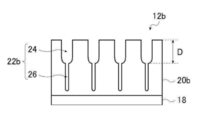
- FIG. 3 is a schematic cross-sectional view of another embodiment of an aluminum support. It is a graph which shows an example of the alternating waveform current waveform diagram used for the electrochemical roughening process in the manufacturing method of an aluminum support. It is a side view which shows an example of the radial type cell in the electrochemical roughening treatment using alternating current in the manufacturing method of an aluminum support.
- the notation that does not describe substitution and non-substitution includes those having no substituent as well as those having a substituent.
- the "alkyl group” includes not only an alkyl group having no substituent (unsubstituted alkyl group) but also an alkyl group having a substituent (substituted alkyl group).
- (meth) acrylic is a term used in a concept that includes both acrylic and methacrylic
- “(meth) acryloyl” is a term that is used as a concept that includes both acryloyl and methacryloyl. Is.
- process in the present specification is not limited to an independent process, and even if it cannot be clearly distinguished from other processes, the term “process” will be used as long as the intended purpose of the process is achieved. included. Further, in the present disclosure, “% by mass” and “% by weight” are synonymous, and “parts by mass” and “parts by weight” are synonymous. Further, in the present disclosure, a combination of two or more preferred embodiments is a more preferred embodiment.
- the weight average molecular weight (Mw) and the number average molecular weight (Mn) in the present disclosure use columns of TSKgel GMHxL, TSKgel G4000HxL, and TSKgel G2000HxL (all are trade names manufactured by Toso Co., Ltd.). It is a molecular weight converted by detecting with a solvent THF (tetrahydrofuran) and a differential refractometer by a gel permeation chromatography (GPC) analyzer and using polystyrene as a standard substance.
- THF tetrahydrofuran
- GPC gel permeation chromatography
- the term "lithographic printing plate original plate” includes not only a lithographic printing plate original plate but also a discarded plate original plate.
- lithographic printing plate includes not only a lithographic printing plate produced by subjecting a lithographic printing plate original plate through operations such as exposure and development as necessary, but also a discarded plate. In the case of a discarded original plate, exposure and development operations are not always necessary.
- the discard plate is a planographic printing plate original plate for attaching to an unused plate cylinder when printing a part of the paper surface in a single color or two colors in, for example, color newspaper printing.
- the first embodiment of the on-machine development type lithographic printing plate original plate (also simply referred to as "lithographic printing plate original plate") according to the present disclosure includes a support and an image recording layer on the support, and the above.
- the image recording layer contains a compound A having a partial structure in which the value of the dispersion term ⁇ d of the Hansen dissolution parameter is 15.5 or more, and the compound A is a compound having a partial structure in which the value of the dispersion term ⁇ d is 15.5 or more.
- a second embodiment of the on-machine development type lithographic printing plate original plate according to the present disclosure has a support and an image recording layer on the support, and the image recording layer is the dispersion term ⁇ d of the Hansen dissolution parameter.
- This is an on-machine developing type lithographic printing plate original plate containing compound A having a partial structure having a value of 15.5 or more and the image recording layer satisfying the following formula K.
- KGK x 2 ⁇ KGK0 formula K In the formula K, KGK represents the amount of on-board developed residue deposited on the image recording layer, and KGK0 represents the amount of on-machine developed residue deposited on the same layer as the above-mentioned image recording layer except that the above-mentioned compound A is excluded. ..
- the term "machine-developed lithographic printing plate original plate according to the present disclosure” or “lithographic printing plate original plate according to the present disclosure” is referred to as the above-mentioned first embodiment and the above-mentioned first embodiment. Both of the two embodiments shall be described. Further, without particular notice, when the term “image recording layer” or the like is simply used, the image recording layer or the like of both the first embodiment and the second embodiment will be described. Further, the on-machine development type lithographic printing plate original plate according to the present disclosure is preferably a negative type lithographic printing plate original plate.
- the image recording layer contains compound A having a partial structure in which the value of the dispersion term ⁇ d of the Hansen dissolution parameter is 15.5 or more, and the compound A has a partial structure in which the value of ⁇ d is 15.5 or more.
- the affinity between each component of the image recording layer is improved, the compound A adsorbs the on-machine developing residue, and further.
- the on-machine developing residue on the dampening water and on the watering roller It is estimated that deposition can be suppressed.
- the image recording layer in the first embodiment of the on-board development type lithographic printing plate original plate according to the present disclosure contains compound A having a partial structure in which the value of the dispersion term ⁇ d of the Hansen solubility parameter is 15.5 or more, and is described above.
- Compound A has a partial structure in which the value of ⁇ d is 15.5 or more, which is 50% by mass or more of the total compound.
- the image recording layer in the second embodiment of the on-board development type lithographic printing plate original plate according to the present disclosure contains compound A having a partial structure in which the value of the dispersion term ⁇ d of the Hansen solubility parameter is 15.5 or more, and is described above.
- the image recording layer satisfies the above formula K.
- the image recording layer in the present disclosure is preferably a negative type image recording layer, and more preferably a water-soluble or water-dispersible negative type image recording layer.
- the image recording layer in the present disclosure preferably contains an infrared absorber and a polymerization initiator from the viewpoints of suppressing the accumulation of on-machine developing residue, printing resistance, and on-machine developing property, and absorbs infrared rays. More preferably, it contains an agent, a polymerization initiator, a polymerizable compound, and polymer particles.
- the image recording layer in the present disclosure is preferably the outermost layer from the viewpoint of suppressing the accumulation of on-machine developing residue, printing resistance, and on-machine developing property.
- the image recording layer in the second embodiment of the on-board development type lithographic printing plate original plate according to the present disclosure satisfies the following formula K.
- the image recording layer in the first embodiment of the on-board development type lithographic printing plate original plate according to the present disclosure has the following formula K from the viewpoint of suppressing the accumulation of on-machine developing residue, printing resistance, and on-machine developability. It is preferable to satisfy.
- KGK x 2 ⁇ KGK0 formula K
- KGK represents the amount of on-board developed residue deposited on the image recording layer
- KGK0 represents the amount of on-machine developed residue deposited on the same layer as the above-mentioned image recording layer except that the above-mentioned compound A is excluded. ..
- the values of KGK and KGK0 shall be measured by the following methods.
- Exposure (equivalent to irradiation energy of 110 mJ / cm 2 ) is performed under the condition of 400 dpi (dots per inch, 1 inch is 2.54 cm).
- the image recording layer in the second embodiment of the on-board development type lithographic printing plate original plate according to the present disclosure has the following formula K1 from the viewpoint of suppressing the accumulation of on-machine developing residue, printing resistance, and on-machine developability. It is preferable to satisfy, it is more preferable to satisfy the following formula K2, and it is particularly preferable to satisfy the following formula K3.
- the image recording layer in the first embodiment of the on-board development type lithographic printing plate original plate according to the present disclosure has the following formula K1 from the viewpoint of suppressing the accumulation of on-machine developing residue, printing resistance, and on-machine developability. It is more preferable to satisfy the following formula, it is further preferable to satisfy the following formula K2, and it is particularly preferable to satisfy the following formula K3. KGK x 2.5 ⁇ KGK0 formula K1 KGK x 3.5 ⁇ KGK0 formula K2 KGK ⁇ 4.0 ⁇ KGK0 formula K3
- the value of KGK in the image recording layer of the machine-developed lithographic printing plate original plate according to the present disclosure is 1.0 to 2 from the viewpoints of the deposition suppression property of the machine-developed residue, the printing resistance, and the machine-developing property. It is preferably 0.0, more preferably 1.0 to 1.5, and particularly preferably 1.0 to 1.2.
- the ethylenically unsaturated bond value of the image recording layer in the present disclosure is 1.0 mmol / g or more, and is 1.5 mmol / g or more from the viewpoint of suppressing the deposition of on-machine developing residue and printing resistance. It is more preferable, it is more preferably 2.0 mmol / g or more, further preferably 2.5 mmol / g or more, and particularly preferably 3.7 mmol / g or more.
- the upper limit of the ethylenically unsaturated bond value of the image recording layer is not particularly limited, but is preferably 10 mmol / g or less, and more preferably 8 mmol / g or less.
- the ethylenically unsaturated bond value in the image recording layer in the present disclosure represents the number of moles of ethylenically unsaturated bond per 1 g of the image recording layer.
- the ethylenically unsaturated bond in the polymer particles having an ethylenically unsaturated group is not included in the ethylenically unsaturated bond value.
- the ethylenically unsaturated bond value in the image recording layer in the present disclosure is determined by each of the ethylenically unsaturated compound contained in 1 g of the image recording layer and the polymer having an ethylenically unsaturated group (excluding polymer particles). The content and each structure shall be identified, and the number of moles of ethylenically unsaturated bonds per 1 g of the image recording layer shall be calculated by calculation.
- the image recording layer in the present disclosure preferably contains polymer particles having an ethylenically unsaturated group, which will be described later.
- a polymerizable compound having a pentafunctionality or higher may be contained in an amount of 50% by mass or more based on the total mass of the polymerizable compound. It is preferable to contain 70% by mass or more, more preferably 80% by mass or more, and particularly preferably 90% by mass or more.
- the image recording layer in the present disclosure preferably contains a polymerizable compound having 10 or more functionalities, and contains a polymerizable compound having 11 or more functionalities, from the viewpoint of suppressing the deposition of on-machine developing residue and printing resistance. It is more preferable, and it is particularly preferable to contain a polymerizable compound having 15 or more functionalities.
- the image recording layer in the machine-developed lithographic printing plate original plate according to the present disclosure contains compound A having a partial structure in which the value of the dispersion term ⁇ d of the Hansen solubility parameter is 15.5 or more.
- the compound A in the image recording layer in the first embodiment of the on-board development type lithographic printing plate original plate according to the present disclosure has a partial structure in which the value of ⁇ d is 15.5 or more, which is 50% by mass or more of the whole compound. ..
- the on-machine developing residue is excellent in the accumulation suppressing property, the printing resistance, and the on-machine developing property.
- the compound A in the image recording layer in the second embodiment of the on-machine developing type lithographic printing plate original plate according to the present disclosure is from the viewpoint of suppressing the accumulation of on-machine developing residue, printing resistance, and on-machine developing property. It is preferable to have a partial structure in which the value of ⁇ d is 15.5 or more, which is 50% by mass or more of the whole compound.
- the value of the dispersion term ⁇ d of the Hansen dissolution parameter in the partial structure of the compound shall be the value of ⁇ d for each monomer unit when the compound is a polymer such as an addition polymerization type resin or a polycondensation type resin.
- the value of ⁇ d of the entire compound is used.
- the mass ratio of the partial structure in which the value of ⁇ d is 15.5 or more is the mass with respect to the total mass of the encapsulated polymer particle. It shall be a ratio.
- the dispersion term ⁇ d [unit: MPa 0.5 ] and the polar term ⁇ p [unit: MPa 0.5 ] in the solubility parameter of Hansen are used.
- the solubility parameter of Hansen is the solubility parameter introduced by Hildebrand divided into three components, a dispersion term ⁇ d, a polar term ⁇ p, and a hydrogen bond term ⁇ h, and expressed in a three-dimensional space. Is. For more information on Hansen's solubility parameters, see Charles M. It is described in the document "Hansen Solubility Parameter; A Users Handbook (CRC Press, 2007)" by Hansen.
- ⁇ d in the Hansen solubility parameter in the partial structure of the compound A is a value estimated from the chemical structure by using the computer software “Hansen Solubility Parameters in Practice (HSPiP ver. 4.1.07)”. is there.
- the compound A preferably has a partial structure in which the value of ⁇ d is 16.5 or more, and the compound A preferably has a partial structure in which the value of ⁇ d is 16.5 or more from the viewpoint of the deposition inhibitory property of the on-machine developing residue, the printing resistance, and the on-machine developability. It is more preferable to have a partial structure having a value of 17.5 or more, and it is particularly preferable to have a partial structure having a value of ⁇ d of 18.0 or more and 25.0 or less.
- the compound A in the image recording layer in the first embodiment of the machine-developed flat plate printing plate original plate according to the present disclosure is from the viewpoint of suppressing the deposition of the machine-developed residue, printing resistance, and machine-developing property.
- the partial structure in which the value of ⁇ d is 15.5 or more is more preferably 60% by mass or more, more preferably 70% by mass or more, and particularly preferably 70% by mass to 100% by mass. , 70% by mass to 90% by mass, most preferably.
- the compound A in the image recording layer in the second embodiment of the machine-developed flat plate printing plate original plate according to the present disclosure is from the viewpoint of suppressing the deposition of the machine-developed residue, printing resistance, and machine-developing property.
- the partial structure in which the value of ⁇ d is 15.5 or more is preferably 60% by mass or more, more preferably 70% by mass or more, and further preferably 70% by mass to 100% by mass. It is particularly preferably 70% by mass to 90% by mass.
- the on-board development type lithographic printing plate original plate according to the present disclosure has a value of ⁇ d of 18.0 or more and 25. from the viewpoints of on-machine development residue accumulation suppressing property, printing resistance, and on-machine developability. It is preferable to have a partial structure of 0 or less in an amount of 50% by mass or more of the total compound.
- the compound A may be a polymer, a low molecular weight compound, a monomer, or an oligomer, but it may be a polymer, a low molecular weight compound, a monomer, or an oligomer. From the viewpoint of top developability, it is preferable to contain a polymer. Further, in the present disclosure, unless otherwise specified, the polymer is a compound having a weight average molecular weight (Mw) of more than 5,000, and the oligomer is a compound having Mw of 1,000 or more and 5,000 or less. And low molecular weight compounds are compounds having a molecular weight of less than 1,000.
- Mw weight average molecular weight
- the compound A preferably contains the compound A in the form of particles such as polymer particles from the viewpoint of the deposition inhibitory property of the on-machine developed residue, the printing resistance, and the on-machine developability, and preferably contains the polymer particles. Is more preferable, and it is particularly preferable to include encapsulated polymer particles.
- the polymer particles in the compound A include addition polymerization type resin particles, polyaddition type resin particles, polycondensation type resin particles, etc., from the viewpoint of suppressing the accumulation of on-machine development residue and printing resistance. , Addition polymerization type resin particles are preferable.
- the polymer particles in the compound A are preferably crosslinked resin particles, and more preferably addition polymerization type crosslinked resin particles, from the viewpoint of suppressing the deposition of on-machine development residue and printing resistance.
- the polymer particles in the compound A are preferably emulsion-polymerized resin particles from the viewpoint of suppressing the deposition of the on-machine developing residue and the on-machine developing property.
- the polymer particles in the compound A are preferably thermoplastic resin particles from the viewpoint that they can be polymer particles capable of heat fusion.
- the compound A preferably contains at least one of a monomer or an oligomer, and more preferably contains a polymer particle and at least one of a monomer or an oligomer. Further, the monomer and the oligomer are preferably compounds having an ethylenically unsaturated bond.
- the compound A or the partial structure is a polar structure from the viewpoint of the deposition inhibitory property of the on-machine developing residue, the printing resistance, and the on-machine developability. , And preferably having at least one structure selected from the group consisting of aromatic ring structures.
- the polar structure include urethane bond, urea bond, cyano group, sulfonamide bond, sulfonimide group, anion structure and the like.
- the above-mentioned compound A or the above-mentioned partial structure has a urethane bond, a urea bond, a cyano group, a sulfone amide bond, and a sulfone from the viewpoint of the deposition inhibitory property of the on-machine developed residue, the printing resistance, and the on-machine developability. It is preferable to have at least one structure selected from the group consisting of imide groups, and more preferably to have at least one structure selected from the group consisting of urethane bonds, urea bonds, and cyano groups. It is more preferable to have a bond, and it is particularly preferable to have two or more urethane bonds.
- the aromatic ring structure examples include a benzene ring structure, a naphthalene structure, and an anthracene structure.
- the compound A or the partial structure preferably has a benzene ring structure, and has a phenyl group or a phenylene group, from the viewpoint of suppressing the deposition of on-machine developed residue, printing resistance, and on-machine developability. It is more preferable, and it is particularly preferable to have two or more phenyl groups or phenylene groups in one molecule. Further, the phenyl group and the phenylene group may have a substituent.
- the above-mentioned substituent is not particularly limited, but is an alkyl group, an aryl group, a halogen atom, an amino group, an alkylamino group, an arylamino group, a dialkylamino group, a monoalkyl monoarylamino group, a diarylamino group, a hydroxy group, and the like.
- Examples thereof include an alkoxy group, an aryloxy group, an acyl group, an alkoxycarbonyl group, an aryloxycarbonyl group and a cyano group.
- these substituents may be further substituted with these substituents.
- an alkyl group is preferably mentioned as the above-mentioned substituent.
- the compound A or the partial structure preferably has a polar structure and an aromatic ring structure from the viewpoint of suppressing the deposition of on-machine developed residue, printing resistance, and on-machine developability, and is urethane-bonded. It is more preferable to have a benzene ring structure, and it is particularly preferable to have two or more urethane bonds and two or more benzene ring structures.
- the compound A has a Hansen solubility parameter dispersion term ⁇ d of 15.5 or more in the components contained in various image recording layers such as the particles, the polymerizable compound, the polymerization initiator, and the infrared absorber.
- image recording layer is used as a polymerizable compound, a polymerization initiator, an infrared absorber, and the compound A from the viewpoints of suppressing the deposition of on-machine developing residue, printing resistance, and on-machine developing property.
- With polymer particles are preferred.
- the polymer particles of the compound A preferably contain a resin having a monomer unit having an aromatic ring structure from the viewpoint of suppressing the deposition of on-board developed residue, and a resin having a monomer unit formed of styrene is used. It is more preferable to contain a resin having a monomer unit formed of styrene and a monomer unit formed of acrylonitrile. Further, the polymer particles of the compound A preferably contain a resin having a monomer unit derived from a poly (ethylene glycol) alkyl ether methacrylate compound from the viewpoint of suppressing the deposition of on-board developed residue, and poly (ethylene).
- a resin having a monomer unit derived from a glycol) alkyl ether methacrylate compound and a monomer unit formed from styrene a monomer unit derived from a poly (ethylene glycol) alkyl ether methacrylate compound, and a monomer formed from styrene. It is particularly preferable to include a resin having a unit and a monomer unit formed of acrylonitrile.
- the polymer particles of the compound A preferably contain a urethane resin from the viewpoint of suppressing the accumulation of on-board developed residue, printing resistance, and on-machine developability, and a urethane resin having an aromatic ring structure is used. It is more preferable to include it, and it is particularly preferable that the encapsulating polymer particles contain at least a urethane resin having an aromatic ring structure on the particle surface.
- the image recording layer may contain the compound A alone or in combination of two or more.
- the content of the compound A in the image recording layer is 5% by mass or more with respect to the total mass of the image recording layer from the viewpoint of the accumulation inhibitory property of the on-machine developed residue, the printing resistance, and the on-machine developability. It is preferably 90% by mass, more preferably 10% by mass to 90% by mass, further preferably 20% by mass to 90% by mass, and particularly preferably 50% by mass to 90% by mass. ..
- the image recording layer preferably contains particles from the viewpoint of suppressing the deposition of on-machine developing residue, printing resistance, and on-machine developing property.
- the particles may be organic particles or inorganic particles, but preferably contain organic particles from the viewpoint of suppressing the deposition of on-machine development residue, printing resistance, and on-machine developability.
- the inorganic particles known inorganic particles can be used, and metal oxide particles such as silica particles and titania particles can be preferably used.
- the polymer particles may be selected from the group consisting of thermoplastic polymer particles, heat-reactive polymer particles, polymer particles having a polymerizable group, microcapsules containing a hydrophobic compound, and microgels (crosslinked polymer particles). preferable. Of these, polymer particles or microgels having a polymerizable group are preferable. In a particularly preferred embodiment, the polymer particles contain at least one ethylenically unsaturated polymerizable group. The presence of such polymer particles has the effect of enhancing the print resistance of the exposed portion and the on-machine developability of the unexposed portion. Further, the polymer particles are preferably thermoplastic polymer particles.
- thermoplastic polymer particles Research Disclosure No. 1 of January 1992.
- the thermoplastic polymer particles described in 33303, JP-A-9-123387, JP-A-9-131850, JP-A-9-171249, JP-A-9-171250, and European Patent No. 931647 are preferable.
- Specific examples of the polymer constituting the thermoplastic polymer particles include ethylene, styrene, vinyl chloride, methyl acrylate, ethyl acrylate, methyl methacrylate, ethyl methacrylate, vinylidene chloride, acrylonitrile, vinylcarbazole, and a polyalkylene structure.
- thermoplastic polymer particles examples include homopolymers or copolymers of monomers such as acrylates or methacrylates or mixtures thereof.
- a copolymer containing polystyrene, styrene and acrylonitrile, or polymethylmethacrylate can be mentioned.
- the average particle size of the thermoplastic polymer particles is preferably 0.01 ⁇ m to 3.0 ⁇ m.
- heat-reactive polymer particles examples include polymer particles having a heat-reactive group.
- the heat-reactive polymer particles form a hydrophobic region by cross-linking due to a heat reaction and the change of functional groups at that time.
- the thermally reactive group in the polymer particles having a thermally reactive group may be a functional group that undergoes any reaction as long as a chemical bond is formed, but a polymerizable group is preferable, and as an example, it is preferable.
- Eethylene unsaturated groups eg, acryloyl group, methacryloyl group, vinyl group, allyl group, etc.
- cationically polymerizable groups eg, vinyl group, vinyloxy group, epoxy group, oxetanyl group, etc.
- Preferred examples thereof include a hydroxy group or an amino group as a partner, an acid anhydride for carrying out a ring-opening addition
- the microcapsules for example, as described in JP-A-2001-277740 and JP-A-2001-277742, at least a part of the constituent components of the image recording layer is encapsulated in the microcapsules.
- the constituent components of the image recording layer can also be contained outside the microcapsules.
- the image recording layer containing the microcapsules is preferably configured such that the hydrophobic constituents are encapsulated in the microcapsules and the hydrophilic constituents are contained outside the microcapsules.
- the microgel (crosslinked polymer particles) can contain a part of the constituent components of the image recording layer on at least one of the surface or the inside thereof.
- a reactive microgel having a radically polymerizable group on its surface is preferable from the viewpoint of the sensitivity of the obtained lithographic printing plate original plate and the printing durability of the obtained lithographic printing plate.
- a known method can be applied to microencapsulate or microgelify the constituents of the image recording layer.
- an adduct of a polyhydric phenol compound having two or more hydroxy groups in the molecule and isophorone diisocyanate from the viewpoint of printing resistance, stain resistance and storage stability of the obtained flat plate printing plate.
- the one obtained by the reaction of the polyhydric isocyanate compound and the compound having active hydrogen is preferable.
- the multivalent phenol compound a compound having a plurality of benzene rings having a phenolic hydroxy group is preferable.
- a polyol compound or a polyamine compound is preferable, a polyol compound is more preferable, and at least one compound selected from the group consisting of propylene glycol, glycerin and trimethylolpropane is further preferable.
- the resin particles obtained by the reaction of the polyhydric phenol compound having two or more hydroxy groups in the molecule, the polyhydric isocyanate compound which is an adduct of isophorone diisocyanate, and the compound having active hydrogen include The polymer particles described in paragraphs 0032 to 0905 of JP-206495 are preferably mentioned.
- the polymer particles have a hydrophobic main chain from the viewpoint of printing resistance and solvent resistance of the obtained lithographic printing plate, and i) a pendant cyano group directly bonded to the hydrophobic main chain. It is preferable to include both a constituent unit having and ii) a constituent unit having a pendant group containing a hydrophilic polyalkylene oxide segment.
- Acrylic resin chains are preferably mentioned as the hydrophobic main chain.
- the pendant cyano group -[CH 2 CH (C ⁇ N)]-or-[CH 2 C (CH 3 ) (C ⁇ N)]-is preferably mentioned.
- the constituent unit having the pendant cyano group can be easily derived from an ethylene-based unsaturated monomer such as acrylonitrile or methacrylonitrile, or from a combination thereof.
- an ethylene-based unsaturated monomer such as acrylonitrile or methacrylonitrile, or from a combination thereof.
- the alkylene oxide in the hydrophilic polyalkylene oxide segment ethylene oxide or propylene oxide is preferable, and ethylene oxide is more preferable.
- the number of repetitions of the alkylene oxide structure in the hydrophilic polyalkylene oxide segment is preferably 10 to 100, more preferably 25 to 75, and even more preferably 40 to 50.
- Both a constituent unit having a hydrophobic backbone and i) having a pendant cyano group directly attached to the hydrophobic backbone and ii) a constituent unit having a pendant group containing a hydrophilic polyalkylene oxide segment are preferably mentioned.
- the polymer particles preferably have a hydrophilic group from the viewpoint of suppressing the deposition of on-machine developing residue, printing resistance, and on-machine developing property.
- the hydrophilic group is not particularly limited as long as it has a hydrophilic structure, and examples thereof include an acid group such as a carboxy group, a hydroxy group, an amino group, a cyano group, and a polyalkylene oxide structure.
- a polyalkylene oxide structure is preferable, and a polyethylene oxide structure, a polypropylene oxide structure, or a polyethylene / propylene oxide structure is more preferable, from the viewpoint of suppressing the deposition of on-board developed residue, printing resistance, and on-machine developability. ..
- the polyalkylene oxide structure preferably has a polypropylene oxide structure, and may have a polyethylene oxide structure and a polypropylene oxide structure. More preferred.
- the hydrophilic group preferably contains a structural unit having a cyano group or a group represented by the following formula Z from the viewpoint of print resistance, fillability and on-machine developability. It is more preferable to include a structural unit represented by the following formula (AN) or a group represented by the following formula Z, and it is particularly preferable to include a group represented by the following formula Z.
- Q represents a divalent linking group
- W represents a divalent group having a hydrophilic structure or a divalent group having a hydrophobic structure
- Y represents a monovalent group having a hydrophilic structure or It represents a monovalent group having a hydrophobic structure, either W or Y has a hydrophilic structure
- * represents a binding site with another structure.
- RAN represents a hydrogen atom or a methyl group.
- the polymer contained in the polymer particles preferably contains a structural unit formed of a compound having a cyano group.
- the cyano group is usually preferably introduced into the resin A as a structural unit containing a cyano group by using a compound (monomer) having a cyano group.
- Examples of the compound having a cyano group include acrylonitrile compounds, and (meth) acrylonitrile is preferable.
- the structural unit having a cyano group is preferably a structural unit formed of an acrylonitrile compound, and more preferably a structural unit formed of (meth) acrylonitrile, that is, a structural unit represented by the above formula (AN). ..
- the content of the structural unit having a cyano group, preferably the structural unit represented by the above formula (AN), in the polymer having a structural unit having a cyano group. Is preferably 5% by mass to 90% by mass, and more preferably 20% by mass to 80% by mass, based on the total mass of the polymer having a structural unit having a cyano group, from the viewpoint of UV printing resistance. It is preferable, and it is particularly preferable that it is 30% by mass to 60% by mass.
- the polymer particles preferably contain polymer particles having a group represented by the above formula Z from the viewpoint of suppressing the deposition of on-machine developing residue, printing resistance, and on-machine developing property.
- Q in the above formula Z is preferably a divalent linking group having 1 to 20 carbon atoms, and more preferably a divalent linking group having 1 to 10 carbon atoms. Further, Q in the above formula Z is preferably an alkylene group, an arylene group, an ester bond, an amide bond, or a group in which two or more of these are combined, and may be a phenylene group, an ester bond, or an amide bond. More preferred.
- the divalent group having a hydrophilic structure in W of the above formula Z is preferably a polyalkyleneoxy group or a group in which -CH 2 CH 2 NR W- is bonded to one end of a polyalkyleneoxy group. ..
- R W represents a hydrogen atom or an alkyl group.
- the RWAs are independently linear, branched or cyclic alkylene groups having 6 to 120 carbon atoms, haloalkylene groups having 6 to 120 carbon atoms, arylene groups having 6 to 120 carbon atoms, and alcoholylenes having 6 to 120 carbon atoms. It represents a group (a divalent group obtained by removing one hydrogen atom from an alkylaryl group) or an aralkylene group having 6 to 120 carbon atoms.
- the monovalent group having a hydrophobic structure in Y of the above formula Z is a linear, branched or cyclic alkyl group having 6 to 120 carbon atoms, a haloalkyl group having 6 to 120 carbon atoms, an aryl group having 6 to 120 carbon atoms, and the like.
- RWB represents an alkyl group having 6 to 20 carbon atoms.
- the polymer particles having a group represented by the above formula Z are divalent groups in which W has a hydrophilic structure from the viewpoints of inhibition of deposition of on-board developed residue, printing resistance, and on-machine developability. More preferably, Q is a phenylene group, an ester bond, or an amide bond, W is a polyalkyleneoxy group, and Y is a polyalkyleneoxy group having a hydrogen atom or an alkyl group at the end. More preferred.
- the polymer particles preferably contain polymer particles having a polymerizable group from the viewpoint of suppressing the accumulation of on-machine developed residue, printing resistance, and on-machine developability, and have a polymerizable group on the particle surface. It is more preferable to include polymer particles having. Further, from the viewpoint of printing resistance, the polymer particles preferably contain polymer particles having a hydrophilic group and a polymerizable group. Even if the polymerizable group is a cationically polymerizable group, it is a radically polymerizable group. However, from the viewpoint of reactivity, a radically polymerizable group is preferable.
- the polymerizable group is not particularly limited as long as it is a polymerizable group, but from the viewpoint of reactivity, an ethylenically unsaturated group is preferable, and a vinylphenyl group (styryl group), a (meth) acryloxy group, or a (meth) acryloxy group, or A (meth) acrylamide group is more preferred, and a (meth) acryloxy group is particularly preferred.
- the polymer in the polymer particles having a polymerizable group preferably has a structural unit having a polymerizable group.
- a polymerizable group may be introduced on the surface of the polymer particles by a polymer reaction.
- the polymer particles preferably contain a resin having a urea bond from the viewpoint of suppressing the accumulation of on-machine developed residue, printing resistance, and on-machine developability, and are represented by the following formula (Iso). It is more preferable to contain a resin having a structure obtained by at least reacting an isocyanate compound with water, and having a structure obtained by at least reacting an isocyanate compound represented by the following formula (Iso) with water, and It is particularly preferable that the polyoxyalkylene structure contains a resin having a polyethylene oxide structure and a polypropylene oxide structure. Further, the particles containing the resin having a urea bond are preferably microgels.
- n represents an integer from 0 to 10.
- a compound having active hydrogen reactive with an isocyanate group such as an alcohol compound or an amine compound
- an isocyanate group such as an alcohol compound or an amine compound
- the structure of the alcohol compound or the amine compound is introduced into the resin having a urea bond. You can also do it.
- the compound having active hydrogen those described in the above-mentioned microgel are preferably mentioned.
- the resin having a urea bond preferably has an ethylenically unsaturated group, and more preferably has a group represented by the following formula (PETA).
- the average particle size of the particles is preferably 0.01 ⁇ m to 3.0 ⁇ m, more preferably 0.03 ⁇ m to 2.0 ⁇ m, and even more preferably 0.10 ⁇ m to 1.0 ⁇ m. Within these ranges, the resolution and stability over time are excellent.
- the average primary particle size of the particles in the present disclosure is measured by a light scattering method, or an electron micrograph of the particles is taken, and a total of 5,000 particle sizes are measured on the photograph, and the average value is obtained. Shall be calculated. For non-spherical particles, the particle size value of spherical particles having the same particle area as the particle area on the photograph is used as the particle size. Further, the average particle size in the present disclosure shall be the volume average particle size unless otherwise specified.
- the image recording layer may contain particles, particularly polymer particles, alone or in combination of two or more. Further, the content of the particles, particularly the polymer particles, in the image recording layer is based on the total mass of the image recording layer from the viewpoint of the accumulation inhibitory property of the on-machine development residue, the printing resistance, and the on-machine developability. It is preferably 5% by mass to 90% by mass, more preferably 10% by mass to 90% by mass, further preferably 20% by mass to 90% by mass, and particularly preferably 50% by mass to 90% by mass. preferable.
- the content of the polymer particles other than the compound A in the image recording layer is the total mass of the image recording layer from the viewpoint of the deposition inhibitory property of the on-machine developing residue, the printing resistance, and the on-machine developability. On the other hand, it is preferably less than 20% by mass, more preferably less than 10% by mass, further preferably less than 5% by mass, particularly preferably less than 1% by mass, and most preferably not contained. preferable.
- the image recording layer preferably contains a polymerizable compound.
- the polymerizable compound used in the present disclosure may be, for example, a radical-polymerizable compound or a cationically polymerizable compound, but is an addition-polymerizable compound having at least one ethylenically unsaturated bond (ethyleney). It is preferably an unsaturated compound).
- the ethylenically unsaturated compound is preferably a compound having at least one terminal ethylenically unsaturated bond, and more preferably a compound having two or more terminal ethylenically unsaturated bonds.
- Polymerizable compounds have chemical forms such as, for example, monomers, prepolymers, ie dimers, trimers or oligomers, or mixtures thereof.
- the polymerizable compound preferably contains a trifunctional or higher-functional polymerizable compound, more preferably a 7-functional or higher-functional polymerizable compound, and has a 10-functionality or higher-functionality, from the viewpoint of UV printing resistance. It is more preferable to contain a compound, particularly preferably to contain a polymerizable compound having 11 or more functionalities, and most preferably to contain a polymerizable compound having 15 or more functionalities.
- the polymerizable compound preferably contains a trifunctional or higher (preferably 7 or higher, more preferably 10 or higher) ethylenically unsaturated compound from the viewpoint of UV printing resistance in the obtained lithographic printing plate. It is more preferable to contain a trifunctional or higher (preferably 7 or higher functional, more preferably 10 or higher functional) (meth) acrylate compound.
- Examples of the monomer include unsaturated carboxylic acids (for example, acrylic acid, methacrylic acid, itaconic acid, crotonic acid, isocrotonic acid, maleic acid, etc.), esters thereof, and amides, and unsaturated carboxylic acids are preferable.
- Esters of an acid and a polyhydric alcohol compound, and amides of an unsaturated carboxylic acid and a polyhydric amine compound are used.
- an addition reaction product of an unsaturated carboxylic acid ester or amide having a nucleophilic substituent such as a hydroxy group, an amino group or a mercapto group with a monofunctional or polyfunctional isocyanate or an epoxy, and a monofunctional or polyfunctional group.
- a dehydration condensation reaction product with a functional carboxylic acid is also preferably used.
- an addition reaction product of an unsaturated carboxylic acid ester or amide having a polyelectron substituent such as an isocyanate group or an epoxy group with a monofunctional or polyfunctional alcohol, an amine or a thiol, and a halogen atom is also suitable.
- the monomer of the ester of the polyhydric alcohol compound and the unsaturated carboxylic acid include ethylene glycol diacrylate, 1,3-butanediol diacrylate, tetramethylene glycol diacrylate, and propylene glycol diacrylate as acrylic acid esters.
- EO ethylene oxide
- methacrylic acid ester As methacrylic acid ester, tetramethylene glycol dimethacrylate, neopentyl glycol dimethacrylate, trimethylolpropantrimethacrylate, ethylene glycol dimethacrylate, pentaerythritol trimethacrylate, bis [p- (3-methacryloxy-2-hydroxypropoxy) phenyl] There are dimethylmethane, bis [p- (methacrylicoxyethoxy) phenyl] dimethylmethane and the like.
- amide monomer of the polyvalent amine compound and the unsaturated carboxylic acid examples include methylenebisacrylamide, methylenebismethacrylamide, 1,6-hexamethylenebisacrylamide, and 1,6-hexamethylenebismethacrylamide.
- a urethane-based addition-polymerizable compound produced by using an addition reaction of isocyanate and a hydroxy group is also suitable, and specific examples thereof include, for example, 2 per molecule described in JP-A-48-41708.
- a vinyl urethane compound containing two or more polymerizable vinyl groups in one molecule obtained by adding a vinyl monomer containing a hydroxy group represented by the following formula (M) to a polyisocyanate compound having two or more isocyanate groups. And so on.
- CH 2 C (R M4) COOCH 2 CH (R M5) OH (M)
- RM4 and RM5 each independently represent a hydrogen atom or a methyl group.
- urethane acrylates described in JP-A-51-37193, JP-A-2-32293, JP-A-2-16765, JP-A-2003-344997, and JP-A-2006-65210 Ethylene described in Japanese Patent Application Laid-Open No. 58-49860, Japanese Patent Publication No. 56-17654, Japanese Patent Publication No. 62-39417, Japanese Patent Application Laid-Open No. 62-39418, Japanese Patent Application Laid-Open No. 2000-250211, and Japanese Patent Application Laid-Open No. 2007-94138.
- Kind is also suitable.
- the polymerizable compound preferably contains a compound having an ethylenically unsaturated bond value of 5.0 mmol / g or more (hereinafter, also referred to as specific compound B1).
- the ethylenically unsaturated bond value of the specific compound B1 is preferably 5.5 mmol / g or more, and more preferably 6.0 mmol / g or more.
- the upper limit of the ethylenically unsaturated bond value of the specific compound B1 is, for example, 10.0 mmol / g or less, and more preferably 8.5 mmol / g or less.
- the ethylenically unsaturated bond value of the compound in the present disclosure is determined by the following method. First, for a compound having a predetermined sample amount (for example, 0.2 g), the structure of the compound is specified by using, for example, thermal decomposition GC / MS, FT-IR, NMR, TOF-SIMS, etc., and ethylenically unsaturated. Find the total amount (mmol) of the groups. The ethylenically unsaturated bond value of a compound is calculated by dividing the total amount (mmol) of the determined ethylenically unsaturated groups by the sample amount (g) of the compound.
- a predetermined sample amount for example, 0.2 g
- the structure of the compound is specified by using, for example, thermal decomposition GC / MS, FT-IR, NMR, TOF-SIMS, etc.
- the polymerizable compound preferably contains a polymerizable compound represented by the following formula (I) from the viewpoint of print resistance and on-machine developability. Further, the polymerizable compound represented by the following formula (I) preferably has an ethylenically unsaturated bond value of 5.0 mmol / g or more.
- the polymerizable compound represented by the above formula (I) preferably has at least one structure selected from the group consisting of an adduct structure, a biuret structure, and an isocyanurate structure.
- Hydrogen bonding group in A P of the formula (I) may be any capable of hydrogen bonding groups, be a hydrogen bond donor group, be a hydrogen bond acceptor group, even both Good.
- the hydrogen-bonding group include a hydroxy group, a carboxy group, an amino group, a carbonyl group, a sulfonyl group, a urethane group, a urea group, an imide group, an amide group, a sulfonamide group and the like.
- the hydrogen-bonding group is at least one group selected from the group consisting of a urethane group, a urea group, an imide group, an amide group, and a sulfonamide group from the viewpoint of printing resistance.
- a P in formula (I) is preferably an organic group having no ethylenically unsaturated bond.
- the group is a combination of two or more kinds of structures selected from the group, and is preferably a monovalent to nP-valent aliphatic hydrocarbon group, a monovalent to nP-valent aromatic hydrocarbon group, a urethane bond, a urea bond, and the like. It is more preferable that the group is a combination of two or more structures selected from the group consisting of biuret bonds.
- the group is a group from which the isocyanate group of the above is removed, and the group from which the terminal isocyanate group is removed from the quantifier (including the adduct of the polyfunctional alcohol compound) in which the bifunctional isocyanate compound is increased is more preferable.
- the hexamethylene diisocyanate is a quantified product (including an adduct of a polyfunctional alcohol compound) in which the terminal isocyanate group is removed.
- the weight average molecular weight of A P in formula (I) (Mw), from the viewpoint of printing durability, preferably 10,000 or more 145,000 or less, 30,000 140,000 or less Is more preferable, and 60,000 or more and 140,000 or less are particularly preferable. Further, from the viewpoint of developability, the weight-average molecular weight of A P in formula (I) is preferably 120,000 or less.
- the polymerizable group in BP of the formula (I) may be, for example, a cationically polymerizable group or a radically polymerizable group, but from the viewpoint of reactivity, it may be a radically polymerizable group. It is preferable to have.
- the polymerizable group is not particularly limited, but is preferably an ethylenically unsaturated group from the viewpoint of reactivity and printing resistance, and is preferably a vinylphenyl group (styryl group), a vinyl ester group, a vinyl ether group, or an allyl.
- it is at least one group selected from the group consisting of a group, a (meth) acryloxy group and a (meth) acrylamide group, preferably a vinylphenyl group (styryl group), a (meth) acryloxy group and a (meth) acrylamide group. It is more preferably at least one group selected from the group consisting of groups, and particularly preferably a (meth) acryloxy group.
- the BP in the formula (I) may have a structure represented by the following formula (Y-1) or the formula (Y-2) from the viewpoint of on-machine developability and print resistance.
- R independently represents an acrylic group or a methacrylic group, and the wavy line portion represents the bonding position with another structure.
- R is preferably an acrylic group.
- B P of the formula (I) are preferably all the same groups.
- the molecular weight of BP in the formula (I) is preferably 300 or more and 1,000 or less, and more preferably 400 or more and 800 or less, from the viewpoint of printing resistance.
- the structure of the specific compound B1 preferably has a structure in which the terminal isocyanate group of the quantifier (including the adduct) of the polyfunctional isocyanate compound is sealed with a compound having an ethylenically unsaturated group.
- the quantifier of the polyfunctional isocyanate compound the quantifier of the bifunctional isocyanate compound is preferable.
- the specific compound B1 is a polyfunctional ethylene having a hydroxy group (also referred to as a hydroxyl group) at the end of the terminal isocyanate group of the multimerized product in which the polyfunctional isocyanate compound is increased in quantity. It is preferably a compound obtained by reacting a sex unsaturated compound.
- the specific compound B1 is a polyfunctional ethylenic compound having a hydroxy group at the terminal isocyanate group of a multimeric compound (including an adduct compound of a polyfunctional alcohol compound) in which a difunctional isocyanate compound is increased in quantity.
- the compound is obtained by reacting an unsaturated compound.
- the specific compound B1 is a polyfunctional ethylenically non-polyfunctional compound having a hydroxy group at the terminal isocyanate group of the multimer (including the adduct of the polyfunctional alcohol compound) in which hexamethylene diisocyanate is increased. It is particularly preferable that the compound is obtained by reacting a saturated compound.
- the polyfunctional isocyanate compound is not particularly limited, and known compounds can be used, and may be an aliphatic polyfunctional isocyanate compound or an aromatic polyfunctional isocyanate compound.
- Specific examples of the polyfunctional isocyanate compound include 1,3-bis (isocyanatomethyl) cyclohexane, isophorone diisocyanate, trimethylene diisocyanate, tetramethylene diisocyanate, pentamethylene diisocyanate, hexamethylene diisocyanate, and 1,3-.
- Cyclopentane diisocyanate, 9H-fluorene-2,7-diisocyanate, 9H-fluoren-9-on-2,7-diisocyanate, 4,4'-diphenylmethane diisocyanate, 1,3-phenylenediisocyanate, trilen-2 , 4-Diisocyanate, Trilen-2,6-Diisocyanate, 1,3-bis (isocyanatomethyl) cyclohexane, 2,2-bis (4-isocyanatophenyl) hexafluoropropane, 1,5-di Isocyanatonaphthalene, dimers of these polyisocyanates, trimmers (isocyanurate bonds) and the like are preferably mentioned.
- a biuret compound obtained by reacting the above polyisocyanate compound with a known amine compound may be used.
- the polyfunctional ethylenically unsaturated compound having a hydroxy group is preferably a trifunctional or higher functional ethylenically unsaturated compound having a hydroxy group, and is a pentafunctional or higher functional ethylenically unsaturated compound having a hydroxy group. Is more preferable.
- the polyfunctional ethylenically unsaturated compound having a hydroxy group is preferably a polyfunctional (meth) acrylate compound having a hydroxy group.
- the specific compound B1 preferably has at least one structure selected from the group consisting of an adduct structure, a biuret structure, and an isocyanurate structure from the viewpoint of on-machine developability and print resistance. From the same viewpoint as above, it is more preferable that the specific compound B1 has at least one structure selected from the group consisting of a trimethylolpropane adduct structure, a biuret structure, and an isocyanurate structure, and the trimethylolpropane adduct structure is formed. It is particularly preferable to have.
- the specific compound B1 preferably has a structure represented by any of the following formulas (A-1) to (A-3), and the following formula (A-). It is more preferable to have the structure represented by 1).
- RA1 represents a hydrogen atom or an alkyl group having 1 to 8 carbon atoms, and the wavy line portion represents a bond position with another structure.
- R A1 in the formula (A1) from the viewpoint of on-press development property and printing durability, a hydrogen atom, or preferably an alkyl group having 1 to 4 carbon atoms, an alkyl group having 1 to 3 carbon atoms It is more preferably present, more preferably a methyl group or an ethyl group, and particularly preferably an ethyl group.
- the specific compound B1 is preferably a (meth) acrylate compound having a urethane group, that is, a urethane (meth) acrylate oligomer from the viewpoint of on-machine developability and print resistance.
- the specific compound B1 may be an oligomer having a polyester bond (hereinafter, also referred to as a polyester (meth) acrylate oligomer) as long as the ethylenically unsaturated bond value is 5.0 mmol / g or more, or an epoxy residue may be used. It may be an oligomer having an oligomer (hereinafter, also referred to as an epoxy (meth) acrylate oligomer). Here, the epoxy residues in the epoxy (meth) acrylate oligomer are as described above.
- the number of ethylenically unsaturated groups in the polyester (meth) acrylate oligomer which is the specific compound B1 is preferably 3 or more, and more preferably 6 or more.
- the epoxy (meth) acrylate oligomer which is the specific compound B1 a compound containing a hydroxy group in the compound is preferable.
- the number of ethylenically unsaturated groups in the epoxy (meth) acrylate oligomer is preferably 2 to 6, and more preferably 2 to 3.
- the epoxy (meth) acrylate oligomer can be obtained, for example, by reacting a compound having an epoxy group with acrylic acid.
- the molecular weight of the specific compound B1 (weight average molecular weight when having a molecular weight distribution) is preferably more than 1,000, more preferably 1,100 to 10,000, and even more preferably 1,100 to 5,000.
- Specific compound B1 a synthetic product or a commercially available product may be used.
- Specific examples of the specific compound B1 include, for example, the following commercially available products, but the specific compound B1 used in the present disclosure is not limited thereto.
- the content of the specific compound B1 is preferably 10% by mass to 90% by mass, and 15% by mass to 85% by mass, based on the total mass of the image recording layer, from the viewpoint of on-machine developability and print resistance. Is more preferable, and 15% by mass to 60% by mass is further preferable.
- the content of the specific compound B1 in the image recording layer with respect to the total mass of the polymerizable compound is preferably 10% by mass to 100% by mass, preferably 50% by mass to 100% by mass. Is more preferable, and 80% by mass to 100% by mass is further preferable.
- the polymerizable compound may contain, as a low molecular weight compound, a compound having one or two ethylenically unsaturated bonding groups (hereinafter, also referred to as a specific compound B2).
- a preferred embodiment of the ethylenically unsaturated group contained in the specific compound B2 is the same as that of the ethylenically unsaturated group in the specific compound B1.
- the specific compound B2 is preferably a compound having two ethylenically unsaturated bonding groups (that is, a bifunctional polymerizable compound) from the viewpoint of suppressing a decrease in on-machine developability.
- the specific compound B2 is preferably a methacrylate compound, that is, a compound having a methacryloxy group, from the viewpoint of on-machine developability and print resistance.
- the specific compound B2 preferably contains an alkyleneoxy structure or a urethane bond from the viewpoint of on-machine developability.
- the molecular weight (weight average molecular weight when having a molecular weight distribution) of the specific compound B2 is preferably 50 or more and less than 1,000, more preferably 200 to 900, and more preferably 250 to 800. More preferred.
- specific compound B2 commercially available products shown below may be used, but the specific compound B2 used in the present disclosure is not limited thereto.
- Specific examples of the specific compound B2 include BPE-80N (compound of (1) above) manufactured by Shin Nakamura Chemical Industry Co., Ltd., BPE-100, BPE-200, BPE-500, and CN104 manufactured by Sartmer Co., Ltd. Examples thereof include ethoxylated bisphenol A dimethacrylate such as the compound of 1).
- Specific examples of the specific compound B2 include ethoxylated bisphenol A diacrylates such as A-BPE-10 (compound of (2) above) manufactured by Shin Nakamura Chemical Industry Co., Ltd. and A-BPE-4. ..
- specific examples of the specific compound B2 include bifunctional methacrylate such as FST 510 manufactured by AZ Electronics.
- FST 510 is a reaction product of 1 mol of 2,2,4-trimethylhexamethylene diisocyanate and 2 mol of hydroxyethyl methacrylate, and is a solution of the compound of the above (3) in an 82% by mass of methyl ethyl ketone. is there.
- the content of the polymerizable compound B is preferably 1% by mass to 60% by mass, and 5% by mass to 55% by mass, based on the total mass of the image recording layer, from the viewpoint of on-machine developability and print resistance. It is more preferably%, and further preferably 5% by mass to 50% by mass.
- the content of the specific compound B2 with respect to the total mass of the polymerizable compound in the image recording layer is preferably 10% by mass to 100% by mass, preferably 50% by mass to 100% by mass. Is more preferable, and 80% by mass to 100% by mass is further preferable.
- the details of the method of use such as the structure of the polymerizable compound, whether it is used alone or in combination, and the amount of addition can be arbitrarily set.
- the content of the polymerizable compound is preferably 5% by mass to 75% by mass, more preferably 10% by mass to 70% by mass, and 15% by mass to 60% by mass with respect to the total mass of the image recording layer. It is particularly preferably by mass%.
- the image recording layer in the lithographic printing plate original plate according to the present disclosure preferably contains a polymerization initiator.
- the polymerization initiator preferably contains an electron-accepting polymerization initiator, and more preferably contains an electron-accepting polymerization initiator and an electron-donating polymerization initiator.
- the image recording layer preferably contains an electron-accepting polymerization initiator as the polymerization initiator.
- the electron-accepting polymerization initiator is a compound that generates a polymerization initiator such as a radical by accepting one electron by electron transfer between molecules when the electrons of the infrared absorber are excited by infrared exposure.
- the electron-accepting polymerization initiator used in the present disclosure is a compound that generates a polymerization initiator such as a radical or a cation by energy of light, heat, or both, and is a known thermal polymerization initiator and has a small bond dissociation energy.
- a compound having a bond, a photopolymerization initiator and the like can be appropriately selected and used.
- a radical polymerization initiator is preferable, and an onium salt compound is more preferable.
- the electron-accepting polymerization initiator is preferably an infrared photosensitive polymerization initiator.
- the electron-accepting radical polymerization initiator include (a) an organic halide, (b) a carbonyl compound, (c) an azo compound, (d) an organic peroxide, (e) a metallocene compound, and (f) an azide compound. , (G) hexaarylbiimidazole compounds, (i) disulfone compounds, (j) oxime ester compounds, and (k) onium salt compounds.
- the compounds described in paragraphs 0022 to 0023 of JP-A-2008-195018 are preferable.
- B) As the carbonyl compound for example, the compound described in paragraph 0024 of JP-A-2008-195018 is preferable.
- C) As the azo compound for example, the azo compound described in JP-A-8-108621 can be used.
- D) As the organic peroxide for example, the compound described in paragraph 0025 of JP-A-2008-195018 is preferable.
- the metallocene compound for example, the compound described in paragraph 0026 of JP-A-2008-195018 is preferable.
- Examples of the (f) azide compound include compounds such as 2,6-bis (4-azidobenzylidene) -4-methylcyclohexanone.
- Examples of the hexaarylbiimidazole compound for example, the compound described in paragraph 0027 of JP-A-2008-195018 is preferable.
- Examples of the disulfon compound include the compounds described in JP-A-61-166544 and JP-A-2002-328465.
- As the (j) oxime ester compound for example, the compounds described in paragraphs 0028 to 0030 of JP-A-2008-195018 are preferable.
- oxime ester compounds and onium salt compounds are preferable from the viewpoint of curability.
- an iodonium salt compound, a sulfonium salt compound or an azinium salt compound is preferable, an iodonium salt compound or a sulfonium salt compound is more preferable, and an iodonium salt compound is particularly preferable. Specific examples of these compounds are shown below, but the present disclosure is not limited thereto.
- a diaryl iodonium salt compound is preferable, a diphenyl iodonium salt compound substituted with an electron donating group such as an alkyl group or an alkoxyl group is more preferable, and an asymmetric diphenyl iodonium salt compound is preferable.
- a triarylsulfonium salt compound is preferable, and in particular, an electron-attracting group, for example, a triarylsulfonium salt compound in which at least a part of a group on the aromatic ring is substituted with a halogen atom is preferable, and aromatic.
- a triarylsulfonium salt compound having a total number of halogen atoms substituted on the ring of 4 or more is more preferable.
- triphenylsulfonium hexafluorophosphate
- triphenylsulfonium benzoylformate
- bis (4-chlorophenyl) phenylsulfonium benzoylformate
- bis (4-chlorophenyl) -4-methylphenylsulfonium tetrafluoro.
- Tris (4-chlorophenyl) Sulfonium 3,5-bis (methoxycarbonyl) Benzene Sulfonium
- Tris (4-chlorophenyl) Sulfonium Hexafluorophosphate
- a sulfonamide anion or a sulfonimide anion is preferable, and a sulfonimide anion is more preferable.
- a sulfonamide anion an aryl sulfonamide anion is preferable.
- a bisaryl sulfonimide anion is preferable. Specific examples of the sulfonamide anion or the sulfonamide anion are shown below, but the present disclosure is not limited thereto. In the specific examples below, Ph represents a phenyl group, Me represents a methyl group, and Et represents an ethyl group.
- the electron-accepting polymerization initiator may contain a compound represented by the following formula (II) from the viewpoint of developability and UV printing resistance in the obtained lithographic printing plate.
- X represents a halogen atom and R 3 represents an aryl group.
- X in the formula (II) include a fluorine atom, a chlorine atom, a bromine atom and an iodine atom.
- a chlorine atom or a bromine atom is preferable because it has excellent sensitivity, and a bromine atom is particularly preferable.
- R 3 from the viewpoint of excellent balance between sensitivity and storage stability, an aryl group substituted with an amide group.
- electron-accepting polymerization initiator represented by the above formula (II) include compounds represented by the following formula, but the present disclosure is not limited thereto.
- the minimum empty orbital (LUMO) of the electron-accepting polymerization initiator is preferably ⁇ 3.00 eV or less, and more preferably ⁇ 3.02 eV or less, from the viewpoint of improving sensitivity. Further, as the lower limit, it is preferably -3.80 eV or more, and more preferably -3.60 eV or more.
- the electron-accepting polymerization initiator may be used alone or in combination of two or more.
- the content of the electron-accepting polymerization initiator is preferably 0.1% by mass to 50% by mass, more preferably 0.5% by mass to 30% by mass, based on the total mass of the image recording layer. It is preferably 0.8% by mass to 20% by mass, and particularly preferably 0.8% by mass.
- the image recording layer preferably contains an electron-donating polymerization initiator (also referred to as a "polymerization aid") as a polymerization initiator, and contains an electron-accepting polymerization initiator and an electron-donating polymerization initiator. Is more preferable. Further, it is preferable that the image recording layer contains an infrared absorber and a polymerization initiator, and the polymerization initiator contains an electron donating type polymerization initiator.
- the electron donating type polymerization initiator in the present disclosure donates one electron by intermolecular electron transfer to an orbit where one electron is missing from the infrared absorber when the electron of the infrared absorber is excited or moved intramolecularly by infrared exposure.
- This is a compound that generates a polymerization-initiated species such as a radical.
- the electron-donating type polymerization initiator is preferably an electron-donating radical polymerization initiator.
- the image recording layer more preferably contains the electron donating type polymerization initiator described below, and examples thereof include the following five types.
- Alkyl or arylate complex It is considered that the carbon-heterobond is oxidatively cleaved to generate an active radical. Specifically, a borate compound is preferable.
- N-arylalkylamine compound It is considered that the CX bond on the carbon adjacent to nitrogen is cleaved by oxidation to generate an active radical.
- X a hydrogen atom, a carboxyl group, a trimethylsilyl group or a benzyl group is preferable.
- N-phenylglycines (which may or may not have a substituent on the phenyl group) and N-phenyliminodiacetic acid (which may or may not have a substituent on the phenyl group).
- N-phenylglycines (which may or may not have a substituent on the phenyl group)
- N-phenyliminodiacetic acid (which may or may not have a substituent on the phenyl group).
- Sulfur-containing compound The above-mentioned amines in which the nitrogen atom is replaced with a sulfur atom can generate an active radical by the same action.
- phenylthioacetic acid (which may or may not have a substituent on the phenyl group) can be mentioned.
- Tin-containing compounds The above-mentioned amines in which the nitrogen atom is replaced with a tin atom can generate active radicals by the same action.
- Sulfinates Oxidation can generate active radicals. Specific examples thereof include arylsulfinic sodium.
- the image recording layer preferably contains a borate compound from the viewpoint of printing resistance.
- the borate compound is preferably a tetraaryl borate compound or a monoalkyl triaryl borate compound, and more preferably a tetraaryl borate compound from the viewpoint of print resistance and color development.
- the counter cation contained in the borate compound is not particularly limited, but is preferably an alkali metal ion or a tetraalkylammonium ion, and more preferably a sodium ion, a potassium ion, or a tetrabutylammonium ion.
- sodium tetraphenylborate is preferably mentioned as the borate compound.
- B-1 to B-9 are shown below as preferable specific examples of the electron donating type polymerization initiator, but it goes without saying that the present invention is not limited to these. Further, in the following chemical formula, Ph represents a phenyl group and Bu represents an n-butyl group.
- the maximum occupied orbital (HOMO) of the electron donating type polymerization initiator used in the present disclosure is preferably ⁇ 6.00 eV or higher, and preferably ⁇ 5.95 eV or higher, from the viewpoint of improving sensitivity. More preferably, it is more preferably ⁇ 5.93 eV or more.
- the upper limit is preferably ⁇ 5.00 eV or less, and more preferably ⁇ 5.40 eV or less.
- the electron donating type polymerization initiator only one kind may be added, or two or more kinds may be used in combination.
- the content of the electron donating type polymerization initiator is preferably 0.01% by mass to 30% by mass, preferably 0.05% by mass, based on the total mass of the image recording layer from the viewpoint of sensitivity and printing resistance. It is more preferably to 25% by mass, and further preferably 0.1% by mass to 20% by mass.
- the image recording layer contains an onium ion and an anion in the above-mentioned electron donating type polymerization initiator
- the image recording layer is assumed to contain an electron accepting type polymerization initiator and the above-mentioned electron donating type polymerization initiator. ..
- the image recording layer preferably contains an infrared absorber.
- the infrared absorber include pigments and dyes.
- the dye used as the infrared absorber commercially available dyes and known dyes described in documents such as "Dye Handbook” (edited by the Society of Synthetic Organic Chemistry, published in 1970) can be used.
- dyes such as azo dyes, metal complex salt azo dyes, pyrazolone azo dyes, naphthoquinone dyes, anthraquinone dyes, phthalocyanine dyes, carbonium dyes, quinoneimine dyes, methine dyes, cyanine dyes, squarylium dyes, pyrylium salts, and metal thiolate complexes.
- dyes such as azo dyes, metal complex salt azo dyes, pyrazolone azo dyes, naphthoquinone dyes, anthraquinone dyes, phthalocyanine dyes, carbonium dyes, quinoneimine dyes, methine dyes, cyanine dyes, squarylium dyes, pyrylium salts, and metal thiolate complexes.
- Particularly preferable of these dyes are cyanine pigments, squarylium pigments, pyrylium salts, nickel thiolate complexe
- the cyanine dye include the compounds described in paragraphs 0017 to 0019 of JP-A-2001-133769, paragraphs 0016 to 0021 of JP-A-2002-0233360, and paragraphs 0012 to 0037 of JP-A-2002-040638.
- the compounds described in paragraphs 0034 to 0041 of JP-A-2002-278057, paragraphs 0080-0086 of JP-A-2008-195018, and particularly preferably paragraphs 0035 of JP-A-2007-90850 examples thereof include the compounds described in 0043 and the compounds described in paragraphs 0105 to 0113 of JP2012-206495A.
- the compounds described in paragraphs 0008 to 0009 of JP-A-5-5005 and paragraphs 0022 to 0025 of JP-A-2001-222101 can also be preferably used.
- the pigment the compounds described in paragraphs 0072 to 0076 of JP-A-2008-195018 are preferable.
- an infrared absorber that decomposes by infrared exposure also referred to as "degradable infrared absorber”
- the infrared absorber that decomposes by infrared exposure those described in Japanese Patent Publication No. 2008-544322, International Publication No. 2016/027886, International Publication No. 2017/141882, or International Publication No. 2018/0432559 are preferable. Can be used for.
- infrared absorber Only one type of infrared absorber may be used, or two or more types may be used in combination. Further, a pigment and a dye may be used in combination as an infrared absorber.
- the content of the infrared absorber in the image recording layer is preferably 0.1% by mass to 10.0% by mass, more preferably 0.5% by mass to 5.0% by mass, based on the total mass of the image recording layer. preferable.
- the image recording layer in the present disclosure contains the electron-donating polymerization initiator and the infrared absorber, and the value of HOMO of the infrared absorber-HOMO of the electron-donating polymerization initiator is 0. It is preferably 70 eV or less, and more preferably 0.70 eV to ⁇ 0.10 eV.
- a negative value means that the HOMO of the electron-donating polymerization initiator is higher than that of the infrared absorber HOMO.
- the highest occupied orbital (HOMO) and the lowest empty orbital (LUMO) are calculated by the following methods.
- free counterions in the compound to be calculated are excluded from the calculation.
- the cationic one-electron accepting polymerization initiator and the cationic infrared absorber exclude the counter anion
- the anionic one-electron donating polymerization initiator excludes the counter cation from the calculation target.
- free as used herein means that the target compound and its counterion are not covalently linked.
- Quantum chemistry calculation software Gaussian09 is used, and structural optimization is performed by DFT (B3LYP / 6-31G (d)).
- the MO energy Ebare (unit: hartree) obtained by the above MO energy calculation is converted into Escaled (unit: eV) used as the values of HOMO and LUMO in the present disclosure by the following formula.
- Escaled 0.823168 x 27.2114 x Ebare-1.07634 Note that 27.2114 is simply a coefficient for converting heartree to eV, 0.823168 and ⁇ 1.07634 are adjustment coefficients, and HOMO and LUMO of the compound to be calculated are calculated values. Determine to suit.
- the infrared absorber in the present disclosure includes an organic anion having ⁇ d of 16 or more, ⁇ p of 16 to 32, and ⁇ h of 60% or less of ⁇ p in the solubility parameter of Hansen from the viewpoint of improving sensitivity. It is a preferable embodiment to have.
- ⁇ d in the solubility parameter of Hansen is 16 or more, ⁇ p is 16 to 32, and ⁇ h is 60% or less of ⁇ p. It is a preferred embodiment to have an organic anion.
- ⁇ d, ⁇ p and ⁇ h in the Hansen solubility parameter of the organic anion are estimated from the chemical structure by using the computer software “Hansen Solubility Parameters in Practice (HSPiP ver. 4.1.07)”. The value.
- organic anions having ⁇ d of 16 or more, ⁇ p of 16 to 32, and ⁇ h of 60% or less of ⁇ p in Hansen's solubility parameter are I-1 to I-15 and I described above. -17 to I-21, I-23 to I-25, and the following are preferable, but it goes without saying that the present invention is not limited thereto. Among them, bis (halogen-substituted benzenesulfonyl) imide anion is more preferably mentioned, and I-5 described above is particularly preferable.
- the image recording layer may contain a binder polymer, but it is preferable that the image recording layer does not contain the binder polymer from the viewpoint of suppressing the deposition of the on-machine developing residue, the printing resistance, and the on-machine developing property.
- the binder polymer is a polymer other than the polymer particles, that is, a binder polymer that is not in the form of particles.
- a (meth) acrylic resin, a polyvinyl acetal resin, or a polyurethane resin is preferable.
- a known binder polymer used for the image recording layer of the lithographic printing plate original plate can be preferably used.
- a binder polymer (hereinafter, also referred to as a binder polymer for on-machine development) used in a machine-developed planographic printing plate original plate will be described in detail.
- a binder polymer for on-machine development a binder polymer having an alkylene oxide chain is preferable.
- the binder polymer having an alkylene oxide chain may have a poly (alkylene oxide) moiety in the main chain or the side chain.
- graft polymer having a poly (alkylene oxide) in a side chain, or a block copolymer of a block composed of a poly (alkylene oxide) -containing repeating unit and a block composed of a (alkylene oxide) -free repeating unit.
- a polyurethane resin is preferable.
- the polymer of the main chain is (meth) acrylic resin, polyvinyl acetal resin, polyurethane resin, polyurea resin, polyimide resin, polyamide resin, epoxy resin, polystyrene resin, novolak type. Examples thereof include phenol resin, polyester resin, synthetic rubber and natural rubber, and (meth) acrylic resin is particularly preferable.
- a high molecular weight polymer chain having a polyfunctional thiol having 6 or more functionalities and 10 or less functional as a nucleus and being bonded to the nucleus by a sulfide bond, and the polymer chain having a polymerizable group examples thereof include molecular compounds (hereinafter, also referred to as star-shaped polymer compounds).
- the star-shaped polymer compound for example, the compound described in JP2012-148555 can be preferably used.
- the star-shaped polymer compound contains a polymerizable group such as an ethylenically unsaturated bond for improving the film strength of the image portion as described in JP-A-2008-195018, with a main chain or a side chain, preferably a side chain. Examples include those held in the chain.
- the polymerizable group forms crosslinks between the polymer molecules to promote curing.
- an ethylenically unsaturated group such as a (meth) acrylic group, a vinyl group, an allyl group or a styryl group or an epoxy group is preferable, and a (meth) acrylic group, a vinyl group or a styryl group is polymerizable.
- a (meth) acrylic group is particularly preferable.
- These groups can be introduced into the polymer by polymer reaction or copolymerization. For example, a reaction between a polymer having a carboxy group in the side chain and glycidyl methacrylate, or a reaction between a polymer having an epoxy group and an ethylenically unsaturated group-containing carboxylic acid such as methacrylic acid can be used. These groups may be used together.
- the molecular weight of the binder polymer preferably has a weight average molecular weight (Mw) of 2,000 or more, more preferably 5,000 or more, and is 10,000 to 300,000 as a polystyrene-equivalent value by the GPC method. It is more preferable to have.
- Mw weight average molecular weight
- hydrophilic polymers such as polyacrylic acid and polyvinyl alcohol described in JP-A-2008-195018 can be used in combination.
- a lipophilic polymer and a hydrophilic polymer can be used in combination.
- the binder polymer used in the present disclosure preferably has a glass transition temperature (Tg) of 50 ° C. or higher, preferably 70 ° C. or higher, from the viewpoint of suppressing a decrease in on-machine developability over time. More preferably, it is more preferably 80 ° C. or higher, and particularly preferably 90 ° C. or higher.
- the upper limit of the glass transition temperature of the binder polymer is preferably 200 ° C., more preferably 120 ° C. or lower, from the viewpoint of easy water penetration into the image recording layer.
- polyvinyl acetal is preferable from the viewpoint of further suppressing the decrease in on-machine developability with time.
- Polyvinyl acetal is a resin obtained by acetalizing the hydroxy group of polyvinyl alcohol with an aldehyde.
- polyvinyl butyral in which the hydroxy group of polyvinyl alcohol is acetalized (that is, butyralized) with butyraldehyde is preferable.
- the polyvinyl acetal preferably contains a structural unit represented by the following (a) by acetalizing the hydroxy group of polyvinyl alcohol with an aldehyde.
- R represents a residue of the aldehyde used for acetalization.
- R include a hydrogen atom, an alkyl group and the like, as well as an ethylenically unsaturated group described later.
- the content of the structural unit represented by (a) above (also referred to as the amount of ethylene groups in the main chain contained in the structural unit represented by (a) above, and also referred to as the degree of acetalization) is polyvinyl acetal. 50 mol% to 90 mol% is preferable, 55 mol% to 85 mol% is more preferable, and 55 mol% to 80 mol% is further more preferable with respect to the total structural unit (total ethylene group amount of the main chain).
- the degree of acetalization is the amount of ethylene groups to which acetal groups are bonded (the amount of ethylene groups in the main chain included in the structural unit represented by (a) above) divided by the total amount of ethylene groups in the main chain. It is a value showing the molar fraction obtained by the above as a percentage. The same applies to the content of each structural unit of polyvinyl acetal, which will be described later.
- the polyvinyl acetal preferably has an ethylenically unsaturated group from the viewpoint of improving printing resistance.
- the ethylenically unsaturated group contained in the polyvinyl acetal is not particularly limited, and from the viewpoint of reactivity, on-machine developability, and print resistance, a vinylphenyl group (styryl group), a vinyl ester group, a vinyl ether group, It is more preferable that it is at least one group selected from the group consisting of an allyl group, a (meth) acryloxy group, and a (meth) acrylamide group, and a vinyl group, an allyl group, a (meth) acryloxy group and the like are preferable.
- the polyvinyl acetal preferably contains a structural unit having an ethylenically unsaturated group.
- the structural unit having an ethylenically unsaturated group may be a structural unit having an acetal ring described above, or a structural unit other than the structural unit having an acetal ring.
- polyvinyl acetal is preferably a compound in which an ethylenically unsaturated group is introduced into the acetal ring. That is, it is preferable that R has an ethylenically unsaturated group in the structural unit represented by (a) above.
- the structural unit having an ethylenically unsaturated group is a structural unit other than the structural unit having an acetal ring, for example, the structural unit having an acrylate group, specifically, the structural unit represented by the following (d). There may be.
- the content of this structural unit is the same as that of all the structural units of polyvinyl acetal. It is preferably 1 mol% to 15 mol%, more preferably 1 mol% to 10 mol%.
- the polyvinyl acetal preferably further contains a structural unit having a hydroxy group from the viewpoint of on-machine developability and the like. That is, the polyvinyl acetal preferably contains a structural unit derived from vinyl alcohol. Examples of the structural unit having a hydroxy group include the structural unit represented by the following (b).
- the content (also referred to as the amount of hydroxyl groups) of the structural unit represented by (b) above is preferably 5 mol% to 50 mol%, preferably 10 mol%, based on all the structural units of polyvinyl acetal from the viewpoint of on-machine developability. It is more preferably from 40 mol%, still more preferably from 20 mol% to 40 mol%.
- the polyvinyl acetal may further contain other structural units.
- the other structural unit include a structural unit having an acetyl group, specifically, a structural unit represented by the following (c).
- the content (also referred to as the amount of acetyl group) of the structural unit represented by the above (c) is preferably 0.5 mol% to 10 mol%, preferably 0.5 mol% to 8 mol%, based on all the structural units of polyvinyl acetal. Is more preferable, and 1 mol% to 3 mol% is further preferable.
- the degree of acetalization, the amount of acrylate groups, the amount of hydroxyl groups, and the amount of acetyl groups can be determined as follows. That is, the mol content is calculated from the proton peak area ratios of the methyl or methylene moiety of acetal, the methyl moiety of the acrylate group, and the methyl moiety of the hydroxyl group and the acetyl group by 1 H NMR measurement.
- the weight average molecular weight of the polyvinyl acetal is preferably 18,000 to 150,000.
- Solubility parameter of the polyvinyl acetal (also referred to as SP value) is preferably from 17.5MPa 1/2 ⁇ 20.0MPa 1/2, to be 18.0MPa 1/2 ⁇ 19.5MPa 1/2 More preferable.
- the “solubility parameter (unit: (MPa) 1/2 )” in the present disclosure uses the Hansen solubility parameter.
- the Hansen solubility parameter is a three-dimensional space obtained by dividing the solubility parameter introduced by Hildebrand into three components, a dispersion term ⁇ d, a polarity term ⁇ p, and a hydrogen bond term ⁇ h.
- the solubility parameter (hereinafter, also referred to as SP value) is represented by ⁇ (unit: (MPa) 1/2 ), and a value calculated using the following formula is used.
- ⁇ (MPa) 1/2 ( ⁇ d 2 + ⁇ p 2 + ⁇ h 2 ) 1/2
- the dispersion term ⁇ d, the polarity term ⁇ p, and the hydrogen bond term ⁇ h are more sought after by Hansen and his successors, and are described in detail in the Polymer Handbook (fourth edition), VII-698-711. ..
- the details of the value of the solubility parameter of Hansen are described in the document "Hansen Solubility Parameters; A Users Handbook (CRC Press, 2007)" by Charles M. Hansen.
- the Hansen solubility parameter in the partial structure of the compound can be a value estimated from the chemical structure by using the computer software "Hansen Solubility Parameters in Practice (HSPiP ver.4.1.07)".
- Hansen Solubility Parameters in Practice HSPiP ver.4.1.07
- the SP value for each monomer unit is shown as the total amount multiplied by the molar fraction, and the compound has no monomer unit. If it is a molecular compound, it is the SP value of the entire compound.
- the SP value of the polymer may be calculated from the molecular structure of the polymer by the Hoy method described in the Polymer Handbook (fourth edition).
- polyvinyl acetals [P-1 to P-3] are listed below, but the polyvinyl acetals used in the present disclosure are not limited thereto.
- “l” is 50 mol% to 90 mol%
- “m” is 0.5 mol% to 10 mass%
- "n” is 5 mol% to 50 mol%
- “o” is 1 mol% to 1 mol%. It is 15 mol%.
- polyvinyl acetal a commercially available product can be used.
- Eslek series specifically, Eslek BX-L, BX-1, BX-5, BL-7Z, BM-1, BM-5, BH -6, BH-3, etc.
- the image recording layer in the present disclosure preferably contains a resin having a fluorine atom, and more preferably contains a fluoroaliphatic group-containing copolymer.
- a resin having a fluorine atom, particularly a fluoroaliphatic group-containing copolymer it is possible to suppress surface quality abnormalities due to foaming during formation of the image recording layer, improve the coating surface shape, and further form the image recording layer.
- the inking property of the ink in the image recording layer can be improved.
- the image recording layer containing the fluoroaliphatic group-containing copolymer has high gradation, for example, high sensitivity to laser light, good fog resistance due to scattered light, reflected light, etc., and excellent printing resistance. An excellent lithographic printing plate can be obtained.
- the fluoroaliphatic group-containing copolymer preferably has a structural unit formed of a compound represented by either the following formula (F1) or the following formula (F2).
- R F1 independently represents a hydrogen atom or a methyl group
- X independently represents an oxygen atom, a sulfur atom, or -N ( RF2 )-.
- m represents an integer of 1 ⁇ 6
- n represents an integer of 1 ⁇ 10
- l represents an integer of 0 ⁇ 10
- R F2 represents a hydrogen atom or an alkyl group having 1 to 4 carbon atoms.
- the alkyl group having 1 to 4 carbon atoms represented by RF2 in the formulas (F1) and (F2) is preferably a methyl group, an ethyl group, an n-propyl group, or an n-butyl group, preferably a hydrogen atom or a methyl group. Is more preferable. It is preferable that X in the formulas (F1) and (F2) is an oxygen atom.
- the m in the formula (F1) is preferably 1 or 2, and more preferably 2.
- N in the formula (F1) is preferably 2, 4, 6, 8, or 10, and more preferably 4 or 6.
- the l in the formula (F1) is preferably 0.
- the fluoroaliphatic group-containing copolymer is composed of poly (oxyalkylene) acrylate and poly (oxyalkylene) in addition to the structural unit formed from the compound represented by any of the above formulas (F1) and (F2). It is preferable to further have a structural unit formed by at least one compound selected from the group consisting of methacrylates.
- the polyoxyalkylene group in the poly (oxyalkylene) acrylate and the poly (oxyalkylene) methacrylate can be represented by- (OR F3 ) x- , RF3 represents an alkyl group, and x is an integer of 2 or more. Represent.
- the RF3 is preferably a linear or branched alkylene group having 2 to 4 carbon atoms. Examples of the linear or branched alkylene group having a carbon number of 2 ⁇ 4, -CH 2 CH 2 -, - CH 2 CH 2 CH 2 -, - CH (CH 3) CH 2 -, or -CH (CH 3 ) CH (CH 3 )-preferably.
- x is preferably an integer of 2 to 100.
- x "OR F3 " may be the same or different. That is, the polyoxyalkylene group may be one in which two or more kinds of "OR F3 " are regularly or irregularly bonded.
- the polyoxyalkylene group may be one in which linear or branched oxypropylene units and oxyethylene units are regularly or irregularly bonded. More specifically, the polyoxyalkylene group may be a combination of a linear or branched block of oxypropylene units and a block of oxyethylene units.
- the polyoxyalkylene group may contain one or more linking groups (for example, -CONH-Ph-NHCO-, -S-, etc., where Ph represents a phenylene group). ..
- the molecular weight of the polyoxyalkylene group is preferably 250 to 3,000.
- poly (oxyalkylene) acrylate and the poly (oxyalkylene) methacrylate a commercially available product or a synthetic product may be used.
- the poly (oxyalkylene) acrylate and the poly (oxyalkylene) methacrylate react, for example, with a hydroxypoly (oxyalkylene) compound with acrylic acid, methacrylic acid, acrylic chloride, methacrylic chloride, anhydrous acrylic acid, or the like by a known method. It can be synthesized by letting it.
- hydroxypoly (oxyalkylene) compound a commercially available product may be used, for example, ADEKA (registered trademark) Pluronic manufactured by ADEKA Corporation, ADEKA polyether manufactured by ADEKA Corporation, and Union Carbide Corporation. Examples thereof include Carbowax (registered trademark), Triton manufactured by Dow Chemical Corporation, and PEG manufactured by Daiichi Kogyo Seiyaku Co., Ltd.
- ADEKA registered trademark
- ADEKA polyether manufactured by ADEKA Corporation ADEKA Corporation
- Union Carbide Corporation examples thereof include Carbowax (registered trademark), Triton manufactured by Dow Chemical Corporation, and PEG manufactured by Daiichi Kogyo Seiyaku Co., Ltd.
- poly (oxyalkylene) acrylate and the poly (oxyalkylene) methacrylate poly (oxyalkylene) diacrylate or the like synthesized by a known method may be used.
- one type of binder polymer may be used alone, or two or more types may be used in combination.
- the binder polymer can be contained in the image recording layer in an arbitrary amount, but does not contain the binder polymer from the viewpoint of suppressing the deposition of on-machine developed residue, printing resistance, and on-machine developability.
- the content of the binder polymer is preferably more than 0% by mass and 20% by mass or less with respect to the total mass of the image recording layer, and does not contain the binder polymer or contains the binder polymer.
- the content of the binder polymer is more preferably more than 0% by mass and 10% by mass or less with respect to the total mass of the image recording layer, and the binder polymer is not contained or the content of the binder polymer is the image. It is more preferably more than 0% by mass and 5% by mass or less with respect to the total mass of the recording layer, and the binder polymer is not contained or the content of the binder polymer is the total mass of the image recording layer. On the other hand, it is particularly preferably more than 0% by mass and 2% by mass or less, and most preferably it does not contain the above binder polymer.
- the image recording layer preferably contains a color former, and more preferably contains an acid color former. Moreover, it is preferable that the color former contains a leuco compound.
- the "color former” used in the present disclosure means a compound having the property of changing the color of the image recording layer by developing or decoloring the color by a stimulus such as light or acid, and the "acid color former" is used. It means a compound having a property of developing or decoloring and changing the color of an image recording layer by heating in a state of receiving an electron-accepting compound (for example, a proton such as an acid).
- the acid color former has a partial skeleton such as lactone, lactam, salton, spiropyrane, ester, and amide, and when it comes into contact with an electron-accepting compound, these partial skeletons are rapidly ring-opened or cleaved. Compounds are preferred.
- Examples of such acid color formers are 3,3-bis (4-dimethylaminophenyl) -6-dimethylaminophthalide (referred to as "crystal violet lactone") and 3,3-bis (4).
- -Dimethylaminophenyl) phthalide 3- (4-dimethylaminophenyl) -3- (4-diethylamino-2-methylphenyl) -6-dimethylaminophthalide, 3- (4-dimethylaminophenyl) -3- ( 1,2-dimethylindole-3-yl) phthalide, 3- (4-dimethylaminophenyl) -3- (2-methylindole-3-yl) phthalide, 3,3-bis (1,2-dimethylindole-) 3-yl) -5-dimethylaminophthalide, 3,3-bis (1,2-dimethylindole-3-yl) -6-dimethylaminophthalide, 3,3-bis (9-ethy
- the color former used in the present disclosure is preferably at least one compound selected from the group consisting of a spiropyran compound, a spirooxazine compound, a spirolactone compound, and a spirolactam compound from the viewpoint of color development. .. From the viewpoint of visibility, the hue of the dye after color development is preferably green, blue or black.
- the acid coloring agent is preferably a leuco dye from the viewpoint of color developing property and visibility of the exposed portion.
- the leuco dye is not particularly limited as long as it has a leuco structure, but preferably has a spiro structure, and more preferably has a spirolactone ring structure.
- the leuco dye is preferably a leuco dye having a phthalide structure or a fluorine structure from the viewpoint of color development and visibility of the exposed portion.
- the leuco dye having the phthalide structure or the fluorine structure is a compound represented by any of the following formulas (Le-1) to (Le-3) from the viewpoint of color development and visibility of the exposed portion. It is more preferable that the compound is represented by the following formula (Le-2).
- each ERG independently represents an electron donating group
- each X 1 ⁇ X 4 independently represent a hydrogen atom, a halogen atom or a dialkyl anilino group
- X 5 to X 10 independently represent a hydrogen atom, a halogen atom or a monovalent organic group
- Y 1 and Y 2 independently represent C or N, and when Y 1 is N, If X 1 is absent and Y 2 is N, then X 4 is absent, Ra 1 represents a hydrogen atom, an alkyl group or an alkoxy group, and Rb 1 to Rb 4 are independent alkyl groups. Or represents an aryl group.
- the electron-donating groups in the ERGs of the formulas (Le-1) to (Le-3) include amino groups, alkylamino groups, arylamino groups, and dialkylamino groups from the viewpoint of color development and visibility of the exposed area.
- a group, a monoalkyl monoarylamino group, a diarylamino group, an alkoxy group, an aryloxy group, or an alkyl group is preferable, and an amino group, an alkylamino group, an arylamino group, a dialkylamino group, or a monoalkyl monoarylamino group.
- a diarylamino group, an alkoxy group, or an aryloxy group is more preferable, a monoalkyl monoarylamino group or a diarylamino group is further preferable, and a monoalkyl monoarylamino group is particularly preferable. ..
- Formula (Le-1) ⁇ formula each X 1 ⁇ X 4 is in (Le-3) independently chromogenic, and, from the viewpoint of visibility of the exposure unit, a hydrogen atom, or, be a chlorine atom preferably , A hydrogen atom is more preferable.
- X 5 to X 10 in the formula (Le-2) or the formula (Le-3) are independently, from the viewpoint of color development and visibility of the exposed part, hydrogen atom, halogen atom, alkyl group, aryl group, respectively.
- a hydrogen atom is particularly preferable. It is preferable that at least one of Y 1 and Y 2 in the formulas (Le-1) to (Le-3) is C from the viewpoint of color development and visibility of the exposed portion, and Y 1 and Y are Y. It is more preferable that both of 2 are C.
- Ra 1 in the formulas (Le-1) to (Le-3) is preferably an alkyl group or an alkoxy group, and more preferably an alkoxy group, from the viewpoint of color development and visibility of the exposed portion. It is preferably a methoxy group, and particularly preferably a methoxy group.
- Rb 1 to Rb 4 in the formulas (Le-1) to (Le-3) are preferably hydrogen atoms or alkyl groups independently from the viewpoint of color development and visibility of the exposed part, and are alkyl. It is more preferably a group, and particularly preferably a methyl group.
- the leuco dye having the phthalide structure or the fluorene structure has the following formulas (Le-4) to the following formulas (Le-4) from the viewpoint of color development and visibility of the exposed portion.
- the compound represented by any of Le-6) is more preferable, and the compound represented by the following formula (Le-5) is further preferable.
- each ERG independently represents an electron donating group
- each X 1 ⁇ X 4 independently represent a hydrogen atom, a halogen atom or a dialkyl anilino group
- Y 1 and Y 2 independently represent C or N, and if Y 1 is N, then X 1 does not exist, and if Y 2 is N, then X 4 does not exist and Ra.
- 1 represents a hydrogen atom, an alkyl group or an alkoxy group
- Rb 1 to Rb 4 independently represent an alkyl group or an aryl group, respectively.
- ERG, X 1 to X 4 , Y 1 , Y 2 , Ra 1 and Rb 1 to Rb 4 in the formulas (Le-4) to (Le-6) are the formulas (Le-1) to the formulas (Le-1) to Rb 4 , respectively.
- the leuco dye having the phthalide structure or the fluorane structure has the following formulas (Le-7) to the following formulas (Le-7) from the viewpoint of color development and visibility of the exposed portion.
- a compound represented by any of Le-9) is more preferable, and a compound represented by the following formula (Le-8) is particularly preferable.
- each X 1 ⁇ X 4 is independently a hydrogen atom, a halogen atom or a dialkyl anilino group
- Y 1 and Y 2 are each independently, C or Representing N, when Y 1 is N, X 1 does not exist, when Y 2 is N, X 4 does not exist
- Ra 1 to Ra 4 are independent hydrogen atoms and alkyl, respectively.
- Rb 1 to Rb 4 independently represent an alkyl group or an aryl group
- Rc 1 and Rc 2 each independently represent an aryl group.
- Ra 1 to Ra 4 in the formulas (Le-7) to (Le-9) are preferably alkyl groups or alkoxy groups independently from the viewpoint of color development and visibility of the exposed portion, respectively, and are alkoxy groups. It is more preferably a group, and particularly preferably a methoxy group.
- Rb 1 to Rb 4 in the formulas (Le-7) to (Le-9) are independently substituted with a hydrogen atom, an alkyl group, or an alkoxy group from the viewpoint of color development and visibility of the exposed portion. It is preferably a group, more preferably an alkyl group, and particularly preferably a methyl group.
- Rc 1 and Rc 2 in the formula (Le-8) are preferably phenyl groups or alkylphenyl groups, and are preferably phenyl groups, independently from the viewpoint of color development and visibility of the exposed portion. Is more preferable.
- X 1 to X 4 are hydrogen atoms and Y 1 and Y 2 are C from the viewpoint of color development and visibility of the exposed portion.
- Rb 1 and Rb 2 are independently alkyl groups or aryl groups substituted with an alkoxy group.
- the alkyl group in the formulas (Le-1) to (Le-9) may be linear, have a branch, or have a ring structure. Further, the number of carbon atoms of the alkyl group in the formulas (Le-1) to (Le-9) is preferably 1 to 20, more preferably 1 to 8, and further preferably 1 to 4. It is preferably 1 or 2, and particularly preferably 1. The number of carbon atoms of the aryl group in the formulas (Le-1) to (Le-9) is preferably 6 to 20, more preferably 6 to 10, and particularly preferably 6 to 8.
- each group such as a monovalent organic group, an alkyl group, an aryl group, a dialkylanilino group, an alkylamino group and an alkoxy group in the formulas (Le-1) to (Le-9) has a substituent.
- substituents include alkyl groups, aryl groups, halogen atoms, amino groups, alkylamino groups, arylamino groups, dialkylamino groups, monoalkyl monoarylamino groups, diarylamino groups, hydroxy groups, alkoxy groups, allyloxy groups and acyl groups. Examples thereof include a group, an alkoxycarbonyl group, an aryloxycarbonyl group and a cyano group. Further, these substituents may be further substituted with these substituents.
- Examples of the leuco dye having a phthalide structure or a fluorine structure that are preferably used include the following compounds.
- Me represents a methyl group.
- ETAC, S-205, BLACK305, BLACK400, BLACK100, BLACK500, H-7001, GREEN300, NIRBLACK78, H-3035, ATP, H-1046, H-2114, GREEN-DCF, Blue-63. , GN-169, and crystal violet lactone are preferable because the film to be formed has a good visible light absorption rate.
- color formers may be used alone or in combination of two or more kinds of components.
- the content of the color former is preferably 0.5% by mass to 10% by mass, and more preferably 1% by mass to 5% by mass, based on the total mass of the image recording layer.
- the image recording layer used in the present disclosure may contain a chain transfer agent.
- the chain transfer agent contributes to the improvement of printing durability in the lithographic printing plate.
- a thiol compound is preferable, a thiol having 7 or more carbon atoms is more preferable from the viewpoint of boiling point (difficulty in volatilization), and a compound having a mercapto group on the aromatic ring (aromatic thiol compound) is further preferable.
- the thiol compound is preferably a monofunctional thiol compound.
- chain transfer agent examples include the following compounds.
- the content of the chain transfer agent is preferably 0.01% by mass to 50% by mass, more preferably 0.05% by mass to 40% by mass, and 0.1% by mass to 30% by mass with respect to the total mass of the image recording layer. % Is more preferable.
- the image recording layer may contain a low molecular weight hydrophilic compound in order to improve on-machine developability while suppressing a decrease in printing resistance.
- the low molecular weight hydrophilic compound is preferably a compound having a molecular weight of less than 1,000, more preferably a compound having a molecular weight of less than 800, and further preferably a compound having a molecular weight of less than 500.
- low molecular weight hydrophilic compound examples include, as water-soluble organic compounds, glycols such as ethylene glycol, diethylene glycol, triethylene glycol, propylene glycol, dipropylene glycol, and tripropylene glycol, ethers or ester derivatives thereof, and glycerin.
- glycols such as ethylene glycol, diethylene glycol, triethylene glycol, propylene glycol, dipropylene glycol, and tripropylene glycol, ethers or ester derivatives thereof, and glycerin.
- Polyols such as pentaerythritol and tris (2-hydroxyethyl) isocyanurate
- organic amines such as triethanolamine, diethanolamine and monoethanolamine and salts thereof
- organic sulfates such as alkyl sulfonic acid, toluene sulfonic acid and benzene sulfonic acid.
- organic sulfamic acids such as alkylsulfamic acid and salts thereof, organic sulfates such as alkylsulfuric acid and alkylether sulfuric acid and salts thereof, organic phosphonic acids such as phenylphosphonic acid and salts thereof, tartrate acid, oxalic acid, quench Examples thereof include organic carboxylic acids such as acids, malic acids, lactic acids, gluconic acids and amino acids, salts thereof, and betaines.
- the low molecular weight hydrophilic compound it is preferable to contain at least one selected from polyols, organic sulfates, organic sulfonates and betaines.
- organic sulfonates include alkyl sulfonates such as sodium n-butyl sulfonate, sodium n-hexyl sulfonate, sodium 2-ethylhexyl sulfonate, sodium cyclohexyl sulfonate, and sodium n-octyl sulfonate; 5 , 8,11-Trioxapentadecane-1-sulfonate, 5,8,11-trioxaheptadecane-1-sulfonate, 13-ethyl-5,8,11-trioxaheptadecane-1-sulfon Alkyl sulfonates containing ethylene oxide chains such as sodium acid, sodium 5,8,11,14-tetraoxatetracosan-1-sulfonate; sodium benzenesulfonate, sodium p-toluenesulfonate, p-hydroxybenzenesulfonic
- organic sulfates include sulfates of alkyl, alkenyl, alkynyl, aryl or heterocyclic monoether of polyethylene oxide.
- the number of ethylene oxide units is preferably 1 to 4, and the salt is preferably a sodium salt, a potassium salt or a lithium salt.
- Specific examples include the compounds described in paragraphs 0034 to 0038 of JP-A-2007-276454.
- betaines compounds having 1 to 5 carbon atoms of the hydrocarbon substituent on the nitrogen atom are preferable, and specific examples thereof include trimethylammonium acetate, dimethylpropylammonium acetate, and 3-hydroxy-4-trimethylammonium.
- Obutyrate, 4- (1-pyridinio) butyrate, 1-hydroxyethyl-1-imidazolioacetate, trimethylammonium methanesulfonate, dimethylpropylammonium methanesulfonate, 3-trimethylammonio-1-propanesulfonate, 3 -(1-Pyridinio) -1-propanesulfonate and the like can be mentioned.
- the low-molecular-weight hydrophilic compound has a small structure of the hydrophobic part and has almost no surface-active action, dampening water permeates the exposed part (image part) of the image recording layer and reduces the hydrophobicity and film strength of the image part. It is possible to maintain good ink acceptability and printing resistance of the image recording layer.
- the content of the low molecular weight hydrophilic compound is preferably 0.5% by mass to 20% by mass, more preferably 1% by mass to 15% by mass, and 2% by mass to 10% by mass with respect to the total mass of the image recording layer. Is more preferable. Good on-machine developability and print resistance can be obtained in this range.
- the low molecular weight hydrophilic compound may be used alone or in combination of two or more.
- the image recording layer may contain a fat-sensing agent such as a phosphonium compound, a nitrogen-containing low molecular weight compound, and an ammonium group-containing polymer in order to improve the meat-forming property.
- a fat-sensing agent such as a phosphonium compound, a nitrogen-containing low molecular weight compound, and an ammonium group-containing polymer in order to improve the meat-forming property.
- these compounds function as a surface coating agent for the inorganic layered compound, and it is possible to suppress a decrease in inking property during printing due to the inorganic layered compound.
- the fat sensitive agent it is preferable to use a phosphonium compound, a nitrogen-containing low molecular weight compound, and an ammonium group-containing polymer in combination, and the phosphonium compound, a quaternary ammonium salt, and an ammonium group-containing polymer are used in combination. Is more preferable.
- Examples of the phosphonium compound include the phosphonium compounds described in JP-A-2006-297907 and JP-A-2007-50660. Specific examples include tetrabutylphosphonium iodide, butyltriphenylphosphonium bromide, tetraphenylphosphonium bromide, 1,4-bis (triphenylphosphonio) butane-di (hexafluorophosphine), and 1,7-bis (tri). Phenylphosphonio) heptane-sulfate, 1,9-bis (triphenylphosphonio) nonane-naphthalen-2,7-disulfonate and the like can be mentioned.
- nitrogen-containing low molecular weight compounds examples include amine salts and quaternary ammonium salts.
- imidazolinium salts, benzoimidazolinium salts, pyridinium salts, quinolinium salts and the like can also be mentioned. Of these, quaternary ammonium salts and pyridinium salts are preferable.
- tetramethylammonium hexafluorophosphate
- tetrabutylammonium hexafluorophosphate
- dodecyltrimethylammonium p-toluenesulfonate
- benzyltriethylammonium hexafluorophosphate
- benzyldimethyloctylammonium hexafluorophos.
- Examples thereof include fert, benzyldimethyldodecylammonium-hexafluorophosphate, compounds described in paragraphs 0021 to 0037 of JP-A-2008-284858 and paragraphs 0030 to 0057 of JP-A-2009-90645.
- the ammonium group-containing polymer may have an ammonium group in its structure, and a polymer containing 5 mol% to 80 mol% of a (meth) acrylate having an ammonium group in the side chain as a copolymerization component is preferable.
- Specific examples include the polymers described in paragraphs 0008-0105 of JP2009-208458A.
- the ammonium salt-containing polymer preferably has a reduced specific viscosity (unit: ml / g) value in the range of 5 to 120, which is obtained according to the measurement method described in JP-A-2009-208458, and is in the range of 10 to 110. Is more preferable, and those in the range of 15 to 100 are particularly preferable.
- Mw weight average molecular weight
- the content of the oil-sensitive agent is preferably 0.01% by mass to 30.0% by mass, more preferably 0.1% by mass to 15.0% by mass, and 1% by mass with respect to the total mass of the image recording layer. % To 10% by mass is more preferable.
- the image recording layer may contain, as other components, a surfactant, a polymerization inhibitor, a higher fatty acid derivative, a plasticizer, inorganic particles, an inorganic layered compound and the like. Specifically, the description in paragraphs 0114 to 0159 of JP-A-2008-284817 can be referred to.
- the image recording layer in the lithographic printing plate original plate according to the present disclosure is coated by dispersing or dissolving each of the necessary components in a known solvent, for example, as described in paragraphs 0142 to 0143 of Japanese Patent Application Laid-Open No. 2008-195018. It can be formed by preparing a liquid, applying the coating liquid on the support by a known method such as coating with a bar coater, and drying. As the solvent, a known solvent can be used.
- the solvent may be used alone or in combination of two or more.
- the solid content concentration in the coating liquid is preferably about 1 to 50% by mass.
- the coating amount (solid content) of the image recording layer after coating and drying varies depending on the application, but from the viewpoint of obtaining good sensitivity and good film characteristics of the image recording layer, 0.3 g / m 2 to 3.0 g / m 2 is preferred.
- the aluminum support in the lithographic printing plate original plate according to the present disclosure can be appropriately selected from known aluminum supports for lithographic printing plate original plates and used.
- the aluminum support is also simply referred to as a "support”.
- an aluminum support having a hydrophilic surface (hereinafter, also referred to as “hydrophilic aluminum support”) is preferable.
- the aluminum support in the lithographic printing plate original plate according to the present disclosure has a contact angle with water on the surface of the aluminum support on the image recording layer side by the aerial water droplet method of 110 ° or less from the viewpoint of suppressing scratches and stains.
- the contact angle with water by the aerial water droplet method on the surface of the aluminum support on the image recording layer side shall be measured by the following method.
- the lithographic printing plate original plate is immersed in a solvent capable of removing the image recording layer (for example, the solvent used in the coating liquid for the image recording layer), the image recording layer is scraped off at least one of the sponge and cotton, and the image recording layer is used as a solvent.
- the surface of the aluminum support is exposed by dissolving in it.
- the contact angle with water on the surface of the exposed aluminum support on the image recording layer side is measured on the surface at 25 ° C. by a fully automatic contact angle meter (for example, DM-501 manufactured by Kyowa Surface Chemistry Co., Ltd.) as a measuring device. It is measured as the contact angle of water droplets (after 0.2 seconds).
- the aluminum support in the present disclosure an aluminum plate that has been roughened and anodized by a known method is preferable. That is, the aluminum support in the present disclosure preferably has an aluminum plate and an anodized film of aluminum arranged on the aluminum plate.
- the support (1) has an aluminum plate and an anodized film of aluminum arranged on the aluminum plate, and the anodized film is located closer to the image recording layer than the aluminum plate.
- the anodic oxide film has micropores extending in the depth direction from the surface on the image recording layer side, and the average diameter of the micropores on the surface of the anodic oxide film is 10 nm or more and 100 nm or less.
- the value of the brightness L * in the surface L * a * b * color system of the surface on the image recording layer side is 70 to 100.
- FIG. 1 is a schematic cross-sectional view of an embodiment of the aluminum support 12a.
- the aluminum support 12a has a laminated structure in which an aluminum plate 18 and an anodized film 20a of aluminum (hereinafter, also simply referred to as “anodized film 20a”) are laminated in this order.
- the anodized film 20a in the aluminum support 12a is located closer to the image recording layer than the aluminum plate 18. That is, it is preferable that the lithographic printing plate original plate according to the present disclosure has at least an anodized film, an image recording layer, and a protective layer on an aluminum plate in this order.
- the anodized film 20a is a film formed on the surface of the aluminum plate 18 by anodizing treatment, and this film is extremely fine micropores 22a which are substantially perpendicular to the film surface and are uniformly distributed among individuals.
- the micropores 22a extend from the surface of the anodized film 20a on the image recording layer side (the surface of the anodized film 20a on the side opposite to the aluminum plate 18 side) along the thickness direction (aluminum plate 18 side).
- the average diameter (average opening diameter) of the micropores 22a in the anodized film 20a on the surface of the anodized film is preferably 10 nm or more and 100 nm or less. Among them, from the viewpoint of the balance between printing resistance, stain resistance, and image visibility, it is more preferably more than 10 nm and 100 nm or less, further preferably 15 nm to 60 nm, particularly preferably 20 nm to 50 nm, and most preferably 25 nm to 40 nm.
- the diameter inside the pores may be wider or narrower than the surface layer.
- the average diameter is 10 nm or more, the printing resistance and image visibility are further excellent. Further, when the average diameter is 100 nm or less, the printing resistance is further excellent.
- the average diameter of the micropores 22a is 400 nm ⁇ 600 nm in the four images obtained by observing the surface of the anodized film 20a with a field emission scanning electron microscope (FE-SEM) at a magnification of 150,000.
- the diameter (diameter) of the micropores existing in the range of is measured at 50 points and calculated as an arithmetic average value. If the shape of the micropore 22a is not circular, the diameter equivalent to the circle is used.
- the "circle equivalent diameter” is the diameter of a circle when the shape of the opening is assumed to be a circle having the same projected area as the projected area of the opening.
- the depth of the micropore 22a is not particularly limited, but is preferably 10 nm to 3,000 nm, more preferably 50 nm to 2,000 nm, and even more preferably 300 nm to 1,600 nm.
- the depth is an average value obtained by taking a photograph (150,000 times) of the cross section of the anodized film 20a and measuring the depths of 25 or more micropores 22a.
- the shape of the micropore 22a is not particularly limited, and in FIG. 1, it is a substantially straight tubular (substantially cylindrical) shape, but it may be a conical shape whose diameter decreases in the depth direction (thickness direction).
- the shape of the bottom of the micropore 22a is not particularly limited, and may be curved (convex) or flat.
- the value of L * a * b * brightness L * in the color system of the surface of the aluminum support 12a on the image recording layer side (the surface of the anodized film 20a on the image recording layer side) is preferably 70 to 100. .. Among them, 75 to 100 is preferable, and 75 to 90 is more preferable, in that the balance between printing resistance and image visibility is more excellent.
- the brightness L * is measured using a color difference meter Specro Eye manufactured by X-Light Co., Ltd.
- the micropore communicates with the large-diameter hole extending from the surface of the anodic oxide film to a depth of 10 nm to 1,000 nm and the bottom of the large-diameter hole, and is deep from the communication position. It is composed of a small-diameter hole extending from 20 nm to 2,000 nm, and the average diameter of the large-diameter hole on the surface of the anodic oxide film is 15 nm to 150 nm, and the average diameter of the small-diameter hole at the communication position.
- a mode in which the diameter is 13 nm or less (hereinafter, the support according to the above mode is also referred to as “support (2)”) is also preferably mentioned.
- support (2) is also preferably mentioned.
- the aluminum support 12b includes an aluminum plate 18 and an anodic oxide film 20b having a micropore 22b composed of a large-diameter hole portion 24 and a small-diameter hole portion 26.
- the micropores 22b in the anodized film 20b have a large-diameter hole portion 24 extending from the surface of the anodized film to a depth of 10 nm to 1,000 nm (depth D: see FIG. 2) and a bottom portion of the large-diameter hole portion 24.
- the large-diameter hole portion 24 and the small-diameter hole portion 26 will be described in detail below.
- the average diameter of the large-diameter pore portion 24 on the surface of the anodized film 20b is the same as the average diameter of the micropores 22a in the above-mentioned anodized film 20a on the surface of the anodized film, which is more than 10 nm and 100 nm or less, and the preferable range is also the same. Is.
- the method for measuring the average diameter on the surface of the anodic oxide film 20b of the large-diameter hole portion 24 is the same as the method for measuring the average diameter on the surface of the anodic oxide film of the micropores 22a in the anodic oxide film 20a.
- the bottom of the large-diameter hole portion 24 is located at a depth of 10 nm to 1,000 nm (hereinafter, also referred to as a depth D) from the surface of the anodized film. That is, the large-diameter hole portion 24 is a hole portion extending from the surface of the anodized film to a position of 10 nm to 1,000 nm in the depth direction (thickness direction).
- the depth is preferably 10 nm to 200 nm.
- the depth is an average value obtained by taking a photograph (150,000 times) of the cross section of the anodized film 20b, measuring the depths of 25 or more large-diameter hole portions 24, and averaging them.
- the shape of the large-diameter hole portion 24 is not particularly limited, and examples thereof include a substantially straight tubular shape (substantially cylindrical) and a conical shape whose diameter decreases in the depth direction (thickness direction). preferable.
- the small-diameter hole portion 26 is a hole portion that communicates with the bottom portion of the large-diameter hole portion 24 and extends further in the depth direction (thickness direction) from the communication position.
- the average diameter of the small-diameter hole portion 26 at the communication position is preferably 13 nm or less. Of these, 11 nm or less is preferable, and 10 nm or less is more preferable.
- the lower limit is not particularly limited, but it is often 5 nm or more.
- the diameter (diameter) of the (small diameter hole) is measured and obtained as an arithmetic mean value. If the large-diameter hole is deep, the upper part of the anodic oxide film 20b (the region with the large-diameter hole) is cut (for example, cut with argon gas), and then the anodic oxide film 20b is cut.
- the surface may be observed with the above FE-SEM to obtain the average diameter of the small-diameter holes.
- the diameter equivalent to a circle is used.
- the "circle equivalent diameter” is the diameter of a circle when the shape of the opening is assumed to be a circle having the same projected area as the projected area of the opening.
- the bottom portion of the small-diameter hole portion 26 is located at a position extending 20 nm to 2,000 nm in the depth direction from the communication position with the large-diameter hole portion 24.
- the small-diameter hole portion 26 is a hole portion that extends further in the depth direction (thickness direction) from the communication position with the large-diameter hole portion 24, and the depth of the small-diameter hole portion 26 is 20 nm to 2,000 nm. ..
- the depth is preferably 500 nm to 1,500 nm.
- the depth is an average value obtained by taking a photograph (50,000 times) of the cross section of the anodized film 20b and measuring the depths of 25 or more small-diameter holes.
- the shape of the small-diameter hole portion 26 is not particularly limited, and examples thereof include a substantially straight tubular (approximately cylindrical) shape and a conical shape whose diameter decreases in the depth direction, and a substantially straight tubular shape is preferable.
- -Manufacturing method of aluminum support As a method for manufacturing the aluminum support used in the present disclosure, for example, a manufacturing method in which the following steps are sequentially performed is preferable.
- -Roughening treatment step A step of roughening an aluminum plate-Anodization treatment step: A step of anodizing an aluminum plate that has been roughened-Pore wide treatment step: Anodizer obtained in an anodization treatment step Step of bringing an aluminum plate having an oxide film into contact with an acid aqueous solution or an alkaline aqueous solution to increase the diameter of micropores in the anodic oxide film.
- the roughening treatment step is a step of applying a roughening treatment including an electrochemical roughening treatment to the surface of the aluminum plate. This step is preferably carried out before the anodizing treatment step described later, but it may not be carried out in particular as long as the surface of the aluminum plate already has a preferable surface shape.
- the roughening treatment may be carried out only by the electrochemical roughening treatment, but is carried out by combining the electrochemical roughening treatment with the mechanical roughening treatment and / or the chemical roughening treatment. You may.
- the electrochemical roughening treatment is preferably carried out using direct current or alternating current in an aqueous solution mainly containing nitric acid or hydrochloric acid.
- the method of mechanical roughening treatment is not particularly limited, and examples thereof include the methods described in Japanese Patent Publication No. 50-40047.
- the chemical roughening treatment is also not particularly limited, and known methods can be mentioned.
- the chemical etching treatment performed after the mechanical roughening treatment smoothes the uneven edges on the surface of the aluminum plate, prevents ink from getting caught during printing, and improves the stain resistance of the printing plate. , It is performed to remove unnecessary substances such as abrasive particles remaining on the surface.
- Examples of the chemical etching treatment include etching with an acid and etching with an alkali, and as a method particularly excellent in terms of etching efficiency, a chemical etching treatment using an alkaline aqueous solution (hereinafter, also referred to as “alkali etching treatment”) can be mentioned. Be done.
- the alkaline agent used in the alkaline aqueous solution is not particularly limited, and examples thereof include caustic soda, caustic potash, sodium metasilicate, sodium carbonate, sodium aluminate, and sodium gluconate.
- the alkaline aqueous solution may contain aluminum ions.
- the concentration of the alkaline agent in the alkaline aqueous solution is preferably 0.01% by mass or more, more preferably 3% by mass or more, and preferably 30% by mass or less.
- the alkaline etching treatment When the alkaline etching treatment is performed, it is preferable to perform a chemical etching treatment (hereinafter, also referred to as "desmat treatment") using a low-temperature acidic aqueous solution in order to remove the product generated by the alkaline etching treatment.
- the acid used in the acidic aqueous solution is not particularly limited, and examples thereof include sulfuric acid, nitric acid, and hydrochloric acid.
- the temperature of the acidic aqueous solution is preferably 20 ° C to 80 ° C.
- (1) mechanical roughening treatment may be carried out before the treatment of (2) of the A aspect or (10) of the B aspect.
- the amount of the aluminum plate dissolved in the first alkali etching treatment and the fourth alkali etching treatment is preferably 0.5 g / m 2 to 30 g / m 2, and more preferably 1.0 g / m 2 to 20 g / m 2 .
- Examples of the nitric acid-based aqueous solution used in the first electrochemical roughening treatment in the A aspect include an aqueous solution used in the electrochemical roughening treatment using direct current or alternating current.
- an aqueous solution obtained by adding aluminum nitrate, sodium nitrate, ammonium nitrate or the like to an aqueous nitric acid solution of 1 to 100 g / L can be mentioned.
- the aqueous solution mainly containing hydrochloric acid used in the second electrochemical roughening treatment in the A aspect and the third electrochemical roughening treatment in the B aspect is an electrochemical rough surface using ordinary direct current or alternating current. Examples thereof include an aqueous solution used for the chemical treatment.
- an aqueous solution obtained by adding 0 g / L to 30 g / L of sulfuric acid to a 1 g / L to 100 g / L hydrochloric acid aqueous solution can be mentioned.
- nitrate ions such as aluminum nitrate, sodium nitrate and ammonium nitrate
- hydrochloric acid ions such as aluminum chloride, sodium chloride and ammonium chloride may be further added to this solution.
- FIG. 3 is a graph showing an example of an alternating waveform current waveform diagram used in the electrochemical roughening process.
- ta is the anode reaction time
- ct is the cathode reaction time
- tp is the time from 0 to the peak of the current
- Ia is the peak current on the anode cycle side
- Ic is the peak current on the cathode cycle side.
- AA is the current of the anode reaction of the aluminum plate
- CA is the current of the cathode reaction of the aluminum plate.
- the time tp from 0 to the peak of the current is preferably 1 ms to 10 ms.
- the conditions for one cycle of AC used for electrochemical roughening are that the ratio ct / ta of the anode reaction time ta and the cathode reaction time ct of the aluminum plate is 1 to 20, and the amount of electricity Qc and the anode when the aluminum plate is the anode.
- the ratio Qc / Qa of the amount of electricity Qa at the time is in the range of 0.3 to 20 and the anode reaction time ta is in the range of 5 ms to 1,000 ms.
- the current density is the peak value of the trapezoidal wave, and is preferably 10 A / dm 2 to 200 A / dm 2 for both the anode cycle side Ia and the cathode cycle side Ic of the current.
- Ic / Ia is preferably 0.3 to 20.
- the total amount of electricity furnished to anode reaction of the aluminum plate at the time the electrochemical graining is completed, 25C / dm 2 ⁇ 1,000C / dm 2 is preferred.
- FIG. 4 is a side view showing an example of a radial cell in an electrochemical roughening treatment using alternating current.
- 50 is a main electrolytic cell
- 51 is an AC power supply
- 52 is a radial drum roller
- 53a and 53b are main poles
- 54 is an electrolytic solution supply port
- 55 is an electrolytic solution
- 56 is a slit
- 57 is an electrolytic solution passage.
- 58 is an auxiliary anode
- 60 is an auxiliary anode tank
- W is an aluminum plate.
- the arrow A1 indicates the supply direction of the electrolytic solution
- the arrow A2 indicates the discharge direction of the electrolytic solution. Is.
- the electrolysis conditions may be the same or different.
- the aluminum plate W is wound around a radial drum roller 52 immersed in the main electrolytic cell 50 and is electrolyzed by the main poles 53a and 53b connected to the AC power supply 51 during the transfer process.
- the electrolytic solution 55 is supplied from the electrolytic solution supply port 54 to the electrolytic solution passage 57 between the radial drum roller 52 and the main poles 53a and 53b through the slit 56.
- the aluminum plate W treated in the main electrolytic cell 50 is then electrolyzed in the auxiliary anode tank 60.
- An auxiliary anode 58 is arranged to face the aluminum plate W in the auxiliary anode tank 60, and the electrolytic solution 55 is supplied so as to flow in the space between the auxiliary anode 58 and the aluminum plate W.
- the amount of the aluminum plate dissolved in the second alkali etching treatment is preferably 1.0 g / m 2 or more, and more preferably 2.0 g / m 2 to 10 g / m 2 in that a predetermined printing plate original plate can be easily produced.
- the amount of the aluminum plate dissolved in the third alkali etching treatment and the fourth alkali etching treatment is preferably 0.01 g / m 2 to 0.8 g / m 2 and 0.05 g in that a predetermined printing plate original plate can be easily produced.
- / M 2 to 0.3 g / m 2 is more preferable.
- an acidic aqueous solution containing phosphoric acid, nitric acid, sulfuric acid, chromium acid, hydrochloric acid, or a mixed acid containing two or more of these acids is preferably used.
- the acid concentration of the acidic aqueous solution is preferably 0.5% by mass to 60% by mass.
- the procedure of the anodizing treatment step is not particularly limited as long as the above-mentioned micropores can be obtained, and known methods can be mentioned.
- aqueous solutions of sulfuric acid, phosphoric acid, oxalic acid and the like can be used as the electrolytic bath.
- the concentration of sulfuric acid is 100 g / L to 300 g / L.
- the conditions for the anodic oxidation treatment are appropriately set depending on the electrolytic solution used, and for example, the liquid temperature is 5 ° C. to 70 ° C. (preferably 10 ° C. to 60 ° C.), and the current density is 0.5 A / dm 2 to 60 A / dm 2.
- the pore-wide treatment is a treatment (pore diameter enlargement treatment) for enlarging the diameter (pore diameter) of micropores existing in the anodizing film formed by the above-mentioned anodizing treatment step.
- the pore-wide treatment can be carried out by bringing the aluminum plate obtained by the above-mentioned anodizing treatment step into contact with an acid aqueous solution or an alkaline aqueous solution.
- the method of contact is not particularly limited, and examples thereof include a dipping method and a spraying method.
- the planographic printing plate original plate according to the present disclosure preferably has an undercoat layer (sometimes referred to as an intermediate layer) between the image recording layer and the support.
- the undercoat layer strengthens the adhesion between the support and the image recording layer in the exposed portion, and makes it easy for the image recording layer to peel off from the support in the unexposed portion, so that the developability is not impaired. Contributes to improving.
- the undercoat layer functions as a heat insulating layer, so that the heat generated by the exposure is diffused to the support to prevent the sensitivity from being lowered.
- Examples of the compound used for the undercoat layer include polymers having an adsorptive group and a hydrophilic group that can be adsorbed on the surface of the support.
- a polymer having an adsorptive group and a hydrophilic group and further having a crosslinkable group is preferable in order to improve the adhesion to the image recording layer.
- the compound used for the undercoat layer may be a low molecular weight compound or a polymer.
- two or more kinds may be mixed and used as needed.
- the compound used for the undercoat layer is a polymer
- a copolymer of a monomer having an adsorptive group, a monomer having a hydrophilic group and a monomer having a crosslinkable group is preferable.
- Adsorbent groups that can be adsorbed on the surface of the support include phenolic hydroxy groups, carboxy groups, -PO 3 H 2 , -OPO 3 H 2 , -CONHSO 2- , -SO 2 NHSO 2- , -COCH 2 COCH 3 Is preferable.
- As the hydrophilic group a sulfo group or a salt thereof, or a salt of a carboxy group is preferable.
- the polymer may have a crosslinkable group introduced by salt formation of the polar substituent of the polymer, a substituent having a pair charge with the polar substituent and a compound having an ethylenically unsaturated bond, and the above.
- a monomer other than the above, preferably a hydrophilic monomer, may be further copolymerized.
- a phosphorus compound having a double bond reactive group is preferably used.
- Crosslinkable groups preferably ethylenically unsaturated bonding groups
- supports described in JP-A-2005-238816, JP-A-2005-125479, JP-A-2006-239867, and JP-A-2006-215263 Low molecular weight or high molecular weight compounds having functional and hydrophilic groups that interact with the surface are also preferably used.
- More preferable examples thereof include polymer polymers having an adsorptive group, a hydrophilic group and a crosslinkable group that can be adsorbed on the surface of the support described in JP-A-2005-125794 and JP-A-2006-188038.
- the content of the ethylenically unsaturated bond group in the polymer used for the undercoat layer is preferably 0.1 mmol to 10.0 mmol, more preferably 0.2 mmol to 5.5 mmol per 1 g of the polymer.
- the weight average molecular weight (Mw) of the polymer used in the undercoat layer is preferably 5,000 or more, and more preferably 10,000 to 300,000.
- the undercoat layer preferably contains a hydrophilic compound from the viewpoint of developability.
- the hydrophilic compound is not particularly limited, and a known hydrophilic compound used for the undercoat layer can be used.
- Preferred examples of the hydrophilic compound include phosphonic acids having an amino group such as carboxymethyl cellulose and dextrin, organic phosphonic acid, organic phosphoric acid, organic phosphinic acid, amino acids, and hydrochloride of amine having a hydroxy group.
- hydrophilic compound a compound having an amino group or a functional group having a polymerization prohibitive ability and a group interacting with the surface of the support (for example, 1,4-diazabicyclo [2.2.2] octane (DABCO)).
- DABCO 1,4-diazabicyclo [2.2.2] octane
- 2,3,5,6-tetrahydroxy-p-quinone, chloranyl, sulfophthalic acid, ethylenediaminetetraacetic acid (EDTA) or its salt, hydroxyethylethylenediaminetriacetic acid or its salt, dihydroxyethylethylenediaminediacetic acid or its salt, hydroxy (Ethyliminodiacetic acid or a salt thereof, etc.) is preferably mentioned.
- the hydrophilic compound preferably contains hydroxycarboxylic acid or a salt thereof from the viewpoint of suppressing scratches and stains. Further, the hydrophilic compound, preferably hydroxycarboxylic acid or a salt thereof, is preferably contained in the layer on the aluminum support from the viewpoint of suppressing scratches and stains. Further, the layer on the aluminum support is preferably a layer on the side where the image recording layer is formed, and is preferably a layer in contact with the aluminum support. As the layer on the aluminum support, an undercoat layer or an image recording layer is preferably mentioned as a layer in contact with the aluminum support.
- a layer other than the layer in contact with the aluminum support for example, a protective layer or an image recording layer may contain a hydrophilic compound, preferably hydroxycarboxylic acid or a salt thereof.
- the image recording layer contains hydroxycarboxylic acid or a salt thereof from the viewpoint of suppressing scratches and stains.
- an embodiment in which the surface of the aluminum support on the image recording layer side is surface-treated with a composition containing at least hydroxycarboxylic acid or a salt thereof is also preferably mentioned. Be done.
- the treated hydroxycarboxylic acid or a salt thereof is detected in a layer on the image recording layer side (for example, an image recording layer or an undercoat layer) in contact with the aluminum support.
- a layer on the image recording layer side for example, an image recording layer or an undercoat layer
- the surface of the aluminum support on the image recording layer side can be made hydrophilic, and the aluminum support can also be made hydrophilic.
- the contact angle with water on the surface of the image recording layer side by the aerial water droplet method can be easily set to 110 ° or less, and the scratch stain suppressing property is excellent.
- Hydroxycarboxylic acid is a general term for organic compounds having one or more carboxy groups and one or more hydroxy groups in one molecule, and is also called hydroxy acid, oxyic acid, oxycarboxylic acid, or alcoholic acid (). Iwanami Physics and Chemistry Dictionary 5th Edition, published by Iwanami Shoten Co., Ltd. (1998)).
- the hydroxycarboxylic acid or a salt thereof is preferably represented by the following formula (HC).
- R HC (OH) mhc ( COMM HC ) nhc formula (HC)
- R HC represents a mhc + nhc valent organic group
- M HC independently represents a hydrogen atom, an alkali metal or onium
- mhc and nhc each independently represent an integer of 1 or more. When is 2 or more, M may be the same or different.
- the organic group for mhc + NHC value represented by R HC includes mhc + NHC valent hydrocarbon group.
- the hydrocarbon group may have a substituent and / or a linking group.
- a group having a mhc + nhc valence derived from an aliphatic hydrocarbon for example, an alkylene group, an alcantryyl group, an alkanetetrayl group, an alcampentile group, an alkenylene group, an arcentryyl group, an alkentetrayl group.
- Mhc + nhc valent groups derived from aromatic hydrocarbons such as groups, alkenylpentyl groups, alkynylene groups, alkyntriyl groups, alkynetetrayl groups, alkynpentyl groups, etc., such as allylene groups, allenetriyl groups, allenes. Examples thereof include a tetrayl group and an arenepentile group. Examples of the substituent other than the hydroxy group and the carboxy group include an alkyl group, an alkenyl group, an alkynyl group, an aralkyl group, an aryl group and the like.
- substituents include methyl group, ethyl group, propyl group, butyl group, pentyl group, hexyl group, heptyl group, octyl group, nonyl group, decyl group, undecyl group, dodecyl group, tridecyl group, hexadecyl group, Octadecyl group, eicosyl group, isopropyl group, isobutyl group, s-butyl group, t-butyl group, isopentyl group, neopentyl group, 1-methylbutyl group, isohexyl group, 2-ethylhexyl group, 2-methylhexyl group, cyclohexyl group, Cyclopentyl group, 2-norbornyl group, methoxymethyl group, methoxyethoxyethyl group, allyloxymethyl group, phenoxymethyl group, acetyloxymethyl
- the linking group is composed of at least one atom selected from the group consisting of hydrogen atom, carbon atom, oxygen atom, nitrogen atom, sulfur atom and halogen atom, and the number of atoms is preferably 1 to 50. Is. Specific examples thereof include an alkylene group, a substituted alkylene group, an arylene group and a substituted arylene group, and a plurality of these divalent groups are linked by any of an amide bond, an ether bond, a urethane bond, a urea bond and an ester bond. It may have an esterified structure.
- Examples of the alkali metal represented by MHC include lithium, sodium, potassium and the like, and sodium is particularly preferable.
- Examples of onium include ammonium, phosphonium, sulfonium and the like, and ammonium is particularly preferable.
- M HC from the viewpoint of scratch stain inhibitory, preferably an alkali metal or an onium, and more preferably an alkali metal.
- the total number of mhc and nhc is preferably 3 or more, more preferably 3 to 8, and even more preferably 4 to 6.
- the hydroxycarboxylic acid or a salt thereof preferably has a molecular weight of 600 or less, more preferably 500 or less, and particularly preferably 300 or less.
- the molecular weight is preferably 76 or more.
- Specific examples of the hydroxycarboxylic acid constituting the hydroxycarboxylic acid or the salt of the hydroxycarboxylic acid include gluconic acid, glycolic acid, lactic acid, tartron acid, and hydroxybutyric acid (2-hydroxybutyric acid, 3-hydroxybutyric acid, ⁇ -Hydroxybutyric acid, etc.), malic acid, tartaric acid, citramal acid, citric acid, isocitrate, leucic acid, mevalonic acid, pantoic acid, ricinolic acid, ricineraidic acid, cerebronic acid, quinic acid, shikimic acid, monohydroxybenzoic acid derivative (Salicylic acid, cleosortic acid (homosalicylic acid, hydroxy (methyl) benzoic
- hydroxycarboxylic acid or the hydroxycarboxylic acid constituting the salt of the hydroxycarboxylic acid a compound having two or more hydroxy groups is preferable from the viewpoint of suppressing scratches and stains, and a hydroxy group is preferable.
- a compound having 3 or more hydroxy groups is more preferable, a compound having 5 or more hydroxy groups is further preferable, and a compound having 5 to 8 hydroxy groups is particularly preferable.
- gluconic acid or shikimic acid is preferable as a substance having one carboxy group and two or more hydroxy groups.
- Citric acid or malic acid is preferable as having two or more carboxy groups and one hydroxy group.
- Tartaric acid is preferable as having two or more carboxy groups and two or more hydroxy groups.
- gluconic acid is particularly preferable as the hydroxycarboxylic acid.
- the hydrophilic compound may be used alone or in combination of two or more.
- the undercoat layer contains a hydrophilic compound, preferably hydroxycarboxylic acid or a salt thereof
- the content of the hydrophilic compound, preferably hydroxycarboxylic acid and its salt is 0.01% by mass or more based on the total mass of the undercoat layer. It is preferably 50% by mass, more preferably 0.1% by mass to 40% by mass, and particularly preferably 1.0% by mass to 30% by mass.
- the undercoat layer may contain a chelating agent, a secondary or tertiary amine, a polymerization inhibitor, or the like in order to prevent stains over time.
- the undercoat layer is applied by a known method.
- the coating amount (solid content) of the undercoat layer is preferably 0.1 mg / m 2 to 100 mg / m 2, and more preferably 1 mg / m 2 to 30 mg / m 2 .
- the planographic printing plate original plate according to the present disclosure may have a protective layer (sometimes referred to as an overcoat layer) as the outermost layer on the image recording layer side.
- the protective layer preferably has a function of suppressing an image formation inhibitory reaction by blocking oxygen, a function of preventing the occurrence of scratches on the image recording layer, and a function of preventing ablation during high-intensity laser exposure.
- Protective layers with such properties are described, for example, in US Pat. Nos. 3,458,311 and JP-A-55-49729.
- the oxygen low-permeability polymer used for the protective layer either a water-soluble polymer or a water-insoluble polymer can be appropriately selected and used, and if necessary, two or more kinds may be mixed and used. it can.
- a water-soluble polymer or a water-insoluble polymer can be appropriately selected and used, and if necessary, two or more kinds may be mixed and used. it can.
- Specific examples thereof include polyvinyl alcohol, modified polyvinyl alcohol, polyvinylpyrrolidone, water-soluble cellulose derivatives, poly (meth) acrylonitrile, and the like.
- the modified polyvinyl alcohol an acid-modified polyvinyl alcohol having a carboxy group or a sulfo group is preferably used.
- Specific examples thereof include the modified polyvinyl alcohols described in JP-A-2005-250216 and JP-A-2006-259137.
- the protective layer preferably contains a hydrophilic resin.
- the hydrophilic resin used for the protective layer is preferably a resin that exhibits low oxygen permeability after layer formation.
- the hydrophilic resin is a solution in which 1 g or more is dissolved in 100 g of pure water at 70 ° C. and 1 g of the resin is dissolved in 100 g of pure water at 70 ° C. and cooled to 25 ° C. A resin that does not precipitate even if.
- hydrophilic resin used for the protective layer examples include polyvinyl alcohol, modified polyvinyl alcohol, polyvinylpyrrolidone, water-soluble cellulose derivative, polyethylene glycol, poly (meth) acrylonitrile and the like.
- modified polyvinyl alcohol an acid-modified polyvinyl alcohol having a carboxy group or a sulfo group is preferably used. More specifically, the modified polyvinyl alcohols described in JP-A-2005-250216 and JP-A-2006-259137 can be mentioned.
- the protective layer preferably contains polyvinyl alcohol, and more preferably contains polyvinyl alcohol having a saponification degree of 50% or more.
- the saponification degree is preferably 60% or more, more preferably 70% or more, still more preferably 85% or more.
- the upper limit of the saponification degree is not particularly limited, and may be 100% or less.
- the degree of saponification is measured according to the method described in JIS K 6726: 1994.
- an aspect containing polyvinyl alcohol and polyethylene glycol is also preferably mentioned.
- the content of the hydrophilic resin is preferably 1% by mass to 99% by mass, more preferably 3% by mass to 97% by mass, and 5% by mass to 95% by mass with respect to the total mass of the protective layer. It is more preferably%. Further, from the viewpoint of developability, the content of the hydrophilic resin is preferably 30% by mass to 95% by mass, more preferably 50% by mass to 95% by mass, based on the total mass of the protective layer. It is preferable, and it is more preferably 60% by mass to 95% by mass.
- the protective layer preferably contains a hydrophobic resin.
- the hydrophobic resin refers to a polymer that dissolves or does not dissolve in less than 5 g of pure water at 125 ° C. and 100 g.
- examples of the hydrophobic resin include polyethylene, polystyrene, polyvinyl chloride, polyvinylidene chloride, poly (meth) acrylate alkyl ester (for example, methyl poly (meth) acrylate, ethyl poly (meth) acrylate, and poly (meth). ) Butyl acrylate, etc.), copolymers combining raw material monomers of these resins, and the like.
- the hydrophobic resin preferably contains a polyvinylidene chloride resin. Further, the hydrophobic resin preferably contains a styrene-acrylic copolymer (also referred to as a styrene acrylic resin). Furthermore, the hydrophobic resin is preferably hydrophobic resin particles from the viewpoint of on-machine developability.
- the hydrophobic resin may be used alone or in combination of two or more.
- the content of the hydrophobic resin is preferably 1% by mass to 70% by mass and 5% by mass to 50% by mass with respect to the total mass of the protective layer. Is more preferable, and 10% by mass to 40% by mass is further preferable.
- the occupied area ratio of the hydrophobic resin on the surface of the protective layer is preferably 30 area% or more, more preferably 40 area% or more, and further preferably 50 area% or more.
- the upper limit of the occupied area ratio on the surface of the protective layer of the hydrophobic resin is, for example, 90 area%.
- the occupied area ratio of the hydrophobic resin on the surface of the protective layer can be measured as follows. Using ULVAC-PHI's PHI nano TOFII type time-of-flight secondary ion mass spectrometer (TOF-SIMS), the surface of the protective layer is irradiated with a Bi ion beam (primary ion) at an acceleration voltage of 30 kV and emitted from the surface.
- TOF-SIMS ULVAC-PHI's PHI nano TOFII type time-of-flight secondary ion mass spectrometer
- the hydrophobic part By measuring the peak of the ion (secondary ion) corresponding to the hydrophobic part (that is, the region formed by the hydrophobic resin), the hydrophobic part is mapped, and the area of the hydrophobic part occupying 1 ⁇ m 2 is measured.
- the occupied area ratio of the above is obtained, and this is referred to as the "occupied area ratio on the surface of the protective layer of the hydrophobic resin".
- the hydrophobic resin is an acrylic resin
- the measurement is performed based on the peak of C 6 H 13 O ⁇ .
- the hydrophobic resin is polyvinylidene chloride
- the measurement is performed based on the peak of C 2 H 2 Cl + .
- the occupied area ratio can be adjusted by the amount of the hydrophobic resin added or the like.
- the protective layer preferably contains a discoloring compound from the viewpoint of enhancing the visibility of the exposed portion.
- a discoloring compound it becomes easy to set the brightness change ⁇ L in the lithographic printing plate original plate to 2.0 or more, which will be described later.
- the brightness change ⁇ L is more preferably 3.0 or more, further preferably 5.0 or more, particularly preferably 8.0 or more, and most preferably 10.0 or more.
- An upper limit of the brightness change ⁇ L is, for example, 20.0.
- the brightness change ⁇ L is measured by the following method.
- the "discolorable compound” refers to a compound whose absorption in the visible light region (wavelength: 400 nm or more and less than 750 nm) changes due to infrared exposure. That is, in the present disclosure, “discoloration” means that the absorption in the visible light region (wavelength: 400 nm or more and less than 750 nm) changes due to infrared exposure.
- the discoloring compounds in the present disclosure are (1) a compound in which absorption in the visible light region is increased due to infrared exposure compared to before infrared exposure, and (2) absorption in the visible light region due to infrared exposure.
- the infrared rays in the present disclosure are light rays having a wavelength of 750 nm to 1 mm, and preferably light rays having a wavelength of 750 nm to 1,400 nm.
- the discoloring compound preferably contains a compound that develops color due to infrared exposure. Further, the discoloring compound is preferably an infrared absorber. Further, the discoloring compound preferably contains a degradable compound that decomposes due to infrared exposure, and more particularly, it may contain a degradable compound that decomposes due to heat, electron transfer, or both due to infrared exposure. preferable. More specifically, the discoloring compounds in the present disclosure are decomposed by infrared exposure (more preferably, by heat, electron transfer, or both due to infrared exposure) and before infrared exposure.
- the compound has increased absorption in the visible light region, or the absorption has a shorter wavelength and has absorption in the visible light region.
- “decomposition by electron transfer” means that an electron excited from HOMO (highest occupied orbital) to LUMO (lowest empty orbital) of a discoloring compound by infrared exposure is an electron accepting group (LUMO and potential) in the molecule. It means that the electron transfers in the molecule to a group close to), and the decomposition occurs accordingly.
- the degradable compound may be a compound that absorbs and decomposes at least one part of light in the infrared wavelength range (wavelength range of 750 nm to 1 mm, preferably wavelength range of 750 nm to 1,400 nm), but may be 750 nm to 1, It is preferably a compound having maximum absorption in the wavelength range of 400 nm. More specifically, the degradable compound is preferably a compound that decomposes due to infrared exposure to produce a compound having a maximum absorption wavelength in the wavelength range of 500 nm to 600 nm.
- the degradable compound may be a cyanine dye having a group (specifically, R 1 in the following formulas 1-1 to 1-7) that is decomposed by infrared exposure from the viewpoint of enhancing the visibility of the exposed portion.
- R 1 in the following formulas 1-1 to 1-7
- the degradable compound is more preferably a compound represented by the following formula 1-1 from the viewpoint of enhancing the visibility of the exposed portion.
- R 1 represents a group represented by any of the following formulas 2 to 4, and R 11 to R 18 independently represent a hydrogen atom, a halogen atom, -R a , -OR b , and so on.
- -SR c or represents -NR d R e, in each of R a ⁇ R e independently represents a hydrocarbon group, a 1, a 2 and a plurality of R 11 ⁇ R 18 are linked monocyclic or Polycycles may be formed, where A 1 and A 2 independently represent an oxygen atom, a sulfur atom, or a nitrogen atom, and n 11 and n 12 each independently represent an integer of 0 to 5.
- n 11 and n 12 is 2 or more, n 13 and n 14 independently represent 0 or 1, L represents an oxygen atom, a sulfur atom, or -NR 10- , and R 10 represents a hydrogen atom, an alkyl group, or an aryl group, and Za represents a counterion that neutralizes the charge.
- R 20 , R 30 , R 41 and R 42 independently represent an alkyl group or an aryl group
- Zb represents a charge-neutralizing counterion
- the wavy line represents the above formula 1-.
- R 1 represents a group represented by any of the above formulas 2 to 4.
- the group represented by the formula 2 the group represented by the formula 3, and the group represented by the formula 4 will be described.
- R 20 represents an alkyl group or an aryl group, and the wavy line portion represents a binding site with a group represented by L in formula 1-1.
- the alkyl group represented by R 20 an alkyl group having 1 to 30 carbon atoms is preferable, an alkyl group having 1 to 15 carbon atoms is more preferable, and an alkyl group having 1 to 10 carbon atoms is further preferable.
- the alkyl group may be linear, have a branch, or have a ring structure.
- aryl group represented by R 20 an aryl group having 6 to 30 carbon atoms is preferable, an aryl group having 6 to 20 carbon atoms is more preferable, and an aryl group having 6 to 12 carbon atoms is further preferable.
- the R 20 is preferably an alkyl group from the viewpoint of color development.
- degradable and, from the viewpoint of coloring properties, be the alkyl group represented by R 20, is preferably a secondary alkyl group or a tertiary alkyl group, tertiary alkyl group preferable.
- the degradability, and, from the viewpoint of coloring properties, the alkyl group represented by R 20, preferably an alkyl group having 1 to 8 carbon atoms, branched alkyl groups having 3 to 10 carbon atoms It is more preferable to have a branched alkyl group having 3 to 6 carbon atoms, an isopropyl group or a tert-butyl group is particularly preferable, and a tert-butyl group is most preferable.
- the alkyl group represented by R 20 may be a substituted alkyl group substituted with a halogen atom (for example, a chloro group) or the like.
- ⁇ represents the binding site with the group represented by L in the formula 1-1.
- R 30 represents an alkyl group or an aryl group, and the wavy line portion represents a binding site with a group represented by L in formula 1-1.
- the alkyl group and aryl group represented by R 30 are the same as those of the alkyl group and aryl group represented by R 20 in Formula 2, and the preferred embodiment is also the same.
- the alkyl group represented by R 30 is preferably a secondary alkyl group or a tertiary alkyl group, and preferably a tertiary alkyl group.
- the alkyl group represented by R 30, preferably an alkyl group having 1 to 8 carbon atoms, branched alkyl groups having 3 to 10 carbon atoms It is more preferable to have a branched alkyl group having 3 to 6 carbon atoms, an isopropyl group or a tert-butyl group is particularly preferable, and a tert-butyl group is most preferable.
- the alkyl group represented by R 30 is preferably a substituted alkyl group, more preferably a fluorosubstituted alkyl group, and a perfluoroalkyl group. Is more preferable, and a trifluoromethyl group is particularly preferable.
- the aryl group represented by R 30 is preferably a substituted aryl group, and the substituent is an alkyl group (preferably an alkyl group having 1 to 4 carbon atoms) or an alkoxy. Examples thereof include a group (preferably an alkoxy group having 1 to 4 carbon atoms).
- ⁇ represents the binding site with the group represented by L in the formula 1-1.
- R 41 and R 42 independently represent an alkyl group or an aryl group
- Zb represents a charge-neutralizing counterion
- the wavy line portion is a group represented by L in Formula 1-1. Represents the binding site with.
- the alkyl group and aryl group represented by R 41 or R 42 are the same as those of the alkyl group and aryl group represented by R 20 in Formula 2, and the preferred embodiment is also the same.
- the R 41 is preferably an alkyl group from the viewpoint of decomposability and color development.
- R 42 is preferably an alkyl group from the viewpoint of decomposability and color development.
- the alkyl group represented by R 41 is preferably an alkyl group having 1 to 8 carbon atoms, and more preferably an alkyl group having 1 to 4 carbon atoms. , Methyl group is particularly preferred.
- the alkyl group represented by R 42 is preferably a secondary alkyl group or a tertiary alkyl group, and preferably a tertiary alkyl group.
- the alkyl group represented by R 42 is preferably an alkyl group having 1 to 8 carbon atoms, and is a branched alkyl group having 3 to 10 carbon atoms.
- a branched alkyl group having 3 to 6 carbon atoms an isopropyl group or a tert-butyl group is particularly preferable, and a tert-butyl group is most preferable.
- Zb in the formula 4 may be a counterion for neutralizing the charge, and the compound as a whole may be contained in Za in the formula 1-1.
- Zb is preferably a sulfonate ion, a carboxylate ion, a tetrafluoroborate ion, a hexafluorophosphate ion, a p-toluenesulfonate ion, or a perchlorate ion, and more preferably a tetrafluoroborate ion.
- ⁇ represents the binding site with the group represented by L in the formula 1-1.
- L is preferably an oxygen atom or ⁇ NR 10 ⁇ , and an oxygen atom is particularly preferable.
- R 10 in ⁇ NR 10 ⁇ is preferably an alkyl group.
- the alkyl group represented by R 10 an alkyl group having 1 to 10 carbon atoms is preferable.
- the alkyl group represented by R 10 may be linear, have a branch, or have a ring structure.
- a methyl group or a cyclohexyl group is preferable.
- R 10 in ⁇ NR 10 ⁇ is an aryl group
- an aryl group having 6 to 30 carbon atoms is preferable, an aryl group having 6 to 20 carbon atoms is more preferable, and an aryl group having 6 to 12 carbon atoms is further preferable.
- these aryl groups may have a substituent.
- R 11 ⁇ R 18 are each independently a hydrogen atom, -R a, is preferably -OR b, -SR c, or -NR d R e.
- Hydrocarbon groups represented by R a ⁇ R e is preferably a hydrocarbon group having 1 to 30 carbon atoms, more preferably a hydrocarbon group having 1 to 15 carbon atoms, further a hydrocarbon group having 1 to 10 carbon atoms preferable.
- the hydrocarbon group may be linear, have a branch, or have a ring structure.
- an alkyl group is particularly preferable.
- an alkyl group having 1 to 30 carbon atoms is preferable, an alkyl group having 1 to 15 carbon atoms is more preferable, and an alkyl group having 1 to 10 carbon atoms is further preferable.
- the alkyl group may be linear, have a branch, or have a ring structure. Specifically, for example, methyl group, ethyl group, propyl group, butyl group, pentyl group, hexyl group, heptyl group, octyl group, nonyl group, decyl group, undecyl group, dodecyl group, tridecyl group, hexadecyl group, octadecyl group.
- the alkyl group may have a substituent.
- substituents include an alkoxy group, an aryloxy group, an amino group, an alkylthio group, an arylthio group, a halogen atom, a carboxy group, a carboxylate group, a sulfo group, a sulfonate group, an alkyloxycarbonyl group, an aryloxycarbonyl group, and these. Examples include a group in which the above are combined.
- R 11 to R 14 in the formula 1-1 are each independently preferably a hydrogen atom or —R a (that is, a hydrocarbon group), more preferably a hydrogen atom or an alkyl group, and the following Except for the case of, it is more preferably a hydrogen atom.
- R 11 and R 13 bonded to the carbon atom to which L is bonded are preferably an alkyl group, and it is more preferable that both are linked to form a ring.
- the ring formed may be a monocyclic ring or a polycyclic ring.
- the ring formed include a monocycle such as a cyclopentene ring, a cyclopentadiene ring, a cyclohexene ring and a cyclohexadiene ring, and a polycycle such as an indene ring and an indole ring.
- R 12 bonded to the carbon atom to which A 1 + is bonded preferably is linked to R 15 or R 16 (preferably R 16 ) to form a ring, and R is bonded to the carbon atom to which A 2 is bonded.
- 14 is preferably linked to R 17 or R 18 (preferably R 18 ) to form a ring.
- n 13 is preferably 1 and R 16 is preferably —R a (ie, a hydrocarbon group). Further, it is preferable that R 16 is linked to R 12 bonded to the carbon atom to which A 1 + is bonded to form a ring.
- R 16 is linked to R 12 bonded to the carbon atom to which A 1 + is bonded to form a ring.
- an indolium ring, a pyrylium ring, a thiopyrylium ring, a benzoxazoline ring, or a benzoimidazoline ring is preferable, and an indolium ring is more preferable from the viewpoint of enhancing the visibility of the exposed portion. These rings may further have a substituent.
- n 14 is preferably 1 and R 18 is preferably —R a (ie, a hydrocarbon group). Further, it is preferable that R 18 is linked to R 14 bonded to the carbon atom to which A 2 is bonded to form a ring.
- R 18 is linked to R 14 bonded to the carbon atom to which A 2 is bonded to form a ring.
- an indole ring, a pyran ring, a thiopyran ring, a benzoxazole ring, or a benzimidazole ring is preferable, and an indole ring is more preferable from the viewpoint of enhancing the visibility of the exposed portion. These rings may further have a substituent.
- R 16 and R 18 in the formula 1-1 are preferably the same group, and when they form a ring, it is preferable to form a ring having the same structure except for A 1 + and A 2 .
- R 15 and R 17 in the formula 1-1 are the same group. Further, R 15 and R 17 are preferably —R a (that is, a hydrocarbon group), more preferably an alkyl group, and further preferably a substituted alkyl group.
- R 15 and R 17 are preferably substituent alkyl groups from the viewpoint of improving water solubility.
- Examples of the substituted alkyl group represented by R 15 or R 17 include a group represented by any of the following formulas (a1) to (a4).
- R W0 represents an alkylene group having 2 to 6 carbon atoms
- W is a single bond or an oxygen atom
- n W1 represents an integer of 1 ⁇ 45
- R W5 represents an alkyl group having 1 to 12 carbon atoms
- R W2 ⁇ R W4 are each independently a single bond or 1 carbon atoms It represents an alkylene group of ⁇ 12
- M represents a hydrogen atom, a sodium atom, a potassium atom, or an onium group.
- alkylene group represented by RW0 in the formula (a1) examples include an ethylene group, an n-propylene group, an isopropylene group, an n-butylene group, an isobutylene group, an n-pentylene group, an isopentylene group, and n-.
- examples thereof include a hexyl group and an isohexyl group, and an ethylene group, an n-propylene group, an isopropylene group, or an n-butylene group is preferable, and an n-propylene group is particularly preferable.
- n W1 is preferably 1 to 10, more preferably 1 to 5, and particularly preferably 1 to 3.
- alkyl group represented by RW1 examples include methyl group, ethyl group, n-propyl group, isopropyl group, n-butyl group, isobutyl group, tert-butyl group, n-pentyl group, isopentyl group and neopentyl.
- a group, an n-hexyl group, an n-octyl group, an n-dodecyl group and the like can be mentioned, and a methyl group, an ethyl group, an n-propyl group, an isopropyl group, or an n-butyl group and a tert-butyl group are preferable.
- Alkyl group represented by R W5 is the same as defined for the alkyl group represented by R W1, preferred embodiments are also the same as the preferred embodiment of the alkyl group represented by R W1.
- Me represents a methyl group
- Et represents an ethyl group
- * represents a binding site
- alkylene groups represented by RW2 to RW4 in the formulas (a2) to (a4) include a methylene group, an ethylene group, an n-propylene group, an isopropylene group, an n-butylene group, and an isobutylene group.
- an ethylene group or an n-propylene group is particularly preferable.
- the two existing Ms may be the same or different.
- examples of the onium group represented by M include an ammonium group, an iodonium group, a phosphonium group, a sulfonium group and the like.
- the CO 2 M in the formula (a2), the PO 3 M 2 in the formula (a 2), and the SO 3 M in the formula (a 4) may all have an anion structure in which M is dissociated.
- Counter cation of the anion structure may be a A 1 +, may be a cation may be included in R 1 -L in Formula 1-1.
- the group represented by the formula (a1), the formula (a2), or the formula (a4) is preferable.
- n 11 and n 12 in the formula 1-1 are the same, and an integer of 1 to 5 is preferable, an integer of 1 to 3 is more preferable, 1 or 2 is further preferable, and 2 is particularly preferable.
- a 1 and A 2 in the formula 1-1 independently represent an oxygen atom, a sulfur atom, or a nitrogen atom, and a nitrogen atom is preferable. It is preferable that A 1 and A 2 in the formula 1-1 are the same atom.
- Za in Equation 1-1 represents a counterion that neutralizes the charge. If all of R 11 to R 18 and R 1- L are charge-neutral groups, Za is a monovalent counter anion. However, R 11 to R 18 and R 1 to L may have an anion structure or a cation structure. For example, when R 11 to R 18 and R 1 to L have two or more anion structures, Za Can also be a countercation. If the cyanine dye represented by the formula 1-1 has a charge-neutral structure as a whole except for Za, Za is not necessary.
- Za is a counter anion
- sulfonate ion carboxylate ion, tetrafluoroborate ion, hexafluorophosphate ion, p-toluenesulfonate ion, perchlorate ion and the like
- tetrafluoroborate ion is preferable.
- alkali metal ion, alkaline earth metal ion, ammonium ion, pyridinium ion, sulfonium ion and the like can be mentioned, and sodium ion, potassium ion, ammonium ion, pyridinium ion or sulfonium ion is preferable, and sodium is preferable. Ions, potassium ions, or ammonium ions are more preferred.
- the degradable compound is more preferably a compound represented by the following formula 1-2 (that is, a cyanine pigment) from the viewpoint of enhancing the visibility of the exposed portion.
- R 1 represents a group represented by any of the above formulas 2 to 4, and R 19 to R 22 are independently hydrogen atom, halogen atom, -R a , -OR b , and so on.
- -CN represents -SR c, or -NR d R e
- R 23 and R 24 each independently represent a hydrogen atom, or represents a -R a, each is R a ⁇ R e independently, a hydrocarbon group
- R 19 and R 20 , R 21 and R 22 , or R 23 and R 24 may be connected to form a monocyclic or polycyclic, and L may be an oxygen atom, a sulfur atom, or a sulfur atom.
- R 10 represents a hydrogen atom, an alkyl group, or an aryl group
- R d1 to R d4 , W 1 and W 2 each independently may have a substituent.
- Za represents a counterion that neutralizes the charge.
- R 1 in Equation 1-2 is synonymous with R 1 in Equation 1-1, and so is the preferred embodiment.
- R 19 to R 22 are preferably hydrogen atoms, halogen atoms, -R a , -OR b , or -CN, respectively. More specifically, R 19 and R 21 are preferably hydrogen atom, or a -R a. Further, R 20 and R 22 are preferably hydrogen atoms, -R a , -OR b , or -CN. As —R a represented by R 19 to R 22 , an alkyl group or an alkenyl group is preferable. When all of R 19 to R 22 are ⁇ R a, it is preferable that R 19 and R 20 and R 21 and R 22 are connected to form a monocyclic or polycyclic ring. Examples of the ring formed by connecting R 19 and R 20 or R 21 and R 22 include a benzene ring and a naphthalene ring.
- R 23 and R 24 are connected to form a monocyclic or polycyclic ring.
- the ring formed by connecting R 23 and R 24 may be a monocyclic ring or a polycyclic ring.
- Specific examples of the ring formed include a monocycle such as a cyclopentene ring, a cyclopentadiene ring, a cyclohexene ring and a cyclohexadiene ring, and a polycycle such as an inden ring.
- R d1 to R d4 are preferably unsubstituted alkyl groups. Further, it is preferable that R d1 to R d4 are all the same group. Examples of the unsubstituted alkyl group include an unsubstituted alkyl group having 1 to 4 carbon atoms, and among them, a methyl group is preferable.
- W 1 and W 2 are preferably substituted alkyl groups independently from the viewpoint of increasing water solubility in the compound represented by formula 1-2.
- Examples of the substituted alkyl group represented by W 1 and W 2 include groups represented by any of the formulas (a1) to (a4) in the formula 1-1, and the preferred embodiment is also the same.
- W 1 and W 2 are independently alkyl groups having a substituent from the viewpoint of on-machine developability, and the above-mentioned substituents include- (OCH 2 CH 2 )-, a sulfo group and a sulfo group.
- a carboxy group, or a group having at least a salt of a carboxy group is preferable.
- Za represents a counterion that neutralizes the charge in the molecule. If all of R 19 to R 22 , R 23 to R 24 , R d1 to R d4 , W 1 , W 2 , and R 1 to L are charge-neutral groups, then Za is a monovalent pair. It becomes an anion. However, R 19 to R 22 , R 23 to R 24 , R d1 to R d4 , W 1 , W 2 , and R 1 to L may have an anionic structure or a cation structure, for example, R.
- Za can also be a counter cation if 19 -R 22 , R 23 -R 24 , R d1 -R d4 , W 1 , W 2 , and R 1- L have more than one anionic structure. If the compound represented by the formula 1-2 has a charge-neutral structure as a whole except for Za, Za is not necessary.
- the example when Za is a counter anion is the same as that of Za in the formula 1-1, and the preferred embodiment is also the same. Further, the case where Za is a counter cation is the same as that of Za in the formula 1-1, and the preferred embodiment is also the same.
- the cyanine dye as a degradable compound is more preferably a compound represented by any of the following formulas 1-3 to 1-7 from the viewpoint of degradability and color development.
- the compound represented by any of the formulas 1-3, 1-5, and 1-6 is preferable.
- R 1 represents a group represented by any of the above formulas 2 to 4, and R 19 to R 22 are independently hydrogen atom, halogen atom, and ⁇ R a. , -OR b, -CN, -SR c, or represents -NR d R e, each R 25 and R 26 independently represent a hydrogen atom, a halogen atom, or represents a -R a, R a ⁇ R e each independently represents a hydrocarbon group, and R 19 and R 20 , R 21 and R 22 , or R 25 and R 26 may be linked to form a monocyclic or polycyclic, and L is , Oxygen atom, sulfur atom, or -NR 10- , R 10 represents a hydrogen atom, an alkyl group, or an aryl group, and R d1 to R d4 , W 1 and W 2 are independent of each other.
- Za represents a counteri
- R 1, R 19 ⁇ R 22 in Formula 1-3 to Formula 1-7, R d1 ⁇ R d4, W 1, W 2, and L is, R 1 in Formula 1-2, R 19 ⁇ R 22, R d1 ⁇ R d4, W 1, W 2, and has the same meaning as L, and also the same preferred embodiment.
- R 25 and R 26 in Formula 1-7 are each independently preferably a hydrogen atom or an alkyl group, more preferably an alkyl group, and particularly preferably a methyl group.
- the infrared absorbing compound described in International Publication No. 2019/219560 can be preferably used.
- an acid color former as a discolorant compound.
- the acid color former those described as the acid color developer in the image recording layer can be used, and the preferred embodiment is also the same.
- the discoloring compound may be used alone or in combination of two or more kinds of components.
- the acid coloring agent described above and the acid generating agent described later may be used in combination.
- the content of the discoloring compound in the protective layer is preferably 0.10% by mass to 50% by mass, more preferably 0.50% by mass to 30% by mass, based on the total mass of the protective layer. , 1.0% by mass to 20% by mass is more preferable.
- the ratio M X / M Y between the content M Y of the infrared absorber content M X and the image recording layer of the discoloring compound of the protective layer is, in terms of color development property, is 0.1 or more It is preferable, 0.2 or more is more preferable, and 0.3 or more and 3.0 or less is particularly preferable.
- the protective layer preferably contains an inorganic layered compound in order to enhance oxygen blocking property.
- Inorganic laminar compound is a particle having a thin tabular shape, for example, natural mica, micas such as synthetic mica, wherein: talc represented by 3MgO ⁇ 4SiO ⁇ H 2 O, teniolite, montmorillonite, saponite, hectorite Examples include light, zirconium phosphate and the like.
- the inorganic layered compound preferably used is a mica compound.
- Examples of the mica compound include formula: A (B, C) 2-5 D 4 O 10 (OH, F, O) 2 [However, A is any of K, Na, Ca, and B and C are It is any of Fe (II), Fe (III), Mn, Al, Mg, and V, and D is Si or Al. ] Can be mentioned as a group of mica such as natural mica and synthetic mica.
- natural mica includes muscovite, paragonite, phlogopite, biotite and lepidolite.
- synthetic mica non-swelling mica such as fluorine gold mica KMg 3 (AlSi 3 O 10 ) F 2 , potassium tetrasilicon mica KMg 2.5 Si 4 O 10 ) F 2 , and Na tetrasilic mica Namg 2.
- the lattice layer causes a positive charge shortage, and in order to compensate for this, cations such as Li + , Na + , Ca 2+ , and Mg 2+ are adsorbed between the layers.
- the cations intervening between these layers are called exchangeable cations and can be exchanged with various cations.
- the bond between the layered crystal lattices is weak because the ionic radius is small, and the cations swell greatly with water.
- Swellable synthetic mica has this tendency and is particularly preferably used.
- the aspect ratio is preferably 20 or more, more preferably 100 or more, and particularly preferably 200 or more.
- the aspect ratio is the ratio of the major axis to the thickness of the particles, which can be measured, for example, from a micrograph projection of the particles. The larger the aspect ratio, the greater the effect obtained.
- the average major axis of the mica compound is preferably 0.3 ⁇ m to 20 ⁇ m, more preferably 0.5 ⁇ m to 10 ⁇ m, and particularly preferably 1 ⁇ m to 5 ⁇ m.
- the average thickness of the particles is preferably 0.1 ⁇ m or less, more preferably 0.05 ⁇ m or less, and particularly preferably 0.01 ⁇ m or less.
- the preferred embodiment is such that the thickness is about 1 nm to 50 nm and the surface size (major axis) is about 1 ⁇ m to 20 ⁇ m.
- the content of the inorganic layered compound is preferably 1% by mass to 60% by mass, more preferably 3% by mass to 50% by mass, based on the total solid content of the protective layer. Even when a plurality of types of inorganic layered compounds are used in combination, the total amount of the inorganic layered compounds is preferably the above content. Oxygen blocking property is improved in the above range, and good sensitivity can be obtained. In addition, it is possible to prevent deterioration of meat-forming property.
- the protective layer may contain known additives such as a plasticizer for imparting flexibility, a surfactant for improving coatability, and inorganic particles for controlling the slipperiness of the surface. Further, the protective layer may contain the oil-sensitive agent described in the image recording layer.
- the protective layer is applied by a known method.
- the coating amount of the protective layer (solid content) is preferably from 0.01g / m 2 ⁇ 10g / m 2, more preferably 0.02g / m 2 ⁇ 3g / m 2, 0.02g / m 2 ⁇ 1g / m 2 is particularly preferable.
- the lithographic printing plate original plate according to the present disclosure may have other layers other than those described above.
- the other layer is not particularly limited and may have a known layer.
- a back coat layer may be provided on the side of the support opposite to the image recording layer side, if necessary.
- a lithographic printing plate can be produced by subjecting the original plate of the lithographic printing plate according to the present disclosure to an image and developing the plate.
- the method for producing a lithographic printing plate according to the present disclosure comprises a step of exposing the lithographic printing plate original plate according to the present disclosure to an image (hereinafter, also referred to as an “exposure step”), and a group consisting of printing ink and dampening water. It is preferable to include a step of supplying at least one of the selected ones and removing the image recording layer of the non-image portion on the printing machine (hereinafter, also referred to as “on-machine development step”).
- the lithographic printing method according to the present disclosure includes a step of exposing the lithographic printing plate original plate according to the present disclosure to an image (exposure step) and printing by supplying at least one selected from the group consisting of printing ink and dampening water. It is preferable to include a step of removing the image recording layer of the non-image portion on the machine to produce a lithographic printing plate (on-machine development step) and a step of printing with the obtained lithographic printing plate (printing step).
- exposure step a step of removing the image recording layer of the non-image portion on the machine to produce a lithographic printing plate (on-machine development step) and a step of printing with the obtained lithographic printing plate (printing step).
- the lithographic printing plate original plate according to the present disclosure can also be developed with a developing solution.
- the exposure step and the on-machine development step in the lithographic printing plate manufacturing method will be described, but the exposure step in the lithographic printing plate manufacturing method according to the present disclosure and the exposure step in the lithographic printing method according to the present disclosure are the same. It is a step, and the on-machine development step in the lithographic printing plate manufacturing method according to the present disclosure and the on-machine development step in the lithographic printing method according to the present disclosure are the same steps. Further, it is estimated that a part of the outermost layer is removed at the time of on-machine development, and a part remains on the surface of the image part or permeates into the inside of the image part by printing ink.
- the method for producing a lithographic printing plate according to the present disclosure preferably includes an exposure step of exposing the lithographic printing plate original plate according to the present disclosure to an image to form an exposed portion and an unexposed portion.
- the planographic printing plate original plate according to the present disclosure is preferably exposed by laser exposure through a transparent original image having a line image, a halftone dot image, or the like, or by laser light scanning with digital data or the like.
- the wavelength of the light source is preferably 750 nm to 1,400 nm.
- a solid-state laser and a semiconductor laser that emit infrared rays are suitable.
- the output is preferably 100 mW or more, the exposure time per pixel is preferably within 20 microseconds, and the irradiation energy amount is 10 mJ / cm 2 to 300 mJ / cm 2. preferable. Further, it is preferable to use a multi-beam laser device in order to shorten the exposure time.
- the exposure mechanism may be any of an inner drum method, an outer drum method, a flatbed method and the like. Image exposure can be performed by a conventional method using a platesetter or the like. In the case of on-machine development, the lithographic printing plate original plate may be mounted on the printing machine and then the image may be exposed on the printing machine.
- the method for producing a lithographic printing plate according to the present disclosure involves an on-machine development step of supplying at least one selected from the group consisting of printing ink and dampening water to remove an image recording layer in a non-image area on a printing machine. It is preferable to include it.
- the on-machine development method will be described below.
- the image-exposed lithographic printing plate original plate supplies oil-based ink and water-based components on the printing machine, and the image recording layer in the non-image area is removed to produce a lithographic printing plate.
- the flat plate printing plate original plate is mounted on the printing machine as it is without any development processing after the image exposure, or the flat plate printing plate original plate is mounted on the printing machine and then the image is exposed on the printing machine, and then When printing is performed by supplying an oil-based ink and a water-based component, in the non-image area, an uncured image recording layer is formed by either or both of the supplied oil-based ink and the water-based component in the initial stage of printing.
- the image recording layer cured by exposure forms an oil-based ink receiving portion having a lipophilic surface.
- the first supply to the printing plate may be an oil-based ink or a water-based component, but the oil-based ink is first supplied in terms of preventing contamination by the components of the image recording layer from which the water-based components have been removed. Is preferable.
- the lithographic printing plate original plate is developed on the printing machine and used as it is for printing a large number of sheets.
- the oil-based ink and the water-based component ordinary printing ink for lithographic printing and dampening water are preferably used.
- the wavelength of the light source is preferably 300 nm to 450 nm or 750 nm to 1,400 nm as the laser for image-exposing the lithographic printing plate original plate according to the present disclosure.
- a light source having a wavelength of 300 nm to 450 nm a lithographic printing plate original plate containing a sensitizing dye having an absorption maximum in this wavelength region in the image recording layer is preferably used, and the light source having a wavelength of 750 nm to 1,400 nm is as described above. It is preferably used.
- a semiconductor laser is suitable as a light source having a wavelength of 300 nm to 450 nm.
- the method for producing a lithographic printing plate according to the present disclosure includes a step of exposing the lithographic printing plate original plate according to the present disclosure to an image, and a step of removing the image recording layer of the non-image portion with a developing solution to prepare a lithographic printing plate ( It may also be a method including "developer development step"). Further, the lithographic printing method according to the present disclosure includes a step of exposing the lithographic printing plate original plate according to the present disclosure to an image, and a step of removing the image recording layer of the non-image portion with a developing solution to prepare a lithographic printing plate. A method may include a step of printing with the obtained lithographic printing plate.
- the developing solution a known developing solution can be used.
- the pH of the developing solution is not particularly limited and may be a strong alkaline developing solution, but a developing solution having a pH of 2 to 11 is preferable.
- a developing solution having a pH of 2 to 11 for example, a developing solution containing at least one of a surfactant and a water-soluble polymer compound is preferable.
- a strong alkaline developer a method in which the protective layer is removed by a pre-washing step, then alkaline development is performed, the alkali is washed and removed in a post-washing step, a gum solution treatment is performed, and the drying step is performed. Can be mentioned.
- the developer-gum solution treatment can be performed at the same time. Therefore, the post-washing step is not particularly required, and the drying step can be performed after the development and the gum liquid treatment are performed with one liquid. Further, since the protective layer can be removed at the same time as the development and the gum solution treatment, the pre-washing step is not particularly required. After the development treatment, it is preferable to remove excess developer using a squeeze roller or the like and then dry.
- the lithographic printing method includes a printing step of supplying printing ink to a lithographic printing plate to print a recording medium.
- the printing ink is not particularly limited, and various known inks can be used as desired. Further, as the printing ink, oil-based ink or ultraviolet curable ink (UV ink) is preferably mentioned. Further, in the printing process, dampening water may be supplied as needed. Further, the printing step may be continuously performed in the on-machine development step or the developer development step without stopping the printing machine.
- the recording medium is not particularly limited, and a known recording medium can be used as desired.
- lithographic printing is performed before, during, and between exposure and development as necessary.
- the entire surface of the plate original may be heated.
- Heating before development is preferably performed under mild conditions of 150 ° C. or lower.
- very strong conditions for heating after development preferably in the range of 100 ° C. to 500 ° C. Within the above range, a sufficient image enhancement effect can be obtained, and problems such as deterioration of the support and thermal decomposition of the image portion can be suppressed.
- the molecular weight is the weight average molecular weight (Mw), and the ratio of the constituent repeating units is a molar percentage, except for those specified specifically.
- Mw weight average molecular weight
- the weight average molecular weight (Mw) is a value measured as a polystyrene-equivalent value by a gel permeation chromatography (GPC) method.
- GPC gel permeation chromatography
- the average particle size means a volume average particle size unless otherwise specified.
- D-116N Takenate (registered trademark) D-116N manufactured by Mitsui Chemicals, Inc., trimethylolpropane (
- aqueous phase component was added to the oil phase component and mixed, and the obtained mixture was emulsified with a homogenizer at 12,000 rpm for 12 minutes to obtain an emulsion.
- the obtained emulsion was added to 10 parts of distilled water, and the obtained liquid was stirred at room temperature for 30 minutes. Next, the stirred liquid was heated to 45 ° C., and the mixture was stirred for 4 hours while maintaining the liquid temperature at 45 ° C. to distill off ethyl acetate from the above liquid. Next, the liquid from which ethyl acetate was distilled off was heated to 50 ° C., and the mixture was stirred for 24 hours while maintaining the liquid temperature at 50 ° C.
- the liquid containing the microcapsules was diluted with distilled water so that the solid content concentration became 20% by mass to obtain an aqueous dispersion of the microcapsules (polymer particles P-1).
- the volume average particle diameter of the polymer particles P-1 was in the range of 0.10 ⁇ m to 0.20 ⁇ m.
- Polyfunctional isocyanate compound (Polymeric MDI WANNAME (registered trademark) PM-200: manufactured by Manka Kagaku Co., Ltd.): 6.66 parts and "Takenate (registered trademark) D-116N (trimethylolpropane) manufactured by Mitsui Chemicals Co., Ltd. 50% by mass ethyl acetate solution of "addition of TMP), m-xylylene diisocyanate (XDI) and polyethylene glycol monomethyl ether (EO90) (the above structure): 5.46 parts and the polymerizable compound M- having the following structure. 11.53 parts of 65 mass% ethyl acetate solution of No.
- the obtained emulsion was added to 16.66 parts of distilled water, and then the liquid after stirring was heated to 45 ° C., and the mixture was stirred for 4 hours while maintaining the liquid temperature at 45 ° C. to obtain acetate from the above liquid. Ethyl was distilled off. Next, the liquid from which ethyl acetate was distilled off was heated to 45 ° C., and the liquid was stirred for 48 hours while maintaining the liquid temperature at 45 ° C., whereby microcapsule-type encapsulating polymer particles made of a heavy addition resin were contained in the liquid. Obtained P-2.
- the liquid containing the encapsulated polymer particles P-2 was diluted with distilled water so that the solid content concentration was 20% by mass to obtain an aqueous dispersion of the encapsulated polymer particles P-1.
- the volume average particle size of the encapsulated polymer particles P-2 was measured by a laser diffraction / scattering type particle size distribution measuring device LA-920 (manufactured by Horiba Seisakusho Co., Ltd.) and found to be 220 nm.
- the content of the polymerizable compound M-1 in the total mass of the encapsulated polymer particles P-2 was 42% by mass.
- a polymer emulsion (thermoplastic resin) was prepared by seed emulsion polymerization using styrene and acrylonitrile as monomers. It was confirmed that the following surfactants were present in the reaction vessel before adding the monomer. 10.35 parts of Chemfac PB-133 (Chemfac PB-133, alkyl ether phosphate surfactant), 1.65 parts of NaHCO 3 and 1,482.1 parts in a double jacket reaction vessel. Demineralized water was added. Nitrogen was flowed through the reaction vessel and heated to 75 ° C.
- a 1.5% monomer mixture was added (ie, 2.29 parts styrene and 1.16 parts acrylonitrile monomer mixture).
- the monomer mixture was emulsified at 75 ° C. for 15 minutes, followed by the addition of 37.95 parts of 2 mass% sodium persulfate aqueous solution.
- the reaction vessel was heated to a temperature of 80 ° C. for 30 minutes.
- the remaining monomer mixture (150.1 parts styrene and 76.5 parts acrylonitrile monomer mixture) was then charged into the reaction mixture for 180 minutes.
- the polymer particles P-3 have a composition ratio of 2: 1 (mass ratio) between a structural unit formed of styrene and a structural unit formed of acrylonitrile, and have a solid content of 20% by mass, and Brookhaven BI.
- the arithmetic average particle size measured by the dynamic scattering method using ⁇ 90 (manufactured by Brookhaven Instrument Company) was 25 nm, and the glass transition temperature was 120 ° C.
- ⁇ Preparation of polymer particles P-4> 10.0 parts of the following B-1 (n 45), 85.0 parts of distilled water and 240.0 parts of n-propanol were added to the four-necked flask, and the mixture was heated and stirred at 70 ° C. under a nitrogen atmosphere. Next, a mixture of 20.0 parts of styrene (styrene), 70.0 parts of acrylonitrile and 0.7 parts of 2,2'-azobisisobutyronitrile mixed in advance was added dropwise over 2 hours. After the reaction was continued for 5 hours after the completion of the dropping, 0.5 g of 2,2'-azobisisobutyronitrile was added and the temperature was raised to 80 ° C.
- Examples 1 to 23 and Comparative Example 1 ⁇ Preparation of support>
- degreasing treatment was performed at 50 ° C. for 30 seconds using a 10 mass% sodium aluminate aqueous solution, and then the hair diameter was 0.
- the surface of the aluminum plate was sanded using three 3 mm bundled nylon brushes and a Pamis-aqueous suspension (specific gravity 1.1 g / cm 3 ) having a median diameter of 25 ⁇ m, and washed thoroughly with water.
- the aluminum plate was immersed in a 25 mass% sodium hydroxide aqueous solution at 45 ° C.
- etching amount on the sand trimming surface was about 3 g / m 2 .
- the electrolytic solution was a 1% by mass aqueous solution of nitric acid (containing 0.5% by mass of aluminum ions), and the liquid temperature was 50 ° C.
- the AC power supply waveform is electrochemically roughened using a carbon electrode as a counter electrode using a trapezoidal square wave AC with a TP of 0.8 msec, a duty ratio of 1: 1 and a time from zero to the peak of the current value. Was done. Ferrite was used as the auxiliary anode.
- the current density was 30 A / dm 2 at the peak value of the current, and 5% of the current flowing from the power supply was diverted to the auxiliary anode.
- the amount of electricity in nitric acid electrolysis was 175 C / dm 2 when the aluminum plate was an anode. Then, it was washed with water by spraying.
- nitrate electrolysis was performed under the condition that the amount of electricity at the aluminum plate was 50 C / dm 2 at the anode.
- the surface was electrolytically roughened in the same manner, and then washed with water by spraying.
- a 15 mass% sulfuric acid aqueous solution (containing 0.5 mass% of aluminum ions) was used as an electrolytic solution on an aluminum plate to form a 2.5 g / m 2 DC anodized film at a current density of 15 A / dm 2 , and then washed with water.
- the average pore diameter (surface average pore diameter) in the surface layer of the anodized film was 10 nm.
- an ultra-high resolution SEM S-900 manufactured by Hitachi, Ltd.
- a thin-film deposition process that imparts conductivity at a relatively low acceleration voltage of 12 V is performed.
- the surface was observed at a magnification of 150,000 times without application, and 50 pores were randomly selected to obtain an average value.
- the standard error was ⁇ 10% or less.
- the support A was used as a support.
- undercoat layer coating solution (1) having the following composition was applied onto the support so that the dry coating amount was 20 mg / m 2 to form an undercoat layer.
- ⁇ Composition of protective layer coating liquid> -Inorganic layered compound dispersion (1) 1.5 parts-Polyvinyl alcohol (CKS50, manufactured by Nippon Synthetic Chemical Industry Co., Ltd., sulfonic acid modification, saponification degree 99 mol% or more, degree of polymerization 300) 6% by mass Aqueous solution: 0.55 parts ⁇ Polyvinyl alcohol (PVA-405, manufactured by Kuraray Co., Ltd., saponification degree 81.5 mol%, degree of polymerization 500) 6% by mass Aqueous solution: 0.03 parts ⁇ Surfactant (polyoxyethylene lauryl) Ether, Emarex 710, manufactured by Nippon Emulsion Co., Ltd.) 1% by mass aqueous solution: 0.86 parts, ion-exchanged water: 6.0 parts
- the preparation method of the inorganic layered compound dispersion liquid (1) used in the protective layer coating liquid is shown below.
- Ph represents a phenyl group.
- H-1 S-205 (manufactured by Fukui Yamada Chemical Industry Co., Ltd.)
- T-1 Tris (2-hydroxyethyl) isocyanurate
- [Surfactant] W-1 A compound having the following structure.
- the subscript of the main chain represents the content ratio (mass ratio) of each structural unit.
- the image recording layer coating solution was bar-coated on the undercoat layer formed above, and dried in an oven at 120 ° C. for 40 seconds to form an image recording layer having a dry coating amount of 1.0 g / m 2 .
- the image recording layer coating liquid was prepared by mixing and stirring the polymer particles immediately before coating. If necessary, a protective layer coating solution having the above composition was bar-coated on the image recording layer and dried in an oven at 120 ° C. for 60 seconds to form a protective layer having a dry coating amount of 0.15 g / m 2 .
- the protective layer coating liquid was changed to form a protective layer in the same manner as described above.
- ⁇ Composition of protective layer coating liquid 2> -Partially hydrolyzed polyvinyl alcohol (Mouiol 4-88, manufactured by Kuraray Europe): 0.450 parts-K-2: 0.050 parts above-Surfactant (BASF Lutensol A8, nonionic surfactant): 0 .012 parts ⁇ Ion-exchanged water: Amount of 10 parts in total
- the obtained exposed original plate was attached to a cylinder of a Heidelberg printing machine SX-74 having a chrysanthemum size (636 mm ⁇ 939 mm) without being developed.
- a non-woven fabric filter and a dampening water circulation tank having a capacity of 100 L containing a temperature control device were connected to the printing machine.
- Damping water S-Z1 manufactured by Fujifilm Co., Ltd.
- 2.0% by mass of dampening water 80L is charged in the circulation device, and T & K UV OFS K-HS ink GE-M (T & K TOKA Co., Ltd.) is used as printing ink.
- the lithographic printing plate original plate produced as described above was subjected to a Magnus 800 Quantum manufactured by Kodak equipped with an infrared semiconductor laser, and had an output of 27 W, an outer drum rotation speed of 450 rpm, and a resolution of 2,400 dpi (dots). Exposure (equivalent to irradiation energy of 110 mJ / cm 2 ) was performed under the condition of per inch and 1 inch (2.54 cm). The exposed image was made to include a solid image and a chart of AM screen (Amplitude Modified Screening) 3% halftone dots.
- AM screen Amplitude Modified Screening
- the obtained exposed original plate was attached to a cylinder of a Heidelberg printing machine SX-74 having a chrysanthemum size (636 mm ⁇ 939 mm) without being developed.
- a non-woven fabric filter and a dampening water circulation tank having a capacity of 100 L containing a temperature control device were connected to the printing machine.
- Damping water S-Z1 manufactured by Fujifilm Co., Ltd.
- 2.0% by mass of dampening water 80L is charged in the circulation device, and T & K UV OFS K-HS ink GE-M (T & K TOKA Co., Ltd.) is used as printing ink.
- P-1 to P-4 Polymer particles P-1 to P-4 described above (all correspond to compound A), respectively.
- M-1 Tris (acryloyloxyethyl) isocyanurate, NK ester A-9300, manufactured by Shin-Nakamura Chemical Industry Co., Ltd.
- M-2 Dipentaerythritol pentaacrylate, SR-399, manufactured by Sartmer
- M-3 Dipenta Ellis Ritol Pentaacrylate Hexamethylene Diisocyanate Urethane Prepolymer, UA-510H Kyoeisha Chemical Co., Ltd.
- M-4 Urethane Acrylate Containing Compounds with the following Structure, U-15HA Shin-Nakamura Chemical Industry Co., Ltd.
- M-1 to M -4 is a compound having a value of ⁇ d of less than 15.5.
- Example 24 ⁇ Preparation of support>
- the surface was carried out according to the following procedure, and the liquid concentration of the electrochemical roughening and the amount of alkaline etching after the electrochemical roughening (including no alkaline etching treatment) were changed to support the surface.
- the body was made.
- a desmat treatment was performed using an acidic aqueous solution.
- an acidic aqueous solution of sulfuric acid of 150 g / L was used as the acidic aqueous solution used for the desmat treatment.
- the liquid temperature was 30 ° C.
- An acidic aqueous solution was sprayed onto an aluminum plate to perform a desmat treatment for 3 seconds. Then, it was washed with water.
- an electrolytic solution having a hydrochloric acid concentration of 14 g / L, an aluminum ion concentration of 13 g / L, and a sulfuric acid concentration of 3 g / L was used, and an electrochemical roughening treatment was performed using an alternating current.
- the temperature of the electrolytic solution was 30 ° C.
- the aluminum ion concentration was adjusted by adding aluminum chloride.
- the AC current waveform is a sinusoidal wave with symmetrical positive and negative waveforms, the frequency is 50 Hz, the anode reaction time and cathode reaction time in one AC current cycle are 1: 1, and the current density is the peak current value of the AC current waveform. It was 75 A / dm 2 .
- the electric amount was 450C / dm 2 in terms of the total electric quantity aluminum plate participating in the anode reaction, electrolytic treatment was carried out four times to open the energization interval 112.5C / dm 2 by 4 seconds. A carbon electrode was used as the counter electrode of the aluminum plate. Then, it was washed with water.
- a desmat treatment was performed using an acidic aqueous solution. Specifically, an acidic aqueous solution was sprayed onto an aluminum plate to perform a desmat treatment for 3 seconds.
- an acidic aqueous solution used for the desmat treatment an aqueous solution having a sulfuric acid concentration of 170 g / L and an aluminum ion concentration of 5 g / L) was used.
- the liquid temperature was 35 ° C.
- undercoat layer coating solution having the following composition was applied onto the obtained support so that the dry coating amount was 20 mg / m 2, and dried in an oven at 100 ° C. for 30 seconds to form an undercoat layer.
- Electron-accepting polymerization initiator Int-1 (compound below): 0.06 parts by mass
- Polymethine dye IR-11 (compound below): 0.026 parts by mass
- a protective layer coating solution having the above composition is bar-coated on the image recording layer and dried in an oven at 120 ° C. for 60 seconds to form a protective layer having a dry coating amount of 0.15 g / m 2 , and lithographic printing according to Example 24.
- a plate original was prepared. Using the obtained planographic printing plate original plate, evaluation was performed in the same manner as in Example 1. The evaluation results are shown in Table 2.
- Example 25 A planographic printing plate original plate of Example 25 was prepared in the same manner as in Example 17 except that the protective layer coating liquid was changed to the following protective layer coating liquid 1 and the dry coating amount was changed to 0.70 g / m 2 . .. Using the obtained planographic printing plate original plate, evaluation was performed in the same manner as in Example 1. The evaluation results are shown in Table 2.
- Example 26 A planographic printing plate original plate of Example 26 was prepared in the same manner as in Example 2 except that the surfactant W-1 in the image recording layer coating liquid was changed to W-2 below. Using the obtained planographic printing plate original plate, evaluation was performed in the same manner as in Example 1. The evaluation results are shown in Table 2.
- Example 27 A planographic printing plate original plate of Example 27 was prepared in the same manner as in Example 2 except that the surfactant W-1 in the image recording layer coating liquid was changed to W-3 below. Using the obtained planographic printing plate original plate, evaluation was performed in the same manner as in Example 1. The evaluation results are shown in Table 2.
- Example 28 A planographic printing plate original plate of Example 28 was prepared in the same manner as in Example 2 except that the polymer particles P-2 were changed to the following polymer particles P-5. Using the obtained planographic printing plate original plate, evaluation was performed in the same manner as in Example 1. The evaluation results are shown in Table 2.
- aqueous phase component was added to the oil phase component and mixed, and the obtained mixture was emulsified with a homogenizer at 12,000 rpm for 16 minutes to obtain an emulsion.
- 16.8 g of distilled water was added to the obtained emulsion, and the obtained liquid was stirred at room temperature for 180 minutes.
- the stirred liquid was heated to 45 ° C., and the mixture was stirred for 5 hours while maintaining the liquid temperature at 45 ° C. to distill off ethyl acetate from the above liquid.
- the solid content concentration was adjusted to 20% by mass with distilled water to obtain an aqueous dispersion of polymer particles P-5.
- the volume average particle diameter of P-5 was 165 nm as measured by a laser diffraction / scattering type particle size distribution measuring device LA-920 (manufactured by Horiba Seisakusho Co., Ltd.).
- Example 29 A protective layer coating solution 2 having the following composition was bar-coated on the image recording layer of the lithographic printing plate original plate obtained in Example 2, oven-dried at 120 ° C. for 60 seconds, and the dry coating amount was 0.07 g / m 2. The protective layer of the above was formed, and the planographic printing plate original plate of Example 29 was prepared. Using the obtained planographic printing plate original plate, evaluation was performed in the same manner as in Example 1. The evaluation results are shown in Table 2.
- the lithographic printing plate original plates of Examples 1 to 29, which are the lithographic printing plate original plates according to the present disclosure suppress the accumulation of on-board development residue as compared with the lithographic printing plate original plates of the comparative examples. Excellent in sex. Further, from the results shown in Tables 1 and 2, the lithographic printing plate original plates of Examples 1 to 29, which are the lithographic printing plate original plates according to the present disclosure, are also excellent in printing resistance and on-machine developability.
Landscapes
- Physics & Mathematics (AREA)
- Engineering & Computer Science (AREA)
- General Physics & Mathematics (AREA)
- Optics & Photonics (AREA)
- Thermal Sciences (AREA)
- Manufacturing & Machinery (AREA)
- Structural Engineering (AREA)
- Architecture (AREA)
- Spectroscopy & Molecular Physics (AREA)
- Materials For Photolithography (AREA)
- Photosensitive Polymer And Photoresist Processing (AREA)
- Printing Methods (AREA)
- Printing Plates And Materials Therefor (AREA)
Priority Applications (4)
| Application Number | Priority Date | Filing Date | Title |
|---|---|---|---|
| CN202080047116.4A CN114072290B (zh) | 2019-06-28 | 2020-06-26 | 机上显影型平版印刷版原版、平版印刷版的制作方法及平版印刷方法 |
| JP2021528296A JP7293356B2 (ja) | 2019-06-28 | 2020-06-26 | 機上現像型平版印刷版原版、平版印刷版の作製方法、及び、平版印刷方法 |
| EP20831892.3A EP3991987A4 (en) | 2019-06-28 | 2020-06-26 | PRECURSOR OF A LITHOGRAPHIC PRINTING PLATE WITH PRINTING DEVELOPMENT, METHOD OF MAKING A LITHOGRAPHIC PRINTING PLATE AND LITHOGRAPHIC PRINTING PROCESS |
| US17/560,981 US20220118787A1 (en) | 2019-06-28 | 2021-12-23 | On-press development type lithographic printing plate precursor, method for preparing lithographic printing plate, and lithographic printing method |
Applications Claiming Priority (8)
| Application Number | Priority Date | Filing Date | Title |
|---|---|---|---|
| JP2019-122479 | 2019-06-28 | ||
| JP2019122479 | 2019-06-28 | ||
| JP2019-158812 | 2019-08-30 | ||
| JP2019158812 | 2019-08-30 | ||
| JP2019-169808 | 2019-09-18 | ||
| JP2019169808 | 2019-09-18 | ||
| JP2020015679 | 2020-01-31 | ||
| JP2020-015679 | 2020-01-31 |
Related Child Applications (1)
| Application Number | Title | Priority Date | Filing Date |
|---|---|---|---|
| US17/560,981 Continuation US20220118787A1 (en) | 2019-06-28 | 2021-12-23 | On-press development type lithographic printing plate precursor, method for preparing lithographic printing plate, and lithographic printing method |
Publications (1)
| Publication Number | Publication Date |
|---|---|
| WO2020262689A1 true WO2020262689A1 (ja) | 2020-12-30 |
Family
ID=74060240
Family Applications (1)
| Application Number | Title | Priority Date | Filing Date |
|---|---|---|---|
| PCT/JP2020/025411 Ceased WO2020262689A1 (ja) | 2019-06-28 | 2020-06-26 | 機上現像型平版印刷版原版、平版印刷版の作製方法、及び、平版印刷方法 |
Country Status (5)
| Country | Link |
|---|---|
| US (1) | US20220118787A1 (https=) |
| EP (1) | EP3991987A4 (https=) |
| JP (1) | JP7293356B2 (https=) |
| CN (1) | CN114072290B (https=) |
| WO (1) | WO2020262689A1 (https=) |
Cited By (5)
| Publication number | Priority date | Publication date | Assignee | Title |
|---|---|---|---|---|
| US20220317569A1 (en) * | 2021-04-01 | 2022-10-06 | Eastman Kodak Company | Lithographic printing plate precursor and method of use |
| WO2022212032A1 (en) * | 2021-04-01 | 2022-10-06 | Eastman Kodak Company | Lithographic printing plate precursor and method of use |
| US20220324220A1 (en) * | 2021-04-01 | 2022-10-13 | Eastman Kodak Company | Lithographic printing plate precursor and method of use |
| WO2023167796A1 (en) * | 2022-03-03 | 2023-09-07 | Eastman Kodak Company | Lithographic printing plate precursor and method of use |
| CN117098665A (zh) * | 2021-04-01 | 2023-11-21 | 伊斯曼柯达公司 | 平版印版前体和使用方法 |
Citations (84)
| Publication number | Priority date | Publication date | Assignee | Title |
|---|---|---|---|---|
| US3458311A (en) | 1966-06-27 | 1969-07-29 | Du Pont | Photopolymerizable elements with solvent removable protective layers |
| JPS4841708B1 (https=) | 1970-01-13 | 1973-12-07 | ||
| JPS5040047B2 (https=) | 1971-09-06 | 1975-12-22 | ||
| JPS5137193A (https=) | 1974-09-25 | 1976-03-29 | Toyo Boseki | |
| JPS5549729B2 (https=) | 1973-02-07 | 1980-12-13 | ||
| JPS5617654B2 (https=) | 1970-12-28 | 1981-04-23 | ||
| JPS5849860B2 (ja) | 1973-12-07 | 1983-11-07 | ヘキスト アクチェンゲゼルシャフト | コウジユウゴウセイフクシヤザイリヨウ |
| JPS6057340A (ja) * | 1983-09-08 | 1985-04-03 | Fuji Photo Film Co Ltd | 焼出し性組成物 |
| JPS61166544A (ja) | 1985-01-18 | 1986-07-28 | Fuji Photo Film Co Ltd | 光可溶化組成物 |
| JPS6239418B2 (https=) | 1978-05-20 | 1987-08-22 | Hoechst Ag | |
| JPS6239417B2 (https=) | 1978-05-20 | 1987-08-22 | Hoechst Ag | |
| JPH0216765B2 (https=) | 1980-09-29 | 1990-04-18 | Hoechst Ag | |
| JPH0232293B2 (https=) | 1980-12-22 | 1990-07-19 | Hoechst Ag | |
| JPH02304441A (ja) | 1989-05-18 | 1990-12-18 | Fuji Photo Film Co Ltd | 感光性平版印刷版 |
| JPH055005A (ja) | 1991-04-26 | 1993-01-14 | Kyowa Hakko Kogyo Co Ltd | 光重合開始剤およびこれを含有する光重合性組成物 |
| JPH08108621A (ja) | 1994-10-06 | 1996-04-30 | Konica Corp | 画像記録媒体及びそれを用いる画像形成方法 |
| JPH08505958A (ja) | 1993-01-20 | 1996-06-25 | アグファ−ゲヴェルト ナームロゼ ベンノートチャップ | 高感度の光重合性組成物及びそれで像を得るための方法 |
| JPH09123387A (ja) | 1995-10-24 | 1997-05-13 | Agfa Gevaert Nv | 印刷機上現像を含む平版印刷版の製造方法 |
| JPH09131850A (ja) | 1995-10-24 | 1997-05-20 | Agfa Gevaert Nv | 印刷機上現像を含む平版印刷版の製造方法 |
| JPH09171249A (ja) | 1995-11-09 | 1997-06-30 | Agfa Gevaert Nv | 感熱性像形成要素およびそれを用いて印刷版を製造する方法 |
| JPH09171250A (ja) | 1995-11-09 | 1997-06-30 | Agfa Gevaert Nv | 感熱性像形成要素およびそれらを用いて印刷版を製造する方法 |
| JPH09179297A (ja) | 1995-12-22 | 1997-07-11 | Mitsubishi Chem Corp | 光重合性組成物 |
| JPH09179296A (ja) | 1995-12-22 | 1997-07-11 | Mitsubishi Chem Corp | 光重合性組成物 |
| JPH09179298A (ja) | 1995-12-22 | 1997-07-11 | Mitsubishi Chem Corp | 光重合性組成物 |
| JPH10282679A (ja) | 1997-04-08 | 1998-10-23 | Fuji Photo Film Co Ltd | ネガ型感光性平版印刷版 |
| JPH10333321A (ja) | 1997-06-03 | 1998-12-18 | Mitsubishi Chem Corp | 印刷現像感光性平版印刷版及びその製版方法 |
| JP2000250211A (ja) | 1999-03-01 | 2000-09-14 | Fuji Photo Film Co Ltd | 光重合性組成物 |
| JP2001133969A (ja) | 1999-11-01 | 2001-05-18 | Fuji Photo Film Co Ltd | ネガ型平版印刷版原版 |
| JP2001222101A (ja) | 2000-02-09 | 2001-08-17 | Mitsubishi Paper Mills Ltd | 感光性組成物および感光性平版印刷版材料 |
| JP2001277740A (ja) | 2000-01-27 | 2001-10-10 | Fuji Photo Film Co Ltd | 平版印刷版用原版 |
| JP2001277742A (ja) | 2000-01-27 | 2001-10-10 | Fuji Photo Film Co Ltd | 平版印刷版用原版 |
| JP2001342222A (ja) | 2000-03-30 | 2001-12-11 | Mitsubishi Chemicals Corp | 光硬化性組成物、低複屈折光学部材及びその製造方法 |
| JP2002023360A (ja) | 2000-07-12 | 2002-01-23 | Fuji Photo Film Co Ltd | ネガ型画像記録材料 |
| JP2002040638A (ja) | 2000-07-25 | 2002-02-06 | Fuji Photo Film Co Ltd | ネガ型画像記録材料及び画像形成方法 |
| JP2002275129A (ja) | 2001-03-14 | 2002-09-25 | Fuji Photo Film Co Ltd | ラジカル重合性化合物 |
| JP2002278057A (ja) | 2001-01-15 | 2002-09-27 | Fuji Photo Film Co Ltd | ネガ型画像記録材料及びシアニン色素 |
| JP2002287344A (ja) | 2001-03-27 | 2002-10-03 | Fuji Photo Film Co Ltd | 光重合性平版印刷版 |
| JP2002328465A (ja) | 2001-04-27 | 2002-11-15 | Fuji Photo Film Co Ltd | 平版印刷版原版 |
| JP2003064130A (ja) | 2001-08-29 | 2003-03-05 | Fuji Photo Film Co Ltd | 光重合性組成物 |
| EP0931647B1 (en) | 1998-01-23 | 2003-04-02 | Agfa-Gevaert | A heat sensitive element and a method for producing lithographic plates therewith |
| JP2003280187A (ja) | 2002-03-25 | 2003-10-02 | Fuji Photo Film Co Ltd | 光重合性組成物 |
| JP2003344997A (ja) | 2002-04-29 | 2003-12-03 | Agfa Gevaert Nv | 放射線感受性混合物およびそれを用いて製造される記録材料 |
| JP2004294935A (ja) | 2003-03-28 | 2004-10-21 | Mitsubishi Paper Mills Ltd | 感光性組成物および感光性平版印刷版材料 |
| JP2005125749A (ja) | 2003-09-30 | 2005-05-19 | Fuji Photo Film Co Ltd | 平版印刷版原版および平版印刷方法 |
| JP2005238816A (ja) | 2003-07-22 | 2005-09-08 | Fuji Photo Film Co Ltd | 平版印刷版原版および平版印刷方法 |
| JP2005250216A (ja) | 2004-03-05 | 2005-09-15 | Fuji Photo Film Co Ltd | ネガ型平版印刷版原版およびこれを用いた平版印刷版の製版方法 |
| JP2006065210A (ja) | 2004-08-30 | 2006-03-09 | Fuji Photo Film Co Ltd | 感光性平版印刷版 |
| JP2006508380A (ja) | 2002-11-28 | 2006-03-09 | コダック ポリクロウム グラフィクス ゲゼルシャフト ミット ベシュレンクテル ハフツング | 放射感応性エレメント |
| JP2006188038A (ja) | 2004-12-10 | 2006-07-20 | Fuji Photo Film Co Ltd | 平版印刷版原版および製版方法 |
| JP2006215263A (ja) | 2005-02-03 | 2006-08-17 | Fuji Photo Film Co Ltd | 平版印刷版原版 |
| JP2006239867A (ja) | 2005-02-28 | 2006-09-14 | Fuji Photo Film Co Ltd | 平版印刷版原版および平版印刷方法 |
| JP2006243493A (ja) | 2005-03-04 | 2006-09-14 | Fuji Photo Film Co Ltd | 感光性平版印刷版 |
| JP2006259137A (ja) | 2005-03-16 | 2006-09-28 | Fuji Photo Film Co Ltd | ネガ型平版印刷版原版 |
| JP2006297907A (ja) | 2005-02-28 | 2006-11-02 | Fuji Photo Film Co Ltd | 平版印刷版原版、平版印刷版原版の製造方法および平版印刷方法 |
| US7153632B1 (en) | 2005-08-03 | 2006-12-26 | Eastman Kodak Company | Radiation-sensitive compositions and imageable materials |
| JP2007050660A (ja) | 2005-08-19 | 2007-03-01 | Fujifilm Corp | 平版印刷版原版および平版印刷方法 |
| JP2007094138A (ja) | 2005-09-29 | 2007-04-12 | Fujifilm Corp | 平版印刷版原版及びその製版方法 |
| JP2007090850A (ja) | 2005-08-29 | 2007-04-12 | Fujifilm Corp | 平版印刷版原版、平版印刷方法、及び新規シアニン色素 |
| JP2007276454A (ja) | 2006-03-14 | 2007-10-25 | Fujifilm Corp | 平版印刷版原版 |
| JP2007293221A (ja) | 2006-03-31 | 2007-11-08 | Fujifilm Corp | 平版印刷版の作製方法及び平版印刷版原版 |
| JP2007293223A (ja) | 2006-03-31 | 2007-11-08 | Fujifilm Corp | 感光性組成物、平版印刷版原版及び平版印刷方法 |
| JP2008503365A (ja) | 2004-06-17 | 2008-02-07 | イーストマン コダック カンパニー | 耐溶剤性高分子バインダーを有する画像形成可能要素 |
| JP2008195018A (ja) | 2007-02-15 | 2008-08-28 | Fujifilm Corp | 平版印刷版原版および平版印刷方法 |
| JP2008256850A (ja) | 2007-04-03 | 2008-10-23 | Mitsubishi Chemicals Corp | 光重合性組成物 |
| JP2008284858A (ja) | 2007-05-21 | 2008-11-27 | Fujifilm Corp | 平版印刷版原版、及びそれを用いた印刷方法 |
| JP2008284817A (ja) | 2007-05-18 | 2008-11-27 | Fujifilm Corp | 平版印刷版原版、及びそれを用いた印刷方法 |
| JP2008544322A (ja) | 2005-06-21 | 2008-12-04 | アグフア・グラフイクス・ナームローゼ・フエンノートシヤツプ | 感熱性像形成要素 |
| JP2009090645A (ja) | 2007-09-20 | 2009-04-30 | Fujifilm Corp | 平版印刷版原版、及びそれを用いた印刷方法 |
| JP2009154525A (ja) | 2007-10-29 | 2009-07-16 | Fujifilm Corp | 平版印刷版原版 |
| JP2009208458A (ja) | 2007-06-21 | 2009-09-17 | Fujifilm Corp | 平版印刷版原版および平版印刷方法 |
| US20090269699A1 (en) * | 2008-04-29 | 2009-10-29 | Munnelly Heidi M | On-press developable elements and methods of use |
| JP2011161872A (ja) * | 2010-02-12 | 2011-08-25 | Fujifilm Corp | 平版印刷版原版及びその製版方法 |
| JP2012148555A (ja) | 2010-12-28 | 2012-08-09 | Fujifilm Corp | 平版印刷版原版及びその平版印刷方法 |
| JP2012206495A (ja) | 2010-04-30 | 2012-10-25 | Fujifilm Corp | 平版印刷版原版、その製版方法、及び、多価イソシアネート化合物 |
| WO2016027886A1 (ja) | 2014-08-22 | 2016-02-25 | 富士フイルム株式会社 | 発色組成物、平版印刷版原版、平版印刷版の製版方法、及び、発色剤 |
| WO2017141882A1 (ja) | 2016-02-19 | 2017-08-24 | 富士フイルム株式会社 | 発色組成物、平版印刷版原版、平版印刷版の作製方法、及び発色性化合物 |
| WO2018043259A1 (ja) | 2016-08-31 | 2018-03-08 | 富士フイルム株式会社 | 発色組成物、平版印刷版原版、平版印刷版の作製方法、及び、化合物 |
| WO2018181406A1 (ja) * | 2017-03-31 | 2018-10-04 | 富士フイルム株式会社 | 平版印刷版原版及びその製造方法、平版印刷版原版積層体、並びに、平版印刷方法 |
| WO2018230412A1 (ja) | 2017-06-12 | 2018-12-20 | 富士フイルム株式会社 | 平版印刷版原版、平版印刷版の製版方法、有機ポリマー粒子、及び、感光性樹脂組成物 |
| JP2019122479A (ja) | 2018-01-12 | 2019-07-25 | 豊丸産業株式会社 | 遊技機 |
| JP2019158812A (ja) | 2018-03-16 | 2019-09-19 | 株式会社熊谷組 | コンクリートの流動性測定装置 |
| JP2019169808A (ja) | 2018-03-22 | 2019-10-03 | キヤノン株式会社 | 監視装置、監視システム、制御方法、及びプログラム |
| WO2019219560A1 (en) | 2018-05-14 | 2019-11-21 | Agfa Nv | A lithographic printing plate precursor |
| JP2020015679A (ja) | 2018-07-25 | 2020-01-30 | 株式会社 沖縄リサーチセンター | 下部尿路症状改善用組成物 |
Family Cites Families (12)
| Publication number | Priority date | Publication date | Assignee | Title |
|---|---|---|---|---|
| US6806031B2 (en) * | 2000-05-15 | 2004-10-19 | Fuji Photo Film Co., Ltd. | Support for lithographic printing plate and presensitized plate |
| US6899994B2 (en) * | 2001-04-04 | 2005-05-31 | Kodak Polychrome Graphics Llc | On-press developable IR sensitive printing plates using binder resins having polyethylene oxide segments |
| CN100590525C (zh) * | 2002-12-18 | 2010-02-17 | 富士胶片株式会社 | 可聚合组合物和平版印刷版前体 |
| CN1717630A (zh) * | 2003-06-30 | 2006-01-04 | 株式会社新克 | 正型感光性组合物 |
| WO2007016109A2 (en) * | 2005-07-29 | 2007-02-08 | Anocoil Corporation | Imageable printing plate for on-press development |
| US8221960B2 (en) * | 2009-06-03 | 2012-07-17 | Eastman Kodak Company | On-press development of imaged elements |
| JP5786099B2 (ja) * | 2012-09-26 | 2015-09-30 | 富士フイルム株式会社 | 平版印刷版原版及び平版印刷版の製版方法 |
| JP2015202586A (ja) * | 2014-04-11 | 2015-11-16 | イーストマン コダック カンパニー | 平版印刷版原版 |
| WO2017110325A1 (ja) * | 2015-12-22 | 2017-06-29 | 富士フイルム株式会社 | 感活性光線性又は感放射線性樹脂組成物、感活性光線性又は感放射線性膜、パターン形成方法、及び、電子デバイスの製造方法 |
| JP6408191B2 (ja) * | 2016-03-30 | 2018-10-17 | 富士フイルム株式会社 | 機上現像用平版印刷版原版、平版印刷版の作製方法、及び、平版印刷方法 |
| EP3239184A1 (en) * | 2016-04-25 | 2017-11-01 | Agfa Graphics NV | Thermoplastic polymer particles and a lithographic printing plate precursor |
| EP3456547B1 (en) * | 2017-02-28 | 2020-10-28 | Fujifilm Corporation | Lithographic printing plate precursor, method of producing lithographic printing plate, and lithographic printing method |
-
2020
- 2020-06-26 EP EP20831892.3A patent/EP3991987A4/en active Pending
- 2020-06-26 WO PCT/JP2020/025411 patent/WO2020262689A1/ja not_active Ceased
- 2020-06-26 CN CN202080047116.4A patent/CN114072290B/zh active Active
- 2020-06-26 JP JP2021528296A patent/JP7293356B2/ja active Active
-
2021
- 2021-12-23 US US17/560,981 patent/US20220118787A1/en not_active Abandoned
Patent Citations (84)
| Publication number | Priority date | Publication date | Assignee | Title |
|---|---|---|---|---|
| US3458311A (en) | 1966-06-27 | 1969-07-29 | Du Pont | Photopolymerizable elements with solvent removable protective layers |
| JPS4841708B1 (https=) | 1970-01-13 | 1973-12-07 | ||
| JPS5617654B2 (https=) | 1970-12-28 | 1981-04-23 | ||
| JPS5040047B2 (https=) | 1971-09-06 | 1975-12-22 | ||
| JPS5549729B2 (https=) | 1973-02-07 | 1980-12-13 | ||
| JPS5849860B2 (ja) | 1973-12-07 | 1983-11-07 | ヘキスト アクチェンゲゼルシャフト | コウジユウゴウセイフクシヤザイリヨウ |
| JPS5137193A (https=) | 1974-09-25 | 1976-03-29 | Toyo Boseki | |
| JPS6239418B2 (https=) | 1978-05-20 | 1987-08-22 | Hoechst Ag | |
| JPS6239417B2 (https=) | 1978-05-20 | 1987-08-22 | Hoechst Ag | |
| JPH0216765B2 (https=) | 1980-09-29 | 1990-04-18 | Hoechst Ag | |
| JPH0232293B2 (https=) | 1980-12-22 | 1990-07-19 | Hoechst Ag | |
| JPS6057340A (ja) * | 1983-09-08 | 1985-04-03 | Fuji Photo Film Co Ltd | 焼出し性組成物 |
| JPS61166544A (ja) | 1985-01-18 | 1986-07-28 | Fuji Photo Film Co Ltd | 光可溶化組成物 |
| JPH02304441A (ja) | 1989-05-18 | 1990-12-18 | Fuji Photo Film Co Ltd | 感光性平版印刷版 |
| JPH055005A (ja) | 1991-04-26 | 1993-01-14 | Kyowa Hakko Kogyo Co Ltd | 光重合開始剤およびこれを含有する光重合性組成物 |
| JPH08505958A (ja) | 1993-01-20 | 1996-06-25 | アグファ−ゲヴェルト ナームロゼ ベンノートチャップ | 高感度の光重合性組成物及びそれで像を得るための方法 |
| JPH08108621A (ja) | 1994-10-06 | 1996-04-30 | Konica Corp | 画像記録媒体及びそれを用いる画像形成方法 |
| JPH09123387A (ja) | 1995-10-24 | 1997-05-13 | Agfa Gevaert Nv | 印刷機上現像を含む平版印刷版の製造方法 |
| JPH09131850A (ja) | 1995-10-24 | 1997-05-20 | Agfa Gevaert Nv | 印刷機上現像を含む平版印刷版の製造方法 |
| JPH09171250A (ja) | 1995-11-09 | 1997-06-30 | Agfa Gevaert Nv | 感熱性像形成要素およびそれらを用いて印刷版を製造する方法 |
| JPH09171249A (ja) | 1995-11-09 | 1997-06-30 | Agfa Gevaert Nv | 感熱性像形成要素およびそれを用いて印刷版を製造する方法 |
| JPH09179297A (ja) | 1995-12-22 | 1997-07-11 | Mitsubishi Chem Corp | 光重合性組成物 |
| JPH09179296A (ja) | 1995-12-22 | 1997-07-11 | Mitsubishi Chem Corp | 光重合性組成物 |
| JPH09179298A (ja) | 1995-12-22 | 1997-07-11 | Mitsubishi Chem Corp | 光重合性組成物 |
| JPH10282679A (ja) | 1997-04-08 | 1998-10-23 | Fuji Photo Film Co Ltd | ネガ型感光性平版印刷版 |
| JPH10333321A (ja) | 1997-06-03 | 1998-12-18 | Mitsubishi Chem Corp | 印刷現像感光性平版印刷版及びその製版方法 |
| EP0931647B1 (en) | 1998-01-23 | 2003-04-02 | Agfa-Gevaert | A heat sensitive element and a method for producing lithographic plates therewith |
| JP2000250211A (ja) | 1999-03-01 | 2000-09-14 | Fuji Photo Film Co Ltd | 光重合性組成物 |
| JP2001133969A (ja) | 1999-11-01 | 2001-05-18 | Fuji Photo Film Co Ltd | ネガ型平版印刷版原版 |
| JP2001277742A (ja) | 2000-01-27 | 2001-10-10 | Fuji Photo Film Co Ltd | 平版印刷版用原版 |
| JP2001277740A (ja) | 2000-01-27 | 2001-10-10 | Fuji Photo Film Co Ltd | 平版印刷版用原版 |
| JP2001222101A (ja) | 2000-02-09 | 2001-08-17 | Mitsubishi Paper Mills Ltd | 感光性組成物および感光性平版印刷版材料 |
| JP2001342222A (ja) | 2000-03-30 | 2001-12-11 | Mitsubishi Chemicals Corp | 光硬化性組成物、低複屈折光学部材及びその製造方法 |
| JP2002023360A (ja) | 2000-07-12 | 2002-01-23 | Fuji Photo Film Co Ltd | ネガ型画像記録材料 |
| JP2002040638A (ja) | 2000-07-25 | 2002-02-06 | Fuji Photo Film Co Ltd | ネガ型画像記録材料及び画像形成方法 |
| JP2002278057A (ja) | 2001-01-15 | 2002-09-27 | Fuji Photo Film Co Ltd | ネガ型画像記録材料及びシアニン色素 |
| JP2002275129A (ja) | 2001-03-14 | 2002-09-25 | Fuji Photo Film Co Ltd | ラジカル重合性化合物 |
| JP2002287344A (ja) | 2001-03-27 | 2002-10-03 | Fuji Photo Film Co Ltd | 光重合性平版印刷版 |
| JP2002328465A (ja) | 2001-04-27 | 2002-11-15 | Fuji Photo Film Co Ltd | 平版印刷版原版 |
| JP2003064130A (ja) | 2001-08-29 | 2003-03-05 | Fuji Photo Film Co Ltd | 光重合性組成物 |
| JP2003280187A (ja) | 2002-03-25 | 2003-10-02 | Fuji Photo Film Co Ltd | 光重合性組成物 |
| JP2003344997A (ja) | 2002-04-29 | 2003-12-03 | Agfa Gevaert Nv | 放射線感受性混合物およびそれを用いて製造される記録材料 |
| JP2006508380A (ja) | 2002-11-28 | 2006-03-09 | コダック ポリクロウム グラフィクス ゲゼルシャフト ミット ベシュレンクテル ハフツング | 放射感応性エレメント |
| JP2004294935A (ja) | 2003-03-28 | 2004-10-21 | Mitsubishi Paper Mills Ltd | 感光性組成物および感光性平版印刷版材料 |
| JP2005238816A (ja) | 2003-07-22 | 2005-09-08 | Fuji Photo Film Co Ltd | 平版印刷版原版および平版印刷方法 |
| JP2005125749A (ja) | 2003-09-30 | 2005-05-19 | Fuji Photo Film Co Ltd | 平版印刷版原版および平版印刷方法 |
| JP2005250216A (ja) | 2004-03-05 | 2005-09-15 | Fuji Photo Film Co Ltd | ネガ型平版印刷版原版およびこれを用いた平版印刷版の製版方法 |
| JP2008503365A (ja) | 2004-06-17 | 2008-02-07 | イーストマン コダック カンパニー | 耐溶剤性高分子バインダーを有する画像形成可能要素 |
| JP2006065210A (ja) | 2004-08-30 | 2006-03-09 | Fuji Photo Film Co Ltd | 感光性平版印刷版 |
| JP2006188038A (ja) | 2004-12-10 | 2006-07-20 | Fuji Photo Film Co Ltd | 平版印刷版原版および製版方法 |
| JP2006215263A (ja) | 2005-02-03 | 2006-08-17 | Fuji Photo Film Co Ltd | 平版印刷版原版 |
| JP2006239867A (ja) | 2005-02-28 | 2006-09-14 | Fuji Photo Film Co Ltd | 平版印刷版原版および平版印刷方法 |
| JP2006297907A (ja) | 2005-02-28 | 2006-11-02 | Fuji Photo Film Co Ltd | 平版印刷版原版、平版印刷版原版の製造方法および平版印刷方法 |
| JP2006243493A (ja) | 2005-03-04 | 2006-09-14 | Fuji Photo Film Co Ltd | 感光性平版印刷版 |
| JP2006259137A (ja) | 2005-03-16 | 2006-09-28 | Fuji Photo Film Co Ltd | ネガ型平版印刷版原版 |
| JP2008544322A (ja) | 2005-06-21 | 2008-12-04 | アグフア・グラフイクス・ナームローゼ・フエンノートシヤツプ | 感熱性像形成要素 |
| US7153632B1 (en) | 2005-08-03 | 2006-12-26 | Eastman Kodak Company | Radiation-sensitive compositions and imageable materials |
| JP2007050660A (ja) | 2005-08-19 | 2007-03-01 | Fujifilm Corp | 平版印刷版原版および平版印刷方法 |
| JP2007090850A (ja) | 2005-08-29 | 2007-04-12 | Fujifilm Corp | 平版印刷版原版、平版印刷方法、及び新規シアニン色素 |
| JP2007094138A (ja) | 2005-09-29 | 2007-04-12 | Fujifilm Corp | 平版印刷版原版及びその製版方法 |
| JP2007276454A (ja) | 2006-03-14 | 2007-10-25 | Fujifilm Corp | 平版印刷版原版 |
| JP2007293221A (ja) | 2006-03-31 | 2007-11-08 | Fujifilm Corp | 平版印刷版の作製方法及び平版印刷版原版 |
| JP2007293223A (ja) | 2006-03-31 | 2007-11-08 | Fujifilm Corp | 感光性組成物、平版印刷版原版及び平版印刷方法 |
| JP2008195018A (ja) | 2007-02-15 | 2008-08-28 | Fujifilm Corp | 平版印刷版原版および平版印刷方法 |
| JP2008256850A (ja) | 2007-04-03 | 2008-10-23 | Mitsubishi Chemicals Corp | 光重合性組成物 |
| JP2008284817A (ja) | 2007-05-18 | 2008-11-27 | Fujifilm Corp | 平版印刷版原版、及びそれを用いた印刷方法 |
| JP2008284858A (ja) | 2007-05-21 | 2008-11-27 | Fujifilm Corp | 平版印刷版原版、及びそれを用いた印刷方法 |
| JP2009208458A (ja) | 2007-06-21 | 2009-09-17 | Fujifilm Corp | 平版印刷版原版および平版印刷方法 |
| JP2009090645A (ja) | 2007-09-20 | 2009-04-30 | Fujifilm Corp | 平版印刷版原版、及びそれを用いた印刷方法 |
| JP2009154525A (ja) | 2007-10-29 | 2009-07-16 | Fujifilm Corp | 平版印刷版原版 |
| US20090269699A1 (en) * | 2008-04-29 | 2009-10-29 | Munnelly Heidi M | On-press developable elements and methods of use |
| JP2011161872A (ja) * | 2010-02-12 | 2011-08-25 | Fujifilm Corp | 平版印刷版原版及びその製版方法 |
| JP2012206495A (ja) | 2010-04-30 | 2012-10-25 | Fujifilm Corp | 平版印刷版原版、その製版方法、及び、多価イソシアネート化合物 |
| JP2012148555A (ja) | 2010-12-28 | 2012-08-09 | Fujifilm Corp | 平版印刷版原版及びその平版印刷方法 |
| WO2016027886A1 (ja) | 2014-08-22 | 2016-02-25 | 富士フイルム株式会社 | 発色組成物、平版印刷版原版、平版印刷版の製版方法、及び、発色剤 |
| WO2017141882A1 (ja) | 2016-02-19 | 2017-08-24 | 富士フイルム株式会社 | 発色組成物、平版印刷版原版、平版印刷版の作製方法、及び発色性化合物 |
| WO2018043259A1 (ja) | 2016-08-31 | 2018-03-08 | 富士フイルム株式会社 | 発色組成物、平版印刷版原版、平版印刷版の作製方法、及び、化合物 |
| WO2018181406A1 (ja) * | 2017-03-31 | 2018-10-04 | 富士フイルム株式会社 | 平版印刷版原版及びその製造方法、平版印刷版原版積層体、並びに、平版印刷方法 |
| WO2018230412A1 (ja) | 2017-06-12 | 2018-12-20 | 富士フイルム株式会社 | 平版印刷版原版、平版印刷版の製版方法、有機ポリマー粒子、及び、感光性樹脂組成物 |
| JP2019122479A (ja) | 2018-01-12 | 2019-07-25 | 豊丸産業株式会社 | 遊技機 |
| JP2019158812A (ja) | 2018-03-16 | 2019-09-19 | 株式会社熊谷組 | コンクリートの流動性測定装置 |
| JP2019169808A (ja) | 2018-03-22 | 2019-10-03 | キヤノン株式会社 | 監視装置、監視システム、制御方法、及びプログラム |
| WO2019219560A1 (en) | 2018-05-14 | 2019-11-21 | Agfa Nv | A lithographic printing plate precursor |
| JP2020015679A (ja) | 2018-07-25 | 2020-01-30 | 株式会社 沖縄リサーチセンター | 下部尿路症状改善用組成物 |
Non-Patent Citations (5)
| Title |
|---|
| "Dye Handbooks", 1970 |
| CHARLES M. HANSEN: "Hansen Solubility Parameters; A Users Handbook", 2007, CRC PRESS |
| HANSEN SOLUBILITY PARAMETERS IN PRACTICE |
| IWANAMI: "Dictionary of Physics and Chemistry", 1998, IWANAMI SHOTEN |
| RESEARCH DISCLOSURE, no. 33303, January 1992 (1992-01-01) |
Cited By (10)
| Publication number | Priority date | Publication date | Assignee | Title |
|---|---|---|---|---|
| US20220317569A1 (en) * | 2021-04-01 | 2022-10-06 | Eastman Kodak Company | Lithographic printing plate precursor and method of use |
| WO2022212032A1 (en) * | 2021-04-01 | 2022-10-06 | Eastman Kodak Company | Lithographic printing plate precursor and method of use |
| US20220324220A1 (en) * | 2021-04-01 | 2022-10-13 | Eastman Kodak Company | Lithographic printing plate precursor and method of use |
| CN117098665A (zh) * | 2021-04-01 | 2023-11-21 | 伊斯曼柯达公司 | 平版印版前体和使用方法 |
| US12436459B2 (en) * | 2021-04-01 | 2025-10-07 | Eastman Kodak Company | Lithographic printing plate precursor and method of use |
| CN117098665B (zh) * | 2021-04-01 | 2025-10-10 | 伊斯曼柯达公司 | 平版印版前体和使用方法 |
| WO2023167796A1 (en) * | 2022-03-03 | 2023-09-07 | Eastman Kodak Company | Lithographic printing plate precursor and method of use |
| US20230314935A1 (en) * | 2022-03-03 | 2023-10-05 | Eastman Kodak Company | Lithographic printing plate precursor and method of use |
| CN119136985A (zh) * | 2022-03-03 | 2024-12-13 | 伊斯曼柯达公司 | 平版印刷版前体和使用方法 |
| US12222645B2 (en) | 2022-03-03 | 2025-02-11 | Eastman Kodak Company | Lithographic printing plate precursor and method of use |
Also Published As
| Publication number | Publication date |
|---|---|
| JP7293356B2 (ja) | 2023-06-19 |
| JPWO2020262689A1 (https=) | 2020-12-30 |
| CN114072290A (zh) | 2022-02-18 |
| EP3991987A1 (en) | 2022-05-04 |
| US20220118787A1 (en) | 2022-04-21 |
| EP3991987A4 (en) | 2022-09-14 |
| CN114072290B (zh) | 2024-04-30 |
Similar Documents
| Publication | Publication Date | Title |
|---|---|---|
| JP6621570B2 (ja) | 平版印刷版原版、及び、平版印刷版の作製方法 | |
| JP7096435B2 (ja) | 機上現像型平版印刷版原版、平版印刷版の作製方法、及び、平版印刷方法 | |
| JP6832431B2 (ja) | 平版印刷版原版、平版印刷版の作製方法、及び、発色組成物 | |
| JP7282885B2 (ja) | 平版印刷版原版、平版印刷版の作製方法、及び、平版印刷方法 | |
| JP7293356B2 (ja) | 機上現像型平版印刷版原版、平版印刷版の作製方法、及び、平版印刷方法 | |
| JP7372324B2 (ja) | 機上現像型平版印刷版原版、平版印刷版の作製方法、及び、平版印刷方法 | |
| WO2020262686A1 (ja) | 機上現像型平版印刷版原版、平版印刷版の作製方法、及び、平版印刷方法 | |
| JP7408675B2 (ja) | 平版印刷版原版、平版印刷版の作製方法、及び、平版印刷方法 | |
| WO2021171862A1 (ja) | 平版印刷版原版、平版印刷版の作製方法、及び、平版印刷方法 | |
| WO2020262694A1 (ja) | 平版印刷版原版、平版印刷版の作製方法、及び平版印刷方法 | |
| WO2020045587A1 (ja) | 平版印刷版原版、平版印刷版の作製方法、平版印刷方法、及び、硬化性組成物 | |
| JP2023171431A (ja) | 平版印刷版原版、平版印刷版の作製方法、及び、平版印刷方法 | |
| JP7084503B2 (ja) | 平版印刷版原版、平版印刷版の作製方法、及び、平版印刷方法 | |
| CN113382869B (zh) | 平版印刷版原版、平版印刷版的制作方法及平版印刷方法 | |
| JPWO2020158139A1 (ja) | 平版印刷版原版、平版印刷版の作製方法、及び、平版印刷方法 | |
| JPWO2020026810A1 (ja) | 機上現像型平版印刷版原版、平版印刷版の作製方法、及び、平版印刷方法 | |
| JP7293377B2 (ja) | 平版印刷版原版、平版印刷版の作製方法、及び、平版印刷方法 | |
| JP7321261B2 (ja) | 平版印刷版原版、平版印刷版の作製方法、及び、平版印刷方法 | |
| WO2020262690A1 (ja) | 機上現像型平版印刷版原版、平版印刷版の作製方法、及び、平版印刷方法 | |
| WO2021132610A1 (ja) | 平版印刷版の作製方法、及び、平版印刷方法 | |
| JP2020179567A (ja) | 平版印刷版原版、平版印刷版の作製方法、及び、平版印刷方法 | |
| WO2020066377A1 (ja) | 平版印刷版原版、及び、平版印刷版の作製方法 | |
| JP7062064B2 (ja) | 機上現像型平版印刷版原版、平版印刷版の作製方法、及び、平版印刷方法 | |
| JP7064596B2 (ja) | 機上現像型平版印刷版原版、平版印刷版の作製方法、及び、平版印刷方法 | |
| JP7064595B2 (ja) | 機上現像型平版印刷版原版、平版印刷版の作製方法、及び、平版印刷方法 |
Legal Events
| Date | Code | Title | Description |
|---|---|---|---|
| 121 | Ep: the epo has been informed by wipo that ep was designated in this application |
Ref document number: 20831892 Country of ref document: EP Kind code of ref document: A1 |
|
| ENP | Entry into the national phase |
Ref document number: 2021528296 Country of ref document: JP Kind code of ref document: A |
|
| NENP | Non-entry into the national phase |
Ref country code: DE |
|
| WWE | Wipo information: entry into national phase |
Ref document number: 2020831892 Country of ref document: EP |