WO2020262192A1 - チューブ接合装置及びチューブ接合装置を用いた接合方法 - Google Patents
チューブ接合装置及びチューブ接合装置を用いた接合方法 Download PDFInfo
- Publication number
- WO2020262192A1 WO2020262192A1 PCT/JP2020/023984 JP2020023984W WO2020262192A1 WO 2020262192 A1 WO2020262192 A1 WO 2020262192A1 JP 2020023984 W JP2020023984 W JP 2020023984W WO 2020262192 A1 WO2020262192 A1 WO 2020262192A1
- Authority
- WO
- WIPO (PCT)
- Prior art keywords
- tube
- unit
- joining
- clamp
- tubes
- Prior art date
- Legal status (The legal status is an assumption and is not a legal conclusion. Google has not performed a legal analysis and makes no representation as to the accuracy of the status listed.)
- Ceased
Links
Images











Classifications
-
- B—PERFORMING OPERATIONS; TRANSPORTING
- B29—WORKING OF PLASTICS; WORKING OF SUBSTANCES IN A PLASTIC STATE IN GENERAL
- B29C—SHAPING OR JOINING OF PLASTICS; SHAPING OF MATERIAL IN A PLASTIC STATE, NOT OTHERWISE PROVIDED FOR; AFTER-TREATMENT OF THE SHAPED PRODUCTS, e.g. REPAIRING
- B29C66/00—General aspects of processes or apparatus for joining preformed parts
- B29C66/80—General aspects of machine operations or constructions and parts thereof
- B29C66/81—General aspects of the pressing elements, i.e. the elements applying pressure on the parts to be joined in the area to be joined, e.g. the welding jaws or clamps
- B29C66/816—General aspects of the pressing elements, i.e. the elements applying pressure on the parts to be joined in the area to be joined, e.g. the welding jaws or clamps characterised by the mounting of the pressing elements, e.g. of the welding jaws or clamps
- B29C66/8167—Quick change joining tools or surfaces
-
- A—HUMAN NECESSITIES
- A61—MEDICAL OR VETERINARY SCIENCE; HYGIENE
- A61M—DEVICES FOR INTRODUCING MEDIA INTO, OR ONTO, THE BODY; DEVICES FOR TRANSDUCING BODY MEDIA OR FOR TAKING MEDIA FROM THE BODY; DEVICES FOR PRODUCING OR ENDING SLEEP OR STUPOR
- A61M1/00—Suction or pumping devices for medical purposes; Devices for carrying-off, for treatment of, or for carrying-over, body-liquids; Drainage systems
- A61M1/14—Dialysis systems; Artificial kidneys; Blood oxygenators ; Reciprocating systems for treatment of body fluids, e.g. single needle systems for hemofiltration or pheresis
- A61M1/28—Peritoneal dialysis ; Other peritoneal treatment, e.g. oxygenation
-
- B—PERFORMING OPERATIONS; TRANSPORTING
- B29—WORKING OF PLASTICS; WORKING OF SUBSTANCES IN A PLASTIC STATE IN GENERAL
- B29C—SHAPING OR JOINING OF PLASTICS; SHAPING OF MATERIAL IN A PLASTIC STATE, NOT OTHERWISE PROVIDED FOR; AFTER-TREATMENT OF THE SHAPED PRODUCTS, e.g. REPAIRING
- B29C65/00—Joining or sealing of preformed parts, e.g. welding of plastics materials; Apparatus therefor
- B29C65/02—Joining or sealing of preformed parts, e.g. welding of plastics materials; Apparatus therefor by heating, with or without pressure
- B29C65/18—Joining or sealing of preformed parts, e.g. welding of plastics materials; Apparatus therefor by heating, with or without pressure using heated tools
- B29C65/20—Joining or sealing of preformed parts, e.g. welding of plastics materials; Apparatus therefor by heating, with or without pressure using heated tools with direct contact, e.g. using "mirror"
- B29C65/2046—Joining or sealing of preformed parts, e.g. welding of plastics materials; Apparatus therefor by heating, with or without pressure using heated tools with direct contact, e.g. using "mirror" using a welding mirror which also cuts the parts to be joined, e.g. for sterile welding
-
- B—PERFORMING OPERATIONS; TRANSPORTING
- B29—WORKING OF PLASTICS; WORKING OF SUBSTANCES IN A PLASTIC STATE IN GENERAL
- B29C—SHAPING OR JOINING OF PLASTICS; SHAPING OF MATERIAL IN A PLASTIC STATE, NOT OTHERWISE PROVIDED FOR; AFTER-TREATMENT OF THE SHAPED PRODUCTS, e.g. REPAIRING
- B29C65/00—Joining or sealing of preformed parts, e.g. welding of plastics materials; Apparatus therefor
- B29C65/02—Joining or sealing of preformed parts, e.g. welding of plastics materials; Apparatus therefor by heating, with or without pressure
- B29C65/18—Joining or sealing of preformed parts, e.g. welding of plastics materials; Apparatus therefor by heating, with or without pressure using heated tools
- B29C65/20—Joining or sealing of preformed parts, e.g. welding of plastics materials; Apparatus therefor by heating, with or without pressure using heated tools with direct contact, e.g. using "mirror"
- B29C65/2053—Joining or sealing of preformed parts, e.g. welding of plastics materials; Apparatus therefor by heating, with or without pressure using heated tools with direct contact, e.g. using "mirror" characterised by special ways of bringing the welding mirrors into position
- B29C65/2061—Joining or sealing of preformed parts, e.g. welding of plastics materials; Apparatus therefor by heating, with or without pressure using heated tools with direct contact, e.g. using "mirror" characterised by special ways of bringing the welding mirrors into position by sliding
-
- B—PERFORMING OPERATIONS; TRANSPORTING
- B29—WORKING OF PLASTICS; WORKING OF SUBSTANCES IN A PLASTIC STATE IN GENERAL
- B29C—SHAPING OR JOINING OF PLASTICS; SHAPING OF MATERIAL IN A PLASTIC STATE, NOT OTHERWISE PROVIDED FOR; AFTER-TREATMENT OF THE SHAPED PRODUCTS, e.g. REPAIRING
- B29C65/00—Joining or sealing of preformed parts, e.g. welding of plastics materials; Apparatus therefor
- B29C65/78—Means for handling the parts to be joined, e.g. for making containers or hollow articles, e.g. means for handling sheets, plates, web-like materials, tubular articles, hollow articles or elements to be joined therewith; Means for discharging the joined articles from the joining apparatus
- B29C65/7802—Positioning the parts to be joined, e.g. aligning, indexing or centring
-
- B—PERFORMING OPERATIONS; TRANSPORTING
- B29—WORKING OF PLASTICS; WORKING OF SUBSTANCES IN A PLASTIC STATE IN GENERAL
- B29C—SHAPING OR JOINING OF PLASTICS; SHAPING OF MATERIAL IN A PLASTIC STATE, NOT OTHERWISE PROVIDED FOR; AFTER-TREATMENT OF THE SHAPED PRODUCTS, e.g. REPAIRING
- B29C65/00—Joining or sealing of preformed parts, e.g. welding of plastics materials; Apparatus therefor
- B29C65/78—Means for handling the parts to be joined, e.g. for making containers or hollow articles, e.g. means for handling sheets, plates, web-like materials, tubular articles, hollow articles or elements to be joined therewith; Means for discharging the joined articles from the joining apparatus
- B29C65/7841—Holding or clamping means for handling purposes
-
- B—PERFORMING OPERATIONS; TRANSPORTING
- B29—WORKING OF PLASTICS; WORKING OF SUBSTANCES IN A PLASTIC STATE IN GENERAL
- B29C—SHAPING OR JOINING OF PLASTICS; SHAPING OF MATERIAL IN A PLASTIC STATE, NOT OTHERWISE PROVIDED FOR; AFTER-TREATMENT OF THE SHAPED PRODUCTS, e.g. REPAIRING
- B29C66/00—General aspects of processes or apparatus for joining preformed parts
- B29C66/001—Joining in special atmospheres
- B29C66/0012—Joining in special atmospheres characterised by the type of environment
- B29C66/0018—Joining in special atmospheres characterised by the type of environment being sterile
-
- B—PERFORMING OPERATIONS; TRANSPORTING
- B29—WORKING OF PLASTICS; WORKING OF SUBSTANCES IN A PLASTIC STATE IN GENERAL
- B29C—SHAPING OR JOINING OF PLASTICS; SHAPING OF MATERIAL IN A PLASTIC STATE, NOT OTHERWISE PROVIDED FOR; AFTER-TREATMENT OF THE SHAPED PRODUCTS, e.g. REPAIRING
- B29C66/00—General aspects of processes or apparatus for joining preformed parts
- B29C66/01—General aspects dealing with the joint area or with the area to be joined
- B29C66/05—Particular design of joint configurations
- B29C66/10—Particular design of joint configurations particular design of the joint cross-sections
- B29C66/11—Joint cross-sections comprising a single joint-segment, i.e. one of the parts to be joined comprising a single joint-segment in the joint cross-section
- B29C66/114—Single butt joints
- B29C66/1142—Single butt to butt joints
-
- B—PERFORMING OPERATIONS; TRANSPORTING
- B29—WORKING OF PLASTICS; WORKING OF SUBSTANCES IN A PLASTIC STATE IN GENERAL
- B29C—SHAPING OR JOINING OF PLASTICS; SHAPING OF MATERIAL IN A PLASTIC STATE, NOT OTHERWISE PROVIDED FOR; AFTER-TREATMENT OF THE SHAPED PRODUCTS, e.g. REPAIRING
- B29C66/00—General aspects of processes or apparatus for joining preformed parts
- B29C66/50—General aspects of joining tubular articles; General aspects of joining long products, i.e. bars or profiled elements; General aspects of joining single elements to tubular articles, hollow articles or bars; General aspects of joining several hollow-preforms to form hollow or tubular articles
- B29C66/51—Joining tubular articles, profiled elements or bars; Joining single elements to tubular articles, hollow articles or bars; Joining several hollow-preforms to form hollow or tubular articles
- B29C66/52—Joining tubular articles, bars or profiled elements
- B29C66/522—Joining tubular articles
- B29C66/5221—Joining tubular articles for forming coaxial connections, i.e. the tubular articles to be joined forming a zero angle relative to each other
-
- B—PERFORMING OPERATIONS; TRANSPORTING
- B29—WORKING OF PLASTICS; WORKING OF SUBSTANCES IN A PLASTIC STATE IN GENERAL
- B29C—SHAPING OR JOINING OF PLASTICS; SHAPING OF MATERIAL IN A PLASTIC STATE, NOT OTHERWISE PROVIDED FOR; AFTER-TREATMENT OF THE SHAPED PRODUCTS, e.g. REPAIRING
- B29C66/00—General aspects of processes or apparatus for joining preformed parts
- B29C66/70—General aspects of processes or apparatus for joining preformed parts characterised by the composition, physical properties or the structure of the material of the parts to be joined; Joining with non-plastics material
- B29C66/73—General aspects of processes or apparatus for joining preformed parts characterised by the composition, physical properties or the structure of the material of the parts to be joined; Joining with non-plastics material characterised by the intensive physical properties of the material of the parts to be joined, by the optical properties of the material of the parts to be joined, by the extensive physical properties of the parts to be joined, by the state of the material of the parts to be joined or by the material of the parts to be joined being a thermoplastic or a thermoset
- B29C66/739—General aspects of processes or apparatus for joining preformed parts characterised by the composition, physical properties or the structure of the material of the parts to be joined; Joining with non-plastics material characterised by the intensive physical properties of the material of the parts to be joined, by the optical properties of the material of the parts to be joined, by the extensive physical properties of the parts to be joined, by the state of the material of the parts to be joined or by the material of the parts to be joined being a thermoplastic or a thermoset characterised by the material of the parts to be joined being a thermoplastic or a thermoset
- B29C66/7392—General aspects of processes or apparatus for joining preformed parts characterised by the composition, physical properties or the structure of the material of the parts to be joined; Joining with non-plastics material characterised by the intensive physical properties of the material of the parts to be joined, by the optical properties of the material of the parts to be joined, by the extensive physical properties of the parts to be joined, by the state of the material of the parts to be joined or by the material of the parts to be joined being a thermoplastic or a thermoset characterised by the material of the parts to be joined being a thermoplastic or a thermoset characterised by the material of at least one of the parts being a thermoplastic
- B29C66/73921—General aspects of processes or apparatus for joining preformed parts characterised by the composition, physical properties or the structure of the material of the parts to be joined; Joining with non-plastics material characterised by the intensive physical properties of the material of the parts to be joined, by the optical properties of the material of the parts to be joined, by the extensive physical properties of the parts to be joined, by the state of the material of the parts to be joined or by the material of the parts to be joined being a thermoplastic or a thermoset characterised by the material of the parts to be joined being a thermoplastic or a thermoset characterised by the material of at least one of the parts being a thermoplastic characterised by the materials of both parts being thermoplastics
-
- B—PERFORMING OPERATIONS; TRANSPORTING
- B29—WORKING OF PLASTICS; WORKING OF SUBSTANCES IN A PLASTIC STATE IN GENERAL
- B29C—SHAPING OR JOINING OF PLASTICS; SHAPING OF MATERIAL IN A PLASTIC STATE, NOT OTHERWISE PROVIDED FOR; AFTER-TREATMENT OF THE SHAPED PRODUCTS, e.g. REPAIRING
- B29C66/00—General aspects of processes or apparatus for joining preformed parts
- B29C66/80—General aspects of machine operations or constructions and parts thereof
- B29C66/84—Specific machine types or machines suitable for specific applications
- B29C66/857—Medical tube welding machines
-
- B—PERFORMING OPERATIONS; TRANSPORTING
- B29—WORKING OF PLASTICS; WORKING OF SUBSTANCES IN A PLASTIC STATE IN GENERAL
- B29C—SHAPING OR JOINING OF PLASTICS; SHAPING OF MATERIAL IN A PLASTIC STATE, NOT OTHERWISE PROVIDED FOR; AFTER-TREATMENT OF THE SHAPED PRODUCTS, e.g. REPAIRING
- B29C66/00—General aspects of processes or apparatus for joining preformed parts
- B29C66/80—General aspects of machine operations or constructions and parts thereof
- B29C66/84—Specific machine types or machines suitable for specific applications
- B29C66/861—Hand-held tools
- B29C66/8618—Hand-held tools being battery operated
-
- B—PERFORMING OPERATIONS; TRANSPORTING
- B29—WORKING OF PLASTICS; WORKING OF SUBSTANCES IN A PLASTIC STATE IN GENERAL
- B29C—SHAPING OR JOINING OF PLASTICS; SHAPING OF MATERIAL IN A PLASTIC STATE, NOT OTHERWISE PROVIDED FOR; AFTER-TREATMENT OF THE SHAPED PRODUCTS, e.g. REPAIRING
- B29C66/00—General aspects of processes or apparatus for joining preformed parts
- B29C66/80—General aspects of machine operations or constructions and parts thereof
- B29C66/87—Auxiliary operations or devices
- B29C66/872—Starting or stopping procedures
-
- A—HUMAN NECESSITIES
- A61—MEDICAL OR VETERINARY SCIENCE; HYGIENE
- A61M—DEVICES FOR INTRODUCING MEDIA INTO, OR ONTO, THE BODY; DEVICES FOR TRANSDUCING BODY MEDIA OR FOR TAKING MEDIA FROM THE BODY; DEVICES FOR PRODUCING OR ENDING SLEEP OR STUPOR
- A61M39/00—Tubes, tube connectors, tube couplings, valves, access sites or the like, specially adapted for medical use
- A61M39/10—Tube connectors; Tube couplings
- A61M39/14—Tube connectors; Tube couplings for connecting tubes having sealed ends
-
- B—PERFORMING OPERATIONS; TRANSPORTING
- B29—WORKING OF PLASTICS; WORKING OF SUBSTANCES IN A PLASTIC STATE IN GENERAL
- B29C—SHAPING OR JOINING OF PLASTICS; SHAPING OF MATERIAL IN A PLASTIC STATE, NOT OTHERWISE PROVIDED FOR; AFTER-TREATMENT OF THE SHAPED PRODUCTS, e.g. REPAIRING
- B29C66/00—General aspects of processes or apparatus for joining preformed parts
- B29C66/80—General aspects of machine operations or constructions and parts thereof
- B29C66/81—General aspects of the pressing elements, i.e. the elements applying pressure on the parts to be joined in the area to be joined, e.g. the welding jaws or clamps
- B29C66/818—General aspects of the pressing elements, i.e. the elements applying pressure on the parts to be joined in the area to be joined, e.g. the welding jaws or clamps characterised by the cooling constructional aspects, or by the thermal or electrical insulating or conducting constructional aspects of the welding jaws or of the clamps ; comprising means for compensating for the thermal expansion of the welding jaws or of the clamps
- B29C66/8181—General aspects of the pressing elements, i.e. the elements applying pressure on the parts to be joined in the area to be joined, e.g. the welding jaws or clamps characterised by the cooling constructional aspects, or by the thermal or electrical insulating or conducting constructional aspects of the welding jaws or of the clamps ; comprising means for compensating for the thermal expansion of the welding jaws or of the clamps characterised by the cooling constructional aspects
-
- B—PERFORMING OPERATIONS; TRANSPORTING
- B29—WORKING OF PLASTICS; WORKING OF SUBSTANCES IN A PLASTIC STATE IN GENERAL
- B29L—INDEXING SCHEME ASSOCIATED WITH SUBCLASS B29C, RELATING TO PARTICULAR ARTICLES
- B29L2031/00—Other particular articles
- B29L2031/753—Medical equipment; Accessories therefor
- B29L2031/7542—Catheters
Definitions
- the present invention relates to a tube joining device and a joining method using the tube joining device.
- Patent Document 1 discloses a tube joining device for joining by exchanging the flute ends of two tubes used for peritoneal dialysis.
- the tube joining device described in Patent Document 1 can sandwich two blown tubes, and can place the two tubes before the blown in the initial state and the ends of the two blown tubes. It has a clamp portion that can be transferred to a bonded state that can be bonded. In Patent Document 1, after the joining of the two tubes is completed, the clamp portion is configured to be restored from the joined state to the initial state by the user operating the power supply.
- APD Automatic Peritoneal Dialysis
- APD Automatic Peritoneal Dialysis
- the peritoneal dialysis machine includes a peritoneal line connected to a tube extending from the peritoneum, an injection line connected to the peritoneal line and connected to a plurality of dialysate containers, and a drainage line connected to the peritoneal line and connected to the drainage container.
- the above-mentioned tube joining device may be used when connecting a tube extending from the peritoneum and a peritoneal line, or when connecting a plurality of tubes of a plurality of dialysate containers and a plurality of tubes constituting an injection line.
- the tube joining device continuously joins the tubes. Therefore, as in Patent Document 1, when the clamp portion is configured to be restored from the joined state to the initial state by the operation of the user, the user initially resets the clamp portion from the joined state each time the next joining is performed. It is necessary to perform an operation to restore the state, which impairs the convenience of the user.
- an object of the present invention is to provide a tube joining device and a joining method using the tube joining device, which can improve the convenience of the user when joining the tubes continuously.
- the end of the first tube and the end of the second tube are fused by a heated plate-shaped cutting member, and then the end of the first tube is fused.
- a tube joining device that replaces and joins the fused ends of the second tube, capable of sandwiching the first tube and the second tube, and the first tube and the second tube before fracture.
- the joining method according to the present invention is a joining method using the tube joining device described above, in which the clamp portion in the initial state sandwiches the first tube and the second tube before fusing.
- the cutting member blows the end portion of the first tube and the end portion of the second tube, and the clamp portion shifts from the initial state to the joining state, whereby the first tube is blown.
- the end portion and the fused end portion of the second tube are joined, and after the joining of the first tube and the second tube is completed, the tube detection portion takes out the first tube and the second tube from the clamp portion.
- the clamp portion is restored from the bonded state to the initial state, and the clamp portion in the initial state sandwiches the first tube and the second tube to be joined next, and the fusing.
- the joining and the restoration are performed.
- the tube joining device and joining method according to the present invention when the removal of the first tube and the second tube from the clamp portion is detected after the joining is completed, the clamp portion is restored from the joined state to the initial state. Therefore, as compared with the tube joining device that restores the clamp portion from the joining state to the initial state by the operation of the user, the tube joining device according to the present invention is convenient for the user when continuously joining the tubes. Can be improved.
- FIG. 5 is a cross-sectional view taken along the line 10-10 of FIG. 5 showing a tube joining device with a lid open. It is a figure which shows the state which the lid part of the tube joining device shown in FIG. 10 is closed. It is a schematic diagram which shows the rotation drive part which comprises the tube joining device. It is a schematic diagram which shows the straight driving part which constitutes a tube joining device.
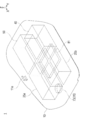
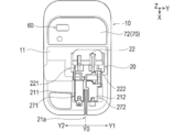
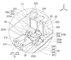
- FIG. 1 to 14 are views provided for explaining the overall configuration and the configuration of each part of the tube joining device 1 according to the embodiment of the present invention.
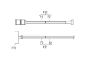
- FIG. 15 is a diagram provided for explaining a plurality of tubes joined by the tube joining device 1.
- 16 to 24 are views for explaining a usage example of the tube joining device 1.
- the front-rear direction in the tube joining device 1 will be referred to as a front-rear direction X
- a left-right direction will be referred to as a left-right direction Y
- a height direction will be referred to as a height direction Z.
- ⁇ Tube joining device> In the tube joining device 1 of the present embodiment, for example, when performing APD using the peritoneal dialysis device F (see FIG. 15), a plurality of tubes F2, F3, and F1 constituting the peritoneal dialysis device F are connected to each other. It can be used to continuously join T2, T3, and T1.
- the peritoneal dialysis apparatus F is connected to a peritoneal line F11 connected to a tube T1 extending from the peritoneum of a patient M performing peritoneal dialysis, and to a plurality of dialysate containers T12. Communication / interruption between the infusion line F12, the additional infusion line F13 connected to the additional dialysate container T13, the discharge line F14 connected to the drainage container T14, the peritoneal line F11, and the other lines F12 to F14. It has a main body F15 that automatically injects and discharges dialysate by switching between.
- the additional injection line F13 can be used when it is desired to additionally inject the dialysate in addition to the injection of the dialysate by the injection line F12, or when it is desired to change the concentration of the dialysate to be injected.
- the tube joining device 1 can be used, for example, for fusing and joining a plurality of tubes F2 constituting the injection line F12 and the end portions of the tubes T2 of the dialysate container T12 of the plurality of peritoneums. Further, the tube joining device 1 can be used for fusing and joining the end of the tube F3 constituting the additional injection line F13 and the end of the tube T3 of the additional dialysate container T13. Further, the tube joining device 1 can be used, for example, to flute and join the end of the tube F1 constituting the peritoneal line F11 and the end of the tube T1 connected to the peritoneal catheter T11 of the patient M.
- the tube joining device 1 continuously joins a plurality of tubes F2 constituting the injection line F12 and tubes T2 (corresponding to the first tube and the second tube) of the plurality of dialysate containers T12.
- the configuration of the tube joining device 1 will be described as an example.
- “continuously joining” means joining two tubes in sequence while the power of the tube joining device is ON. Therefore, as long as the power of the tube joining device 1 is ON, there may be an interval between the completion of joining the two tubes and the start of joining the next two tubes.
- the tube joining device 1 is used in combination with a wafer cassette WC having a plurality of wafer WFs (corresponding to cutting members) used for fusing.
- the tubes F2 and T2 are fusing by the heated wafer WF in a state where the juxtaposed tubes F2 and T2 are pressed against each other and crushed. ..
- FIGS. 20 and 21 After that, as shown in FIGS. 20 and 21, the positions of one side of the fused tube F2 and one side of the tube T2 are exchanged, and the tubes F2 and T2 are pressed and joined. Details will be described later.
- the tube joining device 1 is outlined with reference to FIG. 1, a housing 10 for accommodating each part of the tube joining device 1, crushing the tubes F2 and T2 at the time of fusing, and one side of the tube F2 after fusing and the tube. It has a clamp portion 20 that replaces one side of the T2, and an interlock 30 that locks the clamp portion 20 in a state where the tubes F2 and T2 are sandwiched at the time of fusing and joining.
- the tube joining device 1 has a storage unit 40 that stores the wafer cassette WC inserted in the housing 10 and a feed unit 50 that heats the wafer WF and sends it to the fusing position.
- the tube joining device 1 supplies electric power to the operation unit 60 capable of receiving an instruction to switch the power ON / OFF, the notification unit 70 for notifying the user of necessary information, and each unit. It has a power supply unit 80 that can be supplied, and a control unit 90 that comprehensively controls the operation of each unit.
- the side where the positions are switched after the fusing is defined as the “replacement side Y1” with the fusing position Y0 of the tubes F2 and T2 as the boundary.
- the opposite side is referred to as "fixed side Y2". The details will be described below.
- the housing 10 includes an upper portion 11 which is an upper side surface of a substantially hexahedron, and a lower portion 12 which is arranged below the upper portion 11 and constitutes a side surface other than the upper side surface of the substantially hexahedron. It is composed of a combination of cases.
- the upper portion 11 is provided with a hole 11r in which the clamp portion 20 can be arranged.
- a cassette insertion hole 11c for inserting the wafer cassette WC and an take-out switch 11d for taking out the wafer cassette WC inserted in the housing 10 are arranged on the side surface of the lower portion 12. If the user pushes the take-out switch 11d with a finger while the wafer cassette WC is inserted through the cassette insertion hole 11c, the wafer cassette WC can be taken out of the housing 10 through the cassette insertion hole 11c.
- the housing 10 has a built-in temperature sensor 11e capable of measuring the ambient temperature around the housing 10.
- the heating time for the wafer WF to heat the tubes F2 and T2 can be adjusted according to the environmental temperature measured by the temperature sensor 11e.
- the clamp portion 20 holds the tubes F2 and T2 side by side, presses the tubes F2 and T2 against each other at the time of fusing, and after the fusing, the positions of one side of the tube F2 and one side of the tube T2 are exchanged, and the fusing tubes F2 and T2 One is pressed against the other in the left-right direction Y.
- the clamp portion 20 includes a pedestal 21 protruding from the upper portion 11 and a lid portion 22 configured to be openable and closable by relatively approaching and separating from the pedestal 21. ..
- the clamp portion 20 is installed on the pedestal 21, and the holding portion 23 for holding the tubes F2 and T2 and the lid portion 22 press the tubes F2 and T2 against each other as the lid portion 22 approaches the pedestal 21 to crush the tubes F2 and T2.
- a tube pressing portion 25 is provided.
- the pedestal 21 includes a first pedestal 211 provided on the fixed side Y2 of the tubes F2 and T2, and a second pedestal 212 provided on the replacement side Y1 of the tubes F2 and T2. ..
- a gap 21a is provided between the first pedestal 211 and the second pedestal 212 along the extending direction of the tubes F2 and T2. The gap 21a is provided for the wafer WF to pass through when the wafer WF before use moves to the fusing position, when the used wafer WF is sent out to the outside of the housing 10, and the like.
- each of the first pedestal 211 and the second pedestal 212 is provided with an engaged portion 213 that can be engaged with the engaging claw 225 of the lid portion 22, which will be described later.
- the lid portion 22 includes a first clamp arm 221 rotatably provided with respect to the first pedestal 211 and a second clamp arm 222 rotatably provided with respect to the second pedestal 212.
- the lid portion 22 is rotatably provided with respect to the cover 223 covering the first clamp arm 221 and the second clamp arm 222, the first clamp arm 221 and the second clamp arm 222, and can be gripped by the user. It is provided with a part 224.
- the cover 223 integrally covers the first clamp arm 221 and the second clamp arm 222. Therefore, as shown in FIG. 2, when the lid portion 22 is closed, the cover 223 covers the first pedestal 211, the second pedestal 212, and the region where fusing-joining is performed between them.
- the grip portion 224 includes an engaging claw 225 that can be engaged with the engaged portion 213 of the pedestal 21. Therefore, as shown in FIGS. 10 and 11, after closing the first clamp arm 221 and the second clamp arm 222 and the cover 223, the grip portion 224 is rotated with respect to the first clamp arm 221 and the second clamp arm 222. Then, the engaging claw 225 engages with the engaged portion 213. As a result, the state in which the clamp portion 20 sandwiches the tubes F2 and T2 can be preferably maintained.
- the pedestal 21 is provided with an open / close detection unit 26 for detecting the opening / closing of the lid portion 22.
- the open / close detection unit 26 can detect that the lid portion 22 is closed with respect to the pedestal 21, the specific configuration is not particularly limited.
- the open / close detection unit 26 is composed of a sensor such as a limit switch adjacent to the engaged unit 213 as shown in FIG. In the open / close detection unit 26, when the engaging claw 225 engages with the engaged portion 213, the tip of the engaging claw 225 comes into contact with the sensor and pushes the sensor, whereby the lid portion 22 is closed. It has been detected.
- the holding portion 23 movably holds the first holding portion 231 that fixedly holds the fixed side Y2 of each tube F2 and T2, and the replacement side Y1 of each tube F2 and T2. 2 Holding unit 232 and.
- the holding unit 23 changes the release unit 233 capable of switching the second holding unit 232 from the holding state in which the tubes F2 and T2 can be held to the released state in which the holding is released, and the second holding unit 232 from the released state to the holding state. It includes a switchable restoration unit 234.
- the first holding portion 231 is fixed to the upper surface of the first pedestal 211. As shown in FIG. 6, the first holding portion 231 includes a concave groove portion 231a into which the tube T2 can be fitted (held), and a concave groove portion 231b into which the tube F2 can be fitted.
- the groove portions 231a and 231b are provided so as to be arranged in a direction inclined by an angle ⁇ with respect to the mounting surface FS of the housing 10 (diagonal direction D1). Therefore, the tubes F2 and T2 are held by the first holding portion 231 in a state of being inclined and arranged with respect to the mounting surface FS in the holding portion 23.
- the second holding portion 232 is rotatably attached to the side surface of the second pedestal 212 with the rotation shaft 232c substantially parallel to the left-right direction Y as the center of rotation.
- the second holding portion 232 includes groove portions 232a and 232b arranged at the same height and inclination as the first holding portion 231 in a state where the lid portion 22 is opened.
- the groove portions 232a and 232b are configured to hold the tubes F2 and T2 together with the groove portions 231a and 231b in a state where the lid portion 22 is opened. That is, in the holding state, it means that the second holding portion 232 is arranged at a position (holding position) where the tubes F2 and T2 are arranged in the grooves 232a and 232b when the lid portion 22 is opened. ..
- the second holding portion 232 is displaced downward in the height direction Z with the rotation shaft 232c as the center of rotation in a state where the lid portion 22 is closed, and the groove portions 232a and 232b are separated from the tubes F2 and T2. That is, the release state means a state in which the second holding portion 232 is arranged at a position (release position) where the tubes F2 and T2 are not arranged in the grooves 232a and 232b when the lid portion 22 is closed. To do.
- the release portion 233 is composed of protrusions protruding from the second holding portion 232 toward the second clamp arm 222 with the lid portion 22 open as shown in FIG.
- the release portion 233 comes into contact with the second clamp arm 222 of the lid portion 22 as the lid portion 22 approaches the housing 10 relatively.
- the release portion 233 retracts the second holding portion 232 from the holding position to the release position as the lid portion 22 approaches the housing 10 relatively.
- the restoring portion 234 is provided by a cam capable of pushing up the second holding portion 232 in conjunction with the operation in which the second clamp arm 222 of the lid portion 22 is relatively separated from the housing 10. It is configured.
- the restoration unit 234 is configured so as to be in contact with the second holding unit 232.
- the restoration unit 234 has a substantially fan-shaped outer shape when viewed from the side surface of the housing 10.
- the restoration portion 234 is fixed in the vicinity of the rotating portion of the second clamp arm 222. Therefore, the restoration unit 234 rotates in conjunction with the rotation of the second clamp arm 222.
- the second holding unit 232 is configured to be movable between the holding position and the releasing position by the releasing unit 233 and the restoring unit 234.
- the first holding unit 231 is provided with a tube detecting unit 24 that can detect whether or not the tubes F2 and T2 are set.
- the tube detection unit 24 is provided in the groove portions 231a and 231b of the first holding portion 231, and the elastic member 244 is configured to allow the groove portions 231a and 231b to protrude and sink from the bottom. It includes a pin 241 and a magnet 242 provided at the base of the pin 241 and a Hall element 243.
- the pin 241 changes its position from the protruding position to the depressed position when the tubes F2 and T2 are fitted into the groove portions 231a and 231b.
- the magnet 242 moves in accordance with the protrusion or depression of the pin 241 from the groove 231a and 231b.
- the Hall element 243 is arranged adjacent to the magnet 242.
- the tube detection unit 24 detects whether or not the tubes F2 and T2 are arranged in the grooves 231a and 231b by changing the magnitude of the magnetic force of the magnet 242 detected by the Hall element 243 according to the position of the pin 241. ..
- the specific configuration is not limited to the above as long as it can be detected that the tubes F2 and T2 are arranged in the grooves 231a and 231b.
- the tube pressing portion 25 includes a fixed side pressing portion 25a and a movable side pressing portion 25b as shown in FIG.
- the fixed-side pressing portion 25a brings the tubes F2 and T2 close to the direction D1 in which the tubes F2 and T2 are lined up on the fixed-side Y2 of the tubes F2 and T2, and presses the tubes F2 and T2 in contact with each other. Is given.
- the fixed-side pressing portion 25a includes a lid-side pressing portion 251 provided on the first clamp arm 221 and a housing-side pressing portion 252 provided on the first pedestal 211.
- the movable side pressing portion 25b brings the tubes F2 and T2 close to each other in the direction D1 in which the tubes F2 and T2 are lined up on the replacement side Y1 of the tubes F2 and T2 in the same manner as the fixed side pressing portion 25a.
- a pressing force is applied to the tubes F2 and T2.
- the movable side pressing portion 25b includes a lid side pressing portion 253 provided on the second clamp arm 222 and a housing side pressing portion 254 provided on the second pedestal 212.
- the clamp portion 20 sandwiches the fixed side Y2 (corresponding to one side) of the tubes T2 and F2 in the longitudinal direction (horizontal direction Y) of the tubes T2 and F2 with the fusing position Y0 as a boundary.
- Movable clamp unit 272 (second clamp unit) that sandwiches the fixed clamp unit 271 (first clamp unit) and the replacement side Y1 (corresponding to the other side) in the longitudinal direction of the tubes T2 and F2 with the fusing position Y0 as the boundary. And have.
- the fixed clamp unit 271 is composed of a first pedestal 211, a first clamp arm 221, a first holding portion 231 and a fixed side pressing portion 25a.
- the movable clamp unit 272 is composed of a second pedestal 212, a second clamp arm 222, and a movable side pressing portion 25b.
- the clamp portion 20 is in an initial state in which the tube F2 and the tube T2 before fusing can be arranged by the transition portion 27, and a joined state in which the end portion of the fusing tube F2 and the fusing end portion of the tube T2 can be joined. It is configured to be migratable.
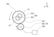
- the transition portion 27 rotates the movable side pressing portion 25b constituting the movable clamp unit 272 to fix the movable end portions of the fused tubes F2 and T2, as shown in FIGS. 12 to 14. It has a rotary drive unit 28 that is interchanged with respect to the side, and a straight drive unit 29 that can approach and separate the movable clamp unit 272 from the fixed clamp unit 271.
- the rotation drive unit 28 includes a first gear 281 provided around the lid-side pressing portion 253 and the housing-side pressing portion 254 integrated with the lid portion 22 closed, and the first gear. It includes a second gear 282 that meshes with 281 and a motor 283 that is connected to the rotating shaft of the second gear 282.
- the control unit 90 described later drives the motor 283 at the stage where the fusing is completed, the second gear 282 rotates. Since the first gear 281 rotates with the rotation of the second gear 282, the lid-side pressing portion 253 and the housing-side pressing portion 254 integrated with the first gear 281 also rotate. As a result, the lid-side pressing portion 253 and the housing-side pressing portion 254 also rotate. As a result, as shown in FIG. 20, the positions of the replacement side Y1 of the tube T2 and the replacement side Y1 of the tube F2 after fusing can be exchanged.
- the movable side pressing portion 25b is in a state in which the positions of the lid side pressing portion 253 and the housing side pressing portion 254 are reversed (the lid side pressing portion 253 is arranged on the second pedestal 212 side, and the housing. Even when the body-side pressing portion 254 is arranged on the second clamp arm 222 side), the lid portion 22 is opened so that the tubes F2 and T2 to be joined next can be arranged. Therefore, in the present embodiment, the rotary drive unit 28 is not configured to be driven when the clamp unit 20 is restored from the bonded state to the initial state after the tube joining is completed.
- the clamp portion 20 is initially from the joined state.
- the rotation drive unit 28 may be driven.
- the straight drive unit 29 is configured so that the movable clamp unit 272 can be relatively close to and separated from the fixed clamp unit 271.
- the movable clamp unit 272 and the fixed clamp unit 271 are separated from each other in the longitudinal direction (horizontal direction Y) of the tubes F2 and T2, and the tubes F2 and T2 before fusing are separated.
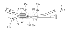
- the movable clamp unit 272 is arranged at the initial position P1 where the movable clamp unit 272 can be arranged.
- the straight-ahead drive unit 29 as shown in FIG.
- the fixed clamp unit 271 and the movable clamp unit 272 are closer to each other than the initial position P1 and the end portion of the tube F2 that has been blown in the longitudinal direction of the tubes F2 and T2.
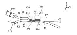
- the movable clamp unit 272 is arranged at the joining position P2 where the ends of the blown tube T2 can be pressed against each other to be joined.
- the straight drive unit 29 includes a cam 291 configured to be rotatable around a rotation axis along the front-rear direction X, a motor for rotating the cam 291 (not shown), and a movable clamp, as shown in FIG.
- the unit 272 is attached and includes a contact member 292 capable of contacting the cam 291 in the left-right direction Y, and an urging member 293 that biases the contact member 292 in a direction of approaching the cam 291.
- the contact position of the cam 291 with the contact member 292 in the left-right direction Y differs depending on the rotation of the cam 291. Therefore, the ends of the movable tube F2 and T2 are fixed to the fixed side tube F2. Press against the end of T2.
- the tube joining device 1 is provided with a position detecting unit 294 capable of detecting the position of the movable clamp unit 272 in the left-right direction Y.
- the position detection unit 294 is not particularly limited, but can be configured by a photo sensor or the like that detects the position of the movable clamp unit 272 in the left-right direction Y from the rotation angle of the cam 291 or the like.
- the interlock 30 has a function of locking the clamp portion 20 in a state of sandwiching the tubes F2 and T2 at the time of fusing and joining.
- the interlock 30 is composed of an electromagnetically driven solenoid rod 31 as shown in FIG. 11 in the present embodiment.
- the storage unit 40 is located at a location shown in FIG. 3, and has a function of storing the wafer cassette WC inserted in the housing 10 and a function of detecting the remaining amount of the wafer WF in the wafer cassette WC. ..
- the storage unit 40 includes a mounting unit (not shown) on which the wafer cassette WC inserted through the cassette insertion hole 11c is mounted, a wafer detecting unit 42 (see FIG. 14) capable of detecting the wafer WF in the wafer cassette WC, and a wafer detecting unit 42 (see FIG. 14). Is equipped with.
- the wafer detection unit 42 monitors the remaining amount of the wafer WF and whether or not the wafer WF can be used in a state where the power is turned on by the operation unit 60.
- the wafer detection unit 42 can be configured by, for example, a known photosensor.
- the feeding unit 50 is located at the location shown in FIG. 3, and feeds the wafer WF to the fusing position, heats the wafer WF at the time of fusing, cools the used wafer WF, and disposes the used wafer WF into the housing 10. Send out to the outside of.
- the feed unit 50 is configured so that the wafer WF can be fed from the wafer cassette WC in the storage unit 40 to the fusing position.
- the feeding unit 50 includes a driving unit (not shown) capable of feeding the used wafer WF to the outside of the housing 10 through the gap 21a between the first pedestal 211 and the second pedestal 121.
- the feed unit 50 is provided inside the wafer WF and can cool a heating wire capable of heating the wafer WF, a terminal capable of supplying electric power necessary for heating the wafer WF at the time of fusing, and a used wafer WF. It is equipped with a fan (not shown).
- the operation unit 60 receives an instruction from the user to the tube joining device 1. As shown in FIGS. 1 and 2, the operation unit 60 includes a switch for switching ON / OFF of the power supply of the tube joining device 1. The operation unit 60 is provided on the rear end side of the upper portion 11 of the housing 10 as shown in FIG. 2 in the present embodiment, but the specific position is not limited to this.
- the notification unit 70 notifies the user of necessary information. As shown in FIGS. 1 and 3, the notification unit 70 includes a plurality of display units 71 and 72 for displaying information necessary for the user, and a speaker 73 for notifying the user of necessary information by voice. There is.
- the power supply unit 80 has a function of supplying electric power to each part of the tube joining device 1. As shown in FIGS. 1 and 3, the power supply unit 80 includes a battery 81 capable of supplying electric power to each unit and a charger 82 for charging the battery 81.
- the control unit 90 can be configured by a microcomputer or the like.
- the control unit 90 includes a CPU, a ROM that stores control programs and various data of the entire device executed by the CPU, and a RAM that temporarily stores measurement data and various data as a work area.
- the control unit 90 includes a power supply unit 80, an operation unit 60, a notification unit 70, a tube detection unit 24, an open / close detection unit 26, an interlock 30, a temperature sensor 11e, a wafer detection unit 42, and a feed unit. It is electrically connected to 50, the transition unit 27, the position detection unit 294, and the like.
- the control unit 90 controls each unit in an integrated manner.
- the control unit 90 operates each unit when the tube detection unit 24 detects that the tubes F2 and T2 are arranged in the clamp unit 20 and the open / close detection unit 26 detects that the lid 22 is closed. Is controlled to start the fusing operation.
- the control unit 90 controls the operation of the transition unit 27 after the tubes F2 and T2 are blown, and shifts the clamp unit 20 from the initial state to the joined state. Specifically, the control unit 90 controls the operation of the rotation drive unit 28 of the transition unit 27, rotates the movable side pressing unit 25b as shown in FIG. 20, and replaces the tube T2 with the replacement side Y1 and the tube after fusing. The position of F2 with the replacement side Y1 is exchanged. Next, the control unit 90 controls the operation of the straight drive unit 29 of the transition unit 27 based on the signal from the position detection unit 294, and as shown in FIG. 21, the fixed clamp unit 271 and the movable clamp unit 272 are combined. The movable clamp unit 272 is moved from the initial position P1 to the joint position P2 by making them relatively close to each other.
- the control unit 90 When the tube detection unit 24 detects the removal of the tubes F2 and T2 from the clamp unit 20 after the joining is completed, the control unit 90 operates the transition unit 27 so that the clamp unit 20 restores from the bonding state to the initial state. Control. Specifically, when the tube detection unit 24 detects the removal of the tubes F2 and T2 from the clamp unit 20 after the joining is completed, the control unit 90 advances straight through the transition unit 27 based on the signal from the position detection unit 294. The operation of the drive unit 29 is controlled, and the movable clamp unit 272 is moved from the joint position P2 (see FIG. 21) to the initial position P1 (see FIG. 22).
- the control unit 90 causes the notification unit 70 to notify the handling method of the removed tubes F2 and T2. .
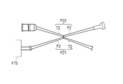
- the notification unit 70 includes a tube F21 on the use side (a tube led out from the main body F15) and a tube F22 on the discard side (tubes in which ends are connected to each other). ) Is pulled apart, and the joint portion of the tube F21 on the side to be used is pushed with a finger to notify the opening. While the notification unit 70 notifies the handling method of the removed tubes F2 and T2, the control unit 90 controls the operation of the transition unit 27 so that the clamp unit 20 restores from the joined state to the initial state.
- the user opens the lid 22 of the tube joining device 1.
- the user sets the tubes T2 and F2 in the first holding portion 23231 and the second holding portion 232 as shown in FIGS. 5 and 17.
- the user performs an operation of closing the lid portion 22 (an operation of bringing the lid portion 22 relatively close to the housing 10). Since the lid portion 22 is closed, the outer peripheral portion of the fusing portion of the tubes T2 and F2 is covered with the cover 223 and is isolated from the outside. This makes it possible to carry out the fusing-joining operation in an aseptic state.
- the control unit 90 starts the fusing-joining operation.
- the control unit 90 confirms whether the tubes T2 and F2 are set in the first holding unit 231 by the tube detecting unit 24 with the lid portion 22 closed as shown in FIG. 16 (ST1).
- the control unit 90 controls the operation of the notification unit 70, sets the tubes T2 and F2 to the user, and sets the tubes T2 and F2 to the user. Notify the lid 22 to be closed (ST2).
- the control unit 90 confirms whether the wafer WF is housed in the wafer cassette WC by the wafer detecting unit 42 (ST3).
- the control unit 90 notifies the notification unit 70 to notify the wafer cassette WC to store the wafer WF (ST4).
- the control unit 90 causes the feed unit 50 to take out the wafer WF from the wafer cassette WC, and the fusing preparation position (the wafer WF in FIG. 19 is indicated by a broken line). It is sent out to the position where it is (ST5).
- the control unit 90 confirms whether the wafer WF can be used for fusing (ST6).
- the control unit 90 notifies the notification unit 70 that the wafer WF is not suitable for fusing or that the wafer WF is sent out again. (ST7).
- control unit 90 causes the feed unit 50 to take out the wafer WF from the wafer cassette WC again and send it to the fusing preparation position (ST5). At this time, the wafer WF that is not suitable for fusing is pushed out from the fusing preparation position by the next wafer WF.
- control unit 90 starts controlling the fusing work by the wafer WF.
- control unit 90 operates the interlock 30 to lock the lid 22 in the closed state.
- the wafer WF at the fusing preparation position is heated by the built-in heater (ST8). Then, the wafer WF heated by the feed unit 50 is moved to a fusing position (the position where the wafer WF in FIG. 19 is shown by a solid line), and fusing is performed as shown in FIG. 19 (ST9).
- the control unit 90 controls the operation of the transition unit 27 to shift the clamp unit 20 from the initial state to the joined state (ST10).
- the rotation drive unit 28 of the transition unit 27 rotates the movable side pressing unit 25b to exchange the positions of the replacement side Y1 of the tube F2 and the replacement side Y1 of the tube T2.
- the straight drive unit 29 of the transition unit 27 brings the movable clamp unit 272 closer to the fixed clamp unit 271 and moves it from the initial position P1 to the joint position P2.
- the fused ends of the tube T2 and the tube F2 are pressed against each other in the longitudinal direction of the tubes T2 and F2, and are pressure-bonded.
- control unit 90 unlocks the interlock 30.
- the user performs an operation of opening the lid portion 22, and removes the joined tubes T2 and F2 from the tube joining device 1 as shown in FIG.
- control unit 90 confirms whether or not the joined tubes F2 and T2 have been removed from the first holding unit 231 (ST11).
- control unit 90 When the tubes F2 and T2 are not removed from the first holding unit 231 (ST11: NO), the control unit 90 notifies the notification unit 70 to remove the tubes F2 and T2 (ST12).
- the control unit 90 When the tubes F2 and T2 are removed from the first holding unit 231 (ST11: YES), the control unit 90 notifies the notification unit 70 of how to handle the removed tubes F2 and T2, and operates the transition unit 27. To restore the clamp portion 20 from the joined state to the initial state (ST13). Specifically, as shown in FIG. 22, the straight drive unit 29 of the transition unit 27 separates the movable clamp unit 272 from the fixed clamp unit 271 and restores the movable clamp unit 272 from the joint position P2 to the initial position P1.
- the user pulls the removed tubes F2 and T2 from the tube F21 on the side to be used and the tube F22 on the side to be discarded and uses them, as shown in FIGS. Push the joint of the side tube F21 with your fingers to open it.
- the tube F2, T2 (or the tubes F3, T3 or the tubes F1, T1) to be joined next are held in the first holding portion 231 and the second. Set in the holding unit 232.
- the user performs an operation of closing the lid portion 22 (an operation of bringing the lid portion 22 relatively close to the housing 10).
- an example of joining in the order of tube F2 and tube T2, tube F3 and tube T3, and tube F1 and tube T1 has been described, but the joining order is not particularly limited.
- the control unit 90 confirms whether the lid portion 22 is closed within a predetermined time from the completion of joining the tubes (ST14). If the lid 22 is not closed within a predetermined time from the completion of tube joining (ST14: NO), the control unit 90 automatically turns off the power of the tube joining device 1 (ST15). The user may manually turn off the power.
- control unit 90 When the lid portion 22 is closed within a predetermined time from the completion of joining the tubes (ST14: YES), the control unit 90 performs ST2 to ST14 again.
- the tube joining device 1 includes a clamp unit 20, a transition unit 27, a tube detection unit 24, and a control unit 90.
- the clamp portion 20 can sandwich the tube F2 and the tube T2, and joins the fusing end of the tube F2 and the fusing end of the tube T2 with the initial state in which the tube F2 and the tube T2 before fusing can be arranged. It is possible to shift to a possible joining state.
- the transition portion 27 shifts the clamp portion 20 to the initial state and the joined state.
- the tube detection unit 24 can detect the removal of the tube F2 and the tube T2 from the clamp unit.
- the control unit 90 restores the clamp unit 20 from the bonded state to the initial state.
- the operation of the transition unit 27 is controlled as described above.
- the tube joining device 1 when the removal of the tubes F2 and T2 from the clamp portion 20 is detected after the joining is completed, the clamp portion 20 is restored from the joined state to the initial state. Therefore, according to the tube joining device 1, the user when continuously joining tubes as compared with the tube joining device configured to restore the joining state to the initial state by the operation of the user. It is possible to improve the convenience of.
- the clamp portion 20 has a fixed clamp unit 271 that holds one side of the tubes F2 and T2 in the longitudinal direction with the fusing position Y0 as the boundary, and the other side of the tubes F2 and T2 in the longitudinal direction with the fusing position Y0 as the boundary. It has a movable clamp unit 272 which holds the portion of the above.
- the transition unit 27 makes the blown end of the tube F2 and the blown end of the tube T2 in the longitudinal direction.
- the fixed clamp unit 271 and the movable clamp unit 272 are relatively separated from the joint position P2 that can be pressed and joined, and the tubes F2 and T2 to be joined next are restored to the initial position P1 that can be arranged. Therefore, the tube joining device 1 is used, for example, when the tubes are continuously joined as compared with the tube joining device configured to restore the joining position P2 to the initial position P1 by the operation of the user. It is possible to improve the convenience of the person.
- the tube joining device 1 further includes a notification unit 70 that notifies the handling method of the removed tubes F2 and T2 when the tube detection unit 24 detects the removal of the tubes F2 and T2 from the clamp unit 20. While the notification unit 70 notifies the handling method of the removed tubes F2 and T2, the control unit 90 controls the operation of the transition unit 27 so that the clamp unit 20 restores from the joined state to the initial state. Therefore, it is possible to prevent the user from accidentally arranging the tube to be joined next to the clamp portion 20 while the clamp portion 20 is restored from the joined state to the initial state.
- the tube joining method according to the above embodiment is a joining method using the above tube joining device 1.
- the wafer WF fuses the end of the tube F2 and the end of the tube T2 with the clamp portion 20 in the initial state sandwiching the tube F2 and the tube T2 before fusing.
- the clamp portion 20 shifts from the initial state to the joined state, the blown end portion of the tube F2 and the blown end portion of the tube T2 are joined.
- the tube detection unit 24 detects the removal of the tube F2 and the tube T2 from the clamp unit 20 after the bonding of the tube F2 and the tube T2 is completed, the clamp unit 20 restores the bonded state to the initial state.
- the clamp portion 20 in the initial state sandwiches the tube F2 and the tube T2 to be joined next, and the fusing, the joining, and the restoration are performed. Therefore, according to the above-mentioned tube joining method, as compared with a tube joining device configured to restore the joining state to the initial state by the user's operation, the user's method of continuously joining the tubes is improved. Convenience can be improved.
- a plurality of tubes F1, F2, and F3 constituting the peritoneal dialysis apparatus F that automatically injects and discharges dialysate into the peritoneum are continuously connected to the corresponding tubes T1, T2, and T3. To join. Therefore, the user can efficiently prepare the APD.
- the present invention can be used not only for peritoneal dialysis, but also for, for example, a device for aseptically joining a tube connected to a container (bag) containing a blood product or the like used for blood transfusion to another tube.
- a container bag
- a blood product or the like used for blood transfusion to another tube.
- the sterility of the blood components (preparations) in the tube and the bag can be maintained.
- the present invention can also be used in an apparatus for aseptically joining a tube connected to a container (bag) containing a cell culture solution containing various collected and cultured cells to another tube. Also in this case, the sterility and safety of the cell culture solution in the tube and the bag can be maintained at the time of tube joining.
- the tube joining device connects a plurality of tubes constituting the injection line of the automatic dialysis device to the tubes of the dialysis container, and then connects the tubes constituting the additional injection line and the peritoneal line to the corresponding tubes.
- An example of doing so was explained.
- the order in which the tubes are connected is not particularly limited.
- the transition unit restores the clamp portion from the joined state to the initial state while the notification unit notifies the handling method of the removed tube.
- the transition unit may restore the clamp portion from the joined state to the initial state without the notification unit notifying.
- the notification unit may notify that the tube to be joined next can be arranged.
- the tube joining device may be used to connect the tube constituting the discharge line F4 to the tube of the drainage container.
- Tube joining device 10 housings, 20 Clamp part, 24 tube detector, 27 Transition Department, 90 Control unit, 271 Fixed clamp unit (1st clamp unit), 272 Movable clamp unit (second clamp unit), F Peritoneal dialysis machine, F1, F2, F3 Multiple tubes constituting the peritoneal dialysis machine, T1, T2, T3 compatible tubes, P1 initial position, P2 joint position, WF wafer (cutting member), Y0 fusing position.
Landscapes
- Engineering & Computer Science (AREA)
- Mechanical Engineering (AREA)
- Health & Medical Sciences (AREA)
- Emergency Medicine (AREA)
- Urology & Nephrology (AREA)
- Heart & Thoracic Surgery (AREA)
- Hematology (AREA)
- Biomedical Technology (AREA)
- Anesthesiology (AREA)
- Life Sciences & Earth Sciences (AREA)
- Animal Behavior & Ethology (AREA)
- General Health & Medical Sciences (AREA)
- Public Health (AREA)
- Veterinary Medicine (AREA)
- Vascular Medicine (AREA)
- Toxicology (AREA)
- Branch Pipes, Bends, And The Like (AREA)
- Lining Or Joining Of Plastics Or The Like (AREA)
- External Artificial Organs (AREA)
Abstract
【課題】チューブの接合を連続して行う際に使用者の利便性を向上させることのできるチューブ接合装置及びチューブ接合装置を用いた接合方法を提供する。 【解決手段】チューブ接合装置1は、加熱した板状のウェハーWDによってチューブF2の端部とチューブT2の端部を溶断した後、チューF2ブの溶断した端部とチューブT2の溶断した端部を入れ替えて接合するチューブ接合装置である。チューブ接合装置は、チューブF2及びチューブT2を挟みこみ可能であり、溶断前のチューブF2及びチューブT2を配置可能な初期状態と、チューブF2の溶断した端部とチューブT2の溶断した端部を接合可能な接合状態とに、移行可能なクランプ部20と、クランプ部を初期状態及び接合状態に移行させる移行部27と、クランプ部からのチューブF2及びチューブT2の取出しを検出可能なチューブ検出部24と、チューブF2とチューブT2の接合完了後に、チューブ検出部がクランプ部からのチューブF2及びチューブT2の取出しを検出した場合に、クランプ部が接合状態から初期状態に移行するように移行部の動作を制御する制御部90と、を有する。
Description
本発明は、チューブ接合装置及びチューブ接合装置を用いた接合方法に関する。
樹脂製のチューブ同士等をつなぎ合わせる技術として、各樹脂製のチューブの端部を溶断し、溶断した端部同士を相互に押し付けて加圧接合する接合方法が従来から知られている。このような技術は、様々な産業分野において広く用いられており、その一例として、腹膜透析方法などの医療技術への応用が試みられている。
腹膜透析方法は、患者の腹腔内に埋め込んだチューブ(カテーテル)を使用して所定の透析液を体内に入れ、一定時間経過後、腹膜を介して透析液内へ移行させた水や老廃物を体外へ取除く方法である。特許文献1には、腹膜透析に用いる2本のチューブにおいて溶断した端部を入れ替えて接合を行うチューブ接合装置が開示されている。
特許文献1に記載のチューブ接合装置は、溶断した2本のチューブを挟みこみ可能であり、溶断前の2本のチューブを配置可能な初期状態と、溶断した2本のチューブの端部同士を接合可能な接合状態とに、移行可能なクランプ部を有している。特許文献1では、2本のチューブの接合完了後、クランプ部は、使用者が電源を操作するによって接合状態から初期状態に復元するように構成している。
ところで、腹膜透析方法の一つとして、夜間等に連続して透析液の注入及び排出を行う自動腹膜灌流療法(APD:Automated Peritoneal Dialysis)が知られている。APDでは、腹膜への透析液の注入と排出を自動的に行う腹膜透析装置等が用いられる。腹膜透析装置は、腹膜から延びるチューブに接続される腹膜ラインと、腹膜ラインに連なると共に複数の透析液容器に接続される注入ラインと、腹膜ラインに連なるとともに排液容器に接続される排出ラインと、を有する。
腹膜から延びるチューブと腹膜ラインを接続する場合や複数の透析液容器の複数のチューブと注入ラインを構成する複数のチューブを接続する場合等において、上述したチューブ接合装置が用いられる場合がある。この場合、チューブ接合装置は、チューブの接合を連続して行う。そのため、特許文献1のように、使用者の操作によってクランプ部を接合状態から初期状態に復元するように構成している場合、次の接合を行う度に使用者がクランプ部を接合状態から初期状態に復元するための操作を行う必要があり、使用者の利便性が損なわれる。
そこで本発明は、チューブの接合を連続して行う際に使用者の利便性を向上させることのできるチューブ接合装置及びチューブ接合装置を用いた接合方法を提供することを目的とする。
上記目的を達成する本発明に係るチューブ接合装置は、加熱した板状の切断部材によって第1チューブの端部と第2チューブの端部を溶断した後、前記第1チューブの溶断した端部と前記第2チューブの溶断した端部を入れ替えて接合するチューブ接合装置であって、前記第1チューブ及び前記第2チューブを挟みこみ可能であり、溶断前の前記第1チューブ及び前記第2チューブを配置可能な初期状態と、前記第1チューブの溶断した端部と前記第2チューブの溶断した端部を接合可能な接合状態とに、移行可能なクランプ部と、前記クランプ部を前記初期状態及び前記接合状態に移行させる移行部と、前記クランプ部からの前記第1チューブ及び前記第2チューブの取出しを検出可能なチューブ検出部と、前記第1チューブと前記第2チューブの接合完了後に、前記チューブ検出部が前記クランプ部からの前記第1チューブ及び前記第2チューブの取出しを検出した場合に、前記クランプ部が前記接合状態から前記初期状態に復元するように前記移行部の動作を制御する制御部と、を有する。
また、本発明に係る接合方法は、上記に記載のチューブ接合装置を用いた接合方法であって、前記初期状態の前記クランプ部が溶断前の前記第1チューブ及び前記第2チューブを挟みこんだ状態で、前記切断部材が前記第1チューブの端部と前記第2チューブの端部を溶断し、前記クランプ部が前記初期状態から前記接合状態に移行することで、前記第1チューブの溶断した端部と前記第2チューブの溶断した端部を接合し、前記第1チューブと前記第2チューブの接合完了後に前記チューブ検出部が前記クランプ部からの前記第1チューブ及び前記第2チューブの取出しを検出した場合に、前記クランプ部は、前記接合状態から前記初期状態に復元し、前記初期状態の前記クランプ部が次に接合する前記第1チューブ及び前記第2チューブを挟みこみ、前記溶断、前記接合、及び前記復元が行われる。
本発明に係るチューブ接合装置および接合方法によれば、接合完了後にクランプ部からの第1チューブ及び第2チューブの取出しが検出された場合に、クランプ部は接合状態から初期状態に復元する。したがって、使用者の操作によってクランプ部を接合状態から初期状態に復元するチューブ接合装置と比較して、本発明に係るチューブ接合装置は、チューブの接合を連続して行う際に使用者の利便性を向上させることができる。
以下、添付した図面を参照しながら、本発明の実施形態を説明する。
図1~図14は、本発明の一実施形態に係るチューブ接合装置1の全体構成及び各部の構成の説明に供する図である。図15は、チューブ接合装置1によって接合される複数のチューブの説明に供する図である。図16~図24は、チューブ接合装置1の使用例の説明に供する図である。また、以下においてチューブ接合装置1における前後方向を前後方向X、左右方向を左右方向Y、高さ方向を高さ方向Zと称する。
<チューブ接合装置>
本実施形態におけるチューブ接合装置1は、例えば、腹膜透析装置F(図15参照)を用いてAPDを行うに際して、腹膜透析装置Fを構成する複数のチューブF2、F3、F1を、接続相手のチューブT2、T3、T1に連続して接合するために用いることができる。
本実施形態におけるチューブ接合装置1は、例えば、腹膜透析装置F(図15参照)を用いてAPDを行うに際して、腹膜透析装置Fを構成する複数のチューブF2、F3、F1を、接続相手のチューブT2、T3、T1に連続して接合するために用いることができる。
具体的には、例えば、図15に示すように、腹膜透析装置Fは、腹膜透析を行う患者Mの腹膜から延びるチューブT1に接続される腹膜ラインF11と、複数の透析液容器T12に接続される注入ラインF12と、追加の透析液容器T13に接続される追加注入ラインF13と、排液容器T14に接続される排出ラインF14と、腹膜ラインF11と他のラインF12~F14との連通/遮断を切り替えて透析液の注入と排出を自動的に行う本体部F15と、を有する。なお、追加注入ラインF13は、注入ラインF12による透析液の注入に加えて透析液の注入を追加で行いたい場合や注入する透析液の濃度を変更したい場合等に使用できる。
チューブ接合装置1は、例えば、注入ラインF12を構成する複数のチューブF2と複数の腹膜の透析液容器T12のチューブT2の端部を溶断して接合するために用いることができる。また、チューブ接合装置1は、追加注入ラインF13を構成するチューブF3の端部と追加の透析液容器T13のチューブT3の端部を溶断して接合するために用いることができる。また、チューブ接合装置1は、例えば、腹膜ラインF11を構成するチューブF1の端部と患者Mの腹膜カテーテルT11に接続されたチューブT1の端部を溶断して接合するために用いることができる。
なお、以下では、チューブ接合装置1が、注入ラインF12を構成する複数のチューブF2と複数の透析液容器T12のチューブT2(第1チューブと第2チューブに相当)を連続して接合する場合を例に、チューブ接合装置1の構成を説明する。なお、本明細書で、「連続して接合する」とは、チューブ接合装置の電源がONの間に、順次2本のチューブの接合を行うことを意味する。したがって、チューブ接合装置1の電源がONである限り、2本のチューブの接合完了から次の2本のチューブの接合を開始するまでの間に、インターバルがあってもよい。
チューブ接合装置1は、図1に示すように、溶断に用いられる複数枚のウェハーWF(切断部材に相当)を備えるウェハーカセットWCと組合せて使用される。チューブF2、T2の溶断作業では、図17~図19に示すように、並置されているチューブF2とチューブT2を互いに押し付けて潰した状態で、チューブF2、T2が加熱したウェハーWFによって溶断される。その後、図20、21に示すように、溶断したチューブF2の片側とチューブT2の片側との位置が入れ替えられ、チューブF2、T2が加圧して接合される。詳細は後述する。
チューブ接合装置1は、図1を参照して概説すれば、チューブ接合装置1の各部を収納する筐体10と、溶断に際してチューブF2、T2の押し潰しと、溶断後のチューブF2の片側とチューブT2の片側の入れ替えを行うクランプ部20と、溶断-接合の際にクランプ部20をチューブF2、T2を挟み込んだ状態にロックするインターロック30と、を有する。
チューブ接合装置1は、図3に示すように、筐体10に挿入されたウェハーカセットWCを収納する収納部40と、ウェハーWFを加熱して溶断位置へ送り出す送り部50と、を有する。チューブ接合装置1は、図14に示すように、電源のON/OFFの切り替えの指示等を受付可能な操作部60と、使用者に必要な情報を報知する報知部70と、各部に電力を供給可能な電力供給部80と、各部の動作を統括的に制御する制御部90と、を有する。
なお、図4、5に示すように、チューブF2、T2が延在する左右方向Yにおいて、チューブF2、T2の溶断位置Y0を境界として、溶断後に位置が入れ替わる側を「入替側Y1」、その反対側を「固定側Y2」と称する。以下、詳述する。
<筐体>
筐体10は、図1、2に示すように、略六面体の上側面にあたる上部分11と、上部分11の下方に配置され略六面体の上側面以外の側面を構成する下部分12と、を組み合わせたケースによって構成している。
筐体10は、図1、2に示すように、略六面体の上側面にあたる上部分11と、上部分11の下方に配置され略六面体の上側面以外の側面を構成する下部分12と、を組み合わせたケースによって構成している。
上部分11には、図1に示すように、クランプ部20を配置可能な孔11rが設けられている。
下部分12の側面には、ウェハーカセットWCを挿入するためのカセット挿入孔11cと、筐体10内に挿入されたウェハーカセットWCを取り出すための取出スイッチ11dと、が配置されている。ウェハーカセットWCをカセット挿入孔11cから挿入した状態で、使用者が指で取出スイッチ11dを押し込めば、ウェハーカセットWCは、カセット挿入孔11cを通じて筐体10の外部に取り出すことができる。
また、筐体10には、図3に示すように、筐体10の周囲の環境温度を計測可能な温度センサ11eが内蔵されている。温度センサ11eの計測した環境温度に応じて、ウェハーWFがチューブF2、T2を加熱する加熱時間を調整することができる。
<クランプ部>
クランプ部20は、チューブF2、T2を並置した状態で保持し、溶断に際してチューブF2、T2を互いに押付け、溶断後にチューブF2の片側とチューブT2の片側との位置を入れ替え、溶断したチューブF2、T2の一方を左右方向Yにおいて他方に押し付ける。
クランプ部20は、チューブF2、T2を並置した状態で保持し、溶断に際してチューブF2、T2を互いに押付け、溶断後にチューブF2の片側とチューブT2の片側との位置を入れ替え、溶断したチューブF2、T2の一方を左右方向Yにおいて他方に押し付ける。
クランプ部20は、図6に示すように、上部分11から突出している台座21と、台座21に対して相対的に接近-離反することによって開閉可能に構成された蓋部22と、を備える。クランプ部20は、台座21に設置されるとともに、チューブF2、T2を保持する保持部23と、蓋部22が台座21に相対的に接近する動作に伴ってチューブF2、T2を互いに押し付けて潰すチューブ押し付け部25と、を備える。
台座21は、図5、6に示すようにチューブF2、T2の固定側Y2に設けられる第1台座211と、チューブF2、T2の入替側Y1に設けられる第2台座212と、を備えている。第1台座211と第2台座212との間には、チューブF2、T2の延在方向に沿って隙間21aが設けられている。隙間21aは、使用前のウェハーWFが溶断位置に移動する際や、使用済みのウェハーWFを筐体10の外部に送り出す際等に、ウェハーWFが通過するため等に設けられる。
また、第1台座211及び第2台座212のそれぞれには、後述する蓋部22の係合爪225に係合可能な被係合部213が設けられている。
蓋部22は、第1台座211に対して回動可能に設けられた第1クランプアーム221と、第2台座212に対して回動可能に設けられた第2クランプアーム222と、を備える。蓋部22は、第1クランプアーム221及び第2クランプアーム222を覆うカバー223と、第1クランプアーム221及び第2クランプアーム222に対して回動可能に設けられるとともに使用者が把持可能な把持部224と、を備えている。
カバー223は、第1クランプアーム221及び第2クランプアーム222を一体的に覆う。このため、図2に示すように、蓋部22を閉じた状態では、カバー223は、第1台座211、第2台座212及びその間の溶断-接合が行われる領域を覆う。
把持部224は、図6に示すように、台座21の被係合部213に係合可能な係合爪225を備えている。このため、図10、11に示すように、第1クランプアーム221、第2クランプアーム222及びカバー223を閉じた後に、把持部224を第1クランプアーム221及び第2クランプアーム222に対して回転させれば、係合爪225が被係合部213に係合する。これにより、クランプ部20が各チューブF2、T2を挟み込んだ状態を好適に維持することができる。
図7に示すように、台座21には、蓋部22の開閉を検出する開閉検出部26が設けられている。開閉検出部26は、台座21に対して蓋部22が閉状態となったことを検出できれば、具体的な構成は特に限定されない。開閉検出部26は、本実施形態では図7に示すように被係合部213に隣接するリミットスイッチ等のセンサによって構成している。開閉検出部26は、係合爪225が被係合部213に係合することによって、係合爪225の先端が上記センサに接触してセンサを押し込み、これによって蓋部22が閉状態となったことを検出している。
保持部23は、図6に示すように、各チューブF2、T2の固定側Y2を固定的に保持する第1保持部231と、各チューブF2、T2の入替側Y1を可動的に保持する第2保持部232と、を備える。保持部23は、第2保持部232を各チューブF2、T2を保持可能な保持状態から保持を解除した解除状態へ切り替え可能な解除部233と、第2保持部232を解除状態から保持状態へ切り替え可能な復元部234と、を備える。
第1保持部231は、第1台座211の上面に固定されている。第1保持部231は、図6に示すようにチューブT2を嵌め込み(保持)可能な凹状の溝部231aと、チューブF2を嵌め込み可能な凹状の溝部231bと、を備えている。
溝部231a、231bは、図10に示すように、筐体10の載置面FSに対して角度θ傾いた方向(斜め方向D1)に並ぶように設けられている。このため、チューブF2、T2は、保持部23において載置面FSに対して傾斜して並んだ状態で第1保持部231に保持される。
第2保持部232は、図6に示すように左右方向Yに略平行な回転軸232cを回転中心として第2台座212の側面に回動可能に取り付けられている。第2保持部232は、蓋部22を開いた状態において第1保持部231と同じ高さ及び傾きに配置された溝部232a、232bを備える。
溝部232a、232bは、蓋部22を開いた状態において溝部231a、231bとともにチューブF2、T2を保持するように構成している。すなわち、保持状態では、蓋部22が開いた状態において、チューブF2、T2が溝部232a、232bに配置されるような位置(保持位置)に第2保持部232が配置されている状態を意味する。第2保持部232は、蓋部22を閉じた状態において回転軸232cを回転中心として高さ方向Zにおける下方に変位し、溝部232a、232bがチューブF2,T2から離間した状態となる。すなわち、解除状態とは、蓋部22が閉じた状態においてチューブF2、T2が溝部232a、232bに配置されていないような位置(解除位置)に第2保持部232が配置されている状態を意味する。
解除部233は、本実施形態では、図6に示すように蓋部22を開いた状態において第2保持部232から第2クランプアーム222に向かって突出する突起によって構成している。
解除部233は、蓋部22が筐体10に相対的に接近する動作に伴って、蓋部22の第2クランプアーム222に当接する。解除部233は、蓋部22が筐体10に相対的に接近する動作に伴って、第2保持部232を保持位置から解除位置に退避させる。
復元部234は、図6において破線にて示すように、蓋部22の第2クランプアーム222が筐体10に相対的に離反する動作と連動して第2保持部232を押し上げ可能なカムによって構成している。復元部234は、第2保持部232と当接可能に構成している。
復元部234は、筐体10の側面方向からの矢視において略扇形の外形形状を備えている。復元部234は、第2クランプアーム222の回動部付近に固定されている。このため、復元部234は、第2クランプアーム222の回動に連動して回動する。このように、第2保持部232は、解除部233と復元部234によって保持位置と解除位置との間で移動可能に構成している。
第1保持部231には、チューブF2、T2がセットされているか否かを検出可能なチューブ検出部24が設けられている。
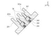
チューブ検出部24は、図8、9に示すように第1保持部231の溝部231a、231bに設けられ、弾性部材244によって、溝部231a、231bの底部からの突出及び陥没が可能に構成されたピン241と、ピン241の根元部分に設けられた磁石242と、ホール素子243と、を備える。ピン241は、チューブF2、T2が溝部231a、231bに嵌め込まれることによって突出位置から陥没位置に位置を変える。磁石242は、ピン241の溝部231a、231bからの突出又は陥没に合わせて移動する。ホール素子243は、磁石242に隣接して配置している。チューブ検出部24は、ホール素子243が検出する磁石242の磁力の大きさがピン241の位置に応じて変化することによって、チューブF2、T2が溝部231a、231bに配置されたか否かを検出する。ただし、溝部231a、231bにチューブF2、T2が配置されたことを検出できれば、具体的な構成は上記に限定されない。
チューブ押し付け部25は、図6に示すように固定側押し付け部25aと、可動側押し付け部25bと、を備える。
固定側押し付け部25aは、図11に示すようにチューブF2、T2の固定側Y2においてチューブF2、T2の並ぶ方向D1にチューブF2、T2を接近させ、互いに当接したチューブF2、T2に押圧力を付与する。固定側押し付け部25aは、図6、18に示すように第1クランプアーム221に設けられる蓋側押し付け部251と、第1台座211に設けられる筐体側押し付け部252と、を備える。
可動側押し付け部25bは、図11に示すようにチューブF2,T2の入替側Y1において固定側押し付け部25aと同様にチューブF2、T2の並ぶ方向D1にチューブF2、T2を接近させ、互いに当接したチューブF2、T2に押圧力を付与する。可動側押し付け部25bは、図6、18に示すように第2クランプアーム222に設けられる蓋側押し付け部253と、第2台座212に設けられる筐体側押し付け部254と、を備える。
クランプ部20は、図4、5に示すように、溶断位置Y0を境界として、チューブT2、F2の長手方向(左右方向Y)におけるチューブT2、F2の固定側Y2(一方側に相当)を挟みこむ固定クランプユニット271(第1クランプユニット)と、溶断位置Y0を境界として、チューブT2、F2の長手方向における入替側Y1(他方側に相当)を挟みこむ可動クランプユニット272(第2クランプユニット)と、を有する。
固定クランプユニット271は、本実施形態では、第1台座211、第1クランプアーム221、第1保持部231、及び固定側押し付け部25aによって構成している。可動クランプユニット272は、本実施形態では、第2台座212、第2クランプアーム222、及び可動側押し付け部25bによって構成している。
クランプ部20は、移行部27によって、溶断前のチューブF2及びチューブT2を配置可能な初期状態と、溶断したチューブF2の端部とチューブT2の溶断した端部を接合可能な接合状態とに、移行可能に構成している。
移行部27は、本実施形態では、図12~14に示すように、可動クランプユニット272を構成する可動側押し付け部25bを回転させ、溶断されたチューブF2、T2の可動側の端部を固定側に対して入れ替える回転駆動部28と、可動クランプユニット272を固定クランプユニット271に接近離反可能な直進駆動部29と、を有する。
回転駆動部28は、図12に示すように、蓋部22を閉じた状態において一体化した蓋側押し付け部253と筐体側押し付け部254の周囲に設けられた第1ギア281と、第1ギア281と噛合う第2ギア282と、第2ギア282の回転軸に接続されているモータ283と、を備えている。溶断が完了した段階で、後述する制御部90がモータ283を駆動させると、第2ギア282が回転する。第2ギア282の回転に伴い第1ギア281が回転するため、第1ギア281とともに一体化した蓋側押し付け部253及び筐体側押し付け部254も回転する。その結果、蓋側押し付け部253と筐体側押し付け部254も回転する。その結果、図20に示すように、溶断後のチューブT2の入替側Y1とチューブF2の入替側Y1との位置を入れ替えることができる。
なお、本実施形態では、可動側押し付け部25bは、蓋側押し付け部253と筐体側押し付け部254の位置が反転した状態(蓋側押し付け部253が第2台座212側に配置され、かつ、筐体側押し付け部254が第2クランプアーム222側に配置された状態)でも、蓋部22を開き、次に接合されるチューブF2、T2を配置できるように構成している。したがって、本実施形態では、チューブ接合完了後にクランプ部20を接合状態から初期状態に復元する際に、回転駆動部28は、駆動するように構成されていない。ただし、可動側押し付け部が、蓋側押し付け部253と筐体側押し付け部254の位置が反転した状態で、チューブF2、T2を配置できるように構成していない場合、クランプ部20を接合状態から初期状態に復元する際に、回転駆動部28を駆動させてもよい。
直進駆動部29は、可動クランプユニット272を固定クランプユニット271に対して相対的に接近離反可能に構成している。直進駆動部29は、初期状態では図17に示すように、チューブF2、T2の長手方向(左右方向Y)において可動クランプユニット272と固定クランプユニット271とが離間し、溶断前のチューブF2、T2を配置可能な初期位置P1に可動クランプユニット272を配置する。直進駆動部29は、接合状態では図21に示すように、初期位置P1よりも固定クランプユニット271と可動クランプユニット272が接近し、チューブF2、T2の長手方向において溶断したチューブF2の端部と溶断したチューブT2の端部を押し付け合って接合可能な接合位置P2に、可動クランプユニット272を配置する。
直進駆動部29は、本実施形態では図13に示すように、前後方向Xに沿う回転軸周りに回転可能に構成されたカム291と、カム291を回転させるモータ(図示省略)と、可動クランプユニット272が取り付けられ、左右方向Yにおいてカム291に当接可能な当接部材292と、当接部材292をカム291に接近させる方向に付勢する付勢部材293と、を備える。可動クランプユニット272は、カム291において当接部材292との左右方向Yにおける接触位置がカム291の回転に応じて異なることによって、可動側のチューブF2、T2の端部を固定側のチューブF2、T2の端部に押し付ける。
さらに、チューブ接合装置1には、可動クランプユニット272の左右方向Yの位置を検出可能な位置検出部294が設けられている。位置検出部294は、特に限定されないが、カム291の回転角度等から可動クランプユニット272の左右方向Yの位置を検出するフォトセンサ等によって構成できる。
<インターロック>
インターロック30は、溶断-接合の際に、クランプ部20がチューブF2、T2を挟み込んだ状態にロックする機能を備えている。
インターロック30は、溶断-接合の際に、クランプ部20がチューブF2、T2を挟み込んだ状態にロックする機能を備えている。
インターロック30は、本実施形態において図11に示すように電磁駆動式のソレノイドのロッド31により構成している。
<収容部>
収納部40は、図3に示す箇所に位置しており、筐体10に挿入されたウェハーカセットWCを収納する機能、及びウェハーカセットWC内のウェハーWFの残量を検出する機能を備えている。
収納部40は、図3に示す箇所に位置しており、筐体10に挿入されたウェハーカセットWCを収納する機能、及びウェハーカセットWC内のウェハーWFの残量を検出する機能を備えている。
収納部40は、カセット挿入孔11cから挿入されたウェハーカセットWCが装着される装着部(図示省略)と、ウェハーカセットWC内のウェハーWFを検出可能なウェハー検出部42(図14参照)と、を備えている。ウェハー検出部42は、操作部60によって電源がONになった状態においてウェハーWFの残量とウェハーWFが使用可能かどうか監視する。ウェハー検出部42は、例えば、公知のフォトセンサによって構成できる。
<送り部>
送り部50は、図3に示す箇所に位置しており、ウェハーWFを溶断位置まで送り出し、溶断に際してウェハーWFを加熱し、使用後のウェハーWFを冷却し、使用後のウェハーWFを筐体10の外部へ送り出す。
送り部50は、図3に示す箇所に位置しており、ウェハーWFを溶断位置まで送り出し、溶断に際してウェハーWFを加熱し、使用後のウェハーWFを冷却し、使用後のウェハーWFを筐体10の外部へ送り出す。
送り部50は、ウェハーWFを収納部40内のウェハーカセットWCから溶断位置まで送り出し可能に構成している。送り部50は、使用後のウェハーWFを第1台座211と第2台座121の間の隙間21aを介して筐体10の外部へ送り出し可能な駆動部(図示省略)を備える。送り部50は、ウェハーWFの内部に設けられウェハーWFを加熱可能な電熱線と、溶断に際してウェハーWFを加熱するために必要な電力を供給可能な端子と、使用済みのウェハーWFを冷却可能なファンと、を備えている(図示省略)。
<操作部>
操作部60は、使用者からチューブ接合装置1への指示を受け付ける。操作部60は、図1、2に示すように、チューブ接合装置1の電源のON/OFFを切り替えるスイッチ等を含む。操作部60は、本実施形態において図2に示すように筐体10の上部分11の後端側に設けているが、具体的な位置はこれに限定されない。
操作部60は、使用者からチューブ接合装置1への指示を受け付ける。操作部60は、図1、2に示すように、チューブ接合装置1の電源のON/OFFを切り替えるスイッチ等を含む。操作部60は、本実施形態において図2に示すように筐体10の上部分11の後端側に設けているが、具体的な位置はこれに限定されない。
<報知部>
報知部70は、使用者に必要な情報を報知する。報知部70は、図1、3に示すように、使用者に必要な情報を表示する複数の表示部71、72と、音声によって使用者に必要な情報を報知するスピーカ73と、を備えている。
報知部70は、使用者に必要な情報を報知する。報知部70は、図1、3に示すように、使用者に必要な情報を表示する複数の表示部71、72と、音声によって使用者に必要な情報を報知するスピーカ73と、を備えている。
<電力供給部>
電力供給部80は、チューブ接合装置1の各部に電力を供給する機能を備えている。電力供給部80は、図1、3に示すように、各部に電力を供給可能なバッテリ81と、バッテリ81を充電するための充電器82と、を備えている。
電力供給部80は、チューブ接合装置1の各部に電力を供給する機能を備えている。電力供給部80は、図1、3に示すように、各部に電力を供給可能なバッテリ81と、バッテリ81を充電するための充電器82と、を備えている。
<制御部>
制御部90は、マイクロコンピュータなどによって構成できる。制御部90は、CPUと、CPUにより実行される装置全体の制御プログラムや各種データを記憶するROMと、ワークエリアとして測定データや各種データを一時的に記憶するRAMとを備えている。
制御部90は、マイクロコンピュータなどによって構成できる。制御部90は、CPUと、CPUにより実行される装置全体の制御プログラムや各種データを記憶するROMと、ワークエリアとして測定データや各種データを一時的に記憶するRAMとを備えている。
制御部90は、図14に示すように、電力供給部80、操作部60、報知部70、チューブ検出部24、開閉検出部26、インターロック30、温度センサ11e、ウェハー検出部42、送り部50、移行部27、位置検出部294等に電気的に接続されている。制御部90は、各部を統括的に制御する。
制御部90は、チューブF2、T2がクランプ部20に配置されたことをチューブ検出部24が検出し、かつ、蓋部22が閉じたことを開閉検出部26が検出した場合に、各部の動作を制御して、溶断動作を開始する。
制御部90は、チューブF2、T2が溶断された後、移行部27の動作を制御し、クランプ部20を初期状態から接合状態に移行させる。具体的には、制御部90は移行部27の回転駆動部28の動作を制御し、図20に示すように、可動側押し付け部25bを回転させ、溶断後のチューブT2の入替側Y1とチューブF2の入替側Y1との位置を入れ替える。次に、制御部90は、位置検出部294からの信号に基づいて移行部27の直進駆動部29の動作を制御し、図21に示すように、固定クランプユニット271と可動クランプユニット272とを相対的に接近させ、初期位置P1から接合位置P2に可動クランプユニット272を移動させる。
制御部90は、接合完了後にチューブ検出部24がクランプ部20からのチューブF2、T2の取出しを検出した場合に、クランプ部20が接合状態から初期状態に復元するように移行部27の動作を制御する。具体的には、接合完了後にチューブ検出部24がクランプ部20からのチューブF2、T2の取出しを検出した場合に、制御部90は、位置検出部294からの信号に基づいて移行部27の直進駆動部29の動作を制御し、接合位置P2(図21参照)から初期位置P1(図22参照)に、可動クランプユニット272を移動させる。
さらに、本実施形態では、制御部90は、チューブ検出部24がクランプ部20からのチューブF2、T2の取出しを検出した場合に、報知部70に取り外したチューブF2、T2の取り扱い方法を報知させる。具体的には、報知部70は、図23、24に示すように、使用する側のチューブF21(本体部F15から導出するチューブ)と捨てる側のチューブF22(端部同士が接続されて成るチューブ)を引き離し、使用する側のチューブF21の接合部を手指で押し、開通させるように報知する。報知部70が取り外したチューブF2、T2の取り扱い方法を報知する間に、制御部90は、クランプ部20が接合状態から初期状態に復元するように移行部27の動作を制御する。
<使用例>
次に、チューブ接合装置1の使用例について説明する。まず、使用者は、チューブ接合装置1を使用するに際し、ウェハーWFをケースWC1に収納したウェハーカセットWCをチューブ接合装置1のカセット挿入孔11cに挿入する。次に、使用者は、操作部60のボタンを押して、チューブ接合装置1の電源をONにする。
次に、チューブ接合装置1の使用例について説明する。まず、使用者は、チューブ接合装置1を使用するに際し、ウェハーWFをケースWC1に収納したウェハーカセットWCをチューブ接合装置1のカセット挿入孔11cに挿入する。次に、使用者は、操作部60のボタンを押して、チューブ接合装置1の電源をONにする。
次に、使用者は、図1に示すように、チューブ接合装置1の蓋部22を開いた状態にする。次に、使用者は、図5、17に示すように、チューブT2、F2を第1保持部23231及び第2保持部232にセットする。次に、使用者は、蓋部22を閉じる操作(蓋部22を筐体10に相対的に接近させる操作)を行う。蓋部22が閉じられたことにより、チューブT2、F2の溶断部位の外周部分はカバー223によって覆われ、外部から隔離された状態となる。これにより、溶断-接合作業を無菌状態で実施することが可能となる。制御部90は、開閉検出部26が蓋部22が閉じたことを検出した場合に、溶断-接合作業を開始する。
まず、制御部90は、図16に示すように蓋部22が閉じた状態でチューブ検出部24によってチューブT2、F2が第1保持部231にセットされているかを確認する(ST1)。チューブT2、F2の第1保持部231へのセットが検知できない場合(ST1:NO)、制御部90は、報知部70の動作を制御し、使用者にチューブT2、F2をセットし、かつ、蓋部22を閉じるように報知する(ST2)。
チューブT2、F2の第1保持部231へのセットを検知した場合(ST1:YES)、制御部90は、ウェハー検出部42によってウェハーカセットWCにウェハーWFが収納されているか確認する(ST3)。ウェハーカセットWCにウェハーWFが収納されていない場合(ST3:NO)、制御部90は報知部70にウェハーカセットWCへウェハーWFを収納するように報知させる(ST4)。
ウェハーカセットWCにウェハーWFが収納されている場合(ST3:YES)、制御部90は、送り部50にウェハーカセットWCからウェハーWFを取り出させ、溶断準備位置(図19のウェハーWFが破線で示されている位置)に送り出させる(ST5)。次に、制御部90はウェハーWFが溶断に使用できるか確認する(ST6)。ウェハーWFが溶断に適さない場合(ST6:NO)、制御部90は、報知部70に、ウェハーWFが溶断に適さないものであること、またはウェハーWFの送り出しが再度実施されることを報知させる(ST7)。そして、制御部90は、再度、送り部50にウェハーカセットWCからウェハーWFを取り出させ、溶断準備位置に送り出させる(ST5)。このとき、溶断に適さないとされたウェハーWFは、次のウェハーWFによって溶断準備位置から押し出される。
溶断準備位置に送り出されたウェハーWFが使用できる場合(ST6:YES)、制御部90はウェハーWFによる溶断作業の制御を開始する。
まず、制御部90は、インターロック30を作動させ、蓋部22を閉じた状態にロックさせる。
そして、溶断準備位置のウェハーWFを、内蔵したヒータによって加熱する(ST8)。そして、送り部50によって加熱したウェハーWFを溶断位置(図19のウェハーWFが実線で示されている位置)まで移動させ、図19に示すように溶断を行わせる(ST9)。
次に、制御部90は、移行部27の動作を制御して、クランプ部20を初期状態から接合状態に移行させる(ST10)。具体的には、移行部27の回転駆動部28は、図20に示すように、可動側押し付け部25bを回転させ、チューブF2の入替側Y1とチューブT2の入替側Y1の位置を入れ替えさせる。次に、移行部27の直進駆動部29は、図21に示すように、可動クランプユニット272を固定クランプユニット271に接近させて、初期位置P1から接合位置P2に移動せる。これによって、溶断したチューブT2とチューブF2の端部同士が、チューブT2、F2の長手方向に押し付け合わされ、加圧接合される。
次に、制御部90は、インターロック30のロックを解除する。次に、使用者は、蓋部22を開く作業を行い、図22に示すように接合したチューブT2、F2をチューブ接合装置1から取り外す。
次に、制御部90は、接合したチューブF2、T2が第1保持部231から取り外されたか否かを確認する(ST11)。
チューブF2、T2が第1保持部231から取り外されていない場合(ST11:NO)、制御部90は、報知部70に接合したチューブF2、T2を取り外すように報知させる(ST12)。
チューブF2、T2が第1保持部231から取り外されている場合(ST11:YES)、制御部90は、報知部70に取り外したチューブF2、T2の取り扱い方法を報知するとともに、移行部27の動作を制御し、クランプ部20を接合状態から初期状態に復元する(ST13)。具体的には、移行部27の直進駆動部29は、図22に示すように、可動クランプユニット272を固定クランプユニット271から離間させ、接合位置P2から初期位置P1に復元する。
使用者は、ステップST14における報知部70の報知内容に基づいて、図23、24に示すように、取り外したチューブF2、T2の使用する側のチューブF21と捨てる側のチューブF22を引き離し、使用する側のチューブF21の接合部を手指で押し、開通させる。
次に、使用者は、連続してチューブの溶断-接合を行いたい場合は、次に接合するチューブF2、T2(またはチューブF3、T3やチューブF1、T1)を第1保持部231及び第2保持部232にセットする。次に、使用者は、蓋部22を閉じる操作(蓋部22を筐体10に相対的に接近させる操作)を行う。なお、本実施形態では、チューブF2とチューブT2、チューブF3とチューブT3、チューブF1とチューブT1の順に、接合を行う例を説明したが、接合順は特に限定されない。
制御部90は、チューブの接合完了から所定時間内に蓋部22が閉じられているかを確認する(ST14)。チューブの接合完了から所定時間内に、蓋部22が閉じられなかった場合(ST14:NO)、制御部90は、チューブ接合装置1の電源を自動的にOFFにする(ST15)。なお、使用者が手動で、電源をOFFにしてもよい。
チューブの接合完了から所定時間内に蓋部22が閉じられた場合(ST14:YES)、制御部90は、再びST2~ST14を行う。
以上説明したように、チューブ接合装置1は、加熱した板状のウェハーWFによってチューブF2の端部とチューブT2の端部を溶断した後、チューブF2の溶断した端部とチューブT2の溶断した端部を入れ替えて接合するチューブ接合装置である。チューブ接合装置1は、クランプ部20と、移行部27と、チューブ検出部24と、制御部90と、を有する。クランプ部20は、チューブF2及びチューブT2を挟みこみ可能であり、溶断前のチューブF2及びチューブT2を配置可能な初期状態と、チューブF2の溶断した端部とチューブT2の溶断した端部を接合可能な接合状態とに、移行可能である。移行部27は、クランプ部20を初期状態及び接合状態に移行させる。チューブ検出部24は、クランプ部からのチューブF2及びチューブT2の取出しを検出可能である。制御部90は、チューブF2とチューブT2の接合完了後に、チューブ検出部24がクランプ部20からのチューブF2及びチューブT2の取出しを検出した場合に、クランプ部20が接合状態から初期状態に復元するように移行部27の動作を制御する。
上記チューブ接合装置1によれば、接合完了後にクランプ部20からのチューブF2、T2の取出しが検出された場合に、クランプ部20は接合状態から初期状態に復元する。したがって、上記チューブ接合装置1によれば、使用者の操作によって接合状態から初期状態に復元するように構成されているチューブ接合装置と比較して、チューブの接合を連続して行う際の使用者の利便性を向上させることができる。
また、クランプ部20は、溶断位置Y0を境界としてチューブF2、T2の長手方向の一方側の部分を保持する固定クランプユニット271と、溶断位置Y0を境界としてチューブF2、T2の長手方向の他方側の部分を保持する可動クランプユニット272と、を有する。接合完了後にチューブ検出部24がクランプ部20からのチューブF2、T2の取出しを検出した場合に、移行部27は、チューブF2の溶断した端部とチューブT2の溶断した端部とを長手方向に押し付け合って接合可能な接合位置P2から、長手方向において固定クランプユニット271と可動クランプユニット272とを相対的に離間させ、次に接合するチューブF2、T2を配置可能な初期位置P1に復元させる。そのため、チューブ接合装置1は、例えば、使用者の操作によって接合位置P2から初期位置P1に復元するように構成されているチューブ接合装置と比較して、チューブの接合を連続して行う際の使用者の利便性を向上させることができる。
また、チューブ接合装置1は、チューブ検出部24がクランプ部20からのチューブF2、T2の取出しを検出した場合に、取り外したチューブF2、T2の取り扱い方法を報知する報知部70をさらに有する。報知部70が取り外したチューブF2、T2の取り扱い方法を報知する間に、制御部90は、クランプ部20が接合状態から初期状態に復元するように移行部27の動作を制御する。そのため、クランプ部20が接合状態から初期状態に復元する最中に、使用者が誤ってクランプ部20に次に接合するチューブを配置することを抑制できる。
また、上記実施形態に係るチューブ接合方法は、上記のチューブ接合装置1を用いた接合方法である。初期状態のクランプ部20が溶断前のチューブF2及びチューブT2を挟みこんだ状態で、ウェハーWFがチューブF2の端部とチューブT2の端部を溶断する。そして、クランプ部20が初期状態から接合状態に移行することで、チューブF2の溶断した端部とチューブT2の溶断した端部を接合する。そして、チューブF2とチューブT2の接合完了後にチューブ検出部24がクランプ部20からのチューブF2及びチューブT2の取出しを検出した場合に、クランプ部20は、接合状態から初期状態に復元する。そして、初期状態のクランプ部20が次に接合するチューブF2及びチューブT2を挟みこみ、前記溶断、前記接合、及び前記復元が行われる。したがって、上記チューブ接合方法によれば、使用者の操作によって接合状態から初期状態に復元するように構成されているチューブ接合装置と比較して、チューブの接合を連続して行う際の使用者の利便性を向上させることができる。
また、接合方法によれば、腹膜への透析液の注入及び排出を自動的に行う腹膜透析装置Fを構成する複数のチューブF1、F2、F3を、対応するチューブT1、T2、T3に連続して接合する。そのため、使用者は、APDの準備を効率的に行うことができる。
なお、本発明は上述した実施形態にのみ限定されず、特許請求の範囲において種々の変更が可能である。
例えば、本発明は、腹膜透析のみならず、例えば輸血に用いる血液製剤等を収容する容器(バッグ)に接続されたチューブと他のチューブとを無菌的に接合する装置にも用いることができる。この場合、チューブ及びバッグ内の血液成分(製剤)等の無菌性を保持することができる。
また、本発明は、採取・培養した各種細胞を含む細胞培養液を収容する容器(バッグ)に接続されたチューブと他のチューブとを無菌的に接合する装置にも用いることができる。この場合も、チューブ接合時にチューブ及びバッグ内の細胞培養液の無菌性・安全性を保持することができる。
また、上記実施形態では、チューブ接合装置は、自動透析装置の注入ラインを構成する複数のチューブを透析容器のチューブに接続した後、追加注入ラインや腹膜ラインを構成するチューブを対応するチューブに接続する例を説明した。しかし、チューブを接続する順番は特に限定されない。
また、上記実施形態では、報知部が取り外したチューブを取り扱い方法を報知している間に、移行部がクランプ部を接合状態から初期状態に復元する例を説明した。しかし、報知部が報知を行うことなく、移行部がクランプ部を接合状態から初期状態に復元してもよい。また、移行部がクランプ部を接合状態から初期状態に復元した後に、次に接合するチューブを配置可能である旨を報知部が報知してもよい。
また、チューブ接合装置は、排出ラインF4を構成するチューブを排液容器のチューブに接続するために用いてもよい。
本出願は、2019年6月25日に出願された日本国特許出願第2019-117308号に基づいており、その開示内容は、参照により全体として引用されている。
1 チューブ接合装置、
10 筐体、
20 クランプ部、
24 チューブ検出部、
27 移行部、
90 制御部、
271 固定クランプユニット(第1クランプユニット)、
272 可動クランプユニット(第2クランプユニット)、
F 腹膜透析装置、
F1、F2、F3 腹膜透析装置を構成する複数のチューブ、
T1、T2、T3 対応するチューブ、
P1 初期位置、
P2 接合位置、
WF ウェハー(切断部材)、
Y0 溶断位置。
10 筐体、
20 クランプ部、
24 チューブ検出部、
27 移行部、
90 制御部、
271 固定クランプユニット(第1クランプユニット)、
272 可動クランプユニット(第2クランプユニット)、
F 腹膜透析装置、
F1、F2、F3 腹膜透析装置を構成する複数のチューブ、
T1、T2、T3 対応するチューブ、
P1 初期位置、
P2 接合位置、
WF ウェハー(切断部材)、
Y0 溶断位置。
Claims (5)
- 加熱した板状の切断部材によって第1チューブの端部と第2チューブの端部を溶断した後、前記第1チューブの溶断した端部と前記第2チューブの溶断した端部を入れ替えて接合するチューブ接合装置であって、
前記第1チューブ及び前記第2チューブを挟みこみ可能であり、溶断前の前記第1チューブ及び前記第2チューブを配置可能な初期状態と、前記第1チューブの溶断した端部と前記第2チューブの溶断した端部を接合可能な接合状態とに、移行可能なクランプ部と、
前記クランプ部を前記初期状態及び前記接合状態に移行させる移行部と、
前記クランプ部からの前記第1チューブ及び前記第2チューブの取出しを検出可能なチューブ検出部と、
前記第1チューブと前記第2チューブの接合完了後に、前記チューブ検出部が前記クランプ部からの前記第1チューブ及び前記第2チューブの取出しを検出した場合に、前記クランプ部が前記接合状態から前記初期状態に復元するように前記移行部の動作を制御する制御部と、を有する、チューブ接合装置。 - 前記クランプ部は、溶断位置を境界として前記第1チューブ及び前記第2チューブの一方側を挟みこむ第1クランプユニットと、前記溶断位置を境界として前記第1チューブ及び前記第2チューブの他方側を挟みこむ第2クランプユニットと、を有し、
前記第1チューブと前記第2チューブの接合完了後に、前記チューブ検出部が前記クランプ部からの前記第1チューブ及び前記第2チューブの取出しを検出した場合に、
前記移行部は、前記第1チューブの溶断した端部と溶断した前記第2チューブの端部とを押し付け合って接合可能な接合位置から、前記第1クランプユニットと前記第2クランプユニットを相対的に離間させ、次に接合する前記第1チューブ及び前記第2チューブを配置可能な初期位置に復元する、請求項1に記載のチューブ接合装置。 - 前記チューブ検出部が前記クランプ部からの前記第1チューブ及び前記第2チューブの取出しを検出した場合に、取り外した前記第1チューブ及び前記第2チューブの取り扱い方法を報知する報知部をさらに有し、
前記報知部が取り外した前記第1チューブ及び前記第2チューブの取り扱い方法を報知する間に、前記制御部は、前記クランプ部が前記接合状態から前記初期状態に復元するように前記移行部の動作を制御する、請求項1または請求項2に記載のチューブ接合装置。 - 請求項1~3のいずれか一項に記載のチューブ接合装置を用いた接合方法であって、
前記初期状態の前記クランプ部が溶断前の前記第1チューブ及び前記第2チューブを挟みこんだ状態で、前記切断部材が前記第1チューブの端部と前記第2チューブの端部を溶断し、
前記クランプ部が前記初期状態から前記接合状態に移行することで、前記第1チューブの溶断した端部と前記第2チューブの溶断した端部を接合し、
前記第1チューブと前記第2チューブの接合完了後に前記チューブ検出部が前記クランプ部からの前記第1チューブ及び前記第2チューブの取出しを検出した場合に、前記クランプ部は、前記接合状態から前記初期状態に復元し、
前記初期状態の前記クランプ部が次に接合する前記第1チューブ及び前記第2チューブを挟みこみ、前記溶断、前記接合、及び前記復元が行われる、接合方法。 - 腹膜への透析液の注入及び排出を自動的に行う腹膜透析装置を構成する複数のチューブを、接続相手のチューブに連続して接合する、請求項4に記載のチューブの接合方法。
Priority Applications (1)
| Application Number | Priority Date | Filing Date | Title |
|---|---|---|---|
| JP2021526878A JP7513606B2 (ja) | 2019-06-25 | 2020-06-18 | チューブ接合装置及びチューブ接合装置を用いた接合方法 |
Applications Claiming Priority (2)
| Application Number | Priority Date | Filing Date | Title |
|---|---|---|---|
| JP2019117308 | 2019-06-25 | ||
| JP2019-117308 | 2019-06-25 |
Publications (1)
| Publication Number | Publication Date |
|---|---|
| WO2020262192A1 true WO2020262192A1 (ja) | 2020-12-30 |
Family
ID=74059738
Family Applications (1)
| Application Number | Title | Priority Date | Filing Date |
|---|---|---|---|
| PCT/JP2020/023984 Ceased WO2020262192A1 (ja) | 2019-06-25 | 2020-06-18 | チューブ接合装置及びチューブ接合装置を用いた接合方法 |
Country Status (2)
| Country | Link |
|---|---|
| JP (1) | JP7513606B2 (ja) |
| WO (1) | WO2020262192A1 (ja) |
Citations (2)
| Publication number | Priority date | Publication date | Assignee | Title |
|---|---|---|---|---|
| JP2005022341A (ja) * | 2003-07-04 | 2005-01-27 | Terumo Corp | チューブ接合装置 |
| JP2016022227A (ja) * | 2014-07-22 | 2016-02-08 | テルモ株式会社 | チューブ接合装置 |
-
2020
- 2020-06-18 JP JP2021526878A patent/JP7513606B2/ja active Active
- 2020-06-18 WO PCT/JP2020/023984 patent/WO2020262192A1/ja not_active Ceased
Patent Citations (2)
| Publication number | Priority date | Publication date | Assignee | Title |
|---|---|---|---|---|
| JP2005022341A (ja) * | 2003-07-04 | 2005-01-27 | Terumo Corp | チューブ接合装置 |
| JP2016022227A (ja) * | 2014-07-22 | 2016-02-08 | テルモ株式会社 | チューブ接合装置 |
Also Published As
| Publication number | Publication date |
|---|---|
| JPWO2020262192A1 (ja) | 2020-12-30 |
| JP7513606B2 (ja) | 2024-07-09 |
Similar Documents
| Publication | Publication Date | Title |
|---|---|---|
| JP6349184B2 (ja) | チューブ接合装置 | |
| WO2019021529A1 (ja) | チューブ接合装置 | |
| JP6197025B2 (ja) | 無菌接合装置 | |
| JP6923382B2 (ja) | クランプ | |
| JP7513606B2 (ja) | チューブ接合装置及びチューブ接合装置を用いた接合方法 | |
| JP7323351B2 (ja) | チューブ接合装置 | |
| JP7290478B2 (ja) | チューブ接合装置 | |
| JP7051861B2 (ja) | チューブ接合装置 | |
| JP7204503B2 (ja) | チューブ接合装置 | |
| JP7565917B2 (ja) | チューブ接合装置 | |
| JP7252071B2 (ja) | チューブ接合装置及び着脱部材 | |
| JP6974057B2 (ja) | チューブ接合装置 | |
| JP7290667B2 (ja) | チューブ接合装置 | |
| JP7290482B2 (ja) | チューブ接合装置 | |
| JP7252087B2 (ja) | チューブ接合装置 | |
| JP7513607B2 (ja) | チューブ接合装置 | |
| JP7513608B2 (ja) | チューブ接合装置 | |
| JP7323292B2 (ja) | チューブ接合装置 | |
| JP7197381B2 (ja) | チューブ接合装置 | |
| JP2020116286A (ja) | チューブ接合装置 | |
| JP7092694B2 (ja) | チューブ接合装置 | |
| JP2013150718A (ja) | 無菌接合装置 | |
| JP5955570B2 (ja) | 無菌接合装置 | |
| JP2023049822A (ja) | チューブ接合装置 | |
| JP2023049817A (ja) | チューブ接合装置 |
Legal Events
| Date | Code | Title | Description |
|---|---|---|---|
| 121 | Ep: the epo has been informed by wipo that ep was designated in this application |
Ref document number: 20831574 Country of ref document: EP Kind code of ref document: A1 |
|
| ENP | Entry into the national phase |
Ref document number: 2021526878 Country of ref document: JP Kind code of ref document: A |
|
| NENP | Non-entry into the national phase |
Ref country code: DE |
|
| 122 | Ep: pct application non-entry in european phase |
Ref document number: 20831574 Country of ref document: EP Kind code of ref document: A1 |