WO2020261949A1 - ウエハー試験装置 - Google Patents
ウエハー試験装置 Download PDFInfo
- Publication number
- WO2020261949A1 WO2020261949A1 PCT/JP2020/022452 JP2020022452W WO2020261949A1 WO 2020261949 A1 WO2020261949 A1 WO 2020261949A1 JP 2020022452 W JP2020022452 W JP 2020022452W WO 2020261949 A1 WO2020261949 A1 WO 2020261949A1
- Authority
- WO
- WIPO (PCT)
- Prior art keywords
- wafer
- slide
- unit
- drive mechanism
- tray
- Prior art date
- Legal status (The legal status is an assumption and is not a legal conclusion. Google has not performed a legal analysis and makes no representation as to the accuracy of the status listed.)
- Ceased
Links
Images










Classifications
-
- G—PHYSICS
- G01—MEASURING; TESTING
- G01R—MEASURING ELECTRIC VARIABLES; MEASURING MAGNETIC VARIABLES
- G01R31/00—Arrangements for testing electric properties; Arrangements for locating electric faults; Arrangements for electrical testing characterised by what is being tested not provided for elsewhere
- G01R31/26—Testing of individual semiconductor devices
-
- G—PHYSICS
- G01—MEASURING; TESTING
- G01R—MEASURING ELECTRIC VARIABLES; MEASURING MAGNETIC VARIABLES
- G01R31/00—Arrangements for testing electric properties; Arrangements for locating electric faults; Arrangements for electrical testing characterised by what is being tested not provided for elsewhere
- G01R31/28—Testing of electronic circuits, e.g. by signal tracer
-
- H—ELECTRICITY
- H10—SEMICONDUCTOR DEVICES; ELECTRIC SOLID-STATE DEVICES NOT OTHERWISE PROVIDED FOR
- H10P—GENERIC PROCESSES OR APPARATUS FOR THE MANUFACTURE OR TREATMENT OF DEVICES COVERED BY CLASS H10
- H10P72/00—Handling or holding of wafers, substrates or devices during manufacture or treatment thereof
- H10P72/50—Handling or holding of wafers, substrates or devices during manufacture or treatment thereof for positioning, orientation or alignment
Definitions
- the present invention relates to a wafer test apparatus, and more particularly, a probe card having a terminal for contacting a wafer electrode used in a front-process test apparatus, a post-process test apparatus, a burn-in test apparatus, and the like of a semiconductor wafer.
- a wafer test unit having a load board on which a test circuit or the like is mounted, a wafer tray on which a wafer is placed, and a vacuum chamber for forming a closed space.
- a wafer positioning stage that aligns the electrodes of the wafer and the terminals of the probe card, a wafer positioning unit that has a position information imaging mechanism, and an elevating mechanism. Equipped with an equipment frame for mounting multiple wafer test units,
- the present invention relates to a wafer test apparatus for performing a test by pressurizing and contacting a wafer electrode and a probe card terminal with a vacuum pressure.
- the wafer test is performed in an environment of high temperature or low temperature using a test device called a prober to perform electrical property tests such as stress test and functional test, and after the wafer test is completed. After the wafer cutting and assembly process, it is mounted on a burn-in socket or test socket as a semiconductor package, and burn-in test and post-process test are performed.
- Patent Document 1 discloses a wafer inspection device that tests a wafer by pressure contact.
- Patent Document 1 a wafer is placed on a chuck member via a wafer plate and conveyed to a position facing the probe card, and the conveyed wafer is conveyed together with the wafer plate toward the probe card by using an elevating device. After moving and bringing the plurality of electrodes of the semiconductor device provided on the wafer into contact with the plurality of terminals provided on the probe card, the wafer is further overdriven toward the probe card, and then the probe card and the wafer The space between the plate and the probe card is depressurized to maintain the contact state between the electrode of the semiconductor device and the terminal of the probe card, and the means for contacting the probe card that separates the chuck member from the wafer plate is disclosed. The invention is disclosed to move to a position corresponding to another probe card to prepare for testing the next wafer.
- Patent Document 1 utilizes vacuum pressure for electrical connection between a wafer mounted on a wafer plate, which is a wafer mounting stage, and a probe card, and further, a wafer mounting stage is a wafer plate and the wafer plate.
- a multi-stage wafer inspection device has been realized by adopting a method of separating into a moving stage equipped with an alignment mechanism that pushes up the wafer.
- the wafer mounting portion is separated into a wafer plate and a member that pushes up the wafer plate, and a unit having the member that pushes up the wafer plate and an alignment mechanism is used as a moving stage, and the wafer is mounted on the wafer plate.
- the wafer plate After being placed and aligned, the wafer plate is pushed up toward the probe card, sucked by vacuum pressure, and then the moving stage is lowered and moved to prepare for mounting, aligning, and taking out the wafer on the next prober.
- the height of the prober mechanism is lowered as compared with the conventional apparatus, and a multi-stage wafer inspection apparatus is realized.
- the moving stage is installed under the wafer test device and the wafer plate is moved up and down by the moving stage, the space required in the height direction of the wafer test device becomes large, and many of them are placed in a row of device frames. It was difficult to load the test equipment of.
- the wafer plate on which the wafer is placed is raised and lowered by raising and lowering the moving stage, vertical running performance when raising and lowering the moving stage and horizontality of the probe card mounted on the wafer test device are important, and the wafer test device.
- the horizontal mounting of each wafer test device and the vertical running performance of the moving stage greatly affect the position accuracy.
- the problem to be solved by the present invention is to provide a wafer test device with a unit slide mechanism that slides a wafer test device (referred to as a wafer test unit in the text) so as to face a moving stage (referred to as a wafer positioning stage in the text).
- a wafer test unit referred to as a wafer test unit in the text
- a moving stage referred to as a wafer positioning stage in the text.
- the wafer test device is provided with a positioning means that does not depend on the horizontality when the wafer test device is mounted and the vertical running property of the moving stage. is there.
- the means for solving the problem of the present invention is as follows.
- a load board on which a test circuit or the like is mounted, a probe card, a wafer tray on which the wafer is placed, a space sandwiched between the load board and the probe card, and a space sandwiched between the probe card and the wafer tray.
- a wafer test unit with a vacuum chamber that surrounds and forms an enclosed space A wafer positioning stage arranged on the front side of the wafer test unit, on which the wafer tray is placed, and positioning between the electrodes of the wafer and the terminals of the probe card, a position information photographing mechanism having a camera, and the wafer.
- a wafer positioning unit having a positioning stage and a unit elevating mechanism for raising and lowering the position information photographing mechanism, and An apparatus frame on which the wafer test unit is mounted and With The wafer test unit is A unit that slides the wafer test unit so that the wafer tray held in the vacuum chamber so as to face the probe card faces the wafer positioning stage arranged on the front side of the wafer test unit.
- a wafer test apparatus including a slide mechanism.
- the unit slide mechanism A linear slide mechanism with a slide unit and slide guide, A drive mechanism that slides the slide unit and The linear slide mechanism, the frame member on which the drive mechanism is mounted, and With The slide unit is connected to the wafer test unit,
- the wafer test apparatus according to the first aspect, wherein the frame member is installed in the apparatus frame.
- the wafer positioning stage is Arranged so as to face the wafer tray of the sliding wafer test unit.
- An alignment stage that controls the positions in the X, Y, and rotation directions,
- An alignment stage swing mechanism that makes the inclination of the wafer tray mounting surface of the alignment stage follow the inclination of the wafer tray.
- An alignment stage elevating mechanism that elevates and elevates the wafer tray between the position held in the vacuum chamber and the position on which the wafer is placed.
- the alignment stage swing mechanism is When the wafer test unit slides and the wafer positioning stage is pushed up by the unit elevating mechanism, abutting members that come into contact with the four corners of the lower surface of the vacuum chamber and A rocking plate having the abutting member and Spherical plain bearings with moving and fixed parts, A spring member that supports a load applied to the outer peripheral portion of the rocking plate when the abutting member comes into contact with the vacuum chamber.
- a rocking mechanism mounting plate installed under the rocking plate while maintaining a space for the rocking plate to swing, With The abutting member When in contact with the vacuum chamber, the position information photographing mechanism is inserted between the wafer tray and the probe card, and has a height capable of acquiring position information of the electrodes of the wafer and the terminals of the probe card.
- the spherical plain bearing is Installed in the central part between the rocking plate and the rocking mechanism mounting plate, The spring member.
- the alignment stage elevating mechanism is With the rocking plate An alignment stage mounting plate on which the alignment stage is mounted and an alignment stage mounting plate A drive mechanism having a ball screw, a drive mechanism slide shaft that slides by driving the ball screw, and a drive mechanism slide unit that fits with the drive mechanism slide shaft.
- the drive motor that drives the drive mechanism and A slide mechanism with a slide shaft and a slide unit, With The drive mechanism
- the drive mechanism slide unit is installed at required locations at the four corners of the rocking plate.
- the tips of the drive mechanism slide shafts are connected to the four corners of the alignment stage mounting plate facing the locations where the drive mechanism slide units are installed.
- the ball screw is connected to the drive motor installed on the rocking plate, and the ball screw is connected to the drive motor.
- the slide mechanism is installed at four corners of the rocking plate where the drive mechanism slide unit is not installed.
- the wafer test apparatus according to a third aspect, wherein the tips of the slide shafts are connected to locations facing the locations where the slide units are installed at the four corners of the alignment stage mounting plate.
- the required location where the drive mechanism of the alignment stage elevating mechanism is installed is The required number can be selected from 1 to 4 depending on the load applied to the alignment stage mounting plate and the speed at which the alignment stage mounting plate is moved up and down, and the installation location is determined only when there are two locations, and two locations are installed.
- the wafer test apparatus according to the fifth aspect wherein the wafer test apparatus is installed at two diagonally opposite locations at the four corners.
- the alignment stage elevating mechanism is A ball spline with an integrated ball screw is used for the drive mechanism.
- the wafer test apparatus according to a fifth to sixth aspects, wherein a ball spline is used for the slide mechanism.
- the wafer test unit is With the unit slide mechanism A wafer tray elevating mechanism that elevates and elevates the wafer tray between a position held in the vacuum chamber and a position on which the wafer is placed.
- the wafer test unit according to the first aspect which comprises.
- the wafer tray elevating mechanism is With the vacuum chamber A wafer tray holding plate on which the wafer tray is placed and The drive mechanism having a ball screw, a drive mechanism slide shaft that slides by driving the ball screw, and a drive mechanism slide unit that fits with the drive mechanism slide shaft.
- the drive motor that drives the ball screw and The slide mechanism having a slide shaft and a slide unit, With The drive mechanism
- the drive mechanism slide unit is installed at required locations at the four corners of the vacuum chamber.
- the tips of the drive mechanism slide shafts of the previous term are connected to the four corners of the wafer tray holding plate facing the locations where the drive mechanism slide units are installed.
- the ball screw of the previous term is connected to the drive motor installed in the vacuum chamber,
- the slide mechanism The slide unit is installed at four corners of the vacuum chamber where the drive mechanism slide unit is not installed.
- the required location where the drive mechanism of the wafer tray elevating mechanism is installed is The required number can be selected from 1 to 4 depending on the load applied to the wafer tray holding plate and the speed at which the wafer tray holding plate is moved up and down, and the installation location is determined only when two locations are installed, and two locations are installed.
- the ninth wafer test apparatus according to the ninth aspect wherein the wafer test apparatus is installed at two diagonally opposite locations at the four corners.
- the wafer tray elevating mechanism is A ball spline with an integrated ball screw is used for the drive mechanism. 9. The wafer test apparatus according to a ninth to tenth, wherein a ball spline is used for the slide mechanism.
- the wafer positioning stage is Arranged so as to face the wafer tray of the sliding wafer test unit.
- An alignment stage that controls the positions in the X, Y, and rotation directions,
- An alignment stage swing mechanism that makes the inclination of the wafer tray mounting surface of the alignment stage follow the inclination of the wafer tray, and
- the eighth wafer test apparatus according to the eighth aspect.
- the alignment stage swing mechanism is When the wafer test unit slides and the wafer positioning stage is pushed up by the unit elevating mechanism, abutting members that come into contact with the four corners of the lower surface of the wafer tray holding plate and The rocking plate having the abutting member and The spherical plain bearing having a movable part and a fixed part, When the abutting member comes into contact with the wafer tray holding plate, the spring member that supports the load applied to the outer peripheral portion of the rocking plate and the spring member.
- a rocking mechanism mounting plate installed under the rocking plate while maintaining a space for the rocking plate to swing, With The abutting member When in contact with the wafer tray holding plate, the alignment stage has a height at which the wafer tray can be pushed up to control the position.
- the spherical plain bearing is Installed in the central part between the rocking plate and the rocking mechanism mounting plate, The spring member The twelfth wafer test unit, wherein a plurality of the spherical bearings are arranged on the outer peripheral portion where the spherical bearings are installed.
- the wafer positioning unit is The wafer positioning stage and With the position information photographing mechanism With the unit elevating mechanism A lateral unit slide mechanism that slides the wafer positioning unit in the row direction, With The lateral unit slide mechanism is A rear slide mechanism with a slide unit and slide guide, A drive mechanism that slides the slide unit and The linear slide mechanism, the frame member on which the drive mechanism is mounted, and The wafer test apparatus according to 1st to 13th.
- a load board on which a test circuit or the like is mounted, a probe card, a wafer tray on which the wafer is placed, a space sandwiched between the load board and the probe card, and a space sandwiched between the probe card and the wafer tray.
- a wafer test unit with a vacuum chamber that surrounds and forms an enclosed space A wafer positioning stage arranged on the front side of the wafer test unit, on which the wafer tray is placed, and positioning between the electrodes of the wafer and the terminals of the probe card, a position information photographing mechanism having a camera, and the wafer.
- a wafer positioning unit having a positioning stage and a unit elevating mechanism for raising and lowering the position information photographing mechanism, and An apparatus frame on which the wafer test unit is mounted and With
- the wafer test unit is A unit that slides the wafer test unit so that the wafer tray held in the vacuum chamber so as to face the probe card faces the wafer positioning stage arranged on the front side of the wafer test unit.
- Space for the wafer positioning stage is not required under the wafer test unit, and the wafer test unit can be continuously mounted on the apparatus frame. Further, after the wafer test unit is slid by the wafer positioning stage, the wafer and the probe card can be aligned with each other.
- the unit slide mechanism A linear slide mechanism with a slide unit and slide guide, A drive mechanism that slides the slide unit and The linear slide mechanism, the frame member on which the drive mechanism is mounted, and With The slide unit is connected to the wafer test unit, By installing the frame member on the device frame, By driving the drive mechanism, the wafer test unit can be slid so that the wafer tray faces the wafer positioning stage, eliminating the installation space of the wafer positioning unit under the wafer test unit. , The wafer test unit can be continuously mounted on the apparatus frame.
- the wafer positioning stage is Arranged so as to face the wafer tray of the sliding wafer test unit.
- An alignment stage that controls the positions in the X, Y, and rotation directions,
- An alignment stage swing mechanism that makes the inclination of the wafer tray mounting surface of the alignment stage follow the inclination of the wafer tray.
- An alignment stage elevating mechanism that elevates and elevates the wafer tray between the position held in the vacuum chamber and the position on which the wafer is placed.
- the wafer positioning stage arranged so as to face the wafer tray
- the inclination of the alignment stage is made to follow the inclination of the wafer tray, and the wafer tray is moved up and down between the position where the wafer tray is held in the vacuum chamber and the position where the wafer is placed without changing the inclination of the wafer tray.
- the wafer can be placed on the wafer tray and the electrodes of the wafer and the terminals of the probe card can be aligned.
- the wafer tray is horizontal to the probe card due to the functions of the alignment stage swing mechanism and the alignment stage elevating mechanism. It can be raised vertically with a degree, and the terminals can be connected with high accuracy without causing misalignment due to the rise.
- the alignment stage swing mechanism is When the wafer test unit slides and the wafer positioning stage is pushed up by the unit elevating mechanism, abutting members that come into contact with the four corners of the lower surface of the vacuum chamber and A rocking plate having the abutting member and Spherical plain bearings with moving and fixed parts, A spring member that supports a load applied to the outer peripheral portion of the rocking plate when the abutting member comes into contact with the vacuum chamber.
- a rocking mechanism mounting plate installed under the rocking plate while maintaining a space for the rocking plate to swing, With The abutting member When in contact with the vacuum chamber, the position information photographing mechanism is inserted between the wafer tray and the probe card, and has a height capable of acquiring position information of the electrodes of the wafer and the terminals of the probe card.
- the spherical plain bearing is Installed in the central part between the rocking plate and the rocking mechanism mounting plate, The spring member By arranging a plurality of them on the outer peripheral portion of the spherical slide bearing, The alignment stage can swing in all directions, and the load applied to the outer peripheral portion of the swing plate can be balanced by arranging a plurality of the spring members around the spherical slide bearing. ..
- the wafer positioning stage is raised by the unit elevating mechanism, and the abutting member arranged on the rocking plate comes into contact with the four corners of the lower surface of the vacuum chamber, so that the tilt of the rocking plate is tilted.
- the wafer tray mounting surface of the alignment stage can follow the inclination of the vacuum chamber.
- the wafer tray mounting surface of the alignment stage can obtain the same inclination as the wafer tray. Since the abutting member has a height at which the position information photographing mechanism can acquire the respective position information between the wafer and the probe card, the position information acquisition mechanism can acquire the position information. Can be done.
- the alignment stage elevating mechanism is With the rocking plate An alignment stage mounting plate on which the alignment stage is mounted and an alignment stage mounting plate A drive mechanism having a ball screw, a drive mechanism slide shaft that slides by driving the ball screw, and a drive mechanism slide unit that fits with the drive mechanism slide shaft.
- the drive motor that drives the drive mechanism and A slide mechanism with a slide shaft and a slide unit, With The drive mechanism
- the drive mechanism slide unit is installed at required locations at the four corners of the rocking plate.
- the tips of the drive mechanism slide shafts are connected to the four corners of the alignment stage mounting plate facing the locations where the drive mechanism slide units are installed.
- the ball screw is connected to the drive motor installed on the rocking plate, and the ball screw is connected to the drive motor.
- the slide mechanism is installed at four corners of the rocking plate where the drive mechanism slide unit is not installed.
- the drive mechanism in which the ball screw, the drive mechanism slide shaft that slides by driving the ball screw, and the drive mechanism slide unit that fits with the drive mechanism slide shaft are integrated, is aligned with the inclination of the wafer tray.
- the stage can be raised and lowered at high speed and with low vibration.
- the place where the drive mechanism is installed can be selected from one place to four places, and the payload and elevating speed required by the alignment stage. Therefore, the optimum required number can be selected.
- the payload of the alignment stage can be increased, and vibration can be suppressed to raise and lower the alignment stage at high speed.
- the required location where the drive mechanism of the alignment stage elevating mechanism is installed is The required number can be selected from 1 to 4 depending on the load applied to the alignment stage mounting plate and the speed at which the alignment stage mounting plate is moved up and down, and the installation location is determined only in the case of two locations, and two locations are installed. In the case, by installing it in two places diagonally facing each other at the four corners, The optimum required number can be selected according to the payload and elevating speed required by the alignment stage.
- the plurality of the drive mechanisms are installed, the plurality of drive mechanisms are driven in synchronization, so that the payload of the alignment stage can be increased, vibration can be suppressed, and the vehicle can be raised and lowered at high speed.
- the alignment stage elevating mechanism is A ball spline with an integrated ball screw is used for the drive mechanism.
- a ball spline for the slide mechanism.
- Commercially available products can be used for the drive mechanism and the slide mechanism, the alignment stage elevating mechanism can be easily constructed, and the alignment stage can be elevated vertically, at high speed and with low vibration, and the number of installed drive mechanisms. Therefore, the payload of the alignment stage can be increased to a large weight such as 50 kg, 80 kg, or 100 kg.
- the wafer test unit is With the unit slide mechanism A wafer tray elevating mechanism that elevates and elevates the wafer tray between a position held in the vacuum chamber and a position on which the wafer is placed.
- a wafer tray elevating mechanism that elevates and elevates the wafer tray between a position held in the vacuum chamber and a position on which the wafer is placed.
- the wafer tray elevating mechanism is With the vacuum chamber A wafer tray holding plate on which the wafer tray is placed and The drive mechanism having a ball screw, a drive mechanism slide shaft that slides by driving the ball screw, and a drive mechanism slide unit that fits with the drive mechanism slide shaft.
- the drive motor that drives the ball screw and The slide mechanism having a slide shaft and a slide unit is provided.
- the drive mechanism The drive mechanism slide unit is installed at required locations at the four corners of the vacuum chamber.
- the tips of the drive mechanism slide shafts of the previous term are connected to the four corners of the wafer tray holding plate facing the locations where the drive mechanism slide units are installed.
- the ball screw of the previous term is connected to the drive motor installed in the vacuum chamber,
- the slide mechanism The slide unit is installed at four corners of the vacuum chamber where the drive mechanism slide unit is not installed.
- the drive mechanism in which the ball screw, the drive mechanism slide shaft that slides by the drive of the ball screw, and the drive mechanism slide unit that fits with the drive mechanism slide shaft are integrated causes the wafer tray holding plate to vibrate at high speed and with low vibration. Can be raised and lowered with.
- the place where the drive mechanism is installed can be selected from one place to four places, which is optimal depending on the payload and elevating speed required by the wafer tray holding plate. It is possible to select the required number.
- the payload of the wafer tray holding plate can be increased, and the wafer tray holding plate can be raised and lowered at high speed and with low vibration.
- the required location where the drive mechanism for the wafer tray elevating function is installed is The required number can be selected from 1 to 4 depending on the load applied to the wafer tray holding plate and the speed at which the wafer tray holding plate is raised and lowered.
- the installation location is determined only in the case of two locations, and in the case of installation in two locations. By being installed in two diagonally opposite locations at the four corners, The optimum number of drive mechanisms can be selected according to the payload and lifting speed required by the wafer tray holding plate.
- the plurality of drive mechanisms are driven in synchronization with each other. As a result, the payload of the wafer tray holding plate can be increased, and the wafer tray can be raised and lowered at high speed and with low vibration.
- the wafer tray elevating mechanism is A ball spline with an integrated ball screw is used for the drive mechanism.
- a ball spline for the slide mechanism
- Commercially available products can be used for the drive mechanism and the slide mechanism, the tray elevating mechanism can be easily constructed, and the wafer tray holding plate can be elevated vertically, at high speed and with low vibration, and the drive mechanism can be installed.
- the payload of the wafer tray holding plate can be increased to a large weight such as 50 kg, 80 kg, or 100 kg.
- the wafer positioning stage is Arranged so as to face the wafer tray of the sliding wafer test unit.
- An alignment stage that controls the positions in the X, Y, and rotation directions,
- An alignment stage swing mechanism that makes the inclination of the wafer tray mounting surface of the alignment stage follow the inclination of the wafer tray, and
- the wafer positioning stage arranged so as to face the wafer tray When the unit elevating mechanism is raised, it is pushed up until it comes into contact with the back surface of the wafer tray holding plate which is lowered to the position where the wafer is placed, and the wafer tray is pushed up by the function of the alignment stage swing mechanism.
- the inclination of the alignment stage can be made to follow the inclination of.
- the wafer tray held by the wafer tray holding plate is pushed up to a position where it can be moved back and forth and left and right without changing the inclination of the wafer tray, and the electrodes of the wafer and the terminals of the probe card are aligned. It can be carried out.
- the height at which the wafer tray is pushed up is only a few millimeters.
- the alignment stage swing mechanism is When the wafer test unit slides and the wafer positioning stage is pushed up by the unit elevating mechanism, abutting members that come into contact with the four corners of the lower surface of the wafer tray holding plate and The rocking plate having the abutting member and The spherical plain bearing having a movable part and a fixed part, When the abutting member comes into contact with the wafer tray holding plate, the spring member that supports the load applied to the outer peripheral portion of the rocking plate and the spring member.
- a rocking mechanism mounting plate installed under the rocking plate while maintaining a space for the rocking plate to swing, With The abutting member When in contact with the wafer tray holding plate, the alignment stage has a height at which the wafer tray can be pushed up to control the position.
- the spherical plain bearing is Installed in the central part between the rocking plate and the rocking mechanism mounting plate, The spring member By arranging a plurality of spherical bearings on the outer peripheral portion where they are installed, The alignment stage can swing in all directions, and the load applied to the outer peripheral portion of the swing plate can be balanced by arranging a plurality of the spring members around them.
- the abutting member arranged on the rocking plate comes into contact with the four corners of the lower surface of the wafer tray holding plate, and at the same time, the wafer tray of the alignment stage
- the mounting surface is in contact with the wafer tray and pushed up by several millimeters. Due to this contact, the inclination of the rocking plate follows the inclination of the wafer tray holding plate, and the rocking plate mounts the alignment stage. Therefore, the wafer tray mounting surface of the alignment stage is the same. It can follow the inclination of the wafer tray holding plate.
- the wafer tray mounting surface of the alignment stage can obtain the same inclination as the wafer tray. Further, since the abutting member has a height at which the alignment stage can push up the wafer tray by several millimeters to control the position, the X direction, the Y direction, and the rotation direction of the wafer tray by the alignment stage. Position control is possible.
- the wafer positioning unit is The wafer positioning stage and With the position information photographing mechanism With the unit elevating mechanism A lateral unit slide mechanism that slides the wafer positioning unit in the row direction, With The lateral unit slide mechanism is A rear slide mechanism with a slide unit and slide guide, A drive mechanism that slides the slide unit and The linear slide mechanism, the frame member on which the drive mechanism is mounted, and By providing It can correspond to the wafer test unit mounted on the apparatus frame arranged in a plurality of rows.
- the function of the wafer positioning unit is only the alignment of the wafer and the probe card, so that it is possible to support a plurality of wafer test devices.
- the wafer test apparatus can be operated efficiently.
- FIG. 7 It is a perspective view which shows the wafer positioning stage which the drive mechanism of the alignment stage elevating mechanism is installed in two places.
- the wafer tray In the front view (cross section) showing the positional relationship between the wafer test unit and the wafer positioning stage, the wafer tray is sucked into the vacuum chamber, and the abutting member constituting the wafer positioning stage is in contact with the vacuum chamber.
- the front view shows the state which the alignment stage was pushed up from the state shown in FIG. 7 and was in contact with a wafer tray.
- FIG. 7 shows the state which the alignment stage lowered the wafer tray to the position where the wafer is mounted from the state shown by FIG.
- FIG. 3 is a perspective view of the wafer test unit shown in FIG. 11 as viewed from below. It is a perspective view which shows the structure of the wafer tray elevating mechanism which concerns on 9th to 11th Embodiment of this invention.
- FIG. 3 is a perspective view of the wafer tray elevating mechanism shown in FIG. 13 as viewed from below.
- FIG. 5 is a front view showing a state in which a wafer tray elevating mechanism is raised and a wafer positioning stage is arranged below the wafer test unit according to the eighth embodiment of the present invention. It is a front view which shows the state which the wafer tray elevating mechanism descended from the state of FIG. 18 to the position where a wafer is placed.
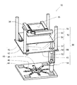
- FIG. 1 is an external perspective view showing a wafer test apparatus 10 according to the first embodiment of the present invention. It includes a wafer test unit 20, an apparatus frame 11 on which the wafer test unit 20 is mounted, and a wafer positioning unit 30 having a wafer positioning stage 32, a position information photographing mechanism 33, and a unit elevating mechanism 31.
- the wafer positioning stage 32 and the wafer are arranged on the front side of the wafer test unit 20 by driving the unit slide mechanism 28 (FIG. 2) with the wafer test unit 20 mounted in the second stage from the top.
- the trays 23 are sliding so as to face each other. Further, the wafer tray 23 is separated from the wafer test unit 20 by the wafer positioning stage 32 and moved to a position where the wafer 15 is placed.
- the wafer test unit 20 and the wafer positioning unit 30 constituting the wafer test apparatus 10 with respect to the process from the placement of the wafer 15 to the end of the test will be described in FIGS. 2 and later.
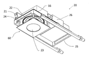
- FIG. 2 is a perspective view showing the wafer test unit 20 according to the first to second embodiments of the present invention, and is a tester unit 26 equipped with a device power supply and a test function, a load board 16, and a unit frame. 25, the unit slide mechanism 28, the probe card 21 shown in FIG. 3, the seal member 22, the wafer tray 23, the vacuum chamber 24, and the connecting member 27 are provided.
- the unit slide mechanism 28 A linear slide mechanism 28a into which the slide unit 28b is incorporated, a drive mechanism 28c for sliding the slide unit 28b, a frame member 28d on which the linear slide mechanism 28a and the drive mechanism 28c are mounted, and a drive motor 28e are provided. There is.
- the slide unit 28b is connected to the unit frame 25, and the frame member 28d is installed in the device frame 11 as shown in FIG. As a result, the wafer test unit 20 can be slid by driving the drive mechanism 28c by the drive motor 28e.
- the wafer test unit 20 is equipped with the tester unit 26, and the wafer test unit 20 can be easily slid by using a flexible cable such as a robot cable as a wiring material for connecting to the outside. be able to.
- an integrated linear slide guide unit in which the linear slide mechanism 28a, the slide unit 28b, the drive mechanism 28c, and the frame member 28d are incorporated is used.
- a ball screw is used for the drive mechanism 28c, a nut is incorporated in the slide unit 28b, and the slide unit 28b slides by driving the ball screw.
- the unit slide mechanism 28 is installed on both sides of the wafer test unit 20, and the motors on both sides operate synchronously so that the heavy unit can be slid at high speed and with low vibration. If the wafer test unit 20 is lightweight and slides at a low speed, it can be installed on one side.
- the wafer test unit 20 is loaded on the apparatus frame 11 and can be slid so as to face the wafer positioning stage 32 by the unit slide mechanism 28.
- FIG. 3 is a perspective view showing the configuration of the wafer test unit 20 shown in FIG. 2 as viewed from below, showing a state in which the wafer test unit 20 is slid forward, and the tester unit 26 and the load board 16 are shown.
- the vacuum chamber 24, the probe card 21, the seal member 22, the wafer tray 23, the unit frame 25, the connecting member 27, and the unit slide mechanism 28 are provided.
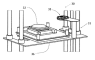
- FIG. 4 is a perspective view showing the appearance of each member of the wafer positioning unit 30 having the wafer positioning stage 32 according to the third to seventh embodiments, the unit elevating mechanism 31 and the wafer positioning stage 32.
- the position information photographing mechanism 33, and the wafer positioning stage 32 includes an alignment stage 34 having a wafer tray mounting surface 35, an alignment stage swing mechanism 40, and an alignment stage elevating mechanism 50. (Details are explained in Fig. 5)
- the wafer positioning stage 32 and the position information photographing mechanism 33 are mounted on the elevating table 36 and can be elevated by the unit elevating mechanism 31 (details are omitted). Further, the position information photographing mechanism 33 has a camera and lighting for photographing the upper and lower surfaces.
- FIG. 5 is a perspective view showing the appearance of the members constituting the wafer positioning stage 32.
- the alignment stage 34 is moved upward to move the swing mechanism mounting plate 44. Is moved downward and displayed, and the alignment stage elevating mechanism 50 shows a state in which the alignment stage mounting plate 51 is pushed up.
- the wafer positioning stage 32 includes the alignment stage 34 having the wafer tray mounting surface 35 and controlling the positions in the X, Y, and rotation directions, the alignment stage swing mechanism 40, and the alignment stage elevating mechanism. It has 50 and. Although not shown, the wafer tray mounting surface 35 has a suction port for sucking and holding the wafer tray 23, and is sucked by a vacuum mechanism 29 (not shown).
- the alignment stage swing mechanism 40 has a swing plate 41 on which the alignment stage elevating mechanism 50 is mounted, abutting members 42 that come into contact with the four corners of the lower surface of the vacuum chamber 24, and a spherical slide bearing 45 at a central position.
- the swing mechanism mounting plate 44 having a plurality of spring members 46 radially provided on the outer peripheral portion of the spherical slide bearing 45 is provided.
- the central portion of the swing plate 41 is connected to the movable portion (the portion connected to the ball of the ball joint) of the spherical slide bearing 45, and the central portion of the swing mechanism mounting plate 44 is fixed to the spherical slide bearing 45.
- the rocking space of the rocking plate 41 is secured between the rocking plate 41 and the rocking mechanism mounting plate 44, which is connected to the portion.
- a ball joint type bearing is used for the spherical slide bearing 45
- a leaf spring is used for the spring member 46.
- the alignment stage elevating mechanism 50 is a drive mechanism that fits the swing plate 41, the alignment stage mounting plate 51, a drive mechanism slide shaft 57 that slides with the ball screw 56 and the ball screw 56, and the drive mechanism slide shaft 57. It includes a drive mechanism 55 having a slide unit 58, a drive motor 59 connected to the ball screw 56, and a slide mechanism 52 having a slide shaft 53 and a slide unit 54.
- the drive motor 59 is installed on the rocking plate 41 via a metal fitting.
- the drive mechanism slide unit 58 constituting the drive mechanism 55 is installed at one place, and the slide unit 54 constituting the slide mechanism 52 is installed at three places at the four corners of the rocking plate 41.
- the tip of the drive mechanism slide shaft 57 constituting the drive mechanism 55 is connected to the four corners of the alignment stage mounting plate 51 at one place and the tip of the slide shaft 53 constituting the slide mechanism 52 at three places.
- the number of the drive mechanism 55 used is one in FIG. 5, but as described in the sixth aspect of the present invention, one place is used according to the weight carried by the alignment stage elevating mechanism 50 and the speed of elevating and lowering. You can choose from up to 4 locations.
- FIG. 6 is a perspective view of the wafer positioning stage 32 using the drive mechanism 55 at two locations.
- the wafer positioning stage 32 includes the alignment stage 34, the alignment stage swing mechanism 40, and the alignment stage elevating and lowering.
- the transport load of the alignment stage 34 can be raised and lowered at a higher speed and with low vibration.
- a ball screw integrated ball spline is used for the drive mechanism 55
- a ball spline is used for the slide mechanism 52, whereby the drive mechanism 55 and the drive mechanism 55 are used.
- a commercially available product can be used for the slide mechanism 52, the alignment stage elevating mechanism 50 can be easily constructed, and the alignment stage 34 can be elevated vertically at high speed and with low vibration. (Same for Fig. 5)
- the wafer positioning stage 32 is pushed up by the unit elevating mechanism 31, and the abutting members 42 provided at the four corners of the upper surface of the swing plate 41 constituting the alignment stage swing mechanism 40 are the wafer. It shows a state of contact with the four corners of the lower surface of the vacuum chamber 24 constituting the test unit 20.
- the oscillating plate 41 is ensured parallelism with the vacuum chamber 24, and at the same time, the alignment stage 34 is also ensured parallelism. Since the wafer tray 23 is sucked into the vacuum chamber 24 and maintains parallelism with the vacuum chamber 24, the wafer tray 23 and the alignment stage 34 can have the same inclination. (Parallelity is obtained).
- This figure shows a state in which the alignment stage elevating mechanism 50 stops the alignment stage 34 at the lowest point.
- the first closed space 24a and the second closed space 24b for connecting are formed as follows.
- the first sealed space 24a is formed by the load board 16, the sealing member 22a, the vacuum chamber 24, the sealing member 22b, and the probe card 21 of the previous period, and the vacuum chamber 24 and the sealing member 22b
- a second sealed space 24b is formed by the probe card 21, the sealing member 22, and the wafer tray 23.
- FIG. 8 shows a state in which the alignment stage 34 whose parallelism is ensured with the vacuum chamber 24 is pushed up by the alignment stage elevating mechanism 50 and comes into contact with the wafer tray 23 held in the vacuum chamber 24. ing. Similar to FIG. 7, the abutting member 42 is in contact with the lower surface of the vacuum chamber 24.
- the wafer tray 23 held in the vacuum chamber 24 is separated from the vacuum chamber 24 after the pressure of the second sealed space 24b is adjusted by the vacuum mechanism 29, and the alignment stage is moved up and down.
- the mechanism 50 shows a state in which the wafer 15 is placed and taken out, and the wafer 15 and the probe card 21 are aligned with each other.
- the position information photographing mechanism 33 moves between the wafer tray 23 and the probe card 21 to acquire position information. Similar to FIGS. 7 and 8, the abutting member 42 is in contact with the lower surface of the vacuum chamber 24.
- the wafer positioning stage 32 is pushed up by the unit lifting mechanism 31 and is pushed up to the four corners of the upper surface of the swing plate 41.
- the abutting member 42 provided comes into contact with the four corners of the lower surface of the vacuum chamber 24, the inclination of the alignment stage 34 can be made to follow the inclination of the vacuum chamber 24.
- the alignment stage 34 that follows the inclination of the vacuum chamber 24 is raised by the alignment stage elevating mechanism 50 so that the wafer tray 23 is brought into contact with the lower surface of the wafer tray 23 without changing the inclination of the wafer tray 23. be able to.
- vacuum suction is performed by the vacuum mechanism 29.
- a step of lowering the wafer tray 23 to a position where the wafer 15 is mounted, taken out, and aligned a step of aligning the wafer 15 with the probe card 21, and the wafer tray 23.
- the wafer tray 23 can be raised and lowered without changing the inclination of the wafer tray 23, and highly accurate alignment is possible.
- the moving distance from the position where the wafer tray 23 is sucked and held in the vacuum chamber 24 to the position where the wafer 15 is placed is a height at which the position information photographing mechanism 33 can photograph the position information. It is secured at the height of the abutting member 42.
- a ball screw integrated ball spline is used for the drive mechanism 55 constituting the alignment stage elevating mechanism 50, and a ball spline is used for the slide mechanism 52 (7th embodiment of the present invention). ).
- a ball spline is used for the slide mechanism 52 (7th embodiment of the present invention).
- FIG. 10 is an external perspective view of the wafer test apparatus 10 on which the wafer test unit 20 according to the eighth embodiment of the present invention is mounted.
- the wafer tray elevating mechanism 60 the wafer 15 is placed on the wafer tray 23.
- the wafer positioning stage 32 is waiting below the wafer positioning stage 32.
- FIG. 11 shows a wafer test unit 20 according to an eighth embodiment of the present invention, which is equipped with the wafer tray elevating mechanism 60 according to the ninth embodiment of the present invention in addition to the unit slide mechanism 28 to hold a wafer tray.
- the wafer tray elevating mechanism 60 is lowered to a position where the wafer 15 is placed.
- the unit slide mechanism 28 includes the linear slide mechanism 28a in which the slide unit 28b is incorporated, the drive mechanism 28c that slides the slide unit 28b, and the frame in which the linear slide mechanism 28a and the drive mechanism 28c are mounted. It includes a member 28d and a drive motor 28e.
- unit slide mechanism 28 uses the unit slide mechanism 28 according to the second embodiment of the present invention, detailed description thereof will be omitted.
- FIG. 12 is a perspective view of the wafer test unit 20 shown in FIG. 11 as viewed from below.
- the load board 16 the wafer tray elevating mechanism 60, the wafer tray 23, the unit frame 25, and the above.
- the tester unit 26, the vacuum chamber 24, the probe card 21, and the seal member 22 are displayed.
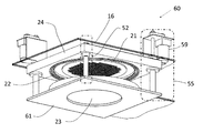
- FIG. 13 is a perspective view showing the wafer tray elevating mechanism 60 according to the ninth to eleventh embodiments of the present invention, in which the wafer tray elevating mechanism 60 includes the vacuum chamber 24, the drive mechanism 55, and the slide.
- the mechanism 52, the wafer tray holding plate 61, the sealing member 22, the sealing member 22a, and the sealing member 22b are provided.
- the probe card 21 and the wafer tray 23 are also displayed for ease of understanding.
- the drive mechanism 55 includes a ball screw 56, a drive mechanism slide shaft 57 that slides by driving the ball screw 56, and a drive mechanism slide unit 58 that fits with the drive mechanism slide shaft 57.
- the slide mechanism 52 includes a slide shaft 53 and a slide unit 54. As the drive mechanism 55 and the slide mechanism 52, the same mechanisms as the drive mechanism 55 and the slide mechanism 52 described with reference to FIG. 5 are used.
- the drive mechanism 55 is driven by the drive motor 59 and slides the drive mechanism slide shaft 57.
- the drive motor 59 is installed in the vacuum chamber 24 from above the load board 16 via a mounting bracket, and the ball screw 56 is driven by a belt in order to lower the height of the wafer test unit 20. Is adopted.
- the drive mechanism slide unit 58 of the drive mechanism 55 and the slide unit 54 of the slide mechanism 52 are installed at two diagonally opposed positions at the four corners of the vacuum chamber 24, and the tip of the drive mechanism slide shaft 57 of the drive mechanism 55.
- the tip of the slide shaft 53 of the slide mechanism 52 is connected to two diagonally opposed positions of the four corners of the wafer wafer tray holding plate 61.
- the number of the drive mechanisms installed is from 1 to 4 depending on the load applied to the wafer tray holding plate 61 and the speed of raising and lowering, as described in the tenth embodiment of the present invention. You can choose.
- a ball screw integrated ball spline is used for the drive mechanism 55
- a ball spline is used for the slide mechanism 52, whereby the drive mechanism 55 and the drive mechanism 55 are used.
- a commercially available product can be used for the slide mechanism 52, the wafer tray elevating mechanism 60 can be easily constructed, and the wafer tray holding plate 61 can be elevated vertically at high speed and with low vibration.
- a connecting member 27 for connecting between the load board 16 (visualized) and the probe card 21 is displayed and is arranged inside the vacuum chamber 24. The positional relationship of the members will be described with reference to FIG.
- FIG. 14 is a perspective view of the wafer tray elevating mechanism 60 of FIG. 13 as viewed from below, and all of the displayed members are the same as those of FIG. 13 except for the probe card 21 and the seal member 22. The description will be omitted, and the seal member 22 will be described with reference to FIG.
- FIG. 15 is a perspective view showing the appearance of each member of the wafer positioning unit 30 having the wafer positioning stage 32 according to the twelfth embodiment of the present invention, and is a perspective view showing the wafer positioning stage 32 and the position information photographing mechanism 33. Is mounted on the elevating table 36 and can be elevated by the unit elevating mechanism 31.
- FIG. 16 is an external perspective view of the wafer positioning stage 32 and the position information photographing mechanism 33 according to the twelfth embodiment of the present invention, and in order to make the configuration of the wafer positioning stage 32 easy to understand, the rocking plate.
- the alignment stage 34 above the 41 is moved upward, and the swing mechanism mounting plate 44a is moved downward to be displayed.
- the wafer positioning stage 32 includes the alignment stage 34 which has the wafer tray mounting surface 35 and controls the positions in the X direction, the Y direction, and the rotation direction, and the alignment stage swing mechanism 40.
- the wafer tray mounting surface 35 has a suction port for sucking and holding the wafer tray 23, and is sucked by the vacuum mechanism 29.
- the alignment stage swing mechanism 40 has the swing plate 41 on which the alignment stage 34 is mounted and the abutting member 42a in contact with the four corners of the lower surface of the wafer tray holding plate 61.
- the rocking mechanism mounting plate 44a having the spherical sliding bearing 45 at a central position and having a plurality of the spring members 46 radially on the outer peripheral portion of the spherical sliding bearing 45 is provided, and the rocking mechanism mounting plate 44a is provided. It is mounted on the elevating table 36.
- the central portion of the swing plate 41 is connected to the movable portion (the portion connected to the ball of the ball joint) of the spherical slide bearing 45, and the central portion of the swing mechanism mounting plate 44a is fixed to the spherical slide bearing 45.
- a swing space of the swing plate 41 is secured between the swing plate 41 and the swing mechanism mounting plate 44a, which is connected to the portion.
- a ball joint type bearing is used for the spherical slide bearing 45
- a leaf spring is used for the spring member 46.
- the height of the abutting member 42a is such that when the wafer positioning stage 32 is raised by raising the unit elevating mechanism 31 and the abutting member 42a comes into contact with the wafer wafer tray holding plate 61, the alignment stage 34
- the wafer tray mounting surface 35 pushes up the wafer tray 23 by several millimeters, and the wafer tray 23 has a height that allows it to move back and forth and left and right. By this push-up, the wafer 15 and the probe card 21 in the previous period can be aligned.
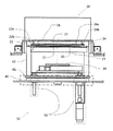
- FIG. 17 is surrounded by the load board 16 constituting the wafer test unit 20 according to the eighth embodiment of the present invention, the vacuum chamber 24, the probe card 21, and the wafer tray 23. It is sectional drawing which shows the formation of two closed spaces.
- the load board 16 As the wafer tray elevating mechanism 60 rises (the portion indicated by the alternate long and short dash line in the figure), the load board 16, the seal member 22a, the vacuum chamber 24, the seal member 22b, and the probe card 21 of the previous period are used.
- One closed space 24a is formed
- a second sealed space 24b is formed by the vacuum chamber 24, the sealing member 22b, the early probe card 21, the sealing member 22, and the wafer tray 23.
- an electrical connection between the load board 16 and the probe card 21 is made via the connecting member 27 such as a pogo tower, and the second closed space 24b is provided.
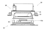
- Vacuum suction makes an electrical connection between the probe card 21 and the wafer 15. The vacuum suction is performed by the vacuum mechanism 29, and the pressure of the vacuum mechanism 29 is adjusted to reduce the pressure, pressurize, and open the closed space to the atmospheric pressure.
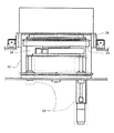
- the wafer tray elevating mechanism 60 was raised in the wafer test unit 20 according to the eighth embodiment of the present invention, and the wafer 15 mounted on the wafer tray 23 was brought into contact with the probe card 21. It is a schematic diagram which shows the position of time (details are omitted).
- the wafer positioning stage 32 stands by below it.
- the wafer positioning stage 32 includes the alignment stage 34 and the early alignment stage swing mechanism 40.
- FIG. 19 shows a state in which the wafer tray elevating mechanism 60 is lowered from the state of FIG. 18 and stopped at a position (lowest point) where the wafer 15 is placed on and taken out from the wafer tray 23. ..
- the wafer positioning stage 32 is stopped downward, the abutting member 42a is separated from the wafer tray holding plate 61, and the alignment stage swing mechanism 40 is not operating.
- the wafer positioning stage 32 is pushed up by the unit elevating mechanism 31 from the state of FIG. 19, and the abutting member 42a is in contact with the wafer tray holding plate 61 of the previous period.
- the wafer tray mounting surface 35 of the alignment stage 34 is in contact with the wafer tray 23 and is pushed up by several millimeters.
- the alignment stage 34 can control the position of the wafer tray 23 in the X direction, the Y direction, and the rotation direction, and the position information photographing mechanism 33 and the wafer tray 23 It can be inserted between the probe cards 21 of the previous term to acquire and align the required position information.
- FIG. 21 shows an external perspective view of the wafer test device 10 on which the wafer positioning unit 30 according to the 14th embodiment of the present invention is mounted, and the device frame 11 on which the wafer test unit 20 is mounted is 2. It shows the case where the columns are arranged.
- the wafer positioning unit 30 includes the wafer positioning stage 32, the position information photographing mechanism 33, the unit elevating mechanism 31, and the lateral unit slide 37 mechanism, and the movement of the lateral unit slide mechanism 37 causes the two rows of the above. It is possible to deal with the wafer test unit 20 mounted on the apparatus frame 11.
- the lateral unit slide mechanism 37 is equipped with a rear slide mechanism 38 having a slide guide 38a and a slide unit 38b, a drive mechanism 39 for sliding the slide unit 38b, a linear slide mechanism 38, and the drive mechanism 39. It includes a frame member 37a (details are omitted).
- the wafer positioning unit 30 can be slid in the row direction.
- the wafer positioning unit 30 can be slid at high speed and with low vibration.
- the role of the wafer positioning stage 32 is only to align the wafer 15 and the probe card 21.
- the wafer test unit 20 can be moved to the next scheduled wafer test unit 20 immediately after the alignment is completed, so that the cost of the test device can be suppressed and the operation rate of the test device can be further improved.
- the present invention is configured as described above, it is possible to specifically deal with the following problems.
- a unit slide mechanism in the wafer test unit and further providing an alignment stage swing mechanism and an alignment stage elevating mechanism in the wafer positioning stage,
- the space of the wafer positioning stage can be eliminated under the wafer test unit, the wafer placed on the wafer tray and the probe card are aligned, and the wafer tray is raised to connect the wafer electrodes and the probe card terminals.
- the electrodes of the wafer and the terminals of the probe card can be brought into contact with each other with high accuracy without causing a positional deviation due to the raising of the wafer tray.
- the step of raising and lowering the wafer tray by the wafer positioning stage can be separated from the wafer positioning stage and caused by the wafer tray elevating mechanism.
- the positioning stage By causing the positioning stage to perform only the wafer alignment step, it is possible to provide a highly accurate alignment between the wafer electrode and the terminal of the probe card and a wafer test apparatus having a high operating rate.
- this method there is a demerit that the cost of the wafer test unit is high, but by using the wafer positioning unit according to the 14th embodiment of the present invention, a wafer test apparatus having a high operating rate can be realized.
- the wafer test apparatus in the present invention enables mounting of a larger number of wafer test units as compared with the conventional multi-stage test apparatus, a wafer level burn-in test that requires testing of a large number of wafers at one time is required. It can be expected as a test device such as.
- Wafer test equipment 11 Equipment frame 15 Wafer 16 Load board 20 Wafer test unit 21 Probe card 22 Sealing member 22a Sealing member 22b Sealing member 23 Wafer tray 24 Vacuum chamber 24a First sealed space 24b Second sealed space 25 Unit frame 26 Tester 27 Connection member 28 Unit slide mechanism 28a Linear slide mechanism 28b Slide unit 28c Drive mechanism 28d Frame member 28e Drive motor 29 Vacuum mechanism 30 Wafer positioning unit 31 Unit lifting mechanism 32 Wafer positioning stage 33 Position information imaging mechanism 34 Alignment stage 35 Wafer Tray mounting surface 36 Lifting table 37 Horizontal unit Slide mechanism 37a Frame member 38 Linear slide mechanism 38a Slide guide 38b Slide unit 39 Drive mechanism 40 Alignment stage swing mechanism 41 Swing plate 42 Butting member 42a Butting member 44 Swing Mechanism mounting plate 44a Swing mechanism mounting plate 45 Spherical sliding bearing 46 Spring member 50 Alignment stage elevating mechanism 51 Alignment stage mounting plate 52 Slide mechanism 53 Slide shaft 54 Slide unit 55 Drive mechanism 56 Ball screw 57 Drive mechanism slide shaft 58 Drive mechanism slide unit 59 Drive motor 60 Wafer tray elevating mechanism 61
Landscapes
- Physics & Mathematics (AREA)
- General Physics & Mathematics (AREA)
- Engineering & Computer Science (AREA)
- General Engineering & Computer Science (AREA)
- Testing Or Measuring Of Semiconductors Or The Like (AREA)
- Testing Of Individual Semiconductor Devices (AREA)
- Tests Of Electronic Circuits (AREA)
- Container, Conveyance, Adherence, Positioning, Of Wafer (AREA)
Applications Claiming Priority (2)
| Application Number | Priority Date | Filing Date | Title |
|---|---|---|---|
| JP2019-130610 | 2019-06-26 | ||
| JP2019130610 | 2019-06-26 |
Publications (1)
| Publication Number | Publication Date |
|---|---|
| WO2020261949A1 true WO2020261949A1 (ja) | 2020-12-30 |
Family
ID=74060838
Family Applications (1)
| Application Number | Title | Priority Date | Filing Date |
|---|---|---|---|
| PCT/JP2020/022452 Ceased WO2020261949A1 (ja) | 2019-06-26 | 2020-06-01 | ウエハー試験装置 |
Country Status (2)
| Country | Link |
|---|---|
| JP (1) | JP6906128B2 (https=) |
| WO (1) | WO2020261949A1 (https=) |
Cited By (1)
| Publication number | Priority date | Publication date | Assignee | Title |
|---|---|---|---|---|
| CN114054385A (zh) * | 2021-11-11 | 2022-02-18 | 四川和恩泰半导体有限公司 | 全自动双头晶片测试机 |
Citations (4)
| Publication number | Priority date | Publication date | Assignee | Title |
|---|---|---|---|---|
| JP2015088555A (ja) * | 2013-10-29 | 2015-05-07 | 東京エレクトロン株式会社 | ウエハ検査装置の整備用台車及びウエハ検査装置の整備方法 |
| JP2017069428A (ja) * | 2015-09-30 | 2017-04-06 | 東京エレクトロン株式会社 | ウエハ検査方法及びウエハ検査装置 |
| WO2018235411A1 (ja) * | 2017-06-21 | 2018-12-27 | 東京エレクトロン株式会社 | 検査システム |
| JP2019149500A (ja) * | 2018-02-28 | 2019-09-05 | 東京エレクトロン株式会社 | 検査システム |
-
2020
- 2020-04-24 JP JP2020093761A patent/JP6906128B2/ja active Active
- 2020-06-01 WO PCT/JP2020/022452 patent/WO2020261949A1/ja not_active Ceased
Patent Citations (4)
| Publication number | Priority date | Publication date | Assignee | Title |
|---|---|---|---|---|
| JP2015088555A (ja) * | 2013-10-29 | 2015-05-07 | 東京エレクトロン株式会社 | ウエハ検査装置の整備用台車及びウエハ検査装置の整備方法 |
| JP2017069428A (ja) * | 2015-09-30 | 2017-04-06 | 東京エレクトロン株式会社 | ウエハ検査方法及びウエハ検査装置 |
| WO2018235411A1 (ja) * | 2017-06-21 | 2018-12-27 | 東京エレクトロン株式会社 | 検査システム |
| JP2019149500A (ja) * | 2018-02-28 | 2019-09-05 | 東京エレクトロン株式会社 | 検査システム |
Cited By (2)
| Publication number | Priority date | Publication date | Assignee | Title |
|---|---|---|---|---|
| CN114054385A (zh) * | 2021-11-11 | 2022-02-18 | 四川和恩泰半导体有限公司 | 全自动双头晶片测试机 |
| CN114054385B (zh) * | 2021-11-11 | 2024-02-09 | 四川和恩泰半导体有限公司 | 全自动双头晶片测试机 |
Also Published As
| Publication number | Publication date |
|---|---|
| JP2021005700A (ja) | 2021-01-14 |
| JP6906128B2 (ja) | 2021-07-21 |
Similar Documents
| Publication | Publication Date | Title |
|---|---|---|
| KR102361259B1 (ko) | 웨이퍼 시험장치 | |
| JP3745750B2 (ja) | 表示パネルの検査装置および検査方法 | |
| TWI400764B (zh) | 試驗裝置 | |
| JP5952645B2 (ja) | ウエハ検査用インターフェース及びウエハ検査装置 | |
| JPWO2011016097A1 (ja) | ウエハトレイおよび試験装置 | |
| KR20200138002A (ko) | 위치 결정 기구 및 위치 결정 방법 | |
| CN110211889B (zh) | 检查系统 | |
| JP2021136425A (ja) | ウエハー試験装置 | |
| JP6471401B1 (ja) | 半導体ウエハーの試験ユニット | |
| US20240288493A1 (en) | Apparatus for aligning device having fine pitch, apparatus for testing device having fine pitch, and device alignment method | |
| JP2009539112A (ja) | Tft−lcd検査のための小型プローバ | |
| CN115902309A (zh) | 工作台、检查装置及工作台的动作方法 | |
| TW200403792A (en) | Substrate assembling device and method | |
| JP6906128B2 (ja) | ウエハー試験装置 | |
| TWI613452B (zh) | 電子零件搬送裝置及電子零件檢查裝置 | |
| JP2021118344A (ja) | ウエハー試験装置 | |
| CN114729964A (zh) | 具有细小间距的器件测试装置及其方法 | |
| JP2018125507A (ja) | ウエハーレベルパッケージの試験ユニット | |
| TW202213565A (zh) | 檢查裝置及檢查方法 | |
| JP4482707B1 (ja) | 試験装置 | |
| KR102297834B1 (ko) | 대형 패널 검사용 회전스테이지 장치 | |
| WO2013012162A1 (ko) | 향상된 기구적 강성을 갖는 수평수직 이동기구 | |
| JP2017167019A (ja) | 電子部品搬送装置、および電子部品検査装置 | |
| JP2018148060A (ja) | ウエハーレベルパッケージの試験装置 | |
| CN223664244U (zh) | 显示屏的检测系统 |
Legal Events
| Date | Code | Title | Description |
|---|---|---|---|
| 121 | Ep: the epo has been informed by wipo that ep was designated in this application |
Ref document number: 20833689 Country of ref document: EP Kind code of ref document: A1 |
|
| NENP | Non-entry into the national phase |
Ref country code: DE |
|
| 122 | Ep: pct application non-entry in european phase |
Ref document number: 20833689 Country of ref document: EP Kind code of ref document: A1 |