WO2020261674A1 - 嚥下医療装置、装着ユニットおよびプログラム - Google Patents
嚥下医療装置、装着ユニットおよびプログラム Download PDFInfo
- Publication number
- WO2020261674A1 WO2020261674A1 PCT/JP2020/012352 JP2020012352W WO2020261674A1 WO 2020261674 A1 WO2020261674 A1 WO 2020261674A1 JP 2020012352 W JP2020012352 W JP 2020012352W WO 2020261674 A1 WO2020261674 A1 WO 2020261674A1
- Authority
- WO
- WIPO (PCT)
- Prior art keywords
- unit
- swallowing
- control unit
- medical device
- mounting unit
- Prior art date
- Legal status (The legal status is an assumption and is not a legal conclusion. Google has not performed a legal analysis and makes no representation as to the accuracy of the status listed.)
- Ceased
Links
Images








Classifications
-
- A—HUMAN NECESSITIES
- A61—MEDICAL OR VETERINARY SCIENCE; HYGIENE
- A61N—ELECTROTHERAPY; MAGNETOTHERAPY; RADIATION THERAPY; ULTRASOUND THERAPY
- A61N1/00—Electrotherapy; Circuits therefor
- A61N1/18—Applying electric currents by contact electrodes
- A61N1/32—Applying electric currents by contact electrodes alternating or intermittent currents
- A61N1/36—Applying electric currents by contact electrodes alternating or intermittent currents for stimulation
- A61N1/36007—Applying electric currents by contact electrodes alternating or intermittent currents for stimulation of urogenital or gastrointestinal organs, e.g. for incontinence control
-
- A—HUMAN NECESSITIES
- A61—MEDICAL OR VETERINARY SCIENCE; HYGIENE
- A61B—DIAGNOSIS; SURGERY; IDENTIFICATION
- A61B5/00—Measuring for diagnostic purposes; Identification of persons
- A61B5/08—Measuring devices for evaluating the respiratory organs
- A61B5/0806—Measuring devices for evaluating the respiratory organs by whole-body plethysmography
-
- A—HUMAN NECESSITIES
- A61—MEDICAL OR VETERINARY SCIENCE; HYGIENE
- A61B—DIAGNOSIS; SURGERY; IDENTIFICATION
- A61B5/00—Measuring for diagnostic purposes; Identification of persons
- A61B5/103—Measuring devices for testing the shape, pattern, colour, size or movement of the body or parts thereof, for diagnostic purposes
- A61B5/11—Measuring movement of the entire body or parts thereof, e.g. head or hand tremor or mobility of a limb
- A61B5/113—Measuring movement of the entire body or parts thereof, e.g. head or hand tremor or mobility of a limb occurring during breathing
- A61B5/1135—Measuring movement of the entire body or parts thereof, e.g. head or hand tremor or mobility of a limb occurring during breathing by monitoring thoracic expansion
-
- A—HUMAN NECESSITIES
- A61—MEDICAL OR VETERINARY SCIENCE; HYGIENE
- A61B—DIAGNOSIS; SURGERY; IDENTIFICATION
- A61B5/00—Measuring for diagnostic purposes; Identification of persons
- A61B5/42—Detecting, measuring or recording for evaluating the gastrointestinal, the endocrine or the exocrine systems
- A61B5/4205—Evaluating swallowing
-
- A—HUMAN NECESSITIES
- A61—MEDICAL OR VETERINARY SCIENCE; HYGIENE
- A61B—DIAGNOSIS; SURGERY; IDENTIFICATION
- A61B5/00—Measuring for diagnostic purposes; Identification of persons
- A61B5/48—Other medical applications
- A61B5/4836—Diagnosis combined with treatment in closed-loop systems or methods
-
- A—HUMAN NECESSITIES
- A61—MEDICAL OR VETERINARY SCIENCE; HYGIENE
- A61N—ELECTROTHERAPY; MAGNETOTHERAPY; RADIATION THERAPY; ULTRASOUND THERAPY
- A61N1/00—Electrotherapy; Circuits therefor
- A61N1/02—Details
- A61N1/04—Electrodes
- A61N1/0404—Electrodes for external use
- A61N1/0408—Use-related aspects
- A61N1/0452—Specially adapted for transcutaneous muscle stimulation [TMS]
-
- A—HUMAN NECESSITIES
- A61—MEDICAL OR VETERINARY SCIENCE; HYGIENE
- A61N—ELECTROTHERAPY; MAGNETOTHERAPY; RADIATION THERAPY; ULTRASOUND THERAPY
- A61N1/00—Electrotherapy; Circuits therefor
- A61N1/02—Details
- A61N1/04—Electrodes
- A61N1/0404—Electrodes for external use
- A61N1/0472—Structure-related aspects
- A61N1/0492—Patch electrodes
-
- A—HUMAN NECESSITIES
- A61—MEDICAL OR VETERINARY SCIENCE; HYGIENE
- A61N—ELECTROTHERAPY; MAGNETOTHERAPY; RADIATION THERAPY; ULTRASOUND THERAPY
- A61N1/00—Electrotherapy; Circuits therefor
- A61N1/18—Applying electric currents by contact electrodes
- A61N1/32—Applying electric currents by contact electrodes alternating or intermittent currents
- A61N1/36—Applying electric currents by contact electrodes alternating or intermittent currents for stimulation
- A61N1/36014—External stimulators, e.g. with patch electrodes
- A61N1/3603—Control systems
- A61N1/36031—Control systems using physiological parameters for adjustment
Definitions
- the present invention relates to a swallowing medical device that performs medical movements related to swallowing, a wearing unit that is attached to the human body during medical movements related to swallowing, and a program for controlling medical movements related to swallowing.
- Patent Document 1 describes a device that induces swallowing at an appropriate timing by giving an electrical stimulus to the pharynx.
- electrical stimulation is applied to the patient's superior laryngeal nerve from an electrode attached near the patient's pharynx to induce swallowing. Electrical stimulation is given during the patient's exhalation period.
- Patent Document 2 describes a device that monitors swallowing based on each detection result of a patient's breathing, swallowing sound, and displacement of the larynx, and determines the risk of aspiration.
- a conductive adhesive member such as a gel sheet is laminated on the upper surface of the electrode in order to improve the adhesion to the patient's skin.
- the adhesive member comes into close contact with the patient's skin, and electrical stimulation is effectively applied from the electrodes to the pharynx. As a result, swallowing can be appropriately induced in the patient.
- the adhesive member is attached to the pharynx in a state of being in close contact with the skin. Therefore, the patient's sebum or the like adheres to the adhesive member according to the number of times the device is used, and as a result, the adhesive force of the adhesive member gradually decreases.
- the adhesive member is an adhesive conductive water-containing gel, sweat or the like caused by sweating of the patient permeates the adhesive conductive water-containing gel and the adhesive strength is reduced. Further, by repeated use, the adhesive strength is remarkably lowered and the adhesion to the skin is deteriorated, so that there is a possibility that the conductivity is deteriorated.
- the adhesive member is an adhesive conductive hydrophobic gel
- the adhesive force is remarkably lowered and the adhesion to the skin is deteriorated, so that the conductivity may be deteriorated.
- the original characteristics of the adhesive member are not ensured, it is not possible to appropriately apply electrical stimulation to the pharynx of the patient, and as a result, there is a possibility that swallowing cannot be properly induced.
- an object of the present invention is to provide a swallowing medical device, a wearing unit and a program capable of ensuring the appropriateness of medical operation related to swallowing.
- the first aspect of the present invention relates to a swallowing medical device that performs a medical operation related to swallowing.
- the swallowing medical device is a memory that stores a wearing unit that is attached to a target part of the human body for the medical operation, a control unit that controls the medical operation, and usage information regarding the usage status of the wearing unit. It has a department.
- the control unit executes control for limiting the use of the mounting unit based on the fact that the usage information does not satisfy the setting conditions for ensuring the characteristics of the mounting unit.
- control is performed to limit the use of the wearing unit when the usage information regarding the usage status of the wearing unit does not satisfy the setting conditions for ensuring the characteristics of the wearing unit. .. Therefore, the appropriateness of medical operation related to swallowing can be ensured.
- the wearing unit may be replaceable.
- the storage unit may be arranged in the mounting unit. According to this configuration, even when the mounting unit is combined with different control units, the usage information regarding the usage status can be properly managed in the mounting unit. Therefore, in the control unit, control for limiting the use of the mounting unit can be appropriately executed.
- the mounting unit may be configured to determine whether or not the usage information satisfies the setting condition and to transmit the determination result to the control unit. As a result, the processing load on the control unit can be reduced. It should be noted that the control unit may determine whether or not the usage information satisfies the above setting conditions. In this case, the mounting unit reads the usage information from the storage unit and transmits it to the control unit.
- the storage unit may further store confirmation information for confirming that the mounting unit is a genuine product.
- the control unit may be configured to perform control to limit the use of the mounting unit based on the fact that the confirmation information could not confirm that the mounting unit is genuine. According to this configuration, when the mounting unit is not a genuine product, control is performed to limit the use of the mounting unit. This eliminates the use of inferior imitations of the mounting unit. Therefore, the appropriateness of medical operation related to swallowing can be more reliably ensured.
- the medical operation is, for example, a swallowing guidance operation for inducing swallowing to a patient.
- the swallowing medical device includes, as the wearing unit, an electrode unit mounted on the pharynx to give a stimulus that promotes swallowing, and the electrode unit includes an electrode for giving the stimulus and the electrode.
- a conductive adhesive member that brings the electrode into close contact with the target portion may be provided.
- the "conductive adhesive member that brings the electrode into close contact with the target portion” is a form in which the adhesive member is arranged so as to be superposed on the electrode, or a form in which the adhesive member itself constitutes the electrode, that is, adhesive. It also includes a form in which the member also has the function of an electrode.
- the swallowing medical device includes a respiration detection unit attached to the body to detect respiration as the wearing unit, and the respiration detection unit detects expansion and contraction of the body accompanying respiration.
- a respiration detection unit attached to the body to detect respiration as the wearing unit, and the respiration detection unit detects expansion and contraction of the body accompanying respiration.
- the medical operation may be a swallowing monitoring operation for monitoring the swallowing of a patient.
- the swallowing medical device includes, as the wearing unit, a displacement detecting unit mounted on the larynx to detect the displacement of the larynx, and the displacement detecting unit detects the displacement of the larynx.
- Displacement sensor may be provided. According to this configuration, control is performed to limit the use of the displacement detection unit when the usage information does not satisfy the setting conditions, that is, when it is assumed that the displacement sensor has deteriorated over time. Therefore, the appropriateness of the swallowing monitoring operation can be ensured.
- the swallowing medical device includes a respiration detection unit attached to the body to detect respiration as the wearing unit, and the respiration detection unit detects expansion and contraction of the body accompanying respiration.
- a respiration detection unit attached to the body to detect respiration as the wearing unit, and the respiration detection unit detects expansion and contraction of the body accompanying respiration.
- control unit may be configured to determine the presence or absence of a risk of aspiration based on the detection result of the wearing unit. According to this configuration, the use of the deteriorated wearing unit is restricted, so that the risk of aspiration can be accurately determined.
- the control unit may be configured to stop the medical operation based on the usage information not satisfying the setting condition. According to this configuration, the medical operation itself is stopped when it is assumed that the wearing unit has deteriorated over time. Therefore, it is possible to prevent the medical operation from being performed by the deteriorated mounting unit, and it is possible to ensure the appropriateness of the medical operation.
- the swallowing medical device may include a display unit for displaying information.
- the control unit causes the display unit to display notification information for stopping the use of the mounting unit based on the usage information not satisfying the setting condition. According to this configuration, a user such as a doctor can avoid using the deteriorated mounting unit by referring to the notification information. Therefore, the appropriateness of medical operation can be guaranteed.
- control unit may be configured to display information indicating the relationship between the usage information and the setting condition on the display unit.
- a user such as a doctor can grasp the state of deterioration of the mounting unit over time by referring to the information displayed on the display unit, and can take measures such as replacing the mounting unit as appropriate. Can be taken. Therefore, the medical operation can be advanced more appropriately.
- a second aspect of the present invention relates to a replaceable mounting unit that is mounted on a target site for medical operation related to swallowing.
- the mounting unit according to this aspect is a control that stores a storage unit that stores usage information regarding the usage status of the mounting unit and transmits information based on the usage information to a control unit that executes the medical operation using the mounting unit. It has a department.
- the control unit when the usage information does not satisfy the setting conditions for ensuring the characteristics of the mounting unit, control for limiting the use of the mounting unit can be performed. Therefore, the appropriateness of medical operation related to swallowing can be ensured.
- control unit of the control unit that executes a medical operation related to swallowing by using the wearing unit mounted on the target portion of the human body is provided with usage information regarding the usage status of the wearing unit. It is a program that executes a function of restricting the use of the mounting unit based on the fact that the setting conditions for ensuring the characteristics of the above are not satisfied.
- the present invention it is possible to provide a swallowing medical device, a wearing unit, and a program capable of ensuring the appropriateness of medical operation related to swallowing.
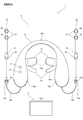
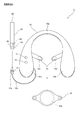
- FIG. 1 is a diagram showing a configuration of a swallowing guidance device according to the first embodiment.
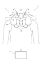
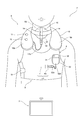
- FIG. 2 is a diagram showing a usage state of the swallowing guidance device according to the first embodiment.
- FIG. 3 is a block diagram showing a circuit configuration of the electrical stimulator according to the first embodiment.
- FIG. 4A is a diagram showing a configuration of usage information according to the first embodiment.
- FIG. 4B is a diagram showing a configuration of confirmation information according to the first embodiment.
- FIG. 5 is a diagram showing a circuit configuration of the control unit according to the first embodiment.
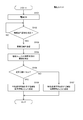
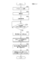
- FIG. 6 is a flowchart showing the control executed by the control unit of the electrode unit when the swallowing guidance operation according to the first embodiment is started.
- FIG. 1 is a diagram showing a configuration of a swallowing guidance device according to the first embodiment.
- FIG. 2 is a diagram showing a usage state of the swallowing guidance device according to the first embodiment.
- FIG. 3 is a block diagram showing a circuit configuration of the electrical stimul
- FIG. 7 is a flowchart showing the control executed by the control unit of the control unit when the swallowing guidance operation according to the first embodiment is started.
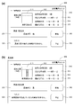
- 8 (a) and 8 (b) are diagrams showing the configuration of the start screen displayed at the start of the swallowing guidance operation according to the first embodiment.
- FIG. 9A is a diagram showing a configuration of a start screen displayed at the start of the swallowing guidance operation according to the first embodiment.
- FIG. 9B is a diagram showing another configuration of the start screen displayed at the start of the swallowing guidance operation according to the first embodiment.
- FIG. 10 is a flowchart showing a usage information update process according to the first embodiment.
- FIG. 11A shows a diagram showing the configuration of the breathing detection device according to the second embodiment, and FIG.
- FIG. 11B shows a configuration of a life jacket for attaching the breathing detection device to the patient according to the second embodiment. It is a figure.
- FIG. 12 is a block diagram showing a circuit configuration of the respiration detection device according to the second embodiment.
- FIG. 13 is a diagram showing a state in which the electrical stimulator and the respiration detector according to the second embodiment are attached to the patient.
- FIG. 14 is a diagram showing a configuration of a swallowing monitoring device according to the third embodiment.
- FIG. 15 is a block diagram showing a circuit configuration of the swallowing monitoring device according to the third embodiment.
- FIG. 16 is a diagram showing a state in which the breathing detection device and the swallowing monitoring device according to the third embodiment are attached to the patient.
- FIG. 17 is a diagram showing a configuration of an electrode unit according to a modified example.
- FIG. 18 is a flowchart showing the control executed by the control unit of the control unit when the swallowing guidance operation is started according to another modification.
- Embodiment 1 is an application of the present invention to a swallowing induction device 1 for inducing swallowing to a patient, for example, to treat aspiration.
- the swallowing guidance device 1 and the electrical stimulation device 2 correspond to the "swallowing medical device” described in the claims
- the electrode unit 20 corresponds to the "wearing unit” described in the claims.
- the first embodiment shown below is merely a configuration example when the present invention is put into practice, and does not limit the invention according to the claims.
- FIG. 1 is a diagram showing the configuration of the swallowing guidance device 1 according to the first embodiment
- FIG. 2 is a diagram showing a usage status of the swallowing guidance device 1.
- the swallowing guidance device 1 includes an electrical stimulator 2 and a control unit 3.
- the electrical stimulator 2 applies electrical stimulation to the patient's pharynx.
- the control unit 3 controls the electrical stimulator 2 to induce swallowing.
- the electrical stimulator 2 and the control unit 3 can communicate with each other by wireless communication such as Bluetooth (registered trademark).
- the control unit 3 is composed of, for example, a tablet.
- the control unit 3 may be another information terminal device such as a mobile phone.
- the electrical stimulator 2 and the control unit 3 may be able to communicate with each other by wire.
- the control unit 3 may be able to communicate individually with a plurality of electrical stimulators 2 different from each other.
- the electrical stimulator 2 includes a holder unit 10 and an electrode unit 20.
- the holder unit 10 has a shape along the patient's neck. That is, the holder unit 10 has a shape in which two end portions 10b hanging near the upper chest of the patient when worn are connected by a connecting portion 10a. When the holder unit 10 is attached, the connecting portion 10a rotates along the back of the patient's neck.
- the outer surface of the holder unit 10 is made of, for example, an ABS material.
- the connecting portion 10a that wraps around the neck is preferably made of a soft material such as EVA material.
- a symbol (left / right, L / R) or the like for indicating whether each end 10b is turned to the left or right of the patient's neck may be added to the surface or the like of the two ends 10b.
- the holder unit 10 has a power button 11 and an emergency stop button 12 arranged on the surface of one end 10b.
- the power button 11 is a button for operating the electrical stimulator 2.
- the emergency stop button 12 is a button for emergency stopping the operation of the electric stimulator 2.
- a circuit board is included in the back of the power button 11 and the emergency stop button 12. On this circuit board, a communication unit for wirelessly communicating with the control unit 3, a control unit for driving the electrode unit 20 based on a control signal from the control unit 3, and the like are mounted.
- Elastic pressing members 13 are attached to the inner surfaces of the two ends 10b, respectively.
- the pressing member 13 is for pressing the electrode portion of the electrode unit 20 against the patient's neck when the holder unit 10 is attached to the patient.
- the pressing member 13 is formed in a bag shape by, for example, an elastic cloth, and a cushioning member 13a such as microbeads is included in the bag.
- a belt-shaped belt 14 is further attached to the inner surface of the two end portions 10b.
- the belt 14 is for fixing the holder unit 10 to the patient's neck.
- a fastening portion 14a forming one side of the hook-and-loop fastener is provided on the inner surface of one of the belts 14.
- the entire outer surface of the other belt 14 is the other fastening portion of the hook-and-loop fastener.
- Cables 15b are pulled out from the lower ends of the two ends 10b, respectively.
- the cable 15b is connected to the circuit board described above built in the holder unit 10.
- a connector 15a for connecting the electrode unit 20 is attached to the tip of the cable 15b. As shown by the arrow of the alternate long and short dash line in FIG. 1, the terminal 22 of the electrode unit 20 is inserted into the connector 15a.
- the connector 15a is provided with a structure for fixing the inserted terminal 22.
- a lever 15c for switching between fixing and releasing is provided on the outer surface of the connector 15a.
- the electrode unit 20 has a flexible thin plate-like structure. In a plan view, the electrode unit 20 has an elongated shape in one direction. Two adhesive members 21 are arranged on the inner surface of one end of the electrode unit 20, and the electrodes 24 are arranged inside the adhesive members 21.
- the adhesive member 21 has conductivity.
- the adhesive member 21 is composed of, for example, a pad made of a gel material. As the gel material, an adhesive conductive water-containing gel or an adhesive conductive hydrophobic gel can be used.
- the terminal 22 protrudes from the other end of the electrode unit 20.
- a circuit board is built in the other end of the electrode unit 20, and terminals 22 are connected to the circuit board.
- a storage unit 23 including an EEPROM is mounted on this circuit board. As will be described later, the storage unit 23 stores usage information regarding the usage status of the electrode unit 20 over time, confirmation information for confirming that the electrode unit 20 is a genuine product, and the like.
- the electrode unit 20 When the electrical stimulator 2 is not in use, the electrode unit 20 is removed from the connector 15a and stored by a storage sheet (template paper) so as not to be exposed to moisture or sunlight. When the electrical stimulator 2 is used, the electrode unit 20 is attached to the connector 15a and integrated with the holder unit 10.
- a storage sheet template paper
- the connecting portion 10a of the holder unit 10 is hung on the patient's neck, and the ends of the two electrode units 20 are applied to the left and right portions of the patient's larynx, respectively.
- the adhesive member 21 arranged at the end of the electrode unit 20 adheres to the surface of the skin.
- the two pressing members 13 are respectively applied to the upper surface of the end portion of the electrode unit 20, and the two belts 14 are overlapped and joined.
- the pressing member 13 bends, and the reaction force thereof presses the end portion of the electrode unit 20 against the patient's neck.
- the electrode unit 20 is attached to the patient with the adhesive member 21 pressed against the patient's neck.
- the electrode unit 20 is driven by the control unit 3, a current flows through the electrodes 24 arranged inside the adhesive member 21, and the swallowing reflex is promoted.
- the two electrodes 24 are set to the positive and negative electrodes, and the remaining two electrodes 24 are set to the positive and negative electrodes.
- the four electrodes 24 are arranged so that the pair of positive and negative electrodes and the other pair of positive and negative electrodes are arranged in an X shape centered on the thyroid cartilage.
- the two pairs of electrodes 24 are both driven to have a medium frequency, and the difference in frequency between the two pairs of electrodes 24 is driven to a low frequency.
- FIG. 3 is a block diagram showing a circuit configuration of the electrical stimulator 2.
- FIG. 3 For convenience, one of the two electrode units 20 mounted on the holder unit 10 is shown in FIG. 3, but the other electrode unit 20 has the same configuration. The combination of the driver 113, the connector 15a and the other electrode unit 20 is further added to the configuration of FIG.
- the holder unit 10 and the electrode unit 20 include circuit boards 110 and 120, respectively.
- the circuit board 110 is built in the holder unit 10.
- the circuit board 120 is built in at the end of the electrode unit 20 on the terminal 22 side. These circuit boards 110 and 120 are connected to each other by connecting the terminal 22 to the connector 15a.
- a control unit 111, a storage unit 112, a driver 113, a wireless communication unit 114, and a power supply 115 are mounted on the circuit board 110 of the holder unit 10.
- the power button 11 and the emergency stop button 12 shown in FIG. 1 are also installed on the circuit board 110.
- the control unit 111 is configured by, for example, a microcomputer, and controls each unit according to a program stored in the storage unit 112.
- the storage unit 112 is composed of a ROM, a RAM, or the like, and stores a program for controlling each unit. Further, the storage unit 112 is used as a work area when the control unit 111 controls each unit.
- the driver 113 drives the electrode 24 according to the control from the control unit 111.
- the wireless communication unit 114 wirelessly communicates with the control unit 3 according to the control from the control unit 111.
- the power supply 115 includes a battery and supplies a power supply voltage to each circuit section of the circuit boards 110 and 120. The power supply voltage is supplied to the circuit board 120 on the electrode unit 20 side via the cable 15b of FIG.
- a control unit 121 and a storage unit 23 are mounted on the circuit board 120 of the electrode unit 20.
- the control unit 121 is composed of, for example, a microcomputer, and controls each unit according to a program stored in the storage unit 23.
- the control unit 121 has a clock function for measuring the current date and time.
- the storage unit 23 is composed of a ROM, a RAM, or the like, and stores a program for controlling each unit. Further, the storage unit 23 is used as a work area when the control unit 121 controls each unit.
- the storage unit 23 includes a non-volatile memory (EEPROM) capable of writing and erasing data.
- EEPROM non-volatile memory
- the storage unit 23 stores usage information regarding the usage status of the electrode unit 20 in the non-volatile memory. Further, the storage unit 23 confirms that the electrode unit 20 is a genuine product in a predetermined area other than the writing area of the usage information in the non-volatile memory, that is, that the electrode unit 20 is manufactured by an appropriate manufacturer. Memorize information.
- FIG. 4 (a) is a diagram showing the structure of usage information
- FIG. 4 (b) is a diagram showing the structure of confirmation information.
- the usage information includes the number of times the electrode unit 20 has been used, the start date and time, the end date and time, and the usage time at each use, and the usage information from the time when the electrode unit 20 is first used. It consists of cumulative usage time.
- the usage time is calculated as the difference between the start date and time and the end date and time.
- the cumulative usage time is calculated by adding the usage time up to each usage count.
- the usage information may consist only of the start date and time and the end date and time.
- the number of sets of the start date and time and the end date and time stored in the storage unit 23 is the number of times of use.
- the usage time and the cumulative usage time can be calculated at any time by the above calculation based on the start date and time and the end date and time stored in the storage unit 23.
- the usage information may consist only of the usage time.
- the number of times of use stored in the storage unit 23 is the number of times of use.
- the cumulative usage time can be calculated at any time by adding the usage time.
- the confirmation information consists of a serial number having a predetermined number of digits and an encryption key.
- the serial number is encrypted with an encryption key, and the serial number having a predetermined number of digits is acquired by decrypting the data in the memory area in which the serial number is stored with the encryption key.
- FIG. 5 is a diagram showing a circuit configuration of the control unit 3.
- the control unit 3 includes a control unit 201, a storage unit 202, a display input unit 203, a first wireless communication unit 204, and a second wireless communication unit 205.
- the control unit 201 is composed of, for example, an arithmetic processing circuit such as a CPU, and controls each unit according to the program 202a stored in the storage unit 202.
- the storage unit 202 is composed of a ROM, a RAM, and the like, and stores a program 202a for controlling the swallowing guidance operation. Further, the storage unit 202 is used as a work area when the control unit 201 controls each unit.
- the display input unit 203 displays predetermined information and accepts operation input from the user.
- the display input unit 203 is composed of, for example, a touch panel.
- the control unit 3 is a tablet, substantially the entire range on the front surface of the control unit 3 is the arrangement area of the display input unit 203.
- the first wireless communication unit 204 wirelessly communicates with the wireless communication unit 114 of the electrical stimulator 2 according to the control from the control unit 201.
- the second wireless communication unit 205 communicates with the server 220 connected to the external communication network 210 according to the control from the control unit 201.
- the external communication network 210 is, for example, a public line.
- the server 220 manages various information related to the swallowing guidance operation.
- the program 202a for controlling the swallowing guidance operation is downloaded from the server 220 to the control unit 3 via the second wireless communication unit 205, and is installed in the storage unit 202.
- the program 202a may be incorporated into the control unit 3 via a USB memory or an optical disk and installed in the storage unit 202.
- FIG. 6 is a flowchart showing the control executed by the control unit 121 of the electrode unit 20 when the swallowing guidance operation is started.
- FIG. 7 is a flowchart showing the control executed by the control unit 201 of the control unit 3 when the swallowing guidance operation is started.
- a user After attaching the electrode unit 20 to the patient as shown in FIG. 2, a user such as a doctor activates an application based on the program 202a installed in the control unit 3, and further operates the power button 11 of the holder unit 10. Then, the power is turned on to the electric stimulator 2.
- the control unit 121 of the electrode unit 20 waits for the information transmission request to be transmitted from the control unit 3 (S102). Further, as shown in FIG. 7, when the application based on the program 202a is activated (S201), the control unit 201 of the control unit 3 communicates with the electrical stimulator 2 via the first wireless communication unit 204. Establish (S202). Then, when the communication is established, the control unit 201 transmits a transmission request for the management information and the usage information to the electrical stimulator 2 (S203), and the electrical stimulator 2 transmits the management information and the usage information. Wait (S204). The transmitted transmission request is transferred to the control unit 121 of the electrode unit 20 via the control unit 111 arranged on the circuit board 110 of the electrical stimulator 2.
- the control unit 121 of the electrode unit 20 when the control unit 121 of the electrode unit 20 receives the information transmission request from the control unit 3 (S102: YES), the control unit 121 reads data from the management information storage area on the storage unit 23, and the read data. Is transmitted to the control unit 3 via the control unit 111 arranged on the circuit board 110 (S103). Further, the control unit 121 reads data from the usage information storage area on the storage unit 23, and determines the suitability of the usage status of the electrode unit 20 based on the read data (S104).
- the control unit 121 acquires the number of times the electrode unit 20 has been used from the usage information, and whether or not the number of times of use satisfies the setting condition for ensuring the characteristics of the electrode unit 20, that is, the electrode unit. It is determined whether or not the characteristic of 20 is less than the upper limit number of times Nth that can be guaranteed (S105).
- the upper limit number of times Nth is set based on the deterioration of the adhesive member 21 arranged on the electrode unit 20 with time.
- the adhesive member 21 comes into close contact with the patient's skin. Therefore, the patient's sebum or the like adheres to the adhesive member 21 according to the number of times the electrode unit 20 is used, and as a result, the adhesive force of the adhesive member 21 gradually decreases. Further, when the adhesive member 21 is water-absorbent, there is a possibility that the sweat of the patient or the like permeates the adhesive member 21 and the original characteristics of the adhesive member 21 are not guaranteed. Alternatively, when the adhesive member 21 is non-water-absorbent, there is a risk that the moisture of the adhesive member 21 will volatilize and the adhesive force of the adhesive member 21 will decrease. As described above, when the original characteristics of the adhesive member 21 are not ensured, it is not possible to appropriately apply electrical stimulation to the pharynx of the patient, and as a result, there is a possibility that swallowing cannot be properly induced.
- the upper limit number of times Nth is set to the number of times that the adhesive member 21 is assumed to remain sticky to the extent that swallowing can be properly guided.
- the upper limit number of times Nth is set to about 14 to 20 times.
- the upper limit number of times Nth is preset in the program 202a. The user may be able to adjust the maximum number of times Nth from the default value.
- the control unit 121 When the number of times the electrode unit 20 is used is less than the upper limit number of times Nth (S105: YES), the control unit 121 includes information indicating that the characteristics of the electrode unit 20 can be guaranteed and usage information read from the storage unit 23. The status information is transmitted to the control unit 3 (S106). On the other hand, when the number of times the electrode unit 20 is used is equal to or greater than the upper limit number of times Nth (S105: NO), the control unit 121 contains information indicating that the characteristics of the electrode unit 20 cannot be guaranteed and usage information read from the storage unit 23. The usage status information including the above is transmitted to the control unit 3 (S107). This information is also transmitted to the control unit 3 via the control unit 111 arranged on the circuit board 110.
- steps S101 to S107 are performed for each of the two electrode units 20 connected to the holder unit 10. Therefore, confirmation information and usage status information are transmitted to the control unit 3 for each of these two electrode units 20.
- the control unit 201 of the control unit 3 receives the confirmation information and the usage status information from the electrode unit 20 with reference to FIG. 7 (S204: YES), first, the authenticity of the electrode unit 20 is based on the received confirmation information. Is determined (S205). Specifically, the control unit 201 decrypts the serial number based on the encryption key included in the confirmation information. Then, the control unit 201 determines the authenticity of the electrode unit 20 based on whether or not the number of digits of the decoded serial number is a predetermined number of digits.
- control unit 201 inquires the server 220 whether the decrypted serial number is double-registered in the server 220, and determines the authenticity of the electrode unit 20 based on the response.
- the control unit 201 transmits the decrypted serial number to the server 220 together with the code number of the medical facility in which the control unit 3 is used.
- the server 220 associates the received serial number with the code number of the medical facility and registers it in the database.
- the server 220 has the same serial number but different medical facilities. Multiple registrations are made in association with the code number.
- the server 220 indicates that double registration exists (the electrode unit 20 is a counterfeit product).
- the response is transmitted to the control unit 201.
- the server 220 does not have double registration (the electrode unit 20 is a genuine product). Is transmitted to the control unit 201.
- the control unit 201 After determining the authenticity of the electrode unit 20, the control unit 201 causes the display input unit 203 to display the start screen based on the authenticity determination result and the usage status information received in step S204 (S206). ..
- the control unit 201 starts the swallowing guidance operation or stops the swallowing guidance operation in response to an operation from the user on the start screen (S207). As a result, the process at the start of swallowing guidance is completed.
- 8 (a), 8 (b) and 9 (a) are diagrams showing the configuration of the start screen 300 displayed in step S206.
- FIG. 8A is a start screen 300 when the authenticity determination result of the electrode unit 20 is true and the number of times the electrode unit 20 has been used has not reached the upper limit number of times Nth.
- FIG. 8B is a start screen. This is the start screen 300 when the authenticity determination result of the electrode unit 20 is true and the number of times the electrode unit 20 has been used has reached the upper limit number of times Nth.
- FIG. 9A is a start screen 300 when the authenticity determination result of the electrode unit 20 is false and the number of times the electrode unit 20 has been used has not reached the upper limit number of times Nth.
- the upper limit number of times Nth is set to 14 times.
- start screen 300 relating to one of the two electrode units 20 mounted on the holder unit 10 (here, the left electrode unit 20). Has been done.
- the start button 340 is operated on these start screens 300, the start screen 300 for the other electrode unit 20 (here, the right electrode unit 20) is displayed.
- the start screen 300 may be configured to simultaneously display information about the two electrode units 20.
- the start screen 300 includes areas 310, 320, 330, a start button 340, and a stop button 350.
- the usage status of the electrode unit 20 is displayed in the area 310.
- the area 310 includes a graph 311 showing the relationship between the number of times the electrode unit 20 has been used up to the present time and the upper limit number of times Nth, the number of times of use until the upper limit number of times Nth is reached (remaining usable number 312), and the electrode unit up to the present time.
- the cumulative usage time 313 of 20 and the usage start date 314 and the last usage date 315 of the electrode unit 20 are included.
- the number of times of use, cumulative use time 313, use start date 314, and last use date 315 are acquired from the number of times of use information, cumulative use time, start date and time, and end date and time shown in FIG. 4A, respectively.
- the current number of times of use (13 times in this case) is shown by character information and a bar graph, and the upper limit number of times Nth (14 times in this case) is shown by character information and a broken line.
- the user can intuitively grasp the relationship between the current number of times the electrode unit 20 is used and the upper limit number of times Nth by referring to the graph 311. Further, the user can accurately grasp the remaining number of times that the electrode unit 20 can be used properly by referring to the remaining number of usable times 312, and the electrode unit 20 is used by referring to the cumulative used time 313. You can grasp the total usage time from the beginning. Further, the user can grasp the possibility of deterioration of the electrode unit 20 over time, the relationship with the guarantee period of quality assurance, and the like by referring to the use start date 314 and the last use date 315.
- the authenticity determination result of the electrode unit 20 made in step S205 of FIG. 7 is displayed.
- the user can grasp whether or not the electrode unit 20 attached to the patient is a genuine product.
- a comment suggesting whether or not the characteristics of the electrode unit 20 can be guaranteed is displayed.
- a comment indicating the determination result in step S205 of FIG. 7 and the relationship between the number of times the electrode unit 20 has been used up to the present time and the upper limit number of times Nth is displayed.
- the user can grasp whether or not the characteristics of the electrode unit 20 can be guaranteed.
- the start button 340 is a button for starting the operation of the swallowing guidance device 1
- the stop button 350 is a button for ending the operation of the swallowing guidance device 1.
- the user operates either the start button 340 or the stop button 350 after grasping the information displayed in the areas 310, 320, and 330.
- the user when the start screen 300 of FIG. 8A is displayed, the user understands that there is no problem with the authenticity of the electrode unit 20 and the usage status. In this case, the user may operate the start button 340.
- the start screen 300 of FIG. 8B when the start screen 300 of FIG. 8B is displayed, the user understands that there is no problem in the authenticity of the electrode unit 20, but there is a problem in the number of times of use. In this case, the user may operate the stop button 350 to replace the electrode unit 20.
- the user determines that the quality of the electrode unit 20 can be guaranteed, such as when the cumulative usage time 313 is short even though the number of uses matches the upper limit number Nth, the user presses the start button 340. You may operate it.
- the start screen 300 of FIG. 9A When the start screen 300 of FIG. 9A is displayed, the user knows that the electrode unit 20 is not a genuine product. In this case, the start button 340 is invalidated. As a result, the user operates the stop button 350 and then replaces the electrode unit 20 whose authenticity determination is false.
- the start screen 300 of the other electrode unit 20 may be displayed in response to the operation of the stop button 350. As a result, the user can grasp the authenticity determination result and the number of times of use of the other electrode unit 20, and can proceed with the replacement of the other electrode unit 20 as appropriate. This also applies when the start screen 300 of FIG. 8B is displayed.
- the start button 340 could be operated even when the number of times the electrode unit 20 was used reached the upper limit Nth, but as shown in FIG. 9B, When the number of times the electrode unit 20 is used reaches the upper limit number of times Nth, the start button 340 may be disabled inoperable. In this case, even if the number of times the electrode unit 20 is used reaches the upper limit number Nth, if the cumulative use time 313 is shorter than the predetermined upper limit time, the start button 340 may be activated.
- the start button 340 may be disabled inoperable. In this case as well, if the cumulative usage time 313 is shorter than the predetermined upper limit time, the start button 340 may be activated.
- the elapsed time from the use start date 314 exceeds a predetermined upper limit time (for example, the quality assurance period of the electrode unit 20), or when the elapsed time from the last use date 315 exceeds a predetermined upper limit time (for example, the quality of the electrode unit 20). If the warranty period is exceeded, a message to alert the user may be included in the area 330. Further, in these cases, the start button 340 may be disabled.
- FIG. 10 is a flowchart showing the update process of the usage information shown in FIG. 4 (a).
- the control unit 201 of the control unit 3 starts at the control unit 111 of the holder unit 10.
- Send a notification the control unit 111 transmits a start notification to the control unit 121 of the electrode unit 20.
- the control unit 121 of the electrode unit 20 When the control unit 121 of the electrode unit 20 receives the start notification (S111: YES), the control unit 121 adds a row of usage counts obtained by counting up the usage count of the current usage information by 1 to the usage information table (S112), and this row The current date and time is stored in the start date and time column of (S113). After that, the control unit 121 waits for the end notification to be transmitted from the control unit 111 of the holder unit 10 (S114).
- the screen displayed on the display input unit 203 of the control unit 3 switches to the operation screen.
- This operation screen includes an area indicating an operation status such as an operation time, and an end button for terminating the operation.
- the end notification is transmitted from the control unit 201 of the control unit 3 to the control unit 111 of the holder unit 10.
- the control unit 111 transmits a completion notification to the control unit 121 of the electrode unit 20.
- the swallowing guidance operation may be automatically terminated when a predetermined time (default time or a time arbitrarily set by the user) has elapsed from the start of the swallowing guidance operation.
- the end notification is transmitted from the control unit 3 to the control unit 111 of the holder unit 10 in response to the end of the swallowing guidance operation, and accordingly, the end notification is transmitted from the control unit 111 to the control unit 121 of the electrode unit 20. Will be done.
- the control unit 121 When the control unit 121 receives the end notification (S114: YES), the control unit 121 stores the current date and time in the end date and time column of the above line (S115). Further, the control unit 121 stores the time difference between the start date and time and the end date and time of this line in the usage time column of the line (S116), and adds the time difference to the immediately preceding cumulative usage time to accumulate the line. It is stored in the usage time column (S117). As a result, the process of updating the usage information in the electrode unit 20 is completed.
- the process of FIG. 10 is performed in each of the two electrode units 20 mounted on the holder unit 10. As a result, the usage information held in the storage units 23 of the two electrode units 20 is updated respectively.
- the data accumulated in the control unit 3 by the processes of FIGS. 6 and 7 may be transmitted from the control unit 3 to the server 200 via the second wireless communication unit 205 of FIG. 5 and managed by the server 220. ..
- Control for limiting the use of the electrode unit 20 when the usage information (number of times of use) regarding the usage status of the electrode unit 20 does not satisfy the setting condition (upper limit number of times Nth) for ensuring the characteristics of the electrode unit 20.
- Screen 300 display is performed.
- the use of the electrode unit 20 is restricted when it is assumed that the adhesive member 21 of the electrode unit 20 has deteriorated over time. Therefore, the appropriateness of the swallowing guidance motion (medical motion) can be ensured.
- a storage unit 23 for storing usage information is arranged in the electrode unit 20. Therefore, even when the electrode unit 20 is combined with different control units 3, usage information can be appropriately managed in the electrode unit 20. Therefore, in the control unit 3, control for limiting the use of the electrode unit 20 can be appropriately executed.
- the control unit 3 may determine whether or not the usage information (number of times of use) satisfies the setting condition (upper limit number of times Nth). In this case, the electrode unit 20 only needs to read the usage information from the storage unit 23 and transmit it to the control unit 3.
- the storage unit 23 of the electrode unit 20 further stores confirmation information for confirming that the electrode unit 20 is a genuine product. Then, the control unit 3 controls to limit the use of the electrode unit 20 based on the fact that the electrode unit 20 could not be confirmed as a genuine product by the confirmation information (invalidation of the start button 340 on the start screen 300). ) Is executed. This can eliminate the use of inferior imitations of the electrode unit 20. Therefore, the appropriateness of the swallowing guidance operation can be more reliably ensured.
- the start button 340 is invalidated and the swallowing guidance operation is stopped based on the fact that the usage information (number of uses) does not satisfy the setting condition (upper limit number of times Nth). .. That is, when it is assumed that the electrode unit 20 has deteriorated over time, the swallowing induction operation itself is stopped. Therefore, it is possible to prevent the swallowing guidance operation from being performed by the deteriorated electrode unit 20, and it is possible to reliably ensure the appropriateness of the swallowing guidance operation.
- the control unit 3 has notification information for stopping the use of the electrode unit 20 based on the usage information (number of times of use) not satisfying the setting condition (upper limit number of times Nth).
- Message in area 330 is displayed on the display input unit 203.
- a user such as a doctor can avoid using the deteriorated electrode unit 20 by referring to the notification information (message in the area 330). Therefore, the appropriateness of the swallowing guidance operation can be ensured.
- the control unit 3 has information (graph 311; remaining usable times) indicating the relationship between the usage information (number of times of use) and the setting condition (upper limit number of times Nth). 312, the message of the area 330) is displayed on the display input unit 203.
- a user such as a doctor can grasp the state of deterioration of the electrode unit 20 over time by referring to the information displayed on the display input unit 203, and replace the electrode unit 20 as appropriate. Can be taken. Therefore, the swallowing guidance operation can be advanced more appropriately.
- FIG. 11 (a) is a diagram showing the configuration of the breathing detection device 4 according to the second embodiment
- FIG. 11 (b) is a diagram showing the configuration of a life jacket 5 for attaching the breathing detection device 4 to a patient.
- the respiration detection device 4 for detecting the respiration of the patient is further included in the swallowing guidance device 1.
- the swallowing guidance device 1 controls the timing of electrical stimulation by the electrode unit 20 based on the patient's respiration detected by the respiration detection device 4.
- the electrode unit 20 is controlled so that the exhalation period of the patient includes the entire period of electrical stimulation.
- the respiration detection unit 40 corresponds to the "wearing unit" described in the claims.
- the second embodiment shown below is merely a configuration example when the present invention is put into practice, and does not limit the invention according to the claims.
- the respiration detection device 4 includes a main body unit 30 and a respiration detection unit 40.
- the main body unit 30 has a shape to be stored in the pocket 52 of the jacket 5.
- the shape of the main body unit 30 is a rectangular parallelepiped shape with rounded corners.
- the main unit 30 houses a power source such as a battery and a circuit board for driving the respiration detection unit 40.
- a power button 31 is arranged on the surface of the main body unit 30.
- a cable 32b is pulled out from the main body unit 30, and a connector 32a is installed at the tip of the cable 32b.
- the cable 32b is connected to the circuit board housed in the main body unit 30.
- the terminal 43 of the breathing detection unit 40 is inserted into the connector 32a as shown by the arrow of the alternate long and short dash line in FIG. 11A.
- the connector 32a is provided with a structure for fixing the inserted terminal 43.
- a lever 32c for switching between fixing and releasing is provided on the outer surface of the connector 32a.
- the terminal 43 can be attached to and detached from the connector 32a. In this state, the terminal 43 is inserted into the connector 32a, and then the lever 32c is tilted toward the outer surface of the connector 32a to fix the terminal 43 to the connector 32a.
- the breathing detection unit 40 includes a band-shaped telescopic sensor 41 for detecting the expansion and contraction of the patient's torso due to breathing.
- the expansion / contraction sensor 41 has, for example, a configuration in which the capacitance changes according to expansion and contraction.
- the expansion / contraction sensor 41 is made of, for example, a rubber material.
- a grip portion 42 is attached to one end of the expansion / contraction sensor 41, and a terminal 43 projects from the grip portion 42.
- a circuit board is built in the grip portion 42, and a terminal 43 is connected to the circuit board. This circuit board is also connected to the expansion / contraction sensor 41. Further, for example, a storage unit 44 made of EEPROM is mounted on this circuit board. As will be described later, the storage unit 44 stores usage information regarding the usage status of the expansion / contraction sensor 41 over time, confirmation information for confirming that the expansion / contraction sensor 41 is a genuine product, and the like.
- wide pedestals 45 are provided at both ends of the expansion / contraction sensor 41.
- a fastening portion 45a made of a hook-and-loop fastener is provided on the back surface of these pedestals 45.
- the fastening portion 45a is for mounting the breathing detection unit 40 in the wearing region 53 of the jacket 5.
- the fastening portion 45a constitutes one side of the hook-and-loop fastener, and the other side of the hook-and-loop fastener is provided in the mounting area 53.
- the expansion / contraction sensor 41 may be adhered to the elastic cloth, and this cloth may be attached to the attachment area 53 of the jacket 5 by a hook-and-loop fastener or the like.
- the vest 5 has a jacket-like shape that can be worn on the upper body of the patient.
- the vest 5 is made of a stretchable material.
- One side of the jacket 5 can be opened and closed, and a belt 51 is installed on this side.
- a fastening portion 51a made of a hook-and-loop fastener is provided on the back surface of the end portion of the belt 51.
- a hook-and-loop fastener is also provided on the surface of the jacket 5 on which the fastening portion 51a overlaps.
- a pocket 52 is provided near the chest of the jacket 5.
- the bottom of the pocket 52 is provided with a hole for passing the connector 32a and the cable 32b.
- a wearing area 53 is provided near the abdomen of the jacket 5. As described above, the mounting area 53 is provided with a hook-and-loop fastener.
- FIG. 12 is a block diagram showing a circuit configuration of the respiration detection device 4.
- the main body unit 30 and the respiration detection unit 40 include circuit boards 410 and 420, respectively.
- the circuit board 110 is built in the main body unit 30.
- the circuit board 420 is built in the grip portion 42 of the respiration detection unit 40. These circuit boards 410 and 420 are connected to each other by connecting the terminal 43 to the connector 32a.
- a control unit 411, a storage unit 412, a detection unit 413, a wireless communication unit 414, and a power supply 415 are mounted on the circuit board 410 of the main unit 30.
- the power button 31 shown in FIG. 11 is also installed on the circuit board 410.
- the control unit 411 is composed of, for example, a microcomputer, and controls each unit according to a program stored in the storage unit 412.
- the storage unit 412 is composed of a ROM, a RAM, or the like, and stores a program for controlling each unit. Further, the storage unit 412 is used as a work area when the control unit 411 controls each unit.
- the detection unit 413 applies a voltage to both ends of the expansion / contraction sensor 41, detects a change in voltage according to the expansion / contraction of the expansion / contraction sensor 41, and outputs the detection result to the control unit 411.
- the wireless communication unit 414 performs wireless communication with the control unit 3 shown in FIG. 5 according to the control from the control unit 411.
- the power supply 415 includes a battery and supplies a power supply voltage to each circuit section of the circuit boards 410 and 420. The power supply voltage is supplied to the circuit board 420 on the breathing detection unit 40 side via the cable 32b of FIG.
- a control unit 421 and a storage unit 44 are mounted on the circuit board 420 of the breathing detection unit 40.
- the control unit 421 is composed of, for example, a microcomputer, and controls each unit according to a program stored in the storage unit 44.
- the control unit 421 has a clock function for measuring the current date and time.
- the storage unit 44 is composed of a ROM, a RAM, or the like, and stores a program for controlling each unit. Further, the storage unit 44 is used as a work area when the control unit 421 controls each unit.
- the storage unit 44 includes a non-volatile memory (EEPROM) capable of writing and erasing data.
- EEPROM non-volatile memory
- the storage unit 44 stores usage information regarding the usage status of the respiration detection unit 40 in the non-volatile memory. Further, the storage unit 44 is for confirming that the breathing detection unit 40 is a genuine product, that is, manufactured by an appropriate manufacturer in a predetermined area other than the writing area of the usage information in the non-volatile memory. Memorize confirmation information.
- the configurations of the usage information and the confirmation information are the same as those in FIGS. 4A and 4B, respectively.
- FIG. 13 is a diagram showing a state in which the electrical stimulator 2 and the respiration detector 4 are attached to the patient.
- the jacket 5 is attached to the patient, and the side portion of the jacket 5 is closed by the belt 51. At this time, the belt 51 is superposed on the jacket 5 so that the vicinity of the patient's chest is slightly tightened.
- the main body unit 30 is housed in the pocket 52, and the terminal 43 of the breathing detection unit 40 is connected to the connector 32a.
- the respiration detection unit 40 is attached to the attachment area 53 of the jacket 5.
- the breathing detection device 4 is attached to the patient.
- the electrical stimulator 2 is attached to the patient by the same method as in the first embodiment. In this way, the attachment of the electrical stimulator 2 and the respiration detector 4 to the patient is completed.
- the expansion / contraction sensor 41 expands / contracts according to the expansion / contraction of the patient's torso. This makes it possible to detect respiration.
- a user such as a doctor operates the power button 11 of the holder unit 10 and operates the power button 31 of the main body unit 30. Further, the user launches an application program for swallowing guidance (program 202a in FIG. 5) installed in the control unit 3 as in the first embodiment. As a result, a wireless communication path is established between the control unit 3 and the electrical stimulator 2 and the respiration detection device 4.
- an application program for swallowing guidance program 202a in FIG. 5
- the control unit 121 of the electrode unit 20 and the control unit 201 of the control unit 3 perform the processes of FIGS. 6 and 7, respectively.
- the start screen 300 shown in FIGS. 8 (a) to 9 (a) is displayed on the display input unit 203 of the control unit 3.
- the user determines whether or not the characteristics of the electrode unit 20 are guaranteed with reference to the displayed start screen 300, and operates the start button 340 or the stop button 350 according to the determination result.
- the control unit 421 of the respiration detection unit 40 and the control unit 201 of the control unit 3 perform the same processing as in FIGS. 6 and 7, respectively.
- the upper limit number of times Nth in step S105 of FIG. 6 is set to the number of times that the characteristics of the telescopic sensor 41 can be assumed to be guaranteed.
- the expansion / contraction sensor 41 deteriorates due to repeated expansion and contraction.
- the upper limit number Nth is set. For example, when one swallowing operation is performed for about 30 minutes, the upper limit number of times Nth is set to about 100 times.
- the breathing detection unit 40 is subjected to the same processing as in FIGS. 6 and 7, so that the display input unit 203 of the control unit 3 has the same start screen 300 as shown in FIGS. 8A to 9A.
- the start screen of is displayed.
- This start screen is displayed, for example, in response to the operation of the start button 340 on the start screen 300 displayed for the electrode unit 20.
- This start screen includes an area (similar to areas 310, 320, 330) for displaying the usage status of the breathing detection unit 40, the authenticity determination result, and a comment suggesting whether or not the characteristic can be guaranteed. Further, a button corresponding to the start button 340 and the stop button 350 is included.
- the user refers to the displayed start screen, determines whether or not the characteristics of the breathing detection unit 40 are guaranteed, and operates the start button or the stop button according to the determination result.
- the swallowing guidance operation is started by operating the start button 340 on the start screen 300 displayed on the electrode unit 20 and further operating the start button on the start screen displayed on the breathing detection unit 40.
- control unit 201 of the control unit 3 detects the patient's respiration based on the signal corresponding to the expansion / contraction of the expansion / contraction sensor 41 received from the respiration detection unit 40, and the electrical stimulator is based on the respiration detection result. 2 is controlled. Specifically, the control unit 201 drives the electrical stimulator 2 so that the patient's exhalation period includes the entire period of electrical stimulation. As a result, swallowing can be promoted at an appropriate timing.
- the process shown in FIG. 10 is performed by the control unit 121 of the electrode unit 20, and further, the same process as in FIG. 10 is performed by the control unit 421 of the respiration detection unit 40.
- the usage information stored in the storage unit 23 of the electrode unit 20 is updated, and the usage information stored in the storage unit 44 of the respiration detection unit 40 is updated.
- the usage information (number of times of use) of the respiration detection unit 40 does not satisfy the set condition (upper limit number of times Nth), that is, when it is assumed that the expansion / contraction sensor 41 has deteriorated over time.
- Control display of the start screen similar to the start screen 300 for limiting the use of the breath detection unit 40 is performed. As a result, the appropriateness of the swallowing guidance operation can be ensured.
- the present invention is applied to a swallowing monitoring device 6 that monitors the swallowing movement of a patient and a swallowing diagnostic device 7 for diagnosing the risk of aspiration of a patient by using the swallowing monitoring device 6.
- the swallowing monitoring device 6 or the swallowing diagnostic device 7 corresponds to the "swallowing medical device” described in the claims, and the respiration detection unit 40 and the displacement detection unit 60 are described in the claims. Corresponds to the "mounting unit".
- the first embodiment shown below is merely a configuration example when the present invention is put into practice, and does not limit the invention according to the claims.
- FIG. 14 is a diagram showing the configuration of the swallowing monitoring device 6 according to the third embodiment.
- the swallowing monitoring device 6 includes a holder unit 10 having substantially the same configuration as that of FIG.
- the holding member 13 of FIG. 1 is omitted from the holder unit 10, and instead, the holding member 16 is included in the holder unit 10.
- the cable 17b is pulled out from only one of the two end portions 10b, and the connector 17a is attached to the tip of the cable 17b.
- the configuration of the connector 17a is the same as that of the connector 15a of FIG.
- the pressing member 16 is for pressing the displacement sensor 61 of the displacement detecting unit 60 against the larynx of the patient when the holder unit 10 is attached to the patient.
- the pressing member 16 is formed in a bag shape by, for example, an elastic cloth, and a cushioning member 16a such as microbeads is included in the bag. Further, on the surface of the left and right protrusions of the pressing member 16, fastening portions 14a forming one side of the hook-and-loop fastener are provided. The fastening portion 14a is joined to the other surface fastener provided on the back surface of the belt 14.
- the displacement detection unit 60 includes a band-shaped displacement sensor 61, a grip portion 62, a terminal 63, and a storage unit 64.
- the displacement sensor 61 is, for example, a film-shaped piezoelectric sensor (PVDF polymer piezoelectric body).
- the displacement sensor 61 outputs a voltage corresponding to the displacement.
- a grip portion 62 is attached to one end of the displacement sensor 61, and a terminal 63 projects from the grip portion 62.
- a circuit board is built in the grip portion 62, and a terminal 63 is connected to the circuit board. This circuit board is also connected to the displacement sensor 61. Further, for example, a storage unit 64 made of EEPROM is mounted on this circuit board. As will be described later, the storage unit 64 stores usage information regarding the usage status of the displacement sensor 61 over time, confirmation information for confirming that the displacement sensor 61 is a genuine product, and the like.
- FIG. 15 is a block diagram showing a circuit configuration of the swallowing monitoring device 6.
- the holder unit 10 and the displacement detection unit 60 include circuit boards 130 and 600, respectively. Similar to the first embodiment, the circuit board 130 is built inside the power button 11 and the emergency stop button 12 of the holder unit 10. Further, the circuit board 600 is built in the grip portion 62 of the displacement detection unit 60. These circuit boards 130 and 600 are connected to each other by connecting the terminal 63 to the connector 17a.
- a control unit 131, a storage unit 132, a detection unit 133, a wireless communication unit 134, and a power supply 135 are mounted on the circuit board 130 of the holder unit 10.
- the power button 11 and the emergency stop button 12 shown in FIG. 15 are also installed on the circuit board 130.
- the configuration of each part other than the emergency stop button 12 is the same as the configuration of each part installed on the circuit board 410 of FIG. 12 shown in the second embodiment.
- the detection unit 133 applies a voltage to the displacement sensor 61, detects a change in the voltage according to the displacement of the displacement sensor 61, and outputs the detection result to the control unit 131.
- a control unit 601 and a storage unit 64 are mounted on the circuit board 600 of the displacement detection unit 60.
- the control unit 601 is configured by, for example, a microcomputer, and controls each unit according to a program stored in the storage unit 64.
- the control unit 601 has a clock function for measuring the current date and time.
- the storage unit 64 is composed of a ROM, a RAM, or the like, and stores a program for controlling each unit. Further, the storage unit 64 is used as a work area when the control unit 601 controls each unit.
- the storage unit 64 includes a non-volatile memory (EEPROM) capable of writing and erasing data.
- EEPROM non-volatile memory
- the storage unit 64 stores usage information regarding the usage status of the displacement detection unit 60 in the non-volatile memory. Further, the storage unit 64 is for confirming that the displacement detection unit 60 is a genuine product, that is, manufactured by an appropriate manufacturer in a predetermined area other than the usage information writing area in the non-volatile memory. Memorize confirmation information.
- the configurations of the usage information and the confirmation information are the same as those in FIGS. 4A and 4B, respectively.
- FIG. 16 is a diagram showing a state in which the breathing detection device 4 and the swallowing monitoring device 6 are attached to the patient.
- the respiration detection device 4 has the same configuration as that of the second embodiment.
- the respiration detector 4 is attached to the patient in the same manner as in the second embodiment.
- the swallowing monitoring device 6 is attached to the patient.
- the displacement detection unit 60 is connected to the holder unit 10.
- the holder unit 10 is then turned around the patient's neck.
- the displacement sensor 61 is superposed on the patient's larynx, and the pressing member 16 is superposed on the surface of the displacement sensor 61. In this state, the two belts 14 are overlapped, and the pressing member 16 is pressed by the belt 14. As a result, the displacement sensor 61 is attached to the patient's larynx.
- the program 202a for monitoring the swallowing of the patient and diagnosing the risk of aspiration is installed in the storage unit 202 of the control unit 3.
- a user such as a doctor operates the power button 11 of the holder unit 10 and operates the power button 31 of the main body unit 30. Further, the user launches an application program (program 202a) for swallowing diagnosis installed in the control unit 3. As a result, a wireless communication path is established between the control unit 3, the breathing detection device 4, and the swallowing monitoring device 6.
- the control unit 421 of the respiration detection unit 40 and the control unit 201 of the control unit 3 perform the same processing as in FIGS. 6 and 7, respectively.
- the display input unit 203 of the control unit 3 displays a start screen similar to the start screen 300 shown in FIGS. 8A to 9A. The user determines whether or not the characteristics of the respiration detection unit 40 are guaranteed with reference to the displayed start screen, and operates the start button or the stop button according to the determination result.
- the control unit 601 of the displacement detection unit 60 and the control unit 201 of the control unit 3 perform the same processing as in FIGS. 6 and 7, respectively.
- the upper limit number Nth in step S105 of FIG. 6 is set to the number of times that the characteristics of the displacement sensor 61 can be assumed to be guaranteed.
- the displacement sensor 61 deteriorates due to repeated displacements. Assuming this deterioration, the upper limit number Nth is set. For example, when one swallowing operation is performed for about 30 minutes, the upper limit number of times Nth is set to about 100 times.
- the displacement detection unit 60 is subjected to the same processing as in FIGS. 6 and 7, so that the display input unit 203 of the control unit 3 has the same start screen 300 as shown in FIGS. 8A to 9A.
- the start screen of is displayed.
- This start screen is displayed, for example, in response to an operation of the start button on the start screen displayed for the breathing detection unit 40.
- This start screen includes an area (similar to areas 310, 320, and 330) for displaying the usage status of the displacement detection unit 60, the authenticity determination result, and a comment suggesting whether or not the characteristic can be guaranteed. Further, a button corresponding to the start button 340 and the stop button 350 is included.
- the user refers to the displayed start screen, determines whether or not the characteristics of the breathing detection unit 40 are guaranteed, and operates the start button or the stop button according to the determination result.
- the swallowing diagnosis operation is started by operating the start button on the start screen displayed for the breathing detection unit 40 and further operating the start button on the start screen displayed for the displacement detection unit 60.
- the control unit 201 of the control unit 3 detects the patient's breathing based on the signal corresponding to the expansion / contraction of the expansion / contraction sensor 41 received from the breathing detection unit 40, and the displacement sensor received from the displacement detection unit 60.
- the patient's swallowing is detected based on the signal corresponding to the displacement of 61.
- the control unit 201 determines the risk of aspiration of the patient based on whether or not the detected swallowing timing is appropriate for respiration. Specifically, the control unit 201 determines that swallowing is appropriate when the period before and after swallowing is the exhalation period, and when either before or after swallowing is the period of inspiration, swallowing is not possible. Judge as appropriate.
- the control unit 201 causes the display input unit 203 to display the determination result of the suitability of swallowing for each swallow as information indicating the presence or absence of the risk of aspiration.
- the control unit 421 of the respiration detection unit 40 performs the same processing as in FIG. 10 as in the second embodiment, and further, the control unit of the displacement detection unit 60.
- the same process as in FIG. 10 is performed.
- the usage information stored in the storage unit 44 of the breathing detection unit 40 is updated, and the usage information stored in the storage unit 64 of the displacement detection unit 60 is updated.
- the control unit 3 When the control unit 3 is used at the patient's home to perform a swallowing monitoring operation and a swallowing diagnosis operation, the results of these operations are stored in the storage unit 202 of the control unit 3 together with the date.
- the patient brings the control unit 3 to a medical staff such as a doctor when he / she receives medical treatment at a medical institution at a later date, and presents the results of the swallowing monitoring operation and the swallowing diagnosis operation performed at home to the doctor. This allows the doctor to properly treat the patient.
- the doctor appropriately moves the information on the swallowing diagnosis result in the control unit 3 to the terminal of the medical institution or the like.
- the information regarding the swallowing diagnosis result stored in the control unit 3 may be transmitted to the server 220 via the second wireless communication unit 205 of FIG. 5 and managed by the server 220.
- the control unit 3 transmits information on the diagnosis result to the server 220 together with the patient ID information and the diagnosis date and time.
- the server 220 stores the diagnosis date and time and the diagnosis result in the database in association with the patient ID information.
- the usage information (number of times of use) of the displacement detection unit 60 does not satisfy the setting condition (upper limit number of times Nth), that is, when it is assumed that the displacement sensor 61 has deteriorated over time.
- Control display of the start screen similar to the start screen 300 for limiting the use of the displacement detection unit 60 is performed. As a result, the appropriateness of the swallowing monitoring operation and the swallowing diagnosis operation can be ensured.
- whether or not the characteristics of the electrode unit 20, the respiration detection unit 40, and the displacement detection unit 60 can be guaranteed based on whether or not the number of times of use exceeds the upper limit of the usage information.
- whether or not the characteristics of the electrode unit 20, the respiration detection unit 40, and the displacement detection unit 60 can be guaranteed based on other information contained in the usage information. May be determined. For example, it is determined whether or not the characteristics of the electrode unit 20, the respiration detection unit 40, and the displacement detection unit 60 can be guaranteed depending on whether or not the cumulative usage time included in the usage information exceeds a preset upper limit time.
- the characteristics of the electrode unit 20, the respiration detection unit 40, and the displacement detection unit 60 may change depending on whether the elapsed time from the start of use or the elapsed time from the last use exceeds a preset upper limit time. It may be determined whether or not it can be secured. Further, when the manufacturing date and the shipping date are managed, the electrode unit 20, the respiration detection unit 40, and the displacement detection unit are determined depending on whether or not the elapsed time from these dates exceeds a preset upper limit time. It may be determined whether or not the characteristics of 60 can be guaranteed.
- the start screens 300 of FIGS. 8 (a) to 9 (b) are displayed based on the management information and the usage information, but the configuration of the start screen 300 is limited to this. It is not something that can be done.
- the graph 311 may be a graph of another format such as a line graph or a pie chart, and the number of times of use exceeding the upper limit number of times Nth may be included in the area 310. Further, when the number of times of use reaches the upper limit number of times Nth, the background color, border, etc. of the graph 311 and the area 330 may be highlighted for alerting, or the remaining number of usable times 312 may be red or the like. It may be highlighted with the letters.
- the background color, the border, etc. of the area 320 may be highlighted for alerting. Further, the area 310 may be omitted from the start screen 300 shown in FIGS. 8A to 9B, or the area 330 may be omitted from the start screen 300. Further, when the authenticity determination result is false, the start button 340 may not be invalidated, and that fact may only be displayed in the area 330.
- the processes of FIGS. 6 and 7 are executed after the electrode unit 20, the respiration detection unit 40, and the displacement detection unit 60 are attached to the patient. 20. Before the respiration detection unit 40 and the displacement detection unit 60 are attached to the patient, the electrode unit 20, the respiration detection unit 40, the displacement detection unit 60 and the control unit 3 are operated to perform the processes of FIGS. 6 and 7. May be executed.
- the processes of FIGS. 6 and 7 are executed at the start of the operation of each device, and the suitability of the electrode unit 20, the respiration detection unit 40, and the displacement detection unit 60 is determined.
- the suitability of the electrode unit 20, the respiration detection unit 40, and the displacement detection unit 60 may be similarly determined during the operation of the device.
- the control unit 3 inquires the server 220 whether or not the serial number is double-registered, but this inquiry is omitted and the encryption key is used.
- the authenticity of the electrode unit 20, the respiration detection unit 40, and the displacement detection unit 60 may be determined only by whether or not the serial number used can be decoded and whether or not the number of digits of the decoded serial number is appropriate.
- the configurations of the electrode unit 20, the respiration detection unit 40, and the displacement detection unit 60 are not limited to those shown in the above-described first to third embodiments, and electrical stimulation can be appropriately applied to the pharynx of the patient.
- other configurations may be used as long as the patient's breathing and displacement of the larynx can be appropriately detected.
- the length of the electrode unit 20 may be shortened.
- the cost of the electrode unit 20 can be reduced.
- the respiratory detection unit 40 may be configured to detect the patient's respiratory pressure by nasal cannula.
- the control units 121, 421 and 601 and the storage units 23, 44 and 64 are protected from static electricity on the circuit board of these units.
- An electrostatic protection circuit for this purpose may be provided.
- an electrostatic absorbing element such as a varistor for absorbing static electricity is inserted between the signal lines of the control units 121, 421, 601 and the storage units 23, 44, 64 and the ground line or the shield line. ..
- At least the control units 121, 421, and 601 may be provided with an electrostatic protection circuit.
- the electrode unit 20 determines whether or not the usage information (number of uses) satisfies the setting condition (upper limit number of times Nth), but as described above, this determination is controlled. It may be done on the unit 3 side.
- steps S104 to S107 are omitted from the flowchart of FIG. 6, and in step S103, usage information is transmitted from the electrode unit 20 to the control unit 3 together with management information. Further, as shown in FIG. 18, step S210 is added to the flowchart of FIG. 7, and the suitability of the usage status of the electrode unit 20 is determined on the control unit 3 side based on the usage information received from the electrode unit 20. It is said.
- the method for determining the suitability of the usage status of the electrode unit 20 is the same as in steps S104 and S105 of FIG.
- the start screens 300 of FIGS. 8 and 9 are displayed on the control unit 3, but when the swallowing guidance is controlled by the patient's mobile phone, the start screen 300 is the patient's mobile phone. It may be displayed on.
- the start date and time and the end date and time shown in FIG. 4A are acquired by the clock function provided to the control unit 121 of the electrode unit 20, but the control unit is at the start and end of the operation.
- the time stamp information may be transmitted from the three sides to the electrode unit 20, and the start date and time and the end date and time in FIG. 4A may be acquired based on this information.
- the process of FIG. 6 is performed by the control unit 121 of the electrode unit 20, but this process may be performed by the control unit 111 of the holder unit 10.
- the control unit 111 communicates with the control unit 121 of the electrode unit 20 and acquires management information and usage information from the storage unit 23.
- the control unit 121 waits for the information transmission request to be transmitted from the control unit 3 in step S102.
- the control unit 121 receives the information transmission request, the control unit 121 performs the processes of steps S103 to S107 based on the management information and the usage information acquired from the electrode unit 20.
- the control unit 121 may only transmit the management information and the usage information without determining the suitability of the usage status based on the usage information, and the determination of the suitability of the usage status may be performed on the control unit 3 side. ..
- swallowing is detected by detecting the displacement of the larynx by the displacement sensor 61, but swallowing may be detected by detecting the swallowing sound with the microphone.
- a microphone may be installed inside or on the surface of the holder unit 10, and the microphone may be connected to the circuit board 130 inside the holder unit 10.
- the displacement detection unit 60 may be omitted.
- swallowing occurs when the microphone detects a sound exceeding the threshold for swallowing detection during the period when the patient's apnea is detected by the detection signal from the respiration detection unit 40. May be detected.
- both the displacement detection unit 60 and the microphone are provided, for example, when swallowing is detected in both, it may be determined that the patient has swallowed.
- the electrode unit 20 may be combined with the configuration of the third embodiment to enable swallowing induction operation. Further, the invention may be applied to a swallowing medical device other than the swallowing guidance device 1 and the swallowing diagnostic device 7.
- the usage information is managed by the electrode unit 20, the respiration detection unit 40 and the displacement detection unit 60, but the control unit in which the electrode unit 20, the respiration detection unit 40 and the displacement detection unit 60 are combined.
- usage information may be managed by the control unit 3.
- the control unit 3 may receive serial numbers from, for example, the electrode unit 20, the respiration detection unit 40, and the displacement detection unit 60, and manage the usage information of each unit in association with the received serial numbers.
- usage information may be managed by the holder unit 10.
- the usage information of the electrode unit 20, the respiration detection unit 40, and the displacement detection unit 60 may be centrally managed by the server 220.
- the server 220 receives a serial number from the electrode unit 20, the respiration detection unit 40, and the displacement detection unit 60 via the control unit 3 at the start and end of use of the device, and associates the serial number with the received serial number.
- the usage information of each unit may be managed.
- usage information and management information are not limited to the items shown in FIGS. 4A and 4B, and some of these items are deleted or other items are added to these items. May be done.
- the encryption key may be omitted from the confirmation information, and the manufacturer code or the like may be added instead of the encryption firing key.
Landscapes
- Health & Medical Sciences (AREA)
- Life Sciences & Earth Sciences (AREA)
- Engineering & Computer Science (AREA)
- General Health & Medical Sciences (AREA)
- Biomedical Technology (AREA)
- Veterinary Medicine (AREA)
- Animal Behavior & Ethology (AREA)
- Public Health (AREA)
- Biophysics (AREA)
- Heart & Thoracic Surgery (AREA)
- Physiology (AREA)
- Nuclear Medicine, Radiotherapy & Molecular Imaging (AREA)
- Radiology & Medical Imaging (AREA)
- Molecular Biology (AREA)
- Surgery (AREA)
- Medical Informatics (AREA)
- Pathology (AREA)
- Physics & Mathematics (AREA)
- Gastroenterology & Hepatology (AREA)
- Hematology (AREA)
- Pulmonology (AREA)
- Endocrinology (AREA)
- Dentistry (AREA)
- Oral & Maxillofacial Surgery (AREA)
- Electrotherapy Devices (AREA)
- Prostheses (AREA)
Priority Applications (5)
| Application Number | Priority Date | Filing Date | Title |
|---|---|---|---|
| KR1020227000529A KR102363067B1 (ko) | 2019-06-24 | 2020-03-19 | 연하 의료 장치, 장착 유닛 및 프로그램 |
| JP2021527373A JP7240686B2 (ja) | 2019-06-24 | 2020-03-19 | 嚥下医療装置およびプログラム |
| CN202080046127.0A CN114072201A (zh) | 2019-06-24 | 2020-03-19 | 吞咽医疗装置、佩戴单元及程序 |
| EP20831155.5A EP3984592B1 (en) | 2019-06-24 | 2020-03-19 | Deglutition medical device, attachment unit, and program |
| US17/558,612 US11565110B2 (en) | 2019-06-24 | 2021-12-22 | Swallowing medical device, attachment unit, and storage medium |
Applications Claiming Priority (2)
| Application Number | Priority Date | Filing Date | Title |
|---|---|---|---|
| JP2019116091 | 2019-06-24 | ||
| JP2019-116091 | 2019-06-24 |
Related Child Applications (1)
| Application Number | Title | Priority Date | Filing Date |
|---|---|---|---|
| US17/558,612 Continuation US11565110B2 (en) | 2019-06-24 | 2021-12-22 | Swallowing medical device, attachment unit, and storage medium |
Publications (1)
| Publication Number | Publication Date |
|---|---|
| WO2020261674A1 true WO2020261674A1 (ja) | 2020-12-30 |
Family
ID=74060551
Family Applications (1)
| Application Number | Title | Priority Date | Filing Date |
|---|---|---|---|
| PCT/JP2020/012352 Ceased WO2020261674A1 (ja) | 2019-06-24 | 2020-03-19 | 嚥下医療装置、装着ユニットおよびプログラム |
Country Status (7)
| Country | Link |
|---|---|
| US (1) | US11565110B2 (https=) |
| EP (1) | EP3984592B1 (https=) |
| JP (1) | JP7240686B2 (https=) |
| KR (1) | KR102363067B1 (https=) |
| CN (1) | CN114072201A (https=) |
| TW (1) | TWI739333B (https=) |
| WO (1) | WO2020261674A1 (https=) |
Families Citing this family (1)
| Publication number | Priority date | Publication date | Assignee | Title |
|---|---|---|---|---|
| JP1662391S (https=) * | 2019-11-21 | 2020-06-29 |
Citations (7)
| Publication number | Priority date | Publication date | Assignee | Title |
|---|---|---|---|---|
| JP2007151747A (ja) * | 2005-12-02 | 2007-06-21 | Tohoku Univ | 表面刺激用電気刺激装置及びそれを用いた頸部電極装着具 |
| WO2014038390A1 (ja) | 2012-09-07 | 2014-03-13 | 学校法人兵庫医科大学 | 嚥下補助装置 |
| JP2017519552A (ja) * | 2014-05-25 | 2017-07-20 | ハイイン エクイティ インベストメント ファンド エル.ピー. | 経皮および経頭蓋刺激のためのカンチレバー電極 |
| JP2017217427A (ja) * | 2016-06-02 | 2017-12-14 | 計芳 鈴木 | 喉筋肉鍛錬装置 |
| WO2018003127A1 (ja) | 2016-07-01 | 2018-01-04 | 学校法人兵庫医科大学 | 嚥下訓練装置 |
| WO2018093765A1 (en) * | 2016-11-15 | 2018-05-24 | Regents Of The University Of California | Methods and apparatuses for improving peripheral nerve function |
| JP2018108276A (ja) * | 2017-01-04 | 2018-07-12 | オムロンヘルスケア株式会社 | 電気治療器、システムおよびプログラム |
Family Cites Families (13)
| Publication number | Priority date | Publication date | Assignee | Title |
|---|---|---|---|---|
| US8388561B2 (en) * | 2005-07-01 | 2013-03-05 | The United States Of America, As Represented By The Secretary, Department Of Health And Human Services | Systems and methods for recovery from motor control via stimulation to a substituted site to an affected area |
| JP2007014727A (ja) * | 2005-07-08 | 2007-01-25 | Junichi Shimizu | 飲み込み評価システム |
| US8449445B2 (en) * | 2006-03-30 | 2013-05-28 | The United States Of America, As Represented By The Secretary, Department Of Health And Human Services | Device for volitional swallowing with a substitute sensory system |
| US7890178B2 (en) * | 2006-12-15 | 2011-02-15 | Medtronic Xomed, Inc. | Method and apparatus for assisting deglutition |
| DK2667777T3 (en) * | 2011-01-28 | 2016-10-03 | Nestec Sa | APPARATUS FOR DIAGNOSIS OF SAG dysfunction |
| US8644921B2 (en) * | 2011-03-28 | 2014-02-04 | Neurostream Technologies G. P. | Neuromodulation system and method for treating apnea |
| JP2015058172A (ja) * | 2013-09-19 | 2015-03-30 | テルモ株式会社 | 電気刺激装置 |
| EP3128941B1 (en) | 2014-04-09 | 2020-11-18 | Gyrus ACMI, Inc. (D.B.A. Olympus Surgical Technologies America) | Enforcement device for limited usage product |
| US11304651B2 (en) * | 2014-05-24 | 2022-04-19 | The Governors Of The University Of Alberta | Systems and methods for diagnosis and treatment of swallowing disorders |
| KR101929720B1 (ko) * | 2015-06-30 | 2019-03-14 | 가꼬우호우징 효고 이카다이가쿠 | 연하 장해 검사 장치, 연하 장해 검사 방법, 연하 장해 치료 장치 및 자극 전류 설정 방법 |
| TWM542463U (zh) * | 2016-08-16 | 2017-06-01 | 國立臺北護理健康大學 | 吞嚥治療刺激器 |
| US11235142B2 (en) * | 2016-12-23 | 2022-02-01 | Neurometrix, Inc. | “Smart” electrode assembly for transcutaneous electrical nerve stimulation (TENS) |
| US11135428B2 (en) * | 2017-07-02 | 2021-10-05 | Ebt Medical, Inc. | Systems and methods for providing patient signaling and contingent stimulation |
-
2020
- 2020-03-06 TW TW109107451A patent/TWI739333B/zh active
- 2020-03-19 EP EP20831155.5A patent/EP3984592B1/en active Active
- 2020-03-19 KR KR1020227000529A patent/KR102363067B1/ko active Active
- 2020-03-19 WO PCT/JP2020/012352 patent/WO2020261674A1/ja not_active Ceased
- 2020-03-19 CN CN202080046127.0A patent/CN114072201A/zh active Pending
- 2020-03-19 JP JP2021527373A patent/JP7240686B2/ja active Active
-
2021
- 2021-12-22 US US17/558,612 patent/US11565110B2/en active Active
Patent Citations (7)
| Publication number | Priority date | Publication date | Assignee | Title |
|---|---|---|---|---|
| JP2007151747A (ja) * | 2005-12-02 | 2007-06-21 | Tohoku Univ | 表面刺激用電気刺激装置及びそれを用いた頸部電極装着具 |
| WO2014038390A1 (ja) | 2012-09-07 | 2014-03-13 | 学校法人兵庫医科大学 | 嚥下補助装置 |
| JP2017519552A (ja) * | 2014-05-25 | 2017-07-20 | ハイイン エクイティ インベストメント ファンド エル.ピー. | 経皮および経頭蓋刺激のためのカンチレバー電極 |
| JP2017217427A (ja) * | 2016-06-02 | 2017-12-14 | 計芳 鈴木 | 喉筋肉鍛錬装置 |
| WO2018003127A1 (ja) | 2016-07-01 | 2018-01-04 | 学校法人兵庫医科大学 | 嚥下訓練装置 |
| WO2018093765A1 (en) * | 2016-11-15 | 2018-05-24 | Regents Of The University Of California | Methods and apparatuses for improving peripheral nerve function |
| JP2018108276A (ja) * | 2017-01-04 | 2018-07-12 | オムロンヘルスケア株式会社 | 電気治療器、システムおよびプログラム |
Non-Patent Citations (1)
| Title |
|---|
| See also references of EP3984592A4 |
Also Published As
| Publication number | Publication date |
|---|---|
| EP3984592A1 (en) | 2022-04-20 |
| TWI739333B (zh) | 2021-09-11 |
| KR20220008943A (ko) | 2022-01-21 |
| US11565110B2 (en) | 2023-01-31 |
| EP3984592B1 (en) | 2023-06-07 |
| JPWO2020261674A1 (https=) | 2020-12-30 |
| EP3984592A4 (en) | 2022-08-03 |
| KR102363067B1 (ko) | 2022-02-16 |
| US20220111204A1 (en) | 2022-04-14 |
| CN114072201A (zh) | 2022-02-18 |
| JP7240686B2 (ja) | 2023-03-16 |
| TW202100130A (zh) | 2021-01-01 |
Similar Documents
| Publication | Publication Date | Title |
|---|---|---|
| JP7113845B2 (ja) | 身体着用可能な医療用装置 | |
| CN106470593B (zh) | 可分离式监测装置和方法 | |
| EP3727248B1 (en) | Devices and method for bruxism management | |
| US9084583B2 (en) | Medical device with automatic start-up upon contact to patient tissue | |
| US9592385B2 (en) | Patient handheld device for use with a spinal cord stimulation system | |
| CN101917903B (zh) | 呼吸暂停检测器与系统 | |
| US20230021272A1 (en) | Vibrotactile stimulation device | |
| US20170181703A1 (en) | Monitoring A Garment | |
| JP2016523174A (ja) | 音響センサを含む治療デバイス | |
| EP3902598B1 (en) | Wearable medical device response mechanisms | |
| ES2313843A1 (es) | Sistema para la deteccion y el tratamiento del bruxismo y otras patologias oclusales. | |
| CN114144216B (zh) | 护帽组件 | |
| US20040044383A1 (en) | Status indicator for implantable systems | |
| JP7240686B2 (ja) | 嚥下医療装置およびプログラム | |
| US11160462B2 (en) | Physiological status monitoring device | |
| KR20190130089A (ko) | 스마트 웨어러블 미세전류 치료기 및 그 제어방법 | |
| KR102541687B1 (ko) | 신생아용 맥박계 | |
| KR20230144144A (ko) | 흉벽 진동 조끼 | |
| HK40061257A (en) | Deglutition medical device, attachment unit, and program | |
| WO2021240855A1 (ja) | 電気刺激装置、導電性シートおよびパッケージ製品 | |
| JP6656815B2 (ja) | 生体情報モニター | |
| JP5094061B2 (ja) | モニタリング装置、医療用テレメータ、ベッドサイドモニタおよび医療機器 | |
| GB2601295A (en) | Wearable assembly | |
| JP4131997B2 (ja) | ドクターコールシステム | |
| WO2022138289A1 (ja) | 電気刺激装置および患者管理システム |
Legal Events
| Date | Code | Title | Description |
|---|---|---|---|
| 121 | Ep: the epo has been informed by wipo that ep was designated in this application |
Ref document number: 20831155 Country of ref document: EP Kind code of ref document: A1 |
|
| DPE1 | Request for preliminary examination filed after expiration of 19th month from priority date (pct application filed from 20040101) | ||
| ENP | Entry into the national phase |
Ref document number: 2021527373 Country of ref document: JP Kind code of ref document: A |
|
| NENP | Non-entry into the national phase |
Ref country code: DE |
|
| ENP | Entry into the national phase |
Ref document number: 20227000529 Country of ref document: KR Kind code of ref document: A |
|
| ENP | Entry into the national phase |
Ref document number: 2020831155 Country of ref document: EP Effective date: 20220111 |