WO2020255737A1 - カテーテル - Google Patents
カテーテル Download PDFInfo
- Publication number
- WO2020255737A1 WO2020255737A1 PCT/JP2020/022152 JP2020022152W WO2020255737A1 WO 2020255737 A1 WO2020255737 A1 WO 2020255737A1 JP 2020022152 W JP2020022152 W JP 2020022152W WO 2020255737 A1 WO2020255737 A1 WO 2020255737A1
- Authority
- WO
- WIPO (PCT)
- Prior art keywords
- tubular member
- reinforcing
- distal
- distal end
- proximal end
- Prior art date
- Legal status (The legal status is an assumption and is not a legal conclusion. Google has not performed a legal analysis and makes no representation as to the accuracy of the status listed.)
- Ceased
Links
Images




Classifications
-
- A—HUMAN NECESSITIES
- A61—MEDICAL OR VETERINARY SCIENCE; HYGIENE
- A61M—DEVICES FOR INTRODUCING MEDIA INTO, OR ONTO, THE BODY; DEVICES FOR TRANSDUCING BODY MEDIA OR FOR TAKING MEDIA FROM THE BODY; DEVICES FOR PRODUCING OR ENDING SLEEP OR STUPOR
- A61M25/00—Catheters; Hollow probes
Definitions
- the present invention relates to a catheter having excellent safety.
- Patent Document 1 includes a resin shaft composed of two sections, an distal shaft and a proximal shaft, and a part of the distal shaft includes a first lumen and a second lumen.
- a medical catheter having a dual lumen structure is disclosed.
- Patent Document 2 discloses a catheter having a shaft having a first lumen through which the first wire is passed and a second lumen through which the second wire having a bent portion at the tip is passed.
- Patent Document 3 discloses a catheter having a first lumen and a second lumen, in which at least the second lumen is composed of an inner layer, a reinforcing layer, and an outer layer.
- Patent Document 2 discloses a technique of preventing the tip bending wire from penetrating through the lumen by providing a reinforcing layer around the lumen. However, if the reinforcing layer is provided up to the tip of the shaft, the flexibility is lowered and the tip of the shaft may be easily caught on the inner wall of the blood vessel or the like.
- Patent Document 3 discloses a catheter in which the lumen is composed of an inner layer, a reinforcing layer, and an outer layer, and removes the reinforcing layer located on the distal end side of the first X-ray opaque marker on the distal end side of the lumen. The process to do is disclosed. According to the catheter, since the extending portion from which the reinforcing layer is removed is made of resin, the tip portion is highly flexible and can be less likely to be caught by the inner wall of the blood vessel or the like.
- the present invention has been made in view of the above circumstances, and an object of the present invention is to provide a catheter having excellent safety when inserting a tip bending wire.
- the catheter according to the present invention that has been able to solve the above problems has the following configuration.
- the first tubular member extending in the longitudinal direction, having a distal end and a proximal end, and having a first tubular member into which a wire is inserted, and a distal end and a proximal end. It is provided with a member and a second tubular member adjacent in the radial direction.
- the distal end of the first tubular member is located proximal to the distal end of the second tubular member.
- the proximal end of the first tubular member is located proximal to the proximal end of the second tubular member.
- the first tubular member has a reinforcing portion having an inner layer containing at least one selected from the group consisting of polytetrafluoroethylene and a tetrafluoroethylene / perfluoroalkyl vinyl ether copolymer and a reinforcing member.
- the first tubular member is made of a resin that does not contain the polytetrafluoroethylene, the tetrafluoroethylene / perfluoroalkyl vinyl ether copolymer, and the reinforcing member on the distal side of the distal end of the reinforcing portion. Catheter with an extension of.
- the inner layer of the reinforcing portion is made of a resin containing a polymer such as polytetrafluoroethylene or a tetrafluoroethylene / perfluoroalkyl vinyl ether copolymer, while the extending portion is made of a resin not containing these polymers.
- the catheter according to the present invention preferably includes the following configurations [2] to [16].
- [2] The axial length from the distal end of the reinforcing portion of the first tubular member to the distal end of the extending portion is at least four times the inner diameter at the distal end of the reinforcing portion, 35.
- the extending portion of the first tubular member has an opening on the distal side, and the opening has a tapered portion having a tapered surface and an outer surface [1] to [6].
- the catheter according to any of. [8] The catheter according to [7], wherein the first tubular member has a raised portion that is distal to the opening and is raised toward the side opposite to the second tubular member.
- the second tubular member is described in any one of [1] to [8] in which an X-ray opaque marker is arranged at a position distal to the distal end of the reinforcing portion. Catheter.
- an X-ray opaque marker is arranged at a position distal to the distal end of the reinforcing portion, and the X-ray opaque marker is extended.
- a second outer tubular member having a longitudinal direction is provided on the proximal side of the proximal end of the second tubular member. The catheter according to any one of [1] to [10], wherein the first tubular member is arranged in the lumen of the second outer tubular member.
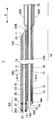
- FIG. 1 is a side view of the catheter according to the embodiment of the present invention.
- FIG. 2 is a cross-sectional view of the region R1 of FIG. 1 in the axial direction.
- FIG. 3 is an enlarged view of the region R3 of FIG.
- FIG. 4 is a cross-sectional view showing another embodiment of FIG.
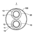
- FIG. 5 is a sectional view taken along line VV of FIG.
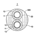
- FIG. 6 is a cross-sectional view showing another embodiment of FIG.
- FIG. 7 is a partially enlarged view of a cross section of the region R2 in FIG. 1 in the axial direction.
- the catheter of the present invention has a first tubular member extending in the longitudinal direction, having a distal end and a proximal end, into which a wire is inserted, and a distal end and a proximal end, the above-mentioned first.
- a tubular member and a second tubular member adjacent in the radial direction are provided, and the distal end of the first tubular member is located proximal to the distal end of the second tubular member.
- the proximal end of the first tubular member is located proximal to the proximal end of the second tubular member, and the first tubular member is polytetrafluoroethylene and tetrafluoroethylene par.
- It has a reinforcing portion having an inner layer containing at least one selected from the group consisting of fluoroalkyl vinyl ether copolymers and a reinforcing member, and the first tubular member is distal to the distal end of the reinforcing portion.
- a resin extending portion that does not include the polytetrafluoroethylene, the tetrafluoroethylene / perfluoroalkyl vinyl ether copolymer, and the reinforcing member.
- the present inventor has made it possible to improve safety when inserting a tip bending wire in a catheter having a resin extending portion having no reinforcing member on the distal side as disclosed in Patent Document 3. I examined it diligently. As a result, the inner layer of the reinforcing portion is made to contain at least one selected from the group consisting of polytetrafluoroethylene (PTFE) and tetrafluoroethylene / perfluoroalkyl vinyl ether copolymer (PFA), while the extending portion is included. It was found that the safety when inserting the tip bending wire can be improved by making the above content free of PTFE and PFA.
- PTFE polytetrafluoroethylene
- PFA perfluoroalkyl vinyl ether copolymer
- the lumen of the extending portion not containing PTFE and PFA is larger than the lumen of the reinforcing portion containing PTFE and PFA. Friction resistance tends to be high.
- the insertion speed is likely to be temporarily attenuated when the tip bending wire reaches the extending portion. It was found that it is possible to easily avoid damage to blood vessels and the like caused by pushing the tip bending wire too vigorously.
- the extending portion does not contain the reinforcing member and PTFE and PFA, the flexibility is easily improved, so that the lumen of the extending portion can easily follow the shape of the tip bending wire, and the extending portion is extended by the tip bending wire. It was found that it can be easily prevented from breaking through the existing part.
- FIG. 1 is a side view of the catheter according to the embodiment of the present invention.
- FIG. 2 is a cross-sectional view of the region R1 of FIG. 1 in the axial direction.
- FIG. 3 is an enlarged view of the region R3 of FIG.
- FIG. 5 is a sectional view taken along line VV of FIG.
- FIG. 7 is a partially enlarged view of a cross section of the region R2 in FIG. 1 in the axial direction.
- the catheter 1 extends in the longitudinal direction X, has a distal end 10A and a proximal end 10B, and has a first tubular shape into which a wire is inserted.
- the catheter 1 has a member 10, a distal end 20A, and a proximal end 20B, and includes a first tubular member 10 and a second tubular member 20 that is radially adjacent to each other.
- the catheter 1 can be preferably used for the treatment of dilating a narrowing of a passage such as a blood vessel in the body or a occluded site, and is preferably used for performing coronary intervention (PCI) for a bifurcation lesion of a coronary arterial blood vessel. be able to.
- PCI coronary intervention
- a guide wire is inserted into the second tubular member 20 to extend the catheter 1 to the distal side of the bifurcation origin in the main blood vessel. Can be induced.
- the tip bending wire 50 as shown in FIG. 1 can be inserted to the narrowed portion of the branch portion through the first tubular member 10 to search for the entrance of the narrowed portion or to penetrate the narrowed portion.
- a guide wire is inserted into the second tubular member 20 to guide the catheter 1 into the bifurcation, while the tip bending wire 50 is passed through the first tubular member 10.
- the first tubular member 10 shown in FIGS. 2 and 3 includes an inner layer 11 containing at least one selected from the group consisting of polytetrafluoroethylene and a tetrafluoroethylene / perfluoroalkyl vinyl ether copolymer, and a reinforcing member 12. It has a reinforcing portion 14 having and.
- the inner layer 11 improves chemical resistance, non-adhesiveness, and low friction resistance by containing at least one selected from the group consisting of polytetrafluoroethylene and a tetrafluoroethylene / perfluoroalkyl vinyl ether copolymer. be able to.
- the inner layer 11 contains at least one selected from the group consisting of polytetrafluoroethylene and a tetrafluoroethylene / perfluoroalkyl vinyl ether copolymer in a content of 60% by mass or more, assuming that the inner layer 11 is 100% by mass. It is more preferably 80% by mass or more, further preferably 90% by mass or more, still more preferably 95% by mass or more, and most preferably 100% by mass.
- the inner layer 11 may contain at least one selected from the group consisting of polytetrafluoroethylene and a tetrafluoroethylene / perfluoroalkyl vinyl ether copolymer, and may further contain other resins.
- Other resins include polyamide resins, polyester resins, polyurethane resins, polyolefin resins, and fluororesins other than polytetrafluoroethylene and tetrafluoroethylene / perfluoroalkyl vinyl ether copolymers (hereinafter, other fluororesins). (Sometimes referred to as a resin), vinyl chloride resin, silicone resin, and at least one selected from the group consisting of natural rubber.
- At least one selected from the group consisting of polyolefin-based resins and other fluorine-based resins is preferable, and other fluorine-based resins are more preferable.
- fluororesins include tetrafluoroethylene / hexafluoropropylene copolymer, tetrafluoroethylene / ethylene copolymer, polyvinylidene fluoride, polychlorotrifluoroethylene, ethylene-chlorotrifluoroethylene copolymer and the like. .. These may be used alone or in combination of two or more.
- the reinforcing member 12 is preferably a braided body in which the wire rod is braided, or a coil body in which the wire rod is spirally wound. This makes it easier to prevent the first tubular member 10 from being pierced by the tip bending wire 50 or the like. Of these, the reinforcing member 12 is more preferably a braided body because the braided body tends to improve the rigidity.
- Examples of the wire material constituting the reinforcing member 12 include metal wire and fiber.
- As the material constituting the metal wire for example, stainless steel, titanium, nickel-titanium alloy, cobalt-chromium alloy, tungsten alloy and the like are preferable. Of these, stainless steel is more preferable.
- the metal wire may be a single wire or a stranded wire.
- Examples of the fiber include polyarylate fiber, aramid fiber, ultra-high molecular weight polyethylene fiber, PBO fiber, carbon fiber and the like.
- the fibers may be monofilaments or multifilaments.
- the reinforcing member 12 may contain an X-ray opaque substance in order to make it easier to confirm the position of the tubular member 10 under fluoroscopy or the like.
- the X-ray impermeable substance is, for example, at least one selected from the group consisting of lead, barium, iodine, tungsten, gold, platinum, iridium, platinum iridium alloy, stainless steel, titanium, cobalt-chromium alloy, palladium, and tantalum. Seeds are mentioned.
- the reinforcing portion 14 includes an inner layer 11 and a reinforcing member 12.
- the reinforcing portion 14 preferably further includes an outer layer 13. It is more preferable that the reinforcing portion 14 is provided with the reinforcing member 12 between the inner layer 11 and the outer layer 13.
- the outer layer 13 preferably contains at least one selected from the group consisting of low-density polyethylene, polyurethane, polyamide elastomer, and polyamide, and more preferably contains at least one selected from the group consisting of polyurethane and polyamide.
- the first tubular member 10 includes a polytetrafluoroethylene, a tetrafluoroethylene / perfluoroalkyl vinyl ether copolymer, and a reinforcing member on the distal side of the distal end 14A of the reinforcing portion 14. It has an extending portion 15 made of resin that does not contain 12 and.
- the extending portion 15 does not contain polytetrafluoroethylene and a tetrafluoroethylene / perfluoroalkyl vinyl ether copolymer, the lumen of the extending portion 15 has more frictional resistance than the cavity of the inner layer 11 of the reinforcing portion 14. Is likely to be high. Therefore, when the tip bending wire 50 is inserted from the proximal side to the distal side of the catheter 1, the insertion speed is likely to be temporarily reduced when the tip bending wire 50 reaches the extending portion 15. As a result, it is possible to easily avoid damage to blood vessels and the like due to the tip bending wire caused by pushing the tip bending wire 50 too vigorously.
- the flexibility of the extending portion 15 is easily improved, so that the lumen of the extending portion 15 can easily follow the shape of the tip bending wire 50, and as a result, the extending portion 15 by the tip bending wire 50 is easily improved. It can be easily prevented from breaking through. Further, by adjusting the pushing force when the practitioner senses that the tip of the tip bending wire 50 has reached the extending portion 15 due to the change in frictional resistance as described above, the tip bending wire extends. It can be easily prevented from breaking through the part.
- the extending portion 15 does not contain polytetrafluoroethylene and a tetrafluoroethylene / perfluoroalkyl vinyl ether copolymer.
- the resin constituting the extending portion 15 specifically, at least one selected from the group consisting of low-density polyethylene, polyurethane, polyamide elastomer, and polyamide is preferable, and at least one selected from the group consisting of polyurethane and polyamide is preferable. Is more preferable. Further, the extending portion 15 is preferably made of these resins.
- the resin contained in the extending portion 15 and the resin contained in the outer layer 13 of the reinforcing portion 14 may be different, but it is preferable that they are the same because they are easily joined by heating and melting. Further, it is preferable that the extending portion 15 is joined to at least the outer layer 13 of the reinforcing portion 14 and the second tubular member 20.
- the extending portion 15 does not include the reinforcing member 12, the flexibility is likely to be improved. Further, this makes it easy to form the tapered portion 15T as described later. Specifically, when the reinforcing member 12 is tapered, it is necessary to perform laser processing or the like on the cut portion so as not to damage the blood vessel after cutting the reinforcing member 12, but the reinforcing member 12 is included. By not having, such end processing can be omitted.
- the axial length L from the distal end 14A of the reinforcing portion 14 of the first tubular member 10 to the distal end 15A of the extending portion 15 is the distal end 14A of the reinforcing portion 14.
- the length is preferably 4 times or more and 35 times or less the inner diameter of the reinforcing portion 14.
- the axial length L of the first tubular member 10 from the distal end 14A to the distal end 15A is extended by being four times or more the inner diameter of the reinforcing portion 14 at the distal end 14A.
- the length L is 35 times or less the inner diameter of the reinforcing portion 14 at the distal end 14A, it is possible to easily avoid damage to the extending portion 15 by the tip bending wire 50. Therefore, it is more preferably 30 times or less, still more preferably 25 times or less.
- the inner diameter of the reinforcing portion 14 at the distal end 14A of the reinforcing portion 14 is preferably 0.3 mm or more and 0.5 mm or less.
- the distal end 15A of the extending portion 15 is preferably located proximal to the distal end 20A of the second tubular member 20. This makes it difficult for the distal end of the extending portion 15 to get caught in the inner wall of the blood vessel or the like.
- the proximal end 14B of the reinforcing portion 14 of the first tubular member 10 is preferably located proximal to the proximal end 20B of the second tubular member 20. Since the reinforcing portion 14 is present on the proximal side of the first tubular member 10 in this way, it is possible to easily prevent the tip bending wire 50 from penetrating the proximal side of the first tubular member 10. Further, it is more preferable that the proximal end 14B of the reinforcing portion 14 of the first tubular member 10 is located in the cavity of the handle portion 70, which will be described later.
- the proximal end 14B of the reinforcing portion 14 of the first tubular member 10 is preferably located on the distal side of the proximal end 10B of the first tubular member 10. That is, by having the non-reinforcing portion 17 having no reinforcing member 12 at the proximal end portion 10b of the first tubular member 10, for example, in the manufacturing process, the lumen of the handle portion 70, which will be described later, and the first The non-reinforcing portion 17 can be processed into a shape that easily communicates with the lumen of the tubular member 10.
- the catheter 1 further includes a first outer tubular member 100 having a longitudinal direction X, and a first tubular member 10 and a first tubular member 10 in the lumen of the first outer tubular member 100. It is preferable that the two tubular members 20 are arranged. As a result, it is possible to easily prevent the first tubular member 10 and the second tubular member 20 from being separated from each other.
- FIG. 6 is a cross-sectional view showing another embodiment of FIG. As shown in FIG. 6, even if the outer surfaces of the first tubular member 10 and the second tubular member 20 are sealed by the resin columnar body 300 extending in the axial direction of the first tubular member 10. Good. This makes it easier to prevent the tip bending wire 50 from penetrating.
- the first outer tubular member 100 preferably contains at least one selected from the group consisting of polyethylene, polyurethane, polyamide elastomer, and polyamide. Of these, at least one selected from the group consisting of polyurethane and polyamide is more preferable.
- the columnar body 300 preferably contains at least one selected from the group consisting of polyethylene, polyurethane, polyamide elastomer, and polyamide. Of these, at least one selected from the group consisting of polyurethane and polyamide is more preferable.
- the extending portion 15 of the first tubular member 10 has an opening 15O on the distal side, and the opening 15O has a tapered portion 15T having a tapered surface and an outer surface. Is preferable.
- the tapered portion 15T that tapers toward the distal side makes it difficult for the distal end of the first tubular member 10 to get caught in the inner wall of the blood vessel or the like.
- the tapered portion 15T may not be formed.
- the tapered surface of the tapered portion 15T is preferably inclined at an angle of 5 ° or more and 85 ° or less with respect to the axial direction of the first tubular member 10.
- the inclination angle is more preferably 60 ° or less, still more preferably 40 ° or less, and even more preferably 30 ° or less.
- the inclination angle is more preferably 8 ° or more, still more preferably 10 ° or more.
- FIG. 4 is a cross-sectional view showing another embodiment of FIG.
- the first tubular member 10 has a raised portion 16 that is raised toward the side opposite to the second tubular member 20 on the distal side of the opening 15O. ..
- the tip of the wire to be inserted into the first tubular member 10 can be guided in a direction different from the tip of the wire to be inserted into the second tubular member 20, so that treatment for a bifurcation lesion or the like can be facilitated. Can be done. Further, this makes it difficult for each wire to be entangled.
- the alternate long and short dash line in FIGS. 3 and 4 indicates the traveling path of the wire.
- the second tubular member 20 has an inner layer 11 and an outer layer 13. Further, it is more preferable that the reinforcing member 12 is not provided between the inner layer 11 and the outer layer 13. This makes it easier to improve the flexibility of the second tubular member 20.
- a guide wire for guiding the catheter 1 to the vicinity of the lesion is preferably inserted into the second tubular member 20, but such a guide wire is more flexible than the tip bending wire 50 and is the second cylinder. Since the possibility of breaking through the shaped member 20 is extremely low, the second tubular member 20 does not have to include the reinforcing member 12.
- the description of the outer layer 13 of the reinforcing portion 14 of the first tubular member 10 can be referred to.
- the inner layer 11 of the second tubular member 20 is selected from the group consisting of a polyamide resin, a polyester resin, a polyurethane resin, a polyolefin resin, a fluorine resin, a vinyl chloride resin, a silicone resin, and a natural rubber. It is preferable to contain at least one kind. Of these, at least one selected from the group consisting of polyester-based resin, polyolefin-based resin, fluorine-based resin, silicone-based resin, and natural rubber is more preferable, and it is selected from the group consisting of polyolefin-based resin and fluorine-based resin. At least one is more preferred.
- the polyolefin-based resin also includes polyethylene, and examples of the polyethylene include high-density polyethylene having a density of 942 kg / m 3 or more measured based on the provisions of JIS K6922-1.
- the second tubular member 20 has a first X-ray opaque marker 31 and a second X-ray impermeable marker at positions distal to the distal end 14A of the reinforcing portion 14. It is preferable that an X-ray opaque marker such as the permeable marker 32 is arranged. As a result, it is possible to easily grasp the positions of the distal end 20A of the second tubular member, the opening 15O on the distal side of the first tubular member 10, and the like in the body.
- the second tubular member 20 does not necessarily have to include both the first X-ray opaque marker 31 and the second X-ray opaque marker 32, and the first X-ray opaque marker 32 is not necessarily provided. Only the marker 31 may be provided, or only the second X-ray opaque marker 32 may be provided. Further, the second tubular member 20 may include other X-ray opaque markers in addition to the first X-ray opaque marker 31 and the second X-ray opaque marker 32.
- the first X-ray opaque marker 31 is preferably located on the distal side of the distal end 15OA of the opening 15O on the distal side of the extending portion 15. This makes it easier to grasp the position of the distal end 20A of the second tubular member 20 in the body. Further, it is preferable that the second X-ray opaque marker 32 is also located on the proximal side of the proximal end 15OB of the opening 15O. This makes it easier to grasp the position of the opening 15O in the body.
- FIG. 4 is a cross-sectional view showing another embodiment of FIG.
- the first X-ray opaque marker 31 is located distal to the distal end 15OA of the distal opening 15O of the extension 15.
- the second X-ray opaque marker 32 is preferably located proximal to the ridge 16. This makes it easier to accurately grasp the position of the opening 15O in the body.
- the second tubular member 20 does not have an X-ray opaque marker arranged on the proximal side of the distal end 14A of the reinforcing portion 14. As a result, it is possible to easily improve the flexibility while reducing the outer diameter.
- the X-ray opaque marker is not arranged on the extending portion 15 of the first tubular member 10.
- the shape of the X-ray opaque marker is not particularly limited, and examples thereof include a band shape and a spiral shape.
- Examples of the material constituting the X-ray opaque marker include the above-mentioned X-ray opaque substance.
- the catheter 1 includes a second outer tubular member 200 having a longitudinal direction X on the proximal side of the proximal end 20B of the second tubular member 20, and the second outer cylinder. It is preferable that the first tubular member 10 is arranged in the cavity of the shaped member 200.
- a second outer tubular member 200 that is, a so-called double pipe structure (coaxial structure), it is possible to improve the pushing force transmission property while protecting the first tubular member 10.
- the second outer tubular member 200 preferably contains the same material as the first outer tubular member 100. Further, it is preferable that the distal end of the second outer tubular member 200 and the proximal end of the first outer tubular member 100 are integrated.
- the outer surface of the first tubular member 10 is provided with a metal reinforcing wire 19 along the axial direction of the first tubular member 10.
- the number of metal reinforcing wires 19 may be one or two or more. It is preferable that the metal reinforcing wire 19 exists at least from the distal side of the proximal end 14B of the reinforcing portion 14 of the first tubular member 10 to the position of the proximal end 20B of the second tubular member 20.
- the shape of the metal reinforcing wire 19 may be a barrel shape from the proximal side to the distal side, or a tapered shape that tapers toward the distal side. Examples of the material of the metal reinforcing wire 19 include stainless steel, nickel titanium, cobalt chrome and the like.
- the first tubular member 10 preferably includes an outer layer 13. Specifically, it is preferable that at least the reinforcing portion 14 is provided with the outer layer 13. For details, refer to the description of the outer layer 13 of the reinforcing portion 14.
- FIG. 7 is a partially enlarged view of a cross section of the first tubular member 10 in the region R2 of FIG. 1 in the axial direction, and the handle portion 70 will be described with reference to FIGS. 1 and 7.
- the handle portion 70 has a first lumen 71 and a second lumen 72 proximal to the first lumen 71, and the proximal end 71B of the first lumen 71.
- the inner diameter of the second lumen 72 is preferably larger than the inner diameter of the distal end 72A of the second lumen 72.
- the non-reinforcing portion 17 is fixed to the first lumen 71 so that the proximal end 17B of the non-reinforcing portion 17 is located at the proximal end 71B of the first lumen 71.
- the non-reinforcing portion 17 of the first tubular member 10 is arranged in the first lumen 71, and the second lumen 72 communicates with the non-reinforcing portion 17 and the lumen of the reinforcing portion 14. Is preferable.
- the non-reinforcing portion 17 is a portion of the proximal end portion 10b of the first tubular member 10 that does not have the reinforcing member 12.
- the non-reinforcing portion 17 preferably has a tapered portion 17T whose inner diameter increases toward the proximal side. If the tapered portion 17T is provided in this way, even if there is a step between the distal end of the tapered portion 17T and the proximal end 14B of the reinforcing portion 14, the tapered portion 17T allows the tip bending wire 50 to be formed. Since the tip is guided in the direction away from the step, it becomes difficult to get caught.
- the inner wall of the tapered portion 17T of the non-reinforcing portion 17 is preferably inclined at an angle of 3 ° or more and 85 ° or less with respect to the axial direction of the first tubular member 10.
- the inclination angle is 3 ° or more, for example, the bent portion of the tip bending wire 50 as shown in FIG. 1 is extended to some extent, so that the tip bending wire 50 is inserted into the cavity of the first tubular member 10. Can be easily inserted.
- the inclination angle is 85 ° or less, it is possible to easily reduce the movement resistance of the wire due to contact with the inner wall of the tapered portion 17T. Therefore, the inclination angle is more preferably 70 ° or less, still more preferably 60 ° or less, even more preferably 50 ° or less, and particularly preferably 20 ° or less.
- the catheter 1 is configured to satisfy the following equations (1) to (3) in order to facilitate insertion of the tip bending wire 50 from the second lumen 72 into the lumen of the first tubular member 10. It is preferable that it is.
- a is an inner diameter (mm) at a position 14C 1 mm away from the proximal end 14B of the reinforcing portion 14 of the first tubular member 10 on the distal side.
- b is the inner diameter (mm) at the proximal end 17B of the non-reinforcing portion 17 of the first tubular member 10.
- the inner diameter b (mm) at the proximal end 17B of the non-reinforcing portion 17 is larger than the inner diameter a (mm) at the position 14C 1 mm away from the proximal end 14B of the reinforcing portion 14 to the distal side. 17 is in a state of expanding in diameter toward the proximal side.
- the inner diameter b is more preferably 1.1 times or more, still more preferably 1.2 times or more, still more preferably 1.3 times or more the inner diameter a.
- the upper limit is not particularly limited, but for example, the inner diameter b may be 10 times or less, 5 times or less, or 2 times or less the inner diameter a.
- the inner diameter a (mm) is preferably 0.1 mm or more and 0.8 mm or less, and more preferably 0.3 mm or more and 0.55 mm or less.
- a is an inner diameter (mm) at a position 14C 1 mm away from the proximal end 14B of the reinforcing portion 14 of the first tubular member 10 on the distal side.
- c is the inner diameter (mm) at the distal end 72A of the second lumen 72 of the handle 70.
- the inner diameter c (mm) at the distal end 72A of the second lumen 72 of the handle portion 70 is the inner diameter a at a position 14C distal to the proximal end 14B of the reinforcing portion 14 of the first tubular member 10.
- the inner diameter c is more preferably 1.1 times or more, still more preferably 1.2 times or more, still more preferably 1.3 times or more the inner diameter a.
- the upper limit is not particularly limited, but for example, the inner diameter c may be 5 times or less, 4 times or less, or 3 times or less the inner diameter a.
- b is the inner diameter (mm) at the proximal end 17B of the non-reinforcing portion 17 of the first tubular member 10.
- c is the inner diameter (mm) at the distal end 72A of the second lumen 72 of the handle 70.
- the tip bending wire 50 is proximal because the inner diameter b (mm) at the proximal end 17B of the non-reinforcing portion 17 is equal to or greater than the inner diameter c (mm) at the distal end 72A of the second lumen 72 of the handle portion 70.
- the inner diameter b is more preferably 1.1 times or more, still more preferably 1.2 times or more, still more preferably 1.3 times or more the inner diameter c.
- the inner diameter b is 2.0 times or less the inner diameter c, it is difficult for the tip bending wire 50 to be caught by the distal end 72A of the second lumen 72 when the tip bending wire 50 is pulled back toward the proximal side. it can. Therefore, the inner diameter b is preferably 2.0 times or less, more preferably 1.7 times or less, still more preferably 1.5 times or less the inner diameter c.
- the second lumen 72 of the handle portion 70 preferably has a tapered portion 72T whose diameter is reduced toward the distal side as shown in FIGS. 1 and 7.
- the bent portion of the tip bending wire 50 is extended to some extent.
- the tip bending wire 50 can be easily inserted into the cavity of the first tubular member 10.
- the inner wall of the tapered portion 72T of the second lumen 72 of the handle portion 70 is inclined at an angle of 5 ° or more and 85 ° or less with respect to the axial direction of the first tubular member 10.
- the inclination angle is 5 ° or more, the bent portion of the tip bending wire 50 can be easily extended to some extent.
- the inclination angle is 85 ° or less, it is possible to easily reduce the movement resistance of the wire due to contact with the inner wall of the tapered portion 72T of the second lumen 72. Therefore, the inclination angle is more preferably 70 ° or less, still more preferably 60 ° or less, and even more preferably 50 ° or less.
- the first lumen 71 of the handle portion 70 may have a stepped portion having a large diameter on the distal side.
- the second outer tubular member 200 can be easily arranged in the first cavity 71.
- the first lumen 71 may have a barrel shape having a diameter substantially constant in the longitudinal direction X.
- the proximal end 200B of the second outer tubular member 200 is preferably located on the distal side of the proximal end 14B of the reinforcing portion 14.
- the outer surface of the reinforcing portion 14 can also be fixed by the adhesive 73 or the like, and the fixing force can be easily improved.
- An adhesive 73 or the like may be used to fix the proximal end 10b of the first tubular member 10 and the proximal end 200b of the second outer tubular member 200 into the first cavity 71.
- the adhesive 73 is preferably at least one selected from the group consisting of cyanoacrylate adhesives, acrylic adhesives, epoxy adhesives, and urethane adhesives, and is preferably an acrylic adhesive and a urethane adhesive. More preferably, it is at least one selected from the group consisting of adhesives. Of these, urethane-based adhesives are even more preferably urethane-based adhesives because they are excellent in durability and adhesion to resins. Further, when the handle portion 70 is formed around the reinforcing portion 14 by injection molding, pressure is applied to the reinforcing portion 14 and the reinforcing portion 14 is easily damaged. However, the handle portion 70 is obtained by molding the reinforcing portion 70 in advance. By fixing the reinforcing portion 14 inside using an adhesive, it is possible to easily avoid damage due to the above pressure.
- the outer layer 13 of the first tubular member 10 preferably contains fine particles in a portion fixed by an adhesive 73 or the like. As a result, minute irregularities are likely to be formed on the surface of the outer layer 13, and it is easy to be fixed by the adhesive 73 or the like.
- the fine particles include pigments, and examples of the pigments include inorganic fine particles, organic fine particles, and synthetic inorganic pigments.
- the major axis of the fine particles is preferably 0.1 ⁇ m or more, more preferably 0.5 ⁇ m or more, still more preferably 0.8 ⁇ m or more, preferably 50 ⁇ m or less, more preferably 10 ⁇ m or less, still more preferably 5 ⁇ m or less.
- the outer layer 13 of the first tubular member 10 preferably contains a barium salt in a portion located in the first lumen 71.
- a barium salt at least one selected from the group consisting of barium sulfate, barium carbonate, barium hydroxide, barium chloride, barium nitrate, and barium acetate is preferable, and barium sulfate is more preferable.
- the second outer tubular member 200 preferably contains fine particles in a portion fixed by the adhesive 73 or the like.
- the description of the outer layer 13 can be referred to.
- the second outer tubular member 200 preferably contains a barium salt in a portion located in the first cavity 71.
- a barium salt the description of the outer layer 13 can be referred to.
- the handle portion 70 may be provided with a through hole 74 for fluid injection that communicates with the first lumen 71 from the outer surface of the handle portion 70.
- a heated fluid or a bactericidal fluid can be injected into the lumen of the second outer tubular member 200 through the through hole 74 for sterilization.
- the handle portion 70 may be provided with a through hole 75 for injecting an adhesive that communicates from the outer surface of the handle portion 70 to the first cavity 71.
- the adhesive 73 can be injected from the outside to fix the non-reinforcing portion 17 and the like.
- the outer surface of the second outer tubular member 200 may be fixed to the lumen of the first lumen 71 by the adhesive 73.
- the proximal end of the second outer tubular member 200 is not sealed with the adhesive 73.
- the second outer tubular member 200 does not necessarily have to be fixed in the first cavity 71 via the adhesive 73 as shown in FIG. 7.
- the second outer tubular member 200 may be fixed outside the first lumen 71 by adhering the adhesive 73 to the outer surface of the distal end portion of the handle portion 70.
- the outer shape of the handle portion 70 is preferably shaped so that the practitioner can grasp it with a finger.
- the handle portion 70 is preferably a resin molded product obtained by injection molding or the like.
- the resin include polyolefin-based resins such as polyethylene and polypropylene, polycarbonate-based resins, and (meth) acrylic-based resins. Of these resins, transparent resins such as polycarbonate and polymethyl methacrylate are preferable. As a result, the inside of the handle portion 70 can be easily seen, and the wire can be easily inserted.
- the catheter 1 is a resin sleeve that covers the outer surface of the proximal end portion 14b of the reinforcing portion 14 and extends to the proximal side to form the tapered portion 17T of the non-reinforcing portion 17. It is preferable to provide 18.
- the proximal end 14B of the reinforcing portion 14 is a portion where the reinforcing member 12 is easily deformed toward the outside, but the above deformation can be achieved by covering the proximal end portion 14b of the reinforcing portion 14 with a resin sleeve 18. It can be easily prevented.
- the inner surface of the distal end portion of the sleeve 18 is joined to the outer surface of the proximal end portion 14b of the reinforcing portion 14 by heating and melting or the like.
- the axial length from the proximal end 14B of the reinforcing portion 14 to the distal end 18A of the sleeve 18 (hereinafter, may be simply referred to as the covering length) is close to the reinforcing portion 14 of the first tubular member 10. It is preferably twice or more and 35 times or less the inner diameter a at the position 14C 1 mm away from the position end 14B on the distal side.
- the coating length is more preferably 3 times or more the inner diameter a, and further preferably 4 times or more the inner diameter a.
- the coating length is 35 times or less of the inner diameter a
- the vicinity of the distal end 18A of the sleeve 18 is fixed in the first cavity 71 using, for example, an adhesive 73, the distal end 18A
- the anchor effect is exerted and the durability against the force acting in the axial direction is easily improved. Therefore, the coating length is more preferably 28 times or less of the inner diameter a, further preferably 20 times or less of the inner diameter a, further preferably 15 times or less of the inner diameter a, and 10 times the inner diameter a.
- the following is particularly preferable.
- the sleeve 18 preferably contains a thermoplastic resin. It is more preferable that the thermoplastic resin contained in the sleeve 18 contains the same resin as the resin contained in the outer layer 13.
- one end of a tubular body including a reinforcing member is covered with one end of a resin sleeve, and then a metal body having a tapered portion is heated.
- a method of inserting a metal body from the other end of the sleeve toward one end can be mentioned.
Landscapes
- Health & Medical Sciences (AREA)
- Life Sciences & Earth Sciences (AREA)
- Biophysics (AREA)
- Pulmonology (AREA)
- Engineering & Computer Science (AREA)
- Anesthesiology (AREA)
- Biomedical Technology (AREA)
- Heart & Thoracic Surgery (AREA)
- Hematology (AREA)
- Animal Behavior & Ethology (AREA)
- General Health & Medical Sciences (AREA)
- Public Health (AREA)
- Veterinary Medicine (AREA)
- Media Introduction/Drainage Providing Device (AREA)
Priority Applications (2)
| Application Number | Priority Date | Filing Date | Title |
|---|---|---|---|
| CN202080044316.4A CN113993569B (zh) | 2019-06-19 | 2020-06-04 | 导管 |
| JP2021527576A JP7498709B2 (ja) | 2019-06-19 | 2020-06-04 | カテーテル |
Applications Claiming Priority (2)
| Application Number | Priority Date | Filing Date | Title |
|---|---|---|---|
| JP2019-114065 | 2019-06-19 | ||
| JP2019114065 | 2019-06-19 |
Publications (1)
| Publication Number | Publication Date |
|---|---|
| WO2020255737A1 true WO2020255737A1 (ja) | 2020-12-24 |
Family
ID=74040029
Family Applications (1)
| Application Number | Title | Priority Date | Filing Date |
|---|---|---|---|
| PCT/JP2020/022152 Ceased WO2020255737A1 (ja) | 2019-06-19 | 2020-06-04 | カテーテル |
Country Status (3)
| Country | Link |
|---|---|
| JP (1) | JP7498709B2 (https=) |
| CN (1) | CN113993569B (https=) |
| WO (1) | WO2020255737A1 (https=) |
Cited By (1)
| Publication number | Priority date | Publication date | Assignee | Title |
|---|---|---|---|---|
| JP2024037226A (ja) * | 2022-09-07 | 2024-03-19 | 朝日インテック株式会社 | カテーテル |
Families Citing this family (1)
| Publication number | Priority date | Publication date | Assignee | Title |
|---|---|---|---|---|
| CN119607372A (zh) * | 2025-01-22 | 2025-03-14 | 苏州祥利医疗科技有限公司 | 一种血管内柔性输送通道装置及其使用方法 |
Citations (6)
| Publication number | Priority date | Publication date | Assignee | Title |
|---|---|---|---|---|
| WO2006126642A1 (ja) * | 2005-05-26 | 2006-11-30 | Kaneka Corporation | カテーテル |
| JP2007130116A (ja) * | 2005-11-09 | 2007-05-31 | Kaneka Corp | カテーテル |
| JP2007520281A (ja) * | 2004-01-29 | 2007-07-26 | イコス コーポレイション | 小血管用超音波カテーテル |
| JP2013153892A (ja) * | 2012-01-30 | 2013-08-15 | Goodman Co Ltd | カテーテル |
| JP2015156956A (ja) * | 2014-02-24 | 2015-09-03 | 朝日インテック株式会社 | カテーテル |
| WO2018008272A1 (ja) * | 2016-07-04 | 2018-01-11 | 株式会社カネカ | カテーテル |
Family Cites Families (1)
| Publication number | Priority date | Publication date | Assignee | Title |
|---|---|---|---|---|
| WO2013037370A1 (en) * | 2011-09-12 | 2013-03-21 | Safeair Ag | Methods of manufacturing flexible polymeric medical spiral tubings, tubings made by the methods and uses of the tubings |
-
2020
- 2020-06-04 WO PCT/JP2020/022152 patent/WO2020255737A1/ja not_active Ceased
- 2020-06-04 JP JP2021527576A patent/JP7498709B2/ja active Active
- 2020-06-04 CN CN202080044316.4A patent/CN113993569B/zh active Active
Patent Citations (6)
| Publication number | Priority date | Publication date | Assignee | Title |
|---|---|---|---|---|
| JP2007520281A (ja) * | 2004-01-29 | 2007-07-26 | イコス コーポレイション | 小血管用超音波カテーテル |
| WO2006126642A1 (ja) * | 2005-05-26 | 2006-11-30 | Kaneka Corporation | カテーテル |
| JP2007130116A (ja) * | 2005-11-09 | 2007-05-31 | Kaneka Corp | カテーテル |
| JP2013153892A (ja) * | 2012-01-30 | 2013-08-15 | Goodman Co Ltd | カテーテル |
| JP2015156956A (ja) * | 2014-02-24 | 2015-09-03 | 朝日インテック株式会社 | カテーテル |
| WO2018008272A1 (ja) * | 2016-07-04 | 2018-01-11 | 株式会社カネカ | カテーテル |
Cited By (2)
| Publication number | Priority date | Publication date | Assignee | Title |
|---|---|---|---|---|
| JP2024037226A (ja) * | 2022-09-07 | 2024-03-19 | 朝日インテック株式会社 | カテーテル |
| JP7762635B2 (ja) | 2022-09-07 | 2025-10-30 | 朝日インテック株式会社 | カテーテル |
Also Published As
| Publication number | Publication date |
|---|---|
| JPWO2020255737A1 (https=) | 2020-12-24 |
| JP7498709B2 (ja) | 2024-06-12 |
| CN113993569B (zh) | 2024-12-03 |
| CN113993569A (zh) | 2022-01-28 |
Similar Documents
| Publication | Publication Date | Title |
|---|---|---|
| JPWO2020162287A1 (ja) | 延長カテーテル、及びその製造方法 | |
| JP7444879B2 (ja) | カテーテル、及びカテーテルの製造方法 | |
| WO2020255737A1 (ja) | カテーテル | |
| JP7524080B2 (ja) | 延長カテーテル、及びその製造方法 | |
| JP2024036702A (ja) | カテーテル | |
| WO2023062984A1 (ja) | 延長ガイドカテーテル | |
| JP3944395B2 (ja) | 脳動脈用カテーテルおよびカテーテル器具 | |
| WO2025028184A1 (ja) | カテーテル | |
| WO2025028183A1 (ja) | カテーテル | |
| WO2025028185A1 (ja) | カテーテル | |
| WO2020195134A1 (ja) | 延長カテーテル | |
| JP7853314B2 (ja) | 延長ガイドカテーテル | |
| JP4316252B2 (ja) | カテーテル | |
| JP2025023675A (ja) | カテーテル | |
| WO2022154118A1 (ja) | カテーテルおよびカテーテル組立体 | |
| WO2025033067A1 (ja) | カテーテル | |
| JP2025023674A (ja) | カテーテル | |
| JP2024012725A (ja) | カテーテル | |
| WO2025028186A1 (ja) | カテーテル | |
| JP2024162903A (ja) | 医療デバイス | |
| JP2024040728A (ja) | カテーテル | |
| WO2023062985A1 (ja) | 延長ガイドカテーテル | |
| JP2024036701A (ja) | カテーテル | |
| JP2025134505A (ja) | 延長カテーテル | |
| WO2023062983A1 (ja) | 延長ガイドカテーテル |
Legal Events
| Date | Code | Title | Description |
|---|---|---|---|
| 121 | Ep: the epo has been informed by wipo that ep was designated in this application |
Ref document number: 20827483 Country of ref document: EP Kind code of ref document: A1 |
|
| ENP | Entry into the national phase |
Ref document number: 2021527576 Country of ref document: JP Kind code of ref document: A |
|
| NENP | Non-entry into the national phase |
Ref country code: DE |
|
| 122 | Ep: pct application non-entry in european phase |
Ref document number: 20827483 Country of ref document: EP Kind code of ref document: A1 |