WO2020255707A1 - 携帯機、車載装置、通信システム - Google Patents
携帯機、車載装置、通信システム Download PDFInfo
- Publication number
- WO2020255707A1 WO2020255707A1 PCT/JP2020/021861 JP2020021861W WO2020255707A1 WO 2020255707 A1 WO2020255707 A1 WO 2020255707A1 JP 2020021861 W JP2020021861 W JP 2020021861W WO 2020255707 A1 WO2020255707 A1 WO 2020255707A1
- Authority
- WO
- WIPO (PCT)
- Prior art keywords
- mode
- vehicle
- owner
- guest
- processing unit
- Prior art date
- Legal status (The legal status is an assumption and is not a legal conclusion. Google has not performed a legal analysis and makes no representation as to the accuracy of the status listed.)
- Ceased
Links
Images








Classifications
-
- B—PERFORMING OPERATIONS; TRANSPORTING
- B60—VEHICLES IN GENERAL
- B60W—CONJOINT CONTROL OF VEHICLE SUB-UNITS OF DIFFERENT TYPE OR DIFFERENT FUNCTION; CONTROL SYSTEMS SPECIALLY ADAPTED FOR HYBRID VEHICLES; ROAD VEHICLE DRIVE CONTROL SYSTEMS FOR PURPOSES NOT RELATED TO THE CONTROL OF A PARTICULAR SUB-UNIT
- B60W50/00—Details of control systems for road vehicle drive control not related to the control of a particular sub-unit, e.g. process diagnostic or vehicle driver interfaces
- B60W50/08—Interaction between the driver and the control system
- B60W50/082—Selecting or switching between different modes of propelling
-
- H—ELECTRICITY
- H04—ELECTRIC COMMUNICATION TECHNIQUE
- H04W—WIRELESS COMMUNICATION NETWORKS
- H04W4/00—Services specially adapted for wireless communication networks; Facilities therefor
- H04W4/30—Services specially adapted for particular environments, situations or purposes
- H04W4/40—Services specially adapted for particular environments, situations or purposes for vehicles, e.g. vehicle-to-pedestrians [V2P]
- H04W4/48—Services specially adapted for particular environments, situations or purposes for vehicles, e.g. vehicle-to-pedestrians [V2P] for in-vehicle communication
-
- B—PERFORMING OPERATIONS; TRANSPORTING
- B60—VEHICLES IN GENERAL
- B60R—VEHICLES, VEHICLE FITTINGS, OR VEHICLE PARTS, NOT OTHERWISE PROVIDED FOR
- B60R16/00—Electric or fluid circuits specially adapted for vehicles and not otherwise provided for; Arrangement of elements of electric or fluid circuits specially adapted for vehicles and not otherwise provided for
- B60R16/02—Electric or fluid circuits specially adapted for vehicles and not otherwise provided for; Arrangement of elements of electric or fluid circuits specially adapted for vehicles and not otherwise provided for electric constitutive elements
- B60R16/037—Electric or fluid circuits specially adapted for vehicles and not otherwise provided for; Arrangement of elements of electric or fluid circuits specially adapted for vehicles and not otherwise provided for electric constitutive elements for occupant comfort, e.g. for automatic adjustment of appliances according to personal settings, e.g. seats, mirrors, steering wheel
-
- B—PERFORMING OPERATIONS; TRANSPORTING
- B60—VEHICLES IN GENERAL
- B60W—CONJOINT CONTROL OF VEHICLE SUB-UNITS OF DIFFERENT TYPE OR DIFFERENT FUNCTION; CONTROL SYSTEMS SPECIALLY ADAPTED FOR HYBRID VEHICLES; ROAD VEHICLE DRIVE CONTROL SYSTEMS FOR PURPOSES NOT RELATED TO THE CONTROL OF A PARTICULAR SUB-UNIT
- B60W40/00—Estimation or calculation of non-directly measurable driving parameters for road vehicle drive control systems not related to the control of a particular sub unit, e.g. by using mathematical models
- B60W40/08—Estimation or calculation of non-directly measurable driving parameters for road vehicle drive control systems not related to the control of a particular sub unit, e.g. by using mathematical models related to drivers or passengers
- B60W40/09—Driving style or behaviour
-
- H—ELECTRICITY
- H04—ELECTRIC COMMUNICATION TECHNIQUE
- H04Q—SELECTING
- H04Q9/00—Arrangements in telecontrol or telemetry systems for selectively calling a substation from a main station, in which substation desired apparatus is selected for applying a control signal thereto or for obtaining measured values therefrom
-
- B—PERFORMING OPERATIONS; TRANSPORTING
- B60—VEHICLES IN GENERAL
- B60W—CONJOINT CONTROL OF VEHICLE SUB-UNITS OF DIFFERENT TYPE OR DIFFERENT FUNCTION; CONTROL SYSTEMS SPECIALLY ADAPTED FOR HYBRID VEHICLES; ROAD VEHICLE DRIVE CONTROL SYSTEMS FOR PURPOSES NOT RELATED TO THE CONTROL OF A PARTICULAR SUB-UNIT
- B60W2540/00—Input parameters relating to occupants
- B60W2540/215—Selection or confirmation of options
Definitions
- This disclosure relates to portable devices, in-vehicle devices, and communication systems.
- Patent Document 1 discloses a technique for changing the function of an electronic key by a regular mechanical key stored in the main body of the electronic key (key).
- the vehicle When the vehicle is used by multiple users, it is assumed that different settings are desired for the in-vehicle device depending on the user. For example, it is desirable that the seat in the driver's seat is set at a different position depending on the user. From this point of view, it is desirable to switch the setting on which the in-vehicle device operates, instead of switching the function of the electronic key.
- the portable device of the present disclosure is a portable device configured to transmit radio waves to an in-vehicle device that controls an in-vehicle device that operates in each of a plurality of modes.
- the portable device includes a first processing unit and a second processing unit.
- the first processing unit is configured to specify one mode from the plurality of modes and output mode information which is information indicating the specified one mode.
- the second processing unit is configured to transmit the mode information to the vehicle-mounted device using the radio waves.
- the in-vehicle device of the present disclosure is an in-vehicle device that controls an in-vehicle device that operates in each of a plurality of modes and is mounted on a vehicle.
- the in-vehicle device includes a first processing unit and a second processing unit.
- the first processing unit is configured to receive radio waves including mode information, extract the mode information from the radio waves, and give the mode information to the second processing unit.
- the mode information is information indicating one mode specified from the plurality of modes.
- the second processing unit is configured to control the operation of the in-vehicle device in the one mode indicated by the mode information.
- the present disclosure can be realized not only as a portable device or an in-vehicle device provided with such a characteristic processing unit, but also as a processing method in which the characteristic processing is a step, or such a step.
- it can be realized as a semiconductor integrated circuit that realizes a part or all of a portable device and an in-vehicle device, or can be realized as a communication system including a portable device and an in-vehicle device.
- FIG. 1 is a block diagram schematically illustrating the configurations of an in-vehicle device and a portable device adopted in the embodiment.
- FIG. 2 is a front view and a top view illustrating the appearance of the portable device.
- FIG. 3 is a front view illustrating the appearance of the mechanical key.
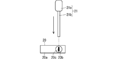
- FIG. 4 is a top view and a side view illustrating the direction in which the insertion portion is inserted into the portable device.
- FIG. 5 is a front view and a top view illustrating the appearance of the portable device.
- FIG. 6 is a front view and a top view illustrating the appearance of the portable device.
- FIG. 7 is a front view and a top view illustrating the appearance of the portable device.
- FIG. 8 is a block diagram schematically illustrating a region in which operating parameters are set.
- FIG. 9 is a flowchart illustrating a process periodically executed by the in-vehicle device.
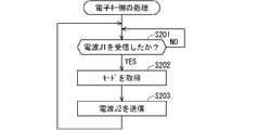
- FIG. 10 is a flowchart illustrating a process executed by the portable device.
- FIG. 11 is a flowchart illustrating the first process executed by the in-vehicle device.
- FIG. 12 is a flowchart illustrating a process of changing the display setting according to the mode.
- FIG. 13 is a flowchart illustrating a second process executed by the in-vehicle device.
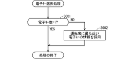
- FIG. 14 is a flowchart illustrating a process of selecting a portable device.
- the disclosure is as follows.
- the portable device of the present disclosure is configured to transmit radio waves to an in-vehicle device that controls an in-vehicle device that operates in each of a plurality of modes, and includes a first processing unit and a second processing unit.
- the first processing unit is configured to specify one mode from the plurality of modes and output mode information which is information indicating the specified one mode.
- the second processing unit is configured to transmit the mode information to the vehicle-mounted device using the radio waves.
- the portable device supplies the information about one specified mode to the in-vehicle device, it is easy for the in-vehicle device to operate the in-vehicle device in the mode. This can be said to make it easier for the portable device to switch the setting on which the in-vehicle device operates.
- the first processing unit is preferably configured to distinguish between the plurality of modes. This is because such a configuration is advantageous from the viewpoint of making different settings between modes.
- the first processing unit is configured to distinguish between the guest mode, which is the initial setting of the plurality of modes, and the plurality of modes other than the guest mode. Even when different guests use the vehicle as users, it is advantageous from the viewpoint of simplifying the operation of adjusting the in-vehicle device again.
- the in-vehicle device of the present disclosure is an in-vehicle device that controls an in-vehicle device that operates in each of a plurality of modes and is mounted on a vehicle.
- the in-vehicle device includes a first processing unit and a second processing unit.
- the first processing unit is configured to receive radio waves including mode information, extract the mode information from the radio waves, and give the mode information to the second processing unit.
- the mode information is information indicating one mode specified from the plurality of modes.
- the second processing unit is configured to control the operation of the in-vehicle device in the one mode indicated by the mode information.
- the plurality of modes include a guest mode which is an initial setting of the plurality of modes and an owner mode other than the guest mode, and the parameters on which the operation of the in-vehicle device depends can be changed in the guest mode. It is preferable that the first possible item is set to be less than the second item that can be changed in the owner mode. This is because the advantage of the owner mode over the guest mode can be obtained.
- FIG. 1 is a block diagram schematically illustrating the configurations of an in-vehicle device 10 and a portable device 20 adopted in the present embodiment.
- the in-vehicle device 10 is mounted on the vehicle 9.
- the vehicle 9 is equipped with a body control module (body control module) 11, a car navigation system (car navigation system) 12, and an actuator (actuator) 13.
- the actuator 13 is used, for example, in a motor for setting a seat position.
- At least one of the car navigation system 12 and the actuator 13 is an in-vehicle device that operates in each of a plurality of modes.
- the owner mode (owner mode) and the guest mode (guest mode) will be described as examples as a plurality of modes.
- guest mode the case where both the car navigation system 12 and the actuator 13 operate in each of the plurality of modes will be described as an example.
- the car navigation system 12 and the actuator 13 operate in a common mode.
- the actuator 13 When the car navigation system 12 operates in the owner mode, the actuator 13 also operates in the owner mode, and when the actuator 13 operates in the owner mode, the car navigation system 12 also operates in the owner mode.
- the car navigation system 12 When the car navigation system 12 operates in the guest mode, the actuator 13 also operates in the guest mode, and when the actuator 13 operates in the guest mode, the car navigation system 12 also operates in the guest mode.
- the owner mode is adopted as a mode in which the car navigation system 12 and the actuator 13 operate when the owner of the vehicle 9 drives the vehicle 9
- the guest mode is a mode in which the guest about the vehicle 9 drives the vehicle 9. It is sometimes adopted as a mode in which the car navigation system 12 and the actuator 13 operate.
- Guest is a concept that indicates a user other than the owner. For example, when car sharing (Car sharing) is performed, a plurality of different users may correspond to guests.
- Car sharing Car sharing
- a mode signal D indicating a mode is given to the body control module 11.
- the body control module 11 operates the car navigation system 12 and the actuator 13 in the owner mode or the guest mode based on the information contained in the mode signal D.
- an integer value is exemplified as the information included in the mode signal D and indicating the mode.
- the in-vehicle device 10 includes a control unit 100, a radio wave receiving unit 101, a radio wave transmitting unit 102, and a mode switching unit 103.
- the control unit 100 controls the functions of the radio wave receiving unit 101, the radio wave transmitting unit 102, and the mode switching unit 103, as well as their cooperative operations.
- the portable device 20 includes a control unit 200, a radio wave receiving unit 201, a radio wave transmitting unit 202, and a mode acquisition unit 203.
- the control unit 200 controls the functions of the radio wave receiving unit 201, the radio wave transmitting unit 202, and the mode acquisition unit 203, as well as their cooperative operations. More specifically, the mechanical key 21 can be attached to and detached from the mode acquisition unit 203 of the portable device 20.
- the mode acquisition unit 203 acquires the owner mode as the above-mentioned mode when the mechanical key 21 is attached to the portable device 20.
- the mode acquisition unit 203 acquires the guest mode as the above-mentioned mode when the mechanical key 21 is not attached to the portable device 20.
- FIG. 2 is a front view and a top view illustrating the appearance of the portable device 20.
- the front view is drawn above the paper surface with respect to the top view.
- the portable device 20 has an upper surface 20a.
- the upper surface of the cylinder 20b is exposed on the upper surface 20a.
- the cylinder 20b is provided inside the portable device 20.
- the cylinder 20b has a keyhole 20c. In the state of FIG. 2, the keyhole 20c is located parallel to the direction from the front surface of the portable device 20 toward the upper surface 20a (vertical direction in the drawing).
- FIG. 3 is a front view illustrating the appearance of the mechanical key 21.
- the mechanical key 21 has a grip portion 21a and an insertion portion 21b.
- the insertion portion 21b can be inserted into the keyhole 20c.
- the cylinder 20b can rotate when the keyhole 20c and the insertion portion 21b have a predetermined relationship, for example, a fitting relationship, and the insertion portion 21b is inserted into the keyhole 20c.
- Such rotation is, for example, about the normal direction of the upper surface 20a.
- Such rotation can be realized by adopting, for example, a cylinder lock configuration.
- FIG. 4 is a top view and a side view illustrating the direction in which the insertion portion 21b is inserted into the portable device 20.
- a side view is drawn for the mechanical key 21, and a top view is drawn for the portable device 20.
- the insertion portion 21b is inserted into the keyhole 20c along the chain line in the direction indicated by the arrow.
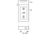
- FIG. 5 is a front view and a top view illustrating the appearance of the portable device 20 after the insertion portion 21b is inserted from the state shown in FIG.
- the front view is drawn above the paper surface with respect to the top view. In this state, the entire grip portion 21a protrudes from the portable device 20.
- the side surface of the grip portion 21a is also drawn.
- the top view of FIG. 5 it is considered that a part of the upper surface 20a is hidden by the grip portion 21a, and the cylinder 20b, the keyhole 20c, and the insertion portion 21b inserted into the keyhole 20c are drawn by broken lines.
- the grip portion 21a can be rotated counterclockwise in the top view from the state.
- FIG. 6 is a front view and a top view illustrating the appearance of the portable device 20 in a state after the grip portion 21a has rotated from the state shown in FIG.
- the front view is drawn above the paper surface with respect to the top view.
- the front surface of the grip portion 21a is also drawn.
- the top view of FIG. 6 considering that the upper surface 20a (see FIG. 5) is hidden by the grip portion 21a, the cylinder 20b, the keyhole 20c, and the insertion portion 21b inserted into the keyhole 20c are drawn by broken lines. From this state, a part of the grip portion 21a can be pushed into the portable device 20 along the direction indicated by the arrow.
- FIG. 7 is a front view and a top view illustrating the appearance of the portable device 20 after the grip portion 21a is pushed in from the state shown in FIG.
- the front view is drawn above the paper surface with respect to the top view.
- the top view of FIG. 7 considering that the upper surface 20a (see FIG. 5) is hidden by the grip portion 21a, the cylinder 20b, the keyhole 20c, and the insertion portion 21b inserted into the keyhole 20c are drawn by broken lines.
- the insertion portion 21b is inserted into the keyhole 20c, the cylinder 20b rotates, and the grip portion 21a is pushed into the portable device 20, so that the portable device 20 specifies the owner mode as a mode. ..
- the portable device 20 specifies a guest mode as a mode.
- Such mode identification can be realized by using, for example, a switch that opens and closes when the cylinder 20b rotates.
- the switch may be opened and closed by mechanically detecting the rotation of the cylinder 20b, or may be opened and closed by magnetically detecting the rotation of the cylinder 20b.
- the mode acquisition unit 203 acquires the owner mode and the guest mode as modes based on whether or not the mechanical key 21 is attached. For example, the mode acquisition unit 203 may detect the opening and closing of the switch and acquire the owner mode and the guest mode separately. The type of mode acquired by the mode acquisition unit 203 is output by the mode acquisition unit 203 as mode information M2.
- the mode acquisition unit 203 distinguishes between a plurality of modes (here, the owner mode and the guest mode), identifies one mode (here, the owner mode or the guest mode) from the plurality of modes, and provides information indicating the specified mode (here, the owner mode or the guest mode).
- the processing unit is configured to output the mode information M2).
- modes are advantageous from the viewpoint of making different settings between the modes, and is preferable from the viewpoint that the in-vehicle device operates depending on the settings according to the user when using the vehicle 9.
- the radio wave transmitting unit 102 transmits the radio wave J1, the radio wave receiving unit 201 receives the radio wave J1, the radio wave transmitting unit 202 transmits the radio wave J2, and the radio wave receiving unit 101 receives the radio wave J2 (see FIG. 1).
- Mode information M2 is transmitted by radio wave J2. It can be said that the radio wave J2 includes the mode information M2. It can be said that the radio wave transmission unit 202 is a processing unit configured to transmit the mode information M2 to the in-vehicle device 10 using the radio wave J2.
- the radio wave receiving unit 101 is a processing unit that extracts the mode information M1 from the radio wave J2 and gives it to the mode switching unit 103.
- the radio wave receiving unit 101 that has received the radio wave J2 extracts the mode information M2 as the mode information M1.
- Mode information M1 is given to the mode switching unit 103, a mode signal D is generated based on the mode information M1, and the mode signal D is output to the body control module 11.
- the mode switching unit 103 is a processing unit configured to control the car navigation system 12 and the actuator 13 to operate in one mode indicated by the mode information M1 via the body control module 11.
- the mode information M2 is transmitted from the portable device 20 using the radio wave J2, and the mode information M1 is extracted from the radio wave J2 in the in-vehicle device 10.
- the mode signal D is generated from the mode information M1.
- the body control module 11 to which the mode signal D is given operates the car navigation system 12 and the actuator 13 in one mode based on the mode signal D.
- the portable device 20 supplies information about one specified mode to the vehicle-mounted device 10, it is easy for the vehicle-mounted device 10 to operate the vehicle-mounted device exemplified by the car navigation system 12 and the actuator 13 by the mode. To do. It can be said that the portable device 20 makes it easy for the vehicle-mounted device 10 to switch the setting on which the vehicle-mounted device operates.
- the portable device 20 (more specifically, the mode acquisition unit 203) specifies either the owner mode or the guest mode according to whether or not the mechanical key 21 is attached. Therefore, when the owner of the mechanical key 21 (usually the owner of the vehicle 9) uses the portable device 20 by another person, the owner of the mechanical key 21 may or may not give the mechanical key 21 to the other person when the other person uses the vehicle 9. You can decide the mode.
- the in-vehicle device 10 controls the operations performed by the car navigation system 12 and the actuator 13 by the mode information M2 obtained from the portable device 20 as the mode information M1. From the portable device 20, the setting on which the operation performed by the in-vehicle device depends can be made different depending on the user.
- the actuator 13 moves the driver's seat to a position suitable for the owner of the vehicle 9, for example.
- Such an operation of the actuator 13 requires that the owner adjust the position of the driver's seat again in the vehicle 9 when the guest is using the vehicle 9 before the owner of the vehicle 9 uses the vehicle 9. It is advantageous from the viewpoint of reducing.
- the actuator 13 moves, for example, the driver's seat of the vehicle 9 to the initial setting position.
- Such an operation of the actuator 13 is advantageous from the viewpoint of simplifying the operation of adjusting the position of the seat of the driver's seat of the vehicle again even when different guests use the vehicle 9 as a user.
- setting the in-vehicle device as the initial setting is suitable when the vehicle 9 is adopted for car sharing. From this point of view, it can be said that the guest mode is the initial setting of a plurality of modes.
- the display of the home position of the owner of the vehicle 9 in the car navigation system 12 is possible when the mode information M1 indicates the owner mode, and is impossible when the mode information M1 indicates the guest mode.
- Such a difference in display is advantageous from the viewpoint of protecting the privacy of the owner. From the viewpoint of protecting privacy, it is desirable that the history of the car navigation system 12 can be deleted when the car navigation system 12 is used regardless of whether it is in the guest mode or the owner mode.
- operation parameters The parameters (hereinafter, “operation parameters") that the in-vehicle devices exemplified by the car navigation system 12 and the actuator 13 depend on when operating are set items (hereinafter, tentatively referred to as “first items”) that can be changed in the guest mode. , It is set to be less than the setting items that can be changed in the owner mode (hereinafter referred to as "second item”). It can be said that the owner mode is superior to the guest mode in terms of the breadth and narrowness of this setting item.
- FIG. 8 is a block diagram schematically illustrating the area 6 in which the operation parameters are set.
- the area is realized, for example, in a storage area set in the memory of each in-vehicle device. Since the technology for operating the in-vehicle device based on the operation parameters stored in the storage area is well known, the technology itself is not described here.
- FIG. 8 a case where the area 6 has a first owner-only setting area 61, a second owner-only setting area 62, and a guest settable area 63 is illustrated.
- the operation parameters stored in the first owner-only setting area 61 can be changed only in the first owner mode.
- the operation parameters stored in the second owner-only setting area 62 can be changed only in the second owner mode.
- the guest settable area 63 can be changed in any of the guest mode, the first owner mode, and the second owner mode. All of the first items are included in the second item, depending on the permission or disapproval of changing the operating parameters.
- the operation parameters stored in the second owner-only setting area 62 cannot be changed in the first owner mode, and the operation parameters stored in the first owner-only setting area 61 cannot be changed in the second owner mode. It is advantageous from the viewpoint of storing the operating parameters differently for each owner.
- the owner mode is superior to the guest mode in that there are operation parameters that cannot be changed in the guest mode but can be changed in the owner mode. This advantage is preferred when the vehicle 9 is used for car sharing.
- the first owner mode and the second owner mode are both the above-mentioned owner modes. For example, by using different mechanical keys 21, these two owner modes are specified.
- the second item that can be changed in the first owner mode is the operation parameter stored in the first owner-only setting area 61 and the operation parameter stored in the guest settable area 63.
- the first item that can be changed in the guest mode is an operation parameter stored in the guest settable area 63, and therefore the first item is less than the second item. In this case, all of the first items are included in the second item.
- the second item that can be changed in the second owner mode is the operation parameter stored in the second owner-only setting area 62 and the operation parameter stored in the guest settable area 63.
- the first item that can be changed in the guest mode is an operation parameter stored in the guest settable area 63, and therefore the first item is less than the second item. In this case, all of the first items are included in the second item.
- the items listed below can be changed only in the owner mode and cannot be changed in the guest mode. That is, these items are stored in the first owner-only setting area 61 and the second owner-only setting area 62, but are not stored in the guest settable area 63.
- FIG. 9 is a flowchart (flow chart) illustrating a process periodically executed by the vehicle-mounted device 10, and the process is abbreviated as “vehicle-side periodic process”.
- the radio wave transmission unit 102 periodically transmits the radio wave J1.
- the radio wave J1 is a signal that requests the radio wave J2 from the portable device 20.
- step S101 it is determined whether a certain time has elapsed after the radio wave J1 was transmitted in step S102. For example, the control unit 100 makes such a determination. If a positive result is obtained in the determination, step S101 ends and step S102 is executed. In step S102, the radio wave transmitting unit 102 transmits the radio wave J1. Step S102 is executed by the radio wave transmitting unit 102 under the control of the control unit 100.
- step S102 the radio wave J1 is once stopped being transmitted and step S101 is executed. If a negative determination result is obtained in step S101, step S101 is repeatedly executed.
- FIG. 10 is a flowchart illustrating the processing executed by the portable device 20. Since the portable device 20 is realized by, for example, a so-called electronic key (key), the processing is abbreviated as "processing on the electronic key side".
- step S201 the radio wave receiving unit 201 determines whether or not the radio wave J1 has been received. For example, the control unit 200 makes such a determination. If a negative determination result is obtained in step S201, step S201 is repeatedly executed. If a positive determination result is obtained in step S201, step S201 ends and step S202 is executed.
- the mode is acquired in step S202. Such acquisition can be grasped as the identification of the mode described above. For example, if the mechanical key 21 is not attached to the portable device 20, the guest mode is set, if the first mechanical key 21 is attached to the portable device 20, the first owner mode is set, and the second mechanical key 21 is the portable device. If it is attached to 20, the second owner mode is specified as each mode. Step S202 is executed by the mode acquisition unit 203 under the control of the control unit 200.
- the specified mode is output as mode information M2 from the mode acquisition unit 203 to the radio wave transmission unit 202. Therefore, the acquisition in step S202 may include both a process in which the mode is specified by the mode acquisition unit 203 and a process in which the mode information M2 is output by the mode acquisition unit 203.
- step S203 is executed.
- the radio wave transmission unit 202 transmits the radio wave J2.
- the mode information M2 is transmitted by the radio wave J2.
- Step S203 is executed by the radio wave transmitting unit 202 under the control of the control unit 200.
- step S201 is executed again, and the processing in step S202 waits until the radio wave J1 is received.
- FIG. 11 is a flowchart illustrating the first process executed by the in-vehicle device 10, and the process is labeled as "first process on the vehicle side".
- step S301 the radio wave receiving unit 101 determines whether or not the radio wave J2 has been received. For example, the control unit 100 makes such a determination. If a negative determination result is obtained in step S301, step S301 is repeatedly executed. If a positive determination result is obtained in step S301, step S301 ends and step S302 is executed.
- step S302 the radio wave J2 is analyzed and the mode information M1 is extracted.
- processing is abbreviated as "radio wave analysis”.
- Step S302 is executed by the radio wave receiving unit 101 under the control of the control unit 100.
- step S303 it is determined whether or not the mode indicated by the mode information M1 is the owner mode.
- the first owner mode and the second owner mode are described without distinction, but they may be judged separately.
- Step S303 is executed by the radio wave receiving unit 101 under the control of the control unit 100.
- step S304 is executed after step S303 is executed. If a negative result is obtained in the determination, it corresponds to the guest mode, and step S305 is executed after step S303 is executed. Steps S304 and S305 are executed by the mode switching unit 103 under the control of the control unit 100.
- step S304 a value 1 is given to the mode signal D.
- the mode indicated by the mode information M1 is the first owner mode
- a value 1 is given to the mode signal D
- the mode information M1 If the mode indicated by is the first owner mode, a value 2 is given to the mode signal D.
- the value of the mode signal D is 1 or 2, the in-vehicle device mounted on the vehicle 9 operates in the owner mode.
- step S305 a value 3 is given to the mode signal D.
- the value of the mode signal D is 3, the in-vehicle device mounted on the vehicle 9 operates in the guest mode.
- steps S304 and S305 When any of steps S304 and S305 is executed, the first process ends. However, the periodic processing on the vehicle side shown in FIG. 9 continues to be executed.
- FIG. 12 is a flowchart illustrating a process of changing the display setting in the car navigation system 12 according to the mode. The process is abbreviated as "display change process”.
- step S401 the body control module 11 determines the value of the mode signal D. If it is determined in step S401 that the mode signal D has a value of 1, step S401 is executed and then step S402 is executed. If it is determined in step S401 that the mode signal D has a value of 3, step S401 is executed and then step S403 is executed. If the mode signal D is neither a value 1 nor a value 3, step S401 is repeatedly executed. In FIG. 12, the value of the mode signal D, which is neither the value 1 nor the value 3, is drawn as represented by 0.
- step S402 under the control of the body control module 11, the car navigation system 12 uses the operation parameters stored in the first owner-only setting area 61 (or the second owner-only setting area 62) of the area 6 owned by the car navigation system 12. , Adopt the display in owner mode. In FIG. 12, such adoption is abbreviated as "adopting owner mode display”.
- step S403 under the control of the body control module 11, the car navigation system 12 adopts the display in the guest mode by using the operation parameters stored in the guest settable area 63 of the area 6 owned by the car navigation system 12.
- adoption is abbreviated as "adopting guest mode display”.
- the car navigation system 12 operates by adopting the display adopted in any one of steps S402 and S403.
- the operation corresponding to each of the owner mode and the guest mode can be adopted.
- the motor for setting the seat position uses the operation parameters stored in the first owner-only setting area 61 (or the second owner-only setting area 62) to move to the seat position in the owner mode. And move the driver's seat seed.
- the motor for setting the seat position uses the operation parameters stored in the guest settable area 63 to move the driver's seat seed to the seat position in the guest mode.
- the area 6 having the first owner-only setting area 61 (or the second owner-only setting area 62) and the guest settable area 63 can be provided in the body control module 11.
- FIG. 13 is a flowchart illustrating the second process executed by the in-vehicle device 10, and the process is labeled as "the second process on the vehicle side".
- step S501 the body control module 11 determines the value of the mode signal D. If it is determined in step S501 that the mode signal D has a value of 1, step S501 is executed and then step S502 is executed. If it is determined in step S501 that the mode signal D has a value of 3, step S501 is executed and then step S503 is executed. If the mode signal D is neither a value 1 nor a value 3, step S501 is repeatedly executed. In FIG. 13, the value of the mode signal D, which is neither the value 1 nor the value 3, is drawn as represented by 0.
- step S502 the setting change of the change requested by the user is accepted.
- FIG. 13 illustrates a case where the first owner mode and the second owner mode are not distinguished in step S502.
- the value of the mode signal D is 1, it corresponds to the owner mode, so that the setting change in the first owner-only setting area 61 (or the second owner-only setting area 62) and the guest settable area 63 is accepted.
- the operating parameters stored in these areas are changed according to the changes requested by the user. This change corresponds to the change of the second item.
- step S503 it is determined whether the change setting requested by the user is a change in the guest settable area 63. If a positive result is obtained in the determination, after step S503 is executed, the change requested by the user is accepted in step S504, and the operation parameter stored in the guest settable area 63 is changed according to the change. Be changed. This change corresponds to the change of the first item.
- step S503 If a negative determination result is obtained in step S503, the change requested by the user in step S505 is rejected after step S503 is executed.
- This refusal corresponds to the operation parameters not stored in the guest configurable area 63 in the guest mode not responding to the changes requested by the user.
- This refusal also corresponds to the fact that the second matter other than the first matter is not changed in the guest mode.
- Steps S501, S502, S503, S504, and S505 are executed by the car navigation system 12 or the actuator 13 by the body control module 11 or by the control from the body control module 11.
- steps S501, S502, S503, S504, and S505 are controlled by the body control module 11. It may be executed by the car navigation system 12 or the actuator 13.
- steps S501, S502, S503, S504, and S505 may be executed by the body control module 11.
- FIG. 14 is a flowchart illustrating a process of selecting the portable device 20. This process is based on the assumption that a plurality of portable devices 20 are prepared for one vehicle 9. Since the portable device 20 is realized by, for example, a so-called electronic key (key), the process is abbreviated as "electronic key selection process". The process is executed, for example, in the vehicle-mounted device 10 as part of step S302 (see FIG. 11).
- step S601 If a positive result is obtained in the determination in step S601, the electronic key selection process ends. Since it was determined that there is only one portable device 20, after the electronic key selection process is completed, a process based on the received radio wave J2, specifically, a process of extracting mode information M1 from the radio wave J2, for example, is performed. Will be done.
- step S601 ends and step S602 is executed.
- step S602 is executed.
- the radio waves J2 are received from the plurality of portable devices 20, the information obtained from the portable devices 20 closest to the driver's seat is adopted in step S602.
- step S602 When the execution of step S602 is completed, the electronic key selection process is completed. Since the portable device 20 is specified as one, after the electronic key selection process is completed, a process based on the received radio wave J2, specifically, a process of extracting mode information M1 from the radio wave J2 is performed. ..
- Each of the control unit 100 and mode switching unit 103 in the in-vehicle device 10 and the control unit 200 and mode acquisition unit 203 in the portable device 20 are a microprocessor (micro processor), ROM (Read Only Memory), RAM (Random Access Memory), and the like. It may be realized by including a computer configured to include.
- Each of the radio wave receiving units 101 and 201 may be realized by a known receiving circuit.
- Each of the radio wave transmission units 102 and 202 may be realized by a known transmission circuit.
- An arithmetic processing unit such as a microprocessor stores a computer program (computer program) including a part or all of each step of a sequence diagram or a flowchart as shown in FIGS. 9 to 14 in a ROM, RAM, or the like. Read from each part and execute.
- the computer programs of these multiple devices can be installed from an external server device or the like.
- Such a computer program is stored in a recording medium such as a CD-ROM (Compact Disc Read Only Memory), a DVD-ROM (Digital entirely Disk Read Only Memory), or a semiconductor memory (memory), respectively. And distribute.
- a recording medium such as a CD-ROM (Compact Disc Read Only Memory), a DVD-ROM (Digital entirely Disk Read Only Memory), or a semiconductor memory (memory), respectively. And distribute.
- the following items may be adopted as the advantages of the owner mode over the guest mode: -In owner mode, the guest settable area 63 can be changed; -It is possible in the owner mode to acquire the position information (directly or indirectly) of the vehicle 9 being driven in the guest mode; -In owner mode, it is possible to open the locked glove box, but in guest mode it is not allowed; -In owner mode, the owner authority of the car body can be changed, but in guest mode it is not changed.
Landscapes
- Engineering & Computer Science (AREA)
- Automation & Control Theory (AREA)
- Mechanical Engineering (AREA)
- Computer Networks & Wireless Communication (AREA)
- Transportation (AREA)
- Signal Processing (AREA)
- Human Computer Interaction (AREA)
- Physics & Mathematics (AREA)
- Mathematical Physics (AREA)
- Lock And Its Accessories (AREA)
- Selective Calling Equipment (AREA)
Abstract
車載機器が依拠して動作する設定を車載装置が容易に切換える。携帯機はモード取得部と電波送信部とを備える。モード取得部は、複数のモードから一つのモードを特定し、特定された一つのモードを示す情報であるモード情報を出力するように構成される処理部である。電波送信部は、モード情報を電波を用いて車載装置へ送信するように構成される処理部である。
Description
本開示は、携帯機、車載装置、通信システムに関する。
特許文献1には電子キー(key)の本体に収納されている正規のメカニカルキー(mechanical key)によって電子キーの機能を変更する技術が開示される。
車両が複数のユーザによって利用される場合、ユーザによって異なった設定が車載機器に望まれることが想定される。例えば運転席におけるシートはユーザによって異なった位置に設定されることが望まれる。かかる観点では、電子キーの機能を切換えるのではなく、車載機器が依拠して動作する設定が切り替わることが望ましい。
そこで、車載機器が依拠して動作する設定を容易に切換える技術を提供することを目的とする。
本開示の携帯機は、複数のモードの各々によって動作する車載機器を制御する車載装置に対して電波を送信するように構成された携帯機である。当該携帯機は第1処理部および第2処理部を備える。前記第1処理部は前記複数のモードから一つのモードを特定し、特定された前記一つのモードを示す情報であるモード情報を出力するように構成される。前記第2処理部は前記モード情報を前記電波を用いて前記車載装置へ送信するように構成される。
本開示の車載装置は、複数のモードの各々によって動作する車載機器を制御し、車両に搭載される車載装置である。当該車載装置は第1処理部および第2処理部を備える。前記第1処理部はモード情報を含む電波を受信し、前記電波から前記モード情報を抽出して前記第2処理部へ与えるように構成される。前記モード情報は、前記複数のモードから特定される一つのモードを示す情報である。前記第2処理部は前記モード情報によって示された前記一つのモードによって前記車載機器を動作させる制御を行うように構成される。
本開示は、このような特徴的な処理部を備える携帯機、車載装置として実現することができるのみならず、かかる特徴的な処理をステップとする処理方法として実現したり、かかるステップ(step)をコンピュータ(computer)に実行させるためのプログラム(program)として実現したりすることができる。また、携帯機、車載装置の一部又は全部を実現する半導体集積回路として実現したり、携帯機、車載装置を含む通信システムとして実現することができる。
本開示によれば、車載機器が依拠して動作する設定を切換えることが容易である。
[本開示の実施形態の説明]
最初に本開示の実施態様が列記して説明される。
最初に本開示の実施態様が列記して説明される。
本開示は、次の通りである。
(1)本開示の携帯機は、複数のモードの各々によって動作する車載機器を制御する車載装置に対して電波を送信するように構成され、第1処理部および第2処理部を備える。前記第1処理部は前記複数のモードから一つのモードを特定し、特定された前記一つのモードを示す情報であるモード情報を出力するように構成される。前記第2処理部は前記モード情報を前記電波を用いて前記車載装置へ送信するように構成される。
(1)本開示の携帯機は、複数のモードの各々によって動作する車載機器を制御する車載装置に対して電波を送信するように構成され、第1処理部および第2処理部を備える。前記第1処理部は前記複数のモードから一つのモードを特定し、特定された前記一つのモードを示す情報であるモード情報を出力するように構成される。前記第2処理部は前記モード情報を前記電波を用いて前記車載装置へ送信するように構成される。
携帯機は、特定された一つのモードについての情報を車載装置に供給するので、車載装置が当該モードによって車載機器を動作させることを容易にする。これは、車載機器が依拠して動作する設定を切換えることを、携帯機が容易にするともいえる。
(2)前記第1処理部は前記複数のモード同士を区別するように構成されることが好ましい。かかる構成は、モード同士の間で異なる設定を行う観点で有利だからである。
(3)前記第1処理部は前記複数のモードの初期設定であるゲストモードと、前記ゲストモード以外の前記複数のモードとを区別するように構成されることが好ましい。異なるゲストがユーザとして車両を使用する場合であっても、改めて車載機器を調整する操作を簡易にする観点で有利である。
(4)また、本開示の車載装置は、複数のモードの各々によって動作する車載機器を制御し、車両に搭載される車載装置である。当該車載装置は第1処理部および第2処理部を備える。前記第1処理部はモード情報を含む電波を受信し、前記電波から前記モード情報を抽出して前記第2処理部へ与えるように構成される。前記モード情報は、前記複数のモードから特定される一つのモードを示す情報である。前記第2処理部は前記モード情報によって示された前記一つのモードによって前記車載機器を動作させる制御を行うように構成される。
かかる構成により、車載機器が依拠して動作する設定を車載装置が切換えることが、携帯機によって容易となる。
(5)前記複数のモードは、前記複数のモードの初期設定であるゲストモードと、前記ゲストモード以外のオーナーモードとを含み、前記車載機器の動作が依拠するパラメータは、前記ゲストモードにおいて変更が可能な第1事項が、前記オーナーモードにおいて変更が可能な第2事項よりも少ないように設定されることが好ましい。ゲストモードに対するオーナーモードの優位性が得られるからである。
(6)前記第1事項は全て前記第2事項に含まれることは、上記優位性の観点で一層好ましい。
(7)本開示の携帯機と本開示の車載装置とを備える通信システムが得られることも好ましい。
[本開示の実施形態の詳細]
本開示の携帯機、車載装置、通信システムの具体例が、以下に図面が参照されつつ説明される。なお、本開示はこれらの例示に限定されず、請求の範囲によって示され、請求の範囲と均等の意味および範囲内におけるすべての変更が含まれることが意図される。以下に記載する実施形態の少なくとも一部が任意に組み合わされてもよい。
本開示の携帯機、車載装置、通信システムの具体例が、以下に図面が参照されつつ説明される。なお、本開示はこれらの例示に限定されず、請求の範囲によって示され、請求の範囲と均等の意味および範囲内におけるすべての変更が含まれることが意図される。以下に記載する実施形態の少なくとも一部が任意に組み合わされてもよい。
[実施形態]
以下において実施形態が説明される。図1は、本実施の形態において採用される車載装置10および携帯機20の構成を概略的に例示するブロック図である。
以下において実施形態が説明される。図1は、本実施の形態において採用される車載装置10および携帯機20の構成を概略的に例示するブロック図である。
車載装置10は車両9に搭載される。車両9にはボディコントロールモジュール(body control module)11、カーナビゲーションシステム(car navigation system)12、アクチュエータ(actuator)13が搭載される。アクチュエータ13は例えばシート(seat)位置を設定するモータに採用される。
カーナビゲーションシステム12およびアクチュエータ13のすくなくともいずれかひとつは、複数のモード(mode)の各々で動作する車載機器である。以下では複数のモードとしてオーナーモード(owner mode)とゲストモード(guest mode)とが例として説明される。以下ではカーナビゲーションシステム12およびアクチュエータ13の両方が、複数のモードの各々で動作する場合が例として説明される。
但し、カーナビゲーションシステム12およびアクチュエータ13は共通のモードで動作する。カーナビゲーションシステム12がオーナーモードで動作するときにはアクチュエータ13もオーナーモードで動作し、アクチュエータ13がオーナーモードで動作するときにはカーナビゲーションシステム12もオーナーモードで動作する。カーナビゲーションシステム12がゲストモードで動作するときにはアクチュエータ13もゲストモードで動作し、アクチュエータ13がゲストモードで動作するときにはカーナビゲーションシステム12もゲストモードで動作する。
例えば、オーナーモードは車両9の所有者(オーナー)が車両9を運転するときにカーナビゲーションシステム12およびアクチュエータ13が動作するモードとして採用され、ゲストモードは車両9についてのゲストが車両9を運転するときにカーナビゲーションシステム12およびアクチュエータ13が動作するモードとして採用される。
ゲストはオーナー以外のユーザを示す概念である。例えばカーシェアリング(Car sharing)が行われる場合には、複数の異なるユーザがゲストに該当し得る。
ボディコントロールモジュール11にはモードを示すモード信号Dが与えられる。ボディコントロールモジュール11はモード信号Dに含まれる情報に基づいて、カーナビゲーションシステム12およびアクチュエータ13をオーナーモードもしくはゲストモードで動作させる。以下ではモード信号Dに含まれてモードを示す情報として整数値が例示される。
車載装置10は制御部100、電波受信部101、電波送信部102、モード切替部103を備える。制御部100は、電波受信部101、電波送信部102、モード切替部103のそれぞれの機能、および相互の連携した動作を制御する。
携帯機20は制御部200、電波受信部201、電波送信部202、モード取得部203を備える。制御部200は、電波受信部201、電波送信部202、モード取得部203のそれぞれの機能、および相互の連携した動作を制御する。携帯機20には、より具体的にはモード取得部203にはメカニカルキー21が脱着可能である。
モード取得部203は、携帯機20にメカニカルキー21が装着されているときに上述のモードとしてオーナーモードを取得する。モード取得部203は、携帯機20にメカニカルキー21が装着されていないときに上述のモードとしてゲストモードを取得する。
[携帯機20とメカニカルキー21との関係]
図2は携帯機20の外観を例示する正面図および上面図である。図2において正面図は上面図よりも紙面の上方に描かれる。携帯機20は上面20aを有する。上面20aには筒20bの上面が露出する。筒20bは携帯機20の内部に設けられる。筒20bは鍵穴20cを有する。図2の状態では鍵穴20cは携帯機20の正面から上面20aに向かう方向(図面において上下方向)に平行に位置する。
図2は携帯機20の外観を例示する正面図および上面図である。図2において正面図は上面図よりも紙面の上方に描かれる。携帯機20は上面20aを有する。上面20aには筒20bの上面が露出する。筒20bは携帯機20の内部に設けられる。筒20bは鍵穴20cを有する。図2の状態では鍵穴20cは携帯機20の正面から上面20aに向かう方向(図面において上下方向)に平行に位置する。
図3はメカニカルキー21の外観を例示する正面図である。メカニカルキー21は把持部21aと挿入部21bとを有する。挿入部21bは鍵穴20cに挿入することができる。鍵穴20cと挿入部21bとが所定の関係、例えば嵌合する関係にあり、かつ挿入部21bが鍵穴20cに挿入されることにより、筒20bは回転が可能である。かかる回転は例えば上面20aの法線方向を軸とする。かかる回転は、例えばシリンダー錠の構成を採用して実現できる。
図4は挿入部21bが携帯機20に挿入される方向を例示する上面図および側面図である。図4においてメカニカルキー21は側面図が描かれ、携帯機20は上面図が描かれる。矢印で示された方向に鎖線に沿って挿入部21bが鍵穴20cに挿入される。
図5は図4に示された状態から挿入部21bが挿入された後の携帯機20の外観を例示する正面図および上面図である。図5において正面図は上面図よりも紙面の上方に描かれる。当該状態においては携帯機20からは把持部21aの全体がはみ出る。図5の正面図においては把持部21aの側面も併せて描かれる。図5の上面図においては把持部21aによって上面20aの一部が隠れることが考慮され、筒20b、鍵穴20cおよび鍵穴20cに挿入された挿入部21bは破線で描かれる。上述の所定の関係が得られるとき、当該状態から把持部21aを上面視において反時計回りに回転させることができる。
図6は図5に示された状態から把持部21aが回転した後の状態における携帯機20の外観を例示する正面図および上面図である。図6において正面図は上面図よりも紙面の上方に描かれる。図6の正面図においては把持部21aの正面も併せて描かれる。図6の上面図においては把持部21aによって上面20a(図5参照)が隠れることが考慮され、筒20b、鍵穴20cおよび鍵穴20cに挿入された挿入部21bは破線で描かれる。当該状態から矢印で示された方向に沿って把持部21aの一部が携帯機20に押し込まれることが可能である。
図7は図6に示された状態から把持部21aが押し込まれた後の携帯機20の外観を例示する正面図および上面図である。図7において正面図は上面図よりも紙面の上方に描かれる。図7の上面図においては把持部21aによって上面20a(図5参照)が隠れることが考慮され、筒20b、鍵穴20cおよび鍵穴20cに挿入された挿入部21bは破線で描かれる。
図4から図7に示されるように挿入部21bが鍵穴20cに挿入され、筒20bが回転し、把持部21aが携帯機20に押し込まれることにより、携帯機20はモードとしてオーナーモードを特定する。図2に示されるようにメカニカルキー21が携帯機20に装着されていない状態では、携帯機20はモードとしてゲストモードを特定する。
このようなモードの特定は、例えば筒20bが回転することにより開閉するスイッチを用いて実現することができる。当該スイッチは、筒20bの回転が機械的に検出されて開閉してもよいし、筒20bの回転が磁気的に検出されて開閉してもよい。
モード取得部203はメカニカルキー21が装着されているか否かに基づいて、モードとしてそれぞれオーナーモードかゲストモードかを取得する。例えばモード取得部203が上記のスイッチの開閉を検出してオーナーモードかゲストモードかを区別して取得してもよい。モード取得部203が取得したモードの種類は、モード情報M2としてモード取得部203によって出力される。
モード取得部203は複数のモード(ここではオーナーモードおよびゲストモード)同士を区別し、複数のモードから一つのモード(ここではオーナーモードあるいはゲストモード)を特定し、特定されたモードを示す情報(ここではモード情報M2)を出力するように構成される処理部であるということができる。このようなモードの区別はモード同士の間で異なる設定を行う観点で有利であり、ひいては車両9を利用するときのユーザに応じた設定に依拠して車載機器が動作する観点で好適である。
[モード情報の送受信]
電波送信部102は電波J1を送信し、電波受信部201は電波J1を受信し、電波送信部202は電波J2を送信し、電波受信部101は電波J2を受信する(図1参照)。
電波送信部102は電波J1を送信し、電波受信部201は電波J1を受信し、電波送信部202は電波J2を送信し、電波受信部101は電波J2を受信する(図1参照)。
モード情報M2は電波J2によって送信される。電波J2はモード情報M2を含むということができる。電波送信部202は、モード情報M2を電波J2を用いて車載装置10へ送信するように構成される処理部であるということができる。
電波受信部101は電波J2からモード情報M1を抽出してモード切替部103へ与える処理部である。電波J2を用いてモード情報M2が携帯機20から送信されたとき、当該電波J2を受信した電波受信部101は、モード情報M2をモード情報M1として抽出する。
モード切替部103にはモード情報M1が与えられ、モード情報M1に基づいてモード信号Dを生成し、モード信号Dをボディコントロールモジュール11へ出力する。
モード切替部103は、ボディコントロールモジュール11を介して、カーナビゲーションシステム12およびアクチュエータ13にモード情報M1で示された一つのモードで動作させる制御を行うように構成される処理部であるといえる。
このように、携帯機20から電波J2を用いてモード情報M2が送信され、車載装置10においては電波J2からモード情報M1が抽出される。車載装置10においてはモード情報M1からモード信号Dが生成される。モード信号Dが与えられたボディコントロールモジュール11は、モード信号Dに基づいた一つのモードでカーナビゲーションシステム12およびアクチュエータ13を動作させる。
携帯機20は、特定された一つのモードについての情報を車載装置10に供給するので、車載装置10が当該モードによってカーナビゲーションシステム12およびアクチュエータ13で例示される車載機器を動作させることを容易にする。これは、車載機器が依拠して動作する設定を車載装置10が切換えることを、携帯機20が容易にするともいえる。
特に携帯機20(より具体的にはモード取得部203)は、メカニカルキー21の装着の有無に従ってオーナーモードとゲストモードとのいずれかを特定する。よってメカニカルキー21の所有者(通常は車両9のオーナー)は携帯機20を他人に使用させる際に、メカニカルキー21を当該他人に渡すか否かにより、当該他人が車両9を使用する際のモードを決定できる。
車載装置10は、モード情報M1として携帯機20から得られたモード情報M2によってカーナビゲーションシステム12およびアクチュエータ13が行う動作を制御する。携帯機20から、車載装置が行う動作が依拠する設定を、ユーザによって異ならせることができる。
モード情報M1がオーナーモードを示すときにはアクチュエータ13は、例えば車両9のオーナーの着座に適した位置に運転席のシートを移動させる。このようなアクチュエータ13の動作は、車両9のオーナーが車両9を使用する前にゲストが車両9を使用していたときに、オーナーが車両9において改めて運転席のシートの位置を調整する必要性を低減する観点で有利である。
モード情報M1がゲストモードを示すときにはアクチュエータ13は、例えば車両9の運転席のシートを初期設定の位置へ移動させる。このようなアクチュエータ13の動作は、異なるゲストがユーザとして車両9を使用する場合であっても、改めて車運転席のシートの位置を調整する操作を簡易にする観点で有利である。このようにゲストモードにおいては車載機器の設定を初期設定とすることは、車両9がカーシェアリングに採用される場合に好適である。かかる観点からゲストモードは複数のモードの初期設定であるということができる。
例えばカーナビゲーションシステム12における車両9の所有者の自宅の位置の表示は、モード情報M1がオーナーモードを示すときには可能であり、モード情報M1がゲストモードを示すときには不可能である。かかる表示の相違は、オーナーのプライバシーを保護する観点で有利である。プライバシーを保護する観点では、ゲストモードであるかオーナーモードであるかに拘わらず、カーナビゲーションシステム12が使用された場合、その履歴を消去できることが望ましい。
カーナビゲーションシステム12およびアクチュエータ13で例示される車載機器が動作する際に依拠するパラメータ(以下「動作パラメータ」)は、ゲストモードにおいて変更が可能な設定事項(以下「第1事項」と仮称)が、オーナーモードにおいて変更が可能な設定事項(以下「第2事項」と仮称)よりも少ないように設定される。この設定事項の広狭の観点においてオーナーモードはゲストモードよりも優位性があるといえる。
[オーナーモードの優位性]
図8は動作パラメータが設定される領域6を模式的に例示するブロック図である。当該領域は例えば車載機器のそれぞれが有するメモリにおいて設定される記憶領域で実現される。当該記憶領域に記憶された動作パラメータに依拠して車載機器が動作する技術は、周知であるので、当該技術それ自体はここでは説明されない。
図8は動作パラメータが設定される領域6を模式的に例示するブロック図である。当該領域は例えば車載機器のそれぞれが有するメモリにおいて設定される記憶領域で実現される。当該記憶領域に記憶された動作パラメータに依拠して車載機器が動作する技術は、周知であるので、当該技術それ自体はここでは説明されない。
図8においては、領域6が第1オーナー専用設定領域61、第2オーナー専用設定領域62、ゲスト設定可能領域63を有する場合が例示される。第1オーナー専用設定領域61において記憶される動作パラメータは、第1のオーナーモードにおいてのみ変更可能である。第2オーナー専用設定領域62において記憶される動作パラメータは、第2のオーナーモードにおいてのみ変更可能である。ゲスト設定可能領域63はゲストモード、第1のオーナーモード、第2のオーナーモードのいずれにおいても変更可能である。動作パラメータを変更することについてのかかる許否により、第1事項の全てが第2事項に含まれる。
第1のオーナーモードにおいて第2オーナー専用設定領域62において記憶される動作パラメータは変更できず、第2のオーナーモードにおいて第1オーナー専用設定領域61において記憶される動作パラメータは変更できないことは、複数のオーナー毎に動作パラメータを異ならせて記憶させる観点で有利である。
ゲストモードでは変更できないがオーナーモードで変更できる動作パラメータがあるという観点で、オーナーモードはゲストモードに対して優位性があるといえる。かかる優位性は車両9がカーシェアリングに供されるときに好ましい。
第1のオーナーモード、第2のオーナーモードは、いずれも上述のオーナーモードである。例えば異なるメカニカルキー21を用いることで、これら二つのオーナーモードが特定される。
第1のオーナーモードにおいて変更可能である第2事項は第1オーナー専用設定領域61に記憶される動作パラメータおよびゲスト設定可能領域63に記憶される動作パラメータである。ゲストモードにおいて変更可能である第1事項はゲスト設定可能領域63に記憶される動作パラメータであり、したがって第1事項は第2事項よりも少ない。この場合、第1事項の全てが第2事項に含まれる。
第2のオーナーモードにおいて変更可能である第2事項は第2オーナー専用設定領域62に記憶される動作パラメータおよびゲスト設定可能領域63に記憶される動作パラメータである。ゲストモードにおいて変更可能である第1事項はゲスト設定可能領域63に記憶される動作パラメータであり、したがって第1事項は第2事項よりも少ない。この場合、第1事項の全てが第2事項に含まれる。
動作パラメータについては、例えば以下に列挙される事項がオーナーモードにおいてのみ変更可能であってゲストモードでは変更できない。つまりこれらの事項は第1オーナー専用設定領域61および第2オーナー専用設定領域62に記憶されるが、ゲスト設定可能領域63には記憶されない。
・車載されるデバイス、例えばIVI(In-Vehicle Infotainment system)やカーナビゲーションシステム12についてのソフトウェア(software)を更新、また新規にインストール(install)する操作:ゲストモードでは更新されたソフトウェアが存在することも表示されず、ユーザが手動で更新することも不可にされる。ただし、アプリケーション(application)についてはゲスト設定可能領域63におけるインストールのみが許可されてもよい。この場合、アプリケーションの配布元は信頼されるウェブサイト(website)であることが望まれる。
・ドライブレコーダ(drive recorder)においてデータを保存する機能の設定:データが高解像度、高レート(rate)で保存されるとデータが保存される領域が圧迫されるからである。またゲストモードにおいて車両9が運転された状況を示すデータが削除されないようにするためである。
[処理の説明]
図9は車載装置10が周期的に実行する処理を例示するフローチャート(flow chart)であり、当該処理は「車両側の周期処理」と略記して標記される。
図9は車載装置10が周期的に実行する処理を例示するフローチャート(flow chart)であり、当該処理は「車両側の周期処理」と略記して標記される。
当該処理においては電波送信部102が周期的に電波J1を送信する。電波J1は携帯機20に対して電波J2を要求する信号である。
ステップS101はステップS102において電波J1が送信されたのち、一定時間が経過したかが判断される。かかる判断は例えば制御部100が行う。当該判断において肯定的な結果が得られればステップS101が終了し、ステップS102が実行される。ステップS102においては電波送信部102が電波J1を送信する。ステップS102は制御部100からの制御によって電波送信部102が実行する。
ステップS102が実行されれば、一旦は電波J1は送信されなくなってステップS101が実行される。ステップS101において否定的な判断結果が得られればステップS101が繰り返し実行される。
図10は携帯機20が実行する処理を例示するフローチャートである。携帯機20は例えばいわゆる電子キー(key)で実現されるので、当該処理は「電子キー側の処理」と略記して標記される。
ステップS201において、電波受信部201は電波J1を受信したかが判断される。かかる判断は例えば制御部200が行う。ステップS201において否定的な判断結果が得られればステップS201が繰り返し実行される。ステップS201において肯定的な判断結果が得られればステップS201が終了し、ステップS202が実行される。
ステップS202ではモードが取得される。かかる取得は既述したモードの特定として把握できる。例えばメカニカルキー21が携帯機20に装着されていなければゲストモードが、第1のメカニカルキー21が携帯機20に装着されていれば第1のオーナーモードが、第2のメカニカルキー21が携帯機20に装着されていれば第2のオーナーモードが、それぞれモードとして特定される。ステップS202は制御部200からの制御によってモード取得部203が実行する。
特定されたモードがモード情報M2としてモード取得部203から電波送信部202へ出力される。よってステップS202における取得は、モード取得部203によってモードが特定される処理と、モード取得部203によってモード情報M2が出力される処理の両方を含めてもよい。
ステップS202における処理が終了した後、ステップS203が実行される。ステップS203において電波送信部202が電波J2を送信する。上述のように、モード情報M2は電波J2によって送信される。ステップS203は制御部200からの制御によって電波送信部202が実行する。
ステップS202における処理が終了した後、再びステップS201が実行され、電波J1が受信されるまではステップS202における処理が待機される。
図11は車載装置10が実行する第1処理を例示するフローチャートであり、当該処理は「車両側の第1処理」と標記される。
ステップS301において、電波受信部101は電波J2を受信したかが判断される。かかる判断は例えば制御部100が行う。ステップS301において否定的な判断結果が得られればステップS301が繰り返し実行される。ステップS301において肯定的な判断結果が得られればステップS301が終了し、ステップS302が実行される。
ステップS302では電波J2が解析され、モード情報M1が抽出される。図11ではかかる処理が「電波解析」と略記される。ステップS302は制御部100からの制御によって電波受信部101が実行する。
ステップS303ではモード情報M1が示すモードがオーナーモードであるか否かが判断される。ここでは第1のオーナーモードと第2のオーナーモードとが区別されずに説明されるが、区別して判断されてもよい。ステップS303は制御部100からの制御によって電波受信部101が実行する。
当該判断において肯定的な結果が得られた場合はオーナーモードに相当し、ステップS303が実行された後にステップS304が実行される。当該判断において否定的な結果が得られた場合はゲストモードに相当し、ステップS303が実行された後にステップS305が実行される。ステップS304,S305は制御部100からの制御によってモード切替部103が実行する。
ステップS304ではモード信号Dに値1が与えられる。ステップS303において第1のオーナーモードと第2のオーナーモードとが区別される場合には、モード情報M1が示すモードが第1のオーナーモードであればモード信号Dに値1を与え、モード情報M1が示すモードが第1のオーナーモードであればモード信号Dに値2を与える。モード信号Dの値が1あるいは2であるとき、車両9に搭載される車載機器はオーナーモードにおける動作を行う。
ステップS305ではモード信号Dに値3が与えられる。モード信号Dの値が3であるとき、車両9に搭載される車載機器はゲストモードにおける動作を行う。
ステップS304,S305のいずれかが実行されると、第1処理は終了する。但し図9で示される車両側の周期処理は実行され続ける。
図12はカーナビゲーションシステム12における表示の設定を、モードに応じて変更する処理を例示するフローチャートである。当該処理は「表示変更処理」と略記して標記される。
ステップS401において、ボディコントロールモジュール11はモード信号Dの値を判断する。ステップS401においてモード信号Dが値1であると判断されれば、ステップS401が実行されてからステップS402が実行される。ステップS401においてモード信号Dが値3であると判断されれば、ステップS401が実行されてからステップS403が実行される。モード信号Dが値1でも値3でもない場合には、ステップS401が繰り返し実行される。図12では値1でも値3でもないモード信号Dの値は0で代表されて描かれる。
ステップS402において、ボディコントロールモジュール11からの制御により、カーナビゲーションシステム12は、自身が有する領域6の第1オーナー専用設定領域61(あるいは第2オーナー専用設定領域62)に記憶された動作パラメータを用い、オーナーモードにおける表示を採用する。図12ではかかる採用が「オーナーモードの表示を採用」と略記される。
ステップS403において、ボディコントロールモジュール11からの制御により、カーナビゲーションシステム12は、自身が有する領域6のゲスト設定可能領域63に記憶された動作パラメータを用い、ゲストモードにおける表示を採用する。図12ではかかる採用が「ゲストモードの表示を採用」と略記される。
ステップS402,S403のいずれかが実行されると、表示器変更処理は終了する。カーナビゲーションシステム12は、ステップS402,S403のいずれかで採用された表示を採用して、動作する。
アクチュエータ13についても同様に、オーナーモードとゲストモードの各々に対応した動作が採用できる。例えばステップS402における処理と代替して、シート位置を設定するモータは、第1オーナー専用設定領域61(あるいは第2オーナー専用設定領域62)に記憶された動作パラメータを用い、オーナーモードにおけるシート位置へと運転席シードを移動させる。例えばステップS403における処理と代替して、シート位置を設定するモータは、ゲスト設定可能領域63に記憶された動作パラメータを用い、ゲストモードにおけるシート位置へと運転席シードを移動させる。これらの第1オーナー専用設定領域61(あるいは第2オーナー専用設定領域62)、ゲスト設定可能領域63を有する領域6は、ボディコントロールモジュール11において設けることができる。
図13は車載装置10が実行する第2処理を例示するフローチャートであり、当該処理は「車両側の第2処理」と標記される。
ステップS501において、ボディコントロールモジュール11はモード信号Dの値を判断する。ステップS501においてモード信号Dが値1であると判断されれば、ステップS501が実行されてからステップS502が実行される。ステップS501においてモード信号Dが値3であると判断されれば、ステップS501が実行されてからステップS503が実行される。モード信号Dが値1でも値3でもない場合、ステップS501が繰り返し実行される。図13では値1でも値3でもないモード信号Dの値は0で代表されて描かれる。
ステップS502において、ユーザから要求された変更の設定変更が受諾される。図13ではステップS502において第1のオーナーモードと第2のオーナーモードとが区別されない場合を例示する。モード信号Dの値が1のときはオーナーモードに相当するので、第1オーナー専用設定領域61(あるいは第2オーナー専用設定領域62)およびゲスト設定可能領域63における設定変更が受諾される。これらの領域に記憶される動作パラメータが、ユーザから要求された変更に応じて変更される。この変更は第2事項の変更に相当する。
ステップS501,S502において第1のオーナーモードと第2のオーナーモードとが区別される場合には、モード信号Dが値1であれば第1オーナー専用設定領域61およびゲスト設定可能領域63における設定変更を受諾し、モード信号Dが値2であれば第2オーナー専用設定領域62およびゲスト設定可能領域63における設定変更を受諾する。
ステップS503において、ユーザから要求された変更の設定変更がゲスト設定可能領域63における変更であるかが判断される。当該判断において肯定的な結果が得られれば、ステップS503が実行された後、ユーザから要求された変更がステップS504において受諾され、ゲスト設定可能領域63に記憶される動作パラメータが当該変更に応じて変更される。この変更は第1事項の変更に相当する。
ステップS503において否定的な判断結果が得られれば、ステップS503が実行された後、ステップS505においてユーザから要求された変更が拒否される。この拒否は、ゲストモードにおいてゲスト設定可能領域63に記憶されない動作パラメータは、ユーザから要求された変更に応じないことに相当する。この拒否はまた、第1事項以外の第2事項についてはゲストモードにおいて変更されないことに相当する。
ステップS502,S504,S505のいずれかの実行が終了すると、第2処理は終了する。ステップS501,S502,S503,S504,S505はボディコントロールモジュール11によって、あるいはボディコントロールモジュール11からの制御によりカーナビゲーションシステム12あるいはアクチュエータ13によって実行される。
例えば第2処理においてユーザから変更が要求される動作パラメータを記憶する領域6をカーナビゲーションシステム12あるいはアクチュエータ13が有する場合、ステップS501,S502,S503,S504,S505はボディコントロールモジュール11からの制御によりカーナビゲーションシステム12あるいはアクチュエータ13によって実行されてもよい。当該領域6をボディコントロールモジュール11が有する場合、ステップS501,S502,S503,S504,S505はボディコントロールモジュール11によって実行されてもよい。
[複数の携帯機20が準備される場合]
図14は携帯機20を選択する処理を例示するフローチャートである。一つの車両9について複数の携帯機20が準備される場合を想定した処理である。携帯機20は例えばいわゆる電子キー(key)で実現されるので、当該処理は「電子キー選択処理」と略記して標記される。当該処理は例えば車載装置10においてステップS302(図11参照)の一部として実行される。
図14は携帯機20を選択する処理を例示するフローチャートである。一つの車両9について複数の携帯機20が準備される場合を想定した処理である。携帯機20は例えばいわゆる電子キー(key)で実現されるので、当該処理は「電子キー選択処理」と略記して標記される。当該処理は例えば車載装置10においてステップS302(図11参照)の一部として実行される。
ステップS601において、複数の携帯機20が検出されるか否かが判断される。例えばステップS301で受信された電波J2が複数種類存在した場合、複数の携帯機20から電波J2が送信された可能性がある。このような複数の携帯機20から受信した複数種類の電波J2同士を区別するには、例えばそれぞれの携帯機20に固有の情報を電波J2に含め、電波受信部101が当該固有の情報を検出することで実現できる。図14ではこのような判断が「電子キー数=1?」と略記される。
ステップS601における判断において肯定的な結果が得られた場合、電子キー選択処理は終了する。携帯機20は一つであると判断されたので、電子キー選択処理が終了した後には、受信された電波J2に基づいた処理、具体的には例えば電波J2からモード情報M1を抽出する処理が行われる。
ステップS601における判断において否定的な結果が得られた場合、ステップS601が終了してステップS602が実行される。この場合には複数の携帯機20から電波J2が受信されているので、ステップS602では運転席に最も近い携帯機20から得られる情報が採用される。
複数の携帯機20の各々と車載装置10とを隔てる距離を測定することは周知の技術である。よって複数の携帯機20のうち車載装置10に最も近い一つを特定することについての詳細な説明は省略する。
ステップS602の実行が終了すると電子キー選択処理は終了する。携帯機20は一つに特定されたので、電子キー選択処理が終了した後には、受信された電波J2に基づいた処理、具体的には例えば電波J2からモード情報M1を抽出する処理が行われる。
車載装置10における制御部100およびモード切替部103、携帯機20における制御部200およびモード取得部203のそれぞれが、マイクロプロセッサ(micro processor)、ROM(Read Only Memory)、RAM(Random Access Memory)等を含み構成されるコンピュータを備えて実現されてもよい。電波受信部101,201のそれぞれが公知の受信回路で実現されてもよい。電波送信部102,202のそれぞれが公知の送信回路で実現されてもよい。
マイクロプロセッサ等の演算処理部は、図9~図14に示すような、シーケンス(sequence)図またはフローチャートの各ステップの一部または全部を含むコンピュータプログラム(computer program)を、ROM、RAM等の記憶部からそれぞれ読み出して実行する。
これら複数の装置のコンピュータプログラムは、それぞれ、外部のサーバ(server)装置等からインストールすることができる。
また、このようなコンピュータプログラムは、それぞれ、CD-ROM(Compact Disc Read Only Memory)、DVD-ROM(Digital Versatile Disk Read Only Memory)、半導体メモリ(memory)等の記録媒体に格納された状態にあって流通する。
[付記]
本開示ではオーナーモードのゲストモードに対する優位性として以下の事項が採用されてもよい:
・オーナーモードではゲスト設定可能領域63を変更可能とする;
・ゲストモードにおいて運転されている車両9の位置情報を(直接若しくは間接に)取得することが、オーナーモードでは可能とする;
・オーナーモードでは、施錠されたグローブボックス(glove box)を開くことが可能であるが、ゲストモードでは許可されない;
・オーナーモードでは車体の所有者権限が変更可能であるが、ゲストモードでは変更されない。
本開示ではオーナーモードのゲストモードに対する優位性として以下の事項が採用されてもよい:
・オーナーモードではゲスト設定可能領域63を変更可能とする;
・ゲストモードにおいて運転されている車両9の位置情報を(直接若しくは間接に)取得することが、オーナーモードでは可能とする;
・オーナーモードでは、施錠されたグローブボックス(glove box)を開くことが可能であるが、ゲストモードでは許可されない;
・オーナーモードでは車体の所有者権限が変更可能であるが、ゲストモードでは変更されない。
なお、上記実施形態及び各変形例において説明された各構成は、相互に矛盾しない限り適宜に組合わせられることができる。
6 領域
9 車両
10 車載装置
11 ボディコントロールモジュール
12 カーナビゲーションシステム
13 アクチュエータ
20 携帯機
20a 上面
20b 筒
20c 鍵穴
21 メカニカルキー
21a 把持部
21b 挿入部
61 第1オーナー専用設定領域
62 第2オーナー専用設定領域
63 ゲスト設定可能領域
100,200 制御部
101,201 電波受信部
102,202 電波送信部
103 モード切替部
203 モード取得部
D モード信号
J1,J2 電波
M1,M2 モード情報
S101,S102,S201,S202,S203,S301,S302,S303,S304,S305,S401,S402,S403,S501,S502,S503,S504,S505,S601,S602,S503 ステップ
9 車両
10 車載装置
11 ボディコントロールモジュール
12 カーナビゲーションシステム
13 アクチュエータ
20 携帯機
20a 上面
20b 筒
20c 鍵穴
21 メカニカルキー
21a 把持部
21b 挿入部
61 第1オーナー専用設定領域
62 第2オーナー専用設定領域
63 ゲスト設定可能領域
100,200 制御部
101,201 電波受信部
102,202 電波送信部
103 モード切替部
203 モード取得部
D モード信号
J1,J2 電波
M1,M2 モード情報
S101,S102,S201,S202,S203,S301,S302,S303,S304,S305,S401,S402,S403,S501,S502,S503,S504,S505,S601,S602,S503 ステップ
Claims (7)
- 複数のモードの各々によって動作する車載機器を制御する車載装置に対して電波を送信するように構成された携帯機であって、
第1処理部および第2処理部を備え、
前記第1処理部は前記複数のモードから一つのモードを特定し、特定された前記一つのモードを示す情報であるモード情報を出力するように構成され、
前記第2処理部は前記モード情報を前記電波を用いて前記車載装置へ送信するように構成される、携帯機。 - 前記第1処理部は前記複数のモード同士を区別するように構成される、請求項1に記載の携帯機。
- 前記第1処理部は前記複数のモードの初期設定であるゲストモードと、前記ゲストモード以外の前記複数のモードとを区別するように構成される、請求項2に記載の携帯機。
- 複数のモードの各々によって動作する車載機器を制御し、車両に搭載される車載装置であって、
第1処理部および第2処理部を備え、
前記第1処理部はモード情報を含む電波を受信し、前記電波から前記モード情報を抽出して前記第2処理部へ与えるように構成され、
前記モード情報は、前記複数のモードから特定される一つのモードを示す情報であり、
前記第2処理部は前記モード情報によって示された前記一つのモードによって前記車載機器を動作させる制御を行うように構成される、車載装置。 - 前記複数のモードは、前記複数のモードの初期設定であるゲストモードと、前記ゲストモード以外のオーナーモードとを含み、
前記車載機器の動作が依拠するパラメータは、前記ゲストモードにおいて変更が可能な第1事項が、前記オーナーモードにおいて変更が可能な第2事項よりも少ないように設定される、請求項4に記載の車載装置。 - 前記第1事項は全て前記第2事項に含まれる、請求項5に記載の車載装置。
- 請求項1から請求項3のいずれか一項に記載の携帯機と、
請求項4から請求項6のいずれか一項に記載の車載装置と
を備える通信システム。
Priority Applications (2)
| Application Number | Priority Date | Filing Date | Title |
|---|---|---|---|
| US17/619,761 US20220355811A1 (en) | 2019-06-19 | 2020-06-03 | Portable device, in-vehicle device, and communication system |
| CN202080044674.5A CN114009059A (zh) | 2019-06-19 | 2020-06-03 | 便携机、车载装置、通信系统 |
Applications Claiming Priority (2)
| Application Number | Priority Date | Filing Date | Title |
|---|---|---|---|
| JP2019-113526 | 2019-06-19 | ||
| JP2019113526A JP7172871B2 (ja) | 2019-06-19 | 2019-06-19 | 携帯機、車載装置、通信システム |
Publications (1)
| Publication Number | Publication Date |
|---|---|
| WO2020255707A1 true WO2020255707A1 (ja) | 2020-12-24 |
Family
ID=73836858
Family Applications (1)
| Application Number | Title | Priority Date | Filing Date |
|---|---|---|---|
| PCT/JP2020/021861 Ceased WO2020255707A1 (ja) | 2019-06-19 | 2020-06-03 | 携帯機、車載装置、通信システム |
Country Status (4)
| Country | Link |
|---|---|
| US (1) | US20220355811A1 (ja) |
| JP (1) | JP7172871B2 (ja) |
| CN (1) | CN114009059A (ja) |
| WO (1) | WO2020255707A1 (ja) |
Families Citing this family (1)
| Publication number | Priority date | Publication date | Assignee | Title |
|---|---|---|---|---|
| JP7831356B2 (ja) * | 2023-03-10 | 2026-03-17 | トヨタ自動車株式会社 | サーバ |
Citations (5)
| Publication number | Priority date | Publication date | Assignee | Title |
|---|---|---|---|---|
| JPH11245771A (ja) * | 1997-12-22 | 1999-09-14 | Trw Inc | カストマイズされたビークル特色の指紋作動システム |
| JP2003216263A (ja) * | 2002-01-28 | 2003-07-31 | Ricoh Co Ltd | 電子撮像装置、プログラムおよび記録媒体 |
| US20180059913A1 (en) * | 2011-04-22 | 2018-03-01 | Emerging Automotive, Llc | Vehicle systems for providing access to vehicle controls, functions, environment and applications to guests/passengers via mobile devices |
| JP2018121411A (ja) * | 2017-01-24 | 2018-08-02 | トヨタ自動車株式会社 | 電動車両 |
| JP2019091220A (ja) * | 2017-11-14 | 2019-06-13 | 株式会社東海理化電機製作所 | カーシェアリングシステム |
Family Cites Families (18)
| Publication number | Priority date | Publication date | Assignee | Title |
|---|---|---|---|---|
| JP4053839B2 (ja) * | 2002-08-23 | 2008-02-27 | 株式会社東海理化電機製作所 | 車両用データ通信システム |
| US6718240B1 (en) * | 2002-08-28 | 2004-04-06 | Honda Giken Kogyo Kabushiki Kaisha | Remote keyless entry system |
| TW200534531A (en) * | 2004-03-30 | 2005-10-16 | Aisin Seiki | Vehicle mounted radio device |
| JP2006225974A (ja) * | 2005-02-17 | 2006-08-31 | Mazda Motor Corp | スマートキーレスシステム |
| JP4317861B2 (ja) * | 2006-08-31 | 2009-08-19 | 株式会社東海理化電機製作所 | ハイブリッド車の走行モード設定装置 |
| JP4897554B2 (ja) * | 2007-04-19 | 2012-03-14 | アルプス電気株式会社 | キーレスエントリー装置 |
| JP5038238B2 (ja) * | 2008-06-12 | 2012-10-03 | 株式会社東海理化電機製作所 | 車両機能制限システム |
| US8487743B2 (en) * | 2008-08-18 | 2013-07-16 | GM Global Technology Operations LLC | Valet keyfob system |
| JP5275741B2 (ja) * | 2008-10-14 | 2013-08-28 | 株式会社東海理化電機製作所 | 車両の電子キーシステム |
| JP4743669B2 (ja) * | 2009-03-16 | 2011-08-10 | トヨタ自動車株式会社 | 電子キー |
| JP5368224B2 (ja) * | 2009-09-14 | 2013-12-18 | 株式会社東海理化電機製作所 | セキュリティシステム |
| JP5286343B2 (ja) * | 2010-10-19 | 2013-09-11 | 本田技研工業株式会社 | 車両用電子キーシステム |
| JP2015194398A (ja) * | 2014-03-31 | 2015-11-05 | シャープ株式会社 | カーナビゲーション装置、カーナビゲーションシステム、及びプログラム |
| US9460577B2 (en) * | 2014-07-17 | 2016-10-04 | Hyundai Motor Company | Sharing a key for a vehicle |
| JP2018107607A (ja) * | 2016-12-26 | 2018-07-05 | 株式会社オートネットワーク技術研究所 | 制御システム及び車載機 |
| JP2018141264A (ja) * | 2017-02-24 | 2018-09-13 | カルソニックカンセイ株式会社 | 車両用キーレスエントリーシステム |
| JP6585664B2 (ja) * | 2017-06-29 | 2019-10-02 | 株式会社東海理化電機製作所 | カーシェアリングシステム |
| JP2019091221A (ja) * | 2017-11-14 | 2019-06-13 | 株式会社東海理化電機製作所 | バレットキー及びバレットキー制御方法 |
-
2019
- 2019-06-19 JP JP2019113526A patent/JP7172871B2/ja active Active
-
2020
- 2020-06-03 US US17/619,761 patent/US20220355811A1/en not_active Abandoned
- 2020-06-03 WO PCT/JP2020/021861 patent/WO2020255707A1/ja not_active Ceased
- 2020-06-03 CN CN202080044674.5A patent/CN114009059A/zh active Pending
Patent Citations (5)
| Publication number | Priority date | Publication date | Assignee | Title |
|---|---|---|---|---|
| JPH11245771A (ja) * | 1997-12-22 | 1999-09-14 | Trw Inc | カストマイズされたビークル特色の指紋作動システム |
| JP2003216263A (ja) * | 2002-01-28 | 2003-07-31 | Ricoh Co Ltd | 電子撮像装置、プログラムおよび記録媒体 |
| US20180059913A1 (en) * | 2011-04-22 | 2018-03-01 | Emerging Automotive, Llc | Vehicle systems for providing access to vehicle controls, functions, environment and applications to guests/passengers via mobile devices |
| JP2018121411A (ja) * | 2017-01-24 | 2018-08-02 | トヨタ自動車株式会社 | 電動車両 |
| JP2019091220A (ja) * | 2017-11-14 | 2019-06-13 | 株式会社東海理化電機製作所 | カーシェアリングシステム |
Also Published As
| Publication number | Publication date |
|---|---|
| JP7172871B2 (ja) | 2022-11-16 |
| JP2020203646A (ja) | 2020-12-24 |
| US20220355811A1 (en) | 2022-11-10 |
| CN114009059A (zh) | 2022-02-01 |
Similar Documents
| Publication | Publication Date | Title |
|---|---|---|
| US8682503B2 (en) | Mobile interface and system for controlling vehicle functions | |
| CN101830209B (zh) | 控制系统以及方法与通信装置以及方法 | |
| US8267792B2 (en) | Managing portable wagering game machines | |
| US8751104B2 (en) | System and method for updating vehicle computing platform configuration information | |
| CN105898886B (zh) | 蓝牙控制系统和用于蓝牙控制系统的方法 | |
| US11374747B2 (en) | Vehicular system for processing encryption key and electronic control device | |
| WO2007146346A2 (en) | Location detection for portable wagering game machines | |
| US9262617B2 (en) | Method for providing software to be used by a control unit of a vehicle | |
| JP2002202895A (ja) | 車両基本機能制御プログラム更新装置 | |
| CN112543433B (zh) | 车辆操作装置、车辆操作方法以及非易失性存储介质 | |
| US20190202401A1 (en) | Device and method for controlling vehicle | |
| US20200314610A1 (en) | Vehicle control system | |
| US10647253B2 (en) | Information processing device, method of controlling terminal device, and non-transitory computer-readable recording medium | |
| EP2014524A1 (en) | Control device and method | |
| JP2010100125A (ja) | 制御装置及び制御方法 | |
| WO2020255707A1 (ja) | 携帯機、車載装置、通信システム | |
| JP2015063827A (ja) | 車両の電子キーシステム | |
| JP7655170B2 (ja) | 情報処理装置、方法、プログラム、車両、送信方法およびプログラム | |
| WO2019049638A1 (ja) | 警告装置、車両制御システム、警告方法、及びコンピュータプログラム | |
| US20240259198A1 (en) | Updating vehicle ownership authorizations | |
| KR20220009117A (ko) | IoT 기반 비대면 차량공유 시스템 | |
| JP2005252458A (ja) | 車両遠隔操作システム及び通信局装置 | |
| CN116264022A (zh) | 车辆控制装置、车辆、车辆控制方法以及记录介质 | |
| KR20140080107A (ko) | 글로브박스를 개방하기 위한 차량 제어 시스템 및 그 방법 | |
| EP4636631A1 (en) | Access permission device and access permission method |
Legal Events
| Date | Code | Title | Description |
|---|---|---|---|
| 121 | Ep: the epo has been informed by wipo that ep was designated in this application |
Ref document number: 20825117 Country of ref document: EP Kind code of ref document: A1 |
|
| NENP | Non-entry into the national phase |
Ref country code: DE |
|
| 122 | Ep: pct application non-entry in european phase |
Ref document number: 20825117 Country of ref document: EP Kind code of ref document: A1 |