WO2020255427A1 - 腐食検知センサ、およびそれを備えた電気機器、ならびに腐食検知方法 - Google Patents
腐食検知センサ、およびそれを備えた電気機器、ならびに腐食検知方法 Download PDFInfo
- Publication number
- WO2020255427A1 WO2020255427A1 PCT/JP2019/033119 JP2019033119W WO2020255427A1 WO 2020255427 A1 WO2020255427 A1 WO 2020255427A1 JP 2019033119 W JP2019033119 W JP 2019033119W WO 2020255427 A1 WO2020255427 A1 WO 2020255427A1
- Authority
- WO
- WIPO (PCT)
- Prior art keywords
- thin film
- resistance
- corrosion detection
- corrosion
- metal thin
- Prior art date
- Legal status (The legal status is an assumption and is not a legal conclusion. Google has not performed a legal analysis and makes no representation as to the accuracy of the status listed.)
- Ceased
Links
Images












Classifications
-
- G—PHYSICS
- G01—MEASURING; TESTING
- G01N—INVESTIGATING OR ANALYSING MATERIALS BY DETERMINING THEIR CHEMICAL OR PHYSICAL PROPERTIES
- G01N17/00—Investigating resistance of materials to the weather, to corrosion, or to light
- G01N17/02—Electrochemical measuring systems for weathering, corrosion or corrosion-protection measurement
-
- G—PHYSICS
- G01—MEASURING; TESTING
- G01N—INVESTIGATING OR ANALYSING MATERIALS BY DETERMINING THEIR CHEMICAL OR PHYSICAL PROPERTIES
- G01N17/00—Investigating resistance of materials to the weather, to corrosion, or to light
- G01N17/04—Corrosion probes
-
- G—PHYSICS
- G01—MEASURING; TESTING
- G01N—INVESTIGATING OR ANALYSING MATERIALS BY DETERMINING THEIR CHEMICAL OR PHYSICAL PROPERTIES
- G01N27/00—Investigating or analysing materials by the use of electric, electrochemical, or magnetic means
- G01N27/02—Investigating or analysing materials by the use of electric, electrochemical, or magnetic means by investigating impedance
- G01N27/04—Investigating or analysing materials by the use of electric, electrochemical, or magnetic means by investigating impedance by investigating resistance
- G01N27/12—Investigating or analysing materials by the use of electric, electrochemical, or magnetic means by investigating impedance by investigating resistance of a solid body in dependence upon absorption of a fluid; of a solid body in dependence upon reaction with a fluid, for detecting components in the fluid
-
- G—PHYSICS
- G01—MEASURING; TESTING
- G01N—INVESTIGATING OR ANALYSING MATERIALS BY DETERMINING THEIR CHEMICAL OR PHYSICAL PROPERTIES
- G01N27/00—Investigating or analysing materials by the use of electric, electrochemical, or magnetic means
- G01N27/02—Investigating or analysing materials by the use of electric, electrochemical, or magnetic means by investigating impedance
- G01N27/04—Investigating or analysing materials by the use of electric, electrochemical, or magnetic means by investigating impedance by investigating resistance
- G01N27/20—Investigating the presence of flaws
Definitions
- the present disclosure relates to a corrosion detection sensor, an electric device equipped with the sensor, and a corrosion detection method.
- the electrical equipment may corrode over time, causing corrosion damage to the circuit board, etc. (for example, corrosion breakage of metal wiring).
- a technique for grasping the corrosiveness of the installation environment of electrical equipment (corresponding to the degree of progress of corrosion of electrical equipment) has been proposed.
- Patent Document 1 discloses a deterioration diagnosis system for estimating the amount of corrosion of a conductive member in the future with high accuracy.
- This deterioration diagnosis system includes a diagnostic processing device and an outside air environment database.
- the diagnostic processing device records the environment data inside the housing consisting of the temperature and humidity inside the housing containing the diagnosis target and the corrosion data of the diagnosis target for a set period, and based on the recorded data, the future corrosion amount of the diagnosis target.
- the outside air environment database records outside air environment data consisting of the past temperature and humidity outside the housing.
- Patent Document 1 In the deterioration diagnosis system disclosed in Patent Document 1, it is necessary to install a device capable of time management as to whether or not a set period (for example, 1 month to 3 months) has elapsed. Further, as an outside air environment database, for example, a meteorological statistical information database must be prepared (see paragraph [0008] of Patent Document 1). Therefore, it is required to construct an advanced and complicated system.
- a set period for example, 1 month to 3 months
- the present disclosure has been made to solve the above problems, and the purpose of the present disclosure is to provide a technique capable of grasping the progress of corrosion of electrical equipment by corrosive gas by a simple configuration.
- a corrosion detection sensor detects corrosion of electrical equipment due to corrosive gas.
- the corrosion detection sensor is measured by a metal thin film corroded by a corrosive gas, a resistor connected in series with the metal thin film, a resistance measuring device for measuring the combined resistance of the metal thin film and the resistor, and a resistance measuring device. It is provided with a resistance output device that outputs a detection result that the combined resistance has exceeded a predetermined reference resistance.
- the reference resistance is determined according to the risk of corrosive gas causing corrosion damage to electrical equipment.
- the degree of risk is the ratio of the actual decrease in the film thickness of the metal thin film to the maximum decrease in the film thickness of the metal thin film.
- the maximum amount of reduction is the amount of reduction in the film thickness of the metal thin film until the electrical equipment is corroded and damaged when the electrical equipment and the metal thin film are exposed to an environment in which a corrosive gas is present.
- the metal thin film includes a plurality of thin films connected in parallel.
- the materials of the multiple thin films are the same.
- the film thicknesses of the plurality of thin films are different.
- a reference resistance is set to correspond to each of the plurality of thin films.
- the resistance output device outputs a detection result each time the combined resistance measured by the resistance measuring device exceeds the corresponding reference resistance.
- the metal thin film includes a plurality of thin films connected in series.
- Multiple thin film materials include materials that are corroded by different types of corrosive gases.
- the metal thin film includes the first to fourth thin films.
- the first thin film and the second thin film are connected in series.
- the third thin film and the fourth thin film are connected in series.
- the first and second thin films and the third and fourth thin films are connected in parallel.
- the material of the first thin film and the material of the third thin film include a material that is corroded by the first corrosive gas.
- the material of the second thin film and the material of the fourth thin film include a material that is corroded by a second corrosive gas different from the first corrosive gas.
- the film thickness of the first thin film and the film thickness of the third thin film are different.
- the film thickness of the second thin film and the film thickness of the fourth thin film are different.
- a first reference resistance is defined for the first and second thin films.
- a second reference resistance is defined for the third and fourth thin films.
- the resistance output device outputs a detection result each time the combined resistance measured by the resistance measuring device exceeds one of the first and second reference
- the metal thin film includes a plurality of thin films connected in parallel. The materials of multiple thin films are different from each other.
- a reference resistance is set to correspond to each of the plurality of thin films.
- the resistance output device outputs a detection result each time the combined resistance measured by the resistance measuring device exceeds the corresponding reference resistance.
- the metal thin film includes the first to third thin films.
- the first thin film and the second thin film are connected in series.
- the first and second thin films and the third thin film are connected in parallel.
- the material of the first thin film and the material of the third thin film include different materials that are corroded by the first corrosive gas.
- the material of the second thin film includes a material that is corroded by a second corrosive gas different from the first corrosive gas.
- a first reference resistance is defined for the first and second thin films.
- a second reference resistance is defined for the third thin film.
- the resistance output device outputs a detection result each time the combined resistance measured by the resistance measuring device exceeds one of the first and second reference resistances.
- the corrosion detection sensor is further equipped with an insulating substrate.
- the metal thin film and the resistor are integrally arranged on the insulating substrate.
- the corrosion detection sensor is further equipped with a corrosion insulating substrate.
- the metal thin film is arranged on the insulating substrate.
- the resistor is arranged as a discrete component outside the insulating substrate.
- An electric device includes the above-mentioned corrosion detection sensor and the main body of the electric device.
- the corrosion detection method detects corrosion of electrical equipment due to corrosive gas by a corrosion detection sensor.
- the corrosion detection sensor includes a metal thin film that is corroded by a corrosive gas and a resistor connected in series with the metal thin film.
- the corrosion detection method includes a step of measuring the combined resistance of the metal thin film and the resistor, and a step of outputting a detection result that the combined resistance measured in the measuring step exceeds a predetermined reference resistance.
- the reference resistance is determined according to the risk of corrosive gas causing corrosion damage to electrical equipment.
- FIG. It is a figure which shows the electric apparatus provided with the corrosion detection sensor which concerns on Embodiment 1.
- FIG. It is a figure which shows an example of the structure of the sensor main body in Embodiment 1.
- FIG. It is a perspective view which shows an example of the structure of the corrosion detection structure. It is sectional drawing of the corrosion detection structure along line IV-IV of FIG. It is a perspective view which shows another example of the structure of the corrosion detection structure. It is sectional drawing of the corrosion detection structure along the VI-VI line of FIG. It is a perspective view which shows still another example of the structure of the corrosion detection structure. It is sectional drawing of the corrosion detection structure along the line VIII-VIII of FIG. It is a flowchart which shows the corrosion detection processing in Embodiment 1.
- FIG. 2 It is a figure which shows an example of the structure of the sensor main body in Embodiment 2. It is a flowchart which shows the corrosion detection processing corresponding to the structure of the sensor body shown in FIG. It is a figure which shows another example of the structure of the sensor main body in Embodiment 2. FIG. It is a figure which shows still another example of the structure of the sensor main body in Embodiment 2. FIG. It is a flowchart which shows the corrosion detection processing corresponding to the structure of the sensor body shown in FIG. It is a figure which shows still another example of the structure of the sensor main body in Embodiment 2. FIG. It is a figure which shows an example of the structure of the sensor main body in Embodiment 3.
- FIG. It is a figure which shows another example of the structure of the sensor main body in Embodiment 3. It is a figure which shows still another example of the structure of the sensor main body in Embodiment 3.
- FIG. It is a figure which shows the electric device which includes the corrosion detection sensor which concerns on Embodiment 4. It is a perspective view which shows an example of the structure of the corrosion detection structure in Embodiment 4. It is sectional drawing of the corrosion detection structure along the line XXI-XXI of FIG. It is a figure which shows the 2nd example of the structure of the sensor main body in Embodiment 4. It is a figure which shows the 3rd example of the structure of the sensor main body in Embodiment 4.
- FIG. 1 is a diagram showing an electric device including a corrosion detection sensor according to the first embodiment.
- the electric device 900 is a power conversion device such as an inverter or a converter, but the type of the electric device is not particularly limited.
- the electric device 900 is installed in a programmable logic controller (PLC), an elevator, a generator, an automobile, a railroad, or the like. Under such usage environments for various purposes, the electric device 900 (more specifically, the electric device main body 90 described later) may be corroded and damaged by the corrosive gas.
- PLC programmable logic controller
- the electric device 900 includes a corrosion detection sensor 101 and an electric device main body 90.
- the corrosion detection sensor 101 is used to estimate the degree of progress of corrosion of the electric device main body 90.
- the corrosion detection sensor 101 includes a sensor body 11, a resistance measuring device 20, a control device 30, and a notification device 40.
- FIG. 2 is a diagram showing an example of the configuration of the sensor main body 11 according to the first embodiment.
- the sensor body 11 includes a corrosion detection structure 21, a circuit board 3, wiring 4, and solder 5.
- the circuit board 3 is, for example, a printed circuit board, and is configured to be capable of mounting various wiring and electronic components.
- Wiring 4 includes wirings 41 and 42.
- Each of the wirings 41 and 42 is a conductor wiring arranged on the circuit board 3.
- the wiring 41 and the wiring 42 are arranged so as to be separated from each other. Copper (Cu) or the like can be used as the material of the wirings 41 and 42.
- the corrosion detection structure 21 is arranged so as to connect between the wiring 41 and the wiring 42, and is mounted on the wirings 41 and 42 by the solder 5.
- the corrosion detection structure 21 is configured to detect the degree of progress of corrosion of the corrosion detection sensor 101 and thereby estimate the degree of progress of corrosion of the electric device main body 90. The configuration of the corrosion detection structure 21 will be described later.
- the resistance measuring device 20 measures the resistance of the sensor main body 11 and outputs the measurement result to the control device 30.
- a predetermined voltage is applied from the electric device main body 90 between both ends of the sensor main body 11 (between the wiring 41 and the wiring 42).
- the resistance measuring instrument 20 includes, for example, a voltmeter 201 and an ammeter 202.
- the voltmeter 201 measures the voltage applied between both ends of the sensor main body 11 and outputs the measurement result to the control device 30.
- the ammeter 202 measures the current flowing through the sensor body 11 and outputs the measurement result to the control device 30.
- a voltage may be applied between both ends of the sensor body 11 by a power source (for example, a small battery) independent of the electric device body 90.
- the resistance measuring device 20 corresponds to the “resistance measuring device” according to the present disclosure.
- the control device 30 includes, for example, a microprocessor, and controls the notification device 40 based on the measurement result of the resistance of the sensor main body 11 by the resistance measuring device 20. More specifically, the control device 30 controls the notification device 40 so as to notify the user when the resistance measured by the resistance measuring device 20 exceeds the predetermined reference resistance REF.
- This reference resistance REF is predetermined based on the degree of risk that the electric device main body 90 is corroded and damaged by the corrosive gas. The method for setting the reference resistor REF and the degree of risk will also be described in detail later.
- the control device 30 is not an essential component of the corrosion detection sensor 101.
- the corrosion detection sensor 101 may include a circuit (for example, a comparator circuit) for comparing the resistance measured by the resistance measuring device 20 with the reference resistance REF instead of the control device 30.
- the notification device 40 is composed of a liquid crystal display, an LED (Light Emitting Diode) indicator, or the like, and notifies the user that the resistance measured by the resistance measuring device 20 exceeds the reference resistance REF.
- LED Light Emitting Diode
- the notification device 40 is an example of the "resistance output device” according to the present disclosure.
- the “resistance output device” according to the present disclosure is not limited to a device that outputs a resistance measurement result (or a detection result that the measured resistance exceeds the reference resistance REF) by the resistance measuring device 20 to the user. It also includes those that output to electronic devices.
- the control device 30 is a comparator circuit or the like
- the “resistor output device” according to the present disclosure compares the resistance measured by the resistance measuring device 20 with the reference resistance REF and obtains a signal voltage level ( That is, it may be output according to H (high) level or L (low) level).
- FIG. 3 is a perspective view showing an example of the configuration of the corrosion detection structure 21.
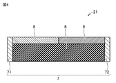
- FIG. 4 is a cross-sectional view of the corrosion detection structure 21 along the line IV-IV of FIG.
- the corrosion detection structure 21 includes an insulating substrate 6, an electrode pair 7, a metal thin film 8, and a resistor 9.
- the insulating substrate 6 is, for example, an insulating substrate having a rectangular parallelepiped shape.
- the electrode pair 7 includes a pair of electrodes, a first electrode 71 and a second electrode 72.
- the first electrode 71 and the second electrode 72 are arranged on the side surfaces of the rectangular parallelepiped of the insulating substrate 6 facing each other.
- Each of the first electrode 71 and the second electrode 72 is a conductor thin film, and can be formed by, for example, tin (Sn) plating.
- the first electrode 71 is electrically connected to the metal thin film 8.
- the second electrode 72 is electrically connected to the resistor 9.
- the metal thin film 8 is a metal thin film arranged on the insulating substrate 6.
- the width and length of the metal thin film 8 are significantly larger than the thickness (film thickness) of the metal thin film 8.
- the film thickness of the metal thin film 8 is 3 ⁇ m to 12 ⁇ m
- the width of the metal thin film 8 is 0.8 mm
- the length of the metal thin film 8 is 1.6 mm.
- the metal thin film 8 is corroded by a corrosive gas.
- a corrosive gas As the material of the metal thin film 8, silver (Ag) or copper can be used. These materials are typical metals used in electrical equipment and react sensitively with major corrosive gases, making them suitable as materials for quantitatively assessing the corrosiveness of the environment in which the electrical equipment 900 is exposed. Is.
- the corrosive gas is a general term for sulfur-based gas, chlorine-based gas, and nitrogen oxides.
- the sulfur-based gas includes hydrogen sulfide (H 2 S), sulfur dioxide (SO 2 ), sulfur flower (S 8 ) and the like.
- Chlorine-based gas includes chlorine gas (Cl 2 ).
- Nitrogen oxides (NO x ) include, for example, nitrogen dioxide (NO 2 ).
- Silver which is the material of the metal thin film 8, reacts sensitively with sulfur flowers and chlorine gas.
- Copper reacts sensitively to hydrogen sulfide, sulfur dioxide and nitrogen dioxide.
- the resistor 9 is connected in series with the metal thin film 8 on the insulating substrate 6.
- the resistor 9 has resistance to corrosive gas.
- an oxide semiconductor for example, ruthenium oxide (RuO 2 )
- RuO 2 ruthenium oxide
- a specific metal such as tin may be used for the resistor 9.
- the resistance value of the resistor 9 is preferably set higher than the resistance value of the metal thin film 8.
- the resistor 9 corresponds to the "resistor" according to the present disclosure.
- FIGS. 3 and 4 the film thickness of the metal thin film 8 and the thickness of the resistor 9 are equal, but this is merely a schematic diagram and is not an essential condition. Further, the configurations shown in FIGS. 3 and 4 are merely examples of the configurations of the corrosion detection structures, and other configurations can be adopted as shown in FIGS. 5 to 8.
- FIG. 5 is a perspective view showing another example of the configuration of the corrosion detection structure.
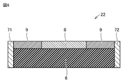
- FIG. 6 is a cross-sectional view of the corrosion detection structure 22 along the VI-VI line of FIG. With reference to FIGS. 5 and 6, in the corrosion detection structure 22, the resistor 9, the metal thin film 8, and the resistor 9 are connected in series in this order between the first electrode 71 and the second electrode 72. Has been done.
- FIG. 7 is a perspective view showing still another example of the configuration of the corrosion detection structure.
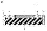
- FIG. 8 is a cross-sectional view of the corrosion detection structure 23 along the line VIII-VIII of FIG. With reference to FIGS. 7 and 8, in the corrosion detection structure 23, the metal thin film 8, the resistor 9, and the metal thin film 8 are connected in series in this order between the first electrode 71 and the second electrode 72. Has been done.
- the number of each of the metal thin film 8 and the resistor 9 included in the corrosion detection structure may be one or a plurality. Further, the connection order of the metal thin film 8 and the resistor 9 is not particularly limited.
- the corrosion detection structure 21 see FIGS. 3 and 4
- the corrosion detection structure 21 can be appropriately read as the corrosion detection structure 22 or the corrosion detection structure 23. ..
- the "risk level” is used as a parameter for adjusting the timing of notifying the user.
- the risk setting method will be described.
- the electric device 900 provided with the corrosion detection sensor 101 is exposed to an environment in which a corrosive gas is present, and the amount of reduction in the film thickness of the metal thin film 8 until the electric device main body 90 is damaged by corrosion is obtained in advance.
- the amount of reduction obtained by this is referred to as "maximum reduction amount".
- the initial film thickness of the metal thin film 8 is set to be sufficiently thick (for example, 20 ⁇ m).
- the ratio of the amount of decrease in the film thickness of the metal thin film 8 due to the corrosive gas to the maximum amount of decrease under the actual use conditions is defined as the "risk degree" (see the following formula (1)).
- FIG. 9 is a flowchart showing the corrosion detection process according to the first embodiment.
- the processes shown in FIG. 9 and the flowcharts of FIGS. 11 and 14 described later are called from a main routine (not shown) and executed by the control device 30 each time a predetermined cycle elapses.
- Each step (hereinafter, abbreviated as S) is basically realized by software processing by the control device 30, but may be realized by hardware processing by an electronic circuit manufactured in the control device 30.
- the control device 30 measures the resistance between both ends of the sensor main body 11 using the resistance measuring device 20.
- the resistance measured by the resistance measuring device 20 is a combination of the resistance of the insulating substrate 6, the resistance of the metal thin film 8, the resistance of the resistor 9, and the resistance of the electrode pair 7. Therefore, in the following, “combined resistance X". ".
- the control device 30 compares the combined resistor X measured in S11 with the reference resistor REF.
- a value higher than the combined resistance X before corrosion by the corrosive gas can be set by a minute amount (for example, a value corresponding to several% of the combined resistance X before corrosion).
- the control device 30 When the combined resistance X is equal to or less than the reference resistance REF (NO in S12), the control device 30 skips the subsequent processing in S13 and returns the processing to the main routine. Then, when the predetermined cycle elapses next time, the series of processes shown in FIG. 9 will be executed again. On the other hand, when the combined resistance X is higher than the reference resistance REF (YES in S12), the control device 30 advances the process to S13.
- the control device 30 controls the notification device 40 so as to notify that the risk level has reached a predetermined value (25% in the above example).
- the notification device 40 is an LED indicator
- the notification device 40 is not displayed until the risk level reaches 25%, but when the risk level reaches 25%, it emits red light and the risk level reaches 25%. Notify the user that it has risen.
- the mode of notification to the user is not limited to this.
- a numerical value (a numerical value of 25%) indicating the degree of danger may be displayed.
- the notification device 40 is a buzzer, a speaker, or the like, the increase in the degree of danger may be notified by voice.
- the electrical equipment 900 in this example was exposed to an environment in which the corrosion of the metal thin film 8 was accelerated. More specifically, in the first embodiment of the first embodiment, an exposure test of the electric device 900 was performed in an environment of 75 ° C. in the presence of sulfur flowers. As the metal thin film 8, the silver thin film having a film thickness of 3 ⁇ m was used.
- the combined resistance X hereinafter, also referred to as “initial combined resistance X0”) before the start of the exposure test was 1000 k ⁇ .
- the reference resistor REF can be set to 1010 k ⁇ , which is 1% higher than the initial combined resistor X0.
- the second embodiment of the first embodiment In the second embodiment of the first embodiment, a copper thin film having a film thickness of 3 ⁇ m was used as the metal thin film 8 contained in the corrosion detection structure 21.
- the maximum reduction amount of the copper thin film was 12 ⁇ m.
- the initial combined resistance X0 of the sensor body 11 was 1000 k ⁇ .
- An electrical device 900 equipped with such a corrosion detection sensor 101 was exposed to an environment of 40 ° C./95% RH / (3 ppmH 2 S + 10 ppm NO 2 ). Then, 1.2 days after the start of the exposure test, the combined resistance X became higher than 1010 k ⁇ . When the sensor body 11 at this time was observed, corrosion disconnection of the metal thin film 8 (copper thin film having a film thickness of 3 ⁇ m) contained in the corrosion detection structure 21 was confirmed.
- the corrosion detection structure 21 by using the corrosion detection structure 21, the degree of progress of corrosion of the electric device 900 caused by the corrosive gas can be grasped with a very simple configuration. Then, by setting the degree of risk to a desired value of less than 100%, it is possible to notify the user of the degree of progress of corrosion of the electric device 900 before the trouble of corrosion damage occurs in the electric device main body 90. The user can take necessary measures such as repair or replacement of the electric device main body 90.
- Embodiment 2 a configuration for notifying the user of the progress of corrosion of the electric device 900 step by step will be described.
- the overall configuration of the electrical equipment according to the second embodiment is the same as the overall configuration of the electrical equipment 900 according to the first embodiment (see FIG. 1) except that the corrosion detection sensor is different.
- the configuration of the corrosion detection sensor according to the second embodiment is the same as the configuration of the corrosion detection sensor 101 (see FIG. 1) according to the first embodiment except for the configuration of the sensor main body. Therefore, in order to prevent the drawing from becoming complicated, the sensor main body is extracted and shown below.
- FIG. 10 is a diagram showing an example of the configuration of the sensor main body according to the second embodiment.
- the sensor body 121 includes two corrosion detection structures 21A, 21B connected in parallel.
- the configurations of the corrosion detection structures 21A and 21B are the same as the configurations of the corrosion detection structures 21 shown in FIGS. 3 and 4.
- the material of the metal thin film 8 included in the corrosion detection structure 21A and the material of the metal thin film 8 included in the corrosion detection structure 21B are the same.
- the film thickness of the metal thin film 8 included in the corrosion detection structure 21A is different from the film thickness of the metal thin film 8 included in the corrosion detection structure 21B.
- the film thickness of the metal thin film 8 included in the corrosion detection structure 21A is thinner than the film thickness of the metal thin film 8 included in the corrosion detection structure 21B.
- the resistance value of the corrosion detection structure 21A is higher than the resistance value of the corrosion detection structure 21B.
- the material of the metal thin film 8 contained in the corrosion detection structure 21A and the material of the metal thin film 8 contained in the corrosion detection structure 21B were both silver. ..
- the film thickness of the metal thin film 8 contained in the corrosion detection structure 21A was 3 ⁇ m.
- the film thickness of the metal thin film 8 contained in the corrosion detection structure 21B was 6 ⁇ m.
- the resistance value of the corrosion detection structure 21A was 1000 k ⁇
- the resistance value of the corrosion detection structure 21B was 100 k ⁇ .
- the first reference resistance REF1 is a corrosion detection structure having a thick metal thin film 8 although the corrosion detection structure 21A having a thin metal thin film 8 is broken due to corrosion among the two corrosion detection structures 21A and 21B.
- 21B is determined based on the resistance (combined resistance X) at both ends of the sensor main body 121 in a state where the wire is not broken.
- the second reference resistor REF2 is determined based on the combined resistance X of the sensor body 121 in a state where both of the two corrosion detection structures 21A and 21B are disconnected due to corrosion.
- the second coefficient is larger than the first coefficient (K2> K1). Therefore, the second reference resistor REF2 is higher than the first reference resistor REF1 (REF2> REF1).
- the initial combined resistance X0 is 91 k ⁇ .
- the first reference resistor REF1 is set to 92 k ⁇ , which is a value 1.2% higher than the initial combined resistor X0.
- the second reference resistor REF2 is set to 101 k ⁇ , which is a value 11% higher than the initial combined resistor X0.
- the fact that the combined resistance X exceeds the first reference resistance REF1 means that the corrosion detection structure 21A is broken, that is, the metal thin film 8 having a film thickness of 3 ⁇ m is broken due to corrosion. From this, it can be understood that the risk level has reached 25%.
- the fact that the combined resistance X exceeds the second reference resistance REF2 indicates that the corrosion detection structure 21B having the metal thin film 8 having a film thickness of 6 ⁇ m was broken due to corrosion. As a result, it is understood that the risk level has reached 50%.
- FIG. 11 is a flowchart showing a corrosion detection process corresponding to the configuration of the sensor main body 121 shown in FIG. With reference to FIG. 11, in S21, the control device 30 measures the resistance (combined resistance X) between both ends of the sensor body 121 using the resistance measuring device 20.
- the control device 30 keeps both the two LEDs off when the risk level is D1 or less.
- the control device 30 turns on (may be blinking) the other LED while keeping one LED off (S25). Further, when the degree of danger is more than D2, the control device 30 turns on both LEDs (S24).
- the control device 30 may control the LED so as to emit light in a color according to the degree of danger. .. For example, the control device 30 turns off the LED when the degree of danger is D1 or less, emits yellow light when the degree of danger is more than D1 and D2 or less, and emits red light when the degree of danger is more than D2. Can be controlled.
- the first embodiment of the second embodiment An exposure test of an electric device 900 (specifically, an inverter) provided with a corrosion detection sensor including the sensor body 121 shown in FIG. 10 was conducted in a temperature environment of 75 ° C. containing sulfur flowers.
- the initial combined resistance X0 was 91 k ⁇ .
- the second reference resistance REF2 101 k ⁇ . It was confirmed that this increase in resistance was caused by the corrosion disconnection of the corrosion detection structure 21B (silver thin film having a film thickness of 6 ⁇ m).
- FIG. 12 is a diagram showing another example of the configuration of the sensor body according to the second embodiment.
- FIG. 12 shows a specific configuration of the corrosion detection structure in the second embodiment of the second embodiment (material and film thickness of the metal thin film 8 and the initial resistance of the corrosion detection structure).
- the configuration of the sensor body 122 is basically the same as the configuration of the sensor body 121 (see FIG. 10).
- the material of the metal thin film 8 contained in the corrosion detection structure 21C and the material of the metal thin film 8 included in the corrosion detection structure 21D were both copper.
- the film thickness of the metal thin film 8 contained in the corrosion detection structure 21C was 3 ⁇ m.
- the film thickness of the metal thin film 8 contained in the corrosion detection structure 21D was 6 ⁇ m.
- the resistance value of the corrosion detection structure 21C was 1000 k ⁇ , and the resistance value of the corrosion detection structure 21D was 100 k ⁇ .
- An exposure test of an electric device 900 (inverter) provided with a corrosion detection sensor including a sensor body 122 was conducted in an environment of 40 ° C./95% RH / (3 ppmH 2 S + 10 ppm NO 2 ).
- the initial combined resistance X0 was 91 k ⁇ .
- FIG. 13 is a diagram showing still another example of the configuration of the sensor body according to the second embodiment.
- FIG. 13 shows a specific configuration of the corrosion detection structure according to the third embodiment of the second embodiment.
- the sensor body 131 includes three corrosion detection structures 21E-21G connected in parallel. Each configuration of the corrosion detection structures 21E to 21G is equivalent to the configuration of the corrosion detection structure 21 shown in FIGS. 3 and 4.
- the material of the metal thin film 8 included in the corrosion detection structure 21E, the material of the metal thin film 8 included in the corrosion detection structure 21F, and the material of the metal thin film 8 included in the corrosion detection structure 21G are the same.
- the film thickness of the metal thin film 8 included in the corrosion detection structure 21E, the film thickness of the metal thin film 8 included in the corrosion detection structure 21F, and the film thickness of the metal thin film 8 included in the corrosion detection structure 21G ? different.
- the film thickness of the metal thin film 8 contained in the corrosion detection structure 21E is the thinnest, the film thickness of the metal thin film 8 contained in the corrosion detection structure 21F is the next thinnest, and the film thickness of the metal thin film 8 contained in the corrosion detection structure 21G The thickest.
- the resistance value of the corrosion detection structure 21E is the highest, the resistance value of the corrosion detection structure 21F is the next highest, and the resistance value of the corrosion detection structure 21G is the lowest.
- the material of the metal thin film 8 included in the corrosion detection structure 21E, the material of the metal thin film 8 included in the corrosion detection structure 21F, and the metal contained in the corrosion detection structure 21G was silver.
- the film thickness of the metal thin film 8 contained in the corrosion detection structure 21G was 9 ⁇ m.
- the resistance value of the corrosion detection structure 21E was 1000 k ⁇
- the resistance value of the corrosion detection structure 21F was 100 k ⁇
- the resistance value of the corrosion detection structure 21G was 10 k ⁇ .
- first reference resistor REF1 to third reference resistor REF3
- the first reference resistance REF1 is that the corrosion detection structure 21E, which has the thinnest metal thin film 8 of the three corrosion detection structures 21E to 21G, is broken due to corrosion, but the remaining two corrosion detection structures 21F and 21G are It is determined based on the combined resistance X at both ends of the sensor main body 131 in a state where the wire is not broken.
- the second reference resistance REF2 is the combined resistance at both ends of the sensor body 131 in a state where the corrosion detection structures 21E and 21F are broken due to corrosion, but the corrosion detection structure 21G having the thickest metal thin film 8 is not broken. Determined based on X.
- the third reference resistor REF3 is determined based on the combined resistance X of the sensor main body 131 in a state where all three corrosion detection structures 21E to 21G are disconnected due to corrosion.
- the third coefficient K3, the second coefficient K2, and the first coefficient K1 are larger in this order (K3> K2> K1). Therefore, the third reference resistor REF3, the second reference resistor REF2, and the first reference resistor REF1 are higher in this order (REF3> REF2> REF1).
- the initial combined resistance X0 was 9.01 k ⁇ .
- the first reference resistor REF1 was set to 9.02 k ⁇ , which is a value 0.1% higher than the initial combined resistor X0.
- the second reference resistor REF2 was set to 9.10 k ⁇ , which is a value 1% higher than the initial combined resistor X0.
- the third reference resistor REF3 was set to 10.1 k ⁇ , which is a value 12% higher than the initial combined resistor X0.
- the fact that the combined resistance X exceeds the first reference resistance REF1 means that the metal thin film 8 having a film thickness of 3 ⁇ m contained in the corrosion detection structure 21E is broken due to corrosion.
- the risk level has reached 25%.
- the fact that the combined resistance X exceeds the second reference resistance REF2 means that the metal thin film 8 having a film thickness of 6 ⁇ m contained in the corrosion detection structure 21F is further broken due to corrosion. From this, it can be understood that the risk level has reached 50%.
- the fact that the combined resistance X exceeds the third reference resistance REF3 means that the metal thin film 8 having a film thickness of 9 ⁇ m contained in the corrosion detection structure 21G is further broken due to corrosion. From this, it can be understood that the risk level has reached 75%.
- FIG. 14 is a flowchart showing a corrosion detection process corresponding to the configuration of the sensor main body 131 shown in FIG. With reference to FIG. 14, in S31, the control device 30 measures the resistance (combined resistance X) between both ends of the sensor main body 131 using the resistance measuring device 20.
- the control device 30 processes the process in S36. Proceed to.
- the control device 30 advances the process to S35.
- the notification mode of each risk level D1 to D3 is the same as the notification mode described with reference to FIG. Specifically, when the notification device 40 is an LED indicator and includes three LEDs, the control device 30 turns off all three LEDs when the degree of danger is D1 or less. When the degree of danger is greater than D1 and less than or equal to D2, the control device 30 turns on one LED while keeping the two LEDs off. Further, when the degree of danger is more than D2 and less than D3, the control device 30 turns off one LED and turns on two LEDs. Then, when the degree of danger is greater than D3, the control device 30 turns on all three LEDs.
- the control device 30 may control the LED so as to emit light in a color according to the degree of danger. ..
- the control device 30 turns off when the risk level is D1 or less, emits green light when the risk level is more than D1 and D2 or less, and emits yellow light when the danger level is more than D2 and D3 or less.
- the LED can be controlled so that it emits red light when the risk is greater than D3.
- An exposure test was conducted on an electric device 900 (inverter) provided with a corrosion detection sensor including the sensor body 131 shown in FIG. 13 in a temperature environment of 75 ° C. containing sulfur flowers.
- the initial combined resistance X0 was 9.01 k ⁇ .
- FIG. 15 is a diagram showing still another example of the configuration of the sensor body according to the second embodiment.
- FIG. 15 shows a specific configuration of the corrosion detection structures 21H to 21J included in the sensor main body 132 in the fourth embodiment of the second embodiment.
- the configuration of the sensor main body 132 is basically the same as the configuration of the sensor main body 131 (see FIG. 13).
- the material of the metal thin film 8 included in the corrosion detection structure 21H, the material of the metal thin film 8 included in the corrosion detection structure 21I, and the material of the metal thin film 8 included in the corrosion detection structure 21J are all made of copper. there were.
- the film thickness of the metal thin film 8 contained in the corrosion detection structure 21H was 3 ⁇ m.
- the film thickness of the metal thin film 8 contained in the corrosion detection structure 21I was 6 ⁇ m.
- the film thickness of the metal thin film 8 contained in the corrosion detection structure 21J was 9 ⁇ m.
- the resistance value of the corrosion detection structure 21H was 1000 k ⁇
- the resistance value of the corrosion detection structure 21I was 100 k ⁇
- the resistance value of the corrosion detection structure 21J was 10 k ⁇ .
- An exposure test of an electric device 900 (inverter) provided with a corrosion detection sensor including a sensor body 132 was conducted in an environment of 40 ° C./95% RH / (3 ppmH 2 S + 10 ppm NO 2 ).
- the initial combined resistance X0 was 9.01 k ⁇ .
- Ten days after the start of the test, the combined resistance X became higher than the first reference resistance REF1 9.02 k ⁇ , but this increase in resistance was caused by the corrosion disconnection of the corrosion detection structure 21H (copper thin film with a film thickness of 3 ⁇ m). It was confirmed that.
- the second embodiment it is possible to grasp the progress of corrosion of the electric device due to the corrosive gas by a simple configuration as in the first embodiment. Further, in the second embodiment, a plurality of corrosion detection structures are connected in parallel, and a plurality of risk levels are set. This makes it possible to notify the user of the progress of corrosion in more detail and step by step.
- FIG. 10 the configuration in which two or three corrosion detection structures are connected in parallel has been described as an example, but even if four or more corrosion detection structures are used. Good.
- N is a natural number of 2 or more
- an N parallel circuit is constructed. The larger N is, the more complicated the configuration of the corrosion detection sensor is, but it is possible to notify the user of a more detailed degree of progress (risk) of corrosion.
- Embodiment 3 Electrical equipment 900 is installed in various environments and may be exposed to various corrosive gases. In the third embodiment, a configuration capable of detecting corrosion by a plurality of types of corrosive gases will be described.
- FIG. 16 is a diagram showing an example of the configuration of the sensor main body in the third embodiment.
- FIG. 16 shows a specific configuration of the corrosion detection structures 21H to 21J included in the sensor main body 14 in the first embodiment of the third embodiment.
- the sensor body 14 includes two corrosion detection structures 21K, 21L connected in series and three wirings 41-43.
- the configurations of the corrosion detection structures 21K and 21L are the same as the configurations of the corrosion detection structures 21 shown in FIGS. 3 and 4.
- the wiring 41 and the wiring 42 are arranged so as to be separated from each other.
- the corrosion detection structure 21K is arranged so as to connect between the wiring 41 and the wiring 42, and is mounted on the wirings 41 and 42 by soldering.
- the wiring 42 and the wiring 43 are arranged at intervals from each other.
- the corrosion detection structure 21L is arranged so as to connect between the wiring 42 and the wiring 43, and is mounted on the wirings 42 and 43 by soldering.
- the material of the metal thin film 8 contained in the corrosion detection structure 21K is different from the material of the metal thin film 8 contained in the corrosion detection structure 21L. In the present embodiment, it is essential that the materials are different between the corrosion detection structures 21K and 21L connected in series.
- the film thickness of the metal thin film 8 contained in the corrosion detection structure 21K is equal to the film thickness of the metal thin film 8 contained in the corrosion detection structure 21L.
- these film thicknesses may be different from each other.
- the film thickness of each metal thin film 8 may be appropriately set in consideration of the difference in the corrosion rate for each material depending on the type or concentration of the corrosive gas, the risk of notifying the user, and the like.
- the resistance value of the corrosion detection structure 21K and the resistance value of the corrosion detection structure 21L are equal to each other.
- the corrosion detection sensor according to the present disclosure only needs to be able to detect an increase in resistance due to corrosion disconnection, it is not essential that these resistance values are equal.
- the specifications (material, size, etc.) of the resistor 9 can be standardized, so that the corrosion detection structures 21K and 21L can be manufactured more easily.
- the material of the metal thin film 8 contained in the corrosion detection structure 21K was silver, and the material of the metal thin film 8 contained in the corrosion detection structure 21L was copper.
- the film thickness of the metal thin film 8 contained in the corrosion detection structure 21K was 3 ⁇ m, and the film thickness of the metal thin film 8 contained in the corrosion detection structure 21L was also 3 ⁇ m.
- the resistance value of the corrosion detection structure 21K and the resistance value of the corrosion detection structure 21L were 1000 k ⁇ .
- the reference resistor REF is prepared as a reference for comparing the magnitude relationship with the combined resistor X.
- the first embodiment of the third embodiment An exposure test of an electric device 900 (inverter) provided with a corrosion detection sensor including the sensor body 14 shown in FIG. 16 was conducted in a temperature environment of 75 ° C. containing sulfur flowers.
- the initial combined resistance X0 was 2000 k ⁇ .
- the reference resistance REF was set to 2020 k ⁇ , which is a value 1% higher than the initial combined resistance X0.
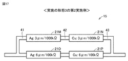
- FIG. 17 is a diagram showing another example of the configuration of the sensor body according to the third embodiment.
- FIG. 17 shows a specific configuration of the corrosion detection structure included in the sensor main body 15 in the second embodiment of the third embodiment.
- the sensor body 15 includes four corrosion detection structures 21M-21P and three wirings 41-43.
- the corrosion detection structure 21M and the corrosion detection structure 21N are connected in series via the wiring 42.
- the corrosion detection structure 21O and the corrosion detection structure 21P are connected in series via the wiring 42.
- the corrosion detection structures 21M and 21N and the corrosion detection structures 21O and 21P are connected in parallel between the wiring 41 and the wiring 43.
- Each configuration of the corrosion detection structures 21M to 21P is equivalent to the configuration of the corrosion detection structure 21 shown in FIGS. 3 and 4.
- the resistance value of the corrosion detection structure 21M is equal to the resistance value of the corrosion detection structure 21N. Further, the resistance value of the corrosion detection structure 21O is equal to the resistance value of the corrosion detection structure 21P. Further, the resistance values of the corrosion detection structures 21M and 21N are higher than the resistance values of the corrosion detection structures 21O and 21P.
- the material of the metal thin film 8 contained in the corrosion detection structures 21M and 21O is silver
- the material of the metal thin film 8 contained in the corrosion detection structures 21N and 21P is copper. It was.
- the resistance values of the corrosion detection structures 21M and 21N were 1000 k ⁇
- the resistance values of the corrosion detection structures 21O and 21P were 100 k ⁇ .
- first reference resistor REF1 and second reference resistor REF2 Two types of reference resistors are prepared as a reference for comparing the magnitude relationship with the combined resistor X.
- the first reference resistor REF1 is determined based on the combined resistance X at both ends of the sensor main body 15 in a state where at least one of the corrosion detection structures 21M and 21N connected in series is disconnected due to corrosion.
- the second reference resistor REF2 is determined based on the combined resistance X at both ends of the sensor main body 15 in a state where at least one of the corrosion detection structures 21O and 21P connected in series is disconnected due to corrosion.
- the specific setting method using the coefficient is the same as the setting method in the first embodiment (see FIG. 10) of the second embodiment. Further, since the corrosion detection process performed by using the corrosion detection sensor including the sensor body 15 is the same as the process represented by the flowchart shown in FIG. 11, the description will not be repeated.
- An exposure test was conducted on an electric device 900 (inverter) provided with a corrosion detection sensor including a sensor body 15 in a temperature environment of 75 ° C. containing sulfur flowers.
- the initial combined resistance X0 was 182 k ⁇ .
- FIG. 18 is a diagram showing still another example of the configuration of the sensor body according to the third embodiment.
- FIG. 18 shows a specific configuration of the corrosion detection structure included in the sensor main body 16 in the third embodiment of the third embodiment.
- the sensor body 15 includes six corrosion detection structures 21Q-21V and three wirings 41-43.
- the corrosion detection structure 21Q and the corrosion detection structure 21R are connected in series via the wiring 42.
- the corrosion detection structure 21S and the corrosion detection structure 21T are connected in series via the wiring 42.
- Both the corrosion detection structure 21U and the corrosion detection structure 21V are connected in series via the wiring 42.
- the corrosion detection structures 21Q and 21R, the corrosion detection structures 21S and 21T, and the corrosion detection structures 21U and 21V are connected in parallel between the wiring 41 and the wiring 43.
- Each configuration of the corrosion detection structure 21Q to 21V is equivalent to the configuration of the corrosion detection structure 21 shown in FIGS. 3 and 4.
- the material of the metal thin film 8 included in the corrosion detection structure 21Q is different from the material of the metal thin film 8 included in the corrosion detection structure 21R. Further, the material of the metal thin film 8 included in the corrosion detection structure 21S is different from the material of the metal thin film 8 included in the corrosion detection structure 21T. The material of the metal thin film 8 included in the corrosion detection structure 21U is different from the material of the metal thin film 8 included in the corrosion detection structure 21V.
- the resistance value of the corrosion detection structure 21Q is equal to the resistance value of the corrosion detection structure 21R.
- the resistance value of the corrosion detection structure 21S is equal to the resistance value of the corrosion detection structure 21T.
- the resistance value of the corrosion detection structure 21U is equal to the resistance value of the corrosion detection structure 21V.
- the resistance values of the corrosion detection structures 21Q and 21R are higher than the resistance values of the corrosion detection structures 21S and 21T. Further, the resistance values of the corrosion detection structures 21S and 21T are higher than the resistance values of the corrosion detection structures 21U and 21V.
- the material of the metal thin film 8 contained in the corrosion detection structures 21Q, 21S, 21U is silver, and the material of the metal thin film 8 contained in the corrosion detection structures 21R, 21T, 21V.
- the film thickness of the metal thin film 8 contained in the corrosion detection structures 21U and 21V was 9 ⁇ m.
- the resistance values of the corrosion detection structures 21Q and 21R were 1000 k ⁇
- the resistance values of the corrosion detection structures 21S and 21T were 100 k ⁇
- the resistance values of the corrosion detection structures 21U and 21V were 10 k ⁇ .
- first reference resistor REF1 Three types of reference resistors (first reference resistor REF1 to third reference resistor REF3) are prepared as a reference for comparing the magnitude relationship with the combined resistor X.
- the first reference resistor REF1 is determined based on the combined resistance X at both ends of the sensor main body 16 in a state where at least one of the corrosion detection structures 21Q and 21R connected in series is disconnected due to corrosion.
- the second reference resistor REF2 is determined based on the combined resistance X at both ends of the sensor main body 16 in a state where at least one of the corrosion detection structures 21S and 21T connected in series is disconnected due to corrosion.
- the third reference resistor REF3 is determined based on the combined resistance X at both ends of the sensor main body 16 in a state where at least one of the corrosion detection structures 21U and 21V connected in series is disconnected due to corrosion.
- the specific setting method using the coefficient is the same as the setting method in the third embodiment (see FIG. 13) of the second embodiment. Further, since the corrosion detection process performed by using the corrosion detection sensor including the sensor main body 16 is the same as the process represented by the flowchart shown in FIG. 14, the description will not be repeated.
- An exposure test of an electric device 900 (inverter) provided with a corrosion detection sensor including a sensor body 16 was conducted in an environment of 40 ° C./95% RH / (3 ppmH 2 S + 10 ppm NO 2 ).
- the initial combined resistance X0 was 18 k ⁇ .
- the third embodiment it is possible to grasp the progress of corrosion of the electric device 900 caused by the corrosive gas by a simple configuration as in the first and second embodiments. Further, in the third embodiment, a plurality of corrosion detection structures made of different materials for the metal thin film 8 are connected in series. Since the corrosiveness (corrosion rate) differs depending on the combination of the type of corrosive gas and the type of metal, it is possible to detect the corrosion of the electric device 900 by a plurality of types of corrosive gas by utilizing this property. Further, by combining the series connection and the parallel connection of the corrosion detection structure, it is possible to notify the user in detail of the degree of corrosion progress (risk degree) of the electric device 900.
- Embodiment 4 In the first to third embodiments, the configuration in which both the metal thin film 8 and the resistor 9 are included in the corrosion detection structure has been described. However, as described below, the configuration of the corrosion detection structure is not limited to this. The resistor 9 may be provided outside the corrosion detection structure.
- FIG. 19 is a diagram showing an electric device including a corrosion detection sensor according to the fourth embodiment.
- electrical equipment 904 includes a corrosion detection sensor 104.
- the corrosion detection sensor 104 includes a sensor body 171.
- the sensor main body 171 differs from the sensor main body 11 (see FIG. 1) in the first embodiment in that the corrosion detection structure 24 is included in place of the corrosion detection structure 21 and the fixed resistor 50 is further included. Since the other configurations of the sensor main body 171 are the same as the corresponding configurations of the sensor main body 11, the description will not be repeated.
- the configuration of the corrosion detection structure 24 for example, the configuration of the first embodiment of the fourth embodiment described later can be adopted.
- the fixed resistor 50 is, for example, a surface mount type resistor (chip resistor) or a lead wire type resistor.
- the fixed resistor 50 is connected in series with the corrosion detection structure 24.
- the fixed resistor 50 is resistant to corrosive gases. Further, the resistance value of the fixed resistor 50 is set higher than the resistance value of the metal thin film 8 (see FIGS. 20 and 21).
- the fixed resistor 50 is another example of the “resistor” according to the present disclosure.
- FIG. 20 is a perspective view showing an example of the configuration of the corrosion detection structure 24 according to the fourth embodiment.
- FIG. 21 is a cross-sectional view of the corrosion detection structure 24 along the line XXI-XXI of FIG.
- the corrosion detection structure 24 is different from the corrosion detection structures 21 to 23 in the first embodiment (see FIGS. 3, 5 and 7) in that the resistor 9 is not included. different.
- the metal thin film 8 is arranged on the insulating substrate 6 so as to electrically connect the first electrode 71 and the second electrode 72.
- the material of the metal thin film 8 is a metal (silver, copper, etc.) that is corroded by a corrosive gas, as in the first embodiment.
- the fixed resistor 50 is arranged as a discrete component outside the corrosion detection structure 24. You may.
- the fourth embodiment as well in the first embodiment, it is possible to detect the progress of corrosion of the electric device 900 by the corrosive gas. Since this detection method is the same as the method in the first embodiment (see FIG. 9), detailed description will not be repeated.
- the first embodiment of the fourth embodiment In the first embodiment of the fourth embodiment, the material of the metal thin film 8 contained in the corrosion detection structure 24 was silver.
- the resistance value of the fixed resistor 50 was 1000 k ⁇ .
- An exposure test of an electric device 904 (inverter) provided with a corrosion detection sensor 104 including such a sensor body 171 was performed in an environment where sulfur flowers are present.
- the initial combined resistance X0 was 1000 k ⁇ .
- the fourth embodiment as described in the second and third embodiments, it is possible to appropriately connect the series circuit including the corrosion detection structure 24 and the fixed resistor 50 in series or in parallel.
- the configuration of the sensor main body in the fourth embodiment is the same as that of the sensor main body already described in the second and third embodiments, except that the fixed resistor 50 is provided outside the corrosion detection structure instead of the resistor 9. It is basically the same as the configuration.
- the description of the corresponding configuration in the second and third embodiments will be referred to, and the verification result of the effectiveness of the corrosion detection sensor will be mainly described.
- FIG. 22 is a diagram showing a second example of the configuration of the sensor body according to the fourth embodiment.
- the sensor body 172 corresponds to the sensor body 121 shown in FIG. 10 or the sensor body 122 shown in FIG.
- An exposure test was conducted on an electric device 904 (inverter) provided with a corrosion detection sensor including a sensor body 172 in a temperature environment of 75 ° C. containing sulfur flowers.
- the initial combined resistance X0 was 91 k ⁇ .
- the second reference resistance REF2 101 k ⁇ . It was confirmed that this increase in resistance was caused by the corrosion disconnection of the corrosion detection structure 24B (silver thin film having a film thickness of 6 ⁇ m).
- FIG. 23 is a diagram showing a third example of the configuration of the sensor body according to the fourth embodiment.
- the sensor body 173 corresponds to the sensor body 131 shown in FIG. 13 or the sensor body 132 shown in FIG.
- An exposure test was conducted on an electric device 904 (inverter) provided with a corrosion detection sensor including a sensor body 173 in a temperature environment of 75 ° C. containing sulfur flowers.
- the initial combined resistance X0 was 9.01 k ⁇ .
- FIG. 24 is a diagram showing a fourth example of the configuration of the sensor body according to the fourth embodiment.
- the sensor body 174 corresponds to the sensor body 14 shown in FIG.
- An exposure test was conducted on an electric device 904 (inverter) provided with a corrosion detection sensor including a sensor body 174 in a temperature environment of 75 ° C. containing sulfur flowers.
- the initial combined resistance X0 was 2000 k ⁇ .
- FIG. 25 is a diagram showing a fifth example of the configuration of the sensor body according to the fourth embodiment.
- the sensor body 175 corresponds to the sensor body 15 shown in FIG.
- An exposure test was conducted on an electric device 904 (inverter) provided with a corrosion detection sensor including a sensor body 175 in a temperature environment of 75 ° C. containing sulfur flowers.
- the initial combined resistance X0 was 182 k ⁇ .
- FIG. 26 is a diagram showing a sixth example of the configuration of the sensor body according to the fourth embodiment.
- the sensor body 176 corresponds to the sensor body 16 shown in FIG.
- An exposure test was conducted on an electric device 904 (inverter) provided with a corrosion detection sensor including a sensor body 176 in a temperature environment of 75 ° C. containing sulfur flowers.
- the initial combined resistance X0 was 18.0 k ⁇ .
- the corrosive gas has a simple configuration as in the first embodiment. It is possible to grasp the degree of progress of corrosion of the electric device 904 by the above. Further, by connecting a plurality of corrosion detection structures in series, it is possible to detect corrosion of the electric device 904 by a plurality of types of corrosive gases. Further, by connecting a plurality of corrosion detection structures in parallel, it is possible to notify the user of a more detailed degree of corrosion progress (risk degree) of the electric device 904.
- Embodiment 5 the structure in which the materials of the metal thin films are different from each other among the plurality of corrosion detection structures will be described.
- the overall configuration of the electrical equipment according to the fifth embodiment is the same as the overall configuration of the electrical equipment 900 according to the first embodiment (see FIG. 1) except that the material of the metal thin film is different.
- Additive elements in silver-based alloys or copper-based alloys are nickel (Ni), titanium (Ti), magnesium (Mg), aluminum (Al), tin (Sn), palladium (Pd), gold (Au), zinc (Zn). ) Or platinum (Pt).
- the additive element is added in the range of 0 to 30 wt% with respect to silver or copper.
- copper can be added in the range of 0 to 30 wt% to the silver alloy, and silver can be added in the range of 0 to 30 wt% to the copper alloy.
- the constituent elements of the silver-based alloy and the copper-based alloy may be three or more.
- FIG. 27 is a diagram showing an example of the configuration of the sensor main body according to the fifth embodiment.
- FIG. 27 shows a specific configuration of the corrosion detection structure included in the sensor body according to the first embodiment of the fifth embodiment.
- the sensor body 181 includes two corrosion detection structures 25A, 25B connected in parallel.
- the configurations of the corrosion detection structures 25A and 25B are the same as the configurations of the corrosion detection structures 21 shown in FIGS. 3 and 4.
- the material of the metal thin film 8 included in the corrosion detection structure 25A is different from the material of the metal thin film 8 included in the corrosion detection structure 25B.
- the maximum reduction amount of the material of the metal thin film 8 contained in the corrosion detection structure 25A is larger than the maximum reduction amount of the material of the metal thin film 8 contained in the corrosion detection structure 25B.
- the film thickness of the metal thin film 8 contained in the corrosion detection structure 25A is equal to the film thickness of the metal thin film 8 included in the corrosion detection structure 25B.
- the resistance value of the corrosion detection structure 25A is higher than the resistance value of the corrosion detection structure 25B.
- the film thickness of the metal thin film 8 contained in the corrosion detection structure 25A and the film thickness of the metal thin film 8 contained in the corrosion detection structure 25B were both 3 ⁇ m. ..
- the material of the metal thin film 8 contained in the corrosion detection structure 25A was silver, and the material of the metal thin film 8 contained in the corrosion detection structure 25B was a silver-zinc alloy (zinc addition amount was 0.4 wt%).
- the maximum reduction amount of the silver-zinc alloy thin film (zinc addition amount was 0.4 wt%) was 9.1 ⁇ m.
- the resistance value of the corrosion detection structure 25A was 1000 k ⁇ , and the resistance value of the corrosion detection structure 25B was 100 k ⁇ .
- two types of reference resistors are prepared for comparing the magnitude relationship with the combined resistor X.
- the first reference resistance REF is determined based on the resistance (combined resistance X) at both ends of the sensor main body 181 in a state where the corrosion detection structure 25A is broken due to corrosion, but the corrosion detection structure 25B is not broken.
- the second reference resistor REF2 is determined based on the combined resistor X of the sensor body 181 in a state where both of the two corrosion detection structures 25A and 25B are disconnected due to corrosion.
- the second coefficient is larger than the first coefficient (K2> K1). Therefore, the second reference resistor REF2 is higher than the first reference resistor REF1 (REF2> REF1).
- the initial combined resistance X0 is 91 k ⁇ .
- the first reference resistor REF1 is set to 92 k ⁇ , which is a value 1.2% higher than the initial combined resistor X0.
- the second reference resistor REF2 is set to 101 k ⁇ , which is a value 11% higher than the initial combined resistor X0.
- the fact that the combined resistance X exceeds the first reference resistance REF1 means that the corrosion detection structure 25A is broken, that is, the metal thin film 8 having a maximum reduction amount of 12 ⁇ m and a film thickness of 3 ⁇ m is broken due to corrosion. Means. From this, it can be understood that the risk level has reached 25%.
- the fact that the combined resistance X subsequently exceeded the second reference resistance REF2 indicates that the metal thin film 8 having a maximum reduction amount of 9.1 ⁇ m and a film thickness of 3 ⁇ m was broken due to corrosion. As a result, it is understood that the risk level has reached 32%.
- the first embodiment of the fifth embodiment An exposure test of an electric device 900 (inverter) provided with a corrosion detection sensor including a sensor body 181 shown in FIG. 27 was conducted in a temperature environment of 75 ° C. containing sulfur flowers.
- the initial combined resistance X0 was 91 k ⁇ .
- the second reference resistance REF2 101 k ⁇ . It was confirmed that this increase in resistance was caused by the corrosion disconnection of the corrosion detection structure 25B (silver-zinc alloy thin film having a film thickness of 3 ⁇ m).
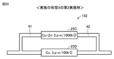
- FIG. 28 is a diagram showing another example of the configuration of the sensor body according to the fifth embodiment.
- FIG. 28 shows a specific configuration of the corrosion detection structure included in the sensor body according to the second embodiment of the fifth embodiment.
- the configuration of the sensor body 182 is basically the same as the configuration of the sensor body 181 (see FIG. 27).
- the film thickness of the metal thin film 8 contained in the corrosion detection structure 25C and the film thickness of the metal thin film 8 included in the corrosion detection structure 25D were both 3 ⁇ m. ..
- the material of the metal thin film 8 contained in the corrosion detection structure 25C was a copper-zinc alloy (zinc addition amount was 30 wt%).
- the material of the metal thin film 8 contained in the corrosion detection structure 25D was copper.
- the resistance value of the corrosion detection structure 25C was 1000 k ⁇ , and the resistance value of the corrosion detection structure 25D was 100 k ⁇ .
- An exposure test of an electric device 900 (inverter) provided with a corrosion detection sensor including a sensor body 182 was conducted in an environment of 40 ° C./95% RH / (3 ppmH 2 S + 10 ppm NO 2 ).
- the initial combined resistance X0 was 91 k ⁇ .
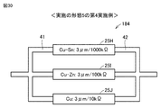
- FIG. 29 is a diagram showing still another example of the configuration of the sensor body according to the fifth embodiment.
- FIG. 29 shows a specific configuration of the corrosion detection structure included in the sensor body according to the third embodiment of the fifth embodiment.
- the sensor body 183 includes three corrosion detection structures 25E-25G connected in parallel. Each configuration of the corrosion detection structures 25E to 25G is equivalent to the configuration of the corrosion detection structure 21 shown in FIGS. 3 and 4.
- the film thickness of the metal thin film 8 included in the corrosion detection structure 25E, the film thickness of the metal thin film 8 included in the corrosion detection structure 25F, and the film thickness of the metal thin film 8 included in the corrosion detection structure 25G are equal.
- the material of the metal thin film 8 included in the corrosion detection structure 25E, the material of the metal thin film 8 included in the corrosion detection structure 25F, and the material of the metal thin film 8 included in the corrosion detection structure 25G are different.
- the maximum reduction amount of the metal thin film 8 contained in the corrosion detection structure 25E is the largest, the maximum reduction amount of the metal thin film 8 contained in the corrosion detection structure 25F is the next largest, and the metal thin film 8 contained in the corrosion detection structure 25G is the second largest.
- the maximum reduction amount of is the smallest.
- the resistance value of the corrosion detection structure 25E is the highest, the resistance value of the corrosion detection structure 25F is the next highest, and the resistance value of the corrosion detection structure 25G is the lowest.
- the film thickness of the metal thin film 8 included in the corrosion detection structure 25E, the film thickness of the metal thin film 8 included in the corrosion detection structure 25F, and the thickness of the metal thin film 8 included in the corrosion detection structure 25G are included.
- the thickness of the metal thin film 8 was 3 ⁇ m.
- the material of the metal thin film 8 contained in the corrosion detection structure 25E was silver.
- the material of the metal thin film 8 contained in the corrosion detection structure 25F was a silver-zinc alloy (zinc addition amount was 0.4 wt%).
- the material of the metal thin film 8 contained in the corrosion detection structure 25G was a silver-aluminum alloy (aluminum addition amount was 0.4 wt%).
- the resistance value of the corrosion detection structure 25E was 1000 k ⁇
- the resistance value of the corrosion detection structure 25F was 100 k ⁇
- the resistance value of the corrosion detection structure 25G was 10 k ⁇ .
- first reference resistor REF1 to third reference resistor REF3 three types of reference resistors (first reference resistor REF1 to third reference resistor REF3) are prepared as a reference for comparison with the combined resistor X.
- first reference resistor REF1 the corrosion detection structure 25E having the largest reduction amount among the three corrosion detection structures 25E to 25G was broken due to corrosion, but the remaining two corrosion detection structures 25F and 25G were broken. It is determined based on the combined resistance X at both ends of the sensor body 183 in the absence state.
- the second reference resistor REF2 is based on the combined resistance X at both ends of the sensor body 183 when the corrosion detection structures 25E and 25F are broken due to corrosion, but the corrosion detection structure 25G having the smallest maximum reduction is not broken. Is determined.
- the third reference resistor REF3 is determined based on the combined resistor X of the sensor main body 183 in a state where all three corrosion detection structures 25E to 25G are disconnected due to corrosion.
- the third coefficient K3, the second coefficient K2, and the first coefficient K1 are larger in this order (K3> K2> K1). Therefore, the third reference resistor REF3, the second reference resistor REF2, and the first reference resistor REF1 are higher in this order (REF3> REF2> REF1).
- the initial combined resistance X0 was 9.01 k ⁇ .
- the first reference resistor REF1 was set to 9.02 k ⁇ , which is a value 0.1% higher than the initial combined resistor X0.
- the second reference resistor REF2 was set to 9.10 k ⁇ , which is a value 1% higher than the initial combined resistor X0.
- the third reference resistor REF3 was set to 10.1 k ⁇ , which is a value 12% higher than the initial combined resistor X0.
- the fact that the combined resistance X exceeds the first reference resistance REF1 means that the silver metal thin film 8 contained in the corrosion detection structure 25E is broken due to corrosion. From this, it can be understood that the risk level has reached 25%.
- the fact that the combined resistance X exceeds the second reference resistance REF2 means that the metal thin film 8 of the silver-zinc alloy contained in the corrosion detection structure 25F is further broken due to corrosion. From this, it can be understood that the risk level has reached 50% and 32%.
- the fact that the combined resistance X exceeds the third reference resistance REF3 means that the metal thin film 8 of the silver-aluminum alloy contained in the corrosion detection structure 21G is further broken due to corrosion. From this, it can be understood that the risk level has reached 41%.
- An exposure test was conducted on an electric device 900 (inverter) provided with a corrosion detection sensor including a sensor body 183 shown in FIG. 29 under a temperature environment of 75 ° C. containing sulfur flowers.
- the initial combined resistance X0 was 9.01 k ⁇ .
- FIG. 30 is a diagram showing still another example of the configuration of the sensor body according to the fifth embodiment.
- FIG. 30 shows a specific configuration of the corrosion detection structure included in the sensor body according to the fourth embodiment of the fifth embodiment.
- the configuration of the sensor body 184 is basically the same as the configuration of the sensor body 183 (see FIG. 29).
- the film thickness of the metal thin film 8 included in the corrosion detection structure 25H, the film thickness of the metal thin film 8 included in the corrosion detection structure 25I, and the film thickness of the metal thin film 8 included in the corrosion detection structure 25J was also 3 ⁇ m.
- the material of the metal thin film 8 contained in the corrosion detection structure 25H was a copper-tin alloy (tin addition amount was 6 wt%).
- the material of the metal thin film 8 contained in the corrosion detection structure 25I was a copper-zinc alloy (zinc addition amount was 30 wt%).
- the material of the metal thin film 8 contained in the corrosion detection structure 21J was copper.
- the resistance value of the corrosion detection structure 25H was 1000 k ⁇
- the resistance value of the corrosion detection structure 25I was 100 k ⁇
- the resistance value of the corrosion detection structure 25J was 10 k ⁇ .
- An exposure test of an electric device 900 (inverter) provided with a corrosion detection sensor including a sensor body 184 was conducted in an environment of 40 ° C./95% RH / (3 ppmH 2 S + 10 ppm NO 2 ).
- the initial combined resistance X0 was 9.01 k ⁇ .
- the degree of progress of corrosion of the electric device due to the corrosive gas can be grasped by a simple configuration. Further, in the fifth embodiment, a plurality of corrosion detection structures are connected in parallel, and a plurality of risk levels are set. This makes it possible to notify the user of the progress of corrosion in more detail and step by step.
- FIGS. 27 to 30 the configuration in which two or three corrosion detection structures are connected in parallel has been described as an example, but as in the second embodiment, four or more corrosion detection structures are used. You may.
- N is a natural number of 2 or more
- an N parallel circuit is constructed. The larger N is, the more complicated the configuration of the corrosion detection sensor is, but it is possible to notify the user of a more detailed degree of progress (risk) of corrosion.
- Embodiment 6 similarly to the third embodiment, a configuration capable of detecting corrosion by a plurality of types of corrosive gases will be described.
- Silver and silver-based alloys react sensitively to sulfur flowers and chlorine gas.
- Copper and copper-based alloys react sensitively to hydrogen sulfide, sulfur dioxide, nitrogen dioxide, and the like.
- sulfur flowers are present in the installation environment of electrical equipment, the corrosion rate of silver or silver-based alloy is faster than the corrosion rate of copper or copper-based alloy. Therefore, the degree of progress (risk) of corrosion of electrical equipment due to sulfur flowers or the like can be evaluated by a corrosion detection structure containing a silver thin film or a silver alloy thin film.
- the corrosion rate of copper or copper-based alloy is faster than the corrosion rate of silver or silver-based alloy. Therefore, the risk of electric equipment due to hydrogen sulfide or the like can be evaluated by the corrosion detection structure including the copper thin film or the copper-based alloy thin film.
- FIG. 31 is a diagram showing an example of the configuration of the sensor body according to the sixth embodiment.
- FIG. 31 shows a specific configuration of the corrosion detection structure included in the sensor body according to the first embodiment of the sixth embodiment.
- the sensor body 191 includes three corrosion detection structures 26A-26C and three wirings 41-43.
- the corrosion detection structure 26A and the corrosion detection structure 26B are connected in series via wiring 42.
- the corrosion detection structures 26A and 26B and the corrosion detection structure 26C are connected in parallel between the wiring 41 and the wiring 43.
- Each configuration of the corrosion detection structures 26A to 26C is equivalent to the configuration of the corrosion detection structure 21 shown in FIGS. 3 and 4.
- the material of the metal thin film 8 contained in the corrosion detection structure 26A or the corrosion detection structure 26B is different from the material of the metal thin film 8 contained in the corrosion detection structure 26C.
- the resistance values of the corrosion detection structures 26A and 26B are higher than the resistance values of the corrosion detection structure 26C.
- the material of the metal thin film 8 included in the corrosion detection structure 26A is silver
- the material of the metal thin film 8 included in the corrosion detection structure 26B is copper
- the material of the metal thin film 8 contained in the body 26C was a silver-zinc alloy (zinc addition amount was 0.4 wt%).
- the resistance values of the corrosion detection structures 26A and 26B were 1000 k ⁇
- the resistance values of the corrosion detection structures 26C were 200 k ⁇ .
- first reference resistor REF1 and second reference resistor REF2 Two types of reference resistors are prepared as a reference for comparing the magnitude relationship with the combined resistor X.
- the first reference resistor REF1 is determined based on the combined resistance X at both ends of the sensor main body 191 in a state where at least one of the corrosion detection structures 26A and 26B connected in series is disconnected due to corrosion.
- the second reference resistor REF2 is determined based on the combined resistors X at both ends of the sensor body 191 in a state where the corrosion detection structure 26C is disconnected due to corrosion.
- the specific setting method using the coefficient is the same as the setting method in the first embodiment (see FIG. 10) of the second embodiment. Further, since the corrosion detection process performed by using the corrosion detection sensor including the sensor body 191 is the same as the process represented by the flowchart shown in FIG. 11, the description will not be repeated.
- An exposure test was conducted on an electric device 900 (inverter) provided with a corrosion detection sensor including a sensor body 191 in a temperature environment of 75 ° C. containing sulfur flowers.
- the initial combined resistance X0 was 182 k ⁇ .
- FIG. 32 is a diagram showing another example of the configuration of the sensor body according to the sixth embodiment.
- FIG. 32 shows a specific configuration of the corrosion detection structure included in the sensor body according to the second embodiment of the sixth embodiment.
- the sensor body 191 includes four corrosion detection structures 26D-26G and three wirings 41-43.
- the corrosion detection structure 26D and the corrosion detection structure 26E are connected in series via the wiring 42.
- the corrosion detection structures 26D and 26E, the corrosion detection structure 26F, and the corrosion detection structure 26G are connected in parallel between the wiring 41 and the wiring 43.
- Each configuration of the corrosion detection structures 26D to 26G is equivalent to the configuration of the corrosion detection structure 21 shown in FIGS. 3 and 4.
- the material of the metal thin film 8 included in the corrosion detection structure 26D or the corrosion detection structure 26E, the material of the metal thin film 8 included in the corrosion detection structure 26F, and the material of the metal thin film 8 included in the corrosion detection structure 26G. Is different.
- the resistance value of the corrosion detection structure 26D is equal to the resistance value of the corrosion detection structure 26E.
- the resistance values of the corrosion detection structures 26D and 26E are higher than the resistance values of the corrosion detection structure 26F. Further, the resistance value of the corrosion detection structure 26F is higher than the resistance value of the corrosion detection structure 26G.
- the material of the metal thin film 8 included in the corrosion detection structure 26D is silver
- the material of the metal thin film 8 included in the corrosion detection structure 26E is copper
- the material of the metal thin film 8 contained in the body 26F is a silver-zinc alloy (zinc addition amount is 0.4 wt%)
- the material of the metal thin film 8 contained in the corrosion detection structure 26G is a silver-aluminum alloy (aluminum addition amount).
- the film thickness of the metal thin films 8 contained in the corrosion detection structures 26D to 26G was 3 ⁇ m.
- the resistance values of the corrosion detection structures 26D and 26E were 1000 k ⁇ , the resistance value of the corrosion detection structure 26F was 200 k ⁇ , and the resistance value of the corrosion detection structure 26G was 20 k ⁇ .
- first reference resistor REF1 to third reference resistor REF3 Three types of reference resistors (first reference resistor REF1 to third reference resistor REF3) are prepared as a reference for comparing the magnitude relationship with the combined resistor X.
- the first reference resistor REF1 is determined based on the combined resistors X at both ends of the sensor body 192 in a state where at least one of the corrosion detection structures 26D and 26E connected in series is disconnected due to corrosion.
- the second reference resistor REF2 is determined based on the combined resistors X at both ends of the sensor body 192 in a state where the corrosion detection structure 26F is broken due to corrosion.
- the third reference resistor REF3 is determined based on the combined resistors X at both ends of the sensor body 192 in a state where the corrosion detection structure 26G is broken due to corrosion.
- the specific setting method using the coefficient is the same as the setting method in the third embodiment (see FIG. 13) of the second embodiment. Further, since the corrosion detection process performed by using the corrosion detection sensor including the sensor body 192 is the same as the process represented by the flowchart shown in FIG. 14, the description will not be repeated.
- An exposure test was conducted on an electric device 900 (inverter) provided with a corrosion detection sensor including a sensor body 192 in a temperature environment of 75 ° C. containing sulfur flowers.
- the initial combined resistance X0 was 18 k ⁇ .
- the sixth embodiment it is possible to grasp the progress of the corrosion of the electric device 900 caused by the corrosive gas by the simple configuration as in the first to fifth embodiments. Further, in the sixth embodiment, as in the third embodiment, it is possible to detect the corrosion of the electric device 900 by a plurality of types of corrosive gases. Further, by combining the series connection and the parallel connection of the corrosion detection structure, it is possible to notify the user in detail of the degree of corrosion progress (risk degree) of the electric device 900.
- Embodiment 7 Even when the material of the metal thin film 8 is different for each corrosion detection structure, the resistor 9 may be provided outside the corrosion detection structure as described in the fourth embodiment.
- the configuration of the electric device including the corrosion detection sensor according to the seventh embodiment is the same as the configuration of the electric device 904 including the corrosion detection sensor according to the fourth embodiment (see FIG. 19). Further, the configuration of the corrosion detection structure in the seventh embodiment is the same as the configuration of the corrosion detection structure 24 in the fourth embodiment (see FIG. 20). However, in each of the examples of the seventh embodiment, a silver alloy, a copper alloy, or the like is used in addition to silver and copper as the material of the metal thin film corroded by the corrosive gas.
- FIG. 33 is a diagram showing a first example of the configuration of the sensor body according to the seventh embodiment.
- the sensor body 193 corresponds to the sensor body 181 shown in FIG. 27 or the sensor body 182 shown in FIG. 28.
- An exposure test was conducted on an electric device 904 (inverter) provided with a corrosion detection sensor including a sensor body 193 in a temperature environment of 75 ° C. containing sulfur flowers.
- the initial combined resistance X0 was 91 k ⁇ .
- the second reference resistance REF2 101 k ⁇ . It was confirmed that this increase in resistance was caused by the corrosion disconnection of the corrosion detection structure 27B (silver-zinc alloy thin film having a film thickness of 3 ⁇ m).
- FIG. 34 is a diagram showing a second example of the configuration of the sensor body according to the seventh embodiment.
- the sensor body 194 corresponds to the sensor body 183 shown in FIG. 29 or the sensor body 184 shown in FIG.
- An exposure test was conducted on an electric device 904 (inverter) provided with a corrosion detection sensor including a sensor body 194 in a temperature environment of 75 ° C. containing sulfur flowers.
- the initial combined resistance X0 was 9.01 k ⁇ .
- FIG. 35 is a diagram showing a third example of the configuration of the sensor body according to the seventh embodiment.
- the sensor body 195 corresponds to the sensor body 191 shown in FIG.
- An exposure test was conducted on an electric device 904 (inverter) provided with a corrosion detection sensor including a sensor body 195 in a temperature environment of 75 ° C. containing sulfur flowers.
- the initial combined resistance X0 was 182 k ⁇ .
- the second reference resistance REF2 202 k ⁇ . It was confirmed that this increase in resistance was caused by the corrosion disconnection of the corrosion detection structure 27H (silver-zinc alloy thin film having a film thickness of 3 ⁇ m).
- FIG. 36 is a diagram showing a fourth example of the configuration of the sensor body according to the seventh embodiment.
- the sensor body 196 corresponds to the sensor body 192 shown in FIG.
- An exposure test was conducted on an electric device 904 (inverter) provided with a corrosion detection sensor including a sensor body 196 in a temperature environment of 75 ° C. containing sulfur flowers.
- the initial combined resistance X0 was 18.0 k ⁇ .
- the fixed resistor 50 50L to 50R
- it has a simple configuration. Therefore, the degree of progress of corrosion of the electric device 904 by the corrosive gas can be grasped. Further, by connecting a plurality of corrosion detection structures in series, it is possible to detect corrosion of the electric device 904 by a plurality of types of corrosive gases. Further, by connecting a plurality of corrosion detection structures in parallel, it is possible to notify the user of a more detailed degree of corrosion progress (risk degree) of the electric device 904.
Landscapes
- Chemical & Material Sciences (AREA)
- Life Sciences & Earth Sciences (AREA)
- Immunology (AREA)
- Biochemistry (AREA)
- Pathology (AREA)
- Physics & Mathematics (AREA)
- Health & Medical Sciences (AREA)
- General Physics & Mathematics (AREA)
- Analytical Chemistry (AREA)
- General Health & Medical Sciences (AREA)
- Chemical Kinetics & Catalysis (AREA)
- Electrochemistry (AREA)
- Environmental & Geological Engineering (AREA)
- Ecology (AREA)
- Biodiversity & Conservation Biology (AREA)
- Environmental Sciences (AREA)
- Investigating Or Analyzing Materials By The Use Of Electric Means (AREA)
- Testing Resistance To Weather, Investigating Materials By Mechanical Methods (AREA)
Priority Applications (4)
| Application Number | Priority Date | Filing Date | Title |
|---|---|---|---|
| JP2021527315A JP7199536B2 (ja) | 2019-06-18 | 2019-08-23 | 腐食検知センサ、およびそれを備えた電気機器、ならびに腐食検知方法 |
| DE112019007478.4T DE112019007478T5 (de) | 2019-06-18 | 2019-08-23 | Sensor zur erkennung von korrosion, elektrogerät mit diesem sensor und verfahren zur erkennung von korrosion |
| CN201980097426.4A CN113966468B (zh) | 2019-06-18 | 2019-08-23 | 腐蚀检测传感器及具有该腐蚀检测传感器的电气设备及腐蚀检测方法 |
| US17/611,194 US11747264B2 (en) | 2019-06-18 | 2019-08-23 | Corrosion detection sensor, electrical apparatus including the same, and method of detecting corrosion |
Applications Claiming Priority (4)
| Application Number | Priority Date | Filing Date | Title |
|---|---|---|---|
| JP2019112493 | 2019-06-18 | ||
| JP2019-112493 | 2019-06-18 | ||
| JP2019-137005 | 2019-07-25 | ||
| JP2019137005 | 2019-07-25 |
Publications (1)
| Publication Number | Publication Date |
|---|---|
| WO2020255427A1 true WO2020255427A1 (ja) | 2020-12-24 |
Family
ID=74037612
Family Applications (1)
| Application Number | Title | Priority Date | Filing Date |
|---|---|---|---|
| PCT/JP2019/033119 Ceased WO2020255427A1 (ja) | 2019-06-18 | 2019-08-23 | 腐食検知センサ、およびそれを備えた電気機器、ならびに腐食検知方法 |
Country Status (5)
| Country | Link |
|---|---|
| US (1) | US11747264B2 (https=) |
| JP (1) | JP7199536B2 (https=) |
| CN (1) | CN113966468B (https=) |
| DE (1) | DE112019007478T5 (https=) |
| WO (1) | WO2020255427A1 (https=) |
Cited By (4)
| Publication number | Priority date | Publication date | Assignee | Title |
|---|---|---|---|---|
| JP6999868B1 (ja) * | 2021-06-09 | 2022-02-10 | 三菱電機株式会社 | センサ、および、当該センサを備える電気機器 |
| JP2023004230A (ja) * | 2021-06-25 | 2023-01-17 | Koa株式会社 | 硫化検出センサ |
| JP2023056692A (ja) * | 2021-10-08 | 2023-04-20 | 大日本印刷株式会社 | センサ及びセンサシステム |
| JP2024131975A (ja) * | 2023-03-17 | 2024-09-30 | 株式会社Tmeic | 劣化診断装置 |
Families Citing this family (1)
| Publication number | Priority date | Publication date | Assignee | Title |
|---|---|---|---|---|
| US20240085310A1 (en) * | 2022-09-12 | 2024-03-14 | Antony Trueman | Resistance-Based Sensor System for Measuring Atmospheric Corrosion |
Citations (6)
| Publication number | Priority date | Publication date | Assignee | Title |
|---|---|---|---|---|
| JP2015206723A (ja) * | 2014-04-22 | 2015-11-19 | 三菱電機株式会社 | 腐食進行指標体、腐食進行監視装置、空調システム、水冷式冷却システム、及び、腐食進行監視方法 |
| US9291543B1 (en) * | 2014-06-23 | 2016-03-22 | Sandia Corporation | PC board mount corrosion sensitive sensor |
| JP2016138751A (ja) * | 2015-01-26 | 2016-08-04 | 株式会社日立製作所 | 腐食状態の判定方法および環境クラスの表示方法 |
| JP2017003285A (ja) * | 2015-06-04 | 2017-01-05 | ファナック株式会社 | 基板の腐食検出回路及びそれを具備したモータ駆動装置 |
| CN108169112A (zh) * | 2017-12-25 | 2018-06-15 | 联想(北京)有限公司 | 电路板腐蚀监控方法和装置以及环境腐蚀监控方法和装置 |
| JP2019002860A (ja) * | 2017-06-19 | 2019-01-10 | いすゞ自動車株式会社 | 品質検査装置、車両および品質検査方法 |
Family Cites Families (8)
| Publication number | Priority date | Publication date | Assignee | Title |
|---|---|---|---|---|
| JP2002139416A (ja) | 2000-10-31 | 2002-05-17 | Hitachi Ltd | 腐食センサ |
| JP4599439B2 (ja) | 2008-08-07 | 2010-12-15 | 株式会社日立製作所 | 制御装置の劣化診断システム |
| JP2012132718A (ja) * | 2010-12-20 | 2012-07-12 | Mitsubishi Electric Corp | コーティング剤の腐食性ガス耐性評価方法および評価装置 |
| JP2014153089A (ja) | 2013-02-05 | 2014-08-25 | Mitsubishi Electric Corp | 金属の腐食検知方法、腐食検知装置、および、その製造方法 |
| JP6362920B2 (ja) * | 2014-05-16 | 2018-07-25 | 株式会社日立製作所 | 腐食環境モニタリング装置及び方法 |
| JP2017009246A (ja) | 2015-06-25 | 2017-01-12 | ジョンソンコントロールズ ヒタチ エア コンディショニング テクノロジー(ホンコン)リミテッド | 熱交換器の腐食検知装置及び冷凍サイクル装置 |
| US10712256B2 (en) * | 2015-10-07 | 2020-07-14 | Hitachi, Ltd. | Corrosive environment monitoring device and method |
| CA3015729A1 (en) * | 2018-03-01 | 2019-09-01 | Transcanada Pipelines Limited | System and method for corrosion detection |
-
2019
- 2019-08-23 JP JP2021527315A patent/JP7199536B2/ja active Active
- 2019-08-23 CN CN201980097426.4A patent/CN113966468B/zh active Active
- 2019-08-23 US US17/611,194 patent/US11747264B2/en active Active
- 2019-08-23 DE DE112019007478.4T patent/DE112019007478T5/de active Pending
- 2019-08-23 WO PCT/JP2019/033119 patent/WO2020255427A1/ja not_active Ceased
Patent Citations (6)
| Publication number | Priority date | Publication date | Assignee | Title |
|---|---|---|---|---|
| JP2015206723A (ja) * | 2014-04-22 | 2015-11-19 | 三菱電機株式会社 | 腐食進行指標体、腐食進行監視装置、空調システム、水冷式冷却システム、及び、腐食進行監視方法 |
| US9291543B1 (en) * | 2014-06-23 | 2016-03-22 | Sandia Corporation | PC board mount corrosion sensitive sensor |
| JP2016138751A (ja) * | 2015-01-26 | 2016-08-04 | 株式会社日立製作所 | 腐食状態の判定方法および環境クラスの表示方法 |
| JP2017003285A (ja) * | 2015-06-04 | 2017-01-05 | ファナック株式会社 | 基板の腐食検出回路及びそれを具備したモータ駆動装置 |
| JP2019002860A (ja) * | 2017-06-19 | 2019-01-10 | いすゞ自動車株式会社 | 品質検査装置、車両および品質検査方法 |
| CN108169112A (zh) * | 2017-12-25 | 2018-06-15 | 联想(北京)有限公司 | 电路板腐蚀监控方法和装置以及环境腐蚀监控方法和装置 |
Cited By (9)
| Publication number | Priority date | Publication date | Assignee | Title |
|---|---|---|---|---|
| JP6999868B1 (ja) * | 2021-06-09 | 2022-02-10 | 三菱電機株式会社 | センサ、および、当該センサを備える電気機器 |
| WO2022259423A1 (ja) * | 2021-06-09 | 2022-12-15 | 三菱電機株式会社 | センサ、および、当該センサを備える電気機器 |
| CN117355738A (zh) * | 2021-06-09 | 2024-01-05 | 三菱电机株式会社 | 传感器及具有该传感器的电气设备 |
| US12092563B2 (en) | 2021-06-09 | 2024-09-17 | Mitsubishi Electric Corporation | Sensor and electric device with the sensor |
| JP2023004230A (ja) * | 2021-06-25 | 2023-01-17 | Koa株式会社 | 硫化検出センサ |
| JP7701812B2 (ja) | 2021-06-25 | 2025-07-02 | Koa株式会社 | 硫化検出センサ |
| JP2023056692A (ja) * | 2021-10-08 | 2023-04-20 | 大日本印刷株式会社 | センサ及びセンサシステム |
| JP7786114B2 (ja) | 2021-10-08 | 2025-12-16 | 大日本印刷株式会社 | センサ及びセンサシステム |
| JP2024131975A (ja) * | 2023-03-17 | 2024-09-30 | 株式会社Tmeic | 劣化診断装置 |
Also Published As
| Publication number | Publication date |
|---|---|
| CN113966468B (zh) | 2024-01-09 |
| US20220307969A1 (en) | 2022-09-29 |
| JPWO2020255427A1 (https=) | 2020-12-24 |
| DE112019007478T5 (de) | 2022-03-24 |
| JP7199536B2 (ja) | 2023-01-05 |
| US11747264B2 (en) | 2023-09-05 |
| CN113966468A (zh) | 2022-01-21 |
Similar Documents
| Publication | Publication Date | Title |
|---|---|---|
| JP7199536B2 (ja) | 腐食検知センサ、およびそれを備えた電気機器、ならびに腐食検知方法 | |
| CN1250964C (zh) | 低成本、在线腐蚀监测装置以及智能腐蚀探头 | |
| JP3895087B2 (ja) | 劣化診断方法 | |
| CN108139342B (zh) | 腐蚀环境监测装置及方法 | |
| CN101644654B (zh) | 控制装置的老化诊断系统 | |
| US12092563B2 (en) | Sensor and electric device with the sensor | |
| JP6362920B2 (ja) | 腐食環境モニタリング装置及び方法 | |
| EP2256900A1 (en) | Terminal Assembly for a Battery | |
| US8854053B2 (en) | Apparatus and method for analyzing the state of oil-filled electrical devices | |
| US10884054B2 (en) | Detecting deterioration of an electrical circuit in an aggressive environment | |
| JP6224311B2 (ja) | 半導体ガスセンサ素子 | |
| JPWO2020255427A5 (https=) | ||
| JP2011253849A (ja) | プリント配線基板及び電子装置 | |
| CN1366612A (zh) | 电池电流测量装置 | |
| JP4224704B2 (ja) | 腐食度センサー、その製造方法、及び測定システム | |
| JP5003460B2 (ja) | 絶縁抵抗測定用端子器具 | |
| JP5013103B2 (ja) | ピンホールの評価方法 | |
| JP7672591B1 (ja) | 環境診断センサ、環境診断センサアレイ、及び環境診断装置 | |
| JP2024142030A (ja) | 情報処理装置、情報処理方法および情報処理プログラム | |
| JPH0527012Y2 (https=) | ||
| CN205506939U (zh) | 一种大气薄液膜电导的测量设备 | |
| JP2006010497A (ja) | 環境診断ツール | |
| CN119936782A (zh) | 一种智能电能计量设备实时监测和误差校准方法 | |
| JP5041213B2 (ja) | 劣化診断システム |
Legal Events
| Date | Code | Title | Description |
|---|---|---|---|
| 121 | Ep: the epo has been informed by wipo that ep was designated in this application |
Ref document number: 19933594 Country of ref document: EP Kind code of ref document: A1 |
|
| ENP | Entry into the national phase |
Ref document number: 2021527315 Country of ref document: JP Kind code of ref document: A |
|
| 122 | Ep: pct application non-entry in european phase |
Ref document number: 19933594 Country of ref document: EP Kind code of ref document: A1 |