WO2020250535A1 - トランスミッション及び噛合いクラッチ - Google Patents
トランスミッション及び噛合いクラッチ Download PDFInfo
- Publication number
- WO2020250535A1 WO2020250535A1 PCT/JP2020/012245 JP2020012245W WO2020250535A1 WO 2020250535 A1 WO2020250535 A1 WO 2020250535A1 JP 2020012245 W JP2020012245 W JP 2020012245W WO 2020250535 A1 WO2020250535 A1 WO 2020250535A1
- Authority
- WO
- WIPO (PCT)
- Prior art keywords
- meshing
- shift
- rotating member
- gear
- torque
- Prior art date
- Legal status (The legal status is an assumption and is not a legal conclusion. Google has not performed a legal analysis and makes no representation as to the accuracy of the status listed.)
- Ceased
Links
Images










Classifications
-
- F—MECHANICAL ENGINEERING; LIGHTING; HEATING; WEAPONS; BLASTING
- F16—ENGINEERING ELEMENTS AND UNITS; GENERAL MEASURES FOR PRODUCING AND MAINTAINING EFFECTIVE FUNCTIONING OF MACHINES OR INSTALLATIONS; THERMAL INSULATION IN GENERAL
- F16H—GEARING
- F16H63/00—Control outputs from the control unit to change-speed- or reversing-gearings for conveying rotary motion or to other devices than the final output mechanism
- F16H63/02—Final output mechanisms therefor; Actuating means for the final output mechanisms
- F16H63/30—Constructional features of the final output mechanisms
-
- F—MECHANICAL ENGINEERING; LIGHTING; HEATING; WEAPONS; BLASTING
- F16—ENGINEERING ELEMENTS AND UNITS; GENERAL MEASURES FOR PRODUCING AND MAINTAINING EFFECTIVE FUNCTIONING OF MACHINES OR INSTALLATIONS; THERMAL INSULATION IN GENERAL
- F16H—GEARING
- F16H63/00—Control outputs from the control unit to change-speed- or reversing-gearings for conveying rotary motion or to other devices than the final output mechanism
- F16H63/02—Final output mechanisms therefor; Actuating means for the final output mechanisms
- F16H63/08—Multiple final output mechanisms being moved by a single common final actuating mechanism
- F16H63/16—Multiple final output mechanisms being moved by a single common final actuating mechanism the final output mechanisms being successively actuated by progressive movement of the final actuating mechanism
- F16H63/18—Multiple final output mechanisms being moved by a single common final actuating mechanism the final output mechanisms being successively actuated by progressive movement of the final actuating mechanism the final actuating mechanism comprising cams
-
- F—MECHANICAL ENGINEERING; LIGHTING; HEATING; WEAPONS; BLASTING
- F16—ENGINEERING ELEMENTS AND UNITS; GENERAL MEASURES FOR PRODUCING AND MAINTAINING EFFECTIVE FUNCTIONING OF MACHINES OR INSTALLATIONS; THERMAL INSULATION IN GENERAL
- F16D—COUPLINGS FOR TRANSMITTING ROTATION; CLUTCHES; BRAKES
- F16D11/00—Clutches in which the members have interengaging parts
- F16D11/14—Clutches in which the members have interengaging parts with clutching members movable only axially
-
- F—MECHANICAL ENGINEERING; LIGHTING; HEATING; WEAPONS; BLASTING
- F16—ENGINEERING ELEMENTS AND UNITS; GENERAL MEASURES FOR PRODUCING AND MAINTAINING EFFECTIVE FUNCTIONING OF MACHINES OR INSTALLATIONS; THERMAL INSULATION IN GENERAL
- F16H—GEARING
- F16H3/00—Toothed gearings for conveying rotary motion with variable gear ratio or for reversing rotary motion
- F16H3/02—Toothed gearings for conveying rotary motion with variable gear ratio or for reversing rotary motion without gears having orbital motion
- F16H3/08—Toothed gearings for conveying rotary motion with variable gear ratio or for reversing rotary motion without gears having orbital motion exclusively or essentially with continuously meshing gears, that can be disengaged from their shafts
-
- F—MECHANICAL ENGINEERING; LIGHTING; HEATING; WEAPONS; BLASTING
- F16—ENGINEERING ELEMENTS AND UNITS; GENERAL MEASURES FOR PRODUCING AND MAINTAINING EFFECTIVE FUNCTIONING OF MACHINES OR INSTALLATIONS; THERMAL INSULATION IN GENERAL
- F16H—GEARING
- F16H61/00—Control functions within control units of change-speed- or reversing-gearings for conveying rotary motion ; Control of exclusively fluid gearing, friction gearing, gearings with endless flexible members or other particular types of gearing
- F16H61/04—Smoothing ratio shift
-
- F—MECHANICAL ENGINEERING; LIGHTING; HEATING; WEAPONS; BLASTING
- F16—ENGINEERING ELEMENTS AND UNITS; GENERAL MEASURES FOR PRODUCING AND MAINTAINING EFFECTIVE FUNCTIONING OF MACHINES OR INSTALLATIONS; THERMAL INSULATION IN GENERAL
- F16H—GEARING
- F16H3/00—Toothed gearings for conveying rotary motion with variable gear ratio or for reversing rotary motion
- F16H3/02—Toothed gearings for conveying rotary motion with variable gear ratio or for reversing rotary motion without gears having orbital motion
- F16H3/08—Toothed gearings for conveying rotary motion with variable gear ratio or for reversing rotary motion without gears having orbital motion exclusively or essentially with continuously meshing gears, that can be disengaged from their shafts
- F16H2003/0811—Toothed gearings for conveying rotary motion with variable gear ratio or for reversing rotary motion without gears having orbital motion exclusively or essentially with continuously meshing gears, that can be disengaged from their shafts using unsynchronised clutches
-
- F—MECHANICAL ENGINEERING; LIGHTING; HEATING; WEAPONS; BLASTING
- F16—ENGINEERING ELEMENTS AND UNITS; GENERAL MEASURES FOR PRODUCING AND MAINTAINING EFFECTIVE FUNCTIONING OF MACHINES OR INSTALLATIONS; THERMAL INSULATION IN GENERAL
- F16H—GEARING
- F16H3/00—Toothed gearings for conveying rotary motion with variable gear ratio or for reversing rotary motion
- F16H3/02—Toothed gearings for conveying rotary motion with variable gear ratio or for reversing rotary motion without gears having orbital motion
- F16H3/08—Toothed gearings for conveying rotary motion with variable gear ratio or for reversing rotary motion without gears having orbital motion exclusively or essentially with continuously meshing gears, that can be disengaged from their shafts
- F16H2003/0822—Toothed gearings for conveying rotary motion with variable gear ratio or for reversing rotary motion without gears having orbital motion exclusively or essentially with continuously meshing gears, that can be disengaged from their shafts characterised by the arrangement of at least one reverse gear
-
- F—MECHANICAL ENGINEERING; LIGHTING; HEATING; WEAPONS; BLASTING
- F16—ENGINEERING ELEMENTS AND UNITS; GENERAL MEASURES FOR PRODUCING AND MAINTAINING EFFECTIVE FUNCTIONING OF MACHINES OR INSTALLATIONS; THERMAL INSULATION IN GENERAL
- F16H—GEARING
- F16H61/00—Control functions within control units of change-speed- or reversing-gearings for conveying rotary motion ; Control of exclusively fluid gearing, friction gearing, gearings with endless flexible members or other particular types of gearing
- F16H61/04—Smoothing ratio shift
- F16H2061/0474—Smoothing ratio shift by smoothing engagement or release of positive clutches; Methods or means for shock free engagement of dog clutches
-
- F—MECHANICAL ENGINEERING; LIGHTING; HEATING; WEAPONS; BLASTING
- F16—ENGINEERING ELEMENTS AND UNITS; GENERAL MEASURES FOR PRODUCING AND MAINTAINING EFFECTIVE FUNCTIONING OF MACHINES OR INSTALLATIONS; THERMAL INSULATION IN GENERAL
- F16H—GEARING
- F16H63/00—Control outputs from the control unit to change-speed- or reversing-gearings for conveying rotary motion or to other devices than the final output mechanism
- F16H63/02—Final output mechanisms therefor; Actuating means for the final output mechanisms
- F16H63/30—Constructional features of the final output mechanisms
- F16H2063/3093—Final output elements, i.e. the final elements to establish gear ratio, e.g. coupling sleeves or other means establishing coupling to shaft
-
- F—MECHANICAL ENGINEERING; LIGHTING; HEATING; WEAPONS; BLASTING
- F16—ENGINEERING ELEMENTS AND UNITS; GENERAL MEASURES FOR PRODUCING AND MAINTAINING EFFECTIVE FUNCTIONING OF MACHINES OR INSTALLATIONS; THERMAL INSULATION IN GENERAL
- F16H—GEARING
- F16H2200/00—Transmissions for multiple ratios
- F16H2200/003—Transmissions for multiple ratios characterised by the number of forward speeds
- F16H2200/0052—Transmissions for multiple ratios characterised by the number of forward speeds the gear ratios comprising six forward speeds
-
- F—MECHANICAL ENGINEERING; LIGHTING; HEATING; WEAPONS; BLASTING
- F16—ENGINEERING ELEMENTS AND UNITS; GENERAL MEASURES FOR PRODUCING AND MAINTAINING EFFECTIVE FUNCTIONING OF MACHINES OR INSTALLATIONS; THERMAL INSULATION IN GENERAL
- F16H—GEARING
- F16H3/00—Toothed gearings for conveying rotary motion with variable gear ratio or for reversing rotary motion
- F16H3/02—Toothed gearings for conveying rotary motion with variable gear ratio or for reversing rotary motion without gears having orbital motion
- F16H3/08—Toothed gearings for conveying rotary motion with variable gear ratio or for reversing rotary motion without gears having orbital motion exclusively or essentially with continuously meshing gears, that can be disengaged from their shafts
- F16H3/087—Toothed gearings for conveying rotary motion with variable gear ratio or for reversing rotary motion without gears having orbital motion exclusively or essentially with continuously meshing gears, that can be disengaged from their shafts characterised by the disposition of the gears
- F16H3/089—Toothed gearings for conveying rotary motion with variable gear ratio or for reversing rotary motion without gears having orbital motion exclusively or essentially with continuously meshing gears, that can be disengaged from their shafts characterised by the disposition of the gears all of the meshing gears being supported by a pair of parallel shafts, one being the input shaft and the other the output shaft, there being no countershaft involved
-
- F—MECHANICAL ENGINEERING; LIGHTING; HEATING; WEAPONS; BLASTING
- F16—ENGINEERING ELEMENTS AND UNITS; GENERAL MEASURES FOR PRODUCING AND MAINTAINING EFFECTIVE FUNCTIONING OF MACHINES OR INSTALLATIONS; THERMAL INSULATION IN GENERAL
- F16H—GEARING
- F16H3/00—Toothed gearings for conveying rotary motion with variable gear ratio or for reversing rotary motion
- F16H3/02—Toothed gearings for conveying rotary motion with variable gear ratio or for reversing rotary motion without gears having orbital motion
- F16H3/16—Toothed gearings for conveying rotary motion with variable gear ratio or for reversing rotary motion without gears having orbital motion essentially with both gears that can be put out of gear and continuously-meshing gears that can be disengaged from their shafts
-
- F—MECHANICAL ENGINEERING; LIGHTING; HEATING; WEAPONS; BLASTING
- F16—ENGINEERING ELEMENTS AND UNITS; GENERAL MEASURES FOR PRODUCING AND MAINTAINING EFFECTIVE FUNCTIONING OF MACHINES OR INSTALLATIONS; THERMAL INSULATION IN GENERAL
- F16H—GEARING
- F16H63/00—Control outputs from the control unit to change-speed- or reversing-gearings for conveying rotary motion or to other devices than the final output mechanism
- F16H63/02—Final output mechanisms therefor; Actuating means for the final output mechanisms
- F16H63/30—Constructional features of the final output mechanisms
- F16H63/38—Detents
Definitions
- the present invention relates to a transmission and a meshing clutch for shifting gears of automobiles, construction machinery, agricultural vehicles, etc.
- the driving force is interrupted at the time of shifting, and shifting shock and acceleration delay are unavoidable. Further, in the case of construction machinery, agricultural machinery, etc., which have a large running resistance and a small speed energy, if the driving force is interrupted during shifting, the gearing may stop immediately and shifting may be difficult.
- twin-clutch transmission is known to be able to suppress shift shock and acceleration delay without interrupting the driving force.
- twin clutch transmission has a problem that the structure is complicated and the weight is heavy.
- Patent Document 1 The applicant has further improved this type of transmission from the viewpoint of shift shock and proposed it as Patent Document 1.
- This transmission is equipped with multiple transmission gears, multiple clutch sleeves, and a shift mechanism.
- the transmission gear is supported so as to be rotatable relative to the torque transmission shaft.
- the clutch sleeve is for selectively coupling the transmission gear to the torque transmission shaft to output a speed change, and the meshing teeth can selectively engage the transmission gear.
- the shift mechanism selectively operates the clutch sleeve according to the accelerator work or the like.
- the clutch sleeve and transmission gear of such a transmission are provided with meshing teeth for torque transmission that mesh in the rotational direction, and the meshing teeth are guide surfaces that generate an axial force in the disengagement direction by the action of a slope due to coasting torque. It has.
- the lower or upper clutch sleeve can be reliably disengaged by the torque acting on the slope, and the shift shock can be reduced.
- the guide surface is formed on the surface of the meshing teeth on the rotation direction side, the inclination of the inclination cannot be reduced.
- the meshing teeth of the lower speed change stage come off, the inside due to simultaneous meshing.
- the circulation torque was in a state of being considerably increased.
- the problem to be solved is that shock and abnormal noise remain when the meshing clutch is disengaged.
- one shift stage is coupled by meshing and simultaneously meshed to another shift stage.
- the meshing clutch comprises a meshing clutch that disengages when the coupling is changed, the meshing clutch comprises one and the other meshing teeth that engage the meshing, and the one meshing tooth torques in the one gear.
- the other meshing tooth is engaged with the one meshing tooth due to the axial movement of the one rotating member.
- the tip of the other rotating member In preparation for the other rotating member that transmits the torque to and from the member, the tip of the other rotating member is brought into contact with the tip of either one of the one or the other meshing teeth by relative rotation to guide the detachment. It is provided with an inclined release guide portion, and when the meshing teeth mesh with each other to transmit drive torque, an axial force for moving one of the rotating members to an axial position that enables contact in the relative rotation is generated.
- a moving mechanism for releasing the axial force by generating a coast torque is provided, one of the rotating members is engaged with the torque transmission member in the rotational direction and is supported so as to be movable in the axial direction, and the other rotating member is supported.
- the torque transmission member It is supported by the torque transmission member so as to be relatively rotatable and non-movably in the axial direction, and is arranged between the one rotating member and the torque transmitting member so that the one rotating member rotates from the neutral position to the other.
- the urging mechanism includes an urging mechanism that urges one of the rotating members with a force weaker than the axial force generated by the moving mechanism so that the meshing teeth mesh with each other due to the movement to the member.
- the abutting body is provided in a support hole formed in the torque transmission member in the radial direction, and the abutting body is directed toward the inner circumference of the one rotating member by the urging function portion.
- the abutting body is urged and urged in the radial direction by the urging function portion on the inner circumference of the one rotating member, and the urging direction is changed to the axial direction to rotate the one. It is characterized by including an urging conversion unit that urges the axial movement of the member and connects the one rotating member to the torque transmission member in the rotational direction via an abutting body.
- the meshing clutch of the present invention includes one and the other meshing teeth that engage with each other, and the one meshing tooth is provided with one axially movable rotating member that transmits torque and the other.
- the meshing teeth are provided on the other rotating member in which the one meshing tooth meshes with the one rotating member and transmits the torque to and from the one rotating member due to the axial movement of the one rotating member.
- the tip of either one of the other meshing teeth is provided with an inclined detachment guide portion that abuts the tip of the other tooth by relative rotation to guide the detachment, and the meshing teeth mesh with each other to transmit drive torque.
- the one is provided with a moving mechanism that generates an axial force for moving the one rotating member to an axial position that enables contact in the relative rotation and releases the axial force by generating a coast torque.
- Rotating member engages with the torque transmitting member in the rotational direction and is supported so as to be movable in the axial direction, and the other rotating member is supported by the torque transmitting member so as to be relatively rotatable and non-movably supported in the axial direction.
- the one is arranged between the one rotating member and the torque transmitting member so that the meshing teeth mesh with each other due to the movement of the one rotating member from the neutral position to the other rotating member.
- the rotating member is provided with an urging mechanism that urges the rotating member with a force weaker than the axial force generated by the moving mechanism, the urging mechanism includes a contact body and an urging function unit, and the contact body includes the contact body. It is arranged in a support hole formed in the torque transmission member in the radial direction and is urged toward the inner circumference of the one rotating member by the urging function portion, and the urging function is provided on the inner circumference of the one rotating member. Upon receiving the abutting body urged in the radial direction by the portion, the urging direction is changed to the axial direction to urge the axial movement of the one rotating member, and the torque is transmitted to the one rotating member.
- the member is provided with an urging conversion unit that is coupled to the member in the rotational direction via an abutting body.
- the transmission of the present invention has the above configuration, when the coupling is changed from the coupling of one shift stage to the other shift stage through simultaneous meshing, the mating tooth of the mating tooth is connected to the disengagement guide portion of the tooth tip of the mating tooth. Since the tooth tips of the teeth are brought into contact with each other and the meshing clutch is guided to be disengaged by relative rotation, the meshing clutch can be disengaged while greatly reducing the meshing force acting on the meshing clutch in the relative rotation direction, reducing shift shock and abnormal noise. can do.
- the meshing clutch of the present invention has the above configuration, the tooth tips of the mating teeth of the other party are brought into contact with the disengagement guide portion of the tooth tips of the meshing teeth to guide the disengagement of the meshing clutch by relative rotation.
- the clutch can be disengaged while greatly reducing the meshing force acting on the clutch in the relative rotation direction, and shock and abnormal noise can be reduced.
- Example 1 It is the schematic sectional drawing which shows the transmission of a seamless shift.
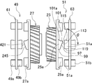
- Example 1 It is explanatory drawing which shows the 2nd and 3rd meshing clutch in relation to 4th gear and 5th gear.
- Example 1 Regarding the state of the 4th gear, (A) is a partially omitted development view showing meshing due to drive torque, and (B) is a partially omitted development view showing meshing due to coast torque.
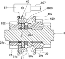
- Example 1 It is an enlarged sectional view of the urging mechanism in the third meshing clutch.
- Example 1 It is sectional drawing corresponding to the VV line arrow view of FIG. (Example 1) It is sectional drawing which shows the urging state of the clutch sleeve in the 4th gear direction by the urging mechanism.
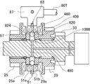
- Example 1 It is sectional drawing which shows the modification of the urging mechanism.
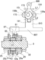
- Example 1 It is sectional drawing of the shift mechanism.
- Example 1 It is explanatory drawing which shows the relationship between the shift function and the 3rd meshing clutch.
- Example 1 It is a front view of the relationship between the shift cam and the rocker arm at the time of upshifting as seen from the 6th speed shift cam side.
- the relationship between the cam and the sub cam is shown, (A) is a front view showing the relationship between the shift cam and the sub cam at the time of upshifting, and (B) is a front view showing the relationship between the shift cam and the sub cam at the time of downshifting. is there.
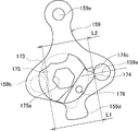
- Example 1 It is a front view of a rocker arm.
- Example 1 It is a front view which shows the relationship between the rocker arm at the time of upshifting, and the shift cam before operation of an auxiliary cam.
- Example 1 It is a front view which shows the relationship between the rocker arm at the time of downshifting, and the shift cam after operation of an auxiliary cam.
- Example 1 It is explanatory drawing which applied to the auxiliary cam to the shift drum in relation to the modification of the shift mechanism.
- Example 1 It is explanatory drawing which shows the example of the shift drum which replaced the rocker arm and the shift cam with respect to the modification of the shift mechanism.
- Example 1 It is explanatory drawing which shows the example of the shift actuator which replaced the rocker arm and the shift cam with respect to the modification of the shift mechanism.
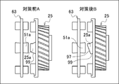
- Example 1 It is a graph which shows the comparison of the noise generation between the Example (after the measure B) and the comparative example (before the measure A).
- Example 1 It is explanatory drawing which shows the Example (B after the measure) and the comparative example (A before a measure).
- Example 1 It is a schematic block diagram of the system which cancels a shift.
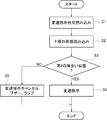
- Example 2 It is a flowchart which cancels a shift. (Example 2)
- the transmission is provided with a meshing clutch that engages one gear by meshing and disengages when the coupling is changed to another gear through simultaneous meshing, while the meshing clutch performs the meshing and
- the other meshing tooth is provided, the one meshing tooth is provided with one axially movable rotating member that transmits torque in the one shift stage, and the other meshing tooth is the one.
- One of the one or the other meshing tooth is provided with the other rotating member which engages with the one meshing tooth due to the axial movement of the rotating member and transmits the torque to and from the one rotating member.
- One of the tooth tips is provided with an inclined detachment guide portion that abuts the other tooth tip by relative rotation to guide the detachment, and when the meshing teeth are engaged to transmit drive torque, the relative rotation
- the one rotating member is provided with a moving mechanism that generates an axial force for moving the one rotating member to an axial position that enables contact and releases the axial force by generating a coast torque, and the one rotating member is a torque transmission member.
- the other rotating member is supported by the torque transmission member so as to be relatively rotatable and axially immovable, and is supported by the torque transmitting member so as to be movable in the axial direction.
- the moving mechanism moves the one rotating member so that the meshing teeth are engaged due to the movement of the one rotating member from the neutral position to the other rotating member, which is arranged between the torque transmitting member and the torque transmitting member.
- a urging mechanism that urges the torque with a force weaker than the generated axial force is provided, the urging mechanism includes a contact body and an urging function unit, and the contact body is formed on the torque transmission member in the radial direction. It is arranged in the support hole and is urged toward the inner circumference of the one rotating member by the urging function portion, and is urged radially to the inner circumference of the one rotating member by the urging function portion.
- the abutting body is received and the urging direction is changed to the axial direction to urge the axial movement of the one rotating member, and the one rotating member is attached to the torque transmission member via the abutting body. It is equipped with an urging conversion unit that couples in the direction of rotation.
- the meshing clutch that disengages after the simultaneous meshing can be provided in all shift stages.
- the meshing clutch that is disengaged through the simultaneous meshing may be provided for one shift stage, and the other shift stages may be shift stages of general meshing teeth.
- a meshing surface parallel to the rotation axis of the rotating member can be set, or a meshing surface inclined forward or backward in the torque transmission direction with respect to the rotation axis can be set.
- the detachment guide portion is set on an inclined surface so as to have a constant inclination over the entire tooth tip.
- the detachment guide portion may be formed of a curved surface.
- a surface parallel to the rotation direction may be formed between the inclined upper end portion of the detachment guide portion and the meshing direction.
- a chamfer or radius may be formed with the inclined upper end portion of the guide portion.
- the inclination of the detachment guide portion is set at an angle ⁇ exceeding 45 ° in the rotational direction with respect to the axial direction of the rotating member, and cot ⁇ is the coefficient of friction at the detachment guide portion where the one and the other meshing teeth abut. It is set to exceed.
- the inclination angle of the tangent line at the detachment guide portion with which one and the other meshing teeth abut is set at an angle ⁇ exceeding 45 ° in the rotational direction with respect to the axial direction of the rotating member. Will be done.
- the disengagement guide portion When the disengagement guide portion is formed on both of the rotating members, the disengagement guide portion can be intermittently arranged on the meshing teeth and set so that the tips of the mating teeth of the other party can come into contact with each other. ..
- the one rotating member is a clutch sleeve that engages with the torque transmitting member in the rotational direction and is supported so as to be movable in the axial direction, and the other rotating member is rotatably supported by the torque transmitting member. It is a transmission gear that is supported so that it cannot move in the axial direction.
- the relative rotation for guiding the disengagement includes the coasting torque generated in the lower clutch sleeve when the clutch sleeves of the lower gear and the upper gear are simultaneously meshed with the respective gears due to the shift-up operation. This is due to the drive torque generated in the upper clutch sleeve.
- one of the rotating members is made to stand by at the axial position where the tooth tip of the other party can come into contact with the release guide portion by the shift down operation so that the release guide portion works. May be good.
- the detachment guide portion has a spiral shape.
- the spiral shape is composed of a spiral surface, a spiral strip, or the like.
- a moving mechanism that generates an axial force that moves one of the rotating members to an axial position that enables the contact when the meshing teeth mesh with each other to transmit torque, and releases the axial force by generating a coast torque. Equipped with.
- the moving mechanism is formed so as to be inclined at the root of the meshing tooth, and when the meshing teeth mesh with each other to transmit drive torque, the other rotating member is guided to a first meshing position of the one rotating member. It is a movement guide portion which is moved from the to the second meshing position to the axial position which enables the contact by the relative rotation.
- the movement guide portion is a movement guide surface formed at the root of the meshing tooth.
- the moving mechanism may be configured by an actuator such as a clutch driver instead of the moving guide surface.
- the clutch driver can be configured by, for example, a shift drive unit, and can be set in relation to the shift groove setting of the shift drum and the shift arm.
- a mechanical torque adjusting mechanism is used in the clutch driver to move the clutch sleeve and prevent the clutch from being disengaged when a force is received from the clutch sleeve to give a position holding force to the clutch sleeve.
- the one rotating member engages with the torque transmitting member in the rotational direction and is supported so as to be movable in the axial direction, and the other rotating member is supported by the torque transmitting member so as to be relatively rotatable and cannot be moved in the axial direction.
- the meshing teeth are engaged with each other due to the movement of the one rotating member from the neutral position to the other rotating member, which is arranged between the one rotating member and the torque transmitting member.
- An urging mechanism for urging one of the rotating members with a force weaker than the axial force generated by the moving mechanism is provided.
- the urging mechanism includes an abutting body and an urging function portion, and the abutting body is arranged in a support hole formed in the torque transmission member in the radial direction, and the one rotating member is arranged by the urging function portion.
- the abutting body is urged toward the inner circumference of the above and urged in the radial direction by the urging function portion on the inner circumference of the one rotating member, and the urging direction is changed to the axial direction. It is provided with an urging conversion unit that urges the axial movement of the one rotating member and connects the one rotating member to the torque transmission member in the rotational direction via an abutting body.
- the abutting body is a ball
- the urging function portion is a coil spring
- the ball is supported so as to project and urge the support hole in the radial direction by the coil spring.
- the support hole is formed in the clutch hub that forms a part of the torque transmission member. The ball can be brought into contact with the urging conversion unit whose inclination is set on the inner circumference of the clutch sleeve.
- the contact body may be a pin, a burette-shaped body, or the like.
- the urging function unit is replaced with a configuration that uses the centrifugal force of the ball itself in addition to the coil spring, or a configuration that uses the fluid pressure by guiding the oil pressure from the oil hole on the torque transmission member side to the support hole. Furthermore, these combinations can be used.
- the urging mechanism functions if it is provided at one location in the axial direction, but it can also be arranged at a plurality of locations.
- the urging conversion unit is an inclined groove portion that connects the one rotating member to the torque transmitting member via the abutting body in the rotational direction, and the inclined groove portion is involved in torque transmission. However, the inclined groove portion can also be configured as an inclined portion that is not involved in torque transmission.
- the one shift stage is the upper stage and the other shift stage is the lower stage, and the shift drive unit for changing the coupling from the one shift stage to the other shift stage is provided, and the shift drive unit is the other.
- a shift stroke for axial movement between one rotating member of the upper gear and one rotating member of the lower gear is set in order to change the coupling to the gear of the gear. The shift stroke was set by the above when the shift down to the lower stage was made larger than when the shift up to the upper stage was performed.
- the shift stroke is set, for example, by connecting a small sub cam to the main body of the shift cam so that it can rotate relative to each other.
- the rotation of the shift cam to one side causes the secondary cam to protrude to increase the contour of the shift cam, and the swing range to one side of the rocker arm that interlocks with the shift arm is made larger than that of the other side to change the shift stroke setting. ..
- a shift drive unit that changes the coupling from one shift stage to the other shift stage, a detector that detects the axial position of one rotating member of the one shift stage, and the other through simultaneous meshing.
- the control unit cancels the change of the coupling to the other shift stage by the shift drive unit. And equipped.
- the shift drive unit may be either a shift cam, a shift drum, or the like driven by an electric motor or the like to change the coupling of the shift stages, or a manual shift operation.
- a proximity sensor, a laser sensor, a 360 ° angle sensor, or the like is used as the detector, and the detector detects the positions of the shift fork, shift rod, clutch sleeve, and the like. It is also possible to use the shift sensor that the transmission originally has. If the clutch sleeve does not indicate the position where it should be, the control unit may determine that the clutch sleeve of one shift stage is not in the original axial position and cancel the coupling of the shift stages.
- An alarm may be generated in a state where the change of coupling to another shift stage by the shift drive unit is canceled.
- the meshing clutch includes one and the other meshing teeth that engage with each other, and the one meshing tooth is provided with one axially movable rotating member that transmits torque and the other meshing tooth. Is provided for the other rotating member in which the one meshing tooth engages and transmits the torque to and from the one rotating member due to the axial movement of the one rotating member, and the one or the other When one of the meshing teeth is provided with an inclined guide portion that abuts the other tooth tip by relative rotation to guide the detachment, and the meshing teeth mesh with each other to transmit drive torque.
- the one rotating member is provided with a moving mechanism that generates an axial force for moving the one rotating member to an axial position that enables contact and releases the axial force by generating a coast torque, and the one rotating member is a torque transmitting member.
- the other rotating member is supported by the torque transmitting member so as to be relatively rotatable and axially immovable, and is supported with the one rotating member.
- the moving mechanism moves the one rotating member so that the meshing teeth mesh with each other due to the movement of the one rotating member from the neutral position to the other rotating member, which is arranged between the torque transmitting member and the torque transmitting member.
- the urging mechanism that urges with a force weaker than the generated axial force
- the urging mechanism includes a contact body and an urging function unit, and the contact body is formed on the torque transmission member in the radial direction. It is arranged in the supporting hole and is urged toward the inner circumference of the one rotating member by the urging function portion, and is urged radially to the inner circumference of the one rotating member by the urging function portion.
- the abutting body is received and the urging direction is changed to the axial direction to urge the axial movement of the one rotating member, and the one rotating member is attached to the torque transmission member via the abutting body.
- It is equipped with an urging conversion unit that couples in the direction of rotation.
- FIG. 1 is a schematic cross-sectional view showing a seamless shift transmission according to a first embodiment of the present invention.
- the transmission 1 includes a solid main shaft 3, a counter shaft 5, and an idler shaft 40 as torque transmission members.
- the main shaft 3 and the counter shaft 5 are rotatably supported by a transmission case (not shown) by bearings 9, 11, 13, 15, and the like.
- the idler shaft 40 is fixed to the transmission case side.
- 1st gear 19, 2nd gear 21, 3rd gear 23, 4th gear 25, 5th gear 27, and 6th gear 29 are in place on the main shaft 3 and the counter shaft 5 as a plurality of gears. It is supported so that it can rotate relative to each other.
- the 1st gear 19 and the 3rd gear 23 on the counter shaft 5 mesh with the output gears 31 and 33 of the main shaft 3, and the 2nd gear 21, the 4th gear 25, and the 5th gear 27 on the main shaft 3
- the 6-speed gear 29 meshes with the gears 35, 37, 39, and 41 of the counter shaft 5, respectively.
- the reverse idler 42 on the idler shaft 40 is arranged so as to be meshable with the output gear 44 on the main shaft 3 and the input gear 45 on the counter shaft 5 by moving in the axial direction.
- the 1st gear 19 and the 3rd gear 23 are selectively coupled to the counter shaft 5 by the first meshing clutch 47.
- the 2nd and 5th gears 27 and the 4th and 6th gears 29 are selectively coupled to the main shaft 3 by the second and third meshing clutches 49 and 51, respectively.
- the first to third meshing clutches 47, 49, 51 are configured to selectively engage one shift stage by meshing and disengage when the coupling is changed to another shift stage through simultaneous meshing. ing.
- the upper gears are combined and the lower gears are simultaneously meshed with each other to disengage the lower gears.
- the coupling from the 1st gear 19 to the 2nd gear 21 is changed by the first and second meshing clutches 47 and 49.
- the first to third meshing clutches 47, 49, 51 basically have the same structure, and the clutch hubs 53, 55, 57, the clutch sleeves 59, 61, 63, and the meshing teeth 47a, 47b, 49a. , 49b, 51a, 51b, 19a, 21a, 23a, 25a, 27a, 29a.
- the one meshing tooth 47a, 47b, 49a, 49b, 51a, 51b is provided in the clutch sleeves 59, 61, 63.
- These meshing teeth 47a, 47b, 49a, 49b, 51a, 51b are provided on the facing surfaces of the clutch sleeves 59, 61, 63 with respect to the first gear 19 to the sixth gear 29.
- These clutch sleeves 59, 61, 63 constitute one of the rotating members. That is, the clutch sleeves 59, 61, and 63 are engaged with the main shaft 3 and the counter shaft 5 as torque transmission members in the rotational direction and are supported so as to be movable in the axial direction.
- the other meshing teeth 19a, 21a, 23a, 25a, 27a, 29a are provided in the clutch sleeves 59, 61, 63. These meshing teeth 19a, 21a, 23a, 25a, 27a, 29a are provided on the opposite surfaces of the first-speed gears 19 to 6-speed gears 29 with respect to the clutch sleeves 59, 61, 63.
- These 1st gears 19 to 6th gears 29 constitute the other rotating member. That is, the 1st gears 19 to 6th gears 29 are supported by the counter shaft 5 via needle bearings or the like so as to be relatively rotatable and immovable in the axial direction.
- the one meshing tooth 47a, 47b, 49a, 49b, 51a, 51b has the other meshing tooth 19a, 21a, 23a, 25a, 27a. , 29a selectively meshes.
- the clutch hub 53 of the first meshing clutch 47 is coupled to the counter shaft 5 by spline fitting or the like so that it can rotate integrally.
- the clutch hubs 55 and 57 of the second and third meshing clutches 49 and 51 are coupled to the main shaft 3 by spline fitting or the like so that they can rotate integrally. Positioning of these clutch hubs 53, 55, 57 is performed by a stepped portion and a snap ring formed on the counter shaft 5 and the main shaft 3.
- the clutch hub 53 is spline-fitted to the counter shaft 5, one side is abutted against the stepped portion of the counter shaft 5, and a snap ring engaged with the counter shaft 5 is positioned and arranged on the other side of the clutch hub 53.
- the clutch hubs 55 and 57 are also positioned with respect to the main shaft 3 in the same structure.
- the clutch sleeves 59, 61, 63 of the first to third meshing clutches 47, 49, 51 are fitted and arranged on the outer periphery of the clutch hubs 53, 55, 57, and are spline-coupled so as to be movable in the axial direction.
- the clutch sleeve 61 is provided for shifting output by selectively coupling the 4th gear 25 and the 6th gear 29 to the main shaft 3 of the 2nd gear 21, the 5th gear 27, and the clutch sleeve 63, which are transmission gears.
- the clutch sleeve 59 is provided for selectively coupling the 1st gear 19 and the 3rd gear 23, which are transmission gears, to the counter shaft 5 to output a speed change.
- the clutch sleeve 59 is formed with a peripheral recess 81 into which the shift fork 80 is fitted.
- the reverse idler 42 on the idler shaft 40 is also formed with a peripheral recess 86 into which the shift fork 84 is fitted.
- the idler shaft 40 is fixedly supported on the mission case side.
- the input gear 45 is further formed on the clutch sleeve 59.
- the clutch sleeves 61 and 63 are formed with peripheral protrusions 89 and 91 to which the shift forks 85 and 87 are fitted. 1st gear 19, 2nd gear 21, 3rd gear 23, 4th gear 25, 5th gear 27, 6th gear 29 are selected on both sides of the clutch sleeves 59, 61 and 63. They are placed two or more gears apart, allowing selective engagement with the transmission gears on both sides.
- 1st gear 19 and 3rd gear 23 are arranged on both sides of the clutch sleeve 59, 2nd gear 21 and 5th gear 27 are arranged on both sides of the clutch sleeve 61, and both sides of the clutch sleeve 63.
- 4th gear 25 and 6th gear 29 are arranged in the vehicle.
- the first to third meshing clutches 47, 49, 51 are selectively operated by the shift mechanism 800, which is a shift drive unit.
- the reverse idler 42 is also operated by the shift mechanism 800.
- the shift mechanism 800 is provided in the transmission case, and the shift forks 80, 85, 87, shift rods 803, 805, 807, and shift arms 811, 813, 815 are used to provide the first to third meshing clutches 47. It is interlocked with 49 and 51.
- the shift mechanism 800 is interlocked with the reverse idler 42 by the shift fork 80, the shift rod 801 and the shift arm 809.
- the first to third urging mechanisms 1000 are arranged between the clutch sleeves 59, 61, 63 of the first to third meshing clutches 47, 49, 51 and the clutch hubs 53, 55, 57. There is.
- the first urging mechanism 1000 urges the clutch sleeve 59. That is, the clutch sleeve 59 is urged so that the meshing teeth 47a, 19a or the meshing teeth 47b, 23a mesh with each other due to the movement from the neutral position toward the first gear 19 or the third gear 23.
- the second urging mechanism 1000 urges the clutch sleeve 61.
- the third urging mechanism 1000 urges the clutch sleeve 63. That is, the clutch sleeve 63 is urged so that the meshing teeth 51a, 25a or the meshing teeth 51b, 29a mesh with each other due to the movement from the neutral position to the 4th gear 25 or the 6th gear 29.
- the first to third urging mechanisms 1000 have substantially the same configuration, and will be described later on behalf of the third urging mechanism 1000 in the third meshing clutch 51.
- the output of the transmission 1 is performed from the front differential device that meshes with the output gear 93 of the counter shaft 5 by the reduction gear 212R.
- the shift mechanism 800 when the shift mechanism 800 is driven based on the manual operation signal of the shift lever or the accelerator opening and vehicle speed signal by operating the accelerator pedal, the shift mechanism 800 is driven via any of the shift arms 809, 811, 813, 815.
- the shift rods 801 and 803, 805 and 807 are selectively driven in the axial direction.
- the corresponding first to third meshing clutches 47, 49, 51 are driven and operated via the shift forks 811, 813, 815, and the reverse idler 42 is driven and operated via the shift fork 809.
- the clutch By this operation, the 1st gears 19 to 6th gears 29 and the reverse idler 42 are selectively combined, and upshifting, downshifting, and reverse shifting can be performed.
- FIG. 2 is an explanatory view showing the relationship between the second and third meshing clutches and the fourth and fifth gears.
- 3A and 3B are related to the state of the 4th gear
- FIG. 3A is a partially omitted development view showing meshing due to drive torque
- FIG. 3B is a partially omitted development view showing meshing due to coast torque. is there.
- the meshing teeth of the first to third meshing clutches 47, 49, 51 of this embodiment are formed to have the same structure. Therefore, the specific shape of the meshing tooth of the third meshing clutch 51 will be described with reference to FIGS. 2 and 3, and the shape of the meshing tooth of the first and second meshing clutches 47 and 49 is the third.
- the shape of the meshing teeth of the meshing clutch 51 will be referred to as appropriate, and duplicated description will be omitted.
- the third meshing clutch 51 includes a plurality of meshing teeth 51a and 51b of the clutch sleeve 63, and a plurality of meshing of the fourth gear 25 that meshes with the meshing teeth 51a. It has a plurality of meshing teeth 29a (FIG. 1) having teeth 25a and a 6-speed gear 29 (FIG. 1).
- the third meshing clutch 51 of this embodiment will be further described in relation to the clutch sleeve 63 and the 4-speed gear 25.
- the meshing teeth 51a of the clutch sleeve 63 and the meshing teeth 25a of the 4th gear 25 are set to uniform heights in the circumferential direction.
- the meshing teeth 51a and 25a can be set to have heights at predetermined intervals in the circumferential direction, for example, for each tooth.
- the meshing teeth 51a and 25a are formed spirally with respect to the axial center of the main shaft 3. Therefore, when the meshing teeth 51a engage with or disengage from the meshing teeth 25a, the meshing of the two is spirally guided with a screw-like operation.
- the spiral shape with respect to the axis means both a spiral shape centered on the axis center and a spiral shape in which the center of the spiral is offset from the axis center.
- the tip of the meshing tooth 25a is provided with a disengagement guide surface 97 as a disengagement guide portion.
- the meshing tooth 25a is provided with a drive meshing surface 101 at the rear portion in the drive torque transmission direction and a coast meshing surface 99 at the front portion thereof.
- the drive meshing surface 101, the detachment guide surface 97, and the coast meshing surface 99 are both formed in a spiral shape in order to make the meshing teeth 25a spiral.
- the detachment guide surface 97 is formed so as to be gradually inclined in the rotation direction with respect to the rotation axis of the main shaft 3. Due to this inclination, the disengagement guide surface 97 has a function of relatively guiding the other meshing tooth 51a by the coasting torque to generate an axial force in the disengaging direction in the clutch sleeve 63.
- the clutch sleeves 63 and 61 go through simultaneous meshing.
- the 5th gear 27 is engaged with the clutch sleeve 61 of the second engagement clutch 49 in a state where the 4th gear 25 is coupled to the main shaft 3 by the engagement of the clutch sleeve 63. It will be in a state of being combined with 3.
- the relative rotation is caused by the coasting torque generated in the lower gear and the drive torque generated in the upper gear due to the simultaneous engagement of the clutch sleeves 61 and 63 in the upshift operation.
- the inclination of the detachment guide surface 97 is set so that cot ⁇ exceeds the friction coefficient of the detachment guide surface 97 between the meshing teeth 25a and 51a.
- the inclination angle of the disengagement guide surface 97 is set in the disengagement direction with the clutch sleeve 63 of the lower gear due to the coasting torque when the clutch sleeves 61 and 63 of the lower gear and the clutch sleeves 61 and 63 of the upper gear are simultaneously meshed. Anything that generates an axial force may be used, and in some cases, the upper limit may be set to exceed 80 °.
- the inclination angle 45 ° of the detachment guide surface 97 with respect to the rotation axis is such that the component force in the circumferential direction and the component force in the rotation axis direction antagonize each other, but the inclination angle is less than 45 ° in which the component force in the rotation axis direction exceeds. It can be defined as a limit that can suppress an increase in internal circulation torque, which will be described later.
- the angle of inclination of the detachment guide surface 97 can be increased from the middle to the tooth tip 113.
- the inclined upper end side of the detachment guide surface 97 may be formed by a surface along the rotation direction. It is also possible to make the detachment guide surface 97 and the drive meshing surface 101 continuous with a radius.
- the disengagement guide surface 97 is formed in substantially the entire tooth thickness in the circumferential direction of the clutch sleeve 61, and spirals from the inner diameter side to the outer diameter side.
- the detachment guide surface 97 may be formed as a slope along the radial direction without being spiral.
- the drive meshing surface 101 is set to face backward with respect to the drive torque transmission direction.
- the drive meshing surface 101 is set so as to be inclined rearward toward the tooth tip with respect to the transmission direction of the drive torque with respect to the rotation axis. Due to the inclination of this setting, when the meshing teeth 51a are engaged, the meshing teeth 51a are pulled in the meshing direction.
- the drive meshing surface 101 can be set to incline forward toward the tooth tip with respect to the drive torque transmission direction. In this case, when the meshing teeth 51a are engaged, the meshing teeth 51a are pushed out in the meshing direction. However, this pushing action is such that it does not come off when the drive torque is transmitted.
- the moving mechanism is a clutch at a second meshing position in an axial position that enables the meshing teeth 51a to come into contact with the disengagement guide surface 97 when the meshing teeth 25a and 51a mesh with each other to transmit torque.
- the axial force for moving the sleeve 63 is generated and the axial force is released by the generation of the coast torque.
- the tooth root of the meshing tooth 25a is provided with a movement guide surface 101a adjacent to the drive meshing surface 101.
- the movement guide surface 101a constitutes a movement guide portion as a movement mechanism.
- the movement guide surface 101a is a surface formed at an angle at the tooth root of the meshing tooth 25a.
- the first meshing position is a deep meshing position where the coast meshing surfaces 99 and 115 can be meshed by the relative rotation of the clutch sleeve 63 and the 4th gear 25 at the coast torque.
- the second meshing position is a shallow meshing position where the tip of the meshing tooth 51a faces the detachment guide surface 97 in the rotational direction.
- the movement guide surface 101a is inclined with respect to the rotation axis. Due to this inclination, the movement guide surface 101a generates an axial force on the meshing teeth 51a when the tooth tips of the meshing teeth 51a come into contact with each other due to the drive torque. Due to this axial force, the meshing tooth 51a moves from the first meshing position to the second meshing position. This second meshing position is a distance of ⁇ X from the surface of the tooth bottom of the meshing tooth 25a.
- the coastal meshing surface 99 of the meshing teeth 25a meshes with the meshing teeth 51a during gear shifting and engine braking.
- the coast meshing surface 99 rises along the axial direction of the main shaft 3 at the lower end of the inclination of the detachment guide surface 97.
- the coast meshing surface 99 is set so as to be inclined rearward from the surface of the tooth bottom toward the detachment guide surface 97 with respect to the transmission direction of the coasting torque with respect to the rotation axis of the main shaft 3.
- the coast meshing surface 99 can be set to incline forward toward the detachment guide surface 97 with respect to the transmission direction of the coasting torque.
- the meshing teeth 51a mesh with each other, the meshing teeth 51a are pushed out in the meshing direction.
- this pushing action is such that it does not come off when the engine brake is transmitted.
- the axial force acting on the clutch sleeve 63 during engine braking is very small, and the meshing teeth 25a and 51a can be reasonably maintained by a guide or the like on the shift mechanism 800 side.
- the height of the coast meshing surface 99 in the direction of the rotation axis should be as low as possible within a range in which the clutch sleeve 63 does not come off from the meshing teeth 25a of the other 4th gear 25 during engine braking.
- the inclination of the coast meshing surface 99 with respect to the rotation axis of the main shaft 3 can also be set to zero.
- the inclination angle of the coast meshing surface 99 is such that the meshing teeth 25a of the 4th gear 25 mesh with the clutch sleeve 63 during engine braking.
- the range is such that the tooth 51a cannot be removed autonomously.
- the axial force generated by the inclination angle of the coast meshing surface 99 is small, it is possible to restrict the pull-out by setting the shift mechanism 800 or the like. Even when the coast meshing surface 99 is eliminated, the meshing teeth 51a of the clutch sleeve 63 engage with the inclined lower end of the disengagement guide surface 97, and this engaged state can be maintained by setting the shift mechanism 800 or the like.
- the tooth tip 113 of the meshing tooth 51a of the clutch sleeve 63 is formed of a flat surface or a rounded surface (curved surface).
- a drive meshing surface 119 and a coast meshing surface 115 are formed on the meshing teeth 51a.
- the drive meshing surface 119 and the coast meshing surface 115 of the meshing tooth 51a are set to be inclined in accordance with the drive meshing surface 101 and the coast meshing surface 99 of the meshing tooth 25a.
- the tooth tip 113, the drive meshing surface 119, and the coast meshing surface 115 of the meshing tooth 51a are formed in a spiral shape with respect to the rotation axis of the main shaft 3.
- This spiral shape is for making the meshing tooth 51a spiral like the meshing tooth 25a. Therefore, when the meshing teeth 25a are not spiral and have a shape along the radial direction, the meshing teeth 51a also have a shape along the radial direction.
- the heights of the meshing teeth 25a and 51a and the tooth widths in the rotation direction are set to be substantially the same.
- the tooth spacing of the meshing teeth 25a and 51a is set to be larger than the tooth width. In this embodiment, the tooth spacing is set to be approximately 1.5 times the width of the tooth tip.
- the setting of the tooth spacing is for smoothly engaging and disengaging the meshing teeth 25a and 51a, and the setting is free.
- the meshing teeth 25a are formed on the 4th gear 25 and the meshing teeth 51a are formed on the clutch sleeve 63, but the meshing teeth 25a are formed on the clutch sleeve 63 and the meshing teeth 51a are formed on the 4th gear.
- the relationship may be formed on the gear 25.
- FIG. 4 is an enlarged cross-sectional view of the urging mechanism in the third meshing clutch.
- FIG. 5 is a cross-sectional view corresponding to the arrow line VV of FIG.
- FIG. 6 is a cross-sectional view showing a state in which the clutch sleeve is urged by the urging mechanism in the 4th gear direction.
- FIG. 7 is a cross-sectional view showing a modified example of the urging mechanism.
- the third urging mechanism 1000 in the third meshing clutch 51 includes a ball 824 as an abutting body and a coil spring 822 as an urging function unit.
- the clutch hub 57 is formed with a support hole 620 penetrating in the radial direction.
- a recess 823 such as a spring seat is formed in the main shaft 3 facing the support hole 620.
- a plurality of support holes 620 are formed at predetermined intervals in the circumferential direction. In the embodiment, six locations are evenly provided.
- a ball 824 is housed in each support hole 620 together with a coil spring 822. The radial inner end of each coil spring 822 is seated in each recess 823. Each ball 824 is urged toward the inner circumference of the clutch sleeve 63 by each coil spring 822.
- An inclined groove portion 460 which is an urging conversion portion, is provided on the inner circumference of the clutch sleeve 63. The inclined groove portion 460 receives the ball 824 urged in the radial direction by the coil spring 822, converts the urging in the radial direction into the axial direction, and urges the axial movement of the clutch sle
- the inclined groove portions 460 are evenly provided at six locations in the circumferential direction in the embodiment according to each ball 824. Therefore, the elastic force of the coil spring 822 acting between the clutch hub 57 and the clutch sleeve 63 in the radial direction is offset.
- the cross-sectional shape of the inclined groove portion 460 is formed so as to have a radius slightly larger than the radius of the ball 824 so that the ball 824 fits without rattling.
- the inclined groove portion 460 may be provided only on one side of the clutch sleeve 63 according to the specifications of the transmission 1.
- the inclined groove portion 460 is formed so as to be inclined from the inner circumference of the clutch sleeve 63 to the side surface.
- a valley portion 409 is formed between the inclined groove portions 460 on both sides in the axial direction on the inner circumference of the clutch sleeve 63.
- the clutch sleeve 63 is positioned with the ball 824 in contact with the valley portion 409 at the neutral position as shown in FIG.
- the valley portion 409 may be omitted.
- the clutch sleeve 63 is pressed in the shift direction, and the meshing teeth 51a are urged to mesh with the meshing teeth 25a of the 4th gear 25.
- the inclined groove portion 460 on the opposite side functions, and similarly, the meshing teeth 51b are meshed with the meshing teeth 29a of the 6th gear 29.
- the coil spring 822 that gives an urging force to the ball 824 can be replaced with the fluid pressure shown in FIG.
- the flood control is guided to the support hole 620 from the oil hole 490 on the main shaft 3 side, which is a torque transmission member.
- the axial force generated by the urging mechanism 1000 is set to be smaller than the axial force given to the meshing teeth 51a by the movement guide surface 101a of the meshing teeth 25a when the engine is in the driving state. Therefore, even if there is an urging force of the urging mechanism 1000, in the third meshing clutch 51, the clutch sleeve 63 at the second meshing position maintains the position, and the meshing teeth 51a are the meshing teeth 25a. Maintain a distance of ⁇ X from the surface of the tooth bottom.
- FIG. 8 is a cross-sectional view of the speed change drive unit.
- FIG. 9 is an explanatory diagram showing the relationship between the shift drive unit and the third meshing clutch.
- FIG. 10 is a front view of the relationship between the shift cam and the rocker arm at the time of upshifting as viewed from the 6th speed shift cam side.
- 11A and 11B show the relationship between the shift cam and the secondary cam,
- FIG. 11A is a front view showing the relationship between the shift cam and the secondary cam during shift-up
- FIG. 11B shows the relationship between the shift cam and the secondary cam during shift-down. It is a front view which shows.
- FIG. 12 is a front view of the rocker arm.
- the third meshing clutch 51 is engaged with the rocker arm 159 of the shift mechanism 800 as the shift drive unit with the engaging portion 141 of the shift arm 815.
- the shift mechanism 800 of FIG. 8 of this embodiment is configured to share a rocker arm with a pair of shift cams and the pair of shift cams as a set.
- the shift mechanism 800 includes cam mechanisms CA1 to CA4 in the housing 143.
- the cam mechanism CA1 is for the back gear and drives the shift arm 809.
- the cam mechanism CA2 is for 1st speed and 3rd speed, and drives the shift arm 811.
- the cam mechanism CA3 is for 2nd speed and 5th speed, and drives the shift arm 813.
- the cam mechanism CA4 is for 4th and 6th speeds and drives the shift arm 815.
- the cam mechanisms CA1 to CA4 include cam sets 145, 147, 149, 151, and rocker arms 153, 155, 157, 159 as shift operation units for each of the cam mechanisms CA1 to CA4.
- the shift guide of the rocker arm 153, 155, 157, 159 is performed by each engagement guide by each cam surface of the cam set 145, 147, 149, 151.
- each rocker arm 153, 155, 157, 159 moves the shift arms 809, 811, 813, 815 in the shift direction axially via the respective engaging portions 141.
- the cam sets 145, 147, 149, and 151 are attached to the cam shaft 161.
- the cam set 145 is a shift cam 163 for reverse
- the cam set 147 is a shift cam 165 for 1st speed
- a cam set 149 is for 2nd speed as an operation output rotating part corresponding to a plurality of gears.
- the shift cam 169, the shift cam 171 for the fifth speed, and the cam set 151 include a shift cam 173 for the fourth speed and a shift cam 175 for the sixth speed, respectively.
- Each shift cam 163, 165, 167, 169, 171, 173, 175 is formed of a plate cam, has a cam surface described later on the outer periphery thereof, and is rotationally driven together with the cam shaft 161 according to a shift instruction.
- An electric shift motor 890 is coupled to the camshaft 161. Instead of the shift motor 890, actuators such as hydraulic, pneumatic, and electromagnetic solenoids can be used. An operation lever for manual operation can be used instead of the shift motor 890.
- FIG. 9 represents the rocker arm 159 and the cam set 151 that operate the third meshing clutch 51.
- a pair of shift cams 173 and 175 are arranged on both sides of the rocker arm 159 in the axial direction.
- the shift cams 173 and 175 are separated by two or more gears.
- the shift cams 173 and 175 share the corresponding rocker arm 159, and each shift cam 173 and 175 is involved in the swinging motion of one rocker arm 159.
- Each of the shift cams 173 and 175 is integrally rotated by the rotation of the cam shaft 161 and relates to the shift guides of the 4th and 6th speeds, respectively, in this embodiment.
- the play (L1> L2) shown in FIGS. 9 and 10 is defined as the distance between pins 159a and 159b for L1 and the outer edge dimension between the shift cams 173 and 175 of the cam set 151 between pins 159a and 159b for L2. That is, play (L1> L2) is formed between the cam surface of the shift cams 173 and 175 of the cam set 151 and the pins 159a and 159b of the rocker arm 159 in the swing direction.
- the shift cam 173 is involved in a shift guide of the rocker arm 159 to the fourth speed.
- the shift cam 175 relates to a shift guide of the rocker arm 159 to the sixth speed. The same applies to other gears.
- the play (L1> L2) frees the shift fork 87 within the range of play and does not hinder the axial movement of the clutch sleeve 63 between the first and second meshing positions. This ensures torque transmission in both the drive and coast directions.
- the rocker arm 153, 155, 159, 159 and the cam set 145, 147, 149, 151 perform a shift operation of the reverse idler 42 and a shift operation of the first to third meshing clutches 47, 49, 51.
- the shift mechanism 800 shifts for axial movement between the clutch sleeve of the upper gear and the clutch sleeve of the lower gear in order to change the coupling from the lower gear to the upper gear.
- the stroke is set. Due to the structure of the shift cam, the shift stroke setting by the shift mechanism 800 makes the shift down to the lower stage larger than the shift up to the upper stage. However, the shift strokes at the time of upshifting and downshifting may be the same. The shift stroke setting will be described later.
- the shift cam 175 has a hexagonal hole 175a formed in the axial center portion, and the hexagonal hole 175a is fitted to the peripheral surface of the hexagonal cross section of the camshaft 161 of FIG. 8 so that the shift cam 175 can rotate integrally.
- a well-known structure such as a spline or a key can be applied.
- the 1st, 3rd, 6th, 4th, 5th, and 2nd speed shift cams 165, 167, 175, 173, 171 and 169 from the right in FIG. 8 and the reverse shift cam 163 at the right end in FIG. 8 are shown. It is attached to the camshaft 161 with a phase shift.
- the peripheral surface of the shift cam 175 is a cam surface 175b.
- Pins 159a and 159b of the rocker arm 159 act on the cam surface 175b, and the rocker arm 159 swings to perform a shift operation.
- a pair of stopper surfaces 175c and 175d are formed in a stepped shape on the surface of the shift cam 175.
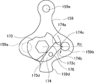
- a sub cam 174 is rotatably supported by a shaft 176 on a stepped portion on the surface of the shift cam 175.
- the auxiliary cam 174 is formed with a contact edge portion 174a facing the stopper surfaces 175c and 175d on one side, and an outer edge portion 174b is formed following a part of the cam surface 175b.
- the auxiliary cam 174 can be brought into contact with the auxiliary cam 174 by rotating the shaft 176 around the shaft 176 so that the contact edge portion 174a switches to any of the stopper surfaces 175c and 175d.
- the outer edge portion 174b of the sub cam 174 includes a convex portion 174c.
- the outer edge portion 174b of the secondary cam 174 follows the cam surface 175b so that the convex portion 174c includes the convex portion 175e of the shift cam 175.
- the shift stroke of the convex portions 175e and 174c is set by setting the height thereof.
- the convex portion 174c of the sub cam 174 overlaps the convex portion 175e of the shift cam 175.
- the common turning radius of the tips of the convex portions 175e and 174c is R1.
- the convex portion 174c of the sub cam 174 is radially larger than the convex portion 175e of the shift cam 175. Protrude.
- the turning radius of the tip of the convex portion 174c is R2.
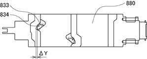
- the relationship between the turning radii R1 and R2 is R1 ⁇ R2. Due to the relationship of the turning radius R1 ⁇ R2 on the shift cam 175 side, the shift stroke on the lower shift down side can be made larger by ⁇ Y than on the upper shift up side. This ⁇ Y corresponds to the distance ⁇ X between the first meshing position and the second meshing position.
- the shift cam 175 does not form a special protrusion, and the relationship between the turning radii R1 and R2 can be formed only by the convex portion 174c of the sub cam 174.
- the rocker arm 159 is provided with pins 159a and 159b on both sides.
- the pin 159a is guided by the cam surface of the shift cam 175 on the 6th speed side.
- the pin 159b is guided by the cam surface of the shift cam 173 on the 4th speed side. That is, the pins 159a and 159b are arranged on the left and right sides of the rocker arm 159 separately on the front and back when viewed from the front.
- a hole 159c is formed in an arc shape in the central portion of the rocker arm 159 and is loosely fitted to the cam shaft 161.
- An acting portion 159d is provided at the tip of the rocker arm 159 and is engaged with the engaging portion 141 of the shift arm 815.
- the rocker arm 159 is swingably and rotatably supported by a housing 143 by a pivot 159e.
- the drive meshing surface 119 of the clutch sleeve 63 becomes the 4th gear 25 as shown in FIG. 3A.
- the meshing drive torque is transmitted to the drive meshing surface 101 of the above.
- the meshing at this time is performed at the second meshing position separated by ⁇ X from the meshing teeth 51a and 25a by the action of the axial force guide surface 101a.
- the clutch sleeve 63 rotates relative to the coast meshing surface 99 direction from the position of FIG. 3 (A) as shown in FIG. 3 (B).
- the drive meshing surface 119 of the meshing tooth 51a is released from the meshing of the meshing tooth 25a with respect to the drive meshing surface 101.
- the clutch sleeve 63 moves to the left in the drawing due to the urging force of the urging mechanism 1000.
- the meshing tooth 51a moves to the tooth bottom of the meshing tooth 25a.
- the coast meshing surface 113 of the meshing tooth 51a meshes with the coast meshing surface 99 at the first meshing position.
- the axial movement of the clutch sleeve 63 due to this change in the torque direction is autonomously performed by the action of the urging mechanism 1000 and the movement guide surface 101a, not by the shift mechanism 800.
- the clutch sleeve 63 can be smoothly operated.
- the autonomous operation of the clutch sleeve 63 by the action of the urging mechanism 1000 and the movement guide surface 101a eliminates the need for forcing the clutch sleeve 63 by the shift fork 87, and suppresses wear of the clutch sleeve 63 and the shift fork 87. Can be done.
- the inclined groove portion 460 of the clutch sleeve 63 receives the axial force directly from the ball 824 in the same axial direction, it is possible to set a large axial force.
- the urging force of each coil spring 822 arranged in the radial direction and the radial force due to the centrifugal force of the ball 824 are received by the inclined groove portion 460 and cancel each other out. Therefore, harmful friction is not generated or suppressed in the sliding portion between the clutch hub 57 and the clutch sleeve 63.
- the ball 824 and the coil spring 822 (the centrifugal force of the fluid or the like in the support hole 620 when the urging force is generated by the fluid pressure) are released from the clutch sleeve. It increases in proportion to the square of the number of revolutions of 63. Therefore, the axial force for pressing the clutch sleeve 63 by the urging mechanism 1000 also increases as the engine speed increases. That is, even when the engine speed is high, the axial movement of the clutch sleeve 63 can accurately follow the change in the torque direction. As a result, reliable torque transmission becomes possible.
- the shift mechanism 800 shifts when an appropriate slip occurs, such as when the coupling force of the starting clutch 2 is weakened and the output transmission torque of the starting clutch 2 matches the coasting torque. Drive.
- the shift mechanism 800 operates in a timely manner by operating the shift lever or by the controller controlling the motor drive or the like according to the accelerator work. For example, when the shift up from the 4th speed to the 5th speed is performed, the upper clutch sleeve 61 and the lower clutch sleeve 63 are operated via the shift arms 813 and 815, the shift rods 805 and 807, and the shift forks 85 and 87.
- the clutch when the shift up from the 4th speed to the 5th speed is performed, the upper clutch sleeve 61 and the lower clutch sleeve 63 are operated via the shift arms 813 and 815, the shift rods 805 and 807, and the shift forks 85 and 87.
- the clutch when the shift up from the 4th speed to the 5th speed is performed, the upper clutch sleeve 61 and the lower clutch sleeve 63 are operated via the shift arms 813 and 815, the shift rods 805 and 807, and the shift forks 85 and
- the clutch sleeve 63 starts rotating faster than the 4th gear 25 due to the difference in the gear ratio between the upper and lower gears. Therefore, the meshing teeth 51a of the clutch sleeve 63 rotate relative to the coast meshing surface 99 of the meshing teeth 25a of the 4th gear 25, and the meshing on the drive meshing surfaces 101 and 119 is released.
- the clutch sleeve 63 is urged toward the tooth bottom of the meshing teeth 25a by the urging of the urging mechanism 1000.
- the movement of the rocker arm 159 is restricted by the cam surface 173b of the shift cam 173 of the lower 4th gear 25 that rotates in conjunction with the rotation of the shift cam 171 of the upper 5th gear 27, and the meshing teeth 51a are meshing teeth. It is held in the second meshed state in which only ⁇ X is raised with respect to 25a.
- the shift mechanism 800 is only responsible for the function of keeping the clutch sleeve 63 separated from the second meshing position as it is. Therefore, the shift mechanism 800 does not need to drive the clutch sleeve 63 to be forcibly lifted from the first meshing position to the second meshing position, and wear of the shift mechanism 800 and energy consumption can be prevented.
- the magnitude of the internal circulation torque is equal to the magnitude Ti of the coasting torque of the lower low-speed meshing teeth 25a and 51a.
- the magnitude of the torque Ti is the axial acceleration resistance of the total mass M on the shift mechanism side such as the meshing teeth 51a, the clutch sleeve 63, and the interlocking shift fork 87, and the meshing teeth 25a, 51a, and the clutch hub 57. It is determined by the frictional resistance of the spline between the clutch sleeve 63 and the clutch sleeve 63.
- the internal circulation torque Ti is proportional to the square of cot ⁇ , and the larger the ⁇ , the sharper the decrease. As a result, the potential energy of the shaft twist is also reduced, and the noise at the time of release is reduced.
- the axial speed on the shift mechanism side such as the clutch sleeve 63 and the shift fork 87 connected to the clutch sleeve 63 is also reduced. Since the kinetic energy is proportional to the square of Vth, the larger the ⁇ , the less the collision sound on the shift mechanism side such as the shift fork 87.
- the size thereof is, for example, the above-mentioned predetermined range.
- the start clutch 2 is disengaged and the second clutch 49 on the upper gear is disengaged from the 5th gear 27 and moved to the neutral position in the same manner as in a normal manual transmission.
- the lower third meshing clutch 51 is engaged with the 4th gear 25.
- ⁇ is set in a range where ⁇ is larger than 45 degrees and cot ⁇ is larger than the friction coefficient between the tooth tip 113 of the meshing tooth 51a and the detachment guide surface 97.
- FIG. 13 is a front view showing the relationship between the rocker arm at the time of upshifting and the shift cam before the operation of the auxiliary cam.
- FIG. 14 is a front view showing the relationship between the rocker arm at the time of downshifting and the shift cam after the operation of the auxiliary cam. Since there is no difference in shift stroke between shift, up, and downshift in 6th gear, it will be described between 5th gear and 4th gear.
- the rocker arm 159 swings around the pivot 159e by driving two pins 159b and 159a by the rotation of the shift cams 173 and 175.
- the clutch sleeve 63 allows free movement within the play.
- the sub cam 174 rotates to the other side and the contact edge portion 174a comes into contact with the stopper surface 173d. Due to this contact, the convex portion 174c of the sub cam 174 protrudes in the radial direction from the convex portion 173e of the shift cam 173. At this time, the turning radius of the tip of the convex portion 174c is R2.
- the clutch sleeve 63 may rotate slower than the 4th gear 25 due to the gear ratio and the inertia of the gears.
- the tooth tip 113 of the meshing tooth 51a of the clutch sleeve 63 is loaded with a velocity component in the direction of disengagement by the disengagement guide surface 97 of the meshing tooth 25a.
- the urging force of the urging mechanism 1000 may not be enough to cancel the velocity component and give an acceleration sufficient to move the meshing tooth 51a to the tooth bottom of the tooth next to the mating tooth 25a of the partner. Occurs. Therefore, in addition to the urging mechanism 1000, by providing a difference in shift stroke between the time of downshifting and the time of upshifting, the tooth tip 113 of the meshing tooth 51a is surely fed to the tooth root of the meshing tooth 25a.
- the coast torque is applied.
- a shaft thrust is generated that pulls the meshing tooth 51a away from the meshing tooth 25a.
- the thrust can be calculated from the inclination angles of the tooth surfaces of the coast meshing surfaces 99 and 115, the tooth surfaces, the friction coefficient between the clutch sleeve 63 and the clutch hub 57, and the like.
- the inclination of the coastal meshing surfaces 115 and 99 of the meshing teeth 51a and the meshing teeth 25a is such that the meshing teeth 51a mesh with the thrust generated when a normal coast torque (torque due to engine braking) is applied.
- the movement in the direction away from the tooth 25a is set to an angle that can be sufficiently suppressed by the urging force of the urging mechanism 1000. This angle can be determined based on the above calculation and the like.
- An unexpectedly large coastal torque may be temporarily and impactfully applied in which the axial thrust generated on the tooth surfaces of the meshing teeth 25a and 51a exceeds the thrust of the urging mechanism 1000. At this time, the meshing of the meshing teeth 25a and 51a may be temporarily disengaged, but the urging force of the urging mechanism 1000 quickly returns to the normal meshing position.
- the failure mode can be improved. .. That is, the meshing of the lower meshing teeth 25a, 51a is released before the gears 25, 27, etc. are damaged due to the large internal circulation torque caused by the upper and lower steps meshing at the same time. Further, even if such a situation occurs, the traveling by the upper meshing clutch can be sustained.
- FIG. 15 is an explanatory diagram in which a sub cam is applied to the shift drum according to a modified example of the shift mechanism.
- FIG. 16 is an explanatory diagram showing an example of a shift drum instead of a rocker arm and a shift cam according to a modified example of the shift mechanism.
- FIG. 17 is an explanatory view showing an example of a shift actuator in which the rocker arm and the shift cam are replaced with respect to the modified example of the shift mechanism.
- the shift mechanism 800 only needs to be able to drive the shift rod independently, and the auxiliary cam 833 is rotatably supported by the shaft 834 on the shift drum 880 of FIG. 15 so as to appear and disappear in the range of ⁇ Y with respect to the shift groove.
- Those configured, those composed of a rotating drum 821 as shown in FIG. 16, those composed of an actuator 900 of either electric, hydraulic, or pneumatic pressure or a combination of individually driving a shift rod 860 as shown in FIG. 17, etc. Can be adopted.
- FIG. 18 is a graph showing a comparison of noise generation between the example (after the countermeasure B) and the comparative example (before the countermeasure A).
- FIG. 19 is an explanatory diagram showing an embodiment (after countermeasure B) and a comparative example (before countermeasure A).
- FIG. 18 shows comparative experimental data of A before countermeasures and B after countermeasures in FIG. 19, and B after countermeasures adopted the meshing clutch of the above embodiment as a transmission for seamless shift. That is, after the countermeasure B, the tooth tip of the meshing tooth 25a is provided with the detachment guide surface 97, and the tooth root is provided with the coast meshing surface 99. Before the countermeasure A, the tooth tip of the meshing tooth 25a is flat in the rotation direction, the coast meshing surface 99 is an inclined surface, and the tooth tip does not have a detachment guide surface.
- the experimental conditions are as follows.
- the actual vehicle was measured by accelerating and shifting on the chassis dynamometer. Sound measurement was performed by installing a microphone directly above the transmission. On the displacement meter side, a gap sensor was installed on the lower sleeve inside the transmission. A roller chassis dynamometer was used as the laboratory equipment.
- the measuring instruments are DR-7100 portable recorder manufactured by Ono Sokki Co., Ltd. as a data recorder, MI-1235 measurement microphone and MI3111 preamplifier manufactured by Ono Sokki Co., Ltd. as sound measurement, and electronic application PU- as displacement measurement.
- a 05 gap sensor and an AEC-55 converter were used.
- the horizontal axis shows the time change in both the measures A and the measures B.
- the volume is shown on the vertical axis.
- the holes, screws, and V-grooves of the shift fork for the shift position check mechanism are no longer required, which simplifies the structure and contributes to cost reduction.
- a large backlash or a combination of high and low teeth is usually required for the meshing teeth 27a and 49b to mesh with each other. You will need it.
- the clutch sleeve 61 can obtain an axial velocity component in the biting direction by the tip 421 of the meshing tooth 49b advancing along the slope of the disengagement guide surface 245.
- FIG. 20 and 21 show Example 2.
- FIG. 20 is a schematic configuration diagram of a system that cancels shifting.
- FIG. 21 is a flowchart for canceling the shift.
- FIG. 20 shows the behavior of the lower meshing teeth when the upper and lower meshes mesh with each other at the same time. For example, the relationship between the clutch sleeve 63 and the 4th gear 25 in the third meshing clutch 51 is shown.
- the disengagement guide surface 97, the drive meshing surface 101, the coast meshing surface 99, and the moving guide surface 101a are provided on the meshing teeth 51a of the clutch sleeve 63.
- the meshing teeth 25a of the 4th gear 25 are provided with a drive meshing surface 119, a coast meshing surface 115, and a tooth tip 113.
- the relationship between the shapes of the meshing teeth 25a and 51a is opposite to that of the first embodiment.
- the drive direction and the coast direction are displayed in the opposite directions to the above.
- the seamless shift transmission of this embodiment includes a shift mechanism 800, a detector 200, and a control unit 201.
- the shift mechanism 800 constitutes a shift drive unit that changes the coupling from one shift stage to the other shift stage, and can be configured in the same manner as in the first embodiment.
- the detector 200 is a proximity sensor or the like that detects the state of one shift stage. The detector 200 detects whether or not the clutch sleeve has moved from the first meshing position to the second meshing position as the state of one shift stage. The detection signal of the detector 200 is input to the control unit 201.
- the control unit 201 includes an MPU, a ROM, a RAM, and the like, controls the foot mechanism 800, and performs a normal shift operation according to the accelerator work and the like. Further, when the state of one shift stage is not in the above state, that is, when the clutch sleeve 63 is not in the second meshing position where the engagement is shallow in FIG. 20, the shift mechanism 800 is engaged with the fifth gear. Cancel the signal for change.
- interrupt processing is executed when a shift-up signal based on accelerator work or the like is input.
- step S1 the process of "reading the shift instruction signal” is executed, and the process proceeds to step S2.
- the control unit 201 reads a signal for which the control unit 201 gives a shift instruction by a signal based on the accelerator work or the like.
- step S2 the process of "reading the state in the lower row” is executed, and the process proceeds to step S3.
- the lower stage is, for example, a shift up from the 4th speed to the 5th speed
- the clutch sleeve 63 in the lower stage is in a state of being moved to the second meshing position. This state is detected by the detector 200 and a detection signal is input to the control unit 201.
- the control unit 201 reads the input detection signal.
- step S3 the determination process of "second meshing position?" Is executed.
- the read detection signal and the reference signal that the clutch sleeve 63 should originally be in the second meshing position are compared, and if they match (YES), the process proceeds to step S4, and one If not (NO), the process proceeds to step S5.
- step S4 the process of "shift instruction” is executed. Since the clutch sleeve 63 has moved to the second meshing position and the disengagement guide surface 97 functions effectively due to the relative rotation of the meshing teeth 25a and 51a, the operation of the shift mechanism 800 is permitted by the shift instruction. By the operation of the shift mechanism 800, the upper clutch sleeve 61 is engaged with the 5th gear 27 and the lower clutch sleeve 63 is engaged with the transmission gear 25 at the same time by the contact guide on the disengagement guide surface 97. Changes are made.
- step S5 the process of "shift instruction cancellation” is executed.
- so-called double meshing due to a defect at the time of upshifting is prevented, and the shift instruction by the shift mechanism 800 is canceled. That is, if, for example, a shift instruction from 4th gear to 5th gear is given as it is as a shift-up instruction to the shift mechanism 800, when the 4th gear clutch sleeve 63 in the lower gear shift is not in the second meshing position, simultaneous meshing is performed.
- the coastal meshing surface 99 of the clutch sleeve 63 collides with the coastal meshing surface 115 of the transmission gear 25 due to relative rotation. This collision causes so-called double meshing of the upper and lower stages.
- step S5 at the same time as canceling the shift instruction, the alarm buzzer is sounded and the lamp is turned on to notify the driver.
- the transmission performs simultaneous meshing when shifting up, but double meshing can be prevented and damage to the transmission can be prevented.
Landscapes
- Engineering & Computer Science (AREA)
- General Engineering & Computer Science (AREA)
- Mechanical Engineering (AREA)
- Mechanical Operated Clutches (AREA)
Priority Applications (4)
| Application Number | Priority Date | Filing Date | Title |
|---|---|---|---|
| US17/616,777 US12049957B2 (en) | 2019-06-08 | 2020-03-19 | Transmission and meshing clutch |
| EP20823057.3A EP3982012B1 (en) | 2019-06-08 | 2020-03-19 | Transmission and meshing clutch |
| JP2021525918A JP7595941B2 (ja) | 2019-06-08 | 2020-03-19 | トランスミッション及び噛合いクラッチ |
| CN202080042041.0A CN113924433B (zh) | 2019-06-08 | 2020-03-19 | 变速器及啮合离合器 |
Applications Claiming Priority (2)
| Application Number | Priority Date | Filing Date | Title |
|---|---|---|---|
| JP2019-117861 | 2019-06-08 | ||
| JP2019117861 | 2019-06-08 |
Publications (1)
| Publication Number | Publication Date |
|---|---|
| WO2020250535A1 true WO2020250535A1 (ja) | 2020-12-17 |
Family
ID=73781773
Family Applications (1)
| Application Number | Title | Priority Date | Filing Date |
|---|---|---|---|
| PCT/JP2020/012245 Ceased WO2020250535A1 (ja) | 2019-06-08 | 2020-03-19 | トランスミッション及び噛合いクラッチ |
Country Status (5)
| Country | Link |
|---|---|
| US (1) | US12049957B2 (https=) |
| EP (1) | EP3982012B1 (https=) |
| JP (1) | JP7595941B2 (https=) |
| CN (1) | CN113924433B (https=) |
| WO (1) | WO2020250535A1 (https=) |
Cited By (7)
| Publication number | Priority date | Publication date | Assignee | Title |
|---|---|---|---|---|
| CN114183505A (zh) * | 2022-01-12 | 2022-03-15 | 百变动力科技(深圳)有限公司 | 变速箱及模型车 |
| WO2022185415A1 (ja) * | 2021-03-02 | 2022-09-09 | 株式会社ユニバンス | 変速機 |
| JP2022146837A (ja) * | 2021-03-22 | 2022-10-05 | 株式会社イケヤフォ-ミュラ | 噛み合いクラッチ機構、摩擦クラッチ機構、及び2段変速装置 |
| WO2023238944A1 (ja) | 2022-06-09 | 2023-12-14 | ヤマハ発動機株式会社 | 変速装置 |
| WO2023238313A1 (ja) * | 2022-06-09 | 2023-12-14 | ヤマハ発動機株式会社 | 変速装置 |
| WO2023238947A1 (ja) | 2022-06-09 | 2023-12-14 | ヤマハ発動機株式会社 | 変速装置 |
| WO2023238946A1 (ja) | 2022-06-09 | 2023-12-14 | ヤマハ発動機株式会社 | 変速装置 |
Citations (6)
| Publication number | Priority date | Publication date | Assignee | Title |
|---|---|---|---|---|
| JPS3728816Y1 (https=) * | 1960-02-17 | 1962-10-25 | ||
| GB2184177A (en) * | 1985-12-14 | 1987-06-17 | Ford Motor Co | Gear-shift clutch mechanism for change-speed gearboxes |
| JPH02236040A (ja) * | 1988-12-30 | 1990-09-18 | Peugeot Sa <Psa> | 統合された軸方向ロック手段を有する複式シンクロナイザ |
| JPH09264336A (ja) * | 1996-03-26 | 1997-10-07 | Hino Motors Ltd | 変速装置の給油機構 |
| JP2015140892A (ja) * | 2014-01-30 | 2015-08-03 | 株式会社イケヤフォ−ミュラ | トランスミッション |
| JP2018076905A (ja) * | 2016-11-08 | 2018-05-17 | ジヤトコ株式会社 | 自動変速機 |
Family Cites Families (8)
| Publication number | Priority date | Publication date | Assignee | Title |
|---|---|---|---|---|
| US2369843A (en) * | 1943-05-27 | 1945-02-20 | Chrysler Corp | Synchromesh transmission |
| US3780840A (en) * | 1972-05-19 | 1973-12-25 | Carter H | Gear selector for a transmission |
| DE10136429C1 (de) | 2001-07-26 | 2002-10-10 | Daimler Chrysler Ag | Schalteinrichtung |
| DE102010010402A1 (de) | 2010-03-05 | 2011-09-08 | GM Global Technology Operations LLC , (n. d. Ges. d. Staates Delaware) | Schaltkupplung |
| WO2012066740A1 (ja) * | 2010-11-19 | 2012-05-24 | 株式会社イケヤフォーミュラ | トランスミッション及び変速制御システム |
| GB2506199A (en) * | 2012-09-25 | 2014-03-26 | Qinetiq Ltd | Drive member selection mechanism having torque transmitting projections on each face |
| DE102016212838B3 (de) | 2016-07-14 | 2017-09-21 | Schaeffler Technologies AG & Co. KG | Multifunktionaler Riegelnutzahn |
| US11078967B2 (en) * | 2019-02-13 | 2021-08-03 | Toyota Jidosha Kabushiki Kaisha | Vehicle transmission and control device for vehicle transmission |
-
2020
- 2020-03-19 CN CN202080042041.0A patent/CN113924433B/zh active Active
- 2020-03-19 EP EP20823057.3A patent/EP3982012B1/en active Active
- 2020-03-19 JP JP2021525918A patent/JP7595941B2/ja active Active
- 2020-03-19 WO PCT/JP2020/012245 patent/WO2020250535A1/ja not_active Ceased
- 2020-03-19 US US17/616,777 patent/US12049957B2/en active Active
Patent Citations (6)
| Publication number | Priority date | Publication date | Assignee | Title |
|---|---|---|---|---|
| JPS3728816Y1 (https=) * | 1960-02-17 | 1962-10-25 | ||
| GB2184177A (en) * | 1985-12-14 | 1987-06-17 | Ford Motor Co | Gear-shift clutch mechanism for change-speed gearboxes |
| JPH02236040A (ja) * | 1988-12-30 | 1990-09-18 | Peugeot Sa <Psa> | 統合された軸方向ロック手段を有する複式シンクロナイザ |
| JPH09264336A (ja) * | 1996-03-26 | 1997-10-07 | Hino Motors Ltd | 変速装置の給油機構 |
| JP2015140892A (ja) * | 2014-01-30 | 2015-08-03 | 株式会社イケヤフォ−ミュラ | トランスミッション |
| JP2018076905A (ja) * | 2016-11-08 | 2018-05-17 | ジヤトコ株式会社 | 自動変速機 |
Non-Patent Citations (1)
| Title |
|---|
| See also references of EP3982012A4 * |
Cited By (14)
| Publication number | Priority date | Publication date | Assignee | Title |
|---|---|---|---|---|
| JP7422933B2 (ja) | 2021-03-02 | 2024-01-26 | 株式会社ユニバンス | 変速機 |
| WO2022185415A1 (ja) * | 2021-03-02 | 2022-09-09 | 株式会社ユニバンス | 変速機 |
| EP4234983A4 (en) * | 2021-03-02 | 2024-08-14 | Univance Corporation | Transmission |
| JP2022146837A (ja) * | 2021-03-22 | 2022-10-05 | 株式会社イケヤフォ-ミュラ | 噛み合いクラッチ機構、摩擦クラッチ機構、及び2段変速装置 |
| CN114183505A (zh) * | 2022-01-12 | 2022-03-15 | 百变动力科技(深圳)有限公司 | 变速箱及模型车 |
| WO2023238944A1 (ja) | 2022-06-09 | 2023-12-14 | ヤマハ発動機株式会社 | 変速装置 |
| WO2023238946A1 (ja) | 2022-06-09 | 2023-12-14 | ヤマハ発動機株式会社 | 変速装置 |
| WO2023238943A1 (ja) | 2022-06-09 | 2023-12-14 | ヤマハ発動機株式会社 | 変速装置 |
| WO2023238314A1 (ja) * | 2022-06-09 | 2023-12-14 | ヤマハ発動機株式会社 | 変速装置 |
| WO2023238947A1 (ja) | 2022-06-09 | 2023-12-14 | ヤマハ発動機株式会社 | 変速装置 |
| WO2023238313A1 (ja) * | 2022-06-09 | 2023-12-14 | ヤマハ発動機株式会社 | 変速装置 |
| EP4474680A4 (en) * | 2022-06-09 | 2025-06-25 | Yamaha Hatsudoki Kabushiki Kaisha | Transmission |
| EP4459158A4 (en) * | 2022-06-09 | 2025-06-25 | Yamaha Hatsudoki Kabushiki Kaisha | TRANSMISSION |
| EP4528127A4 (en) * | 2022-06-09 | 2025-10-08 | Yamaha Motor Co Ltd | GEAR CHANGE DEVICE |
Also Published As
| Publication number | Publication date |
|---|---|
| CN113924433A (zh) | 2022-01-11 |
| US12049957B2 (en) | 2024-07-30 |
| JP7595941B2 (ja) | 2024-12-09 |
| JPWO2020250535A1 (https=) | 2020-12-17 |
| EP3982012A1 (en) | 2022-04-13 |
| EP3982012B1 (en) | 2026-04-08 |
| US20220341492A1 (en) | 2022-10-27 |
| EP3982012A4 (en) | 2023-06-28 |
| CN113924433B (zh) | 2024-04-30 |
Similar Documents
| Publication | Publication Date | Title |
|---|---|---|
| JP7595941B2 (ja) | トランスミッション及び噛合いクラッチ | |
| US10035512B2 (en) | Transmission and shift control system | |
| US8408086B2 (en) | Automated shift control device and straddle-type vehicle equipped with the same | |
| JP5061383B2 (ja) | 変速機の変速制御装置 | |
| JP6416568B2 (ja) | トランスミッション | |
| JP2003314635A (ja) | 自動変速機 | |
| US6672180B2 (en) | Manual transmission with upshift and downshift synchronization clutches | |
| JP3446444B2 (ja) | 車両用自動変速機の変速制御装置 | |
| JP7197906B2 (ja) | トランスミッション及び噛合いクラッチ | |
| JP4356665B2 (ja) | 複数クラッチ式変速機 | |
| JP2015140892A (ja) | トランスミッション | |
| JP5909135B2 (ja) | 変速機 | |
| JPS6188058A (ja) | 自動クラツチ付自動変速機 | |
| JP6669835B2 (ja) | トランスミッション | |
| JPS6314221B2 (https=) | ||
| JP2014199102A (ja) | 変速装置 | |
| JP7422934B2 (ja) | 変速機 | |
| JP7422933B2 (ja) | 変速機 | |
| EP4234977B1 (en) | Power transmission device | |
| JP2004044736A (ja) | 車両の動力伝達装置 | |
| JPS6219624B2 (https=) | ||
| WO2024084883A1 (ja) | 噛合い機構 | |
| JP6034617B2 (ja) | 変速機 | |
| JP2849949B2 (ja) | ローラシンクロ機構のリテーナ構造 | |
| JPH04203637A (ja) | クラッチのダンパー構造 |
Legal Events
| Date | Code | Title | Description |
|---|---|---|---|
| 121 | Ep: the epo has been informed by wipo that ep was designated in this application |
Ref document number: 20823057 Country of ref document: EP Kind code of ref document: A1 |
|
| ENP | Entry into the national phase |
Ref document number: 2021525918 Country of ref document: JP Kind code of ref document: A |
|
| NENP | Non-entry into the national phase |
Ref country code: DE |
|
| ENP | Entry into the national phase |
Ref document number: 2020823057 Country of ref document: EP Effective date: 20220110 |
|
| WWG | Wipo information: grant in national office |
Ref document number: 2020823057 Country of ref document: EP |