WO2020250517A1 - タイヤ劣化推定装置およびタイヤ劣化推定方法 - Google Patents
タイヤ劣化推定装置およびタイヤ劣化推定方法 Download PDFInfo
- Publication number
- WO2020250517A1 WO2020250517A1 PCT/JP2020/010984 JP2020010984W WO2020250517A1 WO 2020250517 A1 WO2020250517 A1 WO 2020250517A1 JP 2020010984 W JP2020010984 W JP 2020010984W WO 2020250517 A1 WO2020250517 A1 WO 2020250517A1
- Authority
- WO
- WIPO (PCT)
- Prior art keywords
- tire
- peak value
- deterioration
- deformation
- piezoelectric sensor
- Prior art date
- Legal status (The legal status is an assumption and is not a legal conclusion. Google has not performed a legal analysis and makes no representation as to the accuracy of the status listed.)
- Ceased
Links
Images





Classifications
-
- B—PERFORMING OPERATIONS; TRANSPORTING
- B60—VEHICLES IN GENERAL
- B60C—VEHICLE TYRES; TYRE INFLATION; TYRE CHANGING; CONNECTING VALVES TO INFLATABLE ELASTIC BODIES IN GENERAL; DEVICES OR ARRANGEMENTS RELATED TO TYRES
- B60C11/00—Tyre tread bands; Tread patterns; Anti-skid inserts
- B60C11/24—Wear-indicating arrangements
- B60C11/243—Tread wear sensors, e.g. electronic sensors
-
- B—PERFORMING OPERATIONS; TRANSPORTING
- B60—VEHICLES IN GENERAL
- B60C—VEHICLE TYRES; TYRE INFLATION; TYRE CHANGING; CONNECTING VALVES TO INFLATABLE ELASTIC BODIES IN GENERAL; DEVICES OR ARRANGEMENTS RELATED TO TYRES
- B60C11/00—Tyre tread bands; Tread patterns; Anti-skid inserts
- B60C11/24—Wear-indicating arrangements
- B60C11/246—Tread wear monitoring systems
-
- B—PERFORMING OPERATIONS; TRANSPORTING
- B60—VEHICLES IN GENERAL
- B60C—VEHICLE TYRES; TYRE INFLATION; TYRE CHANGING; CONNECTING VALVES TO INFLATABLE ELASTIC BODIES IN GENERAL; DEVICES OR ARRANGEMENTS RELATED TO TYRES
- B60C23/00—Devices for measuring, signalling, controlling, or distributing tyre pressure or temperature, specially adapted for mounting on vehicles; Arrangement of tyre inflating devices on vehicles, e.g. of pumps or of tanks; Tyre cooling arrangements
- B60C23/06—Signalling devices actuated by deformation of the tyre, e.g. tyre mounted deformation sensors or indirect determination of tyre deformation based on wheel speed, wheel-centre to ground distance or inclination of wheel axle
- B60C23/064—Signalling devices actuated by deformation of the tyre, e.g. tyre mounted deformation sensors or indirect determination of tyre deformation based on wheel speed, wheel-centre to ground distance or inclination of wheel axle comprising tyre mounted deformation sensors, e.g. to determine road contact area
-
- G—PHYSICS
- G01—MEASURING; TESTING
- G01M—TESTING STATIC OR DYNAMIC BALANCE OF MACHINES OR STRUCTURES; TESTING OF STRUCTURES OR APPARATUS, NOT OTHERWISE PROVIDED FOR
- G01M17/00—Testing of vehicles
- G01M17/007—Wheeled or endless-tracked vehicles
- G01M17/02—Tyres
-
- H—ELECTRICITY
- H10—SEMICONDUCTOR DEVICES; ELECTRIC SOLID-STATE DEVICES NOT OTHERWISE PROVIDED FOR
- H10N—ELECTRIC SOLID-STATE DEVICES NOT OTHERWISE PROVIDED FOR
- H10N30/00—Piezoelectric or electrostrictive devices
- H10N30/30—Piezoelectric or electrostrictive devices with mechanical input and electrical output, e.g. functioning as generators or sensors
-
- B—PERFORMING OPERATIONS; TRANSPORTING
- B60—VEHICLES IN GENERAL
- B60C—VEHICLE TYRES; TYRE INFLATION; TYRE CHANGING; CONNECTING VALVES TO INFLATABLE ELASTIC BODIES IN GENERAL; DEVICES OR ARRANGEMENTS RELATED TO TYRES
- B60C19/00—Tyre parts or constructions not otherwise provided for
- B60C2019/006—Warning devices, e.g. devices generating noise due to flat or worn tyres
- B60C2019/007—Warning devices, e.g. devices generating noise due to flat or worn tyres triggered by sensors
Definitions
- the present invention relates to a tire deterioration estimation device and a tire deterioration estimation method for estimating the degree of deterioration such as tire wear.
- Patent Document 1 describes a method for estimating the degree of tire wear in a stable and accurate manner.
- the tire deformation speed is calculated from the tire radial acceleration, the tire rotation time is obtained, the deformation speed index is obtained from the deformation speed and the rotation time, and the degree of wear is calculated from the magnitude of the index. ..
- the cube value of the tire rotation time is multiplied or divided in order to standardize the index of the tire deformation speed that fluctuates depending on the rotation speed. Since this method determines the degree of wear in consideration of a plurality of data such as tire load, pressure, speed, and friction coefficient of the road surface, the amount of calculation required for estimating the degree of wear of the tire is large. Therefore, there is a problem that the power consumption of the tire deterioration estimation device increases. Therefore, an object of the present invention is to provide a tire deterioration estimation device and a tire deterioration estimation method capable of estimating the degree of tire deterioration by a method different from the conventional method.
- the present invention uses the deformation before stepping on the tire (before touchdown) or after kicking out (after touchdown) and the deformation when the tire touches down to determine the degree of deterioration of the tire such as wear and decrease in flexibility. Based on the finding that can be evaluated, it has the following configuration.
- the tire deterioration estimation method of the present invention is a tire deterioration estimation method using a tire deterioration estimation device arranged on the inner surface of a tire, and is a tire deformation which is a deformation speed of the tire when the tire is rotating.
- the first peak value which is the peak value of the tire deformation speed before the tire is stepped on or after the tire is kicked out, the degree of tire deterioration can be estimated accurately.
- the calculation step is based on the time-series change of the first peak value, which is the peak value of the tire deformation speed before the tire is depressed or after the tire is kicked out, and the tire deformation speed when the tire touches the ground. Even if the second peak value, which is the peak value, is calculated, and the estimation step estimates the degree of deterioration of the tire based on the ratio of the second peak value to the first peak value. Good. By calculating the second peak value in addition to the first peak value and estimating the degree of tire deterioration using the ratio of the two, the influence of changes caused by changes in external temperature etc. is suppressed and the estimation accuracy is estimated. Can be improved.
- the first ratio obtained by dividing the first peak value before touchdown by the second peak value, or the first peak value after touchdown is the second peak value.
- the degree of deterioration of the tire may be estimated based on the second ratio obtained by dividing by.
- the tire deterioration estimation method of the present invention is a tire deterioration estimation method using a tire deterioration estimation device arranged on the inner surface of the tire, and the deformation of the tire when the tire is rotating.
- the degree of deterioration of the tire is estimated using the third peak value, which is the peak value of the tire deformation amount before the tire is depressed or after the tire is kicked out, in the time-series change of the tire deformation amount. It is characterized by including an estimation step.
- the deformation amount measurement step includes the third peak value of the tire deformation amount before the tire is depressed or after the kicking out, and the fourth peak of the tire deformation amount when the tire touches the ground.
- the value may be calculated, and the estimation step may estimate the degree of deterioration of the tire based on the ratio of the third peak value to the fourth peak value.
- the tire deterioration estimation device of the present invention is a deformation measurement unit capable of measuring the deformation of the tire when the tire is rotating in the tire deterioration estimation device arranged on the inner surface of the tire to determine the deterioration state of the tire.
- a calculation unit that calculates the first peak value of the tire deformation speed in time series change before the tire is depressed or after the tire is kicked out from the time series change of the tire deformation speed, and the above-mentioned tire deformation speed. It is characterized by including an estimation unit for estimating the degree of deterioration of the tire using the first peak value.
- the calculation unit determines the first peak value of the tire deformation speed before the tire is depressed or after the kicking out, and the second peak value of the tire deformation speed when the tire touches the ground.
- the peak value may be calculated, and the estimation unit may estimate the degree of deterioration of the tire by using the first peak value and the second peak value of the tire deformation speed.
- the deformation measuring unit is a piezoelectric sensor formed in a sheet shape, is arranged in contact with the inner surface of the tire, measures the deformation speed of the inner surface of the tire, and measures the measured deformation speed. It may be the tire deformation speed.
- the piezoelectric sensor includes a first piezoelectric sensor and a second piezoelectric sensor, and the first piezoelectric sensor and the second piezoelectric sensor may have different sensitivities to the deformation direction of the tire. ..
- the first piezoelectric sensor may have higher sensitivity in the width direction of the tire than the second piezoelectric sensor.
- the first piezoelectric sensor is formed in a rectangular shape when viewed from the normal direction, and is arranged so that the longitudinal direction is the width direction of the tire. It may be formed in a circular shape when viewed from the normal direction.
- the first piezoelectric sensor and the second piezoelectric sensor may be arranged on the same straight line along the rotation direction of the tire.
- the difference in output from the first and second piezoelectric sensors can be used, for example, of the tire. It is possible to detect deformation in a specific direction such as the width direction.
- the estimation unit measures the first peak value of the tire deformation speed before the tire is depressed or after the tire is kicked out, and the measurement of the second piezoelectric sensor, based on the measurement result of the first piezoelectric sensor. Based on the result, the degree of deterioration of the tire may be estimated by using the second peak value of the tire deformation speed when the tire touches the ground.
- the estimation unit uses the ratio of the first peak value to the second peak value, or the first peak of the tire deformation speed based on the measurement results of the first piezoelectric sensor and the second piezoelectric sensor.
- the degree of deterioration of the tire may be estimated based on the difference in values. With these configurations, the estimation unit can accurately estimate the degree of deterioration of the tire.
- the tire deterioration estimation device may further include a communication unit capable of communicating with the outside and a warning unit that gives a warning instruction when the estimation unit estimates that the tire is deteriorated.
- a warning from the warning unit can be output via the communication unit to notify the vehicle manager or the driver.
- the degree of deterioration of the tire can be estimated accurately with a small amount of calculation.
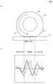
- FIG. 1 A schematic diagram schematically showing the deformation of the tire due to rotation, (b) A waveform graph showing the changes in the deformation speed (solid line) and the amount of deformation (broken line) of the tire.
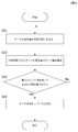
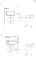
- Flowchart of tire deterioration estimation method of the second embodiment Flowchart of tire deterioration estimation method of the third embodiment
- Functional block diagram of tire deterioration estimation device A) A plan view schematically showing a configuration example of a deformation measuring unit of a tire deterioration estimation device, and (b) a plan view schematically showing another configuration example of a deformation measuring unit.
- FIG. 6 is a perspective view schematically showing a state in which the deformation measuring unit is arranged on the inner surface of the tire.
- (A) A plan view explaining the rotation of the tire and the position (rotation angle) of the tire deterioration estimation device,
- (b) A waveform showing the relationship between the rotation angle of the tire and the output voltage from the piezoelectric sensor of the deformation measuring unit.
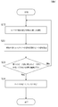
- the tire deterioration estimation method of the present embodiment is a tire deterioration estimation method using a tire deterioration estimation device arranged on the inner surface of the tire, and is calculated by the deformation speed measurement step (S11). It includes a step (S12) and an estimation step (S13). Each step will be described below.
- the deformation speed measurement step (S11) is a step of measuring the tire deformation speed, which is the deformation speed of the rotating tire 200 at the location where the tire deterioration estimation device 100 is arranged.
- FIG. 2A is a front view schematically showing the deformation of the tire 200 when it is rotating
- FIG. 2B is a measurement of the rotating tire 200 by the tire deterioration estimation device 100.
- It is a waveform which schematically shows the time-series change of the tire deformation speed and the tire deformation amount.
- the solid line shows the time-series change of the tire deformation speed
- the broken line shows the time-series change of the tire deformation amount.
- the portion where the deformation measuring unit 10 (see FIG. 5) is arranged repeatedly steps on the road surface 50, touches the ground, and kicks out.
- the deformation of the tire 200 that accompanies this is measured.
- the deformation measuring unit 10 (see FIGS. 5 and 7) of the tire deterioration estimation device 100 measures periodic deformation as the tire 200 rotates.
- the deformation speed measurement step measures the periodic change in the tire deformation speed of the tire 200.
- the horizontal axis represents time
- the vertical axis represents the magnitude of tire deformation speed or the amount of tire deformation.
- the solid line is a simplified waveform of the time-series change in the tire deformation speed
- the broken line is a simplified waveform of the time-series change in the tire deformation amount.
- the value (maximum value / minimum value) of the wave peak in the waveform showing the time-series change of the tire deformation speed is used. Calculate a certain peak value.
- the peak that gives the peak value of the tire deformation speed is the peak when the tire surface 202 corresponding to the location where the tire deterioration estimation device 100 is arranged on the inner surface 201 of the tire 200 is not in contact with the road surface 50 ( It is classified into a peak (first peak) and a peak (second peak) when the road surface 50 is in contact with the ground.
- the first peak which is the peak when the tire surface 202 is not in contact with the road surface 50, is the peak before stepping on (FIG. 2 (b)). Then, it is composed of peaks a1 and a2) and peaks after kicking (peaks a5 and a6 in FIG. 2B).
- the amount of deformation of the tire 200 is maximized when the tire surface 202 and the road surface 50 are in contact with each other (FIG. 2A), and the directions are opposite to each other before and after the center point at the time of contact (hereinafter, appropriately referred to as "ground contact center point C"). Peaks a3 and a4 appear as the second peak (FIG. 2 (b)).
- the "first peak” before and after the tire touches down, before stepping on or after kicking out is obtained.
- two peaks a1 and a2 appear before the peak a3 at the time of touchdown, and two peaks a5 and a6 appear after the peak a4 at the time of touchdown, respectively.
- the peaks a2 and a5 that occur near the peaks a3 and a4 at the time of touchdown are easy to detect because the absolute value of the peak value is larger than that of the peaks a1 and a6.
- the peaks a2 and a5 that maximize the absolute value of the tire deformation speed when the tire surface 202 and the road surface 50 are not in contact with the ground, that is, before the tire is stepped on or after the tire is kicked out, are used as the first peaks. Is preferable.
- the peak on the same side as the grounding peak a3 that occurs immediately before the grounding center point C is the top peak
- the peak on the same side as the grounding peak a4 that occurs immediately after the grounding center point C is the bottom peak.
- a1 and a5 are top peaks
- a2 and a6 are bottom peaks.
- the estimation step (S13) is a step of estimating the degree of deterioration of the tire by using the first peak value which is the value of the first peak in the time series change of the tire deformation speed calculated in the calculation step.
- the index obtained by using the first peak value is compared with the threshold value, and if the index is equal to or less than the threshold value (Yes in S13), it is determined that the tire 200 has deteriorated (S14), and the tire deterioration estimation is completed. To do.
- the index is larger than the threshold value (No in S13)
- the process returns to the deformation speed measurement step (S11).
- the first peak value is used to estimate the degree of deterioration of the tire. Therefore, in the calculation step (S12), at least the first peak value among the peak values of the tire deformation speed is obtained.
- FIG. 9B shows a waveform showing the relationship between the rotation angle of the tire and the output voltage from the piezoelectric sensor of the deformation measuring unit in the case of a new tire and the case of a used tire. From FIG. 9B, the peak values a3 and a4 at the time of touchdown have almost no difference between new and used output values, whereas the peak values before and after touchdown a1, a2, a5 and a6 have almost no difference. You can see that there is a difference.
- the maximum value of the deformation speed of the tire more sensitively reflects the degree of deterioration of the tire 200, particularly the change in characteristics such as hardness due to the deterioration, before and after the contact with the tire 200 when the tire 200 is in contact with the ground. You can see that it does. Therefore, the deterioration state of the tire can be estimated accurately by estimating the degree of deterioration of the tire using the first peak value which is the peak value of the tire deformation speed before and after the tire touches the ground obtained in the calculation step.
- the peak value of peak a2 or the peak value of peak a5 is equal to or less than a predetermined threshold value, and the peak value of peak a2 or peak a5 is equal to or less than a predetermined ratio with respect to the initial value of each peak value.
- the predetermined ratio can be, for example, 40 to 60%, 50%, or the like.
- the tire deterioration estimation method of the present embodiment is different from the first embodiment in that the calculation step (S22) is provided instead of the calculation step (S12) described above.
- the calculation step (S22) in addition to the first peak, the second peak value of the tire deformation speed when the tire touches the ground is calculated.
- the second peak is the peak having the maximum peak value on the top side and the bottom side.
- one second peak occurs in the opposite direction of the waveform before and after the ground contact center point C when the tire touches the ground.
- the peaks a3 and a4 immediately before and after the contact center point C where the amount of deformation of the tire 200 is maximized are the second peaks, and the value of the deformation rate at these peaks is the second peak. Is the peak value of.
- the second peak value is the maximum value of the deformation speed of the tire in the opposite direction when the tire touches the ground.
- the second peak value is calculated in addition to the first peak value. Therefore, in the estimation step (S23) following the calculation step (S22), the index obtained by using the first peak value and the second peak value can be used for estimating the deterioration of the tire.
- the second peak value in addition to the first peak value, it is possible to suppress the influence of factors other than the degree of tire deterioration and improve the estimation accuracy. For example, in a low temperature environment, all materials tend to be hard, so the output waveform changes in a similar manner to the output waveform at room temperature. Therefore, the ratio of the second peak value to the first peak value is the same even when the first peak value and the second peak value change due to a change in the external environment.
- the peak value of the peak a2 (first peak) in FIG. 2B is changed to the peak value of the peak a3 (second peak).
- the first ratio obtained by dividing by, or the second ratio obtained by dividing the peak a5 (first peak) by the peak a4 (second peak) can be used.
- combinations of the first peak and the second peak and other combinations may be used, or a ratio obtained by dividing the second peak value by the first peak value may be used.
- the process returns to the deformation speed measurement step (S11) and continues the measurement of the time-series change in the deformation speed of the tire.
- the reference value include the ratio (initial value) of the first peak value to the second peak value of the tire (new) at the time before use.
- An appropriate value may be set for the predetermined ratio according to the type of tire and the like, and for example, it may be 40 to 60% or 50%.
- the tire deterioration degree estimation method of the present embodiment includes a deformation amount measurement step (S31), a calculation step (S32), and an estimation step (S33).
- the deformation amount measurement step (S31) is a step of measuring the time-series change of the deformation amount of the tire. For example, the deformation speed of the tire when the tire is rotating is measured, and the tire deformation speed is integrated to integrate the tire. Measure the amount of deformation. As a result, the waveform of the time-series change of the tire deformation amount shown by the broken line in the figure can be obtained.
- the peak value of the tire deformation amount is specified from the time-series change of the tire deformation amount.
- the waveform of the time-series change in the amount of tire deformation includes peaks b1 and b2 before stepping on, peak b3 at the time of touchdown where the amount of deformation is maximum, and peak b4 after kicking out. And b5 occur.
- the third peak is b1, b2, b4 and b5. Similar to the first peak in the first embodiment, the third peak of the tire deformation amount sensitively reflects the change in the elasticity of the tire due to deterioration. Therefore, in the estimation step (S33), by using the third peak value of the tire deformation amount and determining that the tire is deteriorated when the obtained index is equal to or less than the threshold value (S14), the tire can be accurately measured. The degree of deterioration can be estimated.
- the fourth peak value that maximizes the amount of deformation may be obtained.
- the fourth peak value in addition to the third peak value, it is possible to suppress the influence of temperature changes and the like as well as the tire deformation speed, so that the estimation accuracy in the estimation step (S33) is improved.
- a value obtained by dividing the third peak value by the fourth peak value may be used as an index for evaluating the degree of deterioration of the tire 200.
- FIG. 5 is a functional block diagram of the tire deterioration estimation device 100 of the present embodiment.
- the tire deterioration estimation device 100 is arranged on the inner surface 201 (see FIG. 2A) of the tire 200 to determine the degree of tire deterioration, and includes the deformation measurement unit 10, the calculation unit 21, and the estimation unit 22. I have.
- the deformation measuring unit 10 can measure the deformation speed of the tire when the tire 200 is rotating.
- a piezoelectric layer in which piezoelectric particles are dispersed in a matrix of synthetic resin is used as an electrode layer.
- a sheet-shaped piezoelectric sensor having a sandwiched configuration can be used.
- the deformation measuring unit 10 is arranged in contact with the inner surface of the tire 200, measures the deformation speed of the inner surface of the tire, and outputs the measurement result as the tire deformation speed to the calculation unit 21.
- the calculation unit 21 calculates the peak value in the time-series change of the tire deformation speed from the time-series change of the tire deformation speed measured by the deformation measurement unit 10.
- the peak value of (first peak), the peak value of peaks a3 and a4 (second peak) at the time of touchdown, and the like are calculated.
- the peak value can be calculated from the data of the time-series change of the tire deformation speed, or can be obtained by analyzing the image of the waveform of the time-series change.
- the estimation unit 22 estimates the degree of deterioration of the tire 200 by using the first peak value calculated by the calculation unit 21.
- the calculation unit 21 and the estimation unit 22 are a part of the control unit 20 that is responsible for various controls of the tire deterioration estimation device 100.
- the control unit 20 includes a warning unit 23 for notifying that the tire has deteriorated, and when the degree of deterioration of the tire estimated by the estimation unit 22 is equal to or less than a predetermined threshold value, the tire Outputs a signal to warn of deterioration.
- a CPU Central Processing Unit
- the calculation unit 21, the estimation unit 22, and the warning unit 23 may be configured as software functions.
- the tire deterioration estimation device 100 of the present embodiment includes a storage unit 30 and a communication unit 40 in addition to the deformation measurement unit 10 and the control unit 20 described above.
- Various data are recorded in the storage unit 30, and these recorded data are referred to when the control unit 20 estimates or warns of the deterioration state of the tire.
- Examples of the data stored in the storage unit 30 include a table showing the relationship between the index used for evaluation and the degree of deterioration of the tire.
- the estimation unit 22 can accurately estimate the deterioration state of the tire 200 by comparing the index based on the first peak value calculated by the calculation unit 21 with the information stored in the storage unit 30.
- the storage unit 30 may be a storage unit 30 provided with an external device such as a vehicle body 300 capable of communicating with the tire deterioration estimation device 100.
- the first peak value of the tire deformation speed before and after the portion where the deformation measurement unit 10 is provided touches down is calculated.
- the peak value that is, the first peak value which is the maximum value of the deformation rate at each peak is calculated.
- the estimation unit 22 estimates the degree of deterioration of the tire 200 using the first peak value calculated by the calculation unit 21. As shown in FIG. 2B, in the waveform showing the time-series change of the tire deformation speed, the maximum peaks a3 and a4 are generated on the top side and the bottom side, respectively, at the time of touchdown.
- the present invention uses the values of the first peaks a1, a2, a5, and / or a6 that occur before and after (before and after grounding) the largest peaks a3 and a4 on the top side and the bottom side, respectively. Therefore, the deteriorated state of the tire 200 can be estimated accurately.
- the estimation unit 22 calculates a second peak value of the tire deformation speed when the tire touches the ground, and uses the first peak value and the second peak value of the tire.
- the degree of deterioration may be estimated.
- the degree of deterioration of the tire may be evaluated using a value obtained by dividing the first peak value by the second peak value as an index.
- the maximum value of the tire deformation speed before or after the tire touchdown and the second peak which is the maximum value of the tire deformation speed when the tire touches down can be used in combination.
- (A5 / a4) and the like can be used as an index for evaluating the degree of deterioration of the tire.
- the deformation measuring unit 10 may obtain a time-series change in the amount of tire deformation obtained by integrating the tire deformation speed instead of the tire deformation speed.
- the estimation unit 22 determines the third peak value of the tire deformation amount before the tire is depressed or after the kicking out, and the fourth peak value of the tire deformation amount when the tire touches the ground, based on the time-series change of the tire deformation amount.
- the peak value is calculated, and the degree of deterioration of the tire is estimated based on the ratio of the third peak value to the fourth peak value. For example, in the waveform showing the time-series change of the tire deformation amount shown by the broken line in FIG.
- the peak value of peak b2 or b4 (third peak value) is changed to the peak value of peak b3 (fourth peak value).
- a piezoelectric sensor formed in a sheet shape can be used.
- the piezoelectric sensor is a second piezoelectric sensor whose sensitivity to the deformation direction of the tire 200 is different from that of the first piezoelectric sensor 11 and the first piezoelectric sensor 11. It is preferable to have 12 and.
- the first piezoelectric sensor 11 is formed in a rectangular shape when viewed from the normal direction (Z-axis direction), and the second piezoelectric sensor 12 is formed by the method.
- the configuration may be formed in a circular shape when viewed from the linear direction.
- the first piezoelectric sensor 11 has a shape having shape anisotropy in the X-axis direction and the Y-axis direction
- the second piezoelectric sensor 12 has a shape having no shape anisotropy in the X-axis and Y-axis. Therefore, in addition to the magnitude of the deformation of the tire in the portion where the deformation measuring unit 10 is provided, the deformation speed in a specific direction can be measured.
- the outputs of the first piezoelectric sensor 11 and the second piezoelectric sensor 12 are made equal, and when the deformation speed in the width direction of the tire is large, the first piezoelectric sensor The output of 11 is made larger than the output of the second piezoelectric sensor 12. As a result, the deformation direction of the tire can be measured by the output difference between the first piezoelectric sensor 11 and the second piezoelectric sensor 12.
- the estimation unit 22 may obtain the deformation speed in a specific direction by using the difference between the output of the first piezoelectric sensor 11 and the output of the second piezoelectric sensor 12. In this case, since the difference between the outputs is small, the difference between the output of the first piezoelectric sensor 11 and the output of the second piezoelectric sensor 12 may be amplified and used.
- the first piezoelectric sensor 11 mainly accurately deforms the deformation in the width direction of the tire. Can be measured. As will be described later, the tire is greatly deformed in the width direction before and after touchdown. Therefore, by using the first piezoelectric sensor 11, it is possible to accurately measure the deformation speed of the tire, especially before and after touchdown.
- FIG. 6 shows an example in which the deformation measuring unit 10 includes both the first piezoelectric sensor 11 and the second piezoelectric sensor 12, but the deformation measuring unit 10 shows the first piezoelectric sensor 11 or the second piezoelectric sensor 11.
- a configuration may be configured in which only one of the sensors 12 is provided.
- the aspect ratio (W1: L1) of the first piezoelectric sensor 11 is preferably 10: 1 or more and 10:10 or less in order to measure the force applied in the width direction with high sensitivity and accuracy and to increase the output. It is more preferably 10: 3 or more and 10: 8 or less, and further preferably 10: 4 or more and 10: 6 or less. Further, a plurality of notches extending in the longitudinal direction (Y-axis direction) may be provided.
- the length W1 of the first piezoelectric sensor 11 in the width direction of the tire is preferably about 10 to 20 mm, and the shape of the first piezoelectric sensor 11 (length in the rotation direction (circumferential direction) L1 ⁇ length in the width direction). Examples of W1) include 5 mm ⁇ 10 mm, 7 mm ⁇ 15 mm, and the like. Further, the diameter L2 of the first piezoelectric sensor 11 is preferably about 5 to 20 mm.
- FIG. 6B is a plan view schematically showing another configuration example of the deformation measuring unit.
- the first piezoelectric sensor 11 may have a configuration in which about 2 to 5 piezoelectric sensors 11a, 11b, and 11c having the same shape (rectangular shape) are arranged parallel to the rotation direction of the tire. With this configuration, the measurement accuracy of the deformation speed in the width direction is improved.
- the length W1 in the width direction of the first piezoelectric sensor 11 is equal to the length W1 in the width direction of the tires of the piezoelectric sensors 11a, 11b, 11c, and the length in the rotation direction of the tire of the first piezoelectric sensor 11.
- L1 is the total value (3 l) of the lengths l of the piezoelectric sensors 11a, 11b, and 11c.
- FIG. 6B shows an example in which piezoelectric sensors 11a, 11b, and 11c having the same shape are used, those having different shapes may be used. Further, it may be arranged so that a gap is formed between the piezoelectric sensors 11a, 11b and 11c.
- FIG. 7 schematically shows a state in which the deformation measuring unit 10 provided with the first piezoelectric sensor 11 and the second piezoelectric sensor 12 is provided on the inner surface 201 of the tire 200.
- the first piezoelectric sensor 11 and the second piezoelectric sensor 12 are arranged on the same straight line along the rotation direction L of the tire 200.
- the influence of the position of the tire 200 in the width direction W on the first piezoelectric sensor 11 and the second piezoelectric sensor 12 can be suppressed. Therefore, the difference in output from the first piezoelectric sensor 11 and the second piezoelectric sensor 12 can be measured accurately.
- both the peak values based on the measurement results of the first piezoelectric sensor 11 and the second piezoelectric sensor 12 may be used, or only one of them may be used. Further, the estimation unit 22 may estimate the degree of deterioration of the tire based on the difference between the first peak values based on the measurement results of the first piezoelectric sensor 11 and the second piezoelectric sensor 12. As the deformation speed of the tire in the width direction increases, the output of the first piezoelectric sensor 11 having better sensitivity to deformation in the width direction (Y-axis direction) and the second piezoelectric sensor having no difference in sensitivity depending on the deformation direction. The difference from the output of 12 becomes large.
- the deformation speed in the width direction before and after the ground contact is largely changed by the characteristic change due to the deterioration of the tire. Therefore, by using the difference in output from sensors having different detection sensitivities in the width direction of the tire, it is possible to detect the change in the deformation speed in the width direction and accurately estimate the degree of deterioration of the tire.
- the control unit 20 of the tire deterioration estimation device 100 of the present embodiment includes a warning unit 23 that gives a warning instruction when the tire is estimated to be deteriorated by the estimation unit 22.
- the output from the estimation unit 22 and / or the output from the warning unit 23 described above are output to the vehicle body 300 via the communication unit 40.
- the deterioration state of the tire 200 is displayed on a display device or the like provided in the vehicle body 300, or a warning by sound or light is issued.
- the communication unit 40 may output to a mobile terminal such as a smartphone, or may output to an external server or the like via a public communication line.
- the information on the tire condition obtained by the tire deterioration estimation device 100 may be used alone or in combination with the information obtained from other devices.
- Examples of other devices include a TPMS (Tire Pressure Monitoring System) that monitors the tire pressure of an automobile.
- TPMS Transire Pressure Monitoring System
- the tire deterioration estimation device 100 including the deformation measurement unit 10, the control unit 20, the storage unit 30, and the communication unit 40 has been described.
- the tire deterioration estimation device 100 may be configured by the deformation measuring unit 10 and the communication unit 40.
- the ECU Electronic Control Unit included in the vehicle body 300 fulfills the functions of the control unit 20, the calculation unit 21, the estimation unit 22, and the warning unit 23.
- the acquisition of information on the tire deterioration state by the ECU is performed by using a wireless communication means such as Bluetooth (registered trademark) when the vehicle body 300 maintains a speed of about 40 to 60 km / hour, for example. This is done by communicating with the estimation device 100 and receiving only data for a few seconds.
- a wireless communication means such as Bluetooth (registered trademark) when the vehicle body 300 maintains a speed of about 40 to 60 km / hour, for example. This is done by communicating with the estimation device 100 and receiving only data for a few seconds.
- FIG. 8 shows the simulation results of the strain characteristics generated on the inner surface 201 of the rotating tire 200, that is, the deformation direction and the magnitude of the deformation speed, before stepping on, when stepping on, when touching down, when kicking out, and after kicking out.
- the hollow arrow in the figure indicates the direction of deformation and the size indicates the magnitude of the deformation speed.
- the tire 200 tends to expand in the rotation direction (L) and contract in the width direction (W) due to the air pressure of the air enclosed therein, but when touching the ground, the expansion in the rotation direction (L) is dominant. When stepping on and kicking out, the extension in the width direction (W) becomes dominant.
- a vertical load due to ground contact, a centrifugal force due to rotation, or a force due to curvature deformation in the width direction of the tire is applied to the tire 200 during rotation (running).
- the parts that come into contact with the ground change periodically, so that the vertical load applied to each part changes periodically.
- the behavior of the tire at the time of touchdown in the state where this force is applied can be captured as peaks a3 and a4 shown in FIGS. 2 (a) and 2 (b).
- the extension of the tire 200 in the rotation direction (L) is loosened, and at the same time, the contraction in the width direction (W) is loosened.
- the tire 200 extends in the width direction due to the action of centrifugal force due to rotation.
- FIG. 9B shows a first piezoelectric sensor 11 having a rectangular planar shape (three sets of size 10 mm ⁇ 6 mm: 10 mm ⁇ 2 mm, see FIG. 6B), the longitudinal direction thereof being the width direction of the tire 200. It is a graph (waveform) showing the result of measuring the output voltage from the first piezoelectric sensor 11 as the tire 200 rotates, which is arranged on the inner surface 201 of the tire (new and used) 200 so as to be parallel to. ..
- the rotation angle X is an angle formed by a straight line connecting the top peak point of the tire 200 at the time of contact and the rotation center O of the tire 200 shown in FIG.
- the top peak point at the time of touchdown refers to the position of the tire deterioration estimation device 100 at which the first peak a3 at the time of touchdown is obtained, as shown in FIG. 9B.
- the waveform obtained by measuring a new tire is shown by a solid line
- the waveform obtained by measuring a used tire is shown by a broken line.
- the maximum value of the output voltage (peaks a3 and a4) is obtained when the tire touches down on both the top side and the bottom side, and a plurality of peaks (a1, a2, before and after the tire touches down). a5 and a6) were obtained. These peaks before and after the tire touched down were smaller than the peaks when the tire touched down, but the difference between the new tire and the used tire was large. From this result, it was found that the degree of deterioration of the tire can be accurately evaluated by using the peaks before and after the tire touches the ground.
- Tire deterioration estimation including a deformation measuring unit 10 including a deformation measuring unit 10 including a first piezoelectric sensor 11 having a rectangular planar shape (three sets of size 10 mm ⁇ 6 mm: 10 mm ⁇ 2 mm, see FIG. 6B).
- the device 100 is arranged on the inner surface of the tire (new and used) so that the longitudinal direction of the first piezoelectric sensor 11 is parallel to the width direction of the tire, and the results of measuring the output from the piezoelectric sensor are as follows. 1 and FIG. 10 (a).
- a tire deterioration estimation device 100 including a deformation measuring unit 10 including a second piezoelectric sensor 12 having a circular planar shape (diameter 10 mm, see FIG. 6B) is used as a tire (new and used).
- the result of measuring the output from the second piezoelectric sensor 12 is shown in Table 2 and FIG. 10 (b).
- a tire deterioration estimation device 100 including a deformation measuring unit 10 including a first piezoelectric sensor 11 having a rectangular planar shape (three sets having a size of 10 mm ⁇ 2 mm, see FIG. 6B) is provided.
- the first piezoelectric sensor 11 is arranged on the inner surface of the tire (new) so that the longitudinal direction is parallel to the width direction of the tire, and before scraping the rubber on the tire surface to a predetermined thickness by buffing (initial value). : 0%) and later (30% and 50% polishing of the whole) are shown in Table 3 and FIG. 11 (a).
- the measurement results are shown in Table 4 and FIG. 11 (b).
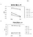
- FIG. 10 is a graph comparing peak values obtained by measuring new tires and used tires, in which (a) is a rectangular piezoelectric sensor and (b) is a circular piezoelectric sensor as a deformation measuring unit. The result is shown.
- the change in tire behavior due to tire deterioration could be grasped as the change in the peak value in the waveform of the tire deformation speed over time.
- the degree of deterioration of the tire can be detected with high sensitivity by using a rectangular piezoelectric sensor having a rectangular planar shape with good sensitivity in the width direction of the tire.
- the peaks (a2, a5) before and after touchdown have a larger difference in waveform between the new tire and the used tire than the peaks (a3, a4) at the time of touchdown, and the degree of deterioration of the tire is detected with high sensitivity. I was able to.
- FIG. 11 is a graph for comparing the peak values obtained by forcibly wearing a new tire using a buff, and as deformation measuring units, (a) a rectangular piezoelectric sensor and (b) a circular piezoelectric sensor. The measurement result using is shown. As shown in FIGS. 11 (a) to 11 (b), the change in the behavior of the tire due to the progress of friction of the tire could be grasped as the change in the peak of the waveform of the deformation speed of the tire over time. As for the piezoelectric sensor used for the measurement, there was no big difference between the piezoelectric sensor having a rectangular planar shape and the piezoelectric sensor having a circular planar shape, which had good sensitivity in the width direction of the tire. The peaks (a3, a4) at the time of touchdown could detect the degree of progress of tire wear more sensitively than the peaks (a2, a5) before and after touchdown.
- the deformation speed of the tire depends on whether the deterioration of the tire is due to a change in characteristics such as hardness or wear.
- the peaks the ones with good sensitivity were different.
- the value obtained by dividing the first peak value before and after touchdown by the second peak value at touchdown (first peak / second peak, a2 / a3, a5 / a4) is used for tire deterioration.
- it is possible to estimate the deterioration state of the tire by detecting both the characteristic change such as the change in flexibility with time and the decrease in rubber thickness due to wear.
- the present invention is useful as a method and device for estimating the degree of tire deterioration.
Landscapes
- Engineering & Computer Science (AREA)
- Mechanical Engineering (AREA)
- Physics & Mathematics (AREA)
- General Physics & Mathematics (AREA)
- Tires In General (AREA)
- Length Measuring Devices With Unspecified Measuring Means (AREA)
Abstract
本発明の一態様に係るタイヤ劣化推定方法は、タイヤの内側面に配置されたタイヤ劣化推定装置を用い、タイヤが回転しているときのタイヤの変形速度であるタイヤ変形速度を計測し、前記タイヤ変形速度の時系列変化を得る変形速度計測ステップ(S11)と、前記タイヤ変形速度の時系列変化から、前記タイヤ変形速度のピーク値を算出する算出ステップ(S12)と、前記タイヤ変形速度の時系列変化における、前記タイヤの踏み込み時以前または蹴り出し時以後における前記タイヤ変形速度の前記ピーク値である第1のピーク値を用いて、前記タイヤの劣化度を推定する推定ステップ(S13)と、を備えるため、タイヤの劣化度合いを推定できる。
Description
本発明は、タイヤの摩耗等の劣化の程度を推定するタイヤ劣化推定装置およびタイヤ劣化推定方法に関する。
タイヤの摩耗が進行すると、乾いた路面を走行する際におけるグリップ性能や、濡れた路面を走行する際におけるタイヤと路面との間の水を排出する排水性能が低下する。そこで、運転者や車両管理者は、トレッドの摩耗状態を目視で点検し、安全性を確保するために使用限度を超える前にタイヤを交換する。目視による点検にはタイヤの溝に設けられたスリップサインなどが用いられるが、点検作業は煩雑であり、また、摩耗状態の評価を誤るおそれもある。評価を誤った場合、性能が低下したタイヤが継続して使用されることになり、安全性の観点から好ましくない。
そこで、目視以外の方法によってタイヤの摩耗の程度を推定する方法が提案されている。たとえば、特許文献1には、安定してかつ精度よくタイヤの摩耗の程度を推定する方法が記載されている。
そこで、目視以外の方法によってタイヤの摩耗の程度を推定する方法が提案されている。たとえば、特許文献1には、安定してかつ精度よくタイヤの摩耗の程度を推定する方法が記載されている。
特許文献1に記載の方法は、タイヤ径方向加速度からタイヤ変形速度を算出し、タイヤ回転時間を求め、変形速度と回転時間から変形速度の指標を求め、指標の大きさから摩耗度合いを算出する。また、回転速度によって変動するタイヤの変形速度の指標を基準化するために、タイヤの回転時間の三乗値を乗算または除算する。この方法は、タイヤ荷重、圧力、速度、路面の摩擦係数などの複数のデータを考慮して摩耗の程度を割り出すことから、タイヤの摩耗度合いを推定するために必要な計算量が大きくなる。このため、タイヤ劣化推定装置の電力消費量が増えるという問題がある。
そこで、本発明は、従来とは異なる方法によって、タイヤの劣化の程度を推定することができるタイヤ劣化推定装置およびタイヤ劣化推定方法の提供を目的としている。
そこで、本発明は、従来とは異なる方法によって、タイヤの劣化の程度を推定することができるタイヤ劣化推定装置およびタイヤ劣化推定方法の提供を目的としている。
本発明は、タイヤの踏み込み時以前(接地前)または蹴り出し時以後(接地後)における変形と、タイヤの接地時における変形とを用いることにより、摩耗や柔軟性の低下といったタイヤの劣化の度合いを評価することができるという知見に基づいており、以下の構成を備えている。
本発明のタイヤ劣化推定方法は、タイヤの内側面に配置されたタイヤ劣化推定装置を用いたタイヤ劣化推定方法であって、前記タイヤが回転しているときの前記タイヤの変形速度であるタイヤ変形速度を計測し、前記タイヤ変形速度の時系列変化を得る変形速度計測ステップと、前記タイヤ変形速度の時系列変化から、前記タイヤ変形速度のピーク値を算出する算出ステップと、前記タイヤ変形速度の時系列変化における、前記タイヤの踏み込み時以前または蹴り出し時以後における前記タイヤ変形速度の前記ピーク値である前記第1のピーク値を用いて、前記タイヤの劣化度を推定する推定ステップと、を備えることを特徴とする。
タイヤの踏み込み時以前または蹴り出し時以後におけるタイヤ変形速度のピーク値である第1のピーク値を用いることで、タイヤの劣化の程度を精度よく推定することができる。
タイヤの踏み込み時以前または蹴り出し時以後におけるタイヤ変形速度のピーク値である第1のピーク値を用いることで、タイヤの劣化の程度を精度よく推定することができる。
前記算出ステップは、前記時系列変化から、前記タイヤの踏み込み時以前または蹴り出し時以後における前記タイヤ変形速度の前記ピーク値である前記第1のピーク値、およびタイヤ接地時における前記タイヤ変形速度のピーク値である前記第2のピーク値を算出し、前記推定ステップは、前記第2のピーク値と前記第1のピーク値との比に基づいて、前記タイヤの前記劣化度を推定してもよい。
第1のピーク値に加えて第2のピーク値を算出し、両者の比を用いてタイヤの劣化度を推定することにより、外部温度の変化等に起因する変化の影響を抑えて、推定精度を向上させることができる。
第1のピーク値に加えて第2のピーク値を算出し、両者の比を用いてタイヤの劣化度を推定することにより、外部温度の変化等に起因する変化の影響を抑えて、推定精度を向上させることができる。
前記推定ステップは、接地前における前記第1のピーク値を前記第2のピーク値で除算して得られた第1の比率、または接地後における前記第1のピーク値を前記第2のピーク値で除算して得られた第2の比率に基づいて、前記タイヤの前記劣化度を推定してもよい。
前記推定ステップは、前記第2のピーク値に対する前記第1のピーク値の比率が、基準値の50%以下となったときに、前記タイヤが劣化したと推定してもよい。
前記推定ステップは、前記第2のピーク値に対する前記第1のピーク値の比率が、基準値の50%以下となったときに、前記タイヤが劣化したと推定してもよい。
本発明のタイヤ劣化推定方法は、他の態様として、タイヤの内側面に配置されたタイヤ劣化推定装置を用いたタイヤ劣化推定方法であって、前記タイヤが回転しているときの前記タイヤの変形速度を計測し、タイヤ変形速度を積分したタイヤ変形量の時系列変化を得る変形量計測ステップと、前記タイヤ変形量の時系列変化から、前記タイヤ変形量のピーク値を特定する算出ステップと、前記タイヤ変形量の時系列変化における、前記タイヤの踏み込み時以前または蹴り出し時以後における前記タイヤ変形量の前記ピーク値である第3のピーク値を用いて、前記タイヤの前記劣化度を推定する推定ステップと、を備えることを特徴とする。
前記変形量計測ステップは、前記時系列変化から、タイヤの踏み込み時以前または蹴り出し時以後における前記タイヤ変形量の前記第3のピーク値、およびタイヤ接地時における前記タイヤ変形量の第4のピーク値を算出し、前記推定ステップは、前記第3のピーク値と前記第4のピーク値との比に基づいて、前記タイヤの劣化度を推定してもよい。
本発明のタイヤ劣化推定装置は、タイヤの内側面に配置されてタイヤの劣化状態を判別するタイヤ劣化推定装置において、前記タイヤが回転しているときの前記タイヤの変形を計測可能な変形計測部と、タイヤ変形速度の時系列変化から、前記タイヤの踏み込み時以前または蹴り出し時以後における前記タイヤ変形速度の時系列変化における第1のピーク値を算出する算出部と、前記タイヤ変形速度の前記第1のピーク値を用いて、前記タイヤの劣化度を推定する推定部と、を備えることを特徴とする。
前記算出部が、前記タイヤ変形速度の時系列変化から、タイヤの踏み込み時以前または蹴り出し時以後における前記タイヤ変形速度の第1のピーク値、およびタイヤ接地時における前記タイヤ変形速度の第2のピーク値を算出し、前記推定部が、前記タイヤ変形速度の前記第1のピーク値および前記第2のピーク値を用いて、前記タイヤの劣化度を推定するものであってもよい。
前記変形計測部は、シート状に形成された圧電センサであり、前記タイヤの前記内側面に接して配置され、前記タイヤの前記内側面の変形速度を測定するとともに、当該測定した変形速度を前記タイヤ変形速度としてもよい。
前記圧電センサは、第1の圧電センサおよび第2の圧電センサを備えており、前記第1の圧電センサと前記第2の圧電センサとは、前記タイヤの変形方向に対する感度が異なっていてもよい。
前記第1の圧電センサは、前記第2の圧電センサよりも、前記タイヤの幅方向の感度が高いものであってもよい。例えば、前記第1の圧電センサは、法線方向から見たときに長方形状に形成されており、長手方向がタイヤの幅方向となるように配置されており、前記第2の圧電センサは、法線方向から見たときに円形状に形成されていてもよい。前記第1の圧電センサおよび前記第2の圧電センサは、前記タイヤの回転方向に沿った同一直線上に配置されていてもよい。
圧電センサを、タイヤの変形方向に対する感度が異なる第1の圧電センサおよび第2の圧電センサで構成することにより、第1と第2の圧電センサからの出力の差を用いて、たとえば、タイヤの幅方向のような特定方向の変形を検知することができる。
前記第1の圧電センサは、前記第2の圧電センサよりも、前記タイヤの幅方向の感度が高いものであってもよい。例えば、前記第1の圧電センサは、法線方向から見たときに長方形状に形成されており、長手方向がタイヤの幅方向となるように配置されており、前記第2の圧電センサは、法線方向から見たときに円形状に形成されていてもよい。前記第1の圧電センサおよび前記第2の圧電センサは、前記タイヤの回転方向に沿った同一直線上に配置されていてもよい。
圧電センサを、タイヤの変形方向に対する感度が異なる第1の圧電センサおよび第2の圧電センサで構成することにより、第1と第2の圧電センサからの出力の差を用いて、たとえば、タイヤの幅方向のような特定方向の変形を検知することができる。
前記推定部は、前記第1の圧電センサの計測結果に基づく、前記タイヤの踏み込み時以前または蹴り出し時以後における前記タイヤ変形速度の前記第1のピーク値と、前記第2の圧電センサの計測結果に基づく、前記タイヤの接地時における前記タイヤ変形速度の第2のピーク値とを用いて、前記タイヤの劣化度を推定してもよい。
前記推定部は、前記第2のピーク値に対する前記第1のピーク値の比率、または、前記第1の圧電センサおよび前記第2の圧電センサの計測結果に基づくタイヤ変形速度の前記第1のピーク値の差に基づいて、タイヤの劣化度を推定してもよい。
これらの構成により、推定部はタイヤの劣化度を精度よく推定することができる。
前記推定部は、前記第2のピーク値に対する前記第1のピーク値の比率、または、前記第1の圧電センサおよび前記第2の圧電センサの計測結果に基づくタイヤ変形速度の前記第1のピーク値の差に基づいて、タイヤの劣化度を推定してもよい。
これらの構成により、推定部はタイヤの劣化度を精度よく推定することができる。
タイヤ劣化推定装置は、外部と通信可能な通信部と、前記タイヤが劣化していると前記推定部が推定した場合に警告の指示を行う警告部と、をさらに備えていてもよい。
推定部によりタイヤが劣化していると推定されたときに、警告部からの警告を通信部を介して出力し、車両の管理者や運転者に知らせることができる。
推定部によりタイヤが劣化していると推定されたときに、警告部からの警告を通信部を介して出力し、車両の管理者や運転者に知らせることができる。
本発明によれば、第1のピーク値を用いることにより、少ない計算量でタイヤの劣化度を精度よく推定することができる。
本発明の実施形態について、以下、図を参照しつつ説明する。各図において、同一の部材や工程(ステップ)には同じ番号を付して、適宜、説明を省略する。
(第1の実施形態)
図1に示すように、本実施形態のタイヤ劣化推定方法は、タイヤの内側面に配置されたタイヤ劣化推定装置を用いたタイヤ劣化推定方法であって、変形速度計測ステップ(S11)と、算出ステップ(S12)と、推定ステップ(S13)とを備えている。以下、各ステップについて説明する。
(第1の実施形態)
図1に示すように、本実施形態のタイヤ劣化推定方法は、タイヤの内側面に配置されたタイヤ劣化推定装置を用いたタイヤ劣化推定方法であって、変形速度計測ステップ(S11)と、算出ステップ(S12)と、推定ステップ(S13)とを備えている。以下、各ステップについて説明する。
変形速度計測ステップ(S11)は、回転しているタイヤ200における、タイヤ劣化推定装置100が配置された箇所の変形速度であるタイヤ変形速度を計測するステップである。図2(a)は、タイヤ200が回転しているときの変形を模式的に示した正面図であり、図2(b)は、回転しているタイヤ200において、タイヤ劣化推定装置100により測定されるタイヤ変形速度およびタイヤ変形量の時系列変化を模式的に示す波形である。同図では、実線がタイヤ変形速度の時系列変化を示し、破線がタイヤ変形量の時系列変化を示している。
図2(a)に示すように、タイヤ劣化推定装置100は、タイヤ200の回転によって、変形計測部10(図5参照)が配置された箇所が、路面50に対する踏み込み、接地、蹴り出しを繰り返すことに伴って生じるタイヤ200の変形を測定する。タイヤ劣化推定装置100の変形計測部10(図5、図7参照)により、タイヤ200の回転に伴って、周期的な変形が計測される。変形速度計測ステップは、このタイヤ200の周期的なタイヤ変形速度の変化を計測する。図2(b)のグラフは、横軸が時間を示し、縦軸がタイヤ変形速度の大きさまたはタイヤ変形量を示している。実線がタイヤ変形速度の時系列変化の波形を、破線がタイヤ変形量の時系列変化の波形を、それぞれ簡略化したものである。
算出ステップ(S12)では、変形速度計測ステップにおいて計測したタイヤ変形速度の時系列変化から、タイヤ変形速度の時系列変化を示す波形における波の頂点(ピーク)の値(極大値・極小値)であるピーク値を算出する。ここで、タイヤ変形速度のピーク値を与えるピークは、タイヤ200の内側面201におけるタイヤ劣化推定装置100が配置された箇所に対応するタイヤ表面202が、路面50に接地していないときにおけるピーク(第1のピーク)と、路面50に接地しているときにおけるピーク(第2のピーク)とに分類される。これらのピークについて、図2(a)および図2(b)を用いて説明する。
タイヤ表面202が、路面50に接地していないときにおけるピークである第1のピークは、図2(a)および図2(b)に示すように、踏み込み時以前のピーク(図2(b)ではピークa1およびピークa2)および蹴り出し時以後におけるピーク(図2(b)ではピークa5およびピークa6)からなる。タイヤ表面202と路面50との接地時にはタイヤ200の変形量が最大となり(図2(a))、接地時の中心点(以下、適宜「接地中心点C」という)の前後において、互いに反対向きのピークa3、a4が第2のピークとして現れる(図2(b))。
算出ステップでは、タイヤ接地時の前後である、踏み込み時以前または蹴り出し時以後における「第1のピーク」を求める。図2(b)に示すように、接地時におけるピークa3の前にa1およびa2の2つのピーク、接地時におけるピークa4の後にa5およびa6の2つのピークが、それぞれ現れる。これら4つのピークのうち、接地時のピークa3およびa4に近い位置に生じるピークa2およびa5は、ピークa1およびa6よりもピーク値の絶対値が大きいことから、検知が容易である。このため、タイヤ表面202と路面50との非接地時、すなわちタイヤの踏み込み時以前または蹴り出し時以後における、タイヤ変形速度の絶対値が最大となるピークa2およびa5を第1のピークとして用いることが好ましい。なお、本明細書では、接地中心点Cの直前に生じる接地時のピークa3と同じ側のピークをトップピーク、接地中心点Cの直後に生じる接地時のピークa4と同じ側のピークをボトムピークともいう。例えば、図2(b)の波形では、第1のピーク値のうちa1とa5とがトップピークであり、a2とa6とがボトムピークである。
推定ステップ(S13)は、算出ステップにおいて算出したタイヤ変形速度の時系列変化における第1のピークの値である第1のピーク値を用いて、タイヤの劣化度を推定するステップである。第1のピーク値を用いて求めた指標と閾値とを比較し、指標が閾値以下である場合(S13のYes)、タイヤ200が劣化していると判断し(S14)、タイヤ劣化推定を終了する。指標が閾値よりも大きい場合(S13のNo)、変形速度計測ステップ(S11)に戻る。
推定ステップ(S13)は、タイヤの劣化度を推定するために第1のピーク値を用いる。このため、算出ステップ(S12)は、タイヤ変形速度のピーク値のうち、少なくとも第1のピーク値を求める。
ここで、図9(b)を参照する。図9(b)は、タイヤの回転角度と変形計測部の圧電センサからの出力電圧との関係を示す波形について、新品タイヤの場合と、中古品タイヤの場合と、を示している。図9(b)から、接地時のピーク値であるa3、a4ではその出力値に新品・中古でほとんど差がないのに対して、接地前後のピーク値であるa1、a2、a5、a6では差が出ていることがわかる。すなわち、タイヤの変形速度の最大値は、タイヤ200が地面に接地している接地時よりも、接地前後において、タイヤ200の劣化の程度、特に、劣化による硬度等の特性の変化を敏感に反映することが分かる。このため、算出ステップで求めたタイヤの接地前後におけるタイヤ変形速度のピーク値である第1のピーク値を用いてタイヤの劣化度を推定することにより、精度よくタイヤの劣化状態を推定できる。例えば、ピークa2のピーク値またはピークa5のピーク値が、所定の閾値以下であることや、ピークa2またはピークa5のピーク値が、各ピーク値の初期値に対して所定の割合以下となったことの検出により、タイヤ200が劣化したと推定する。所定の割合としては、例えば、40~60%、50%等とすることができる。
(第2の実施形態)
図3に示すように、本実施形態のタイヤ劣化推定方法は、上述した算出ステップ(S12)に変えて、算出ステップ(S22)を備えている点において、第1の実施形態と異なっている。算出ステップ(S22)は、第1のピークに加えて、タイヤ接地時におけるタイヤ変形速度の第2のピーク値を算出する。
第2のピークは、トップ側およびボトム側においてピーク値が最大となるピークである。算出ステップ(S22)において、第1のピーク値に加えて第2のピーク値を算出することにより、推定ステップ(S23)で第1のピーク値と第2のピーク値とを用いることができる。これにより、タイヤの劣化度の推定において、外部の温度変化等によるタイヤの特性変化の影響を考慮できるから、推定精度を高くすることが可能になる。
図3に示すように、本実施形態のタイヤ劣化推定方法は、上述した算出ステップ(S12)に変えて、算出ステップ(S22)を備えている点において、第1の実施形態と異なっている。算出ステップ(S22)は、第1のピークに加えて、タイヤ接地時におけるタイヤ変形速度の第2のピーク値を算出する。
第2のピークは、トップ側およびボトム側においてピーク値が最大となるピークである。算出ステップ(S22)において、第1のピーク値に加えて第2のピーク値を算出することにより、推定ステップ(S23)で第1のピーク値と第2のピーク値とを用いることができる。これにより、タイヤの劣化度の推定において、外部の温度変化等によるタイヤの特性変化の影響を考慮できるから、推定精度を高くすることが可能になる。
第2のピークは、図2(b)に示すように、タイヤ接地時における接地中心点Cの前後にそれぞれ、波形の反対方向に一つずつ生じる。図2(b)の波形では、タイヤ200の変形量が最大となる接地中心点Cの直前および直後のピークa3およびピークa4が第2のピークであり、これらピークにおける変形速度の値が第2のピーク値である。第2のピーク値はそれぞれ、タイヤ接地時における反対方向へのタイヤの変形速度の最大値である。
本実施形態では、算出ステップ(S22)において、第1のピーク値に加えて第2のピーク値を算出している。このため、算出ステップ(S22)に続く推定ステップ(S23)において、第1のピーク値と第2のピーク値とを用いて求めた指標をタイヤの劣化の推定に用いることができる。第1のピーク値に加えて第2のピーク値を用いることにより、タイヤの劣化程度以外の要素の影響を抑えて、推定の精度を向上させることができる。例えば、低温環境下では全ての材料が硬くなる傾向なので、その出力波形は常温時の出力波形と相似で変化する。このため、外部環境の変化によって、第1のピーク値と第2のピーク値と変化した場合であっても、第2のピーク値と第1のピーク値との比は同じである。それに対して、摩耗の場合はトレッドゴムだけが削れることでワイヤーの影響が大きくなるため、出力波形は、相似ではなくなる。そのため、第2のピーク値と第1のピーク値との比を指標とすれば、外部温度のような環境の影響を抑制することができる。
推定ステップ(S23)では、タイヤ200の劣化度を推定するために、たとえば、図2(b)における、ピークa2(第1のピーク)のピーク値をピークa3(第2のピーク)のピーク値で除算して得られた第1の比率、またはピークa5(第1のピーク)をピークa4(第2のピーク)で除算して得られた第2の比率を用いることができる。これらは第1のピークと第2のピークとの組み合わせの例であり、これら以外を組み合わせてもよく、また、第2のピーク値を第1のピーク値で除算した比率を用いてもよい。
推定ステップ(S23)は、たとえば、第2のピーク値に対する第1のピーク値の比が、基準値に対して所定の割合以下となったときに、タイヤが劣化していると判断する(S14)。基準値に対して所定の割合以下ではないときに、変形速度計測ステップ(S11)に戻って、タイヤの変形速度の時系列変化の測定を継続する。基準値としては、使用前の時点におけるタイヤ(新品)の第2のピーク値に対する第1のピーク値の比(初期値)が挙げられる。所定の割合は、タイヤの種類等に応じて、適切な値を設定すればよいが、例えば、40~60%、50%とすればよい。
<第3の実施形態>
本実施形態のタイヤの劣化度推定方法は、タイヤの変形速度の時系列変化(図2(b)の実線)の代わりに、タイヤの変形量の時系列変化(図2(b)の破線)から特定したタイヤ変形量の第3のピーク値を用いて、タイヤの劣化度を推定する。
図4に示すように、本実施形態のタイヤの劣化度推定方法は、変形量計測ステップ(S31)と、算出ステップ(S32)と、推定ステップ(S33)を備えている。
本実施形態のタイヤの劣化度推定方法は、タイヤの変形速度の時系列変化(図2(b)の実線)の代わりに、タイヤの変形量の時系列変化(図2(b)の破線)から特定したタイヤ変形量の第3のピーク値を用いて、タイヤの劣化度を推定する。
図4に示すように、本実施形態のタイヤの劣化度推定方法は、変形量計測ステップ(S31)と、算出ステップ(S32)と、推定ステップ(S33)を備えている。
変形量計測ステップ(S31)は、タイヤの変形量の時系列変化を測定するステップであり、例えばタイヤが回転しているときのタイヤの変形速度を計測し、タイヤ変形速度を積分することでタイヤ変形量を測定する。これにより、同図に破線で示すタイヤ変形量の時系列変化の波形が得られる。
算出ステップ(S32)は、タイヤ変形量の時系列変化から、タイヤ変形量のピーク値を特定する。図2(b)に示すように、タイヤ変形量の時系列変化の波形には、踏み込み時以前のピークb1、b2、変形量が最大である接地時のピークb3、蹴り出し時以後のピークb4およびb5が生じる。
上述したピークb1~b5のうち、第3のピークはb1、b2、b4およびb5である。第1の実施形態における第1のピーク同様、タイヤ変形量の第3のピークは、劣化に伴うタイヤの伸縮性の変化を敏感に反映する。したがって、推定ステップ(S33)において、タイヤ変形量の第3のピーク値を用い、求めた指標が閾値以下である場合にタイヤが劣化していると判断することで(S14)、精度よくタイヤの劣化度を推定できる。
なお、算出ステップ(S32)において、第3のピーク値に加えて、変形量が最大となる第4のピーク値を求めてもよい。第3のピーク値に加えて、第4のピーク値を用いることにより、タイヤ変形速度同様、温度変化などの影響を抑制できるから、推定ステップ(S33)における推定精度が向上する。推定ステップ(S33)において、タイヤ200の劣化の程度を評価する指標として、第3のピーク値を第4のピーク値で除算した値を用いてもよい。この場合、例えば、当該指標が、初期値に対して所定の割合(閾値)以下である場合(S33のYes)、タイヤが劣化していると判断し、初期値に対して所定の割合(閾値)以下ではない場合(S33のNo)、変形量計測ステップ(S31)に戻って、算出ステップ(S32)および推定ステップ(S33)を繰り返す。
(第4の実施形態)
図5は、本実施形態のタイヤ劣化推定装置100の機能ブロック図である。タイヤ劣化推定装置100は、タイヤ200の内側面201(図2(a)参照)に配置されてタイヤの劣化の程度を判別するものであり、変形計測部10、算出部21および推定部22を備えている。
図5は、本実施形態のタイヤ劣化推定装置100の機能ブロック図である。タイヤ劣化推定装置100は、タイヤ200の内側面201(図2(a)参照)に配置されてタイヤの劣化の程度を判別するものであり、変形計測部10、算出部21および推定部22を備えている。
変形計測部10は、タイヤ200が回転しているときのタイヤの変形速度を計測可能なものであり、例えば、合成樹脂のマトリックス中に圧電粒子が分散されてなる圧電体層が、電極層に挟まれた構成を備えたシート状に形成された圧電センサを用いることができる。変形計測部10は、タイヤ200の内側面に接して配置され、タイヤ内側面の変形速度を測定するとともに、測定結果をタイヤ変形速度として算出部21に出力する。
算出部21は、変形計測部10が計測したタイヤ変形速度の時系列変化から、タイヤ変形速度の時系列変化におけるピーク値を算出する。図2(b)に実線で示したタイヤ変形速度の時系列変化の波形では、タイヤの踏み込み時以前(接地前)におけるピークa1およびa2、ならびに蹴り出し時以後(接地後)におけるピークa5およびa6(第1のピーク)のピーク値や、接地時におけるピークa3およびa4(第2のピーク)のピーク値などを算出する。ピーク値の算出は、タイヤ変形速度の時系列変化のデータから求めたり、時系列変化の波形の画像を解析して求めたりすることができる。
推定部22は、算出部21において算出した第1のピーク値を用いて、タイヤ200の劣化度を推定する。
算出部21および推定部22は、タイヤ劣化推定装置100の種々の制御を担う制御部20の一部である。図5に示すように、制御部20は、タイヤが劣化したことを知らせる警告部23を備えており、推定部22により推定されたタイヤの劣化度が、所定の閾値以下となった場合、タイヤ劣化を警告する信号を出力する。制御部20としてCPU(中央演算処理装置)などが用いられ、算出部21、推定部22、警告部23は、ソフトウェアの機能として構成されてもよい。
算出部21および推定部22は、タイヤ劣化推定装置100の種々の制御を担う制御部20の一部である。図5に示すように、制御部20は、タイヤが劣化したことを知らせる警告部23を備えており、推定部22により推定されたタイヤの劣化度が、所定の閾値以下となった場合、タイヤ劣化を警告する信号を出力する。制御部20としてCPU(中央演算処理装置)などが用いられ、算出部21、推定部22、警告部23は、ソフトウェアの機能として構成されてもよい。
本実施形態のタイヤ劣化推定装置100は、上述した変形計測部10および制御部20に加えて、記憶部30および通信部40を備えている。記憶部30には種々のデータが記録されており、これら記録されたデータは制御部20がタイヤの劣化状態を推定したり警告したりする際などに参照される。記憶部30に記憶されるデータとしては、例えば、評価に用いる指標とタイヤの劣化度との関係を示すテーブル等が挙げられる。推定部22は、算出部21が算出した第1のピーク値に基づく指標と、記憶部30に記憶された情報とを比較することにより、タイヤ200の劣化状態を精度よく推定できる。なお、記憶部30は、タイヤ劣化推定装置100と通信可能な、車体300などの外部の装置が備えたものを用いてもよい。
変形計測部10が計測したタイヤ変形速度の時系列変化から、変形計測部10を設けた部分が接地する前後におけるタイヤ変形速度における第1のピーク値を算出する。図2(b)に実線で示したタイヤ変形速度の時系列変化の波形では、タイヤの踏み込み時以前(接地前)におけるピークa1およびa2、ならびに蹴り出し時(接地後)におけるピークa5およびa6における頂点、すなわち、各ピークにおける変形速度の最大値である第1のピーク値を算出する。
推定部22は、算出部21において算出した第1のピーク値を用いて、タイヤ200の劣化度を推定する。図2(b)に示すように、タイヤ変形速度の時系列変化を示す波形では、接地時において、トップ側とボトム側とのそれぞれに、最大のピークa3とa4とが生じる。本発明は、トップ側とボトム側とのそれぞれにおける最も大きなピークa3およびa4の前後(接地の前後)に生じる第1のピーク、すなわちピークa1、a2、a5、および/またはa6の値を用いることにより、タイヤ200の劣化状態を精度よく推定できる。
推定部22は、上述した第1のピーク値に加えて、タイヤ接地時におけるタイヤ変形速度の第2のピーク値を算出し、第1のピーク値および第2のピーク値を用いて、タイヤの劣化度を推定してもよい。例えば、第1のピーク値を第2のピーク値で除算して得られる値を指標として用い、タイヤの劣化度を評価してもよい。
この場合、第1のピーク値のうち、タイヤ接地時の前または後におけるタイヤ変形速度の最大値と、タイヤ接地時におけるタイヤ変形速度の最大値である第2のピークとを組合せて用いることが好ましい。例えば、図2(b)における、ピークa2またはピークa5のピーク値をピークa3またはピークa4のピーク値で除算して得られる値(a2/a3)、(a2/a4)、(a5/a3)(a5/a4)等をタイヤの劣化の程度を評価する指標として用いることができる。
また、変形計測部10は、タイヤ変形速度に代えて、タイヤ変形速度を積分して得られるタイヤ変形量の時系列変化を得てもよい。この場合、推定部22は、タイヤ変形量の時系列変化から、タイヤの踏み込み時以前または蹴り出し時以後におけるタイヤ変形量の第3のピーク値、およびタイヤ接地時におけるタイヤ変形量の第4のピーク値を算出し、第3のピーク値と第4のピーク値との比に基づいて、タイヤの劣化度を推定する。例えば、図2(b)に破線で示すタイヤ変形量の時系列変化を示す波形における、ピークb2またはb4のピーク値(第3のピーク値)を、ピークb3のピーク値(第4のピーク値)で除算して得られる値(b2/b3またはb4/b3)をタイヤ200の劣化状態を評価する指標として用いてもよい。
変形計測部10は、例えば、シート状に形成された圧電センサを用いることができる。圧電センサは、図6(a)および図6(b)に示すように、第1の圧電センサ11と、第1の圧電センサ11とはタイヤ200の変形方向に対する感度が異なる第2の圧電センサ12とを備えていることが好ましい。
図6(a)に示すように、例えば、第1の圧電センサ11が、法線方向(Z軸方向)から見たときに長方形状に形成されるとともに、第2の圧電センサ12が、法線方向から見たときに円形状に形成された構成としてもよい。このように、第1の圧電センサ11をX軸方向とY軸方向とで形状異方性がある形状とし、第2の圧電センサ12をX軸とY軸とで形状異方性がない形状とすることにより、変形計測部10が設けられた部分におけるタイヤの変形の大きさに加えて、特定方向の変形速度を測定することができる。例えば、全方向に等しく変形が生じた場合に、第1の圧電センサ11と第2の圧電センサ12との出力が等しくなるようにし、タイヤの幅方向の変形速度が大きいと第1の圧電センサ11の出力が第2の圧電センサ12の出力よりも大きくなるようにする。これにより、第1の圧電センサ11と第2の圧電センサ12との出力差により、タイヤの変形方向を測定することができる。
推定部22は、第1の圧電センサ11の出力と、第2の圧電センサ12の出力との差を用いて、特定方向の変形速度を得てもよい。この場合、各出力の差が小さいことから、第1の圧電センサ11の出力と第2の圧電センサ12の出力との差を増幅して用いてもよい。
例えば、第1の圧電センサ11の長手方向がタイヤの幅方向(W、Y軸方向)となるように配置することで、第1の圧電センサ11により主にタイヤの幅方向の変形を精度よく計測することができる。後述するように、タイヤは接地前後において、幅方向に大きく変形する。このため、第1の圧電センサ11を用いることにより、特に、接地前後におけるタイヤの変形速度を精度よく測定することが可能となる。図6には、変形計測部10が第1の圧電センサ11および第2の圧電センサ12の両方を備えた例を示したが、変形計測部10は第1の圧電センサ11または第2の圧電センサ12の一方のみを備えた構成としてもよい。
第1の圧電センサ11のアスペクト比(W1:L1)は、幅方向に加えられた力を高感度で精度よく測定するとともに、出力を大きくするために、10:1以上10:10以下が好ましく、10:3以上10:8以下がより好ましく、10:4以上10:6以下がさらに好ましい。また、長手方向(Y軸方向)に伸びる切欠き部が複数設けられた構成としてもよい。
第1の圧電センサ11のタイヤの幅方向の長さW1は10~20mm程度が好適であり、第1の圧電センサ11の形状(回転方向(周方向)の長さL1×幅方向の長さW1)として、例えば、5mm×10mmや7mm×15mm等が挙げられる。また、第1の圧電センサ11の直径L2は、5~20mm程度が好適である。
第1の圧電センサ11のタイヤの幅方向の長さW1は10~20mm程度が好適であり、第1の圧電センサ11の形状(回転方向(周方向)の長さL1×幅方向の長さW1)として、例えば、5mm×10mmや7mm×15mm等が挙げられる。また、第1の圧電センサ11の直径L2は、5~20mm程度が好適である。
図6(b)は、変形計測部の他の構成例を模式的に示す平面図である。同図に示すように、第1の圧電センサ11は、2~5個程度の同形状(矩形)の圧電センサ11a、11b、11cをタイヤの回転方向に平行に並べた構成としてもよい。この構成により、幅方向の変形速度の測定精度が向上する。この場合、第1の圧電センサ11の幅方向の長さW1は、圧電センサ11a、11b、11cのタイヤの幅方向の長さW1と等しく、第1の圧電センサ11のタイヤの回転方向の長さL1は、各圧電センサ11a、11b、11cの長さlを合計した値(3l)となる。なお、図6(b)には、同形状の圧電センサ11a、11b、11cを用いた例を示したが、異なる形状のものを用いてもよい。また、圧電センサ11a、11b、11cの間に隙間が形成されるように配置してもよい。
図7は、第1の圧電センサ11および第2の圧電センサ12を備えた変形計測部10がタイヤ200の内側面201に設けられた状態を模式的に示している。同図に示すように、第1の圧電センサ11および第2の圧電センサ12は、タイヤ200の回転方向Lに沿った同一直線上に配置することが好ましい。これにより、第1の圧電センサ11と第2の圧電センサ12とに対する、タイヤ200の幅方向Wにおける位置の影響を抑えることができる。したがって、第1の圧電センサ11および第2の圧電センサ12からの出力の差を精度よく測定できる。
推定部22によるタイヤの劣化度の推定には、第1の圧電センサ11および第2の圧電センサ12の測定結果に基づくピーク値の両方を用いても、一方のみを用いてもよい。
また、推定部22は、第1の圧電センサ11と第2の圧電センサ12の計測結果に基づく第1のピーク値の差に基づいて、タイヤの劣化度を推定してもよい。タイヤの幅方向への変形速度が大きくなるほど、幅方向(Y軸方向)への変形に対する感度が良好な第1の圧電センサ11の出力と、変形方向による感度の差が無い第2の圧電センサ12の出力との差が大きくなる。接地時の前後における幅方向の変形速度は、タイヤの劣化による特性変化により変化する程度が大きい。したがって、タイヤの幅方向の検知感度が異なるセンサからの出力の差を用いることで、幅方向への変形速度の変化を検知し、精度よくタイヤの劣化度合いを推定することができる。
また、推定部22は、第1の圧電センサ11と第2の圧電センサ12の計測結果に基づく第1のピーク値の差に基づいて、タイヤの劣化度を推定してもよい。タイヤの幅方向への変形速度が大きくなるほど、幅方向(Y軸方向)への変形に対する感度が良好な第1の圧電センサ11の出力と、変形方向による感度の差が無い第2の圧電センサ12の出力との差が大きくなる。接地時の前後における幅方向の変形速度は、タイヤの劣化による特性変化により変化する程度が大きい。したがって、タイヤの幅方向の検知感度が異なるセンサからの出力の差を用いることで、幅方向への変形速度の変化を検知し、精度よくタイヤの劣化度合いを推定することができる。
本実施形態のタイヤ劣化推定装置100の制御部20は、推定部22によりタイヤが劣化していると推定された場合に警告の指示を行う警告部23を備えている。上述した推定部22からの出力、および/または、警告部23からの出力は、通信部40を介して、車体300に出力される。推定部22や警告部23からの出力に基づいて、車体300の備える表示装置等にタイヤ200の劣化状態を表示したり、音や光による警告を発したりする。通信部40は、車体300に加えて、スマートフォン等の携帯端末に出力したり、公衆通信回線を介して、外部のサーバなどに出力したりしてもよい。
タイヤ劣化推定装置100によって得られたタイヤの状態に関する情報は、単独で用いても、他の装置から得られた情報と組み合わせて用いてもよい。他の装置としては、自動車のタイヤ空気圧を監視するTPMS(Tire Pressure Monitoring System)等が挙げられる。
上述した実施形態では、変形計測部10、制御部20、記憶部30および通信部40を備えたタイヤ劣化推定装置100について説明した。しかし、これは一例であり、変形計測部10および通信部40によりタイヤ劣化推定装置100を構成してもよい。この場合、車体300が備えているECU(Electronic Control Unit)が、制御部20、算出部21、推定部22および警告部23の機能を果たす。通信部40が通信回線を介して通信可能な、車体300等の装置が備える記憶手段を用いることができる。ECUによるタイヤの劣化状態に関する情報の取得は、例えば、車体300が40~60km/時間くらいの速度を維持しているときに、Bluetooth(ブルートゥース、登録商標)等の無線通信手段を用いてタイヤ劣化推定装置100と通信を行い、数秒間のデータだけを受信することにより行う。
<タイヤの歪特性>
図8は、踏み込み前、踏み込み時、接地時、蹴り出し時、および蹴り出し後における、回転中のタイヤ200の内側面201に生じる歪み特性、すなわち変形方向および変形速度の大きさのシミュレーション結果を示す模式図である。同図における中抜き矢印は、向きが変形方向を示し、大きさが変形速度の大きさを示している。タイヤ200は、内部に封入された空気の空気圧によって回転方向(L)に伸び、幅方向(W)に縮む傾向があるが、接地時は回転方向(L)への伸びが支配的であり、踏み込み時および蹴り出し時は幅方向(W)への伸びが支配的になる。
図8は、踏み込み前、踏み込み時、接地時、蹴り出し時、および蹴り出し後における、回転中のタイヤ200の内側面201に生じる歪み特性、すなわち変形方向および変形速度の大きさのシミュレーション結果を示す模式図である。同図における中抜き矢印は、向きが変形方向を示し、大きさが変形速度の大きさを示している。タイヤ200は、内部に封入された空気の空気圧によって回転方向(L)に伸び、幅方向(W)に縮む傾向があるが、接地時は回転方向(L)への伸びが支配的であり、踏み込み時および蹴り出し時は幅方向(W)への伸びが支配的になる。
回転中(走行中)におけるタイヤ200には、接地による垂直荷重と、回転による遠心力あるいは、タイヤの幅方向の曲率変形による力が加わっている。タイヤ200が回転することで、接地する部分が周期的に変化するから、各部に加えられる垂直荷重が周期的に変化する。この力が加えられた状態である接地時におけるタイヤの挙動は、図2(a)および図2(b)に示すピークa3およびa4として捕えることができる。
タイヤ200が路面50に接地する直前・直後の踏み込み部分・蹴り出し部分において、タイヤ200の回転方向(L)の伸びが緩み、同時に幅方向(W)の縮みが緩む。これにより、タイヤ200は回転による遠心力の働きで、幅方向に伸びる。この踏み込み時以前および蹴り出し時以後におけるタイヤ200の挙動を圧電センサ等で測定することにより、図2(b)の出力波形における、ピークa1およびa2(踏み込み時以前)ならびにピークa5およびa6(蹴り出し時以後)を得ることができる。なお、踏み込み時以前および蹴り出し時以後とは、タイヤ200の回転に伴って生じるタイヤ劣化推定装置100が設けられた部分の周期的な変形の一周期における範囲を特定するものである。
<新品タイヤと中古品タイヤの評価>
図9(b)は、平面形状が矩形の第1の圧電センサ11(サイズ10mm×6mm:10mm×2mmの3本セット、図6(b)参照)を、その長手方向がタイヤ200の幅方向と平行になるように、タイヤ(新品および中古)200の内側面201に配置し、タイヤ200の回転に伴う第1の圧電センサ11からの出力電圧を測定した結果を示すグラフ(波形)である。回転角度Xは、図9(a)に示すタイヤ200の接地時トップピーク点とタイヤ200の回転中心Oとを結ぶ直線と、回転中心Oとタイヤ劣化推定装置100とを結ぶ直線がなす角度をいい、接地時におけるトップピーク点を基準として、踏み込み時側をマイナス(-)、接地後の蹴り出し時以後側をプラス(+)とする。なお、接地時トップピーク点とは、図9(b)に示す、接地時における最初のピークa3が得られるタイヤ劣化推定装置100の位置をいう。
図9(b)は、平面形状が矩形の第1の圧電センサ11(サイズ10mm×6mm:10mm×2mmの3本セット、図6(b)参照)を、その長手方向がタイヤ200の幅方向と平行になるように、タイヤ(新品および中古)200の内側面201に配置し、タイヤ200の回転に伴う第1の圧電センサ11からの出力電圧を測定した結果を示すグラフ(波形)である。回転角度Xは、図9(a)に示すタイヤ200の接地時トップピーク点とタイヤ200の回転中心Oとを結ぶ直線と、回転中心Oとタイヤ劣化推定装置100とを結ぶ直線がなす角度をいい、接地時におけるトップピーク点を基準として、踏み込み時側をマイナス(-)、接地後の蹴り出し時以後側をプラス(+)とする。なお、接地時トップピーク点とは、図9(b)に示す、接地時における最初のピークa3が得られるタイヤ劣化推定装置100の位置をいう。
図9(b)では、新品タイヤを測定して得られた波形を実線で示し、中古品タイヤを測定して得られた波形を破線で示している。なお、中古品タイヤは、硬度等の特性の変化および摩耗による厚みの低下の両方が生じたものである。同図の波形から、トップ側およびボトム側の何れでも、タイヤの接地時において出力電圧の最大値(ピークa3およびa4)が得られ、タイヤの接地時の前後において複数のピーク(a1、a2、a5、a6)が得られた。これら、タイヤの接地時の前後におけるピークは、タイヤの接地時におけるピークよりもピーク値が小さいが、新品タイヤと中古品タイヤとの差が大きかった。この結果から、タイヤの接地時の前後におけるピークを用いることで、タイヤの劣化の程度を精度よく評価できることが分かった。
<圧電センサの形状による影響>
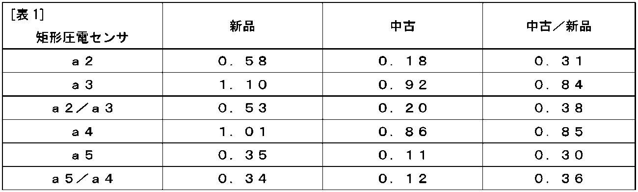
変形計測部10として、平面形状が矩形の第1の圧電センサ11(サイズ10mm×6mm:10mm×2mmの3本セット、図6(b)参照)からなる変形計測部10を備えたタイヤ劣化推定装置100を、第1の圧電センサ11の長手方向がタイヤの幅方向と平行になるように、タイヤ(新品および中古)の内側面に配置して、圧電センサからの出力を測定した結果を以下の表1および図10(a)に示す。
変形計測部10として、平面形状が矩形の第1の圧電センサ11(サイズ10mm×6mm:10mm×2mmの3本セット、図6(b)参照)からなる変形計測部10を備えたタイヤ劣化推定装置100を、第1の圧電センサ11の長手方向がタイヤの幅方向と平行になるように、タイヤ(新品および中古)の内側面に配置して、圧電センサからの出力を測定した結果を以下の表1および図10(a)に示す。
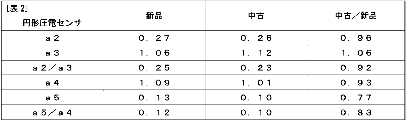
変形計測部10として、平面形状が円形の第2の圧電センサ12(直径10mm、図6(b)参照、)からなる変形計測部10を備えたタイヤ劣化推定装置100を、タイヤ(新品および中古)の内側面に配置して、第2の圧電センサ12からの出力を測定した結果を表2および図10(b)に示す。
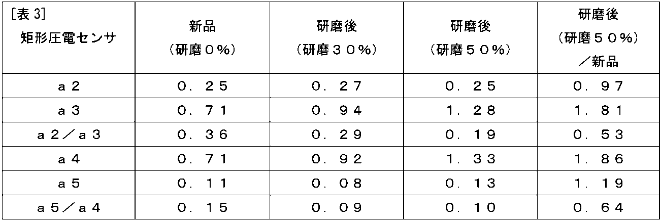
<新品タイヤのバフ研磨前後の評価>
変形計測部10として、平面形状が矩形の第1の圧電センサ11(サイズ10mm×2mmの3本セット、図6(b)参照)からなる変形計測部10を備えたタイヤ劣化推定装置100を、第1の圧電センサ11の長手方向がタイヤの幅方向と平行になるように、タイヤ(新品)の内側面に配置し、バフ研磨によりタイヤ表面のゴムを所定の厚みで削りとる前(初期値:0%)と後(全体の30%・50%研磨)に測定した結果を表3および図11(a)に示す。
変形計測部10として、平面形状が矩形の第1の圧電センサ11(サイズ10mm×2mmの3本セット、図6(b)参照)からなる変形計測部10を備えたタイヤ劣化推定装置100を、第1の圧電センサ11の長手方向がタイヤの幅方向と平行になるように、タイヤ(新品)の内側面に配置し、バフ研磨によりタイヤ表面のゴムを所定の厚みで削りとる前(初期値:0%)と後(全体の30%・50%研磨)に測定した結果を表3および図11(a)に示す。
変形計測部10として、平面形状が円形の第2の圧電センサ12(直径L2=10mm、図6参照、)を、タイヤ(新品および中古)の内側面に配置して、圧電センサからの出力を測定した結果を表4および図11(b)に示す。
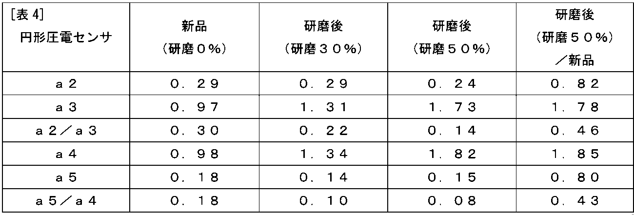
表1~4の結果のうち、a2/a3およびa5/a4について、新品時の値に対する劣化後(中古またはバフ研磨後)における値の比について、以下の表5にまとめて示す。

図10は、新品タイヤと中古品タイヤの測定により得られたピーク値を比較するグラフであり、変形計測部として(a)が矩形の圧電センサ、(b)が円形の圧電センサを用いた測定結果を示している。
タイヤの劣化に伴うタイヤの挙動変化は、タイヤの変形速度の経時的な波形におけるピーク値の変化として捉えることができた。図10(a)と図10(b)とに示すように、タイヤの幅方向の感度が良好な平面形状が矩形の矩形圧電センサを用いることにより、タイヤの劣化の程度を感度よく検知することができた。また、接地前後におけるピーク(a2、a5)のほうが、接地時におけるピーク(a3、a4)よりも、新品タイヤと中古品タイヤとの波形の差が大きく、タイヤの劣化の程度を感度よく検知することができた。
図11は、バフを用いて新品タイヤを強制的に摩耗させた後に測定して得られたピーク値を比較するグラフであり、変形計測部として(a)矩形圧電センサ、(b)円形圧電センサを用いた測定結果を示している。
図11(a)~図11(b)に示すように、タイヤの摩擦進行に伴うタイヤの挙動変化は、タイヤの変形速度の経時的な波形のピークの変化として捉えることができた。測定に用いる圧電センサは、タイヤの幅方向の感度が良好な平面形状が矩形の圧電センサと、平面形状が円形の圧電センサとで、大きな違いは無かった。接地時のピーク(a3、a4)のほうが、接地前後におけるピーク(a2、a5)よりも、タイヤの摩耗の進行程度を感度よく検知することができた。
図11(a)~図11(b)に示すように、タイヤの摩擦進行に伴うタイヤの挙動変化は、タイヤの変形速度の経時的な波形のピークの変化として捉えることができた。測定に用いる圧電センサは、タイヤの幅方向の感度が良好な平面形状が矩形の圧電センサと、平面形状が円形の圧電センサとで、大きな違いは無かった。接地時のピーク(a3、a4)のほうが、接地前後におけるピーク(a2、a5)よりも、タイヤの摩耗の進行程度を感度よく検知することができた。
図10(a)、図10(b)および図11(a)、図11(b)に示すように、タイヤの劣化が、硬度などの特性変化によるか摩耗によるかによって、タイヤの変形速度のピークのうち、感度のよいものが異なっていた。しかし、接地前後における第1のピーク値を接地時における第2ピーク値で除算して得られた値(第1のピーク/第2のピーク、a2/a3、a5/a4)を、タイヤ劣化の指標として用いることにより、経時的な柔軟性変化などの特性変化および摩耗によるゴムの厚の減少のいずれも検知して、タイヤの劣化状態を推定することが可能である。すなわち、(第1のピーク/第2のピーク)の値は、タイヤの劣化が進行するにしたがって小さくなるから、初期の値からの変化を評価指標とすることにより、経時的な劣化を伴う摩耗および経時的な劣化を伴わない急激な摩耗の何れの劣化も推定することができる。新品と中古品のタイヤの違いを精度良く検知できることから、矩形の圧電センサを変形計測部として用いることが好ましいといえる。
本発明は、タイヤの劣化の程度を推定する方法および装置として有用である。
10 :変形計測部
11、11a、11b、11c :第1の圧電センサ
12 :第2の圧電センサ
20 :制御部
21 :算出部
22 :推定部
23 :警告部
30 :記憶部
40 :通信部
50 :路面
100 :タイヤ劣化推定装置
200 :タイヤ
201 :内側面
202 :タイヤ表面
300 :車体
C :接地中心点
O :回転中心
X :回転角度
L :回転方向
W :幅方向
a1、a2、a5、a6:ピーク(第1のピーク)
a3、a4 :ピーク(第2のピーク)
b1、b2、b4、b5:ピーク(第3のピーク)
b3 :ピーク(第4のピーク)
11、11a、11b、11c :第1の圧電センサ
12 :第2の圧電センサ
20 :制御部
21 :算出部
22 :推定部
23 :警告部
30 :記憶部
40 :通信部
50 :路面
100 :タイヤ劣化推定装置
200 :タイヤ
201 :内側面
202 :タイヤ表面
300 :車体
C :接地中心点
O :回転中心
X :回転角度
L :回転方向
W :幅方向
a1、a2、a5、a6:ピーク(第1のピーク)
a3、a4 :ピーク(第2のピーク)
b1、b2、b4、b5:ピーク(第3のピーク)
b3 :ピーク(第4のピーク)
Claims (17)
- タイヤの内側面に配置されたタイヤ劣化推定装置を用いたタイヤ劣化推定方法であって、
前記タイヤが回転しているときの前記タイヤの変形速度であるタイヤ変形速度を計測し、前記タイヤ変形速度の時系列変化を得る変形速度計測ステップと、
前記タイヤ変形速度の時系列変化から、前記タイヤ変形速度のピーク値を算出する算出ステップと、
前記タイヤ変形速度の時系列変化における、前記タイヤの踏み込み時以前または蹴り出し時以後における前記タイヤ変形速度の前記ピーク値である第1のピーク値を用いて、前記タイヤの劣化度を推定する推定ステップと、
を備えることを特徴とするタイヤ劣化推定方法。 - 前記算出ステップは、前記時系列変化から、前記タイヤの踏み込み時以前または蹴り出し時以後における前記タイヤ変形速度の前記ピーク値である前記第1のピーク値、およびタイヤ接地時における前記タイヤ変形速度の前記ピーク値である第2のピーク値を算出し、
前記推定ステップは、前記第2のピーク値と前記第1のピーク値との比に基づいて、前記タイヤの前記劣化度を推定する
請求項1に記載のタイヤ劣化推定方法。 - 前記推定ステップは、
接地前における前記第1のピーク値を前記第2のピーク値で除算して得られた第1の比率、または
接地後における前記第1のピーク値を前記第2のピーク値で除算して得られた第2の比率に基づいて、前記タイヤの前記劣化度を推定する
請求項2に記載のタイヤ劣化推定方法。 - 前記推定ステップは、前記第2のピーク値に対する前記第1のピーク値の比率が、
基準値の50%以下となったときに、前記タイヤが劣化したと推定する
請求項2に記載のタイヤ劣化推定方法。 - タイヤの内側面に配置されたタイヤ劣化推定装置を用いたタイヤ劣化推定方法であって、
前記タイヤが回転しているときの前記タイヤの変形速度を計測し、タイヤ変形速度を積分したタイヤ変形量の時系列変化を得る変形量計測ステップと、
前記タイヤ変形量の時系列変化から、前記タイヤ変形量のピーク値を特定する算出ステップと、
前記タイヤ変形量の時系列変化における、前記タイヤの踏み込み時以前または蹴り出し時以後における前記タイヤ変形量の前記ピーク値である第3のピーク値を用いて、前記タイヤの劣化度を推定する推定ステップと、
を備えることを特徴とするタイヤ劣化推定方法。 - 前記変形量計測ステップは、前記時系列変化から、タイヤの踏み込み時以前または蹴り出し時以後における前記タイヤ変形量の前記第3のピーク値、およびタイヤ接地時における前記タイヤ変形量の第4のピーク値を算出し、
前記推定ステップは、前記第3のピーク値と前記第4のピーク値との比に基づいて、前記タイヤの前記劣化度を推定する
請求項5に記載のタイヤ劣化推定方法。 - タイヤの内側面に配置されて前記タイヤの劣化状態を判別するタイヤ劣化推定装置において、
前記タイヤが回転しているときの前記タイヤの変形を計測可能な変形計測部と、
タイヤ変形速度の時系列変化から、前記タイヤの踏み込み時以前または蹴り出し時以後における前記タイヤ変形速度の時系列変化における第1のピーク値を算出する算出部と、
前記タイヤ変形速度の前記第1のピーク値を用いて、前記タイヤの劣化度を推定する推定部と、
を備えることを特徴とするタイヤ劣化推定装置。 - 前記算出部が、前記タイヤ変形速度の時系列変化から、タイヤの踏み込み時以前または蹴り出し時以後における前記タイヤ変形速度の前記第1のピーク値、およびタイヤ接地時における前記タイヤ変形速度の第2のピーク値を算出し、
前記推定部が、前記タイヤ変形速度の前記第1のピーク値および前記第2のピーク値を用いて、前記タイヤの劣化度を推定する、
請求項7に記載のタイヤ劣化推定装置。 - 前記変形計測部は、シート状に形成された圧電センサであり、前記タイヤの前記内側面に接して配置され、前記タイヤの前記内側面の変形速度を測定するとともに、当該測定した変形速度を前記タイヤ変形速度とすることを特徴とする請求項7に記載のタイヤ劣化推定装置。
- 前記圧電センサは、第1の圧電センサおよび第2の圧電センサを備えており、前記第1の圧電センサと前記第2の圧電センサとは、前記タイヤの変形方向に対する感度が異なる、
請求項9に記載のタイヤ劣化推定装置。 - 前記第1の圧電センサは、前記第2の圧電センサよりも、前記タイヤの幅方向の感度が高い、
請求項10に記載のタイヤ劣化推定装置。 - 前記第1の圧電センサは、法線方向から見たときに長方形状に形成されており、長手方向が前記タイヤの幅方向となるように配置されており、
前記第2の圧電センサは、法線方向から見たときに円形状に形成されている、
請求項11に記載のタイヤ劣化推定装置。 - 前記第1の圧電センサおよび前記第2の圧電センサは、前記タイヤの回転方向に沿った同一直線上に配置されている
請求項10、11または12に記載のタイヤ劣化推定装置。 - 前記推定部は、前記第1の圧電センサの計測結果に基づく、前記タイヤの踏み込み時以前または蹴り出し時以後における前記タイヤ変形速度の前記第1のピーク値と、前記第2の圧電センサの計測結果に基づく、前記タイヤの接地時における前記タイヤ変形速度の第2のピーク値とを用いて、前記タイヤの劣化度を推定する
請求項10ないし13のいずれか1項に記載のタイヤ劣化推定装置。 - 前記推定部は、前記第2のピーク値に対する前記第1のピーク値の比率に基づいてタイヤの劣化度を推定する
請求項14に記載のタイヤ劣化推定装置。 - 前記推定部は、前記第1の圧電センサおよび前記第2の圧電センサの計測結果に基づくタイヤ変形速度の前記第1のピーク値の差に基づいて、前記タイヤの劣化度を推定する
請求項11に記載のタイヤ劣化推定装置。 - 外部と通信可能な通信部と、
前記タイヤが劣化していると前記推定部が推定した場合に警告の指示を行う警告部と、をさらに備えている、請求項7に記載のタイヤ劣化推定装置。
Priority Applications (4)
| Application Number | Priority Date | Filing Date | Title |
|---|---|---|---|
| JP2021525917A JP7216821B2 (ja) | 2019-06-14 | 2020-03-13 | タイヤ劣化推定装置 |
| CN202080043656.5A CN114008435B (zh) | 2019-06-14 | 2020-03-13 | 轮胎劣化推断装置以及轮胎劣化推断方法 |
| DE112020002863.1T DE112020002863T5 (de) | 2019-06-14 | 2020-03-13 | Vorrichtung zur abschätzung der reifenabnutzung und verfahren zur abschätzung der reifenabnutzung |
| US17/535,207 US12083832B2 (en) | 2019-06-14 | 2021-11-24 | Tire deterioration inferring device and tire deterioration inferring method |
Applications Claiming Priority (2)
| Application Number | Priority Date | Filing Date | Title |
|---|---|---|---|
| JP2019111194 | 2019-06-14 | ||
| JP2019-111194 | 2019-06-14 |
Related Child Applications (1)
| Application Number | Title | Priority Date | Filing Date |
|---|---|---|---|
| US17/535,207 Continuation US12083832B2 (en) | 2019-06-14 | 2021-11-24 | Tire deterioration inferring device and tire deterioration inferring method |
Publications (1)
| Publication Number | Publication Date |
|---|---|
| WO2020250517A1 true WO2020250517A1 (ja) | 2020-12-17 |
Family
ID=73781734
Family Applications (1)
| Application Number | Title | Priority Date | Filing Date |
|---|---|---|---|
| PCT/JP2020/010984 Ceased WO2020250517A1 (ja) | 2019-06-14 | 2020-03-13 | タイヤ劣化推定装置およびタイヤ劣化推定方法 |
Country Status (5)
| Country | Link |
|---|---|
| US (1) | US12083832B2 (ja) |
| JP (1) | JP7216821B2 (ja) |
| CN (1) | CN114008435B (ja) |
| DE (1) | DE112020002863T5 (ja) |
| WO (1) | WO2020250517A1 (ja) |
Cited By (4)
| Publication number | Priority date | Publication date | Assignee | Title |
|---|---|---|---|---|
| US20210208029A1 (en) * | 2018-10-05 | 2021-07-08 | Bridgestone Corporation | Tire wear estimation method |
| WO2021153277A1 (ja) * | 2020-01-29 | 2021-08-05 | 横浜ゴム株式会社 | 摩耗状態検知装置 |
| JP2024040618A (ja) * | 2022-09-13 | 2024-03-26 | Toyo Tire株式会社 | タイヤの陸剛性の評価方法 |
| EP4349620A4 (en) * | 2021-10-01 | 2024-10-23 | Sumitomo Rubber Industries, Ltd. | SYSTEM FOR DETERMINING TIRE ANOMALIES, DEVICE FOR DETERMINING TIRE ANOMALIES, METHOD FOR DETERMINING TIRE ANOMALIES AND PROGRAM |
Families Citing this family (5)
| Publication number | Priority date | Publication date | Assignee | Title |
|---|---|---|---|---|
| JP7425579B2 (ja) * | 2019-10-21 | 2024-01-31 | 株式会社ブリヂストン | タイヤ摩耗量推定システム、タイヤ摩耗量推定プログラム及びタイヤ摩耗量推定方法 |
| JP2024516636A (ja) * | 2021-04-30 | 2024-04-16 | テクスキャン インコーポレイテッド | 接触センサ |
| JP7726144B2 (ja) | 2022-07-14 | 2025-08-20 | トヨタ自動車株式会社 | 情報処理装置、それを備えた車両、情報処理方法およびプログラム |
| US12067854B2 (en) * | 2022-10-06 | 2024-08-20 | Ford Global Technologies, Llc | Vehicle wheel theft detection systems and methods using wheel sensor data |
| CN121716723B (zh) * | 2026-02-26 | 2026-04-21 | 山东兴达轮胎有限公司 | 车辆轮胎动态载荷监测系统及方法 |
Citations (9)
| Publication number | Priority date | Publication date | Assignee | Title |
|---|---|---|---|---|
| JP2005345238A (ja) * | 2004-06-02 | 2005-12-15 | Bridgestone Corp | 路面摩擦係数の推定方法とその装置 |
| JP2006142991A (ja) * | 2004-11-19 | 2006-06-08 | Yokohama Rubber Co Ltd:The | タイヤ滑り状態検出方法及びタイヤ滑り状態検出装置 |
| WO2009008502A1 (ja) * | 2007-07-11 | 2009-01-15 | Kabushiki Kaisha Bridgestone | タイヤ摩耗推定方法 |
| JP2009061917A (ja) * | 2007-09-06 | 2009-03-26 | Bridgestone Corp | タイヤ摩耗推定方法及びタイヤ摩耗推定装置 |
| US20100131208A1 (en) * | 2006-11-29 | 2010-05-27 | Federico Mancosu | Method for determining at least one parameter representative of at least one interaction along a longitudinal direction between a tyre for vehicle and the ground |
| JP2011168211A (ja) * | 2010-02-19 | 2011-09-01 | Bridgestone Corp | タイヤ偏摩耗の推定方法 |
| JP2012218682A (ja) * | 2011-04-13 | 2012-11-12 | Honda Motor Co Ltd | 車輪荷重値算出装置 |
| JP2014234038A (ja) * | 2013-05-31 | 2014-12-15 | 国立大学法人 東京大学 | タイヤ内センサーの変形状態検知方法、タイヤ接地状態推定方法、及び、タイヤ接地状態推定装置 |
| JP2016190615A (ja) * | 2015-03-31 | 2016-11-10 | 株式会社ブリヂストン | タイヤ摩耗量推定方法及びタイヤ摩耗量推定装置 |
Family Cites Families (5)
| Publication number | Priority date | Publication date | Assignee | Title |
|---|---|---|---|---|
| JPS5111505B1 (ja) | 1969-01-08 | 1976-04-12 | ||
| CN2468032Y (zh) * | 2001-03-13 | 2001-12-26 | 上海轮胎橡胶(集团)股份有限公司 | 受力轮胎花纹块与胎体变形量测试装置 |
| JP4680532B2 (ja) * | 2004-06-02 | 2011-05-11 | 株式会社ブリヂストン | タイヤの動的状態推定方法とその装置 |
| JP5165603B2 (ja) * | 2009-01-09 | 2013-03-21 | 株式会社ブリヂストン | タイヤ走行状態推定方法、定常走行状態推定装置、タイヤ摩耗推定方法とその装置 |
| KR101772858B1 (ko) * | 2012-11-20 | 2017-08-30 | 미쉐린 러쉐르슈 에 떼크니크 에스.에이. | 신호 품질을 개선하기 위한 타이어 내 압전 디바이스의 원주방향 배향 |
-
2020
- 2020-03-13 WO PCT/JP2020/010984 patent/WO2020250517A1/ja not_active Ceased
- 2020-03-13 DE DE112020002863.1T patent/DE112020002863T5/de not_active Ceased
- 2020-03-13 CN CN202080043656.5A patent/CN114008435B/zh active Active
- 2020-03-13 JP JP2021525917A patent/JP7216821B2/ja active Active
-
2021
- 2021-11-24 US US17/535,207 patent/US12083832B2/en active Active
Patent Citations (9)
| Publication number | Priority date | Publication date | Assignee | Title |
|---|---|---|---|---|
| JP2005345238A (ja) * | 2004-06-02 | 2005-12-15 | Bridgestone Corp | 路面摩擦係数の推定方法とその装置 |
| JP2006142991A (ja) * | 2004-11-19 | 2006-06-08 | Yokohama Rubber Co Ltd:The | タイヤ滑り状態検出方法及びタイヤ滑り状態検出装置 |
| US20100131208A1 (en) * | 2006-11-29 | 2010-05-27 | Federico Mancosu | Method for determining at least one parameter representative of at least one interaction along a longitudinal direction between a tyre for vehicle and the ground |
| WO2009008502A1 (ja) * | 2007-07-11 | 2009-01-15 | Kabushiki Kaisha Bridgestone | タイヤ摩耗推定方法 |
| JP2009061917A (ja) * | 2007-09-06 | 2009-03-26 | Bridgestone Corp | タイヤ摩耗推定方法及びタイヤ摩耗推定装置 |
| JP2011168211A (ja) * | 2010-02-19 | 2011-09-01 | Bridgestone Corp | タイヤ偏摩耗の推定方法 |
| JP2012218682A (ja) * | 2011-04-13 | 2012-11-12 | Honda Motor Co Ltd | 車輪荷重値算出装置 |
| JP2014234038A (ja) * | 2013-05-31 | 2014-12-15 | 国立大学法人 東京大学 | タイヤ内センサーの変形状態検知方法、タイヤ接地状態推定方法、及び、タイヤ接地状態推定装置 |
| JP2016190615A (ja) * | 2015-03-31 | 2016-11-10 | 株式会社ブリヂストン | タイヤ摩耗量推定方法及びタイヤ摩耗量推定装置 |
Cited By (6)
| Publication number | Priority date | Publication date | Assignee | Title |
|---|---|---|---|---|
| US20210208029A1 (en) * | 2018-10-05 | 2021-07-08 | Bridgestone Corporation | Tire wear estimation method |
| US11662272B2 (en) * | 2018-10-05 | 2023-05-30 | Bridgestone Corporation | Tire wear estimation method |
| WO2021153277A1 (ja) * | 2020-01-29 | 2021-08-05 | 横浜ゴム株式会社 | 摩耗状態検知装置 |
| US12214625B2 (en) | 2020-01-29 | 2025-02-04 | The Yokohama Rubber Co., Ltd. | Wear-condition-sensing device |
| EP4349620A4 (en) * | 2021-10-01 | 2024-10-23 | Sumitomo Rubber Industries, Ltd. | SYSTEM FOR DETERMINING TIRE ANOMALIES, DEVICE FOR DETERMINING TIRE ANOMALIES, METHOD FOR DETERMINING TIRE ANOMALIES AND PROGRAM |
| JP2024040618A (ja) * | 2022-09-13 | 2024-03-26 | Toyo Tire株式会社 | タイヤの陸剛性の評価方法 |
Also Published As
| Publication number | Publication date |
|---|---|
| US20220080779A1 (en) | 2022-03-17 |
| JP7216821B2 (ja) | 2023-02-01 |
| US12083832B2 (en) | 2024-09-10 |
| JPWO2020250517A1 (ja) | 2020-12-17 |
| DE112020002863T5 (de) | 2022-03-03 |
| CN114008435A (zh) | 2022-02-01 |
| CN114008435B (zh) | 2024-12-06 |
Similar Documents
| Publication | Publication Date | Title |
|---|---|---|
| JP7216821B2 (ja) | タイヤ劣化推定装置 | |
| JP6563165B2 (ja) | タイヤサイドウォール荷重推定システム及び方法 | |
| JP5412315B2 (ja) | タイヤ偏摩耗の推定方法 | |
| JP7425579B2 (ja) | タイヤ摩耗量推定システム、タイヤ摩耗量推定プログラム及びタイヤ摩耗量推定方法 | |
| JP6650680B2 (ja) | タイヤ摩耗量推定方法及びタイヤ摩耗量推定装置 | |
| JP5620268B2 (ja) | タイヤ摩耗推定方法及びタイヤ摩耗推定装置 | |
| JP6997845B2 (ja) | タイヤの曲げ剛性の変化によるタイヤの摩耗測定装置及びそれを用いたタイヤの摩耗測定方法 | |
| JP2007153034A (ja) | タイヤ摩耗状態判定装置 | |
| JP7348198B2 (ja) | タイヤ摩耗推定方法 | |
| US11731466B2 (en) | Tire wear detection apparatus having a signal processor in the tire side apparatus including a state detection unit and level acquisition unit and/or level calculaton unit | |
| JP6265375B2 (ja) | タイヤスリップ角推定システムおよび方法 | |
| JP2019011048A (ja) | タイヤ摩耗状態推定システムおよび方法 | |
| JP2005138702A (ja) | 路面状態判定方法および装置、ならびに路面状態判定のプログラム | |
| JP7460379B2 (ja) | 摩耗状態検知装置 | |
| JP2019006351A (ja) | 路面状態推定方法及び路面状態推定装置 | |
| JP4752704B2 (ja) | タイヤ摩耗寿命予測方法 | |
| JP2018127091A (ja) | スリップ検出システム、スリップ検出方法及びスリップ検出プログラム | |
| JP7407100B2 (ja) | タイヤ摩耗状態予測システム、タイヤ摩耗状態予測プログラムおよびタイヤ摩耗状態予測方法 | |
| JP2015145841A (ja) | タイヤのトレッド剛性評価方法 | |
| JP6422162B2 (ja) | タイヤの剛性感評価方法 | |
| JP2001047822A (ja) | 転動タイヤの摩擦エネルギー解析方法 | |
| JP6112870B2 (ja) | タイヤの摩耗予測方法、及びタイヤの摩耗予測プログラム | |
| JP6912686B1 (ja) | タイヤ試験装置 | |
| JP6394223B2 (ja) | タイヤ状態評価システムおよびタイヤ状態評価方法 | |
| JP2007137086A (ja) | 路面摩擦状態推定方法、路面摩擦状態推定装置、及び、路面摩擦状態推定用タイヤ |
Legal Events
| Date | Code | Title | Description |
|---|---|---|---|
| 121 | Ep: the epo has been informed by wipo that ep was designated in this application |
Ref document number: 20823059 Country of ref document: EP Kind code of ref document: A1 |
|
| ENP | Entry into the national phase |
Ref document number: 2021525917 Country of ref document: JP Kind code of ref document: A |
|
| 122 | Ep: pct application non-entry in european phase |
Ref document number: 20823059 Country of ref document: EP Kind code of ref document: A1 |