WO2020246375A1 - 光ファイバー給電システムの光コネクタ及び給電装置並びに光ファイバー給電システム - Google Patents
光ファイバー給電システムの光コネクタ及び給電装置並びに光ファイバー給電システム Download PDFInfo
- Publication number
- WO2020246375A1 WO2020246375A1 PCT/JP2020/021305 JP2020021305W WO2020246375A1 WO 2020246375 A1 WO2020246375 A1 WO 2020246375A1 JP 2020021305 W JP2020021305 W JP 2020021305W WO 2020246375 A1 WO2020246375 A1 WO 2020246375A1
- Authority
- WO
- WIPO (PCT)
- Prior art keywords
- light
- optical fiber
- power supply
- feeding
- power
- Prior art date
- Legal status (The legal status is an assumption and is not a legal conclusion. Google has not performed a legal analysis and makes no representation as to the accuracy of the status listed.)
- Ceased
Links
Images


Classifications
-
- G—PHYSICS
- G02—OPTICS
- G02B—OPTICAL ELEMENTS, SYSTEMS OR APPARATUS
- G02B6/00—Light guides; Structural details of arrangements comprising light guides and other optical elements, e.g. couplings
- G02B6/24—Coupling light guides
- G02B6/42—Coupling light guides with opto-electronic elements
- G02B6/4296—Coupling light guides with opto-electronic elements coupling with sources of high radiant energy, e.g. high power lasers, high temperature light sources
-
- H—ELECTRICITY
- H02—GENERATION; CONVERSION OR DISTRIBUTION OF ELECTRIC POWER
- H02J—ELECTRIC POWER NETWORKS; CIRCUIT ARRANGEMENTS OR SYSTEMS FOR SUPPLYING OR DISTRIBUTING ELECTRIC POWER; SYSTEMS FOR STORING ELECTRIC ENERGY
- H02J4/00—Circuit arrangements for mains or distribution networks not specified as AC or DC; Circuit arrangements for mains or distribution networks combining AC and DC sections or sub-networks
-
- G—PHYSICS
- G02—OPTICS
- G02B—OPTICAL ELEMENTS, SYSTEMS OR APPARATUS
- G02B6/00—Light guides; Structural details of arrangements comprising light guides and other optical elements, e.g. couplings
- G02B6/24—Coupling light guides
- G02B6/42—Coupling light guides with opto-electronic elements
- G02B6/4201—Packages, e.g. shape, construction, internal or external details
- G02B6/4204—Packages, e.g. shape, construction, internal or external details the coupling comprising intermediate optical elements, e.g. lenses, holograms
- G02B6/4206—Optical features
-
- G—PHYSICS
- G02—OPTICS
- G02B—OPTICAL ELEMENTS, SYSTEMS OR APPARATUS
- G02B6/00—Light guides; Structural details of arrangements comprising light guides and other optical elements, e.g. couplings
- G02B6/24—Coupling light guides
- G02B6/42—Coupling light guides with opto-electronic elements
- G02B6/4292—Coupling light guides with opto-electronic elements the light guide being disconnectable from the opto-electronic element, e.g. mutually self aligning arrangements
-
- H—ELECTRICITY
- H01—ELECTRIC ELEMENTS
- H01S—DEVICES USING THE PROCESS OF LIGHT AMPLIFICATION BY STIMULATED EMISSION OF RADIATION [LASER] TO AMPLIFY OR GENERATE LIGHT; DEVICES USING STIMULATED EMISSION OF ELECTROMAGNETIC RADIATION IN WAVE RANGES OTHER THAN OPTICAL
- H01S5/00—Semiconductor lasers
- H01S5/04—Processes or apparatus for excitation, e.g. pumping, e.g. by electron beams
- H01S5/042—Electrical excitation ; Circuits therefor
-
- H—ELECTRICITY
- H02—GENERATION; CONVERSION OR DISTRIBUTION OF ELECTRIC POWER
- H02J—ELECTRIC POWER NETWORKS; CIRCUIT ARRANGEMENTS OR SYSTEMS FOR SUPPLYING OR DISTRIBUTING ELECTRIC POWER; SYSTEMS FOR STORING ELECTRIC ENERGY
- H02J50/00—Circuit arrangements or systems for wireless supply or distribution of electric power
- H02J50/30—Circuit arrangements or systems for wireless supply or distribution of electric power using light, e.g. lasers
-
- H—ELECTRICITY
- H04—ELECTRIC COMMUNICATION TECHNIQUE
- H04B—TRANSMISSION
- H04B10/00—Transmission systems employing electromagnetic waves other than radio-waves, e.g. infrared, visible or ultraviolet light, or employing corpuscular radiation, e.g. quantum communication
- H04B10/80—Optical aspects relating to the use of optical transmission for specific applications, not provided for in groups H04B10/03 - H04B10/70, e.g. optical power feeding or optical transmission through water
- H04B10/806—Arrangements for feeding power
- H04B10/807—Optical power feeding, i.e. transmitting power using an optical signal
-
- G—PHYSICS
- G02—OPTICS
- G02B—OPTICAL ELEMENTS, SYSTEMS OR APPARATUS
- G02B6/00—Light guides; Structural details of arrangements comprising light guides and other optical elements, e.g. couplings
- G02B6/24—Coupling light guides
- G02B6/42—Coupling light guides with opto-electronic elements
- G02B6/4296—Coupling light guides with opto-electronic elements coupling with sources of high radiant energy, e.g. high power lasers, high temperature light sources
- G02B2006/4297—Coupling light guides with opto-electronic elements coupling with sources of high radiant energy, e.g. high power lasers, high temperature light sources having protection means, e.g. protecting humans against accidental exposure to harmful laser radiation
-
- G—PHYSICS
- G02—OPTICS
- G02B—OPTICAL ELEMENTS, SYSTEMS OR APPARATUS
- G02B6/00—Light guides; Structural details of arrangements comprising light guides and other optical elements, e.g. couplings
- G02B6/24—Coupling light guides
- G02B6/36—Mechanical coupling means
- G02B6/38—Mechanical coupling means having fibre to fibre mating means
- G02B6/3807—Dismountable connectors, i.e. comprising plugs
- G02B6/3895—Dismountable connectors, i.e. comprising plugs identification of connection, e.g. right plug to the right socket or full engagement of the mating parts
-
- H—ELECTRICITY
- H04—ELECTRIC COMMUNICATION TECHNIQUE
- H04B—TRANSMISSION
- H04B2210/00—Indexing scheme relating to optical transmission systems
- H04B2210/08—Shut-down or eye-safety
Definitions
- This disclosure relates to optical power supply.
- Patent Document 1 describes an optical transmitter that transmits signal light modulated by an electric signal and feed light for supplying power, a core that transmits the signal light, and a core formed around the core.
- An optical fiber having a first clad having a small refractive index and transmitting the feeding light, and a second clad formed around the first clad and having a smaller refractive index than the first clad, and a first clad of the optical fiber are used for transmission.
- an optical communication device including an optical receiver that operates with the converted power of the fed light and converts the signal light transmitted by the core of the optical fiber into the electric signal.
- the optical connector of the optical fiber feeding system of one aspect of the present disclosure is an optical connector arranged at the output end of the feeding light of the optical fiber feeding system, and opens in conjunction with the connection operation to enable the connection and the disconnection operation. It has a shutter that is closed in conjunction with the above and blocks the emission of the feeding light, and the light receiving surface of the feeding light of the shutter when it is closed is a mirror surface.
- the optical connector of the optical fiber feeding system of one aspect is an optical connector arranged at the output end of the feeding light of the optical fiber feeding system, and opens in conjunction with the connection operation to enable the connection and to perform the disconnection operation. It has a shutter that is closed in conjunction with it to block the emission of the feeding light, and the light receiving surface of the feeding light of the shutter when it is closed is made of a wavelength conversion material.
- the optical fiber power supply (PoF: Power over Fiber) system 1A of the present embodiment includes a power supply device (PSE: Power Sourcing Equipment) 110, an optical fiber cable 200A, and a power receiving device (PD: Powered Device) 310.
- PSE Power Sourcing Equipment
- PD Powered Device
- the power feeding device in the present disclosure is a device that converts electric power into light energy and supplies it
- a power receiving device is a device that receives the supply of light energy and converts the light energy into electric power.
- the power feeding device 110 includes a power feeding semiconductor laser 111.
- the optical fiber cable 200A includes an optical fiber 250A that forms a transmission path for feeding light.
- the power receiving device 310 includes a photoelectric conversion element 311.
- the power feeding device 110 is connected to a power source, and a power feeding semiconductor laser 111 or the like is electrically driven.
- the power feeding semiconductor laser 111 oscillates the laser with the electric power from the power source and outputs the power feeding light 112.
- one end 201A can be connected to the power feeding device 110, and the other end 202A can be connected to the power receiving device 310 to transmit the feeding light 112.
- the power feeding light 112 from the power feeding device 110 is input to one end 201A of the optical fiber cable 200A, the feeding light 112 propagates in the optical fiber 250A, and is output from the other end 202A to the power receiving device 310.
- the photoelectric conversion element 311 converts the feeding light 112 transmitted through the optical fiber cable 200A into electric power.
- the electric power converted by the photoelectric conversion element 311 is used as the driving power required in the power receiving device 310. Further, the power receiving device 310 can output the electric power converted by the photoelectric conversion element 311 for an external device.
- the semiconductor material constituting the semiconductor region that exerts the light-electric conversion effect of the power feeding semiconductor laser 111 and the photoelectric conversion element 311 is a semiconductor having a short wavelength laser wavelength of 500 nm or less. Since a semiconductor having a short wavelength laser wavelength has a large band gap and high photoelectric conversion efficiency, the photoelectric conversion efficiency on the power generation side and the power receiving side of optical power supply is improved, and the optical power supply efficiency is improved.
- the semiconductor material for example, a semiconductor material of a laser medium having a laser wavelength (fundamental wave) of 200 to 500 nm, such as diamond, gallium oxide, aluminum nitride, and GaN, may be used.
- a semiconductor having a band gap of 2.4 eV or more is applied as the semiconductor material.
- a semiconductor material of a laser medium having a bandgap of 2.4 to 6.2 eV such as diamond, gallium oxide, aluminum nitride, and GaN, may be used.
- a semiconductor material of a laser medium having a laser wavelength (fundamental wave) smaller than 200 nm may be used.
- These semiconductor materials may be applied to either one of the power feeding semiconductor laser 111 and the photoelectric conversion element 311. The photoelectric conversion efficiency on the power feeding side or the power receiving side is improved, and the optical power feeding efficiency is improved.
- the optical fiber power supply (PoF: Power over Fiber) system 1 of the present embodiment includes a power supply system via an optical fiber and an optical communication system, and is a power supply device (PSE: Power Sourcing Equipment) 110.
- a first data communication device 100 including the above, an optical fiber cable 200, and a second data communication device 300 including a power receiving device (PD) 310 are provided.
- the power feeding device 110 includes a power feeding semiconductor laser 111.
- the first data communication device 100 includes a power supply device 110, a transmission unit 120 that performs data communication, and a reception unit 130.
- the first data communication device 100 corresponds to a data terminal equipment (DTE (Data Terminal Equipment)), a repeater (Repeater), and the like.
- the transmitter 120 includes a signal semiconductor laser 121 and a modulator 122.
- the receiving unit 130 includes a signal photodiode 131.
- the optical fiber cable 200 includes an optical fiber 250 having a core 210 forming a signal light transmission path and a clad 220 arranged on the outer periphery of the core 210 and forming a feeding light transmission path.
- the power receiving device 310 includes a photoelectric conversion element 311.
- the second data communication device 300 includes a power receiving device 310, a transmitting unit 320, a receiving unit 330, and a data processing unit 340.
- the second data communication device 300 corresponds to a power end station (Power End Station) or the like.
- the transmitter 320 includes a signal semiconductor laser 321 and a modulator 322.
- the receiving unit 330 includes a signal photodiode 331.
- the data processing unit 340 is a unit that processes a received signal.
- the second data communication device 300 is a node in the communication network. Alternatively, the second data communication device 300 may be a node that communicates with another node.
- the first data communication device 100 is connected to a power source, and a power feeding semiconductor laser 111, a signal semiconductor laser 121, a modulator 122, a signal photodiode 131, and the like are electrically driven.
- the first data communication device 100 is a node in the communication network.
- the first data communication device 100 may be a node that communicates with another node.
- the power feeding semiconductor laser 111 oscillates the laser with the electric power from the power source and outputs the power feeding light 112.
- the photoelectric conversion element 311 converts the power feeding light 112 transmitted through the optical fiber cable 200 into electric power.
- the electric power converted by the photoelectric conversion element 311 is the driving power of the transmitting unit 320, the receiving unit 330, and the data processing unit 340, and other driving power required in the second data communication device 300.
- the second data communication device 300 may be capable of outputting the electric power converted by the photoelectric conversion element 311 for an external device.
- the modulator 122 of the transmitting unit 120 modulates the laser light 123 from the signal semiconductor laser 121 based on the transmission data 124 and outputs it as the signal light 125.
- the signal photodiode 331 of the receiving unit 330 demodulates the signal light 125 transmitted through the optical fiber cable 200 into an electric signal and outputs it to the data processing unit 340.
- the data processing unit 340 transmits data based on the electric signal to the node, while receiving data from the node and outputting the data as transmission data 324 to the modulator 322.
- the modulator 322 of the transmitting unit 320 modulates the laser light 323 from the signal semiconductor laser 321 based on the transmission data 324 and outputs it as the signal light 325.
- the signal photodiode 131 of the receiving unit 130 demodulates the signal light 325 transmitted through the optical fiber cable 200 into an electric signal and outputs it.
- the data by the electric signal is transmitted to the node, while the data from the node is referred to as transmission data 124.
- the feed light 112 and the signal light 125 from the first data communication device 100 are input to one end 201 of the optical fiber cable 200, the feed light 112 propagates through the clad 220, the signal light 125 propagates through the core 210, and the other end. It is output from 202 to the second data communication device 300.
- the signal light 325 from the second data communication device 300 is input to the other end 202 of the optical fiber cable 200, propagates through the core 210, and is output from one end 201 to the first data communication device 100.
- the first data communication device 100 is provided with an optical input / output unit 140 and an optical connector 141 attached to the optical input / output unit 140.
- the second data communication device 300 is provided with an optical input / output unit 350 and an optical connector 351 attached to the optical input / output unit 350.
- An optical connector 230 provided at one end 201 of the optical fiber cable 200 connects to the optical connector 141.
- An optical connector 240 provided at the other end 202 of the optical fiber cable 200 connects to the optical connector 351.
- the optical input / output unit 140 guides the feeding light 112 to the clad 220, guides the signal light 125 to the core 210, and guides the signal light 325 to the receiving unit 130.
- the optical input / output unit 350 guides the feeding light 112 to the power receiving device 310, guides the signal light 125 to the receiving unit 330, and guides the signal light 325 to the core 210.
- the optical fiber cable 200 has one end 201 connectable to the first data communication device 100 and the other end 202 connectable to the second data communication device 300 to transmit the feeding light 112. Further, in the present embodiment, the optical fiber cable 200 transmits the signal lights 125 and 325 in both directions.
- the semiconductor material constituting the semiconductor region that exerts the light-electricity conversion effect of the power feeding semiconductor laser 111 and the photoelectric conversion element 311 As the semiconductor material constituting the semiconductor region that exerts the light-electricity conversion effect of the power feeding semiconductor laser 111 and the photoelectric conversion element 311, the same material as in the first embodiment is applied, and high light power feeding efficiency is realized. ..
- the optical fiber 260 for transmitting signal light and the optical fiber 270 for transmitting the feeding light may be provided separately.
- the optical fiber cable 200B may also be composed of a plurality of cables.
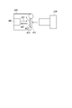
- the optical connector 410 is arranged at the output terminal 401 of the feeding light 112 of the above optical fiber feeding system 1 or 1A, 1B.
- the optical connector 420 is a mating connector that connects to the optical connector 410.
- the optical connector 410 is applied as the optical connector 141 and the optical connector 351 shown in FIG. 3, and the optical connector 420 is applied as the optical connector 230 and the optical connector 240 shown in FIG.
- the optical connector 410 has a shutter 411.
- the shutter 411 opens in conjunction with the connection operation between the optical connector 410 and the optical connector 420 to enable the connection. At the same time, the shutter 411 is closed in conjunction with the detachment operation of the optical connector 410 and the optical connector 420 to block the emission of the feeding light 112 to the outside.
- the mechanism for closing the shutter 411 is composed of a hinge mechanism or the like having an elastic member for urging the shutter 411 on the closing side.
- the light receiving surface 412 of the feeding light 112 of the shutter 411 when it is closed is a mirror surface. That is, the light receiving surface 412, which is the inner surface of the shutter 411, is a mirror surface.
- the member 413 that constitutes the light receiving surface 412 is a reflecting mirror, and the light receiving surface 412 is formed by the mirror surface. Therefore, when the shutter 411 is closed, the feeding light 112 is reflected on the mirror surface (412) of the reflecting mirror (413) to become the return light 402, and a part of the light is incident on the output end 401.
- the 6 detects the disconnection of the connector by detecting the return light 402 radiated from the shutter 411, and executes the control to stop the output of the power supply light 112 by the power supply device 110. Since the return light 402 returns through the propagation path of the feeding light or the propagation path of the signal light, it can be received by the photodiode and analyzed by the control device 150 to detect the disconnection of the connector.
- a signal photodiode 131 may be used, or a special signal photodiode 131 may be provided.
- a wavelength conversion material such as a fluorescent material is applied instead of the above reflector. That is, as shown in FIG. 5, a mode is implemented in which the light receiving surface 412 of the feeding light 112 of the shutter 411 when it is closed is made of a wavelength conversion material. That is, the member 413 constituting the light receiving surface 412, which is the inner surface of the shutter 411, is the wavelength conversion material. Therefore, when the shutter 411 is closed, the feeding light 112 is applied to the wavelength conversion material (413), and the wavelength conversion material (413) emits a return light 402 containing light having a wavelength different from that of the feeding light 112. A part of it is incident on the output end 401.
- the wavelength conversion material may have a property of completely converting the received light into a different wavelength, or a material having a property of spreading spectrum over a wavelength of the received light and a wavelength different from the received light.
- the shutter 411 can prevent leakage of the feeding light 112 when the connector is disconnected. Further, it is easy to detect the shutter release by the return light 402 radiated from the shutter 411.
- the light receiving surface 412 of the feeding light 112 of the shutter 411 is a mirror surface, the light intensity of the return light 402 can be secured, and even when the return path is a long distance, it can be detected.
- the light receiving surface 412 of the feeding light 112 of the shutter 411 is made of a wavelength conversion material, the distinguishability from other light such as stray light originating from the inside is good, and the detection accuracy of the connector disconnection can be ensured.
- the control device 150 stops the output of the feeding light 112, it is possible to prevent accidents from being generated or destroyed by irradiating the shutter 411 with the feeding light 112 for a long time, and to stop wasteful power consumption. be able to.
- the present invention can be used for an optical connector and a power supply device of an optical fiber power supply system and an optical fiber power supply system.
- Optical fiber power supply system 1 Optical fiber power supply system 1B
- Optical fiber power supply system 100 First data communication device 110 Power supply device 111 Semiconductor laser for power supply 112 Power supply light 120 Transmission unit 125 Signal light 130 Reception unit 140 Optical input / output unit 141
- Optical connector 200A Optical fiber cable 200
- Optical fiber cable 200B Optical fiber cable 210 Core 220 Clad 250A Optical fiber 250 Optical fiber 260 Optical fiber 270 Optical fiber 300
- Optical connector 410 Optical Fiber 411 Shutter 420 Optical Fiber
Landscapes
- Physics & Mathematics (AREA)
- Optics & Photonics (AREA)
- General Physics & Mathematics (AREA)
- Engineering & Computer Science (AREA)
- Electromagnetism (AREA)
- Computer Networks & Wireless Communication (AREA)
- Signal Processing (AREA)
- Power Engineering (AREA)
- Condensed Matter Physics & Semiconductors (AREA)
- Optical Couplings Of Light Guides (AREA)
- Optical Communication System (AREA)
Priority Applications (3)
| Application Number | Priority Date | Filing Date | Title |
|---|---|---|---|
| EP20818694.0A EP3930216B1 (en) | 2019-06-06 | 2020-05-29 | Optical connector for optical fiber power feed system, power feed device, and optical fiber power feed system |
| CN202080019128.6A CN113544928A (zh) | 2019-06-06 | 2020-05-29 | 光纤供电系统的光连接器及供电装置和光纤供电系统 |
| US17/442,619 US11509401B2 (en) | 2019-06-06 | 2020-05-29 | Optical connector and power sourcing equipment of power over fiber system, and power over fiber system |
Applications Claiming Priority (2)
| Application Number | Priority Date | Filing Date | Title |
|---|---|---|---|
| JP2019105973A JP6890631B2 (ja) | 2019-06-06 | 2019-06-06 | 光ファイバー給電システムの光コネクタ及び給電装置並びに光ファイバー給電システム |
| JP2019-105973 | 2019-06-06 |
Publications (1)
| Publication Number | Publication Date |
|---|---|
| WO2020246375A1 true WO2020246375A1 (ja) | 2020-12-10 |
Family
ID=73652838
Family Applications (1)
| Application Number | Title | Priority Date | Filing Date |
|---|---|---|---|
| PCT/JP2020/021305 Ceased WO2020246375A1 (ja) | 2019-06-06 | 2020-05-29 | 光ファイバー給電システムの光コネクタ及び給電装置並びに光ファイバー給電システム |
Country Status (5)
| Country | Link |
|---|---|
| US (1) | US11509401B2 (https=) |
| EP (1) | EP3930216B1 (https=) |
| JP (1) | JP6890631B2 (https=) |
| CN (1) | CN113544928A (https=) |
| WO (1) | WO2020246375A1 (https=) |
Cited By (6)
| Publication number | Priority date | Publication date | Assignee | Title |
|---|---|---|---|---|
| WO2022169970A1 (en) * | 2021-02-03 | 2022-08-11 | Nubis Communications, Inc. | Communication systems having optical power supplies |
| EP4152650A1 (en) * | 2021-09-16 | 2023-03-22 | Nubis Communications, Inc. | Polarization-diversity optical power supply |
| US11621795B2 (en) | 2020-06-01 | 2023-04-04 | Nubis Communications, Inc. | Polarization-diversity optical power supply |
| US12066653B2 (en) | 2021-04-22 | 2024-08-20 | Nubis Communications, Inc. | Communication systems having optical power supplies |
| US12250027B2 (en) | 2020-06-01 | 2025-03-11 | Nubis Communications, Inc. | Polarization-diversity optical power supply |
| US12615091B2 (en) | 2020-06-01 | 2026-04-28 | Ciena Corporation | Polarization-diversity optical power supply |
Families Citing this family (2)
| Publication number | Priority date | Publication date | Assignee | Title |
|---|---|---|---|---|
| US11575055B2 (en) | 2019-07-15 | 2023-02-07 | SLT Technologies, Inc | Methods for coupling of optical fibers to a power photodiode |
| US20240255708A1 (en) * | 2023-01-30 | 2024-08-01 | Nokia Solutions And Networks Oy | Self-reporting optical connector device |
Citations (6)
| Publication number | Priority date | Publication date | Assignee | Title |
|---|---|---|---|---|
| JPH0453910A (ja) * | 1990-06-22 | 1992-02-21 | Hitachi Cable Ltd | 光コネクタ |
| JPH08331061A (ja) * | 1995-05-31 | 1996-12-13 | Fuji Electric Co Ltd | 光信号伝送装置 |
| JP2001194562A (ja) * | 1999-10-25 | 2001-07-19 | Furukawa Electric Co Ltd:The | 遮光シャッター付きアダプタおよび遮光シャッター付き光モジュールレセプタクル |
| JP2007094151A (ja) * | 2005-09-29 | 2007-04-12 | Chugoku Electric Power Co Inc:The | 信号処理装置及び信号処理システム |
| JP2010135989A (ja) | 2008-12-03 | 2010-06-17 | Mitsubishi Electric Corp | 光ファイバ、光通信装置、及び光通信方法 |
| WO2010146659A1 (ja) * | 2009-06-16 | 2010-12-23 | 富士通オプティカルコンポーネンツ株式会社 | 光伝送装置 |
Family Cites Families (15)
| Publication number | Priority date | Publication date | Assignee | Title |
|---|---|---|---|---|
| US6811325B2 (en) * | 2001-04-18 | 2004-11-02 | Corona Optical Systems, Inc. | Communications assembly disabling mechanism |
| JP2003131071A (ja) | 2001-10-30 | 2003-05-08 | Matsushita Electric Ind Co Ltd | 光コネクタ用キャップ |
| WO2008134750A2 (en) * | 2007-04-30 | 2008-11-06 | Finisar Corporation | Eye safety and interoperability of active cable devices |
| US20110278479A1 (en) * | 2010-05-11 | 2011-11-17 | Searete Llc, A Limited Liability Corporation Of The State Of Delaware | Optical power transmission system and method having counter-propagating control signal |
| CN201878048U (zh) | 2010-11-04 | 2011-06-22 | 中电普瑞科技有限公司 | 一种采用多模通信光纤传递能量装置 |
| CN202083537U (zh) * | 2011-05-05 | 2011-12-21 | 禾普股份有限公司 | 光纤检测装置 |
| EP3115815B1 (en) * | 2014-03-06 | 2022-08-17 | Sony Group Corporation | Optical connector, cable, and optical communication device |
| EP3132295B1 (en) * | 2014-04-16 | 2024-12-18 | Koninklijke Philips N.V. | Optical fiber calibration connector |
| JP6187691B2 (ja) * | 2014-06-12 | 2017-08-30 | 株式会社島津製作所 | ファイバカップリングモジュール |
| CN104459670B (zh) * | 2014-12-04 | 2017-08-11 | 北京理工大学 | 一种基于光纤阵列的多光谱探测波长转换系统 |
| CN105785261A (zh) * | 2014-12-23 | 2016-07-20 | 南京南瑞继保电气有限公司 | 一种高速开关检测装置及方法 |
| US9673893B2 (en) * | 2015-03-20 | 2017-06-06 | Oracle International Corporation | Safety-enhanced laser array |
| JP6283006B2 (ja) * | 2015-09-18 | 2018-02-21 | 株式会社フジクラ | 光コネクタ部品 |
| CN108990224B (zh) * | 2017-06-02 | 2021-05-04 | 深圳市绎立锐光科技开发有限公司 | 激光光纤照明系统、室内照明系统及室外照明系统 |
| US10313026B2 (en) * | 2017-06-27 | 2019-06-04 | Rolls-Royce North American Technologies, Inc. | Power and communications over fiber optic cabling |
-
2019
- 2019-06-06 JP JP2019105973A patent/JP6890631B2/ja active Active
-
2020
- 2020-05-29 CN CN202080019128.6A patent/CN113544928A/zh active Pending
- 2020-05-29 EP EP20818694.0A patent/EP3930216B1/en active Active
- 2020-05-29 US US17/442,619 patent/US11509401B2/en active Active
- 2020-05-29 WO PCT/JP2020/021305 patent/WO2020246375A1/ja not_active Ceased
Patent Citations (6)
| Publication number | Priority date | Publication date | Assignee | Title |
|---|---|---|---|---|
| JPH0453910A (ja) * | 1990-06-22 | 1992-02-21 | Hitachi Cable Ltd | 光コネクタ |
| JPH08331061A (ja) * | 1995-05-31 | 1996-12-13 | Fuji Electric Co Ltd | 光信号伝送装置 |
| JP2001194562A (ja) * | 1999-10-25 | 2001-07-19 | Furukawa Electric Co Ltd:The | 遮光シャッター付きアダプタおよび遮光シャッター付き光モジュールレセプタクル |
| JP2007094151A (ja) * | 2005-09-29 | 2007-04-12 | Chugoku Electric Power Co Inc:The | 信号処理装置及び信号処理システム |
| JP2010135989A (ja) | 2008-12-03 | 2010-06-17 | Mitsubishi Electric Corp | 光ファイバ、光通信装置、及び光通信方法 |
| WO2010146659A1 (ja) * | 2009-06-16 | 2010-12-23 | 富士通オプティカルコンポーネンツ株式会社 | 光伝送装置 |
Non-Patent Citations (1)
| Title |
|---|
| See also references of EP3930216A4 |
Cited By (9)
| Publication number | Priority date | Publication date | Assignee | Title |
|---|---|---|---|---|
| US11621795B2 (en) | 2020-06-01 | 2023-04-04 | Nubis Communications, Inc. | Polarization-diversity optical power supply |
| US12184402B2 (en) | 2020-06-01 | 2024-12-31 | Nubis Communications, Inc. | Polarization-diversity optical power supply |
| US12250027B2 (en) | 2020-06-01 | 2025-03-11 | Nubis Communications, Inc. | Polarization-diversity optical power supply |
| US12615091B2 (en) | 2020-06-01 | 2026-04-28 | Ciena Corporation | Polarization-diversity optical power supply |
| WO2022169970A1 (en) * | 2021-02-03 | 2022-08-11 | Nubis Communications, Inc. | Communication systems having optical power supplies |
| US12101129B2 (en) | 2021-02-03 | 2024-09-24 | Nubis Communications, Inc. | Communication systems having optical power supplies |
| US12066653B2 (en) | 2021-04-22 | 2024-08-20 | Nubis Communications, Inc. | Communication systems having optical power supplies |
| US12164142B2 (en) | 2021-04-22 | 2024-12-10 | Nubis Communications, Inc. | Communication systems having optical power supplies |
| EP4152650A1 (en) * | 2021-09-16 | 2023-03-22 | Nubis Communications, Inc. | Polarization-diversity optical power supply |
Also Published As
| Publication number | Publication date |
|---|---|
| EP3930216A1 (en) | 2021-12-29 |
| JP2020202423A (ja) | 2020-12-17 |
| US20220094449A1 (en) | 2022-03-24 |
| JP6890631B2 (ja) | 2021-06-18 |
| EP3930216A4 (en) | 2022-05-04 |
| EP3930216B1 (en) | 2023-01-04 |
| CN113544928A (zh) | 2021-10-22 |
| US11509401B2 (en) | 2022-11-22 |
Similar Documents
| Publication | Publication Date | Title |
|---|---|---|
| JP6890631B2 (ja) | 光ファイバー給電システムの光コネクタ及び給電装置並びに光ファイバー給電システム | |
| JP6814253B2 (ja) | 光ファイバー給電システム及びデータ通信装置 | |
| JP2023153145A (ja) | データ通信装置及び光給電システム | |
| JP6890638B2 (ja) | 光ファイバー給電システム及び光ファイバーケーブル | |
| JP6972078B2 (ja) | 光ファイバー給電システム | |
| WO2021186828A1 (ja) | 光給電システムの受電装置及び光給電システム | |
| JP7344698B2 (ja) | 光ファイバー給電システム | |
| JP6890636B2 (ja) | 光給電システム | |
| WO2021075087A1 (ja) | 光ファイバー給電システム | |
| JP6898391B2 (ja) | 光ファイバー給電システム | |
| JP7436160B2 (ja) | 光給電システム | |
| WO2020246298A1 (ja) | 光ファイバー給電システム及び給電光可視化蓋部材 | |
| JP6898411B2 (ja) | 光伝送システム | |
| JP2020202424A (ja) | 光電アダプタ及び電気入出力可能な光伝送ケーブル | |
| JP7084441B2 (ja) | 光ファイバー給電システムの給電装置及び光ファイバー給電システム | |
| JP7308682B2 (ja) | 光給電システム | |
| WO2021186827A1 (ja) | 給電光伝送用光ファイバーケーブル及び光ファイバー給電システム |
Legal Events
| Date | Code | Title | Description |
|---|---|---|---|
| 121 | Ep: the epo has been informed by wipo that ep was designated in this application |
Ref document number: 20818694 Country of ref document: EP Kind code of ref document: A1 |
|
| ENP | Entry into the national phase |
Ref document number: 2020818694 Country of ref document: EP Effective date: 20210923 |
|
| NENP | Non-entry into the national phase |
Ref country code: DE |