WO2020246375A1 - Optical connector for optical fiber power feed system, power feed device, and optical fiber power feed system - Google Patents
Optical connector for optical fiber power feed system, power feed device, and optical fiber power feed system Download PDFInfo
- Publication number
- WO2020246375A1 WO2020246375A1 PCT/JP2020/021305 JP2020021305W WO2020246375A1 WO 2020246375 A1 WO2020246375 A1 WO 2020246375A1 JP 2020021305 W JP2020021305 W JP 2020021305W WO 2020246375 A1 WO2020246375 A1 WO 2020246375A1
- Authority
- WO
- WIPO (PCT)
- Prior art keywords
- light
- optical fiber
- power supply
- feeding
- power
- Prior art date
Links
Images


Classifications
-
- G—PHYSICS
- G02—OPTICS
- G02B—OPTICAL ELEMENTS, SYSTEMS OR APPARATUS
- G02B6/00—Light guides; Structural details of arrangements comprising light guides and other optical elements, e.g. couplings
- G02B6/24—Coupling light guides
- G02B6/42—Coupling light guides with opto-electronic elements
- G02B6/4296—Coupling light guides with opto-electronic elements coupling with sources of high radiant energy, e.g. high power lasers, high temperature light sources
-
- H—ELECTRICITY
- H02—GENERATION; CONVERSION OR DISTRIBUTION OF ELECTRIC POWER
- H02J—CIRCUIT ARRANGEMENTS OR SYSTEMS FOR SUPPLYING OR DISTRIBUTING ELECTRIC POWER; SYSTEMS FOR STORING ELECTRIC ENERGY
- H02J4/00—Circuit arrangements for mains or distribution networks not specified as ac or dc
-
- G—PHYSICS
- G02—OPTICS
- G02B—OPTICAL ELEMENTS, SYSTEMS OR APPARATUS
- G02B6/00—Light guides; Structural details of arrangements comprising light guides and other optical elements, e.g. couplings
- G02B6/24—Coupling light guides
- G02B6/42—Coupling light guides with opto-electronic elements
- G02B6/4201—Packages, e.g. shape, construction, internal or external details
- G02B6/4204—Packages, e.g. shape, construction, internal or external details the coupling comprising intermediate optical elements, e.g. lenses, holograms
- G02B6/4206—Optical features
-
- G—PHYSICS
- G02—OPTICS
- G02B—OPTICAL ELEMENTS, SYSTEMS OR APPARATUS
- G02B6/00—Light guides; Structural details of arrangements comprising light guides and other optical elements, e.g. couplings
- G02B6/24—Coupling light guides
- G02B6/42—Coupling light guides with opto-electronic elements
- G02B6/4292—Coupling light guides with opto-electronic elements the light guide being disconnectable from the opto-electronic element, e.g. mutually self aligning arrangements
-
- H—ELECTRICITY
- H01—ELECTRIC ELEMENTS
- H01S—DEVICES USING THE PROCESS OF LIGHT AMPLIFICATION BY STIMULATED EMISSION OF RADIATION [LASER] TO AMPLIFY OR GENERATE LIGHT; DEVICES USING STIMULATED EMISSION OF ELECTROMAGNETIC RADIATION IN WAVE RANGES OTHER THAN OPTICAL
- H01S5/00—Semiconductor lasers
- H01S5/04—Processes or apparatus for excitation, e.g. pumping, e.g. by electron beams
- H01S5/042—Electrical excitation ; Circuits therefor
-
- H—ELECTRICITY
- H02—GENERATION; CONVERSION OR DISTRIBUTION OF ELECTRIC POWER
- H02J—CIRCUIT ARRANGEMENTS OR SYSTEMS FOR SUPPLYING OR DISTRIBUTING ELECTRIC POWER; SYSTEMS FOR STORING ELECTRIC ENERGY
- H02J50/00—Circuit arrangements or systems for wireless supply or distribution of electric power
- H02J50/30—Circuit arrangements or systems for wireless supply or distribution of electric power using light, e.g. lasers
-
- H—ELECTRICITY
- H04—ELECTRIC COMMUNICATION TECHNIQUE
- H04B—TRANSMISSION
- H04B10/00—Transmission systems employing electromagnetic waves other than radio-waves, e.g. infrared, visible or ultraviolet light, or employing corpuscular radiation, e.g. quantum communication
- H04B10/80—Optical aspects relating to the use of optical transmission for specific applications, not provided for in groups H04B10/03 - H04B10/70, e.g. optical power feeding or optical transmission through water
- H04B10/806—Arrangements for feeding power
- H04B10/807—Optical power feeding, i.e. transmitting power using an optical signal
-
- G—PHYSICS
- G02—OPTICS
- G02B—OPTICAL ELEMENTS, SYSTEMS OR APPARATUS
- G02B6/00—Light guides; Structural details of arrangements comprising light guides and other optical elements, e.g. couplings
- G02B6/24—Coupling light guides
- G02B6/42—Coupling light guides with opto-electronic elements
- G02B6/4296—Coupling light guides with opto-electronic elements coupling with sources of high radiant energy, e.g. high power lasers, high temperature light sources
- G02B2006/4297—Coupling light guides with opto-electronic elements coupling with sources of high radiant energy, e.g. high power lasers, high temperature light sources having protection means, e.g. protecting humans against accidental exposure to harmful laser radiation
-
- G—PHYSICS
- G02—OPTICS
- G02B—OPTICAL ELEMENTS, SYSTEMS OR APPARATUS
- G02B6/00—Light guides; Structural details of arrangements comprising light guides and other optical elements, e.g. couplings
- G02B6/24—Coupling light guides
- G02B6/36—Mechanical coupling means
- G02B6/38—Mechanical coupling means having fibre to fibre mating means
- G02B6/3807—Dismountable connectors, i.e. comprising plugs
- G02B6/3895—Dismountable connectors, i.e. comprising plugs identification of connection, e.g. right plug to the right socket or full engagement of the mating parts
-
- H—ELECTRICITY
- H04—ELECTRIC COMMUNICATION TECHNIQUE
- H04B—TRANSMISSION
- H04B2210/00—Indexing scheme relating to optical transmission systems
- H04B2210/08—Shut-down or eye-safety
Definitions
- This disclosure relates to optical power supply.
- Patent Document 1 describes an optical transmitter that transmits signal light modulated by an electric signal and feed light for supplying power, a core that transmits the signal light, and a core formed around the core.
- An optical fiber having a first clad having a small refractive index and transmitting the feeding light, and a second clad formed around the first clad and having a smaller refractive index than the first clad, and a first clad of the optical fiber are used for transmission.
- an optical communication device including an optical receiver that operates with the converted power of the fed light and converts the signal light transmitted by the core of the optical fiber into the electric signal.
- the optical connector of the optical fiber feeding system of one aspect of the present disclosure is an optical connector arranged at the output end of the feeding light of the optical fiber feeding system, and opens in conjunction with the connection operation to enable the connection and the disconnection operation. It has a shutter that is closed in conjunction with the above and blocks the emission of the feeding light, and the light receiving surface of the feeding light of the shutter when it is closed is a mirror surface.
- the optical connector of the optical fiber feeding system of one aspect is an optical connector arranged at the output end of the feeding light of the optical fiber feeding system, and opens in conjunction with the connection operation to enable the connection and to perform the disconnection operation. It has a shutter that is closed in conjunction with it to block the emission of the feeding light, and the light receiving surface of the feeding light of the shutter when it is closed is made of a wavelength conversion material.
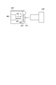
- the optical fiber power supply (PoF: Power over Fiber) system 1A of the present embodiment includes a power supply device (PSE: Power Sourcing Equipment) 110, an optical fiber cable 200A, and a power receiving device (PD: Powered Device) 310.
- PSE Power Sourcing Equipment
- PD Powered Device
- the power feeding device in the present disclosure is a device that converts electric power into light energy and supplies it
- a power receiving device is a device that receives the supply of light energy and converts the light energy into electric power.
- the power feeding device 110 includes a power feeding semiconductor laser 111.
- the optical fiber cable 200A includes an optical fiber 250A that forms a transmission path for feeding light.
- the power receiving device 310 includes a photoelectric conversion element 311.
- the power feeding device 110 is connected to a power source, and a power feeding semiconductor laser 111 or the like is electrically driven.
- the power feeding semiconductor laser 111 oscillates the laser with the electric power from the power source and outputs the power feeding light 112.
- one end 201A can be connected to the power feeding device 110, and the other end 202A can be connected to the power receiving device 310 to transmit the feeding light 112.
- the power feeding light 112 from the power feeding device 110 is input to one end 201A of the optical fiber cable 200A, the feeding light 112 propagates in the optical fiber 250A, and is output from the other end 202A to the power receiving device 310.
- the photoelectric conversion element 311 converts the feeding light 112 transmitted through the optical fiber cable 200A into electric power.
- the electric power converted by the photoelectric conversion element 311 is used as the driving power required in the power receiving device 310. Further, the power receiving device 310 can output the electric power converted by the photoelectric conversion element 311 for an external device.
- the semiconductor material constituting the semiconductor region that exerts the light-electric conversion effect of the power feeding semiconductor laser 111 and the photoelectric conversion element 311 is a semiconductor having a short wavelength laser wavelength of 500 nm or less. Since a semiconductor having a short wavelength laser wavelength has a large band gap and high photoelectric conversion efficiency, the photoelectric conversion efficiency on the power generation side and the power receiving side of optical power supply is improved, and the optical power supply efficiency is improved.
- the semiconductor material for example, a semiconductor material of a laser medium having a laser wavelength (fundamental wave) of 200 to 500 nm, such as diamond, gallium oxide, aluminum nitride, and GaN, may be used.
- a semiconductor having a band gap of 2.4 eV or more is applied as the semiconductor material.
- a semiconductor material of a laser medium having a bandgap of 2.4 to 6.2 eV such as diamond, gallium oxide, aluminum nitride, and GaN, may be used.
- a semiconductor material of a laser medium having a laser wavelength (fundamental wave) smaller than 200 nm may be used.
- These semiconductor materials may be applied to either one of the power feeding semiconductor laser 111 and the photoelectric conversion element 311. The photoelectric conversion efficiency on the power feeding side or the power receiving side is improved, and the optical power feeding efficiency is improved.
- the optical fiber power supply (PoF: Power over Fiber) system 1 of the present embodiment includes a power supply system via an optical fiber and an optical communication system, and is a power supply device (PSE: Power Sourcing Equipment) 110.
- a first data communication device 100 including the above, an optical fiber cable 200, and a second data communication device 300 including a power receiving device (PD) 310 are provided.
- the power feeding device 110 includes a power feeding semiconductor laser 111.
- the first data communication device 100 includes a power supply device 110, a transmission unit 120 that performs data communication, and a reception unit 130.
- the first data communication device 100 corresponds to a data terminal equipment (DTE (Data Terminal Equipment)), a repeater (Repeater), and the like.
- the transmitter 120 includes a signal semiconductor laser 121 and a modulator 122.
- the receiving unit 130 includes a signal photodiode 131.
- the optical fiber cable 200 includes an optical fiber 250 having a core 210 forming a signal light transmission path and a clad 220 arranged on the outer periphery of the core 210 and forming a feeding light transmission path.
- the power receiving device 310 includes a photoelectric conversion element 311.
- the second data communication device 300 includes a power receiving device 310, a transmitting unit 320, a receiving unit 330, and a data processing unit 340.
- the second data communication device 300 corresponds to a power end station (Power End Station) or the like.
- the transmitter 320 includes a signal semiconductor laser 321 and a modulator 322.
- the receiving unit 330 includes a signal photodiode 331.
- the data processing unit 340 is a unit that processes a received signal.
- the second data communication device 300 is a node in the communication network. Alternatively, the second data communication device 300 may be a node that communicates with another node.
- the first data communication device 100 is connected to a power source, and a power feeding semiconductor laser 111, a signal semiconductor laser 121, a modulator 122, a signal photodiode 131, and the like are electrically driven.
- the first data communication device 100 is a node in the communication network.
- the first data communication device 100 may be a node that communicates with another node.
- the power feeding semiconductor laser 111 oscillates the laser with the electric power from the power source and outputs the power feeding light 112.
- the photoelectric conversion element 311 converts the power feeding light 112 transmitted through the optical fiber cable 200 into electric power.
- the electric power converted by the photoelectric conversion element 311 is the driving power of the transmitting unit 320, the receiving unit 330, and the data processing unit 340, and other driving power required in the second data communication device 300.
- the second data communication device 300 may be capable of outputting the electric power converted by the photoelectric conversion element 311 for an external device.
- the modulator 122 of the transmitting unit 120 modulates the laser light 123 from the signal semiconductor laser 121 based on the transmission data 124 and outputs it as the signal light 125.
- the signal photodiode 331 of the receiving unit 330 demodulates the signal light 125 transmitted through the optical fiber cable 200 into an electric signal and outputs it to the data processing unit 340.
- the data processing unit 340 transmits data based on the electric signal to the node, while receiving data from the node and outputting the data as transmission data 324 to the modulator 322.
- the modulator 322 of the transmitting unit 320 modulates the laser light 323 from the signal semiconductor laser 321 based on the transmission data 324 and outputs it as the signal light 325.
- the signal photodiode 131 of the receiving unit 130 demodulates the signal light 325 transmitted through the optical fiber cable 200 into an electric signal and outputs it.
- the data by the electric signal is transmitted to the node, while the data from the node is referred to as transmission data 124.
- the feed light 112 and the signal light 125 from the first data communication device 100 are input to one end 201 of the optical fiber cable 200, the feed light 112 propagates through the clad 220, the signal light 125 propagates through the core 210, and the other end. It is output from 202 to the second data communication device 300.
- the signal light 325 from the second data communication device 300 is input to the other end 202 of the optical fiber cable 200, propagates through the core 210, and is output from one end 201 to the first data communication device 100.
- the first data communication device 100 is provided with an optical input / output unit 140 and an optical connector 141 attached to the optical input / output unit 140.
- the second data communication device 300 is provided with an optical input / output unit 350 and an optical connector 351 attached to the optical input / output unit 350.
- An optical connector 230 provided at one end 201 of the optical fiber cable 200 connects to the optical connector 141.
- An optical connector 240 provided at the other end 202 of the optical fiber cable 200 connects to the optical connector 351.
- the optical input / output unit 140 guides the feeding light 112 to the clad 220, guides the signal light 125 to the core 210, and guides the signal light 325 to the receiving unit 130.
- the optical input / output unit 350 guides the feeding light 112 to the power receiving device 310, guides the signal light 125 to the receiving unit 330, and guides the signal light 325 to the core 210.
- the optical fiber cable 200 has one end 201 connectable to the first data communication device 100 and the other end 202 connectable to the second data communication device 300 to transmit the feeding light 112. Further, in the present embodiment, the optical fiber cable 200 transmits the signal lights 125 and 325 in both directions.
- the semiconductor material constituting the semiconductor region that exerts the light-electricity conversion effect of the power feeding semiconductor laser 111 and the photoelectric conversion element 311 As the semiconductor material constituting the semiconductor region that exerts the light-electricity conversion effect of the power feeding semiconductor laser 111 and the photoelectric conversion element 311, the same material as in the first embodiment is applied, and high light power feeding efficiency is realized. ..
- the optical fiber 260 for transmitting signal light and the optical fiber 270 for transmitting the feeding light may be provided separately.
- the optical fiber cable 200B may also be composed of a plurality of cables.
- the optical connector 410 is arranged at the output terminal 401 of the feeding light 112 of the above optical fiber feeding system 1 or 1A, 1B.
- the optical connector 420 is a mating connector that connects to the optical connector 410.
- the optical connector 410 is applied as the optical connector 141 and the optical connector 351 shown in FIG. 3, and the optical connector 420 is applied as the optical connector 230 and the optical connector 240 shown in FIG.
- the optical connector 410 has a shutter 411.
- the shutter 411 opens in conjunction with the connection operation between the optical connector 410 and the optical connector 420 to enable the connection. At the same time, the shutter 411 is closed in conjunction with the detachment operation of the optical connector 410 and the optical connector 420 to block the emission of the feeding light 112 to the outside.
- the mechanism for closing the shutter 411 is composed of a hinge mechanism or the like having an elastic member for urging the shutter 411 on the closing side.
- the light receiving surface 412 of the feeding light 112 of the shutter 411 when it is closed is a mirror surface. That is, the light receiving surface 412, which is the inner surface of the shutter 411, is a mirror surface.
- the member 413 that constitutes the light receiving surface 412 is a reflecting mirror, and the light receiving surface 412 is formed by the mirror surface. Therefore, when the shutter 411 is closed, the feeding light 112 is reflected on the mirror surface (412) of the reflecting mirror (413) to become the return light 402, and a part of the light is incident on the output end 401.
- the 6 detects the disconnection of the connector by detecting the return light 402 radiated from the shutter 411, and executes the control to stop the output of the power supply light 112 by the power supply device 110. Since the return light 402 returns through the propagation path of the feeding light or the propagation path of the signal light, it can be received by the photodiode and analyzed by the control device 150 to detect the disconnection of the connector.
- a signal photodiode 131 may be used, or a special signal photodiode 131 may be provided.
- a wavelength conversion material such as a fluorescent material is applied instead of the above reflector. That is, as shown in FIG. 5, a mode is implemented in which the light receiving surface 412 of the feeding light 112 of the shutter 411 when it is closed is made of a wavelength conversion material. That is, the member 413 constituting the light receiving surface 412, which is the inner surface of the shutter 411, is the wavelength conversion material. Therefore, when the shutter 411 is closed, the feeding light 112 is applied to the wavelength conversion material (413), and the wavelength conversion material (413) emits a return light 402 containing light having a wavelength different from that of the feeding light 112. A part of it is incident on the output end 401.
- the wavelength conversion material may have a property of completely converting the received light into a different wavelength, or a material having a property of spreading spectrum over a wavelength of the received light and a wavelength different from the received light.
- the shutter 411 can prevent leakage of the feeding light 112 when the connector is disconnected. Further, it is easy to detect the shutter release by the return light 402 radiated from the shutter 411.
- the light receiving surface 412 of the feeding light 112 of the shutter 411 is a mirror surface, the light intensity of the return light 402 can be secured, and even when the return path is a long distance, it can be detected.
- the light receiving surface 412 of the feeding light 112 of the shutter 411 is made of a wavelength conversion material, the distinguishability from other light such as stray light originating from the inside is good, and the detection accuracy of the connector disconnection can be ensured.
- the control device 150 stops the output of the feeding light 112, it is possible to prevent accidents from being generated or destroyed by irradiating the shutter 411 with the feeding light 112 for a long time, and to stop wasteful power consumption. be able to.
- the present invention can be used for an optical connector and a power supply device of an optical fiber power supply system and an optical fiber power supply system.
- Optical fiber power supply system 1 Optical fiber power supply system 1B
- Optical fiber power supply system 100 First data communication device 110 Power supply device 111 Semiconductor laser for power supply 112 Power supply light 120 Transmission unit 125 Signal light 130 Reception unit 140 Optical input / output unit 141
- Optical connector 200A Optical fiber cable 200
- Optical fiber cable 200B Optical fiber cable 210 Core 220 Clad 250A Optical fiber 250 Optical fiber 260 Optical fiber 270 Optical fiber 300
- Optical connector 410 Optical Fiber 411 Shutter 420 Optical Fiber
Abstract
This optical connector 410 which is for an optical fiber power feed system and is disposed on an output end 401 of power feed light 112, has a shutter 411 that opens in linkage with a connection operation to enable the connection and closes in linkage with a disconnection operation to block the emission of the power feed light, wherein a light-receiving surface 412, for the power feed light, of the shutter when being closed is configured as a mirror surface. Alternatively, the light-receiving surface, for the power feed light, of the shutter when being closed is formed of a wavelength conversion material.
Description
本開示は、光給電に関する。
This disclosure relates to optical power supply.
近時、電力を光(給電光と呼ばれる)に変換して伝送し、当該給電光を電気エネルギーに変換して電力として利用する光給電システムが研究されている。
特許文献1には、電気信号で変調された信号光、及び電力を供給するための給電光を発信する光発信機と、上記信号光を伝送するコア、上記コアの周囲に形成され上記コアより屈折率が小さく上記給電光を伝送する第1クラッド、及び上記第1クラッドの周囲に形成され上記第1クラッドより屈折率が小さい第2クラッド、を有する光ファイバーと、上記光ファイバーの第1クラッドで伝送された上記給電光を変換した電力で動作し、上記光ファイバーのコアで伝送された上記信号光を上記電気信号に変換する光受信機と、を備えた光通信装置が記載されている。 Recently, research has been conducted on an optical power supply system that converts electric power into light (called feed light) and transmits it, converts the feed light into electrical energy, and uses it as electric power.
Patent Document 1 describes an optical transmitter that transmits signal light modulated by an electric signal and feed light for supplying power, a core that transmits the signal light, and a core formed around the core. An optical fiber having a first clad having a small refractive index and transmitting the feeding light, and a second clad formed around the first clad and having a smaller refractive index than the first clad, and a first clad of the optical fiber are used for transmission. Described is an optical communication device including an optical receiver that operates with the converted power of the fed light and converts the signal light transmitted by the core of the optical fiber into the electric signal.
特許文献1には、電気信号で変調された信号光、及び電力を供給するための給電光を発信する光発信機と、上記信号光を伝送するコア、上記コアの周囲に形成され上記コアより屈折率が小さく上記給電光を伝送する第1クラッド、及び上記第1クラッドの周囲に形成され上記第1クラッドより屈折率が小さい第2クラッド、を有する光ファイバーと、上記光ファイバーの第1クラッドで伝送された上記給電光を変換した電力で動作し、上記光ファイバーのコアで伝送された上記信号光を上記電気信号に変換する光受信機と、を備えた光通信装置が記載されている。 Recently, research has been conducted on an optical power supply system that converts electric power into light (called feed light) and transmits it, converts the feed light into electrical energy, and uses it as electric power.
光給電においては、より高エネルギーの光伝送が行われるようになることが見込まれる。
光ファイバー給電システムの敷設時および運用中に、不慮の事故でコネクタが外れてしまったままとなっている場合、給電光のエネルギーによる事故に繋がる危険性がある。よってコネクタが外れている場合には早期に発見する必要がある。 In optical power supply, it is expected that higher energy optical transmission will be performed.
If the connector is left disconnected due to an accident during the installation and operation of the optical fiber power supply system, there is a risk of accident due to the energy of the power supply light. Therefore, if the connector is disconnected, it is necessary to detect it early.
本開示の1つの態様の光ファイバー給電システムの光コネクタは、光ファイバー給電システムの給電光の出力端に配置される光コネクタであって、接続動作に連動して開き当該接続を可能とするとともに離脱動作に連動して閉じられて給電光の出射を遮るシャッターを有し、閉じられている時の当該シャッターの給電光の受光面が鏡面とされている。
また、1つの態様の光ファイバー給電システムの光コネクタは、光ファイバー給電システムの給電光の出力端に配置された光コネクタであって、接続動作に連動して開き当該接続を可能とするとともに離脱動作に連動して閉じられて給電光の出射を遮るシャッターを有し、閉じられている時の当該シャッターの給電光の受光面が波長変換材により構成されている。 The optical connector of the optical fiber feeding system of one aspect of the present disclosure is an optical connector arranged at the output end of the feeding light of the optical fiber feeding system, and opens in conjunction with the connection operation to enable the connection and the disconnection operation. It has a shutter that is closed in conjunction with the above and blocks the emission of the feeding light, and the light receiving surface of the feeding light of the shutter when it is closed is a mirror surface.
Further, the optical connector of the optical fiber feeding system of one aspect is an optical connector arranged at the output end of the feeding light of the optical fiber feeding system, and opens in conjunction with the connection operation to enable the connection and to perform the disconnection operation. It has a shutter that is closed in conjunction with it to block the emission of the feeding light, and the light receiving surface of the feeding light of the shutter when it is closed is made of a wavelength conversion material.
以下に本開示の一実施形態につき図面を参照して説明する。
An embodiment of the present disclosure will be described below with reference to the drawings.
(1)システム概要
〔第1実施形態〕
図1に示すように本実施形態の光ファイバー給電(PoF:Power over Fiber)システム1Aは、給電装置(PSE:Power Sourcing Equipment)110と、光ファイバーケーブル200Aと、受電装置(PD:Powered Device)310を備える。
なお、本開示における給電装置は電力を光エネルギーに変換して供給する装置であり、受電装置は光エネルギーの供給を受け当該光エネルギーを電力に変換する装置である。
給電装置110は、給電用半導体レーザー111を含む。
光ファイバーケーブル200Aは、給電光の伝送路を形成する光ファイバー250Aを含む。
受電装置310は、光電変換素子311を含む。 (1) System overview [First embodiment]
As shown in FIG. 1, the optical fiber power supply (PoF: Power over Fiber) system 1A of the present embodiment includes a power supply device (PSE: Power Sourcing Equipment) 110, anoptical fiber cable 200A, and a power receiving device (PD: Powered Device) 310. Be prepared.
The power feeding device in the present disclosure is a device that converts electric power into light energy and supplies it, and a power receiving device is a device that receives the supply of light energy and converts the light energy into electric power.
Thepower feeding device 110 includes a power feeding semiconductor laser 111.
Theoptical fiber cable 200A includes an optical fiber 250A that forms a transmission path for feeding light.
Thepower receiving device 310 includes a photoelectric conversion element 311.
〔第1実施形態〕
図1に示すように本実施形態の光ファイバー給電(PoF:Power over Fiber)システム1Aは、給電装置(PSE:Power Sourcing Equipment)110と、光ファイバーケーブル200Aと、受電装置(PD:Powered Device)310を備える。
なお、本開示における給電装置は電力を光エネルギーに変換して供給する装置であり、受電装置は光エネルギーの供給を受け当該光エネルギーを電力に変換する装置である。
給電装置110は、給電用半導体レーザー111を含む。
光ファイバーケーブル200Aは、給電光の伝送路を形成する光ファイバー250Aを含む。
受電装置310は、光電変換素子311を含む。 (1) System overview [First embodiment]
As shown in FIG. 1, the optical fiber power supply (PoF: Power over Fiber) system 1A of the present embodiment includes a power supply device (PSE: Power Sourcing Equipment) 110, an
The power feeding device in the present disclosure is a device that converts electric power into light energy and supplies it, and a power receiving device is a device that receives the supply of light energy and converts the light energy into electric power.
The
The
The
給電装置110は電源に接続され、給電用半導体レーザー111等が電気駆動される。
給電用半導体レーザー111は、上記電源からの電力によりレーザー発振して給電光112を出力する。 Thepower feeding device 110 is connected to a power source, and a power feeding semiconductor laser 111 or the like is electrically driven.
The powerfeeding semiconductor laser 111 oscillates the laser with the electric power from the power source and outputs the power feeding light 112.
給電用半導体レーザー111は、上記電源からの電力によりレーザー発振して給電光112を出力する。 The
The power
光ファイバーケーブル200Aは、一端201Aが給電装置110に接続可能とされ、他端202Aが受電装置310に接続可能とされ、給電光112を伝送する。
給電装置110からの給電光112が、光ファイバーケーブル200Aの一端201Aに入力され、給電光112は光ファイバー250A中を伝搬し、他端202Aから受電装置310に出力される。 In theoptical fiber cable 200A, one end 201A can be connected to the power feeding device 110, and the other end 202A can be connected to the power receiving device 310 to transmit the feeding light 112.
Thepower feeding light 112 from the power feeding device 110 is input to one end 201A of the optical fiber cable 200A, the feeding light 112 propagates in the optical fiber 250A, and is output from the other end 202A to the power receiving device 310.
給電装置110からの給電光112が、光ファイバーケーブル200Aの一端201Aに入力され、給電光112は光ファイバー250A中を伝搬し、他端202Aから受電装置310に出力される。 In the
The
光電変換素子311は、光ファイバーケーブル200Aを通して伝送されてきた給電光112を電力に変換する。光電変換素子311により変換された電力が、受電装置310内で必要な駆動電力とされる。さらに受電装置310は光電変換素子311により変換された電力を外部機器用に出力可能とされる。
The photoelectric conversion element 311 converts the feeding light 112 transmitted through the optical fiber cable 200A into electric power. The electric power converted by the photoelectric conversion element 311 is used as the driving power required in the power receiving device 310. Further, the power receiving device 310 can output the electric power converted by the photoelectric conversion element 311 for an external device.
給電用半導体レーザー111及び光電変換素子311の光‐電気間の変換効果を奏する半導体領域を構成する半導体材料が500nm以下の短波長のレーザー波長をもった半導体とされる。
短波長のレーザー波長をもった半導体は、バンドギャップが大きく光電変換効率が高いので、光給電の発電側及び受電側における光電変換効率が向上され、光給電効率が向上する。
そのためには、同半導体材料として、例えば、ダイヤモンド、酸化ガリウム、窒化アルミニウム、GaN等、レーザー波長(基本波)が200~500nmのレーザー媒体の半導体材料を用いてもよい。
また、同半導体材料として、2.4eV以上のバンドギャップを有した半導体が適用される。
例えば、ダイヤモンド、酸化ガリウム、窒化アルミニウム、GaN等、バンドギャップ2.4~6.2eVのレーザー媒体の半導体材料を用いてもよい。
なお、レーザー光は長波長ほど伝送効率が良く、短波長ほど光電変換効率が良い傾向にある。したがって、長距離伝送の場合には、レーザー波長(基本波)が500nmより大きいレーザー媒体の半導体材料を用いてもよい。また、光電変換効率を優先する場合には、レーザー波長(基本波)が200nmより小さいレーザー媒体の半導体材料を用いてもよい。
これらの半導体材料は、給電用半導体レーザー111及び光電変換素子311のいずれか一方に適用してもよい。給電側又は受電側における光電変換効率が向上され、光給電効率が向上する。 The semiconductor material constituting the semiconductor region that exerts the light-electric conversion effect of the powerfeeding semiconductor laser 111 and the photoelectric conversion element 311 is a semiconductor having a short wavelength laser wavelength of 500 nm or less.
Since a semiconductor having a short wavelength laser wavelength has a large band gap and high photoelectric conversion efficiency, the photoelectric conversion efficiency on the power generation side and the power receiving side of optical power supply is improved, and the optical power supply efficiency is improved.
For that purpose, as the semiconductor material, for example, a semiconductor material of a laser medium having a laser wavelength (fundamental wave) of 200 to 500 nm, such as diamond, gallium oxide, aluminum nitride, and GaN, may be used.
Further, as the semiconductor material, a semiconductor having a band gap of 2.4 eV or more is applied.
For example, a semiconductor material of a laser medium having a bandgap of 2.4 to 6.2 eV, such as diamond, gallium oxide, aluminum nitride, and GaN, may be used.
The longer the wavelength of the laser light, the better the transmission efficiency, and the shorter the wavelength, the better the photoelectric conversion efficiency. Therefore, in the case of long-distance transmission, a semiconductor material of a laser medium having a laser wavelength (primary wave) larger than 500 nm may be used. When the photoelectric conversion efficiency is prioritized, a semiconductor material of a laser medium having a laser wavelength (fundamental wave) smaller than 200 nm may be used.
These semiconductor materials may be applied to either one of the powerfeeding semiconductor laser 111 and the photoelectric conversion element 311. The photoelectric conversion efficiency on the power feeding side or the power receiving side is improved, and the optical power feeding efficiency is improved.
短波長のレーザー波長をもった半導体は、バンドギャップが大きく光電変換効率が高いので、光給電の発電側及び受電側における光電変換効率が向上され、光給電効率が向上する。
そのためには、同半導体材料として、例えば、ダイヤモンド、酸化ガリウム、窒化アルミニウム、GaN等、レーザー波長(基本波)が200~500nmのレーザー媒体の半導体材料を用いてもよい。
また、同半導体材料として、2.4eV以上のバンドギャップを有した半導体が適用される。
例えば、ダイヤモンド、酸化ガリウム、窒化アルミニウム、GaN等、バンドギャップ2.4~6.2eVのレーザー媒体の半導体材料を用いてもよい。
なお、レーザー光は長波長ほど伝送効率が良く、短波長ほど光電変換効率が良い傾向にある。したがって、長距離伝送の場合には、レーザー波長(基本波)が500nmより大きいレーザー媒体の半導体材料を用いてもよい。また、光電変換効率を優先する場合には、レーザー波長(基本波)が200nmより小さいレーザー媒体の半導体材料を用いてもよい。
これらの半導体材料は、給電用半導体レーザー111及び光電変換素子311のいずれか一方に適用してもよい。給電側又は受電側における光電変換効率が向上され、光給電効率が向上する。 The semiconductor material constituting the semiconductor region that exerts the light-electric conversion effect of the power
Since a semiconductor having a short wavelength laser wavelength has a large band gap and high photoelectric conversion efficiency, the photoelectric conversion efficiency on the power generation side and the power receiving side of optical power supply is improved, and the optical power supply efficiency is improved.
For that purpose, as the semiconductor material, for example, a semiconductor material of a laser medium having a laser wavelength (fundamental wave) of 200 to 500 nm, such as diamond, gallium oxide, aluminum nitride, and GaN, may be used.
Further, as the semiconductor material, a semiconductor having a band gap of 2.4 eV or more is applied.
For example, a semiconductor material of a laser medium having a bandgap of 2.4 to 6.2 eV, such as diamond, gallium oxide, aluminum nitride, and GaN, may be used.
The longer the wavelength of the laser light, the better the transmission efficiency, and the shorter the wavelength, the better the photoelectric conversion efficiency. Therefore, in the case of long-distance transmission, a semiconductor material of a laser medium having a laser wavelength (primary wave) larger than 500 nm may be used. When the photoelectric conversion efficiency is prioritized, a semiconductor material of a laser medium having a laser wavelength (fundamental wave) smaller than 200 nm may be used.
These semiconductor materials may be applied to either one of the power
〔第2実施形態〕
図2に示すように本実施形態の光ファイバー給電(PoF:Power over Fiber)システム1は、光ファイバーを介した給電システムと光通信システムとを含むものであり、給電装置(PSE:Power Sourcing Equipment)110を含む第1のデータ通信装置100と、光ファイバーケーブル200と、受電装置(PD:Powered Device)310を含む第2のデータ通信装置300とを備える。
給電装置110は、給電用半導体レーザー111を含む。第1のデータ通信装置100は、給電装置110のほか、データ通信を行う発信部120と、受信部130とを含む。第1のデータ通信装置100は、データ端末装置(DTE(Data Terminal Equipment))、中継器(Repeater)等に相当する。発信部120は、信号用半導体レーザー121と、モジュレーター122とを含む。受信部130は、信号用フォトダイオード131を含む。 [Second Embodiment]
As shown in FIG. 2, the optical fiber power supply (PoF: Power over Fiber)system 1 of the present embodiment includes a power supply system via an optical fiber and an optical communication system, and is a power supply device (PSE: Power Sourcing Equipment) 110. A first data communication device 100 including the above, an optical fiber cable 200, and a second data communication device 300 including a power receiving device (PD) 310 are provided.
Thepower feeding device 110 includes a power feeding semiconductor laser 111. The first data communication device 100 includes a power supply device 110, a transmission unit 120 that performs data communication, and a reception unit 130. The first data communication device 100 corresponds to a data terminal equipment (DTE (Data Terminal Equipment)), a repeater (Repeater), and the like. The transmitter 120 includes a signal semiconductor laser 121 and a modulator 122. The receiving unit 130 includes a signal photodiode 131.
図2に示すように本実施形態の光ファイバー給電(PoF:Power over Fiber)システム1は、光ファイバーを介した給電システムと光通信システムとを含むものであり、給電装置(PSE:Power Sourcing Equipment)110を含む第1のデータ通信装置100と、光ファイバーケーブル200と、受電装置(PD:Powered Device)310を含む第2のデータ通信装置300とを備える。
給電装置110は、給電用半導体レーザー111を含む。第1のデータ通信装置100は、給電装置110のほか、データ通信を行う発信部120と、受信部130とを含む。第1のデータ通信装置100は、データ端末装置(DTE(Data Terminal Equipment))、中継器(Repeater)等に相当する。発信部120は、信号用半導体レーザー121と、モジュレーター122とを含む。受信部130は、信号用フォトダイオード131を含む。 [Second Embodiment]
As shown in FIG. 2, the optical fiber power supply (PoF: Power over Fiber)
The
光ファイバーケーブル200は、信号光の伝送路を形成するコア210と、コア210の外周に配置され、給電光の伝送路を形成するクラッド220と有する光ファイバー250を含む。
The optical fiber cable 200 includes an optical fiber 250 having a core 210 forming a signal light transmission path and a clad 220 arranged on the outer periphery of the core 210 and forming a feeding light transmission path.
受電装置310は、光電変換素子311を含む。第2のデータ通信装置300は、受電装置310のほか、発信部320と、受信部330と、データ処理ユニット340とを含む。第2のデータ通信装置300は、パワーエンドステーション(Power End Station)等に相当する。発信部320は、信号用半導体レーザー321と、モジュレーター322とを含む。受信部330は、信号用フォトダイオード331を含む。データ処理ユニット340は、受信した信号を処理するユニットである。また、第2のデータ通信装置300は、通信ネットワークにおけるノードである。または第2のデータ通信装置300は、他のノードと通信するノードでもよい。
The power receiving device 310 includes a photoelectric conversion element 311. The second data communication device 300 includes a power receiving device 310, a transmitting unit 320, a receiving unit 330, and a data processing unit 340. The second data communication device 300 corresponds to a power end station (Power End Station) or the like. The transmitter 320 includes a signal semiconductor laser 321 and a modulator 322. The receiving unit 330 includes a signal photodiode 331. The data processing unit 340 is a unit that processes a received signal. The second data communication device 300 is a node in the communication network. Alternatively, the second data communication device 300 may be a node that communicates with another node.
第1のデータ通信装置100は電源に接続され、給電用半導体レーザー111、信号用半導体レーザー121と、モジュレーター122、信号用フォトダイオード131等が電気駆動される。また、第1のデータ通信装置100は、通信ネットワークにおけるノードである。または第1のデータ通信装置100は、他のノードと通信するノードでもよい。
給電用半導体レーザー111は、上記電源からの電力によりレーザー発振して給電光112を出力する。 The firstdata communication device 100 is connected to a power source, and a power feeding semiconductor laser 111, a signal semiconductor laser 121, a modulator 122, a signal photodiode 131, and the like are electrically driven. The first data communication device 100 is a node in the communication network. Alternatively, the first data communication device 100 may be a node that communicates with another node.
The powerfeeding semiconductor laser 111 oscillates the laser with the electric power from the power source and outputs the power feeding light 112.
給電用半導体レーザー111は、上記電源からの電力によりレーザー発振して給電光112を出力する。 The first
The power
光電変換素子311は、光ファイバーケーブル200を通して伝送されてきた給電光112を電力に変換する。光電変換素子311により変換された電力は、発信部320、受信部330及びデータ処理ユニット340の駆動電力、その他の第2のデータ通信装置300内で必要となる駆動電力とされる。さらに第2のデータ通信装置300は、光電変換素子311により変換された電力を外部機器用に出力可能とされていてもよい。
The photoelectric conversion element 311 converts the power feeding light 112 transmitted through the optical fiber cable 200 into electric power. The electric power converted by the photoelectric conversion element 311 is the driving power of the transmitting unit 320, the receiving unit 330, and the data processing unit 340, and other driving power required in the second data communication device 300. Further, the second data communication device 300 may be capable of outputting the electric power converted by the photoelectric conversion element 311 for an external device.
一方、発信部120のモジュレーター122は、信号用半導体レーザー121からのレーザー光123を送信データ124に基づき変調して信号光125として出力する。
受信部330の信号用フォトダイオード331は、光ファイバーケーブル200を通して伝送されてきた信号光125を電気信号に復調し、データ処理ユニット340に出力する。データ処理ユニット340は、当該電気信号によるデータをノードに送信し、その一
方で当該ノードからデータを受信し、送信データ324としてモジュレーター322に出力する。
発信部320のモジュレーター322は、信号用半導体レーザー321からのレーザー光323を送信データ324に基づき変調して信号光325として出力する。
受信部130の信号用フォトダイオード131は、光ファイバーケーブル200を通して伝送されてきた信号光325を電気信号に復調し出力する。当該電気信号によるデータがノードに送信され、その一方で当該ノードからデータが送信データ124とされる。 On the other hand, themodulator 122 of the transmitting unit 120 modulates the laser light 123 from the signal semiconductor laser 121 based on the transmission data 124 and outputs it as the signal light 125.
Thesignal photodiode 331 of the receiving unit 330 demodulates the signal light 125 transmitted through the optical fiber cable 200 into an electric signal and outputs it to the data processing unit 340. The data processing unit 340 transmits data based on the electric signal to the node, while receiving data from the node and outputting the data as transmission data 324 to the modulator 322.
Themodulator 322 of the transmitting unit 320 modulates the laser light 323 from the signal semiconductor laser 321 based on the transmission data 324 and outputs it as the signal light 325.
Thesignal photodiode 131 of the receiving unit 130 demodulates the signal light 325 transmitted through the optical fiber cable 200 into an electric signal and outputs it. The data by the electric signal is transmitted to the node, while the data from the node is referred to as transmission data 124.
受信部330の信号用フォトダイオード331は、光ファイバーケーブル200を通して伝送されてきた信号光125を電気信号に復調し、データ処理ユニット340に出力する。データ処理ユニット340は、当該電気信号によるデータをノードに送信し、その一
方で当該ノードからデータを受信し、送信データ324としてモジュレーター322に出力する。
発信部320のモジュレーター322は、信号用半導体レーザー321からのレーザー光323を送信データ324に基づき変調して信号光325として出力する。
受信部130の信号用フォトダイオード131は、光ファイバーケーブル200を通して伝送されてきた信号光325を電気信号に復調し出力する。当該電気信号によるデータがノードに送信され、その一方で当該ノードからデータが送信データ124とされる。 On the other hand, the
The
The
The
第1のデータ通信装置100からの給電光112及び信号光125が、光ファイバーケーブル200の一端201に入力され、給電光112はクラッド220を伝搬し、信号光125はコア210を伝搬し、他端202から第2のデータ通信装置300に出力される。
第2のデータ通信装置300からの信号光325が、光ファイバーケーブル200の他端202に入力され、コア210を伝搬し、一端201から第1のデータ通信装置100に出力される。 Thefeed light 112 and the signal light 125 from the first data communication device 100 are input to one end 201 of the optical fiber cable 200, the feed light 112 propagates through the clad 220, the signal light 125 propagates through the core 210, and the other end. It is output from 202 to the second data communication device 300.
The signal light 325 from the seconddata communication device 300 is input to the other end 202 of the optical fiber cable 200, propagates through the core 210, and is output from one end 201 to the first data communication device 100.
第2のデータ通信装置300からの信号光325が、光ファイバーケーブル200の他端202に入力され、コア210を伝搬し、一端201から第1のデータ通信装置100に出力される。 The
The signal light 325 from the second
なお、図3に示すように第1のデータ通信装置100に光入出力部140とこれに付設された光コネクタ141が設けられる。また、第2のデータ通信装置300に光入出力部350とこれに付設された光コネクタ351が設けられる。光ファイバーケーブル200の一端201に設けられた光コネクタ230が光コネクタ141に接続する。光ファイバーケーブル200の他端202に設けられた光コネクタ240が光コネクタ351に接続する。光入出力部140は、給電光112をクラッド220に導光し、信号光125をコア210に導光し、信号光325を受信部130に導光する。光入出力部350は、給電光112を受電装置310に導光し、信号光125を受信部330に導光し、信号光325をコア210に導光する。
以上のように、光ファイバーケーブル200は、一端201が第1のデータ通信装置100に接続可能とされ、他端202が第2のデータ通信装置300に接続可能とされ、給電光112を伝送する。さらに本実施形態では、光ファイバーケーブル200は、信号光125,325を双方向伝送する。 As shown in FIG. 3, the firstdata communication device 100 is provided with an optical input / output unit 140 and an optical connector 141 attached to the optical input / output unit 140. Further, the second data communication device 300 is provided with an optical input / output unit 350 and an optical connector 351 attached to the optical input / output unit 350. An optical connector 230 provided at one end 201 of the optical fiber cable 200 connects to the optical connector 141. An optical connector 240 provided at the other end 202 of the optical fiber cable 200 connects to the optical connector 351. The optical input / output unit 140 guides the feeding light 112 to the clad 220, guides the signal light 125 to the core 210, and guides the signal light 325 to the receiving unit 130. The optical input / output unit 350 guides the feeding light 112 to the power receiving device 310, guides the signal light 125 to the receiving unit 330, and guides the signal light 325 to the core 210.
As described above, theoptical fiber cable 200 has one end 201 connectable to the first data communication device 100 and the other end 202 connectable to the second data communication device 300 to transmit the feeding light 112. Further, in the present embodiment, the optical fiber cable 200 transmits the signal lights 125 and 325 in both directions.
以上のように、光ファイバーケーブル200は、一端201が第1のデータ通信装置100に接続可能とされ、他端202が第2のデータ通信装置300に接続可能とされ、給電光112を伝送する。さらに本実施形態では、光ファイバーケーブル200は、信号光125,325を双方向伝送する。 As shown in FIG. 3, the first
As described above, the
給電用半導体レーザー111及び光電変換素子311の光‐電気間の変換効果を奏する半導体領域を構成する半導体材料としては上記第1実施形態と同様のものが適用され、高い光給電効率が実現される。
As the semiconductor material constituting the semiconductor region that exerts the light-electricity conversion effect of the power feeding semiconductor laser 111 and the photoelectric conversion element 311, the same material as in the first embodiment is applied, and high light power feeding efficiency is realized. ..
なお、図4に示す光ファイバー給電システム1Bの光ファイバーケーブル200Bように、信号光を伝送する光ファイバー260と、給電光を伝送する光ファイバー270とを別々に設けてもよい。光ファイバーケーブル200Bも複数本で構成してもよい。
Note that, as in the optical fiber cable 200B of the optical fiber feeding system 1B shown in FIG. 4, the optical fiber 260 for transmitting signal light and the optical fiber 270 for transmitting the feeding light may be provided separately. The optical fiber cable 200B may also be composed of a plurality of cables.
(2)シャッターを備えた光コネクタについて
次に、シャッターを備えた光コネクタにつき図5を参照して説明する。
図5に示すように光コネクタ410は、以上の光ファイバー給電システム1又は1A,1Bの給電光112の出力端401に配置される。
光コネクタ420は、光コネクタ410と接続する相手方コネクタである。
図3に示した光コネクタ141や光コネクタ351として光コネクタ410が適用され、図3に示した光コネクタ230や光コネクタ240として光コネクタ420が適用される。 (2) Optical Connector with Shutter Next, an optical connector with a shutter will be described with reference to FIG.
As shown in FIG. 5, theoptical connector 410 is arranged at the output terminal 401 of the feeding light 112 of the above optical fiber feeding system 1 or 1A, 1B.
Theoptical connector 420 is a mating connector that connects to the optical connector 410.
Theoptical connector 410 is applied as the optical connector 141 and the optical connector 351 shown in FIG. 3, and the optical connector 420 is applied as the optical connector 230 and the optical connector 240 shown in FIG.
次に、シャッターを備えた光コネクタにつき図5を参照して説明する。
図5に示すように光コネクタ410は、以上の光ファイバー給電システム1又は1A,1Bの給電光112の出力端401に配置される。
光コネクタ420は、光コネクタ410と接続する相手方コネクタである。
図3に示した光コネクタ141や光コネクタ351として光コネクタ410が適用され、図3に示した光コネクタ230や光コネクタ240として光コネクタ420が適用される。 (2) Optical Connector with Shutter Next, an optical connector with a shutter will be described with reference to FIG.
As shown in FIG. 5, the
The
The
光コネクタ410はシャッター411を有する。
シャッター411は、光コネクタ410と光コネクタ420との接続動作に連動して開き当該接続を可能とする。
それとともにシャッター411は、光コネクタ410と光コネクタ420との離脱動作に連動して閉じられて給電光112の外部への出射を遮る。シャッター411を閉じる機構は、シャッター411を閉じる側に付勢する弾性部材を有したヒンジ機構等により構成される。 Theoptical connector 410 has a shutter 411.
Theshutter 411 opens in conjunction with the connection operation between the optical connector 410 and the optical connector 420 to enable the connection.
At the same time, theshutter 411 is closed in conjunction with the detachment operation of the optical connector 410 and the optical connector 420 to block the emission of the feeding light 112 to the outside. The mechanism for closing the shutter 411 is composed of a hinge mechanism or the like having an elastic member for urging the shutter 411 on the closing side.
シャッター411は、光コネクタ410と光コネクタ420との接続動作に連動して開き当該接続を可能とする。
それとともにシャッター411は、光コネクタ410と光コネクタ420との離脱動作に連動して閉じられて給電光112の外部への出射を遮る。シャッター411を閉じる機構は、シャッター411を閉じる側に付勢する弾性部材を有したヒンジ機構等により構成される。 The
The
At the same time, the
一つの形態としては図5に示すように閉じられている時のシャッター411の給電光112の受光面412が鏡面とされている形態を実施する。すなわち、シャッター411の内面である受光面412が鏡面とされている。受光面412を構成する部材413が反射鏡であり、その鏡面により受光面412が構成される。
したがって、シャッター411が閉じられているとき、給電光112は反射鏡(413)の鏡面(412)に反射して戻り光402となりその一部は出力端401に入射する。
一方、図6に示す制御装置150は、シャッター411から放射される戻り光402を検出することによりコネクタ外れを検出し、給電装置110による給電光112の出力を停止する制御を実行する。
戻り光402は、給電光の伝搬路又は信号光の伝搬路を通って戻ってくるから、これをフォトダイオードで受信し制御装置150により分析して、コネクタ外れを検出することができる。当該フォトダイオードとしては、信号用フォトダイオード131を利用してもよいし、特別に設けてもよい。 As one embodiment, as shown in FIG. 5, thelight receiving surface 412 of the feeding light 112 of the shutter 411 when it is closed is a mirror surface. That is, the light receiving surface 412, which is the inner surface of the shutter 411, is a mirror surface. The member 413 that constitutes the light receiving surface 412 is a reflecting mirror, and the light receiving surface 412 is formed by the mirror surface.
Therefore, when theshutter 411 is closed, the feeding light 112 is reflected on the mirror surface (412) of the reflecting mirror (413) to become the return light 402, and a part of the light is incident on the output end 401.
On the other hand, thecontrol device 150 shown in FIG. 6 detects the disconnection of the connector by detecting the return light 402 radiated from the shutter 411, and executes the control to stop the output of the power supply light 112 by the power supply device 110.
Since thereturn light 402 returns through the propagation path of the feeding light or the propagation path of the signal light, it can be received by the photodiode and analyzed by the control device 150 to detect the disconnection of the connector. As the photodiode, a signal photodiode 131 may be used, or a special signal photodiode 131 may be provided.
したがって、シャッター411が閉じられているとき、給電光112は反射鏡(413)の鏡面(412)に反射して戻り光402となりその一部は出力端401に入射する。
一方、図6に示す制御装置150は、シャッター411から放射される戻り光402を検出することによりコネクタ外れを検出し、給電装置110による給電光112の出力を停止する制御を実行する。
戻り光402は、給電光の伝搬路又は信号光の伝搬路を通って戻ってくるから、これをフォトダイオードで受信し制御装置150により分析して、コネクタ外れを検出することができる。当該フォトダイオードとしては、信号用フォトダイオード131を利用してもよいし、特別に設けてもよい。 As one embodiment, as shown in FIG. 5, the
Therefore, when the
On the other hand, the
Since the
又は以上の反射鏡に代え蛍光材等の波長変換材を適用する。すなわち、図5に示すように閉じられている時のシャッター411の給電光112の受光面412が波長変換材により構成されている形態を実施する。すなわち、シャッター411の内面である受光面412を構成する部材413が波長変換材である。
したがって、シャッター411が閉じられているとき、給電光112は波長変換材(413)に照射され、波長変換材(413)から給電光112とは異なる波長の光を含む戻り光402が放射され、その一部は出力端401に入射する。
一方、図6に示す制御装置150は、シャッター411から放射される戻り光402に含まれる上記異なる波長の成分を検出することによりコネクタ外れを検出し、給電装置110による給電光112の出力を停止する制御を実行する。
戻り光402に、給電光112でも信号光でもない波長の光が含まれるように、波長変換材を選択することで、戻り光402の識別性を良好にすることができる。
波長変換材としては、受けた光を異なる波長に全変換する性質のものでも、受けた光の波長と受けた光とは異なる波長とに亘ってスペクトラム拡散する性質のものでもよい。 Alternatively, a wavelength conversion material such as a fluorescent material is applied instead of the above reflector. That is, as shown in FIG. 5, a mode is implemented in which thelight receiving surface 412 of the feeding light 112 of the shutter 411 when it is closed is made of a wavelength conversion material. That is, the member 413 constituting the light receiving surface 412, which is the inner surface of the shutter 411, is the wavelength conversion material.
Therefore, when theshutter 411 is closed, the feeding light 112 is applied to the wavelength conversion material (413), and the wavelength conversion material (413) emits a return light 402 containing light having a wavelength different from that of the feeding light 112. A part of it is incident on the output end 401.
On the other hand, thecontrol device 150 shown in FIG. 6 detects the disconnection of the connector by detecting the components of the different wavelengths contained in the return light 402 radiated from the shutter 411, and stops the output of the power supply light 112 by the power supply device 110. Perform control.
By selecting the wavelength conversion material so that thereturn light 402 includes light having a wavelength that is neither the feed light 112 nor the signal light, the distinctiveness of the return light 402 can be improved.
The wavelength conversion material may have a property of completely converting the received light into a different wavelength, or a material having a property of spreading spectrum over a wavelength of the received light and a wavelength different from the received light.
したがって、シャッター411が閉じられているとき、給電光112は波長変換材(413)に照射され、波長変換材(413)から給電光112とは異なる波長の光を含む戻り光402が放射され、その一部は出力端401に入射する。
一方、図6に示す制御装置150は、シャッター411から放射される戻り光402に含まれる上記異なる波長の成分を検出することによりコネクタ外れを検出し、給電装置110による給電光112の出力を停止する制御を実行する。
戻り光402に、給電光112でも信号光でもない波長の光が含まれるように、波長変換材を選択することで、戻り光402の識別性を良好にすることができる。
波長変換材としては、受けた光を異なる波長に全変換する性質のものでも、受けた光の波長と受けた光とは異なる波長とに亘ってスペクトラム拡散する性質のものでもよい。 Alternatively, a wavelength conversion material such as a fluorescent material is applied instead of the above reflector. That is, as shown in FIG. 5, a mode is implemented in which the
Therefore, when the
On the other hand, the
By selecting the wavelength conversion material so that the
The wavelength conversion material may have a property of completely converting the received light into a different wavelength, or a material having a property of spreading spectrum over a wavelength of the received light and a wavelength different from the received light.
以上のようにシャッター411により、コネクタ外れ時の給電光112の漏洩を防止することができる。
また、シャッター411から放射される戻り光402によりシャッター外れを検出することが容易である。
シャッター411の給電光112の受光面412が鏡面とされる場合には、戻り光402の光強度を確保することができ、戻り経路が長距離となる場合にも検出可能にする。
シャッター411の給電光112の受光面412が波長変換材により構成される場合には、内部由来の迷光などの他の光との識別性が良好であり、コネクタ外れの検出精度を確保できる。
また、制御装置150が給電光112の出力を停止するので、シャッター411への長時間の給電光112の照射による発熱や破壊を避けて未然に事故を防止できるとともに、無駄な電力消費を停止することができる。 As described above, theshutter 411 can prevent leakage of the feeding light 112 when the connector is disconnected.
Further, it is easy to detect the shutter release by thereturn light 402 radiated from the shutter 411.
When thelight receiving surface 412 of the feeding light 112 of the shutter 411 is a mirror surface, the light intensity of the return light 402 can be secured, and even when the return path is a long distance, it can be detected.
When thelight receiving surface 412 of the feeding light 112 of the shutter 411 is made of a wavelength conversion material, the distinguishability from other light such as stray light originating from the inside is good, and the detection accuracy of the connector disconnection can be ensured.
Further, since thecontrol device 150 stops the output of the feeding light 112, it is possible to prevent accidents from being generated or destroyed by irradiating the shutter 411 with the feeding light 112 for a long time, and to stop wasteful power consumption. be able to.
また、シャッター411から放射される戻り光402によりシャッター外れを検出することが容易である。
シャッター411の給電光112の受光面412が鏡面とされる場合には、戻り光402の光強度を確保することができ、戻り経路が長距離となる場合にも検出可能にする。
シャッター411の給電光112の受光面412が波長変換材により構成される場合には、内部由来の迷光などの他の光との識別性が良好であり、コネクタ外れの検出精度を確保できる。
また、制御装置150が給電光112の出力を停止するので、シャッター411への長時間の給電光112の照射による発熱や破壊を避けて未然に事故を防止できるとともに、無駄な電力消費を停止することができる。 As described above, the
Further, it is easy to detect the shutter release by the
When the
When the
Further, since the
以上本開示の実施形態を説明したが、この実施形態は、例として示したものであり、この他の様々な形態で実施が可能であり、発明の要旨を逸脱しない範囲で、構成要素の省略、置き換え、変更を行うことができる。
Although the embodiments of the present disclosure have been described above, the embodiments are shown as examples, and can be implemented in various other embodiments, and the components are omitted as long as the gist of the invention is not deviated. , Can be replaced or changed.
本発明は、光ファイバー給電システムの光コネクタ及び給電装置並びに光ファイバー給電システムに利用することができる。
The present invention can be used for an optical connector and a power supply device of an optical fiber power supply system and an optical fiber power supply system.
1A 光ファイバー給電システム
1 光ファイバー給電システム
1B 光ファイバー給電システム
100 第1のデータ通信装置
110 給電装置
111 給電用半導体レーザー
112 給電光
120 発信部
125 信号光
130 受信部
140 光入出力部
141 光コネクタ
200A 光ファイバーケーブル
200 光ファイバーケーブル
200B 光ファイバーケーブル
210 コア
220 クラッド
250A 光ファイバー
250 光ファイバー
260 光ファイバー
270 光ファイバー
300 第2のデータ通信装置
310 受電装置
311 光電変換素子
320 発信部
325 信号光
330 受信部
350 光入出力部
351 光コネクタ
410 光コネクタ
411 シャッター
420 光コネクタ 1A Optical fiberpower supply system 1 Optical fiber power supply system 1B Optical fiber power supply system 100 First data communication device 110 Power supply device 111 Semiconductor laser for power supply 112 Power supply light 120 Transmission unit 125 Signal light 130 Reception unit 140 Optical input / output unit 141 Optical connector 200A Optical fiber cable 200 Optical fiber cable 200B Optical fiber cable 210 Core 220 Clad 250A Optical fiber 250 Optical fiber 260 Optical fiber 270 Optical fiber 300 Second data communication device 310 Power receiving device 311 Photoelectric conversion element 320 Transmitter 325 Signal light 330 Receiver 350 Optical input / output 351 Optical connector 410 Optical Fiber 411 Shutter 420 Optical Fiber
1 光ファイバー給電システム
1B 光ファイバー給電システム
100 第1のデータ通信装置
110 給電装置
111 給電用半導体レーザー
112 給電光
120 発信部
125 信号光
130 受信部
140 光入出力部
141 光コネクタ
200A 光ファイバーケーブル
200 光ファイバーケーブル
200B 光ファイバーケーブル
210 コア
220 クラッド
250A 光ファイバー
250 光ファイバー
260 光ファイバー
270 光ファイバー
300 第2のデータ通信装置
310 受電装置
311 光電変換素子
320 発信部
325 信号光
330 受信部
350 光入出力部
351 光コネクタ
410 光コネクタ
411 シャッター
420 光コネクタ 1A Optical fiber
Claims (7)
- 光ファイバー給電システムの給電光の出力端に配置される光コネクタであって、
接続動作に連動して開き当該接続を可能とするとともに離脱動作に連動して閉じられて給電光の出射を遮るシャッターを有し、閉じられている時の当該シャッターの給電光の受光面が鏡面とされた光ファイバー給電システムの光コネクタ。 An optical connector located at the output end of the feed light of an optical fiber power supply system.
It has a shutter that opens in conjunction with the connection operation to enable the connection and closes in conjunction with the disconnection operation to block the emission of the feeding light, and the light receiving surface of the feeding light of the shutter when closed is a mirror surface. Optical connector of the optical fiber power supply system. - 光ファイバー給電システムの給電光の出力端に配置された光コネクタであって、
接続動作に連動して開き当該接続を可能とするとともに離脱動作に連動して閉じられて給電光の出射を遮るシャッターを有し、閉じられている時の当該シャッターの給電光の受光面が波長変換材により構成された光ファイバー給電システムの光コネクタ。 An optical connector located at the output end of the power supply light of an optical fiber power supply system.
It has a shutter that opens in conjunction with the connection operation to enable the connection and closes in conjunction with the disconnection operation to block the emission of the feeding light, and the light receiving surface of the feeding light of the shutter when closed has a wavelength. Optical connector of optical fiber power supply system composed of conversion material. - 請求項1又は請求項2に記載の光コネクタを給電光の出力端に有し、電力によりレーザー発振して給電光を出力する半導体レーザーを含む給電装置であって、前記半導体レーザーの光‐電気間の変換効果を奏する半導体領域を構成する半導体材料が、レーザー波長500nm以下のレーザー媒体とされた光ファイバー給電システムの給電装置。 A power feeding device including a semiconductor laser having the optical connector according to claim 1 or 2 at the output end of the feeding light, oscillating the laser with electric power and outputting the feeding light, and the light-electricity of the semiconductor laser. A power feeding device for an optical fiber power feeding system in which the semiconductor material constituting the semiconductor region that exerts the conversion effect between the two is a laser medium having a laser wavelength of 500 nm or less.
- 前記シャッターから放射される戻り光を検出することによりコネクタ外れを検出し、前記給電光の出力を停止する制御装置を備える請求項3に記載の光ファイバー給電システムの給電装置。 The power supply device for the optical fiber power supply system according to claim 3, further comprising a control device that detects disconnection of the connector by detecting the return light radiated from the shutter and stops the output of the power supply light.
- 請求項3に記載の給電装置と、当該給電装置による給電光を電力に変換する光電変換素子を含む受電装置と、一端が前記給電装置に接続可能とされ他端が前記受電装置に接続可能とされ前記給電光を伝送する光ファイバーケーブルとを備え、
請求項1又は請求項2に記載の光コネクタを前記光ファイバーケーブルの前記他端に有する光ファイバー給電システム。 The power feeding device according to claim 3, a power receiving device including a photoelectric conversion element that converts the power feeding light by the power feeding device into electric power, and one end that can be connected to the power feeding device and the other end that can be connected to the power receiving device. It is equipped with an optical fiber cable that transmits the power feeding light.
An optical fiber power supply system having the optical connector according to claim 1 or 2 at the other end of the optical fiber cable. - 前記シャッターから放射される戻り光を検出することによりコネクタ外れを検出し、前記給電光の出力を停止する制御装置を備える請求項5に記載の光ファイバー給電システム。 The optical fiber power supply system according to claim 5, further comprising a control device that detects disconnection of the connector by detecting the return light radiated from the shutter and stops the output of the power supply light.
- 請求項1又は請求項2に記載の光コネクタを給電光の出力端に有し、
前記シャッターから放射される戻り光を検出することによりコネクタ外れを検出し、前記給電光の出力を停止する制御装置を備える光ファイバー給電システム。 The optical connector according to claim 1 or 2 is provided at the output end of the feeding light.
An optical fiber power supply system including a control device that detects disconnection of a connector by detecting return light radiated from the shutter and stops the output of the power supply light.
Priority Applications (3)
| Application Number | Priority Date | Filing Date | Title |
|---|---|---|---|
| US17/442,619 US11509401B2 (en) | 2019-06-06 | 2020-05-29 | Optical connector and power sourcing equipment of power over fiber system, and power over fiber system |
| EP20818694.0A EP3930216B1 (en) | 2019-06-06 | 2020-05-29 | Optical connector for optical fiber power feed system, power feed device, and optical fiber power feed system |
| CN202080019128.6A CN113544928A (en) | 2019-06-06 | 2020-05-29 | Optical connector of optical fiber power supply system, power supply device and optical fiber power supply system |
Applications Claiming Priority (2)
| Application Number | Priority Date | Filing Date | Title |
|---|---|---|---|
| JP2019-105973 | 2019-06-06 | ||
| JP2019105973A JP6890631B2 (en) | 2019-06-06 | 2019-06-06 | Optical connector and power supply device of optical fiber power supply system and optical fiber power supply system |
Publications (1)
| Publication Number | Publication Date |
|---|---|
| WO2020246375A1 true WO2020246375A1 (en) | 2020-12-10 |
Family
ID=73652838
Family Applications (1)
| Application Number | Title | Priority Date | Filing Date |
|---|---|---|---|
| PCT/JP2020/021305 WO2020246375A1 (en) | 2019-06-06 | 2020-05-29 | Optical connector for optical fiber power feed system, power feed device, and optical fiber power feed system |
Country Status (5)
| Country | Link |
|---|---|
| US (1) | US11509401B2 (en) |
| EP (1) | EP3930216B1 (en) |
| JP (1) | JP6890631B2 (en) |
| CN (1) | CN113544928A (en) |
| WO (1) | WO2020246375A1 (en) |
Cited By (3)
| Publication number | Priority date | Publication date | Assignee | Title |
|---|---|---|---|---|
| WO2022169970A1 (en) * | 2021-02-03 | 2022-08-11 | Nubis Communications, Inc. | Communication systems having optical power supplies |
| EP4152650A1 (en) * | 2021-09-16 | 2023-03-22 | Nubis Communications, Inc. | Polarization-diversity optical power supply |
| US11621795B2 (en) | 2020-06-01 | 2023-04-04 | Nubis Communications, Inc. | Polarization-diversity optical power supply |
Citations (6)
| Publication number | Priority date | Publication date | Assignee | Title |
|---|---|---|---|---|
| JPH0453910A (en) * | 1990-06-22 | 1992-02-21 | Hitachi Cable Ltd | Optical connector and its optical path switching device and optical communication equipment |
| JPH08331061A (en) * | 1995-05-31 | 1996-12-13 | Fuji Electric Co Ltd | Optical signal transmitter |
| JP2001194562A (en) * | 1999-10-25 | 2001-07-19 | Furukawa Electric Co Ltd:The | Adapter having light shielding shutter and optical module receptacle having light shielding shutter |
| JP2007094151A (en) * | 2005-09-29 | 2007-04-12 | Chugoku Electric Power Co Inc:The | Signal processor and signal processing system |
| JP2010135989A (en) | 2008-12-03 | 2010-06-17 | Mitsubishi Electric Corp | Optic fiber, optical communication device, and optical communication method |
| WO2010146659A1 (en) * | 2009-06-16 | 2010-12-23 | 富士通オプティカルコンポーネンツ株式会社 | Optical transmission apparatus |
Family Cites Families (15)
| Publication number | Priority date | Publication date | Assignee | Title |
|---|---|---|---|---|
| US6811325B2 (en) * | 2001-04-18 | 2004-11-02 | Corona Optical Systems, Inc. | Communications assembly disabling mechanism |
| JP2003131071A (en) | 2001-10-30 | 2003-05-08 | Matsushita Electric Ind Co Ltd | Cap for optical connector |
| WO2008134750A2 (en) * | 2007-04-30 | 2008-11-06 | Finisar Corporation | Eye safety and interoperability of active cable devices |
| US20110278479A1 (en) * | 2010-05-11 | 2011-11-17 | Searete Llc, A Limited Liability Corporation Of The State Of Delaware | Optical power transmission system and method having counter-propagating control signal |
| CN201878048U (en) | 2010-11-04 | 2011-06-22 | 中电普瑞科技有限公司 | Device for transmitting energy by multimode communication optical fiber |
| CN202083537U (en) * | 2011-05-05 | 2011-12-21 | 禾普股份有限公司 | Optical fiber detection device |
| US9971097B2 (en) * | 2014-03-06 | 2018-05-15 | Sony Corporation | Optical connector, cable, and optical communication device |
| WO2015158564A1 (en) * | 2014-04-16 | 2015-10-22 | Koninklijke Philips N.V. | Optical fiber calibration connector |
| WO2015189965A1 (en) * | 2014-06-12 | 2015-12-17 | 株式会社島津製作所 | Fiber coupling module |
| CN104459670B (en) * | 2014-12-04 | 2017-08-11 | 北京理工大学 | A kind of multispectral sensing Wavelength conversion system based on fiber array |
| CN105785261A (en) * | 2014-12-23 | 2016-07-20 | 南京南瑞继保电气有限公司 | High-speed switch detection device and method |
| US9673893B2 (en) * | 2015-03-20 | 2017-06-06 | Oracle International Corporation | Safety-enhanced laser array |
| JP6283006B2 (en) * | 2015-09-18 | 2018-02-21 | 株式会社フジクラ | Optical connector parts |
| CN113382523B (en) * | 2017-06-02 | 2023-04-18 | 深圳市绎立锐光科技开发有限公司 | Laser optical fiber lighting system, indoor lighting system and outdoor lighting system |
| US10313026B2 (en) * | 2017-06-27 | 2019-06-04 | Rolls-Royce North American Technologies, Inc. | Power and communications over fiber optic cabling |
-
2019
- 2019-06-06 JP JP2019105973A patent/JP6890631B2/en active Active
-
2020
- 2020-05-29 CN CN202080019128.6A patent/CN113544928A/en active Pending
- 2020-05-29 US US17/442,619 patent/US11509401B2/en active Active
- 2020-05-29 EP EP20818694.0A patent/EP3930216B1/en active Active
- 2020-05-29 WO PCT/JP2020/021305 patent/WO2020246375A1/en unknown
Patent Citations (6)
| Publication number | Priority date | Publication date | Assignee | Title |
|---|---|---|---|---|
| JPH0453910A (en) * | 1990-06-22 | 1992-02-21 | Hitachi Cable Ltd | Optical connector and its optical path switching device and optical communication equipment |
| JPH08331061A (en) * | 1995-05-31 | 1996-12-13 | Fuji Electric Co Ltd | Optical signal transmitter |
| JP2001194562A (en) * | 1999-10-25 | 2001-07-19 | Furukawa Electric Co Ltd:The | Adapter having light shielding shutter and optical module receptacle having light shielding shutter |
| JP2007094151A (en) * | 2005-09-29 | 2007-04-12 | Chugoku Electric Power Co Inc:The | Signal processor and signal processing system |
| JP2010135989A (en) | 2008-12-03 | 2010-06-17 | Mitsubishi Electric Corp | Optic fiber, optical communication device, and optical communication method |
| WO2010146659A1 (en) * | 2009-06-16 | 2010-12-23 | 富士通オプティカルコンポーネンツ株式会社 | Optical transmission apparatus |
Non-Patent Citations (1)
| Title |
|---|
| See also references of EP3930216A4 |
Cited By (3)
| Publication number | Priority date | Publication date | Assignee | Title |
|---|---|---|---|---|
| US11621795B2 (en) | 2020-06-01 | 2023-04-04 | Nubis Communications, Inc. | Polarization-diversity optical power supply |
| WO2022169970A1 (en) * | 2021-02-03 | 2022-08-11 | Nubis Communications, Inc. | Communication systems having optical power supplies |
| EP4152650A1 (en) * | 2021-09-16 | 2023-03-22 | Nubis Communications, Inc. | Polarization-diversity optical power supply |
Also Published As
| Publication number | Publication date |
|---|---|
| JP6890631B2 (en) | 2021-06-18 |
| JP2020202423A (en) | 2020-12-17 |
| EP3930216A4 (en) | 2022-05-04 |
| EP3930216B1 (en) | 2023-01-04 |
| US20220094449A1 (en) | 2022-03-24 |
| US11509401B2 (en) | 2022-11-22 |
| CN113544928A (en) | 2021-10-22 |
| EP3930216A1 (en) | 2021-12-29 |
Similar Documents
| Publication | Publication Date | Title |
|---|---|---|
| WO2020246375A1 (en) | Optical connector for optical fiber power feed system, power feed device, and optical fiber power feed system | |
| JP2023153145A (en) | Data communication device and optical feeding system | |
| JP6890636B2 (en) | Optical power supply system | |
| WO2021186828A1 (en) | Power receiving device for optical power feed system, and optical power feed system | |
| WO2021079663A1 (en) | Optical fiber power supply system | |
| JP7436160B2 (en) | Optical power supply system | |
| WO2021014841A1 (en) | Light power supply system | |
| WO2020246298A1 (en) | Optical fiber power supply system and power supply light visualization lid member | |
| WO2021019995A1 (en) | Optical fiber power feeding system | |
| WO2021024689A1 (en) | Optical fiber power supply system and optical fiber cable | |
| JP6898391B2 (en) | Fiber optic power supply system | |
| WO2021186831A1 (en) | Power supply device of fiber optic power supply system, and fiber optic power supply system | |
| WO2020255636A1 (en) | Optical fiber power supply system and data communication device | |
| JP7308682B2 (en) | Optical power supply system | |
| WO2021186827A1 (en) | Feeding light transmitting optical fiber cable and optical fiber feeding system | |
| JP6898411B2 (en) | Optical transmission system | |
| WO2021075087A1 (en) | Optical fiber power feeding system | |
| JP2020202424A (en) | Photoelectric adapter and optical transmission cable allowing electrical input and output |
Legal Events
| Date | Code | Title | Description |
|---|---|---|---|
| 121 | Ep: the epo has been informed by wipo that ep was designated in this application |
Ref document number: 20818694 Country of ref document: EP Kind code of ref document: A1 |
|
| ENP | Entry into the national phase |
Ref document number: 2020818694 Country of ref document: EP Effective date: 20210923 |
|
| NENP | Non-entry into the national phase |
Ref country code: DE |