WO2020255636A1 - Optical fiber power supply system and data communication device - Google Patents
Optical fiber power supply system and data communication device Download PDFInfo
- Publication number
- WO2020255636A1 WO2020255636A1 PCT/JP2020/020460 JP2020020460W WO2020255636A1 WO 2020255636 A1 WO2020255636 A1 WO 2020255636A1 JP 2020020460 W JP2020020460 W JP 2020020460W WO 2020255636 A1 WO2020255636 A1 WO 2020255636A1
- Authority
- WO
- WIPO (PCT)
- Prior art keywords
- light
- optical fiber
- transmission line
- power supply
- feeding
- Prior art date
Links
Images


Classifications
-
- G—PHYSICS
- G02—OPTICS
- G02B—OPTICAL ELEMENTS, SYSTEMS OR APPARATUS
- G02B6/00—Light guides; Structural details of arrangements comprising light guides and other optical elements, e.g. couplings
- G02B6/24—Coupling light guides
- G02B6/42—Coupling light guides with opto-electronic elements
- G02B6/4201—Packages, e.g. shape, construction, internal or external details
- G02B6/4286—Optical modules with optical power monitoring
-
- H—ELECTRICITY
- H04—ELECTRIC COMMUNICATION TECHNIQUE
- H04B—TRANSMISSION
- H04B10/00—Transmission systems employing electromagnetic waves other than radio-waves, e.g. infrared, visible or ultraviolet light, or employing corpuscular radiation, e.g. quantum communication
- H04B10/80—Optical aspects relating to the use of optical transmission for specific applications, not provided for in groups H04B10/03 - H04B10/70, e.g. optical power feeding or optical transmission through water
- H04B10/806—Arrangements for feeding power
- H04B10/807—Optical power feeding, i.e. transmitting power using an optical signal
-
- H—ELECTRICITY
- H04—ELECTRIC COMMUNICATION TECHNIQUE
- H04B—TRANSMISSION
- H04B10/00—Transmission systems employing electromagnetic waves other than radio-waves, e.g. infrared, visible or ultraviolet light, or employing corpuscular radiation, e.g. quantum communication
- H04B10/25—Arrangements specific to fibre transmission
-
- H—ELECTRICITY
- H04—ELECTRIC COMMUNICATION TECHNIQUE
- H04B—TRANSMISSION
- H04B10/00—Transmission systems employing electromagnetic waves other than radio-waves, e.g. infrared, visible or ultraviolet light, or employing corpuscular radiation, e.g. quantum communication
- H04B10/40—Transceivers
Definitions
- This disclosure relates to an optical fiber power supply system and a data communication device.
- Patent Document 1 describes an optical transmitter that transmits signal light modulated by an electric signal and feed light for supplying power, a core that transmits the signal light, and a core formed around the core.
- An optical fiber having a first clad having a small refractive index and transmitting the feed light and a second clad formed around the first clad and having a smaller refractive index than the first clad, and a first clad of the optical fiber are used for transmission.
- an optical communication device including an optical receiver that operates with the converted power of the fed light and converts the signal light transmitted by the core of the optical fiber into the electric signal.
- optical power supply it is expected that higher energy power supply light will be transmitted. If the optical fiber is damaged during the installation and operation of the optical fiber power supply system, it is not preferable that the power supply light leaks from the damaged part.
- the optical fiber power supply system of the present disclosure is An optical fiber power feeding system that transmits power feeding light and signal light via an optical fiber having a first transmission line that is a core or a clad and a second transmission line that is clad and is located on the outer periphery of the first transmission line. hand, The feeding light is propagated through the first transmission line, and the signal light is propagated through the second transmission line.
- the data communication device of the present disclosure is Data of an optical fiber power supply system that transmits feed light and signal light via an optical fiber having a first transmission line that is a core or a clad and a second transmission line that is a clad and is located on the outer periphery of the first transmission line. It is a communication device A power supply device that outputs power supply light to the first transmission line, and A transmitting unit or a receiving unit that transmits signal light via the second transmission line and To be equipped.
- Another data communication device of the present disclosure is Data of an optical fiber power supply system that transmits feed light and signal light via an optical fiber having a first transmission line that is a core or a clad and a second transmission line that is a clad and is located on the outer periphery of the first transmission line. It is a communication device A power receiving device that inputs feeding light from the first transmission line, and A transmitting unit or a receiving unit that transmits signal light via the second transmission line and To be equipped.
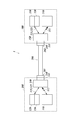
- the optical fiber power supply (PoF: Power over Fiber) system 1A of the present embodiment includes a power supply device (PSE: Power Sourcing Equipment) 110, an optical fiber cable 200A, and a power receiving device (PD: Powered Device) 310.
- PSE Power Sourcing Equipment
- PD Powered Device
- the power feeding device in the present disclosure is a device that converts electric power into light energy and supplies it
- a power receiving device is a device that receives the supply of light energy and converts the light energy into electric power.
- the power feeding device 110 includes a power feeding semiconductor laser 111.
- the optical fiber cable 200A includes an optical fiber 250A that forms a transmission line for feeding light.
- the power receiving device 310 includes a photoelectric conversion element 311.
- the power feeding device 110 is connected to a power source, and a power feeding semiconductor laser 111 or the like is electrically driven.
- the power feeding semiconductor laser 111 oscillates the laser with the electric power from the power source and outputs the power feeding light 112.
- one end 201A can be connected to the power feeding device 110, and the other end 202A can be connected to the power receiving device 310 to transmit the feeding light 112.
- the power feeding light 112 from the power feeding device 110 is input to one end 201A of the optical fiber cable 200A, the feeding light 112 propagates in the optical fiber 250A, and is output from the other end 202A to the power receiving device 310.
- the photoelectric conversion element 311 converts the feeding light 112 transmitted through the optical fiber cable 200A into electric power.
- the electric power converted by the photoelectric conversion element 311 is used as the driving power required in the power receiving device 310. Further, the power receiving device 310 can output the electric power converted by the photoelectric conversion element 311 for an external device.
- the semiconductor material constituting the semiconductor region that exerts the light-electric conversion effect of the power feeding semiconductor laser 111 and the photoelectric conversion element 311 is a semiconductor having a short wavelength laser wavelength of 500 nm or less. Since a semiconductor having a short wavelength laser wavelength has a large band gap and high photoelectric conversion efficiency, the photoelectric conversion efficiency on the power generation side and the power receiving side of optical power supply is improved, and the optical power supply efficiency is improved.
- the semiconductor material for example, a semiconductor material of a laser medium having a laser wavelength (fundamental wave) of 200 to 500 nm, such as diamond, gallium oxide, aluminum nitride, and GaN, may be used.
- a semiconductor having a band gap of 2.4 eV or more is applied as the semiconductor material.
- a semiconductor material of a laser medium having a bandgap of 2.4 to 6.2 eV such as diamond, gallium oxide, aluminum nitride, and GaN, may be used.
- a semiconductor material of a laser medium having a laser wavelength (fundamental wave) smaller than 200 nm may be used.
- These semiconductor materials may be applied to either one of the power feeding semiconductor laser 111 and the photoelectric conversion element 311. The photoelectric conversion efficiency on the power feeding side or the power receiving side is improved, and the optical power feeding efficiency is improved.
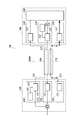
- the optical fiber power supply (PoF: Power over Fiber) system 1 of the present embodiment includes a power supply system via an optical fiber and an optical communication system, and is a power supply device (PSE: Power Sourcing Equipment) 110. It includes a first data communication device 100 including the above, an optical fiber cable 200, and a second data communication device 300 including a power receiving device (PD) 310.
- the power feeding device 110 includes a power feeding semiconductor laser 111.
- the first data communication device 100 includes a power supply device 110, a transmission unit 120 that performs data communication, and a reception unit 130.
- the first data communication device 100 corresponds to a data terminal equipment (DTE: Data Terminal Equipment), a repeater (Repeater), and the like.
- the transmitter 120 includes a signal semiconductor laser 121 and a modulator 122.
- the receiving unit 130 includes a signal photodiode 131.
- the optical fiber cable 200 includes an optical fiber 250 having a core 210 forming a signal light transmission path and a clad 220 arranged on the outer periphery of the core 210 and forming a feeding light transmission path.
- the power receiving device 310 includes a photoelectric conversion element 311.
- the second data communication device 300 includes a power receiving device 310, a transmitting unit 320, a receiving unit 330, and a data processing unit 340.
- the second data communication device 300 corresponds to a power end station (Power End Station) or the like.
- the transmitter 320 includes a signal semiconductor laser 321 and a modulator 322.
- the receiving unit 330 includes a signal photodiode 331.
- the data processing unit 340 is a unit that processes a received signal.
- the second data communication device 300 is a node in the communication network. Alternatively, the second data communication device 300 may be a node that communicates with another node.
- the first data communication device 100 is connected to a power source, and a power feeding semiconductor laser 111, a signal semiconductor laser 121, a modulator 122, a signal photodiode 131, and the like are electrically driven.
- the first data communication device 100 is a node in the communication network.
- the first data communication device 100 may be a node that communicates with another node.
- the power feeding semiconductor laser 111 oscillates the laser with the electric power from the power source and outputs the power feeding light 112.
- the photoelectric conversion element 311 converts the power feeding light 112 transmitted through the optical fiber cable 200 into electric power.
- the electric power converted by the photoelectric conversion element 311 is the driving power of the transmitting unit 320, the receiving unit 330, and the data processing unit 340, and other driving power required in the second data communication device 300.
- the second data communication device 300 may be capable of outputting the electric power converted by the photoelectric conversion element 311 for an external device.
- the modulator 122 of the transmitting unit 120 modulates the laser light 123 from the signal semiconductor laser 121 based on the transmission data 124 and outputs it as the signal light 125.
- the signal photodiode 331 of the receiving unit 330 demodulates the signal light 125 transmitted through the optical fiber cable 200 into an electric signal and outputs it to the data processing unit 340.
- the data processing unit 340 transmits the data by the electric signal to the node, while receiving the data from the node and outputting the data as the transmission data 324 to the modulator 322.
- the modulator 322 of the transmitting unit 320 modulates the laser light 323 from the signal semiconductor laser 321 based on the transmission data 324 and outputs it as the signal light 325.
- the signal photodiode 131 of the receiving unit 130 demodulates the signal light 325 transmitted through the optical fiber cable 200 into an electric signal and outputs it.
- the data from the electrical signal is transmitted to the node, while the data from the node is referred to as transmission data 124.
- the feed light 112 and the signal light 125 from the first data communication device 100 are input to one end 201 of the optical fiber cable 200, the feed light 112 propagates through the clad 220, the signal light 125 propagates through the core 210, and the other end. It is output from 202 to the second data communication device 300.
- the signal light 325 from the second data communication device 300 is input to the other end 202 of the optical fiber cable 200, propagates through the core 210, and is output from one end 201 to the first data communication device 100.
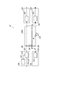
- the first data communication device 100 is provided with an optical input / output unit 140 and an optical connector 141 attached to the optical input / output unit 140.
- the second data communication device 300 is provided with an optical input / output unit 350 and an optical connector 351 attached to the optical input / output unit 350.
- An optical connector 230 provided at one end 201 of the optical fiber cable 200 connects to the optical connector 141.
- An optical connector 240 provided at the other end 202 of the optical fiber cable 200 connects to the optical connector 351.
- the optical input / output unit 140 guides the feeding light 112 to the clad 220, guides the signal light 125 to the core 210, and guides the signal light 325 to the receiving unit 130.
- the optical input / output unit 350 guides the feeding light 112 to the power receiving device 310, guides the signal light 125 to the receiving unit 330, and guides the signal light 325 to the core 210.
- the optical fiber cable 200 has one end 201 connectable to the first data communication device 100 and the other end 202 connectable to the second data communication device 300 to transmit the feeding light 112. Further, in the present embodiment, the optical fiber cable 200 transmits the signal lights 125 and 325 in both directions.
- the semiconductor material constituting the semiconductor region that exhibits the light-electricity conversion effect of the power feeding semiconductor laser 111 and the photoelectric conversion element 311 As the semiconductor material constituting the semiconductor region that exhibits the light-electricity conversion effect of the power feeding semiconductor laser 111 and the photoelectric conversion element 311, the same materials as those in the first embodiment are applied, and high light power feeding efficiency is realized. ..
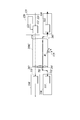
- the optical fiber 260 for transmitting signal light and the optical fiber 270 for transmitting the feeding light may be provided separately.
- the optical fiber cable 200B may also be composed of a plurality of cables.
- FIG. 5 is a configuration diagram of an optical fiber power feeding system according to a third embodiment to which the power feeding light leakage prevention means is applied.
- the same components as those described above are designated by the same reference numerals, and detailed description thereof will be omitted.
- the optical fiber power supply system 1C of the third embodiment includes an optical fiber 250C including a first transmission line 281 and a second transmission line 282 capable of transmitting light.
- the optical fiber 250C includes a core, a first clad around the core, and a second clad around the first clad.
- the optical fiber 250C may have more clads such as a third clad located on the outer periphery than the second clad and a fourth clad located on the outer periphery thereof.
- Two of the core and the plurality of claddings are used as the first transmission line 281 and the second transmission line 282.
- the feeding light 112 is transmitted through the first transmission line 281 and the signal light 125 is transmitted through the second transmission line 282.
- a clad located on the outer periphery of the first transmission line 281 is selected.
- an optical fiber 250C having a core, a first clad around the core, and a second clad around the first clad is adopted.
- the core may be used as the first transmission line 281 for the transmission of the feeding light 112
- the first clad may be used as the second transmission line 282 for the transmission of the signal light 125.
- an optical fiber 250C having a core, a first clad around the core, a second clad around the first clad, and a third clad around the second clad is adopted.
- the first clad may be used as the first transmission line 281 for the transmission of the feeding light 112
- the second clad may be used as the second transmission line 282 for the transmission of the signal light 125.
- the first transmission line 281 through which the feeding light 112 propagates may have a larger cross-sectional area than the other transmission lines.
- the power feeding device 110 outputs the power feeding light 112 to the first transmission line 281 (for example, the core) of the optical fiber 250C.
- the power receiving device 310 inputs the feeding light 112 from the first transmission line 281 of the optical fiber 250C.
- the transmission unit 120 outputs the signal light 125 to the second transmission line 282 (for example, the first cladding) of the optical fiber 250C.
- the receiving unit 330 inputs the signal light 125 from the second transmission line 282 of the optical fiber 250C.
- the signal light 125 may include the main body data of the data communication, or may be a signal for detecting damage to the optical fiber 250C.
- the optical fiber 250C is damaged during the transmission of the power supply light 112 and the signal light 125.
- the feed light 112 is higher energy light (high intensity) than the signal light 125. Therefore, it is not preferable that high energy light leaks when the optical fiber 250C is disconnected. Since the damaged portion W is damaged from the outer peripheral transmission line, the signal light 125 leaks from the second transmission line 282 before the feeding light 112 leaks from the first transmission line 281.
- Leakage of the signal light 125 appears as an abnormality such as a decrease in the amount of light received by the receiving unit 330, an increase in the amount of reflected light of the signal light 125, or the signal light 125 leaking from the damaged unit W being reflected on the infrared camera. Therefore, damage to the optical fiber 250C can be quickly detected due to an abnormality in the signal light 125, and the damage may be dealt with before the damage to the optical fiber 250C progresses and the feeding light 112 leaks. Therefore, according to the optical fiber power feeding system 1C of the third embodiment, it is possible to prevent the feeding light 112 from suddenly leaking or the feeding light 112 from continuing to leak for a long time.
- the system of the third embodiment can be applied to the optical fiber power supply system of FIGS. 1, 2, and 4.
- the optical fiber 250A of FIG. 1 is changed to the optical fiber 250C of the third embodiment
- the power feeding device 110 of FIG. 1 is changed to the power feeding device 110 and the transmitting unit 120 of the third embodiment.
- the power receiving device 310 of 1 may be changed to the power receiving device 310 and the receiving unit 330 of the third embodiment.
- the optical fiber 250 of FIG. 2 is changed to the optical fiber 250C of the third embodiment, and the power feeding device 110, the transmitting unit 120, the power receiving device 310, and the feeding light 112 and the signal of the receiving unit 330 of FIG. 2 are changed.
- the input / output position of the optical 125 may be the same as that of the third embodiment.
- the transmitting unit 120 and the receiving unit 330 of the third embodiment may be newly added as a configuration different from the transmitting unit 120 and the receiving unit 330 of FIG. In this case, the system includes two sets of transmitting unit 120 and receiving unit 330.
- one combination transmits the signal light 125 via the second transmission line 282 (for example, the second cladding), and the other combination is the first transmission line 281 (for example, the second transmission line 281 (for example, the second cladding).
- the signal light 125 may be transmitted via a transmission line (for example, a core) inside the first clad).
- the optical fiber 270 of FIG. 4 is changed to the optical fiber 250C of the third embodiment, and the power feeding device 110 of FIG. 4 is changed to the power feeding device 110 and the transmitting unit 120 of the third embodiment.
- the power receiving device 310 of 4 may be changed to the power receiving device 310 and the receiving unit 330 of the third embodiment.
- the transmitting unit 120 and the receiving unit 330 may be arranged in reverse.
- FIG. 7 is a configuration diagram of an optical fiber power feeding system according to a fourth embodiment to which the power feeding light leakage prevention means is applied.
- the same components as those in FIG. 5 are designated by the same reference numerals, and detailed description thereof will be omitted.
- the monitoring unit 181 that monitors the reflected light amount of the signal light 125
- the monitoring unit 381 that monitors the received light amount of the signal light 125
- the abnormality of the reflected light amount or the received light amount of the signal light 125 is further provided.
- One of the monitoring units 181 and 381 may be omitted.
- a transmission line 291 capable of transmitting a signal indicating an abnormality or a signal indicating the amount of received light from the monitoring unit 381 to the control unit 191 may be provided.
- the transmission line 291 may be a metal wiring, a wireless transmission line, another transmission line closer to the center than the second transmission line 282 in the optical fiber 250C, or an optical fiber different from the optical fiber 250C.
- the monitoring unit 181 may include an isolator that extracts the return light from the second transmission line 282 of the optical fiber 250C and a light receiving element (photodiode or the like) that receives the extracted return light.
- the monitoring unit 381 may include, for example, a beam splitter that splits a part of the signal light 125 at a constant ratio, and a light receiving element (photodiode or the like) that receives the branched signal light.
- the receiving unit 330 may also have the function of the monitoring unit 381.
- the control unit 191 determines whether or not a change in the signal light 125 indicating damage to the optical fiber 250C has occurred (step S1), and when it is determined that a change has occurred, stops driving the power feeding device 110 or stops driving.
- the output is reduced (step S2).
- the change in the signal light 125 in step S1 is, for example, an increase in reflected light (increase exceeding the threshold value), a decrease in the amount of received light (decrease below the threshold value), and the like.
- the control unit 191 may be composed of a microcomputer, or may be composed of a sequencer using an analog circuit or a digital circuit.
- the optical fiber 250C is damaged during the transmission of the feeding light 112 and the signal light 125. Since the damaged portion W is damaged from the outer peripheral transmission line, the signal light 125 leaks from the second transmission line 282 before the feeding light 112 leaks from the first transmission line 281. When the signal light 125 leaks, the reflection of the signal light 125 at the damaged portion W increases, and the amount of light propagated by the signal light 125 to the other end 202 of the optical fiber 250C decreases.
- control unit 191 detects a change in the reflected light amount or the received light amount by the monitoring of the monitoring units 181 and 381, and the control unit 191 stops driving the power feeding device 110 or reduces the output.
- the feeding light 112 propagating in the first transmission line 281 is stopped or weakened. Therefore, even if the damage progresses to the first transmission line 281 of the optical fiber 250C, it is possible to prevent the high-intensity feeding light 112 from leaking from the damaged portion.
- the configuration of the fourth embodiment can be applied to the optical fiber power supply system of FIGS. 1, 2, and 4 as in the third embodiment.
- the transmitting unit 120 and the monitoring unit 181 and the receiving unit 330 and the monitoring unit 381 may be arranged in reverse.
- the control unit 191 may be arranged in a device different from the device having the power feeding device 110.
- the control unit 191 may adopt a configuration in which the control signal can be transmitted via a transmission line other than the first transmission line 281 and the second transmission line 282 to stop the driving of the power feeding device 110.
- This disclosure can be used for optical fiber power supply systems and data communication devices.
- Optical fiber power supply system 1 Optical fiber power supply system 1B
- Optical fiber power supply system 1C Optical fiber power supply system 1D
- Optical fiber power supply system 100 First data communication device 110 Power supply device 111 Semiconductor laser for power supply 112 Power supply light 120 Transmission unit 125 Signal light 130 Receiver unit 140 Optical input Output unit 141 Optical connector 181 Monitoring unit 191
Abstract
Provided are an optical fiber power supply system and a data communication device such that leakage of power supply light can be suppressed even when an optical fiber is damaged. The optical fiber power supply system is for transmitting power supply light and signal light through an optical fiber having a first transmission path made of a core or cladding and a second transmission path made of a cladding and positioned on the outer periphery of the first transmission path. The power supply light is propagated through the first transmission path, and the signal light is propagated through the second transmission path. The data communication device is provided with: a power supply device for outputting the power supply light to the first transmission path; and a transmission unit or reception unit for transmitting or receiving the signal light through the second transmission path. Alternatively, the data communication device is provided with: a power reception device to which the power supply light is input from the first transmission path; and a transmission unit or reception unit for transmitting or receiving the signal light through the second transmission path.
Description
本開示は、光ファイバー給電システム及びデータ通信装置に関する。
This disclosure relates to an optical fiber power supply system and a data communication device.
近時、電力を光(給電光と呼ばれる)に変換して伝送し、当該給電光を電気エネルギーに変換して電力として利用する光給電システムが研究されている。特許文献1には、電気信号で変調された信号光、及び電力を供給するための給電光を発信する光発信機と、上記信号光を伝送するコア、上記コアの周囲に形成され上記コアより屈折率が小さく上記給電光を伝送する第1クラッド、及び上記第1クラッドの周囲に形成され上記第1クラッドより屈折率が小さい第2クラッド、を有する光ファイバーと、上記光ファイバーの第1クラッドで伝送された上記給電光を変換した電力で動作し、上記光ファイバーのコアで伝送された上記信号光を上記電気信号に変換する光受信機と、を備えた光通信装置が記載されている。
Recently, an optical power supply system that converts electric power into light (called feed light) and transmits it, and converts the feed light into electrical energy and uses it as electric power is being researched. Patent Document 1 describes an optical transmitter that transmits signal light modulated by an electric signal and feed light for supplying power, a core that transmits the signal light, and a core formed around the core. An optical fiber having a first clad having a small refractive index and transmitting the feed light and a second clad formed around the first clad and having a smaller refractive index than the first clad, and a first clad of the optical fiber are used for transmission. Described is an optical communication device including an optical receiver that operates with the converted power of the fed light and converts the signal light transmitted by the core of the optical fiber into the electric signal.
光給電においては、より高エネルギーの給電光の伝送が行われるようになることが見込まれる。光ファイバー給電システムの敷設時及び運用中に光ファイバーが損傷した場合、損傷個所から給電光が漏れることは好ましくない。
In optical power supply, it is expected that higher energy power supply light will be transmitted. If the optical fiber is damaged during the installation and operation of the optical fiber power supply system, it is not preferable that the power supply light leaks from the damaged part.
本開示の光ファイバー給電システムは、
コア又はクラッドである第1伝送路と、クラッドであり前記第1伝送路よりも外周に位置する第2伝送路とを有する光ファイバーを介して給電光と信号光とを伝送する光ファイバー給電システムであって、
前記第1伝送路を介して給電光が伝搬され、前記第2伝送路を介して信号光が伝搬される。 The optical fiber power supply system of the present disclosure is
An optical fiber power feeding system that transmits power feeding light and signal light via an optical fiber having a first transmission line that is a core or a clad and a second transmission line that is clad and is located on the outer periphery of the first transmission line. hand,
The feeding light is propagated through the first transmission line, and the signal light is propagated through the second transmission line.
本開示のデータ通信装置は、
コア又はクラッドである第1伝送路と、クラッドであり前記第1伝送路よりも外周に位置する第2伝送路とを有する光ファイバーを介して給電光と信号光とを伝送する光ファイバー給電システムのデータ通信装置であって、
前記第1伝送路に給電光を出力する給電装置と、
前記第2伝送路を介して信号光を送信する発信部又は受信する受信部と、
を備える。 The data communication device of the present disclosure is
Data of an optical fiber power supply system that transmits feed light and signal light via an optical fiber having a first transmission line that is a core or a clad and a second transmission line that is a clad and is located on the outer periphery of the first transmission line. It is a communication device
A power supply device that outputs power supply light to the first transmission line, and
A transmitting unit or a receiving unit that transmits signal light via the second transmission line and
To be equipped.
本開示のもう一つのデータ通信装置は、
コア又はクラッドである第1伝送路と、クラッドであり前記第1伝送路よりも外周に位置する第2伝送路とを有する光ファイバーを介して給電光と信号光とを伝送する光ファイバー給電システムのデータ通信装置であって、
前記第1伝送路から給電光を入力する受電装置と、
前記第2伝送路を介して信号光を送信する発信部又は受信する受信部と、
を備える。 Another data communication device of the present disclosure is
Data of an optical fiber power supply system that transmits feed light and signal light via an optical fiber having a first transmission line that is a core or a clad and a second transmission line that is a clad and is located on the outer periphery of the first transmission line. It is a communication device
A power receiving device that inputs feeding light from the first transmission line, and
A transmitting unit or a receiving unit that transmits signal light via the second transmission line and
To be equipped.
以下に本開示の一実施形態につき図面を参照して説明する。
An embodiment of the present disclosure will be described below with reference to the drawings.
(1)システム概要
〔第1実施形態〕
図1に示すように本実施形態の光ファイバー給電(PoF:Power over Fiber)システム1Aは、給電装置(PSE:Power Sourcing Equipment)110と、光ファイバーケーブル200Aと、受電装置(PD:Powered Device)310を備える。
なお、本開示における給電装置は電力を光エネルギーに変換して供給する装置であり、受電装置は光エネルギーの供給を受け当該光エネルギーを電力に変換する装置である。
給電装置110は、給電用半導体レーザー111を含む。
光ファイバーケーブル200Aは、給電光の伝送路を形成する光ファイバー250Aを含む。
受電装置310は、光電変換素子311を含む。 (1) System overview [First embodiment]
As shown in FIG. 1, the optical fiber power supply (PoF: Power over Fiber)system 1A of the present embodiment includes a power supply device (PSE: Power Sourcing Equipment) 110, an optical fiber cable 200A, and a power receiving device (PD: Powered Device) 310. Be prepared.
The power feeding device in the present disclosure is a device that converts electric power into light energy and supplies it, and a power receiving device is a device that receives the supply of light energy and converts the light energy into electric power.
Thepower feeding device 110 includes a power feeding semiconductor laser 111.
Theoptical fiber cable 200A includes an optical fiber 250A that forms a transmission line for feeding light.
Thepower receiving device 310 includes a photoelectric conversion element 311.
〔第1実施形態〕
図1に示すように本実施形態の光ファイバー給電(PoF:Power over Fiber)システム1Aは、給電装置(PSE:Power Sourcing Equipment)110と、光ファイバーケーブル200Aと、受電装置(PD:Powered Device)310を備える。
なお、本開示における給電装置は電力を光エネルギーに変換して供給する装置であり、受電装置は光エネルギーの供給を受け当該光エネルギーを電力に変換する装置である。
給電装置110は、給電用半導体レーザー111を含む。
光ファイバーケーブル200Aは、給電光の伝送路を形成する光ファイバー250Aを含む。
受電装置310は、光電変換素子311を含む。 (1) System overview [First embodiment]
As shown in FIG. 1, the optical fiber power supply (PoF: Power over Fiber)
The power feeding device in the present disclosure is a device that converts electric power into light energy and supplies it, and a power receiving device is a device that receives the supply of light energy and converts the light energy into electric power.
The
The
The
給電装置110は電源に接続され、給電用半導体レーザー111等が電気駆動される。
給電用半導体レーザー111は、上記電源からの電力によりレーザー発振して給電光112を出力する。 Thepower feeding device 110 is connected to a power source, and a power feeding semiconductor laser 111 or the like is electrically driven.
The powerfeeding semiconductor laser 111 oscillates the laser with the electric power from the power source and outputs the power feeding light 112.
給電用半導体レーザー111は、上記電源からの電力によりレーザー発振して給電光112を出力する。 The
The power
光ファイバーケーブル200Aは、一端201Aが給電装置110に接続可能とされ、他端202Aが受電装置310に接続可能とされ、給電光112を伝送する。
給電装置110からの給電光112が、光ファイバーケーブル200Aの一端201Aに入力され、給電光112は光ファイバー250A中を伝搬し、他端202Aから受電装置310に出力される。 In theoptical fiber cable 200A, one end 201A can be connected to the power feeding device 110, and the other end 202A can be connected to the power receiving device 310 to transmit the feeding light 112.
Thepower feeding light 112 from the power feeding device 110 is input to one end 201A of the optical fiber cable 200A, the feeding light 112 propagates in the optical fiber 250A, and is output from the other end 202A to the power receiving device 310.
給電装置110からの給電光112が、光ファイバーケーブル200Aの一端201Aに入力され、給電光112は光ファイバー250A中を伝搬し、他端202Aから受電装置310に出力される。 In the
The
光電変換素子311は、光ファイバーケーブル200Aを通して伝送されてきた給電光112を電力に変換する。光電変換素子311により変換された電力が、受電装置310内で必要な駆動電力とされる。さらに受電装置310は光電変換素子311により変換された電力を外部機器用に出力可能とされる。
The photoelectric conversion element 311 converts the feeding light 112 transmitted through the optical fiber cable 200A into electric power. The electric power converted by the photoelectric conversion element 311 is used as the driving power required in the power receiving device 310. Further, the power receiving device 310 can output the electric power converted by the photoelectric conversion element 311 for an external device.
給電用半導体レーザー111及び光電変換素子311の光‐電気間の変換効果を奏する半導体領域を構成する半導体材料が500nm以下の短波長のレーザー波長をもった半導体とされる。
短波長のレーザー波長をもった半導体は、バンドギャップが大きく光電変換効率が高いので、光給電の発電側及び受電側における光電変換効率が向上され、光給電効率が向上する。
そのためには、同半導体材料として、例えば、ダイヤモンド、酸化ガリウム、窒化アルミニウム、GaN等、レーザー波長(基本波)が200~500nmのレーザー媒体の半導体材料を用いてもよい。
また、同半導体材料として、2.4eV以上のバンドギャップを有した半導体が適用される。
例えば、ダイヤモンド、酸化ガリウム、窒化アルミニウム、GaN等、バンドギャップ2.4~6.2eVのレーザー媒体の半導体材料を用いてもよい。
なお、レーザー光は長波長ほど伝送効率が良く、短波長ほど光電変換効率が良い傾向にある。したがって、長距離伝送の場合には、レーザー波長(基本波)が500nmより大きいレーザー媒体の半導体材料を用いてもよい。また、光電変換効率を優先する場合には、レーザー波長(基本波)が200nmより小さいレーザー媒体の半導体材料を用いてもよい。
これらの半導体材料は、給電用半導体レーザー111及び光電変換素子311のいずれか一方に適用してもよい。給電側又は受電側における光電変換効率が向上され、光給電効率が向上する。 The semiconductor material constituting the semiconductor region that exerts the light-electric conversion effect of the powerfeeding semiconductor laser 111 and the photoelectric conversion element 311 is a semiconductor having a short wavelength laser wavelength of 500 nm or less.
Since a semiconductor having a short wavelength laser wavelength has a large band gap and high photoelectric conversion efficiency, the photoelectric conversion efficiency on the power generation side and the power receiving side of optical power supply is improved, and the optical power supply efficiency is improved.
For that purpose, as the semiconductor material, for example, a semiconductor material of a laser medium having a laser wavelength (fundamental wave) of 200 to 500 nm, such as diamond, gallium oxide, aluminum nitride, and GaN, may be used.
Further, as the semiconductor material, a semiconductor having a band gap of 2.4 eV or more is applied.
For example, a semiconductor material of a laser medium having a bandgap of 2.4 to 6.2 eV, such as diamond, gallium oxide, aluminum nitride, and GaN, may be used.
The longer the wavelength of the laser light, the better the transmission efficiency, and the shorter the wavelength, the better the photoelectric conversion efficiency. Therefore, in the case of long-distance transmission, a semiconductor material of a laser medium having a laser wavelength (primary wave) larger than 500 nm may be used. When the photoelectric conversion efficiency is prioritized, a semiconductor material of a laser medium having a laser wavelength (fundamental wave) smaller than 200 nm may be used.
These semiconductor materials may be applied to either one of the powerfeeding semiconductor laser 111 and the photoelectric conversion element 311. The photoelectric conversion efficiency on the power feeding side or the power receiving side is improved, and the optical power feeding efficiency is improved.
短波長のレーザー波長をもった半導体は、バンドギャップが大きく光電変換効率が高いので、光給電の発電側及び受電側における光電変換効率が向上され、光給電効率が向上する。
そのためには、同半導体材料として、例えば、ダイヤモンド、酸化ガリウム、窒化アルミニウム、GaN等、レーザー波長(基本波)が200~500nmのレーザー媒体の半導体材料を用いてもよい。
また、同半導体材料として、2.4eV以上のバンドギャップを有した半導体が適用される。
例えば、ダイヤモンド、酸化ガリウム、窒化アルミニウム、GaN等、バンドギャップ2.4~6.2eVのレーザー媒体の半導体材料を用いてもよい。
なお、レーザー光は長波長ほど伝送効率が良く、短波長ほど光電変換効率が良い傾向にある。したがって、長距離伝送の場合には、レーザー波長(基本波)が500nmより大きいレーザー媒体の半導体材料を用いてもよい。また、光電変換効率を優先する場合には、レーザー波長(基本波)が200nmより小さいレーザー媒体の半導体材料を用いてもよい。
これらの半導体材料は、給電用半導体レーザー111及び光電変換素子311のいずれか一方に適用してもよい。給電側又は受電側における光電変換効率が向上され、光給電効率が向上する。 The semiconductor material constituting the semiconductor region that exerts the light-electric conversion effect of the power
Since a semiconductor having a short wavelength laser wavelength has a large band gap and high photoelectric conversion efficiency, the photoelectric conversion efficiency on the power generation side and the power receiving side of optical power supply is improved, and the optical power supply efficiency is improved.
For that purpose, as the semiconductor material, for example, a semiconductor material of a laser medium having a laser wavelength (fundamental wave) of 200 to 500 nm, such as diamond, gallium oxide, aluminum nitride, and GaN, may be used.
Further, as the semiconductor material, a semiconductor having a band gap of 2.4 eV or more is applied.
For example, a semiconductor material of a laser medium having a bandgap of 2.4 to 6.2 eV, such as diamond, gallium oxide, aluminum nitride, and GaN, may be used.
The longer the wavelength of the laser light, the better the transmission efficiency, and the shorter the wavelength, the better the photoelectric conversion efficiency. Therefore, in the case of long-distance transmission, a semiconductor material of a laser medium having a laser wavelength (primary wave) larger than 500 nm may be used. When the photoelectric conversion efficiency is prioritized, a semiconductor material of a laser medium having a laser wavelength (fundamental wave) smaller than 200 nm may be used.
These semiconductor materials may be applied to either one of the power
〔第2実施形態〕
図2に示すように本実施形態の光ファイバー給電(PoF:Power over Fiber)システム1は、光ファイバーを介した給電システムと光通信システムとを含むものであり、給電装置(PSE:Power Sourcing Equipment)110を含む第1のデータ通信装置100と、光ファイバーケーブル200と、受電装置(PD:Powered Device)310を含む第2のデータ通信装置300とを備える。
給電装置110は、給電用半導体レーザー111を含む。第1のデータ通信装置100は、給電装置110のほか、データ通信を行う発信部120と、受信部130とを含む。第1のデータ通信装置100は、データ端末装置(DTE:Data Terminal Equipment)、中継器(Repeater)等に相当する。発信部120は、信号用半導体レーザー121と、モジュレーター122とを含む。受信部130は、信号用フォトダイオード131を含む。 [Second Embodiment]
As shown in FIG. 2, the optical fiber power supply (PoF: Power over Fiber)system 1 of the present embodiment includes a power supply system via an optical fiber and an optical communication system, and is a power supply device (PSE: Power Sourcing Equipment) 110. It includes a first data communication device 100 including the above, an optical fiber cable 200, and a second data communication device 300 including a power receiving device (PD) 310.
Thepower feeding device 110 includes a power feeding semiconductor laser 111. The first data communication device 100 includes a power supply device 110, a transmission unit 120 that performs data communication, and a reception unit 130. The first data communication device 100 corresponds to a data terminal equipment (DTE: Data Terminal Equipment), a repeater (Repeater), and the like. The transmitter 120 includes a signal semiconductor laser 121 and a modulator 122. The receiving unit 130 includes a signal photodiode 131.
図2に示すように本実施形態の光ファイバー給電(PoF:Power over Fiber)システム1は、光ファイバーを介した給電システムと光通信システムとを含むものであり、給電装置(PSE:Power Sourcing Equipment)110を含む第1のデータ通信装置100と、光ファイバーケーブル200と、受電装置(PD:Powered Device)310を含む第2のデータ通信装置300とを備える。
給電装置110は、給電用半導体レーザー111を含む。第1のデータ通信装置100は、給電装置110のほか、データ通信を行う発信部120と、受信部130とを含む。第1のデータ通信装置100は、データ端末装置(DTE:Data Terminal Equipment)、中継器(Repeater)等に相当する。発信部120は、信号用半導体レーザー121と、モジュレーター122とを含む。受信部130は、信号用フォトダイオード131を含む。 [Second Embodiment]
As shown in FIG. 2, the optical fiber power supply (PoF: Power over Fiber)
The
光ファイバーケーブル200は、信号光の伝送路を形成するコア210と、コア210の外周に配置され、給電光の伝送路を形成するクラッド220と有する光ファイバー250を含む。
The optical fiber cable 200 includes an optical fiber 250 having a core 210 forming a signal light transmission path and a clad 220 arranged on the outer periphery of the core 210 and forming a feeding light transmission path.
受電装置310は、光電変換素子311を含む。第2のデータ通信装置300は、受電装置310のほか、発信部320と、受信部330と、データ処理ユニット340とを含む。第2のデータ通信装置300は、パワーエンドステーション(Power End Station)等に相当する。発信部320は、信号用半導体レーザー321と、モジュレーター322とを含む。受信部330は、信号用フォトダイオード331を含む。データ処理ユニット340は、受信した信号を処理するユニットである。また、第2のデータ通信装置300は、通信ネットワークにおけるノードである。または第2のデータ通信装置300は、他のノードと通信するノードでもよい。
The power receiving device 310 includes a photoelectric conversion element 311. The second data communication device 300 includes a power receiving device 310, a transmitting unit 320, a receiving unit 330, and a data processing unit 340. The second data communication device 300 corresponds to a power end station (Power End Station) or the like. The transmitter 320 includes a signal semiconductor laser 321 and a modulator 322. The receiving unit 330 includes a signal photodiode 331. The data processing unit 340 is a unit that processes a received signal. The second data communication device 300 is a node in the communication network. Alternatively, the second data communication device 300 may be a node that communicates with another node.
第1のデータ通信装置100は電源に接続され、給電用半導体レーザー111、信号用半導体レーザー121と、モジュレーター122、信号用フォトダイオード131等が電気駆動される。また、第1のデータ通信装置100は、通信ネットワークにおけるノードである。または第1のデータ通信装置100は、他のノードと通信するノードでもよい。
給電用半導体レーザー111は、上記電源からの電力によりレーザー発振して給電光112を出力する。 The firstdata communication device 100 is connected to a power source, and a power feeding semiconductor laser 111, a signal semiconductor laser 121, a modulator 122, a signal photodiode 131, and the like are electrically driven. The first data communication device 100 is a node in the communication network. Alternatively, the first data communication device 100 may be a node that communicates with another node.
The powerfeeding semiconductor laser 111 oscillates the laser with the electric power from the power source and outputs the power feeding light 112.
給電用半導体レーザー111は、上記電源からの電力によりレーザー発振して給電光112を出力する。 The first
The power
光電変換素子311は、光ファイバーケーブル200を通して伝送されてきた給電光112を電力に変換する。光電変換素子311により変換された電力は、発信部320、受信部330及びデータ処理ユニット340の駆動電力、その他の第2のデータ通信装置300内で必要となる駆動電力とされる。さらに第2のデータ通信装置300は、光電変換素子311により変換された電力を外部機器用に出力可能とされていてもよい。
The photoelectric conversion element 311 converts the power feeding light 112 transmitted through the optical fiber cable 200 into electric power. The electric power converted by the photoelectric conversion element 311 is the driving power of the transmitting unit 320, the receiving unit 330, and the data processing unit 340, and other driving power required in the second data communication device 300. Further, the second data communication device 300 may be capable of outputting the electric power converted by the photoelectric conversion element 311 for an external device.
一方、発信部120のモジュレーター122は、信号用半導体レーザー121からのレーザー光123を送信データ124に基づき変調して信号光125として出力する。
受信部330の信号用フォトダイオード331は、光ファイバーケーブル200を通して伝送されてきた信号光125を電気信号に復調し、データ処理ユニット340に出力する。データ処理ユニット340は、当該電気信号によるデータをノードに送信し、その一方で当該ノードからデータを受信し、送信データ324としてモジュレーター322に出力する。
発信部320のモジュレーター322は、信号用半導体レーザー321からのレーザー光323を送信データ324に基づき変調して信号光325として出力する。
受信部130の信号用フォトダイオード131は、光ファイバーケーブル200を通して伝送されてきた信号光325を電気信号に復調し出力する。当該電気信号によるデータがノードに送信され、その一方で当該ノードからのデータが送信データ124とされる。 On the other hand, themodulator 122 of the transmitting unit 120 modulates the laser light 123 from the signal semiconductor laser 121 based on the transmission data 124 and outputs it as the signal light 125.
Thesignal photodiode 331 of the receiving unit 330 demodulates the signal light 125 transmitted through the optical fiber cable 200 into an electric signal and outputs it to the data processing unit 340. The data processing unit 340 transmits the data by the electric signal to the node, while receiving the data from the node and outputting the data as the transmission data 324 to the modulator 322.
Themodulator 322 of the transmitting unit 320 modulates the laser light 323 from the signal semiconductor laser 321 based on the transmission data 324 and outputs it as the signal light 325.
Thesignal photodiode 131 of the receiving unit 130 demodulates the signal light 325 transmitted through the optical fiber cable 200 into an electric signal and outputs it. The data from the electrical signal is transmitted to the node, while the data from the node is referred to as transmission data 124.
受信部330の信号用フォトダイオード331は、光ファイバーケーブル200を通して伝送されてきた信号光125を電気信号に復調し、データ処理ユニット340に出力する。データ処理ユニット340は、当該電気信号によるデータをノードに送信し、その一方で当該ノードからデータを受信し、送信データ324としてモジュレーター322に出力する。
発信部320のモジュレーター322は、信号用半導体レーザー321からのレーザー光323を送信データ324に基づき変調して信号光325として出力する。
受信部130の信号用フォトダイオード131は、光ファイバーケーブル200を通して伝送されてきた信号光325を電気信号に復調し出力する。当該電気信号によるデータがノードに送信され、その一方で当該ノードからのデータが送信データ124とされる。 On the other hand, the
The
The
The
第1のデータ通信装置100からの給電光112及び信号光125が、光ファイバーケーブル200の一端201に入力され、給電光112はクラッド220を伝搬し、信号光125はコア210を伝搬し、他端202から第2のデータ通信装置300に出力される。
第2のデータ通信装置300からの信号光325が、光ファイバーケーブル200の他端202に入力され、コア210を伝搬し、一端201から第1のデータ通信装置100に出力される。 Thefeed light 112 and the signal light 125 from the first data communication device 100 are input to one end 201 of the optical fiber cable 200, the feed light 112 propagates through the clad 220, the signal light 125 propagates through the core 210, and the other end. It is output from 202 to the second data communication device 300.
The signal light 325 from the seconddata communication device 300 is input to the other end 202 of the optical fiber cable 200, propagates through the core 210, and is output from one end 201 to the first data communication device 100.
第2のデータ通信装置300からの信号光325が、光ファイバーケーブル200の他端202に入力され、コア210を伝搬し、一端201から第1のデータ通信装置100に出力される。 The
The signal light 325 from the second
なお、図3に示すように第1のデータ通信装置100に光入出力部140とこれに付設された光コネクタ141が設けられる。また、第2のデータ通信装置300に光入出力部350とこれに付設された光コネクタ351が設けられる。光ファイバーケーブル200の一端201に設けられた光コネクタ230が光コネクタ141に接続する。光ファイバーケーブル200の他端202に設けられた光コネクタ240が光コネクタ351に接続する。光入出力部140は、給電光112をクラッド220に導光し、信号光125をコア210に導光し、信号光325を受信部130に導光する。光入出力部350は、給電光112を受電装置310に導光し、信号光125を受信部330に導光し、信号光325をコア210に導光する。
以上のように、光ファイバーケーブル200は、一端201が第1のデータ通信装置100に接続可能とされ、他端202が第2のデータ通信装置300に接続可能とされ、給電光112を伝送する。さらに本実施形態では、光ファイバーケーブル200は、信号光125,325を双方向伝送する。 As shown in FIG. 3, the firstdata communication device 100 is provided with an optical input / output unit 140 and an optical connector 141 attached to the optical input / output unit 140. Further, the second data communication device 300 is provided with an optical input / output unit 350 and an optical connector 351 attached to the optical input / output unit 350. An optical connector 230 provided at one end 201 of the optical fiber cable 200 connects to the optical connector 141. An optical connector 240 provided at the other end 202 of the optical fiber cable 200 connects to the optical connector 351. The optical input / output unit 140 guides the feeding light 112 to the clad 220, guides the signal light 125 to the core 210, and guides the signal light 325 to the receiving unit 130. The optical input / output unit 350 guides the feeding light 112 to the power receiving device 310, guides the signal light 125 to the receiving unit 330, and guides the signal light 325 to the core 210.
As described above, theoptical fiber cable 200 has one end 201 connectable to the first data communication device 100 and the other end 202 connectable to the second data communication device 300 to transmit the feeding light 112. Further, in the present embodiment, the optical fiber cable 200 transmits the signal lights 125 and 325 in both directions.
以上のように、光ファイバーケーブル200は、一端201が第1のデータ通信装置100に接続可能とされ、他端202が第2のデータ通信装置300に接続可能とされ、給電光112を伝送する。さらに本実施形態では、光ファイバーケーブル200は、信号光125,325を双方向伝送する。 As shown in FIG. 3, the first
As described above, the
給電用半導体レーザー111及び光電変換素子311の光‐電気間の変換効果を奏する半導体領域を構成する半導体材料としては上記第1実施形態と同様のものが適用され、高い光給電効率が実現される。
As the semiconductor material constituting the semiconductor region that exhibits the light-electricity conversion effect of the power feeding semiconductor laser 111 and the photoelectric conversion element 311, the same materials as those in the first embodiment are applied, and high light power feeding efficiency is realized. ..
なお、図4に示す光ファイバー給電システム1Bの光ファイバーケーブル200Bように、信号光を伝送する光ファイバー260と、給電光を伝送する光ファイバー270とを別々に設けてもよい。光ファイバーケーブル200Bも複数本で構成してもよい。
Note that, as in the optical fiber cable 200B of the optical fiber feeding system 1B shown in FIG. 4, the optical fiber 260 for transmitting signal light and the optical fiber 270 for transmitting the feeding light may be provided separately. The optical fiber cable 200B may also be composed of a plurality of cables.
(2)給電光の漏れ抑制手段
次に、給電光の漏れ抑制手段について説明する。
〔第3実施形態〕
図5は、給電光の漏れ防止手段が適用された第3実施形態の光ファイバー給電システムの構成図である。図5中、上述したものと同一の構成要素については同一符号を付して詳細な説明を省略する。 (2) Leakage Suppressing Means for Feeding Light Next, the leakage suppressing means for feeding light will be described.
[Third Embodiment]
FIG. 5 is a configuration diagram of an optical fiber power feeding system according to a third embodiment to which the power feeding light leakage prevention means is applied. In FIG. 5, the same components as those described above are designated by the same reference numerals, and detailed description thereof will be omitted.
第3実施形態の光ファイバー給電システム1Cは、光を伝送可能な第1伝送路281及び第2伝送路282を含んだ光ファイバー250Cを備える。光ファイバー250Cは、コアと、コアの周囲の第1クラッドと、第1クラッドの周囲の第2クラッドとを含む。光ファイバー250Cは、第2クラッドよりも外周に位置する第3クラッド、その外周に位置する第4クラッドなど、より多くのクラッドを有してもよい。コアと複数のクラッドのうちの2つが第1伝送路281及び第2伝送路282として使用される。第1伝送路281を介して給電光112が伝送され、第2伝送路282を介して信号光125が伝送される。ただし、第2伝送路282としては第1伝送路281よりも外周に位置するクラッドが選択される。
The optical fiber power supply system 1C of the third embodiment includes an optical fiber 250C including a first transmission line 281 and a second transmission line 282 capable of transmitting light. The optical fiber 250C includes a core, a first clad around the core, and a second clad around the first clad. The optical fiber 250C may have more clads such as a third clad located on the outer periphery than the second clad and a fourth clad located on the outer periphery thereof. Two of the core and the plurality of claddings are used as the first transmission line 281 and the second transmission line 282. The feeding light 112 is transmitted through the first transmission line 281 and the signal light 125 is transmitted through the second transmission line 282. However, as the second transmission line 282, a clad located on the outer periphery of the first transmission line 281 is selected.
一例として、コア、コアの周囲の第1クラッド、第1クラッドの周囲の第2クラッドを有する光ファイバー250Cが採用されたとする。この場合、第1伝送路281としてコアが給電光112の伝送に使用され、第2伝送路282として第1クラッドが信号光125の伝送に使用されてもよい。
As an example, it is assumed that an optical fiber 250C having a core, a first clad around the core, and a second clad around the first clad is adopted. In this case, the core may be used as the first transmission line 281 for the transmission of the feeding light 112, and the first clad may be used as the second transmission line 282 for the transmission of the signal light 125.
あるいは、コア、コアの周囲の第1クラッド、第1クラッドの周囲の第2クラッド、並びに、第2クラッドの周囲の第3クラッドを有する光ファイバー250Cが採用されたとする。この場合、第1伝送路281として第1クラッドが給電光112の伝送に使用され、第2伝送路282として第2クラッドが信号光125の伝送に使用されてもよい。
Alternatively, it is assumed that an optical fiber 250C having a core, a first clad around the core, a second clad around the first clad, and a third clad around the second clad is adopted. In this case, the first clad may be used as the first transmission line 281 for the transmission of the feeding light 112, and the second clad may be used as the second transmission line 282 for the transmission of the signal light 125.
給電光112が伝搬する第1伝送路281は、その他の伝送路と比較して断面積が大きく構成されていてもよい。
The first transmission line 281 through which the feeding light 112 propagates may have a larger cross-sectional area than the other transmission lines.
給電装置110は、光ファイバー250Cの第1伝送路281(例えばコア)に給電光112を出力する。受電装置310は、光ファイバー250Cの第1伝送路281から給電光112を入力する。
The power feeding device 110 outputs the power feeding light 112 to the first transmission line 281 (for example, the core) of the optical fiber 250C. The power receiving device 310 inputs the feeding light 112 from the first transmission line 281 of the optical fiber 250C.
発信部120は、光ファイバー250Cの第2伝送路282(例えば第1クラッド)に信号光125を出力する。受信部330は、光ファイバー250Cの第2伝送路282から信号光125を入力する。信号光125は、データ通信の本体データを含むものであってもよいし、光ファイバー250Cの損傷を検知するための信号であってもよい。
The transmission unit 120 outputs the signal light 125 to the second transmission line 282 (for example, the first cladding) of the optical fiber 250C. The receiving unit 330 inputs the signal light 125 from the second transmission line 282 of the optical fiber 250C. The signal light 125 may include the main body data of the data communication, or may be a signal for detecting damage to the optical fiber 250C.
図5に示すように、第3実施形態の光ファイバー給電システム1Cにおいて、給電光112及び信号光125の伝送中に光ファイバー250Cが損傷したとする。給電光112は信号光125に比べて高いエネルギー光(高強度)である。したがって、光ファイバー250Cが断線したときに高いエネルギー光が漏れるのは好ましくない。損傷部Wでは外周の伝送路から損傷を受けるため、第1伝送路281から給電光112が漏れる前に、第2伝送路282から信号光125が漏れる。信号光125の漏れは、例えば受信部330の受光量の低下、信号光125の反射光量の増加、あるいは、損傷部Wから漏れた信号光125が赤外線カメラに映るなどの異常となって現れる。したがって、信号光125の異常により光ファイバー250Cの損傷を速やかに発見でき、光ファイバー250Cの損傷が進んで給電光112が漏れる前に、損傷に対処できる場合がある。よって、第3実施形態の光ファイバー給電システム1Cによれば、急に、給電光112が漏れたり、長い時間、給電光112が漏れ続けてしまうことを抑制できる。
As shown in FIG. 5, in the optical fiber power supply system 1C of the third embodiment, it is assumed that the optical fiber 250C is damaged during the transmission of the power supply light 112 and the signal light 125. The feed light 112 is higher energy light (high intensity) than the signal light 125. Therefore, it is not preferable that high energy light leaks when the optical fiber 250C is disconnected. Since the damaged portion W is damaged from the outer peripheral transmission line, the signal light 125 leaks from the second transmission line 282 before the feeding light 112 leaks from the first transmission line 281. Leakage of the signal light 125 appears as an abnormality such as a decrease in the amount of light received by the receiving unit 330, an increase in the amount of reflected light of the signal light 125, or the signal light 125 leaking from the damaged unit W being reflected on the infrared camera. Therefore, damage to the optical fiber 250C can be quickly detected due to an abnormality in the signal light 125, and the damage may be dealt with before the damage to the optical fiber 250C progresses and the feeding light 112 leaks. Therefore, according to the optical fiber power feeding system 1C of the third embodiment, it is possible to prevent the feeding light 112 from suddenly leaking or the feeding light 112 from continuing to leak for a long time.
第3実施形態のシステムは、図1、図2、図4の光ファイバー給電システムに適用できる。図1のシステムに適用する場合、図1の光ファイバー250Aを第3実施形態の光ファイバー250Cに変更し、図1の給電装置110を第3実施形態の給電装置110及び発信部120に変更し、図1の受電装置310を第3実施形態の受電装置310及び受信部330に変更すればよい。
The system of the third embodiment can be applied to the optical fiber power supply system of FIGS. 1, 2, and 4. When applied to the system of FIG. 1, the optical fiber 250A of FIG. 1 is changed to the optical fiber 250C of the third embodiment, and the power feeding device 110 of FIG. 1 is changed to the power feeding device 110 and the transmitting unit 120 of the third embodiment. The power receiving device 310 of 1 may be changed to the power receiving device 310 and the receiving unit 330 of the third embodiment.
図2のシステムに適用する場合、図2の光ファイバー250を第3実施形態の光ファイバー250Cに変更し、図2の給電装置110、発信部120、受電装置310及び受信部330の給電光112及び信号光125の入出力位置を、第3実施形態と同一にすればよい。あるいは、図2の発信部120及び受信部330とは別の構成として、第3実施形態の発信部120及び受信部330が、新たに追加されてもよい。この場合、システム中に、二組の発信部120及び受信部330が備わる。二組の発信部120及び受信部330のうち、一方の組み合わせが第2伝送路282(例えば第2クラッド)を介して信号光125を伝送し、もう一方の組み合わせが、第1伝送路281(例えば第1クラッド)よりも内方の伝送路(例えばコア)を介して信号光125を伝送してもよい。
When applied to the system of FIG. 2, the optical fiber 250 of FIG. 2 is changed to the optical fiber 250C of the third embodiment, and the power feeding device 110, the transmitting unit 120, the power receiving device 310, and the feeding light 112 and the signal of the receiving unit 330 of FIG. 2 are changed. The input / output position of the optical 125 may be the same as that of the third embodiment. Alternatively, the transmitting unit 120 and the receiving unit 330 of the third embodiment may be newly added as a configuration different from the transmitting unit 120 and the receiving unit 330 of FIG. In this case, the system includes two sets of transmitting unit 120 and receiving unit 330. Of the two sets of transmitting unit 120 and receiving unit 330, one combination transmits the signal light 125 via the second transmission line 282 (for example, the second cladding), and the other combination is the first transmission line 281 (for example, the second transmission line 281 (for example, the second cladding). For example, the signal light 125 may be transmitted via a transmission line (for example, a core) inside the first clad).
図4のシステムに適用する場合、図4の光ファイバー270を第3実施形態の光ファイバー250Cに変更し、図4の給電装置110を第3実施形態の給電装置110及び発信部120に変更し、図4の受電装置310を第3実施形態の受電装置310及び受信部330に変更すればよい。
When applied to the system of FIG. 4, the optical fiber 270 of FIG. 4 is changed to the optical fiber 250C of the third embodiment, and the power feeding device 110 of FIG. 4 is changed to the power feeding device 110 and the transmitting unit 120 of the third embodiment. The power receiving device 310 of 4 may be changed to the power receiving device 310 and the receiving unit 330 of the third embodiment.
なお、第3実施形態の光ファイバー給電システム1Cにおいては、図6に示すように、発信部120と受信部330とが逆に配置されてもよい。
In the optical fiber power supply system 1C of the third embodiment, as shown in FIG. 6, the transmitting unit 120 and the receiving unit 330 may be arranged in reverse.
〔第4実施形態〕
図7は、給電光の漏れ防止手段が適用された第4実施形態の光ファイバー給電システムの構成図である。図7中、図5と同一の構成要素については同一符号を付して詳細な説明を省略する。 [Fourth Embodiment]
FIG. 7 is a configuration diagram of an optical fiber power feeding system according to a fourth embodiment to which the power feeding light leakage prevention means is applied. In FIG. 7, the same components as those in FIG. 5 are designated by the same reference numerals, and detailed description thereof will be omitted.
第4実施形態の光ファイバー給電システム1Dは、信号光125の反射光量を監視する監視部181と、信号光125の受光量を監視する監視部381と、信号光125の反射光量又は受光量の異常に基づいて給電装置110の駆動の停止又は出力の低減制御を行う制御部191とを更に備える。監視部181、381の一方は省略されてもよい。
In the optical fiber power feeding system 1D of the fourth embodiment, the monitoring unit 181 that monitors the reflected light amount of the signal light 125, the monitoring unit 381 that monitors the received light amount of the signal light 125, and the abnormality of the reflected light amount or the received light amount of the signal light 125. A control unit 191 that stops driving the power feeding device 110 or controls output reduction based on the above is further provided. One of the monitoring units 181 and 381 may be omitted.
受電装置310側に監視部381を有する場合、監視部381から制御部191へ異常を示す信号又は受光量を示す信号を送信可能な伝送路291を備えてもよい。伝送路291は、メタル配線、無線伝送路、光ファイバー250C内の第2伝送路282よりも中央に近い別の伝送路、あるいは、光ファイバー250Cとは別の光ファイバーであってもよい。
When the monitoring unit 381 is provided on the power receiving device 310 side, a transmission line 291 capable of transmitting a signal indicating an abnormality or a signal indicating the amount of received light from the monitoring unit 381 to the control unit 191 may be provided. The transmission line 291 may be a metal wiring, a wireless transmission line, another transmission line closer to the center than the second transmission line 282 in the optical fiber 250C, or an optical fiber different from the optical fiber 250C.
監視部181は、光ファイバー250Cの第2伝送路282からの戻り光を取り出すアイソレータと、取り出された戻り光を受ける受光素子(フォトダイオード等)とを含む構成としてもよい。
The monitoring unit 181 may include an isolator that extracts the return light from the second transmission line 282 of the optical fiber 250C and a light receiving element (photodiode or the like) that receives the extracted return light.
監視部381は、例えば、信号光125の一部を一定の割合で分岐させるビームスプリッタと、分岐された信号光を受ける受光素子(フォトダイオード等)とを含む構成としてもよい。あるいは、受信部330が監視部381の機能を兼ねる構成としてもよい。
The monitoring unit 381 may include, for example, a beam splitter that splits a part of the signal light 125 at a constant ratio, and a light receiving element (photodiode or the like) that receives the branched signal light. Alternatively, the receiving unit 330 may also have the function of the monitoring unit 381.
制御部191は、図8に示すように、光ファイバー250Cの損傷を示す信号光125の変化が生じたか判別し(ステップS1)、変化が生じたと判別した場合に、給電装置110の駆動を停止又は出力を低減させる(ステップS2)。ステップS1の信号光125の変化とは、例えば反射光の増加(閾値を超える増加)、受光量の低下(閾値を下回る低下)などである。制御部191は、マイクロコンピュータから構成されてもよいし、アナログ回路又はデジタル回路を利用したシーケンサから構成されてもよい。
As shown in FIG. 8, the control unit 191 determines whether or not a change in the signal light 125 indicating damage to the optical fiber 250C has occurred (step S1), and when it is determined that a change has occurred, stops driving the power feeding device 110 or stops driving. The output is reduced (step S2). The change in the signal light 125 in step S1 is, for example, an increase in reflected light (increase exceeding the threshold value), a decrease in the amount of received light (decrease below the threshold value), and the like. The control unit 191 may be composed of a microcomputer, or may be composed of a sequencer using an analog circuit or a digital circuit.
図7に示すように、第4実施形態の光ファイバー給電システム1Dにおいて、給電光112及び信号光125の伝送中に光ファイバー250Cが損傷したとする。損傷部Wでは、外周の伝送路から損傷を受けるため、第1伝送路281から給電光112が漏れる前に、第2伝送路282から信号光125が漏れる。信号光125が漏れるような場合、損傷部Wにおける信号光125の反射が増加し、また、信号光125が光ファイバー250Cの他端202まで伝搬する光量が低下する。すると、監視部181、381の監視により反射光量又は受光量の変化が制御部191において検知され、制御部191は、給電装置110の駆動を停止又は出力を低減させる。この制御により、第1伝送路281を伝搬する給電光112が停止又は微弱にされる。よって、光ファイバー250Cの第1伝送路281まで損傷が進んでも、損傷部から高強度の給電光112が漏れてしまうことが抑制される。
As shown in FIG. 7, in the optical fiber feeding system 1D of the fourth embodiment, it is assumed that the optical fiber 250C is damaged during the transmission of the feeding light 112 and the signal light 125. Since the damaged portion W is damaged from the outer peripheral transmission line, the signal light 125 leaks from the second transmission line 282 before the feeding light 112 leaks from the first transmission line 281. When the signal light 125 leaks, the reflection of the signal light 125 at the damaged portion W increases, and the amount of light propagated by the signal light 125 to the other end 202 of the optical fiber 250C decreases. Then, the control unit 191 detects a change in the reflected light amount or the received light amount by the monitoring of the monitoring units 181 and 381, and the control unit 191 stops driving the power feeding device 110 or reduces the output. By this control, the feeding light 112 propagating in the first transmission line 281 is stopped or weakened. Therefore, even if the damage progresses to the first transmission line 281 of the optical fiber 250C, it is possible to prevent the high-intensity feeding light 112 from leaking from the damaged portion.
第4実施形態の構成は、第3実施形態と同様に、図1、図2、図4の光ファイバー給電システムに適用できる。
The configuration of the fourth embodiment can be applied to the optical fiber power supply system of FIGS. 1, 2, and 4 as in the third embodiment.
なお、第4実施形態の光ファイバー給電システム1Dにおいては、図9に示すように、発信部120及び監視部181と、受信部330及び監視部381とが逆に配置されてもよい。また、制御部191は、給電装置110を有する装置とは、別の装置に配置されてもよい。この場合、制御部191は、第1伝送路281及び第2伝送路282以外の伝送路を介して制御信号を送信し、給電装置110の駆動を停止できる構成が採用されてもよい。
In the optical fiber power supply system 1D of the fourth embodiment, as shown in FIG. 9, the transmitting unit 120 and the monitoring unit 181 and the receiving unit 330 and the monitoring unit 381 may be arranged in reverse. Further, the control unit 191 may be arranged in a device different from the device having the power feeding device 110. In this case, the control unit 191 may adopt a configuration in which the control signal can be transmitted via a transmission line other than the first transmission line 281 and the second transmission line 282 to stop the driving of the power feeding device 110.
以上本開示の実施形態を説明したが、この実施形態は、例として示したものであり、この他の様々な形態で実施が可能であり、発明の要旨を逸脱しない範囲で、構成要素の省略、置き換え、変更を行うことができる。
Although the embodiments of the present disclosure have been described above, the embodiments are shown as examples, and can be implemented in various other embodiments, and the components are omitted as long as the gist of the invention is not deviated. , Can be replaced or changed.
本開示は、光ファイバー給電システム及びデータ通信装置に利用できる。
This disclosure can be used for optical fiber power supply systems and data communication devices.
1A 光ファイバー給電システム
1 光ファイバー給電システム
1B 光ファイバー給電システム
1C 光ファイバー給電システム
1D 光ファイバー給電システム
100 第1のデータ通信装置
110 給電装置
111 給電用半導体レーザー
112 給電光
120 発信部
125 信号光
130 受信部
140 光入出力部
141 光コネクタ
181 監視部
191 制御部
200A 光ファイバーケーブル
200 光ファイバーケーブル
200B 光ファイバーケーブル
210 コア
220 クラッド
250A 光ファイバー
250 光ファイバー
250C 光ファイバー
281 第1伝送路
282 第2伝送路
W 損傷部
260 光ファイバー
270 光ファイバー
300 第2のデータ通信装置
310 受電装置
311 光電変換素子
320 発信部
325 信号光
330 受信部
350 光入出力部
351 光コネクタ
381 監視部 1A Optical fiberpower supply system 1 Optical fiber power supply system 1B Optical fiber power supply system 1C Optical fiber power supply system 1D Optical fiber power supply system 100 First data communication device 110 Power supply device 111 Semiconductor laser for power supply 112 Power supply light 120 Transmission unit 125 Signal light 130 Receiver unit 140 Optical input Output unit 141 Optical connector 181 Monitoring unit 191 Control unit 200A Optical fiber cable 200 Optical fiber cable 200B Optical fiber cable 210 Core 220 Clad 250A Optical fiber 250 Optical fiber 250C Optical fiber 281 First transmission line 282 Second transmission line W Damaged part 260 Optical fiber 270 Optical fiber 300 Second Data communication device 310 Power receiving device 311 Photoelectric conversion element 320 Transmission unit 325 Signal light 330 Reception unit 350 Optical input / output unit 351 Optical connector 381 Monitoring unit
1 光ファイバー給電システム
1B 光ファイバー給電システム
1C 光ファイバー給電システム
1D 光ファイバー給電システム
100 第1のデータ通信装置
110 給電装置
111 給電用半導体レーザー
112 給電光
120 発信部
125 信号光
130 受信部
140 光入出力部
141 光コネクタ
181 監視部
191 制御部
200A 光ファイバーケーブル
200 光ファイバーケーブル
200B 光ファイバーケーブル
210 コア
220 クラッド
250A 光ファイバー
250 光ファイバー
250C 光ファイバー
281 第1伝送路
282 第2伝送路
W 損傷部
260 光ファイバー
270 光ファイバー
300 第2のデータ通信装置
310 受電装置
311 光電変換素子
320 発信部
325 信号光
330 受信部
350 光入出力部
351 光コネクタ
381 監視部 1A Optical fiber
Claims (5)
- コア又はクラッドである第1伝送路と、クラッドであり前記第1伝送路よりも外周に位置する第2伝送路とを有する光ファイバーを介して給電光と信号光とを伝送する光ファイバー給電システムであって、
前記第1伝送路を介して給電光が伝搬され、前記第2伝送路を介して信号光が伝搬される、
光ファイバー給電システム。 An optical fiber power feeding system that transmits power feeding light and signal light via an optical fiber having a first transmission line that is a core or a clad and a second transmission line that is clad and is located on the outer periphery of the first transmission line. hand,
The feeding light is propagated through the first transmission line, and the signal light is propagated through the second transmission line.
Fiber optic power supply system. - 前記信号光を監視する監視部と、
前記監視部の監視に基づき前記信号光の異常と判別された場合に前記給電光の伝送を停止又は前記給電光の出力を低減する制御部と、
を備える請求項1記載の光ファイバー給電システム。 A monitoring unit that monitors the signal light and
A control unit that stops the transmission of the feeding light or reduces the output of the feeding light when it is determined that the signal light is abnormal based on the monitoring of the monitoring unit.
The optical fiber power supply system according to claim 1. - コア又はクラッドである第1伝送路と、クラッドであり前記第1伝送路よりも外周に位置する第2伝送路とを有する光ファイバーを介して給電光と信号光とを伝送する光ファイバー給電システムのデータ通信装置であって、
前記第1伝送路に給電光を出力する給電装置と、
前記第2伝送路を介して信号光を送信する発信部又は受信する受信部と、
を備えるデータ通信装置。 Data of an optical fiber power supply system that transmits feed light and signal light via an optical fiber having a first transmission line that is a core or a clad and a second transmission line that is a clad and is located on the outer periphery of the first transmission line. It is a communication device
A power supply device that outputs power supply light to the first transmission line, and
A transmitting unit or a receiving unit that transmits signal light via the second transmission line and
A data communication device comprising. - コア又はクラッドである第1伝送路と、クラッドであり前記第1伝送路よりも外周に位置する第2伝送路とを有する光ファイバーを介して給電光と信号光とを伝送する光ファイバー給電システムのデータ通信装置であって、
前記第1伝送路から給電光を入力する受電装置と、
前記第2伝送路を介して信号光を送信する発信部又は受信する受信部と、
を備えるデータ通信装置。 Data of an optical fiber power supply system that transmits feed light and signal light via an optical fiber having a first transmission line that is a core or a clad and a second transmission line that is a clad and is located on the outer periphery of the first transmission line. It is a communication device
A power receiving device that inputs feeding light from the first transmission line, and
A transmitting unit or a receiving unit that transmits signal light via the second transmission line and
A data communication device comprising. - 前記信号光の反射光量又は受光量を監視する監視部と、
前記監視部の監視に基づき前記信号光の異常と判別された場合に前記給電光の伝送を停止又は前記給電光の出力を低減する制御部と、
を備える請求項3又は請求項4記載のデータ通信装置。 A monitoring unit that monitors the amount of reflected light or the amount of received signal light,
A control unit that stops the transmission of the feeding light or reduces the output of the feeding light when it is determined that the signal light is abnormal based on the monitoring of the monitoring unit.
3. The data communication device according to claim 3 or 4.
Priority Applications (3)
| Application Number | Priority Date | Filing Date | Title |
|---|---|---|---|
| US17/271,598 US11137561B2 (en) | 2019-06-20 | 2020-05-25 | Power over fiber system and data communication devices |
| CN202080004647.5A CN112585891B (en) | 2019-06-20 | 2020-05-25 | Optical fiber power supply system and data communication device |
| EP20826272.5A EP3829085B1 (en) | 2019-06-20 | 2020-05-25 | Optical fiber power supply system and data communication device |
Applications Claiming Priority (2)
| Application Number | Priority Date | Filing Date | Title |
|---|---|---|---|
| JP2019114741A JP6814253B2 (en) | 2019-06-20 | 2019-06-20 | Fiber optic power supply system and data communication equipment |
| JP2019-114741 | 2019-06-20 |
Publications (1)
| Publication Number | Publication Date |
|---|---|
| WO2020255636A1 true WO2020255636A1 (en) | 2020-12-24 |
Family
ID=73994278
Family Applications (1)
| Application Number | Title | Priority Date | Filing Date |
|---|---|---|---|
| PCT/JP2020/020460 WO2020255636A1 (en) | 2019-06-20 | 2020-05-25 | Optical fiber power supply system and data communication device |
Country Status (5)
| Country | Link |
|---|---|
| US (1) | US11137561B2 (en) |
| EP (1) | EP3829085B1 (en) |
| JP (1) | JP6814253B2 (en) |
| CN (1) | CN112585891B (en) |
| WO (1) | WO2020255636A1 (en) |
Citations (3)
| Publication number | Priority date | Publication date | Assignee | Title |
|---|---|---|---|---|
| JP2010135989A (en) | 2008-12-03 | 2010-06-17 | Mitsubishi Electric Corp | Optic fiber, optical communication device, and optical communication method |
| JP2014042166A (en) * | 2012-08-22 | 2014-03-06 | Sumitomo Electric Ind Ltd | Optical device and power supply system |
| JP2019054423A (en) * | 2017-09-15 | 2019-04-04 | 株式会社日立製作所 | Light feeding system |
Family Cites Families (14)
| Publication number | Priority date | Publication date | Assignee | Title |
|---|---|---|---|---|
| US4217488A (en) * | 1977-01-21 | 1980-08-12 | Bell Telephone Laboratories, Incorporated | Secure optical communication components, method, and system |
| US4298794A (en) * | 1979-08-30 | 1981-11-03 | United Technologies Corporation | Fiber optic hot spot detector |
| DE19961515C2 (en) * | 1999-12-20 | 2002-04-25 | Siemens Ag | Arrangement for the transmission of pump light of high power for remote feeding of a fiber amplifier |
| WO2005072229A2 (en) * | 2004-01-23 | 2005-08-11 | University Of Pittsburgh Of The Commonwealth System Of Higher Education | Active in-fiber optic components powered by in-fiber light |
| US20070003288A1 (en) * | 2005-06-30 | 2007-01-04 | Xiaolin Tong | Bidirectional HDCP transmission module using single optical fiber |
| US7844154B2 (en) * | 2007-05-07 | 2010-11-30 | Corning Incorporated | Optical fiber for optical power transmission |
| US7813646B2 (en) * | 2007-07-11 | 2010-10-12 | RLH Industries, Inc | Power over optical fiber system |
| US7941022B1 (en) * | 2008-05-06 | 2011-05-10 | Hrl Laboratories, Llc | Single fiber optical links for simultaneous data and power transmission |
| JP2014013311A (en) * | 2012-07-04 | 2014-01-23 | Sumitomo Electric Ind Ltd | Optical fiber and optical communication system |
| US9529147B2 (en) * | 2014-04-29 | 2016-12-27 | Florida Institute of Technology, Inc. | All-optical spatial domain multiplexing de-multiplexer |
| CN107533194B (en) * | 2014-11-07 | 2021-02-12 | 普睿司曼股份公司 | Multimode optical fiber for power over fiber applications |
| KR101772908B1 (en) * | 2015-08-12 | 2017-08-30 | 광주과학기술원 | Optical fiber, coupler and method for transferring optical signal and optical energy using optical fiber |
| CN109286440A (en) * | 2018-10-11 | 2019-01-29 | 东南大学 | A kind of laser power supply based on doubly clad optical fiber and total road information back system |
| CN111211837A (en) * | 2020-01-16 | 2020-05-29 | 新疆大学 | Visible light communication system based on optical fiber energy supply |
-
2019
- 2019-06-20 JP JP2019114741A patent/JP6814253B2/en active Active
-
2020
- 2020-05-25 US US17/271,598 patent/US11137561B2/en active Active
- 2020-05-25 EP EP20826272.5A patent/EP3829085B1/en active Active
- 2020-05-25 CN CN202080004647.5A patent/CN112585891B/en active Active
- 2020-05-25 WO PCT/JP2020/020460 patent/WO2020255636A1/en unknown
Patent Citations (3)
| Publication number | Priority date | Publication date | Assignee | Title |
|---|---|---|---|---|
| JP2010135989A (en) | 2008-12-03 | 2010-06-17 | Mitsubishi Electric Corp | Optic fiber, optical communication device, and optical communication method |
| JP2014042166A (en) * | 2012-08-22 | 2014-03-06 | Sumitomo Electric Ind Ltd | Optical device and power supply system |
| JP2019054423A (en) * | 2017-09-15 | 2019-04-04 | 株式会社日立製作所 | Light feeding system |
Non-Patent Citations (1)
| Title |
|---|
| See also references of EP3829085A4 |
Also Published As
| Publication number | Publication date |
|---|---|
| US20210247578A1 (en) | 2021-08-12 |
| EP3829085B1 (en) | 2023-01-04 |
| CN112585891A (en) | 2021-03-30 |
| CN112585891B (en) | 2021-11-30 |
| EP3829085A4 (en) | 2021-10-20 |
| JP6814253B2 (en) | 2021-01-13 |
| JP2021002715A (en) | 2021-01-07 |
| US11137561B2 (en) | 2021-10-05 |
| EP3829085A1 (en) | 2021-06-02 |
Similar Documents
| Publication | Publication Date | Title |
|---|---|---|
| US20220094449A1 (en) | Optical connector and power sourcing equipment of power over fiber system, and power over fiber system | |
| US11870204B2 (en) | PSE device and powered device of optical power supply system, and optical power supply system | |
| JP6890636B2 (en) | Optical power supply system | |
| WO2020255636A1 (en) | Optical fiber power supply system and data communication device | |
| JP7436160B2 (en) | Optical power supply system | |
| WO2021014727A1 (en) | Optical fiber power feed system | |
| JP7399630B2 (en) | photoelectric adapter | |
| JP7399673B2 (en) | Fiber optic power supply system | |
| US20220094446A1 (en) | Power over fiber system and optical fiber cable | |
| US20230163862A1 (en) | Power sourcing equipment of power-over-fiber system and power-over-fiber system | |
| US11888329B2 (en) | Power over fiber system and feed light visualization lid member | |
| US20220094450A1 (en) | Power over fiber system | |
| JP7308682B2 (en) | Optical power supply system | |
| US20230111478A1 (en) | Optical fiber cable for feed-light transmission and power-over-fiber system |
Legal Events
| Date | Code | Title | Description |
|---|---|---|---|
| 121 | Ep: the epo has been informed by wipo that ep was designated in this application |
Ref document number: 20826272 Country of ref document: EP Kind code of ref document: A1 |
|
| ENP | Entry into the national phase |
Ref document number: 2020826272 Country of ref document: EP Effective date: 20210225 |
|
| NENP | Non-entry into the national phase |
Ref country code: DE |