WO2020255636A1 - Système d'alimentation électrique à fibre optique et dispositif de communication de données - Google Patents
Système d'alimentation électrique à fibre optique et dispositif de communication de données Download PDFInfo
- Publication number
- WO2020255636A1 WO2020255636A1 PCT/JP2020/020460 JP2020020460W WO2020255636A1 WO 2020255636 A1 WO2020255636 A1 WO 2020255636A1 JP 2020020460 W JP2020020460 W JP 2020020460W WO 2020255636 A1 WO2020255636 A1 WO 2020255636A1
- Authority
- WO
- WIPO (PCT)
- Prior art keywords
- light
- optical fiber
- transmission line
- power supply
- feeding
- Prior art date
Links
Images


Classifications
-
- G—PHYSICS
- G02—OPTICS
- G02B—OPTICAL ELEMENTS, SYSTEMS OR APPARATUS
- G02B6/00—Light guides; Structural details of arrangements comprising light guides and other optical elements, e.g. couplings
- G02B6/24—Coupling light guides
- G02B6/42—Coupling light guides with opto-electronic elements
- G02B6/4201—Packages, e.g. shape, construction, internal or external details
- G02B6/4286—Optical modules with optical power monitoring
-
- H—ELECTRICITY
- H04—ELECTRIC COMMUNICATION TECHNIQUE
- H04B—TRANSMISSION
- H04B10/00—Transmission systems employing electromagnetic waves other than radio-waves, e.g. infrared, visible or ultraviolet light, or employing corpuscular radiation, e.g. quantum communication
- H04B10/80—Optical aspects relating to the use of optical transmission for specific applications, not provided for in groups H04B10/03 - H04B10/70, e.g. optical power feeding or optical transmission through water
- H04B10/806—Arrangements for feeding power
- H04B10/807—Optical power feeding, i.e. transmitting power using an optical signal
-
- H—ELECTRICITY
- H04—ELECTRIC COMMUNICATION TECHNIQUE
- H04B—TRANSMISSION
- H04B10/00—Transmission systems employing electromagnetic waves other than radio-waves, e.g. infrared, visible or ultraviolet light, or employing corpuscular radiation, e.g. quantum communication
- H04B10/25—Arrangements specific to fibre transmission
-
- H—ELECTRICITY
- H04—ELECTRIC COMMUNICATION TECHNIQUE
- H04B—TRANSMISSION
- H04B10/00—Transmission systems employing electromagnetic waves other than radio-waves, e.g. infrared, visible or ultraviolet light, or employing corpuscular radiation, e.g. quantum communication
- H04B10/40—Transceivers
Definitions
- This disclosure relates to an optical fiber power supply system and a data communication device.
- Patent Document 1 describes an optical transmitter that transmits signal light modulated by an electric signal and feed light for supplying power, a core that transmits the signal light, and a core formed around the core.
- An optical fiber having a first clad having a small refractive index and transmitting the feed light and a second clad formed around the first clad and having a smaller refractive index than the first clad, and a first clad of the optical fiber are used for transmission.
- an optical communication device including an optical receiver that operates with the converted power of the fed light and converts the signal light transmitted by the core of the optical fiber into the electric signal.
- optical power supply it is expected that higher energy power supply light will be transmitted. If the optical fiber is damaged during the installation and operation of the optical fiber power supply system, it is not preferable that the power supply light leaks from the damaged part.
- the optical fiber power supply system of the present disclosure is An optical fiber power feeding system that transmits power feeding light and signal light via an optical fiber having a first transmission line that is a core or a clad and a second transmission line that is clad and is located on the outer periphery of the first transmission line. hand, The feeding light is propagated through the first transmission line, and the signal light is propagated through the second transmission line.
- the data communication device of the present disclosure is Data of an optical fiber power supply system that transmits feed light and signal light via an optical fiber having a first transmission line that is a core or a clad and a second transmission line that is a clad and is located on the outer periphery of the first transmission line. It is a communication device A power supply device that outputs power supply light to the first transmission line, and A transmitting unit or a receiving unit that transmits signal light via the second transmission line and To be equipped.
- Another data communication device of the present disclosure is Data of an optical fiber power supply system that transmits feed light and signal light via an optical fiber having a first transmission line that is a core or a clad and a second transmission line that is a clad and is located on the outer periphery of the first transmission line. It is a communication device A power receiving device that inputs feeding light from the first transmission line, and A transmitting unit or a receiving unit that transmits signal light via the second transmission line and To be equipped.
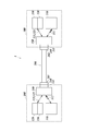
- the optical fiber power supply (PoF: Power over Fiber) system 1A of the present embodiment includes a power supply device (PSE: Power Sourcing Equipment) 110, an optical fiber cable 200A, and a power receiving device (PD: Powered Device) 310.
- PSE Power Sourcing Equipment
- PD Powered Device
- the power feeding device in the present disclosure is a device that converts electric power into light energy and supplies it
- a power receiving device is a device that receives the supply of light energy and converts the light energy into electric power.
- the power feeding device 110 includes a power feeding semiconductor laser 111.
- the optical fiber cable 200A includes an optical fiber 250A that forms a transmission line for feeding light.
- the power receiving device 310 includes a photoelectric conversion element 311.
- the power feeding device 110 is connected to a power source, and a power feeding semiconductor laser 111 or the like is electrically driven.
- the power feeding semiconductor laser 111 oscillates the laser with the electric power from the power source and outputs the power feeding light 112.
- one end 201A can be connected to the power feeding device 110, and the other end 202A can be connected to the power receiving device 310 to transmit the feeding light 112.
- the power feeding light 112 from the power feeding device 110 is input to one end 201A of the optical fiber cable 200A, the feeding light 112 propagates in the optical fiber 250A, and is output from the other end 202A to the power receiving device 310.
- the photoelectric conversion element 311 converts the feeding light 112 transmitted through the optical fiber cable 200A into electric power.
- the electric power converted by the photoelectric conversion element 311 is used as the driving power required in the power receiving device 310. Further, the power receiving device 310 can output the electric power converted by the photoelectric conversion element 311 for an external device.
- the semiconductor material constituting the semiconductor region that exerts the light-electric conversion effect of the power feeding semiconductor laser 111 and the photoelectric conversion element 311 is a semiconductor having a short wavelength laser wavelength of 500 nm or less. Since a semiconductor having a short wavelength laser wavelength has a large band gap and high photoelectric conversion efficiency, the photoelectric conversion efficiency on the power generation side and the power receiving side of optical power supply is improved, and the optical power supply efficiency is improved.
- the semiconductor material for example, a semiconductor material of a laser medium having a laser wavelength (fundamental wave) of 200 to 500 nm, such as diamond, gallium oxide, aluminum nitride, and GaN, may be used.
- a semiconductor having a band gap of 2.4 eV or more is applied as the semiconductor material.
- a semiconductor material of a laser medium having a bandgap of 2.4 to 6.2 eV such as diamond, gallium oxide, aluminum nitride, and GaN, may be used.
- a semiconductor material of a laser medium having a laser wavelength (fundamental wave) smaller than 200 nm may be used.
- These semiconductor materials may be applied to either one of the power feeding semiconductor laser 111 and the photoelectric conversion element 311. The photoelectric conversion efficiency on the power feeding side or the power receiving side is improved, and the optical power feeding efficiency is improved.
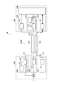
- the optical fiber power supply (PoF: Power over Fiber) system 1 of the present embodiment includes a power supply system via an optical fiber and an optical communication system, and is a power supply device (PSE: Power Sourcing Equipment) 110. It includes a first data communication device 100 including the above, an optical fiber cable 200, and a second data communication device 300 including a power receiving device (PD) 310.
- the power feeding device 110 includes a power feeding semiconductor laser 111.
- the first data communication device 100 includes a power supply device 110, a transmission unit 120 that performs data communication, and a reception unit 130.
- the first data communication device 100 corresponds to a data terminal equipment (DTE: Data Terminal Equipment), a repeater (Repeater), and the like.
- the transmitter 120 includes a signal semiconductor laser 121 and a modulator 122.
- the receiving unit 130 includes a signal photodiode 131.
- the optical fiber cable 200 includes an optical fiber 250 having a core 210 forming a signal light transmission path and a clad 220 arranged on the outer periphery of the core 210 and forming a feeding light transmission path.
- the power receiving device 310 includes a photoelectric conversion element 311.
- the second data communication device 300 includes a power receiving device 310, a transmitting unit 320, a receiving unit 330, and a data processing unit 340.
- the second data communication device 300 corresponds to a power end station (Power End Station) or the like.
- the transmitter 320 includes a signal semiconductor laser 321 and a modulator 322.
- the receiving unit 330 includes a signal photodiode 331.
- the data processing unit 340 is a unit that processes a received signal.
- the second data communication device 300 is a node in the communication network. Alternatively, the second data communication device 300 may be a node that communicates with another node.
- the first data communication device 100 is connected to a power source, and a power feeding semiconductor laser 111, a signal semiconductor laser 121, a modulator 122, a signal photodiode 131, and the like are electrically driven.
- the first data communication device 100 is a node in the communication network.
- the first data communication device 100 may be a node that communicates with another node.
- the power feeding semiconductor laser 111 oscillates the laser with the electric power from the power source and outputs the power feeding light 112.
- the photoelectric conversion element 311 converts the power feeding light 112 transmitted through the optical fiber cable 200 into electric power.
- the electric power converted by the photoelectric conversion element 311 is the driving power of the transmitting unit 320, the receiving unit 330, and the data processing unit 340, and other driving power required in the second data communication device 300.
- the second data communication device 300 may be capable of outputting the electric power converted by the photoelectric conversion element 311 for an external device.
- the modulator 122 of the transmitting unit 120 modulates the laser light 123 from the signal semiconductor laser 121 based on the transmission data 124 and outputs it as the signal light 125.
- the signal photodiode 331 of the receiving unit 330 demodulates the signal light 125 transmitted through the optical fiber cable 200 into an electric signal and outputs it to the data processing unit 340.
- the data processing unit 340 transmits the data by the electric signal to the node, while receiving the data from the node and outputting the data as the transmission data 324 to the modulator 322.
- the modulator 322 of the transmitting unit 320 modulates the laser light 323 from the signal semiconductor laser 321 based on the transmission data 324 and outputs it as the signal light 325.
- the signal photodiode 131 of the receiving unit 130 demodulates the signal light 325 transmitted through the optical fiber cable 200 into an electric signal and outputs it.
- the data from the electrical signal is transmitted to the node, while the data from the node is referred to as transmission data 124.
- the feed light 112 and the signal light 125 from the first data communication device 100 are input to one end 201 of the optical fiber cable 200, the feed light 112 propagates through the clad 220, the signal light 125 propagates through the core 210, and the other end. It is output from 202 to the second data communication device 300.
- the signal light 325 from the second data communication device 300 is input to the other end 202 of the optical fiber cable 200, propagates through the core 210, and is output from one end 201 to the first data communication device 100.
- the first data communication device 100 is provided with an optical input / output unit 140 and an optical connector 141 attached to the optical input / output unit 140.
- the second data communication device 300 is provided with an optical input / output unit 350 and an optical connector 351 attached to the optical input / output unit 350.
- An optical connector 230 provided at one end 201 of the optical fiber cable 200 connects to the optical connector 141.
- An optical connector 240 provided at the other end 202 of the optical fiber cable 200 connects to the optical connector 351.
- the optical input / output unit 140 guides the feeding light 112 to the clad 220, guides the signal light 125 to the core 210, and guides the signal light 325 to the receiving unit 130.
- the optical input / output unit 350 guides the feeding light 112 to the power receiving device 310, guides the signal light 125 to the receiving unit 330, and guides the signal light 325 to the core 210.
- the optical fiber cable 200 has one end 201 connectable to the first data communication device 100 and the other end 202 connectable to the second data communication device 300 to transmit the feeding light 112. Further, in the present embodiment, the optical fiber cable 200 transmits the signal lights 125 and 325 in both directions.
- the semiconductor material constituting the semiconductor region that exhibits the light-electricity conversion effect of the power feeding semiconductor laser 111 and the photoelectric conversion element 311 As the semiconductor material constituting the semiconductor region that exhibits the light-electricity conversion effect of the power feeding semiconductor laser 111 and the photoelectric conversion element 311, the same materials as those in the first embodiment are applied, and high light power feeding efficiency is realized. ..
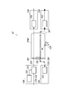
- the optical fiber 260 for transmitting signal light and the optical fiber 270 for transmitting the feeding light may be provided separately.
- the optical fiber cable 200B may also be composed of a plurality of cables.
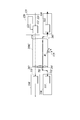
- FIG. 5 is a configuration diagram of an optical fiber power feeding system according to a third embodiment to which the power feeding light leakage prevention means is applied.
- the same components as those described above are designated by the same reference numerals, and detailed description thereof will be omitted.
- the optical fiber power supply system 1C of the third embodiment includes an optical fiber 250C including a first transmission line 281 and a second transmission line 282 capable of transmitting light.
- the optical fiber 250C includes a core, a first clad around the core, and a second clad around the first clad.
- the optical fiber 250C may have more clads such as a third clad located on the outer periphery than the second clad and a fourth clad located on the outer periphery thereof.
- Two of the core and the plurality of claddings are used as the first transmission line 281 and the second transmission line 282.
- the feeding light 112 is transmitted through the first transmission line 281 and the signal light 125 is transmitted through the second transmission line 282.
- a clad located on the outer periphery of the first transmission line 281 is selected.
- an optical fiber 250C having a core, a first clad around the core, and a second clad around the first clad is adopted.
- the core may be used as the first transmission line 281 for the transmission of the feeding light 112
- the first clad may be used as the second transmission line 282 for the transmission of the signal light 125.
- an optical fiber 250C having a core, a first clad around the core, a second clad around the first clad, and a third clad around the second clad is adopted.
- the first clad may be used as the first transmission line 281 for the transmission of the feeding light 112
- the second clad may be used as the second transmission line 282 for the transmission of the signal light 125.
- the first transmission line 281 through which the feeding light 112 propagates may have a larger cross-sectional area than the other transmission lines.
- the power feeding device 110 outputs the power feeding light 112 to the first transmission line 281 (for example, the core) of the optical fiber 250C.
- the power receiving device 310 inputs the feeding light 112 from the first transmission line 281 of the optical fiber 250C.
- the transmission unit 120 outputs the signal light 125 to the second transmission line 282 (for example, the first cladding) of the optical fiber 250C.
- the receiving unit 330 inputs the signal light 125 from the second transmission line 282 of the optical fiber 250C.
- the signal light 125 may include the main body data of the data communication, or may be a signal for detecting damage to the optical fiber 250C.
- the optical fiber 250C is damaged during the transmission of the power supply light 112 and the signal light 125.
- the feed light 112 is higher energy light (high intensity) than the signal light 125. Therefore, it is not preferable that high energy light leaks when the optical fiber 250C is disconnected. Since the damaged portion W is damaged from the outer peripheral transmission line, the signal light 125 leaks from the second transmission line 282 before the feeding light 112 leaks from the first transmission line 281.
- Leakage of the signal light 125 appears as an abnormality such as a decrease in the amount of light received by the receiving unit 330, an increase in the amount of reflected light of the signal light 125, or the signal light 125 leaking from the damaged unit W being reflected on the infrared camera. Therefore, damage to the optical fiber 250C can be quickly detected due to an abnormality in the signal light 125, and the damage may be dealt with before the damage to the optical fiber 250C progresses and the feeding light 112 leaks. Therefore, according to the optical fiber power feeding system 1C of the third embodiment, it is possible to prevent the feeding light 112 from suddenly leaking or the feeding light 112 from continuing to leak for a long time.
- the system of the third embodiment can be applied to the optical fiber power supply system of FIGS. 1, 2, and 4.
- the optical fiber 250A of FIG. 1 is changed to the optical fiber 250C of the third embodiment
- the power feeding device 110 of FIG. 1 is changed to the power feeding device 110 and the transmitting unit 120 of the third embodiment.
- the power receiving device 310 of 1 may be changed to the power receiving device 310 and the receiving unit 330 of the third embodiment.
- the optical fiber 250 of FIG. 2 is changed to the optical fiber 250C of the third embodiment, and the power feeding device 110, the transmitting unit 120, the power receiving device 310, and the feeding light 112 and the signal of the receiving unit 330 of FIG. 2 are changed.
- the input / output position of the optical 125 may be the same as that of the third embodiment.
- the transmitting unit 120 and the receiving unit 330 of the third embodiment may be newly added as a configuration different from the transmitting unit 120 and the receiving unit 330 of FIG. In this case, the system includes two sets of transmitting unit 120 and receiving unit 330.
- one combination transmits the signal light 125 via the second transmission line 282 (for example, the second cladding), and the other combination is the first transmission line 281 (for example, the second transmission line 281 (for example, the second cladding).
- the signal light 125 may be transmitted via a transmission line (for example, a core) inside the first clad).
- the optical fiber 270 of FIG. 4 is changed to the optical fiber 250C of the third embodiment, and the power feeding device 110 of FIG. 4 is changed to the power feeding device 110 and the transmitting unit 120 of the third embodiment.
- the power receiving device 310 of 4 may be changed to the power receiving device 310 and the receiving unit 330 of the third embodiment.
- the transmitting unit 120 and the receiving unit 330 may be arranged in reverse.
- FIG. 7 is a configuration diagram of an optical fiber power feeding system according to a fourth embodiment to which the power feeding light leakage prevention means is applied.
- the same components as those in FIG. 5 are designated by the same reference numerals, and detailed description thereof will be omitted.
- the monitoring unit 181 that monitors the reflected light amount of the signal light 125
- the monitoring unit 381 that monitors the received light amount of the signal light 125
- the abnormality of the reflected light amount or the received light amount of the signal light 125 is further provided.
- One of the monitoring units 181 and 381 may be omitted.
- a transmission line 291 capable of transmitting a signal indicating an abnormality or a signal indicating the amount of received light from the monitoring unit 381 to the control unit 191 may be provided.
- the transmission line 291 may be a metal wiring, a wireless transmission line, another transmission line closer to the center than the second transmission line 282 in the optical fiber 250C, or an optical fiber different from the optical fiber 250C.
- the monitoring unit 181 may include an isolator that extracts the return light from the second transmission line 282 of the optical fiber 250C and a light receiving element (photodiode or the like) that receives the extracted return light.
- the monitoring unit 381 may include, for example, a beam splitter that splits a part of the signal light 125 at a constant ratio, and a light receiving element (photodiode or the like) that receives the branched signal light.
- the receiving unit 330 may also have the function of the monitoring unit 381.
- the control unit 191 determines whether or not a change in the signal light 125 indicating damage to the optical fiber 250C has occurred (step S1), and when it is determined that a change has occurred, stops driving the power feeding device 110 or stops driving.
- the output is reduced (step S2).
- the change in the signal light 125 in step S1 is, for example, an increase in reflected light (increase exceeding the threshold value), a decrease in the amount of received light (decrease below the threshold value), and the like.
- the control unit 191 may be composed of a microcomputer, or may be composed of a sequencer using an analog circuit or a digital circuit.
- the optical fiber 250C is damaged during the transmission of the feeding light 112 and the signal light 125. Since the damaged portion W is damaged from the outer peripheral transmission line, the signal light 125 leaks from the second transmission line 282 before the feeding light 112 leaks from the first transmission line 281. When the signal light 125 leaks, the reflection of the signal light 125 at the damaged portion W increases, and the amount of light propagated by the signal light 125 to the other end 202 of the optical fiber 250C decreases.
- control unit 191 detects a change in the reflected light amount or the received light amount by the monitoring of the monitoring units 181 and 381, and the control unit 191 stops driving the power feeding device 110 or reduces the output.
- the feeding light 112 propagating in the first transmission line 281 is stopped or weakened. Therefore, even if the damage progresses to the first transmission line 281 of the optical fiber 250C, it is possible to prevent the high-intensity feeding light 112 from leaking from the damaged portion.
- the configuration of the fourth embodiment can be applied to the optical fiber power supply system of FIGS. 1, 2, and 4 as in the third embodiment.
- the transmitting unit 120 and the monitoring unit 181 and the receiving unit 330 and the monitoring unit 381 may be arranged in reverse.
- the control unit 191 may be arranged in a device different from the device having the power feeding device 110.
- the control unit 191 may adopt a configuration in which the control signal can be transmitted via a transmission line other than the first transmission line 281 and the second transmission line 282 to stop the driving of the power feeding device 110.
- This disclosure can be used for optical fiber power supply systems and data communication devices.
- Optical fiber power supply system 1 Optical fiber power supply system 1B
- Optical fiber power supply system 1C Optical fiber power supply system 1D
- Optical fiber power supply system 100 First data communication device 110 Power supply device 111 Semiconductor laser for power supply 112 Power supply light 120 Transmission unit 125 Signal light 130 Receiver unit 140 Optical input Output unit 141 Optical connector 181 Monitoring unit 191
Abstract
L'invention concerne un système d'alimentation électrique à fibre optique et un dispositif de communication de données de telle sorte qu'une fuite de lumière d'alimentation électrique peut être supprimée même lorsqu'une fibre optique est endommagée. Le système d'alimentation électrique à fibre optique est destiné à transmettre une lumière d'alimentation électrique et une lumière de signal à travers une fibre optique ayant un premier trajet de transmission constitué d'un noyau ou d'une gaine et d'un second trajet de transmission constitué d'une gaine et positionné sur la périphérie extérieure du premier trajet de transmission. La lumière d'alimentation est propagée à travers le premier trajet de transmission, et la lumière de signal est propagée à travers le second trajet de transmission. Le dispositif de communication de données comporte : un dispositif d'alimentation électrique pour délivrer la lumière d'alimentation électrique au premier trajet de transmission ; et une unité de transmission ou une unité de réception pour émettre ou recevoir la lumière de signal à travers le second trajet de transmission. En variante, le dispositif de communication de données comporte : un dispositif de réception d'énergie auquel la lumière d'alimentation électrique est entrée à partir du premier trajet de transmission ; et une unité de transmission ou une unité de réception pour émettre ou recevoir la lumière de signal à travers le second trajet de transmission.
Priority Applications (3)
| Application Number | Priority Date | Filing Date | Title |
|---|---|---|---|
| EP20826272.5A EP3829085B1 (fr) | 2019-06-20 | 2020-05-25 | Système d'alimentation électrique à fibre optique et dispositif de communication de données |
| CN202080004647.5A CN112585891B (zh) | 2019-06-20 | 2020-05-25 | 光纤供电系统以及数据通信装置 |
| US17/271,598 US11137561B2 (en) | 2019-06-20 | 2020-05-25 | Power over fiber system and data communication devices |
Applications Claiming Priority (2)
| Application Number | Priority Date | Filing Date | Title |
|---|---|---|---|
| JP2019-114741 | 2019-06-20 | ||
| JP2019114741A JP6814253B2 (ja) | 2019-06-20 | 2019-06-20 | 光ファイバー給電システム及びデータ通信装置 |
Publications (1)
| Publication Number | Publication Date |
|---|---|
| WO2020255636A1 true WO2020255636A1 (fr) | 2020-12-24 |
Family
ID=73994278
Family Applications (1)
| Application Number | Title | Priority Date | Filing Date |
|---|---|---|---|
| PCT/JP2020/020460 WO2020255636A1 (fr) | 2019-06-20 | 2020-05-25 | Système d'alimentation électrique à fibre optique et dispositif de communication de données |
Country Status (5)
| Country | Link |
|---|---|
| US (1) | US11137561B2 (fr) |
| EP (1) | EP3829085B1 (fr) |
| JP (1) | JP6814253B2 (fr) |
| CN (1) | CN112585891B (fr) |
| WO (1) | WO2020255636A1 (fr) |
Citations (3)
| Publication number | Priority date | Publication date | Assignee | Title |
|---|---|---|---|---|
| JP2010135989A (ja) | 2008-12-03 | 2010-06-17 | Mitsubishi Electric Corp | 光ファイバ、光通信装置、及び光通信方法 |
| JP2014042166A (ja) * | 2012-08-22 | 2014-03-06 | Sumitomo Electric Ind Ltd | 光学装置および給電システム |
| JP2019054423A (ja) * | 2017-09-15 | 2019-04-04 | 株式会社日立製作所 | 光給電システム |
Family Cites Families (14)
| Publication number | Priority date | Publication date | Assignee | Title |
|---|---|---|---|---|
| US4217488A (en) * | 1977-01-21 | 1980-08-12 | Bell Telephone Laboratories, Incorporated | Secure optical communication components, method, and system |
| US4298794A (en) * | 1979-08-30 | 1981-11-03 | United Technologies Corporation | Fiber optic hot spot detector |
| DE19961515C2 (de) * | 1999-12-20 | 2002-04-25 | Siemens Ag | Anordnung zur Übertragung von Pumplicht hoher Leistung zur Fernspeisung eines Faserverstärkers |
| WO2005072229A2 (fr) * | 2004-01-23 | 2005-08-11 | University Of Pittsburgh Of The Commonwealth System Of Higher Education | Composants optiques actifs dans la fibre alimentes par une lumiere dans la fibre |
| US20070003288A1 (en) * | 2005-06-30 | 2007-01-04 | Xiaolin Tong | Bidirectional HDCP transmission module using single optical fiber |
| US7844154B2 (en) * | 2007-05-07 | 2010-11-30 | Corning Incorporated | Optical fiber for optical power transmission |
| US7813646B2 (en) * | 2007-07-11 | 2010-10-12 | RLH Industries, Inc | Power over optical fiber system |
| US7941022B1 (en) * | 2008-05-06 | 2011-05-10 | Hrl Laboratories, Llc | Single fiber optical links for simultaneous data and power transmission |
| JP2014013311A (ja) * | 2012-07-04 | 2014-01-23 | Sumitomo Electric Ind Ltd | 光ファイバ及び光通信システム |
| US9529147B2 (en) * | 2014-04-29 | 2016-12-27 | Florida Institute of Technology, Inc. | All-optical spatial domain multiplexing de-multiplexer |
| BR112017009284B1 (pt) * | 2014-11-07 | 2022-07-12 | Prysmian S.P.A | Fibra óptica multimodo para transmissão contínua de radiação eletromagnética a alta potência, métodos para transmitir radiação a alta potência ao longo de uma fibra óptica, e, cabo óptico |
| KR101772908B1 (ko) * | 2015-08-12 | 2017-08-30 | 광주과학기술원 | 광섬유, 광섬유 결합기 및 광섬유를 이용한 광신호와 광에너지의 전달방법 |
| CN109286440A (zh) * | 2018-10-11 | 2019-01-29 | 东南大学 | 一种基于双包层光纤的激光供能及共路信息回传系统 |
| CN111211837A (zh) * | 2020-01-16 | 2020-05-29 | 新疆大学 | 基于光纤供能的可见光通信系统 |
-
2019
- 2019-06-20 JP JP2019114741A patent/JP6814253B2/ja active Active
-
2020
- 2020-05-25 EP EP20826272.5A patent/EP3829085B1/fr active Active
- 2020-05-25 US US17/271,598 patent/US11137561B2/en active Active
- 2020-05-25 WO PCT/JP2020/020460 patent/WO2020255636A1/fr unknown
- 2020-05-25 CN CN202080004647.5A patent/CN112585891B/zh active Active
Patent Citations (3)
| Publication number | Priority date | Publication date | Assignee | Title |
|---|---|---|---|---|
| JP2010135989A (ja) | 2008-12-03 | 2010-06-17 | Mitsubishi Electric Corp | 光ファイバ、光通信装置、及び光通信方法 |
| JP2014042166A (ja) * | 2012-08-22 | 2014-03-06 | Sumitomo Electric Ind Ltd | 光学装置および給電システム |
| JP2019054423A (ja) * | 2017-09-15 | 2019-04-04 | 株式会社日立製作所 | 光給電システム |
Non-Patent Citations (1)
| Title |
|---|
| See also references of EP3829085A4 |
Also Published As
| Publication number | Publication date |
|---|---|
| CN112585891B (zh) | 2021-11-30 |
| CN112585891A (zh) | 2021-03-30 |
| EP3829085A1 (fr) | 2021-06-02 |
| JP6814253B2 (ja) | 2021-01-13 |
| US11137561B2 (en) | 2021-10-05 |
| EP3829085A4 (fr) | 2021-10-20 |
| EP3829085B1 (fr) | 2023-01-04 |
| US20210247578A1 (en) | 2021-08-12 |
| JP2021002715A (ja) | 2021-01-07 |
Similar Documents
| Publication | Publication Date | Title |
|---|---|---|
| US20220094449A1 (en) | Optical connector and power sourcing equipment of power over fiber system, and power over fiber system | |
| US11870204B2 (en) | PSE device and powered device of optical power supply system, and optical power supply system | |
| JP6890636B2 (ja) | 光給電システム | |
| WO2020255636A1 (fr) | Système d'alimentation électrique à fibre optique et dispositif de communication de données | |
| JP7436160B2 (ja) | 光給電システム | |
| WO2021014727A1 (fr) | Système d'alimentation électrique à fibre optique | |
| JP7399630B2 (ja) | 光電アダプタ | |
| JP7399673B2 (ja) | 光ファイバー給電システム | |
| US20220094446A1 (en) | Power over fiber system and optical fiber cable | |
| US11888534B2 (en) | Power sourcing equipment of power-over-fiber system and power-over-fiber system | |
| US11888329B2 (en) | Power over fiber system and feed light visualization lid member | |
| US20220094450A1 (en) | Power over fiber system | |
| JP7308682B2 (ja) | 光給電システム |
Legal Events
| Date | Code | Title | Description |
|---|---|---|---|
| 121 | Ep: the epo has been informed by wipo that ep was designated in this application |
Ref document number: 20826272 Country of ref document: EP Kind code of ref document: A1 |
|
| ENP | Entry into the national phase |
Ref document number: 2020826272 Country of ref document: EP Effective date: 20210225 |
|
| NENP | Non-entry into the national phase |
Ref country code: DE |