WO2020241808A1 - 排ガスセンサ - Google Patents
排ガスセンサ Download PDFInfo
- Publication number
- WO2020241808A1 WO2020241808A1 PCT/JP2020/021260 JP2020021260W WO2020241808A1 WO 2020241808 A1 WO2020241808 A1 WO 2020241808A1 JP 2020021260 W JP2020021260 W JP 2020021260W WO 2020241808 A1 WO2020241808 A1 WO 2020241808A1
- Authority
- WO
- WIPO (PCT)
- Prior art keywords
- sensor
- temperature
- exhaust gas
- fluctuation amount
- unit
- Prior art date
Links
Images


Classifications
-
- F—MECHANICAL ENGINEERING; LIGHTING; HEATING; WEAPONS; BLASTING
- F01—MACHINES OR ENGINES IN GENERAL; ENGINE PLANTS IN GENERAL; STEAM ENGINES
- F01N—GAS-FLOW SILENCERS OR EXHAUST APPARATUS FOR MACHINES OR ENGINES IN GENERAL; GAS-FLOW SILENCERS OR EXHAUST APPARATUS FOR INTERNAL COMBUSTION ENGINES
- F01N11/00—Monitoring or diagnostic devices for exhaust-gas treatment apparatus, e.g. for catalytic activity
-
- F—MECHANICAL ENGINEERING; LIGHTING; HEATING; WEAPONS; BLASTING
- F02—COMBUSTION ENGINES; HOT-GAS OR COMBUSTION-PRODUCT ENGINE PLANTS
- F02D—CONTROLLING COMBUSTION ENGINES
- F02D45/00—Electrical control not provided for in groups F02D41/00 - F02D43/00
-
- G—PHYSICS
- G01—MEASURING; TESTING
- G01N—INVESTIGATING OR ANALYSING MATERIALS BY DETERMINING THEIR CHEMICAL OR PHYSICAL PROPERTIES
- G01N27/00—Investigating or analysing materials by the use of electric, electrochemical, or magnetic means
- G01N27/02—Investigating or analysing materials by the use of electric, electrochemical, or magnetic means by investigating impedance
- G01N27/04—Investigating or analysing materials by the use of electric, electrochemical, or magnetic means by investigating impedance by investigating resistance
-
- F—MECHANICAL ENGINEERING; LIGHTING; HEATING; WEAPONS; BLASTING
- F01—MACHINES OR ENGINES IN GENERAL; ENGINE PLANTS IN GENERAL; STEAM ENGINES
- F01N—GAS-FLOW SILENCERS OR EXHAUST APPARATUS FOR MACHINES OR ENGINES IN GENERAL; GAS-FLOW SILENCERS OR EXHAUST APPARATUS FOR INTERNAL COMBUSTION ENGINES
- F01N2550/00—Monitoring or diagnosing the deterioration of exhaust systems
- F01N2550/24—Determining the presence or absence of an exhaust treating device
-
- F—MECHANICAL ENGINEERING; LIGHTING; HEATING; WEAPONS; BLASTING
- F01—MACHINES OR ENGINES IN GENERAL; ENGINE PLANTS IN GENERAL; STEAM ENGINES
- F01N—GAS-FLOW SILENCERS OR EXHAUST APPARATUS FOR MACHINES OR ENGINES IN GENERAL; GAS-FLOW SILENCERS OR EXHAUST APPARATUS FOR INTERNAL COMBUSTION ENGINES
- F01N2560/00—Exhaust systems with means for detecting or measuring exhaust gas components or characteristics
- F01N2560/02—Exhaust systems with means for detecting or measuring exhaust gas components or characteristics the means being an exhaust gas sensor
-
- F—MECHANICAL ENGINEERING; LIGHTING; HEATING; WEAPONS; BLASTING
- F01—MACHINES OR ENGINES IN GENERAL; ENGINE PLANTS IN GENERAL; STEAM ENGINES
- F01N—GAS-FLOW SILENCERS OR EXHAUST APPARATUS FOR MACHINES OR ENGINES IN GENERAL; GAS-FLOW SILENCERS OR EXHAUST APPARATUS FOR INTERNAL COMBUSTION ENGINES
- F01N2560/00—Exhaust systems with means for detecting or measuring exhaust gas components or characteristics
- F01N2560/06—Exhaust systems with means for detecting or measuring exhaust gas components or characteristics the means being a temperature sensor
-
- F—MECHANICAL ENGINEERING; LIGHTING; HEATING; WEAPONS; BLASTING
- F01—MACHINES OR ENGINES IN GENERAL; ENGINE PLANTS IN GENERAL; STEAM ENGINES
- F01N—GAS-FLOW SILENCERS OR EXHAUST APPARATUS FOR MACHINES OR ENGINES IN GENERAL; GAS-FLOW SILENCERS OR EXHAUST APPARATUS FOR INTERNAL COMBUSTION ENGINES
- F01N2560/00—Exhaust systems with means for detecting or measuring exhaust gas components or characteristics
- F01N2560/20—Sensor having heating means
-
- Y—GENERAL TAGGING OF NEW TECHNOLOGICAL DEVELOPMENTS; GENERAL TAGGING OF CROSS-SECTIONAL TECHNOLOGIES SPANNING OVER SEVERAL SECTIONS OF THE IPC; TECHNICAL SUBJECTS COVERED BY FORMER USPC CROSS-REFERENCE ART COLLECTIONS [XRACs] AND DIGESTS
- Y02—TECHNOLOGIES OR APPLICATIONS FOR MITIGATION OR ADAPTATION AGAINST CLIMATE CHANGE
- Y02T—CLIMATE CHANGE MITIGATION TECHNOLOGIES RELATED TO TRANSPORTATION
- Y02T10/00—Road transport of goods or passengers
- Y02T10/10—Internal combustion engine [ICE] based vehicles
- Y02T10/40—Engine management systems
Definitions
- the present disclosure relates to an exhaust gas sensor for detecting components contained in exhaust gas.
- An exhaust gas sensor is used to detect a specific gas component (for example, NOx) or particulate matter (that is, Particulate Matter; hereinafter, appropriately referred to as PM) contained in the exhaust gas from a vehicle engine or the like.
- the exhaust gas sensor is usually attached so that the tip of the sensor element supported by the housing is located in the exhaust gas passage in a state of being housed in the element cover.
- an exhaust gas purification system including a particulate filter that collects particulate matter is provided with a PM sensor to detect particulate matter that leaks when the particulate filter is damaged. If the PM sensor does not operate normally, erroneous detection may occur. Therefore, in order to ensure the reliability of the system, it is necessary to detect the presence or absence of abnormality in the PM sensor itself.
- Patent Document 1 proposes a system for diagnosing that the sensor unit is not in the non-mounted state or the correct mounted state by monitoring the sensor unit arranged in the exhaust gas pipe and comparing the sensor temperature with the exhaust gas temperature. ing.
- the sensor temperature changes according to the exhaust gas temperature, so if the sensor temperature changes in the direction of decrease under the operating conditions where the exhaust gas temperature is increasing, there is a possibility of some abnormality. Therefore, as in Patent Document 1, it is conceivable to utilize the temperature difference between the sensor temperature and the exhaust gas temperature, and to diagnose, for example, a mounting abnormality when the temperature difference becomes larger than a predetermined diagnostic threshold.
- the relationship between the sensor temperature and the exhaust gas temperature changes depending on the surrounding environment in which the exhaust gas purification system is used, for example, the outside air temperature and the weather, and the temperature difference between the sensor temperature and the exhaust gas temperature also changes. Therefore, it is not easy to set the diagnostic threshold value appropriately, the environment in which the diagnosis can be made is limited, or there is a risk of erroneous diagnosis, and it is difficult to accurately diagnose the non-mounted state.
- the purpose of the present disclosure is to provide a more reliable exhaust gas sensor by making it possible to accurately diagnose the mounted state of the sensor element.
- An exhaust gas sensor that detects specific components contained in the exhaust gas of an internal combustion engine.
- a sensor body that holds a sensor element having a detection unit for the specific component inside a housing attached to an exhaust gas pipe, and a sensor body.
- An element cover that houses the sensor element inside and has a gas flow hole for introducing or deriving exhaust gas to the detection unit.
- a heater that generates heat when energized to heat the sensor element
- a heater control unit that controls the heating of the sensor element by the heater
- a sensor temperature detector that detects the temperature of the sensor element, It has a mounting state diagnosis unit for diagnosing the mounting state of the sensor body with respect to the exhaust gas pipe based on the sensor temperature detected by the sensor temperature detection unit.
- the mounting state diagnosis unit includes a temperature fluctuation amount calculation unit that calculates the fluctuation amount of the sensor temperature, a temperature fluctuation amount integration unit that integrates the fluctuation amount of the sensor temperature, and the sensor temperature integration unit by the temperature fluctuation amount integration unit. It is an exhaust gas sensor having an abnormality determination unit that determines the presence or absence of mounting abnormality based on the comparison result between the fluctuation amount integration information and the diagnostic threshold value.
- the mounting state diagnosis unit calculates the fluctuation amount of the sensor temperature detected by the sensor temperature detection unit, and makes a diagnosis using the fluctuation amount integration information obtained by integrating the fluctuation amount.
- the exhaust gas temperature is higher than the outside air temperature
- the sensor element is normally mounted together with the sensor body, the temperature of the sensor element rises due to exposure to the exhaust gas passing through the gas flow hole of the element cover.
- the sensor temperature also fluctuates to follow it.
- the temperature of the sensor element does not follow the exhaust gas temperature and the change is small.
- the mounting state diagnosis unit diagnoses the abnormality of the mounting state by comparing it with the diagnostic threshold value using the sensor temperature fluctuation amount integrated information as an index.
- the fluctuation amount becomes large according to the fluctuation of the exhaust gas temperature, and in the state where there is a mounting abnormality, the fluctuation amount becomes small.
- the difference between the individual fluctuation amounts is small, the difference between the normal time and the abnormal time becomes large by integrating the fluctuation amounts, and it becomes possible to distinguish by setting the diagnostic threshold value based on the relationship between them. .. Therefore, at the time of diagnosis, the mounting state diagnosis can be performed accurately without being affected by the surrounding environment as in the conventional case.
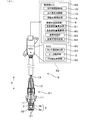
- FIG. 1 is an overall configuration diagram of an exhaust gas sensor according to the first embodiment.
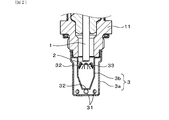
- FIG. 2 is an enlarged cross-sectional view of a main part of the sensor body of the exhaust gas sensor according to the first embodiment.
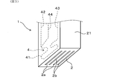
- FIG. 3 is an enlarged perspective view of a main part of the sensor element of the exhaust gas sensor according to the first embodiment.
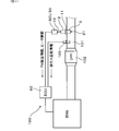
- FIG. 4 is an overall configuration diagram of an exhaust gas purification system including an exhaust gas sensor according to the first embodiment.
- FIG. 5 is a schematic cross-sectional view for explaining the operation of the sensor element in the first embodiment.
- FIG. 6 is a diagram showing an example of the relationship between the sensor temperature of the sensor element and the heater resistance in the first embodiment.
- FIG. 7 is a diagram showing an outline of processing in the mounting state diagnosis unit of the exhaust gas sensor in the first embodiment.
- FIG. 8 is a diagram showing the relationship between the control mode of the sensor element of the exhaust gas sensor and the sensor temperature in the first embodiment.
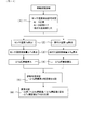
- FIG. 9 is a flowchart of the mounting state diagnosis process performed in the mounting state diagnosis unit of the exhaust gas sensor in the first embodiment.
- FIG. 10 is a time chart diagram showing the heating control by the heater portion of the exhaust gas sensor and the transition of the temperature of the sensor element in the first embodiment.
- FIG. 11 is a diagram showing the relationship between the ⁇ Tg integrated value and the ⁇ Ts integrated value used in the mounting state diagnosis unit of the exhaust gas sensor in the first embodiment by comparing the mounted normal product and the mounted abnormal product.
- FIG. 12 is a diagram showing the relationship between the ⁇ Tg integrated value and the ⁇ Ts integrated value used in the mounting state diagnosis unit of the exhaust gas sensor in the first embodiment and the diagnostic threshold value.
- FIG. 13 is a time chart diagram for explaining the method of diagnosing the mounting state of the exhaust gas sensor in the conventional exhaust gas sensor and the influence of the surrounding environment on the diagnosis.
- FIG. 14 is a diagram showing an outline of processing in the mounting state diagnosis unit of the exhaust gas sensor in the second embodiment.
- FIG. 15 is a flowchart of the mounting state diagnosis process carried out in the diagnosis possibility determination unit included in the mounting state diagnosis unit of the exhaust gas sensor in the second embodiment.
- FIG. 16 is a time chart diagram showing the heating control by the heater portion of the exhaust gas sensor and the transition of the temperature of the sensor element in the second embodiment.
- the exhaust gas sensor S includes a sensor main body S1 and a control device S2, and the sensor main body S1 has a sensor element 1 having a detection unit 2 and a sensor element 1 inside. It has an element cover 3 for accommodating and a heater 4 for heating the sensor element 1 by generating heat when energized.
- the control device S2 includes a heater control unit 5 that controls heating of the sensor element 1 by the heater 4, a sensor temperature detection unit 51 that detects the temperature of the sensor element 1, and a mounting state diagnosis unit 6 that diagnoses the state of the element cover 3. have.
- the exhaust gas sensor S is mounted on, for example, the exhaust gas purification device 100 of the vehicle engine ENG as an internal combustion engine.
- the exhaust gas sensor S is attached to the exhaust gas pipe 101 in a state where the sensor main body S1 is held inside the housing 11, and the exhaust gas is introduced into the element cover 3 located in the exhaust gas pipe 101 and is included in the exhaust gas. It is configured to detect a specific component.
- the sensor element 1 has an elongated rectangular parallelepiped shape and extends in the axial direction X of the sensor body S1.
- the vertical direction in FIG. 1 is the axial direction X
- the lower end side thereof is the tip end side of the sensor body S1
- the upper end side is the base end side of the sensor body S1.
- the detection unit 2 is provided at the tip of the sensor element 1 in the axial direction X, and detects a specific component contained in the exhaust gas.
- the specific component is, for example, a particulate matter (hereinafter, appropriately abbreviated as PM) contained in the exhaust gas discharged from the vehicle engine ENG, or a gas component such as NOx.
- PM particulate matter
- the element cover 3 is for protecting the sensor element 1 from toxic substances and condensed water in the exhaust gas, and has gas flow holes 31 and 32 so that the exhaust gas can be introduced or derived into the internal space.
- the sensor element 1 has a built-in heater 4 for heating the sensor element 1 by generating heat when energized (see, for example, FIG. 3), and the heater control unit 5 controls the heating of the sensor element 1 by the heater 4. ..
- the sensor element 1 passes through a sensor control unit (Sensor Control Unit; hereinafter referred to as SCU) 50 including a heater control unit 5 and an electronic control unit (Electronic Control Unit; hereinafter, a vehicle side including a mounting state diagnosis unit 6). It is connected to (referred to as ECU) 60.
- SCU Sensor Control Unit
- ECU Electronic Control Unit
- the mounting state diagnosis unit 6 diagnoses the mounting state of the sensor main body S1 with respect to the exhaust gas pipe 101 based on the sensor temperature Ts detected by the sensor temperature detecting unit 51.
- the mounting state diagnosis unit 6 is provided with a temperature fluctuation amount calculation unit 61, a temperature fluctuation amount integration unit 62, and an abnormality determination unit 63 for determining a mounting abnormality.
- the temperature fluctuation amount calculation unit 61 calculates the fluctuation amount of the sensor temperature Ts (hereinafter, appropriately abbreviated as the sensor temperature fluctuation amount) ⁇ Ts in a predetermined period, and the temperature fluctuation amount integration unit 62 calculates the calculated sensor temperature fluctuation amount. Accumulate ⁇ Ts.
- the abnormality determination unit 63 determines the presence or absence of mounting abnormality based on the comparison result between the fluctuation amount integrated information of the sensor temperature Ts and the diagnostic threshold value (for example, the first diagnostic threshold value TH1).
- the temperature fluctuation amount calculation unit 61 further calculates the fluctuation amount of the exhaust gas temperature Tg (hereinafter, appropriately abbreviated as the exhaust gas temperature fluctuation amount) ⁇ Tg. Further, the temperature fluctuation amount integrating unit 62 further calculates an integrated value of the exhaust gas temperature fluctuation amount ⁇ Tg.
- the first diagnostic threshold TH1 can be set based on the integrated value of the exhaust gas temperature fluctuation amount ⁇ Tg. Specifically, the temperature fluctuation amount integrating unit 62 calculates the integrated value of the sensor temperature fluctuation amount ⁇ Ts as the fluctuation amount integration information of the sensor temperature Ts.
- the abnormality determination unit 63 can determine that there is no mounting abnormality when the integrated value of the sensor temperature fluctuation amount ⁇ Ts becomes the first diagnostic threshold TH1 or more.
- the mounting state diagnosis unit 6 further includes a diagnosis possibility determination unit 64 that determines whether or not the mounting state can be diagnosed based on the integrated value of the exhaust gas temperature fluctuation amount ⁇ Tg.
- the diagnosis possibility determination unit 64 can determine that the mounting state can be diagnosed when the integrated value of the exhaust gas temperature fluctuation amount ⁇ Tg becomes a preset specified value T0 or more. In this way, by performing the mounting state diagnosis after reaching the integrated amount corresponding to the specified value T0, more accurate diagnosis becomes possible.
- the diagnosis possibility determination unit 64 is at least one of the control state of the heater control unit 5, the state of the sensor temperature detection unit 51, and the operating state of the vehicle engine ENG. It is also possible to determine whether or not the mounting state diagnosis is possible based on one.
- the sensor body S1 of the exhaust gas sensor S accommodates the sensor element 1 inside the tubular housing 11, and also has a container-shaped element cover 3 fixed to the tip side of the housing 11 in the axial direction X.
- a tubular air cover 12 fixed to the other end side is provided.
- the housing 11 is attached to, for example, the exhaust gas pipe 101 of the exhaust gas purification device 100 shown in FIG. 4, and the tip end side of the sensor element 1 covered with the element cover 3 projects from the exhaust gas pipe 101.
- the atmosphere cover 12 covers the proximal end side of the sensor element 1 located outside the exhaust gas pipe 101, and the sensor element 1 and the sensor control unit 50 pass through a lead wire 13 taken out from the proximal end side of the atmospheric cover 12. Is electrically connected.
- the sensor element 1 is, for example, a laminated element having a laminated structure, and the tip surface of the flat rectangular parallelepiped insulating substrate 21 is the detection unit 2.
- a plurality of linear electrodes serving as a pair of detection electrodes 2a and 2b are arranged in the detection unit 2, and a plurality of electrode pairs having different polarities are formed alternately.
- the detection unit 2 is formed by, for example, alternately arranging electrode films to be the detection electrodes 2a and 2b between a plurality of insulating sheets to be the insulating substrate 21 to form a laminated body, and firing and integrating them. It is formed.
- the edge portion of the electrode film, which is at least partially embedded in the insulating substrate 21, is linearly exposed on the tip surface of the insulating substrate 21 to form the detection electrodes 2a and 2b.
- the insulating substrate 21 can be constructed by using an insulating ceramic material such as alumina.
- the PM detection control unit 52 includes, for example, a voltage application circuit for applying a PM detection voltage between the pair of detection electrodes 2a and 2b, and causes PM between the pair of detection electrodes 2a and 2b during a predetermined detection period. Electrostatic collection.
- the element cover 3 has, for example, a double container shape in which the housing 11 side opens, and is composed of an outer cover 3a and an inner cover 3b that are coaxially arranged.
- the outer cover 3a is composed of a tubular body having a substantially constant diameter and a tip surface that closes the tubular body, and a plurality of gas flow holes 31 are formed through the side surface on the tip surface side so that exhaust gas can be introduced or derived from the exhaust gas pipe 101. It has become.
- the inner cover 3b has a gas flow hole 32 penetrating the tip surface thereof to communicate the space inside the inner cover 3b and the space inside the outer cover 3a.
- a plurality of gas flow holes 32 are formed through the side surface of the inner cover 3b on the base end side, and the gas flow holes 32 are provided with a guide portion 33 that is inclined toward the inside of the inner cover 3b. There is.
- the exhaust gas introduced into the outer cover 3a is guided to the proximal end side along the outer surface of the inner cover 3b, and is introduced into the inner cover 3b from the gas flow hole 32.
- the tip of the guide unit 33 is arranged toward the detection unit 2 of the sensor element 1 located on the axis of the inner cover 3b, and the exhaust gas introduced into the inner cover 3b is directed to the detection unit 2 and then the tip surface. It is led out from the gas flow hole 32 of the above and joins the flow of the exhaust gas led out from the outer cover 3a to the outside.
- the gas flow holes 31 and 32 on the front end surface side of the outer cover 3a and the inner cover 3b have, for example, a circular hole shape, and the gas flow holes 32 on the base end side of the inner cover 3b are, for example, elongated holes elongated in the axial direction X. In shape, it is integrally formed with an elongated plate-shaped guide portion 33 formed by cutting out the side surface of the inner cover 3b.
- the shapes of the outer cover 3a and the inner cover 3b and the shapes of the gas flow holes 31 and 32 are not limited to those described above, and may have any configuration. Further, the gas flow hole 32 may not be provided with the guide portion 33, and the number and arrangement of the gas flow holes 31 and 32 can be arbitrarily set. Preferably, if the gas flow holes 31 and 32 are evenly arranged on the entire circumference of the side surface of the outer cover 3a or the inner cover 3b, the configuration does not have directivity with respect to the gas flow.
- the exhaust gas sensor S in this embodiment is applied to the exhaust gas purification device 100 of a vehicle engine (for example, a diesel engine) ENG.
- a housing 11 is attached to the pipe wall of the exhaust gas pipe 101 on the downstream side of the diesel particulate filter (hereinafter abbreviated as DPF) 102, and a half of the element cover 3 side is inside the exhaust gas pipe 101.
- DPF diesel particulate filter
- the exhaust gas sensor S is used as a PM sensor, detects particulate matter leaking from the DPF 102, and transmits a detection signal to the SCU 50.
- a temperature sensor 103 is arranged between the DPF 102 and the sensor body S1 to detect the exhaust gas temperature Tg in the exhaust gas pipe 101 on the downstream side of the DPF 102.
- the detection signal of the temperature sensor 103 is transmitted to the ECU 60 as exhaust gas temperature information.
- the PM detection principle will be described with reference to the schematic diagram shown in FIG.
- a pair of detection electrodes 2a and 2b are arranged to face each other on the surface of the insulating substrate 21 at predetermined intervals, and the pair of detection electrodes 2a and 2b are conductive in the initial state. Absent.
- the PM detection control unit 52 When a predetermined voltage is applied by the PM detection control unit 52 during the PM detection period, the PM is attracted by the electric field generated between the pair of detection electrodes 2a and 2b and gradually deposited.
- the pair of detection electrodes 2a and 2b are electrically connected, the resistance value between the pair of detection electrodes 2a and 2b changes according to the amount of PM collected. Therefore, in the PM detection control unit 52, the pair of detection electrodes The current between 2a and 2b can be detected.
- the heater electrodes forming the heat generating portion 41 of the heater 4 and the heat generating portion 41 are formed in the vicinity of the tip surface where the detection electrodes 2a and 2b are formed.
- a pair of lead portions 42 and 43 for energizing and a detection lead portion 44 are embedded. These lead portions 42, 43, 44 are pulled out to the proximal end side of the sensor element 1 and connected to the heater control portion 5 of the SCU 50 via the lead wire 13 (see, for example, FIG. 1).
- the heater control unit 5 includes, for example, a pulse width modulation circuit that controls the pulse width of the heater drive signal, and controls the amount of electricity supplied to the heat generating unit 41 by the duty ratio of the pulse signal (hereinafter referred to as heater duty).
- the heat generation amount of the heater 4 can be controlled by the heater control unit 5 so as to correspond to the preset control mode of the sensor temperature Ts, and the sensor element 1 can be heated to a desired temperature.
- the detection unit 2 can be heated to a temperature equal to or higher than the combustion temperature of PM, and the collected PM can be burned and removed to return to the initial state.
- the heater control unit 5 variably controls the heater duty so that the sensor temperature Ts detected by the sensor temperature detection unit 51 becomes a temperature according to the control mode. At that time, the sensor temperature detection unit 51 can detect the sensor temperature Ts based on, for example, the resistance value of the heater 4 built in the sensor element 1. Alternatively, the sensor element 1 may be provided with a temperature detecting means such as a thermocouple or a thermistor to detect the sensor temperature Ts. The control mode of the sensor temperature Ts by the SCU 50 will be described later.
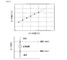
- FIG. 6 shows the heater resistance characteristics, and as shown in the upper diagram of FIG. 6 the relationship between the sensor temperature Ts (unit: ° C.) and the heater resistance (unit: ⁇ ), the higher the sensor temperature Ts, the higher the heater resistance. Becomes larger. Therefore, for example, a heater resistance detection circuit is provided in the sensor temperature detection unit 51 to detect the heater resistance from the current flowing through the heat generating unit 41 of the heater 4 when a predetermined voltage is applied, and further, the relationship shown in FIG. Can be used to detect the sensor temperature Ts. The lower figure of FIG. 6 will be described later.
- the PM sensor information includes heater control information such as a control mode and heater duty by the heater control unit 5, sensor temperature information from the sensor temperature detection unit 51, and PM detection information from the PM detection control unit 52.
- the ECU 60 is provided with an operating state detection unit 14 for inputting an intake air amount detected by an air flow meter (not shown) and a detection signal from an engine speed sensor, an accelerator opening sensor, or the like (for example, FIG. 1). reference). Based on these input information, the ECU 60 knows the operating state of the engine ENG and controls the entire vehicle.
- the operating state of the engine ENG also includes exhaust gas information such as the exhaust gas flow velocity in the exhaust gas pipe 101 and regeneration information of the DPF 102 installed in the exhaust gas pipe 101.
- the exhaust gas flow velocity may be a detected value or an estimated value estimated from the operating state of the engine ENG or the like.
- the ECU 60 is provided with a DPF regeneration control unit 15 that controls regeneration of the DPF 102 and a DPF failure diagnosis unit 16 that diagnoses the failure of the DPF 102.
- the DPF regeneration control unit 15 determines whether or not the regeneration of the DPF 102 is necessary based on, for example, the driving state of the vehicle detected by the driving state detection unit 14, and the DPF failure diagnosis unit 16 determines, for example, the PM detection control unit 52. Based on the PM detection information from, it is determined whether or not there is a failure such as a crack in the DPF 102.
- the engine ENG is not limited to a diesel engine, but may be a gasoline engine. In that case, a gasoline particulate filter (ie, GPF) is arranged in place of the DPF 102.
- GPF gasoline particulate filter
- the PM detection information by the PM detection control unit 52 is mainly used for the failure diagnosis of the DPF 102 in the DPF failure diagnosis unit 16 of the ECU 60 described above.
- the PM detection by the exhaust gas sensor S is normally performed, and as a premise, the sensor body S1 including the sensor element 1 is placed at a predetermined position. It is important that it is properly mounted.
- the engine ENG starts operation in a state where the sensor body S1 is intentionally or accidentally removed from the exhaust gas pipe 101, the exhaust gas does not reach the sensor element 1.
- the PM detection signal is not output from the sensor element 1, so that the failure is not determined and the occupant is not notified, and the particulate matter may be discharged to the outside of the vehicle.
- the sensor body S1 is not properly attached to the exhaust gas pipe 101 or is not in the correct mounting posture, sufficient exhaust gas is not introduced into the element cover 6, the sensor element 1 There is a concern that PM detection will be difficult because the original output cannot be obtained.
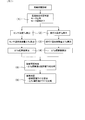
- the exhaust gas sensor S is provided with a mounting state diagnosis unit 6 whose outline is shown in FIG. 7, and diagnoses the mounting state of the sensor element 1 (hereinafter, appropriately referred to as mounting state diagnosis) to perform the mounting state diagnosis. It is possible to detect mounting abnormalities due to disconnection of the sensor body S1 including the above.
- the procedure (3) corresponds to the temperature fluctuation amount calculation unit 61
- the procedure (4) corresponds to the temperature fluctuation amount integration unit 62.
- the procedure (6) corresponds to the abnormality determination unit 63.
- the procedures (1) and (5) correspond to the diagnosis possibility determination unit 64, and the sensor temperature detection unit 51 is used in the procedure (2).
- the fluctuation amount integration information of the sensor temperature Ts based on the detection result of the sensor temperature detection unit 51 in the procedure (2).
- the integrated value of the sensor temperature fluctuation amount ⁇ Ts (hereinafter, appropriately referred to as ⁇ Ts integrated value) is used as the fluctuation amount integrated information of the sensor temperature Ts, and is compared with the predetermined first diagnostic threshold TH1.
- the mounted state is based on the state of the sensor temperature detection unit 51 and the control state of the heater control unit 5 prior to the calculation of the ⁇ Ts integrated value in the procedures (2) to (4). It is desirable to judge whether or not the diagnosis is possible.
- the state of the sensor temperature detection unit 51 can be determined based on whether or not the temperature detection by the sensor temperature detection unit 51 can be performed, and the control state of the heater control unit 5 is determined based on the control mode of the sensor element 1 by the SCU 50. can do.
- the sensor temperature Ts can be detected normally using the resistance value of the heater 4, and the control mode of the sensor element 1 is a mode in which the energization of the heater 4 is turned off (for example, particulate matter). It can be determined that the mounting state diagnosis is possible, assuming that the temperature detection can be performed by the sensor temperature detecting unit 51 and the state is suitable for the mounting state diagnosis when the sensor temperature detection unit 51 is in the collection mode).
- whether or not the temperature can be detected is determined based on the heater resistance used for detecting the sensor temperature Ts. For example, if the heater resistance changes due to deterioration or the like, the detection accuracy of the sensor temperature Ts using the heater resistance decreases. Therefore, the normal range of the heater resistance is set in advance with the resistance thresholds Rth1 and Rth2 as the upper and lower limit values. When the detected heater resistance is in the normal range (that is, Rth1 ⁇ heater resistance ⁇ Rth2), it can be determined that the heater 4 is in the normal state.
- the control modes of the sensor element 1 by the SCU 50 are water- and liquid-phase poisoning-resistant mode, sensor regeneration mode, cooling mode, collection mode, and solid-phase poisoning resistance when the engine ENG is started. Transition in the order of modes. For example, in the water- and liquid-phase poisoning-resistant mode, the water droplets and the like adhering to the sensor element 1 are kept at a temperature at which they can evaporate at the time of low-temperature starting, and further, in the sensor regeneration mode, particulate matter is released. The temperature is raised to a combustible temperature and maintained.
- the solid phase poisoning resistant mode the solid phase poisoning substance adhering to the sensor element 1 can be maintained at a temperature at which it can be removed.
- the sensor temperature detection unit 51 detects the sensor temperature Ts and calculates the sensor temperature fluctuation amount ⁇ Ts in the procedures (2) to (4).
- the calculation of the ⁇ Ts integrated value is sequentially performed.
- the sensor temperature fluctuation amount ⁇ Ts may be the fluctuation amount of the sensor temperature Ts per unit time, for example, the difference value (absolute value) between the previous value and the current value of the sensor temperature Ts detected in a fixed cycle. it can.
- it can be a fluctuation amount of the sensor temperature Ts detected every unit time, for example, a difference value (absolute value) between the sensor temperature Ts detected at a fixed cycle and the reference temperature.
- the exhaust gas temperature fluctuation amount ⁇ Tg (hereinafter, appropriately referred to as ⁇ Tg integrated value) as the fluctuation amount integrated information for the exhaust gas temperature Tg in addition to the sensor temperature Ts.
- the exhaust gas temperature Tg can be detected by using the temperature sensor 103 in the same procedure as the sensor temperature Ts, the exhaust gas temperature fluctuation amount ⁇ Tg can be calculated, and the ⁇ Tg integrated value can be calculated in sequence.
- the exhaust gas temperature fluctuation amount ⁇ Tg can be calculated in the same manner as the sensor temperature fluctuation amount ⁇ Ts.
- the mounting state diagnosis unit 6 determines whether or not the mounting state can be diagnosed based on the calculated ⁇ Tg integrated value in the procedure (5) prior to the determination of the mounting abnormality.
- the ⁇ Tg integrated value with the preset specified value T0, it can be determined whether or not the fluctuation of the exhaust gas temperature Tg has reached an integrated amount sufficient for diagnosis.
- the mounting state diagnosis unit 6 determines whether or not there is a mounting abnormality based on the calculated ⁇ Ts integrated value in the procedure (6).
- the variable first diagnostic threshold TH1 is calculated based on the ⁇ Tg integrated value and compared with the ⁇ Ts integrated value. If the ⁇ Ts integrated value reaches the first diagnostic threshold TH1, it can be determined that the mounting is normal, and if it does not reach the diagnostic threshold TH1, it can be determined that the mounting is abnormal.
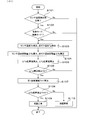
- Step S101 to S102 of FIG. 9 correspond to the procedure (1) of FIG. 7, and steps S103 to S105 correspond to the procedures (2) to (4) of FIG. 7, respectively.
- Step S106 corresponds to the procedure (5) of FIG. 7, and steps S107 to S108 correspond to the procedure (6) of FIG. 7.
- step S101 it is determined whether or not the sensor temperature detection unit 51 is in a state in which it can normally operate. Specifically, the heater control unit 5 detects the heater resistance from the current flowing when a predetermined voltage is applied to the heater 4, and the detected heater resistance is within the normal range based on the relationship shown in the lower figure of FIG. (That is, Rth1 ⁇ heater resistance ⁇ Rth2?).
- the heater 4 is made of a conductive material containing a noble metal or the like, and when the heater 4 is repeatedly heated continuously or intermittently with the operation of the sensor element 1, due to aggregation of the noble metal material or the like, the heater 4 is formed.
- the heater resistance changes. When this change becomes large, the heater 4 does not function normally, and the accuracy of the mounting state diagnosis also deteriorates. Therefore, for example, the heater resistance in the initial state is measured in advance, and the resistance threshold value Rth1 based on this initial resistance is set as the lower limit value in the normal range. Further, with respect to this resistance threshold value Rth1, the resistance threshold value Rth2, which is the upper limit value of the normal range, can be set in consideration of the amount of change in the heater resistance due to aged deterioration or the like.
- step S101 it is determined that the sensor temperature detection unit 51 for detecting the sensor temperature Ts is in a state in which it can operate normally, and the process proceeds to step S102. If a negative determination is made, it is determined that the sensor temperature detection unit 51 does not operate normally, this process is temporarily terminated, and the mounting state diagnosis is not performed.
- step S102 it is determined whether or not the control mode of the sensor temperature Ts by the SCU 50 is the collection mode. If the affirmative determination is made in step S102, it is determined that the heater 4 is in the off state, is not affected by the heating by the heater 4, and is suitable for the mounting state diagnosis, and the process proceeds to step S103. When the negative determination in step S102 is made, it is determined that the control mode is other than the collection mode and the state is not suitable for the mounting state diagnosis using the sensor temperature detection unit 51, and this process is terminated and mounted. No condition diagnosis is performed.
- the control mode of the sensor element 1 by the SCU 50 transitions to the water-resistant / liquid-phase poisoning mode and the sensor regeneration mode when the engine ENG is started, and the heater control unit 5 shifts to the heater 4. It is energized and controlled to a predetermined temperature. After that, in the cooling mode, the heater 4 is turned off and the mode shifts to the collection mode. In the collection mode after cooling, the sensor element 1 is lowered to the same level as the exhaust gas temperature Tg, and the sensor temperature Ts also fluctuates as the exhaust gas temperature Tg fluctuates.
- the control mode of the sensor element 1 by the SCU 50 is the collection mode
- the heater 4 is in the off state and the sensor temperature Ts is equivalent to the exhaust gas temperature Tg
- the mounting state diagnosis unit 6 can determine an abnormality. It is in a state.
- the reliability of the mounting state diagnosis can be improved by determining in advance whether or not the mounting state diagnosis can be performed based on the heater state.
- step S103 the sensor temperature Ts detected by the sensor temperature detection unit 51 is taken in, and the exhaust gas temperature Tg detected by the temperature sensor 103 is taken in.
- step S104 the sensor temperature fluctuation amount ⁇ Ts and the exhaust gas temperature fluctuation amount ⁇ Tg are calculated, respectively.
- the absolute value of the difference value is calculated from the previously detected sensor temperature Ts and exhaust gas temperature Tg and the sensor temperature Ts and exhaust gas temperature Tg detected this time, and the sensor temperature fluctuates.
- the amount ⁇ Ts and the exhaust gas temperature fluctuation amount ⁇ Tg can be set.
- ⁇ Ts absolute value of [previous Ts-current Ts]
- ⁇ Tg absolute value of [previous Tg-current Tg]
- step S105 calculate the ⁇ Ts integrated value and the ⁇ Tg integrated value.
- the sensor temperature fluctuation amount ⁇ Ts and the exhaust gas temperature fluctuation amount ⁇ Tg calculated this time are added to the previous ⁇ Ts integrated value or ⁇ Tg integrated value, and the current ⁇ Ts integrated value and ⁇ Tg integrated value are added.
- the integrated value calculated this time is a value obtained by adding all the temperature fluctuation amounts (absolute values) up to this time.
- ⁇ Ts integrated value ⁇ Ts + [previous ⁇ Ts integrated value]
- ⁇ Tg integrated value ⁇ Tg + [previous ⁇ Tg integrated value]
- the process proceeds to step S106 and subsequent steps to perform the mounting state diagnosis.
- the relationship between the exhaust gas temperature Tg and the sensor temperature Ts differs depending on whether the mounting state is normal or not in the operating state in which the engine speed and the exhaust gas flow velocity fluctuate. That is, when the mounting state is normal, the sensor temperature Ts drops to the exhaust gas temperature Tg due to the regeneration and cooling of the sensor element 1, and then the sensor temperature Ts also fluctuates so as to follow the fluctuation of the exhaust gas temperature Tg. To do. On the other hand, when the sensor main body S1 is not mounted, the sensor temperature Ts drops to about the outside air temperature lower than the exhaust gas temperature Tg, and the subsequent change is small.
- the sensor temperature Ts fluctuates more in the normal mounting than in the abnormal mounting
- the ⁇ Ts integrated value in the normal mounting is the ⁇ Ts integrated value in the abnormal mounting. Greater than.
- the ⁇ Ts integrated value at the time of normal mounting changes along the ⁇ Tg integrated value
- the ⁇ Ts integrated value at the time of abnormal mounting deviates from the ⁇ Tg integrated value with the passage of time, and the time As the lapse of time, the difference between the ⁇ Ts integrated value at the time of normal mounting and the time of abnormal mounting becomes larger.
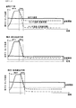
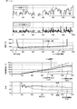
- FIG. 10 shows the relationship between the fluctuations of the exhaust gas temperature Tg and the sensor temperature Ts in the WLTC (Worldwide harmonized Light duty driving Test Cycle) mode, which is the exhaust gas test mode for automobiles, and their integrated values. It is a thing. At this time, when the temperature detection becomes feasible, the integration of the temperature detection is started.
- the ⁇ Tg integrated value and the ⁇ Ts integrated value are the total length of the locus of the characteristic line indicating the temperature change of the sensor temperature Ts after the integration is started.
- the exhaust gas that has passed through the gas flow holes 31 and 32 easily hits the surface of the sensor element 1. Therefore, it is easily affected by the fluctuation of the exhaust gas temperature Tg, and the fluctuation amount of the sensor temperature Ts becomes large. Further, the sensor temperature Ts also fluctuates due to the fluctuation of the exhaust gas flow velocity. For example, when the exhaust gas flow velocity is high, the change of the exhaust gas temperature Tg is easily transmitted to the sensor element 1, and the sensor temperature Ts is higher than when it is low. The amount of fluctuation of is larger.
- the sensor temperature Ts at the time of mounting abnormality approaches the outside air temperature lower than the exhaust gas temperature Tg, and the amount of fluctuation of the sensor temperature Ts is also smaller than that at the time of normal mounting. Therefore, by utilizing this relationship, it is possible to determine whether or not there is an abnormality in the mounted state of the sensor element 1 from the ⁇ Ts integrated value obtained by integrating the sensor fluctuation amount ⁇ Ts.
- the specified value T0 can be distinguished from each other within a range in which the ⁇ Ts integrated value (lower limit value including variation) at the time of normal mounting considering the variation and the ⁇ Ts integrated value (upper limit value including variation) at the time of abnormal mounting do not overlap. It can be set as appropriate.
- the first diagnostic threshold TH1 for distinguishing between the normal mounting and the abnormal mounting according to the magnitude of the ⁇ Tg integrated value.
- the first diagnostic threshold TH1 can be, for example, the median value of the ⁇ Ts integrated value (lower limit value including variation) at the time of normal mounting and the ⁇ Ts integrated value (upper limit value including variation) at the time of abnormal mounting.
- the settings are as shown in Table 1.
- step S106 it is determined whether or not the ⁇ Tg integrated value calculated in step S105 is equal to or greater than the specified value T0 (that is, ⁇ Tg integrated value ⁇ T0?) Using the relationship shown in FIG. If the affirmative determination is made in step S106, it is determined that the integrated amount of the exhaust gas temperature fluctuation amount ⁇ Tg has reached the specified value T0 capable of diagnosing the mounting state, and the process proceeds to step S107. If the negative determination in step S106 is made, the process returns to step S103 and the subsequent steps are repeated.
- the first diagnostic threshold TH1 is calculated from the ⁇ Tg integrated value calculated in step S105 using the relationship shown in FIG.
- the mounting state diagnosis unit 6 stores the threshold value map or the calculation formula based on the relationship shown in Table 1 in advance so as to correspond to the ⁇ Tg integrated value at the time of diagnosing the mounting state for the mounting state diagnosis.
- the first diagnostic threshold TH1 can be appropriately calculated.
- step S108 determines whether or not the ⁇ Ts integrated value calculated in step S105 is equal to or higher than the first diagnostic threshold TH1 calculated in S106 (that is, ⁇ Ts integrated value ⁇ TH1?). If the affirmative determination is made in step S108, the process proceeds to step S109 to determine that the mounting is normal, and if the negative determination is made, the process proceeds to step S110 to determine that the mounting is abnormal. After that, this process ends.
- the first diagnostic threshold TH1 is 43 ° C. If the element cover 3 is in a normal state, the ⁇ Ts integrated value including variation is about 47 to 77 ° C., which is larger than the first diagnostic threshold value TH1, and thus a normal determination is made. On the other hand, when the element cover 3 is not in a normal state, the ⁇ Ts integrated value including the variation is about 24 to 39 ° C., which is smaller than the first diagnostic threshold TH1, and thus an abnormality is determined.
- the fluctuation amount calculation unit 61 which integrates the fluctuation amount of the sensor temperature Ts detected by the temperature detection unit 51, while integrating the fluctuation amount of the exhaust gas temperature Tg
- a fluctuation amount integrating unit 62 is provided, and the abnormality determination unit 63 compares the first diagnostic threshold TH1 corresponding to the ⁇ Tg integrated value with the ⁇ Ts integrated value to determine whether the mounted state of the sensor element 1 is a normal state or an abnormal state. Can be reliably determined.
- the integrated amount of the exhaust gas temperature fluctuation amount ⁇ Tg is equal to or more than the predetermined specified value T0 and the state of the heater 4 is suitable for temperature detection.
- the sensor temperature Ts and the exhaust gas temperature Tg are compared, their temperature differences also change as the surrounding environment such as the outside air temperature and the weather changes.
- the upper figure of FIG. 13 shows the temperature change after the regeneration mode during normal running, and the sensor temperature Ts after regeneration / cooling is stable at a temperature slightly lower than the exhaust gas temperature Tg in the normal mounting state.
- the temperature drops to a lower temperature, and the temperature difference between the exhaust gas temperature Tg and the sensor temperature Ts in the normal state becomes large.
- the mounting state diagnosis using the temperature difference between the sensor temperature Ts and the exhaust gas temperature Tg is performed.
- the exhaust gas temperature Tg flowing inside the exhaust gas pipe 101 is lower than that during normal traveling. It will be easier. Therefore, not only the sensor temperature Ts in the normally mounted state that follows the exhaust gas temperature Tg, but also the temperature difference between the sensor temperature Ts in the non-mounted state and the exhaust gas temperature Tg is within the range of the assumed diagnostic threshold value, and is regarded as the normal state. There is a risk of misjudgment.
- the exhaust gas temperature Tg is the same as in the normal state in an environment where the exhaust gas flow rate is large and the exhaust gas temperature Tg is unlikely to decrease during rainy weather / submerged canal driving.
- the exhaust gas temperature Tg may decrease. In that case, even in the normal mounting state, the exhaust gas temperature Tg The temperature difference from the sensor temperature Ts becomes large. Therefore, the sensor element 1 in the normal state may be erroneously determined to be in the non-mounted state.
- the mounting state diagnosis unit 6 of the present embodiment accurate diagnosis can be performed regardless of the surrounding environment.
- the procedure (3) corresponds to the temperature fluctuation amount calculation unit 61
- the procedure (4) corresponds to the temperature fluctuation amount integration unit 62
- Procedure (6) corresponds to the abnormality determination unit 63
- the procedures (1) and (5) correspond to the diagnosis possibility determination unit 64
- the sensor temperature detection unit 51 is used in the procedure (2).
- the processing procedures (2) to (5) are the same as those in the first embodiment, and the description thereof will be omitted.
- the state of the sensor temperature detection unit 51 and the heater control unit 5 are used when determining whether or not the mounting state diagnosis is possible prior to the calculation of the ⁇ Ts integrated value in the procedures (2) to (4).
- the exhaust gas flow velocity is detected as the state of the exhaust gas in the exhaust gas pipe 101, and it is determined whether or not the change in the exhaust gas flow velocity per unit time is a predetermined specified value V0 or more (for example, 1 m / s). To do.
- the temperature detection may be enabled only when the change in the exhaust gas flow velocity is large. If the change in the exhaust gas flow velocity is small, the following procedure is not performed.
- the propriety of the mounting state diagnosis based on the state of the sensor temperature detection unit 51 and the control state of the heater control unit 5 is also determined in the same manner as in the first embodiment. In this way, it is desirable to carry out the temperature detection and the mounting state diagnosis after the procedure (2) only when the state is suitable for the mounting state diagnosis. In this way, by determining in advance whether or not temperature detection for mounting state diagnosis can be performed, more accurate mounting state diagnosis can be made.
- the sensor temperature Ts is detected, the sensor temperature fluctuation amount ⁇ Ts is calculated, and the ⁇ Ts integrated value is calculated in the procedures (2) to (4) in the same manner as in the first embodiment.
- the calculation is carried out sequentially.
- the exhaust gas temperature Tg is detected, the exhaust gas temperature fluctuation amount ⁇ Tg is calculated, and the ⁇ Tg integrated value is calculated.
- the exhaust gas temperature Tg is determined by comparing with the preset specified value T0 based on the calculated ⁇ Tg integrated value to determine whether or not the mounting state diagnosis is possible. Determine if the variability has reached an integrated amount sufficient for diagnosis.
- the mounting state diagnosis unit 6 determines whether or not there is a mounting abnormality based on the calculated ⁇ Ts integrated value in the procedure (6).
- the first diagnostic threshold TH1 which is a variable value is calculated based on the ⁇ Tg integrated value and compared with the ⁇ Ts integrated value.
- the ratio based on the ⁇ Tg integrated value may be calculated, and a map or the like for calculating the diagnostic threshold value for the on-board state diagnosis can be unnecessary. If the ⁇ Ts integrated value reaches the second diagnostic threshold TH2, it can be determined that the mounting is normal, and if it does not reach the second diagnostic threshold TH2, it can be determined that the mounting is abnormal.
- Step S201 to S203 of FIG. 15 correspond to the procedure (1) of FIG. 14, and steps S204 to S206 correspond to the procedures (2) to (4) of FIG. 14, respectively.
- Step S207 corresponds to the procedure (5) of FIG. 14, and steps S208 to S209 correspond to the procedure (6) of FIG.
- step S201 the sensor temperature detection unit 51 determines whether or not it is in a state in which it can operate normally, and if a positive judgment is made, it is determined.
- Step S202 the control mode of the sensor temperature Ts by the SCU 50 is the collection mode. Steps S201 to S202 are the same as steps S101 to S102 in the first embodiment, and the description thereof will be omitted.
- step S203 the exhaust gas flow velocity detected by the operating state detection unit 14 is further taken in, and it is determined whether or not the change in the exhaust gas flow velocity from the previous time is a specified value V0 or more (for example, 1 m / s) (that is,). , Exhaust gas flow velocity change ⁇ V0?). If the affirmative determination is made in step S203, it is determined that the exhaust gas flow velocity is in a state suitable for the mounting state diagnosis, and the process proceeds to step S204. If any of steps S201 to S203 is negatively determined, this process ends.
- step S204 the sensor temperature Ts detected by the sensor temperature detection unit 51 and the exhaust gas temperature Tg detected by the temperature sensor 103 are taken in, and then the process proceeds to step S205 to obtain the sensor temperature fluctuation amount ⁇ Ts and the exhaust gas temperature fluctuation amount ⁇ Tg. , Calculate respectively. Further, the process proceeds to step S206 to calculate the ⁇ Ts integrated value and the ⁇ Tg integrated value.
- step S207 it is determined whether or not the calculated ⁇ Tg integrated value is equal to or greater than the specified value T0 (that is, ⁇ Tg integrated value ⁇ T0?) In the same manner as in step S106 in the first embodiment. If the affirmative determination is made in step S207, the process proceeds to step S208, and if the negative determination is made, the process returns to step S204 and the subsequent steps are repeated.
- step S208 the ratio of the ⁇ Ts integrated value and the ⁇ Tg integrated value is calculated, and the process proceeds to step S209.
- step S209 it is determined whether or not the calculated ratio is equal to or higher than the preset second diagnostic threshold TH2 (that is, ratio ⁇ TH2?). If the affirmative determination is made in step S209, the process proceeds to step S210 to determine that the mounting is normal, and if the negative determination is made, the process proceeds to step S211 to determine that the mounting is abnormal. After that, this process ends.
- the preset second diagnostic threshold TH2 that is, ratio ⁇ TH2?
- FIG. 16 shows the ratios obtained from the relationship between the ⁇ Ts integrated value and the ⁇ Tg integrated value in the traveling mode shown in FIG. 10 and compared between the normal mounting and the abnormal mounting.
- temperature detection becomes possible, and the lower limit of the ratio at the time of normal mounting and the upper limit of the ratio at the time of abnormal mounting in consideration of variation do not overlap with each other, and both fluctuate after a certain period of time. As it becomes smaller, the difference in ratio becomes larger.
- the second diagnostic threshold TH2 so as to be a value between the lower limit of the ratio at the time of normal mounting and the upper limit of the ratio at the time of abnormal mounting, the mounting state diagnosis becomes possible. ..
- the second diagnostic threshold TH2 when the second diagnostic threshold TH2 is set to 0.5, if the sensor body S1 is normally mounted, the calculated ratio (for example, 0.7) is the second. 2 The value becomes larger than the diagnostic threshold TH2, and it is diagnosed that the mounting is normal.
- the calculated ratio for example, 0.3
- the mounting abnormality is diagnosed.
- the fluctuation amount calculation unit 61 that integrates the fluctuation amount of the sensor temperature Ts detected by the temperature detection unit 51 while integrating the fluctuation amount of the exhaust gas temperature Tg.
- the fluctuation amount integrating unit 62 is provided, and the abnormality determination unit 63 compares the ratio of the ⁇ Ts integrated value with the ⁇ Tg integrated value with the second diagnostic threshold TH2 to determine whether the mounted state of the sensor element 1 is normal or abnormal. You can make a definite judgment.
- the integrated amount of the exhaust gas temperature fluctuation amount ⁇ Tg becomes a predetermined specified value T0 or more, and the state of the heater 4 and the exhaust gas flow velocity are in a state suitable for temperature detection.
- the present disclosure is not limited to each of the above embodiments, and can be applied to various embodiments without departing from the gist thereof.
- the exhaust gas sensor S can be used not only for the PM sensor but also for a gas sensor such as a NOx sensor. Even when it is used for such a gas sensor, the mounted state of the sensor element 1 can be diagnosed in the same manner by providing the mounted state diagnosis unit 6.
- the engine including the DPF 102 to the exhaust gas purification system is shown, but the system configuration including the engine can be changed as appropriate. Further, it can be used not only for vehicles but also for various purposes, and the structures of the exhaust gas sensor S and the sensor element 1 can be appropriately changed.
Landscapes
- Engineering & Computer Science (AREA)
- Chemical & Material Sciences (AREA)
- Chemical Kinetics & Catalysis (AREA)
- Combustion & Propulsion (AREA)
- Mechanical Engineering (AREA)
- General Engineering & Computer Science (AREA)
- Analytical Chemistry (AREA)
- Health & Medical Sciences (AREA)
- Physics & Mathematics (AREA)
- Life Sciences & Earth Sciences (AREA)
- Electrochemistry (AREA)
- Biochemistry (AREA)
- General Health & Medical Sciences (AREA)
- General Physics & Mathematics (AREA)
- Immunology (AREA)
- Pathology (AREA)
- Exhaust Gas After Treatment (AREA)
- Investigating Or Analyzing Materials By The Use Of Electric Means (AREA)
- Combined Controls Of Internal Combustion Engines (AREA)
Priority Applications (1)
| Application Number | Priority Date | Filing Date | Title |
|---|---|---|---|
| US17/535,883 US11512622B2 (en) | 2019-05-29 | 2021-11-26 | Exhaust gas sensor |
Applications Claiming Priority (2)
| Application Number | Priority Date | Filing Date | Title |
|---|---|---|---|
| JP2019100209A JP7172861B2 (ja) | 2019-05-29 | 2019-05-29 | 排ガスセンサ |
| JP2019-100209 | 2019-05-29 |
Related Child Applications (1)
| Application Number | Title | Priority Date | Filing Date |
|---|---|---|---|
| US17/535,883 Continuation US11512622B2 (en) | 2019-05-29 | 2021-11-26 | Exhaust gas sensor |
Publications (1)
| Publication Number | Publication Date |
|---|---|
| WO2020241808A1 true WO2020241808A1 (ja) | 2020-12-03 |
Family
ID=73548676
Family Applications (1)
| Application Number | Title | Priority Date | Filing Date |
|---|---|---|---|
| PCT/JP2020/021260 WO2020241808A1 (ja) | 2019-05-29 | 2020-05-29 | 排ガスセンサ |
Country Status (3)
| Country | Link |
|---|---|
| US (1) | US11512622B2 (zh) |
| JP (1) | JP7172861B2 (zh) |
| WO (1) | WO2020241808A1 (zh) |
Cited By (1)
| Publication number | Priority date | Publication date | Assignee | Title |
|---|---|---|---|---|
| WO2022232408A1 (en) * | 2021-04-30 | 2022-11-03 | Cummins Inc. | Heater control unit for exhaust after treatment system |
Families Citing this family (1)
| Publication number | Priority date | Publication date | Assignee | Title |
|---|---|---|---|---|
| WO2024138214A2 (en) * | 2022-12-23 | 2024-06-27 | Chorus, Llc | Systems and methods for identifying gas concentrations using an mox sensor |
Citations (5)
| Publication number | Priority date | Publication date | Assignee | Title |
|---|---|---|---|---|
| JP2005030345A (ja) * | 2003-07-10 | 2005-02-03 | Honda Motor Co Ltd | 排気ガスセンサの劣化故障診断装置 |
| JP2007002700A (ja) * | 2005-06-22 | 2007-01-11 | Honda Motor Co Ltd | 排気温度センサの異常診断装置 |
| WO2012032622A1 (ja) * | 2010-09-08 | 2012-03-15 | トヨタ自動車株式会社 | Pm検出装置 |
| US20120120981A1 (en) * | 2009-05-14 | 2012-05-17 | Andreas Genssle | Method and device for monitoring a component arranged in an exhaust region of an internal combustion engine |
| US20180266298A1 (en) * | 2017-03-20 | 2018-09-20 | Nissan North America, Inc. | Exhaust gas temperature sensor diagnostic system |
Family Cites Families (3)
| Publication number | Priority date | Publication date | Assignee | Title |
|---|---|---|---|---|
| JP3849546B2 (ja) * | 2002-02-28 | 2006-11-22 | トヨタ自動車株式会社 | 温度センサの状態検知装置および状態検知方法 |
| JP4539554B2 (ja) * | 2005-12-26 | 2010-09-08 | 株式会社デンソー | 内燃機関の排気浄化装置 |
| JP2014222021A (ja) * | 2013-05-13 | 2014-11-27 | ダイムラー・アクチェンゲゼルシャフトDaimler AG | 排気温度センサの異常診断装置 |
-
2019
- 2019-05-29 JP JP2019100209A patent/JP7172861B2/ja active Active
-
2020
- 2020-05-29 WO PCT/JP2020/021260 patent/WO2020241808A1/ja active Application Filing
-
2021
- 2021-11-26 US US17/535,883 patent/US11512622B2/en active Active
Patent Citations (5)
| Publication number | Priority date | Publication date | Assignee | Title |
|---|---|---|---|---|
| JP2005030345A (ja) * | 2003-07-10 | 2005-02-03 | Honda Motor Co Ltd | 排気ガスセンサの劣化故障診断装置 |
| JP2007002700A (ja) * | 2005-06-22 | 2007-01-11 | Honda Motor Co Ltd | 排気温度センサの異常診断装置 |
| US20120120981A1 (en) * | 2009-05-14 | 2012-05-17 | Andreas Genssle | Method and device for monitoring a component arranged in an exhaust region of an internal combustion engine |
| WO2012032622A1 (ja) * | 2010-09-08 | 2012-03-15 | トヨタ自動車株式会社 | Pm検出装置 |
| US20180266298A1 (en) * | 2017-03-20 | 2018-09-20 | Nissan North America, Inc. | Exhaust gas temperature sensor diagnostic system |
Cited By (1)
| Publication number | Priority date | Publication date | Assignee | Title |
|---|---|---|---|---|
| WO2022232408A1 (en) * | 2021-04-30 | 2022-11-03 | Cummins Inc. | Heater control unit for exhaust after treatment system |
Also Published As
| Publication number | Publication date |
|---|---|
| JP7172861B2 (ja) | 2022-11-16 |
| US20220082044A1 (en) | 2022-03-17 |
| JP2020193893A (ja) | 2020-12-03 |
| US11512622B2 (en) | 2022-11-29 |
Similar Documents
| Publication | Publication Date | Title |
|---|---|---|
| US8845798B2 (en) | Particulate matter detecting apparatus for internal combustion engine | |
| US8578756B2 (en) | Particulate matter detection sensor and particulate matter detection sensor unit | |
| JP5278615B2 (ja) | 内燃機関の粒子状物質検出装置 | |
| KR101701536B1 (ko) | 내연 기관의 배기 가스 영역에 배치된 부품을 모니터링하기 위한 방법 및 장치 | |
| US11927120B2 (en) | Exhaust gas sensor | |
| EP2492481A1 (en) | Soot sensor functional capability monitoring | |
| WO2020241808A1 (ja) | 排ガスセンサ | |
| JP2006266961A (ja) | 煤検出センサ | |
| US20150285117A1 (en) | Abnormality detection apparatus for electrically heated catalyst | |
| JP2009144577A (ja) | パティキュレートフィルタの故障判定装置 | |
| JP2012047722A (ja) | 粒子状物質検出センサとその異常判定方法 | |
| WO2020241807A1 (ja) | 排ガスセンサ | |
| JP2011080439A (ja) | パティキュレートフィルタの異常検出装置 | |
| JP2015081561A (ja) | フィルタの故障検出装置 | |
| JP7087985B2 (ja) | 粒子状物質検出装置 | |
| JP7088056B2 (ja) | 粒子状物質検出センサ | |
| JP2017173052A (ja) | 粒子状物質検出装置及び内燃機関の排ガス浄化装置 | |
| CN108138620B (zh) | 颗粒状物质检测装置 | |
| JP2020101393A5 (zh) | ||
| JP2009097962A (ja) | 酸素センサの故障診断装置 | |
| JP2005156389A (ja) | 温度検出・断線検出回路、温度検出・断線検出方法、及び内燃機関制御装置 | |
| JP2018127982A (ja) | 加熱装置 |
Legal Events
| Date | Code | Title | Description |
|---|---|---|---|
| 121 | Ep: the epo has been informed by wipo that ep was designated in this application |
Ref document number: 20812717 Country of ref document: EP Kind code of ref document: A1 |
|
| NENP | Non-entry into the national phase |
Ref country code: DE |
|
| 122 | Ep: pct application non-entry in european phase |
Ref document number: 20812717 Country of ref document: EP Kind code of ref document: A1 |