WO2020241518A1 - ダンパー装置 - Google Patents
ダンパー装置 Download PDFInfo
- Publication number
- WO2020241518A1 WO2020241518A1 PCT/JP2020/020389 JP2020020389W WO2020241518A1 WO 2020241518 A1 WO2020241518 A1 WO 2020241518A1 JP 2020020389 W JP2020020389 W JP 2020020389W WO 2020241518 A1 WO2020241518 A1 WO 2020241518A1
- Authority
- WO
- WIPO (PCT)
- Prior art keywords
- gear
- planetary gear
- rotation
- case
- damper device
- Prior art date
- Legal status (The legal status is an assumption and is not a legal conclusion. Google has not performed a legal analysis and makes no representation as to the accuracy of the status listed.)
- Ceased
Links
Images


Classifications
-
- E—FIXED CONSTRUCTIONS
- E05—LOCKS; KEYS; WINDOW OR DOOR FITTINGS; SAFES
- E05F—DEVICES FOR MOVING WINGS INTO OPEN OR CLOSED POSITION; CHECKS FOR WINGS; WING FITTINGS NOT OTHERWISE PROVIDED FOR, CONCERNED WITH THE FUNCTIONING OF THE WING
- E05F3/00—Closers or openers with braking devices, e.g. checks; Construction of pneumatic or liquid braking devices
- E05F3/14—Closers or openers with braking devices, e.g. checks; Construction of pneumatic or liquid braking devices with fluid brakes of the rotary type
-
- E—FIXED CONSTRUCTIONS
- E05—LOCKS; KEYS; WINDOW OR DOOR FITTINGS; SAFES
- E05F—DEVICES FOR MOVING WINGS INTO OPEN OR CLOSED POSITION; CHECKS FOR WINGS; WING FITTINGS NOT OTHERWISE PROVIDED FOR, CONCERNED WITH THE FUNCTIONING OF THE WING
- E05F3/00—Closers or openers with braking devices, e.g. checks; Construction of pneumatic or liquid braking devices
- E05F3/22—Additional arrangements for closers, e.g. for holding the wing in opened or other position
- E05F3/221—Mechanical power-locks, e.g. for holding the wing open or for free-moving zones
-
- F—MECHANICAL ENGINEERING; LIGHTING; HEATING; WEAPONS; BLASTING
- F16—ENGINEERING ELEMENTS AND UNITS; GENERAL MEASURES FOR PRODUCING AND MAINTAINING EFFECTIVE FUNCTIONING OF MACHINES OR INSTALLATIONS; THERMAL INSULATION IN GENERAL
- F16D—COUPLINGS FOR TRANSMITTING ROTATION; CLUTCHES; BRAKES
- F16D41/00—Freewheels or freewheel clutches
- F16D41/18—Freewheels or freewheel clutches with non-hinged detent
-
- F—MECHANICAL ENGINEERING; LIGHTING; HEATING; WEAPONS; BLASTING
- F16—ENGINEERING ELEMENTS AND UNITS; GENERAL MEASURES FOR PRODUCING AND MAINTAINING EFFECTIVE FUNCTIONING OF MACHINES OR INSTALLATIONS; THERMAL INSULATION IN GENERAL
- F16F—SPRINGS; SHOCK-ABSORBERS; MEANS FOR DAMPING VIBRATION
- F16F9/00—Springs, vibration-dampers, shock-absorbers, or similarly-constructed movement-dampers using a fluid or the equivalent as damping medium
- F16F9/10—Springs, vibration-dampers, shock-absorbers, or similarly-constructed movement-dampers using a fluid or the equivalent as damping medium using liquid only; using a fluid of which the nature is immaterial
- F16F9/12—Devices with one or more rotary vanes turning in the fluid any throttling effect being immaterial, i.e. damping by viscous shear effect only
-
- F—MECHANICAL ENGINEERING; LIGHTING; HEATING; WEAPONS; BLASTING
- F16—ENGINEERING ELEMENTS AND UNITS; GENERAL MEASURES FOR PRODUCING AND MAINTAINING EFFECTIVE FUNCTIONING OF MACHINES OR INSTALLATIONS; THERMAL INSULATION IN GENERAL
- F16H—GEARING
- F16H19/00—Gearings comprising essentially only toothed gears or friction members and not capable of conveying indefinitely-continuing rotary motion
- F16H19/02—Gearings comprising essentially only toothed gears or friction members and not capable of conveying indefinitely-continuing rotary motion for interconverting rotary or oscillating motion and reciprocating motion
- F16H19/04—Gearings comprising essentially only toothed gears or friction members and not capable of conveying indefinitely-continuing rotary motion for interconverting rotary or oscillating motion and reciprocating motion comprising a rack
-
- E—FIXED CONSTRUCTIONS
- E05—LOCKS; KEYS; WINDOW OR DOOR FITTINGS; SAFES
- E05Y—INDEXING SCHEME ASSOCIATED WITH SUBCLASSES E05D AND E05F, RELATING TO CONSTRUCTION ELEMENTS, ELECTRIC CONTROL, POWER SUPPLY, POWER SIGNAL OR TRANSMISSION, USER INTERFACES, MOUNTING OR COUPLING, DETAILS, ACCESSORIES, AUXILIARY OPERATIONS NOT OTHERWISE PROVIDED FOR, APPLICATION THEREOF
- E05Y2900/00—Application of doors, windows, wings or fittings thereof
- E05Y2900/50—Application of doors, windows, wings or fittings thereof for vehicles
- E05Y2900/53—Type of wing
- E05Y2900/538—Interior lids
Definitions
- the present invention relates to a damper device that is applied to, for example, a glove box of a vehicle and exerts a damper action during a predetermined operation such as when opening the glove box.
- a damper device may be provided on an opening / closing body such as a glove box of a vehicle in order to prevent the opening / closing body from opening suddenly.
- an opening / closing body such as a glove box of a vehicle
- a damper device using a rotary damper has an advantage that the device can be easily made compact.
- Patent Document 1 describes a first part, a second part rotatably or relatively rotatably combined with the first part, and a viscosity filled between both parts.
- a rotating damper body provided with a fluid, configured to exert a braking force on the rotation by the viscous fluid, and having a pinion portion on either one of the first part and the second part, and the rotating damper body.
- a protrusion for a recess provided on the other side of the first part and the second part of the rotary damper body is provided, and a support that accommodates the recess and rotatably supports the rotary damper body is provided.
- the recesses and protrusions are engaged with each other by moving the rotating damper body in the same direction as the rack body when moving toward or relative to the rack body combined with the pinion portion. At the same time, when the rack body is moved in the other direction or relative to the rack body, the rotating damper body is moved in the same direction as the rack body to disengage the engagement, and an engaging portion is formed.
- the damper device is disclosed.
- an object of the present invention is to provide a damper device having good braking force response when the rack body is reversed in the moving direction.
- the damper device of the present invention is A rack body having a rack gear formed along the length direction, a rotary damper having a pinion gear meshing with the rack gear and a large-diameter gear provided on the outer periphery, and a rotary damper having a large-diameter gear meshing with the large-diameter gear are arranged.
- a planetary gear and a case for slidably holding the rack body and rotatably accommodating the rotary damper and the planetary gear are provided.
- the rotary damper has a rotor connected to the pinion gear and a gear housing that surrounds the rotor via a viscous fluid, is mounted so as to be rotatable relative to the rotor, and has the large-diameter gear on the outer circumference.
- the case includes an accommodating portion that accommodates the planetary gear so as to be movable a predetermined distance along the circumferential direction of the large-diameter gear in a state where the planetary gear is meshed with the large-diameter gear of the rotary damper, and an inner wall of the accommodating portion.
- the engaging portion provided on one side and restricting its rotation when the planetary gear comes into contact with the planetary gear and the other side of the inner wall of the accommodating portion facing the one side are brought into contact with the planetary gear. It has a rotation allowance part that allows the rotation in the state, When the rack body moves in a predetermined direction, the planetary gear moves to one side of the accommodating portion with the rotation of the gear housing, engages with the engaging portion, and the rotation is restricted. The planetary gear moves to the other side of the accommodating portion as the gear housing rotates, and abuts on the rotation permitting portion to allow rotation. It is characterized by being.
- the planetary gear moves to one side of the accommodating portion as the gear housing rotates, and engages with the engaging portion to regulate the rotation.
- the rotation of the gear housing is stopped via the planetary gears, and the rotor rotates with respect to the gear housing, so that a braking force is applied to the rotation of the rotor via the viscous fluid, and the braking force to the movement of the rack body is applied. Granted.
- the planetary gear moves to the other side of the accommodating portion as the gear housing rotates, and abuts on the rotation permitting portion to allow rotation.
- the gear housing rotates so as to accompany the rotation, the braking force against the rotation of the rotor is released, and the braking force against the movement of the rack body is released.
- the rotation regulation and the rotation regulation release of the gear housing are performed by moving the planetary gear in the accommodating portion, the switching operation can be smoothly performed, and the braking force responsiveness when the moving direction of the rack body is reversed. Can be improved.
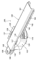
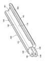
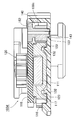
- the damper device 100 is slidably mounted on the rotary damper 110, the case 130 for holding the rotary damper 110 rotatably, and the rotary damper 110, and is attached to the rotary damper 110. It includes a rack body 160 having a rack gear 170 (see FIG. 6) that meshes with the provided pinion gear 120.
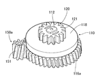
- the rotary damper 110 includes a rotor 111 and a gear housing 115 that surrounds the rotor 111 with a viscous fluid and applies a braking force to the rotation of the rotor 111.
- the gear housing 115 has a recess 117 for accommodating the rotor 111 inside, and a large-diameter gear 116 having a gear formed on the outer periphery thereof and a cap 118 for sealing the opening of the recess 117 of the large-diameter gear 116.
- a shaft insertion hole 119 through which the support shaft 112 provided in the rotor 111 is inserted is formed in the central portion of the cap 118.
- the rotor 111 has a disk shape as a whole, and a support shaft 112 projects from the center of one side of the rotor 111.
- the support shaft 112 is inserted into a shaft insertion hole 119 of a cap 118 via a seal ring 113, and a gear housing is provided. It protrudes to the outside of 115.
- the pinion gear 120 has a gear portion 121 on the outer periphery and a shaft hole 122 is formed in the central portion.
- the support shaft 112 is inserted and fixed in the shaft hole 122, and the support shaft 112 and the pinion gear 120 are integrally formed. It is designed to rotate.
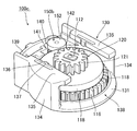
- the case 130 has a bottom wall 131, a pair of side walls 134 erected from both sides of the bottom wall 131, and one end of the pair of side walls 134. It has a front wall 139 erected from the bottom wall 131 so as to connect the two, and the side opposite to the front wall 139 forms an insertion opening 138 for inserting the rotary damper 110. Further, an arc-shaped rib 132 is formed on the inner surface of the bottom wall 131, and the arc-shaped rib 132 is fitted into the annular groove 123 formed on the bottom surface of the large-diameter gear 116 of the rotary damper 110 ( (See FIG. 5), the large-diameter gear 116 is rotatably supported.
- a hook 133 for attaching to a member giving a damper action is provided on the outer surface (lower surface) side of the bottom wall 131.
- the hook 133 is attached to the side wall of the main body provided on the vehicle body side, and the bracket 165 of the rack body 160, which will be described later, is attached to the main body so as to be openable and closable. It is designed to be connected to the side wall of the glove box.
- Presser flanges 135 extend inward from each other on the upper end edges of the pair of side walls 134, and the presser flanges 135 cover the guide ribs 163 on both sides of the rack body 160, which will be described later, to cover the rack body 160. Is designed to be slidable.
- elastic pieces 136 are formed on the facing side portions of the pair of holding flanges 135 via slits, and elastic pieces 162 are elastically formed on the side wall 162 of the rack body 160 described later in the intermediate portion of the elastic pieces 136.
- a pressing convex portion 137 that comes into contact with the surface is formed.
- each of the accommodating portions 140 for accommodating the planetary gear 150 is formed inside the connecting portion between the pair of side wall 134s of the case 130 and the front wall 139.
- the accommodating portion 140 has a shape that holds the planetary gear 150 so that the planetary gear 150 can be moved along the outer circumference of the large-diameter gear 116 by a predetermined distance, and has a shape that is line-symmetric with respect to the center line L shown in FIG. A pair is provided.
- An engaging portion 141 is provided to regulate the speed.
- the engaging portion 141 is composed of a corner portion that can be engaged with the gear portion 151 of the planetary gear 150. Further, when the planetary gear 150 comes into contact with the other end of the accommodating portion 140 in the moving direction of the planetary gear 150 (the end away from the center line L in FIG. 8), the planetary gear 150 is allowed to rotate.
- a rotation permitting portion 142 is provided.
- the rotation allowance portion 142 is formed of a concave curved surface having an arc shape when viewed in a plane, and the planetary gear 150 can rotate while abutting on the curved surface.
- the rack body 160 stands on the elongated plate-shaped substrate 161 and on both sides of the substrate 161 in the width direction toward the inner surface side of the substrate 161 (direction toward the rotary damper 110). It has a pair of side walls 162 provided and a guide rib 163 extending outward from each end of the side wall 162 in the projecting direction.
- the convex portion 114 formed on the protruding end surface of the support shaft 112 hits the central portion in the width direction on the inner surface side (lower surface side) of the substrate 161.
- the pressing flange 135 covers the upper surface side of the guide rib 163 so as to be slidably held inside the case 130.
- the pressing convex portion 137 of the elastic piece 136 provided on the holding flange 135 elastically contacts the side wall 162 of the rack body 160, and the rack body 160 rattles in the case 130. Is retained without.
- a rack gear 170 is formed along the longitudinal direction on the inner surface side of one side wall 162, and the rack gear 170 meshes with the pinion gear 120 mounted on the support shaft 112 of the rotary damper 110. It has become like. Therefore, when the rack body 160 slides with respect to the case 130, the pinion gear 120 meshing with the rack gear 170 rotates, and the rotor 111 rotates via the support shaft 112.
- a pair of brackets 165 extend in parallel to one end of the rack body 160, and mounting holes 166 are formed in each bracket 165.
- a mounting shaft projecting from the side wall of the glove box is inserted into the mounting hole 166 so that one end of the rack body 160 can be mounted on a component such as the glove box to which braking force is to be applied.
- a stopper portion 164 is projected from each portion of the rack body 160 close to one end portion in the longitudinal direction of the pair of guide ribs 163, and as shown in FIG. 7B, the rack with respect to the case 130.
- the lower surface of the rack body 160 is arranged so as to overlap a part of the upper end surface of the planetary gear 150, whereby the planetary gear 150 is prevented from coming off from the case 130. Is to be done. Since the planetary gear 150 can be prevented from coming off by using the rack body 160 in this way, it is possible to make the structure simple and compact.
- the damper device 100 is mounted between a pair of parts that are close to each other and want to apply a braking force.
- the hook 133 of the case 130 is connected to the side wall of the main body provided on the vehicle body side, and the bracket 165 is attached to the side wall of the glove box that opens and closes the main body. It is connected via the mounting hole 166.
- the bracket 165 is located close to the case 130 as shown in FIG. 7A, and when the glove box is pulled out, the rack body 160 is pulled out with respect to the case 130.
- the stopper portion 164 comes into contact with the case 130, further withdrawal is restricted.
- a braking force is applied by the rotary damper 110 to prevent the glove box from opening suddenly.
- the damper device 100 is used.
- the gear portion 151 of the planetary gear 150 engages with the engaging portion 141 of the accommodating portion 140, and the rotation of the planetary gear 150 is restricted, so that the rotation of the large-diameter gear 116 is stopped and the rotor is inside the gear housing 115. Only 111 will rotate. Therefore, a braking force for the rotation of the rotor 111 is applied via the viscous fluid, and acts as a braking force for the movement of the rack body 160 in the arrow A direction. As a result, the glove box can be prevented from opening suddenly.
- the gear portion 151 of the planetary gear 150 comes into contact with the inner wall of the rotation allowable portion 142 of the accommodating portion 140, and the rotation of the planetary gear 150 is permitted. Therefore, the large diameter gear 116 also rotates together with the rotor 111, and the rack body The braking force for the movement of 160 is released. As a result, the rack body 160 is pushed into the case 130 with less resistance, and the glove box can be quickly closed.
- this damper device 100 when the moving direction of the rack body 160 is reversed, the braking force is switched by the planetary gear 150 having an outer diameter smaller than that of the large diameter gear 116 moving in the accommodating portion 140. , The movement distance required for switching can be shortened, and the responsiveness of braking force switching can be improved.
- the case 130 is formed in a shape line-symmetrical with respect to the center line L, and a pair of accommodating portions 140 are arranged at positions line-symmetrical with respect to the center line L. It is formed. Therefore, the braking direction of the rack body 160 can be changed by selecting the accommodating portion 140 in which the planetary gear 150 is inserted and arranged.
- This damper device 100a is different from the above-described embodiment in the structure for preventing the planetary gear 150 from coming out of the case 130. That is, of the large diameter gear 116 and the cap 118 constituting the gear housing 115 of the rotary damper 110, the outer diameter of the cap 118 is increased and protrudes outward from the outer diameter of the large diameter gear 116. On the other hand, the axial length of the planetary gear 150 is shorter than that of the embodiment, and the outer peripheral edge of the protruding cap 118 is arranged so as to be in contact with at least a part of the axial end surface of the planetary gear 150. As a result, the planetary gear 150 is prevented from coming off.
- the cap 118 of the gear housing 115 prevents the planetary gear 150 from coming off, the planetary gear 150 can be prevented from coming off at a position lower than the bottom wall 131 of the case 130, and the planetary gear 150 is tilted. It can be made difficult.
- the gear portion 151 of the planetary gear 150a forms a hasba gear
- the large diameter gear 116a also forms a hasba gear that can be meshed with the planetary gear 150a.
- the tilting direction of each of the hasba gears is not particularly limited, but when the planetary gear 150a moves to the rotation allowable portion 142 of the accommodating portion 140 and rotates in mesh with the large diameter gear 116a, the planetary gear 150a is moved to the case 130. It is preferable that the tilting direction of the hasba gear is set so that the force pressing against the bottom wall 131 acts. As a result, the planetary gear 150a can be pressed against the bottom wall 131 of the case 130 to suppress rattling of the planetary gear 150a.
- FIGS. 17-19 show still other embodiments of the present invention.
- the shape of the planetary gear 150b of the damper device 100c is different from that of the embodiment.
- a disk portion 152 having an outer diameter equal to or larger than the outer diameter of the gear portion 151 is formed adjacent to the axial end surface of the gear portion 151. Therefore, as shown in FIG. 19, when the planetary gear 150b abuts on the rotation allowance portion 142 of the accommodating portion 140 and rotates, the disc portion 152 abuts on the inner circumference of the rotation allowance portion 142 and smooth rotation occurs. This is done, and the generation of abnormal noise can be suppressed.
- the engaging portion 141 of the accommodating portion 140 is lowered as compared with the above-described embodiment, and the disc portion 152 does not come into contact with the engaging portion 141.
- a support groove 143 into which the columnar portion 153 is inserted is provided on the bottom surface of the accommodating portion 140 of the case 130.
- the support groove 143 has a shape that allows the planetary gear 150c to move along the outer circumference of the large-diameter gear 116 at a distance that allows the planetary gear 150c to appropriately mesh with the large-diameter gear 116.
- one end of the support groove 143 close to the rotation allowable portion 142 has an arc shape to which the outer circumference of the cylindrical portion 153 matches, and supports the cylindrical portion 153 when the planetary gear 150 moves to the rotation allowable portion 142. Therefore, the planetary gear 150 is smoothly rotated.
- the planetary gear 150c is moved while the cylindrical portion 153 is guided by the support groove 143, so that the planetary gear 150c can be moved without rattling, and the planetary gear 150c can be rotated. It is possible to more effectively suppress the generation of abnormal noise due to movement.
- FIG. 22 shows yet another embodiment of the present invention.
- the shape of the large-diameter gear 116 of the damper device 100e is different from that of the embodiment. That is, in this embodiment, the upper edge portion 116a of the large-diameter gear 116 extends in a flange shape so as to surround the outer circumference of the cap 118, and the lower surface of the upper edge portion 116a covers a part of the upper end surface of the planetary gear 150. It is arranged so as to cover it, and has a structure for preventing the planetary gear 150 from coming out of the case 130.
- the planetary gear 150 is prevented from coming off by the upper edge 116a of the large diameter gear 116 of the gear housing 115, so that the planetary gear 150 is prevented from coming off at a position lower than the bottom wall 131 of the case 130.
- the planetary gear 150 can be made difficult to tilt.
Landscapes
- Engineering & Computer Science (AREA)
- General Engineering & Computer Science (AREA)
- Mechanical Engineering (AREA)
- Fluid-Damping Devices (AREA)
- Transmission Devices (AREA)
- Vehicle Step Arrangements And Article Storage (AREA)
Priority Applications (2)
| Application Number | Priority Date | Filing Date | Title |
|---|---|---|---|
| JP2021522326A JP7133709B2 (ja) | 2019-05-28 | 2020-05-22 | ダンパー装置 |
| CN202080036664.7A CN113853470B (zh) | 2019-05-28 | 2020-05-22 | 阻尼器装置 |
Applications Claiming Priority (2)
| Application Number | Priority Date | Filing Date | Title |
|---|---|---|---|
| JP2019-099113 | 2019-05-28 | ||
| JP2019099113 | 2019-05-28 |
Publications (1)
| Publication Number | Publication Date |
|---|---|
| WO2020241518A1 true WO2020241518A1 (ja) | 2020-12-03 |
Family
ID=73553480
Family Applications (1)
| Application Number | Title | Priority Date | Filing Date |
|---|---|---|---|
| PCT/JP2020/020389 Ceased WO2020241518A1 (ja) | 2019-05-28 | 2020-05-22 | ダンパー装置 |
Country Status (3)
| Country | Link |
|---|---|
| JP (1) | JP7133709B2 (https=) |
| CN (1) | CN113853470B (https=) |
| WO (1) | WO2020241518A1 (https=) |
Cited By (2)
| Publication number | Priority date | Publication date | Assignee | Title |
|---|---|---|---|---|
| WO2023074538A1 (ja) * | 2021-10-26 | 2023-05-04 | 株式会社パイオラックス | 端子付きダンパー装置 |
| WO2023074537A1 (ja) * | 2021-10-26 | 2023-05-04 | 株式会社パイオラックス | 端子付きダンパー装置 |
Families Citing this family (1)
| Publication number | Priority date | Publication date | Assignee | Title |
|---|---|---|---|---|
| WO2025243967A1 (ja) * | 2024-05-24 | 2025-11-27 | 株式会社パイオラックス | ダンパ装置 |
Citations (6)
| Publication number | Priority date | Publication date | Assignee | Title |
|---|---|---|---|---|
| JP2008163667A (ja) * | 2006-12-28 | 2008-07-17 | Nifco Inc | ダンパー装置 |
| JP2009516132A (ja) * | 2005-11-14 | 2009-04-16 | イリノイ トゥール ワークス インコーポレイティド | 粘性ストランドダンパー組立体 |
| JP2009203990A (ja) * | 2008-02-26 | 2009-09-10 | Piolax Inc | ダンパー装置 |
| WO2012070583A1 (ja) * | 2010-11-24 | 2012-05-31 | 株式会社ニフコ | ダンパー装置 |
| WO2012117654A1 (ja) * | 2011-03-02 | 2012-09-07 | 株式会社ニフコ | 回転ダンパ装置及びその製造方法 |
| WO2018181905A1 (ja) * | 2017-03-31 | 2018-10-04 | 株式会社ニフコ | 一方向ダンパー機構 |
Family Cites Families (3)
| Publication number | Priority date | Publication date | Assignee | Title |
|---|---|---|---|---|
| CN101258299A (zh) * | 2005-11-14 | 2008-09-03 | 伊利诺斯工具制品有限公司 | 粘滞带阻尼器组件 |
| DE102010009375B4 (de) * | 2010-02-12 | 2022-06-30 | Illinois Tool Works Inc. | Dämpfereinrichtung |
| CN204127101U (zh) * | 2014-10-10 | 2015-01-28 | 上海度邦电子制品有限公司 | 带独立安装座的单向阻力旋转阻尼器 |
-
2020
- 2020-05-22 CN CN202080036664.7A patent/CN113853470B/zh active Active
- 2020-05-22 WO PCT/JP2020/020389 patent/WO2020241518A1/ja not_active Ceased
- 2020-05-22 JP JP2021522326A patent/JP7133709B2/ja active Active
Patent Citations (6)
| Publication number | Priority date | Publication date | Assignee | Title |
|---|---|---|---|---|
| JP2009516132A (ja) * | 2005-11-14 | 2009-04-16 | イリノイ トゥール ワークス インコーポレイティド | 粘性ストランドダンパー組立体 |
| JP2008163667A (ja) * | 2006-12-28 | 2008-07-17 | Nifco Inc | ダンパー装置 |
| JP2009203990A (ja) * | 2008-02-26 | 2009-09-10 | Piolax Inc | ダンパー装置 |
| WO2012070583A1 (ja) * | 2010-11-24 | 2012-05-31 | 株式会社ニフコ | ダンパー装置 |
| WO2012117654A1 (ja) * | 2011-03-02 | 2012-09-07 | 株式会社ニフコ | 回転ダンパ装置及びその製造方法 |
| WO2018181905A1 (ja) * | 2017-03-31 | 2018-10-04 | 株式会社ニフコ | 一方向ダンパー機構 |
Cited By (6)
| Publication number | Priority date | Publication date | Assignee | Title |
|---|---|---|---|---|
| WO2023074538A1 (ja) * | 2021-10-26 | 2023-05-04 | 株式会社パイオラックス | 端子付きダンパー装置 |
| WO2023074537A1 (ja) * | 2021-10-26 | 2023-05-04 | 株式会社パイオラックス | 端子付きダンパー装置 |
| GB2627619A (en) * | 2021-10-26 | 2024-08-28 | Piolax Inc Kangawa | Terminal-equipped damper device |
| JP7576186B2 (ja) | 2021-10-26 | 2024-10-30 | 株式会社パイオラックス | 端子付きダンパー装置 |
| JP7594685B2 (ja) | 2021-10-26 | 2024-12-04 | 株式会社パイオラックス | 端子付きダンパー装置 |
| GB2627619B (en) * | 2021-10-26 | 2025-02-26 | Piolax Inc Kanagawa | Terminal-equipped damper device |
Also Published As
| Publication number | Publication date |
|---|---|
| CN113853470A (zh) | 2021-12-28 |
| JP7133709B2 (ja) | 2022-09-08 |
| JPWO2020241518A1 (https=) | 2020-12-03 |
| CN113853470B (zh) | 2023-06-09 |
Similar Documents
| Publication | Publication Date | Title |
|---|---|---|
| WO2020241518A1 (ja) | ダンパー装置 | |
| JP6782356B2 (ja) | 一方向ダンパー機構 | |
| TWI399477B (zh) | 具有阻尼裝置的傢俱鉸鏈 | |
| JP6408147B2 (ja) | 開閉体の電動式ロック装置 | |
| JP5666376B2 (ja) | ワンウェイクラッチ付き回転ダンパ装置 | |
| CN102753774B (zh) | 阻尼器 | |
| EP1371873A1 (en) | Damper | |
| JP7427101B2 (ja) | 開閉体のロック装置 | |
| KR20030096220A (ko) | 로터리 댐퍼 | |
| KR20030030848A (ko) | 개폐부재의 제동기구와 이것을 구비한 용기홀더 및자동차용 도어 | |
| JP2016117313A (ja) | リッド開閉装置 | |
| JP7133710B2 (ja) | ダンパー装置 | |
| JP7269372B2 (ja) | ロック解除装置 | |
| CN102459796B (zh) | 铰链阻尼器组件 | |
| JP6806653B2 (ja) | 動力で動く乗物用のギア・シフト装置 | |
| JP6475792B2 (ja) | 車両用リッドロック装置 | |
| JP4297493B2 (ja) | 蓋開閉機構及びその装置 | |
| KR20160094093A (ko) | 스티어링 컬럼의 틸팅장치 | |
| JP5836281B2 (ja) | ダンパー装置 | |
| JP5016350B2 (ja) | 車両用物入装置 | |
| WO2025243967A1 (ja) | ダンパ装置 | |
| JP6786707B2 (ja) | エアダンパー | |
| JP7126692B2 (ja) | ダンパーヒンジ | |
| JP6469607B2 (ja) | カップホルダー | |
| KR960001132B1 (ko) | 자동차의 슬라이딩 루우프용 로타리 드라이브 축의 회전수 제한 기구 |
Legal Events
| Date | Code | Title | Description |
|---|---|---|---|
| 121 | Ep: the epo has been informed by wipo that ep was designated in this application |
Ref document number: 20812814 Country of ref document: EP Kind code of ref document: A1 |
|
| ENP | Entry into the national phase |
Ref document number: 2021522326 Country of ref document: JP Kind code of ref document: A |
|
| NENP | Non-entry into the national phase |
Ref country code: DE |
|
| 122 | Ep: pct application non-entry in european phase |
Ref document number: 20812814 Country of ref document: EP Kind code of ref document: A1 |