WO2020241045A1 - ダンパー装置 - Google Patents
ダンパー装置 Download PDFInfo
- Publication number
- WO2020241045A1 WO2020241045A1 PCT/JP2020/015235 JP2020015235W WO2020241045A1 WO 2020241045 A1 WO2020241045 A1 WO 2020241045A1 JP 2020015235 W JP2020015235 W JP 2020015235W WO 2020241045 A1 WO2020241045 A1 WO 2020241045A1
- Authority
- WO
- WIPO (PCT)
- Prior art keywords
- cap
- base
- seal
- damper device
- wall portion
- Prior art date
- Legal status (The legal status is an assumption and is not a legal conclusion. Google has not performed a legal analysis and makes no representation as to the accuracy of the status listed.)
- Ceased
Links
Images






Classifications
-
- F—MECHANICAL ENGINEERING; LIGHTING; HEATING; WEAPONS; BLASTING
- F16—ENGINEERING ELEMENTS AND UNITS; GENERAL MEASURES FOR PRODUCING AND MAINTAINING EFFECTIVE FUNCTIONING OF MACHINES OR INSTALLATIONS; THERMAL INSULATION IN GENERAL
- F16F—SPRINGS; SHOCK-ABSORBERS; MEANS FOR DAMPING VIBRATION
- F16F9/00—Springs, vibration-dampers, shock-absorbers, or similarly-constructed movement-dampers using a fluid or the equivalent as damping medium
- F16F9/10—Springs, vibration-dampers, shock-absorbers, or similarly-constructed movement-dampers using a fluid or the equivalent as damping medium using liquid only; using a fluid of which the nature is immaterial
- F16F9/12—Devices with one or more rotary vanes turning in the fluid any throttling effect being immaterial, i.e. damping by viscous shear effect only
-
- F—MECHANICAL ENGINEERING; LIGHTING; HEATING; WEAPONS; BLASTING
- F16—ENGINEERING ELEMENTS AND UNITS; GENERAL MEASURES FOR PRODUCING AND MAINTAINING EFFECTIVE FUNCTIONING OF MACHINES OR INSTALLATIONS; THERMAL INSULATION IN GENERAL
- F16F—SPRINGS; SHOCK-ABSORBERS; MEANS FOR DAMPING VIBRATION
- F16F9/00—Springs, vibration-dampers, shock-absorbers, or similarly-constructed movement-dampers using a fluid or the equivalent as damping medium
- F16F9/10—Springs, vibration-dampers, shock-absorbers, or similarly-constructed movement-dampers using a fluid or the equivalent as damping medium using liquid only; using a fluid of which the nature is immaterial
- F16F9/14—Devices with one or more members, e.g. pistons, vanes, moving to and fro in chambers and using throttling effect
-
- F—MECHANICAL ENGINEERING; LIGHTING; HEATING; WEAPONS; BLASTING
- F16—ENGINEERING ELEMENTS AND UNITS; GENERAL MEASURES FOR PRODUCING AND MAINTAINING EFFECTIVE FUNCTIONING OF MACHINES OR INSTALLATIONS; THERMAL INSULATION IN GENERAL
- F16H—GEARING
- F16H57/00—General details of gearing
- F16H57/0006—Vibration-damping or noise reducing means specially adapted for gearings
Definitions
- the present invention relates to a damper device filled with a viscous liquid.
- Patent Document 1 describes a rotatable rotor, a housing and a cap for accommodating the rotor, a damping medium filled in the rotating region of the rotor, and an encapsulation portion provided outside the rotating region of the rotor and communicating with the rotating region. Dampers equipped with are disclosed.
- the housing and cap have a plurality of annular protrusions, and the rotor has a plurality of annular rotor protrusions that project vertically. The rotor protrusion fits into the gap between the annular protrusion of the housing and cap.
- the gas existing in the sealed portion may move to the gap around the annular protrusion to reduce the damping force.
- An object of the present invention is to provide a damper device capable of stably generating a damping force.
- the damper device of an embodiment of the present invention is filled with a base, a rotor rotatably supported by the base, a cap that defines the storage chamber of the rotor together with the base, and the storage chamber. It is provided with a viscous liquid.
- the base and cap define a viscous liquid reservoir on the radial outer side of the containment chamber and seal between the containment chambers.
- FIG. 1 is a perspective view of the damper device 10 of the embodiment.
- the damper device 10 is attached to the glove box of a vehicle, for example, and applies a damping force to the opening / closing operation of the opening / closing body (lid member) of the glove box. Further, the damper device 10 may be attached to the console box of the vehicle to apply a damping force to the opening and closing of the opening / closing body of the console box. In any case, the damper device 10 is attached to the fixed body and the opening / closing body that opens and closes the opening of the fixed body.
- the damper device 10 includes a base 20, a cap 22, a rotor 24, a connecting gear 26, a seal ring (not shown), and a viscous liquid (not shown).
- the viscous liquid is filled between the base 20 and the cap 22 to provide viscous resistance to the rotation of the rotor 24.
- the viscous liquid is, for example, oil such as grease, and is filled so as not to leak between the base 20 and the cap 22.
- the base 20 is connected to either the fixed body or the opening / closing body, and the connecting gear 26 is connected to either the fixed body or the opening / closing body.
- the connecting gear 26 is connected to the opening / closing body via a rack gear or the like, rotates according to the movement of the opening / closing body, and the base 20 is connected to the fixed body.
- the rotor 24 rotates together with the connecting gear 26 to receive a resistance force from the viscous liquid and generate a damping force.
- the usage mode of the damper device 10 is not limited to the mode in which the base 20 is arranged on the lower side and the connecting gear 26 is arranged on the upper side as shown in FIG. 1, and the rotation axis of the rotor 24 is oriented in the vertical direction. It may be used in a tilted state.
- FIG. 2 is an exploded view of the damper device 10.
- FIG. 3 is a cross-sectional view of the damper device 10.
- the cross-sectional views of the damper device 10 shown in FIGS. 3 (a) and 3 (b) are both along the axial direction, but the rotation positions are different. Note that FIGS. 2 and 3 show a state in which the viscous liquid is not filled.
- the base 20 has a peripheral wall portion 30, a recess 32, a base inclined surface 34, an annular groove portion 36, an annular recess portion 38, a tooth portion 40, and a connecting hole portion 42.
- the cap 22 has an insertion hole 60, an outer peripheral wall portion 62, a cap inclined surface 64, and an inner peripheral groove portion 66.
- the rotor 24 has a rotating shaft portion 50, an inclined portion 52, a through hole portion 54, an annular wall portion 56, and a convex portion 58.
- the connecting gear 26 has a connecting hole 68.
- the base 20 is formed in a bottomed cylindrical shape.
- a recess 32, a base inclined surface 34, and an annular groove 36 are formed at the bottom of the base 20.
- the recess 32 is formed as a cylindrical recess in the center of the base 20. It becomes easy to put a lot of viscous liquid in the recess 32 during the assembling process.
- the base inclined surface 34 is formed on the inner surface of the base 20, is inclined so as to rise outward in the radial direction from the recess 32, and is inclined with respect to a surface orthogonal to the axial direction. That is, the base inclined surface 34 extends in a direction away from the bottom surface of the base 20 in the radial direction.
- the base inclined surface 34 is formed in a conical shape recessed from the inner edge of the annular groove portion 36 toward the recess 32.
- the annular groove portion 36 is continuously provided on the radial outer side of the base inclined surface 34, and is formed by being recessed in an annular shape.
- the annular groove 36 guides the rotation of the rotor 24.
- the peripheral wall portion 30 is formed so as to be connected to the annular groove portion 36 and to stand on the outer periphery of the base 20.
- a tooth portion 40 is formed on the outer peripheral surface of the peripheral wall portion 30. The tooth portion 40 meshes with a fixed body, for example, to regulate the rotation of the base 20.
- the annular recessed portion 38 is formed by recessing the upper end portion of the peripheral wall portion 30, and is formed in an annular shape along the peripheral wall portion 30. Excess viscous liquid is stored in the annular recess 38.
- the peripheral wall portion 30 has an inner side wall portion 30a and an outer wall portion 30b that sandwich the annular recess portion 38 in the radial direction.
- the inner side wall portion 30a is set so that the height in the axial direction is lower than that of the outer wall portion 30b. This makes it difficult for the viscous liquid to move to the outer diameter side of the outer wall portion 30b.
- the tip end side of the inner side wall portion 30a is inclined in a tapered shape so as to rise outward in the radial direction.
- the connecting hole 42 is formed in an annular shape on the lower surface of the base 20 and engages with a protrusion formed on a pedestal on which the damper device 10 is attached. As a result, the damper device 10 can be stably attached. Further, the connecting hole portion 42 is formed not on the central side but on the outer side in the radial direction from the annular groove portion 36, and is provided at a position where the connecting hole portion 42 overlaps when viewed in the axial direction of the pool chamber 44, so that the axial height of the base 20 is increased. Can be suppressed.
- the rotating shaft portion 50 of the rotor 24 is erected in the center of the rotor 24 and is formed in a columnar shape.
- the rotor 24 rotates about the axis of the rotating shaft portion 50.
- a flat surface that fits into the connecting gear 26 is formed on the side surface of the rotating shaft portion 50 on the tip end side.
- a plurality of inclined portions 52 project outward from the rotating shaft portion 50 in the radial direction and are formed at equal intervals in the circumferential direction.
- a through hole portion 54 is formed between the adjacent inclined portions 52.
- the inclined portion 52 extends so as to rise outward in the radial direction from the rotating shaft portion 50, and is inclined along the base inclined surface 34 as shown in FIG. 3A.
- the inclined portion 52 is inclined with respect to a plane orthogonal to the rotating shaft portion 50, and is inclined outward in the radial direction and upward in the axial direction.
- the inclined portion 52 and the through hole portion 54 have the same radial length.
- the annular wall portion 56 is formed in a cylindrical shape, is located on the radial outer side of the plurality of inclined portions 52, and hangs down from the outer peripheral edge of the inclined portions 52.
- the annular wall portion 56 fits into and engages with the annular groove portion 36 of the base 20 to stabilize the rotation of the rotor 24.
- the convex portion 58 is formed in a columnar shape so as to project the rotating shaft portion 50 downward, and is coaxial with the rotating shaft portion 50.
- An axial groove for securing a gas movement path is formed on the outer peripheral surface of the convex portion 58. The rotation of the rotor 24 can be stabilized by engaging the convex portion 58 in the concave portion 32.
- the cap 22 sandwiches the rotor 24 with the base 20 and defines the storage chamber 70 of the rotor 24 together with the base 20.
- the insertion hole 60 is formed in the center of the cap 22 and exposes the rotating shaft portion 50 of the rotor 24 to the outside from the accommodation chamber 70.
- the rotating shaft portion 50 is inserted into the insertion hole 60.
- the outer peripheral wall portion 62 is formed in a cylindrical shape on the outer periphery of the cap 22.
- the inner peripheral groove portion 66 is formed inside the outer peripheral wall portion 62, receives the peripheral wall portion 30 of the base 20, and is coupled to the peripheral wall portion 30.
- the inner peripheral groove portion 66 faces the annular recessed portion 38 of the base 20.
- the first seal portion 46 and the second seal portion 48 are formed by welding.
- the first seal portion 46 and the second seal portion 48 of FIGS. 3 (a) and 3 (b) are shown in a state in which the base 20 and the cap 22 of the seal portion are overlapped and not melted.
- the first seal portion 46 is formed on the inner peripheral surface of the peripheral wall portion 30, and the second seal portion 48 is formed on the outer peripheral surface of the peripheral wall portion 30.
- the pool chamber 44 is formed on the radial outer side of the storage chamber 70 by being closed by the first seal portion 46 and the second seal portion 48.
- the base 20 and the cap 22 define a viscous liquid pool 44 on the radial outer side of the storage chamber 70.
- the sump chamber 44 is formed by the peripheral wall portion 30 of the base 20 and the inner peripheral groove portion 66 of the cap 22, and the volume of the sump chamber 44 is secured by the annular recessed portion 38.
- the sump chamber 44 is formed along the circumferential direction and stores the viscous liquid discharged from the storage chamber 70.
- the storage chamber 70 is filled with a sufficient viscous liquid, and the storage chamber 44 stores the excess viscous liquid.
- the cap inclined surface 64 is formed on the inner surface of the cap 22, is inclined so as to be lowered inward in the radial direction, and is inclined with respect to a surface orthogonal to the axial direction.
- the cap inclined surface 64 is formed parallel to the inclined portion 52 and the base inclined surface 34.
- the inclined portion 52 of the rotor 24 is sandwiched between the base inclined surface 34 and the cap inclined surface 64.
- the inclined portion 52 is located in the area in the accommodation chamber 70 formed by the base inclined surface 34 and the cap inclined surface 64. That is, the base inclined surface 34 faces the lower surface of the inclined portion 52, the cap inclined surface 64 faces the upper surface of the inclined portion 52, and the base inclined surface 34, the inclined portion 52, and the cap inclined surface 64 overlap when viewed in the axial direction. Is located.
- the accommodation chamber 70 is formed so as to rise outward in the radial direction from the position of the rotating shaft portion 50.
- the seal ring 28 surrounds the rotating shaft portion 50, abuts on the outer peripheral surface of the rotating shaft portion 50 and the inner peripheral surface of the insertion hole 60, and the viscous liquid in the storage chamber 70 leaks through the insertion hole 60. suppress.
- FIG. 4 is a diagram illustrating an assembly process of the damper device 10.
- the discharge port of the discharge device 72 is aligned with the central position of the base 20, and the discharge device 72 discharges the viscous liquid 74.
- the viscous liquid 74 rests in the center of the base 20 and is discharged in excess of the amount required for the containment chamber 70.
- the recess 32 makes it easier to place more viscous liquid 74 on the base 20.
- FIG. 5 is a diagram showing a continuation of the assembly process of the damper device 10 of FIG.
- the rotor 24 is brought close to the base 20 from above and placed on the base 20 as shown in FIG. 5 (b).
- the convex portion 58 enters the concave portion 32 and pushes the viscous liquid 74, and the viscous liquid 74 protrudes upward from the through hole portion 54 and becomes a raised state.
- the convex portion 58 of the rotor 24 fits into and engages with the concave portion 32 of the base 20. If the concave-convex relationship between the base 20 and the rotor 24 is opposite, gas may accumulate in the concave portion of the rotor 24, but by forming the convex portion 58 in the rotor 24, it is possible to suppress the accumulation of gas. Further, since the base inclined surface 34 is formed so as to rise along the inclined portion 52 of the rotor 24, the gas on the central side can be guided outward in the radial direction.
- FIG. 6 is a diagram showing a continuation of the assembly process of the damper device 10 of FIG.
- the cap 22 is brought closer to the base 20 side from above, and as shown in FIG. 6B, the cap inclined surface 64 comes into contact with the raised viscous liquid 74, and the viscous liquid Push 74 apart.
- the viscous liquid 74 and the gas are guided by the cap inclined surface 64 and the inclined portion 52 and spread in the radial direction, and are guided toward the annular recess portion 38 by the inclination. Since the cap inclined surface 64 and the inclined portion 52 are inclined so as to rise outward in the radial direction, the gas in the accommodation chamber 70 can be easily pushed out in the radial direction.
- FIG. 7 is a diagram showing a continuation of the assembly process of the damper device 10 of FIG.
- the cap 22 is brought close to the base 20, the tip of the outer peripheral wall portion 62 comes into contact with the outer wall portion 30b and the approach stops.
- the viscous liquid 74 is pushed by the cap 22 and spreads to the annular groove portion 36 and the annular recess portion 38.
- the ultrasonic welding device 76 is driven in a state where the tip of the outer peripheral wall portion 62 and the outer wall portion 30b are in contact with each other, the contact portion is melted and can be approached, and the cap 22 is pushed further onto the base 20. As they approach each other, the inner peripheral edge of the inner peripheral groove portion 66 comes into contact with the inner side wall portion 30a. By melting the contact portion between the tip of the outer peripheral wall portion 62 and the outer wall portion 30b, the second seal portion 48 is formed, and the viscous liquid 74 can be prevented from leaking to the outside of the damper device 10.
- the first seal portion 46 is formed. As shown in FIG. 7B, the first seal portion 46 cuts off the communication between the storage chamber 70 and the storage chamber 44. The first sealing portion 46 seals between the accommodating chamber 70 and the collecting chamber 44. As a result, it is possible to limit the return of the gas to the storage chamber 70 after pushing the gas into the storage chamber 44, and prevent the viscous resistance generated when the rotor 24 is rotated due to the accumulation of air bubbles in the storage chamber 70 from being stably exhibited. be able to.
- the sump chamber 44 is closed to the outside by the second seal portion 48 on the radial outer side of the sump chamber 44, and the viscous liquid 74 can be prevented from leaking to the outside.
- FIG. 8 is a partial cross-sectional view of the damper device 10.
- the portion where the first seal portion 46 and the second seal portion 48 are formed is shown in a state where the base 20 and the cap 22 are overlapped with each other, but the overlapped portions are actually melted and joined.
- the second seal portion 48 is melted before the first seal portion 46 and welding is started. Since the second seal portion 48 is formed before the first seal portion 46, the seal allowance L2 of the second seal portion 48 is larger than the seal allowance L1 of the first seal portion 46, and the axial length is long. It is formed.
- the first seal portion 46 and the second seal portion 48 are formed in an annular shape, the axial length of the first seal portion 46 is the seal allowance L1, and the axial length of the second seal portion 48 is the seal allowance L2. is there.
- the cap 22 when the cap 22 is pushed toward the base 20, it is possible to secure a path for pushing gas from the accommodating chamber 70 to the collecting chamber 44 side until the pushing is completed. That is, the gas can be pushed out from the storage chamber 70 while the second seal portion 48 is formed. As a result, the viscous liquid 74 is filled in the storage chamber 70 with a sufficient filling rate. Further, by starting the formation of the second seal portion 48 first, it is possible to prevent the viscous liquid 74 from leaking to the outside in the step of pushing the cap 22.
- the second seal portion 48 is started to be welded while the first seal portion 46 is being welded, and the first seal portion 48 is welded.
- the cap 22 is pushed toward the base 20 while melting both the seal portion 46 and the second seal portion 48.
- the first seal portion 46 and the second seal portion 48 can be formed in one pushing step, and the work efficiency can be improved.
- the axial lengths of the annular wall portion 56 and the annular groove portion 36 are secured in order to generate a desired damping force. There is a need. Since the inclined portion 52 is raised, even if the annular wall portion 56 is hung down from the inclined portion 52, it is possible to suppress an increase in the axial length of the entire damper device 10. Further, since the pool chamber 44 is provided at a position where it does not overlap the annular wall portion 56 when viewed in the axial direction, the axial length of the damper device 10 becomes longer while ensuring the axial length of the annular wall portion 56. It can be suppressed.
- the base inclined surface 34 extends to the annular groove portion 36, and all of the portions facing the inclined portion 52 and the through hole portion 54 are formed so as to be inclined.
- FIG. 9 is an exploded view of the damper device of the first modified example.
- the damper device 100 of the first modification is mainly different from the damper device 10 shown in FIG. 2 in that the cap is divided into two members.
- the damper device 100 includes members of a base 120, a first cap 122a, a second cap 122b, a seal ring 28, and a rotor 124.
- the rotor 124, the seal ring 28, the first cap 122a, and the second cap 122b with the base 120 at the bottom are attached in this order from above.
- the configuration of each member will be described with reference to the new drawings.
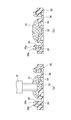
- FIG. 10 is a perspective sectional view of the damper device 100 of the first modification. Further, FIG. 11 is a partially enlarged view of the damper device 100 shown in FIG.
- the damper device 100 further includes a first seal portion 93, a second seal portion 94, a third seal portion 95, and a fourth seal portion 96 that connect the members.
- the base 120 has a bottom portion 80, an inner side wall portion 82a and an outer wall portion 82b.
- the bottom 80 of the base 120 is also the bottom of the damper device 100 and constitutes the bottom of the storage chamber 170.
- the inner side wall portion 82a and the outer wall portion 82b stand upright from the bottom portion 80 and face each other.
- the inner side wall portion 82a is located inside the outer wall portion 82b.
- the storage chamber 170 is located inside the inner side wall portion 82a, and the pool portion 144 is located between the inner side wall portion 82a and the outer wall portion 82b.
- the rotor 124 has a rotating shaft portion 150 and an overhanging portion 152.
- the rotating shaft portion 150 is erected in the center of the rotor 124 and is formed in a columnar shape.
- the overhanging portion 152 projects radially outward from the rotating shaft portion 150 and is accommodated in the accommodating chamber 170.
- the first cap 122a defines the base 120 and the storage chamber 170.
- the storage chamber 170 is filled with the viscous liquid 74.
- the second cap 122b is fixed to the base 120 to prevent the first cap 122a from coming off.
- the second cap 122b can prevent the first cap 122a from coming off while maintaining the closed state of the storage chamber 170.
- the amount of air remaining in the accommodation chamber 170 can be reduced.
- the first cap 122a has a first annular plate portion 84, a first peripheral wall portion 86, and an engaging portion 88.
- the first annular plate portion 84 has an insertion hole 60 in the center and extends radially outward from the insertion hole 60.
- the first annular plate portion 84 has an annular rib 84a formed so as to project from the upper surface.
- the first peripheral wall portion 86 projects so as to hang down from the outer peripheral edge of the first annular plate portion 84, and is formed in a substantially cylindrical shape.
- the engaging portion 88 is formed at the tip end portion of the first peripheral wall portion 86, and engages with the inner side wall portion 82a of the base 120 so as to face in the axial direction.
- the engaging portion 88 is located between the accommodating chamber 170 and the reservoir chamber 144. As a result, the storage chamber 170 defined by the base 120 and the first cap 122a is closed.
- the engaging portion 88 is formed in a convex shape protruding downward, and the tip portion of the inner side wall portion 82a is formed in a concave shape. As a result, the engaging portion 88 and the tip end portion of the inner side wall portion 82a can be concavely engaged with each other, and the base 120 and the first cap 122a can be prevented from being displaced in the radial direction.
- the second cap 122b has a second annular plate portion 90 and a second peripheral wall portion 92.
- the second annular plate portion 90 has a central hole 90a and extends radially outward from the central hole 90a.
- the second peripheral wall portion 92 projects so as to hang down from the lower surface of the second annular plate portion 90, and is formed in a substantially cylindrical shape.
- the second peripheral wall portion 92 is located in the middle in the radial range of the second annular plate portion 90. That is, the second annular plate portion 90 projects radially outward from the second peripheral wall portion 92.
- the annular rib 84a enters the inside of the central hole 90a, and the inner peripheral region of the second annular plate portion 90 overlaps with the outer peripheral region of the first annular plate portion 84 in the axial direction.
- the second peripheral wall portion 92 is inserted between the inner side wall portion 82a and the outer wall portion 82b, and is located on the radial outer side of the first peripheral wall portion 86.
- the second peripheral wall portion 92 of the second cap 122b has a plurality of ribs 92a on the outer peripheral surface.
- the plurality of ribs 92a are formed so as to project from the outer peripheral surface of the second peripheral wall portion 92, and are formed apart from each other in the circumferential direction.
- the rib 92a is provided in a shape along the inner peripheral surface of the outer wall portion 82b.
- the first seal portion 93, the second seal portion 94, the third seal portion 95, and the fourth seal portion 96 shown in FIG. 11 are formed by welding.
- the seal portion of each member is shown in a state where it is not melted by welding.
- the first seal portion 93 is formed by welding the outer peripheral surface of the first peripheral wall portion 86 of the first cap 122a and the inner peripheral surface of the second peripheral wall portion 92 of the second cap 122b.
- the first seal portion 93 is located between the accommodating chamber 170 and the reservoir portion 144 in the radial direction, and fixes the first cap 122a and the second cap 122b.
- the first seal portion 93 blocks communication between the storage chamber 170 and the outside, and prevents the viscous liquid 74 from leaking from the inside of the storage chamber 170.
- the second seal portion 94 is formed by welding the outer peripheral surface of the inner side wall portion 82a of the base 120 and the inner peripheral surface of the second peripheral wall portion 92 of the second cap 122b.
- the second seal portion 94 is located between the storage chamber 170 and the pool portion 144 in the radial direction, blocks communication between the storage chamber 170 and the pool portion 144, and prevents the viscous liquid 74 from leaking from the storage chamber 170.
- the second cap 122b is fixed to the base 120 by the first seal portion 93 and the second seal portion 94 to seal between the storage chamber 170 and the storage chamber 144, and is fixed to the first cap 122a (welding in the embodiment). Is).
- the first cap 122a has a function of closing the storage chamber 170
- the second cap 122b has a function of fixing to the base 120.
- the first seal portion 93 and the second seal portion 94 are connected to the engaging portion 88 and are formed continuously in the axial direction on the radial outer side of the engaging portion 88. That is, the space between the engaging portion 88 and the inner side wall portion 82a is sealed up and down, and the viscous liquid 74 is restricted from moving from between the engaging portion 88 and the inner side wall portion 82a in the radial direction. Further, the second cap 122b is bonded to the first cap 122a and the base 120 by welding. By sealing the positions of the first seal portion 93 and the second seal portion 94 close to the storage chamber 170, it is possible to prevent the viscous liquid 74 injected in advance from being scattered in various places and stabilize the amount of seal in the storage chamber 170. it can.
- the third seal portion 95 is formed by welding the outer peripheral surface of the second peripheral wall portion 92 and the inner peripheral surface of the outer wall portion 82b.
- the third seal portion 95 is located outside the pool portion 144 and seals the viscous liquid 74 from leaking from the pool portion 144. Further, the third seal portion 95 connects the second cap 122b and the base 120.
- the fourth seal portion 96 is formed by welding the outer peripheral surface of the first annular plate portion 84 and the inner peripheral surface of the second peripheral wall portion 92.
- the fourth seal portion 96 seals the viscous liquid 74 from leaking from the gap between the first cap 122a and the second cap 122b. Further, the fourth seal portion 96 connects the first cap 122a and the second cap 122b.
- the first seal portion 93 and the fourth seal portion 96 can doubly seal the viscous liquid 74 from leaking between the first cap 122a and the second cap 122b. Further, the second seal portion 94 and the third seal portion 95 can doubly seal the viscous liquid 74 from leaking between the second cap 122b and the base 120.
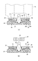
- FIG. 12 is a diagram for explaining an assembly process of the damper device 100 of the first modification.
- the viscous liquid 74 is placed in the center of the base 120, the rotor 124 is placed on the base 120, and the first cap 122a is pressed from above toward the base 120. As a result, the viscous liquid 74 is pushed out to the pool portion 144 side through the gap between the engaging portion 88 and the inner side wall portion 82a.
- the first cap 122a approaches the base 120, and as shown in FIG. 12A, the engaging portion 88 of the first cap 122a is in a state of being engaged with the tip end portion of the inner side wall portion 82a of the base 120. ..
- the engagement between the engaging portion 88 and the inner side wall portion 82a closes the storage chamber 170 and restricts the movement of the viscous liquid 74.
- the step of welding the second cap 122b is executed with the storage chamber 170 closed. As a result, it is possible to prevent the viscous liquid 74 from being compressed in the storage chamber 170 by pushing the second cap 122b.
- the second cap 122b is brought closer to the base 120 with the second peripheral wall portion 92 aligned between the inner side wall portion 82a and the outer wall portion 82b.
- the tip of the second peripheral wall portion 92 corresponds to the inclined surface 97 formed on the outer peripheral surface of the first annular plate portion 84.
- the inclined surface 97 is inclined so as to project downward in the radial direction, and projects outward in the radial direction from the inner peripheral surface of the second peripheral wall portion 92. That is, when the second peripheral wall portion 92 is pushed into the outer periphery of the first annular plate portion 84, it always comes into contact with the inclined surface 97.
- the ultrasonic welding device 76 With the second peripheral wall portion 92 in contact with the inclined surface 97 of the first annular plate portion 84, the ultrasonic welding device 76 is driven to melt the contact portion, and the second cap 122b further approaches the base 120.
- FIG. 12B shows a state in which the second cap 122b is pushed toward the base 120 and the inner peripheral surface of the second peripheral wall portion 92 and the outer peripheral surface of the first peripheral wall portion 86 are melted, and the first seal portion is shown. 93 is starting to be generated. Further, the second peripheral wall portion 92 hits the engaging portion between the engaging portion 88 and the inner side wall portion 82a and begins to melt, and the accommodation chamber 170 is sealed. By melting the engaging portion between the engaging portion 88 and the inner side wall portion 82a, the communication between the accommodating chamber 170 and the collecting portion 144 can be reliably cut off.
- the inner peripheral surface of the second peripheral wall portion 92 on the base end side corresponds to the outer peripheral edge of the first annular plate portion 84, and the outer peripheral surface of the second peripheral wall portion 92 on the base end side is the outer wall portion 82b. It corresponds to the inner peripheral edge on the tip side.
- the hit portion begins to be melted by the ultrasonic welding device 76.
- FIG. 12C the pushing of the second cap 122b is completed, the first seal portion 93, the second seal portion 94, the third seal portion 95, and the fourth seal portion 96 are formed, and the assembly of the damper device 100 is completed.
- the first seal portion 93 is formed, then the second seal portion 94 is formed, and then the third seal portion 95 and the fourth seal portion 96 are formed.
- the accommodating chamber 170 can be sealed, and then the pool portion 144 can be sealed.
- the welding start timings of the second seal portion 94, the third seal portion 95, and the fourth seal portion 96 may be at the same time.
- FIG. 13 is a perspective sectional view of the damper device 200 of the second modified example.
- FIG. 14 is a partially enlarged view of the damper device 200 shown in FIG.
- the positions of the first seal portion 293 and the second seal portion 294 are different from those of the damper device 100 of the first modification shown in FIG. 10, and the positions of the first seal portion 293 and the second seal portion 293 and the second are different.
- the seal portion 294 is located above the first seal portion 93 and the second seal portion 94 of the damper device 100.
- the damper device 200 includes a base 220, a first cap 222a, a second cap 222b, a rotor 124, a first seal portion 293, a second seal portion 294, and a third seal portion 295.
- the base 220 has a bottom 80, an inner wall 282a and an outer wall 282b.
- the inner side wall portion 282a and the outer wall portion 282b are erected from the bottom portion 80 and face each other.
- the inner side wall portion 282a is located inside the outer wall portion 282b.
- the accommodation chamber 170 is located inside the inner side wall portion 282a, and the pool portion 244 is located between the inner side wall portion 282a and the outer wall portion 282b.
- the inner side wall portion 282a is erected so as to cover the outer periphery of the accommodation chamber 170, and is erected above the overhanging portion 152. By forming the inner side wall portion 282a high, the pool chamber 244 can be enlarged.
- the first cap 222a is formed in a substantially disk shape and has an insertion hole 60 in the center.
- the engaging portion 288 of the first cap 222a is formed on the lower surface on the outer peripheral side and engages with the inner side wall portion 282a of the base 220 so as to face in the axial direction.
- the second cap 222b has a second annular plate portion 290 and a peripheral wall portion 292.
- the second annular plate portion 290 extends outward in the radial direction.
- the peripheral wall portion 292 projects so as to hang down from the lower surface of the second annular plate portion 290, and is formed in a substantially cylindrical shape.
- FIG. 15 is a diagram for explaining an assembly process of the damper device 200 of the second modification.
- the engaging portion 288 of the first cap 222a is engaged with the tip end portion of the inner side wall portion 282a of the base 220, and the storage chamber 170 is closed.
- the step of welding the second cap 222b is executed. As a result, it is possible to prevent the viscous liquid 74 from being compressed in the storage chamber 170 by pushing the second cap 222b.
- the second cap 222b is brought closer toward the base 220 with the peripheral wall portion 292 aligned between the inner side wall portion 282a and the outer wall portion 282b.
- the tip of the peripheral wall portion 292 corresponds to an inclined surface 297 formed on the outer peripheral surface of the first cap 222a.
- the contacted portion is melted by the ultrasonic welding device 76.
- FIG. 15B shows a state in which the second cap 222b is pushed toward the base 220 and the inner peripheral surface of the peripheral wall portion 292 and the outer peripheral surface of the first cap 222a are melted, and the first seal portion 293 is generated. I'm starting. Further, the peripheral wall portion 292 hits the engaging portion of the engaging portion 288 and the inner side wall portion 282a and begins to melt, and the accommodation chamber 170 is sealed.
- the outer peripheral surface of the peripheral wall portion 292 on the base end side corresponds to the inner peripheral edge of the outer wall portion 282b on the distal end side.
- the pushing of the second cap 222b is completed, the first seal portion 293, the second seal portion 294, and the third seal portion 295 are formed, and the assembly of the damper device 200 is completed.
- the accommodation chamber 170 can be sealed, and then the reservoir portion 244 can be sealed.
- a mode in which the fixed body or the opening / closing body is connected to the tooth portion 40 formed on the base 20 is shown, but the present invention is not limited to this mode.
- a flange plate-shaped mounting portion having a screw hole may be formed.
- the connecting gear 26 is connected to the opening / closing body, the base 20 is connected to the fixed body in a state where rotation is restricted.
- the mode in which the first seal portion 46 and the second seal portion 48 are formed by welding is shown, but the present invention is not limited to this mode.
- the second seal portion 48 may be formed by adhesion or mechanical coupling
- the first seal portion 46 may be formed by mechanical coupling, for example, a seal ring.
- the method is not limited to ultrasonic welding, and may be formed by another method such as vibration welding or laser welding.
- the first seal portion 93, the second seal portion 94, the third seal portion 95, and the fourth seal portion 96 are also limited to the mode formed by welding like the first seal portion 46 and the second seal portion 48. It does not have to be, and may be formed by adhesion or mechanical bonding. In any case, these sealing portions fix the members to each other and restrict the movement of the viscous liquid 74. That is, fixation includes welding, adhesion, and the like.
- the base inclined surface 34 and the cap inclined surface 64 are parallel to the inclined portion 52 of the rotor 24
- the present invention is not limited to this aspect and may not be parallel.
- the base inclined surface 34, the cap inclined surface 64, and the inclined portion 52 are inclined so as to rise outward in the radial direction, and are inclined with respect to the plane orthogonal to the rotation shaft portion 50, and the viscous liquid 74. Is guided to the pool room 44.
- the present invention relates to a damper device filled with a viscous liquid.
- damper device 20 base, 22 cap, 24 rotor, 26 connecting gear, 28 seal ring, 30 peripheral wall part, 30a inner side wall part, 30b outer wall part, 32 recesses, 34 base inclined surface, 36 annular groove, 38 annular recess Part, 40 tooth part, 42 connecting hole part, 44 pool chamber, 46 first seal part, 48 second seal part, 50 rotating shaft part, 52 inclined part, 54 through hole part, 56 annular wall part, 58 convex part, 60 insertion hole, 62 outer peripheral wall part, 64 cap inclined surface, 66 inner peripheral groove part, 68 connecting hole, 70 accommodation chamber, 72 discharge device, 74 viscous liquid, 76 ultrasonic welding device, 88 engaging part, 93 first seal Part, 94 2nd seal part, 122a 1st cap, 122b 2nd cap.
Landscapes
- Engineering & Computer Science (AREA)
- General Engineering & Computer Science (AREA)
- Mechanical Engineering (AREA)
- Fluid-Damping Devices (AREA)
- Pressure Vessels And Lids Thereof (AREA)
Priority Applications (4)
| Application Number | Priority Date | Filing Date | Title |
|---|---|---|---|
| US17/611,789 US11988263B2 (en) | 2019-05-28 | 2020-04-02 | Damper device |
| GB2116643.4A GB2597220B (en) | 2019-05-28 | 2020-04-02 | Damper device |
| JP2021522667A JP7094650B2 (ja) | 2019-05-28 | 2020-04-02 | ダンパー装置 |
| CN202080036319.3A CN113825925B (zh) | 2019-05-28 | 2020-04-02 | 阻尼器装置 |
Applications Claiming Priority (2)
| Application Number | Priority Date | Filing Date | Title |
|---|---|---|---|
| JP2019099405 | 2019-05-28 | ||
| JP2019-099405 | 2019-05-28 |
Publications (1)
| Publication Number | Publication Date |
|---|---|
| WO2020241045A1 true WO2020241045A1 (ja) | 2020-12-03 |
Family
ID=73553390
Family Applications (1)
| Application Number | Title | Priority Date | Filing Date |
|---|---|---|---|
| PCT/JP2020/015235 Ceased WO2020241045A1 (ja) | 2019-05-28 | 2020-04-02 | ダンパー装置 |
Country Status (5)
| Country | Link |
|---|---|
| US (1) | US11988263B2 (https=) |
| JP (1) | JP7094650B2 (https=) |
| CN (1) | CN113825925B (https=) |
| GB (1) | GB2597220B (https=) |
| WO (1) | WO2020241045A1 (https=) |
Families Citing this family (1)
| Publication number | Priority date | Publication date | Assignee | Title |
|---|---|---|---|---|
| JP7311202B2 (ja) * | 2020-02-17 | 2023-07-19 | 株式会社Tok | 回転ダンパ |
Citations (4)
| Publication number | Priority date | Publication date | Assignee | Title |
|---|---|---|---|---|
| JPS5061583A (https=) * | 1973-10-03 | 1975-05-27 | ||
| JPS61133134U (https=) * | 1985-02-08 | 1986-08-20 | ||
| JPH10115337A (ja) * | 1996-10-09 | 1998-05-06 | Koyo Fastener Kk | 回転制御ダンパー |
| JP2016114183A (ja) * | 2014-12-16 | 2016-06-23 | 株式会社ニフコ | ダンパー、および、ダンパーの製造方法 |
Family Cites Families (24)
| Publication number | Priority date | Publication date | Assignee | Title |
|---|---|---|---|---|
| JPS61133134A (ja) | 1984-12-04 | 1986-06-20 | Mitsuo Sohgoh Kenkyusho Kk | 物質の変圧処理法と複合材の製造法及び含泡体の製造法 |
| JPS6124850A (ja) * | 1984-07-16 | 1986-02-03 | Nifco Inc | 一方向性ダンパ− |
| JP2884267B2 (ja) * | 1991-03-11 | 1999-04-19 | 株式会社ニフコ | 回転ダンパー |
| JP3459078B2 (ja) * | 1992-05-08 | 2003-10-20 | 株式会社ニフコ | 回転ダンパー |
| US5301775A (en) * | 1993-06-29 | 1994-04-12 | Illinois Tool Works Inc. | Adjustable high torque damper device |
| SE509769C2 (sv) * | 1993-09-03 | 1999-03-08 | Itw Ateco Gmbh | Rotationsdämpare |
| JP3421484B2 (ja) * | 1995-09-01 | 2003-06-30 | 株式会社ニフコ | 回転ダンパー |
| US5660254A (en) * | 1995-12-04 | 1997-08-26 | Illinois Tool Works Inc. | Dry rotary damper |
| GB2316994B (en) * | 1996-09-04 | 2000-08-30 | Kinetrol Ltd | Rotary dampers |
| JP3044010B2 (ja) * | 1997-12-17 | 2000-05-22 | 株式会社渡辺製作所 | 回転ダンパー取付構造 |
| DE60227862D1 (de) * | 2001-02-14 | 2008-09-11 | Oiles Industry Co Ltd | Dämpfer und Kraftfahrzeugsitz mit einem solchen Dämpfer |
| DE10210917C1 (de) * | 2002-03-13 | 2003-11-13 | Itw Automotive Prod Gmbh & Co | Bremsvorrichtung mit Freilauf |
| US20040155392A1 (en) * | 2003-02-06 | 2004-08-12 | Doornbos David A. | Laser welded viscous damper |
| US6968929B2 (en) * | 2003-04-15 | 2005-11-29 | Illinois Tool Works Inc. | Damper |
| JP2005030550A (ja) * | 2003-06-19 | 2005-02-03 | Nifco Inc | 回転ダンパー |
| JP4434755B2 (ja) * | 2003-09-17 | 2010-03-17 | 株式会社ニフコ | 回転ダンパー |
| WO2005040535A1 (en) * | 2003-10-29 | 2005-05-06 | Antonino Cultraro | A device for slowing the movement of a drawer or similar movable member, having releasable locking means |
| JP4553121B2 (ja) * | 2004-11-30 | 2010-09-29 | 株式会社ニフコ | 回転ダンパー |
| JP2006162044A (ja) * | 2004-12-10 | 2006-06-22 | Fuji Latex Kk | 回転ダンパー装置 |
| ITTO20060031U1 (it) * | 2006-03-03 | 2007-09-04 | Antonino Cultraro | Dispositivo per la frenatura del movimento di uno sportello, cassetto, o simile organo mobile |
| WO2008053570A1 (en) * | 2006-10-31 | 2008-05-08 | Nifco Inc. | Rotation damper |
| US9297195B2 (en) * | 2009-06-03 | 2016-03-29 | Illinois Tool Works Inc. | Hinge damper assembly |
| JP5613502B2 (ja) * | 2010-05-19 | 2014-10-22 | 株式会社ニフコ | ダンパー |
| JP6258188B2 (ja) * | 2014-11-27 | 2018-01-10 | 株式会社ニフコ | ダンパー及びダンパーの製造方法 |
-
2020
- 2020-04-02 US US17/611,789 patent/US11988263B2/en active Active
- 2020-04-02 WO PCT/JP2020/015235 patent/WO2020241045A1/ja not_active Ceased
- 2020-04-02 GB GB2116643.4A patent/GB2597220B/en active Active
- 2020-04-02 JP JP2021522667A patent/JP7094650B2/ja active Active
- 2020-04-02 CN CN202080036319.3A patent/CN113825925B/zh active Active
Patent Citations (4)
| Publication number | Priority date | Publication date | Assignee | Title |
|---|---|---|---|---|
| JPS5061583A (https=) * | 1973-10-03 | 1975-05-27 | ||
| JPS61133134U (https=) * | 1985-02-08 | 1986-08-20 | ||
| JPH10115337A (ja) * | 1996-10-09 | 1998-05-06 | Koyo Fastener Kk | 回転制御ダンパー |
| JP2016114183A (ja) * | 2014-12-16 | 2016-06-23 | 株式会社ニフコ | ダンパー、および、ダンパーの製造方法 |
Also Published As
| Publication number | Publication date |
|---|---|
| GB2597220B (en) | 2023-05-03 |
| US20220235843A1 (en) | 2022-07-28 |
| CN113825925B (zh) | 2024-07-12 |
| CN113825925A (zh) | 2021-12-21 |
| GB2597220A (en) | 2022-01-19 |
| JP7094650B2 (ja) | 2022-07-04 |
| US11988263B2 (en) | 2024-05-21 |
| JPWO2020241045A1 (https=) | 2020-12-03 |
| GB202116643D0 (en) | 2022-01-05 |
Similar Documents
| Publication | Publication Date | Title |
|---|---|---|
| US5269397A (en) | Rotary damper with improved connection between cap and housing | |
| JP5915042B2 (ja) | 摩擦接合構造及びポンプ装置 | |
| JPH0434015B2 (https=) | ||
| JP7094650B2 (ja) | ダンパー装置 | |
| JP4434755B2 (ja) | 回転ダンパー | |
| US7051618B2 (en) | Ultrasonic welded hinge damper | |
| WO2020241290A1 (ja) | ダンパー装置 | |
| JPH0511023B2 (https=) | ||
| TWI404056B (zh) | Viscous fluid sealed damper | |
| JP4373756B2 (ja) | 回転ダンパー | |
| JP4317397B2 (ja) | フロート弁装置の製造方法 | |
| KR20090076985A (ko) | 회전댐퍼 | |
| JP2008095951A (ja) | 粘性流体封入ダンパー | |
| KR20070014074A (ko) | 점성 유체 봉입 댐퍼 및 점성 유체 봉입 댐퍼의 장착 구조 | |
| JP4733430B2 (ja) | 粘性流体封入ダンパー及び振動減衰装置 | |
| JP4431378B2 (ja) | 粘性流体封入ダンパー | |
| KR910000315B1 (ko) | 초음파 용착방법 | |
| JPH09144795A (ja) | 回転ダンパ | |
| JP2005090534A (ja) | 回転ダンパー | |
| JPH0199978A (ja) | 密閉シール容器 | |
| JP2003139184A (ja) | 粘性流体封入ダンパの製造方法 | |
| JPH0429632A (ja) | ロータリーダンパ | |
| JP2000193011A (ja) | 粘性液体封入ダンパー | |
| JP2013234687A (ja) | 動圧流体軸受 | |
| KR20080055400A (ko) | 회전댐퍼 |
Legal Events
| Date | Code | Title | Description |
|---|---|---|---|
| 121 | Ep: the epo has been informed by wipo that ep was designated in this application |
Ref document number: 20814575 Country of ref document: EP Kind code of ref document: A1 |
|
| DPE1 | Request for preliminary examination filed after expiration of 19th month from priority date (pct application filed from 20040101) | ||
| ENP | Entry into the national phase |
Ref document number: 2021522667 Country of ref document: JP Kind code of ref document: A |
|
| WWE | Wipo information: entry into national phase |
Ref document number: 2116643.4 Country of ref document: GB |
|
| NENP | Non-entry into the national phase |
Ref country code: DE |
|
| 122 | Ep: pct application non-entry in european phase |
Ref document number: 20814575 Country of ref document: EP Kind code of ref document: A1 |
|
| WWG | Wipo information: grant in national office |
Ref document number: 2116643.4 Country of ref document: GB |