WO2020230754A1 - Élément de serrage, machine-outil et procédé de production d'une pièce découpée - Google Patents
Élément de serrage, machine-outil et procédé de production d'une pièce découpée Download PDFInfo
- Publication number
- WO2020230754A1 WO2020230754A1 PCT/JP2020/018817 JP2020018817W WO2020230754A1 WO 2020230754 A1 WO2020230754 A1 WO 2020230754A1 JP 2020018817 W JP2020018817 W JP 2020018817W WO 2020230754 A1 WO2020230754 A1 WO 2020230754A1
- Authority
- WO
- WIPO (PCT)
- Prior art keywords
- hardness
- clamp member
- cutting tool
- cutting
- upper jaw
- Prior art date
Links
Images


Classifications
-
- B—PERFORMING OPERATIONS; TRANSPORTING
- B23—MACHINE TOOLS; METAL-WORKING NOT OTHERWISE PROVIDED FOR
- B23B—TURNING; BORING
- B23B29/00—Holders for non-rotary cutting tools; Boring bars or boring heads; Accessories for tool holders
- B23B29/04—Tool holders for a single cutting tool
- B23B29/06—Tool holders equipped with longitudinally-arranged grooves for setting the cutting tool
-
- B—PERFORMING OPERATIONS; TRANSPORTING
- B23—MACHINE TOOLS; METAL-WORKING NOT OTHERWISE PROVIDED FOR
- B23B—TURNING; BORING
- B23B29/00—Holders for non-rotary cutting tools; Boring bars or boring heads; Accessories for tool holders
- B23B29/04—Tool holders for a single cutting tool
- B23B29/043—Tool holders for a single cutting tool with cutting-off, grooving or profile cutting tools, i.e. blade- or disc-like main cutting parts
-
- B—PERFORMING OPERATIONS; TRANSPORTING
- B23—MACHINE TOOLS; METAL-WORKING NOT OTHERWISE PROVIDED FOR
- B23B—TURNING; BORING
- B23B27/00—Tools for turning or boring machines; Tools of a similar kind in general; Accessories therefor
- B23B27/04—Cutting-off tools
-
- B—PERFORMING OPERATIONS; TRANSPORTING
- B23—MACHINE TOOLS; METAL-WORKING NOT OTHERWISE PROVIDED FOR
- B23B—TURNING; BORING
- B23B27/00—Tools for turning or boring machines; Tools of a similar kind in general; Accessories therefor
- B23B27/08—Cutting tools with blade- or disc-like main parts
- B23B27/086—Cutting tools with blade- or disc-like main parts with yieldable support for the cutting insert
-
- B—PERFORMING OPERATIONS; TRANSPORTING
- B23—MACHINE TOOLS; METAL-WORKING NOT OTHERWISE PROVIDED FOR
- B23B—TURNING; BORING
- B23B29/00—Holders for non-rotary cutting tools; Boring bars or boring heads; Accessories for tool holders
- B23B29/04—Tool holders for a single cutting tool
- B23B29/12—Special arrangements on tool holders
- B23B29/14—Special arrangements on tool holders affording a yielding support of the cutting tool, e.g. by spring clamping
-
- B—PERFORMING OPERATIONS; TRANSPORTING
- B23—MACHINE TOOLS; METAL-WORKING NOT OTHERWISE PROVIDED FOR
- B23B—TURNING; BORING
- B23B2210/00—Details of turning tools
- B23B2210/08—Tools comprising intermediary toolholders
Definitions
- the present disclosure relates to a clamp member that grips a cutting tool used in cutting.
- the present invention relates to a clamp member that grips a cutting tool used for turning such as grooving.
- Patent Document 1 Japanese Patent Application Laid-Open No. 2016-182671
- Patent Document 1 describes a tool block for holding a plate-shaped member (cutting tool) and a clamp member (upper jaw) for fixing the plate-shaped member to the tool block.
- the clamp member based on one surface without limitation of the present disclosure has a pillar shape extending from the first end to the second end.
- the clamp member has an upper jaw, a lower jaw, and a pocket.
- the maxilla and mandible are located apart from each other.
- the pocket is located between the upper and lower jaws.
- the upper jaw has a first member and a second member.
- the second member is located closer to the first end than the first member.
- the hardness of the first member is defined as the first hardness
- the hardness of the second member is defined as the second hardness.
- the first hardness is different from the second hardness.
- FIG. 5 is a plan view of the clamp member shown in FIG. 1 as viewed from the pocket side. It is a perspective view which shows the machine tool of embodiment which is not limited in this disclosure.
- FIG. 5 is a plan view of the machine tool shown in FIG. 5 as viewed from the side of the upper jaw. It is a top view which looked at the machine tool shown in FIG. FIG. 5 is a plan view of the machine tool shown in FIG.
- clamp member 1 of the embodiment not limited to the present disclosure will be described in detail with reference to the drawings.
- the clamp member 1 may include any constituent member not shown in each referenced figure.
- the dimensions of the members in each drawing do not faithfully represent the dimensions of the actual constituent members and the dimensional ratio of each member.
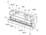
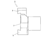
- the clamp member 1 may have a pillar shape extending from the first end 1a to the second end 1b, as in the non-limiting example shown in FIGS. 1 to 4. Further, the clamp member 1 may have an upper jaw 3, a lower jaw 5, and a pocket 7. The upper jaw 3 and the lower jaw 5 may be located apart from each other. The pocket 7 may be located between the upper jaw 3 and the lower jaw 5.
- the upper jaw 3 and the lower jaw 5 are expressions for convenience and do not indicate the upward and downward directions. For example, the upper jaw 3 does not have to face upward when using the clamp member 1.
- the lower right end may be the first end 1a and the upper left end may be the second end 1b.
- the first end 1a is also called the front end
- the second end 1b is also called the rear end.
- the clamp member 1 may have a prismatic shape extending from the first end 1a to the second end 1b. The shape of the clamp member 1 is not limited to the prismatic shape.
- the clamp member 1 is not limited to a specific size.
- the length of the clamp member 1 in the extended direction of the clamp member 1 may be set to about 40 to 100 mm, and is orthogonal to the extended direction of the clamp member 1.
- the length of the clamp member 1 in the direction may be set to about 10 to 20 mm.
- the height of the clamp member 1 indicated by the distance between the upper end of the upper jaw 3 and the lower end of the lower jaw 5 may be set to about 30 to 60 mm.
- the upper jaw 3 and the lower jaw 5 can come into contact with the cutting tool when the cutting tool is attached to the clamp member 1, and can sandwich the cutting tool. Further, a cutting tool can be positioned in the pocket 7. Therefore, the cutting tool can be gripped by the clamp member 1 by positioning the cutting tool in the pocket 7 and bringing the upper jaw 3 and the lower jaw 5 into contact with the cutting tool.
- Examples of the material of the upper jaw 3 include elastic members such as rubber, resin, steel, and cast iron.
- Examples of the material of the lower jaw 5 include steel and cast iron. The materials of the upper jaw 3 and the lower jaw 5 are not limited to those illustrated.
- the upper jaw 3 may have a first member 9 and a second member 11 as in the non-limiting example shown in FIGS. 1 to 4.
- the second member 11 may be located closer to the first end 1a than the first member 9. At least a part of the second member 11 may be located closer to the first end 1a than the first member 9. As in the non-limiting example shown in FIG. 2, when the clamp member 1 is viewed from the side of the upper jaw 3, the second member 11 may be located closer to the first end 1a than the first member 9. ..
- the hardness of the first member 9 may be the first hardness
- the hardness of the second member 11 may be the second hardness.
- the first hardness may be different from the second hardness.
- the hardness of the maxilla can be adjusted. That is, it is possible to adjust the hardness of the upper jaw 3 in the extended direction of the clamp member 1 by the first member 9 and the second member 11 having different hardnesses from each other.
- the hardness of the upper jaw 3 can be adjusted according to the shape of the cutting tool and the processing conditions. Therefore, the cutting tool can be stably gripped by the clamp member 1.
- the first hardness may be higher than the second hardness and may be lower than the second hardness.
- the first hardness is lower than the second hardness.
- the cutting tool can be more stably gripped by the clamp member 1.
- the portion used as the cutting edge in the cutting tool is positioned so as to protrude outward from the first end 1a, if the second hardness is relatively high, the first member 9 The cutting tool can be stably gripped by the clamp member 1 in the second member 11 close to the cutting edge. Further, when the first hardness is relatively low, the vibration generated by the cutting process is easily absorbed by the first member 9. Therefore, the surface quality of the machined surface of the work material is likely to be improved.
- the clamp member 1 may further include a third member 13.
- the third member 13 may be located closer to the second end 1b than the first member 9. At least a part of the third member 13 may be located closer to the second end 1b than the first member 9. As in the non-limiting example shown in FIG. 2, when the clamp member 1 is viewed from the side of the upper jaw 3, the third member 13 may be located closer to the second end 1b than the first member 9. ..
- the hardness of the third member 13 may be the third hardness.
- the first hardness may be different from the third hardness. In this case, the degree of freedom in adjusting the hardness of the upper jaw 3 is high.
- the first hardness may be higher than the third hardness and may be lower than the third hardness.
- the first hardness is lower than the third hardness.
- the cutting tool can be more stably gripped by the clamp member 1.
- the second hardness and the third hardness may be the same or may be different.
- the portion used as the cutting edge in the cutting tool is positioned so as to protrude outward from the second end 1b, if the third hardness is relatively high, the first member 9 The cutting tool can be stably gripped by the clamp member 1 in the third member 13 close to the cutting edge. Further, when the first hardness is relatively low, the vibration generated by the cutting process is easily absorbed by the first member 9. Therefore, the surface quality of the machined surface of the work material is likely to be improved.
- the cutting tool comes into contact with the first member 9, the second member 11, and the third member 13, if the second hardness and the third hardness are relatively high, the first end 1a of the clamp member 1 The cutting tool is stably gripped by the clamp member 1 on both ends of the second end 1b. Therefore, the position of the cutting tool is easy to stabilize.
- the hardness of the lower jaw 5 may be the fourth hardness.
- the first hardness may be lower than the fourth hardness.
- the first hardness is lower than the fourth hardness.
- the main component force applied to the cutting tool during cutting is easily received by the lower jaw 5, which has a relatively high hardness.
- the second hardness and the fourth hardness may be the same or may be different.
- the third hardness and the fourth hardness may be the same or different.
- the first hardness, the second hardness, the third hardness, and the fourth hardness may be evaluated by Young's modulus. Young's modulus may be measured using the nanoindentation method.
- the first hardness, the second hardness, the third hardness, and the fourth hardness are not limited to specific values.
- each hardness may be set as follows.
- the first hardness may be set to, for example, 20 MPa to 240 GPa.
- the second hardness may be set to, for example, 30 MPa to 250 GPa.
- the third hardness may be set to, for example, 30 MPa to 250 GPa.
- the fourth hardness may be set to, for example, 30 MPa to 250 GPa.
- the first hardness, the second hardness, the third hardness and the fourth hardness may be evaluated by the damping rate. When the hardness is high, the attenuation rate tends to be low. On the contrary, when the hardness is low, the attenuation rate tends to be high.
- the attenuation factor may be measured in accordance with JIS Z 2354 (1992).
- the length of the first member 9 in the extended direction of the clamp member 1 is the first length L1
- the length of the second member 11 in the extended direction of the clamp member 1 is the first. 2
- the length may be L2.
- the maximum value of the first length L1 may be larger than the maximum value of the second length L2. In this case, the position of the cutting tool is less likely to shift in the direction orthogonal to the extending direction of the clamp member 1 when the upper jaw 3 is viewed from the front.
- the length of the third member 13 in the extending direction of the clamp member 1 may be the third length L3.
- the maximum value of the first length L1 may be larger than the maximum value of the third length L3. In this case, the position of the cutting tool is less likely to shift in the direction orthogonal to the extending direction of the clamp member 1 when the upper jaw 3 is viewed from the front.
- the second length L2 and the third length L3 may be the same or different.
- the first member 9 may have a first step 15.
- the first step 15 may be located on the side of the first end 1a.
- the second member 11 may have a second step 17.
- the second step 17 may be located on the side of the first member 9 and away from the lower jaw 5 than the first step 15. Then, the first member 9 and the second member 11 may be fixed in a state where the first step 15 and the second step 17 face each other. In this case, the position of the cutting tool is less likely to shift in the direction orthogonal to the extending direction of the clamp member 1 when the upper jaw 3 is viewed from the front.
- the first member 9 may have a third step 19.
- the third step 19 may be located on the side of the second end 1b.
- the third member 13 may have a fourth step 21.
- the fourth step 21 may be located on the side of the first member 9 and away from the lower jaw 5 than the third step 19. Then, the first member 9 and the third member 13 may be fixed in a state where the third step 19 and the fourth step 21 face each other. In this case, the position of the cutting tool is less likely to shift in the direction orthogonal to the extending direction of the clamp member 1 when the upper jaw 3 is viewed from the front.
- the clamp member 1 may have a fixing screw 23.
- the first member 9 and the second member 11 may be fixed by the fixing screw 23.
- the first member 9 and the third member 13 may be fixed by the fixing screw 23.
- the clamp member 1 may have a first screw hole 25.
- the first screw hole 25 may penetrate the upper jaw 3 toward the lower jaw 5.
- the first screw can be inserted into the first screw hole 25.
- the clamping force can be adjusted by tightening the first screw inserted into the first screw hole 25.
- the first screw hole 25 may be located from the upper jaw 3 to the lower jaw 5.
- the clamp member 1 may have a plurality of first screw holes 25.
- the clamp member 1 may have a second screw hole 27.
- the second screw hole 27 may be opened in the pocket 7 so as to be exposed from the through hole that opens in the first side surface and the second side surface located on the opposite side of the first side surface of the plate-shaped cutting tool.
- the second screw can be inserted into the second screw hole 27.
- the cutting tool can be fixed in the pocket 7 by tightening the second screw inserted into the through hole and the second screw hole 27.
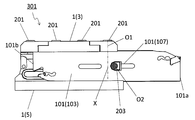
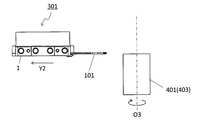
- the machine tool 301 may include the clamp member 1 and the cutting tool 101.
- the machine tool 301 has the clamp member 1, the hardness of the upper jaw 3 can be adjusted, so that excellent cutting performance can be exhibited.
- the cutting tool 101 may be located in the pocket 7. In other words, the cutting tool 101 may be sandwiched between the upper jaw 3 and the lower jaw 5.
- the cutting tool 101 may be mounted so that at least a part of the portion used as the cutting edge protrudes outward from the clamp member 1. Specifically, as in the non-limiting example shown in FIG. 5, the cutting edge 119 in the cutting tool 101 may be located farther from the second end 1b than the first end 1a of the clamp member 1.
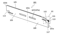
- the cutting tool 101 may have a plate shape extending from the third end 101a to the fourth end 101b, as in the non-limiting example shown in FIGS. 9 and 10.
- the cutting tool 101 may have a first side surface 103, a second side surface 105, and a through hole 107.
- the second side surface 105 may be located on the opposite side of the first side surface 103.
- the through hole 107 may be opened in the first side surface 103 and the second side surface 105, respectively.
- a second screw can be inserted into the through hole 107.
- the lower right end may be the third end 101a and the upper left end may be the fourth end 101b.
- the third end 101a is also called the front end
- the fourth end 101b is also called the rear end.
- the first side surface 103 and the second side surface 105 may be rectangular, respectively, from the side of the third end 101a toward the side of the fourth end 101b, respectively. It may be extended.
- the cutting tool 101 is not limited to a specific size.
- the length of the cutting tool 101 in the extended direction of the cutting tool 101 may be set to about 80 to 160 mm.
- the length of the cutting tool 101 in the direction orthogonal to the extending direction of the cutting tool 101 may be set to about 1 to 10 mm.
- the height of the cutting tool 101 in the direction from the upper jaw 3 to the lower jaw 5 may be set to about 15 to 35 mm.
- the machine tool 301 may have a first screw 201 and a second screw 203.
- the first screw 201 may be inserted into the first screw hole 25 of the clamp member 1.
- the second screw 203 may be inserted into the through hole 107 and the second screw hole 27 of the clamp member 1.
- the cutting tool 101 can be stably fixed in the pocket 7. That is, by fixing with the first screw 201, it is easy to receive the main component force applied to the cutting tool 101 during cutting. Further, by fixing with the second screw 203, the cutting tool 101 is less likely to bend during cutting. Therefore, the cutting tool 101 can be stably fixed in the pocket 7.
- the virtual line X extending the first central axis O1 of the first screw 201 toward the lower jaw 5 is the second screw 203. It is not necessary to intersect the second central axis O2 of. In this case, the cutting tool 101 can be stably fixed in the pocket 7.
- the second central axis O2 may be located closer to the third end 101a than the virtual line X in the side view from the side of the first side surface 103. In this case, the cutting tool 101 is less likely to bend during cutting.
- the virtual line X extending the first central axis O1 of the first screw 201 toward the lower jaw 5 is the second screw 203. It may intersect with the second central axis O2 of. In this case, the contact between the blade and the tool block becomes uniform, the pressure is improved, and the vibration of the blade is suppressed.
- the virtual line X may be orthogonal to the second central axis O2. Orthogonality is not limited to strict orthogonality, and may mean that a range of about 90 ° ⁇ 5 ° is allowed.
- the machine tool 301 may have a plurality of first screws 201.
- the clamp member 1 may have a plurality of first screw holes 25. At least one of the plurality of first screw holes 25 may be located closer to the second end 1b than the second screw hole 27. At least one of the plurality of first screws 201 may be inserted into the first screw hole 25 located closer to the second end 1b than the second screw hole 27. In these cases, it is easy to receive the main component force applied to the cutting tool 101 during cutting.
- the through hole 107 may be located closer to the third end 101a than the center 101c of the cutting tool 101 in the extending direction of the cutting tool 101.
- the through hole 107 is located near the cutting edge to which a cutting load is applied during cutting.
- the fixing by the second screw 203 is also located near the cutting edge, the cutting tool 101 is less likely to bend during cutting.
- the second screw 203 may be separated from the inner wall surface 107a of the through hole 107. In this case, the amount of protrusion of the blade can be adjusted.
- the through hole 107 may extend along the extending direction of the cutting tool 101.
- the through hole 107 may have a slit shape. In this case, the amount of protrusion of the cutting tool 101 can be adjusted.
- the cutting tool 101 may have a holder 109 and a cutting insert 111 (hereinafter, also simply referred to as an insert 111).
- the holder 109 may have a plate shape extending from the side of the third end 101a toward the side of the fourth end 101b. Further, the holder 109 may have an insert pocket 113 located on the side of the third end 101a. As in a non-limiting example shown in FIG. 10, the holder 109 has an upper jaw 115 and a lower jaw 117 located on the side of the third end 101a and separated from each other, and is inserted by the upper jaw 115 and the lower jaw 117. Pocket 113 may be configured.
- the insert 111 may be located in the insert pocket 113. In other words, the insert 111 may be sandwiched between the maxilla 115 and the mandible 117.
- the insert 111 may have a pillar shape extending from the side of the third end 101a toward the side of the fourth end 101b. As in the non-limiting example shown in FIG. 10, the insert 111 may have a prismatic shape. The shape of the insert 111 is not limited to the prismatic shape.
- the insert 111 may have a cutting edge 119. As in the non-limiting example shown in FIG. 10, the insert 111 may be located in the insert pocket 113 such that the cutting edge 119 projects outward on the side of the third end 101a of the holder 109.
- the cutting tool 101 can perform cutting by bringing the cutting edge 119 into contact with the work material.
- Steel, cast iron, or the like may be used as the material of the holder 109.
- the toughness of the holder 109 is high.
- Examples of the material of the insert 111 include inorganic materials such as cemented carbide, cermet and ceramics.
- examples of the composition of the cemented carbide include WC (tungsten carbide) -Co, WC-TiC (titanium carbide) -Co and WC-TiC-TaC (tantallum carbide) -Co.
- WC, TiC and TaC may be hard particles, and Co may be a bonded phase.
- the cermet may be a sintered composite material in which a metal is composited with a ceramic component.
- a compound containing TiC or TiN (titanium nitride) as a main component can be mentioned.
- the material of the insert 111 is not limited to these.
- a cutting tool 101 used for so-called turning is shown.
- the cutting tool 101 of the non-limiting embodiment of the present disclosure can be used in grooving, but is not limited to such machining.
- the work piece 401 can be produced by cutting the work material 403.
- the method for manufacturing the work piece 401 in the non-limiting embodiment of the present disclosure may include the following steps. That is, (1) The process of rotating the work material 403 and (2) A step of bringing the rotating work material 403 into contact with the cutting tool 101 in the machine tool 301 represented by the above-mentioned not limited embodiment. (3) The process of separating the cutting tool 101 from the work material 403 and May be provided.
- the work material 403 is rotated around the shaft O3, and the cutting tool 101 attached to the machine tool 301 is relative to the work material 403. You may approach the target.
- the ridge line (cutting edge) of the cutting tool 101 may be brought into contact with the work material 403 to cut the work material 403.
- the cutting tool 101 may be relatively far from the work material 403.
- the cutting tool 101 is moved in the Y1 direction while the shaft O3 is fixed and the work material 403 is rotated around the shaft O3 to bring the work material 403 closer to the work material 403. .
- the work material 403 is cut by bringing the cutting edge 119 of the insert 111 into contact with the rotating work material 403.
- the cutting tool 101 is moved away in the Y2 direction while the work material 403 is rotated.
- the cutting tool 101 is brought into contact with the work material 403 by moving the cutting tool 101 in each step, or the cutting tool 101 is cut. Although it is separated from the material 403, it is not limited to such a form as a matter of course.
- the work material 403 may be brought closer to the cutting tool 101.
- the work material 403 may be moved away from the cutting tool 101.
- the process of keeping the work material 403 rotated and bringing the cutting edge 119 of the insert 111 into contact with different parts of the work material 403 may be repeated.
- typical examples of the material of the work material 403 may be carbon steel, alloy steel, stainless steel, cast iron, non-ferrous metal, or the like.
Landscapes
- Engineering & Computer Science (AREA)
- Mechanical Engineering (AREA)
- Cutting Tools, Boring Holders, And Turrets (AREA)
Abstract
Selon un aspect non limitatif, la présente invention concerne un élément de serrage présentant une forme en colonne se prolongeant d'une première extrémité à une seconde extrémité. Cet élément de serrage comporte une mâchoire supérieure, une mâchoire inférieure et une alvéole. La mâchoire supérieure et la mâchoire inférieure sont situées séparément l'une de l'autre. L'alvéole est située entre la mâchoire supérieure et la mâchoire inférieure. La mâchoire supérieure comprend un premier élément et un second élément. Le second élément est situé sur le premier côté d'extrémité par rapport au premier élément. La dureté du premier élément est définie comme une première dureté, et la dureté du second élément est définie comme une seconde dureté. La première dureté est différente de la seconde dureté.
Priority Applications (4)
| Application Number | Priority Date | Filing Date | Title |
|---|---|---|---|
| JP2021519423A JP7225387B2 (ja) | 2019-05-13 | 2020-05-11 | クランプ部材、工作機械及び切削加工物の製造方法 |
| CN202080034379.1A CN113795344B (zh) | 2019-05-13 | 2020-05-11 | 夹紧构件、机床以及切削加工物的制造方法 |
| DE112020002378.8T DE112020002378T5 (de) | 2019-05-13 | 2020-05-11 | Klemmelement, maschinenwerkzeug und verfahren zum herstellen eines maschinell bearbeiteten produkts |
| US17/610,601 US20220203457A1 (en) | 2019-05-13 | 2020-05-11 | Clamping member, machine tool, and method for manufacturing machined product |
Applications Claiming Priority (2)
| Application Number | Priority Date | Filing Date | Title |
|---|---|---|---|
| JP2019-090729 | 2019-05-13 | ||
| JP2019090729 | 2019-05-13 |
Publications (1)
| Publication Number | Publication Date |
|---|---|
| WO2020230754A1 true WO2020230754A1 (fr) | 2020-11-19 |
Family
ID=73289584
Family Applications (1)
| Application Number | Title | Priority Date | Filing Date |
|---|---|---|---|
| PCT/JP2020/018817 WO2020230754A1 (fr) | 2019-05-13 | 2020-05-11 | Élément de serrage, machine-outil et procédé de production d'une pièce découpée |
Country Status (5)
| Country | Link |
|---|---|
| US (1) | US20220203457A1 (fr) |
| JP (1) | JP7225387B2 (fr) |
| CN (1) | CN113795344B (fr) |
| DE (1) | DE112020002378T5 (fr) |
| WO (1) | WO2020230754A1 (fr) |
Citations (7)
| Publication number | Priority date | Publication date | Assignee | Title |
|---|---|---|---|---|
| JPS4714639U (fr) * | 1971-03-17 | 1972-10-20 | ||
| JPS4916994A (fr) * | 1972-06-07 | 1974-02-14 | ||
| JPS56121921A (en) * | 1980-02-29 | 1981-09-25 | Adachi Jimusho:Kk | Controlling method of temperature for green house |
| JPS6011747B2 (ja) * | 1976-03-04 | 1985-03-27 | 帝人株式会社 | 樹脂組成物 |
| JPS6142722A (ja) * | 1984-08-02 | 1986-03-01 | Tdk Corp | 磁気記録方法 |
| JP2009028857A (ja) * | 2007-07-27 | 2009-02-12 | Kyocera Corp | 切削工具及び切削方法 |
| JP2018075676A (ja) * | 2016-11-10 | 2018-05-17 | 三菱マテリアル株式会社 | 溝入れ工具用ホルダ、溝入れ工具および溝入れ工具ユニット |
Family Cites Families (27)
| Publication number | Priority date | Publication date | Assignee | Title |
|---|---|---|---|---|
| US3497935A (en) * | 1967-02-15 | 1970-03-03 | C & L Machine Shop Inc | Cut-off tool assembly |
| US3688366A (en) * | 1970-07-13 | 1972-09-05 | Kennametal Inc | Tool |
| DE3208923A1 (de) * | 1982-03-12 | 1983-09-22 | Bruno 3338 Schöningen Müntel | Fassung und halterung fuer drehmaschinenwerkzeuge |
| JPS59191291U (ja) * | 1983-06-03 | 1984-12-19 | 神鋼電機株式会社 | メカニカルハンド |
| FI894671A (fi) * | 1989-10-03 | 1991-04-04 | Erkki Rinne | Reglerbar faestanordning. |
| US5516241A (en) * | 1994-06-27 | 1996-05-14 | Valenite Inc. | Holder blade |
| SE511928C2 (sv) * | 1997-03-19 | 1999-12-20 | Sandvik Ab | Anordning samt förfarande för fastspänning av skär |
| DE19807498A1 (de) * | 1998-02-21 | 1999-09-02 | Horn P Hartmetall Werkzeugfab | Halter für spanabhebende Werkzeug-Einsätze |
| SE526539C2 (sv) * | 2002-05-28 | 2005-10-04 | Sandvik Intellectual Property | Verktyg för spånavskiljande bearbetning där skärläget uppvisar flexibla partier. |
| US7331736B2 (en) * | 2003-10-14 | 2008-02-19 | Kennametal Inc. | Metal cutting tool |
| SE530579C2 (sv) * | 2006-11-28 | 2008-07-08 | Sandvik Intellectual Property | Verktyg och grundkropp för spånavskiljande bearbetning med flera kanaler |
| JP2008238350A (ja) * | 2007-03-28 | 2008-10-09 | Kyocera Corp | 切削工具及び工具ホルダ並びに切削方法 |
| JP5196951B2 (ja) * | 2007-10-30 | 2013-05-15 | 京セラ株式会社 | 切削工具及び切削方法 |
| IL195696A0 (en) * | 2008-12-03 | 2009-09-01 | Iscar Ltd | Tool holder for clamping an insert holder |
| IL205988A (en) * | 2010-05-26 | 2015-03-31 | Iscar Ltd | Assembling a tool and holding a tool for it |
| DE102011053760A1 (de) * | 2011-09-19 | 2013-03-21 | Walter Ag | Stechplatte und Klemmhalter mit Vier-Punktanlagen |
| US8827598B2 (en) * | 2011-11-22 | 2014-09-09 | Kennametal Inc. | Cutting assembly with enhanced coolant delivery |
| RU2617466C2 (ru) * | 2012-03-06 | 2017-04-25 | Искар Лтд. | Отрезная пластина и держатель пластины, выполненные с возможностью подачи охлаждающей жидкости под давлением |
| SE536741C2 (sv) * | 2012-11-08 | 2014-07-08 | Sandvik Intellectual Property | Skärverktyg jämte stickblad härför |
| US8985913B2 (en) * | 2012-11-13 | 2015-03-24 | Iscar, Ltd. | Cutting tool holder with internal coolant passage having a compressible member |
| EP2745963B2 (fr) * | 2012-12-19 | 2021-03-17 | Seco Tools Ab | Accouplement pour un système de refroidissement dans un outil de coupe |
| JP2015150659A (ja) * | 2014-02-17 | 2015-08-24 | 三菱マテリアル株式会社 | 刃先交換式溝入れ工具 |
| EP3023179B1 (fr) * | 2014-11-18 | 2020-04-08 | Walter Ag | Lame à tronçonner pour un outil destiné à tronçonner ou à saigner |
| WO2016121663A1 (fr) * | 2015-01-26 | 2016-08-04 | 株式会社タンガロイ | Élément à buse et outil de coupe |
| JP6677870B2 (ja) * | 2016-02-26 | 2020-04-08 | 三菱マテリアル株式会社 | クランプ作業工具付き刃先交換式溝入れ工具、及びクランプ作業工具 |
| TWI808983B (zh) * | 2017-09-08 | 2023-07-21 | 日商索尼股份有限公司 | 機器人手部、機器人裝置及電子機器的製造方法 |
| JP6791101B2 (ja) | 2017-11-15 | 2020-11-25 | オムロン株式会社 | 静電容量式圧力センサ |
-
2020
- 2020-05-11 CN CN202080034379.1A patent/CN113795344B/zh active Active
- 2020-05-11 DE DE112020002378.8T patent/DE112020002378T5/de active Pending
- 2020-05-11 US US17/610,601 patent/US20220203457A1/en active Pending
- 2020-05-11 WO PCT/JP2020/018817 patent/WO2020230754A1/fr active Application Filing
- 2020-05-11 JP JP2021519423A patent/JP7225387B2/ja active Active
Patent Citations (7)
| Publication number | Priority date | Publication date | Assignee | Title |
|---|---|---|---|---|
| JPS4714639U (fr) * | 1971-03-17 | 1972-10-20 | ||
| JPS4916994A (fr) * | 1972-06-07 | 1974-02-14 | ||
| JPS6011747B2 (ja) * | 1976-03-04 | 1985-03-27 | 帝人株式会社 | 樹脂組成物 |
| JPS56121921A (en) * | 1980-02-29 | 1981-09-25 | Adachi Jimusho:Kk | Controlling method of temperature for green house |
| JPS6142722A (ja) * | 1984-08-02 | 1986-03-01 | Tdk Corp | 磁気記録方法 |
| JP2009028857A (ja) * | 2007-07-27 | 2009-02-12 | Kyocera Corp | 切削工具及び切削方法 |
| JP2018075676A (ja) * | 2016-11-10 | 2018-05-17 | 三菱マテリアル株式会社 | 溝入れ工具用ホルダ、溝入れ工具および溝入れ工具ユニット |
Also Published As
| Publication number | Publication date |
|---|---|
| DE112020002378T5 (de) | 2022-01-27 |
| CN113795344B (zh) | 2024-01-19 |
| CN113795344A (zh) | 2021-12-14 |
| JPWO2020230754A1 (fr) | 2020-11-19 |
| US20220203457A1 (en) | 2022-06-30 |
| JP7225387B2 (ja) | 2023-02-20 |
Similar Documents
| Publication | Publication Date | Title |
|---|---|---|
| JP7304989B2 (ja) | 切削インサート、切削工具及び切削加工物の製造方法 | |
| JPWO2012086375A1 (ja) | 切削工具およびそれを用いた切削加工物の製造方法 | |
| JP7368064B2 (ja) | 工作機械及び切削加工物の製造方法 | |
| JP6272457B2 (ja) | 切削インサート、切削工具及び切削加工物の製造方法 | |
| EP4049778A1 (fr) | Insert de découpe | |
| JP5528264B2 (ja) | 切削工具および切削工具を用いた被削材の切削方法 | |
| WO2021132357A1 (fr) | Support, outil de coupe, et procédé de fabrication de pièce découpée | |
| WO2020230754A1 (fr) | Élément de serrage, machine-outil et procédé de production d'une pièce découpée | |
| JP2020028943A (ja) | ホルダ、切削工具及び切削加工物の製造方法 | |
| JP6810807B2 (ja) | 切削インサート、切削工具及び切削加工物の製造方法 | |
| WO2021205878A1 (fr) | Support, outil de coupe et procédé de fabrication d'une pièce coupée | |
| JP7045460B2 (ja) | 切削工具及び切削加工物の製造方法 | |
| JP7216744B2 (ja) | ホルダ、切削工具及び切削加工物の製造方法 | |
| WO2020179538A1 (fr) | Outil de coupe et procédé de production d'une pièce découpée | |
| WO2023176441A1 (fr) | Outil de coupe et procédé de production de pièce coupée | |
| CN113474109B (zh) | 切削刀片、切削刀具及切削加工物的制造方法 | |
| WO2024048256A1 (fr) | Unité de coupe, outil de coupe et porte-outil de coupe, et procédé de fabrication d'article coupé | |
| WO2023277180A1 (fr) | Support, outil de coupe et procédé de fabrication de produit usiné | |
| WO2020184422A1 (fr) | Plaquette de coupe, outil de coupe et procédé de fabrication de pièce coupée | |
| WO2023084973A1 (fr) | Plaquette de coupe, outil de coupe, et procédé de fabrication de pièce coupée | |
| JP7117389B2 (ja) | 切削インサート、切削工具及び切削加工物の製造方法 | |
| JP6920811B2 (ja) | 切削工具用ホルダ、切削工具及び切削加工物の製造方法 | |
| WO2020189336A1 (fr) | Insert de coupe, outil de coupe et procédé de fabrication de pièce coupée | |
| WO2020138084A1 (fr) | Outil rotatif et procédé de fabrication d'un article coupé | |
| JP2015188949A (ja) | 切削インサート、切削工具および切削加工物の製造方法 |
Legal Events
| Date | Code | Title | Description |
|---|---|---|---|
| 121 | Ep: the epo has been informed by wipo that ep was designated in this application |
Ref document number: 20805837 Country of ref document: EP Kind code of ref document: A1 |
|
| ENP | Entry into the national phase |
Ref document number: 2021519423 Country of ref document: JP Kind code of ref document: A |
|
| 122 | Ep: pct application non-entry in european phase |
Ref document number: 20805837 Country of ref document: EP Kind code of ref document: A1 |