WO2020230754A1 - Clamp member, machine tool, and method for producing cut workpiece - Google Patents
Clamp member, machine tool, and method for producing cut workpiece Download PDFInfo
- Publication number
- WO2020230754A1 WO2020230754A1 PCT/JP2020/018817 JP2020018817W WO2020230754A1 WO 2020230754 A1 WO2020230754 A1 WO 2020230754A1 JP 2020018817 W JP2020018817 W JP 2020018817W WO 2020230754 A1 WO2020230754 A1 WO 2020230754A1
- Authority
- WO
- WIPO (PCT)
- Prior art keywords
- hardness
- clamp member
- cutting tool
- cutting
- upper jaw
- Prior art date
Links
Images


Classifications
-
- B—PERFORMING OPERATIONS; TRANSPORTING
- B23—MACHINE TOOLS; METAL-WORKING NOT OTHERWISE PROVIDED FOR
- B23B—TURNING; BORING
- B23B29/00—Holders for non-rotary cutting tools; Boring bars or boring heads; Accessories for tool holders
- B23B29/04—Tool holders for a single cutting tool
- B23B29/06—Tool holders equipped with longitudinally-arranged grooves for setting the cutting tool
-
- B—PERFORMING OPERATIONS; TRANSPORTING
- B23—MACHINE TOOLS; METAL-WORKING NOT OTHERWISE PROVIDED FOR
- B23B—TURNING; BORING
- B23B29/00—Holders for non-rotary cutting tools; Boring bars or boring heads; Accessories for tool holders
- B23B29/04—Tool holders for a single cutting tool
- B23B29/043—Tool holders for a single cutting tool with cutting-off, grooving or profile cutting tools, i.e. blade- or disc-like main cutting parts
-
- B—PERFORMING OPERATIONS; TRANSPORTING
- B23—MACHINE TOOLS; METAL-WORKING NOT OTHERWISE PROVIDED FOR
- B23B—TURNING; BORING
- B23B27/00—Tools for turning or boring machines; Tools of a similar kind in general; Accessories therefor
- B23B27/04—Cutting-off tools
-
- B—PERFORMING OPERATIONS; TRANSPORTING
- B23—MACHINE TOOLS; METAL-WORKING NOT OTHERWISE PROVIDED FOR
- B23B—TURNING; BORING
- B23B27/00—Tools for turning or boring machines; Tools of a similar kind in general; Accessories therefor
- B23B27/08—Cutting tools with blade- or disc-like main parts
- B23B27/086—Cutting tools with blade- or disc-like main parts with yieldable support for the cutting insert
-
- B—PERFORMING OPERATIONS; TRANSPORTING
- B23—MACHINE TOOLS; METAL-WORKING NOT OTHERWISE PROVIDED FOR
- B23B—TURNING; BORING
- B23B29/00—Holders for non-rotary cutting tools; Boring bars or boring heads; Accessories for tool holders
- B23B29/04—Tool holders for a single cutting tool
- B23B29/12—Special arrangements on tool holders
- B23B29/14—Special arrangements on tool holders affording a yielding support of the cutting tool, e.g. by spring clamping
-
- B—PERFORMING OPERATIONS; TRANSPORTING
- B23—MACHINE TOOLS; METAL-WORKING NOT OTHERWISE PROVIDED FOR
- B23B—TURNING; BORING
- B23B2210/00—Details of turning tools
- B23B2210/08—Tools comprising intermediary toolholders
Abstract
The clamp member according to one non-limiting aspect of the present invention has a columnar shape extending from a first end to a second end. This clamp member has an upper jaw, a lower jaw, and a pocket. The upper jaw and the lower jaw are located separately from each other. The pocket is located between the upper jaw and the lower jaw. The upper jaw has a first member and a second member. The second member is located on the first end side with respect to the first member. The hardness of the first member is set as a first hardness, and the hardness of the second member is set as a second hardness. The first hardness is different from the second hardness.
Description
本出願は、2019年5月13日に出願された日本国特許出願2019-090729号の優先権を主張するものであり、この先の出願の開示全体を、ここに参照のために取り込む。
This application claims the priority of Japanese Patent Application No. 2019-090729 filed on May 13, 2019, and the entire disclosure of future applications is incorporated herein by reference.
本開示は、切削加工において用いられる切削工具を把持するクランプ部材に関する。具体的には、溝入れ加工のような旋削加工に用いられる切削工具を把持するクランプ部材に関する。
The present disclosure relates to a clamp member that grips a cutting tool used in cutting. Specifically, the present invention relates to a clamp member that grips a cutting tool used for turning such as grooving.
従来から旋削加工に用いられる切削工具を把持するクランプ部材が知られており、このクランプ部材を有する工作機械も知られている。例えば、特開2016-182671号公報(特許文献1)には、板状部材(切削工具)を保持するためのツールブロックと、板状部材をツールブロックへ固定するためのクランプ部材(上顎)と、を有する溝加工用の切削工具(工作機械)が記載されている。
Conventionally, a clamp member for gripping a cutting tool used for turning is known, and a machine tool having this clamp member is also known. For example, Japanese Patent Application Laid-Open No. 2016-182671 (Patent Document 1) describes a tool block for holding a plate-shaped member (cutting tool) and a clamp member (upper jaw) for fixing the plate-shaped member to the tool block. A cutting tool (machine tool) for grooving having a, is described.
本開示の限定されない一面に基づくクランプ部材は、第1端から第2端にかけて延びた柱形状である。クランプ部材は、上顎及び下顎と、ポケットと、を有する。上顎及び下顎は、互いに離れて位置する。ポケットは、上顎及び下顎の間に位置する。上顎は、第1部材及び第2部材を有する。第2部材は、第1部材よりも第1端の側に位置する。第1部材の硬度を第1硬度、第2部材の硬度を第2硬度とする。第1硬度が、第2硬度と異なる。
The clamp member based on one surface without limitation of the present disclosure has a pillar shape extending from the first end to the second end. The clamp member has an upper jaw, a lower jaw, and a pocket. The maxilla and mandible are located apart from each other. The pocket is located between the upper and lower jaws. The upper jaw has a first member and a second member. The second member is located closer to the first end than the first member. The hardness of the first member is defined as the first hardness, and the hardness of the second member is defined as the second hardness. The first hardness is different from the second hardness.
<クランプ部材>
以下、本開示の限定されない実施形態のクランプ部材1について、図面を用いて詳細に説明する。但し、以下で参照する各図は、説明の便宜上、実施形態を説明する上で必要な主要部材のみが簡略化して示されている。したがって、クランプ部材1は、参照する各図に示されていない任意の構成部材を備え得る。また、各図中の部材の寸法は、実際の構成部材の寸法及び各部材の寸法比率などを忠実に表したものではない。 <Clamp member>
Hereinafter, theclamp member 1 of the embodiment not limited to the present disclosure will be described in detail with reference to the drawings. However, in each of the figures referred to below, for convenience of explanation, only the main members necessary for explaining the embodiment are shown in a simplified manner. Therefore, the clamp member 1 may include any constituent member not shown in each referenced figure. Further, the dimensions of the members in each drawing do not faithfully represent the dimensions of the actual constituent members and the dimensional ratio of each member.
以下、本開示の限定されない実施形態のクランプ部材1について、図面を用いて詳細に説明する。但し、以下で参照する各図は、説明の便宜上、実施形態を説明する上で必要な主要部材のみが簡略化して示されている。したがって、クランプ部材1は、参照する各図に示されていない任意の構成部材を備え得る。また、各図中の部材の寸法は、実際の構成部材の寸法及び各部材の寸法比率などを忠実に表したものではない。 <Clamp member>
Hereinafter, the
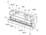
クランプ部材1は、図1~図4に示す限定されない一例のように、第1端1aから第2端1bにかけて延びた柱形状であってもよい。また、クランプ部材1は、上顎3及び下顎5と、ポケット7と、を有してもよい。上顎3及び下顎5は、互いに離れて位置してもよい。ポケット7は、上顎3及び下顎5の間に位置してもよい。なお、上顎3及び下顎5は、便宜上の表現であり、上及び下の方向性を示すものではない。例えば、上顎3は、クランプ部材1を使用するときに上方を向く必要はない。
The clamp member 1 may have a pillar shape extending from the first end 1a to the second end 1b, as in the non-limiting example shown in FIGS. 1 to 4. Further, the clamp member 1 may have an upper jaw 3, a lower jaw 5, and a pocket 7. The upper jaw 3 and the lower jaw 5 may be located apart from each other. The pocket 7 may be located between the upper jaw 3 and the lower jaw 5. The upper jaw 3 and the lower jaw 5 are expressions for convenience and do not indicate the upward and downward directions. For example, the upper jaw 3 does not have to face upward when using the clamp member 1.
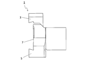
図1に示す限定されない一例のように、右下端が第1端1a、左上端が第2端1bであってもよい。一般的に、第1端1aは先端、第2端1bは後端とも呼ばれる。また、図1に示す限定されない一例のように、クランプ部材1は、第1端1aから第2端1bにかけて延びた角柱形状であってもよい。なお、クランプ部材1の形状は、角柱形状に限定されない。
As in the non-limiting example shown in FIG. 1, the lower right end may be the first end 1a and the upper left end may be the second end 1b. Generally, the first end 1a is also called the front end, and the second end 1b is also called the rear end. Further, as in the non-limiting example shown in FIG. 1, the clamp member 1 may have a prismatic shape extending from the first end 1a to the second end 1b. The shape of the clamp member 1 is not limited to the prismatic shape.
クランプ部材1は、特定の大きさに限定されない。例えば、上顎3を正面視した場合において、クランプ部材1の延びた方向におけるクランプ部材1の長さは、40~100mm程度に設定されてもよく、また、クランプ部材1の延びた方向に直交する方向におけるクランプ部材1の長さは、10~20mm程度に設定されてもよい。上顎3の上端及び下顎5の下端の間隔で示されるクランプ部材1の高さは、30~60mm程度に設定されてもよい。
The clamp member 1 is not limited to a specific size. For example, when the upper jaw 3 is viewed from the front, the length of the clamp member 1 in the extended direction of the clamp member 1 may be set to about 40 to 100 mm, and is orthogonal to the extended direction of the clamp member 1. The length of the clamp member 1 in the direction may be set to about 10 to 20 mm. The height of the clamp member 1 indicated by the distance between the upper end of the upper jaw 3 and the lower end of the lower jaw 5 may be set to about 30 to 60 mm.
上顎3及び下顎5は、切削工具をクランプ部材1に取り付けた際に切削工具に当接(接触)可能であり、切削工具を挟むことが可能である。また、ポケット7内には、切削工具を位置させることが可能である。したがって、ポケット7内に切削工具を位置させて上顎3及び下顎5を切削工具に当接させることによって、切削工具をクランプ部材1で把持することが可能である。
The upper jaw 3 and the lower jaw 5 can come into contact with the cutting tool when the cutting tool is attached to the clamp member 1, and can sandwich the cutting tool. Further, a cutting tool can be positioned in the pocket 7. Therefore, the cutting tool can be gripped by the clamp member 1 by positioning the cutting tool in the pocket 7 and bringing the upper jaw 3 and the lower jaw 5 into contact with the cutting tool.
上顎3の材質としては、例えば、ゴムなどの弾性部材、樹脂、鋼及び鋳鉄などが挙げられ得る。下顎5の材質としては、例えば、鋼及び鋳鉄などが挙げられ得る。なお、上顎3及び下顎5のそれぞれの材質は、例示したものに限定されない。
Examples of the material of the upper jaw 3 include elastic members such as rubber, resin, steel, and cast iron. Examples of the material of the lower jaw 5 include steel and cast iron. The materials of the upper jaw 3 and the lower jaw 5 are not limited to those illustrated.
上顎3は、図1~図4に示す限定されない一例のように、第1部材9及び第2部材11を有してもよい。第2部材11は、第1部材9よりも第1端1aの側に位置してもよい。第2部材11の少なくとも一部が、第1部材9よりも第1端1aの側に位置してもよい。図2に示す限定されない一例のように、クランプ部材1を上顎3の側から正面視した場合において、第2部材11が、第1部材9よりも第1端1aの側に位置してもよい。
The upper jaw 3 may have a first member 9 and a second member 11 as in the non-limiting example shown in FIGS. 1 to 4. The second member 11 may be located closer to the first end 1a than the first member 9. At least a part of the second member 11 may be located closer to the first end 1a than the first member 9. As in the non-limiting example shown in FIG. 2, when the clamp member 1 is viewed from the side of the upper jaw 3, the second member 11 may be located closer to the first end 1a than the first member 9. ..
ここで、第1部材9の硬度を第1硬度、第2部材11の硬度を第2硬度としてもよい。第1硬度は、第2硬度と異なってもよい。この場合には、上顎の硬度を調整することが可能である。すなわち、互いに硬度が異なる第1部材9及び第2部材11によって、クランプ部材1の延びた方向における上顎3の硬度を調整することが可能である。例えば、切削工具の形状及び加工条件などに応じて、上顎3の硬度を調整できる。そのため、切削工具をクランプ部材1で安定して把持できる。
Here, the hardness of the first member 9 may be the first hardness, and the hardness of the second member 11 may be the second hardness. The first hardness may be different from the second hardness. In this case, the hardness of the maxilla can be adjusted. That is, it is possible to adjust the hardness of the upper jaw 3 in the extended direction of the clamp member 1 by the first member 9 and the second member 11 having different hardnesses from each other. For example, the hardness of the upper jaw 3 can be adjusted according to the shape of the cutting tool and the processing conditions. Therefore, the cutting tool can be stably gripped by the clamp member 1.
第1硬度は、第2硬度よりも高くてもよく、また、第2硬度よりも低くてもよい。例えば、第1部材9の材質がゴムであり、第2部材11の材質が鋼の場合には、第1硬度が第2硬度よりも低い。第1硬度が第2硬度よりも低い場合には、切削工具をクランプ部材1でより安定して把持し易い。
The first hardness may be higher than the second hardness and may be lower than the second hardness. For example, when the material of the first member 9 is rubber and the material of the second member 11 is steel, the first hardness is lower than the second hardness. When the first hardness is lower than the second hardness, the cutting tool can be more stably gripped by the clamp member 1.
例えば、切削工具における切刃として用いられる部分が、第1端1aよりも外方に向かって突出した状態で位置する際に、第2硬度が相対的に高い場合には、第1部材9よりも切刃に近い第2部材11において切削工具をクランプ部材1で安定して把持できる。また、第1硬度が相対的に低い場合には、切削加工に伴い生じる振動が第1部材9において吸収され易い。そのため、被削材の加工面の面品位が向上し易い。
For example, when the portion used as the cutting edge in the cutting tool is positioned so as to protrude outward from the first end 1a, if the second hardness is relatively high, the first member 9 The cutting tool can be stably gripped by the clamp member 1 in the second member 11 close to the cutting edge. Further, when the first hardness is relatively low, the vibration generated by the cutting process is easily absorbed by the first member 9. Therefore, the surface quality of the machined surface of the work material is likely to be improved.
クランプ部材1は、第3部材13を更に有してもよい。第3部材13は、第1部材9よりも第2端1bの側に位置してもよい。第3部材13の少なくとも一部が、第1部材9よりも第2端1bの側に位置してもよい。図2に示す限定されない一例のように、クランプ部材1を上顎3の側から正面視した場合において、第3部材13が、第1部材9よりも第2端1bの側に位置してもよい。
The clamp member 1 may further include a third member 13. The third member 13 may be located closer to the second end 1b than the first member 9. At least a part of the third member 13 may be located closer to the second end 1b than the first member 9. As in the non-limiting example shown in FIG. 2, when the clamp member 1 is viewed from the side of the upper jaw 3, the third member 13 may be located closer to the second end 1b than the first member 9. ..
ここで、第3部材13の硬度を第3硬度としてもよい。第1硬度は、第3硬度と異なってもよい。この場合には、上顎3における硬度の調整の自由度が高い。
Here, the hardness of the third member 13 may be the third hardness. The first hardness may be different from the third hardness. In this case, the degree of freedom in adjusting the hardness of the upper jaw 3 is high.
第1硬度は、第3硬度よりも高くてもよく、また、第3硬度よりも低くてもよい。例えば、第1部材9の材質がゴムであり、第3部材13の材質が鋼の場合には、第1硬度が第3硬度よりも低い。第1硬度が第3硬度よりも低い場合には、切削工具をクランプ部材1でより安定して把持し易い。なお、第2硬度及び第3硬度は、同じでもよく、また、異なってもよい。
The first hardness may be higher than the third hardness and may be lower than the third hardness. For example, when the material of the first member 9 is rubber and the material of the third member 13 is steel, the first hardness is lower than the third hardness. When the first hardness is lower than the third hardness, the cutting tool can be more stably gripped by the clamp member 1. The second hardness and the third hardness may be the same or may be different.
例えば、切削工具における切刃として用いられる部分が、第2端1bよりも外方に向かって突出した状態で位置する際に、第3硬度が相対的に高い場合には、第1部材9よりも切刃に近い第3部材13において切削工具をクランプ部材1で安定して把持できる。また、第1硬度が相対的に低い場合には、切削加工に伴い生じる振動が第1部材9において吸収され易い。そのため、被削材の加工面の面品位が向上し易い。
For example, when the portion used as the cutting edge in the cutting tool is positioned so as to protrude outward from the second end 1b, if the third hardness is relatively high, the first member 9 The cutting tool can be stably gripped by the clamp member 1 in the third member 13 close to the cutting edge. Further, when the first hardness is relatively low, the vibration generated by the cutting process is easily absorbed by the first member 9. Therefore, the surface quality of the machined surface of the work material is likely to be improved.
また、切削工具が、第1部材9、第2部材11及び第3部材13に当接する際に、第2硬度及び第3硬度が相対的に高い場合には、クランプ部材1における第1端1a及び第2端1bの両端側において切削工具がクランプ部材1に安定して把持される。そのため、切削工具の位置が安定し易い。
Further, when the cutting tool comes into contact with the first member 9, the second member 11, and the third member 13, if the second hardness and the third hardness are relatively high, the first end 1a of the clamp member 1 The cutting tool is stably gripped by the clamp member 1 on both ends of the second end 1b. Therefore, the position of the cutting tool is easy to stabilize.
下顎5の硬度を第4硬度としてもよい。第1硬度は第4硬度よりも低くてもよい。例えば、第1部材9の材質がゴムであり、下顎5の材質が鋼の場合には、第1硬度が第4硬度よりも低い。第1硬度が第4硬度よりも低い場合には、切削加工時に切削工具に加わる主分力を相対的に硬度が高い下顎5で受け止め易い。なお、第2硬度及び第4硬度は、同じでもよく、また、異なってもよい。同様に、第3硬度及び第4硬度は、同じでもよく、また、異なってもよい。
The hardness of the lower jaw 5 may be the fourth hardness. The first hardness may be lower than the fourth hardness. For example, when the material of the first member 9 is rubber and the material of the lower jaw 5 is steel, the first hardness is lower than the fourth hardness. When the first hardness is lower than the fourth hardness, the main component force applied to the cutting tool during cutting is easily received by the lower jaw 5, which has a relatively high hardness. The second hardness and the fourth hardness may be the same or may be different. Similarly, the third hardness and the fourth hardness may be the same or different.
第1硬度、第2硬度、第3硬度及び第4硬度は、ヤング率によって評価してもよい。ヤング率は、ナノインデンテーション法を用いて測定してもよい。
The first hardness, the second hardness, the third hardness, and the fourth hardness may be evaluated by Young's modulus. Young's modulus may be measured using the nanoindentation method.
第1硬度、第2硬度、第3硬度及び第4硬度は、特定の値に限定されない。第1硬度、第2硬度、第3硬度及び第4硬度をヤング率によって評価する場合には、各硬度は次のように設定されてもよい。第1硬度は、例えば20MPa~240GPaに設定されてもよい。第2硬度は、例えば30MPa~250GPaに設定されてもよい。第3硬度は、例えば30MPa~250GPaに設定されてもよい。第4硬度は、例えば30MPa~250GPaに設定されてもよい。
The first hardness, the second hardness, the third hardness, and the fourth hardness are not limited to specific values. When the first hardness, the second hardness, the third hardness, and the fourth hardness are evaluated by Young's modulus, each hardness may be set as follows. The first hardness may be set to, for example, 20 MPa to 240 GPa. The second hardness may be set to, for example, 30 MPa to 250 GPa. The third hardness may be set to, for example, 30 MPa to 250 GPa. The fourth hardness may be set to, for example, 30 MPa to 250 GPa.
第1硬度、第2硬度、第3硬度及び第4硬度は、減衰率によって評価してもよい。硬度が高い場合には、減衰率は低い傾向にある。逆に、硬度が低い場合には、減衰率は高い傾向にある。減衰率は、JIS Z 2354(1992)に準拠して測定してもよい。
The first hardness, the second hardness, the third hardness and the fourth hardness may be evaluated by the damping rate. When the hardness is high, the attenuation rate tends to be low. On the contrary, when the hardness is low, the attenuation rate tends to be high. The attenuation factor may be measured in accordance with JIS Z 2354 (1992).
図4に示す限定されない一例のように、クランプ部材1の延びた方向における第1部材9の長さを第1長さL1、クランプ部材1の延びた方向における第2部材11の長さを第2長さL2としてもよい。第1長さL1の最大値が、第2長さL2の最大値よりも大きくてもよい。この場合には、上顎3を正面視した場合におけるクランプ部材1の延びた方向に直交する方向での切削工具の位置ずれが生じにくい。
As in the non-limiting example shown in FIG. 4, the length of the first member 9 in the extended direction of the clamp member 1 is the first length L1, and the length of the second member 11 in the extended direction of the clamp member 1 is the first. 2 The length may be L2. The maximum value of the first length L1 may be larger than the maximum value of the second length L2. In this case, the position of the cutting tool is less likely to shift in the direction orthogonal to the extending direction of the clamp member 1 when the upper jaw 3 is viewed from the front.
クランプ部材1の延びた方向における第3部材13の長さを第3長さL3としてもよい。第1長さL1の最大値が、第3長さL3の最大値よりも大きくてもよい。この場合には、上顎3を正面視した場合におけるクランプ部材1の延びた方向に直交する方向での切削工具の位置ずれが生じにくい。なお、第2長さL2及び第3長さL3は、同じでもよく、また、異なってもよい。
The length of the third member 13 in the extending direction of the clamp member 1 may be the third length L3. The maximum value of the first length L1 may be larger than the maximum value of the third length L3. In this case, the position of the cutting tool is less likely to shift in the direction orthogonal to the extending direction of the clamp member 1 when the upper jaw 3 is viewed from the front. The second length L2 and the third length L3 may be the same or different.
第1部材9は、第1段差15を有してもよい。第1段差15は、第1端1aの側に位置してもよい。また、第2部材11は、第2段差17を有してもよい。第2段差17は、第1部材9の側であって、第1段差15よりも下顎5から離れて位置してもよい。そして、第1部材9及び第2部材11は、第1段差15及び第2段差17を互いに対向させた状態で固定されてもよい。この場合には、上顎3を正面視した場合におけるクランプ部材1の延びた方向に直交する方向での切削工具の位置ずれが生じにくい。
The first member 9 may have a first step 15. The first step 15 may be located on the side of the first end 1a. Further, the second member 11 may have a second step 17. The second step 17 may be located on the side of the first member 9 and away from the lower jaw 5 than the first step 15. Then, the first member 9 and the second member 11 may be fixed in a state where the first step 15 and the second step 17 face each other. In this case, the position of the cutting tool is less likely to shift in the direction orthogonal to the extending direction of the clamp member 1 when the upper jaw 3 is viewed from the front.
第1部材9は、第3段差19を有してもよい。第3段差19は、第2端1bの側に位置してもよい。また、第3部材13は、第4段差21を有してもよい。第4段差21は、第1部材9の側であって、第3段差19よりも下顎5から離れて位置してもよい。そして、第1部材9及び第3部材13は、第3段差19及び第4段差21を互いに対向させた状態で固定されてもよい。この場合には、上顎3を正面視した場合におけるクランプ部材1の延びた方向に直交する方向での切削工具の位置ずれが生じにくい。
The first member 9 may have a third step 19. The third step 19 may be located on the side of the second end 1b. Further, the third member 13 may have a fourth step 21. The fourth step 21 may be located on the side of the first member 9 and away from the lower jaw 5 than the third step 19. Then, the first member 9 and the third member 13 may be fixed in a state where the third step 19 and the fourth step 21 face each other. In this case, the position of the cutting tool is less likely to shift in the direction orthogonal to the extending direction of the clamp member 1 when the upper jaw 3 is viewed from the front.
クランプ部材1は、固定ネジ23を有してもよい。第1部材9及び第2部材11は、固定ネジ23によって固定されてもよい。同様に、第1部材9及び第3部材13は、固定ネジ23によって固定されてもよい。
The clamp member 1 may have a fixing screw 23. The first member 9 and the second member 11 may be fixed by the fixing screw 23. Similarly, the first member 9 and the third member 13 may be fixed by the fixing screw 23.
クランプ部材1は、第1ネジ孔25を有してもよい。第1ネジ孔25は、下顎5に向かって上顎3を貫通してもよい。第1ネジ孔25には、第1ネジを挿入させることが可能である。第1ネジ孔25に挿入した第1ネジの締め付けによって、クランプ力を調整できる。図1に示す限定されない一例のように、第1ネジ孔25は、上顎3から下顎5にかけて位置してもよい。なお、クランプ部材1は、第1ネジ孔25を複数有してもよい。
The clamp member 1 may have a first screw hole 25. The first screw hole 25 may penetrate the upper jaw 3 toward the lower jaw 5. The first screw can be inserted into the first screw hole 25. The clamping force can be adjusted by tightening the first screw inserted into the first screw hole 25. As in the non-limiting example shown in FIG. 1, the first screw hole 25 may be located from the upper jaw 3 to the lower jaw 5. The clamp member 1 may have a plurality of first screw holes 25.
クランプ部材1は、第2ネジ孔27を有してもよい。第2ネジ孔27は、板形状の切削工具における第1側面及び第1側面の反対側に位置する第2側面にそれぞれ開口する貫通孔から露出するように、ポケット7に開口してもよい。第2ネジ孔27には、第2ネジを挿入させることが可能である。貫通孔及び第2ネジ孔27に挿入した第2ネジの締め付けによって、切削工具をポケット7内に固定できる。
The clamp member 1 may have a second screw hole 27. The second screw hole 27 may be opened in the pocket 7 so as to be exposed from the through hole that opens in the first side surface and the second side surface located on the opposite side of the first side surface of the plate-shaped cutting tool. The second screw can be inserted into the second screw hole 27. The cutting tool can be fixed in the pocket 7 by tightening the second screw inserted into the through hole and the second screw hole 27.
<工作機械>
次に、本開示の限定されない実施形態の工作機械301について図面を用いて説明する。 <Machine tool>
Next, themachine tool 301 of the non-limiting embodiment of the present disclosure will be described with reference to the drawings.
次に、本開示の限定されない実施形態の工作機械301について図面を用いて説明する。 <Machine tool>
Next, the
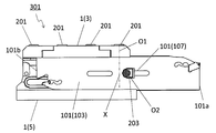
図5~図8に示す限定されない一例のように、工作機械301は、クランプ部材1及び切削工具101を有してもよい。工作機械301がクランプ部材1を有する場合には、上顎3の硬度を調整することが可能なため、優れた切削性能を発揮することができる。
As in the non-limiting example shown in FIGS. 5 to 8, the machine tool 301 may include the clamp member 1 and the cutting tool 101. When the machine tool 301 has the clamp member 1, the hardness of the upper jaw 3 can be adjusted, so that excellent cutting performance can be exhibited.
切削工具101は、ポケット7内に位置してもよい。言い換えれば、切削工具101は、上顎3及び下顎5によって挟まれてもよい。切削工具101は、切刃として用いられる部分の少なくとも一部がクランプ部材1から外方に突出するように装着されてもよい。具体的には、図5に示す限定されない一例のように、切削工具101における切刃119がクランプ部材1の第1端1aよりも第2端1bから離れて位置してもよい。
The cutting tool 101 may be located in the pocket 7. In other words, the cutting tool 101 may be sandwiched between the upper jaw 3 and the lower jaw 5. The cutting tool 101 may be mounted so that at least a part of the portion used as the cutting edge protrudes outward from the clamp member 1. Specifically, as in the non-limiting example shown in FIG. 5, the cutting edge 119 in the cutting tool 101 may be located farther from the second end 1b than the first end 1a of the clamp member 1.
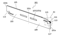
切削工具101は、図9及び図10に示す限定されない一例のように、第3端101aから第4端101bにかけて延びた板形状であってもよい。切削工具101は、第1側面103、第2側面105及び貫通孔107を有してもよい。第2側面105は、第1側面103の反対側に位置してもよい。貫通孔107は、第1側面103及び第2側面105にそれぞれ開口してもよい。貫通孔107には、第2ネジを挿入させることが可能である。
The cutting tool 101 may have a plate shape extending from the third end 101a to the fourth end 101b, as in the non-limiting example shown in FIGS. 9 and 10. The cutting tool 101 may have a first side surface 103, a second side surface 105, and a through hole 107. The second side surface 105 may be located on the opposite side of the first side surface 103. The through hole 107 may be opened in the first side surface 103 and the second side surface 105, respectively. A second screw can be inserted into the through hole 107.
図9に示す限定されない一例のように、右下端が第3端101a、左上端が第4端101bであってもよい。一般的に、第3端101aは先端、第4端101bは後端とも呼ばれる。図9に示す限定されない一例のように、第1側面103及び第2側面105が、それぞれ四角形(長方形)であってもよく、第3端101aの側から第4端101bの側に向かってそれぞれ延びてもよい。
As in the non-limiting example shown in FIG. 9, the lower right end may be the third end 101a and the upper left end may be the fourth end 101b. Generally, the third end 101a is also called the front end, and the fourth end 101b is also called the rear end. As in the non-limiting example shown in FIG. 9, the first side surface 103 and the second side surface 105 may be rectangular, respectively, from the side of the third end 101a toward the side of the fourth end 101b, respectively. It may be extended.
切削工具101は、特定の大きさに限定されない。例えば、ポケット7内に位置する切削工具101を上顎3の側から正面視した場合において、切削工具101の延びた方向における切削工具101の長さは、80~160mm程度に設定されてもよく、また、切削工具101の延びた方向に直交する方向における切削工具101の長さは、1~10mm程度に設定されてもよい。上顎3から下顎5に向かう方向における切削工具101の高さは、15~35mm程度に設定されてもよい。
The cutting tool 101 is not limited to a specific size. For example, when the cutting tool 101 located in the pocket 7 is viewed from the side of the upper jaw 3, the length of the cutting tool 101 in the extended direction of the cutting tool 101 may be set to about 80 to 160 mm. Further, the length of the cutting tool 101 in the direction orthogonal to the extending direction of the cutting tool 101 may be set to about 1 to 10 mm. The height of the cutting tool 101 in the direction from the upper jaw 3 to the lower jaw 5 may be set to about 15 to 35 mm.
工作機械301は、第1ネジ201及び第2ネジ203を有してもよい。第1ネジ201は、クランプ部材1の第1ネジ孔25に挿入されてもよい。第2ネジ203は、貫通孔107及びクランプ部材1の第2ネジ孔27に挿入されてもよい。これらの場合には、切削工具101をポケット7内に安定して固定することが可能である。すなわち、第1ネジ201による固定によって、切削加工時に切削工具101に加わる主分力を受け止め易い。また、第2ネジ203による固定によって、切削加工時に切削工具101が撓みにくい。そのため、切削工具101をポケット7内に安定して固定できる。
The machine tool 301 may have a first screw 201 and a second screw 203. The first screw 201 may be inserted into the first screw hole 25 of the clamp member 1. The second screw 203 may be inserted into the through hole 107 and the second screw hole 27 of the clamp member 1. In these cases, the cutting tool 101 can be stably fixed in the pocket 7. That is, by fixing with the first screw 201, it is easy to receive the main component force applied to the cutting tool 101 during cutting. Further, by fixing with the second screw 203, the cutting tool 101 is less likely to bend during cutting. Therefore, the cutting tool 101 can be stably fixed in the pocket 7.
図8に示す限定されない一例のように、第1側面103の側からの側面視において、第1ネジ201の第1中心軸O1を下顎5に向かって延ばした仮想線Xが、第2ネジ203の第2中心軸O2と交差しなくてもよい。この場合には、切削工具101をポケット7内に安定して固定できる。
As in the non-limiting example shown in FIG. 8, in the side view from the side of the first side surface 103, the virtual line X extending the first central axis O1 of the first screw 201 toward the lower jaw 5 is the second screw 203. It is not necessary to intersect the second central axis O2 of. In this case, the cutting tool 101 can be stably fixed in the pocket 7.
第1側面103の側からの側面視において、第2中心軸O2が、仮想線Xよりも第3端101aの近くに位置してもよい。この場合には、切削加工時に切削工具101が撓みにくい。
The second central axis O2 may be located closer to the third end 101a than the virtual line X in the side view from the side of the first side surface 103. In this case, the cutting tool 101 is less likely to bend during cutting.
図7に示す限定されない一例のように、第3端101aの側からの正面視において、第1ネジ201の第1中心軸O1を下顎5に向かって延ばした仮想線Xが、第2ネジ203の第2中心軸O2と交差してもよい。この場合には、ブレードとツールブロックの接触が均一になり、また、圧力が向上し、ブレードの振動を抑制する。第3端101aの側からの正面視において、仮想線Xは第2中心軸O2と直交してもよい。直交とは、厳密な直交に限定されず、90°±5°程度の範囲を許容することを意味してもよい。
As in the unrestricted example shown in FIG. 7, when viewed from the side of the third end 101a, the virtual line X extending the first central axis O1 of the first screw 201 toward the lower jaw 5 is the second screw 203. It may intersect with the second central axis O2 of. In this case, the contact between the blade and the tool block becomes uniform, the pressure is improved, and the vibration of the blade is suppressed. In front view from the side of the third end 101a, the virtual line X may be orthogonal to the second central axis O2. Orthogonality is not limited to strict orthogonality, and may mean that a range of about 90 ° ± 5 ° is allowed.
工作機械301は、第1ネジ201を複数有してもよい。クランプ部材1は、上記したように、第1ネジ孔25を複数有してもよい。複数の第1ネジ孔25のうち少なくとも1つは、第2ネジ孔27よりも第2端1bの側に位置してもよい。複数の第1ネジ201のうち少なくとも1つは、第2ネジ孔27よりも第2端1bの側に位置する第1ネジ孔25に挿入されてもよい。これらの場合には、切削加工時に切削工具101に加わる主分力を受け止め易い。
The machine tool 301 may have a plurality of first screws 201. As described above, the clamp member 1 may have a plurality of first screw holes 25. At least one of the plurality of first screw holes 25 may be located closer to the second end 1b than the second screw hole 27. At least one of the plurality of first screws 201 may be inserted into the first screw hole 25 located closer to the second end 1b than the second screw hole 27. In these cases, it is easy to receive the main component force applied to the cutting tool 101 during cutting.
図9に示す限定されない一例のように、貫通孔107は、切削工具101の延びた方向における切削工具101の中央101cよりも第3端101aの側に位置してもよい。この場合には、切削加工時に切削負荷が加わる切刃の近くに貫通孔107が位置する。これに伴い、第2ネジ203による固定も切刃の近くに位置することから、切削加工時に切削工具101が撓みにくい。
As in the non-limiting example shown in FIG. 9, the through hole 107 may be located closer to the third end 101a than the center 101c of the cutting tool 101 in the extending direction of the cutting tool 101. In this case, the through hole 107 is located near the cutting edge to which a cutting load is applied during cutting. Along with this, since the fixing by the second screw 203 is also located near the cutting edge, the cutting tool 101 is less likely to bend during cutting.
第2ネジ203は、貫通孔107の内壁面107aから離れてもよい。この場合には、ブレードの突出し量を調整できる。
The second screw 203 may be separated from the inner wall surface 107a of the through hole 107. In this case, the amount of protrusion of the blade can be adjusted.
貫通孔107は、切削工具101の延びた方向に沿って延びてもよい。言い換えれば、貫通孔107は、スリット状でもよい。この場合には、切削工具101の突き出し量を調整できる。
The through hole 107 may extend along the extending direction of the cutting tool 101. In other words, the through hole 107 may have a slit shape. In this case, the amount of protrusion of the cutting tool 101 can be adjusted.
切削工具101は、ホルダ109及び切削インサート111(以下、単にインサート111とも言う。)を有してもよい。
The cutting tool 101 may have a holder 109 and a cutting insert 111 (hereinafter, also simply referred to as an insert 111).
ホルダ109は、第3端101aの側から第4端101bの側に向かって延びた板形状であってもよい。また、ホルダ109は、第3端101aの側に位置するインサートポケット113を有してもよい。図10に示す限定されない一例のように、ホルダ109が第3端101aの側に位置するとともに互いに離れて位置する上顎部115及び下顎部117を有し、この上顎部115及び下顎部117によってインサートポケット113が構成されてもよい。
The holder 109 may have a plate shape extending from the side of the third end 101a toward the side of the fourth end 101b. Further, the holder 109 may have an insert pocket 113 located on the side of the third end 101a. As in a non-limiting example shown in FIG. 10, the holder 109 has an upper jaw 115 and a lower jaw 117 located on the side of the third end 101a and separated from each other, and is inserted by the upper jaw 115 and the lower jaw 117. Pocket 113 may be configured.
インサート111は、インサートポケット113に位置してもよい。言い換えれば、インサート111は、上顎部115及び下顎部117によって挟まれてもよい。
The insert 111 may be located in the insert pocket 113. In other words, the insert 111 may be sandwiched between the maxilla 115 and the mandible 117.
インサート111は、第3端101aの側から第4端101bの側に向かって延びた柱形状であってもよい。図10に示す限定されない一例のように、インサート111は、角柱形状であってもよい。なお、インサート111の形状は、角柱形状に限定されない。
The insert 111 may have a pillar shape extending from the side of the third end 101a toward the side of the fourth end 101b. As in the non-limiting example shown in FIG. 10, the insert 111 may have a prismatic shape. The shape of the insert 111 is not limited to the prismatic shape.
インサート111は、切刃119を有してもよい。図10に示す限定されない一例のように、インサート111は、切刃119がホルダ109の第3端101aの側において外方に突出するようにインサートポケット113に位置してもよい。切削工具101は、切刃119を被削材に接触させることによって切削加工を行うことが可能である。
The insert 111 may have a cutting edge 119. As in the non-limiting example shown in FIG. 10, the insert 111 may be located in the insert pocket 113 such that the cutting edge 119 projects outward on the side of the third end 101a of the holder 109. The cutting tool 101 can perform cutting by bringing the cutting edge 119 into contact with the work material.
ホルダ109の材質として、鋼及び鋳鉄などが用いられてもよい。特に、これらの材質の中で鋼が用いられた場合には、ホルダ109の靱性が高い。
Steel, cast iron, or the like may be used as the material of the holder 109. In particular, when steel is used among these materials, the toughness of the holder 109 is high.
インサート111の材質としては、例えば、超硬合金、サーメット及びセラミックスなどの無機材料が挙げられ得る。超硬合金の組成としては、例えば、WC(炭化タングステン)-Co、WC-TiC(炭化チタン)-Co及びWC-TiC-TaC(炭化タンタル)-Coが挙げられ得る。ここで、WC、TiC及びTaCは硬質粒子であってもよく、Coは結合相であってもよい。
Examples of the material of the insert 111 include inorganic materials such as cemented carbide, cermet and ceramics. Examples of the composition of the cemented carbide include WC (tungsten carbide) -Co, WC-TiC (titanium carbide) -Co and WC-TiC-TaC (tantallum carbide) -Co. Here, WC, TiC and TaC may be hard particles, and Co may be a bonded phase.
また、サーメットは、セラミック成分に金属を複合させた焼結複合材料であってもよい。具体的には、サーメットとして、TiC又はTiN(窒化チタン)を主成分とした化合物が挙げられ得る。インサート111の材質がこれらに限定されないことは言うまでもない。
Further, the cermet may be a sintered composite material in which a metal is composited with a ceramic component. Specifically, as the cermet, a compound containing TiC or TiN (titanium nitride) as a main component can be mentioned. Needless to say, the material of the insert 111 is not limited to these.
図9に示す限定されない一例においては、いわゆる旋削加工に用いられる切削工具101が示されている。本開示の限定されない実施形態の切削工具101は、溝入れ加工において用いられることが可能であるが、このような加工に限定されない。例えば、限定されない実施形態の切削工具101が、内径加工、外径加工及び横送り加工に用いられても何ら問題ない。
In a non-limiting example shown in FIG. 9, a cutting tool 101 used for so-called turning is shown. The cutting tool 101 of the non-limiting embodiment of the present disclosure can be used in grooving, but is not limited to such machining. For example, there is no problem even if the cutting tool 101 of the embodiment without limitation is used for inner diameter machining, outer diameter machining, and lateral feed machining.
<切削加工物の製造方法>
次に、本開示の限定されない実施形態の切削加工物401の製造方法について図面を用いて説明する。 <Manufacturing method of machined products>
Next, a method of manufacturing the machinedproduct 401 according to an embodiment not limited to the present disclosure will be described with reference to the drawings.
次に、本開示の限定されない実施形態の切削加工物401の製造方法について図面を用いて説明する。 <Manufacturing method of machined products>
Next, a method of manufacturing the machined
切削加工物401は、被削材403を切削加工することによって作製され得る。本開示の限定されない実施形態における切削加工物401の製造方法は、以下の工程を備えてもよい。すなわち、
(1)被削材403を回転させる工程と、
(2)回転する被削材403に上記の限定されない実施形態に代表される工作機械301における切削工具101を接触させる工程と、
(3)切削工具101を被削材403から離す工程と、
を備えてもよい。 Thework piece 401 can be produced by cutting the work material 403. The method for manufacturing the work piece 401 in the non-limiting embodiment of the present disclosure may include the following steps. That is,
(1) The process of rotating thework material 403 and
(2) A step of bringing therotating work material 403 into contact with the cutting tool 101 in the machine tool 301 represented by the above-mentioned not limited embodiment.
(3) The process of separating thecutting tool 101 from the work material 403 and
May be provided.
(1)被削材403を回転させる工程と、
(2)回転する被削材403に上記の限定されない実施形態に代表される工作機械301における切削工具101を接触させる工程と、
(3)切削工具101を被削材403から離す工程と、
を備えてもよい。 The
(1) The process of rotating the
(2) A step of bringing the
(3) The process of separating the
May be provided.
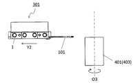
より具体的には、まず、図11に示す限定されない一例のように、被削材403を軸O3の周りで回転させるとともに、被削材403に工作機械301に取り付けられた切削工具101を相対的に近付けてもよい。次に、図12及び図13に示す限定されない一例のように、切削工具101における稜線(切刃)を被削材403に接触させて、被削材403を切削してもよい。そして、図14に示す限定されない一例のように、切削工具101を被削材403から相対的に遠ざけてもよい。
More specifically, first, as in the non-limiting example shown in FIG. 11, the work material 403 is rotated around the shaft O3, and the cutting tool 101 attached to the machine tool 301 is relative to the work material 403. You may approach the target. Next, as in the non-limiting example shown in FIGS. 12 and 13, the ridge line (cutting edge) of the cutting tool 101 may be brought into contact with the work material 403 to cut the work material 403. Then, as in the non-limiting example shown in FIG. 14, the cutting tool 101 may be relatively far from the work material 403.
図11に示す限定されない一例においては、軸O3を固定するとともに被削材403を軸O3の周りで回転させた状態で切削工具101をY1方向に移動させることによって被削材403に近づけている。また、図12及び図13に示す限定されない一例においては、回転している被削材403にインサート111における切刃119を接触させることによって被削材403を切削している。また、図14に示す限定されない一例においては、被削材403を回転させた状態で切削工具101をY2方向に移動させることによって遠ざけている。
In an example not limited to that shown in FIG. 11, the cutting tool 101 is moved in the Y1 direction while the shaft O3 is fixed and the work material 403 is rotated around the shaft O3 to bring the work material 403 closer to the work material 403. .. Further, in the non-limiting example shown in FIGS. 12 and 13, the work material 403 is cut by bringing the cutting edge 119 of the insert 111 into contact with the rotating work material 403. Further, in the non-limiting example shown in FIG. 14, the cutting tool 101 is moved away in the Y2 direction while the work material 403 is rotated.
なお、本開示の限定されない実施形態の製造方法における切削加工では、それぞれの工程において、切削工具101を動かすことによって、切削工具101を被削材403に接触させる、あるいは、切削工具101を被削材403から離しているが、当然ながらこのような形態に限定されない。
In the cutting process in the manufacturing method of the embodiment not limited to the present disclosure, the cutting tool 101 is brought into contact with the work material 403 by moving the cutting tool 101 in each step, or the cutting tool 101 is cut. Although it is separated from the material 403, it is not limited to such a form as a matter of course.
例えば、(1)の工程において、被削材403を切削工具101に近づけてもよい。同様に、(3)の工程において、被削材403を切削工具101から遠ざけてもよい。切削加工を継続する場合には、被削材403を回転させた状態を維持して、被削材403の異なる箇所にインサート111における切刃119を接触させる工程を繰り返せばよい。
For example, in the step (1), the work material 403 may be brought closer to the cutting tool 101. Similarly, in the step (3), the work material 403 may be moved away from the cutting tool 101. When the cutting process is continued, the process of keeping the work material 403 rotated and bringing the cutting edge 119 of the insert 111 into contact with different parts of the work material 403 may be repeated.
なお、被削材403の材質の代表例としては、炭素鋼、合金鋼、ステンレス、鋳鉄、又は非鉄金属などが挙げられ得る。
Note that typical examples of the material of the work material 403 may be carbon steel, alloy steel, stainless steel, cast iron, non-ferrous metal, or the like.
1・・・クランプ部材
1a・・・第1端
1b・・・第2端
3・・・上顎
5・・・下顎
7・・・ポケット
9・・・第1部材
11・・・第2部材
13・・・第3部材
15・・・第1段差
17・・・第2段差
19・・・第3段差
21・・・第4段差
23・・・固定ネジ
25・・・第1ネジ孔
27・・・第2ネジ孔
101・・・切削工具
101a・・・第3端
101b・・・第4端
101c・・・中央
103・・・第1側面
105・・・第2側面
107・・・貫通孔
107a・・・内壁面
109・・・ホルダ
111・・・切削インサート(インサート)
113・・・インサートポケット
115・・・上顎部
117・・・下顎部
119・・・切刃
201・・・第1ネジ
203・・・第2ネジ
301・・・工作機械
401・・・切削加工物
403・・・被削材
L1・・・第1長さ
L2・・・第2長さ
L3・・・第3長さ
O1・・・第1中心軸
O2・・・第2中心軸
O3・・・軸
X・・・仮想線 1 ...Clamp member 1a ... 1st end 1b ... 2nd end 3 ... Upper jaw 5 ... Lower jaw 7 ... Pocket 9 ... 1st member 11 ... 2nd member 13 ... 3rd member 15 ... 1st step 17 ... 2nd step 19 ... 3rd step 21 ... 4th step 23 ... Fixing screw 25 ... 1st screw hole 27 ... 2nd screw hole 101 ... Cutting tool 101a ... 3rd end 101b ... 4th end 101c ... Center 103 ... 1st side surface 105 ... 2nd side surface 107 ... Penetration Hole 107a ... Inner wall surface 109 ... Holder 111 ... Cutting insert (insert)
113 ...Insert pocket 115 ... Upper jaw 117 ... Lower jaw 119 ... Cutting edge 201 ... 1st screw 203 ... 2nd screw 301 ... Machine tool 401 ... Cutting Object 403 ... Work material L1 ... 1st length L2 ... 2nd length L3 ... 3rd length O1 ... 1st central axis O2 ... 2nd central axis O3 ...・ ・ Axis X ・ ・ ・ Virtual line
1a・・・第1端
1b・・・第2端
3・・・上顎
5・・・下顎
7・・・ポケット
9・・・第1部材
11・・・第2部材
13・・・第3部材
15・・・第1段差
17・・・第2段差
19・・・第3段差
21・・・第4段差
23・・・固定ネジ
25・・・第1ネジ孔
27・・・第2ネジ孔
101・・・切削工具
101a・・・第3端
101b・・・第4端
101c・・・中央
103・・・第1側面
105・・・第2側面
107・・・貫通孔
107a・・・内壁面
109・・・ホルダ
111・・・切削インサート(インサート)
113・・・インサートポケット
115・・・上顎部
117・・・下顎部
119・・・切刃
201・・・第1ネジ
203・・・第2ネジ
301・・・工作機械
401・・・切削加工物
403・・・被削材
L1・・・第1長さ
L2・・・第2長さ
L3・・・第3長さ
O1・・・第1中心軸
O2・・・第2中心軸
O3・・・軸
X・・・仮想線 1 ...
113 ...
Claims (9)
- 第1端から第2端にかけて延びた柱形状であって、互いに離れて位置する上顎及び下顎と、前記上顎及び前記下顎の間に位置するポケットと、を有し、
前記上顎は、第1部材と、前記第1部材よりも前記第1端の側に位置する第2部材と、を有し、
前記第1部材の硬度を第1硬度、前記第2部材の硬度を第2硬度としたとき、
前記第1硬度が、前記第2硬度と異なる、クランプ部材。 It has a pillar shape extending from the first end to the second end, and has an upper jaw and a lower jaw located apart from each other, and a pocket located between the upper jaw and the lower jaw.
The maxilla has a first member and a second member located closer to the first end than the first member.
When the hardness of the first member is the first hardness and the hardness of the second member is the second hardness,
A clamp member whose first hardness is different from that of the second hardness. - 前記第1硬度が、前記第2硬度よりも低い、請求項1に記載のクランプ部材。 The clamp member according to claim 1, wherein the first hardness is lower than the second hardness.
- 前記第1部材よりも前記第2端の側に位置する第3部材を更に有し、
前記第3部材の硬度を第3硬度としたとき、
前記第1硬度が、前記第3硬度と異なる、請求項1又は2に記載のクランプ部材。 It further has a third member located closer to the second end than the first member.
When the hardness of the third member is the third hardness,
The clamp member according to claim 1 or 2, wherein the first hardness is different from the third hardness. - 前記第1硬度が、前記第3硬度よりも低い、請求項3に記載のクランプ部材。 The clamp member according to claim 3, wherein the first hardness is lower than the third hardness.
- 前記下顎の硬度を第4硬度としたとき、
前記第1硬度が、前記第4硬度よりも低い、請求項1~4のいずれか1つに記載のクランプ部材。 When the hardness of the lower jaw is the fourth hardness,
The clamp member according to any one of claims 1 to 4, wherein the first hardness is lower than the fourth hardness. - 前記クランプ部材の延びた方向における前記第1部材の長さを第1長さ、前記クランプ部材の延びた方向における前記第2部材の長さを第2長さとしたとき、
前記第1長さの最大値が、前記第2長さの最大値よりも大きい、請求項1~5のいずれか1つに記載のクランプ部材。 When the length of the first member in the extending direction of the clamp member is defined as the first length and the length of the second member in the extending direction of the clamp member is defined as the second length.
The clamp member according to any one of claims 1 to 5, wherein the maximum value of the first length is larger than the maximum value of the second length. - 前記第1部材は、前記第1端の側に位置する第1段差を有し、
前記第2部材は、前記第1部材の側であって、前記第1段差よりも前記下顎から離れて位置する第2段差を有し、
前記第1部材及び前記第2部材が、前記第1段差及び前記第2段差を互いに対向させた状態で固定されている、請求項1~6のいずれか1つに記載のクランプ部材。 The first member has a first step located on the side of the first end.
The second member has a second step on the side of the first member, which is located farther from the lower jaw than the first step.
The clamp member according to any one of claims 1 to 6, wherein the first member and the second member are fixed in a state where the first step and the second step face each other. - 請求項1~7のいずれか1つに記載のクランプ部材と、
前記ポケット内に位置する切削工具と、を有する工作機械。 The clamp member according to any one of claims 1 to 7.
A machine tool having a cutting tool located in the pocket. - 被削材を回転させる工程と、
回転している前記被削材に請求項8に記載の工作機械における前記切削工具を接触させる工程と、
前記切削工具を前記被削材から離す工程と、を備えた切削加工物の製造方法。 The process of rotating the work material and
The step of bringing the cutting tool in the machine tool according to claim 8 into contact with the rotating work material, and
A method for manufacturing a work piece, comprising a step of separating the cutting tool from the work material.
Priority Applications (4)
| Application Number | Priority Date | Filing Date | Title |
|---|---|---|---|
| CN202080034379.1A CN113795344B (en) | 2019-05-13 | 2020-05-11 | Clamping member, machine tool, and method for manufacturing machined product |
| US17/610,601 US20220203457A1 (en) | 2019-05-13 | 2020-05-11 | Clamping member, machine tool, and method for manufacturing machined product |
| JP2021519423A JP7225387B2 (en) | 2019-05-13 | 2020-05-11 | CLAMP MEMBER, MACHINE TOOL, AND METHOD FOR MANUFACTURING MACHINED WORK |
| DE112020002378.8T DE112020002378T5 (en) | 2019-05-13 | 2020-05-11 | CLAMP, MACHINE TOOL AND METHOD OF MAKING A MACHINED PRODUCT |
Applications Claiming Priority (2)
| Application Number | Priority Date | Filing Date | Title |
|---|---|---|---|
| JP2019090729 | 2019-05-13 | ||
| JP2019-090729 | 2019-05-13 |
Publications (1)
| Publication Number | Publication Date |
|---|---|
| WO2020230754A1 true WO2020230754A1 (en) | 2020-11-19 |
Family
ID=73289584
Family Applications (1)
| Application Number | Title | Priority Date | Filing Date |
|---|---|---|---|
| PCT/JP2020/018817 WO2020230754A1 (en) | 2019-05-13 | 2020-05-11 | Clamp member, machine tool, and method for producing cut workpiece |
Country Status (5)
| Country | Link |
|---|---|
| US (1) | US20220203457A1 (en) |
| JP (1) | JP7225387B2 (en) |
| CN (1) | CN113795344B (en) |
| DE (1) | DE112020002378T5 (en) |
| WO (1) | WO2020230754A1 (en) |
Citations (7)
| Publication number | Priority date | Publication date | Assignee | Title |
|---|---|---|---|---|
| JPS4714639U (en) * | 1971-03-17 | 1972-10-20 | ||
| JPS4916994A (en) * | 1972-06-07 | 1974-02-14 | ||
| JPS56121921A (en) * | 1980-02-29 | 1981-09-25 | Adachi Jimusho:Kk | Controlling method of temperature for green house |
| JPS6011747B2 (en) * | 1976-03-04 | 1985-03-27 | 帝人株式会社 | resin composition |
| JPS6142722A (en) * | 1984-08-02 | 1986-03-01 | Tdk Corp | Magnetic recording medium and magnetic recording method |
| JP2009028857A (en) * | 2007-07-27 | 2009-02-12 | Kyocera Corp | Cutting tool and cutting method |
| JP2018075676A (en) * | 2016-11-10 | 2018-05-17 | 三菱マテリアル株式会社 | Holder for grooving tool, grooving tool, and grooving tool unit |
Family Cites Families (27)
| Publication number | Priority date | Publication date | Assignee | Title |
|---|---|---|---|---|
| US3497935A (en) * | 1967-02-15 | 1970-03-03 | C & L Machine Shop Inc | Cut-off tool assembly |
| US3688366A (en) * | 1970-07-13 | 1972-09-05 | Kennametal Inc | Tool |
| DE3208923A1 (en) * | 1982-03-12 | 1983-09-22 | Bruno 3338 Schöningen Müntel | SOCKET AND MOUNT FOR LATHE TOOLS |
| JPS59191291U (en) * | 1983-06-03 | 1984-12-19 | 神鋼電機株式会社 | mechanical hand |
| FI894671A (en) * | 1989-10-03 | 1991-04-04 | Erkki Rinne | ADJUSTMENT OF MEASURES. |
| US5516241A (en) * | 1994-06-27 | 1996-05-14 | Valenite Inc. | Holder blade |
| SE511928C2 (en) * | 1997-03-19 | 1999-12-20 | Sandvik Ab | Device and method of clamping inserts |
| DE19807498A1 (en) * | 1998-02-21 | 1999-09-02 | Horn P Hartmetall Werkzeugfab | Holder for cutting tool inserts |
| SE526539C2 (en) * | 2002-05-28 | 2005-10-04 | Sandvik Intellectual Property | Chip separation machining tool where the cutting position has flexible portions. |
| US7331736B2 (en) * | 2003-10-14 | 2008-02-19 | Kennametal Inc. | Metal cutting tool |
| SE530579C2 (en) * | 2006-11-28 | 2008-07-08 | Sandvik Intellectual Property | Tools and basic body for multi-channel chip separation machining |
| JP2008238350A (en) * | 2007-03-28 | 2008-10-09 | Kyocera Corp | Cutting tool, tool holder, and cutting method |
| JP5196951B2 (en) * | 2007-10-30 | 2013-05-15 | 京セラ株式会社 | Cutting tool and cutting method |
| IL195696A0 (en) * | 2008-12-03 | 2009-09-01 | Iscar Ltd | Tool holder for clamping an insert holder |
| IL205988A (en) * | 2010-05-26 | 2015-03-31 | Iscar Ltd | Tool assembly and tool holder therefor |
| DE102011053760A1 (en) * | 2011-09-19 | 2013-03-21 | Walter Ag | Grooving plate and clamp holder with four-point systems |
| US8827598B2 (en) * | 2011-11-22 | 2014-09-09 | Kennametal Inc. | Cutting assembly with enhanced coolant delivery |
| EP2822720B1 (en) * | 2012-03-06 | 2016-07-20 | Iscar Ltd. | Parting blade and blade holder configured for conveyance of pressurized coolant |
| SE536741C2 (en) * | 2012-11-08 | 2014-07-08 | Sandvik Intellectual Property | Cutting tools and knitting blades for this |
| US8985913B2 (en) * | 2012-11-13 | 2015-03-24 | Iscar, Ltd. | Cutting tool holder with internal coolant passage having a compressible member |
| EP2745963B2 (en) * | 2012-12-19 | 2021-03-17 | Seco Tools Ab | Coupling for a cooling system in a cutting tool |
| JP2015150659A (en) * | 2014-02-17 | 2015-08-24 | 三菱マテリアル株式会社 | Tip replacement type grooving tool |
| ES2796260T3 (en) * | 2014-11-18 | 2020-11-26 | Walter Ag | Perforator Blade and Slotting and Cutting Tool |
| JP6011747B1 (en) * | 2015-01-26 | 2016-10-19 | 株式会社タンガロイ | Cutting tools |
| JP6677870B2 (en) * | 2016-02-26 | 2020-04-08 | 三菱マテリアル株式会社 | Indexable grooving tool with clamp work tool and clamp work tool |
| TWI808983B (en) * | 2017-09-08 | 2023-07-21 | 日商索尼股份有限公司 | Manufacturing method of robot hand, robot device and electronic equipment |
| JP6791101B2 (en) | 2017-11-15 | 2020-11-25 | オムロン株式会社 | Capacitive pressure sensor |
-
2020
- 2020-05-11 WO PCT/JP2020/018817 patent/WO2020230754A1/en active Application Filing
- 2020-05-11 US US17/610,601 patent/US20220203457A1/en active Pending
- 2020-05-11 CN CN202080034379.1A patent/CN113795344B/en active Active
- 2020-05-11 DE DE112020002378.8T patent/DE112020002378T5/en active Pending
- 2020-05-11 JP JP2021519423A patent/JP7225387B2/en active Active
Patent Citations (7)
| Publication number | Priority date | Publication date | Assignee | Title |
|---|---|---|---|---|
| JPS4714639U (en) * | 1971-03-17 | 1972-10-20 | ||
| JPS4916994A (en) * | 1972-06-07 | 1974-02-14 | ||
| JPS6011747B2 (en) * | 1976-03-04 | 1985-03-27 | 帝人株式会社 | resin composition |
| JPS56121921A (en) * | 1980-02-29 | 1981-09-25 | Adachi Jimusho:Kk | Controlling method of temperature for green house |
| JPS6142722A (en) * | 1984-08-02 | 1986-03-01 | Tdk Corp | Magnetic recording medium and magnetic recording method |
| JP2009028857A (en) * | 2007-07-27 | 2009-02-12 | Kyocera Corp | Cutting tool and cutting method |
| JP2018075676A (en) * | 2016-11-10 | 2018-05-17 | 三菱マテリアル株式会社 | Holder for grooving tool, grooving tool, and grooving tool unit |
Also Published As
| Publication number | Publication date |
|---|---|
| US20220203457A1 (en) | 2022-06-30 |
| CN113795344A (en) | 2021-12-14 |
| JP7225387B2 (en) | 2023-02-20 |
| JPWO2020230754A1 (en) | 2020-11-19 |
| DE112020002378T5 (en) | 2022-01-27 |
| CN113795344B (en) | 2024-01-19 |
Similar Documents
| Publication | Publication Date | Title |
|---|---|---|
| US10576555B2 (en) | Cutting insert, cutting tool, and method for manufacturing a cut workpiece | |
| JP7304989B2 (en) | Manufacturing method of cutting insert, cutting tool and cutting work | |
| JPWO2012086375A1 (en) | CUTTING TOOL AND CUTTING PRODUCT MANUFACTURING METHOD USING THE CUTTING TOOL | |
| JP7368064B2 (en) | Manufacturing method for machine tools and cutting products | |
| EP4049778A1 (en) | Cutting insert | |
| JP5528264B2 (en) | Cutting tool and method of cutting work material using cutting tool | |
| WO2021132357A1 (en) | Holder, cutting tool, and method for manufacturing cut workpiece | |
| WO2020230754A1 (en) | Clamp member, machine tool, and method for producing cut workpiece | |
| JP2020028943A (en) | Holder, cutting tool and manufacturing method for cut work-piece | |
| WO2015146956A1 (en) | Cutting insert, cutting tool, and method for manufacturing cut product | |
| JP6810807B2 (en) | Manufacturing method for cutting inserts, cutting tools and cutting products | |
| WO2021205878A1 (en) | Holder, cutting tool, and manufacturing method for cut workpiece | |
| JP7045460B2 (en) | Manufacturing method of cutting tools and cutting products | |
| WO2020179538A1 (en) | Cutting tool, and method for producing cut workpiece | |
| WO2023176441A1 (en) | Cutting tool and method for producing cut workpiece | |
| CN113474109B (en) | Cutting insert, cutting tool, and method for manufacturing cut product | |
| WO2024048256A1 (en) | Cutting unit, cutting tool, and cutting tool rest, and method for manufacturing cut article | |
| WO2023277180A1 (en) | Holder, cutting tool, and method for manufacturing machined product | |
| WO2023058589A1 (en) | Cutting tool and method for producing cut workpiece | |
| KR102540681B1 (en) | Methods for manufacturing cutting inserts, cutting tools and cutting components | |
| WO2020184422A1 (en) | Cutting insert, cutting tool, and method for manufacturing cut workpiece | |
| WO2023084973A1 (en) | Cutting insert, cutting tool, and method for manufacturing cut workpiece | |
| JP7117389B2 (en) | Manufacturing method of cutting insert, cutting tool and cutting work | |
| JP6920811B2 (en) | Manufacturing method for cutting tool holders, cutting tools and cutting products | |
| WO2020138084A1 (en) | Rotating tool and method of manufacturing cut article |
Legal Events
| Date | Code | Title | Description |
|---|---|---|---|
| 121 | Ep: the epo has been informed by wipo that ep was designated in this application |
Ref document number: 20805837 Country of ref document: EP Kind code of ref document: A1 |
|
| ENP | Entry into the national phase |
Ref document number: 2021519423 Country of ref document: JP Kind code of ref document: A |
|
| 122 | Ep: pct application non-entry in european phase |
Ref document number: 20805837 Country of ref document: EP Kind code of ref document: A1 |