WO2020230559A1 - リザーブタンク - Google Patents
リザーブタンク Download PDFInfo
- Publication number
- WO2020230559A1 WO2020230559A1 PCT/JP2020/017364 JP2020017364W WO2020230559A1 WO 2020230559 A1 WO2020230559 A1 WO 2020230559A1 JP 2020017364 W JP2020017364 W JP 2020017364W WO 2020230559 A1 WO2020230559 A1 WO 2020230559A1
- Authority
- WO
- WIPO (PCT)
- Prior art keywords
- opening
- cooling water
- reserve tank
- gas
- liquid separation
- Prior art date
- Legal status (The legal status is an assumption and is not a legal conclusion. Google has not performed a legal analysis and makes no representation as to the accuracy of the status listed.)
- Ceased
Links
Images


Classifications
-
- F—MECHANICAL ENGINEERING; LIGHTING; HEATING; WEAPONS; BLASTING
- F01—MACHINES OR ENGINES IN GENERAL; ENGINE PLANTS IN GENERAL; STEAM ENGINES
- F01P—COOLING OF MACHINES OR ENGINES IN GENERAL; COOLING OF INTERNAL-COMBUSTION ENGINES
- F01P11/00—Component parts, details, or accessories not provided for in, or of interest apart from, groups F01P1/00 - F01P9/00
- F01P11/02—Liquid-coolant filling, overflow, venting, or draining devices
- F01P11/029—Expansion reservoirs
-
- B—PERFORMING OPERATIONS; TRANSPORTING
- B01—PHYSICAL OR CHEMICAL PROCESSES OR APPARATUS IN GENERAL
- B01D—SEPARATION
- B01D19/00—Degasification of liquids
- B01D19/0042—Degasification of liquids modifying the liquid flow
- B01D19/0052—Degasification of liquids modifying the liquid flow in rotating vessels, vessels containing movable parts or in which centrifugal movement is caused
- B01D19/0057—Degasification of liquids modifying the liquid flow in rotating vessels, vessels containing movable parts or in which centrifugal movement is caused the centrifugal movement being caused by a vortex, e.g. using a cyclone, or by a tangential inlet
-
- F—MECHANICAL ENGINEERING; LIGHTING; HEATING; WEAPONS; BLASTING
- F01—MACHINES OR ENGINES IN GENERAL; ENGINE PLANTS IN GENERAL; STEAM ENGINES
- F01P—COOLING OF MACHINES OR ENGINES IN GENERAL; COOLING OF INTERNAL-COMBUSTION ENGINES
- F01P11/00—Component parts, details, or accessories not provided for in, or of interest apart from, groups F01P1/00 - F01P9/00
- F01P11/02—Liquid-coolant filling, overflow, venting, or draining devices
- F01P11/028—Deaeration devices
Definitions
- the present disclosure relates to a reserve tank provided in the middle of a path through which cooling water circulates.
- the vehicle is provided with a cooling system for cooling each part of the vehicle by circulating cooling water.
- Targets to be cooled by the cooling system include, for example, an engine and auxiliary equipment such as an intercooler.
- a water pump for sending out the cooling water, a reserve tank for storing a part of the cooling water, and the like are provided in the path for circulating the cooling water. ..
- the cooling water is supplemented from the reserve tank. This prevents a decrease in cooling performance due to a decrease in cooling water.
- the reserve tank is also required to have a function of separating and removing air bubbles from the cooling water.
- the reserve tank is also required to have a function of preventing the generation of such bubbles.
- the reserve tank described in Patent Document 1 below is provided with a gas-liquid separation chamber which is a space for separating air bubbles from the cooling water.
- the gas-liquid separation chamber is generally a cylindrical space.
- An inflow port, which is an inlet for cooling water, and an outflow port, which is an outlet for cooling water, are formed in the lower portion of the gas-liquid separation chamber.
- the cooling water flowing in from the inflow port rises while swirling in the gas-liquid separation chamber.
- not only large bubbles but also bubbles with low buoyancy rise due to the swirling flow reach the liquid surface, and disappear.
- both the inflow port and the outflow port are provided below the liquid level, it is possible to prevent new bubbles from being generated due to the inflow of the cooling water.
- An object of the present disclosure is to provide a reserve tank capable of stably exerting each of a function of preventing the generation of air bubbles and a function of removing air bubbles.
- the reserve tank is a reserve tank provided in the middle of a path through which cooling water circulates, and is a gas-liquid separation portion in which an internal space for separating the gas-liquid of the cooling water is formed, and an internal space.
- An inlet portion having a first opening for supplying cooling water to the interior space, an outlet portion having a second opening for discharging cooling water from the internal space, and an upward side from the bottom of the internal space. It includes a protruding portion and a protruding portion.
- the gas-liquid separation portion and the protrusion are formed so that the shape of the inner peripheral surface of the gas-liquid separation portion and the shape of the outer peripheral surface of the protrusion are concentric circles. ..
- the portion between the inner peripheral surface of the gas-liquid separation portion and the outer peripheral surface of the protruding portion is an annular flow path.
- the reserve tank is configured so that the cooling water flowing in from the first opening swirls around the annular flow path.
- the flow velocity of the cooling water that has flowed into the annular flow path from the first opening is relatively large, the air is swirled around the outer peripheral side of the annular flow path, that is, the portion near the inner peripheral surface of the gas-liquid separation portion. Ascend the liquid separation part. The bubbles contained in the cooling water disappear when they reach the liquid level. After that, as the flow velocity of the cooling water decreases, the cooling water descends while swirling around the inner peripheral side portion of the gas-liquid separation portion. The cooling water flows into the lower annular flow path again, reaches the second opening, and discharges to the outside while swirling the inner peripheral side portion of the annular flow path, that is, the portion close to the outer peripheral surface of the protruding portion. Will be done.
- the flow of the cooling water flowing in from the first opening and rising while swirling and the flow of the cooling water falling while swirling toward the second opening interfere with each other. It is prevented from being lost. Therefore, it is possible to prevent new bubbles from being generated in the reserve tank due to the turbulence of the flow of the cooling water.
- the range of the flow velocity at which the flow is stable without such turbulence is wider than that of the conventional configuration having no protrusion. Since the flow of the cooling water in the gas-liquid separation section is stable in a wide flow velocity range, it is possible to stably exert each of the function of preventing the generation of bubbles and the function of removing the bubbles.
- a reserve tank capable of stably exerting each of a function of preventing the generation of air bubbles and a function of removing air bubbles is provided.
- FIG. 1 is a side view showing the configuration of the reserve tank according to the first embodiment.
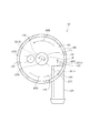
- FIG. 2 is a top view showing the internal structure of the reserve tank according to the first embodiment.
- FIG. 3 is a diagram schematically showing the flow of cooling water inside the reserve tank according to the first embodiment.
- FIG. 4 is a side view showing the configuration of the reserve tank according to the second embodiment.
- FIG. 5 is a top view showing the internal structure of the reserve tank according to the third embodiment.
- FIG. 6 is a diagram showing the shape of the protruding portion provided in the reserve tank according to the fourth embodiment.
- FIG. 7 is a diagram showing the shape of the protruding portion provided in the reserve tank according to the modified example of the fourth embodiment.
- FIG. 8 is a side view showing the configuration of the reserve tank according to the fifth embodiment.
- FIG. 9 is a side view showing the configuration of the reserve tank according to the sixth embodiment.
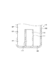
- FIG. 10 is a cross-sectional view showing the configuration of the reserve tank according to the seventh embodiment
- the reserve tank 10 constitutes a part of a cooling system mounted on a vehicle (not shown).
- the cooling system is a system for cooling each part of the vehicle, specifically, an internal combustion engine and auxiliary machinery by circulating cooling water.
- the cooling water sent out by the water pump is supplied to a cooling target such as an internal combustion engine and used for cooling these.
- the cooling water that has passed through the object to be cooled and becomes hot is returned to the water pump after the temperature is lowered in the radiator, and is sent out from the water pump again. Since a known configuration of such a cooling system can be adopted, specific illustrations and explanations thereof will be omitted.
- the reserve tank 10 is a container provided in the above cooling system at a position in the middle of the path through which the cooling water circulates, for example, a position on the upstream side of the water pump. Note that "in the middle of the path in which the cooling water circulates” does not have to be in the middle of the path in which the cooling water is always flowing. For example, in the middle of the path in which the cooling water temporarily flows, such as a bypass flow path. There may be.
- the configuration of the reserve tank 10 will be described with reference to FIGS. 1 and 2.
- FIG. 1 shows the configuration of the reserve tank 10 from the side view.
- the internal configuration of the reserve tank 10 is shown by a dotted line.
- FIG. 2 shows the internal structure of the reserve tank in a top view.
- FIG. 2 is a view in which the gas-liquid separation portion 100 is cut along a horizontal surface and then viewed from above. The cutting position is, for example, the position indicated by the alternate long and short dash line DL2 in FIG.
- the reserve tank 10 includes a gas-liquid separation unit 100, an inlet unit 120, and an outlet unit 130.
- the gas-liquid separation unit 100 is a container for removing air bubbles contained in the cooling water while temporarily storing the supplied cooling water.
- the gas-liquid separation unit 100 is configured as a container having a substantially cylindrical shape, and is arranged so that its central axis is aligned in the vertical direction.
- the gas-liquid separation unit 100 occupies almost the entire reserve tank 10, and the entire reserve tank 10 is configured as a single container.
- the reserve tank 10 may be configured to separately include a storage unit which is a container for storing cooling water in addition to the gas-liquid separation unit 100.
- the gas-liquid separation unit 100 and the storage unit may be arranged so as to be adjacent to each other via the partition wall, and an opening for the cooling water to pass through may be formed in the partition wall.
- the internal space SP is a space for temporarily storing the cooling water, and at the same time, a space for separating the gas and liquid of the cooling water to remove air bubbles.
- An opening for injecting cooling water into the internal space SP is formed at the upper end of the gas-liquid separation unit 100. Normally, the opening is closed by the cap 11.
- the cap 11 is provided with a valve (not shown). In the normal state when the pressure of the internal space SP is low, the valve is closed and the internal space SP and the outside air are cut off from each other. When the pressure of the internal space SP rises and exceeds a predetermined value, the valve is opened so that the air of the internal space SP can be released to the outside.
- the internal space SP is provided with a protrusion 110.
- the projecting portion 110 is formed so as to project upward from the bottom surface 102 of the internal space SP.
- the protruding portion 110 has a substantially cylindrical shape as a whole.
- the central axis of the protruding portion 110 coincides with the central axis of the gas-liquid separation portion 100. Therefore, in the cross section along the horizontal plane, the shape of the inner peripheral surface 101 of the gas-liquid separation portion 100 and the shape of the outer peripheral surface 111 of the protruding portion 110 are concentric circles.
- annular space FP annular space in the top view. ing. As will be described later, the cooling water flows in a swirling manner in this annular space. Therefore, this annular space is also referred to as "annular flow path FP" below.
- the alternate long and short dash line DL1 shown in FIG. 1 is a line indicating the upper limit water level in the gas-liquid separation unit 100.
- the alternate long and short dash line DL2 shown in the figure is a line indicating the lower limit water level in the gas-liquid separation unit 100. Lines indicating the upper limit water level and the lower limit water level are engraved on the outer surface of the gas-liquid separation unit 100 so that the height of each water level can be visually recognized.
- the cooling water is injected into the reserve tank 10
- the amount of water injection is adjusted so that the cooling water level is between the lower limit water level and the upper limit water level.
- the position of the upper end of the protrusion 110 described above is further lower than the position of the lower limit water level indicated by the alternate long and short dash line DL2. Therefore, the upper end of the protruding portion 110 does not protrude upward from the liquid level of the cooling water.
- the inlet 120 is a part for receiving the cooling water circulating in the cooling system and supplying it to the internal space SP.
- the inlet portion 120 is a tubular portion formed so as to extend linearly along the horizontal direction.
- the inlet 120 projects outward from the gas-liquid separation 100.
- a pipe (not shown) constituting a cooling water circulation path is connected to the tip thereof.
- the inlet portion 120 projects inside the gas-liquid separation portion 100, that is, toward the internal space SP, and an opening 121 is formed at the tip thereof.
- the cooling water that has passed through the inlet portion 120 is supplied from the opening 121 to the internal space SP.
- the opening 121 corresponds to an opening for supplying cooling water to the internal space SP, that is, a “first opening” in the present embodiment.
- the position where the entrance portion 120 is provided is lower than the lower portion of the internal space SP, specifically, the upper end of the protruding portion 110 and higher than the bottom surface 102. Further, the direction in which the cooling water immediately after flowing out from the opening 121 is such that the cooling water does not directly hit the protruding portion 110 as shown by the arrow AR1 in FIG. Therefore, the cooling water flowing out from the opening 121 flows so as to swirl around the annular flow path FP as indicated by arrows AR2 and AR3 in FIG. The specific path through which the cooling water flows will be described later.
- the outlet portion 130 is a portion for discharging the cooling water from the internal space SP to the outside. As shown in FIG. 1, the outlet portion 130 is a tubular portion formed so as to extend linearly along the vertical direction, and the upper end thereof is connected to the bottom portion of the gas-liquid separation portion 100. There is. The outlet portion 130 projects downward to the outside of the gas-liquid separation portion 100. A pipe (not shown) that constitutes a circulation path for cooling water is connected to the tip thereof.
- An opening 131 is formed in the upper end portion of the outlet portion 130, that is, the portion of the bottom surface 102 to which the outlet portion 130 is connected.
- the cooling water in the internal space SP flows into the outlet portion 130 through the opening 131 and is discharged to the outside.
- the opening 131 corresponds to an opening for discharging cooling water from the internal space SP, that is, a “second opening” in the present embodiment.
- the flow of cooling water in the internal space SP will be described with reference to FIG.
- the flow of the cooling water immediately after being supplied from the opening 121 is indicated by the solid arrow AR11.
- the cooling water flows upward while swirling around the annular flow path FP.
- the flow velocity of the cooling water immediately after being supplied from the opening 121 is relatively large. Therefore, the cooling water rises while swirling around the outer peripheral side portion of the annular flow path FP, that is, the portion close to the inner peripheral surface 101 of the gas-liquid separation portion 100. Even after reaching the upper side of the annular flow path FP, the cooling water continues to rise while swirling around the portion close to the inner peripheral surface 101.
- FIG. 3 schematically shows a liquid level WS whose center is concave due to swirl.
- the cooling water flows into the lower annular flow path FP again, and while swirling the inner peripheral side portion of the annular flow path FP, that is, the portion of the protruding portion 110 near the outer peripheral surface 111, the opening 131 of the outlet portion 130. It is discharged to the outside through.
- the cooling water can easily flow while swirling in the annular flow path FP around the protruding portion 110. Further, the cooling water toward the lower opening 131 can easily flow while swirling along the outer peripheral surface 111 of the protrusion 110. As a result, the phenomenon that the outer swirling flow toward the upper side (arrow AR11) and the inner swirling flow toward the lower side (arrow AR12) interfere with each other and are disturbed is less likely to occur. Therefore, it is possible to prevent new bubbles from being generated in the reserve tank 10 due to the turbulence of the flow of the cooling water. According to experiments and the like conducted by the present inventors, it has been confirmed that the range of the flow velocity at which the flow is stable without such turbulence is wider than that of the conventional configuration having no protrusion 110. There is.
- Reference numeral "122" in FIG. 2 is an opening formed in a portion of the inner peripheral surface 101 corresponding to the inlet portion 120.
- the opening is also referred to as “opening 122" below.
- the opening 122 functions as an opening for supplying cooling water to the internal space SP, that is, as a "first opening” of the present embodiment, similarly to the opening 121 described above.
- the configuration of the reserve tank 10 will be described while regarding the opening 122 as the first opening instead of the opening 121.
- a reference numeral “125” is attached to a portion of the entrance portion 120 that protrudes toward the internal space SP. It can also be said that the portion is a wall formed so as to project from the edge of the opening 122, which is the first opening, toward the internal space SP.
- the wall will also be referred to as “interference prevention wall 125" below.
- the cooling water flowing into the internal space from the inlet portion 120 has a high flow velocity, so that the outer peripheral side portion of the annular flow path FP is swirled. Therefore, a part of the swirling cooling water is flowing toward the opening 122 as indicated by the arrow AR3. If the above-mentioned interference prevention wall 125 is not formed, the flow of cooling water toward the opening 122 along the arrow AR3 interferes with the flow of cooling water immediately after flowing in from the opening 122, and the cooling water There is a possibility that the flow of
- the interference prevention wall 125 is formed so as to surround the opening 122. Since the flow of the cooling water toward the opening 122 along the arrow AR3 is blocked by the interference prevention wall 125, it is prevented from interfering with the flow of the cooling water immediately after flowing in from the opening 122.
- the cooling water immediately after the flow of the cooling water swirling around the annular flow path FP is supplied from the opening 122, which is the first opening, to the internal space SP.
- An interference prevention wall 125 is provided to prevent the flow from interfering with the flow.
- the interference prevention wall 125 does not need to be provided so as to project from the entire circumference of the edge of the opening 122.
- the interference prevention wall 125 is formed as the minimum necessary wall for blocking the flow indicated by the arrow AR3 by eliminating the portion on the front side of the paper surface and the portion on the right side of the interference prevention wall 125 in FIG. You may be. That is, the interference prevention wall 125 may be formed as a wall that projects inward from only the left side portion in FIG. 2 of the edge of the opening 122.
- FIGS. 1 and 2 the center CT11 of the opening 121, the center CT1 of the opening 122, and the center CT2 of the opening 131 are shown, respectively.
- the "center” referred to here is the center of the opening 121 or the like that is circular, but when the opening 121 or the like is not circular, it is the center of gravity in the shape of the opening 121 or the like.
- the position of the center CT1 of the opening 122 is higher than the position of the center CT2 of the opening 131. That is, the position of the center CT1 of the first opening, which is the inlet of the cooling water, is higher than the position of the center CT2 of the second opening, which is the outlet of the cooling water.
- the positional relationship as described above is the same even when the opening 121 is regarded as the first opening.
- the low-speed cooling water immediately before flowing into the second opening is cooled at high speed immediately after flowing from the first opening. It prevents the flow of water from interfering. As a result, the generation of new bubbles due to the turbulence of the flow is further prevented.
- the point indicating the central axis of the protruding portion 110 is shown as the central CT0.
- the line connecting the center CT0 and the center CT1 is shown as the dotted line DL11
- the line connecting the center CT0 and the center CT2 is shown as the dotted line DL12.
- the length of the dotted line DL12 is shorter than the length of the dotted line DL11.
- the distance from the center CT2 of the second opening to the center CT0 of the protrusion 110 is the distance from the center CT1 of the first opening to the protrusion 110. It is smaller than the distance to the center CT0 of.
- the opening 131 which is the outlet of the cooling water, is formed at a position on the inner peripheral side of the opening 122, which is the inlet of the cooling water. Therefore, the flow of the cooling water that swirls inside the internal space SP toward the opening 131 and the flow of the cooling water that rises while swirling outside the internal space SP are less likely to interfere with each other.
- the angle formed by the dotted line DL11 and the dotted line DL12 is shown as an angle ⁇ .
- the angle ⁇ reaches from the center CT1 of the opening 122, which is the first opening, to the center CT2 of the opening 131, which is the second opening, along the annular flow path FP when the reserve tank 10 is viewed along the vertical direction. It can be said that the angle is up to.
- the positions of the openings 122 and 131 are determined so that the angle ⁇ is 90 degrees or more. The positional relationship as described above is the same even when the opening 121 is regarded as the first opening.
- the angle ⁇ is smaller than 90 degrees, the first opening gets too close to the second opening, so that the flow of cooling water flowing in from the first opening interferes with the flow of cooling water toward the second opening. There is a possibility that it will end up. In addition, a part of the cooling water flowing in from the first opening may be discharged from the second opening as it is without rising. According to the results confirmed by the present inventors through experiments and the like, it has been found that if the angle ⁇ is secured at 90 degrees or more, the above-mentioned flow interference and the like can be sufficiently suppressed. ..
- the position of the upper end of the protrusion 110 is lower than the position of the lower limit water level shown by the alternate long and short dash line DL2 in FIG. Since the protruding portion 110 does not protrude from the liquid level WS, the formation of swirls and the like is not hindered by the protruding portion 110. This further prevents the flow of the cooling water from being disturbed.
- the second embodiment will be described with reference to FIG. In the following, the points different from the first embodiment will be mainly described, and the points common to the first embodiment will be omitted as appropriate.
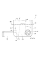
- FIG. 4 shows the configuration of the lower portion of the reserve tank 10 according to the present embodiment in the same side view as in FIG.
- the entire inner peripheral surface 101 of the gas-liquid separation portion 100 does not have a cylindrical shape
- the portion of the inner peripheral surface 101 below the alternate long and short dash line DL3 is , It has a tapered shape that becomes smaller toward the lower side. That is, in the portion below the alternate long and short dash line DL3, the shape of the inner peripheral surface 101 in the cross section along the horizontal plane becomes smaller toward the lower side.
- the cooling water that has flowed into the annular flow path FP from the inlet 120 collides with the tapered portion of the inner peripheral surface 101 as described above, and the flow direction is smoothly directed upward. Change. As a result, it is possible to form a more stable flow of cooling water toward the upper side while turning.
- the range in which the inner peripheral surface 101 has a tapered shape as described above may be only the lower portion of the inner peripheral surface 101 as in the present embodiment, but the upper and lower parts of the inner peripheral surface 101 may be formed. It may be the whole in the direction.
- the shape of the outer peripheral surface 111 of the protruding portion 110 in the cross section along the horizontal plane becomes smaller toward the upper side. That is, the protrusion 110 in the present embodiment has a shape in which the upper end of the cone is cut along the horizontal plane.
- the cooling water heading downward along the outer peripheral surface 111 of the protrusion 110 tends to flow into the opening 131 as it is without leaving the outer peripheral surface 111. Therefore, it is further prevented that the flow of the cooling water immediately after flowing in from the opening 121 interferes with the flow of the cooling water immediately before flowing into the opening 131.
- a part of the opening 131, which is the second opening, may be formed on the outer peripheral surface 111 of the protruding portion 110 as in the present embodiment, but the entire opening 131 is formed on the outer peripheral surface 111 of the protruding portion 110. You may be.
- the configurations of the inner peripheral surface 101, the protruding portion 110, and the outlet portion 130 described above can be individually adopted.
- the entire inner peripheral surface 101 may have a cylindrical shape as in the first embodiment, and the protruding portion may be formed.
- 110 may have a cylindrical shape as in the first embodiment.
- the third embodiment will be described with reference to FIG. In the following, the points different from the first embodiment will be mainly described, and the points common to the first embodiment will be omitted as appropriate.
- FIG. 5 shows the internal configuration of the reserve tank 10 according to the present embodiment in the same top view as in FIG.
- the entrance portion 120 protrudes from the inner peripheral surface 101 toward the internal space SP, and a part of the entrance portion 120 is connected to the outer peripheral surface 111 of the protruding portion 110. ..
- the interference prevention wall 125 is further extended toward the inside of the internal space SP, and a part thereof is connected to the inner peripheral surface 101. Even in such a configuration, as in the first embodiment, the cooling water immediately after the flow of the cooling water swirling around the annular flow path FP is supplied from the opening 122, which is the first opening, to the internal space SP. Interference with the flow can be prevented by the interference prevention wall 125.
- the same configuration as in the second embodiment can be adopted for a part or all of the configuration of the inner peripheral surface 101, the configuration of the protruding portion 110, and the configuration of the outlet portion 130.
- the distance from the center CT2 of the second opening to the center CT0 of the protrusion 110 is smaller than the distance from the center CT1 of the first opening to the center CT0 of the protrusion 110. It is preferable to form one opening and a second opening.
- the fourth embodiment will be described with reference to FIG. In the following, the points different from the first embodiment will be mainly described, and the points common to the first embodiment will be omitted as appropriate.
- FIG. 6 is a perspective view showing only the shape of the protruding portion 110 provided in the reserve tank 10 according to the present embodiment. As shown in the figure, in the present embodiment, as in the second embodiment of FIG. 4, the shape of the outer peripheral surface 111 of the protruding portion 110 in the cross section along the horizontal plane becomes smaller toward the upper side. ..
- a spiral recess 112 is formed on the outer peripheral surface 111.
- the recess 112 is a groove formed by retracting a part of the outer peripheral surface 111 inward.
- the direction in which the recess 112 extends is a direction along the flow direction of the cooling water descending while swirling, as shown by the arrow AR12 in FIG.
- the protrusion 110 may have a cylindrical shape similar to that of the first embodiment, and a spiral recess 112 may be formed on the outer peripheral surface 111 thereof.
- FIG. 7 is a perspective view showing only the shape of the protruding portion 110 provided in the reserve tank 10 according to the modified example of the present embodiment.
- the spiral convex portion 113 may be formed instead of the spiral concave portion 112.
- the convex portion 113 is formed by projecting a part of the outer peripheral surface 111 outward. Even with such a configuration, the same effect as described above can be obtained.
- the fifth embodiment will be described with reference to FIG. In the following, the points different from the second embodiment of FIG. 4 will be mainly described, and the points common to the second embodiment will be omitted as appropriate.
- FIG. 8 shows the configuration of the lower portion of the reserve tank 10 according to the present embodiment in the same side view as in FIG.
- the outlet portion 130 is a tubular portion formed so as to extend linearly along the horizontal direction.
- One end of the outlet portion 130 is connected to the outer surface of the gas-liquid separation portion 100. Therefore, the opening 131, which is the second opening, is formed on the inner peripheral surface 101 of the gas-liquid separation portion 100.
- the position of the center CT2 of 1 of the opening 131 which is the second opening is lower than the center CT1 of the opening 122 which is the first opening also in this embodiment.
- the second opening serving as the outlet for the cooling water is formed near the protruding portion 110 of the bottom surface 102.
- the configuration of the present embodiment can be adopted. It should be noted that such a configuration of the outlet portion 130 may be combined with the configuration of other embodiments described above.
- the sixth embodiment will be described with reference to FIG. In the following, the points different from the first embodiment will be mainly described, and the points common to the first embodiment will be omitted as appropriate.
- FIG. 9 shows the configuration of the lower portion of the reserve tank 10 according to the present embodiment in the same side view as in FIG.
- the inlet portion 120 is a tubular portion formed so as to extend linearly along a direction inclined with respect to the horizontal plane.
- the upper end of the inlet 120 is connected obliquely to the bottom of the gas-liquid separation 100. Therefore, the opening 121, which is the first opening, is formed on the bottom surface 102 of the gas-liquid separation unit 100.
- the first opening serving as the inlet of the cooling water is formed so that its center CT1 is higher than the center CT2 of the second opening.
- the configuration of the present embodiment can be adopted. It should be noted that such a configuration of the entrance portion 120 may be combined with the configuration of other embodiments described above.
- the seventh embodiment will be described with reference to FIG. In the following, the points different from the first embodiment will be mainly described, and the points common to the first embodiment will be omitted as appropriate.
- the reserve tank 10 according to the present embodiment is different from the first embodiment only in the shape of the protruding portion 110.
- FIG. 10 shows a cross section of the reserve tank 10 according to the present embodiment when it is cut along a plane passing through its central axis. In FIG. 10, the inlet portion 120 and the outlet portion 130 provided in the reserve tank 10 are not shown.
- the shape of the protruding portion 110 protruding upward from the bottom surface 102 of the internal space SP is not a cylindrical shape but a cylindrical shape. That is, a space 114 is formed inside the protruding portion 110, and the space 114 is open toward the internal space SP at the upper end of the protruding portion 110. Even in such an embodiment, the same effect as that described in the first embodiment is obtained.
- the shape of the protruding portion 110 may be combined with the configurations of other embodiments described above.
Landscapes
- Engineering & Computer Science (AREA)
- Chemical & Material Sciences (AREA)
- Combustion & Propulsion (AREA)
- Mechanical Engineering (AREA)
- General Engineering & Computer Science (AREA)
- Chemical Kinetics & Catalysis (AREA)
- Heat-Exchange Devices With Radiators And Conduit Assemblies (AREA)
- Degasification And Air Bubble Elimination (AREA)
Priority Applications (2)
| Application Number | Priority Date | Filing Date | Title |
|---|---|---|---|
| CN202080035384.4A CN113825894B (zh) | 2019-05-15 | 2020-04-22 | 贮水箱 |
| US17/454,298 US11421580B2 (en) | 2019-05-15 | 2021-11-10 | Reserve tank |
Applications Claiming Priority (2)
| Application Number | Priority Date | Filing Date | Title |
|---|---|---|---|
| JP2019092054A JP7211256B2 (ja) | 2019-05-15 | 2019-05-15 | リザーブタンク |
| JP2019-092054 | 2019-05-15 |
Related Child Applications (1)
| Application Number | Title | Priority Date | Filing Date |
|---|---|---|---|
| US17/454,298 Continuation US11421580B2 (en) | 2019-05-15 | 2021-11-10 | Reserve tank |
Publications (1)
| Publication Number | Publication Date |
|---|---|
| WO2020230559A1 true WO2020230559A1 (ja) | 2020-11-19 |
Family
ID=73221628
Family Applications (1)
| Application Number | Title | Priority Date | Filing Date |
|---|---|---|---|
| PCT/JP2020/017364 Ceased WO2020230559A1 (ja) | 2019-05-15 | 2020-04-22 | リザーブタンク |
Country Status (4)
| Country | Link |
|---|---|
| US (1) | US11421580B2 (https=) |
| JP (1) | JP7211256B2 (https=) |
| CN (1) | CN113825894B (https=) |
| WO (1) | WO2020230559A1 (https=) |
Families Citing this family (4)
| Publication number | Priority date | Publication date | Assignee | Title |
|---|---|---|---|---|
| DE112021002336T5 (de) * | 2020-04-15 | 2023-01-26 | Denso Corporation | Reservebehälter |
| JP2024010361A (ja) | 2022-07-12 | 2024-01-24 | 株式会社Subaru | リザーブタンクの気液分離機構 |
| JP7790322B2 (ja) * | 2022-11-09 | 2025-12-23 | 豊田合成株式会社 | 貯留装置 |
| CN116512855B (zh) * | 2023-04-27 | 2025-11-11 | 大创汽车系统(南通)有限公司 | 膨胀水壶、热管理系统及新能源汽车 |
Citations (5)
| Publication number | Priority date | Publication date | Assignee | Title |
|---|---|---|---|---|
| JP2002250230A (ja) * | 2001-02-21 | 2002-09-06 | Nissan Motor Co Ltd | リザーブタンク |
| WO2007052461A1 (ja) * | 2005-11-01 | 2007-05-10 | Calsonic Kansei Corporation | 加圧式リザーブタンク |
| DE102011118837A1 (de) * | 2011-11-18 | 2013-05-23 | Volkswagen Aktiengesellschaft | Kühlmittelkreislauf einer Brennkraftmaschine sowie ein für diesen Kühlmittelkreislauf bestimmter Ausgleichsbehälter |
| JP2020023965A (ja) * | 2018-07-25 | 2020-02-13 | 株式会社デンソー | 車両の冷却システム |
| JP2020081970A (ja) * | 2018-11-26 | 2020-06-04 | 株式会社デンソー | リザーブタンク |
Family Cites Families (14)
| Publication number | Priority date | Publication date | Assignee | Title |
|---|---|---|---|---|
| SU1752417A1 (ru) * | 1990-01-04 | 1992-08-07 | Военная академия им.Ф.Э.Дзержинского | Дегазатор жидкости |
| CN1140624A (zh) * | 1995-07-19 | 1997-01-22 | 大宇电子株式会社 | 气体锅炉用的气—液分离装置 |
| US7311746B2 (en) * | 2004-05-21 | 2007-12-25 | Exxonmobil Chemical Patents Inc. | Vapor/liquid separation apparatus for use in cracking hydrocarbon feedstock containing resid |
| KR101283601B1 (ko) * | 2011-12-07 | 2013-07-05 | 현대자동차주식회사 | 차량용 라디에이터 |
| CN202715276U (zh) * | 2012-07-13 | 2013-02-06 | 郑州宇通客车股份有限公司 | 气泡分离筒及使用该气泡分离筒的膨胀水箱 |
| FR2993513B1 (fr) * | 2012-07-19 | 2015-02-27 | Illinois Tool Works | Reservoir de degazage, et systeme de refroidissement de vehicule automobile equipe d'un tel reservoir de degazage |
| JP2015028336A (ja) | 2013-06-24 | 2015-02-12 | トヨタ車体株式会社 | エンジン冷却水のリザーバタンク |
| US10202889B2 (en) * | 2015-01-20 | 2019-02-12 | Ford Global Technologies, Llc | Degas bottle having centrifugal air separator for use in engine cooling system |
| JP2016147214A (ja) * | 2015-02-10 | 2016-08-18 | いすゞ自動車株式会社 | 冷却補助装置 |
| CN205117481U (zh) * | 2015-11-04 | 2016-03-30 | 上海联谊汽车拖拉机工贸有限公司 | 膨胀水箱 |
| KR102452554B1 (ko) * | 2018-04-06 | 2022-10-07 | 현대자동차주식회사 | 엔진 냉각수 기체 분리장치 및 이를 포함하는 엔진 냉각시스템 |
| CN112177759A (zh) * | 2019-07-01 | 2021-01-05 | 泰贺斯聚合物股份有限公司 | 蓄液罐 |
| FR3113698B1 (fr) * | 2020-08-28 | 2022-08-12 | Hutchinson | Dispositif de séparation par effet vortex pour un circuit de transfert de fluide |
| US11466607B2 (en) * | 2020-09-29 | 2022-10-11 | Tigers Polymer Corporation | Reservoir tank |
-
2019
- 2019-05-15 JP JP2019092054A patent/JP7211256B2/ja active Active
-
2020
- 2020-04-22 WO PCT/JP2020/017364 patent/WO2020230559A1/ja not_active Ceased
- 2020-04-22 CN CN202080035384.4A patent/CN113825894B/zh active Active
-
2021
- 2021-11-10 US US17/454,298 patent/US11421580B2/en active Active
Patent Citations (5)
| Publication number | Priority date | Publication date | Assignee | Title |
|---|---|---|---|---|
| JP2002250230A (ja) * | 2001-02-21 | 2002-09-06 | Nissan Motor Co Ltd | リザーブタンク |
| WO2007052461A1 (ja) * | 2005-11-01 | 2007-05-10 | Calsonic Kansei Corporation | 加圧式リザーブタンク |
| DE102011118837A1 (de) * | 2011-11-18 | 2013-05-23 | Volkswagen Aktiengesellschaft | Kühlmittelkreislauf einer Brennkraftmaschine sowie ein für diesen Kühlmittelkreislauf bestimmter Ausgleichsbehälter |
| JP2020023965A (ja) * | 2018-07-25 | 2020-02-13 | 株式会社デンソー | 車両の冷却システム |
| JP2020081970A (ja) * | 2018-11-26 | 2020-06-04 | 株式会社デンソー | リザーブタンク |
Also Published As
| Publication number | Publication date |
|---|---|
| CN113825894B (zh) | 2024-10-18 |
| JP7211256B2 (ja) | 2023-01-24 |
| US20220065157A1 (en) | 2022-03-03 |
| JP2020186684A (ja) | 2020-11-19 |
| US11421580B2 (en) | 2022-08-23 |
| CN113825894A (zh) | 2021-12-21 |
Similar Documents
| Publication | Publication Date | Title |
|---|---|---|
| WO2020230559A1 (ja) | リザーブタンク | |
| WO2017104183A1 (ja) | 気液分離用旋回流発生装置 | |
| WO2017104184A1 (ja) | 気液分離装置 | |
| JP6575578B2 (ja) | 多気筒エンジンの冷却構造 | |
| JP7094091B2 (ja) | 気液分離装置 | |
| WO2020110640A1 (ja) | リザーブタンク | |
| CN113464265B (zh) | 膨胀箱 | |
| JP7287377B2 (ja) | リザーブタンク | |
| JP2009197698A (ja) | シリンダライナの冷却構造 | |
| JP2020186684A5 (https=) | ||
| WO2021210283A1 (ja) | リザーブタンク | |
| JP2021011866A (ja) | リザーバタンク | |
| JP6637803B2 (ja) | 給油口 | |
| WO2018110351A1 (ja) | Egrクーラ | |
| US11421630B2 (en) | Gas-liquid separator | |
| JP2018053830A (ja) | 気液分離器及び該気液分離器を備えたエンジン冷却液の気体抜き構造 | |
| JP2022104200A (ja) | 気液分離装置 | |
| JP2020067081A (ja) | リザーブタンク | |
| KR101921848B1 (ko) | 주 증기 밸브 및 증기 터빈 | |
| JP2020051272A (ja) | ターボチャージャ | |
| JP2019127899A (ja) | オイルミストセパレータ | |
| WO2022145423A1 (ja) | 気液分離装置 | |
| JP7384120B2 (ja) | プリクリーナ | |
| JP2021008877A (ja) | リザーバタンク | |
| JP2015229144A (ja) | 気液分離装置 |
Legal Events
| Date | Code | Title | Description |
|---|---|---|---|
| 121 | Ep: the epo has been informed by wipo that ep was designated in this application |
Ref document number: 20806127 Country of ref document: EP Kind code of ref document: A1 |
|
| NENP | Non-entry into the national phase |
Ref country code: DE |
|
| 122 | Ep: pct application non-entry in european phase |
Ref document number: 20806127 Country of ref document: EP Kind code of ref document: A1 |