WO2020230237A1 - 交通流推定装置、交通流推定方法、交通流推定プログラムおよび交通流推定プログラムを記憶した記憶媒体 - Google Patents
交通流推定装置、交通流推定方法、交通流推定プログラムおよび交通流推定プログラムを記憶した記憶媒体 Download PDFInfo
- Publication number
- WO2020230237A1 WO2020230237A1 PCT/JP2019/018945 JP2019018945W WO2020230237A1 WO 2020230237 A1 WO2020230237 A1 WO 2020230237A1 JP 2019018945 W JP2019018945 W JP 2019018945W WO 2020230237 A1 WO2020230237 A1 WO 2020230237A1
- Authority
- WO
- WIPO (PCT)
- Prior art keywords
- moving body
- lane
- traffic flow
- moving
- data
- Prior art date
- Legal status (The legal status is an assumption and is not a legal conclusion. Google has not performed a legal analysis and makes no representation as to the accuracy of the status listed.)
- Ceased
Links
Images


Classifications
-
- G—PHYSICS
- G08—SIGNALLING
- G08G—TRAFFIC CONTROL SYSTEMS
- G08G1/00—Traffic control systems for road vehicles
- G08G1/01—Detecting movement of traffic to be counted or controlled
- G08G1/0104—Measuring and analyzing of parameters relative to traffic conditions
- G08G1/0125—Traffic data processing
- G08G1/0133—Traffic data processing for classifying traffic situation
-
- G—PHYSICS
- G06—COMPUTING OR CALCULATING; COUNTING
- G06V—IMAGE OR VIDEO RECOGNITION OR UNDERSTANDING
- G06V10/00—Arrangements for image or video recognition or understanding
- G06V10/40—Extraction of image or video features
- G06V10/62—Extraction of image or video features relating to a temporal dimension, e.g. time-based feature extraction; Pattern tracking
-
- G—PHYSICS
- G06—COMPUTING OR CALCULATING; COUNTING
- G06V—IMAGE OR VIDEO RECOGNITION OR UNDERSTANDING
- G06V20/00—Scenes; Scene-specific elements
- G06V20/50—Context or environment of the image
- G06V20/56—Context or environment of the image exterior to a vehicle by using sensors mounted on the vehicle
- G06V20/58—Recognition of moving objects or obstacles, e.g. vehicles or pedestrians; Recognition of traffic objects, e.g. traffic signs, traffic lights or roads
-
- G—PHYSICS
- G08—SIGNALLING
- G08G—TRAFFIC CONTROL SYSTEMS
- G08G1/00—Traffic control systems for road vehicles
- G08G1/01—Detecting movement of traffic to be counted or controlled
- G08G1/0104—Measuring and analyzing of parameters relative to traffic conditions
- G08G1/0108—Measuring and analyzing of parameters relative to traffic conditions based on the source of data
- G08G1/0112—Measuring and analyzing of parameters relative to traffic conditions based on the source of data from the vehicle, e.g. floating car data [FCD]
-
- G—PHYSICS
- G08—SIGNALLING
- G08G—TRAFFIC CONTROL SYSTEMS
- G08G1/00—Traffic control systems for road vehicles
- G08G1/01—Detecting movement of traffic to be counted or controlled
- G08G1/0104—Measuring and analyzing of parameters relative to traffic conditions
- G08G1/0137—Measuring and analyzing of parameters relative to traffic conditions for specific applications
- G08G1/0141—Measuring and analyzing of parameters relative to traffic conditions for specific applications for traffic information dissemination
-
- G—PHYSICS
- G08—SIGNALLING
- G08G—TRAFFIC CONTROL SYSTEMS
- G08G1/00—Traffic control systems for road vehicles
- G08G1/01—Detecting movement of traffic to be counted or controlled
- G08G1/015—Detecting movement of traffic to be counted or controlled with provision for distinguishing between two or more types of vehicles, e.g. between motor-cars and cycles
-
- G—PHYSICS
- G08—SIGNALLING
- G08G—TRAFFIC CONTROL SYSTEMS
- G08G1/00—Traffic control systems for road vehicles
- G08G1/01—Detecting movement of traffic to be counted or controlled
- G08G1/017—Detecting movement of traffic to be counted or controlled identifying vehicles
- G08G1/0175—Detecting movement of traffic to be counted or controlled identifying vehicles by photographing vehicles, e.g. when violating traffic rules
-
- G—PHYSICS
- G08—SIGNALLING
- G08G—TRAFFIC CONTROL SYSTEMS
- G08G1/00—Traffic control systems for road vehicles
- G08G1/01—Detecting movement of traffic to be counted or controlled
- G08G1/04—Detecting movement of traffic to be counted or controlled using optical or ultrasonic detectors
-
- G—PHYSICS
- G08—SIGNALLING
- G08G—TRAFFIC CONTROL SYSTEMS
- G08G1/00—Traffic control systems for road vehicles
- G08G1/01—Detecting movement of traffic to be counted or controlled
- G08G1/052—Detecting movement of traffic to be counted or controlled with provision for determining speed or overspeed
-
- G—PHYSICS
- G08—SIGNALLING
- G08G—TRAFFIC CONTROL SYSTEMS
- G08G1/00—Traffic control systems for road vehicles
- G08G1/01—Detecting movement of traffic to be counted or controlled
- G08G1/056—Detecting movement of traffic to be counted or controlled with provision for distinguishing direction of travel
-
- G—PHYSICS
- G08—SIGNALLING
- G08G—TRAFFIC CONTROL SYSTEMS
- G08G1/00—Traffic control systems for road vehicles
- G08G1/01—Detecting movement of traffic to be counted or controlled
- G08G1/0104—Measuring and analyzing of parameters relative to traffic conditions
- G08G1/0137—Measuring and analyzing of parameters relative to traffic conditions for specific applications
- G08G1/0145—Measuring and analyzing of parameters relative to traffic conditions for specific applications for active traffic flow control
Definitions
- One aspect of the present invention relates to a traffic flow estimation device, a traffic flow estimation method, a traffic flow estimation program, and a storage medium that stores a traffic flow estimation program.
- position information can be collected along with speed and acceleration, and the observation accuracy of the position information is improving year by year. Therefore, it is expected that it will be possible to identify the lane of the moving vehicle, and based on that information, it will be possible to grasp the traffic situation not only on a road basis but also on a lane basis.
- a method of identifying the lane of the traveling vehicle and referring to the traveling speed of the vehicle can be considered. In this way, if the driving data of a vehicle traveling in each lane on the road can be collected, the traffic flow for each lane can be estimated.
- driving data collected in a cloud environment may be data unique to each automobile manufacturer, for example. It is difficult to collect driving data from all vehicles traveling in the cloud. That is, in the conventionally proposed system, for example, even if driving data can be collected from a car traveling in a certain lane, driving data cannot be collected from a car traveling in the adjacent lane. There was a problem that the traffic flow in all lanes could not be estimated because it could occur.
- the present invention was made by paying attention to the above circumstances, and an object of the present invention is to provide a technique for estimating a wider range of traffic flow based on limited driving data.
- the first aspect of the present invention is a traffic flow estimation device having a hardware processor and a memory, in which the memory stores lane information of a target area for estimating traffic flow.
- a plurality of images including a second moving body in the vicinity and a plurality of images taken by the hardware processor at a plurality of timings different from those of the first moving body moving in the target area.
- Acquiring mobile data including the position information and speed information of the first mobile at the timing when each of the images is taken, the lane information stored in the storage unit, and the acquired mobile data.
- the lane in which the first moving body is moving is specified, and the above image is based on the image included in the moving body data.
- the information representing the change with time of the position of the second moving body in the above is calculated, and the positional relationship of the second moving body with respect to the first moving body is detected from the image included in the moving body data.
- the second moving body estimates the moving lane based on the positional relationship and the estimated first moving body lane, and the first moving body data included in the moving body data. Based on the speed information of the moving body, the information representing the change in the position of the second moving body with time, and the estimated lanes in which the first moving body and the second moving body are moving. , Estimating the traffic flow for each lane in the target area, and executing.
- the second aspect of the present invention it is possible to calculate the information representing the time-dependent change in the position of the second moving body, which is included in the plurality of images by comparing the plurality of images. It is intended to include determining the identity of a moving object.
- the lane in which the second moving body is moving can be estimated, and the lane in which the first moving body is moving is determined with respect to the image included in the moving body data.
- the second moving body is moving based on the setting of the lane determination line to be represented and the positional relationship between the set lane judgment line and the second moving body with respect to the first moving body. It includes estimating the lane.
- a fourth aspect of the present invention is to calculate information representing a change over time in the position of the second moving body based on a change in the in-image coordinates of the second moving body included in the plurality of images. Including the calculation of the moving direction of the second moving body, the estimation of the lane in which the second moving body is moving is the calculation of the calculated moving direction and the estimated first moving direction. This includes estimating the lane in which the second moving body is moving based on the lane in which the moving body is moving.
- a fifth aspect of the present invention is to calculate information representing a change over time in the position of the second moving body based on a change in the in-image coordinates of the second moving body included in the plurality of images. Including the calculation of the movement amount of the second moving body and estimating the traffic flow are the velocity information of the first moving body included in the moving body data and the calculated above. Based on the movement amount of the second moving body, the velocity of the first moving body and the moving amount of the second moving body are used as explanatory variables, and the velocity of the second moving body is used as the objective variable. It includes calculating the velocity of the second moving body by using the regression model obtained in advance by the analysis.
- the traffic flow is estimated by associating the information representing the time-dependent change in the position of the second moving body with the speed information of the first moving body. , Dividing the generated traffic data according to a predetermined standard and executing the necessary interpolation, the traffic data divided and performing the necessary interpolation, and the first moving body. It includes estimating the traffic flow in the target area based on the moving lane.
- the traffic flow estimation device stores the lane information of the target area for estimating the traffic flow, and takes pictures at different times depending on the first moving body moving in the target area. Acquires mobile data including the plurality of images including the other second moving body and the position information and speed information of the first moving body at the time when each of the plurality of images is taken. .. Then, the traffic flow estimation device moves the first moving body based on the stored lane information, a plurality of images included in the acquired moving body data, and the position information and speed information of the first moving body. Identify the lane inside, calculate information that represents the change in the position of the second moving body over time, estimate the lane in which the second moving body is moving, and target based on these estimated or calculated information. Estimate traffic flow by lane in the area.
- the traffic flow estimation device can use the plurality of images taken by the first moving body and the first moving body at the time of shooting even when the traveling data from the second moving body cannot be obtained.
- various information including the time-dependent change of the position and the moving lane can be estimated or calculated for the second moving body, and the first moving body can be estimated or calculated. It is possible to estimate a wider range of traffic flow without being limited to the lane in which the vehicle is moving.
- the traffic flow estimation device compares the images in calculating the information representing the time-dependent change in the position of the second moving body in the image taken by the first moving body.
- the identity of the second moving body is determined by. Therefore, more accurate information can be obtained based on the image information including the second moving object that satisfies the predetermined identity determination criterion, and the traffic flow can be estimated more accurately.
- the traffic flow estimation device sets a determination line representing the lane in which the first moving body is moving with respect to the image taken by the first moving body.
- the lane in which the second moving body is moving is estimated based on the determination line and the positional relationship between the first moving body and the second moving body detected from the image.
- the traffic flow estimation device determines the change in the in-image coordinates of the second moving body included in the plurality of images as information indicating the time-dependent change in the position of the second moving body. Based on this, the moving direction of the second moving body is calculated, and the lane in which the second moving body is moving is determined based on the calculated moving direction and the lane in which the first moving body is moving. presume. In this way, by using a geometric method that can handle a variety of data, it is possible to estimate a wider range of traffic flow from limited data.
- the traffic flow estimation device determines the amount of movement of the second moving body based on the change of the coordinates in the image of the second moving body as information indicating the change of the position of the second moving body with time. calculate. Then, the traffic flow estimation device uses the regression model obtained by performing regression analysis in advance from the calculated movement amount of the second moving body and the velocity information of the first moving body, and uses the second movement. Calculate the speed of the body.
- the traffic flow estimation device divides the traffic data including the acquired information and the estimated or calculated information, performs necessary interpolation, and then performs the necessary interpolation of the traffic flow. Make an estimate. As a result, it is possible to estimate a wide range of traffic flows by making more effective use of limited data.
- each aspect of the present invention it is possible to provide a technique for estimating a wider range of traffic flow based on limited travel data.
- FIG. 1 is a diagram showing an overall configuration of a system including a traffic flow estimation device according to an embodiment of the present invention.
- FIG. 2 is a block diagram showing a hardware configuration of a traffic flow estimation device according to an embodiment of the present invention.
- FIG. 3 is a block diagram showing a software configuration of a traffic flow estimation device according to an embodiment of the present invention.
- FIG. 4 is a flowchart showing a processing procedure and processing contents of the traffic flow estimation process by the traffic flow estimation device shown in FIG.
- FIG. 5 is a diagram showing an example of an image taken by an in-vehicle camera.
- FIG. 6 is a diagram showing an example of sensor data acquired by the vehicle-mounted sensor.
- FIG. 1 is a diagram showing an overall configuration of a system including a traffic flow estimation device according to an embodiment of the present invention.
- FIG. 2 is a block diagram showing a hardware configuration of a traffic flow estimation device according to an embodiment of the present invention.
- FIG. 3 is a block diagram showing a
- FIG. 7 is a flowchart showing a processing procedure and processing contents of the vehicle detection processing among the processes shown in FIG.
- FIG. 8 is a diagram showing an example of the processing result of the vehicle detection process shown in FIG. 7.
- FIG. 9 is a flowchart showing a processing procedure and processing contents of the movement amount calculation processing among the processes shown in FIG.
- FIG. 10A is a diagram showing a first example of vehicle association between frames.
- FIG. 10B is a diagram showing a second example of vehicle association between frames.
- FIG. 11 is a diagram showing an example of a processing result of the movement amount calculation process shown in FIG.
- FIG. 12 is a flowchart showing a processing procedure and processing contents of the area determination processing among the processes shown in FIG. FIG.
- FIG. 13 is a diagram showing an example of a region determination line used in the region determination process shown in FIG.
- FIG. 14 is a diagram showing an example of the detected image of the moving direction of the other vehicle.
- FIG. 15 is a diagram showing an example of data stored in the road-specific information storage unit.
- FIG. 16 is a diagram showing an example of an analysis image of the data shown in FIG.
- FIG. 17 is a flowchart showing a processing procedure and processing contents of the traffic flow calculation processing among the processes shown in FIG.
- FIG. 18A is a diagram showing an example of teacher data for constructing a regression model used in the process of calculating the traveling speed of the other vehicle shown in FIG. FIG.
- FIG. 18B is a diagram showing an example of a coefficient vector used in the process of calculating the traveling speed of the other vehicle shown in FIG.
- FIG. 19 is a diagram showing an example of a calculation result of the traveling speed of another vehicle associated with the lane ID.
- FIG. 20 is a diagram showing an example of data stored in the traffic flow information storage unit.
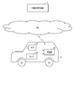
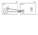
- FIG. 1 is a diagram showing an example of an overall configuration of a system including a traffic flow estimation device 1 according to an embodiment of the present invention.
- This system is equipped with a traffic flow estimation device 1 on the Web or the cloud, for example. Then, the traffic flow estimation device 1 and the vehicle-mounted device 63 having a communication function mounted on the mobile body 6 can communicate with each other via the communication network NW. Although only one mobile body 6 is shown in FIG. 1 for simplicity, the traffic flow estimation device 1 can communicate with a plurality of mobile bodies 6.
- the network NW is composed of, for example, a relay network and a plurality of access networks for accessing this relay network.
- a relay network a closed network controlled so that it can be accessed only from a public network such as the general Internet or a limited number of devices is used.
- a wireless LAN Local Area Network
- a mobile phone network a wired telephone network, or the like is used.
- the moving body 6 further includes a camera 61 and a sensor 62.
- the camera 61 uses a solid-state imaging device such as a CCD (Charge Coupled Device) or CMOS (Complementary Metal Oxide Semiconductor) sensor, and covers a road region in an arbitrary direction such as the traveling direction of the moving body 6 in an imaging range.
- the installation location, orientation and angle are set to include.
- the camera 61 acquires camera image data and outputs the acquired data to the vehicle-mounted device 63.
- the camera 61 may be provided exclusively for traffic flow estimation processing, it is possible to obtain equivalent data such as a drive recorder camera or an in-vehicle camera mounted for other purposes. Any camera can be used as long as it is.
- a camera provided on the driver's helmet may be used, or a mobile terminal such as a smartphone or tablet terminal owned by a passenger of the mobile body 6 may be used. You may use a camera.
- an infrared camera may be used as the type of the camera 61.
- the data acquired by the camera 61 may be moving image (video) data or still image data captured at regular time intervals.
- the sensor 62 includes a GPS sensor and a speed sensor, and may also be provided exclusively for traffic flow estimation processing, or for operation control or log data collection of the automobile 6 such as CAN (Controller Area Network). Therefore, it may be a sensor normally provided. Further, the sensor 62 may be a mobile terminal such as a smartphone.
- the GPS sensor calculates the latitude and longitude of the moving body 6 by receiving GPS signals transmitted by a plurality of GPS satellites and performing a ranging calculation, and the GPS data including the calculated latitude and longitude is used as an in-vehicle device VD. Output to.
- the GPS data can include information indicating the certainty of GPS measurement in addition to latitude and longitude (hereinafter, also referred to as "position information").
- position information information indicating the certainty of GPS measurement in addition to latitude and longitude
- the certainty of GPS measurement is determined, for example, according to the arrangement of GPS satellites.
- the acquisition of position information is not limited to the method using signals from GPS satellites, and if the same function is exhibited, the position information of a wireless base station or WiFi access point can be used, etc. You may use the method of.
- the speed sensor is, for example, a wheel speed sensor, which is installed in a rotating part such as a drive shaft and measures the speed of the automobile 6 based on the rotating speed of the rotating part.
- the speed sensor outputs the measured speed data to the on-board unit 63.
- the on-board unit 63 is, for example, a wireless device mounted on the dashboard of an automobile, and receives various data from the camera 61 and the sensor 62 to receive date and time information and the on-board unit 63 (or an ETC card inserted therein). Together with the identification information, it can be transmitted to the traffic flow estimation device 1 via the network NW.
- the on-board unit 63 is not an indispensable configuration, and the camera 61 and the sensor 62 may be configured to directly transmit data to the traffic flow estimation device 1. Further, the camera 61 and the sensor 62 do not have to be separate devices, and these can be incorporated into one device or integrated into the vehicle-mounted device 63.
- the traffic flow estimation device 1 is, for example, a server device provided in a traffic control center, and performs a process of estimating (calculating) a traffic flow in a target area.
- traffic flow will be described as an average speed [km / h] in a specific lane of a specific road, but the present invention is not limited to this.
- the traffic flow may be defined according to the application, and for example, a traffic volume representing the number of vehicles passing through a specific point, a traffic density, or the like may be used.
- the traffic flow estimation device 1 receives the moving body data (hereinafter referred to as “traveling data”) including the camera image data, the GPS data and the speed data collected by the moving body 6 via the network NW, and receives the moving body data. Based on the received data, for example, the traffic flow in the target area is calculated periodically or in response to a request from an operator or the like. Further, the traffic flow estimation device 1 can output the calculated traffic flow to an external device. For example, the traffic flow estimation device 1 transmits the calculated traffic flow to the vehicle-mounted device 63 in order to notify the driver of the moving body 6. It can be displayed on the display unit, or can be transmitted to a road information display device (not shown) or the like under the control of the traffic control center for display.
- the traffic flow estimation device 1 may, for example, directly receive the traveling data transmitted by the vehicle-mounted device 63 periodically or at an arbitrary timing, or access the vehicle-mounted device 63 to acquire necessary data. It may be a thing. Alternatively, the traffic flow estimation device 1 may acquire the traveling data by accessing the data once transmitted from the vehicle-mounted device 63 to the database server (not shown) or the like at an arbitrary timing. The travel data stored in the external medium may be acquired via the input device 2.
- the automobile exemplified as the moving body 6 is not limited to a specific automobile, and may be an automobile of various individuals, vehicle types, and manufacturers.
- the moving body 6 will be described as a vehicle 6 as an example, but the moving body 6 may be charged for the use of roads such as automobiles, motorcycles, bicycles, personal mobility, vehicles towed by livestock such as carriages, etc.
- a moving body may be included, and the vehicle may be a pedestrian. Therefore, the on-board unit 63 shown in FIG. 1 is only an example, and can be replaced with an information processing terminal such as a smartphone.
- FIG. 2 is a block diagram showing an example of the hardware configuration of the traffic flow estimation device 1.
- the traffic flow estimation device 1 is composed of, for example, a server computer or a personal computer, and has a hardware processor 20A such as a CPU (Central Processing Unit). Then, the program memory 20B, the data memory 30, the communication interface 11 and the input / output interface 12 are connected to the hardware processor 20A via the bus 40.
- a hardware processor 20A such as a CPU (Central Processing Unit).
- the program memory 20B, the data memory 30, the communication interface 11 and the input / output interface 12 are connected to the hardware processor 20A via the bus 40.
- the communication interface 11 includes, for example, one or more wired or wireless communication interface units, and enables information to be transmitted / received to / from an external device including an on-board unit 63 mounted on the vehicle 6.
- a wired LAN is used
- the wireless interface an interface adopting a low power wireless data communication standard such as a wireless LAN or Bluetooth (registered trademark) is used.
- the input / output interface 12 is connected to the input device 2 and the output device 3 attached to the traffic flow estimation device 1.
- the input / output interface 12 captures operation data input by the operator through an input device 2 such as a keyboard, touch panel, touch pad, and mouse, and outputs data as a display device or voice using a liquid crystal or organic EL (Electro Luminescence).
- a process of outputting to an output device 3 including an output speaker and displaying the data is performed.
- the input device 2 and the output device 3 may use the device built in the traffic flow estimation device 1, or may use the input device and the output device of another information terminal capable of communicating via the network NW. May be good.
- the program memory 20B is used as a storage medium in combination with, for example, a non-volatile memory such as an HDD (Hard Disk Drive) or an SSD (Solid State Drive) that can be written and read at any time, and a non-volatile memory such as a ROM. It stores programs necessary for executing various control processes according to the embodiment.
- a non-volatile memory such as an HDD (Hard Disk Drive) or an SSD (Solid State Drive) that can be written and read at any time
- a non-volatile memory such as a ROM. It stores programs necessary for executing various control processes according to the embodiment.
- the data memory 30 uses, for example, a non-volatile memory such as an HDD or SSD that can be written and read at any time and a volatile memory such as a RAM (Random Access Memory) as a storage medium. It is used to store various data acquired and created in the process of performing estimation processing.
- a non-volatile memory such as an HDD or SSD that can be written and read at any time
- a volatile memory such as a RAM (Random Access Memory) as a storage medium. It is used to store various data acquired and created in the process of performing estimation processing.
- RAM Random Access Memory
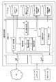
- FIG. 3 is a block diagram showing the software configuration of the traffic flow estimation device 1 according to the embodiment of the present invention in association with the hardware configuration shown in FIG.
- the storage area of the data memory 30 is provided with a travel data storage unit 31, a road network data storage unit 32, a road-specific information storage unit 33, and a traffic flow information storage unit 34.
- the travel data storage unit 31 is used to store travel data including camera image data and sensor data acquired by the travel data acquisition unit 21.
- the road network data storage unit 32 is used to store various data related to the road network including lane information, which is stored in advance.
- the road-specific information storage unit 33 is used to store various road-specific information (road-specific data) specified based on the travel data.
- the traffic flow information storage unit 34 is used to store the calculated information on the traffic flow.
- the storage units 31 to 34 are not essential configurations, and may be provided in, for example, an external storage medium such as a USB memory or a storage device such as a database server arranged in the cloud.
- the control unit 20 is composed of the hardware processor 20A and the program memory 20B, and has a traveling data acquisition unit 21, a vehicle detection unit 22, a movement amount calculation unit 23, and an area determination as processing function units by software.
- a unit 24, a traveling road specifying unit 25, a traffic flow calculation unit 26, and an output control unit 27 are provided. All of the processing functions in each of these parts are realized by causing the hardware processor 20A to execute the program stored in the program memory 20B. It should be noted that these processing functions may not be realized by using the program stored in the program memory 20B, but may be realized by using the program provided through the network.
- the control unit 20 may also be implemented in a variety of other forms, including integrated circuits such as ASICs (Application Specific Integrated Circuits) and FPGAs (field-programmable gate arrays).
- the traveling data acquisition unit 21 acquires the in-vehicle camera image and CAN data transmitted from the vehicle 6 via the communication interface 11 or the input / output interface 12, and extracts the camera image data and the sensor data necessary for processing. , Performs a process of storing in the traveling data storage unit 31.
- the vehicle detection unit 22 reads out the camera image data stored in the traveling data storage unit 31, cuts out the read camera image data into a frame, and displays another vehicle (a second moving body around) projected in the frame. A process is performed in which the detection is performed, the detected coordinates in the image of another vehicle are calculated, and the calculated coordinates in the image are output to the movement amount calculation unit 23.
- the movement amount calculation unit 23 calculates information indicating the movement of another vehicle (change in position with time) based on the coordinates in the image in each frame output from the vehicle detection unit 22, and outputs the information to the area determination unit 24. Do.
- the area determination unit 24 determines in which lane the vehicle is located (in which lane) based on the information indicating the movement of another vehicle in each frame output from the movement amount calculation unit 23. , The determination result is output to the road-specific information storage unit 33 and stored.
- the traveling road specifying unit 25 reads out the camera image data and the sensor data stored in the traveling data storage unit 31, and which road is the vehicle 6 (hereinafter, also referred to as “own vehicle 6”) from which the data is acquired. Determine which lane you are driving in.
- the traveling road specifying unit 25 also stores information on the traveling speed, traveling road, and traveling lane of the own vehicle 6 in the road-specific information storage unit 33 in association with the data output by the area determination unit 24. I do.
- the traffic flow calculation unit 26 reads out the data stored in the road-specific information storage unit 33, calculates the traffic flow for each lane of each road, and stores the calculation result in the traffic flow information storage unit 34. ..
- the output control unit 27 reads the information stored in the traffic flow information storage unit 34, for example, periodically or in response to an output instruction from the operator, generates data for output, and inputs / outputs the communication interface 11 or A process of outputting to the outside via the interface 12 is performed.
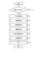
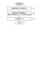
- FIG. 4 is a flowchart showing the processing procedure and the processing content.
- the traffic flow estimation device 1 monitors the presence or absence of a trigger for starting the traffic flow estimation process in step S1. In this state, for example, by receiving a trigger signal generated by an internal timer at regular intervals, or by the operator inputting a processing start request using the input device 2 and receiving this request as a trigger.
- the traffic flow estimation device 1 executes the following processing.
- step S2 the traffic flow estimation device 1 is controlled by the control unit 20 and is controlled by the travel data acquisition unit 21 via the communication interface 11 or the input / output interface 12.
- the data is taken in and stored in the traveling data storage unit 31.
- the data transmitted from the vehicle-mounted device 63 is accumulated as a database or a file on the cloud, and the traffic flow estimation device 1 acquires necessary data by accessing these.
- this data acquisition process may be directly received from the vehicle-mounted device 63, and the traveling data acquisition unit 21 acquires the data pushed by the vehicle-mounted device 63 at an arbitrary timing. It may be something to do. Therefore, step S2 does not necessarily have to be executed in response to the trigger of step S1.
- the camera image data acquired by the traveling data acquisition unit 21 will be described as being an in-vehicle camera image taken by the in-vehicle camera 61 of the vehicle 6. Further, the in-vehicle camera 61 mounted on the vehicle 6 captures an image including the front of the moving vehicle 6.
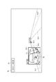
- FIG. 5 shows an example of a frame 50 cut out from the camera image data acquired by the traveling data acquisition unit 21 as an image (image data) used for the traffic flow estimation process.
- the frame 50 includes date and time information 51 representing the date and time taken by the camera 61.
- a part of the own vehicle 6 in which the camera 61 is installed another vehicle 7 (7-1, 7-2, 7) As a surrounding moving body, a lane boundary line 8, and a lane (lane). ) 9 (9-1, 9-2, ...) Is projected.
- the sensor data acquired by the traveling data acquisition unit 21 includes at least the speed and position information of the traveling vehicle 6 measured by the sensor 62 mounted on the vehicle 6.
- the position information is assumed to be the latitude and longitude measured at 1 [Hz].
- FIG. 6 shows an example of sensor data acquired by the driving data acquisition unit 21.
- the traveling data acquisition unit 21 reads the signals representing the position information and the speed information transmitted from the sensor 62 and performs sampling at a sampling rate of 1 Hz, respectively, thereby performing GPS [latitude / longitude] data and speed [km / km /. h] Generate data.
- the frame rate [fps (frame per second)] recorded as camera video data, the better, but it is desirable that the frame rate is 10 [fps] or more. Further, it is assumed that the camera image data and the sensor data (GPS data and speed data) are time-synchronized within an error of at least 1 second.
- step S3 the traffic flow estimation device 1 performs vehicle detection processing by the vehicle detection unit 22 under the control of the control unit 20.
- FIG. 7 is a flowchart showing an example of the processing procedure and processing content of the vehicle detection process in step S3.
- step S31 the vehicle detection unit 22 reads out the camera image data (file) stored in the travel data storage unit 31.
- step S32 the vehicle detection unit 22 performs a process of cutting out the read camera image data into frames (also referred to as “images”) in units of 0.1 seconds, for example.
- the frame at the time t cut out is referred to as "frame_t" (1 ⁇ t ⁇ N) (N is an arbitrary integer according to the length of the read video data).
- the process of cutting out the video into a frame may be performed by an arbitrary method, and may be performed by a method such as ffmpeg.
- step S33 the vehicle detection unit 22 performs a process of detecting another vehicle 7 reflected in the image of each cut out frame.
- the method of detecting the other vehicle 7 may be any method, for example, using a known YOLO (see the Internet ⁇ https://arxiv.org/abs/1804.02767>) as a method using deep learning. May be good.
- the unit for cutting out into a frame may be changed according to the frame rate when the video is acquired.
- the vehicle detection unit 22 outputs the detected coordinates of the other vehicle 7 to the movement amount calculation unit 23 in a format associated with the time information of the frame. For example, when the vehicle detection unit 22 executes the detection of the other vehicle 7 as a rectangle, the vehicle detection unit 22 outputs the image coordinates ⁇ (x1, y1), (x2, y2) ⁇ regarding the two points of the upper left and lower right of the rectangle. To do.
- the origin of the coordinates has the upper left as the origin, as is generally used in the image coordinate system.
- a threshold value is set for the certainty, and an image of only the detection target that exceeds the threshold value.
- the coordinates ⁇ (x1, y1), (x2, y2) ⁇ may be output.
- FIG. 8 shows how the other vehicle 7 is detected by the vehicle detection process by the vehicle detection unit 22.
- a rectangle 52 (52-1, 52-2, 52-3, ...) Showing the detected other vehicle 7 is shown.
- the numerical value on the upper left of the rectangle detecting the other vehicle 7 (for example, 0.95 for the rectangle 52-1) is a value indicating the certainty of the vehicle (car).
- step S4 the traffic flow estimation device 1 performs a movement amount calculation process by the movement amount calculation unit 23 under the control of the control unit 20.
- FIG. 9 is a flowchart showing an example of the processing procedure and processing content of the movement amount calculation processing in step S4.
- step S41 the movement amount calculation unit 23 reads the rectangular coordinates of the other vehicle 7 detected in each frame as an output result from the vehicle detection unit 22.
- step S42 the movement amount calculation unit 23 calculates the tracking points for the other vehicle 7 detected in each frame.
- Any point can be adopted as the tracking point, and for example, the center of gravity (c1, c2) of the rectangular coordinates obtained by detecting the other vehicle 7 can be used.
- the center of gravity is, for example, from the rectangular coordinates ⁇ (x1, y1), (x2, y2) ⁇ that detected the other vehicle 7.
- c1 (x1 + x2) / 2
- step S43 the movement amount calculation unit 23 tracks to determine whether or not the frame (frame_t) at time t and the vehicle 7 detected at the frame (frame_t + 1) at time t + 1 are the same. Performs the process of associating points. If the vehicle 7 detected in frame_t and frame_t + 1 is the same, the movement amount can be calculated from the difference between the tracking point coordinates of frame_t and the tracking point coordinates of frame_t + 1.
- the movement amount calculation unit 23 uses the tracking point coordinates of the vehicle 7 detected in frame_t as a reference, and detects in frame_t + 1. After calculating the distance from the tracking point coordinates of the vehicle, the tracking point coordinates that minimize the distance are associated. When there are a plurality of vehicles 7 detected by frame_t + 1, the distance is calculated by the detected number, and the vehicle 7 having the minimum distance is associated.
- the distance may be a straight line distance between the centers of gravity (c1, c2) of the rectangular coordinates in which the vehicle 7 is detected.
- a certain threshold value for this distance it is possible to reduce mistakes in mapping between each frame.
- An arbitrary value can be set for a certain threshold value, and for example, a maximum moving distance that the vehicle 7 can move in one frame (for example, 0.1 second) can be set.
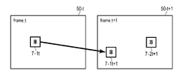
- FIG. 10A shows an example of an image of the vehicle association detected between frame_t (frame 50-t) and frame_t + 1 (frame 50-t + 1).
- the other vehicle 7-1t detected in the frame_t and the other vehicle 7-1t + 1 detected in the frame_t + 1 are associated with each other.
- Another vehicle 7-2t + 1 was also detected in frame_t + 1, but it was determined that there was no association with the vehicle detected in frame_t.
- the mapping from frame_t may be duplicated.
- a 1: 1 correspondence is performed by adding a condition.
- the condition may be, for example, associating vehicles having the closest detected vehicle areas with each other, or associating vehicles with the highest correlation coefficient between the detected vehicle images. You may.
- FIG. 10B shows an example of an image when a duplicate association is made between frame_t and frame_t + 1.
- the other vehicle 7-1t and t-3t detected in the frame_t overlap with the other vehicle 7-1t + 1 detected in the frame_t + 1 (frame 50-t + 1).
- the association between the vehicle 7-1t and the vehicle 7-1t + 1 is adopted.
- the movement amount calculation unit 23 calculates the movement amount of each vehicle 7 in each frame, and the area determination unit Output to 24.
- the movement amount a distance in the x component, a distance in the y component, a linear distance of the xy composite component, and the like in the image can be adopted.
- the detected rectangular coordinates of the vehicle 7 ⁇ (x1, y1), (x2, y2) ⁇ and the coordinates (c1, c2) as tracking points are linked to the movement amount and output to the area determination unit 24.
- FIG. 11 shows an example of the movement amount calculation result by the movement amount calculation unit 23. If the amount of movement of each vehicle in each frame can be obtained, the direction and length of movement of the vehicle to the next frame can be grasped.
- the moving direction and length of the vehicle 7-1 in the frame 50 are indicated by arrows 54.
- the arrow 54 is also an example of information indicating a change over time in the position of the moving body (other vehicle 7) in the image.
- the amount of movement may also be calculated for the truck (detected in the rectangle 52-2) reflected in front of the own vehicle 6. Further, here, a person walking on the sidewalk (detected in the rectangle 52-5) is set not to be used in the movement amount calculation process.
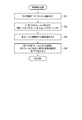
- step S5 the traffic flow estimation device 1 performs an area determination process by the area determination unit 24 under the control of the control unit 20.
- FIG. 12 is a flowchart showing an example of the processing procedure and processing content of the area determination processing in step S5.
- step S51 the area determination unit 24 reads the movement amount information of the other vehicle 7 in each frame 50 output as an output result from the movement amount calculation unit 23, and uses the coordinates (c1, c1,) as the tracking points of the other vehicle 7. See c2).
- step S52 the area determination unit 24 performs a process of relatively determining which lane 9 the other vehicle 7 is traveling from from the tracking point coordinates (c1, c2).
- the region determination unit 24 first determines the region determination line (lane determination) with respect to both ends of the lane 9 in which the own vehicle 6 is traveling. (Also called a line) is provided.
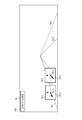
- FIG. 13 shows an example of an image of such a region determination line 53 (53-1, 53-2, 53-3, 53-4).
- a region determination line 53 (53-1, 53-2, 53-3, 53-4).
- the tracking point coordinates of the other vehicle 7 are in which area. Can be determined.
- the area determination line 53 may be defined as a line along the width of the adjacent lane. Based on this rule, it is possible to determine the lane in which the own vehicle 6 is traveling and the area such as ⁇ same lane / one left lane / one right lane / two or more left lanes / two or more right lanes ⁇ . On the computer, where the tracking point coordinates (c1, c2) are located on the area determination line 53 can be determined, for example, by using the characteristics of the outer product.
- each line of the area determination line 53 is regarded as a vector
- a vector is created from the in-image cut point coordinates and the tracking point coordinates (c1, c2) of the area determination line 53, and the angle between these two vectors is 180 °.
- the method of region determination by the region determination unit 24 is not limited to the method using the region determination line 53 described above.
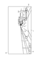
- the movement direction of the vehicle 7 in the image (the movement direction of the other vehicle 7-1 in FIG. 13 (arrow 54). (Inclination)) can be obtained.
- FIG. 14 is a diagram showing an example of an image in which the inclination of the arrow 54 becomes closer to horizontal as the vehicle travels in a lane farther from the own vehicle.
- the arrow 54-1 of the vehicle detected in the rectangle 52-1 farther from the own vehicle is compared with the arrow 54-2 of the vehicle detected in the rectangle 52-2 closer to the own vehicle. It can be seen that it is close to horizontal (the broken line is drawn so that the inclination of the arrow 54 is easy to understand).
- step S53 the area determination unit 24 outputs the determination result to the road-specific information storage unit 33 and stores it.
- step S6 the traffic flow estimation device 1 performs a process of identifying the road on which the own vehicle 6 is traveling by the travel road identification unit 25 under the control of the control unit 20. More specifically, the traveling road specifying unit 25 reads out the camera image data and the sensor data stored in the traveling data storage unit 31 and determines which lane of which road the own vehicle 6 is traveling on.
- the road-specific information storage unit 33 stores information on the traveling speed, the traveling road, and the traveling lane.
- the driving road identification unit 25 performs map matching processing using the position information (latitude / longitude) included in the sensor data and the road network data stored in advance in the road network data storage unit 32. It can be carried out. Map matching is a process of associating a vehicle with a road ID defined in road network data based on the location information of the vehicle (for example, the Internet ⁇ http://bin.tu-tokyo.ac.jp). See /startup15/file/0529yamamoto.pdf>).
- the latitude and longitude of the start point and the end point of the road are defined as road network data for each road ID, and the lane number information of the road is also stored in association with it.
- map matching a known method can be used. For example, a method of associating a road ID of a road such that the distance obtained by drawing a perpendicular line from the position of a vehicle to the road is minimized is used. be able to.
- the driving road specifying unit 25 specifies which lane of the road the own vehicle is traveling in.
- a method of specifying the traveling lane position a known method can be used.
- the lane position may be specified after detecting the lane reflected in the image of the vehicle-mounted camera 61.
- the traveling road specifying unit 25 can know, for example, which lane the own vehicle is traveling from the left by detecting the area determination line 53 shown in FIG.
- the driving road specifying unit 25 provides information on ⁇ time, the road on which the own vehicle is located, the number of lanes on the road, the lane in which the own vehicle is located, and the traveling speed of the own vehicle ⁇ specified as described above by road. It is stored in the storage unit 33.
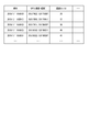
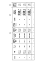
- FIG. 15 shows an example of an image of road-specific data stored in the road-specific information storage unit 33.
- the road-specific data stored in the road-specific information storage unit 33 includes the information output from the area determination unit 24 ⁇ time, frame number, other vehicle ID, movement amount information of other vehicle, relative position where other vehicle is located ⁇ .
- Information output from the driving road identification unit 25 ⁇ time, frame number, own vehicle ID, road on which the own vehicle is located, number of lanes on the road, lane in which the own vehicle is located, traveling speed of the own vehicle ⁇ are linked. It is stored in the format.
- the road-specific data is the information D01 ⁇ the road on which the own vehicle is located and the number of lanes on the road, which is associated with the own vehicle ID, the time, and the frame number and is specified by the traveling road specifying unit 25.
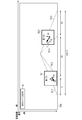
- FIG. 16 is a diagram showing an example of an image of the road-specific data shown in FIG.
- the ID of the road on which the own vehicle travels is set to X (road-X), and when the road is a three-lane road, each lane is set to X1, X2, X3 from the left in the traveling direction.
- the lane ID in which the own vehicle travels can be specified by the traveling road specifying unit 25, and the lane ID in which the other vehicle is located can also be specified by the processing of the area determination unit 24.
- the road-specific information storage unit 33 may store the area of another vehicle obtained by the processing of the area determination unit 24 in a form associated with the lane ID.
- the vehicle (T1) detected in the rectangle 52-1 is traveling in the same lane as the own vehicle from the direction of the arrow indicating the amount of movement, and is in the rectangle 52-2. It is presumed that the detected vehicle (T2) is traveling in the lane opposite to the own vehicle.
- the numerical value in each rectangle 52 represents the coordinate change.
- step S7 the traffic flow estimation device 1 performs a traffic flow calculation process by the traffic flow calculation unit 26 under the control of the control unit 20.
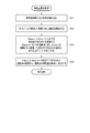
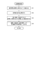
- FIG. 17 is a flowchart showing an example of the processing procedure and processing contents of the traffic flow calculation processing in step S7.
- step S71 the traffic flow calculation unit 26 reads the data stored in the road-specific information storage unit 33.
- step S72 the traffic flow calculation unit 26 calculates the traveling speed of the other vehicle 7 from the traveling speed of the own vehicle 6 and the movement amount information of the other vehicle 7 among the read data.
- the traffic flow calculation unit 26 can create the teacher data in advance and then calculate by the regression model. That is, the coefficient vector for each explanatory variable vector is estimated by performing regression analysis using the traveling speed of the own vehicle 6 and the movement amount information of the other vehicle 7 as explanatory variables and the traveling speed of the other vehicle 7 as the objective variable. Can be done.
- the regression analysis model may be, for example, a linear combination model.
- the explanatory variable vector is X
- the coefficient vector corresponding to the explanatory variable vector is W
- the objective variable is Y
- the inner product of X and W is used by the least squares method or the like. W can be found so that is most similar to Y. After that, by using the obtained coefficient vector W, when the traveling speed of the own vehicle 6 and the movement amount information of the other vehicle 7 are obtained, it is possible to estimate the traveling speed of the other vehicle 7 which is unknown.
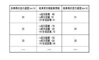
- FIG. 18A shows an example of an image of teacher data used for constructing the regression model as described above.
- the teacher data may be, for example, one created based on actual measurement data or one created based on simulation results.
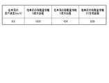
- FIG. 18B shows an example of an image of the coefficient vector W obtained by the regression analysis as described above.
- step S73 the traffic flow calculation unit 26 performs a process of associating the traveling lane ID and traveling speed of the own vehicle / other vehicle with the time, road ID, and lane ID as keys.
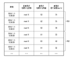
- FIG. 19 shows an example of an image of such a processing result.
- R01 represents the information of the own vehicle 6
- R02 represents the information of the other vehicle 7 detected from the own vehicle 6.
- the traffic flow calculation unit 26 links the speed of a traveling vehicle for each time-road-lane. Here, it is not necessary to identify the own vehicle / other vehicle.
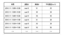
- step S74 the traffic flow calculation unit 26 calculates the average value (average speed (km / h)) of the traveling speed in an arbitrary time range for each road ID and lane ID, and stores the calculation result in the traffic flow information storage unit. Output to 34 and memorize.
- the time range for obtaining the traffic flow may be any range such as 10-minute units and 30-minute units.
- the traffic flow calculation unit 26 divides the data according to the determined time range, road ID, and lane ID, and obtains the average value of the traveling speeds included in the data to obtain the average value of the traveling speeds included in the data. Can be sought. In addition, it is not always necessary to be an average value, and an arbitrary statistic such as a median value or a deviation may be obtained according to the purpose of use.
- the information of the time range before and after that time range is displayed. May be used for interpolation.
- it is possible to obtain the traffic flow for each lane of a plurality of lanes for any of the time ranges it is possible to calculate the correlation between the lanes and interpolate from the average speed of the adjacent lane. For example, if the speed ratio between the first lane and the second lane is 1: 1.2, the average speed calculated for the first lane may be multiplied by 1.2 and interpolated as the average speed for the second lane.
- the average speed for 10: 00-10: 30 and 11: 11: 30 in the time range if the average speed can be calculated for 10: 00-10: 30 and 11: 11: 30 in the time range, and 10: 30-11: 00 cannot be calculated, the average speed for 10: 00-10: 30
- the average value of the average speed at 11 o'clock-11: 30 may be interpolated as the average speed at 10:30-11 o'clock. By performing interpolation, the traffic flow estimation device 1 can calculate the traffic flow for each lane from a smaller amount of travel data.
- the traffic flow calculation unit 26 stores the average speed (km / h) calculated in this way in the traffic flow information storage unit 34.
- FIG. 20 shows an example of a data image stored in the traffic flow information storage unit 34.
- FIG. 20 shows an example in which the average speed is calculated with the time range in units of 30 minutes.
- step S8 the traffic flow estimation device 1 performs arbitrary output processing by the output control unit 27.
- the output control unit 27 receives information stored in the traffic flow information storage unit 34, for example, periodically or in response to a transmission request from the vehicle 6 or an output request from the operator input via the input device 2. Is read, data for output is generated, and the data is output via the communication interface 11 or the input / output interface 12.
- the output control unit 27 takes 5 minutes, 10 minutes, and 30 minutes.
- the average speed (traffic flow) calculated for each time range, road ID, and lane ID based on the information read from the traffic flow information storage unit 34 at an arbitrary time interval such as every time is calculated by the input / output interface unit. It can be output to a liquid crystal display and displayed. Then, the operator of the traffic control center who sees this display can immediately grasp the road conditions in the city such as traffic congestion information and take appropriate measures.
- the traffic flow estimation device 1 acquires camera image data and sensor data collected by the vehicle 6 traveling on the road, and is included in the camera image data.
- the other vehicle 7 is detected from the image of the frame, the movement amount of the other vehicle 7 and the like are calculated, and which lane on the road the other vehicle 7 is traveling with respect to the traveling position of the vehicle 6 is estimated.
- the traffic flow estimation device 1 also identifies the road and lane in which the vehicle 6 is traveling from the sensor data (and camera image data if necessary).
- the traffic flow estimation device 1 of the other vehicle 7 is based on the speed of the vehicle 6, the road and lane on which the vehicle 6 is traveling, the amount of movement of the other vehicle 7, and the estimated traveling lane of the other vehicle 7. Calculate the speed and calculate the traffic flow for each lane.
- the traffic flow estimation device 1 can calculate not only the lane in which the vehicle (own vehicle) 6 from which the camera image data and the sensor data are collected travels, but also the traffic flow in other lanes, resulting in less travel.
- a wider range (lane) of traffic flow can be calculated from the data. For example, it is possible to estimate the traffic flow in each lane even in a situation where driving data can be collected only from vehicles traveling in a part of the vehicles traveling on a certain road. Further, this makes it possible to estimate the traffic flow by effectively utilizing the limited data while suppressing the traffic between the vehicle and the traffic flow estimation device 1.
- the traffic flow estimation device 1 detects another vehicle 7 reflected in the video data showing the front of the moving vehicle 6, and when calculating the movement amount of the other vehicle 7, the movement amount calculation unit 23 performs each frame.
- the vehicles inside are associated with each other.
- the traffic flow estimation device 1 can calculate the movement amount more accurately than in the case where the association is not performed, so that the traffic flow can be calculated more accurately.
- the traffic flow estimation device 1 detects another vehicle 7 reflected in the video data showing the front of the moving vehicle 6, calculates the amount of movement of the other vehicle 7, and then travels in which lane on the road. The area is automatically determined to see if it is done.
- the area determination unit 24 that performs such area determination determines the area of the lane to the right and the lane to the left of the lane in which the own vehicle 6 travels in the coordinate system in the image in the video (image) data. By determining whether or not the other vehicle 7 exists in the area, it is possible to determine which lane the other vehicle 7 is traveling in. As a result, it is possible to calculate the traffic flow of the adjacent lane from the traveling data of the vehicle 6 traveling in a certain lane.
- the area determination unit 24 uses not only the movement amount of the other vehicle 7 but also the movement direction of the other vehicle 7 in the image coordinate system. By using the moving direction, it is possible to automatically determine whether the lane in which the other vehicle 7 is traveling is, for example, one lane to the right or two to the right of the lane in which the own vehicle is traveling. Therefore, the traffic flow in the adjacent lane can be calculated in a wide range from the traveling data of the vehicle 6 traveling in a certain lane.
- the traffic flow estimation device 1 detects the other vehicle 7 reflected in the video data showing the front of the moving vehicle 6, and estimates the movement amount and the relative traveling position of the other vehicle 7 so that the own vehicle 6 can move. It is possible to calculate the traffic flow in other lanes other than the driving lane. In the traffic flow calculation unit 26 that calculates the traffic flow, it is possible to estimate the relative speed such that the other vehicle 7 is faster, the same, or slower than the traveling speed of the own vehicle 6.
- the traveling speed of the other vehicle 7 can be collected as traveling data
- the traveling speed of the other vehicle 7, the moving amount of the other vehicle 7 calculated by the movement amount calculation unit 23, and the other vehicle 7 are collected.
- the traveling speed of the own vehicle 6 By accumulating the traveling speed of the own vehicle 6 at the time of detection in association with each other and formulating the relationship between the movement amount of the other vehicle and the speed difference (relative speed) between the own vehicle and the other vehicle.
- the relative speed difference with the traveling speed of the own vehicle 6 can be quantitatively calculated. Therefore, from the travel data obtained by the vehicle 6 traveling in a certain lane, even the traffic flow in the adjacent lane can be calculated in more detail.
- the traffic flow estimation device 1 extracts the relative movement (change in relative position) of the other vehicle 7 as a movement amount, converts the movement amount into a speed, and then calculates the traffic flow. Therefore, the traffic flow estimation device 1 can similarly calculate the speed of the oncoming vehicle traveling in the oncoming lane, and can be applied to the traffic flow calculation in the oncoming lane.
- each functional unit included in the traffic flow estimation device 1 may be distributed and arranged in a plurality of devices, and the processing may be performed by coordinating these devices with each other. Further, each functional unit may be realized by using a circuit.
- the circuit may be a dedicated circuit that realizes a specific function, or may be a general-purpose circuit such as a processor.
- the road-specific information storage unit 33 has been described as combining and storing the data output by the area determination unit 24 and the data output by the driving road identification unit 25. However, the present invention is not limited to this, and the road-specific information storage unit 33 may be configured as two or more separate storage units.
- the traffic flow estimation device 1 has been described as acquiring camera image data, GPS data, and speed data as driving data. However, the present invention is not limited to this, and the traffic flow estimation device 1 may also acquire other CAN data. For example, the traffic flow estimation device 1 may additionally acquire acceleration data and angular velocity data and use them as an auxiliary for improving the accuracy of area determination or driving road identification, or control of brakes, steering, and the like. Information may be additionally acquired and used when estimating the speed or traffic flow of the other vehicle 7.
- the traffic flow estimation device 1 does not need to use only GPS data to obtain position information, and may estimate position information based on speed information and control information, and may be connected to a roadside machine.
- the driving road or the traveling lane may be specified by using the information obtained by the road-to-vehicle communication.
- the traffic flow estimation device 1 may use not only latitude and longitude but also altitude (elevation) data for estimating various information.
- the movement amount calculation unit 23 may use another method for determining whether or not the vehicles 7 detected in each frame are the same. For example, character information may be read from the license plate of the vehicle displayed on each frame, and the vehicles may be associated with each other based on the read character information. Alternatively, the identity of the vehicle may be detected by vehicle-to-vehicle communication using a BLE (Bluetooth Low Energy) beacon or the like.
- BLE Bluetooth Low Energy
- the traffic flow estimation device 1 can calculate the traffic flow based on an arbitrary data range. For example, the traffic flow estimation device 1 may extract only the data that matches a specific condition from the accumulated camera image data and sensor data and use it for calculating the traffic flow.
- the flow of each process described above is not limited to the procedure described above, and the order of some steps may be changed, or some steps may be performed in parallel. .. Further, the series of processes described above need not be executed continuously in time, and each step may be executed at an arbitrary timing.
- the steps for identifying the driving road or driving lane of the own vehicle described with respect to step S6 are not limited to the order shown in the drawing, and are, for example, before steps S3 to 5 or in parallel with steps S3 to 5. You can also do it.
- the vehicle 6 itself may identify the traveling road or the traveling lane, and the traffic flow estimation device 1 may acquire the road identification information specified by the vehicle 6 together with the traveling data.
- the method described above can be executed by a computer (computer) as a program (software means) such as a magnetic disk (floppy (registered trademark) disk, hard disk, etc.) or an optical disk (CD-ROM, DVD, MO, etc.).
- a program software means
- a magnetic disk floppy (registered trademark) disk, hard disk, etc.) or an optical disk (CD-ROM, DVD, MO, etc.
- a recording medium storage medium
- the program stored on the medium side also includes a setting program for configuring the software means (including not only the execution program but also the table and the data structure) to be executed by the computer in the computer.
- a computer that realizes the above-mentioned apparatus reads a program recorded on a recording medium, constructs software means by a setting program in some cases, and executes the above-mentioned processing by controlling the operation by the software means.
- the recording medium referred to in the present specification is not limited to distribution, and includes storage media such as magnetic disks and semiconductor memories provided in devices connected inside a computer or via a network.
- the present invention is not limited to the above embodiment, and can be variously modified at the implementation stage without departing from the gist thereof.
- each embodiment may be carried out in combination as appropriate, in which case the combined effect can be obtained.
- the above-described embodiment includes various inventions, and various inventions can be extracted by a combination selected from a plurality of disclosed constituent requirements. For example, even if some constituent requirements are deleted from all the constituent requirements shown in the embodiment, if the problem can be solved and the effect is obtained, the configuration in which the constituent requirements are deleted can be extracted as an invention.
- [C1] It is a traffic flow estimation device (1) and A storage medium (30) that stores lane information in the target area for estimating traffic flow, and A plurality of images including the peripheral second moving body (7) taken at a plurality of timings different by the first moving body (6) moving in the target area, and each of the plurality of images.
- a data acquisition unit (21) that acquires mobile data including the position information and speed information of the first mobile body (6) at the time of shooting. The first moving body (6) is moving based on the lane information stored in the storage medium and the position information of the first moving body (6) included in the acquired moving body data.
- a traffic flow calculation unit (26) that calculates a traffic flow for each lane in the target area based on each lane in which the (6) and the second moving body (7) are moving, and A traffic flow estimation device (1) configured to perform the above.
- the change amount calculation unit (23) determines the identity of the second moving body (7) included in the plurality of images by comparing the plurality of images, and when it is determined that they are the same, the said Calculate information representing the time course of the position of the second moving body (7).
- the traffic flow estimation device (1) according to C1.
- the second lane estimation unit (24) A lane determination line representing the lane in which the first moving body is moving is set for the image included in the moving body data.
- the lane in which the second moving body (7) is moving based on the set lane determination line and the positional relationship of the second moving body (7) with respect to the first moving body (6).
- the traffic flow estimation device (1) according to C1.
- the change amount calculation unit (23) The second moving body (7) is calculated by calculating the moving direction of the second moving body (7) based on the change in the coordinates in the image of the second moving body (7) included in the plurality of images. Calculate the information representing the change over time of the position in (7), The second lane estimation unit (24) The second moving body (7) is based on the calculated moving direction of the second moving body (7) and the estimated moving direction of the first moving body (6) and the lane in which the first moving body (6) is moving. Including estimating the lane in motion, The traffic flow estimation device (1) according to C1.
- the change amount calculation unit (23) The second moving body (7) is calculated by calculating the amount of movement of the second moving body (7) based on the change in the coordinates in the image of the second moving body (7) included in the plurality of images. Calculate the information representing the change of the position of (7) with time,
- the traffic flow calculation unit (26) Based on the velocity information of the first moving body (6) included in the moving body data and the calculated movement amount of the second moving body (7), the first moving body ( Using a regression model obtained in advance by regression analysis using the velocity of 6) and the amount of movement of the second moving body (7) as explanatory variables and the velocity of the second moving body (7) as the objective variable, By calculating the speed of the second moving body (7), the traffic flow in the lane in which the second moving body (7) is moving is estimated.
- the traffic flow estimation device (1) according to C1.
- the traffic flow calculation unit (26) Traffic data in which the information representing the time-dependent change in the position of the second moving body (7) and the speed information of the first moving body (6) are associated with each other is generated. Divide the generated traffic data according to a predetermined standard, perform the necessary interpolation, and perform the necessary interpolation. The traffic flow in the target area is calculated based on the traffic data divided and subjected to the necessary interpolation and the lane in which the first moving body (6) is moving.
- the traffic flow estimation device (1) according to C1.
- the processor detects the positional relationship of the second moving body (7) with respect to the first moving body (6) from the image included in the moving body data, and the positional relationship and the estimated first A process (S5) of estimating the moving lane by the second moving body (7) based on the moving lane of the moving body (6).
- the processor includes speed information of the first mobile body (6) included in the mobile body data, information representing a time-dependent change in the position of the second mobile body (7), and the estimated first movement.
- [C8] A program that causes a processor to execute processing by each part of the traffic flow estimation device (1) according to any one of the above [C1] to [C6].
Landscapes
- Physics & Mathematics (AREA)
- General Physics & Mathematics (AREA)
- Chemical & Material Sciences (AREA)
- Analytical Chemistry (AREA)
- Engineering & Computer Science (AREA)
- Multimedia (AREA)
- Theoretical Computer Science (AREA)
- Computer Vision & Pattern Recognition (AREA)
- Traffic Control Systems (AREA)
Priority Applications (5)
| Application Number | Priority Date | Filing Date | Title |
|---|---|---|---|
| US17/595,379 US11837084B2 (en) | 2019-05-13 | 2019-05-13 | Traffic flow estimation apparatus, traffic flow estimation method, traffic flow estimation program, and storage medium storing traffic flow estimation program |
| EP19928838.2A EP3971855B1 (en) | 2019-05-13 | 2019-05-13 | Traffic flow estimation apparatus, traffic flow estimation method, traffic flow estimation program, and storage medium storing traffic flow estimation program |
| CN201980096383.8A CN113841188B (zh) | 2019-05-13 | 2019-05-13 | 交通流估计装置、交通流估计方法、存储介质 |
| PCT/JP2019/018945 WO2020230237A1 (ja) | 2019-05-13 | 2019-05-13 | 交通流推定装置、交通流推定方法、交通流推定プログラムおよび交通流推定プログラムを記憶した記憶媒体 |
| JP2021519075A JP7276435B2 (ja) | 2019-05-13 | 2019-05-13 | 交通流推定装置、交通流推定方法、交通流推定プログラムおよび交通流推定プログラムを記憶した記憶媒体 |
Applications Claiming Priority (1)
| Application Number | Priority Date | Filing Date | Title |
|---|---|---|---|
| PCT/JP2019/018945 WO2020230237A1 (ja) | 2019-05-13 | 2019-05-13 | 交通流推定装置、交通流推定方法、交通流推定プログラムおよび交通流推定プログラムを記憶した記憶媒体 |
Publications (1)
| Publication Number | Publication Date |
|---|---|
| WO2020230237A1 true WO2020230237A1 (ja) | 2020-11-19 |
Family
ID=73288983
Family Applications (1)
| Application Number | Title | Priority Date | Filing Date |
|---|---|---|---|
| PCT/JP2019/018945 Ceased WO2020230237A1 (ja) | 2019-05-13 | 2019-05-13 | 交通流推定装置、交通流推定方法、交通流推定プログラムおよび交通流推定プログラムを記憶した記憶媒体 |
Country Status (5)
| Country | Link |
|---|---|
| US (1) | US11837084B2 (enExample) |
| EP (1) | EP3971855B1 (enExample) |
| JP (1) | JP7276435B2 (enExample) |
| CN (1) | CN113841188B (enExample) |
| WO (1) | WO2020230237A1 (enExample) |
Cited By (2)
| Publication number | Priority date | Publication date | Assignee | Title |
|---|---|---|---|---|
| CN113469026A (zh) * | 2021-06-30 | 2021-10-01 | 上海智能交通有限公司 | 一种基于机器学习的路口滞留事件检测方法及系统 |
| US20240242360A1 (en) * | 2021-05-17 | 2024-07-18 | Nippon Telegraph And Telephone Corporation | Judgment device, judgment method, and judgment program |
Families Citing this family (6)
| Publication number | Priority date | Publication date | Assignee | Title |
|---|---|---|---|---|
| EP3971855B1 (en) * | 2019-05-13 | 2024-11-20 | Nippon Telegraph And Telephone Corporation | Traffic flow estimation apparatus, traffic flow estimation method, traffic flow estimation program, and storage medium storing traffic flow estimation program |
| US20220230330A1 (en) * | 2019-05-31 | 2022-07-21 | Nec Corporation | Estimation device, estimation method, and non-transitory computer-readable medium |
| DE102019217099A1 (de) * | 2019-11-06 | 2021-05-06 | Zf Friedrichshafen Ag | Steuerungssystem und Steuerungsverfahren für ein Erkennen und eine Reaktion eines Reißverschlussverfahrens für ein Kraftfahrzeug |
| JP2022165349A (ja) * | 2021-04-19 | 2022-10-31 | 日立Astemo株式会社 | 情報処理装置、情報処理システム、及び、情報処理方法 |
| CN116052079B (zh) * | 2022-12-30 | 2025-10-21 | 杭州海康威视数字技术股份有限公司 | 目标流量统计系统、方法、装置及设备 |
| TWI875424B (zh) * | 2024-01-09 | 2025-03-01 | 鴻海精密工業股份有限公司 | 用於規避目標車輛的路徑規劃方法、裝置、設備及介質 |
Citations (5)
| Publication number | Priority date | Publication date | Assignee | Title |
|---|---|---|---|---|
| JP2000163685A (ja) * | 1998-11-30 | 2000-06-16 | Fuji Electric Co Ltd | 交通流監視システム |
| JP2015076077A (ja) * | 2013-10-11 | 2015-04-20 | パイオニア株式会社 | 交通量推定システム、端末装置、交通量推定方法および交通量推定プログラム |
| JP2018106762A (ja) * | 2018-04-04 | 2018-07-05 | パイオニア株式会社 | 渋滞予測システム、端末装置、渋滞予測方法および渋滞予測プログラム |
| JP2019016081A (ja) * | 2017-07-05 | 2019-01-31 | 国立大学法人 東京大学 | 渋滞予測装置及びその渋滞予測方法 |
| JP2019016082A (ja) * | 2017-07-05 | 2019-01-31 | 国立大学法人 東京大学 | 渋滞予測装置及びその渋滞予測方法 |
Family Cites Families (31)
| Publication number | Priority date | Publication date | Assignee | Title |
|---|---|---|---|---|
| ATE203844T1 (de) * | 1992-03-20 | 2001-08-15 | Commw Scient Ind Res Org | Gegenstands-überwachungsystem |
| EP0567059B1 (en) * | 1992-04-24 | 1998-12-02 | Hitachi, Ltd. | Object recognition system using image processing |
| US5586063A (en) * | 1993-09-01 | 1996-12-17 | Hardin; Larry C. | Optical range and speed detection system |
| JP3606223B2 (ja) * | 2001-04-26 | 2005-01-05 | 住友電気工業株式会社 | 車両側方映像生成方法及び車両側方映像生成装置 |
| DE102005053461B4 (de) * | 2005-11-04 | 2007-10-18 | Deutsches Zentrum für Luft- und Raumfahrt e.V. | Verfahren und Vorrichtung zur Verkehrssteuerung |
| MY184347A (en) * | 2012-07-27 | 2021-04-01 | Nissan Motor | In-vehicle image recognizer |
| GB2513399B (en) * | 2013-04-26 | 2017-07-26 | Optasense Holdings Ltd | Traffic Monitoring |
| US9117098B2 (en) | 2013-06-03 | 2015-08-25 | Ford Global Technologies, Llc | On-board traffic density estimator |
| JP2015076078A (ja) * | 2013-10-11 | 2015-04-20 | パイオニア株式会社 | 渋滞予測システム、端末装置、渋滞予測方法および渋滞予測プログラム |
| US9240123B2 (en) | 2013-12-13 | 2016-01-19 | Here Global B.V. | Systems and methods for detecting road congestion and incidents in real time |
| JP6567659B2 (ja) * | 2015-05-07 | 2019-08-28 | 株式会社日立製作所 | レーン検出装置およびレーン検出方法 |
| JP6338159B2 (ja) * | 2016-05-19 | 2018-06-06 | 本田技研工業株式会社 | 交通状況推定装置、車両制御システム、経路誘導装置、交通状況推定方法、および交通状況推定プログラム |
| US9965950B2 (en) | 2016-06-03 | 2018-05-08 | Here Global B.V. | Method and apparatus for classifying a traffic jam from probe data |
| JP6615725B2 (ja) * | 2016-09-16 | 2019-12-04 | 株式会社東芝 | 走行速度算出装置および走行速度算出方法 |
| US10417906B2 (en) * | 2016-12-23 | 2019-09-17 | Here Global B.V. | Lane level traffic information and navigation |
| US20200035100A1 (en) * | 2017-03-30 | 2020-01-30 | Sony Corporation | Driving support apparatus and driving support method |
| US11367346B2 (en) * | 2017-06-07 | 2022-06-21 | Nexar, Ltd. | Digitizing and mapping the public space using collaborative networks of mobile agents and cloud nodes |
| JP6904849B2 (ja) * | 2017-08-14 | 2021-07-21 | 本田技研工業株式会社 | 車両制御装置、車両制御方法、およびプログラム。 |
| US11062608B2 (en) * | 2018-05-11 | 2021-07-13 | Arnold Chase | Passive infra-red pedestrian and animal detection and avoidance system |
| JP6956268B2 (ja) * | 2018-07-11 | 2021-11-02 | 日産自動車株式会社 | 走行環境情報の生成方法、運転制御方法、走行環境情報生成装置 |
| US11322025B2 (en) * | 2018-12-12 | 2022-05-03 | Here Global B.V. | Method and system for validating existence of roadwork |
| US11513518B2 (en) * | 2019-01-30 | 2022-11-29 | Toyota Motor Engineering & Manufacturing North America, Inc. | Avoidance of obscured roadway obstacles |
| US11341846B2 (en) * | 2019-04-04 | 2022-05-24 | Geotab Inc. | Traffic analytics system for defining road networks |
| US10699564B1 (en) * | 2019-04-04 | 2020-06-30 | Geotab Inc. | Method for defining intersections using machine learning |
| US11335189B2 (en) * | 2019-04-04 | 2022-05-17 | Geotab Inc. | Method for defining road networks |
| EP3971855B1 (en) * | 2019-05-13 | 2024-11-20 | Nippon Telegraph And Telephone Corporation | Traffic flow estimation apparatus, traffic flow estimation method, traffic flow estimation program, and storage medium storing traffic flow estimation program |
| WO2020264098A1 (en) * | 2019-06-25 | 2020-12-30 | Intelligent Commute Llc | Extensiview and adaptive lka for adas and autonomous driving |
| CN110322702B (zh) * | 2019-07-08 | 2020-08-14 | 中原工学院 | 一种基于双目立体视觉系统的车辆智能测速方法 |
| JP7120260B2 (ja) * | 2020-01-30 | 2022-08-17 | トヨタ自動車株式会社 | 車両制御装置 |
| US11338810B2 (en) * | 2020-02-25 | 2022-05-24 | Ford Global Technologies, Llc | Vehicle yield decision |
| US11767037B2 (en) * | 2020-09-22 | 2023-09-26 | Argo AI, LLC | Enhanced obstacle detection |
-
2019
- 2019-05-13 EP EP19928838.2A patent/EP3971855B1/en active Active
- 2019-05-13 WO PCT/JP2019/018945 patent/WO2020230237A1/ja not_active Ceased
- 2019-05-13 US US17/595,379 patent/US11837084B2/en active Active
- 2019-05-13 CN CN201980096383.8A patent/CN113841188B/zh active Active
- 2019-05-13 JP JP2021519075A patent/JP7276435B2/ja active Active
Patent Citations (5)
| Publication number | Priority date | Publication date | Assignee | Title |
|---|---|---|---|---|
| JP2000163685A (ja) * | 1998-11-30 | 2000-06-16 | Fuji Electric Co Ltd | 交通流監視システム |
| JP2015076077A (ja) * | 2013-10-11 | 2015-04-20 | パイオニア株式会社 | 交通量推定システム、端末装置、交通量推定方法および交通量推定プログラム |
| JP2019016081A (ja) * | 2017-07-05 | 2019-01-31 | 国立大学法人 東京大学 | 渋滞予測装置及びその渋滞予測方法 |
| JP2019016082A (ja) * | 2017-07-05 | 2019-01-31 | 国立大学法人 東京大学 | 渋滞予測装置及びその渋滞予測方法 |
| JP2018106762A (ja) * | 2018-04-04 | 2018-07-05 | パイオニア株式会社 | 渋滞予測システム、端末装置、渋滞予測方法および渋滞予測プログラム |
Non-Patent Citations (2)
| Title |
|---|
| NATIONAL STRATEGY OFFICE OF INFORMATION AND COMMUNICATION TECHNOLOGYCABINET SECRETARIATGOVERNMENT OF JAPAN, KOUTSUU DETA RIKATSUYOU NI KAKARU KOREMADE NO TORIKUMI TO SAIKIN NO DOUKOU NI TSUITE (AN) (KOUTSUU DETA KANRENN) (EFFORTS IN THE PAST AND THE RECENT TRENDS REGARDING TRAFFIC DATA UTILIZATION (DRAFT) (TRAFFIC DATA-RELATED, 25 December 2013 (2013-12-25), Retrieved from the Internet <URL:http://www.kantei.go.jp/jp/singi/it2/senmon_bunka/douro/dai3/siryoul.pdf> |
| See also references of EP3971855A4 |
Cited By (2)
| Publication number | Priority date | Publication date | Assignee | Title |
|---|---|---|---|---|
| US20240242360A1 (en) * | 2021-05-17 | 2024-07-18 | Nippon Telegraph And Telephone Corporation | Judgment device, judgment method, and judgment program |
| CN113469026A (zh) * | 2021-06-30 | 2021-10-01 | 上海智能交通有限公司 | 一种基于机器学习的路口滞留事件检测方法及系统 |
Also Published As
| Publication number | Publication date |
|---|---|
| US11837084B2 (en) | 2023-12-05 |
| EP3971855A4 (en) | 2022-12-14 |
| JPWO2020230237A1 (enExample) | 2020-11-19 |
| US20220207997A1 (en) | 2022-06-30 |
| CN113841188A (zh) | 2021-12-24 |
| EP3971855B1 (en) | 2024-11-20 |
| EP3971855A1 (en) | 2022-03-23 |
| JP7276435B2 (ja) | 2023-05-18 |
| CN113841188B (zh) | 2024-02-20 |
Similar Documents
| Publication | Publication Date | Title |
|---|---|---|
| JP7276435B2 (ja) | 交通流推定装置、交通流推定方法、交通流推定プログラムおよび交通流推定プログラムを記憶した記憶媒体 | |
| CN109215433B (zh) | 用于自动驾驶仿真的基于视觉的驾驶场景生成器 | |
| CN106611497B (zh) | 交通量预测系统及预测方法、车辆用显示装置以及车辆 | |
| US10317240B1 (en) | Travel data collection and publication | |
| EP3244591B1 (en) | System and method for providing augmented virtual reality content in autonomous vehicles | |
| US11333517B1 (en) | Distributed collection and verification of map information | |
| US9569960B2 (en) | Method and apparatus for providing traffic jam detection and prediction | |
| EP3654241A1 (en) | System and method for vehicle localization | |
| US10083613B2 (en) | Driving support | |
| CN102951089B (zh) | 基于移动设备摄像头的车载导航及主动安全系统 | |
| US12049218B2 (en) | Evaluating the safety performance of vehicles | |
| KR101744963B1 (ko) | 블랙박스 영상 정보를 이용하여 교통정보 및 차량정보 제공 시스템 및 그 방법 | |
| US9709414B2 (en) | Personalized suggestion of automated driving features | |
| US11188765B2 (en) | Method and apparatus for providing real time feature triangulation | |
| JP7233386B2 (ja) | 地図更新装置、地図更新システム、及び地図更新方法 | |
| JP2015076077A (ja) | 交通量推定システム、端末装置、交通量推定方法および交通量推定プログラム | |
| CN111443882A (zh) | 信息处理装置、信息处理系统、以及信息处理方法 | |
| CN110470311A (zh) | 一种地图生成方法、装置及计算机存储介质 | |
| CN105387854B (zh) | 采用内容分发机制的导航系统及其操作的方法 | |
| US11423660B2 (en) | Methods and systems for determining emergency data for a vehicle | |
| JP2019179554A (ja) | 情報処理方法およびサーバ装置 | |
| JP7331929B2 (ja) | 画像データ収集装置、方法、プログラムおよび画像データ送信装置 | |
| JP2023134733A (ja) | 情報処理装置 | |
| JP2023064093A (ja) | 交通標識検出方法及び交通標識検出モデルのトレーニング方法 | |
| JP7626194B2 (ja) | 模擬道路生成システム、模擬道路生成方法及びプログラム |
Legal Events
| Date | Code | Title | Description |
|---|---|---|---|
| 121 | Ep: the epo has been informed by wipo that ep was designated in this application |
Ref document number: 19928838 Country of ref document: EP Kind code of ref document: A1 |
|
| ENP | Entry into the national phase |
Ref document number: 2021519075 Country of ref document: JP Kind code of ref document: A |
|
| NENP | Non-entry into the national phase |
Ref country code: DE |
|
| ENP | Entry into the national phase |
Ref document number: 2019928838 Country of ref document: EP Effective date: 20211213 |