EP3971855B1 - Traffic flow estimation apparatus, traffic flow estimation method, traffic flow estimation program, and storage medium storing traffic flow estimation program - Google Patents
Traffic flow estimation apparatus, traffic flow estimation method, traffic flow estimation program, and storage medium storing traffic flow estimation program Download PDFInfo
- Publication number
- EP3971855B1 EP3971855B1 EP19928838.2A EP19928838A EP3971855B1 EP 3971855 B1 EP3971855 B1 EP 3971855B1 EP 19928838 A EP19928838 A EP 19928838A EP 3971855 B1 EP3971855 B1 EP 3971855B1
- Authority
- EP
- European Patent Office
- Prior art keywords
- moving object
- lane
- traffic flow
- data
- vehicle
- Prior art date
- Legal status (The legal status is an assumption and is not a legal conclusion. Google has not performed a legal analysis and makes no representation as to the accuracy of the status listed.)
- Active
Links
Images


Classifications
-
- G—PHYSICS
- G08—SIGNALLING
- G08G—TRAFFIC CONTROL SYSTEMS
- G08G1/00—Traffic control systems for road vehicles
- G08G1/01—Detecting movement of traffic to be counted or controlled
- G08G1/0104—Measuring and analyzing of parameters relative to traffic conditions
- G08G1/0125—Traffic data processing
- G08G1/0133—Traffic data processing for classifying traffic situation
-
- G—PHYSICS
- G06—COMPUTING OR CALCULATING; COUNTING
- G06V—IMAGE OR VIDEO RECOGNITION OR UNDERSTANDING
- G06V10/00—Arrangements for image or video recognition or understanding
- G06V10/40—Extraction of image or video features
- G06V10/62—Extraction of image or video features relating to a temporal dimension, e.g. time-based feature extraction; Pattern tracking
-
- G—PHYSICS
- G06—COMPUTING OR CALCULATING; COUNTING
- G06V—IMAGE OR VIDEO RECOGNITION OR UNDERSTANDING
- G06V20/00—Scenes; Scene-specific elements
- G06V20/50—Context or environment of the image
- G06V20/56—Context or environment of the image exterior to a vehicle by using sensors mounted on the vehicle
- G06V20/58—Recognition of moving objects or obstacles, e.g. vehicles or pedestrians; Recognition of traffic objects, e.g. traffic signs, traffic lights or roads
-
- G—PHYSICS
- G08—SIGNALLING
- G08G—TRAFFIC CONTROL SYSTEMS
- G08G1/00—Traffic control systems for road vehicles
- G08G1/01—Detecting movement of traffic to be counted or controlled
- G08G1/0104—Measuring and analyzing of parameters relative to traffic conditions
- G08G1/0108—Measuring and analyzing of parameters relative to traffic conditions based on the source of data
- G08G1/0112—Measuring and analyzing of parameters relative to traffic conditions based on the source of data from the vehicle, e.g. floating car data [FCD]
-
- G—PHYSICS
- G08—SIGNALLING
- G08G—TRAFFIC CONTROL SYSTEMS
- G08G1/00—Traffic control systems for road vehicles
- G08G1/01—Detecting movement of traffic to be counted or controlled
- G08G1/0104—Measuring and analyzing of parameters relative to traffic conditions
- G08G1/0137—Measuring and analyzing of parameters relative to traffic conditions for specific applications
- G08G1/0141—Measuring and analyzing of parameters relative to traffic conditions for specific applications for traffic information dissemination
-
- G—PHYSICS
- G08—SIGNALLING
- G08G—TRAFFIC CONTROL SYSTEMS
- G08G1/00—Traffic control systems for road vehicles
- G08G1/01—Detecting movement of traffic to be counted or controlled
- G08G1/015—Detecting movement of traffic to be counted or controlled with provision for distinguishing between two or more types of vehicles, e.g. between motor-cars and cycles
-
- G—PHYSICS
- G08—SIGNALLING
- G08G—TRAFFIC CONTROL SYSTEMS
- G08G1/00—Traffic control systems for road vehicles
- G08G1/01—Detecting movement of traffic to be counted or controlled
- G08G1/017—Detecting movement of traffic to be counted or controlled identifying vehicles
- G08G1/0175—Detecting movement of traffic to be counted or controlled identifying vehicles by photographing vehicles, e.g. when violating traffic rules
-
- G—PHYSICS
- G08—SIGNALLING
- G08G—TRAFFIC CONTROL SYSTEMS
- G08G1/00—Traffic control systems for road vehicles
- G08G1/01—Detecting movement of traffic to be counted or controlled
- G08G1/04—Detecting movement of traffic to be counted or controlled using optical or ultrasonic detectors
-
- G—PHYSICS
- G08—SIGNALLING
- G08G—TRAFFIC CONTROL SYSTEMS
- G08G1/00—Traffic control systems for road vehicles
- G08G1/01—Detecting movement of traffic to be counted or controlled
- G08G1/052—Detecting movement of traffic to be counted or controlled with provision for determining speed or overspeed
-
- G—PHYSICS
- G08—SIGNALLING
- G08G—TRAFFIC CONTROL SYSTEMS
- G08G1/00—Traffic control systems for road vehicles
- G08G1/01—Detecting movement of traffic to be counted or controlled
- G08G1/056—Detecting movement of traffic to be counted or controlled with provision for distinguishing direction of travel
-
- G—PHYSICS
- G08—SIGNALLING
- G08G—TRAFFIC CONTROL SYSTEMS
- G08G1/00—Traffic control systems for road vehicles
- G08G1/01—Detecting movement of traffic to be counted or controlled
- G08G1/0104—Measuring and analyzing of parameters relative to traffic conditions
- G08G1/0137—Measuring and analyzing of parameters relative to traffic conditions for specific applications
- G08G1/0145—Measuring and analyzing of parameters relative to traffic conditions for specific applications for active traffic flow control
Definitions
- One aspect of the present invention relates to a traffic flow estimation apparatus, a traffic flow estimation method, a traffic flow estimation program, and a storage medium storing the traffic flow estimation program.
- position information can be collected together with speed and acceleration, and the observation accuracy of the position information has been improved from year to year.
- speed and acceleration the observation accuracy of the position information has been improved from year to year.
- a method of estimating a traffic flow for each lane using vehicle data there may be a method of identifying the lane in which a vehicle is traveling and referring to the traveling speed of the vehicle. In this way, collecting the vehicle data of a vehicle traveling in each lane on the road makes it possible to estimate the traffic flow for each lane.
- JP 2015 076077 A discloses a traffic volume estimation device 100 which includes: an image processing part 101 for extracting information on a road and traveling bodies existing in an image on the basis of the image obtained by photographing the traveling bodies on the road and position information indicating a photographing position; and a traffic volume estimation part 104 for calculating traffic volume on the photographed road on the basis of the information extracted by the image processing part 101, calculating a ratio at which a plurality of traveling bodies passing through a road whose traffic volume is calculated pass through to any road among a plurality of unphotographed roads connected to the road on the basis of information on traveling history when the traveling bodies travel on the roads, and calculating traffic volume of the other unphotographed roads on the basis of the traffic volume of the photographed roads and the ratio.
- the present invention has been made in view of the foregoing, and an object of the present invention is to provide a technique for estimating a traffic flow in a wider range based on limited vehicle data.
- a first aspect of the present invention in order to solve the above problem is a traffic flow estimation apparatus according to claim 1.
- calculating the information indicative of a change over time of positions of the second moving object includes determining identity among second moving objects included in the plurality of images by comparing the plurality of images.
- estimating the lane in which the second moving object is in motion includes setting, in the images included in the moving object data, a lane determination line representing a lane in which the first moving object is in motion; and estimating a lane in which the second moving object is in motion based on the set lane determination line and the positional relationship of the second moving object with respect to the first moving object.
- calculating the information indicative of a change over time of positions of the second moving object includes calculating a moving direction of the second moving object based on a change in in-image coordinates of the second moving object included in the plurality of images, and estimating a lane in which the second moving object is in motion includes estimating a lane in which the second moving object is in motion based on the calculated moving direction and the estimated lane in which the first moving object is in motion.
- calculating the information indicative of a change over time of positions of the second moving object includes calculating a moving amount of the second moving object based on a change in in-image coordinates of the second moving object included in the plurality of images, and estimating the traffic flow includes calculating a speed of the second moving object by using a regression model in advance obtained by a regression analysis in which, based on the speed information of the first moving object included in the moving object data and the calculated moving amount of the second moving object, the speed of the first moving object and the moving amount of the second moving object are used as explanatory variables and the speed of the second moving object is used as an objective variable.
- estimating the traffic flow includes generating traffic data in which the information indicative of a change over time of positions of the second moving object and the speed information of the first moving object are associated with each other; dividing the generated traffic data by using a predetermined reference to perform a necessary interpolation; and estimating a traffic flow of the target area based on the divided traffic data subjected to the necessary interpolation and the lane in which the first moving object is in motion.
- Another aspect of the present invention is a traffic flow estimation method according to claim 9.
- Another aspect of the present invention is a computer-readable storage medium according to claim 10.
- the traffic flow estimation apparatus stores lane information of a target area whose traffic flow is to be estimated, and acquires moving object data that includes a plurality of images and position information and speed information, the plurality of images being captured at a plurality of different timings by a first moving object that is in motion in the target area and including a second moving object around the first moving object, the position information and speed information being of the first moving object at the timings.
- the traffic flow estimation apparatus based on the stored lane information and based on the plurality of images and the position information and speed information of the first moving object included in the acquired moving object data, the traffic flow estimation apparatus identifies a lane in which the first moving object is in motion, calculates information indicative of a change over time of positions of the second moving object, estimates a lane in which the second moving object is in motion, and estimates a traffic flow for each lane in the target area based on the estimated or calculated information.
- the traffic flow estimation apparatus can acquire the plurality of images captured by the first moving object and the position information and speed information of the first moving object at the time of capturing, and thus estimate or calculate various information including even a change over time of the positions of the second moving object and the lane in which the second moving object is in motion. This makes it possible to estimate a wider range of traffic flow without being limited to the lane in which the first moving object is in motion.
- the traffic flow estimation apparatus determines identity among second moving objects by comparing the images in order to calculate the information indicative of a change over time of positions of the second moving object in the images captured by the first moving object.
- the traffic flow estimation apparatus sets, in the images captured by the first moving object, a lane determination line representing a lane in which the first moving object is in motion, and estimates a lane in which the second moving object is in motion based on the determination line and based on the first moving object and the positional relationship of the second moving object which are detected from the images. Setting such a determination line makes it possible to more accurately estimate the lane in which the second moving object is in motion based on the relative positional relationship and thus to estimate appropriately estimate the traffic flow for each lane.
- the traffic flow estimation apparatus calculates a moving direction of the second moving object, as the information indicative of a change over time of positions of the second moving object, based on a change in in-image coordinates of the second moving object included in the plurality of images, and estimates a lane in which the second moving object is in motion based on the calculated moving direction and the lane in which the first moving object is in motion.
- the traffic flow estimation apparatus calculates a moving amount of the second moving object, as the information indicative of a change over time of positions of the second moving object, based on a change in in-image coordinates of the second moving object.
- the traffic flow estimation apparatus calculates a speed of the second moving object by using a regression model in advance obtained by performing a regression analysis from the calculated moving amount of the second moving object and the speed information of the first moving object. Using such a regression model makes it possible to, based on the data obtained from the first moving object, perform parameter estimation with high reliability also for moving objects surrounding the first moving object and thus to accurately estimate a wider range of traffic flow from limited data.
- the traffic flow estimation apparatus divides traffic data including the acquired information and the estimated or calculated information to perform a necessary interpolation, and then estimates a traffic flow. This makes it possible to estimate a wide range of traffic flow with the limited data being more effectively used.
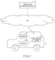
- Fig. 1 is a diagram illustrating an example of the overall configuration of a system including a traffic flow estimation apparatus 1 according to an embodiment of the present invention.
- This system includes the traffic flow estimation apparatus 1 on Web or cloud, for example. Also, the traffic flow estimation apparatus 1 and an in-vehicle device 63 having a communication function and mounted on a moving object 6 can communicate with each other via a communication network NW. Although only one moving object 6 is illustrated in Fig. 1 for simplicity, the traffic flow estimation apparatus 1 can communicate with a plurality of moving objects 6.
- the network NW is composed of, for example, a relay network and a plurality of access networks for accessing the relay network.
- the relay network to be used is a closed network controlled so that it can be accessed only from a public network, such as the general Internet, or a limited number of devices.
- the access network to be used is, for example, a wireless LAN (Local Area Network), a mobile phone network, a wired telephone network, or the like.
- the moving object 6 further includes a camera 61 and a sensor 62.
- the camera 61 uses a solid-state imaging device such as a CCD (Charge Coupled Device) or CMOS (Complementary Metal Oxide Semiconductor) sensor, and is set with installation location, orientation, and angle to have a capture range including a road area in any direction such as the traveling direction of the moving object 6.
- the camera 61 acquires camera video data and outputs the acquired data to the in-vehicle device 63.
- the camera 61 may be one provided exclusively for traffic flow estimation processing, but may be any camera as long as it can obtain same type or level data, for example, a dashcam or an in-vehicle camera mounted for other purposes.
- a camera may be used mounted on a driver helmet or installed in a portable terminal, such as a smart phone or tablet computer, owned by a passenger of the moving object 6.
- an infrared type of camera may be used as the camera 61.
- the data acquired by the camera 61 may be moving image (video) data or still image data captured at regular time intervals.
- the sensor 62 includes a GPS sensor and a speed sensor, and may also be provided exclusively for the traffic flow estimation processing, or may be a sensor used typically for operation control or log data collection for the automobile 6, such as CAN (Controller Area Network). Further, the sensor 62 may be a mobile terminal such as a smartphone.
- the GPS sensor operates to receive GPS signals transmitted from a plurality of GPS satellites and then perform range-finding calculation to calculate the latitude and longitude of the moving object 6, and outputs GPS data including the calculated latitude and longitude to an in-vehicle device VD.
- the GPS data can include information indicative of a reliability of GPS measurement in addition to the latitude and longitude (hereinafter, also referred to as "position information").
- position information information indicative of a reliability of GPS measurement in addition to the latitude and longitude
- the reliability of GPS measurement is determined, for example, according to the arrangement of GPS satellites. Note that the acquisition of the position information is not limited to the method using signals from GPS satellites, and may use any other method, for example, using the position information of a wireless base station or a WiFi access point as long as the same function is provided.
- the speed sensor is, for example, a wheel speed sensor, and is installed in a rotating portion such as a drive shaft to measure the speed of the automobile 6 based on the rotating speed of the rotating portion.
- the speed sensor outputs the measured speed data to the in-vehicle device 63.
- the in-vehicle device 63 is, for example, a radio device mounted on an automobile dashboard, and can receive various data from the camera 61 and the sensor 62 and transmit the received data together with date and time information and the identification information of the in-vehicle device 63 (or an ETC card inserted thereinto) to the traffic flow estimation apparatus 1 via the network NW.
- the in-vehicle device 63 is not an essential component, and the camera 61 and the sensor 62 may be configured to directly transmit data to the traffic flow estimation apparatus 1. Further, the camera 61 and the sensor 62 do not have to be separate devices, and these can be incorporated into one device or integrated into the in-vehicle device 63.
- the traffic flow estimation apparatus 1 is, for example, a server apparatus installed in a traffic control center, and performs processing of estimating (calculating) a traffic flow in a target area.
- the "traffic flow” will be described as, but not limited to, an average speed [km/h] in a specific lane of a specific road.
- the traffic flow may be defined according to applications, and for example, a traffic volume indicative of the number of vehicles passing through a specific point, a traffic density, or the like may be used.
- the traffic flow estimation apparatus 1 receives moving object data (hereinafter referred to as "vehicle data") including camera video data, GPS data, and speed data which are collected by the moving object 6 via the network NW, and calculates a traffic flow in the target area based on the received moving object data, for example, periodically or in response to a request from an operator or the like. Further, the traffic flow estimation apparatus 1 can output the calculated traffic flow to an external device. For example, the traffic flow estimation apparatus 1 can transmit it to the in-vehicle device 63 to notify to the driver of the moving object 6 so that it can be displayed on its own display unit, and can also transmit it to a road information display device under the control of the traffic control center so that it can be displayed.
- vehicle data moving object data
- speed data which are collected by the moving object 6 via the network NW
- the traffic flow estimation apparatus 1 can output the calculated traffic flow to an external device. For example, the traffic flow estimation apparatus 1 can transmit it to the in-vehicle device 63 to notify to the driver of the moving object 6
- the traffic flow estimation apparatus 1 may be configured so that, for example, the in-vehicle device 63 directly receives the vehicle data transmitted periodically or at any timing, or may be configured to access the in-vehicle device 63 to acquire necessary data. Alternatively, the traffic flow estimation apparatus 1 may be configured to access data once transmitted from the in-vehicle device 63 to and stored in a database server (not illustrated) or the like at a timing to acquire the vehicle data, or may be configured to acquire the vehicle data stored in an external medium via an input device 2.
- the automobile exemplified as the moving object 6 is not limited to a specific automobile, and may be one of various automobiles for individuals, of vehicle types, and from manufacturers.
- the moving object 6 will be described as a vehicle 6 by way of example, but examples of the moving object 6 may include any type of moving object to be charged for the use of roads, such as an automobile, a motorcycle, a bicycle, a personal mobility, and a vehicle towed by livestock such as a carriage, or the moving object 6 may also be a pedestrian as not limited to a vehicle. Therefore, the in-vehicle device 63 illustrated in Fig. 1 is merely an example, and can be replaced with an information processing terminal such as a smart phone.
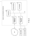
- Fig. 2 is a block diagram illustrating an example of a hardware configuration of the traffic flow estimation apparatus 1.
- the traffic flow estimation apparatus 1 is composed of, for example, a server computer or a personal computer, and includes a hardware processor 20A such as a CPU (Central Processing Unit). Also, a program memory 20B, a data memory 30, a communication interface 11, and an input/output interface 12 are connected to the hardware processor 20A via a bus 40.
- a hardware processor 20A such as a CPU (Central Processing Unit).
- a program memory 20B a data memory 30, a communication interface 11, and an input/output interface 12 are connected to the hardware processor 20A via a bus 40.
- the communication interface 11 includes, for example, one or more wired or wireless communication interface units, and enables information to be transmitted to and received from an external device including the in-vehicle device 63 mounted on the vehicle 6.
- the wired interface to be used is, for example, a wired LAN
- the wireless interface to be used is, for example, an interface that adopts a low-power wireless data communication standard such as wireless LAN or Bluetooth (registered trademark).
- the input/output interface 12 performs processing of acquiring operation data input by an operator through the input device 2 such as a keyboard, touch panel, touch pad, and mouse, and also of outputting output data to the output device 3 including a display device using a liquid crystal, an organic EL (Electro Luminescence), or the like and a speaker for outputting voice.
- a device or devices built in the traffic flow estimation apparatus 1 may be used, or an input device and output device of another information terminal capable of communicating via the network NW may be used.
- the program memory 20B uses as a storage medium a combination of, for example, a non-volatile memory which is writable and readable at any time, such as an HDD (Hard Disk Drive) or an SSD (Solid State Drive) and a non-volatile memory such as a ROM, to store programs necessary for executing various control processing according to the embodiment.
- the data memory 30 uses as a storage medium a combination of, for example, a non-volatile memory which is writable and readable at any time, such as an HDD or an SSD and a volatile memory such as a RAM (Random Access Memory), to store various data acquired and generated in the course of the traffic flow estimation processing.
- a non-volatile memory which is writable and readable at any time
- a volatile memory such as a RAM (Random Access Memory)
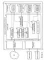
- FIG. 3 is a block diagram illustrating a software configuration of the traffic flow estimation apparatus 1 according to the embodiment of the present invention in association with the hardware configuration illustrated in Fig. 2 .
- a storage area of the data memory 30 includes a vehicle data storage unit 31, a road network data storage unit 32, a road-specific information storage unit 33, and a traffic flow information storage unit 34.
- the vehicle data storage unit 31 is used to store vehicle data including camera image data and sensor data acquired by a vehicle data acquisition unit 21.
- the road network data storage unit 32 is used to store various data related to a road network including lane information, which is stored in advance.
- the road-specific information storage unit 33 is used to store various road-specific information (road-specific data) identified based on vehicle data.
- the traffic flow information storage unit 34 is used to store information related to the calculated traffic flow.
- the storage units 31 to 34 are not essential components, and may be built in, for example, an external storage medium such as a USB memory or a storage device such as a database server deployed on cloud.
- an external storage medium such as a USB memory
- a storage device such as a database server deployed on cloud.
- a control unit 20 is composed of the hardware processor 20A and the program memory 20B, and includes, as processing function units by software, the vehicle data acquisition unit 21, a vehicle detection unit 22, a moving amount calculation unit 23, an area determination unit 24, a traveling road identification unit 25, a traffic flow calculation unit 26, and an output control unit 27. All processing functions in these units are implemented by causing the hardware processor 20A to execute the program(s) stored in the program memory 20B. Note that these processing functions may not be implemented by using the program(s) stored in the program memory 20B, but may be implemented by using a program or programs provided through the network.
- the control unit 20 may also be realized in various other forms including an integrated circuit such as an ASIC (Application Specific Integrated Circuit) or an FPGA (field-programmable gate array).
- the vehicle data acquisition unit 21 performs processing of acquiring the in-vehicle camera video and CAN data transmitted from the vehicle 6 via the communication interface 11 or the input/output interface 12, extracting camera video data and sensor data necessary for processing, and causing the vehicle data storage unit 31 to store the extracted data.
- the vehicle detection unit 22 performs processing of reading out the camera video data stored in the vehicle data storage unit 31, cutting out the read camera video data into frames, detecting another vehicle (second moving object around) appearing in the frames, calculating the in-image coordinates of the detected other vehicle, and outputting the calculated in-image coordinates to the moving amount calculation unit 23.
- the moving amount calculation unit 23 performs processing of calculating information indicative of a movement of the other vehicle (change over time of position) based on the in-image coordinates in each frame output from the vehicle detection unit 22, and outputting the information to the area determination unit 24.
- the area determination unit 24 performs processing of determining, based on the information indicative of a movement of the other vehicle in each frame output from the moving amount calculation unit 23, what lane the vehicle is in (what lane the vehicle is traveling in), and outputting the determination result to the road-specific information storage unit 33 to store it.
- the traveling road identification unit 25 reads out the camera video data and sensor data stored in the vehicle data storage unit 31 to determine what lane of what road the vehicle 6, which is an acquisition source of the read data (hereinafter, sometimes referred to as the "own vehicle 6"), is traveling in.
- the traveling road identification unit 25 also performs processing of associating information related to the traveling speed, traveling road, and traveling lane of the own vehicle 6 with the data output from the area determination unit 24, and causing the road-specific information storage unit 33 to store the resulting information.
- the traffic flow calculation unit 26 performs processing of reading out the data stored in the road-specific information storage unit 33, calculating a traffic flow for each lane of each road, and then causing the traffic flow information storage unit 34 to store the calculation result.
- the output control unit 27 performs processing of reading out the information stored in the traffic flow information storage unit 34, for example, periodically or in response to an output instruction from the operator, generating data for output, and outputting the generated data to the outside via the communication interface 11 or the input/output interface 12.
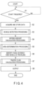
- Fig. 4 is a flowchart illustrating the processing procedure and processing content.
- the traffic flow estimation apparatus 1 monitors the occurrence of a trigger for starting the traffic flow estimation processing in step S1. In this state, for example, in response to receiving a trigger signal generated by an internal timer at regular intervals, or in response to receiving a trigger as a request to start the processing from the operator inputting the request using the input device 2, the traffic flow estimation apparatus 1 performs the following processing.
- step S2 under the control of the control unit 20, the traffic flow estimation apparatus 1 causes the vehicle data acquisition unit 21 to acquire the camera video data and sensor data via the communication interface 11 or the input/output interface 12, and causes the vehicle data storage unit 31 to store the acquired data.
- the data transmitted from the in-vehicle device 63 is accumulated as a database or a file on cloud, and the traffic flow estimation apparatus 1 accesses the database or file to acquire necessary data.
- this data acquisition processing may be receiving the data directly from the in-vehicle device 63, and the vehicle data acquisition unit 21 may acquire the data transmitted to be pushed by the in-vehicle device 63 at a timing. Therefore, step S2 does not necessarily have to be performed in response to the trigger of step S1.
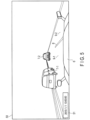
- the camera video data to be acquired by the vehicle data acquisition unit 21 will now be described as being an in-vehicle camera video captured by the in-vehicle camera 61 of the vehicle 6. Further, the in-vehicle camera 61 mounted on the vehicle 6 captures a video including the view in front of the moving vehicle 6.
- Fig. 5 illustrates an example of a frame 50 cut out from camera video data acquired by the vehicle data acquisition unit 21, as an image (image data) used for the traffic flow estimation processing.
- the frame 50 includes date and time information 51 indicative of the date and time at which the camera 61 captured the frame 50.
- a part of the own vehicle 6 in which the camera 61 is installed other vehicles 7 (7-1, 7-2, ...) which are surrounding moving objects, a lane boundary line 8, and lanes 9 (9-1, 9-2, ...) appear.
- the sensor data to be acquired by the vehicle data acquisition unit 21 includes at least speed and position information of the traveling vehicle 6 measured by the sensor 62 mounted on the vehicle 6. Further, the position information is to be the latitude and longitude measured at 1 [Hz].
- Fig. 6 illustrates an example of sensor data acquired by the vehicle data acquisition unit 21.
- the vehicle data acquisition unit 21 reads signals indicative of, for example, the position information and speed information transmitted from the sensor 62, and performs sampling on the respective signals at a sampling rate of 1 Hz, and to generate GPS [latitude and longitude] data and speed [km/h] data.
- step S3 under the control of the control unit 20 in the traffic flow estimation apparatus 1, the vehicle detection unit 22 performs vehicle detection processing.
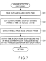
- Fig. 7 is a flowchart illustrating an example of processing procedure and processing content of the vehicle detection processing in step S3.
- step S31 the vehicle detection unit 22 reads out the camera video data (file) stored in the vehicle data storage unit 31.
- step S32 the vehicle detection unit 22 performs processing of cutting out the read camera video data into frames (also referred to as "images") in units of, for example, 0.1 seconds.
- the frame cut out at the time t is referred to as "frame_t" (1 ⁇ t ⁇ N) (N is an integer depending on the length of the read video data).
- the processing of cutting out the video into frames may be performed by any method, for example, using ffmpeg.
- step S33 the vehicle detection unit 22 performs processing of detecting the other vehicles 7 appearing in the image of each frame cut out.
- the method of detecting the other vehicles 7 may also be any method, and a method using deep learning, for example, a known YOLO (see ⁇ https://arxiv.org/abs/1804.02767> from the Internet ) or the like may be used. Further, the unit for cutting out into frames may be changed depending on the frame rate at which the video is acquired.
- step S34 the vehicle detection unit 22 outputs the coordinates of the detected other vehicles 7 to the moving amount calculation unit 23 in a format that the coordinates are associated with the time information of the corresponding frame.
- the vehicle detection unit 22 performs the detection of the other vehicles 7 as a rectangle
- the vehicle detection unit 22 outputs the image coordinates ⁇ (x1, y1), (x2, y2) ⁇ of two points of the rectangle: the upper left and lower right.
- the origin of the coordinates is the upper left, as is typically used in the image coordinate system.
- a threshold value may be set for the likelihood so that the image coordinates ⁇ (x1, y1), (x2, y2) ⁇ of only the detection target having the threshold value or more can be output.
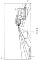
- Fig. 8 illustrates a state where the other vehicles 7 are detected in the vehicle detection processing performed by the vehicle detection unit 22.
- rectangles 52 (52-1, 52-2, 52-3, ...) representing the detected other vehicles 7 are displayed.
- the numerical value on the upper left of a rectangle where another vehicle 7 is detected (e.g., 0.95 for the rectangle 52-1) is a value representing the likelihood of a vehicle (car).
- step S4 under the control of the control unit 20 in the traffic flow estimation apparatus 1, the moving amount calculation unit 23 performs the moving amount calculation processing.
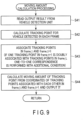
- Fig. 9 is a flowchart illustrating an example of processing procedure and processing content of the moving amount calculation processing in step S4.
- step S41 the moving amount calculation unit 23 reads, as output results from the vehicle detection unit 22, the rectangular coordinates of the other vehicles 7 detected in each frame.
- the moving amount calculation unit 23 calculates tracking points for the other vehicles 7 detected in each frame. Any points can be used as the tracking point.
- the centroid (c1, c2) of the rectangular coordinates for the detected other vehicle 7 can be used.
- step S43 the moving amount calculation unit 23 performs processing of associating the tracking points to determine whether or not a vehicle 7 detected in a frame (frame_t+1) at time t + 1 is identical to a vehicle 7 detected in a frame (frame_t) at time t. If the vehicle 7 detected in frame_t+1 is identical to the vehicle 7 detected in frame_t, a moving amount can be calculated from the difference between the tracking point coordinates of frame_t and the tracking point coordinates of frame_t+1.
- the moving amount calculation unit 23 uses as a reference the tracking point coordinates of the vehicle 7 detected in frame_t to calculate a distance from the tracking point coordinates of the vehicle 7 detected in frame_t+1 and then associates the tracking point coordinates having the minimum distance. If a plurality of vehicles 7 are detected in frame_t+1, distances are calculated for the number of detected vehicles, and vehicles 7 having the minimum distance are associated with each other.
- the distance may be a linear distance between the centroids (c1, c2) of the rectangular coordinates of the detected vehicles 7.
- setting a certain threshold value for this distance also makes it possible to reduce mistakes in associating frames. Any value can be set for the certain threshold value. For example, the maximum moving distance that the vehicle 7 can move in one frame (e.g., 0.1 seconds) can be set.
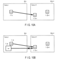
- Fig. 10A illustrates an example of an image of associating vehicles detected in frame_t (frame 50-t) and frame_t+1 (frame 50-t+1).
- the other vehicle 7-1t detected in frame_t and the other vehicle 7-1t+1 detected in frame_t+1 are associated with each other.
- Another vehicle 7-2t+1 is also detected in frame_t+1, but it has been determined not to be associated with any other vehicle detected in frame_t.
- the additional condition may be, for example, that detected vehicles whose areas are closest to each other are associated, or that detected vehicles whose images have the highest correlation coefficient are associated.
- Fig. 10B illustrates an example of an image in a case where multiple association between frame_t and frame_t+1 occurs.
- the association of the vehicle 7-1t with the vehicle 7-1t+1 is selected in accordance with the condition (e.g. that detected vehicles whose areas are closest to each other are associated).
- the moving amount calculation unit 23 calculates a moving amount of each vehicle 7 in each frame, and outputs it to the area determination unit 24 in step S44.
- the moving amount a distance in the x component, a distance in the y component, a linear distance in the xy composite component, and the like in the image can be used.
- the rectangular coordinates ⁇ (x1, y1), (x2, y2) ⁇ of the detected vehicle 7 and the coordinates (c1, c2) used as tracking points are associated to the moving amount and output to the area determination unit 24.
- Fig. 11 illustrates an example of moving amount calculation results from the moving amount calculation unit 23. If the moving amount of each vehicle in each frame can be obtained, the direction and length of the vehicle moving to the next frame can be found.
- the moving direction and length of the vehicle 7-1 in the frame 50 is indicated as an arrow 54.
- the arrow 54 is also an example of information indicative of a change over time in the position of the moving object (other vehicle 7) in the image.
- a moving amount may also be calculated for a truck (detected as the rectangle 52-2) appearing in front of the own vehicle 6. Further, here, a person (detected as a rectangle 52-5) walking on the sidewalk is set not to be used in the moving amount calculation processing.
- step S5 under the control of the control unit 20 in the traffic flow estimation apparatus 1, the area determination unit 24 performs area determination processing.
- Fig. 12 is a flowchart illustrating an example of processing procedure and processing content of the area determination processing in step S5.
- step S51 the area determination unit 24 reads moving amount information of the other vehicles 7 in each frame 50, which is output as an output result from the moving amount calculation unit 23, and refers to the coordinates (c1, c2) as the tracking points of the other vehicles 7.
- step S52 the area determination unit 24 performs processing of relatively determining which lane 9 the other vehicle 7 is traveling in from the tracking point coordinates (c1, c2).
- the area determination unit 24 first performs processing of setting area determination lines (also referred to as lane determination lines) for both sides of the lane 9 in which the own vehicle 6 is traveling.
- Fig. 13 illustrates an example of an image of such area determination lines 53 (53-1, 53-2, 53-3, 53-4).
- the area determination unit 24 can set a rule-based area determination lines 53 to determine which area the tracking point coordinates of the other vehicle 7 are in.
- the area determination lines 53 may be defined as lines defining the width of the adjacent lane. Based on this rule, it is possible to determine the area of the lane in which the own vehicle 6 is traveling and the areas of other lanes such as ⁇ same lane/one left lane/one right lane/two or more lane to the left/two or more lane to the right ⁇ . On a computer, where the tracking point coordinates (c1, c2) are located with respect to the area determination lines 53 can be determined by using, for example, the characteristics of outer product.
- the area determination unit 24 regards each of the area determination lines 53 as a vector, generates a vector from the in-image cut point coordinates of the area determination line 53 and the tracking point coordinates (c1, c2), and determines whether or not the angle formed by the two vectors is within 180 degrees by using the characteristics of outer product, so that it is possible to determine which area the tracking point coordinates (c1, c2) are located with respect to the area determination property.
- the method of area determination performed by the area determination unit 24 is not limited to the method using the area determination lines 53 described above.
- the area determination unit 24 calculates the moving direction of the vehicle 7 in the image (the moving direction of the other vehicle 7-1 in Fig. 13 (inclination of the arrow 54)). There is exhibited characteristics that as the other vehicle is traveling in a lane farther from the own vehicle, the moving direction (inclination of the arrow 54) becomes closer to being horizontal with respect to the image.
- Fig. 14 is a diagram illustrating an example of an image in which as a vehicle is traveling in a lane farther from the own vehicle, the inclination of the arrow 54 becomes closer to being horizontal.
- an arrow 54-1 of the vehicle detected in the rectangle 52-1 farther from the own vehicle is closer to being horizontal as compared with an arrow 54-2 of the vehicle detected in the rectangle 52-2 closer to the own vehicle (a dashed line is drawn to clearly show the inclination of the arrow 54).
- the area determination unit 24 can determine the area of the lane in which the own vehicle is traveling and the areas of other lanes such as ⁇ same lane/one left lane/one right lane/two or more lane to the left/two or more lane to the right ⁇ .
- using the moving direction of another vehicle 7 (inclination of the arrow 54) makes it possible to obtain the relative positional relationship with the own vehicle 6 (this will be further described later).
- step S53 the area determination unit 24 outputs the determination result to the road-specific information storage unit 33 to store it.
- step S6 under the control of the control unit 20 in the traffic flow estimation apparatus 1, the traveling road identification unit 25 performs processing of identifying the road on which the own vehicle 6 is traveling. More specifically, the traveling road identification unit 25 reads out the camera video data and sensor data stored in the vehicle data storage unit 31, determines which lane of which road the own vehicle 6 is traveling in, and then causes the road-specific information storage unit 33 to store information related to the traveling speed, traveling road, and traveling lane.
- the traveling road identification unit 25 can perform map matching processing using the position information (latitude and longitude) included in the sensor data, and the road network data stored in advance in the road network data storage unit 32.
- the map matching is processing of associating a vehicle with a road ID defined in road network data based on the position information of the vehicle (e.g., ⁇ http://bin.t.u-tokyo.ac.jp/ startup15/ file/0529yamamoto.pdf> from the Internet).
- latitude and longitude of each of the start point and end point of a road are defined as the road network data for each road ID, and information on the number of lanes of the road is also stored in association with the latitude and longitude.
- map matching a known method can be used. For example, a method of associating the road ID of a road having the minimum distance drawn from the position of the vehicle to the road can be used.
- the traveling road identification unit 25 identifies which lane of the road the own vehicle is traveling in.
- a known method can be used.
- the traveling road identification unit 25 may detect the lane appearing in the image of the in-vehicle camera 61 and then identify the lane position.
- the traveling road identification unit 25 can determine, for example, which lane the own vehicle is traveling in from the left by detecting the area determination lines 53 illustrated in Fig. 13 .
- the traveling road identification unit 25 causes the road-specific information storage unit 33 to store information related to ⁇ time, road on which own vehicle is located, the number of lanes of the road, lane in which the own vehicle is located, traveling speed of the own vehicle ⁇ identified as described above.
- Fig. 15 illustrates an example of an image of road-specific data stored in the road-specific information storage unit 33.
- the road-specific data stored in the road-specific information storage unit 33 is stored in a format in which information output from the area determination unit 24 ⁇ time, frame number, other vehicle ID, moving amount information of the other vehicle, relative position where other vehicle is located ⁇ and information output from the traveling road identification unit 25 ⁇ time, frame number, own vehicle ID, road on which the own vehicle is located, the number of lanes on the road, lane in which the own vehicle is located, traveling speed of the own vehicle ⁇ are associated with each other.
- the road-specific data includes information D01 ⁇ road on which the own vehicle is located, the number of lanes on the road, lane in which the own vehicle is located, traveling speed (km/h) of the own vehicle ⁇ identified by the traveling road identification unit 25; information D02 ⁇ other vehicle ID, moving amount information of the other vehicle ⁇ identified by the moving amount calculation unit 23; and information D03 ⁇ relative position in which another vehicle is located ⁇ identified by the area determination unit 24, which are all associated with the own vehicle ID, time, and frame number.
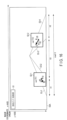
- Fig. 16 is a diagram illustrating an example of an image of the road-specific data illustrated in Fig. 15 .
- the ID of the road on which the own vehicle travels is set to X (road-X), and when the road is a three-lane road, the lanes are set as X1, X2, and X3 from the left in the traveling direction.
- the lane ID in which the own vehicle travels can be identified by the traveling road identification unit 25, and the lane ID in which another vehicle is located can also be identified by the processing performed by the area determination unit 24.
- the road-specific information storage unit 33 may store the area of another vehicle obtained by the processing performed by the area determination unit 24 in a format in which it is associated with the lane ID. Note that in Fig.
- the direction of the arrow indicative of the moving amount may show that the vehicle (T1) detected as the rectangle 52-1 is traveling in the lane for the same traveling direction as the own vehicle while the vehicle (T2) detected as the rectangle 52-2 is traveling in the lane for the opposite traveling direction to the own vehicle.
- the numerical value in each rectangle 52 represents a change in coordinates.
- step S7 under the control of the control unit 20 in the traffic flow estimation apparatus 1, the traffic flow calculation unit 26 performs traffic flow calculation processing.
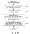
- Fig. 17 is a flowchart illustrating an example of processing procedure and processing content of the traffic flow calculation processing in step S7.
- step S71 the traffic flow calculation unit 26 reads the data stored in the road-specific information storage unit 33.
- step S72 the traffic flow calculation unit 26 calculates the traveling speeds of the other vehicles 7 from the traveling speed of the own vehicle 6 and the moving amount information of the other vehicles 7 in the read data.
- the traffic flow calculation unit 26 can generate training data in advance and then calculate the traveling speeds by using a regression model. Specifically, a regression analysis is performed in which the traveling speed of the own vehicle 6 and the moving amount information of the other vehicles 7 are used as explanatory variables and the traveling speeds of the other vehicles 7 are used as objective variables, so that a coefficient vector for each explanatory variable vector can be estimated.
- the regression analysis model may be, for example, a linear combination model, and where X is an explanatory variable vector, W is a coefficient vector corresponding to the explanatory variable vector, and Y is an objective variable, W can be calculated such that the inner product of X and W is nearest to Y by using the least squares method or the like. Thereafter, using the calculated coefficient vector W makes it possible to estimate the traveling speed of unknown another vehicle 7 when the traveling speed of the own vehicle 6 and the moving amount information of the other vehicle 7 are obtained.
- Fig. 18A illustrates an example of an image of the training data used for constructing the regression model as described above.
- the training data may be, for example, generated based on actual measurement data or generated based on simulation results.
- Fig. 18B illustrates an example of an image of the coefficient vector W obtained by the regression analysis as described above.
- step S73 the traffic flow calculation unit 26 performs processing of associating lane IDs of lanes in which the own vehicle and other vehicles are traveling and traveling speeds by using time, road ID, and lane ID as keys.
- Fig. 19 illustrates an example of an image of such a processing result.
- R01 indicates information on the own vehicle 6
- R02 indicates information on the other vehicles 7 detected from the own vehicle 6.
- the traffic flow calculation unit 26 associates the speed of a traveling vehicle for each set of time, road, and lane. Here, it is not necessary to identify the own vehicle and the other vehicles.
- the traffic flow calculation unit 26 calculates an average value (average speed (km/h)) of traveling speeds in a time range for each road ID and each lane ID, and outputs the calculation result to the traffic flow information storage unit 34 to store it.
- the time range for calculating a traffic flow may be any range such as 10-minute units and 30-minute units.
- the traffic flow calculation unit 26 divides the data for each of the determined time range, road ID, and lane ID, and then calculates the average value of the traveling speeds included in the data, so that a traffic flow for each lane in a time zone can be calculated. Note that it is not always necessary to be an average value, and any statistic such as a median value or a deviation may be calculated depending on the purpose of use.
- the traffic flow calculation unit 26 may use information on time ranges before and after that time range to perform interpolation. Alternatively, when the traffic flow calculation unit 26 successfully obtains a traffic flow for each lane of a plurality of lanes for any time range, the traffic flow calculation unit 26 can also calculate a correlation between the lanes and then perform interpolation from the average speed for the adjacent lane.
- the traffic flow calculation unit 26 may multiply the average speed calculated for the first lane by 1.2 to obtain the average speed for the second lane for interpolation.
- the traffic flow calculation unit 26 may perform interpolation such that an average value of the average speeds 10:00 - 10:30 and 11:00 - 11:30 is used for the average speed for 10:30 - 11:00. By performing interpolation, the traffic flow estimation apparatus 1 can calculate the traffic flow for each lane from a smaller amount of vehicle data.
- the traffic flow calculation unit 26 stores the average speeds (km/h) calculated in this way in the traffic flow information storage unit 34.
- Fig. 20 illustrates an example of a data image stored in the traffic flow information storage unit 34.
- the example indicated in Fig. 20 includes average speeds calculated with a time range of 30 minutes.
- step S8 in the traffic flow estimation apparatus 1, the output control unit 27 performs some output processing.
- the output control unit 27 reads out the information stored in the traffic flow information storage unit 34, for example, periodically or in response to a transmission request from the vehicle 6 or an output request from the operator input via the input device 2, generates data for output, and outputs the data via the communication interface 11 or the input/output interface 12.
- the output control unit 27 can display the average speed (traffic flow) calculated for each set of time range, road ID, and lane ID to the liquid crystal display via an input/output interface unit to display it, based on information read from the traffic flow information storage unit 34 at certain time intervals such as 5 min, 10 min, or 30 min. Then, the operator of the traffic control center who sees this display can immediately grasp the road conditions in streets such as traffic congestion information and take appropriate measures.
- the traffic flow estimation apparatus 1 acquires camera video data and sensor data collected by the vehicle 6 traveling on a road, detects the other vehicles 7 from the image of each frame included in the camera video data, calculates moving amounts of the other vehicles 7 and the like, and estimates which lane on the road the other vehicle 7 is traveling with respect to the traveling position of the vehicle 6.
- the traffic flow estimation apparatus 1 also identifies the road and the lane where vehicle 6 is traveling from the sensor data (and the camera video data, optionally).
- the traffic flow estimation apparatus 1 calculates the speeds of the other vehicles 7 based on the speed of the vehicle 6, the road and lane where the vehicle 6 is traveling, the moving amounts of the other vehicles 7, and the estimated lanes in which the other vehicles 7 are traveling, and thus calculates a traffic flow for each lane.
- the traffic flow estimation apparatus 1 can calculate not only the lane in which the vehicle (own vehicle) 6 from which the camera video data and the sensor data are collected is traveling, but also the traffic flow of other lanes, and thus calculate a traffic flow in a wider range (lane) from less vehicle data. For example, even in a situation where vehicle data can be collected only from vehicles traveling in one or some lanes among vehicles traveling on a certain road, the traffic flow estimation apparatus 1 can estimate a traffic flow in each lane. In addition, this makes it possible to estimate the traffic flow by effectively utilizing the limited data while suppressing the traffic between the vehicle and the traffic flow estimation apparatus 1.
- the traffic flow estimation apparatus 1 is configured to detect another vehicle 7 appearing in video data of the view in front of the traveling vehicle 6, and when the moving amount of the other vehicle 7 is calculated, cause the moving amount calculation unit 23 to associate vehicles in frames. As a result, the traffic flow estimation apparatus 1 can calculate the moving amount more accurately than in the case where the association is not performed, so that the traffic flow can be calculated more accurately.
- the traffic flow estimation apparatus 1 also detects the other vehicle 7 appearing in the video data of the view in front of the traveling vehicle 6, calculates the moving amount of the other vehicle 7, and then automatically determine the area of which lane on which road that vehicle is traveling in.
- the area determination unit 24 that performs such area determination determines the area of one right lane and one left lane with respect to the lane in which the own vehicle 6 is traveling in the in-image coordinate system in the video (image) data, determines whether or not other vehicle(s) 7 is in the area, so that it is possible to determine which lane the other vehicle 7 is traveling in.
- the traffic flow estimation apparatus 1 can calculate a traffic flow of the adjacent lane from the vehicle data of the vehicle 6 traveling in a certain lane.
- the area determination unit 24 uses not only the moving amount of the other vehicle 7 but also the moving direction of the other vehicle 7 in the image coordinate system. By using the moving direction, the area determination unit 24 can automatically determine whether the lane in which the other vehicle 7 is traveling is, for example, one right lane or two or more lane to the right with respect to the lane in which the own vehicle is traveling. As a result, the traffic flow estimation apparatus 1 can calculate a traffic flow of the adjacent lane in a wide range from the vehicle data of the vehicle 6 traveling in a certain lane.
- the traffic flow calculation unit 26 accumulates the traveling speeds of the other vehicles 7, the moving amounts of the other vehicles 7 calculated by the moving amount calculation unit 23, and the traveling speed of the own vehicle 6 when the other vehicles 7 are detected in association with one another, and formulates the relationships between the moving amounts of the other vehicles and the speed differences (relative speeds) between the own vehicle and the other vehicles, so that it is possible to quantitatively calculate the relative speed difference from the traveling speed of the own vehicle 6 for a given moving amount of a certain other vehicle 7. Therefore, the traffic flow estimation apparatus 1 can calculate a more accurate traffic flow of the adjacent lane from the vehicle data obtained from the vehicle 6 traveling in a certain lane.
- the functional units included in the traffic flow estimation apparatus 1 may be distributed to and deployed in a plurality of apparatuses, and the processing may be performed by coordinating these apparatuses with each other. Further, each functional unit may be realized by using a circuit.
- the circuit may be a dedicated circuit that implements a specific function, or may be a general-purpose circuit such as a processor.
- the road-specific information storage unit 33 has been described as being a unit that combines the data output by the area determination unit 24 and the data output by the traveling road identification unit 25 and stores the resulting data.
- the road-specific information storage unit 33 is not limited to this, and the road-specific information storage unit 33 may be configured as two or more separate storage units.
- the traffic flow estimation apparatus 1 has been described as being an apparatus that acquires camera video data, GPS data, and speed data as vehicle data. However, the traffic flow estimation apparatus 1 is not limited to this, and the traffic flow estimation apparatus 1 may also acquire other CAN data.
- the traffic flow estimation apparatus 1 may be configured to additionally acquire acceleration data and angular velocity data and use them as an auxiliary for improving the accuracy of area determination or traveling road identification, or to additionally acquire control information such as brakes, steering, and the like and use it to estimate the speed of another vehicle 7 or a traffic flow.
- the moving amount calculation unit 23 may use another method for determining whether or not the vehicles 7 detected in frames are identical. For example, the text information of the license plates of vehicles appearing in each frame may be read to associate the vehicles based on the read character information. Alternatively, the identity of the vehicles may be detected through inter-vehicle communication with BLE (Bluetooth Low Energy) beacon or the like.
- BLE Bluetooth Low Energy
- the method described above can be stored as a computer-executable program (software means) in a recording medium (storage medium) such as a magnetic disk (floppy (registered trademark) disk, hard disk, etc.), an optical disk (CD-ROM, DVD, MO, etc.), and a semiconductor memory (ROM, RAM, flash memory, etc.), and be transmitted and distributed by a communication medium.
- a recording medium such as a magnetic disk (floppy (registered trademark) disk, hard disk, etc.), an optical disk (CD-ROM, DVD, MO, etc.), and a semiconductor memory (ROM, RAM, flash memory, etc.
- the program stored on the medium side also includes a setting program for configuring the computer-executable software means (including not only an execution program but also a table and data structure) in the computer.
- the computer that realizes the above-mentioned apparatus reads the program recorded on the recording medium, constructs the software means by the setting program in some cases, and executes the above-described steps of processing by the software means controlling the operation.
- the recording medium referred to in the present description is not limited to one for distribution, and includes a storage medium such as a magnetic disk and a semiconductor memory provided in devices inside the computer or connected via a network.
Landscapes
- Physics & Mathematics (AREA)
- General Physics & Mathematics (AREA)
- Chemical & Material Sciences (AREA)
- Analytical Chemistry (AREA)
- Engineering & Computer Science (AREA)
- Multimedia (AREA)
- Theoretical Computer Science (AREA)
- Computer Vision & Pattern Recognition (AREA)
- Traffic Control Systems (AREA)
Applications Claiming Priority (1)
| Application Number | Priority Date | Filing Date | Title |
|---|---|---|---|
| PCT/JP2019/018945 WO2020230237A1 (ja) | 2019-05-13 | 2019-05-13 | 交通流推定装置、交通流推定方法、交通流推定プログラムおよび交通流推定プログラムを記憶した記憶媒体 |
Publications (3)
| Publication Number | Publication Date |
|---|---|
| EP3971855A1 EP3971855A1 (en) | 2022-03-23 |
| EP3971855A4 EP3971855A4 (en) | 2022-12-14 |
| EP3971855B1 true EP3971855B1 (en) | 2024-11-20 |
Family
ID=73288983
Family Applications (1)
| Application Number | Title | Priority Date | Filing Date |
|---|---|---|---|
| EP19928838.2A Active EP3971855B1 (en) | 2019-05-13 | 2019-05-13 | Traffic flow estimation apparatus, traffic flow estimation method, traffic flow estimation program, and storage medium storing traffic flow estimation program |
Country Status (5)
| Country | Link |
|---|---|
| US (1) | US11837084B2 (enExample) |
| EP (1) | EP3971855B1 (enExample) |
| JP (1) | JP7276435B2 (enExample) |
| CN (1) | CN113841188B (enExample) |
| WO (1) | WO2020230237A1 (enExample) |
Families Citing this family (8)
| Publication number | Priority date | Publication date | Assignee | Title |
|---|---|---|---|---|
| WO2020230237A1 (ja) * | 2019-05-13 | 2020-11-19 | 日本電信電話株式会社 | 交通流推定装置、交通流推定方法、交通流推定プログラムおよび交通流推定プログラムを記憶した記憶媒体 |
| WO2020240803A1 (ja) * | 2019-05-31 | 2020-12-03 | 日本電気株式会社 | 推定装置、推定方法、及び非一時的なコンピュータ可読媒体 |
| DE102019217099A1 (de) * | 2019-11-06 | 2021-05-06 | Zf Friedrichshafen Ag | Steuerungssystem und Steuerungsverfahren für ein Erkennen und eine Reaktion eines Reißverschlussverfahrens für ein Kraftfahrzeug |
| JP2022165349A (ja) * | 2021-04-19 | 2022-10-31 | 日立Astemo株式会社 | 情報処理装置、情報処理システム、及び、情報処理方法 |
| WO2022244063A1 (ja) * | 2021-05-17 | 2022-11-24 | 日本電信電話株式会社 | 判定装置、判定方法、及び判定プログラム |
| CN113469026B (zh) * | 2021-06-30 | 2023-03-24 | 上海智能交通有限公司 | 一种基于机器学习的路口滞留事件检测方法及系统 |
| CN116052079B (zh) * | 2022-12-30 | 2025-10-21 | 杭州海康威视数字技术股份有限公司 | 目标流量统计系统、方法、装置及设备 |
| TWI875424B (zh) * | 2024-01-09 | 2025-03-01 | 鴻海精密工業股份有限公司 | 用於規避目標車輛的路徑規劃方法、裝置、設備及介質 |
Citations (3)
| Publication number | Priority date | Publication date | Assignee | Title |
|---|---|---|---|---|
| US20150170514A1 (en) * | 2013-12-13 | 2015-06-18 | Here Global B.V. | Systems and Methods for Detecting Road Congestion and Incidents in Real Time |
| US20170352262A1 (en) * | 2016-06-03 | 2017-12-07 | Here Global B.V. | Method and apparatus for classifying a traffic jam from probe data |
| US20180182238A1 (en) * | 2016-12-23 | 2018-06-28 | Here Global B.V. | Lane level traffic information and navigation |
Family Cites Families (33)
| Publication number | Priority date | Publication date | Assignee | Title |
|---|---|---|---|---|
| DE69330513D1 (de) * | 1992-03-20 | 2001-09-06 | Commw Scient Ind Res Org | Gegenstands-überwachungsystem |
| DE69322306T2 (de) * | 1992-04-24 | 1999-04-29 | Hitachi, Ltd., Tokio/Tokyo | Gegenstandserkennungssystem mittels Bildverarbeitung |
| US5586063A (en) * | 1993-09-01 | 1996-12-17 | Hardin; Larry C. | Optical range and speed detection system |
| JP2000163685A (ja) * | 1998-11-30 | 2000-06-16 | Fuji Electric Co Ltd | 交通流監視システム |
| JP3606223B2 (ja) * | 2001-04-26 | 2005-01-05 | 住友電気工業株式会社 | 車両側方映像生成方法及び車両側方映像生成装置 |
| DE102005053461B4 (de) * | 2005-11-04 | 2007-10-18 | Deutsches Zentrum für Luft- und Raumfahrt e.V. | Verfahren und Vorrichtung zur Verkehrssteuerung |
| US9288381B2 (en) * | 2012-07-27 | 2016-03-15 | Clarion Co., Ltd. | In-vehicle image recognizer |
| GB2513399B (en) * | 2013-04-26 | 2017-07-26 | Optasense Holdings Ltd | Traffic Monitoring |
| US9117098B2 (en) | 2013-06-03 | 2015-08-25 | Ford Global Technologies, Llc | On-board traffic density estimator |
| JP2015076077A (ja) * | 2013-10-11 | 2015-04-20 | パイオニア株式会社 | 交通量推定システム、端末装置、交通量推定方法および交通量推定プログラム |
| JP2015076078A (ja) * | 2013-10-11 | 2015-04-20 | パイオニア株式会社 | 渋滞予測システム、端末装置、渋滞予測方法および渋滞予測プログラム |
| US10650252B2 (en) * | 2015-05-07 | 2020-05-12 | Hitachi, Ltd. | Lane detection device and lane detection method |
| JP6338159B2 (ja) * | 2016-05-19 | 2018-06-06 | 本田技研工業株式会社 | 交通状況推定装置、車両制御システム、経路誘導装置、交通状況推定方法、および交通状況推定プログラム |
| JP6615725B2 (ja) * | 2016-09-16 | 2019-12-04 | 株式会社東芝 | 走行速度算出装置および走行速度算出方法 |
| WO2018180122A1 (ja) * | 2017-03-30 | 2018-10-04 | ソニー株式会社 | 運転支援装置と運転支援方法 |
| WO2018225069A1 (en) * | 2017-06-07 | 2018-12-13 | Nexar Ltd. | Digitizing and mapping the public space using collaborative networks of mobile agents and cloud nodes |
| JP6952517B2 (ja) * | 2017-07-05 | 2021-10-20 | 国立大学法人 東京大学 | 渋滞予測装置及びその渋滞予測方法 |
| JP6952516B2 (ja) * | 2017-07-05 | 2021-10-20 | 国立大学法人 東京大学 | 渋滞予測装置及びその渋滞予測方法 |
| JP6904849B2 (ja) * | 2017-08-14 | 2021-07-21 | 本田技研工業株式会社 | 車両制御装置、車両制御方法、およびプログラム。 |
| JP2018106762A (ja) * | 2018-04-04 | 2018-07-05 | パイオニア株式会社 | 渋滞予測システム、端末装置、渋滞予測方法および渋滞予測プログラム |
| US11062608B2 (en) * | 2018-05-11 | 2021-07-13 | Arnold Chase | Passive infra-red pedestrian and animal detection and avoidance system |
| JP6956268B2 (ja) * | 2018-07-11 | 2021-11-02 | 日産自動車株式会社 | 走行環境情報の生成方法、運転制御方法、走行環境情報生成装置 |
| US11322025B2 (en) * | 2018-12-12 | 2022-05-03 | Here Global B.V. | Method and system for validating existence of roadwork |
| US11513518B2 (en) * | 2019-01-30 | 2022-11-29 | Toyota Motor Engineering & Manufacturing North America, Inc. | Avoidance of obscured roadway obstacles |
| US11341846B2 (en) * | 2019-04-04 | 2022-05-24 | Geotab Inc. | Traffic analytics system for defining road networks |
| US11335189B2 (en) * | 2019-04-04 | 2022-05-17 | Geotab Inc. | Method for defining road networks |
| US10699564B1 (en) * | 2019-04-04 | 2020-06-30 | Geotab Inc. | Method for defining intersections using machine learning |
| WO2020230237A1 (ja) * | 2019-05-13 | 2020-11-19 | 日本電信電話株式会社 | 交通流推定装置、交通流推定方法、交通流推定プログラムおよび交通流推定プログラムを記憶した記憶媒体 |
| US20220299860A1 (en) * | 2019-06-25 | 2022-09-22 | Shanghai Jun Kai Technology Llc | Extensiview and adaptive lka for adas and autonomous driving |
| CN110322702B (zh) * | 2019-07-08 | 2020-08-14 | 中原工学院 | 一种基于双目立体视觉系统的车辆智能测速方法 |
| JP7120260B2 (ja) * | 2020-01-30 | 2022-08-17 | トヨタ自動車株式会社 | 車両制御装置 |
| US11338810B2 (en) * | 2020-02-25 | 2022-05-24 | Ford Global Technologies, Llc | Vehicle yield decision |
| US11767037B2 (en) * | 2020-09-22 | 2023-09-26 | Argo AI, LLC | Enhanced obstacle detection |
-
2019
- 2019-05-13 WO PCT/JP2019/018945 patent/WO2020230237A1/ja not_active Ceased
- 2019-05-13 US US17/595,379 patent/US11837084B2/en active Active
- 2019-05-13 JP JP2021519075A patent/JP7276435B2/ja active Active
- 2019-05-13 EP EP19928838.2A patent/EP3971855B1/en active Active
- 2019-05-13 CN CN201980096383.8A patent/CN113841188B/zh active Active
Patent Citations (3)
| Publication number | Priority date | Publication date | Assignee | Title |
|---|---|---|---|---|
| US20150170514A1 (en) * | 2013-12-13 | 2015-06-18 | Here Global B.V. | Systems and Methods for Detecting Road Congestion and Incidents in Real Time |
| US20170352262A1 (en) * | 2016-06-03 | 2017-12-07 | Here Global B.V. | Method and apparatus for classifying a traffic jam from probe data |
| US20180182238A1 (en) * | 2016-12-23 | 2018-06-28 | Here Global B.V. | Lane level traffic information and navigation |
Non-Patent Citations (3)
| Title |
|---|
| AHMED JAVED ET AL: "Stabilized active camera tracking system", JOURNAL OF REAL-TIME IMAGE PROCESSING, SPRINGER, DE, vol. 11, no. 2, 13 May 2012 (2012-05-13), pages 315 - 334, XP035713435, ISSN: 1861-8200, [retrieved on 20120513], DOI: 10.1007/S11554-012-0251-Z * |
| AHMED WAQAS ET AL: "A Systematic Review on Vehicle Identification and Classification Techniques", 2018 IEEE 21ST INTERNATIONAL MULTI-TOPIC CONFERENCE (INMIC), IEEE, 1 November 2018 (2018-11-01), pages 1 - 6, XP033487394, DOI: 10.1109/INMIC.2018.8595585 * |
| AKSHAY RANGESH ET AL: "No Blind Spots: Full-Surround Multi-Object Tracking for Autonomous Vehicles using Cameras & LiDARs", ARXIV.ORG, CORNELL UNIVERSITY LIBRARY, 201 OLIN LIBRARY CORNELL UNIVERSITY ITHACA, NY 14853, 23 February 2018 (2018-02-23), XP081020879 * |
Also Published As
| Publication number | Publication date |
|---|---|
| WO2020230237A1 (ja) | 2020-11-19 |
| CN113841188B (zh) | 2024-02-20 |
| JP7276435B2 (ja) | 2023-05-18 |
| JPWO2020230237A1 (enExample) | 2020-11-19 |
| EP3971855A1 (en) | 2022-03-23 |
| EP3971855A4 (en) | 2022-12-14 |
| US20220207997A1 (en) | 2022-06-30 |
| US11837084B2 (en) | 2023-12-05 |
| CN113841188A (zh) | 2021-12-24 |
Similar Documents
| Publication | Publication Date | Title |
|---|---|---|
| EP3971855B1 (en) | Traffic flow estimation apparatus, traffic flow estimation method, traffic flow estimation program, and storage medium storing traffic flow estimation program | |
| Qiu et al. | Avr: Augmented vehicular reality | |
| KR101751112B1 (ko) | 영상정보기반 교통정보 생성 장치 및 그 방법 | |
| US11333517B1 (en) | Distributed collection and verification of map information | |
| KR101735557B1 (ko) | 실시간 목표 탐지에 의한 교통 정보 수집 시스템 및 방법 | |
| JP7233386B2 (ja) | 地図更新装置、地図更新システム、及び地図更新方法 | |
| KR101744963B1 (ko) | 블랙박스 영상 정보를 이용하여 교통정보 및 차량정보 제공 시스템 및 그 방법 | |
| CN112203216A (zh) | 定位信息获取方法、辅助驾驶方法以及车端传感器检测方法 | |
| JP2015076077A (ja) | 交通量推定システム、端末装置、交通量推定方法および交通量推定プログラム | |
| CN110648539A (zh) | 车载装置以及控制方法 | |
| Chen et al. | Vision-based road bump detection using a front-mounted car camcorder | |
| Kotha et al. | Potsense: Pothole detection on indian roads using smartphone sensors | |
| JP2025072650A (ja) | 情報処理装置 | |
| JP5667907B2 (ja) | 情報提供システム | |
| Enan et al. | Basic safety message generation through a video-based analytics for potential safety applications | |
| US12219293B2 (en) | Image data collecting apparatus, method, and program | |
| JP2023064093A (ja) | 交通標識検出方法及び交通標識検出モデルのトレーニング方法 | |
| KR101720861B1 (ko) | 구간별 차량 속도 검지 시스템 및 그 방법 | |
| JP7429246B2 (ja) | 対象を識別する方法とシステム | |
| Tummala et al. | RoadMap: mapping vehicles to IP addresses using motion signatures | |
| KR20160097932A (ko) | 주행 중 영상촬영장치를 이용한 차량밀도 측정 방법 | |
| KR20180047116A (ko) | Cctv 영상 분석을 통한 통행정보 추정 장치 및 방법 | |
| KR102591189B1 (ko) | 차량용 인공지능 블랙박스를 이용한 교통사고 현황을 분석하는 방법 및 이를 위한 장치 | |
| Islam et al. | Vision-based Pedestrian Alert Safety System (PASS) for Signalized Intersections | |
| Kamal et al. | Monocular Vision-Based Vehicle Distance Prediction utilizing Number Plate |
Legal Events
| Date | Code | Title | Description |
|---|---|---|---|
| STAA | Information on the status of an ep patent application or granted ep patent |
Free format text: STATUS: THE INTERNATIONAL PUBLICATION HAS BEEN MADE |
|
| PUAI | Public reference made under article 153(3) epc to a published international application that has entered the european phase |
Free format text: ORIGINAL CODE: 0009012 |
|
| STAA | Information on the status of an ep patent application or granted ep patent |
Free format text: STATUS: REQUEST FOR EXAMINATION WAS MADE |
|
| 17P | Request for examination filed |
Effective date: 20211116 |
|
| AK | Designated contracting states |
Kind code of ref document: A1 Designated state(s): AL AT BE BG CH CY CZ DE DK EE ES FI FR GB GR HR HU IE IS IT LI LT LU LV MC MK MT NL NO PL PT RO RS SE SI SK SM TR |
|
| DAV | Request for validation of the european patent (deleted) | ||
| DAX | Request for extension of the european patent (deleted) | ||
| A4 | Supplementary search report drawn up and despatched |
Effective date: 20221116 |
|
| RIC1 | Information provided on ipc code assigned before grant |
Ipc: G08G 1/04 20060101ALI20221110BHEP Ipc: G08G 1/015 20060101ALI20221110BHEP Ipc: G06V 20/58 20220101ALI20221110BHEP Ipc: G06V 10/62 20220101ALI20221110BHEP Ipc: G08G 1/056 20060101ALI20221110BHEP Ipc: G08G 1/052 20060101ALI20221110BHEP Ipc: G08G 1/017 20060101ALI20221110BHEP Ipc: G08G 1/01 20060101ALI20221110BHEP Ipc: G08G 1/00 20060101AFI20221110BHEP |
|
| STAA | Information on the status of an ep patent application or granted ep patent |
Free format text: STATUS: EXAMINATION IS IN PROGRESS |
|
| 17Q | First examination report despatched |
Effective date: 20230623 |
|
| GRAP | Despatch of communication of intention to grant a patent |
Free format text: ORIGINAL CODE: EPIDOSNIGR1 |
|
| STAA | Information on the status of an ep patent application or granted ep patent |
Free format text: STATUS: GRANT OF PATENT IS INTENDED |
|
| INTG | Intention to grant announced |
Effective date: 20240708 |
|
| GRAS | Grant fee paid |
Free format text: ORIGINAL CODE: EPIDOSNIGR3 |
|
| GRAA | (expected) grant |
Free format text: ORIGINAL CODE: 0009210 |
|
| STAA | Information on the status of an ep patent application or granted ep patent |
Free format text: STATUS: THE PATENT HAS BEEN GRANTED |
|
| AK | Designated contracting states |
Kind code of ref document: B1 Designated state(s): AL AT BE BG CH CY CZ DE DK EE ES FI FR GB GR HR HU IE IS IT LI LT LU LV MC MK MT NL NO PL PT RO RS SE SI SK SM TR |
|
| REG | Reference to a national code |
Ref country code: GB Ref legal event code: FG4D |
|
| REG | Reference to a national code |
Ref country code: CH Ref legal event code: EP |
|
| REG | Reference to a national code |
Ref country code: DE Ref legal event code: R096 Ref document number: 602019062429 Country of ref document: DE |
|
| REG | Reference to a national code |
Ref country code: IE Ref legal event code: FG4D |
|
| REG | Reference to a national code |
Ref country code: LT Ref legal event code: MG9D |
|
| REG | Reference to a national code |
Ref country code: NL Ref legal event code: MP Effective date: 20241120 |
|
| PG25 | Lapsed in a contracting state [announced via postgrant information from national office to epo] |
Ref country code: PT Free format text: LAPSE BECAUSE OF FAILURE TO SUBMIT A TRANSLATION OF THE DESCRIPTION OR TO PAY THE FEE WITHIN THE PRESCRIBED TIME-LIMIT Effective date: 20250320 Ref country code: HR Free format text: LAPSE BECAUSE OF FAILURE TO SUBMIT A TRANSLATION OF THE DESCRIPTION OR TO PAY THE FEE WITHIN THE PRESCRIBED TIME-LIMIT Effective date: 20241120 Ref country code: IS Free format text: LAPSE BECAUSE OF FAILURE TO SUBMIT A TRANSLATION OF THE DESCRIPTION OR TO PAY THE FEE WITHIN THE PRESCRIBED TIME-LIMIT Effective date: 20250320 |
|
| PG25 | Lapsed in a contracting state [announced via postgrant information from national office to epo] |
Ref country code: FI Free format text: LAPSE BECAUSE OF FAILURE TO SUBMIT A TRANSLATION OF THE DESCRIPTION OR TO PAY THE FEE WITHIN THE PRESCRIBED TIME-LIMIT Effective date: 20241120 Ref country code: NL Free format text: LAPSE BECAUSE OF FAILURE TO SUBMIT A TRANSLATION OF THE DESCRIPTION OR TO PAY THE FEE WITHIN THE PRESCRIBED TIME-LIMIT Effective date: 20241120 |
|
| REG | Reference to a national code |
Ref country code: AT Ref legal event code: MK05 Ref document number: 1744310 Country of ref document: AT Kind code of ref document: T Effective date: 20241120 |
|
| PG25 | Lapsed in a contracting state [announced via postgrant information from national office to epo] |
Ref country code: BG Free format text: LAPSE BECAUSE OF FAILURE TO SUBMIT A TRANSLATION OF THE DESCRIPTION OR TO PAY THE FEE WITHIN THE PRESCRIBED TIME-LIMIT Effective date: 20241120 |
|
| PG25 | Lapsed in a contracting state [announced via postgrant information from national office to epo] |
Ref country code: ES Free format text: LAPSE BECAUSE OF FAILURE TO SUBMIT A TRANSLATION OF THE DESCRIPTION OR TO PAY THE FEE WITHIN THE PRESCRIBED TIME-LIMIT Effective date: 20241120 |
|
| PG25 | Lapsed in a contracting state [announced via postgrant information from national office to epo] |
Ref country code: NO Free format text: LAPSE BECAUSE OF FAILURE TO SUBMIT A TRANSLATION OF THE DESCRIPTION OR TO PAY THE FEE WITHIN THE PRESCRIBED TIME-LIMIT Effective date: 20250220 |
|
| PG25 | Lapsed in a contracting state [announced via postgrant information from national office to epo] |
Ref country code: AT Free format text: LAPSE BECAUSE OF FAILURE TO SUBMIT A TRANSLATION OF THE DESCRIPTION OR TO PAY THE FEE WITHIN THE PRESCRIBED TIME-LIMIT Effective date: 20241120 Ref country code: GR Free format text: LAPSE BECAUSE OF FAILURE TO SUBMIT A TRANSLATION OF THE DESCRIPTION OR TO PAY THE FEE WITHIN THE PRESCRIBED TIME-LIMIT Effective date: 20250221 Ref country code: LV Free format text: LAPSE BECAUSE OF FAILURE TO SUBMIT A TRANSLATION OF THE DESCRIPTION OR TO PAY THE FEE WITHIN THE PRESCRIBED TIME-LIMIT Effective date: 20241120 |
|
| PG25 | Lapsed in a contracting state [announced via postgrant information from national office to epo] |
Ref country code: PL Free format text: LAPSE BECAUSE OF FAILURE TO SUBMIT A TRANSLATION OF THE DESCRIPTION OR TO PAY THE FEE WITHIN THE PRESCRIBED TIME-LIMIT Effective date: 20241120 |
|
| PGFP | Annual fee paid to national office [announced via postgrant information from national office to epo] |
Ref country code: FR Payment date: 20250314 Year of fee payment: 7 |
|
| PGFP | Annual fee paid to national office [announced via postgrant information from national office to epo] |
Ref country code: IT Payment date: 20250325 Year of fee payment: 7 Ref country code: GB Payment date: 20250313 Year of fee payment: 7 |
|
| PG25 | Lapsed in a contracting state [announced via postgrant information from national office to epo] |
Ref country code: RS Free format text: LAPSE BECAUSE OF FAILURE TO SUBMIT A TRANSLATION OF THE DESCRIPTION OR TO PAY THE FEE WITHIN THE PRESCRIBED TIME-LIMIT Effective date: 20250220 |
|
| PG25 | Lapsed in a contracting state [announced via postgrant information from national office to epo] |
Ref country code: SM Free format text: LAPSE BECAUSE OF FAILURE TO SUBMIT A TRANSLATION OF THE DESCRIPTION OR TO PAY THE FEE WITHIN THE PRESCRIBED TIME-LIMIT Effective date: 20241120 |
|
| PGFP | Annual fee paid to national office [announced via postgrant information from national office to epo] |
Ref country code: DE Payment date: 20250527 Year of fee payment: 7 |
|
| PG25 | Lapsed in a contracting state [announced via postgrant information from national office to epo] |
Ref country code: DK Free format text: LAPSE BECAUSE OF FAILURE TO SUBMIT A TRANSLATION OF THE DESCRIPTION OR TO PAY THE FEE WITHIN THE PRESCRIBED TIME-LIMIT Effective date: 20241120 |
|
| PG25 | Lapsed in a contracting state [announced via postgrant information from national office to epo] |
Ref country code: EE Free format text: LAPSE BECAUSE OF FAILURE TO SUBMIT A TRANSLATION OF THE DESCRIPTION OR TO PAY THE FEE WITHIN THE PRESCRIBED TIME-LIMIT Effective date: 20241120 |
|
| PG25 | Lapsed in a contracting state [announced via postgrant information from national office to epo] |
Ref country code: RO Free format text: LAPSE BECAUSE OF FAILURE TO SUBMIT A TRANSLATION OF THE DESCRIPTION OR TO PAY THE FEE WITHIN THE PRESCRIBED TIME-LIMIT Effective date: 20241120 |
|
| PG25 | Lapsed in a contracting state [announced via postgrant information from national office to epo] |
Ref country code: SK Free format text: LAPSE BECAUSE OF FAILURE TO SUBMIT A TRANSLATION OF THE DESCRIPTION OR TO PAY THE FEE WITHIN THE PRESCRIBED TIME-LIMIT Effective date: 20241120 |
|
| PG25 | Lapsed in a contracting state [announced via postgrant information from national office to epo] |
Ref country code: CZ Free format text: LAPSE BECAUSE OF FAILURE TO SUBMIT A TRANSLATION OF THE DESCRIPTION OR TO PAY THE FEE WITHIN THE PRESCRIBED TIME-LIMIT Effective date: 20241120 |
|
| REG | Reference to a national code |
Ref country code: DE Ref legal event code: R097 Ref document number: 602019062429 Country of ref document: DE |
|
| PG25 | Lapsed in a contracting state [announced via postgrant information from national office to epo] |
Ref country code: SE Free format text: LAPSE BECAUSE OF FAILURE TO SUBMIT A TRANSLATION OF THE DESCRIPTION OR TO PAY THE FEE WITHIN THE PRESCRIBED TIME-LIMIT Effective date: 20241120 |
|
| PLBE | No opposition filed within time limit |
Free format text: ORIGINAL CODE: 0009261 |
|
| STAA | Information on the status of an ep patent application or granted ep patent |
Free format text: STATUS: NO OPPOSITION FILED WITHIN TIME LIMIT |
|
| RAP4 | Party data changed (patent owner data changed or rights of a patent transferred) |
Owner name: NTT, INC. |
|
| 26N | No opposition filed |
Effective date: 20250821 |