WO2020230237A1 - 交通流推定装置、交通流推定方法、交通流推定プログラムおよび交通流推定プログラムを記憶した記憶媒体 - Google Patents
交通流推定装置、交通流推定方法、交通流推定プログラムおよび交通流推定プログラムを記憶した記憶媒体 Download PDFInfo
- Publication number
- WO2020230237A1 WO2020230237A1 PCT/JP2019/018945 JP2019018945W WO2020230237A1 WO 2020230237 A1 WO2020230237 A1 WO 2020230237A1 JP 2019018945 W JP2019018945 W JP 2019018945W WO 2020230237 A1 WO2020230237 A1 WO 2020230237A1
- Authority
- WO
- WIPO (PCT)
- Prior art keywords
- moving body
- lane
- traffic flow
- moving
- data
- Prior art date
Links
Images


Classifications
-
- G—PHYSICS
- G08—SIGNALLING
- G08G—TRAFFIC CONTROL SYSTEMS
- G08G1/00—Traffic control systems for road vehicles
- G08G1/01—Detecting movement of traffic to be counted or controlled
- G08G1/0104—Measuring and analyzing of parameters relative to traffic conditions
- G08G1/0125—Traffic data processing
- G08G1/0133—Traffic data processing for classifying traffic situation
-
- G—PHYSICS
- G06—COMPUTING; CALCULATING OR COUNTING
- G06V—IMAGE OR VIDEO RECOGNITION OR UNDERSTANDING
- G06V10/00—Arrangements for image or video recognition or understanding
- G06V10/40—Extraction of image or video features
- G06V10/62—Extraction of image or video features relating to a temporal dimension, e.g. time-based feature extraction; Pattern tracking
-
- G—PHYSICS
- G06—COMPUTING; CALCULATING OR COUNTING
- G06V—IMAGE OR VIDEO RECOGNITION OR UNDERSTANDING
- G06V20/00—Scenes; Scene-specific elements
- G06V20/50—Context or environment of the image
- G06V20/56—Context or environment of the image exterior to a vehicle by using sensors mounted on the vehicle
- G06V20/58—Recognition of moving objects or obstacles, e.g. vehicles or pedestrians; Recognition of traffic objects, e.g. traffic signs, traffic lights or roads
-
- G—PHYSICS
- G08—SIGNALLING
- G08G—TRAFFIC CONTROL SYSTEMS
- G08G1/00—Traffic control systems for road vehicles
- G08G1/01—Detecting movement of traffic to be counted or controlled
- G08G1/0104—Measuring and analyzing of parameters relative to traffic conditions
- G08G1/0108—Measuring and analyzing of parameters relative to traffic conditions based on the source of data
- G08G1/0112—Measuring and analyzing of parameters relative to traffic conditions based on the source of data from the vehicle, e.g. floating car data [FCD]
-
- G—PHYSICS
- G08—SIGNALLING
- G08G—TRAFFIC CONTROL SYSTEMS
- G08G1/00—Traffic control systems for road vehicles
- G08G1/01—Detecting movement of traffic to be counted or controlled
- G08G1/0104—Measuring and analyzing of parameters relative to traffic conditions
- G08G1/0137—Measuring and analyzing of parameters relative to traffic conditions for specific applications
- G08G1/0141—Measuring and analyzing of parameters relative to traffic conditions for specific applications for traffic information dissemination
-
- G—PHYSICS
- G08—SIGNALLING
- G08G—TRAFFIC CONTROL SYSTEMS
- G08G1/00—Traffic control systems for road vehicles
- G08G1/01—Detecting movement of traffic to be counted or controlled
- G08G1/015—Detecting movement of traffic to be counted or controlled with provision for distinguishing between two or more types of vehicles, e.g. between motor-cars and cycles
-
- G—PHYSICS
- G08—SIGNALLING
- G08G—TRAFFIC CONTROL SYSTEMS
- G08G1/00—Traffic control systems for road vehicles
- G08G1/01—Detecting movement of traffic to be counted or controlled
- G08G1/017—Detecting movement of traffic to be counted or controlled identifying vehicles
- G08G1/0175—Detecting movement of traffic to be counted or controlled identifying vehicles by photographing vehicles, e.g. when violating traffic rules
-
- G—PHYSICS
- G08—SIGNALLING
- G08G—TRAFFIC CONTROL SYSTEMS
- G08G1/00—Traffic control systems for road vehicles
- G08G1/01—Detecting movement of traffic to be counted or controlled
- G08G1/04—Detecting movement of traffic to be counted or controlled using optical or ultrasonic detectors
-
- G—PHYSICS
- G08—SIGNALLING
- G08G—TRAFFIC CONTROL SYSTEMS
- G08G1/00—Traffic control systems for road vehicles
- G08G1/01—Detecting movement of traffic to be counted or controlled
- G08G1/052—Detecting movement of traffic to be counted or controlled with provision for determining speed or overspeed
-
- G—PHYSICS
- G08—SIGNALLING
- G08G—TRAFFIC CONTROL SYSTEMS
- G08G1/00—Traffic control systems for road vehicles
- G08G1/01—Detecting movement of traffic to be counted or controlled
- G08G1/056—Detecting movement of traffic to be counted or controlled with provision for distinguishing direction of travel
-
- G—PHYSICS
- G08—SIGNALLING
- G08G—TRAFFIC CONTROL SYSTEMS
- G08G1/00—Traffic control systems for road vehicles
- G08G1/01—Detecting movement of traffic to be counted or controlled
- G08G1/0104—Measuring and analyzing of parameters relative to traffic conditions
- G08G1/0137—Measuring and analyzing of parameters relative to traffic conditions for specific applications
- G08G1/0145—Measuring and analyzing of parameters relative to traffic conditions for specific applications for active traffic flow control
Definitions
- One aspect of the present invention relates to a traffic flow estimation device, a traffic flow estimation method, a traffic flow estimation program, and a storage medium that stores a traffic flow estimation program.
- position information can be collected along with speed and acceleration, and the observation accuracy of the position information is improving year by year. Therefore, it is expected that it will be possible to identify the lane of the moving vehicle, and based on that information, it will be possible to grasp the traffic situation not only on a road basis but also on a lane basis.
- a method of identifying the lane of the traveling vehicle and referring to the traveling speed of the vehicle can be considered. In this way, if the driving data of a vehicle traveling in each lane on the road can be collected, the traffic flow for each lane can be estimated.
- driving data collected in a cloud environment may be data unique to each automobile manufacturer, for example. It is difficult to collect driving data from all vehicles traveling in the cloud. That is, in the conventionally proposed system, for example, even if driving data can be collected from a car traveling in a certain lane, driving data cannot be collected from a car traveling in the adjacent lane. There was a problem that the traffic flow in all lanes could not be estimated because it could occur.
- the present invention was made by paying attention to the above circumstances, and an object of the present invention is to provide a technique for estimating a wider range of traffic flow based on limited driving data.
- the first aspect of the present invention is a traffic flow estimation device having a hardware processor and a memory, in which the memory stores lane information of a target area for estimating traffic flow.
- a plurality of images including a second moving body in the vicinity and a plurality of images taken by the hardware processor at a plurality of timings different from those of the first moving body moving in the target area.
- Acquiring mobile data including the position information and speed information of the first mobile at the timing when each of the images is taken, the lane information stored in the storage unit, and the acquired mobile data.
- the lane in which the first moving body is moving is specified, and the above image is based on the image included in the moving body data.
- the information representing the change with time of the position of the second moving body in the above is calculated, and the positional relationship of the second moving body with respect to the first moving body is detected from the image included in the moving body data.
- the second moving body estimates the moving lane based on the positional relationship and the estimated first moving body lane, and the first moving body data included in the moving body data. Based on the speed information of the moving body, the information representing the change in the position of the second moving body with time, and the estimated lanes in which the first moving body and the second moving body are moving. , Estimating the traffic flow for each lane in the target area, and executing.
- the second aspect of the present invention it is possible to calculate the information representing the time-dependent change in the position of the second moving body, which is included in the plurality of images by comparing the plurality of images. It is intended to include determining the identity of a moving object.
- the lane in which the second moving body is moving can be estimated, and the lane in which the first moving body is moving is determined with respect to the image included in the moving body data.
- the second moving body is moving based on the setting of the lane determination line to be represented and the positional relationship between the set lane judgment line and the second moving body with respect to the first moving body. It includes estimating the lane.
- a fourth aspect of the present invention is to calculate information representing a change over time in the position of the second moving body based on a change in the in-image coordinates of the second moving body included in the plurality of images. Including the calculation of the moving direction of the second moving body, the estimation of the lane in which the second moving body is moving is the calculation of the calculated moving direction and the estimated first moving direction. This includes estimating the lane in which the second moving body is moving based on the lane in which the moving body is moving.
- a fifth aspect of the present invention is to calculate information representing a change over time in the position of the second moving body based on a change in the in-image coordinates of the second moving body included in the plurality of images. Including the calculation of the movement amount of the second moving body and estimating the traffic flow are the velocity information of the first moving body included in the moving body data and the calculated above. Based on the movement amount of the second moving body, the velocity of the first moving body and the moving amount of the second moving body are used as explanatory variables, and the velocity of the second moving body is used as the objective variable. It includes calculating the velocity of the second moving body by using the regression model obtained in advance by the analysis.
- the traffic flow is estimated by associating the information representing the time-dependent change in the position of the second moving body with the speed information of the first moving body. , Dividing the generated traffic data according to a predetermined standard and executing the necessary interpolation, the traffic data divided and performing the necessary interpolation, and the first moving body. It includes estimating the traffic flow in the target area based on the moving lane.
- the traffic flow estimation device stores the lane information of the target area for estimating the traffic flow, and takes pictures at different times depending on the first moving body moving in the target area. Acquires mobile data including the plurality of images including the other second moving body and the position information and speed information of the first moving body at the time when each of the plurality of images is taken. .. Then, the traffic flow estimation device moves the first moving body based on the stored lane information, a plurality of images included in the acquired moving body data, and the position information and speed information of the first moving body. Identify the lane inside, calculate information that represents the change in the position of the second moving body over time, estimate the lane in which the second moving body is moving, and target based on these estimated or calculated information. Estimate traffic flow by lane in the area.
- the traffic flow estimation device can use the plurality of images taken by the first moving body and the first moving body at the time of shooting even when the traveling data from the second moving body cannot be obtained.
- various information including the time-dependent change of the position and the moving lane can be estimated or calculated for the second moving body, and the first moving body can be estimated or calculated. It is possible to estimate a wider range of traffic flow without being limited to the lane in which the vehicle is moving.
- the traffic flow estimation device compares the images in calculating the information representing the time-dependent change in the position of the second moving body in the image taken by the first moving body.
- the identity of the second moving body is determined by. Therefore, more accurate information can be obtained based on the image information including the second moving object that satisfies the predetermined identity determination criterion, and the traffic flow can be estimated more accurately.
- the traffic flow estimation device sets a determination line representing the lane in which the first moving body is moving with respect to the image taken by the first moving body.
- the lane in which the second moving body is moving is estimated based on the determination line and the positional relationship between the first moving body and the second moving body detected from the image.
- the traffic flow estimation device determines the change in the in-image coordinates of the second moving body included in the plurality of images as information indicating the time-dependent change in the position of the second moving body. Based on this, the moving direction of the second moving body is calculated, and the lane in which the second moving body is moving is determined based on the calculated moving direction and the lane in which the first moving body is moving. presume. In this way, by using a geometric method that can handle a variety of data, it is possible to estimate a wider range of traffic flow from limited data.
- the traffic flow estimation device determines the amount of movement of the second moving body based on the change of the coordinates in the image of the second moving body as information indicating the change of the position of the second moving body with time. calculate. Then, the traffic flow estimation device uses the regression model obtained by performing regression analysis in advance from the calculated movement amount of the second moving body and the velocity information of the first moving body, and uses the second movement. Calculate the speed of the body.
- the traffic flow estimation device divides the traffic data including the acquired information and the estimated or calculated information, performs necessary interpolation, and then performs the necessary interpolation of the traffic flow. Make an estimate. As a result, it is possible to estimate a wide range of traffic flows by making more effective use of limited data.
- each aspect of the present invention it is possible to provide a technique for estimating a wider range of traffic flow based on limited travel data.
- FIG. 1 is a diagram showing an overall configuration of a system including a traffic flow estimation device according to an embodiment of the present invention.
- FIG. 2 is a block diagram showing a hardware configuration of a traffic flow estimation device according to an embodiment of the present invention.
- FIG. 3 is a block diagram showing a software configuration of a traffic flow estimation device according to an embodiment of the present invention.
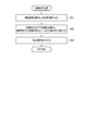
- FIG. 4 is a flowchart showing a processing procedure and processing contents of the traffic flow estimation process by the traffic flow estimation device shown in FIG.
- FIG. 5 is a diagram showing an example of an image taken by an in-vehicle camera.
- FIG. 6 is a diagram showing an example of sensor data acquired by the vehicle-mounted sensor.
- FIG. 1 is a diagram showing an overall configuration of a system including a traffic flow estimation device according to an embodiment of the present invention.
- FIG. 2 is a block diagram showing a hardware configuration of a traffic flow estimation device according to an embodiment of the present invention.
- FIG. 3 is a block diagram showing a
- FIG. 7 is a flowchart showing a processing procedure and processing contents of the vehicle detection processing among the processes shown in FIG.
- FIG. 8 is a diagram showing an example of the processing result of the vehicle detection process shown in FIG. 7.
- FIG. 9 is a flowchart showing a processing procedure and processing contents of the movement amount calculation processing among the processes shown in FIG.
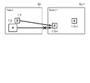
- FIG. 10A is a diagram showing a first example of vehicle association between frames.
- FIG. 10B is a diagram showing a second example of vehicle association between frames.
- FIG. 11 is a diagram showing an example of a processing result of the movement amount calculation process shown in FIG.
- FIG. 12 is a flowchart showing a processing procedure and processing contents of the area determination processing among the processes shown in FIG. FIG.
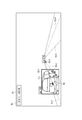
- FIG. 13 is a diagram showing an example of a region determination line used in the region determination process shown in FIG.
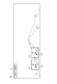
- FIG. 14 is a diagram showing an example of the detected image of the moving direction of the other vehicle.
- FIG. 15 is a diagram showing an example of data stored in the road-specific information storage unit.
- FIG. 16 is a diagram showing an example of an analysis image of the data shown in FIG.
- FIG. 17 is a flowchart showing a processing procedure and processing contents of the traffic flow calculation processing among the processes shown in FIG.
- FIG. 18A is a diagram showing an example of teacher data for constructing a regression model used in the process of calculating the traveling speed of the other vehicle shown in FIG. FIG.
- FIG. 18B is a diagram showing an example of a coefficient vector used in the process of calculating the traveling speed of the other vehicle shown in FIG.
- FIG. 19 is a diagram showing an example of a calculation result of the traveling speed of another vehicle associated with the lane ID.
- FIG. 20 is a diagram showing an example of data stored in the traffic flow information storage unit.
- FIG. 1 is a diagram showing an example of an overall configuration of a system including a traffic flow estimation device 1 according to an embodiment of the present invention.
- This system is equipped with a traffic flow estimation device 1 on the Web or the cloud, for example. Then, the traffic flow estimation device 1 and the vehicle-mounted device 63 having a communication function mounted on the mobile body 6 can communicate with each other via the communication network NW. Although only one mobile body 6 is shown in FIG. 1 for simplicity, the traffic flow estimation device 1 can communicate with a plurality of mobile bodies 6.
- the network NW is composed of, for example, a relay network and a plurality of access networks for accessing this relay network.
- a relay network a closed network controlled so that it can be accessed only from a public network such as the general Internet or a limited number of devices is used.
- a wireless LAN Local Area Network
- a mobile phone network a wired telephone network, or the like is used.
- the moving body 6 further includes a camera 61 and a sensor 62.
- the camera 61 uses a solid-state imaging device such as a CCD (Charge Coupled Device) or CMOS (Complementary Metal Oxide Semiconductor) sensor, and covers a road region in an arbitrary direction such as the traveling direction of the moving body 6 in an imaging range.
- the installation location, orientation and angle are set to include.
- the camera 61 acquires camera image data and outputs the acquired data to the vehicle-mounted device 63.
- the camera 61 may be provided exclusively for traffic flow estimation processing, it is possible to obtain equivalent data such as a drive recorder camera or an in-vehicle camera mounted for other purposes. Any camera can be used as long as it is.
- a camera provided on the driver's helmet may be used, or a mobile terminal such as a smartphone or tablet terminal owned by a passenger of the mobile body 6 may be used. You may use a camera.
- an infrared camera may be used as the type of the camera 61.
- the data acquired by the camera 61 may be moving image (video) data or still image data captured at regular time intervals.
- the sensor 62 includes a GPS sensor and a speed sensor, and may also be provided exclusively for traffic flow estimation processing, or for operation control or log data collection of the automobile 6 such as CAN (Controller Area Network). Therefore, it may be a sensor normally provided. Further, the sensor 62 may be a mobile terminal such as a smartphone.
- the GPS sensor calculates the latitude and longitude of the moving body 6 by receiving GPS signals transmitted by a plurality of GPS satellites and performing a ranging calculation, and the GPS data including the calculated latitude and longitude is used as an in-vehicle device VD. Output to.
- the GPS data can include information indicating the certainty of GPS measurement in addition to latitude and longitude (hereinafter, also referred to as "position information").
- position information information indicating the certainty of GPS measurement in addition to latitude and longitude
- the certainty of GPS measurement is determined, for example, according to the arrangement of GPS satellites.
- the acquisition of position information is not limited to the method using signals from GPS satellites, and if the same function is exhibited, the position information of a wireless base station or WiFi access point can be used, etc. You may use the method of.
- the speed sensor is, for example, a wheel speed sensor, which is installed in a rotating part such as a drive shaft and measures the speed of the automobile 6 based on the rotating speed of the rotating part.
- the speed sensor outputs the measured speed data to the on-board unit 63.
- the on-board unit 63 is, for example, a wireless device mounted on the dashboard of an automobile, and receives various data from the camera 61 and the sensor 62 to receive date and time information and the on-board unit 63 (or an ETC card inserted therein). Together with the identification information, it can be transmitted to the traffic flow estimation device 1 via the network NW.
- the on-board unit 63 is not an indispensable configuration, and the camera 61 and the sensor 62 may be configured to directly transmit data to the traffic flow estimation device 1. Further, the camera 61 and the sensor 62 do not have to be separate devices, and these can be incorporated into one device or integrated into the vehicle-mounted device 63.
- the traffic flow estimation device 1 is, for example, a server device provided in a traffic control center, and performs a process of estimating (calculating) a traffic flow in a target area.
- traffic flow will be described as an average speed [km / h] in a specific lane of a specific road, but the present invention is not limited to this.
- the traffic flow may be defined according to the application, and for example, a traffic volume representing the number of vehicles passing through a specific point, a traffic density, or the like may be used.
- the traffic flow estimation device 1 receives the moving body data (hereinafter referred to as “traveling data”) including the camera image data, the GPS data and the speed data collected by the moving body 6 via the network NW, and receives the moving body data. Based on the received data, for example, the traffic flow in the target area is calculated periodically or in response to a request from an operator or the like. Further, the traffic flow estimation device 1 can output the calculated traffic flow to an external device. For example, the traffic flow estimation device 1 transmits the calculated traffic flow to the vehicle-mounted device 63 in order to notify the driver of the moving body 6. It can be displayed on the display unit, or can be transmitted to a road information display device (not shown) or the like under the control of the traffic control center for display.
- the traffic flow estimation device 1 may, for example, directly receive the traveling data transmitted by the vehicle-mounted device 63 periodically or at an arbitrary timing, or access the vehicle-mounted device 63 to acquire necessary data. It may be a thing. Alternatively, the traffic flow estimation device 1 may acquire the traveling data by accessing the data once transmitted from the vehicle-mounted device 63 to the database server (not shown) or the like at an arbitrary timing. The travel data stored in the external medium may be acquired via the input device 2.
- the automobile exemplified as the moving body 6 is not limited to a specific automobile, and may be an automobile of various individuals, vehicle types, and manufacturers.
- the moving body 6 will be described as a vehicle 6 as an example, but the moving body 6 may be charged for the use of roads such as automobiles, motorcycles, bicycles, personal mobility, vehicles towed by livestock such as carriages, etc.
- a moving body may be included, and the vehicle may be a pedestrian. Therefore, the on-board unit 63 shown in FIG. 1 is only an example, and can be replaced with an information processing terminal such as a smartphone.
- FIG. 2 is a block diagram showing an example of the hardware configuration of the traffic flow estimation device 1.
- the traffic flow estimation device 1 is composed of, for example, a server computer or a personal computer, and has a hardware processor 20A such as a CPU (Central Processing Unit). Then, the program memory 20B, the data memory 30, the communication interface 11 and the input / output interface 12 are connected to the hardware processor 20A via the bus 40.
- a hardware processor 20A such as a CPU (Central Processing Unit).
- the program memory 20B, the data memory 30, the communication interface 11 and the input / output interface 12 are connected to the hardware processor 20A via the bus 40.
- the communication interface 11 includes, for example, one or more wired or wireless communication interface units, and enables information to be transmitted / received to / from an external device including an on-board unit 63 mounted on the vehicle 6.
- a wired LAN is used
- the wireless interface an interface adopting a low power wireless data communication standard such as a wireless LAN or Bluetooth (registered trademark) is used.
- the input / output interface 12 is connected to the input device 2 and the output device 3 attached to the traffic flow estimation device 1.
- the input / output interface 12 captures operation data input by the operator through an input device 2 such as a keyboard, touch panel, touch pad, and mouse, and outputs data as a display device or voice using a liquid crystal or organic EL (Electro Luminescence).
- a process of outputting to an output device 3 including an output speaker and displaying the data is performed.
- the input device 2 and the output device 3 may use the device built in the traffic flow estimation device 1, or may use the input device and the output device of another information terminal capable of communicating via the network NW. May be good.
- the program memory 20B is used as a storage medium in combination with, for example, a non-volatile memory such as an HDD (Hard Disk Drive) or an SSD (Solid State Drive) that can be written and read at any time, and a non-volatile memory such as a ROM. It stores programs necessary for executing various control processes according to the embodiment.
- a non-volatile memory such as an HDD (Hard Disk Drive) or an SSD (Solid State Drive) that can be written and read at any time
- a non-volatile memory such as a ROM. It stores programs necessary for executing various control processes according to the embodiment.
- the data memory 30 uses, for example, a non-volatile memory such as an HDD or SSD that can be written and read at any time and a volatile memory such as a RAM (Random Access Memory) as a storage medium. It is used to store various data acquired and created in the process of performing estimation processing.
- a non-volatile memory such as an HDD or SSD that can be written and read at any time
- a volatile memory such as a RAM (Random Access Memory) as a storage medium. It is used to store various data acquired and created in the process of performing estimation processing.
- RAM Random Access Memory
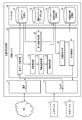
- FIG. 3 is a block diagram showing the software configuration of the traffic flow estimation device 1 according to the embodiment of the present invention in association with the hardware configuration shown in FIG.
- the storage area of the data memory 30 is provided with a travel data storage unit 31, a road network data storage unit 32, a road-specific information storage unit 33, and a traffic flow information storage unit 34.
- the travel data storage unit 31 is used to store travel data including camera image data and sensor data acquired by the travel data acquisition unit 21.
- the road network data storage unit 32 is used to store various data related to the road network including lane information, which is stored in advance.
- the road-specific information storage unit 33 is used to store various road-specific information (road-specific data) specified based on the travel data.
- the traffic flow information storage unit 34 is used to store the calculated information on the traffic flow.
- the storage units 31 to 34 are not essential configurations, and may be provided in, for example, an external storage medium such as a USB memory or a storage device such as a database server arranged in the cloud.
- the control unit 20 is composed of the hardware processor 20A and the program memory 20B, and has a traveling data acquisition unit 21, a vehicle detection unit 22, a movement amount calculation unit 23, and an area determination as processing function units by software.
- a unit 24, a traveling road specifying unit 25, a traffic flow calculation unit 26, and an output control unit 27 are provided. All of the processing functions in each of these parts are realized by causing the hardware processor 20A to execute the program stored in the program memory 20B. It should be noted that these processing functions may not be realized by using the program stored in the program memory 20B, but may be realized by using the program provided through the network.
- the control unit 20 may also be implemented in a variety of other forms, including integrated circuits such as ASICs (Application Specific Integrated Circuits) and FPGAs (field-programmable gate arrays).
- the traveling data acquisition unit 21 acquires the in-vehicle camera image and CAN data transmitted from the vehicle 6 via the communication interface 11 or the input / output interface 12, and extracts the camera image data and the sensor data necessary for processing. , Performs a process of storing in the traveling data storage unit 31.
- the vehicle detection unit 22 reads out the camera image data stored in the traveling data storage unit 31, cuts out the read camera image data into a frame, and displays another vehicle (a second moving body around) projected in the frame. A process is performed in which the detection is performed, the detected coordinates in the image of another vehicle are calculated, and the calculated coordinates in the image are output to the movement amount calculation unit 23.
- the movement amount calculation unit 23 calculates information indicating the movement of another vehicle (change in position with time) based on the coordinates in the image in each frame output from the vehicle detection unit 22, and outputs the information to the area determination unit 24. Do.
- the area determination unit 24 determines in which lane the vehicle is located (in which lane) based on the information indicating the movement of another vehicle in each frame output from the movement amount calculation unit 23. , The determination result is output to the road-specific information storage unit 33 and stored.
- the traveling road specifying unit 25 reads out the camera image data and the sensor data stored in the traveling data storage unit 31, and which road is the vehicle 6 (hereinafter, also referred to as “own vehicle 6”) from which the data is acquired. Determine which lane you are driving in.
- the traveling road specifying unit 25 also stores information on the traveling speed, traveling road, and traveling lane of the own vehicle 6 in the road-specific information storage unit 33 in association with the data output by the area determination unit 24. I do.
- the traffic flow calculation unit 26 reads out the data stored in the road-specific information storage unit 33, calculates the traffic flow for each lane of each road, and stores the calculation result in the traffic flow information storage unit 34. ..
- the output control unit 27 reads the information stored in the traffic flow information storage unit 34, for example, periodically or in response to an output instruction from the operator, generates data for output, and inputs / outputs the communication interface 11 or A process of outputting to the outside via the interface 12 is performed.
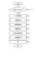
- FIG. 4 is a flowchart showing the processing procedure and the processing content.
- the traffic flow estimation device 1 monitors the presence or absence of a trigger for starting the traffic flow estimation process in step S1. In this state, for example, by receiving a trigger signal generated by an internal timer at regular intervals, or by the operator inputting a processing start request using the input device 2 and receiving this request as a trigger.
- the traffic flow estimation device 1 executes the following processing.
- step S2 the traffic flow estimation device 1 is controlled by the control unit 20 and is controlled by the travel data acquisition unit 21 via the communication interface 11 or the input / output interface 12.
- the data is taken in and stored in the traveling data storage unit 31.
- the data transmitted from the vehicle-mounted device 63 is accumulated as a database or a file on the cloud, and the traffic flow estimation device 1 acquires necessary data by accessing these.
- this data acquisition process may be directly received from the vehicle-mounted device 63, and the traveling data acquisition unit 21 acquires the data pushed by the vehicle-mounted device 63 at an arbitrary timing. It may be something to do. Therefore, step S2 does not necessarily have to be executed in response to the trigger of step S1.
- the camera image data acquired by the traveling data acquisition unit 21 will be described as being an in-vehicle camera image taken by the in-vehicle camera 61 of the vehicle 6. Further, the in-vehicle camera 61 mounted on the vehicle 6 captures an image including the front of the moving vehicle 6.
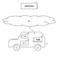
- FIG. 5 shows an example of a frame 50 cut out from the camera image data acquired by the traveling data acquisition unit 21 as an image (image data) used for the traffic flow estimation process.
- the frame 50 includes date and time information 51 representing the date and time taken by the camera 61.
- a part of the own vehicle 6 in which the camera 61 is installed another vehicle 7 (7-1, 7-2, 7) As a surrounding moving body, a lane boundary line 8, and a lane (lane). ) 9 (9-1, 9-2, ...) Is projected.
- the sensor data acquired by the traveling data acquisition unit 21 includes at least the speed and position information of the traveling vehicle 6 measured by the sensor 62 mounted on the vehicle 6.
- the position information is assumed to be the latitude and longitude measured at 1 [Hz].
- FIG. 6 shows an example of sensor data acquired by the driving data acquisition unit 21.
- the traveling data acquisition unit 21 reads the signals representing the position information and the speed information transmitted from the sensor 62 and performs sampling at a sampling rate of 1 Hz, respectively, thereby performing GPS [latitude / longitude] data and speed [km / km /. h] Generate data.
- the frame rate [fps (frame per second)] recorded as camera video data, the better, but it is desirable that the frame rate is 10 [fps] or more. Further, it is assumed that the camera image data and the sensor data (GPS data and speed data) are time-synchronized within an error of at least 1 second.
- step S3 the traffic flow estimation device 1 performs vehicle detection processing by the vehicle detection unit 22 under the control of the control unit 20.
- FIG. 7 is a flowchart showing an example of the processing procedure and processing content of the vehicle detection process in step S3.
- step S31 the vehicle detection unit 22 reads out the camera image data (file) stored in the travel data storage unit 31.
- step S32 the vehicle detection unit 22 performs a process of cutting out the read camera image data into frames (also referred to as “images”) in units of 0.1 seconds, for example.
- the frame at the time t cut out is referred to as "frame_t" (1 ⁇ t ⁇ N) (N is an arbitrary integer according to the length of the read video data).
- the process of cutting out the video into a frame may be performed by an arbitrary method, and may be performed by a method such as ffmpeg.
- step S33 the vehicle detection unit 22 performs a process of detecting another vehicle 7 reflected in the image of each cut out frame.
- the method of detecting the other vehicle 7 may be any method, for example, using a known YOLO (see the Internet ⁇ https://arxiv.org/abs/1804.02767>) as a method using deep learning. May be good.
- the unit for cutting out into a frame may be changed according to the frame rate when the video is acquired.
- the vehicle detection unit 22 outputs the detected coordinates of the other vehicle 7 to the movement amount calculation unit 23 in a format associated with the time information of the frame. For example, when the vehicle detection unit 22 executes the detection of the other vehicle 7 as a rectangle, the vehicle detection unit 22 outputs the image coordinates ⁇ (x1, y1), (x2, y2) ⁇ regarding the two points of the upper left and lower right of the rectangle. To do.
- the origin of the coordinates has the upper left as the origin, as is generally used in the image coordinate system.
- a threshold value is set for the certainty, and an image of only the detection target that exceeds the threshold value.
- the coordinates ⁇ (x1, y1), (x2, y2) ⁇ may be output.
- FIG. 8 shows how the other vehicle 7 is detected by the vehicle detection process by the vehicle detection unit 22.
- a rectangle 52 (52-1, 52-2, 52-3, ...) Showing the detected other vehicle 7 is shown.
- the numerical value on the upper left of the rectangle detecting the other vehicle 7 (for example, 0.95 for the rectangle 52-1) is a value indicating the certainty of the vehicle (car).
- step S4 the traffic flow estimation device 1 performs a movement amount calculation process by the movement amount calculation unit 23 under the control of the control unit 20.
- FIG. 9 is a flowchart showing an example of the processing procedure and processing content of the movement amount calculation processing in step S4.
- step S41 the movement amount calculation unit 23 reads the rectangular coordinates of the other vehicle 7 detected in each frame as an output result from the vehicle detection unit 22.
- step S42 the movement amount calculation unit 23 calculates the tracking points for the other vehicle 7 detected in each frame.
- Any point can be adopted as the tracking point, and for example, the center of gravity (c1, c2) of the rectangular coordinates obtained by detecting the other vehicle 7 can be used.
- the center of gravity is, for example, from the rectangular coordinates ⁇ (x1, y1), (x2, y2) ⁇ that detected the other vehicle 7.
- c1 (x1 + x2) / 2
- step S43 the movement amount calculation unit 23 tracks to determine whether or not the frame (frame_t) at time t and the vehicle 7 detected at the frame (frame_t + 1) at time t + 1 are the same. Performs the process of associating points. If the vehicle 7 detected in frame_t and frame_t + 1 is the same, the movement amount can be calculated from the difference between the tracking point coordinates of frame_t and the tracking point coordinates of frame_t + 1.
- the movement amount calculation unit 23 uses the tracking point coordinates of the vehicle 7 detected in frame_t as a reference, and detects in frame_t + 1. After calculating the distance from the tracking point coordinates of the vehicle, the tracking point coordinates that minimize the distance are associated. When there are a plurality of vehicles 7 detected by frame_t + 1, the distance is calculated by the detected number, and the vehicle 7 having the minimum distance is associated.
- the distance may be a straight line distance between the centers of gravity (c1, c2) of the rectangular coordinates in which the vehicle 7 is detected.
- a certain threshold value for this distance it is possible to reduce mistakes in mapping between each frame.
- An arbitrary value can be set for a certain threshold value, and for example, a maximum moving distance that the vehicle 7 can move in one frame (for example, 0.1 second) can be set.
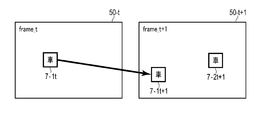
- FIG. 10A shows an example of an image of the vehicle association detected between frame_t (frame 50-t) and frame_t + 1 (frame 50-t + 1).
- the other vehicle 7-1t detected in the frame_t and the other vehicle 7-1t + 1 detected in the frame_t + 1 are associated with each other.
- Another vehicle 7-2t + 1 was also detected in frame_t + 1, but it was determined that there was no association with the vehicle detected in frame_t.
- the mapping from frame_t may be duplicated.
- a 1: 1 correspondence is performed by adding a condition.
- the condition may be, for example, associating vehicles having the closest detected vehicle areas with each other, or associating vehicles with the highest correlation coefficient between the detected vehicle images. You may.
- FIG. 10B shows an example of an image when a duplicate association is made between frame_t and frame_t + 1.
- the other vehicle 7-1t and t-3t detected in the frame_t overlap with the other vehicle 7-1t + 1 detected in the frame_t + 1 (frame 50-t + 1).
- the association between the vehicle 7-1t and the vehicle 7-1t + 1 is adopted.
- the movement amount calculation unit 23 calculates the movement amount of each vehicle 7 in each frame, and the area determination unit Output to 24.
- the movement amount a distance in the x component, a distance in the y component, a linear distance of the xy composite component, and the like in the image can be adopted.
- the detected rectangular coordinates of the vehicle 7 ⁇ (x1, y1), (x2, y2) ⁇ and the coordinates (c1, c2) as tracking points are linked to the movement amount and output to the area determination unit 24.
- FIG. 11 shows an example of the movement amount calculation result by the movement amount calculation unit 23. If the amount of movement of each vehicle in each frame can be obtained, the direction and length of movement of the vehicle to the next frame can be grasped.
- the moving direction and length of the vehicle 7-1 in the frame 50 are indicated by arrows 54.
- the arrow 54 is also an example of information indicating a change over time in the position of the moving body (other vehicle 7) in the image.
- the amount of movement may also be calculated for the truck (detected in the rectangle 52-2) reflected in front of the own vehicle 6. Further, here, a person walking on the sidewalk (detected in the rectangle 52-5) is set not to be used in the movement amount calculation process.
- step S5 the traffic flow estimation device 1 performs an area determination process by the area determination unit 24 under the control of the control unit 20.
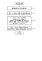
- FIG. 12 is a flowchart showing an example of the processing procedure and processing content of the area determination processing in step S5.
- step S51 the area determination unit 24 reads the movement amount information of the other vehicle 7 in each frame 50 output as an output result from the movement amount calculation unit 23, and uses the coordinates (c1, c1,) as the tracking points of the other vehicle 7. See c2).
- step S52 the area determination unit 24 performs a process of relatively determining which lane 9 the other vehicle 7 is traveling from from the tracking point coordinates (c1, c2).
- the region determination unit 24 first determines the region determination line (lane determination) with respect to both ends of the lane 9 in which the own vehicle 6 is traveling. (Also called a line) is provided.
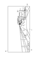
- FIG. 13 shows an example of an image of such a region determination line 53 (53-1, 53-2, 53-3, 53-4).
- a region determination line 53 (53-1, 53-2, 53-3, 53-4).
- the tracking point coordinates of the other vehicle 7 are in which area. Can be determined.
- the area determination line 53 may be defined as a line along the width of the adjacent lane. Based on this rule, it is possible to determine the lane in which the own vehicle 6 is traveling and the area such as ⁇ same lane / one left lane / one right lane / two or more left lanes / two or more right lanes ⁇ . On the computer, where the tracking point coordinates (c1, c2) are located on the area determination line 53 can be determined, for example, by using the characteristics of the outer product.
- each line of the area determination line 53 is regarded as a vector
- a vector is created from the in-image cut point coordinates and the tracking point coordinates (c1, c2) of the area determination line 53, and the angle between these two vectors is 180 °.
- the method of region determination by the region determination unit 24 is not limited to the method using the region determination line 53 described above.
- the movement direction of the vehicle 7 in the image (the movement direction of the other vehicle 7-1 in FIG. 13 (arrow 54). (Inclination)) can be obtained.
- FIG. 14 is a diagram showing an example of an image in which the inclination of the arrow 54 becomes closer to horizontal as the vehicle travels in a lane farther from the own vehicle.
- the arrow 54-1 of the vehicle detected in the rectangle 52-1 farther from the own vehicle is compared with the arrow 54-2 of the vehicle detected in the rectangle 52-2 closer to the own vehicle. It can be seen that it is close to horizontal (the broken line is drawn so that the inclination of the arrow 54 is easy to understand).
- step S53 the area determination unit 24 outputs the determination result to the road-specific information storage unit 33 and stores it.
- step S6 the traffic flow estimation device 1 performs a process of identifying the road on which the own vehicle 6 is traveling by the travel road identification unit 25 under the control of the control unit 20. More specifically, the traveling road specifying unit 25 reads out the camera image data and the sensor data stored in the traveling data storage unit 31 and determines which lane of which road the own vehicle 6 is traveling on.
- the road-specific information storage unit 33 stores information on the traveling speed, the traveling road, and the traveling lane.
- the driving road identification unit 25 performs map matching processing using the position information (latitude / longitude) included in the sensor data and the road network data stored in advance in the road network data storage unit 32. It can be carried out. Map matching is a process of associating a vehicle with a road ID defined in road network data based on the location information of the vehicle (for example, the Internet ⁇ http://bin.tu-tokyo.ac.jp). See /startup15/file/0529yamamoto.pdf>).
- the latitude and longitude of the start point and the end point of the road are defined as road network data for each road ID, and the lane number information of the road is also stored in association with it.
- map matching a known method can be used. For example, a method of associating a road ID of a road such that the distance obtained by drawing a perpendicular line from the position of a vehicle to the road is minimized is used. be able to.
- the driving road specifying unit 25 specifies which lane of the road the own vehicle is traveling in.
- a method of specifying the traveling lane position a known method can be used.
- the lane position may be specified after detecting the lane reflected in the image of the vehicle-mounted camera 61.
- the traveling road specifying unit 25 can know, for example, which lane the own vehicle is traveling from the left by detecting the area determination line 53 shown in FIG.
- the driving road specifying unit 25 provides information on ⁇ time, the road on which the own vehicle is located, the number of lanes on the road, the lane in which the own vehicle is located, and the traveling speed of the own vehicle ⁇ specified as described above by road. It is stored in the storage unit 33.
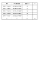
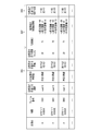
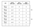
- FIG. 15 shows an example of an image of road-specific data stored in the road-specific information storage unit 33.
- the road-specific data stored in the road-specific information storage unit 33 includes the information output from the area determination unit 24 ⁇ time, frame number, other vehicle ID, movement amount information of other vehicle, relative position where other vehicle is located ⁇ .
- Information output from the driving road identification unit 25 ⁇ time, frame number, own vehicle ID, road on which the own vehicle is located, number of lanes on the road, lane in which the own vehicle is located, traveling speed of the own vehicle ⁇ are linked. It is stored in the format.
- the road-specific data is the information D01 ⁇ the road on which the own vehicle is located and the number of lanes on the road, which is associated with the own vehicle ID, the time, and the frame number and is specified by the traveling road specifying unit 25.
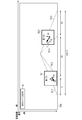
- FIG. 16 is a diagram showing an example of an image of the road-specific data shown in FIG.
- the ID of the road on which the own vehicle travels is set to X (road-X), and when the road is a three-lane road, each lane is set to X1, X2, X3 from the left in the traveling direction.
- the lane ID in which the own vehicle travels can be specified by the traveling road specifying unit 25, and the lane ID in which the other vehicle is located can also be specified by the processing of the area determination unit 24.
- the road-specific information storage unit 33 may store the area of another vehicle obtained by the processing of the area determination unit 24 in a form associated with the lane ID.
- the vehicle (T1) detected in the rectangle 52-1 is traveling in the same lane as the own vehicle from the direction of the arrow indicating the amount of movement, and is in the rectangle 52-2. It is presumed that the detected vehicle (T2) is traveling in the lane opposite to the own vehicle.
- the numerical value in each rectangle 52 represents the coordinate change.
- step S7 the traffic flow estimation device 1 performs a traffic flow calculation process by the traffic flow calculation unit 26 under the control of the control unit 20.
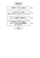
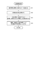
- FIG. 17 is a flowchart showing an example of the processing procedure and processing contents of the traffic flow calculation processing in step S7.
- step S71 the traffic flow calculation unit 26 reads the data stored in the road-specific information storage unit 33.
- step S72 the traffic flow calculation unit 26 calculates the traveling speed of the other vehicle 7 from the traveling speed of the own vehicle 6 and the movement amount information of the other vehicle 7 among the read data.
- the traffic flow calculation unit 26 can create the teacher data in advance and then calculate by the regression model. That is, the coefficient vector for each explanatory variable vector is estimated by performing regression analysis using the traveling speed of the own vehicle 6 and the movement amount information of the other vehicle 7 as explanatory variables and the traveling speed of the other vehicle 7 as the objective variable. Can be done.
- the regression analysis model may be, for example, a linear combination model.
- the explanatory variable vector is X
- the coefficient vector corresponding to the explanatory variable vector is W
- the objective variable is Y
- the inner product of X and W is used by the least squares method or the like. W can be found so that is most similar to Y. After that, by using the obtained coefficient vector W, when the traveling speed of the own vehicle 6 and the movement amount information of the other vehicle 7 are obtained, it is possible to estimate the traveling speed of the other vehicle 7 which is unknown.
- FIG. 18A shows an example of an image of teacher data used for constructing the regression model as described above.
- the teacher data may be, for example, one created based on actual measurement data or one created based on simulation results.
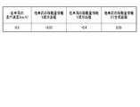
- FIG. 18B shows an example of an image of the coefficient vector W obtained by the regression analysis as described above.
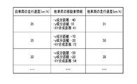
- step S73 the traffic flow calculation unit 26 performs a process of associating the traveling lane ID and traveling speed of the own vehicle / other vehicle with the time, road ID, and lane ID as keys.
- FIG. 19 shows an example of an image of such a processing result.
- R01 represents the information of the own vehicle 6
- R02 represents the information of the other vehicle 7 detected from the own vehicle 6.
- the traffic flow calculation unit 26 links the speed of a traveling vehicle for each time-road-lane. Here, it is not necessary to identify the own vehicle / other vehicle.
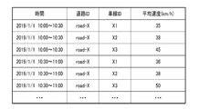
- step S74 the traffic flow calculation unit 26 calculates the average value (average speed (km / h)) of the traveling speed in an arbitrary time range for each road ID and lane ID, and stores the calculation result in the traffic flow information storage unit. Output to 34 and memorize.
- the time range for obtaining the traffic flow may be any range such as 10-minute units and 30-minute units.
- the traffic flow calculation unit 26 divides the data according to the determined time range, road ID, and lane ID, and obtains the average value of the traveling speeds included in the data to obtain the average value of the traveling speeds included in the data. Can be sought. In addition, it is not always necessary to be an average value, and an arbitrary statistic such as a median value or a deviation may be obtained according to the purpose of use.
- the information of the time range before and after that time range is displayed. May be used for interpolation.
- it is possible to obtain the traffic flow for each lane of a plurality of lanes for any of the time ranges it is possible to calculate the correlation between the lanes and interpolate from the average speed of the adjacent lane. For example, if the speed ratio between the first lane and the second lane is 1: 1.2, the average speed calculated for the first lane may be multiplied by 1.2 and interpolated as the average speed for the second lane.
- the average speed for 10: 00-10: 30 and 11: 11: 30 in the time range if the average speed can be calculated for 10: 00-10: 30 and 11: 11: 30 in the time range, and 10: 30-11: 00 cannot be calculated, the average speed for 10: 00-10: 30
- the average value of the average speed at 11 o'clock-11: 30 may be interpolated as the average speed at 10:30-11 o'clock. By performing interpolation, the traffic flow estimation device 1 can calculate the traffic flow for each lane from a smaller amount of travel data.
- the traffic flow calculation unit 26 stores the average speed (km / h) calculated in this way in the traffic flow information storage unit 34.
- FIG. 20 shows an example of a data image stored in the traffic flow information storage unit 34.
- FIG. 20 shows an example in which the average speed is calculated with the time range in units of 30 minutes.
- step S8 the traffic flow estimation device 1 performs arbitrary output processing by the output control unit 27.
- the output control unit 27 receives information stored in the traffic flow information storage unit 34, for example, periodically or in response to a transmission request from the vehicle 6 or an output request from the operator input via the input device 2. Is read, data for output is generated, and the data is output via the communication interface 11 or the input / output interface 12.
- the output control unit 27 takes 5 minutes, 10 minutes, and 30 minutes.
- the average speed (traffic flow) calculated for each time range, road ID, and lane ID based on the information read from the traffic flow information storage unit 34 at an arbitrary time interval such as every time is calculated by the input / output interface unit. It can be output to a liquid crystal display and displayed. Then, the operator of the traffic control center who sees this display can immediately grasp the road conditions in the city such as traffic congestion information and take appropriate measures.
- the traffic flow estimation device 1 acquires camera image data and sensor data collected by the vehicle 6 traveling on the road, and is included in the camera image data.
- the other vehicle 7 is detected from the image of the frame, the movement amount of the other vehicle 7 and the like are calculated, and which lane on the road the other vehicle 7 is traveling with respect to the traveling position of the vehicle 6 is estimated.
- the traffic flow estimation device 1 also identifies the road and lane in which the vehicle 6 is traveling from the sensor data (and camera image data if necessary).
- the traffic flow estimation device 1 of the other vehicle 7 is based on the speed of the vehicle 6, the road and lane on which the vehicle 6 is traveling, the amount of movement of the other vehicle 7, and the estimated traveling lane of the other vehicle 7. Calculate the speed and calculate the traffic flow for each lane.
- the traffic flow estimation device 1 can calculate not only the lane in which the vehicle (own vehicle) 6 from which the camera image data and the sensor data are collected travels, but also the traffic flow in other lanes, resulting in less travel.
- a wider range (lane) of traffic flow can be calculated from the data. For example, it is possible to estimate the traffic flow in each lane even in a situation where driving data can be collected only from vehicles traveling in a part of the vehicles traveling on a certain road. Further, this makes it possible to estimate the traffic flow by effectively utilizing the limited data while suppressing the traffic between the vehicle and the traffic flow estimation device 1.
- the traffic flow estimation device 1 detects another vehicle 7 reflected in the video data showing the front of the moving vehicle 6, and when calculating the movement amount of the other vehicle 7, the movement amount calculation unit 23 performs each frame.
- the vehicles inside are associated with each other.
- the traffic flow estimation device 1 can calculate the movement amount more accurately than in the case where the association is not performed, so that the traffic flow can be calculated more accurately.
- the traffic flow estimation device 1 detects another vehicle 7 reflected in the video data showing the front of the moving vehicle 6, calculates the amount of movement of the other vehicle 7, and then travels in which lane on the road. The area is automatically determined to see if it is done.
- the area determination unit 24 that performs such area determination determines the area of the lane to the right and the lane to the left of the lane in which the own vehicle 6 travels in the coordinate system in the image in the video (image) data. By determining whether or not the other vehicle 7 exists in the area, it is possible to determine which lane the other vehicle 7 is traveling in. As a result, it is possible to calculate the traffic flow of the adjacent lane from the traveling data of the vehicle 6 traveling in a certain lane.
- the area determination unit 24 uses not only the movement amount of the other vehicle 7 but also the movement direction of the other vehicle 7 in the image coordinate system. By using the moving direction, it is possible to automatically determine whether the lane in which the other vehicle 7 is traveling is, for example, one lane to the right or two to the right of the lane in which the own vehicle is traveling. Therefore, the traffic flow in the adjacent lane can be calculated in a wide range from the traveling data of the vehicle 6 traveling in a certain lane.
- the traffic flow estimation device 1 detects the other vehicle 7 reflected in the video data showing the front of the moving vehicle 6, and estimates the movement amount and the relative traveling position of the other vehicle 7 so that the own vehicle 6 can move. It is possible to calculate the traffic flow in other lanes other than the driving lane. In the traffic flow calculation unit 26 that calculates the traffic flow, it is possible to estimate the relative speed such that the other vehicle 7 is faster, the same, or slower than the traveling speed of the own vehicle 6.
- the traveling speed of the other vehicle 7 can be collected as traveling data
- the traveling speed of the other vehicle 7, the moving amount of the other vehicle 7 calculated by the movement amount calculation unit 23, and the other vehicle 7 are collected.
- the traveling speed of the own vehicle 6 By accumulating the traveling speed of the own vehicle 6 at the time of detection in association with each other and formulating the relationship between the movement amount of the other vehicle and the speed difference (relative speed) between the own vehicle and the other vehicle.
- the relative speed difference with the traveling speed of the own vehicle 6 can be quantitatively calculated. Therefore, from the travel data obtained by the vehicle 6 traveling in a certain lane, even the traffic flow in the adjacent lane can be calculated in more detail.
- the traffic flow estimation device 1 extracts the relative movement (change in relative position) of the other vehicle 7 as a movement amount, converts the movement amount into a speed, and then calculates the traffic flow. Therefore, the traffic flow estimation device 1 can similarly calculate the speed of the oncoming vehicle traveling in the oncoming lane, and can be applied to the traffic flow calculation in the oncoming lane.
- each functional unit included in the traffic flow estimation device 1 may be distributed and arranged in a plurality of devices, and the processing may be performed by coordinating these devices with each other. Further, each functional unit may be realized by using a circuit.
- the circuit may be a dedicated circuit that realizes a specific function, or may be a general-purpose circuit such as a processor.
- the road-specific information storage unit 33 has been described as combining and storing the data output by the area determination unit 24 and the data output by the driving road identification unit 25. However, the present invention is not limited to this, and the road-specific information storage unit 33 may be configured as two or more separate storage units.
- the traffic flow estimation device 1 has been described as acquiring camera image data, GPS data, and speed data as driving data. However, the present invention is not limited to this, and the traffic flow estimation device 1 may also acquire other CAN data. For example, the traffic flow estimation device 1 may additionally acquire acceleration data and angular velocity data and use them as an auxiliary for improving the accuracy of area determination or driving road identification, or control of brakes, steering, and the like. Information may be additionally acquired and used when estimating the speed or traffic flow of the other vehicle 7.
- the traffic flow estimation device 1 does not need to use only GPS data to obtain position information, and may estimate position information based on speed information and control information, and may be connected to a roadside machine.
- the driving road or the traveling lane may be specified by using the information obtained by the road-to-vehicle communication.
- the traffic flow estimation device 1 may use not only latitude and longitude but also altitude (elevation) data for estimating various information.
- the movement amount calculation unit 23 may use another method for determining whether or not the vehicles 7 detected in each frame are the same. For example, character information may be read from the license plate of the vehicle displayed on each frame, and the vehicles may be associated with each other based on the read character information. Alternatively, the identity of the vehicle may be detected by vehicle-to-vehicle communication using a BLE (Bluetooth Low Energy) beacon or the like.
- BLE Bluetooth Low Energy
- the traffic flow estimation device 1 can calculate the traffic flow based on an arbitrary data range. For example, the traffic flow estimation device 1 may extract only the data that matches a specific condition from the accumulated camera image data and sensor data and use it for calculating the traffic flow.
- the flow of each process described above is not limited to the procedure described above, and the order of some steps may be changed, or some steps may be performed in parallel. .. Further, the series of processes described above need not be executed continuously in time, and each step may be executed at an arbitrary timing.
- the steps for identifying the driving road or driving lane of the own vehicle described with respect to step S6 are not limited to the order shown in the drawing, and are, for example, before steps S3 to 5 or in parallel with steps S3 to 5. You can also do it.
- the vehicle 6 itself may identify the traveling road or the traveling lane, and the traffic flow estimation device 1 may acquire the road identification information specified by the vehicle 6 together with the traveling data.
- the method described above can be executed by a computer (computer) as a program (software means) such as a magnetic disk (floppy (registered trademark) disk, hard disk, etc.) or an optical disk (CD-ROM, DVD, MO, etc.).
- a program software means
- a magnetic disk floppy (registered trademark) disk, hard disk, etc.) or an optical disk (CD-ROM, DVD, MO, etc.
- a recording medium storage medium
- the program stored on the medium side also includes a setting program for configuring the software means (including not only the execution program but also the table and the data structure) to be executed by the computer in the computer.
- a computer that realizes the above-mentioned apparatus reads a program recorded on a recording medium, constructs software means by a setting program in some cases, and executes the above-mentioned processing by controlling the operation by the software means.
- the recording medium referred to in the present specification is not limited to distribution, and includes storage media such as magnetic disks and semiconductor memories provided in devices connected inside a computer or via a network.
- the present invention is not limited to the above embodiment, and can be variously modified at the implementation stage without departing from the gist thereof.
- each embodiment may be carried out in combination as appropriate, in which case the combined effect can be obtained.
- the above-described embodiment includes various inventions, and various inventions can be extracted by a combination selected from a plurality of disclosed constituent requirements. For example, even if some constituent requirements are deleted from all the constituent requirements shown in the embodiment, if the problem can be solved and the effect is obtained, the configuration in which the constituent requirements are deleted can be extracted as an invention.
- [C1] It is a traffic flow estimation device (1) and A storage medium (30) that stores lane information in the target area for estimating traffic flow, and A plurality of images including the peripheral second moving body (7) taken at a plurality of timings different by the first moving body (6) moving in the target area, and each of the plurality of images.
- a data acquisition unit (21) that acquires mobile data including the position information and speed information of the first mobile body (6) at the time of shooting. The first moving body (6) is moving based on the lane information stored in the storage medium and the position information of the first moving body (6) included in the acquired moving body data.
- a traffic flow calculation unit (26) that calculates a traffic flow for each lane in the target area based on each lane in which the (6) and the second moving body (7) are moving, and A traffic flow estimation device (1) configured to perform the above.
- the change amount calculation unit (23) determines the identity of the second moving body (7) included in the plurality of images by comparing the plurality of images, and when it is determined that they are the same, the said Calculate information representing the time course of the position of the second moving body (7).
- the traffic flow estimation device (1) according to C1.
- the second lane estimation unit (24) A lane determination line representing the lane in which the first moving body is moving is set for the image included in the moving body data.
- the lane in which the second moving body (7) is moving based on the set lane determination line and the positional relationship of the second moving body (7) with respect to the first moving body (6).
- the traffic flow estimation device (1) according to C1.
- the change amount calculation unit (23) The second moving body (7) is calculated by calculating the moving direction of the second moving body (7) based on the change in the coordinates in the image of the second moving body (7) included in the plurality of images. Calculate the information representing the change over time of the position in (7), The second lane estimation unit (24) The second moving body (7) is based on the calculated moving direction of the second moving body (7) and the estimated moving direction of the first moving body (6) and the lane in which the first moving body (6) is moving. Including estimating the lane in motion, The traffic flow estimation device (1) according to C1.
- the change amount calculation unit (23) The second moving body (7) is calculated by calculating the amount of movement of the second moving body (7) based on the change in the coordinates in the image of the second moving body (7) included in the plurality of images. Calculate the information representing the change of the position of (7) with time,
- the traffic flow calculation unit (26) Based on the velocity information of the first moving body (6) included in the moving body data and the calculated movement amount of the second moving body (7), the first moving body ( Using a regression model obtained in advance by regression analysis using the velocity of 6) and the amount of movement of the second moving body (7) as explanatory variables and the velocity of the second moving body (7) as the objective variable, By calculating the speed of the second moving body (7), the traffic flow in the lane in which the second moving body (7) is moving is estimated.
- the traffic flow estimation device (1) according to C1.
- the traffic flow calculation unit (26) Traffic data in which the information representing the time-dependent change in the position of the second moving body (7) and the speed information of the first moving body (6) are associated with each other is generated. Divide the generated traffic data according to a predetermined standard, perform the necessary interpolation, and perform the necessary interpolation. The traffic flow in the target area is calculated based on the traffic data divided and subjected to the necessary interpolation and the lane in which the first moving body (6) is moving.
- the traffic flow estimation device (1) according to C1.
- the processor detects the positional relationship of the second moving body (7) with respect to the first moving body (6) from the image included in the moving body data, and the positional relationship and the estimated first A process (S5) of estimating the moving lane by the second moving body (7) based on the moving lane of the moving body (6).
- the processor includes speed information of the first mobile body (6) included in the mobile body data, information representing a time-dependent change in the position of the second mobile body (7), and the estimated first movement.
- [C8] A program that causes a processor to execute processing by each part of the traffic flow estimation device (1) according to any one of the above [C1] to [C6].
Abstract
対象領域の交通流を推定する交通流推定装置(1)を提供する。交通流推定装置(1)は、対象領域の車線情報を記憶する記憶部(30)を備え、対象領域内を移動中の第1の移動体(6)によって異なるタイミングで撮影された周辺の第2の移動体(7)を含む複数の画像と、各タイミングにおける第1の移動体の位置情報および速度情報とを取得し、車線情報と位置情報とをもとに第1の移動体が移動中の車線を特定し、複数の画像をもとに画像内における第2の移動体の位置の経時変化を算出し、画像から検出される第1の移動体に対する第2の移動体の位置関係に基づいて第2の移動体が移動中の車線を推定し、第1の移動体の速度情報と、第2の移動体の位置の経時変化を表す情報と、第1および第2の移動体が移動中の車線とに基づいて、対象領域の車線別の交通流を推定する。
Description
この発明の一態様は、交通流推定装置、交通流推定方法、交通流推定プログラムおよび交通流推定プログラムを記憶した記憶媒体に関する。
近年、自動車の走行データをリアルタイムにインターネット上のクラウド環境等へ送信するコネクティッドカーが注目を集めている。複数のコネクティッドカーから大量の走行データを収集できれば、渋滞情報といった街中の道路状況をリアルタイムに把握し、交通状態の早期改善や事前対策などが行えるようになると期待されている(例えば、非特許文献1参照)。
さらに、走行データとしては、速度や加速度とあわせて位置情報も収集可能であり、その位置情報の観測精度も年々向上している。このため、走行している自動車の車線まで特定することが可能となり、その情報をもとに、道路単位だけでなく車線単位での交通状況を把握できるようになることが期待される。
走行データを用いて車線ごとの交通流を推測する方法の一例として、走行する車の車線を特定し、その車の走行速度を参照する方法が考えられる。このように、道路上の各車線を走行する自動車の走行データを収集できれば、車線ごとの交通流を推測できることになる。
内閣官房 情報通信技術(IT)総合戦略室、「交通データ利活用に係るこれまでの取組と最近の動向について(案)(交通データ関連)」、[online]、平成25年12月25日、インターネット<URL: http://www.kantei.go.jp/jp/singi/it2/senmon_bunka/douro/dai3/siryou1.pdf>
しかし、すべての自動車が走行データを例えばクラウド環境にアップロードする機能を備えているわけではなく、また、クラウド環境で収集した走行データは例えば各自動車メーカ固有のデータとなることがあるので、ある道路を走行しているすべての自動車から走行データを収集することは困難である。すなわち、従来提案されているシステムでは、例えばある車線を走行している自動車から走行データが収集できたとしても、その隣の車線を走行している自動車からは走行データが収集できないような状況が起こり得るため、すべての車線における交通流を推定できないという問題があった。
この発明は上記事情に着目してなされたもので、その目的とするところは、限られた走行データに基づいて、より広い範囲の交通流を推定する技術を提供することにある。
上記課題を解決するためにこの発明の第1の態様は、ハードウェアプロセッサとメモリとを有する交通流推定装置にあって、上記メモリが、交通流を推定する対象領域の車線情報を記憶する記憶部を備え、上記ハードウェアプロセッサが、上記対象領域内を移動中の第1の移動体によって異なる複数のタイミングで撮影された、周辺の第2の移動体を含む複数の画像と、当該複数の画像の各々が撮影されたタイミングにおける上記第1の移動体の位置情報および速度情報とを含む移動体データを取得することと、上記記憶部に記憶された車線情報と、上記取得した移動体データに含まれる上記第1の移動体の位置情報とをもとに、上記第1の移動体が移動中の車線を特定することと、上記移動体データに含まれる画像をもとに、上記画像内における上記第2の移動体の位置の経時変化を表す情報を算出することと、上記移動体データに含まれる画像から上記第1の移動体に対する上記第2の移動体の位置関係を検出し、当該位置関係と上記推定された第1の移動体が移動中の車線とに基づいて上記第2の移動体が移動中の車線を推定することと、上記移動体データに含まれる上記第1の移動体の速度情報と、上記第2の移動体の位置の経時変化を表す情報と、上記推定された上記第1の移動体および第2の移動体が移動中の各車線とに基づいて、上記対象領域の車線別の交通流を推定することと、を実行するようにしたものである。
この発明の第2の態様は、上記第2の移動体の位置の経時変化を表す情報を算出することが、上記複数の画像を対比することによって、上記複数の画像に含まれる上記第2の移動体の同一性を判定することを含むようにしたものである。
この発明の第3の態様は、上記第2の移動体が移動中の車線を推定することが、上記移動体データに含まれる画像に対して、上記第1の移動体が移動中の車線を表す車線判定線を設定することと、上記設定された車線判定線と、上記第1の移動体に対する上記第2の移動体の位置関係とに基づいて、上記第2の移動体が移動中の車線を推定することとを含むようにしたものである。
この発明の第4の態様は、上記第2の移動体の位置の経時変化を表す情報を算出することが、上記複数の画像に含まれる上記第2の移動体の画像内座標の変化に基づいて、上記第2の移動体の移動方向を算出することを含み、上記第2の移動体が移動中の車線を推定することが、上記算出された移動方向と上記推定された上記第1の移動体が移動中の車線とに基づいて、上記第2の移動体が移動中の車線を推定することを含むようにしたものである。
この発明の第5の態様は、上記第2の移動体の位置の経時変化を表す情報を算出することが、上記複数の画像に含まれる上記第2の移動体の画像内座標の変化に基づいて、上記第2の移動体の移動量を算出することを含み、上記交通流を推定することが、上記移動体データに含まれる上記第1の移動体の速度情報と、上記算出された上記第2の移動体の移動量とをもとに、上記第1の移動体の速度および上記第2の移動体の移動量を説明変数とし上記第2の移動体の速度を目的変数とする回帰分析によってあらかじめ得られた回帰モデルを用いて、上記第2の移動体の速度を算出することを含むようにしたものである。
この発明の第6の態様は、上記交通流を推定することが、上記第2の移動体の位置の経時変化を表す情報と、上記第1の移動体の速度情報とを対応付けた交通データを生成することと、上記生成された交通データを所定の基準により分割し、必要な補間を実行することと、上記分割され必要な補間を実行された交通データと、上記第1の移動体が移動中の車線とに基づいて、上記対象領域の交通流を推定することとを含むようにしたものである。
この発明の第1の態様によれば、交通流推定装置は、交通流を推定する対象領域の車線情報を記憶しており、対象領域内を移動中の第1の移動体によって異なる時間に撮影された、他の第2の移動体を含む複数の画像と、当該複数の画像の各々が撮影された時点の第1の移動体の位置情報および速度情報とを含む、移動体データを取得する。そして、交通流推定装置は、記憶された車線情報と、取得した移動体データに含まれる複数の画像ならびに第1の移動体の位置情報および速度情報とに基づいて、第1の移動体が移動中の車線を特定し、第2の移動体の位置の経時変化を表す情報を算出し、第2の移動体が移動中の車線を推定し、これらの推定または算出された情報に基づいて対象領域の車線別の交通流を推定する。
このように、交通流推定装置は、第2の移動体からの走行データが得られないときでも、第1の移動体により撮影された複数の画像と、撮影時点での第1の移動体の位置情報および速度情報とを取得することによって、第2の移動体についても、その位置の経時変化および移動している車線を含む種々の情報を推定または算出することができ、第1の移動体が移動している車線だけに限定されることなく、より広い範囲の交通流の推定を行うことができる。
この発明の第2の態様によれば、交通流推定装置は、第1の移動体によって撮影された画像内における第2の移動体の位置の経時変化を表す情報を算出するにあたり、画像の対比によって第2の移動体の同一性の判定を行う。したがって、所定の同一性判定基準を満たす第2の移動体を含んだ画像情報に基づいて、より正確な情報を得ることができ、より正確に交通流の推定を行うことができる。
この発明の第3の態様によれば、交通流推定装置は、第1の移動体によって撮影された画像に対して、第1の移動体が移動中の車線を表す判定線を設定し、この判定線と、画像から検出された第1の移動体と第2の移動体の位置関係とに基づいて、第2の移動体が移動中の車線を推定する。このような判定線を設定することによって、相対的な位置関係に基づき、より精度よく、第2の移動体が移動している車線を推定することができ、車線別の交通流を適切に推定することができる。
この発明の第4の態様によれば、交通流推定装置は、第2の移動体の位置の経時変化を表す情報として、複数の画像に含まれる第2の移動体の画像内座標の変化に基づいて第2の移動体の移動方向を算出し、算出された移動方向と、第1の移動体が移動している車線とをもとに、第2の移動体が移動している車線を推定する。このように、多様なデータに対応し得る幾何学的手法を用いることによって、限られたデータからより広い範囲の交通流の推定を行うことができる。
この発明の第5の態様によれば、交通流推定装置は、第2の移動体の位置の経時変化を表す情報として、第2の移動体の画像内座標の変化に基づいてその移動量を算出する。そして、交通流推定装置は、算出された第2の移動体の移動量と、第1の移動体の速度情報から、あらかじめ回帰分析を行って得られた回帰モデルを用いて、第2の移動体の速度を算出する。このような回帰モデルを用いることによって、第1の移動体から得られたデータをもとに、周囲の移動体についても信頼性の高いパラメータ推定を行うことができるので、限られたデータからより広い範囲の交通流を精度よく推定することができる。
この発明の第6の態様によれば、交通流推定装置は、取得された情報と推定または算出された情報とを含む交通データを、分割し、必要な補間を行ったうえで、交通流の推定を行う。これにより、限られたデータをより有効に活用して、広い範囲の交通流を推定することができる。
すなわちこの発明の各態様によれば、限られた走行データに基づいて、より広い範囲の交通流を推定する技術を提供することができる。
以下、図面を参照してこの発明に係わる実施形態を説明する。
[一実施形態]
(構成)
(1)システム
図1は、この発明の一実施形態に係る交通流推定装置1を備えたシステムの全体構成の一例を示す図である。
(構成)
(1)システム
図1は、この発明の一実施形態に係る交通流推定装置1を備えたシステムの全体構成の一例を示す図である。
このシステムは、交通流推定装置1を、例えばWeb上またはクラウド上に備えている。そして、交通流推定装置1と、移動体6に搭載された通信機能を有する車載器63との間で、通信ネットワークNWを介して通信可能としている。なお、図1では簡単のために1つの移動体6のみを示しているが、交通流推定装置1は、複数の移動体6との間で通信可能である。
ネットワークNWは、例えば中継網と、この中継網に対しアクセスするための複数のアクセス網とから構成される。中継網としては、一般的なインターネットのような公衆網や限られた機器などからのみアクセスできるよう制御された閉域網が用いられる。アクセス網としては、例えば、無線LAN(Local Area Network)、携帯電話網、有線電話網等が用いられる。
図1では、移動体6の一例として自動車が示されている。移動体6は、さらにカメラ61とセンサ62とを備えている。
カメラ61は、例えば、CCD(Charge Coupled Device)やCMOS(Complementary Metal Oxide Semiconductor)センサ等の固体撮像デバイスを用いたもので、移動体6の進行方向など、任意の方向の道路領域を撮像範囲に含むように、設置場所、向きおよび角度が設定されている。カメラ61は、カメラ映像データを取得し、取得したデータを車載器63へ出力する。
なお、カメラ61は、交通流推定処理のために専用に設けられるものであってもよいが、ドライブレコーダのカメラやその他の目的で搭載されている車載カメラ等、同等のデータを得ることができるものであれば、どのようなカメラでも利用可能である。例えば、移動体6が二輪車や自転車の場合にはドライバのヘルメットに設けられたカメラを使用してもよく、また移動体6の同乗者が所持するスマートフォンやタブレット端末等の携帯端末に設けられたカメラを使用してもよい。さらに、カメラ61の種類としては赤外線カメラを用いてもよい。また、カメラ61によって取得されるデータは、動画像(映像)データでもよく、一定の時間間隔で撮像される静止画像データであってもよい。
センサ62は、GPSセンサおよび速度センサを含み、やはり交通流推定処理のために専用に設けられるものであってもよいし、CAN(Controller Area Network)など、自動車6の動作制御またはログデータ収集のために通常設けられているセンサであってもよい。またセンサ62は、スマートフォンのようなモバイル端末であってもよい。
GPSセンサは、複数のGPS衛星が送信するGPS信号を受信して測距演算を行うことにより移動体6の緯度経度を算出するもので、この算出された緯度経度を含むGPSデータを車載器VDへ出力する。GPSデータは、緯度経度(以下、「位置情報」とも言う)に加えて、GPS計測の確からしさを表す情報も含むことができる。GPS計測の確からしさは、例えば、GPS衛星の配置状況に応じて決定される。なお、位置情報の取得は、GPS衛星からの信号による方法に限定されるものではなく、同等の機能が発揮されるのであれば、無線基地局やWiFiアクセスポイントの位置情報を利用するなど、他の方法を使用してもよい。
速度センサは、例えば車輪速センサであり、ドライブシャフトをはじめとする回転部に設置され、回転部の回転速度に基づいて自動車6の速度を計測する。速度センサは、計測した速度データを車載器63へ出力する。
車載器63は、例えば、自動車のダッシュボード上に取り付けられる無線装置であり、カメラ61とセンサ62から種々のデータを受け取って、日時情報や車載器63(またはそれに挿入されたETCカード等)の識別情報とともに、ネットワークNWを介して交通流推定装置1に送信することができる。なお、車載器63は必須の構成ではなく、カメラ61およびセンサ62が交通流推定装置1にデータを直接送信するように構成されてもよい。また、カメラ61およびセンサ62は別個のデバイスである必要はなく、これらを1つのデバイスに組み込むこともでき、車載器63に一体化することもできる。
交通流推定装置1は、例えば、交通管制センターに設けられたサーバ装置であり、対象とする領域内の交通流を推定(算出)する処理を行う。以下では、「交通流」を、特定の道路の特定の車線における平均速度[km/h]として説明するが、これに限るものではない。交通流は、アプリケーションに応じて定義されてよく、例えば、特定の地点を通過した車両の台数を表す交通量や、交通密度等を用いてもよい。
交通流推定装置1は、移動体6によって収集された、カメラ映像データ、GPSデータおよび速度データを含む移動体データ(以下、「走行データ」と言う。)を、ネットワークNWを介して受信し、受信したデータをもとに、例えば定期的に、またはオペレータ等の要求に応じて、対象領域内の交通流を算出する。また交通流推定装置1は、算出された交通流を外部機器に出力することができ、例えば、交通流推定装置1は、移動体6の運転者に通知するために車載器63に送信し、その表示部に表示させることもでき、または交通管制センターの制御下にある道路情報表示装置(図示せず)等に送信して表示させることもできる。
交通流推定装置1は、例えば、車載器63が定期的にまたは任意のタイミングで送信する走行データを直接受信するものであってもよいし、車載器63にアクセスして必要なデータを取得するものであってもよい。あるいは、交通流推定装置1は、車載器63からいったんデータベースサーバ(図示せず)等に送信され蓄積されたデータに任意のタイミングでアクセスすることによって走行データを取得するようにしてもよいし、外部媒体に保存された走行データを入力デバイス2を介して取得するようにしてもよい。
なお、移動体6として例示した自動車は、特定の自動車に限定されるものではなく、様々な個人、車種、メーカの自動車であってよい。以下では、一例として移動体6を車両6として説明するが、移動体6には、自動車、二輪車、自転車、パーソナルモビリティ、馬車等の家畜が牽引する車両など、道路の利用に対する課金対象となり得るあらゆる移動体が含まれてよく、さらには車両に限定されず、歩行者であってもよい。したがって、図1に示した車載器63は一例にすぎず、スマートフォンなどの情報処理端末に置き換えることも可能である。
(2)交通流推定装置
(2-1)ハードウェア構成
図2は、交通流推定装置1のハードウェア構成の一例を示すブロック図である。
交通流推定装置1は、例えばサーバコンピュータまたはパーソナルコンピュータにより構成され、CPU(Central Processing Unit)等のハードウェアプロセッサ20Aを有する。そして、このハードウェアプロセッサ20Aに対し、プログラムメモリ20B、データメモリ30、通信インタフェース11および入出力インタフェース12を、バス40を介して接続したものとなっている。
(2-1)ハードウェア構成
図2は、交通流推定装置1のハードウェア構成の一例を示すブロック図である。
交通流推定装置1は、例えばサーバコンピュータまたはパーソナルコンピュータにより構成され、CPU(Central Processing Unit)等のハードウェアプロセッサ20Aを有する。そして、このハードウェアプロセッサ20Aに対し、プログラムメモリ20B、データメモリ30、通信インタフェース11および入出力インタフェース12を、バス40を介して接続したものとなっている。
通信インタフェース11は、例えば1つ以上の有線または無線の通信インタフェースユニットを含んでおり、車両6に搭載された車載器63を含む外部機器との間で情報の送受信を可能にする。有線インタフェースとしては、例えば有線LANが使用され、また無線インタフェースとしては、例えば無線LANやBluetooth(登録商標)などの小電力無線データ通信規格を採用したインタフェースが使用される。
入出力インタフェース12には、交通流推定装置1に付設される入力デバイス2および出力デバイス3が接続される。入出力インタフェース12は、キーボード、タッチパネル、タッチパッド、マウス等の入力デバイス2を通じてオペレータが入力した操作データを取り込むとともに、出力データを液晶または有機EL(Electro Luminescence)等を用いた表示デバイスや音声を出力するスピーカを含む出力デバイス3へ出力して表示させる処理を行う。なお、入力デバイス2および出力デバイス3は交通流推定装置1に内蔵されたデバイスを使用してもよく、またネットワークNWを介して通信可能な他の情報端末の入力デバイスおよび出力デバイスを使用してもよい。
プログラムメモリ20Bは、記憶媒体として、例えば、HDD(Hard Disk Drive)またはSSD(Solid State Drive)等の随時書込みおよび読出しが可能な不揮発性メモリと、ROM等の不揮発性メモリとを組み合わせて使用したもので、一実施形態に係る各種制御処理を実行するために必要なプログラムが格納されている。
データメモリ30は、記憶媒体として、例えば、HDDまたはSSD等の随時書込みおよび読出しが可能な不揮発性メモリと、RAM(Random Access Memory)等の揮発性メモリとを組み合わせて使用したもので、交通流推定処理を行う過程で取得および作成された各種データを記憶するために用いられる。
(2-2)ソフトウェア構成
図3は、この発明の一実施形態に係る交通流推定装置1のソフトウェア構成を、図2に示したハードウェア構成と関連付けて示したブロック図である。
データメモリ30の記憶領域には、走行データ記憶部31と、道路ネットワークデータ記憶部32と、道路別情報記憶部33と、交通流情報記憶部34とが設けられている。
図3は、この発明の一実施形態に係る交通流推定装置1のソフトウェア構成を、図2に示したハードウェア構成と関連付けて示したブロック図である。
データメモリ30の記憶領域には、走行データ記憶部31と、道路ネットワークデータ記憶部32と、道路別情報記憶部33と、交通流情報記憶部34とが設けられている。
走行データ記憶部31は、走行データ取得部21により取得された、カメラ画像データおよびセンサデータを含む走行データを記憶するために使用される。
道路ネットワークデータ記憶部32は、あらかじめ格納された、車線情報を含む道路ネットワークに関する種々のデータを記憶するために使用される。
道路別情報記憶部33は、走行データに基づいて特定された種々の道路別情報(道路別データ)を記憶するために使用される。
交通流情報記憶部34は、算出された交通流に関する情報を記憶するために使用される。
ただし、上記記憶部31~34は必須の構成ではなく、例えば、USBメモリなどの外付け記憶媒体や、クラウドに配置されたデータベースサーバ等の記憶装置に設けられたものであってもよい。
制御ユニット20は、上記ハードウェアプロセッサ20Aと、上記プログラムメモリ20Bとから構成され、ソフトウェアによる処理機能部として、走行データ取得部21と、車両検知部22と、移動量算出部23と、領域判定部24と、走行道路特定部25と、交通流算出部26と、出力制御部27とを備えている。これらの各部における処理機能はいずれも、プログラムメモリ20Bに格納されたプログラムを、上記ハードウェアプロセッサ20Aに実行させることによって実現される。なお、これらの処理機能は、プログラムメモリ20Bに格納されたプログラムを用いて実現されるのではなく、ネットワークを通して提供されるプログラムを用いて実現されてもよい。制御ユニット20は、また、ASIC(Application Specific Integrated Circuit)やFPGA(field-programmable gate array)などの集積回路を含む、他の多様な形式で実現されてもよい。
走行データ取得部21は、通信インタフェース11または入出力インタフェース12を介して、車両6から送信された車載カメラ映像およびCANデータ等を取得し、処理に必要なカメラ映像データおよびセンサデータを抽出して、走行データ記憶部31に記憶させる処理を行う。
車両検知部22は、走行データ記憶部31に記憶されたカメラ映像データを読み出し、読み出したカメラ映像データをフレームに切り出して、フレーム内に映された他車両(周囲の第2の移動体)を検知し、検知された他車両の画像内座標を算出し、算出した画像内座標を移動量算出部23に出力する処理を行う。
移動量算出部23は、車両検知部22から出力された各フレームにおける画像内座標に基づき、他車両の移動(位置の経時変化)を表す情報を算出し、領域判定部24に出力する処理を行う。
領域判定部24は、移動量算出部23から出力された各フレームにおける他車両の移動を表す情報に基づき、その車両がどの車線に位置するか(どの車線を走行しているか)を判定して、その判定結果を道路別情報記憶部33に出力し、記憶させる処理を行う。
走行道路特定部25は、走行データ記憶部31に記憶されたカメラ映像データおよびセンサデータを読み出し、これらのデータの取得元である車両6(以下、「自車両6」とも言う。)がどの道路のどの車線を走行しているかを判定する。走行道路特定部25はまた、当該自車両6の走行速度、走行道路、走行車線に関する情報を、上記領域判定部24によって出力されたデータに紐づけて、道路別情報記憶部33に記憶させる処理を行う。
交通流算出部26は、道路別情報記憶部33に記憶されたデータを読み出し、各道路の車線別の交通流を算出の上、その算出結果を交通流情報記憶部34に記憶させる処理を行う。
出力制御部27は、例えば定期的に、またはオペレータからの出力指示に応じて、交通流情報記憶部34に記憶された情報を読み出し、出力用のデータを生成して、通信インタフェース11または入出力インタフェース12を介して外部に出力する処理を行う。
(動作)
次に、以上のように構成された交通流推定装置1による情報処理動作を説明する。図4はその処理手順と処理内容を示すフローチャートである。
次に、以上のように構成された交通流推定装置1による情報処理動作を説明する。図4はその処理手順と処理内容を示すフローチャートである。
(1)トリガの受取り
一実施形態では、交通流推定装置1は、ステップS1により、交通流推定処理を開始するトリガの有無を監視している。この状態で、例えば、内部タイマにより一定時間ごとに生成されるトリガ信号を受け取ることによって、あるいは、オペレータが入力デバイス2を用いて処理開始の要求を入力し、この要求をトリガとして受け取ることによって、交通流推定装置1は、以下の処理を実行する。
一実施形態では、交通流推定装置1は、ステップS1により、交通流推定処理を開始するトリガの有無を監視している。この状態で、例えば、内部タイマにより一定時間ごとに生成されるトリガ信号を受け取ることによって、あるいは、オペレータが入力デバイス2を用いて処理開始の要求を入力し、この要求をトリガとして受け取ることによって、交通流推定装置1は、以下の処理を実行する。
(2)データの取得
まずステップS2において、交通流推定装置1は、制御ユニット20の制御の下、走行データ取得部21により、通信インタフェース11または入出力インタフェース12を介して、カメラ映像データおよびセンサデータを取り込み、走行データ記憶部31に記憶させる。ここでは、車載器63から送信されたデータがクラウド上のデータベースまたはファイルとして蓄積され、交通流推定装置1がこれらにアクセスすることによって必要なデータを取得するものとする。ただし、上記のように、このデータの取得処理は、車載器63から直接受信するものであってもよく、走行データ取得部21は、車載器63が任意のタイミングでプッシュ式送信したデータを取得するものであってもよい。したがって、ステップS2は、必ずしもステップS1のトリガに応答して実行される必要はない。
まずステップS2において、交通流推定装置1は、制御ユニット20の制御の下、走行データ取得部21により、通信インタフェース11または入出力インタフェース12を介して、カメラ映像データおよびセンサデータを取り込み、走行データ記憶部31に記憶させる。ここでは、車載器63から送信されたデータがクラウド上のデータベースまたはファイルとして蓄積され、交通流推定装置1がこれらにアクセスすることによって必要なデータを取得するものとする。ただし、上記のように、このデータの取得処理は、車載器63から直接受信するものであってもよく、走行データ取得部21は、車載器63が任意のタイミングでプッシュ式送信したデータを取得するものであってもよい。したがって、ステップS2は、必ずしもステップS1のトリガに応答して実行される必要はない。
またここでは、走行データ取得部21によって取得されるカメラ映像データは、車両6の車載カメラ61により撮影された車載カメラ映像であるものとして説明する。また、車両6に搭載された車載カメラ61は、走行中の車両6の前方を含む映像を撮影することとする。
図5は、交通流推定処理に使用される画像(画像データ)として、走行データ取得部21により取得されるカメラ映像データから切り出されたフレーム50の一例を示す。フレーム50は、カメラ61によって撮影された日時を表す日時情報51を含む。フレーム50内には、カメラ61が設置された自車両6の一部、周囲の移動体としての他車両7(7-1,7-2,・・・)、車線境界線8、車線(レーン)9(9-1,9-2,・・・)が映されている。
またここでは、走行データ取得部21によって取得されるセンサデータは、車両6に搭載されたセンサ62によって計測された走行中の車両6の速度および位置情報を少なくとも含むものとする。また位置情報は、1[Hz]で緯度経度を計測したものとする。
図6は、走行データ取得部21により取得されるセンサデータの一例を示す。走行データ取得部21は、例えば、センサ62から送信された位置情報および速度情報を表す信号を読み込み、それぞれサンプリングレート1Hzでサンプリングを行うことにより、GPS[緯度・経度]データと、速度[km/h]データとを生成する。
なお、カメラ映像データとして記録するフレームレート[fps(frame per second)]は高ければ高いほどよいが、10[fps]以上あることが望ましい。また、カメラ映像データとセンサデータ(GPSデータおよび速度データ)は少なくとも1秒誤差以内で時刻が同期されているものとする。
(3)車両検知処理
次に、ステップS3において、交通流推定装置1は、制御ユニット20の制御の下、車両検知部22により、車両検知処理を行う。
図7は、ステップS3における車両検知処理の処理手順と処理内容の一例を示すフローチャートである。
次に、ステップS3において、交通流推定装置1は、制御ユニット20の制御の下、車両検知部22により、車両検知処理を行う。
図7は、ステップS3における車両検知処理の処理手順と処理内容の一例を示すフローチャートである。
まず、ステップS31において、車両検知部22は、走行データ記憶部31に記憶されたカメラ映像データ(ファイル)を読み出す。
次いでステップS32において、車両検知部22は、読み出したカメラ映像データを、例えば0.1秒単位のフレーム(「画像」とも言う)に切り出す処理を行う。ここでは、切り出された時刻tにおけるフレームを「frame_t」と称する(1≦t≦N)(Nは、読み出した映像データの長さに応じた任意の整数)。なお、映像をフレームに切り出す処理は、任意の方法で行われてよく、例えばffmpeg等の方法を用いて行なわれてもよい。
次いでステップS33において、車両検知部22は、切り出された各フレームの画像内に映る他車両7を検出する処理を行う。他車両7を検出する方法もまた、任意の手法でよく、例えば、深層学習を用いた手法として、公知のYOLO(インターネット <https://arxiv.org/abs/1804.02767> 参照)などを使ってもよい。また、フレームに切り出す単位は、映像を取得した際のフレームレートに応じて変えてよい。
次いでステップS34において、車両検知部22は、検出した他車両7の座標を、当該フレームの時刻情報と紐づけした形式で、移動量算出部23に出力する。車両検知部22は、例えば、他車両7の検出を矩形として実行する場合には、その矩形の左上と右下の2点に関する画像座標{(x1, y1), (x2, y2)}を出力する。座標の原点は、画像座標系で一般的に用いられるように、左上を原点とする。ここで、他車両7を検知する際、その検知対象物が自動車である確からしさを求めることができる場合には、その確からしさにしきい値を設け、しきい値を超えた検知対象のみの画像座標{(x1, y1), (x2, y2)}を出力してもよい。
図8は、車両検知部22による車両検知処理によって他車両7が検知された様子を示す。フレーム50内には、検知された他車両7を示す矩形52(52-1,52-2,52-3,・・・)が示されている。図8において他車両7を検知している矩形の左上の数値(例えば、矩形52-1については0.95)は、車両(car)の確からしさをあらわす値である。
(4)移動量算出処理
続いて、ステップS4において、交通流推定装置1は、制御ユニット20の制御の下、移動量算出部23により、移動量算出処理を行う。
図9は、ステップS4における移動量算出処理の処理手順と処理内容の一例を示すフローチャートである。
続いて、ステップS4において、交通流推定装置1は、制御ユニット20の制御の下、移動量算出部23により、移動量算出処理を行う。
図9は、ステップS4における移動量算出処理の処理手順と処理内容の一例を示すフローチャートである。
ステップS41において、移動量算出部23は、車両検知部22から出力結果として、各フレームにおいて検知された他車両7の矩形座標を読み込む。
次いでステップS42において、移動量算出部23は、各フレームで検知した他車両7に対する追跡点を算出する。追跡点は、任意の点を採用できるが、例えば、他車両7を検知した矩形座標の重心 (c1, c2) を用いることができる。重心は、他車両7を検知した矩形座標{(x1, y1), (x2, y2)}より、例えば、
c1=(x1+x2)/2,
c2=(y1+y2)/2
のように求めることができる。
c1=(x1+x2)/2,
c2=(y1+y2)/2
のように求めることができる。
次いでステップS43において、移動量算出部23は、時刻tにおけるフレーム(frame_t)と、時刻t+1におけるフレーム(frame_t+1)において検知された車両7が同一であるか否かを判定するために、追跡点の対応付けをする処理を行う。frame_tとframe_t+1において検知された車両7が同一であれば、frame_tの追跡点座標とframe_t+1の追跡点座標の差分から移動量を計算することができる。
まず、移動量算出部23は、各フレームで検知された車両7が同一であるか否かを判定するために、frame_tで検知された車両7の追跡点座標を基準とし、frame_t+1で検知された車両の追跡点座標との距離を計算の上、その距離が最小となる追跡点座標を対応付けする。frame_t+1で検知される車両7が複数ある場合は、その検知された数だけ距離を計算し、距離が最小となる車両7を対応付けする。ここで、距離は、車両7を検知した矩形座標の重心 (c1, c2) どうしの直線距離であってよい。また、この距離に対してあるしきい値を設定することによって、各フレーム間の対応付けのミスを減らすことも可能である。あるしきい値には、任意の値を設定できるが、例えば、1フレーム(例えば0.1秒)の間で車両7が移動できると考えられる最大移動距離などを設定することができる。
図10Aは、frame_t(フレーム50-t)とframe_t+1(フレーム50-t+1)との間で検知された車両の対応付けのイメージの一例を示す。図10Aでは、frame_t内で検知された他車両7-1tと、frame_t+1内で検知された他車両7-1t+1とが対応付けされている。frame_t+1内には別の他車両7-2t+1も検知されているが、frame_t内で検知された車両との対応付けはないものと判定された。
次に、frame_t+1における追跡点を基準に考える。ここで、frame_tからの対応付けが重複して行われることがありうる。その場合は、条件を加えて1:1の対応付けを行う。ここで、条件とは、例えば検知した車両の面積が最も近い車両どうしを対応づけるものであってもよいし、検知した車両の画像どうしの相関係数が最も高い車どうしを対応づけるものであってもよい。
図10Bは、frame_tとframe_t+1との間で重複して対応付けがなされた場合のイメージの一例を示す。図10Bでは、frame_t(フレーム50-t)内で検知された他車両7-1tとt-3tとが、frame_t+1(フレーム50-t+1)内で検知された他車両7-1t+1に重複して対応付けされたが、条件にしたがって(例えば面積が最も近い車両どうしを対応付けることによって)、車両7-1tと車両7-1t+1との間の対応付けが採用されている。
上記のような、あるフレームの各車両と次フレームの各車両との対応付けの後、ステップS44において、移動量算出部23は、各フレームにおける各車両7の移動量を算出し、領域判定部24へ出力する。ここで、移動量としては、画像内のx成分における距離、y成分における距離、およびxy合成成分の直線距離などを採用することができる。検知した車両7の矩形座標{(x1, y1), (x2, y2)}および追跡点とした座標 (c1, c2) は、移動量に紐づけられて領域判定部24に出力される。
図11は、移動量算出部23による移動量算出結果の一例を示す。各フレームにおける各車両の移動量を求めることができれば、車両が次フレームに移動する方向と長さを捉えることができる。図11では、フレーム50内の車両7-1においてその移動する方向と長さが矢印54として示されている。矢印54はまた、画像内における移動体(他車両7)の位置の経時変化を表す情報の一例である。なお、自車両6の前方に映っているトラック(truck)(矩形52-2において検出)についても、移動量が算出されるようにしてもよい。またここでは、歩道を歩いている人間(person)(矩形52-5において検出)は、移動量算出処理には用いられないように設定される。
(5)領域判定処理
次いで、ステップS5において、交通流推定装置1は、制御ユニット20の制御の下、領域判定部24により、領域判定処理を行う。
図12は、ステップS5における領域判定処理の処理手順と処理内容の一例を示すフローチャートである。
次いで、ステップS5において、交通流推定装置1は、制御ユニット20の制御の下、領域判定部24により、領域判定処理を行う。
図12は、ステップS5における領域判定処理の処理手順と処理内容の一例を示すフローチャートである。
まずステップS51において、領域判定部24は、移動量算出部23から出力結果として出力された、各フレーム50における他車両7の移動量情報を読み込み、他車両7の追跡点とした座標 (c1, c2) を参照する。
次いでステップS52において、領域判定部24は、追跡点座標 (c1, c2) から、その他車両7がどの車線9を走行しているかを相対的に判定する処理を行う。
ここで、領域判定部24は、他車両7がどの車線9を走行しているかを相対的に判定するにあたって、まず、自車両6が走行する車線9の両端に対して領域判定線(車線判定線とも言う)を設ける処理を行う。
図13は、そのような領域判定線53(53-1,53-2,53-3,53-4)のイメージの一例を示す。片道複数車線ある比較的広い道路において、各車線の道路幅はおおむね一定であるという前提のもと、ルールベースで領域判定線53を設けることによって、他車両7の追跡点座標がどの領域にいるかを判定することができる。
領域判定線53は、隣接車線の幅に沿った線として定めてよい。このルールに基づけば、自車両6が走行する車線と、{同じ車線/1つ左車線/1つ右車線/2つ以上左車線/2つ以上右車線}といった領域判定が可能となる。計算機上では、追跡点座標 (c1, c2) が領域判定線53のどこに位置するかは、例えば外積の特性を用いることで判定することができる。すなわち、一例として、領域判定線53の各線をベクトルととらえ、領域判定線53の画像内切点座標と追跡点座標 (c1, c2) からベクトルを作成し、それら2つのベクトルの角度が180°以内かどうかを外積の特性を用いて判定することによって、領域判定性のどの領域に追跡点座標 (c1, c2) が位置するかを判定することができる。
ただし、領域判定部24による領域判定の方法は、上記の領域判定線53を用いる方法に限定されない。例えば、移動量算出部23によって求めた移動量の{x成分における距離,y成分における距離}から、画像内におけるその車両7の移動方向(図13における他車両7-1の移動方向(矢印54の傾き))を求めることができる。自車両から離れた車線を走行しているほど、この移動方向(矢印54の傾き)は、画像に対して水平になっていく特性がある。
図14は、自車両から離れた車線を走行している車両ほど、矢印54の傾きが水平に近くなるイメージの一例を示す図である。図14において、自車両からより離れた矩形52-1内に検知された車両の矢印54-1は、自車両に近い矩形52-2内に検知された車両の矢印54-2に比べて、水平に近くなっていることがわかる(破線は、矢印54の傾きがわかりやすくなるように描いたものである)。
このような特性を利用することによって、自車両が走行する車線と、{同じ車線/1つ左車線/1つ右車線/2つ以上左車線/2つ以上右車線}といった領域判定をすることが可能である。上記の領域判定線53を用いる方法では、車載カメラ61の画像サイズや画角によって領域判定線53の定め方を変える必要がある場合もある。一方、他車両7の移動方向(矢印54の傾き)を用いると、自車両6との相対的な位置関係を求めることができる(これについてはさらに後述する)。
ステップS53において、領域判定部24は、上記判定結果を道路別情報記憶部33に出力し、記憶させる。
(6)走行道路の特定
ステップS6において、交通流推定装置1は、制御ユニット20の制御の下、走行道路特定部25により、自車両6の走行している道路を特定する処理を行う。より詳細には、走行道路特定部25は、走行データ記憶部31に記憶されたカメラ映像データおよびセンサデータを読み出し、自車両6がどの道路のどの車線を走行しているかの判定を行った上で、走行速度、走行道路および走行車線に関する情報を道路別情報記憶部33に記憶させる。
ステップS6において、交通流推定装置1は、制御ユニット20の制御の下、走行道路特定部25により、自車両6の走行している道路を特定する処理を行う。より詳細には、走行道路特定部25は、走行データ記憶部31に記憶されたカメラ映像データおよびセンサデータを読み出し、自車両6がどの道路のどの車線を走行しているかの判定を行った上で、走行速度、走行道路および走行車線に関する情報を道路別情報記憶部33に記憶させる。
一実施形態では、走行道路特定部25は、センサデータに含まれる位置情報(緯度・経度)と、道路ネットワークデータ記憶部32にあらかじめ記憶された道路ネットワークデータとを用いて、マップマッチングの処理を行うことができる。マップマッチングとは、車両の位置情報に基づき、その車両を道路ネットワークデータで定義される道路IDに紐づけを行う処理である(例えば、インターネット <http://bin.t.u-tokyo.ac.jp/startup15/file/0529yamamoto.pdf> 参照)。
道路ネットワークデータ記憶部32には、道路ネットワークデータとして、道路IDごとに、その道路の始点と終点の緯度経度が定義され、その道路の車線数情報も紐づけて記憶されている。マップマッチングの具体的な方法としては、公知の方法を用いることができ、例えば、車両の位置から道路への垂線を引いた距離が最小となるような道路の道路IDを紐づける方法を使用することができる。
走行道路特定部25は、自車両の位置する道路が特定できた後には、自車両がその道路のどの車線を走行するかの特定を行う。走行車線位置を特定する方法としては、公知の方法を用いることができ、例えば、車載カメラ61の映像に映る車線を検知した上で、車線位置を特定してもよい。一例として、走行道路特定部25は、図13に示した領域判定線53を検知することによって、自車両が例えば左から何車線目を走行しているかを知ることができる。
走行道路特定部25は、以上のように特定した、{時間,自車両が位置する道路,その道路の車線数,自車両が位置する車線,自車両の走行速度}に関する情報を、道路別情報記憶部33に記憶させる。
図15は、道路別情報記憶部33に記憶される道路別データのイメージの一例を示す。道路別情報記憶部33に記憶される道路別データは、領域判定部24から出力される情報{時間,フレーム番号,他車両ID,他車両の移動量情報,他車両が位置する相対位置}と、走行道路特定部25から出力される情報{時間,フレーム番号,自車両ID,自車両が位置する道路,その道路の車線数,自車両が位置する車線,自車両の走行速度}が紐づいた形式で記憶される。
図15の例では、道路別データは、自車両ID、時間およびフレーム番号にそれぞれ紐づけられた、走行道路特定部25により特定された情報D01{自車両が位置する道路,その道路の車線数,自車両が位置する車線,自車両の走行速度(km/h)}と、移動量算出部23により特定された情報D02{他車両ID,他車両の移動量情報}と、領域判定部24により特定された情報D03{他車両が位置する相対位置}とを含む。
図16は、図15に示した道路別データのイメージの一例を示す図である。自車両が走行する道路のIDをXとし(road-X)、かつその道路が3車線道路であった場合に各車線を進行方向左からX1,X2,X3とする。このとき、走行道路特定部25によって自車両が走行する車線IDを特定することができ、さらに領域判定部24の処理によって、他車両が位置する車線IDも特定することができる。道路別情報記憶部33は、領域判定部24の処理によって求めた他車両の領域を、車線IDに紐づけた形で記憶してもよい。なお、図16においては、移動量を表す矢印の向きから、矩形52-1内に検知された車両(T1)は自車両と同じ走行方向の車線を走行しており、矩形52-2内に検知された車両(T2)は自車両と反対の走行方向の車線を走行しているものと推測される。なお、各矩形52内の数値は、座標変化を表している。
(7)交通流算出処理
続いて、ステップS7において、交通流推定装置1は、制御ユニット20の制御の下、交通流算出部26により、交通流算出処理を行う。
図17は、ステップS7における交通流算出処理の処理手順と処理内容の一例を示すフローチャートである。
続いて、ステップS7において、交通流推定装置1は、制御ユニット20の制御の下、交通流算出部26により、交通流算出処理を行う。
図17は、ステップS7における交通流算出処理の処理手順と処理内容の一例を示すフローチャートである。
まずステップS71において、交通流算出部26は、道路別情報記憶部33に記憶されたデータを読み込む。
次いでステップS72において、交通流算出部26は、読み込んだデータのうち、自車両6の走行速度と、他車両7の移動量情報から、他車両7の走行速度を算出する。
他車両7の走行速度の算出にあたっては、交通流算出部26は、事前に教師データを作成の上、回帰モデルによって算出することができる。すなわち、自車両6の走行速度と他車両7の移動量情報を説明変数とし、他車両7の走行速度を目的変数とした回帰分析を行うことで、各説明変数ベクトルに対する係数ベクトルを推定することができる。回帰分析モデルは、例えば線形結合モデルであってよく、説明変数ベクトルをX、説明変数ベクトルに対応する係数ベクトルをW、目的変数をYとして、最小二乗法などを用いて、XとWの内積がYに最も近似されるようなWを求めればよい。以降、求めた係数ベクトルWを用いることで、自車両6の走行速度と他車両7の移動量情報が得られたとき、未知である他車両7の走行速度を推測することが可能となる。
図18Aは、上記のような回帰モデルの構築に用いられる教師データのイメージの一例を示す。教師データは、例えば、実測データをもとに作成されたものであってもよいし、シミュレーション結果をもとに作成されたものであってもよい。図18Bは、上記のような回帰分析によって得られる係数ベクトルWのイメージの一例を示す。
次に、ステップS73において、交通流算出部26は、時間,道路ID,車線IDをキーとして自車両/他車両の走行する車線ID,走行速度を紐づける処理を行う。図19は、そのような処理結果のイメージの一例を示す。R01は、自車両6の情報を表し、R02は、自車両6から検知された他車両7の情報を表す。一例では、交通流算出部26は、時間-道路-車線別に、走行する車両の速度を紐づける。ここでは、自車両/他車両の識別は不要となる。
次いで、ステップS74において、交通流算出部26は、道路ID,車線ID別に任意の時間レンジで走行速度の平均値(平均速度(km/h))を算出し、算出結果を交通流情報記憶部34に出力して記憶させる。交通流を求める時間レンジは、10分単位、30分単位など、任意のレンジであってよい。交通流算出部26は、その定めた時間レンジ,道路ID,車線ID別にデータを分割の上、そのデータに含まれる走行速度の平均値を求めることによって、任意の時間帯における車線別の交通流を求めることができる。なお、必ずしも平均値である必要はなく、中央値や偏差など、利用目的に応じた任意の統計量を求めてよい。
また、定めた時間レンジ,道路ID,車線ID別にデータを分割した結果、データレコード数が極めて少ない場合、ないしはレコード数が0となった場合には、その時間レンジの前後の時間レンジの情報を用いて補間してもよい。あるいは、いずれかの時間レンジについて複数の車線の車線別交通流を求めることができた場合には、車線間の相関を算出の上、隣のレーンの平均速度から補間することも可能である。例えば、第1車線と第2車線の速度比率が1:1.2であれば、第1車線について算出された平均速度を1.2倍し、第2車線の平均速度として補間すればよい。あるいは、時間レンジで10時-10時半と11時-11時半については平均速度が算出できており、10時半-11時が算出できない場合は、10時-10時半における平均速度と11時-11時半における平均速度の平均値を、10時半-11時における平均速度として補間すればよい。補間を行うことによって、交通流推定装置1は、さらに少ない走行データから車線別の交通流を算出することができる。
交通流算出部26は、このように算出された平均速度(km/h)を交通流情報記憶部34に記憶させる。
図20は、交通流情報記憶部34に格納されるデータイメージの一例を示す。図20では、時間レンジを30分単位として平均速度を算出した例が示されている。
(8)交通流の出力
ステップS8において、交通流推定装置1は、出力制御部27により、任意の出力処理を行う。出力制御部27は、例えば、定期的に、または車両6からの送信要求もしくは入力デバイス2を介して入力されたオペレータからの出力要求に応答して、交通流情報記憶部34に格納された情報を読み出し、出力用のデータを生成して、通信インタフェース11または入出力インタフェース12を介して出力する。
ステップS8において、交通流推定装置1は、出力制御部27により、任意の出力処理を行う。出力制御部27は、例えば、定期的に、または車両6からの送信要求もしくは入力デバイス2を介して入力されたオペレータからの出力要求に応答して、交通流情報記憶部34に格納された情報を読み出し、出力用のデータを生成して、通信インタフェース11または入出力インタフェース12を介して出力する。
例えば、交通流推定装置1が交通管制センターに設置された装置であり、出力デバイス3が交通管制センターに設置された液晶ディスプレイである場合、出力制御部27は、5分、10分、30分ごとなどの任意の時間間隔で、交通流情報記憶部34から読み出した情報に基づき、時間レンジ,道路ID,車線ID別に算出された平均速度(交通流)を、入出力インタフェースユニットを介して上記液晶ディスプレイに出力し、表示させることができる。そして、この表示を見た交通管制センターのオペレータは、渋滞情報など街中の道路状況を直ちに把握し、適切な対策を講ずることができる。
(効果)
以上詳述したように、この発明の一実施形態に係る交通流推定装置1は、道路を走行中の車両6によって収集されたカメラ映像データおよびセンサデータを取得し、カメラ映像データに含まれる各フレームの画像から他車両7を検知し、他車両7の移動量等を算出するとともに、他車両7が車両6の走行位置に対して道路上のどの車線を走行しているかの推定を行う。交通流推定装置1はまた、センサデータ(および必要に応じてカメラ映像データ)から車両6が走行している道路および車線を特定する。そして、交通流推定装置1は、車両6の速度、車両6が走行している道路および車線、他車両7の移動量、および推定される他車両7の走行車線に基づいて、他車両7の速度を算出し、車線ごとの交通流を算出する。
以上詳述したように、この発明の一実施形態に係る交通流推定装置1は、道路を走行中の車両6によって収集されたカメラ映像データおよびセンサデータを取得し、カメラ映像データに含まれる各フレームの画像から他車両7を検知し、他車両7の移動量等を算出するとともに、他車両7が車両6の走行位置に対して道路上のどの車線を走行しているかの推定を行う。交通流推定装置1はまた、センサデータ(および必要に応じてカメラ映像データ)から車両6が走行している道路および車線を特定する。そして、交通流推定装置1は、車両6の速度、車両6が走行している道路および車線、他車両7の移動量、および推定される他車両7の走行車線に基づいて、他車両7の速度を算出し、車線ごとの交通流を算出する。
このように、交通流推定装置1は、カメラ映像データおよびセンサデータの収集元である車両(自車両)6が走行する車線だけでなく、他車線の交通流も算出することができ、少ない走行データからより広い範囲(車線)の交通流を算出することができる。例えば、ある道路を走行する車両のうち、一部の車線を走行する車両からしか走行データが収集できない状況においても、各車線の交通流を推測することが可能になる。またこれにより、車両と交通流推定装置1との間のトラフィックを抑えつつ、限られたデータを有効に活用して交通流を推定することができる。
また、交通流推定装置1は、走行中の車両6の前方を映す映像データに映る他車両7を検知し、他車両7の移動量を算出する際に、移動量算出部23において、各フレーム内の車両の対応付けを行うようにしている。これにより、交通流推定装置1は、対応付けを行わない場合に比べて、より正確な移動量の算出を遂行できるので、より正確に交通流を算出することができる。
また、交通流推定装置1は、走行中の車両6の前方を映す映像データに映る他車両7を検知し、他車両7の移動量を算出の上、その車両が道路上のどの車線を走行しているかを自動的に領域判定する。このような領域判定を行う領域判定部24は、映像(画像)データ内で、画像内座標系において自車両6が走行する車線の1つ右の車線および1つ左の車線の領域を定め、その領域の中に他車両7が存在するかどうかを判定することによって、他車両7がどの車線を走行しているかを判定することができる。これにより、ある車線を走行する車両6の走行データから、その隣接車線の交通流までも算出することができる。
また、上記領域判定部24は、他車両7がどの車線を走行しているかを判定する際に、他車両7の移動量だけでなく、画像座標系における他車両7の移動方向も利用する。移動方向を用いることによって、他車両7が走行する車線が、自車両が走行する車線より、例えば1つ右の車線か、2つ右の車線かを自動判定することができる。よって、ある車線を走行する車両6の走行データから、その隣接車線の交通流を広範囲に算出することができる。
また交通流推定装置1は、走行中の車両6の前方を映す映像データに映る他車両7を検知し、他車両7の移動量および相対的な走行位置を推定することによって、自車両6が走行する車線以外の他車線の交通流を算出することができる。交通流を算出する交通流算出部26においては,自車両6の走行速度よりも他車両7のほうが速い、同じ、遅いといった相対的な速度を推測することができる。
さらに、他車両7の走行速度を走行データとして収集できた場合には、前記他車両7の走行速度と、移動量算出部23で算出した前記他車両7の移動量と、前記他車両7を検知した際の自車両6の走行速度を紐づけて蓄積し、前記他車両の移動量と、前記自車両と前記他車両の速度差(相対速度)の関係を定式化することで、ある他車両7の移動量が与えられたときに自車両6の走行速度との相対的な速度差を定量的に算出することができる。よって、ある車線を走行する車両6によって得られる走行データから、その隣接車線の交通流までも、より詳細に算出することができる。
上記交通流推定装置1は、他車両7の相対的な動き(相対的な位置の変化)を移動量として抽出し、その移動量を速度に変換した上で交通流を算出するものである。したがって、上記交通流推定装置1は、対向車線を走行する対向車の速度も同様に算出することができ、対向車線の交通流算出にも適用することができる。
[他の実施形態]
なお、この発明は上記実施形態に限定されるものではない。例えば、交通流推定装置1が備える各機能部を、複数の装置に分散配置し、これらの装置が互いに連携することにより処理を行うようにしてもよい。また各機能部は、回路を用いることで実現されてもよい。回路は、特定の機能を実現する専用回路であってもよいし、プロセッサのような汎用回路であってもよい。
なお、この発明は上記実施形態に限定されるものではない。例えば、交通流推定装置1が備える各機能部を、複数の装置に分散配置し、これらの装置が互いに連携することにより処理を行うようにしてもよい。また各機能部は、回路を用いることで実現されてもよい。回路は、特定の機能を実現する専用回路であってもよいし、プロセッサのような汎用回路であってもよい。
道路別情報記憶部33は、領域判定部24によって出力されたデータと走行道路特定部25によって出力されたデータを結合させて格納するものとして説明した。しかし、これに限るものではなく、道路別情報記憶部33を2つ以上の別個の記憶部として構成してもよい。
交通流推定装置1は、走行データとして、カメラ映像データ、GPSデータおよび速度データを取得するものとして説明した。しかし、これに限るものではなく、交通流推定装置1は、さらに他のCANデータも取得するようにしてもよい。例えば、交通流推定装置1は、加速度データや角速度データを追加で取得して、領域判定または走行道路特定の精度向上のために補助的に用いるようにしてもよいし、ブレーキやステアリング等の制御情報を追加で取得して、他車両7の速度または交通流を推定する際に活用するようにしてもよい。
また、交通流推定装置1は、位置情報を得るためにGPSデータだけを使用する必要はなく、速度情報や制御情報をもとに位置情報を推定してもよいし、路側機との間の路車間通信によって得られた情報を用いて走行道路または走行車線の特定を行ってもよい。また交通流推定装置1は、種々の情報の推定のために、緯度および経度のみならず、高度(標高)データを用いるようにしてもよい。
移動量算出部23は、各フレームで検知された車両7が同一であるか否かを判定するために、他の手法を用いてもよい。例えば、各フレームに映っている車両のナンバープレートから文字情報を読み取り、読み取った文字情報に基づいて車両の対応付けを行うようにしてもよい。あるいは、BLE(Bluetooth Low Energy)ビーコン等を用いた車車間通信により、車両の同一性を検知するようにしてもよい。
交通流推定装置1は、任意のデータ範囲に基づいて交通流を算出することができる。例えば、交通流推定装置1は、蓄積されたカメラ映像データおよびセンサデータのうち、特定の条件に合致するデータのみを抽出し、交通流の算出に用いるようにしてもよい。
さらに、以上で説明した各処理の流れは、説明した手順に限定されるものではなく、いくつかのステップの順序が入れ替えられてもよいし、いくつかのステップが同時並行で実施されてもよい。また、以上で説明した一連の処理は、時間的に連続して実行される必要はなく、各ステップは任意のタイミングで実行されてもよい。例えば、ステップS6に関して説明した、自車両の走行道路または走行車線を特定するステップは、図示した順序に限定されるものではなく、例えばステップS3~5よりも前にまたはステップS3~5と並行して行うこともできる。また、車両6自体が走行道路または走行車線を特定し、交通流推定装置1は、車両6によって特定された道路識別情報を走行データとともに取得するようにしてもよい。
以上で記載した手法は、計算機(コンピュータ)に実行させることができるプログラム(ソフトウェア手段)として、例えば磁気ディスク(フロッピー(登録商標)ディスク、ハードディスク等)、光ディスク(CD-ROM、DVD、MO等)、半導体メモリ(ROM、RAM、フラッシュメモリ等)等の記録媒体(記憶媒体)に格納し、また通信媒体により伝送して頒布することもできる。なお、媒体側に格納されるプログラムには、計算機に実行させるソフトウェア手段(実行プログラムのみならずテーブル、データ構造も含む)を計算機内に構成させる設定プログラムをも含む。上記装置を実現する計算機は、記録媒体に記録されたプログラムを読み込み、また場合により設定プログラムによりソフトウェア手段を構築し、このソフトウェア手段によって動作が制御されることにより上述した処理を実行する。なお、本明細書でいう記録媒体は、頒布用に限らず、計算機内部あるいはネットワークを介して接続される機器に設けられた磁気ディスク、半導体メモリ等の記憶媒体を含むものである。
要するにこの発明は、上記実施形態に限定されるものではなく、実施段階ではその要旨を逸脱しない範囲で種々に変形することが可能である。また、各実施形態は適宜組み合わせて実施してもよく、その場合組み合わせた効果が得られる。更に、上記実施形態には種々の発明が含まれており、開示される複数の構成要件から選択された組み合わせにより種々の発明が抽出され得る。例えば、実施形態に示される全構成要件からいくつかの構成要件が削除されても、課題が解決でき、効果が得られる場合には、この構成要件が削除された構成が発明として抽出され得る。
(付記)
上記各実施形態の一部または全部は、特許請求の範囲のほか以下の付記に示すように記載することも可能であるが、これに限られない。
上記各実施形態の一部または全部は、特許請求の範囲のほか以下の付記に示すように記載することも可能であるが、これに限られない。
[C1]
交通流推定装置(1)であって、
交通流を推定する対象領域の車線情報を記憶する記憶媒体(30)と、
前記対象領域内を移動中の第1の移動体(6)によって異なる複数のタイミングで撮影された、周辺の第2の移動体(7)を含む複数の画像と、当該複数の画像の各々が撮影されたタイミングにおける前記第1の移動体(6)の位置情報および速度情報とを含む移動体データを取得する、データ取得部(21)と、
前記記憶媒体に記憶された車線情報と、前記取得した移動体データに含まれる前記第1の移動体(6)の位置情報とをもとに、前記第1の移動体(6)が移動中の車線を特定する、第1の車線推定部(25)と、
前記移動体データに含まれる画像をもとに、前記画像内における前記第2の移動体(7)の位置の経時変化を表す情報を算出する、変化量算出部(23)と、
前記移動体データに含まれる画像から前記第1の移動体(6)に対する前記第2の移動体(7)の位置関係を検出し、当該位置関係と前記推定された第1の移動体(6)が移動中の車線とに基づいて前記第2の移動体(7)が移動中の車線を推定する、第2の車線推定部(24)と、
前記移動体データに含まれる前記第1の移動体(6)の速度情報と、前記第2の移動体(7)の位置の経時変化を表す情報と、前記推定された前記第1の移動体(6)および第2の移動体(7)が移動中の各車線とに基づいて、前記対象領域の車線別の交通流を算出する、交通流算出部(26)と、
を実行するように構成される、交通流推定装置(1)。
[C2]
前記変化量算出部(23)は、前記複数の画像を対比することによって前記複数の画像に含まれる前記第2の移動体(7)の同一性を判定し、同一と判定された場合に前記第2の移動体(7)の位置の経時変化を表す情報を算出する、
上記C1に記載の交通流推定装置(1)。
前記変化量算出部(23)は、前記複数の画像を対比することによって前記複数の画像に含まれる前記第2の移動体(7)の同一性を判定し、同一と判定された場合に前記第2の移動体(7)の位置の経時変化を表す情報を算出する、
上記C1に記載の交通流推定装置(1)。
[C3]
前記第2の車線推定部(24)は、
前記移動体データに含まれる画像に対して、前記第1の移動体が移動中の車線を表す車線判定線を設定し、
前記設定された車線判定線と、前記第1の移動体(6)に対する前記第2の移動体(7)の位置関係とに基づいて、前記第2の移動体(7)が移動中の車線を推定する、
上記C1に記載の交通流推定装置(1)。
前記第2の車線推定部(24)は、
前記移動体データに含まれる画像に対して、前記第1の移動体が移動中の車線を表す車線判定線を設定し、
前記設定された車線判定線と、前記第1の移動体(6)に対する前記第2の移動体(7)の位置関係とに基づいて、前記第2の移動体(7)が移動中の車線を推定する、
上記C1に記載の交通流推定装置(1)。
[C4]
前記変化量算出部(23)は、
前記複数の画像に含まれる前記第2の移動体(7)の画像内座標の変化に基づいて、前記第2の移動体(7)の移動方向を算出することによって、前記第2の移動体(7)の位置の経時変化を表す情報を算出し、
前記第2の車線推定部(24)は、
前記算出された第2の移動体(7)の移動方向と、前記推定された前記第1の移動体(6)が移動中の車線とに基づいて、前記第2の移動体(7)が移動中の車線を推定することを含む、
上記C1に記載の交通流推定装置(1)。
前記変化量算出部(23)は、
前記複数の画像に含まれる前記第2の移動体(7)の画像内座標の変化に基づいて、前記第2の移動体(7)の移動方向を算出することによって、前記第2の移動体(7)の位置の経時変化を表す情報を算出し、
前記第2の車線推定部(24)は、
前記算出された第2の移動体(7)の移動方向と、前記推定された前記第1の移動体(6)が移動中の車線とに基づいて、前記第2の移動体(7)が移動中の車線を推定することを含む、
上記C1に記載の交通流推定装置(1)。
[C5]
前記変化量算出部(23)は、
前記複数の画像に含まれる前記第2の移動体(7)の画像内座標の変化に基づいて、前記第2の移動体(7)の移動量を算出することによって、前記第2の移動体(7)の位置の経時変化を表す情報を算出し、
前記交通流算出部(26)は、
前記移動体データに含まれる前記第1の移動体(6)の速度情報と、前記算出された前記第2の移動体(7)の移動量とをもとに、前記第1の移動体(6)の速度および前記第2の移動体(7)の移動量を説明変数とし前記第2の移動体(7)の速度を目的変数とする回帰分析によってあらかじめ得られた回帰モデルを用いて、前記第2の移動体(7)の速度を算出することによって、前記第2の移動体(7)が移動中の車線の交通流を推定する、
上記C1に記載の交通流推定装置(1)。
[C6]
前記交通流算出部(26)は、
前記第2の移動体(7)の位置の経時変化を表す情報と、前記第1の移動体(6)の速度情報とを対応付けた交通データを生成し、
前記生成された交通データを所定の基準により分割し、必要な補間を実行し、
前記分割され必要な補間を実行された交通データと、前記第1の移動体(6)が移動中の車線とに基づいて、前記対象領域の交通流を算出する、
上記C1に記載の交通流推定装置(1)。
前記交通流算出部(26)は、
前記第2の移動体(7)の位置の経時変化を表す情報と、前記第1の移動体(6)の速度情報とを対応付けた交通データを生成し、
前記生成された交通データを所定の基準により分割し、必要な補間を実行し、
前記分割され必要な補間を実行された交通データと、前記第1の移動体(6)が移動中の車線とに基づいて、前記対象領域の交通流を算出する、
上記C1に記載の交通流推定装置(1)。
[C7]
交通流を推定する対象領域の車線情報を記憶したメモリと、プロセッサとを備える、交通流推定装置(1)が実行する、交通流推定方法であって、
前記プロセッサが、前記対象領域内を移動中の第1の移動体(6)によって異なる複数のタイミングで撮影された、周辺の第2の移動体(7)を含む複数の画像と、当該複数の画像の各々が撮影されたタイミングにおける前記第1の移動体(6)の位置情報および速度情報とを含む移動体データを取得する過程(S2)と、
前記プロセッサが、前記メモリに記憶された車線情報と、前記取得した移動体データに含まれる前記第1の移動体(6)の位置情報とをもとに、前記第1の移動体(6)が移動中の車線を特定する過程(S6)と、
前記プロセッサが、前記移動体データに含まれる画像をもとに、前記画像内における前記第2の移動体(7)の位置の経時変化を表す情報を算出する過程(S4)と、
前記プロセッサが、前記移動体データに含まれる画像から前記第1の移動体(6)に対する前記第2の移動体(7)の位置関係を検出し、当該位置関係と前記推定された第1の移動体(6)が移動中の車線とに基づいて前記第2の移動体(7)が移動中の車線を推定する過程(S5)と、
前記プロセッサが、前記移動体データに含まれる前記第1の移動体(6)の速度情報と、前記第2の移動体(7)の位置の経時変化を表す情報と、前記推定された前記第1の移動体(6)および第2の移動体(7)が移動中の各車線とに基づいて、前記対象領域の車線別の交通流を算出する過程(S7)と、
備える、交通流推定方法。
[C8]
上記[C1]乃至[C6]の何れかに記載の交通流推定装置(1)の各部による処理をプロセッサに実行させるプログラム。
上記[C1]乃至[C6]の何れかに記載の交通流推定装置(1)の各部による処理をプロセッサに実行させるプログラム。
1…交通流推定装置
2…入力デバイス
3…出力デバイス
6…第1の移動体、自車両
7…第2の移動体、他車両
8…車線境界線
9…車線
11…通信インタフェース
12…入出力インタフェース
20…制御ユニット
20A…ハードウェアプロセッサ
20B…プログラムメモリ
21…走行データ取得部
22…車両検知部
23…移動量算出部
24…領域判定部
25…走行道路特定部
26…交通流算出部
27…出力制御部
30…データメモリ
31…走行データ記憶部
32…道路ネットワークデータ記憶部
33…道路別情報記憶部
34…交通流情報記憶部
40…バス
50…フレーム
51…日時情報
52…矩形
53…領域判定線、車線判定線
61…車載カメラ
62…センサ
63…車載器
Claims (8)
- ハードウェアプロセッサとメモリとを有する交通流推定装置であって、
前記メモリは、
交通流を推定する対象領域の車線情報を記憶する記憶部を備え、
前記ハードウェアプロセッサは、
前記対象領域内を移動中の第1の移動体によって異なる複数のタイミングで撮影された、周辺の第2の移動体を含む複数の画像と、当該複数の画像の各々が撮影されたタイミングにおける前記第1の移動体の位置情報および速度情報とを含む移動体データを取得することと、
前記記憶部に記憶された車線情報と、前記取得した移動体データに含まれる前記第1の移動体の位置情報とをもとに、前記第1の移動体が移動中の車線を特定することと、
前記移動体データに含まれる画像をもとに、前記画像内における前記第2の移動体の位置の経時変化を表す情報を算出することと、
前記移動体データに含まれる画像から前記第1の移動体に対する前記第2の移動体の位置関係を検出し、当該位置関係と前記推定された第1の移動体が移動中の車線とに基づいて前記第2の移動体が移動中の車線を推定することと、
前記移動体データに含まれる前記第1の移動体の速度情報と、前記第2の移動体の位置の経時変化を表す情報と、前記推定された前記第1の移動体および第2の移動体が移動中の各車線とに基づいて、前記対象領域の車線別の交通流を推定することと、
を実行するように構成される、交通流推定装置。 - 前記第2の移動体の位置の経時変化を表す情報を算出することは、
前記複数の画像を対比することによって、前記複数の画像に含まれる前記第2の移動体の同一性を判定することを含む、
請求項1に記載の交通流推定装置。 - 前記第2の移動体が移動中の車線を推定することは、
前記移動体データに含まれる画像に対して、前記第1の移動体が移動中の車線を表す車線判定線を設定することと、
前記設定された車線判定線と、前記第1の移動体に対する前記第2の移動体の位置関係とに基づいて、前記第2の移動体が移動中の車線を推定することとを含む、
請求項1に記載の交通流推定装置。 - 前記第2の移動体の位置の経時変化を表す情報を算出することは、
前記複数の画像に含まれる前記第2の移動体の画像内座標の変化に基づいて、前記第2の移動体の移動方向を算出することを含み、
前記第2の移動体が移動中の車線を推定することは、
前記算出された移動方向と、前記推定された前記第1の移動体が移動中の車線とに基づいて、前記第2の移動体が移動中の車線を推定することを含む、
請求項1に記載の交通流推定装置。 - 前記第2の移動体の位置の経時変化を表す情報を算出することは、
前記複数の画像に含まれる前記第2の移動体の画像内座標の変化に基づいて、前記第2の移動体の移動量を算出することを含み、
前記交通流を推定することは、
前記移動体データに含まれる前記第1の移動体の速度情報と、前記算出された前記第2の移動体の移動量とをもとに、前記第1の移動体の速度および前記第2の移動体の移動量を説明変数とし前記第2の移動体の速度を目的変数とする回帰分析によってあらかじめ得られた回帰モデルを用いて、前記第2の移動体の速度を算出することを含む、
請求項1に記載の交通流推定装置。 - 前記交通流を推定することは、
前記第2の移動体の位置の経時変化を表す情報と、前記第1の移動体の速度情報とを対応付けた交通データを生成することと、
前記生成された交通データを所定の基準により分割し、必要な補間を実行することと、
前記分割され必要な補間を実行された交通データと、前記第1の移動体が移動中の車線とに基づいて、前記対象領域の交通流を推定することとを含む、
請求項1に記載の交通流推定装置。 - ハードウェアプロセッサと交通流を推定する対象領域の車線情報を記憶する記憶部を有するメモリとを備える交通流推定装置が実行する、交通流推定方法であって、
前記対象領域内を移動中の第1の移動体によって異なる複数のタイミングで撮影された、周辺の第2の移動体を含む複数の画像と、当該複数の画像の各々が撮影されたタイミングにおける前記第1の移動体の位置情報および速度情報とを含む移動体データを取得することと、
前記記憶部に記憶された車線情報と、前記取得した移動体データに含まれる前記第1の移動体の位置情報とをもとに、前記第1の移動体が移動中の車線を特定することと、
前記移動体データに含まれる画像をもとに、前記画像内における前記第2の移動体の位置の経時変化を表す情報を算出することと、
前記移動体データに含まれる画像から前記第1の移動体に対する前記第2の移動体の位置関係を検出し、当該位置関係と前記推定された第1の移動体が移動中の車線とに基づいて前記第2の移動体が移動中の車線を推定することと、
前記移動体データに含まれる前記第1の移動体の速度情報と、前記第2の移動体の位置の経時変化を表す情報と、前記推定された前記第1の移動体および第2の移動体が移動中の各車線とに基づいて、前記対象領域の車線別の交通流を推定することと、
を備える方法。 - 交通流を推定する対象領域の車線情報をメモリに記憶させることと、
前記対象領域内を移動中の第1の移動体によって異なる複数のタイミングで撮影された、周辺の第2の移動体を含む複数の画像と、当該複数の画像の各々が撮影されたタイミングにおける前記第1の移動体の位置情報および速度情報とを含む移動体データを取得することと、
前記メモリに記憶された車線情報と、前記取得した移動体データに含まれる前記第1の移動体の位置情報とをもとに、前記第1の移動体が移動中の車線を特定することと、
前記移動体データに含まれる画像をもとに、前記画像内における前記第2の移動体の位置の経時変化を表す情報を算出することと、
前記移動体データに含まれる画像から前記第1の移動体に対する前記第2の移動体の位置関係を検出し、当該位置関係と前記推定された第1の移動体が移動中の車線とに基づいて前記第2の移動体が移動中の車線を推定することと、
前記移動体データに含まれる前記第1の移動体の速度情報と、前記第2の移動体の位置の経時変化を表す情報と、前記推定された前記第1の移動体および第2の移動体が移動中の各車線とに基づいて、前記対象領域の車線別の交通流を推定することと、
をハードウェアプロセッサに実行させるためのプログラムを記憶した非一時的な有形のコンピュータ可読記憶媒体。
Priority Applications (5)
| Application Number | Priority Date | Filing Date | Title |
|---|---|---|---|
| EP19928838.2A EP3971855A4 (en) | 2019-05-13 | 2019-05-13 | TRAFFIC FLOW ESTIMATION DEVICE, TRAFFIC FLOW ESTIMATION METHOD, TRAFFIC FLOW ESTIMATION PROGRAM AND STORAGE MEDIA FOR STORING THE TRAFFIC FLOW ESTIMATION PROGRAM |
| US17/595,379 US11837084B2 (en) | 2019-05-13 | 2019-05-13 | Traffic flow estimation apparatus, traffic flow estimation method, traffic flow estimation program, and storage medium storing traffic flow estimation program |
| PCT/JP2019/018945 WO2020230237A1 (ja) | 2019-05-13 | 2019-05-13 | 交通流推定装置、交通流推定方法、交通流推定プログラムおよび交通流推定プログラムを記憶した記憶媒体 |
| CN201980096383.8A CN113841188B (zh) | 2019-05-13 | 2019-05-13 | 交通流估计装置、交通流估计方法、存储介质 |
| JP2021519075A JP7276435B2 (ja) | 2019-05-13 | 2019-05-13 | 交通流推定装置、交通流推定方法、交通流推定プログラムおよび交通流推定プログラムを記憶した記憶媒体 |
Applications Claiming Priority (1)
| Application Number | Priority Date | Filing Date | Title |
|---|---|---|---|
| PCT/JP2019/018945 WO2020230237A1 (ja) | 2019-05-13 | 2019-05-13 | 交通流推定装置、交通流推定方法、交通流推定プログラムおよび交通流推定プログラムを記憶した記憶媒体 |
Publications (1)
| Publication Number | Publication Date |
|---|---|
| WO2020230237A1 true WO2020230237A1 (ja) | 2020-11-19 |
Family
ID=73288983
Family Applications (1)
| Application Number | Title | Priority Date | Filing Date |
|---|---|---|---|
| PCT/JP2019/018945 WO2020230237A1 (ja) | 2019-05-13 | 2019-05-13 | 交通流推定装置、交通流推定方法、交通流推定プログラムおよび交通流推定プログラムを記憶した記憶媒体 |
Country Status (5)
| Country | Link |
|---|---|
| US (1) | US11837084B2 (ja) |
| EP (1) | EP3971855A4 (ja) |
| JP (1) | JP7276435B2 (ja) |
| CN (1) | CN113841188B (ja) |
| WO (1) | WO2020230237A1 (ja) |
Cited By (1)
| Publication number | Priority date | Publication date | Assignee | Title |
|---|---|---|---|---|
| CN113469026A (zh) * | 2021-06-30 | 2021-10-01 | 上海智能交通有限公司 | 一种基于机器学习的路口滞留事件检测方法及系统 |
Families Citing this family (2)
| Publication number | Priority date | Publication date | Assignee | Title |
|---|---|---|---|---|
| CN113841188B (zh) * | 2019-05-13 | 2024-02-20 | 日本电信电话株式会社 | 交通流估计装置、交通流估计方法、存储介质 |
| US20220230330A1 (en) * | 2019-05-31 | 2022-07-21 | Nec Corporation | Estimation device, estimation method, and non-transitory computer-readable medium |
Citations (5)
| Publication number | Priority date | Publication date | Assignee | Title |
|---|---|---|---|---|
| JP2000163685A (ja) * | 1998-11-30 | 2000-06-16 | Fuji Electric Co Ltd | 交通流監視システム |
| JP2015076077A (ja) * | 2013-10-11 | 2015-04-20 | パイオニア株式会社 | 交通量推定システム、端末装置、交通量推定方法および交通量推定プログラム |
| JP2018106762A (ja) * | 2018-04-04 | 2018-07-05 | パイオニア株式会社 | 渋滞予測システム、端末装置、渋滞予測方法および渋滞予測プログラム |
| JP2019016082A (ja) * | 2017-07-05 | 2019-01-31 | 国立大学法人 東京大学 | 渋滞予測装置及びその渋滞予測方法 |
| JP2019016081A (ja) * | 2017-07-05 | 2019-01-31 | 国立大学法人 東京大学 | 渋滞予測装置及びその渋滞予測方法 |
Family Cites Families (31)
| Publication number | Priority date | Publication date | Assignee | Title |
|---|---|---|---|---|
| WO1993019441A1 (en) * | 1992-03-20 | 1993-09-30 | Commonwealth Scientific And Industrial Research Organisation | An object monitoring system |
| DE69322306T2 (de) * | 1992-04-24 | 1999-04-29 | Hitachi Ltd | Gegenstandserkennungssystem mittels Bildverarbeitung |
| US5586063A (en) * | 1993-09-01 | 1996-12-17 | Hardin; Larry C. | Optical range and speed detection system |
| JP3606223B2 (ja) * | 2001-04-26 | 2005-01-05 | 住友電気工業株式会社 | 車両側方映像生成方法及び車両側方映像生成装置 |
| DE102005053461B4 (de) * | 2005-11-04 | 2007-10-18 | Deutsches Zentrum für Luft- und Raumfahrt e.V. | Verfahren und Vorrichtung zur Verkehrssteuerung |
| EP2879370B1 (en) * | 2012-07-27 | 2020-09-02 | Clarion Co., Ltd. | In-vehicle image recognizer |
| GB2513399B (en) * | 2013-04-26 | 2017-07-26 | Optasense Holdings Ltd | Traffic Monitoring |
| US9117098B2 (en) * | 2013-06-03 | 2015-08-25 | Ford Global Technologies, Llc | On-board traffic density estimator |
| JP2015076078A (ja) * | 2013-10-11 | 2015-04-20 | パイオニア株式会社 | 渋滞予測システム、端末装置、渋滞予測方法および渋滞予測プログラム |
| US9240123B2 (en) | 2013-12-13 | 2016-01-19 | Here Global B.V. | Systems and methods for detecting road congestion and incidents in real time |
| JP6567659B2 (ja) * | 2015-05-07 | 2019-08-28 | 株式会社日立製作所 | レーン検出装置およびレーン検出方法 |
| JP6338159B2 (ja) * | 2016-05-19 | 2018-06-06 | 本田技研工業株式会社 | 交通状況推定装置、車両制御システム、経路誘導装置、交通状況推定方法、および交通状況推定プログラム |
| US9965950B2 (en) | 2016-06-03 | 2018-05-08 | Here Global B.V. | Method and apparatus for classifying a traffic jam from probe data |
| JP6615725B2 (ja) * | 2016-09-16 | 2019-12-04 | 株式会社東芝 | 走行速度算出装置および走行速度算出方法 |
| US10417906B2 (en) | 2016-12-23 | 2019-09-17 | Here Global B.V. | Lane level traffic information and navigation |
| WO2018180122A1 (ja) * | 2017-03-30 | 2018-10-04 | ソニー株式会社 | 運転支援装置と運転支援方法 |
| US11367346B2 (en) * | 2017-06-07 | 2022-06-21 | Nexar, Ltd. | Digitizing and mapping the public space using collaborative networks of mobile agents and cloud nodes |
| JP6904849B2 (ja) * | 2017-08-14 | 2021-07-21 | 本田技研工業株式会社 | 車両制御装置、車両制御方法、およびプログラム。 |
| US11062608B2 (en) * | 2018-05-11 | 2021-07-13 | Arnold Chase | Passive infra-red pedestrian and animal detection and avoidance system |
| RU2766038C1 (ru) * | 2018-07-11 | 2022-02-07 | Ниссан Мотор Ко., Лтд. | Способ и устройство для генерирования информации о среде передвижения для транспортного средства, а также способ управления движением для транспортного средства |
| US11322025B2 (en) * | 2018-12-12 | 2022-05-03 | Here Global B.V. | Method and system for validating existence of roadwork |
| US11513518B2 (en) * | 2019-01-30 | 2022-11-29 | Toyota Motor Engineering & Manufacturing North America, Inc. | Avoidance of obscured roadway obstacles |
| US11341846B2 (en) * | 2019-04-04 | 2022-05-24 | Geotab Inc. | Traffic analytics system for defining road networks |
| US11335189B2 (en) * | 2019-04-04 | 2022-05-17 | Geotab Inc. | Method for defining road networks |
| US10699564B1 (en) * | 2019-04-04 | 2020-06-30 | Geotab Inc. | Method for defining intersections using machine learning |
| CN113841188B (zh) * | 2019-05-13 | 2024-02-20 | 日本电信电话株式会社 | 交通流估计装置、交通流估计方法、存储介质 |
| US20220299860A1 (en) * | 2019-06-25 | 2022-09-22 | Shanghai Jun Kai Technology Llc | Extensiview and adaptive lka for adas and autonomous driving |
| CN110322702B (zh) * | 2019-07-08 | 2020-08-14 | 中原工学院 | 一种基于双目立体视觉系统的车辆智能测速方法 |
| JP7120260B2 (ja) * | 2020-01-30 | 2022-08-17 | トヨタ自動車株式会社 | 車両制御装置 |
| US11338810B2 (en) * | 2020-02-25 | 2022-05-24 | Ford Global Technologies, Llc | Vehicle yield decision |
| US11767037B2 (en) * | 2020-09-22 | 2023-09-26 | Argo AI, LLC | Enhanced obstacle detection |
-
2019
- 2019-05-13 CN CN201980096383.8A patent/CN113841188B/zh active Active
- 2019-05-13 US US17/595,379 patent/US11837084B2/en active Active
- 2019-05-13 EP EP19928838.2A patent/EP3971855A4/en active Pending
- 2019-05-13 JP JP2021519075A patent/JP7276435B2/ja active Active
- 2019-05-13 WO PCT/JP2019/018945 patent/WO2020230237A1/ja unknown
Patent Citations (5)
| Publication number | Priority date | Publication date | Assignee | Title |
|---|---|---|---|---|
| JP2000163685A (ja) * | 1998-11-30 | 2000-06-16 | Fuji Electric Co Ltd | 交通流監視システム |
| JP2015076077A (ja) * | 2013-10-11 | 2015-04-20 | パイオニア株式会社 | 交通量推定システム、端末装置、交通量推定方法および交通量推定プログラム |
| JP2019016082A (ja) * | 2017-07-05 | 2019-01-31 | 国立大学法人 東京大学 | 渋滞予測装置及びその渋滞予測方法 |
| JP2019016081A (ja) * | 2017-07-05 | 2019-01-31 | 国立大学法人 東京大学 | 渋滞予測装置及びその渋滞予測方法 |
| JP2018106762A (ja) * | 2018-04-04 | 2018-07-05 | パイオニア株式会社 | 渋滞予測システム、端末装置、渋滞予測方法および渋滞予測プログラム |
Non-Patent Citations (2)
| Title |
|---|
| NATIONAL STRATEGY OFFICE OF INFORMATION AND COMMUNICATION TECHNOLOGYCABINET SECRETARIATGOVERNMENT OF JAPAN, KOUTSUU DETA RIKATSUYOU NI KAKARU KOREMADE NO TORIKUMI TO SAIKIN NO DOUKOU NI TSUITE (AN) (KOUTSUU DETA KANRENN) (EFFORTS IN THE PAST AND THE RECENT TRENDS REGARDING TRAFFIC DATA UTILIZATION (DRAFT) (TRAFFIC DATA-RELATED, 25 December 2013 (2013-12-25), Retrieved from the Internet <URL:http://www.kantei.go.jp/jp/singi/it2/senmon_bunka/douro/dai3/siryoul.pdf> |
| See also references of EP3971855A4 |
Cited By (1)
| Publication number | Priority date | Publication date | Assignee | Title |
|---|---|---|---|---|
| CN113469026A (zh) * | 2021-06-30 | 2021-10-01 | 上海智能交通有限公司 | 一种基于机器学习的路口滞留事件检测方法及系统 |
Also Published As
| Publication number | Publication date |
|---|---|
| JPWO2020230237A1 (ja) | 2020-11-19 |
| EP3971855A4 (en) | 2022-12-14 |
| CN113841188B (zh) | 2024-02-20 |
| EP3971855A1 (en) | 2022-03-23 |
| JP7276435B2 (ja) | 2023-05-18 |
| CN113841188A (zh) | 2021-12-24 |
| US20220207997A1 (en) | 2022-06-30 |
| US11837084B2 (en) | 2023-12-05 |
Similar Documents
| Publication | Publication Date | Title |
|---|---|---|
| US10031526B1 (en) | Vision-based driving scenario generator for autonomous driving simulation | |
| Qiu et al. | Avr: Augmented vehicular reality | |
| CN106611497B (zh) | 交通量预测系统及预测方法、车辆用显示装置以及车辆 | |
| US10317240B1 (en) | Travel data collection and publication | |
| US9569960B2 (en) | Method and apparatus for providing traffic jam detection and prediction | |
| JP2020115322A (ja) | 車両位置推定のためのシステムおよび方法 | |
| US10083613B2 (en) | Driving support | |
| WO2020230237A1 (ja) | 交通流推定装置、交通流推定方法、交通流推定プログラムおよび交通流推定プログラムを記憶した記憶媒体 | |
| KR101744963B1 (ko) | 블랙박스 영상 정보를 이용하여 교통정보 및 차량정보 제공 시스템 및 그 방법 | |
| US10969237B1 (en) | Distributed collection and verification of map information | |
| CN111332309B (zh) | 驾驶员监视系统及其操作方法 | |
| JP6520740B2 (ja) | 物体検出方法、物体検出装置、およびプログラム | |
| JP2019125369A (ja) | 複数のコネクティッド車両による観測値を関連付けるための学習方法 | |
| US9709414B2 (en) | Personalized suggestion of automated driving features | |
| KR20130088480A (ko) | 차량용 감시 카메라를 이용한 통합 관제 시스템 및 그 방법 | |
| KR101751112B1 (ko) | 영상정보기반 교통정보 생성 장치 및 그 방법 | |
| JP2015076077A (ja) | 交通量推定システム、端末装置、交通量推定方法および交通量推定プログラム | |
| CN105387854B (zh) | 采用内容分发机制的导航系统及其操作的方法 | |
| US20210024058A1 (en) | Evaluating the safety performance of vehicles | |
| JP7233386B2 (ja) | 地図更新装置、地図更新システム、及び地図更新方法 | |
| US11423660B2 (en) | Methods and systems for determining emergency data for a vehicle | |
| JP2019179554A (ja) | 情報処理方法およびサーバ装置 | |
| JP7429246B2 (ja) | 対象を識別する方法とシステム | |
| JP7331929B2 (ja) | 画像データ収集装置、方法、プログラムおよび画像データ送信装置 | |
| Haupt et al. | smartLDW: A smartphone-based local danger warning system |
Legal Events
| Date | Code | Title | Description |
|---|---|---|---|
| 121 | Ep: the epo has been informed by wipo that ep was designated in this application |
Ref document number: 19928838 Country of ref document: EP Kind code of ref document: A1 |
|
| ENP | Entry into the national phase |
Ref document number: 2021519075 Country of ref document: JP Kind code of ref document: A |
|
| NENP | Non-entry into the national phase |
Ref country code: DE |
|
| ENP | Entry into the national phase |
Ref document number: 2019928838 Country of ref document: EP Effective date: 20211213 |