WO2020226138A1 - 運転支援システム、車両、車両用灯具 - Google Patents
運転支援システム、車両、車両用灯具 Download PDFInfo
- Publication number
- WO2020226138A1 WO2020226138A1 PCT/JP2020/018428 JP2020018428W WO2020226138A1 WO 2020226138 A1 WO2020226138 A1 WO 2020226138A1 JP 2020018428 W JP2020018428 W JP 2020018428W WO 2020226138 A1 WO2020226138 A1 WO 2020226138A1
- Authority
- WO
- WIPO (PCT)
- Prior art keywords
- vehicle
- support system
- driving support
- controller
- obstacle
- Prior art date
- Legal status (The legal status is an assumption and is not a legal conclusion. Google has not performed a legal analysis and makes no representation as to the accuracy of the status listed.)
- Ceased
Links
Images




Classifications
-
- B—PERFORMING OPERATIONS; TRANSPORTING
- B60—VEHICLES IN GENERAL
- B60Q—ARRANGEMENT OF SIGNALLING OR LIGHTING DEVICES, THE MOUNTING OR SUPPORTING THEREOF OR CIRCUITS THEREFOR, FOR VEHICLES IN GENERAL
- B60Q1/00—Arrangement of optical signalling or lighting devices, the mounting or supporting thereof or circuits therefor
- B60Q1/26—Arrangement of optical signalling or lighting devices, the mounting or supporting thereof or circuits therefor the devices being primarily intended to indicate the vehicle, or parts thereof, or to give signals, to other traffic
- B60Q1/50—Arrangement of optical signalling or lighting devices, the mounting or supporting thereof or circuits therefor the devices being primarily intended to indicate the vehicle, or parts thereof, or to give signals, to other traffic for indicating other intentions or conditions, e.g. request for waiting or overtaking
- B60Q1/52—Arrangement of optical signalling or lighting devices, the mounting or supporting thereof or circuits therefor the devices being primarily intended to indicate the vehicle, or parts thereof, or to give signals, to other traffic for indicating other intentions or conditions, e.g. request for waiting or overtaking for indicating emergencies
-
- G—PHYSICS
- G08—SIGNALLING
- G08G—TRAFFIC CONTROL SYSTEMS
- G08G1/00—Traffic control systems for road vehicles
- G08G1/09—Arrangements for giving variable traffic instructions
- G08G1/0962—Arrangements for giving variable traffic instructions having an indicator mounted inside the vehicle, e.g. giving voice messages
- G08G1/0967—Systems involving transmission of highway information, e.g. weather, speed limits
- G08G1/096766—Systems involving transmission of highway information, e.g. weather, speed limits where the system is characterised by the origin of the information transmission
- G08G1/096783—Systems involving transmission of highway information, e.g. weather, speed limits where the system is characterised by the origin of the information transmission where the origin of the information is a roadside individual element
-
- G—PHYSICS
- G06—COMPUTING OR CALCULATING; COUNTING
- G06V—IMAGE OR VIDEO RECOGNITION OR UNDERSTANDING
- G06V10/00—Arrangements for image or video recognition or understanding
- G06V10/10—Image acquisition
- G06V10/12—Details of acquisition arrangements; Constructional details thereof
- G06V10/14—Optical characteristics of the device performing the acquisition or on the illumination arrangements
- G06V10/141—Control of illumination
-
- G—PHYSICS
- G06—COMPUTING OR CALCULATING; COUNTING
- G06V—IMAGE OR VIDEO RECOGNITION OR UNDERSTANDING
- G06V10/00—Arrangements for image or video recognition or understanding
- G06V10/10—Image acquisition
- G06V10/12—Details of acquisition arrangements; Constructional details thereof
- G06V10/14—Optical characteristics of the device performing the acquisition or on the illumination arrangements
- G06V10/145—Illumination specially adapted for pattern recognition, e.g. using gratings
-
- G—PHYSICS
- G06—COMPUTING OR CALCULATING; COUNTING
- G06V—IMAGE OR VIDEO RECOGNITION OR UNDERSTANDING
- G06V20/00—Scenes; Scene-specific elements
- G06V20/50—Context or environment of the image
- G06V20/56—Context or environment of the image exterior to a vehicle by using sensors mounted on the vehicle
- G06V20/58—Recognition of moving objects or obstacles, e.g. vehicles or pedestrians; Recognition of traffic objects, e.g. traffic signs, traffic lights or roads
-
- G—PHYSICS
- G08—SIGNALLING
- G08G—TRAFFIC CONTROL SYSTEMS
- G08G1/00—Traffic control systems for road vehicles
- G08G1/16—Anti-collision systems
-
- G—PHYSICS
- G08—SIGNALLING
- G08G—TRAFFIC CONTROL SYSTEMS
- G08G1/00—Traffic control systems for road vehicles
- G08G1/16—Anti-collision systems
- G08G1/165—Anti-collision systems for passive traffic, e.g. including static obstacles, trees
-
- G—PHYSICS
- G08—SIGNALLING
- G08G—TRAFFIC CONTROL SYSTEMS
- G08G1/00—Traffic control systems for road vehicles
- G08G1/16—Anti-collision systems
- G08G1/166—Anti-collision systems for active traffic, e.g. moving vehicles, pedestrians, bikes
-
- B—PERFORMING OPERATIONS; TRANSPORTING
- B60—VEHICLES IN GENERAL
- B60Q—ARRANGEMENT OF SIGNALLING OR LIGHTING DEVICES, THE MOUNTING OR SUPPORTING THEREOF OR CIRCUITS THEREFOR, FOR VEHICLES IN GENERAL
- B60Q1/00—Arrangement of optical signalling or lighting devices, the mounting or supporting thereof or circuits therefor
- B60Q1/26—Arrangement of optical signalling or lighting devices, the mounting or supporting thereof or circuits therefor the devices being primarily intended to indicate the vehicle, or parts thereof, or to give signals, to other traffic
- B60Q1/50—Arrangement of optical signalling or lighting devices, the mounting or supporting thereof or circuits therefor the devices being primarily intended to indicate the vehicle, or parts thereof, or to give signals, to other traffic for indicating other intentions or conditions, e.g. request for waiting or overtaking
- B60Q1/525—Arrangement of optical signalling or lighting devices, the mounting or supporting thereof or circuits therefor the devices being primarily intended to indicate the vehicle, or parts thereof, or to give signals, to other traffic for indicating other intentions or conditions, e.g. request for waiting or overtaking automatically indicating risk of collision between vehicles in traffic or with pedestrians, e.g. after risk assessment using the vehicle sensor data
-
- B—PERFORMING OPERATIONS; TRANSPORTING
- B60—VEHICLES IN GENERAL
- B60Q—ARRANGEMENT OF SIGNALLING OR LIGHTING DEVICES, THE MOUNTING OR SUPPORTING THEREOF OR CIRCUITS THEREFOR, FOR VEHICLES IN GENERAL
- B60Q2400/00—Special features or arrangements of exterior signal lamps for vehicles
- B60Q2400/50—Projected symbol or information, e.g. onto the road or car body
-
- G—PHYSICS
- G08—SIGNALLING
- G08G—TRAFFIC CONTROL SYSTEMS
- G08G1/00—Traffic control systems for road vehicles
- G08G1/09—Arrangements for giving variable traffic instructions
- G08G1/0962—Arrangements for giving variable traffic instructions having an indicator mounted inside the vehicle, e.g. giving voice messages
- G08G1/0967—Systems involving transmission of highway information, e.g. weather, speed limits
- G08G1/096708—Systems involving transmission of highway information, e.g. weather, speed limits where the received information might be used to generate an automatic action on the vehicle control
- G08G1/096716—Systems involving transmission of highway information, e.g. weather, speed limits where the received information might be used to generate an automatic action on the vehicle control where the received information does not generate an automatic action on the vehicle control
Definitions
- the present invention relates to a driving support system.
- lamps for vehicles are increasing, and as an example, lamps that irradiate the road surface with a pattern of light beams and draw figures and characters have been proposed.
- the present invention has been made in such a situation, and one of the exemplary purposes of the present invention is to provide a driving support system that contributes to traffic safety.
- the driver assistance system uses a sensor or communication with a lighting device configured to be able to draw on the road surface a pattern indicating the lane in which the vehicle should travel or the direction in which the vehicle should travel in a manner visible to the driver.
- the lighting device is equipped with a controller that draws a pattern.
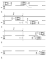
- FIG. 2 (a) to 2 (c) are diagrams for explaining the operation of the driving support system.
- 3 (a) to 3 (d) are diagrams for explaining the operation of the driving support system.
- 6 (a) to 6 (d) are diagrams showing a modified example of the avoidance pattern.
- the driver assistance system includes a lighting device and a controller.
- the lighting device is configured to be able to draw on the road surface a pattern indicating the lane in which the vehicle should travel or the direction in which the vehicle should travel in a manner visible to the driver.
- the controller includes a controller that causes the lighting device to draw a pattern when an obstacle is detected in front of the vehicle by a sensor or communication.
- the controller may have the lighting device draw a pattern in front of the point where the stop distance is away from the obstacle. As a result, even if the steering operation cannot be performed in the recommended direction indicated by the pattern, the vehicle can be stopped in front of the obstacle.
- the controller may notify the driver when the vehicle approaches an obstacle rather than the stopping distance. This can prompt the driver to operate the brakes and the steering wheel.
- the controller may adjust the pattern drawing timing according to the surrounding conditions.
- the controller can detect the overtaking vehicle from the rear of the own vehicle, and when the overtaking vehicle is detected, the pattern may be drawn after the overtaking is completed. As a result, it is possible to prevent the vehicle from interrupting in front of the overtaking vehicle and obstructing the passage of the overtaking vehicle.
- the controller can detect the overtaking vehicle from the rear of the own vehicle, and when the overtaking vehicle is detected, the pattern may indicate that the overtaking vehicle exists in addition to the traveling direction of the own vehicle. As a result, the driver can be notified of the presence of the overtaking vehicle, and interruptions that induce sudden braking can be prevented.
- FIG. 1 is a block diagram of the driving support system 100 according to the first embodiment.
- the driving support system 100 is mounted on the vehicle 200.
- the driving support system 100 includes a lighting device 110, a sensor 120, and a controller 130.
- the lighting device 110 draws a pattern (hereinafter referred to as an avoidance pattern) PTN indicating the direction in which the vehicle 200 should travel in order to avoid the obstacle 6 in front of the vehicle 200 on the road surface 2 in a manner visible to the driver 4. It is configured to be possible.
- Obstacle 6 is an irregular object, and examples thereof include a barricade indicating a road closure, a construction site, a broken vehicle, a signboard, an illumination light, a cone, and the like.
- the lighting device 110 may be configured by a combination of a light source and a patterning device that patterns the intensity distribution of the emitted light of the light source.
- the patterning device include a DMD (Digital Micromirror Device) and a liquid crystal vise.
- the lighting device 110 can also be used for drawing a pattern other than the avoidance pattern.
- the avoidance pattern for avoiding to the right and the avoidance pattern for avoiding to the left may be drawn by a dedicated lighting device for each.
- the lighting device 110 may be built in the headlamp 210.
- the lighting device 110 includes two light sources built in the left and right headlamps 210, and the avoidance pattern PTN may be formed by two beams generated by the two light sources.
- the sensor 120 senses the front of the vehicle.
- the type of the sensor 120 is not limited, and examples thereof include a monocular camera, a compound eye camera, an infrared camera, a ToF (Time of Flight) sensor, and LiDAR (Light Detection and Ringing, Laser Imaging Detection and Ringing).
- the installation location of the sensor 120 is not particularly limited, and as shown in FIG. 1, it may be behind the rearview mirror, the front grill, or the front bumper. Alternatively, the sensor 120 may be housed in the headlamp 210 together with the lighting device 110.
- the controller 130 determines the presence or absence of an obstacle 6 in front of the own vehicle 200 based on the output IMG of the sensor 120. Then, when the controller 130 detects the obstacle 6, the lighting device 110 draws the avoidance pattern PTN.
- All the components of the driving support system 100 may be built into a vehicle lamp such as a headlamp 210.
- High-performance vehicle lighting fixtures such as variable light distribution lamps (ADB: Adaptive Driving Beam) have a built-in camera, processor, etc., and therefore have most of the hardware required for the driving support system 100. There is. In such a case, the hardware can be shared by mounting the driving support system 100 on the headlamp 210.
- ADB Adaptive Driving Beam
- 2 (a) to 2 (c) are diagrams for explaining the operation of the driving support system 100.
- the vehicle 200 is traveling in the right lane of the two-lane road on each side toward the paper. There is an obstacle 6 in front of the vehicle 200.
- the controller 130 When the controller 130 detects an obstacle 6 based on the output of the sensor 120, the controller 130 draws an avoidance pattern PTN on the road surface. In this scene, since it cannot be avoided in the right direction, an avoidance pattern PTN that prompts the driver to change lanes to the left lane is drawn. In addition to drawing the avoidance pattern PTN, the driver may be audibly urged to change lanes.
- the driver who recognizes the avoidance pattern PTN can turn the steering wheel to the left. As a result, the vehicle 200 can move to the left lane and avoid the obstacle 6.
- the driving support system 100 it is possible to secure a margin for driving operation and support safe driving by calling attention in advance.
- the controller 130 may cause the lighting device 110 to draw a pattern in front of the point A which is separated from the obstacle 6 by the stop distance d STOP .
- the controller 130 may calculate the stop distance d STOP in consideration of the vehicle speed, the slipperiness of the road surface, and the like, and may change the timing of drawing the avoidance pattern PTN according to the stop distance d STOP at that time.
- the lighting device 110 may change the avoidance pattern PTN according to the distance to the obstacle 6. For example, as the distance to the obstacle 6 gets closer, the intensity of the light for drawing the avoidance pattern PTN may be increased. Alternatively, as the distance to the obstacle 6 approaches, the avoidance pattern PTN may be blinked to further alert the driver.
- the controller 130 may notify the driver 4 when the own vehicle 200 approaches the obstacle 6 rather than the stop distance.
- the means of notification is not limited, and may be an auditory one such as a warning sound, a visual one using a lamp or an instrument panel, or a tactile one such as vibration. There may be. This can prompt the driver to operate the brakes and the steering wheel.
- 3 (a) to 3 (d) are diagrams for explaining the operation of the driving support system 100.
- the controller 130 adjusts the drawing timing of the avoidance pattern PTN according to the surrounding conditions.
- the vehicle 200 is traveling in the left lane of the two-lane road on each side toward the paper.
- FIG. 3B there is an overtaking vehicle 202 from the rear of the own vehicle 200 in the changed lane (right lane).
- the avoidance pattern PTN is drawn immediately while ignoring the overtaking vehicle 202, it is not preferable because it interrupts immediately before the overtaking vehicle 202.
- FIG. 3C the overtaking vehicle 202 waits until the overtaking is completed, and then the avoidance pattern PTN is drawn.
- the existence of the overtaking vehicle 202 and the completion of overtaking may be detected by a sensor mounted on the vehicle 200, by inter-vehicle communication, or by communication with the infrastructure.
- the avoidance pattern PTN may be drawn after the passage of the intersection is completed.
- the avoidance pattern PTN may be drawn after waiting for acceleration or deceleration to a preferable vehicle speed and reaching a preferable vehicle speed.
- FIG. 4 is a diagram showing a modified example of the avoidance pattern PTN.
- the controller 130 may be able to detect the overtaking vehicle 202 from the rear of the own vehicle.
- the avoidance pattern PTN'when the overtaking vehicle 202 is detected may indicate the traveling direction of the own vehicle and may indicate that the overtaking vehicle 202 exists.
- the large arrow mark 400 indicates the direction in which the vehicle should travel
- the small arrow mark 402 indicates the presence of the overtaking vehicle 202.
- the driver 4 can be notified of the existence of the overtaking vehicle 202, and an interruption that induces sudden braking can be prevented.
- FIG. 5 is a diagram showing a driving support system 100A according to the second embodiment.
- the driver assistance system 100A includes, or in place of, the sensor 120, a wireless communication device 140.
- the wireless communication device 140 acquires information indicating the situation around the vehicle from the traffic infrastructure 8. This information also includes information about obstacles 6 present in front of the vehicle.
- the controller 130 detects the obstacle 6 and draws the avoidance pattern PTN based on the information acquired by the wireless communication device 140.
- the wireless communication device 140 can communicate with a wireless communication device mounted on another vehicle in addition to or instead of the transportation infrastructure 8, and acquires information on the obstacle 6 from the other vehicle. You may.
- Modification example 1 6 (a) to 6 (d) are diagrams showing a modified example of the avoidance pattern.
- the arrow indicating the recommended traveling direction is not limited to the one pointing in the oblique direction.
- a mark 404 that visually indicates the presence of an obstacle may be included.
- the lighting device 110 may be able to draw other patterns on the road surface.
- a road sign or a legal maximum speed may be read out, and the read information may be drawn on the road surface by the lighting device 110.
- the recommended direction of travel based on navigation may be drawn on the road surface.
- Modification 3 In the event of a breakdown or anomaly in a moving vehicle, that vehicle will be a reserve force for future obstacles. Therefore, a vehicle in which a failure or abnormality has occurred by inter-vehicle communication may notify the following vehicle to that effect.
- the following vehicle receives a notification from the preceding vehicle, the preceding vehicle may be treated as an obstacle and the avoidance pattern PTN may be drawn on the road surface by using it as a trigger.
- the present invention relates to a driving support system.
Landscapes
- Engineering & Computer Science (AREA)
- Physics & Mathematics (AREA)
- General Physics & Mathematics (AREA)
- Multimedia (AREA)
- Theoretical Computer Science (AREA)
- Mechanical Engineering (AREA)
- Life Sciences & Earth Sciences (AREA)
- Atmospheric Sciences (AREA)
- Artificial Intelligence (AREA)
- Computer Vision & Pattern Recognition (AREA)
- Traffic Control Systems (AREA)
- Lighting Device Outwards From Vehicle And Optical Signal (AREA)
Abstract
運転支援システム100は、照明装置110およびコントローラ130を備える。照明装置110は、運転者4が視認可能な態様で、自車が走行すべき車線もしくは自車が進行すべき方向を示す回避パターンPTNを路面2に描画可能に構成される。コントローラ130は、センサまたは通信によって、自車前方に障害物6を検知すると、照明装置110に、回避パターンPTNを描画させる。
Description
本発明は、運転支援システムに関する。
車両用の灯具の高機能化が進んでおり、その一例として、路面に光ビームのパターンを照射し、図形や文字を描画するランプが提案されている。
本発明はこうした状況においてなされたものであり、そのある態様の例示的な目的のひとつは、交通安全に貢献する運転支援システムの提供にある。
本発明のある態様は、運転支援システムに関する。運転支援システムは、運転者が視認可能な態様で、自車が走行すべき車線もしくは自車が進行すべき方向を示すパターンを路面に描画可能に構成される照明装置と、センサまたは通信によって、自車前方に障害物を検知すると、照明装置に、パターンを描画させるコントローラと、を備える。
なお、以上の構成要素の任意の組合せ、本発明の表現を方法、装置、システム等の間で変換したものもまた、本発明の態様として有効である。
本発明のある態様によれば、交通安全に貢献する運転支援システムを提供できる。
(実施の形態の概要)
本明細書に開示される一実施の形態は、運転支援システムに関する。運転支援システムは照明装置とコントローラを備える。照明装置は、運転者が視認可能な態様で自車が走行すべき車線もしくは自車が進行すべき方向を示すパターンを路面に描画可能に構成される。コントローラは、センサまたは通信によって、自車前方に障害物を検知すると、照明装置に、パターンを描画させるコントローラと、を備える。
本明細書に開示される一実施の形態は、運転支援システムに関する。運転支援システムは照明装置とコントローラを備える。照明装置は、運転者が視認可能な態様で自車が走行すべき車線もしくは自車が進行すべき方向を示すパターンを路面に描画可能に構成される。コントローラは、センサまたは通信によって、自車前方に障害物を検知すると、照明装置に、パターンを描画させるコントローラと、を備える。
コントローラは、障害物まで停止距離離れた地点より手前で、照明装置にパターンを描画させてもよい。これにより万が一、パターンが示す推奨方向にステアリング操作ができない場合でも、障害物より手前で停止することができる。
コントローラは、自車が停止距離よりも障害物に近づいた場合に運転者に報知してもよい。これにより、運転者にブレーキやステアリング操作を促すことができる。
コントローラは、パターンの描画タイミングを、周囲の状況に応じて調節してもよい。
コントローラは、自車後方からの追い越し車両を検知可能であり、追い越し車両を検知すると、追い越しが完了してから、パターンを描画させてもよい。これにより、追い越し車両の前に割り込み、追い越し車両の通行の妨げとなるのを防止できる。
コントローラは、自車後方からの追い越し車両を検知可能であり、追い越し車両を検知したとき、パターンは、自車の進行方向に加えて、追い越し車両が存在することを示してもよい。これにより運転者に追い越し車両の存在を報知でき、急ブレーキを誘発するような割り込みを防止できる。
(実施の形態)
以下、本発明を好適な実施の形態をもとに図面を参照しながら説明する。実施の形態は、発明を限定するものではなく例示であって、実施の形態に記述されるすべての特徴やその組み合わせは、必ずしも発明の本質的なものであるとは限らない。各図面に示される同一または同等の構成要素、部材、処理には、同一の符号を付するものとし、適宜重複した説明は省略する。
以下、本発明を好適な実施の形態をもとに図面を参照しながら説明する。実施の形態は、発明を限定するものではなく例示であって、実施の形態に記述されるすべての特徴やその組み合わせは、必ずしも発明の本質的なものであるとは限らない。各図面に示される同一または同等の構成要素、部材、処理には、同一の符号を付するものとし、適宜重複した説明は省略する。
(実施の形態1)
図1は、実施の形態1に係る運転支援システム100のブロック図である。運転支援システム100は車両200に搭載される。運転支援システム100は、照明装置110、センサ120、コントローラ130を備える。
図1は、実施の形態1に係る運転支援システム100のブロック図である。運転支援システム100は車両200に搭載される。運転支援システム100は、照明装置110、センサ120、コントローラ130を備える。
照明装置110は、運転者4が視認可能な態様で、自車200が前方の障害物6を回避するために進行すべき方向を示すパターン(以下、回避パターンという)PTNを、路面2に描画可能に構成される。障害物6はイレギュラーな物体であり、通行止め、工事現場、故障車などを示すバリケード、看板、電飾灯、コーン等が例示される。
右に回避する場合と、左に回避する場合とが発生しうるため、最低、2種類の回避パターンが必要となる。この2種類のパターンを切り替えるために、照明装置110を、光源と、光源の出射光の強度分布をパターニングするパターニングデバイスの組み合わせで構成してもよい。パターニングデバイスとしては、DMD(Digital Micromirror Device)や液晶でバイスなどが例示される。これにより照明装置110は、回避パターン以外のパターンの描画にも利用できる。
あるいは、右に回避する場合の回避パターンと左に回避する場合の回避パターンを、それぞれに専用の照明装置によって描画してもよい。
照明装置110は、ヘッドランプ210に内蔵されてもよい。照明装置110は、左右のヘッドランプ210に内蔵される2個の光源を含み、2個の光源が生成する2つのビームによって、回避パターンPTNが形成されてもよい。
センサ120は、車両前方をセンシングする。センサ120の種類は限定されないが、たとえば、単眼カメラ、複眼カメラ、赤外線カメラ、ToF(Time of Flight)センサ、LiDAR(Light Detection and Ranging、Laser Imaging Detection and Ranging)などが例示される。センサ120の設置場所は特に限定されず、図1に示すように、ルームミラーの裏であってもよいし、フロントグリルであってもよいし、フロントバンパーであってもよい。あるいはセンサ120は、照明装置110とともにヘッドランプ210に収容されてもよい。
コントローラ130は、センサ120の出力IMGにもとづいて、自車200の前方の障害物6の有無を判定する。そしてコントローラ130は、障害物6を検知すると、照明装置110に回避パターンPTNを描画させる。
運転支援システム100の構成要素のすべてを、ヘッドランプ210などの車両用灯具に内蔵してもよい。配光可変ランプ(ADB:Adaptive Driving Beam)を初めとする高機能な車両用灯具は、カメラやプロセッサなどを内蔵しているため、運転支援システム100に要求されるハードウェアの多くを具備している。このような場合には、ヘッドランプ210に、運転支援システム100を実装することで、ハードウェアを共通化することができる。
以上が運転支援システム100の構成である。続いてその動作を説明する。図2(a)~(c)は、運転支援システム100の動作を説明する図である。車両200は、片側2車線の道路のうち、右側の車線を紙面上に向かって走行している。車両200の前方には、障害物6が存在する。
コントローラ130は、センサ120の出力にもとづいて障害物6を検出すると、路面に回避パターンPTNを描画する。このシーンでは、右方向に回避することはできないため、左の車線への車線変更を促す回避パターンPTNが描画される。回避パターンPTNの描画に加えて、運転者に対して聴覚的に車線変更を促してもよい。
回避パターンPTNを認識した運転者は、ステアリングを左に切ることができる。これにより、車両200は左車線に移動し、障害物6を回避することができる。
もし左車線を走行中に、左車線に障害物が存在する場合には、右車線への車線変更を促す回避パターンが描画される。
このように実施の形態に係る運転支援システム100によれば、事前の注意喚起により、運転操作の余裕を確保することができ、安全運転をサポートできる。
図2(b)に示すように、コントローラ130は、障害物6まで停止距離dSTOPだけ離れた地点Aより手前で、照明装置110にパターンを描画させるとよい。これにより、万が一、回避パターンPTNが示す推奨方向にステアリングを切ることができない場合でも、障害物6より手前で停止することができる。コントローラ130は、車速や路面の滑りやすさ等を考慮して、停止距離dSTOPを計算し、そのときの停止距離dSTOPに応じて、回避パターンPTNを描画するタイミングを変化させてもよい。
照明装置110は、障害物6までの距離に応じて、回避パターンPTNを変化させてもよい。たとえば障害物6までの距離が近づくにしたがって、回避パターンPTNを描画する光の強度を高めても。あるいは障害物6までの距離が近づくにしたがって、回避パターンPTNを点滅させて、運転者に一層の注意喚起を行ってもよい。
またコントローラ130は、自車200が停止距離よりも障害物6に近づいた場合に運転者4に報知してもよい。報知の手段は限定されず、警告音などの聴覚的なものであってもよいし、ランプやインストルメントパネルを利用した視覚的なものであってもよいし、振動などの触覚的なものであってもよい。これにより、運転者にブレーキやステアリング操作を促すことができる。
図3(a)~(d)は、運転支援システム100の動作を説明する図である。コントローラ130は、回避パターンPTNの描画タイミングを、周囲の状況に応じて調節する。この例では、図3(a)に示すように、車両200は、片側2車線の道路のうち、左側の車線を紙面上に向かって走行している。車両200の前方には、障害物6が存在する。図3(b)に示すように、変更後の車線(右側車線)には、自車200の後方からの追い越し車両202が存在する。この場合に、追い越し車両202を無視して直ちに回避パターンPTNを描画すると、追い越し車両202の直前に割り込むこととなり好ましくない。このような場合には、図3(c)に示すように、追い越し車両202による追い越しが完了するまで待機し、完了後に回避パターンPTNを描画する。
追い越し車両202の存在、および追い越しの完了は、車両200が搭載するセンサによって検出してもよいし、車両間通信によって検出してもよいし、インフラとの間の通信によって検出してもよい。
回避パターンPTNの描画のタイミングを調節すべきシーンとしては、その他、以下のものが考えられる。
たとえば交差点の先に障害物6が存在する場合に、交差点の中で車線変更することは好ましくない。この場合、交差点の通過の完了後に、回避パターンPTNを描画してもよい。
現在の車速のまま、車線変更することが好ましくない状況がありうる。この場合、好ましい車速まで加速あるいは減速するまで待機し、好ましい車速となった後に、回避パターンPTNを描画してもよい。
図4は、回避パターンPTNの変形例を示す図である。上述のようにコントローラ130は、自車後方からの追い越し車両202を検知可能であってもよい。この場合において、追い越し車両202を検知したときの回避パターンPTN’は、自車の進行方向を示すとともに、追い越し車両202が存在することを示してもよい。この例では、大きい矢印のマーク400が進行すべき方向を示し、小さい矢印のマーク402が追い越し車両202の存在を示す。これにより運転者4に追い越し車両202の存在を報知でき、急ブレーキを誘発するような割り込みを防止できる。
(実施の形態2)
図5は、実施の形態2に係る運転支援システム100Aを示す図である。運転支援システム100Aは、センサ120に加えて、あるいはそれに代えて、無線通信装置140を備える。無線通信装置140は、交通インフラ8から、車両の周囲の状況を示す情報を取得する。この情報には、車両前方に存在する障害物6に関する情報も含まれる。コントローラ130は、無線通信装置140が取得した情報にもとづいて、障害物6を検知し、回避パターンPTNを描画する。
図5は、実施の形態2に係る運転支援システム100Aを示す図である。運転支援システム100Aは、センサ120に加えて、あるいはそれに代えて、無線通信装置140を備える。無線通信装置140は、交通インフラ8から、車両の周囲の状況を示す情報を取得する。この情報には、車両前方に存在する障害物6に関する情報も含まれる。コントローラ130は、無線通信装置140が取得した情報にもとづいて、障害物6を検知し、回避パターンPTNを描画する。
無線通信装置140は、交通インフラ8に加えて、あるいはそれに代えて、他の車両に搭載された無線通信装置との間で通信可能であり、他の車両から、障害物6に関する情報を取得してもよい。
以上、本発明について、実施の形態をもとに説明した。この実施の形態は例示であり、それらの各構成要素や各処理プロセスの組み合わせにいろいろな変形例が可能なこと、またそうした変形例も本発明の範囲にあることは当業者に理解されるところである。以下、こうした変形例について説明する。
(変形例1)
図6(a)~(d)は、回避パターンの変形例を示す図である。図6(a)~(c)に示すように、推奨進行方向を示す矢印は、斜め方向を向くものに限定されない。また図6(d)に示すように、矢印に加えて、障害物が存在することを視覚的に示すマーク404を含んでもよい。
図6(a)~(d)は、回避パターンの変形例を示す図である。図6(a)~(c)に示すように、推奨進行方向を示す矢印は、斜め方向を向くものに限定されない。また図6(d)に示すように、矢印に加えて、障害物が存在することを視覚的に示すマーク404を含んでもよい。
(変形例2)
照明装置110は、回避パターンに加えて、その他のパターンを路面に描画可能であってもよい。この場合、たとえば、道路標識や法定最高速度を読み出して、読み出した情報を照明装置110によって路面に描画するようにしてもよい。あるいはナビゲーションにもとづく推奨進行方向を路面に描画してもよい。
照明装置110は、回避パターンに加えて、その他のパターンを路面に描画可能であってもよい。この場合、たとえば、道路標識や法定最高速度を読み出して、読み出した情報を照明装置110によって路面に描画するようにしてもよい。あるいはナビゲーションにもとづく推奨進行方向を路面に描画してもよい。
(変形例3)
走行中の車両に故障や異常が発生した場合、その車両は将来的な障害物の予備軍となる。そこで車両間通信によって、故障や異常が発生した車両は、後続車にその旨を通知してもよい。後続車は先行車から通知を受けると、それをトリガーとして、先行車を障害物として扱い、回避パターンPTNを路面に描画してもよい。
走行中の車両に故障や異常が発生した場合、その車両は将来的な障害物の予備軍となる。そこで車両間通信によって、故障や異常が発生した車両は、後続車にその旨を通知してもよい。後続車は先行車から通知を受けると、それをトリガーとして、先行車を障害物として扱い、回避パターンPTNを路面に描画してもよい。
実施の形態にもとづき、具体的な語句を用いて本発明を説明したが、実施の形態は、本発明の原理、応用の一側面を示しているにすぎず、実施の形態には、請求の範囲に規定された本発明の思想を逸脱しない範囲において、多くの変形例や配置の変更が認められる。
本発明は、運転支援システムに関する。
2 路面
4 運転者
6 障害物
8 交通インフラ
100 運転支援システム
110 照明装置
120 センサ
130 コントローラ
140 無線通信装置
200 車両
202 車両
210 ヘッドランプ
4 運転者
6 障害物
8 交通インフラ
100 運転支援システム
110 照明装置
120 センサ
130 コントローラ
140 無線通信装置
200 車両
202 車両
210 ヘッドランプ
Claims (7)
- 運転者が視認可能な態様で、自車が走行すべき車線もしくは自車が進行すべき方向を示すパターンを路面に描画可能に構成される照明装置と、
センサまたは通信によって、自車前方に障害物を検知すると、前記照明装置に、前記パターンを描画させるコントローラと、
を備えることを特徴とする運転支援システム。 - 前記コントローラは、前記障害物まで停止距離離れた地点より手前で、前記照明装置に前記パターンを描画させることを特徴とする請求項1に記載の運転支援システム。
- 前記コントローラは、前記自車が前記停止距離よりも前記障害物に近づいた場合に前記運転者に報知することを特徴とする請求項2に記載の運転支援システム。
- 前記コントローラは、前記パターンの描画タイミングを、周囲の状況に応じて調節することを特徴とする請求項1から3のいずれかに記載の運転支援システム。
- 前記コントローラは、自車後方からの追い越し車両を検知可能であり、前記追い越し車両を検知すると、追い越しが完了してから、前記パターンを描画させることを特徴とする請求項4に記載の運転支援システム。
- 請求項1から5のいずれかに記載の運転支援システムを備えることを特徴とする車両用灯具。
- 請求項1から5のいずれかに記載の運転支援システムを備えることを特徴とする車両。
Priority Applications (3)
| Application Number | Priority Date | Filing Date | Title |
|---|---|---|---|
| JP2021518386A JP7429227B2 (ja) | 2019-05-09 | 2020-05-01 | 運転支援システム、車両、車両用灯具 |
| CN202080034552.8A CN113825669A (zh) | 2019-05-09 | 2020-05-01 | 驾驶辅助系统、车辆、车辆用灯具 |
| US17/519,830 US11951903B2 (en) | 2019-05-09 | 2021-11-05 | Driving assistance system |
Applications Claiming Priority (2)
| Application Number | Priority Date | Filing Date | Title |
|---|---|---|---|
| JP2019089004 | 2019-05-09 | ||
| JP2019-089004 | 2019-05-09 |
Related Child Applications (1)
| Application Number | Title | Priority Date | Filing Date |
|---|---|---|---|
| US17/519,830 Continuation US11951903B2 (en) | 2019-05-09 | 2021-11-05 | Driving assistance system |
Publications (1)
| Publication Number | Publication Date |
|---|---|
| WO2020226138A1 true WO2020226138A1 (ja) | 2020-11-12 |
Family
ID=73050775
Family Applications (1)
| Application Number | Title | Priority Date | Filing Date |
|---|---|---|---|
| PCT/JP2020/018428 Ceased WO2020226138A1 (ja) | 2019-05-09 | 2020-05-01 | 運転支援システム、車両、車両用灯具 |
Country Status (4)
| Country | Link |
|---|---|
| US (1) | US11951903B2 (ja) |
| JP (1) | JP7429227B2 (ja) |
| CN (1) | CN113825669A (ja) |
| WO (1) | WO2020226138A1 (ja) |
Cited By (1)
| Publication number | Priority date | Publication date | Assignee | Title |
|---|---|---|---|---|
| JP2024117432A (ja) * | 2023-02-17 | 2024-08-29 | トヨタ自動車株式会社 | 車両照明装置 |
Families Citing this family (1)
| Publication number | Priority date | Publication date | Assignee | Title |
|---|---|---|---|---|
| US12391173B2 (en) * | 2023-11-27 | 2025-08-19 | Deere & Company | Pedestrian warning with light spectrum that does not affect camera based object detection at night |
Citations (6)
| Publication number | Priority date | Publication date | Assignee | Title |
|---|---|---|---|---|
| JP2009298360A (ja) * | 2008-06-17 | 2009-12-24 | Mazda Motor Corp | 車両の運転支援装置 |
| JP2015033954A (ja) * | 2013-08-09 | 2015-02-19 | スタンレー電気株式会社 | 車両用前照灯の点灯制御装置、車両用前照灯システム |
| JP2015164828A (ja) * | 2014-03-03 | 2015-09-17 | 株式会社小糸製作所 | 車両用灯具及び車両用灯具の制御システム |
| JP2017033542A (ja) * | 2015-07-29 | 2017-02-09 | 株式会社デンソー | 情報表示装置 |
| WO2017134876A1 (ja) * | 2016-02-05 | 2017-08-10 | 日立マクセル株式会社 | ヘッドアップディスプレイ装置及びその表示制御方法 |
| WO2019082980A1 (ja) * | 2017-10-26 | 2019-05-02 | 株式会社小糸製作所 | 車両用前照灯システム、車両用ランプシステム |
Family Cites Families (13)
| Publication number | Priority date | Publication date | Assignee | Title |
|---|---|---|---|---|
| DE102008061747A1 (de) * | 2007-12-13 | 2009-06-25 | Continental Teves Ag & Co. Ohg | Verfahren und System zum Anpassen eines Fahrzeugs |
| EP2717238B1 (en) * | 2011-06-02 | 2016-11-09 | Toyota Jidosha Kabushiki Kaisha | Vehicular field of view assistance device |
| JP6169364B2 (ja) * | 2013-02-07 | 2017-07-26 | 株式会社小糸製作所 | 車両の運転支援装置 |
| JP2016030527A (ja) | 2014-07-29 | 2016-03-07 | 株式会社小糸製作所 | 車両用表示システム |
| JP6746270B2 (ja) * | 2014-09-08 | 2020-08-26 | 株式会社小糸製作所 | 車両用表示システム |
| DE102015201766B4 (de) * | 2015-02-02 | 2018-04-05 | Volkswagen Aktiengesellschaft | Verfahren zum Erzeugen einer Lichtverteilung zur Ausgabe einer Fahranweisung für ein erstes Fahrzeug |
| KR101768500B1 (ko) * | 2016-01-04 | 2017-08-17 | 엘지전자 주식회사 | 운전 보조 장치 및 그 제어방법 |
| KR102545661B1 (ko) * | 2016-01-07 | 2023-06-21 | 한국전자통신연구원 | 차선 변경 안내 정보 제공 장치 및 그 방법 |
| JP6542137B2 (ja) * | 2016-01-29 | 2019-07-10 | シチズン時計株式会社 | 光記録再生装置 |
| DE102016204096B4 (de) * | 2016-03-11 | 2022-02-17 | Volkswagen Aktiengesellschaft | Verfahren zum Betreiben des Fahrerassistenzsystems und Fahrerassistenzsystem |
| JP6551816B2 (ja) * | 2016-06-14 | 2019-07-31 | 大日本印刷株式会社 | 照明装置、ホログラム素子および車両制御方法 |
| JP6466899B2 (ja) | 2016-12-01 | 2019-02-06 | 株式会社Subaru | 車両用表示装置 |
| US11267394B2 (en) * | 2018-11-19 | 2022-03-08 | Alpine Electronics, Inc. | Projection apparatus for indicating a recommended position to observe a movable body, portable device, and recording medium |
-
2020
- 2020-05-01 JP JP2021518386A patent/JP7429227B2/ja active Active
- 2020-05-01 WO PCT/JP2020/018428 patent/WO2020226138A1/ja not_active Ceased
- 2020-05-01 CN CN202080034552.8A patent/CN113825669A/zh active Pending
-
2021
- 2021-11-05 US US17/519,830 patent/US11951903B2/en active Active
Patent Citations (6)
| Publication number | Priority date | Publication date | Assignee | Title |
|---|---|---|---|---|
| JP2009298360A (ja) * | 2008-06-17 | 2009-12-24 | Mazda Motor Corp | 車両の運転支援装置 |
| JP2015033954A (ja) * | 2013-08-09 | 2015-02-19 | スタンレー電気株式会社 | 車両用前照灯の点灯制御装置、車両用前照灯システム |
| JP2015164828A (ja) * | 2014-03-03 | 2015-09-17 | 株式会社小糸製作所 | 車両用灯具及び車両用灯具の制御システム |
| JP2017033542A (ja) * | 2015-07-29 | 2017-02-09 | 株式会社デンソー | 情報表示装置 |
| WO2017134876A1 (ja) * | 2016-02-05 | 2017-08-10 | 日立マクセル株式会社 | ヘッドアップディスプレイ装置及びその表示制御方法 |
| WO2019082980A1 (ja) * | 2017-10-26 | 2019-05-02 | 株式会社小糸製作所 | 車両用前照灯システム、車両用ランプシステム |
Cited By (2)
| Publication number | Priority date | Publication date | Assignee | Title |
|---|---|---|---|---|
| JP2024117432A (ja) * | 2023-02-17 | 2024-08-29 | トヨタ自動車株式会社 | 車両照明装置 |
| JP7794144B2 (ja) | 2023-02-17 | 2026-01-06 | トヨタ自動車株式会社 | 車両照明装置 |
Also Published As
| Publication number | Publication date |
|---|---|
| US11951903B2 (en) | 2024-04-09 |
| JP7429227B2 (ja) | 2024-02-07 |
| CN113825669A (zh) | 2021-12-21 |
| JPWO2020226138A1 (ja) | 2020-11-12 |
| US20220055531A1 (en) | 2022-02-24 |
Similar Documents
| Publication | Publication Date | Title |
|---|---|---|
| JP6974664B2 (ja) | 自動運転制御装置及び車両 | |
| JP6746270B2 (ja) | 車両用表示システム | |
| JP5919150B2 (ja) | 運転支援装置 | |
| JP4675395B2 (ja) | 車両用警報装置 | |
| JPWO2016103461A1 (ja) | ウインカ装置、及び衝突回避システム | |
| JP2015009647A (ja) | 車両配光制御装置 | |
| WO2015178303A1 (ja) | 安全確認支援装置 | |
| JP2018106487A (ja) | 車両用衝突回避支援装置および車両の衝突回避支援方法 | |
| JP7429227B2 (ja) | 運転支援システム、車両、車両用灯具 | |
| CN118514603A (zh) | 车辆照明装置 | |
| JP2008097501A (ja) | 運転支援システム及び案内音声出力方法 | |
| JP7399158B2 (ja) | センシングシステムおよび車両 | |
| JPWO2019220229A1 (ja) | Ecu及び車線逸脱警告システム | |
| JP2016016762A (ja) | 車両制御システム | |
| JP5721058B2 (ja) | 車両警光灯システムおよびそれを備えた車両 | |
| WO2013121587A1 (ja) | 運転支援装置 | |
| KR102303539B1 (ko) | 차량 충돌 회피 제어 장치 및 그 제어 방법 | |
| KR20150047376A (ko) | 차량용 경고장치 및 차량용 경고장치 제어방법 | |
| JP2007018142A (ja) | 車両周辺監視装置 | |
| JP2018106351A (ja) | 走行支援装置 | |
| JP2014197247A (ja) | 車両用歩行者安全装置 | |
| JP2021076956A (ja) | 車両運転支援システム | |
| JP6596055B2 (ja) | 緊急車両の報知装置 | |
| KR102678438B1 (ko) | 전방 차량의 하이 마운티드 스탑 램프 연동 자동 차로변경 시스템 및 방법 | |
| KR20220060002A (ko) | 어두운 도로의 차량 안전 제어 시스템 및 그 제어 방법 |
Legal Events
| Date | Code | Title | Description |
|---|---|---|---|
| 121 | Ep: the epo has been informed by wipo that ep was designated in this application |
Ref document number: 20802950 Country of ref document: EP Kind code of ref document: A1 |
|
| ENP | Entry into the national phase |
Ref document number: 2021518386 Country of ref document: JP Kind code of ref document: A |
|
| NENP | Non-entry into the national phase |
Ref country code: DE |
|
| 122 | Ep: pct application non-entry in european phase |
Ref document number: 20802950 Country of ref document: EP Kind code of ref document: A1 |