WO2020213652A1 - ベントホール清掃装置及びベントホール清掃方法 - Google Patents
ベントホール清掃装置及びベントホール清掃方法 Download PDFInfo
- Publication number
- WO2020213652A1 WO2020213652A1 PCT/JP2020/016606 JP2020016606W WO2020213652A1 WO 2020213652 A1 WO2020213652 A1 WO 2020213652A1 JP 2020016606 W JP2020016606 W JP 2020016606W WO 2020213652 A1 WO2020213652 A1 WO 2020213652A1
- Authority
- WO
- WIPO (PCT)
- Prior art keywords
- vent hole
- cleaning
- drill
- tool
- unit
- Prior art date
- Legal status (The legal status is an assumption and is not a legal conclusion. Google has not performed a legal analysis and makes no representation as to the accuracy of the status listed.)
- Ceased
Links
Images


Classifications
-
- B—PERFORMING OPERATIONS; TRANSPORTING
- B29—WORKING OF PLASTICS; WORKING OF SUBSTANCES IN A PLASTIC STATE IN GENERAL
- B29C—SHAPING OR JOINING OF PLASTICS; SHAPING OF MATERIAL IN A PLASTIC STATE, NOT OTHERWISE PROVIDED FOR; AFTER-TREATMENT OF THE SHAPED PRODUCTS, e.g. REPAIRING
- B29C33/00—Moulds or cores; Details thereof or accessories therefor
- B29C33/02—Moulds or cores; Details thereof or accessories therefor with incorporated heating or cooling means
-
- B—PERFORMING OPERATIONS; TRANSPORTING
- B29—WORKING OF PLASTICS; WORKING OF SUBSTANCES IN A PLASTIC STATE IN GENERAL
- B29C—SHAPING OR JOINING OF PLASTICS; SHAPING OF MATERIAL IN A PLASTIC STATE, NOT OTHERWISE PROVIDED FOR; AFTER-TREATMENT OF THE SHAPED PRODUCTS, e.g. REPAIRING
- B29C33/00—Moulds or cores; Details thereof or accessories therefor
- B29C33/70—Maintenance
-
- B—PERFORMING OPERATIONS; TRANSPORTING
- B29—WORKING OF PLASTICS; WORKING OF SUBSTANCES IN A PLASTIC STATE IN GENERAL
- B29C—SHAPING OR JOINING OF PLASTICS; SHAPING OF MATERIAL IN A PLASTIC STATE, NOT OTHERWISE PROVIDED FOR; AFTER-TREATMENT OF THE SHAPED PRODUCTS, e.g. REPAIRING
- B29C35/00—Heating, cooling or curing, e.g. crosslinking or vulcanising; Apparatus therefor
- B29C35/02—Heating or curing, e.g. crosslinking or vulcanizing during moulding, e.g. in a mould
Definitions
- the present invention relates to a vent hole cleaning device for cleaning a vent hole formed in a tire vulcanization mold and a vent hole cleaning method.
- the tire vulcanization mold has a plurality of vent holes that allow air inside the mold to escape during tire vulcanization.
- dirt or rubber may adhere to the molding surface (contact surface with the tire) of the tire vulcanization mold for molding the tire, and the vent hole may be clogged with dirt or rubber. Therefore, it is necessary to regularly clean the tire vulcanization mold.
- the work of cleaning the tire vulcanization mold includes the work of removing dirt and rubber adhering to the molded surface of the tire vulcanization mold and the work of cleaning the vent hole.
- the tire vulcanization mold is placed on a dedicated workbench and fixed, and the dirt and rubber adhering to the molding surface of the mold are removed by cleaning treatment (shot blasting treatment, laser treatment, etc.). To do.
- the tire vulcanization mold is removed from the workbench and transported to the next work place.
- the transported tire vulcanization mold is placed on a dedicated workbench and fixed, and the drill (drill blade) is attached to the electric drill device.
- the drill is a cleaning tool and is positioned relative to the vent holes in the tire vulcanization mold.
- the vent hole is cleaned with the drill by inserting the drill into the vent hole while rotating it. As a result, dirt and rubber adhering to the inside of the vent hole are removed.
- the blasting material enters the inside of the vent hole in the shot blasting process of the previous work, the blasting material in the vent hole is also removed.
- the vent hole cleaning device has a sensor for detecting the position of the vent hole and a vent hole cleaning jig for cleaning the vent hole at the tip of the robot arm.
- the vent hole cleaning jig is equipped with a cleaning tool that can be taken in and out and rotated by a motor.
- the cleaning tool is a cone such as a piano wire, and the cone is inserted through a tube.
- the position of the vent hole of the tire vulcanization mold is detected by a sensor, and the cone of the vent hole cleaning jig is positioned based on the detected position of the vent hole.
- push the cone with the tube toward the vent hole push the cone with the tube toward the vent hole.
- the cone and tube reach the vent hole position, insert the cone into the vent hole, leaving the tube behind.
- the cone is rotated to clean the vent hole.
- the cone which is a piano wire, may not be able to remove dirt and rubber adhering to the inside of the vent hole.
- the cone of the vent hole cleaning jig is guarded by the tube up to the vent hole, so that it does not break in the tube.
- the vent holes in the tire vulcanization mold are formed manually. Therefore, the actually formed vent hole does not follow the design drawing, and its position and angle may deviate from the design position. If the deviation is large, if the cone is inserted into the vent hole according to the design drawing by the vent hole cleaning device, even if the cone is a piano wire, the cone may be broken or damaged.
- the present invention has been made in view of the above-mentioned conventional problems, and an object of the present invention is to shorten the working time and insert the vent hole into the vent hole when cleaning the vent hole formed in the tire vulcanization mold. This is to prevent the cleaning tool from being damaged, such as breaking.
- the present invention is a vent hole cleaning device for cleaning a vent hole formed in a tire smelting mold, which comprises a mold detection unit for detecting the posture of the tire smelting mold and a vent hole of the tire smelting mold.
- a vent hole detection unit that detects the position, a cleaning unit that has a cleaning tool that cleans the vent hole of the tire smelting mold, a robot arm that moves the cleaning unit, and cleaning of the cleaning unit when it is inserted into the vent hole.
- the cleaning part is cleaned based on the tool detection part that detects the bending load acting on the tool and the direction of the bending load, the posture of the tire brewing mold detected by the mold detection part, and the position of the vent hole detected by the vent hole detection part. While controlling the movement of the robot arm so that it moves, cleaning is performed based on the bending load and the direction of the bending load acting on the cleaning tool detected by the tool detection unit when the cleaning tool of the cleaning unit is inserted into the vent hole.
- a vent hole cleaning device including a control unit that controls the operation of the robot arm so as to correct the insertion angle of the tool.
- the working time can be shortened, and the cleaning tool inserted into the vent hole is damaged such as broken. Can be prevented.
- FIG. 5A is a diagram showing a state before the correction of the insertion angle of the cleaning tool of the cleaning unit
- FIG. 5B is a diagram showing a state after the correction of the insertion angle of the cleaning tool of the cleaning unit. It is a figure which shows the bending load acting on a drill.
- FIG. 7A is a diagram showing a state before the drill is inserted into the vent hole
- FIG. 7B is a diagram showing a state before the drill is inserted into the vent hole
- FIG 7B is a diagram showing a state in which the drill is inserted into the vent hole. It is a figure which shows another embodiment of the cleaning part. It is a figure which shows another embodiment of the cleaning part. It is a figure which shows another embodiment of the tool detection part.
- the vent hole cleaning device of the present embodiment is a device for cleaning the vent hole formed in the tire vulcanization mold when cleaning the tire vulcanization mold.
- the tire vulcanizing mold is installed in the tire vulcanizing apparatus to vulcanize the tire.
- a plurality of (for example, nine) tire vulcanization molds are arranged in a ring shape surrounding the tire. Further, a plurality of vent holes are formed in the tire vulcanization mold.
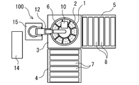
- FIG. 1 is a plan view of the vent hole cleaning device 100 of the present embodiment.
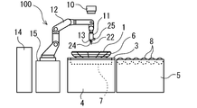
- FIG. 2 is a side view of the vent hole cleaning device 100 of the present embodiment.
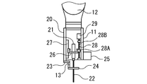
- FIG. 3 is an enlarged view of a main part showing the cleaning part 11 of the vent hole cleaning device 100 of the present embodiment.
- the vent hole cleaning device 100 includes a workbench 3 on which a plurality of tire vulcanization molds 1 are placed and fixed, and a carry-in table for carrying the tire vulcanization mold 1 onto the workbench 3. 4 and a carry-out stand 5 for carrying out the tire vulcanization mold 1 from the workbench 3 are provided.
- the plurality of tire vulcanization molds 1 are placed on the mold holder 6 and held by the mold holder 6.
- the mold holder 6 has a circular basket shape, and holds a plurality of tire vulcanization molds 1 in a petal-like shape so that the molding surface faces upward.
- the tire vulcanization mold 1 is placed on the upper surface of the workbench 3 while being held by the mold holder 6, and is fixed to the workbench 3.
- the vent hole 2 is cleaned in the tire vulcanization mold 1 fixed to the workbench 3.
- the carry-in table 4, the work table 3, and the carry-out table 5 are arranged in order along the moving direction of the tire vulcanization mold 1 and are arranged adjacent to each other.
- the carry-in table 4 has a plurality of conveyor rollers 7 on it, and the tire vulcanization mold 1 held by the mold holder 6 moves toward the workbench 3 by the conveyor roller 7 of the carry-in table 4.
- the unloading table 5 has a plurality of conveyor rollers 8 on the unloading table 5, and the tire vulcanization mold 1 held by the mold holder 6 is separated from the work table 3 by the conveyor rollers 8 of the unloading table 5.
- the tire vulcanization mold 1 While the tire vulcanization mold 1 is held by the mold holder 6, the molded surface is cleaned by a cleaning process (shot blasting process, laser processing, etc.). Subsequently, the tire vulcanization mold 1 is conveyed to the loading table 4 together with the mold holder 6, and is placed on the loading table 4.
- the tire vulcanization mold 1 may be carried in and out of the workbench 3 automatically or manually. Further, the loading table 4, the working table 3, and the loading table 5 may be arranged so as to form an L shape, or may be arranged on a straight line.
- the vent hole cleaning device 100 has a mold detection unit 10 for detecting the posture of the tire vulcanization mold 1 and a vent for detecting the position of the vent hole 2 of the tire vulcanization mold 1.
- a hole detection unit 25 a cleaning unit 11 having a cleaning tool for cleaning the vent hole 2 of the tire vulcanization mold 1, a robot arm 12 for moving the cleaning unit 11, and a cleaning unit when inserted into the vent hole 2.
- a tool detection unit 13 that detects a bending load acting on the cleaning tool of 11 and a direction of the bending load, and a control unit 14 that controls the operation of the robot arm 12 and the cleaning unit 11 are provided.
- the mold detection unit 10 is a 3D sensor (stereoscopic camera), and is arranged above the workbench 3 and facing downward.
- the mold detection unit 10 photographs the tire vulcanization mold 1 fixed to the workbench 3 and detects the three-dimensional shape of the tire vulcanization mold 1. That is, the mold detection unit 10 detects the posture of the tire vulcanization mold 1 held by the mold holder 6 fixed to the workbench 3.
- the mold detection unit 10 may be fixed above the workbench 3 or may be moved by a moving means.
- the mold detection unit 10 is not limited to the 3D sensor, and may be another detection means as long as it can detect the posture of the tire vulcanization mold 1.
- the robot arm 12 is an industrial articulated robot and is installed on a base 15.
- the robot arm 12 is a 6-axis robot arm, and is controlled by the control unit 14 to move the cleaning unit 11 attached to the tip thereof.
- the movement of the cleaning unit 11 is to move the cleaning tool of the cleaning unit 11 to a predetermined position and to change the direction of the cleaning tool.
- the robot arm 12 is installed adjacent to the workbench 3, and the tip of the robot arm 12 is located above the workbench 3.
- the cleaning unit 11 is attached to a rectangular frame 20 fixed to the tip of the robot arm 12, a drill motor 21 provided inside the frame 20, and a drill motor 21.
- a cleaning tool is a drill 22, which is inserted into the vent hole 2 of the tire vulcanization mold 1 while rotating to clean the vent hole 2.
- the cleaning tool is not limited to the drill 22, and other tools may be used.
- the drill motor 21 is, for example, a spindle motor and rotates the drill 22.
- the drill motor 21 is not limited to this, and other motors may be used.
- An L-shaped bracket 23 is fixed to the lower part of the frame 20.
- the bracket 23 is composed of two members separated in the middle.
- a ring-shaped guide 24 is fixed to the tip of the bracket 23. The guide 24 holds the drill 22 rotatably and suppresses the runout of the rotating drill 22.
- the drill motor 21 is slidable up and down with respect to the frame 20. That is, the drill motor 21 is supported by the support member 26.
- the support member 26 is attached to the linear guide 27 fixed to the frame 20 and is attached to the nut 28A of the ball screw 28 provided inside the frame 20.
- the screw shaft 28B of the ball screw 28 is rotated by a servomotor 29 fixed to the frame 20. As the screw shaft 28B of the ball screw 28 rotates, the nut 28A, the support member 26, and the drill motor 21 slide up and down along the linear guide 27.
- the servomotor 29 rotates the screw shaft 28B of the ball screw 28, and the drill motor 21 slides along the linear guide 27. Therefore, when the drill 22 is inserted into the vent hole 2, the robot arm 12 is inserted. The drill 22 is inserted into the vent hole 2 without moving. As a result, the drill 22 can be inserted only by controlling the servomotor 29 of the cleaning unit 11. Therefore, it is possible to eliminate the complicated control of the robot arm 12 and facilitate the control when the drill 22 is inserted.
- the vent hole detection unit 25 is a 3D sensor here.
- the vent hole detection unit 25 is attached to the side surface of the frame 20 of the cleaning unit 11.
- the vent hole detection unit 25 photographs the tire vulcanization mold 1 and detects the position of the vent hole 2 of the tire vulcanization mold 1.
- the vent hole detection unit 25 is preferably a 3D sensor having high detection accuracy of the vent hole 2, but may be another sensor such as a 2D camera.
- the mounting position of the vent hole detection unit 25 is not limited to the frame 20 of the cleaning unit 11. Further, here, the vent hole detection unit 25 and the mold detection unit 10 are separated, but these are collectively detected by one detection unit for the posture of the tire vulcanization mold 1 and the position of the vent hole 2. You may try to do it.
- the tool detection unit 13 is a sensor attached to the middle (separated position) of the bracket 23 fixed to the lower part of the frame 20, here, a 6-axis force sensor.
- the 6-axis force sensor measures the force in each of the X-axis, Y-axis, and Z-axis directions and the torque around each axis.
- the tool detection unit 13 can detect the bending load and the direction of the bending load acting on the drill 22 of the cleaning unit 11 when inserted into the vent hole 2 from the measured data.
- the direction of the bending load and the bending load acting on the drill 22 of the cleaning portion 11 is the direction of the bending load and the bending load acting on the portion of the drill 22 beyond the guide 24 of the cleaning portion 11.
- the tool detection unit 13 As a 6-axis force sensor, it is possible to easily detect the bending load and the direction of the bending load acting on the drill 22 of the cleaning unit 11.
- the tool detection unit 13 is not limited to the 6-axis force sensor, but may be a multi-axis force sensor, a load cell, or the like as long as it can detect the bending load and the direction of the bending load.
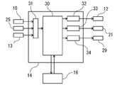
- FIG. 4 is a block diagram schematically showing the control unit 14.
- the control unit 14 includes a computer 30, an input unit 31, a robot arm operation control unit 32, a cleaning tool operation control unit 33, a motor operation control unit 34 of the cleaning unit 11, and the like.
- the computer 30 issues commands to the robot arm motion control unit 32, the cleaning tool motion control unit 33, the motor motion control unit 34 of the cleaning unit 11, and the like based on a predetermined program.
- the robot arm motion control unit 32 is connected to the robot arm 12 and controls its motion.
- the cleaning tool operation control unit 33 is connected to the drill motor 21 and controls its operation.
- the motor operation control unit 34 of the cleaning unit 11 is connected to the servomotor 29 of the motor of the cleaning unit 11 and controls its operation.
- the input unit 31 is connected to the mold detection unit 10, the vent hole detection unit 25, the tool detection unit 13, and the like.
- the posture of the tire vulcanization mold 1 detected by the mold detection unit 10 is input from the input unit 31, and the input data and, for example, the tire vulcanization mold stored in advance in a storage device (server) described later.
- a command is issued to the robot arm motion control unit 32 based on the design data of the positions of 1 and the vent hole 2 formed therein.
- the position of the vent hole 2 of the tire vulcanization mold 1 detected by the vent hole detection unit 25 is input from the input unit 31, and the operation of the robot arm 12 is controlled based on the input data.
- the robot moves the drill 22 of the cleaning unit 11 to a predetermined position with respect to the vent hole 2 formed in the tire vulcanization mold 1 so that the drill 22 can be inserted into the vent hole 2 in a predetermined direction. Controls the operation of the arm 12.
- the computer 30 receives the bending load and the direction of the bending load acting on the drill 22 detected by the tool detection unit 13 at the input unit 31, and issues a command to the robot arm operation control unit 32 based on the received input data. Take it out to control the operation of the robot arm 12. That is, the computer 30 drills the cleaning unit 11 based on the bending load and the direction of the bending load acting on the drill 22 detected by the tool detection unit 13 when the drill 22 of the cleaning unit 11 is inserted into the vent hole 2. The operation of the robot arm 12 is controlled so as to move the 22 (change the direction of the drill 22) and correct the insertion angle of the drill 22 into the vent hole 2.
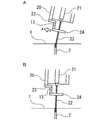
- FIG. 5A is a diagram showing a state before the correction of the insertion angle of the drill 22.
- FIG. 5B is a diagram showing a state after the insertion angle of the drill 22 has been corrected.
- the tool detection unit 13 detects the bending load acting on the drill 22, and when the bending load exceeds the correction start threshold value, the robot arm 12 is moved to tilt the drill 22 (correction start).
- the direction in which the drill 22 is tilted is the same as the direction of the bending load acting on the drill 22 detected by the tool detection unit 13 (indicated by the arrow A in the figure).
- the drill 22 is tilted so as to rotate with reference to the tip thereof.
- a predetermined value here, the correction completion threshold value
- Stop (correction completed).
- the insertion speed of the drill 22 is lowered from the normal speed to reduce the speed, and the insertion angle of the drill 22 is reduced in the low speed state.
- the correction of the insertion angle of the drill 22 is not limited to this.
- the insertion of the drill 22 is stopped, and the insertion angle of the drill 22 is stopped in the stopped state. May be modified.
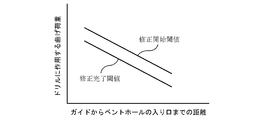
- FIG. 6 is a chart showing a bending load acting on the drill 22.
- the correction start threshold value of the bending load is a value lower than a safe value at which there is no risk of damage such as the drill 22 breaking under the bending load of the drill 22, and even if the correction start threshold value is slightly exceeded, the drill 22 breaks. There is no risk of damage.
- the correction completion threshold value is a value lower than the correction start threshold value. The bending load acting on the drill 22 when considering the correction completion threshold value and the correction start threshold value is the guide of the cleaning unit 11 even if the deviation amount between the insertion angle of the drill 22 and the hole angle of the vent hole 2 is the same.
- the correction start threshold value and the correction completion threshold value of the bending load also differ depending on the distance from the guide 24 to the entrance of the vent hole 2. Therefore, the correction of the insertion angle of the drill 22 is performed based on the distance from the guide 24 to the entrance of the vent hole 2.
- the vent hole cleaning device 100 includes a distance maintaining means for maintaining a constant distance from the guide 24 of the cleaning unit 11 to the entrance of the vent hole 2 when the drill 22 of the cleaning unit 11 is inserted into the vent hole 2.
- the distance maintaining means here is a control unit 14 and a robot arm 12 controlled by the control unit 14.
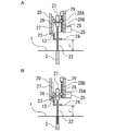
- FIG. 7A is a diagram showing a state before the drill 22 is inserted into the vent hole 2
- FIG. 7B is a diagram showing a state in which the drill 22 is inserted into the vent hole 2.
- the distance maintaining means in order to maintain a constant distance L from the guide 24 of the cleaning unit 11 to the entrance of the vent hole 2, when the drill 22 is inserted into the vent hole 2, as shown in FIG.
- the control unit 14 The movement of the robot arm 12 is controlled to be stopped, and the robot arm 12 is put into a stopped state. From there, as shown in FIG. 7B, the drill 22 is inserted into the vent hole 2 by moving the servomotor 29 and sliding the drill motor 21 along the linear guide 27. As a result, when the drill 22 is inserted into the vent hole 2, the frame 20 and the guide 24 fixed to the robot arm 12 do not move, and only the drill 22 slides and moves. In this way, when the drill 22 is inserted into the vent hole 2, the movement of the robot arm 12 is stopped, so that the distance L from the guide 24 of the cleaning unit 11 to the entrance of the vent hole 2 is kept constant.
- the tire vulcanization mold 1 held by the mold holder 6 is carried from the carry-in table 4 to the workbench 3, and the tire vulcanization mold 1 is fixed to the workbench 3.
- the posture of the tire vulcanization mold 1 is detected by the mold detection unit 10. Further, the posture of the tire vulcanization mold 1 detected by the mold detection unit 10 is collated with the design data stored in advance. From the result, the position of the vent hole 2 of the tire vulcanization mold 1 is obtained, and based on this, the operation of the robot arm 12 is controlled by the control unit 14, the robot arm 12 is moved, and the predetermined vent hole 2 is formed.
- the drill 22 of the cleaning unit 11 is moved to the position. After moving the drill 22 of the cleaning unit 11, the position of the vent hole 2 of the tire vulcanization mold 1 is detected by the vent hole detecting unit 25. Based on the position of the vent hole 2 detected by the vent hole detection unit 25, the control unit 14 controls the operation of the robot arm 12, moves the robot arm 12, changes the position and orientation of the drill 22, and vents the drill 22. Position with respect to hole 2.
- the drill 22 is rotated by the drill motor 21, and the drill 22 is inserted into the vent hole 2.
- the vent hole 2 is cleaned with the drill 22.
- the tool detection unit 13 detects the bending load acting on the drill 22 inserted in the vent hole 2 and the direction of the bending load.
- the insertion speed of the drill 22 is reduced to a lower speed.
- the control unit 14 controls the operation of the robot arm 12 based on the bending load and the direction of the bending load acting on the drill 22 detected by the tool detection unit 13, and the robot arm.
- the control unit 14 collates with the data of the position of the vent hole 2 to distinguish between the vent hole 2 that has been cleaned and the vent hole 2 that has not been cleaned.
- the control unit 14 controls the operation of the robot arm 12, moves the robot arm 12, and drills 22 of the cleaning unit 11 to the position of the next uncleaned vent hole 2.
- the vent hole 2 is cleaned in the same manner as described above. In this way, all the vent holes 2 formed in the tire vulcanization mold 1 are cleaned.
- the tire vulcanization mold 1 is carried out from the workbench 3 to the carry-out stand 5.
- the vent hole cleaning device 100 includes a storage device connected to the control unit 14.
- the storage device is a device that stores various types of data, and here, it is a server 16.
- the storage device is not limited to the server 16.
- the data stored in the server 16 is, for example, design data of the positions of the tire vulcanization mold 1 and the vent holes 2 formed therein.
- the server 16 has the position of the vent hole 2 corrected for each vent hole 2 of the tire vulcanization mold 1 and the drill 22. Collect the insertion angle data and store the collected data.
- the stored data is created in a database.
- the tire vulcanization mold 1 is identified by identification information (for example, individual number). Therefore, regarding the tire vulcanization mold 1 for which the vent hole 2 has been cleaned as described above, the attitude data of the tire vulcanization mold 1 detected by the mold detection unit 10 and the vent hole detection unit 25 The detected data on the position of the vent hole 2 of the tire vulcanization mold 1 and the data on the correction of the insertion angle of the drill 22 when the drill 22 is inserted into the vent hole 2 are stored in the server 16 together with the identification information. That is, the server 16 stores the data of all the tire vulcanization molds 1 that have been cleaned of the vent hole 2 and creates a database.
- identification information for example, individual number
- the drill 22 of the cleaning unit 11 is inserted into the vent hole 2 based on the attitude data of the vulcanization mold 1, the position data of the vent hole 2, and the corrected insertion angle data of the drill 22 when the drill 22 is inserted. Control to do.
- the tire vulcanization mold 1 in which the vent hole 2 cleaning work is performed once the tire vulcanization mold 1 in the first vent hole 2 cleaning work stored in a database in the server 16 is stored.
- the second and subsequent cleaning operations of the vent hole 2 are performed.
- the drill 22 is inserted into the vent hole 2 without detecting the position of the vent hole 2 by the vent hole detection unit 25 or correcting the insertion angle of the drill 22 when the drill 22 is inserted into the vent hole 2. it can.
- the mold detection unit 10 detects the posture of the tire vulcanization mold 1 fixed to the workbench 3.
- the control unit is based on the posture of the tire vulcanization mold 1 detected by the mold detection unit 10 and the data of the tire vulcanization mold 1 in the first cleaning operation of the vent hole 2 stored in the server 16 as a database.
- 14 controls the operation of the robot arm 12, moves the robot arm 12, and moves the drill 22 of the cleaning unit 11 to a predetermined position of the vent hole 2.
- the position and orientation of the drill 22 are changed to position the drill 22 with respect to the vent hole 2. Therefore, the drill 22 can be positioned with respect to the vent hole 2 without detecting the position of the vent hole 2 by the vent hole detecting unit 25.
- the drill 22 is rotated by the drill motor 21, and the drill 22 is inserted into the vent hole 2 to clean the vent hole 2.
- the drill 22 is inserted based on the data at the time of the first cleaning operation of the vent hole 2 (data of the corrected insertion angle of the drill 22 when the drill 22 is inserted). Therefore, it is not necessary for the tool detection unit 13 to detect the bending load acting on the drill 22 and the direction of the bending load, that is, the drill 22 is inserted into the vent hole 2 without correcting the insertion angle of the drill 22. , The vent hole 2 can be cleaned.
- the posture of the tire vulcanization mold 1 is detected by the mold detection unit 10, and the data of this posture and the tire in the first cleaning work of the vent hole 2 are performed. Cleaning work is performed based on the data of the vulcanization mold 1. Therefore, when the drill 22 is positioned with respect to the vent hole 2, the detection of the position of the vent hole 2 by the vent hole detection unit 25 can be eliminated. At the same time, when the drill 22 is inserted into the vent hole 2, it is possible to eliminate the detection of the bending load and the direction of the bending load acting on the drill 22 inserted into the vent hole 2 and the correction of the insertion angle of the drill 22. As a result, the work time for cleaning the vent hole 2 can be significantly shortened.
- the drill 22 when the drill 22 is inserted into the vent hole 2 by the vent hole cleaning device 100, the drill 22 is inserted based on the bending load acting on the drill 22 detected by the tool detection unit 13 and the direction of the bending load. Correct the angle and insert the drill 22 into the vent hole 2. Therefore, for example, even if the angle of the vent hole 2 does not match the design drawing, the drill 22 can be inserted while adjusting the insertion angle so as to match the actual angle of the vent hole 2, and the drill 22 breaks. Etc., it can be prevented from being damaged. In addition, the work time for cleaning the vent hole 2 can be shortened.
- the design data of the position of the vent hole 2 stored in advance is collated, and the vent hole 2 that has been cleaned and the vent hole 2 that has not been cleaned are distinguished.
- the data of the position of the vent hole 2 in the first cleaning operation is collated, and the vent hole 2 that has been cleaned and the vent hole 2 that has not been cleaned are distinguished from each other.
- the computer 30 can also detect the breakage of the drill 22 inserted into the vent hole 2 based on the change in the bending load acting on the drill 22.
- the cleaning unit 11 includes a frame 20 fixed to the tip of the robot arm 12, a drill motor 21 provided inside the frame 20, and a drill 22 (cleaning) attached to the drill motor 21. Have a tool).
- the drill motor 21 is fixed to the lower part of the frame 20.
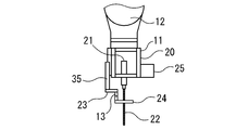
- a linear servo 35 that can slide up and down is attached to the side surface of the frame 20.
- the bracket 23 and the tool detection unit 13 (6-axis force sensor) are attached to the linear servo 35, and the guide 24 is attached to the tip of the bracket 23. By sliding the linear servo 35, the guide 24 slides up and down with respect to the drill 22.
- the vent hole cleaning device 100 provides a distance maintaining means for maintaining a constant distance from the guide 24 of the cleaning unit 11 to the entrance of the vent hole 2 when the drill 22 of the cleaning unit 11 is inserted into the vent hole 2.
- the distance maintaining means here is a control unit 14 and a linear servo 35 of the cleaning unit 11 controlled by the control unit 14. In the distance maintaining means, in order to maintain a constant distance L from the guide 24 of the cleaning unit 11 to the entrance of the vent hole 2, when the drill 22 is inserted into the vent hole 2, the robot arm 12 is moved to move the drill 22. Insert into the vent hole 2.
- the control unit 14 controls the movement of the linear servo 35 of the cleaning unit 11 to slide the guide 24 with respect to the drill 22.
- the movement of the linear servo 35 is a movement that slides in the direction opposite to the moving direction of the robot arm 12, and the amount of movement is the same as the amount of movement of the robot arm 12.
- the linear servo 35 and the guide 24 are moved in the direction opposite to the moving direction of the robot arm 12, so that the guide 24 of the cleaning unit 11 enters the vent hole 2.
- the distance L to is kept constant.
- the cleaning unit 11 of yet another embodiment is attached to the frame 20 fixed to the tip of the robot arm 12, the drill motor 21 provided inside the frame 20, and the drill motor 21. It has a drill 22 (cleaning tool).
- the drill motor 21 is slidable up and down with respect to the frame 20.
- a linear servo 35 that can slide up and down is attached to the side surface of the frame 20.
- the bracket 23 and the tool detection unit 13 (6-axis force sensor) are attached to the linear servo 35, and the guide 24 is attached to the tip of the bracket 23. By sliding the linear servo 35, the guide 24 slides up and down with respect to the drill 22.
- the drill 22 is inserted into the vent hole 2 by sliding the drill motor 21 without moving the robot arm 12.
- the frame 20 and the guide 24 fixed to the robot arm 12 do not move, and the drill 22 slides and moves together with the drill motor 21.
- the vent hole cleaning device 100 maintains a constant distance from the guide 24 of the cleaning unit 11 to the entrance of the vent hole 2 when the drill 22 of the cleaning unit 11 is inserted into the vent hole 2. It has the means.
- the distance L from the guide 24 to the tip of the drill 22, that is, the distance L from the guide 24 of the cleaning portion 11 to the entrance of the vent hole 2 is drilled. It can be easily changed to the optimum distance according to the shape and material of 22.
- the tool detection unit 13 is a 6-axis force sensor attached to the bracket 23 of the cleaning unit 11.
- the tool detection unit 13 may be attached to another location, for example, the tool detection unit 13 may be attached between the tip of the robot arm 12 and the frame 20 of the cleaning unit 11.
- the tool detection unit 13 may be another sensor, for example, a multi-axis force sensor or a load cell 36.
- the load cell 36 as shown in FIG. 10, the four load cells 36 are directly attached to the ring-shaped guide 24 that rotatably holds the drill 22. By measuring each load with the four load cells 36, it is possible to detect the bending load and the direction of the bending load acting on the drill 22 of the cleaning unit 11 when inserted into the vent hole 2.
- Computer 31 ... ⁇ Input unit, 32 ⁇ ⁇ ⁇ Robot arm operation control unit, 33 ⁇ ⁇ ⁇ Cleaning tool operation control unit, 34 ⁇ ⁇ ⁇ Motor operation control unit, 35 ⁇ ⁇ ⁇ Linear servo, 36 ⁇ ⁇ ⁇ Load cell, 100 ⁇ ⁇ ⁇ Vent hole cleaning device.
Landscapes
- Engineering & Computer Science (AREA)
- Mechanical Engineering (AREA)
- Physics & Mathematics (AREA)
- Health & Medical Sciences (AREA)
- Oral & Maxillofacial Surgery (AREA)
- Thermal Sciences (AREA)
- Moulds For Moulding Plastics Or The Like (AREA)
- Heating, Cooling, Or Curing Plastics Or The Like In General (AREA)
Abstract
タイヤ加硫用モールドのベントホールを清掃する際に、ベントホールに挿入する清掃工具が折れるのを防止する。 ベントホール清掃装置(100)は、タイヤ加硫用モールド(1)の姿勢を検出するモールド検出部(10)と、ベントホールの位置を検出するベントホール検出部(25)と、ベントホールを清掃する清掃工具を有する清掃部(11)と、清掃部(11)の移動を行うロボットアーム(12)と、清掃工具に作用する曲げ荷重と曲げ荷重の方向を検出する工具検出部(13)と、タイヤ加硫用モールド(1)の姿勢及びベントホールの位置に基づいて清掃部(11)を移動するようにロボットアーム(12)の動作を制御するとともに、清掃工具に作用する曲げ荷重と曲げ荷重の方向に基づいて、清掃工具の挿入角度を修正するようにロボットアーム(12)の動作を制御する制御部(14)を備える。
Description
本発明は、タイヤ加硫用モールドに形成されたベントホールを清掃するベントホール清掃装置及びベントホール清掃方法に関する。
タイヤ加硫用モールドには、タイヤ加硫時にモールド内部の空気を逃がす複数のベントホールが形成されている。タイヤの加硫工程では、タイヤを成形するタイヤ加硫用モールドの成形面(タイヤとの接触面)に汚れやゴムが付着し、また、ベントホールが汚れやゴムで詰まる場合がある。そのため、タイヤ加硫用モールドを定期的に清掃する必要がある。
タイヤ加硫用モールドの清掃作業は、タイヤ加硫用モールドの成形面に付着した汚れやゴムを除去する作業と、ベントホールを清掃する作業を含む。
汚れやゴムを除去する作業では、専用の作業台にタイヤ加硫用モールドを載せて固定し、清掃処理(ショットブラスト処理、レーザ処理等)により、モールドの成形面に付着した汚れやゴムを除去する。作業完了後に、タイヤ加硫用モールドを作業台から取り外し、次の作業場所に搬送する。
汚れやゴムを除去する作業では、専用の作業台にタイヤ加硫用モールドを載せて固定し、清掃処理(ショットブラスト処理、レーザ処理等)により、モールドの成形面に付着した汚れやゴムを除去する。作業完了後に、タイヤ加硫用モールドを作業台から取り外し、次の作業場所に搬送する。
ベントホールを清掃する作業では、搬送してきたタイヤ加硫用モールドを専用の作業台に載せて固定し、ドリル(ドリル刃)を電動ドリル装置に取り付ける。ドリルは、清掃工具であり、タイヤ加硫用モールドのベントホールに対して位置決めされる。次に、ドリルを回転しながらベントホールに挿入することで、ベントホールをドリルで清掃する。これにより、ベントホールの内部に付着した汚れやゴムを浚って除去する。また、前作業のショットブラスト処理で、ブラスト材がベントホールの内部に入ったときには、ベントホール内のブラスト材も除去する。
ベントホールを清掃する作業では、ドリルのベントホールへの位置決め、及び、ベントホールへのドリルの挿入を、すべて手作業で行っている。そのため、作業には熟練を要する。また、作業者がドリルをベントホールに位置や角度を合わせて挿入するため、ドリルの挿入は、極めて慎重に行わなくてはならず、非常に手間のかかる作業である。そのため、熟練した作業者であっても、時間がかかる。
そこで、従来のベントホールを清掃する作業において、ベントホール清掃装置を用いて行うことが提案されている(特許文献1参照)。
ベントホール清掃装置は、ロボットアームの先端に、ベントホールの位置を検出するセンサーと、ベントホールを清掃するベントホール清掃冶具を有している。ベントホール清掃冶具は、出し入れ自在でモータで回転する清掃工具を備えている。ここでは、清掃工具は、ピアノ線などの錐であり、錐は、チューブに挿通している。
ベントホール清掃装置は、ロボットアームの先端に、ベントホールの位置を検出するセンサーと、ベントホールを清掃するベントホール清掃冶具を有している。ベントホール清掃冶具は、出し入れ自在でモータで回転する清掃工具を備えている。ここでは、清掃工具は、ピアノ線などの錐であり、錐は、チューブに挿通している。
このベントホール清掃装置を用いて行う作業では、センサーでタイヤ加硫用モールドのベントホールの位置を検出し、検出したベントホールの位置に基づいてベントホール清掃冶具の錐を位置決めする。次に、錐をチューブとともにベントホールに向けて押し出す。錐及びチューブがベントホールの位置に到達したら、チューブを残して錐をベントホールに挿入する。その後に、錐を回転して、ベントホールを清掃する。ベントホールを清掃する際に、ピアノ線である錐では、ベントホールの内部に付着した汚れやゴムを除去できない虞がある。
従来のベントホール清掃装置において、ベントホール清掃冶具の錐は、ベントホールまではチューブによりガードされるので、チューブ内で折れることはない。
しかしながら、タイヤ加硫用モールドのベントホールは、手作業で形成される。そのため、実際に形成されたベントホールが設計図通りとはならず、その位置、角度が設計位置からずれる場合がある。そのずれが大きい場合、ベントホール清掃装置により、設計図通りに錐をベントホールに挿入すると、錐がピアノ線であっても、錐が折れる等、破損する虞がある。
しかしながら、タイヤ加硫用モールドのベントホールは、手作業で形成される。そのため、実際に形成されたベントホールが設計図通りとはならず、その位置、角度が設計位置からずれる場合がある。そのずれが大きい場合、ベントホール清掃装置により、設計図通りに錐をベントホールに挿入すると、錐がピアノ線であっても、錐が折れる等、破損する虞がある。
本発明は、前記従来の問題に鑑みなされたもので、その目的は、タイヤ加硫用モールドに形成されたベントホールを清掃する際に、その作業時間の短縮を図るとともに、ベントホールに挿入する清掃工具が折れる等、破損するのを防止することである。
本発明は、タイヤ加硫用モールドに形成されたベントホールを清掃するベントホール清掃装置であって、タイヤ加硫用モールドの姿勢を検出するモールド検出部と、タイヤ加硫用モールドのベントホールの位置を検出するベントホール検出部と、タイヤ加硫用モールドのベントホールを清掃する清掃工具を有する清掃部と、清掃部の移動を行うロボットアームと、ベントホールに挿入したときの清掃部の清掃工具に作用する曲げ荷重と曲げ荷重の方向を検出する工具検出部と、モールド検出部で検出したタイヤ加硫用モールドの姿勢及びベントホール検出部で検出したベントホールの位置に基づいて清掃部を移動するようにロボットアームの動作を制御するとともに、清掃部の清掃工具をベントホールに挿入したときに、工具検出部で検出した清掃工具に作用する曲げ荷重と曲げ荷重の方向に基づいて、清掃工具の挿入角度を修正するようにロボットアームの動作を制御する制御部と、を備えるベントホール清掃装置である。
本発明によれば、タイヤ加硫用モールドに形成されたベントホールを清掃する際に、その作業時間の短縮を図ることができ、また、ベントホールに挿入する清掃工具が折れる等、破損するのを防止することができる。
本発明のベントホール清掃装置及びベントホール清掃方法の一実施形態について、図面を参照して説明する。
本実施形態のベントホール清掃装置は、タイヤ加硫用モールドを清掃するときに、タイヤ加硫用モールドに形成されたベントホールを清掃するための装置である。
タイヤ加硫用モールドは、タイヤ加硫装置に設置されて、タイヤを加硫する。タイヤの加硫時に、複数(例えば、9個)のタイヤ加硫用モールドが、タイヤを囲んで、リング状に配置される。また、タイヤ加硫用モールドには、複数のベントホールが形成されている。
本実施形態のベントホール清掃装置は、タイヤ加硫用モールドを清掃するときに、タイヤ加硫用モールドに形成されたベントホールを清掃するための装置である。
タイヤ加硫用モールドは、タイヤ加硫装置に設置されて、タイヤを加硫する。タイヤの加硫時に、複数(例えば、9個)のタイヤ加硫用モールドが、タイヤを囲んで、リング状に配置される。また、タイヤ加硫用モールドには、複数のベントホールが形成されている。
図1は、本実施形態のベントホール清掃装置100の平面図である。図2は、本実施形態のベントホール清掃装置100の側面図である。図3は、本実施形態のベントホール清掃装置100の清掃部11を示す要部拡大図である。
ベントホール清掃装置100は、図1、図2に示すように、複数のタイヤ加硫用モールド1を載せて固定する作業台3と、作業台3にタイヤ加硫用モールド1を搬入する搬入台4と、作業台3からタイヤ加硫用モールド1を搬出する搬出台5を備える。
複数のタイヤ加硫用モールド1は、モールド保持具6に載置されて、モールド保持具6に保持される。モールド保持具6は、円形のかご状で、複数のタイヤ加硫用モールド1を、成形面が上に向くように花びら状にひらいた状態で保持する。
ベントホール清掃装置100は、図1、図2に示すように、複数のタイヤ加硫用モールド1を載せて固定する作業台3と、作業台3にタイヤ加硫用モールド1を搬入する搬入台4と、作業台3からタイヤ加硫用モールド1を搬出する搬出台5を備える。
複数のタイヤ加硫用モールド1は、モールド保持具6に載置されて、モールド保持具6に保持される。モールド保持具6は、円形のかご状で、複数のタイヤ加硫用モールド1を、成形面が上に向くように花びら状にひらいた状態で保持する。
タイヤ加硫用モールド1は、モールド保持具6で保持された状態で、作業台3の上面に載せられて、作業台3に固定される。作業台3に固定したタイヤ加硫用モールド1において、ベントホール2の清掃が行われる。
搬入台4、作業台3、及び、搬出台5は、タイヤ加硫用モールド1の移動方向に沿って順に配置されるとともに、互いに隣接して配置されている。搬入台4は、その上に複数のコンベアローラー7を有しており、モールド保持具6で保持されたタイヤ加硫用モールド1は、搬入台4のコンベアローラー7により作業台3に向かって移動する。搬出台5は、その上に複数のコンベアローラー8を有しており、モールド保持具6で保持されたタイヤ加硫用モールド1は、搬出台5のコンベアローラー8により作業台3から離れる。
搬入台4、作業台3、及び、搬出台5は、タイヤ加硫用モールド1の移動方向に沿って順に配置されるとともに、互いに隣接して配置されている。搬入台4は、その上に複数のコンベアローラー7を有しており、モールド保持具6で保持されたタイヤ加硫用モールド1は、搬入台4のコンベアローラー7により作業台3に向かって移動する。搬出台5は、その上に複数のコンベアローラー8を有しており、モールド保持具6で保持されたタイヤ加硫用モールド1は、搬出台5のコンベアローラー8により作業台3から離れる。
タイヤ加硫用モールド1がモールド保持具6で保持された状態で、その成形面が清掃処理(ショットブラスト処理、レーザ処理等)により清掃される。続いて、タイヤ加硫用モールド1は、モールド保持具6とともに、搬入台4まで搬送されて、搬入台4に載せられる。
なお、作業台3へのタイヤ加硫用モールド1の搬入及び搬出は、自動で行ってもよく、手動で行ってもよい。また、搬入台4、作業台3、搬出台5は、L字をなすように配置してもよく、直線上に配置してもよい。
なお、作業台3へのタイヤ加硫用モールド1の搬入及び搬出は、自動で行ってもよく、手動で行ってもよい。また、搬入台4、作業台3、搬出台5は、L字をなすように配置してもよく、直線上に配置してもよい。
ベントホール清掃装置100は、図1、図2に示すように、タイヤ加硫用モールド1の姿勢を検出するモールド検出部10と、タイヤ加硫用モールド1のベントホール2の位置を検出するベントホール検出部25と、タイヤ加硫用モールド1のベントホール2を清掃する清掃工具を有する清掃部11と、清掃部11の移動を行うロボットアーム12と、ベントホール2に挿入したときの清掃部11の清掃工具に作用する曲げ荷重と曲げ荷重の方向を検出する工具検出部13と、ロボットアーム12及び清掃部11の動作を制御する制御部14とを備える。
モールド検出部10は、3Dセンサ(立体カメラ)であり、作業台3の上方で、下方に向けて配置されている。モールド検出部10は、作業台3に固定したタイヤ加硫用モールド1を撮影し、タイヤ加硫用モールド1の三次元形状を検出する。つまり、モールド検出部10は、作業台3に固定したモールド保持具6で保持されたタイヤ加硫用モールド1の姿勢を検出する。モールド検出部10は、作業台3の上方に固定されていてもよく、また、移動手段により移動するようにしてもよい。なお、モールド検出部10は、3Dセンサに限らず、タイヤ加硫用モールド1の姿勢を検出できるのであれば、他の検出手段でもよい。
ロボットアーム12は、産業用の多関節ロボットであり、基台15の上に設置されている。ここでは、ロボットアーム12は、6軸のロボットアームであり、制御部14により、その先端に取り付けられた清掃部11を移動するように制御される。この清掃部11の移動は、清掃部11の清掃工具を所定の位置に移動することと、清掃工具の向きを変えることである。ロボットアーム12は、作業台3に隣接して設置されており、ロボットアーム12の先端は、作業台3の上方に位置する。
清掃部11は、図3に示すように、ロボットアーム12の先端に固定された矩形状のフレーム20と、フレーム20の内部に設けられたドリル用モータ21と、ドリル用モータ21に取り付けられた清掃工具を有する。
清掃工具は、ドリル22であり、タイヤ加硫用モールド1のベントホール2に回転しながら挿入されて、ベントホール2を清掃する。なお、清掃工具は、ドリル22に限らず、他の工具でもよい。
ドリル用モータ21は、例えば、スピンドルモータであり、ドリル22を回転する。なお、ドリル用モータ21は、これに限らず、他のモータでもよい。
清掃工具は、ドリル22であり、タイヤ加硫用モールド1のベントホール2に回転しながら挿入されて、ベントホール2を清掃する。なお、清掃工具は、ドリル22に限らず、他の工具でもよい。
ドリル用モータ21は、例えば、スピンドルモータであり、ドリル22を回転する。なお、ドリル用モータ21は、これに限らず、他のモータでもよい。
フレーム20の下部には、L型のブラケット23が固定されている。ブラケット23は、その中間で分離した2つの部材からなる。ブラケット23の先端には、リング状のガイド24が固定されている。ガイド24は、ドリル22を回転自在に保持し、回転するドリル22の振れを抑える。
また、ドリル用モータ21は、フレーム20に対して上下にスライド自在である。即ち、ドリル用モータ21は、支持部材26で支持されている。支持部材26は、フレーム20に固定したリニアガイド27に取り付けられるとともに、フレーム20の内部に設けたボールネジ28のナット28Aに取り付けられる。ボールネジ28のネジ軸28Bは、フレーム20に固着したサーボモータ29で回転する。ボールネジ28のネジ軸28Bが回転することで、ナット28A、支持部材26、及び、ドリル用モータ21がリニアガイド27に沿って上下にスライドする。
このように、サーボモータ29でボールネジ28のネジ軸28Bを回転し、ドリル用モータ21をリニアガイド27に沿ってスライドすることで、ドリル22をベントホール2に挿入する際に、ロボットアーム12を動かすことなく、ドリル22をベントホール2に挿入する。これにより、ドリル22の挿入は、清掃部11のサーボモータ29の制御だけで行うことができる。そのため、ロボットアーム12の複雑な制御をなくして、ドリル22挿入時の制御を容易にすることができる。
ベントホール検出部25は、ここでは3Dセンサである。ベントホール検出部25は、清掃部11のフレーム20の側面に取り付けている。ベントホール検出部25は、タイヤ加硫用モールド1を撮影し、タイヤ加硫用モールド1のベントホール2の位置を検出する。なお、ベントホール検出部25は、ベントホール2の検出精度が高い3Dセンサが好ましいが、例えば2Dカメラなどの他のセンサーでもよい。ベントホール検出部25の取り付け位置も、清掃部11のフレーム20に限らない。
また、ここでは、ベントホール検出部25とモールド検出部10を別体にしているが、これをまとめて、一つの検出部で、タイヤ加硫用モールド1の姿勢とベントホール2の位置を検出するようにしてもよい。
また、ここでは、ベントホール検出部25とモールド検出部10を別体にしているが、これをまとめて、一つの検出部で、タイヤ加硫用モールド1の姿勢とベントホール2の位置を検出するようにしてもよい。
工具検出部13は、フレーム20の下部に固着したブラケット23の中間(分離した位置)に取り付けたセンサー、ここでは6軸力覚センサーである。6軸力覚センサーでは、X軸・Y軸・Z軸の各軸方向の力と、各軸回りのトルクを測定する。これにより、工具検出部13では、測定したデータから、ベントホール2に挿入したときの清掃部11のドリル22に作用する曲げ荷重と曲げ荷重の方向を検出することができる。清掃部11のドリル22に作用する曲げ荷重と曲げ荷重の方向は、ドリル22において清掃部11のガイド24から先の部分に作用する曲げ荷重と曲げ荷重の方向である。
この工具検出部13を6軸力覚センサーにすることで、清掃部11のドリル22に作用する曲げ荷重と曲げ荷重の方向を簡単に検出することができる。なお、工具検出部13は、曲げ荷重と曲げ荷重の方向を検出できるなら、6軸力覚センサーに限らず、多軸力覚センサー、ロードセル等でもよい。
この工具検出部13を6軸力覚センサーにすることで、清掃部11のドリル22に作用する曲げ荷重と曲げ荷重の方向を簡単に検出することができる。なお、工具検出部13は、曲げ荷重と曲げ荷重の方向を検出できるなら、6軸力覚センサーに限らず、多軸力覚センサー、ロードセル等でもよい。
図4は、制御部14を概略的に示すブロック図である。
制御部14は、図示のように、コンピュータ30と、入力部31と、ロボットアーム動作制御部32と、清掃工具動作制御部33と、清掃部11のモータ動作制御部34などを備える。
コンピュータ30は、所定のプログラムに基づいて、ロボットアーム動作制御部32、清掃工具動作制御部33、清掃部11のモータ動作制御部34などに指令を出す。ロボットアーム動作制御部32は、ロボットアーム12に接続し、その動作を制御する。清掃工具動作制御部33は、ドリル用モータ21に接続し、その動作を制御する。清掃部11のモータ動作制御部34は、清掃部11のモータのサーボモータ29に接続し、その動作を制御する。また、入力部31は、モールド検出部10、ベントホール検出部25、工具検出部13などに接続している。
制御部14は、図示のように、コンピュータ30と、入力部31と、ロボットアーム動作制御部32と、清掃工具動作制御部33と、清掃部11のモータ動作制御部34などを備える。
コンピュータ30は、所定のプログラムに基づいて、ロボットアーム動作制御部32、清掃工具動作制御部33、清掃部11のモータ動作制御部34などに指令を出す。ロボットアーム動作制御部32は、ロボットアーム12に接続し、その動作を制御する。清掃工具動作制御部33は、ドリル用モータ21に接続し、その動作を制御する。清掃部11のモータ動作制御部34は、清掃部11のモータのサーボモータ29に接続し、その動作を制御する。また、入力部31は、モールド検出部10、ベントホール検出部25、工具検出部13などに接続している。
コンピュータ30では、モールド検出部10で検出したタイヤ加硫用モールド1の姿勢を入力部31から入力し、この入力したデータと、例えば後述する記憶装置(サーバー)に予め記憶したタイヤ加硫用モールド1及びそこに形成されたベントホール2の位置の設計データとに基づいて、ロボットアーム動作制御部32に指令を出す。これとともに、ベントホール検出部25で検出したタイヤ加硫用モールド1のベントホール2の位置を入力部31から入力し、この入力したデータに基づいて、ロボットアーム12の動作を制御する。つまり、タイヤ加硫用モールド1に形成されたベントホール2に対し、清掃部11のドリル22を所定の位置まで移動し、所定の向きにして、ベントホール2にドリル22が挿入できるようにロボットアーム12の動作を制御する。
また、コンピュータ30は、工具検出部13で検出したドリル22に作用する曲げ荷重と曲げ荷重の方向を入力部31で受領し、受領した入力データに基づいて、ロボットアーム動作制御部32に指令を出してロボットアーム12の動作を制御する。つまり、コンピュータ30は、清掃部11のドリル22をベントホール2に挿入したときに、工具検出部13で検出したドリル22に作用する曲げ荷重と曲げ荷重の方向に基づいて、清掃部11のドリル22を移動(ドリル22の向きの変更)し、ベントホール2へのドリル22の挿入角度を修正するようにロボットアーム12の動作を制御する。
図5Aは、ドリル22の挿入角度の修正前の状態を示す図である。図5Bは、ドリル22の挿入角度の修正後の状態を示す図である。
ベントホール2にドリル22を挿入するとき、図5Aに示すように、ベントホール2の穴の角度とドリル22の挿入角度がずれると、工具検出部13で検出するドリル22に作用する曲げ荷重が大きくなる。この曲げ荷重が所定の値(ここでは、修正開始閾値)を超えたときにドリル22の挿入角度を修正する。即ち、工具検出部13で、ドリル22に作用する曲げ荷重を検出し、その曲げ荷重が修正開始閾値を超えたときに、ロボットアーム12を動かして、ドリル22を傾ける(修正開始)。ドリル22を傾ける方向は、工具検出部13で検出したドリル22に作用する曲げ荷重の方向と同方向(図中に矢印Aで示す)である。また、ロボットアーム12を動かしてドリル22を傾ける際は、ドリル22をその先端を基準にして回転させるように傾ける。図5Bに示すように、ドリル22を傾けることで、ドリル22に作用する曲げ荷重が小さくなり、その曲げ荷重が所定の値(ここでは、修正完了閾値)よりも小さくなると、ドリル22を傾けるのを停止する(修正完了)。
このドリル22の挿入角度の修正は、ドリル22に作用する曲げ荷重が修正開始閾値を超えたとき、ドリル22の挿入速度を通常速度から落として低速にし、低速の状態で、ドリル22の挿入角度の修正を行う。ただし、ドリル22の挿入角度の修正は、これに限らず、ドリル22に作用する曲げ荷重が修正開始閾値を超えたとき、ドリル22の挿入を停止し、停止した状態で、ドリル22の挿入角度の修正を行うようにしてもよい。
ベントホール2にドリル22を挿入するとき、図5Aに示すように、ベントホール2の穴の角度とドリル22の挿入角度がずれると、工具検出部13で検出するドリル22に作用する曲げ荷重が大きくなる。この曲げ荷重が所定の値(ここでは、修正開始閾値)を超えたときにドリル22の挿入角度を修正する。即ち、工具検出部13で、ドリル22に作用する曲げ荷重を検出し、その曲げ荷重が修正開始閾値を超えたときに、ロボットアーム12を動かして、ドリル22を傾ける(修正開始)。ドリル22を傾ける方向は、工具検出部13で検出したドリル22に作用する曲げ荷重の方向と同方向(図中に矢印Aで示す)である。また、ロボットアーム12を動かしてドリル22を傾ける際は、ドリル22をその先端を基準にして回転させるように傾ける。図5Bに示すように、ドリル22を傾けることで、ドリル22に作用する曲げ荷重が小さくなり、その曲げ荷重が所定の値(ここでは、修正完了閾値)よりも小さくなると、ドリル22を傾けるのを停止する(修正完了)。
このドリル22の挿入角度の修正は、ドリル22に作用する曲げ荷重が修正開始閾値を超えたとき、ドリル22の挿入速度を通常速度から落として低速にし、低速の状態で、ドリル22の挿入角度の修正を行う。ただし、ドリル22の挿入角度の修正は、これに限らず、ドリル22に作用する曲げ荷重が修正開始閾値を超えたとき、ドリル22の挿入を停止し、停止した状態で、ドリル22の挿入角度の修正を行うようにしてもよい。
次に、ドリル22に作用する曲げ荷重について説明する。
図6は、ドリル22に作用する曲げ荷重を示す図表である。
曲げ荷重の修正開始閾値は、ドリル22の曲げ荷重におけるドリル22が折れる等、破損の虞のない安全な値よりも低い値であって、この修正開始閾値を少し超えても、ドリル22が折れる等、破損の虞はない。また、修正完了閾値は、修正開始閾値よりも低い値である。
修正完了閾値、修正開始閾値を考慮する際のドリル22に作用する曲げ荷重は、ドリル22の挿入角度とベントホール2の穴の角度とのずれ量が同じであっても、清掃部11のガイド24からベントホール2の入り口までの距離によって異なる。即ち、ドリル22の挿入角度とベントホール2の穴の角度とのずれ量が同じでも、ガイド24からベントホール2の入り口までの距離が短いと、曲げ荷重は大きくなり、ガイド24からベントホール2の入り口までの距離が長いと、曲げ荷重は小さくなる。したがって、図6に示すように、曲げ荷重の修正開始閾値と修正完了閾値も、ガイド24からベントホール2の入り口までの距離によって異なる。そのため、ドリル22の挿入角度の修正は、ガイド24からベントホール2の入り口までの距離に基づいて行われる。
図6は、ドリル22に作用する曲げ荷重を示す図表である。
曲げ荷重の修正開始閾値は、ドリル22の曲げ荷重におけるドリル22が折れる等、破損の虞のない安全な値よりも低い値であって、この修正開始閾値を少し超えても、ドリル22が折れる等、破損の虞はない。また、修正完了閾値は、修正開始閾値よりも低い値である。
修正完了閾値、修正開始閾値を考慮する際のドリル22に作用する曲げ荷重は、ドリル22の挿入角度とベントホール2の穴の角度とのずれ量が同じであっても、清掃部11のガイド24からベントホール2の入り口までの距離によって異なる。即ち、ドリル22の挿入角度とベントホール2の穴の角度とのずれ量が同じでも、ガイド24からベントホール2の入り口までの距離が短いと、曲げ荷重は大きくなり、ガイド24からベントホール2の入り口までの距離が長いと、曲げ荷重は小さくなる。したがって、図6に示すように、曲げ荷重の修正開始閾値と修正完了閾値も、ガイド24からベントホール2の入り口までの距離によって異なる。そのため、ドリル22の挿入角度の修正は、ガイド24からベントホール2の入り口までの距離に基づいて行われる。
また、ベントホール清掃装置100は、清掃部11のドリル22をベントホール2に挿入したときに、清掃部11のガイド24からベントホール2の入り口までの距離を一定に維持する距離維持手段を備える。距離維持手段は、ここでは、制御部14及び制御部14により制御されたロボットアーム12である。
図7Aは、ベントホール2にドリル22を挿入する前の状態を示す図であり、図7Bは、ベントホール2にドリル22を挿入している状態を示す図である。
距離維持手段では、清掃部11のガイド24からベントホール2の入り口までの距離Lを一定に維持するため、ベントホール2にドリル22を挿入するとき、図7Aに示すように、制御部14でロボットアーム12の動きを止めるように制御して、ロボットアーム12を停止状態にする。そこから、図7Bに示すように、サーボモータ29を動かしてドリル用モータ21をリニアガイド27に沿ってスライドさせることで、ドリル22をベントホール2に挿入する。これにより、ドリル22をベントホール2に挿入するときに、ロボットアーム12に固定したフレーム20及びガイド24は動かず、ドリル22のみがスライドして動く。このように、ドリル22をベントホール2に挿入したときに、ロボットアーム12の動きを止めることで、清掃部11のガイド24からベントホール2の入り口までの距離Lが一定に維持される。また、清掃部11のガイド24からベントホール2の入り口までの距離Lを、ドリル22が曲がりにくい最適な長さに設定しておくことで、ドリル22をベントホール2に挿入するとき、この清掃部11のガイド24からベントホール2の入り口までの距離Lが最適な長さで維持され、ベントホール2に挿入するドリル22の折れが低減できる。
図7Aは、ベントホール2にドリル22を挿入する前の状態を示す図であり、図7Bは、ベントホール2にドリル22を挿入している状態を示す図である。
距離維持手段では、清掃部11のガイド24からベントホール2の入り口までの距離Lを一定に維持するため、ベントホール2にドリル22を挿入するとき、図7Aに示すように、制御部14でロボットアーム12の動きを止めるように制御して、ロボットアーム12を停止状態にする。そこから、図7Bに示すように、サーボモータ29を動かしてドリル用モータ21をリニアガイド27に沿ってスライドさせることで、ドリル22をベントホール2に挿入する。これにより、ドリル22をベントホール2に挿入するときに、ロボットアーム12に固定したフレーム20及びガイド24は動かず、ドリル22のみがスライドして動く。このように、ドリル22をベントホール2に挿入したときに、ロボットアーム12の動きを止めることで、清掃部11のガイド24からベントホール2の入り口までの距離Lが一定に維持される。また、清掃部11のガイド24からベントホール2の入り口までの距離Lを、ドリル22が曲がりにくい最適な長さに設定しておくことで、ドリル22をベントホール2に挿入するとき、この清掃部11のガイド24からベントホール2の入り口までの距離Lが最適な長さで維持され、ベントホール2に挿入するドリル22の折れが低減できる。
次に、ベントホール2の清掃作業の手順について説明する。
モールド保持具6で保持されたタイヤ加硫用モールド1を搬入台4から作業台3に搬入し、作業台3にタイヤ加硫用モールド1を固定する。タイヤ加硫用モールド1を作業台3に固定した後、タイヤ加硫用モールド1の姿勢をモールド検出部10で検出する。また、モールド検出部10で検出したタイヤ加硫用モールド1の姿勢と予め記憶した設計データを照合する。その結果から、タイヤ加硫用モールド1のベントホール2の位置を求め、これに基づいて、制御部14でロボットアーム12の動作を制御して、ロボットアーム12を動かし、所定のベントホール2の位置まで清掃部11のドリル22を移動する。清掃部11のドリル22を移動した後、タイヤ加硫用モールド1のベントホール2の位置をベントホール検出部25で検出する。ベントホール検出部25で検出したベントホール2の位置に基づいて、制御部14でロボットアーム12の動作を制御して、ロボットアーム12を動かし、ドリル22の位置及び向きを変えてドリル22をベントホール2に対して位置決めする。
モールド保持具6で保持されたタイヤ加硫用モールド1を搬入台4から作業台3に搬入し、作業台3にタイヤ加硫用モールド1を固定する。タイヤ加硫用モールド1を作業台3に固定した後、タイヤ加硫用モールド1の姿勢をモールド検出部10で検出する。また、モールド検出部10で検出したタイヤ加硫用モールド1の姿勢と予め記憶した設計データを照合する。その結果から、タイヤ加硫用モールド1のベントホール2の位置を求め、これに基づいて、制御部14でロボットアーム12の動作を制御して、ロボットアーム12を動かし、所定のベントホール2の位置まで清掃部11のドリル22を移動する。清掃部11のドリル22を移動した後、タイヤ加硫用モールド1のベントホール2の位置をベントホール検出部25で検出する。ベントホール検出部25で検出したベントホール2の位置に基づいて、制御部14でロボットアーム12の動作を制御して、ロボットアーム12を動かし、ドリル22の位置及び向きを変えてドリル22をベントホール2に対して位置決めする。
次に、ドリル用モータ21でドリル22を回転し、ベントホール2にドリル22を挿入する。これにより、ドリル22でベントホール2の清掃を行う。ベントホール2を清掃するとき、ベントホール2に挿入したドリル22に作用する曲げ荷重と曲げ荷重の方向を工具検出部13で検出する。工具検出部13で検出したドリル22に作用する曲げ荷重が大きくなったとき(曲げ荷重が所定の値を超えたとき)、ドリル22の挿入速度を落として低速にする。ドリル22の挿入速度を低速にした後、工具検出部13で検出したドリル22に作用する曲げ荷重と曲げ荷重の方向に基づいて、制御部14でロボットアーム12の動作を制御して、ロボットアーム12を動かし、ドリル22の挿入角度の修正を行う。修正した後、ドリル22の挿入速度を元の通常速度に戻し、ドリル22を挿入してベントホール2の清掃を行う。ベントホール2を清掃したとき、制御部14では、ベントホール2の位置のデータと照合して、清掃が完了したベントホール2と、未清掃のベントホール2を区別する。
一つのベントホール2の清掃が完了したときは、制御部14でロボットアーム12の動作を制御して、ロボットアーム12を動かし、未清掃の次のベントホール2の位置まで清掃部11のドリル22を移動する。清掃部11のドリル22を移動した後、前記と同様に、ベントホール2の清掃を行う。このように、タイヤ加硫用モールド1に形成されたすべてのベントホール2を清掃する。すべてのベントホール2の清掃完了後、タイヤ加硫用モールド1を作業台3から搬出台5に搬出する。
また、ベントホール清掃装置100は、図4に示すように、制御部14に接続する記憶装置を備える。記憶装置は、各種のデータを記憶する機器であり、ここでは、サーバー16である。ただし、記憶装置は、サーバー16に限らない。サーバー16に記憶するデータは、例えば、タイヤ加硫用モールド1及びそこに形成されたベントホール2の位置の設計データなどである。
また、サーバー16には、清掃部11のドリル(清掃工具)22でベントホール2を清掃した際に、タイヤ加硫用モールド1のベントホール2毎に修正したベントホール2の位置とドリル22の挿入角度のデータをそれぞれ収集して、収集したデータを記憶する。ここでは記憶したデータをデータベース化する。
また、サーバー16には、清掃部11のドリル(清掃工具)22でベントホール2を清掃した際に、タイヤ加硫用モールド1のベントホール2毎に修正したベントホール2の位置とドリル22の挿入角度のデータをそれぞれ収集して、収集したデータを記憶する。ここでは記憶したデータをデータベース化する。
タイヤ加硫用モールド1は、識別情報(例えば、個体ナンバー)により識別される。そこで、前記のように、ベントホール2の清掃作業を行ったタイヤ加硫用モールド1については、モールド検出部10で検出したタイヤ加硫用モールド1の姿勢のデータと、ベントホール検出部25で検出したタイヤ加硫用モールド1のベントホール2の位置のデータと、ベントホール2にドリル22を挿入したときのドリル22の挿入角度の修正のデータを、識別情報とともに、サーバー16に記憶する。つまり、サーバー16には、ベントホール2の清掃作業を行ったすべてのタイヤ加硫用モールド1のデータを記憶して、データベース化する。
また、制御部14では、二回目以降のベントホール2の清掃作業において、サーバー16に記憶してデータベース化した、一回目のベントホール2の清掃作業でのタイヤ加硫用モールド1のデータ(タイヤ加硫用モールド1の姿勢のデータ、ベントホール2の位置のデータ、ドリル22を挿入したときの修正したドリル22の挿入角度のデータ)に基づいて清掃部11のドリル22をベントホール2に挿入するように制御する。
このように、ベントホール2の清掃作業を一回行ったタイヤ加硫用モールド1では、サーバー16にデータベース化して記憶した、一回目のベントホール2の清掃作業でのタイヤ加硫用モールド1のデータに基づいて、二回目以降のベントホール2の清掃作業を行う。これにより、ベントホール検出部25でのベントホール2の位置の検出やベントホール2にドリル22を挿入したときのドリル22の挿入角度の修正などを行うことなく、ドリル22をベントホール2に挿入できる。
このように、ベントホール2の清掃作業を一回行ったタイヤ加硫用モールド1では、サーバー16にデータベース化して記憶した、一回目のベントホール2の清掃作業でのタイヤ加硫用モールド1のデータに基づいて、二回目以降のベントホール2の清掃作業を行う。これにより、ベントホール検出部25でのベントホール2の位置の検出やベントホール2にドリル22を挿入したときのドリル22の挿入角度の修正などを行うことなく、ドリル22をベントホール2に挿入できる。
即ち、二回目以降のベントホール2の清掃作業は、以下の通り行う。作業台3に固定したタイヤ加硫用モールド1の姿勢をモールド検出部10で検出する。モールド検出部10で検出したタイヤ加硫用モールド1の姿勢とともに、サーバー16にデータベース化して記憶した一回目のベントホール2の清掃作業でのタイヤ加硫用モールド1のデータに基づいて、制御部14でロボットアーム12の動作を制御して、ロボットアーム12を動かし、所定のベントホール2の位置まで清掃部11のドリル22を移動する。また、それとともに、ドリル22の位置及び向きを変えてドリル22をベントホール2に対して位置決めする。そのため、ベントホール検出部25でベントホール2の位置を検出することなく、ドリル22をベントホール2に対して位置決めできる。
次に、ドリル用モータ21でドリル22を回転し、ベントホール2にドリル22を挿入してベントホール2の清掃を行う。このときのベントホール2の清掃では、一回目のベントホール2の清掃作業のときのデータ(ドリル22を挿入したときの修正したドリル22の挿入角度のデータ)に基づいてドリル22を挿入する。そのため、工具検出部13でドリル22に作用する曲げ荷重と曲げ荷重の方向を検出する必要がなく、つまり、ドリル22の挿入角度の修正を行うことなく、ドリル22をベントホール2に挿入して、ベントホール2の清掃を行うことができる。
このように、二回目以降のベントホール2の清掃作業では、タイヤ加硫用モールド1の姿勢をモールド検出部10で検出し、この姿勢のデータと一回目のベントホール2の清掃作業でのタイヤ加硫用モールド1のデータとに基づいて清掃作業を行う。そのため、ドリル22をベントホール2に対して位置決めするときに、ベントホール検出部25でのベントホール2の位置の検出をなくすことができる。これとともに、ベントホール2にドリル22を挿入するときに、ベントホール2に挿入したドリル22に作用する曲げ荷重と曲げ荷重の方向の検出及びドリル22の挿入角度の修正をなくすことができる。これにより、ベントホール2清掃の作業時間を大幅に短縮できる。
以上説明したように、ベントホール清掃装置100によるベントホール2へのドリル22の挿入では、工具検出部13で検出したドリル22に作用する曲げ荷重と曲げ荷重の方向に基づいて、ドリル22の挿入角度を修正してドリル22をベントホール2に挿入する。従って、例えば、ベントホール2の角度などが設計図通りでなくても、実際のベントホール2の角度に合わせるように挿入角度を修正しながら、ドリル22を挿入することができ、ドリル22が折れる等、破損するのを防止することができる。また、ベントホール2清掃の作業時間も短縮することができる。
また、ベントホール2の清掃作業において、一回目の清掃作業では、予め記憶したベントホール2の位置の設計データと照合し、清掃が完了したベントホール2と未清掃のベントホール2とに区別して作業を行う。また、二回目以降の清掃作業では、一回目の清掃作業でのベントホール2の位置のデータと照合し、清掃が完了したベントホール2と未清掃のベントホール2とに区別して作業を行う。これにより、タイヤ加硫用モールド1に形成されたすべてのベントホール2を確実に清掃することができ、ベントホール2の清掃忘れを防止できる。
また、コンピュータ30では、ドリル22に作用する曲げ荷重の変化に基づいてベントホール2に挿入されたドリル22の折れを検出することも可能である。例えば、工具検出部13で検出するドリル22に作用する曲げ荷重が急激に減少したときに、ドリル22が折れたと判断し、ドリル22の折れを検出する。これにより、ベントホール2内に折れたドリルが残留したままになるという不具合の発生を防止できる。
また、ベントホール2の清掃作業において、一回目の清掃作業では、予め記憶したベントホール2の位置の設計データと照合し、清掃が完了したベントホール2と未清掃のベントホール2とに区別して作業を行う。また、二回目以降の清掃作業では、一回目の清掃作業でのベントホール2の位置のデータと照合し、清掃が完了したベントホール2と未清掃のベントホール2とに区別して作業を行う。これにより、タイヤ加硫用モールド1に形成されたすべてのベントホール2を確実に清掃することができ、ベントホール2の清掃忘れを防止できる。
また、コンピュータ30では、ドリル22に作用する曲げ荷重の変化に基づいてベントホール2に挿入されたドリル22の折れを検出することも可能である。例えば、工具検出部13で検出するドリル22に作用する曲げ荷重が急激に減少したときに、ドリル22が折れたと判断し、ドリル22の折れを検出する。これにより、ベントホール2内に折れたドリルが残留したままになるという不具合の発生を防止できる。
次に、ベントホール清掃装置100における清掃部11の別の実施形態について説明する。ここでは、前記清掃部11と異なる部分を説明し、その他の部分は前記清掃部11と同じである。
清掃部11は、図8に示すように、ロボットアーム12の先端に固定するフレーム20と、フレーム20の内部に設けられたドリル用モータ21と、ドリル用モータ21に取り付けられたドリル22(清掃工具)を有する。ただし、ドリル用モータ21は、フレーム20の下部に固定する。また、フレーム20の側面には、上下にスライド自在のリニアサーボ35を取り付ける。リニアサーボ35に、ブラケット23及び工具検出部13(6軸力覚センサー)を取り付け、ブラケット23の先にガイド24を取り付ける。リニアサーボ35をスライドさせることで、ドリル22に対してガイド24が上下にスライドする。
清掃部11は、図8に示すように、ロボットアーム12の先端に固定するフレーム20と、フレーム20の内部に設けられたドリル用モータ21と、ドリル用モータ21に取り付けられたドリル22(清掃工具)を有する。ただし、ドリル用モータ21は、フレーム20の下部に固定する。また、フレーム20の側面には、上下にスライド自在のリニアサーボ35を取り付ける。リニアサーボ35に、ブラケット23及び工具検出部13(6軸力覚センサー)を取り付け、ブラケット23の先にガイド24を取り付ける。リニアサーボ35をスライドさせることで、ドリル22に対してガイド24が上下にスライドする。
この場合は、コンピュータ30でロボットアーム12の動作を制御してロボットアーム12を動かすことで、ドリル22をベントホール2に挿入する。
ここでも、ベントホール清掃装置100は、清掃部11のドリル22をベントホール2に挿入したときに、清掃部11のガイド24からベントホール2の入り口までの距離を一定に維持する距離維持手段を備える。距離維持手段は、ここでは、制御部14及び制御部14により制御された清掃部11のリニアサーボ35である。
距離維持手段では、清掃部11のガイド24からベントホール2の入り口までの距離Lを一定に維持するため、ドリル22をベントホール2に挿入するとき、ロボットアーム12を動かすことで、ドリル22をベントホール2に挿入する。これとともに、制御部14で清掃部11のリニアサーボ35の動きを制御してガイド24をドリル22に対してスライドさせる。このリニアサーボ35の動きは、ロボットアーム12の動く方向と逆の方向にスライドするような動きであり、その動く量は、ロボットアーム12の動く量と同じにする。このように、ドリル22をベントホール2に挿入するときに、リニアサーボ35及びガイド24をロボットアーム12の動く方向と逆の方向に動かすことで、清掃部11のガイド24からベントホール2の入り口までの距離Lが一定に維持される。
ここでも、ベントホール清掃装置100は、清掃部11のドリル22をベントホール2に挿入したときに、清掃部11のガイド24からベントホール2の入り口までの距離を一定に維持する距離維持手段を備える。距離維持手段は、ここでは、制御部14及び制御部14により制御された清掃部11のリニアサーボ35である。
距離維持手段では、清掃部11のガイド24からベントホール2の入り口までの距離Lを一定に維持するため、ドリル22をベントホール2に挿入するとき、ロボットアーム12を動かすことで、ドリル22をベントホール2に挿入する。これとともに、制御部14で清掃部11のリニアサーボ35の動きを制御してガイド24をドリル22に対してスライドさせる。このリニアサーボ35の動きは、ロボットアーム12の動く方向と逆の方向にスライドするような動きであり、その動く量は、ロボットアーム12の動く量と同じにする。このように、ドリル22をベントホール2に挿入するときに、リニアサーボ35及びガイド24をロボットアーム12の動く方向と逆の方向に動かすことで、清掃部11のガイド24からベントホール2の入り口までの距離Lが一定に維持される。
さらに別の実施形態の清掃部11は、図9に示すように、ロボットアーム12の先端に固定するフレーム20と、フレーム20の内部に設けられたドリル用モータ21と、ドリル用モータ21に取り付けられたドリル22(清掃工具)を有する。ドリル用モータ21は、フレーム20に対して上下にスライド自在である。また、フレーム20の側面には、上下にスライド自在のリニアサーボ35を取り付ける。リニアサーボ35に、ブラケット23及び工具検出部13(6軸力覚センサー)を取り付け、ブラケット23の先にガイド24を取り付ける。リニアサーボ35をスライドさせることで、ドリル22に対してガイド24が上下にスライドする。
この場合は、ロボットアーム12を動かすことなく、ドリル用モータ21をスライドさせることで、ドリル22をベントホール2に挿入する。
なお、ドリル22をベントホール2に挿入するときに、ロボットアーム12に固定したフレーム20及びガイド24は動かず、ドリル用モータ21とともにドリル22がスライドして動く。このように、ドリル22をベントホール2に挿入したときに、ロボットアーム12の動きを止めることで、清掃部11のガイド24からベントホール2の入り口までの距離Lが一定に維持される。即ち、ここでも、ベントホール清掃装置100は、清掃部11のドリル22をベントホール2に挿入したときに、清掃部11のガイド24からベントホール2の入り口までの距離を一定に維持する距離維持手段を備えている。
また、リニアサーボ35でガイド24をドリル22に対してスライドさせることで、ドリル22におけるガイド24から先の部分、つまり、清掃部11のガイド24からベントホール2の入り口までの距離Lを、ドリル22の形状や材質に合わせて最適な距離に簡単に変更することもできる。
なお、ドリル22をベントホール2に挿入するときに、ロボットアーム12に固定したフレーム20及びガイド24は動かず、ドリル用モータ21とともにドリル22がスライドして動く。このように、ドリル22をベントホール2に挿入したときに、ロボットアーム12の動きを止めることで、清掃部11のガイド24からベントホール2の入り口までの距離Lが一定に維持される。即ち、ここでも、ベントホール清掃装置100は、清掃部11のドリル22をベントホール2に挿入したときに、清掃部11のガイド24からベントホール2の入り口までの距離を一定に維持する距離維持手段を備えている。
また、リニアサーボ35でガイド24をドリル22に対してスライドさせることで、ドリル22におけるガイド24から先の部分、つまり、清掃部11のガイド24からベントホール2の入り口までの距離Lを、ドリル22の形状や材質に合わせて最適な距離に簡単に変更することもできる。
また、ベントホール清掃装置100において、工具検出部13は、清掃部11のブラケット23に取り付けた6軸力覚センサーである。これに対し、工具検出部13の取り付け箇所は、他の箇所でもよく、例えば、ロボットアーム12の先端と清掃部11のフレーム20の間に工具検出部13を取り付けてもよい。また、工具検出部13は、他のセンサーでもよく、例えば、多軸力覚センサー、ロードセル36でもよい。ロードセル36の場合は、図10に示すように、ドリル22を回転自在に保持するリング状のガイド24に、4つのロードセル36を直接取り付ける。4つのロードセル36でそれぞれの荷重を測定することで、ベントホール2に挿入したときの清掃部11のドリル22に作用する曲げ荷重と曲げ荷重の方向を検出することができる。
1・・・タイヤ加硫用モールド、2・・・ベントホール、3・・・作業台、4・・・搬入台、5・・・搬出台、6・・・モールド保持具、7・・・コンベアローラー、8・・・コンベアローラー、10・・・モールド検出部、11・・・清掃部、12・・・ロボットアーム、13・・・工具検出部、14・・・制御部、15・・・基台、16・・・サーバー、20・・・フレーム、21・・・ドリル用モータ、22・・・ドリル、23・・・ブラケット、24・・・ガイド、25・・・ベントホール検出部、26・・・支持部材、27・・・リニアガイド、28・・・ボールネジ、28A・・・ナット、28B・・・ネジ軸、29・・・サーボモータ、30・・・コンピュータ、31・・・入力部、32・・・ロボットアーム動作制御部、33・・・清掃工具動作制御部、34・・・モータ動作制御部、35・・・リニアサーボ、36・・・ロードセル、100・・・ベントホール清掃装置。
Claims (6)
- タイヤ加硫用モールドに形成されたベントホールを清掃するベントホール清掃装置であって、
タイヤ加硫用モールドの姿勢を検出するモールド検出部と、
タイヤ加硫用モールドのベントホールの位置を検出するベントホール検出部と、
タイヤ加硫用モールドのベントホールを清掃する清掃工具を有する清掃部と、
清掃部の移動を行うロボットアームと、
ベントホールに挿入したときの清掃部の清掃工具に作用する曲げ荷重と曲げ荷重の方向を検出する工具検出部と、
モールド検出部で検出したタイヤ加硫用モールドの姿勢及びベントホール検出部で検出したベントホールの位置に基づいて清掃部を移動するようにロボットアームの動作を制御するとともに、清掃部の清掃工具をベントホールに挿入したときに、工具検出部で検出した清掃工具に作用する曲げ荷重と曲げ荷重の方向に基づいて、清掃工具の挿入角度を修正するようにロボットアームの動作を制御する制御部と、
を備えることを特徴とするベントホール清掃装置。 - 請求項1に記載されたベントホール清掃装置において、
制御部は、工具検出部で検出した清掃工具に作用する曲げ荷重が所定の値を超えたときにロボットアームによる清掃工具の挿入角度を修正することを特徴とするベントホール清掃装置。 - 請求項1又は2に記載されたベントホール清掃装置において、
工具検出部は、6軸力覚センサーであることを特徴とするベントホール清掃装置。 - 請求項1ないし3のいずれかに記載されたベントホール清掃装置において、
清掃部の清掃工具を回転自在に保持するガイドと、
清掃部の清掃工具をベントホールに挿入したときに、ガイドからベントホールの入り口までの距離を一定に維持する距離維持手段と、
を備えることを特徴とするベントホール清掃装置。 - 請求項1ないし4のいずれかに記載されたベントホール清掃装置において、
制御部に接続し、清掃部の清掃工具でベントホールを清掃した際に、タイヤ加硫用モールドのベントホール毎に修正したベントホールの位置と清掃工具の挿入角度を記憶する記憶装置を備え、
制御部は、記憶装置に記憶したベントホールの位置と清掃工具の挿入角度のデータに基づいて清掃部の清掃工具をベントホールに挿入するようにロボットアームによる清掃工具の挿入角度を修正することを特徴とするベントホール清掃装置。 - タイヤ加硫用モールドに形成されたベントホールを清掃するベントホール清掃方法であって、
タイヤ加硫用モールドの姿勢をモールド検出部で検出する工程と、
タイヤ加硫用モールドのベントホールの位置をベントホール検出部で検出する工程と、
モールド検出部で検出したタイヤ加硫用モールドの姿勢及びベントホール検出部で検出したベントホールの位置に基づいて、制御部でロボットアームの動作を制御して清掃部を移動する工程と、
清掃部の清掃工具をベントホールに挿入して清掃する工程と、
ベントホールに挿入したときの清掃工具に作用する曲げ荷重と曲げ荷重の方向を工具検出部で検出する工程と、
清掃部の清掃工具をベントホールに挿入したときに、工具検出部で検出した清掃工具に作用する曲げ荷重と曲げ荷重の方向に基づいて、制御部でロボットアームの動作を制御して清掃工具の挿入角度を修正する工程と、
を有することを特徴とするベントホール清掃方法。
Priority Applications (1)
| Application Number | Priority Date | Filing Date | Title |
|---|---|---|---|
| CN202080028711.3A CN113692340B (zh) | 2019-04-16 | 2020-04-15 | 排气孔清洁装置和排气孔清洁方法 |
Applications Claiming Priority (2)
| Application Number | Priority Date | Filing Date | Title |
|---|---|---|---|
| JP2019-077794 | 2019-04-16 | ||
| JP2019077794A JP7117264B2 (ja) | 2019-04-16 | 2019-04-16 | ベントホール清掃装置及びベントホール清掃方法 |
Publications (1)
| Publication Number | Publication Date |
|---|---|
| WO2020213652A1 true WO2020213652A1 (ja) | 2020-10-22 |
Family
ID=72837539
Family Applications (1)
| Application Number | Title | Priority Date | Filing Date |
|---|---|---|---|
| PCT/JP2020/016606 Ceased WO2020213652A1 (ja) | 2019-04-16 | 2020-04-15 | ベントホール清掃装置及びベントホール清掃方法 |
Country Status (3)
| Country | Link |
|---|---|
| JP (1) | JP7117264B2 (ja) |
| CN (1) | CN113692340B (ja) |
| WO (1) | WO2020213652A1 (ja) |
Citations (4)
| Publication number | Priority date | Publication date | Assignee | Title |
|---|---|---|---|---|
| JP2007118460A (ja) * | 2005-10-28 | 2007-05-17 | Bridgestone Corp | タイヤ加硫モールドのクリーニング方法および装置 |
| JP2016150544A (ja) * | 2015-02-18 | 2016-08-22 | 住友ゴム工業株式会社 | ベントホール清掃治具、ベントホール清掃装置およびベントホール清掃方法 |
| WO2017126251A1 (ja) * | 2016-01-19 | 2017-07-27 | 住友ゴム工業株式会社 | ベントホール洗浄装置及びベントホール洗浄方法 |
| US20180297242A1 (en) * | 2017-04-17 | 2018-10-18 | Indian Institute Of Technology Bombay | Laser based tyre mold vent cleaning process and device |
Family Cites Families (16)
| Publication number | Priority date | Publication date | Assignee | Title |
|---|---|---|---|---|
| JP2641635B2 (ja) * | 1991-04-24 | 1997-08-20 | 日新製鋼株式会社 | 連続鋳造設備におけるノズルの洗浄方法 |
| JPH08275917A (ja) * | 1995-04-04 | 1996-10-22 | Asahi Optical Co Ltd | 内視鏡の掃除用ブラシ自動挿入装置 |
| JP3772244B2 (ja) * | 1997-01-28 | 2006-05-10 | 株式会社ブリヂストン | 合成樹脂発泡成形品の成形金型及び成形方法 |
| JP2001293729A (ja) * | 2000-04-17 | 2001-10-23 | Yokohama Rubber Co Ltd:The | タイヤ加硫成形用金型の洗浄方法 |
| US6490748B1 (en) * | 2000-06-12 | 2002-12-10 | Kemtech International Pty, Ltd. | Flexible drill rod |
| JP4367600B2 (ja) * | 2001-03-08 | 2009-11-18 | 横浜ゴム株式会社 | 空気入りタイヤの加硫成形用金型 |
| JP2007045080A (ja) * | 2005-08-11 | 2007-02-22 | Takagi Ind Co Ltd | 樹脂乾燥方法及びその装置 |
| WO2008082427A1 (en) * | 2006-02-13 | 2008-07-10 | Halkey-Roberts Corporation | Apparatus and method for using tetrazine-based energetic material |
| JP2007275438A (ja) * | 2006-04-10 | 2007-10-25 | Olympus Medical Systems Corp | 内視鏡洗滌消毒装置、及び内視鏡管路洗滌ブラシユニット |
| JP5147609B2 (ja) * | 2008-09-05 | 2013-02-20 | 本田技研工業株式会社 | ワークの挿入装置 |
| JP4491041B1 (ja) * | 2009-05-11 | 2010-06-30 | 日本省力機械株式会社 | 樹脂製品製造システム及び製造方法 |
| JP5835400B2 (ja) * | 2014-05-09 | 2015-12-24 | 横浜ゴム株式会社 | モールドの洗浄システム |
| DE102015218114B4 (de) * | 2015-09-21 | 2018-10-18 | Lobbe Industrieservice Gmbh & Co Kg | Verfahren und Vorrichtung zum Reinigen von Rohrbündeln |
| JP6600537B2 (ja) * | 2015-11-19 | 2019-10-30 | 株式会社ブリヂストン | タイヤ加硫モールドおよびその製造方法 |
| US10422707B2 (en) * | 2016-01-19 | 2019-09-24 | Ati Industrial Automation, Inc. | Compact robotic force/torque sensor including strain gages |
| CN208615347U (zh) * | 2018-06-19 | 2019-03-19 | 青岛品金精密模具有限公司 | 一种新型排气轮胎模具 |
-
2019
- 2019-04-16 JP JP2019077794A patent/JP7117264B2/ja active Active
-
2020
- 2020-04-15 WO PCT/JP2020/016606 patent/WO2020213652A1/ja not_active Ceased
- 2020-04-15 CN CN202080028711.3A patent/CN113692340B/zh active Active
Patent Citations (4)
| Publication number | Priority date | Publication date | Assignee | Title |
|---|---|---|---|---|
| JP2007118460A (ja) * | 2005-10-28 | 2007-05-17 | Bridgestone Corp | タイヤ加硫モールドのクリーニング方法および装置 |
| JP2016150544A (ja) * | 2015-02-18 | 2016-08-22 | 住友ゴム工業株式会社 | ベントホール清掃治具、ベントホール清掃装置およびベントホール清掃方法 |
| WO2017126251A1 (ja) * | 2016-01-19 | 2017-07-27 | 住友ゴム工業株式会社 | ベントホール洗浄装置及びベントホール洗浄方法 |
| US20180297242A1 (en) * | 2017-04-17 | 2018-10-18 | Indian Institute Of Technology Bombay | Laser based tyre mold vent cleaning process and device |
Also Published As
| Publication number | Publication date |
|---|---|
| CN113692340A (zh) | 2021-11-23 |
| CN113692340B (zh) | 2023-04-25 |
| JP2020175542A (ja) | 2020-10-29 |
| JP7117264B2 (ja) | 2022-08-12 |
Similar Documents
| Publication | Publication Date | Title |
|---|---|---|
| EP3130971A1 (en) | Machine toolpath compensation using vibration sensing | |
| US8016579B2 (en) | Superabrasive grain setting apparatus | |
| US20150005923A1 (en) | Deburring device including visual sensor and force sensor | |
| CN107443145B (zh) | 机床 | |
| EP0421323A1 (en) | Grinder robot | |
| US10228303B2 (en) | Flexible automation cell for performing secondary operations in concert with a machining center and roll check operations | |
| KR102075933B1 (ko) | 공구의 마모에 따라 가공부하를 조절하는 로봇 시스템 및 이를 이용한 가공부하 조절 방법 | |
| CN104070613A (zh) | 工件的外周加工装置 | |
| CN105014530A (zh) | 工件加工机床以及自动控制该机床中工件尺寸的方法 | |
| TW202004376A (zh) | 加工裝置 | |
| CN116141126B (zh) | 辙叉铸件的机器人自动打磨方法及系统 | |
| KR20200059358A (ko) | 공구 마모를 고려한 공구 위치 가변 가공 장치 및 이를 이용한 공구 위치 제어 방법 | |
| JP7117264B2 (ja) | ベントホール清掃装置及びベントホール清掃方法 | |
| JP2016150544A (ja) | ベントホール清掃治具、ベントホール清掃装置およびベントホール清掃方法 | |
| CN214213433U (zh) | 磨床自动测量装置及磨床 | |
| JPH07132471A (ja) | 車体修繕用ロボットおよび車体修繕方法 | |
| JP2575960B2 (ja) | 自動レンズ研削装置 | |
| JP7157511B2 (ja) | 切削装置及び切削ブレード検出方法 | |
| JPH11170111A (ja) | 加工板材のバリ取り方法およびその装置 | |
| TWI895009B (zh) | 機械手臂與料盤的位置校正機構及其應用 | |
| JP4298416B2 (ja) | レンズの搬送装置及び搬送方法 | |
| US12109736B2 (en) | Molded article manufacturing method | |
| CN119839747B (zh) | 磨床的控制方法及磨床 | |
| JP7360044B2 (ja) | 成形品の製造方法 | |
| WO1997030804A1 (fr) | Procede de mise en oeuvre d'un robot pour presse plieuse et dispositif de commande |
Legal Events
| Date | Code | Title | Description |
|---|---|---|---|
| 121 | Ep: the epo has been informed by wipo that ep was designated in this application |
Ref document number: 20791840 Country of ref document: EP Kind code of ref document: A1 |
|
| NENP | Non-entry into the national phase |
Ref country code: DE |
|
| 122 | Ep: pct application non-entry in european phase |
Ref document number: 20791840 Country of ref document: EP Kind code of ref document: A1 |