WO2020213388A1 - 化合物半導体層積層体及びその形成方法、並びに、発光デバイス - Google Patents
化合物半導体層積層体及びその形成方法、並びに、発光デバイス Download PDFInfo
- Publication number
- WO2020213388A1 WO2020213388A1 PCT/JP2020/014796 JP2020014796W WO2020213388A1 WO 2020213388 A1 WO2020213388 A1 WO 2020213388A1 JP 2020014796 W JP2020014796 W JP 2020014796W WO 2020213388 A1 WO2020213388 A1 WO 2020213388A1
- Authority
- WO
- WIPO (PCT)
- Prior art keywords
- layer
- compound semiconductor
- semiconductor layer
- substrate
- top surface
- Prior art date
- Legal status (The legal status is an assumption and is not a legal conclusion. Google has not performed a legal analysis and makes no representation as to the accuracy of the status listed.)
- Ceased
Links
Images


Classifications
-
- H—ELECTRICITY
- H10—SEMICONDUCTOR DEVICES; ELECTRIC SOLID-STATE DEVICES NOT OTHERWISE PROVIDED FOR
- H10P—GENERIC PROCESSES OR APPARATUS FOR THE MANUFACTURE OR TREATMENT OF DEVICES COVERED BY CLASS H10
- H10P14/00—Formation of materials, e.g. in the shape of layers or pillars
- H10P14/20—Formation of materials, e.g. in the shape of layers or pillars of semiconductor materials
- H10P14/24—Formation of materials, e.g. in the shape of layers or pillars of semiconductor materials using chemical vapour deposition [CVD]
-
- H—ELECTRICITY
- H01—ELECTRIC ELEMENTS
- H01S—DEVICES USING THE PROCESS OF LIGHT AMPLIFICATION BY STIMULATED EMISSION OF RADIATION [LASER] TO AMPLIFY OR GENERATE LIGHT; DEVICES USING STIMULATED EMISSION OF ELECTROMAGNETIC RADIATION IN WAVE RANGES OTHER THAN OPTICAL
- H01S5/00—Semiconductor lasers
- H01S5/02—Structural details or components not essential to laser action
- H01S5/0206—Substrates, e.g. growth, shape, material, removal or bonding
- H01S5/0218—Substrates comprising semiconducting materials from other groups of the Periodic Table than the materials of the active layer
-
- H—ELECTRICITY
- H01—ELECTRIC ELEMENTS
- H01S—DEVICES USING THE PROCESS OF LIGHT AMPLIFICATION BY STIMULATED EMISSION OF RADIATION [LASER] TO AMPLIFY OR GENERATE LIGHT; DEVICES USING STIMULATED EMISSION OF ELECTROMAGNETIC RADIATION IN WAVE RANGES OTHER THAN OPTICAL
- H01S5/00—Semiconductor lasers
- H01S5/02—Structural details or components not essential to laser action
- H01S5/0206—Substrates, e.g. growth, shape, material, removal or bonding
- H01S5/021—Silicon based substrates
-
- H—ELECTRICITY
- H01—ELECTRIC ELEMENTS
- H01S—DEVICES USING THE PROCESS OF LIGHT AMPLIFICATION BY STIMULATED EMISSION OF RADIATION [LASER] TO AMPLIFY OR GENERATE LIGHT; DEVICES USING STIMULATED EMISSION OF ELECTROMAGNETIC RADIATION IN WAVE RANGES OTHER THAN OPTICAL
- H01S5/00—Semiconductor lasers
- H01S5/30—Structure or shape of the active region; Materials used for the active region
- H01S5/34—Structure or shape of the active region; Materials used for the active region comprising quantum well or superlattice structures, e.g. single quantum well [SQW] lasers, multiple quantum well [MQW] lasers or graded index separate confinement heterostructure [GRINSCH] lasers
- H01S5/343—Structure or shape of the active region; Materials used for the active region comprising quantum well or superlattice structures, e.g. single quantum well [SQW] lasers, multiple quantum well [MQW] lasers or graded index separate confinement heterostructure [GRINSCH] lasers in AIIIBV compounds, e.g. AlGaAs-laser, InP-based laser
- H01S5/34333—Structure or shape of the active region; Materials used for the active region comprising quantum well or superlattice structures, e.g. single quantum well [SQW] lasers, multiple quantum well [MQW] lasers or graded index separate confinement heterostructure [GRINSCH] lasers in AIIIBV compounds, e.g. AlGaAs-laser, InP-based laser with a well layer based on Ga(In)N or Ga(In)P, e.g. blue laser
-
- H—ELECTRICITY
- H01—ELECTRIC ELEMENTS
- H01S—DEVICES USING THE PROCESS OF LIGHT AMPLIFICATION BY STIMULATED EMISSION OF RADIATION [LASER] TO AMPLIFY OR GENERATE LIGHT; DEVICES USING STIMULATED EMISSION OF ELECTROMAGNETIC RADIATION IN WAVE RANGES OTHER THAN OPTICAL
- H01S5/00—Semiconductor lasers
- H01S5/30—Structure or shape of the active region; Materials used for the active region
- H01S5/34—Structure or shape of the active region; Materials used for the active region comprising quantum well or superlattice structures, e.g. single quantum well [SQW] lasers, multiple quantum well [MQW] lasers or graded index separate confinement heterostructure [GRINSCH] lasers
- H01S5/343—Structure or shape of the active region; Materials used for the active region comprising quantum well or superlattice structures, e.g. single quantum well [SQW] lasers, multiple quantum well [MQW] lasers or graded index separate confinement heterostructure [GRINSCH] lasers in AIIIBV compounds, e.g. AlGaAs-laser, InP-based laser
- H01S5/34346—Structure or shape of the active region; Materials used for the active region comprising quantum well or superlattice structures, e.g. single quantum well [SQW] lasers, multiple quantum well [MQW] lasers or graded index separate confinement heterostructure [GRINSCH] lasers in AIIIBV compounds, e.g. AlGaAs-laser, InP-based laser characterised by the materials of the barrier layers
-
- H—ELECTRICITY
- H10—SEMICONDUCTOR DEVICES; ELECTRIC SOLID-STATE DEVICES NOT OTHERWISE PROVIDED FOR
- H10H—INORGANIC LIGHT-EMITTING SEMICONDUCTOR DEVICES HAVING POTENTIAL BARRIERS
- H10H20/00—Individual inorganic light-emitting semiconductor devices having potential barriers, e.g. light-emitting diodes [LED]
- H10H20/01—Manufacture or treatment
- H10H20/011—Manufacture or treatment of bodies, e.g. forming semiconductor layers
- H10H20/013—Manufacture or treatment of bodies, e.g. forming semiconductor layers having light-emitting regions comprising only Group III-V materials
- H10H20/0133—Manufacture or treatment of bodies, e.g. forming semiconductor layers having light-emitting regions comprising only Group III-V materials with a substrate not being Group III-V materials
- H10H20/01335—Manufacture or treatment of bodies, e.g. forming semiconductor layers having light-emitting regions comprising only Group III-V materials with a substrate not being Group III-V materials the light-emitting regions comprising nitride materials
-
- H—ELECTRICITY
- H10—SEMICONDUCTOR DEVICES; ELECTRIC SOLID-STATE DEVICES NOT OTHERWISE PROVIDED FOR
- H10H—INORGANIC LIGHT-EMITTING SEMICONDUCTOR DEVICES HAVING POTENTIAL BARRIERS
- H10H20/00—Individual inorganic light-emitting semiconductor devices having potential barriers, e.g. light-emitting diodes [LED]
- H10H20/01—Manufacture or treatment
- H10H20/011—Manufacture or treatment of bodies, e.g. forming semiconductor layers
- H10H20/013—Manufacture or treatment of bodies, e.g. forming semiconductor layers having light-emitting regions comprising only Group III-V materials
- H10H20/0137—Manufacture or treatment of bodies, e.g. forming semiconductor layers having light-emitting regions comprising only Group III-V materials the light-emitting regions comprising nitride materials
-
- H—ELECTRICITY
- H10—SEMICONDUCTOR DEVICES; ELECTRIC SOLID-STATE DEVICES NOT OTHERWISE PROVIDED FOR
- H10P—GENERIC PROCESSES OR APPARATUS FOR THE MANUFACTURE OR TREATMENT OF DEVICES COVERED BY CLASS H10
- H10P14/00—Formation of materials, e.g. in the shape of layers or pillars
- H10P14/20—Formation of materials, e.g. in the shape of layers or pillars of semiconductor materials
- H10P14/32—Formation of materials, e.g. in the shape of layers or pillars of semiconductor materials characterised by intermediate layers between substrates and deposited layers
- H10P14/3202—Materials thereof
- H10P14/3214—Materials thereof being Group IIIA-VA semiconductors
- H10P14/3216—Nitrides
-
- H—ELECTRICITY
- H10—SEMICONDUCTOR DEVICES; ELECTRIC SOLID-STATE DEVICES NOT OTHERWISE PROVIDED FOR
- H10P—GENERIC PROCESSES OR APPARATUS FOR THE MANUFACTURE OR TREATMENT OF DEVICES COVERED BY CLASS H10
- H10P14/00—Formation of materials, e.g. in the shape of layers or pillars
- H10P14/20—Formation of materials, e.g. in the shape of layers or pillars of semiconductor materials
- H10P14/32—Formation of materials, e.g. in the shape of layers or pillars of semiconductor materials characterised by intermediate layers between substrates and deposited layers
- H10P14/3242—Structure
- H10P14/3244—Layer structure
- H10P14/3248—Layer structure consisting of two layers
-
- H—ELECTRICITY
- H10—SEMICONDUCTOR DEVICES; ELECTRIC SOLID-STATE DEVICES NOT OTHERWISE PROVIDED FOR
- H10P—GENERIC PROCESSES OR APPARATUS FOR THE MANUFACTURE OR TREATMENT OF DEVICES COVERED BY CLASS H10
- H10P14/00—Formation of materials, e.g. in the shape of layers or pillars
- H10P14/20—Formation of materials, e.g. in the shape of layers or pillars of semiconductor materials
- H10P14/34—Deposited materials, e.g. layers
- H10P14/3402—Deposited materials, e.g. layers characterised by the chemical composition
- H10P14/3414—Deposited materials, e.g. layers characterised by the chemical composition being group IIIA-VIA materials
- H10P14/3416—Nitrides
-
- H—ELECTRICITY
- H10—SEMICONDUCTOR DEVICES; ELECTRIC SOLID-STATE DEVICES NOT OTHERWISE PROVIDED FOR
- H10P—GENERIC PROCESSES OR APPARATUS FOR THE MANUFACTURE OR TREATMENT OF DEVICES COVERED BY CLASS H10
- H10P14/00—Formation of materials, e.g. in the shape of layers or pillars
- H10P14/20—Formation of materials, e.g. in the shape of layers or pillars of semiconductor materials
- H10P14/34—Deposited materials, e.g. layers
- H10P14/3438—Doping during depositing
- H10P14/3441—Conductivity type
- H10P14/3442—N-type
-
- H—ELECTRICITY
- H10—SEMICONDUCTOR DEVICES; ELECTRIC SOLID-STATE DEVICES NOT OTHERWISE PROVIDED FOR
- H10P—GENERIC PROCESSES OR APPARATUS FOR THE MANUFACTURE OR TREATMENT OF DEVICES COVERED BY CLASS H10
- H10P14/00—Formation of materials, e.g. in the shape of layers or pillars
- H10P14/20—Formation of materials, e.g. in the shape of layers or pillars of semiconductor materials
- H10P14/34—Deposited materials, e.g. layers
- H10P14/3438—Doping during depositing
- H10P14/3441—Conductivity type
- H10P14/3444—P-type
-
- H—ELECTRICITY
- H01—ELECTRIC ELEMENTS
- H01S—DEVICES USING THE PROCESS OF LIGHT AMPLIFICATION BY STIMULATED EMISSION OF RADIATION [LASER] TO AMPLIFY OR GENERATE LIGHT; DEVICES USING STIMULATED EMISSION OF ELECTROMAGNETIC RADIATION IN WAVE RANGES OTHER THAN OPTICAL
- H01S2301/00—Functional characteristics
- H01S2301/17—Semiconductor lasers comprising special layers
- H01S2301/173—The laser chip comprising special buffer layers, e.g. dislocation prevention or reduction
-
- H—ELECTRICITY
- H01—ELECTRIC ELEMENTS
- H01S—DEVICES USING THE PROCESS OF LIGHT AMPLIFICATION BY STIMULATED EMISSION OF RADIATION [LASER] TO AMPLIFY OR GENERATE LIGHT; DEVICES USING STIMULATED EMISSION OF ELECTROMAGNETIC RADIATION IN WAVE RANGES OTHER THAN OPTICAL
- H01S2304/00—Special growth methods for semiconductor lasers
- H01S2304/12—Pendeo epitaxial lateral overgrowth [ELOG], e.g. for growing GaN based blue laser diodes
-
- H—ELECTRICITY
- H01—ELECTRIC ELEMENTS
- H01S—DEVICES USING THE PROCESS OF LIGHT AMPLIFICATION BY STIMULATED EMISSION OF RADIATION [LASER] TO AMPLIFY OR GENERATE LIGHT; DEVICES USING STIMULATED EMISSION OF ELECTROMAGNETIC RADIATION IN WAVE RANGES OTHER THAN OPTICAL
- H01S5/00—Semiconductor lasers
- H01S5/04—Processes or apparatus for excitation, e.g. pumping, e.g. by electron beams
- H01S5/042—Electrical excitation ; Circuits therefor
- H01S5/0425—Electrodes, e.g. characterised by the structure
- H01S5/04256—Electrodes, e.g. characterised by the structure characterised by the configuration
- H01S5/04257—Electrodes, e.g. characterised by the structure characterised by the configuration having positive and negative electrodes on the same side of the substrate
-
- H—ELECTRICITY
- H10—SEMICONDUCTOR DEVICES; ELECTRIC SOLID-STATE DEVICES NOT OTHERWISE PROVIDED FOR
- H10H—INORGANIC LIGHT-EMITTING SEMICONDUCTOR DEVICES HAVING POTENTIAL BARRIERS
- H10H20/00—Individual inorganic light-emitting semiconductor devices having potential barriers, e.g. light-emitting diodes [LED]
- H10H20/80—Constructional details
- H10H20/81—Bodies
- H10H20/822—Materials of the light-emitting regions
- H10H20/824—Materials of the light-emitting regions comprising only Group III-V materials, e.g. GaP
- H10H20/825—Materials of the light-emitting regions comprising only Group III-V materials, e.g. GaP containing nitrogen, e.g. GaN
Definitions
- the present disclosure relates to a compound semiconductor layer laminate, a method for forming the same, and a light emitting device.
- examples of the light emitting device include a light emitting diode or semiconductor laser element that emits red light, a light emitting diode or semiconductor laser element that emits green light, and a light emitting diode or semiconductor laser element that emits blue light.
- examples of electronic devices include power semiconductors having functions such as switching elements and power conversion elements, and examples of display devices include display devices using these light emitting devices.
- the density of dislocations (penetrating dislocations) generated in the compound semiconductor layer and penetrating in the stacking direction is higher than that of a material system such as a GaAs-based compound semiconductor or silicon. high.
- the penetrating dislocations extend to the functional layers in the device (eg, the active layer in the light emitting device, the light emitting layer), the properties of the device are deteriorated.
- through dislocations cause leakage current generation.
- the through dislocation not only causes the generation of a leak current but also becomes a non-luminescent bond center in the active layer, which lowers the luminous efficiency. Therefore, when the density of crystal defects (through dislocations) is high, it is difficult to obtain a light emitting device or an electronic device in which the physical properties of the GaN-based compound semiconductor are fully utilized.
- Japanese Patent Application Laid-Open No. 2007-214380 discloses a technique for growing a GaN-based compound semiconductor layer on a dissimilar substrate using an insulating layer mask.
- an object of the present disclosure is to provide a compound semiconductor layer laminate constituting a base of a light emitting device, a method for forming the same, and a light emitting device provided with the compound semiconductor layer laminate.
- the method for forming the compound semiconductor layer laminate of the present disclosure for achieving the above object is described. After forming the first layer consisting of island-shaped Al x1 In y1 Ga (1-x1-y1) N on the substrate, A second layer consisting of Al x2 In y2 Ga (1-x2-y2) N is formed on the first layer, and then a second layer is formed. A third layer composed of Al x3 Ga (1-x3) N is formed on the entire surface including the second layer. It has each process, The top surface of the third layer is flat. However, 0 ⁇ x1 ⁇ 1,0 ⁇ x2 ⁇ 1,0 ⁇ x3 ⁇ 1,0 ⁇ y1 ⁇ 1,0 ⁇ y2 ⁇ 1.
- the compound semiconductor layer laminate of the present disclosure for achieving the above object is A first layer of island-shaped Al x1 In y1 Ga (1-x1-y1) N formed on the substrate, The second layer composed of Al x2 In y2 Ga (1-x2-y2) N formed on the first layer, and A third layer composed of Al x3 Ga (1-x3) N, which is formed on the entire surface including the second layer. Is equipped with The top surface of the third layer is flat. However, 0 ⁇ x1 ⁇ 1,0 ⁇ x2 ⁇ 1,0 ⁇ x3 ⁇ 1,0 ⁇ y1 ⁇ 1,0 ⁇ y2 ⁇ 1.
- the light emitting device of the present disclosure for achieving the above object is Compound semiconductor layer laminate formed on the substrate, The first compound semiconductor layer formed on the compound semiconductor layer laminate, The active layer formed on the first compound semiconductor layer, Second compound semiconductor layer formed on the active layer, The second electrode electrically connected to the second compound semiconductor layer, and First electrode, which is electrically connected to the first compound semiconductor layer, Is equipped with The compound semiconductor layer laminate is A first layer of island-shaped Al x1 In y1 Ga (1-x1-y1) N formed on the substrate, The second layer composed of Al x2 In y2 Ga (1-x2-y2) N formed on the first layer, and A third layer composed of Al x3 Ga (1-x3) N, which is formed on the entire surface including the second layer. Is equipped with The top surface of the third layer is flat. However, 0 ⁇ x1 ⁇ 1,0 ⁇ x2 ⁇ 1,0 ⁇ x3 ⁇ 1,0 ⁇ y1 ⁇ 1,0 ⁇ y2 ⁇ 1.
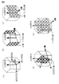
- FIG. 1 is a schematic partial cross-sectional view of the compound semiconductor layer laminate of Example 1 and a light emitting device (specifically, a light emitting element, more specifically, a semiconductor laser element).
- 2A, 2B, 2C and 2D are schematic partial end views of a substrate or the like for explaining the method for forming the compound semiconductor layer laminate of Example 1.
- FIG. 3 is a schematic partial cross-sectional view of the compound semiconductor layer laminate and the light emitting device of Example 2.
- FIG. 4 is a schematic partial cross-sectional view of the compound semiconductor layer laminate and the light emitting device of Example 3.
- FIG. 5 is a schematic partial cross-sectional view of the compound semiconductor layer laminate and the light emitting device of Example 4.
- FIG. 1 is a schematic partial cross-sectional view of the compound semiconductor layer laminate of Example 1 and a light emitting device (specifically, a light emitting element, more specifically, a semiconductor laser element).
- 2A, 2B, 2C and 2D are schematic partial end views of a substrate or the
- FIG. 6 is a schematic partial cross-sectional view of a modified example of the compound semiconductor layer laminate and the light emitting device of Example 4.
- FIG. 7 is a schematic partial cross-sectional view of another modification of the compound semiconductor layer laminate and the light emitting device of Example 4.
- FIG. 8 is a schematic view showing a crystal structure of a hexagonal nitride semiconductor for explaining polar planes, non-polar planes, and semi-polar planes in a nitride semiconductor crystal.
- Example 1 Compound semiconductor layer laminate, its forming method, and light emitting device
- Example 2 Modification of Example 1
- Example 3 Modifications of Examples 1 and 2)
- Example 4 Modifications of Examples 1 to 3) 6.
- the compound semiconductor layer laminate of the present disclosure or the compound semiconductor layer laminate of the present disclosure constituting the light emitting device of the present disclosure (hereinafter, these compound semiconductor layer laminates are collectively referred to as "the compound semiconductor layer laminate of the present disclosure, etc.”
- the first layer may be in the form of having a forward-tapered slope and a flat top surface. Further, in the method for forming the compound semiconductor layer laminate of the present disclosure, the first layer having a forward-tapered slope and a flat top surface can be formed.
- the second layer may be formed on at least the top surface of the first layer, or at least the second layer may be formed on the top surface of the first layer. Further, the second layer can be formed on the top surface and the slope of the first layer, or the second layer can be formed on the top surface and the slope of the first layer. It can be in the form of forming a layer, and further, the thickness of the portion of the second layer formed on the top surface of the first layer is T 2-t , and the thickness of the portion formed on the slope of the first layer is T 2-t . When the thickness of the two layers is T 2-s , T 2-t > T 2-s Can be made into a satisfying form.
- the surface index of the top surface and the surface index of the slope are different. Therefore, as a result of the difference between the growth rate of the second layer on the top surface of the first layer and the growth rate of the second layer on the slope of the first layer, the portion of the second layer on the top surface of the first layer.
- T 2-t and the thickness T 2-s of the portion of the second layer on the slope of the first layer are different, and T 2-t > T 2-s .
- the thickness T 2-s ⁇ the relationship between the thickness T 2-t and the thickness T 2-s is not limited, but is not limited. 0.05 ⁇ T 2-s / T 2-t ⁇ 0.50 Can be mentioned.
- the formation of the first layer having a forward-tapered slope and a flat top surface is basically a growth condition in which, for example, the migration length of gallium (Ga) atoms (distance at which gallium atoms can move, for example, on the surface of a substrate) becomes shorter. based on.
- the distance from the surface of the substrate to the top surface of the first layer is not limited, but is 5 ⁇ 10 -8 m to 5 ⁇ 10 -7 m, preferably 5 ⁇ . 10 -8 m to 2 ⁇ 10 -7 m can be exemplified, and the thickness T 2-t is not limited, but is 1 ⁇ 10 -9 m to 2 ⁇ 10 -7 m, preferably 1 ⁇ 10 -9 m to 2 ⁇ 10 -7 m. 1, 1 ⁇ 10 -9 m to 1 ⁇ 10 -7 m can be exemplified, and the thickness T 2-s is not limited, but 1 ⁇ 10 -9 m to 1 ⁇ 10 -7 m.
- the thickness T 3 of the third layer above the top surface of the first layer is not limited, but is not limited. 5 ⁇ 10 -8 m to 5 ⁇ 10 -7 m, preferably 5 ⁇ 10 -8 m to 2 ⁇ 10 -7 m can be exemplified.
- a mask layer is formed on the substrate, and the first layer is formed on the portion of the substrate that is not covered by the mask layer.
- a mask layer is formed on a substrate and covered with the mask layer before the first layer is formed.
- the structure may be such that the formation of the first layer is started from above the portion of the substrate that is not present.
- the mask layer can be composed of one type of material selected from the group consisting of SiN, SiO 2 and TiO 2 .
- a sea / island structure (the first layer corresponds to an island and the mask layer corresponds to the sea) can be obtained by the mask layer and the first layer.
- a mask layer having an opening is formed on the substrate, and the substrate is exposed at the bottom of the opening.
- the positions of the openings are essentially random.
- the planar shape of the opening is essentially random.
- the formation of the first layer does not start on the mask layer, but on the exposed surface of the substrate. Then, the first layer extends on the mask layer.
- An example of 10% to 99% can be exemplified as the substrate coverage of the mask layer. That is, the opening can be configured to occupy 1% to 90% of the surface of the substrate.
- the thickness of the mask layer is not limited, but 0.1 nm to 5 nm can be exemplified.
- the first layer is doped with impurities composed of Si or Mg, and the doping concentration is 1 ⁇ 10 19 cm -3 or more. It can be configured to be.
- the first layer doped with an impurity made of Si or Mg may be formed on the substrate. In this case, the doping concentration can be 1 ⁇ 10 19 cm -3 or more.
- the formation of the first layer is started in a state where the impurity composed of Mg is doped, microvoids (vacancy) are generated in the first layer, and the first layer starts from the microvoid (vacancy). Further growth.
- the doping concentration as 1 ⁇ 10 19 cm -3 or more, these phenomena can be surely caused.
- the first layer having a forward-tapered slope and a flat top surface can be finally obtained without forming the mask layer.
- a multilayer structure (superlattice structure) of an AlInGaN layer and an AlGaN layer is formed on the third layer. It can be configured.
- Al x2 In y2 Ga (1-x2-y2) N can be exemplified as the composition of the AlGaN layer
- Al x3 Ga (1-x3) N can be exemplified as the composition of the AlGaN layer. It is not limited to the composition.
- the thickness of the AlInGaN layer can be 1 ⁇ 10 -9 m to 1 ⁇ 10 -7 m, and the thickness of the AlGaN layer can be 1 ⁇ 10 -9 m to 2 ⁇ 10 -7 m.
- the substrate may be composed of an InGaN layer, and in this case, the atomic percentage of In atoms in the InGaN layer is 0. It is preferably 5.5% or more and 30% or less.
- the InGaN layer can be formed on the substrate before the first layer is formed. In this case, the atomic percentage of In atom in the InGaN layer is preferably 0.5% or more and 30% or less.
- the substrate is made of an InGaN layer.
- an InGaN template substrate in which a lattice-relaxed InGaN layer (corresponding to a substrate) is laminated on a sapphire substrate or a silicon substrate can be used, and the InGaN substrate can be used. It can also be used.
- the compound semiconductor layer laminate of the present disclosure, the method for forming the same, and the light emitting device are defined as 0 ⁇ y1 ⁇ 1,0 ⁇ y2 ⁇ 1. That is, the first layer may or may not contain In. When y1> 0, As the relationship between y1 and y2, for example, 0.1 ⁇ y1 / y2 ⁇ 0.9 Can be exemplified. If the In component is too large in the first layer, it may be difficult to obtain the first layer having a forward-tapered slope and a flat top surface. In the second layer, the In component is preferably high, which promotes the growth of the third layer in the direction parallel to the surface of the substrate (for convenience, it may be referred to as "lateral direction").
- the third layer does not contain In, which promotes the growth of the third layer in the lateral direction. As a result of the above, it is possible to obtain a third layer having a flat top surface even if the thickness of the third layer is thin. Further, although it is defined that 0 ⁇ x1 ⁇ 1,0 ⁇ x2 ⁇ 1,0 ⁇ x3 ⁇ 1,0 ⁇ y1 ⁇ 1,0 ⁇ y2 ⁇ 1, 0 ⁇ x 1 ⁇ 0.20 0 ⁇ x 2 ⁇ 0.40 0 ⁇ x 3 ⁇ 0.40 0 ⁇ y1 ⁇ 0.20 0 ⁇ y2 ⁇ 0.20 It is preferable to satisfy 0 ⁇ x 1 ⁇ 0.10. 0 ⁇ x 2 ⁇ 0.20 0 ⁇ x 3 ⁇ 0.40 0 ⁇ y1 ⁇ 0.10. 0 ⁇ y2 ⁇ 0.10. It is more preferable to satisfy.
- the substrate not only the above-mentioned InGaN substrate but also a GaN substrate and an AlN substrate can be mentioned, and a GaAs substrate, a SiC substrate, an alumina substrate, a ZnS substrate, a ZnO substrate, an AlN substrate, a LiMgo substrate, and a LiGaO 2 substrate can be mentioned.
- MgAl 2 O 4 substrate, InP substrate can also be mentioned.
- the surface of the substrate made of a group III-V compound semiconductor may be composed of group III atoms or may be composed of group V atoms.
- the surface (main surface) of the substrate made of a group III-V compound semiconductor (specifically, a GaN-based compound semiconductor) is a c-plane which is a ⁇ 0001 ⁇ plane, an a-plane which is a ⁇ 11-20 ⁇ plane, and ⁇ 1.
- It can be composed of a -12 ⁇ plane, a ⁇ 20-21 ⁇ plane, a ⁇ 1-101 ⁇ plane, a ⁇ 2-201 ⁇ plane, and a ⁇ 11-21 ⁇ plane.
- the notation of the crystal plane illustrated below in the hexagonal system Are referred to as ⁇ hk-il ⁇ plane and ⁇ h-quil ⁇ plane in this specification for convenience.
- FIG. 8A is a schematic diagram showing the crystal structure of the hexagonal nitride semiconductor.
- FIG. 8B is a schematic view showing the m-plane and the ⁇ 1-100 ⁇ plane, which are non-polar planes, and the m-plane shown by the gray plane is a plane perpendicular to the m-axis direction.
- FIG. 8C is a schematic view showing the a-plane and the ⁇ 11-20 ⁇ plane, which are non-polar planes, and the a-plane shown by the gray plane is a plane perpendicular to the a-axis direction.
- FIG. 8D is a schematic view showing a ⁇ 20-21 ⁇ plane which is a semi-polar plane.
- the [20-21] direction perpendicular to the ⁇ 20-21 ⁇ plane shown by the gray plane is inclined by 75 degrees from the c-axis to the m-axis direction.
- FIG. 8 (e) is a schematic view showing a ⁇ 11-22 ⁇ plane which is a semi-polar plane.
- the [11-22] direction perpendicular to the ⁇ 11-22 ⁇ plane shown by the gray plane is inclined by 59 degrees from the c-axis to the a-axis direction.
- Table 1 below shows the angles formed by the plane orientations of various crystal planes and the c-axis.
- Surfaces represented by ⁇ 11-2n ⁇ surfaces such as ⁇ 11-21 ⁇ surface, ⁇ 11-22 ⁇ surface, and ⁇ 11-24 ⁇ surface, ⁇ 1-101 ⁇ surface, ⁇ 1-102 ⁇ surface, ⁇ 1-1-plane.
- the 103 ⁇ plane is a semi-polar plane.
- Examples of the light emitting device of the present disclosure including various preferable forms and configurations described above include a semiconductor optical device such as an end face emitting type semiconductor laser device, an end face emitting type superluminescent diode (SLD), or a semiconductor optical amplifier. Can be done.
- the semiconductor optical amplifier does not convert an optical signal into an electric signal, but amplifies it in the state of direct light. It has a laser structure that eliminates the resonator effect as much as possible, and emits incident light based on the optical gain of the semiconductor optical amplifier. Amplify.
- a resonator is constructed by optimizing the light reflectance at the first end face (light emitting end face) and the light reflectance at the second end face (light reflecting end face), and the light is emitted. Emitted from the first end face.
- an external cavity may be arranged.
- the light reflectance at the first end face is set to a very low value
- the light reflectance at the second end face is set to a very high value
- the active layer is not formed as a resonator.
- the light generated by (light emitting layer) is reflected at the second end face and emitted from the first end face.
- a non-reflective coating layer (AR) or a low-reflection coating layer is formed on the first end surface, and a high-reflection coating layer (HR) is formed on the second end surface. It is formed. Further, in the semiconductor optical amplifier, the light reflectance at the first end face and the second end face is set to a very low value, and the light incident from the second end face is amplified without forming a resonator to form the first end face. Emit from.
- the structure of the light emitting device of the present disclosure can also be applied to a light emitting device (semiconductor optical device) such as a surface emitting laser element (vertical cavity laser, also referred to as VCSEL) or a light emitting diode (LED). Further, the configuration and structure of the light emitting device of the present disclosure can be applied to switching elements such as MOSFETs and HEMTs, current amplification elements, high frequency generation elements and the like.
- a light emitting device semiconductor optical device
- VCSEL vertical cavity laser, also referred to as VCSEL
- LED light emitting diode
- switching elements such as MOSFETs and HEMTs, current amplification elements, high frequency generation elements and the like.
- Examples of the compound semiconductor constituting the first compound semiconductor layer, the active layer (light emitting layer), and the second compound semiconductor layer include AlInGaN-based compound semiconductors such as GaN, AlGaN, InGaN, and AlInGaN. Further, these compound semiconductors may contain a boron (B) atom, a thallium (Tl) atom, an arsenic (As) atom, a phosphorus (P) atom, and an antimony (Sb) atom, if desired. ..
- a metalorganic chemical vapor deposition method MOCVD method, MOVPE) Method
- MBE method molecular beam epitaxy method
- MOMBE method metalorganic metal molecular beam epitaxy method
- HVPE method hydride vapor phase growth method in which halogen contributes to transport or reaction
- PPD method plasma assisted physical vapor deposition method
- ALD method atomic layer deposition method
- ALD method atomic layer deposition method
- sputtering method can be mentioned.
- examples of the organic gallium source gas in the MOCVD method include trimethylgallium (TMG) gas and triethyl gallium (TEG) gas, and examples of the nitrogen source gas include ammonia gas and hydrazine gas.
- TMG trimethylgallium
- TMG triethyl gallium
- nitrogen source gas include ammonia gas and hydrazine gas.
- Al aluminum
- In indium
- TMA trimethylaluminum
- TMI trimethylindium
- a striped structure is formed from a laminated light emitting structure composed of a first compound semiconductor layer, an active layer and a second compound semiconductor layer
- a lithography technique is used as a method of etching the laminated light emitting structure structure in order to form the striped structure. Examples include a combination of wet etching technology and a combination of lithography technology and dry etching technology.
- the laminated light emitting body structure is formed on the compound semiconductor layer laminate, and has a structure in which the first compound semiconductor layer, the active layer, and the second compound semiconductor layer are laminated from the compound semiconductor layer laminate side as described above. ..
- the active layer has a quantum well structure.
- it may have a single quantum well structure (SQW structure) or a multiple quantum well structure (MQW structure).
- the active layer having a quantum well structure has a structure in which at least one well layer and a barrier layer are laminated, but as a combination of (compound semiconductors constituting the well layer and compound semiconductors constituting the barrier layer), ( InGaN, GaN), (InGaN, AlInGaN), (InGaN, InGaN) [however, the composition of InGaN constituting the well layer and the composition of InGaN constituting the barrier layer are different] can be exemplified.
- the barrier layer may be composed of a group having a plurality of compositions.
- impurities are added to each of the first compound semiconductor layer and the second compound semiconductor layer. It should be introduced.
- n-type impurities added to the compound semiconductor layer include silicon (Si), sulfur (S), selenium (Se), germanium (Ge), tellurium (Te), tin (Sn), carbon (C), and titanium.
- Ti oxygen (O), palladium (Pd) can be mentioned, and as p-type impurities, zinc (Zn), magnesium (Mg), carbon (C), berylium (Be), cadmium (Cd), etc.
- Calcium (Ca) and barium (Ba) can be mentioned.
- the first compound semiconductor layer is electrically connected to the first electrode
- the second compound semiconductor layer is electrically connected to the second electrode.
- the second electrode is, for example, at least one metal (alloy) selected from the group consisting of palladium (Pd), nickel (Ni), platinum (Pt), gold (Au), cobalt (Co), and rhodium (Rh).
- Alloy selected from the group consisting of palladium (Pd), nickel (Ni), platinum (Pt), gold (Au), cobalt (Co), and rhodium (Rh).
- a single-layer structure or a multi-layer structure for example, a laminated structure of a palladium layer / platinum layer in which the palladium layer is in contact with the second compound semiconductor layer, or a palladium layer / nickel in which the palladium layer is in contact with the second compound semiconductor layer).
- the first electrode is, for example, gold (Au), silver (Ag), palladium (Pd), platinum (Pt), nickel (Ni), Al (aluminum), Ti (titanium), tungsten (W), vanadium (V). ), Chromium (Cr), Cu (Copper), Zn (Zinc), Tin (Sn) and Indium (In), including at least one metal (including alloy) selected from the group.
- the layer before the "/" in the multi-layer structure is located closer to the active layer.
- the first electrode is electrically connected to the first compound semiconductor layer, but the first electrode is formed on the first compound semiconductor layer, and the first electrode is via a conductive material layer or a compound semiconductor layer laminate. The form connected to the first compound semiconductor layer is included.
- the first electrode and the second electrode can be formed by a PVD method such as a vacuum vapor deposition method or a sputtering method.
- a pad electrode may be provided on the first electrode or the second electrode in order to electrically connect to an external electrode or circuit.
- the pad electrode is at least one metal (including alloy) selected from the group consisting of Ti (titanium), aluminum (Al), Pt (platinum), Au (gold), Ni (nickel), and Pd (palladium). It is desirable to have a single-layer structure or a multi-layer structure including.
- the pad electrode may have a Ti / Pt / Au multilayer configuration, a Ti / Au multilayer configuration, a Ti / Pd / Au multilayer configuration, a Ti / Pd / Au multilayer configuration, a Ti / Ni / Au multilayer configuration,
- the multilayer configuration exemplified by the multilayer configuration of Ti / Ni / Au / Cr / Au can also be used.
- a transparent conductive material layer may be formed between the second electrode and the second compound semiconductor layer.
- the transparent conductive material constituting the transparent conductive material layer indium-tin oxide (including ITO, Indium Tin Oxide, Sn-doped In 2 O 3 , crystalline ITO and amorphous ITO), indium-zinc oxide (including ITO, Indium Tin Oxide, Sn-doped In 2 O 3 ) and indium-zinc oxide (including ITO, Indium Tin Oxide, Sn-doped In 2 O 3 ) IZO, Indium Zinc Oxide), IFO (F-doped In 2 O 3 ), tin oxide (SnO 2 ), ATO (Sb-doped SnO 2 ), FTO (F-doped SnO 2 ), zinc oxide (ZnO, Al-doped) (Including ZnO and B-doped Z
- the light emitting device of the present disclosure can be applied to a display device, for example. That is, as such a display device, a projector device, an image display device, a monitor device having the light emitting device of the present disclosure as a light source, a head mounted display (HMD) or a head-up display (HMD) having the light emitting device of the present disclosure as a light source ( HUD), various types of lighting can be mentioned. Further, the light emitting device of the present disclosure can be used as a light source of a microscope. However, it is not limited to these fields.
- Example 1 relates to the compound semiconductor layer laminate of the present disclosure, a method for forming the same, and a light emitting device of the present disclosure.
- FIG. 1 shows a schematic partial cross-sectional view of the compound semiconductor layer laminate and the light emitting device (specifically, a light emitting element or a semiconductor optical device, more specifically, a semiconductor laser element) of the first embodiment.
- the compound semiconductor layer laminate 10 of Example 1 is First layer 11, composed of island-shaped Al x1 In y1 Ga (1-x1-y1) N, formed on the substrate 14.
- the second layer 12 composed of Al x2 In y2 Ga (1-x2-y2) N formed on the first layer 11 and Third layer 13, composed of Al x3 Ga (1-x3) N, formed on the entire surface including the second layer 12.
- the top surface 13A of the third layer 13 is flat. However, 0 ⁇ x1 ⁇ 1,0 ⁇ x2 ⁇ 1,0 ⁇ x3 ⁇ 1,0 ⁇ y1 ⁇ 1,0 ⁇ y2 ⁇ 1.
- the light emitting device of the first embodiment comprises, for example, an end face light emitting type semiconductor laser device.
- Compound semiconductor layer laminate formed on the substrate 14 The first compound semiconductor layer 21 formed on the compound semiconductor layer laminate 10
- the second compound semiconductor layer 22 formed on the active layer 23 The second electrode 26 electrically connected to the second compound semiconductor layer 22 and
- the first electrode 25, which is electrically connected to the first compound semiconductor layer 21, Is equipped with The compound semiconductor layer laminate is composed of the compound semiconductor layer laminate 10 of Example 1.
- the semiconductor laser element of Example 1 emits light having a wavelength of 440 nm or more and 600 nm or less, preferably 495 nm or more and 570 nm or less, although the semiconductor laser element is not limited.
- the first layer 11 has a forward-tapered slope 11B and a flat top surface 11A.
- the second layer 12 is formed on at least the top surface 11A of the first layer 11.
- the second layer 12 is formed on the top surface 11A and the slope 11B of the first layer 11, but in some cases, the second layer 12 is only the top surface 11A of the first layer 11. Formed on top.
- the thickness of the portion of the second layer 12 formed on the top surface 11A of the first layer 11 is T 2-t
- the thickness of the portion of the second layer 12 formed on the slope 11B of the first layer 11 is T 2-t .
- the top surface 11A of the first layer 11 is composed of the (0001) plane, and the slope 11B is composed of the (11-22) plane. Therefore, the growth rate of the second layer 12 on the top surface 11A of the first layer 11 and the growth rate of the second layer 12 on the slope 11B of the first layer 11 are different. Specifically, the first layer 11 The growth rate of the second layer 12 on the slope 11B of the first layer 11 is slower than the growth rate of the second layer 12 on the top surface 11A of the first layer 11, and as a result, the second layer on the top surface 11A of the first layer 11 The thickness T 2-t of the portion 12 and the thickness T 2-s of the portion of the second layer 12 on the slope 11B of the first layer 11 are different, and T 2-t > T 2-s . When the thickness T 2-s ⁇ 0, the relationship between the thickness T 2-t and the thickness T 2-s is not limited, but is not limited. 0.05 ⁇ T 2-s / T 2-t ⁇ 0.50 Can be mentioned.
- the distance from the surface of the substrate 14 to the top surface 11A of the first layer 11 is not limited, but may be 50 nm to 0.5 ⁇ m.
- the mask layer 16 is formed on the substrate 14, and the first layer 11 is formed on the portion of the substrate 14 that is not covered by the mask layer 16.
- the mask layer 16 is made of, for example, SiN.
- the thickness of the mask layer 16 is not limited, but 0.1 nm to 5 nm can be exemplified.
- the mask layer 16 has an opening 17.
- Example 1 0.1 ⁇ y1 / y2 ⁇ 0.9 To be satisfied.
- y2 0.09 And said.
- the GaN template substrate to have was used.
- the GaN layer 15 exposed in the opening 17 corresponds to the substrate 14, and the surface (exposed surface) of the substrate 14 is composed of a (0001) surface.
- a GaN substrate can be used as the substrate 14.
- the first compound semiconductor layer 21, the active layer (light emitting layer) 23, and the second compound semiconductor layer 22 constituting the laminated light emitting body structure are as shown in Table 2 below.
- Second compound semiconductor layer 22 Contact layer (Mg dope) It consists of p-type GaN.
- Second clad layer (Mg dope) P-type AlGaN with a thickness of 0.2 ⁇ m to 0.4 ⁇ m
- Active layer 23 (overall thickness: 0.1 ⁇ m to 0.3 ⁇ m)
- Quantum well active layer well layer: InGaN / barrier layer: InGaN
- First compound semiconductor layer 21 First clad layer (Si-doped) N-type AlGaN with a thickness of 0.5 ⁇ m to 1.5 ⁇ m
- FIGS. 2A, 2B, 2C and 2D are schematic partial end views of the substrate and the like.
- a GaN template substrate having a structure in which a GaN layer 15 is laminated by several ⁇ m on a sapphire substrate or a silicon substrate 14A via a GaN low temperature buffer layer is prepared.
- the mask layer 16 is formed on the substrate 14 based on the MOCVD method (see FIG. 2A).
- the film formation temperature of the mask layer 16 made of SiN may be about 900 ° C. to 1100 ° C., for example, SiH 4 gas may be used as the raw material for Si, and NH 3 may be used as the raw material for N.
- the openings 17 are naturally and randomly formed. That is, the forming position of the opening 17 is random.
- the planar shape of the opening 17 is also random.
- an island-shaped first layer 11 composed of Al x1 In y1 Ga (1-x1-y1) N is formed on the substrate 14. Specifically, the first layer 11 having a three-dimensional structure having a forward-tapered slope 11B and a flat top surface 11A is formed. The first layer 11 is formed on the portion of the substrate 14 that is not covered by the mask layer 16. That is, the formation of the first layer 11 is started from above the substrate 14 exposed at the bottom of the opening 17 of the mask layer 16. As the formation of the first layer 11 progresses, the first layer 11 extends over the mask layer 16.
- a first layer 11 having a three-dimensional structure having a forward-tapered slope 11B and a flat top surface 11A is formed (see FIG. 2B).
- the composition ratio and growth rate of the gas source containing atoms may be selected. Examples of the growth temperature of the first layer 11 include 700 ° C to 1100 ° C.
- a second layer 12 composed of Al x2 In y2 Ga (1-x2-y2) N is formed on at least the first layer 11 (see FIG. 2C). Specifically, the second layer 12 is formed on the top surface 11A and the slope 11B of the first layer 11. Since the surface indices of the forward-tapered slope 11B of the first layer 11 and the flat top surface 11A are different, the growth rate of the second layer 12 on the top surface 11A of the first layer 11 is on the slope 11B of the first layer 11. Since it is faster than the growth rate of the second layer 12 in the above, T 2-t > T 2-s can be achieved.
- the top surface 11A of the first layer 11 is composed of a (0001) surface
- the slope 11B is a ⁇ 11-2n ⁇ surface [where n is an integer of 0 to 4, and specifically, for example, ( Since it is composed of 11-22) planes], the second layer 12 growing on the slope 11B has poor uptake of In atoms, and the second layer 12 on the slope 11B of the first layer 11
- the growth rate is slower than the growth rate of the second layer 12 on the top surface 11A of the first layer 11.
- the second layer 12 may not be formed on the forward-tapered slope 11B of the first layer 11. Examples of the growth temperature of the second layer 12 include 700 ° C to 900 ° C.
- a third layer 13 made of Al x3 Ga (1-x3) N is formed on the entire surface including the second layer 12 (see FIG. 2D).
- a composition ratio of a gas source containing a group III atom and a gas source containing a group V atom used for the growth of the third layer 13, and a growth rate are used for epitaxial growth of the third layer 13, and a growth rate.
- the slow growth rate of the third layer 13 containing no In atoms in the thickness direction on the second layer 12 containing In atoms the growth of the third layer 13 in the lateral direction is promoted.
- the growth temperature of the third layer 13 may be higher than that of the first layer 11, and the growth pressure may be lowered. Examples of the growth temperature of the third layer 13 include 700 ° C to 1100 ° C.
- the flatness is such that an atomic step can be obtained. It is necessary to form a third layer of a thick film of several ⁇ m in order to obtain.
- the thickness T 3 of the third layer 13 is about 200 nm to 300 nm, it is possible to obtain flatness in the third layer 13 so that an atomic step can be obtained. It is possible to reduce the through-dislocation density by one or two orders of magnitude as compared with the conventional structure.
- the first compound semiconductor layer 21, the active layer 23, and the second compound semiconductor layer 22 are sequentially formed on the third layer 13.
- an etching mask is formed on the second compound semiconductor layer 22, and the second compound semiconductor layer 22 and the active layer 23 are etched in the thickness direction using the etching mask, for example, based on the RIE method.
- the first compound semiconductor layer 21 is partially etched in the thickness direction to form the striped structure 20, and then the etching mask is removed.
- the insulating layer 24 is formed on the entire surface, and the portion of the insulating layer 24 located on the top surface of the second compound semiconductor layer 22 is removed.
- the second electrode 26 is formed on the exposed second compound semiconductor layer 22. Further, a part of the first compound semiconductor layer 21 is exposed, and the first electrode 25 is formed in this exposed portion. Further, pad electrodes 27 and 28 are formed on the first electrode 25 and the second electrode 26.
- the first end face and the second end face are formed by cleaving the compound semiconductor layer laminated body and the laminated light emitting body structure. Then, the coat layers of the first end face and the second end face are formed. After that, the light emitting device of Example 1 is completed by forming terminals and the like based on a well-known method in order to connect the electrodes to an external circuit and the like, and packaging and sealing the electrodes.
- the compound semiconductor layer laminate has a three-dimensional structure. It has a structure such as a first layer, a second layer formed on the first layer and having a composition different from that of the first layer, and a third layer formed on the second layer and having a composition different from that of the second layer. Therefore, a third layer having a flat top surface can be obtained even though the thickness is thin. Therefore, the formation time of the compound semiconductor layer laminate can be significantly shortened.
- the through-dislocation density becomes high, but in the first embodiment, in the lateral direction on the second layer.
- dislocation pairs are likely to occur, and the density of dislocations can be reduced.
- the leakage current can be reduced and the reliability can be improved, and in the light emitting element, the leakage current can be reduced and the reliability can be improved, and the luminous efficiency can be improved. Improvements can be achieved.
- Example 2 is a modification of Example 1.
- a schematic partial cross-sectional view of the compound semiconductor layer laminate and the light emitting device of Example 2 shows, in Example 2, a thickness of 20 nm and a number of layers on the third layer 13.
- a multilayer structure (superlattice structure) 18 is formed by 10 AlInGaN layers 18A and an AlGaN layer 18B having a thickness of 20 nm and 10 layers.
- the multilayer structure (superlattice structure) 18 is formed on the third layer 13 in this way, the thickness of the third layer 13 can be further reduced, and the AlInGaN layer 18A containing In atoms exists.
- the laminated illuminant structure is formed by promoting the lateral growth of the AlGaN layer 18B by utilizing the slow growth of the AlGaN layer 18B formed on the AlGaN layer 18B in the thickness direction.
- a flatter surface can be obtained as the base of the body.
- the configuration and structure of the compound semiconductor layer laminate and the light emitting device of Example 2 can be the same as the configuration and structure of the compound semiconductor layer laminate and the light emitting device of Example 1. The explanation is omitted.
- Example 3 is a modification of Examples 1 and 2. As shown in FIG. 4, a schematic partial cross-sectional view of the compound semiconductor layer laminate and the light emitting device of Example 3 is shown, in Example 3, the mask layer 16 is not formed, and the first layer 11'is formed. Impurities composed of Si or Mg are doped, and the doping concentration is 1 ⁇ 10 19 cm -3 or more. When the first layer 11'begins to be formed on the substrate 14, a region having a large amount of impurities made of Si and a region having a small amount of impurities are formed on the surface of the substrate 14.
- the first layer 11' is difficult to be formed in the region where impurities are abundant, and the first layer 11'is formed from the region where impurities are small. Further, when the formation of the first layer 11'is started in a state where the impurity composed of Mg is doped, minute voids (vacancy) are generated in the first layer 11', and the minute voids (vacancy) are used as a starting point. The first layer 11'will grow further. By defining the doping concentration as 1 ⁇ 10 19 cm -3 or more, these phenomena can be surely caused. Then, due to the formation form of the first layer 11', the first layer 11' having a forward-tapered slope 11B and a flat top surface 11A is finally obtained without forming a mask layer. be able to.
- the configuration and structure of the compound semiconductor layer laminate and the light emitting device of Example 3 may be the same as the configuration and structure of the compound semiconductor layer laminate and the light emitting device of Examples 1 and 2. Since it can be done, detailed description is omitted.
- the slope of the forward taper can also be selected by selecting an appropriate growth temperature and growth pressure, a composition ratio of a gas source containing a group III atom and a gas source containing a group V atom used for the growth of the first layer 11', and a growth rate. It is possible to obtain a first layer 11'with 11B and a flat top surface 11A.
- the growth temperature may be set to a low temperature of 1000 ° C. or less, and the growth pressure may be increased. That is, for example, the growth temperature of the first layer 11'is set to 700 ° C or less, the first layer 11'is grown by several nm to several tens of nm, and then the growth temperature of the first layer 11'is 700 ° C. With the above, it is possible to obtain the first layer 11'having a forward tapered slope 11B and a flat top surface 11A.
- Example 4 is a modification of Examples 1 to 3.
- the substrate 14' consists of an InGaN layer. .. Specifically, an InGaN template substrate in which a lattice-relaxed InGaN layer (corresponding to a substrate) was laminated on a sapphire substrate or a silicon substrate 14A was used.
- the thickness of the InGaN layer corresponding to the substrate 14' is, for example, 1 ⁇ m or less.
- the atomic percentage of In atoms in the InGaN layer is preferably 0.5% or more and 30% or less, and specifically, 10 atomic%.
- the substrate 14' may be composed of an InGaN layer having a different In composition, an AlGaN layer, a GaN layer, and the like.
- FIG. 5 shows a modified example of Example 1
- FIG. 6 illustrates a modified example of Example 2
- FIG. 7 illustrates a modified example of Example 3.
- An InGaN substrate can also be used as the substrate 14', and such a configuration is also included in the configuration in which the substrate is composed of an InGaN layer.
- the configuration and structure of the compound semiconductor layer laminate and the light emitting device of Example 4 may be the same as the configuration and structure of the compound semiconductor layer laminate and the light emitting device of Examples 1 to 3. Since it can be done, detailed description is omitted.
- the present disclosure has been described above based on preferred examples, the present disclosure is not limited to these examples.
- the compound semiconductor layer laminate, the device configuration, the structure, and the method for forming the compound semiconductor layer laminate described in the examples are examples, and can be appropriately changed.
- the light emitting device has been described exclusively as a semiconductor laser element, the light emitting device may also be a light emitting diode (LED), a superluminescent diode (SLD), or a semiconductor optical amplifier.
- the configurations and structures of the SLD and the semiconductor optical amplifier are substantially the light emitting devices (semiconductor optical devices) described in Examples 1 to 4 except that the light reflectances of the light emitting end face and the light reflecting end face are different. ) Can have the same configuration and structure.
- the striped structure 20 has a shape extending linearly, but the shape is not limited to this, and the striped structure 20 may not only extend with a constant width but also have a tapered shape or a flared shape. Specifically, for example, a configuration in which the light emitting end face is gradually expanded in a tapered shape from the light emitting end face to the light reflecting end face, and the light emitting end face is first expanded toward the light reflecting end face and exceeds the maximum width. Later, it can be narrowed down.
- the present disclosure may also have the following configuration.
- [A01] ⁇ Method for Forming Compound Semiconductor Layer Laminated Body >> After forming the first layer consisting of island-shaped Al x1 In y1 Ga (1-x1-y1) N on the substrate, A second layer consisting of Al x2 In y2 Ga (1-x2-y2) N is formed on the first layer, and then a second layer is formed. A third layer composed of Al x3 Ga (1-x3) N is formed on the entire surface including the second layer. It has each process, A method for forming a compound semiconductor layer laminate in which the top surface of the third layer is flat.
- [A07] The method for forming a compound semiconductor layer laminate according to [A06], wherein the mask layer is made of one kind of material selected from the group consisting of SiN, SiO 2 and TiO 2 .
- [A08] Forming a first layer doped with impurities composed of Si or Mg, The method for forming a compound semiconductor layer laminate according to any one of [A01] to [A05], wherein the doping concentration is 1 ⁇ 10 19 cm -3 or more.
- [A09] The method for forming a compound semiconductor layer laminate according to any one of [A01] to [A08], wherein a multilayer structure of an AlInGaN layer and an AlGaN layer is formed on the third layer.
- [A10] The method for forming a compound semiconductor layer laminate according to any one of [A01] to [A09], wherein the substrate forms an InGaN layer and the first layer is formed on the InGaN layer.
- [A11] The method for forming a compound semiconductor layer laminate according to [A10], wherein the atomic percentage of In atoms in the InGaN layer is 0.5% or more and 30% or less.
- An InGaN layer is formed on the substrate to form an InGaN layer.
- a mask layer is formed on the InGaN layer, The method for forming a compound semiconductor layer laminate according to any one of [A01] to [A09], wherein the formation of the first layer is started from above the portion of the substrate that is not covered with the mask layer.
- [A13] The method for forming a compound semiconductor layer laminate according to [A12], wherein the atomic percentage of In atoms in the InGaN layer is 0.5% or more and 30% or less.
- [B01] ⁇ Compound semiconductor layer laminate >> A first layer of island-shaped Al x1 In y1 Ga (1-x1-y1) N formed on the substrate, The second layer composed of Al x2 In y2 Ga (1-x2-y2) N formed on the first layer, and A third layer composed of Al x3 Ga (1-x3) N, which is formed on the entire surface including the second layer. Is equipped with A compound semiconductor layer laminate in which the top surface of the third layer is flat.
- the first layer is doped with impurities composed of Si or Mg.
- Compound semiconductor layer laminate formed on the substrate, The first compound semiconductor layer formed on the compound semiconductor layer laminate, The active layer formed on the first compound semiconductor layer, Second compound semiconductor layer formed on the active layer, The second electrode electrically connected to the second compound semiconductor layer, and First electrode, which is electrically connected to the first compound semiconductor layer, Is equipped with The compound semiconductor layer laminate is A first layer of island-shaped Al x1 In y1 Ga (1-x1-y1) N formed on the substrate, The second layer composed of Al x2 In y2 Ga (1-x2-y2) N formed on the first layer, and A third layer composed of Al x3 Ga (1-x3) N, which is formed on the entire surface including the second layer.
- [C05] The thickness of T 2-t of the portion of the second layer formed on the first layer of the top surface, the thickness of the portion of the second layer formed on the inclined surface of the first layer T 2- When s T 2-t > T 2-s
- [C06] A mask layer is formed on the substrate, and a mask layer is formed on the substrate.
- [C07] The light emitting device according to [C06], wherein the mask layer is made of one kind of material selected from the group consisting of SiN, SiO 2 and TiO 2 .
- the first layer is doped with impurities composed of Si or Mg.
Landscapes
- Physics & Mathematics (AREA)
- Condensed Matter Physics & Semiconductors (AREA)
- General Physics & Mathematics (AREA)
- Electromagnetism (AREA)
- Optics & Photonics (AREA)
- Led Devices (AREA)
- Semiconductor Lasers (AREA)
Priority Applications (3)
| Application Number | Priority Date | Filing Date | Title |
|---|---|---|---|
| JP2021514859A JP7548219B2 (ja) | 2019-04-19 | 2020-03-31 | 化合物半導体層積層体及びその形成方法、並びに、発光デバイス |
| EP20791935.8A EP3958333B1 (en) | 2019-04-19 | 2020-03-31 | Compound semiconductor layer laminate and method for forming same, and light-emitting device |
| US17/602,630 US20220190555A1 (en) | 2019-04-19 | 2020-03-31 | Compound semiconductor layer stack, method of forming the same, and light-emitting device |
Applications Claiming Priority (2)
| Application Number | Priority Date | Filing Date | Title |
|---|---|---|---|
| JP2019079978 | 2019-04-19 | ||
| JP2019-079978 | 2019-04-19 |
Publications (1)
| Publication Number | Publication Date |
|---|---|
| WO2020213388A1 true WO2020213388A1 (ja) | 2020-10-22 |
Family
ID=72836822
Family Applications (1)
| Application Number | Title | Priority Date | Filing Date |
|---|---|---|---|
| PCT/JP2020/014796 Ceased WO2020213388A1 (ja) | 2019-04-19 | 2020-03-31 | 化合物半導体層積層体及びその形成方法、並びに、発光デバイス |
Country Status (4)
| Country | Link |
|---|---|
| US (1) | US20220190555A1 (https=) |
| EP (1) | EP3958333B1 (https=) |
| JP (1) | JP7548219B2 (https=) |
| WO (1) | WO2020213388A1 (https=) |
Citations (4)
| Publication number | Priority date | Publication date | Assignee | Title |
|---|---|---|---|---|
| JPH11219909A (ja) * | 1997-11-26 | 1999-08-10 | Nichia Chem Ind Ltd | 窒化物半導体の成長方法 |
| JP2003158295A (ja) * | 2001-11-22 | 2003-05-30 | Showa Denko Kk | GaN系半導体薄膜、その製造方法、半導体発光素子 |
| JP2007214380A (ja) | 2006-02-09 | 2007-08-23 | Hamamatsu Photonics Kk | 窒化化合物半導体基板及び半導体デバイス |
| JP2013074278A (ja) * | 2011-09-29 | 2013-04-22 | Panasonic Corp | 窒化物半導体基板及びその製造方法、並びにそれを用いた窒化物半導体発光素子 |
Family Cites Families (3)
| Publication number | Priority date | Publication date | Assignee | Title |
|---|---|---|---|---|
| US6939730B2 (en) * | 2001-04-24 | 2005-09-06 | Sony Corporation | Nitride semiconductor, semiconductor device, and method of manufacturing the same |
| JP3548735B2 (ja) * | 2001-06-29 | 2004-07-28 | 士郎 酒井 | 窒化ガリウム系化合物半導体の製造方法 |
| JP4229005B2 (ja) * | 2003-06-26 | 2009-02-25 | 住友電気工業株式会社 | GaN基板及びその製造方法、並びに窒化物半導体素子 |
-
2020
- 2020-03-31 WO PCT/JP2020/014796 patent/WO2020213388A1/ja not_active Ceased
- 2020-03-31 EP EP20791935.8A patent/EP3958333B1/en active Active
- 2020-03-31 US US17/602,630 patent/US20220190555A1/en not_active Abandoned
- 2020-03-31 JP JP2021514859A patent/JP7548219B2/ja active Active
Patent Citations (4)
| Publication number | Priority date | Publication date | Assignee | Title |
|---|---|---|---|---|
| JPH11219909A (ja) * | 1997-11-26 | 1999-08-10 | Nichia Chem Ind Ltd | 窒化物半導体の成長方法 |
| JP2003158295A (ja) * | 2001-11-22 | 2003-05-30 | Showa Denko Kk | GaN系半導体薄膜、その製造方法、半導体発光素子 |
| JP2007214380A (ja) | 2006-02-09 | 2007-08-23 | Hamamatsu Photonics Kk | 窒化化合物半導体基板及び半導体デバイス |
| JP2013074278A (ja) * | 2011-09-29 | 2013-04-22 | Panasonic Corp | 窒化物半導体基板及びその製造方法、並びにそれを用いた窒化物半導体発光素子 |
Non-Patent Citations (1)
| Title |
|---|
| See also references of EP3958333A4 |
Also Published As
| Publication number | Publication date |
|---|---|
| JP7548219B2 (ja) | 2024-09-10 |
| JPWO2020213388A1 (https=) | 2020-10-22 |
| US20220190555A1 (en) | 2022-06-16 |
| EP3958333B1 (en) | 2025-01-29 |
| EP3958333A1 (en) | 2022-02-23 |
| EP3958333A4 (en) | 2022-06-08 |
Similar Documents
| Publication | Publication Date | Title |
|---|---|---|
| JP3815335B2 (ja) | 半導体発光素子及びその製造方法 | |
| JP3816176B2 (ja) | 半導体発光素子及び光半導体装置 | |
| JP3282174B2 (ja) | 窒化物半導体発光素子 | |
| JP2007184411A (ja) | 発光ダイオードおよびその製造方法ならびに集積型発光ダイオードおよびその製造方法ならびに発光ダイオードバックライトならびに発光ダイオード照明装置ならびに発光ダイオードディスプレイならびに電子機器ならびに電子装置およびその製造方法 | |
| US20130015487A1 (en) | Semiconductor light-emitting device | |
| WO2002007231A1 (fr) | Dispositif luminescent a semi-conducteur et procede de fabrication correspondant | |
| JPWO2013021606A1 (ja) | 窒化物半導体層成長用構造、積層構造、窒化物系半導体素子および光源ならびにこれらの製造方法 | |
| US10546975B2 (en) | Semiconductor optical device | |
| JP5366518B2 (ja) | 半導体発光素子およびその製造方法 | |
| JP2001077412A (ja) | 半導体素子およびその製造方法 | |
| JP3545197B2 (ja) | 半導体素子およびその製造方法 | |
| US7514707B2 (en) | Group III nitride semiconductor light-emitting device | |
| US20060237709A1 (en) | GaN-based compound semiconductor device | |
| US7452789B2 (en) | Method for forming underlayer composed of GaN-based compound semiconductor, GaN-based semiconductor light-emitting element, and method for manufacturing GaN-based semiconductor light-emitting element | |
| JPH11163402A (ja) | GaN系半導体発光素子 | |
| JP2001077423A (ja) | Iii族窒化物系化合物半導体素子 | |
| JP7548219B2 (ja) | 化合物半導体層積層体及びその形成方法、並びに、発光デバイス | |
| JP4481385B2 (ja) | 半導体発光素子及びその製造方法 | |
| CN110473943A (zh) | 发光二极管元件、以及发光二极管元件的制造方法 | |
| JP4931271B2 (ja) | 窒化物半導体素子及びそれを用いた発光装置 | |
| JP2003086533A (ja) | 窒化物半導体素子および半導体装置 | |
| WO2006106928A1 (ja) | 窒化ガリウム系化合物半導体レーザ素子の製造方法及び窒化ガリウム系化合物半導体レーザ素子 | |
| US8435880B2 (en) | Method for manufacturing semiconductor device and semiconductor device | |
| JP6103241B2 (ja) | 発光素子 | |
| JP2008118048A (ja) | GaN系半導体発光素子 |
Legal Events
| Date | Code | Title | Description |
|---|---|---|---|
| 121 | Ep: the epo has been informed by wipo that ep was designated in this application |
Ref document number: 20791935 Country of ref document: EP Kind code of ref document: A1 |
|
| ENP | Entry into the national phase |
Ref document number: 2021514859 Country of ref document: JP Kind code of ref document: A |
|
| NENP | Non-entry into the national phase |
Ref country code: DE |
|
| WWE | Wipo information: entry into national phase |
Ref document number: 2020791935 Country of ref document: EP |