WO2020213235A1 - 電磁弁機構及びそれを備えた高圧燃料供給ポンプ - Google Patents
電磁弁機構及びそれを備えた高圧燃料供給ポンプ Download PDFInfo
- Publication number
- WO2020213235A1 WO2020213235A1 PCT/JP2020/004731 JP2020004731W WO2020213235A1 WO 2020213235 A1 WO2020213235 A1 WO 2020213235A1 JP 2020004731 W JP2020004731 W JP 2020004731W WO 2020213235 A1 WO2020213235 A1 WO 2020213235A1
- Authority
- WO
- WIPO (PCT)
- Prior art keywords
- movable core
- solenoid valve
- valve mechanism
- guide member
- core
- Prior art date
- Legal status (The legal status is an assumption and is not a legal conclusion. Google has not performed a legal analysis and makes no representation as to the accuracy of the status listed.)
- Ceased
Links
Images


Classifications
-
- F—MECHANICAL ENGINEERING; LIGHTING; HEATING; WEAPONS; BLASTING
- F02—COMBUSTION ENGINES; HOT-GAS OR COMBUSTION-PRODUCT ENGINE PLANTS
- F02M—SUPPLYING COMBUSTION ENGINES IN GENERAL WITH COMBUSTIBLE MIXTURES OR CONSTITUENTS THEREOF
- F02M59/00—Pumps specially adapted for fuel-injection and not provided for in groups F02M39/00 -F02M57/00, e.g. rotary cylinder-block type of pumps
- F02M59/44—Details, components parts, or accessories not provided for in, or of interest apart from, the apparatus of groups F02M59/02 - F02M59/42; Pumps having transducers, e.g. to measure displacement of pump rack or piston
- F02M59/46—Valves
- F02M59/466—Electrically operated valves, e.g. using electromagnetic or piezoelectric operating means
-
- H—ELECTRICITY
- H01—ELECTRIC ELEMENTS
- H01F—MAGNETS; INDUCTANCES; TRANSFORMERS; SELECTION OF MATERIALS FOR THEIR MAGNETIC PROPERTIES
- H01F7/00—Magnets
- H01F7/06—Electromagnets; Actuators including electromagnets
- H01F7/08—Electromagnets; Actuators including electromagnets with armatures
- H01F7/121—Guiding or setting position of armatures, e.g. retaining armatures in their end position
-
- H—ELECTRICITY
- H01—ELECTRIC ELEMENTS
- H01F—MAGNETS; INDUCTANCES; TRANSFORMERS; SELECTION OF MATERIALS FOR THEIR MAGNETIC PROPERTIES
- H01F7/00—Magnets
- H01F7/06—Electromagnets; Actuators including electromagnets
- H01F7/08—Electromagnets; Actuators including electromagnets with armatures
- H01F7/16—Rectilinearly-movable armatures
- H01F7/1607—Armatures entering the winding
-
- H—ELECTRICITY
- H01—ELECTRIC ELEMENTS
- H01F—MAGNETS; INDUCTANCES; TRANSFORMERS; SELECTION OF MATERIALS FOR THEIR MAGNETIC PROPERTIES
- H01F7/00—Magnets
- H01F7/06—Electromagnets; Actuators including electromagnets
- H01F7/08—Electromagnets; Actuators including electromagnets with armatures
- H01F7/16—Rectilinearly-movable armatures
- H01F7/1607—Armatures entering the winding
- H01F2007/163—Armatures entering the winding with axial bearing
Definitions
- the present invention relates to a solenoid valve mechanism for an internal combustion engine of an automobile and a high-pressure fuel supply pump provided with the solenoid valve mechanism.
- Some high-pressure fuel supply pumps for internal combustion engines of automobiles use a solenoid valve mechanism (solenoid intake valve unit) to adjust the fuel flow rate.
- the solenoid valve mechanism controls the opening / closing motion of the valve by energizing the coil.
- a yoke made of magnetic material, a coil housed inside the yoke, and a fixed core located at the center of the coil are included.
- a movable iron core installed so as to face the fixed iron core, a rod that is displaced by transmitting a force from the movable iron core, and a ring-shaped component at a position facing the rod, and in a state where the coil is not energized. It is known that the position of the ring-shaped component is adjusted so that the gap formed between the ring-shaped component and the plunger is smaller than the gap formed between the movable iron core and the fixed iron core (for example, Patent Document). 1).
- the solenoid valve mechanism described above is composed of a movable core, a fixed core, etc., in an ideal case where the movable core moves without tilting when the movable core moves in a state of being relatively tilted with respect to the fixed core.
- the magnitude of the magnetic field generated in the magnetic circuit and the amount of movement (stroke amount) of the movable iron core change. Therefore, the operation (movement) of the movable iron core may vary, which may affect the responsiveness of the valve opening / closing operation.
- the fuel discharge flow rate may vary with respect to the desired flow rate.
- the solenoid valve mechanism is required to suppress variations in the operation of the movable iron core.
- a guide mechanism that guides the movement of the movable iron core in the intended direction is important.
- a movable iron core is fixed to one side in the axial direction of the rod, and a sliding portion (guide mechanism) having a hole for a guide on the other side in the axial direction of the rod. It is slidably supported. Therefore, the movement of the movable iron core is guided by the sliding portion via the rod. Since a gap is provided between the rod and the sliding portion (hole for the guide), the rod may move in an inclined state. If the rod is guided by the sliding portion in a tilted state, the movable iron core fixed to the rod moves in a tilted state according to the tilt of the rod.
- the amount of displacement of the movable core (displacement amount in the direction orthogonal to the ideal moving direction) with respect to the ideal case where the movable core moves without tilting is determined by the rod of the movable core. It increases in proportion to the distance from the position fixed to the rod to the position where the rod is slidably supported by the sliding portion (guide mechanism). That is, the longer the distance from the guide mechanism that guides the movable iron core to the movable iron core, the larger the amount of deviation of the movable iron core. If the amount of deviation due to the inclination of the movable iron core becomes large, the operation of the movable iron core may vary greatly accordingly.
- the present invention has been made to solve the above problems, and an object of the present invention is to provide a solenoid valve mechanism capable of reducing an inclination of a movable core during movement and a high-pressure fuel supply pump provided with the solenoid valve mechanism. It is to be.
- the present application includes a plurality of means for solving the above problems.
- a coil provided in an annular shape, a fixed core arranged radially inside the coil, and a radial inside of the coil. It has a movable core which is arranged so as to face the fixed core and forms a part of a magnetic circuit together with the fixed core, and is attracted to the fixed core by energizing the coil, and has a first central axis.
- a fixed guide member for guiding the movable core in a direction in which the movable core is brought into contact with the fixed core is provided, and the guide member is arranged radially inside the movable core to support the movement of the movable core. It is characterized by that.
- the fixed guide member is configured to support and guide the movable core at a position inside the movable core in the radial direction, the position for guiding and supporting the movable core is closer to the movable core side than the conventional structure. It can be brought closer, and as a result, the inclination of the movable core during movement can be reduced. Issues, configurations and effects other than the above will be clarified by the description of the following embodiments.
- FIG. 2 is an enlarged view of an electromagnetic suction valve unit as an electromagnetic valve mechanism according to the first embodiment of the present invention shown in FIG. It is explanatory drawing which shows the relationship between the movable core and the guide structure part in the solenoid valve mechanism which concerns on 1st Embodiment of this invention shown in FIG. It is sectional drawing which shows the electromagnetic valve mechanism which concerns on 1st modification of 1st Embodiment of this invention. It is sectional drawing which shows the electromagnetic valve mechanism which concerns on the 2nd modification of 1st Embodiment of this invention. It is sectional drawing which shows the solenoid valve mechanism which concerns on 2nd Embodiment of this invention.
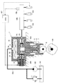
- FIG. 1 is a configuration diagram showing a fuel supply system of an internal combustion engine including a high-pressure fuel supply pump provided with a solenoid valve mechanism according to the first embodiment of the present invention.
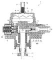
- FIG. 2 is a cross-sectional view showing a high-pressure fuel supply pump provided with a solenoid valve mechanism according to the first embodiment of the present invention.
- the fuel supply system of the internal combustion engine pressurizes, for example, a fuel tank 101 for storing fuel, a feed pump 102 for pumping and delivering fuel in the fuel tank 101, and a fuel delivered from the feed pump 102. It includes a high-pressure fuel supply pump 1 for discharging the fuel, and a plurality of injectors 103 for injecting the high-pressure fuel pumped from the high-pressure fuel supply pump 1.
- This system is a so-called direct injection engine system that injects fuel directly into the cylinder cylinder of an engine as an internal combustion engine.
- the high-pressure fuel supply pump 1 is connected to the feed pump 102 via the suction pipe 104 and is connected to the injector 103 via the common rail 105.
- the injector 103 is mounted on the common rail 105 according to the number of cylinders of the engine, and is controlled to open or close the valve according to a control signal from the engine control unit (hereinafter, referred to as ECU) 107.
- the common rail 105 is equipped with a pressure sensor 106 that detects the pressure of the fuel discharged from the high-pressure fuel supply pump 1.
- the pressure sensor 106 outputs a pressure detection signal to the ECU 107.
- the high-pressure fuel supply pump 1 includes a pump housing 1a having a pressurizing chamber 4 for pressurizing fuel inside, a plunger 5, an electromagnetic suction valve unit 300, and a discharge valve unit 500 assembled to the pump housing 1a. There is.
- the plunger 5 pressurizes the fuel in the pressurizing chamber 4 by reciprocating motion.
- the electromagnetic suction valve unit 300 functions as a capacity variable mechanism for adjusting the flow rate of fuel sucked into the pressurizing chamber 4, and is controlled by a control signal from the ECU 107.
- the discharge valve unit 500 discharges the fuel pressurized by the plunger 5 to the common rail 105 side.
- a bottomed tubular (cup-shaped) damper cover 10 is fixed to the tip end side (upper end portion side in FIGS. 1 and 2) of the pump housing 1a.
- a suction joint 11 is attached to the damper cover 10, and the suction joint 11 forms a low-pressure fuel suction port 2a of the high-pressure fuel supply pump 1.
- a suction filter 12 is installed in the suction joint 11. The suction filter 12 has a role of preventing foreign matter existing between the fuel tank 101 and the low pressure fuel suction port 2a from being absorbed into the high pressure fuel supply pump 1 by the flow of fuel.
- a low-pressure fuel chamber 2b as a part of the fuel flow path is formed on the upstream side of the pressurizing chamber 4 by the tip of the pump housing 1a and the damper cover 10.
- a pressure pulsation reducing mechanism 14 is arranged in the low pressure fuel chamber 2b. The pressure pulsation reducing mechanism 14 reduces the spread of the pressure pulsation generated in the high-pressure fuel supply pump 1 to the suction pipe 104, and is formed on the upstream side of the electromagnetic suction valve unit 300.
- a tappet 6 is provided on the tip side (lower end side in FIG. 1) of the plunger 5 to convert the rotary motion of the cam 108 of the engine into a linear reciprocating motion.
- the plunger 5 is crimped to the tappet 6 by the urging force of the spring 8 via the retainer 7 fixed to the tip of the plunger 5.
- the plunger 5 can be reciprocated with the rotational movement of the cam 108.
- An electromagnetic suction valve unit 300 is provided on the inlet side of the pressurizing chamber 4 of the pump housing 1a. The details of the configuration of the electromagnetic suction valve unit 300 will be described later, but the suction valve 31 is configured to open and close based on the control signal of the ECU 107.
- a discharge passage 2c is formed on the outlet side of the pressurizing chamber 4 of the pump housing 1a, and a discharge valve unit 500 is provided in the discharge passage 2c.
- a discharge joint 16 is provided on the downstream side of the discharge valve unit 500 in the discharge passage 2c, and the discharge joint 16 forms the fuel discharge port 2e of the high-pressure fuel supply pump 1.
- the discharge valve unit 500 includes a discharge valve seat 51, a discharge valve 52 that contacts and separates from the discharge valve seat 51, a discharge valve spring 53 that urges the discharge valve 52 toward the discharge valve seat 51, and a discharge valve seat 51. It is partially composed of a discharge valve 52 and a discharge valve holder 54 for accommodating the discharge valve spring 53.
- the discharge valve seat 51 is press-fitted and held in the discharge passage 2c of the pump housing 1a, for example.
- the discharge valve seat 51 and the discharge valve holder 54 are joined by welding to form a unit in which the discharge valve seat 51, the discharge valve 52, the discharge valve spring 53, and the discharge valve holder 54 are integrated. There is.
- the discharge valve 52 is pressed against the discharge valve seat 51 by the urging force of the discharge valve spring 53 in a state where there is no fuel differential pressure between the pressurizing chamber 4 and the inside of the discharge joint 16, and the valve is closed. It is configured to be.
- the discharge valve 52 is configured to open against the urging force of the discharge valve spring 53.
- the inner peripheral surface of the discharge valve holder 54 guides the discharge valve 52, and the discharge valve 52 is configured to move only in the lift direction during valve opening and closing movements.
- the discharge valve unit 500 functions as a check valve that limits the fuel flow direction in one direction to prevent backflow.
- the fuel in the fuel tank 101 is pumped by the feed pump 102 and pressurized to an appropriate feed pressure, and the high pressure fuel supply pump 1 passes through the suction pipe 104. It is sent to the low pressure fuel suction port 2a.
- the fuel that has passed through the low-pressure fuel suction port 2a passes through the suction filter 12 and reaches the electromagnetic suction valve unit 300 via the pressure pulsation reduction mechanism 14 in the low-pressure fuel chamber 2b.
- the fuel that has flowed into the electromagnetic suction valve unit 300 passes through the suction valve 31 that opens and closes based on the control signal of the ECU 107.
- the fuel that has passed through the suction valve 31 is sucked into the pressurizing chamber 4 in the descending stroke of the reciprocating plunger 5, and is pressurized in the pressurizing chamber 4 in the ascending stroke of the plunger 5.
- the fuel pressurized in the pressurizing chamber 4 passes through the discharge valve unit 500, is pumped to the common rail 105 through the fuel discharge port 2d.
- the high-pressure fuel in the common rail 105 is injected into the cylinder cylinder of the engine by the injector 103.
- the high-pressure fuel supply pump 1 discharges a desired flow rate fuel in response to a control signal from the ECU 107 to the electromagnetic suction valve unit 300.
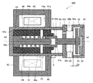
- FIG. 3 is an enlarged view of an electromagnetic suction valve unit as an electromagnetic valve mechanism according to the first embodiment of the present invention shown in FIG.
- FIG. 4 is an explanatory diagram showing the relationship between the movable core and its guide structure portion in the solenoid valve mechanism according to the first embodiment of the present invention shown in FIG. Note that FIG. 3 shows a state in which the electromagnetic suction valve unit is not energized.
- the electromagnetic suction valve unit 300 is roughly classified into a valve mechanism portion including a suction valve 31 and a solenoid mechanism portion including a coil 41 and a movable core 45.
- the valve mechanism is composed of a suction valve 31, a suction valve seat 32, a suction valve stopper 33, and a first urging spring 34.
- the suction valve seat 32 is, for example, a bottomed tubular member that opens on one side (right side in FIG. 3) and has a central axis A1.
- the suction valve seat 32 has an annular valve seat portion 32a on which the suction valve 31 can be seated at an intermediate position in the axial direction of the tubular portion. That is, inside the tubular portion of the suction valve seat 32, the suction valve 31 is movably arranged so as to be seated or separated from the valve seat portion 32a.
- a plurality of suction ports 32b communicating with the low-pressure fuel chamber 2b are provided in the tubular portion of the suction valve seat 32 at intervals in the circumferential direction.
- a guide hole 32c that penetrates along the central axis A1 of the suction valve seat 32 is provided.
- the bottom portion of the suction valve seat 32 having the guide hole 32c functions as a rod guide portion that slidably supports (guides) the rod 48 described later along the central axis A1 of the suction valve seat 32.
- a through hole 32d penetrating the inside of the tubular portion is provided.
- the through hole 32d is a flow path for enabling the movement of fuel in the electromagnetic suction valve unit 300 due to the movement (displacement) of the movable core 45 described later.
- a suction valve stopper 33 is press-fitted and fixed to the opening of the suction valve seat 32.
- the suction valve stopper 33 has a function of regulating the displacement of the suction valve 31 away from the valve seat portion 32a.
- a first urging spring 34 is arranged between the suction valve 31 and the suction valve stopper 33. That is, the first urging spring 34 has one end in contact with the suction valve 31 and the other end in contact with the suction valve stopper 33, and urges the suction valve 31 toward the valve seat portion 32a (in the direction of closing the valve). are doing.
- the solenoid mechanism includes, for example, a coil 41 provided in an annular shape, a housing 42 arranged radially inside the coil 41, an annular yoke 43 surrounding the coil 41 and fixed to the outer peripheral portion of the housing 42, and a housing. It is composed of a fixed core 44, a movable core 45, a guide member 46, a guided member 47, a rod 48, and a second urging spring 49 housed in the 42.
- a control signal from the ECU 107 (see FIG. 1) is input to the coil 41 via a terminal (not shown).
- the yoke 43, the housing 42, the fixed core 44, and the movable core 45 form a magnetic circuit
- the movable core 45, the guided member 47, and the rod 48 form a movable part that drives the suction valve 31. ..
- the movable core 45 and the guided member 47 are integrally provided, but the rod 48 has a separate structure that can be brought into contact with and separated from the movable core 45 and the guided member 47.
- the present embodiment is characterized by a guide structure that guides the movement of the movable core 45.
- the housing 42 is, for example, a bottomed tubular member that opens on one side (right side in FIG. 3) and has a central axis A2.
- the housing 42 and the suction valve seat 32 are fixed so as to be coaxial with each other. That is, the housing 42 is arranged so that its central axis A2 substantially coincides with the central axis A1 of the suction valve seat 32.
- the inner surface of the bottom portion 42a of the housing 42 is formed in a plane substantially orthogonal to the second central axis A2.
- a fixed core 44 is arranged on the bottom 42a side in the housing 42.
- the fixed core 44 is formed so as to extend in the axial direction of the housing 42, for example, and the outer peripheral surface thereof is fixed by being press-fitted into the housing 42.
- An accommodating portion 44a capable of accommodating most of the guide member 46 is provided at a position inside the fixed core 44 in the radial direction (diameter central portion).
- the accommodating portion 44a is formed as, for example, a hole portion penetrating in the axial direction.
- the fixed core 44 forms a part of a magnetic circuit and is made of a magnetic material.
- As the magnetic material for example, a material having a Vickers hardness of 200 HV or less is used.
- the end surface of the fixed core 44 on the opening side of the housing constitutes a magnetic attraction surface on which a magnetic attraction force acts.
- the movable core 45 On the opening side of the housing 42, the movable core 45 is arranged so as to face the fixed core 44.
- the movable core 45 is formed so as to form a gap between the movable core 45 and the inner peripheral surface of the housing 42, and is movable within the housing 42.
- the movable core 45 forms a part of a magnetic circuit together with the fixed core 44, and is made of a magnetic material.
- the magnetic material for example, a material having a Vickers hardness of 200 HV or less is used as in the fixed core 44.
- the housing 42 and the yoke 43 constituting the magnetic circuit are also made of a magnetic material like the fixed core 44 and the movable core 45.
- the facing surface of the fixed core 44 in the movable core 45 constitutes a magnetic attraction surface on which a magnetic attraction force acts.
- a fitting portion 45a into which the guided member 47 is fitted is formed at a position (diameter central portion) inside the movable core 45 in the radial direction.
- the fitting portion 45a is formed as, for example, a hole portion penetrating in the axial direction of the housing 42.
- a guide member 46 having a central axis A3 is arranged in the accommodating portion 44a of the fixed core 44.
- the guide member 46 supports the movable core 45 via the guided member 47 at a position inside the movable core 45 in the radial direction (inside the fitting portion 45a), and supports the movable core 45 along the central axis A3 of the guide member 46. It guides the fixed core 44 in the direction of contact and separation.
- the guide member 46 has a base portion 46a fixed to the accommodating portion 44a inside the fixed core 44 in the radial direction, and an outer diameter smaller than that of the base portion 46a, extending from the base portion 46a and extending the movable core 45 via the guided member 47. It is composed of a guide main body 46b for guiding.
- the tip end portion (right end portion in FIG. 3) of the guide main body 46b is formed in a tapered shape.
- the end surface of the base portion 46a on one side in the axial direction of the guide member 46 is formed in a plane substantially orthogonal to the central axis A3.
- the guide member 46 is arranged so that the end surface of the base portion 46a is in contact with the inner surface of the bottom portion 42a of the housing 42, and the central axis A3 thereof is fixed so as to substantially coincide with the central axis A2 of the housing 42.
- a material having higher hardness and excellent wear resistance than the fixed core 44 or the movable core 45 for example, austenitic stainless steel or martensitic. It is made of austenitic stainless steel. When austenitic stainless steel is used, the strength can be increased by performing a treatment such as carburizing. When martensitic stainless steel is used, the strength can be increased by heat treatment such as quenching. As a material having excellent wear resistance, for example, a material having a Vickers hardness of about 500 to 800 HV is used.
- a guided member 47 is press-fitted into the fitting portion 45a of the movable core 45 to be integrally formed with the movable core 45.
- the guided member 47 is a bottomed tubular member that opens on one side (left side in FIG. 3), and has a tubular portion 47a on which the guide member 46 is arranged and slidable with respect to the guide member 46.
- the tubular portion 47a is composed of a closing portion 47b that closes an opening on the opposite side of the fixed core 44. That is, the movable core 45 is supported by the guide member 46 via the guided member 47, and the movable core 45 and the guided member 47 are integrally movable along the central axis A3 of the guide member 46. There is.
- a through hole 47c is provided in the closed portion 47b of the guided member 47.
- the through hole 47c reduces the fluid resistance when the guided member 47 moves and facilitates the movement of the guided member 47.
- the guided member 47 is arranged so that the end surface of the tubular portion 47a is located inside the fitting portion 45a of the movable core 45.
- the guided member 47 is a member that slides on the guide member 46, it is preferably formed of a material having a hardness substantially equal to that of the material of the guide member 46. That is, the guided member 47 is formed of a high-strength material having excellent wear resistance, such as austenitic stainless steel and martensitic stainless steel, like the guide member 46. As a material having excellent wear resistance, a material having a Vickers hardness of about 500 to 800 HV is used as in the guide member 46.
- the rod 48 has one axial end (left end in FIG. 3) that can be brought into contact with and separated from the closed portion 47b of the guided member 47, and the other axial end (right end in FIG. 3). ) Is configured to be accessible to and from the suction valve 31.
- the rod 48 is inserted through the guide hole 32c of the suction valve seat 32 and slidably supported by the suction valve seat 32. That is, the movement of the rod 48 is guided by the inner wall surface of the guide hole 32c.
- the second urging spring 49 is configured to be arranged in the accommodating portion 44a of the fixed core 44, in the fitting portion 45a of the movable core 45, and radially outside the guide main body 46b of the guide member 46. There is. One end of the second urging spring 49 is in contact with the base 46a of the guide member 46, and the other end is in contact with the end surface of the tubular portion 47a of the guided member 47. The second urging spring 49 urges the movable core 45 in a direction away from the fixed core 44 via the guided member 47.
- the second urging spring 49 is configured such that the urging force thereof is larger than the urging force of the first urging spring 34.
- the difference between the urging force of the second urging spring 49 and the urging force of the first urging spring 34 causes the integral movable core 45 and the guided member 47 to come into contact with each other.
- the rod 48 as a movable portion comes into contact with the suction valve 31 and urges the suction valve 31 in a direction away from the valve seat portion 32a of the suction valve seat 32.
- the suction valve 31 is in a valve open state or a valve closed state depending on the pressure in the pressurizing chamber 4 (see FIG. 2).
- the slidable length (guide length) S of the guide member 46 and the guided member 47 is the distance G1 that allows the movable core 45 to move toward the fixed core 44 side by energizing the coil 41, that is, , It is configured to be larger than the stroke length of the movable core 45.
- the distance G1 is equal to the length of the gap formed between the movable core 45 and the fixed core 44 in the absence of energization of the coil 41.
- the difference between the inner diameter D1 of the tubular portion 47a of the guided member 47 and the outer diameter d2 of the guide body 46b of the guide member 46 is the difference between the inner diameter D3 of the housing 42 and the movable core. It is configured to be smaller than the difference from the outer diameter d4 of 45. With this configuration, the movable core 45 is not slidably supported by the housing 42, but is reliably supported by the guide member 46 via the guided member 47.
- the coil 41 of the electromagnetic suction valve unit 300 is in a non-energized state.
- the movable core is caused by the difference between the urging force of the second urging spring 49 and the urging force of the first urging spring 34.
- the rod 48 is urged to the suction valve 31 side (right side in FIG. 3) via the guided member 47 integrally formed with the 45.
- the suction valve 31 in contact with the rod 48 is separated from the valve seat portion 32a of the suction valve seat 32, and the low-pressure fuel chamber 2b and the pressurizing chamber 4 shown in FIG. 2 communicate with each other. Therefore, the fuel in the low-pressure fuel chamber 2b flows into the pressurizing chamber 4 through the gap between the suction valve 31 and the valve seat portion 32a as the plunger 5 descends. Due to the pressure drop of the fuel flowing through the gap between the suction valve 31 and the valve seat portion 32a, a force acts on the suction valve 31 in the valve opening direction (right direction in FIG. 3).
- the coil 41 is energized from the ECU 107 (see FIG. 1) in a state where the plunger 5 has exceeded the bottom dead center and has started to rise.
- a magnetic flux generated around the coil 41 passes through the yoke 43, the fixed core 44, the housing 42, and the movable core 45 to form a magnetic circuit, and a magnetic attractive force is generated between the facing surfaces of the movable core 45 and the fixed core 44.
- this magnetic attraction force exceeds the difference between the urging forces of the second urging spring 49 and the first urging valve spring, the movable core 45 together with the guided member 47 is the length of the gap between the movable core 45 and the fixed core 44.
- the movable core 45 comes into contact with the fixed core 44, and the operation of the movable core 45 and the guided member 47 is stopped.
- the fixed guide member 46 supports and guides the movable core 45 via the guided member 47 integrally provided in the fitting portion 45a on the inner side in the radial direction of the movable core 45. It is configured to do.
- the distance from the movable core to the guide mechanism is longer than in the case of the present embodiment in which the guide member 46 (guide mechanism) supports the movable core 45 at the position inside the movable core 45 in the radial direction.
- the amount of radial displacement (displacement amount) of the movable core with respect to the ideal case where the movable core is guided without tilting is the movable core. It increases in proportion to the distance from the guide mechanism to the guide mechanism. If the amount of displacement in the radial direction due to the inclination of the movable core becomes large, there is a risk that the operation of the movable core will vary greatly accordingly.
- some conventional structures guide the movement of the movable core by a rod guided by a guide hole (guide mechanism) of the suction valve seat.
- the movable core is slidably supported by a rod inside its radial direction. Therefore, the distance from the sliding support position by the rod of the movable core to the movable core becomes short.
- the rod that supports the movable core is slidably supported by the guide hole (guide mechanism)
- the movable core is guided to the guide hole (guide mechanism) of the suction valve seat via the rod, which is the conventional structure described above.
- the amount of displacement (displacement amount) of the movable core in the radial direction increases in proportion to the distance from the movable core to the guide hole (guide mechanism) of the suction valve seat.
- the distance from the fixed guide member 46 as the guide mechanism to the movable core 45 is shorter than that of the above-mentioned conventional structure, so that the fixed core 44 when the movable core 45 is moved is used. It is possible to suppress the relative inclination more than before.
- the suction valve 31 After the suction valve 31 is completely closed, the pressure in the pressurizing chamber 4 rises and high pressure discharge is started, the energization of the coil 41 is stopped. As a result, the magnetic attraction force generated between the facing surfaces of the fixed core 44 and the movable core 45 disappears, and the magnetic attraction force becomes smaller than the urging force of the second urging spring 49. Therefore, the urging force of the second urging spring 49 moves the movable core 45, the guided portion, and the movable portion of the rod 48 toward the suction valve 31 side.
- the inner peripheral surface of the tubular portion 47a slides on the outer peripheral surface of the guide member 46, and the guide member 46 extends in the extending direction. It moves to the suction valve 31 side along the above. That is, the movement of the movable core 45 toward the suction valve 31 by the urging force of the second urging spring 49 is guided by the guide member 46 via the guided member 47.
- the flow rate of the fuel discharged at high pressure can be adjusted by controlling the timing of energizing the coil 41 based on the command from the ECU 107. If the energization timing is controlled so that the suction valve 31 closes immediately after the plunger 5 shifts from the bottom dead center to the top dead center, the fuel stays less and the amount of fuel discharged at high pressure increases. it can.
- the high-pressure fuel supply pump 1 is configured to control the closing time of the suction valve 31 by controlling the energization time of the coil 41 so that the suction valve 31 can be discharged to a desired flow rate.
- the electromagnetic suction valve unit 300 (solenoid valve mechanism) and the high-pressure fuel supply pump 1 provided with the electromagnetic suction valve unit 300 (electromagnetic valve mechanism) according to the first embodiment of the present invention described above include a coil 41 provided in an annular shape and a radial inside of the coil 41.
- the fixed core 44 arranged in the coil 41 and the fixed core 44 are arranged so as to face the fixed core 44 on the radial inside of the coil 41 to form a part of a magnetic circuit together with the fixed core 44.
- Reference numeral 46 denotes a radial inner side of the movable core 45 to support the movement of the movable core 45.
- the movable core 45 is supported by the guide member 46 via a guided member 47 integrally provided at a position inside in the radial direction, and the guided member 47 is supported by the guided member 46.
- a guide member 46 is arranged inside and has a tubular portion 47a slidable with respect to the guide member 46.
- the guided member 47 is joined to the movable core 45 by press fitting the movable core 45a on the outer peripheral surface of the tubular portion 47a into the inner peripheral surface, and is integrally formed with the movable core 45. There is. Therefore, the movable core 45 and the guided member 47 can be easily assembled.
- the electromagnetic suction valve unit 300 has a tubular shape that is arranged inside the coil 41 in the radial direction and outside the radial direction of the movable core 45 to accommodate the movable core 45, the guided member 47, and the guide member 46.
- the difference between the inner diameter D1 of the tubular portion 47a of the guided portion and the outer diameter d2 of the guide member 46 is smaller than the difference between the inner diameter D3 of the housing 42 and the outer diameter d4 of the movable core 45. It is configured as follows. With this configuration, the movable core 45 is surely supported and guided by the guide member 46 via the guided member 47 without being slidably supported by the housing 42.
- the electromagnetic suction valve unit 300 is arranged inside the coil 41 in the radial direction and outside in the radial direction of the movable core 45 to accommodate the movable core 45 and the guide member 46, and accommodates the movable core 45 and the guide member 46.
- a tubular housing 42 having an axis) A2 is further provided, and the guide member 46 is arranged so that its central axis (first central axis) A3 coincides with the central axis (second central axis) A2 of the housing 42. Is.
- the coincidence between the central axis A3 of the guide member 46 and the central axis A2 of the housing 42 shown here includes not only the case where they completely match but also the case where both central axes A3 and A2 substantially match.
- the case where both center axes A3 and A2 substantially coincide with each other is a concept including, for example, a case where a deviation occurs between both center axes A3 and A2 within an allowable range in assembly.
- the electromagnetic suction valve unit 300 is arranged radially inside the coil 41 and radially outside the movable core 45, and is a bottomed tubular housing 42 that accommodates the movable core 45 and the guide member 46.
- the housing 42 is formed so that the inner surface of the bottom portion 42a is flat, and the guide member 46 is formed so that the end face on one side in the axial direction is orthogonal to the central axis (first central axis) A3.
- the member 46 is arranged so that the end surface on one side in the axial direction comes into contact with the inner surface of the bottom portion 42a of the housing 42. With this configuration, positioning of the central axis A3 of the guide member 46 (centering of the guide member 46) becomes easy.
- the plane orthogonal to the central axis A3 shown here includes not only a plane completely orthogonal to the central axis A3 but also a plane substantially orthogonal to the central axis A3.
- the plane substantially orthogonal to the central axis A3 is a concept including, for example, a case where a deviation occurs within a manufacturing allowable range.
- the slidable length S of the guided member 47 and the guide member 46 moves to the fixed core 44 side of the movable core 45 by energizing the coil 41. It is configured to be larger than the possible distance G1. With this configuration, the guide member 46 can reliably and slidably support the movable core 45 and the guided member 47 within the range of the stroke length G1 of the movable core 45, and suppress the inclination of the movable core 45 during movement. Can be done.
- the guide member 46 is made of a material having a hardness higher than that of the movable core 45. With this configuration, wear of the guide member 46 due to guiding the movable core 45 and the guided member 47 can be suppressed. Therefore, it is possible to suppress the inclination of the movable core 45 during movement caused by the wear of the guide member 46.
- the guided member 47 is made of a material having a hardness higher than that of the movable core 45. With this configuration, wear of the guided member 47 due to sliding with the guide member 46 can be suppressed. Therefore, it is possible to suppress the inclination of the movable core 45 during movement caused by the wear of the guided member 47.
- the guide member 46 and the guided member 47 are made of a material having the same hardness. With this configuration, excessive wear of either one due to sliding of the guide member 46 and the guided member 47 can be suppressed. Therefore, it is possible to prevent the movable core 45 from being tilted significantly during movement due to excessive wear of either the guide member 46 or the guided member 47.
- the same hardness shown here does not mean only the case of exactly the same, but includes the same degree of hardness.
- the hardness of the same level includes, for example, a Vickers hardness in the range of about 500 to 800 HV.
- the electromagnetic suction valve unit 300 includes a second urging spring 49 (spring member) that urges the movable core 45 in a direction away from the fixed core 44, and the guide member 46 is the fixed core 44. It has a base portion 46a fixed at a position inside in the radial direction of the guide body 46a, and a guide body 46b which is smaller in outer diameter than the base portion 46a and extends from the base portion 46a to guide the tubular portion 47a of the guided member 47. 2
- the urging spring 49 (spring member) is arranged on the radial outer side of the guide main body 46b, and one side end portion contacts the base portion 46a of the guide member 46 and the other side end portion is a cylinder of the guided member 47.
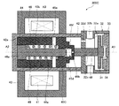
- FIG. 5 is a cross-sectional view showing a solenoid valve mechanism according to a first modification of the first embodiment of the present invention.
- FIG. 6 is a cross-sectional view showing a solenoid valve mechanism according to a second modification of the first embodiment of the present invention.
- FIGS. 5 and 6 those having the same reference numerals as those shown in FIGS. 1 to 4 have the same parts, and thus detailed description thereof will be omitted.
- the solenoid valve mechanism (electromagnetic suction valve unit 300A) according to the first modification of the first embodiment of the present invention shown in FIG. 5 is the solenoid valve mechanism (electromagnetic suction valve unit 300) according to the first embodiment.
- the difference is that the method of joining the guided member 47A to the movable core 45A is different.
- the guided member 47 of the solenoid valve mechanism (solenoid suction valve unit 300) according to the first embodiment is joined to the movable core 45 by press fitting (see FIG. 3).
- the solenoid valve mechanism (solenoid valve unit 300A) according to the first modification of the first embodiment the guided member 47A is fixed to the movable core 45A by screwing and integrally configured. There is.
- a female screw portion 45b is provided on the inner peripheral surface of the fitting portion 45a of the movable core 45A.
- a male screw portion 47d is provided from the opening side edge of the tubular portion 47a to a predetermined position.
- the movable core 45A is joined to the guided member 47A and integrally formed by screwing the male threaded portion 47d of the guided member 47A into the female threaded portion 45b of the movable core 45A. Therefore, the movable core 45A and the guided member 47A can be integrally moved.
- the solenoid valve mechanism (electromagnetic suction valve unit 300B) according to the second modification of the first embodiment of the present invention shown in FIG. 6 is the solenoid valve mechanism (electromagnetic suction valve unit 300) according to the first embodiment.
- the guided member 47 of the solenoid valve mechanism (solenoid suction valve unit 300B) according to the second modification is integrally formed with the movable core 45 by fusion bonding or liquid phase bonding. It is a point that has been done.
- the movable core 45 and the guided member 47 are integrally formed by being joined by a welded portion W provided on the end surface of the movable core 45 on the rod 48 side and the outer peripheral surface of the guided member 47. .. Therefore, the movable core 45 and the guided member 47 can be integrally moved.
- the movable core 45 and the guided member 47 can be joined by a brazed portion or a soldered portion W instead of the welded portion W.
- the movable one is movable as in the first embodiment.
- the position for guiding and supporting the cores 45 and 45A can be made closer to the movable cores 45 and 45A than the conventional structure, and as a result, the inclination of the movable cores 45 and 45A during movement can be reduced.
- the movable core 45A has a female screw portion 45b on the inner peripheral surface thereof, and the guided member 47A has a movable core 45A on the outer peripheral surface of the tubular portion 47a. It has a male threaded portion 47d that is screwed into the female threaded portion 45b, and the guided member 47A is fixed to the movable core 45A by screwing the male threaded portion 47d of the tubular portion 47a into the female threaded portion 45b to form a movable core 45A. It is configured as one. This configuration facilitates the assembly of the movable core 45A and the guided member 47A.
- the guided member 47 is joined to the movable core 45 by melt joining or liquid phase joining to be integrally formed with the movable core 45.
- FIG. 7 is a cross-sectional view showing the solenoid valve mechanism according to the second embodiment of the present invention.
- those having the same reference numerals as those shown in FIGS. 1 to 6 have the same reference numerals, and thus detailed description thereof will be omitted.
- the solenoid valve mechanism (electromagnetic suction valve unit 300C) according to the second embodiment of the present invention shown in FIG. 7 the solenoid valve mechanism (electromagnetic suction valve unit 300) according to the first embodiment is covered with a movable core 45. While the guide member 47 is composed of a separate member (see FIG. 3), the portion of the guided member 47 of the first embodiment is configured as a part of the movable core 45C. Specifically, the movable core 45C has a stepped hole 45d for being guided, which opens to the fixed core 44 side and closes to the rod 48 side, at the position of the radial center portion thereof.
- the guided hole portion 45d is composed of a large diameter portion 45e on the opening side and a small diameter portion 45f on the bottom side.
- a guide member 46 is arranged in the hole 45d for being guided, and the inner peripheral surface of the small diameter portion 45f is slidable on the outer peripheral surface of the guide member 46.
- a part of the second urging spring 49 is housed in the large diameter portion 45e.
- the other side end (right end in FIG. 7) of the second urging spring 49 is in contact with the stepped surface of the large diameter portion 45e and the small diameter portion 45f.
- a through hole 45h is provided at the bottom of the guided hole 45d of the movable core 45C.
- the through hole 45h has the same function as the through hole 47c of the guided member 47 according to the first embodiment.
- the position for guiding and supporting the movable core 45C is the conventional structure as in the first embodiment. It can be brought closer to the movable core 45C side, and as a result, the inclination of the movable core 45C during movement can be reduced.
- the present invention is not limited to the above-described embodiment, and includes various modifications.
- the above-described embodiments have been described in detail in order to explain the present invention in an easy-to-understand manner, and are not necessarily limited to those having all the described configurations. It is possible to replace a part of the configuration of one embodiment with the configuration of another embodiment, and it is also possible to add the configuration of another embodiment to the configuration of one embodiment. It is also possible to add, delete, or replace a part of the configuration of each embodiment with another configuration.
- the guided members 47 and 47A are press-fitted, screwed, welded or welded or liquid phase to the movable cores 45 and 45A.
- An example is shown in which the movable cores 45 and 45A are integrally formed by joining by joining.
- the guided member 47 can be joined to the movable core 45 by caulking at least one of the movable core 45 and the guided member 47 to be integrally formed with the movable core 45. With this configuration, it is possible to prevent the movable core 45 and the guided member 47 from being misaligned due to contact (collision) between the movable core 45 and the fixed core 44.
Landscapes
- Physics & Mathematics (AREA)
- Electromagnetism (AREA)
- Engineering & Computer Science (AREA)
- Power Engineering (AREA)
- Chemical & Material Sciences (AREA)
- Combustion & Propulsion (AREA)
- Mechanical Engineering (AREA)
- General Engineering & Computer Science (AREA)
- Magnetically Actuated Valves (AREA)
- Fuel-Injection Apparatus (AREA)
- Electromagnets (AREA)
Priority Applications (3)
| Application Number | Priority Date | Filing Date | Title |
|---|---|---|---|
| DE112020001277.8T DE112020001277T5 (de) | 2019-04-18 | 2020-02-07 | Elektromagnetischer Ventilmechanismus und Hochdruckkraftstoffzufuhrpumpe, die diesen enthält |
| JP2021514804A JP7248783B2 (ja) | 2019-04-18 | 2020-02-07 | 電磁弁機構及びそれを備えた高圧燃料供給ポンプ |
| CN202080028500.XA CN113692509B (zh) | 2019-04-18 | 2020-02-07 | 电磁阀机构以及配备它的高压燃料供给泵 |
Applications Claiming Priority (2)
| Application Number | Priority Date | Filing Date | Title |
|---|---|---|---|
| JP2019-079247 | 2019-04-18 | ||
| JP2019079247 | 2019-04-18 |
Publications (1)
| Publication Number | Publication Date |
|---|---|
| WO2020213235A1 true WO2020213235A1 (ja) | 2020-10-22 |
Family
ID=72838121
Family Applications (1)
| Application Number | Title | Priority Date | Filing Date |
|---|---|---|---|
| PCT/JP2020/004731 Ceased WO2020213235A1 (ja) | 2019-04-18 | 2020-02-07 | 電磁弁機構及びそれを備えた高圧燃料供給ポンプ |
Country Status (4)
| Country | Link |
|---|---|
| JP (1) | JP7248783B2 (https=) |
| CN (1) | CN113692509B (https=) |
| DE (1) | DE112020001277T5 (https=) |
| WO (1) | WO2020213235A1 (https=) |
Citations (5)
| Publication number | Priority date | Publication date | Assignee | Title |
|---|---|---|---|---|
| DE2503345A1 (de) * | 1975-01-28 | 1976-07-29 | Bosch Gmbh Robert | Kraftstoffeinspritzpumpe fuer brennkraftmaschinen |
| JPS59184365U (ja) * | 1983-05-26 | 1984-12-07 | 株式会社ボッシュオートモーティブ システム | 燃料噴射ポンプの電磁弁 |
| JPS6026282U (ja) * | 1983-07-29 | 1985-02-22 | 株式会社ボッシュオートモーティブ システム | 燃料噴射ポンプの電磁弁 |
| JP2013002332A (ja) * | 2011-06-15 | 2013-01-07 | Denso Corp | 高圧ポンプおよびその制御方法 |
| JP2015108409A (ja) * | 2013-12-05 | 2015-06-11 | 日立オートモティブシステムズ株式会社 | ソレノイドバルブ |
Family Cites Families (7)
| Publication number | Priority date | Publication date | Assignee | Title |
|---|---|---|---|---|
| JPH0672214U (ja) * | 1993-03-22 | 1994-10-07 | 株式会社京浜精機製作所 | 電磁装置 |
| JP5331731B2 (ja) * | 2010-03-03 | 2013-10-30 | 日立オートモティブシステムズ株式会社 | 電磁式の流量制御弁及びそれを用いた高圧燃料供給ポンプ |
| CN105190016B (zh) * | 2013-03-19 | 2018-06-26 | 日立汽车系统株式会社 | 高压燃料供给泵 |
| JP6173959B2 (ja) * | 2014-03-28 | 2017-08-02 | 日立オートモティブシステムズ株式会社 | 電磁弁、電磁弁を備えた高圧燃料供給ポンプ及び燃料噴射弁 |
| WO2016208359A1 (ja) * | 2015-06-25 | 2016-12-29 | 日立オートモティブシステムズ株式会社 | 流量制御弁及び高圧燃料供給ポンプ |
| CN106935356A (zh) * | 2017-03-31 | 2017-07-07 | 广东金禄科技股份有限公司 | 一种带导向的自保持电磁铁 |
| CN108050292A (zh) * | 2018-01-24 | 2018-05-18 | 太仓源凯汽车配件有限公司 | 一种高性能电控旁通阀 |
-
2020
- 2020-02-07 DE DE112020001277.8T patent/DE112020001277T5/de active Pending
- 2020-02-07 JP JP2021514804A patent/JP7248783B2/ja active Active
- 2020-02-07 CN CN202080028500.XA patent/CN113692509B/zh active Active
- 2020-02-07 WO PCT/JP2020/004731 patent/WO2020213235A1/ja not_active Ceased
Patent Citations (5)
| Publication number | Priority date | Publication date | Assignee | Title |
|---|---|---|---|---|
| DE2503345A1 (de) * | 1975-01-28 | 1976-07-29 | Bosch Gmbh Robert | Kraftstoffeinspritzpumpe fuer brennkraftmaschinen |
| JPS59184365U (ja) * | 1983-05-26 | 1984-12-07 | 株式会社ボッシュオートモーティブ システム | 燃料噴射ポンプの電磁弁 |
| JPS6026282U (ja) * | 1983-07-29 | 1985-02-22 | 株式会社ボッシュオートモーティブ システム | 燃料噴射ポンプの電磁弁 |
| JP2013002332A (ja) * | 2011-06-15 | 2013-01-07 | Denso Corp | 高圧ポンプおよびその制御方法 |
| JP2015108409A (ja) * | 2013-12-05 | 2015-06-11 | 日立オートモティブシステムズ株式会社 | ソレノイドバルブ |
Also Published As
| Publication number | Publication date |
|---|---|
| JP7248783B2 (ja) | 2023-03-29 |
| JPWO2020213235A1 (https=) | 2020-10-22 |
| DE112020001277T5 (de) | 2021-12-02 |
| CN113692509A (zh) | 2021-11-23 |
| CN113692509B (zh) | 2023-08-11 |
Similar Documents
| Publication | Publication Date | Title |
|---|---|---|
| JP6370888B2 (ja) | 高圧燃料供給ポンプ | |
| JP6779370B2 (ja) | 高圧燃料ポンプ | |
| CN114502833B (zh) | 燃料供给泵 | |
| US11542903B2 (en) | High-pressure fuel supply pump provided with electromagnetic intake valve | |
| JP2021014791A (ja) | 高圧燃料ポンプ | |
| WO2021054006A1 (ja) | 電磁吸入弁及び高圧燃料供給ポンプ | |
| JP6840238B2 (ja) | 弁機構、電磁吸入弁機構、及び高圧燃料ポンプ | |
| US12085074B2 (en) | Electromagnetic valve mechanism and high-pressure fuel supply pump | |
| EP3653867A1 (en) | High-pressure fuel pump | |
| JP6572241B2 (ja) | バルブ機構、及びこれを備えた高圧燃料供給ポンプ | |
| US12140113B2 (en) | Electromagnetic valve mechanism and fuel pump | |
| JP7248783B2 (ja) | 電磁弁機構及びそれを備えた高圧燃料供給ポンプ | |
| JP2019167897A (ja) | 燃料供給ポンプ | |
| JP2019090365A (ja) | 燃料供給ポンプ | |
| JP2023071061A (ja) | 燃料ポンプ | |
| JP7299817B2 (ja) | 高圧燃料供給ポンプ | |
| JP6754902B2 (ja) | 電磁吸入弁、及びこれを備えた高圧燃料ポンプ | |
| US20220316470A1 (en) | Fuel Pump | |
| JP7024071B2 (ja) | 燃料供給ポンプ | |
| JP7077212B2 (ja) | 高圧燃料ポンプ | |
| JP2020172901A (ja) | 高圧燃料供給ポンプ及び吸入弁機構 | |
| JP2019203437A (ja) | 高圧燃料供給ポンプ | |
| WO2023058287A1 (ja) | 電磁吸入弁機構及び燃料ポンプ | |
| WO2021229862A1 (ja) | 弁機構及びそれを備えた高圧燃料供給ポンプ | |
| WO2020090371A1 (ja) | 燃料ポンプ |
Legal Events
| Date | Code | Title | Description |
|---|---|---|---|
| 121 | Ep: the epo has been informed by wipo that ep was designated in this application |
Ref document number: 20790888 Country of ref document: EP Kind code of ref document: A1 |
|
| ENP | Entry into the national phase |
Ref document number: 2021514804 Country of ref document: JP Kind code of ref document: A |
|
| 122 | Ep: pct application non-entry in european phase |
Ref document number: 20790888 Country of ref document: EP Kind code of ref document: A1 |